Embed Size (px)
Citation preview
VALIDATION OF REDUCED ORDER MODELING FOR THE PREDICTION OF THE RESPONSE AND FATIGUE LIFE OF PANELS
SUBJECTED TO THERMO-ACOUSTIC EFFECTS
Marc P. Mignolet Adrian G. Radu Department of Mechanical and Aerospace Engineering, Arizona State University Tempe, Arizona, 85287-6106, USA. Emails: [email protected] and [email protected] Xiaowei Gao ZONA Technology, 7430 E. Stetson Drive, Suite 205 Scottsdale, AZ 85251-3540, USA. Email: [email protected]
ABSTRACT
This paper focuses on the validation of a reduced order modeling strategy for aircraft panels subjected to combined thermal effects and an incident acoustic wave strong enough to induce a severe geometrically nonlinear behavior. The response of flat panels to two different excitations scenarios serves as a basis to assess the appropriateness of several modal bases for the reduced order modeling. This comparison emphasizes the importance of the in-plane displacement field and of a reliable modeling of the curvature of the deformed panels. Consistently with these observations, a novel basis is introduced that involves separate representations of the transverse displacements and their induced in-plane counterparts.
INTRODUCTION
The reliable and efficient design of the panels of reusable launch vehicles and other future hypersonic vehicles represents a difficult technological challenge. Indeed, these panels will be subjected to thermal effects originating from the aerodynamics and potentially severe acoustic loads emanating for example from the engine exhaust. To avoid a degradation of the structural properties, thermal protection systems (TPS) are expected to be used to “shield” the structural components from the high temperatures. While the normal operating temperature of a thermally protected panel should be much less than the 3000°F that might be obtained without TPS [1], it still might be large enough to induce a decrease of the panel stiffness, either from constrained thermal expansion or from a reduction of the mechanical properties. In all cases, a severe acoustic loading of these panels will induce large deflections and a substantially reduced fatigue life which must be carefully estimated to avoid an unforeseen failure. The prediction of the fatigue life of the panels is however a rather challenging task as
(i) the acoustic excitation is best represented as a random process, (ii) the presence of large deflections implies the nonlinearity of the governing equations for
the panel response and the non-Gaussian character of its probability density function, and
(iii) the presence of large deflections also implies a nonlinearity of the displacement-stress relationship (due to the von Karman strain definition) and thus a further deviation of the
VIII International Conference on Recent Advances in Structural DynamicsSouthampton, UK, 14-16 July 2003
Paper No. 55
distribution of the peak and ranges from the classical models (e.g. Rayleigh, Dirlik, etc., see [2]).
A good qualitative understanding of the dynamic behavior of the panel response through the entire range of sound pressure level (SPL) and temperature can be obtained from the published literature in this area (see [1], [3]-[17] and references therein). While a qualitative perspective on the dynamic response of the panels is important, it is its accurate quantitative prediction which is ultimately required for design considerations. Quite naturally, it would seem that this prediction could be accomplished using standard finite element packages. This is indeed possible but the computational time needed to obtain a time history of the response long enough to derive accurate estimates of the statistics of the response and the expected fatigue life is surprisingly large. For example, achieving this latter task with an accuracy of the order of a few percents for a panel with 1,000 degrees-of-freedom and a material with a S-N curve of exponent 8 appears to require one to several hundred CPU hours on a top of the line single processor PC (2.4 GHz, 2 GB RAM) running the nonlinear NASTRAN dynamic solution with the standard accuracy. While a decrease of this CPU time will naturally arise from the ever increasing processors speed, it is also expected that much more complex models would be studied in practical applications and would include in particular thermal protection systems. Even if such a computational time may be acceptable to analyze a specific panel, it is not appropriate in the design phase when changes may occur frequently and when fast analysis capabilities are needed. These difficulties of a straightforward finite element approach have been well recognized in [9], [10], and [13] who suggested to proceed with reduced order modeling techniques in which the panel displacement field is approximately represented as a linear combination of a series of assumed “modes”. With this representation, the number of degrees-of-freedom is reduced to m, the number of modes considered, which is small enough to permit an efficient solution of the problem. A distinguishing feature of the work of Rizzi and Muravyov [13] lies in the finite element code used, i.e. as opposed to developing separate finite element capabilities, they have efficiently linked their reduced order modeling strategy to NASTRAN thereby allowing the use of all elements and resources inside NASTRAN. Then, the goal of this paper is to report on current validation efforts and extensions of the nonlinear stiffness evaluation approach of [13] to include the panel temperature effects and a stress reduced order modeling to lead to the efficient estimation of the fatigue life of panels subjected to a random acoustic excitation and temperature effects. For clarity, the formulation of the reduced order modeling strategy will first be briefly revisited.
REDUCED ORDER MODELING FORMULATION
In the absence of material nonlinearity, large deformations are assumed to only affect the panel dynamics through the von Karman strains, i.e.
2
21
∂∂
+∂∂
=εxw
xu
x 2
21
∂∂
+∂∂
=εyw
yv
y 0=∂∂
=εzw
z
(1)
∂∂
∂∂
+∂∂
+∂∂
=γyw
xw
xv
yu
xy 21
∂∂
+∂∂
=γxw
zu
xz 21
∂∂
+∂∂
yw
zv
2=γ yz
1
where u(x, y, t), v(x, y, t), and w(x, y, t) are the in-plane and out-of-plane displacement fields, respectively. In a finite element formulation, the determination of these functions is reduced to the computation of the nodal displacements, e.g. the in-plane, out-of-plane displacements and rotations at these points, which are stored in the vector ( )tw . Given the quadratic nature of the above displacement-strain relations, it is expected that this panel displacement vector satisfies the cubic nonlinear equations ( )tFFKwC NLwM +=++ 0&&& (2) where M and C denote the mass and damping matrices of the panel. Further, 0F and ( )tF are respectively a constant excitation vector arising for example from an asymmetry of the panel or of its temperature distribution and the time-varying force vector associated with the acoustic pressure. Finally, NLK is the vector of nonlinear restoring forces the elements of which can be expressed as
( ) pN
pljjliljp
N
ljjlilj
N
jjijiNL wwwKwwKwKK ∑∑∑
===++=
1,,
)3(
1,
)2(
1
)1( (3)
where N is the number of physical degrees of freedom. Further, every physical stress component S (= , or , ...) at every point of the panel can be written in the form xxσ yyσ
. (4) ∑∑==
++=N
jijiij
N
iii wwSwSSS
1,
)2(
1
)1()0(
where the coefficients , , depend in general on both the stress and point
considered. Note that not all the coefficients , , , , , are non-
zero. For example, one can expect the coefficients to vanish for flat symmetric panels
and a constant stress level only occurs when the panel is heated.
)0(S
0(S
)1(iS )2(
ijS)1(
ijK )2(iljK)2(
iiiK
)3(iljpK )0(S )1(
iS )2(ijS
)
The proposed reduced order modeling schemes are based on the representation of the displacement vector in a “modal expansion” of the type
( ) ( ) i
m
ii tqtw Ψ= ∑
=1 (5)
where the vectors iΨ form an appropriately selected basis. Governing equations for the coordinates are then obtained by requiring that the error in Eq. (2) be orthogonal to the basis selected. This process does not change the character of Eq. (2)-(4) which simply become
jq
( )tFFKqCqM NL +=++ 0&&& (6)
( ) pm
pljjliljp
m
ljjlilj
m
jjijiNL qqqKqqKqKK ∑∑∑
===++=
1,,
)3(
1,
)2(
1
)1( (7)
where q denotes the vector of components and jq
∑∑==
++=m
jijiij
m
iii qqSqSSS
1,
)2(
1
)1()0( . (8)
The reduced order coefficients (masses, stiffnesses, etc.) appearing in Eq. (6)-(8) are related to their counterparts for the original system of Eq. (2)-(4) through the transformations
ΨΨ= ˆˆ MM T , ΨΨ= ˆˆ CTC , ΨΨ= ˆˆ )1()1( KKT
(9)
∑=
ΨΨ=N
lppjlrilpirj K
1,,,
)2()2(K ; ; ∑=
ΨΨΨ=N
lpqjpslrilpqirsj KK
1,,,,
)3()3(00
ˆ FF TΨ= (10)
( ) ( )tFtF TΨ= ˆ ; ∑
=Ψ=
N
iijij SS
1,
)1()1( ; and ∑=
ΨΨ=N
jijsirijrs SS
1,,,
)2()2( (11)
where designates the component l of lr,Ψ rΨ and Ψ̂ is the “modal matrix”
[ ]mΨΨΨ=Ψ K21ˆ . (12)
It is then concluded that (i) the nonlinearity is in stiffness only, (ii) the determination of the reduced order models of Eq. (6)-(8) only requires the estimation
of the coefficients )1(ijK , )2(
iljK , )3(iljpK , , )0(S )1(
iS , )2(ijS .
(iii) since the equations (6) are obtained through a Galerkin approach, these coefficients
depend only on a small part of the basis, i.e. the parameter )2(iljK depend only on the
vectors iΨ , jΨ , and lΨ , neither on the rest of the basis nor on the order m. These observations were well recognized by Rizzi and Muravyov [13] who devised an elegant strategy for the evaluation of the coefficients )1(
ijK , )2(iljK , and )3(
iljpK from a series of nonlinear static solutions in which the forces required to obtain a specified displacement field are determined (through a DMAP alter in NASTRAN [13]). Specifically, assume first that a single mode is kept in the expansion of Eq. (5), i.e. ( ) ( ) jj tqtw Ψ= . (13) Then, the external force that must be exerted on the panel to obtain this static displacement is
3)3(2)2()1(1 jijjjjijjjiji qKqKq ++KF = . (14)
Further, the displacement field ( ) ( ) jj tqtw Ψ−= (15) can similarly be accomplished with the forces
3)3(2)2()1(2 jijjjjijjjiji qKqKqK −+F −= . (16)
The knowledge of the forces of Eq. (14) and (16) provides a direct strategy for the evaluation
of the coefficient )2(ijjK . Specifically, it is found that
221)2
2 j
iiq
FF(ijjK +
= (17)
To determine the remaining two coefficients, )1(ijK and )3(
ijjjK , an additional force equation
must be obtained. For example, a linear static solution sequence can be performed that yields directly )1(
ijK so that )3(ijjjK can then be computed from
3
2)2()1(1)3
j
jijjjiji
q
qKqKF −−(ijjjK = . (18)
This approach is not appropriate if the panel temperature effects are to be included in the reduced order model as the NASTRAN linear static solver does not account for in-plane stresses, such as those created by the panel heating/cooling. In this case, one proceeds with the nonlinear force evaluation corresponding to the displacement field ( ) ( ) jj tqtw Ψ= ˆ (19)
where . That is, jj qq ≠ˆ
3)3(2)2()1(3 ˆˆˆ jijjjjijjjiji qKqKq ++KF = . (20)
Combining Eq. (14), (17), and (20) then permits the evaluation of the remaining two
coefficients, )1(ijK and )3(
ijjjK .
During these static solution sequences, both the forces and the entire stress field are evaluated.
While the forces lead to the coefficients )1(ijK , )2(
ijjK , and )3(ijjjK , the stress fields
2)2()1()0(jjjjj qSqSSS ++= , (21)
2)2()1()0(jjjjj qSqSSS +−= (22)
and
2)2()1()0( ˆˆ jjjjj qSqSSS ++= . (23)
can similarly be used for the determination of the coefficients , )0(S )1(jS , and )2(
jjS for any
stress S at any grid point of the finite element model.
The evaluation of the coefficients )2(iljK , )3(
illjK , and )2(ljS for jl ≠ proceeds as above but in
connection with the displacement fields ( ) ( ) ( ) lljj tqtqtw Ψ+Ψ= (24) and ( ) ( ) ( ) lljj tqtqtw Ψ−Ψ= . (25)
Finally, the coefficients )3(iljpK can be evaluated from the single assumed displacements field
( ) ( ) ( ) ( ) pplljj tqtqtqtw Ψ+Ψ+Ψ= . (26)
REDUCED ORDER MODELING VALIDATION
On-going validation efforts are focused primarily on the selection of the “best” basis for the appropriate representation of both the displacement and stress fields. Transverse Displacements Modeling To investigate the modeling of the transverse displacements, a flat rectangular clamped aluminum panel of dimensions 0.3556m x 0.254m x 0.00102m was considered and was discretized with 14x10 CQUAD4 elements. It was further subjected to the combined effects of a uniform temperature equal to 1.8 times the buckling temperature and to a normally incident
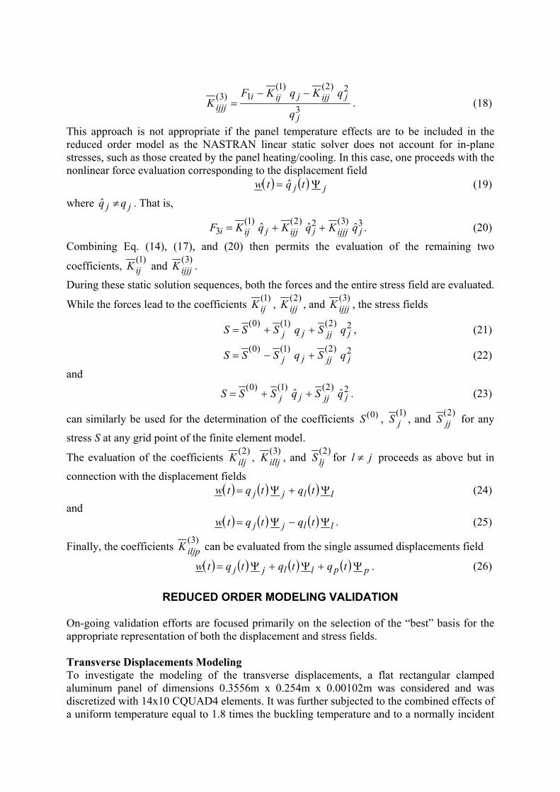
white noise acoustic wave with a sound pressure level (SPL) of 104dB. The excitation level and the temperature were selected to give a reasonably broad response of the panel, i.e. in the range of ± twice the buckling deformations. Next, a time history of this excitation was generated as a series of independent identically distributed normal deviates and was specified as input to a nonlinear transient NASTRAN analysis. The corresponding time histories of the displacement and stresses of the panel were then determined for 15,000 time steps (set at 0.000282 sec.) with the NASTRAN standard two-point Newmark integration scheme (no equivalent linearization technique was used). It should be noted that the small time step selected here to capture well the panel dynamics implies a very high Nyquist frequency, 1773 Hz, and consequently a very large number of excited modes. It was noted that 39 modes were present in the frequency band of the white noise excitation.
-0.003
-0.002
-0.001
0
0.001
0.002
0.003
0 0.25 0.5 0.75 1 1.25 1.5 1.75 2 2.25 2.5 2.75 3 3.25 3.5 3.75 4
Time (sec)
Dis
pace
men
t at c
ente
r (m
)
Figure 1. Time history of the displacement of the panel center
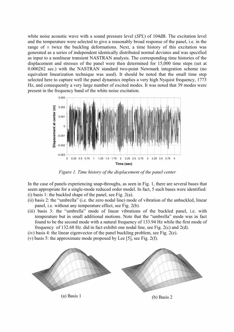
In the case of panels experiencing snap-throughs, as seen in Fig. 1, there are several bases that seem appropriate for a single-mode reduced order model. In fact, 5 such bases were identified: (i) basis 1: the buckled shape of the panel, see Fig. 2(a). (ii) basis 2: the “umbrella” (i.e. the zero nodal line) mode of vibration of the unbuckled, linear
panel, i.e. without any temperature effect, see Fig. 2(b). (iii) basis 3: the “umbrella” mode of linear vibrations of the buckled panel, i.e. with
temperature but in small additional motions. Note that the “umbrella” mode was in fact found to be the second mode with a natural frequency of 133.94 Hz while the first mode of frequency of 132.68 Hz. did in fact exhibit one nodal line, see Fig. 2(c) and 2(d).
(iv) basis 4: the linear eigenvector of the panel buckling problem, see Fig. 2(e). (v) basis 5: the approximate mode proposed by Lee [5], see Fig. 2(f).
(a) Basis 1
(b) Basis 2
(c)
(d) Basis 3
(e) Basis 4
(f) Basis 5
Figure 2. Various responses of the panel. (a) Buckled shape of the panel (basis 1). (b) First linear mode of vibration of the unbuckled panel (basis 2). (c) First linear mode of vibration of the buckled panel. (d) Second linear mode of vibration of the buckled panel (basis 3). (e) First
linear buckling mode of the panel (basis 4). (f) Assumed mode of [5] (basis 5).
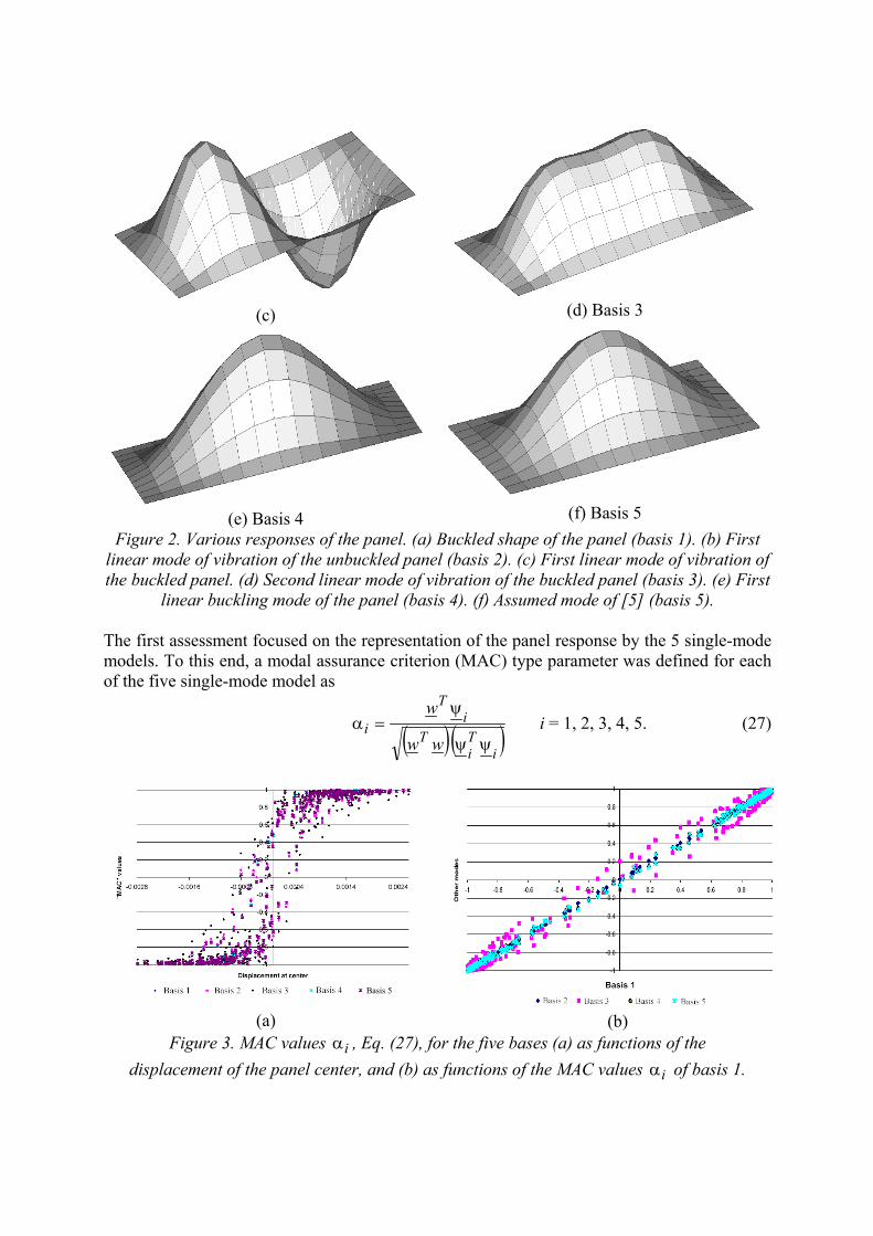
The first assessment focused on the representation of the panel response by the 5 single-mode models. To this end, a modal assurance criterion (MAC) type parameter was defined for each of the five single-mode model as
( ) ( )iTi
Ti
T
iww
w
ψψ
ψ=α i = 1, 2, 3, 4, 5. (27)
(a)
Figure 3. MAC values α ,idisplacement of the panel center
Basis 5
(b) Eq. (27), for the five bases (a) as functions of the , and (b) as functions of the MAC values α of basis 1. i
From the Cauchy-Schartz inequality, a unit value of iα implies that the panel displacement field w is exactly represented by the basis iψ . The time histories of the coefficients iα do
not display any clear trend but a much more interesting correlation is obtained when plotting the values of vs. the displacement of the panel center, see Fig. 3(a), and versus each other, see Fig. 3(b). It appears from these figures that
iα
(i) the coefficients achieve values close to 1 (in magnitude) when the panel deformation is “large”, and
iα
(ii) the differences between the values of iα corresponding to the different bases, see Fig. 3(a) and (b), are typically only small. This observation is particularly appropriate for the bases 1,2, 4, and 5; the third basis, i.e. the linear mode of vibration of the buckled panel, appears to exhibit a larger scatter/variability in MAC value.
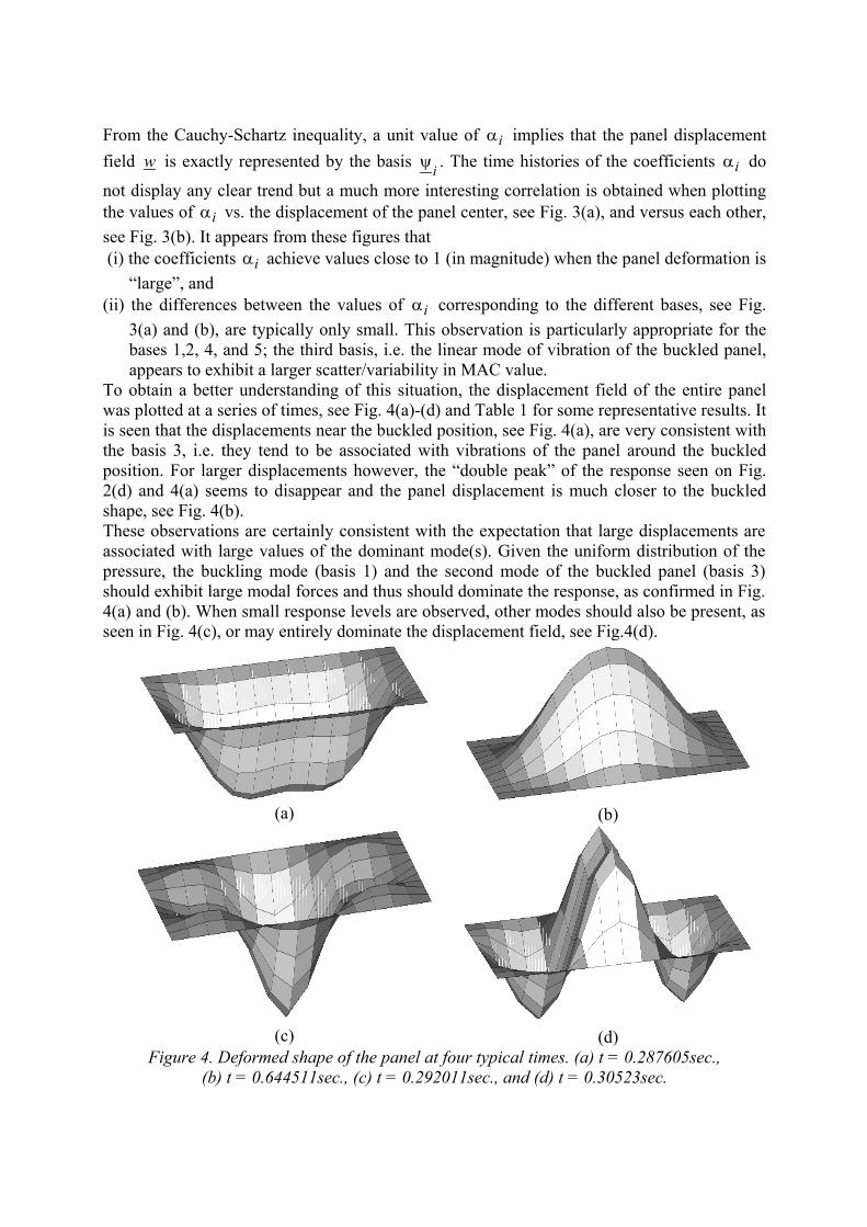
To obtain a better understanding of this situation, the displacement field of the entire panel was plotted at a series of times, see Fig. 4(a)-(d) and Table 1 for some representative results. It is seen that the displacements near the buckled position, see Fig. 4(a), are very consistent with the basis 3, i.e. they tend to be associated with vibrations of the panel around the buckled position. For larger displacements however, the “double peak” of the response seen on Fig. 2(d) and 4(a) seems to disappear and the panel displacement is much closer to the buckled shape, see Fig. 4(b). These observations are certainly consistent with the expectation that large displacements are associated with large values of the dominant mode(s). Given the uniform distribution of the pressure, the buckling mode (basis 1) and the second mode of the buckled panel (basis 3) should exhibit large modal forces and thus should dominate the response, as confirmed in Fig. 4(a) and (b). When small response levels are observed, other modes should also be present, as seen in Fig. 4(c), or may entirely dominate the displacement field, see Fig.4(d).
(a)
(b)
(c)
(d)
Figure 4. Deformed shape of the panel at four typical times. (a) t = 0.287605sec., (b) t = 0.644511sec., (c) t = 0.292011sec., and (d) t = 0.30523sec.
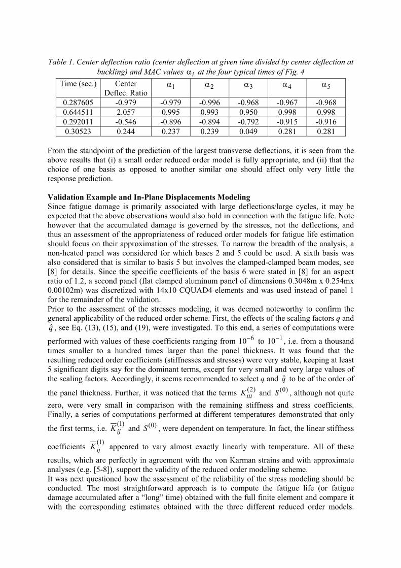
Table 1. Center deflection ratio (center deflection at given time divided by center deflection at buckling) and MAC values iα at the four typical times of Fig. 4
Time (sec.) Center Deflec. Ratio
1α 2α 3α 4α 5α
0.287605 -0.979 -0.979 -0.996 -0.968 -0.967 -0.968 0.644511 2.057 0.995 0.993 0.950 0.998 0.998 0.292011 -0.546 -0.896 -0.894 -0.792 -0.915 -0.916 0.30523 0.244 0.237 0.239 0.049 0.281 0.281
From the standpoint of the prediction of the largest transverse deflections, it is seen from the above results that (i) a small order reduced order model is fully appropriate, and (ii) that the choice of one basis as opposed to another similar one should affect only very little the response prediction. Validation Example and In-Plane Displacements Modeling Since fatigue damage is primarily associated with large deflections/large cycles, it may be expected that the above observations would also hold in connection with the fatigue life. Note however that the accumulated damage is governed by the stresses, not the deflections, and thus an assessment of the appropriateness of reduced order models for fatigue life estimation should focus on their approximation of the stresses. To narrow the breadth of the analysis, a non-heated panel was considered for which bases 2 and 5 could be used. A sixth basis was also considered that is similar to basis 5 but involves the clamped-clamped beam modes, see [8] for details. Since the specific coefficients of the basis 6 were stated in [8] for an aspect ratio of 1.2, a second panel (flat clamped aluminum panel of dimensions 0.3048m x 0.254mx 0.00102m) was discretized with 14x10 CQUAD4 elements and was used instead of panel 1 for the remainder of the validation. Prior to the assessment of the stresses modeling, it was deemed noteworthy to confirm the general applicability of the reduced order scheme. First, the effects of the scaling factors q and
, see Eq. (13), (15), and (19), were investigated. To this end, a series of computations were
performed with values of these coefficients ranging from 10
q̂6− to 10 1− , i.e. from a thousand
times smaller to a hundred times larger than the panel thickness. It was found that the resulting reduced order coefficients (stiffnesses and stresses) were very stable, keeping at least 5 significant digits say for the dominant terms, except for very small and very large values of the scaling factors. Accordingly, it seems recommended to select q and to be of the order of
the panel thickness. Further, it was noticed that the terms and , although not quite zero, were very small in comparison with the remaining stiffness and stress coefficients. Finally, a series of computations performed at different temperatures demonstrated that only
the first terms, i.e.
q̂0(S)2(
iiiK )
)1(ijK and , were dependent on temperature. In fact, the linear stiffness
coefficients
)0(S)1(
ijK appeared to vary almost exactly linearly with temperature. All of these
results, which are perfectly in agreement with the von Karman strains and with approximate analyses (e.g. [5-8]), support the validity of the reduced order modeling scheme. It was next questioned how the assessment of the reliability of the stress modeling should be conducted. The most straightforward approach is to compute the fatigue life (or fatigue damage accumulated after a “long” time) obtained with the full finite element and compare it with the corresponding estimates obtained with the three different reduced order models.
Clearly, this comparison would have to be performed for different sound pressure levels and various S-N curves (e.g. various exponents of the S-N curve). While this parametric study would yield the expected perspective, it would not provide a good basis for the detailed assessment which is desired here. Since the nonlinearity only affects the stiffnesses and the stresses, it was felt that the analysis of the static response of the panel for various load levels would provide a simple, yet clear, basis for the desired validation. Note in this regard that the fatigue life of the panel depends on the level of variability of the stresses, e.g. on their variances, and that the contributions of different modes to the variances are approximately in the same ratio ( vs. ) as they are for the static response in a linear multimodal situation. 3
iω2iω
0.0E+00
2.0E-04
4.0E-04
6.0E-04
8.0E-04
1.0E-03
1.2E-03
1.4E-03
1.6E-03
0 500 1000 1500 2000 2500Pressure (Pa)
Cent
er D
ispl
acem
ent (
m)
MSC.NASTRAN NL Basis 5 Basis 6 Basis 2 Basis 2+D
(a)
0.0E+00
5.0E+06
1.0E+07
1.5E+07
2.0E+07
2.5E+07
3.0E+07
0.0E+00 2.0E-04 4.0E-04 6.0E-04 8.0E-04 1.0E-03 1.2E-03 1.4E-03
Center displacement (m)
Cen
ter n
ode
xx s
tres
s (P
a)
MSC.NASTRAN NL Basis 6 Basis 2 Basis 5 Basis 2+D
(b)
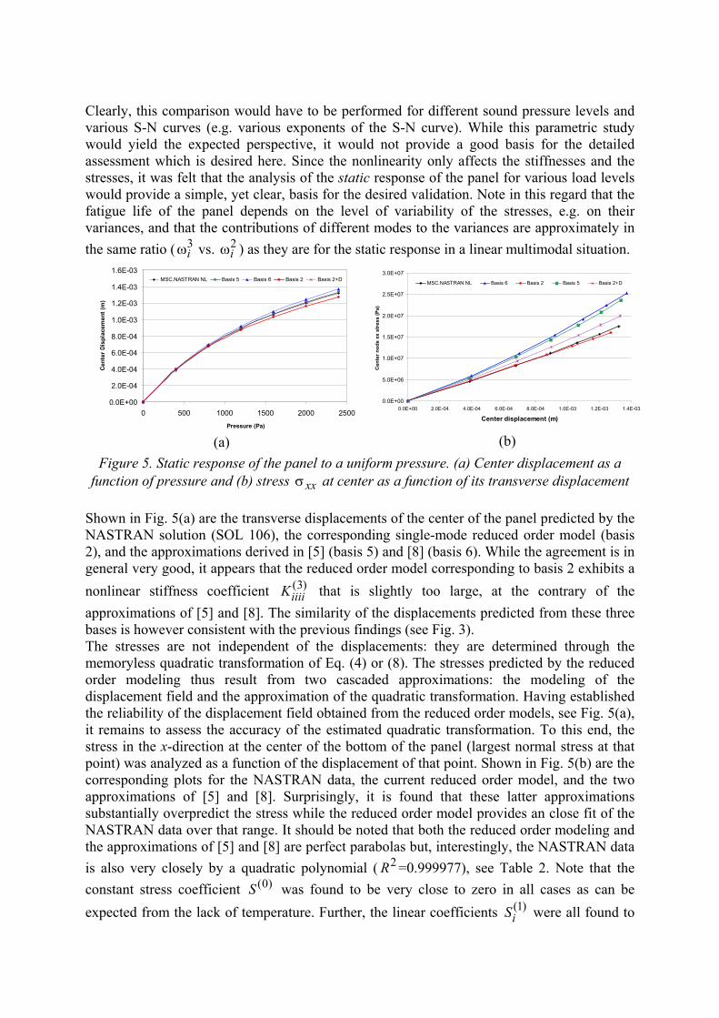
Figure 5. Static response of the panel to a uniform pressure. (a) Center displacement as a function of pressure and (b) stress at center as a function of its transverse displacement xxσ
Shown in Fig. 5(a) are the transverse displacements of the center of the panel predicted by the NASTRAN solution (SOL 106), the corresponding single-mode reduced order model (basis 2), and the approximations derived in [5] (basis 5) and [8] (basis 6). While the agreement is in general very good, it appears that the reduced order model corresponding to basis 2 exhibits a nonlinear stiffness coefficient that is slightly too large, at the contrary of the approximations of [5] and [8]. The similarity of the displacements predicted from these three bases is however consistent with the previous findings (see Fig. 3).
)3(iiiiK
The stresses are not independent of the displacements: they are determined through the memoryless quadratic transformation of Eq. (4) or (8). The stresses predicted by the reduced order modeling thus result from two cascaded approximations: the modeling of the displacement field and the approximation of the quadratic transformation. Having established the reliability of the displacement field obtained from the reduced order models, see Fig. 5(a), it remains to assess the accuracy of the estimated quadratic transformation. To this end, the stress in the x-direction at the center of the bottom of the panel (largest normal stress at that point) was analyzed as a function of the displacement of that point. Shown in Fig. 5(b) are the corresponding plots for the NASTRAN data, the current reduced order model, and the two approximations of [5] and [8]. Surprisingly, it is found that these latter approximations substantially overpredict the stress while the reduced order model provides an close fit of the NASTRAN data over that range. It should be noted that both the reduced order modeling and the approximations of [5] and [8] are perfect parabolas but, interestingly, the NASTRAN data is also very closely by a quadratic polynomial ( 2R =0.999977), see Table 2. Note that the constant stress coefficient was found to be very close to zero in all cases as can be expected from the lack of temperature. Further, the linear coefficients were all found to
)0(S)1(
iS
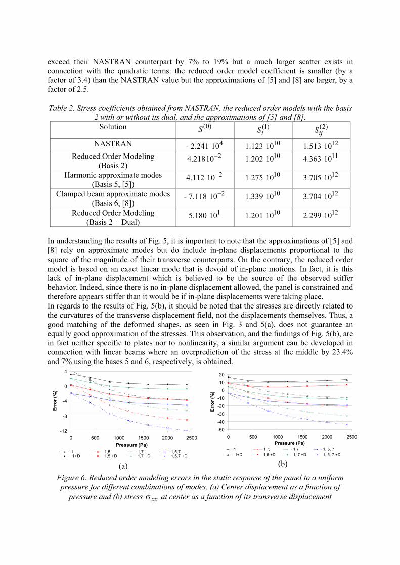
exceed their NASTRAN counterpart by 7% to 19% but a much larger scatter exists in connection with the quadratic terms: the reduced order model coefficient is smaller (by a factor of 3.4) than the NASTRAN value but the approximations of [5] and [8] are larger, by a factor of 2.5. Table 2. Stress coefficients obtained from NASTRAN, the reduced order models with the basis
2 with or without its dual, and the approximations of [5] and [8]. Solution )0(S )1(
iS )2(ijS
NASTRAN - 2.241 10 4 1.123 1010 1.513 10 12
Reduced Order Modeling (Basis 2)
4.21810 2− 1.202 1010 4.363 10 11
Harmonic approximate modes (Basis 5, [5])
4.112 10 2− 1.275 1010 3.705 10 12
Clamped beam approximate modes (Basis 6, [8])
- 7.118 10 2− 1.339 1010 3.704 10 12
Reduced Order Modeling (Basis 2 + Dual)
5.180 10 1 1.201 1010 2.299 10 12
In understanding the results of Fig. 5, it is important to note that the approximations of [5] and [8] rely on approximate modes but do include in-plane displacements proportional to the square of the magnitude of their transverse counterparts. On the contrary, the reduced order model is based on an exact linear mode that is devoid of in-plane motions. In fact, it is this lack of in-plane displacement which is believed to be the source of the observed stiffer behavior. Indeed, since there is no in-plane displacement allowed, the panel is constrained and therefore appears stiffer than it would be if in-plane displacements were taking place. In regards to the results of Fig. 5(b), it should be noted that the stresses are directly related to the curvatures of the transverse displacement field, not the displacements themselves. Thus, a good matching of the deformed shapes, as seen in Fig. 3 and 5(a), does not guarantee an equally good approximation of the stresses. This observation, and the findings of Fig. 5(b), are in fact neither specific to plates nor to nonlinearity, a similar argument can be developed in connection with linear beams where an overprediction of the stress at the middle by 23.4% and 7% using the bases 5 and 6, respectively, is obtained.
-12
-8
-4
0
4
0 500 1000 1500 2000 2500Pressure (Pa)
Erro
r (%
)
1 1,5 1,7 1,5,7 1+D 1,5 +D 1,7 +D 1,5,7 +D
(a)
-50-40-30-20-10
01020
0 500 1000 1500 2000 2500Pressure (Pa)
Erro
r (%
)
1 1, 5 1,7 1, 5, 7 1+D 1,5 +D 1, 7 +D 1, 5, 7 +D
(b)
Figure 6. Reduced order modeling errors in the static response of the panel to a uniform pressure for different combinations of modes. (a) Center displacement as a function of
pressure and (b) stress σ at center as a function of its transverse displacement xx
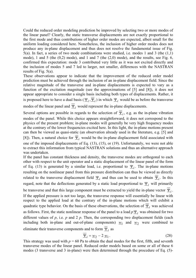
Could the reduced order modeling prediction be improved by selecting two or more modes of the linear panel? Clearly, the static transverse displacements are not exactly proportional to the first mode and thus contributions of higher order modes are expected, albeit small for the uniform loading considered here. Nonetheless, the inclusion of higher order modes does not produce any in-plane displacement and thus does not resolve the fundamental issue of Fig. 5(a). In fact, a series of two mode combinations were studied, i.e. modes 1 and 3 (the (1,1) mode), 1 and 5 (the (0,2) mode), and 1 and 7 (the (2,0) mode), and the results, see Fig. 6, confirmed this expectation: mode 3 contributed very little as it was not excited directly and the inclusion of modes 5 and 7 led to larger, not smaller, differences with the NASTRAN results of Fig. 5(a). These observations appear to indicate that the improvement of the reduced order model prediction must be achieved through the inclusion of an in-plane displacement field. Since the relative magnitude of the transverse and in-plane displacements is expected to vary as a function of the excitation magnitude (see the approximations of [5] and [8]), it does not appear appropriate to consider a single basis including both types of displacements. Rather, it is proposed here to have a dual basis ( iΨ , iΨ ) in which iΨ would be as before the transverse
modes of the linear panel and iΨ would represent the in-plane displacements.
Several options are possible in regards to the selection of iΨ , e.g. as the in-plane vibration modes of the panel. While this choice appears straightforward, it does not correspond to the physics of the present problem; in-plane modes will generally be very high frequency modes at the contrary of the lower frequencies excited here. In this light, the in-plane motions present can then be viewed as quasi-static (an observation already used in the literature, e.g. [5] and [8]). Then, a natural choice for iΨ would be the in-plane displacement field associated with one of the imposed displacements of Eq. (13), (15), or (19). Unfortunately, we were not able to extract this information from typical NASTRAN solutions and thus an alternative approach was undertaken. If the panel has constant thickness and density, the transverse modes are orthogonal to each other with respect to the unit operator and a static displacement of the linear panel of the form of Eq. (13) is generated by a similar load, i.e. proportional to iΨ . The in-plane motions resulting on the nonlinear panel from this pressure distribution can thus be viewed as directly related to the transverse displacement field iΨ and thus can be used to obtain iΨ . In this regard, note that the deflections generated by a static load proportional to iΨ will primarily
be transverse and that this large component must be extracted to yield the in-plane vector iΨ . If the applied pressure is not too large, the transverse response will essentially be linear with respect to the applied load at the contrary of the in-plane motions which will exhibit a quadratic type behavior. On the basis of these observations, the selection of iΨ was achieved as follows. First, the static nonlinear response of the panel to a load p iΨ was obtained for two different values of p, i.e. p and 2 p. Then, the corresponding two displacement fields (each including both in-plane and out-of-plane components) 1w and 2w were combined to
eliminate their transverse components and to form iΨ as
12 2 wwi −=Ψ . (28) This strategy was used with p = 60 Pa to obtain the dual modes for the first, fifth, and seventh transverse modes of the linear panel. Reduced order models based on some or all of these 6 modes (3 transverse and 3 in-plane) were then determined through the procedure of Eq. (5)-
(26) and the corresponding displacements and stress at the center of the panel were recomputed, see Fig. 5 and 6. Note first the excellent agreement of the displacements obtained by including only the first mode and its dual, see Fig. 5(a). As justified above, the inclusion of the mode iΨ has freed the in-plane motions and has decreased the apparent stiffness of the panel thereby leading to larger transverse displacements. An improvement of the stress estimate is also obtained as the quadratic coefficient obtained with the first mode and its
dual is much closer to the NASTRAN value than the coefficient corresponding to the
first mode only, see Table 2. This result may not be clear from Fig. 5(b) because of the limited range of pressures considered there. The above results demonstrate the influence of the in-plane mode but the comparison of the mode 1 and mode 1+D (1 and its dual) may seem inappropriate as the number of assumed modes is not the same. To palliate this situation, compare the predicted displacements and stresses obtained with either modes 1 and 5 or 1 and 7 with those predicted from the mode 1 and its dual. It is clearly seen from Fig. 6 that both displacements and stresses are better matched with the latter combination of modes than any other pair. It is thus concluded that a two-mode reduced order model must include the dual mode.
)2(ijS
)2(ijS
The effect of a higher number of modes was finally considered. In the linear case, it can be demonstrated that the convergence of the displacements and stresses is achieved in an oscillatory fashion, i.e. by repeatedly overshooting the exact solution. Further, modes 5 and 7 will provide contributions that are opposite in sign to both the one of mode 1 and to those of the next three modes (the modes (4,0), (0,4), and (2,2)). Accordingly, it is expected that the modes 1 and 5, 1 and 7, and especially 1, 5, and 7 may/will lead to larger negative errors than obtained for mode 1 alone. This result is clearly seen in Fig. 6 for both displacements and stresses and reduced order models with or without duals. Note however: (i) that the magnitude of the overshoot is substantially reduced by the inclusion of the duals, (ii) the rapid convergence, as the pressure is increased, of the errors associated with the
reduced order models with duals at the contrary of those without duals. This finding suggests that the nonlinear effects are intrinsically captured by using the duals modes.
SUMMARY
This paper focused on the validation of a reduced order modeling strategy for aircraft panels subjected to a combination of thermal effects and an incident acoustic wave strong enough to induce a severe geometrically nonlinear behavior. The approach involved both the derivation of the nonlinear governing equations of the reduced order model and the displacements-stress relationship. Of particular importance in this strategy is the selection of the “modal basis” that will be used to approximate the panel displacement field. While the shape of the transverse displacement field is well represented by a series of different functions, the stresses require an accurate modeling of the curvatures of the panel. Accordingly, it is recommended that the modal basis be constructed from exact responses of the panel considered. A comparison of different approximations/reduced order models of the static nonlinear response of a panel further demonstrated the need for in-plane displacements in the modal basis. Accordingly, a novel dual basis was introduced that contains separately the transverse displacements and their induced in-plane counterparts and is formed by the combination of two similar nonlinear static responses, see Eq. (28). A series of comparisons, see Fig. 5 and 6, clearly demonstrate the value of considering the in-plane modes in addition to their transverse counterparts.
ACKNOWLEDGEMENTS
The support of this investigation by the Air Force Research Laboratory under contract F33615-01-C-3111 is gratefully acknowledged. The authors also wish to thank Capt. S.M. Spottswood and Dr. S. A. Rizzi for their support of and interest in this work.
REFERENCES
1. Blevins, R.D., Holehouse, I. and Wentz, K.R., Thermoacoustic Loads and Fatigue of Hypersonic Vehicle Skin Panels. J. Aircraft, 1993, 30, 971-978.
2. Bouyssy, V., Naboishikov, S.M. and Rackwitz, R., Comparison of Analytical Counting Methods for Gaussian Processes. Structural Safety, 1993, 12, 35-57.
3. Ghazarian, N. and Locke, J., Non-Linear Random Response of Antisymmetric Angle-Ply Laminates Under Thermal-Acoustic Loading. J. Sound and Vibration, 1995, 186, 291-309.
4. Istenes, R.R., Rizzi, S.A. and Wolfe, H.F., Experimental Nonlinear Random Vibration Results of Thermally Buckled Composite Panels. Proc. 36th Structures, Structural Dynamics, and Materials Conf., 1995, 1559-1568.
5. Lee, J., Large-Amplitude Plate Vibration in an Elevated Thermal Environment. Applied Mechanics Rev., 1993, 46, Part 2, S242-S254.
6. Lee, J., Random Vibration of Thermally Buckled Plates: II Nonzero Temperature Gradient Across the Plate Thickness. Applied Mechanics Rev., 1997, 50, Part 2, S105-S116.
7. Lee, J., Displacement and Strain Statistics of Thermally Buckled Plates. J. Aircraft, 2001, 37.
8. Lee, J., Topology of the Four-Mode Strain Energy of Thermally Buckling Plates. J. Thermal Stresses, 2002, 25, 813-857.
9. McEwan, M.I., Wright, J.R., Cooper, J.E. and Leung, A.Y.T., A Combined Modal/Finite Element Analysis Technique for the Dynamic Response of a Non-Linear Beam to Harmonic Excitation. J. Sound and Vibration, 2001, 243, 601-624.
10. Mei, C., Dhainaut, J.M., Duan, B., Spottswood, S.M. and Wolfe, H.F., Nonlinear Random Response of Composite Panels in an Elevated Thermal Environment. Report AFRL-VA-WP-TR-2000-3049, 2000.
11. Murphy, K.D., Virgin, L.N. and Rizzi, S.A., Characterizing the Dynamic Response of a Thermally Loaded, Acoustically Excited Plate. J. Sound and Vibration, 1996, 196, 635-658.
12. Ng, C.F., Nonlinear and Snap-Through Responses of Curved Panels to Intense Acoustic Excitation. J. Aircraft, 1989, 26, 281-288.
13. Rizzi S.A. and Muravyov, A.A., Equivalent Linearization Analysis of Geometrically Nonlinear Random Vibrations Using Commercial Finite Element Codes. NASA Technical Paper TP-2002-211761, 2002.
14. Spottswood, S.M. and Mignolet, M.P., Experimental Nonlinear Response of Tapered Ceramic Matrix Composite Plates to Base Excitation. AIAA J., 2002, 40, 1682-1687.
15. Spottswood, S.M. and Wolfe, H.F., Comparing fatigue life estimates using experimental and spectral density based probability distributions. Proc. 42nd Structures, Structural Dynamics and Materials Conference, 2001.
16. Sun, J.Q., Bao, W. and Miles, R.N., Fatigue Life Prediction of Nonlinear Plates Under Random Excitations. J. Vibration and Acoustics, 1998, 120, 353-360.
17. Vaicaitis, R., Nonlinear Response and Sonic Fatigue of National Aerospace Space Plane Surface Panels. J. Aircraft, 1994, 31, 10-18.


