Embed Size (px)
Citation preview
Full Terms & Conditions of access and use can be found athttps://www.tandfonline.com/action/journalInformation?journalCode=tcim20
International Journal of Computer IntegratedManufacturing
ISSN: (Print) (Online) Journal homepage: https://www.tandfonline.com/loi/tcim20
Versatile IT-system architecture for smartmanufacturing solutions: the example for greenmanufacturing
Martin Plank, Sebastian Thiede & Christoph Herrmann
To cite this article: Martin Plank, Sebastian Thiede & Christoph Herrmann (2021):Versatile IT-system architecture for smart manufacturing solutions: the example forgreen manufacturing, International Journal of Computer Integrated Manufacturing, DOI:10.1080/0951192X.2021.1963478
To link to this article: https://doi.org/10.1080/0951192X.2021.1963478
Published online: 30 Aug 2021.
Submit your article to this journal
Article views: 10
View related articles
View Crossmark data
Versatile IT-system architecture for smart manufacturing solutions: the example for green manufacturingMartin Planka, Sebastian Thiedeb and Christoph Herrmannb
aResearch and Innovation, Festo SE & Co. KG, Esslingen a. N., Germany; bChair of Sustainable Manufacturing and Life Cycle Engineering, Institute of Machine Tools and Production Technology (IWF), Technische Universität Braunschweig, Braunschweig, Germany
ABSTRACTIn the last decade, a rising number of opportunities for IT-based solutions in manufacturing have emerged. Often these opportunities are linked to terms like Industry 4.0, Industrial Internet of Things, Cyber-Physical Production Systems or Artificial Intelligence in Manufacturing and address different fields of action to achieve improvements in manufacturing. These include increased productivity, improved energy and resource efficiency, predictive maintenance or quality manage-ment support. However, current implementations of corresponding improvement measures often lack a common structure of the underlying IT systems, so that each of the measures is often planned and implemented as a stand-alone solution. Possible consequences include redundancies within the IT infrastructure and software functions as well as high efforts for later extensions. Against this background, an approach for a system architecture to implement different IT-based support measures based on a shared versatile system has been developed in order to gain synergy potentials and foster the reuse of software functions. Furthermore, an approach for the planning and implementation is given. This includes the design of the system architecture as well as the conception and implementation of the IT-based improvement measures. An exemplary application case within a factory for pneumatic valves demonstrates the applicability of the approaches.
ARTICLE HISTORY Received 28 June 2020 Accepted 25 July 2021
KEYWORDS Versatile system architecture; IT-based improvement measures; IT planning
1. Introduction
Since the beginning of industrialization, factories have been subject to constant change in order to adapt to changing conditions and requirements, and to remain competitive. Industrial history has devel-oped in four stages: Beginning with the first industrial revolution with the introduction of water and steam powered production equipment in the second half of the 18th century, the introduction of mass production through division of labor and use of electrical energy at the beginning of the 20th century, the introduction of automation at the beginning of the 1970s up to the current continuous transition making use of cyber- physical production systems (CPPS), artificial intelli-gence (AI) and cloud computing (Schwab 2017; Dombrowski and Wagner 2014). This development is closely linked to the term Industry 4.0, which was coined to a large extent as part of the High-Tech Strategy 2020 of the German Federal Ministry of Education and Research (Lasi et al. 2014). While the term Industry 4.0 has its origin in Germany, terms such as the Industrial Internet of Things (IIoT) have
also established themselves internationally describing comparable paradigms.
With these new paradigms mainly based on an increased use of information and communication technologies in manufacturing, new opportunities arise for different fields of action and use cases. In today’s applications, these often have a supporting character for the production as the following exam-ples illustrate:
● Value creation (V), e.g. value stream and supply chain monitoring and management
● Energy and resource efficiency (ER), e.g. energy monitoring and demand side management
● Maintenance (M), e.g. condition monitoring and predictive maintenance
● Quality management (Q), e.g. quality control, assurance and improvement
To visualize the connection between the new para-digms (Industry 4.0, (Industrial) Internet of Things, Cyber-Physical (Production) Systems and Artificial Intelligence) and the fields of action (value
CONTACT Martin Plank [email protected] Research and Innovation, Festo SE & Co. KG, Ruiter Str. 82, 73734 Esslingen A. N, Germany
INTERNATIONAL JOURNAL OF COMPUTER INTEGRATED MANUFACTURING https://doi.org/10.1080/0951192X.2021.1963478
© 2021 Informa UK Limited, trading as Taylor & Francis Group
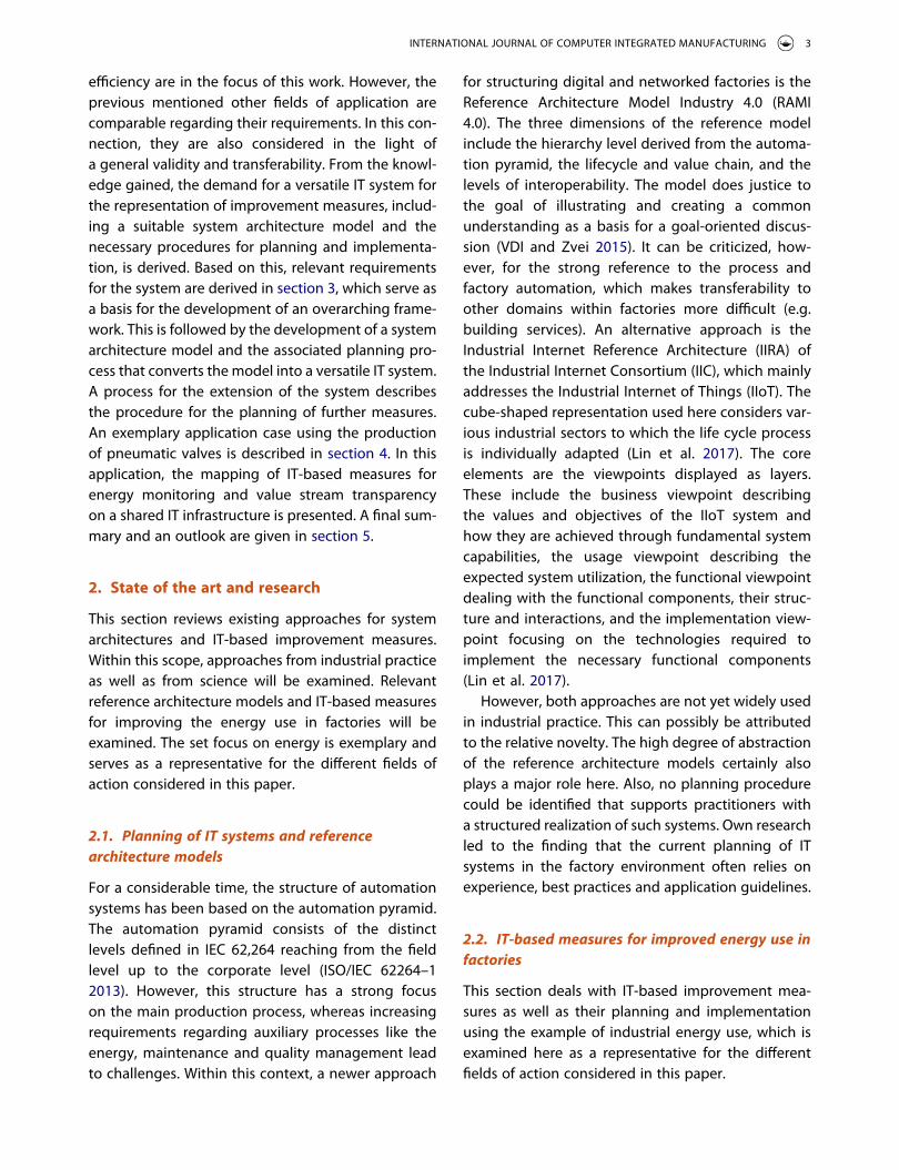
creation, energy and resource efficiency, mainte-nance and quality) have been investigated for the context of manufacturing and factories based on a literature review. For this purpose, the number of hits for different combinations of search terms in scientific databases, namely Science Direct and IEEE Explore, were evaluated and presented in chord diagrams (Figure 1).
The chord diagrams show that the considered paradigms (I4.0, IoT, IIoT, CPS and AI) and fields of action (ER, M, V, Q) are often used or discussed in combination. This refers both to the possible combi-nations of paradigms and fields of action (Figure 1, middle) as well as to combinations of paradigms or fields of action among themselves (Figure 1, left and right side). Against this background, a joint considera-tion appears to be useful in order to maximize poten-tial benefits of the paradigms in the focused fields of action. This includes technical and methodical aspects.
IT-based measures promise considerable improve-ments in operation. However, the planning and implementation of these measures and the IT infra-structure required for this purpose is currently still
associated with challenges for factory operators and those responsible for implementation.
This can be due to a lack of system architectures that are capable of providing a shared IT system, which can be used to host multiple IT-based mea-sures. Furthermore, a lack of structured procedures to plan IT-based measures and the therefore required infrastructure can be diagnosed. As a consequence, new measures and IT systems are often created as stand-alone systems without utilizing already existing infrastructure or software. Thus, in practice this can lead to a reduced use of synergy and scale effects. Consequently, redundancies within the infrastructure, functionality and the data storage as well as a high overall complexity due to parallel systems occur. This is connected with a high effort for the implementa-tion and extension of the overall IT systems, which lowers the economic benefits of specific solutions.
Against this background, this paper is structured as follows: Section 2 analyses existing approaches struc-turing IT systems in the context of factories, consider-ing reference architecture models and existing solutions and approaches for IT-based measures. At this point, IT-based measures to improve energy
Figure 1. Connections between paradigms and fields of action as chord diagrams.
2 M. PLANK ET AL.
efficiency are in the focus of this work. However, the previous mentioned other fields of application are comparable regarding their requirements. In this con-nection, they are also considered in the light of a general validity and transferability. From the knowl-edge gained, the demand for a versatile IT system for the representation of improvement measures, includ-ing a suitable system architecture model and the necessary procedures for planning and implementa-tion, is derived. Based on this, relevant requirements for the system are derived in section 3, which serve as a basis for the development of an overarching frame-work. This is followed by the development of a system architecture model and the associated planning pro-cess that converts the model into a versatile IT system. A process for the extension of the system describes the procedure for the planning of further measures. An exemplary application case using the production of pneumatic valves is described in section 4. In this application, the mapping of IT-based measures for energy monitoring and value stream transparency on a shared IT infrastructure is presented. A final sum-mary and an outlook are given in section 5.
2. State of the art and research
This section reviews existing approaches for system architectures and IT-based improvement measures. Within this scope, approaches from industrial practice as well as from science will be examined. Relevant reference architecture models and IT-based measures for improving the energy use in factories will be examined. The set focus on energy is exemplary and serves as a representative for the different fields of action considered in this paper.
2.1. Planning of IT systems and reference architecture models
For a considerable time, the structure of automation systems has been based on the automation pyramid. The automation pyramid consists of the distinct levels defined in IEC 62,264 reaching from the field level up to the corporate level (ISO/IEC 62264–1 2013). However, this structure has a strong focus on the main production process, whereas increasing requirements regarding auxiliary processes like the energy, maintenance and quality management lead to challenges. Within this context, a newer approach
for structuring digital and networked factories is the Reference Architecture Model Industry 4.0 (RAMI 4.0). The three dimensions of the reference model include the hierarchy level derived from the automa-tion pyramid, the lifecycle and value chain, and the levels of interoperability. The model does justice to the goal of illustrating and creating a common understanding as a basis for a goal-oriented discus-sion (VDI and Zvei 2015). It can be criticized, how-ever, for the strong reference to the process and factory automation, which makes transferability to other domains within factories more difficult (e.g. building services). An alternative approach is the Industrial Internet Reference Architecture (IIRA) of the Industrial Internet Consortium (IIC), which mainly addresses the Industrial Internet of Things (IIoT). The cube-shaped representation used here considers var-ious industrial sectors to which the life cycle process is individually adapted (Lin et al. 2017). The core elements are the viewpoints displayed as layers. These include the business viewpoint describing the values and objectives of the IIoT system and how they are achieved through fundamental system capabilities, the usage viewpoint describing the expected system utilization, the functional viewpoint dealing with the functional components, their struc-ture and interactions, and the implementation view-point focusing on the technologies required to implement the necessary functional components (Lin et al. 2017).
However, both approaches are not yet widely used in industrial practice. This can possibly be attributed to the relative novelty. The high degree of abstraction of the reference architecture models certainly also plays a major role here. Also, no planning procedure could be identified that supports practitioners with a structured realization of such systems. Own research led to the finding that the current planning of IT systems in the factory environment often relies on experience, best practices and application guidelines.
2.2. IT-based measures for improved energy use in factories
This section deals with IT-based improvement mea-sures as well as their planning and implementation using the example of industrial energy use, which is examined here as a representative for the different fields of action considered in this paper.
INTERNATIONAL JOURNAL OF COMPUTER INTEGRATED MANUFACTURING 3
Many of the measures considered are linked to standards as well as generally applicable guidelines and company-specific derivations thereof. Use cases in the field of quality or energy management are generally based on a continuous improvement pro-cess. For energy management systems, this is speci-fied in the standard ISO 50,001. The continuous improvement process anchored therein also includes the planning, implementation and monitoring of improvement measures. Since the standard applies to organizations in general (DIN EN ISO 50001:2011- 12), the planning and implementation of measures is treated only superficially and is not associated with industrial manufacturing.
Scientific approaches often only cover the identifi-cation of factory specific goals, the analysis of poten-tials as well as the evaluation and selection of measures (Engelmann 2009; Müller et al. 2009; Posselt et al. 2014; Fischer 2017), but neglect the planning with regard to the concrete implementation of a measure. In particular, the planning of the infra-structure required for IT-based measures is rarely the subject of the approaches examined. Excepted are some approaches for the planning of single purpose systems like energy transparency systems as described by Buschmann (2013) or Posselt (2016).
Existing IT-based approaches to improve energy use can be divided into the categories of energy data acquisition, energy data monitoring, control of energy flows and integration into other IT systems. Energy data acquisition is a component of measure-ment technology and is already used in various forms in many factories. The collected data can be used as a basis for the internal energy management. In this case, the data is often analyzed and visualized with the help of energy management software. Scientific work in this area deals with system archi-tectures for the monitoring of energy data using sophisticated methods of data analysis such as event processing and pattern matching in order to gain information about the current health state and unusual behavior of production assets (Vijayaraghavan and Dornfeld 2010; Chiotellis and Grismajer 2012; Vikhorev, Greenough, and Brown 2013). To control energy flows, various technical elements such as relays or valves can be used, depending on the energy source. These elements are usually triggered by electric signals generated by programmable logic controllers (PLCs). To
transmit switching signals to the corresponding devices, there are already solutions available on the market using protocols such as PROFIenergy and Sercos Energy (PNO 2016; Hibbard, Lutz, and Larsen 2017). While from a technological point of view the prerequisites for controlling the energy flows of a manufacturing process are given, the higher-level control of the energy flows as well as the integration into other systems is still frequently the subject of scientific investigations. At this point, various works can be mentioned that deal with system architec-tures for improving the energy use in factories. For example, the concept for hierarchically arranged control loops by Verl et al. (2011), which was extended in further research by the description of energy information flows and simulations for deter-mining the optimum operating condition (Schlechtendahl et al. 2013) as well as a methodology for model-based planning, evalua-tion and optimization of energy efficiency (Haag 2013). In addition, these and other works concern the integration of such approaches into components and controls within machines (Abele, Panten, and Menz 2015), manufacturing execution systems (MES) (Abele, Panten, and Menz 2015; Verl et al. 2011; Schlechtendahl et al. 2013; Langer et al. 2014), or enterprise resource planning (ERP) systems (Eberspächer et al. 2015). A more generic approach for the integration of energy data into manufactur-ing information systems is described by Zampou et al. (2014).
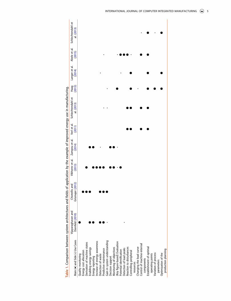
A summary of the reviewed approaches is shown in Table 1. The comparison of the system architectures examined and the fields of application mentioned therein reveals that the architectures were designed for the respective application. A versatile applicable system architecture cannot be determined. Furthermore, the planning with regard to practical implementation is not in the focus of the examined work and is at most considered marginally.
The following points can be summarized for the examined state of the art and research:
● Already today, a multitude of components, tech-nologies and possible measures exist that can be used as a basis for the implementation of IT- based improvement measures. Therefore, the development of new technologies and measures are not required for the context of this work.
4 M. PLANK ET AL.
Tabl
e 1.
Com
paris
on b
etw
een
syst
em a
rchi
tect
ures
and
fiel
ds o
f app
licat
ion
by t
he e
xam
ple
of im
prov
ed e
nerg
y us
e in
man
ufac
turin
g.
Mai
n (●
) and
Sid
e (•)
Use
Cas
esVi
jaya
ragh
avan
and
D
ornf
eld
(201
0)Ch
iote
llis
and
Gris
maj
er (2
012)
Vikh
orev
et
al.
(201
3)Za
mpo
u et
al.
(201
4)Ve
rl et
al.
(201
1)Sc
hlec
hten
dahl
et
al. (
2013
)H
aag
(201
3)La
nger
et
al.
(201
4)Ab
ele
et a
l. (2
015)
Schl
echt
enda
hl e
t al
. (20
13)
Qua
lity
mon
itorin
g●
Ener
gy c
ost
allo
catio
n●
Der
ivat
ion
of m
achi
ne s
tate
s●
●En
ablin
g en
ergy
sav
ings
●●
●En
ergy
rep
ortin
g●
●●
Incr
ease
of e
nerg
y aw
aren
ess
●D
etec
tion
of w
aste
●●
●•
•Pr
edic
tive
mai
nten
ance
●●
●•
•G
ain
in s
yste
m u
nder
stan
ding
•●
••
Dec
isio
n su
ppor
t●
●M
onito
ring
of o
bjec
tives
●●
(Key
figu
re-b
ased
) Eva
luat
ion
••
●•
Pote
ntia
l ide
ntifi
catio
n●
•●
Det
ectio
n of
load
pea
ks•
●Re
actio
n to
dis
turb
ance
s●
●●
Cont
rolli
ng p
erip
hera
l re
sour
ces
●●
●●
•
Chan
ging
the
load
cur
ve•
Cont
rol o
f mac
hine
-inte
rnal
co
mpo
nent
s●
●●
•
Esta
blis
hmen
t of
opt
imal
op
erat
ing
poin
ts●
●●
●●
●
Varia
tion
of p
roce
ss
para
met
ers
●•
Opt
imiz
atio
n of
the
pr
oduc
tion
plan
ning
●●
●
INTERNATIONAL JOURNAL OF COMPUTER INTEGRATED MANUFACTURING 5
● The analysis of existing IT-based improvement measures shows that the underlying infrastruc-ture is specific to the field of application and that there is no suitable versatile system architecture (Table 1). This results in the danger of low con-sistency and complex system landscapes due to grown structures. This leads to high efforts for later modifications and extensions of the systems.
● Existing approaches for IT-based improvement measures as well as the reference architecture models under consideration lack the provision of support for the concrete implementation in factories that is necessary for a systematic and targeted approach.
3. Concept for a versatile It system for improvement measures
Against this background, a concept for a versatile IT system is to be developed, which will be used to map IT-based improvement measures in a shared infra-structure. Within this framework, a system architec-ture model is developed that can be adapted to factory specific requirements by means of a structured implementation process. An extension procedure describes the subsequent addition of (further) IT-based measures.
3.1. Derivation of requirements and conceptual framework
To meet the derived challenges, the IT system must satisfy the requirements (R#) described hereafter. In order to offer a seamless and consistent solution and to mitigate the risk of complex system landscapes, the system must be suitable for various IT-based improve-ment measures (R1). Factory systems are subject to constant change (Westkämper 2009, 9; Wiendahl, Reichardt, and Nyhuis 2015, 102). The IT system should be changeable to keep the effort for corre-sponding adjustments as low as possible. In the sense of this work, this requirement is divided into two essential aspects: Firstly, the system should be designed in such a way that it can be functionally extended (R2), secondly, an expansion of the system (R3) should be possible. To ensure consistency with other IT systems within the factory, it should be pos-sible to integrate the system into the existing system
landscape (R4). A major potential of this work in the development of a uniform infrastructure. The aim is to avoid parallel systems and utilize synergy effects (R5). These relate both to the shared use of the IT infra-structure and to the reuse of software modules. To provide the user with the best possible support, an appropriate planning and extension process should be included (R6). These processes should be designed in such a way that they can be easily integrated into existing organizational processes (R7) within the factory.
The overall conceptual framework derived from the requirements is shown in Figure 2 and consists of two main parts, which will be explained in the following.
The first part deals with the development of a system architecture model (Figure 2, upper half). This part primarily aims at fulfilling the requirements R1 to R5 with a mainly technical focus. It contains the determination of suitable design criteria and the description of the required elements of the system addressing functional and physical aspects.
A second part deals with the planning and exten-sion of the IT system resulting from the system architecture model (Figure 2, lower half). Within this context, the requirements R6 and R7 with methodical reference are primarily addressed. The one time plan-ning process primarily serves to transfer the designed system architecture model into an IT system, consid-ering factory-specific requirements and constraints. The extension process, in contrast, deals with the extension of the IT system by further improvement measures. The focus lies on planning and implement-ing the measures and, if necessary, expanding the existing infrastructure. In contrast to the planning, the extension of the system is intended to be repeated, e.g. within a continuous improvement process.
The detailed description of all elements of the conceptual framework are given in the following sections.
3.2. System architecture model
IT systems usually have a high inherent complexity, which can be made controllable by a suitable archi-tecture (Vogel et al. 2011). When designing and devel-oping the architecture, it is important to maintain a balance between sufficient flexibility and the com-plexity (Vogel et al. 2011; Starke and Hruschka 2011).
6 M. PLANK ET AL.
To address this issue in the case of the system archi-tecture model, various existing principles of software engineering from literature were examined regarding their transferability and applicability. In order to cre-ate a versatile IT system, well-known principles of software engineering are considered and applied to the system architecture model. This includes the separation of concerns, the modularity principle, the loose coupling and tight cohesion of system compo-nents, the information hiding and the abstraction between concept and implementation.
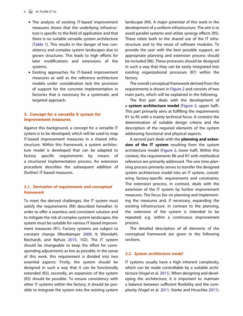
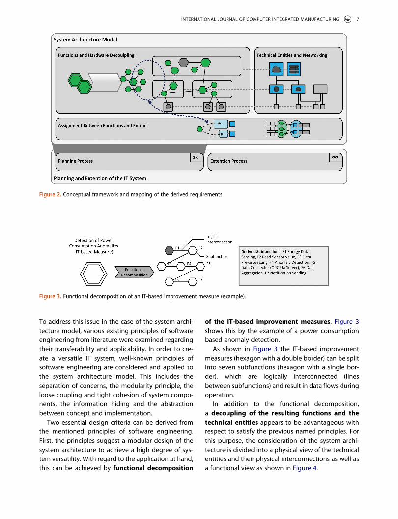
Two essential design criteria can be derived from the mentioned principles of software engineering. First, the principles suggest a modular design of the system architecture to achieve a high degree of sys-tem versatility. With regard to the application at hand, this can be achieved by functional decomposition
of the IT-based improvement measures. Figure 3 shows this by the example of a power consumption based anomaly detection.
As shown in Figure 3 the IT-based improvement measures (hexagon with a double border) can be split into seven subfunctions (hexagon with a single bor-der), which are logically interconnected (lines between subfunctions) and result in data flows during operation.
In addition to the functional decomposition, a decoupling of the resulting functions and the technical entities appears to be advantageous with respect to satisfy the previous named principles. For this purpose, the consideration of the system archi-tecture is divided into a physical view of the technical entities and their physical interconnections as well as a functional view as shown in Figure 4.
Figure 3. Functional decomposition of an IT-based improvement measure (example).
Figure 2. Conceptual framework and mapping of the derived requirements.
INTERNATIONAL JOURNAL OF COMPUTER INTEGRATED MANUFACTURING 7
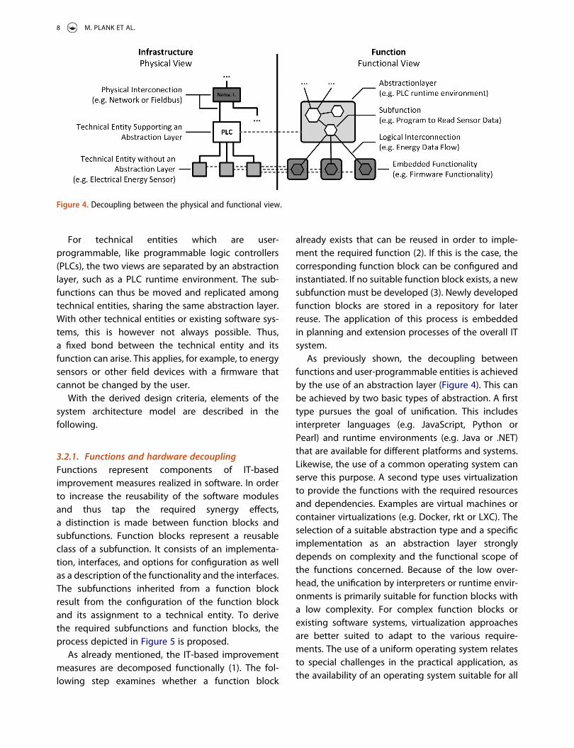
For technical entities which are user- programmable, like programmable logic controllers (PLCs), the two views are separated by an abstraction layer, such as a PLC runtime environment. The sub-functions can thus be moved and replicated among technical entities, sharing the same abstraction layer. With other technical entities or existing software sys-tems, this is however not always possible. Thus, a fixed bond between the technical entity and its function can arise. This applies, for example, to energy sensors or other field devices with a firmware that cannot be changed by the user.
With the derived design criteria, elements of the system architecture model are described in the following.
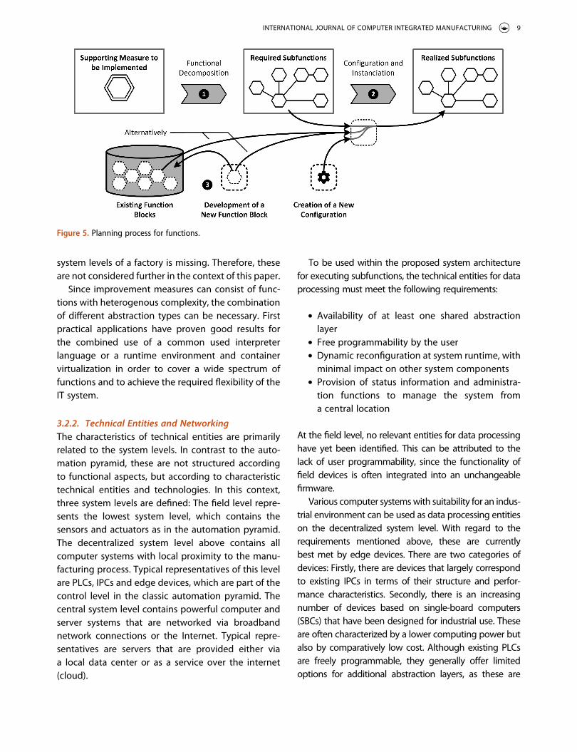
3.2.1. Functions and hardware decouplingFunctions represent components of IT-based improvement measures realized in software. In order to increase the reusability of the software modules and thus tap the required synergy effects, a distinction is made between function blocks and subfunctions. Function blocks represent a reusable class of a subfunction. It consists of an implementa-tion, interfaces, and options for configuration as well as a description of the functionality and the interfaces. The subfunctions inherited from a function block result from the configuration of the function block and its assignment to a technical entity. To derive the required subfunctions and function blocks, the process depicted in Figure 5 is proposed.
As already mentioned, the IT-based improvement measures are decomposed functionally (1). The fol-lowing step examines whether a function block
already exists that can be reused in order to imple-ment the required function (2). If this is the case, the corresponding function block can be configured and instantiated. If no suitable function block exists, a new subfunction must be developed (3). Newly developed function blocks are stored in a repository for later reuse. The application of this process is embedded in planning and extension processes of the overall IT system.
As previously shown, the decoupling between functions and user-programmable entities is achieved by the use of an abstraction layer (Figure 4). This can be achieved by two basic types of abstraction. A first type pursues the goal of unification. This includes interpreter languages (e.g. JavaScript, Python or Pearl) and runtime environments (e.g. Java or .NET) that are available for different platforms and systems. Likewise, the use of a common operating system can serve this purpose. A second type uses virtualization to provide the functions with the required resources and dependencies. Examples are virtual machines or container virtualizations (e.g. Docker, rkt or LXC). The selection of a suitable abstraction type and a specific implementation as an abstraction layer strongly depends on complexity and the functional scope of the functions concerned. Because of the low over-head, the unification by interpreters or runtime envir-onments is primarily suitable for function blocks with a low complexity. For complex function blocks or existing software systems, virtualization approaches are better suited to adapt to the various require-ments. The use of a uniform operating system relates to special challenges in the practical application, as the availability of an operating system suitable for all
Figure 4. Decoupling between the physical and functional view.
8 M. PLANK ET AL.
system levels of a factory is missing. Therefore, these are not considered further in the context of this paper.
Since improvement measures can consist of func-tions with heterogenous complexity, the combination of different abstraction types can be necessary. First practical applications have proven good results for the combined use of a common used interpreter language or a runtime environment and container virtualization in order to cover a wide spectrum of functions and to achieve the required flexibility of the IT system.
3.2.2. Technical Entities and NetworkingThe characteristics of technical entities are primarily related to the system levels. In contrast to the auto-mation pyramid, these are not structured according to functional aspects, but according to characteristic technical entities and technologies. In this context, three system levels are defined: The field level repre-sents the lowest system level, which contains the sensors and actuators as in the automation pyramid. The decentralized system level above contains all computer systems with local proximity to the manu-facturing process. Typical representatives of this level are PLCs, IPCs and edge devices, which are part of the control level in the classic automation pyramid. The central system level contains powerful computer and server systems that are networked via broadband network connections or the Internet. Typical repre-sentatives are servers that are provided either via a local data center or as a service over the internet (cloud).
To be used within the proposed system architecture for executing subfunctions, the technical entities for data processing must meet the following requirements:
● Availability of at least one shared abstraction layer
● Free programmability by the user● Dynamic reconfiguration at system runtime, with
minimal impact on other system components● Provision of status information and administra-
tion functions to manage the system from a central location
At the field level, no relevant entities for data processing have yet been identified. This can be attributed to the lack of user programmability, since the functionality of field devices is often integrated into an unchangeable firmware.
Various computer systems with suitability for an indus-trial environment can be used as data processing entities on the decentralized system level. With regard to the requirements mentioned above, these are currently best met by edge devices. There are two categories of devices: Firstly, there are devices that largely correspond to existing IPCs in terms of their structure and perfor-mance characteristics. Secondly, there is an increasing number of devices based on single-board computers (SBCs) that have been designed for industrial use. These are often characterized by a lower computing power but also by comparatively low cost. Although existing PLCs are freely programmable, they generally offer limited options for additional abstraction layers, as these are
Figure 5. Planning process for functions.
INTERNATIONAL JOURNAL OF COMPUTER INTEGRATED MANUFACTURING 9
often bound to a PLC runtime environment defined by the manufacturer. In the following, the technical entities for data processing on the decentralized system level are referred to as Decentralized System Modules (DSM).
The central system level is characterized by server technology. As mentioned above, this can be obtained in local data centers or as a service via the Internet. In local data centers this can be achieved by dedicated or virtual servers. Concerning cloud technologies, service models like Infrastructure as a Service (IaaS) and Platform as a Service (PaaS) as defined by the National Institute of Standards and Technology (NIST) (Mell and Grance 2011) can be named. With regard to the intro-duced requirements for the usability in the system archi-tecture, the locally provided servers and IaaS offer a high degree of flexibility and cover all requirements. With PaaS, the usability depends on the characteristics of the particular service. At this point, individual reviews must be considered.
The physical networking of technical entities inside the system architecture model is based on common technologies which are linked to the system level. The use of Ethernet is recommended for the central and decentral system level as the technology is wide-spread, therefore an existing network infrastructure can often be used. At the decentralized system level, the heterogeneous field level must be considered. The decentralized system modules (DSMs) must have an appropriate interface. Modular systems (e.g. through dedicated input/output modules) offer a high flexibility at this point.
The definition of the communication protocols refer-ring to the layers 4 to 7 of the ISO/OSI model is, however, part of the planning and implementation of the function blocks. This is a consequence of the implementation of these layers in software and the application-specific applicability of the protocols. Nevertheless, the use of standardized and open protocols is recommended to ensure integrability into existing systems.
3.2.3. Assignment between functions and entitiesFor the IT-based improvement measures on a shared IT infrastructure, the subfunctions resulting from the func-tional decomposition must be assigned to the data pro-cessing entities. This assignment process can be understood as a graph-theoretical assignment problem and can be depicted as a bipartite graph. The subfunc-tions and the technical entities each represent one parti-tion of the graph. Within the system architecture model,
the assignment between functions and entities takes place in a partially formalized process, which keeps the balance between manual assignment effort and required modelling effort. It is based on simple requirement and capability profiles that are defined for the subfunctions and technical entities.
The profiles contain three characteristics that are specified during the planning of the improvement measure. These can be described as follows:
● Area (A#): The area describes the spatial place-ment of a subfunction (AF) or technical entity (AE) and is primarily derived from the task of the function respective the installation location of the technical entity. For example, if the value of a sensor is to be read out, the sensor and func-tion should be located in the same area in order to keep the transported data volume as low as possible. The corresponding assignment condi-tion can be described as AF ¼ AE .
● Abstraction layer (AL#): Subfunctions and tech-nical entity must share a common abstraction layer in order to be mapped. As already men-tioned, a technical entity can have several abstraction layers (MAL;E ¼ AL1E;AL2E; . . .f g), while the implementation of a function block is usually bound to a certain abstraction layer (ALF). The corresponding assignment condition can be described as ALF 2 MAL;E .
● Hardware properties and interfaces (HI#): In the event that subfunctions make special demands on the hardware or require the exis-tence of interfaces, these can be modelled and taken into account via the required (MHI;F) respectively existing hardware properties and interfaces (MHI;E). The corresponding assignment condition can be described as MHI;F � MHI;E .
The described assignment process is illustrated in Figure 6 using the example of an energy monitoring solution which is to be implemented on a dedicated machine group with a centralized visualization. The required subfunctions (F) and their requirement pro-files are shown in Table 2. In addition to the functions, the existing technical entities and their capability profile are included as well.
The assignment process shown in Figure 6 results in three cases, which are described as follows:
10 M. PLANK ET AL.
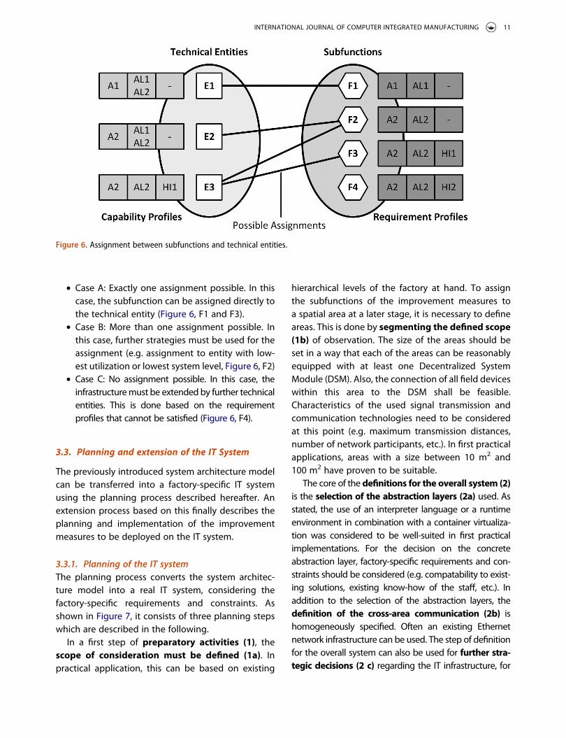
● Case A: Exactly one assignment possible. In this case, the subfunction can be assigned directly to the technical entity (Figure 6, F1 and F3).
● Case B: More than one assignment possible. In this case, further strategies must be used for the assignment (e.g. assignment to entity with low-est utilization or lowest system level, Figure 6, F2)
● Case C: No assignment possible. In this case, the infrastructure must be extended by further technical entities. This is done based on the requirement profiles that cannot be satisfied (Figure 6, F4).
3.3. Planning and extension of the IT System
The previously introduced system architecture model can be transferred into a factory-specific IT system using the planning process described hereafter. An extension process based on this finally describes the planning and implementation of the improvement measures to be deployed on the IT system.
3.3.1. Planning of the IT systemThe planning process converts the system architec-ture model into a real IT system, considering the factory-specific requirements and constraints. As shown in Figure 7, it consists of three planning steps which are described in the following.
In a first step of preparatory activities (1), the scope of consideration must be defined (1a). In practical application, this can be based on existing
hierarchical levels of the factory at hand. To assign the subfunctions of the improvement measures to a spatial area at a later stage, it is necessary to define areas. This is done by segmenting the defined scope (1b) of observation. The size of the areas should be set in a way that each of the areas can be reasonably equipped with at least one Decentralized System Module (DSM). Also, the connection of all field devices within this area to the DSM shall be feasible. Characteristics of the used signal transmission and communication technologies need to be considered at this point (e.g. maximum transmission distances, number of network participants, etc.). In first practical applications, areas with a size between 10 m2 and 100 m2 have proven to be suitable.
The core of the definitions for the overall system (2) is the selection of the abstraction layers (2a) used. As stated, the use of an interpreter language or a runtime environment in combination with a container virtualiza-tion was considered to be well-suited in first practical implementations. For the decision on the concrete abstraction layer, factory-specific requirements and con-straints should be considered (e.g. compatability to exist-ing solutions, existing know-how of the staff, etc.). In addition to the selection of the abstraction layers, the definition of the cross-area communication (2b) is homogeneously specified. Often an existing Ethernet network infrastructure can be used. The step of definition for the overall system can also be used for further stra-tegic decisions (2 c) regarding the IT infrastructure, for
Figure 6. Assignment between subfunctions and technical entities.
INTERNATIONAL JOURNAL OF COMPUTER INTEGRATED MANUFACTURING 11
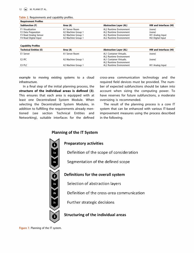
example to moving existing systems to a cloud infrastructure.
In a final step of the initial planning process, the structure of the individual areas is defined (3). This ensures that each area is equipped with at least one Decentralized System Module. When selecting the Decentralized System Modules, in addition to fulfilling the requirements already men-tioned (see section Technical Entities and Networking), suitable interfaces for the defined
cross-area communication technology and the required field devices must be provided. The num-ber of expected subfunctions should be taken into account when sizing the computing power. To have reserves for future subfunctions, a moderate oversizing is recommended.
The result of the planning process is a core IT system that can be enhanced with various IT-based improvement measures using the process described in the following.
Figure 7. Planning of the IT system.
Table 2. Requirements and capability profiles.Requirement Profiles
Subfunction (F) Area (A) Abstraction Layer (AL) HW and Interfaces (HI)
F1 Visualization A1 Server Room AL2 Runtime Environment (none)F2 Data Preparation A2 Machine Group 1 AL2 Runtime Environment (none)F3 Read Analog Sensor A2 Machine Group 1 AL2 Runtime Environment HI1 Analog InputF4 Read Digital Input A2 Machine Group 1 AL2 Runtime Environment HI2 Digital Input
Capability Profiles
Technical Entities (E) Area (A) Abstraction Layer (AL) HW and Interfaces (HI)
E1 Server A1 Server Room AL1 Container Virtualis. AL2 Runtime Environment
(none)
E2 IPC A2 Machine Group 1 AL1 Container Virtualis. AL2 Runtime Environment
(none)
E3 PLC A2 Machine Group 1 AL2 Runtime Environment HI1 Analog Input
12 M. PLANK ET AL.
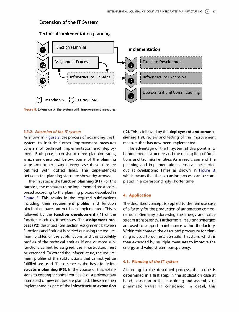
3.3.2. Extension of the IT systemAs shown in Figure 8, the process of expanding the IT system to include further improvement measures consists of technical implementation and deploy-ment. Both phases consist of three planning steps, which are described below. Some of the planning steps are not necessary in every case, these steps are outlined with dotted lines. The dependencies between the planning steps are shown by arrows.
The first step is the function planning (P1). For this purpose, the measures to be implemented are decom-posed according to the planning process described in Figure 5. This results in the required subfunctions including their requirement profiles and function blocks that have not yet been implemented. This is followed by the function development (I1) of the function modules, if necessary. The assignment pro-cess (P2) described (see section Assignment between Functions and Entities) is carried out using the require-ment profiles of the subfunctions and the capability profiles of the technical entities. If one or more sub-functions cannot be assigned, the infrastructure must be extended. To extend the infrastructure, the require-ment profiles of the subfunctions that cannot yet be fulfilled are used. These serve as the basis for infra-structure planning (P3). In the course of this, exten-sions to existing technical entities (e.g. supplementary interfaces) or new entities are planned. These are then implemented as part of the infrastructure expansion
(I2). This is followed by the deployment and commis-sioning (I3), review and testing of the improvement measure that has now been implemented.
The advantage of the IT system at this point is its homogeneous structure and the decoupling of func-tions and technical entities. As a result, some of the planning and implementation steps can be carried out at overlapping times as shown in Figure 8, which means that the expansion process can be com-pleted in a correspondingly shorter time.
4. Application
The described concept is applied to the real use case of a factory for the production of automation compo-nents in Germany addressing the energy and value stream transparency. Furthermore, resulting synergies are used to support maintenance within the factory. Within this context, the described procedure for plan-ning is used to define a versatile IT system, which is then extended by multiple measures to improve the energy and value stream transparency.
4.1. Planning of the IT system
According to the described process, the scope is determined in a first step. In the application case at hand, a section in the machining and assembly of pneumatic valves is considered. In detail, this
Figure 8. Extension of the system with improvement measures.
INTERNATIONAL JOURNAL OF COMPUTER INTEGRATED MANUFACTURING 13
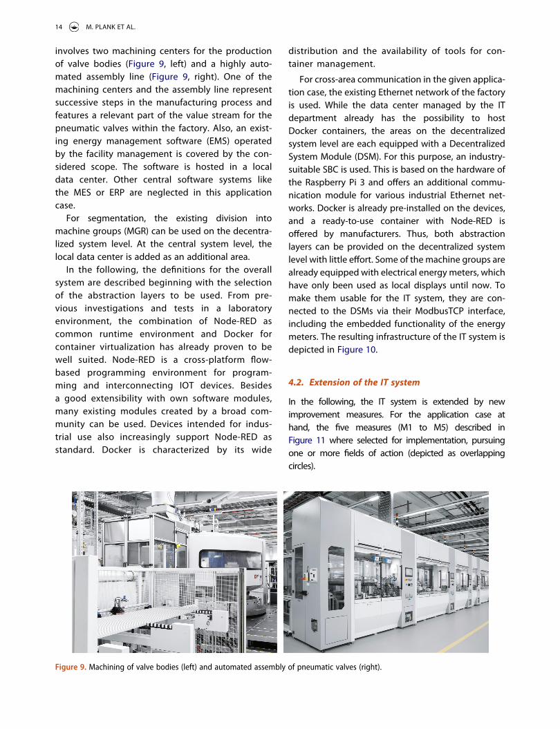
involves two machining centers for the production of valve bodies (Figure 9, left) and a highly auto-mated assembly line (Figure 9, right). One of the machining centers and the assembly line represent successive steps in the manufacturing process and features a relevant part of the value stream for the pneumatic valves within the factory. Also, an exist-ing energy management software (EMS) operated by the facility management is covered by the con-sidered scope. The software is hosted in a local data center. Other central software systems like the MES or ERP are neglected in this application case.
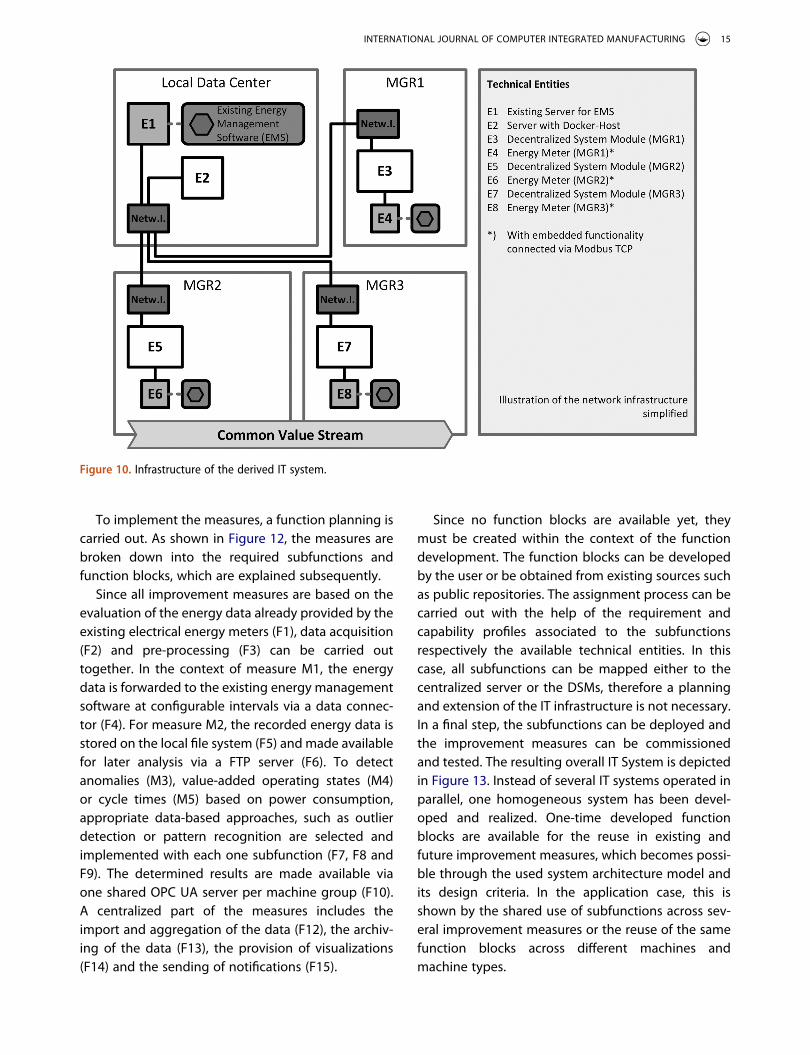
For segmentation, the existing division into machine groups (MGR) can be used on the decentra-lized system level. At the central system level, the local data center is added as an additional area.
In the following, the definitions for the overall system are described beginning with the selection of the abstraction layers to be used. From pre-vious investigations and tests in a laboratory environment, the combination of Node-RED as common runtime environment and Docker for container virtualization has already proven to be well suited. Node-RED is a cross-platform flow- based programming environment for program-ming and interconnecting IOT devices. Besides a good extensibility with own software modules, many existing modules created by a broad com-munity can be used. Devices intended for indus-trial use also increasingly support Node-RED as standard. Docker is characterized by its wide
distribution and the availability of tools for con-tainer management.
For cross-area communication in the given applica-tion case, the existing Ethernet network of the factory is used. While the data center managed by the IT department already has the possibility to host Docker containers, the areas on the decentralized system level are each equipped with a Decentralized System Module (DSM). For this purpose, an industry- suitable SBC is used. This is based on the hardware of the Raspberry Pi 3 and offers an additional commu-nication module for various industrial Ethernet net-works. Docker is already pre-installed on the devices, and a ready-to-use container with Node-RED is offered by manufacturers. Thus, both abstraction layers can be provided on the decentralized system level with little effort. Some of the machine groups are already equipped with electrical energy meters, which have only been used as local displays until now. To make them usable for the IT system, they are con-nected to the DSMs via their ModbusTCP interface, including the embedded functionality of the energy meters. The resulting infrastructure of the IT system is depicted in Figure 10.
4.2. Extension of the IT system
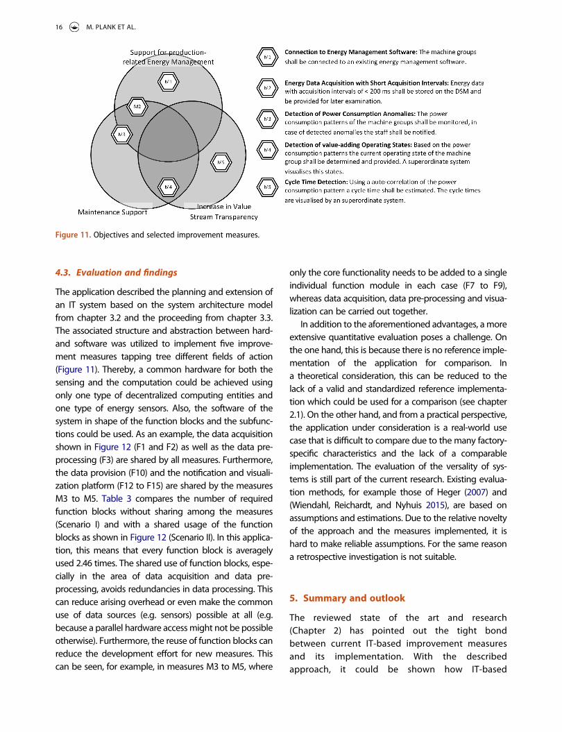
In the following, the IT system is extended by new improvement measures. For the application case at hand, the five measures (M1 to M5) described in Figure 11 where selected for implementation, pursuing one or more fields of action (depicted as overlapping circles).
Figure 9. Machining of valve bodies (left) and automated assembly of pneumatic valves (right).
14 M. PLANK ET AL.
To implement the measures, a function planning is carried out. As shown in Figure 12, the measures are broken down into the required subfunctions and function blocks, which are explained subsequently.
Since all improvement measures are based on the evaluation of the energy data already provided by the existing electrical energy meters (F1), data acquisition (F2) and pre-processing (F3) can be carried out together. In the context of measure M1, the energy data is forwarded to the existing energy management software at configurable intervals via a data connec-tor (F4). For measure M2, the recorded energy data is stored on the local file system (F5) and made available for later analysis via a FTP server (F6). To detect anomalies (M3), value-added operating states (M4) or cycle times (M5) based on power consumption, appropriate data-based approaches, such as outlier detection or pattern recognition are selected and implemented with each one subfunction (F7, F8 and F9). The determined results are made available via one shared OPC UA server per machine group (F10). A centralized part of the measures includes the import and aggregation of the data (F12), the archiv-ing of the data (F13), the provision of visualizations (F14) and the sending of notifications (F15).
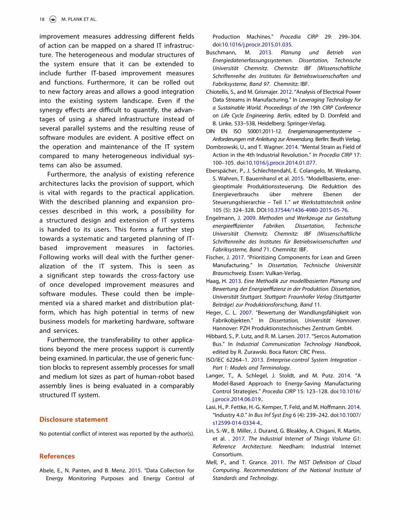
Since no function blocks are available yet, they must be created within the context of the function development. The function blocks can be developed by the user or be obtained from existing sources such as public repositories. The assignment process can be carried out with the help of the requirement and capability profiles associated to the subfunctions respectively the available technical entities. In this case, all subfunctions can be mapped either to the centralized server or the DSMs, therefore a planning and extension of the IT infrastructure is not necessary. In a final step, the subfunctions can be deployed and the improvement measures can be commissioned and tested. The resulting overall IT System is depicted in Figure 13. Instead of several IT systems operated in parallel, one homogeneous system has been devel-oped and realized. One-time developed function blocks are available for the reuse in existing and future improvement measures, which becomes possi-ble through the used system architecture model and its design criteria. In the application case, this is shown by the shared use of subfunctions across sev-eral improvement measures or the reuse of the same function blocks across different machines and machine types.
Figure 10. Infrastructure of the derived IT system.
INTERNATIONAL JOURNAL OF COMPUTER INTEGRATED MANUFACTURING 15
4.3. Evaluation and findings
The application described the planning and extension of an IT system based on the system architecture model from chapter 3.2 and the proceeding from chapter 3.3. The associated structure and abstraction between hard- and software was utilized to implement five improve-ment measures tapping tree different fields of action (Figure 11). Thereby, a common hardware for both the sensing and the computation could be achieved using only one type of decentralized computing entities and one type of energy sensors. Also, the software of the system in shape of the function blocks and the subfunc-tions could be used. As an example, the data acquisition shown in Figure 12 (F1 and F2) as well as the data pre- processing (F3) are shared by all measures. Furthermore, the data provision (F10) and the notification and visuali-zation platform (F12 to F15) are shared by the measures M3 to M5. Table 3 compares the number of required function blocks without sharing among the measures (Scenario I) and with a shared usage of the function blocks as shown in Figure 12 (Scenario II). In this applica-tion, this means that every function block is averagely used 2.46 times. The shared use of function blocks, espe-cially in the area of data acquisition and data pre- processing, avoids redundancies in data processing. This can reduce arising overhead or even make the common use of data sources (e.g. sensors) possible at all (e.g. because a parallel hardware access might not be possible otherwise). Furthermore, the reuse of function blocks can reduce the development effort for new measures. This can be seen, for example, in measures M3 to M5, where
only the core functionality needs to be added to a single individual function module in each case (F7 to F9), whereas data acquisition, data pre-processing and visua-lization can be carried out together.
In addition to the aforementioned advantages, a more extensive quantitative evaluation poses a challenge. On the one hand, this is because there is no reference imple-mentation of the application for comparison. In a theoretical consideration, this can be reduced to the lack of a valid and standardized reference implementa-tion which could be used for a comparison (see chapter 2.1). On the other hand, and from a practical perspective, the application under consideration is a real-world use case that is difficult to compare due to the many factory- specific characteristics and the lack of a comparable implementation. The evaluation of the versality of sys-tems is still part of the current research. Existing evalua-tion methods, for example those of Heger (2007) and (Wiendahl, Reichardt, and Nyhuis 2015), are based on assumptions and estimations. Due to the relative novelty of the approach and the measures implemented, it is hard to make reliable assumptions. For the same reason a retrospective investigation is not suitable.
5. Summary and outlook
The reviewed state of the art and research (Chapter 2) has pointed out the tight bond between current IT-based improvement measures and its implementation. With the described approach, it could be shown how IT-based
Figure 11. Objectives and selected improvement measures.
16 M. PLANK ET AL.
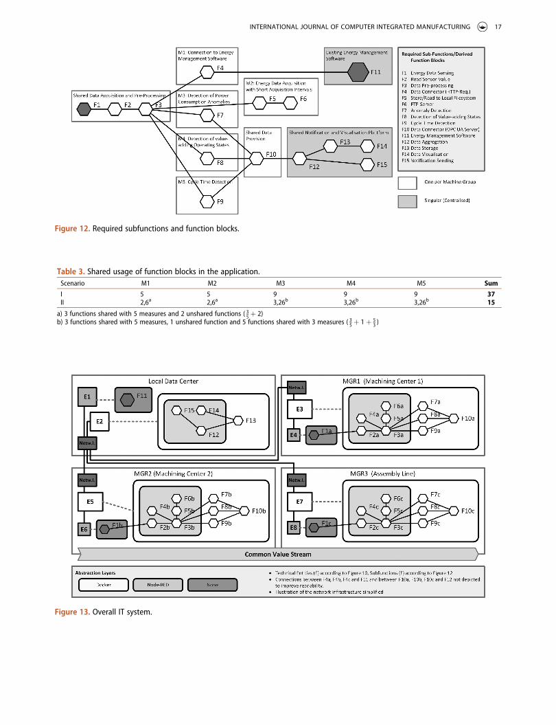
Figure 12. Required subfunctions and function blocks.
Table 3. Shared usage of function blocks in the application.Scenario M1 M2 M3 M4 M5 Sum
I 5 5 9 9 9 37II 2,6a 2,6a 3,26b 3,26b 3,26b 15
a) 3 functions shared with 5 measures and 2 unshared functions ( 35þ 2)
b) 3 functions shared with 5 measures, 1 unshared function and 5 functions shared with 3 measures ( 35þ 1þ 5
3 )
Figure 13. Overall IT system.
INTERNATIONAL JOURNAL OF COMPUTER INTEGRATED MANUFACTURING 17
improvement measures addressing different fields of action can be mapped on a shared IT infrastruc-ture. The heterogeneous and modular structures of the system ensure that it can be extended to include further IT-based improvement measures and functions. Furthermore, it can be rolled out to new factory areas and allows a good integration into the existing system landscape. Even if the synergy effects are difficult to quantify, the advan-tages of using a shared infrastructure instead of several parallel systems and the resulting reuse of software modules are evident. A positive effect on the operation and maintenance of the IT system compared to many heterogeneous individual sys-tems can also be assumed.
Furthermore, the analysis of existing reference architectures lacks the provision of support, which is vital with regards to the practical application. With the described planning and expansion pro-cesses described in this work, a possibility for a structured design and extension of IT systems is handed to its users. This forms a further step towards a systematic and targeted planning of IT- based improvement measures in factories. Following works will deal with the further gener-alization of the IT system. This is seen as a significant step towards the cross-factory use of once developed improvement measures and software modules. These could then be imple-mented via a shared market and distribution plat-form, which has high potential in terms of new business models for marketing hardware, software and services.
Furthermore, the transferability to other applica-tions beyond the mere process support is currently being examined. In particular, the use of generic func-tion blocks to represent assembly processes for small and medium lot sizes as part of human-robot based assembly lines is being evaluated in a comparably structured IT system.
Disclosure statement
No potential conflict of interest was reported by the author(s).
References
Abele, E., N. Panten, and B. Menz. 2015. “Data Collection for Energy Monitoring Purposes and Energy Control of
Production Machines.” Procedia CIRP 29: 299–304. doi:10.1016/j.procir.2015.01.035.
Buschmann, M. 2013. Planung und Betrieb von Energiedatenerfassungssystemen. Dissertation, Technische Universität Chemnitz. Chemnitz: IBF (Wissenschaftliche Schriftenreihe des Institutes für Betriebswissenschaften und Fabriksysteme, Band 97. Chemnitz: IBF.
Chiotellis, S., and M. Grismajer. 2012. “Analysis of Electrical Power Data Streams in Manufacturing.” In Leveraging Technology for a Sustainable World. Proceedings of the 19th CIRP Conference on Life Cycle Engineering. Berlin, edited by D. Dornfeld and B. Linke, 533–538, Heidelberg: Springer-Verlag.
DIN EN ISO 50001:2011-12. Energiemanagementsysteme – Anforderungen mit Anleitung zur Anwendung. Berlin: Beuth Verlag.
Dombrowski, U., and T. Wagner. 2014. “Mental Strain as Field of Action in the 4th Industrial Revolution.” In Procedia CIRP 17: 100–105. doi:10.1016/j.procir.2014.01.077.
Eberspächer, P., J. Schlechtendahl, E. Colangelo, M. Weskamp, S. Wahren, T. Bauernhansl et al. 2015. “Modellbasierte, ener-gieoptimale Produktionssteuerung. Die Reduktion des Energieverbrauchs über mehrere Ebenen der Steuerungshierarchie – Teil 1.” wt Werkstattstechnik online 105 (5): 324–328. DOI:10.37544/1436-4980-2015-05-76.
Engelmann, J. 2009. Methoden und Werkzeuge zur Gestaltung energieeffizienter Fabriken. Dissertation, Technische Universität Chemnitz. Chemnitz: IBF (Wissenschaftliche Schriftenreihe des Institutes für Betriebswissenschaften und Fabriksysteme, Band 71. Chemnitz: IBF.
Fischer, J. 2017. “Prioritizing Components for Lean and Green Manufacturing.” In Dissertation, Technische Universität Braunschweig. Essen: Vulkan-Verlag.
Haag, H. 2013. Eine Methodik zur modellbasierten Planung und Bewertung der Energieeffizienz in der Produktion. Dissertation, Universität Stuttgart. Stuttgart: Fraunhofer Verlag (Stuttgarter Beiträge) zur Produktionsforschung, Band 11.
Heger, C. L. 2007. “Bewertung der Wandlungsfähigkeit von Fabrikobjekten.” In Dissertation, Universität Hannover. Hannover: PZH Produktionstechnisches Zentrum GmbH.
Hibbard, S., P. Lutz, and R. M. Larsen. 2017. “Sercos Automation Bus.” In Industrial Communication Technology Handbook, edited by R. Zurawski. Boca Raton: CRC Press.
ISO/IEC 62264–1. 2013. Enterprise-control System Integration - Part 1: Models and Terminology.
Langer, T., A. Schlegel, J. Stoldt, and M. Putz. 2014. “A Model-Based Approach to Energy-Saving Manufacturing Control Strategies.” Procedia CIRP 15: 123–128. doi:10.1016/ j.procir.2014.06.019..
Lasi, H., P. Fettke, H.-G. Kemper, T. Feld, and M. Hoffmann. 2014. “Industry 4.0.” In Bus Inf Syst Eng 6 (4): 239–242. doi:10.1007/ s12599-014-0334-4..
Lin, S.-W., B. Miller, J. Durand, G. Bleakley, A. Chigani, R. Martin, et al. . 2017. The Industrial Internet of Things Volume G1: Reference Architecture. Needham: Industrial Internet Consortium.
Mell, P., and T. Grance. 2011. The NIST Definition of Cloud Computing. Recommendations of the National Institute of Standards and Technology.
18 M. PLANK ET AL.
Müller, E., J. Engelmann, T. Löffler, and J. Strauch. 2009. Energieeffiziente Fabriken planen und betreiben. Berlin, Heidelberg: Springer-Verlag.
PNO. 2016. PROFIBUS Nutzerorganisation E. V. – Common Application Profile PROFIenergy. Technical Specification for PROFINET.
Posselt, G. 2016. “Towards Energy Transparent Factories.” In Dissertation, Technische Universität Braunschweig. Cham: Springer International Publishing (Sustainable Production, Life Cycle Engineering and Management).
Posselt, G., J. Linzbach, S. Thiede, M. Bernas, and C. Herrmann. 2014. “Energieflusstransparenz fördert transdisziplinäre Planung.” In ZWF 109 (9): 650–654. doi:10.3139/104.111196..
Schlechtendahl, J., P. Eberspächer, H. Haag, A. Verl, and E. Westkämper. 2013. “Framework for Controlling Energy Consumption of Machine Tools.” In EcoProduction and Logistics. Emerging Trends and Business Practices. Berlin, edi-ted by P. Golinska. 155–168: Heidelberg: Springer-Verlag (EcoProduction).
Schwab, K. 2017. The Fourth Industrial Revolution. First pub-lished in Great Britain by Portfolio. London, UK u. a.: Portfolio Penguin.
Starke, G., and P. Hruschka. 2011. Software-Architektur kompakt – Angemessen und zielorientiert. 2. Auflage. Heidelberg: Spektrum Akademischer Verlag (IT kompakt).
Verl, A., E. Westkämper, E. Abele, A. Dietmair, J. Schlechtendahl, J. Friedrich, et al. . 2011. “Architecture for Multilevel Monitoring and Control of Energy Consumption.” In
Glocalized Solutions for Sustainability in Manufacturing. Berlin, edited by J. Hesselbach and C. Herrmann, 347–352. Heidelberg: Springer-Verlag.
Vijayaraghavan, A., and D. A. Dornfeld. 2010. “Automated Energy Monitoring of Machine Tools.” In CIRP Annals - Manufacturing Technology 59 (1): 21–24. doi:10.1016/j. cirp.2010.03.042..
Vikhorev, K., R. Greenough, and N. Brown. 2013. “An Advanced Energy Management Framework to Promote Energy Awareness.” Journal of Cleaner Production 43: 103–112. doi:10.1016/j.jclepro.2012.12.012..
Vogel, O., I. Arnold, A. Chughtai, and T. Kehrer. 2011. Software Architecture. Berlin, Heidelberg: Springer-Verlag.
Westkämper, E. 2009. “Turbulentes Umfeld von Unternehmen.” In Wandlungsfähige Produktionsunternehmen. Das Stuttgarter Unternehmensmodell. Berlin, edited by E. Westkämper and E. Zahn, 7–23, Heidelberg: Springer- Verlag.
Wiendahl, H.-P., J. Reichardt, and P. Nyhuis. 2015. Handbook Factory Planning and Design. Berlin, Heidelberg: Springer- Verlag.
Zampou, E., S. Plitsos, A. Karagiannaki, and I. Mourtos. 2014. “Towards a Framework for Energy-Aware Information Systems in Manufacturing.” In Computers in Industry 65 (3): 419–433. doi:10.1016/j.compind.2014.01.007..
ZVEI, VDI. 2015. VDI/VDE-Gesellschaft Mess- und Automatisierungstechnik; Zentralverband Elektrotechnik- und Elektronikindustrie e. V. – Statusreport Referenzarchitekturmodell Industrie 4.0 (RAMI4.0).
INTERNATIONAL JOURNAL OF COMPUTER INTEGRATED MANUFACTURING 19


