Embed Size (px)
Citation preview

www.emcsolutions.com
Specializing in Motors, Drives, Generators, and Electrical Asset Management
Craig Hartman, P.E.
VFD Theory

www.emcsolutions.com
Specializing in Motors, Drives, Generators, and Electrical Asset Management
When was the microprocessor invented?
a) 1969
b) 1942
c) 1921
d) 1977Intel 4004, the first general-purpose,
commercial microprocessor

www.emcsolutions.com
Specializing in Motors, Drives, Generators, and Electrical Asset Management
Answer: a - 1969
The microprocessor was invented by Ted Hoff, at Intel, for Busicom, a
Japanese calculator manufacturer. It was first advertised in November of
1971 and cost thousands of dollars. It is fascinating to note that the first
manned landing on the moon was also in 1969. Apollo 11 launched from
Kennedy Space Center on July 16, 1969. Neil Armstrong became the
first man to walk on the moon, stepping on its surface on July 20th.
Twelve people have landed on the moon.
VFD Theory: 4
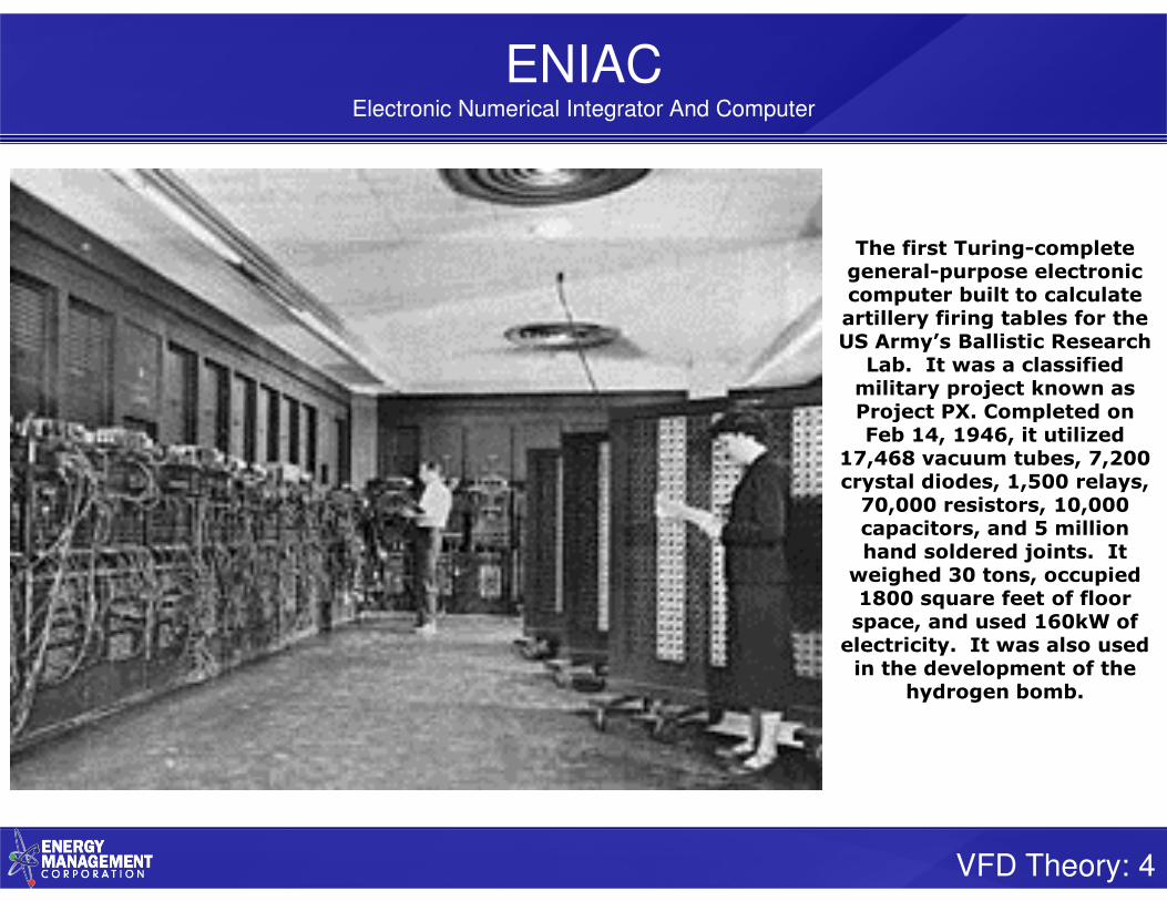
ENIACElectronic Numerical Integrator And Computer
The first Turing-complete general-purpose electronic computer built to calculate artillery firing tables for the US Army’s Ballistic Research
Lab. It was a classified military project known as Project PX. Completed on Feb 14, 1946, it utilized
17,468 vacuum tubes, 7,200 crystal diodes, 1,500 relays, 70,000 resistors, 10,000 capacitors, and 5 million hand soldered joints. It
weighed 30 tons, occupied 1800 square feet of floor space, and used 160kW of electricity. It was also used in the development of the
hydrogen bomb.

VFD Theory: 5
The First Super-Computer Hard Drive
In September, 1956, IBM launched the 305 RAMAC, the first “Super-Computer” with a hard disk drive (HDD). The HDD weighed over a ton
and stored a whopping 5MB of data. This photo shows the “portable” version.
By comparison, a 16GB flash drive holds about 3200 times as much data.

VFD Theory: 6
How to identify a meth lab
VFD Theory: 7
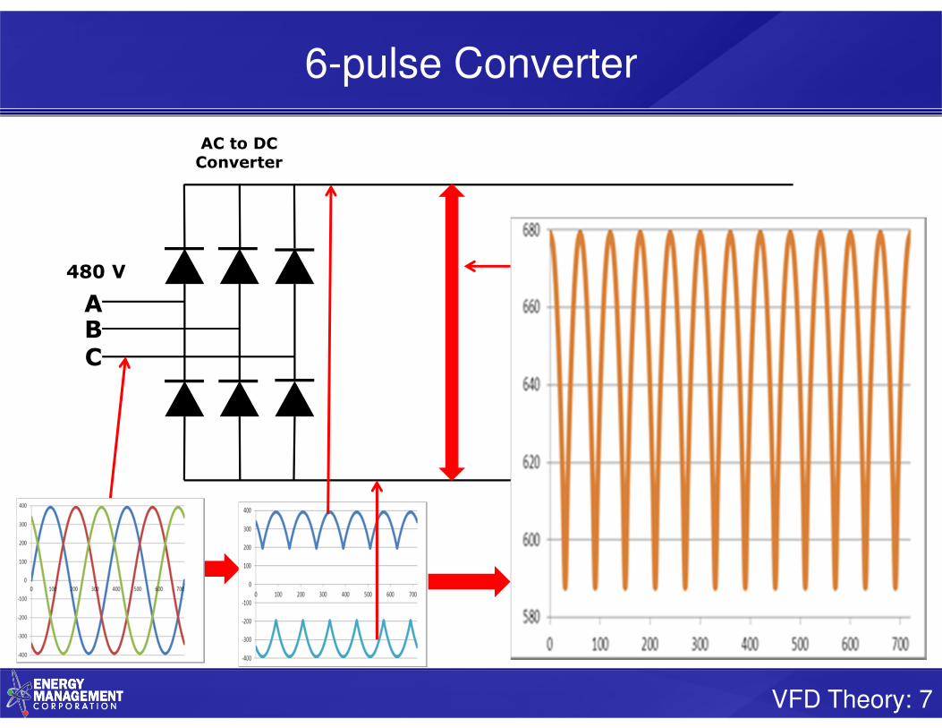
6-pulse Converter
ABC
AC to DCConverter
480 V

VFD Theory: 8
Add DC bus
ABC
AC to DCConverter
DCBus
+
-
+650Vdc
0Vdc
480 V

VFD Theory: 9
Pre-Charge Circuit
ABC
On power-up, the capacitor charges through the pre-charge resistor. Once the dc bus reaches rated voltage, the
contactor (or transistor) bypasses the resistor.
+
-

VFD Theory: 10
Add Inverter
ABC
AC to DCConverter
DCBus
DC to ACInverter
M+
-
480 V
+650Vdc
0Vdc

VFD Theory: 11
PWM Output to Motor
480 V60 Hz
650V

VFD Theory: 12
PWM Output to Motor
480 V60 Hz
240 V30 Hz
650V
650V
VFD Theory: 13
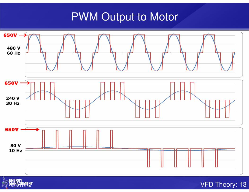
PWM Output to Motor
480 V60 Hz
240 V30 Hz
650V
650V
650V
80 V10 Hz

www.emcsolutions.com
Specializing in Motors, Drives, Generators, and Electrical Asset Management
PWM Waveforms

VFD Theory: 15
Pulse Width Modulation(Pseudo Sine Wave)
Carrier Frequency = 1kHzLight Load

VFD Theory: 16
Pulse Width Modulation
Carrier Frequency = 1kHzLight Load
Carrier Frequency = 1kHzFull Load

VFD Theory: 17
Pulse Width Modulation
Carrier Frequency = 5kHzLight Load
Carrier Frequency = 5kHzFull Load

VFD Theory: 18
Pulse Width Modulation
Carrier Frequency = 10kHzLight Load
Carrier Frequency = 10kHzFull Load

VFD Theory: 19
PWM frequency
Advantages of high carrier frequency
• Lower acoustic noise level

VFD Theory: 20
PWM frequency
Advantages of high carrier frequency
• Lower acoustic noise level
Disadvantages of high carrier frequency
• Lower VFD efficiency• Increased VFD heating• Shortens VFD life• Increased motor heating• Higher overshoot peak voltages• Harder on motor insulation• Exacerbates peak voltage concerns• Increased radiated electro-magnetic noise• Increased ground “leakage” currents in motor
cable and motor capacitances

www.emcsolutions.com
Specializing in Motors, Drives, Generators, and Electrical Asset Management
VFD Construction

VFD Theory: 22
VFD Internals
Cooling Fan
AC to DC Inverter
(2 transistors per module)
DC Bus
AC to DC Converter
(2 diodes per module)
AC Power InputPower Output
to Motor
Heat Sink
DC Bus
Capacitors
Variable Frequency Drivecirca 1980’s

VFD Theory: 23
VFD Internals
Transistor
Snubber
Capacitor
discharge
resistors
Capacitor
pre-charge
circuit
Variable Frequency Drivecirca 1980’s
Control
Board

VFD Theory: 24
AC to DC
Converter Filter
DC to AC
Inverter
MDC Filter
Capacitor
VFDNo Harmonic Mitigation
TH Free-wheeling
diodes

VFD Theory: 25
Internals
USB programming port
Serial CommsRS485
Modbus RTU
Option Slots (3))
Variable Frequency Drivecirca 2010’s

VFD Theory: 26
VFD(with line reactor)
6-Pulse
VFD
Line
Reactor
3-Contactor
Bypass

VFD Theory: 27
VFD(2-reactor harmonic filter)
6-Pulse
VFD
Harmonic Filter
Capacitor
Harmonic Filter
Reactors
3-Contactor
Bypass

VFD Theory: 28
VFD
VFD Device Island

VFD Theory: 29
Why isn’t this VFD working?

VFD Theory: 30
Why isn’t this VFD working?

VFD Theory: 31
VFD

VFD Theory: 32
Dual VFD’s(harmonic filter with dc-link and ac rectors)
6-Pulse
VFD
Dc-link
reactor
Harmonic filter
capacitors
Harmonic filter
reactors
dV/dt
filter

VFD Theory: 33
VFD(3-reactor harmonic filter with dc link reactor)
6-Pulse
VFD
Dc-link
reactor
Harmonic filter
capacitors
Harmonic filter
reactors
dV/dt
filter

VFD Theory: 34
VFD’s in custom assembly

VFD Theory: 35
VFD’s in custom assembly

VFD Theory: 36
VFD’s in Motor Control Center

VFD Theory: 37
VFD’s in Motor Control Center

VFD Theory: 38
NEMA 3R Custom Enclosure (front)

VFD Theory: 39
NEMA 3R Custom Enclosure (internal)

VFD Theory: 40
NEMA 3R Custom Enclosure (rear)
VFD heat sink extends out
the rear of the enclosure

VFD Theory: 41
NEMA 3R Custom Enclosure (rear)
VFD heat sink extends out
the rear of the enclosure

VFD Theory: 42
NEMA 3R Custom Enclosure (installed)

VFD Theory: 43
Constant Torque vs Variable Torque
• Variable Torque (VT) refers to centrifugal pump and fan
applications. Their load torque “varies” in proportion to the
square of motor speed.
• Constant Torque (CT) refers to most other applications. Their
load torque is based on friction losses which are relatively
“constant” at all speeds
• These terms can be confusing and misleading. With a fixed
speed setting, over time, fan and pump loads fluctuate less than
many other applications
• The fundamental difference between VT and CT is the
VFD overload rating
– VT ratings typically range from 0% to 20% overload
for one minute
– CT ratings are typically 50% overload for one
minute

VFD Theory: 44
Speed Range

VFD Theory: 45
Control Methods
F700A500A700A700/V500
• Speed Control
• Torque Control• Position Control

VFD Theory: 46
Regenerative Braking Resistor
Converter DC Link Inverter
L1
L2
L3C
on
tro
l L
og
ic
M
Braking
Resistor
Chopping
Transistor
Regenerative Power FlowRegenerative Power Flow

VFD Theory: 47
Power-Down Braking
Keeps the motor under control even if supply power is lost.
Improved safety for critical applicationse.g. centrifuge, machine tool
VFD Theory: 48
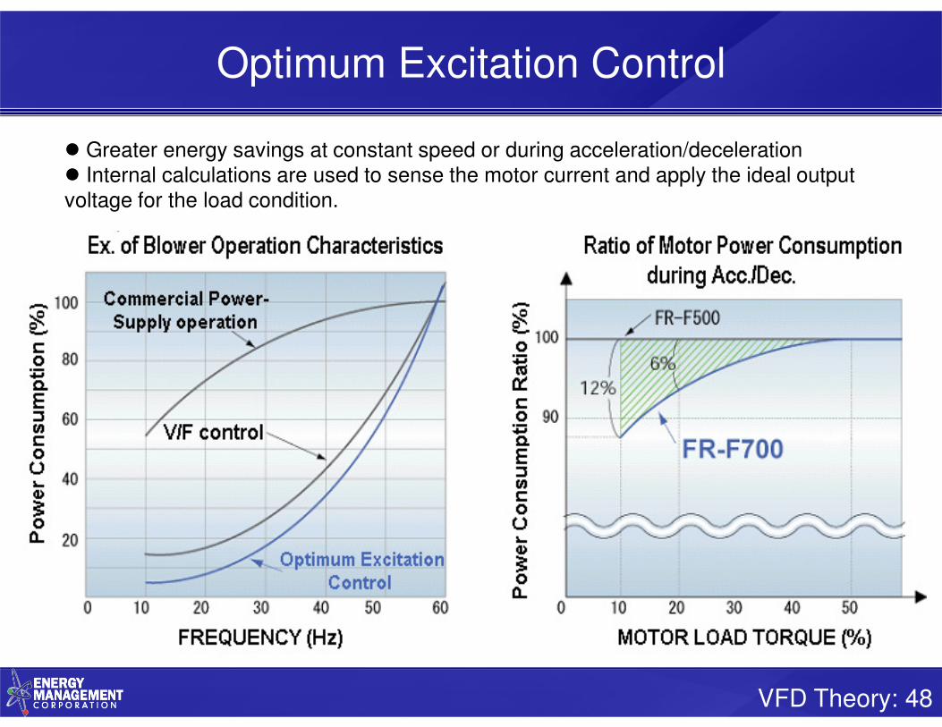
Optimum Excitation Control
� Greater energy savings at constant speed or during acceleration/deceleration� Internal calculations are used to sense the motor current and apply the ideal output voltage for the load condition.

www.emcsolutions.com
Specializing in Motors, Drives, Generators, and Electrical Asset Management
Motor Peak Voltages & dV/dt

VFD Theory: 50
dV/dt
Reflective Wave Phenomenon
Voltage wave reflection is a function of the voltage rise time (dV/dt) and the
length of the motor cables. Impedance mismatches cause voltage pulses to be
reflected back in the direction from which they arrive. As these reflected waves
encounter incoming waves, their values add, causing higher peak voltage. As
wire length or carrier frequency increases, the overshoot peak voltage
also increases. This causes motor insulation degradation and failure.
Resonant Circuit Phenomenon
Electrical systems of every nature have a natural frequency. When system
components have a resonant frequency that matches the natural resonant
frequency of the system, peak voltages can quickly exceed standard reflective
wave overshoots.

VFD Theory: 51
Voltage Stress
ALL MOTORS(NEMA MG1 – Part 30)
VFD MOTORS(NEMA MG1 – Part 31)
Vrated ≤ 600 Volts
Vpeak ≤ 1kV 3.1 * Vrated
Rise time ≥ 2µs 0.1µs
Vrated > 600 Volts
Vpeak ≤ 2.04 * Vrated 2.04 * Vrated
Rise time ≥ 1µs 1µs
Vrated is the line-to-line voltageVpeak is a single amplitude zero-to-peak line-to-line voltage.For 480V: Recommend voltage spikes be limited to 1000V and dV/dt to 1000V/µs

VFD Theory: 52
Typical Voltage Response at Motor TerminalsNEMA MG-1
Voltage
Time
100%Steady-state voltage
Vpeak
90%
10%
∆tRise time
∆V dV
dt
∆V
∆t=

VFD Theory: 53
Common mode voltage
Courtesy TCI
Common mode voltage occurs when the voltages on the three output lines of a drive do not sum instantaneously to zero. dV/dt filters slow down the rate of change of PWM
switching as seen by the load. This reduction in the rate of change results in increased capacitive coupling impedance between bearings and bearing races. This increase in
impedance, in turn, reduces the damaging Common Mode currents.

VFD Theory: 54
dV/dt
Courtesy TCI

VFD Theory: 55
dV/dt
Courtesy TCI

VFD Theory: 56
Is there another way?
dV/dt

VFD Theory: 57
Mitsubishi Soft PWM
dV/dt(proprietary solution)
• Changes acoustic motor noise from a metallic tone into an unoffending complex tone.
• Protects motors from dV/dt for longer lead lengths.
PWM
Frequency
1 hp
and below
2hp 3 hp
and above
2 kHz 300 meters 500 meters 500 meters
3-15 kHz 200 meters 300 meters 500 meters
Note: Assumes NEMA MG1-Part 31VFD-rated motor insulation
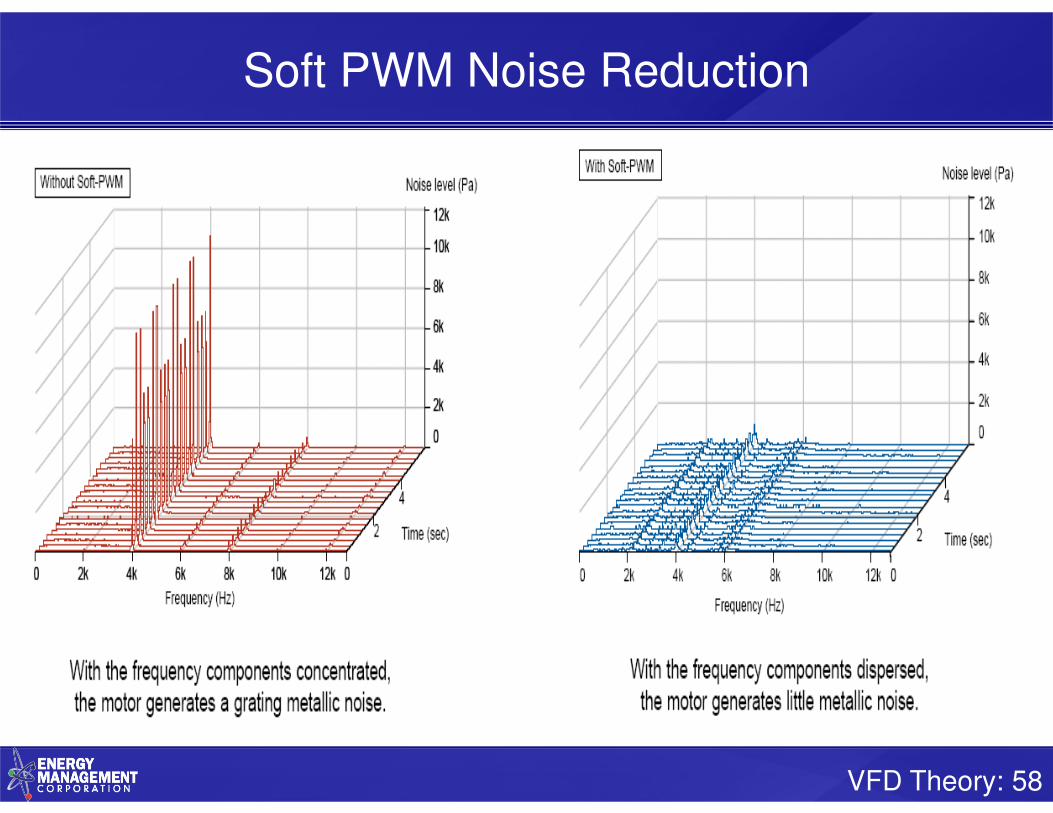
VFD Theory: 58
Soft PWM Noise Reduction

VFD Theory: 59
dV/dt filter
dV/dt filter• Reduces voltage spikes to below 1000 Volts• Slows down PWM dV/dt by a factor of 3• Reduces common mode currents by approximately 30%• Protects both the motor and the cable insulation
Recommendations• Consider when VFD-to-motor cable length exceeds 100 ft• Option: Leave room in VFD cabinet and install only if required• Stay within filter manufacturer’s recommendations for carrier frequency• Use proprietary solution
Note: Keep the VFD to motor voltage drop to 2% or less
HintIf motor runs fine on sine wave power, but trips on VFD, then
have the motor surge tested by a qualified motor rewind shop.

www.emcsolutions.com
Specializing in Motors, Drives, Generators, and Electrical Asset Management
VFD’s & Motor Bearings

Copyright 2010 – Electro Static Technology-ITW – Patented Technology – All Rights ReservedCopyright 2010 – Electro Static Technology-ITW – Patented Technology – All Rights Reserved
=460 VAC
60Hz
Electric Motor DesignElectric Motor Design
Most electric induction motors were designed for operation on 3 phase sign wave power – either 50 or 60 Hz.
The input power was balanced in frequency, phase (120 degrees apart) and in amplitude.
Common mode voltage – the sum of the 3 phases would always equal zero volts.
61

Copyright 2010 – Electro Static Technology-ITW – Patented Technology – All Rights ReservedCopyright 2010 – Electro Static Technology-ITW – Patented Technology – All Rights Reserved
62
+
Electric Motor Operation by VFDElectric Motor Operation by VFD
When operated by VFD, the power to the motor is a series of pulses instead of a smooth sign wave.
The input power is never balanced because the voltage is either 0 volts, positive, or negative with rapid switching between pulses.
The Three phases of voltage pulses ensures that the common mode voltage is never equal to zero and instead is a “square wave” or “6 step” voltage.
=

Copyright 2010 – Electro Static Technology-ITW – Patented Technology – All Rights ReservedCopyright 2010 – Electro Static Technology-ITW – Patented Technology – All Rights Reserved
What effect does this have on the bearings?
Voltage builds up until it exceeds the insulation level of the bearing’s oil film layer –the “break-down” voltage of the bearing.
The voltage then arcs through the bearing creating an electrical discharge machining (EDM) pit.
Thousands of pits per second may be created and over time the ball rolling over the disturbed surface can cause “fluting damage”.
63

Copyright 2010 – Electro Static Technology-ITW – Patented Technology – All Rights ReservedCopyright 2010 – Electro Static Technology-ITW – Patented Technology – All Rights Reserved
Shaft Voltage Readings
A number of
different wave
forms may be
present…
64

Copyright 2010 – Electro Static Technology-ITW – Patented Technology – All Rights ReservedCopyright 2010 – Electro Static Technology-ITW – Patented Technology – All Rights Reserved
Bearing Discharge Voltage Pattern
Voltage Increase & drop
Signifying Current flow
through Bearings
Bearing Discharge~50 nano sec.Creates EDM pitting
65

Copyright 2010 – Electro Static Technology-ITW – Patented Technology – All Rights Reserved
Prevent Bearing Fluting Damage with
AEGIS™ Bearing Protection Ring
66

Copyright 2010 – Electro Static Technology-ITW – Patented Technology – All Rights Reserved
Motor Bearing Damage from Electrical CurrentsMotor Bearing Damage from Electrical CurrentsElectrical Discharge Machining (EDM)
Bearing Pitting Damage
Bearing Fluting Damage
Electron Microscope
(SEM) Image
EDM Pitting
1000x Magnified
EDM Pit
67

VFD Theory: 68
Mitigation Techniques
VFD Waveform
MitigationSine Wave Filter Expense, produces heat
Bearing Insulating
Sleeve
Expense, does not protect driven equipment, capacitive
coupling may allow currents to pass through insulation,
contamination
Ceramic Bearings Expense, does not protect driven equipment
Conductive Grease(Not in current use)
Conductive particles would increase mechanical wear,
rendering lubricants ineffective.
Grounding Brush Expense, wear, contaminants, oxidation, maintenance
Shaft Grounding Ring Expense (lower than others above), contamination
Bearing
Insulation
Alternate
Discharge Paths
Sine-wave filter Ceramic Bearing Ceramic Insulated Bearing

Copyright 2010 – Electro Static Technology-ITW – Patented Technology – All Rights ReservedCopyright 2010 – Electro Static Technology-ITW – Patented Technology – All Rights Reserved
New Conductive Microfiber Shaft Grounding Technology
Uses several methods to transfer
electrical currents*
*IEEE paper, September 2007: Design Aspects of Conductive Microfiber Rings for Shaft Grounding Purposes, by Dr. Annette Muetze et. Al.
Direct Contact Conduction
Electrical Contact without
mechanical contact by field
emission
69

Copyright 2010 – Electro Static Technology-ITW – Patented Technology – All Rights ReservedCopyright 2010 – Electro Static Technology-ITW – Patented Technology – All Rights Reserved
Micro Fiber Shaft Grounding Ring
• Discharges shaft voltages to ground
– Easy to install– Maintenance free– Improves VFD motor bearing reliability– Best ROI - Small investment
• Addresses the root cause of the problem (shaft currents)
– Diverts the shaft current away from the motor bearings
– Protects motor with highly reliable solution
• Longest lasting protection
– Wear rate less than 1 mill per 10,000 hours operation
– Lasts for over 200,000 hours operation– 2 million direction reversals - Zero fiber fatigue or broken
fibers
70

Copyright 2010 – Electro Static Technology-ITW – Patented Technology – All Rights ReservedCopyright 2010 – Electro Static Technology-ITW – Patented Technology – All Rights Reserved
AEGIS SGRBracket Mounted Shaft Grounding Ring
Fits most motor end brackets
Drill and tap for mounting brackets and small screws
Ring slides over shaft
Easy Installation
Applications
• OEM installations
• All VFD driven Motors
• HVAC
• Industrial Process
• OEM installations
• All VFD driven Motors
• HVAC
• Industrial Process

Copyright 2010 – Electro Static Technology-ITW – Patented Technology – All Rights ReservedCopyright 2010 – Electro Static Technology-ITW – Patented Technology – All Rights Reserved
Standard Mounting BracketsShaft diameters: 0.311” to 6.02” (8mm to 153mm)
Ships with mounting brackets, screws and washers
Quick and easy installation to most surfaces
Bolt Through MountingShaft diameters: 0.311” to 6.02” (8mm to 153mm)
M3 x 14 socket head cap screws and lock washers
2 mounting holes up to shaft size 99mm
4 mounting holes for larger sizes
Press Fit MountingShaft diameters: 0.311” to 6.02” (8mm to 153mm)
Clean dry 0.102mm press fit
Custom sizes available
Split RingShaft diameters: 0.311” to 6.02” (8mm to 153mm)
4 to 6 mounting brackets, screws and washers
Installs without decoupling motor
NEMA-IEC Mounting KitsShaft diameters: see chart for standard kits
Custom kits available for other shaft diameters
Clears any slinger, shaft shoulder or protrusion

Copyright 2010 – Electro Static Technology-ITW – Patented Technology – All Rights ReservedCopyright 2010 – Electro Static Technology-ITW – Patented Technology – All Rights Reserved
AEGIS SGRConductive Epoxy Mounting
Split ring or solid ring
Installs with Conductive Epoxy to clean metal surface
No drilling holes or tapping for screws
Best solution for field installation
Applications
• Pump motors
• Fan Motors
• Mechanical Rooms
• Coupled Equipment
• Pump motors
• Fan Motors
• Mechanical Rooms
• Coupled Equipment

Copyright 2010 – Electro Static Technology-ITW – Patented Technology – All Rights ReservedCopyright 2010 – Electro Static Technology-ITW – Patented Technology – All Rights Reserved
AEGIS CS015Colloidal Silver Shaft Coating
Enhances shaft surface conductivity –lowers residual shaft voltage
Can be used in all AEGIS Bearing Protection Ring installations
Required for vertical motors and roller bearings
Helps prevent oxidation
Applications
• For shaft grounding ring installations in harsh areas
• Included in all iPROs
• For shaft grounding ring installations in harsh areas
• Included in all iPROs

Copyright 2010 – Electro Static Technology-ITW – Patented Technology – All Rights ReservedCopyright 2010 – Electro Static Technology-ITW – Patented Technology – All Rights Reserved
Shaft Grounding Ring Bearing Current
Mitigation motors to 100 HP
Stator
RotorShaft
V
F
D
Ground
75

Copyright 2010 – Electro Static Technology-ITW – Patented Technology – All Rights ReservedCopyright 2010 – Electro Static Technology-ITW – Patented Technology – All Rights Reserved
Large Low and Medium Voltage Motors Large Low and Medium Voltage Motors
over 100 HP
Stator
RotorShaft
Ground
V
F
D
Insulatedbearing on
ODE
AEGIS Shaft Grounding Ring on DE
76

TM GE Automations Systems
MMV ASD & Systems SchoolTM GE Automations Systems
MMV ASD & Systems SchoolASD Fundamentals & MV Drive Evolution
We drive industrySlide #77Copyright TM GE Automation Systems March 2011
IEGT Voltage Controlled Gate Driver Equipment
IEGT4.5kV-4kA
IEGT Gate Drive Board
IEGT = Injection
Enhanced Gate
Transistor

TM GE Automations Systems
MMV ASD & Systems SchoolTM GE Automations Systems
MMV ASD & Systems SchoolASD Fundamentals & MV Drive Evolution
We drive industrySlide #78Copyright TM GE Automation Systems March 2011
Building Block for MV PWM Drives
• NPC: Neutral Point Clamped Configuration
• Multiple supply voltage levels allows good waveforms
• Compatible with IGBT, GCT, IEGT Devices
E
E
Q1
Q2
Q3
Q4
E
E
Q1
Q2
Q3
Q4
E
E
Q1
Q2
Q3
Q4
+E 0V -E

TM GE Automations Systems
MMV ASD & Systems SchoolTM GE Automations Systems
MMV ASD & Systems SchoolASD Fundamentals & MV Drive Evolution
We drive industrySlide #79Copyright TM GE Automation Systems March 2011
Complete 3 Level Circuit, Neutral Point Clamped
E
E
Q1
Q2
Q3
Q4
E
E
Q1
Q2
Q3
Q4
E
E
Q1
Q2
Q3
Q4
+E 0V -E
M
3 Level phase output voltage
3 Level Inverter
Output voltage of 3 Level Inverter
3 Level inverter is
� 2 times higher output voltage
� 2 times larger capacity
� Twice as clean waveform
3 Level+E
0V
-E
Line to Line
3 / 5 levels
Including zero

TM GE Automations Systems
MMV ASD & Systems SchoolTM GE Automations Systems
MMV ASD & Systems SchoolASD Fundamentals & MV Drive Evolution
We drive industrySlide #80Copyright TM GE Automation Systems March 2011
Progress of Inverter
Circuits to High Capacity
3
2 Level Inverter
3 Level Inverter
5 Level Inverter
Low voltage application
460V, 690V
Large capacity
3kV - 15MVA 6kV~~~~7kV, 8MVA~~~~120MVA
High voltage, large capacity, clean waveform

TM GE Automations Systems
MMV ASD & Systems SchoolTM GE Automations Systems
MMV ASD & Systems SchoolASD Fundamentals & MV Drive Evolution
We drive industrySlide #81Copyright TM GE Automation Systems March 2011
MV IGBT Drive with Integral Transformer
INCOMING
POWER
BYPASS
CONTACTOR
[option]
TRANSFORMER &
DC CONVERTER
INVERTER
SECTION
DRIVE
CONTROL
TM GE Automations Systems
MMV ASD & Systems SchoolTM GE Automations Systems
MMV ASD & Systems SchoolASD Fundamentals & MV Drive Evolution
We drive industrySlide #82Copyright TM GE Automation Systems March 2011
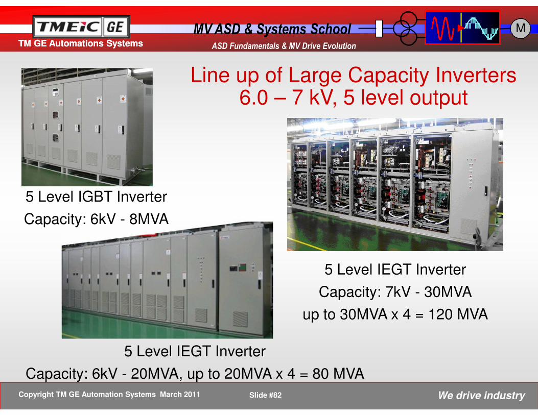
Line up of Large Capacity Inverters6.0 – 7 kV, 5 level output
5 Level IEGT Inverter
Capacity: 6kV - 20MVA, up to 20MVA x 4 = 80 MVA
5 Level IEGT Inverter
Capacity: 7kV - 30MVA
up to 30MVA x 4 = 120 MVA
5 Level IGBT Inverter
Capacity: 6kV - 8MVA

VFD Theory: 83
VFD Custom Assembly Shop

VFD Theory: 84
VFD Repair Area

VFD Theory: 85
VFD Inventory

www.emcsolutions.com
Specializing in Motors, Drives, Generators, and Electrical Asset Management
Thank You!Questions?


