Embed Size (px)
Citation preview
VICTRONIC TECHNOLOGY CORP.
Report No. 0611036001 Page 1 of 35 Issued: January 8, 2007
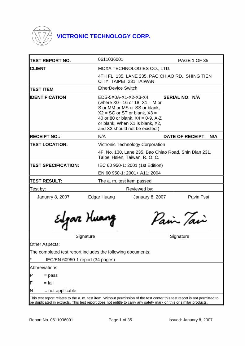
TEST REPORT NO. 0611036001 PAGE 1 OF 35
CLIENT MOXA TECHNOLOGIES CO., LTD.
4TH FL, 135, LANE 235, PAO CHIAO RD., SHING TIEN CITY, TAIPEI, 231 TAIWAN
TEST ITEM EtherDevice Switch
IDENTIFICATION EDS-5X0A-X1-X2-X3-X4 (where X0= 16 or 18, X1 = M or S or MM or MS or SS or blank, X2 = SC or ST or blank, X3 = 40 or 80 or blank, X4 = 0-9, A-Z or blank, When X1 is blank, X2, and X3 should not be existed.)
SERIAL NO: N/A
RECEIPT NO.: N/A DATE OF RECEIPT: N/A
TEST LOCATION: Victronic Technology Corporation
4F, No. 130, Lane 235, Bao Chiao Road, Shin Dian 231, Taipei Hsien, Taiwan, R. O. C.
TEST SPECIFICATION: IEC 60 950-1: 2001 (1st Edition)
EN 60 950-1: 2001+ A11: 2004
TEST RESULT: The a. m. test item passed
Test by: Reviewed by:
January 8, 2007 Edgar Huang January 8, 2007 Pavin Tsai
Signature Signature
Other Aspects:
The completed test report includes the following documents:
* IEC/EN 60950-1 report (34 pages)
Abbreviations:
P = pass
F = fail
N = not applicable This test report relates to the a. m. test item. Without permission of the test center this test report is not permitted to be duplicated in extracts. This test report does not entitle to carry any safety mark on this or similar products.
VICTRONIC TECHNOLOGY CORP.
Report No. 0611036001 Page 2 of 35 Issued: January 8, 2007
TEST REPORT
IEC/EN 60950-1
SAFETY OF INFORMATION TECHNOLOGY EQUIPMENT
Report reference……...…….: 0611036001
Complied by (+signature)….: See cover sheet
Approved by (+signature)…: See cover sheet
Date of issue………………...: See cover sheet
Test laboratory…………..….: Victronic Technology Corporation
Address…………………..….: 4F, No. 130, Lane 235, Bao Chiao Road, Shin Dian 231, Taipei Hsien, Taiwan, R. O. C.
Testing location…………..…: Victronic Technology Corporation
Address…………………..….: 4F, No. 130, Lane 235, Bao Chiao Road, Shin Dian 231, Taipei Hsien, Taiwan, R. O. C.
Standard……………..……...: IEC 60 950-1: 2001 (1st Edition)
EN 60 950-1: 2001+ A11: 2004
Test procedure ……………..: Service of CE Marking in LVD
Procedure deviation……..…: N/A
Non-standard test method..: N/A
Type of test object …..……..: EtherDevice Switch
Trademark……………..……: MOXA or Moxa Technologies Co., Ltd.
Model/type reference……….: EDS-5X0A-X1-X2-X3-X4 (where X0= 16 or 18, X1 = M or S or MM or MS or SS or blank, X2 = SC or ST or blank, X3 = 40 or 80 or blank, X4 = 0-9, A-Z or blank, When X1 is blank, X2, and X3 should not be existed.)
Manufacturer…………..……: MOXA TECHNOLOGIES CO., LTD.
4TH FL, 135, LANE 235, PAO CHIAO RD., SHING TIEN CITY, TAIPEI, 231 TAIWAN
Rating ……………..………..: I/P: 12-45Vdc, 1.59A (optional)
VICTRONIC TECHNOLOGY CORP.
Report No. 0611036001 Page 3 of 35 Issued: January 8, 2007
Test item particulars:
Equipment mobility……………………………………: Portable
Operation condition………………………….……..…: Continuous
Test for IT power system …………………..…….….: No
IT testing, phase-phase voltage (V) ………………...: N. A.
Class of equipment ……….…………………………..: Class III
Mass of equipment (kg)………….……………..…….: Approx. 1.63 Kg
Protection against ingress of water …………………: IP X0
Possible test case verdicts:
- test case does not apply to the test object …….…: N (Not applicable)
- test object does meet the requirement ……….…..: P (Pass)
- test object does not meet the requirement ……....: F (Fail)
"(see remark #)" refers to a remark appended to the report.
"(see appended table)" refers to a table appended to the report.
Throughout this report a comma is used as the decimal separator.
The test results presented in this report relate only to the object tested.
This report shall not be reproduced except in full without the written approval of the testing laboratory.
Comments:
- The equipment model EDS-5X0A-X1-X2-X3-X4 (where X0= 16 or 18, X1 = M or S or MM or MS or SS or blank, X2 = SC or ST or blank, X3 = 40 or 80 or blank, X4 = 0-9, A-Z or blank, When X1 is blank, X2, and X3 should not be existed.) is EtherDevice Switch which is information technology equipment.
- The equipment was submitted and tested for use in a maximum manufacturer’s recommended ambient (Tma) of 55 °C.
- All models are similar to each other except fiber module and model designation.
- "Maximum normal load" was defined connected to computer via cable and operated continuously.
Factory Location:
MOXA TECHNOLOGIES CO., LTD.
8TH FL, 128, LANE 235, PAO CHIAO RD., SHING TIEN, TAIPEI HSIEN, 23145 TAIWAN
VICTRONIC TECHNOLOGY CORP.
Report No. 0611036001 Page 4 of 35 Issued: January 8, 2007
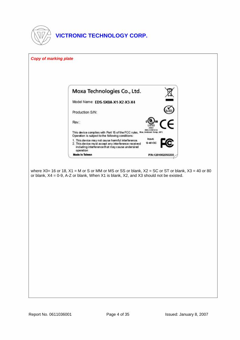
Copy of marking plate
where X0= 16 or 18, X1 = M or S or MM or MS or SS or blank, X2 = SC or ST or blank, X3 = 40 or 80 or blank, X4 = 0-9, A-Z or blank, When X1 is blank, X2, and X3 should not be existed.
VICTRONIC TECHNOLOGY CORP.
IEC/EN 60950-1
Clause Requirement + Test Result - Remark Verdict
Report No. 0611036001 Page 5 of 35 Issued: January 8, 2007
1 GENERAL P
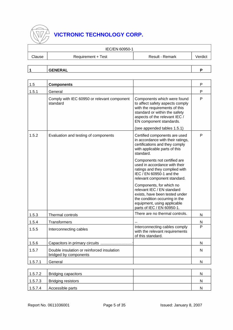
1.5 Components P
1.5.1 General P
Comply with IEC 60950 or relevant component standard
Components which were found to affect safety aspects comply with the requirements of this standard or within the safety aspects of the relevant IEC / EN component standards.
(see appended tables 1.5.1)
P
1.5.2 Evaluation and testing of components Certified components are used in accordance with their ratings, certifications and they comply with applicable parts of this standard.
Components not certified are used in accordance with their ratings and they complied with IEC / EN 60950-1 and the relevant component standard.
Components, for which no relevant IEC / EN standard exists, have been tested under the condition occurring in the equipment, using applicable parts of IEC / EN 60950-1.
P
1.5.3 Thermal controls There are no thermal controls. N
1.5.4 Transformers -- N
1.5.5 Interconnecting cables Interconnecting cables comply with the relevant requirements of this standard.
P
1.5.6 Capacitors in primary circuits .............................: N
1.5.7 Double insulation or reinforced insulation bridged by components
N
1.5.7.1 General N
1.5.7.2 Bridging capacitors N
1.5.7.3 Bridging resistors N
1.5.7.4 Accessible parts N
VICTRONIC TECHNOLOGY CORP.
IEC/EN 60950-1
Clause Requirement + Test Result - Remark Verdict
Report No. 0611036001 Page 6 of 35 Issued: January 8, 2007
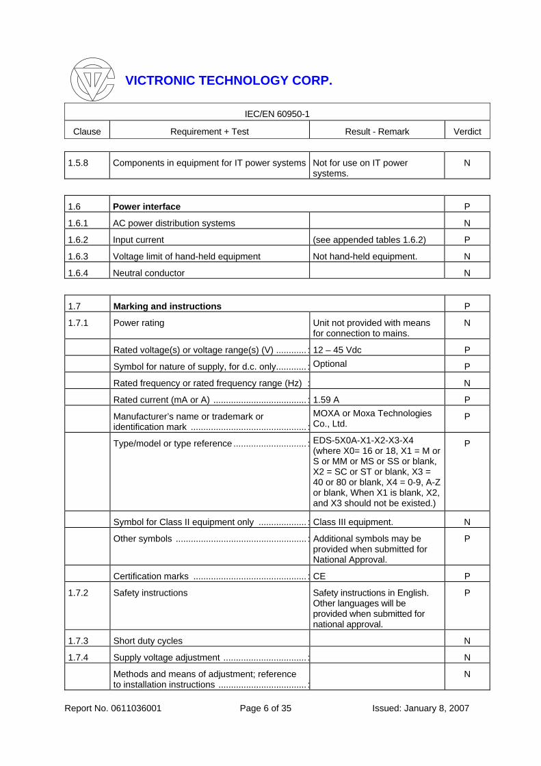
1.5.8 Components in equipment for IT power systems Not for use on IT power systems.
N
1.6 Power interface P
1.6.1 AC power distribution systems N
1.6.2 Input current (see appended tables 1.6.2) P
1.6.3 Voltage limit of hand-held equipment Not hand-held equipment. N
1.6.4 Neutral conductor N
1.7 Marking and instructions P
1.7.1 Power rating Unit not provided with means for connection to mains.
N
Rated voltage(s) or voltage range(s) (V) ............ : 12 – 45 Vdc P
Symbol for nature of supply, for d.c. only............ : Optional P
Rated frequency or rated frequency range (Hz) : N
Rated current (mA or A) ..................................... : 1.59 A P
Manufacturer’s name or trademark or identification mark .............................................. :
MOXA or Moxa Technologies Co., Ltd.
P
Type/model or type reference ............................. : EDS-5X0A-X1-X2-X3-X4 (where X0= 16 or 18, X1 = M or S or MM or MS or SS or blank, X2 = SC or ST or blank, X3 = 40 or 80 or blank, X4 = 0-9, A-Z or blank, When X1 is blank, X2, and X3 should not be existed.)
P
Symbol for Class II equipment only ................... : Class III equipment. N
Other symbols .................................................... : Additional symbols may be provided when submitted for National Approval.
P
Certification marks ............................................. : CE P
1.7.2 Safety instructions Safety instructions in English. Other languages will be provided when submitted for national approval.
P
1.7.3 Short duty cycles N
1.7.4 Supply voltage adjustment ................................. : N
Methods and means of adjustment; reference to installation instructions ................................... :
N
VICTRONIC TECHNOLOGY CORP.
IEC/EN 60950-1
Clause Requirement + Test Result - Remark Verdict
Report No. 0611036001 Page 7 of 35 Issued: January 8, 2007
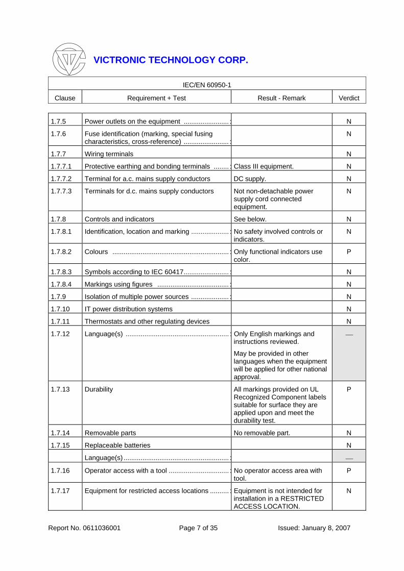
1.7.5 Power outlets on the equipment ........................ : N
1.7.6 Fuse identification (marking, special fusing characteristics, cross-reference) ........................ :
N
1.7.7 Wiring terminals N
1.7.7.1 Protective earthing and bonding terminals ........ : Class III equipment. N
1.7.7.2 Terminal for a.c. mains supply conductors DC supply. N
1.7.7.3 Terminals for d.c. mains supply conductors Not non-detachable power supply cord connected equipment.
N
1.7.8 Controls and indicators See below. N
1.7.8.1 Identification, location and marking .................... : No safety involved controls or indicators.
N
1.7.8.2 Colours .............................................................. : Only functional indicators use color.
P
1.7.8.3 Symbols according to IEC 60417........................ : N
1.7.8.4 Markings using figures ...................................... : N
1.7.9 Isolation of multiple power sources .................... : N
1.7.10 IT power distribution systems N
1.7.11 Thermostats and other regulating devices N
1.7.12 Language(s) ....................................................... : Only English markings and instructions reviewed.
May be provided in other languages when the equipment will be applied for other national approval.
1.7.13 Durability All markings provided on UL Recognized Component labels suitable for surface they are applied upon and meet the durability test.
P
1.7.14 Removable parts No removable part. N
1.7.15 Replaceable batteries N
Language(s) ........................................................ :
1.7.16 Operator access with a tool ................................ : No operator access area with tool.
P
1.7.17 Equipment for restricted access locations .......... : Equipment is not intended for installation in a RESTRICTED ACCESS LOCATION.
N
VICTRONIC TECHNOLOGY CORP.
IEC/EN 60950-1
Clause Requirement + Test Result - Remark Verdict
Report No. 0611036001 Page 8 of 35 Issued: January 8, 2007
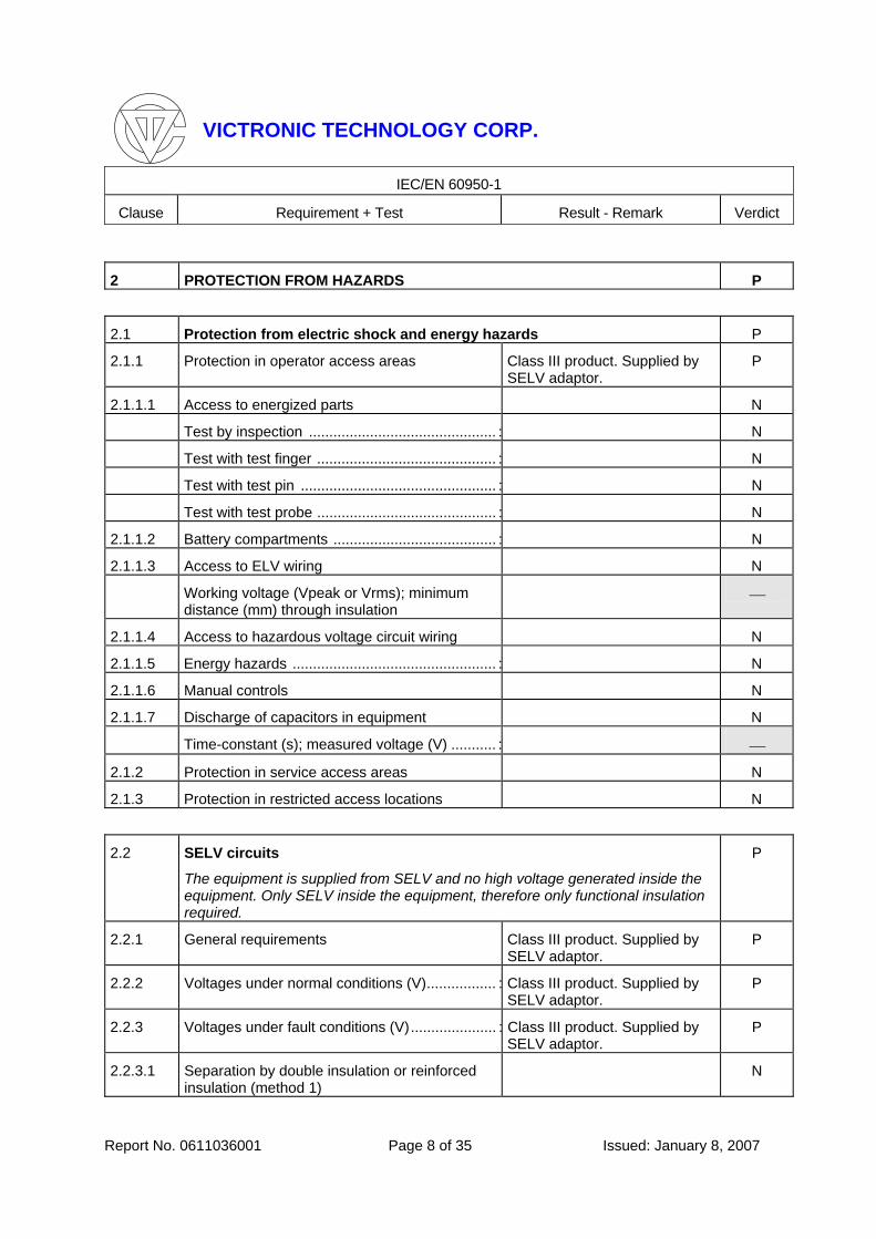
2 PROTECTION FROM HAZARDS P
2.1 Protection from electric shock and energy hazards P
2.1.1 Protection in operator access areas Class III product. Supplied by SELV adaptor.
P
2.1.1.1 Access to energized parts N
Test by inspection .............................................. : N
Test with test finger ............................................ : N
Test with test pin ................................................ : N
Test with test probe ............................................ : N
2.1.1.2 Battery compartments ........................................ : N
2.1.1.3 Access to ELV wiring N
Working voltage (Vpeak or Vrms); minimum distance (mm) through insulation
2.1.1.4 Access to hazardous voltage circuit wiring N
2.1.1.5 Energy hazards .................................................. : N
2.1.1.6 Manual controls N
2.1.1.7 Discharge of capacitors in equipment N
Time-constant (s); measured voltage (V) ........... :
2.1.2 Protection in service access areas N
2.1.3 Protection in restricted access locations N
2.2 SELV circuits
The equipment is supplied from SELV and no high voltage generated inside the equipment. Only SELV inside the equipment, therefore only functional insulation required.
P
2.2.1 General requirements Class III product. Supplied by SELV adaptor.
P
2.2.2 Voltages under normal conditions (V)................. : Class III product. Supplied by SELV adaptor.
P
2.2.3 Voltages under fault conditions (V)..................... : Class III product. Supplied by SELV adaptor.
P
2.2.3.1 Separation by double insulation or reinforced insulation (method 1)
N
VICTRONIC TECHNOLOGY CORP.
IEC/EN 60950-1
Clause Requirement + Test Result - Remark Verdict
Report No. 0611036001 Page 9 of 35 Issued: January 8, 2007
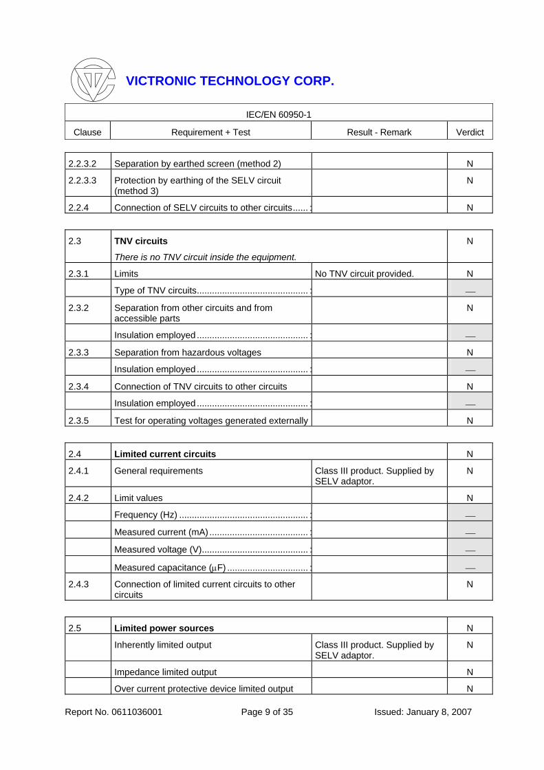
2.2.3.2 Separation by earthed screen (method 2) N
2.2.3.3 Protection by earthing of the SELV circuit (method 3)
N
2.2.4 Connection of SELV circuits to other circuits...... : N
2.3 TNV circuits
There is no TNV circuit inside the equipment.
N
2.3.1 Limits No TNV circuit provided. N
Type of TNV circuits............................................ :
2.3.2 Separation from other circuits and from accessible parts
N
Insulation employed ............................................ :
2.3.3 Separation from hazardous voltages N
Insulation employed ............................................ :
2.3.4 Connection of TNV circuits to other circuits N
Insulation employed ............................................ :
2.3.5 Test for operating voltages generated externally N
2.4 Limited current circuits N
2.4.1 General requirements Class III product. Supplied by SELV adaptor.
N
2.4.2 Limit values N
Frequency (Hz) ................................................... :
Measured current (mA) ....................................... :
Measured voltage (V).......................................... :
Measured capacitance (µF) ................................ :
2.4.3 Connection of limited current circuits to other circuits
N
2.5 Limited power sources N
Inherently limited output Class III product. Supplied by SELV adaptor.
N
Impedance limited output N
Over current protective device limited output N
VICTRONIC TECHNOLOGY CORP.
IEC/EN 60950-1
Clause Requirement + Test Result - Remark Verdict
Report No. 0611036001 Page 10 of 35 Issued: January 8, 2007
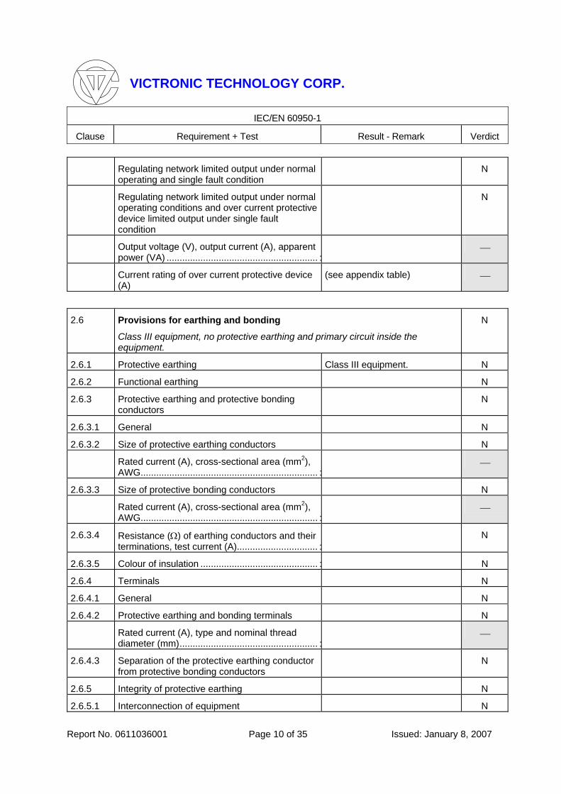
Regulating network limited output under normal operating and single fault condition
N
Regulating network limited output under normal operating conditions and over current protective device limited output under single fault condition
N
Output voltage (V), output current (A), apparent power (VA) .......................................................... :
Current rating of over current protective device (A)
(see appendix table)
2.6 Provisions for earthing and bonding
Class III equipment, no protective earthing and primary circuit inside the equipment.
N
2.6.1 Protective earthing Class III equipment. N
2.6.2 Functional earthing N
2.6.3 Protective earthing and protective bonding conductors
N
2.6.3.1 General N
2.6.3.2 Size of protective earthing conductors N
Rated current (A), cross-sectional area (mm2), AWG.................................................................... :
2.6.3.3 Size of protective bonding conductors N
Rated current (A), cross-sectional area (mm2), AWG.................................................................... :
2.6.3.4 Resistance (Ω) of earthing conductors and their terminations, test current (A)............................... :
N
2.6.3.5 Colour of insulation ............................................. : N
2.6.4 Terminals N
2.6.4.1 General N
2.6.4.2 Protective earthing and bonding terminals N
Rated current (A), type and nominal thread diameter (mm)..................................................... :
2.6.4.3 Separation of the protective earthing conductor from protective bonding conductors
N
2.6.5 Integrity of protective earthing N
2.6.5.1 Interconnection of equipment N
VICTRONIC TECHNOLOGY CORP.
IEC/EN 60950-1
Clause Requirement + Test Result - Remark Verdict
Report No. 0611036001 Page 11 of 35 Issued: January 8, 2007
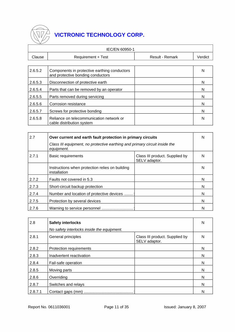
2.6.5.2 Components in protective earthing conductors and protective bonding conductors
N
2.6.5.3 Disconnection of protective earth N
2.6.5.4 Parts that can be removed by an operator N
2.6.5.5 Parts removed during servicing N
2.6.5.6 Corrosion resistance N
2.6.5.7 Screws for protective bonding N
2.6.5.8 Reliance on telecommunication network or cable distribution system
N
2.7 Over current and earth fault protection in primary circuits
Class III equipment, no protective earthing and primary circuit inside the equipment.
N
2.7.1 Basic requirements Class III product. Supplied by SELV adaptor.
N
Instructions when protection relies on building installation
N
2.7.2 Faults not covered in 5.3 N
2.7.3 Short-circuit backup protection N
2.7.4 Number and location of protective devices ........ : N
2.7.5 Protection by several devices N
2.7.6 Warning to service personnel ............................. : N
2.8 Safety interlocks
No safety interlocks inside the equipment.
N
2.8.1 General principles Class III product. Supplied by SELV adaptor.
N
2.8.2 Protection requirements N
2.8.3 Inadvertent reactivation N
2.8.4 Fail-safe operation N
2.8.5 Moving parts N
2.8.6 Overriding N
2.8.7 Switches and relays N
2.8.7.1 Contact gaps (mm) ............................................. : N
VICTRONIC TECHNOLOGY CORP.
IEC/EN 60950-1
Clause Requirement + Test Result - Remark Verdict
Report No. 0611036001 Page 12 of 35 Issued: January 8, 2007
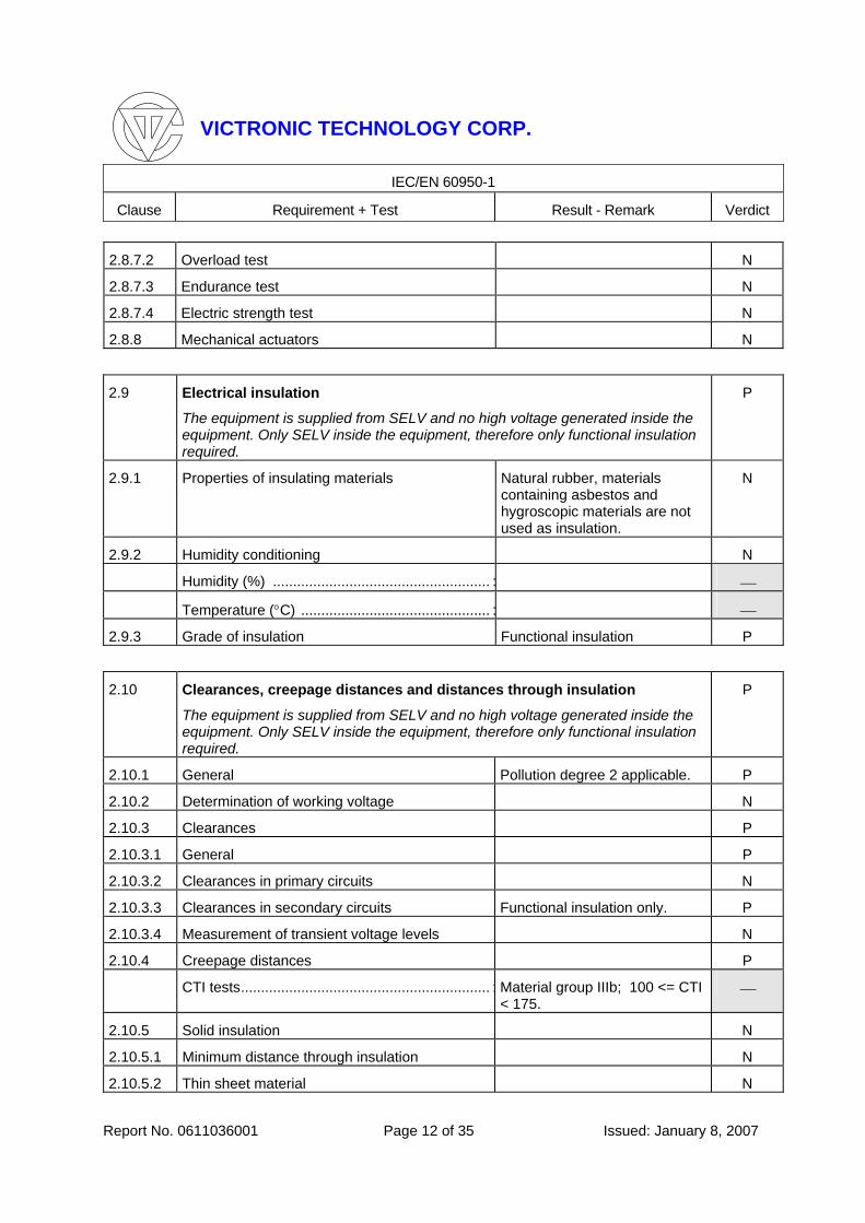
2.8.7.2 Overload test N
2.8.7.3 Endurance test N
2.8.7.4 Electric strength test N
2.8.8 Mechanical actuators N
2.9 Electrical insulation
The equipment is supplied from SELV and no high voltage generated inside the equipment. Only SELV inside the equipment, therefore only functional insulation required.
P
2.9.1 Properties of insulating materials Natural rubber, materials containing asbestos and hygroscopic materials are not used as insulation.
N
2.9.2 Humidity conditioning N
Humidity (%) ...................................................... :
Temperature (°C) ............................................... :
2.9.3 Grade of insulation Functional insulation P
2.10 Clearances, creepage distances and distances through insulation
The equipment is supplied from SELV and no high voltage generated inside the equipment. Only SELV inside the equipment, therefore only functional insulation required.
P
2.10.1 General Pollution degree 2 applicable. P
2.10.2 Determination of working voltage N
2.10.3 Clearances P
2.10.3.1 General P
2.10.3.2 Clearances in primary circuits N
2.10.3.3 Clearances in secondary circuits Functional insulation only. P
2.10.3.4 Measurement of transient voltage levels N
2.10.4 Creepage distances P
CTI tests.............................................................. : Material group IIIb; 100 <= CTI < 175.
2.10.5 Solid insulation N
2.10.5.1 Minimum distance through insulation N
2.10.5.2 Thin sheet material N
VICTRONIC TECHNOLOGY CORP.
IEC/EN 60950-1
Clause Requirement + Test Result - Remark Verdict
Report No. 0611036001 Page 13 of 35 Issued: January 8, 2007
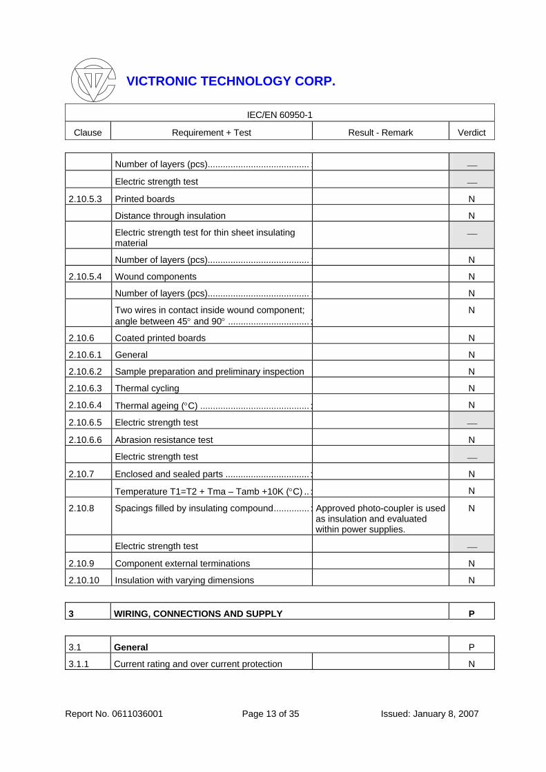
Number of layers (pcs)........................................ :
Electric strength test
2.10.5.3 Printed boards N
Distance through insulation N
Electric strength test for thin sheet insulating material
Number of layers (pcs)........................................ : N
2.10.5.4 Wound components N
Number of layers (pcs)........................................ : N
Two wires in contact inside wound component; angle between 45° and 90° ................................ :
N
2.10.6 Coated printed boards N
2.10.6.1 General N
2.10.6.2 Sample preparation and preliminary inspection N
2.10.6.3 Thermal cycling N
2.10.6.4 Thermal ageing (°C) ........................................... : N
2.10.6.5 Electric strength test
2.10.6.6 Abrasion resistance test N
Electric strength test
2.10.7 Enclosed and sealed parts ................................. : N
Temperature T1=T2 + Tma – Tamb +10K (°C) .. : N
2.10.8 Spacings filled by insulating compound.............. : Approved photo-coupler is used as insulation and evaluated within power supplies.
N
Electric strength test
2.10.9 Component external terminations N
2.10.10 Insulation with varying dimensions N
3 WIRING, CONNECTIONS AND SUPPLY P
3.1 General P
3.1.1 Current rating and over current protection N
VICTRONIC TECHNOLOGY CORP.
IEC/EN 60950-1
Clause Requirement + Test Result - Remark Verdict
Report No. 0611036001 Page 14 of 35 Issued: January 8, 2007
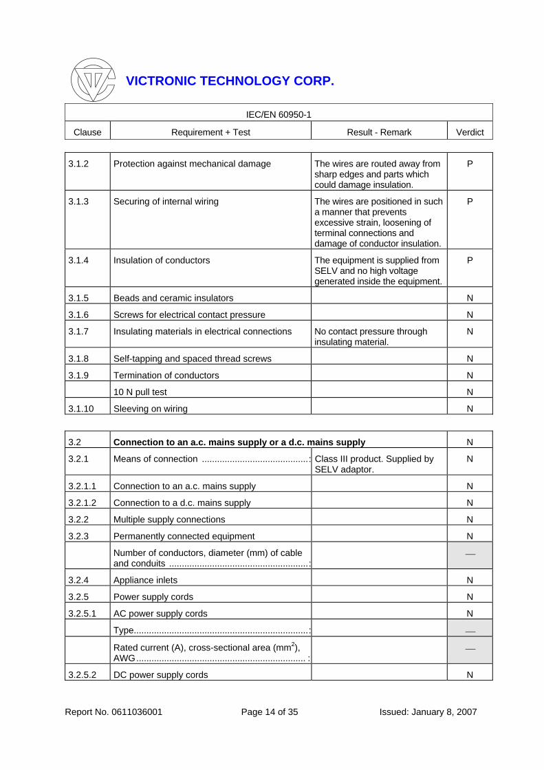
3.1.2 Protection against mechanical damage The wires are routed away from sharp edges and parts which could damage insulation.
P
3.1.3 Securing of internal wiring The wires are positioned in such a manner that prevents excessive strain, loosening of terminal connections and damage of conductor insulation.
P
3.1.4 Insulation of conductors The equipment is supplied from SELV and no high voltage generated inside the equipment.
P
3.1.5 Beads and ceramic insulators N
3.1.6 Screws for electrical contact pressure N
3.1.7 Insulating materials in electrical connections No contact pressure through insulating material.
N
3.1.8 Self-tapping and spaced thread screws N
3.1.9 Termination of conductors N
10 N pull test N
3.1.10 Sleeving on wiring N
3.2 Connection to an a.c. mains supply or a d.c. mains supply N
3.2.1 Means of connection ..........................................: Class III product. Supplied by SELV adaptor.
N
3.2.1.1 Connection to an a.c. mains supply N
3.2.1.2 Connection to a d.c. mains supply N
3.2.2 Multiple supply connections N
3.2.3 Permanently connected equipment N
Number of conductors, diameter (mm) of cable and conduits .......................................................:
3.2.4 Appliance inlets N
3.2.5 Power supply cords N
3.2.5.1 AC power supply cords N
Type.....................................................................:
Rated current (A), cross-sectional area (mm2), AWG................................................................... :
3.2.5.2 DC power supply cords N
VICTRONIC TECHNOLOGY CORP.
IEC/EN 60950-1
Clause Requirement + Test Result - Remark Verdict
Report No. 0611036001 Page 15 of 35 Issued: January 8, 2007
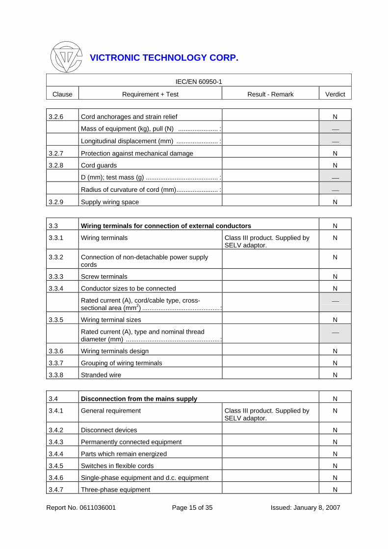
3.2.6 Cord anchorages and strain relief N
Mass of equipment (kg), pull (N) ...................... :
Longitudinal displacement (mm) ....................... :
3.2.7 Protection against mechanical damage N
3.2.8 Cord guards N
D (mm); test mass (g) ........................................ :
Radius of curvature of cord (mm)....................... :
3.2.9 Supply wiring space N
3.3 Wiring terminals for connection of external conductors N
3.3.1 Wiring terminals Class III product. Supplied by SELV adaptor.
N
3.3.2 Connection of non-detachable power supply cords
N
3.3.3 Screw terminals N
3.3.4 Conductor sizes to be connected N
Rated current (A), cord/cable type, cross-sectional area (mm2) ...........................................:
3.3.5 Wiring terminal sizes N
Rated current (A), type and nominal thread diameter (mm) ....................................................:
3.3.6 Wiring terminals design N
3.3.7 Grouping of wiring terminals N
3.3.8 Stranded wire N
3.4 Disconnection from the mains supply N
3.4.1 General requirement Class III product. Supplied by SELV adaptor.
N
3.4.2 Disconnect devices N
3.4.3 Permanently connected equipment N
3.4.4 Parts which remain energized N
3.4.5 Switches in flexible cords N
3.4.6 Single-phase equipment and d.c. equipment N
3.4.7 Three-phase equipment N
VICTRONIC TECHNOLOGY CORP.
IEC/EN 60950-1
Clause Requirement + Test Result - Remark Verdict
Report No. 0611036001 Page 16 of 35 Issued: January 8, 2007
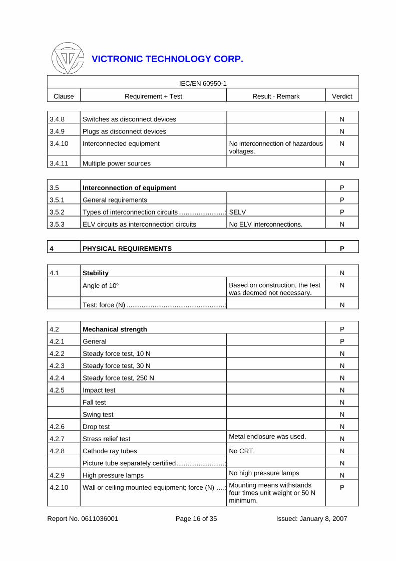
3.4.8 Switches as disconnect devices N
3.4.9 Plugs as disconnect devices N
3.4.10 Interconnected equipment No interconnection of hazardous voltages.
N
3.4.11 Multiple power sources N
3.5 Interconnection of equipment P
3.5.1 General requirements P
3.5.2 Types of interconnection circuits.........................: SELV P
3.5.3 ELV circuits as interconnection circuits No ELV interconnections. N
4 PHYSICAL REQUIREMENTS P
4.1 Stability N
Angle of 10° Based on construction, the test was deemed not necessary.
N
Test: force (N) .....................................................: N
4.2 Mechanical strength P
4.2.1 General P
4.2.2 Steady force test, 10 N N
4.2.3 Steady force test, 30 N N
4.2.4 Steady force test, 250 N N
4.2.5 Impact test N
Fall test N
Swing test N
4.2.6 Drop test N
4.2.7 Stress relief test Metal enclosure was used. N
4.2.8 Cathode ray tubes No CRT. N
Picture tube separately certified..........................: N
4.2.9 High pressure lamps No high pressure lamps N
4.2.10 Wall or ceiling mounted equipment; force (N) ....: Mounting means withstands four times unit weight or 50 N minimum.
P
VICTRONIC TECHNOLOGY CORP.
IEC/EN 60950-1
Clause Requirement + Test Result - Remark Verdict
Report No. 0611036001 Page 17 of 35 Issued: January 8, 2007
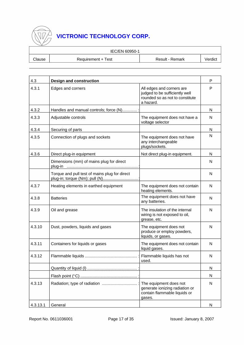
4.3 Design and construction P
4.3.1 Edges and corners All edges and corners are judged to be sufficiently well rounded so as not to constitute a hazard.
P
4.3.2 Handles and manual controls; force (N)............. : N
4.3.3 Adjustable controls The equipment does not have a voltage selector
N
4.3.4 Securing of parts N
4.3.5 Connection of plugs and sockets The equipment does not have any interchangeable plugs/sockets.
N
4.3.6 Direct plug-in equipment Not direct plug-in equipment. N
Dimensions (mm) of mains plug for direct plug-in ...............................................................:
N
Torque and pull test of mains plug for direct plug-in; torque (Nm); pull (N)...............................:
N
4.3.7 Heating elements in earthed equipment The equipment does not contain heating elements.
N
4.3.8 Batteries The equipment does not have any batteries.
N
4.3.9 Oil and grease The insulation of the internal wiring is not exposed to oil, grease, etc.
N
4.3.10 Dust, powders, liquids and gases The equipment does not produce or employ powders, liquids, or gases.
N
4.3.11 Containers for liquids or gases The equipment does not contain liquid gases.
N
4.3.12 Flammable liquids .............................................. : Flammable liquids has not used.
N
Quantity of liquid (l) ............................................ : N
Flash point (°C) .................................................. : N
4.3.13 Radiation; type of radiation ............................... : The equipment does not generate ionizing radiation or contain flammable liquids or gases.
N
4.3.13.1 General N
VICTRONIC TECHNOLOGY CORP.
IEC/EN 60950-1
Clause Requirement + Test Result - Remark Verdict
Report No. 0611036001 Page 18 of 35 Issued: January 8, 2007
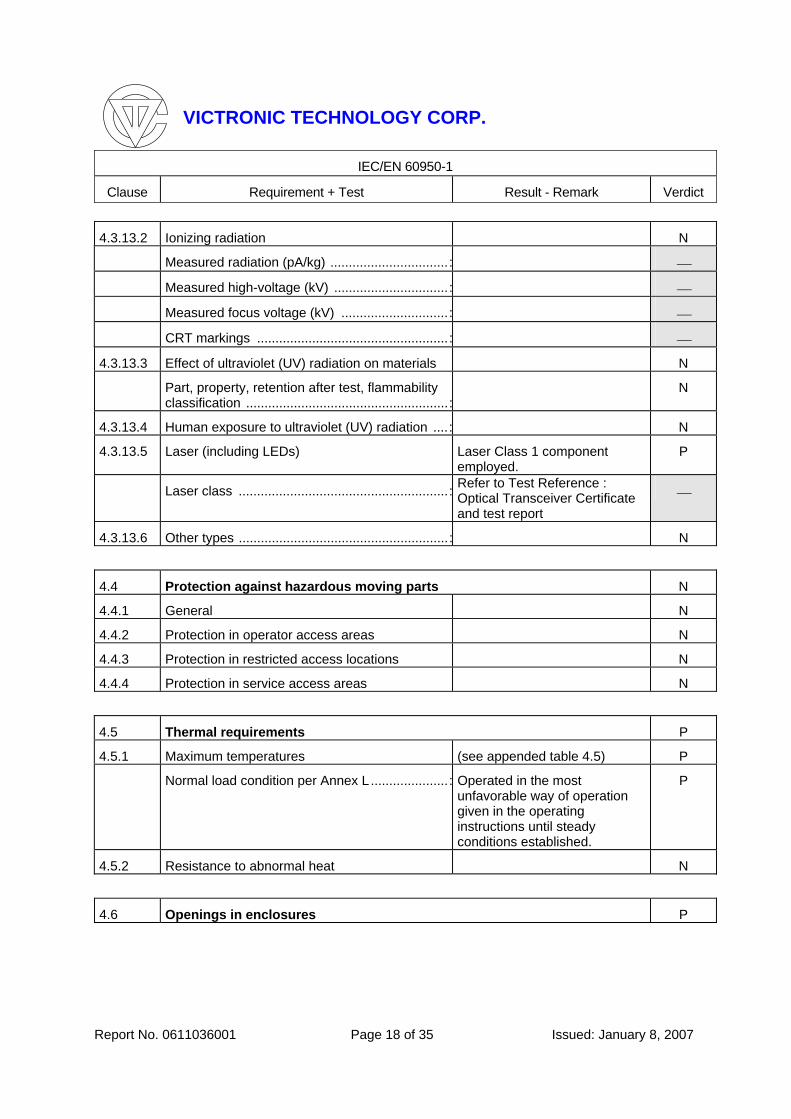
4.3.13.2 Ionizing radiation N
Measured radiation (pA/kg) ................................:
Measured high-voltage (kV) ...............................:
Measured focus voltage (kV) .............................:
CRT markings ....................................................:
4.3.13.3 Effect of ultraviolet (UV) radiation on materials N
Part, property, retention after test, flammability classification .......................................................:
N
4.3.13.4 Human exposure to ultraviolet (UV) radiation ....: N
4.3.13.5 Laser (including LEDs) Laser Class 1 component employed.
P
Laser class .........................................................: Refer to Test Reference : Optical Transceiver Certificate and test report
4.3.13.6 Other types .........................................................: N
4.4 Protection against hazardous moving parts N
4.4.1 General N
4.4.2 Protection in operator access areas N
4.4.3 Protection in restricted access locations N
4.4.4 Protection in service access areas N
4.5 Thermal requirements P
4.5.1 Maximum temperatures (see appended table 4.5) P
Normal load condition per Annex L .....................: Operated in the most unfavorable way of operation given in the operating instructions until steady conditions established.
P
4.5.2 Resistance to abnormal heat N
4.6 Openings in enclosures P
VICTRONIC TECHNOLOGY CORP.
IEC/EN 60950-1
Clause Requirement + Test Result - Remark Verdict
Report No. 0611036001 Page 19 of 35 Issued: January 8, 2007
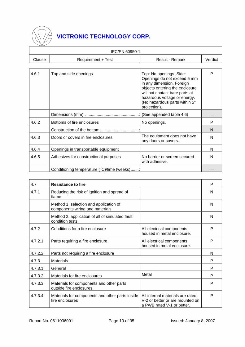
4.6.1 Top and side openings Top: No openings. Side: Openings do not exceed 5 mm in any dimension. Foreign objects entering the enclosure will not contact bare parts at hazardous voltage or energy. (No hazardous parts within 5° projection).
P
Dimensions (mm) ...............................................: (See appended table 4.6)
4.6.2 Bottoms of fire enclosures No openings. P
Construction of the bottom ..................................: N
4.6.3 Doors or covers in fire enclosures The equipment does not have any doors or covers.
N
4.6.4 Openings in transportable equipment N
4.6.5 Adhesives for constructional purposes No barrier or screen secured with adhesive.
N
Conditioning temperature (°C)/time (weeks).......:
4.7 Resistance to fire P
4.7.1 Reducing the risk of ignition and spread of flame
N
Method 1, selection and application of components wiring and materials
N
Method 2, application of all of simulated fault condition tests
N
4.7.2 Conditions for a fire enclosure All electrical components housed in metal enclosure.
P
4.7.2.1 Parts requiring a fire enclosure All electrical components housed in metal enclosure.
P
4.7.2.2 Parts not requiring a fire enclosure N
4.7.3 Materials P
4.7.3.1 General P
4.7.3.2 Materials for fire enclosures Metal P
4.7.3.3 Materials for components and other parts outside fire enclosures
P
4.7.3.4 Materials for components and other parts inside fire enclosures
All internal materials are rated V-2 or better or are mounted on a PWB rated V-1 or better.
P
VICTRONIC TECHNOLOGY CORP.
IEC/EN 60950-1
Clause Requirement + Test Result - Remark Verdict
Report No. 0611036001 Page 20 of 35 Issued: January 8, 2007
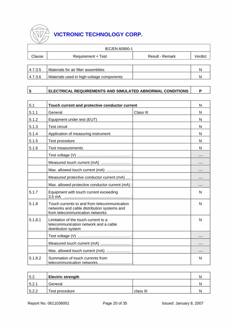
4.7.3.5 Materials for air filter assemblies N
4.7.3.6 Materials used in high-voltage components N
5 ELECTRICAL REQUIREMENTS AND SIMULATED ABNORMAL CONDITIONS P
5.1 Touch current and protective conductor current N
5.1.1 General Class III N
5.1.2 Equipment under test (EUT) N
5.1.3 Test circuit N
5.1.4 Application of measuring instrument N
5.1.5 Test procedure N
5.1.6 Test measurements N
Test voltage (V) ................................................. :
Measured touch current (mA) ........................... :
Max. allowed touch current (mA) ...................... :
Measured protective conductor current (mA) .... :
Max. allowed protective conductor current (mA) :
5.1.7 Equipment with touch current exceeding 3.5 mA ............................................................. :
N
5.1.8 Touch currents to and from telecommunication networks and cable distribution systems and from telecommunication networks
N
5.1.8.1 Limitation of the touch current to a telecommunication network and a cable distribution system
N
Test voltage (V) ................................................. :
Measured touch current (mA) ........................... :
Max. allowed touch current (mA) ...................... :
5.1.8.2 Summation of touch currents from telecommunication networks...............................:
N
5.2 Electric strength N
5.2.1 General N
5.2.2 Test procedure class III N
VICTRONIC TECHNOLOGY CORP.
IEC/EN 60950-1
Clause Requirement + Test Result - Remark Verdict
Report No. 0611036001 Page 21 of 35 Issued: January 8, 2007
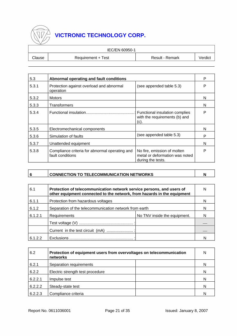
5.3 Abnormal operating and fault conditions P
5.3.1 Protection against overload and abnormal operation
(see appended table 5.3) P
5.3.2 Motors N
5.3.3 Transformers N
5.3.4 Functional insulation............................................: Functional insulation complies with the requirements (b) and (c).
P
5.3.5 Electromechanical components N
5.3.6 Simulation of faults (see appended table 5.3) P
5.3.7 Unattended equipment N
5.3.8 Compliance criteria for abnormal operating and fault conditions
No fire, emission of molten metal or deformation was noted during the tests.
P
6 CONNECTION TO TELECOMMUNICATION NETWORKS N
6.1 Protection of telecommunication network service persons, and users of other equipment connected to the network, from hazards in the equipment
N
6.1.1 Protection from hazardous voltages N
6.1.2 Separation of the telecommunication network from earth N
6.1.2.1 Requirements No TNV inside the equipment. N
Test voltage (V) ................................................. :
Current in the test circuit (mA) ........................ :
6.1.2.2 Exclusions .......................................................... : N
6.2 Protection of equipment users from overvoltages on telecommunication networks
N
6.2.1 Separation requirements N
6.2.2 Electric strength test procedure N
6.2.2.1 Impulse test N
6.2.2.2 Steady-state test N
6.2.2.3 Compliance criteria N
VICTRONIC TECHNOLOGY CORP.
IEC/EN 60950-1
Clause Requirement + Test Result - Remark Verdict
Report No. 0611036001 Page 22 of 35 Issued: January 8, 2007
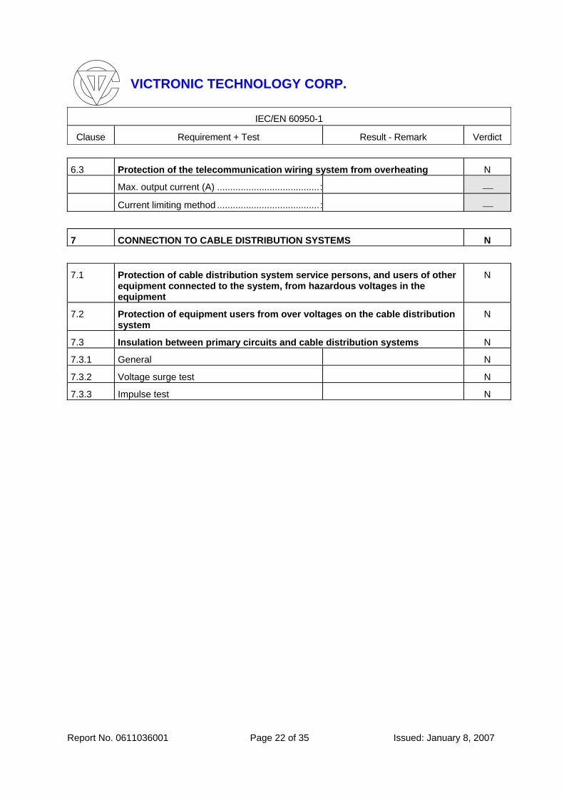
6.3 Protection of the telecommunication wiring system from overheating N
Max. output current (A) .......................................:
Current limiting method .......................................:
7 CONNECTION TO CABLE DISTRIBUTION SYSTEMS N
7.1 Protection of cable distribution system service persons, and users of other equipment connected to the system, from hazardous voltages in the equipment
N
7.2 Protection of equipment users from over voltages on the cable distribution system
N
7.3 Insulation between primary circuits and cable distribution systems N
7.3.1 General N
7.3.2 Voltage surge test N
7.3.3 Impulse test N
VICTRONIC TECHNOLOGY CORP.
IEC/EN 60950-1
Clause Requirement + Test Result - Remark Verdict
Report No. 0611036001 Page 23 of 35 Issued: January 8, 2007
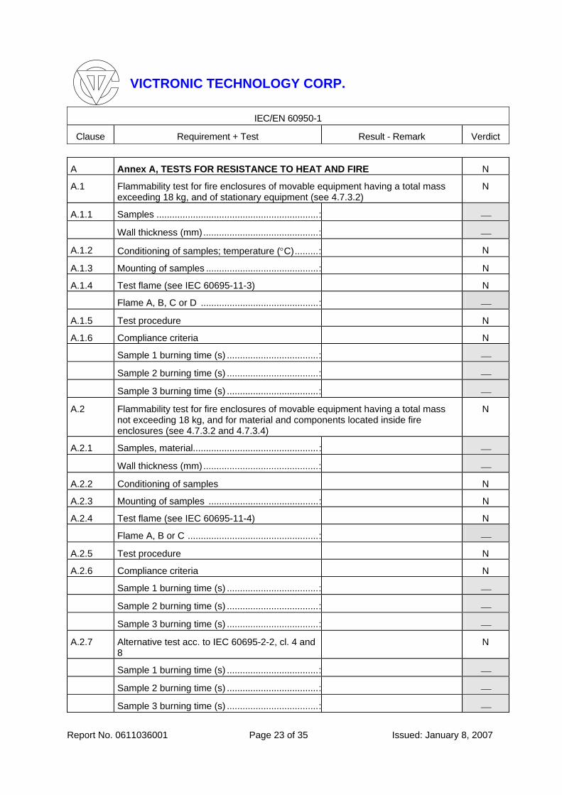
A Annex A, TESTS FOR RESISTANCE TO HEAT AND FIRE N
A.1 Flammability test for fire enclosures of movable equipment having a total mass exceeding 18 kg, and of stationary equipment (see 4.7.3.2)
N
A.1.1 Samples ..............................................................:
Wall thickness (mm)............................................:
A.1.2 Conditioning of samples; temperature (°C).........: N
A.1.3 Mounting of samples ...........................................: N
A.1.4 Test flame (see IEC 60695-11-3) N
Flame A, B, C or D .............................................:
A.1.5 Test procedure N
A.1.6 Compliance criteria N
Sample 1 burning time (s) ...................................:
Sample 2 burning time (s) ...................................:
Sample 3 burning time (s) ...................................:
A.2 Flammability test for fire enclosures of movable equipment having a total mass not exceeding 18 kg, and for material and components located inside fire enclosures (see 4.7.3.2 and 4.7.3.4)
N
A.2.1 Samples, material................................................:
Wall thickness (mm)............................................:
A.2.2 Conditioning of samples N
A.2.3 Mounting of samples ..........................................: N
A.2.4 Test flame (see IEC 60695-11-4) N
Flame A, B or C ..................................................:
A.2.5 Test procedure N
A.2.6 Compliance criteria N
Sample 1 burning time (s) ...................................:
Sample 2 burning time (s) ...................................:
Sample 3 burning time (s) ...................................:
A.2.7 Alternative test acc. to IEC 60695-2-2, cl. 4 and 8
N
Sample 1 burning time (s) ...................................:
Sample 2 burning time (s) ...................................:
Sample 3 burning time (s) ...................................:
VICTRONIC TECHNOLOGY CORP.
IEC/EN 60950-1
Clause Requirement + Test Result - Remark Verdict
Report No. 0611036001 Page 24 of 35 Issued: January 8, 2007
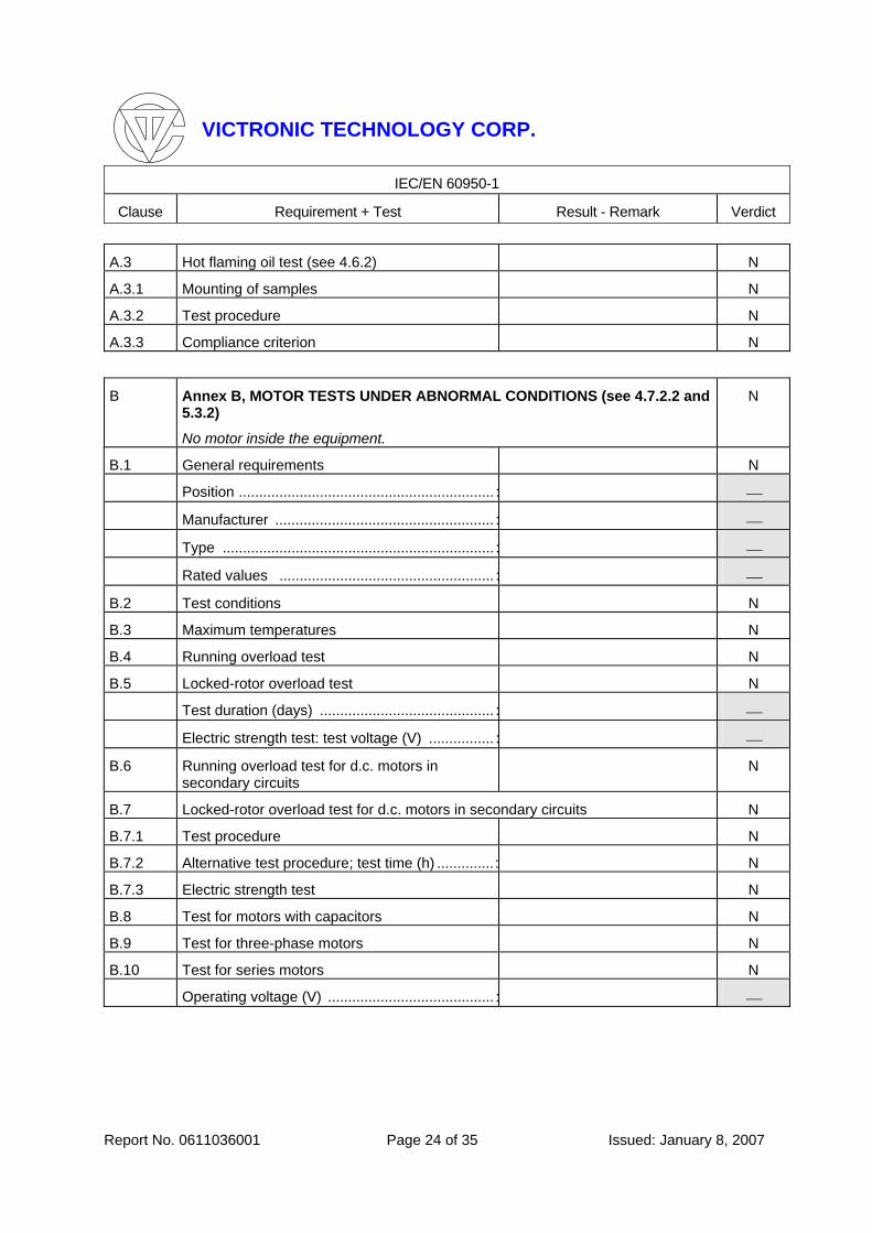
A.3 Hot flaming oil test (see 4.6.2) N
A.3.1 Mounting of samples N
A.3.2 Test procedure N
A.3.3 Compliance criterion N
B Annex B, MOTOR TESTS UNDER ABNORMAL CONDITIONS (see 4.7.2.2 and 5.3.2)
No motor inside the equipment.
N
B.1 General requirements N
Position ............................................................... :
Manufacturer ...................................................... :
Type ................................................................... :
Rated values ..................................................... :
B.2 Test conditions N
B.3 Maximum temperatures N
B.4 Running overload test N
B.5 Locked-rotor overload test N
Test duration (days) ........................................... :
Electric strength test: test voltage (V) ................ :
B.6 Running overload test for d.c. motors in secondary circuits
N
B.7 Locked-rotor overload test for d.c. motors in secondary circuits N
B.7.1 Test procedure N
B.7.2 Alternative test procedure; test time (h) ..............: N
B.7.3 Electric strength test N
B.8 Test for motors with capacitors N
B.9 Test for three-phase motors N
B.10 Test for series motors N
Operating voltage (V) ......................................... :
VICTRONIC TECHNOLOGY CORP.
IEC/EN 60950-1
Clause Requirement + Test Result - Remark Verdict
Report No. 0611036001 Page 25 of 35 Issued: January 8, 2007
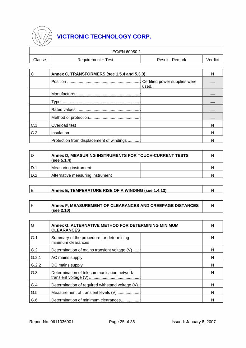
C Annex C, TRANSFORMERS (see 1.5.4 and 5.3.3) N
Position ............................................................... : Certified power supplies were used.
Manufacturer ...................................................... :
Type ................................................................... :
Rated values ..................................................... :
Method of protection............................................:
C.1 Overload test N
C.2 Insulation N
Protection from displacement of windings ..........: N
D Annex D, MEASURING INSTRUMENTS FOR TOUCH-CURRENT TESTS (see 5.1.4)
N
D.1 Measuring instrument N
D.2 Alternative measuring instrument N
E Annex E, TEMPERATURE RISE OF A WINDING (see 1.4.13) N
F Annex F, MEASUREMENT OF CLEARANCES AND CREEPAGE DISTANCES (see 2.10)
N
G Annex G, ALTERNATIVE METHOD FOR DETERMINING MINIMUM CLEARANCES
N
G.1 Summary of the procedure for determining minimum clearances
N
G.2 Determination of mains transient voltage (V)......: N
G.2.1 AC mains supply N
G.2.2 DC mains supply N
G.3 Determination of telecommunication network transient voltage (V) ............................................:
N
G.4 Determination of required withstand voltage (V).: N
G.5 Measurement of transient levels (V) ...................: N
G.6 Determination of minimum clearances................: N
VICTRONIC TECHNOLOGY CORP.
IEC/EN 60950-1
Clause Requirement + Test Result - Remark Verdict
Report No. 0611036001 Page 26 of 35 Issued: January 8, 2007
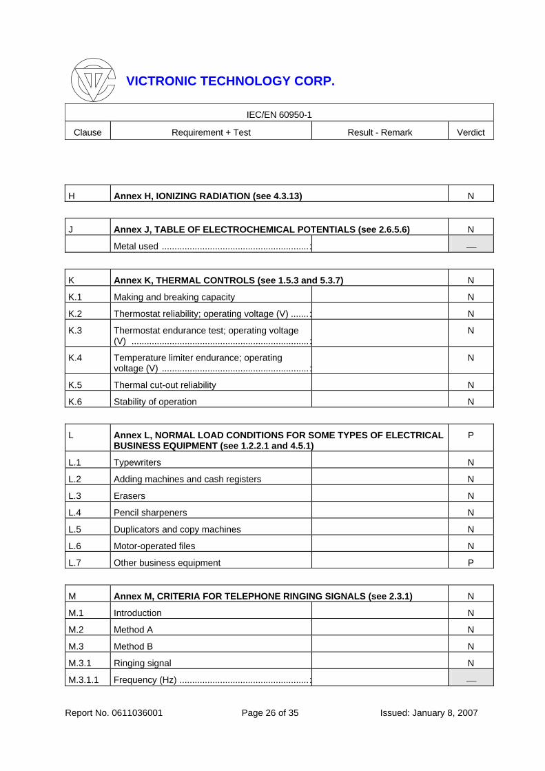
H Annex H, IONIZING RADIATION (see 4.3.13) N
J Annex J, TABLE OF ELECTROCHEMICAL POTENTIALS (see 2.6.5.6) N
Metal used ..........................................................:
K Annex K, THERMAL CONTROLS (see 1.5.3 and 5.3.7) N
K.1 Making and breaking capacity N
K.2 Thermostat reliability; operating voltage (V) .......: N
K.3 Thermostat endurance test; operating voltage (V) ......................................................................:
N
K.4 Temperature limiter endurance; operating voltage (V) ..........................................................:
N
K.5 Thermal cut-out reliability N
K.6 Stability of operation N
L Annex L, NORMAL LOAD CONDITIONS FOR SOME TYPES OF ELECTRICAL BUSINESS EQUIPMENT (see 1.2.2.1 and 4.5.1)
P
L.1 Typewriters N
L.2 Adding machines and cash registers N
L.3 Erasers N
L.4 Pencil sharpeners N
L.5 Duplicators and copy machines N
L.6 Motor-operated files N
L.7 Other business equipment P
M Annex M, CRITERIA FOR TELEPHONE RINGING SIGNALS (see 2.3.1) N
M.1 Introduction N
M.2 Method A N
M.3 Method B N
M.3.1 Ringing signal N
M.3.1.1 Frequency (Hz) ...................................................:
VICTRONIC TECHNOLOGY CORP.
IEC/EN 60950-1
Clause Requirement + Test Result - Remark Verdict
Report No. 0611036001 Page 27 of 35 Issued: January 8, 2007
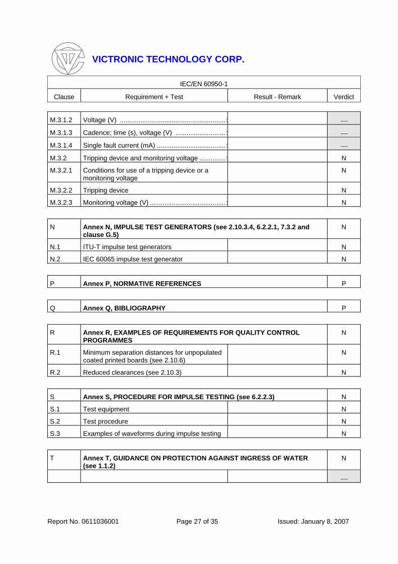
M.3.1.2 Voltage (V) .........................................................:
M.3.1.3 Cadence; time (s), voltage (V) ...........................:
M.3.1.4 Single fault current (mA) .....................................:
M.3.2 Tripping device and monitoring voltage ..............: N
M.3.2.1 Conditions for use of a tripping device or a monitoring voltage
N
M.3.2.2 Tripping device N
M.3.2.3 Monitoring voltage (V) .........................................: N
N Annex N, IMPULSE TEST GENERATORS (see 2.10.3.4, 6.2.2.1, 7.3.2 and clause G.5)
N
N.1 ITU-T impulse test generators N
N.2 IEC 60065 impulse test generator N
P Annex P, NORMATIVE REFERENCES P
Q Annex Q, BIBLIOGRAPHY P
R Annex R, EXAMPLES OF REQUIREMENTS FOR QUALITY CONTROL PROGRAMMES
N
R.1 Minimum separation distances for unpopulated coated printed boards (see 2.10.6)
N
R.2 Reduced clearances (see 2.10.3) N
S Annex S, PROCEDURE FOR IMPULSE TESTING (see 6.2.2.3) N
S.1 Test equipment N
S.2 Test procedure N
S.3 Examples of waveforms during impulse testing N
T Annex T, GUIDANCE ON PROTECTION AGAINST INGRESS OF WATER (see 1.1.2)
N
VICTRONIC TECHNOLOGY CORP.
IEC/EN 60950-1
Clause Requirement + Test Result - Remark Verdict
Report No. 0611036001 Page 28 of 35 Issued: January 8, 2007
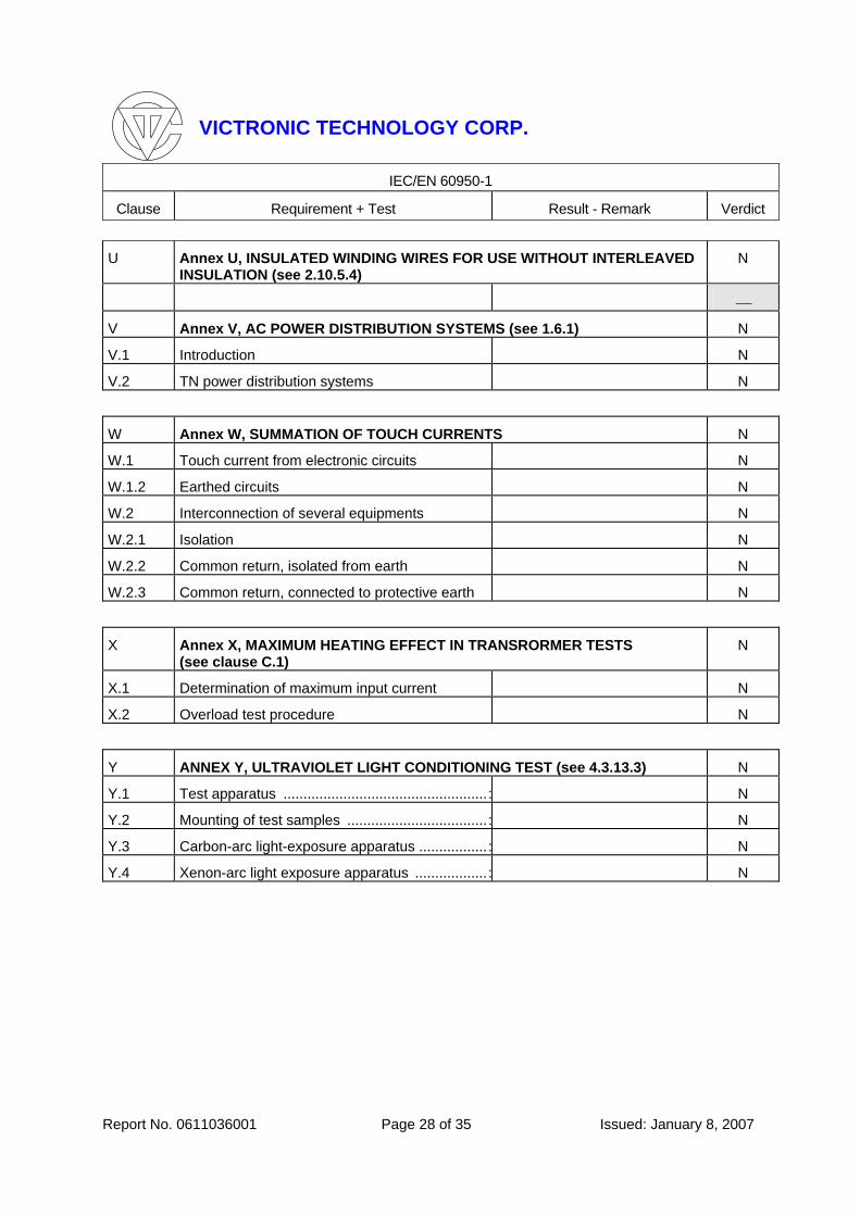
U Annex U, INSULATED WINDING WIRES FOR USE WITHOUT INTERLEAVED INSULATION (see 2.10.5.4)
N
V Annex V, AC POWER DISTRIBUTION SYSTEMS (see 1.6.1) N
V.1 Introduction N
V.2 TN power distribution systems N
W Annex W, SUMMATION OF TOUCH CURRENTS N
W.1 Touch current from electronic circuits N
W.1.2 Earthed circuits N
W.2 Interconnection of several equipments N
W.2.1 Isolation N
W.2.2 Common return, isolated from earth N
W.2.3 Common return, connected to protective earth N
X Annex X, MAXIMUM HEATING EFFECT IN TRANSRORMER TESTS (see clause C.1)
N
X.1 Determination of maximum input current N
X.2 Overload test procedure N
Y ANNEX Y, ULTRAVIOLET LIGHT CONDITIONING TEST (see 4.3.13.3) N
Y.1 Test apparatus ...................................................: N
Y.2 Mounting of test samples ...................................: N
Y.3 Carbon-arc light-exposure apparatus .................: N
Y.4 Xenon-arc light exposure apparatus ..................: N
VICTRONIC TECHNOLOGY CORP.
IEC/EN 60950-1
Clause Requirement + Test Result - Remark Verdict
Report No. 0611036001 Page 29 of 35 Issued: January 8, 2007
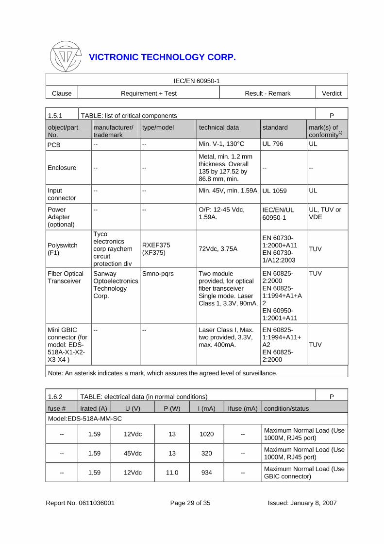
1.5.1 TABLE: list of critical components P
object/part No.
manufacturer/ trademark
type/model technical data standard mark(s) of conformity1)
PCB -- -- Min. V-1, 130°C UL 796 UL
Enclosure -- --
Metal, min. 1.2 mm thickness. Overall 135 by 127.52 by 86.8 mm, min.
-- --
Input connector
-- -- Min. 45V, min. 1.59A UL 1059 UL
Power Adapter (optional)
-- -- O/P: 12-45 Vdc, 1.59A.
IEC/EN/UL 60950-1
UL, TUV or VDE
Polyswitch (F1)
Tyco electronics corp raychem circuit protection div
RXEF375 (XF375) 72Vdc, 3.75A
EN 60730-1:2000+A11 EN 60730-1/A12:2003
TUV
Fiber Optical Transceiver
Sanway Optoelectronics Technology Corp.
Smno-pqrs Two module provided, for optical fiber transceiver Single mode. Laser Class 1. 3.3V, 90mA.
EN 60825-2:2000 EN 60825-1:1994+A1+A2 EN 60950-1:2001+A11
TUV
Mini GBIC connector (for model: EDS-518A-X1-X2-X3-X4 )
-- -- Laser Class I, Max. two provided, 3.3V, max. 400mA.
EN 60825-1:1994+A11+A2 EN 60825-2:2000
TUV
Note: An asterisk indicates a mark, which assures the agreed level of surveillance.
1.6.2 TABLE: electrical data (in normal conditions) P
fuse # Irated (A) U (V) P (W) I (mA) Ifuse (mA) condition/status Model:EDS-518A-MM-SC
-- 1.59 12Vdc 13 1020 -- Maximum Normal Load (Use 1000M, RJ45 port)
-- 1.59 45Vdc 13 320 -- Maximum Normal Load (Use 1000M, RJ45 port)
-- 1.59 12Vdc 11.0 934 -- Maximum Normal Load (Use GBIC connector)
VICTRONIC TECHNOLOGY CORP.
IEC/EN 60950-1
Clause Requirement + Test Result - Remark Verdict
Report No. 0611036001 Page 30 of 35 Issued: January 8, 2007
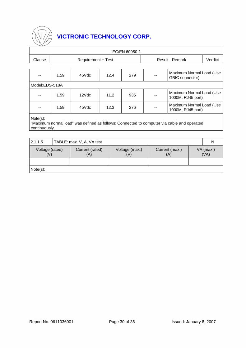
-- 1.59 45Vdc 12.4 279 -- Maximum Normal Load (Use GBIC connector)
Model:EDS-518A
-- 1.59 12Vdc 11.2 935 -- Maximum Normal Load (Use 1000M, RJ45 port)
-- 1.59 45Vdc 12.3 276 -- Maximum Normal Load (Use 1000M, RJ45 port)
Note(s): "Maximum normal load" was defined as follows: Connected to computer via cable and operated continuously.
2.1.1.5 TABLE: max. V, A, VA test N
Voltage (rated) (V)
Current (rated) (A)
Voltage (max.) (V)
Current (max.) (A)
VA (max.) (VA)
Note(s):
VICTRONIC TECHNOLOGY CORP.
IEC/EN 60950-1
Clause Requirement + Test Result - Remark Verdict
Report No. 0611036001 Page 31 of 35 Issued: January 8, 2007
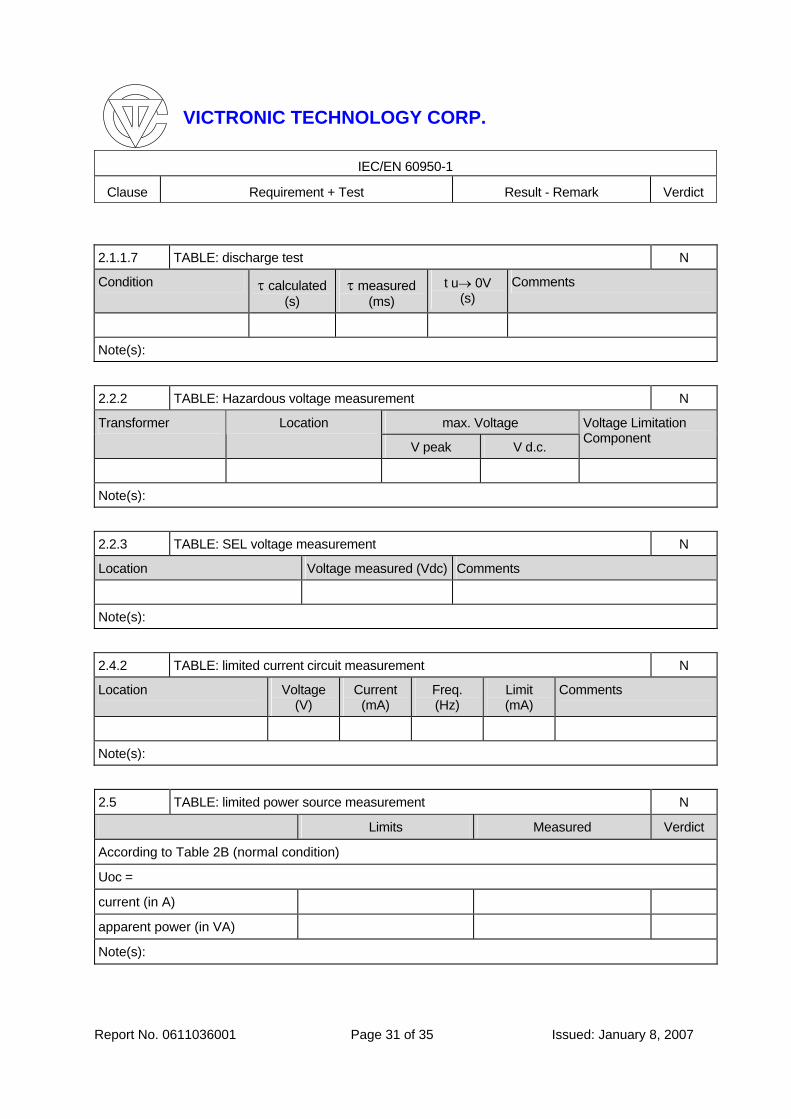
2.1.1.7 TABLE: discharge test N
Condition τ calculated (s)
τ measured(ms)
t u→ 0V (s)
Comments
Note(s):
2.2.2 TABLE: Hazardous voltage measurement N
max. Voltage Transformer Location
V peak V d.c.
Voltage Limitation Component
Note(s):
2.2.3 TABLE: SEL voltage measurement N
Location Voltage measured (Vdc) Comments
Note(s):
2.4.2 TABLE: limited current circuit measurement N
Location Voltage (V)
Current (mA)
Freq. (Hz)
Limit (mA)
Comments
Note(s):
2.5 TABLE: limited power source measurement N
Limits Measured Verdict
According to Table 2B (normal condition)
Uoc =
current (in A)
apparent power (in VA)
Note(s):
VICTRONIC TECHNOLOGY CORP.
IEC/EN 60950-1
Clause Requirement + Test Result - Remark Verdict
Report No. 0611036001 Page 32 of 35 Issued: January 8, 2007
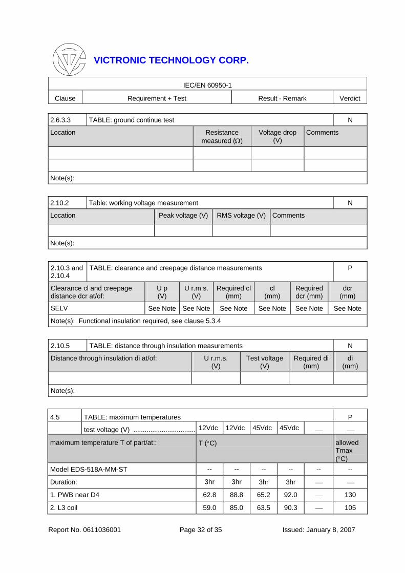
2.6.3.3 TABLE: ground continue test N
Location Resistance measured (Ω)
Voltage drop (V)
Comments
Note(s):
2.10.2 Table: working voltage measurement N
Location Peak voltage (V) RMS voltage (V) Comments
Note(s):
2.10.3 and 2.10.4
TABLE: clearance and creepage distance measurements P
Clearance cl and creepage distance dcr at/of:
U p (V)
U r.m.s.(V)
Required cl (mm)
cl (mm)
Required dcr (mm)
dcr (mm)
SELV See Note See Note See Note See Note See Note See Note
Note(s): Functional insulation required, see clause 5.3.4
2.10.5 TABLE: distance through insulation measurements N
Distance through insulation di at/of: U r.m.s. (V)
Test voltage(V)
Required di (mm)
di (mm)
Note(s):
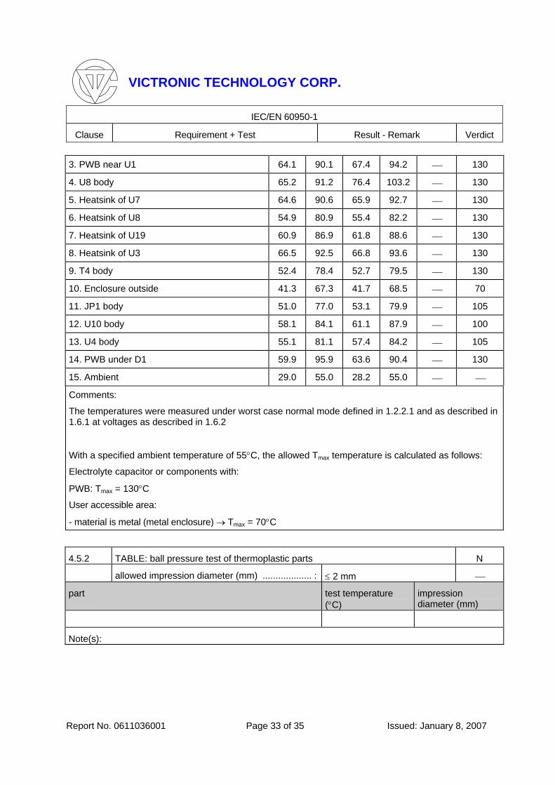
4.5 TABLE: maximum temperatures P
test voltage (V) ................................. 12Vdc 12Vdc 45Vdc 45Vdc
maximum temperature T of part/at:: T (°C) allowed Tmax (°C)
Model EDS-518A-MM-ST -- -- -- -- -- --
Duration: 3hr 3hr 3hr 3hr
1. PWB near D4 62.8 88.8 65.2 92.0 130
2. L3 coil 59.0 85.0 63.5 90.3 105
VICTRONIC TECHNOLOGY CORP.
IEC/EN 60950-1
Clause Requirement + Test Result - Remark Verdict
Report No. 0611036001 Page 33 of 35 Issued: January 8, 2007
3. PWB near U1 64.1 90.1 67.4 94.2 130
4. U8 body 65.2 91.2 76.4 103.2 130
5. Heatsink of U7 64.6 90.6 65.9 92.7 130
6. Heatsink of U8 54.9 80.9 55.4 82.2 130
7. Heatsink of U19 60.9 86.9 61.8 88.6 130
8. Heatsink of U3 66.5 92.5 66.8 93.6 130
9. T4 body 52.4 78.4 52.7 79.5 130
10. Enclosure outside 41.3 67.3 41.7 68.5 70
11. JP1 body 51.0 77.0 53.1 79.9 105
12. U10 body 58.1 84.1 61.1 87.9 100
13. U4 body 55.1 81.1 57.4 84.2 105
14. PWB under D1 59.9 95.9 63.6 90.4 130
15. Ambient 29.0 55.0 28.2 55.0
Comments:
The temperatures were measured under worst case normal mode defined in 1.2.2.1 and as described in 1.6.1 at voltages as described in 1.6.2
With a specified ambient temperature of 55°C, the allowed Tmax temperature is calculated as follows:
Electrolyte capacitor or components with:
PWB: Tmax = 130°C
User accessible area:
- material is metal (metal enclosure) → Tmax = 70°C
4.5.2 TABLE: ball pressure test of thermoplastic parts N
allowed impression diameter (mm) ................... : ≤ 2 mm
part test temperature (°C)
impression diameter (mm)
Note(s):

VICTRONIC TECHNOLOGY CORP.
IEC/EN 60950-1
Clause Requirement + Test Result - Remark Verdict
Report No. 0611036001 Page 34 of 35 Issued: January 8, 2007
4.6.1, 4.6.2 TABLE: openings in enclosures P
Location size (mm) Comments Top None --
Right and Left Sides
Covering two areas. One area of 107 by 32 mm, provided for input connector side. The other area of 102 by 52.3 mm, each opening measured 2 by 2 mm.
Foreign objects entering the enclosure will not contact bare parts at hazardous voltage or energy (No hazardous parts within 5° projection).
Front Side None --
Rear Side None --
Bottom None --
Note(s):
4.7 TABLE: resistance to fire N
part manufacturer of material type of material Thickness (mm)
flammabilityclass
Note(s):
5.1.6 TABLE: touch current measurement N
Condition L→ terminal A (mA)
N → terminal A(mA)
Limit (mA)
Comments
Note(s):
5.2 TABLE: electric strength tests, impulse tests and voltage surge tests P
test voltage applied between: test voltage (V) d.c. breakdown Yes / No
Input to enclosure 707 No
Note(s):
VICTRONIC TECHNOLOGY CORP.
IEC/EN 60950-1
Clause Requirement + Test Result - Remark Verdict
Report No. 0611036001 Page 35 of 35 Issued: January 8, 2007
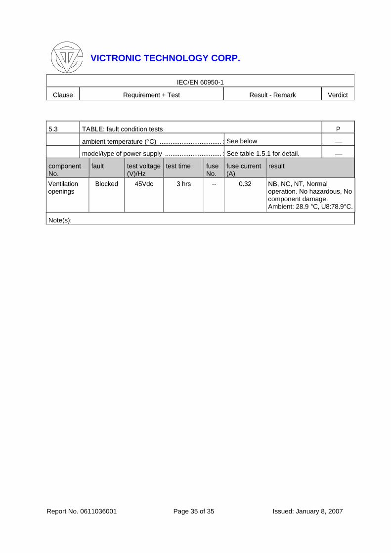
5.3 TABLE: fault condition tests P
ambient temperature (°C) .................................. : See below
model/type of power supply ............................... : See table 1.5.1 for detail.
component No.
fault test voltage (V)/Hz
test time fuse No.
fuse current (A)
result
Ventilation openings
Blocked 45Vdc 3 hrs -- 0.32 NB, NC, NT, Normal operation. No hazardous, No component damage. Ambient: 28.9 °C, U8:78.9°C.
Note(s):
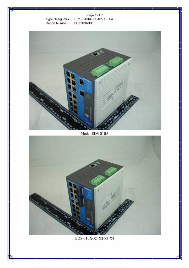
Page 1 of 7 Type Designation: EDS-5X0A-X1-X2-X3-X4 Report Number: 0611036001
Model:EDS-516A
EDS-516A-X1-X2-X3-X4
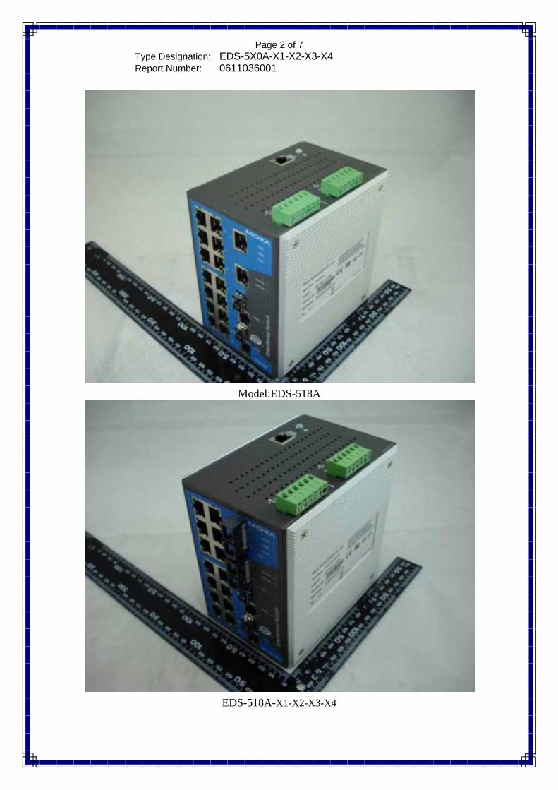
Page 2 of 7 Type Designation: EDS-5X0A-X1-X2-X3-X4 Report Number: 0611036001
Model:EDS-518A
EDS-518A-X1-X2-X3-X4
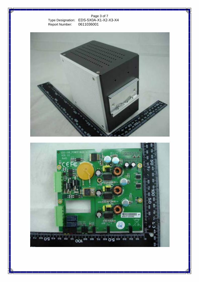
Page 3 of 7 Type Designation: EDS-5X0A-X1-X2-X3-X4 Report Number: 0611036001
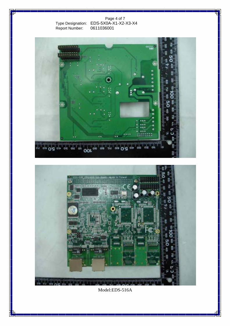
Page 4 of 7 Type Designation: EDS-5X0A-X1-X2-X3-X4 Report Number: 0611036001
Model:EDS-516A
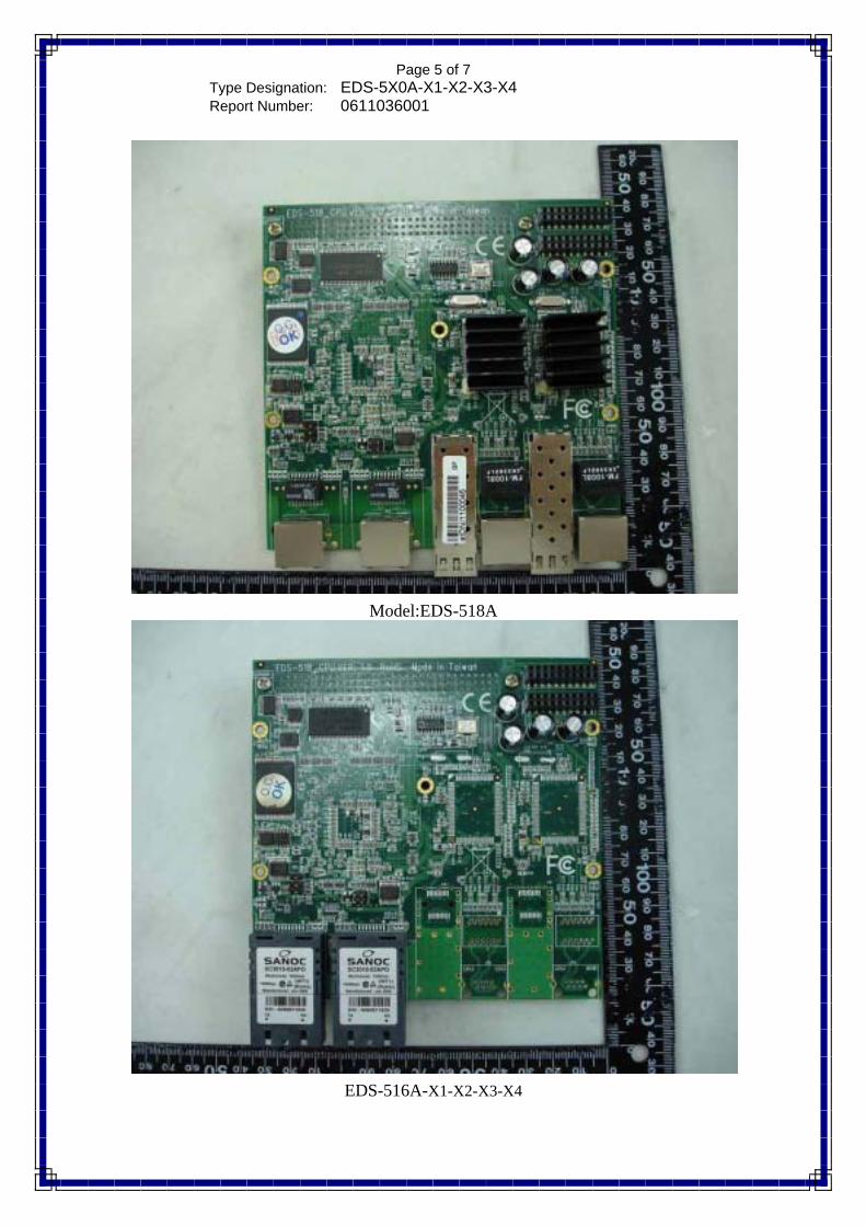
Page 5 of 7 Type Designation: EDS-5X0A-X1-X2-X3-X4 Report Number: 0611036001
Model:EDS-518A
EDS-516A-X1-X2-X3-X4
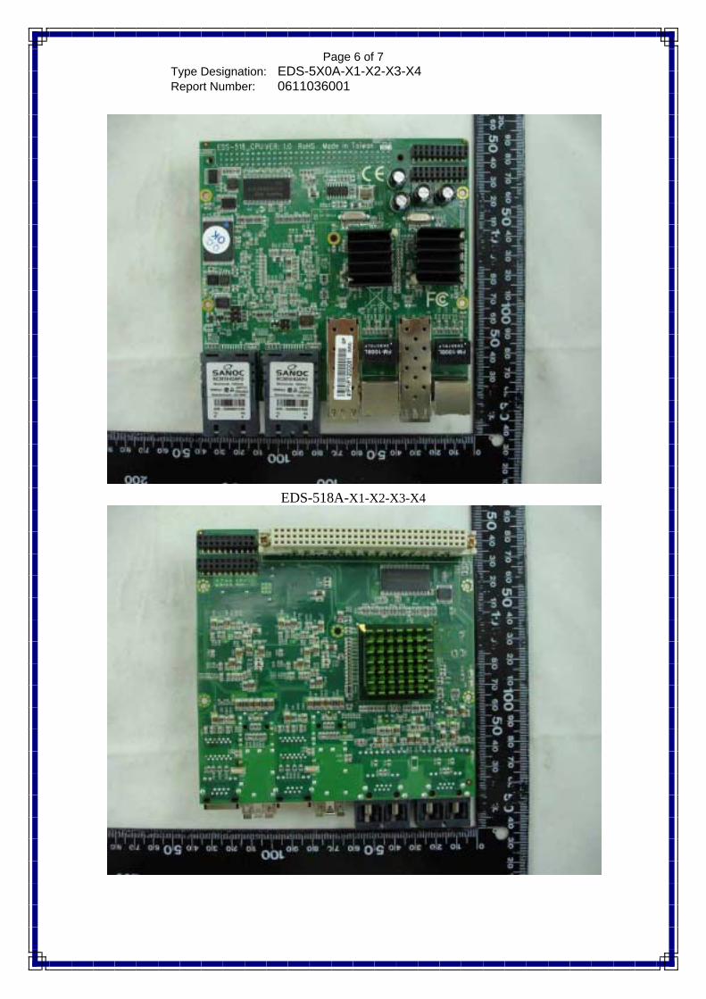
Page 6 of 7 Type Designation: EDS-5X0A-X1-X2-X3-X4 Report Number: 0611036001
EDS-518A-X1-X2-X3-X4
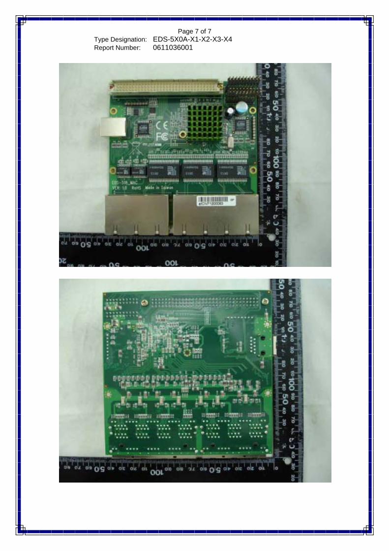
Page 7 of 7 Type Designation: EDS-5X0A-X1-X2-X3-X4 Report Number: 0611036001


