Embed Size (px)
Citation preview

VIP-CORE® Reference Manual
© 2012 Halliburton
February 2012
© 2012 HalliburtonAll Rights Reserved
Information in this document is subject to change without notice. No part of this document may be reproduced or transmitted in any form or by any means, electronic or mechanical, for any purpose, without the express written permission of Halliburton. Unauthorized reproduction or distribution of this documentation, or any portion of it, may result in severe civil and criminal penalties, and will be prosecuted to the maximum extent possible under law.
Halliburton may have patents, patent applications, trademarks, copyrights, or other intellectual property rights covering subject matter in this document. The furnishing of this document does not give you any license to these patents, trademarks, copyrights, or other intellectual property.
Halliburton | Landmark Software & Services2107 CityWest Blvd, Building 2, Houston, Texas 77042-3051, USA
P.O. Box 42806, Houston, Texas 77242, USAPhone:713-839-2000, FAX: 713-839-2015Internet: www.halliburton.com/landmark
Trademarks3D Drill View, 3D Drill View KM, 3D Surveillance, 3DFS, 3DView, Active Field Surveillance, Active Reservoir Surveillance, Adaptive Mesh Refining, ADC, Advanced Data Transfer, Analysis Model Layering, ARIES, ARIES DecisionSuite, Asset Data Mining, Asset Decision Solutions, Asset Development Center, Asset Development Centre, Asset Journal, Asset Performance, AssetConnect, AssetConnect Enterprise, AssetConnect Enterprise Express, AssetConnect Expert, AssetDirector, AssetJournal, AssetLink, AssetLink Advisor, AssetLink Director, AssetLink Observer, AssetObserver, AssetObserver Advisor, AssetOptimizer, AssetPlanner, AssetPredictor, AssetSolver, AssetSolver Online, AssetView, AssetView 2D, AssetView 3D, BLITZPAK, CartoSnap, CasingLife, CasingSeat, CDS Connect, Channel Trim, COMPASS, Contract Generation, Corporate Data Archiver, Corporate Data Store, Data Analyzer, DataManager, DataStar, DBPlot, Decision Management System, DecisionSpace, DecisionSpace 3D Drill View, DecisionSpace 3D Drill View KM, DecisionSpace AssetLink, DecisionSpace AssetPlanner, DecisionSpace AssetSolver, DecisionSpace Atomic Meshing, DecisionSpace Desktop, DecisionSpace Nexus, DecisionSpace Reservoir, DecisionSuite, Deeper Knowledge. Broader Understanding., Depth Team, Depth Team Explorer, Depth Team Express, Depth Team Extreme, Depth Team Interpreter, DepthTeam, DepthTeam Explorer, DepthTeam Express, DepthTeam Extreme, DepthTeam Interpreter, Desktop Navigator, DESKTOP-PVT, DESKTOP-VIP, DEX, DIMS, Discovery, Discovery 3D, Discovery Asset, Discovery Framebuilder, Discovery PowerStation, DMS, Drillability Suite, Drilling Desktop, DrillModel, Drill-to-the-Earth-Model, Drillworks, Drillworks ConnectML, Drillworks Predict, DSS, Dynamic Frameworks to Fill, Dynamic Reservoir Management, Dynamic Surveillance System, EDM, EDM AutoSync, EDT, eLandmark, Engineer’s Data Model, Engineer’s Desktop, Engineer’s Link, ESP, Event Similarity Prediction, ezFault, ezModel, ezSurface, ezTracker, ezTracker2D, FastTrack, Field Scenario Planner, FieldPlan, For Production, FrameBuilder, Frameworks to Fill, FZAP!, GeoAtlas, GeoDataLoad, GeoGraphix, GeoGraphix Exploration System, Geometric Kernel, GeoProbe, GeoProbe GF DataServer, GeoSmith, GES, GES97, GESXplorer, GMAplus, GMI Imager, Grid3D, GRIDGENR, H. Clean, Handheld Field Operator, HHFO, High Science Simplified, Horizon Generation, I2 Enterprise, iDIMS, Infrastructure, Iso Core, IsoMap, iWellFile, KnowledgeSource, Landmark (as a service), Landmark (as software), Landmark Decision Center, Landmark Logo and Design, Landscape, Large Model, Lattix, LeaseMap, LithoTect, LogEdit, LogM, LogPrep, Make Great Decisions, MathPack, MDS Connect, MicroTopology, MIMIC, MIMIC+, Model Builder, NETool, Nexus (as a service), Nexus (as software), Nexus View, Object MP, OpenBooks, OpenJournal, OpenSGM, OpenVision, OpenWells, OpenWire, OpenWire Client, OpenWire Server, OpenWorks, OpenWorks Development Kit, OpenWorks Production, OpenWorks Well File, PAL, Parallel-VIP, Parametric Modeling, Permedia, PetroBank, PetroBank Explorer, PetroBank Master Data Store, PetroStor, PetroWorks, PetroWorks Asset, PetroWorks Pro, PetroWorks ULTRA, PlotView, Point Gridding Plus, Pointing Dispatcher, PostStack, PostStack ESP, PostStack Family, Power Interpretation, PowerCalculator, PowerExplorer, PowerExplorer Connect, PowerGrid, PowerHub, PowerModel, PowerView, PrecisionTarget, Presgraf, PressWorks, PRIZM, Production, Production Asset Manager, PROFILE, Project Administrator, ProMAGIC , ProMAGIC Connect, ProMAGIC Server, ProMAX, ProMAX 2D, ProMax 3D, ProMAX 3DPSDM, ProMAX 4D, ProMAX Family, ProMAX MVA, ProMAX VSP, pSTAx, Query Builder, Quick, Quick+, QUICKDIF, Quickwell, Quickwell+, Quiklog, QUIKRAY, QUIKSHOT, QUIKVSP, RAVE, RAYMAP, RAYMAP+, Real Freedom, Real Time Asset Management Center, Real Time Decision Center, Real Time Operations Center, Real Time Production Surveillance, Real Time Surveillance, Real-time View, Reference Data Manager, Reservoir, Reservoir Framework Builder, RESev, ResMap, RTOC, SCAN, SeisCube, SeisMap, SeisModel, SeisSpace, SeisVision, SeisWell, SeisWorks, SeisWorks 2D, SeisWorks 3D, SeisWorks PowerCalculator, SeisWorks PowerJournal, SeisWorks PowerSection, SeisWorks PowerView, SeisXchange, Semblance Computation and Analysis, Sierra Family, SigmaView, SimConnect, SimConvert, SimDataStudio, SimResults, SimResults+, SimResults+3D, SIVA+, SLAM, SmartFlow, smartSECTION, smartSTRAT, Spatializer, SpecDecomp, StrataAmp, StrataMap, StrataModel, StrataSim, StratWorks, StratWorks 3D, StreamCalc, StressCheck, STRUCT, Structure Cube, Surf & Connect, SurfNet, SynTool, System Start for Servers, SystemStart, SystemStart for Clients, SystemStart for Servers, SystemStart for Storage, Tanks &
Tubes, TDQ, Team Workspace, TERAS, T-Grid, The Engineer’s DeskTop, Total Drilling Performance, TOW/cs, TOW/cs Revenue Interface, TracPlanner, TracPlanner Xpress, Trend Form Gridding, Trimmed Grid, Turbo Synthetics, Unconventional Essentials, VESPA, VESPA+, VIP, VIP-COMP, VIP-CORE, VIPDataStudio, VIP-DUAL, VIP-ENCORE, VIP-EXECUTIVE, VIP-Local Grid Refinement, VIP-THERM, vSpace, vSpace Blueprint, vSpace Onsite, WavX, Web Editor, Well Cost, Well H. Clean, Well Seismic Fusion, Wellbase, Wellbore Planner, Wellbore Planner Connect, WELLCAT, WellDirect, WELLPLAN, WellSolver, WellXchange, WOW, Xsection, You’re in Control. Experience the difference, ZAP!, ZetaAnalytics, and Z-MAP Plus are trademarks, registered trademarks, or service marks of Halliburton.
All other trademarks, service marks, and product or service names are the trademarks or names of their respective owners.
NoteThe information contained in this document is subject to change without notice and should not be construed as a commitment by Halliburton. Halliburton assumes no responsibility for any error that may appear in this manual. Some states or jurisdictions do not allow disclaimer of expressed or implied warranties in certain transactions; therefore, this statement may not apply to you.
Third Party Licenses and AttributionsHalliburton acknowledges that certain third party code has been bundled with, or embedded in, its software. The licensors of this third party code, and the terms and conditions of their respective licenses, may be found in the Nexus-VIP Release Notes.
DisclaimerThe programs and documentation may provide links to external web sites and access to content, products, and services from third parties. Halliburton is not responsible for the availability of, or any content provided on, third party web sites. You bear all risks associated with the use of such content. If you choose to purchase any products or services from a third party, the relationship is directly between you and the third party. Halliburton is not responsible for: (a) the quality of third party products or services; or (b) fulfilling any of the terms of the agreement with the third party, including delivery of products or services and warranty obligations related to purchased products or services. Halliburton is not responsible for any loss or damage of any sort that you may incur from dealing with any third party.

v
Table of Contents
Table of ContentsAbout This Manual
Purpose . . . . . . . . . . . . . . . . . . . . . . . . . . . . . . . . . . . . . . . . . . . . . . . . . . . . . . . . . . . . . xxiiiThe Modules . . . . . . . . . . . . . . . . . . . . . . . . . . . . . . . . . . . . . . . . . . . . . . . . . . . . . . . . . xxiiiThe Chapters . . . . . . . . . . . . . . . . . . . . . . . . . . . . . . . . . . . . . . . . . . . . . . . . . . . . . . . . . xxivData Formatting Conventions . . . . . . . . . . . . . . . . . . . . . . . . . . . . . . . . . . . . . . . . . . . . xxivCompatibility . . . . . . . . . . . . . . . . . . . . . . . . . . . . . . . . . . . . . . . . . . . . . . . . . . . . . . . . . xxvRelated Documentation. . . . . . . . . . . . . . . . . . . . . . . . . . . . . . . . . . . . . . . . . . . . . . . . . . xxv
Chapter 1Data Overview
1.1 Introduction . . . . . . . . . . . . . . . . . . . . . . . . . . . . . . . . . . . . . . . . . . . . . . . . . . . . . . 1-271.1.1 VIP-COMP Overview . . . . . . . . . . . . . . . . . . . . . . . . . . . . . . . . . . . . . . . 1-271.1.2 VIP-ENCORE Overview . . . . . . . . . . . . . . . . . . . . . . . . . . . . . . . . . . . . 1-281.1.3 VIP-DUAL Overview . . . . . . . . . . . . . . . . . . . . . . . . . . . . . . . . . . . . . . . 1-281.1.4 VIP-POLYMER Overview . . . . . . . . . . . . . . . . . . . . . . . . . . . . . . . . . . . 1-291.1.5 VIP-THERM Overview . . . . . . . . . . . . . . . . . . . . . . . . . . . . . . . . . . . . . 1-291.1.6 Shared Features . . . . . . . . . . . . . . . . . . . . . . . . . . . . . . . . . . . . . . . . . . . . 1-30
1.2 Typical Data Requirements to Initialize a Simulation Study . . . . . . . . . . . . . . . . 1-321.2.1 Geological Descriptions . . . . . . . . . . . . . . . . . . . . . . . . . . . . . . . . . . . . . 1-321.2.2 Reservoir Rock Characteristics . . . . . . . . . . . . . . . . . . . . . . . . . . . . . . . . 1-321.2.3 Hydrocarbon Fluid Properties . . . . . . . . . . . . . . . . . . . . . . . . . . . . . . . . . 1-32
1.3 Data Deck Layout . . . . . . . . . . . . . . . . . . . . . . . . . . . . . . . . . . . . . . . . . . . . . . . . . 1-33
1.4 Input Data Template . . . . . . . . . . . . . . . . . . . . . . . . . . . . . . . . . . . . . . . . . . . . . . . 1-35
1.5 Data Format . . . . . . . . . . . . . . . . . . . . . . . . . . . . . . . . . . . . . . . . . . . . . . . . . . . . . . 1-381.5.1 General Utility Data . . . . . . . . . . . . . . . . . . . . . . . . . . . . . . . . . . . . . . . . 1-40
1.5.1.1 Comment Lines (C) . . . . . . . . . . . . . . . . . . . . . . . . . . . . . . . . . 1-401.5.1.2 Read Data from an External File (INCLUDE) . . . . . . . . . . . . 1-401.5.1.3 Stop Reading Data from the Current INCLUDE File (ENDINC) 1-411.5.1.4 Read Array Data from a VDB File (VDB) . . . . . . . . . . . . . . . 1-411.5.1.5 Echo Print On (LIST) . . . . . . . . . . . . . . . . . . . . . . . . . . . . . . . 1-42
5000.4.4 v
VIP-CORE® Reference Guide Landmark
1.5.1.6 Echo Print Off (NOLIST) . . . . . . . . . . . . . . . . . . . . . . . . . . . . 1-421.5.1.7 Skip Data On (SKIP) . . . . . . . . . . . . . . . . . . . . . . . . . . . . . . . . 1-421.5.1.8 Skip Data Off (NOSKIP) . . . . . . . . . . . . . . . . . . . . . . . . . . . . . 1-431.5.1.9 Number of Printed Lines Per Page (NLINES) . . . . . . . . . . . . . 1-431.5.1.10 Columns To Be Read (NCOL) . . . . . . . . . . . . . . . . . . . . . . . 1-431.5.1.11 Data Line Continuation . . . . . . . . . . . . . . . . . . . . . . . . . . . . . 1-43
1.5.2 Array Input Options . . . . . . . . . . . . . . . . . . . . . . . . . . . . . . . . . . . . . . . . 1-431.5.2.1 Constant Array Input Option (CON) . . . . . . . . . . . . . . . . . . . . 1-461.5.2.2 X (or R) Direction Array Value Variation (XVAR/RVAR) . . 1-471.5.2.3 Y (or Theta) Direction Array Value Variation (YVAR/THVAR) 1-481.5.2.4 Z Direction Array Value Variation (ZVAR) . . . . . . . . . . . . . . 1-491.5.2.5 Full Array Input Option (VALUE) . . . . . . . . . . . . . . . . . . . . . 1-501.5.2.6 Automatic Generation of Values for Layers 2 - Nz (LAYER) 1-521.5.2.7 Block Depths From Origin (DIP) . . . . . . . . . . . . . . . . . . . . . . 1-541.5.2.8 Define New Array From Previously Defined Array (MULT) . 1-561.5.2.9 Directional Relative Permeability Option (dir) (Not Available in VIP-THERM) . . . . . . . . . . . . . . . . . . . . . . . . . . . . . . . . . . . . . . . . . . . 1-56
1.5.3 Corner Point Array Options . . . . . . . . . . . . . . . . . . . . . . . . . . . . . . . . . . 1-581.5.3.1 X Direction Variation by Layer (LNXVAR) . . . . . . . . . . . . . . 1-581.5.3.2 Y Direction Variation by Layer (LNYVAR) . . . . . . . . . . . . . . 1-591.5.3.3 Z Direction Variation by Layer (LNZVAR) . . . . . . . . . . . . . . 1-591.5.3.4 Values by Layer (LNVAL) . . . . . . . . . . . . . . . . . . . . . . . . . . . 1-601.5.3.5 Replicate Concurrent Point Arrays (COPY) . . . . . . . . . . . . . . 1-60
1.5.4 Array Modification Options . . . . . . . . . . . . . . . . . . . . . . . . . . . . . . . . . . 1-611.5.4.1 Modify by a Constant (MOD) . . . . . . . . . . . . . . . . . . . . . . . . . 1-621.5.4.2 Modify Depth by a Constant (MODLYR) . . . . . . . . . . . . . . . . 1-631.5.4.3 Replace Selected Values (VMOD) . . . . . . . . . . . . . . . . . . . . . 1-66
1.5.5 Unformatted (BINARY) Data . . . . . . . . . . . . . . . . . . . . . . . . . . . . . . . . 1-68
1.6 Connection Transmissibility Modification (MULT) . . . . . . . . . . . . . . . . . . . . . . . 1-69
1.7 Inter/Intra Region Transmissibility Multiplier (MULTIR) . . . . . . . . . . . . . . . . . . 1-72
1.8 Named Fault/Region Transmissibility Multiplier (MULTFL) . . . . . . . . . . . . . . . 1-73
Chapter 2Initialization Data
2.1 Introduction . . . . . . . . . . . . . . . . . . . . . . . . . . . . . . . . . . . . . . . . . . . . . . . . . . . . . . 2-75
2.2 Initialization Utility Data . . . . . . . . . . . . . . . . . . . . . . . . . . . . . . . . . . . . . . . . . . . . 2-772.2.1 General . . . . . . . . . . . . . . . . . . . . . . . . . . . . . . . . . . . . . . . . . . . . . . . . . . 2-77
2.2.1.1 Initialization (INIT) . . . . . . . . . . . . . . . . . . . . . . . . . . . . . . . . . 2-772.2.1.2 Change Default Dimensions (DIM) . . . . . . . . . . . . . . . . . . . . . 2-772.2.1.3 Descriptive Run Information (TITLEn) . . . . . . . . . . . . . . . . . 2-802.2.1.4 Date (DATE) . . . . . . . . . . . . . . . . . . . . . . . . . . . . . . . . . . . . . . 2-812.2.1.5 End-of-File Marker (END) . . . . . . . . . . . . . . . . . . . . . . . . . . . 2-81
2.2.2 Results File Control . . . . . . . . . . . . . . . . . . . . . . . . . . . . . . . . . . . . . . . . 2-81
vi 5000.4.4
Landmark VIP-CORE® Reference Guide
2.2.2.1 Grid Data Written for Post-Processing (MAP) . . . . . . . . . . . . 2-812.2.2.2 Mole Fraction Data Written for Post-Processing (MAPX, MAPY, MAPZ) . . . . . . . . . . . . . . . . . . . . . . . . . . . . . . . . . . . . . . . . . . . . . . . . . 2-882.2.2.3 Full Size Arrays to VDB File (NOVDBPACK) . . . . . . . . . . . 2-892.2.2.4 Map File Instead of VDB File (NOVDB) (VIP-COMP and VIP-EN-CORE) . . . . . . . . . . . . . . . . . . . . . . . . . . . . . . . . . . . . . . . . . . . . . . . . . 2-892.2.2.5 VDB File (VDB) (VIP-COMP and VIP-ENCORE) . . . . . . . . 2-892.2.2.6 Grid Data Written for Post-Processing to SIMOUT Map File (MA-POLD) . . . . . . . . . . . . . . . . . . . . . . . . . . . . . . . . . . . . . . . . . . . . . . . . . 2-89
2.2.3 Grid System Options . . . . . . . . . . . . . . . . . . . . . . . . . . . . . . . . . . . . . . . . 2-942.2.3.1 Rectangular (Cartesian) Grid System (NX, NY, NZ, NCOMP) . 2-942.2.3.2 Radial (Cylindrical) Grid System (NR, NTHETA, NZ, RI, NCOMP) 2-952.2.3.3 Single-Well Gridded Wellbore Simulation (WBSIM) (Not available in VIP-THERM) . . . . . . . . . . . . . . . . . . . . . . . . . . . . . . . . . . . . . . . . . . . . . . . . . .2-972.2.3.4 Automatic Grid Setup for Pattern Elements (VIP-THERM Only) 2-98
2.2.4 Physical Property Constants . . . . . . . . . . . . . . . . . . . . . . . . . . . . . . . . . 2-1072.2.4.1 VIP-COMP or VIP-ENCORE . . . . . . . . . . . . . . . . . . . . . . . . 2-1082.2.4.2 VIP-THERM . . . . . . . . . . . . . . . . . . . . . . . . . . . . . . . . . . . . . 2-1092.2.4.3 Pore Volume Representation (PVEXP, PVLINEAR) . . . . . . 2-110
2.2.5 Output . . . . . . . . . . . . . . . . . . . . . . . . . . . . . . . . . . . . . . . . . . . . . . . . . . 2-1112.2.5.1 Metric Units for Input and Output (METRIC) . . . . . . . . . . . 2-1112.2.5.2 Laboratory Units for Input and Output (LAB) . . . . . . . . . . . 2-1122.2.5.3 Print by Cross-Sections (CROSS) . . . . . . . . . . . . . . . . . . . . . 2-1122.2.5.4 Layer Output in Initialization Region Summary (REGNZ) . 2-1122.2.5.5 Hydrocarbon Pore Volume and Bulk Volume Tables (HCPVTAB) 2-112
2.2.6 Formulation . . . . . . . . . . . . . . . . . . . . . . . . . . . . . . . . . . . . . . . . . . . . . 2-1132.2.6.1 Gas-Water Option for VIP-ENCORE (GASWATER) . . . . . 2-1132.2.6.2 Water-Oil Option for VIP-ENCORE (WATEROIL) . . . . . . 2-1142.2.6.3 Black-Oil Option (BLACKOIL) (VIP-ENCORE) . . . . . . . . 2-1142.2.6.4 Two-Point Upstream Weighting (TWOPT) (Not available in VIP-THERM) . . . . . . . . . . . . . . . . . . . . . . . . . . . . . . . . . . . . . . . . . . 2-1142.2.6.5 Nine-Point Finite Difference Approximations (NINEPT) . . . 2-1152.2.6.6 SEBOUND option . . . . . . . . . . . . . . . . . . . . . . . . . . . . . . . . . 2-1152.2.6.7 Compositional SORM Option (CSORM) . . . . . . . . . . . . . . . 2-116
2.2.7 Saturation Tables and Hysteresis . . . . . . . . . . . . . . . . . . . . . . . . . . . . . 2-1172.2.7.1 Two-Point Scaling of Relative Permeabilities (END2P) . . . . 2-1172.2.7.2 Two-Point Scaling of Capillary Pressures for Initial Saturations (INIT2P) . . . . . . . . . . . . . . . . . . . . . . . . . . . . . . . . . . . . . . . . . . . . . . . 2-1172.2.7.3 Stone’s Three-Phase kro (STONE1, STONE2) . . . . . . . . . . . 2-1182.2.7.4 Saturation Weighted Three-Phase kro (KROINT) (Not available in VIP-THERM) . . . . . . . . . . . . . . . . . . . . . . . . . . . . . . . . . . . . . . . . . . 2-1192.2.7.5 Water-oil Capillary Pressure Hysteresis (PCHYSW) (Not available
5000.4.4 vii
VIP-CORE® Reference Guide Landmark
in VIP-THERM) . . . . . . . . . . . . . . . . . . . . . . . . . . . . . . . . . . . . . . . . 2-1192.2.7.6 Gas-Oil Capillary Pressure Hysteresis (PCHYSG) (Not available in VIP-THERM) . . . . . . . . . . . . . . . . . . . . . . . . . . . . . . . . . . . . . . . . . . 2-1202.2.7.7 Oil Relative Permeability Hysteresis (RPHYSO) (Not available in VIP-THERM) . . . . . . . . . . . . . . . . . . . . . . . . . . . . . . . . . . . . . . . . . . 2-1222.2.7.8 Gas Relative Permeability Hysteresis (RPHYSG) (Not available in VIP-THERM) . . . . . . . . . . . . . . . . . . . . . . . . . . . . . . . . . . . . . . . . . . 2-1222.2.7.9 Relative Permeability Hysteresis Tolerances (RPHYST) . . . 2-1232.2.7.10 Leverett J-Function (JFUNC) (Not available with SDFUNC op-tion) . . . . . . . . . . . . . . . . . . . . . . . . . . . . . . . . . . . . . . . . . . . . . . . . . . 2-1242.2.7.11 Rock Compaction (COMPACT) . . . . . . . . . . . . . . . . . . . . 2-1242.2.7.12 Freeze Pcwo at Initial Value (FRZPCW) . . . . . . . . . . . . . . 2-1252.2.7.13 Freeze Pcgo at Initial Value (FRZPCG) . . . . . . . . . . . . . . . 2-125
2.2.8 Initialization . . . . . . . . . . . . . . . . . . . . . . . . . . . . . . . . . . . . . . . . . . . . . 2-1252.2.8.1 Nonequilibrium Initialization (NONEQ) . . . . . . . . . . . . . . . . 2-1252.2.8.2 Gridblock Center Initialization (GBC) . . . . . . . . . . . . . . . . . 2-1262.2.8.3 Integrated Saturation Initialization (INTSAT) . . . . . . . . . . . 2-1262.2.8.4 Integrated Saturation Initialization (VAITS) (Not available in VIP-THERM) . . . . . . . . . . . . . . . . . . . . . . . . . . . . . . . . . . . . . . . . . . . . . . 2-1272.2.8.5 Thickness Center (THCNTR) . . . . . . . . . . . . . . . . . . . . . . . . 2-1282.2.8.6 Do Not Initialize (NOINIT) . . . . . . . . . . . . . . . . . . . . . . . . . . 2-1282.2.8.7 Totally Refined ROOT Grid (NOROOT) . . . . . . . . . . . . . . . 2-1282.2.8.8 Grid Deactivation (DEACTIVATE) . . . . . . . . . . . . . . . . . . . 2-1282.2.8.9 Honor Input Water Saturation Values (KEEPSW) . . . . . . . . 2-1292.2.8.10 Honor Input Gas Saturation Values (KEEPSG) . . . . . . . . . 2-129
2.2.9 Off-Band Connections . . . . . . . . . . . . . . . . . . . . . . . . . . . . . . . . . . . . . 2-1292.2.9.1 Pinchout Gridblock Connections (PINCHOUT) . . . . . . . . . . 2-1292.2.9.2 Fault Modeling (FAULTS) . . . . . . . . . . . . . . . . . . . . . . . . . . 2-1302.2.9.3 Completing the Circle in Radial Grids (FLOW360) . . . . . . . 2-130
2.2.10 Vertical Equilibrium (Not available in VIP-THERM) . . . . . . . . . . . . 2-1322.2.10.1 Water-Oil Vertical Equilibrium (VEWO) . . . . . . . . . . . . . . 2-1322.2.10.2 Gas-Oil Vertical Equilibrium (VEGO) . . . . . . . . . . . . . . . . 2-1332.2.10.3 Vertical Equilibrium Directional Relative Permeability (DRELPM) . . . . . . . . . . . . . . . . . . . . . . . . . . . . . . . . . . . . . . . . . . . . . 2-1332.2.10.4 Capillary Gravity Equilibrium (VEITS) . . . . . . . . . . . . . . . 2-134
2.2.11 Fluid Property Options . . . . . . . . . . . . . . . . . . . . . . . . . . . . . . . . . . . . 2-1352.2.11.1 Energy Minimization Phase Equilibrium (GIBBS) (VIP-COMP) 2-1352.2.11.2 Near Critical Fluid Property Adjustment (IFT) (VIP-COMP) . 2-1352.2.11.3 Suppresses Table Data Checking (NOCHK) . . . . . . . . . . . . 2-1362.2.11.4 PVT Interpolation for VIP-ENCORE (BOTINT) . . . . . . . . 2-1362.2.11.5 Flash Calculation Method (FLASH) (VIP-COMP) . . . . . . . 2-1372.2.11.6 Super-Critical Equilibration (CRINIT) (VIP-COMP) . . . . . 2-1382.2.11.7 Li Pseudo-Critical Temperature (LI) (VIP-COMP) . . . . . . 2-1392.2.11.8 Dry Gas Simulation (DRYGAS) . . . . . . . . . . . . . . . . . . . . . 2-140
viii 5000.4.4
Landmark VIP-CORE® Reference Guide
2.2.11.9 Limit on Rate of Increase of Solution GOR (DRSDT) . . . . 2-1402.2.12 Corner-Point Grid . . . . . . . . . . . . . . . . . . . . . . . . . . . . . . . . . . . . . . . . 2-141
2.2.12.1 Corner-Point Simulation Grid (CORNER) . . . . . . . . . . . . . 2-1412.2.12.2 Fault Connections from Corner-Point Data (CORTOL) . . . 2-1422.2.12.3 Data Checking Corner-Point Grid Data (CORCHK) . . . . . 2-143
2.2.13 Dual Porosity with Optional Dual Permeability (VIP-DUAL) (Not available with VIP-THERM) . . . . . . . . . . . . . . . . . . . . . . . . . . . . . . . . . . . . . . . . . . . . 2-144
2.2.13.1 Dual-Porosity/Permeability Option (DUAL) . . . . . . . . . . . . 2-1442.2.13.2 Matrix Pseudo Capillary Pressure (PSEUDO) . . . . . . . . . . 2-1452.2.13.3 Oil-Gas Phase Diffusivities (DIFF) . . . . . . . . . . . . . . . . . . . 2-147
2.2.14 Fluid Tracking (Not available in VIP-THERM) . . . . . . . . . . . . . . . . . 2-1472.2.14.1 Hydrocarbon Tracking Option (TRACK) . . . . . . . . . . . . . . 2-1472.2.14.2 Names of Tracked Hydrocarbons (NAMES) . . . . . . . . . . . . 2-1482.2.14.3 Transition Block Assignments (CONTACT) . . . . . . . . . . . 2-1482.2.14.4 Water Tracking Option (TRACKW) . . . . . . . . . . . . . . . . . . 2-1492.2.14.5 Names of Tracked Water Types (NAMESW) . . . . . . . . . . . 2-149
2.2.15 Todd and Longstaff Miscible Displacement (Not available in VIP-THERM) 2-151
2.2.15.1 Miscible Option Specifications (MIS) . . . . . . . . . . . . . . . . . 2-1512.2.15.2 Miscibility Transition Zone (ALPHA) . . . . . . . . . . . . . . . . 2-151
2.2.16 Time-Dependent Compressibility - Creep Option (Not available in VIP-THERM) . . . . . . . . . . . . . . . . . . . . . . . . . . . . . . . . . . . . . . . . . . . . . . . . . . . . 2-154
2.2.16.1 Reversible Creep (CREEP) . . . . . . . . . . . . . . . . . . . . . . . . . 2-1542.2.17 Hydraulic Fracture Option (Not available in VIP-THERM) . . . . . . . 2-154
2.2.17.1 Fracture Blocks (HYDFRAC) . . . . . . . . . . . . . . . . . . . . . . . 2-1542.2.18 Polymer Injection Option (VIP-POLYMER) . . . . . . . . . . . . . . . . . . . 2-155
2.2.18.1 Initialize for Polymer Injection (POLYMER) . . . . . . . . . . . 2-1552.2.19 Thermal Option (VIP-THERM) . . . . . . . . . . . . . . . . . . . . . . . . . . . . . 2-155
2.2.19.1 THERMAL Card . . . . . . . . . . . . . . . . . . . . . . . . . . . . . . . . . 2-1552.2.19.2 WATIDEAL Card (Compositional Model) . . . . . . . . . . . . . 2-1552.2.19.3 FLOWS Card . . . . . . . . . . . . . . . . . . . . . . . . . . . . . . . . . . . . 2-156
2.2.20 Velocity Dependent Relative Permeability . . . . . . . . . . . . . . . . . . . . . 2-1572.2.21 Change Units for Solution Gas-Oil Ratio (RSM) . . . . . . . . . . . . . . . . 2-1602.2.22 Upscaled Permeabilities (UPSCALE) . . . . . . . . . . . . . . . . . . . . . . . . 2-160
Chapter 3Print Control
3.1 Introduction . . . . . . . . . . . . . . . . . . . . . . . . . . . . . . . . . . . . . . . . . . . . . . . . . . . . . 3-163
3.2 General . . . . . . . . . . . . . . . . . . . . . . . . . . . . . . . . . . . . . . . . . . . . . . . . . . . . . . . . . 3-1633.2.1 Print Everything (ALL) . . . . . . . . . . . . . . . . . . . . . . . . . . . . . . . . . . . . 3-1633.2.2 Print Nothing (NONE) . . . . . . . . . . . . . . . . . . . . . . . . . . . . . . . . . . . . . 3-163
3.3 Individual Group Print Controls . . . . . . . . . . . . . . . . . . . . . . . . . . . . . . . . . . . . . 3-1643.3.1 Input Array Printing (PRINT ARRAYS) . . . . . . . . . . . . . . . . . . . . . . . 3-1643.3.2 Coefficient Array Printing (PRINT COEFS) . . . . . . . . . . . . . . . . . . . . 3-165
5000.4.4 ix
VIP-CORE® Reference Guide Landmark
3.3.3 Compositional Data Printing (PRINT COMP) . . . . . . . . . . . . . . . . . . . 3-1693.3.4 Corner-Point Data Printing (PRINT CORNER) . . . . . . . . . . . . . . . . . . 3-1693.3.5 Equilibrium Data Printing (PRINT EQUIL) . . . . . . . . . . . . . . . . . . . . 3-1703.3.6 Fault Data Printing (PRINT FAULTS) . . . . . . . . . . . . . . . . . . . . . . . . 3-1703.3.7 Influx Data Printing (PRINT INFLUX) . . . . . . . . . . . . . . . . . . . . . . . . 3-1713.3.8 Initialization Arrays . . . . . . . . . . . . . . . . . . . . . . . . . . . . . . . . . . . . . . . 3-1723.3.9 Region Data . . . . . . . . . . . . . . . . . . . . . . . . . . . . . . . . . . . . . . . . . . . . . 3-1773.3.10 Separation Data . . . . . . . . . . . . . . . . . . . . . . . . . . . . . . . . . . . . . . . . . . 3-1773.3.11 Tabular Data - Saturation and PVT tables . . . . . . . . . . . . . . . . . . . . . 3-177
3.4 Rescaled Saturation Tables . . . . . . . . . . . . . . . . . . . . . . . . . . . . . . . . . . . . . . . . . 3-1793.4.1 Print Rescaled Saturation Tables . . . . . . . . . . . . . . . . . . . . . . . . . . . . . 3-1793.4.2 Print Rescaled Fracture Saturation Tables (VIP-DUAL) . . . . . . . . . . . 3-180
Chapter 4Tables
4.1 Introduction . . . . . . . . . . . . . . . . . . . . . . . . . . . . . . . . . . . . . . . . . . . . . . . . . . . . . 4-183
4.2 Equilibrium Tables . . . . . . . . . . . . . . . . . . . . . . . . . . . . . . . . . . . . . . . . . . . . . . . 4-1834.2.1 Saturation Pressure is Constant by Regions . . . . . . . . . . . . . . . . . . . . . 4-185
4.2.1.1 IEQUIL for Three-Phase . . . . . . . . . . . . . . . . . . . . . . . . . . . . 4-1854.2.1.2 IEQUIL for GASWATER Option . . . . . . . . . . . . . . . . . . . . . 4-1864.2.1.3 IEQUIL for WATEROIL Option . . . . . . . . . . . . . . . . . . . . . 4-187
4.2.2 Saturation Pressure Varies with Depth . . . . . . . . . . . . . . . . . . . . . . . . . 4-1884.2.3 Equilibrium for User-Specified Saturations . . . . . . . . . . . . . . . . . . . . . 4-1894.2.4 Saturation Pressures for VIP-ENCORE (BPTAB) . . . . . . . . . . . . . . . . 4-1894.2.5 Saturation Pressure Variation with Depth for Modified Black Oil . . . 4-190
4.3 Saturation-Dependent Data . . . . . . . . . . . . . . . . . . . . . . . . . . . . . . . . . . . . . . . . . 4-1934.3.1 Saturation-Dependent Tables . . . . . . . . . . . . . . . . . . . . . . . . . . . . . . . . 4-195
4.3.1.1 Water-Oil Saturation for the Matrix (SWT) . . . . . . . . . . . . . 4-1964.3.1.2 Gas-Oil Saturation for the Matrix (SGT) . . . . . . . . . . . . . . . . 4-2014.3.1.3 Gas-Dependent Water Relative Permeability for the Matrix (SGWT) 4-2054.3.1.4 Water-Oil Saturation for the Fracture (SWTF) . . . . . . . . . . . 4-2064.3.1.5 Gas-Oil Saturation for the Fracture (SGTF) . . . . . . . . . . . . . 4-2074.3.1.6 Gas-Dependent Water Relative Permeability for the Fracture (SGWTF) . . . . . . . . . . . . . . . . . . . . . . . . . . . . . . . . . . . . . . . . . . . . . . 4-2084.3.1.7 Oil Phase Hysteresis Option (SOTR) (Not available in VIP-THERM) . . . . . . . . . . . . . . . . . . . . . . . . . . . . . . . . . . . . . . . . . . . . . . 4-2094.3.1.8 Gas Phase Hysteresis Option (SGTR) (Not available in VIP-THERM) . . . . . . . . . . . . . . . . . . . . . . . . . . . . . . . . . . . . . . . . . . . . . . 4-2114.3.1.9 Gas Remobilization Option (GASRM) (Not available in VIP-THERM) . . . . . . . . . . . . . . . . . . . . . . . . . . . . . . . . . . . . . . . . . . . . . . 4-2134.3.1.10 Normalized Saturation-Dependent Functions . . . . . . . . . . . 4-2174.3.1.11 Vertical Equilibrium Pseudo-Relative Permeabilities . . . . . 4-217
4.3.2 Saturation-Dependent Functions (VIP-THERM) . . . . . . . . . . . . . . . . . 4-218
x 5000.4.4
Landmark VIP-CORE® Reference Guide
4.3.3 Temperature-Dependent Endpoints (VIP-THERM) . . . . . . . . . . . . . . . 4-2214.3.4 Temperature-Dependent Endpoint Multipliers (VIP-THERM) . . . . . . 4-2234.3.5 Water-Oil Hysteresis (Reference 32) (VIP-THERM) . . . . . . . . . . . . . 4-225
4.4 Equation of State PVT Property Data (VIP-COMP or VIP-THERM) . . . . . . . . 4-2284.4.1 Reservoir Equation of State (EOS) . . . . . . . . . . . . . . . . . . . . . . . . . . . . 4-2294.4.2 Component Names (COMPONENTS) . . . . . . . . . . . . . . . . . . . . . . . . . 4-2314.4.3 Component Characteristics (PROPERTIES) . . . . . . . . . . . . . . . . . . . . 4-2324.4.4 Binary Interaction Coefficients (DJK) . . . . . . . . . . . . . . . . . . . . . . . . . 4-2364.4.5 Lohrenz-Bray-Clark Viscosity Coefficients . . . . . . . . . . . . . . . . . . . . . 4-2384.4.6 HSTAR Card (VIP-THERM) . . . . . . . . . . . . . . . . . . . . . . . . . . . . . . . . 4-2384.4.7 Separator Equation of State (EOSSEP) (VIP-COMP or VIP-THERM) . . 4-2394.4.8 Standing-Katz Density Coefficients (STKZDN) (VIP-COMP) . . . . . . 4-2414.4.9 Binary Interaction Coefficients for Separators (DJKSEP) (VIP-COMP or VIP-THERM) . . . . . . . . . . . . . . . . . . . . . . . . . . . . . . . . . . . . . . . . . . . . . . . . 4-2424.4.10 End of EOS data (ENDEOS) . . . . . . . . . . . . . . . . . . . . . . . . . . . . . . . 4-2454.4.11 Non-EOS PVT Property Data (VIP-THERM Compositional Model) 4-248
4.4.11.1 Oil Phase Viscosity Data . . . . . . . . . . . . . . . . . . . . . . . . . . . 4-2484.4.11.2 Gas Phase Viscosity Data . . . . . . . . . . . . . . . . . . . . . . . . . . 4-2524.4.11.3 Component Oil Density Option . . . . . . . . . . . . . . . . . . . . . . 4-2554.4.11.4 Component Enthalpy Option . . . . . . . . . . . . . . . . . . . . . . . . 4-2574.4.11.5 Component K-value Options . . . . . . . . . . . . . . . . . . . . . . . . 4-259
4.4.12 Initial Fluid Composition Data (VIP-COMP or VIP-THERM) . . . . . 4-2624.4.12.1 Constant Equilibrium Region Oil Composition (OILMF) . 4-2634.4.12.2 Constant Equilibrium Region Gas Composition (GASMF) 4-2634.4.12.3 Composition Varies with Depth (COMPOSITION) . . . . . . 4-2644.4.12.4 Areal Composition Variation (COMPOSITION) . . . . . . . . 4-266
4.4.13 Pedersen Viscosity Correlation (VISPE) (VIP-COMP) . . . . . . . . . . . 4-2684.4.14 Gas Plant Data Input (GASPLANT) (VIP-COMP or VIP-ENCORE) 4-2704.4.15 Carbon Dioxide Solubility in Water Option (CO2TAB) (VIP-COMP) . . 4-272
4.5 Black Oil PVT + (VIP-ENCORE) . . . . . . . . . . . . . . . . . . . . . . . . . . . . . . . . . . . . 4-2744.5.1 Black Oil Laboratory Data (VIP-ENCORE) . . . . . . . . . . . . . . . . . . . . 4-2764.5.2 Black Oil PVT Data (BOTAB) (VIP-ENCORE) . . . . . . . . . . . . . . . . . 4-279
4.5.2.1 Three Phase Data . . . . . . . . . . . . . . . . . . . . . . . . . . . . . . . . . . 4-2794.5.2.2 WATEROIL Option . . . . . . . . . . . . . . . . . . . . . . . . . . . . . . . 4-286
4.5.3 Gas PVT Data for the GASWATER Option (BGTAB) (VIP-ENCORE) . 4-2894.5.4 Modified Black Oil . . . . . . . . . . . . . . . . . . . . . . . . . . . . . . . . . . . . . . . . 4-291
4.5.4.1 BOETAB . . . . . . . . . . . . . . . . . . . . . . . . . . . . . . . . . . . . . . . . 4-2914.5.4.2 BOOTAB . . . . . . . . . . . . . . . . . . . . . . . . . . . . . . . . . . . . . . . . 4-2994.5.4.3 BODTAB . . . . . . . . . . . . . . . . . . . . . . . . . . . . . . . . . . . . . . . . 4-3044.5.4.4 BOGTAB . . . . . . . . . . . . . . . . . . . . . . . . . . . . . . . . . . . . . . . . 4-3064.5.4.5 BDGTAB . . . . . . . . . . . . . . . . . . . . . . . . . . . . . . . . . . . . . . . . 4-3104.5.4.6 Examples . . . . . . . . . . . . . . . . . . . . . . . . . . . . . . . . . . . . . . . . 4-312
5000.4.4 xi
VIP-CORE® Reference Guide Landmark
4.6 K-value Tabular Data (VIP-ENCORE) . . . . . . . . . . . . . . . . . . . . . . . . . . . . . . . . 4-3174.6.1 Start of K-Value Data Input (KVALUES) . . . . . . . . . . . . . . . . . . . . . . 4-3174.6.2 K-Value Component Names (COMPONENTS) . . . . . . . . . . . . . . . . . 4-3184.6.3 K-Value Component Molecular Weights (PROPERTIES) . . . . . . . . . 4-3184.6.4 End of K-Value Components (ENDKV) . . . . . . . . . . . . . . . . . . . . . . . 4-3194.6.5 K-Value Tables (KVTAB) . . . . . . . . . . . . . . . . . . . . . . . . . . . . . . . . . . 4-3204.6.6 Initial Fluid Composition Data (VIP-ENCORE) . . . . . . . . . . . . . . . . . 4-3264.6.7 Example of K-Value Input Data (VIP-ENCORE) . . . . . . . . . . . . . . . . 4-326
4.7 Dead Oil PVT Property Data (VIP-THERM) . . . . . . . . . . . . . . . . . . . . . . . . . . . 4-3274.7.1 Dead Oil PVT Property Tables Option . . . . . . . . . . . . . . . . . . . . . . . . . 4-3274.7.2 Dead Oil PVT Property Correlations Option . . . . . . . . . . . . . . . . . . . . 4-330
4.8 Surface Separation Data (VIP-COMP or VIP-THERM) . . . . . . . . . . . . . . . . . . . 4-3354.8.1 EOS Separator Data (SEPARATOR) . . . . . . . . . . . . . . . . . . . . . . . . . . 4-3354.8.2 Surface Separator OMEGA Data (OMEGAS) . . . . . . . . . . . . . . . . . . . 4-3374.8.3 Surface Separator Binary Interaction Coefficients (DJKSEP) . . . . . . . 4-3384.8.4 Surface Separator Volume Shift Factor (VSHFTS) . . . . . . . . . . . . . . . 4-338
4.9 Surface Separation Data with BOTAB PVT Data (VIP-ENCORE) . . . . . . . . . . 4-3394.9.1 Default Separator . . . . . . . . . . . . . . . . . . . . . . . . . . . . . . . . . . . . . . . . . 4-3404.9.2 Separator K-Value Input (SEPARATOR) . . . . . . . . . . . . . . . . . . . . . . 4-3404.9.3 Separator Test Data Input (SEPTEST) . . . . . . . . . . . . . . . . . . . . . . . . . 4-3444.9.4 Black-oil Separator Data Input (BOSEP) . . . . . . . . . . . . . . . . . . . . . . . 4-346
4.10 Separator Data with KVTAB PVT Data (VIP-ENCORE) . . . . . . . . . . . . . . . . 4-3474.10.1 K-Values Separation Data (SEPARATOR) . . . . . . . . . . . . . . . . . . . . 4-349
4.11 Water Property Regions . . . . . . . . . . . . . . . . . . . . . . . . . . . . . . . . . . . . . . . . . . . 4-3514.11.1 Region Constants (PVTW) . . . . . . . . . . . . . . . . . . . . . . . . . . . . . . . . . 4-3514.11.2 Salinity-Dependent Data (PVTWSAL) . . . . . . . . . . . . . . . . . . . . . . . 4-352
4.12 Compaction Tables (CMT) . . . . . . . . . . . . . . . . . . . . . . . . . . . . . . . . . . . . . . . . 4-352
4.13 Water Induced Rock Compaction Tables (WIRCT) . . . . . . . . . . . . . . . . . . . . . 4-354
4.14 Three and Four Component Miscible Data (Not available in VIP-THERM) . . 4-3564.14.1 Solvent PVT Properties (SLVTAB) . . . . . . . . . . . . . . . . . . . . . . . . . . 4-3574.14.2 Miscibility Pressure Table (MISPTB) . . . . . . . . . . . . . . . . . . . . . . . . 4-3594.14.3 Solvent Molecular Weight (MWS) . . . . . . . . . . . . . . . . . . . . . . . . . . . 4-360
4.15 Matrix-Fracture Transfer (VIP-DUAL) (Available in VIP-COMP or VIP-ENCORE) 4-361
4.15.1 Surface Tension Ratio Tables (SIGT) . . . . . . . . . . . . . . . . . . . . . . . . 4-3614.15.2 Gas-Oil Gravity Drainage Parameter (BETAG) . . . . . . . . . . . . . . . . . 4-362
4.16 Hydraulic Fracture Option (Not available in VIP-THERM) . . . . . . . . . . . . . . . 4-3634.16.1 Beta (Turbulance) Factors (HYDBETA) . . . . . . . . . . . . . . . . . . . . . . 4-363
4.17 Equation of State Interpolation Option(Not available in VIP-THERM) . . . . . . 4-3644.17.1 EOS Interpolation Option (EOSINT) . . . . . . . . . . . . . . . . . . . . . . . . . 4-3674.17.2 Temperature Entries of EOS Interpolation Tables (TEMPERATURE) . . 4-
xii 5000.4.4
Landmark VIP-CORE® Reference Guide
3694.17.3 Maximum Pressure Entry of EOS Interpolation Tables (PMAX) . . . 4-3694.17.4 Minimum Pressure Entry of EOS Interpolation Tables (PMIN) . . . . 4-3704.17.5 Composition Entries of EOS Interpolation Tables (CMP) . . . . . . . . . 4-3704.17.6 Coefficients of Interpolation Function (COEFFICIENTS) . . . . . . . . 4-3714.17.7 Maximum Number of Outer Iterations (ITNMAX) . . . . . . . . . . . . . . 4-3724.17.8 Minimum Increment of the Interpolation Function (DELTA) . . . . . . 4-3734.17.9 Oil and Gas Composition Output (OUTPUT) . . . . . . . . . . . . . . . . . . 4-3744.17.10 Automatic Generation of Composition Entries of EOS Interpolation Tables 4-375
4.17.10.1 Swelling PVT Test Simulation (SWELLTEST) . . . . . . . . 4-3754.17.10.2 Differential Expansion PVT Test Simulation (DIFEXPTEST) 4-3774.17.10.3 Constant Volume Depletion PVT Test Simulation (CONVDPTEST) . . . . . . . . . . . . . . . . . . . . . . . . . . . . . . . . . . . . . . . . 4-3794.17.10.4 Multiple Contact PVT Test Simulation (MULCONTEST) 4-382
4.18 Fracture Modeling (VIP-THERM) . . . . . . . . . . . . . . . . . . . . . . . . . . . . . . . . . . 4-3854.18.1 Porosity Deformation Model . . . . . . . . . . . . . . . . . . . . . . . . . . . . . . . 4-3864.18.2 Permeability Models . . . . . . . . . . . . . . . . . . . . . . . . . . . . . . . . . . . . . . 4-387
4.18.2.1 Method of Beattie, Boberg, and McNab (Reference 32) . . . 4-3874.18.2.2 SIMTECH Method . . . . . . . . . . . . . . . . . . . . . . . . . . . . . . . 4-388
4.19 Rock Heat Capacity Tables (VIP-THERM) . . . . . . . . . . . . . . . . . . . . . . . . . . . 4-388
4.20 Chemical Reactions (REACTION Card) (VIP-THERM Compositional) (Reference 42) . . . . . . . . . . . . . . . . . . . . . . . . . . . . . . . . . . . . . . . . . . . . . . . . . . . . . . . . . . . . . . . 4-388
Chapter 5Grid Data Arrays
5.1 Array Data . . . . . . . . . . . . . . . . . . . . . . . . . . . . . . . . . . . . . . . . . . . . . . . . . . . . . . 5-395
5.2 Start of Array Data (ARRAYS) . . . . . . . . . . . . . . . . . . . . . . . . . . . . . . . . . . . . . . 5-397
5.3 Grid Definition . . . . . . . . . . . . . . . . . . . . . . . . . . . . . . . . . . . . . . . . . . . . . . . . . . . 5-3985.3.1 X (R) Non-Corner Point Grid Dimension (DX, DXB, DR, R) . . . . . . 5-3985.3.2 X Direction Corner Point Location (XCORN) . . . . . . . . . . . . . . . . . . . 5-3995.3.3 Y (THETA) Non-Corner Point Grid Dimension (DY, DYB, DTHETA) . 5-4015.3.4 Y Direction Corner Point Location (YCORN) . . . . . . . . . . . . . . . . . . . 5-401
5.4 Gross Thickness - Z grid dimension . . . . . . . . . . . . . . . . . . . . . . . . . . . . . . . . . . 5-4035.4.1 Gross Vertical Thickness, Non-Corner Point Grid (DZ) . . . . . . . . . . . 5-4035.4.2 Gross Stratum Thickness, Non-Corner Point Grid (DZB) . . . . . . . . . . 5-4035.4.3 Corner Point Gross Vertical Thickness (DZCORN) . . . . . . . . . . . . . . 5-4045.4.4 Corner Point Gross Stratum Thickness (DZBCOR) . . . . . . . . . . . . . . . 5-4045.4.5 Depth Corner Point Gross Stratum Thickness (DZVCOR) . . . . . . . . . 5-405
5.5 Net Thickness - Z Grid Dimension . . . . . . . . . . . . . . . . . . . . . . . . . . . . . . . . . . . 5-405
5000.4.4 xiii
VIP-CORE® Reference Guide Landmark
5.5.1 Net Vertical Thickness, Non-Corner Point Grid (DZNET) . . . . . . . . . 5-4055.5.2 Net Stratum Thickness, Non-Corner Point Grid (DZBNET) . . . . . . . . 5-4065.5.3 Ratio Net Vertical Thickness to Gross Thickness (NETGRS) . . . . . . . 5-4065.5.4 Fracture Block Net to Gross Vertical Thickness Ratio (NETGF) . . . . 5-406
5.6 Depth - Non-Corner Point Grid . . . . . . . . . . . . . . . . . . . . . . . . . . . . . . . . . . . . . . 5-4085.6.1 Depth to Top of Gridblock (DEPTH) . . . . . . . . . . . . . . . . . . . . . . . . . . 5-4085.6.2 Depth to Center of Gridblock (MDEPTH) . . . . . . . . . . . . . . . . . . . . . . 5-408
5.7 Depth - Corner Point Description . . . . . . . . . . . . . . . . . . . . . . . . . . . . . . . . . . . . 5-4085.7.1 Depth to Each Corner Point (ZCORN) . . . . . . . . . . . . . . . . . . . . . . . . . 5-4095.7.2 Depth to NE Corner Point (ZCORNE) . . . . . . . . . . . . . . . . . . . . . . . . . 5-4095.7.3 Depth to NW Corner Point (ZCORNW) . . . . . . . . . . . . . . . . . . . . . . . 5-4105.7.4 Depth to SW Corner Point (ZCORSW) . . . . . . . . . . . . . . . . . . . . . . . . 5-4105.7.5 Depth to Bottom Corner Point (ZBOT) . . . . . . . . . . . . . . . . . . . . . . . . 5-4115.7.6 Depth to NE Bottom Corner Point (ZBOTNE) . . . . . . . . . . . . . . . . . . 5-4115.7.7 Depth to NW Bottom Corner Point (ZBOTNW) . . . . . . . . . . . . . . . . . 5-4125.7.8 Depth to SW Bottom Corner Point (ZBOTSW) . . . . . . . . . . . . . . . . . . 5-4125.7.9 Depth to Point on a Depth Line (ZLNCOR) . . . . . . . . . . . . . . . . . . . . . 5-413
5.8 Fracture Block Depth (DEPF, MDEPF) . . . . . . . . . . . . . . . . . . . . . . . . . . . . . . . 5-413
5.9 Porosity / Pore Volume (POR, PV) . . . . . . . . . . . . . . . . . . . . . . . . . . . . . . . . . . . 5-414
5.10 Fracture Porosity / Pore Volume (PORF, PVF) . . . . . . . . . . . . . . . . . . . . . . . . 5-414
5.11 Permeability / Transmissibility . . . . . . . . . . . . . . . . . . . . . . . . . . . . . . . . . . . . . 5-4155.11.1 X (R) Direction (KX, KXF, TX, KR, KRF, TR) . . . . . . . . . . . . . . . . 5-4155.11.2 Y (Theta) Direction (KY, KYF, TY, KTHETA, KTF, TTHETA) . . . 5-4165.11.3 Z Direction (KZ, KZF, TZ) . . . . . . . . . . . . . . . . . . . . . . . . . . . . . . . . 5-4175.11.4 Diagonal (XY) Directions (TXYL, TXYR) . . . . . . . . . . . . . . . . . . . . 5-4175.11.5 Well PI Upscaled Permeabilities (KWX, KWY, KWZ) . . . . . . . . . . 5-418
5.12 Fracture Permeability / Transmissibility (VIP-DUAL) . . . . . . . . . . . . . . . . . . . 5-4185.12.1 X (R) Direction (KXFEFF, TXF, KRFEFF, TRF) . . . . . . . . . . . . . . . 5-4195.12.2 Y (THETA) Direction (KYFEFF, TYF, KTFEFF, TTHETF) . . . . . . 5-4195.12.3 Z Direction (KZFEFF, TZF) . . . . . . . . . . . . . . . . . . . . . . . . . . . . . . . . 5-4205.12.4 Diagonal (XY) Directions (TXYLF, TXYRF) . . . . . . . . . . . . . . . . . . 5-4205.12.5 Well PI Upscaled Permeabilities (KWXF, KWYF, KWZF) . . . . . . . 5-421
5.13 Rock and Fluid Property Assignment . . . . . . . . . . . . . . . . . . . . . . . . . . . . . . . . 5-4225.13.1 Primary Saturation Table (ISAT) . . . . . . . . . . . . . . . . . . . . . . . . . . . . 5-4225.13.2 Imbibition Saturation Table for Hysteresis (ISATI) . . . . . . . . . . . . . . 5-4225.13.3 Fracture Primary Saturation Table (ISATF) . . . . . . . . . . . . . . . . . . . . 5-4235.13.4 Fracture Imbibition Saturation Table for Hysteresis (ISATIF) . . . . . 5-423
5.14 Fluid Property Tables . . . . . . . . . . . . . . . . . . . . . . . . . . . . . . . . . . . . . . . . . . . . . 5-4245.14.1 PVT Property Table (IPVT) . . . . . . . . . . . . . . . . . . . . . . . . . . . . . . . . 5-4245.14.2 Water Property Table (IPVTW) . . . . . . . . . . . . . . . . . . . . . . . . . . . . . 5-424
5.15 Output Regions (IREGION) . . . . . . . . . . . . . . . . . . . . . . . . . . . . . . . . . . . . . . . 5-425
xiv 5000.4.4
Landmark VIP-CORE® Reference Guide
5.16 Extra Regions (XREG) . . . . . . . . . . . . . . . . . . . . . . . . . . . . . . . . . . . . . . . . . . . 5-425
5.17 Output Regions (IREGF) . . . . . . . . . . . . . . . . . . . . . . . . . . . . . . . . . . . . . . . . . . 5-427
5.18 Reservoir Temperature (TEMP) (VIP-COMP or VIP-THERM) . . . . . . . . . . . 5-427
5.19 Compaction Regions (ICMT) . . . . . . . . . . . . . . . . . . . . . . . . . . . . . . . . . . . . . . 5-429
5.20 Fracture Compaction Regions (ICMTF) . . . . . . . . . . . . . . . . . . . . . . . . . . . . . . 5-429
5.21 Water Induced Rock Compaction Regions (IWIRC) . . . . . . . . . . . . . . . . . . . . 5-429
5.22 Fracture Water Induced Rock Compaction Regions(IWIRCF) . . . . . . . . . . . . . 5-430
5.23 Rock Compressibility (CR) . . . . . . . . . . . . . . . . . . . . . . . . . . . . . . . . . . . . . . . 5-430
5.24 Fracture Compressibility (CRF) . . . . . . . . . . . . . . . . . . . . . . . . . . . . . . . . . . . . 5-430
5.25 Transmissibility Regions (ITRAN) . . . . . . . . . . . . . . . . . . . . . . . . . . . . . . . . . . 5-431
5.26 Fracture Transmissibility Regions (ITRANF) . . . . . . . . . . . . . . . . . . . . . . . . . . 5-431
5.27 Turbidite Reservoir Option (Not available in VIP-THERM) . . . . . . . . . . . . . . 5-4315.27.1 Scaling Factor (SCLFCT) . . . . . . . . . . . . . . . . . . . . . . . . . . . . . . . . . . 5-4325.27.2 Time Constant (TCTBD) . . . . . . . . . . . . . . . . . . . . . . . . . . . . . . . . . . 5-4335.27.3 Shale Capacity (BTBD) . . . . . . . . . . . . . . . . . . . . . . . . . . . . . . . . . . . 5-434
5.28 Equilibrium Regions (IEQUIL) . . . . . . . . . . . . . . . . . . . . . . . . . . . . . . . . . . . . . 5-434
5.29 Water Salinity (SAL) . . . . . . . . . . . . . . . . . . . . . . . . . . . . . . . . . . . . . . . . . . . . . 5-435
5.30 User-Specified Initialization . . . . . . . . . . . . . . . . . . . . . . . . . . . . . . . . . . . . . . . 5-4355.30.1 Pressure and Saturation Overreads (P, SW, SG) . . . . . . . . . . . . . . . . 5-4355.30.2 Gas Composition Overread (YI) . . . . . . . . . . . . . . . . . . . . . . . . . . . . . 5-4365.30.3 Oil Composition Overread (XI) . . . . . . . . . . . . . . . . . . . . . . . . . . . . . 5-437
5.31 User-Specified Fracture Initialization (VIP-DUAL) . . . . . . . . . . . . . . . . . . . . . 5-4375.31.1 Pressure and Saturation Overreads (PF, SWF, SGF) . . . . . . . . . . . . . 5-4375.31.2 Gas Composition Overread (YIF) . . . . . . . . . . . . . . . . . . . . . . . . . . . . 5-4385.31.3 Oil Composition Overread (XIF) . . . . . . . . . . . . . . . . . . . . . . . . . . . . 5-439
5.32 Normalized Saturation-Dependent Functions . . . . . . . . . . . . . . . . . . . . . . . . . . 5-4395.32.1 Water-Oil Normalized Saturations . . . . . . . . . . . . . . . . . . . . . . . . . . . 5-440
5.32.1.1 Connate (Minimum) Water Saturation (SWL) . . . . . . . . . . 5-4405.32.1.2 Residual Water Saturation (SWR) . . . . . . . . . . . . . . . . . . . . 5-4415.32.1.3 Water Saturation at Residual Oil (SWRO) . . . . . . . . . . . . . 5-4415.32.1.4 Maximum Water Saturation (SWU) . . . . . . . . . . . . . . . . . . 5-4415.32.1.5 Maximum Trapped Gas Saturation (SGTR) . . . . . . . . . . . . 5-4415.32.1.6 Fracture Connate (Minimum) Water Saturation (SWLF) . . 5-4415.32.1.7 Fracture Residual Water Saturation (SWRF) . . . . . . . . . . . 5-4425.32.1.8 Fracture Water Saturation at Residual Oil (SWROF) . . . . . 5-4425.32.1.9 Fracture Maximum Water Saturation (SWUF) . . . . . . . . . . 5-442
5.32.2 Gas-Oil Normalized Saturations . . . . . . . . . . . . . . . . . . . . . . . . . . . . . 5-4435.32.2.1 Connate (Minimum) Gas Saturation (SGL) . . . . . . . . . . . . . 5-4435.32.2.2 Residual Gas Saturation (SGR) . . . . . . . . . . . . . . . . . . . . . 5-443
5000.4.4 xv
VIP-CORE® Reference Guide Landmark
5.32.2.3 Gas Saturation at Residual Oil (SGRO) . . . . . . . . . . . . . . . 5-4435.32.2.4 Maximum gas saturation (SGU) . . . . . . . . . . . . . . . . . . . . . 5-4435.32.2.5 Gas Saturation at Residual Water (SGRW) . . . . . . . . . . . . 5-4435.32.2.6 Fracture Connate (Minimum) Gas Saturation (SGLF) . . . . 5-4445.32.2.7 Fracture Residual Gas Saturation (SGRF) . . . . . . . . . . . . . . 5-4445.32.2.8 Fracture Gas Saturation at Residual Oil (SGROF) . . . . . . . 5-4445.32.2.9 Fracture Maximum Gas Saturation (SGUF) . . . . . . . . . . . . 5-4455.32.2.10 Fracture Gas Saturation at Residual Water (SGRWF) . . . 5-445
5.32.3 Normalized Relative Permeability Endpoints . . . . . . . . . . . . . . . . . . . 5-4455.32.3.1 Kro at Connate Water Saturation (KROLW) . . . . . . . . . . . 5-4455.32.3.2 Krw at Residual Oil (KRWRO) . . . . . . . . . . . . . . . . . . . . . . 5-4465.32.3.3 Krg at Residual Oil (KRGRO) . . . . . . . . . . . . . . . . . . . . . . . 5-4465.32.3.4 Krg at Residual Water (KRGRW) . . . . . . . . . . . . . . . . . . . . 5-4465.32.3.5 Fracture Kro at Connate Water (KROLWF) . . . . . . . . . . . . 5-4465.32.3.6 Fracture Krw at Residual Oil (KRWROF) . . . . . . . . . . . . . 5-4465.32.3.7 Fracture Krg at Residual Oil (KRGROF) . . . . . . . . . . . . . . 5-447
5.33 Vertical Equilibrium Fraction . . . . . . . . . . . . . . . . . . . . . . . . . . . . . . . . . . . . . . 5-4475.33.1 Water-Oil VE (FVEWO) . . . . . . . . . . . . . . . . . . . . . . . . . . . . . . . . . . 5-4475.33.2 Gas-Oil VE (FVEGO) . . . . . . . . . . . . . . . . . . . . . . . . . . . . . . . . . . . . 5-448
5.34 Vertical Equilibrium Fraction (VIP-DUAL) . . . . . . . . . . . . . . . . . . . . . . . . . . . 5-4485.34.1 Water-oil VE (FVEWOF) . . . . . . . . . . . . . . . . . . . . . . . . . . . . . . . . . . 5-4485.34.2 Gas-Oil VE (FVEGOF) . . . . . . . . . . . . . . . . . . . . . . . . . . . . . . . . . . . 5-448
5.35 Matrix Fracture Exchange Transmissibility (VIP-DUAL) . . . . . . . . . . . . . . . . 5-4495.35.1 Matrix Block Size (LX, LY, LZ) . . . . . . . . . . . . . . . . . . . . . . . . . . . . 5-4495.35.2 Exchange Shape Factor (SIGMA) . . . . . . . . . . . . . . . . . . . . . . . . . . . 5-4495.35.3 Exchange Transmissibility (TEX) . . . . . . . . . . . . . . . . . . . . . . . . . . . 5-450
5.36 Matrix-Fracture Diffusion (VIP-DUAL) . . . . . . . . . . . . . . . . . . . . . . . . . . . . . . 5-4515.36.1 Diffusion Exchange Shape Factor (SIGMAD) . . . . . . . . . . . . . . . . . . 5-4515.36.2 Gas Diffusion Mass Transfer Coefficient (TDIFFG) . . . . . . . . . . . . . 5-4515.36.3 Oil Diffusion Mass Transfer Coefficient (TDIFFO) . . . . . . . . . . . . . 5-451
5.37 Fluid Tracking (Not available in VIP-THERM) . . . . . . . . . . . . . . . . . . . . . . . . 5-4525.37.1 Oil Tracked Fluid Number (OILTRF) . . . . . . . . . . . . . . . . . . . . . . . . 5-4525.37.2 Gas Tracked Fluid Number (GASTRF) . . . . . . . . . . . . . . . . . . . . . . . 5-4525.37.3 Fractional Flow Exponent for Extraneous Water Tracking (TKWEXP) . 5-452
5.38 Three and Four Component Miscible . . . . . . . . . . . . . . . . . . . . . . . . . . . . . . . . 5-4535.38.1 Mixing Parameter for Effective Viscosity (OMGV) . . . . . . . . . . . . . 5-4535.38.2 Mixing Parameter for Effective Density (OMGD) . . . . . . . . . . . . . . . 5-453
5.39 Time-Dependent Compressibility - Creep Option (Not available in VIP-THERM) 5-454
5.39.1 Reservoir Rock Rate Constant (CREEPB) . . . . . . . . . . . . . . . . . . . . . 5-4545.39.2 Equilibrium State Total Rock Compressibility (CREEPC) . . . . . . . . 5-4545.39.3 Creep Exponent (CREEPM) . . . . . . . . . . . . . . . . . . . . . . . . . . . . . . . . 5-455
xvi 5000.4.4
Landmark VIP-CORE® Reference Guide
5.40 Connection Transmissibility Modification . . . . . . . . . . . . . . . . . . . . . . . . . . . . 5-4555.40.1 X Direction Transmissibility Multiplier (TMX) . . . . . . . . . . . . . . . . . 5-4555.40.2 Y Direction Transmissibility Multiplier (TMY) . . . . . . . . . . . . . . . . . 5-4565.40.3 Z Direction Transmissibility Multiplier (TMZ) . . . . . . . . . . . . . . . . . 5-4565.40.4 R Direction Transmissibility Multiplier (TMR) . . . . . . . . . . . . . . . . . 5-4575.40.5 Theta Direction Transmissibility Multiplier (TMTH) . . . . . . . . . . . . 5-4575.40.6 Left Diagonal Direction Transmissibility Multiplier (TMXYL) . . . . 5-4585.40.7 Right Diagonal Direction Transmissibility Multiplier (TMXYR) . . . 5-4585.40.8 Fracture X Direction Transmissibility Multiplier (TMXF) . . . . . . . . 5-4595.40.9 Fracture Y Direction Transmissibility Multiplier (TMYF) . . . . . . . . 5-4595.40.10 Fracture Z Direction Transmissibility Multiplier (TMZF) . . . . . . . . 5-4595.40.11 Fracture R Direction Transmissibility Multiplier (TMRF) . . . . . . . . 5-4605.40.12 Fracture Theta Direction Tranmissibility Multiplier (TMTHF) . . . . 5-4605.40.13 Fracture Left Diagonal Direction Transmissibility Multiplier (TMXYLF) 5-4605.40.14 Fracture Right Diagonal Direction Transmissibility Multiplier (TMXYRF) . . . . . . . . . . . . . . . . . . . . . . . . . . . . . . . . . . . . . . . . . . . . . . . . . . 5-4615.40.15 X Direction Thermal Transmissibility Multiplier (TTMX) (VIP-THERM) 5-4615.40.16 Y Direction Thermal Transmissibility Multiplier (TTMY) (VIP-THERM) 5-4625.40.17 Z Direction Thermal Transmissibility Multiplier (TTMZ) (VIP-THERM) 5-4625.40.18 R Direction Thermal Transmissibility Multiplier (TTMR) (VIP-THERM) 5-4625.40.19 Theta Direction Thermal Transmissibility Multiplier (TTMTH) (VIP-THERM) . . . . . . . . . . . . . . . . . . . . . . . . . . . . . . . . . . . . . . . . . . . . . . . . . . . . 5-463
5.41 COARSEN Control Integer (ICOARS) . . . . . . . . . . . . . . . . . . . . . . . . . . . . . . . 5-464
5.42 Bulk Volume Multiplier (MULTBV) . . . . . . . . . . . . . . . . . . . . . . . . . . . . . . . . 5-464
5.43 Inactive Gridblock Indicators . . . . . . . . . . . . . . . . . . . . . . . . . . . . . . . . . . . . . . 5-4655.43.1 Inactive Gridblock Indicator (DEADCELL) . . . . . . . . . . . . . . . . . . . 5-4655.43.2 Active Gridblock Indicator (LIVECELL) . . . . . . . . . . . . . . . . . . . . . 5-465
5.44 Function Input Option (FUNCTION) . . . . . . . . . . . . . . . . . . . . . . . . . . . . . . . . 5-466
5.45 Reference Rock Specific Heat Capacity (CPR0) (VIP-THERM) . . . . . . . . . . . 5-477
5.46 Reference Thermal Conductivity (VIP-THERM) . . . . . . . . . . . . . . . . . . . . . . . 5-4775.46.1 X(R) Direction . . . . . . . . . . . . . . . . . . . . . . . . . . . . . . . . . . . . . . . . . . 5-4775.46.2 Y(Theta) Direction . . . . . . . . . . . . . . . . . . . . . . . . . . . . . . . . . . . . . . . 5-4785.46.3 Z Direction . . . . . . . . . . . . . . . . . . . . . . . . . . . . . . . . . . . . . . . . . . . . . 5-478
5.47 Water-Oil Hysteresis Arrays (VIP-THERM) . . . . . . . . . . . . . . . . . . . . . . . . . . . . . . . . . 5-4785.47.1 KWHYS Array . . . . . . . . . . . . . . . . . . . . . . . . . . . . . . . . . . . . . . . . . . 5-4785.47.2 KOHYS Array . . . . . . . . . . . . . . . . . . . . . . . . . . . . . . . . . . . . . . . . . . 5-478
5.48 Beattie et. al Fracture Model Arrays (VIP-THERM) . . . . . . . . . . . . . . . . . . . . 5-479
5000.4.4 xvii
VIP-CORE® Reference Guide Landmark
5.49 Rock Heat Capacity Variations (ICPRTB) (VIP-THERM) . . . . . . . . . . . . . . . 5-480
Chapter 6Fault Data
6.1 Fault Option . . . . . . . . . . . . . . . . . . . . . . . . . . . . . . . . . . . . . . . . . . . . . . . . . . . . . 6-481
6.2 Start of Fault Data (FAULTS) . . . . . . . . . . . . . . . . . . . . . . . . . . . . . . . . . . . . . . . 6-483
6.3 Standard Fault Data (FX, FR, FY, FTHETA, FXCORN, FYCORN) . . . . . . . . . 6-484
6.4 Specification of a Conductive Fault (LEAKY) (Not available in VIP-THERM) 6-487
6.5 Arbitrary Gridblock Connections . . . . . . . . . . . . . . . . . . . . . . . . . . . . . . . . . . . . 6-4886.5.1 Non-Corner-Point Connections (FLTXC, FLTRC, FLTYC, FLTTC) . 6-4886.5.2 Arbitrary Gridblock Connections (FTRANS) . . . . . . . . . . . . . . . . . . . 6-489
6.6 Arbitrary Gridblock Connections (VIP-DUAL) . . . . . . . . . . . . . . . . . . . . . . . . . 6-4916.6.1 Non-Corner-Point Connections for Fracture Blocks (FLTXCF, FLTRCF, FL-TYCF, FLTTCF) . . . . . . . . . . . . . . . . . . . . . . . . . . . . . . . . . . . . . . . . . . . . . . 6-4916.6.2 Arbitrary Gridblock Connections for Fracture Blocks in VIP-DUAL (FTRANF) . . . . . . . . . . . . . . . . . . . . . . . . . . . . . . . . . . . . . . . . . . . . . . . . . . . 6-492
6.7 Automatic Fault Generation . . . . . . . . . . . . . . . . . . . . . . . . . . . . . . . . . . . . . . . . . 6-494
6.8 Automatic Pinchout Detection . . . . . . . . . . . . . . . . . . . . . . . . . . . . . . . . . . . . . . . 6-494
Chapter 7Overread Options
7.1 Transmissibility / Pore Volume Modification Options . . . . . . . . . . . . . . . . . . . . 7-495
7.2 Override Modification (OVER) . . . . . . . . . . . . . . . . . . . . . . . . . . . . . . . . . . . . . . 7-496
7.3 Override Modification for VIP-DUAL (OVER) . . . . . . . . . . . . . . . . . . . . . . . . . 7-499
7.4 Value Override (VOVER) . . . . . . . . . . . . . . . . . . . . . . . . . . . . . . . . . . . . . . . . . . 7-500
7.5 Value Override for VIP-DUAL (VOVER) . . . . . . . . . . . . . . . . . . . . . . . . . . . . . 7-503
Chapter 8Grid Coarsening
8.1 Grid Coarsening (COARSEN) . . . . . . . . . . . . . . . . . . . . . . . . . . . . . . . . . . . . . . . 8-505
Chapter 9Region Data
9.1 Assign Output Region Names (REGION) . . . . . . . . . . . . . . . . . . . . . . . . . . . . . . 9-509
9.2 Assign Output Regions Separator Batteries (REGSEP) . . . . . . . . . . . . . . . . . . . 9-510
9.3 Specify Datum Depth Each Output Region (REGDTM) . . . . . . . . . . . . . . . . . . 9-511
xviii 5000.4.4
Landmark VIP-CORE® Reference Guide
Chapter 10Grid Boundary Flux
10.1 Introduction . . . . . . . . . . . . . . . . . . . . . . . . . . . . . . . . . . . . . . . . . . . . . . . . . . . 10-513
10.2 Analytical Aquifer . . . . . . . . . . . . . . . . . . . . . . . . . . . . . . . . . . . . . . . . . . . . . . 10-51310.2.1 Carter-Tracy Aquifer Influx (INFLUX) . . . . . . . . . . . . . . . . . . . . . . 10-51410.2.2 Fetkovich Aquifer Influx (INFLUX) . . . . . . . . . . . . . . . . . . . . . . . . 10-520
10.3 Coarse Grid, Fine Grid Boundary Flux . . . . . . . . . . . . . . . . . . . . . . . . . . . . . . 10-52410.3.1 Flux Across a Grid Perimeter (FLUX) . . . . . . . . . . . . . . . . . . . . . . . 10-524
Chapter 11Local Grid Refinement
11.1 Introduction . . . . . . . . . . . . . . . . . . . . . . . . . . . . . . . . . . . . . . . . . . . . . . . . . . . 11-533
11.2 Grid Definition . . . . . . . . . . . . . . . . . . . . . . . . . . . . . . . . . . . . . . . . . . . . . . . . . 11-533
11.3 Grid Refinement (LGR) . . . . . . . . . . . . . . . . . . . . . . . . . . . . . . . . . . . . . . . . . . 11-53311.3.1 Grid Refinement Data . . . . . . . . . . . . . . . . . . . . . . . . . . . . . . . . . . . . 11-534
11.3.1.1 Cartesian Grid Refinement . . . . . . . . . . . . . . . . . . . . . . . . 11-53411.3.1.2 Radial Grid Refinement . . . . . . . . . . . . . . . . . . . . . . . . . . . 11-535
11.4 Array Data . . . . . . . . . . . . . . . . . . . . . . . . . . . . . . . . . . . . . . . . . . . . . . . . . . . . 11-545
11.5 Array Data Propagation . . . . . . . . . . . . . . . . . . . . . . . . . . . . . . . . . . . . . . . . . . 11-545
11.6 Array Input Option . . . . . . . . . . . . . . . . . . . . . . . . . . . . . . . . . . . . . . . . . . . . . . 11-545
11.7 Saturation and Relative Permeability Endpoint Arrays . . . . . . . . . . . . . . . . . . 11-546
11.8 Grid Geometry . . . . . . . . . . . . . . . . . . . . . . . . . . . . . . . . . . . . . . . . . . . . . . . . . 11-546
11.9 Corner Point Data (CORP) . . . . . . . . . . . . . . . . . . . . . . . . . . . . . . . . . . . . . . . 11-54611.9.1 Modify by a Constant (MODX,MODY,MODZ) . . . . . . . . . . . . . . . 11-547
11.10 Control of Non-standard Connections Read from the vdb (VDBCONN) . . . 11-549
11.11 Handedness of Coordinates (RIGHTHANDED) . . . . . . . . . . . . . . . . . . . . . . 11-550
11.12 Transmissibility Calculations . . . . . . . . . . . . . . . . . . . . . . . . . . . . . . . . . . . . 11-55111.12.1 Harmonic Integration (HARTRAN) . . . . . . . . . . . . . . . . . . . . . . . . 11-55111.12.2 No Integration (NEWTRAN) . . . . . . . . . . . . . . . . . . . . . . . . . . . . . 11-55111.12.3 Rectangular or Radial ROOT Grid (BLOCKTR) . . . . . . . . . . . . . . 11-551
11.13 Minimum Radius of Radial Refinements (RMIN) . . . . . . . . . . . . . . . . . . . . 11-552
11.14 Connection Transmissibility Modification (MULT) . . . . . . . . . . . . . . . . . . . 11-552
11.15 Function Input Option (FUNCTION) . . . . . . . . . . . . . . . . . . . . . . . . . . . . . . 11-553
11.16 Arbitrary Grid-block Connections (FTRANS) . . . . . . . . . . . . . . . . . . . . . . . 11-553
11.17 Override Modification (OVER) . . . . . . . . . . . . . . . . . . . . . . . . . . . . . . . . . . . 11-553
11.18 Value Override (VOVER) . . . . . . . . . . . . . . . . . . . . . . . . . . . . . . . . . . . . . . . 11-554
5000.4.4 xix
VIP-CORE® Reference Guide Landmark
11.19 Half-Transmissibility Override (TOVER) . . . . . . . . . . . . . . . . . . . . . . . . . . . 11-554
11.20 Pinchout Gridblock Connections (PINCHGRID) . . . . . . . . . . . . . . . . . . . . . 11-555
11.21 Pore Volume Cutoff (TOLPV) . . . . . . . . . . . . . . . . . . . . . . . . . . . . . . . . . . . 11-556
Chapter 12Tracer Option
12.1 Introduction . . . . . . . . . . . . . . . . . . . . . . . . . . . . . . . . . . . . . . . . . . . . . . . . . . . 12-557
12.2 New Input Data for Initialization Module VIP-CORE . . . . . . . . . . . . . . . . . . 12-55712.2.1 Activate Tracer Option (TRACER) . . . . . . . . . . . . . . . . . . . . . . . . . 12-55712.2.2 Additional INFLUX Data (INFLUX) . . . . . . . . . . . . . . . . . . . . . . . . 12-558
Chapter 13Heat Loss Data (VIP-THERM)
13.1 Introduction . . . . . . . . . . . . . . . . . . . . . . . . . . . . . . . . . . . . . . . . . . . . . . . . . . . 13-559
13.2 Gridding of Over/Underburden . . . . . . . . . . . . . . . . . . . . . . . . . . . . . . . . . . . . 13-559
13.3 Method of Vinsome and Westerveld (Reference 10) . . . . . . . . . . . . . . . . . . . 13-559
13.4 Method of Coats, George, Chu, and Marcum (Reference 40) . . . . . . . . . . . . . 13-560
13.5 Heat Loss Data Specification . . . . . . . . . . . . . . . . . . . . . . . . . . . . . . . . . . . . . . 13-56113.5.1 Specified Index Option . . . . . . . . . . . . . . . . . . . . . . . . . . . . . . . . . . . 13-56113.5.2 Automatic Index Option . . . . . . . . . . . . . . . . . . . . . . . . . . . . . . . . . . 13-562
Chapter 14Parallel Computing
14.1 Automatic Grid Decomposition . . . . . . . . . . . . . . . . . . . . . . . . . . . . . . . . . . . . 14-56514.1.1 Introduction . . . . . . . . . . . . . . . . . . . . . . . . . . . . . . . . . . . . . . . . . . . . 14-56514.1.2 Domain Decomposition of Cartesian Grids (DECOMP) . . . . . . . . . 14-565
Chapter 15Diffusion
15.1 Summary . . . . . . . . . . . . . . . . . . . . . . . . . . . . . . . . . . . . . . . . . . . . . . . . . . . . . 15-571
15.2 Methodology . . . . . . . . . . . . . . . . . . . . . . . . . . . . . . . . . . . . . . . . . . . . . . . . . . 15-57215.2.1 Initialization . . . . . . . . . . . . . . . . . . . . . . . . . . . . . . . . . . . . . . . . . . . 15-57215.2.2 IMPES Formulation . . . . . . . . . . . . . . . . . . . . . . . . . . . . . . . . . . . . . 15-57315.2.3 Implicit Formulation . . . . . . . . . . . . . . . . . . . . . . . . . . . . . . . . . . . . . 15-574
15.3 References . . . . . . . . . . . . . . . . . . . . . . . . . . . . . . . . . . . . . . . . . . . . . . . . . . . . 15-574
15.4 Input Data . . . . . . . . . . . . . . . . . . . . . . . . . . . . . . . . . . . . . . . . . . . . . . . . . . . . 15-57515.4.1 VIP-CORE Input Data . . . . . . . . . . . . . . . . . . . . . . . . . . . . . . . . . . . 15-575
15.4.1.1 Diffusion Activation (DIFFUSION) . . . . . . . . . . . . . . . . . 15-57515.4.1.2 Component Characteristics (PROPERTIES) . . . . . . . . . . . 15-576
xx 5000.4.4
Landmark VIP-CORE® Reference Guide
15.4.1.3 Steady-State Diffusion Initialization (DIFFCOMP) . . . . . 15-57615.4.1.4 Coefficient Array Printing (PRINT COEFS) . . . . . . . . . . . 15-57715.4.1.5 Grid Data Written for Post-Processing (MAP) . . . . . . . . . 15-57815.4.1.6 Input Arrays and/or FUNCTION Options (SIGMAD, DEX, TEMPF) . . . . . . . . . . . . . . . . . . . . . . . . . . . . . . . . . . . . . . . . . . . . . . 15-57815.4.1.7 Override Modification (OVER, VOVER) . . . . . . . . . . . . . 15-579
15.4.2 VIP-EXEC Input Data . . . . . . . . . . . . . . . . . . . . . . . . . . . . . . . . . . . 15-58015.4.2.1 Diffusion Activation/Deactivation (DIFFUSION) . . . . . . 15-58015.4.2.2 Mapping Diffusion Fluxes (MAPZ) . . . . . . . . . . . . . . . . . 15-580
ReferencesKeyword IndexSubject Index
5000.4.4 xxi

VIP-CORE® Reference Guide Landmark
xxii 5000.4.4
Preface
v
000000About This Manual
Purpose
VIP-CORE® is the initialization module of the VIP-EXECUTIVE® Family of simulators. 00
The primary purpose of this Reference Manual is to document the input options of the VIP-CORE initialization module. It is assumed that the reader is familiar with reservoir engineering concepts, in general, and reservoir simulation terminology, specifically. This document is not intended to be a cookbook for the novice simulation user. This manual is intended to be used in conjunction with the VIP-EXECUTIVE Simulation Modules Reference Manual. 00
The Modules
The VIP-CORE module calculates the initial reservoir conditions for the following simulation modules: 00
VIP-ENCORE®: Multi-component Black-Oil Model
VIP-COMP®: Equation-of-State Compositional Model
VIP-DUAL®: Dual-Porosity, Dual-Permeability Model
VIP-POLYMER™: Polymer Flooding Model
VIP-THERM™ Thermal Compositional or Dead Oil Model
These modules work together to provide total flexibility in reservoir modeling. For example, VIP-ENCORE and VIP-DUAL could be combined to provide simulation capability for a dual-porosity, dual-permeability, black-oil reservoir. If VIP-COMP were included in the same program, the user could convert to a fully compositional version of the dual-porosity, dual-permeability model simply by substituting the compositional specific data for the black-oil specific data. 00
5000.4.4 xxiii
VIP-CORE® Reference Guide Landmark
The Chapters
The VIP-CORE input data stream consists of keywords and data values which invoke the features of the simulator. 00
n Chapter 1 is an overview of the data required for VIP-CORE; it also describes data cards which are used throughout the entire data stream.
n The subsequent chapters describe the initialization data, which for the most part, are order dependent. (Any restrictions are described in the appropriate section.)
Data Formatting Conventions
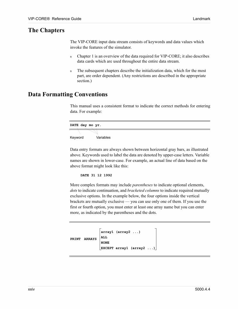
This manual uses a consistent format to indicate the correct methods for entering data. For example:
DATE day mo yr.
Keyword Variables
Data entry formats are always shown between horizontal gray bars, as illustrated above. Keywords used to label the data are denoted by upper-case letters. Variable names are shown in lower-case. For example, an actual line of data based on the above format might look like this:
DATE 31 12 1992
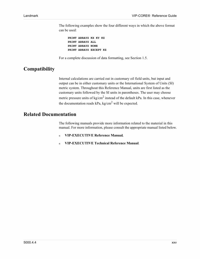
More complex formats may include parentheses to indicate optional elements, dots to indicate continuation, and bracketed columns to indicate required mutually exclusive options. In the example below, the four options inside the vertical brackets are mutually exclusive — you can use only one of them. If you use the first or fourth option, you must enter at least one array name but you can enter more, as indicated by the parentheses and the dots.
PRINT ARRAYS
array1 (array2 ...)
ALL
NONE
EXCEPT array1 (array2 ...)
xxiv 5000.4.4
Landmark VIP-CORE® Reference Guide
The following examples show the four different ways in which the above format can be used:
PRINT ARRAYS KX KY KZPRINT ARRAYS ALLPRINT ARRAYS NONEPRINT ARRAYS EXCEPT KZ
For a complete discussion of data formatting, see Section 1.5.
Compatibility
Internal calculations are carried out in customary oil field units, but input and output can be in either customary units or the International System of Units (SI) metric system. Throughout this Reference Manual, units are first listed as the customary units followed by the SI units in parentheses. The user may choose
metric pressure units of kg/cm2 instead of the default kPa. In this case, whenever
the documentation reads kPa, kg/cm2 will be expected. 00
Related Documentation
The following manuals provide more information related to the material in this manual. For more information, please consult the appropriate manual listed below.
n VIP-EXECUTIVE Reference Manual.
n VIP-EXECUTIVE Technical Reference Manual.
5000.4.4 xxv

VIP-CORE® Reference Guide Landmark
xxvi 5000.4.4
Chapter
1
00000Data Overview
1.1 Introduction
VIP-CORE® is the initialization module of the VIP-EXECUTIVE® family of simulators. It is used to calculate the initial reservoir conditions to be used by several simulation modules, including VIP-COMP®, VIP-ENCORE®, VIP-DUAL®, VIP-POLYMER®, and VIP-THERM. For example, VIP-ENCORE and VIP-DUAL could be combined to simulate a dual-porosity, dual-permeability, "black-oil" reservoir. If VIP-COMP were included in the same program, the user could convert to a fully compositional version of the dual-porosity, dual-permeability model simply by substituting the compositional specific data for the black-oil specific data.
VIP-CORE will only accept data for those modules which have been purchased. They are listed on the first page of the computer output in the title box.
The documentation for entering the initialization data for VIP-COMP, VIP-ENCORE, VIP-DUAL, VIP-POLYMER, and VIP-THERM is all included in this Reference Manual. The majority of the data required for all five of these options is identical since VIP-ENCORE is a special subset of the more generalized VIP-COMP, and VIP-DUAL is only used in conjunction with either VIP-ENCORE or VIP-COMP. Where the data differs between VIP-COMP, VIP-ENCORE, and VIP-THERM or additional data is required for VIP-DUAL, VIP-POLYMER, and VIP-THERM, the model to which the described data applies is enclosed in parentheses after the section heading.
1.1.1 VIP-COMP Overview
VIP-COMP is an n-component, equation-of-state, compositional simulator. It can simulate the flow of oil, gas, and water through an underground reservoir and predict the behavior of all associated production/injection wells. The system takes into account the fact that fluid properties and phase behavior can vary strongly with fluid composition. Fluid properties and phase equilibrium are governed by a generalized cubic equation-of-state which includes the Peng-Robinson equation (see Reference 22) and various versions of the Redlich-Kwong equation (see References 23 and 24). Both oil and gas are treated as mixtures containing an arbitrary number of hydrocarbon and nonhydrocarbon components. In addition, special techniques are implemented in VIP-COMP to provide stability and efficiency of solution for near-critical oil and gas fluid systems.
5000.4.4 1-27
VIP-CORE® Reference Guide Landmark
1.1.2 VIP-ENCORE Overview
VIP-ENCORE is a three-phase reservoir simulator which models the immiscible flow of oil, gas, and water within the reservoir. VIP-ENCORE is a special case of the generalized VIP-COMP simulator. Fluid properties can be described according to the "black-oil convention" — oil at reservoir conditions is a mixture of stock tank oil and dissolved gas. The amount of gas dissolved in the oil is determined by a bubblepoint pressure relationship.
VIP-ENCORE is able to treat water-oil or gas-water two-phase problems as special cases of the more generalized three-phase fluid system. In addition, VIP-ENCORE can process multi-component systems whose PVT properties are adequately described by pressure-dependent K-values. Thus, it can be used to model gas condensates and volatile oils more rigorously than conventional black-oil simulators.
1.1.3 VIP-DUAL Overview
NOTE: VIP-DUAL is available as a separately licensed option.
The VIP-DUAL option simulates the performance of reservoirs which are naturally fractured, heterogeneous, or highly stratified. The full dual-porosity, dual-permeability formulation allows flow in both fractures and matrix rock, thereby enabling correct and accurate modeling of reservoirs which may be highly fractured in some regions while unfractured in others.
VIP-DUAL must be used in conjunction with either VIP-ENCORE or VIP-COMP. Within VIP-DUAL, the exchange of fluids between the fracture and matrix rock is based on the Warren & Root theory, (see Reference 18) and the more recent work of Thomas, Dixon, and Pierson. (see Reference 19). Mass transfer between matrix rock and fractures includes diffusion, convection, imbibition, and gravity drainage. Imbibition and gravity drainage effects can be modeled with pseudo-capillary pressure functions. These functions are automatically and independently determined for the matrix rock and fractures and account for the matrix block and gridblock sizes. Also available is a dual porosity/single permeability option which assumes that the fractures alone are a continuous media and the matrix rock exists only as a source or sink for reservoir fluids.
1-28 5000.4.4
Landmark VIP-CORE® Reference Guide
1.1.4 VIP-POLYMER Overview
NOTE: VIP-POLYMER is available as a separately licensed option.
The VIP-POLYMER option simulates the performance of polymer flooded reservoirs. The model takes into account the major physical properties attributed to the flow of polymer solutions through porous media. These include a non-Newtonian (shear dependent) aqueous phase viscosity that is also a function of polymer concentration.
Other polymer dependent properties are: polymer adsorption, permeability reduction, and polymer inaccessible pore volume phenomenon. The well performance calculations also include the effects of non-Newtonian viscosity. The polymer is represented by a separate component, present only in the aqueous phase and occupying no volume. VIP-POLYMER must be used in conjunction with either VIP-ENCORE or VIP-COMP.
1.1.5 VIP-THERM Overview
VIP-THERM is an extension of the fully implicit formulation of VIP-COMP to include an energy balance, an equilibrium constraint for the water component, heat loss models, and temperature-dependency of all important properties. Two phase behavior models are available: 1) the n-component compositional equation of state model which VIP-THERM shares with VIP-COMP (Section 4.4) or 2) the dead oil model in which oil is treated as a single non-volatile component (Section 4.7).
The VIP-THERM compositional model is a fully implicit, n-component, equation-of-state, thermal simulator. The number of volatile components may be specified as less than or equal to the total number of components. Water and steam properties including density, enthalpy, and viscosity are obtained from a tabular input file which is separate from the file containing the data described in this manual.
The VIP-THERM dead oil model is a fully implicit three-phase reservoir simulator which models the flow of oil, water, and steam within the reservoir. This version is a special case of the generalized compositional version. Oil is represented as a single non-volatile component. Oil properties are either calculated by interpolation from input tables or are calculated from input values of oil compressibility, oil coefficient of thermal expansion, oil heat capacity, and oil viscosity as a function of temperature. Water and steam properties including density, enthalpy, and viscosity are obtained from a tabular input file which is separate from the file containing the data described in this manual.
VIP-COMP or VIP-ENCORE initialization data may easily be converted to VIP-THERM format:
1. Specify THERMAL card in VIP-CORE utility data (Section 2.2.19.1).
5000.4.4 1-29
VIP-CORE® Reference Guide Landmark
2. Specify NCV in the grid system data (Sections 2.2.3.1 or 2.2.3.2).
3. Replace Physical Property Constants table with VIP-THERM format (Section 2.2.4.2).
4. Replace VIP-ENCORE PVT data with either EOS data (Section 4.4) or Dead Oil PVT data (Section 4.7). If PCHOR was specified in VIP-COMP EOS data, that column must be removed before the data will be accepted by VIP-THERM.
5. Specify heat capacity arrays in VIP-CORE array data (Sections 5.45 and 5.46).
6. Specify heat loss data in VIP-CORE (Chapter 12).
VIP-COMP and VIP-ENCORE recurrent data may easily be converted to VIP-THERM format:
1. Specify TINJ and QUAL for all water injectors (VIP-EXECUTIVE Sections 3.4.2.1 and 3.4.2.2). Also specify PINJ (VIP-EXECUTIVE Section 3.4.2.3) for all wells for which steam quality is specified as zero or one.
2. Specify TINJ for all gas injectors (VIP-EXECUTIVE Section 3.4.2.1).
3. Modify DT cards (VIP-EXECUTIVE Section 7.1.1), ITNLIM cards (VIP-EXECUTIVE Section 7.1.3), and TOLD cards (VIP-EXECUTIVE Section 7.1.7) to include values for maximum temperature change.
4. Modify TOLR cards (VIP-EXECUTIVE Section 7.1.8) to include an energy balance tolerance.
1.1.6 Shared Features
VIP-COMP, VIP-ENCORE, VIP-DUAL, VIP-POLYMER, and VIP-THERM share all the same major features in VIP-CORE. Finite difference grids may be constructed in either rectangular (x-y-z) or radial (r--z) coordinates, using either one, two, or three dimensions. Simulations using more general curvilinear grid systems also are possible. However, in this case the user must employ the corner point feature in VIP-EXECUTIVE, or input transmissibility and pore volumes directly.
The reservoir being studied may be initialized to capillary-gravity equilibrium or to a nonequilibrium state. Under equilibrium conditions saturation pressure can vary with depth, and multiple water-oil and gas-oil contacts can be established. VIP-CORE will determine the initial reservoir pressure and saturation distributions for these cases. To achieve a nonequilibrium state both the gas and water saturations must be specified for each gridblock.
Each block in the finite difference grid is designated as containing a particular type of rock with each rock type corresponding to a particular set of relative permeability and capillary pressure curves.
1-30 5000.4.4
Landmark VIP-CORE® Reference Guide
The reservoir description may be completely heterogeneous with regard to the distribution of permeabilities, porosities, and net pay. Furthermore, each gridblock can be assigned a depth that is independent of the depths of the surrounding blocks, so there are no limits on the description of faults or varying dip angles.
Wells are controlled by a variety of options which allow both rate and pressure constraints. Wells can also be shut in, or recompleted, automatically. Rates can be adjusted to meet production and injection targets at any of the target levels. These targets levels include gathering center, flow station, area, and field.
Separator conditions are also taken into consideration for all of the simulator modules. In VIP-COMP (or in the VIP-THERM compositional model), a multi-component model, separators are required to determine surface production rates. In VIP-ENCORE, separators allow for the additional flexibility of treating flash separation conditions at the surface versus the differential calculations which take place in the reservoir.
Both VIP-COMP and VIP-ENCORE allow fully implicit (IMPLICIT) or explicit (IMPES) formulations to be selected for the integration of the flow equations. When the VIP-DUAL option or the VIP-THERM option is activated, only the fully implicit formulation is accepted for the additional required stability.
Internal calculations are carried out in customary oil field units, but input and output can be in either customary units or the International System of Units (SI) metric system. Throughout this Reference Manual, units are first listed as the customary units followed by the SI units in parentheses. The user may choose metric pressure units of kg/cm2 instead of the default kPa. In this case, whenever the documentation reads kPa, kg/cm2 will be expected.
5000.4.4 1-31
VIP-CORE® Reference Guide Landmark
1.2 Typical Data Requirements to Initialize a Simulation Study
1.2.1 Geological Descriptions
The following geological descriptions are required: 00
n Reservoir maps showing the current interpretation of the structure, gross and net sand thicknesses.
n Reservoir maps showing the distribution of pore volume (i.e., porosity - thickness product) or, if appropriate, an average porosity representative of the pool.
n Reservoir maps showing the distribution of flow capacity (i.e. permeability - thickness product) or, if appropriate, an average permeability representative of the pool.
n If the reservoir can be subdivided into geological units that display different rock quality or flow characteristics, then all previous reference maps should be available for each reservoir unit.
n For coning, cross-section, or three-dimensional studies, the well logs and core analysis results should be available to help identify reservoir layering and corresponding layer properties.
1.2.2 Reservoir Rock Characteristics
The following reservoir rock characteristics are required: 00
n Laboratory reports detailing results from relative permeability tests and end-point relative permeability or, if already reviewed by the operator, a set of relative permeability curves for each rock type (lithology related) present in the pool.
n Laboratory reports detailing the results from capillary pressure tests conducted on core samples or the operator’s best estimate of the capillary pressure characteristics of each rock type (lithologically related) present in the pool.
n Formation water analysis including the dissolved solids content.
1.2.3 Hydrocarbon Fluid Properties
The following hydrocarbon fluid properties are required: 00
n Laboratory results from fluid characterization tests performed on reservoir oil and gas samples. Both oil and gas properties are required, including composition and volume factors, viscosity, density, compressibility, and dissolved gas-oil ratios as functions of pressure.
1-32 5000.4.4
Landmark VIP-CORE® Reference Guide
n Operating conditions of field separation units to properly correct laboratory data. The location of the metering equipment should be identified to ensure that volumetric rate information input to the model is consistent with field data.
1.3 Data Deck Layout
VIP-CORE is the initialization module of VIP-EXECUTIVE. It is used to describe the reservoir and the fluids it contains, plus the initial saturation and pressure distributions.
It is possible to write sufficient information onto disk to allow a subsequent run to pick up where the first one left off. The information saved this way is called a restart record. VIP-CORE automatically writes a restart record upon completion of the initialization process. The information on this restart record is then used by VIP-EXECUTIVE simulation modules to begin the simulation.
In addition to the standard output and initialization restart record, VIP-CORE can write the initialization portion of summary records for subsequent processing by ancillary programs. The currently available menu of these data cards, the summary records they control, and the FORTRAN units on which the information is stored include:
PRINT Printer Output (Section 3.1), FORTRAN Unit 6.
MAP Grid Array Maps (Section 2.2.2.6), FORTRAN Units 9 and 27. Also the VDB file.
RESTART Restart Record automatically written upon successful initialization, FORTRAN Unit 2.
CORNER Corner-point data for post-processing (Section 3.1), FORTRAN Unit 12.
To save any or all of these records for subsequent post-processing, appropriate commands must be added to the job control stream for permanent storage of the appropriate FORTRAN units.
5000.4.4 1-33
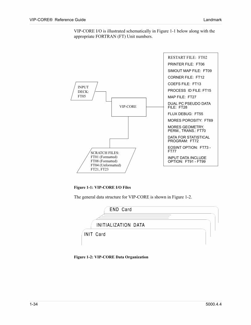
VIP-CORE® Reference Guide Landmark
VIP-CORE I/O is illustrated schematically in Figure 1-1 below along with the appropriate FORTRAN (FT) Unit numbers.
INPUTDECK:FT05
SCRATCH FILES:FT01 (Formatted)FT08 (Formatted)FT04 (Unformatted)FT21, FT23
RESTART FILE: FT02
PRINTER FILE: FT06
SIMOUT MAP FILE: FT09
CORNER FILE: FT12
COEFS FILE: FT13
PROCESS ID FILE: FT15
MAP FILE: FT27
DUAL PC PSEUDO DATA FILE: FT28
FLUX DEBUG: FT55
MORES POROSITY: FT69
MORES GEOMETRY, PERM., TRANS.: FT70
DATA FOR STATISTICAL PROGRAM: FT72
EOSINT OPTION: FT73 - FT77
INPUT DATA INCLUDE OPTION: FT91 - FT99
VIP-CORE
Figure 1-1: VIP-CORE I/O Files
The general data structure for VIP-CORE is shown in Figure 1-2. 00
Figure 1-2: VIP-CORE Data Organization
1-34 5000.4.4
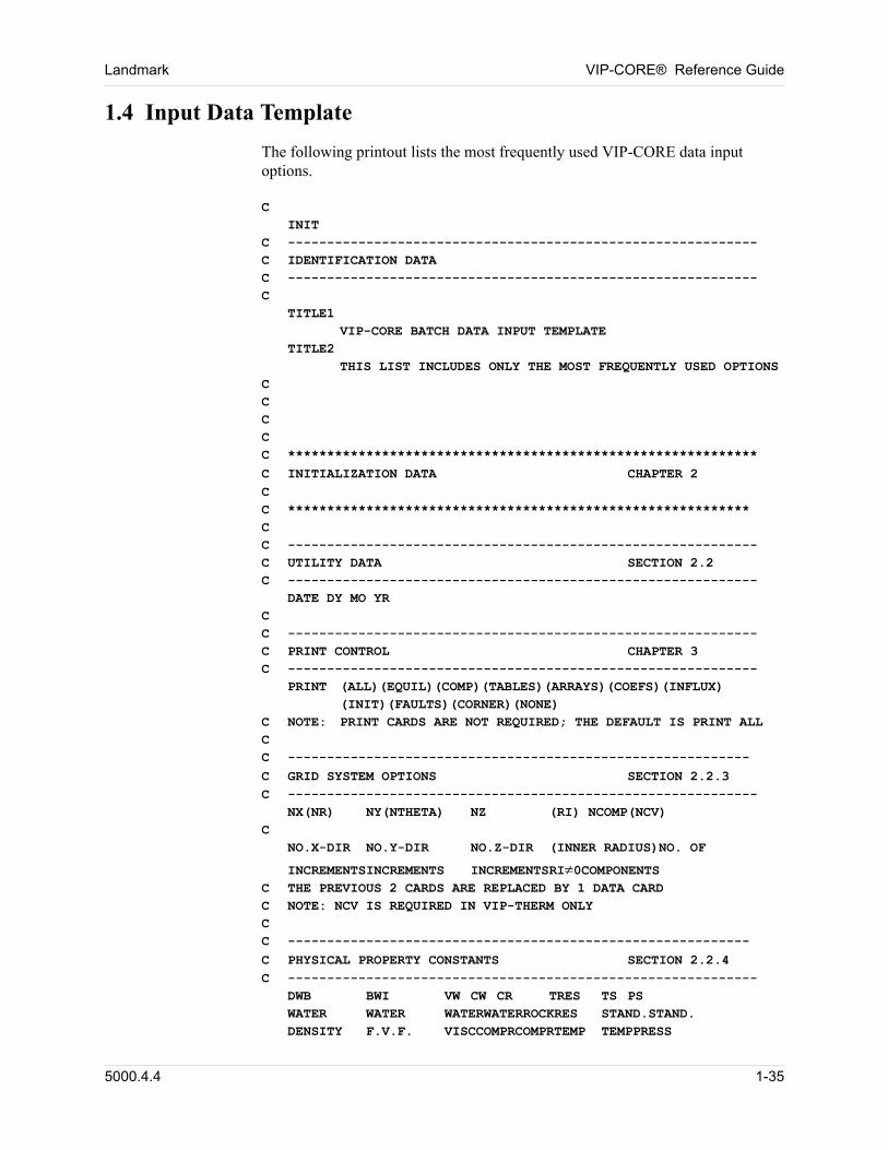
Landmark VIP-CORE® Reference Guide
1.4 Input Data Template
The following printout lists the most frequently used VIP-CORE data input options.
CINIT
C ------------------------------------------------------------C IDENTIFICATION DATAC ------------------------------------------------------------C
TITLE1VIP-CORE BATCH DATA INPUT TEMPLATE
TITLE2THIS LIST INCLUDES ONLY THE MOST FREQUENTLY USED OPTIONS
CCCCC ************************************************************
C INITIALIZATION DATA CHAPTER 2CC ***********************************************************CC ------------------------------------------------------------C UTILITY DATA SECTION 2.2C ------------------------------------------------------------
DATE DY MO YRCC ------------------------------------------------------------C PRINT CONTROL CHAPTER 3C ------------------------------------------------------------
PRINT (ALL)(EQUIL)(COMP)(TABLES)(ARRAYS)(COEFS)(INFLUX)(INIT)(FAULTS)(CORNER)(NONE)
C NOTE: PRINT CARDS ARE NOT REQUIRED; THE DEFAULT IS PRINT ALLCC -----------------------------------------------------------
C GRID SYSTEM OPTIONS SECTION 2.2.3C ------------------------------------------------------------
NX(NR) NY(NTHETA) NZ (RI) NCOMP(NCV)C
NO.X-DIR NO.Y-DIR NO.Z-DIR (INNER RADIUS)NO. OF
INCREMENTSINCREMENTS INCREMENTSRI0COMPONENTSC THE PREVIOUS 2 CARDS ARE REPLACED BY 1 DATA CARDC NOTE: NCV IS REQUIRED IN VIP-THERM ONLYCC -----------------------------------------------------------
C PHYSICAL PROPERTY CONSTANTS SECTION 2.2.4C ------------------------------------------------------------
DWB BWI VW CW CR TRES TS PSWATER WATER WATERWATERROCKRES STAND.STAND.DENSITY F.V.F. VISCCOMPRCOMPRTEMP TEMPPRESS
5000.4.4 1-35
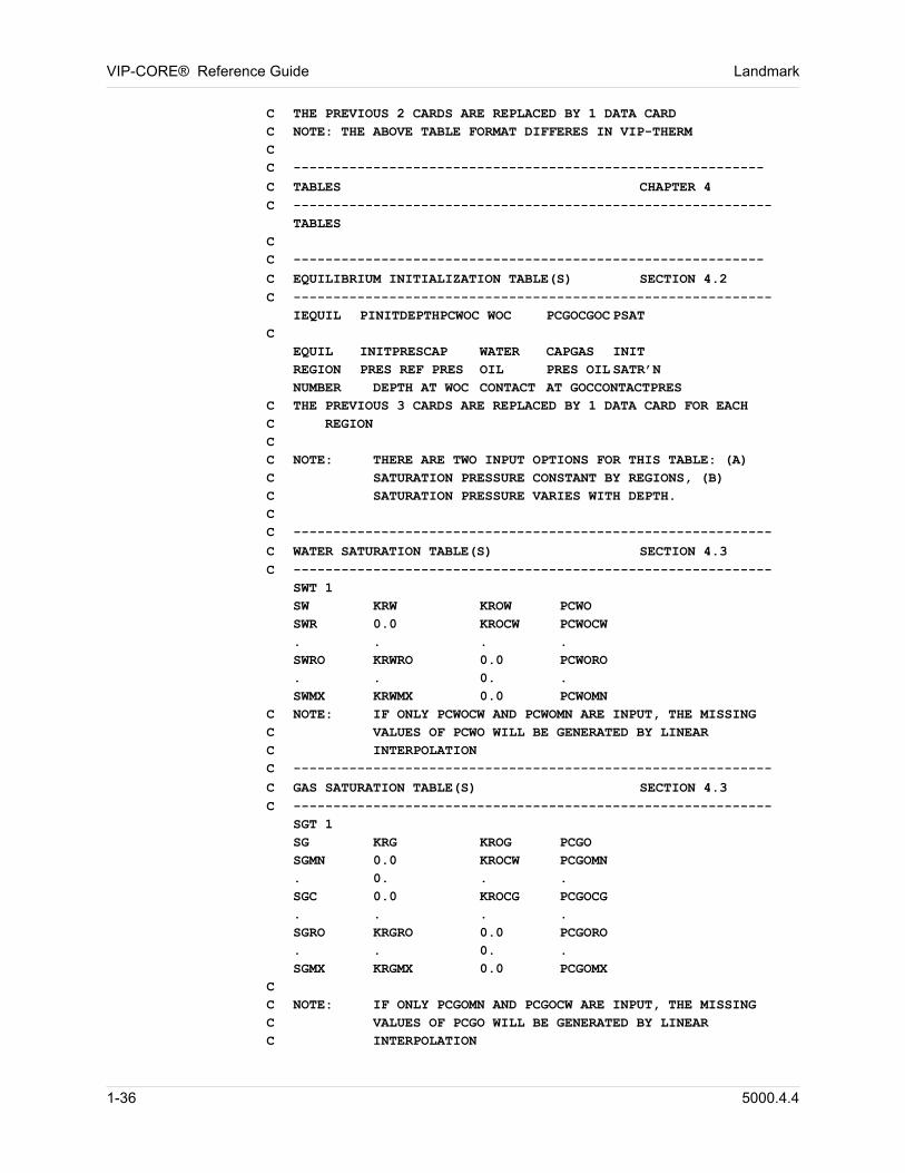
VIP-CORE® Reference Guide Landmark
C THE PREVIOUS 2 CARDS ARE REPLACED BY 1 DATA CARDC NOTE: THE ABOVE TABLE FORMAT DIFFERES IN VIP-THERMCC -----------------------------------------------------------
C TABLES CHAPTER 4C ------------------------------------------------------------
TABLESCC -----------------------------------------------------------
C EQUILIBRIUM INITIALIZATION TABLE(S) SECTION 4.2C ------------------------------------------------------------
IEQUIL PINITDEPTHPCWOC WOC PCGOCGOC PSATC
EQUIL INITPRESCAP WATER CAPGAS INITREGION PRES REF PRES OIL PRES OIL SATR’NNUMBER DEPTH AT WOC CONTACT AT GOCCONTACTPRES
C THE PREVIOUS 3 CARDS ARE REPLACED BY 1 DATA CARD FOR EACH C REGIONCC NOTE: THERE ARE TWO INPUT OPTIONS FOR THIS TABLE: (A) C SATURATION PRESSURE CONSTANT BY REGIONS, (B) C SATURATION PRESSURE VARIES WITH DEPTH.CC ------------------------------------------------------------
C WATER SATURATION TABLE(S) SECTION 4.3C ------------------------------------------------------------
SWT 1SW KRW KROW PCWOSWR 0.0 KROCW PCWOCW. . . .SWRO KRWRO 0.0 PCWORO. . 0. .SWMX KRWMX 0.0 PCWOMN
C NOTE: IF ONLY PCWOCW AND PCWOMN ARE INPUT, THE MISSING C VALUES OF PCWO WILL BE GENERATED BY LINEAR C INTERPOLATIONC ------------------------------------------------------------
C GAS SATURATION TABLE(S) SECTION 4.3C ------------------------------------------------------------
SGT 1SG KRG KROG PCGOSGMN 0.0 KROCW PCGOMN. 0. . .SGC 0.0 KROCG PCGOCG. . . .SGRO KRGRO 0.0 PCGORO. . 0. .SGMX KRGMX 0.0 PCGOMX
CC NOTE: IF ONLY PCGOMN AND PCGOCW ARE INPUT, THE MISSING C VALUES OF PCGO WILL BE GENERATED BY LINEAR C INTERPOLATION
1-36 5000.4.4
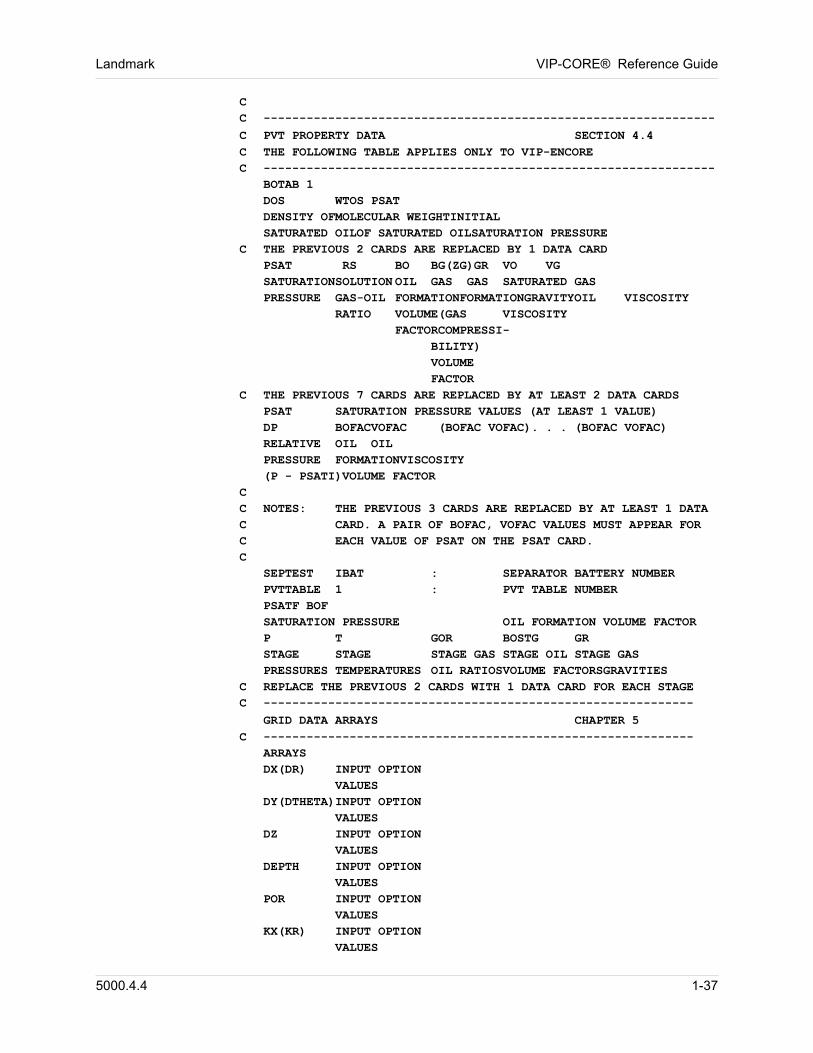
Landmark VIP-CORE® Reference Guide
CC ---------------------------------------------------------------
C PVT PROPERTY DATA SECTION 4.4C THE FOLLOWING TABLE APPLIES ONLY TO VIP-ENCOREC ---------------------------------------------------------------
BOTAB 1DOS WTOS PSATDENSITY OFMOLECULAR WEIGHTINITIALSATURATED OILOF SATURATED OILSATURATION PRESSURE
C THE PREVIOUS 2 CARDS ARE REPLACED BY 1 DATA CARDPSAT RS BO BG(ZG)GR VO VGSATURATIONSOLUTION OIL GAS GAS SATURATED GASPRESSURE GAS-OIL FORMATIONFORMATIONGRAVITYOIL VISCOSITY
RATIO VOLUME(GAS VISCOSITYFACTORCOMPRESSI-
BILITY)VOLUMEFACTOR
C THE PREVIOUS 7 CARDS ARE REPLACED BY AT LEAST 2 DATA CARDSPSAT SATURATION PRESSURE VALUES (AT LEAST 1 VALUE)DP BOFACVOFAC (BOFAC VOFAC). . . (BOFAC VOFAC)RELATIVE OIL OILPRESSURE FORMATIONVISCOSITY(P - PSATI)VOLUME FACTOR
CC NOTES: THE PREVIOUS 3 CARDS ARE REPLACED BY AT LEAST 1 DATA C CARD. A PAIR OF BOFAC, VOFAC VALUES MUST APPEAR FOR C EACH VALUE OF PSAT ON THE PSAT CARD.C
SEPTEST IBAT : SEPARATOR BATTERY NUMBERPVTTABLE 1 : PVT TABLE NUMBERPSATF BOFSATURATION PRESSURE OIL FORMATION VOLUME FACTORP T GOR BOSTG GRSTAGE STAGE STAGE GAS STAGE OIL STAGE GASPRESSURES TEMPERATURES OIL RATIOSVOLUME FACTORSGRAVITIES
C REPLACE THE PREVIOUS 2 CARDS WITH 1 DATA CARD FOR EACH STAGEC ------------------------------------------------------------
GRID DATA ARRAYS CHAPTER 5C ------------------------------------------------------------
ARRAYSDX(DR) INPUT OPTION
VALUESDY(DTHETA)INPUT OPTION
VALUESDZ INPUT OPTION
VALUESDEPTH INPUT OPTION
VALUESPOR INPUT OPTION
VALUESKX(KR) INPUT OPTION
VALUES
5000.4.4 1-37
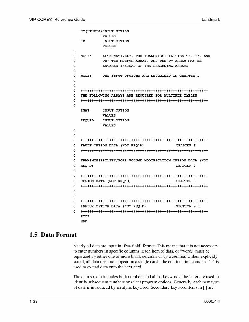
VIP-CORE® Reference Guide Landmark
KY(KTHETA)INPUT OPTION VALUES
KZ INPUT OPTIONVALUES
CC NOTE: ALTERNATIVELY, THE TRANSMISSIBILITIES TX, TY, AND C TZ; THE MDEPTH ARRAY; AND THE PV ARRAY MAY BE C ENTERED INSTEAD OF THE PRECEDING ARRAYSCC NOTE: THE INPUT OPTIONS ARE DESCRIBED IN CHAPTER 1CCC ++++++++++++++++++++++++++++++++++++++++++++++++++++++++++C THE FOLLOWING ARRAYS ARE REQUIRED FOR MULTIPLE TABLESC ++++++++++++++++++++++++++++++++++++++++++++++++++++++++++C
ISAT INPUT OPTIONVALUES
IEQUIL INPUT OPTIONVALUES
CCC ++++++++++++++++++++++++++++++++++++++++++++++++++++++++++
C FAULT OPTION DATA (NOT REQ’D) CHAPTER 6C ++++++++++++++++++++++++++++++++++++++++++++++++++++++++++CC TRANSMISSIBILITY/PORE VOLUME MODIFICATION OPTION DATA (NOT
C REQ’D) CHAPTER 7CC ++++++++++++++++++++++++++++++++++++++++++++++++++++++++++
C REGION DATA (NOT REQ’D) CHAPTER 8C ++++++++++++++++++++++++++++++++++++++++++++++++++++++++++CCC ++++++++++++++++++++++++++++++++++++++++++++++++++++++++++
C INFLUX OPTION DATA (NOT REQ’D) SECTION 9.1C ++++++++++++++++++++++++++++++++++++++++++++++++++++++++++
STOPEND
1.5 Data Format
Nearly all data are input in ‘free field’ format. This means that it is not necessary to enter numbers in specific columns. Each item of data, or "word,” must be separated by either one or more blank columns or by a comma. Unless explicitly stated, all data need not appear on a single card - the continuation character ‘>’ is used to extend data onto the next card.
The data stream includes both numbers and alpha keywords; the latter are used to identify subsequent numbers or select program options. Generally, each new type of data is introduced by an alpha keyword. Secondary keyword items in [ ] are
1-38 5000.4.4
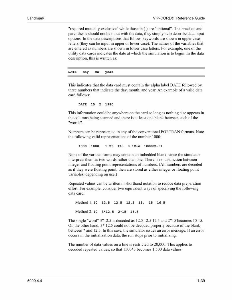
Landmark VIP-CORE® Reference Guide
"required mutually exclusive" while those in ( ) are "optional". The brackets and parenthesis should not be input with the data, they simply help describe data input options. In the data descriptions that follow, keywords are shown in upper case letters (they can be input in upper or lower case). The names of the variables that are entered as numbers are shown in lower case letters. For example, one of the utility data cards indicates the date at which the simulation is to begin. In the data description, this is written as:
DATE day mo year
This indicates that the data card must contain the alpha label DATE followed by three numbers that indicate the day, month, and year. An example of a valid data card follows:
DATE 15 2 1980
This information could be anywhere on the card so long as nothing else appears in the columns being scanned and there is at least one blank between each of the "words".
Numbers can be represented in any of the conventional FORTRAN formats. Note the following valid representations of the number 1000:
1000 1000. 1.E3 1E3 0.1E+4 10000E-01
None of the various forms may contain an imbedded blank, since the simulator interprets them as two words rather than one. There is no distinction between integer and floating point representations of numbers. (All numbers are decoded as if they were floating point, then are stored as either integer or floating point variables, depending on use.)
Repeated values can be written in shorthand notation to reduce data preparation effort. For example, consider two equivalent ways of specifying the following data card:
Method 1: 10 12.5 12.5 12.5 15. 15 16.5
Method 2: 10 3*12.5 2*15 16.5
The single "word" 3*12.5 is decoded as 12.5 12.5 12.5 and 2*15 becomes 15 15. On the other hand, 3* 12.5 could not be decoded properly because of the blank between * and 12.5. In this case, the simulator issues an error message. If an error occurs in the initialization data, the run stops prior to initializing.
The number of data values on a line is restricted to 20,000. This applies to decoded repeated values, so that 1500*3 becomes 1,500 data values.
5000.4.4 1-39
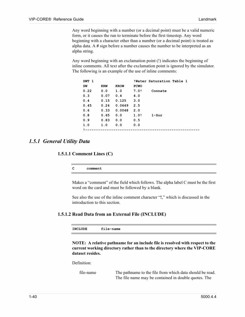
VIP-CORE® Reference Guide Landmark
Any word beginning with a number (or a decimal point) must be a valid numeric form, or it causes the run to terminate before the first timestep. Any word beginning with a character other than a number (or a decimal point) is treated as alpha data. A # sign before a number causes the number to be interpreted as an alpha string.
Any word beginning with an exclamation point (!) indicates the beginning of inline comments. All text after the exclamation point is ignored by the simulator. The following is an example of the use of inline comments:
SWT 1 !Water Saturation Table 1SW KRW KROW PCWO0.22 0.0 1.0 7.0! Connate0.3 0.07 0.4 4.00.4 0.15 0.125 3.00.45 0.24 0.0649 2.50.6 0.33 0.0048 2.00.8 0.65 0.0 1.0! 1-Sor0.9 0.83 0.0 0.51.0 1.0 0.0 0.0!-----------------------------------------------------
1.5.1 General Utility Data
1.5.1.1 Comment Lines (C)
C comment
Makes a “comment” of the field which follows. The alpha label C must be the first word on the card and must be followed by a blank.
See also the use of the inline comment character “!,” which is discussed in the introduction to this section.
1.5.1.2 Read Data from an External File (INCLUDE)
INCLUDE file-name
NOTE: A relative pathname for an include file is resolved with respect to the current working directory rather than to the directory where the VIP-CORE dataset resides. 00
Definition: 00
file-name The pathname to the file from which data should be read. The file name may be contained in double quotes. The
1-40 5000.4.4
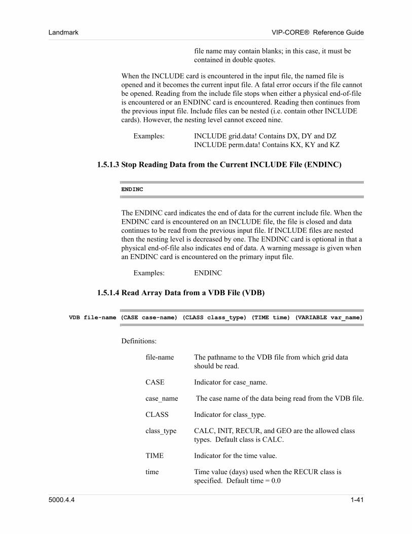
Landmark VIP-CORE® Reference Guide
file name may contain blanks; in this case, it must be contained in double quotes.
When the INCLUDE card is encountered in the input file, the named file is opened and it becomes the current input file. A fatal error occurs if the file cannot be opened. Reading from the include file stops when either a physical end-of-file is encountered or an ENDINC card is encountered. Reading then continues from the previous input file. Include files can be nested (i.e. contain other INCLUDE cards). However, the nesting level cannot exceed nine.
Examples: INCLUDE grid.data! Contains DX, DY and DZINCLUDE perm.data! Contains KX, KY and KZ
1.5.1.3 Stop Reading Data from the Current INCLUDE File (ENDINC)
ENDINC
The ENDINC card indicates the end of data for the current include file. When the ENDINC card is encountered on an INCLUDE file, the file is closed and data continues to be read from the previous input file. If INCLUDE files are nested then the nesting level is decreased by one. The ENDINC card is optional in that a physical end-of-file also indicates end of data. A warning message is given when an ENDINC card is encountered on the primary input file.
Examples: ENDINC
1.5.1.4 Read Array Data from a VDB File (VDB)
VDB file-name (CASE case-name) (CLASS class_type) (TIME time) (VARIABLE var_name)
Definitions:
file-name The pathname to the VDB file from which grid data should be read.
CASE Indicator for case_name.
case_name The case name of the data being read from the VDB file.
CLASS Indicator for class_type.
class_type CALC, INIT, RECUR, and GEO are the allowed class types. Default class is CALC.
TIME Indicator for the time value.
time Time value (days) used when the RECUR class is specified. Default time = 0.0
5000.4.4 1-41
VIP-CORE® Reference Guide Landmark
VARIABLE Indicator for the var_name.
var_name Variable name that exists in the VDB. Default is the name of the array specified preceding the VDB line. Var_name is required when reading VMOD data, (Section 1.5.4.3).
If the case name is entered, obviously it must exist in the VDB file. If the case name is not entered, then only one case name may exist in the VDB file.
The file name may be contained in double quotes. The name may contain blanks; in this case, it must be contained in double quotes.
1.5.1.5 Echo Print On (LIST)
LIST
LIST and NOLIST cards control printing of card images of the data read. Until a NOLIST Card is entered, LIST is assumed.
Examples: LIST
1.5.1.6 Echo Print Off (NOLIST)
NOLIST
If NOLIST is read, printing of card images is suppressed until a LIST card is read.
Examples: NOLIST
1.5.1.7 Skip Data On (SKIP)
SKIP
A skip card indicates that all subsequent data is ignored until a NOSKIP card is encountered; i.e., it is as if all the cards were comment lines. The card images are not printed.
Example: SKIP...NOSKIP
1-42 5000.4.4
Landmark VIP-CORE® Reference Guide
1.5.1.8 Skip Data Off (NOSKIP)
NOSKIP
A NOSKIP card ends the skip data option.
1.5.1.9 Number of Printed Lines Per Page (NLINES)
NLINES nlines
Definition: 00
nlines The maximum number of lines to be printed on a page. Default is 60.
The number of lines to be printed on a page of array output can be specified. This card facilitates printing on short paper.
Examples: NLINES 60
1.5.1.10 Columns To Be Read (NCOL)
NCOL ncol
Definition: 00
ncol Number of columns to be scanned for data; value must be between 30 and 1000, inclusive. Default is 1000.
Only the columns 1 to ncol will be processed. Items beyond column ncol will be ignored (e.g. comments).
Examples: In order to limit processing to the first 45 columns: NCOL 45
1.5.1.11 Data Line Continuation
Data required to be entered in a single record may be input on multiple lines by entering a “greater than” (>) character at the end of each data line to be continued.
1.5.2 Array Input Options
Reservoir properties, such as porosity, absolute permeability, depths, and gridblock locations or dimensions, can vary spatially in VIP-CORE. A value of any one of these properties must be specified for each gridblock in the reservoir
5000.4.4 1-43
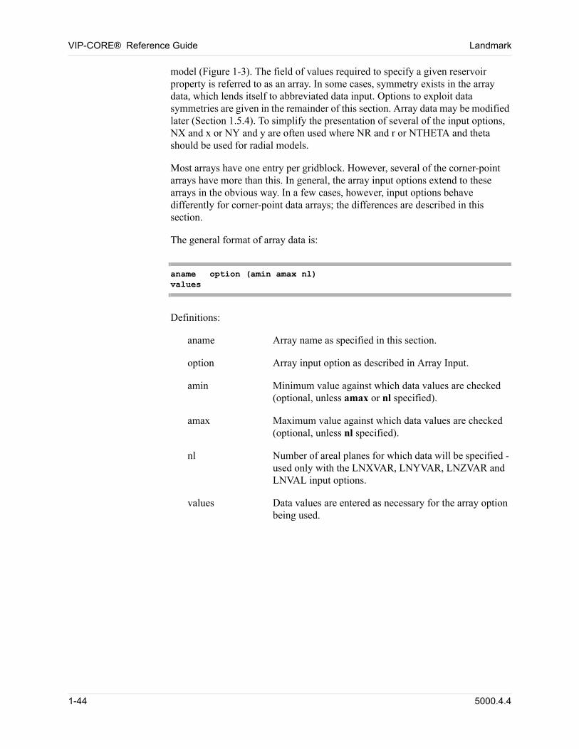
VIP-CORE® Reference Guide Landmark
model (Figure 1-3). The field of values required to specify a given reservoir property is referred to as an array. In some cases, symmetry exists in the array data, which lends itself to abbreviated data input. Options to exploit data symmetries are given in the remainder of this section. Array data may be modified later (Section 1.5.4). To simplify the presentation of several of the input options, NX and x or NY and y are often used where NR and r or NTHETA and theta should be used for radial models.
Most arrays have one entry per gridblock. However, several of the corner-point arrays have more than this. In general, the array input options extend to these arrays in the obvious way. In a few cases, however, input options behave differently for corner-point data arrays; the differences are described in this section.
The general format of array data is: 00
aname option (amin amax nl)values
Definitions: 00
aname Array name as specified in this section.
option Array input option as described in Array Input.
amin Minimum value against which data values are checked (optional, unless amax or nl specified).
amax Maximum value against which data values are checked (optional, unless nl specified).
nl Number of areal planes for which data will be specified - used only with the LNXVAR, LNYVAR, LNZVAR and LNVAL input options.
values Data values are entered as necessary for the array option being used.
1-44 5000.4.4
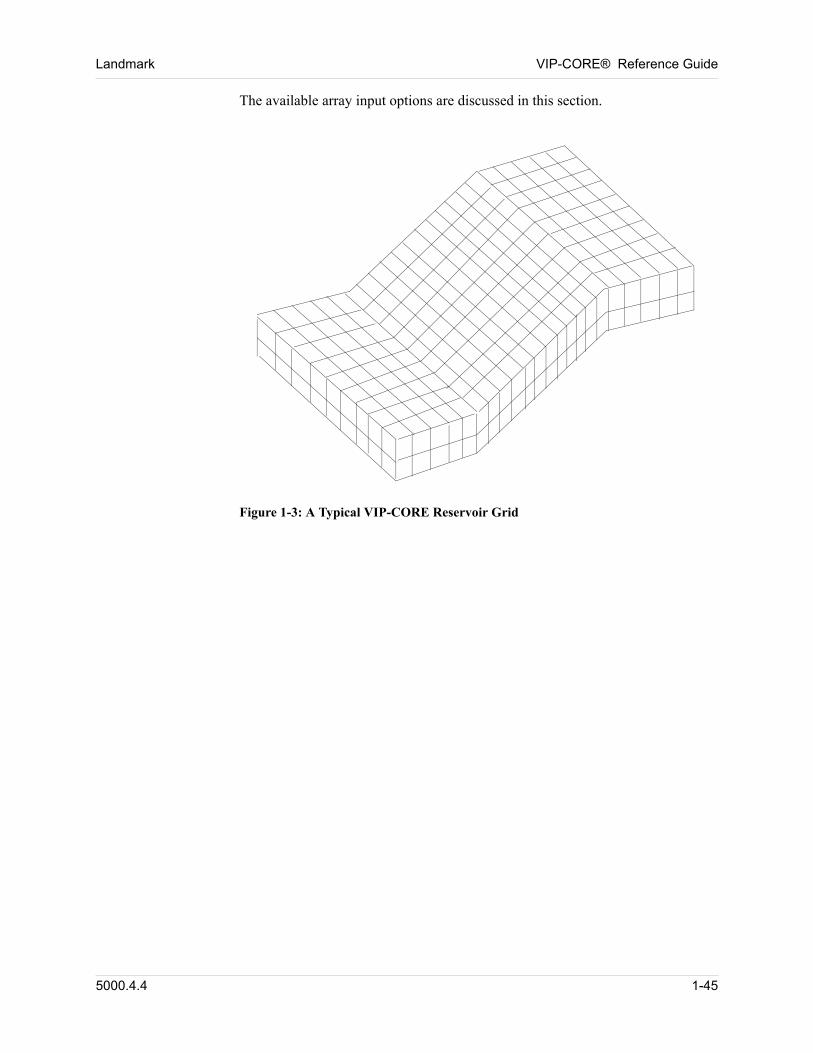
Landmark VIP-CORE® Reference Guide
The available array input options are discussed in this section. 00
Figure 1-3: A Typical VIP-CORE Reservoir Grid
5000.4.4 1-45
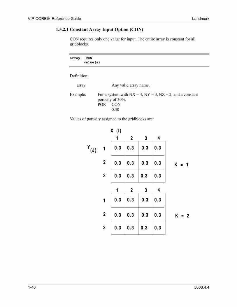
VIP-CORE® Reference Guide Landmark
1.5.2.1 Constant Array Input Option (CON)
CON requires only one value for input. The entire array is constant for all gridblocks.
array CONvalue(s)
Definition: 00
array Any valid array name.
Example: For a system with NX = 4, NY = 3, NZ = 2, and a constant porosity of 30%.POR CON
0.30 00
Values of porosity assigned to the gridblocks are: 00
1-46 5000.4.4
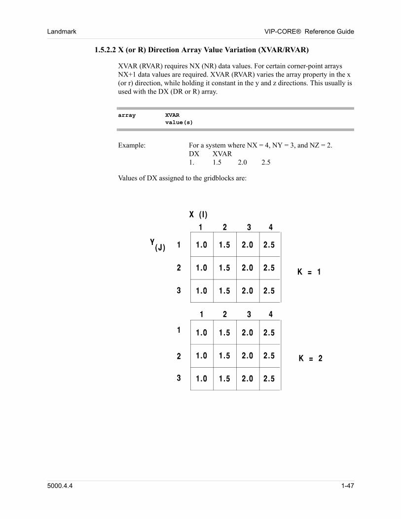
Landmark VIP-CORE® Reference Guide
1.5.2.2 X (or R) Direction Array Value Variation (XVAR/RVAR)
XVAR (RVAR) requires NX (NR) data values. For certain corner-point arrays NX+1 data values are required. XVAR (RVAR) varies the array property in the x (or r) direction, while holding it constant in the y and z directions. This usually is used with the DX (DR or R) array.
array XVARvalue(s)
Example: For a system where NX = 4, NY = 3, and NZ = 2.DX XVAR1. 1.5 2.0 2.5 00
Values of DX assigned to the gridblocks are: 00
5000.4.4 1-47
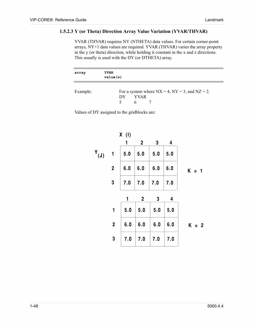
VIP-CORE® Reference Guide Landmark
1.5.2.3 Y (or Theta) Direction Array Value Variation (YVAR/THVAR)
YVAR (THVAR) requires NY (NTHETA) data values. For certain corner-point arrays, NY+1 data values are required. YVAR (THVAR) varies the array property in the y (or theta) direction, while holding it constant in the x and z directions. This usually is used with the DY (or DTHETA) array.
array YVARvalue(s)
Example: For a system where NX = 4, NY = 3, and NZ = 2.DY YVAR5 6 7 00
Values of DY assigned to the gridblocks are: 00
1-48 5000.4.4
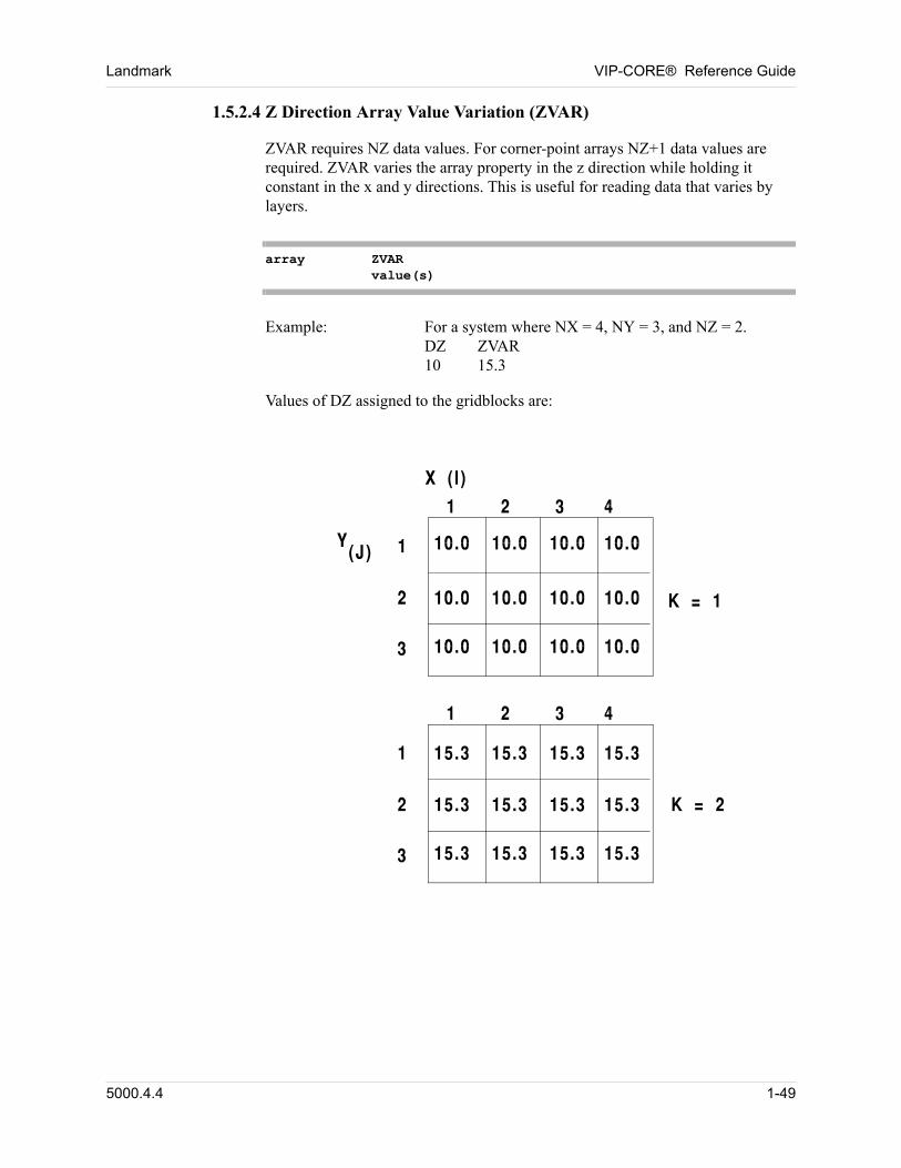
Landmark VIP-CORE® Reference Guide
1.5.2.4 Z Direction Array Value Variation (ZVAR)
ZVAR requires NZ data values. For corner-point arrays NZ+1 data values are required. ZVAR varies the array property in the z direction while holding it constant in the x and y directions. This is useful for reading data that varies by layers.
array ZVARvalue(s)
Example: For a system where NX = 4, NY = 3, and NZ = 2.DZ ZVAR10 15.3 00
Values of DZ assigned to the gridblocks are: 00
5000.4.4 1-49
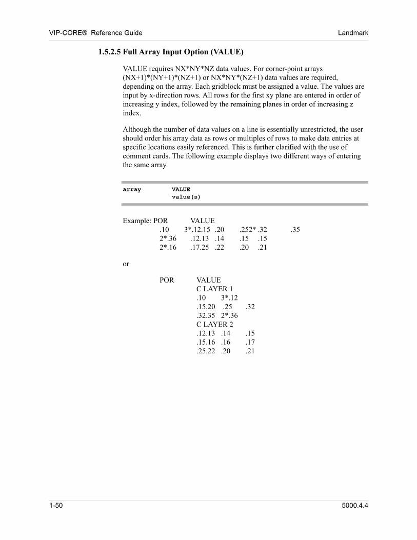
VIP-CORE® Reference Guide Landmark
1.5.2.5 Full Array Input Option (VALUE)
VALUE requires NX*NY*NZ data values. For corner-point arrays (NX+1)*(NY+1)*(NZ+1) or NX*NY*(NZ+1) data values are required, depending on the array. Each gridblock must be assigned a value. The values are input by x-direction rows. All rows for the first xy plane are entered in order of increasing y index, followed by the remaining planes in order of increasing z index.
Although the number of data values on a line is essentially unrestricted, the user should order his array data as rows or multiples of rows to make data entries at specific locations easily referenced. This is further clarified with the use of comment cards. The following example displays two different ways of entering the same array.
array VALUEvalue(s)
Example: POR VALUE.10 3*.12.15 .20 .252* .32 .352*.36 .12.13 .14 .15 .152*.16 .17.25 .22 .20 .21 00
or 00
POR VALUEC LAYER 1.10 3*.12.15.20 .25 .32.32.35 2*.36C LAYER 2.12.13 .14 .15.15.16 .16 .17.25.22 .20 .21 00
1-50 5000.4.4
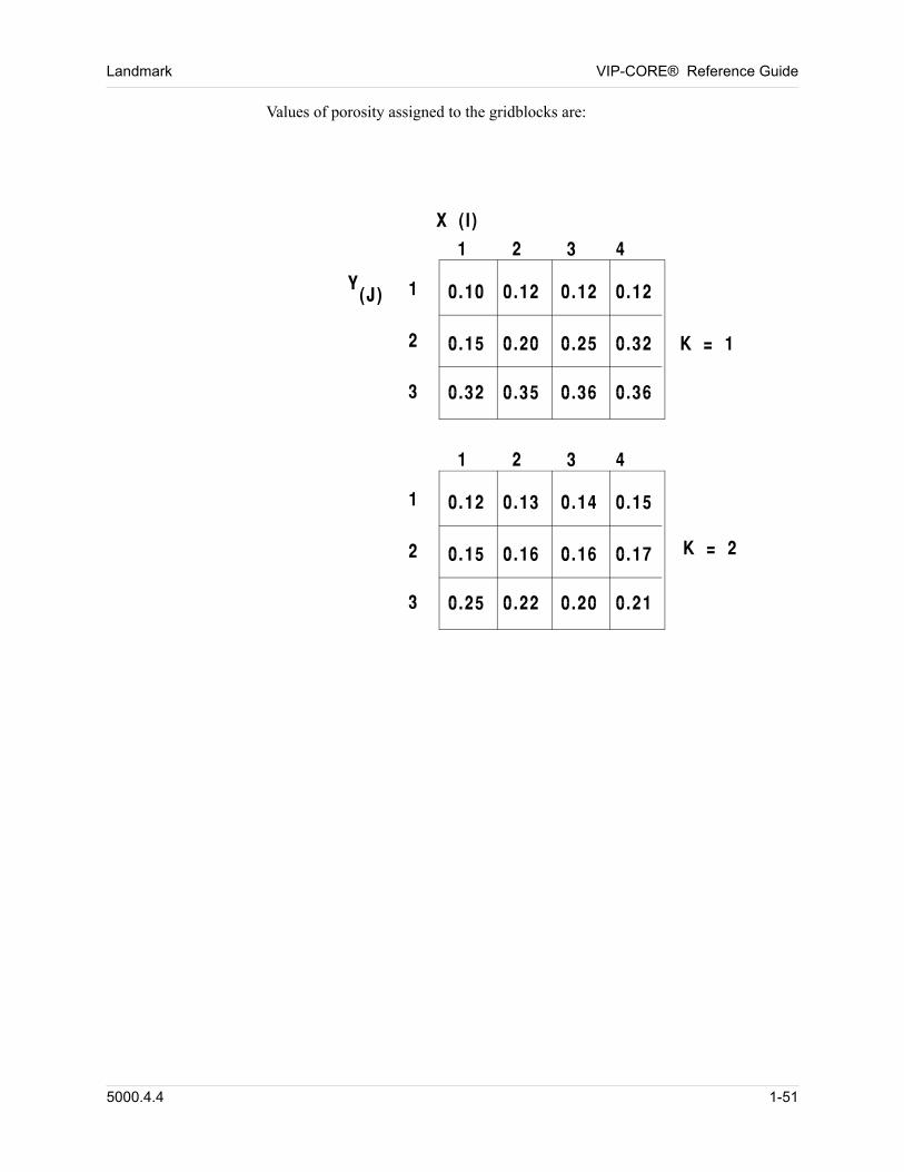
Landmark VIP-CORE® Reference Guide
Values of porosity assigned to the gridblocks are: 00
5000.4.4 1-51
VIP-CORE® Reference Guide Landmark
1.5.2.6 Automatic Generation of Values for Layers 2 - Nz (LAYER)
The LAYER option may be used with any input data arrays, but it is particularly useful for the DEPTH, MDEPTH, or ZCORN arrays. With all but these three arrays, the LAYER option replicates the values provided for the first layer for each of the other layers of the grid. When used with non-corner-point arrays or with the ZCORNE, ZCORNW, or ZCORSW arrays, the LAYER option requires NX*NY values. When used with other corner-point arrays, the LAYER option requires (NX+1)*(NY+1) data values.
To use the LAYER option with the DEPTH or MDEPTH arrays, the DZ array must have been read previously. The depth of each gridblock in the first layer (K = 1) is read. The depths of the remaining gridblocks are then calculated from the depths of the gridblocks in the first layer and gridblock thicknesses.
To use the LAYER option with the ZCORN array, the XCORN and YCORN arrays and one of the corner-point thickness arrays DZCORN, DZVCOR, or DZBCOR must have been previously read. In this case the LAYER option not only adjusts the values of the ZCORN array, but also it may adjust the values of the XCORN and YCORN arrays depending on which of the corner-point thickness arrays are read. If the DZCORN array is read, then no adjustment is made to the XCORN or YCORN arrays; the LAYER option works in this case as it does for DEPTH or MDEPTH. However, if either the DZBCOR or DZVCOR arrays are read, then only the top layer values of the XCORN and YCORN arrays are kept; the values in the other layers are adjusted so that the dip of the top layer is mimicked in succeeding layers and the specified thickness data is honored. The difference between the DZBCOR and DZVCOR is the interpretation of the thickness: for DZBCOR, thickness is the thickness perpendicular to the bedding plane, while for DZVCOR it is the depth difference between a corner point in one layer and the corresponding corner point in the next layer.
When MOD cards (Section 1.5.4.1) are used with this option only the specified locations are changed; the depths of the locations not specified on the MOD cards are not recalculated. For example, if the depths of layer 1 are modified, then the depths of the other layers are not recalculated. Thus,
DEPTH (layer 2) DEPTH (layer 1) + DZ (layer 1). 00
Indiscriminate use of the MOD card may therefore result in different layers occupying the same or overlapping positions.
To avoid this problem MODLYR cards (Section 1.5.4.2) may be used. When the depths of layer 1 are modified using MODLYR cards, the depths of the remaining layers are recalculated.
Although the number of data values on a line is restricted to 20,000, the user should order his array data as rows or multiples of rows to make data entries at specific locations easily referenced.
array LAYER
1-52 5000.4.4
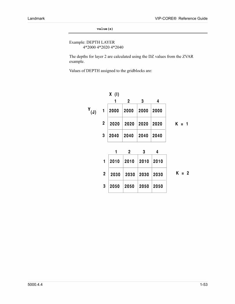
Landmark VIP-CORE® Reference Guide
value(s)
Example: DEPTH LAYER4*2000 4*2020 4*2040 00
The depths for layer 2 are calculated using the DZ values from the ZVAR example.
Values of DEPTH assigned to the gridblocks are: 00
5000.4.4 1-53
VIP-CORE® Reference Guide Landmark
1.5.2.7 Block Depths From Origin (DIP)
The DIP option can be used only to enter the ZCORN, DEPTH or MDEPTH arrays. When used for the ZCORN array, the XCORN and YCORN arrays and one of the corner-point thickness arrays must have been previously read. When used with the DEPTH or MDEPTH arrays, either the DZ or the H array must have been previously read. Using the DIP option, VIP-CORE calculates the data values for the first layer of gridblocks based upon the DIP information, then calculates the depths for the remaining gridblocks based upon the thicknesses using the LAYER option.
For a rectangular coordinate system, the depth of each gridblock in the first layer is calculated from a reference depth (dref), the dip angle in the x direction (xdip), and the dip angle in the y direction (ydip). For a radial coordinate system, the depth of each gridblock is calculated from a reference depth (dref), the steepest dip angle in the radial direction (rdip), and the angle between the radial of steepest dip angle and the 0 radial (theta). Positive dip angles indicate increasing depth. Angles must be entered in decimal degrees. Minutes should be converted to decimal fractions of a degree.
If only the reference depth is given, the system is considered non-dipping and each gridblock in the first layer is assigned the depth value dref.
After a depth value is calculated/assigned for each gridblock in the first layer, the depths of the remaining layers are calculated from the depths of the first layer and gridblock thicknesses.
When MOD cards (Section 1.5.4.1) are used with this option only the specified locations are changed; the depths of the locations not specified on the MOD cards are not recalculated. For example, if the depths of layer 1 are modified, then the depths of the other layers are not recalculated. Thus,
DEPTH (layer 2) DEPTH (layer 1) + DZ (layer 1). 00
Indiscriminate use of the MOD card may therefore result in different layers occupying the same or overlapping positions.
To avoid this problem, MODLYR cards (Section 1.5.4.2) may be used. When the depths of layer 1 are modified using MODLYR cards, the depths of the remaining layers are recalculated.
Using the DIP option for radial coordinates does NOT result in a cone. Instead, it results in a dipping cylinder in which elevations at 180 degrees will decrease moving outward from the well at the same slope that elevations will increase along the 0 degree plane.
1-54 5000.4.4
Landmark VIP-CORE® Reference Guide
For Rectangular Coordinates 00
DEPTH DIPdref xdip ydip
Definitions: 00
dref Depth to the top (DEPTH) or middle (MDEPTH) of gridblock (1,1,1) or depth to corner point (1,1,1) when used for the ZCORN array, in a cartesian grid, ft (m).
xdip Dip in the x direction, measured between the x axis and horizontal, decimal degrees. This can be omitted if both xdip and ydip are equal to zero. A positive value indicates increasing depth.
ydip Dip in the y direction, measured between the y axis and the horizontal, decimal degrees. This can be omitted if it is equal to zero. A positive value indicates increasing depth.
For Radial Coordinates 00
DEPTH DIPdref rdip theta
Definitions: 00
dref Depth to the origin of the radial grid system, ft (m).
rdip The angle measured between the radial of steepest dip angle and the horizontal, decimal degrees. This can be omitted if both rdip and theta are equal to zero. A positive value indicates increasing depth.
theta The angle between the 0 radial and the radial of steepest dip angle, decimal degrees. This can be omitted if it is equal to zero.
Example 1Given:dref = 1575 feetxdip = 0 degreesydip = 32 degrees
Input: MDEPTH DIP
1575 0 32 00
5000.4.4 1-55
VIP-CORE® Reference Guide Landmark
Example 2 Given:dref = 2000 feetrdip = 15 degreestheta = 0 degrees (This can be omitted.)
Input: DEPTH DIP
2000 15 00
1.5.2.8 Define New Array From Previously Defined Array (MULT)
The MULT option allows the user to define a new array from a previously-defined array. Each element of the new array is a constant multiple of the previously defined array. If the new array is the ZCORNE, ZCORNW, or ZCORSW array, and if the previously-defined array is the ZCORN array, then the program automatically matches up corner points in ZCORN and the new array. In all other cases, the new array and the previously-defined array should have the same dimensions.
array MULTmult array
Definitions: 00
array Any valid array name.
mult Multiplier to use with the specified array.
Example: KZ MULT.1 KX 00
In this example, kzi = 0.1 * kxi for all gridblocks i. 00
1.5.2.9 Directional Relative Permeability Option (dir) (Not Available in VIP-THERM)
The directional relative permeability option allows each gridblock to have different relative permeability values in each flow direction. For vertical equilibrium (VE) models, the program will internally generate the relative permeability functions. For non-VE models, the user must assign saturation function tables and/or relative permeability endpoints for each flow direction for which there is variation.
array dirvalue(s)
1-56 5000.4.4
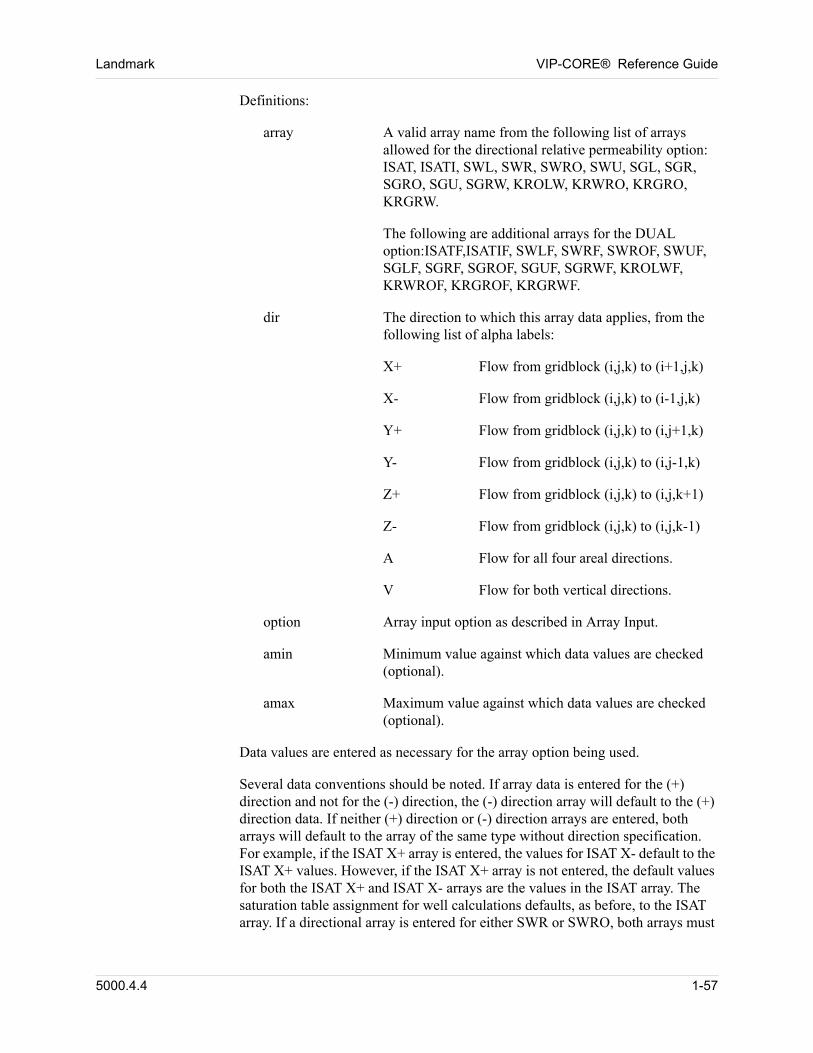
Landmark VIP-CORE® Reference Guide
Definitions: 00
array A valid array name from the following list of arrays allowed for the directional relative permeability option: ISAT, ISATI, SWL, SWR, SWRO, SWU, SGL, SGR, SGRO, SGU, SGRW, KROLW, KRWRO, KRGRO, KRGRW.
The following are additional arrays for the DUAL option:ISATF,ISATIF, SWLF, SWRF, SWROF, SWUF, SGLF, SGRF, SGROF, SGUF, SGRWF, KROLWF, KRWROF, KRGROF, KRGRWF.
dir The direction to which this array data applies, from the following list of alpha labels:
X+ Flow from gridblock (i,j,k) to (i+1,j,k)
X- Flow from gridblock (i,j,k) to (i-1,j,k)
Y+ Flow from gridblock (i,j,k) to (i,j+1,k)
Y- Flow from gridblock (i,j,k) to (i,j-1,k)
Z+ Flow from gridblock (i,j,k) to (i,j,k+1)
Z- Flow from gridblock (i,j,k) to (i,j,k-1)
A Flow for all four areal directions.
V Flow for both vertical directions.
option Array input option as described in Array Input.
amin Minimum value against which data values are checked (optional).
amax Maximum value against which data values are checked (optional).
Data values are entered as necessary for the array option being used. 00
Several data conventions should be noted. If array data is entered for the (+) direction and not for the (-) direction, the (-) direction array will default to the (+) direction data. If neither (+) direction or (-) direction arrays are entered, both arrays will default to the array of the same type without direction specification. For example, if the ISAT X+ array is entered, the values for ISAT X- default to the ISAT X+ values. However, if the ISAT X+ array is not entered, the default values for both the ISAT X+ and ISAT X- arrays are the values in the ISAT array. The saturation table assignment for well calculations defaults, as before, to the ISAT array. If a directional array is entered for either SWR or SWRO, both arrays must
5000.4.4 1-57
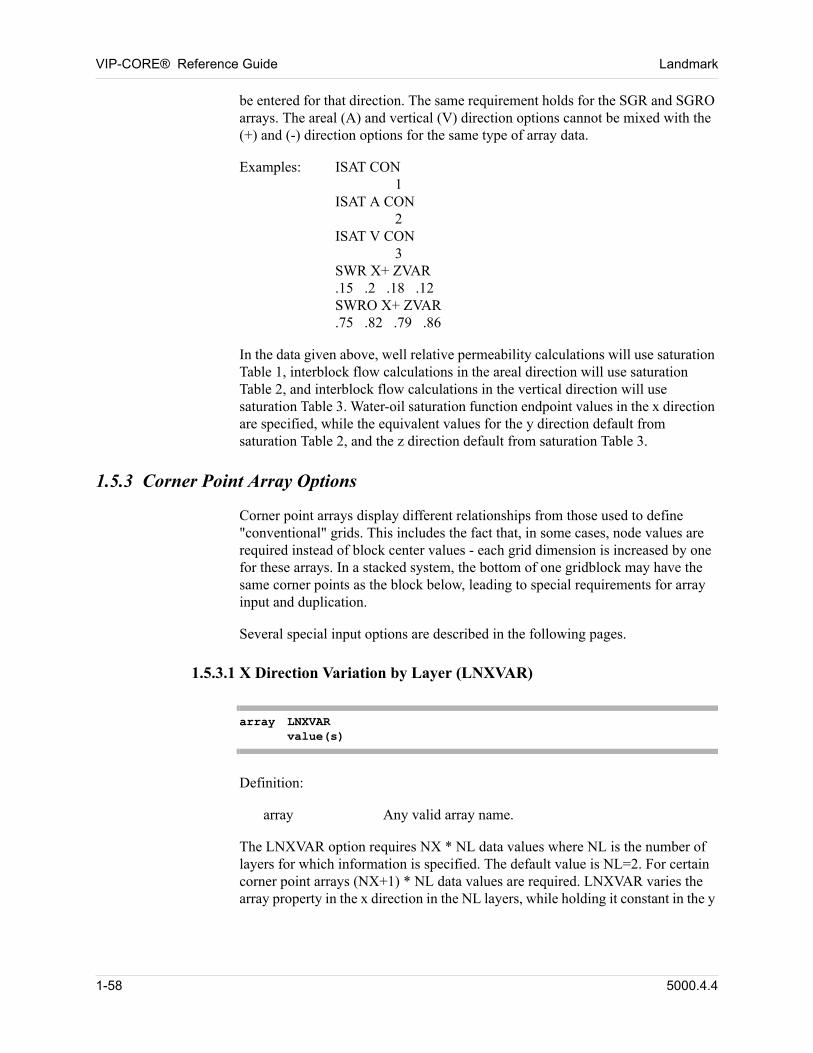
VIP-CORE® Reference Guide Landmark
be entered for that direction. The same requirement holds for the SGR and SGRO arrays. The areal (A) and vertical (V) direction options cannot be mixed with the (+) and (-) direction options for the same type of array data.
Examples: ISAT CON1
ISAT A CON2
ISAT V CON3
SWR X+ ZVAR.15 .2 .18 .12SWRO X+ ZVAR.75 .82 .79 .86 00
In the data given above, well relative permeability calculations will use saturation Table 1, interblock flow calculations in the areal direction will use saturation Table 2, and interblock flow calculations in the vertical direction will use saturation Table 3. Water-oil saturation function endpoint values in the x direction are specified, while the equivalent values for the y direction default from saturation Table 2, and the z direction default from saturation Table 3.
1.5.3 Corner Point Array Options
Corner point arrays display different relationships from those used to define "conventional" grids. This includes the fact that, in some cases, node values are required instead of block center values - each grid dimension is increased by one for these arrays. In a stacked system, the bottom of one gridblock may have the same corner points as the block below, leading to special requirements for array input and duplication.
Several special input options are described in the following pages. 00
1.5.3.1 X Direction Variation by Layer (LNXVAR)
array LNXVARvalue(s)
Definition: 00
array Any valid array name.
The LNXVAR option requires NX * NL data values where NL is the number of layers for which information is specified. The default value is NL=2. For certain corner point arrays (NX+1) * NL data values are required. LNXVAR varies the array property in the x direction in the NL layers, while holding it constant in the y
1-58 5000.4.4
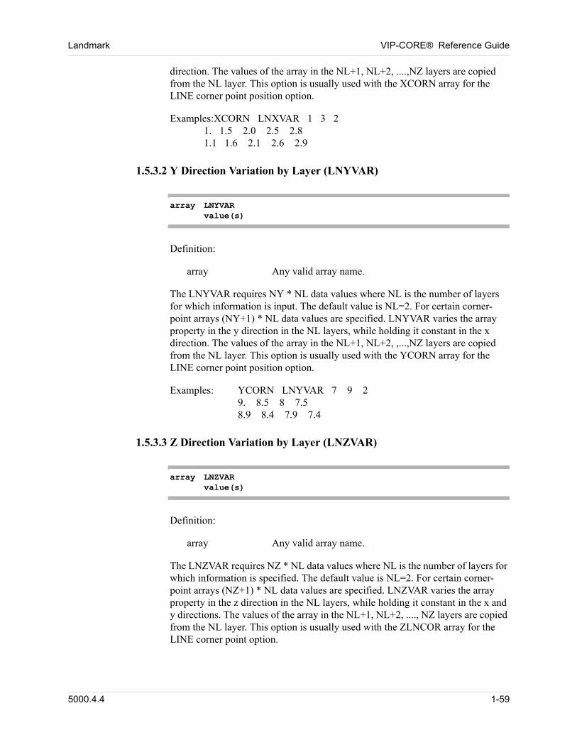
Landmark VIP-CORE® Reference Guide
direction. The values of the array in the NL+1, NL+2, ....,NZ layers are copied from the NL layer. This option is usually used with the XCORN array for the LINE corner point position option.
Examples:XCORN LNXVAR 1 3 21. 1.5 2.0 2.5 2.81.1 1.6 2.1 2.6 2.9 00
1.5.3.2 Y Direction Variation by Layer (LNYVAR)
array LNYVARvalue(s)
Definition: 00
array Any valid array name.
The LNYVAR requires NY * NL data values where NL is the number of layers for which information is input. The default value is NL=2. For certain corner-point arrays (NY+1) * NL data values are specified. LNYVAR varies the array property in the y direction in the NL layers, while holding it constant in the x direction. The values of the array in the NL+1, NL+2, ,...,NZ layers are copied from the NL layer. This option is usually used with the YCORN array for the LINE corner point position option.
Examples: YCORN LNYVAR 7 9 29. 8.5 8 7.58.9 8.4 7.9 7.4 00
1.5.3.3 Z Direction Variation by Layer (LNZVAR)
array LNZVARvalue(s)
Definition: 00
array Any valid array name.
The LNZVAR requires NZ * NL data values where NL is the number of layers for which information is specified. The default value is NL=2. For certain corner-point arrays (NZ+1) * NL data values are specified. LNZVAR varies the array property in the z direction in the NL layers, while holding it constant in the x and y directions. The values of the array in the NL+1, NL+2, ...., NZ layers are copied from the NL layer. This option is usually used with the ZLNCOR array for the LINE corner point option.
5000.4.4 1-59
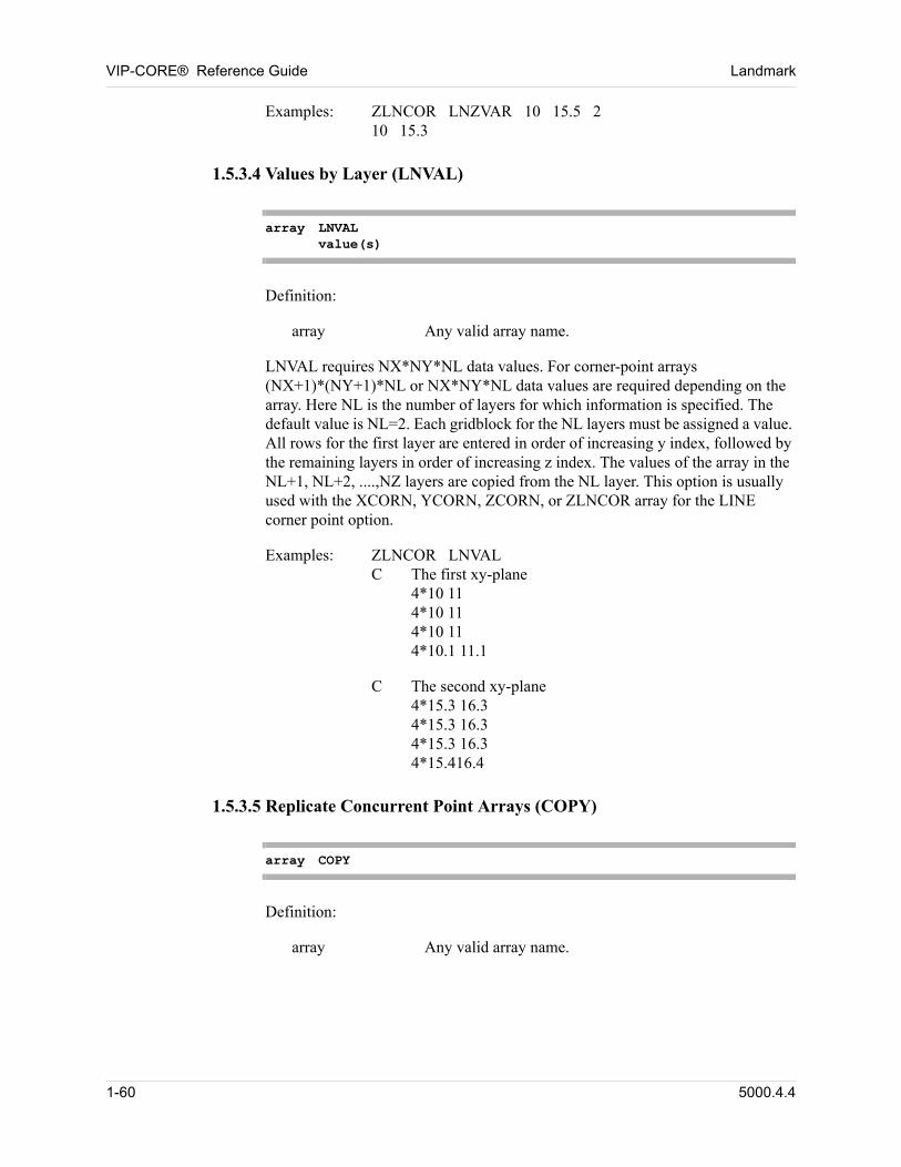
VIP-CORE® Reference Guide Landmark
Examples: ZLNCOR LNZVAR 10 15.5 210 15.3 00
1.5.3.4 Values by Layer (LNVAL)
array LNVALvalue(s)
Definition: 00
array Any valid array name.
LNVAL requires NX*NY*NL data values. For corner-point arrays (NX+1)*(NY+1)*NL or NX*NY*NL data values are required depending on the array. Here NL is the number of layers for which information is specified. The default value is NL=2. Each gridblock for the NL layers must be assigned a value. All rows for the first layer are entered in order of increasing y index, followed by the remaining layers in order of increasing z index. The values of the array in the NL+1, NL+2, ....,NZ layers are copied from the NL layer. This option is usually used with the XCORN, YCORN, ZCORN, or ZLNCOR array for the LINE corner point option.
Examples: ZLNCOR LNVALC The first xy-plane
4*10 114*10 114*10 114*10.1 11.1 00
C The second xy-plane4*15.3 16.34*15.3 16.34*15.3 16.34*15.416.4 00
1.5.3.5 Replicate Concurrent Point Arrays (COPY)
array COPY
Definition: 00
array Any valid array name.
1-60 5000.4.4
Landmark VIP-CORE® Reference Guide
This option can only be used with the ZBOT, ZBOTNW, ZBOTNE, or ZBOTSW array. No data input is required. The depths of the corner points in the bottom of the every block are set to be equal to the depths of the corner points in the top of the next block below it. It is required that ZCORN, or ZCORNW, ZCORNE, ZCORSW arrays must have been previously read.
Examples: For example, such input asZCORN ZVAR10 15.3 18ZBOT COPY 00
is equivalent to 00
ZCORN ZVAR10 15.3 18ZBOT ZVAR15.3 18 00
1.5.4 Array Modification Options
The array modification options in this section can be used to simplify data input and to change data when making comparison runs. The MOD and VMOD options can be used with any of the input arrays. With these options, modification data must immediately follow the array being modified or created. Any number of MOD and/or VMOD changes can follow that array. (There are also modification methods which are used to modify only the pore volume and/or transmissibility just before initialization. These methods are described in Section 6.1.)
The array modification option MODLYR is used to modify the depths in layer 1 of a model. The depths of the remaining layers are then recalculated from the new depths of the first layer and gridblock thicknesses. This option may only be used following the use of LAYER or DIP for one of the depth arrays (Section 5.7) and must immediately follow that array.
The array modification option XREG is used to designate the "extra regions" option. That is, gridblocks may be assigned to more than one output region. This option only applies to the IREGION array (Section 5.15) and must immediately follow the array data, or any MOD/VMOD cards.
A full array is first generated by assigning a value to every gridblock according to the array input option (Section 1.5.2) chosen. Then, only the specific gridblock locations described by the MOD/MODLYR/VMOD/XREG modification are changed within this "full array". The modification described by each data card is performed at the time that card is read. Therefore, the modifications are order dependent. The result of multiple modifications is cumulative.
5000.4.4 1-61
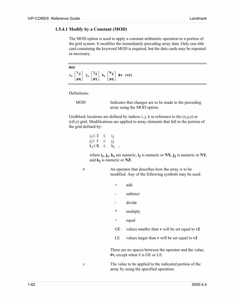
VIP-CORE® Reference Guide Landmark
1.5.4.1 Modify by a Constant (MOD)
The MOD option is used to apply a constant arithmetic operation to a portion of the grid system. It modifies the immediately preceding array data. Only one title card containing the keyword MOD is required, but the data cards may be repeated as necessary.
MOD
i1 i2
NX j1
j2
NY k1
k2
NZ #v (v2)
Definitions:
MOD Indicates that changes are to be made to the preceding array using the MOD option.
Gridblock locations are defined by indices i, j, k in reference to the (x,y,z) or (r,,z) grid. Modifications are applied to array elements that fall in the portion of the grid defined by:
i1 I i2j1 J j2k1K k2 ,
where i1, j1, k1 are numeric, i2 is numeric or NX, j2 is numeric or NY, and k2 is numeric or NZ.
# An operator that describes how the array is to be modified. Any of the following symbols may be used:
+ add
- subtract
/ divide
* multiply
= equal
GE values smaller than v will be set equal to v2
LE values larger than v will be set equal to v2
There are no spaces between the operator and the value, #v, except when # is GE or LE.
v The value to be applied to the indicated portion of the array by using the specified operation.
1-62 5000.4.4
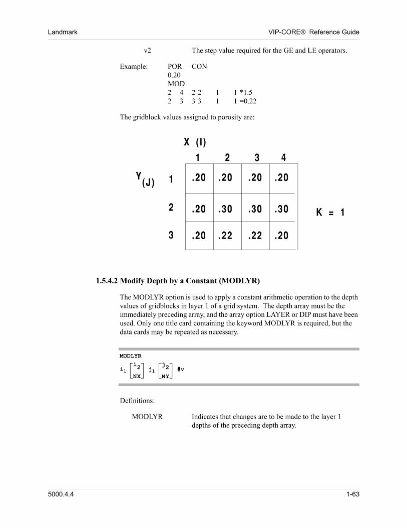
Landmark VIP-CORE® Reference Guide
v2 The step value required for the GE and LE operators.
Example: POR CON0.20MOD2 4 2 2 1 1 *1.52 3 3 3 1 1 =0.22 00
The gridblock values assigned to porosity are: 00
1.5.4.2 Modify Depth by a Constant (MODLYR)
The MODLYR option is used to apply a constant arithmetic operation to the depth values of gridblocks in layer 1 of a grid system. The depth array must be the immediately preceding array, and the array option LAYER or DIP must have been used. Only one title card containing the keyword MODLYR is required, but the data cards may be repeated as necessary.
MODLYR
i1 i2
NX j1
j2
NY #v
Definitions:
MODLYR Indicates that changes are to be made to the layer 1 depths of the preceding depth array.
5000.4.4 1-63
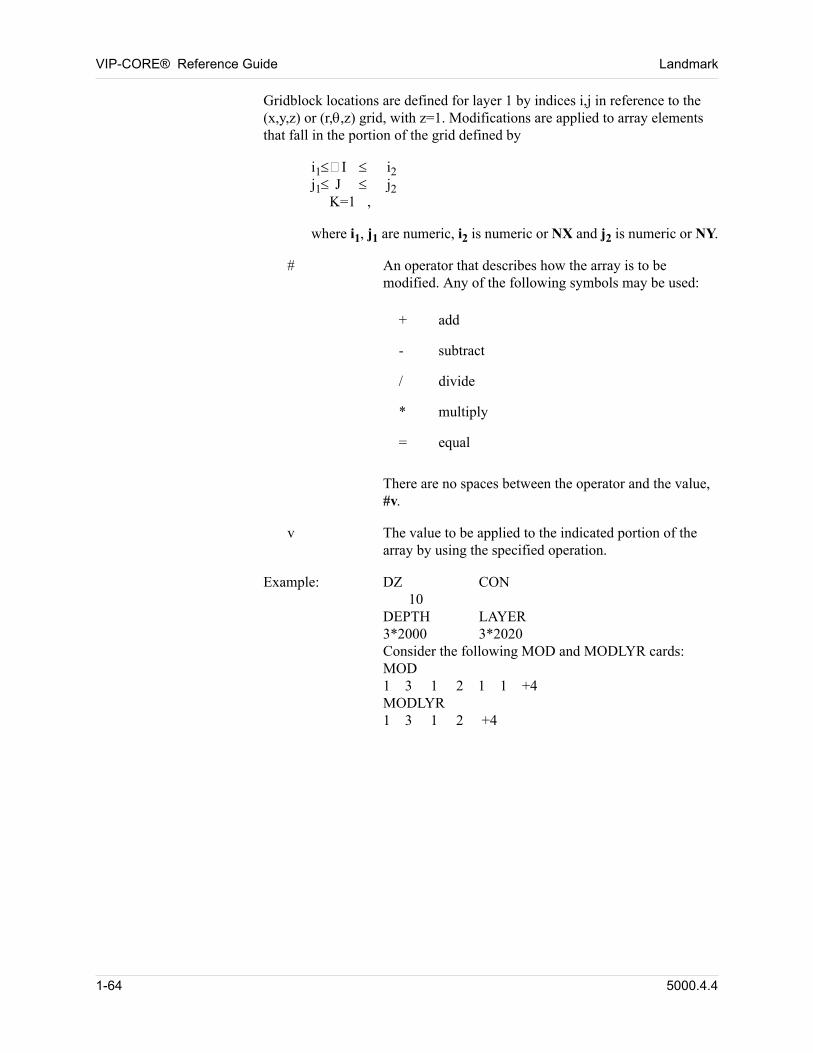
VIP-CORE® Reference Guide Landmark
Gridblock locations are defined for layer 1 by indices i,j in reference to the (x,y,z) or (r,,z) grid, with z=1. Modifications are applied to array elements that fall in the portion of the grid defined by
i1 I i2j1 J j2 K=1 ,
where i1, j1 are numeric, i2 is numeric or NX and j2 is numeric or NY.
# An operator that describes how the array is to be modified. Any of the following symbols may be used:
+ add
- subtract
/ divide
* multiply
= equal
There are no spaces between the operator and the value, #v.
v The value to be applied to the indicated portion of the array by using the specified operation.
Example: DZ CON 10DEPTH LAYER3*2000 3*2020Consider the following MOD and MODLYR cards:MOD1 3 1 2 1 1 +4MODLYR1 3 1 2 +4
1-64 5000.4.4
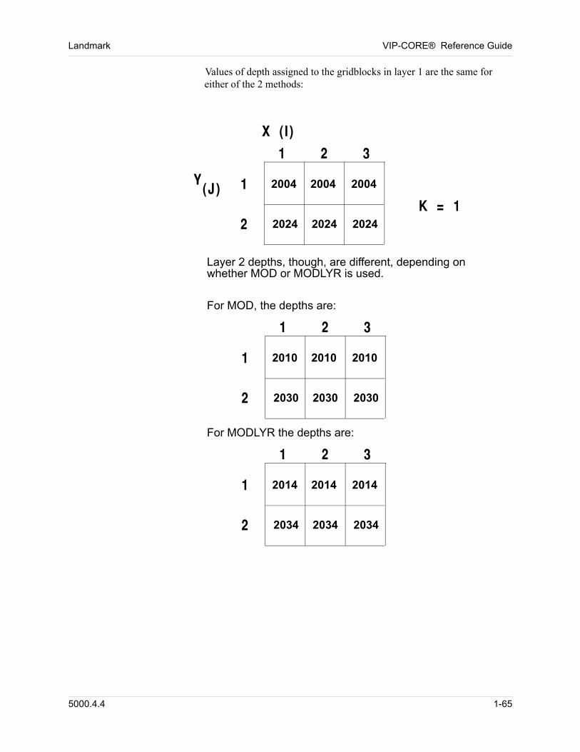
Landmark VIP-CORE® Reference Guide
Values of depth assigned to the gridblocks in layer 1 are the same for either of the 2 methods:
2004 2004 2004
2024 2024 2024
2010 2010 2010
2030 2030 2030
2014 2014 2014
2034 2034 2034
Layer 2 depths, though, are different, depending onwhether MOD or MODLYR is used.
For MOD, the depths are:
For MODLYR the depths are:
5000.4.4 1-65
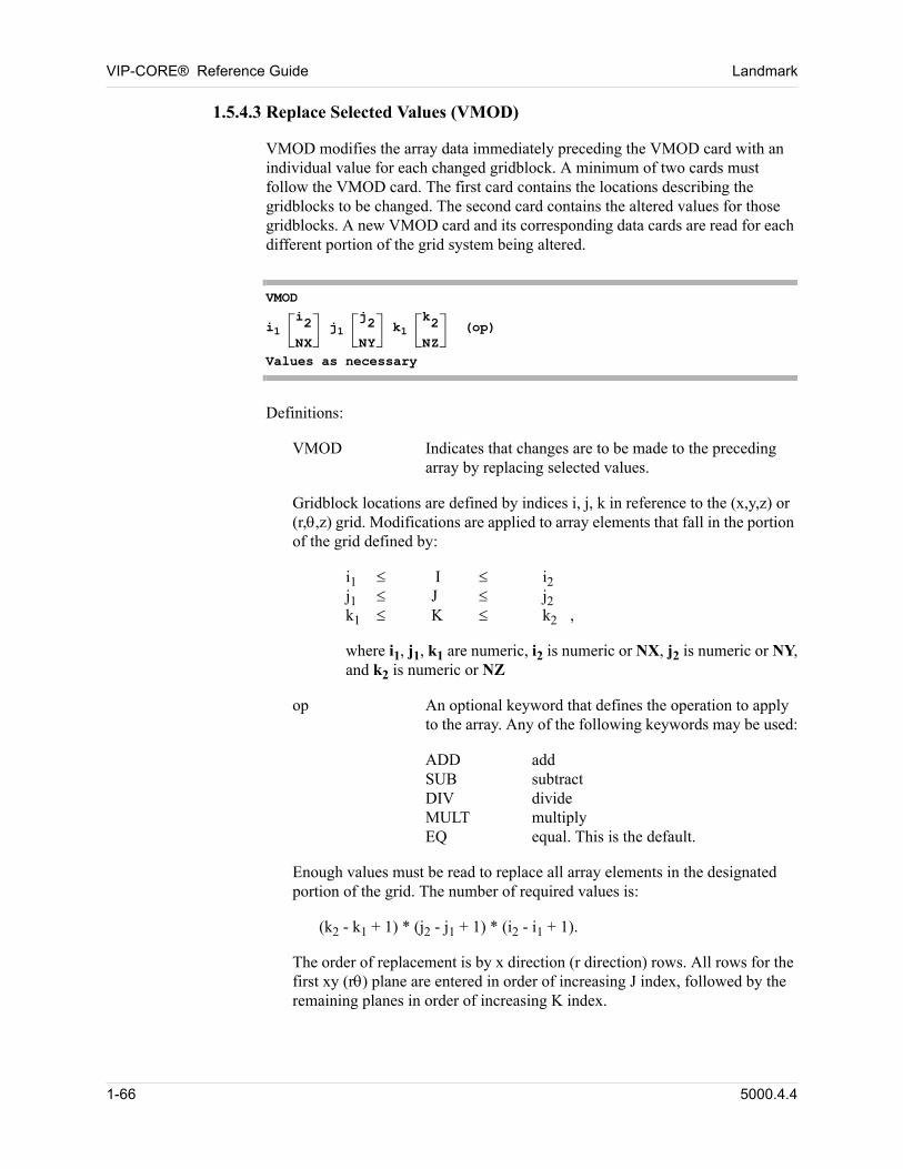
VIP-CORE® Reference Guide Landmark
1.5.4.3 Replace Selected Values (VMOD)
VMOD modifies the array data immediately preceding the VMOD card with an individual value for each changed gridblock. A minimum of two cards must follow the VMOD card. The first card contains the locations describing the gridblocks to be changed. The second card contains the altered values for those gridblocks. A new VMOD card and its corresponding data cards are read for each different portion of the grid system being altered.
VMOD
i1 i2
NX j1
j2
NY k1
k2
NZ (op)
Values as necessary
Definitions: 00
VMOD Indicates that changes are to be made to the preceding array by replacing selected values.
Gridblock locations are defined by indices i, j, k in reference to the (x,y,z) or (r,,z) grid. Modifications are applied to array elements that fall in the portion of the grid defined by:
i1 I i2j1 J j2k1 K k2 ,
where i1, j1, k1 are numeric, i2 is numeric or NX, j2 is numeric or NY, and k2 is numeric or NZ
op An optional keyword that defines the operation to apply to the array. Any of the following keywords may be used:
ADD addSUB subtractDIV divideMULT multiplyEQ equal. This is the default.
Enough values must be read to replace all array elements in the designated portion of the grid. The number of required values is:
(k2 - k1 + 1) * (j2 - j1 + 1) * (i2 - i1 + 1).
The order of replacement is by x direction (r direction) rows. All rows for the first xy (r) plane are entered in order of increasing J index, followed by the remaining planes in order of increasing K index.
1-66 5000.4.4
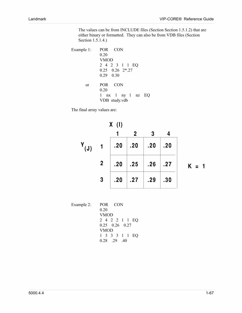
Landmark VIP-CORE® Reference Guide
The values can be from INCLUDE files (Section Section 1.5.1.2) that are either binary or formatted. They can also be from VDB files (Section Section 1.5.1.4.)
Example 1: POR CON 0.20VMOD2 4 2 3 1 1 EQ0.25 0.26 2*.270.29 0.30 00
or POR CON0.201 nx 1 ny 1 nz EQVDB study.vdb 00
The final array values are: 00
Example 2: POR CON0.20VMOD2 4 2 2 1 1 EQ0.25 0.26 0.27VMOD1 3 3 3 1 1 EQ0.28 .29 .40 00
5000.4.4 1-67
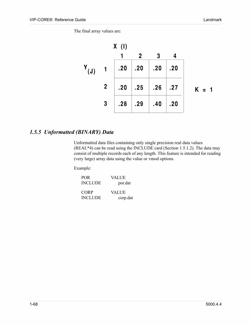
VIP-CORE® Reference Guide Landmark
The final array values are: 00
1.5.5 Unformatted (BINARY) Data
Unformatted data files containing only single precision real data values (REAL*4) can be read using the INCLUDE card (Section 1.5.1.2). The data may consist of multiple records each of any length. This feature is intended for reading (very large) array data using the value or vmod options.
Example:
POR VALUEINCLUDE por.dat
CORP VALUEINCLUDE corp.dat
1-68 5000.4.4
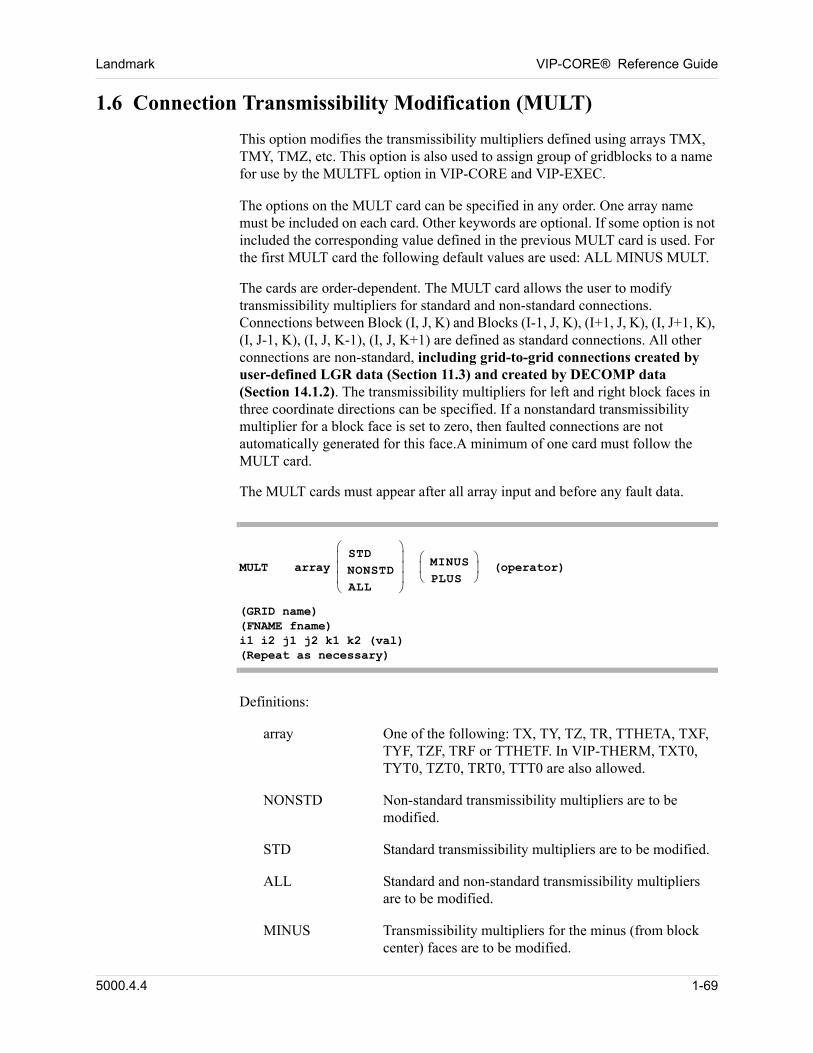
Landmark VIP-CORE® Reference Guide
1.6 Connection Transmissibility Modification (MULT)
This option modifies the transmissibility multipliers defined using arrays TMX, TMY, TMZ, etc. This option is also used to assign group of gridblocks to a name for use by the MULTFL option in VIP-CORE and VIP-EXEC.
The options on the MULT card can be specified in any order. One array name must be included on each card. Other keywords are optional. If some option is not included the corresponding value defined in the previous MULT card is used. For the first MULT card the following default values are used: ALL MINUS MULT.
The cards are order-dependent. The MULT card allows the user to modify transmissibility multipliers for standard and non-standard connections. Connections between Block (I, J, K) and Blocks (I-1, J, K), (I+1, J, K), (I, J+1, K), (I, J-1, K), (I, J, K-1), (I, J, K+1) are defined as standard connections. All other connections are non-standard, including grid-to-grid connections created by user-defined LGR data (Section 11.3) and created by DECOMP data (Section 14.1.2). The transmissibility multipliers for left and right block faces in three coordinate directions can be specified. If a nonstandard transmissibility multiplier for a block face is set to zero, then faulted connections are not automatically generated for this face.A minimum of one card must follow the MULT card.
The MULT cards must appear after all array input and before any fault data.
MULT array
STDNONSTDALL
MINUSPLUS
(operator) (GRID name)(FNAME fname)i1 i2 j1 j2 k1 k2 (val)(Repeat as necessary)
Definitions: 00
array One of the following: TX, TY, TZ, TR, TTHETA, TXF, TYF, TZF, TRF or TTHETF. In VIP-THERM, TXT0, TYT0, TZT0, TRT0, TTT0 are also allowed.
NONSTD Non-standard transmissibility multipliers are to be modified.
STD Standard transmissibility multipliers are to be modified.
ALL Standard and non-standard transmissibility multipliers are to be modified.
MINUS Transmissibility multipliers for the minus (from block center) faces are to be modified.
5000.4.4 1-69
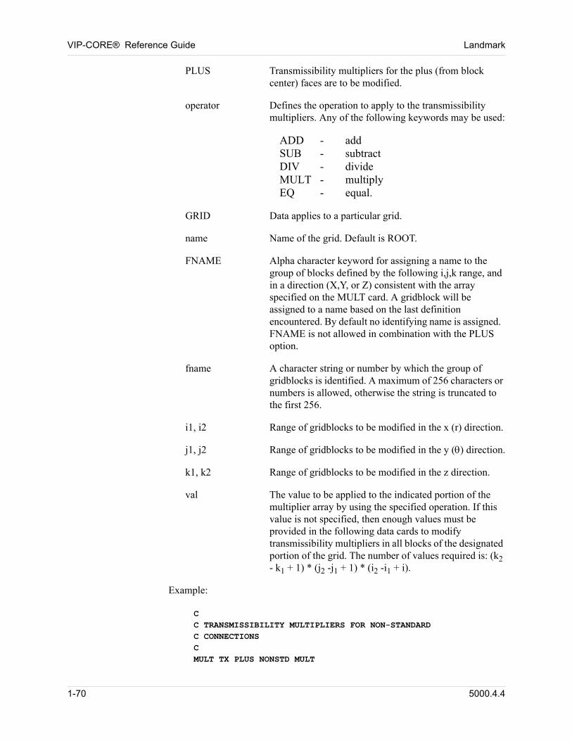
VIP-CORE® Reference Guide Landmark
PLUS Transmissibility multipliers for the plus (from block center) faces are to be modified.
operator Defines the operation to apply to the transmissibility multipliers. Any of the following keywords may be used:
ADD - addSUB - subtractDIV - divideMULT - multiplyEQ - equal.
GRID Data applies to a particular grid.
name Name of the grid. Default is ROOT.
FNAME Alpha character keyword for assigning a name to the group of blocks defined by the following i,j,k range, and in a direction (X,Y, or Z) consistent with the array specified on the MULT card. A gridblock will be assigned to a name based on the last definition encountered. By default no identifying name is assigned. FNAME is not allowed in combination with the PLUS option.
fname A character string or number by which the group of gridblocks is identified. A maximum of 256 characters or numbers is allowed, otherwise the string is truncated to the first 256.
i1, i2 Range of gridblocks to be modified in the x (r) direction.
j1, j2 Range of gridblocks to be modified in the y () direction.
k1, k2 Range of gridblocks to be modified in the z direction.
val The value to be applied to the indicated portion of the multiplier array by using the specified operation. If this value is not specified, then enough values must be provided in the following data cards to modify transmissibility multipliers in all blocks of the designated portion of the grid. The number of values required is: (k2 - k1 + 1) * (j2 -j1 + 1) * (i2 -i1 + i).
Example: 00
CC TRANSMISSIBILITY MULTIPLIERS FOR NON-STANDARDC CONNECTIONSCMULT TX PLUS NONSTD MULT
1-70 5000.4.4
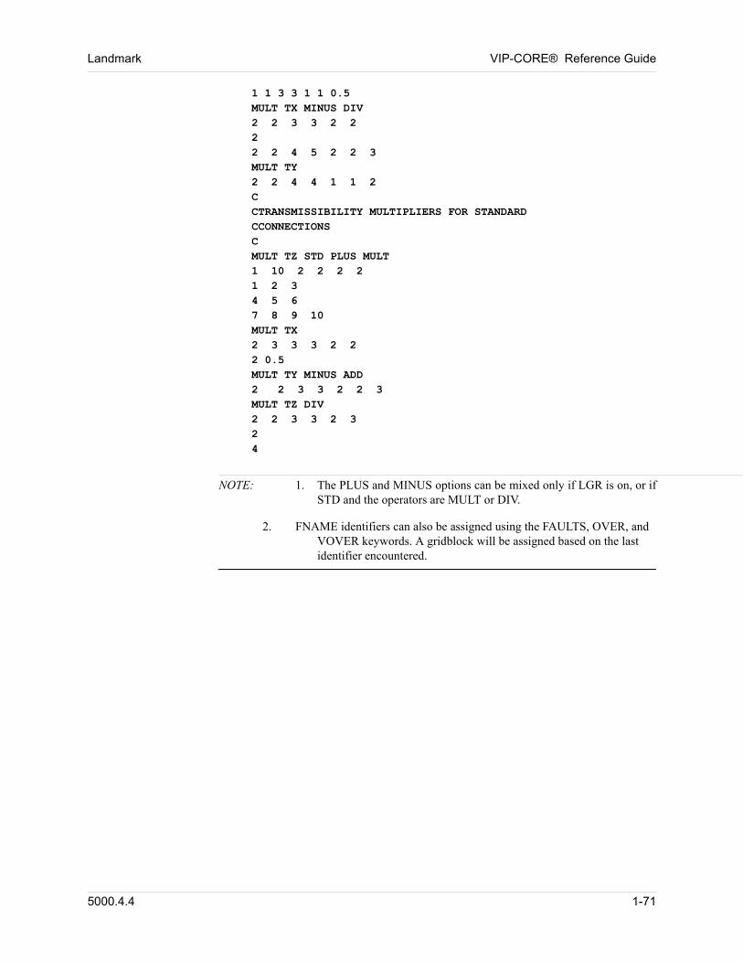
Landmark VIP-CORE® Reference Guide
1 1 3 3 1 1 0.5MULT TX MINUS DIV2 2 3 3 2 222 2 4 5 2 2 3MULT TY2 2 4 4 1 1 2CCTRANSMISSIBILITY MULTIPLIERS FOR STANDARD CCONNECTIONS CMULT TZ STD PLUS MULT1 10 2 2 2 21 2 34 5 67 8 9 10MULT TX2 3 3 3 2 22 0.5MULT TY MINUS ADD2 2 3 3 2 2 3MULT TZ DIV2 2 3 3 2 324
NOTE: 1. The PLUS and MINUS options can be mixed only if LGR is on, or if STD and the operators are MULT or DIV.
2. FNAME identifiers can also be assigned using the FAULTS, OVER, and VOVER keywords. A gridblock will be assigned based on the last identifier encountered.
5000.4.4 1-71
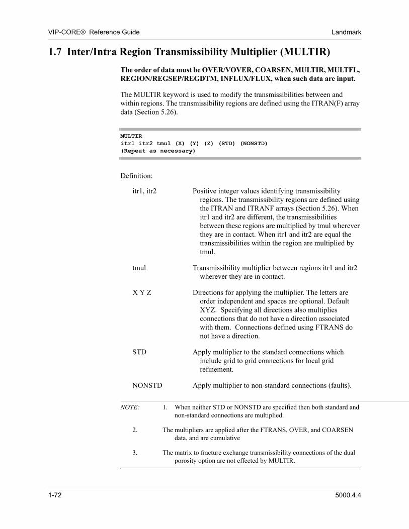
VIP-CORE® Reference Guide Landmark
1.7 Inter/Intra Region Transmissibility Multiplier (MULTIR)
The order of data must be OVER/VOVER, COARSEN, MULTIR, MULTFL, REGION/REGSEP/REGDTM, INFLUX/FLUX, when such data are input. 00
The MULTIR keyword is used to modify the transmissibilities between and within regions. The transmissibility regions are defined using the ITRAN(F) array data (Section 5.26). 00
MULTIRitr1 itr2 tmul (X) (Y) (Z) (STD) (NONSTD)(Repeat as necessary)
Definition: 00
itr1, itr2 Positive integer values identifying transmissibility regions. The transmissibility regions are defined using the ITRAN and ITRANF arrays (Section 5.26). When itr1 and itr2 are different, the transmissibilities between these regions are multiplied by tmul wherever they are in contact. When itr1 and itr2 are equal the transmissibilities within the region are multiplied by tmul.
tmul Transmissibility multiplier between regions itr1 and itr2 wherever they are in contact.
X Y Z Directions for applying the multiplier. The letters are order independent and spaces are optional. Default XYZ. Specifying all directions also multiplies connections that do not have a direction associated with them. Connections defined using FTRANS do not have a direction.
STD Apply multiplier to the standard connections which include grid to grid connections for local grid refinement.
NONSTD Apply multiplier to non-standard connections (faults).
NOTE: 1. When neither STD or NONSTD are specified then both standard and non-standard connections are multiplied.
2. The multipliers are applied after the FTRANS, OVER, and COARSEN data, and are cumulative
3. The matrix to fracture exchange transmissibility connections of the dual porosity option are not effected by MULTIR.
1-72 5000.4.4
Landmark VIP-CORE® Reference Guide
1.8 Named Fault/Region Transmissibility Multiplier (MULTFL)
The order of data must be OVER/VOVER, COARSEN, MULTIR, MULTFL, REGION/REGSEP/REGDTM, INFLUX/FLUX, when such data are input. 00
The MULTFL keyword is used to modify the transmissibilities between gridblocks that have been assigned a name. Grid blocks can be assigned a name using the FNAME parameter on the MULT (Section 1.6), FAULTS (Section 2.2.9.2), OVER (Section 7.2) and VOVER (Section 7.4) options. Both standard and non-standard transmissibility connections if any are multiplied. 00
The MULTFL keyword is also used to modify the transmissibility connections that are defined and named with the FTRANS option (Section 6.5.2). Only the non-standard transmissibility connections defined with the FTRANS data will be effected, while any corresponding standard connections will be left unaltered. 00
Note: All the transmissibility multipliers are cumulative. They are applied on top of any previously defined using other options. 00
MULTFL fname tmul(Repeat as necessary)
Definition: 00
MULTFL Alpha character keyword.
fname Name or number identifying the fault or group of gridblock to be operated upon.
tmul Transmissibility multiplier.
5000.4.4 1-73

VIP-CORE® Reference Guide Landmark
1-74 5000.4.4
Chapter
2
00000Initialization Data
2.1 Introduction
Initialization data include all data defined at time zero in a simulation. These include: 00
n title cards
n fluid initialization controls
n initialization output controls
n the description of the reservoir
n the reservoir rock
n fluid properties.
The data are input after the INIT card and are terminated by the END card. The data are checked for consistency as they are read. If no errors occur, the data are then processed. If no initialization errors are generated, the program initializes and writes an initialization restart file. When the program initializes, the average pressure, fluids in place, saturation pressure, oil, water, and gas saturation, and oil and gas composition arrays are calculated. 00
All of the data on each card are free field, following the description given in
Section 1.5. However, the order of data cards is important. The first card in the initialization data must be the INIT card. 00
The data groups must be arranged as shown in Figure 2-1. Some restrictions on the order of data cards within each data group may apply. These restrictions are described in subsequent sections of this chapter. 00
In all of the data descriptions that follow, parentheses are used to indicate optional items of data. Parentheses are never included in the actual data stream. Items of data that are aligned vertically in the description of a single data card indicate a choice; these items are mutually exclusive. 00
5000.4.4 2-75
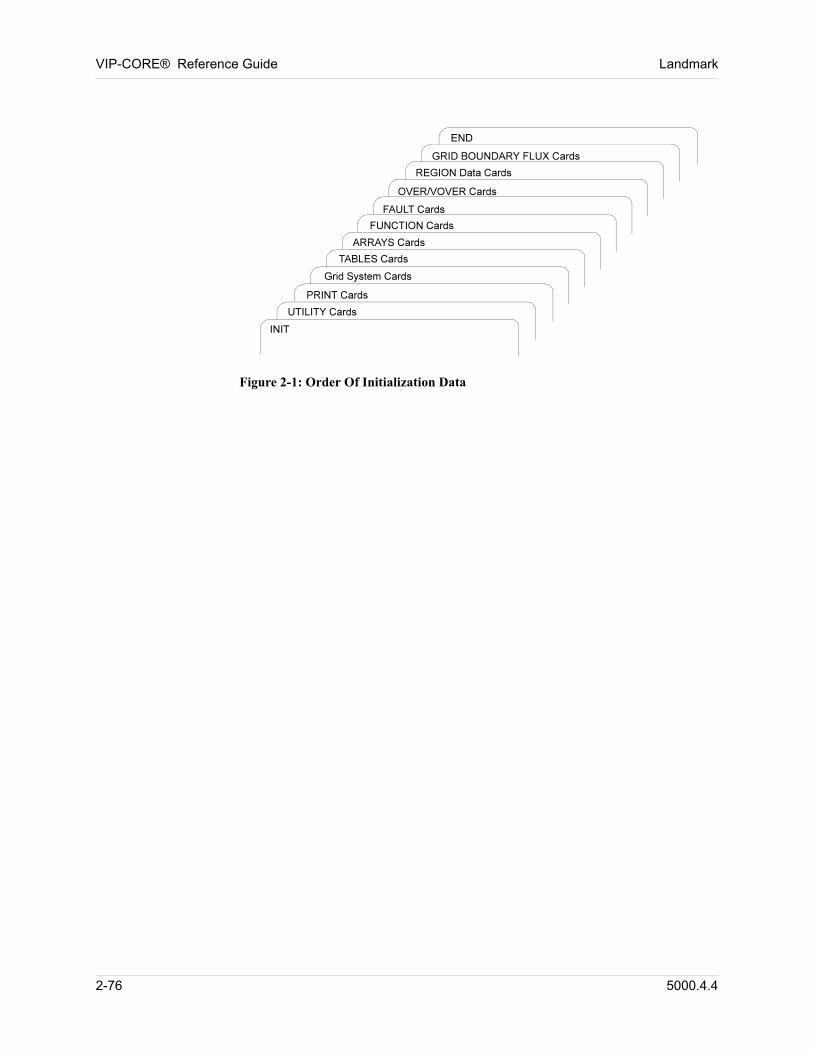
VIP-CORE® Reference Guide Landmark
00
Figure 2-1: Order Of Initialization Data
2-76 5000.4.4
Landmark VIP-CORE® Reference Guide
2.2 Initialization Utility Data
The following cards can be used to control the program. Of these, only the DATE card, a grid system card (NX or NR), and a physical property constants card (DWB) are mandatory for every run. The other cards should be used when appropriate. Within this data group the order of the utility data cards is immaterial. 00
2.2.1 General
2.2.1.1 Initialization (INIT)
INIT
The first card in the initialization data contains only the keyword INIT. Initialization data are terminated by the appearance of an END card. 00
Example: 00
INITTITLE1
HISTORY MATCH NO FAULTS ZEROED OUTTITLE2
SAG12 WITH RELICT OILDATE 1 6 1977 00
2.2.1.2 Change Default Dimensions (DIM)
The DIM card allows the user to change the default dimensions on any initialization run. Multiple sets of DIM cards may be entered, one after the other.00
DIM param1 param2 . . . paramn (card 1)size1 size2 . . . sizen (card 2)
Definitions: 00
param Alpha labels of those dimension parameters being defined:
NBATMX Maximum number of user-defined separator batteries. (NBATMX NSTGMX) Default is 10.
NCBLKS Maximum number of coarse gridblock faces for all flux regions. Default is 100.
5000.4.4 2-77
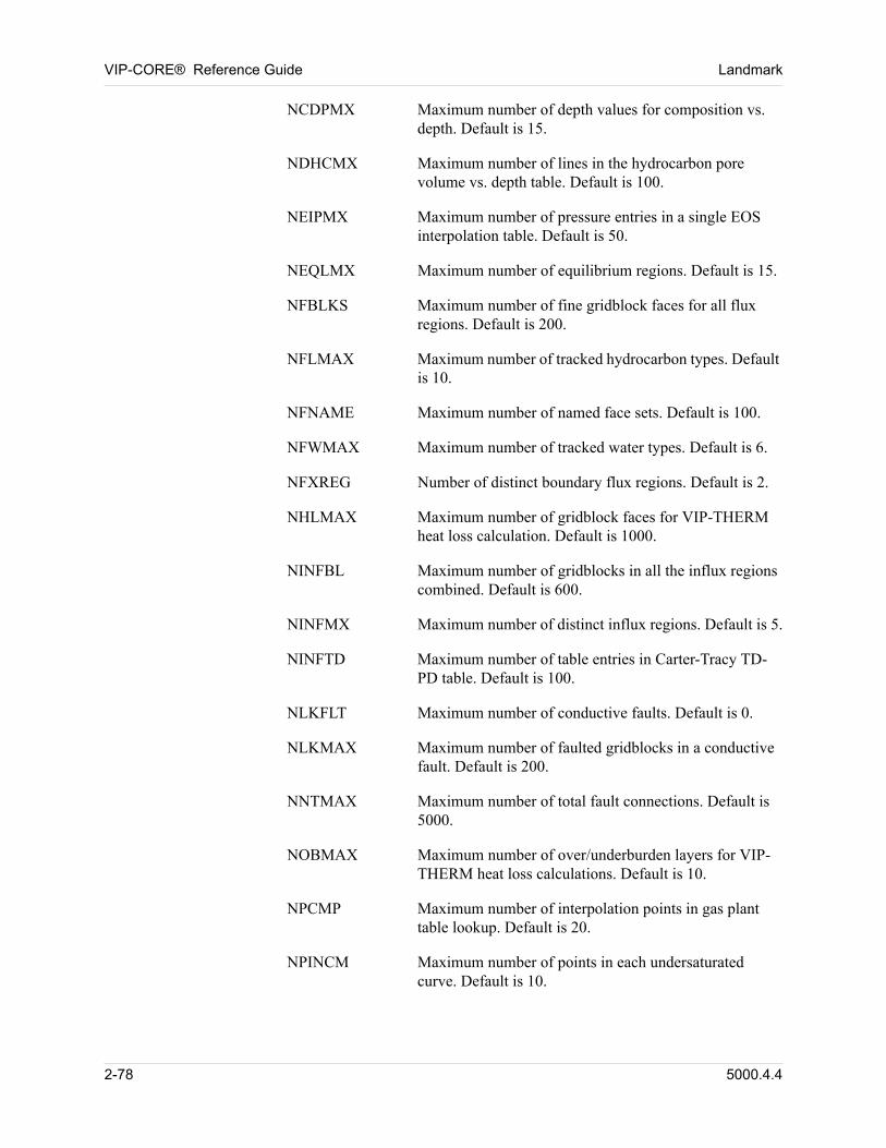
VIP-CORE® Reference Guide Landmark
NCDPMX Maximum number of depth values for composition vs. depth. Default is 15.
NDHCMX Maximum number of lines in the hydrocarbon pore volume vs. depth table. Default is 100.
NEIPMX Maximum number of pressure entries in a single EOS interpolation table. Default is 50.
NEQLMX Maximum number of equilibrium regions. Default is 15.
NFBLKS Maximum number of fine gridblock faces for all flux regions. Default is 200.
NFLMAX Maximum number of tracked hydrocarbon types. Default is 10.
NFNAME Maximum number of named face sets. Default is 100.
NFWMAX Maximum number of tracked water types. Default is 6.
NFXREG Number of distinct boundary flux regions. Default is 2.
NHLMAX Maximum number of gridblock faces for VIP-THERM heat loss calculation. Default is 1000.
NINFBL Maximum number of gridblocks in all the influx regions combined. Default is 600.
NINFMX Maximum number of distinct influx regions. Default is 5.
NINFTD Maximum number of table entries in Carter-Tracy TD-PD table. Default is 100.
NLKFLT Maximum number of conductive faults. Default is 0.
NLKMAX Maximum number of faulted gridblocks in a conductive fault. Default is 200.
NNTMAX Maximum number of total fault connections. Default is 5000.
NOBMAX Maximum number of over/underburden layers for VIP-THERM heat loss calculations. Default is 10.
NPCMP Maximum number of interpolation points in gas plant table lookup. Default is 20.
NPINCM Maximum number of points in each undersaturated curve. Default is 10.
2-78 5000.4.4
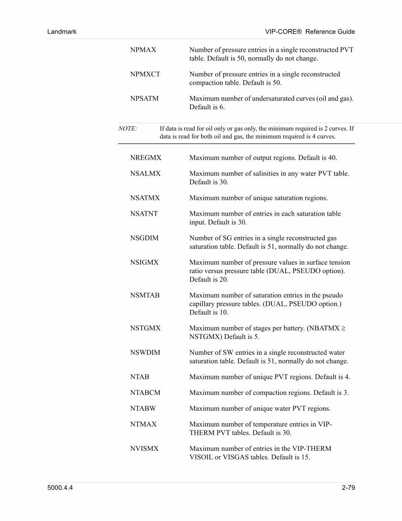
Landmark VIP-CORE® Reference Guide
NPMAX Number of pressure entries in a single reconstructed PVT table. Default is 50, normally do not change.
NPMXCT Number of pressure entries in a single reconstructed compaction table. Default is 50.
NPSATM Maximum number of undersaturated curves (oil and gas). Default is 6.
NOTE: If data is read for oil only or gas only, the minimum required is 2 curves. If data is read for both oil and gas, the minimum required is 4 curves.
NREGMX Maximum number of output regions. Default is 40.
NSALMX Maximum number of salinities in any water PVT table. Default is 30.
NSATMX Maximum number of unique saturation regions.
NSATNT Maximum number of entries in each saturation table input. Default is 30.
NSGDIM Number of SG entries in a single reconstructed gas saturation table. Default is 51, normally do not change.
NSIGMX Maximum number of pressure values in surface tension ratio versus pressure table (DUAL, PSEUDO option). Default is 20.
NSMTAB Maximum number of saturation entries in the pseudo capillary pressure tables. (DUAL, PSEUDO option.) Default is 10.
NSTGMX Maximum number of stages per battery. (NBATMX NSTGMX) Default is 5.
NSWDIM Number of SW entries in a single reconstructed water saturation table. Default is 51, normally do not change.
NTAB Maximum number of unique PVT regions. Default is 4.
NTABCM Maximum number of compaction regions. Default is 3.
NTABW Maximum number of unique water PVT regions.
NTMAX Maximum number of temperature entries in VIP-THERM PVT tables. Default is 30.
NVISMX Maximum number of entries in the VIP-THERM VISOIL or VISGAS tables. Default is 15.
5000.4.4 2-79
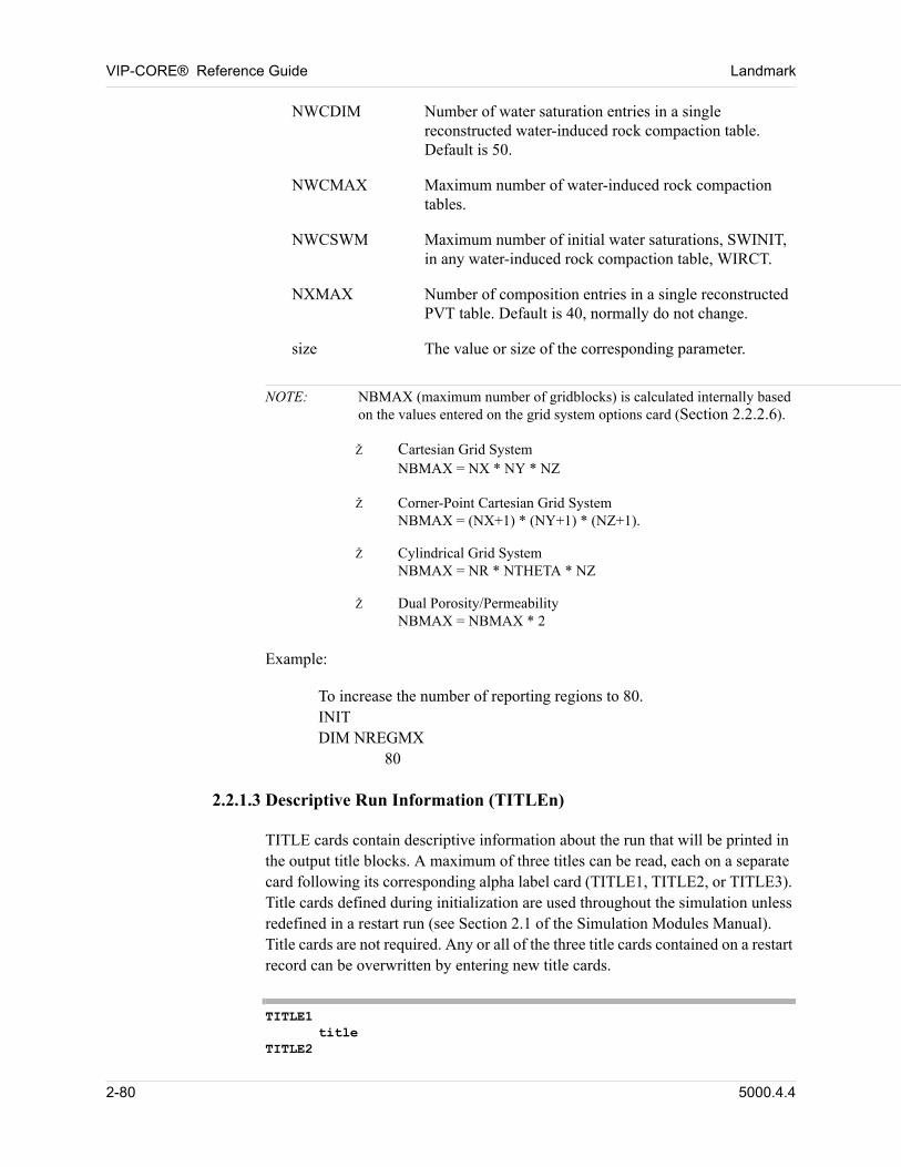
VIP-CORE® Reference Guide Landmark
NWCDIM Number of water saturation entries in a single reconstructed water-induced rock compaction table. Default is 50.
NWCMAX Maximum number of water-induced rock compaction tables.
NWCSWM Maximum number of initial water saturations, SWINIT, in any water-induced rock compaction table, WIRCT.
NXMAX Number of composition entries in a single reconstructed PVT table. Default is 40, normally do not change.
size The value or size of the corresponding parameter.
NOTE: NBMAX (maximum number of gridblocks) is calculated internally based on the values entered on the grid system options card (Section 2.2.2.6).
Ž Cartesian Grid SystemNBMAX = NX * NY * NZ
Ž Corner-Point Cartesian Grid SystemNBMAX = (NX+1) * (NY+1) * (NZ+1).
Ž Cylindrical Grid SystemNBMAX = NR * NTHETA * NZ
Ž Dual Porosity/PermeabilityNBMAX = NBMAX * 2
Example: 00
To increase the number of reporting regions to 80.INITDIM NREGMX
80 00
2.2.1.3 Descriptive Run Information (TITLEn)
TITLE cards contain descriptive information about the run that will be printed in the output title blocks. A maximum of three titles can be read, each on a separate card following its corresponding alpha label card (TITLE1, TITLE2, or TITLE3). Title cards defined during initialization are used throughout the simulation unless redefined in a restart run (see Section 2.1 of the Simulation Modules Manual). Title cards are not required. Any or all of the three title cards contained on a restart record can be overwritten by entering new title cards. 00
TITLE1title
TITLE2
2-80 5000.4.4
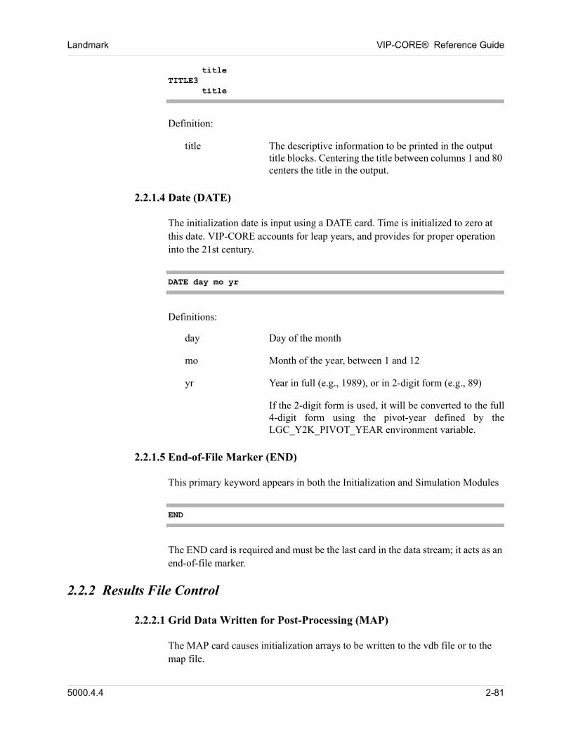
Landmark VIP-CORE® Reference Guide
titleTITLE3
title
Definition: 00
title The descriptive information to be printed in the output title blocks. Centering the title between columns 1 and 80 centers the title in the output.
2.2.1.4 Date (DATE)
The initialization date is input using a DATE card. Time is initialized to zero at this date. VIP-CORE accounts for leap years, and provides for proper operation into the 21st century. 00
DATE day mo yr
Definitions: 00
day Day of the month
mo Month of the year, between 1 and 12
yr Year in full (e.g., 1989), or in 2-digit form (e.g., 89)
If the 2-digit form is used, it will be converted to the full 4-digit form using the pivot-year defined by the LGC_Y2K_PIVOT_YEAR environment variable.
2.2.1.5 End-of-File Marker (END)
This primary keyword appears in both the Initialization and Simulation Modules 00
END
The END card is required and must be the last card in the data stream; it acts as an end-of-file marker. 00
2.2.2 Results File Control
2.2.2.1 Grid Data Written for Post-Processing (MAP)
The MAP card causes initialization arrays to be written to the vdb file or to the map file. 00
5000.4.4 2-81
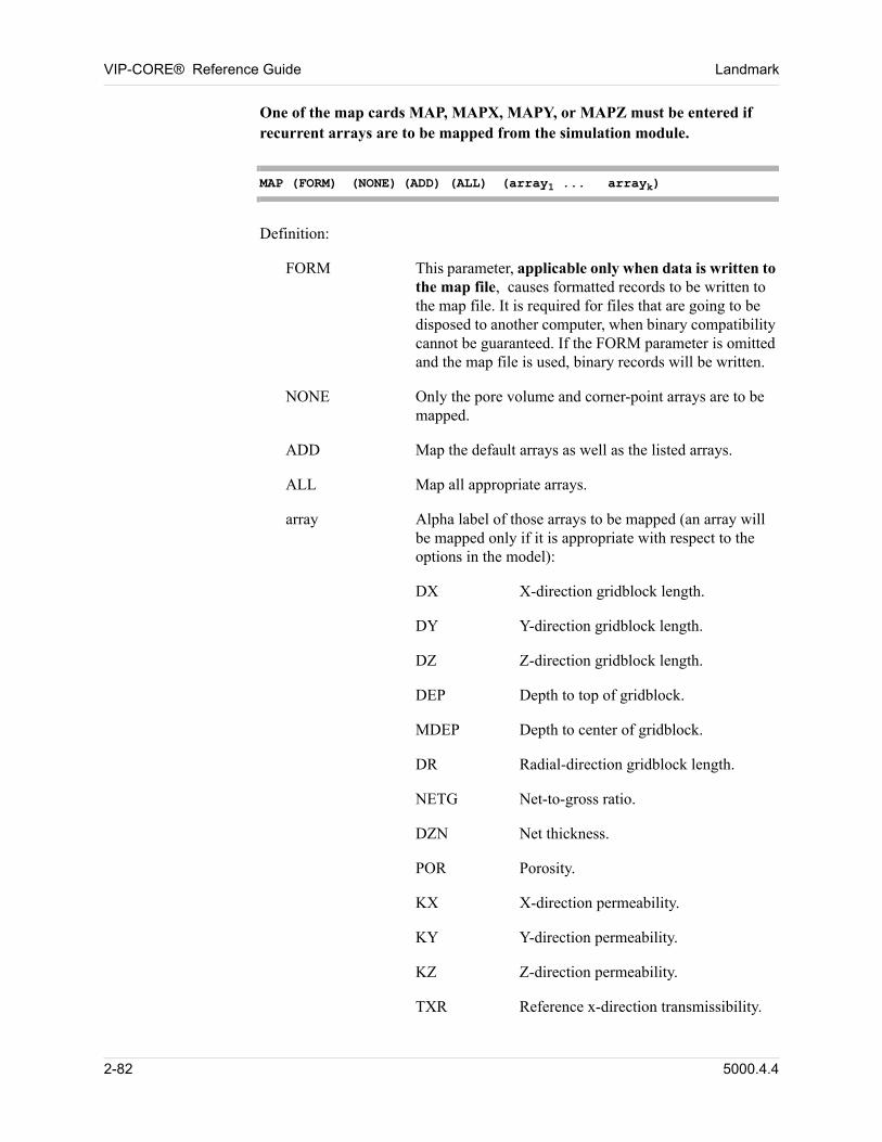
VIP-CORE® Reference Guide Landmark
One of the map cards MAP, MAPX, MAPY, or MAPZ must be entered if recurrent arrays are to be mapped from the simulation module. 00
MAP (FORM) (NONE) (ADD) (ALL) (array1 ... arrayk)
Definition: 00
FORM This parameter, applicable only when data is written to the map file, causes formatted records to be written to the map file. It is required for files that are going to be disposed to another computer, when binary compatibility cannot be guaranteed. If the FORM parameter is omitted and the map file is used, binary records will be written.
NONE Only the pore volume and corner-point arrays are to be mapped.
ADD Map the default arrays as well as the listed arrays.
ALL Map all appropriate arrays.
array Alpha label of those arrays to be mapped (an array will be mapped only if it is appropriate with respect to the options in the model):
DX X-direction gridblock length.
DY Y-direction gridblock length.
DZ Z-direction gridblock length.
DEP Depth to top of gridblock.
MDEP Depth to center of gridblock.
DR Radial-direction gridblock length.
NETG Net-to-gross ratio.
DZN Net thickness.
POR Porosity.
KX X-direction permeability.
KY Y-direction permeability.
KZ Z-direction permeability.
TXR Reference x-direction transmissibility.
2-82 5000.4.4

Landmark VIP-CORE® Reference Guide
TYR Reference y-direction transmissibility.
TZR Reference z-direction transmissibility.
TDLR Reference l-diagonal transmissibility.
TDRR Reference r-diagonal transmissibility.
ISAT Primary saturation table.
IPVT Fluid PVT property table.
IPVTW Water property table.
IEQU Equilibrium region.
IREG Summary region.
ICMT Compaction region.
IWIRC Water-induced compaction region.
IFID Named fault identifier.
ITRAN Transmissibility region identifier.
P Initial pressure.
PSAT Initial saturation pressure.
PDAT Initial datum pressure.
SG Initial gas saturation.
SO Initial oil saturation.
SW Initial water saturation.
SOM Initial mobile oil saturation.
SWM Initial mobile water saturation.
SAL Water salinity. Available only when the PVTWSAL tables are entered.
ENDPTS Relative permeability endpoints,
SWL, SWR, SWRO, SWU, SGL, SGR,
SGRO, SGU, SGRW, KRWRG,
KRGRW, KROLW, KRWRO, KRGRO,
when appropriate.
5000.4.4 2-83
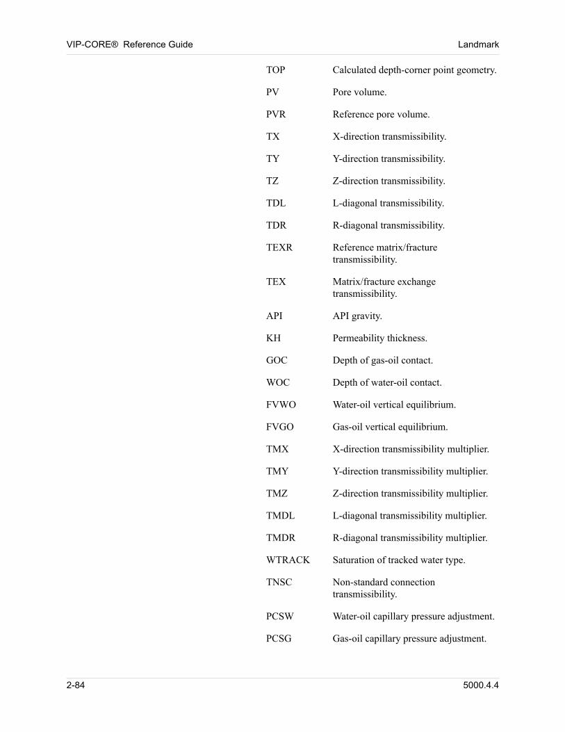
VIP-CORE® Reference Guide Landmark
TOP Calculated depth-corner point geometry.
PV Pore volume.
PVR Reference pore volume.
TX X-direction transmissibility.
TY Y-direction transmissibility.
TZ Z-direction transmissibility.
TDL L-diagonal transmissibility.
TDR R-diagonal transmissibility.
TEXR Reference matrix/fracture transmissibility.
TEX Matrix/fracture exchange transmissibility.
API API gravity.
KH Permeability thickness.
GOC Depth of gas-oil contact.
WOC Depth of water-oil contact.
FVWO Water-oil vertical equilibrium.
FVGO Gas-oil vertical equilibrium.
TMX X-direction transmissibility multiplier.
TMY Y-direction transmissibility multiplier.
TMZ Z-direction transmissibility multiplier.
TMDL L-diagonal transmissibility multiplier.
TMDR R-diagonal transmissibility multiplier.
WTRACK Saturation of tracked water type.
TNSC Non-standard connection transmissibility.
PCSW Water-oil capillary pressure adjustment.
PCSG Gas-oil capillary pressure adjustment.
2-84 5000.4.4
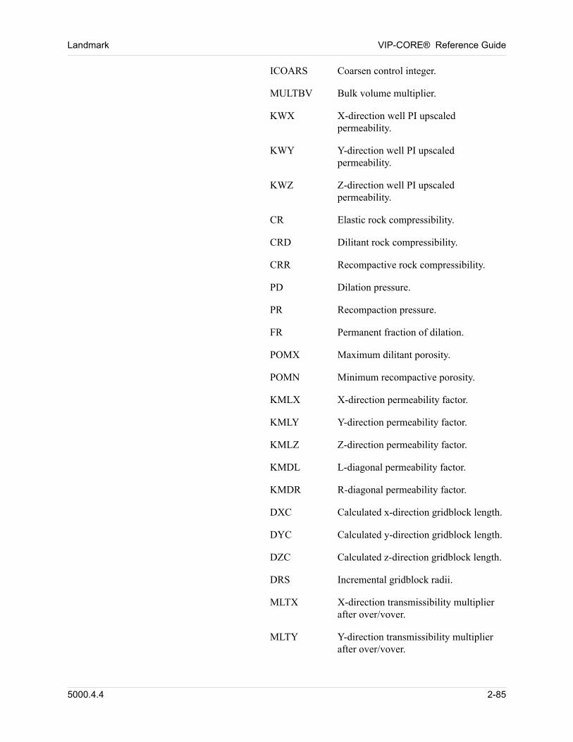
Landmark VIP-CORE® Reference Guide
ICOARS Coarsen control integer.
MULTBV Bulk volume multiplier.
KWX X-direction well PI upscaled permeability.
KWY Y-direction well PI upscaled permeability.
KWZ Z-direction well PI upscaled permeability.
CR Elastic rock compressibility.
CRD Dilitant rock compressibility.
CRR Recompactive rock compressibility.
PD Dilation pressure.
PR Recompaction pressure.
FR Permanent fraction of dilation.
POMX Maximum dilitant porosity.
POMN Minimum recompactive porosity.
KMLX X-direction permeability factor.
KMLY Y-direction permeability factor.
KMLZ Z-direction permeability factor.
KMDL L-diagonal permeability factor.
KMDR R-diagonal permeability factor.
DXC Calculated x-direction gridblock length.
DYC Calculated y-direction gridblock length.
DZC Calculated z-direction gridblock length.
DRS Incremental gridblock radii.
MLTX X-direction transmissibility multiplier after over/vover.
MLTY Y-direction transmissibility multiplier after over/vover.
5000.4.4 2-85
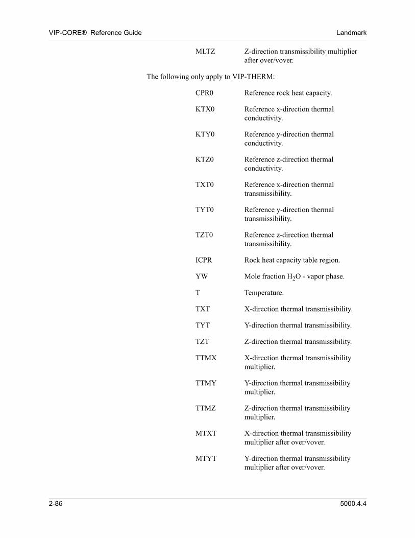
VIP-CORE® Reference Guide Landmark
MLTZ Z-direction transmissibility multiplier after over/vover.
The following only apply to VIP-THERM:
CPR0 Reference rock heat capacity.
KTX0 Reference x-direction thermal conductivity.
KTY0 Reference y-direction thermal conductivity.
KTZ0 Reference z-direction thermal conductivity.
TXT0 Reference x-direction thermal transmissibility.
TYT0 Reference y-direction thermal transmissibility.
TZT0 Reference z-direction thermal transmissibility.
ICPR Rock heat capacity table region.
YW Mole fraction H2O - vapor phase.
T Temperature.
TXT X-direction thermal transmissibility.
TYT Y-direction thermal transmissibility.
TZT Z-direction thermal transmissibility.
TTMX X-direction thermal transmissibility multiplier.
TTMY Y-direction thermal transmissibility multiplier.
TTMZ Z-direction thermal transmissibility multiplier.
MTXT X-direction thermal transmissibility multiplier after over/vover.
MTYT Y-direction thermal transmissibility multiplier after over/vover.
2-86 5000.4.4
Landmark VIP-CORE® Reference Guide
MTZT Z-direction thermal transmissibility multiplier after over/vover.
NOTE: 1. The pore volume array and the corner-point array are always mapped.
2. If no array names are entered on the MAP card (i.e, MAP or MAP FORM is input), the three saturation arrays and the x-direction, y-direction, and z-direction transmissibilty arrays will by default be mapped.
3. Any other array must be entered on the MAP card in order to be mapped. Including the keyword ADD causes the 6 default arrays to be mapped as well as the explicitly entered arrays.
4. The FORM parameter, if included on any of the MAP, MAPX, MAPY, or MAPZ cards will apply to the writing of all data to the map file.
5. Writing map arrays to the vdb file is the default. The NOVDB card (Section 2.2.2.4) must be entered to write arrays to the map file.
6. The MAP and MAPOLD keywords may not be used simultaneously.
5000.4.4 2-87
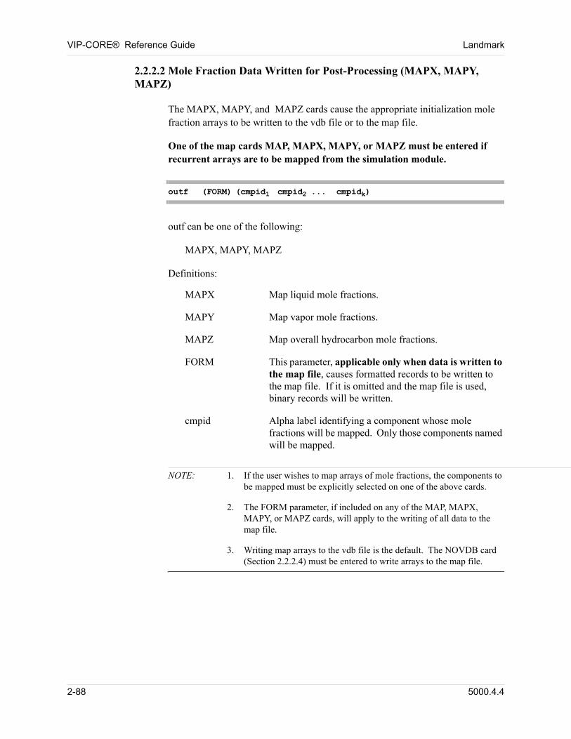
VIP-CORE® Reference Guide Landmark
2.2.2.2 Mole Fraction Data Written for Post-Processing (MAPX, MAPY, MAPZ)
The MAPX, MAPY, and MAPZ cards cause the appropriate initialization mole fraction arrays to be written to the vdb file or to the map file. 00
One of the map cards MAP, MAPX, MAPY, or MAPZ must be entered if recurrent arrays are to be mapped from the simulation module. 00
outf (FORM) (cmpid1 cmpid2 ... cmpidk)
outf can be one of the following: 00
MAPX, MAPY, MAPZ 00
Definitions: 00
MAPX Map liquid mole fractions.
MAPY Map vapor mole fractions.
MAPZ Map overall hydrocarbon mole fractions.
FORM This parameter, applicable only when data is written to the map file, causes formatted records to be written to the map file. If it is omitted and the map file is used, binary records will be written.
cmpid Alpha label identifying a component whose mole fractions will be mapped. Only those components named will be mapped.
NOTE: 1. If the user wishes to map arrays of mole fractions, the components to be mapped must be explicitly selected on one of the above cards.
2. The FORM parameter, if included on any of the MAP, MAPX, MAPY, or MAPZ cards, will apply to the writing of all data to the map file.
3. Writing map arrays to the vdb file is the default. The NOVDB card (Section 2.2.2.4) must be entered to write arrays to the map file.
2-88 5000.4.4
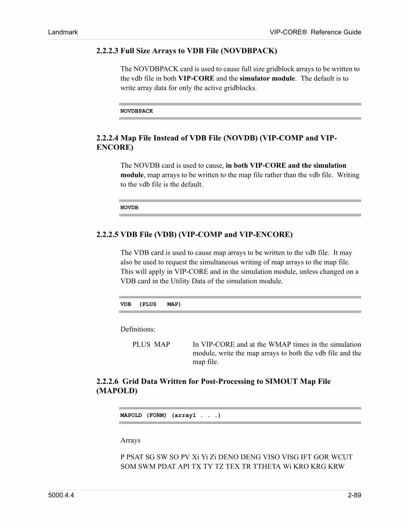
Landmark VIP-CORE® Reference Guide
2.2.2.3 Full Size Arrays to VDB File (NOVDBPACK)
The NOVDBPACK card is used to cause full size gridblock arrays to be written to the vdb file in both VIP-CORE and the simulator module. The default is to write array data for only the active gridblocks. 00
NOVDBPACK
2.2.2.4 Map File Instead of VDB File (NOVDB) (VIP-COMP and VIP-ENCORE)
The NOVDB card is used to cause, in both VIP-CORE and the simulation module, map arrays to be written to the map file rather than the vdb file. Writing to the vdb file is the default. 00
NOVDB
2.2.2.5 VDB File (VDB) (VIP-COMP and VIP-ENCORE)
The VDB card is used to cause map arrays to be written to the vdb file. It may also be used to request the simultaneous writing of map arrays to the map file. This will apply in VIP-CORE and in the simulation module, unless changed on a VDB card in the Utility Data of the simulation module. 00
VDB (PLUS MAP)
Definitions: 00
PLUS MAP In VIP-CORE and at the WMAP times in the simulation module, write the map arrays to both the vdb file and the map file.
2.2.2.6 Grid Data Written for Post-Processing to SIMOUT Map File (MAPOLD)
MAPOLD (FORM) (array1 . . .)
Arrays 00
P PSAT SG SW SO PV Xi Yi Zi DENO DENG VISO VISG IFT GOR WCUT SOM SWM PDAT API TX TY TZ TEX TR TTHETA Wi KRO KRG KRW 00
5000.4.4 2-89
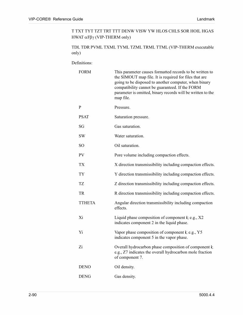
VIP-CORE® Reference Guide Landmark
T TXT TYT TZT TRT TTT DENW VISW YW HLOS CHLS SOR HOIL HGAS
HWAT F (VIP-THERM only) 00
TDL TDR PVML TXML TYML TZML TRML TTML (VIP-THERM executable only) 00
Definitions: 00
FORM This parameter causes formatted records to be written to the SIMOUT map file. It is required for files that are going to be disposed to another computer, when binary compatibility cannot be guaranteed. If the FORM parameter is omitted, binary records will be written to the map file.
P Pressure.
PSAT Saturation pressure.
SG Gas saturation.
SW Water saturation.
SO Oil saturation.
PV Pore volume including compaction effects.
TX X direction transmissibility including compaction effects.
TY Y direction transmissibility including compaction effects.
TZ Z direction transmissibility including compaction effects.
TR R direction transmissibility including compaction effects.
TTHETA Angular direction transmissibility including compaction effects.
Xi Liquid phase composition of component i; e.g., X2 indicates component 2 in the liquid phase.
Yi Vapor phase composition of component i; e.g., Y5 indicates component 5 in the vapor phase.
Zi Overall hydrocarbon phase composition of component i; e.g., Z7 indicates the overall hydrocarbon mole fraction of component 7.
DENO Oil density.
DENG Gas density.
2-90 5000.4.4
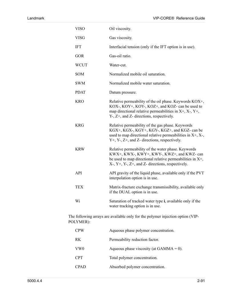
Landmark VIP-CORE® Reference Guide
VISO Oil viscosity.
VISG Gas viscosity.
IFT Interfacial tension (only if the IFT option is in use).
GOR Gas-oil ratio.
WCUT Water-cut.
SOM Normalized mobile oil saturation.
SWM Normalized mobile water saturation.
PDAT Datum pressure.
KRO Relative permeability of the oil phase. Keywords KOX+, KOX-, KOY+, KOY-, KOZ+, and KOZ- can be used to map directional relative permeabilities in X+, X-, Y+, Y-, Z+, and Z- directions, respectively.
KRG Relative permeability of the gas phase. Keywords KGX+, KGX-, KGY+, KGY-, KGZ+, and KGZ- can be used to map directional relative permeabilities in X+, X-, Y+, Y-, Z+, and Z- directions, respectively.
KRW Relative permeability of the water phase. Keywords KWX+, KWX-, KWY+, KWY-, KWZ+, and KWZ- can be used to map directional relative permeabilities in X+, X-, Y+, Y-, Z+, and Z- directions, respectively.
API API gravity of the liquid phase, available only if the PVT interpolation option is in use.
TEX Matrix-fracture exchange transmissibility, available only if the DUAL option is in use.
Wi Saturation of tracked water type i, available only if the water tracking option is in use.
The following arrays are available only for the polymer injection option (VIP-POLYMER): 00
CPW Aqueous phase polymer concentration.
RK Permeability reduction factor.
VW0 Aqueous phase viscosity (at GAMMA = 0).
CPT Total polymer concentration.
CPAD Absorbed polymer concentration.
5000.4.4 2-91
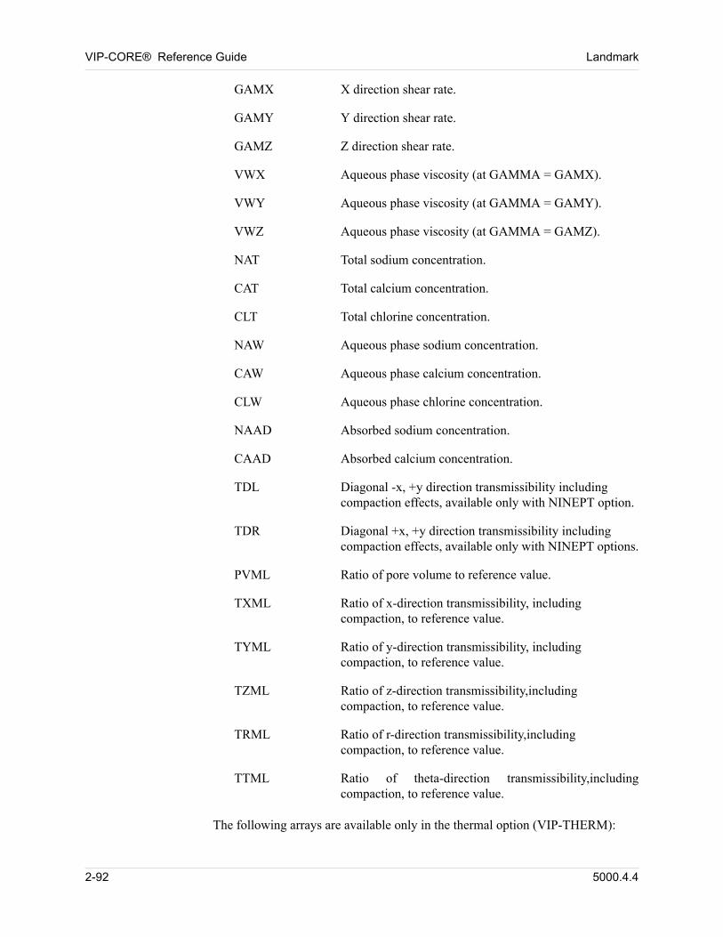
VIP-CORE® Reference Guide Landmark
GAMX X direction shear rate.
GAMY Y direction shear rate.
GAMZ Z direction shear rate.
VWX Aqueous phase viscosity (at GAMMA = GAMX).
VWY Aqueous phase viscosity (at GAMMA = GAMY).
VWZ Aqueous phase viscosity (at GAMMA = GAMZ).
NAT Total sodium concentration.
CAT Total calcium concentration.
CLT Total chlorine concentration.
NAW Aqueous phase sodium concentration.
CAW Aqueous phase calcium concentration.
CLW Aqueous phase chlorine concentration.
NAAD Absorbed sodium concentration.
CAAD Absorbed calcium concentration.
TDL Diagonal -x, +y direction transmissibility including compaction effects, available only with NINEPT option.
TDR Diagonal +x, +y direction transmissibility including compaction effects, available only with NINEPT options.
PVML Ratio of pore volume to reference value.
TXML Ratio of x-direction transmissibility, including compaction, to reference value.
TYML Ratio of y-direction transmissibility, including compaction, to reference value.
TZML Ratio of z-direction transmissibility,including compaction, to reference value.
TRML Ratio of r-direction transmissibility,including compaction, to reference value.
TTML Ratio of theta-direction transmissibility,including compaction, to reference value.
The following arrays are available only in the thermal option (VIP-THERM): 00
2-92 5000.4.4
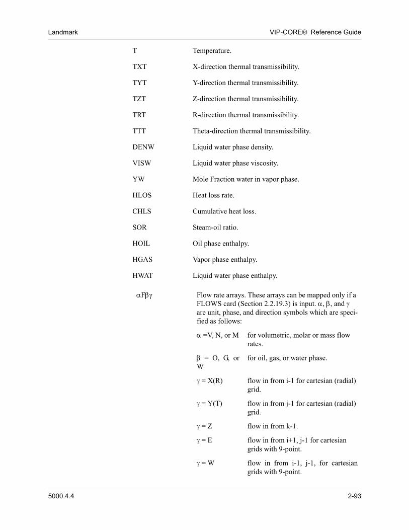
Landmark VIP-CORE® Reference Guide
T Temperature.
TXT X-direction thermal transmissibility.
TYT Y-direction thermal transmissibility.
TZT Z-direction thermal transmissibility.
TRT R-direction thermal transmissibility.
TTT Theta-direction thermal transmissibility.
DENW Liquid water phase density.
VISW Liquid water phase viscosity.
YW Mole Fraction water in vapor phase.
HLOS Heat loss rate.
CHLS Cumulative heat loss.
SOR Steam-oil ratio.
HOIL Oil phase enthalpy.
HGAS Vapor phase enthalpy.
HWAT Liquid water phase enthalpy.
F Flow rate arrays. These arrays can be mapped only if a FLOWS card (Section 2.2.19.3) is input. , , and are unit, phase, and direction symbols which are speci-fied as follows:
=V, N, or M for volumetric, molar or mass flow rates.
= O, G, or W
for oil, gas, or water phase.
= X(R) flow in from i-1 for cartesian (radial) grid.
= Y(T) flow in from j-1 for cartesian (radial) grid.
= Z flow in from k-1.
= E flow in from i+1, j-1 for cartesian grids with 9-point.
= W flow in from i-1, j-1, for cartesian grids with 9-point.
5000.4.4 2-93
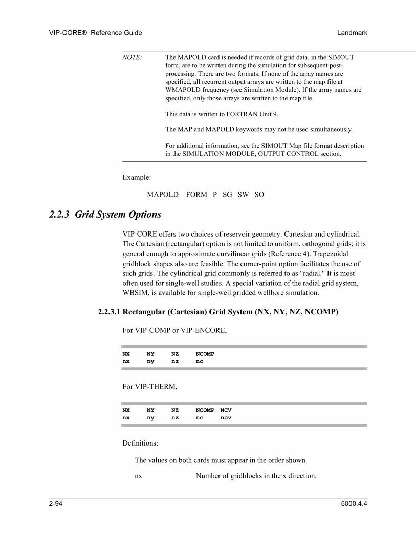
VIP-CORE® Reference Guide Landmark
NOTE: The MAPOLD card is needed if records of grid data, in the SIMOUT form, are to be written during the simulation for subsequent post-processing. There are two formats. If none of the array names are specified, all recurrent output arrays are written to the map file at WMAPOLD frequency (see Simulation Module). If the array names are specified, only those arrays are written to the map file.This data is written to FORTRAN Unit 9.
The MAP and MAPOLD keywords may not be used simultaneously.For additional information, see the SIMOUT Map file format description in the SIMULATION MODULE, OUTPUT CONTROL section.
Example: 00
MAPOLD FORM P SG SW SO 00
2.2.3 Grid System Options
VIP-CORE offers two choices of reservoir geometry: Cartesian and cylindrical. The Cartesian (rectangular) option is not limited to uniform, orthogonal grids; it is
general enough to approximate curvilinear grids (Reference 4). Trapezoidal gridblock shapes also are feasible. The corner-point option facilitates the use of such grids. The cylindrical grid commonly is referred to as "radial." It is most often used for single-well studies. A special variation of the radial grid system, WBSIM, is available for single-well gridded wellbore simulation. 00
2.2.3.1 Rectangular (Cartesian) Grid System (NX, NY, NZ, NCOMP)
For VIP-COMP or VIP-ENCORE, 00
NX NY NZ NCOMPnx ny nz nc
For VIP-THERM, 00
NX NY NZ NCOMP NCVnx ny nz nc ncv
Definitions: 00
The values on both cards must appear in the order shown. 00
nx Number of gridblocks in the x direction.
2-94 5000.4.4
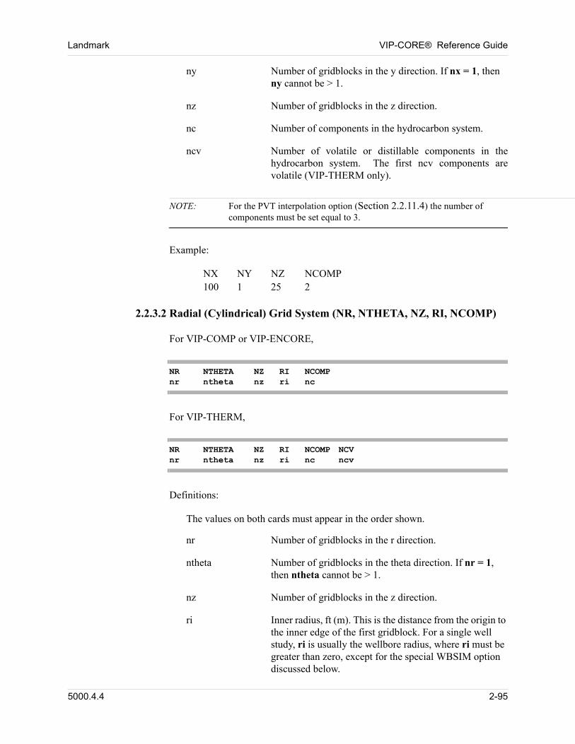
Landmark VIP-CORE® Reference Guide
ny Number of gridblocks in the y direction. If nx = 1, then ny cannot be > 1.
nz Number of gridblocks in the z direction.
nc Number of components in the hydrocarbon system.
ncv Number of volatile or distillable components in the hydrocarbon system. The first ncv components are volatile (VIP-THERM only).
NOTE: For the PVT interpolation option (Section 2.2.11.4) the number of components must be set equal to 3.
Example: 00
NX NY NZ NCOMP100 1 25 2 00
2.2.3.2 Radial (Cylindrical) Grid System (NR, NTHETA, NZ, RI, NCOMP)
For VIP-COMP or VIP-ENCORE, 00
NR NTHETA NZ RI NCOMPnr ntheta nz ri nc
For VIP-THERM, 00
NR NTHETA NZ RI NCOMP NCVnr ntheta nz ri nc ncv
Definitions: 00
The values on both cards must appear in the order shown. 00
nr Number of gridblocks in the r direction.
ntheta Number of gridblocks in the theta direction. If nr = 1, then ntheta cannot be > 1.
nz Number of gridblocks in the z direction.
ri Inner radius, ft (m). This is the distance from the origin to the inner edge of the first gridblock. For a single well study, ri is usually the wellbore radius, where ri must be greater than zero, except for the special WBSIM option discussed below.
5000.4.4 2-95
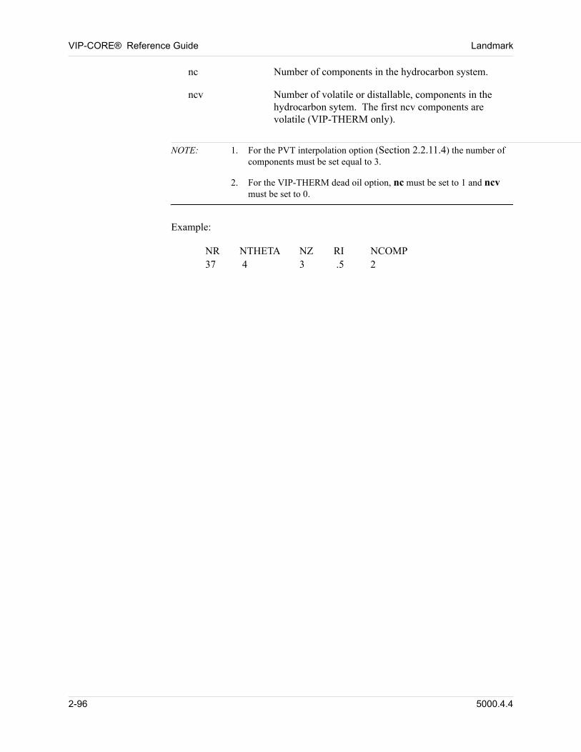
VIP-CORE® Reference Guide Landmark
nc Number of components in the hydrocarbon system.
ncv Number of volatile or distallable, components in the hydrocarbon sytem. The first ncv components are volatile (VIP-THERM only).
NOTE: 1. For the PVT interpolation option (Section 2.2.11.4) the number of components must be set equal to 3.
2. For the VIP-THERM dead oil option, nc must be set to 1 and ncv must be set to 0.
Example: 00
NR NTHETA NZ RI NCOMP37 4 3 .5 2 00
2-96 5000.4.4
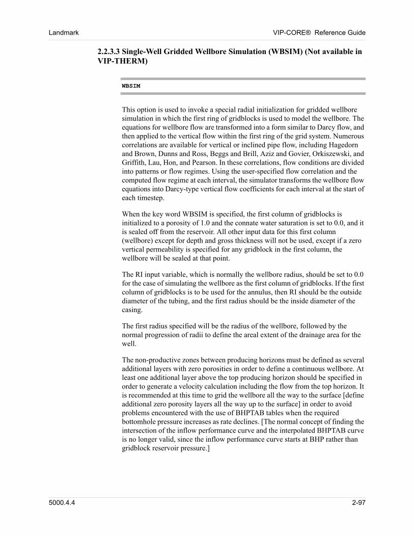
Landmark VIP-CORE® Reference Guide
2.2.3.3 Single-Well Gridded Wellbore Simulation (WBSIM) (Not available in VIP-THERM)
WBSIM
This option is used to invoke a special radial initialization for gridded wellbore simulation in which the first ring of gridblocks is used to model the wellbore. The equations for wellbore flow are transformed into a form similar to Darcy flow, and then applied to the vertical flow within the first ring of the grid system. Numerous correlations are available for vertical or inclined pipe flow, including Hagedorn and Brown, Dunns and Ross, Beggs and Brill, Aziz and Govier, Orkiszewski, and Griffith, Lau, Hon, and Pearson. In these correlations, flow conditions are divided into patterns or flow regimes. Using the user-specified flow correlation and the computed flow regime at each interval, the simulator transforms the wellbore flow equations into Darcy-type vertical flow coefficients for each interval at the start of each timestep.
When the key word WBSIM is specified, the first column of gridblocks is initialized to a porosity of 1.0 and the connate water saturation is set to 0.0, and it is sealed off from the reservoir. All other input data for this first column (wellbore) except for depth and gross thickness will not be used, except if a zero vertical permeability is specified for any gridblock in the first column, the wellbore will be sealed at that point.
The RI input variable, which is normally the wellbore radius, should be set to 0.0 for the case of simulating the wellbore as the first column of gridblocks. If the first column of gridblocks is to be used for the annulus, then RI should be the outside diameter of the tubing, and the first radius should be the inside diameter of the casing.
The first radius specified will be the radius of the wellbore, followed by the normal progression of radii to define the areal extent of the drainage area for the well.
The non-productive zones between producing horizons must be defined as several additional layers with zero porosities in order to define a continuous wellbore. At least one additional layer above the top producing horizon should be specified in order to generate a velocity calculation including the flow from the top horizon. It is recommended at this time to grid the wellbore all the way to the surface [define additional zero porosity layers all the way up to the surface] in order to avoid problems encountered with the use of BHPTAB tables when the required bottomhole pressure increases as rate declines. [The normal concept of finding the intersection of the inflow performance curve and the interpolated BHPTAB curve is no longer valid, since the inflow performance curve starts at BHP rather than gridblock reservoir pressure.]
5000.4.4 2-97
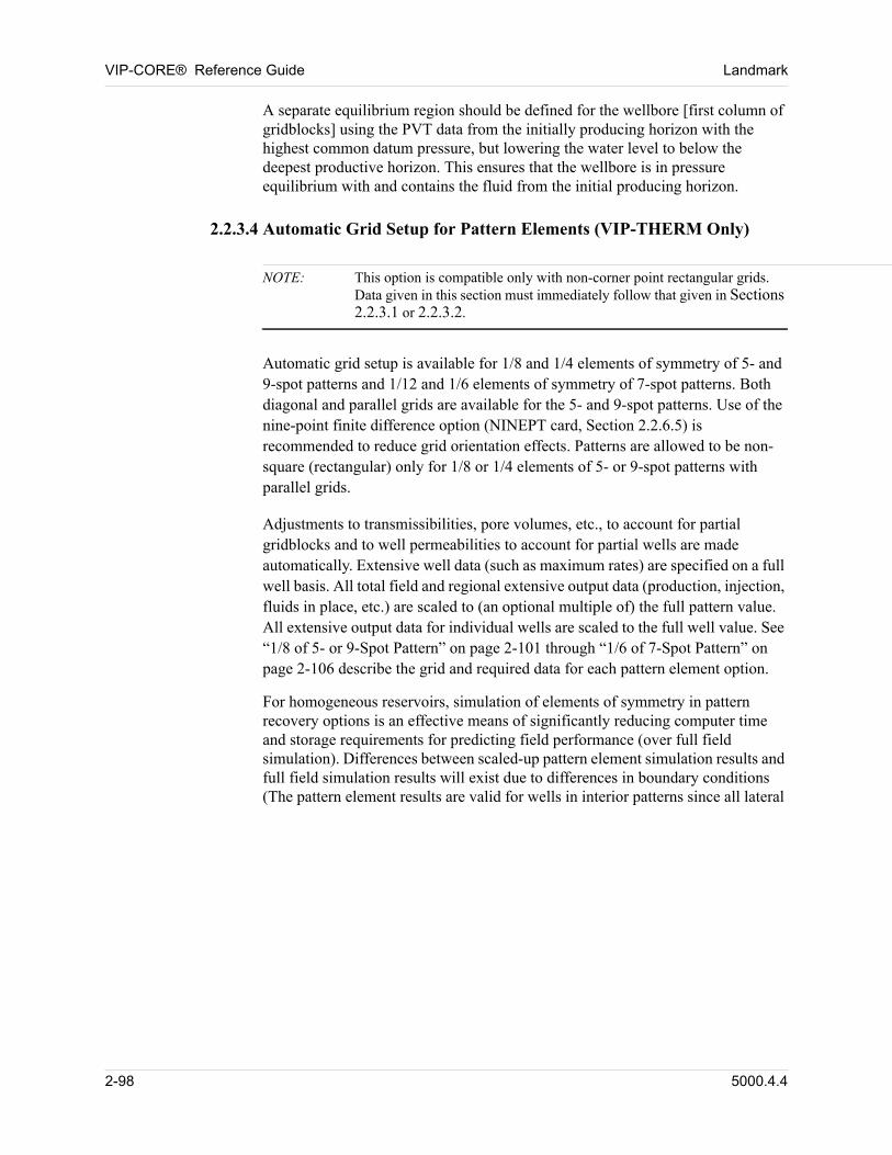
VIP-CORE® Reference Guide Landmark
A separate equilibrium region should be defined for the wellbore [first column of gridblocks] using the PVT data from the initially producing horizon with the highest common datum pressure, but lowering the water level to below the deepest productive horizon. This ensures that the wellbore is in pressure equilibrium with and contains the fluid from the initial producing horizon.
2.2.3.4 Automatic Grid Setup for Pattern Elements (VIP-THERM Only)
NOTE: This option is compatible only with non-corner point rectangular grids. Data given in this section must immediately follow that given in Sections 2.2.3.1 or 2.2.3.2.
Automatic grid setup is available for 1/8 and 1/4 elements of symmetry of 5- and 9-spot patterns and 1/12 and 1/6 elements of symmetry of 7-spot patterns. Both diagonal and parallel grids are available for the 5- and 9-spot patterns. Use of the nine-point finite difference option (NINEPT card, Section 2.2.6.5) is recommended to reduce grid orientation effects. Patterns are allowed to be non-square (rectangular) only for 1/8 or 1/4 elements of 5- or 9-spot patterns with parallel grids. 00
Adjustments to transmissibilities, pore volumes, etc., to account for partial gridblocks and to well permeabilities to account for partial wells are made automatically. Extensive well data (such as maximum rates) are specified on a full well basis. All total field and regional extensive output data (production, injection, fluids in place, etc.) are scaled to (an optional multiple of) the full pattern value. All extensive output data for individual wells are scaled to the full well value. See “1/8 of 5- or 9-Spot Pattern” on page 2-101 through “1/6 of 7-Spot Pattern” on page 2-106 describe the grid and required data for each pattern element option. 00
For homogeneous reservoirs, simulation of elements of symmetry in pattern recovery options is an effective means of significantly reducing computer time and storage requirements for predicting field performance (over full field simulation). Differences between scaled-up pattern element simulation results and full field simulation results will exist due to differences in boundary conditions (The pattern element results are valid for wells in interior patterns since all lateral
2-98 5000.4.4
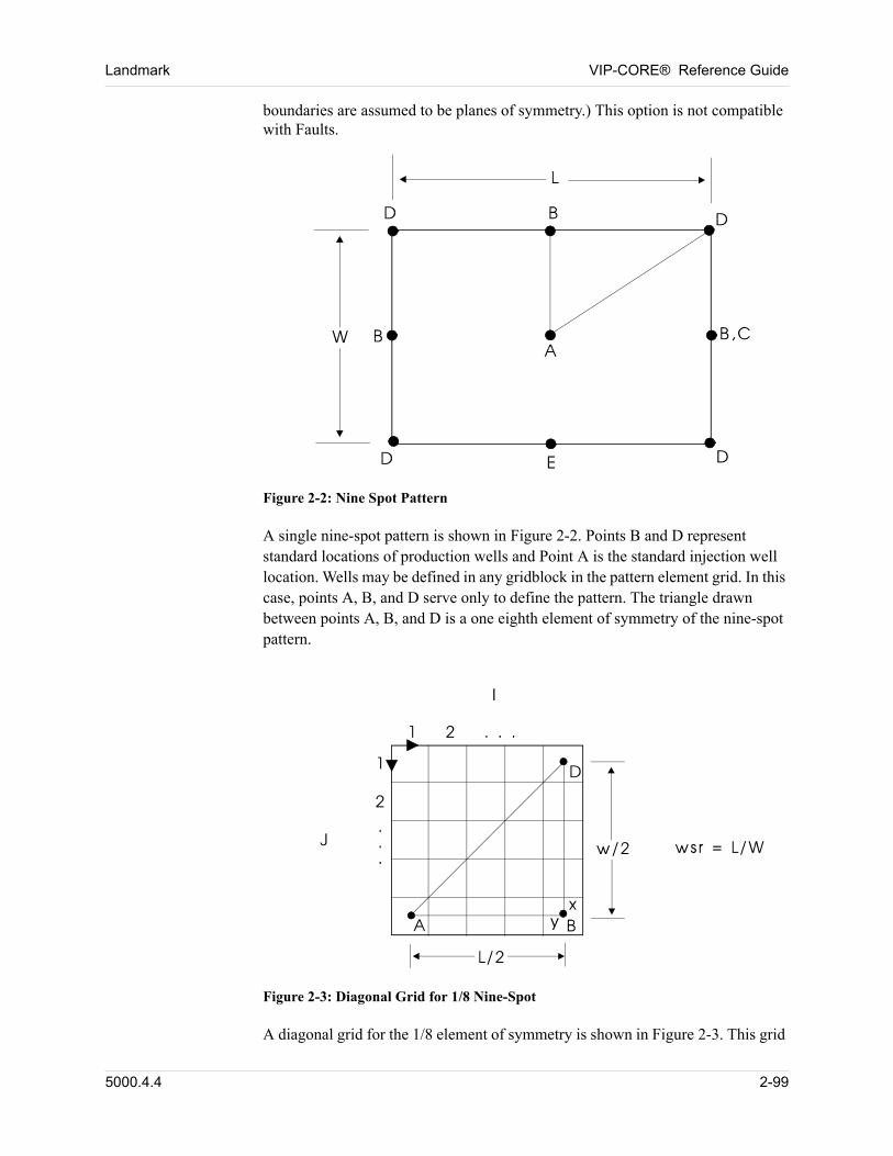
Landmark VIP-CORE® Reference Guide
boundaries are assumed to be planes of symmetry.) This option is not compatible with Faults. 00
Figure 2-2: Nine Spot Pattern
A single nine-spot pattern is shown in Figure 2-2. Points B and D represent standard locations of production wells and Point A is the standard injection well location. Wells may be defined in any gridblock in the pattern element grid. In this case, points A, B, and D serve only to define the pattern. The triangle drawn between points A, B, and D is a one eighth element of symmetry of the nine-spot pattern. 00
00
Figure 2-3: Diagonal Grid for 1/8 Nine-Spot
A diagonal grid for the 1/8 element of symmetry is shown in Figure 2-3. This grid
5000.4.4 2-99
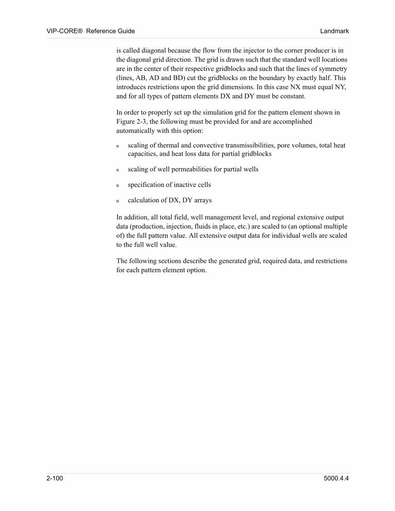
VIP-CORE® Reference Guide Landmark
is called diagonal because the flow from the injector to the corner producer is in the diagonal grid direction. The grid is drawn such that the standard well locations are in the center of their respective gridblocks and such that the lines of symmetry (lines, AB, AD and BD) cut the gridblocks on the boundary by exactly half. This introduces restrictions upon the grid dimensions. In this case NX must equal NY, and for all types of pattern elements DX and DY must be constant. 00
In order to properly set up the simulation grid for the pattern element shown in Figure 2-3, the following must be provided for and are accomplished automatically with this option: 00
n scaling of thermal and convective transmissibilities, pore volumes, total heat capacities, and heat loss data for partial gridblocks
n scaling of well permeabilities for partial wells
n specification of inactive cells
n calculation of DX, DY arrays
In addition, all total field, well management level, and regional extensive output data (production, injection, fluids in place, etc.) are scaled to (an optional multiple of) the full pattern value. All extensive output data for individual wells are scaled to the full well value. 00
The following sections describe the generated grid, required data, and restrictions for each pattern element option. 00
2-100 5000.4.4
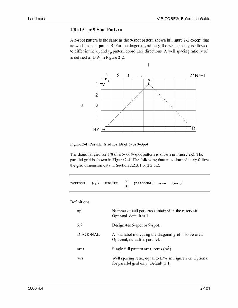
Landmark VIP-CORE® Reference Guide
1/8 of 5- or 9-Spot Pattern 00
A 5-spot pattern is the same as the 9-spot pattern shown in Figure 2-2 except that no wells exist at points B. For the diagonal grid only, the well spacing is allowed to differ in the xp and yp pattern coordinate directions. A well spacing ratio (wsr)
is defined as L/W in Figure 2-2. 00
Figure 2-4: Parallel Grid for 1/8 of 5- or 9-Spot
The diagonal grid for 1/8 of a 5- or 9-spot pattern is shown in Figure 2-3. The parallel grid is shown in Figure 2-4. The following data must immediately follow the grid dimension data in Section 2.2.3.1 or 2.2.3.2. 00
PATTERN (np) EIGHTH 5
9(DIAGONAL) area (wsr)
Definitions: 00
np Number of cell patterns contained in the reservoir. Optional, default is 1.
5,9 Designates 5-spot or 9-spot.
DIAGONAL Alpha label indicating the diagonal grid is to be used. Optional, default is parallel.
area Single full pattern area, acres (m2).
wsr Well spacing ratio, equal to L/W in Figure 2-2. Optional for parallel grid only. Default is 1.
5000.4.4 2-101
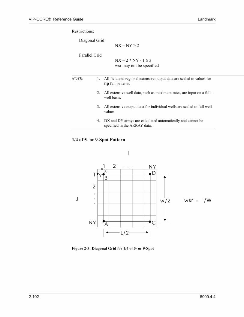
VIP-CORE® Reference Guide Landmark
Restrictions: 00
Diagonal GridNX = NY
Parallel GridNX = 2 * NY - 1 3wsr may not be specified
NOTE: 1. All field and regional extensive output data are scaled to values for np full patterns.
2. All extensive well data, such as maximum rates, are input on a full-well basis.
3. All extensive output data for individual wells are scaled to full well values.
4. DX and DY arrays are calculated automatically and cannot be specified in the ARRAY data.
1/4 of 5- or 9-Spot Pattern00
Figure 2-5: Diagonal Grid for 1/4 of 5- or 9-Spot
2-102 5000.4.4
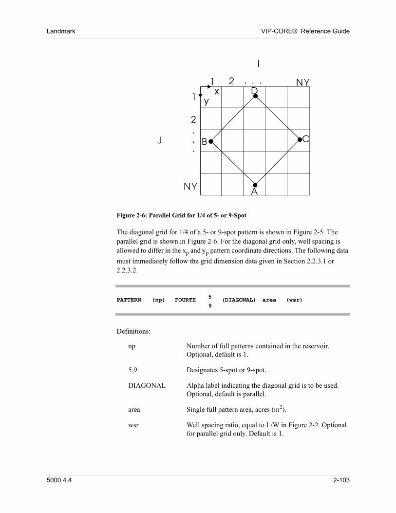
Landmark VIP-CORE® Reference Guide
00
Figure 2-6: Parallel Grid for 1/4 of 5- or 9-Spot
The diagonal grid for 1/4 of a 5- or 9-spot pattern is shown in Figure 2-5. The parallel grid is shown in Figure 2-6. For the diagonal grid only, well spacing is allowed to differ in the xp and yp pattern coordinate directions. The following data
must immediately follow the grid dimension data given in Section 2.2.3.1 or 2.2.3.2. 00
PATTERN (np) FOURTH 5
9(DIAGONAL) area (wsr)
Definitions: 00
np Number of full patterns contained in the reservoir. Optional, default is 1.
5,9 Designates 5-spot or 9-spot.
DIAGONAL Alpha label indicating the diagonal grid is to be used. Optional, default is parallel.
area Single full pattern area, acres (m2).
wsr Well spacing ratio, equal to L/W in Figure 2-2. Optional for parallel grid only. Default is 1.
5000.4.4 2-103
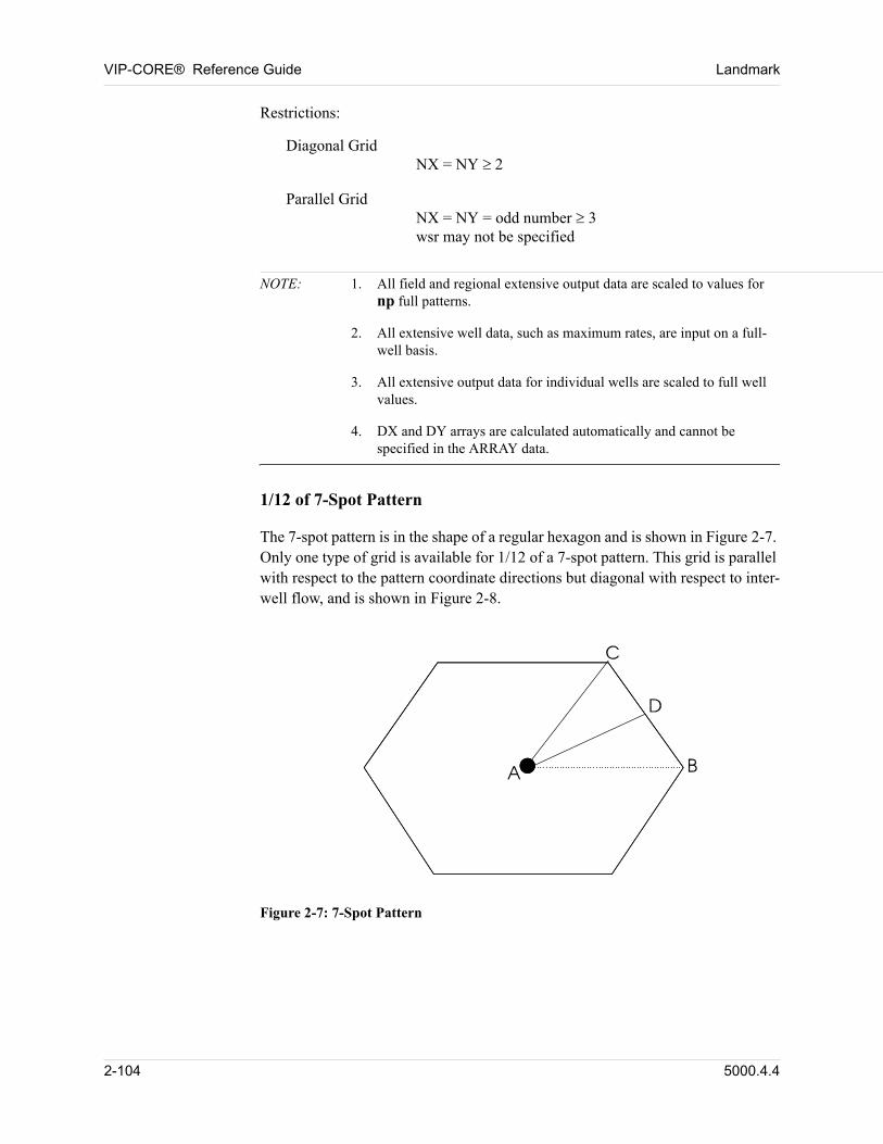
VIP-CORE® Reference Guide Landmark
Restrictions: 00
Diagonal GridNX = NY
Parallel GridNX = NY = odd number 3wsr may not be specified
NOTE: 1. All field and regional extensive output data are scaled to values for np full patterns.
2. All extensive well data, such as maximum rates, are input on a full-well basis.
3. All extensive output data for individual wells are scaled to full well values.
4. DX and DY arrays are calculated automatically and cannot be specified in the ARRAY data.
1/12 of 7-Spot Pattern 00
The 7-spot pattern is in the shape of a regular hexagon and is shown in Figure 2-7. Only one type of grid is available for 1/12 of a 7-spot pattern. This grid is parallel with respect to the pattern coordinate directions but diagonal with respect to inter-well flow, and is shown in Figure 2-8. 00
Figure 2-7: 7-Spot Pattern
2-104 5000.4.4
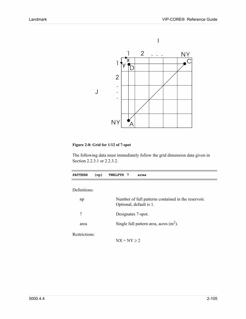
Landmark VIP-CORE® Reference Guide
00
Figure 2-8: Grid for 1/12 of 7-spot
The following data must immediately follow the grid dimension data given in Section 2.2.3.1 or 2.2.3.2. 00
PATTERN (np) TWELFTH 7 area
Definitions: 00
np Number of full patterns contained in the reservoir. Optional, default is 1.
7 Designates 7-spot.
area Single full pattern area, acres (m2).
Restrictions:NX = NY 2 00
5000.4.4 2-105
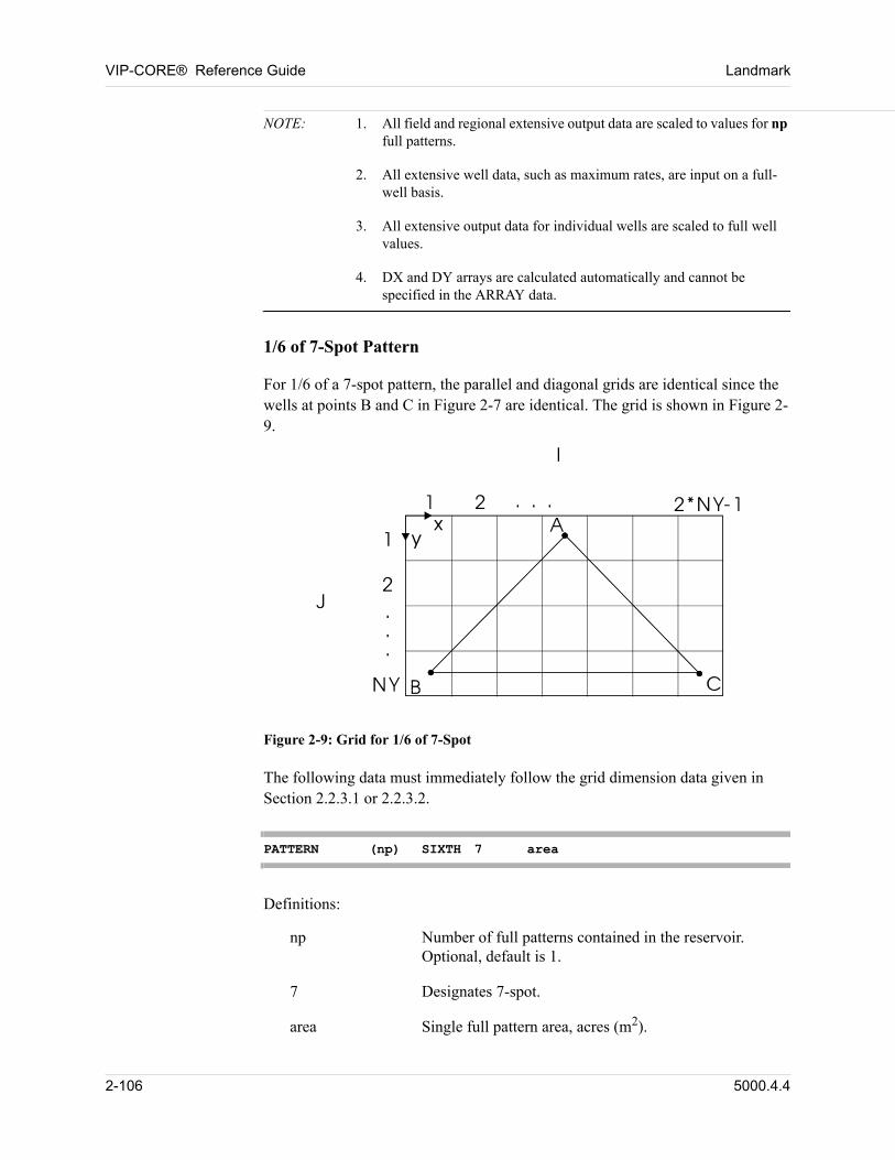
VIP-CORE® Reference Guide Landmark
NOTE: 1. All field and regional extensive output data are scaled to values for np full patterns.
2. All extensive well data, such as maximum rates, are input on a full-well basis.
3. All extensive output data for individual wells are scaled to full well values.
4. DX and DY arrays are calculated automatically and cannot be specified in the ARRAY data.
1/6 of 7-Spot Pattern 00
For 1/6 of a 7-spot pattern, the parallel and diagonal grids are identical since the wells at points B and C in Figure 2-7 are identical. The grid is shown in Figure 2-9. 00
Figure 2-9: Grid for 1/6 of 7-Spot
The following data must immediately follow the grid dimension data given in Section 2.2.3.1 or 2.2.3.2. 00
PATTERN (np) SIXTH 7 area
Definitions: 00
np Number of full patterns contained in the reservoir. Optional, default is 1.
7 Designates 7-spot.
area Single full pattern area, acres (m2).
2-106 5000.4.4
Landmark VIP-CORE® Reference Guide
Restrictions:NX = 2 * NY -1 3 00
NOTE: 1. All field, regional, and well management level extensive output data are scaled to values for np full patterns.
2. All extensive well data, such as maximum rates, are input on a full-well basis.
3. All extensive output data for individual wells are scaled to full well values.
4. DX and DY arrays are calculated automatically and cannot be specified in the ARRAY data.
2.2.4 Physical Property Constants
Initial reservoir temperature may be specified in one or more of the following ways for compositional or thermal models (temperature variation is not allowed in black oil models, but a constant value is required in the constant data): 00
1. Specified as a constant (Required, Section 2.2.4).
2. Specified by equilibrium region in the IEQUIL table (Section 4.2.1.1, 4.2.1.2, 4.2.1.3, or 4.2.2), overriding the constant value in option 1.
3. Specified by equilibrium region, as a function of depth or as a function of depth and areal location, overriding values in options 1 and 2:
a. For isothermal and thermal compositional models, Section 4.4.11.3 or 4.4.11.4.
b. For thermal dead oil models, Section 4.7.1 or 4.7.2.
Entering temperature as a function of depth and areal location (4.4.11.4) is discouraged, since the areal temperature variation is not accounted for in the calculation of equilibrium phase pressures versus depth. See option 4 below for further discussion of this problem.
5000.4.4 2-107
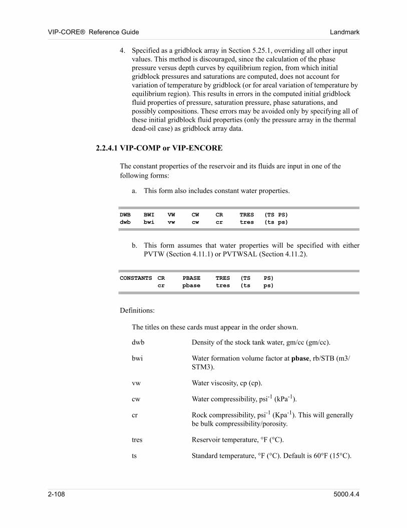
VIP-CORE® Reference Guide Landmark
4. Specified as a gridblock array in Section 5.25.1, overriding all other input values. This method is discouraged, since the calculation of the phase pressure versus depth curves by equilibrium region, from which initial gridblock pressures and saturations are computed, does not account for variation of temperature by gridblock (or for areal variation of temperature by equilibrium region). This results in errors in the computed initial gridblock fluid properties of pressure, saturation pressure, phase saturations, and possibly compositions. These errors may be avoided only by specifying all of these initial gridblock fluid properties (only the pressure array in the thermal dead-oil case) as gridblock array data.
2.2.4.1 VIP-COMP or VIP-ENCORE
The constant properties of the reservoir and its fluids are input in one of the following forms: 00
a. This form also includes constant water properties.
DWB BWI VW CW CR TRES (TS PS)dwb bwi vw cw cr tres (ts ps)
b. This form assumes that water properties will be specified with either PVTW (Section 4.11.1) or PVTWSAL (Section 4.11.2).
CONSTANTS CR PBASE TRES (TS PS)cr pbase tres (ts ps)
Definitions: 00
The titles on these cards must appear in the order shown. 00
dwb Density of the stock tank water, gm/cc (gm/cc).
bwi Water formation volume factor at pbase, rb/STB (m3/STM3).
vw Water viscosity, cp (cp).
cw Water compressibility, psi-1 (kPa-1).
cr Rock compressibility, psi-1 (Kpa-1). This will generally be bulk compressibility/porosity.
tres Reservoir temperature, °F (°C).
ts Standard temperature, °F (°C). Default is 60°F (15°C).
2-108 5000.4.4
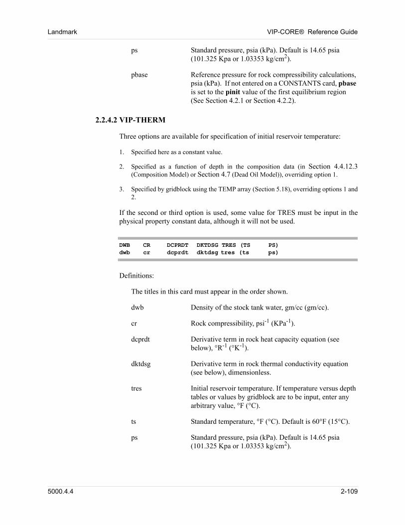
Landmark VIP-CORE® Reference Guide
ps Standard pressure, psia (kPa). Default is 14.65 psia (101.325 Kpa or 1.03353 kg/cm2).
pbase Reference pressure for rock compressibility calculations, psia (kPa). If not entered on a CONSTANTS card, pbase is set to the pinit value of the first equilibrium region (See Section 4.2.1 or Section 4.2.2).
2.2.4.2 VIP-THERM
Three options are available for specification of initial reservoir temperature:
1. Specified here as a constant value.
2. Specified as a function of depth in the composition data (in Section 4.4.12.3(Composition Model) or Section 4.7 (Dead Oil Model)), overriding option 1.
3. Specified by gridblock using the TEMP array (Section 5.18), overriding options 1 and 2.
If the second or third option is used, some value for TRES must be input in the physical property constant data, although it will not be used.
DWB CR DCPRDT DKTDSG TRES (TS PS)dwb cr dcprdt dktdsg tres (ts ps)
Definitions:
The titles in this card must appear in the order shown.
dwb Density of the stock tank water, gm/cc (gm/cc).
cr Rock compressibility, psi-1 (KPa-1).
dcprdt Derivative term in rock heat capacity equation (see below), °R-1 (°K-1).
dktdsg Derivative term in rock thermal conductivity equation (see below), dimensionless.
tres Initial reservoir temperature. If temperature versus depth tables or values by gridblock are to be input, enter any arbitrary value, °F (°C).
ts Standard temperature, °F (°C). Default is 60°F (15°C).
ps Standard pressure, psia (kPa). Default is 14.65 psia (101.325 Kpa or 1.03353 kg/cm2).
5000.4.4 2-109
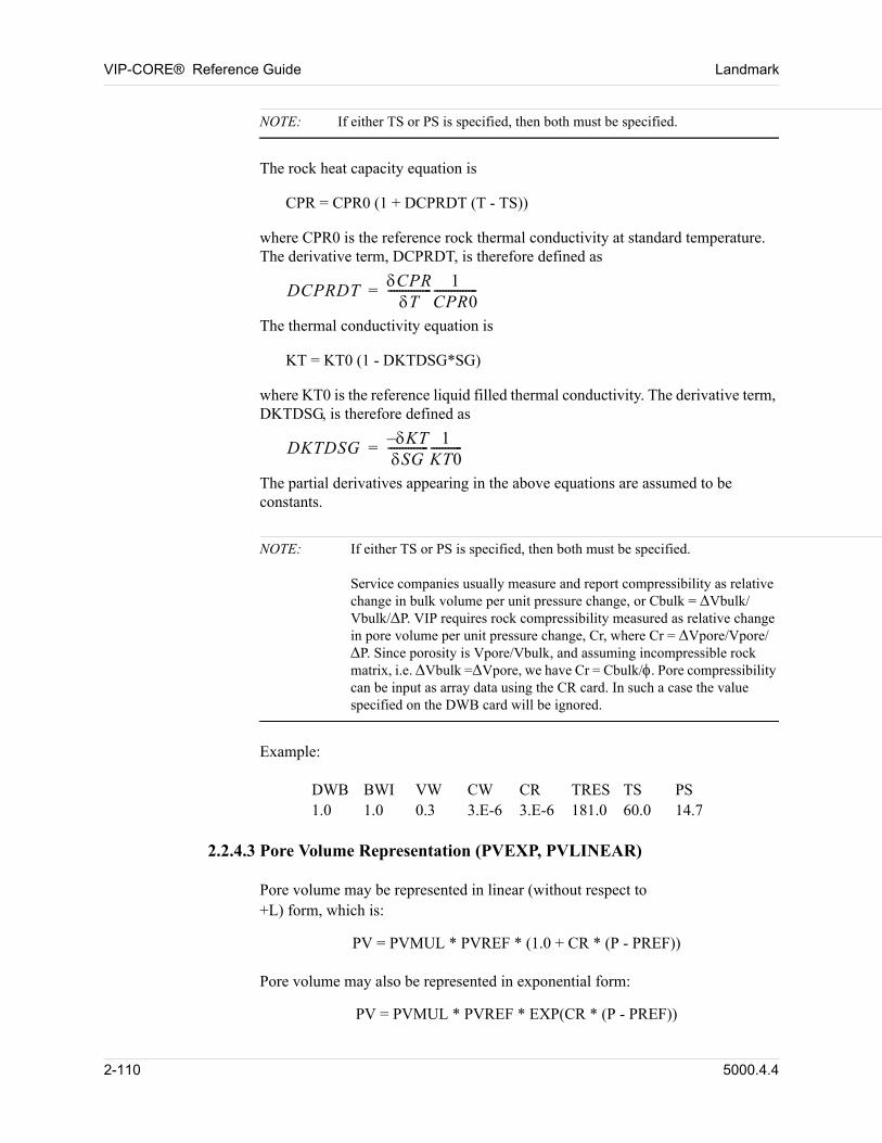
VIP-CORE® Reference Guide Landmark
NOTE: If either TS or PS is specified, then both must be specified.
The rock heat capacity equation is
CPR = CPR0 (1 + DCPRDT (T - TS))
where CPR0 is the reference rock thermal conductivity at standard temperature. The derivative term, DCPRDT, is therefore defined as
DCPRDTCPRT
--------------- 1CPR0---------------=
The thermal conductivity equation is
KT = KT0 (1 - DKTDSG*SG)
where KT0 is the reference liquid filled thermal conductivity. The derivative term, DKTDSG, is therefore defined as
DKTDSG– KTSG
-------------- 1KT0-----------=
The partial derivatives appearing in the above equations are assumed to be constants.
NOTE: If either TS or PS is specified, then both must be specified.Service companies usually measure and report compressibility as relative change in bulk volume per unit pressure change, or Cbulk = Vbulk/Vbulk/P. VIP requires rock compressibility measured as relative change in pore volume per unit pressure change, Cr, where Cr = Vpore/Vpore/P. Since porosity is Vpore/Vbulk, and assuming incompressible rock matrix, i.e. Vbulk =Vpore, we have Cr = Cbulk/. Pore compressibility can be input as array data using the CR card. In such a case the value specified on the DWB card will be ignored.
Example:
DWB BWI VW CW CR TRES TS PS1.0 1.0 0.3 3.E-6 3.E-6 181.0 60.0 14.7
2.2.4.3 Pore Volume Representation (PVEXP, PVLINEAR)
Pore volume may be represented in linear (without respect to+L) form, which is: 00
PV = PVMUL * PVREF * (1.0 + CR * (P - PREF)) 00
Pore volume may also be represented in exponential form: 00
PV = PVMUL * PVREF * EXP(CR * (P - PREF)) 00
2-110 5000.4.4
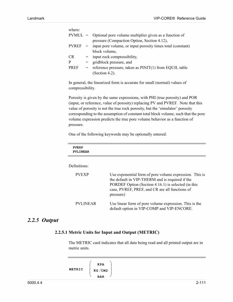
Landmark VIP-CORE® Reference Guide
where:PVMUL = Optional pore volume multiplier given as a function of
pressure (Compaction Option, Section 4.12), PVREF = input pore volume, or input porosity times total (constant)
block volume, CR = input rock compressibility, P = gridblock pressure, and PREF = reference pressure, taken as PINIT(1) from EQUIL table
(Section 4.2). 00
In general, the linearized form is accurate for small (normal) values of compressibility. 00
Porosity is given by the same expressions, with PHI (true porosity) and POR (input, or reference, value of porosity) replacing PV and PVREF. Note that this value of porosity is not the true rock porosity, but the ‘simulator’ porosity corresponding to the assumption of constant total block volume, such that the pore volume expression predicts the true pore volume behavior as a function of pressure. 00
One of the following keywords may be optionally entered: 00
PVEXP PVLINEAR
Definitions: 00
PVEXP Use exponential form of pore volume expression. This is the default in VIP-THERM and is required if the PORDEF Option (Section 4.16.1) is selected (in this case, PVREF, PREF, and CR are all functions of pressure)
PVLINEAR Use linear form of pore volume expression. This is the default option in VIP-COMP and VIP-ENCORE.
2.2.5 Output
2.2.5.1 Metric Units for Input and Output (METRIC)
The METRIC card indicates that all data being read and all printed output are in metric units.
METRIC
KPA
KG CM2BAR
5000.4.4 2-111
VIP-CORE® Reference Guide Landmark
The pressure units for the metric option may be kPa, bar or kg/cm2; if neither KG/CM2 nor BAR is specified, the default is kPa.
Example:
METRIC KG/CM2
2.2.5.2 Laboratory Units for Input and Output (LAB)
The LAB card indicates that all data being read and all printed output are in laboratory units. Please refer to VIP-EXECUTIVE Technical Reference, Chapter 31.
LAB
When laboratory units are used, the program automatically adjusts some of the internal tolerances used by the well calculations for testing of shut-in wells.
2.2.5.3 Print by Cross-Sections (CROSS)
The CROSS card causes arrays to be printed by cross-sections (vertical planes), instead of by areal planes. 00
CROSS
2.2.5.4 Layer Output in Initialization Region Summary (REGNZ)
REGNZ
Initialization region reports usually provide totals for each region, but REGNZ causes layer values to be output, as well. 00
2.2.5.5 Hydrocarbon Pore Volume and Bulk Volume Tables (HCPVTAB)
The HCPVTAB card causes three additional tables to be printed as functions of depth: the first containing hydrocarbon pore volume, the second containing bulk
2-112 5000.4.4
Landmark VIP-CORE® Reference Guide
volume, and the third containing cumulative bulk volume. The tables are generated by rock type, by region, and by totals. 00
HCPVTAB hpvinc (hpvtop)
Definitions: 00
hpvinc Depth increment, ft (m). This controls the spacing of the depths in each of the tables.
hpvtop Optional specification of the top depth, ft (m) subsea, for use in both of the tables. Default is the minimum top depth of any gridblock in the system. The first depth entry in the table is hpvtop. The second depth entry is the next depth value larger than hpvtop that is divisible by hpvinc. Subsequent depth entries increase by hpvinc. For example, the data HCPVTAB 100 8035 will result in tables with depth entries 8035, 8100, 8200, etc.
2.2.6 Formulation
2.2.6.1 Gas-Water Option for VIP-ENCORE (GASWATER)
This option is not applicable with the DUAL module. 00
GASWATER
This option is used to invoke the two phase gas-water option. This option is useful for cases with no oil or condensate in the reservoir (dry gas). The gas phase has constant composition and hence only one hydrocarbon equation is solved in IMPLICIT cases - coefficient generation is unaffected. This option provides reduced data input of the saturation and PVT tables, where only the gas properties are required. 00
NOTE: 1. Simplified equilibrium data for this option is possible (see Section 4.2.1.2).
2. The saturation tables are specified using a modified SGT card, and SWT data is not required (as described in Section 4.3.1.2).
3. The PVT data is specified by the BGTAB card, rather than the BOTAB card (as described in Section 4.5.3).
5000.4.4 2-113
VIP-CORE® Reference Guide Landmark
2.2.6.2 Water-Oil Option for VIP-ENCORE (WATEROIL)
This option is not applicable with the DUAL module. 00
WATEROIL
This option is used to invoke the two phase water-oil option. This option is useful for cases with no gas in the reservoir. The oil phase has constant composition and hence only one hydrocarbon equation is solved in IMPLICIT cases - coefficient generation is unaffected. This option provides reduced data input of the saturation and PVT tables, where only the oil properties are required. 00
NOTE: 1. Simplified equilibrium data for this option is possible (see Section 4.2.1.3).
2. The saturation tables are specified by the SWT card described in Section 4.3.1.1. Gas saturation table data (SGT card) is not required.
3. The PVT data is specified by the BOTAB card, but gas parameters may be omitted (as described in Section 4.5.2.2).
2.2.6.3 Black-Oil Option (BLACKOIL) (VIP-ENCORE)
BLACKOIL
The black-oil option allows the simulation of a true black-oil system in which the
K-value of the oil component is near zero (on the order of 10-10). The option will prevent the residual oil (or the relict oil in a gas cap) from vaporizing during gas injection. In the standard black-oil model, the K-value of the oil component is on
the order of 10-3 to 10-2 even if the oil is specified as non-volatile, i.e., input of a constant GR (gas gravity) in the BOTAB table. In addition to this keyword, the other data requirements are noted below. 00
NOTE: 1. All input GR values in the BOTAB table must be the same.
2. If multiple PVT tables are specified, the WTRO (molecular weight of residual oil) values in all BOTAB tables must be the same, and the GR values in all BOTAB tables must also be the same.
3. Default separators must be used and no additional separator data may be specified.
2.2.6.4 Two-Point Upstream Weighting (TWOPT) (Not available in
2-114 5000.4.4
Landmark VIP-CORE® Reference Guide
VIP-THERM)
TWOPT
This option causes two-point upstream mobility weighting and two-point upstream component mole fraction weighting to be used in generating flow coefficients. It should be noted that two-point upstream weighting cannot be used with the IMPLICIT formulation. 00
Two point upstream has a stability limit only two-thirds the size of the limit of the default single-point upstream method. Care must be taken when timestep size is determined. When using the IMPSTAB option to control timestep size, parameters "ststar" and "stslim" must be explicitly defined (on IMPSTAB card) as 0.6 and 0.66 respectively. 00
2.2.6.5 Nine-Point Finite Difference Approximations (NINEPT)
NINEPT
The use of the nine-point option is subject to the following conditions:
1. Cartesian grid system or LGR model with Cartesian root grid and Cartesian refinements only.
2. NX > 1, NY > 1.
The NINEPT card causes the program to utilize nine-point finite difference approximations on the X-Y plane, while the Z-direction (if present) is discretized using the usual three-point approximation. Unless input, diagonal transmissibilities are internally calculated using the method of Coats and Modine (Reference 3). For models with local grid refinements, the diagonal transmissibilities are computed only inside each grid but not across grid boundaries. 00
2.2.6.6 SEBOUND option
When using the NINEPT option in cartesian or corner point grids, the areal outer reservoir boundary may be specified as passing through the outer gridblock centers rather than along the outer edges of the outer gridblocks. This option is particularly useful when manually setting up pattern elements of symmetry. The areal transmissibilities parallel to these boundaries are then automatically computed using the corrrect boundary conditions (for non-homogenous and/or non-isotropic grids, the correct transmissibilities cannot be obtained by manual scaling when using the NINEPT option). The SEBOUND option affects only the areal flow trans-missibility calculations - scaling of pore volumes, bulk volumes,
5000.4.4 2-115
VIP-CORE® Reference Guide Landmark
vertical transmissibilities, thermal transmissibilities, etc., to account for partial gridblocks must be performed manually. 00
SEBOUND dir
Definitions: 00
dir = any combination of the labels: 00
XM (areal boundary passes through block centers at i = 1) 00
XP (areal boundary passes through block centers at i = nx) 00
YM (areal boundary passes through block centers at j = 1) 00
YP (areal boundary passes through block centers at j = ny) 00
2.2.6.7 Compositional SORM Option (CSORM)
The purpose of this option is to specify a residual oil saturation to miscible displacement in compositional processes. With this option, a portion of the initial oil will be assumed to be isolated and will not participate in any mass transfer calculations during a simulation run. Consequently, this oil will not be recovered through displacement or vaporization during miscible injection. The option is designed to correct errors introduced by the assumption of a stirred tank (complete mixing) in a gridblock. 00
In this option, the residual hydrocarbons will expand (or flash into two phases) or contract with the pressure change. If the pressure drops below the bubblepoint, the total molar density of the residual hydrocarbons will be calculated using internally generated tables. Alternatively, the user may elect to approximate the total molar density using direct extrapolation of the oil phase molar density at the bubblepoint. When using internally generated tables, fine grids in LGR models may not be deactivated and/or activated during the run. 00
The option is not compatible with IMPLICIT or DUAL or THERM. 00
CSORM csorm (prange np)
Definitions: 00
csorm Compositional residual oil saturation to miscible displacement.
prange Pressure range of internally generated molar density tables for pressures below the residual hydrocarbons’
2-116 5000.4.4
Landmark VIP-CORE® Reference Guide
bubblepoint pressure, psia (kPa). If not entered, the molar density tables will not be generated and the residual hydrocarbons’ molar densities at pressures below the bubblepoint will be calculated from extrapolation of the density at the bubblepoint. If entered, the value may not be less than 500 psi.
np Number of pressure intervals for the molar density tables. May be entered only if prange is entered. Default is 20. If entered, the value may not be less than 5.
Example: 00
CSORM 0.03 2000. 50 00
2.2.7 Saturation Tables and Hysteresis
2.2.7.1 Two-Point Scaling of Relative Permeabilities (END2P)
END2P
This option causes two-point scaling of relative permeability table endpoints to be performed, in place of the default three-point scaling (four-point for capillary pressures). The two-point scaling approach was the only method available in VIP-EXECUTIVE Version 1.6R, and earlier versions.
In the two-point case, each curve is scaled over its entire length (from residual/irreducible saturation to the saturation at which it attains a maximum). In the three-point case, all curves in a table are scaled together (retaining the relative kr and Pc characteristics of the curves). In this case, which is the default scaling
method, all endpoints serve to break the table up into partitions, with scaling being done in each partition independently. As an example, the water-oil table would be scaled in two sections; from water saturations of Swir to Swor and from Swor to 1.
2.2.7.2 Two-Point Scaling of Capillary Pressures for Initial Saturations (INIT2P)
INIT2P
In the simulation module, four-point scaling is the default for capillary pressures and two-point scaling will be used if END2P was entered in VIP-CORE. But in any version of VIP-CORE before 2003.19.0.0, two-point scaling of capillary pressures was always used to compute the initial saturations. As of version
5000.4.4 2-117
VIP-CORE® Reference Guide Landmark
2003.19.0.0, the default initial saturation calculation will use four-point scaling of capillary pressure or, if END2P is entered, two-point scaling.
The INIT2P card allows the user to request that the prior method be used for the initial saturation calculation.
2.2.7.3 Stone’s Three-Phase kro (STONE1, STONE2)
The first keyword defines the calculation method for 3-phase oil relative permeability. The second keyword defines the calculation method for 3-phase water relative permeability when the two-curve water relative permeability option is selected. The default method for the two-curve water relative permeability option is the same as the calculation method for oil relative permeability.
STONE1 (st1exp (st1eps (st1nu)))
STONEmKROINT
STONE2
STONEmKROINT
Definition:
m Can be 1 or 2, giving STONE1 or STONE2 respectively.
KROINT Saturated weighted interpolation method will be used to calculate 3-phase water relative permeability for the two-curve water relative permeability option. Not allowed in VIP-THERM.
st1exp Exponent term A in the expanded definition of Sorm (see Section 4.3). Default is 1.
st1eps Coefficient term in the expanded definition of Sorm (see Section 4.3). Default is 0.
st1nu Coefficient term in the expanded definition of Sorm (see Section 4.3). Default is 0.
If not one of the STONE1, STONE2, or KROINT cards is input, the default method is STONE2.
Enter appropriate data card in Utility Data:
2-118 5000.4.4
Landmark VIP-CORE® Reference Guide
Select Stone Method 1. (Reference 1)
STONE1
Select Stone Method 2. (Reference 2)
STONE2
Examples: STONE1
2.2.7.4 Saturation Weighted Three-Phase kro (KROINT) (Not available in VIP-THERM)
This option will cause three phase oil relative permeability to be calculated using
a saturation weighted interpolation method. (see Reference 25).
The calculation model for 3-phase water relative permeability when the two-curve water relative permeability option is selected is defined in the second keyword. The default is the same as the calculation method for oil relative permeability. 00
KROINT
STONEmKROINT
Definitions: 00
m Can be 1 or 2, giving STONE1 or STONE2 respectively
KROINT Saturation weighted interpolation method will be used to calculate 3-phase relative permeability.
2.2.7.5 Water-oil Capillary Pressure Hysteresis (PCHYSW) (Not available in VIP-THERM)
The PCHYSW card is used to invoke the water-oil capillary pressure hysteresis option and to define certain control parameters for use in the simulation module. 00
PCHYSW (eta) (nlevel) (tols) (maxsw) (IMB)(SIMPLE)
Definitions: 00
5000.4.4 2-119
VIP-CORE® Reference Guide Landmark
eta Parameter defining the shape of scanning curves. Recommended value is in the .05 to .1 range. Default is .1.
nlevel The maximum number of levels of scanning curves for water-oil capillary pressure hysteresis. Default is 2.
tols The minimum required change in water saturation to allow saturation reversals to be accepted. Default is .0001.
maxsw The maximum water saturation value for which the program will calculate hysteresis. Default is 1.
IMB Keyword indicating that initialization is from an imbibition curve. Default is to use a drainage curve.
SIMPLE Keyword indicating that no interior scanning loops are generated.
Examples: 00
PCHYSW .05 5 .0001 1. IMB 00
2.2.7.6 Gas-Oil Capillary Pressure Hysteresis (PCHYSG) (Not available in VIP-THERM)
The PCHYSG card is used to invoke the gas-oil capillary pressure hysteresis option and to define certain control parameters for use in the simulation module. 00
PCHYSG (eta) (nlevel) (tols) (minsg) (IMB)
Definitions: 00
eta Parameter defining the shape of scanning curves. Recommended value is in the .05 to .1 range. Default is .1.
nlevel The maximum number of levels of scanning curves for gas-oil capillary pressure hysteresis. Default is 2.
tols The minimum required change in gas saturation to allow saturation reversals to be accepted. Default is .0001.
minsg The minimum gas saturation value for which the program will calculate hysteresis. Default is 0.
IMB Keyword indicating that initialization is from an imbibition curve. Default is to use a drainage curve.
2-120 5000.4.4

Landmark VIP-CORE® Reference Guide
Examples: 00
PCHYSG .07 3 .001 0. 00
5000.4.4 2-121
VIP-CORE® Reference Guide Landmark
2.2.7.7 Oil Relative Permeability Hysteresis (RPHYSO) (Not available in VIP-THERM)
The RPHYSO card is used to invoke the oil phase relative permeability hysteresis option for use in the simulation module. 00
RPHYSO (meth) (somin)(WATER)
Definitions: 00
meth Keyword indicating the method of oil phase relative permeability hysteresis to be used from the following:
CARLSON Carlson’s method
LINEAR Linearized version of Carlson’s method
DRAINAGE Drainage curve is scaled onto the range of saturation needed for imbibition, using the trapped hydrocarbon saturation from Carlson’s method and the historical maximum hydrocarbon saturation as the endpoints.
USER User-specified imbibition curve assigned using ISATI.
The default method is LINEAR unless ISATI was entered, causing USER to be set.
somin The minimum oil saturation value below which oil is immobile when oil phase relative permeability hysteresis is used. Default is 0.001.
WATER Keyword indicating that water relative permeability hysteresis is to be used in addition to oil phase relative permeability hysteresis. The USER method (drainage and imbibition curves entered) must be in use.
2.2.7.8 Gas Relative Permeability Hysteresis (RPHYSG) (Not available in VIP-THERM)
The RPHYSG card is used to invoke the gas phase relative permeability hysteresis option for use in the simulation module. 00
RPHYSG (meth)
2-122 5000.4.4
Landmark VIP-CORE® Reference Guide
Definitions:
meth Keyword indicating the method of gas phase relative permeability hysteresis to be used from the following:
CARLSON Carlson’s method
LINEAR Linearized version of Carlson’s method
DRAINAGE Drainage curve is scaled onto the range of saturation needed for imbibition, using the trapped hydrocarbon saturation from Carlson’s method and the historical maximum hydrocarbon saturation as the endpoints.
USER User-specified imbibition curve assigned using ISATI.
The default method is LINEAR unless ISATI was entered, causing USER to be set.
2.2.7.9 Relative Permeability Hysteresis Tolerances (RPHYST)
The RPHYST card can be used to modify the tolerances to be used for the oil and gas relative permeability hysteresis calculations. These tolerances must be exceeded before the hysteresis calculations are performed; otherwise, only the drainage relative permeability curves are used. 00
RPHYST tolrev (tolhys)
Definitions:
tolrev Saturation fraction by which the phase saturation must be below the historical maximum phase saturation before hysteresis calculations are performed. The imbibition curve is constructed starting at the phase saturation equal to historical maximum phase saturation minus tolrev. Default value is 0.02.
tolhys Used for gas relative permeability hysteresis, only. This is the incremental gas saturation by which the adjusted historical maximum gas saturation (historical maximum gas saturation minus tolrev) must exceed the critical gas saturation before hysteresis calculations are performed. Default value is 0.05.
5000.4.4 2-123
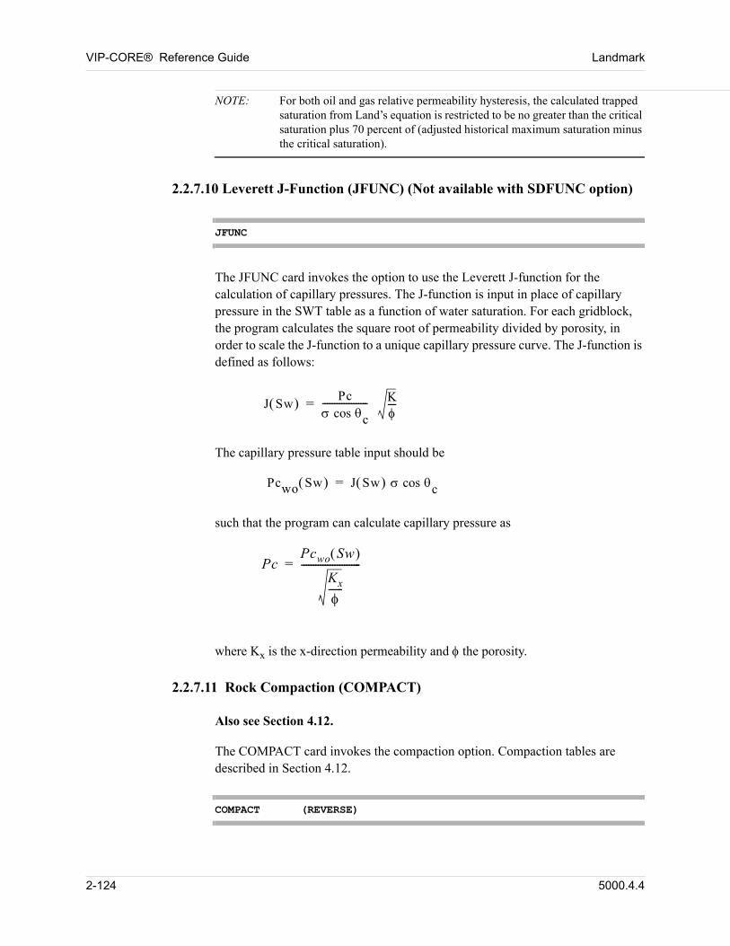
VIP-CORE® Reference Guide Landmark
NOTE: For both oil and gas relative permeability hysteresis, the calculated trapped saturation from Land’s equation is restricted to be no greater than the critical saturation plus 70 percent of (adjusted historical maximum saturation minus the critical saturation).
2.2.7.10 Leverett J-Function (JFUNC) (Not available with SDFUNC option)
JFUNC
The JFUNC card invokes the option to use the Leverett J-function for the calculation of capillary pressures. The J-function is input in place of capillary pressure in the SWT table as a function of water saturation. For each gridblock, the program calculates the square root of permeability divided by porosity, in order to scale the J-function to a unique capillary pressure curve. The J-function is defined as follows: 00
J Sw Pc cos c------------------- K
---=
The capillary pressure table input should be
Pcwo Sw J Sw cos c= 00
such that the program can calculate capillary pressure as
PcPcwo Sw
Kx
------
-------------------------= 00
where Kx is the x-direction permeability and the porosity.
2.2.7.11 Rock Compaction (COMPACT)
Also see Section 4.12.
The COMPACT card invokes the compaction option. Compaction tables are described in Section 4.12.
COMPACT (REVERSE)
2-124 5000.4.4
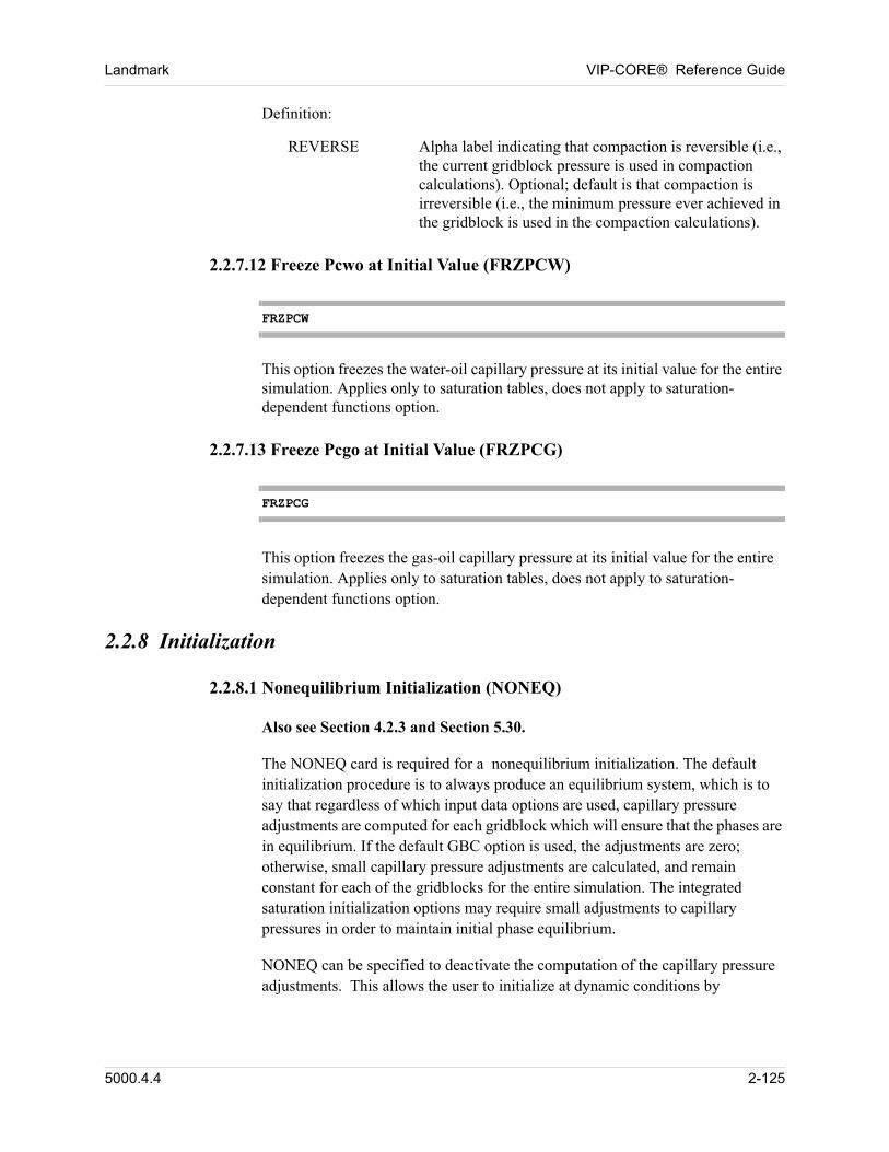
Landmark VIP-CORE® Reference Guide
Definition:
REVERSE Alpha label indicating that compaction is reversible (i.e., the current gridblock pressure is used in compaction calculations). Optional; default is that compaction is irreversible (i.e., the minimum pressure ever achieved in the gridblock is used in the compaction calculations).
2.2.7.12 Freeze Pcwo at Initial Value (FRZPCW)
FRZPCW
This option freezes the water-oil capillary pressure at its initial value for the entire simulation. Applies only to saturation tables, does not apply to saturation-dependent functions option.
2.2.7.13 Freeze Pcgo at Initial Value (FRZPCG)
FRZPCG
This option freezes the gas-oil capillary pressure at its initial value for the entire simulation. Applies only to saturation tables, does not apply to saturation-dependent functions option.
2.2.8 Initialization
2.2.8.1 Nonequilibrium Initialization (NONEQ)
Also see Section 4.2.3 and Section 5.30. 00
The NONEQ card is required for a nonequilibrium initialization. The default initialization procedure is to always produce an equilibrium system, which is to say that regardless of which input data options are used, capillary pressure adjustments are computed for each gridblock which will ensure that the phases are in equilibrium. If the default GBC option is used, the adjustments are zero; otherwise, small capillary pressure adjustments are calculated, and remain constant for each of the gridblocks for the entire simulation. The integrated saturation initialization options may require small adjustments to capillary pressures in order to maintain initial phase equilibrium. 00
NONEQ can be specified to deactivate the computation of the capillary pressure adjustments. This allows the user to initialize at dynamic conditions by
5000.4.4 2-125
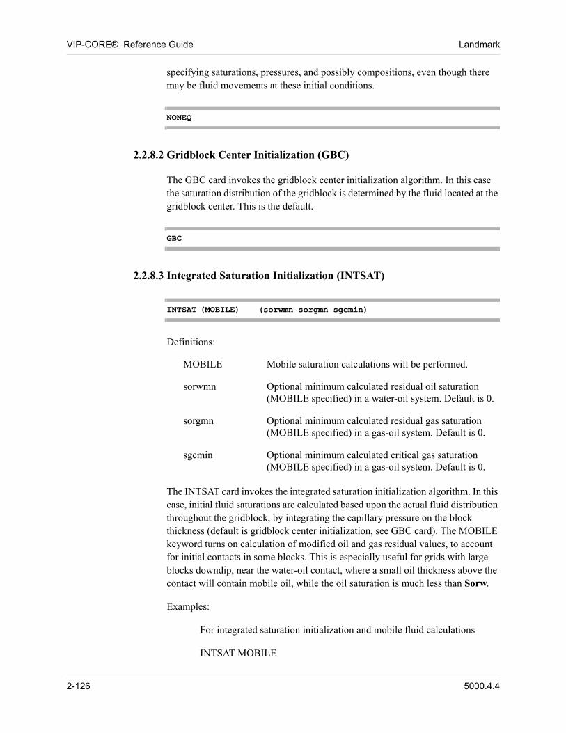
VIP-CORE® Reference Guide Landmark
specifying saturations, pressures, and possibly compositions, even though there may be fluid movements at these initial conditions. 00
NONEQ
2.2.8.2 Gridblock Center Initialization (GBC)
The GBC card invokes the gridblock center initialization algorithm. In this case the saturation distribution of the gridblock is determined by the fluid located at the gridblock center. This is the default. 00
GBC
2.2.8.3 Integrated Saturation Initialization (INTSAT)
INTSAT (MOBILE) (sorwmn sorgmn sgcmin)
Definitions: 00
MOBILE Mobile saturation calculations will be performed.
sorwmn Optional minimum calculated residual oil saturation (MOBILE specified) in a water-oil system. Default is 0.
sorgmn Optional minimum calculated residual gas saturation (MOBILE specified) in a gas-oil system. Default is 0.
sgcmin Optional minimum calculated critical gas saturation (MOBILE specified) in a gas-oil system. Default is 0.
The INTSAT card invokes the integrated saturation initialization algorithm. In this case, initial fluid saturations are calculated based upon the actual fluid distribution throughout the gridblock, by integrating the capillary pressure on the block thickness (default is gridblock center initialization, see GBC card). The MOBILE keyword turns on calculation of modified oil and gas residual values, to account for initial contacts in some blocks. This is especially useful for grids with large blocks downdip, near the water-oil contact, where a small oil thickness above the contact will contain mobile oil, while the oil saturation is much less than Sorw. 00
Examples: 00
For integrated saturation initialization and mobile fluid calculations 00
INTSAT MOBILE 00
2-126 5000.4.4
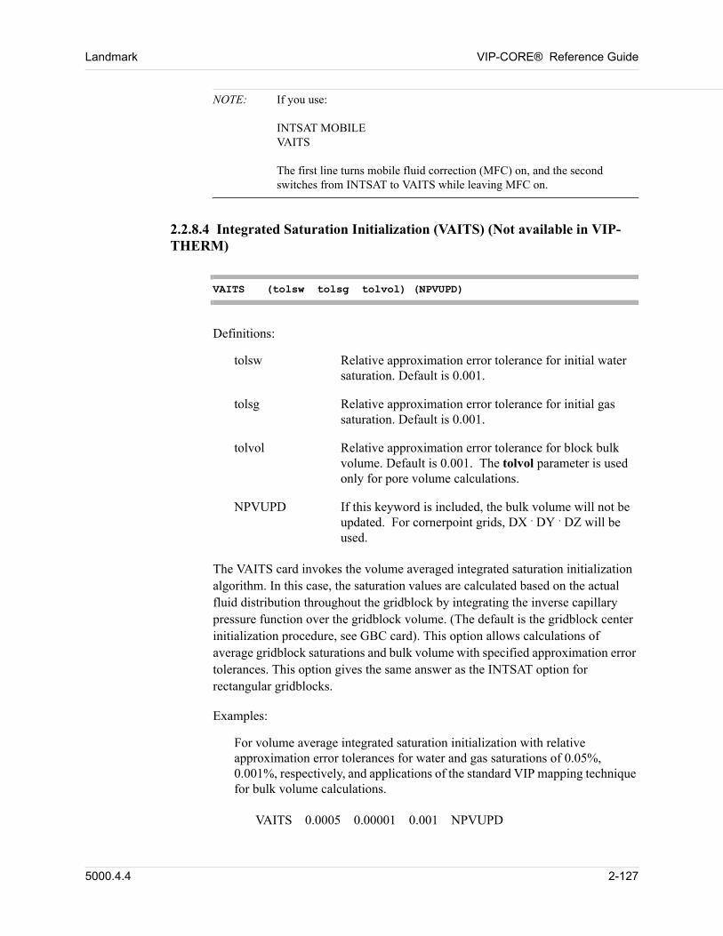
Landmark VIP-CORE® Reference Guide
NOTE: If you use:INTSAT MOBILEVAITSThe first line turns mobile fluid correction (MFC) on, and the second switches from INTSAT to VAITS while leaving MFC on.
2.2.8.4 Integrated Saturation Initialization (VAITS) (Not available in VIP-THERM)
VAITS (tolsw tolsg tolvol) (NPVUPD)
Definitions: 00
tolsw Relative approximation error tolerance for initial water saturation. Default is 0.001.
tolsg Relative approximation error tolerance for initial gas saturation. Default is 0.001.
tolvol Relative approximation error tolerance for block bulk volume. Default is 0.001. The tolvol parameter is used only for pore volume calculations.
NPVUPD If this keyword is included, the bulk volume will not be updated. For cornerpoint grids, DX . DY . DZ will be used.
The VAITS card invokes the volume averaged integrated saturation initialization algorithm. In this case, the saturation values are calculated based on the actual fluid distribution throughout the gridblock by integrating the inverse capillary pressure function over the gridblock volume. (The default is the gridblock center initialization procedure, see GBC card). This option allows calculations of average gridblock saturations and bulk volume with specified approximation error tolerances. This option gives the same answer as the INTSAT option for rectangular gridblocks. 00
Examples: 00
For volume average integrated saturation initialization with relative approximation error tolerances for water and gas saturations of 0.05%, 0.001%, respectively, and applications of the standard VIP mapping technique for bulk volume calculations.
VAITS 0.0005 0.00001 0.001 NPVUPD 00
5000.4.4 2-127
VIP-CORE® Reference Guide Landmark
NOTE: If you use:INTSAT MOBILEVAITSThe first line turns mobile fluid correction (MFC) on, and the second switches from INTSAT to VAITS while leaving MFC on.
2.2.8.5 Thickness Center (THCNTR)
THCNTR
The THCNTR card uses the thickness along the bedding plane to calculate block properties. The default is to use true vertical thickness to calculate block properties; this more accurately represents dipping reservoir blocks. 00
2.2.8.6 Do Not Initialize (NOINIT)
NOINIT
The NOINIT card will cause the program to stop after all the coefficents are calculated. This card is useful when used in conjunction with the PRINT COEFS FILE, Section 3.3.2. 00
2.2.8.7 Totally Refined ROOT Grid (NOROOT)
NOROOT
The keyword NOROOT will reduce memory and disk space by ignoring the ROOT grid, when LGR’s result in no active gridblocks remaining in the ROOT grid. The keyword NOROOT should not be used if grids are planed for deactivation in VIP-EXEC such that gridblocks in the ROOT grid will become active. 00
2.2.8.8 Grid Deactivation (DEACTIVATE)
DEACTIVATE
The keyword DEACTIVATE is required when LGR’s of the same level (i.e., siblings) touch, and are planed to be deactivated separately in VIP-EXEC.
2-128 5000.4.4
Landmark VIP-CORE® Reference Guide
Without this keyword, the transmissibility connections between the LGR’s and the parent grid at the interface between the sibling grids are not created. 00
2.2.8.9 Honor Input Water Saturation Values (KEEPSW)
By default, it is an error when both the water and gas saturation arrays are input and, for any gridblock, the sum of the two saturations is greater than 1. The KEEPSW card allows the water saturation to be honored and the gas saturation to be reset so that the sum is 1. 00
KEEPSW
2.2.8.10 Honor Input Gas Saturation Values (KEEPSG)
By default, it is an error when both the water and gas saturation arrays are input and, for any gridblock, the sum of the two saturations is greater than 1. The KEEPSG card allows the gas saturation to be honored and the water saturation to be reset so that the sum is 1. 00
KEEPSG
2.2.9 Off-Band Connections
2.2.9.1 Pinchout Gridblock Connections (PINCHOUT)
The PINCHOUT card controlls the generation of nonstandard gridblock connections between layers of the grid system where pinchouts occur. Such connections will be generated automatically whenever two layers are separated by one or more inactive blocks, where the total thickness separating them is less than tolth. The transmissibilities generated in this way may be overridden by the use of
FTRANS cards (see Section 6.5.2). The PINCHOUT card requires the use of the
corner-point (see Section 1.5.3) or LGR option (see Section 11.20). 00
PINCHOUT (tolnet) (tolth) (tolgrs) (NONE) (AND)
Definition: 00
tolnet Gridblock net thickness tolerance, ft (m). Pore volume is set to zero for blocks with a net thickness less than or equal to tolnet. In VIP-COMP or VIP-ENCORE, blocks with a zero pore volume are considered to be inactive. Default is 0.
5000.4.4 2-129
VIP-CORE® Reference Guide Landmark
tolth Interblock gross thickness tolerance, ft (m). A block is considered to be "pinched out" if it is inactive (zero pore volume or total volume (VIP-THERM)) and the gross thickness between two active gridblocks is less than or equal to tolth. Default is tolnet.
tolgrs Gridblock gross thickness tolerance, ft(m). Total volume and pore volume are set to zero for blocks with a gross thickness less than or equal to tolgrs. In VIP-THERM, blocks with zero total volume are considered to be inactive. Default is tolnet.
NONE Keyword to turn off the automatic generation of pinchouts.
AND Keyword indicating that total volume and pore volume are set to zero for blocks with a gross thickness less than or equal to tolgrs AND a net thickness less than or equal to tolnet.
2.2.9.2 Fault Modeling (FAULTS)
Also see Section 6.1. 00
The FAULTS card invokes the fault modeling option. Additional fault data are described in Section 6.1. 00
FAULTS LATERAL
NONE
Definition: 00
LATERAL Calculates connections, across any block on the other side of the fault plane. Default only connects logically vertical blocks.
NONE Do not generate automatic faults or pinchout connections.
2.2.9.3 Completing the Circle in Radial Grids (FLOW360)
The FLOW360 card indicates that, for a radial model, flow is permitted between the first and last gridblocks in the theta direction. There is no internal boundary in the angular direction. This option requires that the total angular span be 360 degrees. In radial models sweeping less than 360 degrees it is assumed that no
2-130 5000.4.4
Landmark VIP-CORE® Reference Guide
flow occurs across the external boundaries of the first and last gridblocks in the theta direction. Without a FLOW360 card, a full 360 degree model has a no-flow
boundary at = 0 degrees = 360 degrees. The FLOW360 option is subject to the same formulation choices and solution technique choices as the FAULT option. 00
FLOW360
5000.4.4 2-131
VIP-CORE® Reference Guide Landmark
2.2.10 Vertical Equilibrium (Not available in VIP-THERM)
Also see Section 5.33. 00
The vertical equilibrium with completely segregated fluids may be invoked for the water and oil phases, the gas and oil phases, or both. Initial fluid distributions are calculated which are consistent with total gravity segregation at the phase contacts and with the gridblock geometry, if that option is used. Pseudo capillary pressures are calculated to ensure that the segregated fluids remain in equilibrium. Each gridblock is divided into several sublayers. Fractional volumes and fractional face areas of the sublayers are calculated and stored in tables. Oil and gas saturations in the sublayers are defined to be consistent with the segregated flow assumption and the sublayer fractional volumes. Pseudo relative permeabilities, krw, krow, krg,
krog, for six faces of each gridblock are defined from saturation values and
fractional face areas of the sublayers. 00
Oil relative permeability, kro, is calculated from the usual three phase
correlations. 00
The degree of vertical equilibrium in each block may be varied by using the FVEWO and FVEGO array keywords (Section 5.33.1 and Section 5.33.2). 00
2.2.10.1 Water-Oil Vertical Equilibrium (VEWO)
VEWO (nvelev)
Definitions: 00
VEWO This card invokes the water-oil VE option.
nvelev Number of sublayers into which each gridblock is divided. Fractional volumes and fractional face areas of the sublayers are stored in tables, which are used for the calculation of pseudo relative permeabilities and capillary pressure in the dynamic part of a simulation. The VE corner point option is used whenever nvelev is greater than 1 even if the cartesian geometry option is used. Setting nvelev to 1 will turn off the VE corner point geometry option. VE corner point geometry is always off with the PSEUDO option. Default is 10.
NOTE: If the grid dimension NZ is greater than one and VE corner point geometry option is off then DRELPM (Section 2.2.10.3) should also be used.
2-132 5000.4.4
Landmark VIP-CORE® Reference Guide
2.2.10.2 Gas-Oil Vertical Equilibrium (VEGO)
VEGO (nvelev)
Definitions: 00
VEGO This card invokes the gas-oil VE option.
nvelev Number of sublayers into which each gridblock is divided. Fractional volumes and fractional face areas of the sublayers are stored in tables, which are used for the calculation of pseudo relative permeabilities and capillary pressure in the dynamic part of a simulation. The VE corner point option is used whenever nvelev is greater than 1 even if the cartesian geometry option is used. Setting nvelev to 1 will turn off the VE corner point geometry option. VE corner point geometry is always off with the PSEUDO option. Default is 10.
NOTE: If the grid dimension NZ is greater than one and VE corner point geometry option is off then DRELPM (Section 2.2.10.3) should also be used.
2.2.10.3 Vertical Equilibrium Directional Relative Permeability (DRELPM)
DRELPM (drpfrc)
Definition: 00
drpfrc The fraction of the gridblock to be considered when computing the effective saturation in the vertical directions when using the directional relative permeability option in a vertical equilibrium model. The value must be in the range 0. to 1. inclusive, with default value of .25.
The DRELPM card is used to select the directional relative permeability option for a vertical equilibrium model. DRELPM turns off the VE corner point geometry option (nvelev > 1, sections 2.2.10.1 and 2.2.10.2). If the DRELPM card is omitted in a vertical equilibrium model, and nvelev = 1, the same effective saturation will be used for vertical flow as for areal flow. If the model does not use vertical equilibrium, the DRELPM card has no effect. 00
5000.4.4 2-133
VIP-CORE® Reference Guide Landmark
Example: 00
TITLE1 SPECIFY FRACTION OF BLOCK FOR VETITLE2 OVERRIDE THE DEFAULT VALUE OF .25VEWO VEGODRELPM .5 00
2.2.10.4 Capillary Gravity Equilibrium (VEITS)
VEITS (nvelev)
Definitions: 00
VEITS This card invokes the capillary gravity equilibrium option.
nvelev Number of sublayers into which each gridblock is divided. Fractional volumes and fractional face areas of the sublayers are stored in tables, which are used for the calculation of pseudo relative permeabilities and capillary pressure in the dynamic part of a simulation. Default value is 10.
NOTE: A capillary gravity equilibrium option can be applied only in corner point geometry models if capillary pressure curves are not flat. This assumes that phase hydrostatic potential is independent of depth within a cell. But the assumption about complete fluid segregation is not used. The VAITS option is applied for the calculation of initial saturation distributions. Accuracy of the initial saturation calculations can be controlled by the VAITS card. Each gridblock is divided into several sublayers. Fractional volumes and fractional face areas of the sublayers are calculated and stored in tables. Phase pressure and saturations in the sublayers are accurately defined, taking into account the sublayer fractional volumes, varying ratios of capillary, viscous and gravity forces at different times during simulation. Pseudo relative permeabilities, krw, krow, krg, krog, for the six faces of each gridblock are determined from saturation values and fractional face areas of the sublayers. Oil relative permeability, kro, is calculated from the usual three phase correlations.
Example: 00
VEITS 20 00
2-134 5000.4.4
Landmark VIP-CORE® Reference Guide
2.2.11 Fluid Property Options
2.2.11.1 Energy Minimization Phase Equilibrium (GIBBS) (VIP-COMP)
GIBBS
This card invokes a phase stability test, and calculation of phase equilibrium, using a GIBBS energy minimization algorithm. The technique provides superior near critical fluid property values, but at the expense of higher computing cost. It should be tried in any compositional case where near critical behavior is suspected, and program performance is unsatisfactory. 00
2.2.11.2 Near Critical Fluid Property Adjustment (IFT) (VIP-COMP)
IFT (tenthr) (xex) (teni)
Definitions: 00
tenthr The threshold interfacial tension for relative permeability adjustment, dynes/cm. Default is 0.01 dynes/cm.
xex The value of the exponent for relative permeability adjustment. Default is 0.25.
teni The reference interfacial tension, dynes/cm. Default is defined as the gas-oil interfacial tension at the gas-oil contact of equilibration region 1.
This card invokes the near critical relative permeability and capillary pressure adjustment option. The adjustments are based on interfacial tension (ift) calculations - capillary pressure is multiplied by 00
[ift / ift(reference)] when the fraction is less than 1 00
and relative permeability is interpolated 00
[ift / ift(threshold)]**xex. 00
The IFT option is compatible with both GIBBS and non-GIBBS phase equilibrium calculation options. Additionally, PCHOR data must be included in the fluid properties table. 00
The IFT option is not compatible with the velocity-dependent relative permeabilities. 00
5000.4.4 2-135
VIP-CORE® Reference Guide Landmark
2.2.11.3 Suppresses Table Data Checking (NOCHK)
NOCHK (PVTTAB) (SATTAB)
Definitions: 00
PVTTAB Suppress PVT property data checking of monotonicity and total hydrocarbon compressibility, when BOTAB tables are read. This is necessary in some 3-component miscible cases.
SATTAB Suppress saturation table monotonicity checks - primarily used with pseudo relative permeability curves, generated by Stone’s method, which may not be single valued.
The NOCHK card can selectively suppress PVT table and saturation table data checks. By default, all table checks listed above are suppressed if a NOCHK card is entered. This card should be used cautiously since PVT and saturation table nonconformity can cause instability in the simulation. 00
Examples: 00
To suppress PVT table checking in 3-component miscible case 00
NOCHK PVTTAB 00
2.2.11.4 PVT Interpolation for VIP-ENCORE (BOTINT)
The BOTINT card is used to invoke the PVT interpolation option. In this option, three hydrocarbon components are required, instead of the usual two components for VIP-ENCORE with black-oil data. PVT data is still specified in terms of two pseudo-components, just as for ordinary black-oil models, but the PVT data is parameterized by the API gravity or density of the liquid oil phase at stock tank conditions. In each PVT region, BOTABS data is specified for several different values of API gravity (i.e., for several different oil types), and PVT properties are calculated by interpolation between the specified tables depending on the actual stock tank API gravity of the insitu oil. Internally, the simulator treats the oil phase as a mixture of three pseudo-components, and the PVT properties vary based on the liquid phase split between the heavier two components as well as on the values of pressure and light component composition. Initially, the split between the heavier components is chosen to match the API gravity of the stock tank liquid as specified in a table of API gravity versus depth, so the overall treatment is equivalent to varying PVT properties with stock tank density. 00
The use of the PVT interpolation option requires changes to some of the following
data cards: NX card (Section 2.2.3.1), NR card (Section 2.2.3.2), PRINT INIT
2-136 5000.4.4
Landmark VIP-CORE® Reference Guide
card (Section 2.2.1.1), MAP card (Section 2.2.2.6), IEQUIL card (Section 4.2.1),
BPTAB card (Section 4.2.4), BOTAB card (Section 4.5.2), SEPTEST data
(Section 4.8.3), and other associated cards. In the simulation modules, the option may cause a change to the OUTPUT card (Section 2.5.1 of the Simulation Modules Manual). 00
BOTINT ntypes
Definition: 00
ntypes The number of oil types for which BOTABS data must be provided in each PVT region. The product of ntypes and the actual number of PVT regions must be no larger than the maximum number of PVT tables for which the program is dimensioned. Default is 1.
If SEPTEST separator battery data is input, then the data must be provided for each oil type, for each separator battery defined.
Example: 00
If there are two API gravities in each PVT region: 00
BOTINT 2 00
NOTE: The BOTAB tables for each PVT region must be introduced in decreasing order of API gravity.
2.2.11.5 Flash Calculation Method (FLASH) (VIP-COMP)
The FLASH card allows the user to define the flash calculation method and maximum allowable iterations for reservoir and surface flashes. The two available methods are accelerated successive substitution and Newton-Raphson with successive substitution preconditioning. The default method for reservoir flashes is accelerated successive substitution. The default method for surface flashes is Newton-Raphson. 00
FLASH maxss maxnr RES
SURF(ACC)
Definitions:
5000.4.4 2-137
VIP-CORE® Reference Guide Landmark
maxss Maximum number of successive substitution iterations allowed for a flash calculation. Default is 5 for flashes to surface conditions and 20 for flashes to reservoir conditions.
maxnr Maximum number of Newton-Raphson iterations allowed for a flash calculation. Default is 10 for flashes to surface conditions and 0 for flashes to reservoir conditions.
RES Keyword indicating that the data on this card apply to flashes to reservoir conditions.
SURF Keyword indicating that the data on this card apply to flashes to surface conditions.
ACC Keyword indicating that accelerated successive substitution flash calculations will be performed.
NOTE: 1. Only one of the RES or SURF labels may be specified. Separate FLASH cards can be input for RES and SURF. If neither the RES nor SURF label is specified, the data are used for both reservoir and surface flash calculations.
2. If a FLASH card with the RES option is not input, then ACC (accelerated successive substitution) is the default. If a FLASH card with the SURF option is not input, accelerated successive substitution calculations are not performed. When a FLASH card is input, ACC must be specified to invoke the option.
Example:
To specify the SS and NR iterations for surface flashes as 20 and 10, respectively:
FLASH 20 10 SURF
2.2.11.6 Super-Critical Equilibration (CRINIT) (VIP-COMP)
CRINIT (iequil1 iequil2 ...)
Definition: 00
CRINIT This card invokes super-critical equilibration.
iequil Equilibrium region to which super-critical equilibration is applied.
2-138 5000.4.4
Landmark VIP-CORE® Reference Guide
The CRINIT card is used to invoke the super-critical equilibration option. This option is used to initialize fluid systems which are always one phase but are gas condensate overlaying volatile oils. The compositions are such that they are always above the equilibrium two phase envelope at the reservoir temperature and pressure. The gas-oil contact is defined by looking at the heaviest component k-value to insure it is less than one because there is no two phase region in the reservoir at initial conditions. The value of PINIT at DEPTH from the IEQUIL card is used as the starting point for the initial pressure profile calculations. 00
If the CRINIT card is used with no arguments, all equilibrium regions will be initialized using the super-critical option. If the CRINIT keyword is followed by a list of equilibrium region numbers, the super-critical option will only be applied to the specified equilibrium regions. 00
2.2.11.7 Li Pseudo-Critical Temperature (LI) (VIP-COMP)
LI (factli)
Definition: 00
factli Li pseudo-critical temperature factor. Default is 1.
The LI card is used to invoke the Li pseudo-critical temperature option. This option uses the Li pseudo-critical temperature to determine the labeling of a single phase fluid. The Li pseudo-critical temperature is calculated by the following equation:
Tpc
TcjVcjZj
j 1=
nc
VcjZj
j 1=
nc
-----------------------------=
In the above equation, Tc is the critical temperature, Vc is the critical volume, and z is the mole fraction.
If the reservoir temperature is below the Li pseudo-critical temperature, then the single phase fluid is considered to be an oil phase. Otherwise, it is considered to be a gas phase.
One might use this option for a supercritical fluid in a situation where the saturation pressure cannot be found, or where the user prefers the fluid to be called an oil instead of a gas, or vice versa.
5000.4.4 2-139
VIP-CORE® Reference Guide Landmark
Optionally, a factor can be entered that is used to multiply the Li pseudo-critical number, and thus influence the labeling. The default value is 1.0. The number must be positive. If an factli value between 0 and 1 is entered, a single phase will more likely be labeled a gas phase. Conversely, if an factli value greater than 1 is entered, a single phase will more likely be labeled an oil phase.
2.2.11.8 Dry Gas Simulation (DRYGAS)
DRYGAS
This card invokes the dry gas option. 00
The dry gas option enables the compositional modeling of a hydrocarbon system that is always in a single phase state. The water phase can co-exist with this single phase. The hydrocarbon fluid properties are calculated by an equation of state. 00
The dry gas option should only be used if fluids always remain in a single phase state without crossing any phase boundaries. For example, injection and production from a gas storage reservoir would be an appropriate situation for this option, depending on the compositions of the in-situ and injected gas. 00
The dry gas option is required for a fluid system existing at a reservoir temperature above its cricondentherm. For such a system, no saturation pressure can be found. This would result in termination of the VIP initialization procedure without the dry gas option. The dry gas option also allows the simulator to run considerably faster because phase transition calculations are avoided. 00
2.2.11.9 Limit on Rate of Increase of Solution GOR (DRSDT)
DRSDT limit (FREE)
Definitions: 00
DRSDT Turns limit on. By default, no limit is applied.
limit The limiting value of the rate of solution GOR increase. Units are SCF/STB/day (field), SM3/SM3/day (metric), or Scc/Scc/hr (lab), unless the RSM card (Section 2.2.22) is entered, in which case units are MSCF/STB/day (field), KSM3/SM3/day (metric), or MScc/Scc/hr (lab).
FREE Only applies DRSDT in blocks with free gas saturation.
The DRSDT option can be used in conjunction with certain combinations of extended black oil tables only. They can be used with the BOETAB table, but
2-140 5000.4.4
Landmark VIP-CORE® Reference Guide
only if RS is non-zero and RV is zero. In other words, gas must be allowed to enter into solution with the liquid phase, but oil is not allowed to condense from the vapor phase. The equivalent separate oil and gas data tables are BOOTAB and BDGTAB. 00
The DRSDT option controls the rate at which the solution gas-oil ratio (Rs) within a block can increase. The rate at which Rs can decline during depletion is unaffected. Additionally, the rate at which Rs increases will still be limited by the availability of free gas, and by the saturated values in the tables. 00
At the extreme where DRSDT has a limit of 0, Rs will stay constant within each gridblock, and free gas cannot dissolve into the undersaturated oil. At the other extreme, where DRSDT has a very large limit, Rs will rise to that allowed by the table or until no free gas remains. This is equivalent to not using the option at all.00
The use of the FREE keyword limits the application of the DRSDT constraint to blocks that have free gas. This prevents the limiting of changes in Rs due to the mixing of fluids from adjacent unsaturated blocks that have different starting values of Rs. This will allow gas flowing from a two-phase cell into an undersaturated cell to dissolve into solution in an unrestrained manner. 00
Example: 00
DRSDT 10C Limits increase of solution GOR to 10 SCF/STB/day
2.2.12 Corner-Point Grid
2.2.12.1 Corner-Point Simulation Grid (CORNER)
The CORNER card is used to set optional parameters for corner point grids. The user may set the variables iquads, jquads, and kquads to control the accuracy of the integration process used for pore volume and transmissibility calculations. Corner point grids allow the user to describe more general grid systems than those describable through the specification of block-size arrays only. Some examples of the use of the corner-point option include the description of nonorthogonal grids and the modeling of sloping faults and pinchouts. The user should take great care with the use of this option, since less data checking is performed on the grid system description. The corner-point option is not compatible with radial or cylindrical grids. 00
When the FAULTS card (see Section 2.2.9.2) is also specified, the corner-point option requires somewhat different specification of faults than the standard fault
data description (see Section 6.3). If the user specifies corner-point depths (instead of explicit faults), the program will automatically generate fault connections. 00
5000.4.4 2-141
VIP-CORE® Reference Guide Landmark
When corner point grids are used, the program will automatically recognize pinchouts and generate the appropriate nonstandard interlayer gridblock
connections. The FTRANS fault option (see Section 6.5.2) allows the user to overread the transmissibilities generated in this way. 00
The default method for calculation of inter-block transmissibilities is a method based on harmonic integration (HARINT). This has been found to give a more accurate representation of transmissibilities for corner-point grids. This was not the default in previous versions of VIP-CORE. The previous default can be invoked by using the optional keyword NEWTRAN. 00
The optional keyword LINE should be used to specify corner-point positions along depth lines. 00
CORNER (NEWTRAN (V98)) (LINE) (iquads jquads kquads)
Definitions: 00
NEWTRAN Invoke the NEWTRAN option for the inter-block transmissibility calculation.
V98 Invoke the NEWTRAN calculation in use in version 98.
LINE Specification of corner-point positions along depth lines.
iquads Number of quadrature points (1 iquads 3) in the x direction. Default is 3 (Default for NEWTRAN option is 2).
jquads Number of quadrature points (1 jquads 3) in the y direction. Default is 3 (Default for NEWTRAN option is 2).
kquads Number of quadrature points (1 kquads 3) in the z direction. Default is 3 (Default for NEWTRAN option is 2).
Example: 00
CORNER NEWTRAN 3 3 3 00
2.2.12.2 Fault Connections from Corner-Point Data (CORTOL)
CORTOL tola tolt tolpv tolpn toltt tolvb
Definitions: 00
2-142 5000.4.4
Landmark VIP-CORE® Reference Guide
tola Tolerance for relative overlap area for corner-point faults. When LGR is on or CORP data is read, tola is the absolute overlap area, sq. ft. (sq m). Default is 1.E-3.
tolt Tolerance for absolute transmissibility cutoff for corner-point faults, rb-cp/day/psi (cm-cp/day/kPa). Default is 1.E-8 rb-cp/day/psi.
tolpv Tolerance for pore volume cutoff, rb (m3). Pore volumes in cells with calculated values less than tolpv are set to zero. In VIP-COMP or VIP-ENCORE, zero pore volume cells are inactive. OVER/VOVER of pore volumes are applied after this check. Default is 0.
tolpn Tolerance for determining if corner-point gridblock corner points are in vertical contact, ft (m). If the difference in depth between the corner points at the top of layer n and the bottom of layer n-1 is less than tolpn it is assumed layer n and n-1 are in contact and a non-zero z-direction transmissibility is calculated. Default is 1.E-4 ft.
toltt Tolerance for thermal transmissibility cutoff for corner-point faults. Default is 1.E-8 BTU/DAY-DEG.F (2.198 x 10⁻¹⁰ W/DEG.C). Enter in VIP-THERM only.
tolvb Tolerance for block volume cutoff, rb(m3). Total volume and pore volume in cells with calculated total volume less than tolvb are set to zero. In VIP-THERM, zero total volume cells are inactive. Enter in VIP-THERM only.
The CORTOL card is used to control under what conditions block connections will be generated from corner-point data. If a block connection value is less than one or more of the tolerances, a connection is not calculated. 00
Examples: 00
To change the overlap, transmissibility, and pore volume tolerances to 1.E-2, 1.E-7, and 100, respectively: 00
CORTOL 1.E-2 1.E-7 100 00
NOTE: The CORTOL data must be in put in the order shown, but may truncate at any point after tolt.
2.2.12.3 Data Checking Corner-Point Grid Data (CORCHK)
The program automatically checks to make sure that each face of each gridblock projects as a convex quadrilateral on to an average plane "parallel" to the face.
5000.4.4 2-143
VIP-CORE® Reference Guide Landmark
Faces that fail the convexity condition are checked for the angle between each of the pair of opposite sides. If any angle is larger than 90 degrees a warning message is printed. The check is performed initially excluding blocks with zero porosity. After the pore volume has been calculated the check is repeated for blocks with non-zero pore volume. The CORCHK card allows the user to control the amount of printout. 00
The program checks that x coordinates of corner points (XCORN array) do not decrease with increasing i index. The optional keyword NOX can be used to bypass this check. 00
The program checks that y coordinates of corner points (YCORN array) do not increase with increasing j index. The optional keyword NOY can be used to bypass this check. 00
CORCHK (nblocks) (NOX) (NOY)
Definition: 00
nblocks The maximum number of blocks for which detailed warning messages are printed. Regardless of the value of nblocks, a summary line is printed that shows the total number of blocks that violate the convexity and angle conditions simultaneously. Default is 20.
NOX No checking of x coordinate increasing order.
NOY No checking of y coordinate decreasing order.
Example: 00
CORCHK 300 00
2.2.13 Dual Porosity with Optional Dual Permeability (VIP-DUAL) (Not available with VIP-THERM)
2.2.13.1 Dual-Porosity/Permeability Option (DUAL)
This card invokes the dual porosity/permeability option. Two distinct options are available in VIP-DUAL. By default this option models the flow of fluids in two continuous media which represent the matrix rock and fractures. Exchange of fluids between the fractures and matrix rock is based on the Warren and Root theory and includes the effects of imbibition and gravity drainage. 00
Alternatively, a dual porosity/single permeability option may be selected which assumes that the fractures alone are a continuous media and the matrix rock exists
2-144 5000.4.4
Landmark VIP-CORE® Reference Guide
only as a source or sink for reservoir fluids. While less general than the full dual porosity/dual permeability approach, this option can result in a substantial decrease of computer time. 00
The dual porosity/permeability option requires extra data to be supplied to the simulator. The minimum extra data required is: 00
1. Saturation tables for fractures
2. Fracture array data (porosity, permeability)
3. Matrix block size
4. Surface tension ratio tables (see Section 4.15.1).
DUAL (POR) (SWAPMF) (TEXORG)
Definition: 00
POR Alpha label that invokes the dual porosity/single permeability option. By default the dual porosity/dual permeability option is invoked.
SWAPMF Alpha label used to properly simulate dual porosity reservoirs that are not fractured in some regions. Only applicable with the single permeability option.
TEXORG Invokes the original method for calculating the matrix/fracture exchange transmissibilities. The default is to use the equation described by Coats, reference 53 of the Technical Reference Manual.
Example: 00
C INITIAL DATEDATE 23 6 1983C DUAL POROSITYDUAL 00
2.2.13.2 Matrix Pseudo Capillary Pressure (PSEUDO)
VIP-DUAL accounts accurately for the effects of imbibition and gravity drainage from matrix gridblocks that contain many matrix blocks by invoking an automatic calculation of matrix pseudo capillary pressure. 00
For water-oil imbibitions, the calculation assumes an equilibrium distribution of saturations in each of the matrix blocks and then calculates, for each gridblock, a table of average gridblock saturation versus pseudo capillary pressure at the block
5000.4.4 2-145
VIP-CORE® Reference Guide Landmark
center by varying the fluid contact between the top of the gridblock and the bottom of the gridblock. 00
A smooth curve of pseudo capillary pressure is produced by integrating the saturations over a number of columns of matrix blocks displaced areally relative to one another. 00
Gas-oil gravity drainage is modeled using either a method which is parallel to that
described for the water-oil imbibitions above, or Coats’ method (Reference 29). Coats’ method requires additional data as described in Section 4.15. 00
The PSEUDO card allows the user to change the various parameters associated with these calculations. 00
PSEUDO (NOCOATS) (ncol) (PRINT) (nsmtab) (INTSW)
Definitions: 00
NOCOATS For gas-oil matrix-fracture exchange, use the method parallel to that of water-oil imbibition. If not specified, the default is to use Coats’ method (Reference 29) for gas-oil matrix-fracture exchange.
ncol Number of columns of matrix blocks used in the pseudo capillary pressure calculation. Default is 1.
PRINT Prints to Fortran Unit 28 the internally generated pseudo capillary pressures that are used in the matrix-fracture flow. If not specified, the default is to not print the pseudo capillary pressure.
nsmtab Number of saturation entries in the pseudo capillary pressure tables. Default is 10.
INTSW Integrate water-oil capillary pressure over matrix blocks above the water-oil contact. Default SW = SWC above water-oil contact. Gas-oil capillary pressure is always integrated above the gas-oil contact.
Example: 00
To use 10 entry pseudo Pc tables based on 5 columns and to print the generated pseudo Pc tables. 00
PSEUDO NOCOATS 5 PRINT 10 00
NOTE: The data on the PSEUDO card is order-dependent. Except for the COATS/NOCOATS keyword, all previous fields must be entered to specify a later
2-146 5000.4.4
Landmark VIP-CORE® Reference Guide
one. The COATS/NOCOATS keyword may be omitted entirely if COATS is to be used.
2.2.13.3 Oil-Gas Phase Diffusivities (DIFF)
The DIFF card is used to enter values of oil phase and gas phase diffusivities. These are used to compute mass transfer between fracture and matrix via the mechanism of molecular diffusion. The diffusion calculation is not used for matrix-matrix or fracture-fracture mass transfer. If the DIFF card is omitted, no diffusive mass transfer will take place. 00
DIFF diffg diffo
Definitions: 00
diffg Gas phase diffusivity, sq. ft./day (sq.cm./sec.).
diffo Oil phase diffusivity, sq. ft./day (sq. cm./sec.).
NOTE: The oil and gas phase diffusivities are converted into mass transfer coefficients using the matrix block shape factors (Section 5.36.2 and 5.36.3) and gridblock dimensions:TDg = (diffg)*(sigmad)*(x y z)TDo = (diffo)*(sigmad)*(x y z)Alternatively, TDg and TDo may be entered directly via the TDIFFG and TDIFFO arrays (Section 5.36.2 and 5.36.3).
Example: 00
For gas diffusivity of 1 sq. ft/day and no oil diffusivity: 00
DIFF 1 0 00
2.2.14 Fluid Tracking (Not available in VIP-THERM)
2.2.14.1 Hydrocarbon Tracking Option (TRACK)
TRACK nfl
Definition: 00
nfl Number of tracked fluids.
5000.4.4 2-147
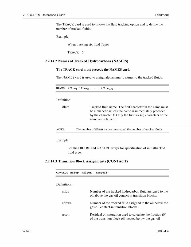
VIP-CORE® Reference Guide Landmark
The TRACK card is used to invoke the fluid tracking option and to define the number of tracked fluids. 00
Example: 00
When tracking six fluid Types 00
TRACK 6 00
2.2.14.2 Names of Tracked Hydrocarbons (NAMES)
The TRACK card must precede the NAMES card. 00
The NAMES card is used to assign alphanumeric names to the tracked fluids. 00
NAMES iflnm1 iflnm2 . . . iflnmnfl
Definition: 00
iflnm Tracked fluid name. The first character in the name must be alphabetic unless the name is immediately preceded by the character #. Only the first six (6) characters of the name are retained.
NOTE: The number of iflnm names must equal the number of tracked fluids.
Example: 00
See the OILTRF and GASTRF arrays for specification of initialtracked fluid type. 00
2.2.14.3 Transition Block Assignments (CONTACT)
CONTACT nflup nfldwn (resoil)
Definitions: 00
nflup Number of the tracked hydrocarbon fluid assigned to the oil above the gas-oil contact in transition blocks.
nfldwn Number of the tracked fluid assigned to the oil below the gas-oil contact in transition blocks.
resoil Residual oil saturation used to calculate the fraction (F) of the transition block oil located below the gas-oil
2-148 5000.4.4
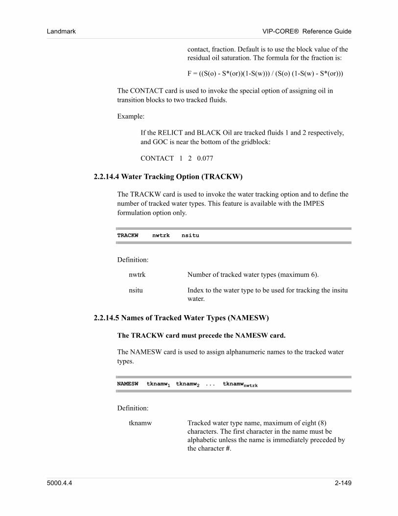
Landmark VIP-CORE® Reference Guide
contact, fraction. Default is to use the block value of the residual oil saturation. The formula for the fraction is:
F = ((S(o) - S*(or))(1-S(w))) / (S(o) (1-S(w) - S*(or)))
The CONTACT card is used to invoke the special option of assigning oil in transition blocks to two tracked fluids. 00
Example: 00
If the RELICT and BLACK Oil are tracked fluids 1 and 2 respectively, and GOC is near the bottom of the gridblock: 00
CONTACT 1 2 0.077 00
2.2.14.4 Water Tracking Option (TRACKW)
The TRACKW card is used to invoke the water tracking option and to define the number of tracked water types. This feature is available with the IMPES formulation option only. 00
TRACKW nwtrk nsitu
Definition: 00
nwtrk Number of tracked water types (maximum 6).
nsitu Index to the water type to be used for tracking the insitu water.
2.2.14.5 Names of Tracked Water Types (NAMESW)
The TRACKW card must precede the NAMESW card. 00
The NAMESW card is used to assign alphanumeric names to the tracked water types. 00
NAMESW tknamw1 tknamw2 ... tknamwnwtrk
Definition: 00
tknamw Tracked water type name, maximum of eight (8) characters. The first character in the name must be alphabetic unless the name is immediately preceded by the character #.
5000.4.4 2-149
VIP-CORE® Reference Guide Landmark
NOTE: The number of tknamw names must equal the number of tracked water types.
2-150 5000.4.4
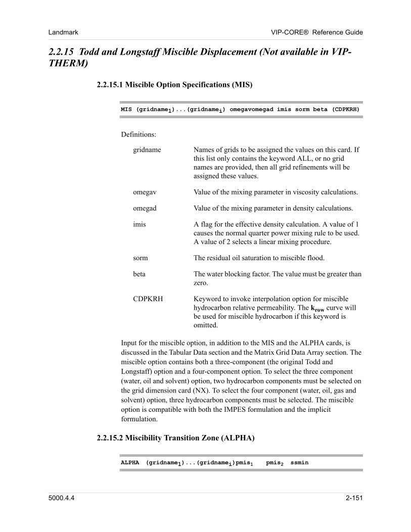
Landmark VIP-CORE® Reference Guide
2.2.15 Todd and Longstaff Miscible Displacement (Not available in VIP-THERM)
2.2.15.1 Miscible Option Specifications (MIS)
MIS (gridname1)...(gridnamei) omegavomegad imis sorm beta (CDPKRH)
Definitions: 00
gridname Names of grids to be assigned the values on this card. If this list only contains the keyword ALL, or no grid names are provided, then all grid refinements will be assigned these values.
omegav Value of the mixing parameter in viscosity calculations.
omegad Value of the mixing parameter in density calculations.
imis A flag for the effective density calculation. A value of 1 causes the normal quarter power mixing rule to be used. A value of 2 selects a linear mixing procedure.
sorm The residual oil saturation to miscible flood.
beta The water blocking factor. The value must be greater than zero.
CDPKRH Keyword to invoke interpolation option for miscible hydrocarbon relative permeability. The krow curve will be used for miscible hydrocarbon if this keyword is omitted.
Input for the miscible option, in addition to the MIS and the ALPHA cards, is discussed in the Tabular Data section and the Matrix Grid Data Array section. The miscible option contains both a three-component (the original Todd and Longstaff) option and a four-component option. To select the three component (water, oil and solvent) option, two hydrocarbon components must be selected on the grid dimension card (NX). To select the four component (water, oil, gas and solvent) option, three hydrocarbon components must be selected. The miscible option is compatible with both the IMPES formulation and the implicit formulation. 00
2.2.15.2 Miscibility Transition Zone (ALPHA)
ALPHA (gridname1)...(gridnamei)pmis1 pmis2 ssmin
5000.4.4 2-151
VIP-CORE® Reference Guide Landmark
or 00
ALPHA (gridname1)...(gridnamei)dpmis
Definitions: 00
gridname Names of grids to be assigned the values on this card. If this list only contains the keyword ALL, or no grid names are provided, then all grid refinements will be assigned these values.
pmis1 The lower-bound miscibility pressure.
pmis2 The upper-bound miscibility pressure.
ssmin The minimum solvent pseudo-saturation to maintain miscibility.
dpmis The size of the transition zone (i.e. pmis2-pmis1).
The user can turn on the miscible transition zone option by entering an ALPHA card. If this card is omitted, a first contact miscible process will be represented. In a first contact miscible process, to avoid the solution gas and oil being treated as miscible when the solvent is not present (i.e., during depletion or waterflood), an ALPHA card with zero values for pmis1 and pmis2 and a non-zero value for
ssmin must be input. 00
There are no default values for pmis1, pmis2, ssmin, and dpmis. The employment
of Format (1) automatically invokes a miscible-immiscible transition where the interpolation parameter increases linearly between the lower- and the upper-bound miscibility pressures, provided that the solvent pseudo-saturation is larger than the value of ssmin. Using the IMPES formulation, the value of pmis1 must be less
than or equal to pmis2, and the user may specify a step function for interpolation
by entering identical values for pmis1 and pmis2. However, if the fully implicit
formulation is to be used, the value of pmis2 must be greater than pmis1, i.e., a
step function for interpolation (with pmis1 = pmis2) is not allowed. Todd and
Longstaff suggest that a value of 0.01 for the parameter ssmin is sufficient to account for the loss of miscibility. 00
Conversely, the employment of Format (2) above automatically invokes the second option for the miscible-immiscible transition where the miscibility pressure is specified as a function of the total hydrocarbon composition. The user is required to enter a two-dimensional (four-component case) or a one-dimensional (three-component case) miscibility pressure table after the solvent property table input. Using the IMPES formulation, the size of the transition zone,
2-152 5000.4.4

Landmark VIP-CORE® Reference Guide
dpmis, can have a value of zero to model a step function. On the other hand, dpmis must be greater than 0 if the fully implicit formulation is used. 00
5000.4.4 2-153
VIP-CORE® Reference Guide Landmark
2.2.16 Time-Dependent Compressibility - Creep Option (Not available in VIP-THERM)
See Section 5.39 for an explanation of and how to invoke the creep option. 00
2.2.16.1 Reversible Creep (CREEP)
CREEP REVERSE
Definition: 00
REVERSE Alpha label indicating that creep is reversible. Optional; default is that creep is irreversible.
2.2.17 Hydraulic Fracture Option (Not available in VIP-THERM)
The purpose of this option is to simulate the performance of a hydraulically fractured, packed fracture in the first XZ plane of a model, including the effects of fracture closure and non-Darcy flow within the fracture. The fracture is assumed to be a vertical fracture, and the simulation involves modelling only one-fourth of the fracture and one-fourth of the drainage area of the well. The well is assumed to be adjacent to the (1,1) gridblock column. 00
The grid description must be defined with the DX, DY, DZ, KX arrays, and the simulator must be run in the fully implicit, single porosity mode. 00
The required data for this option are HYDFRAC and HYDBETA (Section 4.16), along with appropriate compaction (CMT) tables to define the fracture closure effects and permeability reduction as a function of pressure. 00
2.2.17.1 Fracture Blocks (HYDFRAC)
HYDFRAC nf
Definition: 00
nf Number of gridblocks in the X direction comprising the maximum horizontal extend of the fracture.
NOTE: The DY’s for Y=1 should be adjusted to define the tapering half-fracture widths.The porosities for gridblocks nf+1 through NX (for Y=1) should be set to zero.
2-154 5000.4.4
Landmark VIP-CORE® Reference Guide
Fracture closure stress can be simulated using the compaction option, with a separate table(s) for the fracture gridblocks. The pore volume reduction factor will also be used to reduce the cross-sectional area in the flow velocity calculations. The transmissibility reduction factor will also be used to reduce the original KX for the Beta (turbulence) factor calculations.
2.2.18 Polymer Injection Option (VIP-POLYMER)
VIP-POLYMER is available as a separately licensed option. 00
2.2.18.1 Initialize for Polymer Injection (POLYMER)
POLYMER
The POLYMER card will initialize the model for polymer injection. By default the model does not initialize for polymer injection. Initializing for polymer injection will increase the size of the restart files. 00
The physical properties required to model the polymer transport can be introduced at any point of the recurrent data in the simulation module, preceding polymer injection. 00
2.2.19 Thermal Option (VIP-THERM)
VIP-THERM is available as a seperately licensed option. 00
2.2.19.1 THERMAL Card
The THERMAL card is used to invoke VIP-THERM. 00
THERMAL
2.2.19.2 WATIDEAL Card (Compositional Model)
The WATIDEAL card invokes the following assumptions regarding water-oil-vapor phase behavior:
n The saturation pressure of an oil-water system is equal to the sum of the saturation pressures of the oil and water alone at system temperature, regardless of the relative amounts of oil and water as long as sufficient quantities of each are present to saturate the vapor.
5000.4.4 2-155
VIP-CORE® Reference Guide Landmark
n Water mole fraction in the vapor phase yw is given by VPW/P where VPW is the vapor pressure of water as a function of temperature.
n Hydrocarbon vapor-liquid equilibrium (using fugacity coefficients or k-values) is computed at the hydrocarbon partial pressure l yw– P on a water-free basis. Vapor phase properties are obtained from internally tabulated steam properties and water-free hydrocarbon vapor properties using mixing rules. If k-value options are used, k-values are assumed to be input on a water-free basis (The k-values are two phase gas-oil values).
In the default method, water is treated as a component in the vapor phase by the equation of state. Water EOS parameters are internally fixed and were adjusted to match vapor pressure, steam z-factor, and steam enthalpy along the saturation curve. Liquid water fugacity coefficient is obtained from an internal table which contains EOS-predicted values which were adjusted to match the vapor values along the saturation curve. All other liquid water properties are obtained from steam tables. Saturation pressure and flash calculations are performed using three phase algorithms. If k-value options are used, input k-values are assumed to be three-phase values and are evaluated at total system pressure.
WATIDEAL
2.2.19.3 FLOWS Card
The FLOWS card is required in order to map, print, or write to the spreadsheet file (in VIP-EXECUTIVE) flow rate arrays or region boundary flow rates or cumulatives. If all arrays are mapped, flow rate arrays will be mapped only if a FLOWS card is input. Individual flow rate array names may be specified on the MAP card only if a FLOWS card is input.
FLOWS
2-156 5000.4.4
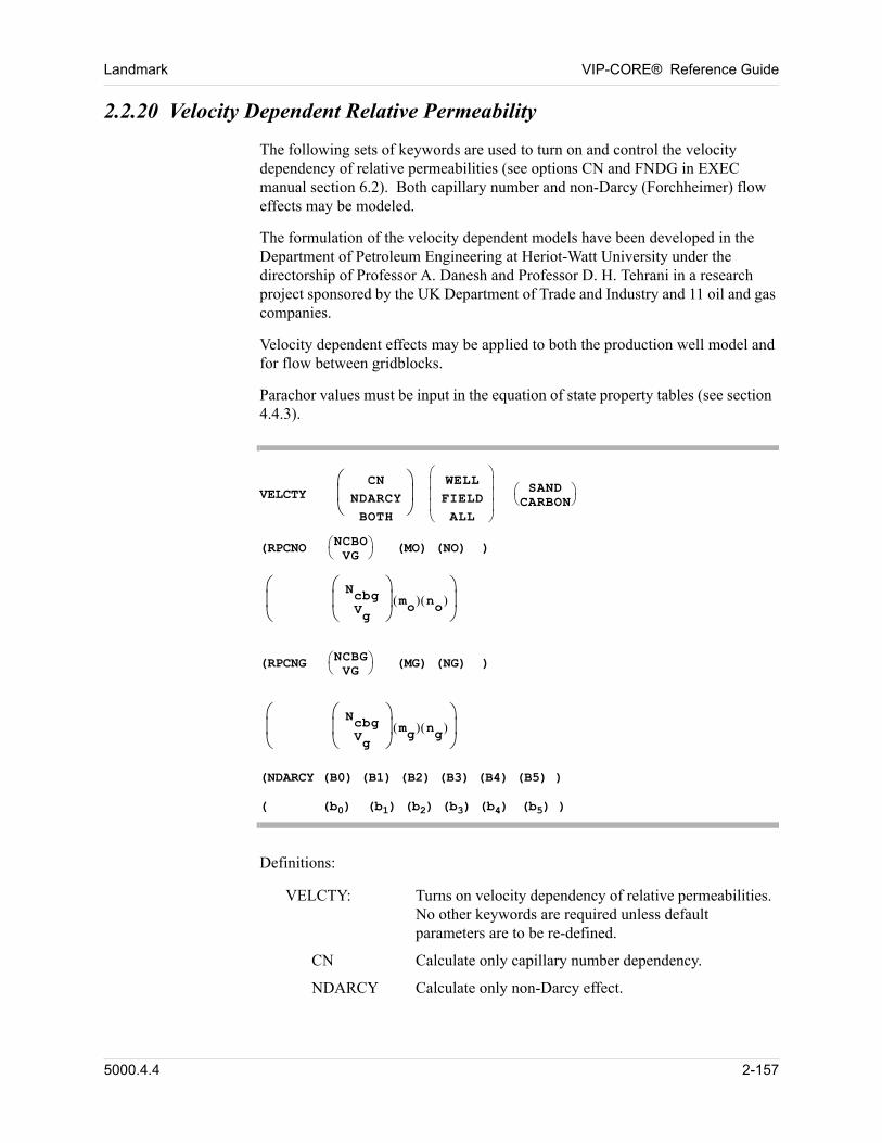
Landmark VIP-CORE® Reference Guide
2.2.20 Velocity Dependent Relative Permeability
The following sets of keywords are used to turn on and control the velocity dependency of relative permeabilities (see options CN and FNDG in EXEC manual section 6.2). Both capillary number and non-Darcy (Forchheimer) flow effects may be modeled. 00
The formulation of the velocity dependent models have been developed in the Department of Petroleum Engineering at Heriot-Watt University under the directorship of Professor A. Danesh and Professor D. H. Tehrani in a research project sponsored by the UK Department of Trade and Industry and 11 oil and gas companies. 00
Velocity dependent effects may be applied to both the production well model and for flow between gridblocks. 00
Parachor values must be input in the equation of state property tables (see section 4.4.3). 00
VELCTY CN
NDARCYBOTH
WELL
FIELDALL
SANDCARBON
(RPCNO NCBOVG
(MO) (NO) )
NcbgVg
mo no
00
(RPCNG NCBGVG
(MG) (NG) ) 00
NcbgVg
mg ng
00
(NDARCY (B0) (B1) (B2) (B3) (B4) (B5) ) 00
( (b0) (b1) (b2) (b3) (b4) (b5) ) 00
Definitions: 00
VELCTY: Turns on velocity dependency of relative permeabilities. No other keywords are required unless default parameters are to be re-defined.
CN Calculate only capillary number dependency.
NDARCY Calculate only non-Darcy effect.
5000.4.4 2-157
VIP-CORE® Reference Guide Landmark
BOTH Calculate combined capillary number and non-Darcy effect (default).
WELL Apply velocity dependent calculations only at the well (default).
FIELD Apply velocity dependent calculations only for inter-gridblock flow.
ALL Apply velocity dependent calculations both at the well and between gridblocks.
SAND Use sandstone default parameters (default).
CARBON Use carbonate default parameters.
RPCNO, RPCNG, and NDARCY are optional input fields that can be used to override the default parameters. They are discussed below.
RPCNO
Ncbo Threshold value for oil phase capillary number dependency.
vg Superficial gas velocity to be used for calculating the threshold value of capillary number dependency.
mo Exponent of residual oil saturation factor.
no Exponent of weighting factor for oil phase relative permeability.
RPCNG
Ncbg Threshold value for gas phase capillary number dependency.
vg Superficial gas velocity to be used for calculating the threshold value of capillary number dependency.
mg Exponent of residual gas saturation factor.
ng Exponent of weighting factor for gas phase relative permeability.
See the Technical Reference manual for a full explanation of these parameters.
2-158 5000.4.4
Landmark VIP-CORE® Reference Guide
Examples 00
1. Use all default parameters:
VELCTY
This is equivalent to:
VELCTY BOTH WELL SAND
Explicitly declaring all parameters, this is also equivalent to
VELCTY BOTH WELL SANDRPCNO VG MO NO 10. 0 0.35RPCNG VG MG NG 10. 35. 0.35NDARCY BO B1 B2 B3 B4 B5 0.001524 -0.5 -5.5 -0.5 -2.99 -4.422
2. Apply only capillary number dependency, using default parameters, both at the wells and between gridblocks:
VELCTY CN ALL
3. Apply both capillary number effects and non-Darcy effects at the well only, but using carbonate default parameters. Also, selectively modify some of the non-Darcy exponents, removing the dependency on interfacial tension.
VELCTY CARBONNDARCY B1 B3 B5 -0.7 0.7 0.
When velocity dependency is applied to wells, the condensate banking option is automatically activated for every production well. The parameters on the condensate banking control cards are ignored, except for the number of intervals to be used for the numerical integration. By default, four intervals are used in each phase region. Condensate banking can be used with or without velocity effects. 00
4. To use 20 intervals for the numerical integration, input the following keyword entry in the well data for VIP-EXEC:
CNDBNK TRAP 20
5000.4.4 2-159
VIP-CORE® Reference Guide Landmark
2.2.21 Change Units for Solution Gas-Oil Ratio (RSM)
This keyword indicates that the units for solution gas oil ratio in VIP-CORE only are multiplied by a thousand, i.e.: 00
n normal field units of SCF/STB will be input as MSCF/STB,
n normal metric units of SM3/SM3 will be input as KSM3/SM3,
n normal lab units of stcc/stcc will be input as mstcc/stcc.
RSM
2.2.22 Upscaled Permeabilities (UPSCALE)
The UPSCALE card is used to define the method of upscaling permeabilities when gridblocks are COARSENed (Section 8.1). 00
UPSCALE param1 . . . paramn
Definitions: 00
param Alpha label indicating the permeability upscaling methods to be used:
In the following descriptions, upper bound refers to slices in series and lower bound refers to tubes in parallel.
KWELLPI Upscaled well permeabilities are based on bulk volume weighted averages of well productivity indices. When KWELLPI is not specified, the upscaled well permeabilities are consistent with the block upscaling methods.
KXHARM X-direction block upscaling method controlled by harmonic average of upper and lower bounds. This is the default method.
KYHARM Y-direction block upscaling method controlled by harmonic average of upper and lower bounds. This is the default method.
KZHARM Z-direction block upscaling method controlled by harmonic average of upper
2-160 5000.4.4
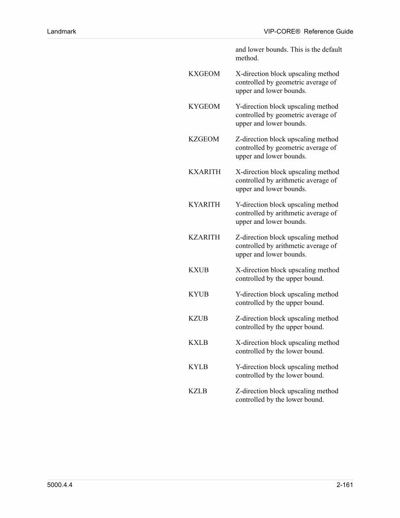
Landmark VIP-CORE® Reference Guide
and lower bounds. This is the default method.
KXGEOM X-direction block upscaling method controlled by geometric average of upper and lower bounds.
KYGEOM Y-direction block upscaling method controlled by geometric average of upper and lower bounds.
KZGEOM Z-direction block upscaling method controlled by geometric average of upper and lower bounds.
KXARITH X-direction block upscaling method controlled by arithmetic average of upper and lower bounds.
KYARITH Y-direction block upscaling method controlled by arithmetic average of upper and lower bounds.
KZARITH Z-direction block upscaling method controlled by arithmetic average of upper and lower bounds.
KXUB X-direction block upscaling method controlled by the upper bound.
KYUB Y-direction block upscaling method controlled by the upper bound.
KZUB Z-direction block upscaling method controlled by the upper bound.
KXLB X-direction block upscaling method controlled by the lower bound.
KYLB Y-direction block upscaling method controlled by the lower bound.
KZLB Z-direction block upscaling method controlled by the lower bound.
00
5000.4.4 2-161

VIP-CORE® Reference Guide Landmark
2-162 5000.4.4
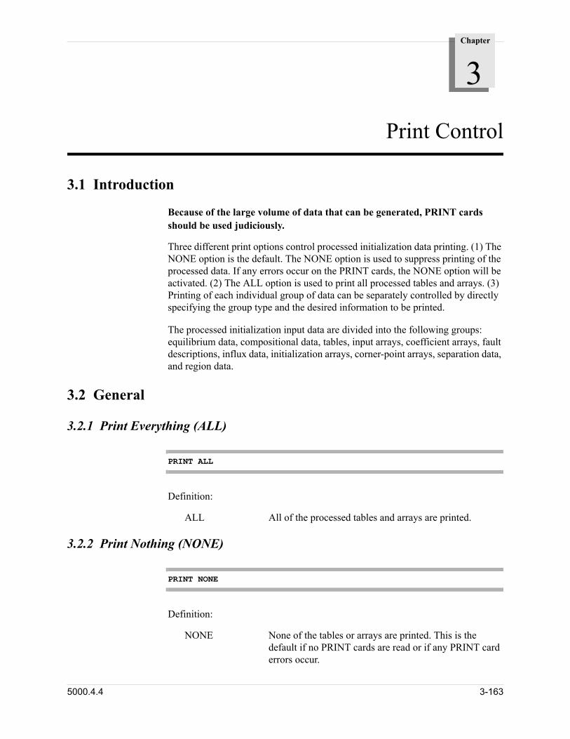
Chapter
3
00000Print Control
3.1 Introduction
Because of the large volume of data that can be generated, PRINT cards should be used judiciously.
Three different print options control processed initialization data printing. (1) The NONE option is the default. The NONE option is used to suppress printing of the processed data. If any errors occur on the PRINT cards, the NONE option will be activated. (2) The ALL option is used to print all processed tables and arrays. (3) Printing of each individual group of data can be separately controlled by directly specifying the group type and the desired information to be printed.
The processed initialization input data are divided into the following groups: equilibrium data, compositional data, tables, input arrays, coefficient arrays, fault descriptions, influx data, initialization arrays, corner-point arrays, separation data, and region data.
3.2 General
3.2.1 Print Everything (ALL)
PRINT ALL
Definition:
ALL All of the processed tables and arrays are printed.
3.2.2 Print Nothing (NONE)
PRINT NONE
Definition:
NONE None of the tables or arrays are printed. This is the default if no PRINT cards are read or if any PRINT card errors occur.
5000.4.4 3-163
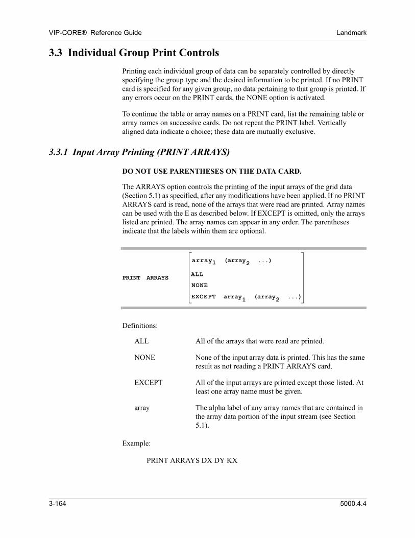
VIP-CORE® Reference Guide Landmark
3.3 Individual Group Print Controls
Printing each individual group of data can be separately controlled by directly specifying the group type and the desired information to be printed. If no PRINT card is specified for any given group, no data pertaining to that group is printed. If any errors occur on the PRINT cards, the NONE option is activated.
To continue the table or array names on a PRINT card, list the remaining table or array names on successive cards. Do not repeat the PRINT label. Vertically aligned data indicate a choice; these data are mutually exclusive.
3.3.1 Input Array Printing (PRINT ARRAYS)
DO NOT USE PARENTHESES ON THE DATA CARD.
The ARRAYS option controls the printing of the input arrays of the grid data (Section 5.1) as specified, after any modifications have been applied. If no PRINT ARRAYS card is read, none of the arrays that were read are printed. Array names can be used with the E as described below. If EXCEPT is omitted, only the arrays listed are printed. The array names can appear in any order. The parentheses indicate that the labels within them are optional.
PRINT ARRAYS
array1 (array2 ...)
ALL
NONE
EXCEPT array1 (array2 ...)
Definitions:
ALL All of the arrays that were read are printed.
NONE None of the input array data is printed. This has the same result as not reading a PRINT ARRAYS card.
EXCEPT All of the input arrays are printed except those listed. At least one array name must be given.
array The alpha label of any array names that are contained in the array data portion of the input stream (see Section 5.1).
Example:
PRINT ARRAYS DX DY KX
3-164 5000.4.4
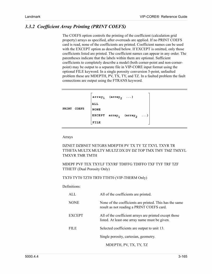
Landmark VIP-CORE® Reference Guide
3.3.2 Coefficient Array Printing (PRINT COEFS)
The COEFS option controls the printing of the coefficient (calculation grid property) arrays as specified, after overreads are applied. If no PRINT COEFS card is read, none of the coefficients are printed. Coefficient names can be used with the EXCEPT option as described below. If EXCEPT is omitted, only those coefficients listed are printed. The coefficient names can appear in any order. The parentheses indicate that the labels within them are optional. Sufficient coefficients to completely describe a model (both corner-point and non-corner-point) may be output to a separate file in VIP-CORE input format using the optional FILE keyword. In a single porosity conversion 5-point, unfaulted problem these are MDEPTH, PV, TX, TY, and TZ. In a faulted problem the fault connections are output using the FTRANS keyword.
PRINT COEFS
array1 (array2 ...)
ALL
NONE
EXCEPT array1 (array2 ...)
FILE
Arrays
DZNET DZBNET NETGRS MDEPTH PV TX TY TZ TXYL TXYR TR TTHETA MULTX MULTY MULTZ DX DY DZ TOP TMX TMY TMZ TMXYL TMXYR TMR TMTH
MDEPF PVF TEX TXYLF TXYRF TDIFFG TDIFFO TXF TYF TRF TZF TTHETF (Dual Porosity Only)
TXT0 TYT0 TZT0 TRT0 TTHT0 (VIP-THERM Only)
Definitions:
ALL All of the coefficients are printed.
NONE None of the coefficients are printed. This has the same result as not reading a PRINT COEFS card.
EXCEPT All of the coefficient arrays are printed except those listed. At least one array name must be given.
FILE Selected coefficients are output to unit 13.
Single porosity, cartesian, geometry.
MDEPTH, PV, TX, TY, TZ
5000.4.4 3-165
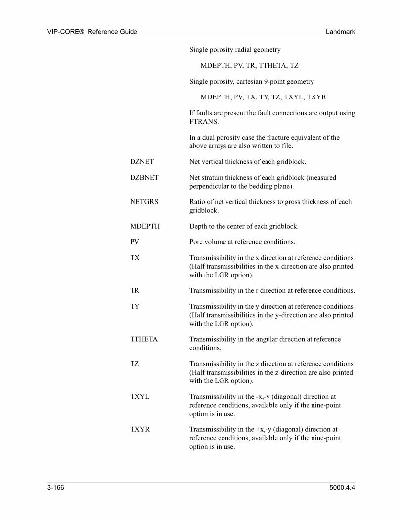
VIP-CORE® Reference Guide Landmark
Single porosity radial geometry
MDEPTH, PV, TR, TTHETA, TZ
Single porosity, cartesian 9-point geometry
MDEPTH, PV, TX, TY, TZ, TXYL, TXYR
If faults are present the fault connections are output using FTRANS.
In a dual porosity case the fracture equivalent of the above arrays are also written to file.
DZNET Net vertical thickness of each gridblock.
DZBNET Net stratum thickness of each gridblock (measured perpendicular to the bedding plane).
NETGRS Ratio of net vertical thickness to gross thickness of each gridblock.
MDEPTH Depth to the center of each gridblock.
PV Pore volume at reference conditions.
TX Transmissibility in the x direction at reference conditions (Half transmissibilities in the x-direction are also printed with the LGR option).
TR Transmissibility in the r direction at reference conditions.
TY Transmissibility in the y direction at reference conditions (Half transmissibilities in the y-direction are also printed with the LGR option).
TTHETA Transmissibility in the angular direction at reference conditions.
TZ Transmissibility in the z direction at reference conditions (Half transmissibilities in the z-direction are also printed with the LGR option).
TXYL Transmissibility in the -x,-y (diagonal) direction at reference conditions, available only if the nine-point option is in use.
TXYR Transmissibility in the +x,-y (diagonal) direction at reference conditions, available only if the nine-point option is in use.
3-166 5000.4.4
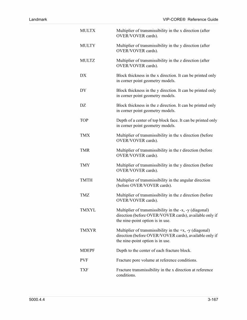
Landmark VIP-CORE® Reference Guide
MULTX Multiplier of transmissibility in the x direction (after OVER/VOVER cards).
MULTY Multiplier of transmissibility in the y direction (after OVER/VOVER cards).
MULTZ Multiplier of transmissibility in the z direction (after OVER/VOVER cards).
DX Block thickness in the x direction. It can be printed only in corner point geometry models.
DY Block thickness in the y direction. It can be printed only in corner point geometry models.
DZ Block thickness in the z direction. It can be printed only in corner point geometry models.
TOP Depth of a center of top block face. It can be printed only in corner point geometry models.
TMX Multiplier of transmissibility in the x direction (before OVER/VOVER cards).
TMR Multiplier of transmissibility in the r direction (before OVER/VOVER cards).
TMY Multiplier of transmissibility in the y direction (before OVER/VOVER cards).
TMTH Multiplier of transmissibility in the angular direction (before OVER/VOVER cards).
TMZ Multiplier of transmissibility in the z direction (before OVER/VOVER cards).
TMXYL Multiplier of transmissibility in the -x, -y (diagonal) direction (before OVER/VOVER cards), available only if the nine-point option is in use.
TMXYR Multiplier of transmissibility in the +x, -y (diagonal) direction (before OVER/VOVER cards), available only if the nine-point option is in use.
MDEPF Depth to the center of each fracture block.
PVF Fracture pore volume at reference conditions.
TXF Fracture transmissibility in the x direction at reference conditions.
5000.4.4 3-167
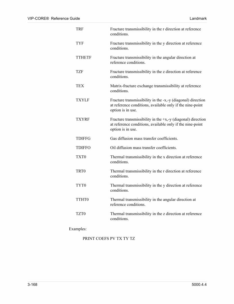
VIP-CORE® Reference Guide Landmark
TRF Fracture transmissibility in the r direction at reference conditions.
TYF Fracture transmissibility in the y direction at reference conditions.
TTHETF Fracture transmissibility in the angular direction at reference conditions.
TZF Fracture transmissibility in the z direction at reference conditions.
TEX Matrix-fracture exchange transmissibility at reference conditions.
TXYLF Fracture transmissibility in the -x,-y (diagonal) direction at reference conditions, available only if the nine-point option is in use.
TXYRF Fracture transmissibility in the +x,-y (diagonal) direction at reference conditions, available only if the nine-point option is in use.
TDIFFG Gas diffusion mass transfer coefficients.
TDIFFO Oil diffusion mass transfer coefficients.
TXT0 Thermal transmissibility in the x direction at reference conditions.
TRT0 Thermal transmissibility in the r direction at reference conditions.
TYT0 Thermal transmissibility in the y direction at reference conditions.
TTHT0 Thermal transmissibility in the angular direction at reference conditions.
TZT0 Thermal transmissibility in the z direction at reference conditions.
Examples:
PRINT COEFS PV TX TY TZ
3-168 5000.4.4
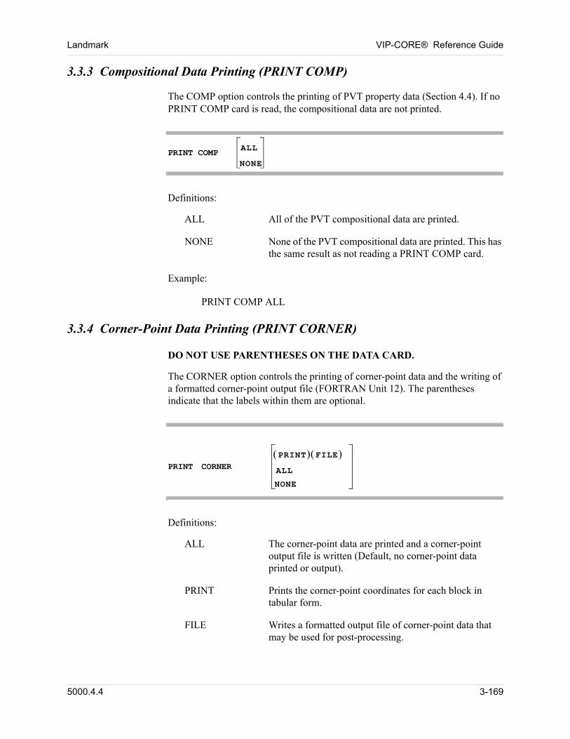
Landmark VIP-CORE® Reference Guide
3.3.3 Compositional Data Printing (PRINT COMP)
The COMP option controls the printing of PVT property data (Section 4.4). If no PRINT COMP card is read, the compositional data are not printed.
PRINT COMP
ALL
NONE
Definitions:
ALL All of the PVT compositional data are printed.
NONE None of the PVT compositional data are printed. This has the same result as not reading a PRINT COMP card.
Example:
PRINT COMP ALL
3.3.4 Corner-Point Data Printing (PRINT CORNER)
DO NOT USE PARENTHESES ON THE DATA CARD.
The CORNER option controls the printing of corner-point data and the writing of a formatted corner-point output file (FORTRAN Unit 12). The parentheses indicate that the labels within them are optional.
PRINT CORNER PRINT FILE ALL
NONE
Definitions:
ALL The corner-point data are printed and a corner-point output file is written (Default, no corner-point data printed or output).
PRINT Prints the corner-point coordinates for each block in tabular form.
FILE Writes a formatted output file of corner-point data that may be used for post-processing.
5000.4.4 3-169
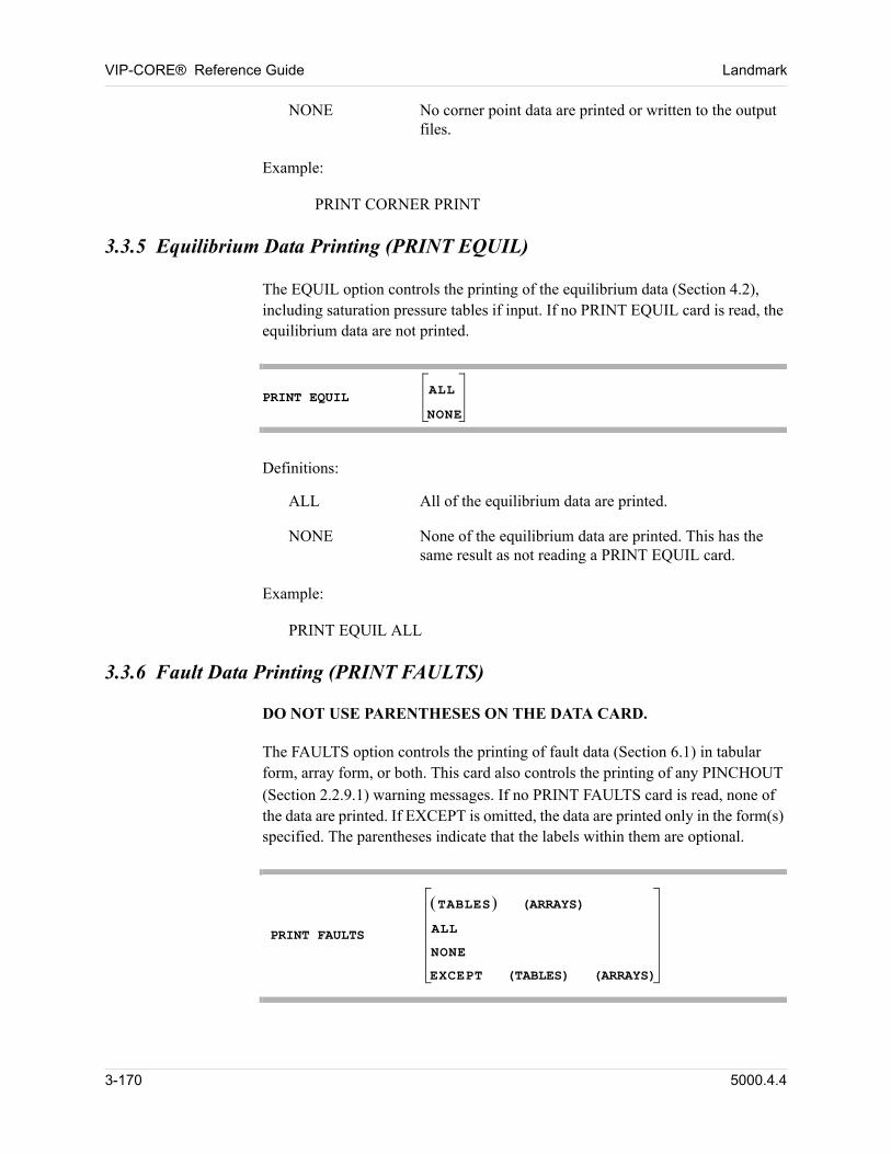
VIP-CORE® Reference Guide Landmark
NONE No corner point data are printed or written to the output files.
Example:
PRINT CORNER PRINT
3.3.5 Equilibrium Data Printing (PRINT EQUIL)
The EQUIL option controls the printing of the equilibrium data (Section 4.2), including saturation pressure tables if input. If no PRINT EQUIL card is read, the equilibrium data are not printed.
PRINT EQUIL
ALL
NONE
Definitions:
ALL All of the equilibrium data are printed.
NONE None of the equilibrium data are printed. This has the same result as not reading a PRINT EQUIL card.
Example:
PRINT EQUIL ALL
3.3.6 Fault Data Printing (PRINT FAULTS)
DO NOT USE PARENTHESES ON THE DATA CARD.
The FAULTS option controls the printing of fault data (Section 6.1) in tabular form, array form, or both. This card also controls the printing of any PINCHOUT
(Section 2.2.9.1) warning messages. If no PRINT FAULTS card is read, none of the data are printed. If EXCEPT is omitted, the data are printed only in the form(s) specified. The parentheses indicate that the labels within them are optional.
PRINT FAULTS
TABLES (ARRAYS)
ALL
NONE
EXCEPT (TABLES) (ARRAYS)
3-170 5000.4.4
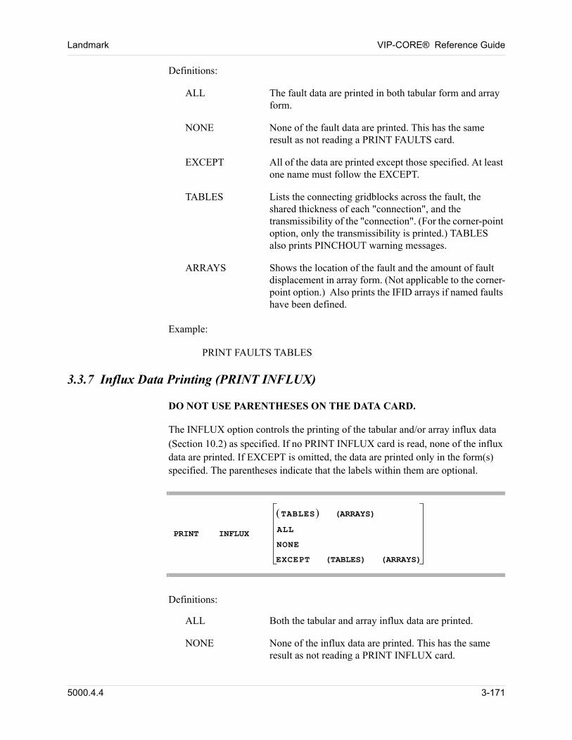
Landmark VIP-CORE® Reference Guide
Definitions:
ALL The fault data are printed in both tabular form and array form.
NONE None of the fault data are printed. This has the same result as not reading a PRINT FAULTS card.
EXCEPT All of the data are printed except those specified. At least one name must follow the EXCEPT.
TABLES Lists the connecting gridblocks across the fault, the shared thickness of each "connection", and the transmissibility of the "connection". (For the corner-point option, only the transmissibility is printed.) TABLES also prints PINCHOUT warning messages.
ARRAYS Shows the location of the fault and the amount of fault displacement in array form. (Not applicable to the corner-point option.) Also prints the IFID arrays if named faults have been defined.
Example:
PRINT FAULTS TABLES
3.3.7 Influx Data Printing (PRINT INFLUX)
DO NOT USE PARENTHESES ON THE DATA CARD.
The INFLUX option controls the printing of the tabular and/or array influx data
(Section 10.2) as specified. If no PRINT INFLUX card is read, none of the influx data are printed. If EXCEPT is omitted, the data are printed only in the form(s) specified. The parentheses indicate that the labels within them are optional.
PRINT INFLUX
TABLES (ARRAYS)
ALL
NONE
EXCEPT (TABLES) (ARRAYS)
Definitions:
ALL Both the tabular and array influx data are printed.
NONE None of the influx data are printed. This has the same result as not reading a PRINT INFLUX card.
5000.4.4 3-171
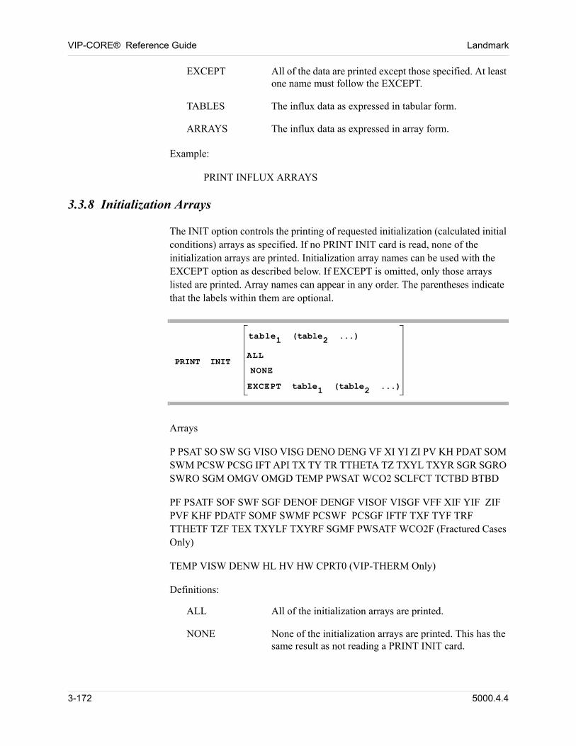
VIP-CORE® Reference Guide Landmark
EXCEPT All of the data are printed except those specified. At least one name must follow the EXCEPT.
TABLES The influx data as expressed in tabular form.
ARRAYS The influx data as expressed in array form.
Example:
PRINT INFLUX ARRAYS
3.3.8 Initialization Arrays
The INIT option controls the printing of requested initialization (calculated initial conditions) arrays as specified. If no PRINT INIT card is read, none of the initialization arrays are printed. Initialization array names can be used with the EXCEPT option as described below. If EXCEPT is omitted, only those arrays listed are printed. Array names can appear in any order. The parentheses indicate that the labels within them are optional.
PRINT INIT
table1 (table2 ...)
ALL
NONE
EXCEPT table1 (table2 ...)
Arrays
P PSAT SO SW SG VISO VISG DENO DENG VF XI YI ZI PV KH PDAT SOM SWM PCSW PCSG IFT API TX TY TR TTHETA TZ TXYL TXYR SGR SGRO SWRO SGM OMGV OMGD TEMP PWSAT WCO2 SCLFCT TCTBD BTBD
PF PSATF SOF SWF SGF DENOF DENGF VISOF VISGF VFF XIF YIF ZIF PVF KHF PDATF SOMF SWMF PCSWF PCSGF IFTF TXF TYF TRF TTHETF TZF TEX TXYLF TXYRF SGMF PWSATF WCO2F (Fractured Cases Only)
TEMP VISW DENW HL HV HW CPRT0 (VIP-THERM Only)
Definitions:
ALL All of the initialization arrays are printed.
NONE None of the initialization arrays are printed. This has the same result as not reading a PRINT INIT card.
3-172 5000.4.4
Landmark VIP-CORE® Reference Guide
EXCEPT All of the initialization arrays are printed except those listed. At least one array name must be given.
P Initial pressure.
PSAT Initial saturation pressure.
SO Initial oil saturation.
SW Initial water saturation.
SG Initial gas saturation.
VISO Initial oil viscosity.
VISG Initial gas viscosity.
DENO Initial oil density.
DENG Initial gas density.
VF Initial vapor fraction.
XI Initial mole fraction of all components in the liquid phase.
YI Initial mole fraction of all components in the vapor phase.
ZI Initial overall hydrocarbon mole fraction of all components.
PV Pore volume at initial conditions.
KH Permeability thickness at initial conditions.
PDAT Initial datum pressure (datum depth defined by the IEQUIL card).
SOM Initial normalized mobile oil saturation.
SWM Initial normalized mobile water saturation.
RS Solution gas-oil ratio.
RV Solution oil-gas ratio.
PCSW Water-oil capillary pressure adjustment, meaningful only if the integrated saturation initialization algorithm is used for equilibrium initialization, or saturations have been overread.
5000.4.4 3-173
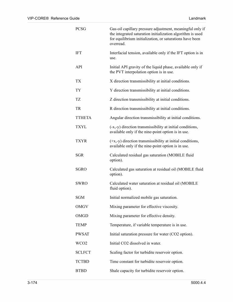
VIP-CORE® Reference Guide Landmark
PCSG Gas-oil capillary pressure adjustment, meaningful only if the integrated saturation initialization algorithm is used for equilibrium initialization, or saturations have been overread.
IFT Interfacial tension, available only if the IFT option is in use.
API Initial API gravity of the liquid phase, available only if the PVT interpolation option is in use.
TX X direction transmissibility at initial conditions.
TY Y direction transmissibility at initial conditions.
TZ Z direction transmissibility at initial conditions.
TR R direction transmissibility at initial conditions.
TTHETA Angular direction transmissibility at initial conditions.
TXYL (-x,-y) direction transmissibility at initial conditions, available only if the nine-point option is in use.
TXYR (+x,-y) direction transmissibility at initial conditions, available only if the nine-point option is in use.
SGR Calculated residual gas saturation (MOBILE fluid option).
SGRO Calculated gas saturation at residual oil (MOBILE fluid option).
SWRO Calculated water saturation at residual oil (MOBILE fluid option).
SGM Initial normalized mobile gas saturation.
OMGV Mixing parameter for effective viscosity.
OMGD Mixing parameter for effective density.
TEMP Temperature, if variable temperature is in use.
PWSAT Initial saturation pressure for water (CO2 option).
WCO2 Initial CO2 dissolved in water.
SCLFCT Scaling factor for turbidite reservoir option.
TCTBD Time constant for turbidite reservoir option.
BTBD Shale capacity for turbidite reservoir option.
3-174 5000.4.4
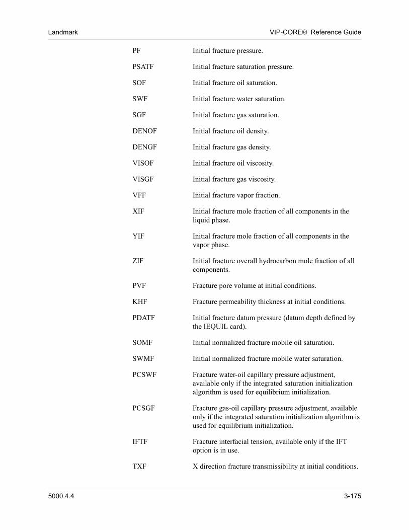
Landmark VIP-CORE® Reference Guide
PF Initial fracture pressure.
PSATF Initial fracture saturation pressure.
SOF Initial fracture oil saturation.
SWF Initial fracture water saturation.
SGF Initial fracture gas saturation.
DENOF Initial fracture oil density.
DENGF Initial fracture gas density.
VISOF Initial fracture oil viscosity.
VISGF Initial fracture gas viscosity.
VFF Initial fracture vapor fraction.
XIF Initial fracture mole fraction of all components in the liquid phase.
YIF Initial fracture mole fraction of all components in the vapor phase.
ZIF Initial fracture overall hydrocarbon mole fraction of all components.
PVF Fracture pore volume at initial conditions.
KHF Fracture permeability thickness at initial conditions.
PDATF Initial fracture datum pressure (datum depth defined by the IEQUIL card).
SOMF Initial normalized fracture mobile oil saturation.
SWMF Initial normalized fracture mobile water saturation.
PCSWF Fracture water-oil capillary pressure adjustment, available only if the integrated saturation initialization algorithm is used for equilibrium initialization.
PCSGF Fracture gas-oil capillary pressure adjustment, available only if the integrated saturation initialization algorithm is used for equilibrium initialization.
IFTF Fracture interfacial tension, available only if the IFT option is in use.
TXF X direction fracture transmissibility at initial conditions.
5000.4.4 3-175
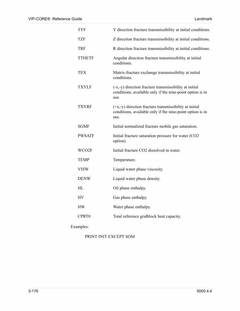
VIP-CORE® Reference Guide Landmark
TYF Y direction fracture transmissibility at initial conditions.
TZF Z direction fracture transmissibility at initial conditions.
TRF R direction fracture transmissibility at initial conditions.
TTHETF Angular direction fracture transmissibility at initial conditions.
TEX Matrix-fracture exchange transmissibility at initial conditions.
TXYLF (-x,-y) direction fracture transmissibility at initial conditions, available only if the nine-point option is in use.
TXYRF (+x,-y) direction fracture transmissibility at initial conditions, available only if the nine-point option is in use.
SGMF Initial normalized fracture mobile gas saturation.
PWSATF Initial fracture saturation pressure for water (CO2 option).
WCO2F Initial fracture CO2 dissolved in water.
TEMP Temperature.
VISW Liquid water phase viscosity.
DENW Liquid water phase density.
HL Oil phase enthalpy.
HV Gas phase enthalpy.
HW Water phase enthalpy.
CPRT0 Total reference gridblock heat capacity.
Examples:
PRINT INIT EXCEPT SOM
3-176 5000.4.4
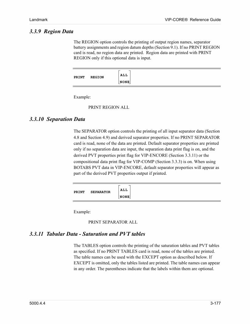
Landmark VIP-CORE® Reference Guide
3.3.9 Region Data
The REGION option controls the printing of output region names, separator battery assignments and region datum depths (Section 9.1). If no PRINT REGION card is read, no region data are printed. Region data are printed with PRINT REGION only if this optional data is input.
PRINT REGION
ALL
NONE
Example:
PRINT REGION ALL
3.3.10 Separation Data
The SEPARATOR option controls the printing of all input separator data (Section
4.8 and Section 4.9) and derived separator properties. If no PRINT SEPARATOR card is read, none of the data are printed. Default separator properties are printed only if no separation data are input, the separation data print flag is on, and the
derived PVT properties print flag for VIP-ENCORE (Section 3.3.11) or the
compositional data print flag for VIP-COMP (Section 3.3.3) is on. When using BOTABS PVT data in VIP-ENCORE, default separator properties will appear as part of the derived PVT properties output if printed.
PRINT SEPARATOR
ALL
NONE
Example:
PRINT SEPARATOR ALL
3.3.11 Tabular Data - Saturation and PVT tables
The TABLES option controls the printing of the saturation tables and PVT tables as specified. If no PRINT TABLES card is read, none of the tables are printed. The table names can be used with the EXCEPT option as described below. If EXCEPT is omitted, only the tables listed are printed. The table names can appear in any order. The parentheses indicate that the labels within them are optional.
5000.4.4 3-177
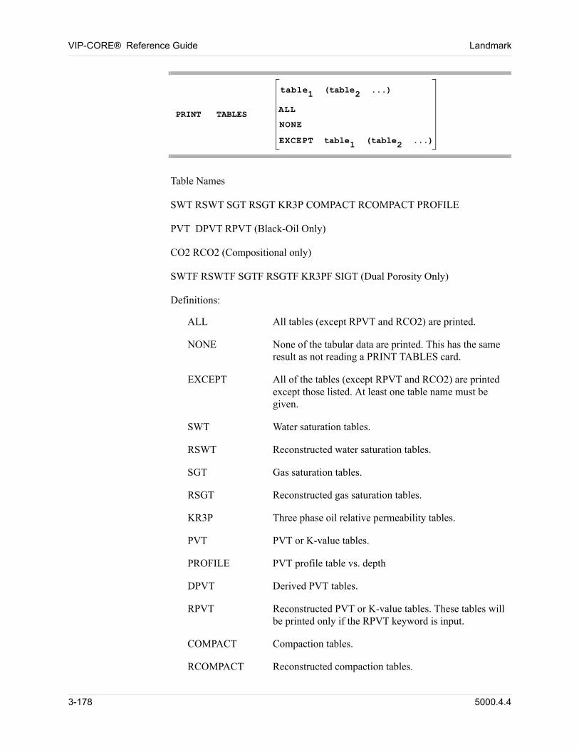
VIP-CORE® Reference Guide Landmark
PRINT TABLES
table1 (table2 ...)
ALL
NONE
EXCEPT table1 (table2 ...)
Table Names
SWT RSWT SGT RSGT KR3P COMPACT RCOMPACT PROFILE
PVT DPVT RPVT (Black-Oil Only)
CO2 RCO2 (Compositional only)
SWTF RSWTF SGTF RSGTF KR3PF SIGT (Dual Porosity Only)
Definitions:
ALL All tables (except RPVT and RCO2) are printed.
NONE None of the tabular data are printed. This has the same result as not reading a PRINT TABLES card.
EXCEPT All of the tables (except RPVT and RCO2) are printed except those listed. At least one table name must be given.
SWT Water saturation tables.
RSWT Reconstructed water saturation tables.
SGT Gas saturation tables.
RSGT Reconstructed gas saturation tables.
KR3P Three phase oil relative permeability tables.
PVT PVT or K-value tables.
PROFILE PVT profile table vs. depth
DPVT Derived PVT tables.
RPVT Reconstructed PVT or K-value tables. These tables will be printed only if the RPVT keyword is input.
COMPACT Compaction tables.
RCOMPACT Reconstructed compaction tables.
3-178 5000.4.4
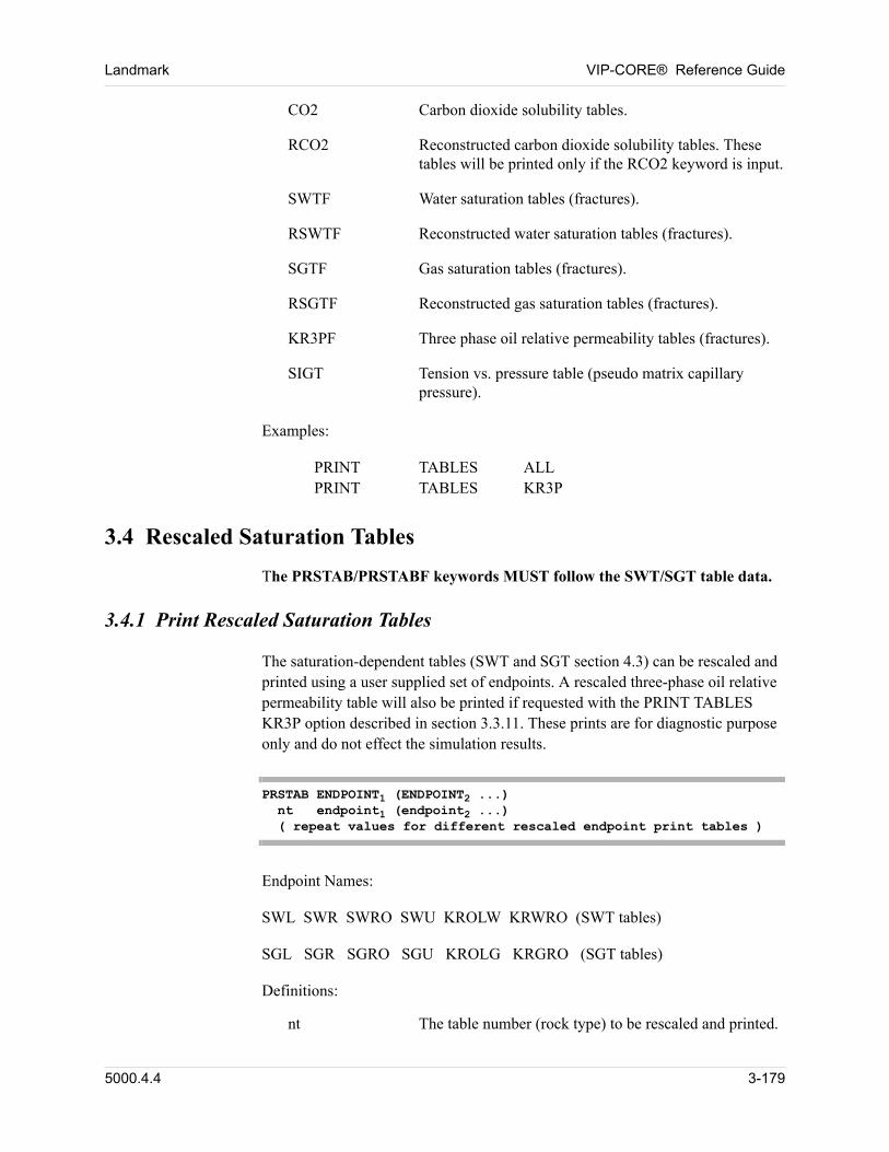
Landmark VIP-CORE® Reference Guide
CO2 Carbon dioxide solubility tables.
RCO2 Reconstructed carbon dioxide solubility tables. These tables will be printed only if the RCO2 keyword is input.
SWTF Water saturation tables (fractures).
RSWTF Reconstructed water saturation tables (fractures).
SGTF Gas saturation tables (fractures).
RSGTF Reconstructed gas saturation tables (fractures).
KR3PF Three phase oil relative permeability tables (fractures).
SIGT Tension vs. pressure table (pseudo matrix capillary pressure).
Examples:
PRINT TABLES ALLPRINT TABLES KR3P
3.4 Rescaled Saturation Tables
The PRSTAB/PRSTABF keywords MUST follow the SWT/SGT table data.
3.4.1 Print Rescaled Saturation Tables
The saturation-dependent tables (SWT and SGT section 4.3) can be rescaled and printed using a user supplied set of endpoints. A rescaled three-phase oil relative permeability table will also be printed if requested with the PRINT TABLES KR3P option described in section 3.3.11. These prints are for diagnostic purpose only and do not effect the simulation results.
PRSTAB ENDPOINT1 (ENDPOINT2 ...) nt endpoint1 (endpoint2 ...) ( repeat values for different rescaled endpoint print tables )
Endpoint Names:
SWL SWR SWRO SWU KROLW KRWRO (SWT tables)
SGL SGR SGRO SGU KROLG KRGRO (SGT tables)
Definitions:
nt The table number (rock type) to be rescaled and printed.
5000.4.4 3-179
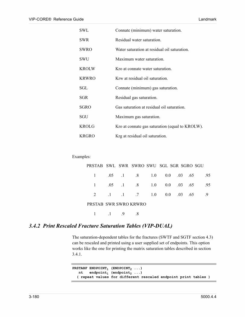
VIP-CORE® Reference Guide Landmark
SWL Connate (minimum) water saturation.
SWR Residual water saturation.
SWRO Water saturation at residual oil saturation.
SWU Maximum water saturation.
KROLW Kro at connate water saturation.
KRWRO Krw at residual oil saturation.
SGL Connate (minimum) gas saturation.
SGR Residual gas saturation.
SGRO Gas saturation at residual oil saturation.
SGU Maximum gas saturation.
KROLG Kro at connate gas saturation (equal to KROLW).
KRGRO Krg at residual oil saturation.
Examples:
PRSTAB SWL SWR SWRO SWU SGL SGR SGRO SGU
1 .05 .1 .8 1.0 0.0 .03 .65 .95
1 .05 .1 .8 1.0 0.0 .03 .65 .95
2 .1 .1 .7 1.0 0.0 .03 .65 .9
PRSTAB SWR SWRO KRWRO
1 .1 .9 .8
3.4.2 Print Rescaled Fracture Saturation Tables (VIP-DUAL)
The saturation-dependent tables for the fractures (SWTF and SGTF section 4.3) can be rescaled and printed using a user supplied set of endpoints. This option works like the one for printing the matrix saturation tables described in section 3.4.1.
PRSTABF ENDPOINT1 (ENDPOINT2 ...) nt endpoint1 (endpoint2 ...) ( repeat values for different rescaled endpoint print tables )
3-180 5000.4.4

Landmark VIP-CORE® Reference Guide
Endpoint Names:
SWL SWR SWRO SWU KROLW KRWRO (SWT tables)
SGL SGR SGRO SGU KROLG KRGRO ( SGT tables)
Definitions:
Definitions are as given in Section 3.4.1, Print Rescaled Saturation Tables.
5000.4.4 3-181

VIP-CORE® Reference Guide Landmark
3-182 5000.4.4
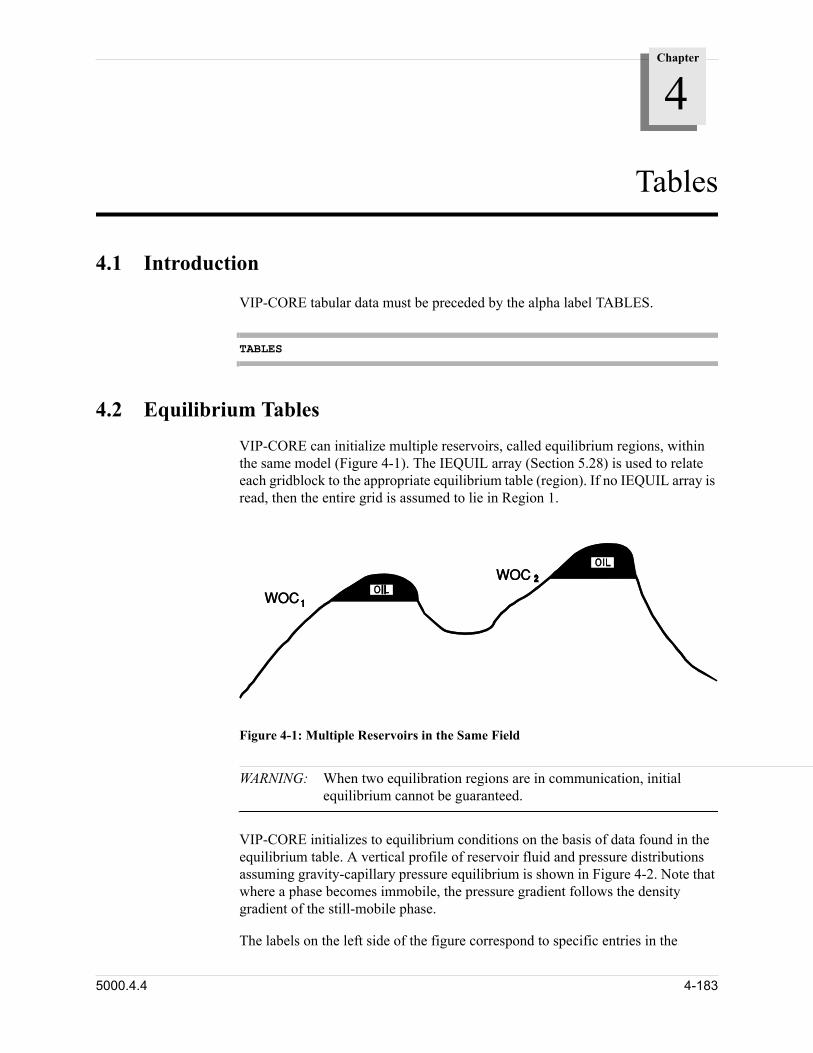
Chapter
4
00000Tables
4.1 Introduction
00 VIP-CORE tabular data must be preceded by the alpha label TABLES.
TABLES
4.2 Equilibrium Tables
00 VIP-CORE can initialize multiple reservoirs, called equilibrium regions, within the same model (Figure 4-1). The IEQUIL array (Section 5.28) is used to relate each gridblock to the appropriate equilibrium table (region). If no IEQUIL array is read, then the entire grid is assumed to lie in Region 1.
Figure 4-1: Multiple Reservoirs in the Same Field
WARNING: When two equilibration regions are in communication, initial equilibrium cannot be guaranteed.
VIP-CORE initializes to equilibrium conditions on the basis of data found in the equilibrium table. A vertical profile of reservoir fluid and pressure distributions assuming gravity-capillary pressure equilibrium is shown in Figure 4-2. Note that where a phase becomes immobile, the pressure gradient follows the density gradient of the still-mobile phase. 00
00 The labels on the left side of the figure correspond to specific entries in the
5000.4.4 4-183
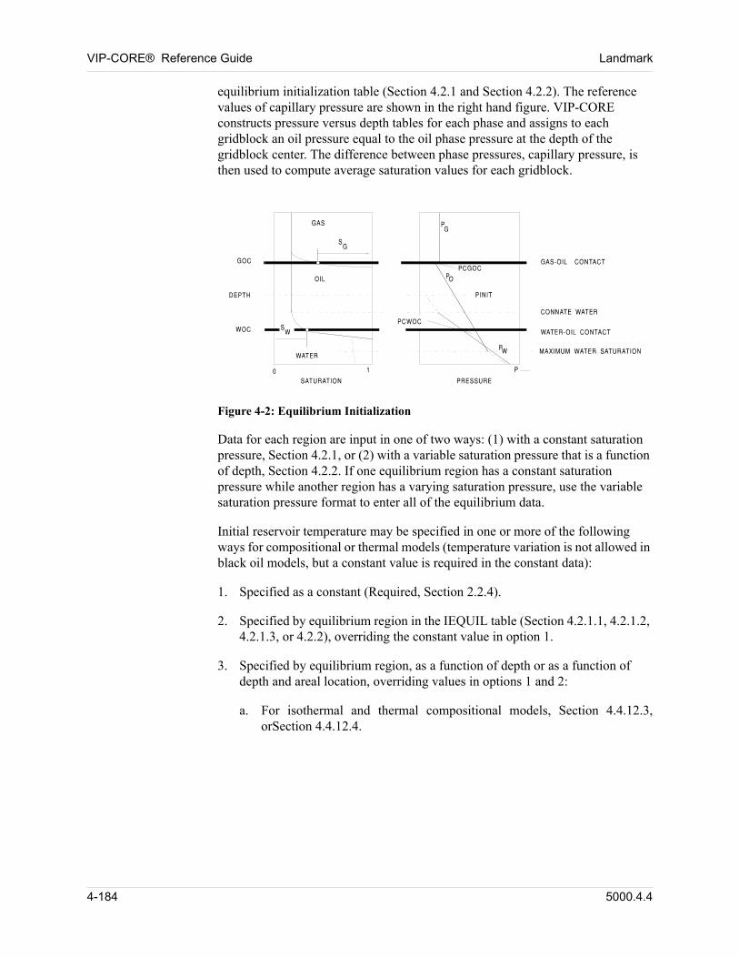
VIP-CORE® Reference Guide Landmark
equilibrium initialization table (Section 4.2.1 and Section 4.2.2). The reference values of capillary pressure are shown in the right hand figure. VIP-CORE constructs pressure versus depth tables for each phase and assigns to each gridblock an oil pressure equal to the oil phase pressure at the depth of the gridblock center. The difference between phase pressures, capillary pressure, is then used to compute average saturation values for each gridblock.
Figure 4-2: Equilibrium Initialization
Data for each region are input in one of two ways: (1) with a constant saturation pressure, Section 4.2.1, or (2) with a variable saturation pressure that is a function of depth, Section 4.2.2. If one equilibrium region has a constant saturation pressure while another region has a varying saturation pressure, use the variable saturation pressure format to enter all of the equilibrium data. 00
Initial reservoir temperature may be specified in one or more of the following ways for compositional or thermal models (temperature variation is not allowed in black oil models, but a constant value is required in the constant data): 00
1. Specified as a constant (Required, Section 2.2.4).
2. Specified by equilibrium region in the IEQUIL table (Section 4.2.1.1, 4.2.1.2, 4.2.1.3, or 4.2.2), overriding the constant value in option 1.
3. Specified by equilibrium region, as a function of depth or as a function of depth and areal location, overriding values in options 1 and 2:
a. For isothermal and thermal compositional models, Section 4.4.12.3, orSection 4.4.12.4.
4-184 5000.4.4
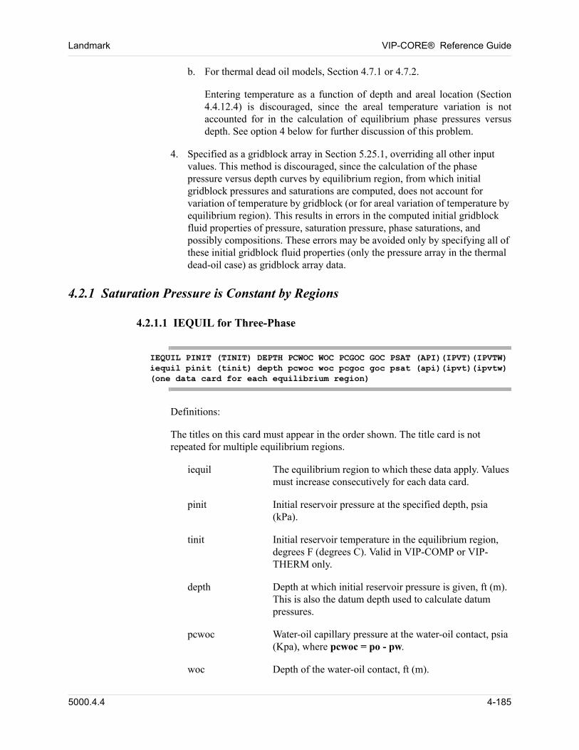
Landmark VIP-CORE® Reference Guide
b. For thermal dead oil models, Section 4.7.1 or 4.7.2.
Entering temperature as a function of depth and areal location (Section 4.4.12.4) is discouraged, since the areal temperature variation is not accounted for in the calculation of equilibrium phase pressures versus depth. See option 4 below for further discussion of this problem.
4. Specified as a gridblock array in Section 5.25.1, overriding all other input values. This method is discouraged, since the calculation of the phase pressure versus depth curves by equilibrium region, from which initial gridblock pressures and saturations are computed, does not account for variation of temperature by gridblock (or for areal variation of temperature by equilibrium region). This results in errors in the computed initial gridblock fluid properties of pressure, saturation pressure, phase saturations, and possibly compositions. These errors may be avoided only by specifying all of these initial gridblock fluid properties (only the pressure array in the thermal dead-oil case) as gridblock array data.
4.2.1 Saturation Pressure is Constant by Regions
4.2.1.1 IEQUIL for Three-Phase
IEQUIL PINIT (TINIT) DEPTH PCWOC WOC PCGOC GOC PSAT (API)(IPVT)(IPVTW)iequil pinit (tinit) depth pcwoc woc pcgoc goc psat (api)(ipvt)(ipvtw)(one data card for each equilibrium region)
Definitions: 00
The titles on this card must appear in the order shown. The title card is not repeated for multiple equilibrium regions. 00
iequil The equilibrium region to which these data apply. Values must increase consecutively for each data card.
pinit Initial reservoir pressure at the specified depth, psia (kPa).
tinit Initial reservoir temperature in the equilibrium region, degrees F (degrees C). Valid in VIP-COMP or VIP-THERM only.
depth Depth at which initial reservoir pressure is given, ft (m). This is also the datum depth used to calculate datum pressures.
pcwoc Water-oil capillary pressure at the water-oil contact, psia (Kpa), where pcwoc = po - pw.
woc Depth of the water-oil contact, ft (m).
5000.4.4 4-185
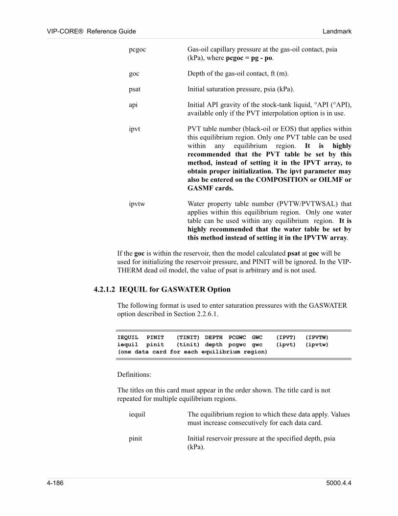
VIP-CORE® Reference Guide Landmark
pcgoc Gas-oil capillary pressure at the gas-oil contact, psia (kPa), where pcgoc = pg - po.
goc Depth of the gas-oil contact, ft (m).
psat Initial saturation pressure, psia (kPa).
api Initial API gravity of the stock-tank liquid, °API (°API), available only if the PVT interpolation option is in use.
ipvt PVT table number (black-oil or EOS) that applies within this equilibrium region. Only one PVT table can be used within any equilibrium region. It is highly recommended that the PVT table be set by this method, instead of setting it in the IPVT array, to obtain proper initialization. The ipvt parameter may also be entered on the COMPOSITION or OILMF or GASMF cards.
ipvtw Water property table number (PVTW/PVTWSAL) that applies within this equilibrium region. Only one water table can be used within any equilibrium region. It is highly recommended that the water table be set by this method instead of setting it in the IPVTW array.
If the goc is within the reservoir, then the model calculated psat at goc will be used for initializing the reservoir pressure, and PINIT will be ignored. In the VIP-THERM dead oil model, the value of psat is arbitrary and is not used. 00
4.2.1.2 IEQUIL for GASWATER Option
The following format is used to enter saturation pressures with the GASWATER option described in Section 2.2.6.1. 00
IEQUIL PINIT (TINIT) DEPTH PCGWC GWC (IPVT) (IPVTW)iequil pinit (tinit) depth pcgwc gwc (ipvt) (ipvtw)(one data card for each equilibrium region)
Definitions: 00
The titles on this card must appear in the order shown. The title card is not repeated for multiple equilibrium regions. 00
iequil The equilibrium region to which these data apply. Values must increase consecutively for each data card.
pinit Initial reservoir pressure at the specified depth, psia (kPa).
4-186 5000.4.4
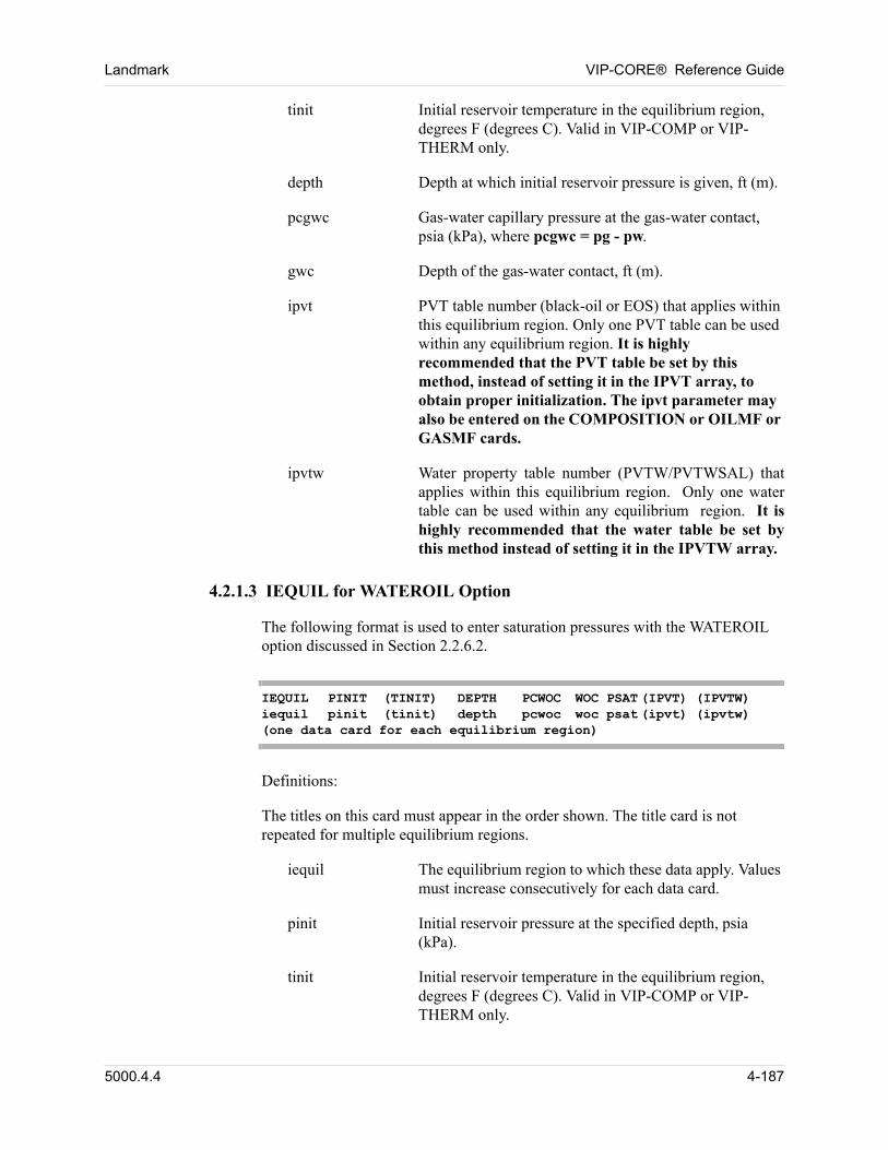
Landmark VIP-CORE® Reference Guide
tinit Initial reservoir temperature in the equilibrium region, degrees F (degrees C). Valid in VIP-COMP or VIP-THERM only.
depth Depth at which initial reservoir pressure is given, ft (m).
pcgwc Gas-water capillary pressure at the gas-water contact, psia (kPa), where pcgwc = pg - pw.
gwc Depth of the gas-water contact, ft (m).
ipvt PVT table number (black-oil or EOS) that applies within this equilibrium region. Only one PVT table can be used within any equilibrium region. It is highly recommended that the PVT table be set by this method, instead of setting it in the IPVT array, to obtain proper initialization. The ipvt parameter may also be entered on the COMPOSITION or OILMF or GASMF cards.
ipvtw Water property table number (PVTW/PVTWSAL) that applies within this equilibrium region. Only one water table can be used within any equilibrium region. It is highly recommended that the water table be set by this method instead of setting it in the IPVTW array.
4.2.1.3 IEQUIL for WATEROIL Option
The following format is used to enter saturation pressures with the WATEROIL option discussed in Section 2.2.6.2. 00
IEQUIL PINIT (TINIT) DEPTH PCWOC WOC PSAT (IPVT) (IPVTW)iequil pinit (tinit) depth pcwoc woc psat (ipvt) (ipvtw)(one data card for each equilibrium region)
Definitions: 00
The titles on this card must appear in the order shown. The title card is not repeated for multiple equilibrium regions. 00
iequil The equilibrium region to which these data apply. Values must increase consecutively for each data card.
pinit Initial reservoir pressure at the specified depth, psia (kPa).
tinit Initial reservoir temperature in the equilibrium region, degrees F (degrees C). Valid in VIP-COMP or VIP-THERM only.
5000.4.4 4-187
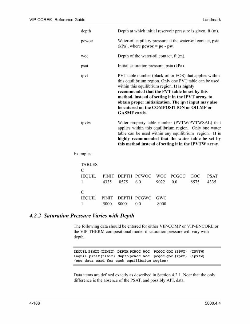
VIP-CORE® Reference Guide Landmark
depth Depth at which initial reservoir pressure is given, ft (m).
pcwoc Water-oil capillary pressure at the water-oil contact, psia (kPa), where pcwoc = po - pw.
woc Depth of the water-oil contact, ft (m).
psat Initial saturation pressure, psia (kPa).
ipvt PVT table number (black-oil or EOS) that applies within this equilibrium region. Only one PVT table can be used within this equilibrium region. It is highly recommended that the PVT table be set by this method, instead of setting it in the IPVT array, to obtain proper initialization. The ipvt input may also be entered on the COMPOSITION or OILMF or GASMF cards.
ipvtw Water property table number (PVTW/PVTWSAL) that applies within this equilibrium region. Only one water table can be used within any equilibrium region. It is highly recommended that the water table be set by this method instead of setting it in the IPVTW array.
Examples: 00
00 TABLESCIEQUIL PINIT DEPTH PCWOC WOC PCGOC GOC PSAT1 4335 8575 6.0 9022 0.0 8575 4335
00 CIEQUIL PINIT DEPTH PCGWC GWC1 5000. 8000. 0.0 8000.
4.2.2 Saturation Pressure Varies with Depth
The following data should be entered for either VIP-COMP or VIP-ENCORE or the VIP-THERM compositional model if saturation pressure will vary with depth. 00
IEQUIL PINIT(TINIT) DEPTH PCWOC WOC PCGOC GOC (IPVT) (IPVTW)iequil pinit(tinit) depth pcwoc woc pcgoc goc (ipvt) (ipvtw)(one data card for each equilibrium region)
Data items are defined exactly as described in Section 4.2.1. Note that the only difference is the absence of the PSAT, and possibly API, data. 00
4-188 5000.4.4
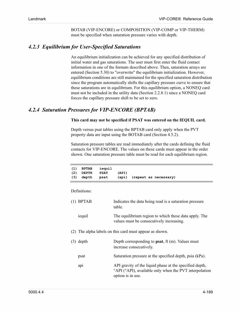
Landmark VIP-CORE® Reference Guide
BOTAB (VIP-ENCORE) or COMPOSITION (VIP-COMP or VIP-THERM) must be specified when saturation pressure varies with depth. 00
4.2.3 Equilibrium for User-Specified Saturations
An equilibrium initialization can be achieved for any specified distribution of initial water and gas saturations. The user must first enter the fluid contact information in one of the formats described above. Then, saturation arrays are entered (Section 5.30) to "overwrite" the equilibrium initialization. However, equilibrium conditions are still maintained for the specified saturation distribution since the program automatically shifts the capillary pressure curve to ensure that these saturations are in equilibrium. For this equilibrium option, a NONEQ card must not be included in the utility data (Section 2.2.8.1) since a NONEQ card forces the capillary pressure shift to be set to zero. 00
4.2.4 Saturation Pressures for VIP-ENCORE (BPTAB)
This card may not be specified if PSAT was entered on the IEQUIL card. 00
Depth versus psat tables using the BPTAB card only apply when the PVT property data are input using the BOTAB card (Section 4.5.2). 00
Saturation pressure tables are read immediately after the cards defining the fluid contacts for VIP-ENCORE. The values on these cards must appear in the order shown. One saturation pressure table must be read for each equilibrium region. 00
(1) BPTAB iequil(2) DEPTH PSAT (API)(3) depth psat (api) (repeat as necessary)
Definitions: 00
00 (1) BPTAB Indicates the data being read is a saturation pressure table.
iequil The equilibrium region to which these data apply. The values must be consecutively increasing.
00 (2) The alpha labels on this card must appear as shown.
00 (3) depth Depth corresponding to psat, ft (m). Values must increase consecutively.
psat Saturation pressure at the specified depth, psia (kPa).
api API gravity of the liquid phase at the specified depth, °API (°API), available only when the PVT interpolation option is in use.
5000.4.4 4-189
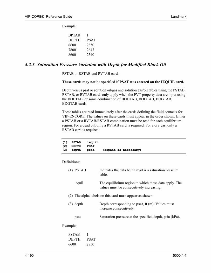
VIP-CORE® Reference Guide Landmark
00 Example:
00 BPTAB 1DEPTH PSAT6600 28507800 26478600 2540
4.2.5 Saturation Pressure Variation with Depth for Modified Black Oil
00 PSTAB or RSTAB and RVTAB cards
These cards may not be specified if PSAT was entered on the IEQUIL card. 00
Depth versus psat or solution oil/gas and solution gas/oil tables using the PSTAB, RSTAB, or RVTAB cards only apply when the PVT property data are input using the BOETAB, or some combination of BODTAB, BOOTAB, BOGTAB, BDGTAB cards. 00
These tables are read immediately after the cards defining the fluid contacts for VIP-ENCORE. The values on these cards must appear in the order shown. Either a PSTAB or a RVTAB/RSTAB combination must be read for each equilibrium region. For a dead oil, only a RVTAB card is required. For a dry gas, only a RSTAB card is required. 00
(1) PSTAB iequil(2) DEPTH PSAT (3) depth psat (repeat as necessary)
00 Definitions:
(1) PSTAB Indicates the data being read is a saturation pressure table.
iequil The equilibrium region to which these data apply. The values must be consecutively increasing.
(2) The alpha labels on this card must appear as shown.
(3) depth Depth corresponding to psat, ft (m). Values must increase consecutively.
psat Saturation pressure at the specified depth, psia (kPa).
00 Example:
00 PSTAB 1DEPTH PSAT6600 2850
4-190 5000.4.4
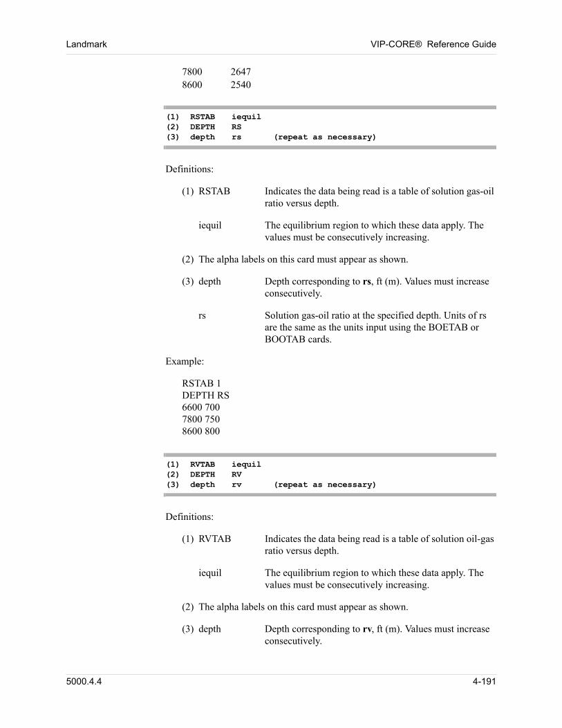
Landmark VIP-CORE® Reference Guide
7800 26478600 2540
(1) RSTAB iequil(2) DEPTH RS (3) depth rs (repeat as necessary)
00 Definitions:
(1) RSTAB Indicates the data being read is a table of solution gas-oil ratio versus depth.
iequil The equilibrium region to which these data apply. The values must be consecutively increasing.
(2) The alpha labels on this card must appear as shown.
(3) depth Depth corresponding to rs, ft (m). Values must increase consecutively.
rs Solution gas-oil ratio at the specified depth. Units of rs are the same as the units input using the BOETAB or BOOTAB cards.
00 Example:
00 RSTAB 1DEPTH RS6600 7007800 7508600 800
(1) RVTAB iequil(2) DEPTH RV (3) depth rv (repeat as necessary)
00 Definitions:
(1) RVTAB Indicates the data being read is a table of solution oil-gas ratio versus depth.
iequil The equilibrium region to which these data apply. The values must be consecutively increasing.
(2) The alpha labels on this card must appear as shown.
(3) depth Depth corresponding to rv, ft (m). Values must increase consecutively.
5000.4.4 4-191
VIP-CORE® Reference Guide Landmark
rv Solution oil-gas ratio at the specified depth, STB/MSCF (stm3/stm3).
Example:
00 RVTAB 1DEPTH RV6600 0.047800 0.0428600 0.045
4-192 5000.4.4
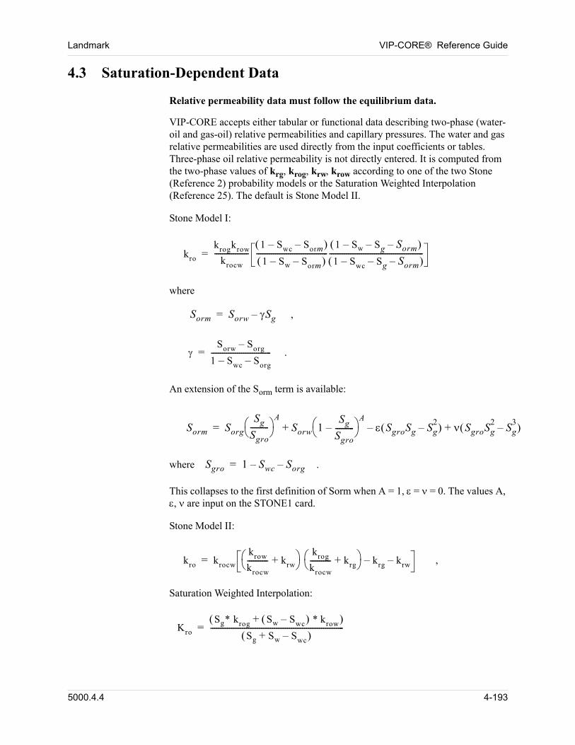
Landmark VIP-CORE® Reference Guide
4.3 Saturation-Dependent Data
00 Relative permeability data must follow the equilibrium data.
VIP-CORE accepts either tabular or functional data describing two-phase (water-oil and gas-oil) relative permeabilities and capillary pressures. The water and gas relative permeabilities are used directly from the input coefficients or tables. Three-phase oil relative permeability is not directly entered. It is computed from the two-phase values of krg, krog, krw, krow according to one of the two Stone (Reference 2) probability models or the Saturation Weighted Interpolation (Reference 25). The default is Stone Model II. 00
Stone Model I: 00
00 kro
krogkrow
krocw
------------------1 Swc Sorm–– 1 Sw Sorm––
--------------------------------------1 Sw Sg Sorm––– 1 Swc Sg–– Sorm–
--------------------------------------------------=
00 where
00 Sorm Sorw Sg–= ,
00 Sorw Sorg–
1 Swc– Sorg–--------------------------------= .
00 An extension of the Sorm term is available:
00 Sorm Sorg
Sg
Sgro----------
ASorw 1
Sg
Sgro----------–
A SgroSg Sg
2– SgroSg
2Sg
3–+–+=
00 where Sgro 1 Swc– Sorg–= .
This collapses to the first definition of Sorm when A = 1, = = 0. The values A, , are input on the STONE1 card. 00
Stone Model II: 00
00 kro krocw
krow
krocw
----------- krw+ krog
krocw
----------- krg+ krg– krw–= ,
Saturation Weighted Interpolation: 00
00 Kro
Sg* krog Sw Swc– * krow+ Sg Sw Swc–+
-----------------------------------------------------------------------=
5000.4.4 4-193
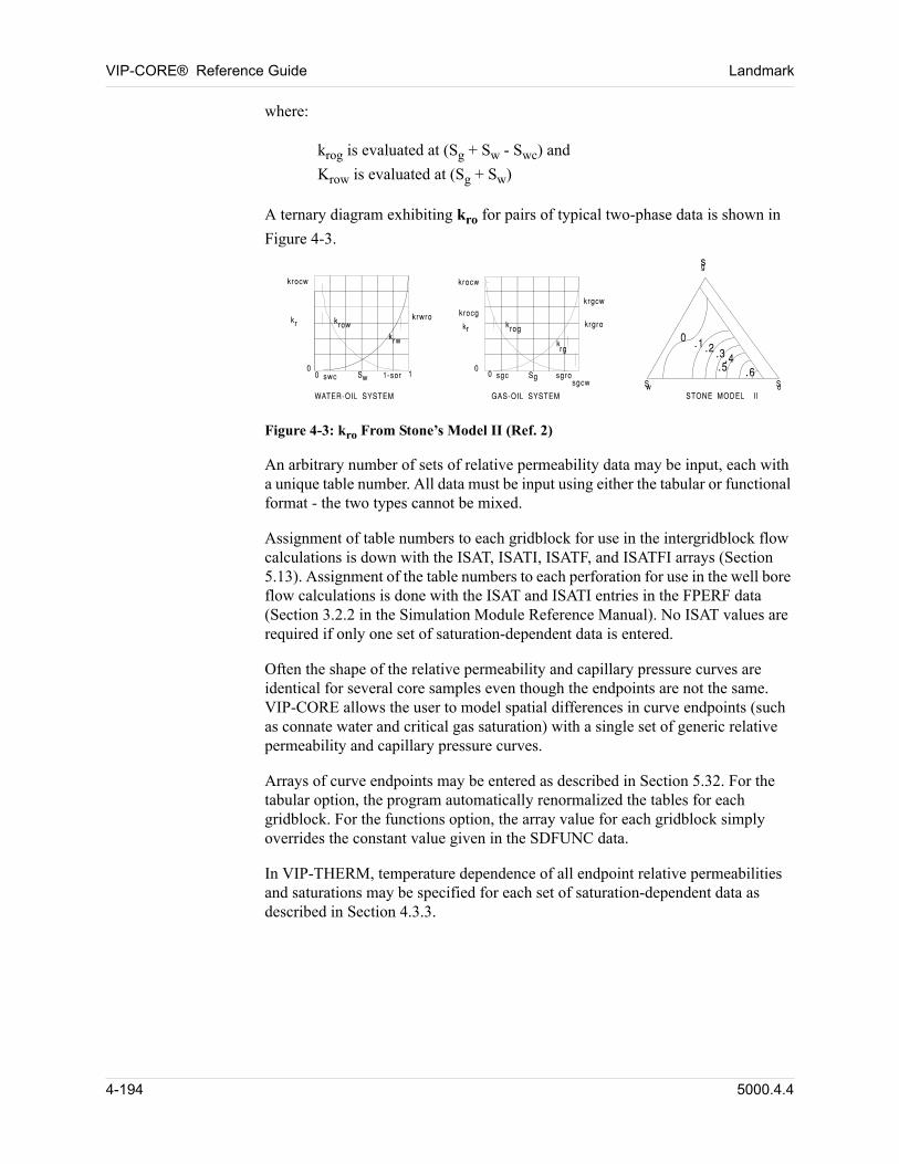
VIP-CORE® Reference Guide Landmark
where: 00
00 krog is evaluated at (Sg + Sw - Swc) andKrow is evaluated at (Sg + Sw)
00 A ternary diagram exhibiting kro for pairs of typical two-phase data is shown in
Figure 4-3.
Figure 4-3: kro From Stone’s Model II (Ref. 2)
An arbitrary number of sets of relative permeability data may be input, each with a unique table number. All data must be input using either the tabular or functional format - the two types cannot be mixed. 00
Assignment of table numbers to each gridblock for use in the intergridblock flow calculations is down with the ISAT, ISATI, ISATF, and ISATFI arrays (Section 5.13). Assignment of the table numbers to each perforation for use in the well bore flow calculations is done with the ISAT and ISATI entries in the FPERF data (Section 3.2.2 in the Simulation Module Reference Manual). No ISAT values are required if only one set of saturation-dependent data is entered. 00
Often the shape of the relative permeability and capillary pressure curves are identical for several core samples even though the endpoints are not the same. VIP-CORE allows the user to model spatial differences in curve endpoints (such as connate water and critical gas saturation) with a single set of generic relative permeability and capillary pressure curves. 00
Arrays of curve endpoints may be entered as described in Section 5.32. For the tabular option, the program automatically renormalized the tables for each gridblock. For the functions option, the array value for each gridblock simply overrides the constant value given in the SDFUNC data. 00
In VIP-THERM, temperature dependence of all endpoint relative permeabilities and saturations may be specified for each set of saturation-dependent data as described in Section 4.3.3. 00
4-194 5000.4.4
Landmark VIP-CORE® Reference Guide
4.3.1 Saturation-Dependent Tables
The saturation tables must satisfy the following requirements: 00
1. All water saturation tables must precede the gas saturation tables, which must precede the gas-water tables, if present.
2. The table numbers for both the water and gas tables must be consecutively increasing.
3. The number of water saturation tables must equal the number of gas saturation tables.
One or both of capillary pressure and relative permeability hysteresis can be represented in one or both of the water-oil and gas-oil tables, but not in the gas-water table. The user can choose to activate one, or the other, or both at once. 00
Capillary pressure hysteresis requires the following changes to the water-oil and/or gas-oil table data: 00
n Secondary drainage curves must be provided on the appropriate drainage saturation table (SWT or SGT). These are used in making the transition from the imbibition curve to the drainage curve and consequently start on the drainage curve and end at the table residual oil saturation.
n An imbibition saturation table must be provided, with the imbibition capillary pressure curve input as the primary capillary pressure.
n An ISATI array must be specified to assign imbibition tables to gridblocks (in concert with the ISAT array for drainage tables.
n PCHYSW and PCHYSG cards can optionally be specified to control scanning loop parameters for the water and gas tables, respectively.
Relative permeability hysteresis (for the relative permeability of oil in an oil-water system and/or the relative permeability of gas in a gas-oil system) requires changes to the water-oil and/or gas-oil table data. There are two options: 00
n Trapped hydrocarbon saturation. A trapped hydrocarbon saturation can be specified on the appropriate table (SOTR with SWT and SGTR with SGT). Note that this value may not be matched exactly if endpoint scaling is also employed. RPHYSO and RPHYSG cards can optionally be specified to control the method used to calculate oil and gas relative permeability hysteresis, respectively.
n Curve input. An imbibition saturation table can be provided, with the appropriate imbibition relative permeability curve input. An ISATI array must be specified to assign imbibition tables to gridblocks (in concert with the ISAT array for drainage tables). RPHYSO and RPHYSG cards can optionally be specified to control the method used to calculate oil and gas relative permeability hysteresis, respectively.
5000.4.4 4-195
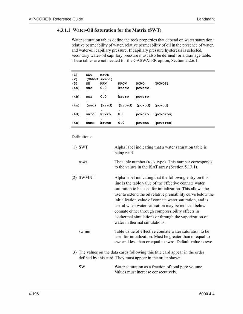
VIP-CORE® Reference Guide Landmark
4.3.1.1 Water-Oil Saturation for the Matrix (SWT)
Water saturation tables define the rock properties that depend on water saturation: relative permeability of water, relative permeability of oil in the presence of water, and water-oil capillary pressure. If capillary pressure hysteresis is selected, secondary water-oil capillary pressure must also be defined for a drainage table. These tables are not needed for the GASWATER option, Section 2.2.6.1. 00
(1) SWT nswt(2) (SWMNI swmni)(3) SW KRW KROW PCWO (PCWOS)(4a) swc 0.0 krocw pcwocw
. . . .(4b) swr 0.0 krorw pcworw
. . . .(4c) (swd) (krwd) (krowd) (pcwod) (pcwod)
. . . .(4d) swro krwro 0.0 pcworo (pcworos)
. . . .(4e) swmx krwmx 0.0 pcwomn (pcworos)
Definitions: 00
00 (1) SWT Alpha label indicating that a water saturation table is being read.
nswt The table number (rock type). This number corresponds to the values in the ISAT array (Section 5.13.1).
00 (2) SWMNI Alpha label indicating that the following entry on this line is the table value of the effective connate water saturation to be used for initialization. This allows the user to extend the oil relative premability curve below the initialization value of connate water saturation, and is useful when water saturation may be reduced below connate either through compressibility effects in isothermal simulations or through the vaporization of water in thermal simulations.
swmni Table value of effective connate water saturation to be used for initialization. Must be greater than or equal to swc and less than or equal to swro. Default value is swc.
00 (3) The values on the data cards following this title card appear in the order defined by this card. They must appear in the order shown.
SW Water saturation as a fraction of total pore volume. Values must increase consecutively.
4-196 5000.4.4
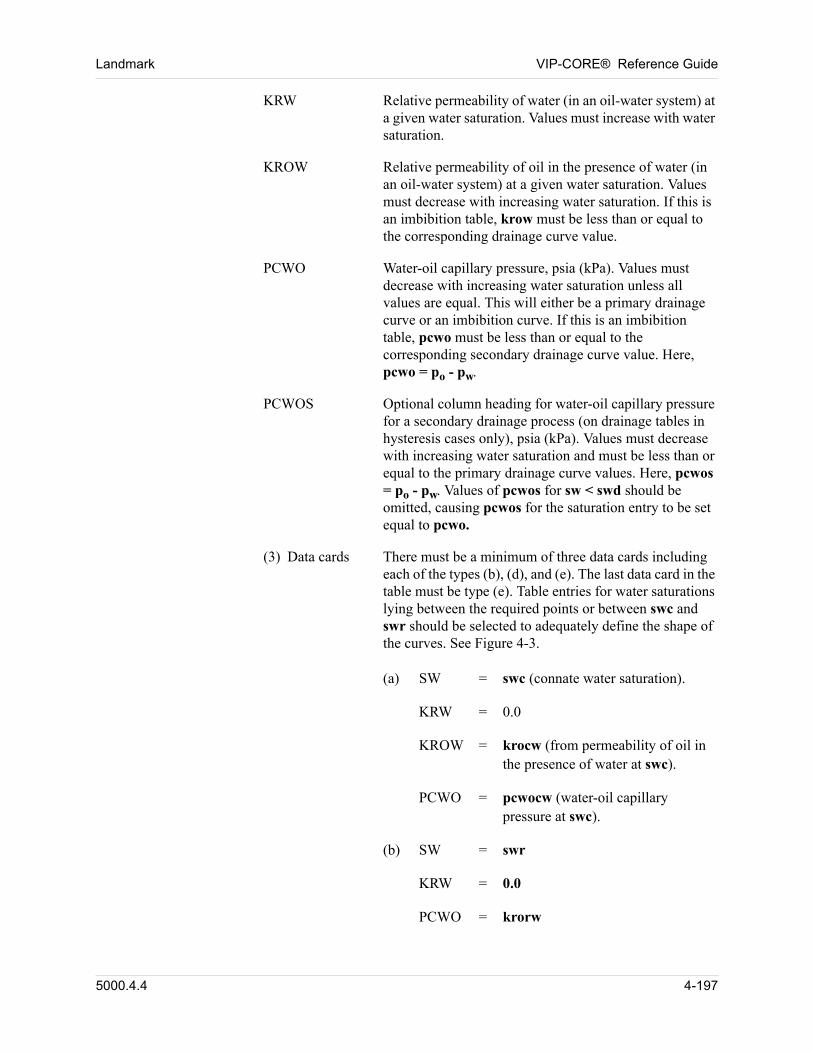
Landmark VIP-CORE® Reference Guide
KRW Relative permeability of water (in an oil-water system) at a given water saturation. Values must increase with water saturation.
KROW Relative permeability of oil in the presence of water (in an oil-water system) at a given water saturation. Values must decrease with increasing water saturation. If this is an imbibition table, krow must be less than or equal to the corresponding drainage curve value.
PCWO Water-oil capillary pressure, psia (kPa). Values must decrease with increasing water saturation unless all values are equal. This will either be a primary drainage curve or an imbibition curve. If this is an imbibition table, pcwo must be less than or equal to the corresponding secondary drainage curve value. Here, pcwo = po - pw.
PCWOS Optional column heading for water-oil capillary pressure for a secondary drainage process (on drainage tables in hysteresis cases only), psia (kPa). Values must decrease with increasing water saturation and must be less than or equal to the primary drainage curve values. Here, pcwos = po - pw. Values of pcwos for sw < swd should be omitted, causing pcwos for the saturation entry to be set equal to pcwo.
(3) Data cards There must be a minimum of three data cards including each of the types (b), (d), and (e). The last data card in the table must be type (e). Table entries for water saturations lying between the required points or between swc and swr should be selected to adequately define the shape of the curves. See Figure 4-3.
00 (a) SW = swc (connate water saturation).
00 KRW = 0.0
00 KROW = krocw (from permeability of oil in the presence of water at swc).
00 PCWO = pcwocw (water-oil capillary pressure at swc).
00 (b) SW = swr
00 KRW = 0.0
00 PCWO = krorw
5000.4.4 4-197
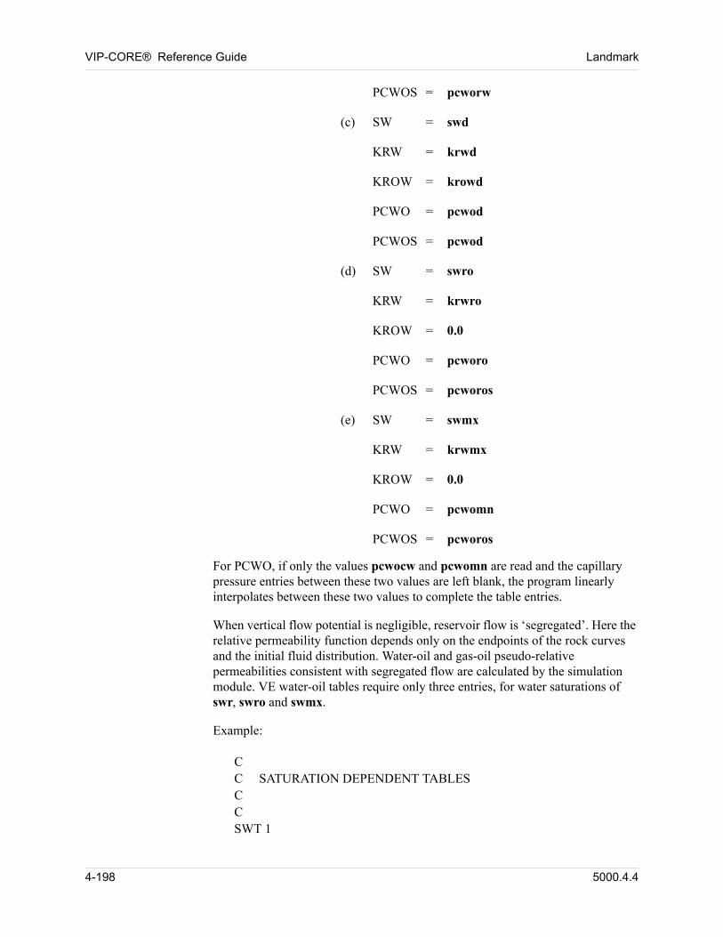
VIP-CORE® Reference Guide Landmark
00 PCWOS = pcworw
00 (c) SW = swd
00 KRW = krwd
00 KROW = krowd
00 PCWO = pcwod
00 PCWOS = pcwod
00 (d) SW = swro
00 KRW = krwro
00 KROW = 0.0
00 PCWO = pcworo
00 PCWOS = pcworos
00 (e) SW = swmx
00 KRW = krwmx
00 KROW = 0.0
00 PCWO = pcwomn
00 PCWOS = pcworos
For PCWO, if only the values pcwocw and pcwomn are read and the capillary pressure entries between these two values are left blank, the program linearly interpolates between these two values to complete the table entries. 00
When vertical flow potential is negligible, reservoir flow is ‘segregated’. Here the relative permeability function depends only on the endpoints of the rock curves and the initial fluid distribution. Water-oil and gas-oil pseudo-relative permeabilities consistent with segregated flow are calculated by the simulation module. VE water-oil tables require only three entries, for water saturations of swr, swro and swmx. 00
Example: 00
00 CC SATURATION DEPENDENT TABLESCCSWT 1
4-198 5000.4.4
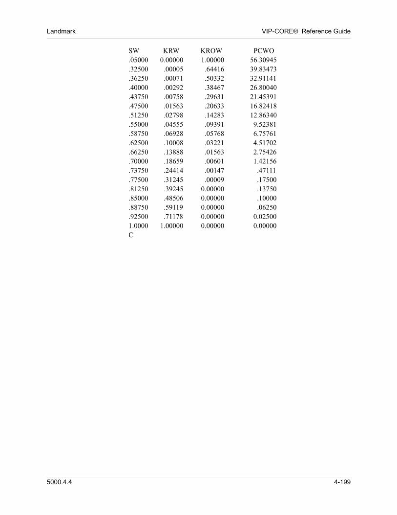
Landmark VIP-CORE® Reference Guide
SW KRW KROW PCWO.05000 0.00000 1.00000 56.30945.32500 .00005 .64416 39.83473.36250 .00071 .50332 32.91141.40000 .00292 .38467 26.80040.43750 .00758 .29631 21.45391.47500 .01563 .20633 16.82418.51250 .02798 .14283 12.86340.55000 .04555 .09391 9.52381 .58750 .06928 .05768 6.75761.62500 .10008 .03221 4.51702.66250 .13888 .01563 2.75426.70000 .18659 .00601 1.42156.73750 .24414 .00147 .47111.77500 .31245 .00009 .17500.81250 .39245 0.00000 .13750.85000 .48506 0.00000 .10000.88750 .59119 0.00000 .06250.92500 .71178 0.00000 0.025001.0000 1.00000 0.00000 0.00000C
5000.4.4 4-199
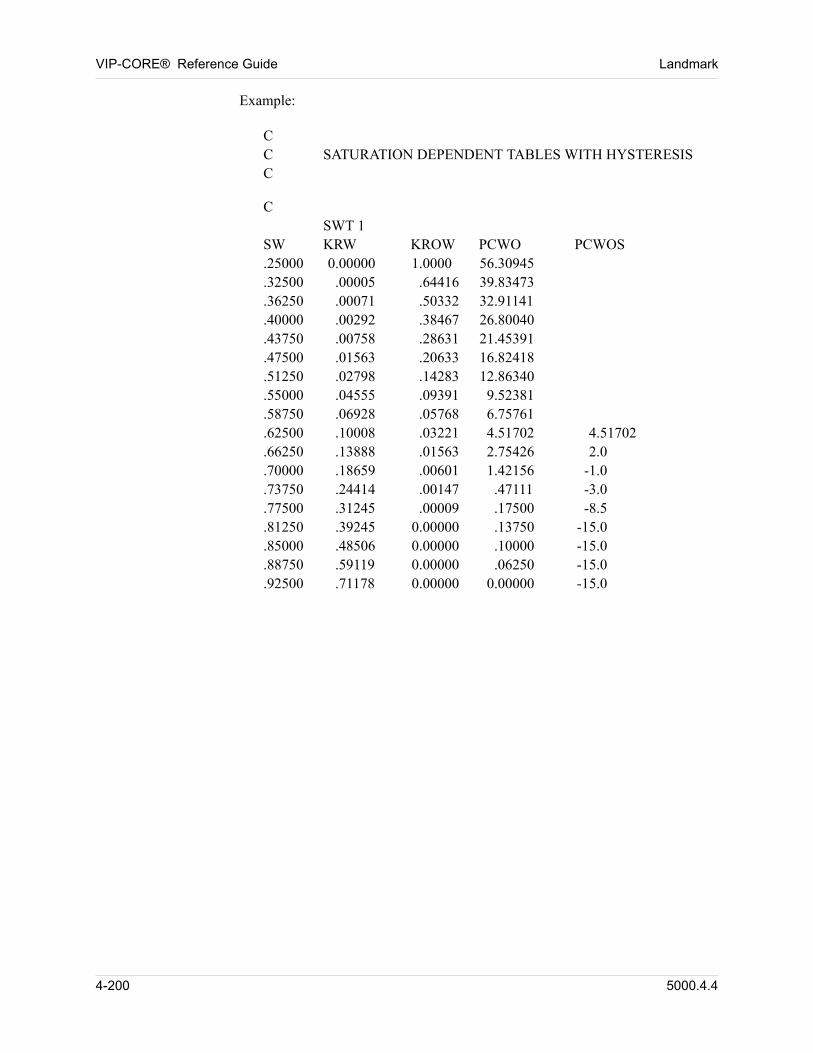
VIP-CORE® Reference Guide Landmark
00 Example:
00 CC SATURATION DEPENDENT TABLES WITH HYSTERESISC
00 CSWT 1
SW KRW KROW PCWO PCWOS.25000 0.00000 1.0000 56.30945.32500 .00005 .64416 39.83473.36250 .00071 .50332 32.91141.40000 .00292 .38467 26.80040.43750 .00758 .28631 21.45391.47500 .01563 .20633 16.82418.51250 .02798 .14283 12.86340.55000 .04555 .09391 9.52381.58750 .06928 .05768 6.75761.62500 .10008 .03221 4.51702 4.51702.66250 .13888 .01563 2.75426 2.0.70000 .18659 .00601 1.42156 -1.0.73750 .24414 .00147 .47111 -3.0.77500 .31245 .00009 .17500 -8.5.81250 .39245 0.00000 .13750 -15.0.85000 .48506 0.00000 .10000 -15.0.88750 .59119 0.00000 .06250 -15.0.92500 .71178 0.00000 0.00000 -15.0
4-200 5000.4.4
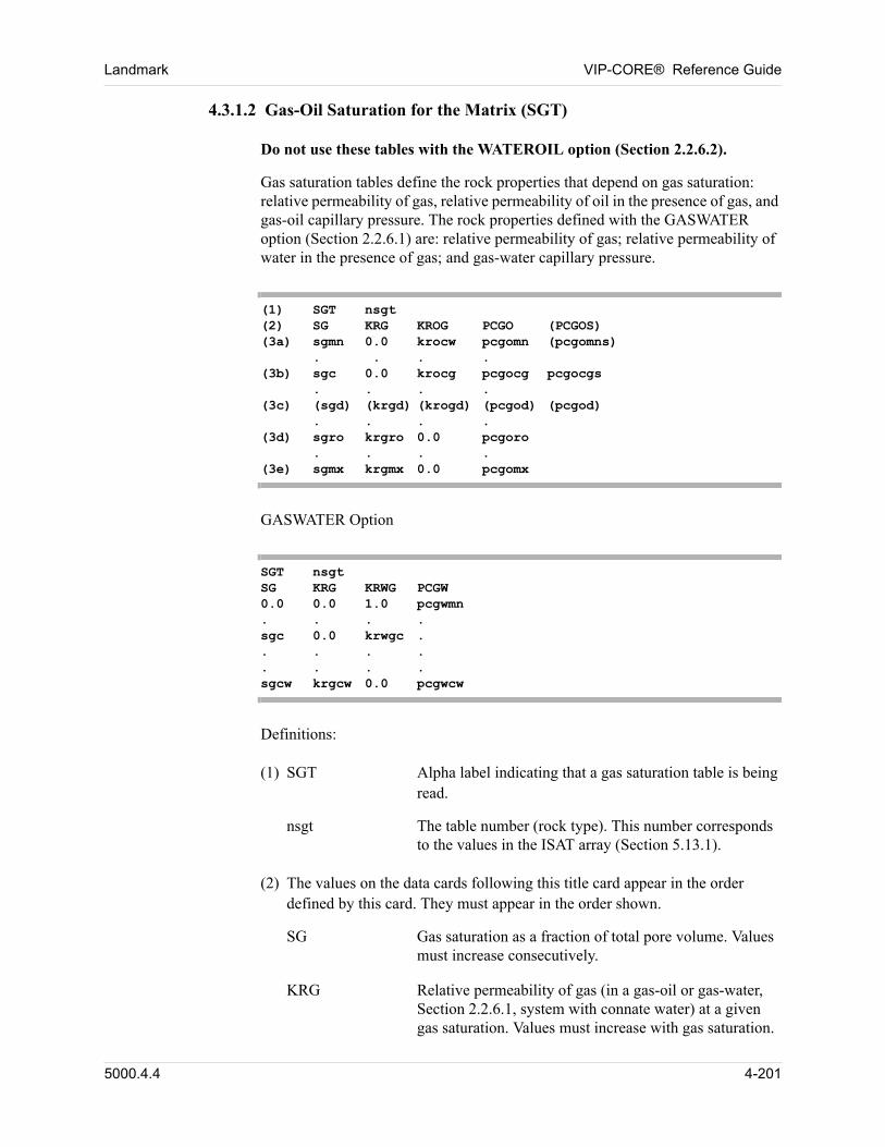
Landmark VIP-CORE® Reference Guide
4.3.1.2 Gas-Oil Saturation for the Matrix (SGT)
00 Do not use these tables with the WATEROIL option (Section 2.2.6.2).
Gas saturation tables define the rock properties that depend on gas saturation: relative permeability of gas, relative permeability of oil in the presence of gas, and gas-oil capillary pressure. The rock properties defined with the GASWATER option (Section 2.2.6.1) are: relative permeability of gas; relative permeability of water in the presence of gas; and gas-water capillary pressure. 00
(1) SGT nsgt(2) SG KRG KROG PCGO (PCGOS)(3a) sgmn 0.0 krocw pcgomn (pcgomns)
. . . .(3b) sgc 0.0 krocg pcgocg pcgocgs
. . . .(3c) (sgd) (krgd) (krogd) (pcgod) (pcgod)
. . . .(3d) sgro krgro 0.0 pcgoro
. . . .(3e) sgmx krgmx 0.0 pcgomx
GASWATER Option 00
SGT nsgtSG KRG KRWG PCGW0.0 0.0 1.0 pcgwmn. . . . sgc 0.0 krwgc .. . . .. . . .sgcw krgcw 0.0 pcgwcw
Definitions: 00
00 (1) SGT Alpha label indicating that a gas saturation table is being read.
nsgt The table number (rock type). This number corresponds to the values in the ISAT array (Section 5.13.1).
00 (2) The values on the data cards following this title card appear in the order defined by this card. They must appear in the order shown.
SG Gas saturation as a fraction of total pore volume. Values must increase consecutively.
KRG Relative permeability of gas (in a gas-oil or gas-water, Section 2.2.6.1, system with connate water) at a given gas saturation. Values must increase with gas saturation.
5000.4.4 4-201
VIP-CORE® Reference Guide Landmark
KROG Relative permeability of oil in the presence of gas (at irreducible water saturation) at a given gas saturation. Values must decrease with increasing gas saturation. If this is an imbibition table, krog must be less than or equal to the corresponding drainage curve value.
KRWG Relative permeability of water in the presence of gas at a given gas saturation. Values must decrease with increasing gas saturation.
PCGO Gas-oil capillary pressure, psia (kPa). Values must increase with increasing gas saturation unless all values are equal. If this is an imbibition table, pcgo must be less than or equal to the corresponding secondary drainage curve value. Here, pcgo = pg - po.
PCGOS Gas-oil capillary pressure for a secondary drainage process (on drainage tables in hysteresis cases), psia (kPa). Values must increase with increasing gas saturation and must be less than or equal to the primary drainage curve values. Here, pcgo = pg - po. Values for sg > sgd should be omitted, causing pcgos for the saturation entry to be set equal to pcgo.
PCGW Gas-water capillary pressure, psia (kPa). Values must increase with increasing gas saturation unless all values are equal. pcgw = pg - pw.
00 (3) Data cards A minimum of four data cards, including each of the types (a), (b), (d), and (e), is required for each gas saturation table. The first data card must be type (a),
while the last must be type (e). See Figure 4-3. For the GASWATER option, a minimum of three data cards (gas saturations of 0.0, sgc, and sgcw) is required for each table.
00 (a) SG = sgmn
00 KRG = 0.0
00 KROG = krocw (from data card (a) in the water saturation table).
00 PCGO = pcgomn (minimum gas-oil capillary pressure at SG = 0).
00 PCGOS = pcgomns
00 (b) SG = sgc
4-202 5000.4.4
Landmark VIP-CORE® Reference Guide
00 KRG = 0.0
00 KROG = krocg
00 PCGO = pcgocg
00 PCGOS = pcgocgs
00 (c) SG = sgd
00 KRG = krgd
00 KROG = krogd
00 PCGO = pcgod
00 PCGOS = pcgod
00 (d) SG = sgro (gas saturation at which oil becomes immobile, one minus the connate water saturation minus residual oil saturation to gas).
00 KRG = krgro (KRG at sgro).
00 KROG = 0.0
00 PCGO = pcgoro
00 (e) SG = sgmx
00 KRG = krgmx
00 KROG = 0.0
00 PCGO = pcgomx
For PCGO, if only the values pcgomn and pcgomx are read and the capillary pressure entries between these two values are left blank, the program linearly interpolates between these two values to complete the table entries. If capillary pressure hysteresis is selected, secondary gas-oil capillary pressure must also be defined. 00
When vertical flow potential is negligible, reservoir flow is ’segregated’. Here the relative permeability function depends only on the endpoints of the rock curves and the initial fluid distribution. Water-oil and gas-oil pseudo-relative permeabilities consistent with segregated flow are calculated by the simulation module. VE gas-oil tables require four entries: Sgmn, Sgr, Sgro, and Sgcw. Critical gas saturation is ignored in the calculation of gas-oil VE relative permeabilities. Hence the gas relative permeability is a straight line between zero
5000.4.4 4-203
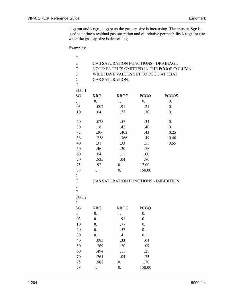
VIP-CORE® Reference Guide Landmark
at sgmn and krgro at sgro as the gas cap size is increasing. The entry at Sgr is used to define a residual gas saturation and oil relative permeability krogr for use when the gas cap size is decreasing. 00
00 Examples:
00 CC GAS SATURATION FUNCTIONS - DRAINAGEC NOTE: ENTRIES OMITTED IN THE PCGOS COLUMNC WILL HAVE VALUES SET TO PCGO AT THATC GAS SATURATION.CSGT 1SG KRG KROG PCGO PCGOS0. 0. 1. 0. 0..03 .007 .91 .21 0..10 .04 .77 .30 0.
00 .20 .075 .57 .34 0..30 .18 .42 .40 0..32 .206 .402 .43 0.25.36 .258 .366 .49 0.40.40 .31 .33 .55 0.55.50 .46 .20 .78.60 .64 .11 1.00.70 .825 .04 1.80.75 .92 0. 17.00.78 1. 0. 150.00CC GAS SATURATION FUNCTIONS - IMBIBITIONCC SGT 2C SG KRG KROG PCGO0. 0. 1. 0..03 0. .91 0..10 0. .77 0..20 0. .57 0..30 0. .4 0..40 .095 .33 .04.50 .269 .20 .09.60 .494 .11 .25.70 .761 .04 .73.75 .908 0. 1.70.78 1. 0. 150.00
4-204 5000.4.4
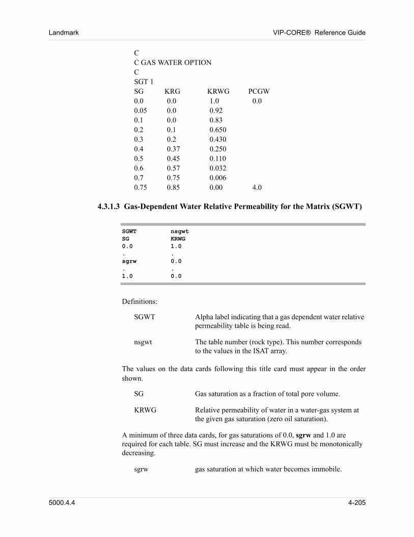
Landmark VIP-CORE® Reference Guide
00 CC GAS WATER OPTIONCSGT 1SG KRG KRWG PCGW0.0 0.0 1.0 0.00.05 0.0 0.920.1 0.0 0.830.2 0.1 0.6500.3 0.2 0.4300.4 0.37 0.2500.5 0.45 0.1100.6 0.57 0.0320.7 0.75 0.0060.75 0.85 0.00 4.0
4.3.1.3 Gas-Dependent Water Relative Permeability for the Matrix (SGWT)
SGWT nsgwtSG KRWG0.0 1.0. .sgrw 0.0. .1.0 0.0
00 Definitions:
SGWT Alpha label indicating that a gas dependent water relative permeability table is being read.
nsgwt The table number (rock type). This number corresponds to the values in the ISAT array.
00 The values on the data cards following this title card must appear in the order shown.
SG Gas saturation as a fraction of total pore volume.
KRWG Relative permeability of water in a water-gas system at the given gas saturation (zero oil saturation).
A minimum of three data cards, for gas saturations of 0.0, sgrw and 1.0 are required for each table. SG must increase and the KRWG must be monotonically decreasing. 00
sgrw gas saturation at which water becomes immobile.
5000.4.4 4-205
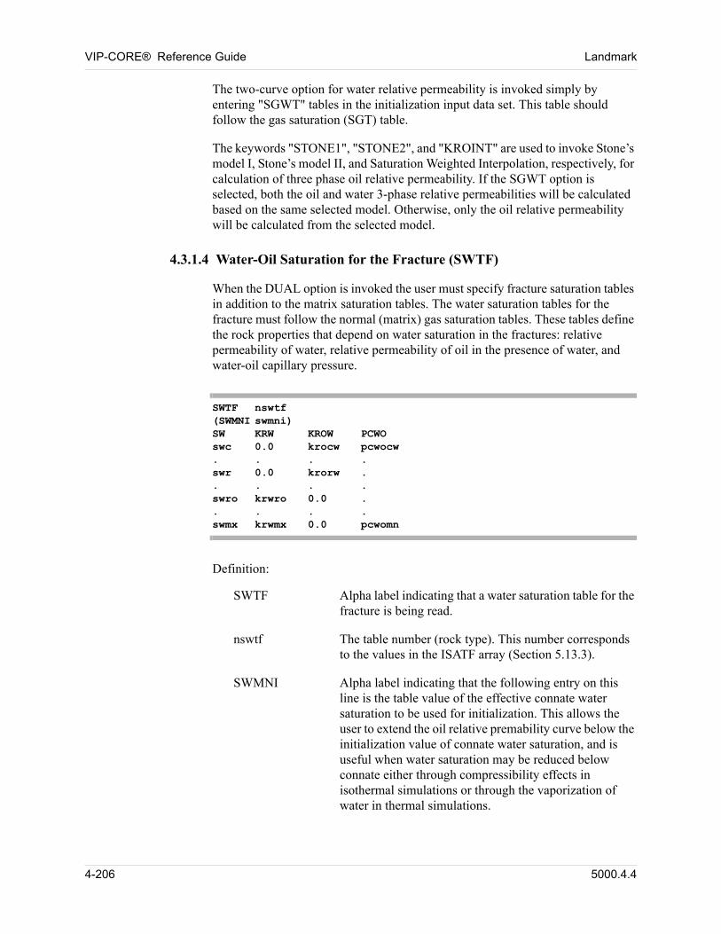
VIP-CORE® Reference Guide Landmark
The two-curve option for water relative permeability is invoked simply by entering "SGWT" tables in the initialization input data set. This table should follow the gas saturation (SGT) table. 00
The keywords "STONE1", "STONE2", and "KROINT" are used to invoke Stone’s model I, Stone’s model II, and Saturation Weighted Interpolation, respectively, for calculation of three phase oil relative permeability. If the SGWT option is selected, both the oil and water 3-phase relative permeabilities will be calculated based on the same selected model. Otherwise, only the oil relative permeability will be calculated from the selected model. 00
4.3.1.4 Water-Oil Saturation for the Fracture (SWTF)
When the DUAL option is invoked the user must specify fracture saturation tables in addition to the matrix saturation tables. The water saturation tables for the fracture must follow the normal (matrix) gas saturation tables. These tables define the rock properties that depend on water saturation in the fractures: relative permeability of water, relative permeability of oil in the presence of water, and water-oil capillary pressure. 00
SWTF nswtf(SWMNI swmni)SW KRW KROW PCWOswc 0.0 krocw pcwocw. . . .swr 0.0 krorw .. . . .swro krwro 0.0 .. . . .swmx krwmx 0.0 pcwomn
00 Definition:
SWTF Alpha label indicating that a water saturation table for the fracture is being read.
nswtf The table number (rock type). This number corresponds to the values in the ISATF array (Section 5.13.3).
SWMNI Alpha label indicating that the following entry on this line is the table value of the effective connate water saturation to be used for initialization. This allows the user to extend the oil relative premability curve below the initialization value of connate water saturation, and is useful when water saturation may be reduced below connate either through compressibility effects in isothermal simulations or through the vaporization of water in thermal simulations.
4-206 5000.4.4
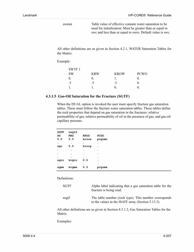
Landmark VIP-CORE® Reference Guide
swmni Table value of effective connate water saturation to be used for initialization. Must be greater than or equal to swc and less than or equal to swro. Default value is swc.
00 All other definitions are as given in Section 4.2.1, WATER Saturation Tables for the Matrix.
00 Example:
00 SWTF 1SW KRW KROW PCWO0. 0. 1. 0..5 .5 .5 0.1. 1. 0. 0.
4.3.1.5 Gas-Oil Saturation for the Fracture (SGTF)
When the DUAL option is invoked the user must specify fracture gas saturation tables. These must follow the fracture water saturation tables. These tables define the rock properties that depend on gas saturation in the fractures: relative permeability of gas, relative permeability of oil in the presence of gas, and gas-oil capillary pressure. 00
SGTF nsgtfSG KRG KROG PCGO0.0 0.0 krocw pcgomn. . . .sgc 0.0 krocg .. . . .. . . .. . . .sgro krgro 0.0 .. . . .sgmx krgmx 0.0 pcgomx
00 Definitions:
SGTF Alpha label indicating that a gas saturation table for the fracture is being read.
nsgtf The table number (rock type). This number corresponds to the values in the ISATF array (Section 5.13.3).
All other definitions are as given in Section 4.3.1.2, Gas Saturation Tables for the Matrix. 00
00 Examples:
5000.4.4 4-207
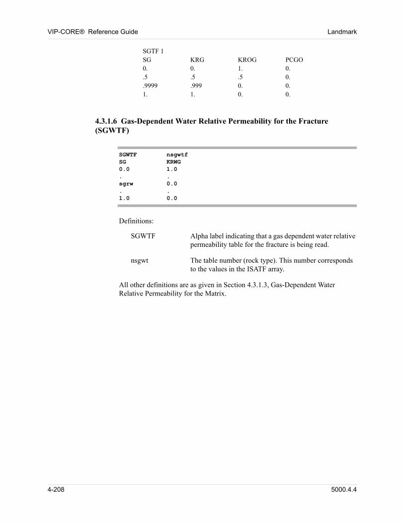
VIP-CORE® Reference Guide Landmark
00 SGTF 1SG KRG KROG PCGO0. 0. 1. 0..5 .5 .5 0..9999 .999 0. 0.1. 1. 0. 0.
4.3.1.6 Gas-Dependent Water Relative Permeability for the Fracture (SGWTF)
SGWTF nsgwtfSG KRWG0.0 1.0. .sgrw 0.0. .1.0 0.0
00 Definitions:
SGWTF Alpha label indicating that a gas dependent water relative permeability table for the fracture is being read.
nsgwt The table number (rock type). This number corresponds to the values in the ISATF array.
All other definitions are as given in Section 4.3.1.3, Gas-Dependent Water Relative Permeability for the Matrix. 00
4-208 5000.4.4
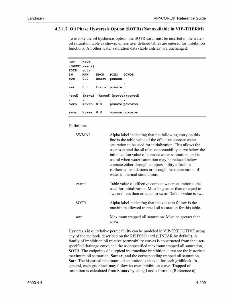
Landmark VIP-CORE® Reference Guide
4.3.1.7 Oil Phase Hysteresis Option (SOTR) (Not available in VIP-THERM)
To invoke the oil hysteresis option, the SOTR card must be inserted in the water-oil saturation table as shown, unless user defined tables are entered for imbibition functions. All other water saturation data (table entries) are unchanged. 00
SWT nswt(SWMNI swmni)SOTR sotrSW KRW KROW PCWO PCWOSswc 0.0 krocw pcwocw. . . . .swr 0.0 krorw pcworw. . . . .(swd) (krwd) (krowd)(pcwod)(pcwod). . . . .swro krwro 0.0 pcworo pcworos. . . . .swmx krwmx 0.0 pcwomn pcworos
00 Definitions:
SWMNI Alpha label indicating that the following entry on this line is the table value of the effective connate water saturation to be used for initialization. This allows the user to extend the oil relative premability curve below the initialization value of connate water saturation, and is useful when water saturation may be reduced below connate either through compressibility effects in isothermal simulations or through the vaporization of water in thermal simulations.
swmni Table value of effective connate water saturation to be used for initialization. Must be greater than or equal to swc and less than or equal to swro. Default value is swc.
SOTR Alpha label indicating that the value to follow is the maximum allowed trapped oil saturation for this table.
sotr Maximum trapped oil saturation. Must be greater than sorw.
Hysteresis in oil relative permeability can be modeled in VIP-EXECUTIVE using any of the methods described on the RPHYSO card (LINEAR by default). A family of imbibition oil relative permeability curves is constructed from the user-specified drainage curve and the user-specified maximum trapped oil saturation, SOTR. The endpoints of a typical intermediate imbibition curve are the historical maximum oil saturation, Somax, and the corresponding trapped oil saturation, Sotr. The historical maximum oil saturation is tracked for each gridblock. In general, each gridblock may follow its own imbibition curve. Trapped oil saturation is calculated from Somax by using Land’s formula (Reference 6). 00
5000.4.4 4-209
VIP-CORE® Reference Guide Landmark
00 Sotr = Somax / [ 1 + (C * Somax) ],
00 where C is Land’s constant C, given by:
00 C = [ (1 -Swc) -Sotr] / [ Sotr * (1 -Swc) ]
Carlson’s approach assumes the imbibition oil relative permeability is equal to the drainage oil relative permeability evaluated at the ’free’ or continuous oil saturation, Sodr: 00
00 krowi(1-So) = krowd(1-Sodr),
00 where the free oil saturation, Sodr, is defined as
00 Sodr = 1/2[(So-Sotr) + [(So-Sotr)**2 + 4*C*(So-Sotr)]**1/2]
4-210 5000.4.4
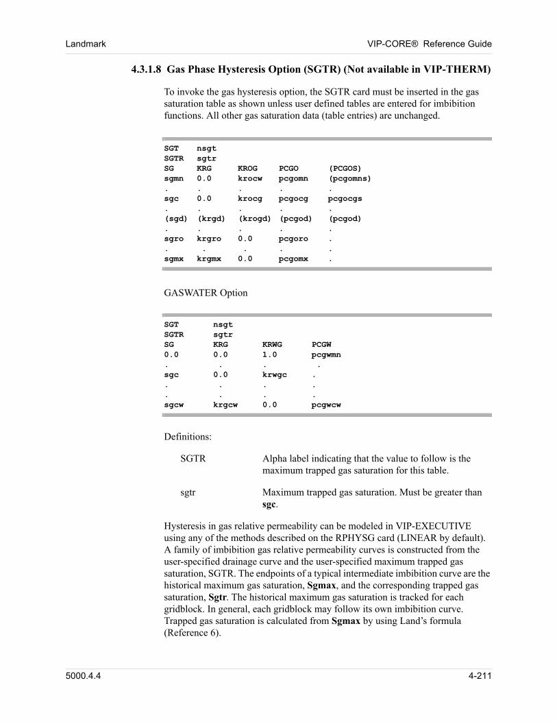
Landmark VIP-CORE® Reference Guide
4.3.1.8 Gas Phase Hysteresis Option (SGTR) (Not available in VIP-THERM)
To invoke the gas hysteresis option, the SGTR card must be inserted in the gas saturation table as shown unless user defined tables are entered for imbibition functions. All other gas saturation data (table entries) are unchanged. 00
SGT nsgtSGTR sgtrSG KRG KROG PCGO (PCGOS)sgmn 0.0 krocw pcgomn (pcgomns). . . . .sgc 0.0 krocg pcgocg pcgocgs. . . . .(sgd) (krgd) (krogd) (pcgod) (pcgod). . . . .sgro krgro 0.0 pcgoro .. . . . .sgmx krgmx 0.0 pcgomx .
00 GASWATER Option
SGT nsgtSGTR sgtrSG KRG KRWG PCGW0.0 0.0 1.0 pcgwmn. . . .sgc 0.0 krwgc .. . . .. . . .sgcw krgcw 0.0 pcgwcw
00 Definitions:
SGTR Alpha label indicating that the value to follow is the maximum trapped gas saturation for this table.
sgtr Maximum trapped gas saturation. Must be greater than sgc.
Hysteresis in gas relative permeability can be modeled in VIP-EXECUTIVE using any of the methods described on the RPHYSG card (LINEAR by default). A family of imbibition gas relative permeability curves is constructed from the user-specified drainage curve and the user-specified maximum trapped gas saturation, SGTR. The endpoints of a typical intermediate imbibition curve are the historical maximum gas saturation, Sgmax, and the corresponding trapped gas saturation, Sgtr. The historical maximum gas saturation is tracked for each gridblock. In general, each gridblock may follow its own imbibition curve. Trapped gas saturation is calculated from Sgmax by using Land’s formula (Reference 6). 00
5000.4.4 4-211
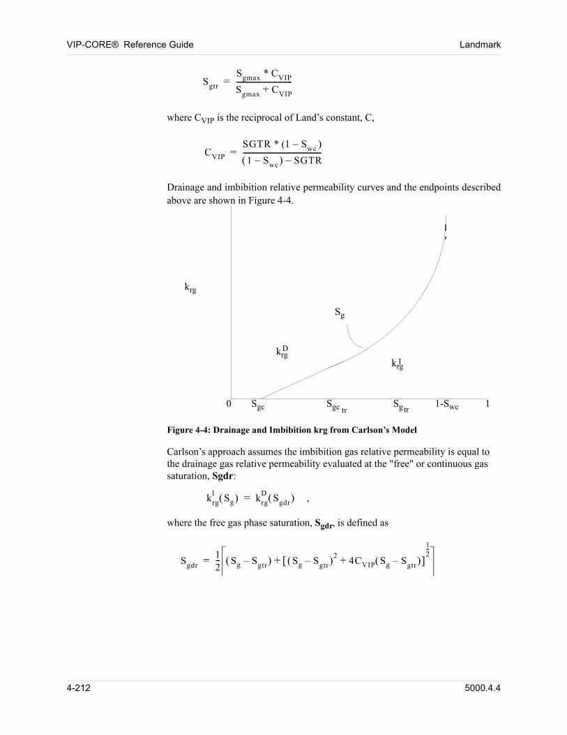
VIP-CORE® Reference Guide Landmark
Sgtr
Sgmax * CVIP
Sgmax CVIP+------------------------------=
where CVIP is the reciprocal of Land’s constant, C,
CVIP
SGTR * (1 Swc –
1 Swc– SGTR–------------------------------------------=
Drainage and imbibition relative permeability curves and the endpoints described above are shown in Figure 4-4.
krg
Sg
Sgc Sgc Sg 1-Swc 10trtr
krgkrg
D
I
Figure 4-4: Drainage and Imbibition krg from Carlson’s Model
Carlson’s approach assumes the imbibition gas relative permeability is equal to the drainage gas relative permeability evaluated at the "free" or continuous gas saturation, Sgdr: 00
krgl
Sg krgD
Sgdr = ,
where the free gas phase saturation, Sgdr, is defined as
Sgdr12-- Sg Sgtr– Sg Sgtr– 2
4CVIP Sg Sgtr– + 12--
+=
4-212 5000.4.4
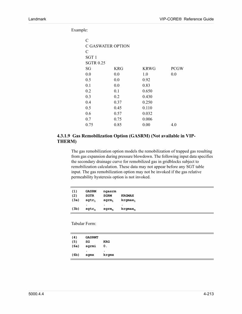
Landmark VIP-CORE® Reference Guide
00 Example:
00 CC GASWATER OPTIONCSGT 1SGTR 0.25SG KRG KRWG PCGW0.0 0.0 1.0 0.00.5 0.0 0.92 0.1 0.0 0.830.2 0.1 0.650 0.3 0.2 0.4300.4 0.37 0.2500.5 0.45 0.1100.6 0.57 0.0320.7 0.75 0.0060.75 0.85 0.00 4.0
4.3.1.9 Gas Remobilization Option (GASRM) (Not available in VIP-THERM)
The gas remobilization option models the remobilization of trapped gas resulting from gas expansion during pressure blowdown. The following input data specifies the secondary drainage curve for remobilized gas in gridblocks subject to remobilization calculation. These data may not appear before any SGT table input. The gas remobilization option may not be invoked if the gas relative permeability hysteresis option is not invoked. 00
(1) GASRM ngasrm(2) SGTR SGRM KRGMAX(3a) sgtr1 sgrm1 krgmax1
. . .(3b) sgtrn sgrmn krgmaxn
00 Tabular Form:
(4) GASRMT(5) SG KRG(6a) sgrmi 0.
. .(6b) sgmx krgmx
5000.4.4 4-213
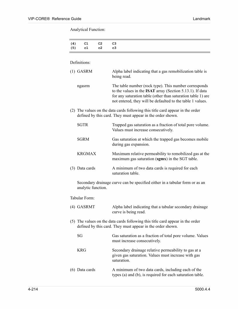
VIP-CORE® Reference Guide Landmark
00 Analytical Function:
(4) C1 C2 C3(5) c1 c2 c3
00 Definitions:
00 (1) GASRM Alpha label indicating that a gas remobilization table is being read.
ngasrm The table number (rock type). This number corresponds to the values in the ISAT array (Section 5.13.1). If data for any saturation table (other than saturation table 1) are not entered, they will be defaulted to the table 1 values.
00 (2) The values on the data cards following this title card appear in the order defined by this card. They must appear in the order shown.
SGTR Trapped gas saturation as a fraction of total pore volume. Values must increase consecutively.
SGRM Gas saturation at which the trapped gas becomes mobile during gas expansion.
KRGMAX Maximum relative permeability to remobilized gas at the maximum gas saturation (sgmx) in the SGT table.
00 (3) Data cards A minimum of two data cards is required for each saturation table.
00 Secondary drainage curve can be specified either in a tabular form or as an analytic function.
00 Tabular Form:
00 (4) GASRMT Alpha label indicating that a tabular secondary drainage curve is being read.
00 (5) The values on the data cards following this title card appear in the order defined by this card. They must appear in the order shown.
SG Gas saturation as a fraction of total pore volume. Values must increase consecutively.
KRG Secondary drainage relative permeability to gas at a given gas saturation. Values must increase with gas saturation.
00 (6) Data cards A minimum of two data cards, including each of the types (a) and (b), is required for each saturation table.
4-214 5000.4.4
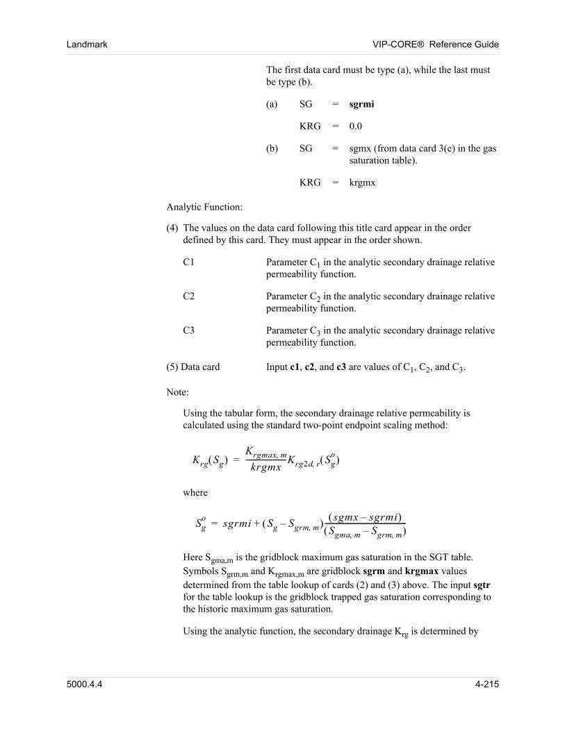
Landmark VIP-CORE® Reference Guide
The first data card must be type (a), while the last must be type (b).
(a) SG = sgrmi
KRG = 0.0
(b) SG = sgmx (from data card 3(e) in the gas saturation table).
KRG = krgmx
00 Analytic Function:
00 (4) The values on the data card following this title card appear in the order defined by this card. They must appear in the order shown.
C1 Parameter C1 in the analytic secondary drainage relative permeability function.
C2 Parameter C2 in the analytic secondary drainage relative permeability function.
C3 Parameter C3 in the analytic secondary drainage relative permeability function.
00 (5) Data card Input c1, c2, and c3 are values of C1, C2, and C3.
00 Note:
Using the tabular form, the secondary drainage relative permeability is calculated using the standard two-point endpoint scaling method:
Krg Sg Krgmax m
krgmx----------------------Krg2d r Sg
o =
00 where
Sgo
sgrmi Sg Sgrm m– sgmx sgrmi– Sgma m Sgrm m–
--------------------------------------------+=
00 Here Sgma,m is the gridblock maximum gas saturation in the SGT table. Symbols Sgrm,m and Krgmax,m are gridblock sgrm and krgmax values determined from the table lookup of cards (2) and (3) above. The input sgtr for the table lookup is the gridblock trapped gas saturation corresponding to the historic maximum gas saturation.
00 Using the analytic function, the secondary drainage Krg is determined by
5000.4.4 4-215
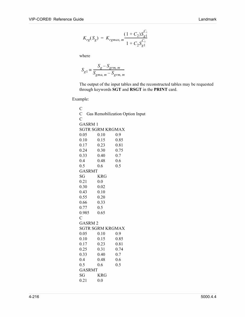
VIP-CORE® Reference Guide Landmark
00 Krg Sg Krgmax m1 C2+ Sg1
C1
1 C2Sg1C3+
-----------------------------=
00 where
Sg1
Sg Sgrm m–
Sgma m Sgrm m–---------------------------------------
00 The output of the input tables and the reconstructed tables may be requested through keywords SGT and RSGT in the PRINT card.
00 Example:
CC Gas Remobilization Option InputCGASRM 1SGTR SGRM KRGMAX0.05 0.10 0.90.10 0.15 0.850.17 0.23 0.810.24 0.30 0.750.33 0.40 0.70.4 0.48 0.60.5 0.6 0.5GASRMTSG KRG0.21 0.00.30 0.020.43 0.100.55 0.200.66 0.330.77 0.50.985 0.65CGASRM 2SGTR SGRM KRGMAX0.05 0.10 0.90.10 0.15 0.850.17 0.23 0.810.25 0.31 0.740.33 0.40 0.70.4 0.48 0.60.5 0.6 0.5GASRMTSG KRG0.21 0.0
4-216 5000.4.4
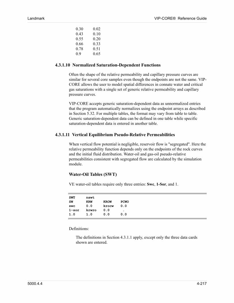
Landmark VIP-CORE® Reference Guide
0.30 0.020.43 0.100.55 0.200.66 0.330.78 0.510.9 0.65
4.3.1.10 Normalized Saturation-Dependent Functions
Often the shape of the relative permeability and capillary pressure curves are similar for several core samples even though the endpoints are not the same. VIP-CORE allows the user to model spatial differences in connate water and critical gas saturations with a single set of generic relative permeability and capillary pressure curves. 00
VIP-CORE accepts generic saturation-dependent data as unnormalized entries that the program automatically normalizes using the endpoint arrays as described in Section 5.32. For multiple tables, the format may vary from table to table. Generic saturation-dependent data can be defined in one table while specific saturation-dependent data is entered in another table. 00
4.3.1.11 Vertical Equilibrium Pseudo-Relative Permeabilities
When vertical flow potential is negligible, reservoir flow is "segregated". Here the relative permeability function depends only on the endpoints of the rock curves and the initial fluid distribution. Water-oil and gas-oil pseudo-relative permeabilities consistent with segregated flow are calculated by the simulation module. 00
Water-Oil Tables (SWT) 00
00 VE water-oil tables require only three entries: Swc, 1-Sor, and 1.
SWT nswtSW KRW KROW PCWOswc 0.0 krocw 0.01-sor krwro 0.0 .1.0 1.0 0.0 0.0
00 Definitions:
The definitions in Section 4.3.1.1 apply, except only the three data cards shown are entered.
5000.4.4 4-217
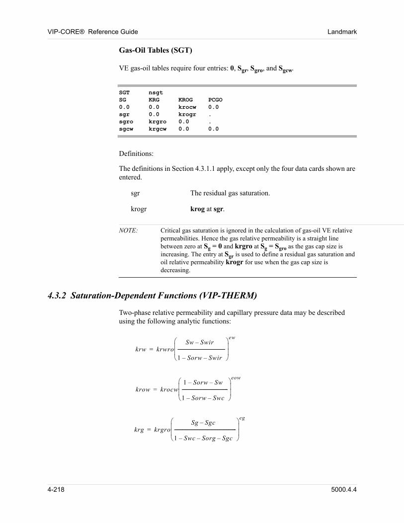
VIP-CORE® Reference Guide Landmark
Gas-Oil Tables (SGT) 00
00 VE gas-oil tables require four entries: 0, Sgr, Sgro, and Sgcw.
SGT nsgtSG KRG KROG PCGO0.0 0.0 krocw 0.0sgr 0.0 krogr .sgro krgro 0.0 .sgcw krgcw 0.0 0.0
00 Definitions:
The definitions in Section 4.3.1.1 apply, except only the four data cards shown are entered. 00
sgr The residual gas saturation.
krogr krog at sgr.
NOTE: Critical gas saturation is ignored in the calculation of gas-oil VE relative permeabilities. Hence the gas relative permeability is a straight line between zero at Sg = 0 and krgro at Sg = Sgro as the gas cap size is increasing. The entry at Sgr is used to define a residual gas saturation and oil relative permeability krogr for use when the gas cap size is decreasing.
4.3.2 Saturation-Dependent Functions (VIP-THERM)
Two-phase relative permeability and capillary pressure data may be described using the following analytic functions:
krw krwroSw Swir–
1 Sorw– Swir–-------------------------------------------
ew
=
krow krocw1 Sorw– Sw–
1 Sorw– Swc–------------------------------------------
eow
=
krg krgroSg Sgc–
1 Swc– Sorg– Sgc–--------------------------------------------------------
eg
=
4-218 5000.4.4
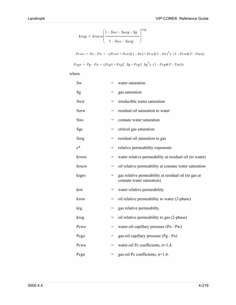
Landmark VIP-CORE® Reference Guide
krog krocw1 Swc– Sorg– Sg–
1 Swc– Sorg–-----------------------------------------------------
eog
=
Pcwo Po Pw– Pcw1 Pcw2 1 Sw– Pcw3 1 Sw– 3+ + 1 Pcw4 T Tini– – –= =
Pcgo Pg Po– Pcg1 Pcg2 Sg Pcg3 Sg3
+ + 1 Pcg4 T Tini– – = =
where
Sw = water saturation
Sg = gas saturation
Swir = irreducible water saturation
Sorw = residual oil saturation to water
Swc = connate water saturation
Sgc = critical gas saturation
Sorg = residual oil saturation to gas
e* = relative permeability exponents
krwro = water relative permeability at residual oil (to water)
krocw = oil relative permeability at connate water saturation
krgro = gas relative permeability at residual oil (to gas at connate water saturation)
krw = water relative permeability
krow = oil relative permeability to water (2-phase)
krg = gas relative permeabilty.
krog = oil relative permeability to gas (2-phase)
Pcwo = water-oil capillary pressure (Po - Pw)
Pcgo = gas-oil capillary pressure (Pg - Po)
Pcwn = water-oil Pc coefficients, n=1,4.
Pcgn = gas-oil Pc coefficients, n=1,4.
5000.4.4 4-219
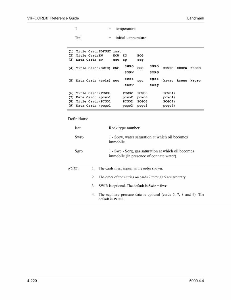
VIP-CORE® Reference Guide Landmark
T = temperature
Tini = initial temperature
(1) Title Card:SDFUNC isat(2) Title Card:EW EOW EG EOG(3) Data Card: ew eow eg eog(4) Title Card:(SWIR) SWC SWRO
SORWSGC SGRO
SORGKRWRO KROCW KRGRO
(5) Data Card: (swir) swc swro
sorwsgc sgro
sorgkrwro krocw krgro
(6) Title Card:(PCWO1 PCWO2 PCWO3 PCWO4)(7) Data Card: (pcwo1 pcwo2 pcwo3 pcwo4)(8) Title Card:(PCGO1 PCGO2 PCGO3 PCGO4)(9) Data Card: (pcgo1 pcgo2 pcgo3 pcgo4)
Definitions:
isat Rock type number.
Swro 1 - Sorw, water saturation at which oil becomes immobile.
Sgro 1 - Swc - Sorg, gas saturation at which oil becomes immobile (in presence of connate water).
NOTE: 1. The cards must appear in the order shown.
2. The order of the entries on cards 2 through 5 are arbitrary.
3. SWIR is optional. The default is Swir = Swc.
4. The capillary pressure data is optional (cards 6, 7, 8 and 9). The default is Pc = 0.
4-220 5000.4.4
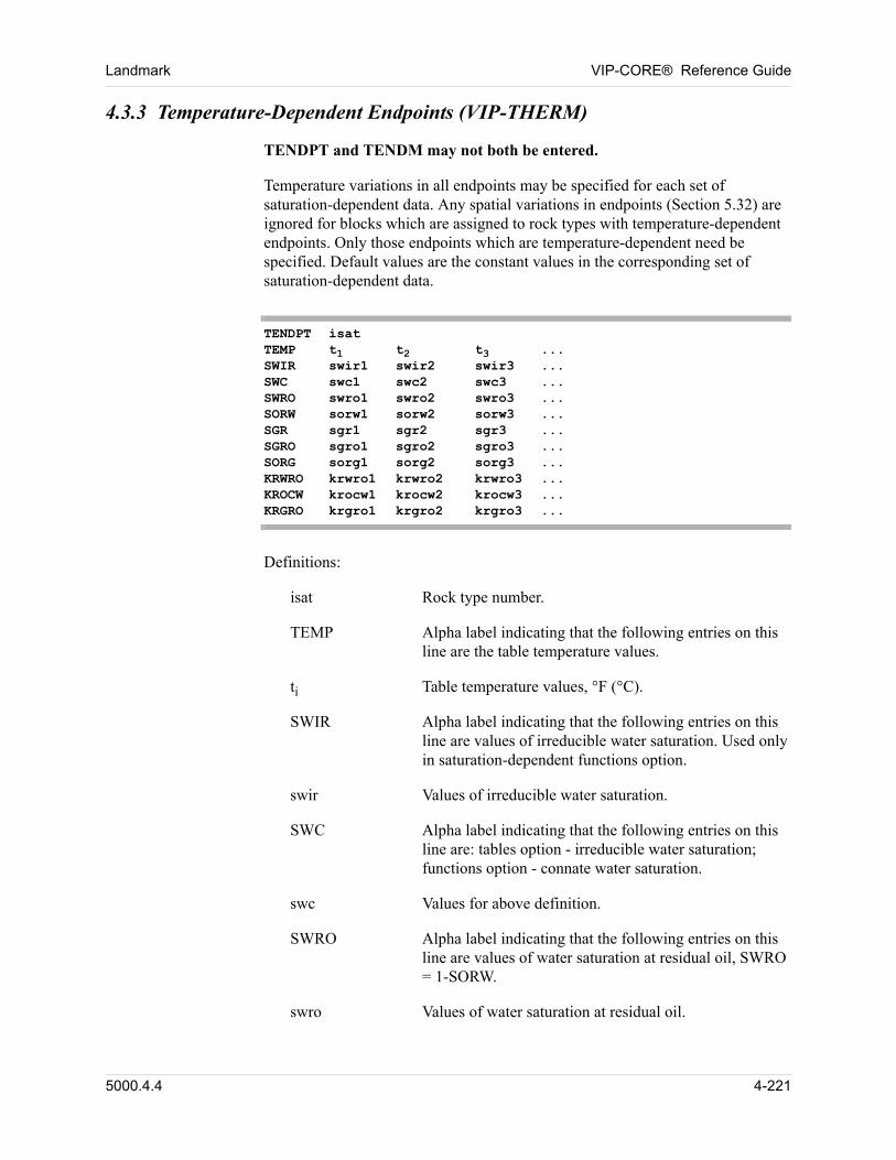
Landmark VIP-CORE® Reference Guide
4.3.3 Temperature-Dependent Endpoints (VIP-THERM)
TENDPT and TENDM may not both be entered.
Temperature variations in all endpoints may be specified for each set of saturation-dependent data. Any spatial variations in endpoints (Section 5.32) are ignored for blocks which are assigned to rock types with temperature-dependent endpoints. Only those endpoints which are temperature-dependent need be specified. Default values are the constant values in the corresponding set of saturation-dependent data.
TENDPT isatTEMP t1 t2 t3 ...SWIR swir1 swir2 swir3 ...SWC swc1 swc2 swc3 ...SWRO swro1 swro2 swro3 ...SORW sorw1 sorw2 sorw3 ...SGR sgr1 sgr2 sgr3 ...SGRO sgro1 sgro2 sgro3 ...SORG sorg1 sorg2 sorg3 ...KRWRO krwro1 krwro2 krwro3 ...KROCW krocw1 krocw2 krocw3 ...KRGRO krgro1 krgro2 krgro3 ...
Definitions:
isat Rock type number.
TEMP Alpha label indicating that the following entries on this line are the table temperature values.
ti Table temperature values, °F (°C).
SWIR Alpha label indicating that the following entries on this line are values of irreducible water saturation. Used only in saturation-dependent functions option.
swir Values of irreducible water saturation.
SWC Alpha label indicating that the following entries on this line are: tables option - irreducible water saturation; functions option - connate water saturation.
swc Values for above definition.
SWRO Alpha label indicating that the following entries on this line are values of water saturation at residual oil, SWRO = 1-SORW.
swro Values of water saturation at residual oil.
5000.4.4 4-221
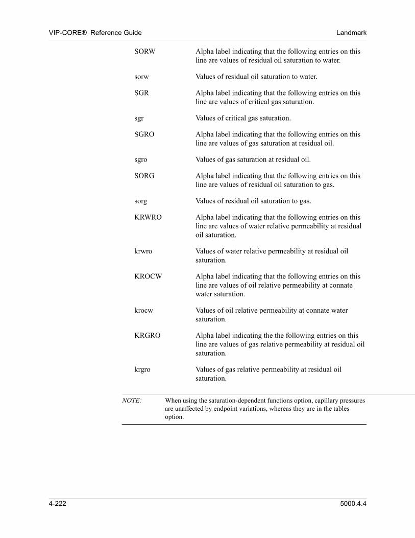
VIP-CORE® Reference Guide Landmark
SORW Alpha label indicating that the following entries on this line are values of residual oil saturation to water.
sorw Values of residual oil saturation to water.
SGR Alpha label indicating that the following entries on this line are values of critical gas saturation.
sgr Values of critical gas saturation.
SGRO Alpha label indicating that the following entries on this line are values of gas saturation at residual oil.
sgro Values of gas saturation at residual oil.
SORG Alpha label indicating that the following entries on this line are values of residual oil saturation to gas.
sorg Values of residual oil saturation to gas.
KRWRO Alpha label indicating that the following entries on this line are values of water relative permeability at residual oil saturation.
krwro Values of water relative permeability at residual oil saturation.
KROCW Alpha label indicating that the following entries on this line are values of oil relative permeability at connate water saturation.
krocw Values of oil relative permeability at connate water saturation.
KRGRO Alpha label indicating the the following entries on this line are values of gas relative permeability at residual oil saturation.
krgro Values of gas relative permeability at residual oil saturation.
NOTE: When using the saturation-dependent functions option, capillary pressures are unaffected by endpoint variations, whereas they are in the tables option.
4-222 5000.4.4
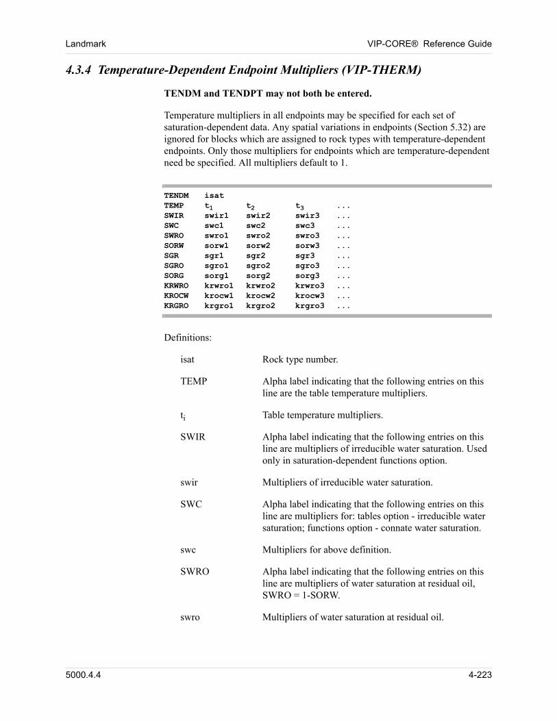
Landmark VIP-CORE® Reference Guide
4.3.4 Temperature-Dependent Endpoint Multipliers (VIP-THERM)
TENDM and TENDPT may not both be entered.
Temperature multipliers in all endpoints may be specified for each set of saturation-dependent data. Any spatial variations in endpoints (Section 5.32) are ignored for blocks which are assigned to rock types with temperature-dependent endpoints. Only those multipliers for endpoints which are temperature-dependent need be specified. All multipliers default to 1.
TENDM isatTEMP t1 t2 t3 ...SWIR swir1 swir2 swir3 ...SWC swc1 swc2 swc3 ...SWRO swro1 swro2 swro3 ...SORW sorw1 sorw2 sorw3 ...SGR sgr1 sgr2 sgr3 ...SGRO sgro1 sgro2 sgro3 ...SORG sorg1 sorg2 sorg3 ...KRWRO krwro1 krwro2 krwro3 ...KROCW krocw1 krocw2 krocw3 ...KRGRO krgro1 krgro2 krgro3 ...
Definitions:
isat Rock type number.
TEMP Alpha label indicating that the following entries on this line are the table temperature multipliers.
ti Table temperature multipliers.
SWIR Alpha label indicating that the following entries on this line are multipliers of irreducible water saturation. Used only in saturation-dependent functions option.
swir Multipliers of irreducible water saturation.
SWC Alpha label indicating that the following entries on this line are multipliers for: tables option - irreducible water saturation; functions option - connate water saturation.
swc Multipliers for above definition.
SWRO Alpha label indicating that the following entries on this line are multipliers of water saturation at residual oil, SWRO = 1-SORW.
swro Multipliers of water saturation at residual oil.
5000.4.4 4-223
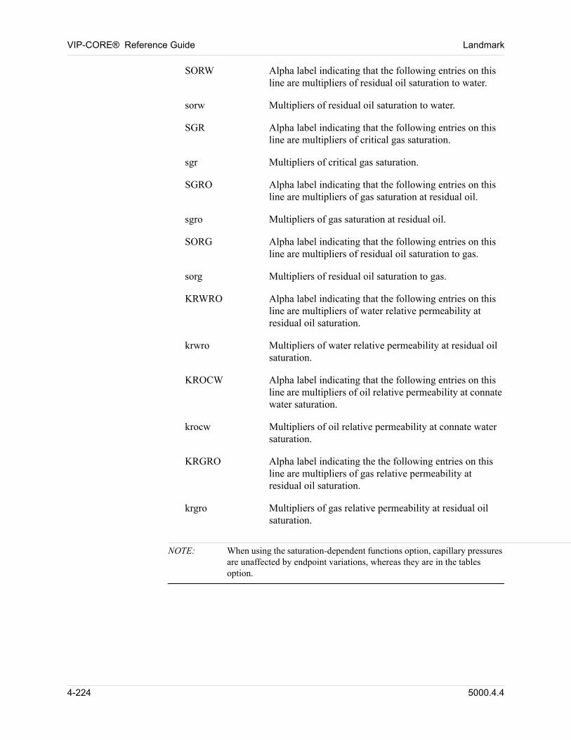
VIP-CORE® Reference Guide Landmark
SORW Alpha label indicating that the following entries on this line are multipliers of residual oil saturation to water.
sorw Multipliers of residual oil saturation to water.
SGR Alpha label indicating that the following entries on this line are multipliers of critical gas saturation.
sgr Multipliers of critical gas saturation.
SGRO Alpha label indicating that the following entries on this line are multipliers of gas saturation at residual oil.
sgro Multipliers of gas saturation at residual oil.
SORG Alpha label indicating that the following entries on this line are multipliers of residual oil saturation to gas.
sorg Multipliers of residual oil saturation to gas.
KRWRO Alpha label indicating that the following entries on this line are multipliers of water relative permeability at residual oil saturation.
krwro Multipliers of water relative permeability at residual oil saturation.
KROCW Alpha label indicating that the following entries on this line are multipliers of oil relative permeability at connate water saturation.
krocw Multipliers of oil relative permeability at connate water saturation.
KRGRO Alpha label indicating the the following entries on this line are multipliers of gas relative permeability at residual oil saturation.
krgro Multipliers of gas relative permeability at residual oil saturation.
NOTE: When using the saturation-dependent functions option, capillary pressures are unaffected by endpoint variations, whereas they are in the tables option.
4-224 5000.4.4
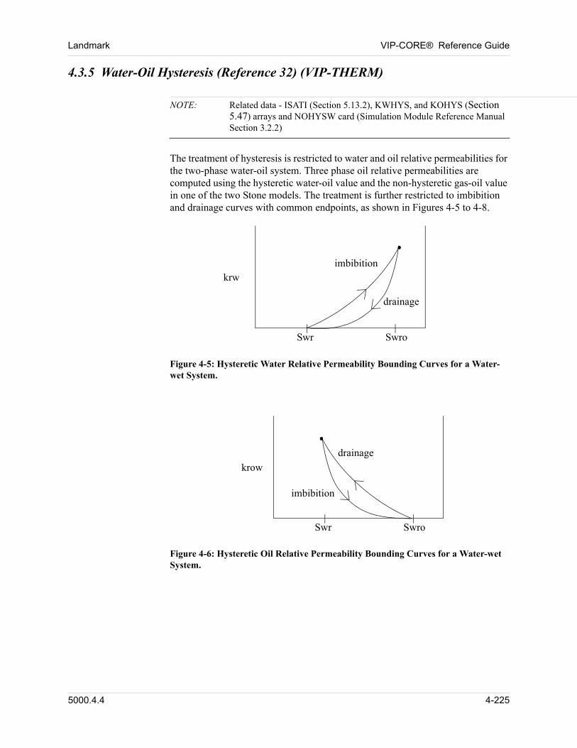
Landmark VIP-CORE® Reference Guide
4.3.5 Water-Oil Hysteresis (Reference 32) (VIP-THERM)
NOTE: Related data - ISATI (Section 5.13.2), KWHYS, and KOHYS (Section 5.47) arrays and NOHYSW card (Simulation Module Reference Manual Section 3.2.2)
The treatment of hysteresis is restricted to water and oil relative permeabilities for the two-phase water-oil system. Three phase oil relative permeabilities are computed using the hysteretic water-oil value and the non-hysteretic gas-oil value in one of the two Stone models. The treatment is further restricted to imbibition and drainage curves with common endpoints, as shown in Figures 4-5 to 4-8.
drainage
imbibition
SwroSwr
krw
Figure 4-5: Hysteretic Water Relative Permeability Bounding Curves for a Water-wet System.
drainage
imbibition
SwroSwr
krow
Figure 4-6: Hysteretic Oil Relative Permeability Bounding Curves for a Water-wet System.
5000.4.4 4-225
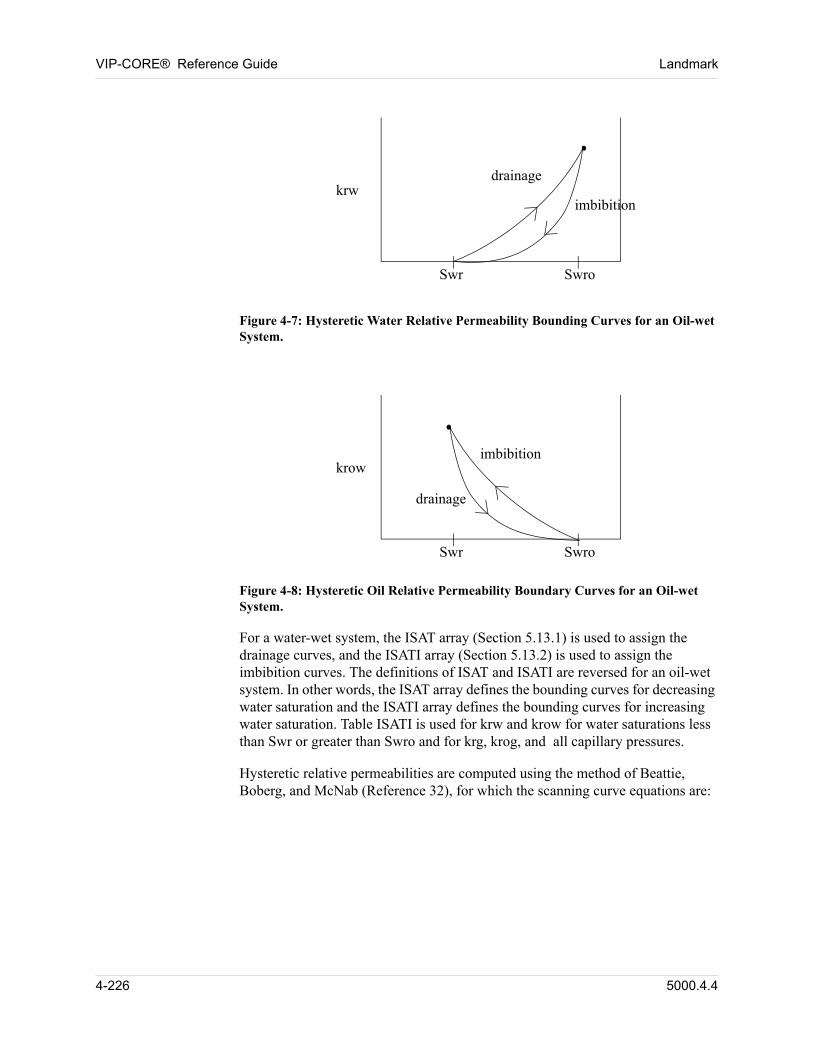
VIP-CORE® Reference Guide Landmark
drainage
imbibition
SwroSwr
krw
Figure 4-7: Hysteretic Water Relative Permeability Bounding Curves for an Oil-wet System.
drainage
imbibition
SwroSwr
krow
Figure 4-8: Hysteretic Oil Relative Permeability Boundary Curves for an Oil-wet System.
For a water-wet system, the ISAT array (Section 5.13.1) is used to assign the drainage curves, and the ISATI array (Section 5.13.2) is used to assign the imbibition curves. The definitions of ISAT and ISATI are reversed for an oil-wet system. In other words, the ISAT array defines the bounding curves for decreasing water saturation and the ISATI array defines the bounding curves for increasing water saturation. Table ISATI is used for krw and krow for water saturations less than Swr or greater than Swro and for krg, krog, and all capillary pressures.
Hysteretic relative permeabilities are computed using the method of Beattie, Boberg, and McNab (Reference 32), for which the scanning curve equations are:
4-226 5000.4.4
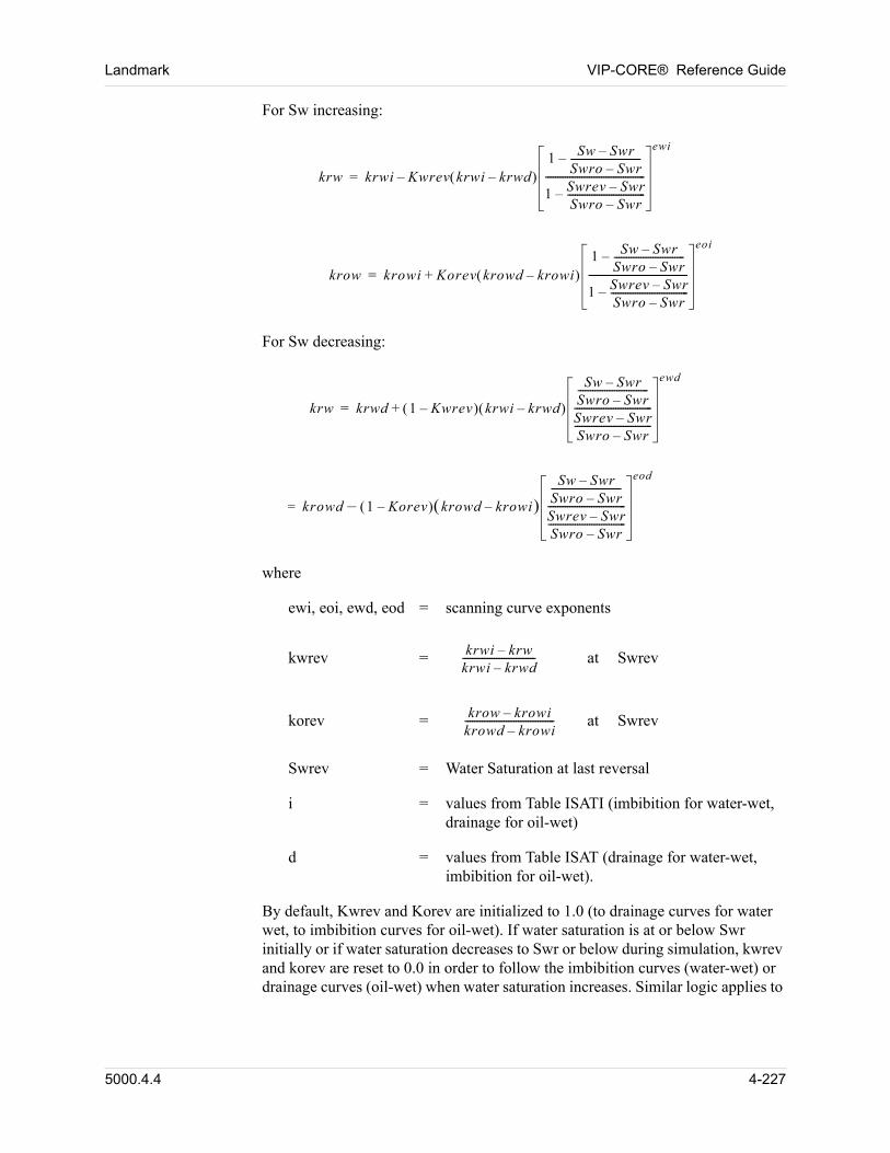
Landmark VIP-CORE® Reference Guide
For Sw increasing:
krw krwi Kwrev krwi krwd– 1 Sw Swr–
Swro Swr–-----------------------------–
1 Swrev Swr–Swro Swr–--------------------------------–
-----------------------------------------
ewi
–=
krow krowi Korev krowd krowi– 1 Sw Swr–
Swro Swr–-----------------------------–
1 Swrev Swr–Swro Swr–--------------------------------–
-----------------------------------------
eoi
+=
For Sw decreasing:
krw krwd 1 Kwrev– krwi krwd– +
Sw Swr–Swro Swr–-----------------------------
Swrev Swr–Swro Swr–----------------------------------------------------------------
ewd
=
krowd 1 Korev– krowd krowi– –
Sw Swr–Swro Swr–-----------------------------
Swrev Swr–Swro Swr–----------------------------------------------------------------
eod
=
where
ewi, eoi, ewd, eod = scanning curve exponents
kwrev = krwi krw–krwi krwd–------------------------------ at Swrev
korev = krow krowi–krowd krowi–------------------------------------- at Swrev
Swrev = Water Saturation at last reversal
i = values from Table ISATI (imbibition for water-wet, drainage for oil-wet)
d = values from Table ISAT (drainage for water-wet, imbibition for oil-wet).
By default, Kwrev and Korev are initialized to 1.0 (to drainage curves for water wet, to imbibition curves for oil-wet). If water saturation is at or below Swr initially or if water saturation decreases to Swr or below during simulation, kwrev and korev are reset to 0.0 in order to follow the imbibition curves (water-wet) or drainage curves (oil-wet) when water saturation increases. Similar logic applies to
5000.4.4 4-227
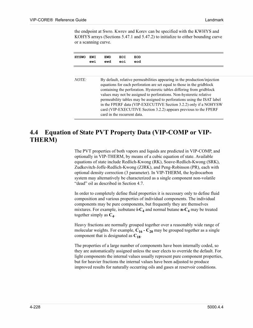
VIP-CORE® Reference Guide Landmark
the endpoint at Swro. Kwrev and Korev can be specified with the KWHYS and KOHYS arrays (Sections 5.47.1 and 5.47.2) to initialize to either bounding curve or a scanning curve.
HYSWO EWI EWD EOI EODewi ewd eoi eod
NOTE: By default, relative permeabilities appearing in the production/injection equations for each perforation are set equal to those in the gridblock containing the perforation. Hysteretic tables differing from gridblock values may not be assigned to perforations. Non-hysteretic relative permeability tables may be assigned to perforations using the ISAT label in the FPERF data (VIP-EXECUTIVE Section 3.2.2) only if a NOHYSW card (VIP-EXECUTIVE Section 3.2.2) appears previous to the FPERF card in the recurrent data.
4.4 Equation of State PVT Property Data (VIP-COMP or VIP-THERM)
The PVT properties of both vapors and liquids are predicted in VIP-COMP, and optionally in VIP-THERM, by means of a cubic equation of state. Available equations of state include Redlich-Kwong (RK), Soave-Redlich-Kwong (SRK), Zudkevitch-Joffe-Redlich-Kwong (ZJRK), and Peng-Robinson (PR), each with optional density correction (3 parameter). In VIP-THERM, the hydrocarbon system may alternatively be characterized as a single component non-volatile “dead” oil as described in Section 4.7. 00
In order to completely define fluid properties it is necessary only to define fluid composition and various properties of individual components. The individual components may be pure components, but frequently they are themselves mixtures. For example, isobutane i-C4 and normal butane n-C4 may be treated together simply as C4. 00
Heavy fractions are normally grouped together over a reasonably wide range of molecular weights. For example, C16 - C20 may be grouped together as a single component that is designated as C18. 00
The properties of a large number of components have been internally coded, so they are automatically assigned unless the user elects to override the default. For light components the internal values usually represent pure component properties, but for heavier fractions the internal values have been adjusted to produce improved results for naturally occurring oils and gases at reservoir conditions. 00
4-228 5000.4.4
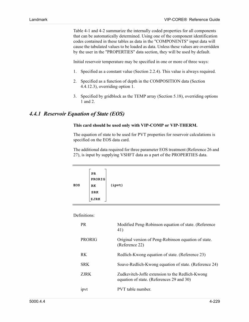
Landmark VIP-CORE® Reference Guide
Table 4-1 and 4-2 summarize the internally coded properties for all components that can be automatically determined. Using one of the component identification codes contained in these tables as data in the "COMPONENTS" input data will cause the tabulated values to be loaded as data. Unless these values are overridden by the user in the "PROPERTIES" data section, they will be used by default. 00
Initial reservoir temperature may be specified in one or more of three ways: 00
1. Specified as a constant value (Section 2.2.4). This value is always required.
2. Specified as a function of depth in the COMPOSITION data (Section 4.4.12.3), overriding option 1.
3. Specified by gridblock as the TEMP array (Section 5.18), overriding options 1 and 2.
4.4.1 Reservoir Equation of State (EOS)
00 This card should be used only with VIP-COMP or VIP-THERM.
The equation of state to be used for PVT properties for reservoir calculations is specified on the EOS data card. 00
The additional data required for three parameter EOS treatment (Reference 26 and 27), is input by supplying VSHFT data as a part of the PROPERTIES data. 00
EOS
PR
PRORIG
RK
SRK
ZJRK
(ipvt)
00 Definitions:
PR Modified Peng-Robinson equation of state. (Reference 41)
PRORIG Original version of Peng-Robinson equation of state. (Reference 22)
RK Redlich-Kwong equation of state. (Reference 23)
SRK Soave-Redlich-Kwong equation of state. (Reference 24)
ZJRK Zudkevitch-Joffe extension to the Redlich-Kwong equation of state. (References 29 and 30)
ipvt PVT table number.
5000.4.4 4-229
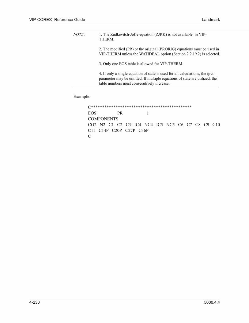
VIP-CORE® Reference Guide Landmark
NOTE: 1. The Zudkevitch-Joffe equation (ZJRK) is not available in VIP-THERM.2. The modified (PR) or the original (PRORIG) equations must be used in VIP-THERM unless the WATIDEAL option (Section 2.2.19.2) is selected.3. Only one EOS table is allowed for VIP-THERM.4. If only a single equation of state is used for all calculations, the ipvt parameter may be omitted. If multiple equations of state are utilized, the table numbers must consecutively increase.
00 Example:
00 C*********************************************EOS PR 1COMPONENTSCO2 N2 C1 C2 C3 IC4 NC4 IC5 NC5 C6 C7 C8 C9 C10C11 C14P C20P C27P C36PC
4-230 5000.4.4
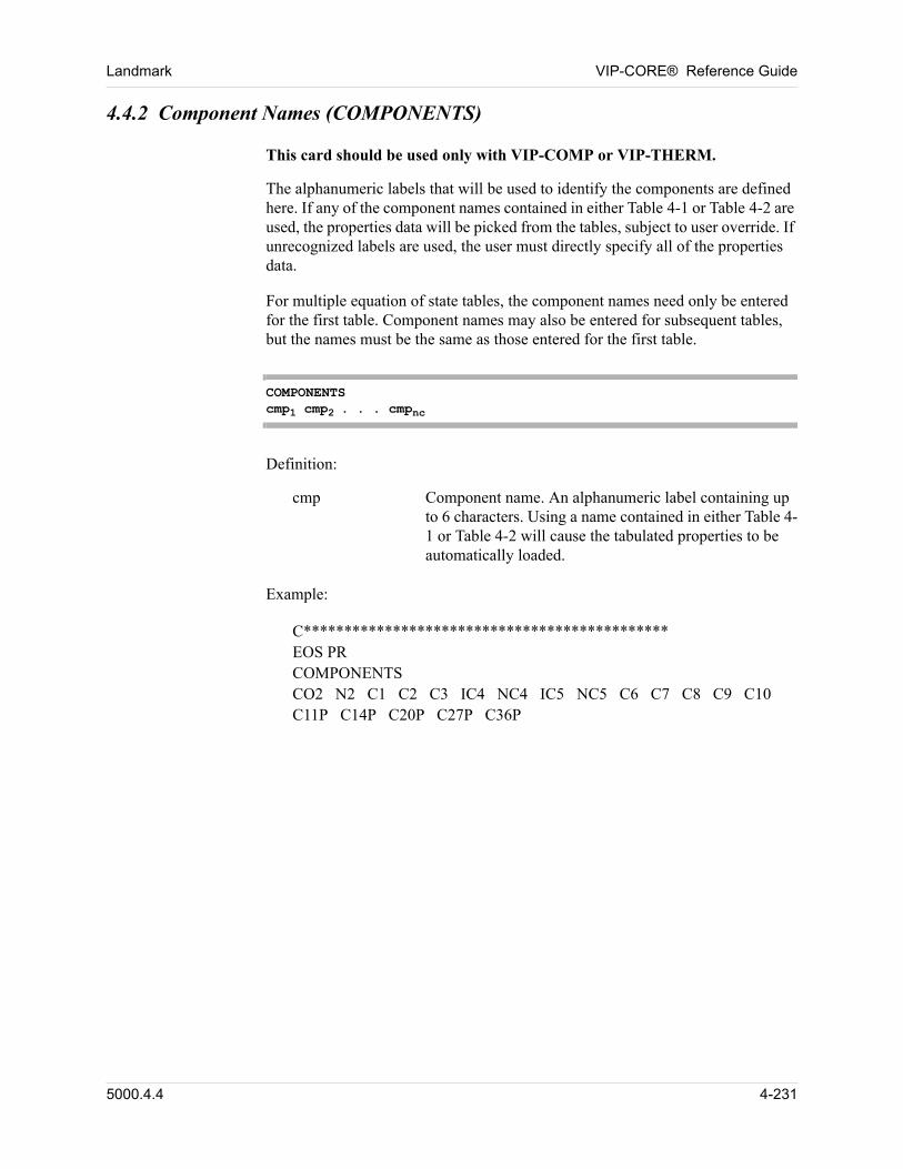
Landmark VIP-CORE® Reference Guide
4.4.2 Component Names (COMPONENTS)
00 This card should be used only with VIP-COMP or VIP-THERM.
The alphanumeric labels that will be used to identify the components are defined here. If any of the component names contained in either Table 4-1 or Table 4-2 are used, the properties data will be picked from the tables, subject to user override. If unrecognized labels are used, the user must directly specify all of the properties data. 00
For multiple equation of state tables, the component names need only be entered for the first table. Component names may also be entered for subsequent tables, but the names must be the same as those entered for the first table. 00
COMPONENTScmp1 cmp2 . . . cmpnc
00 Definition:
cmp Component name. An alphanumeric label containing up to 6 characters. Using a name contained in either Table 4-1 or Table 4-2 will cause the tabulated properties to be automatically loaded.
00 Example:
00 C*********************************************EOS PRCOMPONENTSCO2 N2 C1 C2 C3 IC4 NC4 IC5 NC5 C6 C7 C8 C9 C10C11P C14P C20P C27P C36P
5000.4.4 4-231
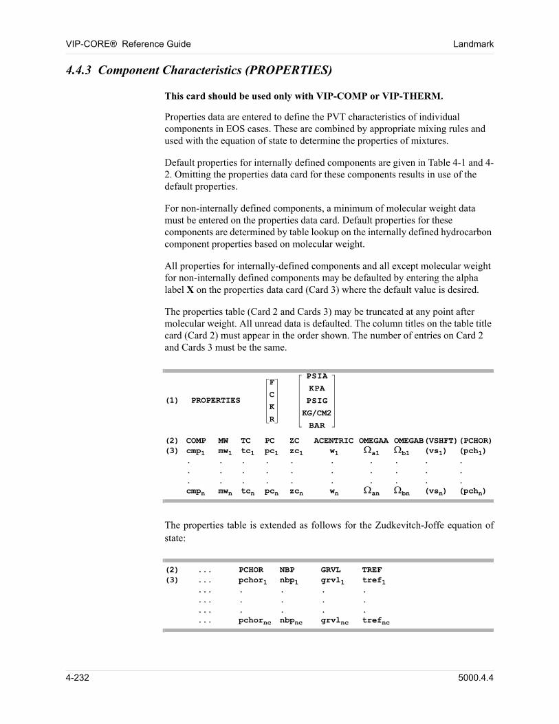
VIP-CORE® Reference Guide Landmark
4.4.3 Component Characteristics (PROPERTIES)
00 This card should be used only with VIP-COMP or VIP-THERM.
Properties data are entered to define the PVT characteristics of individual components in EOS cases. These are combined by appropriate mixing rules and used with the equation of state to determine the properties of mixtures. 00
Default properties for internally defined components are given in Table 4-1 and 4-2. Omitting the properties data card for these components results in use of the default properties. 00
For non-internally defined components, a minimum of molecular weight data must be entered on the properties data card. Default properties for these components are determined by table lookup on the internally defined hydrocarbon component properties based on molecular weight. 00
All properties for internally-defined components and all except molecular weight for non-internally defined components may be defaulted by entering the alpha label X on the properties data card (Card 3) where the default value is desired. 00
The properties table (Card 2 and Cards 3) may be truncated at any point after molecular weight. All unread data is defaulted. The column titles on the table title card (Card 2) must appear in the order shown. The number of entries on Card 2 and Cards 3 must be the same. 00
(1) PROPERTIES
F
C
K
R
PSIA
KPA
PSIG
KG/CM2
BAR
(2) COMP MW TC PC ZC ACENTRIC OMEGAA OMEGAB(VSHFT)(PCHOR)(3) cmp1 mw1 tc1 pc1 zc1 w1 a1 b1 (vs1) (pch1)
. . . . . . . . . .
. . . . . . . . . .
. . . . . . . . . .cmpn mwn tcn pcn zcn wn an bn (vsn) (pchn)
00 The properties table is extended as follows for the Zudkevitch-Joffe equation of state:
(2) ... PCHOR NBP GRVL TREF(3) ... pchor1 nbp1 grvl1 tref1
... . . . .
... . . . .
... . . . .
... pchornc nbpnc grvlnc trefnc
4-232 5000.4.4

Landmark VIP-CORE® Reference Guide
00 Definitions:
00 (1) Alpha label indicating that the units of the critical temperature values (TC) are:
F Degrees Fahrenheit, °F. Default for english units.
C Degrees Centigrade, °C. Default for metric units.
K Degrees Kelvin, °K.
R Degrees Rankine, °R.
Alpha label indicating that the units of the critical pressure values (PC) are:
PSIA Psia. This is the default for english units.
KPA KPa. This is the default for metric units.
PSIG Psig.
KG/CM2 Kg/cm2.
BAR Bar.
00 (2) The titles on this card must appear in the order shown. PCHOR is not allowed in VIP-THERM.
00 (3) cmpi Component name for component i. Must be identical to one of the names included in the COMPONENTS data.
mwi The molecular weight of component i.
tci Critical temperature of component i.
pci Critical pressure of component i.
zci Critical z-factor of component i. (This affects nothing but viscosity calculations.)
wi Acentric factor of component i.
ai a for component i. This is treated as a universal constant in the original formulations of the equations of state (0.4274802 for RK, SRK and ZJRK; 0.457235529 for PR). Additional flexibility in fitting data is gained by allowing it to vary by component.
bi b for component i. This is treated as a universal constant in the original formulation of the equations of state (0.08664035 for RK, SRK and ZJRK; 0.077796074
5000.4.4 4-233
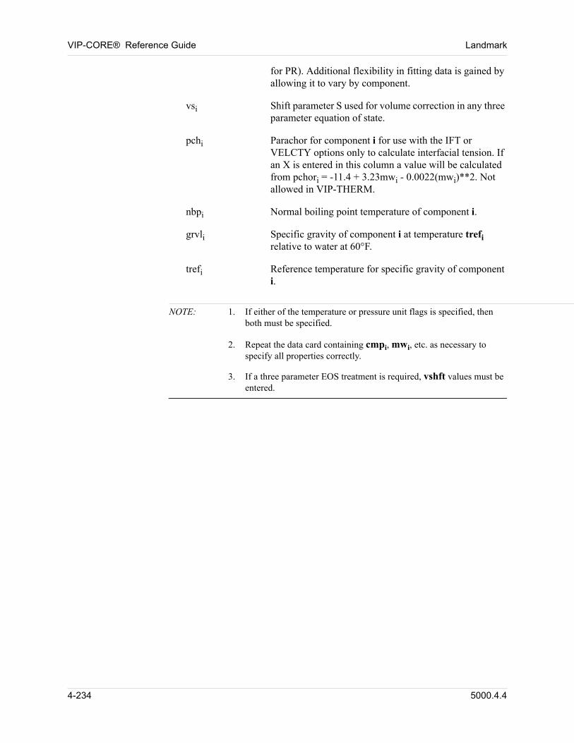
VIP-CORE® Reference Guide Landmark
for PR). Additional flexibility in fitting data is gained by allowing it to vary by component.
vsi Shift parameter S used for volume correction in any three parameter equation of state.
pchi Parachor for component i for use with the IFT or VELCTY options only to calculate interfacial tension. If an X is entered in this column a value will be calculated from pchori = -11.4 + 3.23mwi - 0.0022(mwi)**2. Not allowed in VIP-THERM.
nbpi Normal boiling point temperature of component i.
grvli Specific gravity of component i at temperature trefi relative to water at 60°F.
trefi Reference temperature for specific gravity of component i.
NOTE: 1. If either of the temperature or pressure unit flags is specified, then both must be specified.
2. Repeat the data card containing cmpi, mwi, etc. as necessary to specify all properties correctly.
3. If a three parameter EOS treatment is required, vshft values must be entered.
4-234 5000.4.4
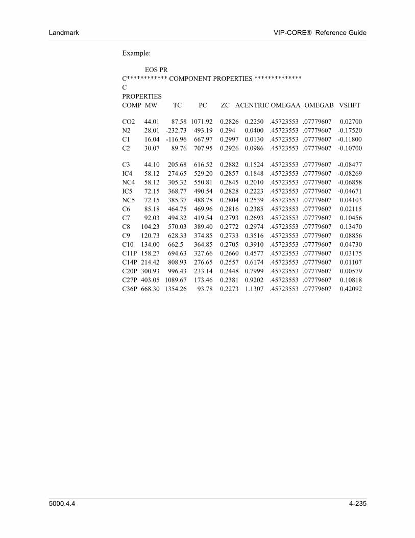
Landmark VIP-CORE® Reference Guide
00 Example:
00 EOS PRC************ COMPONENT PROPERTIES **************CPROPERTIESCOMP MW TC PC ZC ACENTRIC OMEGAA OMEGAB VSHFT
00 CO2 44.01 87.58 1071.92 0.2826 0.2250 .45723553 .07779607 0.02700N2 28.01 -232.73 493.19 0.294 0.0400 .45723553 .07779607 -0.17520C1 16.04 -116.96 667.97 0.2997 0.0130 .45723553 .07779607 -0.11800C2 30.07 89.76 707.95 0.2926 0.0986 .45723553 .07779607 -0.10700
00 C3 44.10 205.68 616.52 0.2882 0.1524 .45723553 .07779607 -0.08477IC4 58.12 274.65 529.20 0.2857 0.1848 .45723553 .07779607 -0.08269NC4 58.12 305.32 550.81 0.2845 0.2010 .45723553 .07779607 -0.06858IC5 72.15 368.77 490.54 0.2828 0.2223 .45723553 .07779607 -0.04671NC5 72.15 385.37 488.78 0.2804 0.2539 .45723553 .07779607 0.04103C6 85.18 464.75 469.96 0.2816 0.2385 .45723553 .07779607 0.02115C7 92.03 494.32 419.54 0.2793 0.2693 .45723553 .07779607 0.10456C8 104.23 570.03 389.40 0.2772 0.2974 .45723553 .07779607 0.13470C9 120.73 628.33 374.85 0.2733 0.3516 .45723553 .07779607 0.08856C10 134.00 662.5 364.85 0.2705 0.3910 .45723553 .07779607 0.04730C11P 158.27 694.63 327.66 0.2660 0.4577 .45723553 .07779607 0.03175C14P 214.42 808.93 276.65 0.2557 0.6174 .45723553 .07779607 0.01107C20P 300.93 996.43 233.14 0.2448 0.7999 .45723553 .07779607 0.00579C27P 403.05 1089.67 173.46 0.2381 0.9202 .45723553 .07779607 0.10818C36P 668.30 1354.26 93.78 0.2273 1.1307 .45723553 .07779607 0.42092
5000.4.4 4-235
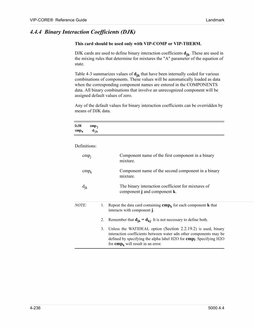
VIP-CORE® Reference Guide Landmark
4.4.4 Binary Interaction Coefficients (DJK)
00 This card should be used only with VIP-COMP or VIP-THERM.
DJK cards are used to define binary interaction coefficients djk. These are used in the mixing rules that determine for mixtures the "A" parameter of the equation of state. 00
Table 4-3 summarizes values of djk that have been internally coded for various combinations of components. These values will be automatically loaded as data when the corresponding component names are entered in the COMPONENTS data. All binary combinations that involve an unrecognized component will be assigned default values of zero. 00
Any of the default values for binary interaction coefficients can be overridden by means of DJK data. 00
DJK cmpjcmpk djk
00 Definitions:
cmpj Component name of the first component in a binary mixture.
cmpk Component name of the second component in a binary mixture.
djk The binary interaction coefficient for mixtures of component j and component k.
NOTE: 1. Repeat the data card containing cmpk for each component k that interacts with component j.
2. Remember that djk = dkj. It is not necessary to define both.
3. Unless the WATIDEAL option (Section 2.2.19.2) is used, binary interaction coefficients between water adn other components may be defined by specifying the alpha label H2O for cmpj. Specifying H2O for cmpk will result in an error.
4-236 5000.4.4
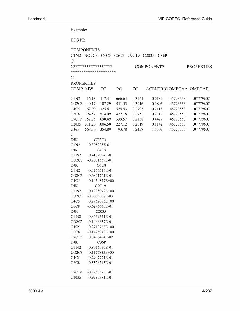
Landmark VIP-CORE® Reference Guide
00 Example:
00 EOS PR
00 COMPONENTSC1N2 NO2C3 C4C5 C5C8 C9C19 C2035 C36PCC****************** COMPONENTS PROPERTIES *********************CPROPERTIESCOMP MW TC PC ZC ACENTRIC OMEGAA OMEGAB
00 C1N2 16.13 -117.31 666.64 0.3141 0.0132 .45723553 .07779607CO2C3 40.17 107.29 911.55 0.3016 0.1805 .45723553 .07779607C4C5 62.99 325.6 525.53 0.2993 0.2118 .45723553 .07779607C6C8 94.57 514.09 422.18 0.2952 0.2712 .45723553 .07779607C9C19 152.75 690.49 339.57 0.2838 0.4427 .45723553 .07779607C2035 311.26 1006.50 227.12 0.2619 0.8142 .45723553 .07779607C36P 668.30 1354.89 93.78 0.2458 1.1307 .45723553 .07779607CDJK CO2C3C1N2 -0.508225E-01DJK C4C5C1 N2 0.4172094E-01CO2C3 -0.2031559E-01DJK C6C8C1N2 -0.3255523E-01CO2C3 -0.6801761E-01C4C5 -0.1434877E+00DJK C9C19C1 N2 0.1238972E+00CO2C3 -0.8605607E-03C4C5 0.2762086E+00C6C8 -0.6246630E-01DJK C2035C1 N2 0.8639371E-01CO2C3 0.1466657E-01C4C5 -0.2710768E+00C6C8 -0.1425948E+00C9C19 0.8496494E-02DJK C36PC1 N2 0.8916950E-01CO2C3 0.1177855E+00C4C5 -0.2947721E-01C6C8 0.5526345E-01
00 C9C19 -0.7258570E-01C2035 -0.9795381E-01
5000.4.4 4-237
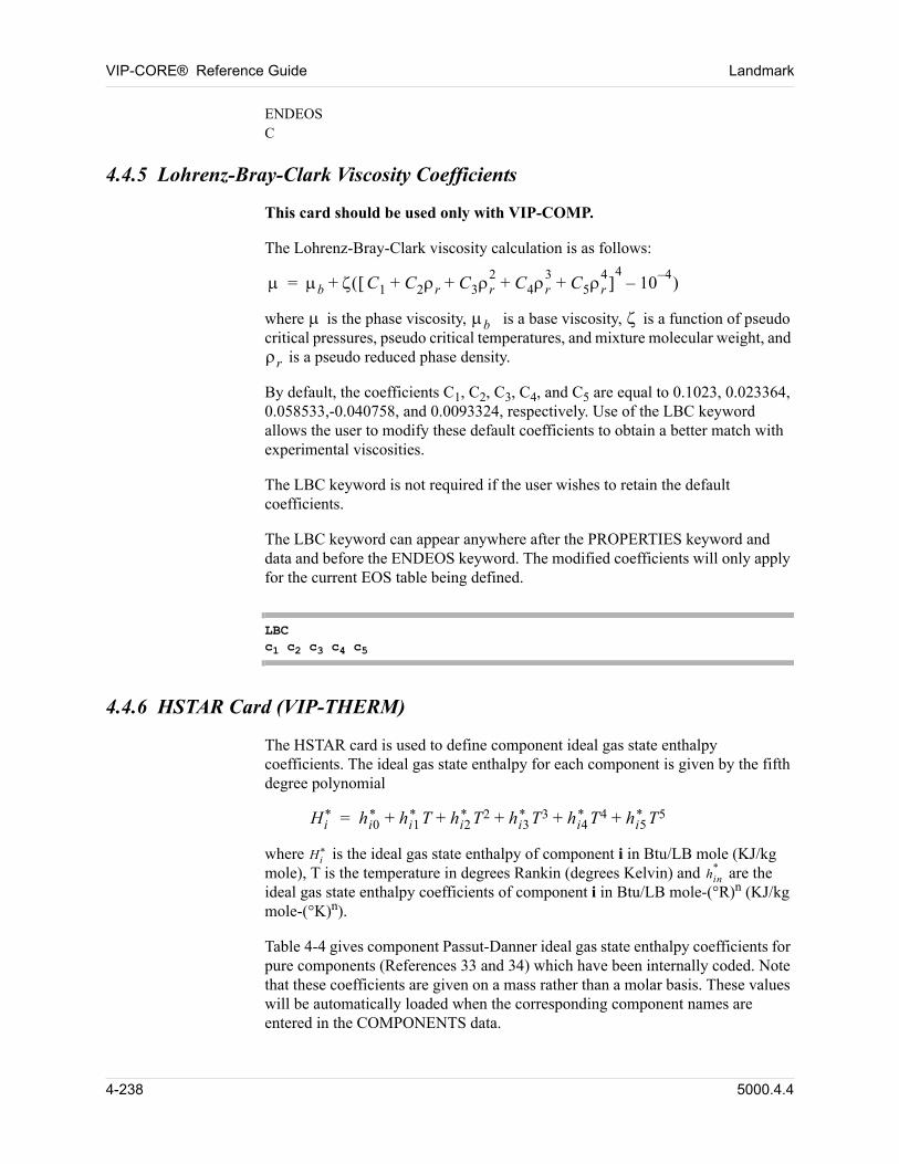
VIP-CORE® Reference Guide Landmark
ENDEOSC
4.4.5 Lohrenz-Bray-Clark Viscosity Coefficients
00 This card should be used only with VIP-COMP.
00 The Lohrenz-Bray-Clark viscosity calculation is as follows:
00 b C1 C2r C3r2
C4r3
C5r4
+ + + + 4
104–
– +=
00 where is the phase viscosity, b is a base viscosity, is a function of pseudo critical pressures, pseudo critical temperatures, and mixture molecular weight, and r is a pseudo reduced phase density.
00 By default, the coefficients C1, C2, C3, C4, and C5 are equal to 0.1023, 0.023364, 0.058533,-0.040758, and 0.0093324, respectively. Use of the LBC keyword allows the user to modify these default coefficients to obtain a better match with experimental viscosities.
00 The LBC keyword is not required if the user wishes to retain the default coefficients.
00 The LBC keyword can appear anywhere after the PROPERTIES keyword and data and before the ENDEOS keyword. The modified coefficients will only apply for the current EOS table being defined.
LBCc1 c2 c3 c4 c5
4.4.6 HSTAR Card (VIP-THERM)
00 The HSTAR card is used to define component ideal gas state enthalpy coefficients. The ideal gas state enthalpy for each component is given by the fifth degree polynomial
Hi* hi0
* hi1* T hi2
* T2 hi3* T3 hi4
* T4 hi5* T5+ + + + +=
where Hi* is the ideal gas state enthalpy of component i in Btu/LB mole (KJ/kg
mole), T is the temperature in degrees Rankin (degrees Kelvin) and hin* are the
ideal gas state enthalpy coefficients of component i in Btu/LB mole-(°R)n (KJ/kg mole-(°K)n).
Table 4-4 gives component Passut-Danner ideal gas state enthalpy coefficients for pure components (References 33 and 34) which have been internally coded. Note that these coefficients are given on a mass rather than a molar basis. These values will be automatically loaded when the corresponding component names are entered in the COMPONENTS data.
4-238 5000.4.4
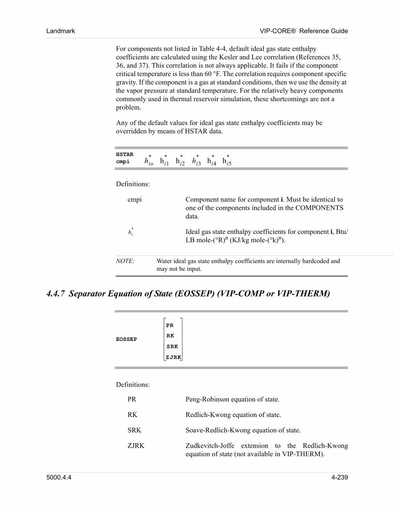
Landmark VIP-CORE® Reference Guide
For components not listed in Table 4-4, default ideal gas state enthalpy coefficients are calculated using the Kesler and Lee correlation (References 35, 36, and 37). This correlation is not always applicable. It fails if the component critical temperature is less than 60 °F. The correlation requires component specific gravity. If the component is a gas at standard conditions, then we use the density at the vapor pressure at standard temperature. For the relatively heavy components commonly used in thermal reservoir simulation, these shortcomings are not a problem.
Any of the default values for ideal gas state enthalpy coefficients may be overridden by means of HSTAR data.
HSTARcmpi hio
*hi1
*hi2
*hi3
*hi4
*hi5
*
Definitions:
cmpi Component name for component i. Must be identical to one of the components included in the COMPONENTS data.
hi* Ideal gas state enthalpy coefficients for component i, Btu/
LB mole-(°R)n (KJ/kg mole-(°k)n).
NOTE: Water ideal gas state enthalpy coefficients are internally hardcoded and may not be input.
4.4.7 Separator Equation of State (EOSSEP) (VIP-COMP or VIP-THERM)
EOSSEP
PR
RK
SRK
ZJRK
00 Definitions:
PR Peng-Robinson equation of state.
RK Redlich-Kwong equation of state.
SRK Soave-Redlich-Kwong equation of state.
ZJRK Zudkevitch-Joffe extension to the Redlich-Kwong equation of state (not available in VIP-THERM).
5000.4.4 4-239
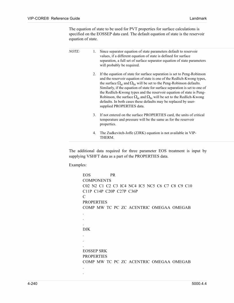
VIP-CORE® Reference Guide Landmark
The equation of state to be used for PVT properties for surface calculations is specified on the EOSSEP data card. The default equation of state is the reservoir equation of state. 00
NOTE: 1. Since separator equation of state parameters default to reservoir values, if a different equation of state is defined for surface separation, a full set of surface separator equation of state parameters will probably be required.
2. If the equation of state for surface separation is set to Peng-Robinson and the reservoir equation of state is one of the Redlich-Kwong types, the surface ai and bi will be set to the Peng-Robinson defaults. Similarly, if the equation of state for surface separation is set to one of the Redlich-Kwong types and the reservoir equation of state is Peng-Robinson, the surface ai and bi will be set to the Redlich-Kwong defaults. In both cases these defaults may be replaced by user-supplied PROPERTIES data.
3. If not entered on the surface PROPERTIES card, the units of critical temperature and pressure will be the same as for the reservoir properties.
4. The Zudkevitch-Joffe (ZJRK) equation is not available in VIP-THERM.
00 The additional data required for three parameter EOS treatment is input by supplying VSHFT data as a part of the PROPERTIES data.
00 Examples:
00 EOS PRCOMPONENTSC02 N2 C1 C2 C3 IC4 NC4 IC5 NC5 C6 C7 C8 C9 C10C11P C14P C20P C27P C36PCPROPERTIESCOMP MW TC PC ZC ACENTRIC OMEGAA OMEGAB...DJK...EOSSEP SRKPROPERTIESCOMP MW TC PC ZC ACENTRIC OMEGAA OMEGAB..
4-240 5000.4.4
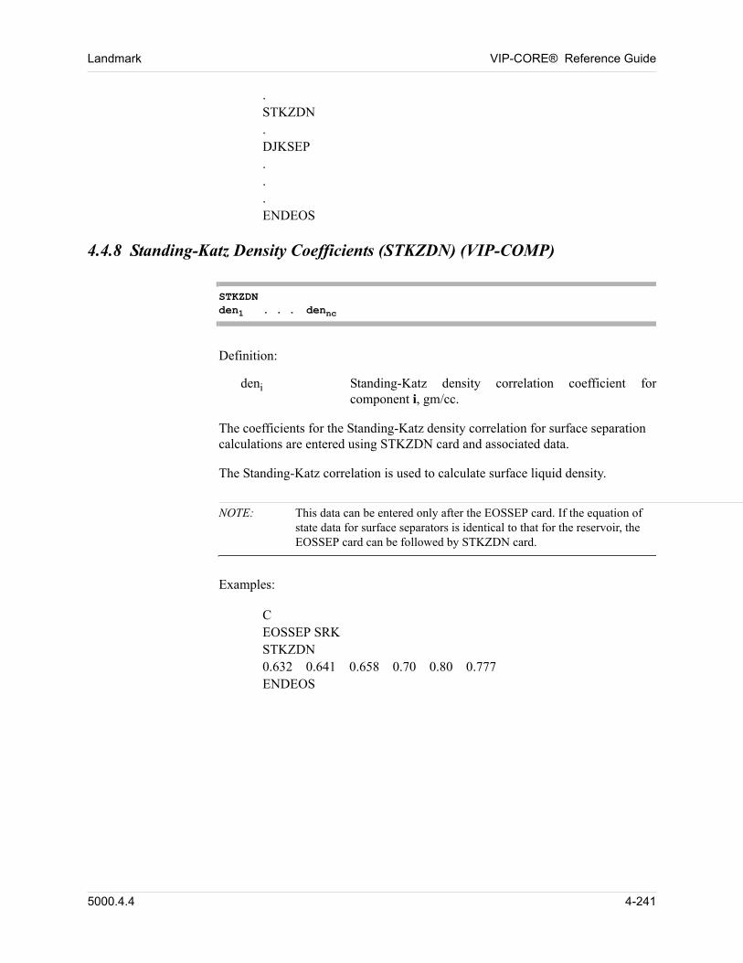
Landmark VIP-CORE® Reference Guide
.STKZDN.DJKSEP...ENDEOS
4.4.8 Standing-Katz Density Coefficients (STKZDN) (VIP-COMP)
STKZDNden1 . . . dennc
00 Definition:
deni Standing-Katz density correlation coefficient for component i, gm/cc.
The coefficients for the Standing-Katz density correlation for surface separation calculations are entered using STKZDN card and associated data. 00
The Standing-Katz correlation is used to calculate surface liquid density. 00
NOTE: This data can be entered only after the EOSSEP card. If the equation of state data for surface separators is identical to that for the reservoir, the EOSSEP card can be followed by STKZDN card.
00 Examples:
00 CEOSSEP SRKSTKZDN0.632 0.641 0.658 0.70 0.80 0.777ENDEOS
5000.4.4 4-241
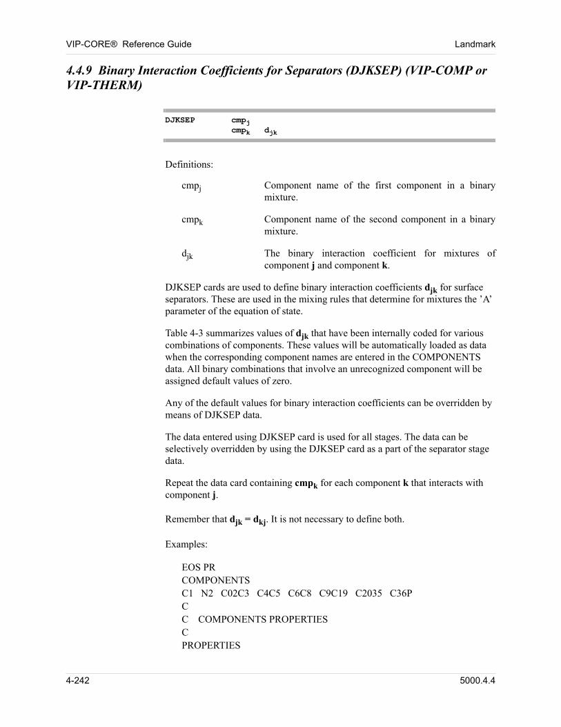
VIP-CORE® Reference Guide Landmark
4.4.9 Binary Interaction Coefficients for Separators (DJKSEP) (VIP-COMP or VIP-THERM)
DJKSEP cmpjcmpk djk
00 Definitions:
cmpj Component name of the first component in a binary mixture.
cmpk Component name of the second component in a binary mixture.
djk The binary interaction coefficient for mixtures of component j and component k.
DJKSEP cards are used to define binary interaction coefficients djk for surface separators. These are used in the mixing rules that determine for mixtures the ’A’ parameter of the equation of state. 00
Table 4-3 summarizes values of djk that have been internally coded for various combinations of components. These values will be automatically loaded as data when the corresponding component names are entered in the COMPONENTS data. All binary combinations that involve an unrecognized component will be assigned default values of zero. 00
Any of the default values for binary interaction coefficients can be overridden by means of DJKSEP data. 00
The data entered using DJKSEP card is used for all stages. The data can be selectively overridden by using the DJKSEP card as a part of the separator stage data. 00
Repeat the data card containing cmpk for each component k that interacts with component j. 00
00 Remember that djk = dkj. It is not necessary to define both.
00 Examples:
00 EOS PRCOMPONENTSC1 N2 C02C3 C4C5 C6C8 C9C19 C2035 C36PCC COMPONENTS PROPERTIESCPROPERTIES
4-242 5000.4.4
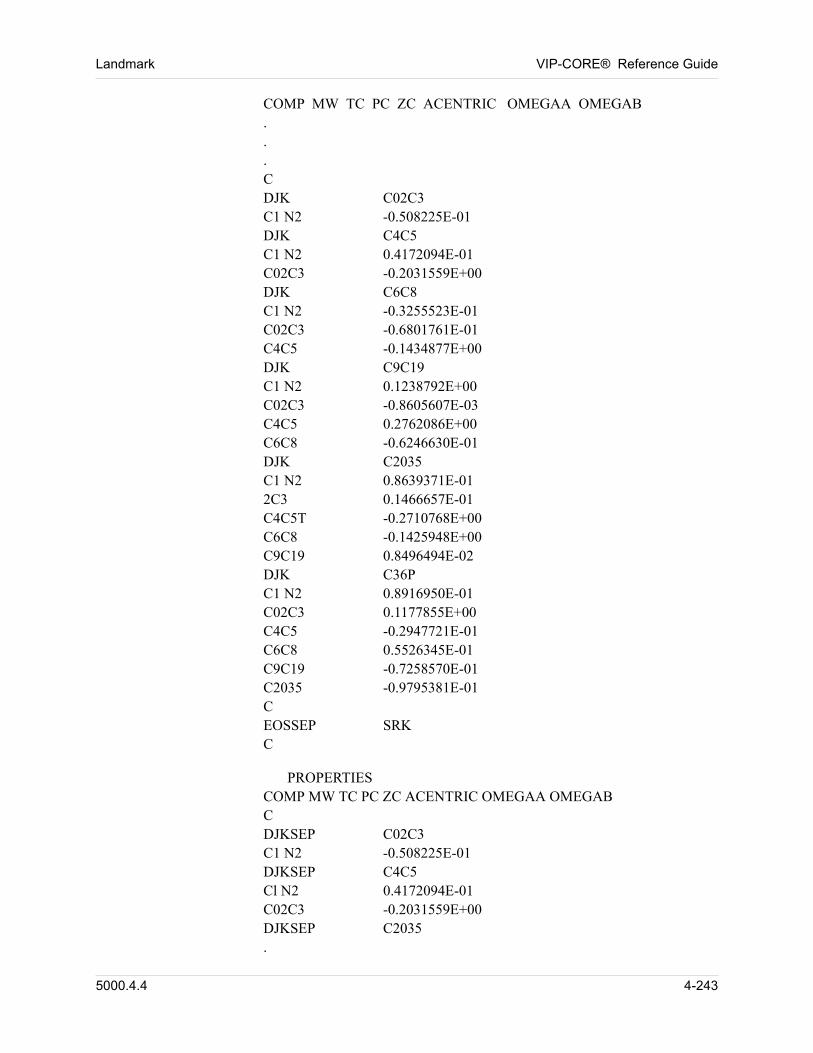
Landmark VIP-CORE® Reference Guide
COMP MW TC PC ZC ACENTRIC OMEGAA OMEGAB . .
.CDJK C02C3C1 N2 -0.508225E-01DJK C4C5C1 N2 0.4172094E-01C02C3 -0.2031559E+00DJK C6C8C1 N2 -0.3255523E-01C02C3 -0.6801761E-01C4C5 -0.1434877E+00DJK C9C19C1 N2 0.1238792E+00C02C3 -0.8605607E-03C4C5 0.2762086E+00C6C8 -0.6246630E-01DJK C2035C1 N2 0.8639371E-012C3 0.1466657E-01C4C5T -0.2710768E+00C6C8 -0.1425948E+00C9C19 0.8496494E-02DJK C36PC1 N2 0.8916950E-01C02C3 0.1177855E+00C4C5 -0.2947721E-01C6C8 0.5526345E-01C9C19 -0.7258570E-01C2035 -0.9795381E-01CEOSSEP SRKC
00 PROPERTIESCOMP MW TC PC ZC ACENTRIC OMEGAA OMEGABCDJKSEP C02C3C1 N2 -0.508225E-01DJKSEP C4C5Cl N2 0.4172094E-01C02C3 -0.2031559E+00DJKSEP C2035.
5000.4.4 4-243
VIP-CORE® Reference Guide Landmark
. .
.C1 N2 0.8639371E-01C02C3 0.1466657E-01C4C5 -0.2710768E+00C6C8 -0.1425948E+00C9C19 0.8496494E-02ENDEOS
4-244 5000.4.4
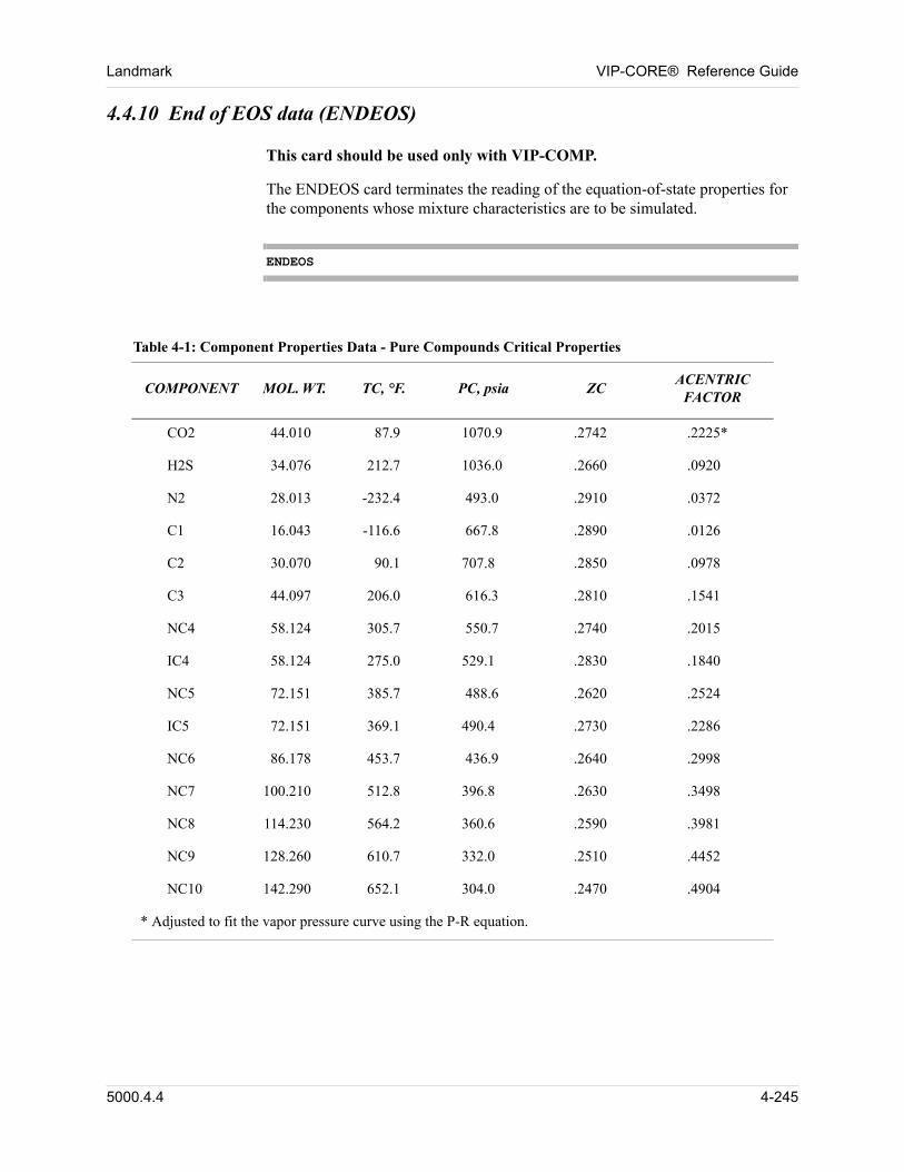
Landmark VIP-CORE® Reference Guide
4.4.10 End of EOS data (ENDEOS)
00 This card should be used only with VIP-COMP.
The ENDEOS card terminates the reading of the equation-of-state properties for the components whose mixture characteristics are to be simulated. 00
ENDEOS
00
Table 4-1: Component Properties Data - Pure Compounds Critical Properties
COMPONENT MOL. WT. TC, °F. PC, psia ZC ACENTRIC
FACTOR
CO2 44.010 87.9 1070.9 .2742 .2225*
H2S 34.076 212.7 1036.0 .2660 .0920
N2 28.013 -232.4 493.0 .2910 .0372
C1 16.043 -116.6 667.8 .2890 .0126
C2 30.070 90.1 707.8 .2850 .0978
C3 44.097 206.0 616.3 .2810 .1541
NC4 58.124 305.7 550.7 .2740 .2015
IC4 58.124 275.0 529.1 .2830 .1840
NC5 72.151 385.7 488.6 .2620 .2524
IC5 72.151 369.1 490.4 .2730 .2286
NC6 86.178 453.7 436.9 .2640 .2998
NC7 100.210 512.8 396.8 .2630 .3498
NC8 114.230 564.2 360.6 .2590 .3981
NC9 128.260 610.7 332.0 .2510 .4452
NC10 142.290 652.1 304.0 .2470 .4904
* Adjusted to fit the vapor pressure curve using the P-R equation.
5000.4.4 4-245
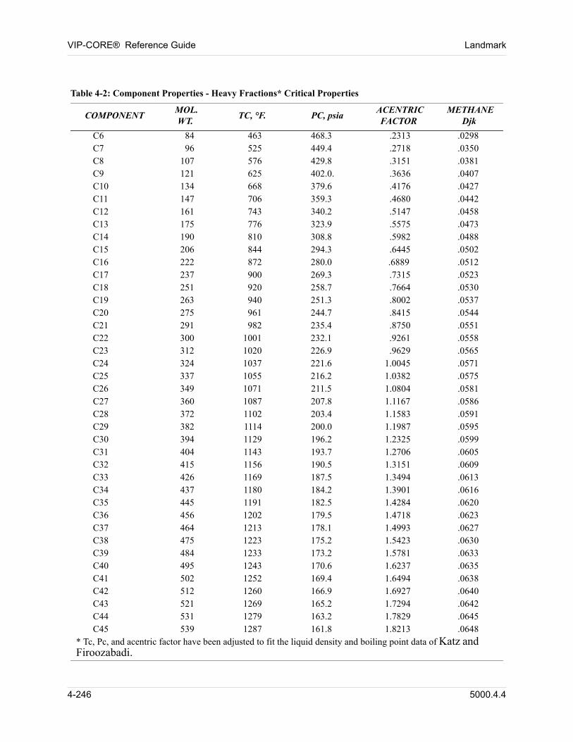
VIP-CORE® Reference Guide Landmark
00
Table 4-2: Component Properties - Heavy Fractions* Critical Properties
COMPONENT MOL.
WT. TC, °F. PC, psia
ACENTRICFACTOR
METHANEDjk
C6 84 463 468.3 .2313 .0298C7 96 525 449.4 .2718 .0350C8 107 576 429.8 .3151 .0381C9 121 625 402.0. .3636 .0407C10 134 668 379.6 .4176 .0427C11 147 706 359.3 .4680 .0442C12 161 743 340.2 .5147 .0458C13 175 776 323.9 .5575 .0473C14 190 810 308.8 .5982 .0488C15 206 844 294.3 .6445 .0502C16 222 872 280.0 .6889 .0512C17 237 900 269.3 .7315 .0523C18 251 920 258.7 .7664 .0530C19 263 940 251.3 .8002 .0537C20 275 961 244.7 .8415 .0544C21 291 982 235.4 .8750 .0551C22 300 1001 232.1 .9261 .0558C23 312 1020 226.9 .9629 .0565C24 324 1037 221.6 1.0045 .0571C25 337 1055 216.2 1.0382 .0575C26 349 1071 211.5 1.0804 .0581C27 360 1087 207.8 1.1167 .0586C28 372 1102 203.4 1.1583 .0591C29 382 1114 200.0 1.1987 .0595C30 394 1129 196.2 1.2325 .0599C31 404 1143 193.7 1.2706 .0605C32 415 1156 190.5 1.3151 .0609C33 426 1169 187.5 1.3494 .0613C34 437 1180 184.2 1.3901 .0616C35 445 1191 182.5 1.4284 .0620C36 456 1202 179.5 1.4718 .0623C37 464 1213 178.1 1.4993 .0627C38 475 1223 175.2 1.5423 .0630C39 484 1233 173.2 1.5781 .0633C40 495 1243 170.6 1.6237 .0635C41 502 1252 169.4 1.6494 .0638C42 512 1260 166.9 1.6927 .0640C43 521 1269 165.2 1.7294 .0642C44 531 1279 163.2 1.7829 .0645C45 539 1287 161.8 1.8213 .0648
* Tc, Pc, and acentric factor have been adjusted to fit the liquid density and boiling point data of Katz and Firoozabadi.
4-246 5000.4.4
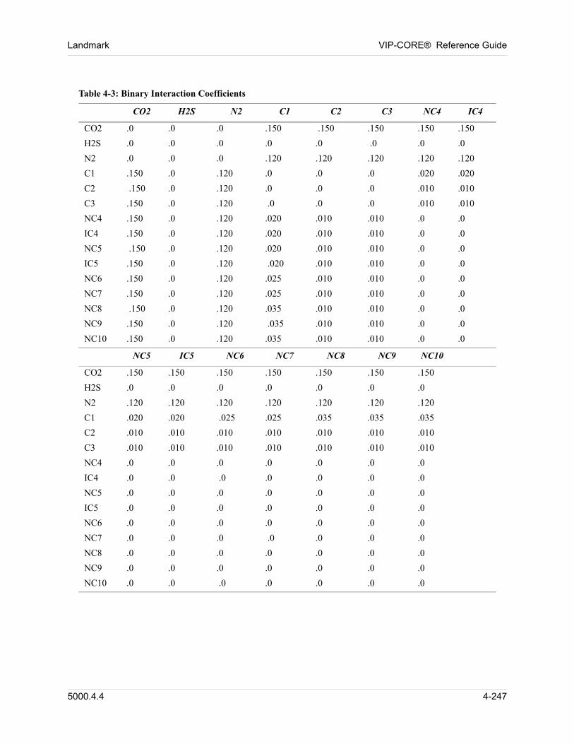
Landmark VIP-CORE® Reference Guide
00
Table 4-3: Binary Interaction Coefficients
CO2 H2S N2 C1 C2 C3 NC4 IC4
CO2 .0 .0 .0 .150 .150 .150 .150 .150
H2S .0 .0 .0 .0 .0 .0 .0 .0
N2 .0 .0 .0 .120 .120 .120 .120 .120
C1 .150 .0 .120 .0 .0 .0 .020 .020
C2 .150 .0 .120 .0 .0 .0 .010 .010
C3 .150 .0 .120 .0 .0 .0 .010 .010
NC4 .150 .0 .120 .020 .010 .010 .0 .0
IC4 .150 .0 .120 .020 .010 .010 .0 .0
NC5 .150 .0 .120 .020 .010 .010 .0 .0
IC5 .150 .0 .120 .020 .010 .010 .0 .0
NC6 .150 .0 .120 .025 .010 .010 .0 .0
NC7 .150 .0 .120 .025 .010 .010 .0 .0
NC8 .150 .0 .120 .035 .010 .010 .0 .0
NC9 .150 .0 .120 .035 .010 .010 .0 .0
NC10 .150 .0 .120 .035 .010 .010 .0 .0
NC5 IC5 NC6 NC7 NC8 NC9 NC10
CO2 .150 .150 .150 .150 .150 .150 .150
H2S .0 .0 .0 .0 .0 .0 .0
N2 .120 .120 .120 .120 .120 .120 .120
C1 .020 .020 .025 .025 .035 .035 .035
C2 .010 .010 .010 .010 .010 .010 .010
C3 .010 .010 .010 .010 .010 .010 .010
NC4 .0 .0 .0 .0 .0 .0 .0
IC4 .0 .0 .0 .0 .0 .0 .0
NC5 .0 .0 .0 .0 .0 .0 .0
IC5 .0 .0 .0 .0 .0 .0 .0
NC6 .0 .0 .0 .0 .0 .0 .0
NC7 .0 .0 .0 .0 .0 .0 .0
NC8 .0 .0 .0 .0 .0 .0 .0
NC9 .0 .0 .0 .0 .0 .0 .0
NC10 .0 .0 .0 .0 .0 .0 .0
5000.4.4 4-247
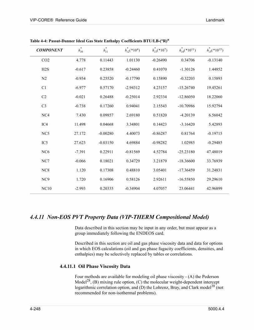
VIP-CORE® Reference Guide Landmark
Table 4-4: Passut-Danner Ideal Gas State Enthalpy Coefficients BTU/LB-(°R)n
COMPONENT hi0*
hi1*
hi2*
*104 hi3*
*107 hi4*
*1011 hi5*
*1015
CO2 4.778 0.11443 1.01130 -0.26490 0.34706 -0.13140
H2S -0.617 0.23858 -0.24460 0.41070 -1.30126 1.44852
N2 -0.934 0.25520 -0.17790 0.15890 -0.32203 0.15893
C1 -6.977 0.57170 -2.94312 4.23157 -15.26740 19.45261
C2 -0.021 0.26488 -0.25014 2.92334 -12.86050 18.22060
C3 -0.738 0.17260 0.94041 2.15543 -10.70986 15.92794
NC4 7.430 0.09857 2.69180 0.51820 -4.20139 6.56042
IC4 11.498 0.04668 3.34801 0.14423 -3.16420 5.42893
NC5 27.172 -0.00280 4.40073 -0.86287 0.81764 -0.19715
IC5 27.623 -0.03150 4.69884 -0.98282 1.02985 -0.29485
NC6 -7.391 0.22911 -0.81569 4.52784 -25.23180 47.48019
NC7 -0.066 0.18021 0.34729 3.21879 -18.36600 33.76939
NC8 1.120 0.17308 0.48810 3.05401 -17.36459 31.24831
NC9 1.720 0.16906 0.58126 2.92611 -16.55850 29.29610
NC10 -2.993 0.20335 -0.34904 4.07057 23.06441 42.96899
00
4.4.11 Non-EOS PVT Property Data (VIP-THERM Compositional Model)
Data described in this section may be input in any order, but must appear as a group immediately following the ENDEOS card.
Described in this section are oil and gas phase viscosity data and data for options in which EOS calculations (oil and gas phase fugacity coefficients, densities, and enthalpies) may be selectively replaced by tables or correlations.
4.4.11.1 Oil Phase Viscosity Data
Four methods are available for modeling oil phase viscosity - (A) the Pederson Model28, (B) mixing rule option, (C) the molecular weight-dependent intercept logarithmic correlation option, and (D) the Lohrenz, Bray, and Clark model38 (not recommended for non-isothermal problems).
4-248 5000.4.4
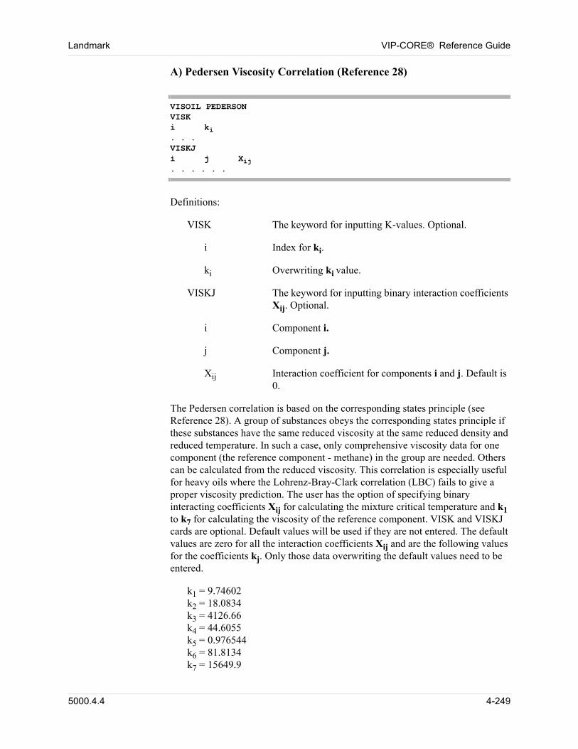
Landmark VIP-CORE® Reference Guide
A) Pedersen Viscosity Correlation (Reference 28)
VISOIL PEDERSONVISKi ki. . .VISKJi j Xij. . . . . .
Definitions:
VISK The keyword for inputting K-values. Optional.
i Index for ki.
ki Overwriting ki value.
VISKJ The keyword for inputting binary interaction coefficients Xij. Optional.
i Component i.
j Component j.
Xij Interaction coefficient for components i and j. Default is 0.
The Pedersen correlation is based on the corresponding states principle (see Reference 28). A group of substances obeys the corresponding states principle if these substances have the same reduced viscosity at the same reduced density and reduced temperature. In such a case, only comprehensive viscosity data for one component (the reference component - methane) in the group are needed. Others can be calculated from the reduced viscosity. This correlation is especially useful for heavy oils where the Lohrenz-Bray-Clark correlation (LBC) fails to give a proper viscosity prediction. The user has the option of specifying binary interacting coefficients Xij for calculating the mixture critical temperature and k1 to k7 for calculating the viscosity of the reference component. VISK and VISKJ cards are optional. Default values will be used if they are not entered. The default values are zero for all the interaction coefficients Xij and are the following values for the coefficients kj. Only those data overwriting the default values need to be entered.
k1 = 9.74602k2 = 18.0834k3 = 4126.66k4 = 44.6055k5 = 0.976544k6 = 81.8134k7 = 15649.9
5000.4.4 4-249
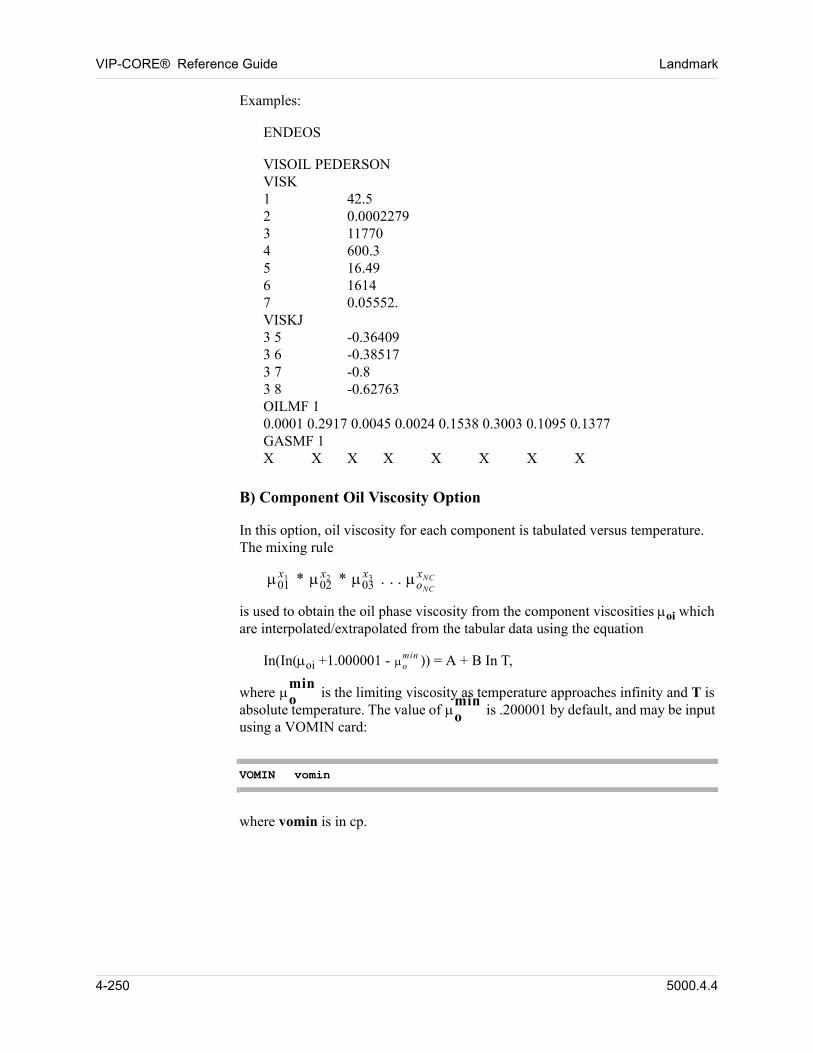
VIP-CORE® Reference Guide Landmark
Examples:
ENDEOS
VISOIL PEDERSONVISK1 42.52 0.00022793 117704 600.35 16.496 16147 0.05552.VISKJ3 5 -0.364093 6 -0.385173 7 -0.83 8 -0.62763OILMF 10.0001 0.2917 0.0045 0.0024 0.1538 0.3003 0.1095 0.1377GASMF 1X X X X X X X X
B) Component Oil Viscosity Option
In this option, oil viscosity for each component is tabulated versus temperature. The mixing rule
01x1 * 02
x2 * 03x3 . . . oNC
xNC
is used to obtain the oil phase viscosity from the component viscosities oi which are interpolated/extrapolated from the tabular data using the equation
In(In(oi +1.000001 - omin )) = A + B In T,
where omin
is the limiting viscosity as temperature approaches infinity and T is absolute temperature. The value of o
min is .200001 by default, and may be input
using a VOMIN card:
VOMIN vomin
where vomin is in cp.
4-250 5000.4.4
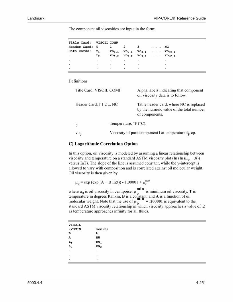
Landmark VIP-CORE® Reference Guide
The component oil viscosities are input in the form:
Title Card: VISOIL COMPHeader Card: T 1 2 3 . . . NCData Cards: t1 vo1,1 vo2,1 vo3,1 . . . voNC,1. t2 vo1,2 vo2,2 vo3,2 . . . voNC,2. . . . . .. . . . . .. . . . . .
Definitions:
Title Card: VISOIL COMP Alpha labels indicating that component oil viscosity data is to follow.
Header Card:T 1 2 ... NC Table header card, where NC is replaced by the numeric value of the total number of components.
tj Temperature, °F (°C).
voij Viscosity of pure component i at temperature tj, cp.
C) Logarithmic Correlation Option
In this option, oil viscosity is modeled by assuming a linear relationship between viscosity and temperature on a standard ASTM viscosity plot (In (In (o + .8)) versus InT). The slope of the line is assumed constant, while the y-intercept is allowed to vary with composition and is correlated against oil molecular weight. Oil viscosity is then given by
o = exp (exp (A + B In(t)) - 1.00001 + omin
00 where o is oil viscosity in centipoise, omin
is minimum oil viscosity, T is temperature in degrees Rankin, B is a constant, and A is a function of oil molecular weight. Note that the use of o
min = .200001 is equivalent to the
standard ASTM viscosity relationship in which viscosity approaches a value of .2 as temperature approaches infinity for all fluids.
VISOIL(VOMIN vomin)B bA MWa1 mw1a2 mw2. .. .. .
5000.4.4 4-251
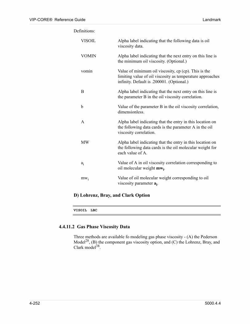
VIP-CORE® Reference Guide Landmark
Definitions:
VISOIL Alpha label indicating that the following data is oil viscosity data.
VOMIN Alpha label indicating that the next entry on this line is the minimum oil viscosity. (Optional.)
vomin Value of minimum oil viscosity, cp (cp). This is the limiting value of oil viscosity as temperature approaches infinity. Default is .200001. (Optional.)
B Alpha label indicating that the next entry on this line is the parameter B in the oil viscosity correlation.
b Value of the parameter B in the oil viscosity correlation, dimensionless.
A Alpha label indicating that the entry in this location on the following data cards is the parameter A in the oil viscosity correlation.
MW Alpha label indicating that the entry in this location on the following data cards is the oil molecular weight for each value of A.
ai Value of A in oil viscosity correlation corresponding to oil molecular weight mwi.
mwi Value of oil molecular weight corresponding to oil viscosity parameter ai.
D) Lohrenz, Bray, and Clark Option
VISOIL LBC
4.4.11.2 Gas Phase Viscosity Data
Three methods are available fo modeling gas phase viscosity - (A) the Pederson Model28, (B) the component gas viscosity option, and (C) the Lohrenz, Bray, and Clark model38.
4-252 5000.4.4
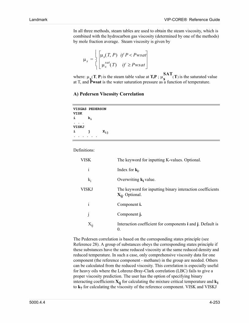
Landmark VIP-CORE® Reference Guide
In all three methods, steam tables are used to obtain the steam viscosity, which is combined with the hydrocarbon gas viscosity (determined by one of the methods) by mole fraction average. Steam viscosity is given by
s
s T P if P Pwsat
ssat
T if Pwsat
=
where: s T P is the steam table value at T,P ; sSAT
T is the saturated value at T, and Pwsat is the water saturation pressure as a function of temperature.
A) Pedersen Viscosity Correlation
VISGAS PEDERSONVISKi ki. . .VISKJi j Xij. . . . . .
Definitions:
VISK The keyword for inputting K-values. Optional.
i Index for ki.
ki Overwriting ki value.
VISKJ The keyword for inputting binary interaction coefficients Xij. Optional.
i Component i.
j Component j.
Xij Interaction coefficient for components i and j. Default is 0.
The Pedersen correlation is based on the corresponding states principle (see Reference 28). A group of substances obeys the corresponding states principle if these substances have the same reduced viscosity at the same reduced density and reduced temperature. In such a case, only comprehensive viscosity data for one component (the reference component - methane) in the group are needed. Others can be calculated from the reduced viscosity. This correlation is especially useful for heavy oils where the Lohrenz-Bray-Clark correlation (LBC) fails to give a proper viscosity prediction. The user has the option of specifying binary interacting coefficients Xij for calculating the mixture critical temperature and k1 to k7 for calculating the viscosity of the reference component. VISK and VISKJ
5000.4.4 4-253
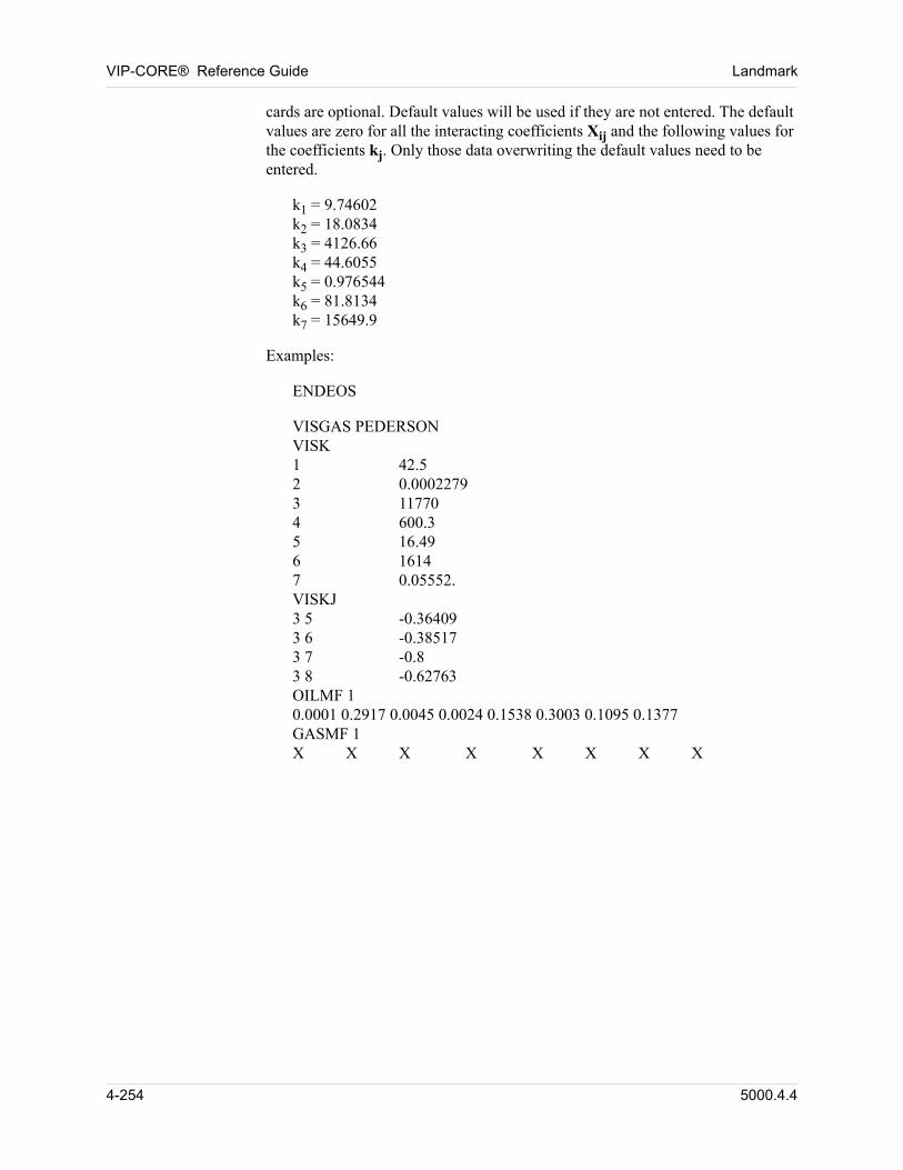
VIP-CORE® Reference Guide Landmark
cards are optional. Default values will be used if they are not entered. The default values are zero for all the interacting coefficients Xij and the following values for the coefficients kj. Only those data overwriting the default values need to be entered.
k1 = 9.74602k2 = 18.0834k3 = 4126.66k4 = 44.6055k5 = 0.976544k6 = 81.8134k7 = 15649.9
Examples:
ENDEOS
VISGAS PEDERSONVISK1 42.52 0.00022793 117704 600.35 16.496 16147 0.05552.VISKJ3 5 -0.364093 6 -0.385173 7 -0.83 8 -0.62763OILMF 10.0001 0.2917 0.0045 0.0024 0.1538 0.3003 0.1095 0.1377GASMF 1X X X X X X X X
4-254 5000.4.4
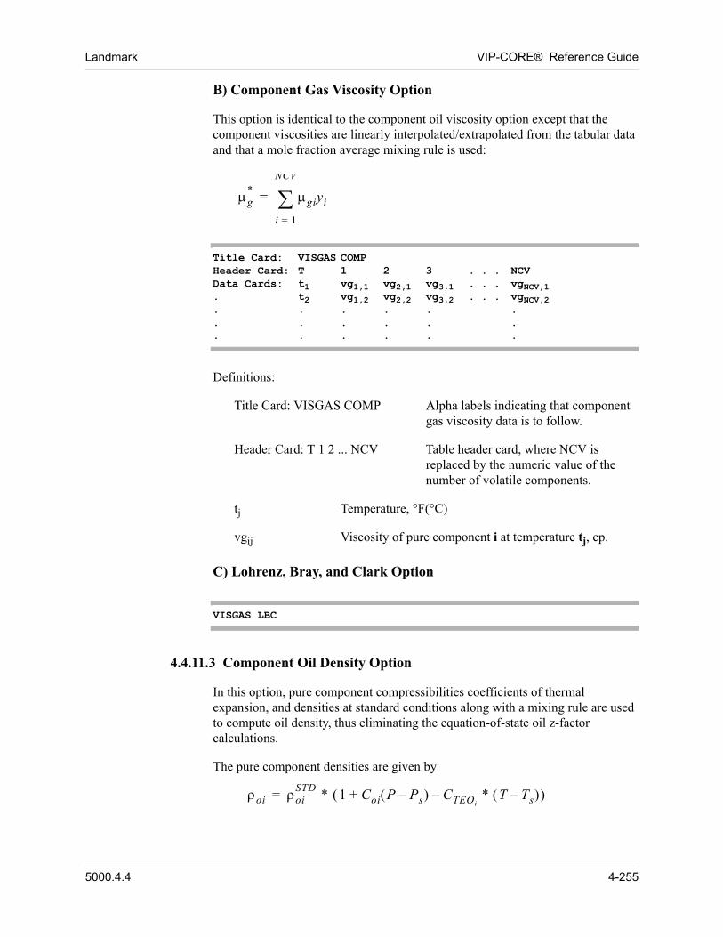
Landmark VIP-CORE® Reference Guide
B) Component Gas Viscosity Option 00
This option is identical to the component oil viscosity option except that the component viscosities are linearly interpolated/extrapolated from the tabular data and that a mole fraction average mixing rule is used:
g* giyi
i 1=
NCV
=
Title Card: VISGAS COMPHeader Card: T 1 2 3 . . . NCVData Cards: t1 vg1,1 vg2,1 vg3,1 . . . vgNCV,1. t2 vg1,2 vg2,2 vg3,2 . . . vgNCV,2. . . . . .. . . . . .. . . . . .
Definitions:
Title Card: VISGAS COMP Alpha labels indicating that component gas viscosity data is to follow.
Header Card: T 1 2 ... NCV Table header card, where NCV is replaced by the numeric value of the number of volatile components.
tj Temperature, °F(°C)
vgij Viscosity of pure component i at temperature tj, cp.
C) Lohrenz, Bray, and Clark Option
VISGAS LBC
4.4.11.3 Component Oil Density Option
In this option, pure component compressibilities coefficients of thermal expansion, and densities at standard conditions along with a mixing rule are used to compute oil density, thus eliminating the equation-of-state oil z-factor calculations.
The pure component densities are given by
oi oiSTD
* 1 Coi P Ps– CTEOi* T Ts– –+ =
5000.4.4 4-255
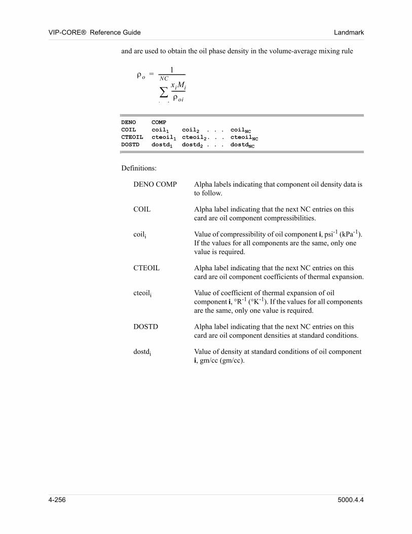
VIP-CORE® Reference Guide Landmark
and are used to obtain the oil phase density in the volume-average mixing rule
o1
xiMi
oi----------
i 1
NC
--------------------=
DENO COMPCOIL coil1 coil2 . . . coilNCCTEOIL cteoil1 cteoil2. . . cteoilNCDOSTD dostd1 dostd2 . . . dostdNC
Definitions:
DENO COMP Alpha labels indicating that component oil density data is to follow.
COIL Alpha label indicating that the next NC entries on this card are oil component compressibilities.
coili Value of compressibility of oil component i, psi-1 (kPa-1). If the values for all components are the same, only one value is required.
CTEOIL Alpha label indicating that the next NC entries on this card are oil component coefficients of thermal expansion.
cteoili Value of coefficient of thermal expansion of oil component i, °R-1 (°K-1). If the values for all components are the same, only one value is required.
DOSTD Alpha label indicating that the next NC entries on this card are oil component densities at standard conditions.
dostdi Value of density at standard conditions of oil component i, gm/cc (gm/cc).
4-256 5000.4.4
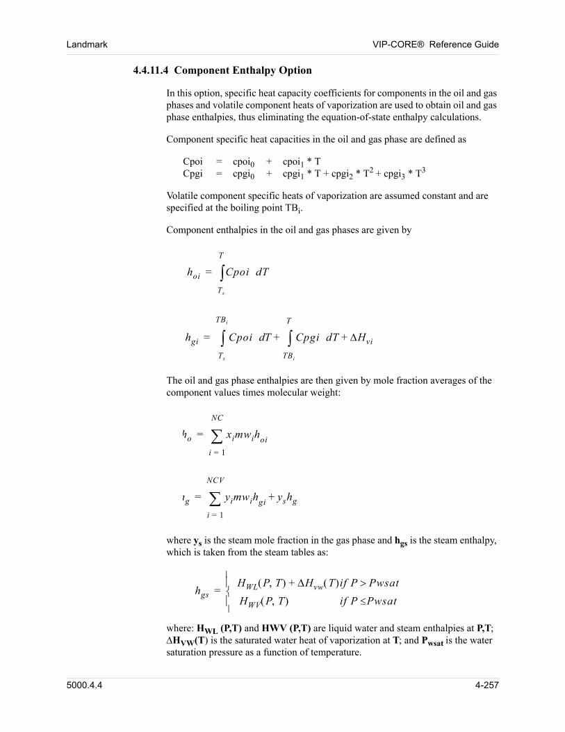
Landmark VIP-CORE® Reference Guide
4.4.11.4 Component Enthalpy Option
In this option, specific heat capacity coefficients for components in the oil and gas phases and volatile component heats of vaporization are used to obtain oil and gas phase enthalpies, thus eliminating the equation-of-state enthalpy calculations.
Component specific heat capacities in the oil and gas phase are defined as
Cpoi = cpoi0 + cpoi1 * TCpgi = cpgi0 + cpgi1 * T + cpgi2 * T2 + cpgi3 * T3
Volatile component specific heats of vaporization are assumed constant and are specified at the boiling point TBi.
Component enthalpies in the oil and gas phases are given by
hoi Cpoi dT
Ts
T
=
hgi Cpoi Td Cpgi dT Hvi+
TBi
T
+
Ts
TBi
=
The oil and gas phase enthalpies are then given by mole fraction averages of the component values times molecular weight:
ho ximwihoi
i 1=
NC
=
hg yimwihgi yshgs+
i 1=
NCV
=
where ys is the steam mole fraction in the gas phase and hgs is the steam enthalpy, which is taken from the steam tables as:
hgsHWL P T Hvw+ T if P Pwsat
HWV P T if P Pwsat
=
where: HWL (P,T) and HWV (P,T) are liquid water and steam enthalpies at P,T; HVW(T) is the saturated water heat of vaporization at T; and Pwsat is the water saturation pressure as a function of temperature.
5000.4.4 4-257
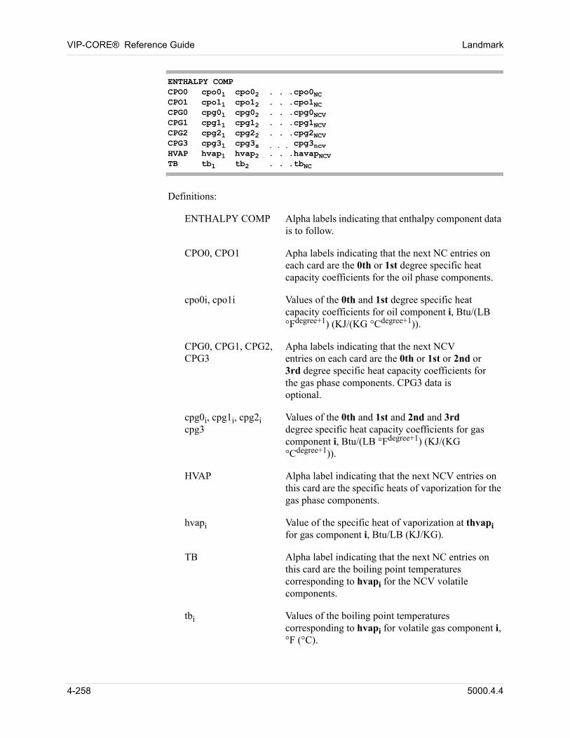
VIP-CORE® Reference Guide Landmark
ENTHALPY COMPCPO0 cpo01 cpo02 . . .cpo0NCCPO1 cpo11 cpo12 . . .cpo1NCCPG0 cpg01 cpg02 . . .cpg0NCVCPG1 cpg11 cpg12 . . .cpg1NCVCPG2 cpg21 cpg22 . . .cpg2NCVCPG3 cpg31 cpg3s . . . cpg3ncvHVAP hvap1 hvap2 . . .havapNCVTB tb1 tb2 . . .tbNC
Definitions:
ENTHALPY COMP Alpha labels indicating that enthalpy component data is to follow.
CPO0, CPO1 Apha labels indicating that the next NC entries on each card are the 0th or 1st degree specific heat capacity coefficients for the oil phase components.
cpo0i, cpo1i Values of the 0th and 1st degree specific heat capacity coefficients for oil component i, Btu/(LB °Fdegree+1) (KJ/(KG °Cdegree+1)).
CPG0, CPG1, CPG2, Apha labels indicating that the next NCV CPG3 entries on each card are the 0th or 1st or 2nd or
3rd degree specific heat capacity coefficients for the gas phase components. CPG3 data is optional.
cpg0i, cpg1i, cpg2i Values of the 0th and 1st and 2nd and 3rd cpg3 degree specific heat capacity coefficients for gas
component i, Btu/(LB °Fdegree+1) (KJ/(KG °Cdegree+1)).
HVAP Alpha label indicating that the next NCV entries on this card are the specific heats of vaporization for the gas phase components.
hvapi Value of the specific heat of vaporization at thvapi for gas component i, Btu/LB (KJ/KG).
TB Alpha label indicating that the next NC entries on this card are the boiling point temperatures corresponding to hvapi for the NCV volatile components.
tbi Values of the boiling point temperatures corresponding to hvapi for volatile gas component i, °F (°C).
4-258 5000.4.4
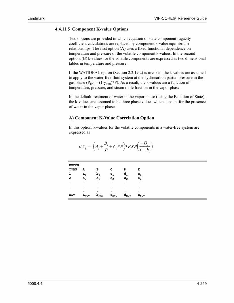
Landmark VIP-CORE® Reference Guide
4.4.11.5 Component K-value Options
Two options are provided in which equation of state component fugacity coefficient calculations are replaced by component k-value equilibrium relationships. The first option (A) uses a fixed functional dependence on temperature and pressure of the volatile component k-values. In the second option, (B) k-values for the volatile components are expressed as two dimensional tables in temperature and pressure.
If the WATIDEAL option (Section 2.2.19.2) is invoked, the k-values are assumed to apply to the water-free fluid system at the hydrocarbon partial pressure in the gas phase (PHC = (1-ystm)*P). As a result, the k-values are a function of temperature, pressure, and steam mole fraction in the vapor phase.
In the default treatment of water in the vapor phase (using the Equation of State), the k-values are assumed to be three phase values which account for the presence of water in the vapor phase.
A) Component K-Value Correlation Option
In this option, k-values for the volatile components in a water-free system are expressed as
KVi Ai
Bi
P----- Ci*P+ +
*EXPDi–
T Ei–-------------- =
KVCORCOMP A B C D E1 a1 b1 c1 d1 e12 a2 b2 c2 d2 e2. . . . . .. . . . . .. . . . . .NCV aNCV bNCV cNVC dNCV eNCV
5000.4.4 4-259
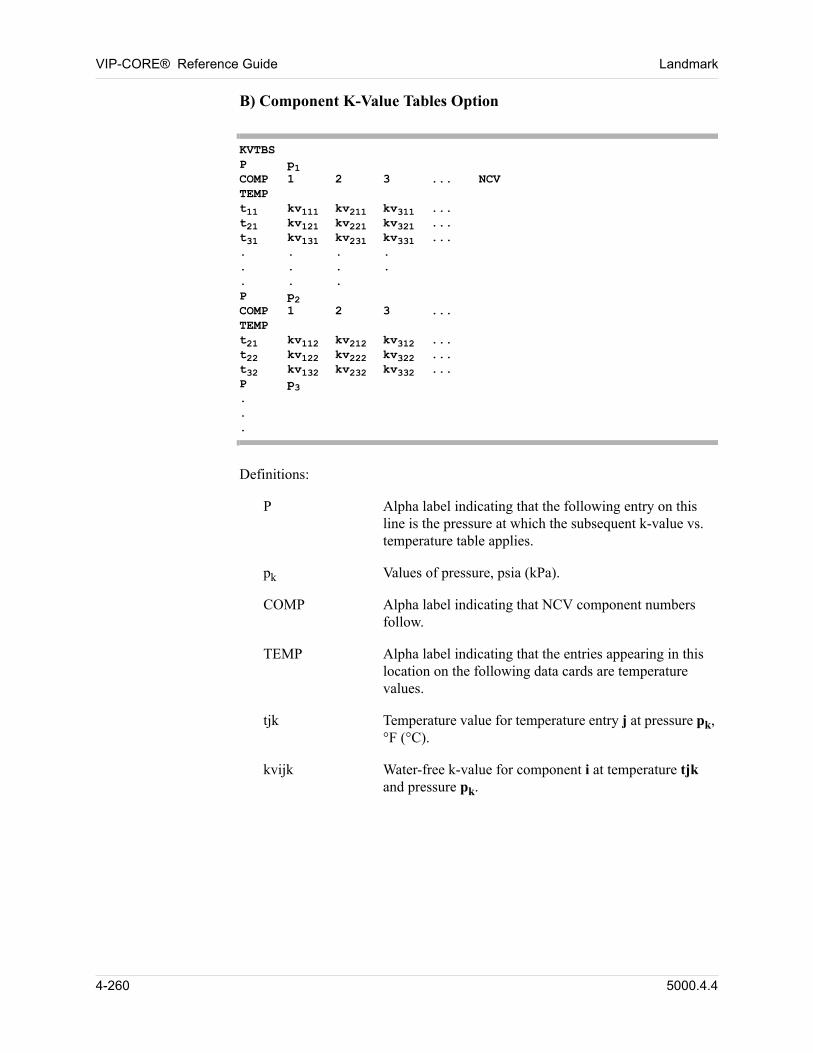
VIP-CORE® Reference Guide Landmark
B) Component K-Value Tables Option
KVTBSP p1COMP 1 2 3 ... NCVTEMPt11 kv111 kv211 kv311 ...t21 kv121 kv221 kv321 ...t31 kv131 kv231 kv331 .... . . .. . . . . . . P p2COMP 1 2 3 ...TEMP t21 kv112 kv212 kv312 ...t22 kv122 kv222 kv322 ...t32 kv132 kv232 kv332 ...P p3...
Definitions:
P Alpha label indicating that the following entry on this line is the pressure at which the subsequent k-value vs. temperature table applies.
pk Values of pressure, psia (kPa).
COMP Alpha label indicating that NCV component numbers follow.
TEMP Alpha label indicating that the entries appearing in this location on the following data cards are temperature values.
tjk Temperature value for temperature entry j at pressure pk, °F (°C).
kvijk Water-free k-value for component i at temperature tjk and pressure pk.
4-260 5000.4.4
Landmark VIP-CORE® Reference Guide
NOTE: 1. Data is required for at least two pressures.
2. At least two temperature entries are required at each pressure.
3. Pressures and temperatures must be monotonically increasing (with the k and j indices, respectively).
4. Linear interpolation is performed in pressure assuming linear kp vs. P and in temperature assuming linear ln k vs. 1/T.
5. Below p1 and above pnp, kp is held constant with pressure.
5000.4.4 4-261
VIP-CORE® Reference Guide Landmark
4.4.12 Initial Fluid Composition Data (VIP-COMP or VIP-THERM)
The initial compositions of the liquid and vapor hydrocarbon phases must be specified to initialize the fluids in the reservoir model. Composition may be constant for a given phase or may vary with depth. Use OILMF/GASMF if PSAT was entered on the IEQUIL card; use COMPOSITION if PSAT was not entered on the IEQUIL card. 00
Initial reservoir temperature may be specified in one or more of the following ways for compositional or thermal models (temperature variation is not allowed in black oil models, but a constant value is required in the constant data): 00
1. Specified as a constant (Required, Section 2.2.4).
2. Specified by equilibrium region in the IEQUIL table (Section 4.2.1.1, 4.2.1.2, 4.2.1.3, or 4.2.2), overriding the constant value in option 1.
3. Specified by equilibrium region, as a function of depth or as a function of depth and areal location, overriding values in options 1 and 2:
a. For isothermal and thermal compositional models, Section 4.4.12.3 or Section 4.4.12.4.
b. For thermal dead oil models, Section 4.7.1 or 4.7.2.
Entering temperature as a function of depth and areal location (Section 4.4.12.4) is discouraged, since the areal temperature variation is not accounted for in the calculation of equilibrium phase pressures versus depth. See option 4 below for further discussion of this problem.
4. Specified as a gridblock array in Section 5.25.1, overriding all other input values. This method is discouraged, since the calculation of the phase pressure versus depth curves by equilibrium region, from which initial gridblock pressures and saturations are computed, does not account for variation of temperature by gridblock (or for areal variation of temperature by equilibrium region). This results in errors in the computed initial gridblock fluid properties of pressure, saturation pressure, phase saturations, and possibly compositions. These errors may be avoided only by specifying all of these initial gridblock fluid properties (only the pressure array in the thermal dead-oil case) as gridblock array data.
00
4-262 5000.4.4
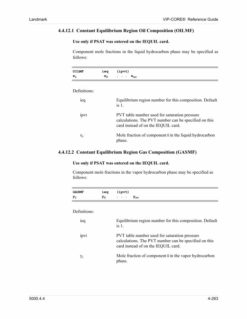
Landmark VIP-CORE® Reference Guide
4.4.12.1 Constant Equilibrium Region Oil Composition (OILMF)
00 Use only if PSAT was entered on the IEQUIL card.
00 Component mole fractions in the liquid hydrocarbon phase may be specified as follows:
OILMF ieq (ipvt)x1 x2 . . . xnc
00 Definitions:
ieq Equilibrium region number for this composition. Default is 1.
ipvt PVT table number used for saturation pressure calculations. The PVT number can be specified on this card instead of on the IEQUIL card.
xi Mole fraction of component i in the liquid hydrocarbon phase.
4.4.12.2 Constant Equilibrium Region Gas Composition (GASMF)
00 Use only if PSAT was entered on the IEQUIL card.
Component mole fractions in the vapor hydrocarbon phase may be specified as follows: 00
GASMF ieq (ipvt)y1 y2 . . . ync
00 Definitions:
ieq Equilibrium region number for this composition. Default is 1.
ipvt PVT table number used for saturation pressure calculations. The PVT number can be specified on this card instead of on the IEQUIL card.
yi Mole fraction of component i in the vapor hydrocarbon phase.
5000.4.4 4-263
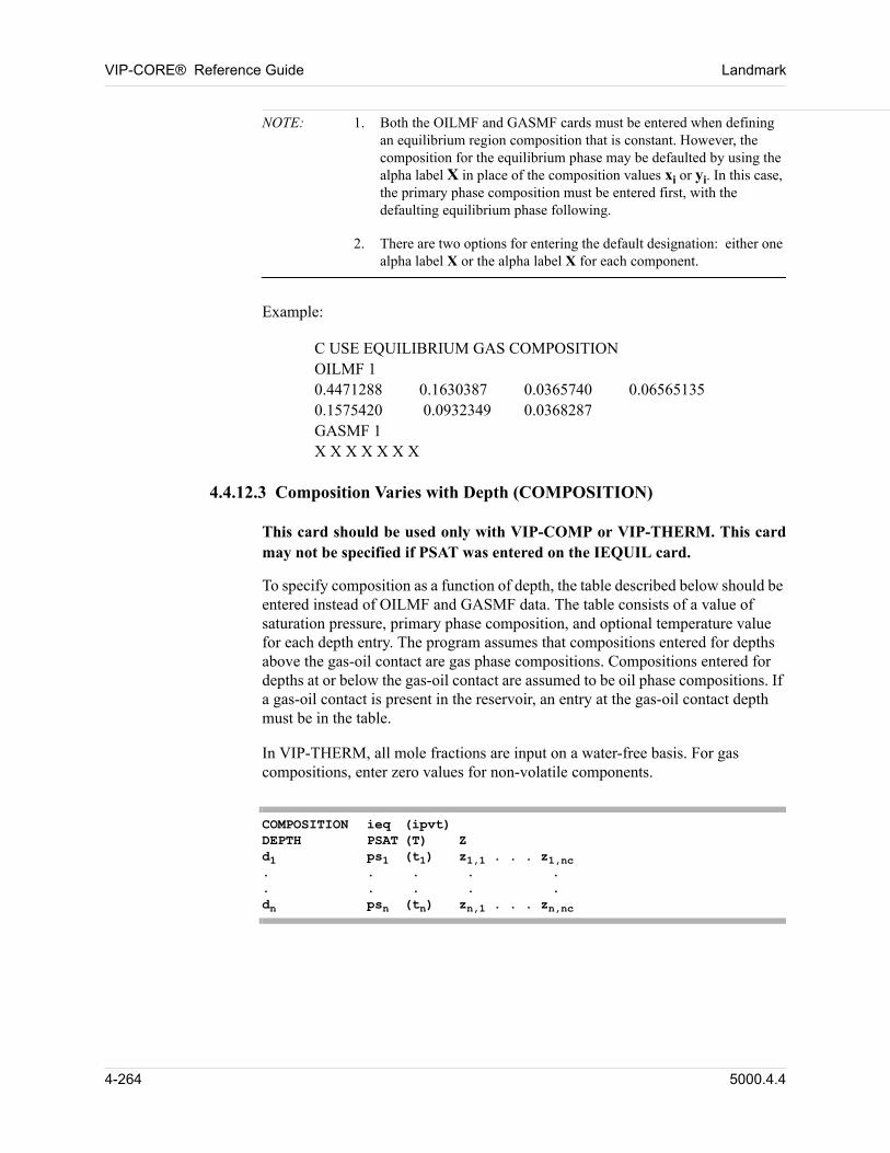
VIP-CORE® Reference Guide Landmark
NOTE: 1. Both the OILMF and GASMF cards must be entered when defining an equilibrium region composition that is constant. However, the composition for the equilibrium phase may be defaulted by using the alpha label X in place of the composition values xi or yi. In this case, the primary phase composition must be entered first, with the defaulting equilibrium phase following.
2. There are two options for entering the default designation: either one alpha label X or the alpha label X for each component.
00 Example:
00 C USE EQUILIBRIUM GAS COMPOSITIONOILMF 10.4471288 0.1630387 0.0365740 0.065651350.1575420 0.0932349 0.0368287GASMF 1X X X X X X X
4.4.12.3 Composition Varies with Depth (COMPOSITION)
00 This card should be used only with VIP-COMP or VIP-THERM. This card may not be specified if PSAT was entered on the IEQUIL card.
00 To specify composition as a function of depth, the table described below should be entered instead of OILMF and GASMF data. The table consists of a value of saturation pressure, primary phase composition, and optional temperature value for each depth entry. The program assumes that compositions entered for depths above the gas-oil contact are gas phase compositions. Compositions entered for depths at or below the gas-oil contact are assumed to be oil phase compositions. If a gas-oil contact is present in the reservoir, an entry at the gas-oil contact depth must be in the table.
00 In VIP-THERM, all mole fractions are input on a water-free basis. For gas compositions, enter zero values for non-volatile components.
COMPOSITION ieq (ipvt)DEPTH PSAT (T) Zd1 ps1 (t1) z1,1 . . . z1,nc. . . . .. . . . .dn psn (tn) zn,1 . . . zn,nc
4-264 5000.4.4
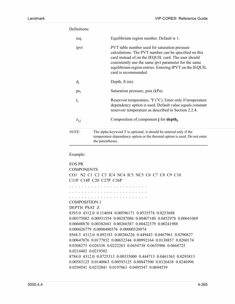
Landmark VIP-CORE® Reference Guide
00 Definitions:
ieq Equilibrium region number. Default is 1.
ipvt PVT table number used for saturation pressure calculations. The PVT number can be specified on this card instead of on the IEQUIL card. The user should consistently use the same ipvt parameter for the same equilibrium region entries. Entering IPVT on the IEQUIL card is recommended.
di Depth, ft (m).
psi Saturation pressure, psia (kPa).
ti Reservoir temperature, °F (°C). Enter only if temperature dependency option is used. Default value equals constant reservoir temperature as described in Section 2.2.4.
zi,j Composition of component j for depthi.
NOTE: The alpha keyword T is optional; it should be entered only if the temperature dependency option or the thermal option is used. Do not enter the parentheses.
00 Example:
00 EOS PRCOMPONENTSCO1 N2 C1 C2 C3 IC4 NC4 IC5 NC5 C6 C7 C8 C9 C10C11P C14P C20 C27P C36P. . . . . . . . . . . . . . . . . . . . . . . . .. . . . . . . . . . . . . . . . . . . . . . . . .. . . . . . . . . . . . . . . . . . . . . . . . .COMPOSITION 1DEPTH PSAT Z8393.0 4312.0 0.114694 0.00596171 0.0535574 0.02536880.00375082 0.00931554 0.00287086 0.00407180 0.0452978 0.006410690.00608870 0.00382681 0.00266587 0.00422379 0.002419880.000426779 0.0000480376 0.000005209748568.5 4312.0 0.092183 0.00286226 0.449443 0.0467961 0.02908270.00647076 0.0177852 0.00652344 0.00992164 0.0138857 0.02601740.0308275 0.026336 0.0222263 0.0454738 0.0655906 0.06687250.0214402 0.02193028784.0 4312.0 0.0725313 0.00335000 0.444713 0.0461563 0.02938130.00583125 0.0140063 0.00593125 0.00847500 0.0126438 0.02469960.0294541 0.0232041 0.0197861 0.0495547 0.0694539
5000.4.4 4-265
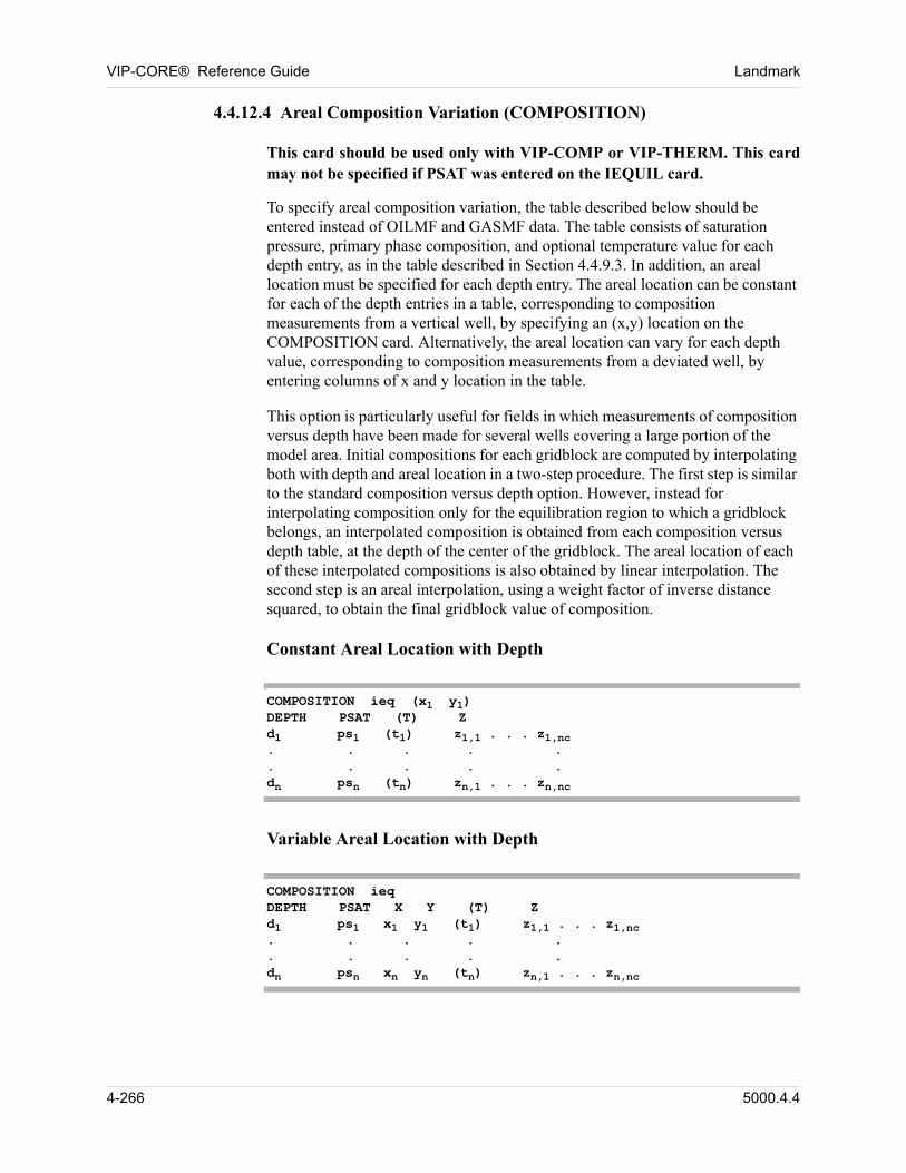
VIP-CORE® Reference Guide Landmark
4.4.12.4 Areal Composition Variation (COMPOSITION)
00 This card should be used only with VIP-COMP or VIP-THERM. This card may not be specified if PSAT was entered on the IEQUIL card.
To specify areal composition variation, the table described below should be entered instead of OILMF and GASMF data. The table consists of saturation pressure, primary phase composition, and optional temperature value for each depth entry, as in the table described in Section 4.4.9.3. In addition, an areal location must be specified for each depth entry. The areal location can be constant for each of the depth entries in a table, corresponding to composition measurements from a vertical well, by specifying an (x,y) location on the COMPOSITION card. Alternatively, the areal location can vary for each depth value, corresponding to composition measurements from a deviated well, by entering columns of x and y location in the table. 00
This option is particularly useful for fields in which measurements of composition versus depth have been made for several wells covering a large portion of the model area. Initial compositions for each gridblock are computed by interpolating both with depth and areal location in a two-step procedure. The first step is similar to the standard composition versus depth option. However, instead for interpolating composition only for the equilibration region to which a gridblock belongs, an interpolated composition is obtained from each composition versus depth table, at the depth of the center of the gridblock. The areal location of each of these interpolated compositions is also obtained by linear interpolation. The second step is an areal interpolation, using a weight factor of inverse distance squared, to obtain the final gridblock value of composition. 00
Constant Areal Location with Depth 00
COMPOSITION ieq (x1 y1)DEPTH PSAT (T) Zd1 ps1 (t1) z1,1 . . . z1,nc. . . . .. . . . .dn psn (tn) zn,1 . . . zn,nc
Variable Areal Location with Depth 00
COMPOSITION ieq DEPTH PSAT X Y (T) Zd1 ps1 x1 y1 (t1) z1,1 . . . z1,nc. . . . .. . . . .dn psn xn yn (tn) zn,1 . . . zn,nc
4-266 5000.4.4
Landmark VIP-CORE® Reference Guide
00 Definitions:
ieq Equilibrium region number. Default is 1.
xi Value of x-direction coordinate location.
yi Value of y-direction coordinate location.
di Depth, ft(m).
psi Saturation pressure, psia(kpa).
ti Reservoir temperature, °F (°C). Enter only if temperature dependency option is used. Default value equals constant reservoir temperature as described in Section 2.2.4.
zi,j Composition of component j for depth i.
NOTE: 1. The alpha keyword T is optional; it should be entered only if the temperature dependency option is used. Do not enter the parentheses.
00 2. Corner point geometry must be used in the model. The areal location of the composition versus depth tables must be (x,y) coordinates, rather than gridblock (i,j) indices.
00 3. Each composition versus depth table must have the areal location specified in order for the option to interpolate properly. Both constant and variable areal location specification may be used in the same data set.
00 4. There must be as many sets if IEQUIL data (Section 4.2.2) as composition versus depth tables. This allows VIP-COMP to calculate phase pressure versus depth tables for each composition table using the standard method. As a result, each gridblock must be assigned to one of the IEQUIL regions, even though the final composition of each block will be derived by interpolation from all the tables.
00 5. The resulting composition distribution is not in capillary-gravity equilibrium. As a result, some initial fluid movement will occur even without production and injection.
00 6. There are no bounds placed on the interpolated fluid compositions other than to normalize them to sum to 1.0. As a result, areas of the model with no measurements nearby may encounter extrapolated values of composition that are inconsistent. To prevent this unconstrained extrapolation, it is recommended to enter additional tables of composition to better control computations in areas without measured data.
5000.4.4 4-267
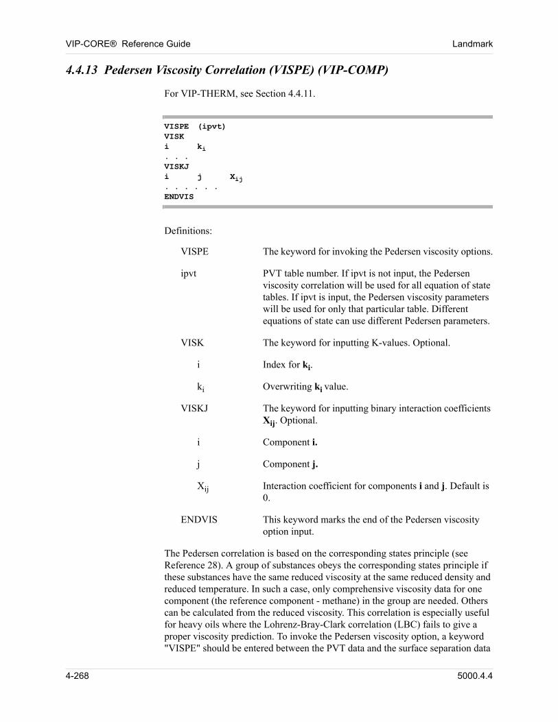
VIP-CORE® Reference Guide Landmark
4.4.13 Pedersen Viscosity Correlation (VISPE) (VIP-COMP)
00 For VIP-THERM, see Section 4.4.11.
VISPE (ipvt)VISKi ki. . .VISKJi j Xij. . . . . .ENDVIS
00 Definitions:
VISPE The keyword for invoking the Pedersen viscosity options.
ipvt PVT table number. If ipvt is not input, the Pedersen viscosity correlation will be used for all equation of state tables. If ipvt is input, the Pedersen viscosity parameters will be used for only that particular table. Different equations of state can use different Pedersen parameters.
VISK The keyword for inputting K-values. Optional.
i Index for ki.
ki Overwriting ki value.
VISKJ The keyword for inputting binary interaction coefficients Xij. Optional.
i Component i.
j Component j.
Xij Interaction coefficient for components i and j. Default is 0.
ENDVIS This keyword marks the end of the Pedersen viscosity option input.
The Pedersen correlation is based on the corresponding states principle (see Reference 28). A group of substances obeys the corresponding states principle if these substances have the same reduced viscosity at the same reduced density and reduced temperature. In such a case, only comprehensive viscosity data for one component (the reference component - methane) in the group are needed. Others can be calculated from the reduced viscosity. This correlation is especially useful for heavy oils where the Lohrenz-Bray-Clark correlation (LBC) fails to give a proper viscosity prediction. To invoke the Pedersen viscosity option, a keyword "VISPE" should be entered between the PVT data and the surface separation data
4-268 5000.4.4
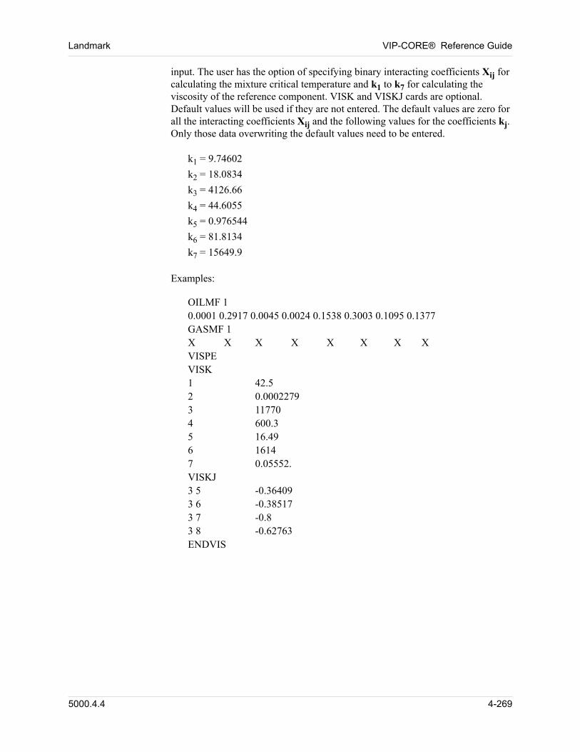
Landmark VIP-CORE® Reference Guide
input. The user has the option of specifying binary interacting coefficients Xij for calculating the mixture critical temperature and k1 to k7 for calculating the viscosity of the reference component. VISK and VISKJ cards are optional. Default values will be used if they are not entered. The default values are zero for all the interacting coefficients Xij and the following values for the coefficients kj. Only those data overwriting the default values need to be entered. 00
00 k1 = 9.74602k2 = 18.0834k3 = 4126.66k4 = 44.6055k5 = 0.976544k6 = 81.8134k7 = 15649.9
00 Examples:
00 OILMF 10.0001 0.2917 0.0045 0.0024 0.1538 0.3003 0.1095 0.1377GASMF 1X X X X X X X XVISPEVISK1 42.52 0.00022793 117704 600.35 16.496 16147 0.05552.VISKJ3 5 -0.364093 6 -0.385173 7 -0.83 8 -0.62763ENDVIS
5000.4.4 4-269
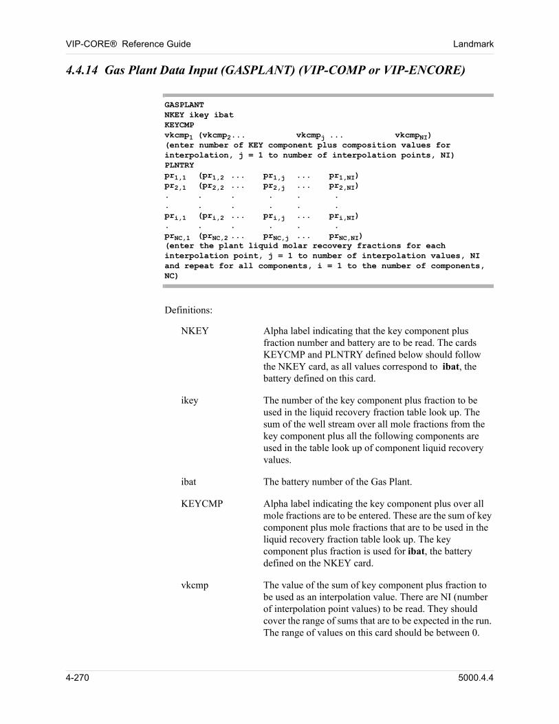
VIP-CORE® Reference Guide Landmark
4.4.14 Gas Plant Data Input (GASPLANT) (VIP-COMP or VIP-ENCORE)
GASPLANTNKEY ikey ibatKEYCMPvkcmp1 (vkcmp2... vkcmpj ... vkcmpNI)(enter number of KEY component plus composition values for interpolation, j = 1 to number of interpolation points, NI)PLNTRYpr1,1 (pr1,2 ... pr1,j ... pr1,NI)pr2,1 (pr2,2 ... pr2,j ... pr2,NI). . . . . .. . . . . .pri,1 (pri,2 ... pri,j ... pri,NI). . . . . .prNC,1 (prNC,2 ... prNC,j ... prNC,NI)(enter the plant liquid molar recovery fractions for each interpolation point, j = 1 to number of interpolation values, NI and repeat for all components, i = 1 to the number of components, NC)
00 Definitions:
NKEY Alpha label indicating that the key component plus fraction number and battery are to be read. The cards KEYCMP and PLNTRY defined below should follow the NKEY card, as all values correspond to ibat, the battery defined on this card.
ikey The number of the key component plus fraction to be used in the liquid recovery fraction table look up. The sum of the well stream over all mole fractions from the key component plus all the following components are used in the table look up of component liquid recovery values.
ibat The battery number of the Gas Plant.
KEYCMP Alpha label indicating the key component plus over all mole fractions are to be entered. These are the sum of key component plus mole fractions that are to be used in the liquid recovery fraction table look up. The key component plus fraction is used for ibat, the battery defined on the NKEY card.
vkcmp The value of the sum of key component plus fraction to be used as an interpolation value. There are NI (number of interpolation point values) to be read. They should cover the range of sums that are to be expected in the run. The range of values on this card should be between 0.
4-270 5000.4.4
Landmark VIP-CORE® Reference Guide
and 1. NI is determined by the number of values read on the card.
PLNTRY Alpha label indicating that the separate liquid recovery fractions will be entered. The liquid recovery fraction is the molar fraction of the component that will be separated to the liquid stream. The plant recovery values are for ibat, the battery that was defined on the NKEY card.
pr The fraction of the component that will be separated to the liquid stream in the Gas Plant. The liquid recovery fractions are entered for each component as a function of the key component plus mole fraction and one value must be entered for NI points and for each component. The data must be ordered so that the liquid recovery fractions should be entered for component 1 for all values of key component plus fraction interpolation points (NI). The next card is for component 2 recovery fractions at NI points. This continues until all component values have been read. In all there should be (NI * NC) values read. The values must be between 0. and 1.
00 Notes:
n Input to a gas plant is the total well stream, while output is determined by the molar liquid recovery fractions. There are no surface flash calculations as are carried out with a normal surface separator.
n A gasplant can be entered in VIP-CORE and/or the simulation modules. Surface batteries in addition to those defined in VIP-CORE may be input, and those defined in VIP-CORE can be redefined in the simulation modules.
n The user may optionally enter the surface separator equation of state parameters. These parameters will be used for the stock tank density calculations to obtain the surface rates. The new equation of state parameters must follow the last stage of the battery to which they apply. The values of the separator equation of state parameters will default to the reservoir if not given.
5000.4.4 4-271
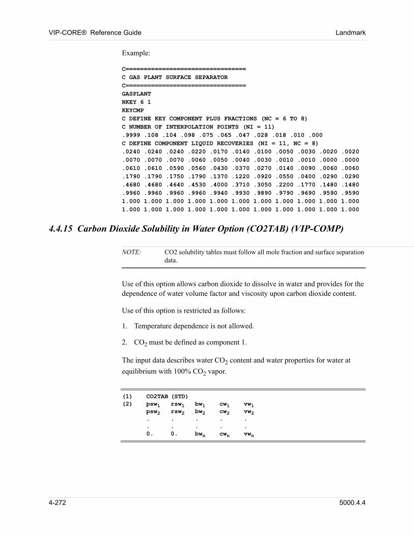
VIP-CORE® Reference Guide Landmark
00 Example:
C=================================C GAS PLANT SURFACE SEPARATORC=================================GASPLANTNKEY 6 1KEYCMPC DEFINE KEY COMPONENT PLUS FRACTIONS (NC = 6 TO 8)C NUMBER OF INTERPOLATION POINTS (NI = 11).9999 .108 .104 .098 .075 .065 .047 .028 .018 .010 .000C DEFINE COMPONENT LIQUID RECOVERIES (NI = 11, NC = 8).0240 .0240 .0240 .0220 .0170 .0140 .0100 .0050 .0030 .0020 .0020.0070 .0070 .0070 .0060 .0050 .0040 .0030 .0010 .0010 .0000 .0000.0610 .0610 .0590 .0560 .0430 .0370 .0270 .0140 .0090 .0060 .0060.1790 .1790 .1750 .1790 .1370 .1220 .0920 .0550 .0400 .0290 .0290.4680 .4680 .4640 .4530 .4000 .3710 .3050 .2200 .1770 .1480 .1480.9960 .9960 .9960 .9960 .9940 .9930 .9890 .9790 .9690 .9590 .95901.000 1.000 1.000 1.000 1.000 1.000 1.000 1.000 1.000 1.000 1.0001.000 1.000 1.000 1.000 1.000 1.000 1.000 1.000 1.000 1.000 1.000
4.4.15 Carbon Dioxide Solubility in Water Option (CO2TAB) (VIP-COMP)
NOTE: CO2 solubility tables must follow all mole fraction and surface separation data.
00 Use of this option allows carbon dioxide to dissolve in water and provides for the dependence of water volume factor and viscosity upon carbon dioxide content.
00 Use of this option is restricted as follows:
1. Temperature dependence is not allowed.
2. CO2 must be defined as component 1.
00 The input data describes water CO2 content and water properties for water at
equilibrium with 100% CO2 vapor.
(1) CO2TAB (STD)(2) psw1 rsw1 bw1 cw1 vw1
psw2 rsw2 bw2 cw2 vw2. . . . .. . . . .0. 0. bwn cwn vwn
4-272 5000.4.4
Landmark VIP-CORE® Reference Guide
00 Definitions:
STD Indicates units of rsw1 are SCF of CO2/STB of water (SM3/STM3). The default is mass of CO2/100 mass units of water.
pswi Values of saturation pressure for CO2/water system, psia (kPa).
rswi Values of quantity of CO2 dissolved in water at equilibrium at pswi.
bwi Values of formation volume factor of CO2 saturated water at pswi, RB/STB (M3/STM3).
cwi Values of water compressibility at pswi, vol/vol/psi (vol/vol/kPa).
vwi Values of CO2 saturated water viscosity at pswi, cp.
00 Water formation volume factor is computed internally as follows:
bwsat
= bw (rsw)
cwsat
= cw (rsw)
pwsat
= psw (rsw)
Bwsat
= 1 bwsat
Bw = Bwsat
1 cwsat
P pwsat
– + , STB/RB (STM3/M3)
00 Notes:
n At least two data cards are required.
n The last data card (pswn = 0, rswn = 0) defines pure water properties.
n Saturated water volume factor, water compressibility, and water viscosity are functions of water CO2 content only.
n Aquifer blocks are initialized at equilibrium with the nonexistent oil phase.
5000.4.4 4-273
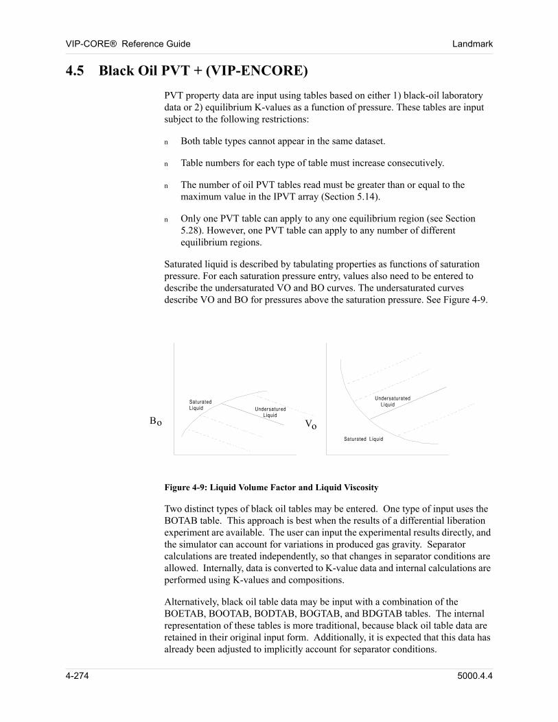
VIP-CORE® Reference Guide Landmark
4.5 Black Oil PVT + (VIP-ENCORE)
PVT property data are input using tables based on either 1) black-oil laboratory data or 2) equilibrium K-values as a function of pressure. These tables are input subject to the following restrictions: 00
n Both table types cannot appear in the same dataset.
n Table numbers for each type of table must increase consecutively.
n The number of oil PVT tables read must be greater than or equal to the maximum value in the IPVT array (Section 5.14).
n Only one PVT table can apply to any one equilibrium region (see Section 5.28). However, one PVT table can apply to any number of different equilibrium regions.
Saturated liquid is described by tabulating properties as functions of saturation pressure. For each saturation pressure entry, values also need to be entered to describe the undersaturated VO and BO curves. The undersaturated curves describe VO and BO for pressures above the saturation pressure. See Figure 4-9. 00
00
VooB
Figure 4-9: Liquid Volume Factor and Liquid Viscosity
00 Two distinct types of black oil tables may be entered. One type of input uses the BOTAB table. This approach is best when the results of a differential liberation experiment are available. The user can input the experimental results directly, and the simulator can account for variations in produced gas gravity. Separator calculations are treated independently, so that changes in separator conditions are allowed. Internally, data is converted to K-value data and internal calculations are performed using K-values and compositions.
00 Alternatively, black oil table data may be input with a combination of the BOETAB, BOOTAB, BODTAB, BOGTAB, and BDGTAB tables. The internal representation of these tables is more traditional, because black oil table data are retained in their original input form. Additionally, it is expected that this data has already been adjusted to implicitly account for separator conditions.
4-274 5000.4.4
Landmark VIP-CORE® Reference Guide
00 The user may choose this alternate form of black oil table data, which we refer to as the modified black oil approach, for a number of reasons. Among them are:
1. The modified approach interpolates directly from the input tables.
2. The modified approach can be used to control the amount of vaporization and oil swelling. It can represent four different cases:
a. Oil swelling without vaporization. This is the traditional black oil model. The BOTAB input format will always lead to some degree of oil vaporization, because of non-zero K-values, but the modified approach can ensure zero vaporization.
b. Vaporization without swelling.
c. Vaporization with swelling.
d. No vaporization or swelling, i.e., no mass transfer between hydrocarbon phases.
3. The modified black oil tables are more flexible because they allow for separate input of oil phase and gas phase tables. This can be considerably more convenient, especially for computer-generated black oil data. The modified tables are also considerably more flexible for the input of undersaturated data, both in terms of the form of the data and the location of the data points. They are also more convenient in that they allow data to be monotonically increasing or decreasing.
00 The original BOTAB table does not allow for the direct specification of a heavy component in the gas phase, so it cannot be used for gas condensate systems. The modified tables allow the user to specify solution oil-gas ratios, which makes them suitable for modeling gas condensate systems.
5000.4.4 4-275
VIP-CORE® Reference Guide Landmark
4.5.1 Black Oil Laboratory Data (VIP-ENCORE)
PVT data for VIP-ENCORE is entered directly from results routinely reported in laboratory differential expansion and constant composition expansion experiments performed at reservoir temperature. No adjustment should be made for separator conditions, since VIP-ENCORE is an extended black-oil model in which phase and volumetric behavior in the reservoir is distinct from that in the separators. The separators are defined by direct input of laboratory separator test data. 00
Alternatively, the conventional black-oil adjustment of the differential expansion test data (oil volume factors, gas-oil ratios, and gas gravities) may be performed and surface separation data omitted. A default separator is provided for this case which gives "flash" volumetrics (oil volume factor and gas-oil ratio) equivalent to the input "differential" volumetrics if the gas gravities have been set to the constant surface gas value. Use of the adjusted data with default separators simplifies VIP-ENCORE to the level of a conventional black-oil simulator in which surface volumes of oil and gas are conserved. 00
Minimum data requirements include the following (items 2, 3, and 5 are adjusted values if VIP-ENCORE is being run in the conventional black-oil mode): 00
1. Density and molecular weight of:
a. The residual oil from the differential expansion, or
b. The reservoir oil at the original bubblepoint.
2. Solution gas-oil ratio Rs as a function of pressure under saturated conditions.
3. Oil formation volume factor Bo as a function of pressure under saturated conditions.
4. Gas compressibility factor (z-factor) or gas formation volume factor Bg as a function of pressure for the equilibrium gas at each stage of the differential expansion.
5. Gas gravity relative to air for the gas removed at each stage of the differential expansion. In most "black-oil" models this is treated as a constant, but gas gravity actually changes with pressure and is reported at each stage by the PVT laboratory. If the correct pressure variation is unknown, a constant value can be entered at each pressure.
6. Viscosity of oil as a function of pressure under saturated conditions. This is normally measured from oil samples removed from a parallel experiment to the one being used for volumetric data.
7. Gas viscosity as a function of pressure for the equilibrium gas. This is normally calculated by the PVT laboratory, rather than being measured.
4-276 5000.4.4
Landmark VIP-CORE® Reference Guide
8. The volume of undersaturated oil relative to the volume of the same oil at its saturation pressure, as a function of pressure elevation above the saturation pressure (p-psat). These values can be taken directly from the relative volume data normally reported among the results of a constant composition expansion experiment.
9. Viscosity of oil measured at undersaturated conditions relative to the viscosity of the same oil at its saturation pressure. Values are tabulated as a function of pressure elevation above the saturation pressure (p-psat).
Since the molecular weight of the residual oil is not usually reported in the differential expansion test, the preferred method is to use values of oil density and molecular weight at the original bubblepoint of the reservoir oil. The molecular weight of the bubblepoint oil is easily calculated from the compositional analysis of the reservoir fluid usually given in the reservoir fluid study. Residual oil molecular weight can be approximated but will lead to inaccuracies in produced oil molecular weight and molar production rates. Surface volumes will not be affected. 00
The data for undersaturated conditions is normally available only for the original oil sample. (Oil that is saturated at the measured bubblepoint of the reservoir.) This is the only data required by the program, but in the event that undersaturated data has been measured for samples at various stages of depletion, the additional data can be used to better define volumetric behavior in the undersaturated region. 00
Similarly, oil properties at saturated conditions are normally reported only at pressures at or below the original bubblepoint of the oil sample. In gas injection projects oil may become saturated at pressures well above the original bubblepoint. Data under such conditions can be determined from the "swelling test" performed by some PVT laboratories. If such data is available, it should be included in the data provided to the program. If unavailable, the user of the program should extrapolate the available data to saturation pressures as high as any that will be encountered in the simulation. Otherwise, the program will extrapolate in a linear fashion as required during the course of the simulation. 00
Since the simulator solves all problems, including black-oil, using multicomponent logic, differential liberation data is internally converted into a compositional format. Properties derived from the input data include oil density, oil z-factor, molecular weight of both oil and gas at each stage of expansion, mole fraction of light and heavy components in both the oil and gas at each stage, and the equilibrium K-values of each component at each stage. If the gas formation volume factor Bg is input, the gas z-factor will also be derived. During the simulation, K-values and z-factors are used for phase behavior and density calculations, rather than Rs, Bo, and Bg values.
The PVT data for saturated conditions (Type 5 Data Cards) is subjected to a consistency check that determines whether the data could lead to a nonpositive total hydrocarbon compressibility. Total hydrocarbon compressibility is given by the following equation:
5000.4.4 4-277
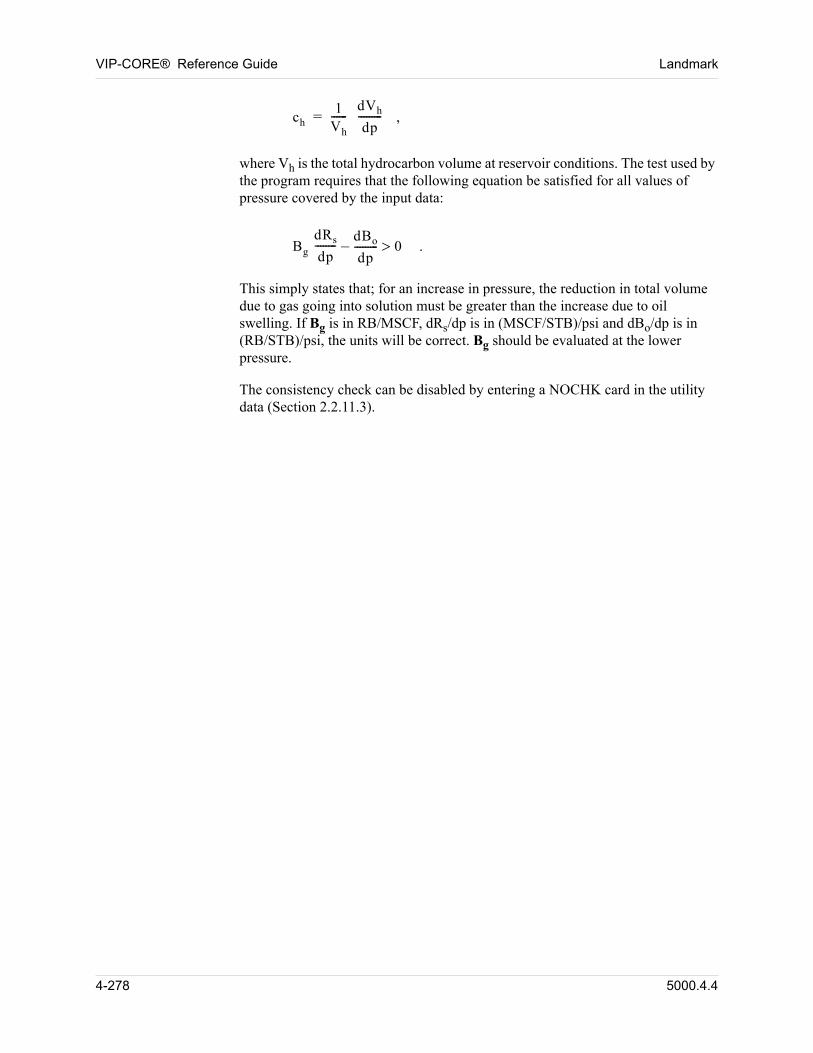
VIP-CORE® Reference Guide Landmark
00 ch1
Vh
------dVh
dp---------= ,
where Vh is the total hydrocarbon volume at reservoir conditions. The test used by the program requires that the following equation be satisfied for all values of pressure covered by the input data:
00 Bg
dRs
dp--------
dBo
dp---------– 0 .
This simply states that; for an increase in pressure, the reduction in total volume due to gas going into solution must be greater than the increase due to oil swelling. If Bg is in RB/MSCF, dRs/dp is in (MSCF/STB)/psi and dBo/dp is in (RB/STB)/psi, the units will be correct. Bg should be evaluated at the lower pressure.
The consistency check can be disabled by entering a NOCHK card in the utility data (Section 2.2.11.3).
4-278 5000.4.4
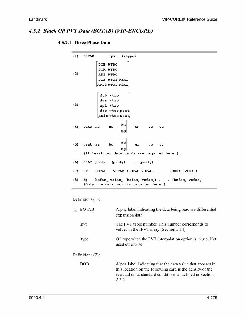
Landmark VIP-CORE® Reference Guide
4.5.2 Black Oil PVT Data (BOTAB) (VIP-ENCORE)
4.5.2.1 Three Phase Data
(1) BOTAB ipvt (itype)(2)
DOB WTRODOR WTROAPI WTRODOS WTOS PSATAPIS WTOS PSAT
(3)
dob wtrodor wtroapi wtrodos wtos psatapis wtos psat
(4) PSAT RS BO ZG
BG GR VO VG
(5) psat rs bo zg
bggr vo vg
(At least two data cards are required here.)
(6) PSAT psat1 (psat2). . . (psati)(7) DP BOFAC VOFAC (BOFAC VOFAC) . . . (BOFAC VOFAC)(8) dp bofac1 vofac1 (bofac2 vofac2) . . . (bofaci vofaci)
(Only one data card is required here.)
00 Definitions (1):
00 (1) BOTAB Alpha label indicating the data being read are differential expansion data.
ipvt The PVT table number. This number corresponds to values in the IPVT array (Section 5.14).
itype Oil type when the PVT interpolation option is in use. Not used otherwise.
00 Definitions (2):
DOB Alpha label indicating that the data value that appears in this location on the following card is the density of the residual oil at standard conditions as defined in Section 2.2.4.
5000.4.4 4-279
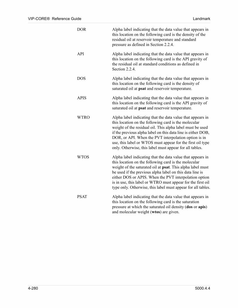
VIP-CORE® Reference Guide Landmark
DOR Alpha label indicating that the data value that appears in this location on the following card is the density of the residual oil at reservoir temperature and standard pressure as defined in Section 2.2.4.
API Alpha label indicating that the data value that appears in this location on the following card is the API gravity of the residual oil at standard conditions as defined in Section 2.2.4.
DOS Alpha label indicating that the data value that appears in this location on the following card is the density of saturated oil at psat and reservoir temperature.
APIS Alpha label indicating that the data value that appears in this location on the following card is the API gravity of saturated oil at psat and reservoir temperature.
WTRO Alpha label indicating that the data value that appears in this location on the following card is the molecular weight of the residual oil. This alpha label must be used if the previous alpha label on this data line is either DOB, DOR, or API. When the PVT interpolation option is in use, this label or WTOS must appear for the first oil type only. Otherwise, this label must appear for all tables.
WTOS Alpha label indicating that the data value that appears in this location on the following card is the molecular weight of the saturated oil at psat. This alpha label must be used if the previous alpha label on this data line is either DOS or APIS. When the PVT interpolation option is in use, this label or WTRO must appear for the first oil type only. Otherwise, this label must appear for all tables.
PSAT Alpha label indicating that the data value that appears in this location on the following card is the saturation pressure at which the saturated oil density (dos or apis) and molecular weight (wtos) are given.
4-280 5000.4.4
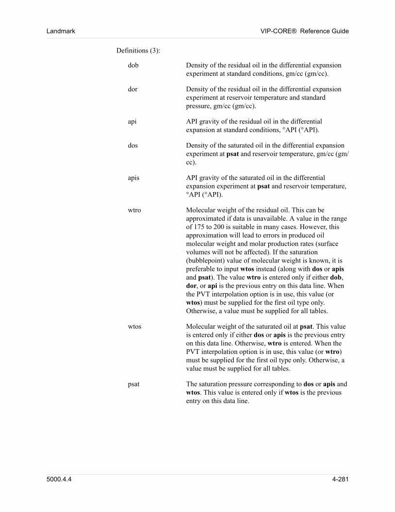
Landmark VIP-CORE® Reference Guide
00 Definitions (3):
dob Density of the residual oil in the differential expansion experiment at standard conditions, gm/cc (gm/cc).
dor Density of the residual oil in the differential expansion experiment at reservoir temperature and standard pressure, gm/cc (gm/cc).
api API gravity of the residual oil in the differential expansion at standard conditions, °API (°API).
dos Density of the saturated oil in the differential expansion experiment at psat and reservoir temperature, gm/cc (gm/cc).
apis API gravity of the saturated oil in the differential expansion experiment at psat and reservoir temperature, °API (°API).
wtro Molecular weight of the residual oil. This can be approximated if data is unavailable. A value in the range of 175 to 200 is suitable in many cases. However, this approximation will lead to errors in produced oil molecular weight and molar production rates (surface volumes will not be affected). If the saturation (bubblepoint) value of molecular weight is known, it is preferable to input wtos instead (along with dos or apis and psat). The value wtro is entered only if either dob, dor, or api is the previous entry on this data line. When the PVT interpolation option is in use, this value (or wtos) must be supplied for the first oil type only. Otherwise, a value must be supplied for all tables.
wtos Molecular weight of the saturated oil at psat. This value is entered only if either dos or apis is the previous entry on this data line. Otherwise, wtro is entered. When the PVT interpolation option is in use, this value (or wtro) must be supplied for the first oil type only. Otherwise, a value must be supplied for all tables.
psat The saturation pressure corresponding to dos or apis and wtos. This value is entered only if wtos is the previous entry on this data line.
5000.4.4 4-281
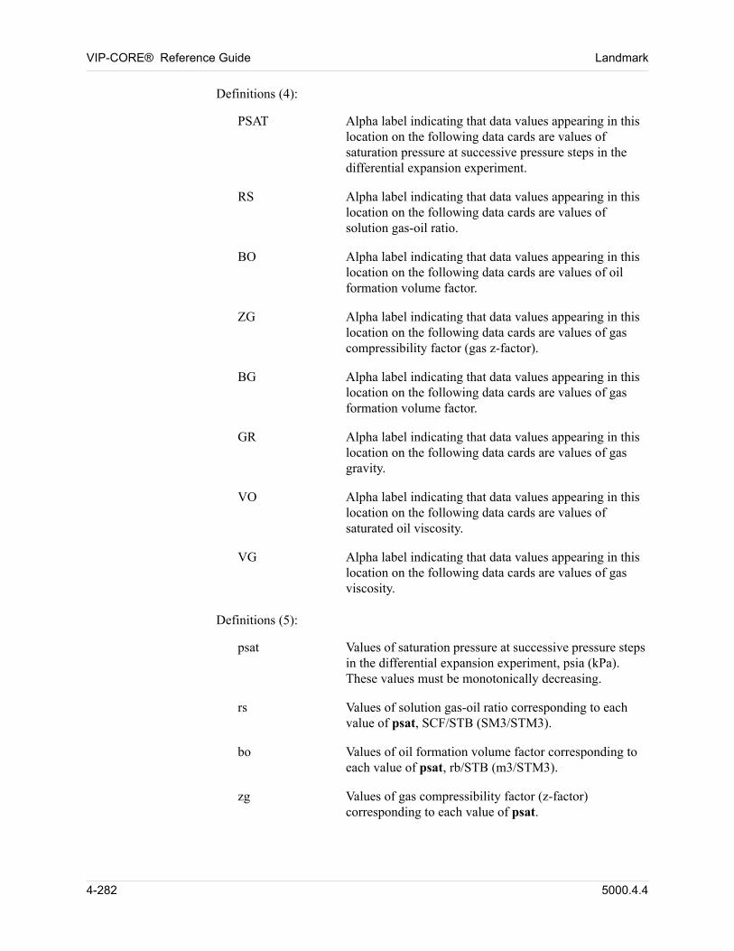
VIP-CORE® Reference Guide Landmark
00 Definitions (4):
PSAT Alpha label indicating that data values appearing in this location on the following data cards are values of saturation pressure at successive pressure steps in the differential expansion experiment.
RS Alpha label indicating that data values appearing in this location on the following data cards are values of solution gas-oil ratio.
BO Alpha label indicating that data values appearing in this location on the following data cards are values of oil formation volume factor.
ZG Alpha label indicating that data values appearing in this location on the following data cards are values of gas compressibility factor (gas z-factor).
BG Alpha label indicating that data values appearing in this location on the following data cards are values of gas formation volume factor.
GR Alpha label indicating that data values appearing in this location on the following data cards are values of gas gravity.
VO Alpha label indicating that data values appearing in this location on the following data cards are values of saturated oil viscosity.
VG Alpha label indicating that data values appearing in this location on the following data cards are values of gas viscosity.
00 Definitions (5):
psat Values of saturation pressure at successive pressure steps in the differential expansion experiment, psia (kPa). These values must be monotonically decreasing.
rs Values of solution gas-oil ratio corresponding to each value of psat, SCF/STB (SM3/STM3).
bo Values of oil formation volume factor corresponding to each value of psat, rb/STB (m3/STM3).
zg Values of gas compressibility factor (z-factor) corresponding to each value of psat.
4-282 5000.4.4
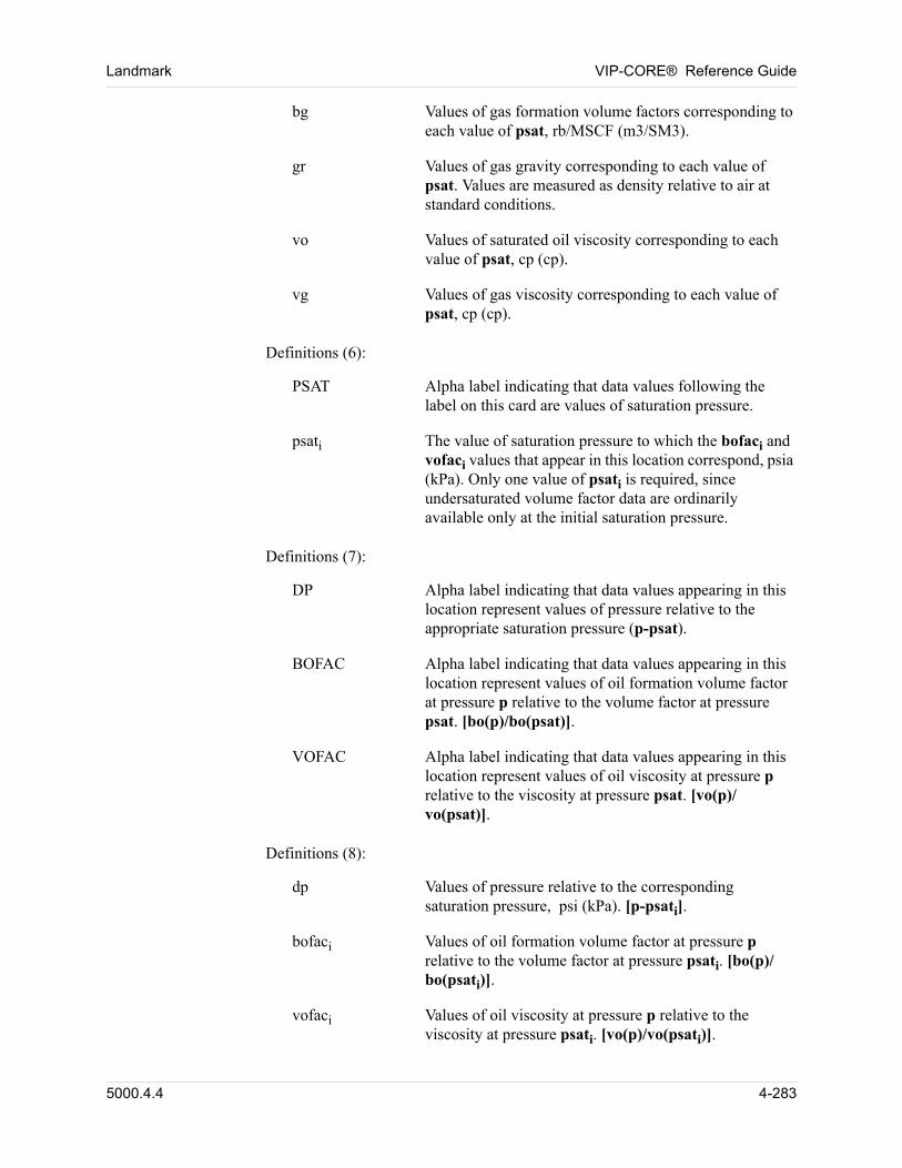
Landmark VIP-CORE® Reference Guide
bg Values of gas formation volume factors corresponding to each value of psat, rb/MSCF (m3/SM3).
gr Values of gas gravity corresponding to each value of psat. Values are measured as density relative to air at standard conditions.
vo Values of saturated oil viscosity corresponding to each value of psat, cp (cp).
vg Values of gas viscosity corresponding to each value of psat, cp (cp).
00 Definitions (6):
PSAT Alpha label indicating that data values following the label on this card are values of saturation pressure.
psati The value of saturation pressure to which the bofaci and vofaci values that appear in this location correspond, psia (kPa). Only one value of psati is required, since undersaturated volume factor data are ordinarily available only at the initial saturation pressure.
00 Definitions (7):
DP Alpha label indicating that data values appearing in this location represent values of pressure relative to the appropriate saturation pressure (p-psat).
BOFAC Alpha label indicating that data values appearing in this location represent values of oil formation volume factor at pressure p relative to the volume factor at pressure psat. [bo(p)/bo(psat)].
VOFAC Alpha label indicating that data values appearing in this location represent values of oil viscosity at pressure p relative to the viscosity at pressure psat. [vo(p)/vo(psat)].
00 Definitions (8):
dp Values of pressure relative to the corresponding saturation pressure, psi (kPa). [p-psati].
bofaci Values of oil formation volume factor at pressure p relative to the volume factor at pressure psati. [bo(p)/bo(psati)].
vofaci Values of oil viscosity at pressure p relative to the viscosity at pressure psati. [vo(p)/vo(psati)].
5000.4.4 4-283
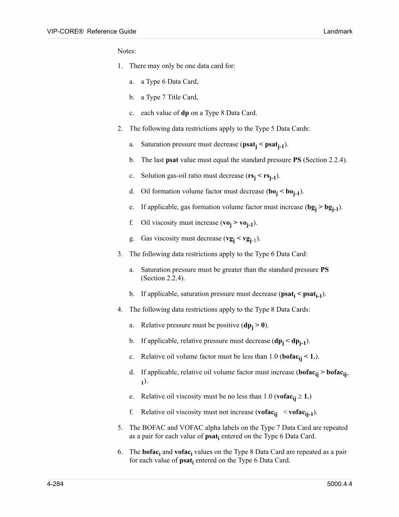
VIP-CORE® Reference Guide Landmark
00 Notes:
1. There may only be one data card for:
a. a Type 6 Data Card,
b. a Type 7 Title Card,
c. each value of dp on a Type 8 Data Card.
2. The following data restrictions apply to the Type 5 Data Cards:
a. Saturation pressure must decrease (psatj < psatj-1).
b. The last psat value must equal the standard pressure PS (Section 2.2.4).
c. Solution gas-oil ratio must decrease (rsj < rsj-1).
d. Oil formation volume factor must decrease (boj < boj-1).
e. If applicable, gas formation volume factor must increase (bgj > bgj-1).
f. Oil viscosity must increase (voj > voj-1).
g. Gas viscosity must decrease (vgj < vgj-1).
3. The following data restrictions apply to the Type 6 Data Card:
a. Saturation pressure must be greater than the standard pressure PS (Section 2.2.4).
b. If applicable, saturation pressure must decrease (psati < psati-1).
4. The following data restrictions apply to the Type 8 Data Cards:
a. Relative pressure must be positive (dpj > 0).
b. If applicable, relative pressure must decrease (dpj < dpj-1).
c. Relative oil volume factor must be less than 1.0 (bofacij < 1.).
d. If applicable, relative oil volume factor must increase (bofacij > bofacij-
1).
e. Relative oil viscosity must be no less than 1.0 (vofacij1.)
f. Relative oil viscosity must not increase (vofacij < vofacij-1).
5. The BOFAC and VOFAC alpha labels on the Type 7 Data Card are repeated as a pair for each value of psati entered on the Type 6 Data Card.
6. The bofaci and vofaci values on the Type 8 Data Card are repeated as a pair for each value of psati entered on the Type 6 Data Card.
4-284 5000.4.4
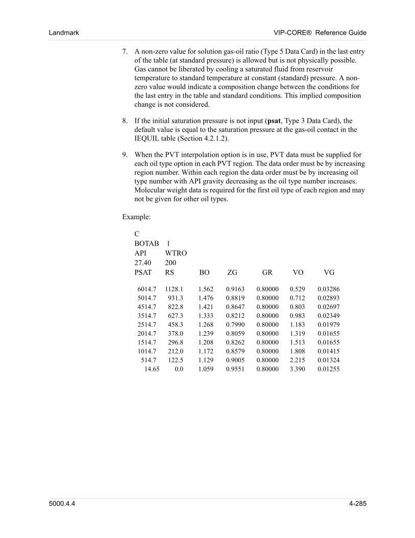
Landmark VIP-CORE® Reference Guide
7. A non-zero value for solution gas-oil ratio (Type 5 Data Card) in the last entry of the table (at standard pressure) is allowed but is not physically possible. Gas cannot be liberated by cooling a saturated fluid from reservoir temperature to standard temperature at constant (standard) pressure. A non-zero value would indicate a composition change between the conditions for the last entry in the table and standard conditions. This implied composition change is not considered.
8. If the initial saturation pressure is not input (psat, Type 3 Data Card), the default value is equal to the saturation pressure at the gas-oil contact in the IEQUIL table (Section 4.2.1.2).
9. When the PVT interpolation option is in use, PVT data must be supplied for each oil type option in each PVT region. The data order must be by increasing region number. Within each region the data order must be by increasing oil type number with API gravity decreasing as the oil type number increases. Molecular weight data is required for the first oil type of each region and may not be given for other oil types.
00 Example:
00 CBOTAB 1API WTRO27.40 200PSAT RS BO ZG GR VO VG
00 6014.7 1128.1 1.562 0.9163 0.80000 0.529 0.032865014.7 931.3 1.476 0.8819 0.80000 0.712 0.028934514.7 822.8 1.421 0.8647 0.80000 0.803 0.026973514.7 627.3 1.333 0.8212 0.80000 0.983 0.023492514.7 458.3 1.268 0.7990 0.80000 1.183 0.019792014.7 378.0 1.239 0.8059 0.80000 1.319 0.016551514.7 296.8 1.208 0.8262 0.80000 1.513 0.016551014.7 212.0 1.172 0.8579 0.80000 1.808 0.01415
514.7 122.5 1.129 0.9005 0.80000 2.215 0.0132414.65 0.0 1.059 0.9551 0.80000 3.390 0.01255
5000.4.4 4-285
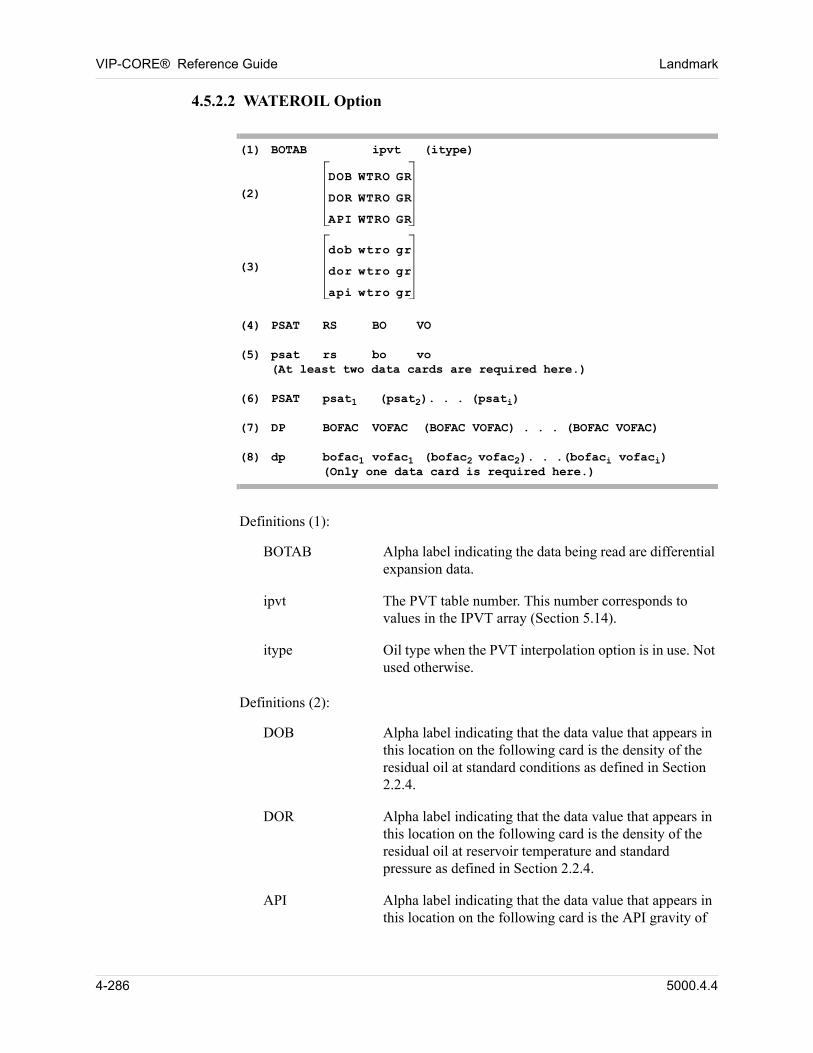
VIP-CORE® Reference Guide Landmark
4.5.2.2 WATEROIL Option
(1) BOTAB ipvt (itype)(2)
DOB WTRO GR
DOR WTRO GR
API WTRO GR
(3)
dob wtro gr
dor wtro gr
api wtro gr
(4) PSAT RS BO VO(5) psat rs bo vo
(At least two data cards are required here.)(6) PSAT psat1 (psat2). . . (psati)(7) DP BOFAC VOFAC (BOFAC VOFAC) . . . (BOFAC VOFAC)(8) dp bofac1 vofac1 (bofac2 vofac2). . .(bofaci vofaci)
(Only one data card is required here.)
00 Definitions (1):
BOTAB Alpha label indicating the data being read are differential expansion data.
ipvt The PVT table number. This number corresponds to values in the IPVT array (Section 5.14).
itype Oil type when the PVT interpolation option is in use. Not used otherwise.
00 Definitions (2):
DOB Alpha label indicating that the data value that appears in this location on the following card is the density of the residual oil at standard conditions as defined in Section 2.2.4.
DOR Alpha label indicating that the data value that appears in this location on the following card is the density of the residual oil at reservoir temperature and standard pressure as defined in Section 2.2.4.
API Alpha label indicating that the data value that appears in this location on the following card is the API gravity of
4-286 5000.4.4
Landmark VIP-CORE® Reference Guide
the residual oil at standard conditions as defined in Section 2.2.4.
WTRO Alpha label indicating that the data value that appears in this location on the following card is the molecular weight of the residual oil. When the PVT interpolation option is in use, this label must appear for the first oil type only. Otherwise, this label must appear for all tables.
GR Alpha label indicating that the data value appearing in this location on the following card is the gas gravity of the solution gas.
00 Definitions (3):
dob Density of the residual oil in the differential expansion experiment at standard conditions, gm/cc (gm/cc).
dor Density of the residual oil in the differential expansion experiment at reservoir temperature and standard pressure, gm/cc (gm/cc).
api API gravity of the residual oil in the differential expansion at standard conditions, °API (°API).
wtro Molecular weight of the residual oil. This can be approximated if data is unavailable. A value in the range of 175 to 200 is suitable in many cases. When the PVT interpolation option is in use, this value must appear for the first oil type only. Otherwise, the value must appear for all tables.
gr The gas gravity of the solution gas.
00 Definitions (4):
PSAT Alpha label indicating that data values appearing in this location on the following data cards are values of saturation pressure at successive pressure steps in the differential expansion experiment.
RS Alpha label indicating that data values appearing in this location on the following data cards are values of solution gas-oil ratio.
BO Alpha label indicating that data values appearing in this location on the following data cards are values of oil formation volume factor.
5000.4.4 4-287
VIP-CORE® Reference Guide Landmark
VO Alpha label indicating that data values appearing in this location on the following data cards are values of saturated oil viscosity.
00 Definitions (5):
psat Values of saturation pressure at successive pressure steps in the differential expansion experiment, psia (kPa). These values must be monotonically decreasing.
rs Values of solution gas-oil ratio corresponding to each value of psat, SCF/STB (SM3/STM3).
bo Values of oil formation volume factor corresponding to each value of psat, rb/STB (m3/STM3).
vo Values of saturated oil viscosity corresponding to each value of psat, cp (cp).
00 Definitions (6):
PSAT Alpha label indicating that data values following the label on this card are values of saturation pressure.
psati The value of saturation pressure to which the botaci and votaci values that appear on the Type 8 Data Cards correspond, psia (Kpa). Only one value of psati is required, since undersaturated volume factor data are ordinarily available only at the initial saturation pressure.
00 Definitions (7):
DP Alpha label indicating that data values appearing in this location on the Type 8 Data Cards represent values of pressure relative to the appropriate saturation pressure (p-psat).
BOFAC Alpha label indicating that data values appearing in this location on the Type 8 Data Cards represent values of oil formation volume factor at pressure p relative to the volume factor at pressure psat. [bo(p)/bo(psat)].
VOFAC Alpha label indicating that data values appearing in this location on the Type 8 Data Cards represent values of oil viscosity at pressure p relative to the viscosity at pressure psat. [vo(p)/vo(psat)].
00 Definitions (8):
4-288 5000.4.4
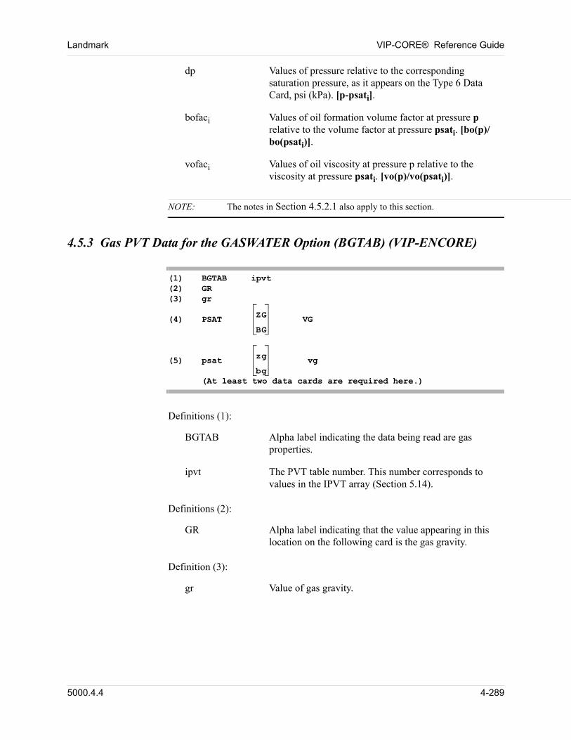
Landmark VIP-CORE® Reference Guide
dp Values of pressure relative to the corresponding saturation pressure, as it appears on the Type 6 Data Card, psi (kPa). [p-psati].
bofaci Values of oil formation volume factor at pressure p relative to the volume factor at pressure psati. [bo(p)/bo(psati)].
vofaci Values of oil viscosity at pressure p relative to the viscosity at pressure psati. [vo(p)/vo(psati)].
NOTE: The notes in Section 4.5.2.1 also apply to this section.
4.5.3 Gas PVT Data for the GASWATER Option (BGTAB) (VIP-ENCORE)
(1) BGTAB ipvt(2) GR(3) gr(4) PSAT ZG
BGVG
(5) psat zg
bg vg
(At least two data cards are required here.)
00 Definitions (1):
BGTAB Alpha label indicating the data being read are gas properties.
ipvt The PVT table number. This number corresponds to values in the IPVT array (Section 5.14).
00 Definitions (2):
GR Alpha label indicating that the value appearing in this location on the following card is the gas gravity.
00 Definition (3):
gr Value of gas gravity.
5000.4.4 4-289
VIP-CORE® Reference Guide Landmark
00 Definitions (4):
PSAT Alpha label indicating that data values appearing in this location on the following data cards are values of pressure.
ZG Alpha label indicating that data values appearing in this location on the following data cards are values of gas compressibility factor (gas z-factor).
BG Alpha label indicating that data values appearing in this location on the following data cards are values of gas formation volume factor.
VG Alpha label indicating that data values appearing in this location on the following data cards are values of gas viscosity.
00 Definitions (5):
psat Values of pressure, psia (kPa).
zg Values of gas compressibility factor (z-factor) corresponding to each value of psat.
bg Values of gas formation volume factors corresponding to each value of psat, rb/MSCF (m3/SM3). If applicable, gas formation volume factor must increase (bg(j) > bg (j-1)).
vg Values of gas viscosity corresponding to each value of psat, cp (cp). Gas viscosity must decrease (vg(j) < vg(j-1)).
NOTE: The notes in Section 4.5.2.1 also apply to this section.
4-290 5000.4.4
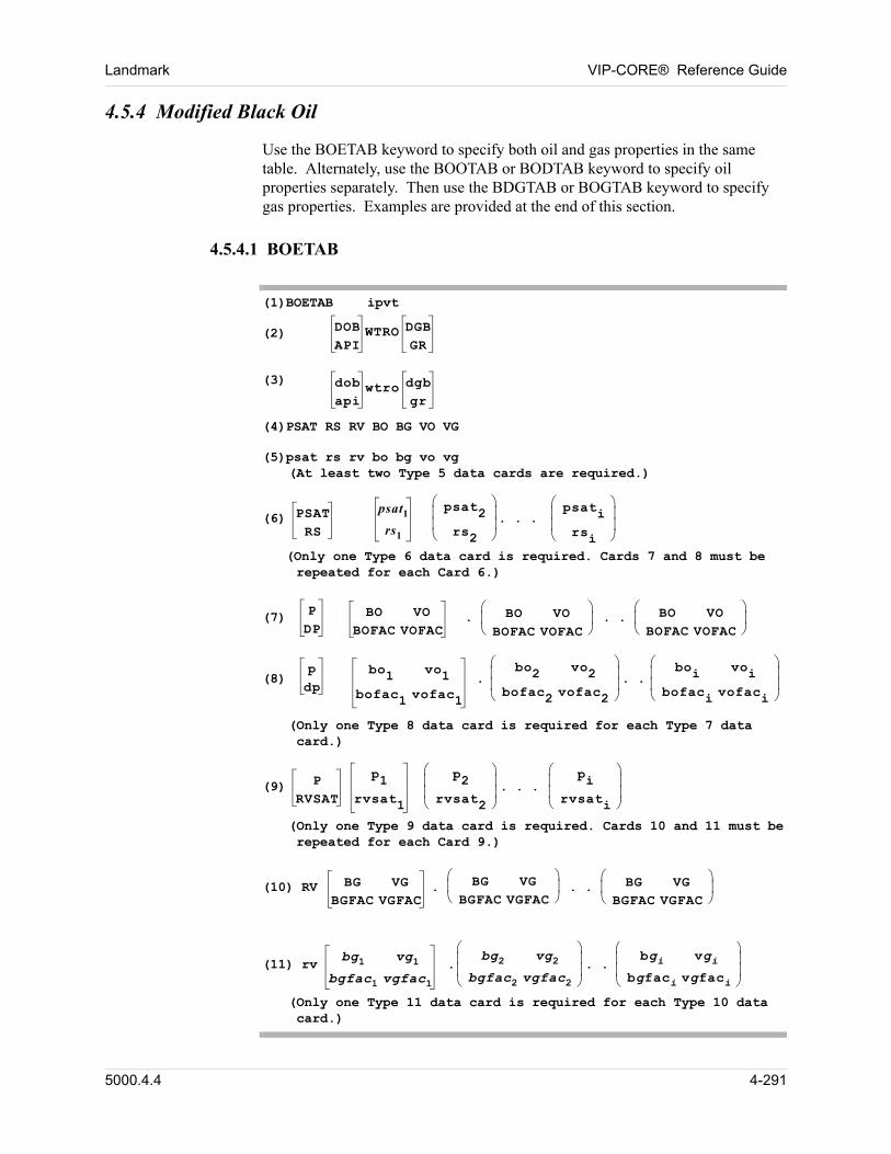
Landmark VIP-CORE® Reference Guide
4.5.4 Modified Black Oil
00 Use the BOETAB keyword to specify both oil and gas properties in the same table. Alternately, use the BOOTAB or BODTAB keyword to specify oil properties separately. Then use the BDGTAB or BOGTAB keyword to specify gas properties. Examples are provided at the end of this section.
4.5.4.1 BOETAB
(1)BOETAB ipvt
(2) DOBAPI
WTRO DGBGR
(3) dobapi
wtro dgbgr
(4)PSAT RS RV BO BG VO VG
(5)psat rs rv bo bg vo vg(At least two Type 5 data cards are required.)
(6) PSATRS
psat1
rs1
psat2rs2
. . . psatirsi
(Only one Type 6 data card is required. Cards 7 and 8 must be repeated for each Card 6.)
(7) PDP
BO VOBOFAC VOFAC
. BO VOBOFAC VOFAC
. . BO VOBOFAC VOFAC
(8)pdp
bo1 vo1
bofac1 vofac1
.bo2 vo2
bofac2 vofac2
. .boi voi
bofaci vofaci
(Only one Type 8 data card is required for each Type 7 data card.)
(9) PRVSAT
p1rvsat1
p2
rvsat2
. . . pi
rvsati
(Only one Type 9 data card is required. Cards 10 and 11 must be repeated for each Card 9.)
(10) RV BG VGBGFAC VGFAC
. BG VGBGFAC VGFAC
. . BG VGBGFAC VGFAC
(11) rvbg1 vg1
bgfac1 vgfac1 .
bg2 vg2bgfac2 vgfac2
. .bgi vgi
bgfaci vgfaci
(Only one Type 11 data card is required for each Type 10 data card.)
5000.4.4 4-291
VIP-CORE® Reference Guide Landmark
00 Definitions (1):
(1) BOETAB Alpha label indicating the data being read are extended black oil data, with both oil and gas data read in the same table.
ipvt The PVT table number. This number corresponds to values in the IPVT array.
00 Definitions (2):
DOB Alpha label indicating that the data value that appears in this location on the following card is the density of the residual oil at standard conditions as defined in Section 2.2.4.
API Alpha label indicating that the data value that appears in this location on the following card is the API gravity of the residual oil at standard conditions as defined in Section 2.2.4.
WTRO Alpha label indicating that the data value that appears in this location on the following card is the molecular weight of the residual oil. This alpha label must be used if the previous alpha label on this data line is either DOB, DOR, or API.
DGB Alpha label indicating that the data value that appears in this location on the following card is the density of the gas at standard conditions as defined in Section 2.2.4.
GR Alpha label indicating that the data value that appears in this location on the following card is the specific gravity of the gas at standard conditions as defined in Section 2.2.4.
Definitions (3): 00
dob Density of the residual oil at standard conditions, gm/cc (gm/cc).
api API gravity of the residual oil at standard conditions, °API (°API).
wtro Molecular weight of the residual oil. This can be approximated if data is unavailable. A value in the range of 175 to 200 is suitable in many cases. However, this approximation will lead to errors in produced oil molecular weight and molar production rates (surface volumes will not be affected).
4-292 5000.4.4
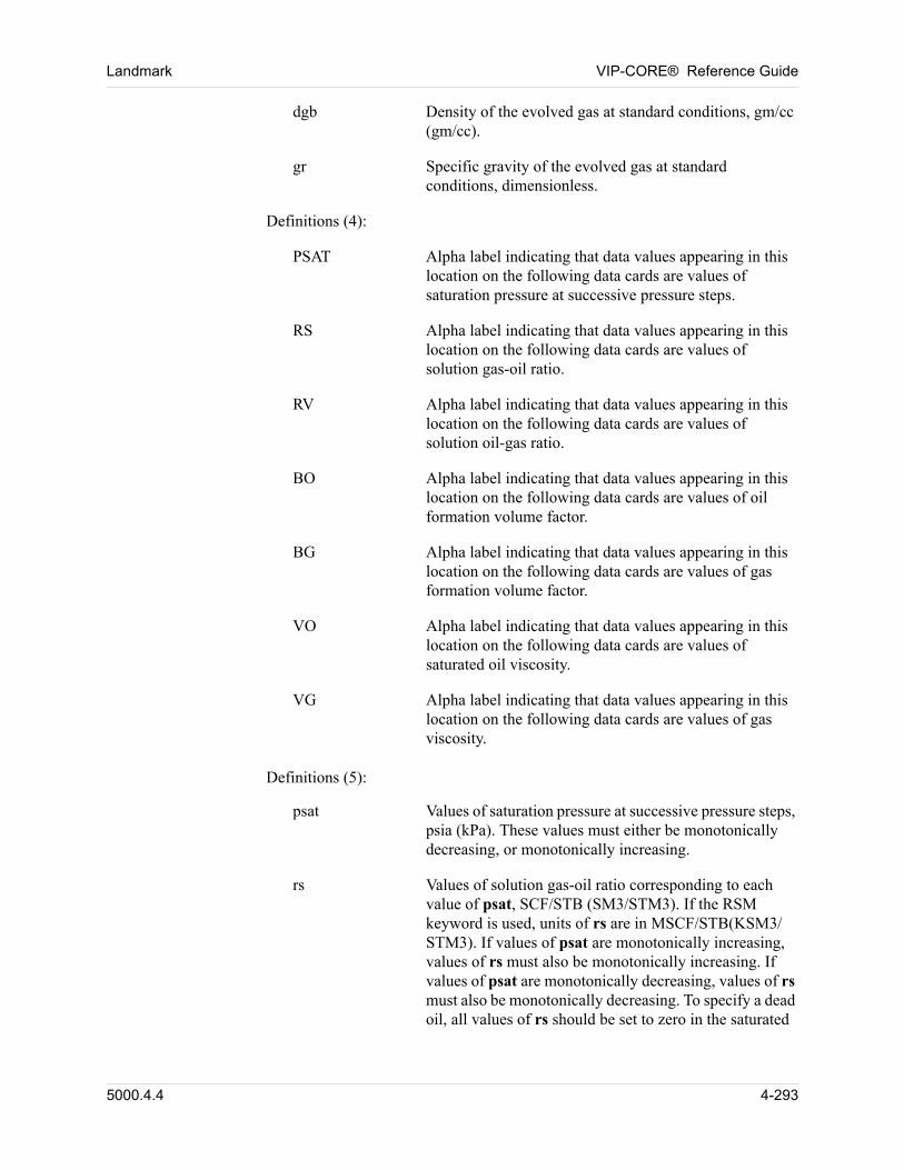
Landmark VIP-CORE® Reference Guide
dgb Density of the evolved gas at standard conditions, gm/cc (gm/cc).
gr Specific gravity of the evolved gas at standard conditions, dimensionless.
Definitions (4): 00
PSAT Alpha label indicating that data values appearing in this location on the following data cards are values of saturation pressure at successive pressure steps.
RS Alpha label indicating that data values appearing in this location on the following data cards are values of solution gas-oil ratio.
RV Alpha label indicating that data values appearing in this location on the following data cards are values of solution oil-gas ratio.
BO Alpha label indicating that data values appearing in this location on the following data cards are values of oil formation volume factor.
BG Alpha label indicating that data values appearing in this location on the following data cards are values of gas formation volume factor.
VO Alpha label indicating that data values appearing in this location on the following data cards are values of saturated oil viscosity.
VG Alpha label indicating that data values appearing in this location on the following data cards are values of gas viscosity.
00 Definitions (5):
psat Values of saturation pressure at successive pressure steps, psia (kPa). These values must either be monotonically decreasing, or monotonically increasing.
rs Values of solution gas-oil ratio corresponding to each value of psat, SCF/STB (SM3/STM3). If the RSM keyword is used, units of rs are in MSCF/STB(KSM3/STM3). If values of psat are monotonically increasing, values of rs must also be monotonically increasing. If values of psat are monotonically decreasing, values of rs must also be monotonically decreasing. To specify a dead oil, all values of rs should be set to zero in the saturated
5000.4.4 4-293
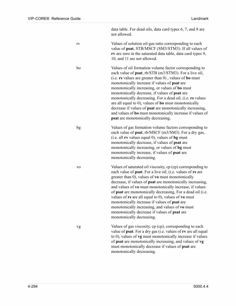
VIP-CORE® Reference Guide Landmark
data table. For dead oils, data card types 6, 7, and 8 are not allowed.
rv Values of solution oil-gas ratio corresponding to each value of psat, STB/MSCF (SM3/STM3). If all values of rv are zero in the saturated data table, data card types 9, 10, and 11 are not allowed.
bo Values of oil formation volume factor corresponding to each value of psat, rb/STB (m3/STM3). For a live oil, (i.e. rs values are greater than 0) , values of bo must monotonically increase if values of psat are monotonically increasing, or values of bo must monotonically decrease, if values of psat are monotonically decreasing. For a dead oil, (i.e. rs values are all equal to 0), values of bo must monotonically decrease if values of psat are monotonically increasing, and values of bo must monotonically increase if values of psat are monotonically decreasing.
bg Values of gas formation volume factors corresponding to each value of psat, rb/MSCF (m3/SM3). For a dry gas, (i.e. all rv values equal 0), values of bg must monotonically decrease, if values of psat are monotonically increasing, or values of bg must monotonically increase, if values of psat are monotonically decreasing.
vo Values of saturated oil viscosity, cp (cp) corresponding to each value of psat. For a live oil, (i.e. values of rs are greater than 0), values of vo must monotonically decrease, if values of psat are monotonically increasing, and values of vo must monotonically increase, if values of psat are monotonically decreasing, For a dead oil (i.e. values of rs are all equal to 0), values of vo must monotonically increase if values of psat are monotonically increasing, and values of vo must monotonically decrease if values of psat are monotonically decreasing.
vg Values of gas viscosity, cp (cp), corresponding to each value of psat. For a dry gas (i.e. values of rv are all equal to 0), values of vg must monotonically increase if values of psat are monotonically increasing, and values of vg must monotonically decrease if values of psat are monotonically decreasing.
4-294 5000.4.4
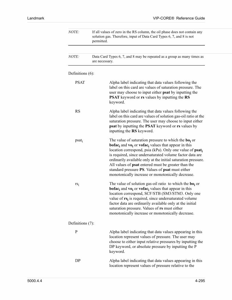
Landmark VIP-CORE® Reference Guide
NOTE: If all values of zero in the RS column, the oil phase does not contain any solution gas. Therefore, input of Data Card Types 6, 7, and 8 is not permitted.
NOTE: Data Card Types 6, 7, and 8 may be repeated as a group as many times as are necessary.
Definitions (6): 00
PSAT Alpha label indicating that data values following the label on this card are values of saturation pressure. The user may choose to input either psat by inputting the PSAT keyword or rs values by inputting the RS keyword.
RS Alpha label indicating that data values following the label on this card are values of solution gas-oil ratio at the saturation pressure. The user may choose to input either psat by inputting the PSAT keyword or rs values by inputting the RS keyword.
psati The value of saturation pressure to which the boi or bofaci and voi or vofaci values that appear in this location correspond, psia (kPa). Only one value of psati is required, since undersaturated volume factor data are ordinarily available only at the initial saturation pressure. All values of psat entered must be greater than the standard pressure PS. Values of psat must either monotonically increase or monotonically decrease.
rsi The value of solution gas-oil ratio to which the boi or bofaci and voi or vofaci values that appear in this location correspond, SCF/STB (SM3/STM3. Only one value of rsi is required, since undersaturated volume factor data are ordinarily available only at the initial saturation pressure. Values of rs must either monotonically increase or monotonically decrease.
00 Definitions (7):
P Alpha label indicating that data values appearing in this location represent values of pressure. The user may choose to either input relative pressures by inputting the DP keyword, or absolute pressure by inputting the P keyword.
DP Alpha label indicating that data values appearing in this location represent values of pressure relative to the
5000.4.4 4-295
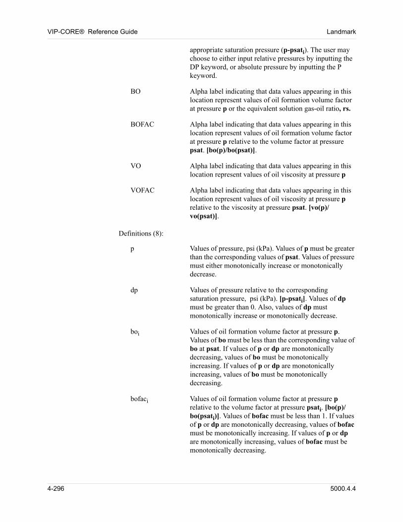
VIP-CORE® Reference Guide Landmark
appropriate saturation pressure (p-psati). The user may choose to either input relative pressures by inputting the DP keyword, or absolute pressure by inputting the P keyword.
BO Alpha label indicating that data values appearing in this location represent values of oil formation volume factor at pressure p or the equivalent solution gas-oil ratio, rs.
BOFAC Alpha label indicating that data values appearing in this location represent values of oil formation volume factor at pressure p relative to the volume factor at pressure psat. [bo(p)/bo(psat)].
VO Alpha label indicating that data values appearing in this location represent values of oil viscosity at pressure p
VOFAC Alpha label indicating that data values appearing in this location represent values of oil viscosity at pressure p relative to the viscosity at pressure psat. [vo(p)/vo(psat)].
00 Definitions (8):
p Values of pressure, psi (kPa). Values of p must be greater than the corresponding values of psat. Values of pressure must either monotonically increase or monotonically decrease.
dp Values of pressure relative to the corresponding saturation pressure, psi (kPa). [p-psati]. Values of dp must be greater than 0. Also, values of dp must monotonically increase or monotonically decrease.
boi Values of oil formation volume factor at pressure p. Values of bo must be less than the corresponding value of bo at psat. If values of p or dp are monotonically decreasing, values of bo must be monotonically increasing. If values of p or dp are monotonically increasing, values of bo must be monotonically decreasing.
bofaci Values of oil formation volume factor at pressure p relative to the volume factor at pressure psati. [bo(p)/bo(psati)]. Values of bofac must be less than 1. If values of p or dp are monotonically decreasing, values of bofac must be monotonically increasing. If values of p or dp are monotonically increasing, values of bofac must be monotonically decreasing.
4-296 5000.4.4
Landmark VIP-CORE® Reference Guide
voi Values of oil viscosity at pressure p. Values of vo must be greater than the corresponding value of vo at psat. If values of p or dp are monotonically decreasing, values of vo must be monotonically decreasing. If values of p or dp are monotonically increasing, values of vo must be monotonically increasing.
vofaci Values of oil viscosity at pressure p relative to the viscosity at pressure psati. [vo(p)/vo(psati)].Values of vofac must be greater than 1. If values of p or dp are monotonically decreasing, values of vofac must be monotonically decreasing. If values of p or dp are monotonically increasing, values of vofac must be monotonically increasing.
NOTE: If all values of zero in the RV column, a dry gas is defined. Therefore, input of Data Card Types 9, 10, and 11 cannot be permitted.
NOTE: Data Card Types 9, 10, and 11 may be repeated as a group as many times as are necessary. However, one set is required.
00 Definitions (9):
P Alpha label indicating that data values following the label on this card are values of pressure. The user has a choice of inputting pressures by using the keyword P or of inputting saturated oil-gas ratios by using the keyword RVSAT. P is preferred over RVSAT because solution oil-gas ratios are not guaranteed to be monotonic. If the RV values in the saturated part of the table are not monotonic, data cannot be input with the RVSAT keyword.
RVSAT Alpha label indicating that data values following the label on this card are values of the corresponding saturated oil-gas ratio at the pressure. The user has a choice of inputting pressures by using the keyword P or of inputting saturated oil-gas ratios by using the keyword RVSAT. P is preferred over RVSAT because solution oil-gas ratios are not guaranteed to be monotonic. If the RV values in the saturated part of the table are not monotonic, data cannot be input with the RVSAT keyword.
pi The value of pressure to which the bgi or bgfaci and voi and vofaci values that appear in this location correspond, psia (kPa). Only one value of pi is required. Pressure must be greater than the pressure at standard conditions,
5000.4.4 4-297
VIP-CORE® Reference Guide Landmark
ps. Pressure must either monotonically increase or decrease.
rvsati The value of saturated oil-gas ratio to which the bgi or bgfaci and voi and vofaci values that appear in this location correspond, psia (kPa). Only one value of rvsati is required. Oil-gas ratio must monotonically increase or decrease.
Definitions (10): 00
RV Alpha label indicating that data values appearing in this location represent values of solution oil-gas ratio at undersaturated conditions at that pressure.
BG Alpha label indicating that data values appearing in this location represent values of gas formation volume factor at pressure p and solution oil-gas ratio, rv.
BGFAC Alpha label indicating that data values appearing in this location represent values of gas formation volume factor at pressure p and solution oil-gas ratio, rv, relative to the volume factor at the saturated solution oil-gas ratio, rvsat. [bg(rv)/bg(rvsat)].
VG Alpha label indicating that data values appearing in this location represent values of gas viscosity at pressure p and solution oil-gas ratio, rv.
VGFAC Alpha label indicating that data values appearing in this location represent values of gas viscosity at pressure p and solution oil-gas ratio, rv, relative to the viscosity at the saturated solution oil-gas ratio, rvsat. [vo(rv)/vo(rvsat)].
00 Definitions (12):
rv Values of solution oil-gas ratio, STB/MSCF (SM3/STM3). Values of rv must monotonically increase or decrease. Values of rv must be less than the corresponding value at saturated conditions.
bgi Values of gas formation volume factor at pi and rv, RB/MSCF (m3/SM3).
bgfaci Values of gas formation volume factor at solution oil gas ratio rv relative to the volume factor at the saturated solution oil-gas ratio, rvsati. [bo(rv)/bo(rvsati)].
vgi Values of gas viscosity at pressure pi and rv.
4-298 5000.4.4
Landmark VIP-CORE® Reference Guide
vgfaci Values of gas viscosity at pressure pi and solution oil-gas ratio, rv, relative to the viscosity at the saturated solution oil-gas ratio, rvsati. [vg(rv)/vg(rvsati)].
4.5.4.2 BOOTAB
(1)BOOTAB ipvt
(2) DOB WTROAPI WTRO
(3) dob wtroapi wtro
(4)RS PSAT BO VO
(5)rs psat bo vo (At least two Type 5 data cards are required.)
(6) PSATRS
psat1
rs1
psat2
rs2
. . . psati
rsi
(Only one Type 6 data card is required. Cards 7 and 8 must be repeated for each Card 6.)
(7) PDP
BO VOBOFAC VOFAC
. BO VOBOFAC VOFAC
. . BO VOBOFAC VOFAC
(8)p
dp
bo1 vo1
bofac1 vofac1 .
bo2 vo2
bofac2 vofac2
. .boi voi
bofaci vofaci
(Only one Type 8 data card is required is for each Type 7 data card.)
00 Definitions (1):
(1) BOOTAB Alpha label indicating that live black oil data is being read.
ipvt The PVT table number. This number corresponds to values in the IPVT array.
00 Definitions (2):
DOB Alpha label indicating that the data value that appears in this location on the following card is the density of the residual oil at standard conditions as defined in Section 2.2.4.
API Alpha label indicating that the data value that appears in this location on the following card is the API gravity of
5000.4.4 4-299
VIP-CORE® Reference Guide Landmark
the residual oil at standard conditions as defined in Section 2.2.4.
WTRO Alpha label indicating that the data value that appears in this location on the following card is the molecular weight of the residual oil. This alpha label must be used if the previous alpha label on this data line is either DOB, DOR, or API.
Definitions (3): 00
dob Density of the residual oil at standard conditions, gm/cc (gm/cc).
api API gravity of the residual oil at standard conditions, °API (°API).
wtro Molecular weight of the residual oil. This can be approximated if data is unavailable. A value in the range of 175 to 200 is suitable in many cases. However, this approximation will lead to errors in produced oil molecular weight and molar production rates (surface volumes will not be affected).
Definitions (4): 00
RS Alpha label indicating that data values appearing in this location on the following data cards are values of solution gas-oil ratio.
PSAT Alpha label indicating that data values appearing in this location on the following data cards are values of saturation pressure at successive pressure steps.
BO Alpha label indicating that data values appearing in this location on the following data cards are values of oil formation volume factor.
VO Alpha label indicating that data values appearing in this location on the following data cards are values of saturated oil viscosity.
00 Definitions (5):
rs Values of solution gas-oil ratio corresponding to each value of psat, SCF/STB (SM3/STM3). If the RSM keyword is used, units of rs are in MSCF/STB(KSM3/STM3). If values of psat are monotonically increasing, values of rs must also be monotonically increasing. If values of psat are monotonically decreasing, values of rs must also be monotonically decreasing. To specify a dead
4-300 5000.4.4
Landmark VIP-CORE® Reference Guide
oil, all values of rs should be set to zero in the saturated data table. For dead oils, data card types 6, 7, and 8 are not allowed.
psat Values of saturation pressure at successive pressure steps, psia (kPa). These values must either be monotonically decreasing, or monotonically increasing.
bo Values of oil formation volume factor corresponding to each value of psat, rb/STB (m3/STM3). For a live oil, (i.e. rs values are greater than 0) , values of bo must monotonically increase if values of psat are monotonically increasing, or values of bo must monotonically decrease, if values of psat are monotonically decreasing. For a dead oil, (i.e. rs values are all equal to 0), values of bo must monotonically decrease if values of psat are monotonically increasing, and values of bo must monotonically increase if values of psat are monotonically decreasing.
bg Values of gas formation volume factors corresponding to each value of psat, rb/MSCF (m3/SM3). For a dry gas, (i.e. all rv values equal 0), values of bg must monotonically decrease, if values of psat are monotonically increasing, and values of bg must monotonically increase, if values of psat are monotonically decreasing.
vo Values of saturated oil viscosity, cp (cp) corresponding to each value of psat. For a live oil, (i.e. values of rs are greater than 0), values of vo must monotonically decrease, if values of psat are monotonically increasing, and values of vo must monotonically increase, if values of psat are monotonically decreasing, For a dead oil (i.e. values of rs are all equal to 0), values of vo must monotonically increase if values of psat are monotonically increasing, and values of vo must monotonically decrease if values of psat are monotonically decreasing.
vg Values of gas viscosity, cp (cp), corresponding to each value of psat. For a dry gas (i.e. values of rv are all equal to 0), values of vg must monotonically increase if values of psat are monotonically increasing, and values of vg must monotonically decrease if values of psat are monotonically decreasing.
5000.4.4 4-301
VIP-CORE® Reference Guide Landmark
NOTE: If all values are zero in the RS column, the oil phase does not contain any solution gas. Therefore, input of Data Card Types 6, 7, and 8 is not permitted.
NOTE: Data Card Types 6, 7, and 8 may be repeated as a group as many times as are necessary.
Definitions (6): 00
PSAT Alpha label indicating that data values following the label on this card are values of saturation pressure. The user may choose to input either psat by inputting the PSAT keyword or rs values by inputting the RS keyword.
RS Alpha label indicating that data values following the label on this card are values of solution gas-oil ratio at the saturation pressure. The user may choose to input either psat by inputting the PSAT keyword or rs values by inputting the RS keyword.
psati The value of saturation pressure to which the boi or bofaci and voi or vofaci values that appear in this location correspond, psia (kPa). Only one value of psati is required, since undersaturated volume factor data are ordinarily available only at the initial saturation pressure. All values of psat entered must be greater than the standard pressure PS. Values of psat must either monotonically increase or monotonically decrease.
rsi The value of solution gas-oil ratio pressure to which the boi or bofaci and voi or vofaci values that appear in this location correspond, psia (kPa). Only one value of rsi is required, since undersaturated volume factor data are ordinarily available only at the initial saturation pressure. Values of rs must either monotonically increase or monotonically decrease.
00 Definitions (7):
P Alpha label indicating that data values appearing in this location represent values of pressure. The user may choose to either input relative pressures by inputting the DP keyword, or absolute pressure by inputting the P keyword.
DP Alpha label indicating that data values appearing in this location represent values of pressure relative to the
4-302 5000.4.4
Landmark VIP-CORE® Reference Guide
appropriate saturation pressure (p-psati). The user may choose to either input relative pressures by inputting the DP keyword, or absolute pressure by inputting the P keyword.
BO Alpha label indicating that data values appearing in this location represent values of oil formation volume factor at pressure p or the equivalent solution gas-oil ratio, rs.
BOFAC Alpha label indicating that data values appearing in this location represent values of oil formation volume factor at pressure p relative to the volume factor at pressure psat. [bo(p)/bo(psat)].
VO Alpha label indicating that data values appearing in this location represent values of oil viscosity at pressure p
VOFAC Alpha label indicating that data values appearing in this location represent values of oil viscosity at pressure p relative to the viscosity at pressure psat. [vo(p)/vo(psat)].
00 Definitions (8):
p Values of pressure, psi (kPa). Values of p must be greater than the corresponding values of psat. Values of pressure must either monotonically increase or monotonically decrease.
dp Values of pressure relative to the corresponding saturation pressure, psi (kPa). [p-psati]. Values of dp must be greater than 0. Also, values of dp must monotonically increase or monotonically decrease.
boi Values of oil formation volume factor at pressure p. Values of bo must be less than the corresponding value of bo at psat. If values of p or dp are monotonically decreasing, values of bo must be monotonically increasing. If values of p or dp are monotonically increasing, values of bo must be monotonically decreasing.
bofaci Values of oil formation volume factor at pressure p relative to the volume factor at pressure psati. [bo(p)/bo(psati)]. Values of bofac must be less than 1. If values of p or dp are monotonically decreasing, values of bofac must be monotonically increasing. If values of p or dp are monotonically increasing, values of bofac must be monotonically decreasing.
5000.4.4 4-303
VIP-CORE® Reference Guide Landmark
voi Values of oil viscosity at pressure p. Values of vo must be greater than the corresponding value of vo at psat. If values of p or dp are monotonically decreasing, values of vo must be monotonically decreasing. If values of p or dp are monotonically increasing, values of vo must be monotonically increasing.
vofaci Values of oil viscosity at pressure p relative to the viscosity at pressure psati. [vo(p)/vo(psati)].Values of vofac must be greater than 1. If values of p or dp are monotonically decreasing, values of vofac must be monotonically decreasing. If values of p or dp are monotonically increasing, values of vofac must be monotonically increasing.
4.5.4.3 BODTAB
(1) BODTAB ipvt
00 (2) DOB WTROAPI WTRO
00 (3) dob wtroapi wtro
00 (4) PSAT BO VO
00 (5) psat bo vo(At least two Type 5 data cards are required.)
00 Definitions (1):
(1) BODTAB Alpha label indicating that dead black oil data is being read.
ipvt The PVT table number. This number corresponds to values in the IPVT array.
00 Definitions (2):
DOB Alpha label indicating that the data value that appears in this location on the following card is the density of the residual oil at standard conditions as defined in Section 2.2.4.
API Alpha label indicating that the data value that appears in this location on the following card is the API gravity of the residual oil at standard conditions as defined in Section 2.2.4.
4-304 5000.4.4
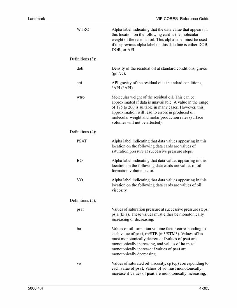
Landmark VIP-CORE® Reference Guide
WTRO Alpha label indicating that the data value that appears in this location on the following card is the molecular weight of the residual oil. This alpha label must be used if the previous alpha label on this data line is either DOB, DOR, or API.
Definitions (3): 00
dob Density of the residual oil at standard conditions, gm/cc (gm/cc).
api API gravity of the residual oil at standard conditions, °API (°API).
wtro Molecular weight of the residual oil. This can be approximated if data is unavailable. A value in the range of 175 to 200 is suitable in many cases. However, this approximation will lead to errors in produced oil molecular weight and molar production rates (surface volumes will not be affected).
Definitions (4): 00
PSAT Alpha label indicating that data values appearing in this location on the following data cards are values of saturation pressure at successive pressure steps.
BO Alpha label indicating that data values appearing in this location on the following data cards are values of oil formation volume factor.
VO Alpha label indicating that data values appearing in this location on the following data cards are values of oil viscosity.
00 Definitions (5):
psat Values of saturation pressure at successive pressure steps, psia (kPa). These values must either be monotonically increasing or decreasing.
bo Values of oil formation volume factor corresponding to each value of psat, rb/STB (m3/STM3). Values of bo must monotonically decrease if values of psat are monotonically increasing, and values of bo must monotonically increase if values of psat are monotonically decreasing.
vo Values of saturated oil viscosity, cp (cp) corresponding to each value of psat. Values of vo must monotonically increase if values of psat are monotonically increasing,
5000.4.4 4-305

VIP-CORE® Reference Guide Landmark
and values of vo must monotonically decrease if values of psat are monotonically decreasing.
4-306 5000.4.4
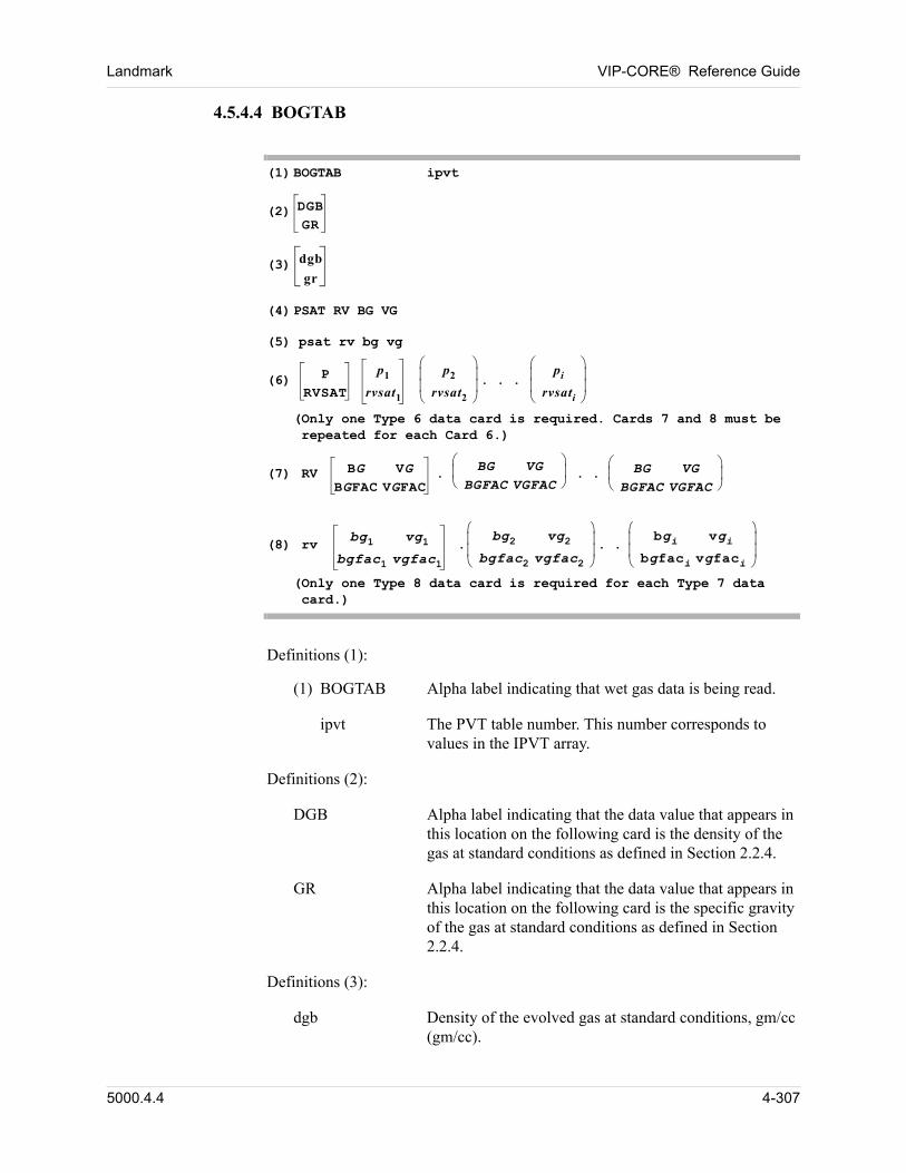
Landmark VIP-CORE® Reference Guide
4.5.4.4 BOGTAB
00 (1) BOGTAB ipvt
00 (2) DGBGR
00 (3) dgb
gr
00 (4) PSAT RV BG VG
00 (5) psat rv bg vg
00 (6) PRVSAT
p1
rvsat1
p2
rvsat2 pi
rvsati
. . .
(Only one Type 6 data card is required. Cards 7 and 8 must be repeated for each Card 6.)
00 (7) RV BG VGBGFAC VGFAC
BG VGBGFAC VGFAC
. . . BG VGBGFAC VGFAC
00 (8) rv bg1 vg1
bgfac1 vgfac1
bg2 vg2bgfac2 vgfac2
.bgi vgi
bgfaci vgfaci
. .
(Only one Type 8 data card is required for each Type 7 data card.)
00 Definitions (1):
(1) BOGTAB Alpha label indicating that wet gas data is being read.
ipvt The PVT table number. This number corresponds to values in the IPVT array.
00 Definitions (2):
DGB Alpha label indicating that the data value that appears in this location on the following card is the density of the gas at standard conditions as defined in Section 2.2.4.
GR Alpha label indicating that the data value that appears in this location on the following card is the specific gravity of the gas at standard conditions as defined in Section 2.2.4.
00 Definitions (3):
dgb Density of the evolved gas at standard conditions, gm/cc (gm/cc).
5000.4.4 4-307
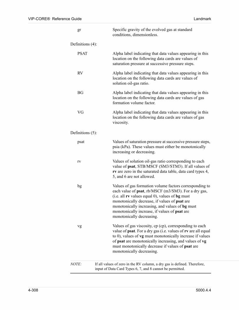
VIP-CORE® Reference Guide Landmark
gr Specific gravity of the evolved gas at standard conditions, dimensionless.
00 Definitions (4):
PSAT Alpha label indicating that data values appearing in this location on the following data cards are values of saturation pressure at successive pressure steps.
RV Alpha label indicating that data values appearing in this location on the following data cards are values of solution oil-gas ratio.
BG Alpha label indicating that data values appearing in this location on the following data cards are values of gas formation volume factor.
VG Alpha label indicating that data values appearing in this location on the following data cards are values of gas viscosity.
00 Definitions (5):
psat Values of saturation pressure at successive pressure steps, psia (kPa). These values must either be monotonically increasing or decreasing.
rv Values of solution oil-gas ratio corresponding to each value of psat, STB/MSCF (SM3/STM3). If all values of rv are zero in the saturated data table, data card types 4, 5, and 6 are not allowed.
bg Values of gas formation volume factors corresponding to each value of psat, rb/MSCF (m3/SM3). For a dry gas, (i.e. all rv values equal 0), values of bg must monotonically decrease, if values of psat are monotonically increasing, and values of bg must monotonically increase, if values of psat are monotonically decreasing.
vg Values of gas viscosity, cp (cp), corresponding to each value of psat. For a dry gas (i.e. values of rv are all equal to 0), values of vg must monotonically increase if values of psat are monotonically increasing, and values of vg must monotonically decrease if values of psat are monotonically decreasing.
NOTE: If all values of zero in the RV column, a dry gas is defined. Therefore, input of Data Card Types 6, 7, and 8 cannot be permitted.
4-308 5000.4.4
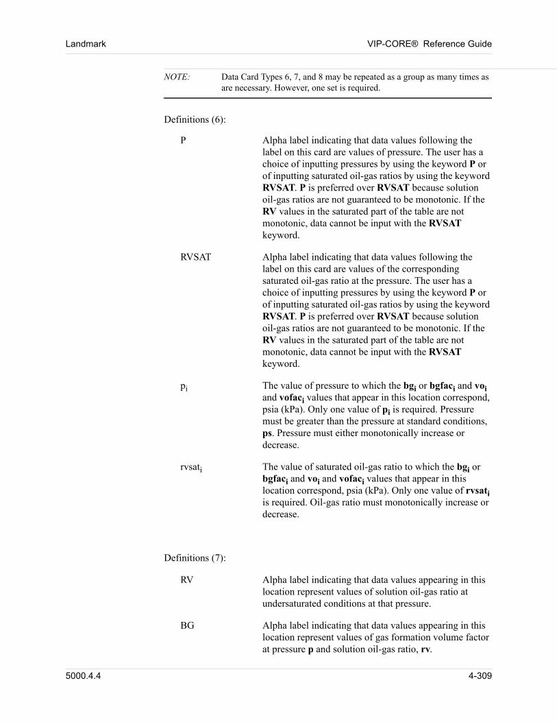
Landmark VIP-CORE® Reference Guide
NOTE: Data Card Types 6, 7, and 8 may be repeated as a group as many times as are necessary. However, one set is required.
00 Definitions (6):
P Alpha label indicating that data values following the label on this card are values of pressure. The user has a choice of inputting pressures by using the keyword P or of inputting saturated oil-gas ratios by using the keyword RVSAT. P is preferred over RVSAT because solution oil-gas ratios are not guaranteed to be monotonic. If the RV values in the saturated part of the table are not monotonic, data cannot be input with the RVSAT keyword.
RVSAT Alpha label indicating that data values following the label on this card are values of the corresponding saturated oil-gas ratio at the pressure. The user has a choice of inputting pressures by using the keyword P or of inputting saturated oil-gas ratios by using the keyword RVSAT. P is preferred over RVSAT because solution oil-gas ratios are not guaranteed to be monotonic. If the RV values in the saturated part of the table are not monotonic, data cannot be input with the RVSAT keyword.
pi The value of pressure to which the bgi or bgfaci and voi and vofaci values that appear in this location correspond, psia (kPa). Only one value of pi is required. Pressure must be greater than the pressure at standard conditions, ps. Pressure must either monotonically increase or decrease.
rvsati The value of saturated oil-gas ratio to which the bgi or bgfaci and voi and vofaci values that appear in this location correspond, psia (kPa). Only one value of rvsati is required. Oil-gas ratio must monotonically increase or decrease.
Definitions (7): 00
RV Alpha label indicating that data values appearing in this location represent values of solution oil-gas ratio at undersaturated conditions at that pressure.
BG Alpha label indicating that data values appearing in this location represent values of gas formation volume factor at pressure p and solution oil-gas ratio, rv.
5000.4.4 4-309
VIP-CORE® Reference Guide Landmark
BGFAC Alpha label indicating that data values appearing in this location represent values of gas formation volume factor at pressure p and solution oil-gas ratio, rv, relative to the volume factor at the saturated solution oil-gas ratio, rvsat. [bg(rv)/bg(rvsat)].
VG Alpha label indicating that data values appearing in this location represent values of gas viscosity at pressure p and solution oil-gas ratio, rv.
VGFAC Alpha label indicating that data values appearing in this location represent values of gas viscosity at pressure p and solution oil-gas ratio, rv, relative to the viscosity at the saturated solution oil-gas ratio, rvsat. [vo(rv)/vo(rvsat)].
00 Definitions (8):
rv Values of solution oil-gas ratio, STB/MSCF (SM3/STM3). Values of rv must monotonically increase or decrease. Values of rv must be less than the corresponding value at saturated conditions.
bgi Values of gas formation volume factor at pi and rv, RB/MSCF (m3/SM3).
bgfaci Values of gas formation volume factor at solution oil gas ratio rv relative to the volume factor at the saturated solution oil-gas ratio, rvsati. [bo(rv)/bo(rvsati)].
vgi Values of gas viscosity at pressure pi and rv.
vgfaci Values of gas viscosity at pressure pi and solution oil-gas ratio, rv, relative to the viscosity at the saturated solution oil-gas ratio, rvsati. [vg(rv)/vg(rvsati)].
4-310 5000.4.4
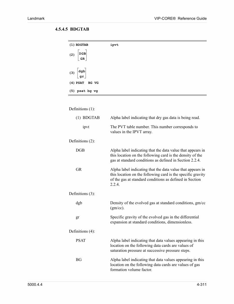
Landmark VIP-CORE® Reference Guide
4.5.4.5 BDGTAB
00 (1) BDGTAB ipvt
00 (2) DGB
GR00
00 (3) dgb
gr
00 (4) PSAT BG VG
00 (5) psat bg vg
00 Definitions (1):
(1) BDGTAB Alpha label indicating that dry gas data is being read.
ipvt The PVT table number. This number corresponds to values in the IPVT array.
00 Definitions (2):
DGB Alpha label indicating that the data value that appears in this location on the following card is the density of the gas at standard conditions as defined in Section 2.2.4.
GR Alpha label indicating that the data value that appears in this location on the following card is the specific gravity of the gas at standard conditions as defined in Section 2.2.4.
00 Definitions (3):
dgb Density of the evolved gas at standard conditions, gm/cc (gm/cc).
gr Specific gravity of the evolved gas in the differential expansion at standard conditions, dimensionless.
00 Definitions (4):
PSAT Alpha label indicating that data values appearing in this location on the following data cards are values of saturation pressure at successive pressure steps.
BG Alpha label indicating that data values appearing in this location on the following data cards are values of gas formation volume factor.
5000.4.4 4-311
VIP-CORE® Reference Guide Landmark
VG Alpha label indicating that data values appearing in this location on the following data cards are values of gas viscosity.
00 Definitions (5):
psat Values of saturation pressure at successive pressure steps, psia (kPa). These values must either be monotonically increasing or decreasing.
bg Values of gas formation volume factors corresponding to each value of psat, rb/MSCF (m3/SM3). Values of bg must monotonically decrease, if values of psat are monotonically increasing, and values of bg must monotonically increase, if values of psat are monotonically decreasing.
vg Values of gas viscosity, cp (cp), corresponding to each value of psat. Values of vg must monotonically increase if values of psat are monotonically increasing, and values of vg must monotonically decrease if values of psat are monotonically decreasing.
4-312 5000.4.4
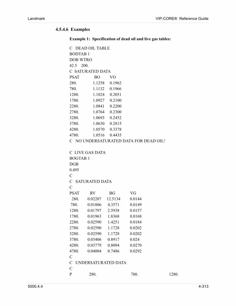
Landmark VIP-CORE® Reference Guide
4.5.4.6 Examples
00 Example 1: Specification of dead oil and live gas tables:
00 C DEAD OIL TABLE00 BODTAB 100 DOB WTRO00 42.5 200. 00 C SATURATED DATA00 PSAT BO VO00 280. 1.1258 0.196200 780. 1.1132 0.196600 1280. 1.1024 0.205100 1780. 1.0927 0.210000 2280. 1.0841 0.2200 00 2780. 1.0764 0.230000 3280. 1.0693 0.245200 3780. 1.0630 0.281500 4280. 1.0570 0.337800 4780. 1.0516 0.443500 C NO UNDERSATURATED DATA FOR DEAD OIL!00
00 C LIVE GAS DATA00 BOGTAB 100 DGB00 0.49500 C00 C SATURATED DATA00 C00 PSAT RV BG VG00 280. 0.02207 12.5134 0.014400 780. 0.01806 4.3571 0.014900 1280. 0.01797 2.5938 0.015700 1780. 0.01963 1.8368 0.016800 2280. 0.02590 1.4251 0.018400 2780. 0.02590 1.1728 0.020200 3280. 0.02590 1.1728 0.020200 3780. 0.03406 0.8917 0.02400 4280. 0.03779 0.8094 0.027000 4780. 0.04004 0.7486 0.029200 C00 C UNDERSATURATED DATA00 C00 P 280. 780. 1280.
5000.4.4 4-313
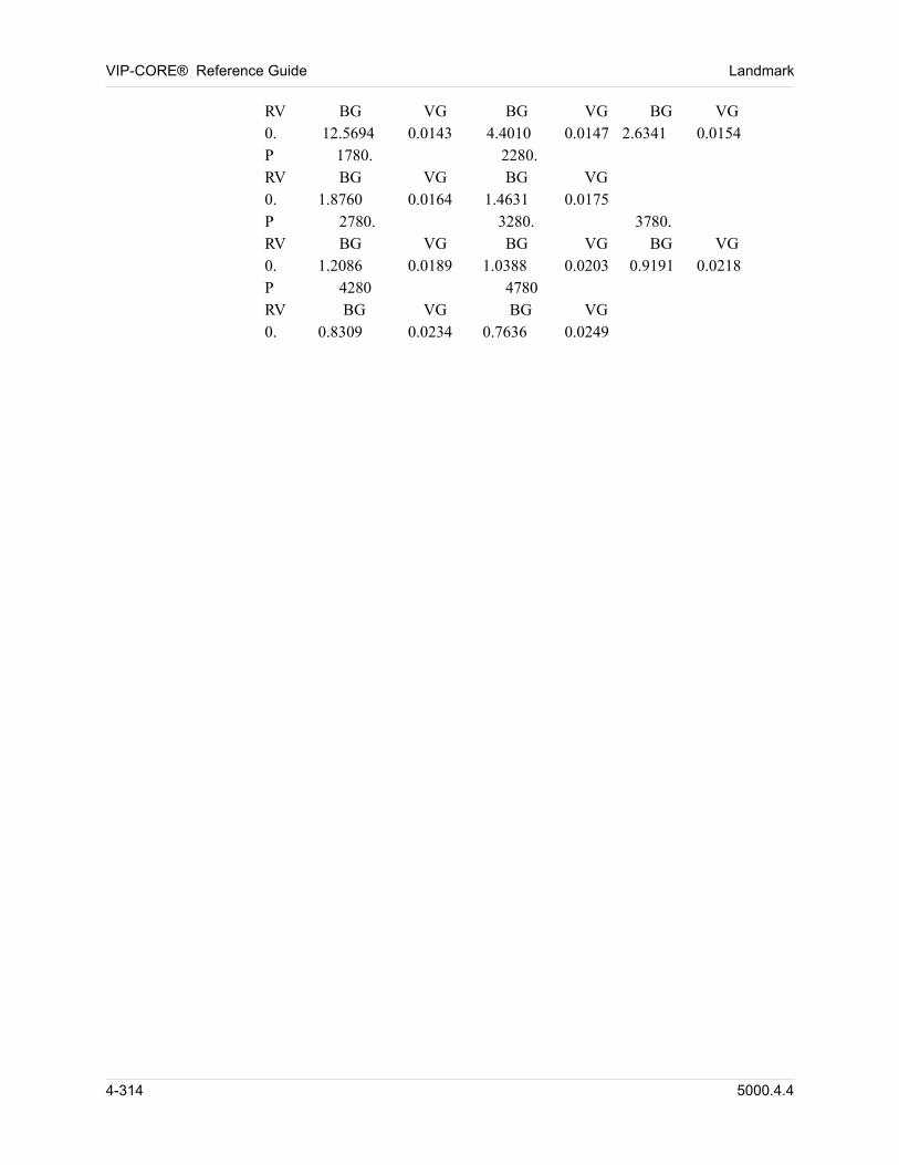
VIP-CORE® Reference Guide Landmark
00 RV BG VG BG VG BG VG00 0. 12.5694 0.0143 4.4010 0.0147 2.6341 0.0154 00 P 1780. 2280. 00 RV BG VG BG VG00 0. 1.8760 0.0164 1.4631 0.017500 P 2780. 3280. 3780.00 RV BG VG BG VG BG VG00 0. 1.2086 0.0189 1.0388 0.0203 0.9191 0.0218 00 P 4280 478000 RV BG VG BG VG 00 0. 0.8309 0.0234 0.7636 0.024900
4-314 5000.4.4
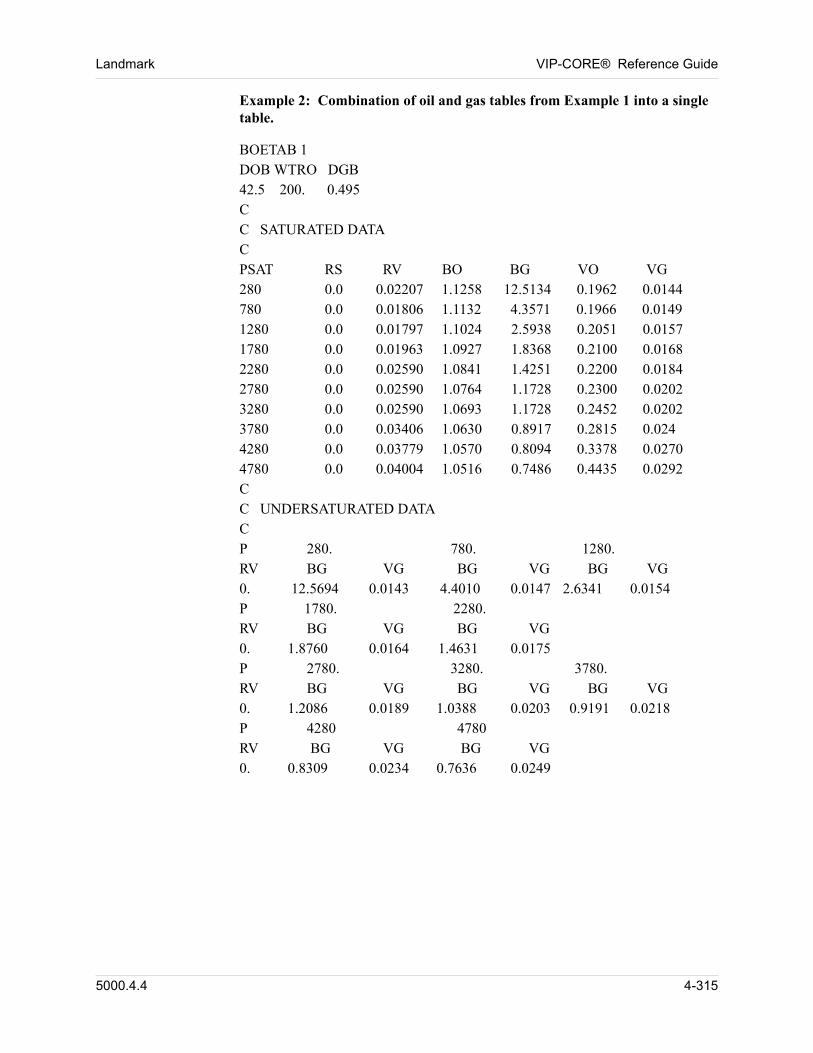
Landmark VIP-CORE® Reference Guide
00 Example 2: Combination of oil and gas tables from Example 1 into a single table.
00 BOETAB 100 DOB WTRO DGB00 42.5 200. 0.49500 C00 C SATURATED DATA00 C00 PSAT RS RV BO BG VO VG00 280 0.0 0.02207 1.1258 12.5134 0.1962 0.014400 780 0.0 0.01806 1.1132 4.3571 0.1966 0.014900 1280 0.0 0.01797 1.1024 2.5938 0.2051 0.015700 1780 0.0 0.01963 1.0927 1.8368 0.2100 0.016800 2280 0.0 0.02590 1.0841 1.4251 0.2200 0.018400 2780 0.0 0.02590 1.0764 1.1728 0.2300 0.020200 3280 0.0 0.02590 1.0693 1.1728 0.2452 0.020200 3780 0.0 0.03406 1.0630 0.8917 0.2815 0.02400 4280 0.0 0.03779 1.0570 0.8094 0.3378 0.027000 4780 0.0 0.04004 1.0516 0.7486 0.4435 0.029200 C00 C UNDERSATURATED DATA00 C00 P 280. 780. 1280. 00 RV BG VG BG VG BG VG00 0. 12.5694 0.0143 4.4010 0.0147 2.6341 0.0154 00 P 1780. 2280. 00 RV BG VG BG VG00 0. 1.8760 0.0164 1.4631 0.017500 P 2780. 3280. 3780.00 RV BG VG BG VG BG VG00 0. 1.2086 0.0189 1.0388 0.0203 0.9191 0.0218 00 P 4280 478000 RV BG VG BG VG 00 0. 0.8309 0.0234 0.7636 0.024900
00
5000.4.4 4-315
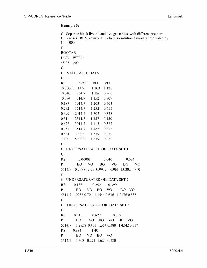
VIP-CORE® Reference Guide Landmark
00 Example 3:
00 C Separate black live oil and live gas tables, with different pressureC entries. RSM keyword invoked, so solution gas-oil ratio divided byC 1000.
00 C00 BOOTAB00 DOB WTRO 00 48.25 200.00 C00 C SATURATED DATA00 C 00 RS PSAT BO VO00 0.00001 14.7 1.103 1.12600 0.040 264.7 1.126 0.96000 0.084 514.7 1.152 0.80900 0.187 1014.7 1.203 0.70300 0.292 1514.7 1.252 0.61500 0.399 2014.7 1.303 0.53500 0.511 2514.7 1.357 0.450 00 0.627 3014.7 1.415 0.38700 0.757 3514.7 1.483 0.31600 0.884 3900.0 1.539 0.27000 1.400 5000.0 1.639 0.27000 C00 C UNDERSATURATED OIL DATA SET 100 C00 RS 0.00001 0.040 0.084 00 P BO VO BO VO BO VO 00 5514.7 0.9688 1.127 0.9979 0.961 1.0302 0.81000 C00 C UNDERSATURATED OIL DATA SET 200 RS 0.187 0.292 0.39900 P BO VO BO VO BO VO 00 5514.7 1.0932 0.704 1.1544 0.616 1.2176 0.53600 C00 C UNDERSATURATED OIL DATA SET 300 C00 RS 0.511 0.627 0.757 00 P BO VO BO VO BO VO 00 5514.7 1.2838 0.451 1.354 0.388 1.4342 0.31700 RS 0.884 1.4000 P BO VO BO VO 00 5514.7 1.503 0.271 1.624 0.280
4-316 5000.4.4
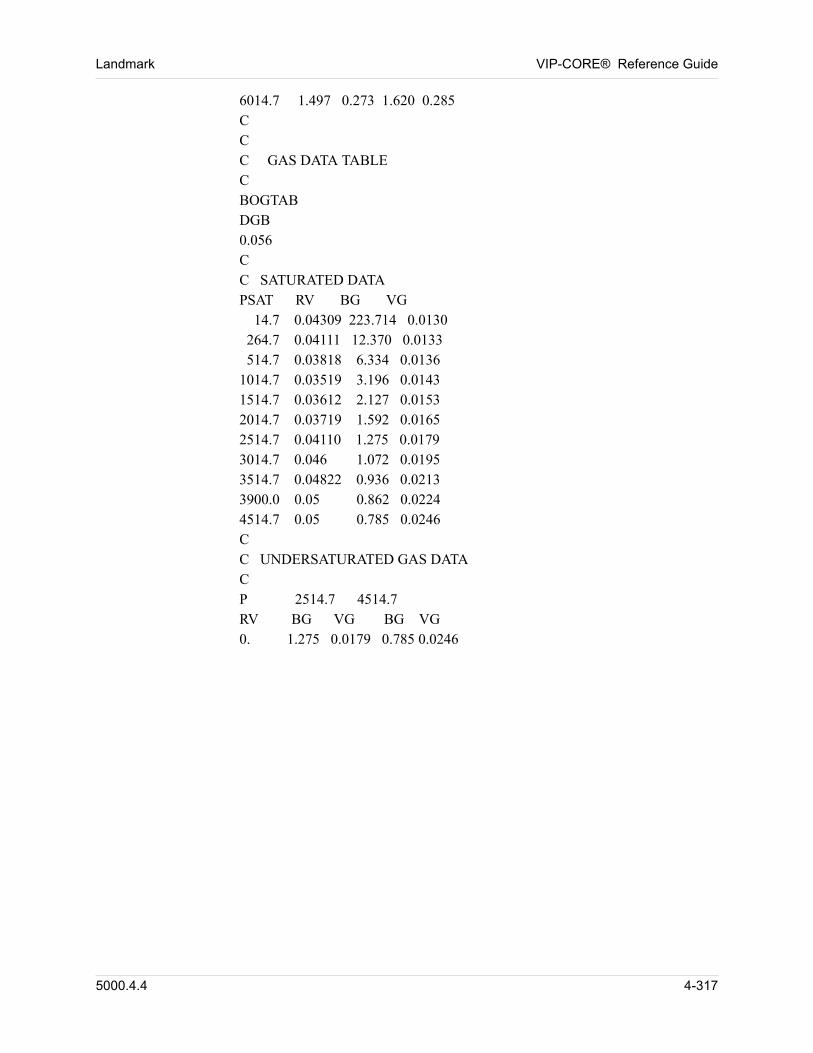
Landmark VIP-CORE® Reference Guide
00 6014.7 1.497 0.273 1.620 0.28500 C00 C00 C GAS DATA TABLE00 C00 BOGTAB00 DGB00 0.05600 C00 C SATURATED DATA00 PSAT RV BG VG00 14.7 0.04309 223.714 0.0130 00 264.7 0.04111 12.370 0.0133 00 514.7 0.03818 6.334 0.0136 00 1014.7 0.03519 3.196 0.0143 00 1514.7 0.03612 2.127 0.0153 00 2014.7 0.03719 1.592 0.0165 00 2514.7 0.04110 1.275 0.017900 3014.7 0.046 1.072 0.0195 00 3514.7 0.04822 0.936 0.0213 00 3900.0 0.05 0.862 0.0224 00 4514.7 0.05 0.785 0.024600 C00 C UNDERSATURATED GAS DATA00 C00 P 2514.7 4514.700 RV BG VG BG VG00 0. 1.275 0.0179 0.785 0.0246
5000.4.4 4-317
VIP-CORE® Reference Guide Landmark
4.6 K-value Tabular Data (VIP-ENCORE)
Data which define equilibrium K-values as a function of pressure for two or more components may optionally be entered in VIP-ENCORE. The data described below are required and if not measured may be provided by DESKTOP-PVT. K-value tables may be entered for either a black-oil or a gas condensate sample. The data requirements are as follows: 00
1. Gas compressibility factor (z-factor) as a function of pressure for the equilibrium gas at each step of a differential expansion or for the primary gas at each step of a constant volume depletion.
2. Gas viscosity as a function of pressure at each step.
3. Oil compressibility factor (z-factor) as a function of pressure at each step.
4. Oil viscosity as a function of pressure at each step
5. Oil phase mole fraction of the first component and/or the gas phase mole fraction of the last component at each pressure step.
6. Equilibrium K-values for each component as a function of pressure only for each step.
7. The volume of undersaturated oil relative to the volume of the same oil at its saturation pressure, as a function of pressure elevation above the saturation pressure (p-psat). These values can be taken directly from the relative volume data normally reported among the results of a constant composition expansion experiment for an oil sample. For a gas condensate sample, the values may be estimated or calculated with DESKTOP-PVT.
8. Viscosity of oil measured at undersaturated conditions relative to the viscosity of the same oil at its saturation pressure. Values are tabulated as a function of pressure elevation above the saturation pressure (p-psat).
9. The volume of undersaturated gas relative to the volume of the same gas at its saturation pressure, as a function of pressure elevation above the saturation pressure (p-psat). These values can be taken directly from the relative volume data normally reported among the results of a constant composition expansion experiment for a gas sample.
10. Viscosity of gas measured at undersaturated conditions relative to the viscosity of the same gas at its saturation pressure. Values are tabulated as a function of pressure elevation above the saturation pressure (p-psat).
11. Initial phase compositions and component molecular weights.
4.6.1 Start of K-Value Data Input (KVALUES)
00 This card should be used only with VIP-ENCORE.
4-318 5000.4.4
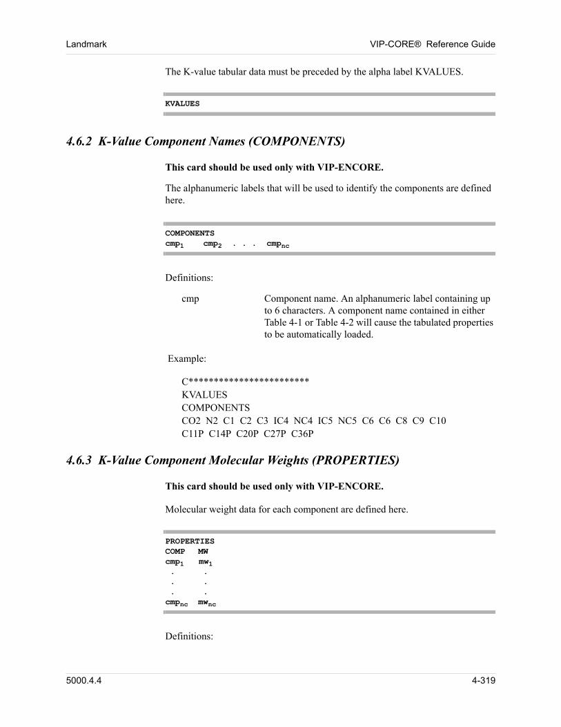
Landmark VIP-CORE® Reference Guide
00 The K-value tabular data must be preceded by the alpha label KVALUES.
KVALUES
4.6.2 K-Value Component Names (COMPONENTS)
00 This card should be used only with VIP-ENCORE.
00 The alphanumeric labels that will be used to identify the components are defined here.
COMPONENTScmp1 cmp2 . . . cmpnc
00 Definitions:
cmp Component name. An alphanumeric label containing up to 6 characters. A component name contained in either Table 4-1 or Table 4-2 will cause the tabulated properties to be automatically loaded.
00 Example:
00 C************************KVALUESCOMPONENTSCO2 N2 C1 C2 C3 IC4 NC4 IC5 NC5 C6 C6 C8 C9 C10C11P C14P C20P C27P C36P
4.6.3 K-Value Component Molecular Weights (PROPERTIES)
00 This card should be used only with VIP-ENCORE.
00 Molecular weight data for each component are defined here.
PROPERTIESCOMP MWcmp1 mw1 . . . . . .cmpnc mwnc
00 Definitions:
5000.4.4 4-319
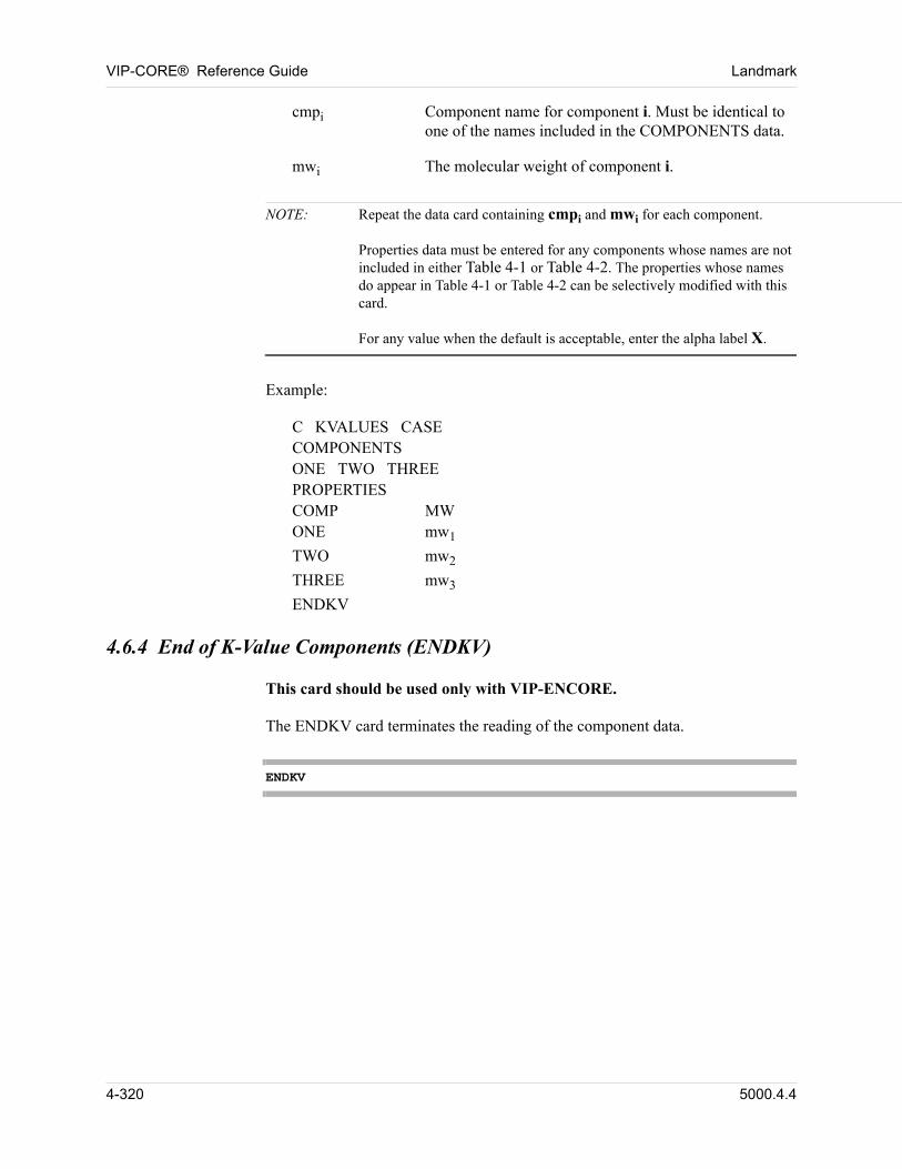
VIP-CORE® Reference Guide Landmark
cmpi Component name for component i. Must be identical to one of the names included in the COMPONENTS data.
mwi The molecular weight of component i.
NOTE: Repeat the data card containing cmpi and mwi for each component.Properties data must be entered for any components whose names are not included in either Table 4-1 or Table 4-2. The properties whose names do appear in Table 4-1 or Table 4-2 can be selectively modified with this card.For any value when the default is acceptable, enter the alpha label X.
00 Example:
00 C KVALUES CASECOMPONENTSONE TWO THREEPROPERTIESCOMP MWONE mw1
TWO mw2
THREE mw3
ENDKV
4.6.4 End of K-Value Components (ENDKV)
00 This card should be used only with VIP-ENCORE.
00 The ENDKV card terminates the reading of the component data.
ENDKV
4-320 5000.4.4
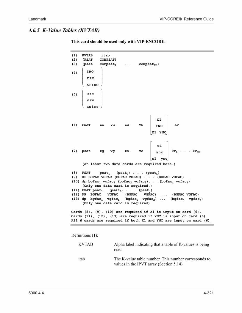
Landmark VIP-CORE® Reference Guide
4.6.5 K-Value Tables (KVTAB)
00 This card should be used only with VIP-ENCORE.
(1) KVTAB itab(2) (PSAT COMPSAT)(3) (psat compsat1 ... compsatNC)(4) ZRO
DRO
APIRO
(5) zro
dro
apiro
(6) PSAT ZG VG ZO VO
X1
YNC
X1 YNC
KV(7) psat zg vg zo vo
x1
ync
x1 ync
kv1 . . . kvNC
(At least two data cards are required here.)(8) PSAT psat1 (psat2) . . . (psati)(9) DP BOFAC VOFAC (BOFAC VOFAC) . . . (BOFAC VOFAC)(10) dp bofac1 vofac1 (bofac2 vofac2). . .(bofaci vofaci)
(Only one data card is required.)(11) PSAT psat1 (psat2) . . . (psatj)(12) DP BGFAC VGFAC (BGFAC VGFAC) ... (BGFAC VGFAC)(13) dp bgfac1 vgfac1 (bgfac2 vgfac2) ... (bgfacj vgfacj)
(Only one data card is required)Cards (8), (9), (10) are required if X1 is input on card (6).Cards (11), (12), (13) are required if YNC is input on card (6). All 6 cards are required if both X1 and YNC are input on card (6).
00 Definitions (1):
KVTAB Alpha label indicating that a table of K-values is being read.
itab The K-value table number. This number corresponds to values in the IPVT array (Section 5.14).
5000.4.4 4-321
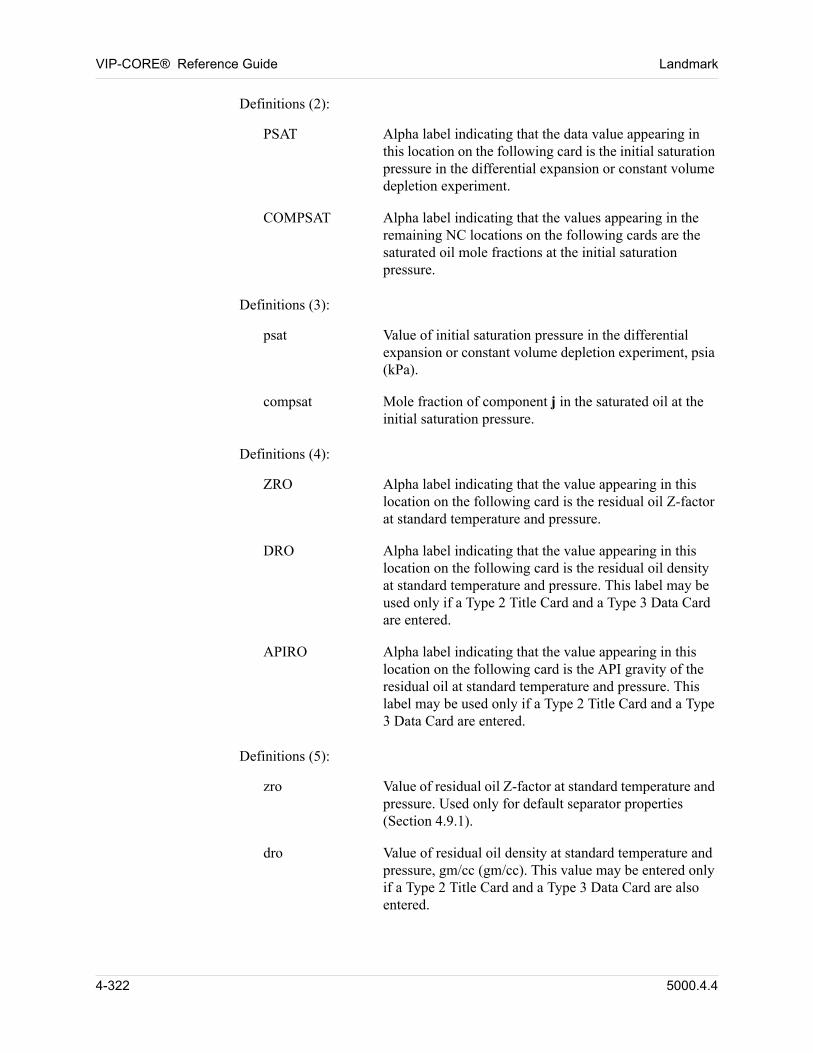
VIP-CORE® Reference Guide Landmark
00 Definitions (2):
PSAT Alpha label indicating that the data value appearing in this location on the following card is the initial saturation pressure in the differential expansion or constant volume depletion experiment.
COMPSAT Alpha label indicating that the values appearing in the remaining NC locations on the following cards are the saturated oil mole fractions at the initial saturation pressure.
00 Definitions (3):
psat Value of initial saturation pressure in the differential expansion or constant volume depletion experiment, psia (kPa).
compsat Mole fraction of component j in the saturated oil at the initial saturation pressure.
00 Definitions (4):
ZRO Alpha label indicating that the value appearing in this location on the following card is the residual oil Z-factor at standard temperature and pressure.
DRO Alpha label indicating that the value appearing in this location on the following card is the residual oil density at standard temperature and pressure. This label may be used only if a Type 2 Title Card and a Type 3 Data Card are entered.
APIRO Alpha label indicating that the value appearing in this location on the following card is the API gravity of the residual oil at standard temperature and pressure. This label may be used only if a Type 2 Title Card and a Type 3 Data Card are entered.
00 Definitions (5):
zro Value of residual oil Z-factor at standard temperature and pressure. Used only for default separator properties (Section 4.9.1).
dro Value of residual oil density at standard temperature and pressure, gm/cc (gm/cc). This value may be entered only if a Type 2 Title Card and a Type 3 Data Card are also entered.
4-322 5000.4.4
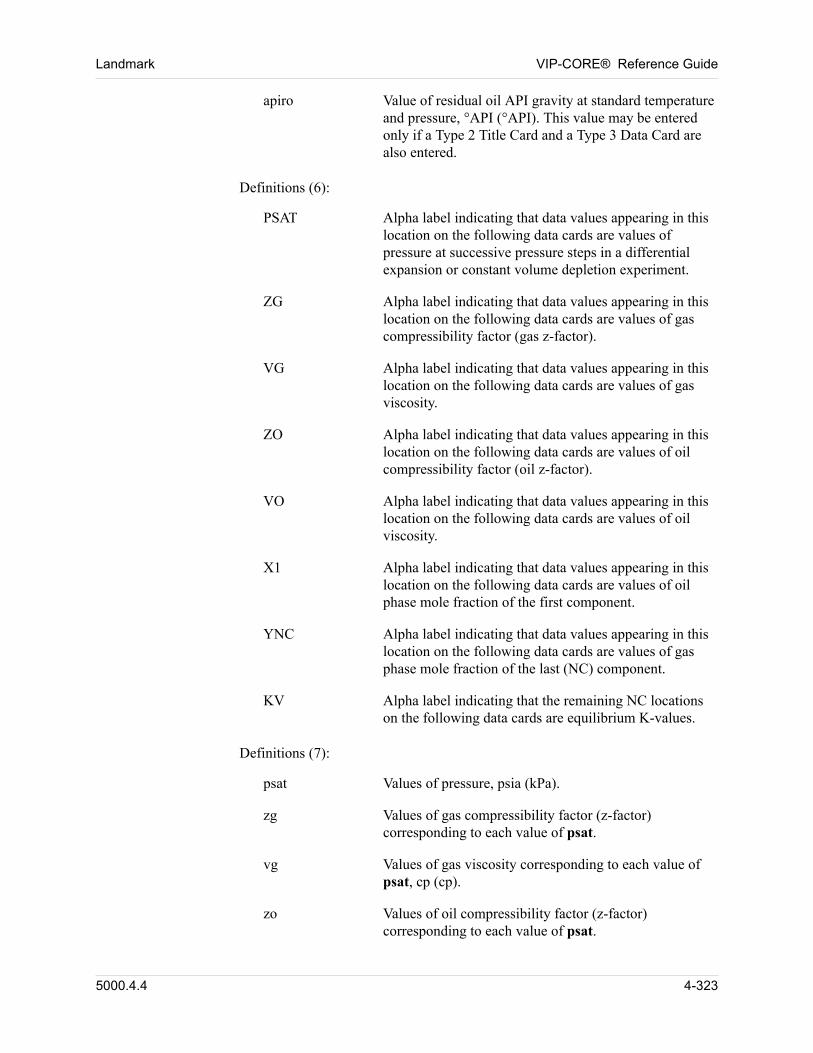
Landmark VIP-CORE® Reference Guide
apiro Value of residual oil API gravity at standard temperature and pressure, °API (°API). This value may be entered only if a Type 2 Title Card and a Type 3 Data Card are also entered.
00 Definitions (6):
PSAT Alpha label indicating that data values appearing in this location on the following data cards are values of pressure at successive pressure steps in a differential expansion or constant volume depletion experiment.
ZG Alpha label indicating that data values appearing in this location on the following data cards are values of gas compressibility factor (gas z-factor).
VG Alpha label indicating that data values appearing in this location on the following data cards are values of gas viscosity.
ZO Alpha label indicating that data values appearing in this location on the following data cards are values of oil compressibility factor (oil z-factor).
VO Alpha label indicating that data values appearing in this location on the following data cards are values of oil viscosity.
X1 Alpha label indicating that data values appearing in this location on the following data cards are values of oil phase mole fraction of the first component.
YNC Alpha label indicating that data values appearing in this location on the following data cards are values of gas phase mole fraction of the last (NC) component.
KV Alpha label indicating that the remaining NC locations on the following data cards are equilibrium K-values.
00 Definitions (7):
psat Values of pressure, psia (kPa).
zg Values of gas compressibility factor (z-factor) corresponding to each value of psat.
vg Values of gas viscosity corresponding to each value of psat, cp (cp).
zo Values of oil compressibility factor (z-factor) corresponding to each value of psat.
5000.4.4 4-323
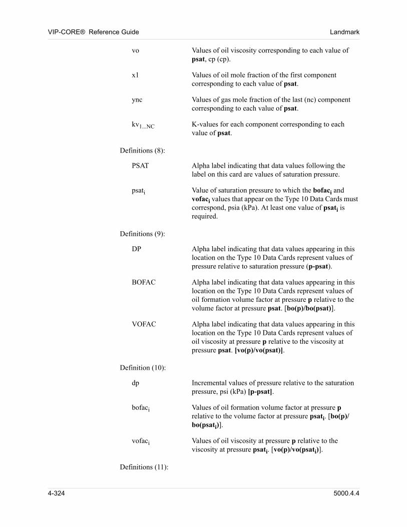
VIP-CORE® Reference Guide Landmark
vo Values of oil viscosity corresponding to each value of psat, cp (cp).
x1 Values of oil mole fraction of the first component corresponding to each value of psat.
ync Values of gas mole fraction of the last (nc) component corresponding to each value of psat.
kv1...NC K-values for each component corresponding to each value of psat.
00 Definitions (8):
PSAT Alpha label indicating that data values following the label on this card are values of saturation pressure.
psati Value of saturation pressure to which the bofaci and vofaci values that appear on the Type 10 Data Cards must correspond, psia (kPa). At least one value of psati is required.
00 Definitions (9):
DP Alpha label indicating that data values appearing in this location on the Type 10 Data Cards represent values of pressure relative to saturation pressure (p-psat).
BOFAC Alpha label indicating that data values appearing in this location on the Type 10 Data Cards represent values of oil formation volume factor at pressure p relative to the volume factor at pressure psat. [bo(p)/bo(psat)].
VOFAC Alpha label indicating that data values appearing in this location on the Type 10 Data Cards represent values of oil viscosity at pressure p relative to the viscosity at pressure psat. [vo(p)/vo(psat)].
00 Definition (10):
dp Incremental values of pressure relative to the saturation pressure, psi (kPa) [p-psat].
bofaci Values of oil formation volume factor at pressure p relative to the volume factor at pressure psati. [bo(p)/bo(psati)].
vofaci Values of oil viscosity at pressure p relative to the viscosity at pressure psati. [vo(p)/vo(psati)].
00 Definitions (11):
4-324 5000.4.4
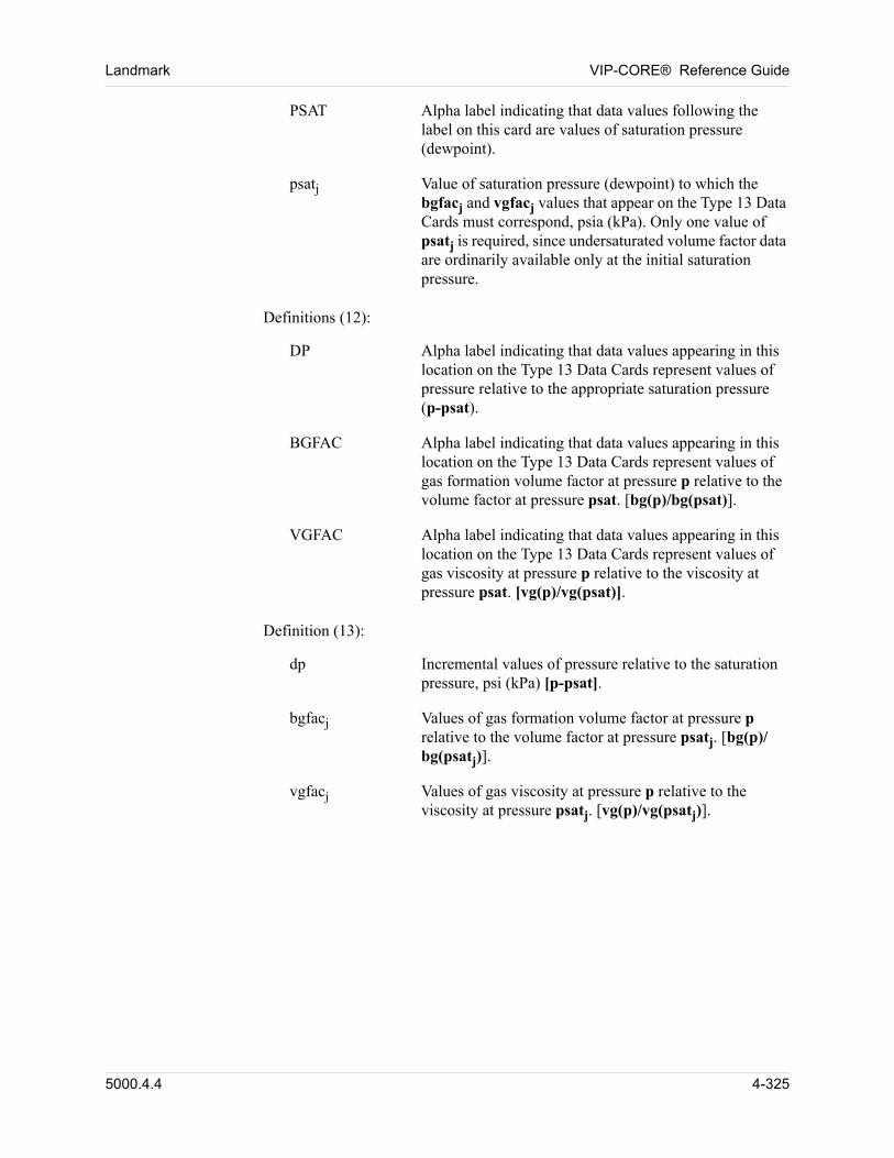
Landmark VIP-CORE® Reference Guide
PSAT Alpha label indicating that data values following the label on this card are values of saturation pressure (dewpoint).
psatj Value of saturation pressure (dewpoint) to which the bgfacj and vgfacj values that appear on the Type 13 Data Cards must correspond, psia (kPa). Only one value of psatj is required, since undersaturated volume factor data are ordinarily available only at the initial saturation pressure.
00 Definitions (12):
DP Alpha label indicating that data values appearing in this location on the Type 13 Data Cards represent values of pressure relative to the appropriate saturation pressure (p-psat).
BGFAC Alpha label indicating that data values appearing in this location on the Type 13 Data Cards represent values of gas formation volume factor at pressure p relative to the volume factor at pressure psat. [bg(p)/bg(psat)].
VGFAC Alpha label indicating that data values appearing in this location on the Type 13 Data Cards represent values of gas viscosity at pressure p relative to the viscosity at pressure psat. [vg(p)/vg(psat)].
00 Definition (13):
dp Incremental values of pressure relative to the saturation pressure, psi (kPa) [p-psat].
bgfacj Values of gas formation volume factor at pressure p relative to the volume factor at pressure psatj. [bg(p)/bg(psatj)].
vgfacj Values of gas viscosity at pressure p relative to the viscosity at pressure psatj. [vg(p)/vg(psatj)].
5000.4.4 4-325
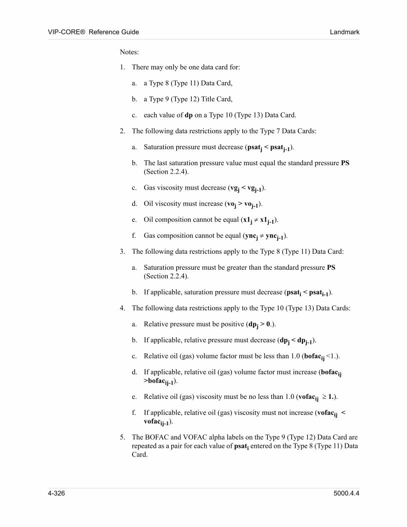
VIP-CORE® Reference Guide Landmark
00 Notes:
1. There may only be one data card for:
a. a Type 8 (Type 11) Data Card,
b. a Type 9 (Type 12) Title Card,
c. each value of dp on a Type 10 (Type 13) Data Card.
2. The following data restrictions apply to the Type 7 Data Cards:
a. Saturation pressure must decrease (psatj < psatj-1).
b. The last saturation pressure value must equal the standard pressure PS (Section 2.2.4).
c. Gas viscosity must decrease (vgj < vgj-1).
d. Oil viscosity must increase (voj > voj-1).
e. Oil composition cannot be equal (x1j x1j-1).
f. Gas composition cannot be equal (yncj yncj-1).
3. The following data restrictions apply to the Type 8 (Type 11) Data Card:
a. Saturation pressure must be greater than the standard pressure PS (Section 2.2.4).
b. If applicable, saturation pressure must decrease (psati < psati-1).
4. The following data restrictions apply to the Type 10 (Type 13) Data Cards:
a. Relative pressure must be positive (dpj > 0.).
b. If applicable, relative pressure must decrease (dpj < dpj-1).
c. Relative oil (gas) volume factor must be less than 1.0 (bofacij <1.).
d. If applicable, relative oil (gas) volume factor must increase (bofacij >bofacij-1).
e. Relative oil (gas) viscosity must be no less than 1.0 (vofacij 1.).
f. If applicable, relative oil (gas) viscosity must not increase (vofacij < vofacij-1).
5. The BOFAC and VOFAC alpha labels on the Type 9 (Type 12) Data Card are repeated as a pair for each value of psati entered on the Type 8 (Type 11) Data Card.
4-326 5000.4.4
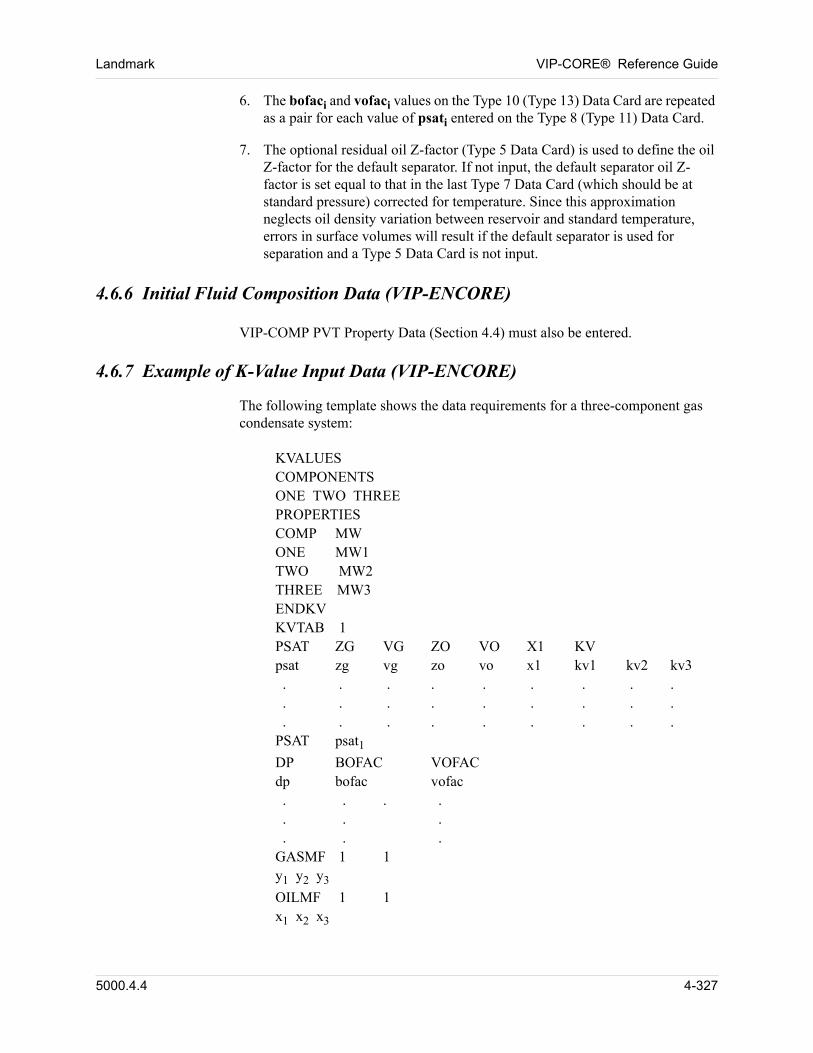
Landmark VIP-CORE® Reference Guide
6. The bofaci and vofaci values on the Type 10 (Type 13) Data Card are repeated as a pair for each value of psati entered on the Type 8 (Type 11) Data Card.
7. The optional residual oil Z-factor (Type 5 Data Card) is used to define the oil Z-factor for the default separator. If not input, the default separator oil Z-factor is set equal to that in the last Type 7 Data Card (which should be at standard pressure) corrected for temperature. Since this approximation neglects oil density variation between reservoir and standard temperature, errors in surface volumes will result if the default separator is used for separation and a Type 5 Data Card is not input.
4.6.6 Initial Fluid Composition Data (VIP-ENCORE)
00 VIP-COMP PVT Property Data (Section 4.4) must also be entered.
4.6.7 Example of K-Value Input Data (VIP-ENCORE)
The following template shows the data requirements for a three-component gas condensate system: 00
00 KVALUESCOMPONENTSONE TWO THREEPROPERTIESCOMP MWONE MW1TWO MW2THREE MW3ENDKVKVTAB 1PSAT ZG VG ZO VO X1 KVpsat zg vg zo vo x1 kv1 kv2 kv3 . . . . . . . . . . . . . . . . . . . . . . . . . . . PSAT psat1DP BOFAC VOFACdp bofac vofac . . . . . . . . . .GASMF 1 1y1 y2 y3
OILMF 1 1x1 x2 x3
5000.4.4 4-327
VIP-CORE® Reference Guide Landmark
4.7 Dead Oil PVT Property Data (VIP-THERM)
When no volatile components are present in the reservoir, two options are available for the representation of oil PVT properties. Oil must be represented by a single component (nc = 1, ncv = 0). Although gas does not exist in the reservoir, gas is allowed to evolve upon surface separation by entering a fixed surface gas-oil ratio and gas gravity. This provides for the case in which the reservoir has previously been depleted to low pressure at which a small amount of solution gas remains in the oil.
In the Dead Oil PVT Property Tables option, oil density, enthalpy, and viscosity are input in tabular form as functions of temperature and pressure. In the Dead Oil PVT Properties Correlations option, oil density is represented by compressibility and coefficient of thermal expansion, oil enthalpy is represented by a constant heat capacity, and oil viscosity is input as a function of temperature.
Initial reservoir temperature may be specified in one or more of the following ways for dead-oil thermal models: 00
1. Specified as a constant value (Section 2.2.4).
2. Specified by equilibrium region in the IEQUIL table (Section 4.2.1.1), overriding the constant value in option 1.
3. Specified as a function of depth (Section 4.7.1 or 4.7.2), overriding values in options 1 and 2.
4. Specified as a gridblock array in Section 5.25.1, overriding all other input values. This method is discouraged, since the calculation of the phase pressure versus depth curves by equilibruim region, from which initial gridblock pressures and saturations are computed, does not account for variation of temperature by gridblock. This results in errors in the computed initial gridblock pressure. Saturations are not a problem in dead oil models unless there is an initial steam cap with a gas-oil transition zone (non-zero capillary pressure curves). These errors may be avoided only by specifying all erroneous initial gridblock fluid properties as gridblock array data.
4.7.1 Dead Oil PVT Property Tables Option
When using this option, required data for the oil include molecular weight, density at standard conditions, and values of density, enthalpy, and viscosity as a function of temperature and pressure over the ranges expected during simulation. Oil densities and enthalpies are calculated by linear interpolation. Oil viscosity is interpolated based on a linear relationship between log (log viscosity) and log (temperature).
4-328 5000.4.4
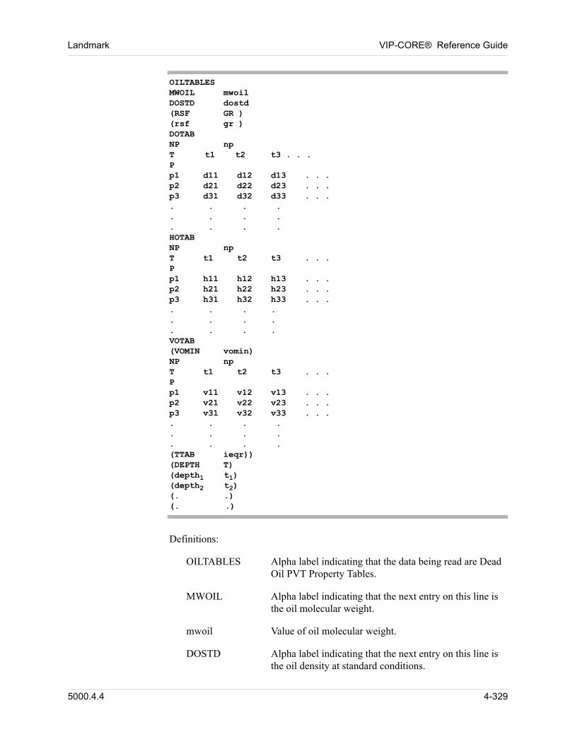
Landmark VIP-CORE® Reference Guide
OILTABLESMWOIL mwoilDOSTD dostd(RSF GR )(rsf gr )DOTABNP npT t1 t2 t3 . . .Pp1 d11 d12 d13 . . .p2 d21 d22 d23 . . .p3 d31 d32 d33 . . .. . . .. . . .. . . .HOTABNP npT t1 t2 t3 . . .Pp1 h11 h12 h13 . . .p2 h21 h22 h23 . . .p3 h31 h32 h33 . . .. . . .. . . .. . . .VOTAB(VOMIN vomin)NP npT t1 t2 t3 . . .Pp1 v11 v12 v13 . . .p2 v21 v22 v23 . . .p3 v31 v32 v33 . . .. . . .. . . .. . . .(TTAB ieqr))(DEPTH T)(depth1 t1)(depth2 t2)(. .)(. .)
Definitions:
OILTABLES Alpha label indicating that the data being read are Dead Oil PVT Property Tables.
MWOIL Alpha label indicating that the next entry on this line is the oil molecular weight.
mwoil Value of oil molecular weight.
DOSTD Alpha label indicating that the next entry on this line is the oil density at standard conditions.
5000.4.4 4-329
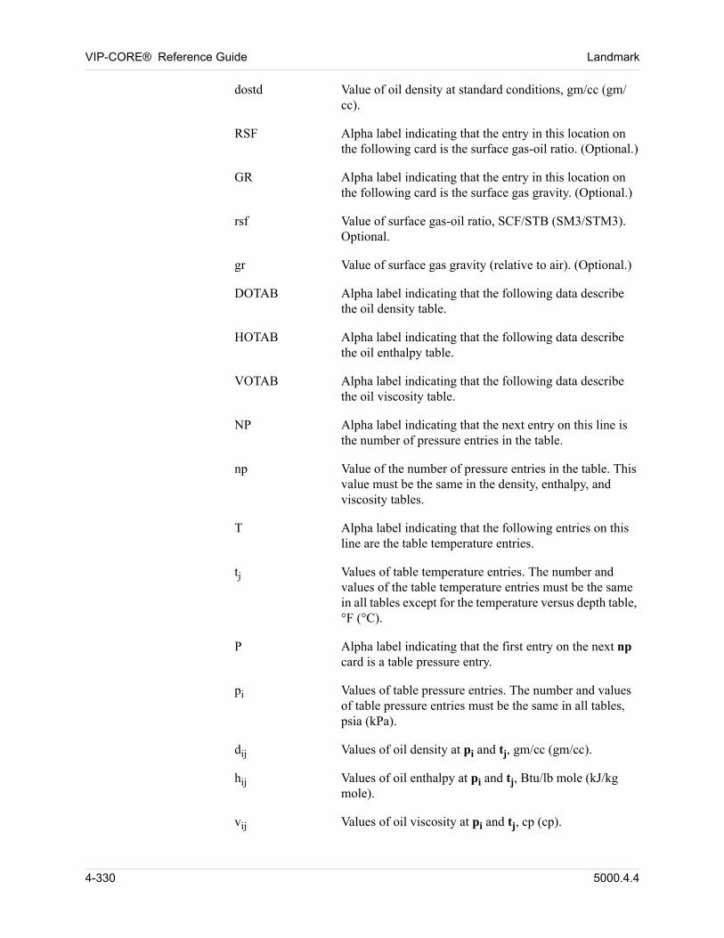
VIP-CORE® Reference Guide Landmark
dostd Value of oil density at standard conditions, gm/cc (gm/cc).
RSF Alpha label indicating that the entry in this location on the following card is the surface gas-oil ratio. (Optional.)
GR Alpha label indicating that the entry in this location on the following card is the surface gas gravity. (Optional.)
rsf Value of surface gas-oil ratio, SCF/STB (SM3/STM3). Optional.
gr Value of surface gas gravity (relative to air). (Optional.)
DOTAB Alpha label indicating that the following data describe the oil density table.
HOTAB Alpha label indicating that the following data describe the oil enthalpy table.
VOTAB Alpha label indicating that the following data describe the oil viscosity table.
NP Alpha label indicating that the next entry on this line is the number of pressure entries in the table.
np Value of the number of pressure entries in the table. This value must be the same in the density, enthalpy, and viscosity tables.
T Alpha label indicating that the following entries on this line are the table temperature entries.
tj Values of table temperature entries. The number and values of the table temperature entries must be the same in all tables except for the temperature versus depth table, °F (°C).
P Alpha label indicating that the first entry on the next np card is a table pressure entry.
pi Values of table pressure entries. The number and values of table pressure entries must be the same in all tables, psia (kPa).
dij Values of oil density at pi and tj, gm/cc (gm/cc).
hij Values of oil enthalpy at pi and tj, Btu/lb mole (kJ/kg mole).
vij Values of oil viscosity at pi and tj, cp (cp).
4-330 5000.4.4
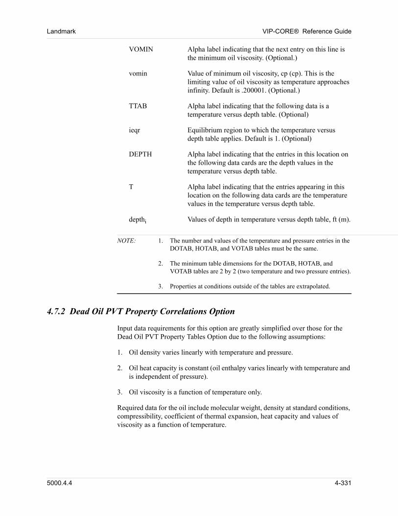
Landmark VIP-CORE® Reference Guide
VOMIN Alpha label indicating that the next entry on this line is the minimum oil viscosity. (Optional.)
vomin Value of minimum oil viscosity, cp (cp). This is the limiting value of oil viscosity as temperature approaches infinity. Default is .200001. (Optional.)
TTAB Alpha label indicating that the following data is a temperature versus depth table. (Optional)
ieqr Equilibrium region to which the temperature versus depth table applies. Default is 1. (Optional)
DEPTH Alpha label indicating that the entries in this location on the following data cards are the depth values in the temperature versus depth table.
T Alpha label indicating that the entries appearing in this location on the following data cards are the temperature values in the temperature versus depth table.
depthi Values of depth in temperature versus depth table, ft (m).
NOTE: 1. The number and values of the temperature and pressure entries in the DOTAB, HOTAB, and VOTAB tables must be the same.
2. The minimum table dimensions for the DOTAB, HOTAB, and VOTAB tables are 2 by 2 (two temperature and two pressure entries).
3. Properties at conditions outside of the tables are extrapolated.
4.7.2 Dead Oil PVT Property Correlations Option
Input data requirements for this option are greatly simplified over those for the Dead Oil PVT Property Tables Option due to the following assumptions:
1. Oil density varies linearly with temperature and pressure.
2. Oil heat capacity is constant (oil enthalpy varies linearly with temperature and is independent of pressure).
3. Oil viscosity is a function of temperature only.
Required data for the oil include molecular weight, density at standard conditions, compressibility, coefficient of thermal expansion, heat capacity and values of viscosity as a function of temperature.
5000.4.4 4-331

VIP-CORE® Reference Guide Landmark
Oil compressibility is defined as
CTEOILDOP
------------ 1DOSTD--------------------=
and the oil coefficient of thermal expansion is defined as
CTEOILDOT
------------ 1DOSTD--------------------–=
4-332 5000.4.4
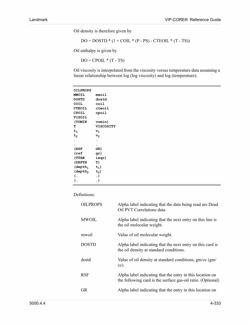
Landmark VIP-CORE® Reference Guide
Oil density is therefore given by
DO = DOSTD * (1 + COIL * (P - PS) - CTEOIL * (T - TS))
Oil enthalpy is given by
HO = CPOIL * (T - TS)
Oil viscosity is interpolated from the viscosity versus temperature data assuming a linear relationship between log (log viscosity) and log (temperature).
OILPROPSMWOIL mwoilDOSTD dostdCOIL coilCTEOIL cteoilCPOIL cpoilVISOIL(VOMIN vomin)T VISCOSITYt1 v1t2 v2. .. .(RSF GR)(rsf gr)(TTAB ieqr)(DEPTH T)(depth1 t1)(depth2 t2)(. .)(. .)
Definitions:
OILPROPS Alpha label indicating that the data being read are Dead Oil PVT Correlations data.
MWOIL Alpha label indicating that the next entry on this line is the oil molecular weight.
mwoil Value of oil molecular weight.
DOSTD Alpha label indicating that the next entry on this card is the oil density at standard conditions.
dostd Value of oil density at standard conditions, gm/cc (gm/cc).
RSF Alpha label indicating that the entry in this location on the following card is the surface gas-oil ratio. (Optional)
GR Alpha label indicating that the entry in this location on
5000.4.4 4-333
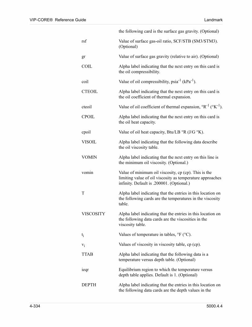
VIP-CORE® Reference Guide Landmark
the following card is the surface gas gravity. (Optional)
rsf Value of surface gas-oil ratio, SCF/STB (SM3/STM3). (Optional)
gr Value of surface gas gravity (relative to air). (Optional)
COIL Alpha label indicating that the next entry on this card is the oil compressibility.
coil Value of oil compressibility, psia-1 (kPa-1).
CTEOIL Alpha label indicating that the next entry on this card is the oil coefficient of thermal expansion.
cteoil Value of oil coefficient of thermal expansion, °R-1 (°K-1).
CPOIL Alpha label indicating that the next entry on this card is the oil heat capacity.
cpoil Value of oil heat capacity, Btu/LB °R (J/G °K).
VISOIL Alpha label indicating that the following data describe the oil viscosity table.
VOMIN Alpha label indicating that the next entry on this line is the minimum oil viscosity. (Optional.)
vomin Value of minimum oil viscosity, cp (cp). This is the limiting value of oil viscosity as temperature approaches infinity. Default is .200001. (Optional.)
T Alpha label indicating that the entries in this location on the following cards are the temperatures in the viscosity table.
VISCOSITY Alpha label indicating that the entries in this location on the following data cards are the viscosities in the viscosity table.
ti Values of temperature in tables, °F (°C).
vi Values of viscosity in viscosity table, cp (cp).
TTAB Alpha label indicating that the following data is a temperature versus depth table. (Optional)
ieqr Equilibrium region to which the temperature versus depth table applies. Default is 1. (Optional)
DEPTH Alpha label indicating that the entries in this location on the following data cards are the depth values in the
4-334 5000.4.4

Landmark VIP-CORE® Reference Guide
temperature versus depth table.
T Alpha label indicating that the entries in this location on the following data cards are the temperature values in the temperature versus depth table.
depthi Values of depth in temperature versus depth table, ft (m).
5000.4.4 4-335
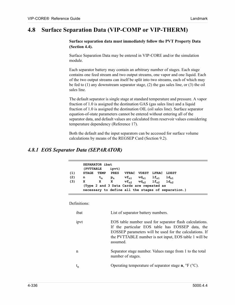
VIP-CORE® Reference Guide Landmark
4.8 Surface Separation Data (VIP-COMP or VIP-THERM)
00 Surface separation data must immediately follow the PVT Property Data (Section 4.4).
Surface Separation Data may be entered in VIP-CORE and/or the simulation module. 00
Each separator battery may contain an arbitrary number of stages. Each stage contains one feed stream and two output streams, one vapor and one liquid. Each of the two output streams can itself be split into two streams, each of which may be fed to (1) any downstream separator stage, (2) the gas sales line, or (3) the oil sales line. 00
The default separator is single stage at standard temperature and pressure. A vapor fraction of 1.0 is assigned the destination GAS (gas sales line) and a liquid fraction of 1.0 is assigned the destination OIL (oil sales line). Surface separator equation-of-state parameters cannot be entered without entering all of the separator data, and default values are calculated from reservoir values considering temperature dependency (Reference 17). 00
Both the default and the input separators can be accessed for surface volume calculations by means of the REGSEP Card (Section 9.2). 00
4.8.1 EOS Separator Data (SEPARATOR)
SEPARATOR ibat(PVTTABLE ipvt)
(1) STAGE TEMP PRES VFRAC VDEST LFRAC LDEST(2) n tn pn vfn1 vdn1 lfn1 ldn1(3) X X X vfn2 vdn2 lfn2 ldn2
(Type 2 and 3 Data Cards are repeated as necessary to define all the stages of separation.)
00 Definitions:
ibat List of separator battery numbers.
ipvt EOS table number used for separator flash calculations. If the particular EOS table has EOSSEP data, the EOSSEP parameters will be used for the calculations. If the PVTTABLE number is not input, EOS table 1 will be assumed.
n Separator stage number. Values range from 1 to the total number of stages.
tn Operating temperature of separator stage n, °F (°C).
4-336 5000.4.4
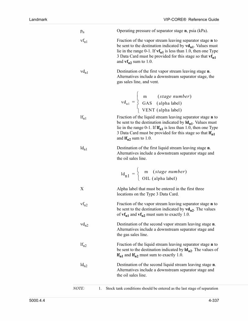
Landmark VIP-CORE® Reference Guide
pn Operating pressure of separator stage n, psia (kPa).
vfn1 Fraction of the vapor stream leaving separator stage n to be sent to the destination indicated by vdn1. Values must lie in the range 0-1. If vfn1 is less than 1.0, then one Type 3 Data Card must be provided for this stage so that vfn1 and vfn2 sum to 1.0.
vdn1 Destination of the first vapor stream leaving stage n. Alternatives include a downstream separator stage, the gas sales line, and vent.
vdn1
m stage number GAS alpha label VENT alpha label
=
lfn1 Fraction of the liquid stream leaving separator stage n to be sent to the destination indicated by ldn1. Values must lie in the range 0-1. If lfn1 is less than 1.0, then one Type 3 Data Card must be provided for this stage so that lfn1 and lfn2 sum to 1.0.
ldn1 Destination of the first liquid stream leaving stage n. Alternatives include a downstream separator stage and the oil sales line.
ldn1m stage number
OIL alpha label
=
X Alpha label that must be entered in the first three locations on the Type 3 Data Card.
vfn2 Fraction of the vapor stream leaving separator stage n to be sent to the destination indicated by vdn2. The values of vfn1 and vfn2 must sum to exactly 1.0.
vdn2 Destination of the second vapor stream leaving stage n. Alternatives include a downstream separator stage and the gas sales line.
lfn2 Fraction of the liquid stream leaving separator stage n to be sent to the destination indicated by ldn2. The values of lfn1 and lfn2 must sum to exactly 1.0.
ldn2 Destination of the second liquid stream leaving stage n. Alternatives include a downstream separator stage and the oil sales line.
NOTE: 1. Stock tank conditions should be entered as the last stage of separation
5000.4.4 4-337
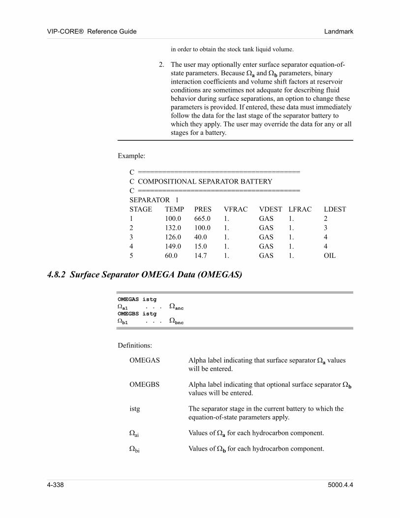
VIP-CORE® Reference Guide Landmark
in order to obtain the stock tank liquid volume.
2. The user may optionally enter surface separator equation-of-state parameters. Because a and b parameters, binary interaction coefficients and volume shift factors at reservoir conditions are sometimes not adequate for describing fluid behavior during surface separations, an option to change these parameters is provided. If entered, these data must immediately follow the data for the last stage of the separator battery to which they apply. The user may override the data for any or all stages for a battery.
00 Example:
00 C ========================================C COMPOSITIONAL SEPARATOR BATTERYC ========================================SEPARATOR 1STAGE TEMP PRES VFRAC VDEST LFRAC LDEST1 100.0 665.0 1. GAS 1. 22 132.0 100.0 1. GAS 1. 33 126.0 40.0 1. GAS 1. 44 149.0 15.0 1. GAS 1. 45 60.0 14.7 1. GAS 1. OIL
4.8.2 Surface Separator OMEGA Data (OMEGAS)
OMEGAS istga1 . . . ancOMEGBS istgb1 . . . bnc
00 Definitions:
OMEGAS Alpha label indicating that surface separator a values will be entered.
OMEGBS Alpha label indicating that optional surface separator b values will be entered.
istg The separator stage in the current battery to which the equation-of-state parameters apply.
ai Values of a for each hydrocarbon component.
bi Values of b for each hydrocarbon component.
4-338 5000.4.4
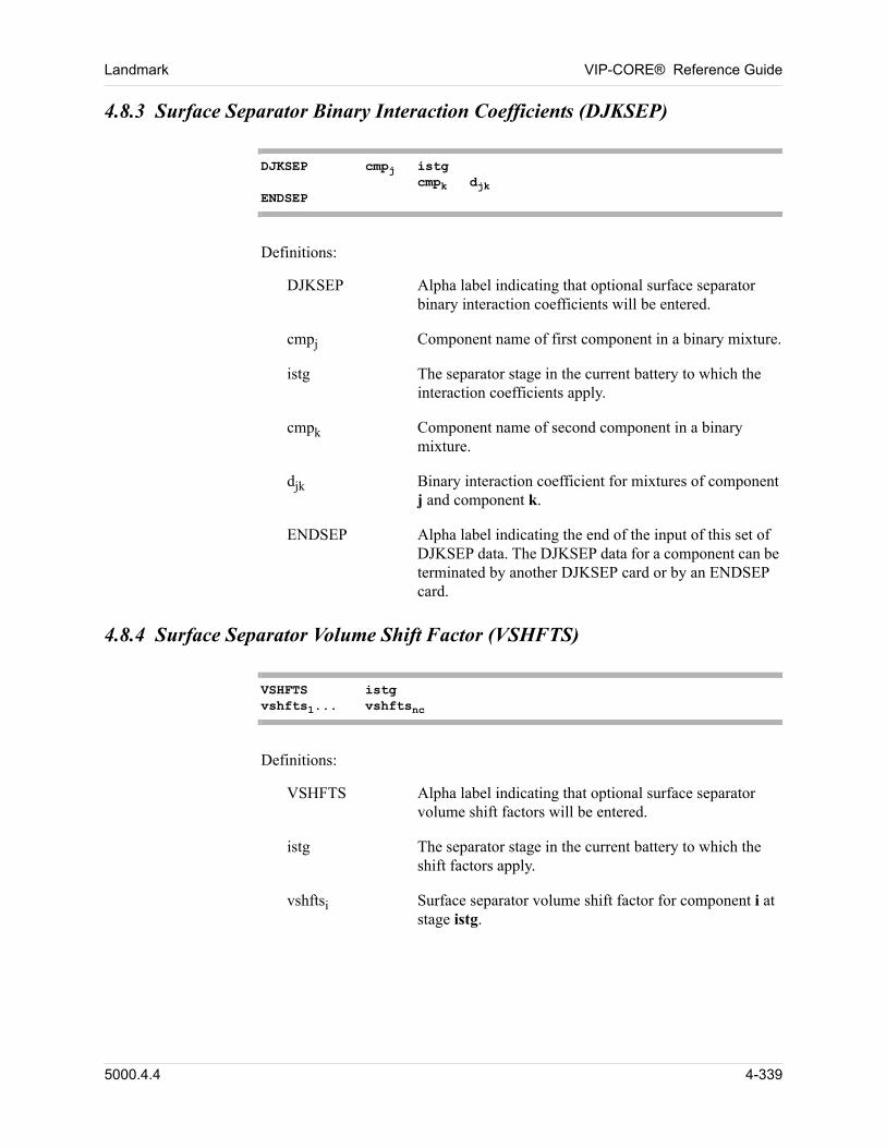
Landmark VIP-CORE® Reference Guide
4.8.3 Surface Separator Binary Interaction Coefficients (DJKSEP)
DJKSEP cmpj istgcmpk djk
ENDSEP
00 Definitions:
DJKSEP Alpha label indicating that optional surface separator binary interaction coefficients will be entered.
cmpj Component name of first component in a binary mixture.
istg The separator stage in the current battery to which the interaction coefficients apply.
cmpk Component name of second component in a binary mixture.
djk Binary interaction coefficient for mixtures of component j and component k.
ENDSEP Alpha label indicating the end of the input of this set of DJKSEP data. The DJKSEP data for a component can be terminated by another DJKSEP card or by an ENDSEP card.
4.8.4 Surface Separator Volume Shift Factor (VSHFTS)
VSHFTS istgvshfts1... vshftsnc
00 Definitions:
VSHFTS Alpha label indicating that optional surface separator volume shift factors will be entered.
istg The separator stage in the current battery to which the shift factors apply.
vshftsi Surface separator volume shift factor for component i at stage istg.
5000.4.4 4-339
VIP-CORE® Reference Guide Landmark
4.9 Surface Separation Data with BOTAB PVT Data (VIP-ENCORE)
00 Surface separation data must immediately follow the PVT Property Data (Section 4.5).
00 Surface separation data may be entered in VIP-CORE and/or the simulation modules. However, more options are available in VIP-CORE.
When “black-oil” type problems are run in VIP-ENCORE, the PVT data are converted into a multicomponent format, including the use of K-values and z-factors to calculate the phase behavior and volumetric behavior of both oil and gas. This treatment makes it possible for separator conditions to be exactly modeled, while using differential expansion data to describe fluid behavior in the reservoir. This eliminates the conflict between differential and flash volumetrics that creates difficulty for conventional black-oil simulators. 00
The types and format of surface separation data depend upon the type of PVT Property Data which is input (black-oil laboratory data or K-value tabular data, see Section 4.4). 00
Both the default and the input separators can be accessed for surface volume calculations by means of the REGSEP Card (Section 9.2). 00
For black-oil laboratory PVT data input, there are four options for the treatment of separators. 00
00 These options are not mutually exclusive, i.e., any number of input separator data options may be used in the same run. Order is not important.
00 Default Separator (only for use with adjusted PVT data)
00 Separator K-value Input
00 Separator Test Data Input
00 Black-oil Separator Data Input
The second option is a slightly modified version of the separator data input format given in the Simulation Modules Manual. 00
Use of the default separator implies that the differential liberation data have been adjusted for flash conditions in the conventional manner (see Section 2.2.2.2 (VIP-ENCORE)). If no adjustments are made and the default separator is used, significant errors in surface volumes will result. 00
4-340 5000.4.4
Landmark VIP-CORE® Reference Guide
4.9.1 Default Separator
Default separators should be used only when VIP-ENCORE is being run in the conventional black-oil mode (the PVT data have been appropriately adjusted). See Section Section 4.5.1. 00
Default separator K-values and liquid compressibility factors are calculated from input laboratory differential liberation data (PVT property data). One separator battery is created for each PVT property table. Each separator is single stage at standard temperature and pressure with a vapor fraction of 1.0 sent to the destination GAS (gas sales line) and a liquid fraction of 1.0 sent to the destination OIL (oil sales line) (see separator configuration data below.) 00
K-values are calculated from the differential liberation data using the calculated composition of the total gas liberated from the initial saturation pressure to standard pressure and the composition of the liquid at standard pressure. A liquid compressibility factor at standard conditions is calculated for each battery using the residual oil density and molecular weight input in or derived from the differential liberation data. 00
If a non-zero value for gas-oil ratio at standard pressure was input in the PVT data, use of the default separator will result in a match between the separation gas-oil ratio at the initial saturation pressure and the “effective” input gas-oil ratio at the initial saturation pressure. The “effective” gas-oil ratio is equal to the difference between the input gas-oil ratio and the gas-oil ratio at standard pressure. See Note 7 at end of Section 4.5.2.1. 00
4.9.2 Separator K-Value Input (SEPARATOR)
00 This card should be used only with VIP-ENCORE.
Input data format for this option is similar to that given in the reference manual for the simulation modules. In earlier documentation it has been suggested that one use the K-values derived for the last step in the differential liberation experiment. This may lead to large errors in surface volumes. This option should be used only when accurate separator K-values and liquid density are known. When using this option, one must take great care to insure that the input K-values are consistent with the internally defined component molecular weights, which are printed out in the default separator properties table. 00
00 The data required for this option include the following:
1. Definition of the separator configuration. This includes the number of stages, the destinations of the two outflow streams leaving each stage, and the fraction of each outflow stream that flows to each destination.
2. The density of the oil product (stock tank oil) leaving the last separator stage.
3. The molecular weight of the stock tank oil or the saturation pressure of the saturated oil feed.
5000.4.4 4-341
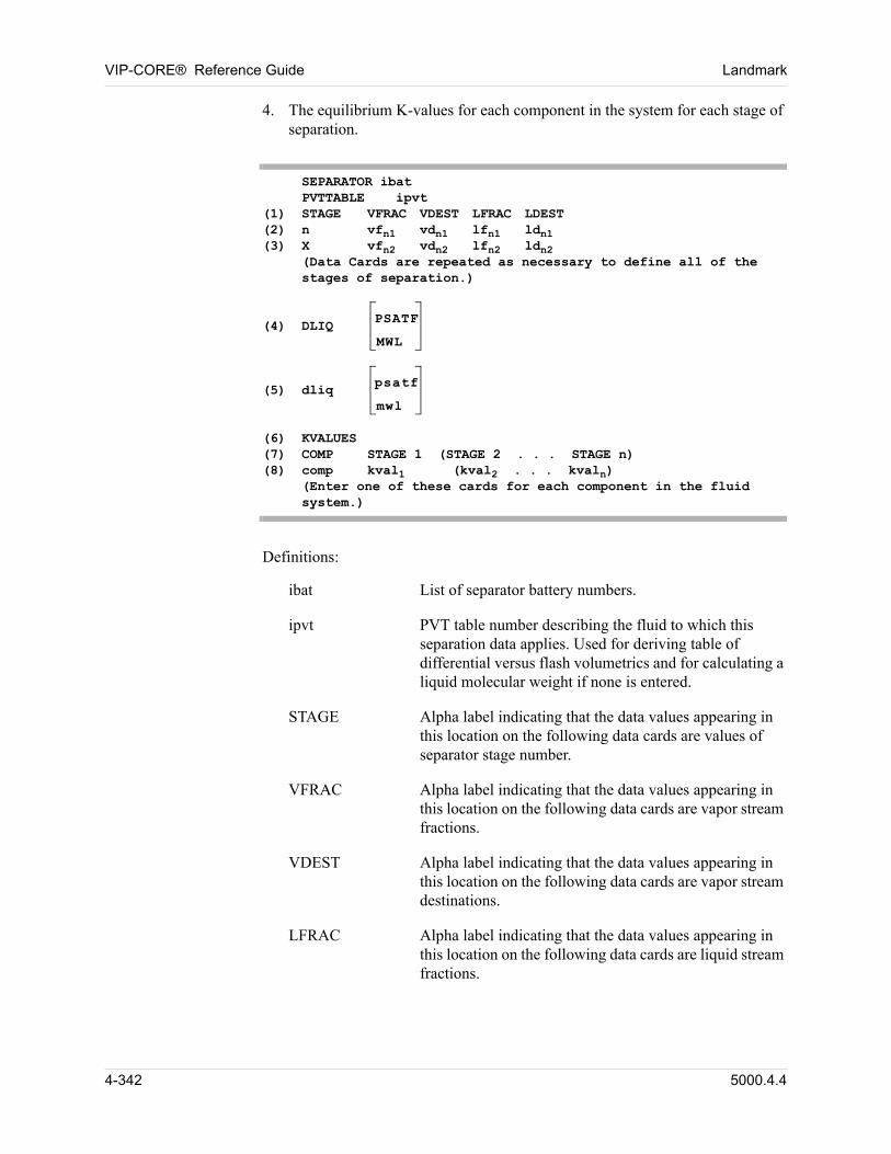
VIP-CORE® Reference Guide Landmark
4. The equilibrium K-values for each component in the system for each stage of separation.
SEPARATOR ibatPVTTABLE ipvt
(1) STAGE VFRAC VDEST LFRAC LDEST(2) n vfn1 vdn1 lfn1 ldn1(3) X vfn2 vdn2 lfn2 ldn2
(Data Cards are repeated as necessary to define all of the stages of separation.)
(4) DLIQ
PSATF
MWL
(5) dliq
psatf
mwl
(6) KVALUES(7) COMP STAGE 1 (STAGE 2 . . . STAGE n)(8) comp kval1 (kval2 . . . kvaln)
(Enter one of these cards for each component in the fluidsystem.)
00 Definitions:
ibat List of separator battery numbers.
ipvt PVT table number describing the fluid to which this separation data applies. Used for deriving table of differential versus flash volumetrics and for calculating a liquid molecular weight if none is entered.
STAGE Alpha label indicating that the data values appearing in this location on the following data cards are values of separator stage number.
VFRAC Alpha label indicating that the data values appearing in this location on the following data cards are vapor stream fractions.
VDEST Alpha label indicating that the data values appearing in this location on the following data cards are vapor stream destinations.
LFRAC Alpha label indicating that the data values appearing in this location on the following data cards are liquid stream fractions.
4-342 5000.4.4
Landmark VIP-CORE® Reference Guide
LDEST Alpha label indicating that the data values appearing in this location on the following data cards are liquid stream destinations.
n Separator stage number. Values range from 1 to the total number of stages.
vfn1 Fraction of the vapor stream leaving separator stage n to be sent to the destination indicated by vdn1. Values must lie in the range 0-1. If vfn1 is less than 1.0, then one Type 3 Data Card must be provided for this stage so that vfn1 and vfn2 sum to 1.0.
vdn1 Destination of the first vapor stream leaving stage n. Alternatives include a downstream separator stage, the gas sales line, and vent.
vdn1
m stage number GAS alpha label VENT alpha label
=
lfn1 Fraction of the liquid stream leaving separator stage n to be sent to the destination indicated by ldn1. Values must lie in the range 0-1. If lfn1 is less than 1.0, then one Type 3 Data Card must be provided for this stage, so that lfn1 and lfn2 sum to 1.0.
ldn1 Destination of the first liquid stream leaving stage n. Alternatives include a downstream separator stage and the oil sales line.
ldn1m stage number
OIL alpha label
=
X Alpha label that must be entered in the first location on the Type 3 Data Card.
vfn2 Fraction of the vapor stream leaving separator stage n to be sent to the destination indicated by vdn2. The values of vfn1 and vfn2 must sum to exactly 1.0.
vdn2 Destination of the second vapor stream leaving stage n. Alternatives include a downstream separator stage and the gas sales line.
lfn2 Fraction of the liquid stream leaving separator stage n to be sent to the destination indicated by ldn2. The values of lfn1 and lfn2 must sum to exactly 1.0.
5000.4.4 4-343
VIP-CORE® Reference Guide Landmark
ldn2 Destination of the second liquid stream leaving stage n. Alternatives include a downstream separator stage and the oil sales line.
DLIQ Alpha label indicating that the data value appearing in this location on the following data card is the density of the stock tank oil.
PSATF Alpha label indicating that the data value appearing in this location on the following data card is the saturation pressure of the feed fluid.
MWL Alpha label indicating that the data value appearing in this location on the following data card is the molecular weight of the stock tank oil.
dliq Density of the oil product (stock tank oil) leaving the last separator stage, gm/cc (gm/cc).
psatf Saturation pressure of the feed (saturated oil from PVT table ntab) in the separator test from which the data were derived, psia (kPa).
mwl Molecular weight of the stock tank oil.
comp Component name (or number).
kvali Equilibrium K-value for this component for stage i.
NOTE: Since the separator data should correspond to a fluid described in one of the PVT tables, psatf should be input instead of mwl. Molecular weight can and will be calculated (if not input) from the input K-values and the differential liberation data.This option may not be used in conjunction with the PVT interpolation option.
Each separator battery may contain any number of stages. Each stage contains one feed stream and two output streams: vapor and liquid. Each of the two output streams can itself be split into two streams, each of which may be fed to any downstream separator stage, the gas sales line or the oil sales line. 00
4-344 5000.4.4
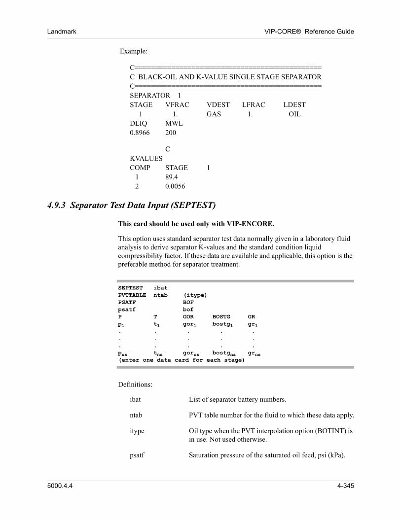
Landmark VIP-CORE® Reference Guide
00 Example:
00 C==============================================C BLACK-OIL AND K-VALUE SINGLE STAGE SEPARATORC==============================================SEPARATOR 1STAGE VFRAC VDEST LFRAC LDEST 1 1. GAS 1. OILDLIQ MWL0.8966 200
00 CKVALUESCOMP STAGE 1 1 89.4 2 0.0056
4.9.3 Separator Test Data Input (SEPTEST)
00 This card should be used only with VIP-ENCORE.
This option uses standard separator test data normally given in a laboratory fluid analysis to derive separator K-values and the standard condition liquid compressibility factor. If these data are available and applicable, this option is the preferable method for separator treatment. 00
SEPTEST ibatPVTTABLE ntab (itype)PSATF BOF psatf bofP T GOR BOSTG GRp1 t1 gor1 bostg1 gr1. . . . .. . . . .. . . . .pns tns gorns bostgns grns(enter one data card for each stage)
00 Definitions:
ibat List of separator battery numbers.
ntab PVT table number for the fluid to which these data apply.
itype Oil type when the PVT interpolation option (BOTINT) is in use. Not used otherwise.
psatf Saturation pressure of the saturated oil feed, psi (kPa).
5000.4.4 4-345
VIP-CORE® Reference Guide Landmark
bof “Flash” oil formation volume factor for feed of saturated oil from PVT table ntab at psatf.
pn Operating pressure of separator stage n, psia (kPa).
tn Operating temperature of separator stage n, °F(°C).
gorn Liberated gas-oil ratio of stage n, SCF/STB (SM3/STM3).
bostgn Separator volume factor of the liquid leaving stage n.
grn Gas gravity of the gas leaving stage n.
NOTE: Separator configuration (as described in Section 4.9.2) is defined automatically with a vapor fraction of 1.0 of the vapor stream from each stage sent to the destination GAS (gas sales line), a liquid fraction of 1.0 of the liquid stream from each stage sent to the next stage, and the liquid stream of the last stage sent to the destination OIL (oil sales line).Only one stage is allowed when the PVT interpolation option is in use.
4-346 5000.4.4
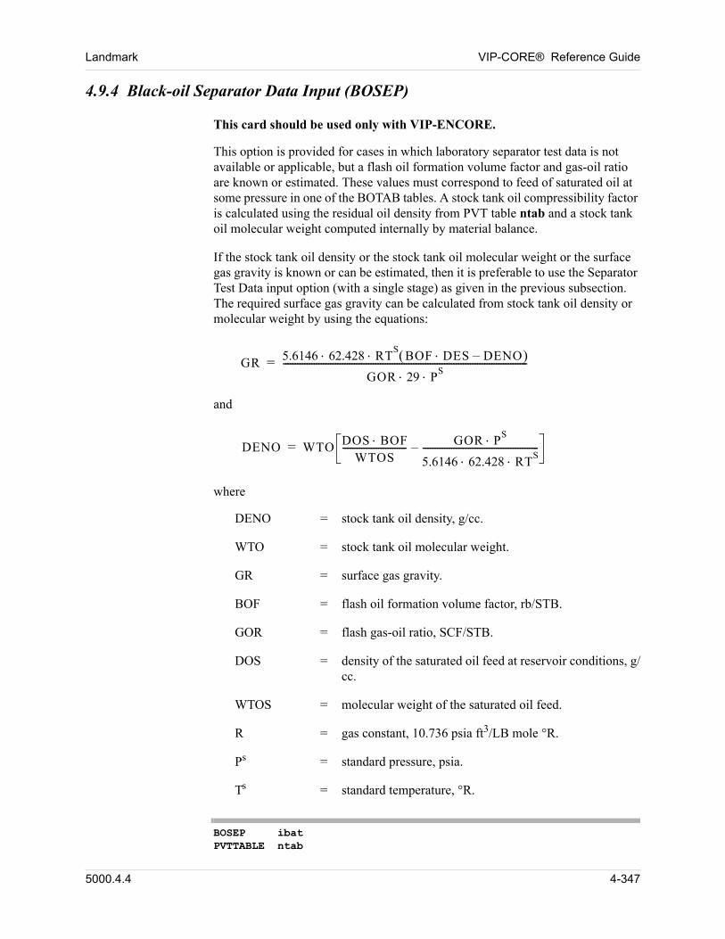
Landmark VIP-CORE® Reference Guide
4.9.4 Black-oil Separator Data Input (BOSEP)
This card should be used only with VIP-ENCORE.
This option is provided for cases in which laboratory separator test data is not available or applicable, but a flash oil formation volume factor and gas-oil ratio are known or estimated. These values must correspond to feed of saturated oil at some pressure in one of the BOTAB tables. A stock tank oil compressibility factor is calculated using the residual oil density from PVT table ntab and a stock tank oil molecular weight computed internally by material balance.
If the stock tank oil density or the stock tank oil molecular weight or the surface gas gravity is known or can be estimated, then it is preferable to use the Separator Test Data input option (with a single stage) as given in the previous subsection. The required surface gas gravity can be calculated from stock tank oil density or molecular weight by using the equations:
GR 5.6146 62.428 RTS BOF DES DENO–
GOR 29 PS
-------------------------------------------------------------------------------------------------------=
00 and
00 DENO WTO DOS BOFWTOS
--------------------------- GOR PS
5.6146 62.428 RTS
-------------------------------------------------–=
00 where
DENO = stock tank oil density, g/cc.
WTO = stock tank oil molecular weight.
GR = surface gas gravity.
BOF = flash oil formation volume factor, rb/STB.
GOR = flash gas-oil ratio, SCF/STB.
DOS = density of the saturated oil feed at reservoir conditions, g/cc.
WTOS = molecular weight of the saturated oil feed.
R = gas constant, 10.736 psia ft3/LB mole °R.
Ps = standard pressure, psia.
Ts = standard temperature, °R.
BOSEP ibatPVTTABLE ntab
5000.4.4 4-347
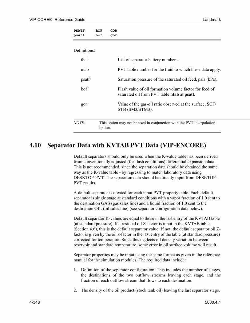
VIP-CORE® Reference Guide Landmark
PSATF BOF GORpsatf bof gor
00 Definitions:
ibat List of separator battery numbers.
ntab PVT table number for the fluid to which these data apply.
psatf Saturation pressure of the saturated oil feed, psia (kPa).
bof Flash value of oil formation volume factor for feed of saturated oil from PVT table ntab at psatf.
gor Value of the gas-oil ratio observed at the surface, SCF/STB (SM3/STM3).
NOTE: This option may not be used in conjunction with the PVT interpolation option.
4.10 Separator Data with KVTAB PVT Data (VIP-ENCORE)
Default separators should only be used when the K-value table has been derived from conventionally adjusted (for flash conditions) differential expansion data. This is not recommended, since the separation data should be obtained the same way as the K-value table - by regressing to match laboratory data using DESKTOP-PVT. The separation data should be directly input from DESKTOP-PVT results. 00
A default separator is created for each input PVT property table. Each default separator is single stage at standard conditions with a vapor fraction of 1.0 sent to the destination GAS (gas sales line) and a liquid fraction of 1.0 sent to the destination OIL (oil sales line) (see separator configuration data below). 00
Default separator K-values are equal to those in the last entry of the KVTAB table (at standard pressure). If a residual oil Z-factor is input in the KVTAB table (Section 4.6), this is the default separator value. If not, the default separator oil Z-factor is given by the oil z-factor in the last entry of the table (at standard pressure) corrected for temperature. Since this neglects oil density variation between reservoir and standard temperature, some error in oil surface volume will result. 00
Separator properties may be input using the same format as given in the reference manual for the simulation modules. The required data include: 00
1. Definition of the separator configuration. This includes the number of stages, the destinations of the two outflow streams leaving each stage, and the fraction of each outflow stream that flows to each destination.
2. The density of the oil product (stock tank oil) leaving the last separator stage.
4-348 5000.4.4

Landmark VIP-CORE® Reference Guide
3. The molecular weight of the stock tank oil.
4. The equilibrium K-values for each component in the system for each stage of separation.
5000.4.4 4-349
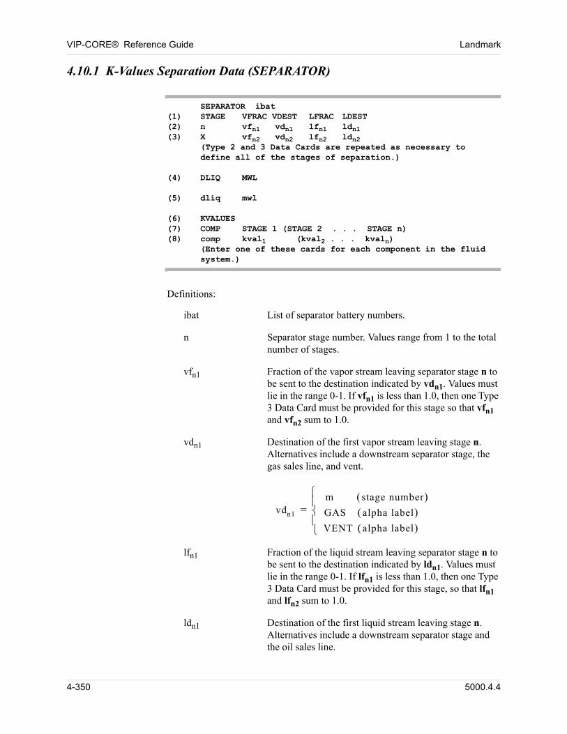
VIP-CORE® Reference Guide Landmark
4.10.1 K-Values Separation Data (SEPARATOR)
SEPARATOR ibat(1) STAGE VFRAC VDEST LFRAC LDEST(2) n vfn1 vdn1 lfn1 ldn1(3) X vfn2 vdn2 lfn2 ldn2
(Type 2 and 3 Data Cards are repeated as necessary todefine all of the stages of separation.)
(4) DLIQ MWL(5) dliq mwl(6) KVALUES(7) COMP STAGE 1 (STAGE 2 . . . STAGE n)(8) comp kval1 (kval2 . . . kvaln)
(Enter one of these cards for each component in the fluidsystem.)
00 Definitions:
ibat List of separator battery numbers.
n Separator stage number. Values range from 1 to the total number of stages.
vfn1 Fraction of the vapor stream leaving separator stage n to be sent to the destination indicated by vdn1. Values must lie in the range 0-1. If vfn1 is less than 1.0, then one Type 3 Data Card must be provided for this stage so that vfn1 and vfn2 sum to 1.0.
vdn1 Destination of the first vapor stream leaving stage n. Alternatives include a downstream separator stage, the gas sales line, and vent.
vdn1
m stage number GAS alpha label VENT alpha label
=
lfn1 Fraction of the liquid stream leaving separator stage n to be sent to the destination indicated by ldn1. Values must lie in the range 0-1. If lfn1 is less than 1.0, then one Type 3 Data Card must be provided for this stage, so that lfn1 and lfn2 sum to 1.0.
ldn1 Destination of the first liquid stream leaving stage n. Alternatives include a downstream separator stage and the oil sales line.
4-350 5000.4.4
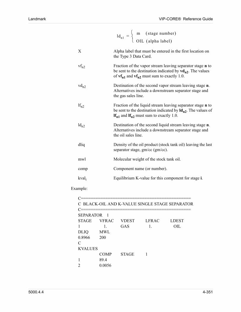
Landmark VIP-CORE® Reference Guide
ldn1m stage number
OIL alpha label
=
X Alpha label that must be entered in the first location on the Type 3 Data Card.
vfn2 Fraction of the vapor stream leaving separator stage n to be sent to the destination indicated by vdn2. The values of vfn1 and vfn2 must sum to exactly 1.0.
vdn2 Destination of the second vapor stream leaving stage n. Alternatives include a downstream separator stage and the gas sales line.
lfn2 Fraction of the liquid stream leaving separator stage n to be sent to the destination indicated by ldn2. The values of lfn1 and lfn2 must sum to exactly 1.0.
ldn2 Destination of the second liquid stream leaving stage n. Alternatives include a downstream separator stage and the oil sales line.
dliq Density of the oil product (stock tank oil) leaving the last separator stage, gm/cc (gm/cc).
mwl Molecular weight of the stock tank oil.
comp Component name (or number).
kvali Equilibrium K-value for this component for stage i.
00 Example:
00 C=============================================C BLACK-OIL AND K-VALUE SINGLE STAGE SEPARATORC=============================================SEPARATOR 1STAGE VFRAC VDEST LFRAC LDEST1 1. GAS 1. OILDLIQ MWL0.8966 200CKVALUES
COMP STAGE 11 89.42 0.0056
5000.4.4 4-351
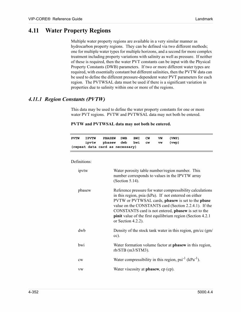
VIP-CORE® Reference Guide Landmark
4.11 Water Property Regions
00 Multiple water property regions are available in a very similar manner as hydrocarbon property regions. They can be defined via two different methods; one for multiple water types for multiple horizons, and a second for more complex treatment including property variations with salinity as well as pressure. If neither of these is required, then the water PVT constants can be input with the Physical Property Constants (DWB) parameters. If two or more different water types are required, with essentially constant but different salinities, then the PVTW data can be used to define the different pressure-dependent water PVT parameters for each region. The PVTWSAL data must be used if there is a significant variation in properties due to salinity within one or more of the regions.
4.11.1 Region Constants (PVTW)
00 This data may be used to define the water property constants for one or more water PVT regions. PVTW and PVTWSAL data may not both be entered.
00 PVTW and PVTWSAL data may not both be entered.
PVTW IPVTW PBASEW DWB BWI CW VW (VWP) ipvtw pbasew dwb bwi cw vw (vwp)
(repeat data card as necessary)
00 Definitions:
ipvtw Water porosity table number/region number. This number corresponds to values in the IPVTW array (Section 5.14).
pbasew Reference pressure for water compressibility calculations in this region, psia (kPa). If not enterred on either PVTW or PVTWSAL cards, pbasew is set to the pbase value on the CONSTANTS card (Section 2.2.4.1). If the CONSTANTS card is not entered, pbasew is set to the pinit value of the first equilibrium region (Section 4.2.1 or Section 4.2.2).
dwb Density of the stock tank water in this region, gm/cc (gm/cc).
bwi Water formation volume factor at pbasew in this region, rb/STB (m3/STM3).
cw Water compressibility in this region, psi-1 (kPa-1).
vw Water viscosity at pbasew, cp (cp).
4-352 5000.4.4
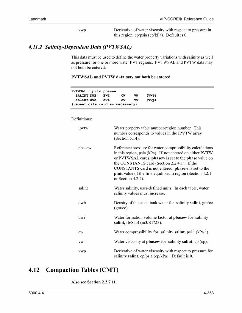
Landmark VIP-CORE® Reference Guide
vwp Derivative of water viscosity with respect to pressure in this region, cp/psia (cp/kPa). Default is 0.
4.11.2 Salinity-Dependent Data (PVTWSAL)
00 This data must be used to define the water property variations with salinity as well as pressure for one or more water PVT regions. PVTWSAL and PVTW data may not both be entered.
00 PVTWSAL and PVTW data may not both be entered.
PVTWSAL ipvtw pbasew SALINT DWB BWI CW VW (VWP) salint dwb bwi cw vw (vwp)
(repeat data card as necessary)
00 Definitions:
ipvtw Water property table number/region number. This number corresponds to values in the IPVTW array (Section 5.14).
pbasew Reference pressure for water compressibility calculations in this region, psia (kPa). If not entered on either PVTW or PVTWSAL cards, pbasew is set to the pbase value on the CONSTANTS card (Section 2.2.4.1). If the CONSTANTS card is not entered, pbasew is set to the pinit value of the first equilibrium region (Section 4.2.1 or Section 4.2.2).
salint Water salinity, user-defined units. In each table, water salinity values must increase.
dwb Density of the stock tank water for salinity salint, gm/cc (gm/cc).
bwi Water formation volume factor at pbasew for salinity salint, rb/STB (m3/STM3).
cw Water compressibility for salinity salint, psi-1 (kPa-1).
vw Water viscosity at pbasew for salinity salint, cp (cp).
vwp Derivative of water viscosity with respect to pressure for salinity salint, cp/psia (cp/kPa). Default is 0.
4.12 Compaction Tables (CMT)
00 Also see Section 2.2.7.11.
5000.4.4 4-353
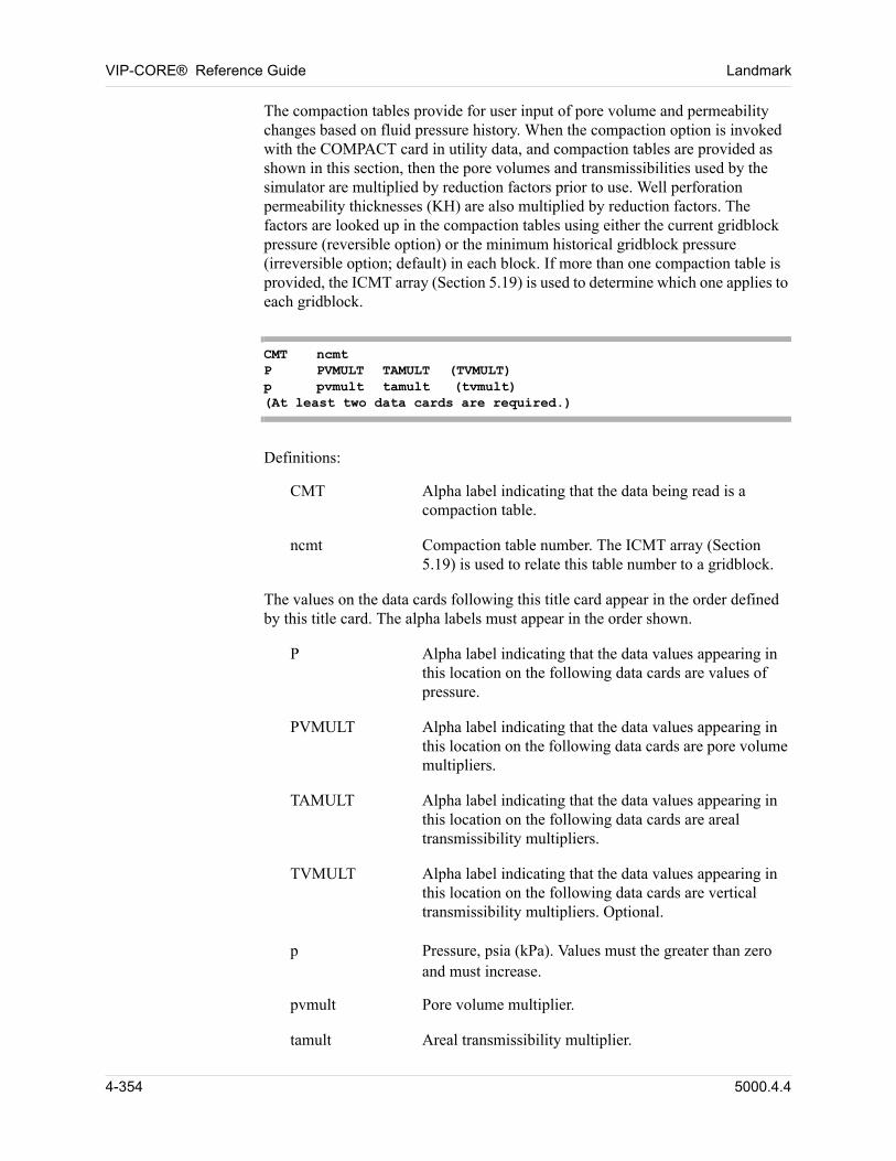
VIP-CORE® Reference Guide Landmark
The compaction tables provide for user input of pore volume and permeability changes based on fluid pressure history. When the compaction option is invoked with the COMPACT card in utility data, and compaction tables are provided as shown in this section, then the pore volumes and transmissibilities used by the simulator are multiplied by reduction factors prior to use. Well perforation permeability thicknesses (KH) are also multiplied by reduction factors. The factors are looked up in the compaction tables using either the current gridblock pressure (reversible option) or the minimum historical gridblock pressure (irreversible option; default) in each block. If more than one compaction table is provided, the ICMT array (Section 5.19) is used to determine which one applies to each gridblock. 00
CMT ncmtP PVMULT TAMULT (TVMULT) p pvmult tamult (tvmult)(At least two data cards are required.)
00 Definitions:
CMT Alpha label indicating that the data being read is a compaction table.
ncmt Compaction table number. The ICMT array (Section 5.19) is used to relate this table number to a gridblock.
The values on the data cards following this title card appear in the order defined by this title card. The alpha labels must appear in the order shown. 00
P Alpha label indicating that the data values appearing in this location on the following data cards are values of pressure.
PVMULT Alpha label indicating that the data values appearing in this location on the following data cards are pore volume multipliers.
TAMULT Alpha label indicating that the data values appearing in this location on the following data cards are areal transmissibility multipliers.
TVMULT Alpha label indicating that the data values appearing in this location on the following data cards are vertical transmissibility multipliers. Optional.
00 p Pressure, psia (kPa). Values must the greater than zero and must increase.
pvmult Pore volume multiplier.
tamult Areal transmissibility multiplier.
4-354 5000.4.4
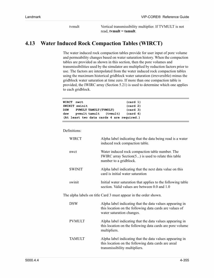
Landmark VIP-CORE® Reference Guide
tvmult Vertical transmissibility multiplier. If TVMULT is not read, tvmult = tamult.
4.13 Water Induced Rock Compaction Tables (WIRCT)
The water induced rock compaction tables provide for user input of pore volume and permeability changes based on water saturation history. When the compaction tables are provided as shown in this section, then the pore volumes and transmissibilities used by the simulator are multiplied by reduction factors prior to use. The factors are interpolated from the water induced rock compaction tables using the maximum historical gridblock water saturation (irreversible) minus the gridblock water saturation at time zero. If more than one compaction table is provided, the IWIRC array (Section 5.21) is used to determine which one applies to each gridblock. 00
WIRCT nwct (card 1)SWINIT swinit (card 2)DSW PVMULT TAMULT(TVMULT) (card 3)dsw pvmult tamult (tvmult) (card 4)(At least two data cards 4 are required.)
00 Definitions:
WIRCT Alpha label indicating that the data being read is a water induced rock compaction table.
nwct Water induced rock compaction table number. The IWIRC array Section(5...) is used to relate this table number to a gridblock.
SWINIT Alpha label indicating that the next data value on this card is initial water saturation
swinit Initial water saturation that applies to the following table section. Valid values are between 0.0 and 1.0
The alpha labels on title Card 3 must appear in the order shown. 00
DSW Alpha label indicating that the data values appearing in this location on the following data cards are values of water saturation changes.
PVMULT Alpha label indicating that the data values appearing in this location on the following data cards are pore volume multipliers.
TAMULT Alpha label indicating that the data values appearing in this location on the following data cards are areal transmissibility multipliers.
5000.4.4 4-355
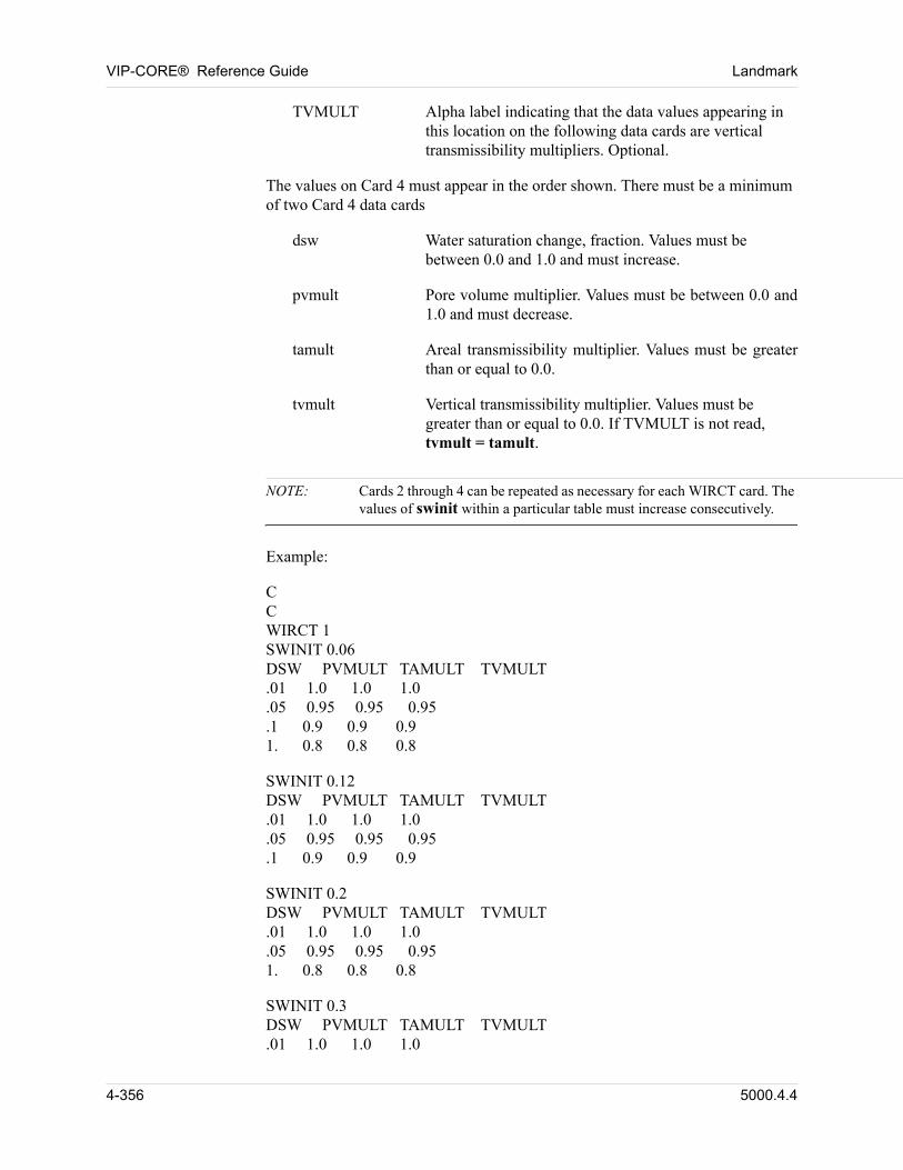
VIP-CORE® Reference Guide Landmark
TVMULT Alpha label indicating that the data values appearing in this location on the following data cards are vertical transmissibility multipliers. Optional.
The values on Card 4 must appear in the order shown. There must be a minimum of two Card 4 data cards 00
dsw Water saturation change, fraction. Values must be between 0.0 and 1.0 and must increase.
pvmult Pore volume multiplier. Values must be between 0.0 and 1.0 and must decrease.
tamult Areal transmissibility multiplier. Values must be greater than or equal to 0.0.
tvmult Vertical transmissibility multiplier. Values must be greater than or equal to 0.0. If TVMULT is not read, tvmult = tamult.
NOTE: Cards 2 through 4 can be repeated as necessary for each WIRCT card. The values of swinit within a particular table must increase consecutively.
00 Example:
00 CCWIRCT 1SWINIT 0.06DSW PVMULT TAMULT TVMULT.01 1.0 1.0 1.0.05 0.95 0.95 0.95.1 0.9 0.9 0.91. 0.8 0.8 0.8
00 SWINIT 0.12DSW PVMULT TAMULT TVMULT.01 1.0 1.0 1.0.05 0.95 0.95 0.95.1 0.9 0.9 0.9
00 SWINIT 0.2DSW PVMULT TAMULT TVMULT.01 1.0 1.0 1.0.05 0.95 0.95 0.951. 0.8 0.8 0.8
00 SWINIT 0.3DSW PVMULT TAMULT TVMULT.01 1.0 1.0 1.0
4-356 5000.4.4
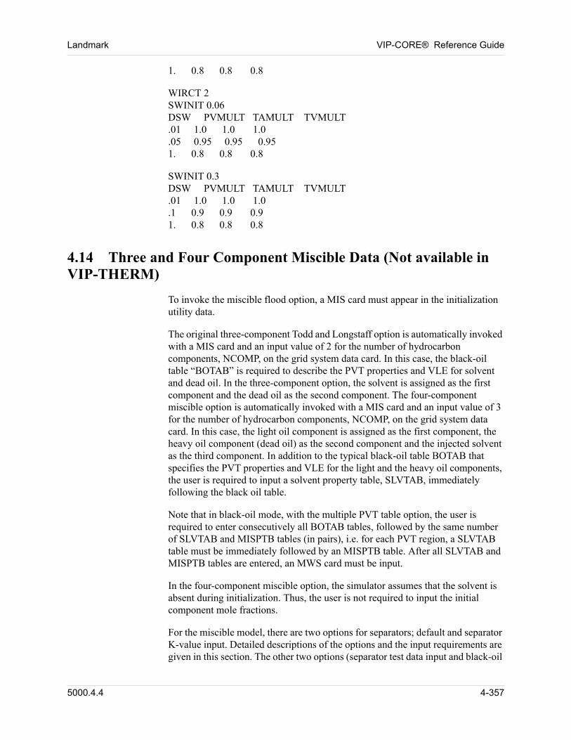
Landmark VIP-CORE® Reference Guide
1. 0.8 0.8 0.8
00 WIRCT 2SWINIT 0.06DSW PVMULT TAMULT TVMULT.01 1.0 1.0 1.0.05 0.95 0.95 0.951. 0.8 0.8 0.8
00 SWINIT 0.3DSW PVMULT TAMULT TVMULT.01 1.0 1.0 1.0.1 0.9 0.9 0.91. 0.8 0.8 0.8
4.14 Three and Four Component Miscible Data (Not available in VIP-THERM)
To invoke the miscible flood option, a MIS card must appear in the initialization utility data. 00
The original three-component Todd and Longstaff option is automatically invoked with a MIS card and an input value of 2 for the number of hydrocarbon components, NCOMP, on the grid system data card. In this case, the black-oil table “BOTAB” is required to describe the PVT properties and VLE for solvent and dead oil. In the three-component option, the solvent is assigned as the first component and the dead oil as the second component. The four-component miscible option is automatically invoked with a MIS card and an input value of 3 for the number of hydrocarbon components, NCOMP, on the grid system data card. In this case, the light oil component is assigned as the first component, the heavy oil component (dead oil) as the second component and the injected solvent as the third component. In addition to the typical black-oil table BOTAB that specifies the PVT properties and VLE for the light and the heavy oil components, the user is required to input a solvent property table, SLVTAB, immediately following the black oil table. 00
Note that in black-oil mode, with the multiple PVT table option, the user is required to enter consecutively all BOTAB tables, followed by the same number of SLVTAB and MISPTB tables (in pairs), i.e. for each PVT region, a SLVTAB table must be immediately followed by an MISPTB table. After all SLVTAB and MISPTB tables are entered, an MWS card must be input. 00
In the four-component miscible option, the simulator assumes that the solvent is absent during initialization. Thus, the user is not required to input the initial component mole fractions. 00
For the miscible model, there are two options for separators; default and separator K-value input. Detailed descriptions of the options and the input requirements are given in this section. The other two options (separator test data input and black-oil
5000.4.4 4-357
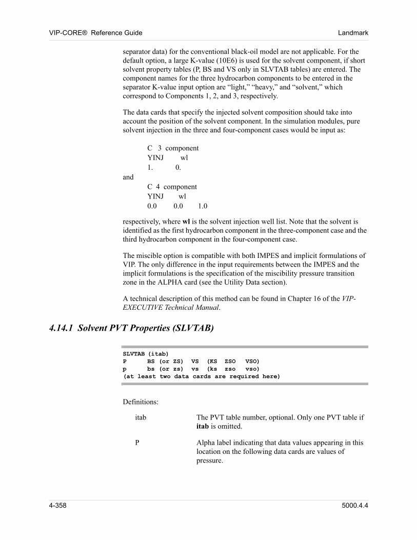
VIP-CORE® Reference Guide Landmark
separator data) for the conventional black-oil model are not applicable. For the default option, a large K-value (10E6) is used for the solvent component, if short solvent property tables (P, BS and VS only in SLVTAB tables) are entered. The component names for the three hydrocarbon components to be entered in the separator K-value input option are “light,” “heavy,” and “solvent,” which correspond to Components 1, 2, and 3, respectively. 00
The data cards that specify the injected solvent composition should take into account the position of the solvent component. In the simulation modules, pure solvent injection in the three and four-component cases would be input as: 00
00 C 3 componentYINJ wl1. 0.
andC 4 componentYINJ wl0.0 0.0 1.0
respectively, where wl is the solvent injection well list. Note that the solvent is identified as the first hydrocarbon component in the three-component case and the third hydrocarbon component in the four-component case. 00
The miscible option is compatible with both IMPES and implicit formulations of VIP. The only difference in the input requirements between the IMPES and the implicit formulations is the specification of the miscibility pressure transition zone in the ALPHA card (see the Utility Data section). 00
A technical description of this method can be found in Chapter 16 of the VIP-EXECUTIVE Technical Manual. 00
4.14.1 Solvent PVT Properties (SLVTAB)
SLVTAB (itab)P BS (or ZS) VS (KS ZSO VSO)p bs (or zs) vs (ks zso vso)(at least two data cards are required here)
00 Definitions:
itab The PVT table number, optional. Only one PVT table if itab is omitted.
P Alpha label indicating that data values appearing in this location on the following data cards are values of pressure.
4-358 5000.4.4
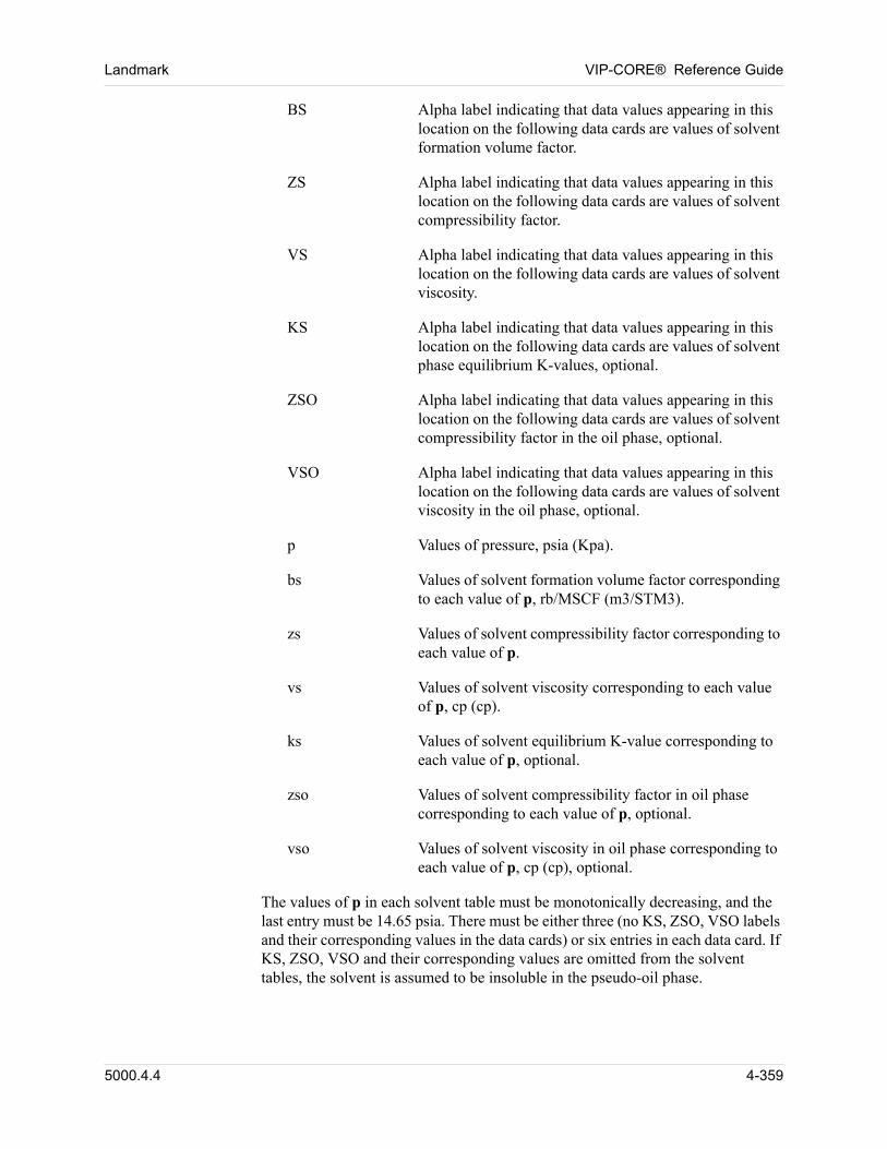
Landmark VIP-CORE® Reference Guide
BS Alpha label indicating that data values appearing in this location on the following data cards are values of solvent formation volume factor.
ZS Alpha label indicating that data values appearing in this location on the following data cards are values of solvent compressibility factor.
VS Alpha label indicating that data values appearing in this location on the following data cards are values of solvent viscosity.
KS Alpha label indicating that data values appearing in this location on the following data cards are values of solvent phase equilibrium K-values, optional.
ZSO Alpha label indicating that data values appearing in this location on the following data cards are values of solvent compressibility factor in the oil phase, optional.
VSO Alpha label indicating that data values appearing in this location on the following data cards are values of solvent viscosity in the oil phase, optional.
p Values of pressure, psia (Kpa).
bs Values of solvent formation volume factor corresponding to each value of p, rb/MSCF (m3/STM3).
zs Values of solvent compressibility factor corresponding to each value of p.
vs Values of solvent viscosity corresponding to each value of p, cp (cp).
ks Values of solvent equilibrium K-value corresponding to each value of p, optional.
zso Values of solvent compressibility factor in oil phase corresponding to each value of p, optional.
vso Values of solvent viscosity in oil phase corresponding to each value of p, cp (cp), optional.
The values of p in each solvent table must be monotonically decreasing, and the last entry must be 14.65 psia. There must be either three (no KS, ZSO, VSO labels and their corresponding values in the data cards) or six entries in each data card. If KS, ZSO, VSO and their corresponding values are omitted from the solvent tables, the solvent is assumed to be insoluble in the pseudo-oil phase. 00
5000.4.4 4-359
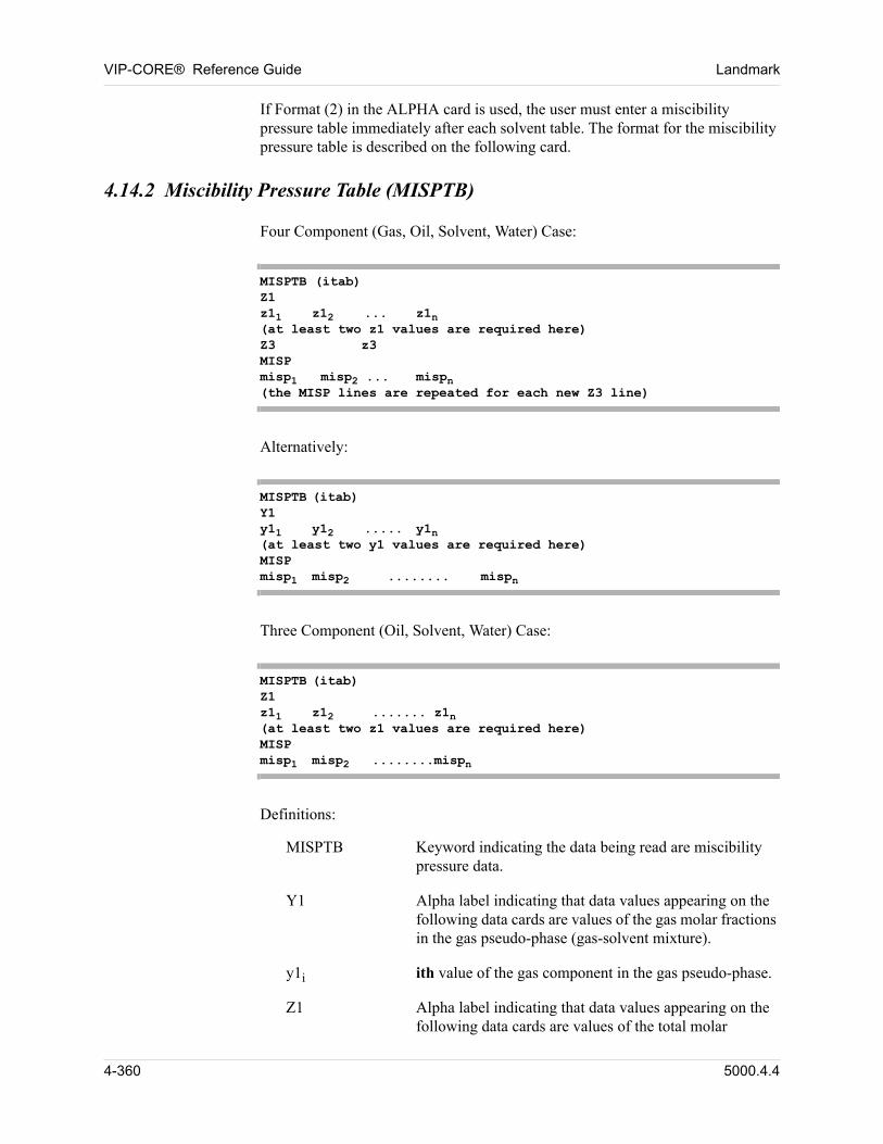
VIP-CORE® Reference Guide Landmark
If Format (2) in the ALPHA card is used, the user must enter a miscibility pressure table immediately after each solvent table. The format for the miscibility pressure table is described on the following card. 00
4.14.2 Miscibility Pressure Table (MISPTB)
00 Four Component (Gas, Oil, Solvent, Water) Case:
MISPTB (itab)Z1z11 z12 ... z1n(at least two z1 values are required here)Z3 z3MISPmisp1 misp2 ... mispn(the MISP lines are repeated for each new Z3 line)
00 Alternatively:
MISPTB (itab)Y1y11 y12 ..... y1n(at least two y1 values are required here)MISPmisp1 misp2 ........ mispn
00 Three Component (Oil, Solvent, Water) Case:
MISPTB (itab)Z1z11 z12 ....... z1n(at least two z1 values are required here)MISPmisp1 misp2 ........mispn
00 Definitions:
MISPTB Keyword indicating the data being read are miscibility pressure data.
Y1 Alpha label indicating that data values appearing on the following data cards are values of the gas molar fractions in the gas pseudo-phase (gas-solvent mixture).
y1i ith value of the gas component in the gas pseudo-phase.
Z1 Alpha label indicating that data values appearing on the following data cards are values of the total molar
4-360 5000.4.4
Landmark VIP-CORE® Reference Guide
fractions of the solvent component for three-component or the gas component for four-component.
z1i ith value of the component total molar fraction.
Z3 Alpha label indicating that a value of the solvent total molar fraction is being read, in four-component cases only.
z3 Value of the solvent total molar fraction.
MISP Alpha label indicating that data values on the following data cards are values of miscibility pressure.
mispi Values of miscibility pressure corresponding to the total composition (z1 in three-component and z1i, z3 in four-component), psia (Kpa). The MISP and mispi cards are repeated for each new z3 value, in four-component cases.
At least two values of z1 (or y1) must be entered and the values of z1 (or y1) must be monotonically increasing. In three-component cases, no gas is allowed and misp is simply a function of solvent mole fraction (z1). In four-component cases, when gas (z1) and solvent (z3) mole fractions are both specified, misp values must be input for each combination (one set for each z3 value). The values of z3 must also be monotonically increasing. Alternatively, the gas pseudo-phase (y1) can be specified. The number of misp values must be equal to the number of z1 values in three-component cases. Values not specified in four-component cases will be filled with the last misp value entered. 00
4.14.3 Solvent Molecular Weight (MWS)
MWS mws
00 Definition:
mws Value of the solvent molecular weight.
5000.4.4 4-361
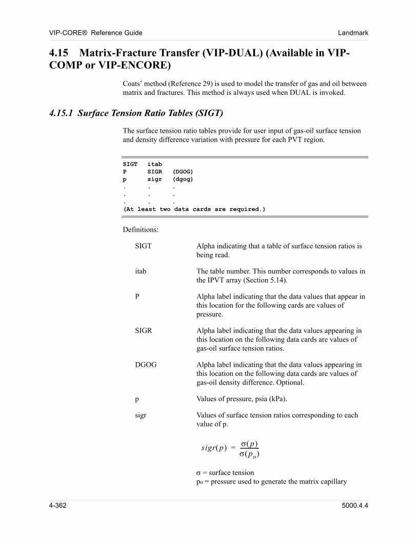
VIP-CORE® Reference Guide Landmark
4.15 Matrix-Fracture Transfer (VIP-DUAL) (Available in VIP-COMP or VIP-ENCORE)
Coats’ method (Reference 29) is used to model the transfer of gas and oil between matrix and fractures. This method is always used when DUAL is invoked. 00
4.15.1 Surface Tension Ratio Tables (SIGT)
The surface tension ratio tables provide for user input of gas-oil surface tension and density difference variation with pressure for each PVT region. 00
SIGT itab P SIGR (DGOG) p sigr (dgog) . . .. . .. . .(At least two data cards are required.)
00 Definitions:
SIGT Alpha indicating that a table of surface tension ratios is being read.
itab The table number. This number corresponds to values in the IPVT array (Section 5.14).
P Alpha label indicating that the data values that appear in this location for the following cards are values of pressure.
SIGR Alpha label indicating that the data values appearing in this location on the following data cards are values of gas-oil surface tension ratios.
DGOG Alpha label indicating that the data values appearing in this location on the following data cards are values of gas-oil density difference. Optional.
p Values of pressure, psia (kPa).
sigr Values of surface tension ratios corresponding to each value of p.
sigr p p po --------------=
= surface tensionpo = pressure used to generate the matrix capillary
4-362 5000.4.4
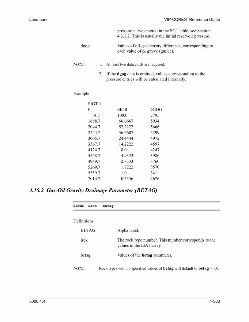
Landmark VIP-CORE® Reference Guide
pressure curve entered in the SGT table, see Section 4.3.1.2. This is usually the initial reservoir pressure.
dgog Values of oil-gas density difference, corresponding to each value of p, gm/cc (gm/cc).
NOTE: 1. At least two data cards are required.
2. If the dgog data is omitted, values corresponding to the pressure entries will be calculated internally.
00 Example:
00 SIGT 1P SIGR DGOG
14.7 100.0 .77951688.7 66.6667 .59342044.7 52.2222 .56662544.7 36.6607 .52993005.7 24.4444 .49723567.7 14.2222 .45974124.7 8.0 .42474558.7 4.9333 .39864949.7 2.8333 .37605269.7 1.7222 .35705559.7 1.0 .34117014.7 0.5556 .2676
4.15.2 Gas-Oil Gravity Drainage Parameter (BETAG)
BETAG irck betag
00 Definitions:
BETAG Alpha label.
irck The rock type number. This number corresponds to the values in the ISAT array.
betag Values of the betag parameter.
NOTE: Rock types with no specified values of betag will default to betag = 1.0.
5000.4.4 4-363
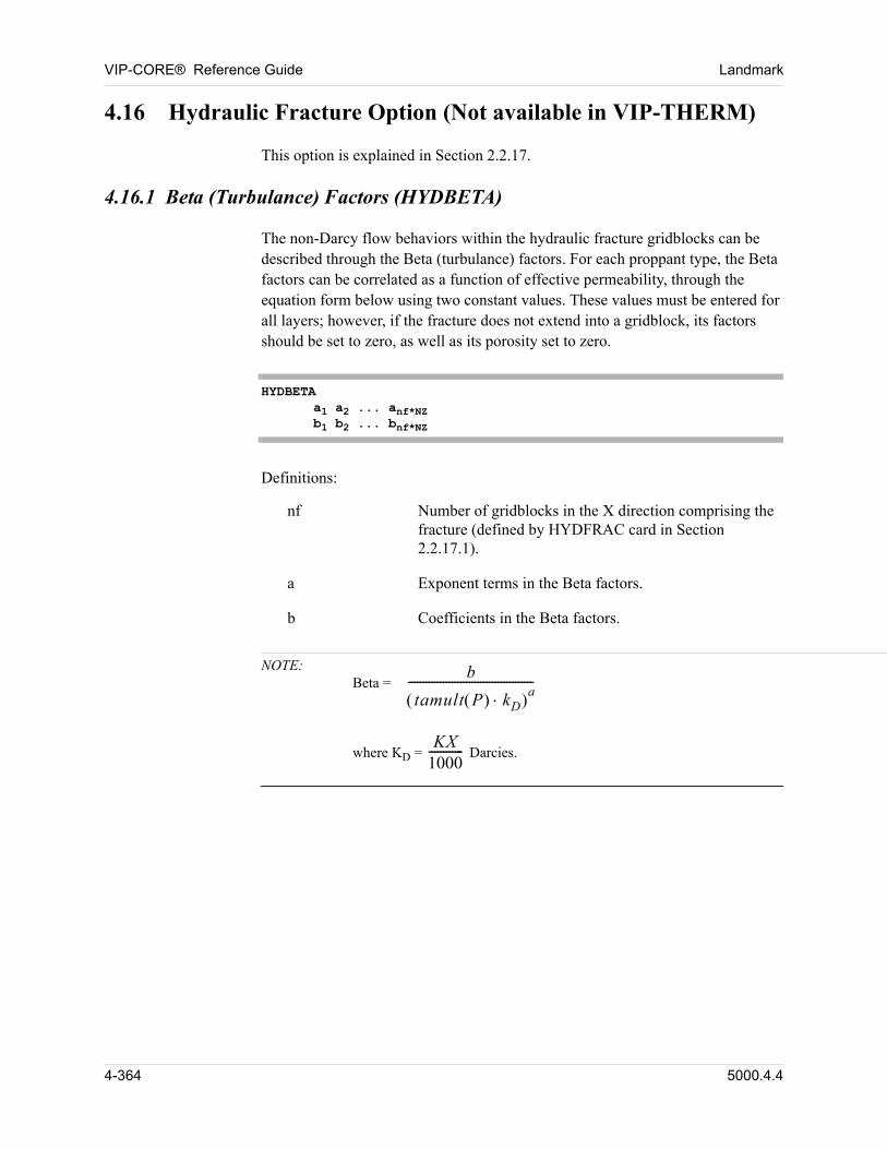
VIP-CORE® Reference Guide Landmark
4.16 Hydraulic Fracture Option (Not available in VIP-THERM)
00 This option is explained in Section 2.2.17.
4.16.1 Beta (Turbulance) Factors (HYDBETA)
00 The non-Darcy flow behaviors within the hydraulic fracture gridblocks can be described through the Beta (turbulance) factors. For each proppant type, the Beta factors can be correlated as a function of effective permeability, through the equation form below using two constant values. These values must be entered for all layers; however, if the fracture does not extend into a gridblock, its factors should be set to zero, as well as its porosity set to zero.
HYDBETAa1 a2 ... anf*NZb1 b2 ... bnf*NZ
00 Definitions:
nf Number of gridblocks in the X direction comprising the fracture (defined by HYDFRAC card in Section 2.2.17.1).
a Exponent terms in the Beta factors.
b Coefficients in the Beta factors.
NOTE: Beta =
b
tamult P kD a-------------------------------------------
where KD =
KX1000------------ Darcies.
4-364 5000.4.4
Landmark VIP-CORE® Reference Guide
4.17 Equation of State Interpolation Option(Not available in VIP-THERM)
00 Both VIP-COMP and VIP-ENCORE must be active.
00 The equation of state interpolation option (EOSINT) is designed for a reduction of the CPU time required for phase-equilibrium calculations and linearization of the equation of state in outer iterations of timesteps.
00 In the EOSINT option, saturation pressure, recovery factors of hydrocarbon components, and liquid and vapor compressibility factors are determined as tabular functions of pressure, temperature, and fluid compositions. The equation of state (EOS) is applied for the automatic generation of these functions in VIP-CORE. Then, the tabular functions of the recovery and compressibility factors are used for phase-equilibrium calculations in different timesteps of the reservoir simulation instead of the equation of state. These functions (EOS interpolation tables) are applied for the determination of compositions and densities of liquid and vapor hydrocarbon phases.
00 The EOSINT option can be applied for the phase-equilibrium calculations in any or all of
n reservoir grid cells
n separator batteries
n well tubing strings (surface pipeline network system)
00 For example, it can be applied only in separator batteries and surface pipeline network system.
00 Parameters of the equation of state must be formulated because the EOS is applied for the generation of the EOS interpolation tables.
00 The user should define
n maximum and minimum pressure on the PMIN and PMAX cards;
n temperature entries of the EOS interpolation tables on the TEMPERATURE card;
n composition entries of the tables using the CMP card or simulations of the PVT tests.
00 Initial compositions of the reservoir fluids defined after the OILMF, GASMF, or COMPOSITION cards are automatically included in the list of the composition entries.
00 Simulations of PVT tests (differential expansion, constant volume depletion,
5000.4.4 4-365
VIP-CORE® Reference Guide Landmark
swelling, and/or multiple contact tests) can be applied in VIP-CORE for the automatic generation of the composition entries. The fluid compositions calculated in different stages of simulated PVT tests are automatically included in the list of the composition entries. Also, these compositions are output in a file (Fortran Unit 77) in the format of the CMP card. Liquid and vapor densities, viscosities, and compressibility factors in different stages of the differential expansion and multiple contact tests are also included in this file.
00 The user can divide the composition entries into paths. Path numbers can be defined in the CMP, SWELLTEST, DIFEXPTEST, CONVDPTEST, and MULCONTEST cards.
00 The pressure entries of the EOS interpolation option are calculated internally. NPMAX pressure entries are selected in the undersaturated region (from the saturation pressure to the maximum pressure), and NPMAX pressure entries are selected in the saturated region (from the minimum pressure to the saturation pressure). The parameter NPMAX can be defined by the user on the DIM card. The pressure increment selected in the undersaturated region near the saturation pressure is much smaller than outside of this region.
00 The EOS interpolation tables are generated in VIP-CORE. The simulator calculates
n saturation pressure (bubblepoint or dewpoint pressure) for all combinations of composition and temperature entries;
n K-values at the saturation pressure for all combinations of composition and temperature entries;
n recovery factors for all combinations of composition, temperature, and pressure entries below the saturation pressure;
n liquid and vapor compressibility factors for all combinations of composition, temperature, and pressure entries.
00 An EOS interpolation table is generated for each equililibrium region. The number of this table corresponds to the equilibrium region number. In the EOSINT option, separator batteries and links, well connections, and node connections of the surface network system need to be assigned to equilibrium regions/EOS interpolation tables. By default they will each be assigned to region/table one. A region/table number can be assigned to a separator battery by entering a PVTTABLE card after the SEPARATOR card. A region/table number can be assigned to a link, well connection, or node connection by entering PVT table numbers on the LINK, NODCON, or WELCON cards in the simulation module.
00 Different equations of state can be used to generate each EOS interpolation table. This is accomplished by associating EOS numbers to each equilibrium region on
4-366 5000.4.4
Landmark VIP-CORE® Reference Guide
the IEQUIL card.
00 An EOS interpolation table is also generated for each separator battery in VIP-CORE. For this reason, all separator descriptions (the SEPARATOR cards) must be included in the VIP-CORE input deck rather than in the simulation module input deck.
00 A multidimensional interpolation procedure is used for the calculations of the K-values, recovery factors, and compressibility factors between table entries. The simulator applies
n cubic spline interpolation in pressure,
n linear spline interpolation in composition,
n linear spline interpolation in temperature,
n linear spline interpolation between compositional paths.
00 The cubic spline interpolation in pressure is applied to assure the continuity of derivatives of the interpolated functions with respect to pressure.
00 Two procedures are implemented for the interpolation in composition:
n linear spline interpolation based on the following interpolation function:
F Z ci zi
i 1=
nc
= , (Eq. 14-1)
00 linear spline interpolation based on the following distance between two composition vectors:
D Zj Z zij
zi– 2
ci
i 1=
nc
= .
00 The non-negative coefficients ci can be defined by the user using the
COEFFICIENT card.
00 The MDI keyword must be included on the EOSINT card to apply the multidimensional interpolation procedure based on the distance. The path definitions are ignored in this case and the interpolation between compositional paths is not applied.
00 The following path interpolation function is used for the interpolation between compositional paths:
5000.4.4 4-367
VIP-CORE® Reference Guide Landmark
Fp Z cpi zi
i 1=
nc
= .
00 The coefficients cp1 cp2 cpnc can be input by the user on the
COEFFICIENT PATH card.
00 All input cards of the EOSINT option must be input in the TABLES section after the EOSINT card. All input cards required for the simulation of a PVT test must be input after the corresponding DIFEXPTEST, CONVDPTEST, SWELLTEST, or MULCONTEST card. Several PVT tests can be simulated.
00 The CPU memory requirements for the EOS interpolation option are determined internally. Therefore, input on the DIM card is not required.
4.17.1 EOS Interpolation Option (EOSINT)
EOSINT (param1) (param2)...
Definitions:
param One or more of the following alpha labels may be included:
NORESERVOIR Alpha label indicating that the EOS interpolation option is not to be used for the phase equilibrium calculations in reservoir gridblocks.
NOSEPARATOR Alpha label indicating that the EOS interpolation option is not to be used for the phase equilibrium calculations in separator batteries.
NONETWORK Alpha label indicating that the EOS interpolation option is not to be used for the phase equilibrium calculations in well tubing strings and surface pipeline network system.
MDI Alpha label indicating that the multidimensional interpolation based on the distance between two composition vectors is to be used.
STOP Alpha label indicating that the simulation must be stopped if current pressure or temperature in a grid cell, well tubing string, or surface pipeline network device is outside the pressure or temperature range of the EOS interpolation tables.
4-368 5000.4.4
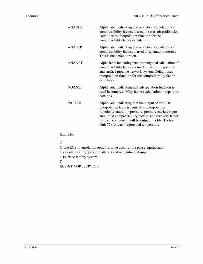
Landmark VIP-CORE® Reference Guide
00 Example:
00 CC The EOS interpolation option is to be used for the phase-equilibrium C calculations in separator batteries and well tubing stringsC (surface facility system).CEOSINT NORESERVOIR
ANARES Alpha label indicating that analytical calculation of compressibility factors is used in reservoir gridblocks. Default uses interpolation function for the compressibility factor calculation.
ANASEP Alpha label indicating that analytical calculation of compressibility factors is used in separator batteries. This is the default option.
ANANET Alpha label indicating that the analytical calculation of compressibility factors is used in well tubing strings and surface pipeline network system. Default uses interpolation function for the compressibility factor calculation.
NOANSP Alpha label indicating that interpolation function is used in compressibility factors calculation in separator batteries.
PRTTAB Alpha label indicating that the output of the EOS interpolation table is requested. Interpolation functions, saturation pressure, pressure entries, vapor and liquid compressibility factors, and recovery factor for each component will be output in a file (Fortran Unit 77) for each region and temperature.
5000.4.4 4-369
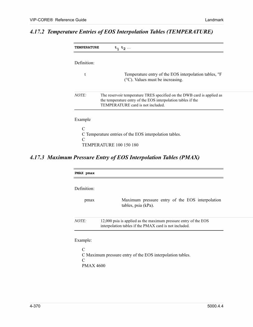
VIP-CORE® Reference Guide Landmark
4.17.2 Temperature Entries of EOS Interpolation Tables (TEMPERATURE)
TEMPERATURE t1 t2
Definition:
t Temperature entry of the EOS interpolation tables, °F (°C). Values must be increasing.
NOTE: The reservoir temperature TRES specified on the DWB card is applied as the temperature entry of the EOS interpolation tables if the TEMPERATURE card is not included.
00 Example
CC Temperature entries of the EOS interpolation tables.CTEMPERATURE 100 150 180
4.17.3 Maximum Pressure Entry of EOS Interpolation Tables (PMAX)
PMAX pmax
Definition:
pmax Maximum pressure entry of the EOS interpolation tables, psia (kPa).
NOTE: 12,000 psia is applied as the maximum pressure entry of the EOS interpolation tables if the PMAX card is not included.
00 Example:
CC Maximum pressure entry of the EOS interpolation tables.CPMAX 4600
4-370 5000.4.4
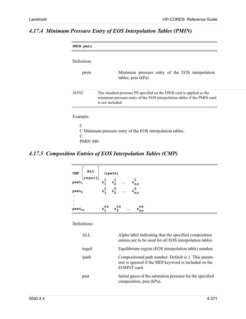
Landmark VIP-CORE® Reference Guide
4.17.4 Minimum Pressure Entry of EOS Interpolation Tables (PMIN)
PMIN pmin
Definition:
pmin Minimum pressure entry of the EOS interpolation tables, psia (kPa).
NOTE: The standard pressure PS specifed on the DWB card is applied as the minimum pressure entry of the EOS interpolation tables if the PMIN card is not included.
00 Example:
CC Minimum pressure entry of the EOS interpolation tables.CPMIN 940
4.17.5 Composition Entries of EOS Interpolation Tables (CMP)
CMP ALL
iequil (ipath)
psat1 z1
1z21 znc
1
psat2 z1
2z22 znc
2
.
.
.psatnz z1
nzz2nz znc
nz
Definitions:
ALL Alpha label indicating that the specified composition entries are to be used for all EOS interpolation tables.
iequil Equilibrium region (EOS interpolation table) number.
ipath Compositional path number. Default is 1. This param-eter is ignored if the MDI keyword is included on the EOSINT card.
psat Initial guess of the saturation pressure for the specified composition, psia (kPa).
5000.4.4 4-371
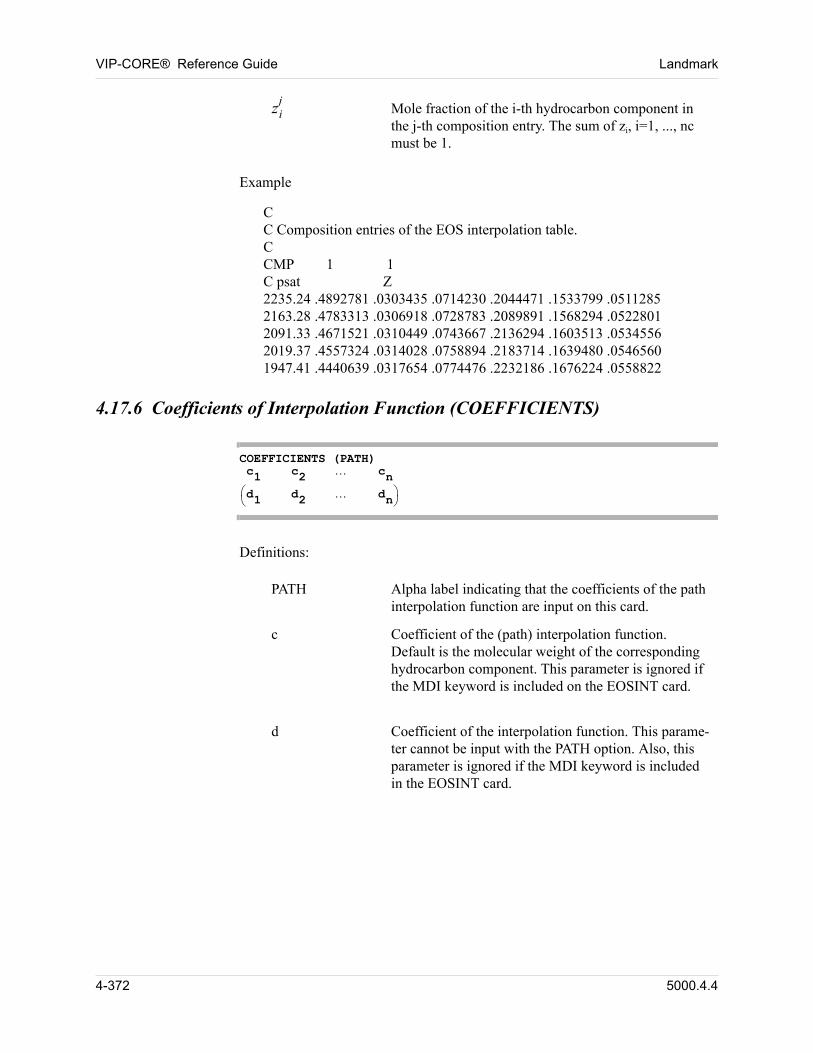
VIP-CORE® Reference Guide Landmark
zij
00 Example
CC Composition entries of the EOS interpolation table.CCMP 1 1C psat Z2235.24 .4892781 .0303435 .0714230 .2044471 .1533799 .05112852163.28 .4783313 .0306918 .0728783 .2089891 .1568294 .05228012091.33 .4671521 .0310449 .0743667 .2136294 .1603513 .05345562019.37 .4557324 .0314028 .0758894 .2183714 .1639480 .05465601947.41 .4440639 .0317654 .0774476 .2232186 .1676224 .0558822
4.17.6 Coefficients of Interpolation Function (COEFFICIENTS)
COEFFICIENTS (PATH) c1 c2 cn
d1 d2 dn
Definitions:
PATH Alpha label indicating that the coefficients of the path interpolation function are input on this card.
c Coefficient of the (path) interpolation function. Default is the molecular weight of the corresponding hydrocarbon component. This parameter is ignored if the MDI keyword is included on the EOSINT card.
d Coefficient of the interpolation function. This parame-ter cannot be input with the PATH option. Also, this parameter is ignored if the MDI keyword is included in the EOSINT card.
Mole fraction of the i-th hydrocarbon component in the j-th composition entry. The sum of zi, i=1, ..., nc must be 1.
4-372 5000.4.4
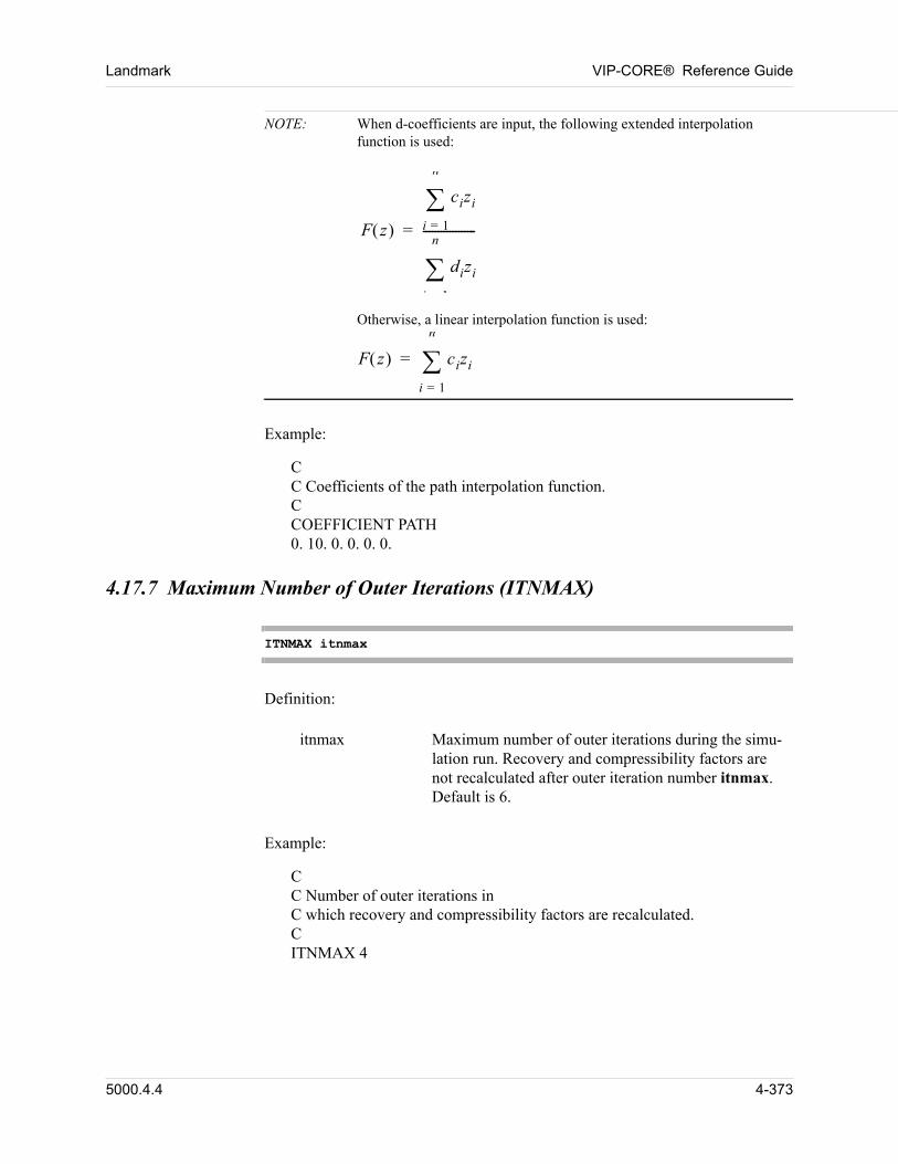
Landmark VIP-CORE® Reference Guide
NOTE: When d-coefficients are input, the following extended interpolation function is used:
F z
cizi
i 1=
n
dizi
i 1
n
------------------=
Otherwise, a linear interpolation function is used:
F z cizi
i 1=
n
=
00 Example:
CC Coefficients of the path interpolation function.CCOEFFICIENT PATH0. 10. 0. 0. 0. 0.
4.17.7 Maximum Number of Outer Iterations (ITNMAX)
ITNMAX itnmax
Definition:
itnmax Maximum number of outer iterations during the simu-lation run. Recovery and compressibility factors are not recalculated after outer iteration number itnmax. Default is 6.
00 Example:
CC Number of outer iterations in C which recovery and compressibility factors are recalculated.CITNMAX 4
5000.4.4 4-373
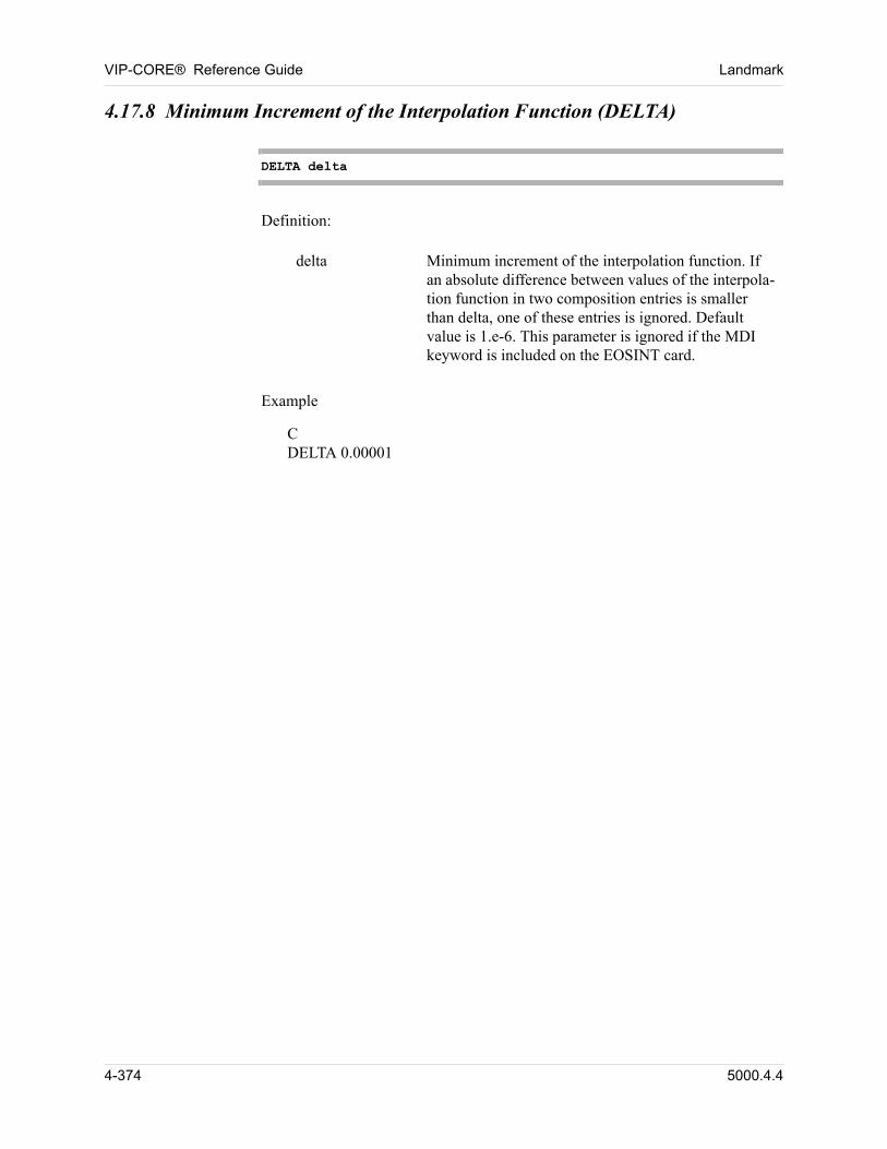
VIP-CORE® Reference Guide Landmark
4.17.8 Minimum Increment of the Interpolation Function (DELTA)
DELTA delta
00 Definition:
delta Minimum increment of the interpolation function. If an absolute difference between values of the interpola-tion function in two composition entries is smaller than delta, one of these entries is ignored. Default value is 1.e-6. This parameter is ignored if the MDI keyword is included on the EOSINT card.
00 Example
CDELTA 0.00001
4-374 5000.4.4
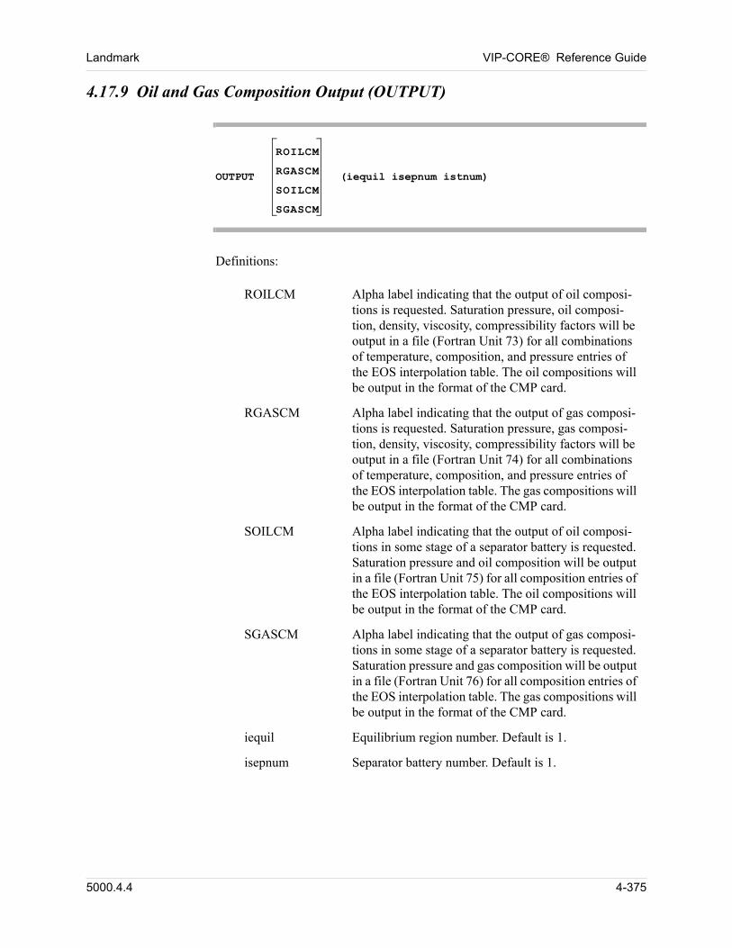
Landmark VIP-CORE® Reference Guide
4.17.9 Oil and Gas Composition Output (OUTPUT)
OUTPUT
ROILCM
RGASCM
SOILCM
SGASCM
(iequil isepnum istnum)
Definitions:
ROILCM Alpha label indicating that the output of oil composi-tions is requested. Saturation pressure, oil composi-tion, density, viscosity, compressibility factors will be output in a file (Fortran Unit 73) for all combinations of temperature, composition, and pressure entries of the EOS interpolation table. The oil compositions will be output in the format of the CMP card.
RGASCM Alpha label indicating that the output of gas composi-tions is requested. Saturation pressure, gas composi-tion, density, viscosity, compressibility factors will be output in a file (Fortran Unit 74) for all combinations of temperature, composition, and pressure entries of the EOS interpolation table. The gas compositions will be output in the format of the CMP card.
SOILCM Alpha label indicating that the output of oil composi-tions in some stage of a separator battery is requested. Saturation pressure and oil composition will be output in a file (Fortran Unit 75) for all composition entries of the EOS interpolation table. The oil compositions will be output in the format of the CMP card.
SGASCM Alpha label indicating that the output of gas composi-tions in some stage of a separator battery is requested. Saturation pressure and gas composition will be output in a file (Fortran Unit 76) for all composition entries of the EOS interpolation table. The gas compositions will be output in the format of the CMP card.
iequil Equilibrium region number. Default is 1.
isepnum Separator battery number. Default is 1.
5000.4.4 4-375
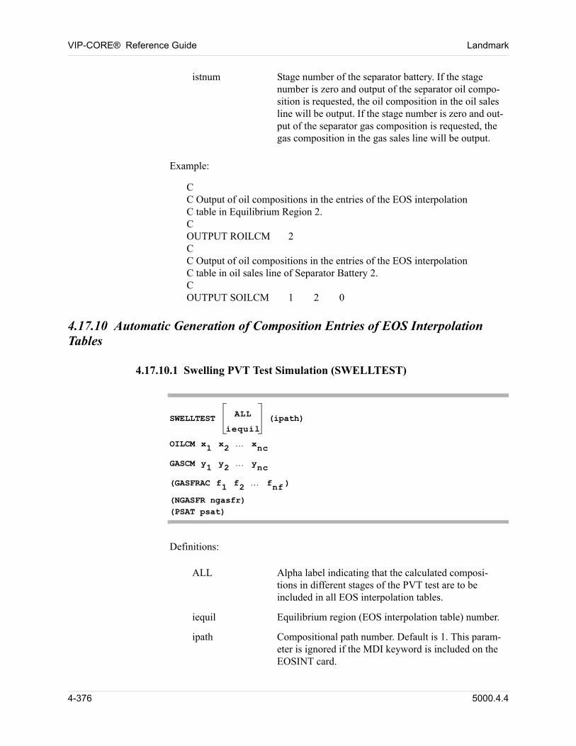
VIP-CORE® Reference Guide Landmark
00 Example:
CC Output of oil compositions in the entries of the EOS interpolation C table in Equilibrium Region 2.COUTPUT ROILCM 2CC Output of oil compositions in the entries of the EOS interpolation C table in oil sales line of Separator Battery 2.COUTPUT SOILCM 1 2 0
4.17.10 Automatic Generation of Composition Entries of EOS Interpolation Tables
4.17.10.1 Swelling PVT Test Simulation (SWELLTEST)
SWELLTEST ALL
iequil (ipath)
OILCM x1 x2 xnc
GASCM y1 y2 ync
(GASFRAC f1 f2 fnf )
(NGASFR ngasfr) (PSAT psat)
Definitions:
istnum Stage number of the separator battery. If the stage number is zero and output of the separator oil compo-sition is requested, the oil composition in the oil sales line will be output. If the stage number is zero and out-put of the separator gas composition is requested, the gas composition in the gas sales line will be output.
ALL Alpha label indicating that the calculated composi-tions in different stages of the PVT test are to be included in all EOS interpolation tables.
iequil Equilibrium region (EOS interpolation table) number.
ipath Compositional path number. Default is 1. This param-eter is ignored if the MDI keyword is included on the EOSINT card.
4-376 5000.4.4
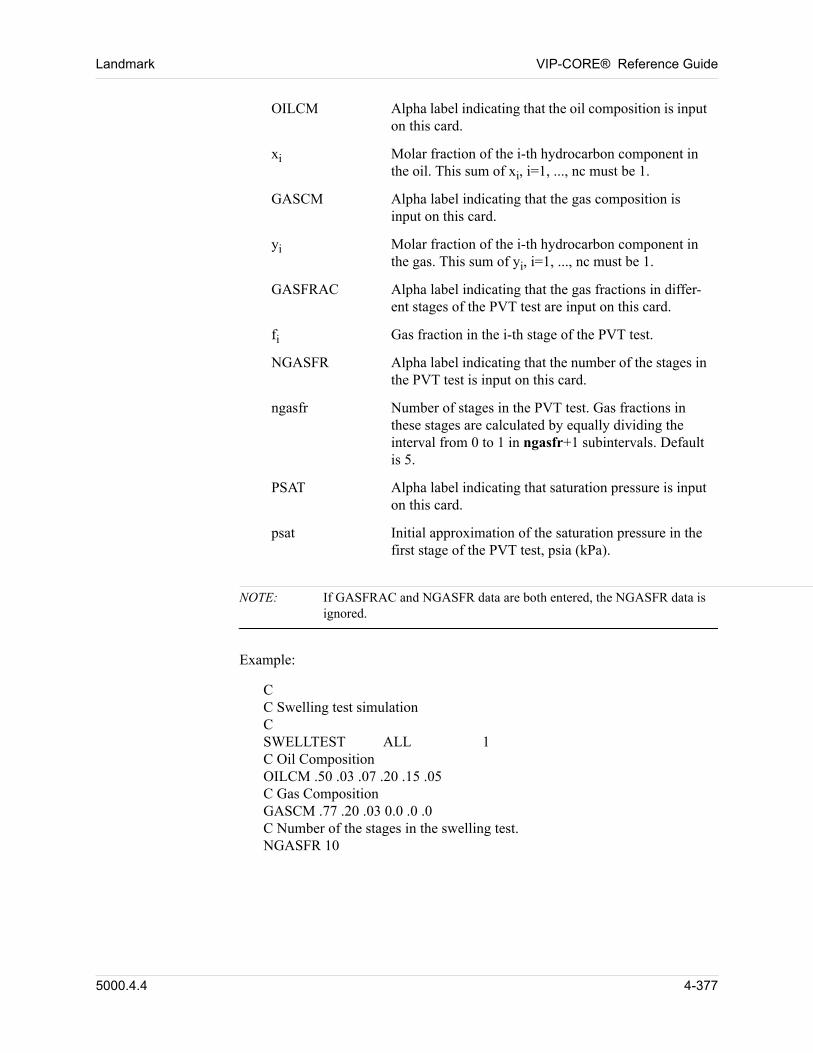
Landmark VIP-CORE® Reference Guide
NOTE: If GASFRAC and NGASFR data are both entered, the NGASFR data is ignored.
00 Example:
CC Swelling test simulationCSWELLTEST ALL 1C Oil CompositionOILCM .50 .03 .07 .20 .15 .05C Gas CompositionGASCM .77 .20 .03 0.0 .0 .0C Number of the stages in the swelling test.NGASFR 10
OILCM Alpha label indicating that the oil composition is input on this card.
xi Molar fraction of the i-th hydrocarbon component in the oil. This sum of xi, i=1, ..., nc must be 1.
GASCM Alpha label indicating that the gas composition is input on this card.
yi Molar fraction of the i-th hydrocarbon component in the gas. This sum of yi, i=1, ..., nc must be 1.
GASFRAC Alpha label indicating that the gas fractions in differ-ent stages of the PVT test are input on this card.
fi Gas fraction in the i-th stage of the PVT test.
NGASFR Alpha label indicating that the number of the stages in the PVT test is input on this card.
ngasfr Number of stages in the PVT test. Gas fractions in these stages are calculated by equally dividing the interval from 0 to 1 in ngasfr+1 subintervals. Default is 5.
PSAT Alpha label indicating that saturation pressure is input on this card.
psat Initial approximation of the saturation pressure in the first stage of the PVT test, psia (kPa).
5000.4.4 4-377
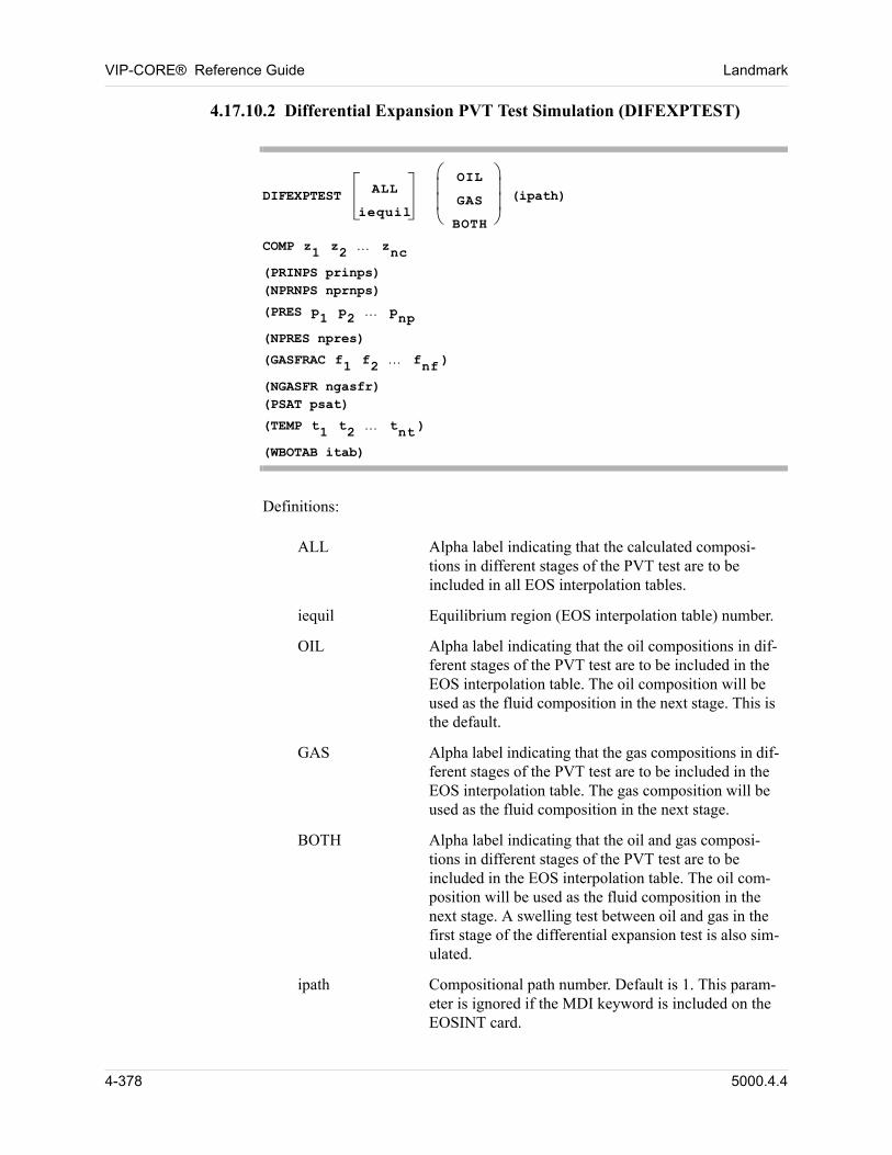
VIP-CORE® Reference Guide Landmark
4.17.10.2 Differential Expansion PVT Test Simulation (DIFEXPTEST)
DIFEXPTEST ALL
iequil
OIL
GAS
BOTH
(ipath)
COMP z1 z2 znc
(PRINPS prinps)(NPRNPS nprnps)
(PRES p1 p2 pnp
(NPRES npres)
(GASFRAC f1 f2 fnf )
(NGASFR ngasfr) (PSAT psat)
(TEMP t1 t2 tnt )
(WBOTAB itab)
Definitions:
ALL Alpha label indicating that the calculated composi-tions in different stages of the PVT test are to be included in all EOS interpolation tables.
iequil Equilibrium region (EOS interpolation table) number.
OIL Alpha label indicating that the oil compositions in dif-ferent stages of the PVT test are to be included in the EOS interpolation table. The oil composition will be used as the fluid composition in the next stage. This is the default.
GAS Alpha label indicating that the gas compositions in dif-ferent stages of the PVT test are to be included in the EOS interpolation table. The gas composition will be used as the fluid composition in the next stage.
BOTH Alpha label indicating that the oil and gas composi-tions in different stages of the PVT test are to be included in the EOS interpolation table. The oil com-position will be used as the fluid composition in the next stage. A swelling test between oil and gas in the first stage of the differential expansion test is also sim-ulated.
ipath Compositional path number. Default is 1. This param-eter is ignored if the MDI keyword is included on the EOSINT card.
4-378 5000.4.4
Landmark VIP-CORE® Reference Guide
COMP Alpha label indicating that the fluid composition in the first stage of the PVT test is input on this card.
zi Molar fraction of the i-th hydrocarbon component in the fluid. The sum of zi, i=1, ..., nc must be 1.
PRINPS Alpha label indicating that the pressure interval near the calculated saturation pressure in the PVT test is input on this card.
prinps Pressure interval near the saturation pressure in the PVT test, psia (kPa). Default is 20.
NPRNPS Alpha label indicating that the number of stages in the PVT test where the pressures in these stages are near the calculated saturation pressure is input on this card. The pressure interval from (saturation pressure minus PRINPS) to the saturation pressure is equally divided into nprnps stages.
nprnps Number of stages in the PVT test where the stage pres-sure is near the saturation pressure. Default is 10.
PRES Alpha label indicating that the pressure values in dif-ferent stages of the PVT test are input on this card.
pi Pressure in the i-th stage of the PVT test, psia (kPa). If the pressure specified is larger than the saturation pres-sure minus PRINPS, it will be ignored.
NPRES Alpha label indicating that the number of the stages in the PVT test is input on this card.
npres Number of stages in the PVT test. From minimum pressure pmin to the calculated saturation pressure minus prinps, the pressure is divided equally into npres-nprnps+1 stages. From saturation pressure minus prinps, the pressure is divided equally into nprnps stages. Default is 5.
GASFRAC Alpha label indicating that the gas fractions in differ-ent stages of the swelling PVT test are input on this card. This card is used only if the keyword BOTH is included on the DIFEXPTEST card.
fi Gas fraction in the i-th stage of the swelling PVT test.
NGASFR Alpha label indicating that the number of the stages in the swelling PVT test is input on this card. This card is used only if the keyword BOTH is included on the DIFEXPTEST card.
5000.4.4 4-379
VIP-CORE® Reference Guide Landmark
NOTE: If PRES and NPRES data are both entered, the NPRES data is ignored. If GASFRAC and NGASFR data are both entered, the NGASFR data is ignored.
00 Example:
CC Differential expansion test simulationCDIFEXPTEST 1 BOTH 1C Number pressure entriesNPRES 20C Fluid composition in the differential expansion testCOMP .50 .03 .07 .20 .15 .05Number of gas fractions in the swelling test.NGASFR 10
4.17.10.3 Constant Volume Depletion PVT Test Simulation
ngasfr Number of stages in the swelling PVT test. Gas frac-tions in these stages are calculated by equally dividing the interval from 0 to 1 in ngasfr+1 subintervals. Default is 5.
PSAT Alpha label indicating that saturation pressure is input on this card.
psat Initial approximation of the saturation pressure in the first stage of the PVT test, psia (kPa).
TEMP Alpha label indicating that the temperature values in the PVT test are input on this card.
t Temperature used in the PVT test. The differential expansion test is repeated several times if the number of the temperature values is larger than one. Default is the reservoir termperature TRES specified on the DWB card.
WBOTAB Alpha label indicating that, for each temperature t on the TEMP card, the black-oil table generated from this differential expansion test will be written to Fortran Unit 77.
itab The black-oil table number being used for the first temperature. The table number will increase consecu-tively for each temperature.
4-380 5000.4.4
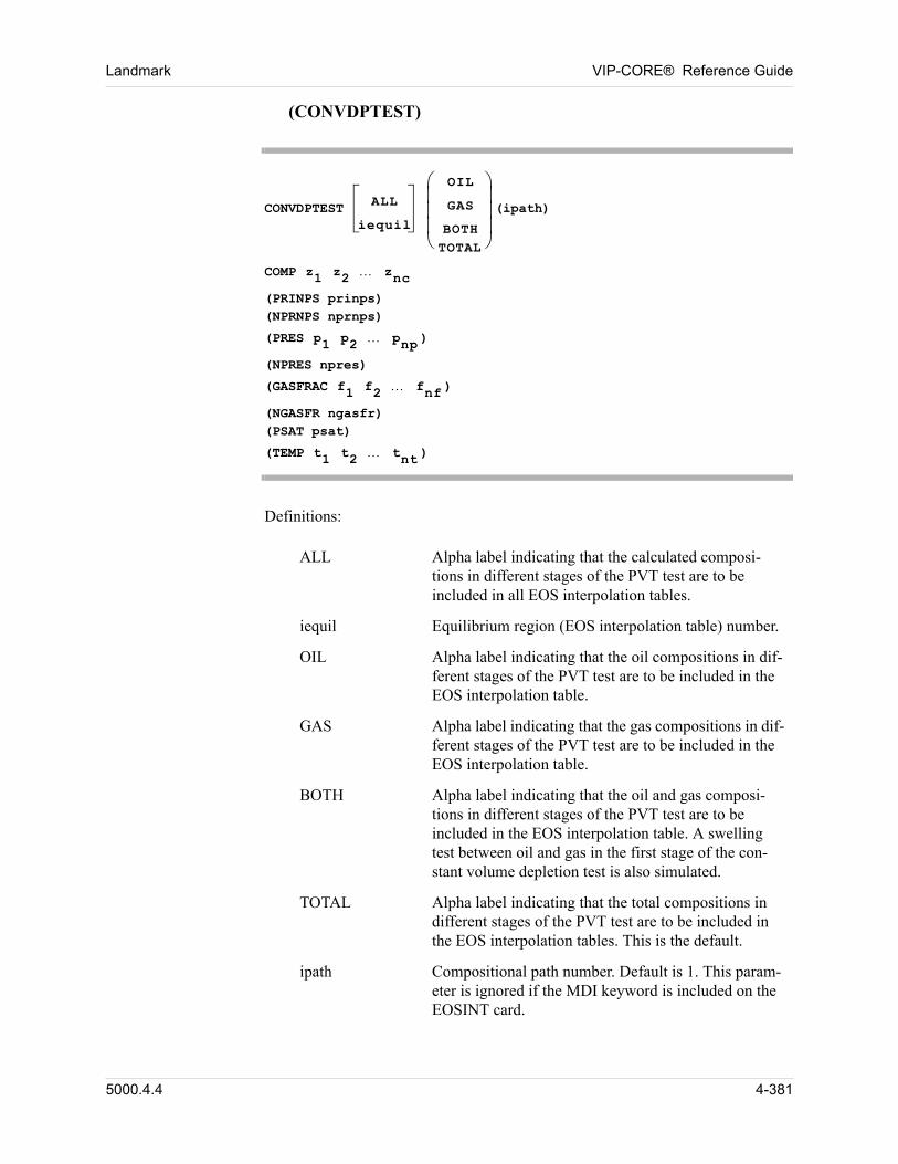
Landmark VIP-CORE® Reference Guide
(CONVDPTEST)
CONVDPTEST ALL
iequil
OIL
GAS
BOTHTOTAL
(ipath)
COMP z1 z2 znc
(PRINPS prinps)(NPRNPS nprnps)
(PRES p1 p2 pnp )
(NPRES npres)
(GASFRAC f1 f2 fnf )
(NGASFR ngasfr) (PSAT psat)
(TEMP t1 t2 tnt )
Definitions:
ALL Alpha label indicating that the calculated composi-tions in different stages of the PVT test are to be included in all EOS interpolation tables.
iequil Equilibrium region (EOS interpolation table) number.
OIL Alpha label indicating that the oil compositions in dif-ferent stages of the PVT test are to be included in the EOS interpolation table.
GAS Alpha label indicating that the gas compositions in dif-ferent stages of the PVT test are to be included in the EOS interpolation table.
BOTH Alpha label indicating that the oil and gas composi-tions in different stages of the PVT test are to be included in the EOS interpolation table. A swelling test between oil and gas in the first stage of the con-stant volume depletion test is also simulated.
TOTAL Alpha label indicating that the total compositions in different stages of the PVT test are to be included in the EOS interpolation tables. This is the default.
ipath Compositional path number. Default is 1. This param-eter is ignored if the MDI keyword is included on the EOSINT card.
5000.4.4 4-381
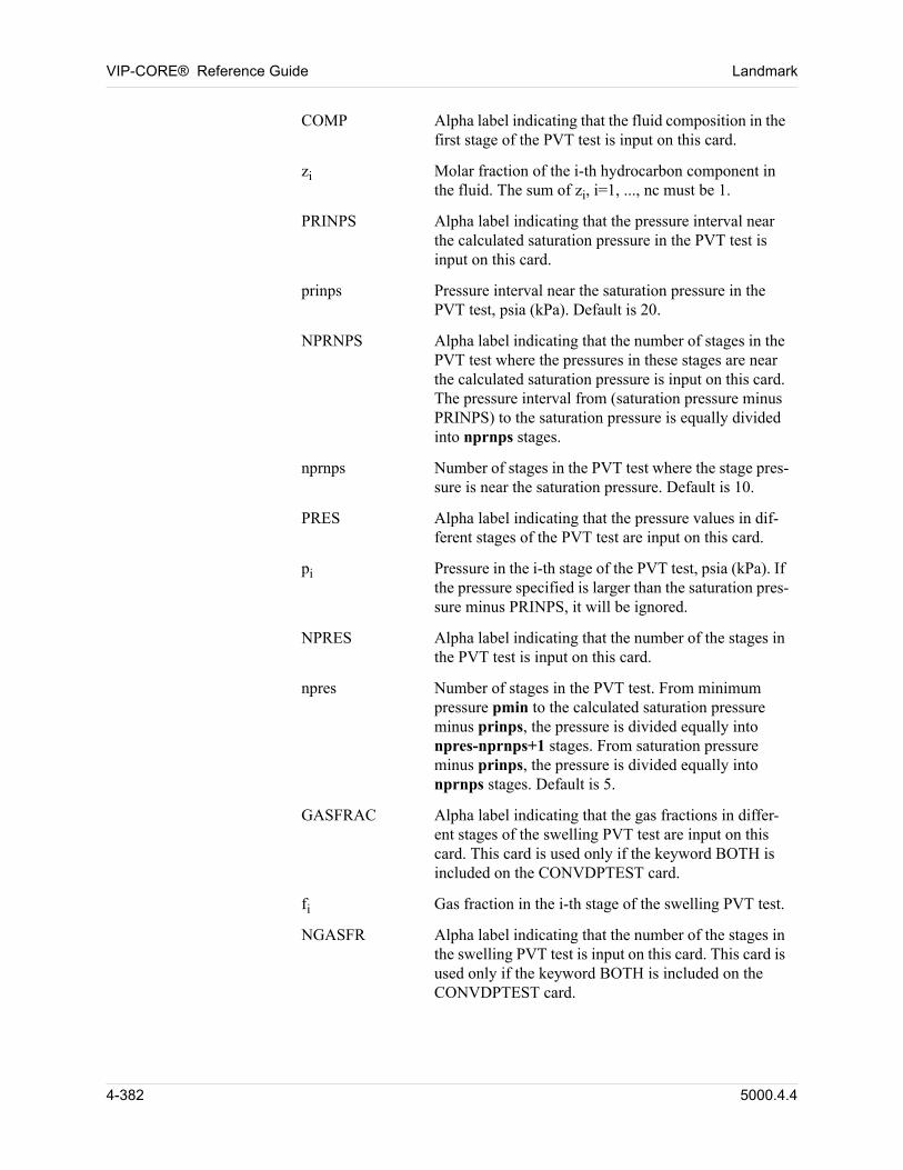
VIP-CORE® Reference Guide Landmark
COMP Alpha label indicating that the fluid composition in the first stage of the PVT test is input on this card.
zi Molar fraction of the i-th hydrocarbon component in the fluid. The sum of zi, i=1, ..., nc must be 1.
PRINPS Alpha label indicating that the pressure interval near the calculated saturation pressure in the PVT test is input on this card.
prinps Pressure interval near the saturation pressure in the PVT test, psia (kPa). Default is 20.
NPRNPS Alpha label indicating that the number of stages in the PVT test where the pressures in these stages are near the calculated saturation pressure is input on this card. The pressure interval from (saturation pressure minus PRINPS) to the saturation pressure is equally divided into nprnps stages.
nprnps Number of stages in the PVT test where the stage pres-sure is near the saturation pressure. Default is 10.
PRES Alpha label indicating that the pressure values in dif-ferent stages of the PVT test are input on this card.
pi Pressure in the i-th stage of the PVT test, psia (kPa). If the pressure specified is larger than the saturation pres-sure minus PRINPS, it will be ignored.
NPRES Alpha label indicating that the number of the stages in the PVT test is input on this card.
npres Number of stages in the PVT test. From minimum pressure pmin to the calculated saturation pressure minus prinps, the pressure is divided equally into npres-nprnps+1 stages. From saturation pressure minus prinps, the pressure is divided equally into nprnps stages. Default is 5.
GASFRAC Alpha label indicating that the gas fractions in differ-ent stages of the swelling PVT test are input on this card. This card is used only if the keyword BOTH is included on the CONVDPTEST card.
fi Gas fraction in the i-th stage of the swelling PVT test.
NGASFR Alpha label indicating that the number of the stages in the swelling PVT test is input on this card. This card is used only if the keyword BOTH is included on the CONVDPTEST card.
4-382 5000.4.4
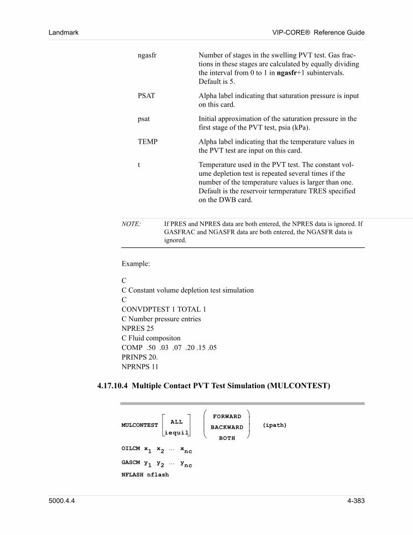
Landmark VIP-CORE® Reference Guide
NOTE: If PRES and NPRES data are both entered, the NPRES data is ignored. If GASFRAC and NGASFR data are both entered, the NGASFR data is ignored.
00 Example:
00 CC Constant volume depletion test simulationCCONVDPTEST 1 TOTAL 1C Number pressure entriesNPRES 25C Fluid compositonCOMP .50 .03 .07 .20 .15 .05PRINPS 20.NPRNPS 11
4.17.10.4 Multiple Contact PVT Test Simulation (MULCONTEST)
MULCONTEST ALL
iequil
FORWARD
BACKWARD
BOTH
(ipath)
OILCM x1 x2 xnc
GASCM y1 y2 ync
NFLASH nflash
ngasfr Number of stages in the swelling PVT test. Gas frac-tions in these stages are calculated by equally dividing the interval from 0 to 1 in ngasfr+1 subintervals. Default is 5.
PSAT Alpha label indicating that saturation pressure is input on this card.
psat Initial approximation of the saturation pressure in the first stage of the PVT test, psia (kPa).
TEMP Alpha label indicating that the temperature values in the PVT test are input on this card.
t Temperature used in the PVT test. The constant vol-ume depletion test is repeated several times if the number of the temperature values is larger than one. Default is the reservoir termperature TRES specified on the DWB card.
5000.4.4 4-383
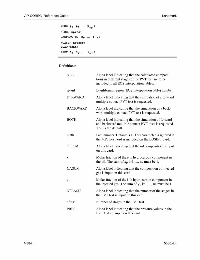
VIP-CORE® Reference Guide Landmark
(PRES p1 p2 pnp )
(NPRES npres)
(GASFRAC f1 f2 fnf )
(NGASFR ngasfr) (PSAT psat)
(TEMP t1 t2 tnt )
Definitions:
ALL Alpha label indicating that the calculated composi-tions in different stages of the PVT test are to be included in all EOS interpolation tables.
iequil Equilibrium region (EOS interpolation table) number.
FORWARD Alpha label indicating that the simulation of a forward multiple contact PVT test is requested.
BACKWARD Alpha label indicating that the simulation of a back-ward multiple contact PVT test is requested.
BOTH Alpha label indicating that the simulation of forward and backward multiple contact PVT tests is requested. This is the default.
ipath Path number. Default is 1. This parameter is ignored if the MDI keyword is included on the EOSINT card.
OILCM Alpha label indicating that the oil composition is input on this card.
xi Molar fraction of the i-th hydrocarbon component in the oil. The sum of xi, i=1, ..., nc must be 1.
GASCM Alpha label indicating that the composition of injected gas is input on this card.
yi Molar fraction of the i-th hydrocarbon component in the injected gas. The sum of yi, i=1, ..., nc must be 1.
NFLASH Alpha label indicating that the number of the stages in the PVT test is input on this card.
nflash Number of stages in the PVT test.
PRES Alpha label indicating that the pressure values in the PVT test are input on this card.
4-384 5000.4.4
Landmark VIP-CORE® Reference Guide
NOTE: If PRES and NPRES data are both entered, the NPRES data is ignored. If GASFRAC and NGASFR data are both entered, the NGASFR data is
p Pressure in the PVT test, psia (kPa). The simulation of the multiple contact test is repeated several times if the number of the pressure values on this card is larger than one.
NPRES Alpha label indicating that the number of the pressure values in the PVT test is input on this card. The simu-lation of the multiple contact test is repeated several times if the number of the pressure values on this card is larger than one.
npres Number of pressure values in the PVT test. The pres-sure values are calculated by equally dividing the interval from minimum pressure pmin to calculated saturated pressure in npres+1 subintervals. Default is 5.
GASFRAC Alpha label indicating that the gas fractions in the PVT test are input on this card.
f Gas fraction in the PVT test. The simulation of the multiple contact test is repeated several times if the number of the gas fractions on this card is larger than one.
NGASFR Alpha label indicating that the number of the gas frac-tions in the PVT test is input on this card. The simula-tion of the multiple contact test is repeated several times if the number of the gas fractions on this card is larger than one.
ngasfr Number of the gas fractions in the PVT test. Gas frac-tions are calculated by equally dividing the interval from 0 to 1 in ngasfr+1 subintervals. Default is 5.
PSAT Alpha label indicating that saturation pressure is input on this card.
psat Initial approximation of the saturation pressure in the first stage of the PVT test, psia (kPa).
TEMP Alpha label indicating that the temperature values in the PVT test are input on this card.
t Temperature used in the PVT test. The multiple con-tact test is repeated several times if the number of the temperature values is larger than one. Default is the reservoir temperature TRES specified on the DWB card.
5000.4.4 4-385
VIP-CORE® Reference Guide Landmark
ignored.
00 Example
CC Multiple contact test simulation.CMULCON ALL BACKWARD 1C Oil CompositionOILCM .50 .03 .07 .20 .15 .05C Injected Gas CompositionGASCM .77 .20 .03 0.0 .0 .0C Number of the stages in the PVT testNFLASH 10C Pressure in the PVT testPRES 2000C Gas fraction in the PVT testGASFRAC 0.525
4.18 Fracture Modeling (VIP-THERM)
Formation breakdown due to steam injection is known to occur in some unconsolidated media and tarsands. This breakdown, or fracturing, will occur in the region of the reservoir in which the stress in the formation exceeds the fracture stress, which is a function of pressure, temperature, and formation composition. Since coupling of a rigorous three- dimensional formation stress model and the simulator conservation equations is not currently practical, simplified methods have been devised to model the formation breakdown phenomena.
Two methods are currently available in VIP-THERM for predicting the effect on permeability (or flow transmissibility) in the fractured region. The first method is the empirical model of Beattie, Boberg, and McNab (Reference 32). The second method is more rigorous and involves coupling of VIP-THERM to SIMTECHs’ fracture mechanics model TARFRAC through the fracture interface TFRACINT (Reference 39). TARFRAC must be independently licensed by the user from SIMTECH Consulting Services Ltd. in order to use this method, in which TARFRAC is executed (stand-alone) to generate a dynamic fracture growth description. This description is then read in as data to VIP-THERM through the fracture interface TFRACINT which modifies flow transmissibilities in the fractured region and by default computes pseudo relative permeabilities (which can be turned off) of oil, gas, and water for gridblocks in the fractured region. Pseudo relative permeabilities are not available in the first method.
4-386 5000.4.4
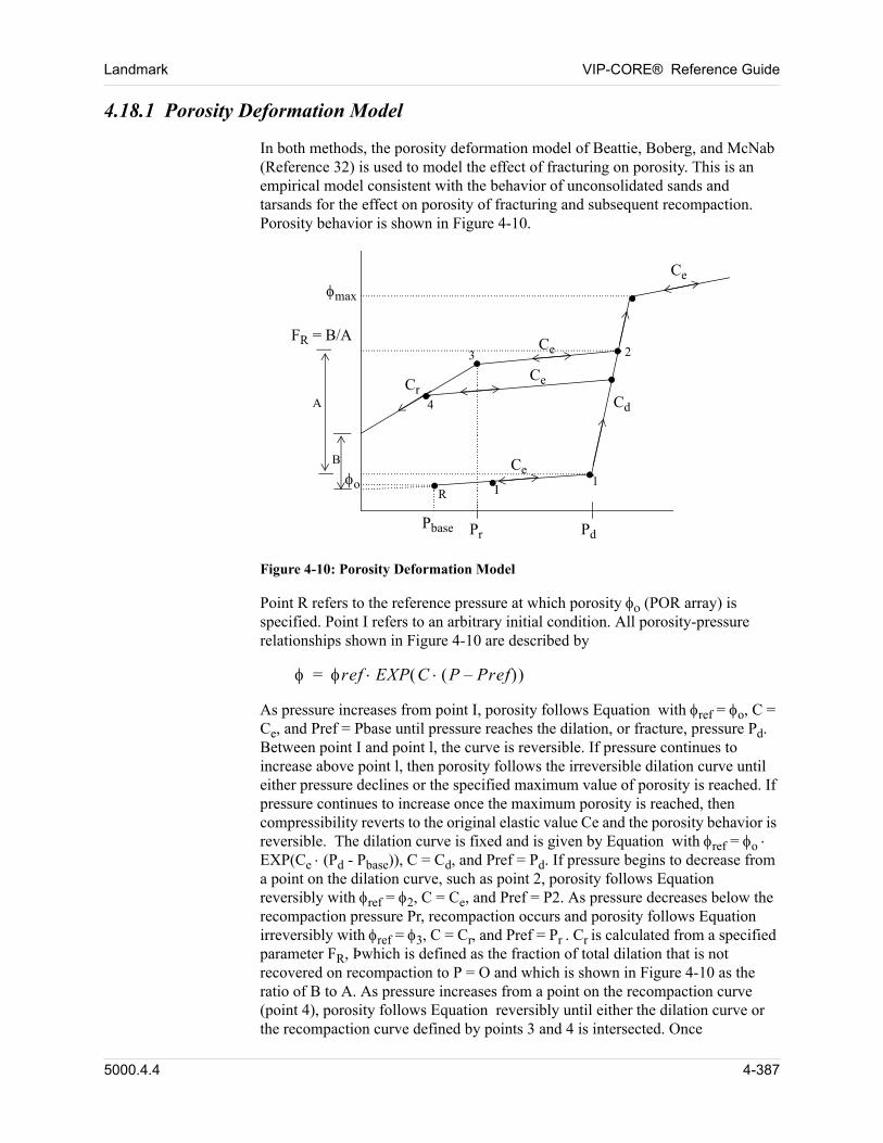
Landmark VIP-CORE® Reference Guide
4.18.1 Porosity Deformation Model
In both methods, the porosity deformation model of Beattie, Boberg, and McNab (Reference 32) is used to model the effect of fracturing on porosity. This is an empirical model consistent with the behavior of unconsolidated sands and tarsands for the effect on porosity of fracturing and subsequent recompaction. Porosity behavior is shown in Figure 4-10.
Pr PdPbase
R I
Cd
Ce
Ce
Cr
max
Ce
A
B
o 1
23
4
FR = B/A
Ce
Figure 4-10: Porosity Deformation Model
Point R refers to the reference pressure at which porosity (POR array) is specified. Point I refers to an arbitrary initial condition. All porosity-pressure relationships shown in Figure 4-10 are described by
ref EXP C P Pref– =
As pressure increases from point I, porosity follows Equation with ref = o, C = Ce, and Pref = Pbase until pressure reaches the dilation, or fracture, pressure Pd. Between point I and point l, the curve is reversible. If pressure continues to increase above point l, then porosity follows the irreversible dilation curve until either pressure declines or the specified maximum value of porosity is reached. If pressure continues to increase once the maximum porosity is reached, then compressibility reverts to the original elastic value Ce and the porosity behavior is reversible. The dilation curve is fixed and is given by Equation with ref = oEXP(Ce (Pd - Pbase)), C = Cd, and Pref = Pd. If pressure begins to decrease from a point on the dilation curve, such as point 2, porosity follows Equation reversibly with ref = 2, C = Ce, and Pref = P2. As pressure decreases below the recompaction pressure Pr, recompaction occurs and porosity follows Equation irreversibly with ref = 3, C = Cr, and Pref = Pr . Cr is calculated from a specified parameter FR, Þwhich is defined as the fraction of total dilation that is not recovered on recompaction to P = O and which is shown in Figure 4-10 as the ratio of B to A. As pressure increases from a point on the recompaction curve (point 4), porosity follows Equation reversibly until either the dilation curve or the recompaction curve defined by points 3 and 4 is intersected. Once
5000.4.4 4-387

VIP-CORE® Reference Guide Landmark
recompaction occurs, the recompaction curve is fixed until dilation occurs subsequently. If pressure decreases to Pr immediately following dilation, a new recompaction curve is computed from FR and the new value of A.
The default value of Pbase shown in Figure 4-10 is PINIT for equilibrium region 1 in the EQUIL table (Section 4.2). If PINIT(1) is greater than Pd, then Pbase must be reset to some value less than Pd as shown below.
PORDEF PD PR CRD FR PORMAX (PBASE)pd pr crd fr pormax (pbase)
Definitions:
pd Dilation (fracture) pressure, psia (kPa).
pr Recompaction pressure, psia (kPa).
crd Dilatant rock compressibility, psia-1 (kPa-1).
fr Fraction of total dilation not recovered on recompaction to P = O.
pormax Maximum allowable value of porosity.
pbase Reference pressure for reference porosity (POR array), psia (kPa). Optional, but required if PINIT (1) > Pd.
NOTE: 1. PD, PR, CRD, and FR may optionally be specified as gridblock array data described in Section 5.48. Elastic rock compressibility Ce is taken as the CR value specified either in the constant data (Section 2.2.4.2) or the array data (Section 5.23).
2. The porosity deformation model is not required in conjunction with SIMTECH’s fracture model, but no other method for predicting the effect of fracturing on porosity is available.
4.18.2 Permeability Models
4.18.2.1 Method of Beattie, Boberg, and McNab (Reference 32)
In this method, permeability behavior is modeled as a function of porosity and user-specified permeability multipliers as:
k k0 EXPKMUL 0–
1 0– -----------------------------------------
=
4-388 5000.4.4
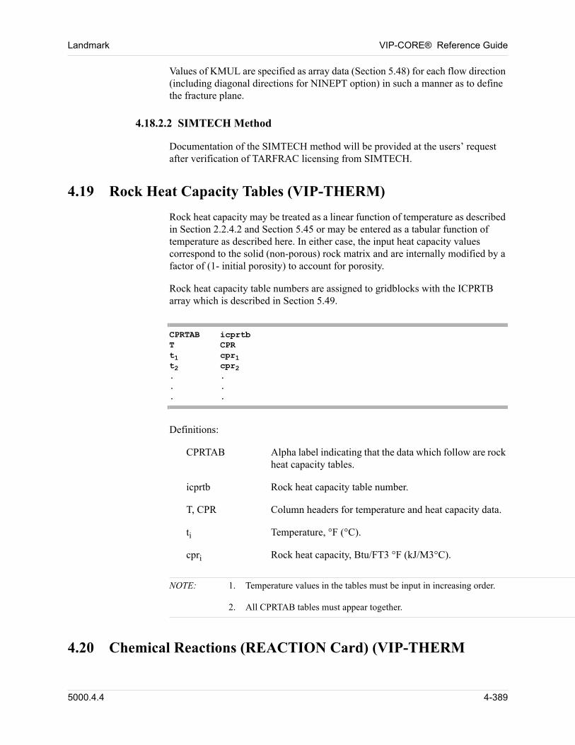
Landmark VIP-CORE® Reference Guide
Values of KMUL are specified as array data (Section 5.48) for each flow direction (including diagonal directions for NINEPT option) in such a manner as to define the fracture plane.
4.18.2.2 SIMTECH Method
Documentation of the SIMTECH method will be provided at the users’ request after verification of TARFRAC licensing from SIMTECH.
4.19 Rock Heat Capacity Tables (VIP-THERM)
Rock heat capacity may be treated as a linear function of temperature as described in Section 2.2.4.2 and Section 5.45 or may be entered as a tabular function of temperature as described here. In either case, the input heat capacity values correspond to the solid (non-porous) rock matrix and are internally modified by a factor of (1- initial porosity) to account for porosity.
Rock heat capacity table numbers are assigned to gridblocks with the ICPRTB array which is described in Section 5.49.
CPRTAB icprtbT CPRt1 cpr1t2 cpr2. .. .. .
Definitions:
CPRTAB Alpha label indicating that the data which follow are rock heat capacity tables.
icprtb Rock heat capacity table number.
T, CPR Column headers for temperature and heat capacity data.
ti Temperature, °F (°C).
cpri Rock heat capacity, Btu/FT3 °F (kJ/M3°C).
NOTE: 1. Temperature values in the tables must be input in increasing order.
2. All CPRTAB tables must appear together.
4.20 Chemical Reactions (REACTION Card) (VIP-THERM
5000.4.4 4-389
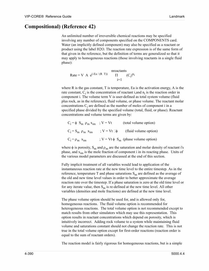
VIP-CORE® Reference Guide Landmark
Compositional) (Reference 42)
00 An unlimited number of irreversible chemical reactions may be specified involving any number of components specified on the COMPONENTS card. Water (an implicitly defined component) may also be specified as a reactant or product using the label H2O. The reaction rate expression is of the same form of that given in the reference, but the definition of terms are generalized so that it may apply to homogeneous reactions (those involving reactants in a single fluid phase):
00 nreactants Rate = V A e(-Ea / (R T)) (Ci)
ni
i=1
00 where R is the gas constant, T is temperature, Ea is the activation energy, A is the rate constant, Ci is the concentration of reactant i,and ni is the reaction order in component i. The volume term V is user-defined as total system volume (fluid plus rock, as in the reference), fluid volume, or phase volume. The reactant molar concentrations Ci are defined as the number of moles of component i in a specified phase divided by the specified volume (total, fluid, or phase). Reactant concentrations and volume terms are given by:
Ci = Sm m xim ; V = Vt (total volume option)
Ci = Sm m xim ; V = Vt (fluid volume option)
Ci = m xim ; V = Vt Sm (phase volume option)
00 where is porosity, Sm and m are the saturation and molar density of reactant i's phase, and xim is the mole fraction of component i in its reacting phase. Units of the various model parameters are discussed at the end of this section.
00 Fully implicit treatment of all variables would lead to application of the instantaneous reaction rate at the new time level to the entire timestep. As in the reference, temperature T and phase saturations Sm are defined as the average of the old and new time level values in order to better approximate the average reaction rate over the timestep. If a phase saturation is zero at the old time level or for any iterate value, then Sm is re-defined at the new time level. All other variables (densities and mole fractions) are defined at the new time level.
00 The phase volume option should be used for, and is allowed only for, homogeneous reactions. The fluid volume option is recommended for heterogeneous reactions. The total volume option is not recommended except to match results from other simulators which may use this representation. This option results in reactant concentrations which depend on porosity, which is intuitively incorrect. Adding rock volume to a system while maintaining fluid volume and saturations constant should not change the reaction rate. This is not true in the total volume option except for first-order reactions (reaction order is equal to the sum of reactant orders).
00 The reaction model is fairly rigorous for homogeneous reactions, but is a simple
4-390 5000.4.4

Landmark VIP-CORE® Reference Guide
approximation to the actual process for heterogeneous reactions, which involves complex factors such as saturation distributions within gridblocks, pore structure, interfacial areas, and diffusion rates. The use of fluid volume average concentrations approximates some of these effects, in that increasing saturations of non-reacting phases decreases the effective reactant concentrations and the rate of reaction for heterogeneous reactions of order greater than one.
00 The input data allow specification of model parameter units for ease of use. The units of rate are moles of first reactant consumed per unit time (MUNIT/TUNIT), concentrations are in moles of reactant per unit volume (MUNIT/VUNIT), molar energies (activation energy and heat of reaction, units may be independently specified) are in energy per mole (EUNIT).
5000.4.4 4-391
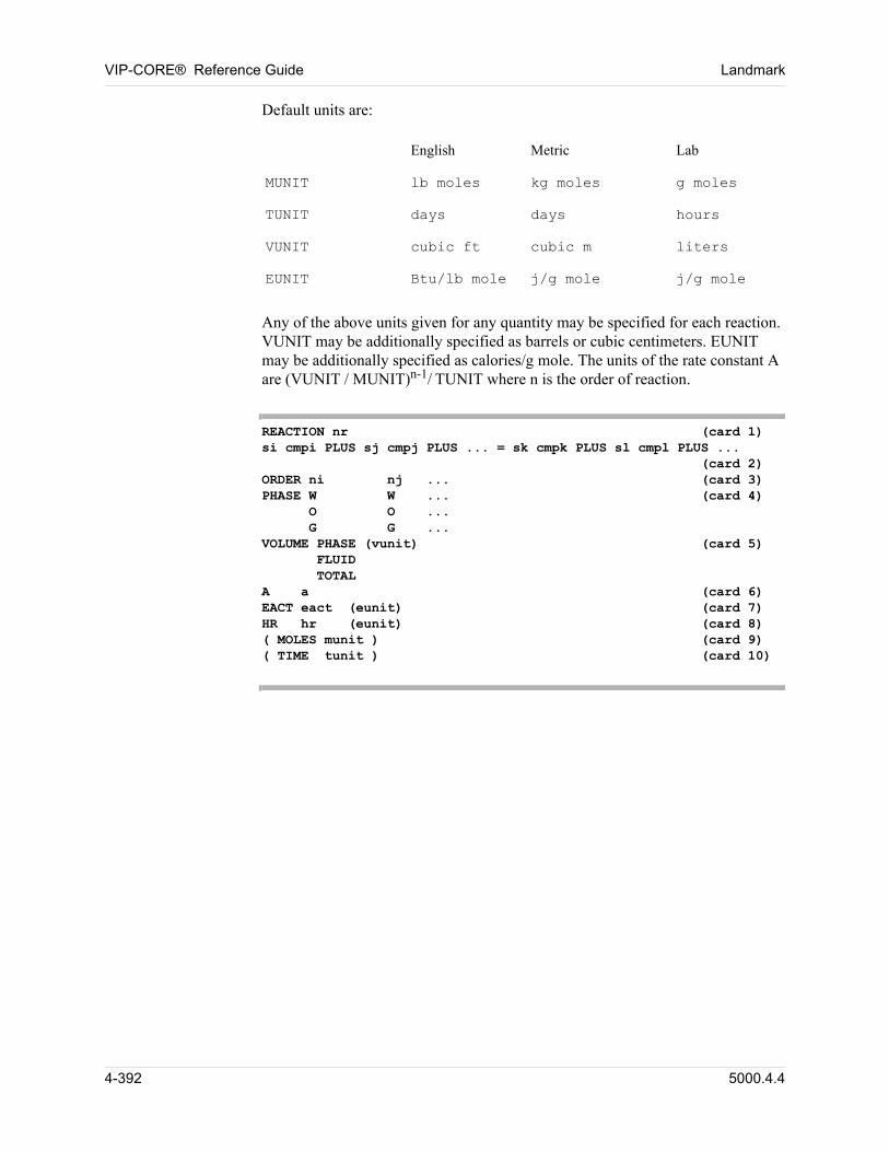
VIP-CORE® Reference Guide Landmark
00 Default units are:
English Metric Lab
MUNIT lb moles kg moles g moles
TUNIT days days hours
VUNIT cubic ft cubic m liters
EUNIT Btu/lb mole j/g mole j/g mole
00 Any of the above units given for any quantity may be specified for each reaction. VUNIT may be additionally specified as barrels or cubic centimeters. EUNIT may be additionally specified as calories/g mole. The units of the rate constant A are (VUNIT / MUNIT)n-1/ TUNIT where n is the order of reaction.
REACTION nr (card 1)si cmpi PLUS sj cmpj PLUS ... = sk cmpk PLUS sl cmpl PLUS ... (card 2)ORDER ni nj ... (card 3)PHASE W W ... (card 4) O O ... G G ...VOLUME PHASE (vunit) (card 5) FLUID TOTALA a (card 6)EACT eact (eunit) (card 7)HR hr (eunit) (card 8)( MOLES munit ) (card 9)( TIME tunit ) (card 10)
4-392 5000.4.4
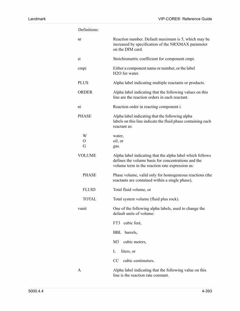
Landmark VIP-CORE® Reference Guide
00 Definitions:
nr Reaction number. Default maximum is 5, which may be increased by specification of the NRXMAX parameter on the DIM card.
si Stoichiometric coefficient for component cmpi.
cmpi Either a component name or number, or the label H2O for water.
PLUS Alpha label indicating multiple reactants or products.
ORDER Alpha label indicating that the following values on this line are the reaction orders in each reactant.
ni Reaction order in reacting component i.
PHASE Alpha label indicating that the following alpha labels on this line indicate the fluid phase containing each reactant as:
W water,O oil, orG gas.
VOLUME Alpha label indicating that the alpha label which follows defines the volume basis for concentrations and the volume term in the reaction rate expression as:
PHASE Phase volume, valid only for homogeneous reactions (the reactants are contained within a single phase),
FLUID Total fluid volume, or
TOTAL Total system volume (fluid plus rock).
vunit One of the following alpha labels, used to change the default units of volume:
FT3 cubic feet,
BBL barrels,
M3 cubic meters,
L liters, or
CC cubic centimeters.
A Alpha label indicating that the following value on this line is the reaction rate constant.
5000.4.4 4-393
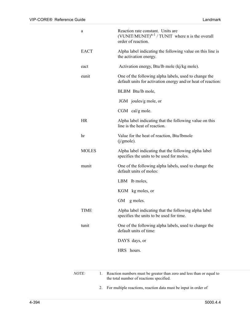
VIP-CORE® Reference Guide Landmark
a Reaction rate constant. Units are (VUNIT/MUNIT)n-1 / TUNIT where n is the overall order of reaction.
EACT Alpha label indicating the following value on this line is the activation energy.
eact Activation energy, Btu/lb mole (kj/kg mole).
eunit One of the following alpha labels, used to change the default units for activation energy and/or heat of reaction:
BLBM Btu/lb mole,
JGM joules/g mole, or
CGM cal/g mole.
HR Alpha label indicating that the following value on this line is the heat of reaction.
hr Value for the heat of reaction, Btu/lbmole(j/gmole).
MOLES Alpha label indicating that the following alpha label specifies the units to be used for moles.
munit One of the following alpha labels, used to change the default units of moles:
LBM lb moles,
KGM kg moles, or
GM g moles.
TIME Alpha label indicating that the following alpha label specifies the units to be used for time.
tunit One of the following alpha labels, used to change the default units of time:
DAYS days, or
HRS hours.
NOTE: 1. Reaction numbers must be greater than zero and less than or equal to the total number of reactions specified.
2. For multiple reactions, reaction data must be input in order of
4-394 5000.4.4
Landmark VIP-CORE® Reference Guide
increasing reaction number.
3. O or G may be specified for the defined components (those on the COMPONENTS card). G may not be specified for the non-volatile components.
4. Stoichiometric coefficients must satisfy mass balance (within a small tolerance), i.e., si Mi + sj Mj + ... = sk Mk + sl Ml + ..., where M is the component molecular weight.
5. O or G may be specified for the defined components (those on the COMPONENTS card). G may not be specified for the non-volatile components.
5000.4.4 4-395
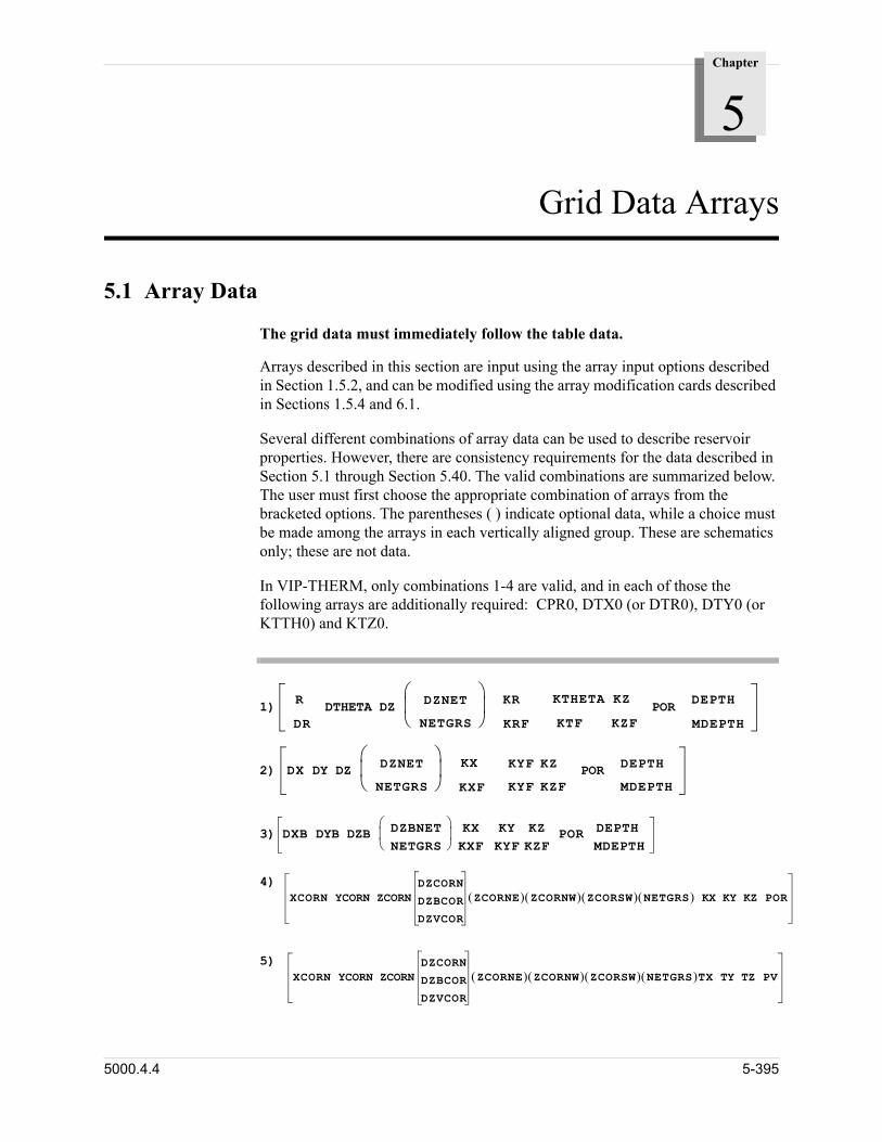
Chapter
5
00000Grid Data Arrays
5.1 Array Data
The grid data must immediately follow the table data. 00
Arrays described in this section are input using the array input options described in Section 1.5.2, and can be modified using the array modification cards described in Sections 1.5.4 and 6.1. 00
Several different combinations of array data can be used to describe reservoir properties. However, there are consistency requirements for the data described in Section 5.1 through Section 5.40. The valid combinations are summarized below. The user must first choose the appropriate combination of arrays from the bracketed options. The parentheses ( ) indicate optional data, while a choice must be made among the arrays in each vertically aligned group. These are schematics only; these are not data. 00
In VIP-THERM, only combinations 1-4 are valid, and in each of those the following arrays are additionally required: CPR0, DTX0 (or DTR0), DTY0 (or KTTH0) and KTZ0. 00
1)
R
DRDTHETA DZ DZNET
NETGRS KR
KRF
KTHETA KZ
KTF KZFPOR
DEPTH
MDEPTH
2) DX DY DZ DZNET
NETGRS KX
KXF
KYF KZ
KYF KZFPOR DEPTH
MDEPTH
3) DXB DYB DZB DZBNET
NETGRS KX
KXFKY KZKYF KZF
POR DEPTHMDEPTH
4)
XCORN YCORN ZCORNDZCORN
DZBCOR
DZVCOR
ZCORNE ZCORNW ZCORSW NETGRS KX KY KZ POR5)
XCORN YCORN ZCORNDZCORN
DZBCOR
DZVCOR
ZCORNE ZCORNW ZCORSW NETGRS TX TY TZ PV
5000.4.4 5-395
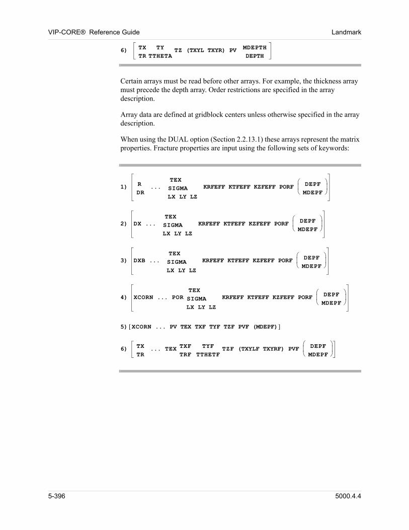
VIP-CORE® Reference Guide Landmark
6) TX TYTR TTHETA
TZ (TXYL TXYR) PV MDEPTHDEPTH
Certain arrays must be read before other arrays. For example, the thickness array must precede the depth array. Order restrictions are specified in the array description. 00
Array data are defined at gridblock centers unless otherwise specified in the array description. 00
When using the DUAL option (Section 2.2.13.1) these arrays represent the matrix properties. Fracture properties are input using the following sets of keywords: 00
1) R
DR...
TEXSIGMALX LY LZ
KRFEFF KTFEFF KZFEFF PORF DEPFMDEPF
2) DX ...
TEXSIGMALX LY LZ
KRFEFF KTFEFF KZFEFF PORF DEPFMDEPF
3) DXB ...
TEXSIGMALX LY LZ
KRFEFF KTFEFF KZFEFF PORF DEPFMDEPF
4) XCORN ... POR
TEXSIGMALX LY LZ
KRFEFF KTFEFF KZFEFF PORF DEPFMDEPF
5) XCORN ... PV TEX TXF TYF TZF PVF (MDEPF) 6) TX
TR... TEX TXF
TRFTYF
TTHETFTZF (TXYLF TXYRF) PVF DEPF
MDEPF
5-396 5000.4.4
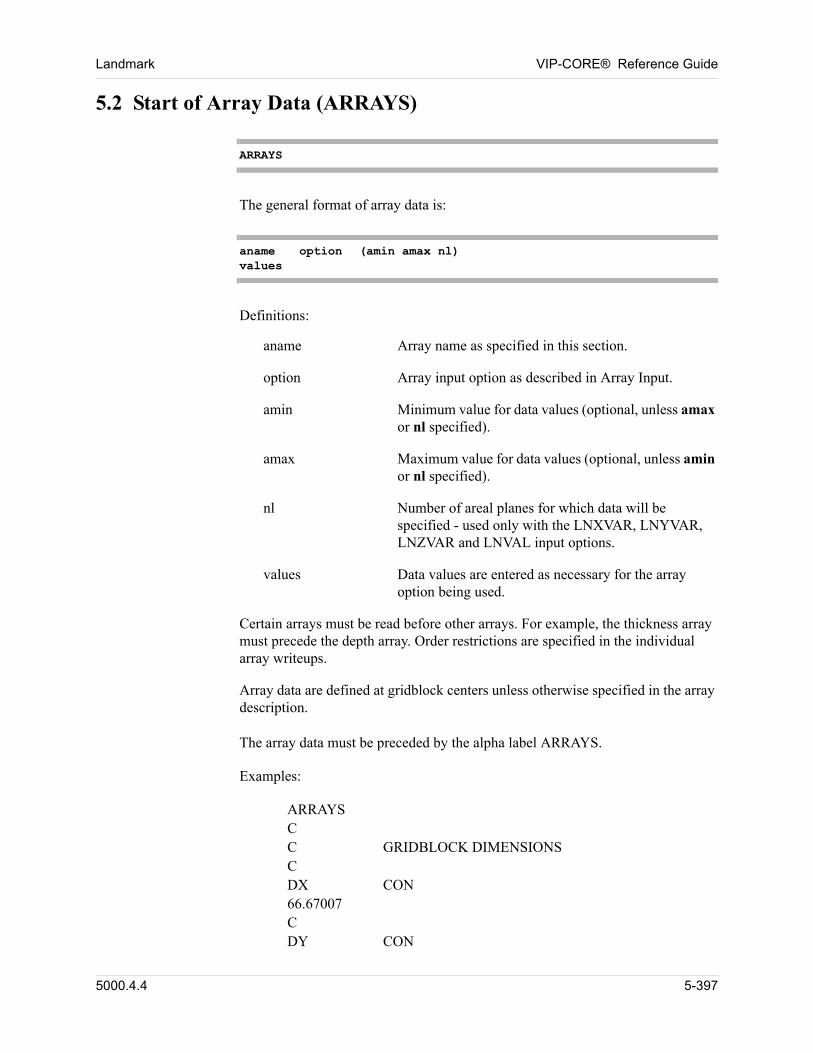
Landmark VIP-CORE® Reference Guide
5.2 Start of Array Data (ARRAYS)
ARRAYS
The general format of array data is: 00
aname option (amin amax nl)values
Definitions: 00
aname Array name as specified in this section.
option Array input option as described in Array Input.
amin Minimum value for data values (optional, unless amax or nl specified).
amax Maximum value for data values (optional, unless amin or nl specified).
nl Number of areal planes for which data will be specified - used only with the LNXVAR, LNYVAR, LNZVAR and LNVAL input options.
values Data values are entered as necessary for the array option being used.
Certain arrays must be read before other arrays. For example, the thickness array must precede the depth array. Order restrictions are specified in the individual array writeups. 00
Array data are defined at gridblock centers unless otherwise specified in the array description. 00
The array data must be preceded by the alpha label ARRAYS. 00
Examples: 00
ARRAYSCC GRIDBLOCK DIMENSIONSCDX CON66.67007CDY CON
5000.4.4 5-397
VIP-CORE® Reference Guide Landmark
66.67007CDZ ZVAR7.2 4.4 15.8CC GRIDBLOCK TOPSC 00
5.3 Grid Definition
5.3.1 X (R) Non-Corner Point Grid Dimension (DX, DXB, DR, R)
array option (amin amax nl)Enter data values as required.
These grid dimensions are usually input using the XVAR (RVAR) option. 00
Definitions: 00
Rectangular Grid: 00
DX, ft (m) Incremental length of each gridblock in the x direction, measured along the horizontal.
DXB, ft (m) Incremental length of each gridblock in the x direction, measured along the bedding plane.
Radial Grid: 00
DR, ft (m) Radial increment of each gridblock, measured along the horizontal.
R, ft (m) Radius to the outer edge of each gridblock, measured along the horizontal from the origin.
Example: 00
ARRAYSCDX XVAR100 150 200 00
5-398 5000.4.4
Landmark VIP-CORE® Reference Guide
5.3.2 X Direction Corner Point Location (XCORN)
XCORN option (amin amax nl)Enter data values as required.
Definition: 00
XCORN, ft(m) X direction coordinate of each corner point in the grid. (NX+1) * (NY+1) * (NZ+1) values are required. Values must not decrease with increasing I index; i.e., XCORN(I,J,K) XCORN(I+1, J,K).
Example: 00
ARRAYSXCORN VALUEC FIRST LAYER0 1000 2000 3000 4000 5000 6000 7000 8000 9000 100000 1000 2000 3000 4000 5000 6000 7000 8000 9000 100000 1000 2000 3000 4000 5000 6000 7000 8000 9000 100000 1000 2000 3000 4000 5000 6000 7000 8000 9000 100000 1000 2000 3000 4000 5000 6000 7000 8000 9000 100000 1000 2000 3000 4000 5000 6000 7000 8000 9000 100000 1000 2000 3000 4000 5000 6000 7000 8000 9000 100000 1000 2000 3000 4000 5000 6000 7000 8000 9000 100000 1000 2000 3000 4000 5000 6000 7000 8000 9000 100000 1000 2000 3000 4000 5000 6000 7000 8000 9000 10000C SECOND LAYER0.00 956.52 1913.04 2869.57 3826.09 4782.61 5739.13 6695.65 7652.178608.70 9565.20.00 956.52 1913.04 2869.57 3826.09 4782.61 5739.13 6695.65 7652.178608.70 9565.220.00 956.52 1913.04 2869.57 3826.09 4782.61 5739.13 6695.65 7652.178608.70 9565.220.00 956.52 1913.04 2869.57 3826.09 4782.61 5739.13 6695.65 7652.178608.70 9565.220.00 956.52 1913.04 2869.57 3826.09 4782.61 5739.13 6695.65 7652.178608.70 9565.220.00 956.52 1913.04 2869.57 3826.09 4782.61 5739.13 6695.65 7652.178608.70 9565.220.00 956.52 1913.04 2869.57 3826.09 4782.61 5739.13 6695.65 7652.178608.70 9565.220.00 956.52 1913.04 2869.57 3826.09 4782.61 5739.13 6695.65 7652.178608.70 9565.220.00 956.52 1913.04 2869.57 3826.09 4782.61 5739.13 6695.65 7652.178608.70 9565.220.00 956.52 1913.04 2869.57 3826.09 4782.61 5739.13 6695.65 7652.178608.70 9565.22
5000.4.4 5-399
VIP-CORE® Reference Guide Landmark
C THIRD LAYER0.00 886.96 1773.91 2660.87 3547.83 4434.78 5321.74 6208.70 7095.657982.61 8869.570.00 886.96 1773.91 2660.87 3547.83 4434.78 5321.74 6208.70 7095.657982.61 8869.570.00 886.96 1773.91 2660.87 3547.83 4434.78 5321.74 6208.70 7095.657982.61 8869.570.00 886.96 1773.91 2660.87 3547.83 4434.78 5321.74 6208.70 7095.657982.61 8869.570.00 886.96 1773.91 2660.87 3547.83 4434.78 5321.74 6208.70 7095.657982.61 8869.570.00 886.96 1773.91 2660.87 3547.83 4434.78 5321.74 6208.70 7095.657982.61 8869.57 00
0.00 886.96 1773.91 2660.87 3547.83 4434.78 5321.74 6208.70 7095.657982.61 8869.570.00 886.96 1773.91 2660.87 3547.83 4434.78 5321.74 6208.70 7095.657982.61 8869.570.00 886.96 1773.91 2660.87 3547.83 4434.78 5321.74 6208.70 7095.657982.61 8869.570.00 886.96 1773.91 2660.87 3547.83 4434.78 5321.74 6208.70 7095.657982.61 8869.57C FOURTH LAYER0 800 1600 2400 3200 4000 4800 5600 6400 7200 80000 800 1600 2400 3200 4000 4800 5600 6400 7200 80000 800 1600 2400 3200 4000 4800 5600 6400 7200 80000 800 1600 2400 3200 4000 4800 5600 6400 7200 80000 800 1600 2400 3200 4000 4800 5600 6400 7200 80000 800 1600 2400 3200 4000 4800 5600 6400 7200 80000 800 1600 2400 3200 4000 4800 5600 6400 7200 80000 800 1600 2400 3200 4000 4800 5600 6400 7200 80000 800 1600 2400 3200 4000 4800 5600 6400 7200 80000 800 1600 2400 3200 4000 4800 5600 6400 7200 8000 00
5-400 5000.4.4
Landmark VIP-CORE® Reference Guide
5.3.3 Y (THETA) Non-Corner Point Grid Dimension (DY, DYB, DTHETA)
array option (amin amax nl)Enter data values as required.
These grid dimensions are usually input using the YVAR (THVAR) option. 00
Definitions: 00
Rectangular Grid: 00
DY, ft (m) Incremental length of each gridblock in the y direction, measured along the horizontal.
DYB, ft (m) Incremental length of each gridblock in the y direction, measured along the bedding plane.
Radial Grid: 00
DTHETA, degrees Incremental angle spanned by each gridblock, measured in a horizontal plane.
5.3.4 Y Direction Corner Point Location (YCORN)
YCORN option (amin amax nl)Enter data values as required.
Definition: 00
YCORN, ft(m) Y direction coordinate of each corner point in the grid. (NX+1) * (NY+1) * (NZ+1) values are required. Values must not increase with increasing J index; i.e., YCORN (I,J,K) YCORN (I,J+1,K).
Example: 00
ARRAYSYCORN VALUEC FIRST LAYER10000 10000 10000 10000 10000 10000 10000 10000 10000 10000 100008000 8000 8000 8000 8000 8000 8000 8000 8000 8000 80007000 7000 7000 7000 7000 7000 7000 7000 7000 7000 70006000 6000 6000 6000 6000 6000 6000 6000 6000 6000 60005000 5000 5000 5000 5000 5000 5000 5000 5000 5000 50004000 4000 4000 4000 4000 4000 4000 4000 4000 4000 40003000 3000 3000 3000 3000 3000 3000 3000 3000 3000 30002000 2000 2000 2000 2000 2000 2000 2000 2000 2000 2000
5000.4.4 5-401
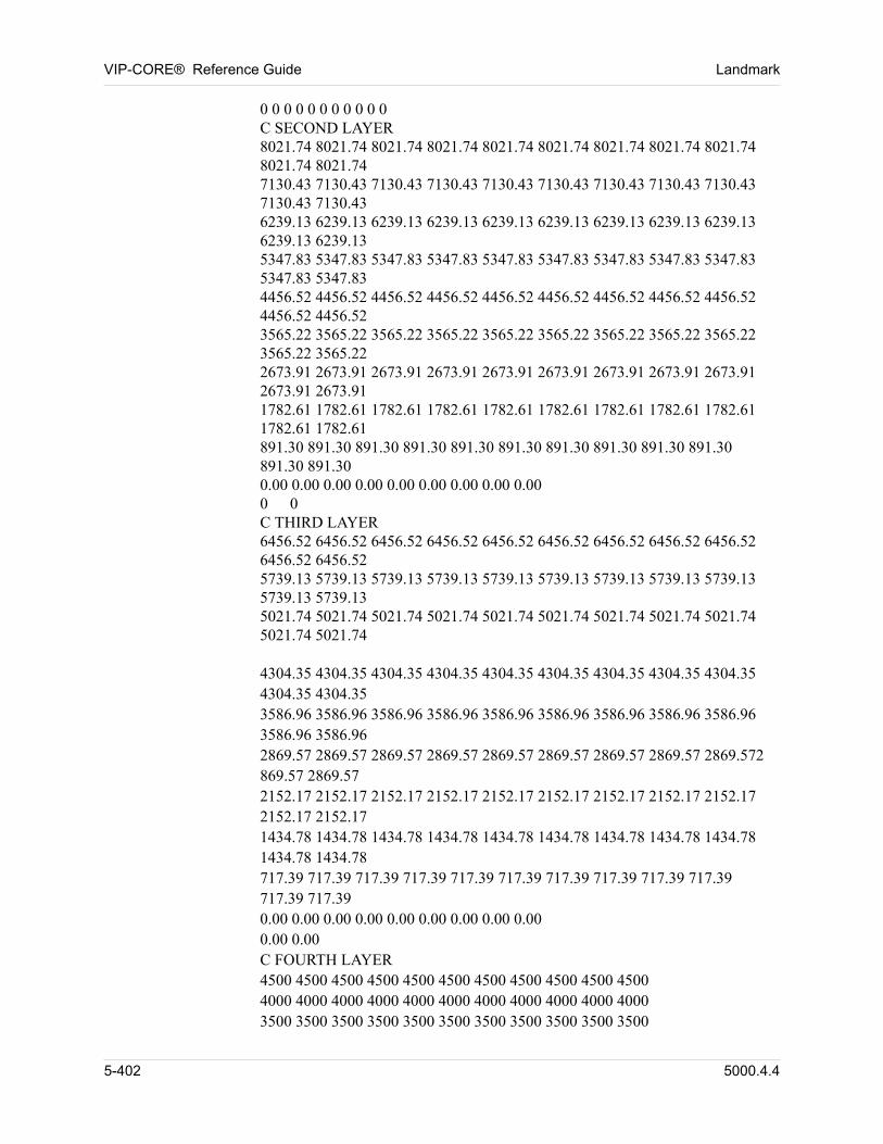
VIP-CORE® Reference Guide Landmark
0 0 0 0 0 0 0 0 0 0 0C SECOND LAYER8021.74 8021.74 8021.74 8021.74 8021.74 8021.74 8021.74 8021.74 8021.748021.74 8021.747130.43 7130.43 7130.43 7130.43 7130.43 7130.43 7130.43 7130.43 7130.437130.43 7130.436239.13 6239.13 6239.13 6239.13 6239.13 6239.13 6239.13 6239.13 6239.136239.13 6239.135347.83 5347.83 5347.83 5347.83 5347.83 5347.83 5347.83 5347.83 5347.835347.83 5347.834456.52 4456.52 4456.52 4456.52 4456.52 4456.52 4456.52 4456.52 4456.524456.52 4456.523565.22 3565.22 3565.22 3565.22 3565.22 3565.22 3565.22 3565.22 3565.223565.22 3565.222673.91 2673.91 2673.91 2673.91 2673.91 2673.91 2673.91 2673.91 2673.912673.91 2673.911782.61 1782.61 1782.61 1782.61 1782.61 1782.61 1782.61 1782.61 1782.611782.61 1782.61891.30 891.30 891.30 891.30 891.30 891.30 891.30 891.30 891.30 891.30891.30 891.300.00 0.00 0.00 0.00 0.00 0.00 0.00 0.00 0.000 0C THIRD LAYER6456.52 6456.52 6456.52 6456.52 6456.52 6456.52 6456.52 6456.52 6456.526456.52 6456.525739.13 5739.13 5739.13 5739.13 5739.13 5739.13 5739.13 5739.13 5739.135739.13 5739.135021.74 5021.74 5021.74 5021.74 5021.74 5021.74 5021.74 5021.74 5021.745021.74 5021.74 00
4304.35 4304.35 4304.35 4304.35 4304.35 4304.35 4304.35 4304.35 4304.354304.35 4304.353586.96 3586.96 3586.96 3586.96 3586.96 3586.96 3586.96 3586.96 3586.963586.96 3586.962869.57 2869.57 2869.57 2869.57 2869.57 2869.57 2869.57 2869.57 2869.572869.57 2869.572152.17 2152.17 2152.17 2152.17 2152.17 2152.17 2152.17 2152.17 2152.172152.17 2152.171434.78 1434.78 1434.78 1434.78 1434.78 1434.78 1434.78 1434.78 1434.781434.78 1434.78717.39 717.39 717.39 717.39 717.39 717.39 717.39 717.39 717.39 717.39717.39 717.390.00 0.00 0.00 0.00 0.00 0.00 0.00 0.00 0.000.00 0.00C FOURTH LAYER4500 4500 4500 4500 4500 4500 4500 4500 4500 4500 45004000 4000 4000 4000 4000 4000 4000 4000 4000 4000 40003500 3500 3500 3500 3500 3500 3500 3500 3500 3500 3500
5-402 5000.4.4
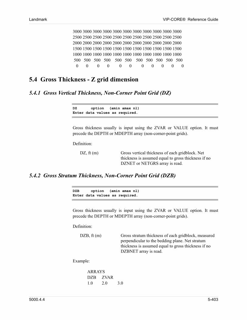
Landmark VIP-CORE® Reference Guide
3000 3000 3000 3000 3000 3000 3000 3000 3000 3000 30002500 2500 2500 2500 2500 2500 2500 2500 2500 2500 25002000 2000 2000 2000 2000 2000 2000 2000 2000 2000 20001500 1500 1500 1500 1500 1500 1500 1500 1500 1500 15001000 1000 1000 1000 1000 1000 1000 1000 1000 1000 1000 500 500 500 500 500 500 500 500 500 500 500 0 0 0 0 0 0 0 0 0 0 0 00
5.4 Gross Thickness - Z grid dimension
5.4.1 Gross Vertical Thickness, Non-Corner Point Grid (DZ)
DZ option (amin amax nl)Enter data values as required.
Gross thickness usually is input using the ZVAR or VALUE option. It must precede the DEPTH or MDEPTH array (non-corner-point grids). 00
Definition: 00
DZ, ft (m) Gross vertical thickness of each gridblock. Net thickness is assumed equal to gross thickness if no DZNET or NETGRS array is read.
5.4.2 Gross Stratum Thickness, Non-Corner Point Grid (DZB)
DZB option (amin amax nl)Enter data values as required.
Gross thickness usually is input using the ZVAR or VALUE option. It must precede the DEPTH or MDEPTH array (non-corner-point grids). 00
Definition: 00
DZB, ft (m) Gross stratum thickness of each gridblock, measured perpendicular to the bedding plane. Net stratum thickness is assumed equal to gross thickness if no DZBNET array is read.
Example: 00
ARRAYSDZB ZVAR1.0 2.0 3.0 00
5000.4.4 5-403
VIP-CORE® Reference Guide Landmark
5.4.3 Corner Point Gross Vertical Thickness (DZCORN)
DZCORN option (amin amax nl)Enter data values as required.
Definition: 00
DZCORN, ft (m) Gross vertical thickness below each corner point, measured as the depth difference between each corner point and the corresponding corner point in the next layer below it. Net thickness is assumed equal to gross thickness if no NETGRS array is read.
This gross thickness array must precede the ZCORN array. This array requires (NX+1) * (NY+1) * NZ values and is used only to process the LAYER or DIP options for the ZCORN array. 00
5.4.4 Corner Point Gross Stratum Thickness (DZBCOR)
DZBCOR option (amin amax nl)Enter data values as required.
Definition: 00
DZBCOR, ft (m) Gross stratum thickness below each corner point, measured perpendicular to the bedding plane. When this array is used, the XCORN and YCORN values are adjusted so that the line from a corner point in one layer to the corresponding corner point in the next layer down is perpendicular to the bedding plane. Net stratum thickness is assumed equal to gross thickness if no NETGRS array is read.
This gross thickness array is usually input using the VALUE option. It must precede the ZCORN array. This array requires (NX+1) * (NY+1) * NZ values and is used only to process the LAYER or DIP options for the ZCORN array. 00
5-404 5000.4.4
Landmark VIP-CORE® Reference Guide
5.4.5 Depth Corner Point Gross Stratum Thickness (DZVCOR)
DZVCOR option (amin amax nl)Enter data values as required.
Definition: 00
DZVCOR, ft (m) Gross stratum thickness below each corner point, measured as the depth difference between a corner point in one layer and the corresponding corner point in the next layer down. This data differs from the use of the DZCORN array in that the XCORN and YCORN values are adjusted so that the line from a corner point in one layer to the corresponding corner point in the next layer down is perpendicular to the bedding plane. Net stratum thickness is assumed equal to gross thickness if no NETGRS array is read.
This gross thickness array is usually input using the VALUE option. It must precede the ZCORN array. This array requires (NX+1) * (NY+1) * NZ values and is used only to process the LAYER or DIP options for the ZCORN array. 00
5.5 Net Thickness - Z Grid Dimension
5.5.1 Net Vertical Thickness, Non-Corner Point Grid (DZNET)
DZNET option (amin amax nl)Enter data values as required.
Net thickness usually is input using the ZVAR or VALUE option. The net pay is assumed to be evenly distributed across the entire gross interval. If both gross and net thicknesses are input, gross thickness is used only in the calculations of depth and vertical transmissibility; net thickness is used to determine pore volume and areal transmissibility. 00
Definition: 00
DZNET, ft (m) Net vertical thickness of each gridblock. Used only when gross vertical thickness is specified with the DZ array. If net and gross thickness are equal, use the DZ array.
5000.4.4 5-405
VIP-CORE® Reference Guide Landmark
5.5.2 Net Stratum Thickness, Non-Corner Point Grid (DZBNET)
DZBNET option (amin amax nl)Enter data values as required.
Net thickness usually is input using the ZVAR or VALUE option. The net pay is assumed to be evenly distributed across the entire gross interval. If both gross and net thicknesses are input, gross thickness is used only in the calculations of depth and vertical transmissibility; net thickness is used to determine pore volume and areal transmissibility. 00
Definition: 00
DZBNET, ft (m) Net stratum thickness of each gridblock, measured perpendicular to the bedding plane. Used only when gross stratum thickness is specified with the DZB array. If net and gross thickness are equal, use the DZB array.
5.5.3 Ratio Net Vertical Thickness to Gross Thickness (NETGRS)
NETGRS option (amin amax nl)Enter data values as required.
Definition: 00
NETGRS Ratio of net vertical thickness to gross thickness of each gridblock. Default is 1.
Net/Gross ratio usually is input using the ZVAR or VALUE option. Net/Gross ratio is used to calculate net from gross thickness. The net pay is assumed to be evenly distributed across the entire gross interval. Gross thickness is used in the calculations of depth and vertical transmissibility; net thickness is used to determine pore volume and areal transmissibility. 00
Can be used with both non-corner point and corner-point grids. 00
5.5.4 Fracture Block Net to Gross Vertical Thickness Ratio (NETGF)
NETGF option (amin amax nl)Enter data values as required.
5-406 5000.4.4

Landmark VIP-CORE® Reference Guide
Definition: 00
NETGF Ratio of net vertical thickness to gross thickness of each fracture gridblock. Default is NETGRS, (the matrix values).
Net/Gross ratio usually is input using the ZVAR or VALUE option. Net/Gross ratio is used to calculate net from gross thickness. The net pay is assumed to be evenly distributed across the entire gross interval. Gross thickness is used in the calculations of depth and vertical transmissibility; net thickness is used to determine pore volume and areal transmissibility. 00
Can be used with both non-corner point and corner-point grids. 00
5000.4.4 5-407
VIP-CORE® Reference Guide Landmark
5.6 Depth - Non-Corner Point Grid
5.6.1 Depth to Top of Gridblock (DEPTH)
DEPTH option (amin amax nl)Enter data values as required
Depth usually is input using the LAYER, DIP, or ZVAR option. 00
Definition: 00
DEPTH, ft (m) Depth to the top of each gridblock, measured from an arbitrary datum, positive downward.
5.6.2 Depth to Center of Gridblock (MDEPTH)
MDEPTH option (amin amax nl)Enter data values as required
Depth usually is input using the LAYER, DIP, or ZVAR option 00
Definition: 00
MDEPTH, ft (m) Depth to the center of each gridblock, measured from an arbitrary datum, positive downward.
Example: 00
MDEPTH LAYER20*120.0 00
5.7 Depth - Corner Point Description
Cartesian and radial grid meshes impose limits on the physical reservoir characteristics which can be represented. An example of this would be the specification of fault planes, which must occur at block boundaries and are restricted to vertical displacement. 00
Since the reservoir simulator deals with block properties and interblock connections only, any system which can be described in these terms can be modelled. Corner point gridding permits the user to define the eight corners of each gridblock and generates the required simulation properties. The user is cautioned that generation of non-orthogonal connections between gridblocks can lead to errors in flow calculations, because the resulting cross terms in the equations are ignored. 00
5-408 5000.4.4
Landmark VIP-CORE® Reference Guide
5.7.1 Depth to Each Corner Point (ZCORN)
ZCORN option (amin amax nl)Enter data values as required.
Definition: 00
ZCORN, ft (m) Depth to each corner point, measured from an arbitrary datum, positive downward. (NX+1)*(NY+1)*(NZ+1) data values are required. In a faulted grid system, this depth is interpreted as the depth of the southeast corner of each block (viewed with the (1,1) block in the northwestern corner and the (NX,NY) block in the southeastern corner of each layer). The depths of the other three corners of each block may be input using the ZCORNE, ZCORNW, or ZCORSW arrays.
Depth usually is input using the LAYER, DIP, or ZVAR option. 00
5.7.2 Depth to NE Corner Point (ZCORNE)
ZCORNE option (amin amax nl)Enter data values as required.
Definition: 00
ZCORNE, ft (m) Depth to the northeast corner of each block in each layer, measured from an arbitrary datum, positive downward. NX*NY*(NZ+1) data values are required. In a faulted grid system, this depth is used, in conjunction with the XCORN, YCORN and ZCORN arrays, to locate the exact position of the corner point so that the depth value is honored and the grid remains valid (e.g., without holes or overlapping blocks).
Depth usually is input using the LAYER, DIP, or ZVAR option. 00
Example: 00
ZCORNE ZVAR100 200 250 00
5000.4.4 5-409
VIP-CORE® Reference Guide Landmark
5.7.3 Depth to NW Corner Point (ZCORNW)
ZCORNW option (amin amax nl)Enter data values as required.
Definition: 00
ZCORNW, ft (m) Depth to the northwest corner of each block in each layer, measured from an arbitrary datum, positive downward. NX*NY*(NZ+1) data values are required. In a faulted grid system, this depth is used, in conjunction with the XCORN, YCORN, and ZCORN arrays, to locate the exact position of the corner point so that the depth value is honored and the grid remains valid (e.g., without holes or overlapping blocks).
Depth usually is input using the LAYER, DIP, or ZVAR option. 00
Example: 00
ZCORNW LAYER20*110.0 00
5.7.4 Depth to SW Corner Point (ZCORSW)
ZCORSW option (amin amax nl)Enter data values as required.
Definition: 00
ZCORSW, ft (m) Depth to the southwest corner of each block in each layer, measured from an arbitrary datum, positive downward. NX*NY*(NZ+1) data values are required. In a faulted grid system, this depth is used, in conjunction with the XCORN, YCORN, and ZCORN arrays, to locate the exact position of the corner point so that the depth value is honored and the grid remains valid (e.g., without holes or overlapping blocks).
Depth usually is input using the LAYER, DIP, or ZVAR option. 00
5-410 5000.4.4
Landmark VIP-CORE® Reference Guide
Example: 00
ZCORSW ZVAR50*200.0 00
5.7.5 Depth to Bottom Corner Point (ZBOT)
ZBOT option (amin amax nl)Enter data values as required.
Definition: 00
ZBOT, ft (m) Depth to each bottom corner point, measured from an arbitrary datum, positive downward. (NX+1)*(NY+1)*NZ data values are required. In a faulted grid system, this depth is interpreted as the depth of the southeast corner of each block bottom (viewed with the (1,1) block in the northwestern corner and the (NX, NY) block in the southeastern corner of each layer). The depths of the other three bottom corners of each block may be input using the ZBOTNE, ZBOTNW, or ZBOTSW arrays.
Depth usually is input using the LAYER, DIP, or ZVAR option. 00
Example: 00
ZBOT ZVAR15.3 18 00
5.7.6 Depth to NE Bottom Corner Point (ZBOTNE)
ZBOTNE option (amin amax nl)Enter data values as required.
Definition: 00
ZBOTNE, ft (m) Depth to the northeast bottom corner of each block in each layer, measured from an arbitrary datum, positive downward. NX*NY*NZ data values are required. In a faulted grid system, this depth is used, in conjunction with XCORN, YCORN, and ZCORN arrays, to locate the exact position of the bottom corner point so that the depth value is honored and the grid remains valid (e.g., without holes or overlapping blocks).
5000.4.4 5-411
VIP-CORE® Reference Guide Landmark
Depth usually is input using the LAYER, DIP, or ZVAR option. 00
Example: 00
ZBOTNE ZVAR15.3 18 00
5.7.7 Depth to NW Bottom Corner Point (ZBOTNW)
ZBOTNW option (amin amax nl)Enter data values as required.
Definition: 00
ZBOTNW, ft (m) Depth to the northwest bottom corner of each block in each layer, measured from an arbitrary datum, positive downward. NX*NY*NZ data values are required. In a faulted grid system, this depth is used, in conjunction with XCORN, YCORN, and ZCORN arrays, to locate the exact position of the bottom corner point so that the depth value is honored and the grid remains valid (e.g., without holes or overlapping blocks).
Depth usually is input using the LAYER, DIP, or ZVAR option. 00
Example: 00
ZBOTNW ZVAR15.3 18 00
5.7.8 Depth to SW Bottom Corner Point (ZBOTSW)
ZBOTSW option (amin amax nl)Enter data values as required.
Definition: 00
ZBOTSW, ft (m) Depth to the southwest bottom corner of each block in each layer, measured from an arbitrary datum, positive downward. NX*NY*NZ data values are required. In a faulted grid system, this depth is used, in conjunction with XCORN, YCORN, and ZCORN arrays, to locate the exact position of the bottom corner point so that the depth value is honored and the grid remains valid (e.g., without holes or overlapping blocks.)
5-412 5000.4.4
Landmark VIP-CORE® Reference Guide
Depth usually is input using the LAYER, DIP, or ZVAR option. 00
Example: 00
ZBOTSW ZVAR15.3 18 00
5.7.9 Depth to Point on a Depth Line (ZLNCOR)
ZLNCOR option (amin amax nl)Enter data values as required.
Definition: 00
ZLNCOR, ft (m) Depth to a point on a depth line in each block of two layers. This option is used for the specification of depth lines in the LINE corner position option. The options LNXVAR, LNYVAR, LNZVAR or LNVAL can be used. If this array is not input then the values of the array ZCORN in the first two layers are used for the specification of z-coordinates of two points on the depth lines.
Depth usually is input using the LAYER, DIP, or ZVAR option. 00
Example: 00
ZLNCOR ZVAR15.3 18 00
5.8 Fracture Block Depth (DEPF, MDEPF)
When the DUAL option has been specified, different depths for the fracture blocks than for the matrix blocks can be entered. If not entered, the depths will be the same as for the matrix blocks. 00
array option (amin amax nl)Enter data values as required.
Definitions: 00
DEPF, ft (m) Depth to the top of each fracture block measured from an arbitrary datum, positive downward.
MDEPF, ft (m) Depth to the center of each fracture block measured from an arbitrary datum, positive downward.
5000.4.4 5-413
VIP-CORE® Reference Guide Landmark
5.9 Porosity / Pore Volume (POR, PV)
Enter one of the following two arrays. 00
array option (amin amax nl)Enter data values as required.
Definitions: 00
POR, fraction Porosity of each gridblock. If both net and gross thickness are input, porosity should correspond to the net thickness.
PV, rb (m3) Pore volume of each gridblock.
Example: 00
POR CON0.3 00
5.10 Fracture Porosity / Pore Volume (PORF, PVF)
When the DUAL option has been specified the user must enter one of the following two arrays. 00
array option (amin amax nl)Enter data values as required.
Definitions: 00
PORF, fraction Fracture porosity of each gridblock. If both net and gross thickness are input, porosity should correspond to the net thickness.
PVF, rb (m3) Fracture pore volume of each gridblock.
The PORF array must be used with the POR array. The PVF array must be used with the PV array. 00
5-414 5000.4.4
Landmark VIP-CORE® Reference Guide
5.11 Permeability / Transmissibility
5.11.1 X (R) Direction (KX, KXF, TX, KR, KRF, TR)
If both net and gross thickness are input, permeability will be used with net thickness (DZNET or DZBNET) to calculate transmissibility. Enter one of the following arrays. 00
array option (amin amax nl)Enter data values as required.
Omit if NX = 1 or NR = 1. (except with VIP-DUAL) 00
Definitions: 00
Rectangular Grid:
KX, md (md) Permeability controlling flow in the x direction, applied to the gridblock center.
KXF, md (md) Permeability controlling flow in the x direction, applied at the gridblock face. The value input for block (i,j,k) is the permeability at the block face between cells (i-1,j,k) and (i,j,k). For i = 1, KXF is zero.
TX, rb-cp/day/psi(m3-cp/day/kPa)
The x-direction transmissibility of gridblock (i,j,k) is defined at the boundary between blocks (i-1,j,k) and (i,j,k) and controls flow between them. For i = 1, TX is zero.
Radial Grid:
KR, md (md) Permeability controlling flow in the r direction, applied to the radial gridblock center.
KRF, md (md) Permeability controlling flow in the r direction, applied at the gridblock face. The value input for block (i,j,k) is the permeability at the block face between cells (i-1,j,k) and (i,j,k). For i = 1, KRF is zero.
TR, rb-cp/day/psi(m3-cp/day/kPa)
The r-direction transmissibility of gridblock (i,j,k) is defined at the boundary between blocks (i-1,j,k) and (i,j,k) and controls flow between them. For i = 1, TR is zero.
Example: 00
5000.4.4 5-415
VIP-CORE® Reference Guide Landmark
KXF ZVAR10 20 25 00
5.11.2 Y (Theta) Direction (KY, KYF, TY, KTHETA, KTF, TTHETA)
If both net and gross thickness are input, permeability will be used with net thickness (DZNET or DZBNET) to calculate transmissibility. Enter one of the following arrays. 00
array option (amin amax nl)Enter data values as required.
Omit if NY = 1 or NTHETA = 1. (except with VIP-DUAL) 00
Definitions: 00
Rectangular Grid:
KY, md (md) Permeability controlling flow in the y direction, applied to the gridblock center.
KYF, md (md) Permeability controlling flow in the y direction, applied at the gridblock face. The value input for block (i,j,k) is the permeability at the block face between cells (i,j-1,k) and (i,j,k). For j = 1, KYF is zero.
TY, rb-cp/day/psi(m3-cp/day/kPa)
The y direction transmissibility of gridblock (i,j,k) is defined at the boundary between blocks (i,j-1,k) and (i,j,k) and controls flow between them. For j = 1, TY is zero.
Radial Grid:
KTHETA, md (md) Permeability controlling flow in the theta direction, applied to the radial gridblock center.
KTF, md (md) Permeability controlling flow in the theta direction, applied at the gridblock face. The value input for block (i,j,k) is the permeability at the block face between cells (i,j-1,k) and (i,j,k). For j = 1, KTF is zero.
TTHETA,rb-cp/day/psi(m3-cp/day/kPa)
The theta-direction transmissibility of gridblock (i,j,k) is defined at the boundary between blocks (i,j-1,k) and (i,j,k) and controls flow between them. For j = 1, TTHETA is zero.
5-416 5000.4.4
Landmark VIP-CORE® Reference Guide
5.11.3 Z Direction (KZ, KZF, TZ)
If both net and gross thickness are input, permeability will be used with gross thickness (DZ or DZB) to calculate transmissibility. Enter one of the following arrays. 00
array option (amin amax nl)Enter data values as required.
Omit if NZ = 1. (except with VIP-DUAL) 00
Definitions:
KZ, md (md) Permeability controlling flow between the layers, applied to the gridblock center.
KZF, md (md) Permeability controlling flow in the z direction, applied at the gridblock face. The value input for block (i,j,k) is the permeability at the block face between cells (i,j,k-1) and (i,j,k). For k = 1, KZF is zero.
TZ, rb-cp/day/psi (m3-cp/day/kPa)
The z-direction transmissibility of gridblock (i,j,k) is defined at the boundary between blocks (i,j,k-1) and (i,j,k) and controls flow between them. For k = 1, TZ is zero.
00
5.11.4 Diagonal (XY) Directions (TXYL, TXYR)
array option (amin amax nl)Enter data values as required.
The TXYL and TXYR arrays may only be entered if the nine-point finite difference operator option is in use (Section 2.2.6.5). 00
If the nine-point finite difference operator option is invoked (Section 2.2.6.5) and permeabilities are input, all transmissibilities in the xy plane (x, y, and diagonal directions) are calculated using the method of Coats and Modine (Reference 3). 00
The use of the nine-point option is subject to the following conditions: 00
Cartesian grid system
No corner points
BLITZ solver (see Simulation Modules Manual)
NX > 1, NY > 1
5000.4.4 5-417
VIP-CORE® Reference Guide Landmark
The gridblock face permeability input option is ignored in the nine-point transmissibility calculations; i.e., the input values are used as block values. 00
Definitions:
TXYL, rb-cp/day/psi(m3-cp/day/kPa)
The left diagonal-direction transmissibility of gridblock (i,j,k) is defined (at an imaginary boundary) between blocks (i-1,j-1,k) and (i,j,k) and controls flow between them. For i=1 and for j=1, TXYL is zero.
TXYR,rb-cp/day/psi(m3-cp/day/kPa)
The right diagonal-direction transmissibility of gridblock (i,j,k) is defined (at an imaginary boundary) between blocks (i+1,j-1,k) and (i,j,k) and controls flow between them. For i=NX and for j=1, TXYR is zero.
00
5.11.5 Well PI Upscaled Permeabilities (KWX, KWY, KWZ)
When the COARSEN (Section 8.1) option is used, permeabilities have to be upscaled. The permeability arrays KX, KY, KZ are used for transmissibility calculations and are upscaled using flow based algorithms from the UPSCALE card (Section 2.2.22). In certain types of calculations, such as well PI and J-function calculations, flow based upscaling is not appropriate. 00
The KWX, KWY, KWZ arrays are used for these other calculations. If only one of the sets of arrays KX, KY, KZ or KWX, KWY, KWZ is input, the set not input will default to the input set. 00
The method for upscaling these well PI permeabilities may be specified on the UPSCALE card (Section 2.2.22). 00
array option (amin amax nl)Enter data values as required.
5.12 Fracture Permeability / Transmissibility (VIP-DUAL)
When the DUAL option has been specified the user must enter one keyword from each of the three following groups of keywords. Fracture permeability is entered as an effective permeability, 00
k = kf * f
where kf is the actual permeability of the fractures themselves and f is the fracture porosity. The effective permeability is that measured by a well test in a fractured reservoir. (Reference 7) 00
5-418 5000.4.4
Landmark VIP-CORE® Reference Guide
5.12.1 X (R) Direction (KXFEFF, TXF, KRFEFF, TRF)
If both net and gross thickness are input, permeability will be used with net thickness (DZNET or DZBNET) to calculate transmissibility. Enter one of the following arrays. 00
array optionEnter data values as required.
Definitions: 00
Rectangular grid:
KXFEFF, md (md) Fracture effective permeability controlling flow in the x direction, applied to the gridblock center.
TXF, rb-cp/day/psi(m3-cp/day/kPa)
The x-direction fracture transmissibility of gridblock (i,j,k) is defined at the boundary between blocks (i-1,j,k) and (i,j,k) and controls flow between them. For i=1, TXF is zero.
Radial grid:
KRFEFF, md (md) Fracture effective permeability controlling flow in the r direction, applied to the gridblock center.
TRF, rb-cp/day/psi(m3-cp/day/kPa)
The r-direction fracture transmissibility of gridblock (i,j,k) is defined at the boundary between blocks (i-1,j,k) and (i,j,k) and controls flow between them. For i=1, TRF is zero.
5.12.2 Y (THETA) Direction (KYFEFF, TYF, KTFEFF, TTHETF)
If both net and gross thickness are input, permeability will be used with net thickness (DZNET or DZBNET) to calculate transmissibility. Enter one of the following arrays. 00
array optionEnter data values as required.
Definitions: 00
Rectangular grid:
KYFEFF, md (md) Fracture effective permeability controlling flow in the y direction, applied to the gridblock center.
5000.4.4 5-419
VIP-CORE® Reference Guide Landmark
Radial grid:
KTFEFF, md (md) Fracture effective permeability controlling flow in the theta direction, applied to the gridblock center.
TTHETFrb-cp/day/psi(m3-cp/day/kPa)
The theta-direction fracture transmissibility of gridblock (i,j,k) is defined at the boundary between blocks (i,j-1,k) and (i,j,k) and controls flow between them. For j=1, TTHETF is zero.
5.12.3 Z Direction (KZFEFF, TZF)
If both net and gross thickness are input, permeability will be used with gross thickness (DZ or DZB) to calculate transmissibility. Enter one of the following arrays. 00
array optionEnter data values as required.
Definitions: 00
Rectangular grid:
KZFEFF, md (md) Fracture effective permeability controlling flow in the z direction, applied to the gridblock center.
TZF, rb-cp/day/psi(m3-cp/day/kPa)
The z-direction fracture transmissibility of gridblock (i,j,k) is defined at the boundary between blocks (i,j,k-1) and (i,j,k) and controls flow between them. For k=1, TZF is zero.
5.12.4 Diagonal (XY) Directions (TXYLF, TXYRF)
array optionEnter data values as required.
The TXYLF and TXYRF arrays may only be entered if the nine-point finite difference operator option is in use (Section 2.2.6.5). 00
If the nine-point finite difference operator option is invoked (Section 2.2.6.5) and
TYF, rb-cp/day/psi(m3-cp/day/kPa)
The y-direction fracture transmissibility of gridblock (i,j,k) is defined at the boundary between blocks (i,j-1,k) and (i,j,k) and controls flow between them. For j=1, TYF is zero.
5-420 5000.4.4
Landmark VIP-CORE® Reference Guide
fracture permeabilities are input, all fracture transmissibilities in the xy plane (x, y, and diagonal directions) are calculated using the method of Coats and Modine (Reference 3). 00
The use of the nine-point option is subject to the following conditions: 00
Cartesian grid system
No corner points
BLITZ solver (see Simulation Modules Manual)
NX > 1, NY > 1
Definitions:
TXYLF, rb-cp/day/psi(m3-cp/day/kPa)
The left diagonal-direction fracture transmissibility of gridblock (i,j,k) is defined (at an imaginary boundary) between blocks (i-1,j-1,k) and (i,j,k) and controls flow between them. For i=1 and for j=1, TXYLF is zero.
TXYRF,rb-cp/day/psi(m3-cp/day/kPa)
The right diagonal-direction fracture transmissibility of gridblock (i,j,k) is defined (at an imaginary boundary) between blocks (i+1,j-1,k) and (i,j,k) and controls flow between them. For i=NX and for j=1, TXYRF is zero.
00
5.12.5 Well PI Upscaled Permeabilities (KWXF, KWYF, KWZF)
When the COARSEN (Section 8.1) option is used, permeabilities have to be upscaled. The permeability arrays KXFEFF, KYFEFF, KZFEFF are used for transmissibility calculations and are upscaled using flow based algorithms from the UPSCALE card (Section 2.2.22). In certain types of calculations, such as well PI and J-function calculations, flow based upscaling is not appropriate. 00
The KWXF, KWYF, KWZF arrays are used for these other calculations. If only one of the sets of arrays KXFEFF, KYFEFF, KZFEFF or KWXF, KWYF, KWZF is input, the set not input will default to the input set. 00
The method for upscaling these well PI permeabilities may be specified on the UPSCALE card (Section 2.2.22). 00
array optionEnter data values as required.
5000.4.4 5-421
VIP-CORE® Reference Guide Landmark
5.13 Rock and Fluid Property Assignment
The ISAT and ISATI arrays may be entered with the directional relative permeability option. See Section 1.5.2.9 for details. 00
5.13.1 Primary Saturation Table (ISAT)
ISAT option (amin amax nl)Enter data values as required.
Definition: 00
ISAT, integer Integer values that distinguish areas containing rock types which require unique saturation-dependent tables for inter-gridblock flow. Each value in the ISAT array directly refers to a set of relative permeability/capillary pressure table input. Default sets the entire array to 1; i,e., either only one set of relative permeability and capillary pressure tables is input or only the first set is used. A set of tables consists of a table of water saturation functions (SWT) plus a table of gas saturation functions (SGT). If the hysteresis option has been selected, the ISAT array refers to drainage relative permeability/capillary pressure tables. The initialization procedure always uses the tables assigned by ISAT.
The ISAT array is required if more than one set of saturation-dependent tables (relative permeabilities and capillary pressures) is input to describe inter-gridblock flow (see Saturation Dependent Tables). 00
5.13.2 Imbibition Saturation Table for Hysteresis (ISATI)
ISATI option (amin amax nl)Enter data values as required.
Definition: 00
ISATI, integer Integer values that distinguish areas containing rock types which require unique saturation-dependent tables for inter-gridblock flow, for use only when the hysteresis option has been selected. The ISATI array refers to imbibition relative permeability/capillary pressure tables. Default sets the entire array to 1; i.e., either only one set of relative permeability and capillary pressure tables is input or only the first set is
5-422 5000.4.4
Landmark VIP-CORE® Reference Guide
used to describe inter-gridblock flow for the imbibition process. A set of tables consists of a table of water saturation functions (SWT) plus a table of gas saturation functions (SGT).
The ISATI array is required if relative permeability or capillary pressure hysteresis is selected and the user chooses to enter the imbibition curves (see Saturation Dependent Tables). A value of ISATI equal to the value of ISAT for a gridblock disables hysteresis for that gridblock. 00
5.13.3 Fracture Primary Saturation Table (ISATF)
ISATF option (amin amax nl)Enter data values as required.
The ISATF array is only required when the DUAL option is in use and the user requires different numbered rock types in the fracture than the matrix. In this case, both the ISAT and the ISATF arrays are entered. If the ISATF array is omitted the rock type for the fractures defaults to the rock type for the matrix. This does not, however, mean that by default the same saturation tables are used for the fracture and matrix but just that if a gridblock uses matrix saturation table 1 (SWT and SGT) it also uses fracture saturation table 1 (SWTF and SGTF). 00
Definition: 00
ISATF, integer Definition as for the ISAT array. If omitted the ISATF array defaults to the same values as in the ISAT array.
5.13.4 Fracture Imbibition Saturation Table for Hysteresis (ISATIF)
ISATIF option (amin amax nl)Enter data values as required.
The ISATIF array is only required when the DUAL option is in use and the user requires different numbered imbibition rock types in the fracture than the matrix. In this case, both the ISATI and the ISATIF arrays are entered. If the ISATIF array is omitted the rock type for the fractures defaults to the rock type for the matrix. This does not, however, mean that by default the same saturation tables are used for the fracture and matrix but just that if a gridblock uses matrix saturation table 1 (SWT and SGT) it also uses fracture saturation table 1 (SWTF and SGTF). 00
Definition: 00
ISATIF, integer Definition as for the ISATI array. If omitted the ISATIF array defaults to the same values as in the ISATI array.
5000.4.4 5-423
VIP-CORE® Reference Guide Landmark
5.14 Fluid Property Tables
5.14.1 PVT Property Table (IPVT)
IPVT option (amin amax nl)Enter data values as required.
The IPVT array is required if more than one set of PVT property tables is input (see Section 4.5). At present the IPVT array is inactive in VIP-COMP and VIP-THERM. It is recommended that the IPVT number should be entered on the IEQUIL card instead of entering this array (Section 4.2.). 00
Definition: 00
IPVT, integer Integer values distinguishing areas with differing PVT properties. Each value in the IPVT array directly refers to a set of input PVT tables. Default sets the entire array to 1; i.e., only one set of PVT tables is input. Only one value of IPVT can apply within any one equilibrium region, as defined by the IEQUIL array (Section 5.28).
5.14.2 Water Property Table (IPVTW)
IPVTW option (amin amax nl)Enter data values as required.
The IPVTW array is required if more than one set of water property tables (PVTW, Section 4.11.1 or PVTWSAL, Section 4.11.2) is input. It is recommended that the IPVTW number should be entered on the IEQUIL card (Section 4.2) instead of entering this array. 00
Definition: 00
IPVTW, integer Integer values distinguishing areas with differing water properties. Each value in the IPVTW array directly refers to a set of input PVTW/PVTWSAL tables. Default sets the entire array to 1; i.e., only one set of water tables is input, or no water tables are input. Only one value of IPVTW can apply within any one equilibrium region, as defined by the IEQUIL array (Section 5.28).
00
5-424 5000.4.4
Landmark VIP-CORE® Reference Guide
5.15 Output Regions (IREGION)
Also see Section 9.1. 00
IREGION option (amin amax nl)Enter data values as required.
The output region information is required if more than one grouping of output data is desired. 00
Definition: 00
IREGION, integer Integer values defining different regions for output purposes. Gridblocks with the same integer value are grouped together and considered a single region for output of average pressure, cumulative injected volumes, cumulative produced volumes, net influx, and current fluids in place in the Region Summary. Default sets the entire array to 1.
The extra region (XREG) option may be used to assign gridblocks to more than one output region. See Section 5.16. 00
Example: 00
C--------------------------------------------------------C ARRAY DATAC--------------------------------------------------------ARRAYS. . . . . . . . . . . . . . . . . . .IREGION ZVAR1 2 3MOD35 37 2 2 1 1 =4 00
34 37 3 3 1 1 =434 37 4 4 1 1 =4 00
5.16 Extra Regions (XREG)
The XREG (extra regions) option is used to assign gridblocks to more than one output region. This option only applies to the IREGION array. 00
The XREG cards must follow the IREGION array specification and any MOD or VMOD cards that apply to it. These extra regions are identified by an X next to the region number on the Initial Fluids in Place report in VIP-CORE and the Region Summary reports in the simulation modules. The totals printed on these
5000.4.4 5-425
VIP-CORE® Reference Guide Landmark
reports do not include the calculated values of the extra regions. 00
The following restrictions apply when using the XREG option: 00
n A gridblock may be contained in at most 4 regions. That is, its original output region and 3 extra regions.
n The maximum number of original output regions is 99 and the maximum number of extra regions is 99. For example, if there are 70 original output regions the maximum range of extra regions is 71-169. This restriction does not apply if extra regions are not being assigned.
Only one title card containing the keyword XREG is required, but the data cards may be repeated as necessary. 00
XREGi1 i2 j1 j2 k1 k2 (= v)
Definitions: 00
XREG Indicates that extra output regions are being defined. 00
Gridblock locations are defined by indices I, J, K in reference to the (x,y,z) or
(r,,z) grid. Extra output regions are assigned to elements of the IREGION array that fall in the portion of the grid defined by: 00
i1 I i2j1 J j2
k1 K k2 00
v Region number assigned to the indicated portion of the IREGION array. This value must be less than or equal to 99 and greater than the largest value in the IREGION array. The "=" sign must precede the value.
If this value is not specified, then enough values must be provided on the following data cards for all blocks of the designated portion of the grid. The number of values required is:
(k2 - k1 + 1) * (j2 - j1 +1) * (i2 - i1 +1)
Examples: 00
IREGION ZVAR1 2 3 4 5XREG1 4 2 3 1 2 =6
5-426 5000.4.4
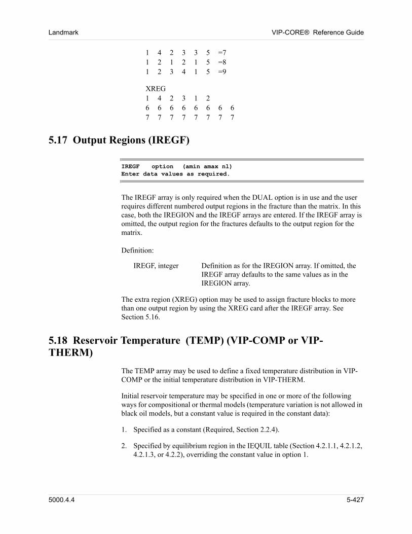
Landmark VIP-CORE® Reference Guide
1 4 2 3 3 5 =71 2 1 2 1 5 =81 2 3 4 1 5 =9 00
XREG1 4 2 3 1 26 6 6 6 6 6 6 67 7 7 7 7 7 7 7 00
5.17 Output Regions (IREGF)
IREGF option (amin amax nl)Enter data values as required.
The IREGF array is only required when the DUAL option is in use and the user requires different numbered output regions in the fracture than the matrix. In this case, both the IREGION and the IREGF arrays are entered. If the IREGF array is omitted, the output region for the fractures defaults to the output region for the matrix. 00
Definition: 00
IREGF, integer Definition as for the IREGION array. If omitted, the IREGF array defaults to the same values as in the IREGION array.
The extra region (XREG) option may be used to assign fracture blocks to more than one output region by using the XREG card after the IREGF array. See Section 5.16. 00
5.18 Reservoir Temperature (TEMP) (VIP-COMP or VIP-THERM)
The TEMP array may be used to define a fixed temperature distribution in VIP-COMP or the initial temperature distribution in VIP-THERM. 00
Initial reservoir temperature may be specified in one or more of the following ways for compositional or thermal models (temperature variation is not allowed in black oil models, but a constant value is required in the constant data): 00
1. Specified as a constant (Required, Section 2.2.4).
2. Specified by equilibrium region in the IEQUIL table (Section 4.2.1.1, 4.2.1.2, 4.2.1.3, or 4.2.2), overriding the constant value in option 1.
5000.4.4 5-427
VIP-CORE® Reference Guide Landmark
3. Specified by equilibrium region, as a function of depth or as a function of depth and areal location, overriding values in options 1 and 2:
a. For isothermal and thermal compositional models, Section 4.4.11.3 or 4.4.11.4.
b. For thermal dead oil models, Section 4.7.1 or 4.7.2.
Entering temperature as a function of depth and areal location (4.4.11.4) is discouraged, since the areal temperature variation is not accounted for in the calculation of equilibrium phase pressures versus depth. See option 4 below for further discussion of this problem.
4. Specified as a gridblock array in Section 5.25.1, overriding all other input values. This method is discouraged, since the calculation of the phase pressure versus depth curves by equilibrium region, from which initial gridblock pressures and saturations are computed, does not account for variation of temperature by gridblock (or for areal variation of temperature by equilibrium region). This results in errors in the computed initial gridblock fluid properties of pressure, saturation pressure, phase saturations, and possibly compositions. These errors may be avoided only by specifying all of these initial gridblock fluid properties (only the pressure aray in the thermal dead-oil case) as gridblock array data.
TEMP option (amin amax nl)Enter data values as required.
Definition: 00
TEMP, °F (°C) Reservoir temperature in each gridblock. If not entered and temperature was not specified in the composition versus depth table (Sections 4.4.12.3, 4.4.12.4, 4.7.1, and 4.7.2), TRES is assumed.
5-428 5000.4.4
Landmark VIP-CORE® Reference Guide
5.19 Compaction Regions (ICMT)
ICMT option (amin amax nl)Enter data values as required.
The ICMT array is required if more than one set of COMPACTION tables is input (see Section 4.12). 00
Definition: 00
ICMT, integer Integer values distinguishing areas with differing compaction properties. Each value in the ICMT array directly refers to a set of input COMPACTION tables. Default sets the entire array to 1; i.e., only one set of COMPACTION tables is input.
The ICMT array may be entered only if the COMPACT card is entered in the utility data (Section 2.2.7.11). 00
5.20 Fracture Compaction Regions (ICMTF)
ICMTF option (amin amax nl)Enter data values as required.
The ICMTF array is only required when the DUAL option is in use and the compaction properties for the fracture are different from those for the matrix. In this case, both the ICMT and the ICMTF arrays are entered. If the ICMTF array is omitted, the compaction table used for each fracture block will be the same as the table used for the corresponding matrix block. 00
Definition: 00
ICMTF, integer Definition as for the ICMT array. If omitted, the ICMTF array defaults to the values in the ICMT array.
5.21 Water Induced Rock Compaction Regions (IWIRC)
IWIRC option (amin amax nl)Enter data values as required.
The IWIRC array is required if more than one set of WATER INDUCED ROCK COMPACTION tables are input (Section 4.13). 00
Definition: 00
5000.4.4 5-429
VIP-CORE® Reference Guide Landmark
IWIRC, integer Positive integer values distinguishing different water induced rock compaction regions. Each value in the IWIRC array directly refers to a set of input water induced rock compaction tables (Section 4.13). Default sets the entire array to 1.
5.22 Fracture Water Induced Rock Compaction Regions(IWIRCF)
IWIRCF option (amin amax nl) Enter data values as required.
The IWIRCF array is only required when the DUAL option is in use and the water induced rock compaction properties for the fracture are different from those for the matrix. In this case, both the IWIRC and IWIRCF arrays are entered. 00
Definition: 00
IWIRCF, integer Positive integer values distinguishing different fracture water induced rock compaction regions. Each value in the IWIRCF array directly refers to a set of input water induced rock compaction tables (Section 4.13). Default sets the array to IWIRC.
5.23 Rock Compressibility (CR)
CR option (amin amax nl)Enter data values as required.
Definition: 00
CR, psi-1(kPa-1) Rock compressibility of each gridblock.
Rock compressibility can be given a value for each gridblock. Typically rock compressibility can be expressed as a function of porosity. Values specified by the CR card will replace the value specified by the DWB card. 00
5.24 Fracture Compressibility (CRF)
CRF option (amin amax nl)Enter data values as required.
5-430 5000.4.4
Landmark VIP-CORE® Reference Guide
The CRF array is only required when the DUAL option is in use and the fracture compressibilities are different from the matrix compressibilities. In this case, both the CR and the CRF arrays are entered. If the CRF array is omitted, the fracture compressibilities will be set equal to the corresponding matrix compressibilities. 00
Definition: 00
CRF, psi-1 (kPa-1) Fracture compressibility of each gridblock.
Fracture compressibility can be given a value for each gridblock. Typically rock compressibility can be expressed as a function of porosity. Values specified by the CRF card will replace those specified by the DWB card. 00
5.25 Transmissibility Regions (ITRAN)
ITRAN option (amin amax nl)Enter data values as required.
Definition: 00
ITRAN, integer Positive integer values distinguishing different transmissibility regions. These values are used to modify the inter/intra region transmissibility using the MULTIR option (Section 1.7). Default sets the entire array to 1.
5.26 Fracture Transmissibility Regions (ITRANF)
ITRANF option (amin amax nl)Enter data values as required.
Definition: 00
ITRANF, integer Positive integer values distinguishing different fracture transmissibility regions. These values are used to modify the inter/intra region transmissibility using the MULTIR option (Section 1.7). Default sets the array to ITRAN.
5.27 Turbidite Reservoir Option (Not available in VIP-THERM)
The turbidite reservoir option models the sand-shale fluid (water) exchange within any simulation gridblock that consists of multiple sand and shale sublayers using an analytic, linear aquifer model. In this model, all shale sublayers within each gridblock are assumed to have the same thickness, and all sand sublayers also
5000.4.4 5-431
VIP-CORE® Reference Guide Landmark
have the same thickness. The model represents each half-shale-sublayer by a linear aquifer. The sand-shale fluid exchange calculation follows the approach of Carter and Tracy aquifer model. Notice that for the linear aquifer model, the PD (tD) function is a universal function that is independent of the aquifer size. This function is internally generated in VIP-CORE. 00
For a turbidite gridblock, the shale sublayers should be considered non-pay. Consequently, the net-to-gross ratio or the net thickness of the gridblock must be specified, and the porosity, compressibility, and areal permeabilities of the sand sublayers must be used. Also, an effective vertical permeability must be specified to account for the existence of shale sublayers. This effective vertical permeability is in general negligibly small and should have little or no effect on the simulation results. 00
The turbidite reservoir option is compatible with both the IMPES and IMPLICIT formulations in the simulation modules. It can be used in both regular Cartesian and radial grid systems. The use of this option in a corner point grid system is not recommended because of its irregular geometry. The option should not be used in conjunction with the dual porosity option and is not yet compatible with the water tracking option. 00
The turbidite reservoir option is automatically invoked by the SCLFCT array input. This array specifies whether a given gridblock is to be treated as a turbidite gridblock and the number of shale sublayers within each turbidite gridblock. Two additional (TCTBD and BTBD) arrays must also be entered to complete the description of the turbidite reservoir system. The TCTBD array specifies the time constant for each gridblock, and the BTBD array specifies the capacity of each linear aquifer (i.e., each half-shale-sublayer within a gridblock). 00
5.27.1 Scaling Factor (SCLFCT)
SCLFCT option (amin amax nl)Enter data values as required
Definition: 00
SCLFCT Number of linear aquifers in each gridblock. For a gridblock with n sand and n shale sublayers, SCLFCT should have a value of 2n. A value of 0 means that the gridblock will be treated as a regular gridblock with no sand-shale fluid exchange.
Any gridblock within the reservoir may be specified either as a regular gridblock or a turbidite gridblock. Non-zero TCTBD and BTBD values must be specified for all gridblocks with non-zero SCLFCT values. 00
Examples: 00
SCLFCT CON
5-432 5000.4.4
Landmark VIP-CORE® Reference Guide
0.MOD6 10 1 3 1 1 = 61 5 1 2 2 2 = 10. 00
6 10 1 3 3 3 = 20. 00
5.27.2 Time Constant (TCTBD)
TCTBD option (amin amax nl)Enter data values as required.
Definitions: 00
TCTBD, day-1 Time constant used to convert time to dimensionless time for turbidite gridblocks.
TCTBD = (4b * kz,shale) / (Ct,shale * shale * w * H2)
where
b 0.006328 for conventional units; 8.527 x 10⁻⁵ for metric units.
kz,shale Vertical permeabilities in shale sublayers, md (md).
Ct,shale Shale total compressibility, 1/psia (1/kPa).
shale Shale porosity, fraction.
w Viscosity of water contained in shale, cp (cp).
H Thickness of each shale sublayer, ft (m).
The TCTBD array must be specified if the SCLFCT array is entered. Non-zero TCTBD values must be entered for all gridblocks with non-zero SCLFCT values. Gridblocks with zero SCLFCT values will be treated as non-turbidite gridblocks without sand-shale fluid exchange, regardless of their TCTBD values. 00
Examples: 00
TCTBD ZVAR6.7645E-3 1.6911E-3 6.7645E-3 0. 00
5000.4.4 5-433
VIP-CORE® Reference Guide Landmark
5.27.3 Shale Capacity (BTBD)
BTBD option (amin amax nl)Enter data values as required.
Definitions: 00
BTBD Shale capacity, rb/psia (m3/kPa).BTBD = (Ct,shale * shale * A * H) / (2 * a1).
where
Ct,shale Shale total compressibility, 1/psia (1/kPa).
shale Shale porosity, fraction.
A Gridblock horizontal area, ft2 (m2).
H Thickness of each shale sublayer, ft (m).
a1 5.6146 for conventional units; 1.0 for metric units.
The BTBD array must be specified if the SCLFCT array is entered. Non-zero BTBD values must be entered for all gridblocks with non-zero SCLFCT values. Gridblocks with zero SCLFCT values will be treated as non-turbidite gridblocks without sand-shale fluid exchange, regardless of their BTBD values. 00
Examples: 00
BTBD ZVAR3.3840E-3 6.7680E-3 3.3840E-3 0. 00
5.28 Equilibrium Regions (IEQUIL)
IEQUIL option (amin amax nl)Enter data values as required.
The IEQUIL array is required if more than one set of fluid contacts is input (see Section 4.2). 00
Definition: 00
IEQUIL, integer Integer values defining distinct regions for equilibrium purposes. Each region may have different water-oil and gas-oil contacts. Each value in the IEQUIL array
5-434 5000.4.4
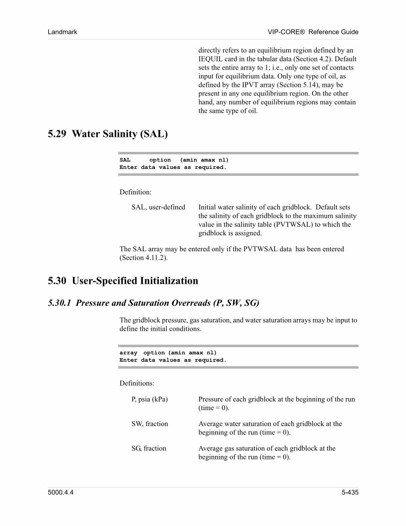
Landmark VIP-CORE® Reference Guide
directly refers to an equilibrium region defined by an IEQUIL card in the tabular data (Section 4.2). Default sets the entire array to 1; i.e., only one set of contacts input for equilibrium data. Only one type of oil, as defined by the IPVT array (Section 5.14), may be present in any one equilibrium region. On the other hand, any number of equilibrium regions may contain the same type of oil.
5.29 Water Salinity (SAL)
SAL option (amin amax nl)Enter data values as required.
Definition: 00
SAL, user-defined Initial water salinity of each gridblock. Default sets the salinity of each gridblock to the maximum salinity value in the salinity table (PVTWSAL) to which the gridblock is assigned.
The SAL array may be entered only if the PVTWSAL data has been entered (Section 4.11.2). 00
5.30 User-Specified Initialization
5.30.1 Pressure and Saturation Overreads (P, SW, SG)
The gridblock pressure, gas saturation, and water saturation arrays may be input to define the initial conditions. 00
array option (amin amax nl)Enter data values as required.
Definitions: 00
P, psia (kPa) Pressure of each gridblock at the beginning of the run (time = 0).
SW, fraction Average water saturation of each gridblock at the beginning of the run (time = 0).
SG, fraction Average gas saturation of each gridblock at the beginning of the run (time = 0).
5000.4.4 5-435
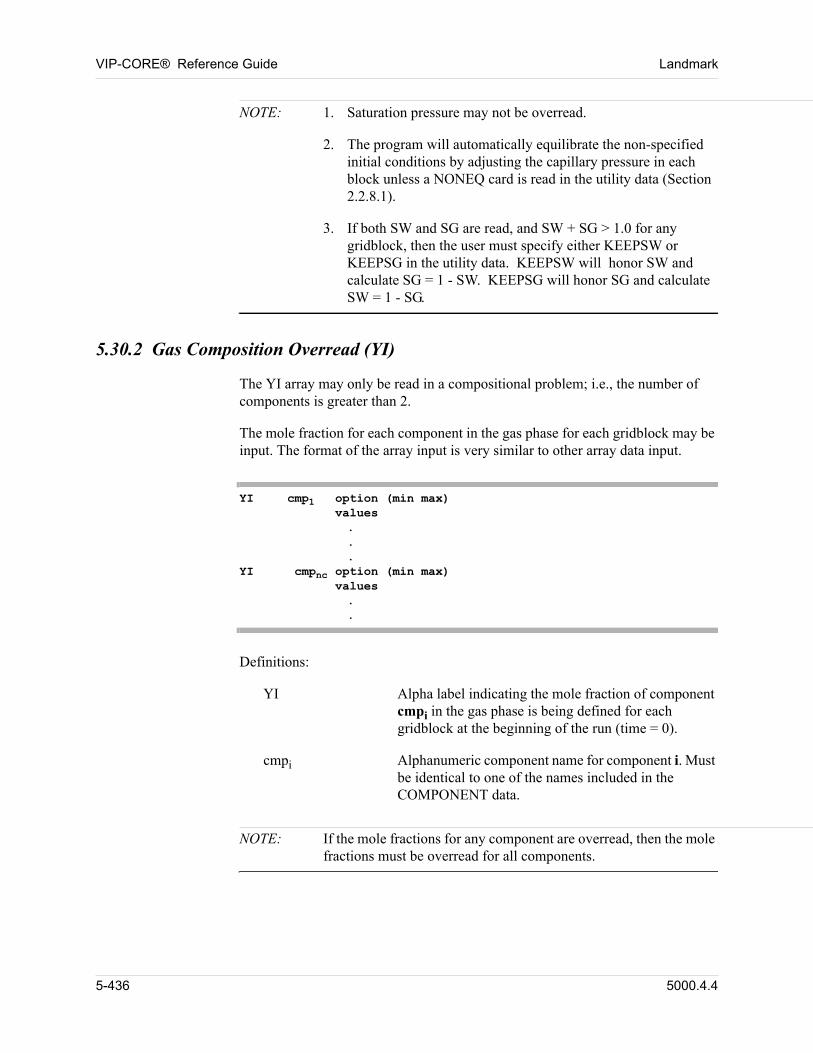
VIP-CORE® Reference Guide Landmark
NOTE: 1. Saturation pressure may not be overread.
2. The program will automatically equilibrate the non-specified initial conditions by adjusting the capillary pressure in each block unless a NONEQ card is read in the utility data (Section 2.2.8.1).
3. If both SW and SG are read, and SW + SG > 1.0 for any gridblock, then the user must specify either KEEPSW or KEEPSG in the utility data. KEEPSW will honor SW and calculate SG = 1 - SW. KEEPSG will honor SG and calculate SW = 1 - SG.
5.30.2 Gas Composition Overread (YI)
The YI array may only be read in a compositional problem; i.e., the number of components is greater than 2. 00
The mole fraction for each component in the gas phase for each gridblock may be input. The format of the array input is very similar to other array data input. 00
YI cmp1 option (min max)values...
YI cmpnc option (min max)values..
Definitions: 00
YI Alpha label indicating the mole fraction of component cmpi in the gas phase is being defined for each gridblock at the beginning of the run (time = 0).
cmpi Alphanumeric component name for component i. Must be identical to one of the names included in the COMPONENT data.
NOTE: If the mole fractions for any component are overread, then the mole fractions must be overread for all components.
5-436 5000.4.4
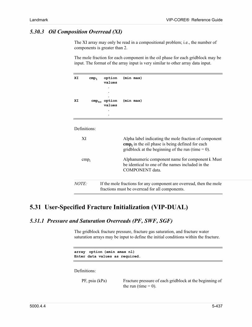
Landmark VIP-CORE® Reference Guide
5.30.3 Oil Composition Overread (XI)
The XI array may only be read in a compositional problem; i.e., the number of components is greater than 2. 00
The mole fraction for each component in the oil phase for each gridblock may be input. The format of the array input is very similar to other array data input. 00
XI cmp1 option (min max)values...
XI cmpnc option (min max)values..
Definitions: 00
XI Alpha label indicating the mole fraction of component cmpi in the oil phase is being defined for each gridblock at the beginning of the run (time = 0).
cmpi Alphanumeric component name for component i. Must be identical to one of the names included in the COMPONENT data.
NOTE: If the mole fractions for any component are overread, then the mole fractions must be overread for all components.
5.31 User-Specified Fracture Initialization (VIP-DUAL)
5.31.1 Pressure and Saturation Overreads (PF, SWF, SGF)
The gridblock fracture pressure, fracture gas saturation, and fracture water saturation arrays may be input to define the initial conditions within the fracture. 00
array option (amin amax nl)Enter data values as required.
Definitions: 00
PF, psia (kPa) Fracture pressure of each gridblock at the beginning of the run (time = 0).
5000.4.4 5-437
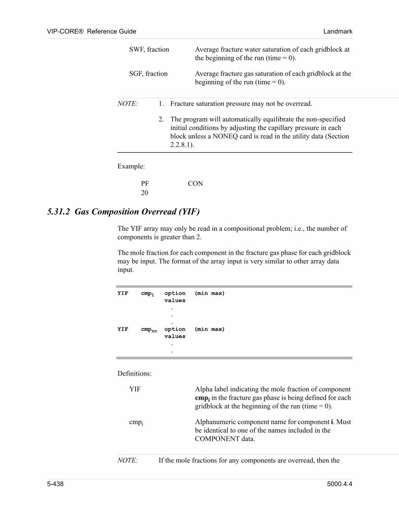
VIP-CORE® Reference Guide Landmark
SWF, fraction Average fracture water saturation of each gridblock at the beginning of the run (time = 0).
SGF, fraction Average fracture gas saturation of each gridblock at the beginning of the run (time = 0).
NOTE: 1. Fracture saturation pressure may not be overread.
2. The program will automatically equilibrate the non-specified initial conditions by adjusting the capillary pressure in each block unless a NONEQ card is read in the utility data (Section 2.2.8.1).
Example: 00
PF CON20 00
5.31.2 Gas Composition Overread (YIF)
The YIF array may only be read in a compositional problem; i.e., the number of components is greater than 2. 00
The mole fraction for each component in the fracture gas phase for each gridblock may be input. The format of the array input is very similar to other array data input. 00
YIF cmp1 option (min max)values...
YIF cmpnc option (min max)values..
Definitions: 00
YIF Alpha label indicating the mole fraction of component cmpi in the fracture gas phase is being defined for each gridblock at the beginning of the run (time = 0).
cmpi Alphanumeric component name for component i. Must be identical to one of the names included in the COMPONENT data.
NOTE: If the mole fractions for any components are overread, then the
5-438 5000.4.4
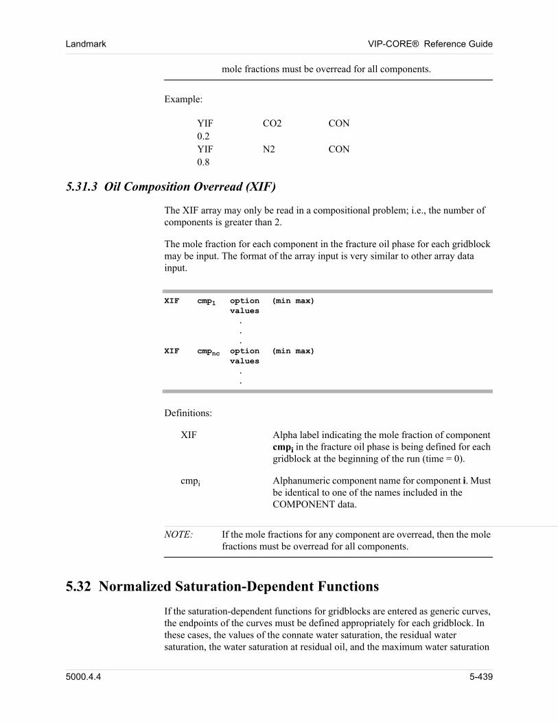
Landmark VIP-CORE® Reference Guide
mole fractions must be overread for all components.
Example: 00
YIF CO2 CON0.2YIF N2 CON0.8 00
5.31.3 Oil Composition Overread (XIF)
The XIF array may only be read in a compositional problem; i.e., the number of components is greater than 2. 00
The mole fraction for each component in the fracture oil phase for each gridblock may be input. The format of the array input is very similar to other array data input. 00
XIF cmp1 option (min max)values...
XIF cmpnc option (min max)values..
Definitions: 00
XIF Alpha label indicating the mole fraction of component cmpi in the fracture oil phase is being defined for each gridblock at the beginning of the run (time = 0).
cmpi Alphanumeric component name for component i. Must be identical to one of the names included in the COMPONENT data.
NOTE: If the mole fractions for any component are overread, then the mole fractions must be overread for all components.
5.32 Normalized Saturation-Dependent Functions
If the saturation-dependent functions for gridblocks are entered as generic curves, the endpoints of the curves must be defined appropriately for each gridblock. In these cases, the values of the connate water saturation, the residual water saturation, the water saturation at residual oil, and the maximum water saturation
5000.4.4 5-439
VIP-CORE® Reference Guide Landmark
and/or the connate gas saturation, the residual gas saturation, the gas saturation at residual oil, and the maximum gas saturation are assigned to each gridblock. These values are entered on a block-by-block basis in the SWL, SWR, SWRO, SWU, SGL, SGR, SGRO, and SGU arrays. Also, the values of oil relative permeability at connate water saturation and water (or gas) relative permeability at residual oil saturation are assigned to each gridblock. These values are entered on a block-by-block basis in the KROLW and KRWRO (or KRGRO) arrays. In a GASWATER problem the values of gas relative permeability at residual water saturation are entered in the KRGRW array. 00
All of the above arrays may be entered with the directional relative permeability option. See Section 1.5.2.9 for details. 00
All of the above arrays are duplicated for DUAL cases, with an "F" appended to the array name (e.g., SWL becomes SWLF). 00
The user can select the two-point scaling of relative permeability table endpoints, or the default three-point scaling (four-point for capillary pressures), by use of the END2P option. The two-point scaling approach was the only method available in VIP-EXECUTIVE Version 1.6R, and earlier versions. In the two-point case, each curve is scaled over its entire length (from residual/irreducible saturation to the saturation at which it attains a maximum). In the three-point case, all curves in a table are scaled together (retaining the relative kr and Pc characteristics of the curves). In this case, which is the default scaling method, all endpoints serve to break the table up into partitions, with scaling being done in each partition independently. As an example, water-oil table relative permeabilities would be scaled in two sections; from water saturations of Swr to Swro and from Swro to 1. 00
If any saturation endpoint is not specified, rock data will be used. The following consistency checks are performed for each gridblock: 00
SGL should not exceed 1-SWU.
SGU should not exceed 1-SWL.
SWL should not exceed SWR.
SGL should not exceed SGR.
SWRO should not exceed SWU.
SGRO should not exceed SGU.
5.32.1 Water-Oil Normalized Saturations
5.32.1.1 Connate (Minimum) Water Saturation (SWL)
SWL option (amin amax nl)Entered data values as required.
5-440 5000.4.4
Landmark VIP-CORE® Reference Guide
5.32.1.2 Residual Water Saturation (SWR)
SWR option (amin amax nl)Enter data values as required.
NOTE: If the SWR array is entered, the SWRO array must also be entered.
5.32.1.3 Water Saturation at Residual Oil (SWRO)
SWRO option (amin amax nl)Enter data values as required.
NOTE: If the SWRO array is entered, the SWR array must also be entered.
5.32.1.4 Maximum Water Saturation (SWU)
SWU option (amin amax nl)Enter data values as required.
5.32.1.5 Maximum Trapped Gas Saturation (SGTR)
SGTR option (amin amax nl)Enter data values as required.
5.32.1.6 Fracture Connate (Minimum) Water Saturation (SWLF)
SWLF option (amin amax nl)Enter data values as required.
NOTE: 1. The SWLF array is required only when the DUAL option is in use and the user requires different values than would be derived from the appropriate fracture saturation tables (based on the ISATF array).
2. If one of the SWL or SWLF arrays is needed, both must be entered.
5000.4.4 5-441
VIP-CORE® Reference Guide Landmark
5.32.1.7 Fracture Residual Water Saturation (SWRF)
SWRF option (amin amax nl)Enter data values as required.
NOTE: 1. The SWRF array is required only when the DUAL option is in use and the user requires different values than would be derived from the appropriate fracture saturation tables (based on the ISATF array).
2. If one of the SWR or SWRF arrays is needed, both must be entered.
3. If the SWRF array is entered, the SWROF array must also be entered.
5.32.1.8 Fracture Water Saturation at Residual Oil (SWROF)
SWROF option (amin amax nl)Enter data values as required.
NOTE: 1. The SWROF array is required only when the DUAL option is in use and the user requires different values than would be derived from the appropriate fracture saturation tables (based on the ISATF array).
2. If one of the SWRO or SWROF arrays is needed, both must be entered.
3. If the SWROF array is entered, the SWRF array must also be entered.
5.32.1.9 Fracture Maximum Water Saturation (SWUF)
SWUF option (amin amax nl)Enter data values as required.
NOTE: 1. The SWUF array is required only when the DUAL option is in use and the user requires different values than would be derived from the appropriate fracture saturation tables (based on the ISATF array).
5-442 5000.4.4
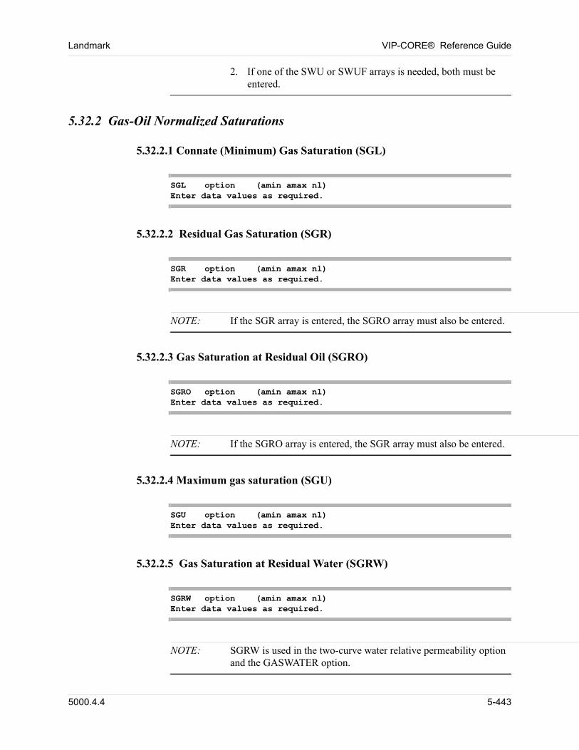
Landmark VIP-CORE® Reference Guide
2. If one of the SWU or SWUF arrays is needed, both must be entered.
5.32.2 Gas-Oil Normalized Saturations
5.32.2.1 Connate (Minimum) Gas Saturation (SGL)
SGL option (amin amax nl)Enter data values as required.
5.32.2.2 Residual Gas Saturation (SGR)
SGR option (amin amax nl)Enter data values as required.
NOTE: If the SGR array is entered, the SGRO array must also be entered.
5.32.2.3 Gas Saturation at Residual Oil (SGRO)
SGRO option (amin amax nl)Enter data values as required.
NOTE: If the SGRO array is entered, the SGR array must also be entered.
5.32.2.4 Maximum gas saturation (SGU)
SGU option (amin amax nl)Enter data values as required.
5.32.2.5 Gas Saturation at Residual Water (SGRW)
SGRW option (amin amax nl)Enter data values as required.
NOTE: SGRW is used in the two-curve water relative permeability option and the GASWATER option.
5000.4.4 5-443
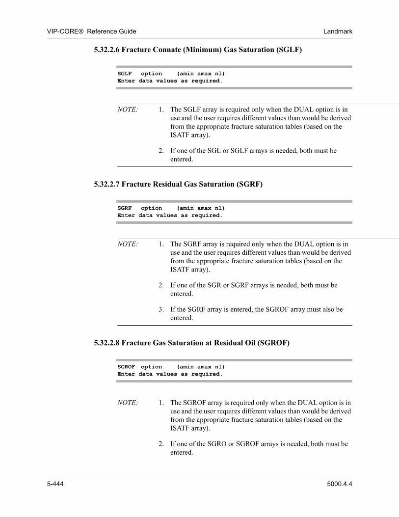
VIP-CORE® Reference Guide Landmark
5.32.2.6 Fracture Connate (Minimum) Gas Saturation (SGLF)
SGLF option (amin amax nl)Enter data values as required.
NOTE: 1. The SGLF array is required only when the DUAL option is in use and the user requires different values than would be derived from the appropriate fracture saturation tables (based on the ISATF array).
2. If one of the SGL or SGLF arrays is needed, both must be entered.
5.32.2.7 Fracture Residual Gas Saturation (SGRF)
SGRF option (amin amax nl)Enter data values as required.
NOTE: 1. The SGRF array is required only when the DUAL option is in use and the user requires different values than would be derived from the appropriate fracture saturation tables (based on the ISATF array).
2. If one of the SGR or SGRF arrays is needed, both must be entered.
3. If the SGRF array is entered, the SGROF array must also be entered.
5.32.2.8 Fracture Gas Saturation at Residual Oil (SGROF)
SGROF option (amin amax nl)Enter data values as required.
NOTE: 1. The SGROF array is required only when the DUAL option is in use and the user requires different values than would be derived from the appropriate fracture saturation tables (based on the ISATF array).
2. If one of the SGRO or SGROF arrays is needed, both must be entered.
5-444 5000.4.4
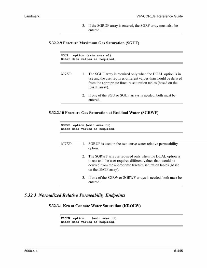
Landmark VIP-CORE® Reference Guide
3. If the SGROF array is entered, the SGRF array must also be entered.
5.32.2.9 Fracture Maximum Gas Saturation (SGUF)
SGUF option (amin amax nl)Enter data values as required.
NOTE: 1. The SGUF array is required only when the DUAL option is in use and the user requires different values than would be derived from the appropriate fracture saturation tables (based on the ISATF array).
2. If one of the SGU or SGUF arrays is needed, both must be entered.
5.32.2.10 Fracture Gas Saturation at Residual Water (SGRWF)
SGRWF option (amin amax nl)Enter data values as required.
NOTE: 1. SGRUF is used in the two-curve water relative permeability option.
2. The SGRWF array is required only when the DUAL option is in use and the user requires different values than would be derived from the appropriate fracture saturation tables (based on the ISATF array).
3. If one of the SGRW or SGRWF arrays is needed, both must be entered.
5.32.3 Normalized Relative Permeability Endpoints
5.32.3.1 Kro at Connate Water Saturation (KROLW)
KROLW option (amin amax nl)Enter data values as required.
5000.4.4 5-445
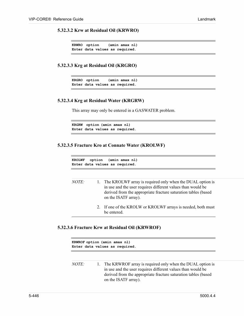
VIP-CORE® Reference Guide Landmark
5.32.3.2 Krw at Residual Oil (KRWRO)
KRWRO option (amin amax nl)Enter data values as required.
5.32.3.3 Krg at Residual Oil (KRGRO)
KRGRO option (amin amax nl)Enter data values as required.
5.32.3.4 Krg at Residual Water (KRGRW)
This array may only be entered in a GASWATER problem. 00
KRGRW option (amin amax nl)Enter data values as required.
5.32.3.5 Fracture Kro at Connate Water (KROLWF)
KROLWF option (amin amax nl)Enter data values as required.
NOTE: 1. The KROLWF array is required only when the DUAL option is in use and the user requires different values than would be derived from the appropriate fracture saturation tables (based on the ISATF array).
2. If one of the KROLW or KROLWF arrays is needed, both must be entered.
5.32.3.6 Fracture Krw at Residual Oil (KRWROF)
KRWROF option (amin amax nl)Enter data values as required.
NOTE: 1. The KRWROF array is required only when the DUAL option is in use and the user requires different values than would be derived from the appropriate fracture saturation tables (based on the ISATF array).
5-446 5000.4.4
Landmark VIP-CORE® Reference Guide
2. If one of the KRWRO or KRWROF arrays is needed, both must be entered.
5.32.3.7 Fracture Krg at Residual Oil (KRGROF)
KRGROF option (amin amax nl)Enter data values as required.
NOTE: 1. The KRGROF array is required only when the DUAL option is in use and the user requires different values than would be derived from the appropriate fracture saturation tables (based on the ISATF array).
2. If one of the KRGRO or KRGROF arrays is needed, both must be entered.
5.33 Vertical Equilibrium Fraction
5.33.1 Water-Oil VE (FVEWO)
The FVEWO array allows the degree of water-oil VE to vary in each block. The values can vary from zero to one for each block, one signifying 100% VE and zero signifying 100% rock values. That is, 00
krwtotal = (1 - FVEWO) krwrock + FVEWO krwVE . 00
FVEWO option (amin amax nl)Enter data values as required.
Definition: 00
FVEWO, fraction Degree of water-oil VE in each gridblock. One signifies 100% VE and zero signifies 100% rock values.
NOTE: The FVEWO array may be entered only if the VEWO card is entered in the utility data (Section 2.2.10.1).
5000.4.4 5-447
VIP-CORE® Reference Guide Landmark
5.33.2 Gas-Oil VE (FVEGO)
The FVEGO array allows the degree of gas-oil VE to vary in each block. It is defined and used in the same sense as FVEWO. 00
FVEGO option (amin amax nl)Enter data values as required.
Definition: 00
FVEGO, fraction Degree of gas-oil VE in each gridblock. One signifies 100% VE and zero signifies 100% rock values.
NOTE: The FVEGO array may be entered only if the VEGO card is entered in the utility data (Section 2.2.10.2).
5.34 Vertical Equilibrium Fraction (VIP-DUAL)
When the DUAL option is in use, if the FVEWO array has been specified for the matrix blocks, then the FVEWOF array must be specified for the fracture blocks. Similarly, if the FVEGO array has been specified, then so must the FVEGOF array be specified. 00
5.34.1 Water-oil VE (FVEWOF)
The FVEWOF array allows the degree of water-oil VE to vary in each fracture block. The values can vary from zero to one for each fracture block, one signifying 100% VE and zero signifying 100% rock values. 00
FVEWOF option (amin amax nl)Enter data values as required.
Definition: 00
FVEWOF, fraction Degree of water-oil VE in each fracture block. One signifies 100% VE and zero signifies 100% rock values.
5.34.2 Gas-Oil VE (FVEGOF)
The FVEGOF array allows the degree of gas-oil VE to vary in each fracture block. It is defined and used in the same sense as FVEWOF. 00
FVEGOF option (amin amax nl)
5-448 5000.4.4
Landmark VIP-CORE® Reference Guide
Enter data values as required.
Definition: 00
FVEGOF, fraction Degree of gas-oil VE in each fracture block. One signifies 100% VE and zero signifies 100% rock values.
5.35 Matrix Fracture Exchange Transmissibility (VIP-DUAL)
The matrix fracture exchange transmissibility defines the exchange of fluids between the matrix rock and fractures in each gridblock. The user may enter data relating to the exchange term in one of the following ways: 00
5.35.1 Matrix Block Size (LX, LY, LZ)
The exchange term is calculated from the matrix block size as discussed in Reference 7. 00
array option (amin amax nl)Enter data values as required.
Definitions: 00
LX, ft (m) Matrix block size in the x direction.
LY, ft (m) Matrix block size in the y direction.
LZ, ft (m) Matrix block size in the z direction.
Example: 00
LX CON100
5.35.2 Exchange Shape Factor (SIGMA)
SIGMA option (amin amax nl)Enter data values as required.
Definition: 00
SIGMA, ft-2 (m-2) Exchange shape factor for gridblock (i,j,k).
5000.4.4 5-449
VIP-CORE® Reference Guide Landmark
5.35.3 Exchange Transmissibility (TEX)
TEX option (amin amax nl)Enter data values as required.
Definition:
TEX, rb-cp/day/psi(m3-cp/day/kPa)
Matrix fracture exchange transmissibility.
00
NOTE: 1. The permeability arrays KX (or KXF), KY (or KYF), KZ (or KZF) must be entered to use either the matrix block size option or the exchange shape factor option. Thus, if the pore volume and transmissibility arrays have been input, only the exchange transmissibility array TEX can be specified.
2. The exchange transmissibility is defined as (for field units):
TEX = .001127 kma x y z,
where kma KX
LX2
---------- KY
LY2
---------- KZ
LZ2
----------+ +
1 PORF– =
00
or is specified directly. The term kma is a harmonic average of matrix and fracture permeabilities.
Example: 00
TEX CON0.1
5-450 5000.4.4
Landmark VIP-CORE® Reference Guide
5.36 Matrix-Fracture Diffusion (VIP-DUAL)
5.36.1 Diffusion Exchange Shape Factor (SIGMAD)
SIGMAD option (amin amax nl)Enter data values as required.
Definition: 00
SIGMAD, ft-2 (m-2) Diffusion exchange shape factor sigma D for gridblock (i,j,k). If SIGMAD is not specified and the diffusion option is active (Section 2.2.13.3), SIGMAD defaults to SIGMA (Section 5.35.2).
Example: 00
SIGMAD CON0.8 00
5.36.2 Gas Diffusion Mass Transfer Coefficient (TDIFFG)
TDIFFG option (amin amax nl)Enter data values as required.
Definition:
TDIFFG,rb/D (rm3/D)
Gas diffusion mass transfer coefficient for gridblock (i,j,k).
00
5.36.3 Oil Diffusion Mass Transfer Coefficient (TDIFFO)
TDIFFO option (amin amax nl)Enter data values as required.
Definition:
TDIFFO,rb/D (rm3/D)
Oil diffusion mass transfer coefficient for gridblock (i,j,k).
00
5000.4.4 5-451
VIP-CORE® Reference Guide Landmark
5.37 Fluid Tracking (Not available in VIP-THERM)
5.37.1 Oil Tracked Fluid Number (OILTRF)
OILTRF option (amin amax nl)Enter data values as required.
Definition: 00
OILTRF Initial tracked fluid number assignment of the oil in every gridblock.
For a transition block that contains a gas-oil contact, if a CONTACT card is entered, the data on the CONTACT card supercedes the OILTRF value. 00
5.37.2 Gas Tracked Fluid Number (GASTRF)
GASTRF option (amin amax nl)Enter data values as required.
Definition: 00
GASTRF Initial tracked fluid number assignment of the gas in every gridblock.
For a transition block that contains a gas-oil contact, if a CONTACT card is entered, the data on the CONTACT card supercedes the GASTRF value. 00
5.37.3 Fractional Flow Exponent for Extraneous Water Tracking (TKWEXP)
The TKWEXP array may optionally be input in either the VIP-CORE data or with OVER/VOVER cards in the simulation modules, if the water tracking option has been invoked. 00
TKWEXP option (amin amax nl)Enter data values as required.
Definition: 00
TKWEXP Exponent used in calculating the fractional flow terms for the extraneous tracked water types. The exponent determines preferential flow between the insitu water and all other water types. The default is 1.0, which yields fractional flow as a function of normalized tracked water type saturation. A value greater than 1
5-452 5000.4.4
Landmark VIP-CORE® Reference Guide
increases the preferential flow of insitu water, while a value less than 1 reduces it.
5.38 Three and Four Component Miscible
5.38.1 Mixing Parameter for Effective Viscosity (OMGV)
OMGV option (amin amax nl)Enter data values as required.
Definition: 00
OMGV Mixing parameter for effective viscosity calculation.
The OMGV array allows the user to input variable values for viscosity mixing parameter in miscible option (invoked by the MIS card). This array overrides the omegav value specified in the MIS card of the Initialization Data section. The omegav value will be used if this card is omitted. 00
Example: 00
OMGV ZVAR0.5 0.6 0.7 00
5.38.2 Mixing Parameter for Effective Density (OMGD)
OMGD option (amin amax nl)Enter data values as required.
Definition: 00
OMGD Mixing parameter for effective density calculation.
The OMGD array allows the user to input variable values for density mixing parameter in miscible option (invoked by the MIS card). This array overrides the omegad value specified in the MIS card of the Initialization Data section. The omegad value will be used if this card is omitted. 00
5000.4.4 5-453
VIP-CORE® Reference Guide Landmark
Example: 00
OMGD ZVAR0.5 0.6 0.7 00
5.39 Time-Dependent Compressibility - Creep Option (Not available in VIP-THERM)
The time-dependent compressibility (creep) option includes a time-delayed compaction due to creep in addition to the standard instantaneous compaction represented by the rock compressibility. In this option, the time-dependent portion of the rate of pore volume change is assumed to be proportional to the difference between the current strain state and a prescribed equilibrium state. 00
To invoke the creep option, the following three arrays must be specified. 00
5.39.1 Reservoir Rock Rate Constant (CREEPB)
CREEPB option (amin amax nl)Enter data values as required.
Definition: 00
CREEPB, day-1 Parameter B in the creep option. This is the reservoir rock rate constant and is inversely proportional to the characteristic time constant of the material (time needed for the rock to creep and reach its relaxed condition).
Example: 00
CREEPB ZVAR6.169 1.227 3.000
5.39.2 Equilibrium State Total Rock Compressibility (CREEPC)
CREEPC option (amin amax nl)Enter data values as required.
Definition:
CREEPC, psi-1 (kPa-1)
Parameter C in the creep option. This is the total rock compressibility at the equilibrium state.
00
Example: 00
5-454 5000.4.4
Landmark VIP-CORE® Reference Guide
CREEPC CON1.E-5
5.39.3 Creep Exponent (CREEPM)
CREEPM option (amin amax nl)Enter data values as required.
Definition: 00
CREEPM Parameter m in the creep option. This is the creep exponent; i.e., the long-term reservoir compressibility.
Example: 00
CREEPM ZVAR17.1 15.65 16.3
5.40 Connection Transmissibility Modification
If flow transmissibilities, and thermal transmissibilities in VIP-THERM, are not directly entered then they are calculated by VIP based on the values of permeability, thermal conductivity, and gridblock dimension. These transmissibility values are modified by the values of the transmissibility multiplier arrays. The values of the transmissibility multiplier arrays may be entered directly and/or modified by the MULT option. The MULT option allows the user to modify transmissibilities in the plus and minus directions, and to enter transmissibility multipliers for non-standard connections separate from standard connections. MULT cards can only be entered after all ARRAY data has been entered. 00
Transmissibilities and pore volumes can also be modified using OVER and VOVER cards. Separate options are available in PRINT ARRAYS output or in the initialization MAP file to report transmissibility multiplier values before and after the effects of OVER/VOVER cards. 00
Transmissibilities are also modified when fault data is entered. If transmissibility multiplier values are entered on fault cards then they will supercede any values that were previously entered. These new values will be reflected in PRINT ARRAYS output and in the initialization MAP file. 00
If transmissibility arrays are not entered then a default value of one is used. 00
5.40.1 X Direction Transmissibility Multiplier (TMX)
TMX option (amin amax nl)
5000.4.4 5-455
VIP-CORE® Reference Guide Landmark
Enter data values as required.
Definition: 00
TMX The x direction transmissibility multiplier for gridblock (i,j,k) is defined at the boundary between blocks (i-1,j,k) and (i,j,k) and controls flow between them. For i = 1, TMX is zero.
NOTE: Omit if NX = 1.
The TMX values modify transmissibilities calculated for standard and nonstandard connections. New values of this array which are specified in the MULT option or on fault cards will be reflected in output generated by PRINT ARRAYS and in the MAP file. The values of this array will not be modified if transmissibilities are further modified by OVER or VOVER cards. 00
5.40.2 Y Direction Transmissibility Multiplier (TMY)
TMY option (amin amax nl)Enter data values as required.
Definition: 00
TMY The y direction transmissibility multiplier for gridblock (i,j,k) is defined at the boundary between blocks (i,j-1,k) and (i,j,k) and controls flow between them. For j = 1, TMY is zero.
NOTE: Omit if NY = 1.
The TMY values modify transmissibilities calculated for standard and nonstandard connections. New values of this array which are specified in the MULT option or on fault cards will be reflected in output generated by PRINT ARRAYS and in the MAP file. The values of this array will not be modified if transmissibilities are further modified by OVER or VOVER cards. 00
5.40.3 Z Direction Transmissibility Multiplier (TMZ)
TMZ option (amin amax nl)Enter data values as required.
Definition: 00
5-456 5000.4.4
Landmark VIP-CORE® Reference Guide
TMZ The z direction transmissibility multiplier for gridblock (i,j,k) is defined at the boundary between blocks (i,j,k-1) and (i,j,k) and controls flow between them. For k = 1, TMZ is zero.
NOTE: Omit if NZ = 1.
The TMZ values modify transmissibilities calculated for standard and nonstandard connections. New values of this array which are specified in the MULT option or on fault cards will be reflected in output generated by PRINT ARRAYS and in the MAP file. The values of this array will not be modified if transmissibilities are further modified by OVER or VOVER cards. 00
5.40.4 R Direction Transmissibility Multiplier (TMR)
TMR option (amin amax nl)Enter data values as required.
Definition: 00
TMR The r direction transmissibility multiplier for gridblock (i,j,k) is defined at the boundary between blocks (i-1,j,k) and (i,j,k) and controls flow between them. For i = 1, TMR is zero.
NOTE: Omit if NR = 1.
The TMR values modify transmissibilities calculated for standard and nonstandard connections. New values of this array which are specified in the MULT option or on fault cards will be reflected in output generated by PRINT ARRAYS and in the MAP file. The values of this array will not be modified if transmissibilities are further modified by OVER or VOVER cards. 00
5.40.5 Theta Direction Transmissibility Multiplier (TMTH)
TMTH option (amin amax nl)Enter data values as required.
Definitions: 00
TMTH The theta direction transmissibility multiplier for gridblock (i,j,k) is defined at the boundary between blocks (i,j-1,k) and (i,j,k) and controls flow between them. For j = 1, TMTH is zero.
5000.4.4 5-457
VIP-CORE® Reference Guide Landmark
NOTE: Omit if NTHETA = 1.
The TMTH values modify transmissibilities calculated for standard and nonstandard connections. New values of this array which are specified in the MULT option or on fault cards will be reflected in output generated by PRINT ARRAYS and in the MAP file. The values of this array will not be modified if transmissibilities are further modified by OVER or VOVER cards. 00
5.40.6 Left Diagonal Direction Transmissibility Multiplier (TMXYL)
TMXYL option (amin amax nl)Enter data values as required.
Definition: 00
TMXYL The left diagonal-direction transmissibility multiplier for gridblock (i,j,k) is defined at the boundary between blocks (i-1,j-1,k) and (i,j,k) and controls flow between them. For i=1 and for j = 1, TMXYL is zero.
If the nine-point differencing operator is invoked (NINEPT Card) and permeabilities are input, then the calculated values of TXYL are modified by this array. The values of this array will not be modified if transmissibilities are modified by OVER or VOVER cards. 00
5.40.7 Right Diagonal Direction Transmissibility Multiplier (TMXYR)
TMXYR option (amin amax nl)Enter data values as required.
Definition: 00
TMXYR The right diagonal-direction transmissibility multiplier for gridblock (i,j,k) is defined at the boundary between blocks (i+1,j-1,k) and (i,j,k) and controls flow between them. For i = NX and for j = 1, TMXYR is zero.
If the nine-point differencing operator is invoked (NINEPT Card) and permeabilities are input, then the calculated values of TXYR are modified by this array. The values of this array will not be modified if transmissibilities are modified by OVER or VOVER cards. 00
5-458 5000.4.4
Landmark VIP-CORE® Reference Guide
5.40.8 Fracture X Direction Transmissibility Multiplier (TMXF)
TMXF option (amin amax nl)Enter data values as required.
The TMXF array is only required when the DUAL option is in use and the fracture transmissibility multipliers are different from the matrix multipliers. In this case both the TMX and the TMXF arrays are entered. If the TMXF array is omitted, the multipliers will be set equal to the corresponding matrix multipliers. 00
Definition: 00
TMXF Definition as for the TMX array. If omitted, the TMXF array defaults to the values in the TMX array.
5.40.9 Fracture Y Direction Transmissibility Multiplier (TMYF)
TMYF option (amin amax nl)Enter data values as required.
The TMYF array is only required when the DUAL option is in use and the fracture transmissibility multipliers are different from the matrix multipliers. In this case both the TMY and the TMYF arrays are entered. If the TMYF array is omitted, the multipliers will be set equal to the corresponding matrix multipliers. 00
Definition: 00
TMYF Definition as for the TMY array. If omitted, the TMYF array defaults to the values in the TMY array.
5.40.10 Fracture Z Direction Transmissibility Multiplier (TMZF)
TMZF option (amin amax nl)Enter data values as required.
The TMZF array is only required when the DUAL option is in use and the fracture transmissibility multipliers are different from the matrix multipliers. In this case both the TMZ and the TMZF arrays are entered. If the TMZF array is omitted, the multipliers will be set equal to the corresponding matrix multipliers. 00
Definition: 00
TMZF Definition as for the TMZ array. If omitted, the TMZF array defaults to the values in the TMZ array.
5000.4.4 5-459
VIP-CORE® Reference Guide Landmark
5.40.11 Fracture R Direction Transmissibility Multiplier (TMRF)
TMRF option (amin amax nl)Enter data values as required.
The TMRF array is only required when the DUAL option is in use and the fracture transmissibility multipliers are different from the matrix multipliers. In this case both the TMR and the TMRF arrays are entered. If the TMRF array is omitted, the multipliers will be set equal to the corresponding matrix multipliers. 00
Definition: 00
TMRF Definition as for the TMR array. If omitted, the TMRF array defaults to the values in the TMR array.
5.40.12 Fracture Theta Direction Tranmissibility Multiplier (TMTHF)
TMTHF option (amin amax nl)Enter data values as required.
The TMTHF array is only required when the DUAL option is in use and the fracture transmissibility multipliers are different from the matrix multipliers. In this case both the TMTH and the TMTHF arrays are entered. If the TMTHF array is omitted, the multipliers will be set equal to the corresponding matrix multipliers. 00
Definition: 00
TMTHF Definition as for the TMTH array. If omitted, the TMTHF array defaults to the values in the TMTH array.
5.40.13 Fracture Left Diagonal Direction Transmissibility Multiplier (TMXYLF)
TMXYLF option (amin amax nl)Enter data values as required.
The TMXYLF array is only required when the DUAL option is in use and the fracture transmissibility multipliers are different from the matrix multipliers. In this case both the TMXYL and the TMXYLF arrays are entered. If the TMXYLF array is omitted, the multipliers will be set equal to the corresponding matrix multipliers. 00
Definition: 00
5-460 5000.4.4
Landmark VIP-CORE® Reference Guide
TMXYLF Definition as for the TMXYL array. If omitted, the TMXYLF array defaults to the values in the TMXYL array.
5.40.14 Fracture Right Diagonal Direction Transmissibility Multiplier (TMXYRF)
TMXYRF option (amin amax nl)Enter data values as required.
The TMXYRF array is only required when the DUAL option is in use and the fracture transmissibility multipliers are different from the matrix multipliers. In this case both the TMXYR and the TMXYRF arrays are entered. If the TMXYRF array is omitted, the multipliers will be set equal to the corresponding matrix multipliers. 00
Definition: 00
TMXYRF Definition as for the TMXYR array. If omitted, the TMXYRF array defaults to the values in the TMXYR array.
5.40.15 X Direction Thermal Transmissibility Multiplier (TTMX) (VIP-THERM)
TTMX option (amin amax n1)Enter data values as required
Definition: 00
TTMX The x direction thermal transmissibility multiplier for gridblock (i,j,k) is defined at the boundary between blocks (i-1,j,k) and (i,j,k) and controls flow between them. For i = 1, TTMX is zero.
NOTE: Omit if NX = 1.
The TTMX values modify thermal transmissibilities calculated for standard and nonstandard connections. New values of this array which are specified in the MULT option or on fault cards will be reflected in output generated by PRINT ARRAYS and in the MAP file. The values of this array will not be modified if thermal transmissibilities are further modified by OVER or VOVER cards. 00
5000.4.4 5-461
VIP-CORE® Reference Guide Landmark
5.40.16 Y Direction Thermal Transmissibility Multiplier (TTMY) (VIP-THERM)
TTMY option (amin amax n1)Enter data values as required
Definition: 00
TTMY The y direction thermal transmissibility multiplier for gridblock (i,j,k) is defined at the boundary between blocks (i,j-1,k) and (i,j,k) and controls flow between them. For j = 1, TTMY is zero.
NOTE: Omit if NY = 1.
The TTMY values modify thermal transmissibilities calculated for standard and nonstandard connections. New values of this array which are specified in the MULT option or on fault cards will be reflected in output generated by PRINT ARRAYS and in the MAP file. The values of this array will not be modified if thermal transmissibilities are further modified by OVER or VOVER cards. 00
5.40.17 Z Direction Thermal Transmissibility Multiplier (TTMZ) (VIP-THERM)
TTMZ option (amin amax n1)Enter data values as required
Definition: 00
TTMZ The z direction thermal transmissibility multiplier for gridblock (i,j,k) is defined at the boundary between blocks (i,j,k-1) and (i,j,k) and controls flow between them. For k = 1, TTMZ is zero.
NOTE: Omit if NZ = 1.
The TTMZ values modify thermal transmissibilities calculated for standard and nonstandard connections. New values of this array which are specified in the MULT option or on fault cards will be reflected in output generated by PRINT ARRAYS and in the MAP file. The values of this array will not be modified if thermal transmissibilities are further modified by OVER or VOVER cards. 00
5.40.18 R Direction Thermal Transmissibility Multiplier (TTMR) (VIP-THERM)
TTMR option (amin amax n1)
5-462 5000.4.4
Landmark VIP-CORE® Reference Guide
Enter data values as required
Definition: 00
TTMR The r direction thermal transmissibility multiplier for gridblock (i,j,k) is defined at the boundary between blocks (i-1,j,k) and (i,j,k) and controls flow between them. For i = 1, TTMR is zero.
NOTE: Omit if NR = 1.
The TTMR values modify thermal transmissibilities calculated for standard and nonstandard connections. New values of this array which are specified in the MULT option or on fault cards will be reflected in output generated by PRINT ARRAYS and in the MAP file. The values of this array will not be modified if thermal transmissibilities are further modified by OVER or VOVER cards. 00
5.40.19 Theta Direction Thermal Transmissibility Multiplier (TTMTH) (VIP-THERM)
TTMTH option (amin amax n1)Enter data values as required
Definitions: 00
TTMTH The theta direction thermal transmissibility multiplier for gridblock (i,j,k) is defined at the boundary between blocks (i,j-1,k) and (i,j,k) and controls flow between them. For j = 1, TTMTH is zero.
NOTE: Omit if NTHETA = 1.
The TTMTH values modify thermal transmissibilities calculated for standard and nonstandard connections. New values of this array which are specified in the MULT option or on fault cards will be reflected in output generated by PRINT ARRAYS and in the MAP file. The values of this array will not be modified if thermal transmissibilities are further modified by OVER or VOVER cards. 00
5000.4.4 5-463
VIP-CORE® Reference Guide Landmark
5.41 COARSEN Control Integer (ICOARS)
The ICOARS array is used by the COARSEN (Section 8.1) option as an indicator flag to skip coarsening in the indicated regions. 00
ICOARS, integer Gridblocks with ICOARS values other than 0 are not coarsened, even if they are part of COARSEN data.
5.42 Bulk Volume Multiplier (MULTBV)
MULTBV, real The bulk volume calculated from the corner point geometry is multiplied by MULTBV values. The operation also effects the pore volume.
5-464 5000.4.4
Landmark VIP-CORE® Reference Guide
5.43 Inactive Gridblock Indicators
Gridblocks are considered inactive if their pore volume is zero. A zero gridblock pore volume results when any of porosity (POR), net thickness (DZNET), or net/gross ratio (NETGRS) is zero. 00
Additionally, gridblocks can be specifically made inactive by entering the DEADCELL and/or LIVECELL indicator arrays. 00
NOTE: A gridblock will be inactive if any of the POR, DZNET, NETGRS, DEADCELL, or LIVECELL conditions are satisfied.
5.43.1 Inactive Gridblock Indicator (DEADCELL)
DEADCELL option (amin amax nl)Enter data values as required.
Definition: 00
DEADCELL, integer Inactive gridblock indicator (values 1 or 0). A value of 1 indicates an inactive gridblock; a value of 0 indicates an active gridblock.
5.43.2 Active Gridblock Indicator (LIVECELL)
LIVECELL option (amin amax nl)Enter data values as required.
Definition: 00
LIVECELL, integer Active gridblock indicator (values 1 or 0). A value of 1 indicates an active gridblock; a value of 0 indicates an inactive gridblock.
5000.4.4 5-465
VIP-CORE® Reference Guide Landmark
5.44 Function Input Option (FUNCTION)
The function input option can be applied in reservoir simulations to: 00
n Calculate average values of rock property arrays in specified gridblocks using information about their values in some reservoir locations.
n Represent some correlations between reservoir rock properties.
Functional dependencies can be represented in tabular or analytical forms. If the tabular function option is applied, known values of output arrays at given values of input arrays should be input as function table entries. In this case, an interpolation procedure is applied for the determination of the values of the output arrays in reservoir gridblocks. In the analytical function option, the values of the output arrays in the gridblocks are calculated as an analytical function of input array values. 00
Advanced multidimensional spline interpolation technique is used for the tabular function representation. The order of the spline and the number of the points of the function table, which are used for the interpolation, are defined internally minimizing the interpolation error. In general, the different number of the function table entries are used for the calculation of the function values in different gridblocks. However, the user can control the number of the function table entries which are used for the interpolation and the spline order using the parameter m in the FUNCTION card and the DRANGE card. 00
The entries of the function table can be input in arbitrary order. However, they are internally sorted for each gridblock in increasing order of a distance between values of the input variables in the gridblock and in the function table. The first m entries of the sorted function table which satisfy the constraints defined in the DRANGE card are used for the interpolation. 00
The function procedure can be executed only for selected blocks. These blocks are defined by the FUNCTION, BLOCKS, and/or RANGE INPUT cards. 00
The optional ANALYT, BLOCKS, RANGE INPUT, RANGE OUTPUT, DRANGE, and VOLAVR cards can be input in arbitrary order. 00
A numerical integration technique is applied in the VOLAVR procedure for the calculation of the volume-averaged values of output variables. The numbers of the quadrature points in the X, Y, and Z directions in corner point geometry models can be input in the CORNER card. They are set to three in rectangular geometry models. This procedure is not implemented for radial geometry models. 00
Input or output variables in the function option can be integer arrays like ISAT, ISATI, IREGION, IPVT, ICMT, and/or IEQUIL. They are internally transformed in a real data type and, then, the standard function option is applied. 00
5-466 5000.4.4
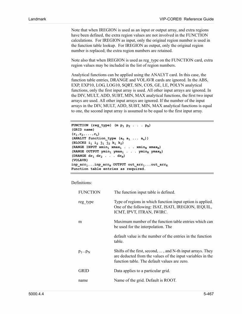
Landmark VIP-CORE® Reference Guide
Note that when IREGION is used as an input or output array, and extra regions have been defined, the extra region values are not involved in the FUNCTION calculations. For IREGION as input, only the original region number is used in the function table lookup. For IREGION as output, only the original region number is replaced; the extra region numbers are retained. 00
Note also that when IREGION is used as reg_type on the FUNCTION card, extra region values may be included in the list of region numbers. 00
Analytical functions can be applied using the ANALYT card. In this case, the function table entries, DRANGE and VOLAVR cards are ignored. In the ABS, EXP, EXP10, LOG, LOG10, SQRT, SIN, COS, GE, LE, POLYN analytical functions, only the first input array is used. All other input arrays are ignored. In the DIV, MULT, ADD, SUBT, MIN, MAX analytical functions, the first two input arrays are used. All other input arrays are ignored. If the number of the input arrays in the DIV, MULT, ADD, SUBT, MIN, MAX analytical functions is equal to one, the second input array is assumed to be equal to the first input array. 00
FUNCTION (reg_type) (m p1 p2 . . . pN)(GRID name)(r1,r2,...,rL)(ANALYT function_type (a0 a1 ... an))(BLOCKS i1 i2 j1 j2 k1 k2)(RANGE INPUT xmin1 xmax1 . . . xminN xmaxN)(RANGE OUTPUT ymin1 ymax1 . . . yminK ymaxK)(DRANGE dr1 dr2 . . . drN)(VOLAVR)inp_arr1...inp_arrN OUTPUT out_arr1...out_arrKFunction table entries as required.
Definitions: 00
FUNCTION The function input table is defined.
reg_type Type of regions in which function input option is applied. One of the following: ISAT, ISATI, IREGION, IEQUIL, ICMT, IPVT, ITRAN, IWIRC.
m Maximum number of the function table entries which can be used for the interpolation. The
default value is the number of the entries in the function table.
p1...pN Shifts of the first, second, ... , and N-th input arrays. They are deducted from the values of the input variables in the function table. The default values are zero.
GRID Data applies to a particular grid.
name Name of the grid. Default is ROOT.
5000.4.4 5-467
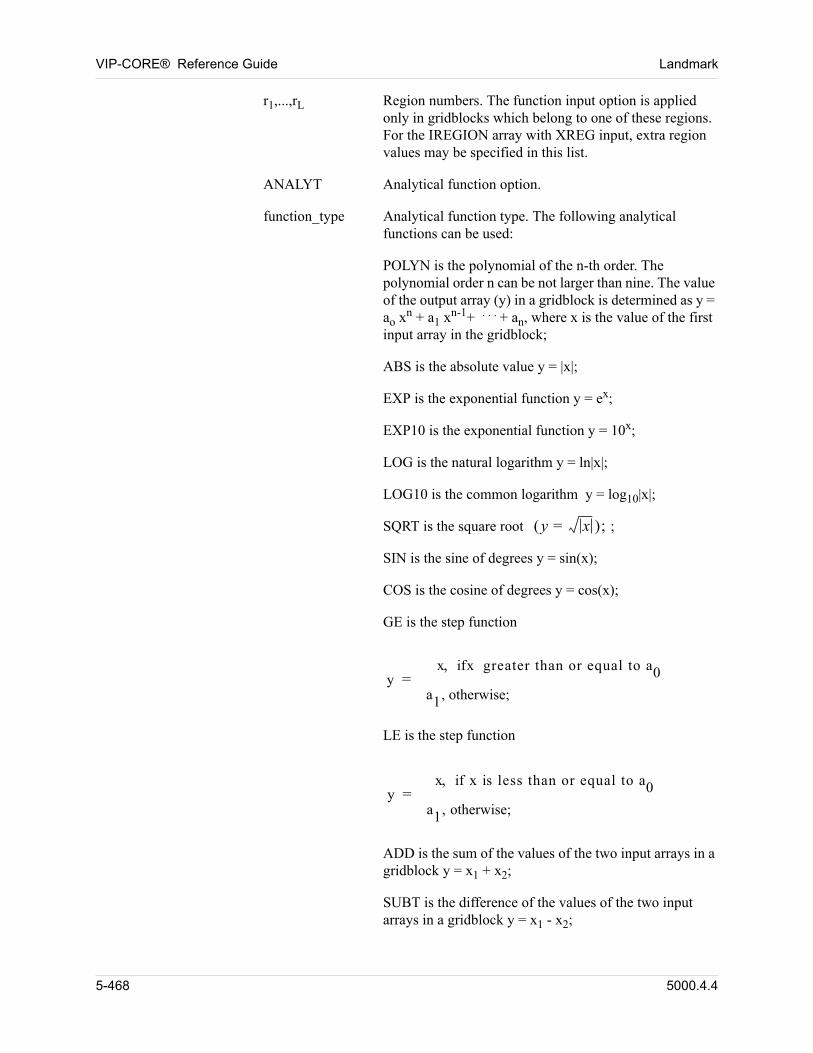
VIP-CORE® Reference Guide Landmark
r1,...,rL Region numbers. The function input option is applied only in gridblocks which belong to one of these regions. For the IREGION array with XREG input, extra region values may be specified in this list.
ANALYT Analytical function option.
function_type Analytical function type. The following analytical functions can be used:
POLYN is the polynomial of the n-th order. The polynomial order n can be not larger than nine. The value of the output array (y) in a gridblock is determined as y = ao xn + a1 xn-1+ . . . + an, where x is the value of the first input array in the gridblock;
ABS is the absolute value y = |x|;
EXP is the exponential function y = ex;
EXP10 is the exponential function y = 10x;
LOG is the natural logarithm y = ln|x|;
LOG10 is the common logarithm y = log10|x|;
SQRT is the square root y x= ; ;
SIN is the sine of degrees y = sin(x);
COS is the cosine of degrees y = cos(x);
GE is the step function
yx ifx greater than or equal to a0
a1, otherwise;=
LE is the step function
yx if x is less than or equal to a0
a1, otherwise;=
ADD is the sum of the values of the two input arrays in a gridblock y = x1 + x2;
SUBT is the difference of the values of the two input arrays in a gridblock y = x1 - x2;
5-468 5000.4.4
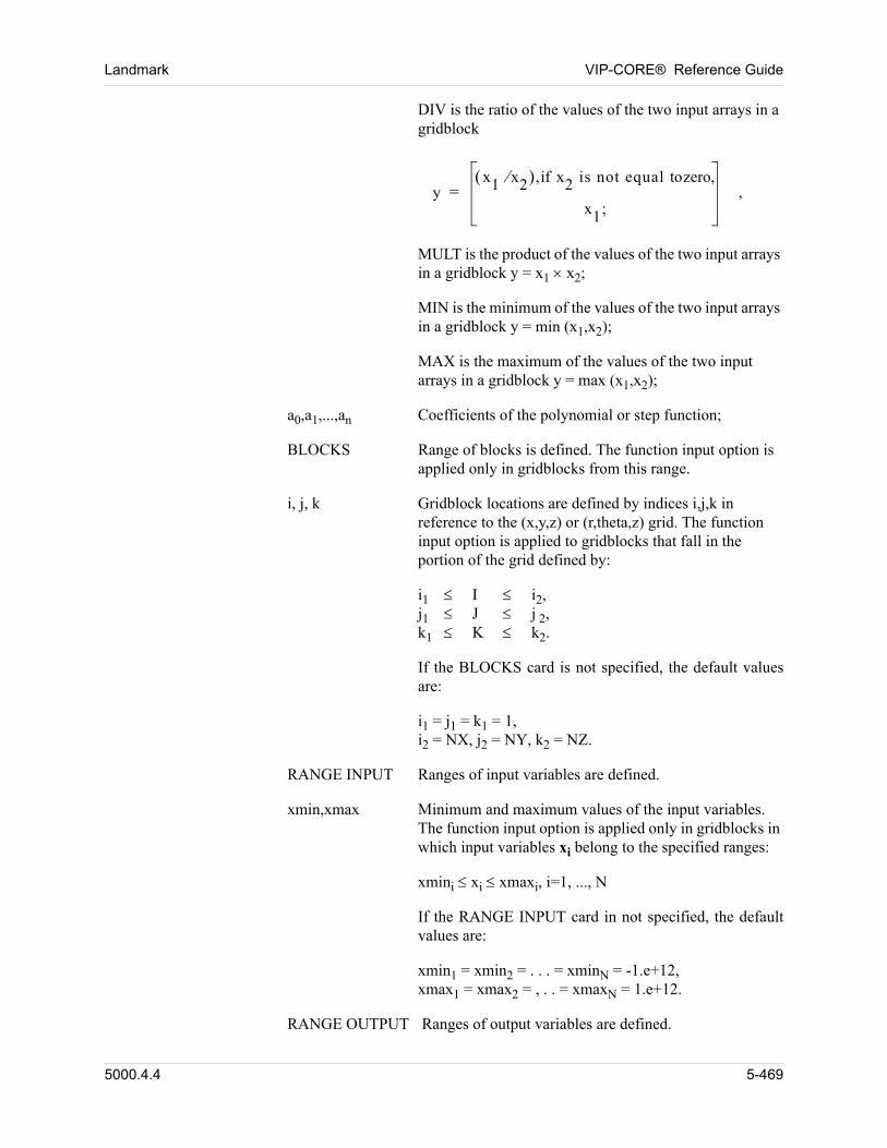
Landmark VIP-CORE® Reference Guide
DIV is the ratio of the values of the two input arrays in a gridblock
yx1 x2 ,if x2 is not equal tozero,
x1;= ,
MULT is the product of the values of the two input arrays in a gridblock y = x1 x2;
MIN is the minimum of the values of the two input arrays in a gridblock y = min (x1,x2);
MAX is the maximum of the values of the two input arrays in a gridblock y = max (x1,x2);
a0,a1,...,an Coefficients of the polynomial or step function;
BLOCKS Range of blocks is defined. The function input option is applied only in gridblocks from this range.
i, j, k Gridblock locations are defined by indices i,j,k in reference to the (x,y,z) or (r,theta,z) grid. The function input option is applied to gridblocks that fall in the portion of the grid defined by:
i1 I i2,j1 J j 2,k1 K k2.
If the BLOCKS card is not specified, the default values are:
i1 = j1 = k1 = 1,i2 = NX, j2 = NY, k2 = NZ.
RANGE INPUT Ranges of input variables are defined.
xmin,xmax Minimum and maximum values of the input variables. The function input option is applied only in gridblocks in which input variables xi belong to the specified ranges:
xmini xi xmaxi, i=1, ..., N
If the RANGE INPUT card in not specified, the default values are:
xmin1 = xmin2 = . . . = xminN = -1.e+12,xmax1 = xmax2 = , . . = xmaxN = 1.e+12.
RANGE OUTPUT Ranges of output variables are defined.
5000.4.4 5-469
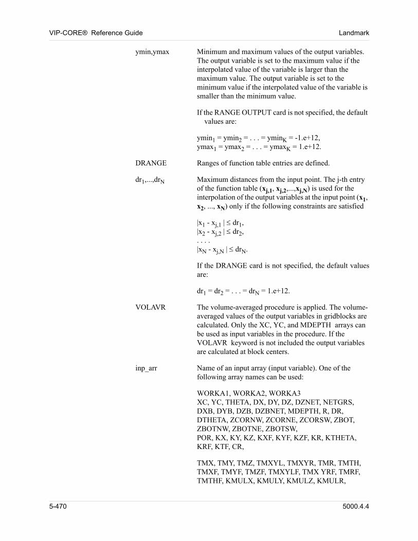
VIP-CORE® Reference Guide Landmark
ymin,ymax Minimum and maximum values of the output variables. The output variable is set to the maximum value if the interpolated value of the variable is larger than the maximum value. The output variable is set to the minimum value if the interpolated value of the variable is smaller than the minimum value.
If the RANGE OUTPUT card is not specified, the default values are:
ymin1 = ymin2 = . . . = yminK = -1.e+12,ymax1 = ymax2 = . . . = ymaxK = 1.e+12.
DRANGE Ranges of function table entries are defined.
dr1,...,drN Maximum distances from the input point. The j-th entry of the function table (xj,1, xj,2,...,xj,N) is used for the interpolation of the output variables at the input point (x1, x2, ..., xN) only if the following constraints are satisfied
|x1 - xj,1 | dr1,|x2 - xj,2 | dr2,. . . .|xN - xj,N | drN.
If the DRANGE card is not specified, the default values are:
dr1 = dr2 = . . . = drN = 1.e+12.
VOLAVR The volume-averaged procedure is applied. The volume-averaged values of the output variables in gridblocks are calculated. Only the XC, YC, and MDEPTH arrays can be used as input variables in the procedure. If the VOLAVR keyword is not included the output variables are calculated at block centers.
inp_arr Name of an input array (input variable). One of the following array names can be used:
WORKA1, WORKA2, WORKA3XC, YC, THETA, DX, DY, DZ, DZNET, NETGRS, DXB, DYB, DZB, DZBNET, MDEPTH, R, DR, DTHETA, ZCORNW, ZCORNE, ZCORSW, ZBOT, ZBOTNW, ZBOTNE, ZBOTSW,POR, KX, KY, KZ, KXF, KYF, KZF, KR, KTHETA, KRF, KTF, CR,
TMX, TMY, TMZ, TMXYL, TMXYR, TMR, TMTH, TMXF, TMYF, TMZF, TMXYLF, TMX YRF, TMRF, TMTHF, KMULX, KMULY, KMULZ, KMULR,
5-470 5000.4.4
Landmark VIP-CORE® Reference Guide
KMULTH, KWHYS, KOHYS, CRD, CRR, PD, PR, FR, PORMAX, PORMIN, CPR0, KTX0, KTY0, KTZ0, KTR0, KTTH0, TXT0, TYT0, TZT0, TRT0, TTHT0, ICPRTB, TTMX, TTMY, TTMZ, TTMR, TTMTH
PV, TX, TR, TY, TTHETA, TZ, TXYR, TXYL,ISAT, ISATI, IPVT, IPVTW,IREGION, IEQUIL, ICMT, ITRAN, IWIRC, SW, SG, P, TEMP, FVEWO, FVEGO,SWL, SWR, SWRO, SWU, SGL, SGR, SGRO, SGU, SGRW, KROLW, KRWRO, KRGRO,ISATX+, ISATX-, ISATY+, ISATY-,ISATZ+, ISATZ-, ISATA, ISATV,ISTIX+, ISTIX-, ISTIY+, ISTIY-,ISTIZ+, ISTIZ-, ISTIA, ISTIV,SWLX+, SWLX-, SWLY+, SWLY-,SWLZ+, SWLZ-, SWLA, SWLV,SWRX+, SWRX-, SWRY+, SWRY-,SWRZ+, SWRZ-, SWRA, SWRV,SWROX+, SWROX-, SWROY+, SWROY-,SWROZ+, SWROZ-, SWRA, SWROV,SWUX+, SWUX-, SWUY+, SWUY-,SWUZ+, SWUZ-, SWUA, SWUV,SGLX+, SGLX-, SGLY+, SGLY-,SGLZ+, SGLZ-, SGLA, SGLV,SGRX+, SGRX-, SGRY+, SGRY-,SGRZ+, SGRZ-, SGRA, SGRV,SGROX+, SGROX-, SGROY+, SGROY-,SGROZ+, SGROZ-, SGROA, SGROV,SGUX+, SGUX-, SGUY+, SGUY-,SGUZ+, SGUZ-, SGUA, SGUV,SGRWX+, SGRWX-, SGRWY+, SGRWY-,SGRWZ+, SGRWZ-, SGRWA, SGRWV,KOLWX+, KOLWX-, KOLWY+, KOLWY-, KOLWZ+, KOLWZ-, KOLWA, KOLWV,KWROX+, KWROX-, KWROY+, KWROY-, KWROZ+, KWROZ-, KWROA, KWROV,
5000.4.4 5-471
VIP-CORE® Reference Guide Landmark
KGROX+, KGROX-, KGROY+, KGROY-,KGROZ+, KGROZ-, KGROA, KGROV.
In addition, for VIP-DUAL , one of the following array names can also be used.
NETGF, MDEPF, PORF, KXFEFF, KYFEFF, KZFEFF, KRFEFF, KTFEFF, CRF, PVF, TXF, TYF, TZF, TRF, TTHETF, TXYRF, TXYLF, TEX, LX, LY, LZ,TDIFFG, TDIFFO, SIGMA, SIGMAD,ISATF, ISATIF, IREGF, ICMTF, ITRANF, IWIRCF, SWF, SGF, PF, FVEWOF, FVEGOF, SWLF, SWRF, SWROF, SWUF, SGLF, SGRF, SGROF, SGUF, SGRWF, KROLWF, KRWROF, KRGROF,ISATFX+, ISATFX-, ISATFY+, ISATFY-,ISATFZ+, ISATFZ-, ISATFA, ISATFV,ISTIFX+, ISTIFX-, ISTIFY+, ISTIFY-,ISTIFZ+, ISTIFZ-, ISTIFA, ISTIFV,SWLFX+, SWLFX-, SWLFY+, SWLFY-,SWLFZ+, SWLFZ-, SWLFA, SWLFV,SWRFX+, SWRFX-, SWRFY+, SWRFY-,SWRFZ+, SWRFZ-, SWRFA, SWRFV,SWROFX+, SWROFX-, SWROFY+, SWROFY-,SWROFZ+, SWROFZ-, SWROFA, SWROFV,SWUFX+, SWUFX-, SWUFY+, SWUFY-,SWUFZ+, SWUFZ-, SWUFA, SWUFV,SGLFX+, SGLFX-, SGLFY+, SGLFY-,SGLFZ+, SGLFZ-, SGLFA, SGLFV,SGRFX+, SGRFX-, SGRFY+, SGRFY-,SGRFZ+, SGRFZ-, SGRFA, SGRFV,SGROFX+, SGROFX-, SGROFY+, SGROFY-,SGROFZ+, SGROFZ-, SGROFA, SGROFV,SGUFX+, SGUFX-, SGUFY+, SGUFY-,SGUFZ+, SGUFZ-, SGUFA, SGUFV,SGRWFX+, SGRWFX-, SGRWFY+, SGRWFY-,SGRWFZ+, SGRWFZ-, SGRWFA, SGRWFV,KOLWFX+, KOLWFX-, KOLWFY+, KOLWFY-, KOLWFZ+, KOLWFZ-, KOLWFA, KOLWFV,
5-472 5000.4.4
Landmark VIP-CORE® Reference Guide
KWROFX+, KWROFX-, KWROFY+, KWROFY-, KWROFZ+, KWROFZ-, KWROFA, KWROFV,KGROFX+, KGROFX-, KGROFY+, KGROFY-,KGROFZ+, KGROFZ-, KGROFA, KGROFV.
Several names can be included. The array names XC, YC, and MDEPTH can be used to input the x-, y-, and z- coordinates of points in rectangular and corner point geometry models. The array names R, THETA, and MDEPTH can be used to input coordinates of points in radial geometry models.
WORKA1, WORKA2, WORKA3 are temporary work arrays that can be read in or defined as OUTPUT arrays.
OUTPUT This keyword separates the names of the input and output arrays.
out_arr Name of an output array (output variable). One of the following names can be used:
WORKA1, WORKA2, WORKA3NETGRS, POR, KX, KY, KZ, KXF, KYF, KZF, KR, KTHETA, KRF, KTF, CR,PV, TX, TR, TY, TTHETA, TZ, TXYR, TXYL,ISAT, ISATI, IPVT, IPVTW, IREGION, IEQUIL, ICMT, ITRAN, IWIRC, SW, SG, P, TEMP, FVEWO, FVEGO,SWL, SWR, SWRO, SWU, SGL, SGR, SGRO, SGU, SGRW, KROLW, KRWRO, KRGRO,
TMX, TMY, TMZ, TMXYL, TMXYR, TMR, TMTH, TMXF, TMYF, TMZF, TMXYLF, TMX YRF, TMRF, TMTHF, KMULX, KMULY, KMULZ, KMULR, KMULTH, KWHYS, KOHYS, CRD, CRR, PD, PR, FR, PORMAX, PORMIN, CPR0, KTX0, KTY0, KTZ0, KTR0, KTTH0, TXT0, TYT0, TZT0, TRT0, TTHT0, ICPRTB, TTMX, TTMY, TTMZ, TTMR, TTMTH
ISATX+, ISATX-, ISATY+, ISATY-, ISATZ+, ISATZ-, ISATA, ISATV, ISTIX+, ISTIX-, ISTIY+, ISTIY-, ISTIZ+, ISTIZ-, ISTIA, ISTIV,SWLX+, SWLX-, SWLY+, SWLY-, SWLZ+, SWLZ-, SWLA, SWLV, SWRX+, SWRX-, SWRY+, SWRY-, SWRZ+, SWRZ-, SWRA, SWRV,
5000.4.4 5-473
VIP-CORE® Reference Guide Landmark
SWROX+, SWROX-, SWROY+, SWROY-,SWROZ+, SWROZ-, SWRA, SWROV, SWUX+, SWUX-, SWUY+, SWUY-,SWUZ+, SWUZ-, SWUA, SWUV, SGLX+, SGLX-, SGLY+, SGLY-, SGLZ+, SGLZ-, SGLA, SGLV,SGRX+, SGRX-, SGRY+, SGRY-, SGRZ+, SGRZ-, SGRA, SGRV,SGROX+, SGROX-, SGROY+, SGROY-, SGROZ+, SGROZ-, SGROA, SGROV, SGUX+, SGUX-, SGUY+, SGUY-, SGUZ+, SGUZ-, SGUA, SGUV, SGRWX+, SGRWX-, SGRWY+, SGRWY-, SGRWZ+, SGRWZ-, SGRWA, SGRWV,KOLWX+, KOLWX-, KOLWY+, KOLWY-, KOLWZ+, KOLWZ-, KOLWA, KOLWV,KWROX+, KWROX-, KWROY+, KWROY-, KWROZ+, KWROZ-, KWROA, KWROV,KGROX+, KGROX-, KGROY+, KGROY-, KGROZ+, KGROZ-, KGROA, KGROV.In addition, for VIP-DUAL , one of the following array names can also be used.
NETGF, PORF, KXFEFF, KYFEFF, KZFEFF, KRFEFF, KTFEFF, CRF, PVF, TXF, TYF, TZF, TRF, TTHETF, TXYRF, TXYLF, TEX, LX, LY, LZ,TDIFFG, TDIFFO, SIGMA, SIGMAD,ISATF, ISATIF, IREGF, ICMTF, ITRANF, IWIRCF, SWF, SGF, PF, FVEWOF, FVEGOF, SWLF, SWRF, SWROF, SWUF, SGLF, SGRF, SGROF, SGUF, SGRWF, KROLWF, KRWROF, KRGROF,ISATFX+, ISATFX-, ISATFY+, ISATFY-,ISATFZ+, ISATFZ-, ISATFA, ISATFV,ISTIFX+, ISTIFX-, ISTIFY+, ISTIFY-,ISTIFZ+, ISTIFZ-, ISTIFA, ISTIFV,SWLFX+, SWLFX-, SWLFY+, SWLFY-,SWLFZ+, SWLFZ-, SWLFA, SWLFV,
5-474 5000.4.4
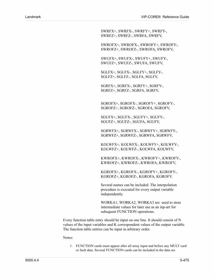
Landmark VIP-CORE® Reference Guide
SWRFX+, SWRFX-, SWRFY+, SWRFY-,SWRFZ+, SWRFZ-, SWRFA, SWRFV,SWROFX+, SWROFX-, SWROFY+, SWROFY-,SWROFZ+, SWROFZ-, SWROFA, SWROFV,SWUFX+, SWUFX-, SWUFY+, SWUFY-,SWUFZ+, SWUFZ-, SWUFA, SWUFV,SGLFX+, SGLFX-, SGLFY+, SGLFY-,SGLFZ+, SGLFZ-, SGLFA, SGLFV,SGRFX+, SGRFX-, SGRFY+, SGRFY-,SGRFZ+, SGRFZ-, SGRFA, SGRFV,
SGROFX+, SGROFX-, SGROFY+, SGROFY-,SGROFZ+, SGROFZ-, SGROFA, SGROFV,SGUFX+, SGUFX-, SGUFY+, SGUFY-,SGUFZ+, SGUFZ-, SGUFA, SGUFV,SGRWFX+, SGRWFX-, SGRWFY+, SGRWFY-,SGRWFZ+, SGRWFZ-, SGRWFA, SGRWFV,KOLWFX+, KOLWFX-, KOLWFY+, KOLWFY-, KOLWFZ+, KOLWFZ-, KOLWFA, KOLWFV,KWROFX+, KWROFX-, KWROFY+, KWROFY-, KWROFZ+, KWROFZ-, KWROFA, KWROFV,KGROFX+, KGROFX-, KGROFY+, KGROFY-,KGROFZ+, KGROFZ-, KGROFA, KGROFV.
Several names can be included. The interpolation procedure is executed for every output variable independently.
WORKA1, WORKA2, WORKA3 are used to store intermediate values for later use as an inp-arr for subsquent FUNCTION operations.
Every function table entry should be input on one line. It should consist of N values of the input variables and K correspondent values of the output variable. The function table entries can be input in arbitrary order. 00
Notes: 00
1. FUNCTION cards must appear after all array input and before any MULT card or fault data. Several FUNCTION cards can be included in the data set.
5000.4.4 5-475
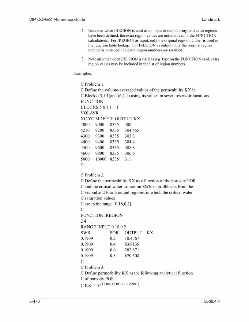
VIP-CORE® Reference Guide Landmark
2. Note that when IREGION is used as an input or output array, and extra regions have been defined, the extra region values are not involved in the FUNCTION calculations. For IREGION as input, only the original region number is used in the function table lookup. For IREGION as output, only the original region number is replaced; the extra region numbers are retained.
3. Note also that when IREGION is used as reg_type on the FUNCTION card, extra region values may be included in the list of region numbers.
Examples: 00
C Problem 1.C Define the volume-averaged values of the permeability KX inC Blocks (5,1,1)and (6,1,1) using its values in seven reservoir locationsFUNCTIONBLOCKS 5 6 1 1 1 1VOLAVRXC YC MDEPTH OUTPUT KX4000 9000 8335 3004210 9200 8335 304.4554300 9300 8335 303.34400 9400 8335 304.44500 9600 8335 305.84600 9800 8335 306.65000 10000 8335 311C 00
C Problem 2.C Define the permeability KX as a function of the porosity PORC and the critical water saturation SWR in gridblocks from theC second and fourth output regions, in which the critical waterC saturation valuesC are in the range [0.18,0.2].CFUNCTION IREGION2 4RANGE INPUT 0.18 0.2SWR POR OUTPUT KX0.1909 0.2 10.47670.1909 0.4 83.81350.1909 0.6 282.8710.1909 0.8 670.508CC Problem 3.C Define permeability KX as the following analytical functionC of porosity POR :C KX = 10(17.06715 POR - 2.70903).
5-476 5000.4.4
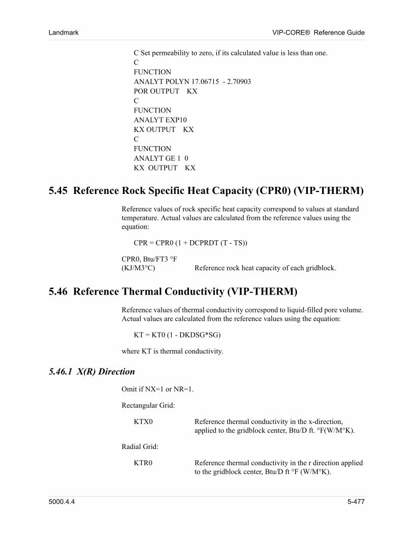
Landmark VIP-CORE® Reference Guide
C Set permeability to zero, if its calculated value is less than one.CFUNCTIONANALYT POLYN 17.06715 - 2.70903POR OUTPUT KXCFUNCTIONANALYT EXP10KX OUTPUT KXCFUNCTIONANALYT GE 1 0KX OUTPUT KX 00
5.45 Reference Rock Specific Heat Capacity (CPR0) (VIP-THERM)
Reference values of rock specific heat capacity correspond to values at standard temperature. Actual values are calculated from the reference values using the equation:
CPR = CPR0 (1 + DCPRDT (T - TS))
CPR0, Btu/FT3 °F(KJ/M3°C) Reference rock heat capacity of each gridblock.
5.46 Reference Thermal Conductivity (VIP-THERM)
Reference values of thermal conductivity correspond to liquid-filled pore volume. Actual values are calculated from the reference values using the equation:
KT = KT0 (1 - DKDSG*SG)
where KT is thermal conductivity.
5.46.1 X(R) Direction
Omit if NX=1 or NR=1.
Rectangular Grid:
KTX0 Reference thermal conductivity in the x-direction, applied to the gridblock center, Btu/D ft. °F(W/M°K).
Radial Grid:
KTR0 Reference thermal conductivity in the r direction applied to the gridblock center, Btu/D ft °F (W/M°K).
5000.4.4 5-477
VIP-CORE® Reference Guide Landmark
5.46.2 Y(Theta) Direction
Omit if NY=1 or NTHETA=1
Enter one of the following arrays:
Rectangular Grid:
KTY0 Reference thermal conductivity in the y direction, applied to the gridblock center, Btu/D ft. F (W/M °K).
Radial Grid:
KTTH0 Reference thermal conductivity in the theta direction, applied to the gridblock center, Btu/D ft. °F (W/M °K).
5.46.3 Z Direction
Omit if NZ=1
Enter one of the following arrays:
KTZ0 Reference thermal conductivity in the z direction, applied to the gridblock center, Btu/D ft. °F (W/M °K).
5.47 Water-Oil Hysteresis Arrays (VIP-THERM)
5.47.1 KWHYS Array
The KWHYS array is used to specify the value of Kwrev (Section 4.3.5). Default is 1.0. A value of zero results in initialization to the krw imbibition (water-wet) or drainage (oil-wet) curve. Values must lie between zero and one.
KWHYS, fraction Value of Kwrev defined in Section 4.3.5.
5.47.2 KOHYS Array
The KOHYS array is used to specify the value of Korev (Section 4.3.5). Default is 1.0.
KOHYS, fraction Value of Korev defined in Section 4.3.5.
5-478 5000.4.4
Landmark VIP-CORE® Reference Guide
5.48 Beattie et. al Fracture Model Arrays (VIP-THERM)
Scalar parameters specified in the PORDEF data (Section 4.18) may optionally be specified as gridblock arrays.
PD, psia (kPa) Dilation pressure.
PR, psia (kPa) Recompaction pressure.
CRD, psia-1 (kPa-1) Dilant rock compressibility.
FR, fraction Permanent fraction of total dilation on recompaction to P = 0.
The elastic rock compressibility (CR) may be specified as a gridblock array as described in Section 5.23.
Permeability multipliers for the fracture model (Section 4.18.2.1, Reference 32) must be specified in each flow direction, including diagonal directions if the NINEPT option is in use.
Rectangular Grid:
KMULX X-direction permeability multiplier, applied to transmissibility at i - 1/2.
KMULY Y-direction permeability multiplier, applied to transmissibility at j - 1/2.
KMULZ Z-direction permeability multiplier, applied to transmissibility at k - 1/2.
For NINEPT option:
KMLXYR +x, -y direction permeability multiplier, applied to transmissibility at i + 1/2, j - 1/2.
KMLXYL -x, -y direction permeability multiplier, applied to transmissibility at i - 1/2, j - 1/2.
Radial Grid:
KMULR R-direction permeability multiplier, applied to transmissibility at i - 1/2.
KMULTH Thetha-direction permeability multiplier, applied to transmissibility at j - 1/2.
KMULZ Z-direction permeability multiplier, applied to transmissibility at k - 1/2.
5000.4.4 5-479
VIP-CORE® Reference Guide Landmark
5.49 Rock Heat Capacity Variations (ICPRTB) (VIP-THERM)
The ICPRTB array is required if more than one set of rock heat capacity tables (Section 4.19) are to be used.
ICPRTB, integer Integer values that distinguish areas containing rock types which require unique heat capacity description. Each value in the ICPRTB array directly refers to a rock heat capacity table input. Default sets the entire array to 1.
5-480 5000.4.4
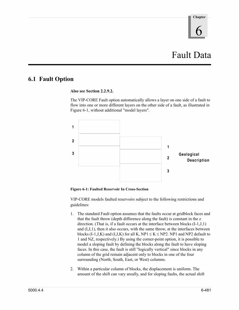
Chapter
6
00000Fault Data
6.1 Fault Option
Also see Section 2.2.9.2. 00
The VIP-CORE Fault option automatically allows a layer on one side of a fault to flow into one or more different layers on the other side of a fault, as illustrated in Figure 6-1, without additional "model layers".
Figure 6-1: Faulted Reservoir In Cross-Section
VIP-CORE models faulted reservoirs subject to the following restrictions and guidelines:
1. The standard Fault option assumes that the faults occur at gridblock faces and that the fault throw (depth difference along the fault) is constant in the z direction. (That is, if a fault occurs at the interface between blocks (I-1,J,1) and (I,J,1), then it also occurs, with the same throw, at the interfaces between blocks (I-1,J,K) and (I,J,K) for all K, NP1 K NP2. NP1 and NP2 default to 1 and NZ, respectively.) By using the corner-point option, it is possible to model a sloping fault by defining the blocks along the fault to have sloping faces. In this case, the fault is still "logically vertical" since blocks in any column of the grid remain adjacent only to blocks in one of the four surrounding (North, South, East, or West) columns.
2. Within a particular column of blocks, the displacement is uniform. The amount of the shift can vary areally, and for sloping faults, the actual shift
5000.4.4 6-481
VIP-CORE® Reference Guide Landmark
along the fault face depends on the angle between the face and the vertical for each block.
3. Permeabilities at gridblock centers must be specified. TX, TY, KXF, and KYF are not valid input in the presence of faults.
4. When faults are modelled using a non-corner-point grid, VIP-CORE sets DX=DXB, DY=DYB, and DZ=DZB.
5. When possible, specify uniform thicknesses for each layer.
6. Depths in non-corner-point grids must be correctly specified in the DEPTH or MDEPTH array to reflect the presence of faults; i.e., the simulator makes no automatic adjustments. Similarly, the entries in the ZCORN array must be set to correctly give the depth of the southeast corner of each block in each layer of grid points. The simulator will automatically compute the ZCORNE, ZCORNW, and ZCORSW arrays to reflect the faults.
7. In non-corner point grids fault connections will be correctly calculated when gaps occur between layers (gridblock thicknesses less than depth differences between gridblocks).
8. Specify the same fault displacement, fshift, as indicated by the depth differences. Be sure to use the proper sign (negative or positive) for the fault displacement variable found on the FX and FY cards.
9. When possible, use the "LAYER" option on the "DEPTH" card to specify depths.
6-482 5000.4.4
Landmark VIP-CORE® Reference Guide
6.2 Start of Fault Data (FAULTS)
A FAULTS card must precede all of the fault description data.
FAULTS(FNAME fname)
Definitions:
FNAME Alpha character keyword for assigning a name to the group of blocks defined by the following FX, FY, etc. data. A gridblock will be assigned to a name based on the last definition encountered. By default no identifying name is assigned.
fname A character string or number by which the group of gridblocks is identified. A maximum of 256 characters or numbers is allowed, otherwise the string is truncated to the first 256.
NOTE: 1. FNAME identifiers can also be assigned using the OVER, and VOVER keywords. A gridblock will be assigned based on the last identifier encountered.
5000.4.4 6-483
VIP-CORE® Reference Guide Landmark
6.3 Standard Fault Data (FX, FR, FY, FTHETA, FXCORN, FYCORN)
To describe a fault, the areal location, vertical displacement, and modification of fault fluid flow transmissibility and fault heat conduction (thermal) transmissibility (VIP-THERM only) must be specified. The FX and FY cards may be used for this purpose for any grid. Additionally, the FXCORN and FYCORN cards may be used for corner-point grids. The layer connections are generated automatically. Omit the tmt data for VIP-COMP or VIP-ENCORE.
FXFR i j1 (-j2) ±fshift (*tm *tmt)
orFYFTHETA j i1 (-i2) ±fshift (*tm *tmt)
or
FXCORN i j1 (-j2)±fshift(j1) ±fshift(j1+1) ... ±fshift(j2)
(tm(j1) tm(j1+1) ... tm(j2-1))(tmt(j1) tmt(j1+1) ... tmt(j2-1))
orFYCORN j i1 (-i2) fshift(i1) ±fshift(i1+1) ... ±fshift(i2)
(tm(i1) tm(i1+1) ... tm(i2-1))(tmt(i1) tmt(i1+1) ... tmt(i2-1))
Definitions:
FX (FR),FXCORN
Alpha label indicating an x(r) direction fault is being described. An x(r) direction fault is defined at the boundary between blocks (i-1,j,k) and (i,j,k).
i Gridblock number describing an x(r) direction fault. The fault is at the gridblock face between blocks i-1 and i.
j, j2 An FX/FR (FXCORN) fault begins at block (point) J = j1 and extends through block (point) J = j2. The "-" means up through and including j2. There are no spaces between the sign and j2. If j2 is not entered, the default is j2 = j1 for FX/FR and j2 = j1+1 for FXCORN.
FY(FTHETA),FYCORN
Alpha label indicating a y(theta) direction fault is being described. A y(theta) direction fault is defined at the boundary between blocks (i,j-1,k) and (i,j,k).
j Gridblock number describing a y(theta) direction fault. The fault is at the gridblock face between blocks j-1 and j.
6-484 5000.4.4
Landmark VIP-CORE® Reference Guide
i1, i2 An FY/FTHETA (FYCORN) fault begins at block (point) I = i1 and extends through block (point) I = i2. The "-" means up through and including i2. There are no spaces between the sign and i2. If i2 is not entered, the default is i2 = i1 for FY/FTHETA and i2 = i1+1 for FYCORN.
fshift The amount of fault displacement, ft (m). A positive amount indicates a downward fault shift, where I (J) is "deeper" than I-1 (J-1). (Should be equal to the differ-ence in depth or ZCORN values entered.) For FXCORN (FYCORN) data, there needs to be either one or j2-j1+1 (i2-i1+1) fshift values. If only one is given, it is used along the entire fault.
tm Multiplier of the flow transmissibility across the fault. Applies to transmissibilities for all blocks along the areal extent of the fault described on the data card, over the entire vertical displacement. For FX/FR (FY/FTHETA) data, there are no spaces between the multi-plier and tm, *tm. The default is 1. For FXCORN (FYCORN) data, the multiplier sign is not entered; the default is 1. There needs to be either one or j2-j1 (i2-i1) tm values. If only one is given, it is used for all blocks along the fault.
tmt Enter for VIP-THERM only. Multiplier of the thermal transmissibility across the fault. Applies to thermal tranmissibilities for all blocks along the areal extent of the fault described on the data card, over the entire vertical displacement. For FX/FR (FY/FTHETA) data, there are no spaces between the multiplier and tmt, *tmt. For FX/FR (FY/FTHETA) data, if any multi-plier (tm or tmt) is specified, then both tm and tmt must be specified. The default is 1. For FXCORN (FYCORN) data, the multiplier sign is not entered; the default is 1. There needs to be either one or j2-j1 (i2-i1) tmt values. If only one is given, it is used for all blocks along the fault. For FXCORN (FYCORN) data, tmt is not required if tm is specified, but tm must be specified if tmt is to be specified.
5000.4.4 6-485
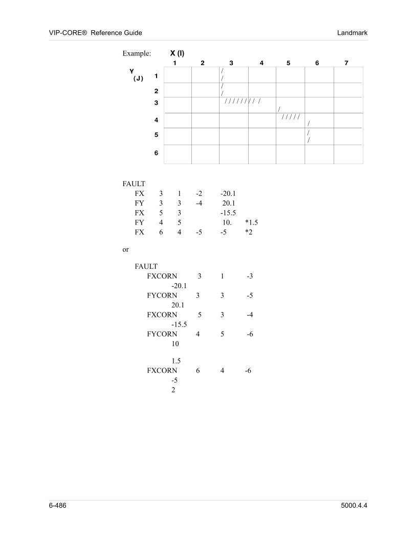
VIP-CORE® Reference Guide Landmark
Example: X (I)
//// / / / / / / / / /
/ / / / / /
///
00
FAULTFX 3 1 -2 -20.1FY 3 3 -4 20.1FX 5 3 -15.5FY 4 5 10. *1.5FX 6 4 -5 -5 *2 00
or 00
FAULTFXCORN 3 1 -3
-20.1FYCORN 3 3 -5
20.1FXCORN 5 3 -4
-15.5FYCORN 4 5 -6
10 00
1.5FXCORN 6 4 -6
-52 00
6-486 5000.4.4
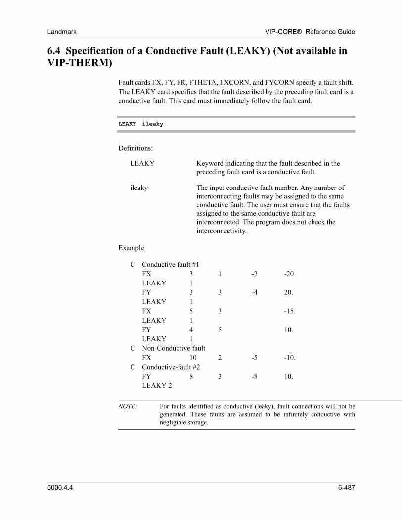
Landmark VIP-CORE® Reference Guide
6.4 Specification of a Conductive Fault (LEAKY) (Not available in VIP-THERM)
Fault cards FX, FY, FR, FTHETA, FXCORN, and FYCORN specify a fault shift. The LEAKY card specifies that the fault described by the preceding fault card is a conductive fault. This card must immediately follow the fault card.
LEAKY ileaky
Definitions:
LEAKY Keyword indicating that the fault described in the preceding fault card is a conductive fault.
ileaky The input conductive fault number. Any number of interconnecting faults may be assigned to the same conductive fault. The user must ensure that the faults assigned to the same conductive fault are interconnected. The program does not check the interconnectivity.
Example:
C Conductive fault #1FX 3 1 -2 -20LEAKY 1FY 3 3 -4 20.LEAKY 1FX 5 3 -15.LEAKY 1FY 4 5 10.LEAKY 1
C Non-Conductive faultFX 10 2 -5 -10.
C Conductive-fault #2FY 8 3 -8 10.LEAKY 2
NOTE: For faults identified as conductive (leaky), fault connections will not be generated. These faults are assumed to be infinitely conductive with negligible storage.
5000.4.4 6-487
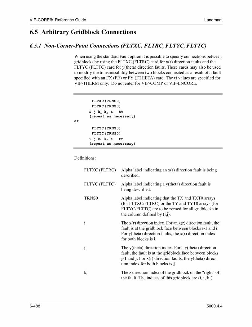
VIP-CORE® Reference Guide Landmark
6.5 Arbitrary Gridblock Connections
6.5.1 Non-Corner-Point Connections (FLTXC, FLTRC, FLTYC, FLTTC)
When using the standard Fault option it is possible to specify connections between gridblocks by using the FLTXC (FLTRC) card for x(r) direction faults and the FLTYC (FLTTC) card for y(theta) direction faults. These cards may also be used to modify the transmissibility between two blocks connected as a result of a fault specified with an FX (FR) or FY (FTHETA) card. The tt values are specified for VIP-THERM only. Do not enter for VIP-COMP or VIP-ENCORE.
FLTXC TRNS0 FLTRC TRNS0
i j k1 k2 t tt(repeat as necessary)
orFLTYC TRNS0 FLTTC TRNS0
i j k1 k2 t tt(repeat as necessary)
Definitions:
FLTXC (FLTRC) Alpha label indicating an x(r) direction fault is being described.
FLTYC (FLTTC) Alpha label indicating a y(theta) direction fault is being described.
TRNS0 Alpha label indicating that the TX and TXT0 arrays (for FLTXC/FLTRC) or the TY and TYT0 arrays (for FLTYC/FLTTC) are to be zeroed for all gridblocks in the column defined by (i,j).
i The x(r) direction index. For an x(r) direction fault, the fault is at the gridblock face between blocks i-1 and i. For y(theta) direction faults, the x(r) direction index for both blocks is i.
j The y(theta) direction index. For a y(theta) direction fault, the fault is at the gridblock face between blocks j-1 and j. For x(r) direction faults, the y(theta) direc-tion index for both blocks is j.
k The z direction index of the gridblock on the "right" of the fault. The indices of this gridblock are (i, j, k1).
6-488 5000.4.4
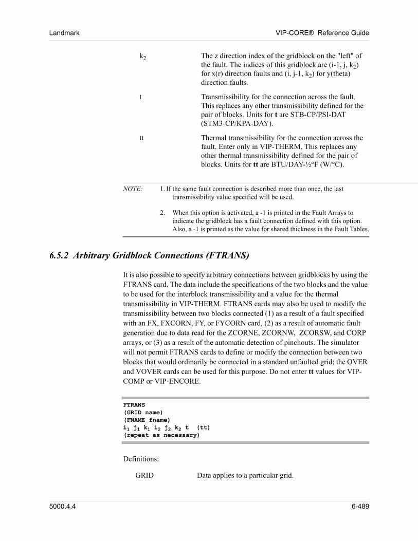
Landmark VIP-CORE® Reference Guide
NOTE: 1. If the same fault connection is described more than once, the last transmissibility value specified will be used.
2. When this option is activated, a -1 is printed in the Fault Arrays to indicate the gridblock has a fault connection defined with this option. Also, a -1 is printed as the value for shared thickness in the Fault Tables.
6.5.2 Arbitrary Gridblock Connections (FTRANS)
It is also possible to specify arbitrary connections between gridblocks by using the FTRANS card. The data include the specifications of the two blocks and the value to be used for the interblock transmissibility and a value for the thermal transmissibility in VIP-THERM. FTRANS cards may also be used to modify the transmissibility between two blocks connected (1) as a result of a fault specified with an FX, FXCORN, FY, or FYCORN card, (2) as a result of automatic fault generation due to data read for the ZCORNE, ZCORNW, ZCORSW, and CORP arrays, or (3) as a result of the automatic detection of pinchouts. The simulator will not permit FTRANS cards to define or modify the connection between two blocks that would ordinarily be connected in a standard unfaulted grid; the OVER and VOVER cards can be used for this purpose. Do not enter tt values for VIP-COMP or VIP-ENCORE.
FTRANS(GRID name)(FNAME fname)i1 j1 k1 i2 j2 k2 t (tt)(repeat as necessary)
Definitions:
GRID Data applies to a particular grid.
k2 The z direction index of the gridblock on the "left" of the fault. The indices of this gridblock are (i-1, j, k2) for x(r) direction faults and (i, j-1, k2) for y(theta) direction faults.
t Transmissibility for the connection across the fault. This replaces any other transmissibility defined for the pair of blocks. Units for t are STB-CP/PSI-DAT (STM3-CP/KPA-DAY).
tt Thermal transmissibility for the connection across the fault. Enter only in VIP-THERM. This replaces any other thermal transmissibility defined for the pair of blocks. Units for tt are BTU/DAY-½°F (W/°C).
5000.4.4 6-489
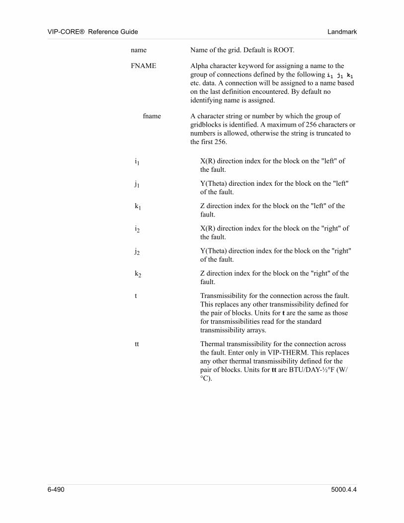
VIP-CORE® Reference Guide Landmark
name Name of the grid. Default is ROOT.
FNAME Alpha character keyword for assigning a name to the group of connections defined by the following i1 j1 k1 etc. data. A connection will be assigned to a name based on the last definition encountered. By default no identifying name is assigned.
fname A character string or number by which the group of gridblocks is identified. A maximum of 256 characters or numbers is allowed, otherwise the string is truncated to the first 256.
i1 X(R) direction index for the block on the "left" of the fault.
j1 Y(Theta) direction index for the block on the "left" of the fault.
k1 Z direction index for the block on the "left" of the fault.
i2 X(R) direction index for the block on the "right" of the fault.
j2 Y(Theta) direction index for the block on the "right" of the fault.
k2 Z direction index for the block on the "right" of the fault.
t Transmissibility for the connection across the fault. This replaces any other transmissibility defined for the pair of blocks. Units for t are the same as those for transmissibilities read for the standard transmissibility arrays.
tt Thermal transmissibility for the connection across the fault. Enter only in VIP-THERM. This replaces any other thermal transmissibility defined for the pair of blocks. Units for tt are BTU/DAY-½°F (W/°C).
6-490 5000.4.4
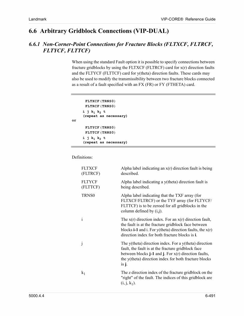
Landmark VIP-CORE® Reference Guide
6.6 Arbitrary Gridblock Connections (VIP-DUAL)
6.6.1 Non-Corner-Point Connections for Fracture Blocks (FLTXCF, FLTRCF, FLTYCF, FLTTCF)
When using the standard Fault option it is possible to specify connections between fracture gridblocks by using the FLTXCF (FLTRCF) card for x(r) direction faults and the FLTYCF (FLTTCF) card for y(theta) direction faults. These cards may also be used to modify the transmissibility between two fracture blocks connected as a result of a fault specified with an FX (FR) or FY (FTHETA) card.
FLTXCF TRNS0 FLTRCF TRNS0
i j k1 k2 t(repeat as necessary)
or
FLTYCF TRNS0 FLTTCF TRNS0
i j k1 k2 t(repeat as necessary)
Definitions: 00
FLTXCF (FLTRCF)
Alpha label indicating an x(r) direction fault is being described.
FLTYCF (FLTTCF)
Alpha label indicating a y(theta) direction fault is being described.
TRNS0 Alpha label indicating that the TXF array (for FLTXCF/FLTRCF) or the TYF array (for FLTYCF/FLTTCF) is to be zeroed for all gridblocks in the column defined by (i,j).
i The x(r) direction index. For an x(r) direction fault, the fault is at the fracture gridblock face between blocks i-1 and i. For y(theta) direction faults, the x(r) direction index for both fracture blocks is i.
j The y(theta) direction index. For a y(theta) direction fault, the fault is at the fracture gridblock face between blocks j-1 and j. For x(r) direction faults, the y(theta) direction index for both fracture blocks is j.
k1 The z direction index of the fracture gridblock on the "right" of the fault. The indices of this gridblock are (i, j, k1).
5000.4.4 6-491
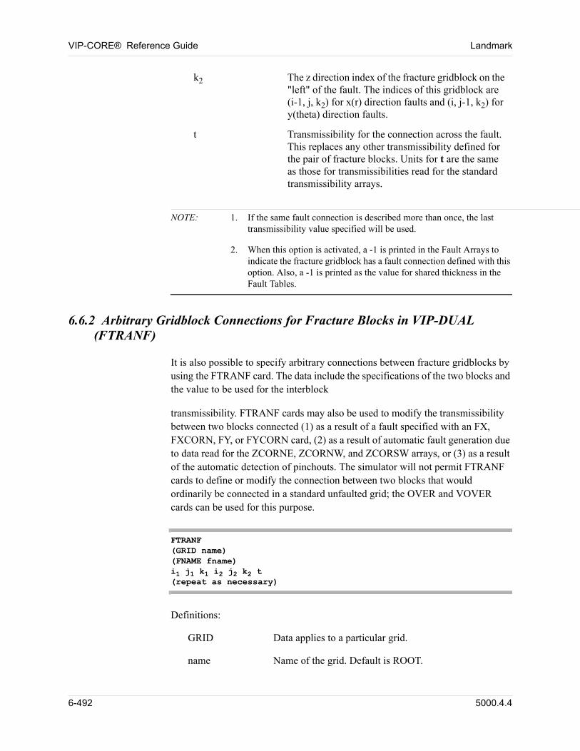
VIP-CORE® Reference Guide Landmark
NOTE: 1. If the same fault connection is described more than once, the last transmissibility value specified will be used.
2. When this option is activated, a -1 is printed in the Fault Arrays to indicate the fracture gridblock has a fault connection defined with this option. Also, a -1 is printed as the value for shared thickness in the Fault Tables.
6.6.2 Arbitrary Gridblock Connections for Fracture Blocks in VIP-DUAL (FTRANF)
It is also possible to specify arbitrary connections between fracture gridblocks by using the FTRANF card. The data include the specifications of the two blocks and the value to be used for the interblock
transmissibility. FTRANF cards may also be used to modify the transmissibility between two blocks connected (1) as a result of a fault specified with an FX, FXCORN, FY, or FYCORN card, (2) as a result of automatic fault generation due to data read for the ZCORNE, ZCORNW, and ZCORSW arrays, or (3) as a result of the automatic detection of pinchouts. The simulator will not permit FTRANF cards to define or modify the connection between two blocks that would ordinarily be connected in a standard unfaulted grid; the OVER and VOVER cards can be used for this purpose.
FTRANF(GRID name)(FNAME fname)i1 j1 k1 i2 j2 k2 t(repeat as necessary)
Definitions: 00
GRID Data applies to a particular grid.
name Name of the grid. Default is ROOT.
k2 The z direction index of the fracture gridblock on the "left" of the fault. The indices of this gridblock are (i-1, j, k2) for x(r) direction faults and (i, j-1, k2) for y(theta) direction faults.
t Transmissibility for the connection across the fault. This replaces any other transmissibility defined for the pair of fracture blocks. Units for t are the same as those for transmissibilities read for the standard transmissibility arrays.
6-492 5000.4.4
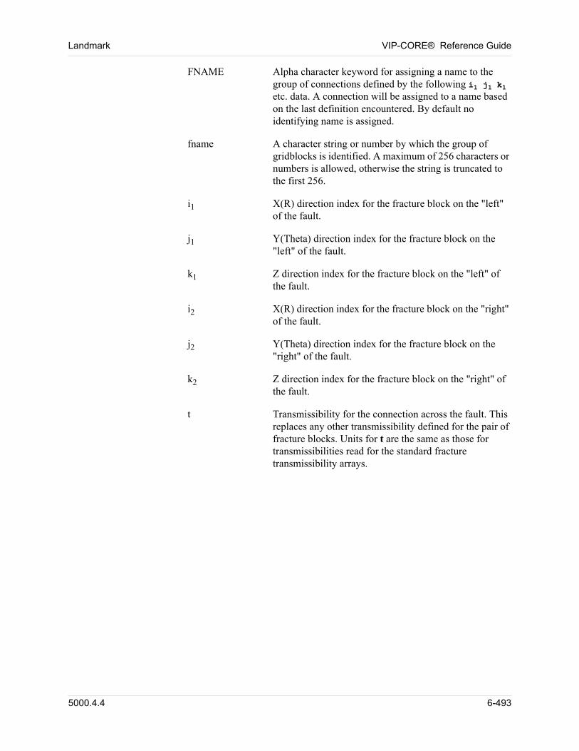
Landmark VIP-CORE® Reference Guide
FNAME Alpha character keyword for assigning a name to the group of connections defined by the following i1 j1 k1 etc. data. A connection will be assigned to a name based on the last definition encountered. By default no identifying name is assigned.
fname A character string or number by which the group of gridblocks is identified. A maximum of 256 characters or numbers is allowed, otherwise the string is truncated to the first 256.
i1 X(R) direction index for the fracture block on the "left" of the fault.
j1 Y(Theta) direction index for the fracture block on the "left" of the fault.
k1 Z direction index for the fracture block on the "left" of the fault.
i2 X(R) direction index for the fracture block on the "right" of the fault.
j2 Y(Theta) direction index for the fracture block on the "right" of the fault.
k2 Z direction index for the fracture block on the "right" of the fault.
t Transmissibility for the connection across the fault. This replaces any other transmissibility defined for the pair of fracture blocks. Units for t are the same as those for transmissibilities read for the standard fracture transmissibility arrays.
5000.4.4 6-493
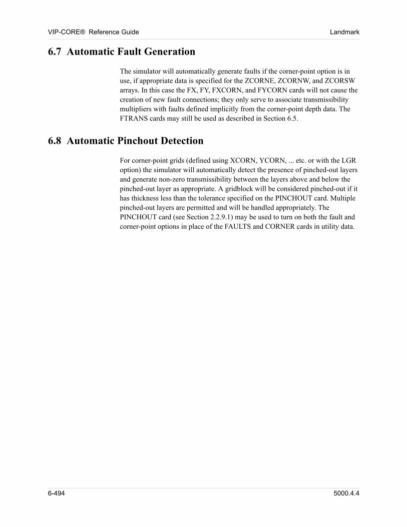
VIP-CORE® Reference Guide Landmark
6.7 Automatic Fault Generation
The simulator will automatically generate faults if the corner-point option is in use, if appropriate data is specified for the ZCORNE, ZCORNW, and ZCORSW arrays. In this case the FX, FY, FXCORN, and FYCORN cards will not cause the creation of new fault connections; they only serve to associate transmissibility multipliers with faults defined implicitly from the corner-point depth data. The FTRANS cards may still be used as described in Section 6.5.
6.8 Automatic Pinchout Detection
For corner-point grids (defined using XCORN, YCORN, ... etc. or with the LGR option) the simulator will automatically detect the presence of pinched-out layers and generate non-zero transmissibility between the layers above and below the pinched-out layer as appropriate. A gridblock will be considered pinched-out if it has thickness less than the tolerance specified on the PINCHOUT card. Multiple pinched-out layers are permitted and will be handled appropriately. The PINCHOUT card (see Section 2.2.9.1) may be used to turn on both the fault and corner-point options in place of the FAULTS and CORNER cards in utility data.
6-494 5000.4.4
Chapter
7
00000Overread Options
7.1 Transmissibility / Pore Volume Modification Options
These cards must appear after all grid data input. The order of data following OVER/VOVER must be COARSEN, MULTIR, MULTFL, REGION/REGSEP/REGDTM, INFLUX/FLUX, when such data are input.
The transmissibility/pore volume arrays may be modified at initialization. This is accomplished with OVER/VOVER cards. Any number of OVER/VOVER cards can be used. The modification described by each card is performed at the time the card is read; hence, these changes are order-dependent. When using the corner point option with automatically generated fault connections, transmissibility overreads can be processed using the MULT keyword. As well as modifying the interblock transmissibilities, these cards also modify the transmissibilities across faults between blocks with modified transmissibilities, whereas the OVER/VOVER cards will only modify normal interblock connection transmissibilities. Care should be taken not to specify, for example, both OVER TX cards and MULT cards with overlapping ranges as this will result in normal interblock transmissibilities being modified twice. The pore volume OVER/VOVER are applied after the TOLPV checks.
5000.4.4 7-495
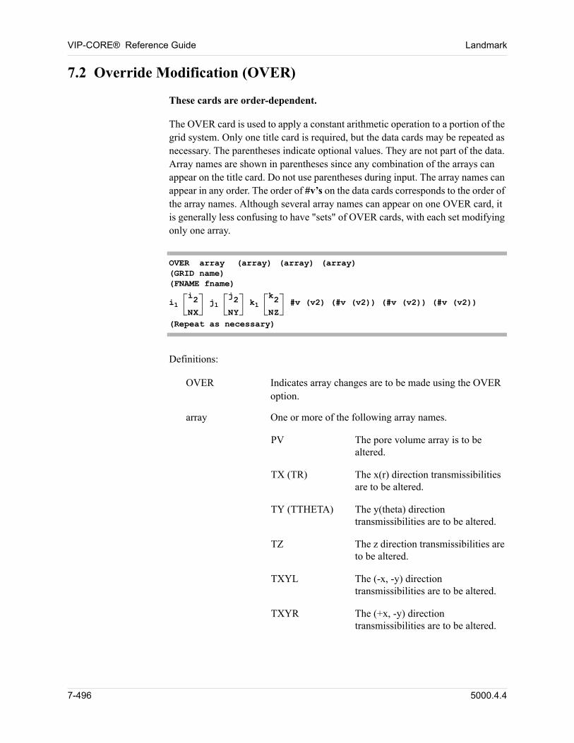
VIP-CORE® Reference Guide Landmark
7.2 Override Modification (OVER)
These cards are order-dependent.
The OVER card is used to apply a constant arithmetic operation to a portion of the grid system. Only one title card is required, but the data cards may be repeated as necessary. The parentheses indicate optional values. They are not part of the data. Array names are shown in parentheses since any combination of the arrays can appear on the title card. Do not use parentheses during input. The array names can appear in any order. The order of #v’s on the data cards corresponds to the order of the array names. Although several array names can appear on one OVER card, it is generally less confusing to have "sets" of OVER cards, with each set modifying only one array.
OVER array (array) (array) (array)(GRID name)(FNAME fname)
i1 i2
NX j1
j2
NY k1
k2
NZ #v (v2) (#v (v2)) (#v (v2)) (#v (v2))
(Repeat as necessary)
Definitions:
OVER Indicates array changes are to be made using the OVER option.
array One or more of the following array names.
PV The pore volume array is to be altered.
TX (TR) The x(r) direction transmissibilities are to be altered.
TY (TTHETA) The y(theta) direction transmissibilities are to be altered.
TZ The z direction transmissibilities are to be altered.
TXYL The (-x, -y) direction transmissibilities are to be altered.
TXYR The (+x, -y) direction transmissibilities are to be altered.
7-496 5000.4.4
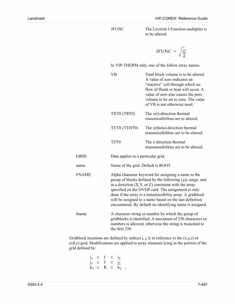
Landmark VIP-CORE® Reference Guide
JFUNC The Leverett J-Function multiplier is to be altered.
JFUNC k----=
In VIP-THERM only, one of the follow array names.
VB Total block volume is to be altered. A value of zero indicates an “inactive” cell through which no flow of fluids or heat will occur. A value of zero also causes the pore volume to be set to zero. The value of VB is not otherwise used.
TXT0 (TRT0) The x(r)-direction thermal transmissibilities are to altered.
TYT0 (TTHT0) The y(theta)-direction thermal transmissibilities are to be altered.
TZT0 The z-direction thermal transmissibilities are to be altered.
GRID Data applies to a particular grid.
name Name of the grid. Default is ROOT.
FNAME Alpha character keyword for assigning a name to the group of blocks defined by the following i,j,k range, and in a direction (X,Y, or Z) consistent with the array specified on the OVER card. The assignment is only done if the array is a transmissibility array. A gridblock will be assigned to a name based on the last definition encountered. By default no identifying name is assigned.
fname A character string or number by which the group of gridblocks is identified. A maximum of 256 characters or numbers is allowed, otherwise the string is truncated to the first 256.
Gridblock locations are defined by indices i, j, k in reference to the (x,y,z) or (r,,z) grid. Modifications are applied to array elements lying in the portion of the grid defined by:
i1 I ij1 J j2k1 K k2 ,
5000.4.4 7-497
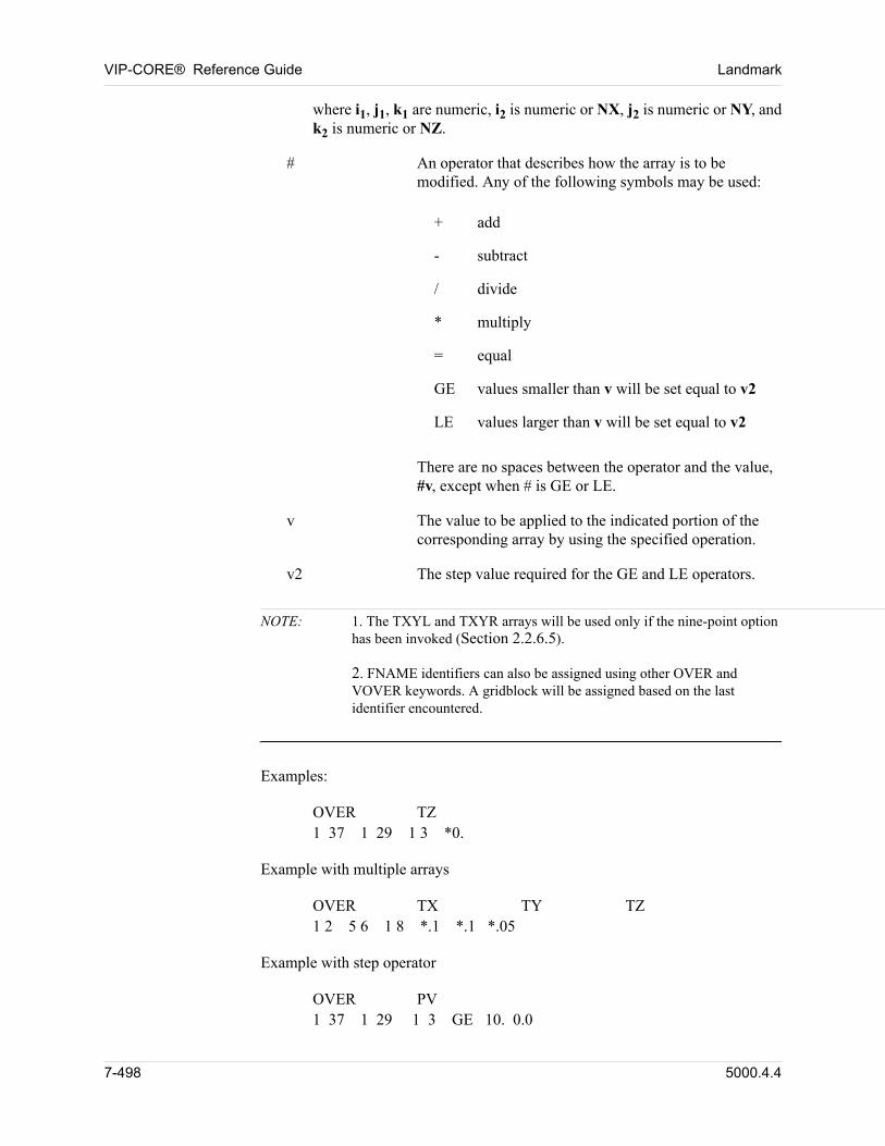
VIP-CORE® Reference Guide Landmark
where i1, j1, k1 are numeric, i2 is numeric or NX, j2 is numeric or NY, and k2 is numeric or NZ.
# An operator that describes how the array is to be modified. Any of the following symbols may be used:
+ add
- subtract
/ divide
* multiply
= equal
GE values smaller than v will be set equal to v2
LE values larger than v will be set equal to v2
There are no spaces between the operator and the value, #v, except when # is GE or LE.
v The value to be applied to the indicated portion of the corresponding array by using the specified operation.
v2 The step value required for the GE and LE operators.
NOTE: 1. The TXYL and TXYR arrays will be used only if the nine-point option has been invoked (Section 2.2.6.5).2. FNAME identifiers can also be assigned using other OVER and VOVER keywords. A gridblock will be assigned based on the last identifier encountered.
Examples:
OVER TZ1 37 1 29 1 3 *0.
Example with multiple arrays
OVER TX TY TZ1 2 5 6 1 8 *.1 *.1 *.05
Example with step operator
OVER PV1 37 1 29 1 3 GE 10. 0.0
7-498 5000.4.4
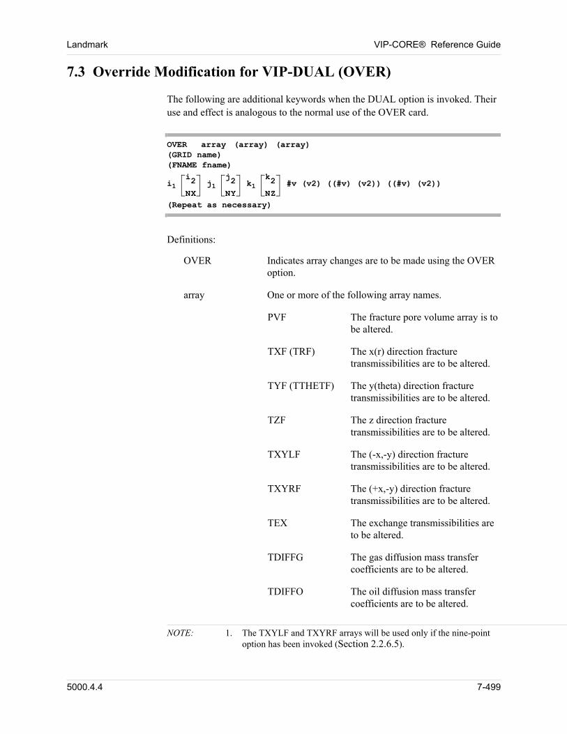
Landmark VIP-CORE® Reference Guide
7.3 Override Modification for VIP-DUAL (OVER)
The following are additional keywords when the DUAL option is invoked. Their use and effect is analogous to the normal use of the OVER card.
OVER array (array) (array) (GRID name)(FNAME fname)
i1 i2
NX j1
j2
NY k1
k2
NZ #v (v2) ((#v) (v2)) ((#v) (v2))
(Repeat as necessary)
Definitions:
OVER Indicates array changes are to be made using the OVER option.
array One or more of the following array names.
PVF The fracture pore volume array is to be altered.
TXF (TRF) The x(r) direction fracture transmissibilities are to be altered.
TYF (TTHETF) The y(theta) direction fracture transmissibilities are to be altered.
TZF The z direction fracture transmissibilities are to be altered.
TXYLF The (-x,-y) direction fracture transmissibilities are to be altered.
TXYRF The (+x,-y) direction fracture transmissibilities are to be altered.
TEX The exchange transmissibilities are to be altered.
TDIFFG The gas diffusion mass transfer coefficients are to be altered.
TDIFFO The oil diffusion mass transfer coefficients are to be altered.
NOTE: 1. The TXYLF and TXYRF arrays will be used only if the nine-point option has been invoked (Section 2.2.6.5).
5000.4.4 7-499
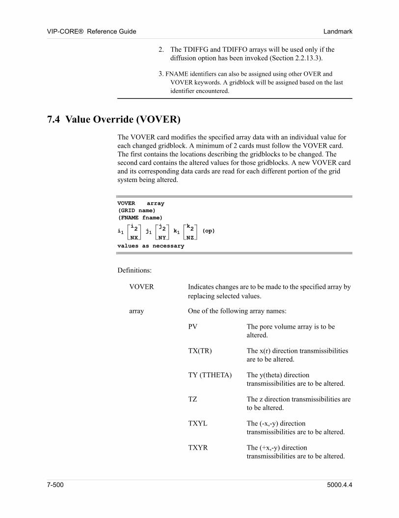
VIP-CORE® Reference Guide Landmark
2. The TDIFFG and TDIFFO arrays will be used only if the diffusion option has been invoked (Section 2.2.13.3).
3. FNAME identifiers can also be assigned using other OVER and VOVER keywords. A gridblock will be assigned based on the last identifier encountered.
7.4 Value Override (VOVER)
The VOVER card modifies the specified array data with an individual value for each changed gridblock. A minimum of 2 cards must follow the VOVER card. The first contains the locations describing the gridblocks to be changed. The second card contains the altered values for those gridblocks. A new VOVER card and its corresponding data cards are read for each different portion of the grid system being altered.
VOVER array(GRID name)(FNAME fname)
i1 i2
NX j1
j2
NY k1
k2
NZ (op)
values as necessary
Definitions:
VOVER Indicates changes are to be made to the specified array by replacing selected values.
array One of the following array names:
PV The pore volume array is to be altered.
TX(TR) The x(r) direction transmissibilities are to be altered.
TY (TTHETA) The y(theta) direction transmissibilities are to be altered.
TZ The z direction transmissibilities are to be altered.
TXYL The (-x,-y) direction transmissibilities are to be altered.
TXYR The (+x,-y) direction transmissibilities are to be altered.
7-500 5000.4.4
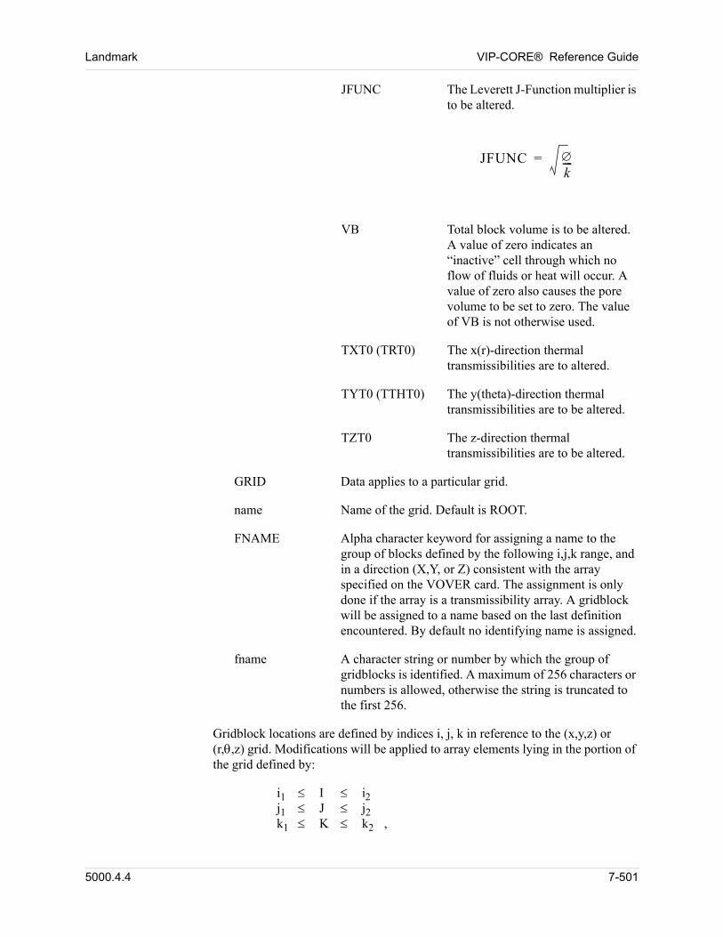
Landmark VIP-CORE® Reference Guide
JFUNC The Leverett J-Function multiplier is to be altered.
JFUNC k----=
VB Total block volume is to be altered. A value of zero indicates an “inactive” cell through which no flow of fluids or heat will occur. A value of zero also causes the pore volume to be set to zero. The value of VB is not otherwise used.
TXT0 (TRT0) The x(r)-direction thermal transmissibilities are to altered.
TYT0 (TTHT0) The y(theta)-direction thermal transmissibilities are to be altered.
TZT0 The z-direction thermal transmissibilities are to be altered.
GRID Data applies to a particular grid.
name Name of the grid. Default is ROOT.
FNAME Alpha character keyword for assigning a name to the group of blocks defined by the following i,j,k range, and in a direction (X,Y, or Z) consistent with the array specified on the VOVER card. The assignment is only done if the array is a transmissibility array. A gridblock will be assigned to a name based on the last definition encountered. By default no identifying name is assigned.
fname A character string or number by which the group of gridblocks is identified. A maximum of 256 characters or numbers is allowed, otherwise the string is truncated to the first 256.
Gridblock locations are defined by indices i, j, k in reference to the (x,y,z) or (r,,z) grid. Modifications will be applied to array elements lying in the portion of the grid defined by:
i1 I ij1 J j2k1 K k2 ,
5000.4.4 7-501
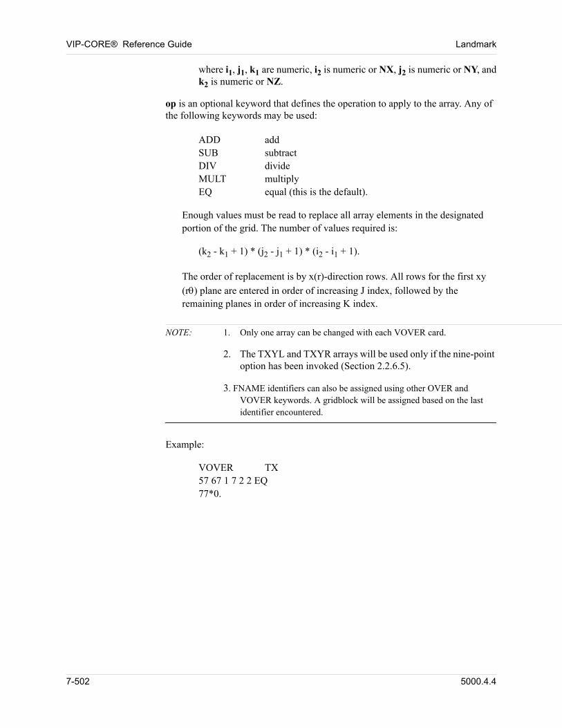
VIP-CORE® Reference Guide Landmark
where i1, j1, k1 are numeric, i2 is numeric or NX, j2 is numeric or NY, and k2 is numeric or NZ.
op is an optional keyword that defines the operation to apply to the array. Any of the following keywords may be used:
ADD addSUB subtractDIV divideMULT multiplyEQ equal (this is the default).
Enough values must be read to replace all array elements in the designated portion of the grid. The number of values required is:
(k2 - k1 + 1) * (j2 - j1 + 1) * (i2 - i1 + 1).
The order of replacement is by x(r)-direction rows. All rows for the first xy
(r) plane are entered in order of increasing J index, followed by the remaining planes in order of increasing K index.
NOTE: 1. Only one array can be changed with each VOVER card.
2. The TXYL and TXYR arrays will be used only if the nine-point option has been invoked (Section 2.2.6.5).
3. FNAME identifiers can also be assigned using other OVER and VOVER keywords. A gridblock will be assigned based on the last identifier encountered.
Example:
VOVER TX57 67 1 7 2 2 EQ77*0.
7-502 5000.4.4
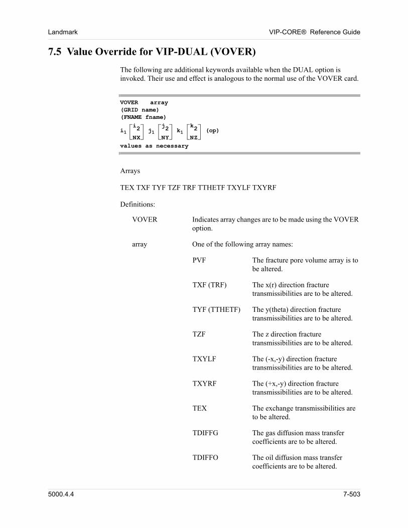
Landmark VIP-CORE® Reference Guide
7.5 Value Override for VIP-DUAL (VOVER)
The following are additional keywords available when the DUAL option is invoked. Their use and effect is analogous to the normal use of the VOVER card.
VOVER array(GRID name)(FNAME fname)
i1 i2
NX j1
j2
NY k1
k2
NZ (op)
values as necessary
Arrays
TEX TXF TYF TZF TRF TTHETF TXYLF TXYRF
Definitions:
VOVER Indicates array changes are to be made using the VOVER option.
array One of the following array names:
PVF The fracture pore volume array is to be altered.
TXF (TRF) The x(r) direction fracture transmissibilities are to be altered.
TYF (TTHETF) The y(theta) direction fracture transmissibilities are to be altered.
TZF The z direction fracture transmissibilities are to be altered.
TXYLF The (-x,-y) direction fracture transmissibilities are to be altered.
TXYRF The (+x,-y) direction fracture transmissibilities are to be altered.
TEX The exchange transmissibilities are to be altered.
TDIFFG The gas diffusion mass transfer coefficients are to be altered.
TDIFFO The oil diffusion mass transfer coefficients are to be altered.
5000.4.4 7-503
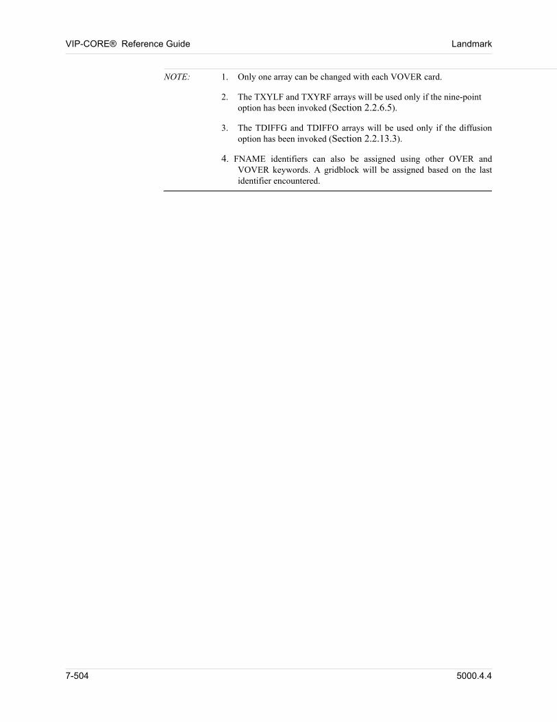
VIP-CORE® Reference Guide Landmark
NOTE: 1. Only one array can be changed with each VOVER card.
2. The TXYLF and TXYRF arrays will be used only if the nine-point option has been invoked (Section 2.2.6.5).
3. The TDIFFG and TDIFFO arrays will be used only if the diffusion option has been invoked (Section 2.2.13.3).
4. FNAME identifiers can also be assigned using other OVER and VOVER keywords. A gridblock will be assigned based on the last identifier encountered.
7-504 5000.4.4
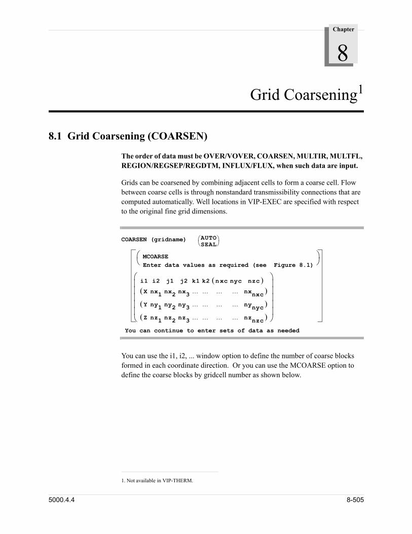
Chapter
8
00000Grid Coarsening1
8.1 Grid Coarsening (COARSEN)
The order of data must be OVER/VOVER, COARSEN, MULTIR, MULTFL, REGION/REGSEP/REGDTM, INFLUX/FLUX, when such data are input.
Grids can be coarsened by combining adjacent cells to form a coarse cell. Flow between coarse cells is through nonstandard transmissibility connections that are computed automatically. Well locations in VIP-EXEC are specified with respect to the original fine grid dimensions.
COARSEN (gridname) AUTOSEAL
MCOARSEEnter data values as required (see Figure 8.1)
i1 i2 j1 j2 k1 k2 n xc nyc nzc X nx1 nx2 nx3 nxnxc
Y ny1 ny2 ny3 nynyc
Z nz1 nz2 nz3 nznzc
You can continue to enter sets of data as needed
You can use the i1, i2, ... window option to define the number of coarse blocks formed in each coordinate direction. Or you can use the MCOARSE option to define the coarse blocks by gridcell number as shown below.
1. Not available in VIP-THERM.
5000.4.4 8-505
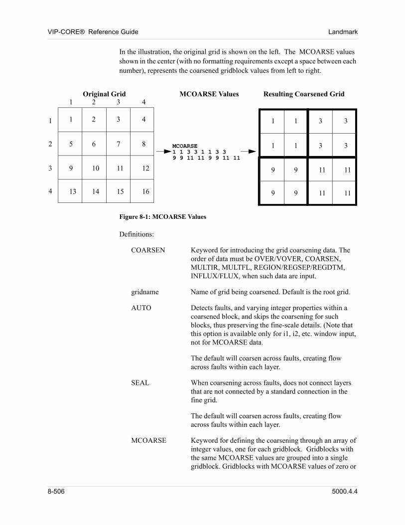
VIP-CORE® Reference Guide Landmark
In the illustration, the original grid is shown on the left. The MCOARSE values shown in the center (with no formatting requirements except a space between each number), represents the coarsened gridblock values from left to right.
2
3
4
1 2 3 4
1 1 2 3 4
5 6 7 8
13 14 15 16
9 10 11 12
1 1 3 3
1 1 3 3
9 9 11 11
9 9 11 11
MCOARSE1 1 3 3 1 1 3 39 9 11 11 9 9 11 11
Original Grid MCOARSE Values Resulting Coarsened Grid
Figure 8-1: MCOARSE Values
Definitions:
COARSEN Keyword for introducing the grid coarsening data. The order of data must be OVER/VOVER, COARSEN, MULTIR, MULTFL, REGION/REGSEP/REGDTM, INFLUX/FLUX, when such data are input.
gridname Name of grid being coarsened. Default is the root grid.
AUTO Detects faults, and varying integer properties within a coarsened block, and skips the coarsening for such blocks, thus preserving the fine-scale details. (Note that this option is available only for i1, i2, etc. window input, not for MCOARSE data.
The default will coarsen across faults, creating flow across faults within each layer.
SEAL When coarsening across faults, does not connect layers that are not connected by a standard connection in the fine grid.
The default will coarsen across faults, creating flow across faults within each layer.
MCOARSE Keyword for defining the coarsening through an array of integer values, one for each gridblock. Gridblocks with the same MCOARSE values are grouped into a single gridblock. Gridblocks with MCOARSE values of zero or
8-506 5000.4.4
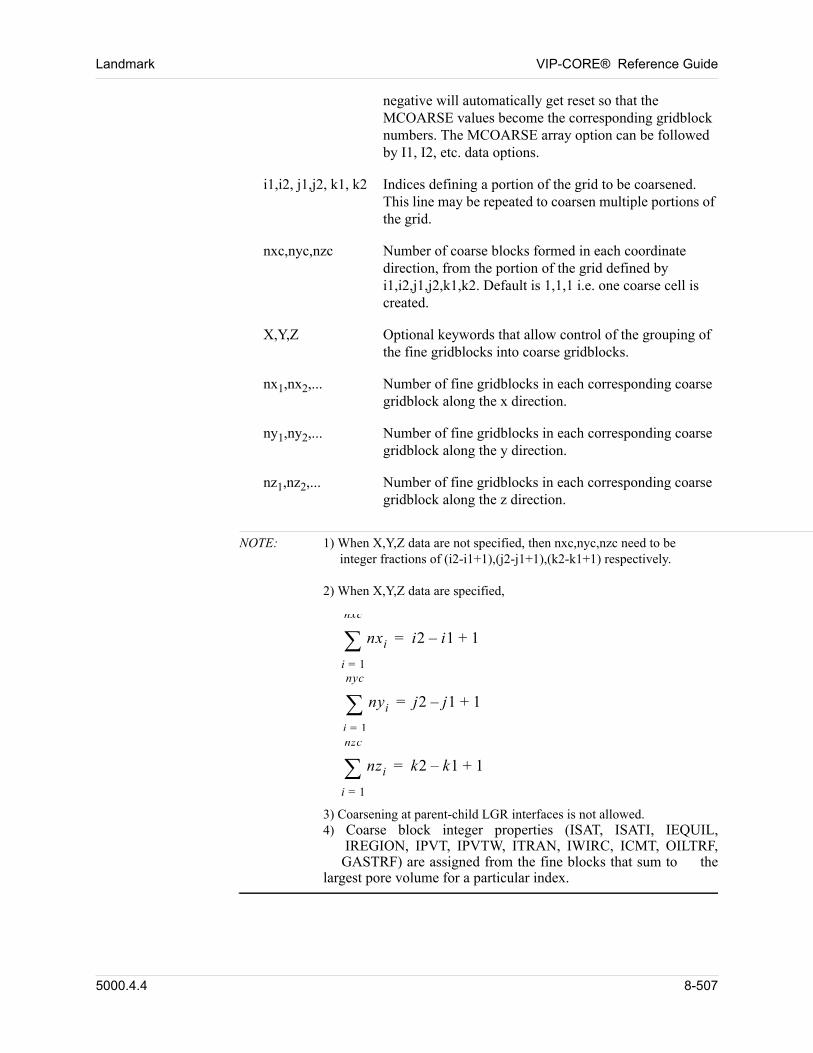
Landmark VIP-CORE® Reference Guide
negative will automatically get reset so that the MCOARSE values become the corresponding gridblock numbers. The MCOARSE array option can be followed by I1, I2, etc. data options.
i1,i2, j1,j2, k1, k2 Indices defining a portion of the grid to be coarsened. This line may be repeated to coarsen multiple portions of the grid.
nxc,nyc,nzc Number of coarse blocks formed in each coordinate direction, from the portion of the grid defined by i1,i2,j1,j2,k1,k2. Default is 1,1,1 i.e. one coarse cell is created.
X,Y,Z Optional keywords that allow control of the grouping of the fine gridblocks into coarse gridblocks.
nx1,nx2,... Number of fine gridblocks in each corresponding coarse gridblock along the x direction.
ny1,ny2,... Number of fine gridblocks in each corresponding coarse gridblock along the y direction.
nz1,nz2,... Number of fine gridblocks in each corresponding coarse gridblock along the z direction.
NOTE: 1) When X,Y,Z data are not specified, then nxc,nyc,nzc need to be integer fractions of (i2-i1+1),(j2-j1+1),(k2-k1+1) respectively. 2) When X,Y,Z data are specified, nxi
i 1=
nxc
i2 i1– 1+= nyi
i 1=
nyc
j2 j1– 1+= nzi
i 1=
nzc
k2 k1– 1+= 3) Coarsening at parent-child LGR interfaces is not allowed.4) Coarse block integer properties (ISAT, ISATI, IEQUIL, IREGION, IPVT, IPVTW, ITRAN, IWIRC, ICMT, OILTRF, GASTRF) are assigned from the fine blocks that sum to the largest pore volume for a particular index.
5000.4.4 8-507
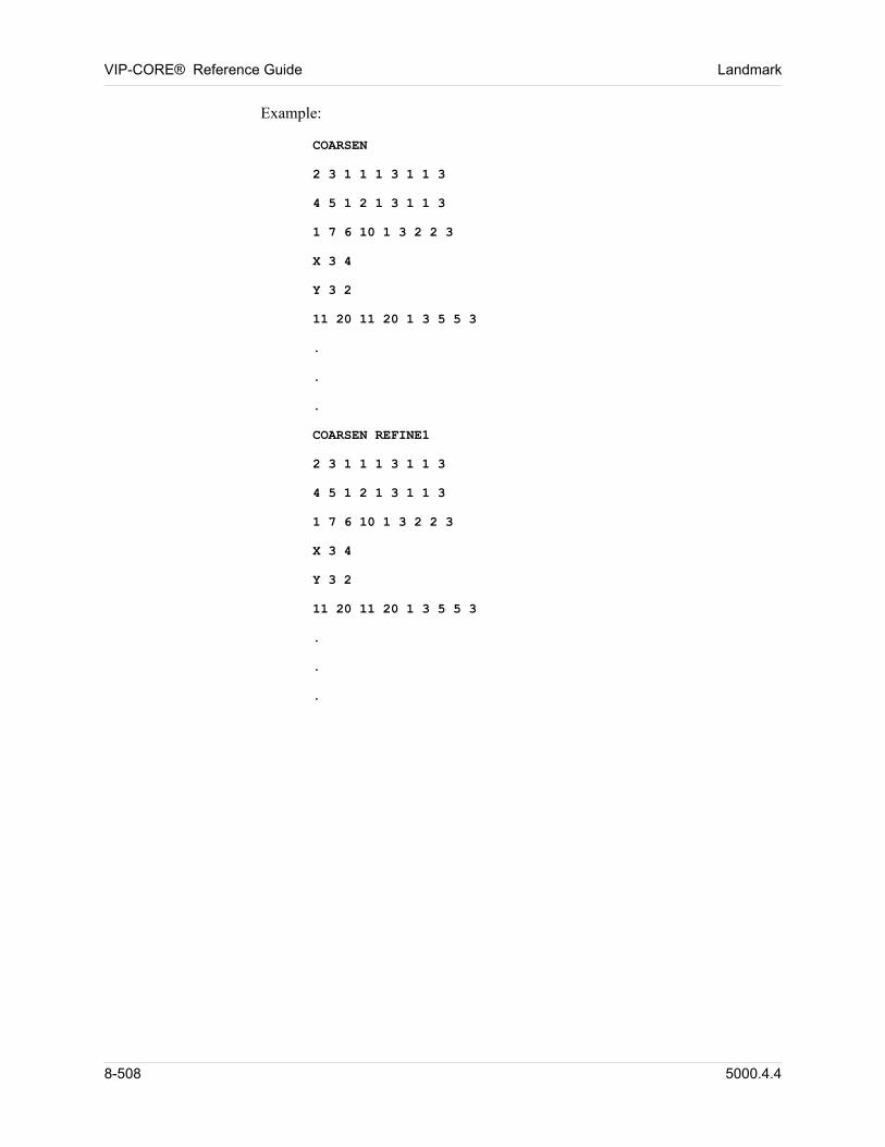
VIP-CORE® Reference Guide Landmark
Example:
COARSEN
2 3 1 1 1 3 1 1 3
4 5 1 2 1 3 1 1 3
1 7 6 10 1 3 2 2 3
X 3 4
Y 3 2
11 20 11 20 1 3 5 5 3
.
.
.
COARSEN REFINE1
2 3 1 1 1 3 1 1 3
4 5 1 2 1 3 1 1 3
1 7 6 10 1 3 2 2 3
X 3 4
Y 3 2
11 20 11 20 1 3 5 5 3
.
.
.
8-508 5000.4.4
Chapter
9
00000Region Data
The order of data must be OVER/VOVER, COARSEN, MULTIR, MULTFL, REGION/REGSEP/REGDTM, INFLUX/FLUX, when such data are input.
9.1 Assign Output Region Names (REGION)
REGION cards permit the user to assign region names to output regions defined by the IREGION (and/or IREGF) array (Section 5.15). One REGION card is input for each region name assignment.
REGION ireg1 regnam1. . .. . .. . .REGION iregn regnamn
Definitions:
iregi Region number defined in the IREGION (and/or IREGF) data.
regnami Region name for region number iregi. The first character in the name must be alphanumeric. Only the first six (6) characters of the name are used. Default is blanks.
All REGION cards must precede any REGSEP or REGDTM da1ta.
Example:
REGION 1 SAGREGION 2 SHUBREGION 3 SADREGION 4 WESAGREGION 5 WESHUBREGION 6 WESAD
5000.4.4 9-509
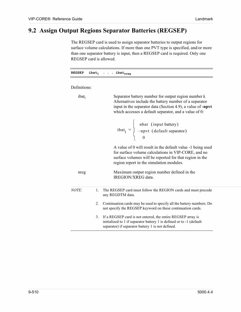
VIP-CORE® Reference Guide Landmark
9.2 Assign Output Regions Separator Batteries (REGSEP)
The REGSEP card is used to assign separator batteries to output regions for surface volume calculations. If more than one PVT type is specified, and/or more than one separator battery is input, then a REGSEP card is required. Only one REGSEP card is allowed.
REGSEP ibat1 . . . ibatnreg
Definitions:
ibati Separator battery number for output region number i. Alternatives include the battery number of a separator input in the separator data (Section 4.9), a value of -npvt which accesses a default separator, and a value of 0:
ibati
nbat input battery npvt– default separator 0
=
A value of 0 will result in the default value -1 being used for surface volume calculations in VIP-CORE, and no surface volumes will be reported for that region in the region report in the simulation modules.
nreg Maximum output region number defined in the IREGION/XREG data.
NOTE: 1. The REGSEP card must follow the REGION cards and must precede any REGDTM data.
2. Continuation cards may be used to specify all the battery numbers. Do not specify the REGSEP keyword on these continuation cards.
3. If a REGSEP card is not entered, the entire REGSEP array is initialized to 1 if separator battery 1 is defined or to -1 (default separator) if separator battery 1 is not defined.
9-510 5000.4.4
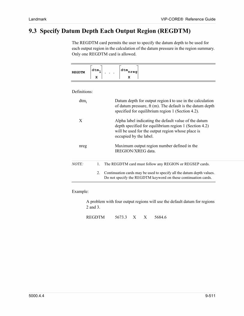
Landmark VIP-CORE® Reference Guide
9.3 Specify Datum Depth Each Output Region (REGDTM)
The REGDTM card permits the user to specify the datum depth to be used for each output region in the calculation of the datum pressure in the region summary. Only one REGDTM card is allowed.
REGDTM
dtm1
X. . .
dtmnreg
X
Definitions:
dtmi Datum depth for output region i to use in the calculation of datum pressure, ft (m). The default is the datum depth specified for equilibrium region 1 (Section 4.2).
X Alpha label indicating the default value of the datum depth specified for equilibrium region 1 (Section 4.2) will be used for the output region whose place is occupied by the label.
nreg Maximum output region number defined in the IREGION/XREG data.
NOTE: 1. The REGDTM card must follow any REGION or REGSEP cards.
2. Continuation cards may be used to specify all the datum depth values. Do not specify the REGDTM keyword on these continuation cards.
Example:
A problem with four output regions will use the default datum for regions 2 and 3.
REGDTM 5673.3 X X 5684.6
5000.4.4 9-511

VIP-CORE® Reference Guide Landmark
9-512 5000.4.4
Chapter
10
00000Grid Boundary Flux 1
10.1 Introduction
The order of data must be OVER/VOVER, COARSEN, MULTIR, MULTFL, REGION/REGSEP/REGDTM, INFLUX/FLUX, when such data are input.
In VIP, boundary flux is handled by including source/sink terms in the interblock flow equations for edge blocks. The outer boundaries of the grid are normally treated as sealing barriers to flow. Two specific boundary flux cases are considered: 1) use of an aquifer influence function to represent a surrounding body of water, and 2) inclusion of flux from a course grid simulation run as the boundary conditions for a fine grid model.
10.2 Analytical Aquifer
In the descriptions that follow, reference is made to "aquifers" that supply fluid to the grid. The model calculates fluid influx by the Carter-Tracy method or the Fetkovich method. A comprehensive discussion of aquifer treatments is given in
Frick and Taylor (Reference 8).
The influx option is subject to the following restrictions and guidelines:
1. A gridblock can receive fluid from only one influx region.
2. Within the data for an influx region, a gridblock can be referenced more than once. The data assigned to each gridblock is cumulative; therefore, the influx data are order dependent.
3. Influx data should not refer to zero pore volume blocks. Such a reference is a fatal error for data entry when using the VALUE option. If the WINDOW option is used in the influx description, the zero pore volume blocks are ignored, depending on the sinf option used.
4. To use the XCALC, YCALC, and ZCALC options, the DX, DY, DZ, XCORN...or CORP, KX, KY, and KZ arrays must be entered in the array data (Section 4.2).
1. Not available in VIP-THERM.
5000.4.4 10-513
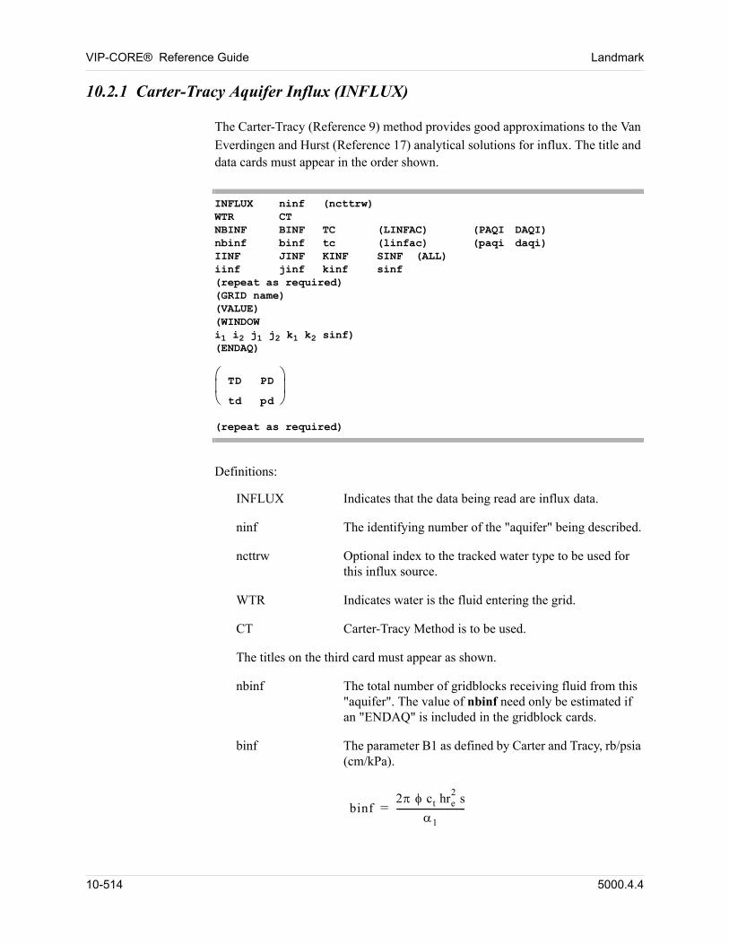
VIP-CORE® Reference Guide Landmark
10.2.1 Carter-Tracy Aquifer Influx (INFLUX)
The Carter-Tracy (Reference 9) method provides good approximations to the Van
Everdingen and Hurst (Reference 17) analytical solutions for influx. The title and data cards must appear in the order shown.
INFLUX ninf (ncttrw)WTR CTNBINF BINF TC (LINFAC) (PAQI DAQI)nbinf binf tc (linfac) (paqi daqi)IINF JINF KINF SINF (ALL)iinf jinf kinf sinf(repeat as required)(GRID name)(VALUE)(WINDOWi1 i2 j1 j2 k1 k2 sinf)(ENDAQ)
TD PD
td pd
(repeat as required)
Definitions:
INFLUX Indicates that the data being read are influx data.
ninf The identifying number of the "aquifer" being described.
ncttrw Optional index to the tracked water type to be used for this influx source.
WTR Indicates water is the fluid entering the grid.
CT Carter-Tracy Method is to be used.
The titles on the third card must appear as shown.
nbinf The total number of gridblocks receiving fluid from this "aquifer". The value of nbinf need only be estimated if an "ENDAQ" is included in the gridblock cards.
binf The parameter B1 as defined by Carter and Tracy, rb/psia (cm/kPa).
binf2 ct hre
2s
1
-----------------------------=
10-514 5000.4.4
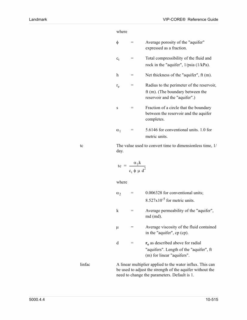
Landmark VIP-CORE® Reference Guide
where
= Average porosity of the "aquifer" expressed as a fraction.
ct = Total compressibility of the fluid and
rock in the "aquifer", 1/psia (1/kPa).
h = Net thickness of the "aquifer", ft (m).
re = Radius to the perimeter of the reservoir,
ft (m). (The boundary between the reservoir and the "aquifer".)
s = Fraction of a circle that the boundary between the reservoir and the aquifer completes.
1 = 5.6146 for conventional units. 1.0 for
metric units.
tc The value used to convert time to dimensionless time, 1/day.
tc2k
ct d2
--------------------=
where
2 = 0.006328 for conventional units;
8.527x10⁻⁵ for metric units.
k = Average permeability of the "aquifer", md (md).
= Average viscosity of the fluid contained in the "aquifer", cp (cp).
d = re as described above for radial
"aquifers". Length of the "aquifer", ft (m) for linear "aquifers".
linfac A linear multiplier applied to the water influx. This can be used to adjust the strength of the aquifer without the need to change the parameters. Default is 1.
5000.4.4 10-515
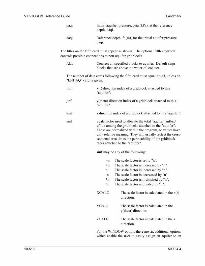
VIP-CORE® Reference Guide Landmark
paqi Initial aquifier pressure, psia (kPa), at the reference depth, daqi.
daqi Reference depth, ft (m), for the initial aquifer pressure, paqi.
The titles on the fifth card must appear as shown. The optional fifth keyword controls possible connections to non-aquifer gridblocks
ALL Connect all specified blocks to aquifer. Default skips blocks that are above the water-oil contact.
The number of data cards following the fifth card must equal nbinf, unless an "ENDAQ" card is given.
iinf x(r) direction index of a gridblock attached to this "aquifer".
jinf y(theta) direction index of a gridblock attached to this "aquifer".
kinf z direction index of a gridblock attached to this "aquifer".
sinf Scale factor used to allocate the total "aquifer" influx/efflux among the gridblocks attached to the "aquifer". These are normalized within the program, so values have only relative meaning. They will usually reflect the cross-sectional area times the permeability of the gridblock faces attached to the "aquifer".
sinf may be any of the following: 00
=n The scale factor is set to "n".+n The scale factor is increased by "n".n The scale factor is increased by "n".-n The scale factor is decreased by "n".*n The scale factor is multiplied by "n"./n The scale factor is divided by "n". 00
XCALC The scale factor is calculated in the x(r) direction. 00
YCALC The scale factor is calculated in the y(theta) direction. 00
ZCALC The scale factor is calculated in the z direction. 00
For the WINDOW option, there are six additional options which enable the user to easily assign an aquifer to an
10-516 5000.4.4
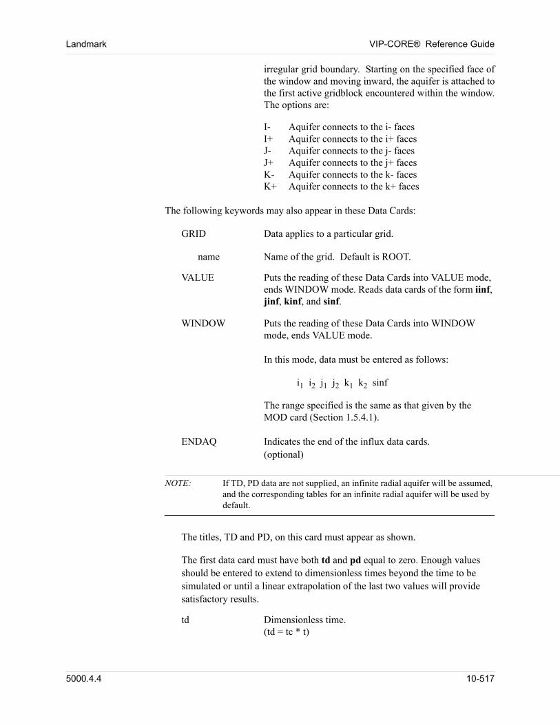
Landmark VIP-CORE® Reference Guide
irregular grid boundary. Starting on the specified face of the window and moving inward, the aquifer is attached to the first active gridblock encountered within the window. The options are:
I- Aquifer connects to the i- facesI+ Aquifer connects to the i+ facesJ- Aquifer connects to the j- facesJ+ Aquifer connects to the j+ facesK- Aquifer connects to the k- facesK+ Aquifer connects to the k+ faces
The following keywords may also appear in these Data Cards: 00
GRID Data applies to a particular grid. 00
name Name of the grid. Default is ROOT. 00
VALUE Puts the reading of these Data Cards into VALUE mode, ends WINDOW mode. Reads data cards of the form iinf, jinf, kinf, and sinf.
WINDOW Puts the reading of these Data Cards into WINDOW mode, ends VALUE mode.
In this mode, data must be entered as follows: 00
i1 i2 j1 j2 k1 k2 sinf 00
The range specified is the same as that given by the MOD card (Section 1.5.4.1).
ENDAQ Indicates the end of the influx data cards.(optional) 00
NOTE: If TD, PD data are not supplied, an infinite radial aquifer will be assumed, and the corresponding tables for an infinite radial aquifer will be used by default.
The titles, TD and PD, on this card must appear as shown. 00
The first data card must have both td and pd equal to zero. Enough values should be entered to extend to dimensionless times beyond the time to be simulated or until a linear extrapolation of the last two values will provide satisfactory results. 00
td Dimensionless time.(td = tc * t)
5000.4.4 10-517
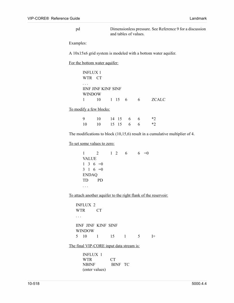
VIP-CORE® Reference Guide Landmark
pd Dimensionless pressure. See Reference 9 for a discussion and tables of values.
Examples: 00
A 10x15x6 grid system is modeled with a bottom water aquifer. 00
For the bottom water aquifer: 00
INFLUX 1WTR CT. . .IINF JINF KINF SINFWINDOW1 10 1 15 6 6 ZCALC 00
To modify a few blocks: 00
9 10 14 15 6 6 *210 10 15 15 6 6 *2 00
The modifications to block (10,15,6) result in a cumulative multiplier of 4.
To set some values to zero: 00
1 2 1 2 6 6 =0VALUE1 3 6 =03 1 6 =0ENDAQTD PD. . . 00
To attach another aquifer to the right flank of the reservoir: 00
INFLUX 2WTR CT. . . 00
IINF JINF KINF SINFWINDOW5 10 1 15 1 5 I+ 00
The final VIP-CORE input data stream is: 00
INFLUX 1WTR CTNBINF BINF TC(enter values) 00
10-518 5000.4.4
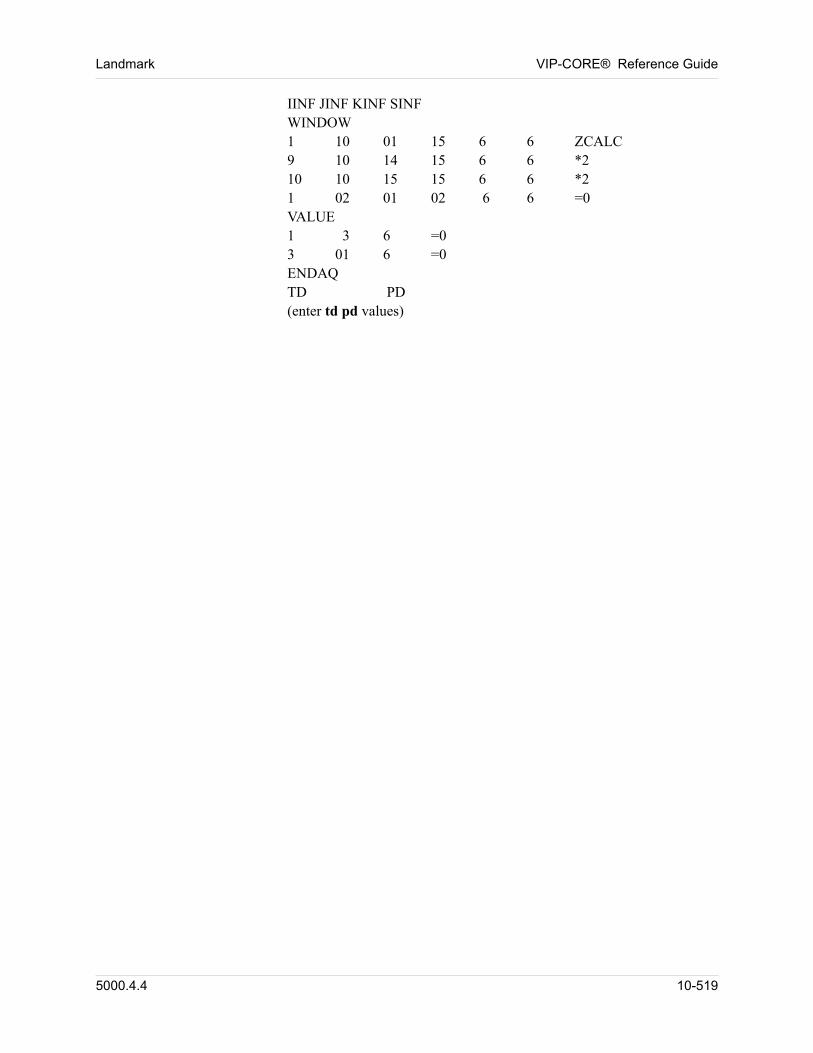
Landmark VIP-CORE® Reference Guide
IINF JINF KINF SINFWINDOW1 10 01 15 6 6 ZCALC9 10 14 15 6 6 *210 10 15 15 6 6 *21 02 01 02 6 6 =0VALUE1 3 6 =03 01 6 =0ENDAQTD PD(enter td pd values) 00
5000.4.4 10-519
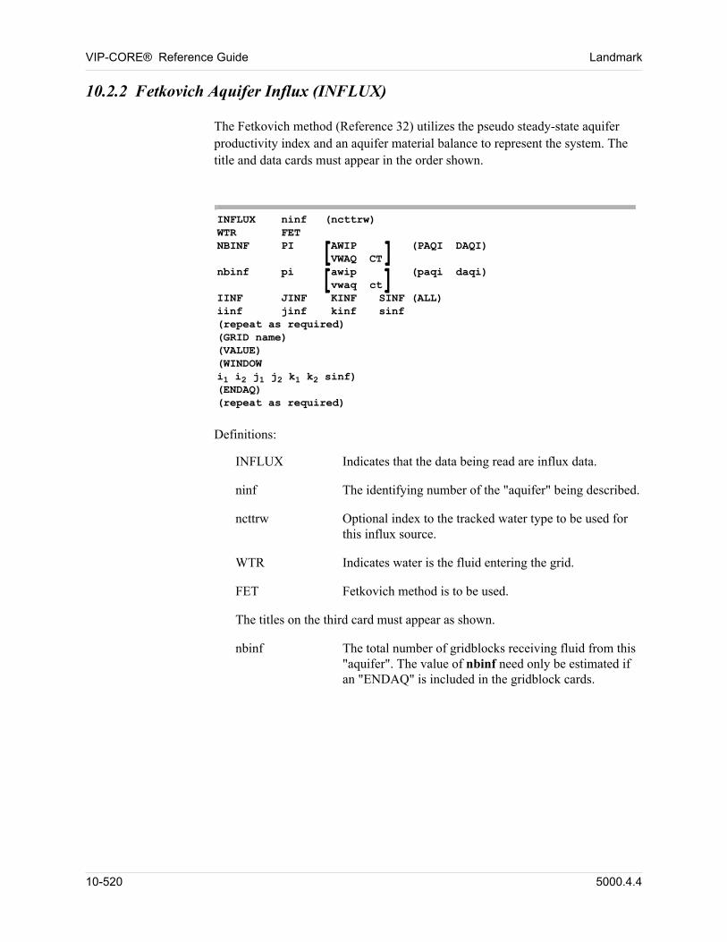
VIP-CORE® Reference Guide Landmark
10.2.2 Fetkovich Aquifer Influx (INFLUX)
The Fetkovich method (Reference 32) utilizes the pseudo steady-state aquifer productivity index and an aquifer material balance to represent the system. The title and data cards must appear in the order shown.
INFLUX ninf (ncttrw)WTR FETNBINF PI AWIP (PAQI DAQI)
VWAQ CTnbinf pi awip (paqi daqi)
vwaq ctIINF JINF KINF SINF (ALL)iinf jinf kinf sinf(repeat as required)(GRID name)(VALUE)(WINDOWi1 i2 j1 j2 k1 k2 sinf)(ENDAQ)(repeat as required)
[][]
Definitions:
INFLUX Indicates that the data being read are influx data.
ninf The identifying number of the "aquifer" being described.
ncttrw Optional index to the tracked water type to be used for this influx source.
WTR Indicates water is the fluid entering the grid.
FET Fetkovich method is to be used.
The titles on the third card must appear as shown.
nbinf The total number of gridblocks receiving fluid from this "aquifer". The value of nbinf need only be estimated if an "ENDAQ" is included in the gridblock cards.
10-520 5000.4.4
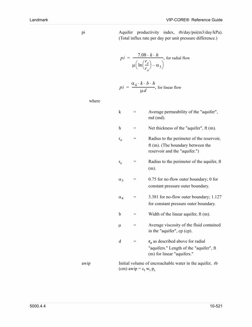
Landmark VIP-CORE® Reference Guide
pi Aquifer productivity index, rb/day/psi(m3/day/kPa). (Total influx rate per day per unit pressure difference.)
pi7.08 k h
re
ro---- ln 3–
------------------------------------- for radial flow=
pi4 k b h
d---------------------------- for linear flow=
where
k = Average permeability of the "aquifer", md (md).
h = Net thickness of the "aquifer", ft (m).
ro = Radius to the perimeter of the reservoir,
ft (m). (The boundary between the reservoir and the "aquifer.")
re = Radius to the perimeter of the aquifer, ft
(m).
3 = 0.75 for no-flow outer boundary; 0 for
constant pressure outer boundary.
4 = 3.381 for no-flow outer boundary; 1.127
for constant pressure outer boundary.
b = Width of the linear aquifer, ft (m).
= Average viscosity of the fluid contained in the "aquifer", cp (cp).
d = re as described above for radial
"aquifers." Length of the "aquifer", ft (m) for linear "aquifers."
awip Initial volume of encroachable water in the aquifer, rb (cm) awip = ct wi pi.
5000.4.4 10-521
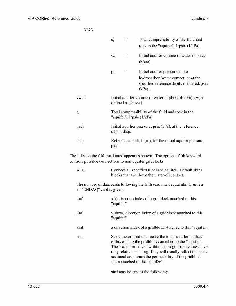
VIP-CORE® Reference Guide Landmark
where
ct = Total compressibility of the fluid and
rock in the "aquifer", 1/psia (1/kPa).
wi = Initial aquifer volume of water in place,
rb(cm).
pi = Initial aquifer pressure at the
hydrocarbon/water contact, or at the specified reference depth, if entered, psia (kPa).
vwaq Initial aquifer volume of water in place, rb (cm). (wi as defined as above.)
ct Total compressibility of the fluid and rock in the "aquifer", 1/psia (1/kPa).
paqi Initial aquifier pressure, psia (kPa), at the reference depth, daqi.
daqi Reference depth, ft (m), for the initial aquifer pressure, paqi.
The titles on the fifth card must appear as shown. The optional fifth keyword controls possible connections to non-aquifer gridblocks
ALL Connect all specified blocks to aquifer. Default skips blocks that are above the water-oil contact.
The number of data cards following the fifth card must equal nbinf, unless an "ENDAQ" card is given.
iinf x(r) direction index of a gridblock attached to this "aquifer".
jinf y(theta) direction index of a gridblock attached to this "aquifer".
kinf z direction index of a gridblock attached to this "aquifer".
sinf Scale factor used to allocate the total "aquifer" influx/efflux among the gridblocks attached to the "aquifer". These are normalized within the program, so values have only relative meaning. They will usually reflect the cross-sectional area times the permeability of the gridblock faces attached to the "aquifer".
sinf may be any of the following: 00
10-522 5000.4.4
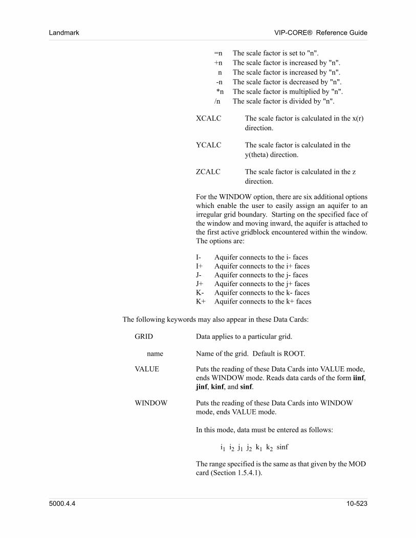
Landmark VIP-CORE® Reference Guide
=n The scale factor is set to "n".+n The scale factor is increased by "n". n The scale factor is increased by "n". -n The scale factor is decreased by "n". *n The scale factor is multiplied by "n"./n The scale factor is divided by "n". 00
XCALC The scale factor is calculated in the x(r) direction. 00
YCALC The scale factor is calculated in the y(theta) direction. 00
ZCALC The scale factor is calculated in the z direction. 00
For the WINDOW option, there are six additional options which enable the user to easily assign an aquifer to an irregular grid boundary. Starting on the specified face of the window and moving inward, the aquifer is attached to the first active gridblock encountered within the window. The options are:
I- Aquifer connects to the i- facesI+ Aquifer connects to the i+ facesJ- Aquifer connects to the j- facesJ+ Aquifer connects to the j+ facesK- Aquifer connects to the k- facesK+ Aquifer connects to the k+ faces
The following keywords may also appear in these Data Cards: 00
GRID Data applies to a particular grid. 00
name Name of the grid. Default is ROOT. 00
VALUE Puts the reading of these Data Cards into VALUE mode, ends WINDOW mode. Reads data cards of the form iinf, jinf, kinf, and sinf.
WINDOW Puts the reading of these Data Cards into WINDOW mode, ends VALUE mode.
In this mode, data must be entered as follows: 00
i1 i2 j1 j2 k1 k2 sinf 00
The range specified is the same as that given by the MOD card (Section 1.5.4.1).
5000.4.4 10-523
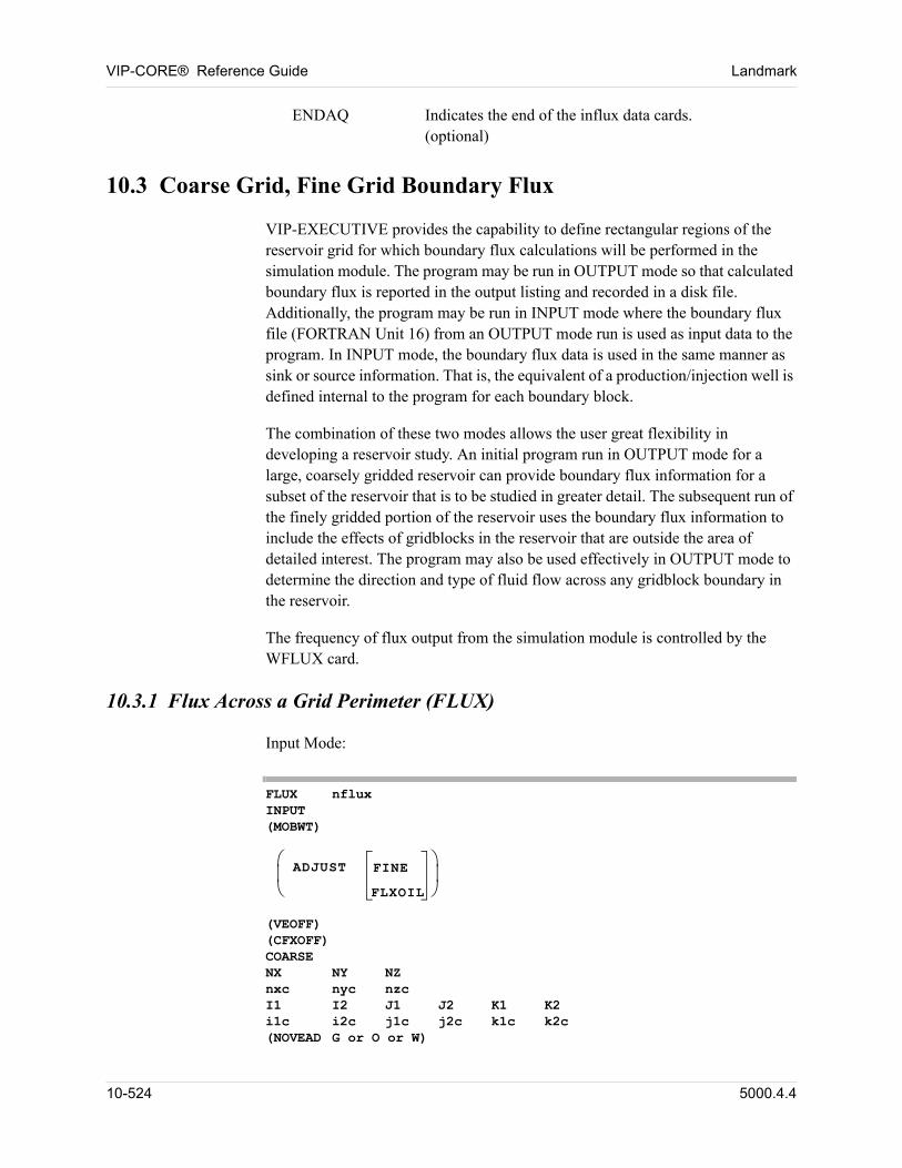
VIP-CORE® Reference Guide Landmark
ENDAQ Indicates the end of the influx data cards.(optional) 00
10.3 Coarse Grid, Fine Grid Boundary Flux
VIP-EXECUTIVE provides the capability to define rectangular regions of the reservoir grid for which boundary flux calculations will be performed in the simulation module. The program may be run in OUTPUT mode so that calculated boundary flux is reported in the output listing and recorded in a disk file. Additionally, the program may be run in INPUT mode where the boundary flux file (FORTRAN Unit 16) from an OUTPUT mode run is used as input data to the program. In INPUT mode, the boundary flux data is used in the same manner as sink or source information. That is, the equivalent of a production/injection well is defined internal to the program for each boundary block.
The combination of these two modes allows the user great flexibility in developing a reservoir study. An initial program run in OUTPUT mode for a large, coarsely gridded reservoir can provide boundary flux information for a subset of the reservoir that is to be studied in greater detail. The subsequent run of the finely gridded portion of the reservoir uses the boundary flux information to include the effects of gridblocks in the reservoir that are outside the area of detailed interest. The program may also be used effectively in OUTPUT mode to determine the direction and type of fluid flow across any gridblock boundary in the reservoir.
The frequency of flux output from the simulation module is controlled by the WFLUX card.
10.3.1 Flux Across a Grid Perimeter (FLUX)
Input Mode: 00
FLUX nflux INPUT (MOBWT)
ADJUST FINE
FLXOIL
(VEOFF) (CFXOFF)COARSE NX NY NZ nxc nyc nzc I1 I2 J1 J2 K1 K2 i1c i2c j1c j2c k1c k2c (NOVEAD G or O or W)
10-524 5000.4.4
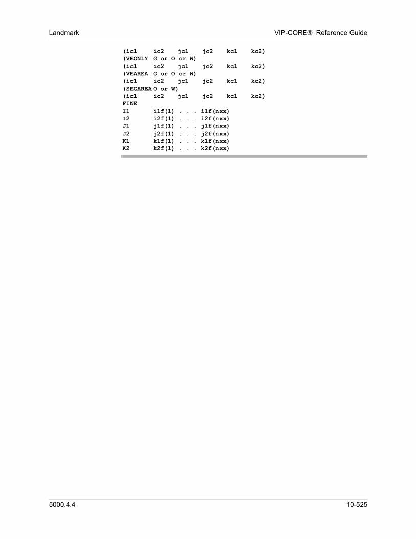
Landmark VIP-CORE® Reference Guide
(ic1 ic2 jc1 jc2 kc1 kc2) (VEONLY G or O or W) (ic1 ic2 jc1 jc2 kc1 kc2) (VEAREA G or O or W) (ic1 ic2 jc1 jc2 kc1 kc2) (SEGAREA O or W) (ic1 ic2 jc1 jc2 kc1 kc2) FINE I1 i1f(1) . . . i1f(nxx) I2 i2f(1) . . . i2f(nxx) J1 j1f(1) . . . j1f(nxx) J2 j2f(1) . . . j2f(nxx) K1 k1f(1) . . . k1f(nxx) K2 k2f(1) . . . k2f(nxx)
5000.4.4 10-525
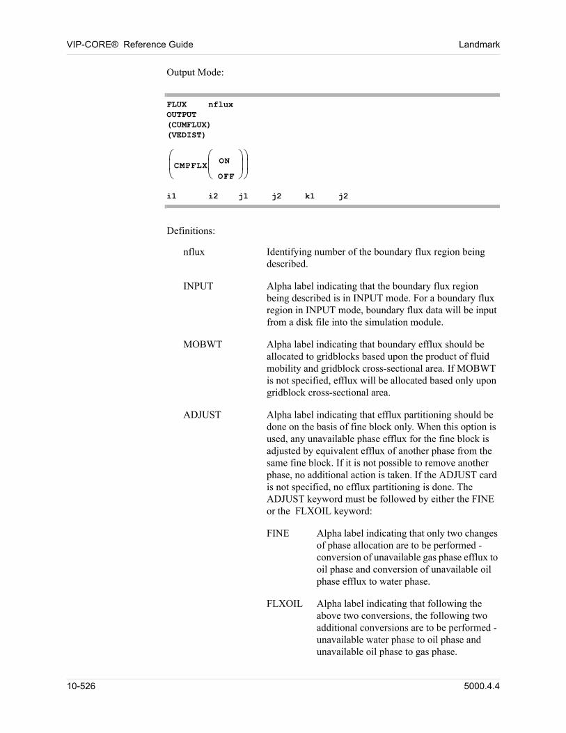
VIP-CORE® Reference Guide Landmark
Output Mode: 00
FLUX nflux OUTPUT (CUMFLUX) (VEDIST) CMPFLX
ON
OFF
i1 i2 j1 j2 k1 j2
Definitions: 00
nflux Identifying number of the boundary flux region being described.
INPUT Alpha label indicating that the boundary flux region being described is in INPUT mode. For a boundary flux region in INPUT mode, boundary flux data will be input from a disk file into the simulation module.
MOBWT Alpha label indicating that boundary efflux should be allocated to gridblocks based upon the product of fluid mobility and gridblock cross-sectional area. If MOBWT is not specified, efflux will be allocated based only upon gridblock cross-sectional area.
ADJUST Alpha label indicating that efflux partitioning should be done on the basis of fine block only. When this option is used, any unavailable phase efflux for the fine block is adjusted by equivalent efflux of another phase from the same fine block. If it is not possible to remove another phase, no additional action is taken. If the ADJUST card is not specified, no efflux partitioning is done. The ADJUST keyword must be followed by either the FINE or the FLXOIL keyword:
FINE Alpha label indicating that only two changes of phase allocation are to be performed - conversion of unavailable gas phase efflux to oil phase and conversion of unavailable oil phase efflux to water phase.
FLXOIL Alpha label indicating that following the above two conversions, the following two additional conversions are to be performed - unavailable water phase to oil phase and unavailable oil phase to gas phase.
10-526 5000.4.4
Landmark VIP-CORE® Reference Guide
VEOFF Influx allocation in the INPUT mode is done using the fully segregated (or vertical equilibrium) assumption, if fluid contact values are available in the flux file. However, the alpha label VEOFF can be specified to use the fully dispersed option even if contact values are available in the flux file. This card is not required if the flux file does not contain fluid contact data.
CFXOFF Component influx option is automatically invoked in the INPUT mode if component influxes are available in the flux file. However, CFXOFF can be specified to use phase molar influxes and fine-grid phase compositions for the calculation of component influxes even if component influxes are available in the flux file. This card is not required if the flux file does not contain component influx data.
COARSE Alpha label indicating that data which follows this card defines the grid correspondence for the coarse grid model.
nxc Number of gridblocks in the x(r) direction for the coarse grid model.
nyc Number of gridblocks in the y(theta) direction for the coarse grid model.
nzc Number of gridblocks in the z direction for the coarse grid model.
Gridblock locations are defined by indices I, J, and K in reference to the (x,y,z) or
(r,,z) grid. The current boundary flux region, nflux, contains all gridblocks lying in the portion of the grid defined by:
i1c < I < i2cj1c < J < j2ck1c < K < k2c 00
NOVEAD Alpha label indicating that no VE influx allocation should be done for the following set of coarse blocks. In this case influx allocation is based on cross-sectional area or the product of mobility and cross-sectional area if the MOBWT option is being used.
VEONLY Alpha label indicating that influx allocation for the following set of coarse blocks should be based on height of fluid contacts only.
VEAREA Alpha label indicating that influx allocation for the following set of coarse blocks should be based on the
5000.4.4 10-527
VIP-CORE® Reference Guide Landmark
product of height of fluid contact and cross-sectional area. This is the default for all coarse blocks for all phases.
SEGAREA Alpha label indicating that the influx will be allocated to all fine blocks (dispersed) below the gas-oil contact for the appropriate phase (O or W) for the following set of coarse blocks. In addition, the influx allocation should be based on the product of height of fluid contact and cross-sectional area.
Alpha label indicating the phase to which each of these options applies
G Influx allocation method applies to gas phase influx. 00
O Influx allocation method applies to oil phase influx. 00
W Influx allocation method applies to water phase influx. 00
FINE Alpha label indicating that data which follows this card defines the grid correspondence for the fine grid model.
The next six cards define the correspondence of fine gridblocks to coarse gridblocks. Each data card contains an alpha label followed by an appropriate number of values, depending upon the direction indicated by the label. If necessary, more than one card may be used to enter the values, but the label should not be repeated on subsequent cards.
For these cards the following values are defined:
nxx = ic2 - ic1 + 1nyy = jc2 - jc1 + 1nzz = kc2 - kc1 + 1 00
I1 Alpha label indicating that the values on this card define the beginning index of the fine gridblocks contained in the flux region of the coarse model in the x(r) direction between indices ic1 and ic2. A total of nxx values must be entered on one or more cards.
I2 Alpha label indicating that the values on this card define the last index of the fine gridblocks contained in the flux region of the coarse model in the x(r) direction between indices ic1 and ic2. A total of nxx values must be entered on one or more cards.
J1 Alpha label indicating that the values on this card define the beginning index of the fine gridblocks contained in the flux region of the coarse model in the y() direction
10-528 5000.4.4
Landmark VIP-CORE® Reference Guide
between indices jc1 and jc2. A total of nyy values must be entered on one or more cards.
J2 Alpha label indicating that the values on this card define the last index of the fine gridblocks contained in the flux region of the coarse model in the y() direction between indices jc1 and ic2. A total of nyy values must be entered on one or more cards.
K1 Alpha label indicating that the values on this card define the beginning index of the fine gridblocks contained in the flux region of the coarse model in the z direction between indices kc1 and kc2. A total of nzz values must be entered on one or more cards.
K2 Alpha label indicating that the values on this card define the last index of the fine gridblocks contained in the flux region of the coarse model in the z direction between indices kc1 and kc2. A total of nzz values must be entered on one or more cards.
nflux Identifying number of the boundary flux region being described.
OUTPUT Alpha label indicating that the boundary flux region being described is in OUTPUT mode. For a boundary flux region in OUTPUT mode, a disk file of boundary flux data will be created in the simulation module.
CUMFLUX Alpha label indicating that cumulative flux values are written to the flux file in the OUTPUT mode. Flux rates are calculated from cumulative flux in the INPUT mode. If the CUMFLUX card is not specified, instantaneous flux rates are written to the flux file.
VEDIST Alpha label indicating that the location of the gas-oil contact and the oil-water contact in each coarse block (determined using vertical equilibrium approximation) is written to the flux file in the OUTPUT mode. If the VEDIST card is not specified, no contact information is written to the flux file.
CMPFLX Alpha label indicating whether component influxes are written to the flux file in OUTPUT mode. The label CMPFLX or CMPFLX ON indicates that component molar fluxes as well as phase molar fluxes are written to the flux file. The label CMPFLX OFF indicates that only phase molar fluxes are written to the flux file. If the CMPFLX card is not specified, the default option is ON for Todd-Longstaff miscible models and OFF for compositional and black-oil models.
5000.4.4 10-529
VIP-CORE® Reference Guide Landmark
Gridblock locations are defined by indices I, J, and K in reference to the (x,y,z) or
(r,,z) grid. The current boundary flux region, nflux, contains all gridblocks lying in the portion of the grid defined by:
i1 < I < i2j1 < J < j2k1 < K < k2. 00
The data given above are used to define a rectangular subregion of the reservoir for which boundary flux calculations will be performed in the simulation module. This data must appear in the order shown.
For each boundary flux region in INPUT mode in VIP-CORE, the simulation module expects to input boundary flux data from a file prepared from a program run in OUTPUT mode. The data given above are used to define a correspondence between the reservoir grid and the boundary flux regions from a previous run of the program in OUTPUT mode. It is assumed in this treatment that each gridblock in the coarsely gridded model contains an integral number of gridblocks in the finely gridded model.
The component influx option (CMPFLX) writes the component molar fluxes to the flux file (OUTPUT mode) and applies these fluxes to fine-grids with net influxes (INPUT mode). Numerically, this option is more rigorous than the phase influx option that uses phase molar influxes and fine-grid phase compositions for the component influx calculation. The CMPFLX option should be used if the influx compositions are expected to be significantly different from the fine-grid phase compositions during the fine-grid run.
10-530 5000.4.4
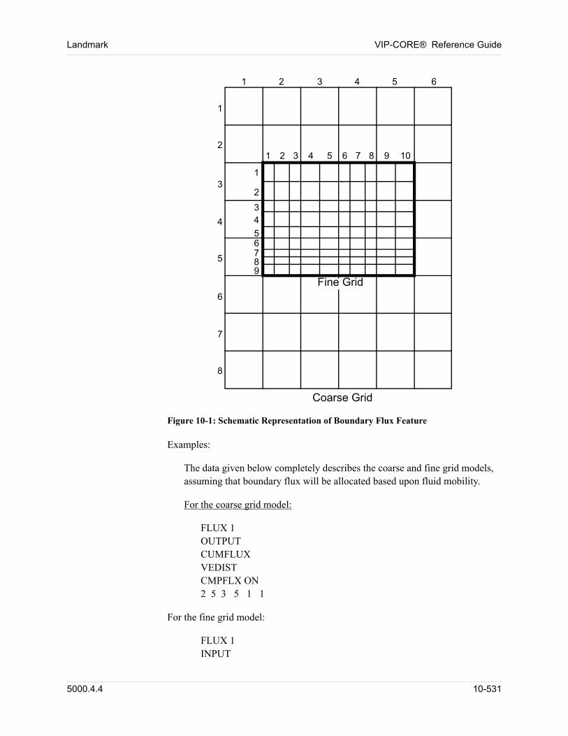
Landmark VIP-CORE® Reference Guide
Fine Grid
Coarse Grid
1 2 3 4 5 6
1
2
3
4
5
6
7
8
1
2
34
56789
1 2 3 4 5 6 7 8 9 10
Figure 10-1: Schematic Representation of Boundary Flux Feature
Examples: 00
The data given below completely describes the coarse and fine grid models, assuming that boundary flux will be allocated based upon fluid mobility. 00
For the coarse grid model: 00
FLUX 1OUTPUTCUMFLUXVEDISTCMPFLX ON2 5 3 5 1 1 00
For the fine grid model: 00
FLUX 1INPUT
5000.4.4 10-531
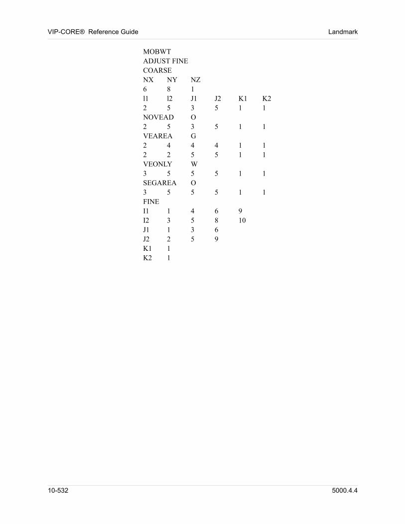
VIP-CORE® Reference Guide Landmark
MOBWTADJUST FINECOARSENX NY NZ6 8 1l1 l2 J1 J2 K1 K22 5 3 5 1 1NOVEAD O2 5 3 5 1 1VEAREA G2 4 4 4 1 12 2 5 5 1 1VEONLY W3 5 5 5 1 1SEGAREA O3 5 5 5 1 1FINEI1 1 4 6 9I2 3 5 8 10J1 1 3 6J2 2 5 9K1 1K2 1 00
10-532 5000.4.4
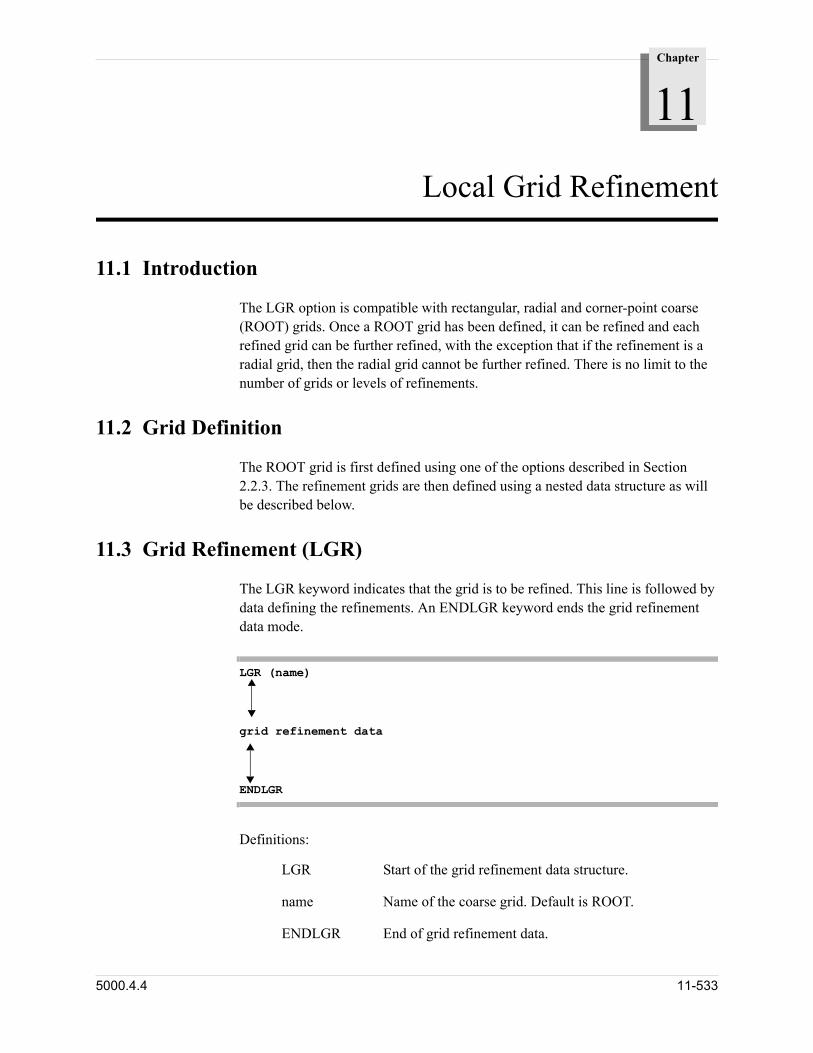
Chapter
11
00000Local Grid Refinement
11.1 Introduction
The LGR option is compatible with rectangular, radial and corner-point coarse (ROOT) grids. Once a ROOT grid has been defined, it can be refined and each refined grid can be further refined, with the exception that if the refinement is a radial grid, then the radial grid cannot be further refined. There is no limit to the number of grids or levels of refinements.
11.2 Grid Definition
The ROOT grid is first defined using one of the options described in Section 2.2.3. The refinement grids are then defined using a nested data structure as will be described below.
11.3 Grid Refinement (LGR)
The LGR keyword indicates that the grid is to be refined. This line is followed by data defining the refinements. An ENDLGR keyword ends the grid refinement data mode.
LGR (name) grid refinement dataENDLGR
Definitions: 00
LGR Start of the grid refinement data structure.
name Name of the coarse grid. Default is ROOT.
ENDLGR End of grid refinement data.
5000.4.4 11-533
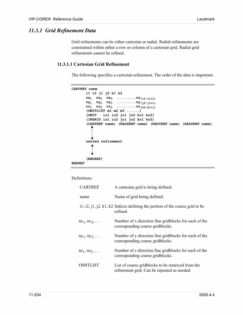
VIP-CORE® Reference Guide Landmark
11.3.1 Grid Refinement Data
Grid refinements can be either cartesian or radial. Radial refinements are constrained within either a row or column of a cartesian grid. Radial grid refinements cannot be refined.
11.3.1.1 Cartesian Grid Refinement
The following specifies a cartesian refinement. The order of the data is important.
CARTREF name i1 i2 j1 j2 k1 k2 nx1 nx2 nx3 .........nx(i2-i1+1) ny1 ny2 ny3 .........ny(j2-j1+1) nz1 nz2 nz3 .........nz(k2-k1+1) (OMITLIST m1 m2 m3 ......) (OMIT io1 io2 jo1 jo2 ko1 ko2) (INGRID in1 in2 jn1 jn2 kn1 kn2) (CARTREF name) (RADXREF name) (RADYREF name) (RADZREF name)
nested refinement
(ENDREF) ENDREF
Definitions:
CARTREF A cartesian grid is being defined.
name Name of grid being defined.
i1, i2, j1, j2, k1, k2 Indices defining the portion of the coarse grid to be refined.
nx1, nx2, . . . Number of x direction fine gridblocks for each of the corresponding coarse gridblocks.
ny1, ny2, . . . Number of y direction fine gridblocks for each of the corresponding coarse gridblocks.
nz1, nz2, . . . Number of z direction fine gridblocks for each of the corresponding coarse gridblocks.
OMITLIST List of coarse gridblocks to be removed from the refinement grid. Can be repeated as needed.
11-534 5000.4.4
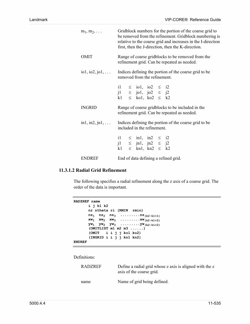
Landmark VIP-CORE® Reference Guide
m1, m2, . . . Gridblock numbers for the portion of the coarse grid to be removed from the refinement. Gridblock numbering is relative to the coarse grid and increases in the I-direction first, then the J-direction, then the K-direction.
OMIT Range of coarse gridblocks to be removed from the refinement grid. Can be repeated as needed.
io1, io2, jo1, . . . Indices defining the portion of the coarse grid to be removed from the refinement.
i1 io1, io2 i2 j1 jo1, jo2 j2 k1 ko1, ko2 k2
INGRID Range of coarse gridblocks to be included in the refinement grid. Can be repeated as needed.
in1, in2, jn1, . . . Indices defining the portion of the coarse grid to be included in the refinement.
i1 in1, in2 i2 j1 jn1, jn2 j2 k1 kn1, kn2 k2
ENDREF End of data defining a refined grid.
11.3.1.2 Radial Grid Refinement
The following specifies a radial refinement along the z axis of a coarse grid. The order of the data is important.
RADZREF name i j k1 k2 nr ntheta ri (RMIN rmin) nz1 nz2 nz3 .........nz(k2-k1+1) xw1 xw2 xw3 .........xw(k2-k1+2) yw1 yw2 yw3 .........yw(k2-k1+2) (OMITLIST m1 m2 m3 ......) (OMIT i i j j ko1 ko2) (INGRID i i j j kn1 kn2)
ENDREF
Definitions:
RADZREF Define a radial grid whose z axis is aligned with the z axis of the coarse grid.
name Name of grid being defined.
5000.4.4 11-535
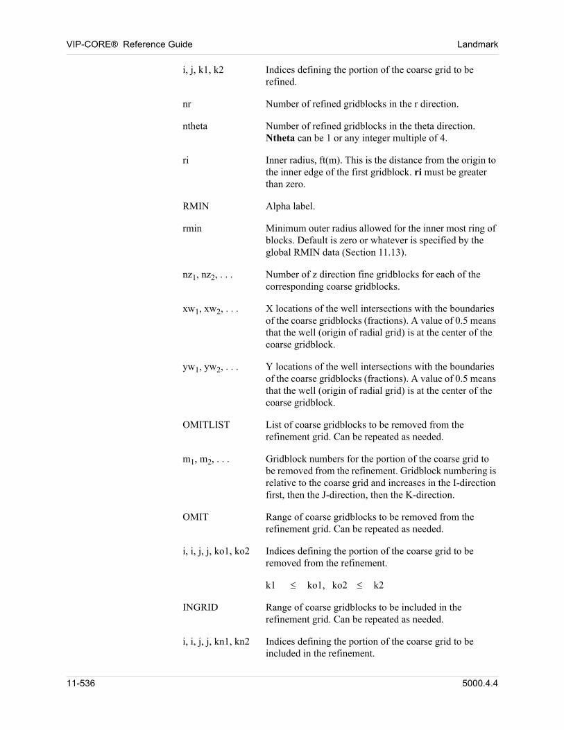
VIP-CORE® Reference Guide Landmark
i, j, k1, k2 Indices defining the portion of the coarse grid to be refined.
nr Number of refined gridblocks in the r direction.
ntheta Number of refined gridblocks in the theta direction. Ntheta can be 1 or any integer multiple of 4.
ri Inner radius, ft(m). This is the distance from the origin to the inner edge of the first gridblock. ri must be greater than zero.
RMIN Alpha label.
rmin Minimum outer radius allowed for the inner most ring of blocks. Default is zero or whatever is specified by the global RMIN data (Section 11.13).
nz1, nz2, . . . Number of z direction fine gridblocks for each of the corresponding coarse gridblocks.
xw1, xw2, . . . X locations of the well intersections with the boundaries of the coarse gridblocks (fractions). A value of 0.5 means that the well (origin of radial grid) is at the center of the coarse gridblock.
yw1, yw2, . . . Y locations of the well intersections with the boundaries of the coarse gridblocks (fractions). A value of 0.5 means that the well (origin of radial grid) is at the center of the coarse gridblock.
OMITLIST List of coarse gridblocks to be removed from the refinement grid. Can be repeated as needed.
m1, m2, . . . Gridblock numbers for the portion of the coarse grid to be removed from the refinement. Gridblock numbering is relative to the coarse grid and increases in the I-direction first, then the J-direction, then the K-direction.
OMIT Range of coarse gridblocks to be removed from the refinement grid. Can be repeated as needed.
i, i, j, j, ko1, ko2 Indices defining the portion of the coarse grid to be removed from the refinement.
k1 ko1, ko2 k2
INGRID Range of coarse gridblocks to be included in the refinement grid. Can be repeated as needed.
i, i, j, j, kn1, kn2 Indices defining the portion of the coarse grid to be included in the refinement.
11-536 5000.4.4
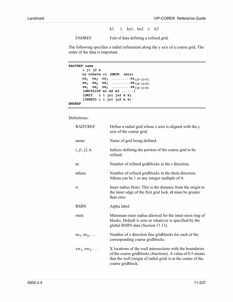
Landmark VIP-CORE® Reference Guide
k1 kn1, kn2 k2
ENDREF End of data defining a refined grid.
The following specifies a radial refinement along the y axis of a coarse grid. The order of the data is important.
RADYREF name i j1 j2 k nr ntheta ri (RMIN rmin) nz1 nz2 nz3 .........nz(j2-j1+1) xw1 xw2 xw3 .........xw(j2-j1+2) zw1 zw2 zw3 .........zw(j2-j1+2) (OMITLIST m1 m2 m3 ......) (OMIT i i jo1 jo2 k k) (INGRID i i jn1 jn2 k k)
ENDREF
Definitions:
RADYREF Define a radial grid whose z axis is aligned with the y axis of the coarse grid.
name Name of grid being defined.
i, j1, j2, k Indices defining the portion of the coarse grid to be refined.
nr Number of refined gridblocks in the r direction.
ntheta Number of refined gridblocks in the theta direction. Ntheta can be 1 or any integer multiple of 4.
ri Inner radius ft(m). This is the distance from the origin to the inner edge of the first grid lock. ri must be greater than zero.
RMIN Alpha label.
rmin Minimum outer radius allowed for the inner most ring of blocks. Default is zero or whatever is specified by the global RMIN data (Section 11.13).
nz1, nz2, . . . Number of z direction fine gridblocks for each of the corresponding coarse gridblocks.
xw1, xw2, . . . X locations of the well intersections with the boundaries of the coarse gridblocks (fractions). A value of 0.5 means that the well (origin of radial grid) is at the center of the coarse gridblock.
5000.4.4 11-537
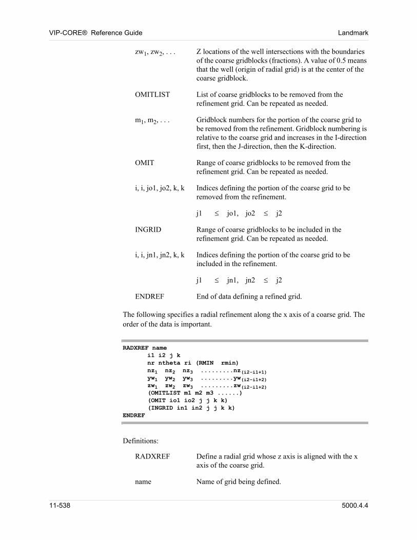
VIP-CORE® Reference Guide Landmark
zw1, zw2, . . . Z locations of the well intersections with the boundaries of the coarse gridblocks (fractions). A value of 0.5 means that the well (origin of radial grid) is at the center of the coarse gridblock.
OMITLIST List of coarse gridblocks to be removed from the refinement grid. Can be repeated as needed.
m1, m2, . . . Gridblock numbers for the portion of the coarse grid to be removed from the refinement. Gridblock numbering is relative to the coarse grid and increases in the I-direction first, then the J-direction, then the K-direction.
OMIT Range of coarse gridblocks to be removed from the refinement grid. Can be repeated as needed.
i, i, jo1, jo2, k, k Indices defining the portion of the coarse grid to be removed from the refinement.
j1 jo1, jo2 j2
INGRID Range of coarse gridblocks to be included in the refinement grid. Can be repeated as needed.
i, i, jn1, jn2, k, k Indices defining the portion of the coarse grid to be included in the refinement.
j1 jn1, jn2 j2
ENDREF End of data defining a refined grid.
The following specifies a radial refinement along the x axis of a coarse grid. The order of the data is important.
RADXREF name i1 i2 j k nr ntheta ri (RMIN rmin) nz1 nz2 nz3 .........nz(i2-i1+1) yw1 yw2 yw3 .........yw(i2-i1+2) zw1 zw2 zw3 .........zw(i2-i1+2) (OMITLIST m1 m2 m3 ......) (OMIT io1 io2 j j k k) (INGRID in1 in2 j j k k)
ENDREF
Definitions:
RADXREF Define a radial grid whose z axis is aligned with the x axis of the coarse grid.
name Name of grid being defined.
11-538 5000.4.4
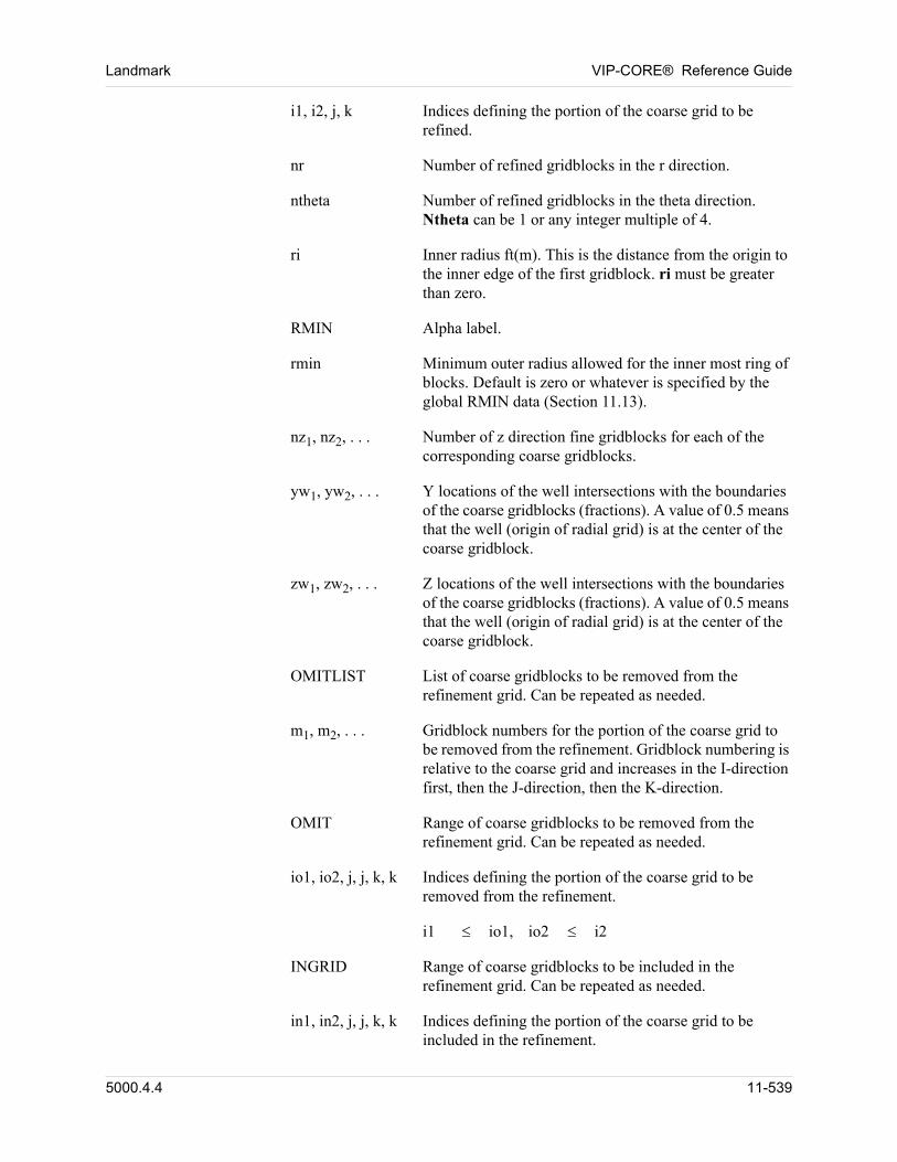
Landmark VIP-CORE® Reference Guide
i1, i2, j, k Indices defining the portion of the coarse grid to be refined.
nr Number of refined gridblocks in the r direction.
ntheta Number of refined gridblocks in the theta direction. Ntheta can be 1 or any integer multiple of 4.
ri Inner radius ft(m). This is the distance from the origin to the inner edge of the first gridblock. ri must be greater than zero.
RMIN Alpha label.
rmin Minimum outer radius allowed for the inner most ring of blocks. Default is zero or whatever is specified by the global RMIN data (Section 11.13).
nz1, nz2, . . . Number of z direction fine gridblocks for each of the corresponding coarse gridblocks.
yw1, yw2, . . . Y locations of the well intersections with the boundaries of the coarse gridblocks (fractions). A value of 0.5 means that the well (origin of radial grid) is at the center of the coarse gridblock.
zw1, zw2, . . . Z locations of the well intersections with the boundaries of the coarse gridblocks (fractions). A value of 0.5 means that the well (origin of radial grid) is at the center of the coarse gridblock.
OMITLIST List of coarse gridblocks to be removed from the refinement grid. Can be repeated as needed.
m1, m2, . . . Gridblock numbers for the portion of the coarse grid to be removed from the refinement. Gridblock numbering is relative to the coarse grid and increases in the I-direction first, then the J-direction, then the K-direction.
OMIT Range of coarse gridblocks to be removed from the refinement grid. Can be repeated as needed.
io1, io2, j, j, k, k Indices defining the portion of the coarse grid to be removed from the refinement.
i1 io1, io2 i2
INGRID Range of coarse gridblocks to be included in the refinement grid. Can be repeated as needed.
in1, in2, j, j, k, k Indices defining the portion of the coarse grid to be included in the refinement.
5000.4.4 11-539
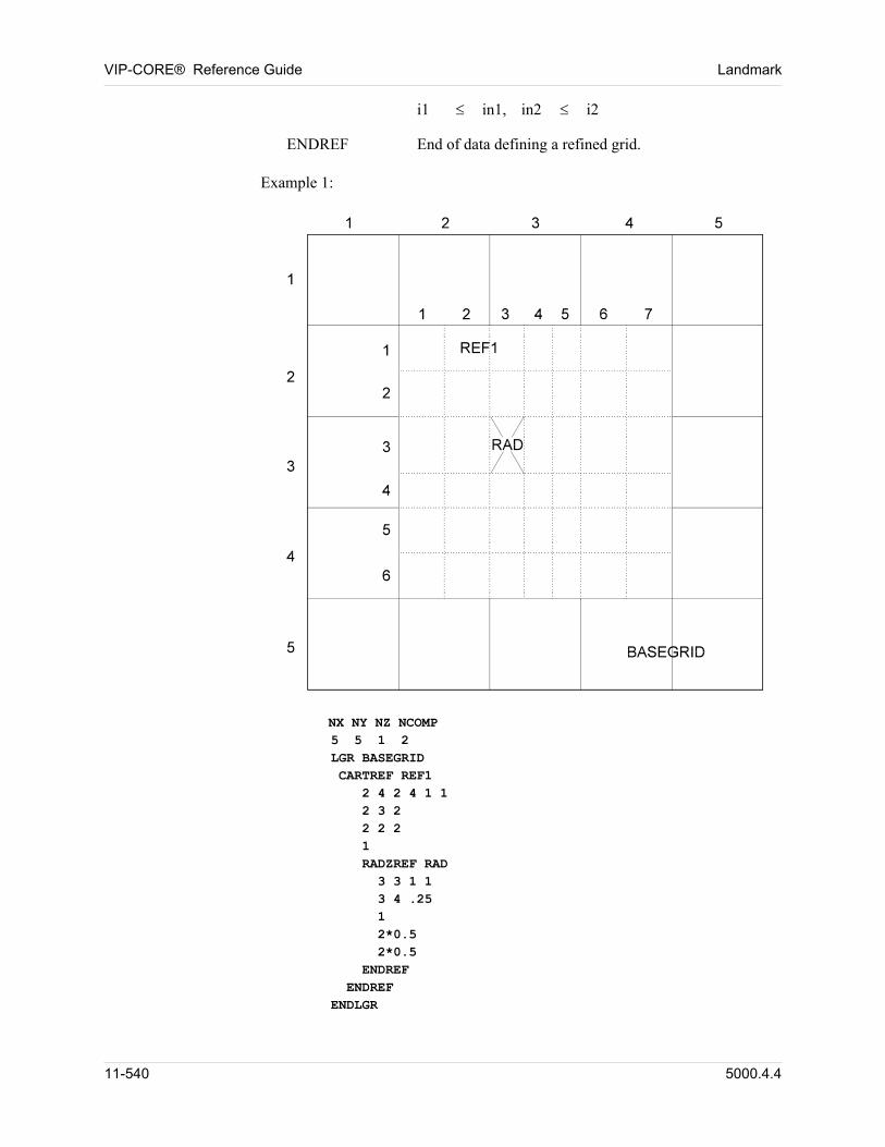
VIP-CORE® Reference Guide Landmark
i1 in1, in2 i2
ENDREF End of data defining a refined grid.
Example 1:
NX NY NZ NCOMP 5 5 1 2 LGR BASEGRID CARTREF REF1 2 4 2 4 1 1 2 3 2 2 2 2 1 RADZREF RAD 3 3 1 1 3 4 .25 1 2*0.5 2*0.5 ENDREF ENDREF ENDLGR
11-540 5000.4.4
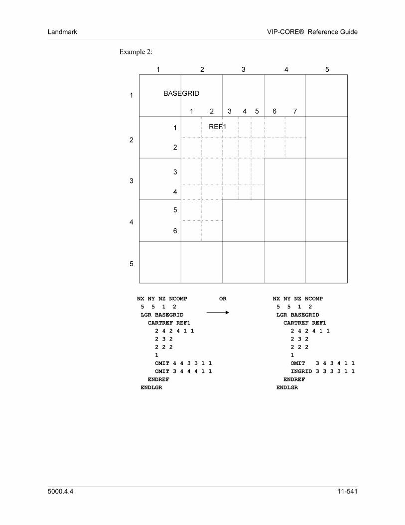
Landmark VIP-CORE® Reference Guide
Example 2:
NX NY NZ NCOMP OR NX NY NZ NCOMP 5 5 1 2 5 5 1 2 LGR BASEGRID LGR BASEGRID CARTREF REF1 CARTREF REF1 2 4 2 4 1 1 2 4 2 4 1 1 2 3 2 2 3 2 2 2 2 2 2 2 1 1 OMIT 4 4 3 3 1 1 OMIT 3 4 3 4 1 1 OMIT 3 4 4 4 1 1 INGRID 3 3 3 3 1 1 ENDREF ENDREF ENDLGR ENDLGR
5000.4.4 11-541
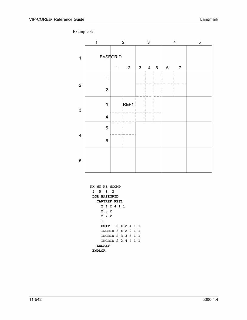
VIP-CORE® Reference Guide Landmark
Example 3:
NX NY NZ NCOMP 5 5 1 2 LGR BASEGRID CARTREF REF1 2 4 2 4 1 1 2 3 2 2 2 2 1 OMIT 2 4 2 4 1 1 INGRID 3 4 2 2 1 1 INGRID 2 3 3 3 1 1 INGRID 2 2 4 4 1 1 ENDREF ENDLGR
11-542 5000.4.4
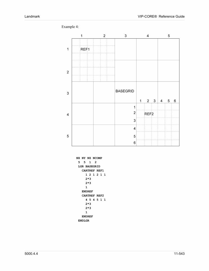
Landmark VIP-CORE® Reference Guide
Example 4:
NX NY NZ NCOMP 5 5 1 2 LGR BASEGRID CARTREF REF1 1 2 1 2 1 1 2*3 2*3 1 ENDREF CARTREF REF2 4 5 4 5 1 1 2*3 2*3 1 ENDREF ENDLGR
5000.4.4 11-543
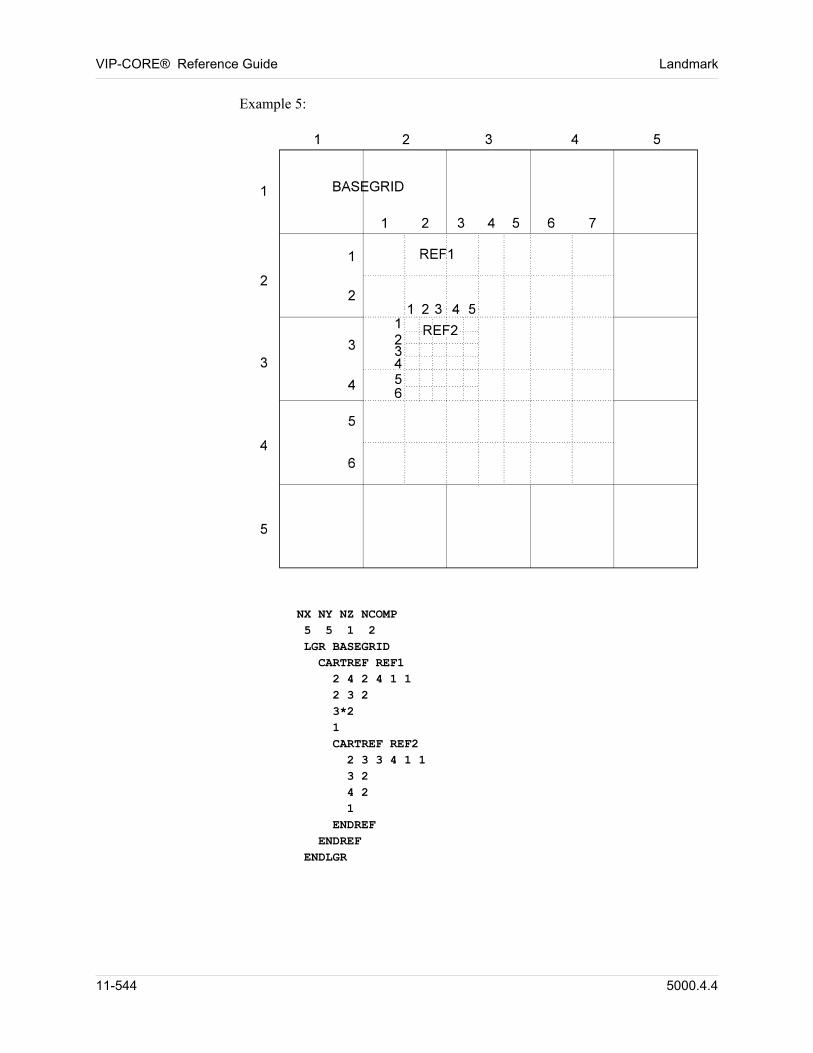
VIP-CORE® Reference Guide Landmark
Example 5:
NX NY NZ NCOMP 5 5 1 2 LGR BASEGRID CARTREF REF1 2 4 2 4 1 1 2 3 2 3*2 1 CARTREF REF2 2 3 3 4 1 1 3 2 4 2 1 ENDREF ENDREF ENDLGR
11-544 5000.4.4
Landmark VIP-CORE® Reference Guide
11.4 Array Data
Array data is introduced grid by grid. All Array data must be together and grid order is important. Array data for the ROOT grid is required. Array data are propagated recursively to the children grids as soon as they are read in. The propagation therefore restricts the order, and data for parent grids need to precede those of its children. Any array data for any child grid can be entered separately to replace the values generated by the propagation process. Permeability arrays at gridblock faces are not allowed with the LGR option.
Arrays NAME
ALL LGRS
Definitions:
Arrays Start of array data for grid (name).
name Name of grid for which the following array data applies. Default is ROOT.
ALL LGRS The ARRAYS data section will be read in a loop for each LGR grid, but excluding the ROOT grid.
11.5 Array Data Propagation
The data for the following arrays apply to gridblock faces and are propagated only to the appropriate fine gridblock faces.
TMX, TMR, TMXF, TMRF TMY, TMTH, TMYF, TMTHFTMZ, TMZFTMXYL, TMXYLF, TMXYR, TMXYRF Transmissibility multipliers (MULT) Section 1.6
11.6 Array Input Option
Array data of children grids (that has been assigned through propagation) can be modified using the MOD or VMOD options, Section 1.5.4. The NONE option for a child array indicates that no data will be input and any MOD or VMOD options will apply to the inherited data. The modified data is then propagated to the grid’s children.
5000.4.4 11-545
VIP-CORE® Reference Guide Landmark
Example:
ARRAYSPOR CON0.3...ARRAYS CHILD1POR NONEVMOD2 4 2 3 1 1 EQ0.25 0.26 2*0.27 0.29 0.3
11.7 Saturation and Relative Permeability Endpoint Arrays
Endpoint arrays can be assigned to children grids without having assigned any values to their parent’s grid. Any unassigned gridblocks or any assigned negative values will be reset to the rock data.
11.8 Grid Geometry
Any of the options previously available for defining a single grid with the exception of the bedding plane geometry DXB, DYB, etc. can be used to describe the ROOT grid. The LGR option requires eight (x, y, z) coordinates for each gridblock: these will be calculated internally. An additional data input option (CORP ARRAY Section 11.9) allows the input of the eight corner points directly. The corner points of children grids are either input using the CORP ARRAY data or are calculated internally from the coordinates of the parent gridblocks. The corner point calculation uses the normalized DX, DY, DZ arrays of children blocks to determine gridblock spacing. Absence of DX, DY, DZ array data (default) will produce a uniform spacing of children blocks within their parent block.
11.9 Corner Point Data (CORP)
The CORP array consists of eight (x, y, z) coordinate values for each gridblock. The size of the CORP array is therefore 24 times the number of gridblocks in a grid. The (x, y) values of CORP data for different children grids need not all be relative to the same origin. Each child grid is rotated and translated in a horizontal plane so as to align with its corresponding parent grid. However, the z (depth) values of different CORP arrays are required to be relative to the same reference and consistent with other depth values used elsewhere in the input data.
CORP (EIGHT)
11-546 5000.4.4
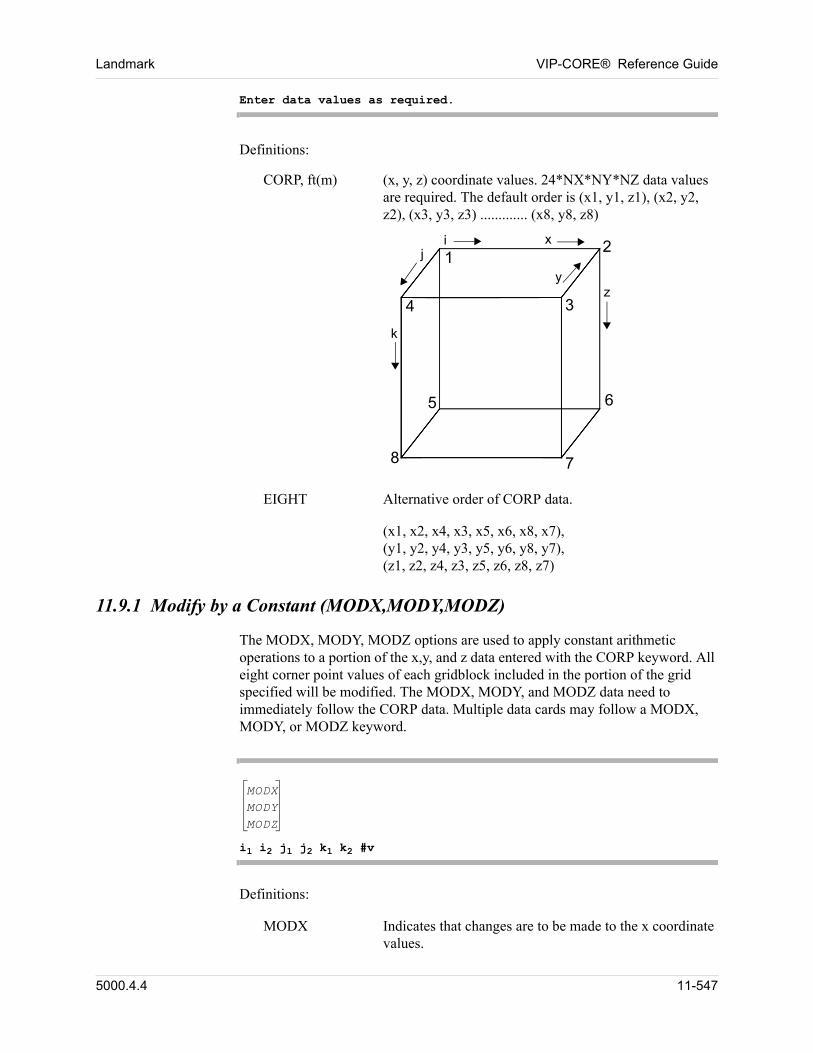
Landmark VIP-CORE® Reference Guide
Enter data values as required.
Definitions:
CORP, ft(m) (x, y, z) coordinate values. 24*NX*NY*NZ data values are required. The default order is (x1, y1, z1), (x2, y2, z2), (x3, y3, z3) ............. (x8, y8, z8)
zy
3
i
k
xj
4
2
7
6
1
5
8
EIGHT Alternative order of CORP data.
(x1, x2, x4, x3, x5, x6, x8, x7), (y1, y2, y4, y3, y5, y6, y8, y7), (z1, z2, z4, z3, z5, z6, z8, z7)
11.9.1 Modify by a Constant (MODX,MODY,MODZ)
The MODX, MODY, MODZ options are used to apply constant arithmetic operations to a portion of the x,y, and z data entered with the CORP keyword. All eight corner point values of each gridblock included in the portion of the grid specified will be modified. The MODX, MODY, and MODZ data need to immediately follow the CORP data. Multiple data cards may follow a MODX, MODY, or MODZ keyword.
MODXMODYMODZ
i1 i2 j1 j2 k1 k2 #v
Definitions: 00
MODX Indicates that changes are to be made to the x coordinate values.
5000.4.4 11-547
VIP-CORE® Reference Guide Landmark
MODY Indicates that changes are to be made to the y coordinate values.
MODZ Indicates that changes are to be made to the z coordinate values.
Gridblock locations are defined by indices i, j, k in reference to the (x,y,z) or (r,,z) grid. Modifications are applied to x, y or z coordinate elements that fall in the portion of the grid defined by:
i1 I i2j1 J j2k1 K k2
# An operator that describes how the coordinate values are to be modified. Any of the following symbols may be used:
+ add- subtract/ divide
* multiply= equal
There are no spaces between the operator and the value, #v.
v The value to be applied to the indicated portion of the x,y,z coordinate arrays, according to the specified operation.
Example: CORPINCLUDE grid.incMODZ1 10 1 10 1 3 *3.048
11-548 5000.4.4
Landmark VIP-CORE® Reference Guide
11.10 Control of Non-standard Connections Read from the vdb (VDBCONN)
When CORP data are read from a vdb, any non-standard connection data in the vdb can also be read. The VDBCONN keyword provides control on how to use the non-standard connection data in the vdb.
VDBCONN
BOTH
OFF
ONLY
Definitions:
BOTH The list of cell pairs read from the vdb are used to build the non-standard connections. In addition, the corner points are searched for any connections that are not already in the list read from the vdb.
OFF Do not read any non-standard connection data from the vdb. The grid corner points are searched to construct the non-standard connections. This is the default.
ONLY Use only the cell pairs read from the vdb to construct the non-standard connections. Do not perform a corner point search for additional connections.
NOTE: The face set data and multipliers read from the vdb are always used; i.e., they are independent from the use of the VDBCONN keyword. The fault multipliers can be changed with MULTFL data.
5000.4.4 11-549
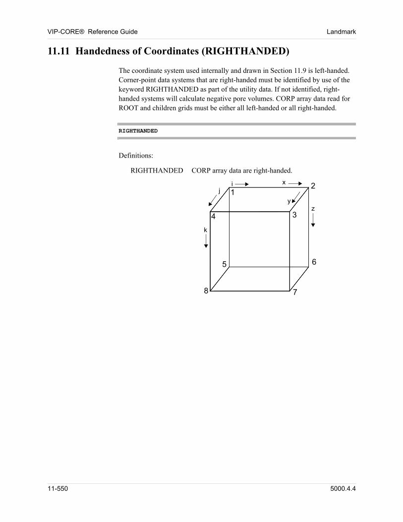
VIP-CORE® Reference Guide Landmark
11.11 Handedness of Coordinates (RIGHTHANDED)
The coordinate system used internally and drawn in Section 11.9 is left-handed. Corner-point data systems that are right-handed must be identified by use of the keyword RIGHTHANDED as part of the utility data. If not identified, right-handed systems will calculate negative pore volumes. CORP array data read for ROOT and children grids must be either all left-handed or all right-handed.
RIGHTHANDED
Definitions:
RIGHTHANDED CORP array data are right-handed.
zy
3
x 2
6
k
j
4
1
5
i
8 7
11-550 5000.4.4
Landmark VIP-CORE® Reference Guide
11.12 Transmissibility Calculations
11.12.1 Harmonic Integration (HARTRAN)
HARTRAN (iquad jquad kquad)
Definitions:
HARTRAN Transmissibilities are calculated using a harmonic integration of the space defined by the block corners. This is the default.
iquad, jquad, kquad Number of quadrature points in the x, y, and z directions, respectively, used by the integration. The integration is performed from the centroid of the block to each of the six faces separately, and iquad, jquad, kquad are used for each of the six directions. This results in six half transmissibilities for each gridblock. Default is (3, 3, 3).
1 iquad, jquad, kquad 3
11.12.2 No Integration (NEWTRAN)
NEWTRAN
Definitions:
NEWTRAN Transmissibilities are calculated by considering paths from the gridblock centroid to each of the six face centroids. The normals of each of the face areas with the corresponding paths are then used in the calculations.
11.12.3 Rectangular or Radial ROOT Grid (BLOCKTR)
ROOT grids that are defined with DX, DY, DZ or DR, DTHETA, DZ options are converted to corner-point grids internally. When LGR/ENDLGR is entered, either alone or with the data defining LGR’s, the block corner points are used in the calculations of pore volumes and transmissibilities (Sections 11.12.1 and 11.12.2). Depending on the structure of the reservoir the calculations using corner-point values can be substantially different than calculations made using the array data directly. An option to use the array data directly for the ROOT grid is provided here.
5000.4.4 11-551
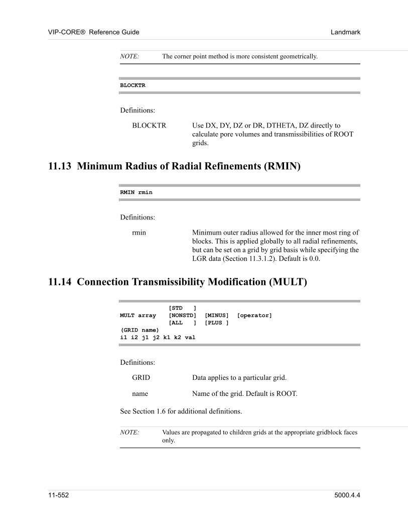
VIP-CORE® Reference Guide Landmark
NOTE: The corner point method is more consistent geometrically.
BLOCKTR
Definitions:
BLOCKTR Use DX, DY, DZ or DR, DTHETA, DZ directly to calculate pore volumes and transmissibilities of ROOT grids.
11.13 Minimum Radius of Radial Refinements (RMIN)
RMIN rmin
Definitions:
rmin Minimum outer radius allowed for the inner most ring of blocks. This is applied globally to all radial refinements, but can be set on a grid by grid basis while specifying the LGR data (Section 11.3.1.2). Default is 0.0.
11.14 Connection Transmissibility Modification (MULT)
[STD ] MULT array [NONSTD] [MINUS] [operator]
[ALL ] [PLUS ] (GRID name) i1 i2 j1 j2 k1 k2 val
Definitions: 00
GRID Data applies to a particular grid.
name Name of the grid. Default is ROOT.
See Section 1.6 for additional definitions.
NOTE: Values are propagated to children grids at the appropriate gridblock faces only.
11-552 5000.4.4
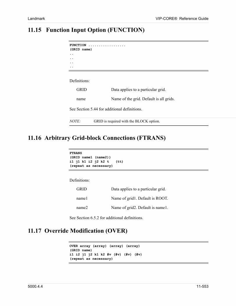
Landmark VIP-CORE® Reference Guide
11.15 Function Input Option (FUNCTION)
FUNCTION .................. (GRID name) .. .. .. ..
Definitions:
GRID Data applies to a particular grid.
name Name of the grid. Default is all grids.
See Section 5.44 for additional definitions.
NOTE: GRID is required with the BLOCK option.
11.16 Arbitrary Grid-block Connections (FTRANS)
FTRANS (GRID name1 (name2)) i1 j1 k1 i2 j2 k2 t (tt) (repeat as necessary)
Definitions:
GRID Data applies to a particular grid.
name1 Name of grid1. Default is ROOT.
name2 Name of grid2. Default is name1.
See Section 6.5.2 for additional definitions.
11.17 Override Modification (OVER)
OVER array (array) (array) (array) (GRID name) i1 i2 j1 j2 k1 k2 #v (#v) (#v) (#v) (repeat as necessary)
5000.4.4 11-553
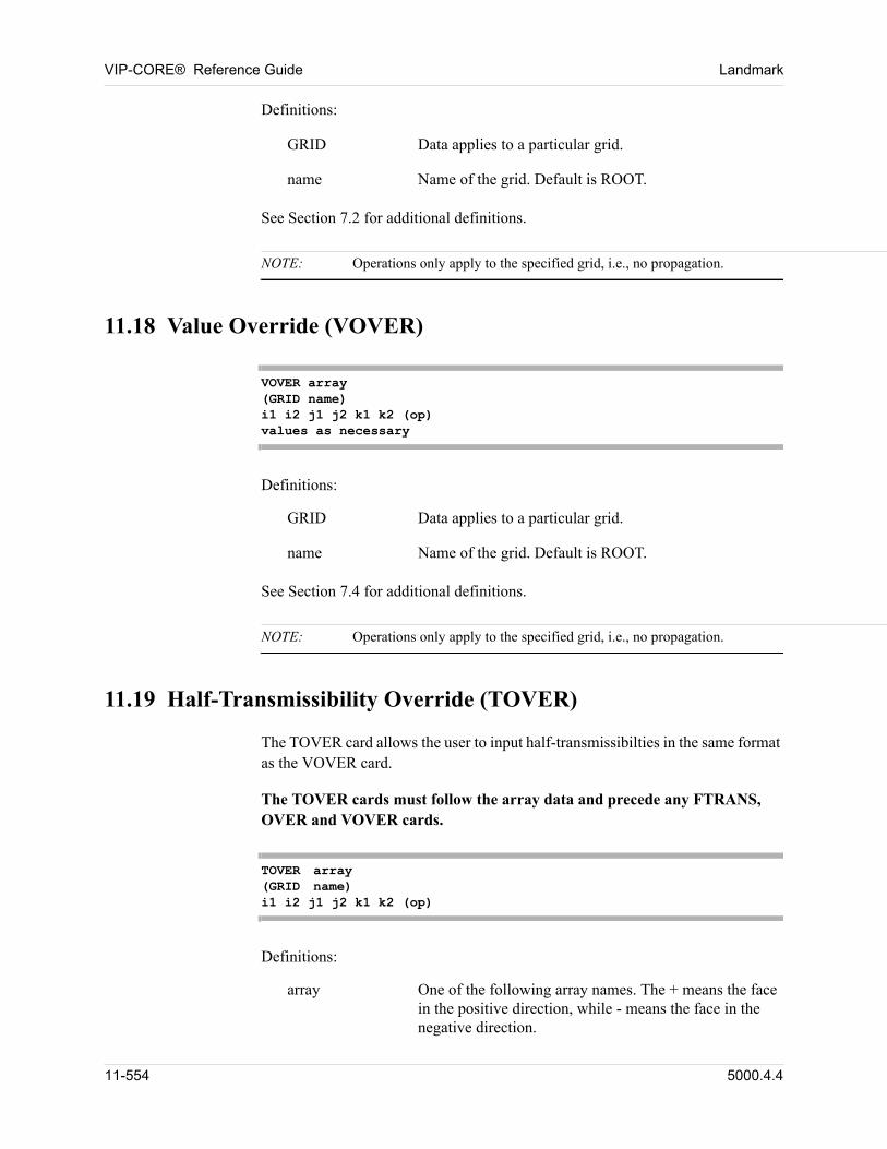
VIP-CORE® Reference Guide Landmark
Definitions:
GRID Data applies to a particular grid.
name Name of the grid. Default is ROOT.
See Section 7.2 for additional definitions.
NOTE: Operations only apply to the specified grid, i.e., no propagation.
11.18 Value Override (VOVER)
VOVER array(GRID name)i1 i2 j1 j2 k1 k2 (op)values as necessary
Definitions:
GRID Data applies to a particular grid.
name Name of the grid. Default is ROOT.
See Section 7.4 for additional definitions.
NOTE: Operations only apply to the specified grid, i.e., no propagation.
11.19 Half-Transmissibility Override (TOVER)
The TOVER card allows the user to input half-transmissibilties in the same format as the VOVER card.
The TOVER cards must follow the array data and precede any FTRANS, OVER and VOVER cards.
TOVER array(GRID name)i1 i2 j1 j2 k1 k2 (op)
Definitions:
array One of the following array names. The + means the face in the positive direction, while - means the face in the negative direction.
11-554 5000.4.4
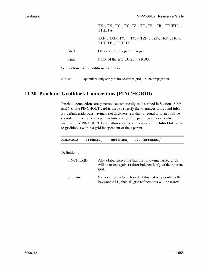
Landmark VIP-CORE® Reference Guide
TX+, TX-, TY+, TY-, TZ+, TZ-, TR+, TR-, TTHETA+, TTHETA-
TXF+, TXF-, TYF+, TYF-, TZF+, TZF-, TRF+, TRF-, TTHETF+, TTHETF-
GRID Data applies to a particular grid.
name Name of the grid. Default is ROOT.
See Section 7.4 for additional definitions.
NOTE: Operations only apply to the specified grid, i.e., no propagation.
11.20 Pinchout Gridblock Connections (PINCHGRID)
Pinchout connections are generated automatically as described in Sections 2.2.9 and 6.8. The PINCHOUT card is used to specify the tolerances tolnet and tolth. By default gridblocks having a net thickness less than or equal to tolnet will be considered inactive (zero pore volume) only if the parent gridblock is also inactive. The PINCHGRID card allows for the application of the tolnet tolerance to gridblocks within a grid independent of their parent.
PINCHGRID gridname1 (gridname2) ... (gridnamei)
Definitions:
PINCHGRID Alpha label indicating that the following named grids will be tested against tolnet independently of their parent grid.
gridname Names of grids to be tested. If this list only contains the keyword ALL, then all grid refinements will be tested.
5000.4.4 11-555
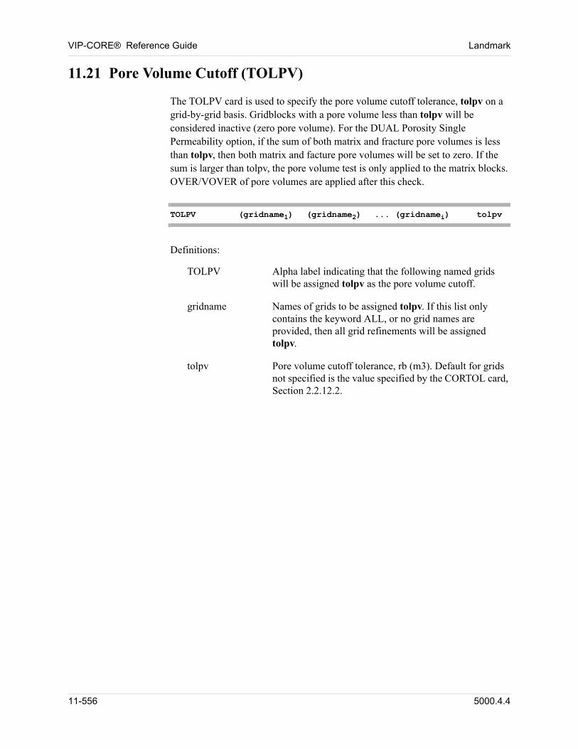
VIP-CORE® Reference Guide Landmark
11.21 Pore Volume Cutoff (TOLPV)
The TOLPV card is used to specify the pore volume cutoff tolerance, tolpv on a grid-by-grid basis. Gridblocks with a pore volume less than tolpv will be considered inactive (zero pore volume). For the DUAL Porosity Single Permeability option, if the sum of both matrix and fracture pore volumes is less than tolpv, then both matrix and facture pore volumes will be set to zero. If the sum is larger than tolpv, the pore volume test is only applied to the matrix blocks. OVER/VOVER of pore volumes are applied after this check.
TOLPV (gridname1) (gridname2) ... (gridnamei) tolpv
Definitions:
TOLPV Alpha label indicating that the following named grids will be assigned tolpv as the pore volume cutoff.
gridname Names of grids to be assigned tolpv. If this list only contains the keyword ALL, or no grid names are provided, then all grid refinements will be assigned tolpv.
tolpv Pore volume cutoff tolerance, rb (m3). Default for grids not specified is the value specified by the CORTOL card, Section 2.2.12.2.
11-556 5000.4.4
Chapter
12
00000Tracer Option1
12.1 Introduction
This is a short description of a set of tools which have been developed to improve and expand the simulation capabilities in the analysis and interpretation of tracer tests and in the design and performance analysis of waterflood projects. The tools are built around the particle tracking method which allows accurate simulation of tracer flow associated with convection and physical dispersion. The method is nearly numerical dispersion free and allows accurate simulation of tracer flow in field scale simulation. The algorithm is implemented in VIP-EXECUTIVE and allows simulation of tracer flow within the framework of three-dimensional, multi-phase, non-steady state reservoir simulation. In addition to accurate simulation of tracer flow the software allows: (1) tracking of water fronts in waterflood operations; (2) construction of three-dimensional flow trajectories and streamlines of velocity field; (3) calculation of the areal sweep; (4) visualization and animation of tracer flow.
Note that the TRACER option requires corner points to perform its calculations. Thus, non-corner point input data DX, DY, DZ will be automatically converted to corner points. This could cause differences in volumes and transmissibilities when compared to an identical model that did not include the TRACER card.
12.2 New Input Data for Initialization Module VIP-CORE
There is one new card in the initialization data set of VIP-CORE, as well as additional aquifer INFLUX data.
12.2.1 Activate Tracer Option (TRACER)
The tracer option is activated by the input of the TRACER card.
TRACER
1. Available as a separately licensed option. Not available in VIP-THERM.
5000.4.4 12-557
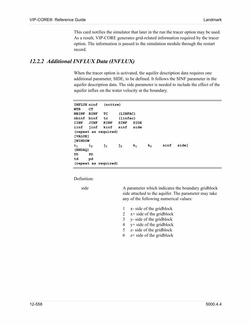
VIP-CORE® Reference Guide Landmark
This card notifies the simulator that later in the run the tracer option may be used. As a result, VIP-CORE generates grid-related information required by the tracer option. The information is passed to the simulation module through the restart record.
12.2.2 Additional INFLUX Data (INFLUX)
When the tracer option is activated, the aquifer description data requires one additional parameter, SIDE, to be defined. It follows the SINF parameter in the aquifer description data. The side parameter is needed to include the effect of the aquifer influx on the water velocity at the boundary.
INFLUX ninf (ncttrw)WTR CTNBINF BINF TC (LINFAC)nbinf binf tc (linfac)IINF JINF KINF SINF SIDEiinf jinf kinf sinf side(repeat as required)[VALUE][WINDOWi1 i2 j1 j2 k1 k2 sinf side](ENDAQ)TD PDtd pd(repeat as required)
Definition:
side A parameter which indicates the boundary gridblock side attached to the aquifer. The parameter may take any of the following numerical values:
1 x- side of the gridblock2 x+ side of the gridblock3 y- side of the gridblock4 y+ side of the gridblock5 z- side of the gridblock6 z+ side of the gridblock
12-558 5000.4.4
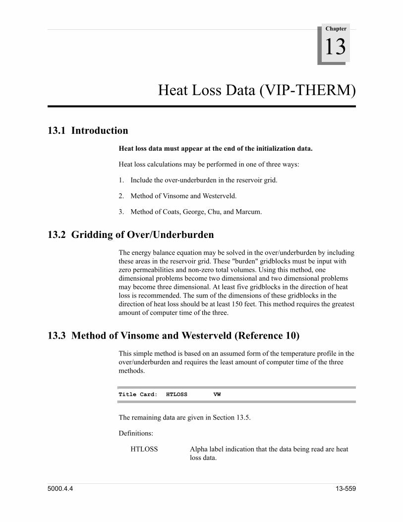
Chapter
13
Heat Loss Data (VIP-THERM)
13.1 Introduction
Heat loss data must appear at the end of the initialization data.
Heat loss calculations may be performed in one of three ways:
1. Include the over-underburden in the reservoir grid.
2. Method of Vinsome and Westerveld.
3. Method of Coats, George, Chu, and Marcum.
13.2 Gridding of Over/Underburden
The energy balance equation may be solved in the over/underburden by including these areas in the reservoir grid. These "burden" gridblocks must be input with zero permeabilities and non-zero total volumes. Using this method, one dimensional problems become two dimensional and two dimensional problems may become three dimensional. At least five gridblocks in the direction of heat loss is recommended. The sum of the dimensions of these gridblocks in the direction of heat loss should be at least 150 feet. This method requires the greatest amount of computer time of the three.
13.3 Method of Vinsome and Westerveld (Reference 10)
This simple method is based on an assumed form of the temperature profile in the over/underburden and requires the least amount of computer time of the three methods.
Title Card: HTLOSS VW
The remaining data are given in Section 13.5.
Definitions:
HTLOSS Alpha label indication that the data being read are heat loss data.
5000.4.4 13-559
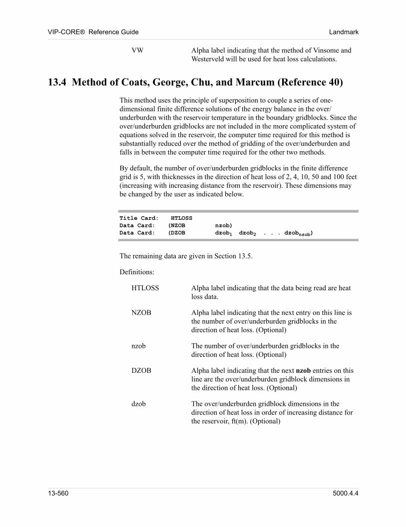
VIP-CORE® Reference Guide Landmark
VW Alpha label indicating that the method of Vinsome and Westerveld will be used for heat loss calculations.
13.4 Method of Coats, George, Chu, and Marcum (Reference 40)
This method uses the principle of superposition to couple a series of one-dimensional finite difference solutions of the energy balance in the over/underburden with the reservoir temperature in the boundary gridblocks. Since the over/underburden gridblocks are not included in the more complicated system of equations solved in the reservoir, the computer time required for this method is substantially reduced over the method of gridding of the over/underburden and falls in between the computer time required for the other two methods.
By default, the number of over/underburden gridblocks in the finite difference grid is 5, with thicknesses in the direction of heat loss of 2, 4, 10, 50 and 100 feet (increasing with increasing distance from the reservoir). These dimensions may be changed by the user as indicated below.
Title Card: HTLOSSData Card: (NZOB nzob)Data Card: (DZOB dzob1 dzob2 . . . dzobnzob)
The remaining data are given in Section 13.5.
Definitions:
HTLOSS Alpha label indicating that the data being read are heat loss data.
NZOB Alpha label indicating that the next entry on this line is the number of over/underburden gridblocks in the direction of heat loss. (Optional)
nzob The number of over/underburden gridblocks in the direction of heat loss. (Optional)
DZOB Alpha label indicating that the next nzob entries on this line are the over/underburden gridblock dimensions in the direction of heat loss. (Optional)
dzob The over/underburden gridblock dimensions in the direction of heat loss in order of increasing distance for the reservoir, ft(m). (Optional)
13-560 5000.4.4
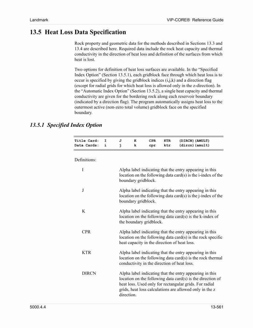
Landmark VIP-CORE® Reference Guide
13.5 Heat Loss Data Specification
Rock property and geometric data for the methods described in Sections 13.3 and 13.4 are described here. Required data include the rock heat capacity and thermal conductivity in the direction of heat loss and definition of the surfaces from which heat is lost.
Two options for definition of heat loss surfaces are available. In the “Specified Index Option” (Section 13.5.1), each gridblock face through which heat loss is to occur is specified by giving the gridblock indices (i,j,k) and a direction flag (except for radial grids for which heat loss is allowed only in the z-direction). In the “Automatic Index Option” (Section 13.5.2), a single heat capacity and thermal conductivity are given for the bordering rock along each reservoir boundary (indicated by a direction flag). The program automatically assigns heat loss to the outermost active (non-zero total volume) gridblock face on the specified boundary.
13.5.1 Specified Index Option
Title Card: I J K CPR KTR (DIRCN)(AMULT)Data Cards: i j k cpr ktr (dircn)(amult)
Definitions:
I Alpha label indicating that the entry appearing in this location on the following data card(s) is the i-index of the boundary gridblock.
J Alpha label indicating that the entry appearing in this location on the following data card(s) is the j-index of the boundary gridblock.
K Alpha label indicating that the entry appearing in this location on the following data card(s) is the k-index of the boundary gridblock.
CPR Alpha label indicating that the entry appearing in this location on the following data card(s) is the rock specific heat capacity in the direction of heat loss.
KTR Alpha label indicating that the entry appearing in this location on the following data card(s) is the rock thermal conductivity in the direction of heat loss.
DIRCN Alpha label indicating that the entry appearing in this location on the following data card(s) is the direction of heat loss. Used only for rectangular grids. For radial grids, heat loss calculations are allowed only in the z direction.
5000.4.4 13-561
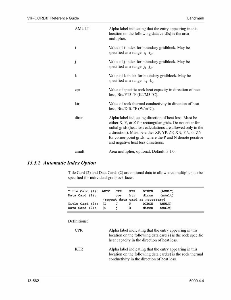
VIP-CORE® Reference Guide Landmark
AMULT Alpha label indicating that the entry appearing in this location on the following data card(s) is the area multiplier.
i Value of i-index for boundary gridblock. May be specified as a range: i1 -i2.
j Value of j-index for boundary gridblock. May be specified as a range: j1 -j2.
k Value of k-index for boundary gridblock. May be specified as a range: k1 -k2.
cpr Value of specific rock heat capacity in direction of heat loss, Btu/FT3 °F (KJ/M3 °C).
ktr Value of rock thermal conductivity in direction of heat loss, Btu/D ft. °F (W/m°C).
dircn Alpha label indicating direction of heat loss. Must be either X, Y, or Z for rectangular grids. Do not enter for radial grids (heat loss calculations are allowed only in the z direction). Must be either XP, YP, ZP, XN, YN, or ZN for corner-point grids, where the P and N denote positive and negative heat loss directions.
amult Area multiplier, optional. Default is 1.0.
13.5.2 Automatic Index Option
Title Card (2) and Data Cards (2) are optional data to allow area multipliers to be specified for individual gridblock faces.
Title Card (1): AUTO CPR KTR DIRCN (AMULT)Data Card (1): cpr ktr dircn (amult) (repeat data card as necessary)Title Card (2): (I J K DIRCN AMULT)Data Card (2): (i j k dircn amult)
Definitions:
CPR Alpha label indicating that the entry appearing in this location on the following data card(s) is the rock specific heat capacity in the direction of heat loss.
KTR Alpha label indicating that the entry appearing in this location on the following data card(s) is the rock thermal conductivity in the direction of heat loss.
13-562 5000.4.4
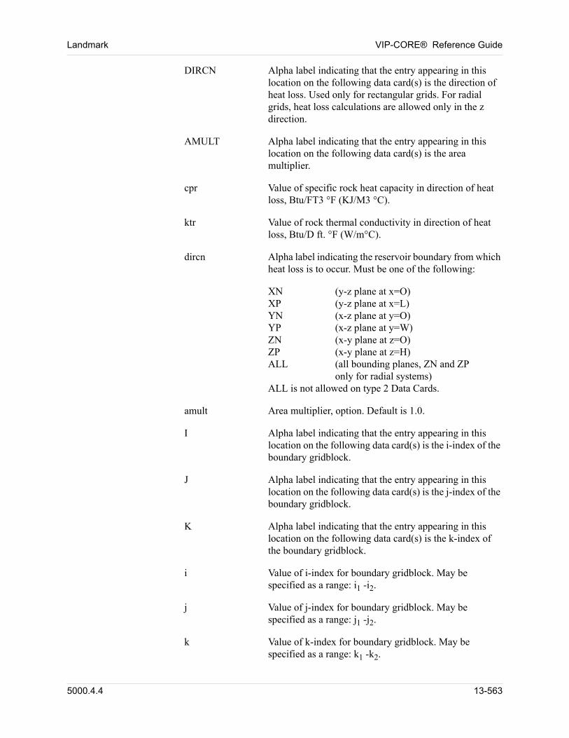
Landmark VIP-CORE® Reference Guide
DIRCN Alpha label indicating that the entry appearing in this location on the following data card(s) is the direction of heat loss. Used only for rectangular grids. For radial grids, heat loss calculations are allowed only in the z direction.
AMULT Alpha label indicating that the entry appearing in this location on the following data card(s) is the area multiplier.
cpr Value of specific rock heat capacity in direction of heat loss, Btu/FT3 °F (KJ/M3 °C).
ktr Value of rock thermal conductivity in direction of heat loss, Btu/D ft. °F (W/m°C).
dircn Alpha label indicating the reservoir boundary from which heat loss is to occur. Must be one of the following:
XN (y-z plane at x=O)XP (y-z plane at x=L)YN (x-z plane at y=O)YP (x-z plane at y=W)ZN (x-y plane at z=O)ZP (x-y plane at z=H)ALL (all bounding planes, ZN and ZP
only for radial systems)ALL is not allowed on type 2 Data Cards.
amult Area multiplier, option. Default is 1.0.
I Alpha label indicating that the entry appearing in this location on the following data card(s) is the i-index of the boundary gridblock.
J Alpha label indicating that the entry appearing in this location on the following data card(s) is the j-index of the boundary gridblock.
K Alpha label indicating that the entry appearing in this location on the following data card(s) is the k-index of the boundary gridblock.
i Value of i-index for boundary gridblock. May be specified as a range: i1 -i2.
j Value of j-index for boundary gridblock. May be specified as a range: j1 -j2.
k Value of k-index for boundary gridblock. May be specified as a range: k1 -k2.
5000.4.4 13-563

VIP-CORE® Reference Guide Landmark
13-564 5000.4.4
Chapter
14
00000Parallel Computing
14.1 Automatic Grid Decomposition
14.1.1 Introduction
Any cartesian grid defined with the LGR option can be automatically decomposed into subdomains for the purpose of running on a network of CPU’s (parallel computing).
The new subdomains are automatically identified by gridnames D1 D2 D3 ... D9999999, with increasing numerals according to the convention of x-direction first followed by y-direction then z-direction. Any name already used for an existing LGR grid will be skipped over. Local refinements within a decomposed grid will be moved into the new subdomains as long as each refinement is contained entirely within any one of the subdomains; otherwise the decomposition is not allowed. Decomposition of nested grids is allowed.
A radial ROOT grid with no periodic boundary conditions (no FLOW360) is considered like a cartesian grid for the context of this section. This section documents the data necessary for specifying the domain decompositions.
NOTE: The subdomains created by decomposition are internally considered to be local grid refinements. The grid-to-grid connections created are flagged as non-standard connections for data options such as MULT (Section 1.6).
14.1.2 Domain Decomposition of Cartesian Grids (DECOMP)
The DECOMP/ENDDEC data must follow the LGR data. If no LGR’s are defined, then the data must follow the grid dimensions data (Section 2.2.3) in which case the LGR option is turned on automatically and the ROOT grid could be decomposed.
DECOMPgridname1 (KEEP) ndx ndy ndz
(X npx1 npx2 npx3 ... npxndx)(Y npy1 npy2 npy3 ... npyndy)(Z npz1 npz2 npz3 ... npzndz)
(gridname2 (KEEP) ndx ndy ndz).
5000.4.4 14-565
VIP-CORE® Reference Guide Landmark
.
.ENDDEC
Definitions:
DECOMP Keyword for introducing grid decomposition data.
gridnamei Name of grid to be decomposed.
NOTE: Nested grids make decomposition dependent on grid order. It is recommended to specify the most refined grids first.
KEEP Keyword that will result in the new grids to be 1 by 1 by 1 refinements on top of the original decomposed grid. The KEEP option increases the size of the model since storage for the original grid is also required. The default is for the new grids to replace the original grid and thus the new grids will be at the same (LGR) level as the original grid.
ndx,ndy,ndz Number of domains in the x, y, z directions.
X,Y,Z Optional keywords that allows control of the size of each new sub domain.
npx1,npx2,... Number of x direction parent gridblocks in each new domain.
NOTE: If the KEEP option is used then the decomposed grid itself will be the parent of the new grids. Otherwise the parent of the decomposed grid will also be the parent of the new grids.
npy1,npy2,... Number of y direction parent gridblocks in each new domain. See note following the definition for npx.
npz1,npz2,... Number of z direction parent gridblocks in each new domain. See note following the definition for npx.
ENDDEC End of grid decomposition data.
14-566 5000.4.4
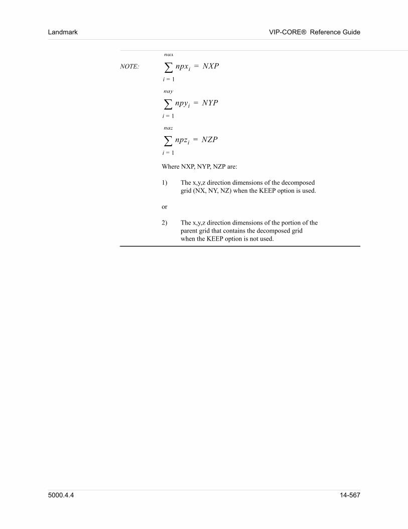
Landmark VIP-CORE® Reference Guide
NOTE: npxi
i 1=
ndx
NXP=
npyi
i 1=
ndy
NYP=
npzi
i 1=
ndz
NZP=
Where NXP, NYP, NZP are:1) The x,y,z direction dimensions of the decomposed
grid (NX, NY, NZ) when the KEEP option is used.or2) The x,y,z direction dimensions of the portion of the
parent grid that contains the decomposed grid when the KEEP option is not used.
5000.4.4 14-567
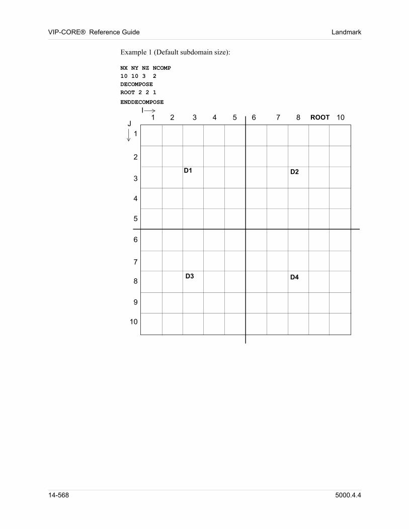
VIP-CORE® Reference Guide Landmark
Example 1 (Default subdomain size):
NX NY NZ NCOMP10 10 3 2DECOMPOSEROOT 2 2 1
ENDDECOMPOSE
D3 D4
D2D1
ROOTI
1 2 3 4 5 6 7 8 10
1
2
3
4
5
6
7
8
9
10
J
14-568 5000.4.4
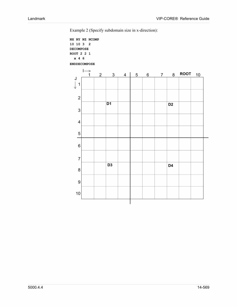
Landmark VIP-CORE® Reference Guide
Example 2 (Specify subdomain size in x-direction):
NX NY NZ NCOMP10 10 3 2DECOMPOSEROOT 2 2 1 x 4 6
ENDDECOMPOSE
D3 D4
D2D1
ROOTI
1 2 3 4 5 6 7 8 10
1
2
3
4
5
6
7
8
9
10
J
5000.4.4 14-569
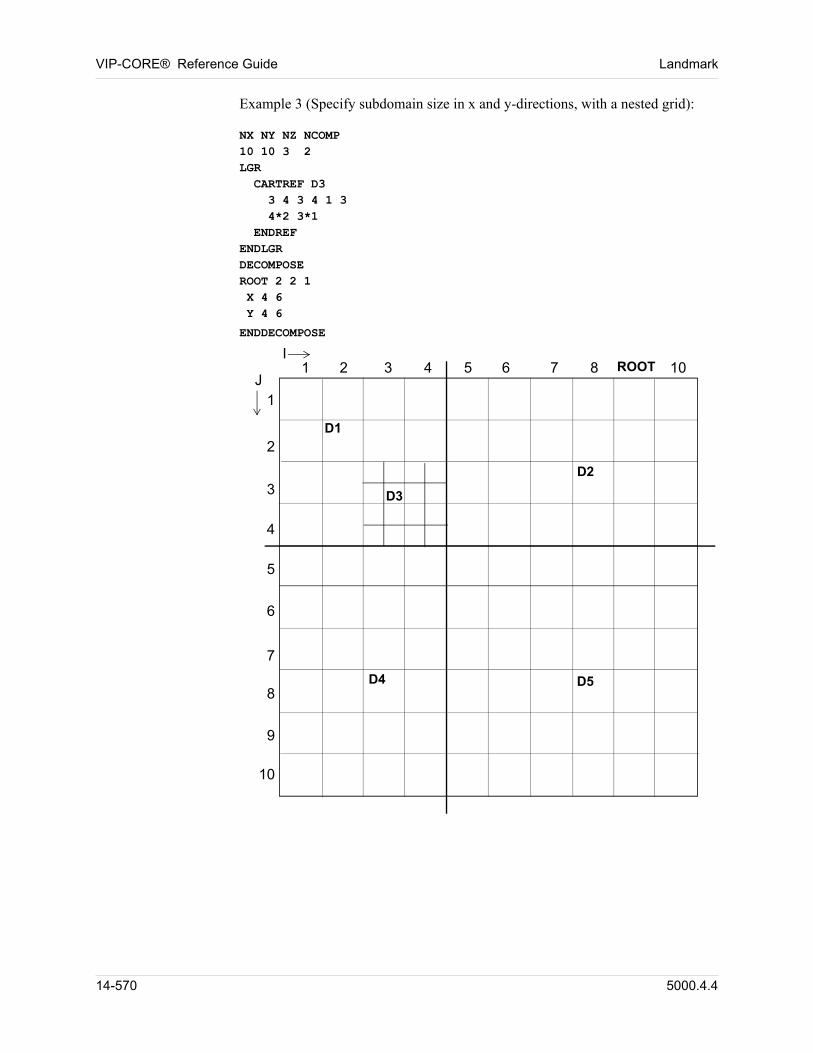
VIP-CORE® Reference Guide Landmark
Example 3 (Specify subdomain size in x and y-directions, with a nested grid):
NX NY NZ NCOMP10 10 3 2LGR CARTREF D3 3 4 3 4 1 3 4*2 3*1 ENDREFENDLGRDECOMPOSEROOT 2 2 1 X 4 6 Y 4 6
ENDDECOMPOSE
D4 D5
D2
D1
ROOT
D3
I1 2 3 4 5 6 7 8 10
1
2
3
4
5
6
7
8
9
10
J
14-570 5000.4.4
Chapter
15
00000Diffusion
15.1 Summary
The Reservoir Engineering Research Institute (RERI) has extensively investigated the effects of diffusion in petroleum reservoirs. Their work can be divided into two categories: (1) calculation of compositional variations due to diffusion alone, which can be used to initialize a reservoir model in which convective effects are ignored , and (2) the combined effects of diffusion and convection, which can be used to initialize a model in which both diffusion and convection are important mechanisms.
RERI developed algorithms for three different types of diffusion (molecular, pressure, and thermal) using the theory of irreversible thermodynamics. The diffusion fluxes within each phase are the products of diffusion coefficients multiplied by a gradient. The molecular diffusion flux of a particular component is the sum of the product of the molecular diffusion coefficients and the gradients of the mole fractions of all the components. The pressure diffusion flux of a particular component is the product of the pressure diffusion coefficients and the pressure gradient. The thermal diffusion flux of a particular component is the product of the thermal diffusion coefficients and the temperature gradient. These complex coefficients can be evaluated at the start of each timestep, based on the pressure, temperature, and compositions of each phase, and held constant over the timestep. For the implicit mode, the diffusive fluxes are then treated implicitly in phase pressures, phase saturations, and phase compositions. These complex calculations require many thermodynamic quantities, which can be calculated by an equation of state (EOS). Shukla and Firoozabadi, and Firoozabadi et al. describe the thermodynamic calculations in detail.
The steady state solution of the diffusion equation, which can be used to generate initial pressures and compositions internally, has been added to VIP-CORE. Additionally, the algorithm rigorously detects the phase state existing in each gridblock, allowing the initialization process to properly initialize the reservoir with oil overlaying gas, overlaying water.
With this enhancement, diffusion flux terms are added to the convective flux terms. These changes have been implemented for IMPES or implicit formulation, single or DUAL porosity/permeability mode, and in serial or parallel. For the
5000.4.4 15-571
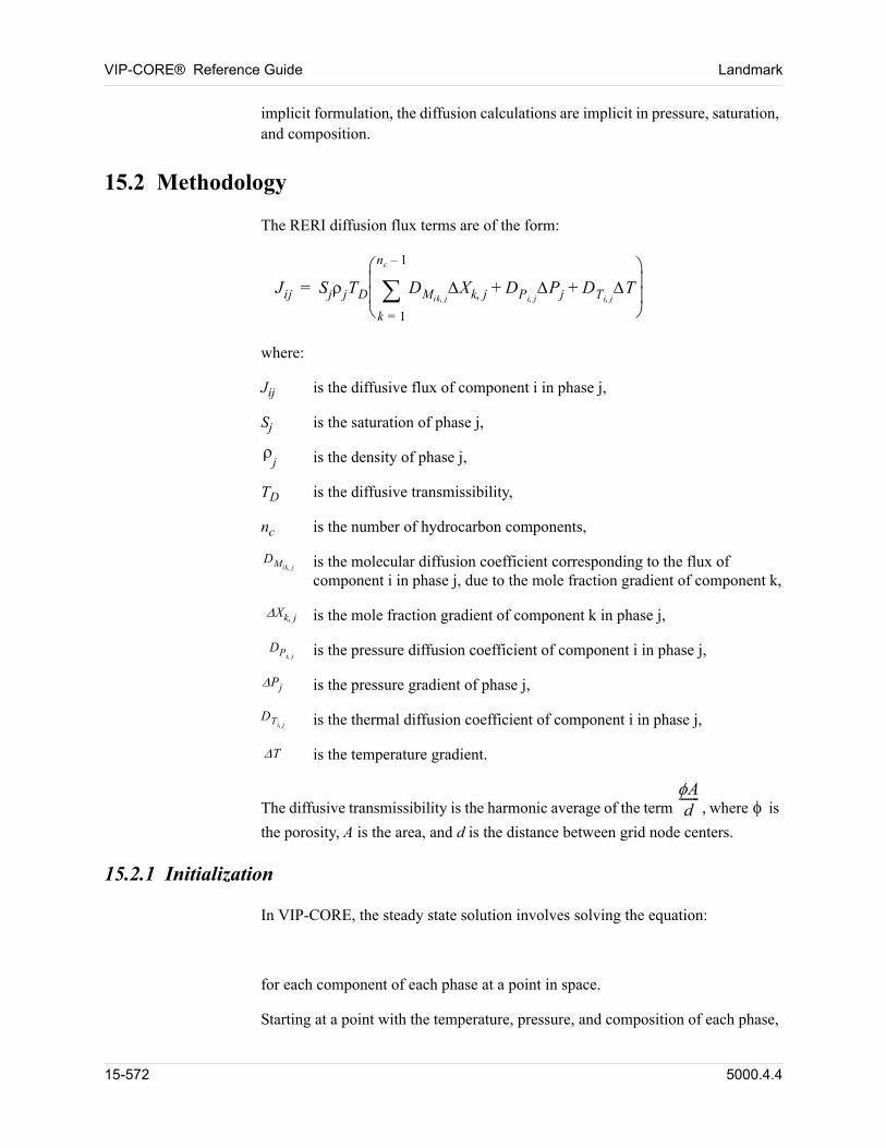
VIP-CORE® Reference Guide Landmark
implicit formulation, the diffusion calculations are implicit in pressure, saturation, and composition.
15.2 Methodology
The RERI diffusion flux terms are of the form:
Jij SjjTD DMik jXk j DPi j
Pj DTi jT+ +
k 1=
nc 1–
=
00 where:
00 Jij is the diffusive flux of component i in phase j,
00 Sj is the saturation of phase j,
00
j is the density of phase j,
00 TD is the diffusive transmissibility,
00 nc is the number of hydrocarbon components,
00DMik j is the molecular diffusion coefficient corresponding to the flux of
component i in phase j, due to the mole fraction gradient of component k,
00Xk j is the mole fraction gradient of component k in phase j,
00DPi j is the pressure diffusion coefficient of component i in phase j,
00Pj is the pressure gradient of phase j,
00DTi j is the thermal diffusion coefficient of component i in phase j,
00 T is the temperature gradient.
The diffusive transmissibility is the harmonic average of the term Ad
-------, where is
the porosity, A is the area, and d is the distance between grid node centers.
15.2.1 Initialization
In VIP-CORE, the steady state solution involves solving the equation:
00 for each component of each phase at a point in space.
00 Starting at a point with the temperature, pressure, and composition of each phase,
15-572 5000.4.4
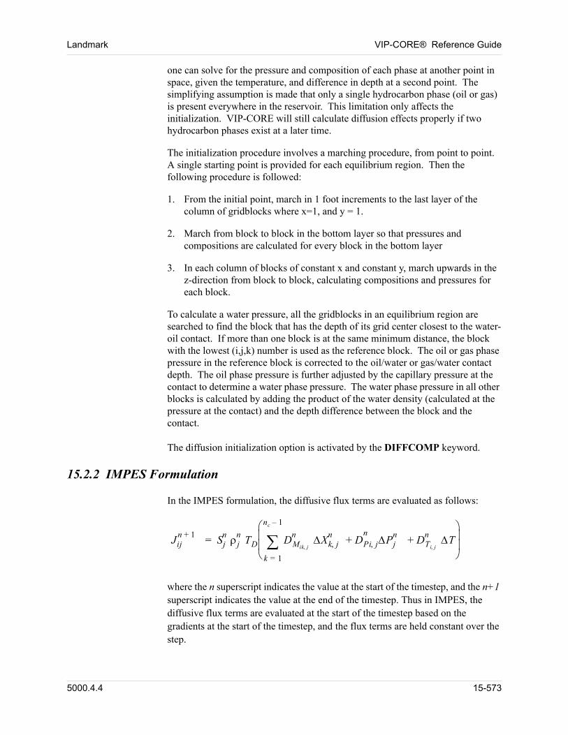
Landmark VIP-CORE® Reference Guide
one can solve for the pressure and composition of each phase at another point in space, given the temperature, and difference in depth at a second point. The simplifying assumption is made that only a single hydrocarbon phase (oil or gas) is present everywhere in the reservoir. This limitation only affects the initialization. VIP-CORE will still calculate diffusion effects properly if two hydrocarbon phases exist at a later time.
00 The initialization procedure involves a marching procedure, from point to point. A single starting point is provided for each equilibrium region. Then the following procedure is followed:
1. From the initial point, march in 1 foot increments to the last layer of the column of gridblocks where x=1, and y = 1.
2. March from block to block in the bottom layer so that pressures and compositions are calculated for every block in the bottom layer
3. In each column of blocks of constant x and constant y, march upwards in the z-direction from block to block, calculating compositions and pressures for each block.
00 To calculate a water pressure, all the gridblocks in an equilibrium region are searched to find the block that has the depth of its grid center closest to the water-oil contact. If more than one block is at the same minimum distance, the block with the lowest (i,j,k) number is used as the reference block. The oil or gas phase pressure in the reference block is corrected to the oil/water or gas/water contact depth. The oil phase pressure is further adjusted by the capillary pressure at the contact to determine a water phase pressure. The water phase pressure in all other blocks is calculated by adding the product of the water density (calculated at the pressure at the contact) and the depth difference between the block and the contact.
The diffusion initialization option is activated by the DIFFCOMP keyword.
15.2.2 IMPES Formulation
In the IMPES formulation, the diffusive flux terms are evaluated as follows:
Jijn 1+
Sjn j
nTD DMik j
n Xk jn
DPi j Pjnn
DTi j
n T+ +
k 1=
nc 1–
=
where the n superscript indicates the value at the start of the timestep, and the n+1 superscript indicates the value at the end of the timestep. Thus in IMPES, the diffusive flux terms are evaluated at the start of the timestep based on the gradients at the start of the timestep, and the flux terms are held constant over the step.
5000.4.4 15-573
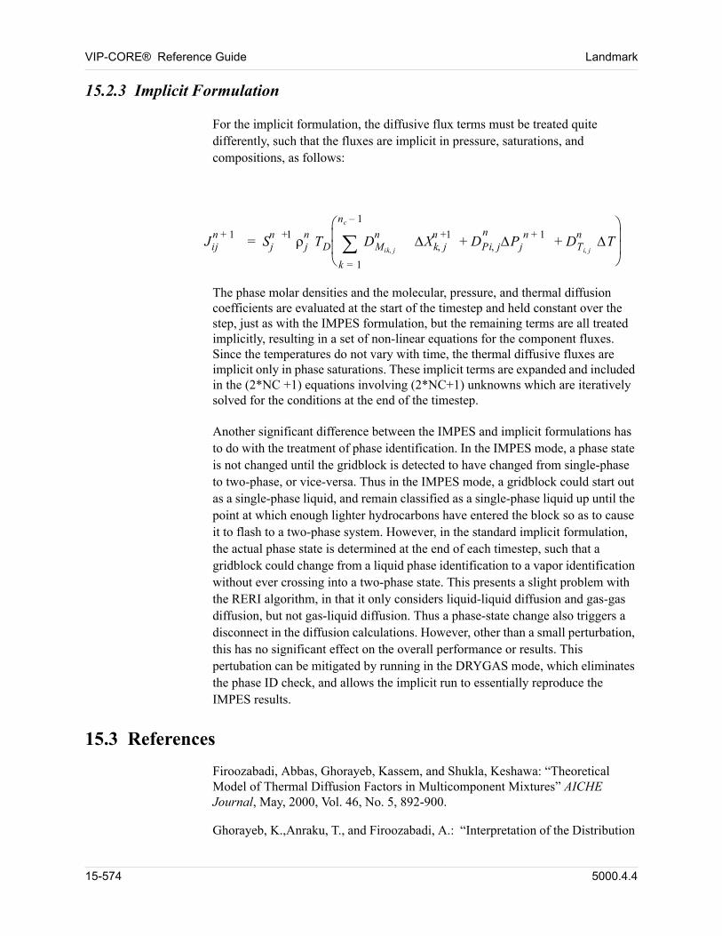
VIP-CORE® Reference Guide Landmark
15.2.3 Implicit Formulation
For the implicit formulation, the diffusive flux terms must be treated quite differently, such that the fluxes are implicit in pressure, saturations, and compositions, as follows:
Jijn 1+
Sjn 1+ j
nTD DMik j
n Xk jn 1+
DPi j Pjn 1+n
DTi j
n T+ +
k 1=
nc 1–
=
00 The phase molar densities and the molecular, pressure, and thermal diffusion coefficients are evaluated at the start of the timestep and held constant over the step, just as with the IMPES formulation, but the remaining terms are all treated implicitly, resulting in a set of non-linear equations for the component fluxes. Since the temperatures do not vary with time, the thermal diffusive fluxes are implicit only in phase saturations. These implicit terms are expanded and included in the (2*NC +1) equations involving (2*NC+1) unknowns which are iteratively solved for the conditions at the end of the timestep.
Another significant difference between the IMPES and implicit formulations has to do with the treatment of phase identification. In the IMPES mode, a phase state is not changed until the gridblock is detected to have changed from single-phase to two-phase, or vice-versa. Thus in the IMPES mode, a gridblock could start out as a single-phase liquid, and remain classified as a single-phase liquid up until the point at which enough lighter hydrocarbons have entered the block so as to cause it to flash to a two-phase system. However, in the standard implicit formulation, the actual phase state is determined at the end of each timestep, such that a gridblock could change from a liquid phase identification to a vapor identification without ever crossing into a two-phase state. This presents a slight problem with the RERI algorithm, in that it only considers liquid-liquid diffusion and gas-gas diffusion, but not gas-liquid diffusion. Thus a phase-state change also triggers a disconnect in the diffusion calculations. However, other than a small perturbation, this has no significant effect on the overall performance or results. This pertubation can be mitigated by running in the DRYGAS mode, which eliminates the phase ID check, and allows the implicit run to essentially reproduce the IMPES results.
15.3 References
00 Firoozabadi, Abbas, Ghorayeb, Kassem, and Shukla, Keshawa: “Theoretical Model of Thermal Diffusion Factors in Multicomponent Mixtures” AICHE Journal, May, 2000, Vol. 46, No. 5, 892-900.
00 Ghorayeb, K.,Anraku, T., and Firoozabadi, A.: “Interpretation of the Distribution
15-574 5000.4.4
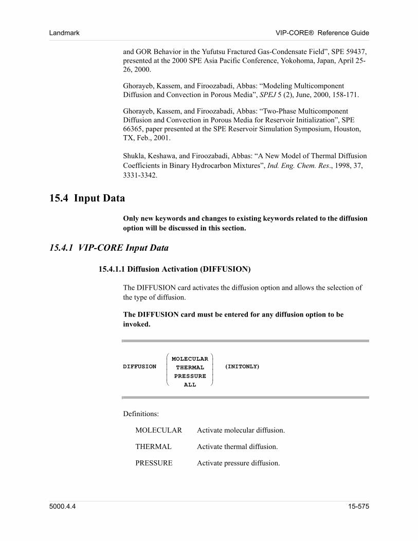
Landmark VIP-CORE® Reference Guide
and GOR Behavior in the Yufutsu Fractured Gas-Condensate Field”, SPE 59437, presented at the 2000 SPE Asia Pacific Conference, Yokohoma, Japan, April 25-26, 2000.
00 Ghorayeb, Kassem, and Firoozabadi, Abbas: “Modeling Multicomponent Diffusion and Convection in Porous Media”, SPEJ 5 (2), June, 2000, 158-171.
00 Ghorayeb, Kassem, and Firoozabadi, Abbas: “Two-Phase Multicomponent Diffusion and Convection in Porous Media for Reservoir Initialization”, SPE 66365, paper presented at the SPE Reservoir Simulation Symposium, Houston, TX, Feb., 2001.
Shukla, Keshawa, and Firoozabadi, Abbas: “A New Model of Thermal Diffusion Coefficients in Binary Hydrocarbon Mixtures”, Ind. Eng. Chem. Res., 1998, 37, 3331-3342.
15.4 Input Data
Only new keywords and changes to existing keywords related to the diffusion option will be discussed in this section.
15.4.1 VIP-CORE Input Data
15.4.1.1 Diffusion Activation (DIFFUSION)
The DIFFUSION card activates the diffusion option and allows the selection of the type of diffusion.
The DIFFUSION card must be entered for any diffusion option to be invoked.
DIFFUSIONMOLECULARTHERMALPRESSURE
ALL
(INITONLY)
00 Definitions:
MOLECULAR Activate molecular diffusion.
THERMAL Activate thermal diffusion.
PRESSURE Activate pressure diffusion.
5000.4.4 15-575
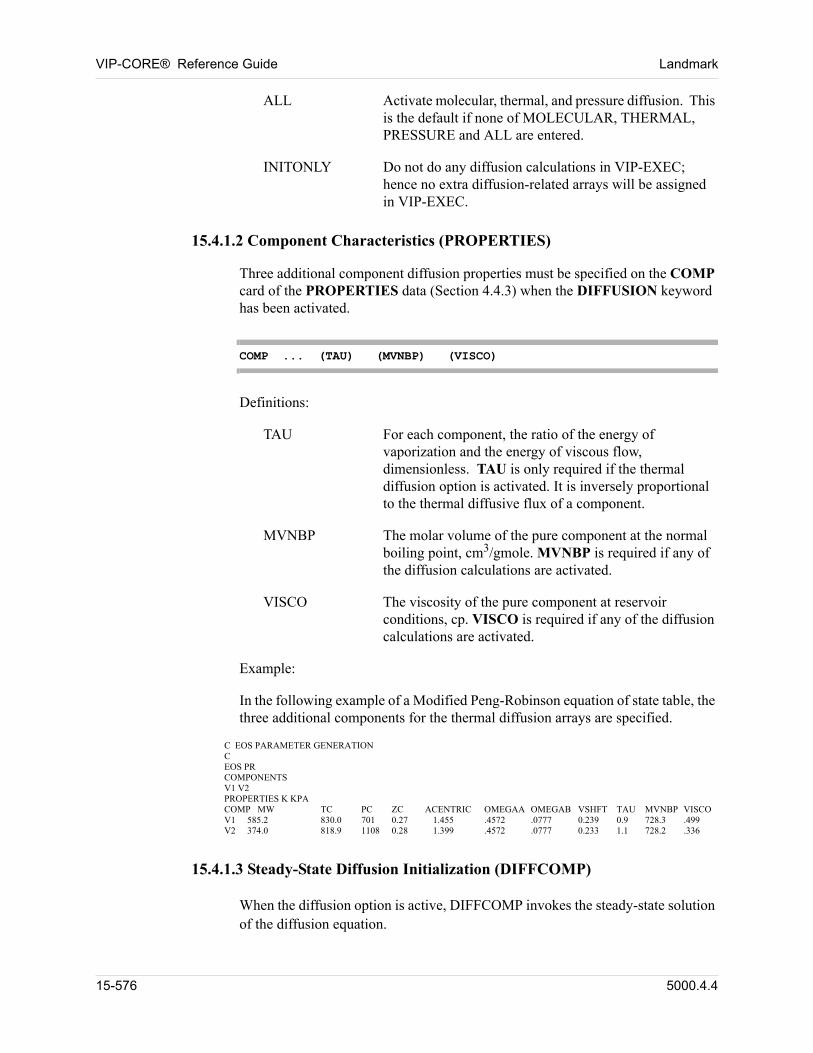
VIP-CORE® Reference Guide Landmark
ALL Activate molecular, thermal, and pressure diffusion. This is the default if none of MOLECULAR, THERMAL, PRESSURE and ALL are entered.
INITONLY Do not do any diffusion calculations in VIP-EXEC; hence no extra diffusion-related arrays will be assigned in VIP-EXEC.
15.4.1.2 Component Characteristics (PROPERTIES)
00 Three additional component diffusion properties must be specified on the COMP card of the PROPERTIES data (Section 4.4.3) when the DIFFUSION keyword has been activated.
COMP ... (TAU) (MVNBP) (VISCO)
00 Definitions:
TAU For each component, the ratio of the energy of vaporization and the energy of viscous flow, dimensionless. TAU is only required if the thermal diffusion option is activated. It is inversely proportional to the thermal diffusive flux of a component.
MVNBP The molar volume of the pure component at the normal boiling point, cm3/gmole. MVNBP is required if any of the diffusion calculations are activated.
VISCO The viscosity of the pure component at reservoir conditions, cp. VISCO is required if any of the diffusion calculations are activated.
00 Example:
00 In the following example of a Modified Peng-Robinson equation of state table, the three additional components for the thermal diffusion arrays are specified.
C EOS PARAMETER GENERATION C EOS PR COMPONENTS V1 V2 PROPERTIES K KPA COMP MW TC PC ZC ACENTRIC OMEGAA OMEGAB VSHFT TAU MVNBP VISCO V1 585.2 830.0 701 0.27 1.455 .4572 .0777 0.239 0.9 728.3 .499 V2 374.0 818.9 1108 0.28 1.399 .4572 .0777 0.233 1.1 728.2 .336
15.4.1.3 Steady-State Diffusion Initialization (DIFFCOMP)
When the diffusion option is active, DIFFCOMP invokes the steady-state solution of the diffusion equation.
15-576 5000.4.4
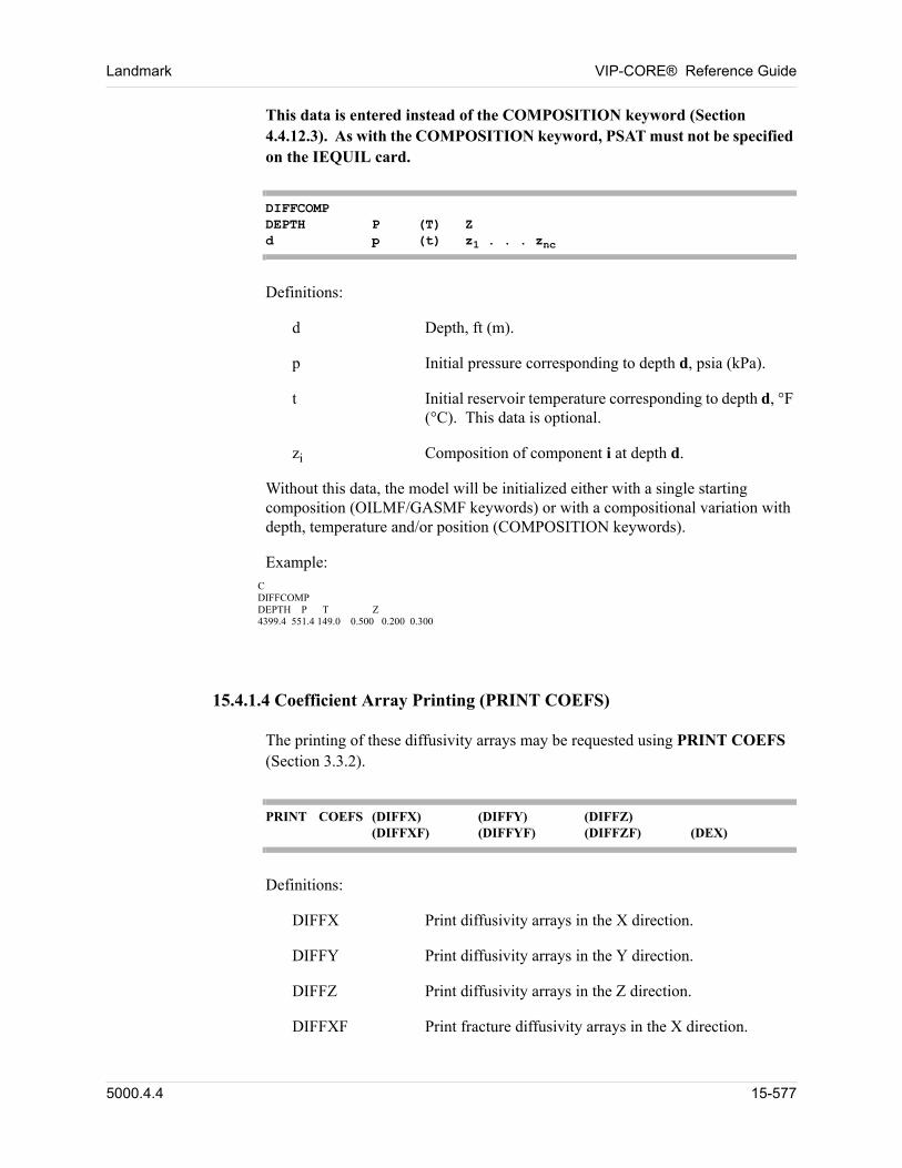
Landmark VIP-CORE® Reference Guide
This data is entered instead of the COMPOSITION keyword (Section 4.4.12.3). As with the COMPOSITION keyword, PSAT must not be specified on the IEQUIL card.
DIFFCOMPDEPTH P (T) Zd p (t) z1 . . . znc
00 Definitions:
d Depth, ft (m).
p Initial pressure corresponding to depth d, psia (kPa).
t Initial reservoir temperature corresponding to depth d, °F (°C). This data is optional.
zi Composition of component i at depth d.
00 Without this data, the model will be initialized either with a single starting composition (OILMF/GASMF keywords) or with a compositional variation with depth, temperature and/or position (COMPOSITION keywords).
00 Example: C DIFFCOMP DEPTH P T Z 4399.4 551.4 149.0 0.500 0.200 0.300
15.4.1.4 Coefficient Array Printing (PRINT COEFS)
The printing of these diffusivity arrays may be requested using PRINT COEFS (Section 3.3.2).
PRINT COEFS (DIFFX) (DIFFY) (DIFFZ)(DIFFXF) (DIFFYF) (DIFFZF) (DEX)
00 Definitions:
DIFFX Print diffusivity arrays in the X direction.
DIFFY Print diffusivity arrays in the Y direction.
DIFFZ Print diffusivity arrays in the Z direction.
DIFFXF Print fracture diffusivity arrays in the X direction.
5000.4.4 15-577
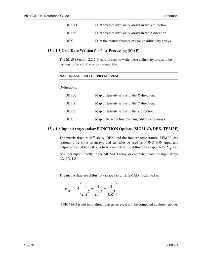
VIP-CORE® Reference Guide Landmark
DIFFYF Print fracture diffusivity arrays in the Y direction.
DIFFZF Print fracture diffusivity arrays in the Z direction.
DEX Print the matrix-fracture exchange diffusivity arrays.
15.4.1.5 Grid Data Written for Post-Processing (MAP)
The MAP (Section 2.2.2.1) card is used to write these diffusivity arrays to be written to the vdb file or to the map file. 00
MAP (DIFFX) (DIFFY) (DIFFZ) (DEX)
00 Definitions:
DIFFX Map diffusivity arrays in the X direction.
DIFFY Map diffusivity arrays in the Y direction.
DIFFZ Map diffusivity arrays in the Z direction.
DEX Map matrix-fracture exchange diffusivity arrays.
15.4.1.6 Input Arrays and/or FUNCTION Options (SIGMAD, DEX, TEMPF)
00 The matrix-fracture diffusivity, DEX, and the fracture temperature, TEMPF, can optionally be input as arrays, and can also be used as FUNCTION input and output arrays. When DEX is to be computed, the diffusivity shape factor d , can
be either input directly, in the SIGMAD array, or computed from the input arrays LX, LY, LZ.
00 The matrix-fracture diffusivity shape factor, SIGMAD, is defined as:
d 4 1
LX2
---------- 1
LY2
--------- 1
LZ2
---------+ +
=
00 If SIGMAD is not input directly as an array, it will be computed as shown above.
15-578 5000.4.4
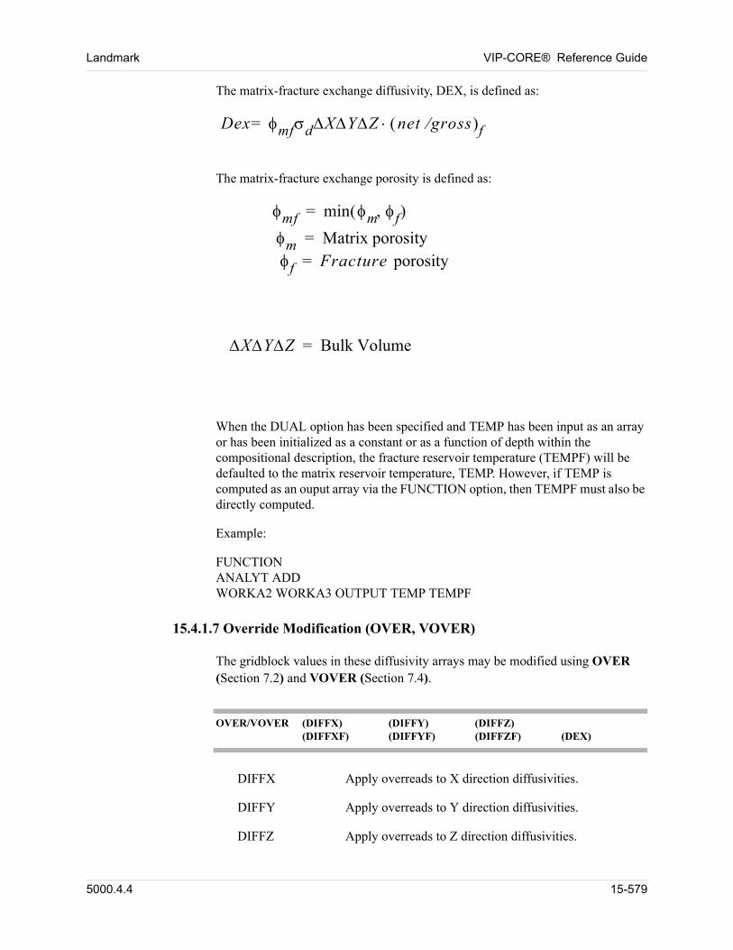
Landmark VIP-CORE® Reference Guide
00 The matrix-fracture exchange diffusivity, DEX, is defined as:
Dex mfdXYZ net gross f=
00 The matrix-fracture exchange porosity is defined as:
mf min m f =
m Matrix porosity=f Fracture porosity=
00
XYZ Bulk Volume=
00 When the DUAL option has been specified and TEMP has been input as an array or has been initialized as a constant or as a function of depth within the compositional description, the fracture reservoir temperature (TEMPF) will be defaulted to the matrix reservoir temperature, TEMP. However, if TEMP is computed as an ouput array via the FUNCTION option, then TEMPF must also be directly computed.
00 Example:
00 FUNCTIONANALYT ADDWORKA2 WORKA3 OUTPUT TEMP TEMPF
15.4.1.7 Override Modification (OVER, VOVER)
The gridblock values in these diffusivity arrays may be modified using OVER (Section 7.2) and VOVER (Section 7.4).
OVER/VOVER (DIFFX) (DIFFY) (DIFFZ)(DIFFXF) (DIFFYF) (DIFFZF) (DEX)
DIFFX Apply overreads to X direction diffusivities.
DIFFY Apply overreads to Y direction diffusivities.
DIFFZ Apply overreads to Z direction diffusivities.
5000.4.4 15-579
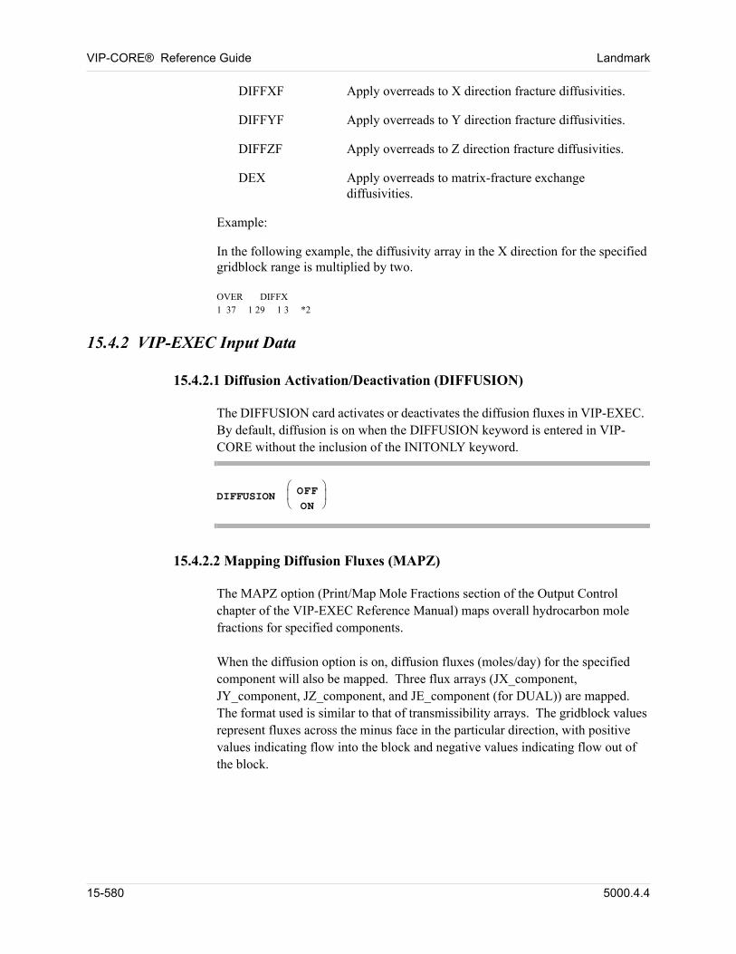
VIP-CORE® Reference Guide Landmark
DIFFXF Apply overreads to X direction fracture diffusivities.
DIFFYF Apply overreads to Y direction fracture diffusivities.
DIFFZF Apply overreads to Z direction fracture diffusivities.
DEX Apply overreads to matrix-fracture exchange diffusivities.
00 Example:
00 In the following example, the diffusivity array in the X direction for the specified gridblock range is multiplied by two.
00 OVER DIFFX1 37 1 29 1 3 *2
15.4.2 VIP-EXEC Input Data
15.4.2.1 Diffusion Activation/Deactivation (DIFFUSION)
The DIFFUSION card activates or deactivates the diffusion fluxes in VIP-EXEC. By default, diffusion is on when the DIFFUSION keyword is entered in VIP-CORE without the inclusion of the INITONLY keyword.
DIFFUSION OFFON
15.4.2.2 Mapping Diffusion Fluxes (MAPZ)
The MAPZ option (Print/Map Mole Fractions section of the Output Control chapter of the VIP-EXEC Reference Manual) maps overall hydrocarbon mole fractions for specified components.
When the diffusion option is on, diffusion fluxes (moles/day) for the specified component will also be mapped. Three flux arrays (JX_component, JY_component, JZ_component, and JE_component (for DUAL)) are mapped. The format used is similar to that of transmissibility arrays. The gridblock values represent fluxes across the minus face in the particular direction, with positive values indicating flow into the block and negative values indicating flow out of the block.
15-580 5000.4.4
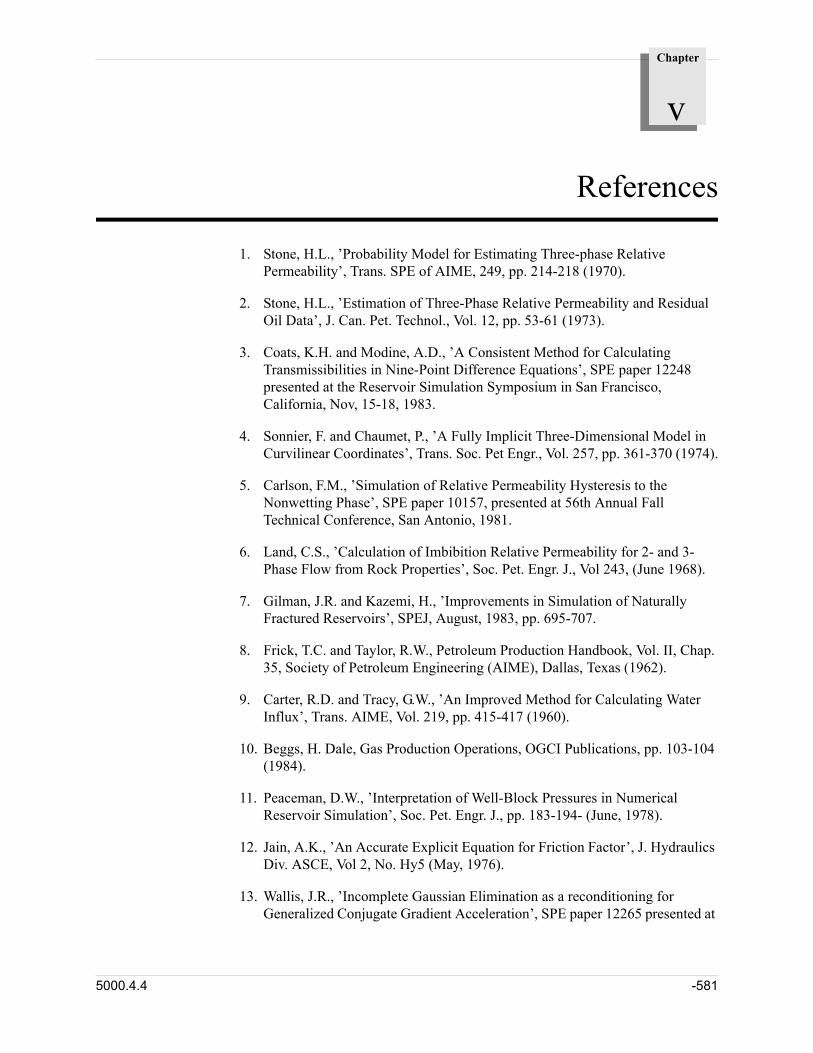
Chapter
v
References
1. Stone, H.L., ’Probability Model for Estimating Three-phase Relative Permeability’, Trans. SPE of AIME, 249, pp. 214-218 (1970).
2. Stone, H.L., ’Estimation of Three-Phase Relative Permeability and Residual Oil Data’, J. Can. Pet. Technol., Vol. 12, pp. 53-61 (1973).
3. Coats, K.H. and Modine, A.D., ’A Consistent Method for Calculating Transmissibilities in Nine-Point Difference Equations’, SPE paper 12248 presented at the Reservoir Simulation Symposium in San Francisco, California, Nov, 15-18, 1983.
4. Sonnier, F. and Chaumet, P., ’A Fully Implicit Three-Dimensional Model in Curvilinear Coordinates’, Trans. Soc. Pet Engr., Vol. 257, pp. 361-370 (1974).
5. Carlson, F.M., ’Simulation of Relative Permeability Hysteresis to the Nonwetting Phase’, SPE paper 10157, presented at 56th Annual Fall Technical Conference, San Antonio, 1981.
6. Land, C.S., ’Calculation of Imbibition Relative Permeability for 2- and 3-Phase Flow from Rock Properties’, Soc. Pet. Engr. J., Vol 243, (June 1968).
7. Gilman, J.R. and Kazemi, H., ’Improvements in Simulation of Naturally Fractured Reservoirs’, SPEJ, August, 1983, pp. 695-707.
8. Frick, T.C. and Taylor, R.W., Petroleum Production Handbook, Vol. II, Chap. 35, Society of Petroleum Engineering (AIME), Dallas, Texas (1962).
9. Carter, R.D. and Tracy, G.W., ’An Improved Method for Calculating Water Influx’, Trans. AIME, Vol. 219, pp. 415-417 (1960).
10. Beggs, H. Dale, Gas Production Operations, OGCI Publications, pp. 103-104 (1984).
11. Peaceman, D.W., ’Interpretation of Well-Block Pressures in Numerical Reservoir Simulation’, Soc. Pet. Engr. J., pp. 183-194- (June, 1978).
12. Jain, A.K., ’An Accurate Explicit Equation for Friction Factor’, J. Hydraulics Div. ASCE, Vol 2, No. Hy5 (May, 1976).
13. Wallis, J.R., ’Incomplete Gaussian Elimination as a reconditioning for Generalized Conjugate Gradient Acceleration’, SPE paper 12265 presented at
5000.4.4 -581
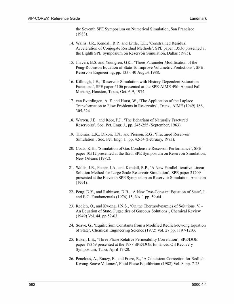
VIP-CORE® Reference Guide Landmark
the Seventh SPE Symposium on Numerical Simulation, San Francisco (1983).
14. Wallis, J.R., Kendall, R.P., and Little, T.E., ’Constrained Residual Acceleration of Conjugate Residual Methods’, SPE paper 13536 presented at the Eighth SPE Symposium on Reservoir Simulation, Dallas (1985).
15. Jhaveri, B.S. and Youngren, G.K., ’Three-Parameter Modification of the Peng-Robinson Equation of State To Improve Volumetric Predictions’, SPE Reservoir Engineering, pp. 133-140 August 1988.
16. Killough, J.E., ’Reservoir Simulation with History-Dependent Saturation Functions’, SPE paper 5106 presented at the SPE-AIME 49th Annual Fall Meeting, Houston, Texas, Oct. 6-9, 1974.
17. van Everdingen, A. F. and Hurst, W., ‘The Application of the Laplace Transformation to Flow Problems in Reservoirs’, Trans., AIME (1949) 186, 305-324.
18. Warren, J.E., and Root, P.J., ‘The Behariam of Naturally Fractured Reservoirs’, Soc. Pet. Engr. J., pp. 245-255 (September, 1963).
19. Thomas, L.K., Dixon, T.N., and Pierson, R.G., ‘Fractured Reservoir Simulation’, Soc. Pet. Engr. J., pp. 42-54 (February, 1983).
20. Coats, K.H., ‘Simulation of Gas Condensate Reservoir Performance’, SPE paper 10512 presented at the Sixth SPE Symposium on Reservoir Simulation, New Orleans (1982).
21. Wallis, J.R., Foster, J.A., and Kendall, R.P., ‘A New Parallel Iterative Linear Solution Method for Large Scale Reservoir Simulation’, SPE paper 21209 presented at the Eleventh SPE Symposium on Reservoir Simulation, Anaheim (1991).
22. Peng, D.Y., and Robinson, D.B., ‘A New Two-Constant Equation of State’, I. and E.C. Fundamentals (1976) 15, No. 1 pp. 59-64.
23. Redich, O., and Kwong, J.N.S., ‘On the Thermodynamics of Solutions. V. - An Equation of State. Fugacities of Gaseous Solutions’, Chemical Review (1949) Vol. 44, pp.52-63.
24. Soave, G., ‘Equilibrium Constants from a Modified Redlich-Kwong Equation of State’, Chemical Engineering Science (1972) Vol. 27 pp. 1197-1203.
25. Baker, L.E., ‘Three Phase Relative Permeability Correlation’, SPE/DOE paper 17369 presented at the 1988 SPE/DOE Enhanced Oil Recovery Symposium, Tulsa, April 17-20.
26. Penelous, A., Rauzy, E., and Freze, R., ‘A Consistent Correction for Redlich-Kwong-Soave Volumes’, Fluid Phase Equilibrium (1982) Vol. 8, pp. 7-23.
-582 5000.4.4
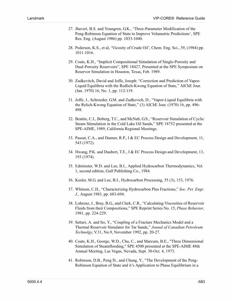
Landmark VIP-CORE® Reference Guide
27. Jhaveri, B.S. and Youngren, G.K., ‘Three-Parameter Modification of the Peng-Robinson Equation of State to Improve Volumetric Predictions’, SPE Res. Eng. (August 1986) pp. 1033-1040.
28. Pedersen, K.S., et al, ‘Vicosity of Crude Oil’, Chem. Eng. Sci., 39, (1984) pp. 1011-1016.
29. Coats, K.H., “Implicit Compositional Simulation of Single-Porosity and Dual-Porosity Reservoirs”, SPE 18427, Presented at the SPE Symposium on Reservor Simulation in Houston, Texas, Feb. 1989.
30. Zudkevitch, David and Joffe, Joseph: “Correction and Prediction of Vapor-Liquid Equilibria with the Redlich-Kwong Equation of State,” AIChE Jour. (Jan. 1970) 16, No. 1, pp. 112-119.
31. Joffe, J., Schroeder, G.M. and Zudkevich, D., “Vapor-Liquid Equilibria with the Relich-Kwong Equation of State,” (3) AIChE Jour. (1970) 16, pp. 496-498.
32. Beattie, C.I., Boberg, T.C., and McNab, G.S., “Reservoir Simulation of Cyclic Steam Stimulation in the Cold Lake Oil Sands,” SPE 18752 presented at the SPE-AIME, 1989, California Regional Meetings.
33. Passut, C.A., and Danner, R.P., I & EC Process Design and Development, 11, 543 (1972).
34. Hwang, P.K. and Daubert, T.E., I & EC Process Design and Development, 13, 193 (1974).
35. Edminster, W.D. and Lee, B.I., Applied Hydrocarbon Thermodynamics, Vol. 1, second edition, Gulf Publishing Co., 1984.
36. Kesler, M.G. and Lee, B.I., Hydrocarbon Processing, 55 (3), 153, 1976.
37. Whitson, C.H., “Characterizing Hydrocarbon Plus Fractions,” Soc. Pet. Engr. J., August 1983, pp. 683-694.
38. Lohrenz, J., Bray, B.G., and Clark, C.R., “Calculating Viscosities of Reservoir Fluids from their Compositions,” SPE Reprint Series No. 15, Phase Behavior, 1981, pp. 224-229.
39. Settari, A. and Ito, Y., “Coupling of a Fracture Mechanics Model and a Thermal Reservoir Simulator for Tar Sands,” Jounal of Canadian Petroleum Technolgy, V.31, No.9, November 1992, pp. 20-27.
40. Coats, K.H., George, W.D., Chu, C., and Marcum, B.E., "Three Dimensional Simulation of Steamflooding," SPE 4500 presented at the SPE-AIME 48th Annual Meeting, Las Vegas, Nevada, Sept. 30-Oct. 4, 1973.
41. Robinson, D.B., Peng D., and Chung, Y., “The Development of the Peng-Robinson Equation of State and it’s Application to Phase Equilibrium in a
5000.4.4 -583

VIP-CORE® Reference Guide Landmark
System Containing Methanol,” Fluid Phase Equilibra (1985), Vol. 24, pp. 25-41.
42. Fetkovich, M.J., “A Simplified Approach to Water Influx Calculations - Finite Aquifer Systems,“ Trans., SPE of AIME (1971), pp. 814-828.
-584 5000.4.4
Keyword
Indexv
000000Keyword Index
AA 4-251, 4-259, 4-391ACC 2-137ACENTRIC 4-232ADD 1-66, 1-70, 2-82, 7-502ADJUST 10-524ADJUST FINE 10-524ALL 1-69, 2-82, 2-158, 3-164, 3-165, 3-169, 3-
170, 3-171, 3-177, 3-178, 4-370, 4-375, 4-377, 4-380, 4-383, 10-514, 10-520, 11-552, 15-576
ALL LGRS 11-545ALPHA 2-151, 2-152AMULT 13-561, 13-562ANALYT 5-467ANANET 4-367ANARES 4-367ANASEP 4-367AND 2-129API 4-185, 4-189, 4-280, 4-286, 4-292, 4-299,
4-304APIRO 4-320APIS 4-280ARRAYS 3-171, 3-172, 5-397AUTO 8-506, 13-562AWIP 10-520
BB 4-251, 4-259B0 2-157B1 2-157B2 2-157B3 2-157
B4 2-157B5 2-157BACKWARD 4-383BAR 2-111, 4-233BDGTAB 4-310BETAG 4-362BG 4-279, 4-290, 4-291, 4-306, 4-310BGFAC 4-291, 4-306, 4-320BGTAB 4-289BINF 10-514, 12-558BLACKOIL 2-114BLOCKS 5-467BLOCKTR 11-552BO 4-279, 4-286, 4-291, 4-299, 4-304BODTAB 4-304BOETAB 4-291BOF 4-344, 4-347BOFAC 4-279, 4-286, 4-291, 4-299, 4-320BOGTAB 4-306BOOTAB 4-299BOSEP 4-346BOSTG 4-344BOTAB 4-279, 4-286BOTH 2-158, 4-377, 4-380, 4-383, 11-549BOTINT 2-137BPTAB 4-189BS 4-357BTBD 5-434BWI 2-108, 4-351, 4-352
CC 1-40, 4-233, 4-259C1 4-214C2 4-214C3 4-214CARBON 2-158CARLSON 2-122, 2-123CARTREF 11-534CASE 1-41CDPKRH 2-151
5000.4.4 KI-585
VIP-CORE® Reference Guide Landmark
CFXOFF 10-524CLASS 1-41CMP 4-370CMPFLX 10-526CMT 4-353CN 2-157CO2TAB 4-272COARSE 10-524COARSEN 8-505COEFFICIENTS 4-371COIL 4-256, 4-332COMP 4-232, 4-251, 4-255, 4-256, 4-258, 4-
259, 4-260, 4-318, 4-341, 4-349, 4-377, 4-380
COMPACT 2-124COMPONENTS 4-231, 4-318COMPOSITION 4-264, 4-266COMPSAT 4-320CON 1-46CONSTANTS 2-108CONTACT 2-148CONVDPTEST 4-380COPY 1-60CORCHK 2-144CORNER 2-142CORP 11-546CORTOL 2-142CPG0 4-258CPG1 4-258CPG2 4-258CPG3 4-258CPO0 4-258CPO1 4-258CPOIL 4-332CPR 4-388, 13-561, 13-562CPR0 5-477CPRTAB 4-388CR 2-108, 2-109, 5-430CRD 4-387CREEP 2-154CREEPB 5-454CREEPC 5-454CREEPM 5-455CRF 5-430CRINIT 2-138CROSS 2-112CSORM 2-116CT 10-514, 10-520, 12-558CTEOIL 4-256, 4-332CUMFLUX 10-526CW 2-108, 4-351, 4-352
DD 4-259DATE 2-81DAQI 10-514, 10-520DATE 1-39DCPRDT 2-109DEACTIVATE 2-128DEADCELL 5-465DECOMP 14-565DELTA 4-373DENO 4-256DEPF 5-413DEPTH 4-185, 4-186, 4-187, 4-188, 4-189, 4-
190, 4-191, 4-264, 4-266, 4-328, 4-332, 5-408, 15-577
DEX 15-578DGB 4-292, 4-306, 4-310DGOG 4-361DIAGONAL 2-101, 2-103DIFEXPTEST 4-377DIFF 2-147DIFFCOMP 15-577DIFFUSION 15-575DIM 2-77DIRCN 13-561, 13-562DIV 1-66, 1-70, 7-502DJK 4-236DJKSEP 4-242, 4-338DKTDSG 2-109DLIQ 4-341, 4-349DOB 4-279, 4-286, 4-292, 4-299, 4-304DOR 4-280, 4-286DOS 4-280DOSTD 4-256, 4-328, 4-332DOTAB 4-328DP 4-279, 4-286, 4-291, 4-299, 4-320DR 5-398DRAINAGE 2-122, 2-123DRANGE 5-467DRELPM 2-133DRO 4-320DRSDT 2-140DRYGAS 2-140DSW 4-354DTHETA 5-401DUAL 2-145DWB 2-108, 2-109, 4-351, 4-352DX 5-398DXB 5-398
KI-586 5000.4.4
Landmark VIP-CORE® Reference Guide
DY 5-401DYB 5-401DZ 5-403DZB 5-403DZBCOR 5-404DZBNET 5-406DZCORN 5-404DZNET 5-405DZOB 13-560DZVCOR 5-405
EE 4-259EACT 4-391EG 4-220EIGHT 11-546EIGHTH 2-101END 2-81END2P 2-117ENDAQ 10-514, 10-520, 12-558ENDDEC 14-566ENDEOS 4-245ENDINC 1-41ENDKV 4-319ENDLGR 11-533ENDREF 11-534, 11-535, 11-537, 11-538ENDSEP 4-338ENDVIS 4-268ENTHALPY 4-258EOD 4-228EOG 4-220EOI 4-228EOS 4-229EOSINT 4-367EOSSEP 4-239EOW 4-220EQ 1-66, 1-70, 7-502EW 4-220EWD 4-228EWI 4-228EXCEPT 3-164, 3-165, 3-169, 3-171, 3-178,
11-549
FF 4-233FAULTS 2-130, 6-483
FET 10-520FIELD 2-158FILE 3-165, 3-169FINE 10-524, 10-525FLASH 2-137FLOW360 2-131FLOWS 2-156FLTRC 6-488FLTRCF 6-491FLTTC 6-488FLTTCF 6-491FLTXC 6-488FLTXCF 6-491FLTYC 6-488FLTYCF 6-491FLUID 4-391FLUX 10-524, 10-526FLXOIL 10-524FNAME 1-69, 6-489, 6-492, 7-496, 7-499, 7-
500, 7-503FORM 2-82, 2-88, 2-89FORWARD 4-383FOURTH 2-103FR 4-387, 6-484FREE 2-140FRZPCG 2-125FRZPCW 2-125FTHETA 6-484FTRANF 6-492FTRANS 6-489, 11-553FUNCTION 5-467, 11-553FVEGO 5-448FVEGOF 5-448FVEWO 5-447FVEWOF 5-448FX 6-484FXCORN 6-484FY 6-484FYCORN 6-484
GG 4-391GAS 4-377, 4-380GASCM 4-375, 4-382GASFRAC 4-375, 4-377, 4-380, 4-383GASMF 4-263GASPLANT 4-270GASRM 4-213GASRMT 4-213
5000.4.4 KI-587
VIP-CORE® Reference Guide Landmark
GASTRF 5-452GASWATER 2-113GBC 2-126GE 1-62, 7-498GIBBS 2-135GOC 4-185, 4-188GOR 4-344, 4-347GR 4-279, 4-287, 4-289, 4-292, 4-306, 4-310,
4-328, 4-332, 4-344GRID 1-69, 5-467, 6-489, 6-492, 7-496, 7-499,
7-500, 7-503, 10-514, 10-520, 11-552, 11-553, 11-554
GRVL 4-232GWC 4-186
HHARTRAN 11-551HCPVTAB 2-113HOTAB 4-328HR 4-391HSTAR 4-239HTLOSS 13-559HVAP 4-258HYDBETA 4-363HYDFRAC 2-154HYSWO 4-228
II 13-561, 13-562I1 10-524, 10-525I2 10-524, 10-525ICMT 5-429ICMTF 5-429ICOARS 5-464ICPRTB 5-480IEQUIL 4-185, 4-186, 4-187, 4-188, 5-434IFT 2-135IINF 10-514, 10-520, 12-558IMB 2-119, 2-120INCLUDE 1-40INFLUX 10-514, 10-520, 12-558INGRID 11-534, 11-535, 11-537, 11-538INIT 2-77INIT2P 2-117INITONLY 15-576INPUT 10-524
INTSAT 2-126INTSW 2-146IPVT 4-185, 4-186, 4-187, 4-188, 5-424IPVTW 4-185, 4-186, 4-187, 4-188, 4-351, 5-
424IREGF 5-427IREGION 5-425ISAT 5-422ISATF 5-423ISATI 5-422ISATIF 5-423ITNMAX 4-372ITRAN 5-431ITRANF 5-431IWIRC 5-429IWIRCF 5-430
JJ 13-561, 13-562J1 10-524, 10-525J2 10-524, 10-525JFUNC 2-124, 7-497, 7-501JINF 10-514, 10-520, 12-558
KK 4-233, 13-561, 13-562K1 10-524, 10-525K2 10-524, 10-525KEEP 14-565KEEPSG 2-129KEEPSW 2-129KEYCMP 4-270KG/CM2 2-111, 4-233KINF 10-514, 10-520, 12-558KMLXYL 5-479KMLXYR 5-479KMULR 5-479KMULTH 5-479KMULX 5-479KMULY 5-479KMULZ 5-479KOHYS 5-478KPA 2-111, 4-233KR 5-415KRF 5-415KRFEFF 5-419
KI-588 5000.4.4
Landmark VIP-CORE® Reference Guide
KRG 4-201, 4-207, 4-211, 4-213, 4-218KRGMAX 4-213KRGRO 4-220, 4-221, 4-223, 5-446KRGROF 5-447KRGRW 5-446KROCW 4-220, 4-221, 4-223KROG 4-201, 4-207, 4-211, 4-218KROINT 2-118, 2-119KROLW 5-445KROLWF 5-446KROW 4-196, 4-206, 4-209, 4-217KRW 4-196, 4-206, 4-209, 4-217KRWG 4-201, 4-205, 4-208, 4-211KRWRO 4-220, 4-221, 4-223, 5-446KRWROF 5-446KS 4-357KT 5-477KTF 5-416KTFEFF 5-420KTHETA 5-416KTR 13-561, 13-562KTR0 5-477KTTH0 5-478KTX0 5-477KTY0 5-478KTZ0 5-478KV 4-320KVALUES 4-318, 4-341, 4-349KVCOR 4-259KVTAB 4-320KVTBS 4-260KWELLPI 2-160KWHYS 5-478KWX 5-418KWXF 5-421KWY 5-418KWYF 5-421KWZ 5-418KWZF 5-421KX 5-415KXARITH 2-161KXF 5-415KXFEFF 5-419KXGEOM 2-161KXHARM 2-160KXLB 2-161KXUB 2-161KY 5-416KYARITH 2-161KYF 5-416KYFEFF 5-419KYGEOM 2-161
KYHARM 2-160KYLB 2-161KYUB 2-161KZ 5-417KZARITH 2-161KZF 5-417KZFEFF 5-420KZGEOM 2-161KZHARM 2-160KZLB 2-161KZUB 2-161
LLAB 2-112LATERAL 2-130LAYER 1-52LBC 4-238, 4-252, 4-255LDEST 4-335, 4-341, 4-349LE 1-62, 7-498LEAKY 6-487LFRAC 4-335, 4-341, 4-349LGR 11-533LI 2-139LINE 2-142LINEAR 2-122, 2-123LINFAC 10-514, 12-558LIST 1-42LIVECELL 5-465LNVAL 1-60LNXVAR 1-58LNYVAR 1-59LNZVAR 1-59LX 5-449LY 5-449LZ 5-449
MMAP 2-82MAPOLD 2-89MAPX 2-88MAPY 2-88MAPZ 2-88MCOARSE 8-506MDEPF 5-413MDEPTH 5-408MDI 4-367
5000.4.4 KI-589
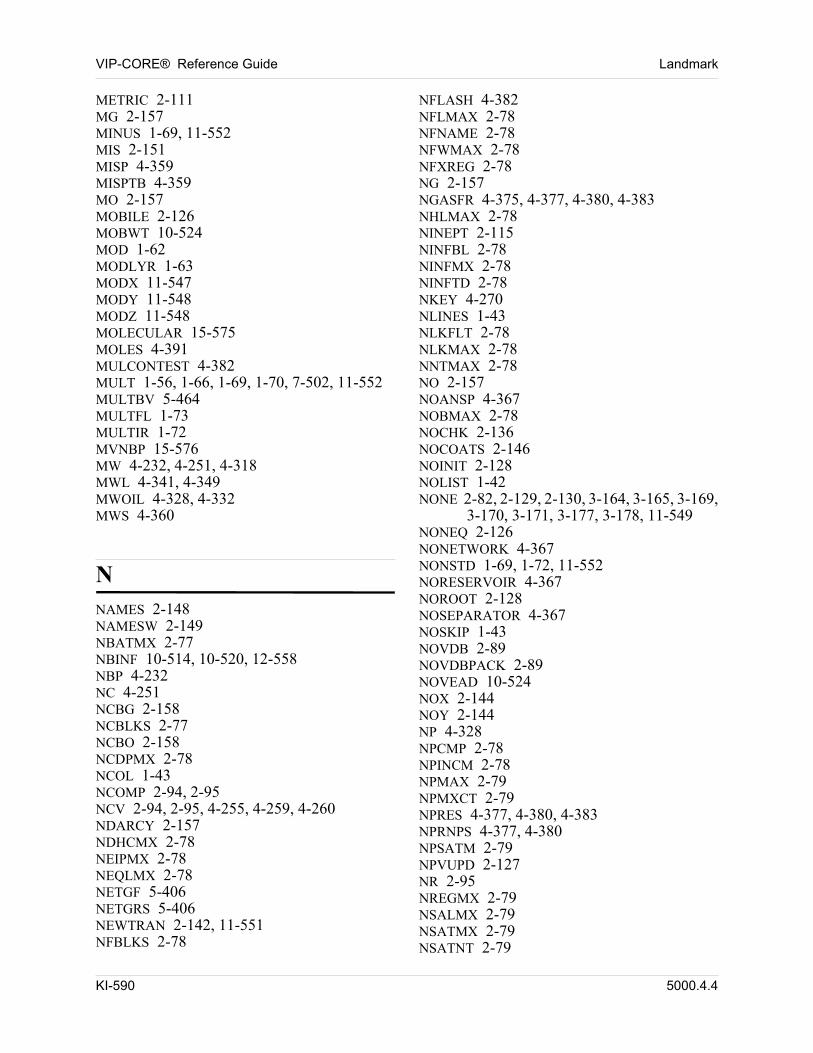
VIP-CORE® Reference Guide Landmark
METRIC 2-111MG 2-157MINUS 1-69, 11-552MIS 2-151MISP 4-359MISPTB 4-359MO 2-157MOBILE 2-126MOBWT 10-524MOD 1-62MODLYR 1-63MODX 11-547MODY 11-548MODZ 11-548MOLECULAR 15-575MOLES 4-391MULCONTEST 4-382MULT 1-56, 1-66, 1-69, 1-70, 7-502, 11-552MULTBV 5-464MULTFL 1-73MULTIR 1-72MVNBP 15-576MW 4-232, 4-251, 4-318MWL 4-341, 4-349MWOIL 4-328, 4-332MWS 4-360
NNAMES 2-148NAMESW 2-149NBATMX 2-77NBINF 10-514, 10-520, 12-558NBP 4-232NC 4-251NCBG 2-158NCBLKS 2-77NCBO 2-158NCDPMX 2-78NCOL 1-43NCOMP 2-94, 2-95NCV 2-94, 2-95, 4-255, 4-259, 4-260NDARCY 2-157NDHCMX 2-78NEIPMX 2-78NEQLMX 2-78NETGF 5-406NETGRS 5-406NEWTRAN 2-142, 11-551NFBLKS 2-78
NFLASH 4-382NFLMAX 2-78NFNAME 2-78NFWMAX 2-78NFXREG 2-78NG 2-157NGASFR 4-375, 4-377, 4-380, 4-383NHLMAX 2-78NINEPT 2-115NINFBL 2-78NINFMX 2-78NINFTD 2-78NKEY 4-270NLINES 1-43NLKFLT 2-78NLKMAX 2-78NNTMAX 2-78NO 2-157NOANSP 4-367NOBMAX 2-78NOCHK 2-136NOCOATS 2-146NOINIT 2-128NOLIST 1-42NONE 2-82, 2-129, 2-130, 3-164, 3-165, 3-169,
3-170, 3-171, 3-177, 3-178, 11-549NONEQ 2-126NONETWORK 4-367NONSTD 1-69, 1-72, 11-552NORESERVOIR 4-367NOROOT 2-128NOSEPARATOR 4-367NOSKIP 1-43NOVDB 2-89NOVDBPACK 2-89NOVEAD 10-524NOX 2-144NOY 2-144NP 4-328NPCMP 2-78NPINCM 2-78NPMAX 2-79NPMXCT 2-79NPRES 4-377, 4-380, 4-383NPRNPS 4-377, 4-380NPSATM 2-79NPVUPD 2-127NR 2-95NREGMX 2-79NSALMX 2-79NSATMX 2-79NSATNT 2-79
KI-590 5000.4.4
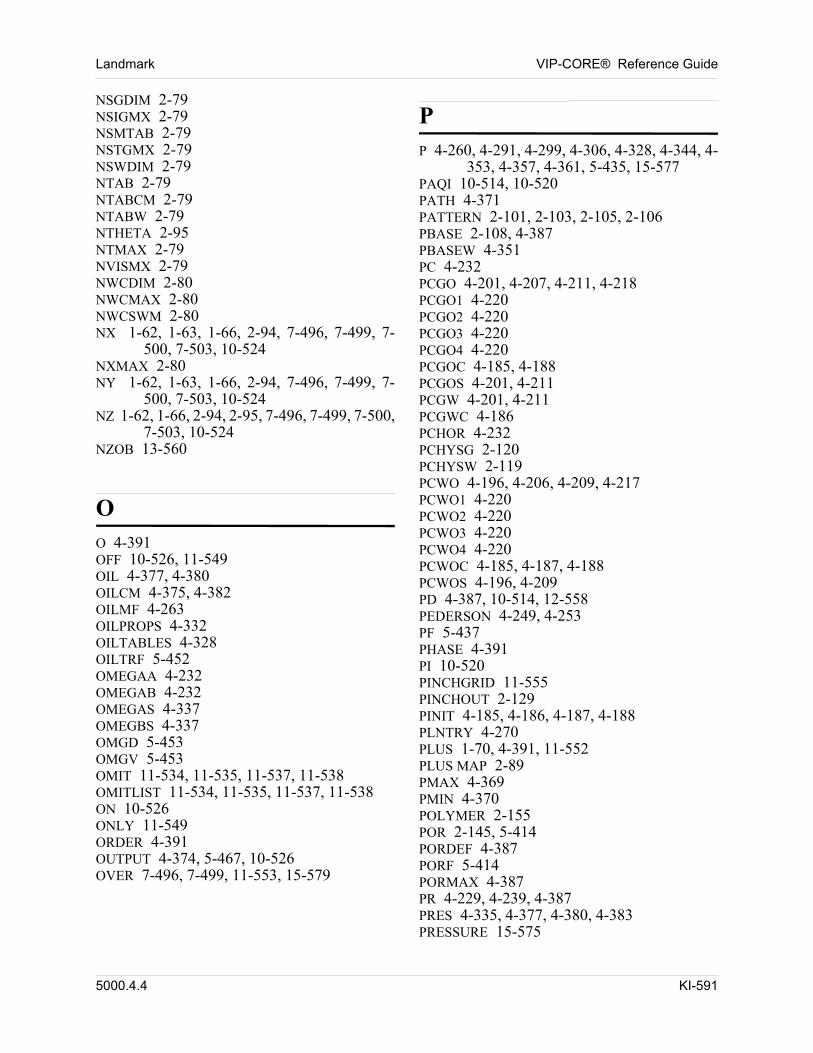
Landmark VIP-CORE® Reference Guide
NSGDIM 2-79NSIGMX 2-79NSMTAB 2-79NSTGMX 2-79NSWDIM 2-79NTAB 2-79NTABCM 2-79NTABW 2-79NTHETA 2-95NTMAX 2-79NVISMX 2-79NWCDIM 2-80NWCMAX 2-80NWCSWM 2-80NX 1-62, 1-63, 1-66, 2-94, 7-496, 7-499, 7-
500, 7-503, 10-524NXMAX 2-80NY 1-62, 1-63, 1-66, 2-94, 7-496, 7-499, 7-
500, 7-503, 10-524NZ 1-62, 1-66, 2-94, 2-95, 7-496, 7-499, 7-500,
7-503, 10-524NZOB 13-560
OO 4-391OFF 10-526, 11-549OIL 4-377, 4-380OILCM 4-375, 4-382OILMF 4-263OILPROPS 4-332OILTABLES 4-328OILTRF 5-452OMEGAA 4-232OMEGAB 4-232OMEGAS 4-337OMEGBS 4-337OMGD 5-453OMGV 5-453OMIT 11-534, 11-535, 11-537, 11-538OMITLIST 11-534, 11-535, 11-537, 11-538ON 10-526ONLY 11-549ORDER 4-391OUTPUT 4-374, 5-467, 10-526OVER 7-496, 7-499, 11-553, 15-579
PP 4-260, 4-291, 4-299, 4-306, 4-328, 4-344, 4-
353, 4-357, 4-361, 5-435, 15-577PAQI 10-514, 10-520PATH 4-371PATTERN 2-101, 2-103, 2-105, 2-106PBASE 2-108, 4-387PBASEW 4-351PC 4-232PCGO 4-201, 4-207, 4-211, 4-218PCGO1 4-220PCGO2 4-220PCGO3 4-220PCGO4 4-220PCGOC 4-185, 4-188PCGOS 4-201, 4-211PCGW 4-201, 4-211PCGWC 4-186PCHOR 4-232PCHYSG 2-120PCHYSW 2-119PCWO 4-196, 4-206, 4-209, 4-217PCWO1 4-220PCWO2 4-220PCWO3 4-220PCWO4 4-220PCWOC 4-185, 4-187, 4-188PCWOS 4-196, 4-209PD 4-387, 10-514, 12-558PEDERSON 4-249, 4-253PF 5-437PHASE 4-391PI 10-520PINCHGRID 11-555PINCHOUT 2-129PINIT 4-185, 4-186, 4-187, 4-188PLNTRY 4-270PLUS 1-70, 4-391, 11-552PLUS MAP 2-89PMAX 4-369PMIN 4-370POLYMER 2-155POR 2-145, 5-414PORDEF 4-387PORF 5-414PORMAX 4-387PR 4-229, 4-239, 4-387PRES 4-335, 4-377, 4-380, 4-383PRESSURE 15-575
5000.4.4 KI-591
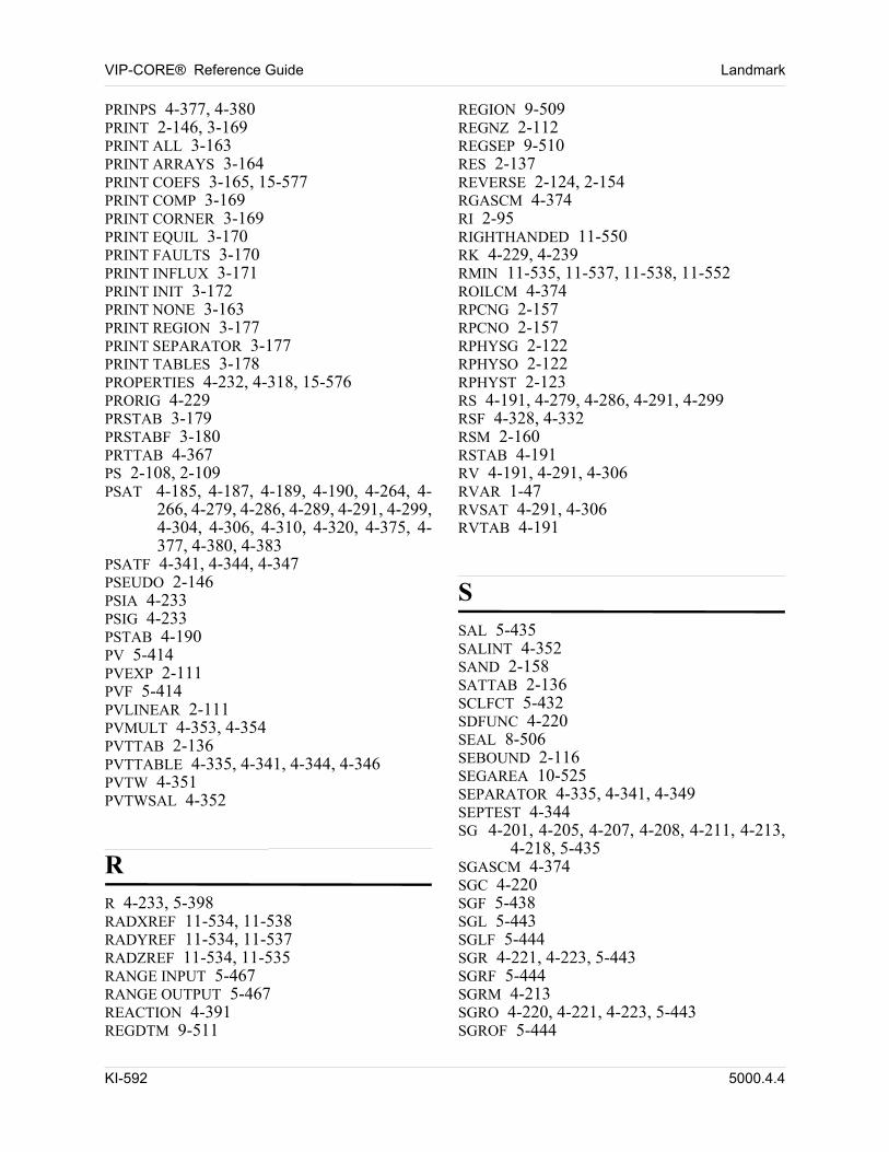
VIP-CORE® Reference Guide Landmark
PRINPS 4-377, 4-380PRINT 2-146, 3-169PRINT ALL 3-163PRINT ARRAYS 3-164PRINT COEFS 3-165, 15-577PRINT COMP 3-169PRINT CORNER 3-169PRINT EQUIL 3-170PRINT FAULTS 3-170PRINT INFLUX 3-171PRINT INIT 3-172PRINT NONE 3-163PRINT REGION 3-177PRINT SEPARATOR 3-177PRINT TABLES 3-178PROPERTIES 4-232, 4-318, 15-576PRORIG 4-229PRSTAB 3-179PRSTABF 3-180PRTTAB 4-367PS 2-108, 2-109PSAT 4-185, 4-187, 4-189, 4-190, 4-264, 4-
266, 4-279, 4-286, 4-289, 4-291, 4-299, 4-304, 4-306, 4-310, 4-320, 4-375, 4-377, 4-380, 4-383
PSATF 4-341, 4-344, 4-347PSEUDO 2-146PSIA 4-233PSIG 4-233PSTAB 4-190PV 5-414PVEXP 2-111PVF 5-414PVLINEAR 2-111PVMULT 4-353, 4-354PVTTAB 2-136PVTTABLE 4-335, 4-341, 4-344, 4-346PVTW 4-351PVTWSAL 4-352
RR 4-233, 5-398RADXREF 11-534, 11-538RADYREF 11-534, 11-537RADZREF 11-534, 11-535RANGE INPUT 5-467RANGE OUTPUT 5-467REACTION 4-391REGDTM 9-511
REGION 9-509REGNZ 2-112REGSEP 9-510RES 2-137REVERSE 2-124, 2-154RGASCM 4-374RI 2-95RIGHTHANDED 11-550RK 4-229, 4-239RMIN 11-535, 11-537, 11-538, 11-552ROILCM 4-374RPCNG 2-157RPCNO 2-157RPHYSG 2-122RPHYSO 2-122RPHYST 2-123RS 4-191, 4-279, 4-286, 4-291, 4-299RSF 4-328, 4-332RSM 2-160RSTAB 4-191RV 4-191, 4-291, 4-306RVAR 1-47RVSAT 4-291, 4-306RVTAB 4-191
SSAL 5-435SALINT 4-352SAND 2-158SATTAB 2-136SCLFCT 5-432SDFUNC 4-220SEAL 8-506SEBOUND 2-116SEGAREA 10-525SEPARATOR 4-335, 4-341, 4-349SEPTEST 4-344SG 4-201, 4-205, 4-207, 4-208, 4-211, 4-213,
4-218, 5-435SGASCM 4-374SGC 4-220SGF 5-438SGL 5-443SGLF 5-444SGR 4-221, 4-223, 5-443SGRF 5-444SGRM 4-213SGRO 4-220, 4-221, 4-223, 5-443SGROF 5-444
KI-592 5000.4.4
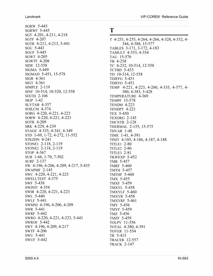
Landmark VIP-CORE® Reference Guide
SGRW 5-443SGRWF 5-445SGT 4-201, 4-211, 4-218SGTF 4-207SGTR 4-211, 4-213, 5-441SGU 5-443SGUF 5-445SGWT 4-205SGWTF 4-208SIDE 12-558SIGMA 5-449SIGMAD 5-451, 15-578SIGR 4-361SIGT 4-361SIMPLE 2-119SINF 10-514, 10-520, 12-558SIXTH 2-106SKIP 1-42SLVTAB 4-357SOILCM 4-374SORG 4-220, 4-221, 4-223SORW 4-220, 4-221, 4-223SOTR 4-209SRK 4-229, 4-239STAGE 4-335, 4-341, 4-349STD 1-69, 1-72, 4-272, 11-552STKZDN 4-241STONE1 2-118, 2-119STONE2 2-118, 2-119STOP 4-367SUB 1-66, 1-70, 7-502SURF 2-137SW 4-196, 4-206, 4-209, 4-217, 5-435SWAPMF 2-145SWC 4-220, 4-221, 4-223SWELLTEST 4-375SWF 5-438SWINIT 4-354SWIR 4-220, 4-221, 4-223SWL 5-440SWLF 5-441SWMNI 4-196, 4-206, 4-209SWR 5-441SWRF 5-442SWRO 4-220, 4-221, 4-223, 5-441SWROF 5-442SWT 4-196, 4-209, 4-217SWTF 4-206SWU 5-441SWUF 5-442
TT 4-251, 4-255, 4-264, 4-266, 4-328, 4-332, 4-
344, 4-388, 15-577TABLES 3-171, 3-172, 4-183TAMULT 4-353, 4-354TAU 15-576TB 4-258TC 4-232, 10-514, 12-558TCTBD 5-433TD 10-514, 12-558TDIFFG 5-451TDIFFO 5-451TEMP 4-221, 4-223, 4-260, 4-335, 4-377, 4-
380, 4-383, 5-428TEMPERATURE 4-369TEMPF 15-578TENDM 4-223TENDPT 4-221TEX 5-450TEXORG 2-145THCNTR 2-128THERMAL 2-155, 15-575THVAR 1-48TIME 1-41, 4-391TINIT 4-185, 4-186, 4-187, 4-188TITLE1 2-80TITLE2 2-80TITLE3 2-81TKWEXP 5-452TMR 5-457TMRF 5-460TMTH 5-457TMTHF 5-460TMX 5-455TMXF 5-459TMXYL 5-458TMXYLF 5-460TMXYR 5-458TMXYRF 5-461TMY 5-456TMYF 5-459TMZ 5-456TMZF 5-459TOLPV 11-556TOTAL 4-380, 4-391TOVER 11-554TR 5-415TRACER 12-557TRACK 2-147
5000.4.4 KI-593
VIP-CORE® Reference Guide Landmark
TRACKW 2-149TREF 4-232TRES 2-108, 2-109TRF 5-419TS 2-108, 2-109TTAB 4-328, 4-332TTHETA 5-416TTHETF 5-420TTMR 5-462TTMTH 5-463TTMX 5-461TTMY 5-462TTMZ 5-462TVMULT 4-353, 4-354TWELFTH 2-105TWOPT 2-115TX 5-415TXF 5-419TXYL 5-418TXYLF 5-421TXYR 5-418TXYRF 5-421TY 5-416TYF 5-420TZ 5-417TZF 5-420
UUPSCALE 2-160USER 2-122, 2-123
VV98 2-142VAITS 2-127VALUE 1-50, 10-514, 10-520, 12-558VARIABLE 1-41VDB 1-41, 2-89VDBCONN 11-549VDEST 4-335, 4-341, 4-349VEAREA 10-525VEDIST 10-526VEGO 2-133VEITS 2-134VELCTY 2-157VEOFF 10-524VEONLY 10-525
VEWO 2-132VFRAC 4-335, 4-341, 4-349VG 2-158, 4-279, 4-289, 4-291, 4-306, 4-310,
4-320VGFAC 4-291, 4-306, 4-320VISCO 15-576VISCOSITY 4-332VISGAS 4-253, 4-255VISK 4-249, 4-253, 4-268VISKJ 4-249, 4-253, 4-268VISOIL 4-249, 4-251, 4-252, 4-332VISPE 4-268VMOD 1-66VO 4-279, 4-286, 4-291, 4-299, 4-304, 4-320VOFAC 4-279, 4-286, 4-291, 4-299, 4-320VOLAVR 5-467VOLUME 4-391VOMIN 4-250, 4-251, 4-328, 4-332VOTAB 4-328VOVER 7-500, 7-503, 11-554, 15-579VS 4-357VSHFT 4-232VSHFTS 4-338VSO 4-357VW 2-108, 4-351, 4-352, 13-559VWAQ 10-520VWP 4-351, 4-352
WW 4-391WATER 2-122WATEROIL 2-114WATIDEAL 2-156WBOTAB 4-377WBSIM 2-97WELL 2-158WINDOW 10-514, 10-520, 12-558WIRCT 4-354WOC 4-185, 4-187, 4-188WTOS 4-280WTR 10-514, 10-520, 12-558WTRO 4-280, 4-287, 4-292, 4-300, 4-304
XX 1-72, 4-266, 8-507, 9-511X1 4-320
KI-594 5000.4.4
Landmark VIP-CORE® Reference Guide
XCORN 5-399XI 5-437XIF 5-439XREG 5-426XVAR 1-47
YY 1-72, 4-266, 8-507Y1 4-359YCORN 5-401YI 5-436YIF 5-438YNC 4-320YVAR 1-48
ZZ 1-72, 4-264, 4-266, 8-507, 15-577Z1 4-359Z3 4-359ZBOT 5-411ZBOTNE 5-411ZBOTNW 5-412ZBOTSW 5-412ZC 4-232ZCORN 5-409ZCORNE 5-409ZCORNW 5-410ZCORSW 5-410ZG 4-279, 4-290, 4-320ZJRK 4-229, 4-239ZLNCOR 5-413ZO 4-320ZRO 4-320ZS 4-357ZSO 4-357ZVAR 1-49
5000.4.4 KI-595

VIP-CORE® Reference Guide Landmark
KI-596 5000.4.4
Subject
Indexv
000000Subject Index
A
accelerated successive substitution 2-137aquifers
fluid influx 10-513number in each gridblock 5-432
areal sweep 12-557arithmetic operations
applying to a grid 7-496applying to a grid (VIP-DUAL) 7-499
array dataarithmetic operations on 1-62, 11-547automatic generation 1-52constant value 1-46define new from previous 1-56directional variation 1-47directional variation (X,r) 1-47directional variation (Y,theta) 1-48directional variation (Z) 1-49faults 6-484fracture model 5-479full array input 1-50general format 1-44gridblock depths 1-54in grid refinements 11-545modifying 1-61options for input 1-44printing by cross-section 2-112printing coefficients 3-165printing corner points 3-169printing of 3-163printing of input 3-164replication of depths 1-61see also grid dataselective replacement 1-66suppress checking 2-136transmissibility 1-69values by layer 1-60
variation in X direction by layer 1-58variation in Y direction by layer 1-59variation in Z direction by layer 1-59writing to map file 2-81writing to SIMOUT 2-89
average valueshow calculated 5-466
Aziz and Govier correlation 2-97
B
Beattie fracture model 5-479Beattie, Boberg, and McNab 4-386, 4-387Beggs and Brill correlation 2-97bibliography A-581binary interaction coefficient 4-236
for surface separator 4-338of separators 4-242of various compounds 4-247
black-oillaboratory data 4-276surface separation data with PVT data 4-
339black-oil option 2-114black-oil reservoirs
how simulated 1-27boundary flux 10-513
defining regions 10-524bulk volume tables 2-112
C
capillary gravity equilibrium 2-134capillary pressure
endpoint scaling 2-117hold steady 2-125
5000.4.4 SI-597
VIP-CORE® Reference Guide Landmark
hysteresis 4-195Leverett-J calculation 2-124matrix pseudo 2-145near-critical 2-135
capillary pressureshow described 4-218
Carter-Tracy methodfor estimating acquifer influx 10-514, 10-
520Cartesian grids
how specified 2-94refinement of 11-534
Chemical Reactions 4-388CO2 solubility 4-272Coats, George, Chu, and Marcum 13-560coefficients
binary interaction 4-236Coefficients of Interpolation Function 4-371columns
to be scanned in input 1-43comments
entering as full lines 1-40entering inline 1-40
compaction option 2-124compaction regions 1-72, 1-73, 5-429, 5-430,
5-431compaction tables 4-353components
naming 4-231properties data for 4-245
compositionoverreads,fracture gas 5-438overreads,fracture oil 5-439overreads,gas 5-436overreads,oils 5-437variation with area 4-266variation with depth 4-264
compositional modeldefinition of 1-29
compositional simulatoroverview 1-27
compressibilitycreep option (time-dependent) 5-454for each gridblock 5-430time dependent 2-154
conductive faults
how specified 6-487connection transmissibility
modification of 5-455connection transmissibility modification 1-69constant equilibrium region
gas 4-263oil 4-263
coordinate systemhandedness 11-550
correlationsusing function input option 5-466
CR 5-479CRD 5-479creep 2-154creep option 2-154critical properties
of pure compounds 4-245cylindrical grids 2-94
how specified 2-95
D
Darcy vertical flow coefficients 2-97data
formatting requirements 1-38how organized 1-33initialization utility 2-77repeated values 1-39sample input 1-35
data checkingof corner-point data 2-143
datehow to specify 2-81
datum depthfor output regions 9-511printing for regions 3-177
dead oil modeldefinition of 1-29
deck layout 1-33defaults
how specified 2-77density
correlation of 4-241mixing parameter 5-453
dependency
SI-598 5000.4.4
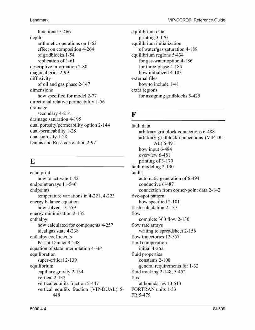
Landmark VIP-CORE® Reference Guide
functional 5-466depth
arithmetic operations on 1-63effect on composition 4-264of gridblocks 1-54replication of 1-61
descriptive information 2-80diagonal grids 2-99diffusivity
of oil and gas phase 2-147dimensions
how specified for model 2-77directional relative permeability 1-56drainage
secondary 4-214drainage saturation 4-195dual porosity/permeability option 2-144dual-permeability 1-28dual-porosity 1-28Dunns and Ross correlation 2-97
E
echo printhow to activate 1-42
endpoint arrays 11-546endpoints
temperature variations in 4-221, 4-223energy balance equation
how solved 13-559energy minimization 2-135enthalpy
how calculated for components 4-257ideal gas state 4-238
enthalpy coefficientsPassut-Danner 4-248
equation of state interpolation 4-364equilibration
super-critical 2-139equilibrium
capillary gravity 2-134vertical 2-132vertical equilib. fraction 5-447vertical equilib. fraction (VIP-DUAL) 5-
448
equilibrium dataprinting 3-170
equilibrium initializationof water/gas saturation 4-189
equilibrium regions 5-434for gas-water option 4-186for three-phase 4-185how initialized 4-183
external fileshow to include 1-41
extra regionsfor assigning gridblocks 5-425
F
fault dataarbitrary gridblock connections 6-488arbitrary gridblock connections (VIP-DU-
AL) 6-491how input 6-484overview 6-481printing of 3-170
fault modeling 2-130faults
automatic generation of 6-494conductive 6-487connection from corner-point data 2-142
five-spot patternhow specified 2-101
flash calculation 2-137flow
complete 360 flow 2-130flow rate arrays
writing to spreadsheet 2-156flow trajectories 12-557fluid composition
initial 4-262fluid properties
constants 2-108general requirements for 1-32
fluid tracking 2-148, 5-452flux
at boundaries 10-513FORTRAN units 1-33FR 5-479
5000.4.4 SI-599
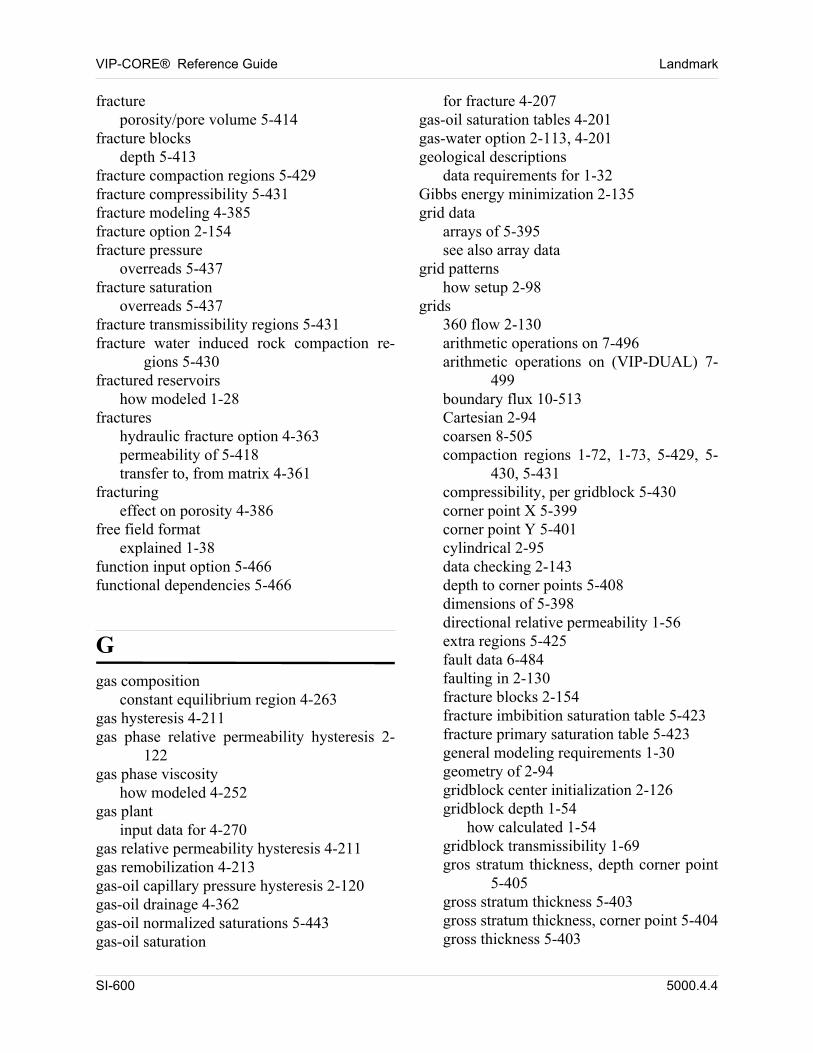
VIP-CORE® Reference Guide Landmark
fractureporosity/pore volume 5-414
fracture blocksdepth 5-413
fracture compaction regions 5-429fracture compressibility 5-431fracture modeling 4-385fracture option 2-154fracture pressure
overreads 5-437fracture saturation
overreads 5-437fracture transmissibility regions 5-431fracture water induced rock compaction re-
gions 5-430fractured reservoirs
how modeled 1-28fractures
hydraulic fracture option 4-363permeability of 5-418transfer to, from matrix 4-361
fracturingeffect on porosity 4-386
free field formatexplained 1-38
function input option 5-466functional dependencies 5-466
G
gas compositionconstant equilibrium region 4-263
gas hysteresis 4-211gas phase relative permeability hysteresis 2-
122gas phase viscosity
how modeled 4-252gas plant
input data for 4-270gas relative permeability hysteresis 4-211gas remobilization 4-213gas-oil capillary pressure hysteresis 2-120gas-oil drainage 4-362gas-oil normalized saturations 5-443gas-oil saturation
for fracture 4-207gas-oil saturation tables 4-201gas-water option 2-113, 4-201geological descriptions
data requirements for 1-32Gibbs energy minimization 2-135grid data
arrays of 5-395see also array data
grid patternshow setup 2-98
grids360 flow 2-130arithmetic operations on 7-496arithmetic operations on (VIP-DUAL) 7-
499boundary flux 10-513Cartesian 2-94coarsen 8-505compaction regions 1-72, 1-73, 5-429, 5-
430, 5-431compressibility, per gridblock 5-430corner point X 5-399corner point Y 5-401cylindrical 2-95data checking 2-143depth to corner points 5-408dimensions of 5-398directional relative permeability 1-56extra regions 5-425fault data 6-484faulting in 2-130fracture blocks 2-154fracture imbibition saturation table 5-423fracture primary saturation table 5-423general modeling requirements 1-30geometry of 2-94gridblock center initialization 2-126gridblock depth 1-54
how calculated 1-54gridblock transmissibility 1-69gros stratum thickness, depth corner point
5-405gross stratum thickness 5-403gross stratum thickness, corner point 5-404gross thickness 5-403
SI-600 5000.4.4
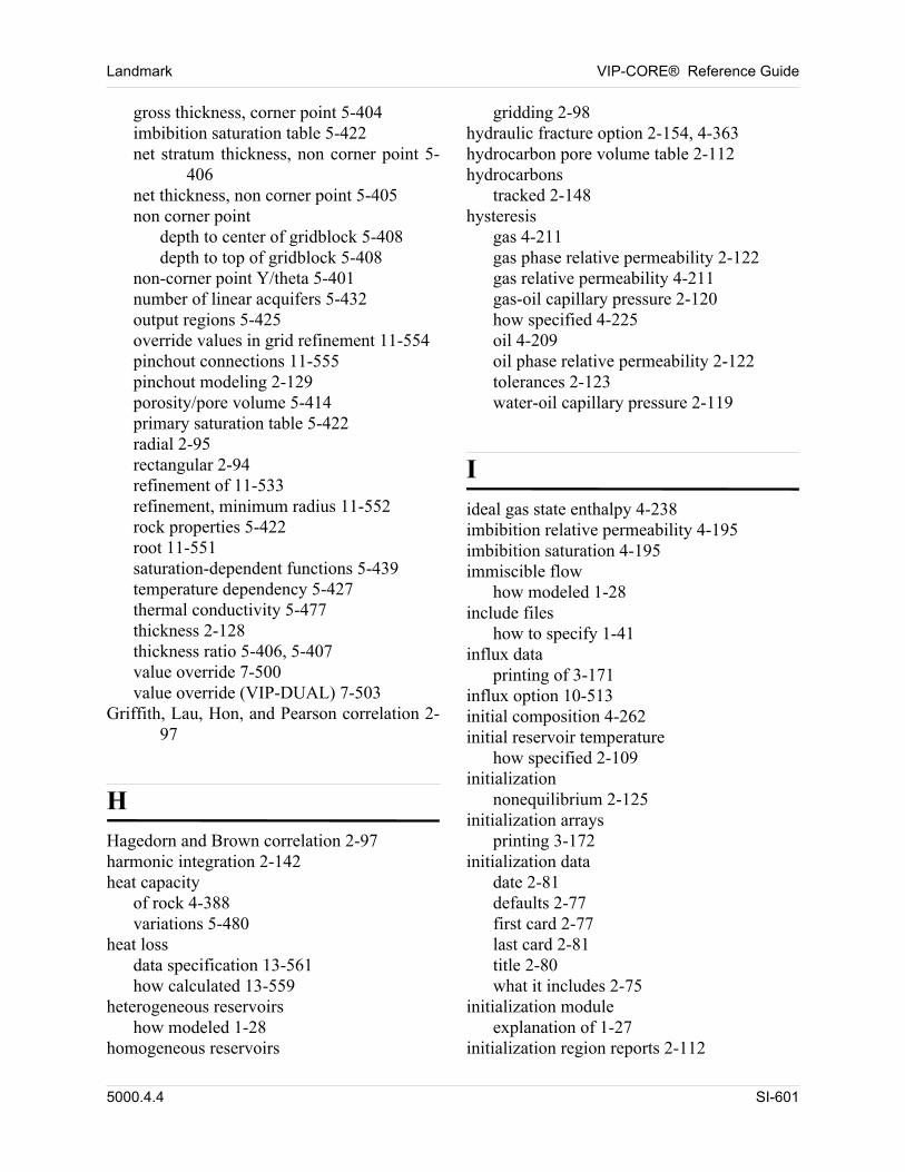
Landmark VIP-CORE® Reference Guide
gross thickness, corner point 5-404imbibition saturation table 5-422net stratum thickness, non corner point 5-
406net thickness, non corner point 5-405non corner point
depth to center of gridblock 5-408depth to top of gridblock 5-408
non-corner point Y/theta 5-401number of linear acquifers 5-432output regions 5-425override values in grid refinement 11-554pinchout connections 11-555pinchout modeling 2-129porosity/pore volume 5-414primary saturation table 5-422radial 2-95rectangular 2-94refinement of 11-533refinement, minimum radius 11-552rock properties 5-422root 11-551saturation-dependent functions 5-439temperature dependency 5-427thermal conductivity 5-477thickness 2-128thickness ratio 5-406, 5-407value override 7-500value override (VIP-DUAL) 7-503
Griffith, Lau, Hon, and Pearson correlation 2-97
H
Hagedorn and Brown correlation 2-97harmonic integration 2-142heat capacity
of rock 4-388variations 5-480
heat lossdata specification 13-561how calculated 13-559
heterogeneous reservoirshow modeled 1-28
homogeneous reservoirs
gridding 2-98hydraulic fracture option 2-154, 4-363hydrocarbon pore volume table 2-112hydrocarbons
tracked 2-148hysteresis
gas 4-211gas phase relative permeability 2-122gas relative permeability 4-211gas-oil capillary pressure 2-120how specified 4-225oil 4-209oil phase relative permeability 2-122tolerances 2-123water-oil capillary pressure 2-119
I
ideal gas state enthalpy 4-238imbibition relative permeability 4-195imbibition saturation 4-195immiscible flow
how modeled 1-28include files
how to specify 1-41influx data
printing of 3-171influx option 10-513initial composition 4-262initial reservoir temperature
how specified 2-109initialization
nonequilibrium 2-125initialization arrays
printing 3-172initialization data
date 2-81defaults 2-77first card 2-77last card 2-81title 2-80what it includes 2-75
initialization moduleexplanation of 1-27
initialization region reports 2-112
5000.4.4 SI-601
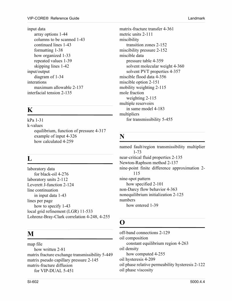
VIP-CORE® Reference Guide Landmark
input dataarray options 1-44columns to be scanned 1-43continued lines 1-43formatting 1-38how organized 1-33repeated values 1-39skipping lines 1-42
input/outputdiagram of 1-34
interationsmaximum allowable 2-137
interfacial tension 2-135
K
kPa 1-31k-values
equilibrium, function of pressure 4-317example of input 4-326how calculated 4-259
L
laboratory datafor black-oil 4-276
laboratory units 2-112Leverett J-function 2-124line continuation
in input data 1-43lines per page
how to specify 1-43local grid refinement (LGR) 11-533Lohrenz-Bray-Clark correlation 4-248, 4-255
M
map filehow written 2-81
matrix fracture exchange transmissibility 5-449matrix pseudo capillary pressure 2-145matrix-fracture diffusion
for VIP-DUAL 5-451
matrix-fracture transfer 4-361metric units 2-111miscibility
transition zones 2-152miscibility pressure 2-152miscible data
pressure table 4-359solvent molecular weight 4-360solvent PVT properties 4-357
miscible flood data 4-356miscible option 2-151mobility weighting 2-115mole fraction
weighting 2-115multiple reservoirs
in same model 4-183multipliers
for transmissibility 5-455
N
named fault/region transmissibility multiplier 1-73
near-critical fluid properties 2-135Newton-Raphson method 2-137nine-point finite difference approximation 2-
115nine-spot pattern
how specified 2-101non-Darcy flow behavior 4-363nonequilibrium initialization 2-125numbers
how entered 1-39
O
off-band connections 2-129oil composition
constant equilibrium region 4-263oil density
how computed 4-255oil hysteresis 4-209oil phase relative permeability hysteresis 2-122oil phase viscosity
SI-602 5000.4.4
Landmark VIP-CORE® Reference Guide
how modeled 4-248oil-vapor phase behavior 2-155OMEGA data
for surface separation 4-337Orkiszewski correlation 2-97output regions
assign separator batteries to 9-510assigning names to 9-509for multiple groups of output data 5-425for VIP-DUAL 5-427specify datum depth 9-511
overreadsfracture gas composition 5-438fracture oil composition 5-439fracture pressure and saturation 5-437gas composition 5-436oil composition 5-437option overview 7-495pressure and saturation 5-435
P
parallel computing 14-565Passut-Danner ideal gas state enthalpy coeffi-
cients 4-248patterns
in grids 2-98PD 5-479Pedersen viscosity correlation 4-268Pederson correlation 4-248Peng-Robinson equation of state 4-228, 4-239permeability
normalized relative endpoints 5-445of fractures 5-418relative 1-56X/R direction 5-415Y/theta direction 5-416Z direction 5-417
permeability behaviorhow modelled 4-387
phase equilibriumcalculation of 2-135
phase stability test 2-135pinchouts
automatic detection of 6-494
nonstandard connections for 2-129warning messages 3-170
polymer flooded reservoirshow modeled 1-29
polymer injection 2-155pore volume
modification options 7-495pore volume calculation 2-141pore volume table
for hydrocarbons 2-112porosity
dual 2-144porosity deformation model 4-386PR 5-479pressure
overreads 5-435pressure table
for miscible data 4-359printing
all none 3-163by cross-sections 2-112control options summarized 3-163corner-point data 3-169echo print 1-42equilibrium data 3-170fault data 3-170individual data groups 3-164influx data 3-171initialization arrays 3-172initialization region reports 2-112input arrays 3-164lines per page 1-43of coefficient arrays 3-165PVT properties 3-169
propertiesof components 4-245
pseudo components 2-136pseudo-relative permeability
vertical equilibrium 4-217PVT interpolation 2-136PVT properties
black-oil laboratory data 4-276equation of state 4-240equation of state for 4-228for black oil 4-274gas-water option 4-289
5000.4.4 SI-603
VIP-CORE® Reference Guide Landmark
how correlated (dead oil) 4-330how input (dead oil) 4-327input multiple tables 5-424mixing rules 4-232non-EOS 4-248printing of 3-169printing of tables 3-177, 3-179, 3-180solvent 4-357
R
radial grids 2-94flow in 2-130how specified 2-95refinement of 11-535
Redlich-Kwong equation of state 4-228, 4-239refinement
of grids 11-533region names
printing of 3-177region reports
for initialization 2-112regions
see output regions, extra regionsrelative permeability
from two-phase saturation table 4-193hysteresis 4-195hysteresis tolerance 2-123hysteresis, gas phase 2-122hysteresis, oil phase 2-122near-critical 2-135of water, gas-dependent 4-205of water, gas-dependent, for fracture 4-208saturation weighted interpolation 2-119scaling of endpoints 2-117two-phase 4-218using Stone method 2-118
repeated valueshow entered 1-39
restart recorddefined/how written 1-33
rock characteristicsdata requirements for 1-32
rock heat capacity 4-388rock properties
assignment of 5-422root grid 11-551run date 2-81run title 2-80
S
sand-shale fluid exchange 5-431saturation
equilibrium initialization 4-189for fracture (gas-oil) 4-207for fracture (water-oil) 4-206gas-oil 4-201gas-oil, normalized 5-443initialization 2-126overreads 5-435printing of tables 3-177, 3-179, 3-180water-oil 4-196water-oil, normalized 5-440
Saturation pressurevariation with depth 4-190
saturation pressureconstant by region 4-185for VIP-ENCORE 4-189, 4-190printing of 3-170variation with depth 4-188
saturation pressuresgas-water option 4-186, 4-187
saturation tablefracture imbibition, for grids 5-423fracture primary, for grids 5-423imbibition, for grids 5-422primary, for grids 5-422
saturation-dependent functions 4-217for gridblocks 5-439
secondary drainage 4-214segregated flow 4-198, 4-203, 4-217separator battery assignments
printing of 3-177separator data
printing of 3-177separator facilities
binary interaction coefficient 4-338black-oil data input 4-346data for (VIP-COMP) 4-335
SI-604 5000.4.4
Landmark VIP-CORE® Reference Guide
default k-values/compressibility 4-340equation of state data 4-335general modeling requirements 1-31k-value input 4-340k-value table/PVT data 4-347OMEGA data 4-337test data input 4-344
separator facitiliesvolume shift factor 4-338
separatorsbinary interaction coefficient of 4-242
seven-spot pattern1/6 of, how specified 2-106how specified 2-104
shale capacityfor turbidite models 5-434
SIMOUT map filehow written 2-89
SIMTECH method 4-388skip data
how to specify 1-42Soave-Redlich-Kwong equation of state 4-228,
4-239solubility
of CO2 4-272solvent molecular weight 4-360specific heat capacity
how calculated 5-477spreadsheet file
writing to 2-156Standing-Katz density correlation 4-241Stone method 2-118Stone Model 4-193streamlines of velocity 12-557summary records
how written 1-33super-critical equilibration 2-139surface tension
ratio tables for 4-361
T
temperaturedependency 5-427initial
how specified 2-109temperature-dependent endpoints 4-221, 4-223thermal conductivity
how calculated 5-477how specified 5-477
thicknessuse in calculating block properties 2-128
Thomas, Dixon, and Pierson 1-28three-phase reservoir simulator
overview 1-28time
conversion constant for turbidite models 5-433
titleof run 2-80
Todd and Longstaff option 4-356tracer tests
analysis of 12-557tracking
of fluids 2-148, 5-452of hydrocarbons 2-148of water 2-149water types 2-149
transition block oil 2-148transmissibility
diagonal 5-417for local grid refinements 11-551matrix fracture exchange 5-449modification for connection 5-455modification options 7-495multipliers 1-69override in grid refinement 11-554use of permeability to calculate 5-415
transmissibility calculation 2-141Transmissibility Regions 5-431transmissibility regions 5-431trapezoidal grids 2-94trapped hydrocarbon saturation 4-195turbidite reservoir option 5-431two phase gas-water option 2-113two phase water-oil option 2-114two-phase relative permeability
how described 4-218two-point scaling 2-117two-point upstream component mole fraction
weighting 2-115
5000.4.4 SI-605
VIP-CORE® Reference Guide Landmark
two-point upstream mobility weighting 2-115
U
unitslaboratory 2-112metric 2-111type allowed/conventions 1-31
utility data 2-77
V
Van Everdingen and Hurst analytical solutionfor aquifer influx 10-514
vapor phasebehavior of 2-156
vdb 2-81vdb file
how written 2-81velocity dependent relative permeability 2-157vertical equilibrium 2-132vertical equilibrium fraction 5-447
for VIP-DUAL 5-448vertical flow coefficients 2-97Vinsome and Westerveld 13-559VIP- ENCORE
surface separation/black oil PVT 4-339VIP-COMP
formulations allowed 1-31overview of 1-27surface separation data 4-335
VIP-COREdata overview 1-27features shared by other models 1-30
VIP-DUALarbitrary fault connections 6-491arithmetic operations on grids 7-499fracture compaction regions 5-429fracture compressibility 5-431fracture imbibition saturation table 5-423fracture porosity/pore volume 5-414fracture primary saturation table 5-423how activated 2-144matrix-fracture diffusion 5-451
output regions 5-427overview 1-28value override in grids 7-503vertical equilibrium fraction 5-448
VIP-ENCOREformulations allowed 1-31initial fluid composition 4-326k-value input example 4-326k-value tables 4-317overview 1-28saturation pressures for 4-189, 4-190
VIP-POLYMERhow activated 2-155overview 1-29
VIP-THERMoverview 1-29
viscositycalculations 2-151mixing parameter 5-453Pederson correlation 4-268
volume shift factorfor surface separators 4-338
W
Warren and Root theory 1-28, 2-144water induced rock compaction 4-354water induced rock compaction regions 5-429water tracking 2-149waterflood projects
design and analysis 12-557water-oil capillary pressure hysteresis 2-119water-oil hysteresis
how specified 4-225water-oil normalized saturations 5-440water-oil option 2-114water-oil saturation 4-196
for fracture 4-206wellbore simulation 2-94, 2-97wells
general modeling requirements 1-31
SI-606 5000.4.4

Landmark VIP-CORE® Reference Guide
Z
Zudkevitch- Joffe-Redlich-Kwong equation of state 4-228
Zudkevitch-Joffe equation of state 4-239
5000.4.4 SI-607