Embed Size (px)
Citation preview
VirtualCube: An Immersive 3D Video Communication System
Yizhong Zhang*, Jiaolong Yang*, Zhen Liu, Ruicheng Wang, Guojun Chen, Xin Tong, and Baining Guo,Fellow, IEEE
(a) (b) (c)
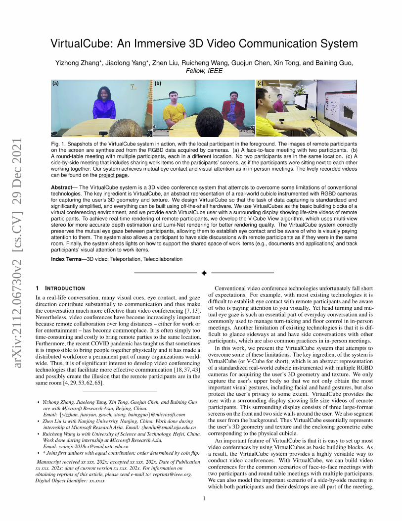
Fig. 1. Snapshots of the VirtualCube system in action, with the local participant in the foreground. The images of remote participantson the screen are synthesized from the RGBD data acquired by cameras. (a) A face-to-face meeting with two participants. (b)A round-table meeting with multiple participants, each in a different location. No two participants are in the same location. (c) Aside-by-side meeting that includes sharing work items on the participants’ screens, as if the participants were sitting next to each otherworking together. Our system achieves mutual eye contact and visual attention as in in-person meetings. The lively recorded videoscan be found on the project page.
Abstract— The VirtualCube system is a 3D video conference system that attempts to overcome some limitations of conventionaltechnologies. The key ingredient is VirtualCube, an abstract representation of a real-world cubicle instrumented with RGBD camerasfor capturing the user’s 3D geometry and texture. We design VirtualCube so that the task of data capturing is standardized andsignificantly simplified, and everything can be built using off-the-shelf hardware. We use VirtualCubes as the basic building blocks of avirtual conferencing environment, and we provide each VirtualCube user with a surrounding display showing life-size videos of remoteparticipants. To achieve real-time rendering of remote participants, we develop the V-Cube View algorithm, which uses multi-viewstereo for more accurate depth estimation and Lumi-Net rendering for better rendering quality. The VirtualCube system correctlypreserves the mutual eye gaze between participants, allowing them to establish eye contact and be aware of who is visually payingattention to them. The system also allows a participant to have side discussions with remote participants as if they were in the sameroom. Finally, the system sheds lights on how to support the shared space of work items (e.g., documents and applications) and trackparticipants’ visual attention to work items.
Index Terms—3D video, Teleportation, Telecollaboration
1 INTRODUCTION
In a real-life conversation, many visual cues, eye contact, and gazedirection contribute substantially to communication and thus makethe conversation much more effective than video conferencing [7, 13].Nevertheless, video conferences have become increasingly importantbecause remote collaboration over long distances – either for work orfor entertainment – has become commonplace. It is often simply tootime-consuming and costly to bring remote parties to the same location.Furthermore, the recent COVID pandemic has taught us that sometimesit is impossible to bring people together physically and it has made adistributed workforce a permanent part of many organizations world-wide. Thus, it is of significant interest to develop video conferencingtechnologies that facilitate more effective communication [18, 37, 43]and possibly create the illusion that the remote participants are in thesame room [4, 29, 53, 62, 65].
• Yizhong Zhang, Jiaolong Yang, Xin Tong, Guojun Chen, and Baining Guoare with Microsoft Research Asia, Beijing, China.Email: {yizzhan, jiaoyan, guoch, xtong, baingguo}@microsoft.com
• Zhen Liu is with Nanjing University, Nanjing, China. Work done duringinternship at Microsoft Research Asia. Email: [email protected]
• Ruicheng Wang is with University of Science and Technology, Hefei, China.Work done during internship at Microsoft Research Asia.Email: [email protected]
• * Joint first authors with equal contribution; order determined by coin flip.
Manuscript received xx xxx. 202x; accepted xx xxx. 202x. Date of Publicationxx xxx. 202x; date of current version xx xxx. 202x. For information onobtaining reprints of this article, please send e-mail to: [email protected] Object Identifier: xx.xxxx
Conventional video conference technologies unfortunately fall shortof expectations. For example, with most existing technologies it isdifficult to establish eye contact with remote participants and be awareof who is paying attention to you visually. Yet head turning and mu-tual eye gaze is such an essential part of everyday conversation and iscommonly used to manage turn-taking and floor control in in-personmeetings. Another limitation of existing technologies is that it is dif-ficult to glance sideways at and have side conversations with otherparticipants, which are also common practices in in-person meetings.
In this work, we present the VirtualCube system that attempts toovercome some of these limitations. The key ingredient of the system isVirtualCube (or V-Cube for short), which is an abstract representationof a standardized real-world cubicle instrumented with multiple RGBDcameras for acquiring the user’s 3D geometry and texture. We onlycapture the user’s upper body so that we not only obtain the mostimportant visual gestures, including facial and hand gestures, but alsoprotect the user’s privacy to some extent. VirtualCube provides theuser with a surrounding display showing life-size videos of remoteparticipants. This surrounding display consists of three large-formatscreens on the front and two side walls around the user. We also segmentthe user from the background. Thus VirtualCube essentially representsthe user’s 3D geometry and texture and the enclosing geometric cubecorresponding to the physical cubicle.
An important feature of VirtualCube is that it is easy to set up mostvideo conferences by using VirtualCubes as basic building blocks. Asa result, the VirtualCube system provides a highly versatile way toconduct video conferences. With VirtualCube, we can build videoconferences for the common scenarios of face-to-face meetings withtwo participants and round table meetings with multiple participants.We can also model the important scenario of a side-by-side meeting inwhich both participants and their desktops are all part of the meeting,
1
arX
iv:2
112.
0673
0v2
[cs
.CV
] 2
9 D
ec 2
021
as if the participants were sitting next to each other working together.This last scenario is quite common in real life but receives only limitedsupport with existing video conferencing technologies. When a videoconference is constructed from a set of adjacent VirtualCubes sittingon a common floor, we call the resulting assembly of VirtualCubes aV-Cube Assembly. In essence, we can view the V-Cube Assembly asthe global virtual environment of the video conference.
The VirtualCube system provides each meeting participant with real-time rendering of all remote participants on his/her surrounding display,thanks to the acquired 3D geometry and texture data of all constituentVirtualCubes of the video conference. Most importantly, the renderingcorrectly preserves the mutual eye gaze between participants becausethe VirtualCube system renders the remote participants in life-sizeusing their positions in the global virtual environment and the localparticipant’s view position in the global virtual environment, just asif the local participant was seeing the remote participants through thescreens of the VirtualCube. The VirtualCube system can perform suchrendering since it knows both the 3D geometry of all participants andthe geometry of their VirtualCubes (both their dimensions and absolutepositions in the virtual environment) and thus can properly carry out allthe 3D geometric transformations needed for correct rendering.
For rendering remote participants, real-time frame rates are essen-tial. To achieve real-time performance while improving renderingquality, we develop the V-Cube View algorithm for novel view syn-thesis. For a given viewpoint, we adapt multi-view stereo to moreaccurately estimate the depth of each image pixel. To best computethe pixel color from the acquired textures, we develop the Lumi-Netrendering technique for geometry-aware texture blending based onlightfield/lumigraph principles [5,16,27,46]. Both the depth estimationand Lumi-Net rendering are carefully crafted to ensure that the overallrendering process achieves real-time performance.
In summary, the VirtualCube system has the following advantages:
• Standardized and simplified, all using off-the-shelf hardware. Asevery VirtualCube is made the same, the VirtualCube system pro-vides a consistent physical environment and device setup whichnot only simplifies the workload of device calibration but alsoreduces the difficulty of 3D video capturing and processing. Also,we only capture the upper body of a seated user, which greatlyreduces the workload for capturing and modeling of complexhuman poses.
• Versatile modeling. A set of VirtualCubes can be easily assembledinto a V-Cube Assembly to model different video communicationscenarios, including scenarios which are poorly supported byexisting technologies.
• Real-time, high-quality rendering. The real-time rendering cancapture a variety of subtle surface appearances, such as glossyreflection on human faces and clothing, as shown in the accompa-nying video.
Our experiments with the VirtualCube system show that it can bringvideo conferencing significantly closer to our everyday experience of in-person meetings. The VirtualCube system allows meeting participantsto establish eye contact and be aware of who is visually paying attentionto them. The system also allow a participant to make side glances andside conversations to remote participants as if they are in the sameroom. Taken together, these abilities form the cornerstone of the notionof a personal space, a notion that we have acquired and internalizedthrough our lifetime experience of in-person conversations [7].
In addition to this shared “person space”, the VirtualCube systemalso shows promise in supporting the shared space of work items(including documents, applications, and other artifacts). In particular,in a side-by-side meeting, both participants and their desktops are allpart of the video conference, as if the two participants were sitting nextto each other working together. This shared “work space” [7], whichencompasses both the participants and work items on their desktops,is a useful addition to the shared “person space” because it lets eachparticipant see whether the remote participant is visually attending
to a specific work item as desired. For example, when a participanthighlights an item on his/her desktop with the cursor, he/she can easilysee whether the remote participant is visually paying attention to thisitem. This experience, albeit simple and very common for in-personcollaboration [7], is not supported in conventional video conferences.
2 RELATED WORK
The techniques and systems for 3D video communication have beenwidely studied in many fields. In this section, we discuss the previousworks that are directly related to our work, including 3D video commu-nication systems, gaze-correction techniques for video conferencing,and free viewpoint video of human characters. For more comprehen-sive reviews of related techniques, the reader is referred to the latestworks [69, 71, 79] and surveys [56, 59].
2.1 3D Video CommunicationEarly 3D video communication systems [3,25,67] attempted to capturethe appearance and geometry of the participants at different locationsand place them in a common virtual environment. Without carefulsystem design and setup, the mutual gaze contact among users in thesesystems is always poorly produced.
Many follow-up techniques [28, 37, 42, 45, 57, 64] have been de-veloped for telecommunication between two sites. Although theseapproaches improved eye contact and user experience in two-site meet-ings, extending them to multiple sites is difficult.
For three-party teleconferencing, the tele-cubicle systems [76, 81]use a cubicle with two walls. In their systems, users are difficult toestablish eye contact [76]. Their focus is to use the two walls as portalsto remote users’ offices; it is not their intention to bring remote usersinto a common virtual meeting room as we do. Also note that theremote users are reconstructed as 3D meshes in their system. Real-time reconstruction of detailed 3D meshes that permit high-qualityrendering cannot be easily achieved even with modern hardware andalgorithms [15, 62]. Later, a number of systems [39, 87] have beenproposed where the participant positions in the virtual environment arepredefined and fixed for maintaining mutual eye contact. However, it isunclear how to extend these systems to other seating arrangements andmeetings with different numbers of participants. Also, the renderingquality of the remote participants is limited due to the fragile depthreconstruction and image warping algorithms used in these systems. Incontrast, our system is designed for implementing meetings betweendifferent numbers of participants, as well as meetings with various userseating setups. To maintain mutual eye contact of the participants indifferent meeting setups, we develop a new deep learning based V-CubeView algorithm for capturing and rendering high-fidelity free-viewpointvideo of the participants in real time.
A collection of telepresence systems [4, 22, 29, 53, 65] have beendesigned for capturing and rendering a virtual or augmented-realityenvironment so that the participants at different sites could work to-gether as if they were in one site. All these methods focus either on theenvironment capturing and 3D display [22, 29, 53, 65] or the interac-tions between the users and the virtual environment [4]. They are notoptimized for teleconference and thus it is difficult for them to achievefaithful mutual gaze contacts between the participants at different sites.
2.2 Gaze Correction for Video ConferencingMany approaches have been developed to correct the gaze of the partic-ipants for better eye contact in video conferencing. Chen [13] studiedthe sensitivity of eye contact in video conferencing and improved theeye contact with more accurate horizontal gaze direction. Kuster etal. [43] warped the face region of the remote participant captured byan RGBD camera and then fused the warped part into the originalRGBD video frame for correcting vertical gaze direction. Later, Gigeret al. [26] extended this method for RGB videos captured by a webcamera. Hsu et al. [34] developed a convolutional neural network togenerate gaze corrected video of the participant by tracking and warp-ing the eye region of the participant in each video frame. Tausif etal. [71] moved a web camera behind a transparent screen accordingto the remote participant’s eye position for capturing videos of the
2
participants with correct eye-contact. All these methods are designedfor video conferencing between two participants, and cannot handleeye contact for three or more participants.
Different from these approaches, our method captures 3D videoof the participants and delivers natural gaze contact and other visualcommunications by realistically rendering life-size remote participantsfrom the local participant’s viewpoint. Our method supports eye contactbetween the participants in a teleconference with two or more users.
2.3 Free Viewpoint Video of Human CharactersNumerous methods have been proposed for generating a realistic avatarof a subject. Some of them [1, 2, 21, 24, 40, 48, 55, 60, 61, 72–74, 80]model a 3D avatar of a subject and then drive its animation using avideo sequence or speech text. However, dedicated device setup andheavily manual work are always needed for generating a realistic avatarand reconstructing the detailed appearance, subtle expressions, andgaze movement of a subject. Recent deep-learning based methods [6,12,30,32,58,78,79,82,85,86,88] avoid 3D avatar modeling and directlysynthesize a talking head video of a subject from one source imageof the subject and a video sequence. Elgharib et al. [18] developeda solution for warping the video of a subject’s face from side viewto front view. Unfortunately, all these deep-learning based methodscannot support arbitrary view rendering. Also, it is unclear how toextend these methods for modeling the dynamics of the upper body.
Other methods [17,31,39,44,51,62,87,91] reconstruct a complete orpartial 3D geometry and texture of a dynamic character in real time andthen render it from novel viewpoints. Although they provide real-timefree-viewpoint rendering of the dynamic character, the reconstructed3D geometry and texture are always imperfect or of low-resolution thusleading to inferior rendering quality.
Generic image-based rendering methods have been developed forsynthesizing novel views from images or videos of a scene capturedfrom sparse or dense views. Traditional optimization-based meth-ods [8, 15, 47, 63, 90] rely on fragile offline processing for obtaininghigh quality rendering results. Deep-learning based approaches lever-age neural networks to improve the robustness and speed of offlineoptimization and have demonstrated high-quality novel view synthesisresults [14, 19, 20, 38, 69, 69, 89]. However, these methods still requireat least a few seconds on a modern GPU to synthesize a novel view.Recently, several neural representations [9, 54, 77, 84] have been pro-posed for modeling and rendering a 3D scene from a given multiviewimage collection. Unfortunately, the computational cost of learningand rendering these neural representations is still high. Although theseimage-based approaches can be applied for rendering human characters,they suffer from the trade-off between speed and quality. To the best ofour knowledge, methods have not been developed for online capturingand realistic rendering in real-time.
In this work, we follow the principle of previous deep-learning basedmethods [14,20,38,69] that first predicts the target-view depth and thensynthesizes texture, and develop a new V-Cube View method to achievereal-time and high-quality 3D freeview synthesis.
3 THE VIRTUALCUBE SYSTEM
In this section, we first provide a conceptual overview of VirtualCubeand then present the implementation details. Our real-time renderingalgorithm is described in Section 4.
3.1 VirtualCube: A Conceptual OverviewThe VirtualCube system aims to provide a standardized solution forremote meeting participants to naturally communicate with one anotheras if they were in the same room. For simplicity, we assume thatno two participants are co-located. The immersive experience of aparticipant is created by surrounding him with a large format displayon which all other participants are rendered at life size. Meanwhile,at each meeting site, multiple cameras capture the local participant’s3D geometry and texture, and thus allow our system to synthesize thevideo of this participant for all remote parties.
VirtualCube has two components: one physical and the other abstract.The physical component is an instrumented real-world cubicle enclosed
RGBD Camera
(a) (b)
(c) (d)
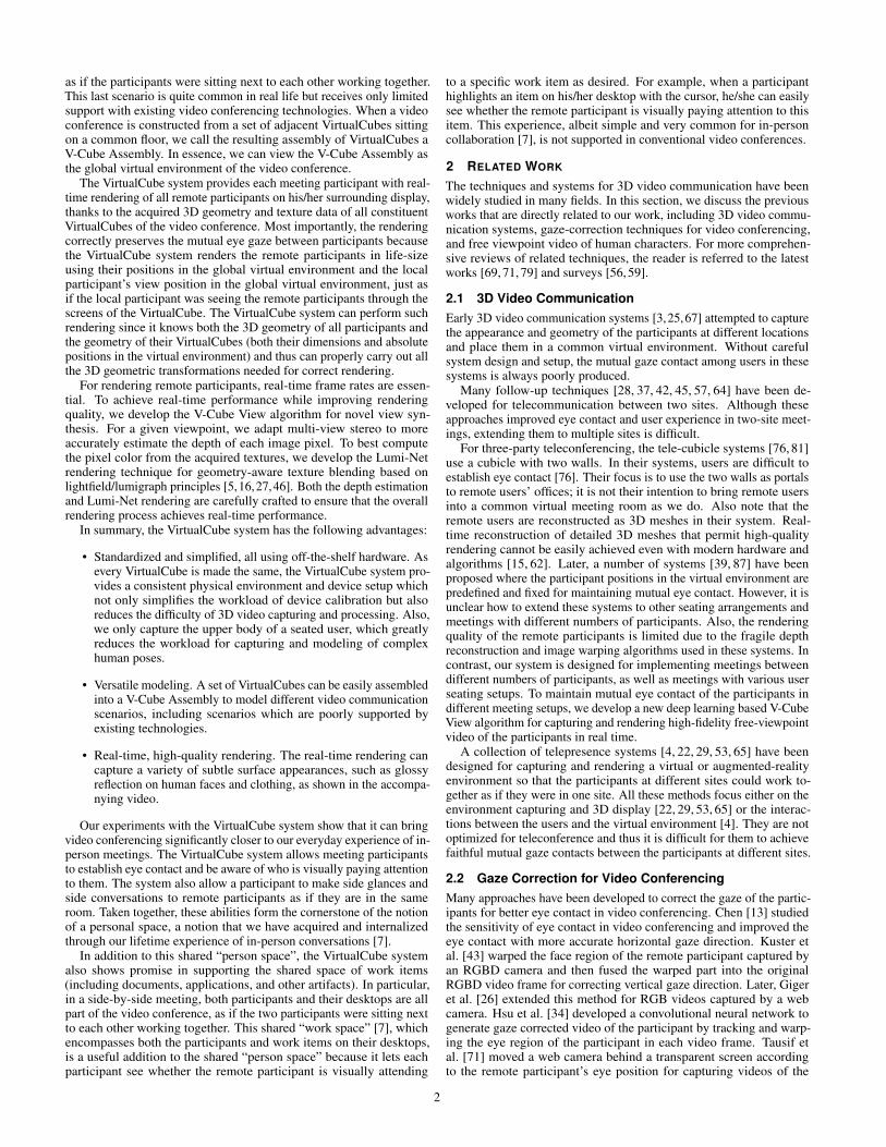
Fig. 2. VirtualCube and various examples of video conferences con-structed by using VirtualCubes as building blocks. (a) The physical setupof VirtualCube, which consists of a surrounding display on the front andtwo side walls and multiple RGBD cameras mounted around the screenon the front wall. The back wall is outlined by dotted lines. (b) A roundtable meeting of three participants. (c) A face-to-face meeting of twoparticipants. (d) A side-by-side meeting of two participants. To simplifyillustration, we only show one participant’s display in (b), (c), and (d).
by four vertical walls as shown in Fig. 2(a). The cubicle has a fixedseat in the middle for the user and a table attached to the front wall.The front and two side walls have large format screens attached fordisplaying life-size videos of remote meeting participants. Along thescreen boundaries of the front wall a set of RGBD cameras (color anddepth) are attached for capturing the user’s 3D geometry and texture.The back wall is painted solid gray for simplifying of the task ofsegmenting the user from the background. The abstract component ofVirtualCube consists of the abstract geometric cube associated with thephysical cubicle and the user’s 3D geometry and texture as captured bythe RGBD cameras.
The VirtualCube system only captures and renders the 3D geometryand color texture of the seated user’s upper body, defined as the bodypart above the table. Our reason for focusing on upper body is mainlyfor efficiency. The upper body of a seated person is easier to capturethan the full body with unconstrained movements. Yet, it providesfacial and hand gestures which are among the most important visualcues for communication. In practice, only rendering the upper bodyalso provides a sense of privacy for the user who knows the lower bodyis safely off the limits and hence any lower garment can be worn.
We use VirtualCube as the basic building block of the virtual environ-ment of our online meetings. This virtual environment is constructed asan assembly of multiple adjacent VirtualCubes on a common floor. Wecall this assembly the V-Cube Assembly. Figure 2(b)-(d) show a fewV-Cube Assemblies in different configurations: one for a face-to-facemeeting with two participants, one for a side-by-side meeting with twoparticipants, and one for a round table meeting with multiple partici-pants. Note that the side-by-side configuration has a special advantageof supporting not only the interaction between the participants but alsothe sharing of their screen content as part of the interaction.
People have different senses of personal spaces. We support thisby allowing different VirtualCubes in a V-Cube Assembly to overlap.Intuitively, the overlap allows participants to sit more closely togetherwhen desired. The amount of overlap is a user-controlled parameter,which can be set by the conference organizer. As a rule of thumb, in ourimplementation we require the meeting participant in each VirtualCubeto be outside of the other VirtualCubes in the V-Cube Assembly so thatwe can correctly project the remote participants on the surroundingdisplay from the view of each participant.
The V-Cube Assembly is the basis of the global coordinate system,
3
ZX
Y
(a) (b)
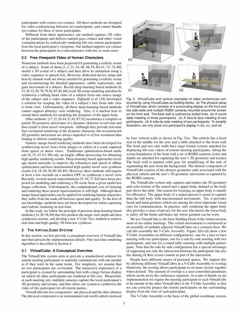
Fig. 3. (a) The hardware setup of our VirtualCube implementation, whichconsists of three large screens on the front and two side walls andsix Azure Kinect cameras mounted around the front display. We alsoshow the VirtualCube’s local coordinate system. (b) Color images of theparticipant captured by the six cameras.
which is defined as the coordinate system of the V-Cube Assemblyand hence the overall virtual environment. This global coordinatesystem is in contrast to the local coordinate system of each individualVirtualCube. The correct 3D geometric transformations between theglobal and local coordinate systems (which take into considerationthe physical size of VirtualCube and its display screens) is importantbecause it is essential for correct rendering of remote participants onthe video display of each meeting participant. In particular, this correctrendering is needed for achieving mutual eye gaze. Specifically, the 3Dgeometry transformations proceed as follows. First, when capturingthe user’s 3D geometry and texture inside a VirtualCube, we use theVirtualCube’s local coordinate system. Then, after forming the V-Cube Assembly, we transform the captured 3D geometry data of allconstituent VirtualCubes from their respective local coordinate systemsinto the global coordinate system so that all VirtualCubes’ 3D geometrydata are correctly positioned in the global virtual environment to createthe global 3D geometry content of the V-Cube Assembly. This global3D geometry is what every participant sees. Finally, to render remoteparticipants on a VirtualCube’s display, we first transform the global3D geometry into the VirtualCube’s local coordinate system and thenproject the transformed global geometry onto the VitualCube’s display.
3.2 Implementation DetailsWe now present our hardware setup and calibration and the resultingcoordinate transformations for the video display of each VirtualCube.
Hardware setup As shown in Figure 2, our VirtualCube prototypeis a cubicle enclosed by the front and two side walls painted solidwhite, and a back wall covered by a curtain of solid grey color foreasy segmentation of the user from the background. The floor planedimension of VirtualCube is 1.6×2.0 meters. In face-to-face meetingsand round-table meetings, the user faces the front display and a semi-circular table is placed between the user and the front wall. In side-by-side meetings, the user faces a side display and an L-shaped longtable is placed between the user and the front wall and one side wall, asshown in Fig. 2(d).
For the surrounding display of a VirtualCube, we mount three 65-inch 4K flat LCD screens on the front and two side walls. The heightfrom the bottoms of these screens to the floor is 0.7 meter, which isdesigned to support life-size display of the upper bodies of remoteparticipants. For capturing the 3D video of the user, we install sixAzureKinect RGBD cameras around the front screen, with four at thecorners and two at the mid-points of the upper and lower boundaries.The viewing directions of the six cameras are set towards the userseated in the center of the VirtualCube. The six cameras capture RGBDvideo sequences in synchronized mode, each recording 2560×1440RGB frames and 640×576 depth frames at 30fps. The RGB and depthframes are aligned and scaled to 1280×960 resolution for later use.
Within VirtualCube, the front and two side screens and six RGBDcameras are connected to a PC workstation with GPUs for 3D videocapturing, rendering, and display. VirtualCube instances at differentsites are connected by a network.
Hardware calibration For the hardware calibration of a Virtual-Cube, we need to define the local coordinate system of the VirtualCube
Global Virtual Environment G
VirtualCube C1 VirtualCube C2
𝐌𝐂𝟏→𝐆 𝐌𝐂𝟐→𝐆
𝐌𝐂𝟐→𝐆−𝟏 𝐌𝐂𝟏→𝐆
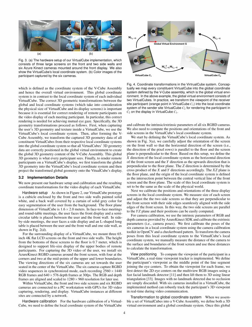
Fig. 4. Coordinate transformations in the VirtrualCube system. Concep-tually we map every constituent VirtualCube into the global coordinatesystem defined by the V-Cube assembly, which is the global virtual envi-ronment. In the above example, the global virtual environment consists oftwo VirtualCubes. In practice, we transform the viewpoint of the receiversite participant (orange point in VirtualCube C1) into the local coordinatesystem of the sender site VirtualCube C2 for rendering the participant inC2 on the display in VirtualCube C1.
and calibrate the intrinsic/extrinsic parameters of all six RGBD cameras.We also need to compute the positions and orientations of the front andside screens in the VirtualCube’s local coordinate system.
We start by defining the VirtualCube’s local coordinate system. Asshown in Fig. 3(a), we carefully adjust the orientation of the screenon the front wall so that the horizontal direction of the screen (i.e.,the direction of the pixel rows) is parallel to the floor and the screenplane is perpendicular to the floor. Based on this setup, we define theX direction of the local coordinate system as the horizontal directionof the front screen and the Y direction as the upwards direction that isperpendicular to the floor plane. The Z direction is determined by thecross product of the X and Y directions accordingly. The XZ plane isthe floor plane, and the origin of the local coordinate system is definedas the intersection point between the central vertical line of the frontscreen and the floor plane. The scale of this local coordinate system isset to be the same as the scale of the physical world.
Next we calibrate the positions and orientations of the three displayscreens in the local coordinate system. We measure size of each screenand adjust the the two side screens so that they are perpendicular tothe front screen with their side edges seamlessly aligned with the sideedges of the front screen. In this way, the two side screens are parallelto the Y Z plane and their positions can be easily computed.
For camera calibration, we use the intrinsic parameters of RGB anddepth cameras provided by AzureKinect SDK and calibrate the extrinsicparameters (i.e., camera poses). We first calibrate the poses of thesix cameras in a local coordinate system using the camera calibrationtoolkit in OpenCV and a checkerboard pattern. To transform the cameraposes from this local coordinate system to the VirtualCube’s localcoordinate system, we manually measure the distance of the camera tothe surface and boundaries of the front screen and use these distancesto calculate the transformation.
View positioning To compute the viewpoint of the participant in aVirtualCube, a real-time viewpoint tracker is implemented. We definethe participant’s viewpoint as the middle point of the line segmentjoining the eye centers. To obtain the viewpoint for each frame, wefirst detect the 2D eye centers on the multiview RGB images using afast facial landmark detector [11] and then lift them to 3D using lineartriangulation [33]. Images with no landmark detected due to occlusionare simply discarded. With six cameras installed in a VirtualCube, theimplemented method can robustly track the participant’s 3D viewpointin real-time during video communication.
Transformation to global coordinate system When we assem-ble a set of VirtualCubes into a V-Cube Assembly, we define both a 3Dvirtual environment and a global coordinate system. Once this global
4
Local User (Receiver)Remote User (Sender)
V-Cube View
PortraitImage
Final Rendering
Network
RGBD Images View Positioning
RGBD Video Acquisition RGBD Video Acquisition
View PositioningRGBD
Images
V-Cube View
Final Rendering
View Position
PortraitImage
View Position
3D Background Scene
3D Background Scene
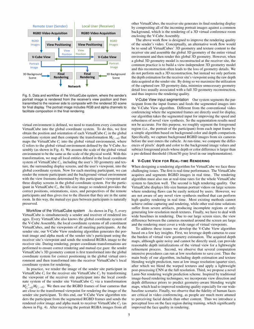
Fig. 5. Data and workflow of the VirtualCube system, where the sender’sportrait image is rendered from the receiver’s view position and thentransmitted to the receiver side to composite with the rendered 3D scenefor final display. The portrait image includes RGB and alpha channels tofacilitate composition in the final rendering.
virtual environment is defined, we need to transform every constituentVirtualCube into the global coordinate system. To do this, we firstobtain the position and orientation of each VirtualCube Ci in the globalcoordinate system and then compute the transformation MCi→G thatmaps the VirtualCube Ci into the global virtual environment, whereG refers to the global virtual environment defined by the V-Cube As-sembly (as shown in Fig. 4). We assume the scale of the global virtualenvironment to be the same as the scale of the physical world. With thistransformation, we map all local entities defined in the local coordinatesystem of VirtualCube Ci, including the user’s 3D geometry and tex-ture, the surrounding display screens, and the user’s viewpoint, into theglobal coordinate system. Now for each meeting participant, we canrender the remote participants and the background virtual environmentwith the view frustums determined by this participant’s viewpoint andthree display screens in the global coordinate system. For the partic-ipant in VirtualCube Ci, the life-size image so rendered provides thecorrect positions, orientations, sizes, and perspectives of the remoteparticipants and thus gives rise to the illusion that they are in the sameroom. In this way, the mutual eye gaze between participants is naturallypreserved.
Workflow of the VirtualCube system As shown in Fig. 5, everyVirtualCube is simultaneously a sender and receiver of rendered im-ages. Every VirtualCube also knows the global coordinate system ofthe V-Cube Assembly, the local coordinate systems of all constituentVirtualCubes, and the viewpoints of all meeting participants. At thesender site, our V-Cube View rendering algorithm generates the por-trait image and alpha mask of the sender site’s participant using thereceiver site’s viewpoint and sends the rendered RGBA image to thereceiver site. During rendering, proper coordinate transformations areperformed to ensure correct rendering and mutual eye gaze: the senderVirtualCube’s 3D geometry content is first transformed into the globalcoordinate system for correct positioning in the global virtual envi-ronment and then transformed into the receiver VirtualCube’s localcoordinate system for rendering.
In practice, we render the image of the sender site participant inVirtualCube Ci for the receiver site VirtualCube C j by transformingthe viewpoint of the receiver site participant into the local coordi-nate system of the sender site VirtualCube Ci via a transformationM−1
Ci→GMC j→G. We then use the RGBD frames of four cameras thatare close to the transformed viewpoint for rendering the image of thesender site participant. To this end, our V-Cube View algorithm ren-ders the participant from the segmented RGBD frames and sends therendered color image and alpha mask to receiver VirtualCube C j (asshown in Fig. 4). After receiving the portrait RGBA images from all
other VirtualCubes, the receiver site generates its final rendering displayby compositing all of the incoming portrait images against a commonbackground, which is the rendering of a 3D virtual conference roomenclosing the V-Cube Assembly.
The above work flow is designed to improve the rendering qualityof the sender’s video. Conceptually, an alternative work flow wouldbe to send all VirtualCubes’ 3D geometry and texture content to thereceiver site and assemble the global 3D geometry of the entire virtualenvironment and then render this global 3D geometry. However, whena global 3D geometry model is reconstructed at the receiver site, thecommon practice is to build a view-independent 3D geometry modeland this reconstruction often leads to the loss of geometry details. Wedo not perform such a 3D reconstruction, but instead we only performthe depth estimation for the receiver site’s viewpoint using the raw depthdata acquired at the sender site. By doing so we maximize the utilizationof the captured raw 3D geometry data, minimize unnecessary geometrydetail loss usually associated with a full 3D geometry reconstruction,and thus improve the rendering quality.
V-Cube View input segmentation Our system segments the par-ticipant from the input frames and feeds the segmented images intothe V-Cube View algorithm. Different from the conventional videoconferencing where the segmented frames are directly used for display,our algorithm takes the segmented input for improving the speed androbustness of novel view synthesis. So the segmentation results neednot be accurate. For this purpose, we roughly segment the foregroundregion (i.e., the portrait of the participant) from each input frame bya simple algorithm based on background color and depth comparison.Specifically, we capture background RGBD images from six camerasbefore the user enters the cubicle. At run-time, we compute the differ-ences of pixels’ depth and color to the background image values andsubtract foreground pixels whose depth or color difference is larger thana pre-defined threshold (10cm/30 gray level in our implementation).
4 V-CUBE VIEW FOR REAL-TIME RENDERING
When designing a rendering algorithm for VirtualCube we face threechallenging issues. The first is real-time performance. The VirtualCubeacquires and segments RGBD images in real time. The renderingalgorithm must also run at real-time rates for the whole VirtualCubesystem to function well. The second is high rendering quality. OurVirtualCube displays life-size human portrait videos on large screenswhere rendering flaws can be easily noticed by users. However, weare not aware of any novel view synthesis method that can performhigh quality rendering in real time. Most existing methods cannotachieve online capturing and rendering, while other real-time solutionssuffer from severe artifacts, producing incomplete regions or onlygenerating low-resolution mesh textures. Finally, we have to deal withwide baselines in rendering. Due to our large screen sizes, the viewdifference between the cameras mounted around the screen are largeand the rendering must cover a wide range of virtual viewpoints.
To address these issues we develop the V-Cube View algorithmbased on a few key insights. First, we leverage depth cameras to easethe burden of virtual view geometry estimation. The acquired depthmaps, although quite noisy and cannot be directly used, can providereasonable depth initializations of the virtual view for a lightweightrefinement process. Second, we observe that several computationintensive procedures can run at low resolutions to save cost. Thus themain body of our algorithm, including depth estimation and textureblending weight prediction, runs at low image resolution (quarter size),after which we blend the warped textures and apply a lightweightpost-processing CNN at the full resolution. Third, we propose a novelLumi-Net rendering weight prediction scheme. Inspired by traditionalimage-based rendering techniques, we incorporate view direction anddepth difference priors to predict geometry-aware blending weightmaps, which lead to improved rendering quality especially for our wide-baseline scenario. Finally, we observe that the fidelity of human facesare critical in video conferencing, as people are much more attunedto perceiving facial details than other content. Thus we introduce aperceptual loss on the face region during training, which significantlyimproved the face quality in rendering.
5
Ⅰ. Virtual View Depth Prediction Ⅱ. Lumi-Net Rendering
…FeatureCNN
CostVolume
CostVolume
BlendingCNN
Post-process
CNN
TextureBlending
MVSCNN
Dow
nsam
ple
4x
Upsa
mpl
e 4x
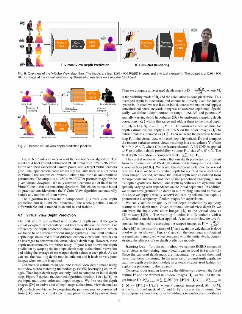
Fig. 6. Overview of the V-Cube View algorithm. The inputs are four 1280×960 RGBD images and a virtual viewpoint. The output is a 1280×960RGBα image at the virtual viewpoint synthesized in real time on a modern GPU card.
Warping & Variance Comp.
FeatureCNN
MVSCNN
Depth CandidatesInitial Depth
Projection &Averaging
∑
Depth Probability
W
Cost Volume
Estimated Depth
WeightedAveraging
Multiview FeaturesMultiview ColorMultiview Depth
Fig. 7. Detailed virtual-view depth prediction pipeline.
Figure 6 provides an overview of the V-Cube View algorithm. Theinput are 4 background-subtracted RGBD images of 1280×960 reso-lution and their associated camera poses, and a target virtual camerapose. The input camera poses are readily available because all camerasin VirtualCube are pre-calibrated to obtain the intrinsic and extrinsicparameters. The output is a 1280×960 RGBα portrait image for thegiven virtual viewpoint. We only activate 4 cameras out of the 6 in theVirtualCube to run our rendering algorithm. This choice is made basedon practical considerations; the V-Cube View algorithm can naturallyhandle any number of input views.
The algorithm has two main components: i) virtual view depthprediction and ii) Lumi-Net rendering. The whole pipeline is madedifferentiable and is trained in an end-to-end fashion.
4.1 Virtual View Depth Prediction
The first step of our method is to predict a depth map at the givenvirtual viewpoint, which will be used later to synthesize the texture. Forefficiency, the depth prediction module runs at 1/4 resolution, whichwe found to be sufficient for our image synthesis. The input containsdepth maps measured at four different camera viewpoints, which canbe leveraged to determine the virtual view’s depth map. However, thesedepth measurements are rather noisy. Figure 8 (a) shows the depthprediction by warping the four input depth maps to the virtual viewpointand taking the average of the warped depth values at each pixel. As wecan see, the resulting depth map is deficient and it leads to very poorimages when texture is applied.
Our method estimates an accurate virtual-view depth image usingmultiview stereo matching methodology (MVS) leveraging color im-ages. Thee input depth maps are only used to compute an initial depthmap. Figure 7 depicts the detailed algorithm pipeline. Let {Ii,Di} bethe input multiview color and depth images. We first use the depthimages {Di} to derive a set of depth maps at the virtual view, denoted as{D′i}, which are obtained by projecting the per-view meshes constructedfrom {Di} onto the virtual view image plane followed by rasterization.
Then we compute an averaged depth map via D = ∑i M′i ·D′i
∑i M′i, where M′
i
is the visibility mask of D′i and the calculation is done pixel-wise. Thisaveraged depth is inaccurate and cannot be directly used for imagesynthesis. Instead, we use D as an initial, coarse estimation and apply aconvolutional neural network to regress an accurate depth map. Specif-ically, we define a depth correction range [−∆d,∆d] and generate Nspatially-varying depth hypotheses {Dk} by uniformly sampling depthcorrections {σk} within this range and adding them to the initial depth,i.e., Dk = D+σk, k = 0, . . . ,N− 1. To construct a cost volume fordepth estimation, we apply a 2D CNN on the color images {Ii} toextract features, denoted as {Fi}. Then we warp the per-view featuremap Fi to the virtual view with each depth hypothesis Dk and computethe feature variance across views, resulting in a cost volume V of sizeH×W ×N×C, where C is the feature channel. A 3D CNN is appliedto V to predict a depth probability volume P of size H×W ×N. Thefinal depth estimation is computed as D = ∑
Nk=1 Pk · Dk.
The careful reader will notice that our depth prediction is differentfrom traditional deep MVS depth estimation techniques in computervision such as [49, 83]. We derive this different technique for severalreasons. First, we have to predict depth for a virtual view without acolor image. Second, we have the initial depth map calculated fromthe input data and we do not need to use predefined sweeping planesas depth hypotheses. Instead, our depth hypotheses are dynamic andspatially varying with dependence on the initial depth map. In addition,we do not have ground truth depth in our training data and to resolvethis issue we apply a weakly-supervised learning scheme that exploitsphotometric discrepancy of color images for supervision.
We can visualize the quality of our depth prediction by applyingtexture to the depth map. Given estimated virtual-view depth D, wecan warp the input-view color images {Ii} to the virtual view as{Iw
i = warp(Ii|D)}. The warping function is differentiable with adifferentiable mesh rasterizer applied. A naive multiview texture fu-sion can be obtained by averaging the warped images as Ia = ∑i Mw
i ·Iwi
∑i Mwi
,where Mw
i is the visibility mask of Iwi and again the calculation is done
pixel-wise. As shown in Fig. 8 (a) and (b), the depth map so-obtainedis significantly improved when compared with the initial depth, demon-strating the efficacy of our depth prediction module.
Training loss To train our method, we capture RGBD images ofnovel views as the training target (details can be found in Section 4.3).Since the captured depth maps are inaccurate, we discard them andnever use them in training. In the absence of ground-truth depth, wetrain the depth prediction module in a weakly-supervised fashion byexploiting photometric discrepancy.
Concretely, our training losses are the differences between the fusedtexture Ia and the warped multiview images {I′i} as well as the tar-get image I∗: L d
color-mv = ∑i ∑x Mwi (x) · ‖Ia(x)− I′i(x)‖1, L d
color-gt =
∑x M(x) · ‖Ia(x)− I∗(x)‖1 where x denotes image pixel, M = ∪iM′i
is the valid pixel mask of Ia, and ‖ · ‖1 indicates the l1 norm. Wealso impose a smoothness prior by adding a second-order smoothness
6
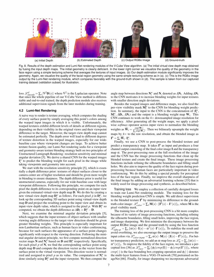
(c) Output RGBα Image (d) Ground-truth(a) Initial Depth (b) Estimated Depth
Fig. 8. Results of the depth estimation and Lumi-Net rendering modules of the V-Cube View algorithm. (a) The initial virtual-view depth map obtainedby fusing the input depth maps. The initial geometry is clearly deficient. In the lower right corner we visualize the quality of the geometry in theface region using a simple texturing scheme that averages the textures of input images. (b) Our depth estimation module significantly improves thegeometry. Again, we visualize the quality of the facial region geometry using the same simple texturing scheme as in (a). (c) This is the RGBα imageoutput by the Lumi-Net rendering module, which compares favorably with the ground-truth shown in (d). The sample is taken from our capturedtraining dataset (validation subset) for illustration.
loss L dsmooth = ∑x |∇2D(x)| where ∇2 is the Laplacian operator. Note
that since the whole pipeline of our V-Cube View method is differen-tiable and end-to-end trained, the depth prediction module also receivesadditional supervision signals from the later modules during training.
4.2 Lumi-Net RenderingA naive way to render is texture averaging, which computes the shadingof every surface point by simply averaging this point’s colors amongthe warped input images in which it is visible. Unfortunately, thewarped textures exhibit different levels of details at different regions,depending on their visibility in the original views and their viewpointdifference to the target. Moreover, the target-view depth map cannotbe estimated perfectly. The depth error will lead to different degreesof texture distortion in the warped images, especially for our wide-baseline case where viewpoint changes are large. To achieve bettertexture fusion quality, our Lumi-Net rendering seeks for a viewpointand geometry-aware texture blending strategy built on two principles ofUnstructured Lumigraph Rendering: resolution sensitivity and minimalangular deviation [5]. We derive a shared CNN for the warped imagesIw
i to predict the blending weight for each pixel in the image whiletaking viewpoints and geometry into account.
We start with the resolution sensitivity principle [5], which is essen-tially a depth difference prior: textures of object surfaces closer to thecamera center are of higher resolution and should be given more weightin blending to ensure sharpness. The depth difference prior is useful forunstructured cameras, especially for our wide-baseline case with largeviewpoint differences. Following this principle, we compute for eachpixel the depth difference to its corresponding point on an input viewgiven the estimated virtual-view depth map D. We do this by creating anew virtual-view depth map Dw
i as follows. For each pixel p in Dwi , we
look up the corresponding 3D surface point using virtual-view depthmap D and project the resulting point to the input view and obtain itsinput-view depth value, which is assigned to the pixel p. With Dw
i socomputed, we obtain the depth difference as ∆Di = Dw
i −D.Next, we examine the minimal angular deviation principle [5],
which suggests that the input textures of object surfaces with smallerviewing angle difference to the target view direction should be givengreater blending weights. This principle is especially important fornon-Lambertian surfaces, such as human faces in video conferencing,because for such surfaces the appearance of a surface point changessignificantly with respect to the viewing direction. Following the mini-mal angular deviation principle, we first compute normalized directionvector maps N and Nw
i based on D and Dwi respectively. Specifically,
for each pixel p of N, we find the corresponding surface point usingdepth map D and compute the direction vector as the vector from thesurface point to the virtual viewpoint. This direction vector is normal-ized and assigned to pixel p as its value. The computation of Nw
i isdone similarly using Dw
i and the input viewpoint. We then compute the
angle map between directions Nwi and N, denoted as ∆Ni. Adding ∆Ni
to the CNN motivates it to increase blending weights for input textureswith smaller direction angle deviations.
Besides the warped images and difference maps, we also feed theper-view visibility mask Mw
i to the CNN for blending weight predic-tion. In summary, the input to the CNN is the concatenation of (Iw
i ,Mw
i , ∆Di, ∆Ni) and the output is a blending weight map Wi. ThisCNN continues to work on the 4× downsampled image resolution forefficiency. After generating all the weight maps, we apply a pixel-wise softmax operator across input views to normalize the blendingweights as Wi =
exp(Wi)∑ j exp(W j)
. Then we bilinearly upsample the weightmaps by 4× to the raw resolution, and obtain the blended image asIb = ∑i Wi · Iw
i .Finally, we use a CNN to post-process the blended texture and
predict a transparency map. It takes Ib as input and produces a fourchannel output consisting of the final color image I and the transparencymap α . The post-processing runs at the full resolution of the imageand the CNN has the image processing functions that clean up theblended texture and create the final image. These image processingfunctions include refining the silhouette boundaries and filling smallholes. We also aim to improve the quality of the face region during post-processing because human faces are particularly important in videoconferencing. We do this by adding a special penalty for perceptualloss of the face region. Finally, we improve the overall sharpness ofthe final image by adding an adversarial learning scheme [35] that iswidely used for image processing and synthesis, as described below.
Training loss We employ a collection of carefully designed lossesto train our Lumi-Net rendering module. The training loss for theblending weight prediction CNN is simple. We add direct supervisionto the blended texture Ib by minimizing its difference to the ground-truth color image: L l
color = ∑x M(x) · ‖Ib(x)− I∗(x)‖1, where M is thepixel visibility mask.
The training loss of the post-processing CNN is a bit more complexbecause of its variety of image processing functions, including refiningthe silhouette boundaries, filling small holes, improving the face region,and image sharpening. We first minimize the discrepancy between theoutput RGBα image and the ground truth by using the loss functionL r
rgba-gt = ∑x ‖α(x) · I(x)−α∗(x) · I∗(x)‖1. To stabilize the result andavoid overfitting, we also encourage the output image to preserve theinput colors via L r
color-input = ∑x α(x) ·M(x) ·‖I(x)−Ib(x)‖1. For bet-ter transparency prediction, we add an α-map loss as L r
α = ∑x ‖α(x)−α∗(x)‖1. To improve the fidelity of the face region, we introduce a per-ceptual loss [36] as L r
f ace = ∑l ‖φl(crop(I))−φl(crop(I∗))‖1, wherecrop(·) is the face bounding box cropping operation and φl(·) denotesthe multi-layer features from a VGG-19 network [70] pretrained on Im-ageNet [66]. Finally, for image sharpening we incorporate adversarial
7
learning with a PatchGAN as in [35] and use the least squares GAN lossfrom [52] as L r
adv = ‖D(I)−1‖2, where D is the discriminator network.The adversarial loss for D is L r
adv-D = 12‖D(I)−0‖2 + 1
2‖D(I∗)−1‖2.
4.3 Training DataTo capture training data for our method, we setup six RGBD cameraswith similar spatial arrangement to the VirtualCube. We place twoadditional cameras to capture the target-view images for training. Weadd perturbations to the camera poses during the data capture campaignto introduce view variations. Modest perturbations are added to thesix cameras, whereas the target camera poses are flexibly adjustedto cover a wide range of viewpoints. To train the method, we usethe left four camera as the input views and synthesize the left targetview. Similarly, the right four cameras are used to generate the targetview on the right. During data capture, we ask actors to sit in frontof the cameras and make natural actions as in a face-to-face meeting,including face expression, body movements, and some hand gestures.We also captured side-view images by asking actors to sit towards theside screens.
We captured multiview RGBD data of 18 subjects in total. Foreach subject, multiple video clips are recorded at 15fps. Each subjectwears 3-5 personal garments during capture. The dataset contains920K frames in total, with 51K frames per person on average. Thebackground matting method of [68] is used to obtain alpha map labelsof the target view images. We detect face regions by the method of [10].
4.4 Temporal SmoothingSince our method synthesizes images frame-by-frame, we apply tem-poral smoothing to the output RGBα sequences to improve temporalconsistency especially for boundary regions. Specifically, for the trans-parency map estimates, we maintain a history buffer αh and blend thecurrent-frame output α with αh via α ′ = wα +(1−w)αh, where scalarw is the blending weight (w = 0.5 in our implementation). The historybuffer is updated at each frame as αh = α ′. We apply a similar temporalsmoothing strategy for color images, except that we only process borderpixels. Let Ih be the image history buffer, we first shrink the processedtransparency map α ′ by n pixels (n = 10 in our implementation) toobtain α ′interior, which is achieved by a spatial min-pooling operationwith (2n+1)× (2n+1) kernel size. Let α ′border = α ′−α ′interior be theborder region transparency map, we blend the current-frame color im-age I with Ih via I′ =
((α ′− (1−w)α ′border)I+(1−w)α ′borderIh
)/α ′.
The history buffer Ih is then updated as Ih = wαI+(1−wα)Ih. The(I′,α ′) pair will be the final RGBα output of our system to be streamedto the remote users.
5 EXPERIMENTS
We implemented three physical VirtualCube instances to evaluate oursystem in different video communication scenarios. The three Virtu-alCubes are located in one building and connected in a LAN networkwith 1Gbps bandwidth. For each VirtualCube, we deploy our softwaresystem on a PC with Intel Core i9-10980XE CPU, 64GB memory, andthree GPU cards: two Nvidia GeForce RTX 3090 for input RGBDvideo processing and rendering and one Nvidia GeForce RTX 2080for displaying the system UI and rendering results onto three screens.After the RGBA video frames are captured by six cameras and trans-mitted to the main memory from USB ports, our system copies allvideo frames to GPU. The following video segmentation, V-Cube Viewalgorithm and smoothing algorithm are all implemented by Direct3Dshaders and executed on the two 3090 GPU cards. For V-Cube View,the neural networks are converted by the NNFusion framework [50],and the 3D warping and rasterization operations are implemented asdedicated HLSL shaders. Each of the two 3090 GPUs is responsiblefor rendering the portrait images of the local participant for one viewof the remote participants. After rendering, the generated frames arecopied from GPU to CPU. We compress RGB and alpha frames intoJPEG images separately and transmit them via the TCP/IP protocol.The transmission bitrate is about 7Mbps. The receiver decompressesthe frames, loads them into the 2080 GPU, composes them with therendered 3D background, and finally displays them on the screens.
Our system achieves real-time performance for meetings betweeneither two or three participants. For a round-table meeting betweenthree participants, the timings of all steps in our system are: 60ms forRGBD video acquisition, 40ms for rendering a portrait frame on anNvidia GeForce RTX 3090 GPU, 30ms for copying and compressingthe portrait images, 100ms for network transmission, and 40ms fordecompressing the portrait images and rendering them on screen. Thusthe end-to-end delay between two sites is about 300ms. Since all thesesteps can be executed in parallel, our system can achieve 23fps forround-table meetings among three participants and 30fps (alternative-frame processing on two GPUs) for one-one meetings between twoparticipants. The viewpoint tracker uses 6 threads to track eye posi-tions and an additional thread for transmission. The viewpoint can beupdated at 30HZ and the network delay is 100ms. The overall delay isadmissible for our meeting scenario without noticeable discomfort.
Our current system focuses on realistic portrait video rendering toestablish visual attention and eye contact. For audio transmission,we use a commercial teleconference software (Microsoft Teams). Inpractice, we found that the video delay of our system is almost the sameas the audio transmission delay so no special processing is applied.
5.1 VirtualCube MeetingWe apply our V-Cube system for several video communication scenar-ios, including face-to-face meetings between two participants, round-table meetings with three participants, and side-by-side meetings be-tween two participants, as shown in Figure 1. Please refer to theaccompanying video for video clips recorded live from a camera behindthe participant in each meeting setup.
Face-to-face meeting As shown in the accompanying video(0′13′′− 1′10′′), our system faithfully preserves the gaze contact be-tween two participants in a face-to-face meeting. In this video clip,both of the two actors are new subjects not present in the trainingdataset of our V-Cube View method. For comparison, we also demon-strate the same video conference using the original view of one camera(1′11′′− 1′26′′) as done in commercial teleconference software. Asthe cameras are mounted around the boundary of the large screen toavoid occluding the displayed content, the camera views are far awayfrom the participant’s view. We choose the bottom camera which isclosest to the participant view in this comparison. It is clear that in thiscase the mutual eye gaze between participants is not preserved and theparticipants cannot establish eye contact.
Round-table meeting We also evaluate the performance of oursystem in a round-table meeting among three participants at three dif-ferent locations. As shown in the accompanying video (1′32′′−3′20′′),our system successfully delivers an immersive meeting experience forall three participants as if they were in the same room. Note that whenone participant speaks (around 1′50′′), the other two visually pay atten-tion to the speaker and the participants naturally switch their attentionto others as the speaker changes. This visual attention is important inreal-world meetings for the participants to not only receive vivid visualfeedback from others but also achieve smooth turn taking and floorcontrol. We also demonstrate that a participant makes side glances andside comments to a remote participant as if they were in the same room(2′30′′− 2′40′′), which cannot be achieved by existing video-basedteleconference systems. In this video clip, the male actor in yellowappeared in the training dataset of V-Cube View, while the other twoactors are unseen. For comparison, we show the same video conferencewith commercial teleconference software in the supplementary video.Again, the participants are not able to establish eye contact, nor can thevisual attention to the speaker be correctly displayed.
Side-by-side meeting Thanks to the flexibility of our V-Cubeassembly, our system also supports side-by-side meetings between twoparticipants at different locations (3′26′′−4′45′′), where the workingitems on the participants’ computer screens are visible and shared byboth participants. During the meeting, a participant can see whether theremote participant is visually paying attention to a specific work itemas desired and naturally switches his attention between his own screenand the other participant, as well as the remote participant’s screen as in
8
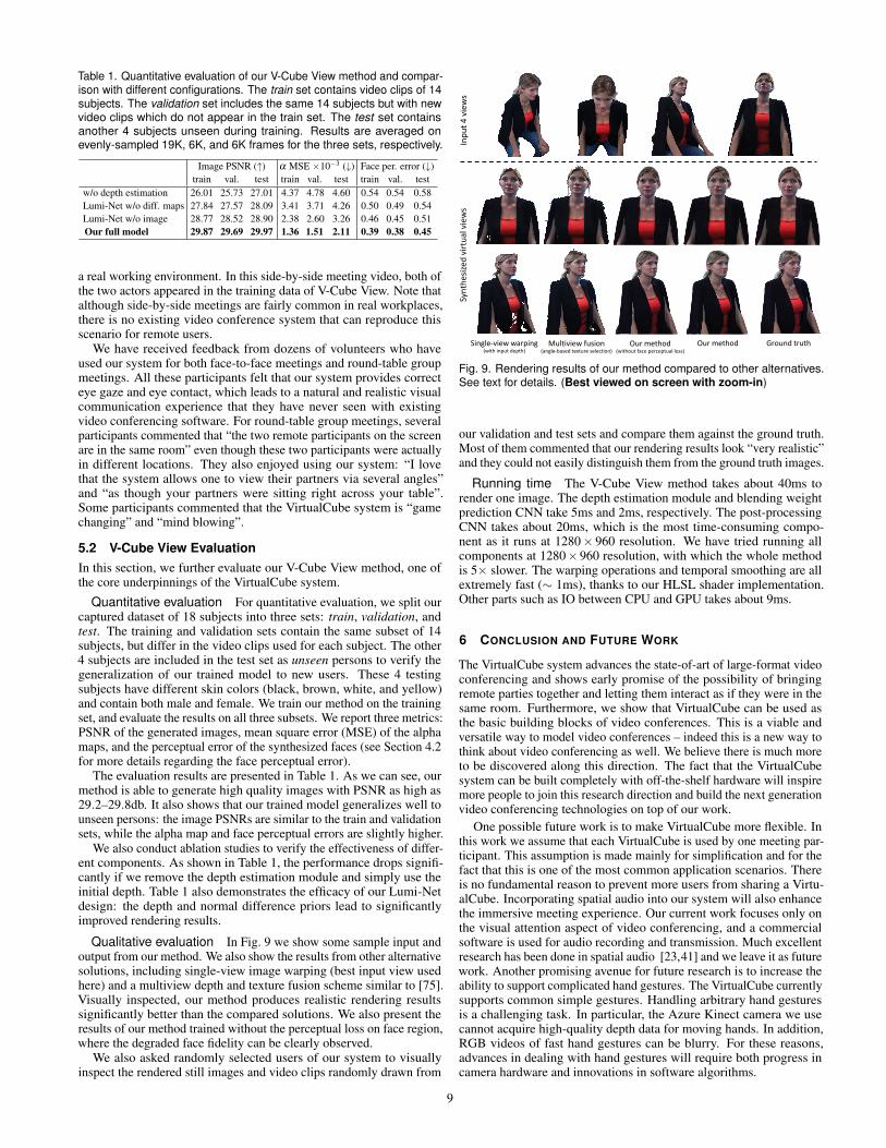
Table 1. Quantitative evaluation of our V-Cube View method and compar-ison with different configurations. The train set contains video clips of 14subjects. The validation set includes the same 14 subjects but with newvideo clips which do not appear in the train set. The test set containsanother 4 subjects unseen during training. Results are averaged onevenly-sampled 19K, 6K, and 6K frames for the three sets, respectively.
Image PSNR (↑) α MSE ×10−3 (↓) Face per. error (↓)train val. test train val. test train val. test
w/o depth estimation 26.01 25.73 27.01 4.37 4.78 4.60 0.54 0.54 0.58Lumi-Net w/o diff. maps 27.84 27.57 28.09 3.41 3.71 4.26 0.50 0.49 0.54Lumi-Net w/o image 28.77 28.52 28.90 2.38 2.60 3.26 0.46 0.45 0.51Our full model 29.87 29.69 29.97 1.36 1.51 2.11 0.39 0.38 0.45
a real working environment. In this side-by-side meeting video, both ofthe two actors appeared in the training data of V-Cube View. Note thatalthough side-by-side meetings are fairly common in real workplaces,there is no existing video conference system that can reproduce thisscenario for remote users.
We have received feedback from dozens of volunteers who haveused our system for both face-to-face meetings and round-table groupmeetings. All these participants felt that our system provides correcteye gaze and eye contact, which leads to a natural and realistic visualcommunication experience that they have never seen with existingvideo conferencing software. For round-table group meetings, severalparticipants commented that “the two remote participants on the screenare in the same room” even though these two participants were actuallyin different locations. They also enjoyed using our system: “I lovethat the system allows one to view their partners via several angles”and “as though your partners were sitting right across your table”.Some participants commented that the VirtualCube system is “gamechanging” and “mind blowing”.
5.2 V-Cube View EvaluationIn this section, we further evaluate our V-Cube View method, one ofthe core underpinnings of the VirtualCube system.
Quantitative evaluation For quantitative evaluation, we split ourcaptured dataset of 18 subjects into three sets: train, validation, andtest. The training and validation sets contain the same subset of 14subjects, but differ in the video clips used for each subject. The other4 subjects are included in the test set as unseen persons to verify thegeneralization of our trained model to new users. These 4 testingsubjects have different skin colors (black, brown, white, and yellow)and contain both male and female. We train our method on the trainingset, and evaluate the results on all three subsets. We report three metrics:PSNR of the generated images, mean square error (MSE) of the alphamaps, and the perceptual error of the synthesized faces (see Section 4.2for more details regarding the face perceptual error).
The evaluation results are presented in Table 1. As we can see, ourmethod is able to generate high quality images with PSNR as high as29.2–29.8db. It also shows that our trained model generalizes well tounseen persons: the image PSNRs are similar to the train and validationsets, while the alpha map and face perceptual errors are slightly higher.
We also conduct ablation studies to verify the effectiveness of differ-ent components. As shown in Table 1, the performance drops signifi-cantly if we remove the depth estimation module and simply use theinitial depth. Table 1 also demonstrates the efficacy of our Lumi-Netdesign: the depth and normal difference priors lead to significantlyimproved rendering results.
Qualitative evaluation In Fig. 9 we show some sample input andoutput from our method. We also show the results from other alternativesolutions, including single-view image warping (best input view usedhere) and a multiview depth and texture fusion scheme similar to [75].Visually inspected, our method produces realistic rendering resultssignificantly better than the compared solutions. We also present theresults of our method trained without the perceptual loss on face region,where the degraded face fidelity can be clearly observed.
We also asked randomly selected users of our system to visuallyinspect the rendered still images and video clips randomly drawn from
Inpu
t 4 views
Synthe
sized
virtua
l views
Single‐view warping(with input depth)
Multiview fusion(angle‐based texture selection)
Our method Ground truthOur method(without face perceptual loss)
Fig. 9. Rendering results of our method compared to other alternatives.See text for details. (Best viewed on screen with zoom-in)
our validation and test sets and compare them against the ground truth.Most of them commented that our rendering results look “very realistic”and they could not easily distinguish them from the ground truth images.
Running time The V-Cube View method takes about 40ms torender one image. The depth estimation module and blending weightprediction CNN take 5ms and 2ms, respectively. The post-processingCNN takes about 20ms, which is the most time-consuming compo-nent as it runs at 1280× 960 resolution. We have tried running allcomponents at 1280×960 resolution, with which the whole methodis 5× slower. The warping operations and temporal smoothing are allextremely fast (∼ 1ms), thanks to our HLSL shader implementation.Other parts such as IO between CPU and GPU takes about 9ms.
6 CONCLUSION AND FUTURE WORK
The VirtualCube system advances the state-of-art of large-format videoconferencing and shows early promise of the possibility of bringingremote parties together and letting them interact as if they were in thesame room. Furthermore, we show that VirtualCube can be used asthe basic building blocks of video conferences. This is a viable andversatile way to model video conferences – indeed this is a new way tothink about video conferencing as well. We believe there is much moreto be discovered along this direction. The fact that the VirtualCubesystem can be built completely with off-the-shelf hardware will inspiremore people to join this research direction and build the next generationvideo conferencing technologies on top of our work.
One possible future work is to make VirtualCube more flexible. Inthis work we assume that each VirtualCube is used by one meeting par-ticipant. This assumption is made mainly for simplification and for thefact that this is one of the most common application scenarios. Thereis no fundamental reason to prevent more users from sharing a Virtu-alCube. Incorporating spatial audio into our system will also enhancethe immersive meeting experience. Our current work focuses only onthe visual attention aspect of video conferencing, and a commercialsoftware is used for audio recording and transmission. Much excellentresearch has been done in spatial audio [23,41] and we leave it as futurework. Another promising avenue for future research is to increase theability to support complicated hand gestures. The VirtualCube currentlysupports common simple gestures. Handling arbitrary hand gesturesis a challenging task. In particular, the Azure Kinect camera we usecannot acquire high-quality depth data for moving hands. In addition,RGB videos of fast hand gestures can be blurry. For these reasons,advances in dealing with hand gestures will require both progress incamera hardware and innovations in software algorithms.
9
REFERENCES
[1] O. Alexander, M. Rogers, W. Lambeth, M. Chiang, and P. Debevec. Thedigital emily project: Photoreal facial modeling and animation. In ACMSIGGRAPH 2009 Courses. ACM, 2009.
[2] T. Bagautdinov, C. Wu, T. Simon, F. Prada, T. Shiratori, S.-E. Wei, W. Xu,Y. Sheikh, and J. Saragih. Driving-signal aware full-body avatars. ACMTrans. Graph., 40(4), 2021.
[3] H. Baker, D. Tanguay, I. Sobel, D. Gelb, M. E. Goss, W. B. Culbertson,and T. Malzbender. The coliseum immersive teleconferencing system. InInternational Workshop on Immersive Telepresence, vol. 6, 2002.
[4] S. Beck, A. Kunert, A. Kulik, and B. Froehlich. Immersive group-to-grouptelepresence. IEEE TVCG, 19(4):616–625, 2013.
[5] C. Buehler, M. Bosse, L. McMillan, S. Gortler, and M. Cohen. Unstruc-tured lumigraph rendering. In SIGGRAPH, pp. 425–432. ACM, 2001.
[6] E. Burkov, I. Pasechnik, A. Grigorev, and V. Lempitsky. Neural headreenactment with latent pose descriptors. In CVPR, pp. 13786–13795,2020.
[7] W. A. Buxton, A. J. Sellen, and M. C. Sheasby. Interfaces for multipartyvideoconferences. Video-mediated communication, pp. 385–400, 1997.
[8] G. Chaurasia, S. Duchene, O. Sorkine-Hornung, and G. Drettakis. Depthsynthesis and local warps for plausible image-based navigation. ACMTrans. on Graphics, 32(3):1–12, 2013.
[9] A. Chen, Z. Xu, F. Zhao, X. Zhang, F. Xiang, J. Yu, and H. Su. Mvsnerf:Fast generalizable radiance field reconstruction from multi-view stereo. InICCV, 2021.
[10] D. Chen, G. Hua, F. Wen, and J. Sun. Supervised transformer network forefficient face detection. In ECCV, pp. 122–138, 2016.
[11] D. Chen, S. Ren, Y. Wei, X. Cao, and J. Sun. Joint cascade face detectionand alignment. In ECCV, pp. 109–122, 2014.
[12] L. Chen, R. K. Maddox, Z. Duan, and C. Xu. Hierarchical cross-modaltalking face generation with dynamic pixel-wise loss. In CVPR, pp. 7832–7841, 2019.
[13] M. Chen. Leveraging the asymmetric sensitivity of eye contact for video-conference. In SIGCHI, p. 49–56, 2002.
[14] I. Choi, O. Gallo, A. Troccoli, M. H. Kim, and J. Kautz. Extreme viewsynthesis. In ICCV, pp. 7781–7790, 2019.
[15] A. Collet, M. Chuang, P. Sweeney, D. Gillett, D. Evseev, D. Calabrese,H. Hoppe, A. Kirk, and S. Sullivan. High-quality streamable free-viewpoint video. ACM Trans. on Graphics, 34(4):1–13, 2015.
[16] P. E. Debevec, C. J. Taylor, and J. Malik. Modeling and rendering archi-tecture from photographs: A hybrid geometry-and image-based approach.In SIGGRAPH, pp. 11–20. ACM, 1996.
[17] M. Dou, S. Khamis, Y. Degtyarev, P. Davidson, S. R. Fanello, A. Kowdle,S. O. Escolano, C. Rhemann, D. Kim, J. Taylor, et al. Fusion4d: Real-timeperformance capture of challenging scenes. ACM Trans. on Graphics,35(4):1–13, 2016.
[18] M. Elgharib, M. Mendiratta, J. Thies, M. Niessner, H.-P. Seidel, A. Tewari,V. Golyanik, and C. Theobalt. Egocentric videoconferencing. ACM Trans.on Graphics, 39(6), 2020.
[19] J. Flynn, M. Broxton, P. Debevec, M. DuVall, G. Fyffe, R. Overbeck,N. Snavely, and R. Tucker. Deepview: View synthesis with learnedgradient descent. In CVPR, pp. 2367–2376, 2019.
[20] J. Flynn, I. Neulander, J. Philbin, and N. Snavely. Deepstereo: Learningto predict new views from the world’s imagery. In CVPR, pp. 5515–5524,2016.
[21] O. Fried, A. Tewari, M. Zollhofer, A. Finkelstein, E. Shechtman, D. B.Goldman, K. Genova, Z. Jin, C. Theobalt, and M. Agrawala. Text-basedediting of talking-head video. ACM Trans. on Graphics, 38(4), 2019.
[22] H. Fuchs, A. State, and J.-C. Bazin. Immersive 3d telepresence. Computer,47(7):46–52, 2014.
[23] T. A. Garner. Echoes of Other Worlds: Sound in Virtual Reality: Past,Present and Future. Springer, 2017.
[24] J. Geng, T. Shao, Y. Zheng, Y. Weng, and K. Zhou. Warp-guided gans forsingle-photo facial animation. ACM Trans. on Graphics, 37(6), 2018.
[25] S. J. Gibbs, C. Arapis, and C. J. Breiteneder. Teleport–towards immersivecopresence. Multimedia Systems, 7(3):214–221, 1999.
[26] D. Giger, J.-C. Bazin, C. Kuster, T. Popa, and M. Gross. Gaze correctionwith a single webcam. In IEEE International Conference on Multimediaand Expo (ICME), pp. 1–6, 2014.
[27] S. J. Gortler, R. Grzeszczuk, R. Szeliski, and M. F. Cohen. The lumigraph.In SIGGRAPH, pp. 43–54. ACM, 1996.
[28] D. Gotsch, X. Zhang, T. Merritt, and R. Vertegaal. Telehuman2: A
cylindrical light field teleconferencing system for life-size 3d humantelepresence. In CHI, vol. 18, p. 552, 2018.
[29] M. Gross, S. Wurmlin, M. Naef, E. Lamboray, C. Spagno, A. Kunz,E. Koller-Meier, T. Svoboda, L. Van Gool, S. Lang, K. Strehlke, A. V.Moere, and O. Staadt. Blue-c: A spatially immersive display and 3d videoportal for telepresence. ACM Trans. on Graphics, 22(3):819–827, 2003.
[30] K. Gu, Y. Zhou, and T. Huang. Flnet: Landmark driven fetching andlearning network for faithful talking facial animation synthesis. In AAAI,vol. 34, pp. 10861–10868, 2020.
[31] K. Guo, F. Xu, T. Yu, X. Liu, Q. Dai, and Y. Liu. Real-time geometry,albedo, and motion reconstruction using a single rgb-d camera. ACMTrans. on Graphics, 36(4), 2017.
[32] S. Ha, M. Kersner, B. Kim, S. Seo, and D. Kim. Marionette: Few-shotface reenactment preserving identity of unseen targets. In AAAI, vol. 34,pp. 10893–10900, 2020.
[33] R. Hartley and A. Zisserman. Multiple View Geometry in Computer Vision.Cambridge University Press, 2003.
[34] C.-F. Hsu, Y.-S. Wang, C.-L. Lei, and K.-T. Chen. Look at me! correctingeye gaze in live video communication. ACM Trans. Multimedia Comput.Commun. Appl., 15(2), 2019.
[35] P. Isola, J.-Y. Zhu, T. Zhou, and A. A. Efros. Image-to-image translationwith conditional adversarial networks. In CVPR, pp. 1125–1134, 2017.
[36] J. Johnson, A. Alahi, and L. Fei-Fei. Perceptual losses for real-time styletransfer and super-resolution. In ECCV, pp. 694–711, 2016.
[37] A. Jones, M. Lang, G. Fyffe, X. Yu, J. Busch, I. McDowall, M. Bolas, andP. Debevec. Achieving eye contact in a one-to-many 3d video teleconfer-encing system. ACM Trans. on Graphics, 28(3), 2009.
[38] N. K. Kalantari, T.-C. Wang, and R. Ramamoorthi. Learning-based viewsynthesis for light field cameras. ACM Trans. on Graphics, 35(6):1–10,2016.
[39] P. Kauff and O. Schreer. An immersive 3d video-conferencing systemusing shared virtual team user environments. In International Conferenceon Collaborative Virtual Environments, pp. 105–112, 2002.
[40] H. Kim, P. Garrido, A. Tewari, W. Xu, J. Thies, M. Nießner, P. Perez,C. Richardt, M. Zollofer, and C. Theobalt. Deep video portraits. ACMTrans. on Graphics, 37(4):163, 2018.
[41] H. Kim, L. Remaggi, P. J. Jackson, and A. Hilton. Immersive spatial audioreproduction for vr/ar using room acoustic modelling from 360 images. InIEEE VR, pp. 120–126, 2019.
[42] M. Kuechler and A. Kunz. Holoport-a device for simultaneous video anddata conferencing featuring gaze awareness. In IEEE VR, pp. 81–88, 2006.
[43] C. Kuster, T. Popa, J.-C. Bazin, C. Gotsman, and M. Gross. Gaze correc-tion for home video conferencing. ACM Trans. on Graphics, 31(6):1–6,2012.
[44] C. Kuster, T. Popa, C. Zach, C. Gotsman, M. H. Gross, P. Eisert, J. Horneg-ger, and K. Polthier. Freecam: A hybrid camera system for interactivefree-viewpoint video. In VMV, pp. 17–24, 2011.
[45] C. Kuster, N. Ranieri, H. Zimmer, J.-C. Bazin, C. Sun, T. Popa, M. Gross,et al. Towards next generation 3d teleconferencing systems. In 3DTV-Conference: The True Vision-Capture, Transmission and Display of 3DVideo (3DTV-CON), pp. 1–4, 2012.
[46] M. Levoy and P. Hanrahan. Light field rendering. In SIGGRAPH, pp.31–42. ACM, 1996.
[47] C. Lipski, C. Linz, K. Berger, A. Sellent, and M. Magnor. Virtual videocamera: Image-based viewpoint navigation through space and time. InComputer Graphics Forum, vol. 29, pp. 2555–2568, 2010.
[48] S. Lombardi, T. Simon, J. Saragih, G. Schwartz, A. Lehrmann, andY. Sheikh. Neural volumes: Learning dynamic renderable volumes fromimages. ACM Trans. on Graphics, 38(4), 2019.
[49] K. Luo, T. Guan, L. Ju, H. Huang, and Y. Luo. P-mvsnet: Learningpatch-wise matching confidence aggregation for multi-view stereo. InICCV, pp. 10452–10461, 2019.
[50] L. Ma, Z. Xie, Z. Yang, J. Xue, Y. Miao, W. Cui, W. Hu, F. Yang, L. Zhang,and L. Zhou. Rammer: Enabling holistic deep learning compiler optimiza-tions with rtasks. In USENIX Symposium on Operating Systems Designand Implementation, pp. 881–897, 2020.
[51] A. Maimone and H. Fuchs. Encumbrance-free telepresence system withreal-time 3d capture and display using commodity depth cameras. InISMAR, pp. 137–146, 2011.
[52] X. Mao, Q. Li, H. Xie, R. Y. Lau, Z. Wang, and S. Paul Smolley. Leastsquares generative adversarial networks. In ICCV, pp. 2794–2802, 2017.
[53] W. Matusik and H. Pfister. 3d tv: A scalable system for real-time acqui-sition, transmission, and autostereoscopic display of dynamic scenes. In
10
SIGGRAPH, p. 814–824. ACM, 2004.[54] B. Mildenhall, P. P. Srinivasan, M. Tancik, J. T. Barron, R. Ramamoorthi,
and R. Ng. Nerf: Representing scenes as neural radiance fields for viewsynthesis. In ECCV, pp. 405–421, 2020.
[55] K. Nagano, J. Seo, J. Xing, L. Wei, Z. Li, S. Saito, A. Agarwal, J. Fursund,and H. Li. Pagan: Real-time avatars using dynamic textures. ACM Trans.on Graphics, 37(6), 2018.
[56] H. Nagata, D. Mikami, H. Miyashita, K. Wakayama, and H. Takada.Virtual reality technologies in telecommunication services. Journal ofInformation Processing, 25:142–152, 2017.
[57] D. Nguyen and J. Canny. Multiview: spatially faithful group video confer-encing. In SIGCHI, pp. 799–808, 2005.
[58] Y. Nirkin, Y. Keller, and T. Hassner. Fsgan: Subject agnostic face swappingand reenactment. In ICCV, pp. 7184–7193, 2019.
[59] S. Ohl. Tele-immersion concepts. IEEE TVCG, 24(10):2827–2842, 2018.[60] K. Olszewski, Z. Li, C. Yang, Y. Zhou, R. Yu, Z. Huang, S. Xiang, S. Saito,
P. Kohli, and H. Li. Realistic dynamic facial textures from a single imageusing gans. In ICCV, pp. 5439–5448, 2017.
[61] K. Olszewski, J. J. Lim, S. Saito, and H. Li. High-fidelity facial and speechanimation for vr hmds. ACM Trans. Graphics, 35(6), 2016.
[62] S. Orts-Escolano, C. Rhemann, S. Fanello, W. Chang, A. Kowdle, Y. Degt-yarev, D. Kim, P. L. Davidson, S. Khamis, M. Dou, V. Tankovich, C. Loop,Q. Cai, P. A. Chou, S. Mennicken, J. Valentin, V. Pradeep, S. Wang, S. B.Kang, P. Kohli, Y. Lutchyn, C. Keskin, and S. Izadi. Holoportation: Virtual3d teleportation in real-time. In UIST, p. 741–754. ACM, 2016.
[63] E. Penner and L. Zhang. Soft 3d reconstruction for view synthesis. ACMTrans. on Graphics, 36(6):1–11, 2017.
[64] C. Pluss, N. Ranieri, J.-C. Bazin, T. Martin, P.-Y. Laffont, T. Popa, andM. Gross. An immersive bidirectional system for life-size 3d communi-cation. In International Conference on Computer Animation and SocialAgents, p. 89–96. ACM, 2016.
[65] R. Raskar, G. Welch, M. Cutts, A. Lake, L. Stesin, and H. Fuchs. Theoffice of the future: A unified approach to image-based modeling andspatially immersive displays. In SIGGRAPH, p. 179–188. ACM, 1998.
[66] O. Russakovsky, J. Deng, H. Su, J. Krause, S. Satheesh, S. Ma, Z. Huang,A. Karpathy, A. Khosla, M. Bernstein, et al. Imagenet large scale visualrecognition challenge. In IJCV, vol. 115, pp. 211–252, 2015.
[67] A. Sadagic, H. Towles, L. Holden, K. Daniilidis, and B. Zeleznik. Tele-immersion portal: Towards an ultimate synthesis of computer graphics andcomputer vision systems. In Annual International Workshop on Presence,pp. 21–23, 2001.
[68] S. Sengupta, V. Jayaram, B. Curless, S. M. Seitz, and I. Kemelmacher-Shlizerman. Background matting: The world is your green screen. InCVPR, pp. 2291–2300, 2020.
[69] J. Shi, X. Jiang, and C. Guillemot. Learning fused pixel and feature-basedview reconstructions for light fields. In CVPR, pp. 2555–2564, 2020.
[70] K. Simonyan and A. Zisserman. Very deep convolutional networks forlarge-scale image recognition. In ICML, 2015.
[71] M. T. Tausif, R. Weaver, and S. W. Lee. Towards enabling eye contact andperspective control in video conference. In UIST Adjunct, p. 96–98. ACM,2020.
[72] J. Thies, M. Zollhofer, M. Nießner, L. Valgaerts, M. Stamminger, andC. Theobalt. Real-time expression transfer for facial reenactment. ACMTrans. on Graphics, 34(6), 2015.
[73] J. Thies, M. Zollhofer, M. Stamminger, C. Theobalt, and M. Niessner.Face2face: Real-time face capture and reenactment of rgb videos. InCVPR, 2016.
[74] J. Thies, M. Zollhofer, M. Stamminger, C. Theobalt, and M. Nießner.Facevr: Real-time gaze-aware facial reenactment in virtual reality. ACMTrans. on Graphics, 37(2), 2018.
[75] E. Tola, C. Zhang, Q. Cai, and Z. Zhang. Virtual view generation with ahybrid camera array. Technical report, 2009.
[76] H. Towles, W. chao Chen, R. Yang, S. uok Kum, H. F. N. Kelshikar, J. Mul-ligan, K. Daniilidis, H. Fuchs, C. C. Hill, N. K. J. Mulligan, L. Holden,B. Zeleznik, A. Sadagic, and J. Lanier. 3d tele-collaboration over internet2.In International Workshop on Immersive Telepresence, 2002.
[77] Q. Wang, Z. Wang, K. Genova, P. P. Srinivasan, H. Zhou, J. T. Barron,R. Martin-Brualla, N. Snavely, and T. Funkhouser. Ibrnet: Learningmulti-view image-based rendering. In CVPR, pp. 4690–4699, 2021.
[78] T.-C. Wang, M.-Y. Liu, A. Tao, G. Liu, J. Kautz, and B. Catanzaro. Few-shot video-to-video synthesis. In NeurIPS, 2019.
[79] T.-C. Wang, A. Mallya, and M.-Y. Liu. One-shot free-view neural talking-head synthesis for video conferencing. In CVPR, 2021.
[80] S.-E. Wei, J. Saragih, T. Simon, A. W. Harley, S. Lombardi, M. Perdoch,A. Hypes, D. Wang, H. Badino, and Y. Sheikh. Vr facial animation viamultiview image translation. ACM Trans. Graph., 38(4), 2019.
[81] W.-C. Wen, H. Towles, L. Nyland, G. Welch, and H. Fuchs. Toward acompelling sensation of telepresence: demonstrating a portal to a distant(static) office. In IEEE Conference on Visualization, pp. 327–333, 2000.
[82] S. Xu, J. Yang, D. Chen, F. Wen, Y. Deng, Y. Jia, and X. Tong. Deep 3dportrait from a single image. In CVPR, pp. 7710–7720, 2020.
[83] Y. Yao, Z. Luo, S. Li, T. Fang, and L. Quan. Mvsnet: Depth inference forunstructured multi-view stereo. In ECCV, pp. 767–783, 2018.
[84] A. Yu, V. Ye, M. Tancik, and A. Kanazawa. Pixelnerf: Neural radiancefields from one or few images. In CVPR, pp. 4578–4587, 2021.
[85] E. Zakharov, A. Ivakhnenko, A. Shysheya, and V. Lempitsky. Fast bi-layerneural synthesis of one-shot realistic head avatars. In ECCV, pp. 524–540,2020.
[86] E. Zakharov, A. Shysheya, E. Burkov, and V. Lempitsky. Few-shot ad-versarial learning of realistic neural talking head models. In ICCV, pp.9459–9468, 2019.
[87] C. Zhang, Q. Cai, P. A. Chou, Z. Zhang, and R. Martin-Brualla. Viewport:A distributed, immersive teleconferencing system with infrared dot pattern.IEEE MultiMedia, 20(1):17–27, 2013.
[88] H. Zhou, Y. Liu, Z. Liu, P. Luo, and X. Wang. Talking face generation byadversarially disentangled audio-visual representation. In AAAI, vol. 33,pp. 9299–9306, 2019.
[89] T. Zhou, R. Tucker, J. Flynn, G. Fyffe, and N. Snavely. Stereo magnifi-cation: learning view synthesis using multiplane images. ACM Trans. onGraphics, 37(4):1–12, 2018.
[90] C. L. Zitnick, S. B. Kang, M. Uyttendaele, S. Winder, and R. Szeliski.High-quality video view interpolation using a layered representation. InSIGGRAPH, pp. 600–608. ACM, 2004.
[91] M. Zollhofer, M. Nießner, S. Izadi, C. Rehmann, C. Zach, M. Fisher,C. Wu, A. Fitzgibbon, C. Loop, C. Theobalt, et al. Real-time non-rigidreconstruction using an rgb-d camera. ACM Trans. on Graphics, 33(4):1–12, 2014.
11


