Embed Size (px)
Citation preview
The 8th International Conference on INFOrmatics and Systems (INFOS2012) - 14-16 May
Computational Intelligence and Multimedia Computing Track
Vision-Based Obstacles Detection for a MobileRobot
Basem M. EIHalawany, Hala M. Abdel-Kader,Adly TagEldeen, Alaa Eldeen Sayed Ahmed
Shoubra Paculty of EngineeringBenha UnIversIty
Cairo, EGYPT
Abstract- Vision-based robot navigation systems allow a
robot to explore and to navigate in its environment in away that facilitates path planning and goal-oriented tasks. Thevision sensor is mainly used for obstacle detection andavoidance, object detection and tracking, and interactionwith users. Usually these systems do not depend solely on visionsensors but use other sensors like sonar and laser range finder.The paper considers an important issue for mobile robotsnavigation. This issue is the detection of obstacles in front of therobot within a corridor. We proposed and evaluated threealgorithms for obstacle detection within a corridorenvironment using image processing techniques.
I. INTRODUCTION
Mobile Robots are now expected to be the next generationfor assisting elderly and disabled persons as they presenthuge contributions in many industrial areas such asproduction lines at factories, surveillance systems, AGVs(autonomous guided vehicles), and indoor cleaning machines.One of the most researched areas in assistive technology isthe development of intelligent wheelchairs. Intelligentwheelchairs are constructed by integrating artificialintelligence methods into a robotic wheelchair which has theability to safely transport users to their desired destination.This work was originally inspired by the need for roboticassistance to contribute in developing an intelligent system toassist users with disabilities in core day-to-day activities.
The final target of this research work is to develop asystem that could be used to control the navigation process ofa mobile robotic platform through an indoor corridor whiledetecting obstacles, avoiding them, avoiding walls, andplanning a shortest path for the robot.
A complete implementation and evaluation are performedfor three obstacle detection algorithms. The first twoalgorithms work by detecting corridor region in front of therobot using the two boundary lines that normally existbetween the walls and the ground. By detecting these twolines we could easily determine the ground region and wecould later detect obstacles within this region only andneglect anything on the walls.
There are many techniques proposed for detecting straightlines on an image for many purposes (power line detection,lane detection [1], etc.) such as Least Squares line fittingMethod, Hough Transform, and Radon Transform. Linefitting can be a time consuming and computationallyinefficient process, especially if there are many of such edgepoints. Therefore, The Hough Transform and the RadonTransform are.
Faculty of Computers and Information - Cairo University
Zaki B. NossairHelwan Faculty of Engineering
Helwan UniversityHelwan, EGYPT
implemented and evaluated in this research for obstacledetectionThe third algorithm uses color segmentation approach todetect the obstacles in the corridor. Each of these threealgorithms generates a grid-based map that could be mergedwith a path planning Algorithm to produce a safe path for therobot to follow.The rest of this paper is organized as follows: section IIexplains the used vision techniques, section III presents theenvironment assumptions for our algorithms, section IVexplains the obstacle detection algorithms, and finally sectionV provide the conclusion.
II. VISION TECHNIQUESThere are many vision techniques have been used for
vision based robot navigation system through the past twodecades. In this research, many image processing techniquesare used in the proposed algorithms such as the edgedetection, Hough Transform, Radon Transform, and ColorSegmentation.
A. Edge Detection
Edge detection is considered a primary method used inmany computer vision systems that greatly reduces theamount of data for the vision system to preserve only themore important structural properties within an image. Edgesin an image consist of either change in luminosity or changein color. One important consideration when using edgedetection is its susceptibility to image noise. Noisy pixelscreate hard edges which introduce false information into thesystem. This problem could be solved using noise reductionfilters and smoothing filters before the edge detectiontechnique is performed to reduce the image noise, therebyreducing any false edge information. There is a large numberof edge finding algorithms in existence [10].
B. Hough Transform
The edge detection techniques tell us where edges are, butnot what their shape are (geometric descriptions like line, arcs,etc.). The Hough Transform [2][3][4] is used to detectstraight lines after edge detection operation. The main idea ofHough transform in line detection is to take intoconsideration the characteristics of the straight line not asimage points x or y, but in terms of its parameters. Tworepresentations for line parameters could be used with Houghtransform. The first one is the slope-intercept form, the slopeparameter (m) and the intercept parameter (c) as in equation(1):
MM-93
The 8th International Conference on INFOrmatics and Systems (INFOS2012) - 14-16 MayComputational Intelligence and Multimedia Computing Track
y = mx +c (1)
The second form that is preferred with the Houghtransform is the one that represent the line as in equation (2):
X cos {} + y sin {} = p (2)
The form in equation (2) is preferred to overcome thedrawback of the first form when vertical lines exist in theimage as the slope parameter (m) will be infinite.
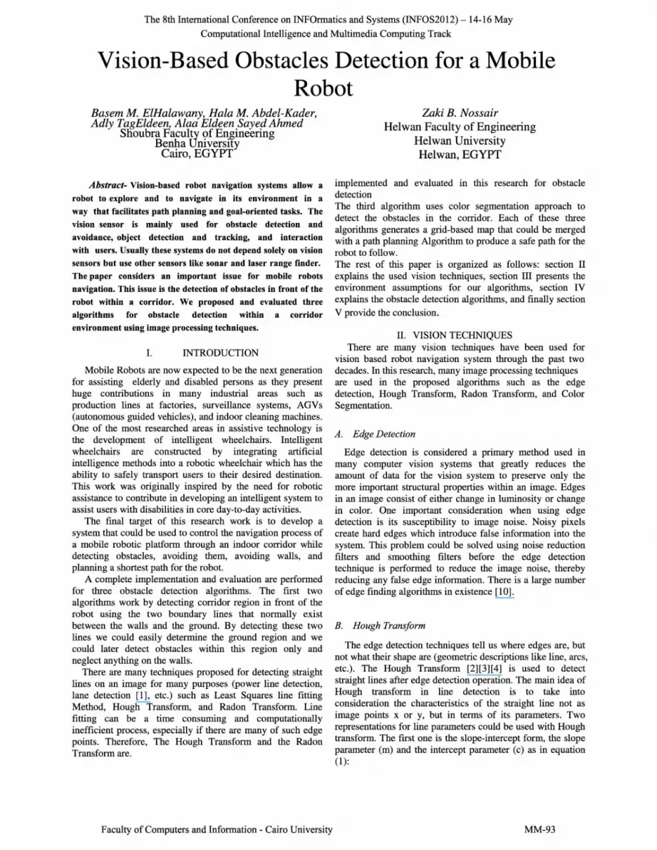
By using equation (2), all lines in the image can betransformed into the Hough space which gives a sinusoidalcurve that is unique for each pixel. The intersection pointbetween two curves in Hough space represents a line segmentin the image space that passes through both pixels. This canbe repeated for all the pixels on the edges in an edge detectedimage as shown in fig.1.
Figure 1. Hough Space.
One important advantage of Hough Transform is itsresistance to noise in the image and its tolerance towardsholes in the detected line. On the other hand, one majordisadvantage of Hough Transform technique for detectingstraight lines is the large memory requirement and slowness.
C. Radon Transform
The Radon Transformation is a fundamental tool which isused in various applications such as radar signals, medicalimaging, character Recognition, and line detection [5][6].
The 2D Radon transformation is the projection of the imageintensity along a radial line oriented at a specific angle asshown in fig.2
Figure 2. Radon Transformation.
Let's suppose we have a 2-D function f(x, y) as shown infig.2, By integrating along the line, whose normal vector is intheta(8) direction, we get a g(s, 8) function in equation (3)which is the projection of the 2D function f(x,y) on the axiss of edirection and ()is the Dirac-delta function.
g(s,B)=f(x,y). 8(xcos B+ysin B-s)dxdy (3)
As in Hough transform, the Radon operator maps from thespatial domain (x,y) to the projection domain (s, 8), in whicheach point corresponds to a straight line in the spatial domain.Using this property, we used Radon transform for detectingstraight lines describing the road boundaries through thecorridor.
D. Color Segmentation
One of the most widely used methods for obstacle detectionis the segmentation of the area in front of the robot usingvision techniques. Segmentation in image analysis is thedivision of an image into homogeneous areas of interest
Faculty of Computers and Information - Cairo University
based on some chosen image features [7][11]. A number ofdifferent features can be used for segmentation, like color,and texture. There are many segmentation approaches thathave been implemented within the past decades such as edgedetection segmentation, Histogram Threshold, Region-Basedsegmentation, Fuzzy and Probabilistic techniques, Clusteringtechniques, and Color segmentation techniques.
Color is a highly relevant feature for segmentation betweenmovable and non- movable areas in the corridor region,which we are dealing with, in our scenario. There are twosteps required for color region segmentation, the first isthresholding all pixels which share the same color and thengrouping those pixels together, throwing out any that don'tseem to be in same area as majority of the pixels (regiongrowing). However we need a representation of color thathighlights the differences between the regions of interest.
One of the primary components to think about to get thepixels that share the same color is to select the appropriatecolor space (also called color model or color system) [8][9].Color spaces are three-dimensional coordinate systems thatdefine colors. The most commonly used models are RGB,HSV, YCbCr, L*a*b*, and CIE L*u*v*. There is noagreement on which is the best.
III. ENVIRONMENT ASSUMPTIONS
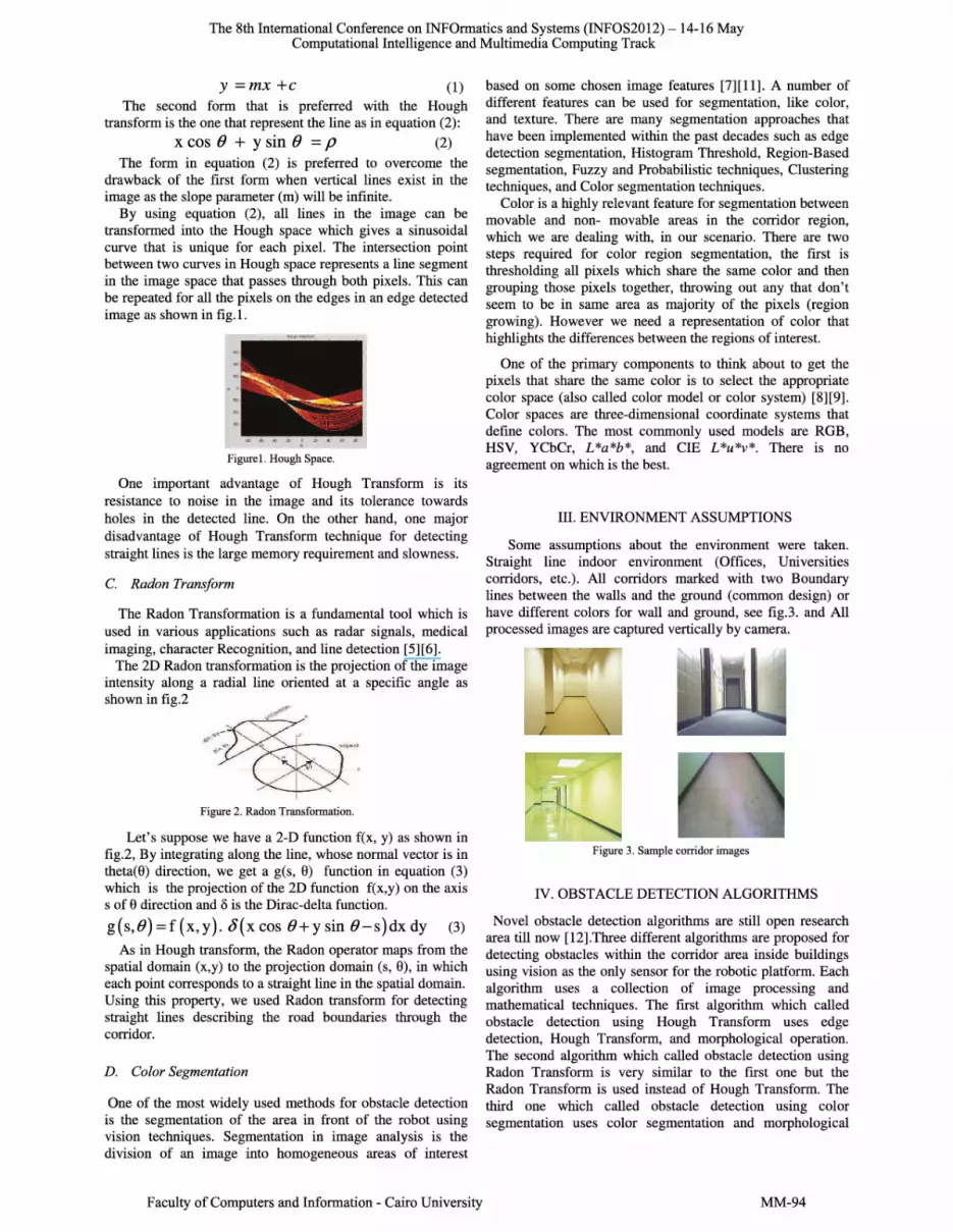
Some assumptions about the environment were taken.Straight line indoor environment (Offices, Universitiescorridors, etc.). All corridors marked with two Boundarylines between the walls and the ground (common design) orhave different colors for wall and ground, see fig.3. and Allprocessed images are captured vertically by camera.
Figure 3. Sample corridor images
IV. OBSTACLE DETECTION ALGORITHMS
Novel obstacle detection algorithms are still open researcharea till now [12].Three different algorithms are proposed fordetecting obstacles within the corridor area inside buildingsusing vision as the only sensor for the robotic platform. Eachalgorithm uses a collection of image processing andmathematical techniques. The first algorithm which calledobstacle detection using Hough Transform uses edgedetection, Hough Transform, and morphological operation.The second algorithm which called obstacle detection usingRadon Transform is very similar to the first one but theRadon Transform is used instead of Hough Transform. Thethird one which called obstacle detection using colorsegmentation uses color segmentation and morphological
MM-94

The 8th International Conference on INFOrmatics and Systems (INFOS2012) - 14-16 MayComputational Intelligence and Multimedia Computing Track
operations. In the next sub-sections, these algorithms arepresented with the results obtained for each algorithm.
The first and second algorithms need to perform edgedetection on the gray image of the area in front of the robot.Therefore, we implemented and tested many methods of edgedetection using Matlab to get suitable results for next stagesof our algorithms. Sobel, Prewitt, Roberts, and Canny edgedetectors are tested. Canny edge detector offered the bestresults. This was not a surprise as canny edge detection givesthin lines for its edges by using non-maximal suppression.Canny also utilizes hysteresis with thresholding to link strongand weak edge pixels. Therefore, a decision is taken to makeit as the edge detector operator through this research.
Figure.4 represents the results of using canny's edgedetector on image samples of the real corridor where ouralgorithm is tested. The values of three parameters of cannyalgorithm (Sigma, Max Threshold "Thmax", and MinThreshold level "Thmin") are changed to get the suitableparameters to be used.
After examining the results of using different values of thethree parameters, the values shown in table 1 were foundmore suitable as they extracted the important details neededto detect the two corridor lines and ignored unimportantdetails in the captured samples of the corridor.
TABLE I. SELECTED CANNY'S PARAMETERS
Figure 4. Results of Canny Edge Detector
A. Obstacle Detection using Hough TransformThis algorithm uses many image processing functions to
detect the obstacles within the corridor area as seen in theflowchart given in fig.5.
Faculty of Computers and Information - Cairo University
Read Colored-Image
Colored-to-Grayscale Conversion
Perform Edge Detection
Detect All Lines Using Hough-Transform
Select specific lines of the corridor
Get Area between the two lines
Threshold the area (to aet obstacles)
Perform Morphological Operations
Build a grid-based Map
Figure 5. Flowchart for obstacle detection using Hough transform.
Through this section, an explanation is introduced for theeach step of the flowchart in fig.5 which is supported bysamples of the obtained results.
a. Reading the color image from samples folder orgetting real-time images from the camera attached tothe robotic platform.
b. Convert the color images into grayscale. Fig.6 showsboth the original colored and the converted one intograyscale.
Figure 6. Original colored and Grayscale image
c. Get the edge points of the grayscale image. Theresults shown in fig.? are done using the canny'sedge with the selected parameters in table 1.
II:.:::.::::-" - ....~::..::.:::.:
.:.-)
Figure 7. Edge points for the image
d. Reduce the number of edge points by eliminating theupper edge points between the wall and wall-floorboundary. This reduces the processing time for nextHough calculation stage as shown in table 2. Theremaining pixels are shown in fig.8
e. Calculating Hough Transform Parameters for thenew edge points to get a voting matrix for thecandidate straight lines.
MM-95

The 8th International Conference on INFOrmatics and Systems (INFOS2012) - 14-16 MayComputational Intelligence and Multimedia Computing Track
TABLE II. TIME REDUCTION BY REMOVING UPPER PIXELS
Sample Time without Time using % reductionNo using reduction reduction in time
1 0.1452 0.1130 22.17%2 0.1115 0.1030 7.6%3 0.1319 0.1175 10.917%4 0.1256 0.1136 9.5541%5 0.1517 0.1358 10.4812%6 0.1510 0.1329 11.9867%7 0.1338 0.1332 0.4484%8 0.1394 0.1092 21.664%9 0.1373 0.1067 22.2869%
Figure 8. Reduced edge points.
f. Calculate the highest values in the voting matrix (oraccumulator) which represent the candidate linepieces and plot as shown in fig.9. Line pieces ingreen, starting points of the piece in yellow, andending points in blue.
Figure 9. Candidate straight line pieces
g. Filter the candidate Hough lines based on theorientation angle to select the two-corridor Lines.Vertical and near vertical Lines are removed fromthe list and the rest are divided into right and leftcategory.
h. Select only one line from each category (if one ofthe two categories has no lines on it this means thatthe robot is facing one of the two corridor walls orheading with angle that shows only one line as infig.10.b.
i, Complete these two line pieces to get theintersections with the image boundaries andintersection between them (if any within the imagerange).
navigation. Fig.11 shows many samples fromdifferent images.
Figure 11. Mask of the corridor region
k, Perform a threshold for the selected area whichconverts it to binary image. Then follow this bymorphological operations to detect obstacles withinthis region
Figure 12. Binary image of the corridor region
I. Label the connected components in the binary imageinto different object regions and get some propertiesof each object such as the "centroid" marked withBLUE asterisk and the RED "Bounding Box"around its area as shown in fig.13.
Figure 13. Corridor region with marked obstacle
m. Use the previous results shown in fig.13 to build agrid-based map that could be used later by pathplanning algorithms. This could be done byquantizing the image resulted from earlier steps.Fig.14 shows a sample of such map created by oursystem that is followed a path planning performedusing A* algorithm.
Figure 14. Grid-based Map
Figure.15 represents more samples from the real corridorat the left side and the detected obstacles at the right side.
B. Obstacle Detection using Radon Transform
j.
Figurel0. corridor lines
Build a mask for the corridor region based on thedata of the two lines and intersection points (i.e.Region of Interest). This area shows the region inthe image that need to be processed to get theobstacles and free region for movement and
Faculty of Computers and Information - Cairo University
In this algorithm, we use the same steps on the flowchartof obstacle detection using Hough Transform but we replacethe process of detecting line segments using Hough transformby the use of Radon Transform. The radon transform is usedto implement the function of Hough transform to detect linesegments. Then we analyze the resultant possible linesegments to get the right and left corridor lines that were used
MM-96

The 8th International Conference on INFOrmatics and Systems (INFOS2012) - 14-16 MayComputational Intelligence and Multimedia Computing Track
earlier as boundaries. Figure.16 shows samples from theseresults. We use these two lines for corridor region detectionand we could apply the morphological operation to detect theobstacles within it.
Figure 15. More Results for Obstacle Detection using Hough Transform
This algorithm provides us with the same results obtainedby the method of obstacle detection using Hough transform.The algorithm detects the obstacles correctly but it is slowerthan first method because the integration process in radontransform consumes more time as shown in table 3 afterperforming both methods on the same image samples.
C. Obstacle Detection using Color Segmentation
This algorithm focuses on color image segmentation using acolor thresholding technique to differentiate betweenmovable free areas of the corridor ground and the obstacleswithin it.
In these experiments, we investigated two color modelsother than the RGB to determine the best one for detectingthe objects within the corridor.
RGB is the most widely used color model in computerhardware and cameras. This model represents the color as athree independent components red, green, and blue. RGB isan additive model and combination of R, G and B valuesgenerates a specific color. This model is hard to comprehendfor humans because the human way of understanding anddescribing color is not based on combination of red, green,and blue. In addition, The RGB is perceptually non-uniform.
Faculty of Computers and Information - Cairo University
This means that the difference of two RGB values does notcorrespond to the perceptual difference [9].
TABLE III. PROCESSING TIME FOR MANY SAMPLES USING
HOUGH TRANSFORM AND RADON TRANSFORM
Sample Hough Time Radon TimeNo (second) (second)1 0.1352 0.19502 0.1342 0.20993 0.1221 0.17984 0.1149 0.1643
Figure16. Radon Transform Line Detection Results
HSV color model is suitable for human description ofcolors as we use three parameters to describe the color by itsHue (H), Saturation (s), and Value (V).The Hue is attributethat describe the color purity or tint (pure red, yellow, orgreen) whereas saturation is a measure of the degree to whicha pure color is diluted by white light, (e.g. red is saturated andpink is less saturated). The value defines how bright the coloris or the quantity of light received by the sensor. The HSVcolor model overcomes the limitations of the RGB colorspace because it describes human vision quite accurately andbecause it mainly uses only the hue to describe color. Theother two components (i.e., saturation and value) aresignificant only when describing black, white, gray, and thevarious shades of the colors. HSV model has somedisadvantages such as the complexity in calculations and theHue is undefined for gray. Equation 4 describes how to getthe Hue (H) value from RGB.
H [3 (G - B) ]
= tan (4)(R - G) + (R - B)
D. Color Segmentation in HSV Space
A sample from the area in front of the robot is captured inHSV space. We use the Hue, Saturation and a combination ofHue and Saturation as a threshold value to get the best results.Figure.17 shows samples of the results which prove that HSVis not valid when dealing with corridor having a gray color.When using both Hue and Saturation together forthresholding the corridor area, better results are obtained butthe obstacles could not be extracted alone for gray grounds.Some false obstacles are detected also due to HSV failure torepresent gray floor. Therefore, another color space is needed
MM-97

The 8th International Conference on INFOrmatics and Systems (INFOS2012) - 14-16 MayComputational Intelligence and Multimedia Computing Track
(5)
overcome the weak point of HSV model for representing thegray objects.
Figure 17. Color thresholding in HSV
E. Color Segmentation in YCbCr Space
The YCbCr color space is widely used for digital video.In this model, luminance information is stored as a singlecomponent (Y), and chrominance information is stored astwo color-difference components (Cb and Cr). Cb representsthe difference between the blue component and a luminancevalue. Cr represents the difference between the redcomponent and a luminance value. The conversion fromRGB to YCbCr illustrated in equation 5.
[
y ] [0.257 0.504 0.098] [R] [16]Cb == -0.148 - 0.291 0.439 G + 128
Cr 0.439 - 0.368 - 0.071 B 128Our Obstacle Detection using color segmentation
algorithm benefits from the efficient YCbCr model. Thisalgorithm performs a color-space conversion to YCbCrsystem followed by a color thresholding on the convertedimage by comparing each pixel to a sample taken from thecorridor area in front of the robot. Comparison is performedusing the two color channels of the YCbCr system (Cb & Cr).As shown in fig.18, the algorithm could easily perform colorthresholding for the gray corridor region.
This algorithm could easily detect doors within thecorridor by the same algorithm as shown in fig.18.e. This willbe easier if the building environment be prepared for robotnavigation by using distinct colors for corridors, walls, anddoors. We advice also that each door be marked with distinctcolored mark to distinguish between different rooms.
V. CONCLUSION
Obstacle detection is a very important issue in the field ofrobot navigation and path planning. The process of detectingthe obstacles in the way of the mobile robotic platform couldbe performed using many sensors such as laser rang finders,Infrared sensors, and vision sensors. By improving the resultsobtained by each type of these sensors, we could make afusion of these results to get a robust obstacle detectionprocess that facilitate the goal-oriented tasks of the robot.
Due to the nature of the problem, it is hard to objectivelyevaluate the performance of the proposed methods. To saywhere the clear movable area starts and ends is a matter ofdefinition and will probably vary depending on the observer.
Faculty of Computers and Information - Cairo University
It is hence more or less impossible to present an absolutequantitative measure of performance. We believe the bestway to test the system's performance is to run it on a group ofreal images from the operating scenario and study the outputsubjectively.
Through the experimental work, the three algorithm weretested on many images captured from the real corridors wetesting the algorithm in. It is found that they detect allobstacles in front of the robot. But in cases, at which there isexist an obstacle very close to the walls, this obstacle is notdetected as a standalone object but it appears as a part of theunmovable area of the walls. This will not be a problem inour scenario as it already marked as an unmovable area butwhen we need to perform a target tracking, a modificationshould be done.
Figurel8. Color thresholding in YCbCr
REFERENCES
[1] Ji-Hun Bae, "Monocular vision-based lane detection usingsegmented regions from edge information ", Ubiquitous Robotsand Ambient Intelligence (URAl), 2011 8th InternationalConference.
[2] Wojciech Wojcikiewicz, "Hough Transform Line Detection inRobot Soccer", Heriot Watt University, March 2008.
[3] Muhammad Azwan and Mohd Rizal Arshad, "A Feature-basedLane Detection System using Hough Transform Method", 8thSeminar on Intelligent Technology and Its Applications,Kampus ITS Sukolilo Surabaya, Indonesia, May 2007
[4] Takeshi Saitoh, Naoya Tada and Ryosuke Konishi, "IndoorMobile Robot Navigation by Center Following based onMonocular Vision", Tottori University, Japan,2008
[5] P. Toft, "The Radon Transform-Theory and Implementation",Ph.D. thesis, Dept. Math. Model, Tech. Univ. Denmark,Lyngby, 1996.
[6] A.S.M Shihavuddin, Kabir Ahmed, Md. Shirajum Munir andKhandakar Rashed Ahmed , "Road Boundary Detection by aRemote Vehicle Using Radon Transform for Path MapGeneration of an Unknown Area", IJCSNS InternationalJournal of Computer Science and Network Security, VOL.8No.8, August 2008.
[7] Urban Bergquist, "Colour vision and Hue for AutonomousVehicle Guidance", M.Sc thesis, Linkoping University, 2000.
[8] H.J.C. Luijten, "Basics of color based computer visionimplemented in Matlab", Technische Universiteit Eindhoven,June 2005.
[9] Mohamed E.Helala, "Quantitative Image Search Based OnFeature Integration", M.Sc thesis, Benha University, Egypt,October 2010.
[10] Raman Maini, Dr. Himanshu Aggarwal, "Study andComparison of Various Image Edge Detection Techniques",
MM-98

The 8th International Conference on INFOrmatics and Systems (INFOS2012) - 14-16 MayComputational Intelligence and Multimedia Computing Track
International Journal of Image Processing (lJIP) , Volume (3) :Issue (1),March 2009.
[11] Bakar, M.N.A, "Development of a doctor following mobilerobot with Mono-vision based marker detection ", AppliedPower Electronics Colloquium (IAPEC), 2011 IEEE.
Faculty of Computers and Information - Cairo University
[12] K. Kungcharoen, "Development of object detection softwarefor a mobile robot using an AForce.Net framework", 9thInternational Conference, ICT and Knowledge Engineering(lCT & Knowledge Engineering), Jan. 2012.
MM-99


