Embed Size (px)
Citation preview
041588 Rev. A11/2018
PowPak | InstallationControl Module with DALI
TestLink Cal. +
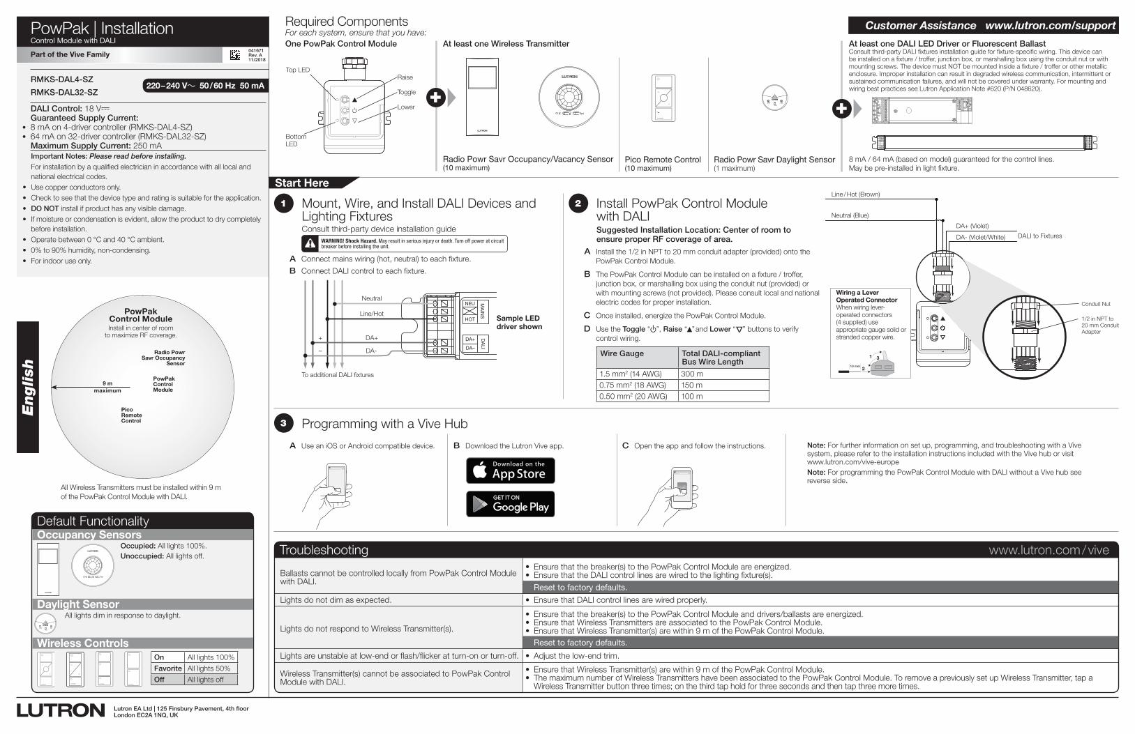
For each system, ensure that you have:One PowPak Control Module At least one Wireless Transmitter At least one DALI LED Driver or Fluorescent Ballast
Required Components
Radio Powr Savr Occupancy/Vacancy Sensor (10 maximum)
Radio Powr Savr Daylight Sensor(1 maximum)
Pico Remote Control(10 maximum)
8 mA / 64 mA (based on model) guaranteed for the control lines. May be pre-installed in light fixture.
Raise
Toggle
Lower
Top LED
Consult third-party DALI fixtures installation guide for fixture-specific wiring. This device can be installed on a fixture / troffer, junction box, or marshalling box using the conduit nut or with mounting screws. The device must NOT be mounted inside a fixture / troffer or other metallic enclosure. Improper installation can result in degraded wireless communication, intermittent or sustained communication failures, and will not be covered under warranty. For mounting and wiring best practices see Lutron Application Note #620 (P/N 048620).+
Occupancy Sensors
Daylight Sensor
Wireless Controls
Occupied: All lights 100%.Unoccupied: All lights off.
TestLink Cal.
All lights dim in response to daylight.
On All lights 100%
Favorite All lights 50%
Off All lights off
Default Functionality
2
A Install the 1/2 in NPT to 20 mm conduit adapter (provided) onto the PowPak Control Module.
B The PowPak Control Module can be installed on a fixture / troffer, junction box, or marshalling box using the conduit nut (provided) or with mounting screws (not provided). Please consult local and national electric codes for proper installation.
C Once installed, energize the PowPak Control Module.
D Use the Toggle “ u” , Raise “▲” and Lower “
Δ
” buttons to verify control wiring.
English
All Wireless Transmitters must be installed within 9 m of the PowPak Control Module with DALI.
DALI Control: 18 V- Guaranteed Supply Current:
• 8 mA on 4-driver controller (RMKS-DAL4-SZ)• 64 mA on 32-driver controller (RMKS-DAL32-SZ)
Maximum Supply Current: 250 mA
220 – 240 V~ 50 / 60 Hz 50 mARMKS-DAL4-SZ
RMKS-DAL32-SZ
A Connect mains wiring (hot, neutral) to each fixture.
B Connect DALI control to each fixture.
1
DA+
DA–
NEU
HOT
DALI
MAINS
To additional DALI fixtures
Neutral
Line/Hot
DA+
DA-
+
–
WARNING! Shock Hazard. May result in serious injury or death. Turn off power at circuit breaker before installing the unit.
Sample LED driver shown
Important Notes: Please read before installing.For installation by a qualified electrician in accordance with all local and national electrical codes.
• Use copper conductors only.• Check to see that the device type and rating is suitable for the application.• DO NOT install if product has any visible damage.• If moisture or condensation is evident, allow the product to dry completely
before installation.• Operate between 0 °C and 40 °C ambient.• 0% to 90% humidity, non-condensing.• For indoor use only.
Start Here
XVive
Programming with a Vive Hub3
Mount, Wire, and Install DALI Devices and Lighting FixturesConsult third-party device installation guide
Install PowPak Control Module with DALISuggested Installation Location: Center of room to ensure proper RF coverage of area.
A Use an iOS or Android compatible device. B Download the Lutron Vive app. C Open the app and follow the instructions. Note: For further information on set up, programming, and troubleshooting with a Vive system, please refer to the installation instructions included with the Vive hub or visit www.lutron.com/vive-europe
Note: For programming the PowPak Control Module with DALI without a Vive hub see reverse side.
Customer Assistance www.lutron.com/support
Troubleshooting www.lutron.com / vive
Ballasts cannot be controlled locally from PowPak Control Module with DALI.
• Ensurethatthebreaker(s)tothePowPakControlModuleareenergized.• EnsurethattheDALIcontrollinesarewiredtothelightingfixture(s). Reset to factory defaults.
Lights do not dim as expected. • EnsurethatDALIcontrollinesarewiredproperly.
Lights do not respond to Wireless Transmitter(s).
• Ensurethatthebreaker(s)tothePowPakControlModuleanddrivers/ballastsareenergized.• EnsurethatWirelessTransmittersareassociatedtothePowPakControlModule.• EnsurethatWirelessTransmitter(s)arewithin9mofthePowPakControlModule. Reset to factory defaults.
Lights are unstable at low-end or flash/flicker at turn-on or turn-off. • Adjustthelow-endtrim.
Wireless Transmitter(s) cannot be associated to PowPak Control Module with DALI.
• EnsurethatWirelessTransmitter(s)arewithin9mofthePowPakControlModule.• ThemaximumnumberofWirelessTransmittershavebeenassociatedtothePowPakControlModule.ToremoveapreviouslysetupWirelessTransmitter,tapa
Wireless Transmitter button three times; on the third tap hold for three seconds and then tap three more times.
Part of the Vive Family
vive.lutron.com X
DALI to Fixtures
DA+ (Violet)
DA- (Violet/White)
Neutral (Blue)
Line / Hot (Brown)
Conduit Nut
1/2 in NPT to 20 mm Conduit Adapter
Wiring a Lever Operated ConnectorWhen wiring lever-operated connectors (4 supplied) use appropriate gauge solid or stranded copper wire.
1
2
3
10 mm
Lutron EA Ltd | 125 Finsbury Pavement, 4th floorLondon EC2A 1NQ, UK
041671 Rev. A 11/2018
Bottom LED
9 mmaximum
Radio Powr Savr Occupancy
Sensor
Pico Remote Control
PowPak Control ModuleInstall in center of room
to maximize RF coverage.
PowPak Control Module
Wire Gauge Total DALI-compliant Bus Wire Length
1.5 mm2 (14 AWG) 300 m0.75 mm2 (18 AWG) 150 m0.50 mm2 (20 AWG) 100 m
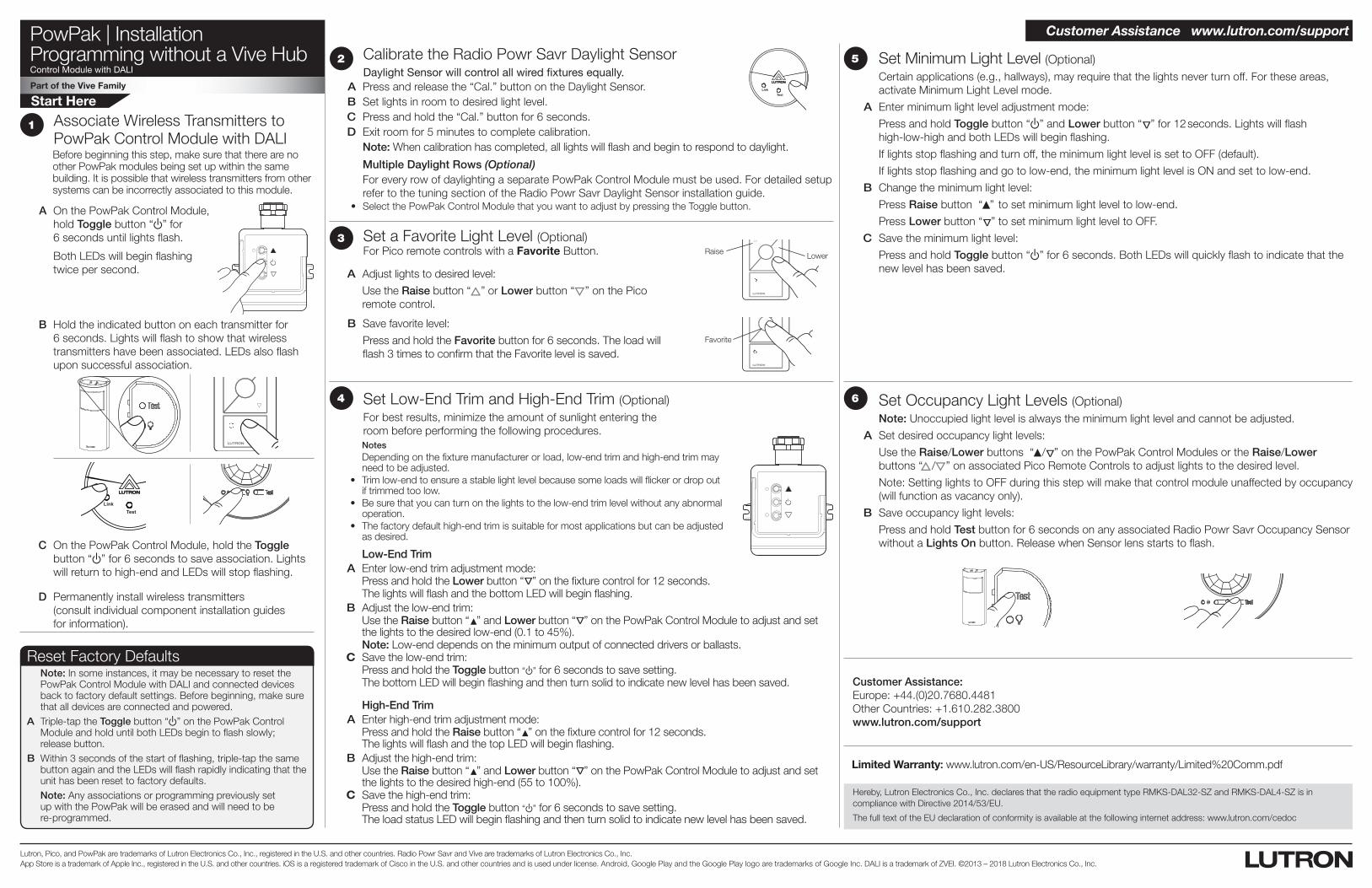
PowPak | InstallationProgramming without a Vive HubControl Module with DALI
Part of the Vive Family
Start Here
Lutron, Pico, and PowPak are trademarks of Lutron Electronics Co., Inc., registered in the U.S. and other countries. Radio Powr Savr and Vive are trademarks of Lutron Electronics Co., Inc. App Store is a trademark of Apple Inc., registered in the U.S. and other countries. iOS is a registered trademark of Cisco in the U.S. and other countries and is used under license. Android, Google Play and the Google Play logo are trademarks of Google Inc. DALI is a trademark of ZVEI. ©2013 – 2018 Lutron Electronics Co., Inc.
A On the PowPak Control Module, hold Toggle button “ u” for 6 seconds until lights flash.
Both LEDs will begin flashing twice per second.
Associate Wireless Transmitters to PowPak Control Module with DALI Before beginning this step, make sure that there are no other PowPak modules being set up within the same building. It is possible that wireless transmitters from other systems can be incorrectly associated to this module.
1
C On the PowPak Control Module, hold the Toggle button “ u” for 6 seconds to save association. Lights will return to high-end and LEDs will stop flashing.
B Hold the indicated button on each transmitter for 6 seconds. Lights will flash to show that wireless transmitters have been associated. LEDs also flash upon successful association.
TestLink Cal.
D Permanently install wireless transmitters (consult individual component installation guides for information).
Raise Lower
Favorite
Set a Favorite Light Level (Optional)For Pico remote controls with a Favorite Button.
A Adjust lights to desired level:
Use the Raise button “ ” or Lower button “ ” on the Pico remote control.
B Save favorite level:
Press and hold the Favorite button for 6 seconds. The load will flash 3 times to confirm that the Favorite level is saved.
3
Low-End Trim A Enter low-end trim adjustment mode: Press and hold the Lower button “
Δ
” on the fixture control for 12 seconds. The lights will flash and the bottom LED will begin flashing. B Adjust the low-end trim: Use the Raise button “▲” and Lower button “
Δ
” on the PowPak Control Module to adjust and set the lights to the desired low-end (0.1 to 45%).
Note: Low-end depends on the minimum output of connected drivers or ballasts. C Save the low-end trim: Press and hold the Toggle button “ u” for 6 seconds to save setting. The bottom LED will begin flashing and then turn solid to indicate new level has been saved.
High-End Trim A Enter high-end trim adjustment mode: Press and hold the Raise button “▲” on the fixture control for 12 seconds.
The lights will flash and the top LED will begin flashing. B Adjust the high-end trim: Use the Raise button “▲” and Lower button “
Δ
” on the PowPak Control Module to adjust and set the lights to the desired high-end (55 to 100%).
C Save the high-end trim: Press and hold the Toggle button “ u” for 6 seconds to save setting.
The load status LED will begin flashing and then turn solid to indicate new level has been saved.
Set Low-End Trim and High-End Trim (Optional)For best results, minimize the amount of sunlight entering the room before performing the following procedures.
Notes Depending on the fixture manufacturer or load, low-end trim and high-end trim may
need to be adjusted. • Trimlow-endtoensureastablelightlevelbecausesomeloadswillflickerordropout
if trimmed too low. • Besurethatyoucanturnonthelightstothelow-endtrimlevelwithoutanyabnormal
operation. • Thefactorydefaulthigh-endtrimissuitableformostapplicationsbutcanbeadjusted
as desired.
4
5 Set Minimum Light Level (Optional)Certain applications (e.g., hallways), may require that the lights never turn off. For these areas, activate Minimum Light Level mode.
A Enter minimum light level adjustment mode:
Press and hold Toggle button “ u” and Lower button “ Δ” for 12 seconds. Lights will flash high-low-high and both LEDs will begin flashing.
If lights stop flashing and turn off, the minimum light level is set to OFF (default).
If lights stop flashing and go to low-end, the minimum light level is ON and set to low-end.
B Change the minimum light level:
Press Raise button “▲” to set minimum light level to low-end.
Press Lower button “ Δ” to set minimum light level to OFF.
C Save the minimum light level:
Press and hold Toggle button “ u” for 6 seconds. Both LEDs will quickly flash to indicate that the new level has been saved.
6 Set Occupancy Light Levels (Optional)Note: Unoccupied light level is always the minimum light level and cannot be adjusted.
A Set desired occupancy light levels:
Use the Raise/Lower buttons “▲ / Δ” on the PowPak Control Modules or the Raise/Lower buttons “ / ” on associated Pico Remote Controls to adjust lights to the desired level.
Note: Setting lights to OFF during this step will make that control module unaffected by occupancy (will function as vacancy only).
B Save occupancy light levels:
Press and hold Test button for 6 seconds on any associated Radio Powr Savr Occupancy Sensor without a Lights On button. Release when Sensor lens starts to flash.
Limited Warranty: www.lutron.com/en-US/ResourceLibrary/warranty/Limited%20Comm.pdf
Calibrate the Radio Powr Savr Daylight Sensor Daylight Sensor will control all wired fixtures equally.
A Press and release the “Cal.” button on the Daylight Sensor. B Set lights in room to desired light level. C Press and hold the “Cal.” button for 6 seconds. D Exit room for 5 minutes to complete calibration.
Note: When calibration has completed, all lights will flash and begin to respond to daylight.
Multiple Daylight Rows (Optional)For every row of daylighting a separate PowPak Control Module must be used. For detailed setup refer to the tuning section of the Radio Powr Savr Daylight Sensor installation guide.
• SelectthePowPakControlModulethatyouwanttoadjustbypressingtheTogglebutton.
TestLink Cal.
2
Reset Factory DefaultsNote: In some instances, it may be necessary to reset the PowPak Control Module with DALI and connected devices back to factory default settings. Before beginning, make sure that all devices are connected and powered.
A Triple-tap the Toggle button “ u” on the PowPak Control Module and hold until both LEDs begin to flash slowly; release button.
B Within 3 seconds of the start of flashing, triple-tap the same button again and the LEDs will flash rapidly indicating that the unit has been reset to factory defaults.Note: Any associations or programming previously set up with the PowPak will be erased and will need to be re-programmed.
Customer Assistance:Europe: +44.(0)20.7680.4481Other Countries: +1.610.282.3800www.lutron.com/support
Customer Assistance www.lutron.com/support
Hereby, Lutron Electronics Co., Inc. declares that the radio equipment type RMKS-DAL32-SZ and RMKS-DAL4-SZ is in compliance with Directive 2014/53/EU.
The full text of the EU declaration of conformity is available at the following internet address: www.lutron.com/cedoc
041588 Rév. A11/2018
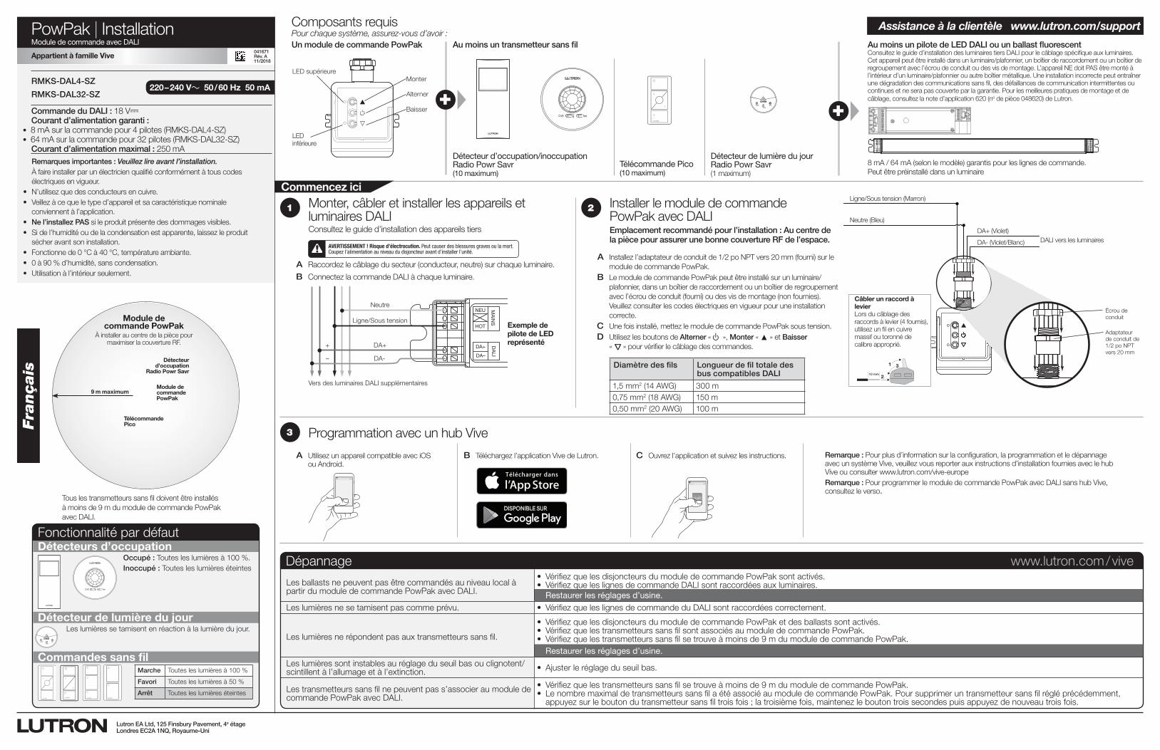
PowPak | InstallationModule de commande avec DALI
TestLink Cal. +
Pour chaque système, assurez-vous d’avoir :Un module de commande PowPak Au moins un transmetteur sans fil Au moins un pilote de LED DALI ou un ballast fluorescent
Composants requis
Détecteur d’occupation/inoccupation Radio Powr Savr(10 maximum)
Détecteur de lumière du jour Radio Powr Savr(1 maximum)
Télécommande Pico(10 maximum)
8 mA / 64 mA (selon le modèle) garantis pour les lignes de commande. Peut être préinstallé dans un luminaire
Monter
Alterner
Baisser
LED supérieure
Consultez le guide d’installation des luminaires tiers DALI pour le câblage spécifique aux luminaires. Cet appareil peut être installé dans un luminaire/plafonnier, un boîtier de raccordement ou un boîtier de regroupement avec l’écrou de conduit ou des vis de montage. L’appareil NE doit PAS être monté à l’intérieur d’un luminaire/plafonnier ou autre boîtier métallique. Une installation incorrecte peut entraîner une dégradation des communications sans fil, des défaillances de communication intermittentes ou continues et ne sera pas couverte par la garantie. Pour les meilleures pratiques de montage et de câblage, consultez la note d’application 620 (no de pièce 048620) de Lutron.+
Détecteurs d’occupation
Détecteur de lumière du jour
Commandes sans fil
Occupé : Toutes les lumières à 100 %.Inoccupé : Toutes les lumières éteintes
TestLink Cal.
Les lumières se tamisent en réaction à la lumière du jour.
Fonctionnalité par défaut
2
A Installez l’adaptateur de conduit de 1/2 po NPT vers 20 mm (fourni) sur le module de commande PowPak.
B Le module de commande PowPak peut être installé sur un luminaire/plafonnier, dans un boîtier de raccordement ou un boîtier de regroupement avec l’écrou de conduit (fourni) ou des vis de montage (non fournies). Veuillez consulter les codes électriques en vigueur pour une installation correcte.
C Une fois installé, mettez le module de commande PowPak sous tension. D Utilisez les boutons de Alterner « u », Monter « ▲ » et Baisser
«
Δ
» pour vérifier le câblage des commandes.
França
is
Tous les transmetteurs sans fil doivent être installés à moins de 9 m du module de commande PowPak avec DALI.
Commande du DALI : 18 V- Courant d’alimentation garanti :
• 8 mA sur la commande pour 4 pilotes (RMKS-DAL4-SZ)• 64 mA sur la commande pour 32 pilotes (RMKS-DAL32-SZ)
Courant d’alimentation maximal : 250 mA
220 – 240 V~ 50 / 60 Hz 50 mARMKS-DAL4-SZ
RMKS-DAL32-SZ
A Raccordez le câblage du secteur (conducteur, neutre) sur chaque luminaire.
B Connectez la commande DALI à chaque luminaire.
1
DA+
DA–
NEU
HOT
DALI
MAINS
Vers des luminaires DALI supplémentaires
Neutre
Ligne/Sous tension
DA+
DA-
+
–
AVERTISSEMENT ! Risque d’électrocution. Peut causer des blessures graves ou la mort. Coupez l’alimentation au niveau du disjoncteur avant d’installer l’unité.
Exemple de pilote de LED représenté
Remarques importantes : Veuillez lire avant l’installation.À faire installer par un électricien qualifié conformément à tous codes électriques en vigueur.
• N’utilisez que des conducteurs en cuivre.• Veillez à ce que le type d’appareil et sa caractéristique nominale
conviennent à l’application.• Ne l’installez PAS si le produit présente des dommages visibles.• Si de l’humidité ou de la condensation est apparente, laissez le produit
sécher avant son installation.• Fonctionne de 0 °C à 40 °C, température ambiante.• 0 à 90 % d’humidité, sans condensation.• Utilisation à l’intérieur seulement.
Commencez ici
XVive
Programmation avec un hub Vive3
Monter, câbler et installer les appareils et luminaires DALIConsultez le guide d’installation des appareils tiers
Installer le module de commande PowPak avec DALIEmplacement recommandé pour l’installation : Au centre de la pièce pour assurer une bonne couverture RF de l’espace.
A Utilisez un appareil compatible avec iOS ou Android.
B Téléchargez l’application Vive de Lutron. C Ouvrez l’application et suivez les instructions. Remarque : Pour plus d’information sur la configuration, la programmation et le dépannage avec un système Vive, veuillez vous reporter aux instructions d’installation fournies avec le hub Vive ou consulter www.lutron.com/vive-europe
Remarque : Pour programmer le module de commande PowPak avec DALI sans hub Vive, consultez le verso.
Assistance à la clientèle www.lutron.com/support
Dépannage www.lutron.com / vive
Les ballasts ne peuvent pas être commandés au niveau local à partir du module de commande PowPak avec DALI.
• VérifiezquelesdisjoncteursdumoduledecommandePowPaksontactivés.• VérifiezqueleslignesdecommandeDALIsontraccordéesauxluminaires. Restaurer les réglages d’usine.
Les lumières ne se tamisent pas comme prévu. • VérifiezqueleslignesdecommandeduDALIsontraccordéescorrectement.
Les lumières ne répondent pas aux transmetteurs sans fil.
• VérifiezquelesdisjoncteursdumoduledecommandePowPaketdesballastssontactivés.• VérifiezquelestransmetteurssansfilsontassociésaumoduledecommandePowPak.• Vérifiezquelestransmetteurssansfilsetrouveàmoinsde9 mdumoduledecommandePowPak. Restaurer les réglages d’usine.
Les lumières sont instables au réglage du seuil bas ou clignotent/scintillent à l’allumage et à l’extinction. • Ajusterleréglageduseuilbas.
Les transmetteurs sans fil ne peuvent pas s’associer au module de commande PowPak avec DALI.
• Vérifiezquelestransmetteurssansfilsetrouveàmoinsde9 mdumoduledecommandePowPak.• LenombremaximaldetransmetteurssansfilaétéassociéaumoduledecommandePowPak.Poursupprimeruntransmetteursansfilrégléprécédemment,
appuyez sur le bouton du transmetteur sans fil trois fois ; la troisième fois, maintenez le bouton trois secondes puis appuyez de nouveau trois fois.
Appartient à famille Vive
vive.lutron.com X
DALI vers les luminairesDA+ (Violet)
DA- (Violet/Blanc)
Neutre (Bleu)
Ligne/Sous tension (Marron)
Écrou de conduit
Adaptateur de conduit de 1/2 po NPT vers 20 mm
Câbler un raccord à levierLors du câblage des raccords à levier (4 fournis), utilisez un fil en cuivre massif ou toronné de calibre approprié.
1
2
3
10 mm
Lutron EA Ltd, 125 Finsbury Pavement, 4e étageLondres EC2A 1NQ, Royaume-Uni
041671Rév. A11/2018
LED inférieure
9 m maximum
Détecteur d’occupation
Radio Powr Savr
Télécommande Pico
Module de commande PowPak
À installer au centre de la pièce pour maximiser la couverture RF.
Module de commande PowPak
Diamètre des fils Longueur de fil totale des bus compatibles DALI
1,5 mm2 (14 AWG) 300 m0,75 mm2 (18 AWG) 150 m0,50 mm2 (20 AWG) 100 m
Marche Toutes les lumières à 100 %
Favori Toutes les lumières à 50 %
Arrêt Toutes les lumières éteintes
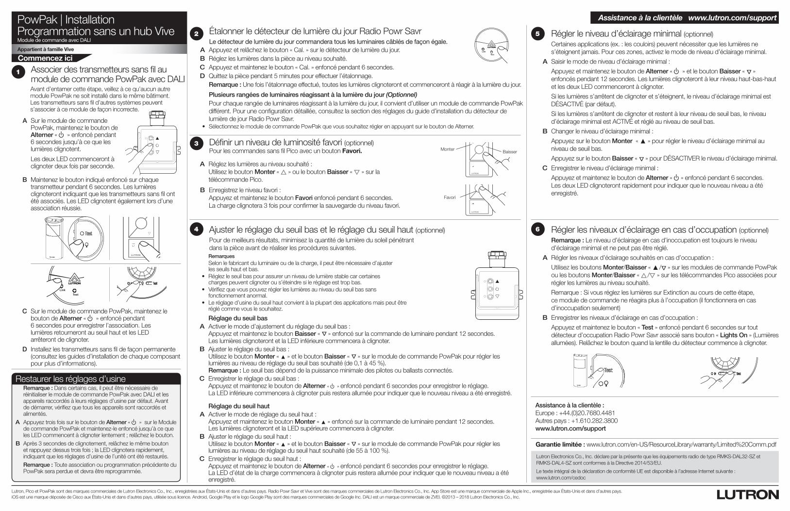
PowPak | InstallationProgrammation sans un hub ViveModule de commande avec DALI
Appartient à famille Vive
Commencez ici
Lutron, Pico et PowPak sont des marques commerciales de Lutron Electronics Co., Inc., enregistrées aux États-Unis et dans d’autres pays. Radio Powr Savr et Vive sont des marques commerciales de Lutron Electronics Co., Inc. App Store est une marque commerciale de Apple Inc., enregistrée aux États-Unis et dans d’autres pays. iOS est une marque déposée de Cisco aux États-Unis et dans d’autres pays, utilisée sous licence. Android, Google Play et le logo Google Play sont des marques commerciales de Google Inc. DALI est un marque commerciale de ZVEI. ©2013 – 2018 Lutron Electronics Co., Inc.
A Sur le module de commande PowPak, maintenez le bouton de Alterner « u » enfoncé pendant 6 secondes jusqu’à ce que les lumières clignotent.
Les deux LED commenceront à clignoter deux fois par seconde.
Associer des transmetteurs sans fil au module de commande PowPak avec DALI Avant d’entamer cette étape, veillez à ce qu’aucun autre module PowPak ne soit installé dans le même bâtiment. Les transmetteurs sans fil d’autres systèmes peuvent s’associer à ce module de façon incorrecte.
1
C Sur le module de commande PowPak, maintenez le bouton de Alterner « u » enfoncé pendant 6 secondes pour enregistrer l’association. Les lumières retourneront au seuil haut et les LED arrêteront de clignoter.
B Maintenez le bouton indiqué enfoncé sur chaque transmetteur pendant 6 secondes. Les lumières clignoteront indiquant que les transmetteurs sans fil ont été associés. Les LED clignotent également lors d’une association réussie.
TestLink Cal.
D Installez les transmetteurs sans fil de façon permanente (consultez les guides d’installation de chaque composant pour plus d’informations).
Monter Baisser
Favori
Définir un niveau de luminosité favori (optionnel)Pour les commandes sans fil Pico avec un bouton Favori.
A Réglez les lumières au niveau souhaité : Utilisez le bouton Monter « » ou le bouton Baisser « » sur la télécommande Pico.
B Enregistrez le niveau favori : Appuyez et maintenez le bouton Favori enfoncé pendant 6 secondes. La charge clignotera 3 fois pour confirmer la sauvegarde du niveau favori.
3
Réglage du seuil bas A Activer le mode d’ajustement du réglage du seuil bas : Appuyez et maintenez le bouton Baisser «
Δ
» enfoncé sur la commande de luminaire pendant 12 secondes. Les lumières clignoteront et la LED inférieure commencera à clignoter. B Ajuster le réglage du seuil bas : Utilisez le bouton Monter « ▲ » et le bouton Baisser «
Δ
» sur le module de commande PowPak pour régler les lumières au niveau de réglage du seuil bas souhaité (de 0,1 à 45 %).
Remarque : Le seuil bas dépend de la puissance minimale des pilotes ou ballasts connectés. C Enregistrer le réglage du seuil bas : Appuyez et maintenez le bouton de Alterner « u » enfoncé pendant 6 secondes pour enregistrer le réglage. La LED inférieure commencera à clignoter puis restera allumée pour indiquer que le nouveau niveau a été enregistré.
Réglage du seuil haut A Activer le mode de réglage du seuil haut : Appuyez et maintenez le bouton Monter « ▲ » enfoncé sur la commande de luminaire pendant 12 secondes.
Les lumières clignoteront et la LED supérieure commencera à clignoter. B Ajuster le réglage du seuil haut : Utilisez le bouton Monter « ▲ » et le bouton Baisser «
Δ
» sur le module de commande PowPak pour régler les lumières au niveau de réglage du seuil haut souhaité (de 55 à 100 %).
C Enregistrer le réglage du seuil haut : Appuyez et maintenez le bouton de Alterner « u » enfoncé pendant 6 secondes pour enregistrer le réglage.
La LED d’état de la charge commencera à clignoter puis restera allumée pour indiquer que le nouveau niveau a été enregistré.
Ajuster le réglage du seuil bas et le réglage du seuil haut (optionnel)Pour de meilleurs résultats, minimisez la quantité de lumière du soleil pénétrant dans la pièce avant de réaliser les procédures suivantes.
Remarques Selon le fabricant du luminaire ou de la charge, il peut être nécessaire d’ajuster
les seuils haut et bas. • Réglezleseuilbaspourassurerunniveaudelumièrestablecarcertaines
charges peuvent clignoter ou s’éteindre si le réglage est trop bas. • Vérifiezquevouspouvezréglerleslumièresauniveauduseuilbassans
fonctionnement anormal. • Leréglaged’usineduseuilhautconvientàlaplupartdesapplicationsmaispeutêtre
réglé comme vous le souhaitez.
4
5 Régler le niveau d’éclairage minimal (optionnel)Certaines applications (ex. : les couloirs) peuvent nécessiter que les lumières ne s’éteignent jamais. Pour ces zones, activez le mode de niveau d’éclairage minimal.
A Saisir le mode de niveau d’éclairage minimal :
Appuyez et maintenez le bouton de Alterner « u » et le bouton Baisser « Δ » enfoncés pendant 12 secondes. Les lumières clignoteront à leur niveau haut-bas-haut et les deux LED commenceront à clignoter.
Si les lumières s’arrêtent de clignoter et s’éteignent, le niveau d’éclairage minimal est DÉSACTIVÉ (par défaut).
Si les lumières s’arrêtent de clignoter et restent à leur niveau de seuil bas, le niveau d’éclairage minimal est ACTIVÉ et réglé au niveau de seuil bas.
B Changer le niveau d’éclairage minimal :
Appuyez sur le bouton Monter « ▲ » pour régler le niveau d’éclairage minimal au niveau de seuil bas.
Appuyez sur le bouton Baisser « Δ » pour DÉSACTIVER le niveau d’éclairage minimal.
C Enregistrer le niveau d’éclairage minimal :
Appuyez et maintenez le bouton de Alterner « u» enfoncé pendant 6 secondes. Les deux LED clignoteront rapidement pour indiquer que le nouveau niveau a été enregistré.
6 Régler les niveaux d’éclairage en cas d’occupation (optionnel)Remarque : Le niveau d’éclairage en cas d’inoccupation est toujours le niveau d’éclairage minimal et ne peut pas être réglé.
A Régler les niveaux d’éclairage souhaités en cas d’occupation :
Utilisez les boutons Monter/Baisser « ▲ / Δ » sur les modules de commande PowPak ou les boutons Monter/Baisser « / » sur les télécommandes Pico associées pour régler les lumières au niveau souhaité.
Remarque : Si vous réglez les lumières sur Extinction au cours de cette étape, ce module de commande ne réagira plus à l’occupation (il fonctionnera en cas d’inoccupation seulement)
B Enregistrer les niveaux d’éclairage en cas d’occupation :
Appuyez et maintenez le bouton « Test » enfoncé pendant 6 secondes sur tout détecteur d’occupation Radio Powr Savr associé sans bouton « Lights On » (Lumières allumées). Relâchez le bouton quand la lentille du détecteur commence à clignoter.
Garantie limitée : www.lutron.com/en-US/ResourceLibrary/warranty/Limited%20Comm.pdf
Étalonner le détecteur de lumière du jour Radio Powr Savr Le détecteur de lumière du jour commandera tous les luminaires câblés de façon égale.
A Appuyez et relâchez le bouton « Cal. » sur le détecteur de lumière du jour. B Réglez les lumières dans la pièce au niveau souhaité. C Appuyez et maintenez le bouton « Cal. » enfoncé pendant 6 secondes. D Quittez la pièce pendant 5 minutes pour effectuer l’étalonnage.
Remarque : Une fois l’étalonnage effectué, toutes les lumières clignoteront et commenceront à réagir à la lumière du jour.
Plusieurs rangées de luminaires réagissant à la lumière du jour (Optionnel)Pour chaque rangée de luminaires réagissant à la lumière du jour, il convient d’utiliser un module de commande PowPak différent. Pour une configuration détaillée, consultez la section des réglages du guide d’installation du détecteur de lumière de jour Radio Powr Savr.
• SélectionnezlemoduledecommandePowPakquevoussouhaitezréglerenappuyantsurleboutondeAlterner.
TestLink Cal.
2
Restaurer les réglages d’usineRemarque : Dans certains cas, il peut être nécessaire de réinitialiser le module de commande PowPak avec DALI et les appareils raccordés à leurs réglages d’usine par défaut. Avant de démarrer, vérifiez que tous les appareils sont raccordés et alimentés.
A Appuyez trois fois sur le bouton de Alterner « u » sur le Module de commande PowPak et maintenez-le enfoncé jusqu’à ce que les LED commencent à clignoter lentement ; relâchez le bouton.
B Après 3 secondes de clignotement, relâchez le même bouton et rappuyez dessus trois fois ; la LED clignotera rapidement, indiquant que les réglages d’usine de l’unité ont été restaurés.Remarque : Toute association ou programmation précédente du PowPak sera perdue et devra être reprogrammée.
Assistance à la clientèle :Europe : +44.(0)20.7680.4481Autres pays : +1.610.282.3800www.lutron.com/support
Assistance à la clientèle www.lutron.com/support
Lutron Electronics Co., Inc. déclare par la présente que les équipements radio de type RMKS-DAL32-SZ et RMKS-DAL4-SZ sont conformes à la Directive 2014/53/EU.
Le texte intégral de la déclaration de conformité UE est disponible à l’adresse Internet suivante : www.lutron.com/cedoc
041588 Rev. A11/2018
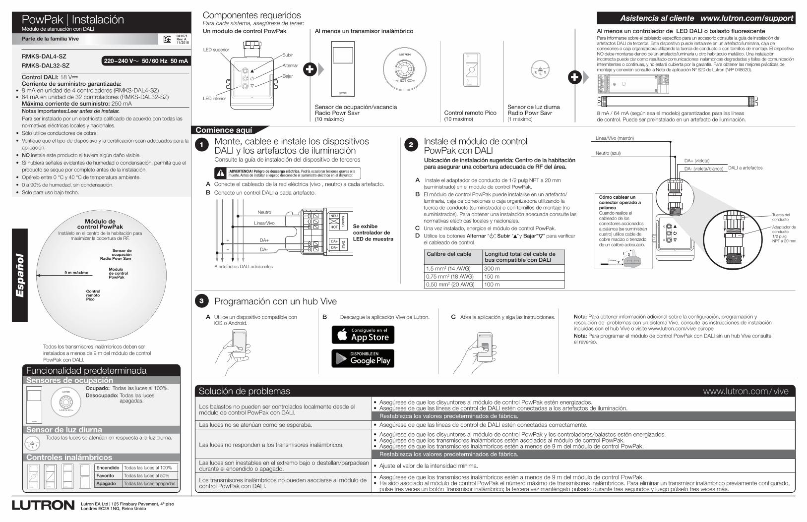
PowPak | InstalaciónMódulo de atenuación con DALI
TestLink Cal. +
Para cada sistema, asegúrese de tener:Un módulo de control PowPak Al menos un transmisor inalámbrico Al menos un controlador de LED DALI o balasto fluorescente
Componentes requeridos
Sensor de ocupación/vacancia Radio Powr Savr(10 máximo)
Sensor de luz diurna Radio Powr Savr(1 máximo)
Control remoto Pico(10 máximo)
8 mA / 64 mA (según sea el modelo) garantizados para las líneas de control. Puede ser preinstalado en un artefacto de iluminación.
Subir
Alternar
Bajar
LED superior
Para informarse sobre el cableado específico para un accesorio consulte la guía de instalación de artefactos DALI de terceros. Este dispositivo puede instalarse en un artefacto/luminaria, caja de conexiones o caja organizadora utilizando la tuerca de conducto o con tornillos de montaje. El dispositivo NO debe montarse dentro de un artefacto/luminaria u otro habitáculo metálico. Una instalación incorrecta puede dar como resultado comunicaciones inalámbricas degradadas y fallas de comunicación intermitentes o continuas, y no estará cubierta por la garantía. Para obtener las mejores prácticas de montaje y conexión consulte la Nota de aplicación Nº 620 de Lutron (N/P 048620).+
Sensores de ocupación
Sensor de luz diurna
Controles inalámbricos
Ocupado: Todas las luces al 100%.Desocupado: Todas las luces
apagadas.
TestLink Cal.
Todas las luces se atenúan en respuesta a la luz diurna.
Funcionalidad predeterminada
2
A Instale el adaptador de conducto de 1/2 pulg NPT a 20 mm (suministrado) en el módulo de control PowPak.
B El módulo de control PowPak puede instalarse en un artefacto/luminaria, caja de conexiones o caja organizadora utilizando la tuerca de conducto (suministrada) o con tornillos de montaje (no suministrados). Para obtener una instalación adecuada consulte las normativas eléctricas locales y nacionales.
C Una vez instalado, energice el módulo de control PowPak. D Utilice los botones Alternar “ u”, Subir “▲” y Bajar“
Δ
” para verificar el cableado de control.
Esp
añol
Todos los transmisores inalámbricos deben ser instalados a menos de 9 m del módulo de control PowPak con DALI.
Control DALI: 18 V- Corriente de suministro garantizada:
• 8 mA en unidad de 4 controladores (RMKS-DAL4-SZ)• 64 mA en unidad de 32 controladores (RMKS-DAL32-SZ)
Máxima corriente de suministro: 250 mA
220 – 240 V~ 50 / 60 Hz 50 mARMKS-DAL4-SZ
RMKS-DAL32-SZ
A Conecte el cableado de la red eléctrica (vivo , neutro) a cada artefacto.
B Conecte un control DALI a cada artefacto.
1
DA+
DA–
NEU
HOT
DALI
MAINS
A artefactos DALI adicionales
Neutro
Línea/Vivo
DA+
DA-
+
–
¡ADVERTENCIA! Peligro de descarga eléctrica. Podría ocasionar lesiones graves o la muerte. Antes de instalar el equipo desconecte el suministro eléctrico en el disyuntor.
Se exhibe controlador de LED de muestra
Notas importantes:Leer antes de instalar.Para ser instalado por un electricista calificado de acuerdo con todas las normativas eléctricas locales y nacionales.
• Sólo utilice conductores de cobre.• Verifique que el tipo de dispositivo y la certificación sean adecuados para la
aplicación.• NO instale este producto si tuviera algún daño visible.• Si hubiera señales evidentes de humedad o condensación, permita que el
producto se seque por completo antes de la instalación.• Opérelo entre 0 °C y 40 °C de temperatura ambiente.• 0 a 90% de humedad, sin condensación.• Sólo para uso bajo techo.
Comience aquí
XVive
Programación con un hub Vive3
Monte, cablee e instale los dispositivos DALI y los artefactos de iluminaciónConsulte la guía de instalación del dispositivo de terceros
Instale el módulo de control PowPak con DALIUbicación de instalación sugerida: Centro de la habitación para asegurar una cobertura adecuada de RF del área.
A Utilice un dispositivo compatible con iOS o Android.
B Descargue la aplicación Vive de Lutron. C Abra la aplicación y siga las instrucciones. Nota: Para obtener información adicional sobre la configuración, programación y resolución de problemas con un sistema Vive, consulte las instrucciones de instalación incluidas con el hub Vive o visite www.lutron.com/vive-europe
Nota: Para programar el módulo de control PowPak con DALI sin un hub Vive consulte el reverso.
Asistencia al cliente www.lutron.com/support
Solución de problemas www.lutron.com / vive
Los balastos no pueden ser controlados localmente desde el módulo de control PowPak con DALI.
• AsegúresedequelosdisyuntoresalmódulodecontrolPowPakesténenergizados.• AsegúresedequelaslíneasdecontroldeDALIesténconectadasalosartefactosdeiluminación. Restablezca los valores predeterminados de fábrica.
Las luces no se atenúan como se esperaba. • AsegúresedequelaslíneasdecontroldeDALIesténconectadascorrectamente.
Las luces no responden a los transmisores inalámbricos.
• AsegúresedequelosdisyuntoresalmódulodecontrolPowPakyloscontroladores/balastosesténenergizados.• AsegúresedequelostransmisoresinalámbricosesténasociadosalmódulodecontrolPowPak.• Asegúresedequelostransmisoresinalámbricosesténamenosde9mdelmódulodecontrolPowPak. Restablezca los valores predeterminados de fábrica.
Las luces son inestables en el extremo bajo o destellan/parpadean durante el encendido o apagado. • Ajusteelvalordelaintensidadmínima.
Los transmisores inalámbricos no pueden asociarse al módulo de control PowPak con DALI.
• Asegúresedequelostransmisoresinalámbricosesténamenosde9mdelmódulodecontrolPowPak.• HasidoasociadoalmódulodecontrolPowPakelnúmeromáximodetransmisoresinalámbricos.Paraeliminaruntransmisorinalámbricopreviamenteconfigurado,
pulse tres veces un botón Transmisor inalámbrico; la tercera vez manténgalo pulsado durante tres segundos y luego púlselo tres veces más.
Parte de la familia Vive
vive.lutron.com X
DALI a artefactos
DA+ (violeta)
DA- (violeta/blanco)
Neutro (azul)
Línea/Vivo (marrón)
Tuerca del conducto
Adaptador de conducto 1/2 pulg NPT a 20 mm
Cómo cablear un conector operado a palancaCuando realice el cableado de los conectores accionados a palanca (se suministran cuatro) utilice cable de cobre macizo o trenzado de un calibre adecuado.
1
2
3
10 mm
Lutron EA Ltd | 125 Finsbury Pavement, 4º pisoLondres EC2A 1NQ, Reino Unido
041671Rev. A11/2018
LED inferior
9 m máximo
Sensor de ocupación
Radio Powr Savr
Control remoto Pico
Módulo de control PowPak
Instálelo en el centro de la habitación para maximizar la cobertura de RF.
Módulo de control PowPak
Calibre del cable Longitud total del cable de bus compatible con DALI
1,5 mm2 (14 AWG) 300 m0,75 mm2 (18 AWG) 150 m0,50 mm2 (20 AWG) 100 m
Encendido Todas las luces al 100%
Favorito Todas las luces al 50%
Apagado Todas las luces apagadas
PowPak | InstalaciónProgramación sin un hub ViveMódulo de atenuación con DALI
Parte de la familia Vive
Comience aquí
Lutron, Pico y PowPak son marcas comerciales de Lutron Electronics Co., Inc. registradas en E.U.A. y otros países. Radio Powr Savr y Vive son marcas comerciales de Lutron Electronics Co., Inc. App Store es una marca comercial de Apple Inc., registrada en E.U.A. y otros países. iOS es una marca comercial registrada de Cisco en E.U.A. y en otros países y se utiliza bajo licencia. Android, Google Play y el logotipo de Google Play son marcas comerciales de Google Inc. DALI es una marca comercial de ZVEI. ©2013 – 2018 Lutron Electronics Co., Inc.
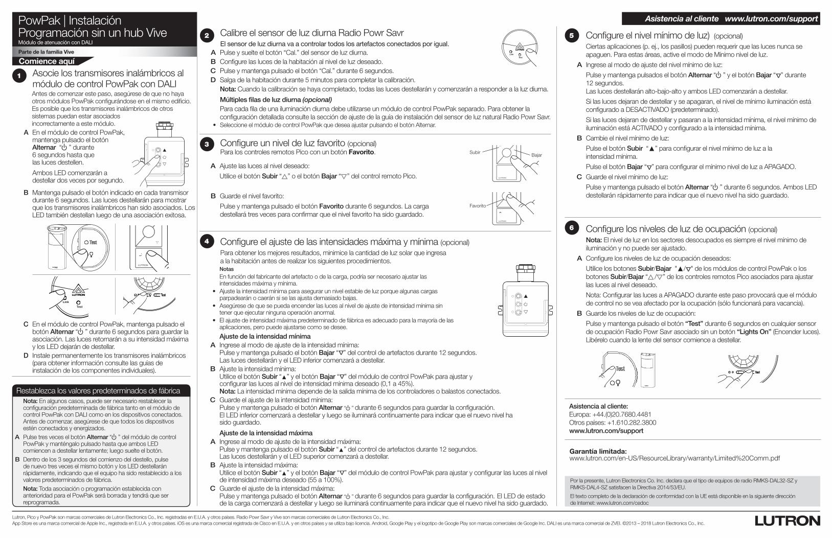
A En el módulo de control PowPak, mantenga pulsado el botón Alternar “ u” durante 6 segundos hasta que las luces destellen.
Ambos LED comenzarán a destellar dos veces por segundo.
Asocie los transmisores inalámbricos al módulo de control PowPak con DALI Antes de comenzar este paso, asegúrese de que no haya otros módulos PowPak configurándose en el mismo edificio. Es posible que los transmisores inalámbricos de otros sistemas puedan estar asociados incorrectamente a este módulo.
1
C En el módulo de control PowPak, mantenga pulsado el botón Alternar “ u” durante 6 segundos para guardar la asociación. Las luces retornarán a su intensidad máxima y los LED dejarán de destellar.
B Mantenga pulsado el botón indicado en cada transmisor durante 6 segundos. Las luces destellarán para mostrar que los transmisores inalámbricos han sido asociados. Los LED también destellan luego de una asociación exitosa.
TestLink Cal.
D Instale permanentemente los transmisores inalámbricos (para obtener información consulte las guías de instalación de los componentes individuales).
Subir Bajar
Favorito
Configure un nivel de luz favorito (opcional)Para los controles remotos Pico con un botón Favorito.
A Ajuste las luces al nivel deseado:
Utilice el botón Subir “ ” o el botón Bajar “ ” del control remoto Pico.
B Guarde el nivel favorito:
Pulse y mantenga pulsado el botón Favorito durante 6 segundos. La carga destellará tres veces para confirmar que el nivel favorito ha sido guardado.
3
Ajuste de la intensidad mínima A Ingrese al modo de ajuste de la intensidad mínima: Pulse y mantenga pulsado el botón Bajar “
Δ
” del control de artefactos durante 12 segundos. Las luces destellarán y el LED inferior comenzará a destellar. B Ajuste la intensidad mínima: Utilice el botón Subir “▲” y el botón Bajar “
Δ
” del módulo de control PowPak para ajustar y configurar las luces al nivel de intensidad mínima deseado (0,1 a 45%).
Nota: La intensidad mínima depende de la salida mínima de los controladores o balastos conectados. C Guarde el ajuste de la intensidad mínima: Pulse y mantenga pulsado el botón Alternar “ u” durante 6 segundos para guardar la configuración. El LED inferior comenzará a destellar y luego se iluminará continuamente para indicar que el nuevo nivel ha
sido guardado.
Ajuste de la intensidad máxima A Ingrese al modo de ajuste de la intensidad máxima: Pulse y mantenga pulsado el botón Subir “▲” del control de artefactos durante 12 segundos.
Las luces destellarán y el LED superior comenzará a destellar. B Ajuste la intensidad máxima: Utilice el botón Subir “▲” y el botón Bajar “
Δ
” del módulo de control PowPak para ajustar y configurar las luces al nivel de intensidad máxima deseado (55 a 100%).
C Guarde el ajuste de la intensidad máxima: Pulse y mantenga pulsado el botón Alternar “ u” durante 6 segundos para guardar la configuración. El LED de estado
de la carga comenzará a destellar y luego se iluminará continuamente para indicar que el nuevo nivel ha sido guardado.
Configure el ajuste de las intensidades máxima y mínima (opcional)Para obtener los mejores resultados, minimice la cantidad de luz solar que ingresa a la habitación antes de realizar los siguientes procedimientos.
Notas En función del fabricante del artefacto o de la carga, podría ser necesario ajustar las
intensidades máxima y mínima. • Ajustelaintensidadmínimaparaasegurarunnivelestabledeluzporquealgunascargas
parpadearán o caerán si se las ajusta demasiado bajas. • Asegúresedequesepuedaencenderlaslucesalniveldeajustedeintensidadmínimasin
tener que ejecutar ninguna operación anormal. • Elajustedeintensidadmáximapredeterminadodefábricaesadecuadoparalamayoríadelas
aplicaciones, pero puede ajustarse como se desee.
4
5 Configure el nivel mínimo de luz) (opcional)Ciertas aplicaciones (p. ej., los pasillos) pueden requerir que las luces nunca se apaguen. Para estas áreas, active el modo de Mínimo nivel de luz.
A Ingrese al modo de ajuste del nivel mínimo de luz:
Pulse y mantenga pulsados el botón Alternar “ u” y el botón Bajar “ Δ” durante 12 segundos. Las luces destellarán alto-bajo-alto y ambos LED comenzarán a destellar.
Si las luces dejaran de destellar y se apagaran, el nivel de mínimo iluminación está configurado a DESACTIVADO (predeterminado).
Si las luces dejaran de destellar y pasaran a la intensidad mínima, el nivel mínimo de iluminación está ACTIVADO y configurado a la intensidad mínima.
B Cambie el nivel mínimo de luz:
Pulse el botón Subir “▲” para configurar el nivel mínimo de luz a la intensidad mínima.
Pulse el botón Bajar “ Δ” para configurar el mínimo nivel de luz a APAGADO.
C Guarde el nivel mínimo de luz:
Pulse y mantenga pulsado el botón Alternar “u” durante 6 segundos. Ambos LED destellarán rápidamente para indicar que el nuevo nivel ha sido guardado.
6 Configure los niveles de luz de ocupación (opcional)Nota: El nivel de luz en los sectores desocupados es siempre el nivel mínimo de iluminación y no puede ser ajustado.
A Configure los niveles de luz de ocupación deseados:
Utilice los botones Subir/Bajar "▲/ Δ" de los módulos de control PowPak o los botones Subir/Bajar “ / ” de los controles remotos Pico asociados para ajustar las luces al nivel deseado.
Nota: Configurar las luces a APAGADO durante este paso provocará que el módulo de control no se vea afectado por la ocupación (sólo funcionará para vacancia).
B Guarde los niveles de luz de ocupación:
Pulse y mantenga pulsado el botón “Test” durante 6 segundos en cualquier sensor de ocupación Radio Powr Savr asociado sin un botón “Lights On” (Encender luces). Libérelo cuando la lente del sensor comience a destellar.
Garantía limitada: www.lutron.com/en-US/ResourceLibrary/warranty/Limited%20Comm.pdf
Calibre el sensor de luz diurna Radio Powr Savr El sensor de luz diurna va a controlar todos los artefactos conectados por igual.
A Pulse y suelte el botón “Cal.” del sensor de luz diurna. B Configure las luces de la habitación al nivel de luz deseado. C Pulse y mantenga pulsado el botón “Cal.” durante 6 segundos. D Salga de la habitación durante 5 minutos para completar la calibración.
Nota: Cuando la calibración se haya completado, todas las luces destellarán y comenzarán a responder a la luz diurna.
Múltiples filas de luz diurna (opcional)Para cada fila de una iluminación diurna debe utilizarse un módulo de control PowPak separado. Para obtener la configuración detallada consulte la sección de ajuste de la guía de instalación del sensor de luz natural Radio Powr Savr.
• SeleccioneelmódulodecontrolPowPakquedeseaajustarpulsandoelbotónAlternar.
TestLink Cal.
2
Restablezca los valores predeterminados de fábricaNota: En algunos casos, puede ser necesario restablecer la configuración predeterminada de fábrica tanto en el módulo de control PowPak con DALI como en los dispositivos conectados. Antes de comenzar, asegúrese de que todos los dispositivos estén conectados y energizados.
A Pulse tres veces el botón Alternar “ u” del módulo de control PowPak y manténgalo pulsado hasta que ambos LED comiencen a destellar lentamente; luego suelte el botón.
B Dentro de los 3 segundos del comienzo del destello, pulse de nuevo tres veces el mismo botón y los LED destellarán rápidamente, indicando que el equipo ha sido restablecido a los valores predeterminados de fábrica.Nota: Toda asociación o programación establecida con anterioridad para el PowPak será borrada y tendrá que ser reprogramada.
Asistencia al cliente:Europa: +44.(0)20.7680.4481Otros países: +1.610.282.3800www.lutron.com/support
Asistencia al cliente www.lutron.com/support
Por la presente, Lutron Electronics Co. Inc. declara que el tipo de equipos de radio RMKS-DAL32-SZ y RMKS-DAL4-SZ satisfacen la Directiva 2014/53/EU.
El texto completo de la declaración de conformidad con la UE está disponible en la siguiente dirección de Internet: www.lutron.com/cedoc
041588 Rev. A11/2018
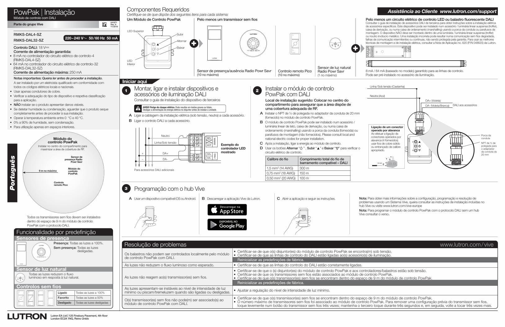
PowPak | InstalaçãoMódulo de controlo com DALI
TestLink Cal. +
Certifique-se de que dispõe dos seguintes itens para cada sistema:Um Módulo de Controlo PowPak Pelo menos um transmissor sem fios Pelo menos um circuito elétrico de controlo LED ou balastro fluorescente DALI
Componentes Requeridos
Sensor de presença/ausência Radio Powr Savr (10 no máximo)
Sensor de luz natural Radio Powr Savr (1 no máximo)
Controlo remoto Pico (10 no máximo)
8 mA / 64 mA (baseado no modelo) garantido para as linhas de controlo. Pode ser pré-instalado no acessório de iluminação.
Subir
Alternar
Baixar
LED Superior
Consultar o guia de instalação de acessórios DALI de terceiros para obter instruções sobre a instalação elétrica de acessórios específicos. Este dispositivo pode ser instalado num acessório / luminária linear suspensa (troffer), caixa de derivação, ou numa caixa de ordenamento (marshalling) usando a porca da conduta ou parafusos de montagem. O dispositivo NÃO deve ser montado dentro de uma luminária / luminária linear suspensa (troffer) ou noutro invólucro metálico. Uma instalação incorreta pode resultar numa comunicação sem fios degradada, falhas de comunicação intermitentes ou contínuas, não sendo protegida pela garantia. Para usar as melhores técnicas de montagem e de instalação elétrica, consultar a Nota de Aplicação no. 620 (P/N 048620) da Lutron.+
Sensores de presença
Sensor de luz natural
Controlos sem fios
Presença: Todas as luzes a 100%.Sem presença: Todas as luzes
desligadas.
TestLink Cal.
Todas as luzes reduzem o fluxo luminoso em resposta à luz natural.
Funcionalidade por predefinição
2
A Instalar o NPT de ½ de polegada no adaptador da conduta de 20 mm (fornecido) no módulo de controlo PowPak.
B O módulo de controlo PowPak pode ser instalado num acessório / luminária linear de teto, caixa de derivação, ou numa caixa de ordenamento (marshalling) usando a porca da conduta (fornecida) ou parafusos de montagem (não fornecidos). Please consult local and national electric codes for proper installation.
C Após a instalação, ligar a energia ao módulo de controlo. D Usar os botões Alternar “ u” , Subir “▲” e Baixar “
Δ
” para verificar o circuito elétrico de controlo.
Português
Todos os transmissores sem fios devem ser instalados dentro do espaço de 9 m do módulo de controlo PowPak com o protocolo DALI.
Controlo DALI: 18 V- Corrente de alimentação garantida:
• 8 mA no controlador do circuito elétrico de controlo-4 (RMKS-DAL4-SZ)
• 64 mA no controlador do circuito elétrico de controlo-32 (RMKS-DAL32-SZ)Corrente de alimentação máxima: 250 mA
220 – 240 V~ 50 / 60 Hz 50 mARMKS-DAL4-SZ
RMKS-DAL32-SZ
A Ligar a cablagem da instalação elétrica (sob tensão, neutra) a cada acessório.
B Ligar o controlo DALI a cada acessório.
1
DA+
DA–
NEU
HOT
DALI
MAINS
Para acessórios DALI adicionais
Neutro
Linha/Sob tensão
DA+
DA-
+
–
AVISO! Perigo de choque elétrico. Pode resultar em lesões graves ou fatais. Desligar a alimentação de energia elétrica no disjuntor antes de instalar a unidade.
Exemplo do controlador LED mostrado
Notas importantes: Queira ler antes de proceder a instalação.A ser instalado por um eletricista qualificado em conformidade com todos os códigos elétricos locais e nacionais.
• Usar apenas condutores de cobre.• Verificar a adequação do tipo de dispositivo e respetiva classificação
para a aplicação.• NÃO instalar se o produto apresentar danos visíveis.• Se detetar humidade ou condensação, aguardar que o produto seque
completamente antes de proceder à sua instalação.• Operar à temperatura ambiente entre 0 °C e 40 °C.• 0% a 90% de humidade, sem condensação.• Para utilização apenas em espaços interiores.
Iniciar aqui
XVive
Programação com o hub Vive3
Montar, ligar e instalar dispositivos e acessórios de iluminação DALI Consultar o guia de instalação do dispositivo de terceiros
Instalar o módulo de controlo PowPak com DALILocal de instalação sugerido: Colocar no centro do compartimento para assegurar que a área dispõe de uma cobertura adequada de RF.
A Usar um dispositivo compatível iOS ou Android. B Descarregar a aplicação Vive da Lutron. C Abrir a aplicação e seguir as instruções. Nota: Para obter mais informações sobre a configuração, programação e resolução de problemas usando um Sistema Vive, queira consultar as instruções de instalação incluídas no hub Vive ou visite www.lutron.com/vive-europe
Nota: Para programar o módulo de controlo PowPak com o protocolo DALI sem um hub Vive consultar o verso.
Assistência ao Cliente www.lutron.com/support
Resolução de problemas www.lutron.com / vive
Os balastros não podem ser controlados localmente pelo módulo de controlo PowPak com DALI.
• Certificar-sedequeo(s)disjuntor(es)domódulodecontroloPowPakseencontra(m)sobtensão.• Certificar-sedequeaslinhasdecontrolodoDALIestãoligadasao(s)acessório(s)deiluminação. Reinicializar as predefinições de fábrica.
As luzes não reduzem o fluxo luminoso como esperado. • Certificar-sedequeaslinhasdocontrolodoDALIestãocorretamenteligadas.
As luzes não reagem ao(s) transmissor(es) sem fios.
• Certificar-sedequeo(s)disjuntor(es)domódulodecontroloPowPakeaoscontroladores/balastrosestãosobtensão.• Certificar-sedequeostransmissoressemfiosestãoassociadosaomódulodecontroloPowPak.• Certificar-sedequeo(s)transmissor(es)semfiosseencontramdentrodoespaçode9mdomódulodecontroloPowPak. Reinicializar as predefinições de fábrica.
As luzes apresentam-se instáveis ao nível de intensidade de luz mínimo ou piscam/tremeluzem quando são ligadas ou desligadas. • Ajustararegulaçãodoníveldeintensidadedeluzmínimo.
O(s) transmissor(es) sem fios não pode(m) ser associado(s) ao módulo de controlo PowPak com DALI.
• Certificar-sedequeo(s)transmissor(es)semfiosseencontramdentrodoespaçode9mdomódulodecontroloPowPak.• OnúmeromáximodetransmissoressemfiosfoiassociadoaomódulodecontroloPowPak.Pararemoverumaconfiguraçãopréviadotransmissorsemfios,
toque levemente num botão do transmissor sem fios três vezes; mantenha o terceiro toque durante três segundos e, em seguida, volte a tocar três vezes mais.
Parte do grupo Vive
vive.lutron.com X
DALI aos acessórios
DA+ (Violeta)
DA- (Violeta/Branca)
Neutra (Azul)
Linha / Sob tensão (Castanha)
Porca da conduta
NPT de ½ de polegada para o adaptador da conduta de 20 mm
Ligação de um conector operado por alavanca Ao efetuar a ligação de conectores operados por alavanca (4 fornecidos) usar fios de cobre sólido ou entrançado de calibre apropriado.
1
2
3
10 mm
Lutron EA Ltd | 125 Finsbury Pavement, 4th floorLondon EC2A 1NQ, Reino Unido
041671Rev. A11/2018
LED Inferior
9 m no máximo
Sensor de presença Radio
Powr Savr
Controlo remoto Pico
Módulo do controlo PowPak
Instalar no centro do compartimento para maximizar a área de cobertura de RF.
Módulo do controlo PowPak
Calibre do fio Comprimento total do fio de barramento compatível – DALI
1,5 mm2 (14 AWG) 300 m0,75 mm2 (18 AWG) 150 m0,50 mm2 (20 AWG) 100 m
Ligado Todas as luzes a 100%
Favorito Todas as luzes a 50%
Desligado Todas as luzes desligadas
PowPak | InstalaçãoProgramação sem um hub Vibe Módulo de controlo com DALI
Parte do grupo Vive
Iniciar aqui
Lutron, Pico, e PowPak são marcas comerciais da Lutron Electronics Co., Inc., registadas nos EUA e em outros países. Radio Powr Savr e Vive são marcas comerciais da Lutron Electronics Co., Inc. App Store é uma marca comercial da Apple Inc., registada nos EUA e em outros países. iOS é uma marca comercial registada da Cisco nos EUA e em outros países e é usada sob licença. Android, Google Play e logótipo Google Play são marcas comerciais da Google Inc. DALI é uma marca comercial da ZVEI. ©2013 – 2018 Lutron Electronics Co., Inc.
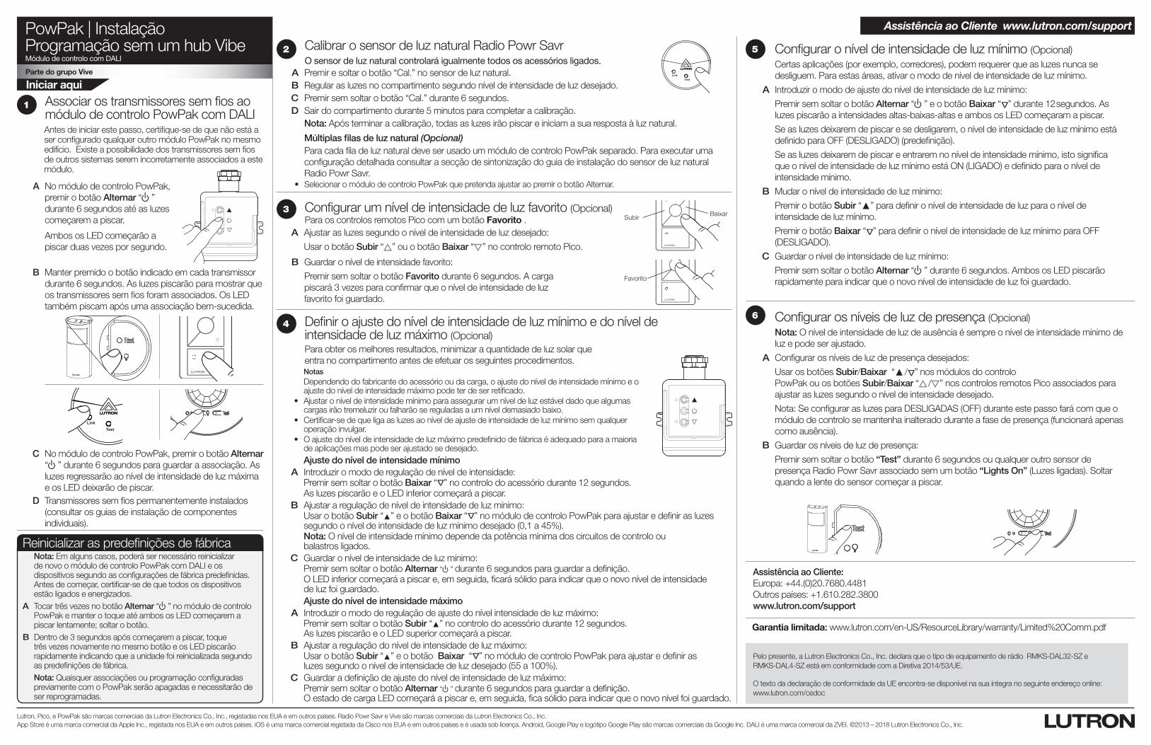
A No módulo de controlo PowPak, premir o botão Alternar “ u” durante 6 segundos até as luzes começarem a piscar.
Ambos os LED começarão a piscar duas vezes por segundo.
Associar os transmissores sem fios ao módulo de controlo PowPak com DALI Antes de iniciar este passo, certifique-se de que não está a ser configurado qualquer outro módulo PowPak no mesmo edifício. Existe a possibilidade dos transmissores sem fios de outros sistemas serem incorretamente associados a este módulo.
1
C No módulo de controlo PowPak, premir o botão Alternar “ u” durante 6 segundos para guardar a associação. As luzes regressarão ao nível de intensidade de luz máxima e os LED deixarão de piscar.
B Manter premido o botão indicado em cada transmissor durante 6 segundos. As luzes piscarão para mostrar que os transmissores sem fios foram associados. Os LED também piscam após uma associação bem-sucedida.
TestLink Cal.
D Transmissores sem fios permanentemente instalados (consultar os guias de instalação de componentes individuais).
Subir Baixar
Favorito
Configurar um nível de intensidade de luz favorito (Opcional)Para os controlos remotos Pico com um botão Favorito .
A Ajustar as luzes segundo o nível de intensidade de luz desejado:
Usar o botão Subir “ ” ou o botão Baixar “ ” no controlo remoto Pico.
B Guardar o nível de intensidade favorito:
Premir sem soltar o botão Favorito durante 6 segundos. A carga piscará 3 vezes para confirmar que o nível de intensidade de luz favorito foi guardado.
3
Ajuste do nível de intensidade mínimo A Introduzir o modo de regulação de nível de intensidade: Premir sem soltar o botão Baixar “
Δ
” no controlo do acessório durante 12 segundos. As luzes piscarão e o LED inferior começará a piscar. B Ajustar a regulação de nível de intensidade de luz mínimo: Usar o botão Subir “▲” e o botão Baixar “
Δ
” no módulo de controlo PowPak para ajustar e definir as luzes segundo o nível de intensidade de luz mínimo desejado (0,1 a 45%).
Nota: O nível de intensidade mínimo depende da potência mínima dos circuitos de controlo ou balastros ligados.
C Guardar o nível de intensidade de luz mínimo: Premir sem soltar o botão Alternar “ u” durante 6 segundos para guardar a definição. O LED inferior começará a piscar e, em seguida, ficará sólido para indicar que o novo nível de intensidade
de luz foi guardado. Ajuste do nível de intensidade máximo A Introduzir o modo de regulação de ajuste do nível intensidade de luz máximo: Premir sem soltar o botão Subir “▲” no controlo do acessório durante 12 segundos.
As luzes piscarão e o LED superior começará a piscar. B Ajustar a regulação do nível de intensidade de luz máximo: Usar o botão Subir “▲” e o botão Baixar “
Δ
” no módulo de controlo PowPak para ajustar e definir as luzes segundo o nível de intensidade de luz desejado (55 a 100%).
C Guardar a definição de ajuste do nível de intensidade de luz máximo: Premir sem soltar o botão Alternar “ u” durante 6 segundos para guardar a definição.
O estado de carga LED começará a piscar e, em seguida, fica sólido para indicar que o novo nível foi guardado.
Definir o ajuste do nível de intensidade de luz mínimo e do nível de intensidade de luz máximo (Opcional)Para obter os melhores resultados, minimizar a quantidade de luz solar que entra no compartimento antes de efetuar os seguintes procedimentos.
Notas Dependendo do fabricante do acessório ou da carga, o ajuste do nível de intensidade mínimo e o
ajuste do nível de intensidade máximo pode ter de ser retificado. • Ajustaroníveldeintensidademínimoparaassegurarumníveldeluzestáveldadoquealgumas
cargas irão tremeluzir ou falharão se reguladas a um nível demasiado baixo. • Certificar-sedequeligaasluzesaoníveldeajustedeintensidadedeluzmínimosemqualquer
operação invulgar. • Oajustedoníveldeintensidadedeluzmáximopredefinidodefábricaéadequadoparaamaioria
de aplicações mas pode ser ajustado se desejado.
4
5 Configurar o nível de intensidade de luz mínimo (Opcional)Certas aplicações (por exemplo, corredores), podem requerer que as luzes nunca se desliguem. Para estas áreas, ativar o modo de nível de intensidade de luz mínimo.
A Introduzir o modo de ajuste do nível de intensidade de luz mínimo:
Premir sem soltar o botão Alternar “ u” e o botão Baixar “ Δ” durante 12 segundos. As luzes piscarão a intensidades altas-baixas-altas e ambos os LED começaram a piscar.
Se as luzes deixarem de piscar e se desligarem, o nível de intensidade de luz mínimo está definido para OFF (DESLIGADO) (predefinição).
Se as luzes deixarem de piscar e entrarem no nível de intensidade mínimo, isto significa que o nível de intensidade de luz mínimo está ON (LIGADO) e definido para o nível de intensidade mínimo.
B Mudar o nível de intensidade de luz mínimo:
Premir o botão Subir “▲” para definir o nível de intensidade de luz para o nível de intensidade de luz mínimo.
Premir o botão Baixar “ Δ” para definir o nível de intensidade de luz mínimo para OFF (DESLIGADO).
C Guardar o nível de intensidade de luz mínimo:
Premir sem soltar o botão Alternar “ u” durante 6 segundos. Ambos os LED piscarão rapidamente para indicar que o novo nível de intensidade de luz foi guardado.
6 Configurar os níveis de luz de presença (Opcional)Nota: O nível de intensidade de luz de ausência é sempre o nível de intensidade mínimo de luz e pode ser ajustado.
A Configurar os níveis de luz de presença desejados:
Usar os botões Subir/Baixar “▲ / Δ” nos módulos do controlo PowPak ou os botões Subir/Baixar “ / ” nos controlos remotos Pico associados para ajustar as luzes segundo o nível de intensidade desejado.
Nota: Se configurar as luzes para DESLIGADAS (OFF) durante este passo fará com que o módulo de controlo se mantenha inalterado durante a fase de presença (funcionará apenas como ausência).
B Guardar os níveis de luz de presença:
Premir sem soltar o botão “Test” durante 6 segundos ou qualquer outro sensor de presença Radio Powr Savr associado sem um botão “Lights On” (Luzes ligadas). Soltar quando a lente do sensor começar a piscar.
Garantia limitada: www.lutron.com/en-US/ResourceLibrary/warranty/Limited%20Comm.pdf
Calibrar o sensor de luz natural Radio Powr Savr O sensor de luz natural controlará igualmente todos os acessórios ligados.
A Premir e soltar o botão “Cal.” no sensor de luz natural. B Regular as luzes no compartimento segundo nível de intensidade de luz desejado. C Premir sem soltar o botão “Cal.” durante 6 segundos. D Sair do compartimento durante 5 minutos para completar a calibração.
Nota: Após terminar a calibração, todas as luzes irão piscar e iniciam a sua resposta à luz natural.
Múltiplas filas de luz natural (Opcional)Para cada fila de luz natural deve ser usado um módulo de controlo PowPak separado. Para executar uma configuração detalhada consultar a secção de sintonização do guia de instalação do sensor de luz natural Radio Powr Savr.
• SelecionaromódulodecontroloPowPakquepretendaajustaraopremirobotãoAlternar.
TestLink Cal.
2
Reinicializar as predefinições de fábrica Nota: Em alguns casos, poderá ser necessário reinicializar de novo o módulo de controlo PowPak com DALI e os dispositivos segundo as configurações de fábrica predefinidas. Antes de começar, certificar-se de que todos os dispositivos estão ligados e energizados.
A Tocar três vezes no botão Alternar “ u” no módulo de controlo PowPak e manter o toque até ambos os LED começarem a piscar lentamente; soltar o botão.
B Dentro de 3 segundos após começarem a piscar, toque três vezes novamente no mesmo botão e os LED piscarão rapidamente indicando que a unidade foi reinicializada segundo as predefinições de fábrica.Nota: Quaisquer associações ou programação configuradas previamente com o PowPak serão apagadas e necessitarão de ser reprogramadas.
Assistência ao Cliente:Europa: +44.(0)20.7680.4481Outros países: +1.610.282.3800www.lutron.com/support
Assistência ao Cliente www.lutron.com/support
Pelo presente, a Lutron Electronics Co., Inc. declara que o tipo de equipamento de rádio RMKS-DAL32-SZ e RMKS-DAL4-SZ está em conformidade com a Diretiva 2014/53/UE.
O texto da declaração de conformidade da UE encontra-se disponível na sua íntegra no seguinte endereço online: www.lutron.com/cedoc
041588 Rev. A11/2018
PowPak | InstallationSteuermodul mit DALI
TestLink Cal. +
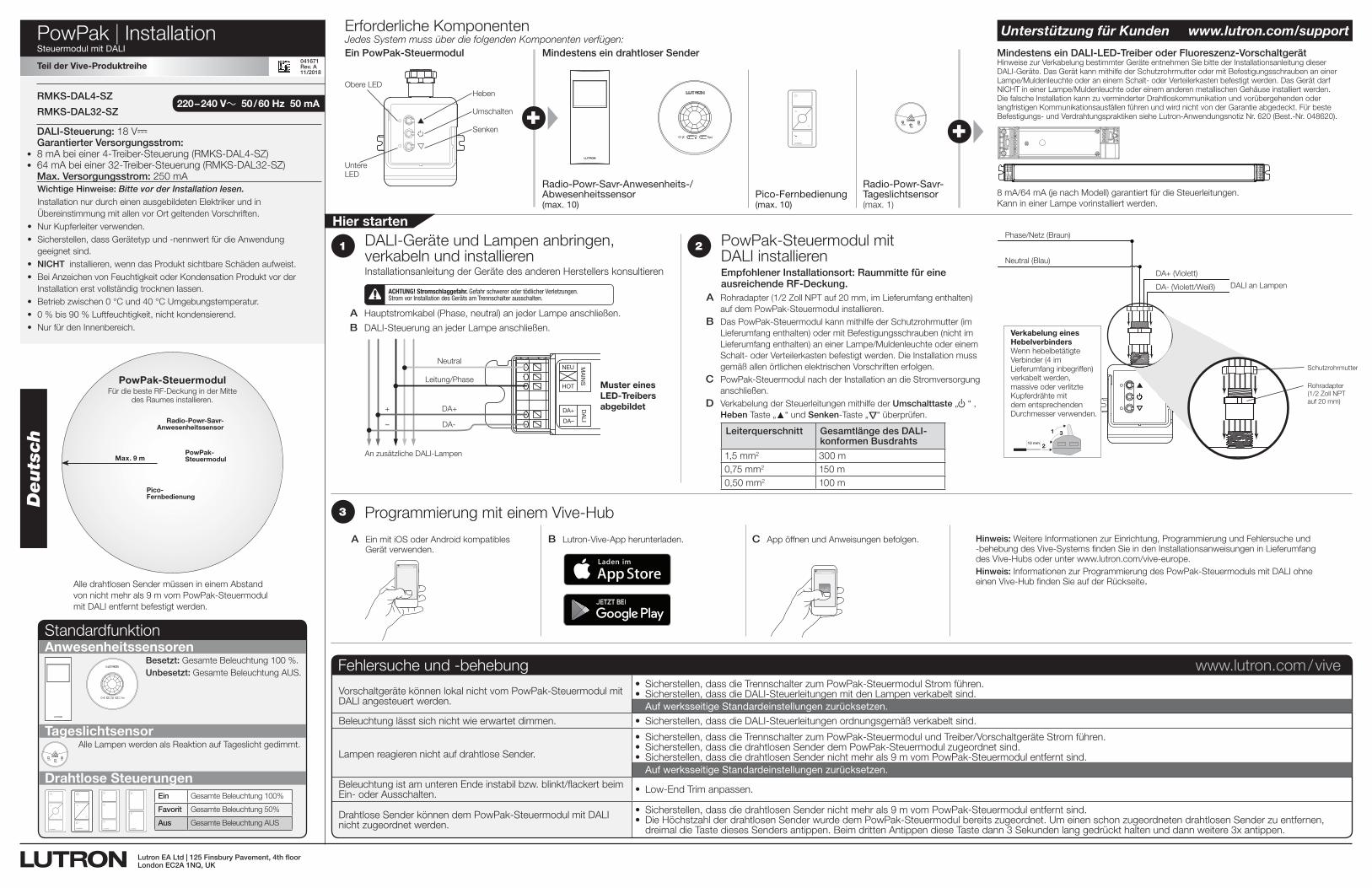
Jedes System muss über die folgenden Komponenten verfügen:Ein PowPak-Steuermodul Mindestens ein drahtloser Sender Mindestens ein DALI-LED-Treiber oder Fluoreszenz-Vorschaltgerät
Erforderliche Komponenten
Radio-Powr-Savr-Anwesenheits-/ Abwesenheitssensor(max. 10)
Radio-Powr-Savr- Tageslichtsensor(max. 1)
Pico-Fernbedienung(max. 10)
8 mA/64 mA (je nach Modell) garantiert für die Steuerleitungen. Kann in einer Lampe vorinstalliert werden.
Heben
Umschalten
Senken
Obere LED
Hinweise zur Verkabelung bestimmter Geräte entnehmen Sie bitte der Installationsanleitung dieser DALI-Geräte. Das Gerät kann mithilfe der Schutzrohrmutter oder mit Befestigungsschrauben an einer Lampe/Muldenleuchte oder an einem Schalt- oder Verteilerkasten befestigt werden. Das Gerät darf NICHT in einer Lampe/Muldenleuchte oder einem anderen metallischen Gehäuse installiert werden. Die falsche Installation kann zu verminderter Drahtloskommunikation und vorübergehenden oder langfristigen Kommunikationsausfällen führen und wird nicht von der Garantie abgedeckt. Für beste Befestigungs- und Verdrahtungspraktiken siehe Lutron-Anwendungsnotiz Nr. 620 (Best.-Nr. 048620).+
Anwesenheitssensoren
Tageslichtsensor
Drahtlose Steuerungen
Besetzt: Gesamte Beleuchtung 100 %.Unbesetzt: Gesamte Beleuchtung AUS.
TestLink Cal.
Alle Lampen werden als Reaktion auf Tageslicht gedimmt.
Standardfunktion
2
A Rohradapter (1/2 Zoll NPT auf 20 mm, im Lieferumfang enthalten) auf dem PowPak-Steuermodul installieren.
B Das PowPak-Steuermodul kann mithilfe der Schutzrohrmutter (im Lieferumfang enthalten) oder mit Befestigungsschrauben (nicht im Lieferumfang enthalten) an einer Lampe/Muldenleuchte oder einem Schalt- oder Verteilerkasten befestigt werden. Die Installation muss gemäß allen örtlichen elektrischen Vorschriften erfolgen.
C PowPak-Steuermodul nach der Installation an die Stromversorgung anschließen.
D Verkabelung der Steuerleitungen mithilfe der Umschalttaste „u“ , Heben Taste „▲“ und Senken-Taste „
Δ
“ überprüfen.
Deutsch
Alle drahtlosen Sender müssen in einem Abstand von nicht mehr als 9 m vom PowPak-Steuermodul mit DALI entfernt befestigt werden.
DALI-Steuerung: 18 V- Garantierter Versorgungsstrom:
• 8 mA bei einer 4-Treiber-Steuerung (RMKS-DAL4-SZ)• 64 mA bei einer 32-Treiber-Steuerung (RMKS-DAL32-SZ)
Max. Versorgungsstrom: 250 mA
220 – 240 V~ 50 / 60 Hz 50 mARMKS-DAL4-SZ
RMKS-DAL32-SZ
A Hauptstromkabel (Phase, neutral) an jeder Lampe anschließen.
B DALI-Steuerung an jeder Lampe anschließen.
1
DA+
DA–
NEU
HOT
DALI
MAINS
An zusätzliche DALI-Lampen
Neutral
Leitung/Phase
DA+
DA-
+
–
ACHTUNG! Stromschlaggefahr. Gefahr schwerer oder tödlicher Verletzungen. Strom vor Installation des Geräts am Trennschalter ausschalten.
Muster eines LED-Treibers abgebildet
Wichtige Hinweise: Bitte vor der Installation lesen.Installation nur durch einen ausgebildeten Elektriker und in Übereinstimmung mit allen vor Ort geltenden Vorschriften.
• Nur Kupferleiter verwenden.• Sicherstellen, dass Gerätetyp und -nennwert für die Anwendung
geeignet sind.• NICHT installieren, wenn das Produkt sichtbare Schäden aufweist.• Bei Anzeichen von Feuchtigkeit oder Kondensation Produkt vor der
Installation erst vollständig trocknen lassen.• Betrieb zwischen 0 °C und 40 °C Umgebungstemperatur.• 0 % bis 90 % Luftfeuchtigkeit, nicht kondensierend.• Nur für den Innenbereich.
Hier starten
XVive
Programmierung mit einem Vive-Hub3
DALI-Geräte und Lampen anbringen, verkabeln und installierenInstallationsanleitung der Geräte des anderen Herstellers konsultieren
PowPak-Steuermodul mit DALI installierenEmpfohlener Installationsort: Raummitte für eine ausreichende RF-Deckung.
A Ein mit iOS oder Android kompatibles Gerät verwenden.
B Lutron-Vive-App herunterladen. C App öffnen und Anweisungen befolgen. Hinweis: Weitere Informationen zur Einrichtung, Programmierung und Fehlersuche und -behebung des Vive-Systems finden Sie in den Installationsanweisungen in Lieferumfang des Vive-Hubs oder unter www.lutron.com/vive-europe.
Hinweis: Informationen zur Programmierung des PowPak-Steuermoduls mit DALI ohne einen Vive-Hub finden Sie auf der Rückseite.
Unterstützung für Kunden www.lutron.com/support
Fehlersuche und -behebung www.lutron.com / vive
Vorschaltgeräte können lokal nicht vom PowPak-Steuermodul mit DALI angesteuert werden.
• Sicherstellen,dassdieTrennschalterzumPowPak-SteuermodulStromführen.• Sicherstellen,dassdieDALI-SteuerleitungenmitdenLampenverkabeltsind. Auf werksseitige Standardeinstellungen zurücksetzen.
Beleuchtung lässt sich nicht wie erwartet dimmen. • Sicherstellen,dassdieDALI-Steuerleitungenordnungsgemäßverkabeltsind.
Lampen reagieren nicht auf drahtlose Sender.
• Sicherstellen,dassdieTrennschalterzumPowPak-SteuermodulundTreiber/VorschaltgeräteStromführen.• Sicherstellen,dassdiedrahtlosenSenderdemPowPak-Steuermodulzugeordnetsind.• Sicherstellen,dassdiedrahtlosenSendernichtmehrals9mvomPowPak-Steuermodulentferntsind. Auf werksseitige Standardeinstellungen zurücksetzen.
Beleuchtung ist am unteren Ende instabil bzw. blinkt/flackert beim Ein- oder Ausschalten. • Low-EndTrimanpassen.
Drahtlose Sender können dem PowPak-Steuermodul mit DALI nicht zugeordnet werden.
• Sicherstellen,dassdiedrahtlosenSendernichtmehrals9mvomPowPak-Steuermodulentferntsind.• DieHöchstzahlderdrahtlosenSenderwurdedemPowPak-Steuermodulbereitszugeordnet.UmeinenschonzugeordnetendrahtlosenSenderzuentfernen,
dreimal die Taste dieses Senders antippen. Beim dritten Antippen diese Taste dann 3 Sekunden lang gedrückt halten und dann weitere 3x antippen.
Teil der Vive-Produktreihe
vive.lutron.com X
DALI an Lampen
DA+ (Violett)
DA- (Violett/Weiß)
Neutral (Blau)
Phase/Netz (Braun)
Schutzrohrmutter
Rohradapter (1/2 Zoll NPT auf 20 mm)
Verkabelung eines HebelverbindersWenn hebelbetätigte Verbinder (4 im Lieferumfang inbegriffen) verkabelt werden, massive oder verlitzte Kupferdrähte mit dem entsprechenden Durchmesser verwenden.
1
2
3
10 mm
Lutron EA Ltd | 125 Finsbury Pavement, 4th floorLondon EC2A 1NQ, UK
041671Rev. A11/2018
Untere LED
Max. 9 m
Radio-Powr-Savr-Anwesenheitssensor
Pico-Fernbedienung
PowPak-SteuermodulFür die beste RF-Deckung in der Mitte
des Raumes installieren.
PowPak-Steuermodul
Leiterquerschnitt Gesamtlänge des DALI-konformen Busdrahts
1,5 mm2 300 m0,75 mm2 150 m0,50 mm2 100 m
Ein Gesamte Beleuchtung 100%
Favorit Gesamte Beleuchtung 50%
Aus Gesamte Beleuchtung AUS
PowPak | – InstallationProgrammierung ohne Vive-HubSteuermodul mit DALI
Teil der Vive-Produktreihe
Hier starten
Lutron, Pico und PowPak sind Marken der Lutron Electronics Co., Inc. und in den USA und in anderen Ländern eingetragen. Radio Powr Savr and Vive sind Marken der Lutron Electronics Co., Inc. App Store ist eine Marke von Apple Inc. und in den USA und in anderen Ländern eingetragen. iOS ist eine eingetragene Marke von Cisco in den USA und in anderen Ländern und wird unter Lizenz genutzt. Android, Google Play und das Google-Play-Logo sind Marken von Google Inc. DALI ist eine Marke von ZVEI. ©2013 – 2018 Lutron Electronics Co., Inc.
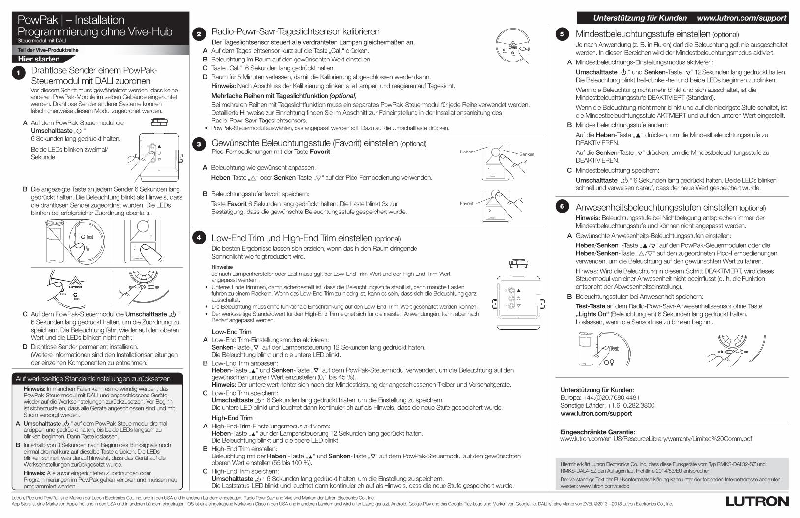
A Auf dem PowPak-Steuermodul die Umschalttaste „u“ 6 Sekunden lang gedrückt halten.
Beide LEDs blinken zweimal/Sekunde.
Drahtlose Sender einem PowPak-Steuermodul mit DALI zuordnen Vor diesem Schritt muss gewährleistet werden, dass keine anderen PowPak-Module im selben Gebäude eingerichtet werden. Drahtlose Sender anderer Systeme können fälschlicherweise diesem Modul zugeordnet werden.
1
C Auf dem PowPak-Steuermodul die Umschalttaste „u“ 6 Sekunden lang gedrückt halten, um die Zuordnung zu speichern. Die Beleuchtung fährt wieder auf den oberen Wert und die LEDs blinken nicht mehr.
B Die angezeigte Taste an jedem Sender 6 Sekunden lang gedrückt halten. Die Beleuchtung blinkt als Hinweis, dass die drahtlosen Sender zugeordnet wurden. Die LEDs blinken bei erfolgreicher Zuordnung ebenfalls.
TestLink Cal.
D Drahtlose Sender permanent installieren. (Weitere Informationen sind den Installationsanleitungen der einzelnen Komponenten zu entnehmen.)
Heben Senken
Favorit
Gewünschte Beleuchtungsstufe (Favorit) einstellen (optional)Pico-Fernbedienungen mit der Taste Favorit.
A Beleuchtung wie gewünscht anpassen:
Heben-Taste „ “ oder Senken-Taste „ “ auf der Pico-Fernbedienung verwenden.
B Beleuchtungsstufenfavorit speichern:
Taste Favorit 6 Sekunden lang gedrückt halten. Die Laste blinkt 3x zur Bestätigung, dass die gewünschte Beleuchtungsstufe gespeichert wurde.
3
Low-End Trim A Low-End Trim-Einstellungsmodus aktivieren: Senken-Taste „
Δ
“ auf der Lampensteuerung 12 Sekunden lang gedrückt halten. Die Beleuchtung blinkt und die untere LED blinkt. B Low-End Trim anpassen: Heben-Taste „▲“ und Senken-Taste „
Δ
“ auf dem PowPak-Steuermodul verwenden, um die Beleuchtung auf den gewünschten unteren Wert einzustellen (0,1 bis 45 %).
Hinweis: Der untere wert richtet sich nach der Mindestleistung der angeschlossenen Treiber und Vorschaltgeräte. C Low-End Trim speichern: Umschalttaste „u“ 6 Sekunden lang gedrückt hlaten, um die Einstellung zu speichern. Die untere LED blinkt und leuchtet dann kontinuierlich auf als Hinweis, dass die neue Stufe gespeichert wurde.
High-End Trim A High-End-Trim-Einstellungsmodus aktivieren: Heben-Taste „▲“ auf der Lampensteuerung 12 Sekunden lang gedrückt halten.
Die Beleuchtung blinkt und die obere LED blinkt. B High-End Trim einstellen: Beleuchtung mit der Heben -Taste „▲“ und Senken-Taste „
Δ
“ auf dem PowPak-Steuermodul auf den gewünschten oberen Wert einstellen (55 bis 100 %).
C High-End Trim speichern: Umschalttaste „ u“ 6 Sekunden lang gedrückt halten, um die Einstellung zu speichern.
Die Laststatus-LED blinkt und leuchtet dann kontinuierlich auf als Hinweis, dass die neue Stufe gespeichert wurde.
Low-End Trim und High-End Trim einstellen (optional)Die besten Ergebnisse lassen sich erzielen, wenn das in den Raum dringende Sonnenlicht wie folgt reduziert wird.
Hinweise Je nach Lampenhersteller oder Last muss ggf. der Low-End-Trim-Wert und der High-End-Trim-Wert
angepasst werden. • UnteresEndetrimmen,damitsichergestelltist,dassdieBeleuchtungsstufestabilist,dennmancheLasten
führen zu einem Flackern. Wenn das Low-End Trim zu niedrig ist, kann es sein, dass sich die Beleuchtung ganz ausschaltet.
• DieBeleuchtungmussohnefunktionaleEinschränkungaufdenLow-End-Trim-Wertgeschaltetwerdenkönnen. • DerwerksseitigeStandardwertfürdenHigh-EndTrimeignetsichfürdiemeistenAnwendungen,kannabernach
Bedarf angepasst werden.
4
5 Mindestbeleuchtungsstufe einstellen (optional)Je nach Anwendung (z. B. in Fluren) darf die Beleuchtung ggf. nie ausgeschaltet werden. In diesen Bereichen wird der Mindestbeleuchtungsmodus aktiviert.
A Mindestbeleuchtungs-Einstellungsmodus aktivieren:
Umschalttaste „ u“ und Senken-Taste „ Δ“ 12 Sekunden lang gedrückt halten. Die Beleuchtung blinkt hell-dunkel-hell und beide LEDs beginnen zu blinken.
Wenn die Beleuchtung nicht mehr blinkt und sich ausschaltet, ist die Mindestbeleuchtungsstufe DEAKTIVIERT (Standard).
Wenn die Beleuchtung nicht mehr blinkt und auf die niedrigste Stufe schaltet, ist die Mindestbeleuchtungsstufe AKTIVIERT und auf den unteren Wert eingestellt.
B Mindestbeleuchtungsstufe ändern:
Auf die Heben-Taste „▲“ drücken, um die Mindestbeleuchtungsstufe zu DEAKTIVIEREN.
Auf die Senken-Taste „ Δ“ drücken, um die Mindestbeleuchtungsstufe zu DEAKTIVIEREN.
C Mindestbeleuchtung speichern:
Umschalttaste „ u“ 6 Sekunden lang gedrückt halten. Beide LEDs blinken schnell und verweisen darauf, dass der neue Wert gespeichert wurde.
6 Anwesenheitsbeleuchtungsstufen einstellen (optional)Hinweis: Beleuchtungsstufe bei Nichtbelegung entsprechen immer der Mindestbeleuchtungsstufe und können nicht angepasst werden.
A Gewünschte Anwesenheits-Beleuchtungsstufen einstellen:
Heben/Senken -Taste „▲ / Δ“ auf den PowPak-Steuermodulen oder die Heben/Senken-Taste „ / “ auf den zugeordneten Pico-Fernbedienungen verwenden, um die Beleuchtung auf den gewünschten Wert zu fahren.
Hinweis: Wird die Beleuchtung in diesem Schritt DEAKTIVIERT, wird dieses Steuermodul von einer Anwesenheit nicht beeinflusst (d. h. die Funktion entspricht der Abwesenheitseinstellung).
B Beleuchtungsstufen bei Anwesenheit speichern:
Test-Taste an dem Radio-Powr-Savr-Anwesenheitssensor ohne Taste „Lights On“ (Beleuchtung ein) 6 Sekunden lang gedrückt halten. Loslassen, wenn die Sensorlinse zu blinken beginnt.
Eingeschränkte Garantie: www.lutron.com/en-US/ResourceLibrary/warranty/Limited%20Comm.pdf
Radio-Powr-Savr-Tageslichtsensor kalibrieren Der Tageslichtsensor steuert alle verdrahteten Lampen gleichermaßen an.
A Auf dem Tageslichtsensor kurz auf die Taste „Cal.“ drücken. B Beleuchtung im Raum auf den gewünschten Wert einstellen. C Taste „Cal.“ 6 Sekunden lang gedrückt halten. D Raum für 5 Minuten verlassen, damit die Kalibrierung abgeschlossen werden kann.
Hinweis: Nach Abschluss der Kalibrierung blinken alle Lampen und reagieren auf Tageslicht.
Mehrfache Reihen mit Tageslichtfunktion (optional)Bei mehreren Reihen mit Tageslichtfunktion muss ein separates PowPak-Steuermodul für jede Reihe verwendet werden. Detaillierte Hinweise zur Einrichtung finden Sie im Abschnitt zur Feineinstellung in der Installationsanleitung des Radio-Powr Savr-Tageslichtsensors.
• PowPak-Steuermodulauswählen,dasangepasstwerdensoll.DazuaufdieUmschalttastedrücken.
TestLink Cal.
2
Auf werksseitige Standardeinstellungen zurücksetzenHinweis: In manchen Fällen kann es notwendig werden, das PowPak-Steuermodul mit DALI und angeschlossene Geräte wieder auf die Werkseinstellungen zurückzusetzen. Vor Beginn ist sicherzustellen, dass alle Geräte angeschlossen sind und mit Strom versorgt werden.
A Umschalttaste „ u“ auf dem PowPak-Steuermodul dreimal antippen und gedrückt halten, bis beide LEDs langsam zu blinken beginnen. Dann Taste loslassen.
B Innerhalb von 3 Sekunden nach Beginn des Blinksignals noch einmal dreimal kurz auf dieselbe Taste drücken. Die LEDs blinken schnell, was darauf hinweist, dass das Gerät auf die Werkseinstellungen zurückgesetzt wurde.Hinweis: Alle zuvor eingerichteten Zuordnungen oder Programmierungen im PowPak gehen verloren und müssen neu programmiert werden.
Unterstützung für Kunden:Europa: +44.(0)20.7680.4481Sonstige Länder: +1.610.282.3800www.lutron.com/support
Unterstützung für Kunden www.lutron.com/support
Hiermit erklärt Lutron Electronics Co. Inc, dass diese Funkgeräte vom Typ RMKS-DAL32-SZ und RMKS-DAL4-SZ den Auflagen laut Richtlinie 2014/53/EU entsprechen.
Der vollständige Text der EU-Konformitätserklärung kann unter der folgenden Internetadresse abgerufen werden: www.lutron.com/cedoc
041588 Rev. A11/2018
PowPak | InstallazioneModulo di controllo con DALI
TestLink Cal. +
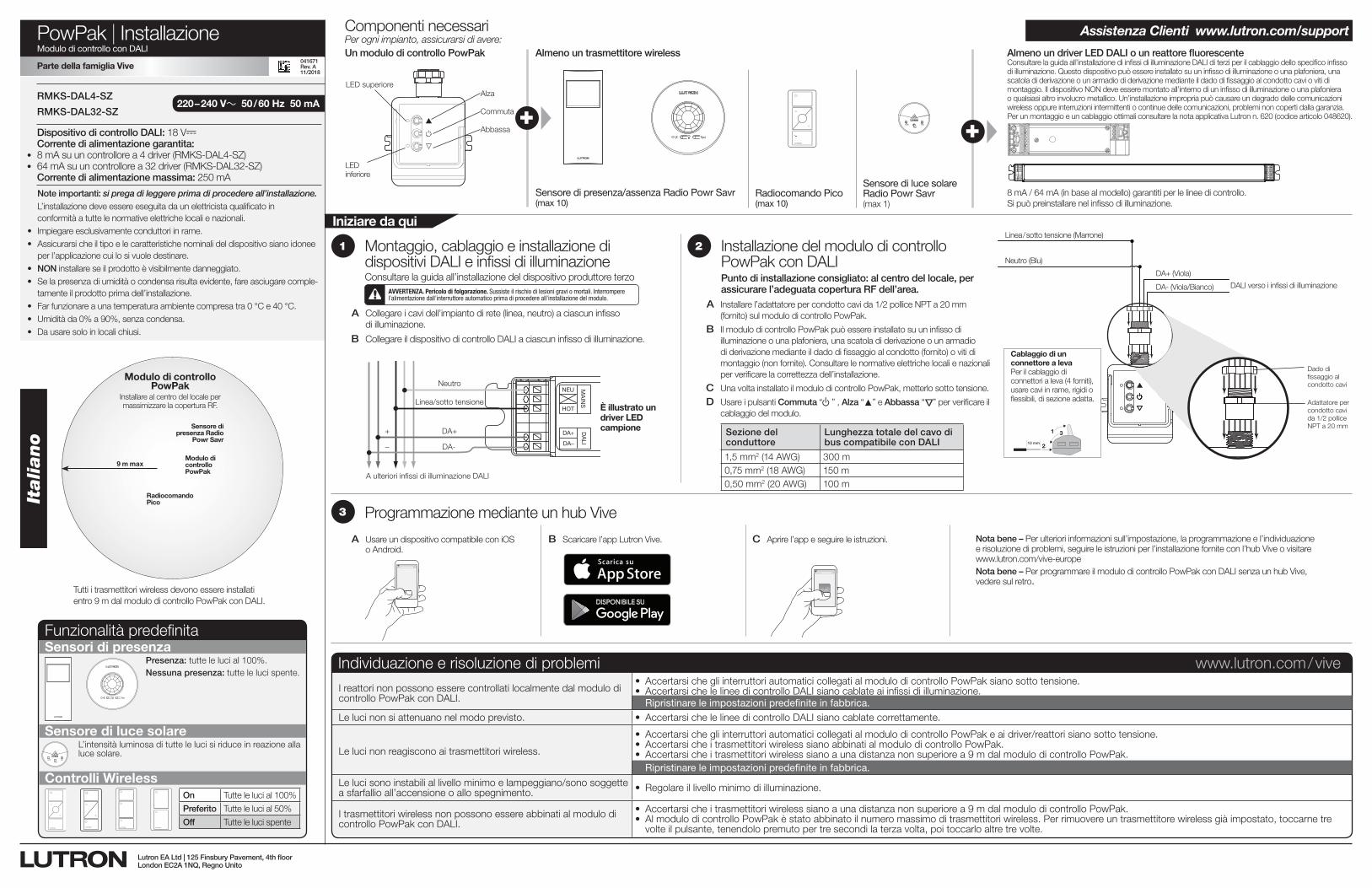
Per ogni impianto, assicurarsi di avere:Un modulo di controllo PowPak Almeno un trasmettitore wireless Almeno un driver LED DALI o un reattore fluorescente
Componenti necessari
Sensore di presenza/assenza Radio Powr Savr(max 10)
Sensore di luce solare Radio Powr Savr(max 1)
Radiocomando Pico(max 10)
8 mA / 64 mA (in base al modello) garantiti per le linee di controllo. Si può preinstallare nel infisso di illuminazione.
Alza
Commuta
Abbassa
LED superiore
Consultare la guida all’installazione di infissi di illuminazione DALI di terzi per il cablaggio dello specifico infisso di illuminazione. Questo dispositivo può essere installato su un infisso di illuminazione o una plafoniera, una scatola di derivazione o un armadio di derivazione mediante il dado di fissaggio al condotto cavi o viti di montaggio. Il dispositivo NON deve essere montato all’interno di un infisso di illuminazione o una plafoniera o qualsiasi altro involucro metallico. Un’installazione impropria può causare un degrado delle comunicazioni wireless oppure interruzioni intermittenti o continue delle comunicazioni, problemi non coperti dalla garanzia. Per un montaggio e un cablaggio ottimali consultare la nota applicativa Lutron n. 620 (codice articolo 048620).+
Sensori di presenza
Sensore di luce solare
Controlli Wireless
Presenza: tutte le luci al 100%.Nessuna presenza: tutte le luci spente.
TestLink Cal.
L’intensità luminosa di tutte le luci si riduce in reazione alla luce solare.
On Tutte le luci al 100%
Preferito Tutte le luci al 50%
Off Tutte le luci spente
Funzionalità predefinita
2
A Installare l’adattatore per condotto cavi da 1/2 pollice NPT a 20 mm (fornito) sul modulo di controllo PowPak.
B Il modulo di controllo PowPak può essere installato su un infisso di illuminazione o una plafoniera, una scatola di derivazione o un armadio di derivazione mediante il dado di fissaggio al condotto (fornito) o viti di montaggio (non fornite). Consultare le normative elettriche locali e nazionali per verificare la correttezza dell’installazione.
C Una volta installato il modulo di controllo PowPak, metterlo sotto tensione.
D Usare i pulsanti Commuta “ u” , Alza “▲” e Abbassa “
Δ
” per verificare il cablaggio del modulo.
Italiano
Tutti i trasmettitori wireless devono essere installati entro 9 m dal modulo di controllo PowPak con DALI.
Dispositivo di controllo DALI: 18 V- Corrente di alimentazione garantita:
• 8 mA su un controllore a 4 driver (RMKS-DAL4-SZ)• 64 mA su un controllore a 32 driver (RMKS-DAL32-SZ)
Corrente di alimentazione massima: 250 mA
220 – 240 V~ 50 / 60 Hz 50 mARMKS-DAL4-SZ
RMKS-DAL32-SZ
A Collegare i cavi dell’impianto di rete (linea, neutro) a ciascun infisso di illuminazione.
B Collegare il dispositivo di controllo DALI a ciascun infisso di illuminazione.
1
DA+
DA–
NEU
HOT
DALI
MAINS
A ulteriori infissi di illuminazione DALI
Neutro
Linea/sotto tensione
DA+
DA-
+
–
AVVERTENZA. Pericolo di folgorazione. Sussiste il rischio di lesioni gravi o mortali. Interrompere l’alimentazione dall’interruttore automatico prima di procedere all’installazione del modulo.
È illustrato un driver LED campione
Note importanti: si prega di leggere prima di procedere all’installazione.L’installazione deve essere eseguita da un elettricista qualificato in conformità a tutte le normative elettriche locali e nazionali.
• Impiegare esclusivamente conduttori in rame.• Assicurarsi che il tipo e le caratteristiche nominali del dispositivo siano idonee
per l’applicazione cui lo si vuole destinare.• NON installare se il prodotto è visibilmente danneggiato.• Se la presenza di umidità o condensa risulta evidente, fare asciugare comple-
tamente il prodotto prima dell’installazione. • Far funzionare a una temperatura ambiente compresa tra 0 °C e 40 °C.• Umidità da 0% a 90%, senza condensa. • Da usare solo in locali chiusi.
Iniziare da qui
XVive
Programmazione mediante un hub Vive3
Montaggio, cablaggio e installazione di dispositivi DALI e infissi di illuminazioneConsultare la guida all’installazione del dispositivo produttore terzo
Installazione del modulo di controllo PowPak con DALIPunto di installazione consigliato: al centro del locale, per assicurare l’adeguata copertura RF dell’area.
A Usare un dispositivo compatibile con iOS o Android.
B Scaricare l’app Lutron Vive. C Aprire l’app e seguire le istruzioni. Nota bene – Per ulteriori informazioni sull’impostazione, la programmazione e l’individuazione e risoluzione di problemi, seguire le istruzioni per l’installazione fornite con l’hub Vive o visitare www.lutron.com/vive-europe
Nota bene – Per programmare il modulo di controllo PowPak con DALI senza un hub Vive, vedere sul retro.
Assistenza Clienti www.lutron.com/support
Individuazione e risoluzione di problemi www.lutron.com / vive
I reattori non possono essere controllati localmente dal modulo di controllo PowPak con DALI.
• AccertarsichegliinterruttoriautomaticicollegatialmodulodicontrolloPowPaksianosottotensione.• AccertarsichelelineedicontrolloDALIsianocablateaiinfissidiilluminazione. Ripristinare le impostazioni predefinite in fabbrica.
Le luci non si attenuano nel modo previsto. • AccertarsichelelineedicontrolloDALIsianocablatecorrettamente.
Le luci non reagiscono ai trasmettitori wireless.
• AccertarsichegliinterruttoriautomaticicollegatialmodulodicontrolloPowPakeaidriver/reattorisianosottotensione.• AccertarsicheitrasmettitoriwirelesssianoabbinatialmodulodicontrolloPowPak.• Accertarsicheitrasmettitoriwirelesssianoaunadistanzanonsuperiorea9mdalmodulodicontrolloPowPak. Ripristinare le impostazioni predefinite in fabbrica.
Le luci sono instabili al livello minimo e lampeggiano/sono soggette a sfarfallio all’accensione o allo spegnimento. • Regolareillivellominimodiilluminazione.
I trasmettitori wireless non possono essere abbinati al modulo di controllo PowPak con DALI.
• Accertarsicheitrasmettitoriwirelesssianoaunadistanzanonsuperiorea9mdalmodulodicontrolloPowPak.• AlmodulodicontrolloPowPakèstatoabbinatoilnumeromassimoditrasmettitoriwireless.Perrimuovereuntrasmettitorewirelessgiàimpostato,toccarnetre
volte il pulsante, tenendolo premuto per tre secondi la terza volta, poi toccarlo altre tre volte.
Parte della famiglia Vive
vive.lutron.com X
DALI verso i infissi di illuminazione
DA+ (Viola)
DA- (Viola/Bianco)
Neutro (Blu)
Linea / sotto tensione (Marrone)
Dado di fissaggio al condotto cavi
Adattatore per condotto cavi da 1/2 pollice NPT a 20 mm
Cablaggio di un connettore a levaPer il cablaggio di connettori a leva (4 forniti), usare cavi in rame, rigidi o flessibili, di sezione adatta.
1
2
3
10 mm
Lutron EA Ltd | 125 Finsbury Pavement, 4th floorLondon EC2A 1NQ, Regno Unito
041671Rev. A11/2018
LED inferiore
9 m max
Sensore di presenza Radio
Powr Savr
Radiocomando Pico
Modulo di controllo PowPak
Installare al centro del locale per massimizzare la copertura RF.
Modulo di controllo PowPak
Sezione del conduttore
Lunghezza totale del cavo di bus compatibile con DALI
1,5 mm2 (14 AWG) 300 m0,75 mm2 (18 AWG) 150 m0,50 mm2 (20 AWG) 100 m
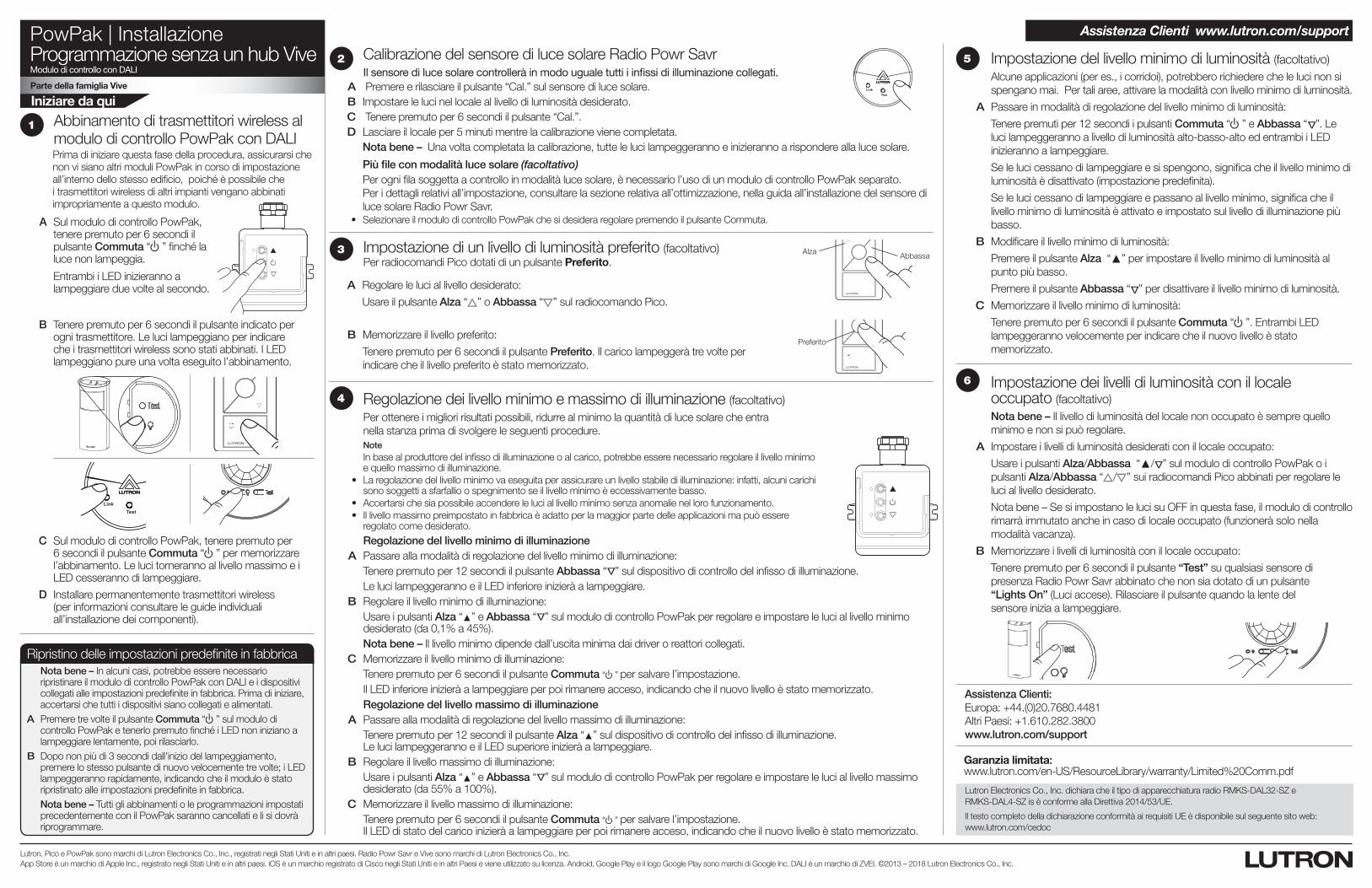
PowPak | InstallazioneProgrammazione senza un hub ViveModulo di controllo con DALI
Parte della famiglia Vive
Iniziare da qui
Lutron, Pico e PowPak sono marchi di Lutron Electronics Co., Inc., registrati negli Stati Uniti e in altri paesi. Radio Powr Savr e Vive sono marchi di Lutron Electronics Co., Inc. App Store è un marchio di Apple Inc., registrato negli Stati Uniti e in altri paesi. iOS è un marchio registrato di Cisco negli Stati Uniti e in altri Paesi e viene utilizzato su licenza. Android, Google Play e il logo Google Play sono marchi di Google Inc. DALI è un marchio di ZVEI. ©2013 – 2018 Lutron Electronics Co., Inc.
A Sul modulo di controllo PowPak, tenere premuto per 6 secondi il pulsante Commuta “ u” finché la luce non lampeggia.
Entrambi i LED inizieranno a lampeggiare due volte al secondo.
Abbinamento di trasmettitori wireless al modulo di controllo PowPak con DALI Prima di iniziare questa fase della procedura, assicurarsi che non vi siano altri moduli PowPak in corso di impostazione all’interno dello stesso edificio, poiché è possibile che i trasmettitori wireless di altri impianti vengano abbinati impropriamente a questo modulo.
1
C Sul modulo di controllo PowPak, tenere premuto per 6 secondi il pulsante Commuta “ u” per memorizzare l’abbinamento. Le luci torneranno al livello massimo e i LED cesseranno di lampeggiare.
B Tenere premuto per 6 secondi il pulsante indicato per ogni trasmettitore. Le luci lampeggiano per indicare che i trasmettitori wireless sono stati abbinati. I LED lampeggiano pure una volta eseguito l’abbinamento.
TestLink Cal.
D Installare permanentemente trasmettitori wireless (per informazioni consultare le guide individuali all’installazione dei componenti).
Alza Abbassa
Preferito
Impostazione di un livello di luminosità preferito (facoltativo)Per radiocomandi Pico dotati di un pulsante Preferito.
A Regolare le luci al livello desiderato:
Usare il pulsante Alza “ ” o Abbassa “ ” sul radiocomando Pico.
B Memorizzare il livello preferito:
Tenere premuto per 6 secondi il pulsante Preferito. Il carico lampeggerà tre volte per indicare che il livello preferito è stato memorizzato.
3
Regolazione del livello minimo di illuminazione A Passare alla modalità di regolazione del livello minimo di illuminazione: Tenere premuto per 12 secondi il pulsante Abbassa “
Δ
” sul dispositivo di controllo del infisso di illuminazione. Le luci lampeggeranno e il LED inferiore inizierà a lampeggiare. B Regolare il livello minimo di illuminazione: Usare i pulsanti Alza “▲” e Abbassa “
Δ
” sul modulo di controllo PowPak per regolare e impostare le luci al livello minimo desiderato (da 0,1% a 45%).
Nota bene – Il livello minimo dipende dall’uscita minima dai driver o reattori collegati. C Memorizzare il livello minimo di illuminazione: Tenere premuto per 6 secondi il pulsante Commuta “ u” per salvare l’impostazione. Il LED inferiore inizierà a lampeggiare per poi rimanere acceso, indicando che il nuovo livello è stato memorizzato. Regolazione del livello massimo di illuminazione A Passare alla modalità di regolazione del livello massimo di illuminazione: Tenere premuto per 12 secondi il pulsante Alza “▲” sul dispositivo di controllo del infisso di illuminazione.
Le luci lampeggeranno e il LED superiore inizierà a lampeggiare. B Regolare il livello massimo di illuminazione: Usare i pulsanti Alza “▲” e Abbassa “
Δ
” sul modulo di controllo PowPak per regolare e impostare le luci al livello massimo desiderato (da 55% a 100%).
C Memorizzare il livello massimo di illuminazione: Tenere premuto per 6 secondi il pulsante Commuta “ u” per salvare l’impostazione.
Il LED di stato del carico inizierà a lampeggiare per poi rimanere acceso, indicando che il nuovo livello è stato memorizzato.
Regolazione dei livello minimo e massimo di illuminazione (facoltativo)Per ottenere i migliori risultati possibili, ridurre al minimo la quantità di luce solare che entra nella stanza prima di svolgere le seguenti procedure.
Note In base al produttore del infisso di illuminazione o al carico, potrebbe essere necessario regolare il livello minimo
e quello massimo di illuminazione. • Laregolazionedellivellominimovaeseguitaperassicurareunlivellostabilediilluminazione:infatti,alcunicarichi
sono soggetti a sfarfallio o spegnimento se il livello minimo è eccessivamente basso. • Accertarsichesiapossibileaccendereleluciallivellominimosenzaanomalienellorofunzionamento. • Illivellomassimopreimpostatoinfabbricaèadattoperlamaggiorpartedelleapplicazionimapuòessere
regolato come desiderato.
4
5 Impostazione del livello minimo di luminosità (facoltativo)Alcune applicazioni (per es., i corridoi), potrebbero richiedere che le luci non si spengano mai. Per tali aree, attivare la modalità con livello minimo di luminosità.
A Passare in modalità di regolazione del livello minimo di luminosità:
Tenere premuti per 12 secondi i pulsanti Commuta “ u” e Abbassa “ Δ”. Le luci lampeggeranno a livello di luminosità alto-basso-alto ed entrambi i LED inizieranno a lampeggiare.
Se le luci cessano di lampeggiare e si spengono, significa che il livello minimo di luminosità è disattivato (impostazione predefinita).
Se le luci cessano di lampeggiare e passano al livello minimo, significa che il livello minimo di luminosità è attivato e impostato sul livello di illuminazione più basso.
B Modificare il livello minimo di luminosità:
Premere il pulsante Alza “▲” per impostare il livello minimo di luminosità al punto più basso.
Premere il pulsante Abbassa “ Δ” per disattivare il livello minimo di luminosità.
C Memorizzare il livello minimo di luminosità:
Tenere premuto per 6 secondi il pulsante Commuta “ u”. Entrambi LED lampeggeranno velocemente per indicare che il nuovo livello è stato memorizzato.
6 Impostazione dei livelli di luminosità con il locale occupato (facoltativo)Nota bene – Il livello di luminosità del locale non occupato è sempre quello minimo e non si può regolare.
A Impostare i livelli di luminosità desiderati con il locale occupato:
Usare i pulsanti Alza/Abbassa “▲/ Δ” sul modulo di controllo PowPak o i pulsanti Alza/Abbassa “ / ” sui radiocomandi Pico abbinati per regolare le luci al livello desiderato.
Nota bene – Se si impostano le luci su OFF in questa fase, il modulo di controllo rimarrà immutato anche in caso di locale occupato (funzionerà solo nella modalità vacanza).
B Memorizzare i livelli di luminosità con il locale occupato:
Tenere premuto per 6 secondi il pulsante “Test” su qualsiasi sensore di presenza Radio Powr Savr abbinato che non sia dotato di un pulsante “Lights On” (Luci accese). Rilasciare il pulsante quando la lente del sensore inizia a lampeggiare.
Garanzia limitata: www.lutron.com/en-US/ResourceLibrary/warranty/Limited%20Comm.pdf
Calibrazione del sensore di luce solare Radio Powr Savr Il sensore di luce solare controllerà in modo uguale tutti i infissi di illuminazione collegati.
A Premere e rilasciare il pulsante “Cal.” sul sensore di luce solare. B Impostare le luci nel locale al livello di luminosità desiderato. C Tenere premuto per 6 secondi il pulsante “Cal.”. D Lasciare il locale per 5 minuti mentre la calibrazione viene completata.
Nota bene – Una volta completata la calibrazione, tutte le luci lampeggeranno e inizieranno a rispondere alla luce solare.
Più file con modalità luce solare (facoltativo)Per ogni fila soggetta a controllo in modalità luce solare, è necessario l’uso di un modulo di controllo PowPak separato. Per i dettagli relativi all’impostazione, consultare la sezione relativa all’ottimizzazione, nella guida all’installazione del sensore di luce solare Radio Powr Savr.
• SelezionareilmodulodicontrolloPowPakchesidesideraregolarepremendoilpulsanteCommuta.
TestLink Cal.
2
Ripristino delle impostazioni predefinite in fabbricaNota bene – In alcuni casi, potrebbe essere necessario ripristinare il modulo di controllo PowPak con DALI e i dispositivi collegati alle impostazioni predefinite in fabbrica. Prima di iniziare, accertarsi che tutti i dispositivi siano collegati e alimentati.
A Premere tre volte il pulsante Commuta “ u” sul modulo di controllo PowPak e tenerlo premuto finché i LED non iniziano a lampeggiare lentamente, poi rilasciarlo.
B Dopo non più di 3 secondi dall’inizio del lampeggiamento, premere lo stesso pulsante di nuovo velocemente tre volte; i LED lampeggeranno rapidamente, indicando che il modulo è stato ripristinato alle impostazioni predefinite in fabbrica. Nota bene – Tutti gli abbinamenti o le programmazioni impostati precedentemente con il PowPak saranno cancellati e li si dovrà riprogrammare.
Assistenza Clienti:Europa: +44.(0)20.7680.4481Altri Paesi: +1.610.282.3800www.lutron.com/support
Assistenza Clienti www.lutron.com/support
Lutron Electronics Co., Inc. dichiara che il tipo di apparecchiatura radio RMKS-DAL32-SZ e RMKS-DAL4-SZ is è conforme alla Direttiva 2014/53/UE.
Il testo completo della dichiarazione conformità ai requisiti UE è disponibile sul seguente sito web: www.lutron.com/cedoc
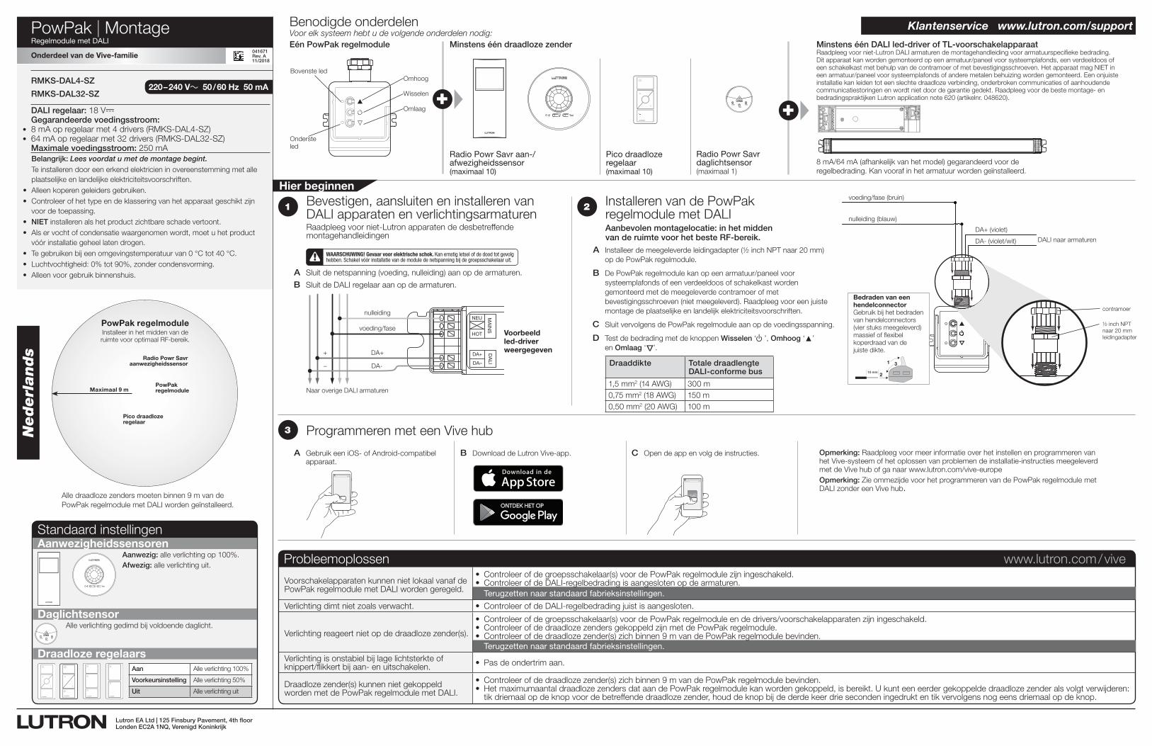
041588 Rev. A11/2018
PowPak | MontageRegelmodule met DALI
TestLink Cal. +
Voor elk systeem hebt u de volgende onderdelen nodig:Eén PowPak regelmodule Minstens één draadloze zender Minstens één DALI led-driver of TL-voorschakelapparaat
Benodigde onderdelen
Radio Powr Savr aan-/ afwezigheidssensor(maximaal 10)
Radio Powr Savr daglichtsensor(maximaal 1)
Pico draadloze regelaar(maximaal 10)
8 mA/64 mA (afhankelijk van het model) gegarandeerd voor de regelbedrading. Kan vooraf in het armatuur worden geïnstalleerd.
Omhoog
Wisselen
Omlaag
Bovenste led
Raadpleeg voor niet-Lutron DALI armaturen de montagehandleiding voor armatuurspecifieke bedrading. Dit apparaat kan worden gemonteerd op een armatuur/paneel voor systeemplafonds, een verdeeldoos of een schakelkast met behulp van de contramoer of met bevestigingsschroeven. Het apparaat mag NIET in een armatuur/paneel voor systeemplafonds of andere metalen behuizing worden gemonteerd. Een onjuiste installatie kan leiden tot een slechte draadloze verbinding, onderbroken communicaties of aanhoudende communicatiestoringen en wordt niet door de garantie gedekt. Raadpleeg voor de beste montage- en bedradingspraktijken Lutron application note 620 (artikelnr. 048620).+
Aanwezigheidssensoren
Daglichtsensor
Draadloze regelaars
Aanwezig: alle verlichting op 100%.Afwezig: alle verlichting uit.
TestLink Cal.
Alle verlichting gedimd bij voldoende daglicht.
Standaard instellingen
2
A Installeer de meegeleverde leidingadapter (½ inch NPT naar 20 mm) op de PowPak regelmodule.
B De PowPak regelmodule kan op een armatuur/paneel voor systeemplafonds of een verdeeldoos of schakelkast worden gemonteerd met de meegeleverde contramoer of met bevestigingsschroeven (niet meegeleverd). Raadpleeg voor een juiste montage de plaatselijke en landelijk elektriciteitsvoorschriften.
C Sluit vervolgens de PowPak regelmodule aan op de voedingsspanning.
D Test de bedrading met de knoppen Wisselen ‘u’, Omhoog ‘▲’ en Omlaag ‘
Δ
’.
Nederlands
Alle draadloze zenders moeten binnen 9 m van de PowPak regelmodule met DALI worden geïnstalleerd.
DALI regelaar: 18 V- Gegarandeerde voedingsstroom:
• 8 mA op regelaar met 4 drivers (RMKS-DAL4-SZ)• 64 mA op regelaar met 32 drivers (RMKS-DAL32-SZ)
Maximale voedingsstroom: 250 mA
220 – 240 V~ 50 / 60 Hz 50 mARMKS-DAL4-SZ
RMKS-DAL32-SZ
A Sluit de netspanning (voeding, nulleiding) aan op de armaturen.
B Sluit de DALI regelaar aan op de armaturen.
1
DA+
DA–
NEU
HOT
DALI
MAINS
Naar overige DALI armaturen
nulleiding
voeding/fase
DA+
DA-
+
–
WAARSCHUWING! Gevaar voor elektrische schok. Kan ernstig letsel of de dood tot gevolg hebben. Schakel vóór installatie van de module de netspanning bij de groepsschakelaar uit.
Voorbeeld led-driver weergegeven
Belangrijk: Lees voordat u met de montage begint.Te installeren door een erkend elektricien in overeenstemming met alle plaatselijke en landelijke elektriciteitsvoorschriften.
• Alleen koperen geleiders gebruiken.• Controleer of het type en de klassering van het apparaat geschikt zijn
voor de toepassing.• NIET installeren als het product zichtbare schade vertoont.• Als er vocht of condensatie waargenomen wordt, moet u het product
vóór installatie geheel laten drogen.• Te gebruiken bij een omgevingstemperatuur van 0 °C tot 40 °C.• Luchtvochtigheid: 0% tot 90%, zonder condensvorming.• Alleen voor gebruik binnenshuis.
Hier beginnen
XVive
Programmeren met een Vive hub3
Bevestigen, aansluiten en installeren van DALI apparaten en verlichtingsarmaturenRaadpleeg voor niet-Lutron apparaten de desbetreffende montagehandleidingen
Installeren van de PowPak regelmodule met DALIAanbevolen montagelocatie: in het midden van de ruimte voor het beste RF-bereik.
A Gebruik een iOS- of Android-compatibel apparaat.
B Download de Lutron Vive-app. C Open de app en volg de instructies. Opmerking: Raadpleeg voor meer informatie over het instellen en programmeren van het Vive-systeem of het oplossen van problemen de installatie-instructies meegeleverd met de Vive hub of ga naar www.lutron.com/vive-europe
Opmerking: Zie ommezijde voor het programmeren van de PowPak regelmodule met DALI zonder een Vive hub.
Klantenservice www.lutron.com/support
Probleemoplossen www.lutron.com / vive
Voorschakelapparaten kunnen niet lokaal vanaf de PowPak regelmodule met DALI worden geregeld.
• Controleerofdegroepsschakelaar(s)voordePowPakregelmodulezijningeschakeld.• ControleerofdeDALI-regelbedradingisaangeslotenopdearmaturen. Terugzetten naar standaard fabrieksinstellingen.
Verlichting dimt niet zoals verwacht. • ControleerofdeDALI-regelbedradingjuistisaangesloten.
Verlichting reageert niet op de draadloze zender(s).
• Controleerofdegroepsschakelaar(s)voordePowPakregelmoduleendedrivers/voorschakelapparatenzijningeschakeld.• ControleerofdedraadlozezendersgekoppeldzijnmetdePowPakregelmodule.• Controleerofdedraadlozezender(s)zichbinnen9mvandePowPakregelmodulebevinden. Terugzetten naar standaard fabrieksinstellingen.
Verlichting is onstabiel bij lage lichtsterkte of knippert/flikkert bij aan- en uitschakelen. • Pasdeondertrimaan.
Draadloze zender(s) kunnen niet gekoppeld worden met de PowPak regelmodule met DALI.
• Controleerofdedraadlozezender(s)zichbinnen9mvandePowPakregelmodulebevinden.• HetmaximumaantaldraadlozezendersdataandePowPakregelmodulekanwordengekoppeld,isbereikt.Ukunteeneerdergekoppeldedraadlozezenderalsvolgtverwijderen:
tik driemaal op de knop voor de betreffende draadloze zender, houd de knop bij de derde keer drie seconden ingedrukt en tik vervolgens nog eens driemaal op de knop.
Onderdeel van de Vive-familie
vive.lutron.com X
DALI naar armaturen
DA+ (violet)
DA- (violet/wit)
nulleiding (blauw)
voeding/fase (bruin)
contramoer
½ inch NPT naar 20 mm leidingadapter
Bedraden van een hendelconnectorGebruik bij het bedraden van hendelconnectors (vier stuks meegeleverd) massief of flexibel koperdraad van de juiste dikte.
1
2
3
10 mm
Lutron EA Ltd | 125 Finsbury Pavement, 4th floorLonden EC2A 1NQ, Verenigd Koninkrijk
041671Rev. A11/2018
Onderste led
Maximaal 9 m
Radio Powr Savr aanwezigheidssensor
Pico draadloze regelaar
PowPak regelmoduleInstalleer in het midden van de ruimte voor optimaal RF-bereik.
PowPak regelmodule
Draaddikte Totale draadlengte DALI-conforme bus
1,5 mm2 (14 AWG) 300 m0,75 mm2 (18 AWG) 150 m0,50 mm2 (20 AWG) 100 m
Aan Alle verlichting 100%
Voorkeursinstelling Alle verlichting 50%
Uit Alle verlichting uit
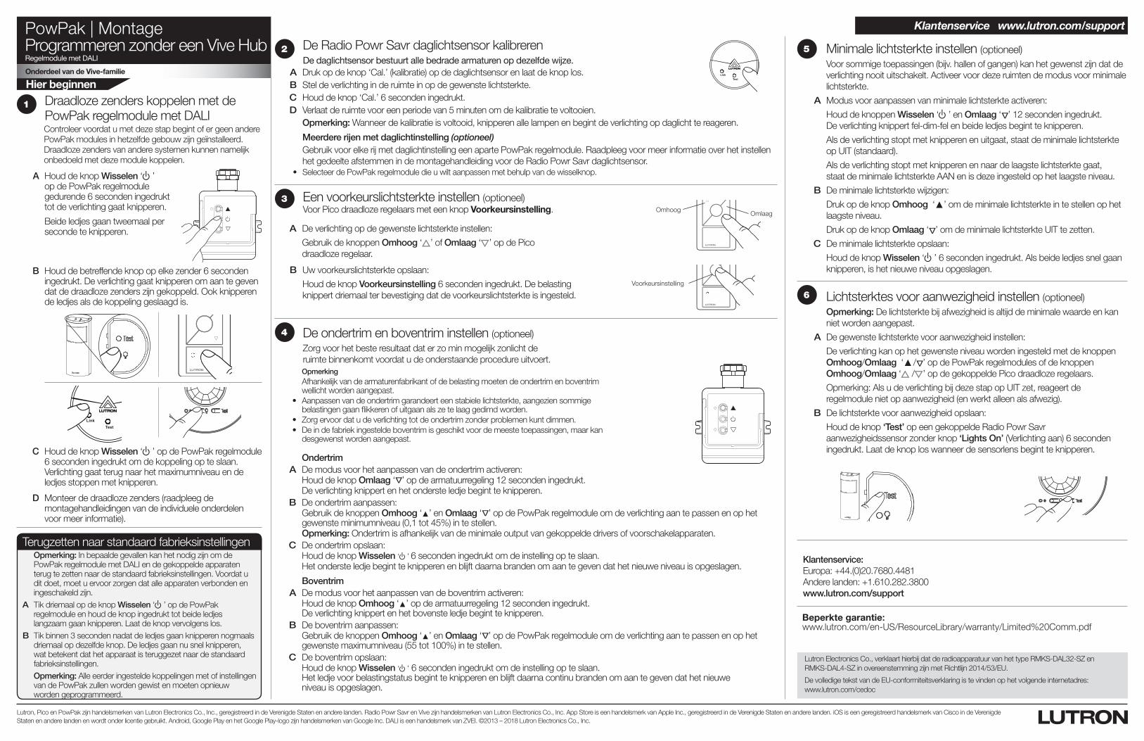
PowPak | MontageProgrammeren zonder een Vive HubRegelmodule met DALI
Onderdeel van de Vive-familie
Hier beginnen
Lutron, Pico en PowPak zijn handelsmerken van Lutron Electronics Co., Inc., geregistreerd in de Verenigde Staten en andere landen. Radio Powr Savr en Vive zijn handelsmerken van Lutron Electronics Co., Inc. App Store is een handelsmerk van Apple Inc., geregistreerd in de Verenigde Staten en andere landen. iOS is een geregistreerd handelsmerk van Cisco in de Verenigde Staten en andere landen en wordt onder licentie gebruikt. Android, Google Play en het Google Play-logo zijn handelsmerken van Google Inc. DALI is een handelsmerk van ZVEI. ©2013 – 2018 Lutron Electronics Co., Inc.
A Houd de knop Wisselen ‘ u’ op de PowPak regelmodule gedurende 6 seconden ingedrukt tot de verlichting gaat knipperen.
Beide ledjes gaan tweemaal per seconde te knipperen.
Draadloze zenders koppelen met de PowPak regelmodule met DALI Controleer voordat u met deze stap begint of er geen andere PowPak modules in hetzelfde gebouw zijn geïnstalleerd. Draadloze zenders van andere systemen kunnen namelijk onbedoeld met deze module koppelen.
1
C Houd de knop Wisselen ‘ u’ op de PowPak regelmodule 6 seconden ingedrukt om de koppeling op te slaan. Verlichting gaat terug naar het maximumniveau en de ledjes stoppen met knipperen.
B Houd de betreffende knop op elke zender 6 seconden ingedrukt. De verlichting gaat knipperen om aan te geven dat de draadloze zenders zijn gekoppeld. Ook knipperen de ledjes als de koppeling geslaagd is.
TestLink Cal.
D Monteer de draadloze zenders (raadpleeg de montagehandleidingen van de individuele onderdelen voor meer informatie).
Omhoog Omlaag
Voorkeursinstelling
Een voorkeurslichtsterkte instellen (optioneel)Voor Pico draadloze regelaars met een knop Voorkeursinstelling.
A De verlichting op de gewenste lichtsterkte instellen:
Gebruik de knoppen Omhoog ‘ ’ of Omlaag ‘ ’ op de Pico draadloze regelaar.
B Uw voorkeurslichtsterkte opslaan:
Houd de knop Voorkeursinstelling 6 seconden ingedrukt. De belasting knippert driemaal ter bevestiging dat de voorkeurslichtsterkte is ingesteld.
3
Ondertrim A De modus voor het aanpassen van de ondertrim activeren: Houd de knop Omlaag ‘
Δ
’ op de armatuurregeling 12 seconden ingedrukt. De verlichting knippert en het onderste ledje begint te knipperen. B De ondertrim aanpassen: Gebruik de knoppen Omhoog ‘▲’ en Omlaag ‘
Δ
’ op de PowPak regelmodule om de verlichting aan te passen en op het gewenste minimumniveau (0,1 tot 45%) in te stellen.
Opmerking: Ondertrim is afhankelijk van de minimale output van gekoppelde drivers of voorschakelapparaten. C De ondertrim opslaan: Houd de knop Wisselen ‘u’ 6 seconden ingedrukt om de instelling op te slaan. Het onderste ledje begint te knipperen en blijft daarna branden om aan te geven dat het nieuwe niveau is opgeslagen.
Boventrim A De modus voor het aanpassen van de boventrim activeren: Houd de knop Omhoog ‘▲’ op de armatuurregeling 12 seconden ingedrukt.
De verlichting knippert en het bovenste ledje begint te knipperen. B De boventrim aanpassen: Gebruik de knoppen Omhoog ‘▲’ en Omlaag ‘
Δ
’ op de PowPak regelmodule om de verlichting aan te passen en op het gewenste maximumniveau (55 tot 100%) in te stellen.
C De boventrim opslaan: Houd de knop Wisselen ‘u’ 6 seconden ingedrukt om de instelling op te slaan.
Het ledje voor belastingstatus begint te knipperen en blijft daarna continu branden om aan te geven dat het nieuwe niveau is opgeslagen.
De ondertrim en boventrim instellen (optioneel)Zorg voor het beste resultaat dat er zo min mogelijk zonlicht de ruimte binnenkomt voordat u de onderstaande procedure uitvoert.
Opmerking Afhankelijk van de armaturenfabrikant of de belasting moeten de ondertrim en boventrim
wellicht worden aangepast. • Aanpassenvandeondertrimgarandeerteenstabielelichtsterkte,aangeziensommige
belastingen gaan flikkeren of uitgaan als ze te laag gedimd worden. • Zorgervoordatudeverlichtingtotdeondertrimzonderproblemenkuntdimmen. • Deindefabriekingesteldeboventrimisgeschiktvoordemeestetoepassingen,maarkan
desgewenst worden aangepast.
4
5 Minimale lichtsterkte instellen (optioneel)Voor sommige toepassingen (bijv. hallen of gangen) kan het gewenst zijn dat de verlichting nooit uitschakelt. Activeer voor deze ruimten de modus voor minimale lichtsterkte.
A Modus voor aanpassen van minimale lichtsterkte activeren:
Houd de knoppen Wisselen ‘u’ en Omlaag ‘ Δ’ 12 seconden ingedrukt. De verlichting knippert fel-dim-fel en beide ledjes begint te knipperen.
Als de verlichting stopt met knipperen en uitgaat, staat de minimale lichtsterkte op UIT (standaard).
Als de verlichting stopt met knipperen en naar de laagste lichtsterkte gaat, staat de minimale lichtsterkte AAN en is deze ingesteld op het laagste niveau.
B De minimale lichtsterkte wijzigen:
Druk op de knop Omhoog ‘▲’ om de minimale lichtsterkte in te stellen op het laagste niveau.
Druk op de knop Omlaag ‘ Δ’ om de minimale lichtsterkte UIT te zetten.
C De minimale lichtsterkte opslaan:
Houd de knop Wisselen ‘ u’ 6 seconden ingedrukt. Als beide ledjes snel gaan knipperen, is het nieuwe niveau opgeslagen.
6 Lichtsterktes voor aanwezigheid instellen (optioneel)Opmerking: De lichtsterkte bij afwezigheid is altijd de minimale waarde en kan niet worden aangepast.
A De gewenste lichtsterkte voor aanwezigheid instellen:
De verlichting kan op het gewenste niveau worden ingesteld met de knoppen Omhoog/Omlaag ‘▲ / Δ’ op de PowPak regelmodules of de knoppen Omhoog/Omlaag ‘ / ’ op de gekoppelde Pico draadloze regelaars.
Opmerking: Als u de verlichting bij deze stap op UIT zet, reageert de regelmodule niet op aanwezigheid (en werkt alleen als afwezig).
B De lichtsterkte voor aanwezigheid opslaan:
Houd de knop ‘Test’ op een gekoppelde Radio Powr Savr aanwezigheidssensor zonder knop ‘Lights On’ (Verlichting aan) 6 seconden ingedrukt. Laat de knop los wanneer de sensorlens begint te knipperen.
Beperkte garantie: www.lutron.com/en-US/ResourceLibrary/warranty/Limited%20Comm.pdf
De Radio Powr Savr daglichtsensor kalibreren De daglichtsensor bestuurt alle bedrade armaturen op dezelfde wijze.
A Druk op de knop ‘Cal.’ (kalibratie) op de daglichtsensor en laat de knop los. B Stel de verlichting in de ruimte in op de gewenste lichtsterkte. C Houd de knop ‘Cal.’ 6 seconden ingedrukt. D Verlaat de ruimte voor een periode van 5 minuten om de kalibratie te voltooien.
Opmerking: Wanneer de kalibratie is voltooid, knipperen alle lampen en begint de verlichting op daglicht te reageren.
Meerdere rijen met daglichtinstelling (optioneel)Gebruik voor elke rij met daglichtinstelling een aparte PowPak regelmodule. Raadpleeg voor meer informatie over het instellen het gedeelte afstemmen in de montagehandleiding voor de Radio Powr Savr daglichtsensor.
• SelecteerdePowPakregelmoduledieuwiltaanpassenmetbehulpvandewisselknop.
TestLink Cal.
2
Terugzetten naar standaard fabrieksinstellingenOpmerking: In bepaalde gevallen kan het nodig zijn om de PowPak regelmodule met DALI en de gekoppelde apparaten terug te zetten naar de standaard fabrieksinstellingen. Voordat u dit doet, moet u ervoor zorgen dat alle apparaten verbonden en ingeschakeld zijn.
A Tik driemaal op de knop Wisselen ‘ u’ op de PowPak regelmodule en houd de knop ingedrukt tot beide ledjes langzaam gaan knipperen. Laat de knop vervolgens los.
B Tik binnen 3 seconden nadat de ledjes gaan knipperen nogmaals driemaal op dezelfde knop. De ledjes gaan nu snel knipperen, wat betekent dat het apparaat is teruggezet naar de standaard fabrieksinstellingen.Opmerking: Alle eerder ingestelde koppelingen met of instellingen van de PowPak zullen worden gewist en moeten opnieuw worden geprogrammeerd.
Klantenservice:Europa: +44.(0)20.7680.4481Andere landen: +1.610.282.3800www.lutron.com/support
Klantenservice www.lutron.com/support
Lutron Electronics Co., verklaart hierbij dat de radioapparatuur van het type RMKS-DAL32-SZ en RMKS-DAL4-SZ in overeenstemming zijn met Richtlijn 2014/53/EU.
De volledige tekst van de EU-conformiteitsverklaring is te vinden op het volgende internetadres: www.lutron.com/cedoc


