Embed Size (px)
Citation preview
VR Content Platform for Multi-Projection Displayswith Realtime Image Adjustment
Takafumi Koike Kei Utsugi Michio OikawaSystems Development Laboratory, Hitachi, Ltd.,
1099 Ohzenji, Asao, Kawasaki, Kanagawa, 215-0013, Japan{koike,utsugi,oikawa}@sdl.hitachi.co.jp
Abstract
We propose a VR content platform for multi-projection dis-plays. Our platform has in common features with framesynchronization methods without any special hardware andreal-time image adjustment mechanism with graphics pro-cessing units.We realized the image adjustment mechanisms as image
effects. The image effects used multipass rendering, mul-titexturing, and programmable shaders. Therefore we caneasily extend adjustment algorithms, and use multiple ef-fects, and implemented several image filters.In above features, we can reduce workflow to create con-
tent for multi-projection display. Because we can efficientlyoperate post-productions for content for multi-projectiondisplay. We used our system to create high-resolution moviecontents for seamless multi-projection display.
Keywords: Immersive Projection Technology (IPT),Frame Synchronization, Graphics Processing Unit (GPU),Realtime Image Adjustment, VR Content Creation
1. Introduction
Seamless multi-projection displays have been thoroughlystudied and applied to many products, as one of the Immer-sive Projection Technologies (IPT). However, most of theseproducts have simple architectures, for example some prod-ucts consist of one PC and three displays. Therefore, stud-ies on more complex systems are now in progress. For ex-ample, Yamasaki studied color and geometry adjustmentsfor the overlapped areas using complex screen shapes andmulti-projectors for immersive projection displays [12].Additionally, special hardware is currently being stud-
ied for multi display systems. For the driver or library,Humphreys studied WireGL([4]) as a scalable OepnGL sys-tem on cluster PCs, and Chromium([5]) as a stream pro-cessing framework for interactive graphics on cluster PCs.For hardware, Stoll studied image reconstruction hardwarefor multi-projection displays [11].However, the GPU processing power surpassed that of
the CPU, and GPUs can execute most image-processingoperations much faster than CPUs, [6] and [7].In these displays, it is difficult to create motion pictures
for immersive projection displays, because they have highlyspecialized, high-resolution screens. For example, duringthe editing of motion pictures, we have to execute fine colorcorrection adjustments, and so on. But, during the ad-justment, we must go back to the beginning to do somework, such as color correction (with tools such as Adobe r°
Photoshop r° or After Effects r°1 on PC), encoding, and pre-
1Adobe, Photoshop, and After Effects are the registered
view process in the actual displays. Chen studied scalableand high-resolution tiled displays([2]) by MPEG video de-livery, but to use specific CODEC(COder/DECorder) is notsuitable for VR contents creations. Because new codecs aredeveloped continually, for example Pixlet for Quicktime 7or WMV HD for WMV9 are these new codecs, and we wantto choose codecs by creating contents.To improve the workflow and solve these problems, we
developed a synchronous GPU system over a network. Ad-ditionally, we applied the system to multi-projection dis-plays to operate interactive and intuitive post-productionof high-resolution motion pictures in realtime.In section two, we show previos works and problems of
past researches. In section threem we propose our archi-tecture to rsolving some problems and show our experi-ment system. In section four, we show experiments results.Lastly, we conclude our research, and show future works.
2. Previous Work and Problems
2.1. Seamless Multi-Projection Displays
In our system, we used the techniques proposed by [12].The system consisted of an equal number of PCs and pro-jectors. Each PC generates and displays one image for oneprojector. In addition, each PC is connected over LAN(ex. 100/1000BASE-T), allowing us to realize fully scalableseamless multi-projection display systems, without restric-tions on the number of projectors.The images from each projector have overlapped areas.
To realize seamless images, the test patterns were projectedand measured using digital still cameras, and we calculatedthe correction data for seamless projections from the pho-tos.To correct images in realtime, we used specially de-
veloped image-processing boards. Each image-processingboard had an image input and an image output. To real-ize seamless projection, these correction data were loadedto our boards, and corrective measures were applied to theinput images.After being geometrically transformed, the real-time ren-
dered images were projected onto a hemispherical screenusing six projectors, and the brightness and color were ad-justed to produce one seamless image on the screen. Thetransformation was executed on our proprietary image pro-cessors.It is not possible for this system to process image cor-
rections using a GPU, because our prototype GPU-basedimage processing system runs at about 25 frames per sec-ond only, without any other graphic processing in Radeon9800. This is because the image processing of our seamless
trademarks of Adobe Systems Incorporated.
projection system processes geometry, color, and gammacorrections for each pixel, which require a huge number oftexture lookups.
The hardware can process images in real time, but is notprogrammable, and the parameters cannot be uploaded inreal time. Therefore, it is difficult to change the correctiondata in real time.
2.2. Frame Synchronization Problem
For simplicity, we used only movie content in our research,but we can easily extend this to real time VR content. Inour system, we choose a Direct Show Technologies on Mi-crosoft Windows platform because it supports many codecs,and we can play movies free from codecs. This enables us tochoose the most suitable format for the content, dependingon the circumstances. Additionally, developing codec is ex-tremely difficult, and therefore impractical for our system.
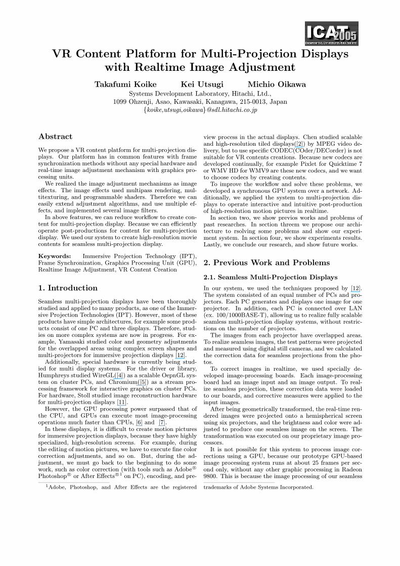
We showed a movie profile (Figure 1) with a setting of30 frames per seconds. The movie contained 2218 frames.The X-axis represents the frame numbers of the movie, andy-axis represents the interval time of the previous frame inmilliseconds. This graph shows that there is a lot of movieplayback jitter.
Figure 1: Movie profile
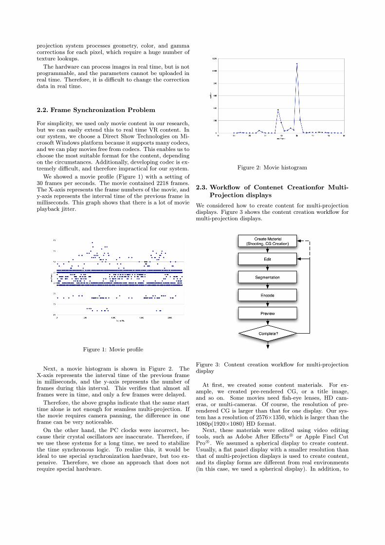
Next, a movie histogram is shown in Figure 2. TheX-axis represents the interval time of the previous framein milliseconds, and the y-axis represents the number offrames during this interval. This verifies that almost allframes were in time, and only a few frames were delayed.
Therefore, the above graphs indicate that the same starttime alone is not enough for seamless multi-projection. Ifthe movie requires camera panning, the difference in oneframe can be very noticeable.
On the other hand, the PC clocks were incorrect, be-cause their crystal oscillators are inaccurate. Therefore, ifwe use these systems for a long time, we need to stabilizethe time synchronous logic. To realize this, it would beideal to use special synchronization hardware, but too ex-pensive. Therefore, we chose an approach that does notrequire special hardware.
Figure 2: Movie histogram
2.3. Workflow of Contenet Creationfor Multi-Projection displays
We considered how to create content for multi-projectiondisplays. Figure 3 shows the content creation workflow formulti-projection displays.
Figure 3: Content creation workflow for multi-projectiondisplay
At first, we created some content materials. For ex-ample, we created pre-rendered CG, or a title image,and so on. Some movies need fish-eye lenses, HD cam-eras, or multi-cameras. Of course, the resolution of pre-rendered CG is larger than that for one display. Our sys-tem has a resolution of 2576×1350, which is larger than the1080p(1920×1080) HD format.Next, these materials were edited using video editing
tools, such as Adobe After Effects r° or Apple Fincl CutPro r°. We assumed a spherical display to create content.Usually, a flat panel display with a smaller resolution thanthat of multi-projection displays is used to create content,and its display forms are different from real environments(in this case, we used a spherical display). In addition, to
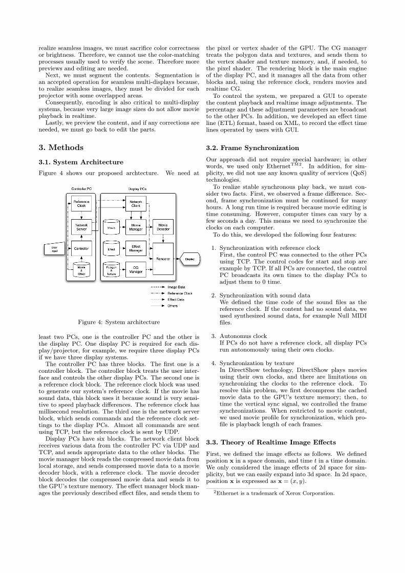
realize seamless images, we must sacrifice color correctnessor brightness. Therefore, we cannot use the color-matchingprocesses usually used to verify the scene. Therefore morepreviews and editing are needed.Next, we must segment the contents. Segmentation is
an accepted operation for seamless multi-displays because,to realize seamless images, they must be divided for eachprojector with some overlapped areas.Consequently, encoding is also critical to multi-display
systems, because very large image sizes do not allow movieplayback in realtime.Lastly, we preview the content, and if any corrections are
needed, we must go back to edit the parts.
3. Methods
3.1. System Architecture
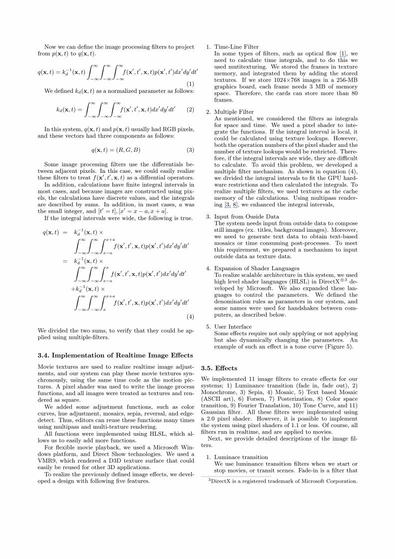
Figure 4 shows our proposed archtecture. We need at
Figure 4: System architecture
least two PCs, one is the controller PC and the other isthe display PC. One display PC is required for each dis-play/projector, for example, we require three display PCsif we have three display systems.The controller PC has three blocks. The first one is a
controller block. The controller block treats the user inter-face and controls the other display PCs. The second one isa reference clock block. The reference clock block was usedto generate our system’s reference clock. If the movie hassound data, this block uses it because sound is very sensi-tive to speed playback differences. The reference clock hasmillisecond resolution. The third one is the network serverblock, which sends commands and the reference clock set-tings to the display PCs. Almost all commands are sentusing TCP, but the reference clock is sent by UDP.Display PCs have six blocks. The network client block
receives various data from the controller PC via UDP andTCP, and sends appropriate data to the other blocks. Themovie manager block reads the compressed movie data fromlocal storage, and sends compressed movie data to a moviedecoder block, with a reference clock. The movie decoderblock decodes the compressed movie data and sends it tothe GPU’s texture memory. The effect manager block man-ages the previously described effect files, and sends them to
the pixel or vertex shader of the GPU. The CG managertreats the polygon data and textures, and sends them tothe vertex shader and texture memory, and, if needed, tothe pixel shader. The rendering block is the main engineof the display PC, and it manages all the data from otherblocks and, using the reference clock, renders movies andrealtime CG.To control the system, we prepared a GUI to operate
the content playback and realtime image adjustments. Thepercentage and these adjustment parameters are broadcastto the other PCs. In addition, we developed an effect timeline (ETL) format, based on XML, to record the effect timelines operated by users with GUI.
3.2. Frame Synchronization
Our approach did not require special hardware; in otherwords, we used only EthernetTM2. In addition, for sim-plicity, we did not use any known quality of services (QoS)technologies.To realize stable synchronous play back, we must con-
sider two facts. First, we observed a frame difference. Sec-ond, frame synchronization must be continued for manyhours. A long run time is required because movie editing istime consuming. However, computer times can vary by afew seconds a day. This means we need to synchronize theclocks on each computer.To do this, we developed the following four features:
1. Synchronization with reference clockFirst, the control PC was connected to the other PCsusing TCP. The control codes for start and stop areexample by TCP. If all PCs are connected, the controlPC broadcasts its own times to the display PCs toadjust them to 0 time.
2. Synchronization with sound dataWe defined the time code of the sound files as thereference clock. If the content had no sound data, weused synthesized sound data, for example Null MIDIfiles.
3. Autonomus clockIf PCs do not have a reference clock, all display PCsrun autonomously using their own clocks.
4. Synchronization by textureIn DirectShow technology, DirectShow plays moviesusing their own clocks, and there are limitations onsynchronizing the clocks to the reference clock. Toresolve this problem, we first decompress the cachedmovie data to the GPU’s texture memory; then, totime the vertical sync signal, we controlled the framesynchronizations. When restricted to movie content,we used movie profile for synchronization, which pro-file is playback length of each frames.
3.3. Theory of Realtime Image Effects
First, we defined the image effects as follows. We definedposition x in a space domain, and time t in a time domain.We only considered the image effects of 2d space for sim-plicity, but we can easily expand into 3d space. In 2d space,position x is expressed as x = (x, y).
2Ethernet is a trademark of Xerox Corporation.
Now we can define the image processing filters to projectfrom p(x, t) to q(x, t).
q(x, t) = k−1d (x, t)
Z ∞−∞
Z ∞−∞
Z ∞−∞f(x0, t0,x, t)p(x0, t0)dx0dy0dt0
(1)We defined kd(x, t) as a normalized parameter as follows:
kd(x, t) =
Z ∞−∞
Z ∞−∞
Z ∞−∞f(x0, t0,x, t)dx0dy0dt0 (2)
In this system, q(x, t) and p(x, t) usually had RGB pixels,and these vectors had three components as follows:
q(x, t) = (R,G,B) (3)
Some image processing filters use the differentials be-tween adjacent pixels. In this case, we could easily realizethese filters to treat f(x0, t0,x, t) as a diffrential operators.In addition, calculations have finite integral intervals in
most cases, and because images are constructed using pix-els, the calculations have discrete values, and the integralsare described by sums. In addition, in most cases, a wasthe small integer, and [t0 = t], [x0 = x− a, x+ a].If the integral intervals were wide, the following is true.
q(x, t) = k−1d (x, t)×Z ∞−∞
Z ∞−∞
Z x+a
x−af(x0, t0,x, t)p(x0, t0)dx0dy0dt0
= k−1d (x, t)×Z ∞−∞
Z ∞−∞
Z x
x−af(x0, t0,x, t)p(x0, t0)dx0dy0dt0
+k−1d (x, t)×Z ∞−∞
Z ∞−∞
Z x+a
x
f(x0, t0,x, t)p(x0, t0)dx0dy0dt0
(4)
We divided the two sums, to verify that they could be ap-plied using multiple-filters.
3.4. Implementation of Realtime Image Effects
Movie textures are used to realize realtime image adjust-ments, and our system can play these movie textures syn-chronously, using the same time code as the motion pic-tures. A pixel shader was used to write the image processfunctions, and all images were treated as textures and ren-dered as square.We added some adjustment functions, such as color
curves, hue adjustment, mosaics, sepia, reversal, and edge-detect. Thus, editors can reuse these functions many timesusing multipass and multi-texture rendering.All functions were implemented using HLSL, which al-
lows us to easily add more functions.For flexible movie playback, we used a Microsoft Win-
dows platform, and Direct Show technologies. We used aVMR9, which rendered a D3D texture surface that couldeasily be reused for other 3D applications.To realize the previously defined image effects, we devel-
oped a design with following five features.
1. Time-Line FilterIn some types of filters, such as optical flow [1], weneed to calculate time integrals, and to do this weused mutitexturing. We stored the frames in texturememory, and integrated them by adding the storedtextures. If we store 1024×768 images in a 256-MBgraphics board, each frame needs 3 MB of memoryspace. Therefore, the cards can store more than 80frames.
2. Multiple FilterAs mentioned, we considered the filters as integralsfor space and time. We used a pixel shader to inte-grate the functions. If the integral interval is local, itcould be calculated using texture lookups. However,both the operation numbers of the pixel shader and thenumber of texture lookups would be restricted. There-fore, if the integral intervals are wide, they are difficultto calculate. To avoid this problem, we developed amultiple filter mechanism. As shown in equation (4),we divided the integral intervals to fit the GPU hard-ware restrictions and then calculated the integrals. Torealize multiple filters, we used textures as the cachememory of the calculations. Using multipass render-ing [3, 8], we enhanced the integral intervals,
3. Input from Ouside DataThe system needs input from outside data to composestill images (ex. titles, background images). Moreover,we need to generate text data to obtain text-basedmosaics or time consuming post-processes. To meetthis requirement, we prepared a mechanism to inputoutside data as texture data.
4. Expansion of Shader LanguagesTo realize scalable architecture in this system, we usedhigh level shader languages (HLSL) in DirectX r°3 de-veloped by Microsoft. We also expanded these lan-guages to control the parameters. We defined thedenomination rules as parameters in our system, andsome names were used for handshakes between com-puters, as described below.
5. User InterfaceSome effects require not only applying or not applyingbut also dynamically changing the parameters. Anexample of such an effect is a tone curve (Figure 5).
3.5. Effects
We implemented 11 image filters to create effects for oursystems; 1) Luminance transition (fade in, fade out), 2)Monochrome, 3) Sepia, 4) Mosaic, 5) Text based Mosaic(ASCII art), 6) Forsen, 7) Posterization, 8) Color spacetransition, 9) Fourier Translation, 10) Tone Curve, and 11)Gaussian filter. All these filters were implemented usinga 2.0 pixel shader. However, it is possible to implementthe system using pixel shaders of 1.1 or less. Of course, allfilters run in realtime, and are applied to movies.Next, we provide detailed descriptions of the image fil-
ters.
1. Luminace transitionWe use luminance transition filters when we start orstop movies, or transit scenes. Fade-in is a filter that
3DirectX is a registered trademark of Microsoft Corporation.
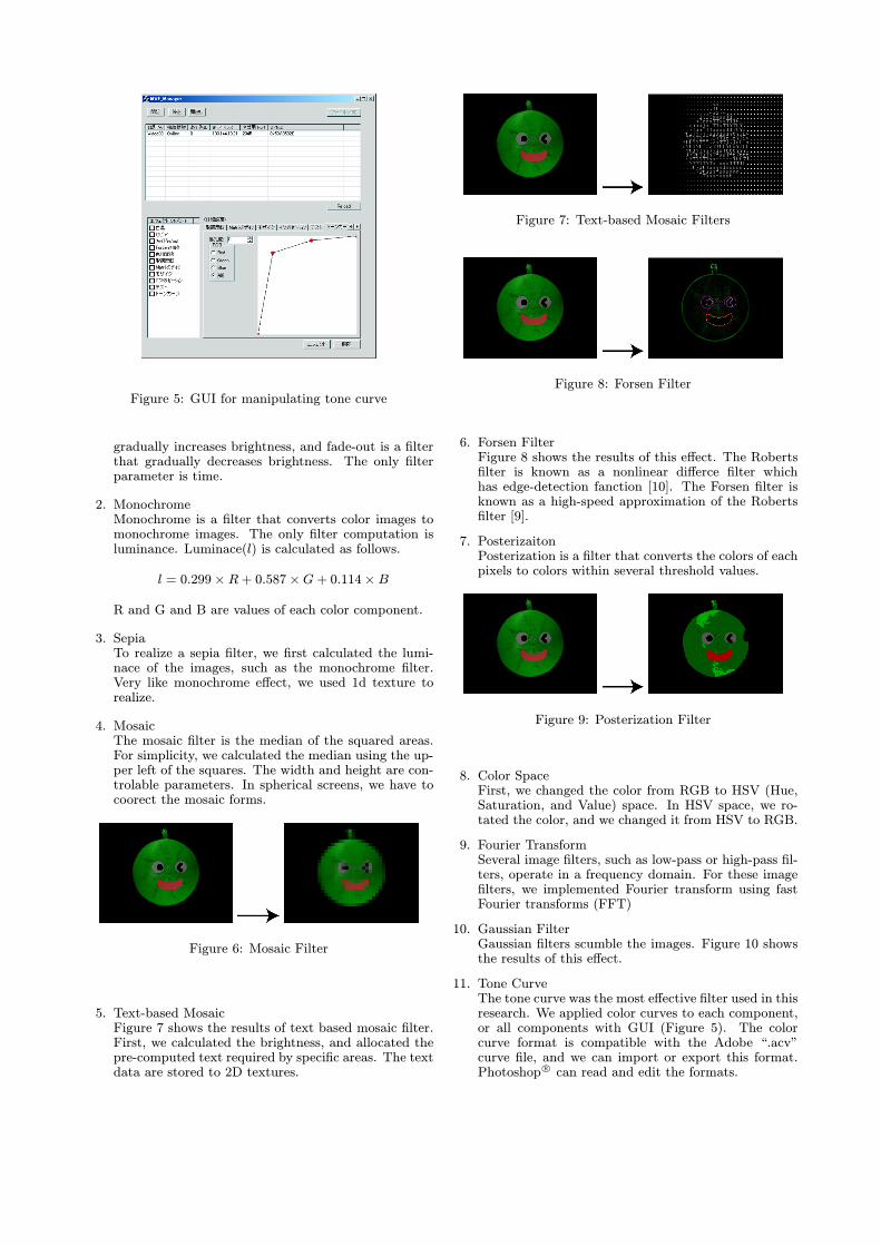
Figure 5: GUI for manipulating tone curve
gradually increases brightness, and fade-out is a filterthat gradually decreases brightness. The only filterparameter is time.
2. MonochromeMonochrome is a filter that converts color images tomonochrome images. The only filter computation isluminance. Luminace(l) is calculated as follows.
l = 0.299× R+ 0.587×G+ 0.114× B
R and G and B are values of each color component.
3. SepiaTo realize a sepia filter, we first calculated the lumi-nace of the images, such as the monochrome filter.Very like monochrome effect, we used 1d texture torealize.
4. MosaicThe mosaic filter is the median of the squared areas.For simplicity, we calculated the median using the up-per left of the squares. The width and height are con-trolable parameters. In spherical screens, we have tocoorect the mosaic forms.
Figure 6: Mosaic Filter
5. Text-based MosaicFigure 7 shows the results of text based mosaic filter.First, we calculated the brightness, and allocated thepre-computed text required by specific areas. The textdata are stored to 2D textures.
Figure 7: Text-based Mosaic Filters
Figure 8: Forsen Filter
6. Forsen FilterFigure 8 shows the results of this effect. The Robertsfilter is known as a nonlinear differce filter whichhas edge-detection fanction [10]. The Forsen filter isknown as a high-speed approximation of the Robertsfilter [9].
7. PosterizaitonPosterization is a filter that converts the colors of eachpixels to colors within several threshold values.
Figure 9: Posterization Filter
8. Color SpaceFirst, we changed the color from RGB to HSV (Hue,Saturation, and Value) space. In HSV space, we ro-tated the color, and we changed it from HSV to RGB.
9. Fourier TransformSeveral image filters, such as low-pass or high-pass fil-ters, operate in a frequency domain. For these imagefilters, we implemented Fourier transform using fastFourier transforms (FFT)
10. Gaussian FilterGaussian filters scumble the images. Figure 10 showsthe results of this effect.
11. Tone CurveThe tone curve was the most effective filter used in thisresearch. We applied color curves to each component,or all components with GUI (Figure 5). The colorcurve format is compatible with the Adobe “.acv”curve file, and we can import or export this format.Photoshop r° can read and edit the formats.
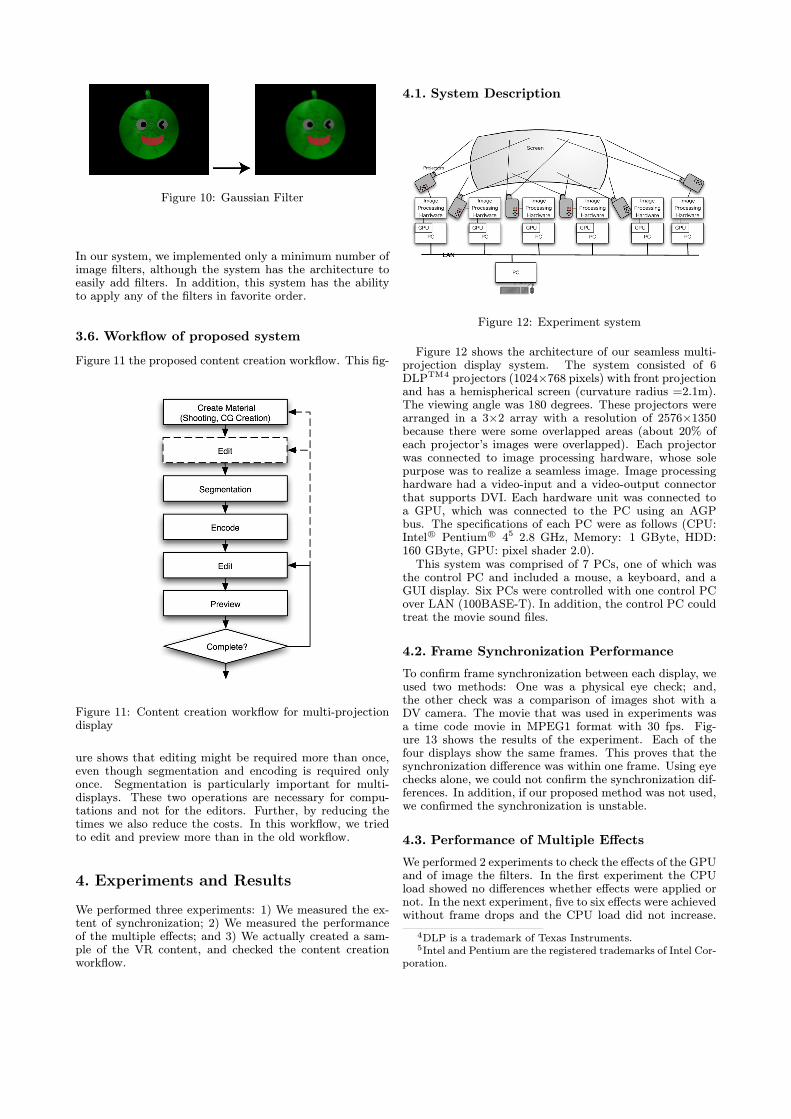
Figure 10: Gaussian Filter
In our system, we implemented only a minimum number ofimage filters, although the system has the architecture toeasily add filters. In addition, this system has the abilityto apply any of the filters in favorite order.
3.6. Workflow of proposed system
Figure 11 the proposed content creation workflow. This fig-
Figure 11: Content creation workflow for multi-projectiondisplay
ure shows that editing might be required more than once,even though segmentation and encoding is required onlyonce. Segmentation is particularly important for multi-displays. These two operations are necessary for compu-tations and not for the editors. Further, by reducing thetimes we also reduce the costs. In this workflow, we triedto edit and preview more than in the old workflow.
4. Experiments and Results
We performed three experiments: 1) We measured the ex-tent of synchronization; 2) We measured the performanceof the multiple effects; and 3) We actually created a sam-ple of the VR content, and checked the content creationworkflow.
4.1. System Description
Figure 12: Experiment system
Figure 12 shows the architecture of our seamless multi-projection display system. The system consisted of 6DLPTM4 projectors (1024×768 pixels) with front projectionand has a hemispherical screen (curvature radius =2.1m).The viewing angle was 180 degrees. These projectors werearranged in a 3×2 array with a resolution of 2576×1350because there were some overlapped areas (about 20% ofeach projector’s images were overlapped). Each projectorwas connected to image processing hardware, whose solepurpose was to realize a seamless image. Image processinghardware had a video-input and a video-output connectorthat supports DVI. Each hardware unit was connected toa GPU, which was connected to the PC using an AGPbus. The specifications of each PC were as follows (CPU:Intel r° Pentium r° 45 2.8 GHz, Memory: 1 GByte, HDD:160 GByte, GPU: pixel shader 2.0).This system was comprised of 7 PCs, one of which was
the control PC and included a mouse, a keyboard, and aGUI display. Six PCs were controlled with one control PCover LAN (100BASE-T). In addition, the control PC couldtreat the movie sound files.
4.2. Frame Synchronization Performance
To confirm frame synchronization between each display, weused two methods: One was a physical eye check; and,the other check was a comparison of images shot with aDV camera. The movie that was used in experiments wasa time code movie in MPEG1 format with 30 fps. Fig-ure 13 shows the results of the experiment. Each of thefour displays show the same frames. This proves that thesynchronization difference was within one frame. Using eyechecks alone, we could not confirm the synchronization dif-ferences. In addition, if our proposed method was not used,we confirmed the synchronization is unstable.
4.3. Performance of Multiple Effects
We performed 2 experiments to check the effects of the GPUand of image the filters. In the first experiment the CPUload showed no differences whether effects were applied ornot. In the next experiment, five to six effects were achievedwithout frame drops and the CPU load did not increase.
4DLP is a trademark of Texas Instruments.5Intel and Pentium are the registered trademarks of Intel Cor-
poration.
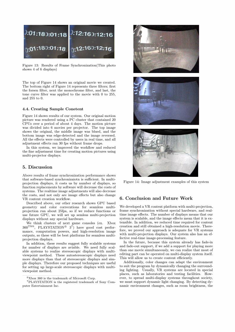
Figure 13: Results of Frame Synchronization(This photoshows 4 of 6 displays)
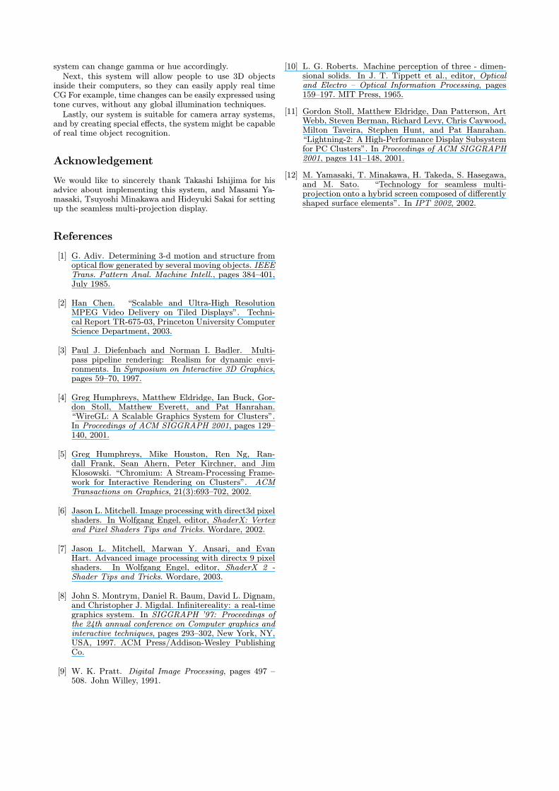
The top of Figure 14 shows an original movie we created.The bottom right of Figure 14 represents three filters; firstthe forsen filter, next the monochrome filter, and last, thetone curve filter was applied to the movie with 0 to 255,and 255 to 0.
4.4. Creating Sample Conetent
Figure 14 shows results of our system. Our original motionpicture was rendered using a PC cluster that contained 20CPUs over a period of about 4 days. The motion picturewas divided into 6 movies per projector. The top imageshows the original, the middle image was blued, and thebottom image was edge-detected and the image reversed.All the effects were controlled by users in real time, and alladjustment effects ran 30 fps without frame drops.In this system, we improved the workflow and reduced
the fine adjustment time for creating motion pictures usingmulti-projector displays.
5. Discussion
Above results of frame synchronization performance showsthat software-based synchronizaiotn is sufficient. In multi-projection displays, it costs us by number of displays, sofunction replacements by software will decrease the costs ofsystems. The realtime image adjustments will also decreasethe costs, and not only are image effects but also changeVR content creation workflow.Described above, our other research shows GPU based
geometry and color correcntions for seamless multi-projection run about 25fps, so if we reduce functions oruse future GPU, we will set up semless multi-projectiondisplays without any special hardware.We think clusters of next game consoles (ex. Xbox
360TM6, PLAYSTATION r° 37) have good cost perfor-mance, computation powers, and high-resolution imageoutputs, so these will be best platforms for seamless multi-projection displays.In addition, these results suggest fully scalable systems
for number of displays are aviable. We need fully scal-able systems to realize stereoscopic displays with multi-viewpoint method. These autostereoscopic displays needmore displays than that of stereoscopic displays and sim-ple displays. Therefore our proposed techniques are usefulfor setting up large-scale stereoscopic displays with multi-viewpoint method.
6Xbox 360 is the trademark of Microsoft Corp.7PLAYSTATION is the registered trademark of Sony Com-
puter Entertainment Inc.
Figure 14: Image adjustment examples of this system
6. Conclusion and Future Work
We developed a VR content platform with multi-projection,frame synchronization without special hardware, and real-time image effects. The number of displays means that oursystem is scalable, and the image effects mean that it is ex-tensible. In addition, we reduced time required for contentcreation and still obtained a high-resolution movie. There-fore, we proved our approach is adequate for VR systemswith multi-projection displays. Our system also has an ef-fective real-time image-processing feature.In the future, because this system already has fade-in
and fade-out support, if we add a support for playing morethan one movie simultaneously, we can realize that most ofediting part can be operated on multi-display system itself.This will allow us to create content efficiently.Additionally, color changes can adapt the environment
to suit the program by dynamically changing the surround-ing lighting. Usually, VR systems are located in specialplaces, such as laboratories and testing facilities. How-ever, to spread multi-display systems throughout society,we must support dynamic light changing. By detecting dy-namic environment changes, such as room brightness, the
system can change gamma or hue accordingly.Next, this system will allow people to use 3D objects
inside their computers, so they can easily apply real timeCG For example, time changes can be easily expressed usingtone curves, without any global illumination techniques.Lastly, our system is suitable for camera array systems,
and by creating special effects, the system might be capableof real time object recognition.
Acknowledgement
We would like to sincerely thank Takashi Ishijima for hisadvice about implementing this system, and Masami Ya-masaki, Tsuyoshi Minakawa and Hideyuki Sakai for settingup the seamless multi-projection display.
References
[1] G. Adiv. Determining 3-d motion and structure fromoptical flow generated by several moving objects. IEEETrans. Pattern Anal. Machine Intell., pages 384—401,July 1985.
[2] Han Chen. “Scalable and Ultra-High ResolutionMPEG Video Delivery on Tiled Displays”. Techni-cal Report TR-675-03, Princeton University ComputerScience Department, 2003.
[3] Paul J. Diefenbach and Norman I. Badler. Multi-pass pipeline rendering: Realism for dynamic envi-ronments. In Symposium on Interactive 3D Graphics,pages 59—70, 1997.
[4] Greg Humphreys, Matthew Eldridge, Ian Buck, Gor-don Stoll, Matthew Everett, and Pat Hanrahan.“WireGL: A Scalable Graphics System for Clusters”.In Proceedings of ACM SIGGRAPH 2001, pages 129—140, 2001.
[5] Greg Humphreys, Mike Houston, Ren Ng, Ran-dall Frank, Sean Ahern, Peter Kirchner, and JimKlosowski. “Chromium: A Stream-Processing Frame-work for Interactive Rendering on Clusters”. ACMTransactions on Graphics, 21(3):693—702, 2002.
[6] Jason L. Mitchell. Image processing with direct3d pixelshaders. In Wolfgang Engel, editor, ShaderX: Vertexand Pixel Shaders Tips and Tricks. Wordare, 2002.
[7] Jason L. Mitchell, Marwan Y. Ansari, and EvanHart. Advanced image processing with directx 9 pixelshaders. In Wolfgang Engel, editor, ShaderX 2 -Shader Tips and Tricks. Wordare, 2003.
[8] John S. Montrym, Daniel R. Baum, David L. Dignam,and Christopher J. Migdal. Infinitereality: a real-timegraphics system. In SIGGRAPH ’97: Proceedings ofthe 24th annual conference on Computer graphics andinteractive techniques, pages 293—302, New York, NY,USA, 1997. ACM Press/Addison-Wesley PublishingCo.
[9] W. K. Pratt. Digital Image Processing, pages 497 —508. John Willey, 1991.
[10] L. G. Roberts. Machine perception of three - dimen-sional solids. In J. T. Tippett et al., editor, Opticaland Electro — Optical Information Processing, pages159—197. MIT Press, 1965.
[11] Gordon Stoll, Matthew Eldridge, Dan Patterson, ArtWebb, Steven Berman, Richard Levy, Chris Caywood,Milton Taveira, Stephen Hunt, and Pat Hanrahan.“Lightning-2: A High-Performance Display Subsystemfor PC Clusters”. In Proceedings of ACM SIGGRAPH2001, pages 141—148, 2001.
[12] M. Yamasaki, T. Minakawa, H. Takeda, S. Hasegawa,and M. Sato. “Technology for seamless multi-projection onto a hybrid screen composed of differentlyshaped surface elements”. In IPT 2002, 2002.


