Embed Size (px)
Citation preview

ENGLISH
VulcanOperator Manual
bandg.com


Preface
DisclaimerAs Navico is continuously improving this product, we retain theright to make changes to the product at any time which may not bereflected in this version of the manual. Please contact your nearestdistributor if you require any further assistance.
It is the owner’s sole responsibility to install and use the equipmentin a manner that will not cause accidents, personal injury orproperty damage. The user of this product is solely responsible forobserving safe boating practices.
NAVICO HOLDING AS AND ITS SUBSIDIARIES, BRANCHES ANDAFFILIATES DISCLAIM ALL LIABILITY FOR ANY USE OF THIS PRODUCTIN A WAY THAT MAY CAUSE ACCIDENTS, DAMAGE OR THAT MAYVIOLATE THE LAW.
Governing Language: This statement, any instruction manuals, userguides and other information relating to the product(Documentation) may be translated to, or has been translated from,another language (Translation). In the event of any conflict betweenany Translation of the Documentation, the English language versionof the Documentation will be the official version of theDocumentation.
This manual represents the product as at the time of printing.Navico Holding AS and its subsidiaries, branches and affiliatesreserve the right to make changes to specifications without notice.
TrademarksLowrance® and Navico® are registered trademarks of Navico.
Fishing Hot Spots® is a registered trademark of Fishing Hot Spots Inc.Copyright© 2012 Fishing Hot Spots.
Navionics® is a registered trademark of Navionics, Inc.
NMEA 2000® is a registered trademark of the National MarineElectronics Association.
SiriusXM® is a registered trademark of Sirius XM Radio Inc.
FUSION-Link™ Marine Entertainment Standard™ is a registeredtrademark of FUSION Electronics Ltd.
Preface | Vulcan Operator Manual 3

The terms HDMI and HDMI High-Definition Multimedia Interface,and the HDMI Logo are trademarks or registered trademarks ofHDMI Licensing LLC in the United States and other countries.
SD™ and microSD™ are trademarks or registered trademarks ofSD-3C, LLC in the United States, other countries or both.
Wi-Fi® is a registered trademark of the Wi-Fi Alliance®.
Additional mapping data: Copyright© 2012 NSI, Inc.: Copyright©2012 by Richardson’s Maptech.
Navico product referencesThis manual can refer to the following Navico products:
• Broadband Sounder™ (Broadband Sounder)• DownScan Imaging™ (DownScan)• DownScan Overlay™ (Overlay)• GoFree™ (GoFree)• SonicHub® (SonicHub)
CopyrightCopyright © 2015 Navico Holding AS.
WarrantyThe warranty card is supplied as a separate document.
In case of any queries, refer to the brand website of your display orsystem: bandg.com.
Regulatory statementsThis equipment is intended for use in international waters as well ascoastal sea areas administered by countries of the E.U. and E.E.A.
The Vulcan complies with:
• CE under R&TTE directive 1999/5/EC• The requirements of level 2 devices of the
Radiocommunications (Electromagnetic Compatibility)standard 2008
The relevant Declaration of conformity is available in the Vulcansection on the following website: bandg.com.
4 Preface | Vulcan Operator Manual

About this manualThis manual is a reference guide for operating the Vulcan. Itassumes that all equipment is installed and configured, and that thesystem is ready to use.
The manual assumes that the user has basic knowledge ofnavigation, nautical terminology and practices.
Important text that requires special attention from the reader isemphasized as follows:
Ú Note: Used to draw the reader’s attention to a comment orsome important information.
Warning: Used when it is necessary to warnpersonnel that they should proceed carefully toprevent risk of injury and/or damage to equipment/personnel.
Manual versionThis manual is written for the Vulcan software version 1.0. Themanual is continuously updated to match new software releases.The latest available manual version can be downloaded frombandg.com.
Preface | Vulcan Operator Manual 5

Viewing the manual on the screenThe pdf viewer included in the Vulcan makes it possible to read themanuals and other pdf files on the screen. Manuals can bedownloaded from bandg.com.
The manuals can be read from a card inserted in the card reader orcopied to the unit’s internal memory.
Use the menu options and on-screen buttons to maneuver in thepdf file as described below:
• Search, Goto page, Page Up and DownSelect the relevant panel button.
• Scroll pagesDrag finger on the screen in any direction.
• Panning on the pageDrag finger on the screen in any direction.
• Zoom In/OutSelect the relevant panel button.Touch operation: Use pinch or spread gestures.
• Exit the pdf viewerSelect the X in the upper right corner of the panel.
6 Preface | Vulcan Operator Manual

The Software versionThe software version currently on this unit can be found in theAbout dialog. The About dialog is available in the System Settings.
For information regarding upgrading your software, refer to "Softwareupgrades" on page 114.
Preface | Vulcan Operator Manual 7

8 Preface | Vulcan Operator Manual

Contents
13 Introduction13 The Home page14 Application pages16 Integration of 3rd party devices17 GoFree wireless17 Remote controllers
18 Basic operation18 System Controls dialog18 Turning the system on and off19 Display illumination19 Locking the touchscreen20 Using menus and dialogs20 Selecting pages and panels21 Using the cursor on the panel22 Creating a Man Overboard waypoint23 Screen capture
24 Customizing your system24 Customizing the Home page wallpaper24 Adjusting panel size25 Adding new favorite pages26 Edit favorite pages26 Setting the appearance of the Instrument bar
27 Charts27 The Chart panel28 Chart data28 Showing dual chart types29 Vessel symbol29 Chart scale29 Panning the chart30 Positioning the vessel on the chart panel30 Displaying information about chart items31 Using the cursor on the chart panel31 Creating routes31 Find objects on chart panels32 3D charts
Contents | Vulcan Operator Manual 9

33 Insight specific chart options33 Insight view options34 Navionics specific chart options35 Navionics chart settings36 Navionics view options39 Jeppesen tides and currents40 Chart settings
44 Waypoints, Routes, and Tracks44 Waypoints46 Routes50 Tracks52 Waypoints, Routes, and Tracks dialogs
53 Navigating53 Navigate to cursor position53 Navigate a route54 Navigating with the autopilot55 Navigation settings
57 The Sail Steer panel58 Selecting data fields for the Sail Steer panel58 Sail Time calculations
59 Time and Wind plots59 The Time plot panel60 Wind Plot panel
61 Autopilot61 Safe operation with the autopilot61 Activating the autopilot61 Switching from automatic mode to manual steering62 Autopilot indication on the pages63 The Autopilot panel64 Mode overview65 Standby mode65 Non-Follow Up (NFU, Power steering)65 Follow-up steering (FU)66 AUTO mode (auto compass)
10 Contents | Vulcan Operator Manual

67 NoDrift mode68 NAV mode69 WIND mode71 WIND Nav mode72 Turn pattern steering75 Using the Vulcan in an AP24/AP28 system75 Using the autopilot in an EVC system76 Autopilot settings
79 Echosounder79 The Echosounder image80 Using the cursor on the Echosounder panel81 Viewing Echosounder history81 Setting up the Echosounder image83 Recording log data85 Echosounder settings
87 DownScan87 The DownScan image88 Zooming the DownScan image88 Using the cursor on the DownScan panel88 Viewing DownScan history89 Setting up the DownScan image
91 AIS91 AIS target symbols92 Viewing information about AIS targets93 Calling an AIS vessel93 AIS SART95 Vessel alarms96 Vessel settings
99 Instrument panels99 Dashboards99 Customizing the Instruments panel
101 Audio101 Enabling audio101 The Audio panel
Contents | Vulcan Operator Manual 11

104 Setting up the audio system104 Operating the audio system105 Favorite channels105 Sirius radio (North America only)
106 Alarms106 Alarm system106 Type of messages106 Single alarms106 Multiple alarms107 Acknowledging a message107 Alarms dialog
109 Tools109 Waypoints/routes/tracks109 Tides109 Alarms109 Settings110 Vessels110 Sun, Moon110 Trip calculator110 Files110 Find
111 Simulator111 Demo mode111 Simulator source files112 Advanced simulator settings
114 Maintenance114 Preventive maintenance114 Cleaning the display unit114 Cleaning the media port door114 Checking the connectors114 Software upgrades115 Backing up your system data
117 Touchscreen operation
12 Contents | Vulcan Operator Manual

Introduction
The Home pageThe Home page is accessed from any operation by selecting theHome button in the upper left corner of a panel.
1 ToolsSelect a button to access dialogs used for carrying out a task,or for browsing stored information.
2 ApplicationsSelect a button to display the application as a full pagepanel. Press and hold a button to display pre-configuredsplit page options for the application.
3 Close buttonSelect to exit the Home page and return to the previousactive page.
4 FavoritesSelect a button to display the panel combination.Press and hold a favorite button to enter edit mode for theFavorites panel.
1
Introduction | Vulcan Operator Manual 13

5 Man Over Board (MOB) buttonSelect to save a Man Over Board (MOB) waypoint at thecurrent vessel position.
Application pages
Each application connected to the system is presented on panels.The application can be presented as a full page, or in combinationwith other panels in a multiple panel page.
All application pages are accessed from the Home page.
1 Application panel
2 Instrument barNavigation and sensor information. The bar can be turnedoff and it can be configured by the user.
3 System controls dialogQuick access to basic system settings.Display the dialog by a short press on the Power key or byswiping down from top of the screen.
4 Status bar
5 DialogInformation to or input from the user.
6 Alarm messageDisplayed if dangerous situations or system faults occur.
14 Introduction | Vulcan Operator Manual

7 MenuPanel specific menu.
Split pagesYou can have up to 4 panels on each page.
2 panels page 3 panels page 4 panels page
Panel sizes in a split page can be adjusted from the SystemControls dialog.
Pre-configured split pagesEach full screen application has several pre-configured split pages,featuring the selected application combined with each of the otherpanels.
Ú Note: The number of pre-configured split pages cannot bechanged, and the pages cannot be customized or deleted.
Access a pre-configured split page by pressing and holding themain panel button.
Favorite pages All preconfigured favorite pages can be modified and deleted, andyou can create your own. You can have a total of 12 favorite pages.
For more information, refer to "Adding new favorite pages" on page 25.
Introduction | Vulcan Operator Manual 15

Integration of 3rd party devicesSeveral 3rd party devices can be connected to the Vulcan. Theapplications are displayed on separate panels or integrated withother panels.
A device connected to the NMEA 2000 network shouldautomatically be identified by the system. If not, enable the featurefrom the advanced option in the System settings dialog.
The 3rd party device is operated by using menus and dialogs as onother panels.
This manual does not include specific operation instructions for any3rd party device. For features and functionality, refer to thedocumentation included with the 3rd party device.
FUSION-Link integrationThe FUSION-Link devices appear as additional sources when usingthe audio function. No additional icons are available.
Refer to "Audio" on page 101 for more information.
BEP CZone integration
The Vulcan integrates with BEP’s CZone system used for controllingand monitoring a distributed power system on your vessel.
The CZone icon is available in the Tools panel on the Home pagewhen a CZone system is available on the network.
A separate manual is provided with your CZone system. Refer to thisdocumentation and to the Vulcan Installation manual for how toinstall and configure the CZone system.
CZone dashboardWhen the CZone is installed and configured, an additional CZonedashboard is added to the Instruments panels.
You switch between a panel’s dashboards by selecting the left andright arrow symbols or by selecting the dashboard from the menu.
Editing a CZone dashboardYou can customize a CZone dashboard by changing the data foreach of the gauges. Available editing options depend on the type ofgauge and which data sources that are connected to your system.
16 Introduction | Vulcan Operator Manual

For more information, refer to "Instrument panels" on page 99.
GoFree wirelessThe Vulcan includes built-in wireless functionality that lets you use awireless device to remotely view (phone and tablet) and control thesystem (tablet only). The system is controlled from the wirelessdevice by Apps downloaded from their relevant Application store.
Configuration and setup are described in the Vulcan Installationmanual.
Ú Note: For safety reasons, Autopilot and CZone functionscannot be controlled from a wireless device.
Operating the system with a wireless deviceWhen remote control is accepted, the active page is mirrored to thewireless device.
The image on the wireless device includes softkeys used foroperating the Vulcan system.
Remote controllers
You can connect a ZC1 to the network and remotely control theVulcan.
A separate manual is included with the remote controller.
Introduction | Vulcan Operator Manual 17

Basic operation
System Controls dialogThe System Controls dialog provides quick access to basic systemsettings. You display the dialog by making a short press on thePower key. The icons displayed on the dialog can vary. For example,the adjust splits option is only available if you are viewing a splitpage when you open the System Controls dialog.
Activating functionsSelect the icon of the function you want to set or toggle on or off.For those functions that toggle on and off, a highlighted iconindicates the function is activated, as shown in the Instrument baricon above.
Turning the system on and off
You turn the system on and off by pressing and holding the Powerkey. You can also turn the unit off from the System Controlsdialog.
If the Power key is released before the shut-down is completed, thepower off process is cancelled.
2
18 Basic operation | Vulcan Operator Manual

First time startupThe first time the unit is started and after a master reset, the systemruns through an automatic start-up sequence, including languagesetup and automatic data source selection.
You can select to interrupt this sequence and later configure thesystem yourself.
Standby mode
You select Standby mode from the System Controls dialog.
Display illumination
Brightness
The display backlighting can be adjusted at any time from theSystem Controls dialog. You can also cycle the preset backlightlevels by short presses on the Power key.
Night modeThe night mode option optimizes the color palette and backlight forlow light conditions.
Ú Note: Details on the chart may be less visible when theNight mode is selected!
Locking the touchscreen
You can temporarily lock a touchscreen to prevent accidentaloperation of the system. Lock the touchscreen when large amountsof water are on the screen, for example, in heavy seas and weather.This feature is also useful when cleaning the screen while the unit isturned on.
You lock the touchscreen from the System Controls dialog.
You remove the lock function by a short press on the Power key.
Basic operation | Vulcan Operator Manual 19
Using menus and dialogs
MenusYou display a page menu by selecting the MENU button in theupper right corner of the page.
• Activate a menu item and toggle on/off an option by selectingit
• Adjust a slide bar value by either:• dragging the slide bar• selecting the + or - icons
Select the Back menu option to return to the previous menu level,and then exit.
You can make the menu slide away by tapping the screen outsidethe menu area, or by pressing the MENU button. When you re-press the MENU button, the menu opens in the same status it hadbefore it closed.
The status of the cursor (active vs. inactive) changes the menuoptions.
Dialog boxesA dialog is closed by saving or cancelling the entry.
A dialog can also be closed by selecting the X in the dialog's upperright corner.
Selecting pages and panels
Selecting a page• Select a full page panel by selecting the relevant application
button on the Home page• Select a favorite page by selecting the relevant favorite button• Select a predefined split panel by pressing and holding the
relevant application icon
Select active panelIn a multiple panel page, only one panel can be active at a time. Theactive panel is outlined with a border.
You can only access the page menu of an active panel.
You activate a panel by tapping it.
20 Basic operation | Vulcan Operator Manual

Using the cursor on the panelThe cursor can be used to measure a distance, to mark a position,and to select items.
By default, the cursor is not shown on the panel.
Position the cursor by tapping the desired location on the screen.
When the cursor is active, the cursor position window is displayed.
To remove the cursor and cursor elements from the panel, selectthe Clear cursor option.
GoTo cursorYou can navigate to a selected position on the image by positioningthe cursor on the panel, then using the Goto Cursor option in themenu.
The Cursor assist functionThe cursor assist function allows for fine tuning and precisionplacement of the cursor without covering details with your finger.
Press and hold your finger on the screen to switch the cursorsymbol to a selection circle, appearing above your finger.
Without removing your finger from the screen, drag the selectioncircle over the desired item to display item information.
When you remove your finger from the screen the cursor reverts tonormal cursor operation.
Basic operation | Vulcan Operator Manual 21

Measuring distance
The cursor can be used to measure the distance between yourvessel and a selected position, or between 2 points on the chartpanel.
1. Position the cursor on the point from where you want tomeasure the distance.
2. Start the measure function from the menu.- The measuring icons appear with a line drawn from the vessel
center to the cursor position, and the distance is listed in thecursor information window.
3. You can reposition the measuring points by dragging eithericon as long as the measuring function is active.
Ú Note: The bearing is always measured from the grey iconto the blue icon.
You can also start the measuring function without an active cursor.Both measuring icons are then initially located at the vessel position.The grey icon follows the vessel as the vessel moves, while the blueicon remains at the position given when you activated the function.
You terminate the measuring function by selecting the Finishmeasuring menu option.
Creating a Man Overboard waypointIf an emergency situation should occur, you can position a ManOverboard (MOB) waypoint at the vessel’s current position byselecting the MOB button on the Home page.
When you activate the MOB function the following actions areautomatically performed:
• a MOB waypoint is positioned at the vessel’s position• the display switches to a zoomed chart panel, centered on the
vessel's position• the system displays navigation information back to the MOB
waypointMultiple MOB waypoints are saved by repeatedly pressing the MOBbuttons. The vessel continues to show navigation information tothe initial MOB waypoint. Navigation to subsequent MOB waypointsneeds to be done manually.
22 Basic operation | Vulcan Operator Manual

Cancel navigation to MOB
The system continues to display navigational information towardsthe MOB waypoint until you cancel the navigation from the menu.
Delete a MOB waypoint1. Select the MOB waypoint to activate it2. Select the MOB waypoint's pop-up to display the MOB waypoint
dialog3. Select the delete option in the dialog.
A MOB waypoint can also be deleted from the menu when it isactivated.
Screen captureYou need to turn on the Screen capture option in the SystemSettings dialog to be able to take a screenshot on a touch screen.When the function is activated, you can take a screenshot on atouch screen by double-selecting the title bar of an open dialog, orby double-selecting the status bar if no dialog is open.
Refer to "Tools" on page 109 for how to view files.
Basic operation | Vulcan Operator Manual 23

Customizing your system
Customizing the Home page wallpaperThe Home page's wallpaper can be customized. You can select oneof the pictures included with the system, or you can use your ownpicture in .jpg or .png format.
The images can be available on any location that can be seen in thefiles browser. When a picture is chosen as the wallpaper, it isautomatically copied to the Wallpaper folder.
Adjusting panel sizeYou can change the panel size for an active split page. The panelsize can be adjusted for both favorite pages and for predefined splitpages.
1. Activate the System Controls dialog2. Select the adjust splits option in the dialog3. Adjust the panel size by dragging the adjustment icon4. Confirm your changes by tapping one of the panels or selecting
the save option in the menu.
3
24 Customizing your system | Vulcan Operator Manual

The changes are saved to the active favorite or split page.
Adding new favorite pages
1. Select the New icon in the favorite panel on the Home page toopen the page editor dialog
2. Drag and drop page icons to set up a new page3. Change the panel arrangement (only possible for 2 or 3 panels),
if required.4. Save the page layout
The system displays the new favorite page, and the new page isincluded in the list of favorite pages on the Home page.
Customizing your system | Vulcan Operator Manual 25

Edit favorite pages
1. Select the edit icon for a favorite icon to enter edit mode- Select the X icon to remove the page- Select the tool icon to display the page editor dialog
2. Add or remove panels in the page editor dialog.3. Save or discard your changes to leave the favorite edit mode.
Setting the appearance of the InstrumentbarData sources connected to the system can be viewed in theInstrument bar.
You can configure the Instrument bar to display either one or twobars, or set it to alternate the bars automatically.
You can turn the Instrument bar off from the System controlsdialog.
Ú Note: This only turns the Instrument bar off for the currentpage.
Turning the Instrument bar on/off1. Activate the System controls dialog2. Deactivate/activate the instrument bar icon to toggle the bar on
and off.
Edit the content of the Instrument bar1. Select the MENU button to edit the content2. Select the content you want to display
Ú Note: You can configure Bar 1 for active page or for allpages except those that have a local configuration. Bar 2can only be configured for active page.
3. Define the time period if you want the two bars to alternateautomatically
4. Select the edit option to change any of the instrument fields,followed by the field you want to change
5. Save your changes by selecting the finish edit option in themenu.
26 Customizing your system | Vulcan Operator Manual

ChartsThe chart function displays your vessel’s position relative to landand other chart objects. On the chart panel you can plan andnavigate routes, place waypoints, and display AIS targets.
The Chart panel
1 MOB (Man Over Board) mark
2 Vessel with extension line (extension line is optional)
3 Waypoint with Laylines*
4 North indicator
5 Route*
6 Grid lines*
7 Track*
8 Range rings*
9 Chart range scale
10 Range rings interval (only displayed when Range rings areturned on)
4
Charts | Vulcan Operator Manual 27

* Optional chart items. You turn the optional images on/offindividually from the Chart settings dialog.
Chart dataThe system is delivered with different embedded cartographydepending on region.
All units support Insight charts from Navico including InsightGenesis. The system also supports Navionics Gold, Platinum+ andNavionics+, C-MAP MAX-N/MAX-N+ by Jeppesen as well as contentcreated by variety of third party mapping providers in the AT5format. For a full selection of available charts please visitinsightstore.navico.com, c-map.jeppesen.com or navionics.com.
Ú Note: The system does not automatically switch toembedded cartography if the chart card is removed. A low-resolution chart will be displayed until you re-insert thecard or manually switch back to the embeddedcartography.
Showing dual chart typesIf you have different chart types available - embedded or in the cardslot - you can show two different chart types simultaneously on apage with two chart panels.
You can select a dual chart panel by pressing and holding the Chartapplication button on the Home page, or by creating a favoritepage with two chart panels.
28 Charts | Vulcan Operator Manual

Selecting chart type
You specify the chart type in the Chart panel by selecting one of theavailable chart types in the chart source menu option. If you have amultiple Chart panel, the chart type is set individually for each chartpanel. Activate one of the chart panels, and then select one of theavailable chart types in the chart source menu option. Repeat theprocess for the second chart panel, and select an alternative charttype for this panel.
Ú Note: To show charts other than Navionics, Insight charttype must be selected.
If you have identical charts available - built in or in the card slot - thesystem automatically selects the chart with most chart details foryour displayed region.
Vessel symbol
When the Vulcan has a valid GPS position lock, the vessel symbolindicates vessel position. If no GPS position is available, the vesselsymbol includes a question mark.
Chart scale
Chart range scale and range rings interval (when turned on) areshown in the lower right corner of the chart panel.
Panning the chartYou can move the chart in any direction by dragging your finger onthe screen.
Select the Clear cursor menu option to remove the cursor andcursor window from the panel. This also centers the chart to thevessel position.
Charts | Vulcan Operator Manual 29

Positioning the vessel on the chart panel
Chart orientationSeveral options are available for how the chart is rotated in thepanel. The chart orientation symbol in the panel’s upper rightcorner indicates the north direction.
North up Heading up Course up
North upDisplays the chart with north upward.
Heading upDisplays the chart with the vessel’s heading directed upward.Heading information is received from a compass. If heading is notavailable, then the COG from the GPS is used.
Course upRotates the chart in the direction of the next waypoint whennavigating a route or navigating to a waypoint. If not navigating theheading up orientation is used until navigation is started.
Look aheadMoves the vessel icon closer to the bottom of the screen so thatyou can maximize your view ahead.
Displaying information about chart itemsWhen you select a chart item, a waypoint, a route, or a target, basicinformation for the selected item is displayed. Select the chart item'spop-up to display all available information for that item. You canalso activate the detailed information dialog from the menu.
Ú Note: Pop-up information has to be enabled in chartsettings to see basic item information.
30 Charts | Vulcan Operator Manual

Using the cursor on the chart panelBy default, the cursor is not shown on the chart panel.
When you activate the cursor, the cursor position window isdisplayed. When the cursor is active, the chart does not pan orrotate to follow the vessel.
Select the Clear cursor menu option to remove the cursor and thecursor window from the panel. This also centers the chart to thevessel position.
Select the Restore cursor menu option to display the cursor in itsprevious location. The Clear cursor and Restore cursor optionsare useful features for toggling between the vessel's currentlocation and the cursor position.
Creating routesYou can create routes as follows on the chart panel.
1. Position the cursor on the chart panel.2. Select New followed by New route in the menu.3. Tap the chart panel to position the first routepoint.4. Continue positioning the remaining routepoints.5. Save the route by selecting the save option in the menu.
Ú Note: For more information, refer to "Waypoints, Routes, andTracks" on page 52.
Find objects on chart panelsYou can search for other vessels or various chart items from a chartpanel.
Charts | Vulcan Operator Manual 31

Activate the cursor on the panel to search from the cursor position.If the cursor is not active, the system searches for items from thevessel's position.
Ú Note: You must have a SIRIUS data package subscription tosearch for fueling stations and an AIS receiver connected tosearch for vessels.
3D chartsThe 3D option provides a three dimensional graphical view of landand sea contours.
Ú Note: All chart types work in 3D mode, but without 3Dcartography for the appropriate area the chart appears flat.
When 3D chart option is selected, the Pan and the Rotate iconsappear on the right side of the chart panel.
Panning the 3D chart
You can move the chart in any direction by selecting the Pan iconand then panning in the desired direction.
Select the Return to vessel menu option to stop panning, and tocenter the chart to vessel position.
Controlling the view angle
You can control the view angle by selecting the Rotate icon andthen panning the chart panel.
• To change the direction you are viewing, pan horizontally• To change the tilt angle of the view, pan vertically
Ú Note: When centered on the vessel position, only the tiltangle can be adjusted. The view direction is controlled by
32 Charts | Vulcan Operator Manual

the chart orientation setting. See "Positioning the vessel on the chartpanel" on page 30.
Zooming a 3D chartYou zoom in and out on a 3D chart by using the zoom (+ or -)buttons, or the touch method of pinching and spreading yourfingers.
Insight specific chart options
Orientation, Look ahead, 3D, and change Chart source (previouslydescribed in this section) are common for all chart types.
Chart imagery styleThe charts can be displayed in three imagery styles.
2D mapping style Shaded relief No contours
Insight view options
Chart detail• Full
All available information for the chart in use.• Medium
Minimum information sufficient for navigation.• Low
Basic level of information that cannot be removed, and includesinformation that is required in all geographic areas. It is notintended to be sufficient for safe navigation.
Charts | Vulcan Operator Manual 33

Insight chart categoriesInsight charts include several categories and sub-categories thatyou can turn on/off individually depending on which informationyou want to see.
Land Exaggeration and Water ExaggerationGraphical settings available in 3D mode only. Exaggeration is amultiplier applied to the drawn height of hills on land, and troughsin water to make them look taller or deeper.
Navionics specific chart options
Orientation, Look ahead, 3D and change Chart source (previouslydescribed in this section) are common for all chart types.
Community editsToggles on the chart layer including Navionics edits. These are userinformation or edits uploaded to Navionics Community by users,and made available in Navionics charts.
For more information, refer to Navionics information included withyour chart, or to Navionics website: www.navionics.com.
34 Charts | Vulcan Operator Manual

Navionics chart settings
Colored seabed areas
Used for displaying different depth areas in different shades of blue.
AnnotationDetermines what area information, such as names of locations andnotes of areas, is available to display.
Presentation typeProvides marine charting information such as symbols, colors of thenavigation chart and wording for either International or U.S.presentation types.
Chart detailsProvides you with different levels of geographical layer information.
Safety depthThe Navionics charts use different shades of blue to distinguishbetween shallow and deep water.
Safety depth, based on a selected limit, is drawn without blueshading.
Ú Note: The built in Navionics database features data downto 20 m, after which it is all white.
Contours depthDetermines which contours you see on the chart down to theselected safety depth value.
Rock filter levelHides rock identification on the chart beneath a given depth.
This helps you to declutter charts in areas where there are manyrocks located at depths well below your vessel's draught.
Charts | Vulcan Operator Manual 35

Navionics view options
Chart shadingShading adds terrain information to the chart.
Navionics dynamic tide and current iconsShows tides and currents with a gauge and an arrow instead of thediamond icons used for static tides and current information.
The tide and current data available in Navionics charts are related toa specific date and time. The system animates the arrows and/orgauges to show the tides and currents evolution over time.
Dynamic tide information Dynamic current information
The following icons and symbology are used:
Current speedThe arrow length depends on the rate, and thesymbol is rotated according to flow direction. Flowrate is shown inside the arrow symbol. The redsymbol is used when current speed is increasing,and the blue symbol is used when current speed isdecreasing.
Tide heightThe gauge has 8 labels and is set according toabsolute max/min value of the evaluated day. Thered arrow is used when tide is rising, and the bluearrow is used when tide is falling.
36 Charts | Vulcan Operator Manual

Ú Note: All numeric values are shown in the relevant systemunits (unit of measurement) set by user.
Easy ViewMagnifying feature that increases the size of chart items and text.
Ú Note: There is no indication on the chart showing that thisfeature is active.
Photo overlayPhoto overlay enables you to view satellite photo images of an areaas an overlay on the chart. The availability of such photos is limitedto certain regions, and cartography versions.
You can view photo overlays in either 2D or 3D modes.
No Photo overlay Photo overlay, land only Full Photo overlay
Photo transparencyThe Photo transparency sets the opaqueness of the photo overlay.With minimum transparency settings the chart details are almosthidden by the photo.
Minimum transparency Maximum transparency
Charts | Vulcan Operator Manual 37

Navionics Fish N' ChipThe system supports Navionics Fish N' Chip (U.S. only) chart feature.
For more information, see www.navionics.com.
Depth highlight rangeSelect a range of depths between which Navionics fills with adifferent color.
This allows you to highlight a specific range of depths for fishingpurposes. The range is only as accurate as the underlying chart data,meaning that if the chart only contains 5 meter intervals for contourlines, the shading is rounded to the nearest available contour line.
No Depth highlight range Depth highlight range: 6 m - 12 m
Shallow water highlightHighlights areas of shallow water.
This allows you to highlight areas of water between 0 and theselected depth (up to 10 meters/30 feet).
No shallow water highlighted Shallow water highlight: 0 m - 3 m
38 Charts | Vulcan Operator Manual

Jeppesen tides and currentsThe system can display Jeppesen tides and currents. With thisinformation it is possible to predict the time, level, direction andstrength of currents and tides. This is an important tool whenconsidering planning and navigation of a trip.
In large zoom ranges the tides and currents are displayed as asquare icon including the letter T (Tides) or C (Current). When youselect one of the icons, tidal or current information for that locationare displayed.
Dynamic current data can be viewed by zooming inside a 1-nauticalmile zoom range. At that range, the Current icon changes to ananimated dynamic icon that shows the speed and direction of thecurrent. Dynamic icons are colored in black (greater than 6 knots),red (greater than 2 knots and less than or equal to 6 knots), yellow(greater than 1 knot and less than or equal to 2 knots) or green(equal to or less than 1 knot), depending on the current in thatlocation.
If there is no current (0 knots) this will be shown as a white, squareicon.
Static Current and Tide icons Dynamic Current icons
Charts | Vulcan Operator Manual 39

Chart settings
Settings and display options made in the Chart settings page arecommon for all chart panels.
3D boat selectionDetermines which icon to use on 3D charts.
Boat settingsThe boat settings are used when calculating an automatic route.The boat's draught, width and height must be input to use theautorouting and easy routing features.
Range RingsThe range rings can be used to present the distance from yourvessel to other chart objects.
The range scale is set automatically by the system to suit the chartscale.
40 Charts | Vulcan Operator Manual
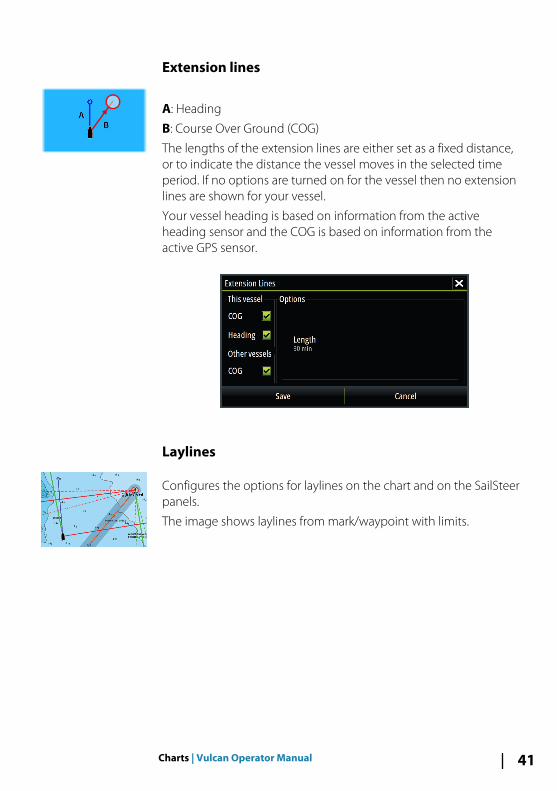
Extension lines
A: Heading
B: Course Over Ground (COG)
The lengths of the extension lines are either set as a fixed distance,or to indicate the distance the vessel moves in the selected timeperiod. If no options are turned on for the vessel then no extensionlines are shown for your vessel.
Your vessel heading is based on information from the activeheading sensor and the COG is based on information from theactive GPS sensor.
Laylines
Configures the options for laylines on the chart and on the SailSteerpanels.
The image shows laylines from mark/waypoint with limits.
Charts | Vulcan Operator Manual 41

The following settings are available:
• BoatDisplays laylines from boat, indicating the target course.
• Always show boat laylinesDisplays boat laylines.
• MarkDisplays laylines from mark/waypoint, indicating the targetcourse to sail to reach the mark/waypoint.
• Tidal flow correctionCalculates the tidal effect of the boat based on COG, andapplies this information to the laylines.
• OverlappedExtends the laylines beyond the tack/gybe intersection.
• LengthSets the length of the laylines.
• Target wind angleDefines the target for the TWA (True Wind Angle). The targetcan be read from your polar table, it can be read from the livemeasurements, or it can be manually entered upwind anddownwind sailing angles.
• LimitsSets the maximum tack/gybe time period to either side of thelaylines. When turned on the limits are indicated with a dottedline on the chart and on the SailSteer panel.
Synchronize 2D/3D chartLinks the position shown on one chart with the position shown onthe other chart when a 2D and a 3D chart are shown side by side.
42 Charts | Vulcan Operator Manual

Pop-up informationSelects whether basic information for chart items is displayed whenyou select the item.
Grid linesTurns on/off viewing of longitude and latitude grid lines on thechart.
Course highwayAdds a graphic presentation of cross track error (XTE) limits to theroute. For setting the XTE limit, see "XTE limit" on page 55.
Waypoints, Routes, TracksTurns on/off displaying of these items on chart panels. Also opensthe Waypoints, Routes and Tracks dialogs you can use to managethem.
Charts | Vulcan Operator Manual 43

Waypoints, Routes, and Tracks
WaypointsA waypoint is a user generated mark positioned on a chart, or onthe Echosounder image. Each waypoint has an exact position withlatitude and longitude coordinates. A waypoint positioned on theEchosounder image has a depth value, in addition to positioninformation. A waypoint is used to mark a position you later maywant to return to. Two or more waypoints can also be combined tocreate a route.
Saving waypointsYou can save a waypoint at a selected location by positioning thecursor on the panel, and then selecting the new waypoint option inthe menu.
In the Chart and Nav panels, you can save a waypoint at the vesselposition, when the cursor is not active, by selecting the newwaypoint option in the menu.
Moving a waypoint
1. Select the waypoint you want to move- The waypoint icon expands to indicate that it is active
2. Activate the menu and select the waypoint in the menu3. Select the move option4. Select the new waypoint position5. Select Finish in the menu
The waypoint is now automatically saved at the new position.
5
44 Waypoints | Vulcan Operator Manual

Edit a waypointYou can edit all information about a waypoint from the EditWaypoint dialog.
This dialog is activated by selecting the waypoint's pop-up, or fromthe menu when the waypoint is activated.
The dialog can also be accessed from the Waypoints tool on theHome page.
Delete a waypointYou can delete a waypoint from the Edit Waypoint dialog or byselecting the Delete menu option when the waypoint is activated.
You can also delete waypoints from the Waypoints tool on theHome page.
You can delete MOB waypoints the same way.
Waypoint alarm settingsYou can set an alarm radius for each individual waypoint you create.The alarm is set in the Edit Waypoint dialog.
Ú Note: The waypoint radius alarm must be toggled ON inthe alarm dialog to activate an alarm when your vesselcomes within the defined radius. For more information,refer to "Alarms dialog" on page 107.
Waypoints | Vulcan Operator Manual 45

Routes
A route consists of a series of routepoints entered in the order thatyou want to navigate them.
When you select a route on the chart panel it turns green, and theroute name is displayed.
The system includes support for Navionics Autorouting andJeppesen Easy Routing. This feature automatically suggestsroutepoints between the first and last routepoint of a route, orbetween selected routepoints in a complex route. You can use thefeature when you create a new route, or you can use it to editalready saved routes.
Creating a new route on the chart panel
1. Activate the cursor on the chart panel.2. Select the new route option from the menu.3. Position the first waypoint on the chart panel.4. Continue positioning new routepoints on the chart panel until
the route is completed.5. Save the route by selecting the save option in the menu.
Edit a route from the chart panel1. Select the route to make it active.2. Select the route edit option in the menu.3. Position the new routepoint on the chart panel:
- If you set the new routepoint on a leg, a new point is addedbetween existing routepoints.
- If you set the new routepoint outside the route, the newroutepoint is added after the last point in the route.
4. Drag a routepoint to move it to a new position.5. Save the route by selecting the save option in the menu.
Ú Note: The menu changes depending on the selected editoption. All edits are confirmed or cancelled from the menu.
46 Waypoints | Vulcan Operator Manual

Delete a routeYou can delete a route by selecting the Delete menu option whenthe route is activated. You can also delete routes from the Routestool on the Home page.
Autorouting and Easy RoutingThe Autorouting and Easy Routing suggest new routepointpositions based on information in the map and on your boat's size.Before you can start using this feature the boat draught, width andheight must be entered into the system. The boat settings dialog isautomatically displayed if the information is missing when you startthe feature.
Ú Note: Vulcan units designed for sale in the U.S. region donot have Autorouting or Easy Routing capabilities.Autorouting or Easy Routing features are disabled on allnon-U.S. units when they are used in U.S. territorial waters.
Ú Note: It is not possible to start the Autorouting or EasyRouting if one of the selected routepoints is located in anunsafe area. A warning dialog is displayed, and you have tomove the relevant routepoint(s) to a safe area to proceed.
Ú Note: If no compatible cartography is available, theAutorouting or Easy Routing menu option is not available.Compatible cartography includes Jeppesen CMAP MAX-N+, Navionics+ and Navionics Platinum. For a full selection ofavailable charts please visit insightstore.navico.com, c-map.jeppesen.com or navionics.com.
1. Position at least two routepoints on a new route, or open anexisting route for editing.
2. Select Autorouting, followed by:- Entire Route if you want the system to add new routepoints
between the first and the last routepoint of the open route.- Selection if you want to manually select the routepoints that
define the limits for the autorouting, then select the relevantroutepoints. Selected routepoints are colored red. Only tworoutepoints can be selected, and the system discards anyroutepoints between your selected start and end points.
3. Select Accept to start the automatic routing.
Waypoints | Vulcan Operator Manual 47

- When the automatic routing is completed the route appearsin preview mode, and the legs are color coded to indicate safeor unsafe areas. Navionics uses red (unsafe) and green (safe),while C-MAP uses red (unsafe), yellow (dangerous) and green(safe).
4. Move any routepoints if required when the route is in previewmode.
5. Select Keep to accept the routepoints positions.6. Eventually repeat step 2 (Selection) and step 3 if you want the
system to automatically position routepoints for other parts ofthe route.
7. Select Save to complete the automatic routing and save theroute.
Autorouting and Easy Routing examples• Entire route option used when first and last route points are
selected.
First and last routepoint Result after automatic routing
• Selection option used for autorouting part of a route.
Two routepoints selected Result after automatic routing
48 Waypoints | Vulcan Operator Manual

Creating routes using existing waypoints
You can create a new route by combining existing waypoints fromthe Routes dialog. The dialog is activated by using the Routes toolon the Home page.
Converting Tracks to RoutesYou can convert a track to a route from the Edit Track dialog. Thedialog is activated by activating the track, then selecting the track'spop-up, or by selecting the info option from the menu.
The Edit Tracks dialog can also be accessed by selecting the Trackstool on the Home page.
Waypoints | Vulcan Operator Manual 49

The Edit Route dialogYou can add and remove routepoints from the Edit Route dialog.This dialog is activated by selecting an active route's pop-up or fromthe menu.
The dialog can also be accessed by using the Routes tool on theHome page.
Tracks
Tracks are a graphical presentation of the historical path of thevessel, allowing you to retrace where you have travelled. Tracks canbe converted to routes from the Edit dialog.
From the factory, the system is set to automatically track and drawthe vessel's movement on the chart panel. The system continues torecord the Tracks until the length reaches the maximum points, andthen automatically begins overwriting the oldest points.
The automatic tracking function can be turned off from the Tracksdialog.
Creating new TracksYou can start a new track from the Tracks dialog, activated by usingthe Tracks tool on the Home page.
50 Waypoints | Vulcan Operator Manual

Tracks settingsTracks are made up of a series of points connected by line segmentswhose length depends on the frequency of the recording.
You can select to position track points based on time settings,distance, or by letting the system position a waypoint automaticallywhen a course change is registered.
Ú Note: The Tracks option must also be turned ON in thechart settings to be visible.
Waypoints | Vulcan Operator Manual 51

Waypoints, Routes, and Tracks dialogsThe Waypoints, Routes, and Tracks dialogs give access to advancededit functions and settings for these items.
The dialogs are accessed from the Tools panel on the Home page.
52 Waypoints | Vulcan Operator Manual
NavigatingThe navigation function included in the system allows you tonavigate to the cursor position, to a waypoint, or along a predefinedroute.
If autopilot functionality is included in your system, the autopilotcan be set to automatically navigate the vessel.
For information about positioning waypoints and creating routes,refer to "Waypoints, Routes, and Tracks" on page 44.
Navigate to cursor positionYou can start navigating to a cursor position on any chart, orEchosounder panel.
Position the cursor at the selected destination on the panel, andthen select the Goto Cursor option in the menu.
Ú Note: The Goto Cursor menu option is not available if youare already navigating.
Navigate a routeYou can start navigating a route from the chart panel or from theRoute dialog.
When route navigation is started, the menu expands and showsoptions for canceling the navigation, for skipping a waypoint, andfor restarting the route from current vessel position.
Starting a route from the chart panelActivate a route on the panel, and then select the route navigationoption from the menu.
You can select a routepoint to start navigating from a selectedposition.
6
Navigating | Vulcan Operator Manual 53

Start navigating a route from the Route dialog
You can start navigating from the Route dialog, activated by:
• Selecting the Route tool from the Home page• Selecting the route details from the menu
Cancel navigation
When you are navigating, the menu includes an option forcancelling the navigation.
Navigating with the autopilotWhen you start navigation on a system with autopilot functionality,you are prompted to set the autopilot to navigation mode.
If you choose not to engage the autopilot, the autopilot can be setto navigation mode from the Autopilot Controller later on.
For more information about autopilot functionality, refer to "Autopilot"on page 61.
54 Navigating | Vulcan Operator Manual

Navigation settings
Navigation methodDifferent methods are available for calculating the distance andbearing between any two points on a chart.
The Great circle route is the shortest path between two points.However, if you are to travel along such a route, it would be difficultto steer manually as the heading would constantly be changing(except in the case of due north, south, or along the equator).
Rhumb lines are tracks of constant bearing. It is possible to travelbetween two locations using Rhumb line computation, but thedistance would usually be greater than if Great circle is used.
Arrival radiusSets an invisible circle around the destination waypoint.
The vessel is considered arrived at the waypoint when it is withinthis radius.
XTE limitThis setting defines how far the vessel can deviate from the selectedroute, if the vessel goes beyond this limit, an alarm is activated.
Navigating | Vulcan Operator Manual 55
Arrival alarmWhen the arrival alarm is enabled, an alarm is activated when thevessel reaches the waypoint or when it is within the specified arrivalradius.
Magnetic variationMagnetic variation is the difference between true bearings andmagnetic bearings, caused by different locations of the Geographicand the Magnetic north poles. Any local anomalies such as irondeposits might also affect the magnetic bearings.
When set to Auto, the system automatically converts magneticnorth to true north. Select manual mode if you need to enter yourown local magnetic variation.
DatumMost paper charts are made in the WGS84 format, which also isused by the Vulcan.
If your paper charts are in a different format, you can change thedatum settings accordingly to match your paper charts.
Coordinate systemSeveral coordinate systems can be used to control the format forlatitude and longitude coordinates displayed on the chart panel.
Phantom LoranEnables use of Phantom Loran positioning system.
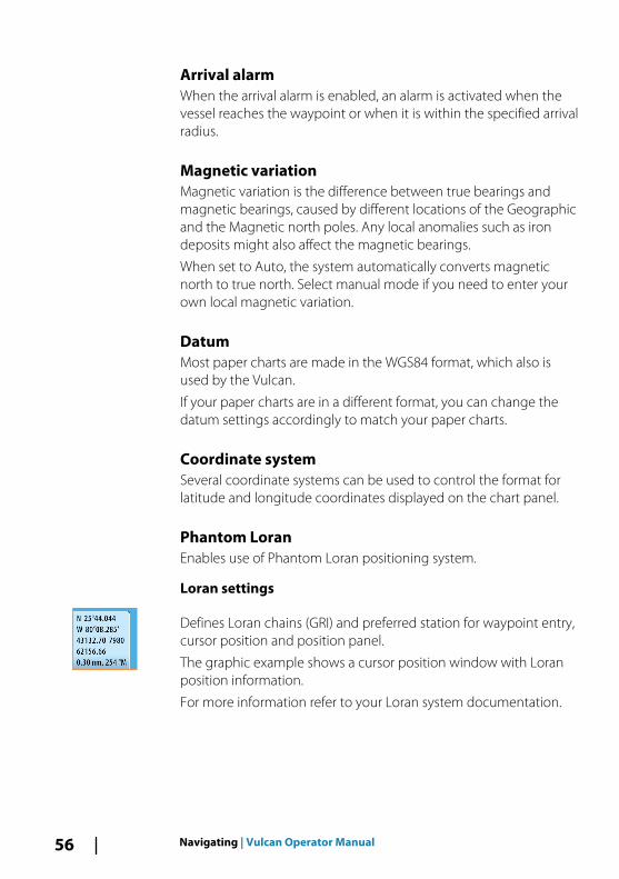
Loran settings
Defines Loran chains (GRI) and preferred station for waypoint entry,cursor position and position panel.
The graphic example shows a cursor position window with Loranposition information.
For more information refer to your Loran system documentation.
56 Navigating | Vulcan Operator Manual

The Sail Steer panelThe Sail Steer panel provides a composite view of key sailing data.All data is displayed relative to the yacht’s bow, providing a clearand easy to understand image of important sailing data.
The Sail Steer panel can be shown as a full screen panel, or in amulti-panel page.
The number of data fields included in the panel is dependent onavailable panel size.
1 User configurable data fields
2 Vessel heading
3 COG (Course Over Ground)
4 Apparent wind*
5 Port and starboard laylines.
6 Magnetic or True reference
7 TWA (True Wind Angle) - Green if on TWA upwind ordownwind. Blue if off target by 10º or more, or on a freeleg. The indicator will fade from blue to green the closeryou get to the exact angle.*
8 Bearing to current waypoint
7
The | Vulcan Operator Manual 57

9 Active (next) waypoint ID, routepoint ID, or cursor
10 Rudder angle
11 Magnetic variation
12 Tide rate and relative direction*
* Optional images. You can turn the optional images on/off fromthe menu.
Selecting data fields for the Sail Steer panelData sources connected to the system can be viewed on the SailSteer panel.
1. Select the Sail Steer panel to make it active.2. Select the MENU button and select the edit option.
- Edit mode is indicated in top of the panel.3. Select the instrument field you want to change.
- The selected field has a highlighted frame.4. Select the MENU button again to select info.5. Repeat the steps to change other instrument fields.6. Save your settings by selecting the save option in the menu.
Sail Time calculationsThe system calculates the time and distance to a waypoint takinginto consideration that the vessel is sailing on a layline course to thewaypoint. Data showing time calculations will be indicated with an -S extension:
DTW-S Sailing Distance to Waypoint
TTW-S Sailing Time to Waypoint
ETA-S Sailing Estimated Time of Arrival
58 The | Vulcan Operator Manual

Time and Wind plotsThe system can present data history in different plots. The plots canbe displayed in full page, or combined with other panels.
The Time plot panelThe Time plot panel consists of two predefined layouts. You switchbetween the layouts by selecting the left and right panel arrows.You can also select the layout from the menu.
You can select which data to present on a time plot panel, and youcan define the time range for each plot.
Layout 1 Layout 2
Missing dataIf the data is unavailable, the relevant plot turns into a dashed lineand flattens out at the point the data was lost. When the databecomes available again, a dashed line joins up the two pointsshowing an average trend line bridging the missing data.
Selecting dataEach data field can be changed to show the preferred data type andthe time range.
1. Select the edit option from the menu2. Activate the field you want to edit3. Change the information type and eventually the range4. Save your changes
The data available for the Time plots are by default the sources usedby the system. If more than one data source is available for a datatype you can select to show alternative data source in the Time plot.You change the data type by using the data source option in themenu.
8
Time and Wind plots| Vulcan Operator Manual 59
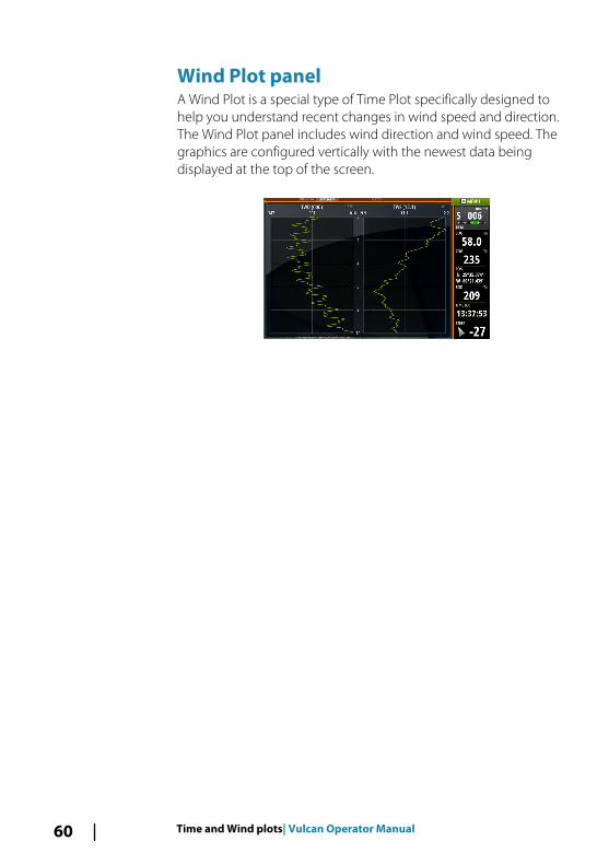
Wind Plot panelA Wind Plot is a special type of Time Plot specifically designed tohelp you understand recent changes in wind speed and direction.The Wind Plot panel includes wind direction and wind speed. Thegraphics are configured vertically with the newest data beingdisplayed at the top of the screen.
60 Time and Wind plots| Vulcan Operator Manual

AutopilotIf an AC12N, AC42N or SG05 autopilot computer is connected to thesystem, autopilot functionality is available in the system.
An Autopilot is designed to maintain an accurate course in varioussea conditions with minimal helm movements.
Safe operation with the autopilot
Warning: An autopilot is a useful navigational aid,but DOES NOT replace a human navigator.
Activating the autopilot
You activate the autopilot from any panel by selecting the autopilottile in the Instrument bar, followed by selecting a mode in theAutopilot Controller.
Switching from automatic mode to manualsteeringYou switch the autopilot to STBY mode from any automaticoperation mode from the autopilot pop-up.
9
Autopilot| Vulcan Operator Manual 61
Autopilot indication on the pages
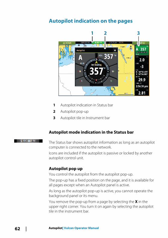
1 Autopilot indication in Status bar
2 Autopilot pop-up
3 Autopilot tile in Instrument bar
Autopilot mode indication in the Status bar
The Status bar shows autopilot information as long as an autopilotcomputer is connected to the network.
Icons are included if the autopilot is passive or locked by anotherautopilot control unit.
Autopilot pop upYou control the autopilot from the autopilot pop-up.
The pop-up has a fixed position on the page, and it is available forall pages except when an Autopilot panel is active.
As long as the autopilot pop-up is active, you cannot operate thebackground panel or its menu.
You remove the pop-up from a page by selecting the X in theupper right corner. You turn it on again by selecting the autopilottile in the instrument bar.
62 Autopilot| Vulcan Operator Manual

The following pop-ups are available:
• Autopilot controller, showing active mode, heading, rudderand various steering information depending on active autopilotmode. Manual adjustments to the set heading can only bemade when the port and starboard arrow indicators areilluminated red and green.
• Mode selection, includes access to turn pattern selection.• Turn pattern selection
Autopilot controller Mode selection Turn pattern selection
Autopilot tile in Instrument bar
You can select to show the autopilot tile in the Instrument bar.
If the autopilot pop-up is turned off you can turn it on by selectingthe tile in the Instrument bar.
The Autopilot panelThe autopilot panel is used to display navigation data. It can beshown as a full screen panel, or in a multi-panel page.
The number of data fields included in the autopilot panel isdependent on available panel size.
Autopilot| Vulcan Operator Manual 63

Data fieldsThe following abbreviations are used in the autopilot panel:
CTS Course to steer
DTD Distance to destination
WPT DIST Distance to next waypoint
SOG Speed over ground
COG Course over ground
XTE Cross track error (L: left or R: right)
Mode overviewThe autopilot has several steering modes. The number of modesand features within the mode depend on boat type and availableinputs, as shown in the following list:
• StandbyStandby mode used when manually steering at the helm.Compass and rudder angle is shown on the display.
• NFUNon-Follow Up steering where the rudder movement iscontrolled by using the Port and Starboard keys in the Pilotpop-up, or by another NFU unit.
• FUFollow-up steering where the rudder angle is set by another FUunit.
• AUTOAutomatic steering where the set heading is maintained.
• Heading captureAborts the turn and uses the instantaneous compassreading as set heading.
• Turn patternsMoves the vessel automatically in pre-defined turn steeringpatterns.
• TackingOnly available if the boat type is set to Sail in the AutopilotCommissioning dialog. Tacking with a fixed angle.
• NoDrift
64 Autopilot| Vulcan Operator Manual

Automatic steering, keeping the vessel on a straight bearingline by compensating for drift.
• DodgingReturns to NoDrift mode after a heading change.
• NAVNavigation steering. Steers the vessel to a specific waypoint orthrough a route.
• WINDOnly available if the boat type is set to Sail in the AutopilotCommissioning dialog. Automatic steering where the vesselheading is changed to maintain a set wind angle.
• Tacking/GybingOnly available if the boat type is set to Sail in the AutopilotCommissioning dialog. Tacking/Gybing with apparent ortrue wing angle as reference.
• WIND NavAutomatic steering, using both wind and GPS data to steer thevessel to a specific waypoint or through a route.
Standby modeStandby (STBY) mode is used when you steer the boat at the helm.
Non-Follow Up (NFU, Power steering)In NFU mode you use the port and starboard arrow buttons in theautopilot pop-up to control the rudder. The rudder will move aslong as the button is pressed.
• Activate NFU mode by selecting the port or starboard arrowbutton in the pop-up when the autopilot is in STBY or FU mode.
You return to STBY mode by selecting the STBY mode button in theautopilot pop-up.
Follow-up steering (FU)Ú Note: FU mode is only available if you have a ZC1 or similar
included in the system. The Vulcan does not have a rotaryknob.
In FU mode you use the rotary knob to control the rudder angle.Press the rotary knob, then turn the knob to set the rudder angle.The rudder moves to the commanded angle and then stop.
• You select FU mode from the autopilot pop-up
Autopilot| Vulcan Operator Manual 65

Ú Note: If the autopilot pop-up is closed or if an alarm dialogis activated on the unit controlling the autopilot in FUmode, the autopilot automatically changes to STBY mode.
Warning: While in FU mode you cannot take manualcontrol of the wheel.
AUTO mode (auto compass)In AUTO mode the autopilot issues rudder commands required tosteer the vessel automatically on a set heading.
• You select AUTO mode from the autopilot pop-up. When themode is activated, the autopilot selects the current boatheading as the set heading.
Changing set heading in AUTO modeYou adjust the set heading by using the Port and Starboard arrowbuttons in the autopilot pop-up, or by selecting the Heading tile inthe autopilot pop-up and then entering the desired heading value.
An immediate heading change takes place. The new heading ismaintained until a new heading is set.
Heading captureWhen the vessel is turning in AUTO mode, an instant reset of themode activates the heading capture function. This automaticallycancels the turn, and the vessel continues on the heading read fromthe compass the very moment you re-activated the mode.
Tacking in AUTO mode
Ú Note: The tack function is only available when the system isset up for boat type SAIL in the Autopilot Commissioningdialog.
Tacking should only be performed into the wind and must be triedout in calm sea conditions with light wind to find out how it workson your boat. Due to a wide range of boat characteristics (fromcruising to racing boats) the performance of the tack function mayvary from boat to boat.
66 Autopilot| Vulcan Operator Manual

Tacking in AUTO mode is different from tacking in WIND mode. InAUTO mode the tack angle is fixed and as defined by the user. Formore details, see "Tacking - WIND mode" on page 70.
You initiate the tack function from AUTO mode.
When tacking direction is selected the autopilot changes thecurrent set course according to the set fixed tacking angle.
You can interrupt the tack operation as long as the tack dialog isopen by selecting the opposite tacking direction. When interruptedthe boat returns to the previous set heading.
NoDrift modeNoDrift mode combines the autopilot and the positioninginformation from the GPS.
In NoDrift mode the vessel is steered along a calculated track line ina direction set by the user. If the vessel's heading is drifting awayfrom the original heading due to current and/or wind, the vesselfollows the line with a crab angle.
1. Turn the vessel to the desired heading2. Activate the NoDrift mode. The autopilot draws an invisible
bearing line based on current heading from the boat’s position
Unlike in AUTO (compass) mode, the autopilot now uses theposition information to calculate the cross track error, andautomatically keeps your track straight.
You use the port/starboard arrow panel buttons in the autopilotpop-up to reset the bearing line while in NoDrift mode.
DodgingIf you need to avoid an obstacle when using NoDrift mode, you canset the autopilot to STBY and power steer or use the helm until theobstacle is passed.
If you return to NoDrift mode within 60 seconds you can select tocontinue on previous set bearing line.
If you do not respond, the dialog disappears and the autopilot goesto NoDrift mode with current heading as set bearing line.
Autopilot| Vulcan Operator Manual 67

NAV mode
Warning: NAV mode should only be used in openwaters.
You can use the autopilot to automatically steer the boat to aspecific waypoint location, or along a pre-defined route. Theposition information from the GPS is used to change the course tosteer to keep the boat on the track line and to the destinationwaypoint.
Ú Note: To obtain satisfactory navigation steering, the Vulcanmust have valid position input. Autosteering must betested and determined satisfactory prior to entering theNAV mode.
Start automatic navigatingWhen you start navigating a route or to a waypoint from the chartpanel, you are prompted to set the autopilot to NAV mode. If youreject this request, you can start NAV mode from the autopilotmode menu.
When NAV mode is initiated, the autopilot automatically keeps thevessel on the leg.
When the vessel reaches the arrival circle for a routepoint, theautopilot gives an audible warning and displays a dialog with thenew course information. If the required course change to the nextwaypoint is less than the Navigation change limit, the autopilotautomatically changes the course. If the required course change tonext waypoint in a route is more than the set limit, you areprompted to verify that the upcoming course change is acceptable.
Ú Note: For information about navigation settings, refer to"Navigation settings" on page 55.
Waypoint arrival circleThe Arrival radius defines the point at which a turn is initiated whenyou are navigating a route.
68 Autopilot| Vulcan Operator Manual
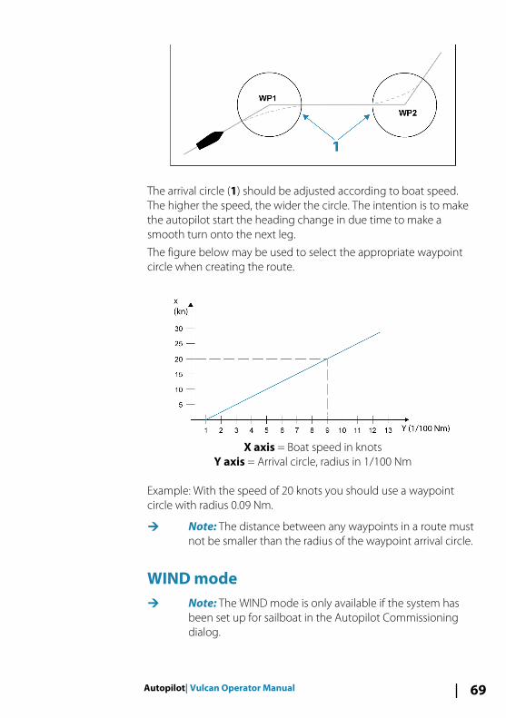
The arrival circle (1) should be adjusted according to boat speed.The higher the speed, the wider the circle. The intention is to makethe autopilot start the heading change in due time to make asmooth turn onto the next leg.
The figure below may be used to select the appropriate waypointcircle when creating the route.
X axis = Boat speed in knotsY axis = Arrival circle, radius in 1/100 Nm
Example: With the speed of 20 knots you should use a waypointcircle with radius 0.09 Nm.
Ú Note: The distance between any waypoints in a route mustnot be smaller than the radius of the waypoint arrival circle.
WIND modeÚ Note: The WIND mode is only available if the system has
been set up for sailboat in the Autopilot Commissioningdialog.
Autopilot| Vulcan Operator Manual 69

Before the WIND mode is started it must be verified that valid inputfrom wind transducer is available.
Initiate wind steering as follows;
1. Switch the Autopilot to AUTO mode2. Adjust the boat heading until wind angle is according to the
angle you want to maintain3. Select the mode indication in the autopilot controller to activate
the autopilot menu, and select WIND mode
The set course to steer (CTS) and set wind angle are entered fromthe compass heading and the wind transducer at the moment theWIND mode is selected. From that point the autopilot changes thecourse to maintain the wind angle as the wind direction maychange.
Tacking in WIND mode
Ú Note: The tack function is only available when the system isset up for boat type SAIL in the Autopilot Commissioningdialog.
Tacking should only be performed into the wind and must be triedout in calm sea conditions with light wind to find out how it workson your boat. Due to a wide range of boat characteristics (fromcruising to racing boats) the performance of the tack function mayvary from boat to boat.
Tacking in WIND mode as compared to AUTO mode is performedwhen sailing with apparent or true wind as the reference. The truewind angle should be less than 90 degrees.
The rate of turn during the tack will be given by the Tack timedefined in the sailing parameter setup. The tack time is alsocontrolled by the speed of the boat to prevent loss of speed duringa tack.
You can initiate the tack function from WIND mode.
When you initiate the tacking, the autopilot immediately mirrors theset wind angle to the opposite side of the bow.
You can interrupt the tack operation as long as the tack dialog isopen by selecting the opposite tacking direction. When interrupted,the boat returns to the previous set heading.
GybingGybing is possible when the true wind angle is larger than 120°.
70 Autopilot| Vulcan Operator Manual

The time to make a gybe is determined by the speed of the boat tomake it as quick as possible within control.
Tack and gybe preventYou should use the autopilot with care when beating and running.
If the sails are unbalanced when beating, yaw forces from the sailscan drive the boat into the wind. If the boat is driven beyond the setminimum wind angle, the thrust from the sails suddenly disappearsand reduces the boat speed. The boat becomes more difficult tosteer as the rudder becomes less effective.
The tack prevent function in WIND mode has been implemented toavoid such situations. It reacts immediately when the apparent windangle becomes 5° less than the set minimum wind angle, and morerudder is commanded.
When running, it is difficult to steer the boat with waves comingsideways or from behind. The waves can yaw the boat into anunwanted gybe; this can be hazardous for both the crew and themast.
The gybe prevent function is activated when the actual apparentwind angle becomes greater than 175° or gets opposite to the setwind angle. More rudder is commanded to prevent an unwantedgybe.
The tack and gybe prevent functions are not a guarantee againstgetting into a hazardous situation. If the effect of the rudder and/ordrive unit is not adequate, a dangerous situation may occur. Payparticular attention in such situations.
WIND Nav modeIn WIND Nav mode the autopilot steers the boat given both windand position data.
In this mode the autopilot calculates the initial course changeneeded to navigate towards the active waypoint, but the pilot alsoutilizes the current wind direction in the calculation.
Autopilot| Vulcan Operator Manual 71

Turn pattern steering
The autopilot includes a number of automatic turn steering featuresfor power boats when the pilot is in AUTO mode.
Ú Note: The turn steering option is not be available if theboat type is set to SAIL in the Autopilot Commissioningdialog, instead the tack/gybe feature is implemented.
Initiating a turnYou start the turn by selecting the relevant turn icon, followed byselecting the port or starboard options in the turn dialog to selectthe turn direction.
Stopping the turnYou can stop the turn from within the turn dialog.
At any time during a turn you can select STBY in the autopilot pop-up to return to STBY mode and manual steering.
Turn variablesThe turn steering options, except the C-turn, have settings that youcan adjust before you start a turn and at any time when the boat isin a turn.
U-turnU-Turn changes the current set heading to be 180° in the oppositedirection.
The turn rate is identical to Rate limit settings. This cannot bechanged during the turn.
Ú Note: Refer to the separate Vulcan Installation manual forinformation about Rate limit settings.
C-turnSteers the vessel in a circle.
You can adjust the Rate of turn from the turn dialog before the turnis initiated and during the turn. Increasing the turn rate makes thevessel turn a smaller circle.
72 Autopilot| Vulcan Operator Manual

Spiral turnSpiral-turn makes the vessel turn in a spiral with a decreasing orincreasing radius. You set the initial radius before the turn isinitiated, and the change per turn during the turn. If the change perturn is set to zero, the vessel turns in a circle. Negative valuesindicate decreasing radius while positive values indicate increasingradius.
Zigzag turnsSteers the vessel in a zigzag pattern.
For navigating in a zigzag pattern, you set the initial headingchange before the turn is started.
During the turn you can alter the main heading, the headingchange, and the leg distance.
Square turnMakes the vessel automatically turn 90° after having travelled adefined leg distance.
At any time during the turn you can change the main heading andthe distance of the leg until the vessel makes a new 90° turn.
Lazy S-turnMakes the vessel yaw around the main heading.
You set the selected heading change before the turn is started.
During the turn you can alter the main heading, the headingchange and the turn radius from within the turn dialog.
Depth contour tracking, DCTTM
If the system has Echosounder input, the autopilot can be set tofollow a depth contour.
Warning: Do not use this feature unless the seabed issuitable. Do not use it in rocky waters where the depthis varying significantly over a small area.
Autopilot| Vulcan Operator Manual 73

Use the following process to initiate DCT steering:
1. Ensure that you have depth reading on the panel or on aseparate depth instrument.
2. Steer the boat to the depth you want to track, and in thedirection of the depth contour.
3. Activate AUTO mode, select depth contour steering andmonitor the depth reading.
4. Select the port or starboard option in the turn dialog to initiatethe depth contour steering to follow the bottom sloping tostarboard or to port:
The following parameters are available for depth contour tracking:
Depth gainThis parameter determines the ratio between commanded rudderand the deviation from the selected depth contour. The higherdepth gain value the more rudder is applied.
If the value is too small, it takes a long time to compensate fordrifting off the set depth contour, and the autopilot fails to keep theboat on the selected depth.
If the value is set too high, the overshoot increases and the steeringis unstable.
Contour Cross Angle (CCA)The CCA is an angle that is added to or subtracted from the setcourse.
With this parameter you can make the boat yaw around thereference depth with lazy-s movements.
The larger the CCA, the bigger yawing is allowed. If you the CCA setto zero there are no lazy-s movements.
74 Autopilot| Vulcan Operator Manual

Using the Vulcan in an AP24/AP28 system
Command transfer
If your Vulcan is connected to an autopilot system including anAP24 or AP28 control unit, only one control unit can be active at thesame time. An inactive control unit is indicated with a square with across symbol in autopilot controller pop-up.
Locking remote stations
The AP24/AP28 includes a Remote Lock function that disablesautopilot control from other units. A locked control unit is indicatedwith a key symbol in autopilot controller pop-up.
When the remote lock function is enabled on an AP24/AP28 controlunit, only the active control unit stays in command. No transfer ofcommand to Vulcan or other autopilot control units on the systemcan take place.
You can only unlock the remote stations from the AP24/AP28 unit incommand.
Using the autopilot in an EVC system
When the Vulcan is connected to an EVC system via the SG05, youcan take manual control of the steering regardless of the autopilotmode.
The mode indicator on the pilot pop-up is replaced by a dash toindicate EVC override.
The system returns to Vulcan control in standby mode if no ruddercommand is given from the EVC system within a predefined period.
Autopilot| Vulcan Operator Manual 75
Autopilot settings
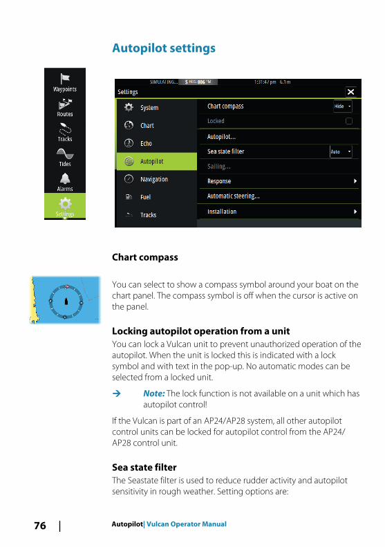
Chart compass
You can select to show a compass symbol around your boat on thechart panel. The compass symbol is off when the cursor is active onthe panel.
Locking autopilot operation from a unitYou can lock a Vulcan unit to prevent unauthorized operation of theautopilot. When the unit is locked this is indicated with a locksymbol and with text in the pop-up. No automatic modes can beselected from a locked unit.
Ú Note: The lock function is not available on a unit which hasautopilot control!
If the Vulcan is part of an AP24/AP28 system, all other autopilotcontrol units can be locked for autopilot control from the AP24/AP28 control unit.
Sea state filterThe Seastate filter is used to reduce rudder activity and autopilotsensitivity in rough weather. Setting options are:
76 Autopilot| Vulcan Operator Manual

• OFFSeastate filter is disabled. This is the default setting.
• AUTOReduces rudder activity and autopilot sensitivity in roughweather by an adaptive process. The AUTO setting isrecommended if you want to use the seastate filter.
• MANUALLinked to the steering response control settings describedpreviously. It may be used to manually find the optimumcombination of course keeping and low rudder activity in roughbut steady sea conditions.
Sailing parameters
Ú Note: Sailing parameter settings are only available if theboat type is set to Sail in the Autopilot Commissioningdialog.
Tack timeWhen performing a tack in WIND mode, the rate of turn (tack time)can be adjusted. This gives single-handed sailors time to handle theboat and the sails during a tack.
A turn performed without shifting wind side, is also made at acontrolled turn rate.
Tack angleThis value is used to preset the course change used when tacking inAUTO mode. By pressing the port and starboard indicators in theautopilot pop-up the course changes as much as this value.
Wind functionWith wind function set to AUTO, the autopilot automatically selectsbetween apparent and true wind steering. AUTO is default andrecommended for cruising.
When the boat is running, it is also surfing on the waves. This maylead to significant changes in boat speed, and thereby also changesin apparent wind angle. True wind steering is therefore used whenrunning, while steering to apparent wind is used when beating orreaching.
Apparent wind steering is preferred when you want to achievemaximum boat speed. The autopilot tries to maintain a constantapparent wind angle to get maximum thrust from a given trim ofthe sails.
Autopilot| Vulcan Operator Manual 77

When sailing in closed waters, the apparent wind angle may changetemporarily due to wind gusts. It may then be preferred to sail tothe true wind.
VMG optimizingYou can optimize the VMG to wind. When selected, the function isactive for 5–10 minutes after a new wind angle has been set andonly when beating.
Layline steeringLayline steering is useful when navigating. Cross Track Error (XTE)from the navigator keeps the boat on the track line. If the XTE fromthe navigator exceeds 0.15 NM, the autopilot calculates the laylineand track towards the waypoint.
ResponseBy default the system switches between HI/LO parameter set basedon speed (motor boats) or speed and wind (sail boats). You canhowever manually select which parameter set that shall be used.
HI or LO must be selected if no speed input is available.
You can manually fine tune each of the two (HI/LO) parameter sets.Level 4 is default with parameter values as set by the autotunefunction. If no autotune is made (not recommended) the level 4values are the factory default values.
A low response level reduces the rudder activity and provides amore “loose” steering.
A high response level increases the rudder activity and provides amore “tight” steering. A too high response level causes the boat tostart lazy-s movements.
Automatic steeringThis option displays an overview of all autopilot steeringparameters, and you can adjust parameters if required.
For more details, refer to the separate Vulcan Installation manual.
InstallationUsed for autopilot installation and commissioning. See the separateVulcan Installation manual.
78 Autopilot| Vulcan Operator Manual
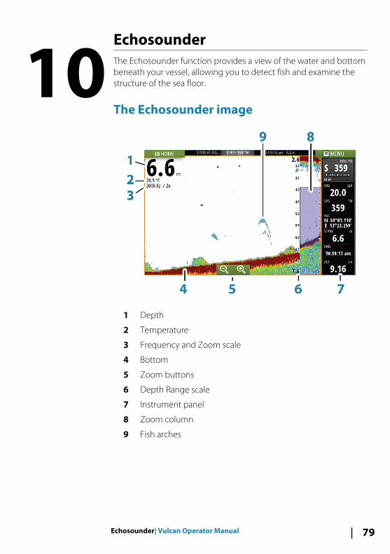
EchosounderThe Echosounder function provides a view of the water and bottombeneath your vessel, allowing you to detect fish and examine thestructure of the sea floor.
The Echosounder image
1 Depth
2 Temperature
3 Frequency and Zoom scale
4 Bottom
5 Zoom buttons
6 Depth Range scale
7 Instrument panel
8 Zoom column
9 Fish arches
10
Echosounder| Vulcan Operator Manual 79

Using the cursor on the Echosounder panelThe cursor can be used to measure a distance to a target, to mark aposition, and to select targets.
By default, the cursor is not shown on the Echosounder image.
When you position the cursor on the Echosounder image; thescreen pauses, the depth at the cursor position is shown, and theinformation window is activated.
To remove the cursor and cursor elements from the panel, selectthe Clear cursor menu option.
GoTo cursorYou can navigate to a selected position on the image by positioningthe cursor on the panel, then using the Goto Cursor option in themenu.
The Cursor assist functionThe cursor assist function allows for fine tuning and precisionplacement of the cursor without covering details with your finger.
Press and hold your finger on the screen to switch the cursorsymbol to a selection circle, appearing above your finger.
Without removing your finger from the screen, drag the selectioncircle over the desired item to display item information.
When you remove your finger from the screen the cursor reverts tonormal cursor operation.
Measuring distanceThe cursor can be used to measure the distance between theposition of two observations on the image.
It is easier to use the measuring function when the image is paused.
1. Position the cursor on the point from where you want tomeasure the distance
2. Start the measuring function from the menu3. Position the cursor on the second measuring point
- A line is drawn between the measuring points, and thedistance is listed in the Information window
4. Continue selecting new measuring points if required
80 Echosounder| Vulcan Operator Manual

You can use the menu to re-position the start point and the endpoint as long as the measuring function is active.
When you select Finish measuring, the image resumes to normalscrolling.
Viewing Echosounder historyYou can view echosounder history by panning the image.
Setting up the Echosounder image
Use the Echosounder menu options to set up the image. When thecursor is active, some options on the Echosounder menu arereplaced with cursor mode features. Select Clear cursor to returnto the normal Echosounder menu.
The rangeThe range setting determines the water depth that is visible on thescreen.
Auto rangeBy default, the range is set to Auto. With Auto, the systemautomatically displays the whole range from the water surface to
Echosounder| Vulcan Operator Manual 81

the bottom. Auto is the preferred setting for most fish finding sonaruse.
Preset range levelsAllows for the selection of a specific depth range that is not tied tothe depth of the water.
Custom rangeThis option allows you to manually set both upper and lower rangelimits.
Ú Note: Setting a custom range puts the sonar in manualmode. If the bottom is well beyond the lower range set,you may lose digital depth.
Echosounder frequencyThe Vulcan unit supports several transducer frequencies. Availablefrequencies depend on the transducer model that is connected.
You can view two frequencies at the same time by selecting dualEchosounder panels from the Home page.
Log sonarSelect to start and stop recording of Echosounder data. For moreinformation, refer to "Recording log data" on page 83.
GainThe gain controls the sensitivity of the Echosounder. The more youincrease the gain, the more details are shown on the image.However, a higher gain setting may introduce more backgroundclutter on the image. If the gain is set too low, weak echoes mightnot be displayed.
Auto gainThe Auto gain option keeps the sensitivity at a level that works wellunder most conditions. With the gain in auto mode, you can set apositive or negative offset that gets applied to the auto gain.
ColorStrong and weak Echosounder signals have different colors toindicate the different signal strengths. The colors used depend onwhich palette you select. The more you increase the Color setting,
82 Echosounder| Vulcan Operator Manual

the more echoes is displayed in the color at the strong return end ofthe scale.
PalettesYou can select between several display palettes optimized for avariety of fishing conditions.
DownScan optionsProvides options for specifying the DownScan image. This menuoption is available when Overlay downscan is selected in Echosettings dialog. For more information see "Echosounder settings" on page85.
Pausing the EchosounderYou can pause the Echosounder, allowing you to examine theEchosounder echoes.
This function is useful when you need to position a waypointexactly on the Echosounder panel, and if you are using the cursor tomeasure a distance between 2 elements on the image.
Recording log data
You can record data and save the file internally in the unit, or save itonto a card inserted into the unit's card reader. Select the Log sonarmenu option, and then Record in the Record Echo dialog.
When the Echosounder data is being recorded, there is a flashingred symbol in the top left corner and a message appearsperiodically at the bottom of the screen.
Echosounder| Vulcan Operator Manual 83

FilenameSpecify the name of the recording (log).
File formatSelect a file format from the drop-down, slg (Echosounder only), xtf(DownScan only*), or sl2 (Echosounder and DownScan).
Ú Note: XTF format is for use only with select 3rd partyEchosounder viewing tools.
Save toSelect whether the recording is to be saved internally or to amemory card in the card reader.
Time remainingShows the remaining allocated space available for recordings.
Viewing the recorded sounder dataBoth internally and externally stored sounder records may bereviewed when selected.
The log file is displayed as a paused image, and you control thescrolling and display from the replay menu option.
You can use the cursor on the replay image, and pan the image ason a normal echo image.
If more than one channel was recorded in the selected echo file,you can select which channel to display.
84 Echosounder| Vulcan Operator Manual

Stop recording log data
Select the Log sonar menu option, and then Stop in the RecordingEcho dialog to stop the recording of Echosounder data.
Echosounder settings
Overlay downscanWhen a HDI transducer with DownScan is connected to yoursystem, you can overlay DownScan images on the regularEchosounder image.
When activated, the Echosounder menu expands to include basicDownScan options.
Echosounder| Vulcan Operator Manual 85

View Echosounder logUsed to view Echosounder recordings. The log file is displayed as apaused image, and you control the scrolling and display from themenu.
You can use the cursor on the image, measure distance, and setview options as on a live Echosounder image. If more than onechannel was recorded in the selected Echosounder file, you canselect which channel to display.
You exit the view function by selecting the X in the upper rightcorner.
InstallationUsed for installation and setup. See the separate Vulcan Installationmanual.
86 Echosounder| Vulcan Operator Manual

DownScanDownScan provides detailed images of structure directly belowyour boat, down to 92 m (300 ft). The DownScan page is accessedfrom the Home page when the DownScan transducer is connected.
The DownScan image
1 Depth
2 Temperature
3 Frequency
4 Zoom buttons
5 Range scale
11
DownScan| Vulcan Operator Manual 87

Zooming the DownScan imageYou can zoom a DownScan image by using the panel zoom icons.
Using the cursor on the DownScan panelBy default, the cursor is not shown on the DownScan image.
When you tap the screen the cursor appears, the informationwindow is activated, the depth is shown at the cursor position, andthe image stops scrolling.
To remove the cursor and cursor elements from the panel, selectthe Clear cursor option.
GoTo cursorYou can navigate to a selected position on the image by positioningthe cursor on the panel, then using the Goto Cursor option in themenu.
Measuring distanceThe cursor can be used to measure the distance between theposition of two observations on the image.
It is easier to use the measuring function when the image is paused.
1. Position the cursor on the point from where you want tomeasure the distance
2. Start the measuring function from the menu3. Position the cursor on the second measuring point
- A line is drawn between the measuring points, and thedistance is listed in the Information window
4. Continue selecting new measuring points if required
You can use the menu to re-position the start point and the endpoint as long as the measuring function is active.
When you select Finish measuring, the image resumes to normalscrolling.
Viewing DownScan historyYou can pan the image history by dragging the image to the leftand right.
To resume normal DownScan scrolling, select the Clear cursoroption.
88 DownScan| Vulcan Operator Manual

Setting up the DownScan image
Use the DownScan menu to set up the image. When the cursor isactive, some options in the menu are replaced with cursor modefeatures. Select Clear cursor to return to the normal menu.
RangeThe range setting determines the water depth that is visible on theimage.
Auto rangeBy default, the range is set to Auto. With Auto, the systemautomatically displays the whole range from the water surface tothe bottom.
Preset range levelsAllows for the selection of a specific depth range that is not tied tothe depth of the water.
FrequencyDownScan can be used at 800 kHz or 455 kHz. 800 kHz provides thehighest resolution with less range. 455 kHz has the best range, butwith lower resolution.
ContrastThe contrast determines the brightness ratio between light anddark areas of the screen. This makes it easier to distinguish objectfrom the background.
Drag the bar up or down to get the desired contrast setting orselect Auto contrast.
PalettesYou can select between several display palettes optimized for avariety of fishing conditions.
DownScan| Vulcan Operator Manual 89

Record DownScan dataYou can record DownScan data and save the file internally in theunit, or onto a memory card in the card reader slot as described in"Recording log data" on page 83.
Pausing the DownScan imageYou can pause the DownScan image, allowing you to examine thestructures and other images in more detail.
This function is useful when you need to position a waypointprecisely on the DownScan image, and if you are using the cursor tomeasure a distance between 2 elements on the image.
90 DownScan| Vulcan Operator Manual
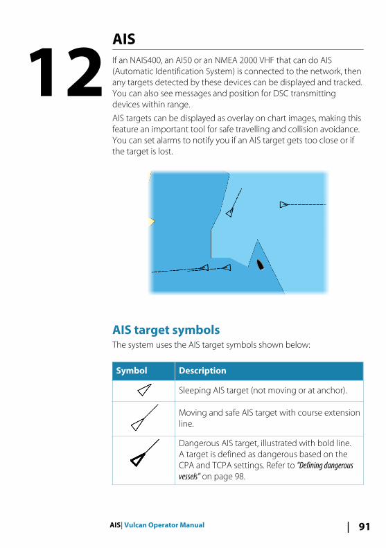
AISIf an NAIS400, an AI50 or an NMEA 2000 VHF that can do AIS(Automatic Identification System) is connected to the network, thenany targets detected by these devices can be displayed and tracked.You can also see messages and position for DSC transmittingdevices within range.
AIS targets can be displayed as overlay on chart images, making thisfeature an important tool for safe travelling and collision avoidance.You can set alarms to notify you if an AIS target gets too close or ifthe target is lost.
AIS target symbolsThe system uses the AIS target symbols shown below:
Symbol Description
Sleeping AIS target (not moving or at anchor).
Moving and safe AIS target with course extensionline.
Dangerous AIS target, illustrated with bold line.A target is defined as dangerous based on theCPA and TCPA settings. Refer to "Defining dangerousvessels" on page 98.
12
AIS| Vulcan Operator Manual 91

Symbol Description
Lost AIS target.When no signals have been received within atime limit, a target is defined as lost.The target symbol represents the last validposition of the target before the reception ofdata was lost.
Selected AIS target, activated by selecting atarget symbol.The target returns to the default target symbolwhen the cursor is removed from the symbol.
Viewing information about AIS targets
Searching for AIS itemsYou can search for AIS targets by using the Find option in the Toolspanel.
From a chart panel you can search for AIS targets by using the Findoption in the menu. If the cursor is active, the system searches forvessels around the cursor position. Without an active cursor, thesystem searches for vessels around your vessel's position.
Viewing information about single AIS targets
When you select an AIS icon on the chart panel the symbol changesto Selected target symbol, and the vessel's name is displayed.
You can display detailed information for a target by selecting theAIS pop-up, or from the menu when the target is selected.
92 AIS| Vulcan Operator Manual

Calling an AIS vessel If the system includes a VHF radio supporting DSC (Digital SelectCalling) calls over NMEA 2000, you can initiate a DSC call to othervessels from the Vulcan.
The call option is available in the AIS Vessel Details dialog, and inthe Vessel status dialog activated from the Tools panel.
From the Call dialog you can change channel or cancel the call. TheCall dialog is closed when the connection is established.
AIS SART
When an AIS SART (Search and Rescue beacon) is activated, it startstransmitting its position and identification data. This data is receivedby your AIS device.
If your AIS receiver is not compliant with AIS SART, it interprets thereceived AIS SART data as a signal from a standard AIS transmitter.An icon is positioned on the chart, but this icon is an AIS vessel icon.
AIS| Vulcan Operator Manual 93

If your AIS receiver is compliant with AIS SART, the following takesplace when AIS SART data is received:
• An AIS SART icon is located on the chart in the position receivedfrom the AIS SART
• An alarm message is displayedIf you have enabled the siren, the alarm message is followed by anaudible alarm.
Ú Note: The icon is green if the received AIS SART data is atest and not an active message.
AIS SART alarm messageWhen data is received from an AIS SART, an alarm message isdisplayed. This message includes the AIS SART’s unique MMSInumber, and its position, distance, and bearing from your vessel.
You have three options:
1. Ignore the alarm- The alarm is muted and the message closed. The alarm does
not reappear2. Save the waypoint
- The waypoint is saved to your waypoint list. This waypointname is prefixed with MOB AIS SART - followed by the uniqueMMSI number of the SART. For example, MOB AIS SART -12345678.
3. Activate the MOB function- The display switches to a zoomed chart panel, centered on
the AIS SART position- The system creates an active route to the AIS SART position
When data is received from an AIS SART, an alarm message isdisplayed. This message includes the AIS SART’s unique MMSInumber, its position and its distance and bearing from your vessels.
94 AIS| Vulcan Operator Manual

If you select the AIS SART icon on the chart panel, then you can seethe AIS MOB details.
Ú Note: If the MOB function is already active, this will beterminated and replaced by the new route towards the AISSART position!
Ú Note: If you ignore the alarm, the AIS SART icon remainsvisible on your chart, and the AIS SART remains in theVessels list.
Ú Note: If the AIS stops receiving the AIS SART message, theAIS SART remains in the Vessels list for 10 minutes after itreceives the last signal.
Vessel alarms
You can define several alarms to alert you if a target shows upwithin predefined range limits, or if a previously identified target islost.
Dangerous vesselControls whether an alarm will be activated when a vessel comeswithin the predefined CPA or TCPA. Refer to "Defining dangerous vessels"on page 98.
AIS| Vulcan Operator Manual 95

AIS vessel lostSets the range for lost vessels. If a vessel is lost within the set range,an alarm occurs.
Ú Note: The check box controls whether the alarm pop-upbox is displayed and if the siren goes on. The CPA and TCPAdefine when a vessel is dangerous regardless of theenabled or disabled state.
Vessel messageControls whether an alarm will be activated when a message isreceived from an AIS target.
Vessel settings
Your vessel’s MMSI numberYou need to have your own MMSI (Maritime Mobile Service Identity)number entered in the system to receive addressed messages fromAIS and DSC vessels.
It is also important to have the MMSI number entered to avoidseeing your own vessel as an AIS target on the chart.
Ú Note: The Vessel message option in the alarm settingsmust be toggled on for any MMSI message to be displayed.
96 AIS| Vulcan Operator Manual

Icon filtersBy default, all targets are shown on the panel if an AIS device isconnected to the system.
You can select not to show any targets, or to filter the icons basedon security settings, distance, and vessel speed.
Extension lines
The length of the extension lines for your vessel and for othervessels can be set by the user.
• A: Heading• B: Course Over Ground (COG)The length of the extension lines is either set as a fixed distance, orto indicate the distance the vessel will move in the selected timeperiod. If no options are turned on for This vessel then noextension lines are shown for your vessel.
Your own vessel heading information is read from the activeheading sensor, and COG information is received from the activeGPS.
AIS| Vulcan Operator Manual 97

For other vessels COG data is included in the message receivedfrom the AIS system.
Defining dangerous vesselsYou can define an invisible guard zone around your vessel. When atarget comes within this distance, the symbol changes to the“dangerous” target symbol. An alarm is triggered if activated in theAlarm settings panel.
Speed and course indicationThe extension line can be used to indicate speed and course fortargets, either as absolute (true) motion in the chart or relative toyour vessel.
A different line style is used on the extension lines to indicatemotion, as shown below.
AIS vessels shown with Absolute motion AIS vessels shown with Relative motion
AIS icon orientationSets the orientation of the AIS icon, either based on heading or COGinformation.
98 AIS| Vulcan Operator Manual

Instrument panels
The Instruments panels consist of multiple gauges - analog, digitaland bar - that can be customized to display selected data. TheInstruments panel displays data on dashboards, and you can defineup to ten dashboards within the Instruments panel.
Ú Note: To include fuel/engine information, engine and tankinformation has to be configured from the Settings panel.
DashboardsA set of dashboard styles are predefined to display vessel,navigation, and angler information.
You switch between the panel’s dashboards by selecting the leftand right arrow buttons on the panel. You can also select thedashboard from the menu.
Vessel dashboard Navigation dashboard Angler dashboard
Ú Note: Additional dashboards can be activated from themenu if other systems (e.g. CZone) are present on thenetwork.
Customizing the Instruments panelYou can customize the Instruments panel by changing the data foreach of the gauges in the dashboard, by changing the dashboardlayout, and by adding new dashboards. You can also set limits foranalog gauges.
All edit options are available from the Instruments panel menu.
Available editing options depends on which data sources areconnected to your system.
13
Instrument panels| Vulcan Operator Manual 99

Edit a dashboard
Activate the dashboard you want to edit, then:
1. Activate the menu.2. Select the edit option.3. Select the gauge you want to change. Selected gauge is
indicated with a blue background.4. Select information to be displayed, configure limits, and
eventually change the source for the information.5. Save your changes by selecting the save option in the menu.
100 Instrument panels| Vulcan Operator Manual

AudioIf a SonicHub server or a FUSION marine entertainment system isconnected to the NMEA 2000 network, you can use the Vulcan tocontrol and customize the audio system on your vessel.
Before you can start using your audio equipment, it must beinstalled according to the Vulcan Installation manual and to thedocumentation included with the audio device.
Enabling audioA compatible audio device connected to the NMEA 2000 networkshould automatically be identified by the system. If not, enable thefeature from the Advanced Settings dialog.
The Audio panelYou activate the audio panel by activating the audio tile in theInstrument bar.
The control buttons, tools and options vary from one audio sourceto another as described later in this chapter.
14
Audio| Vulcan Operator Manual 101

1 Audio source
2 Audio control buttons
3 Audio tile
4 Audio tools
Audio control buttons
Icon Tuner VHF DVD Playback
Select to display the list of available sources
Select to select previous/next frequencyPress and hold to tune ina channel
Select torewind/playfast forward
Select toselectprevious/next track
Select to select next/previous favorite channel
N/A N/A
N/A N/A Select to start
N/A N/A Select to pause playback
102 Audio| Vulcan Operator Manual
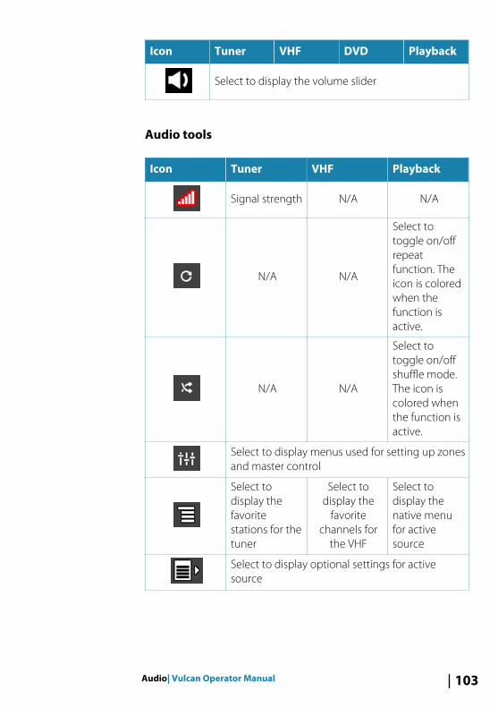
Icon Tuner VHF DVD Playback
Select to display the volume slider
Audio tools
Icon Tuner VHF Playback
Signal strength N/A N/A
N/A N/A
Select totoggle on/offrepeatfunction. Theicon is coloredwhen thefunction isactive.
N/A N/A
Select totoggle on/offshuffle mode.The icon iscolored whenthe function isactive.
Select to display menus used for setting up zonesand master control
Select todisplay thefavoritestations for thetuner
Select todisplay the
favoritechannels for
the VHF
Select todisplay thenative menufor activesource
Select to display optional settings for activesource
Audio| Vulcan Operator Manual 103

Setting up the audio system
The speakers
Speaker zonesThe Vulcan can be set up to control different audio zones. Thenumber of zones depends on the audio server connected to yoursystem.
You can adjust balance, volume and volume limit settingsindividually for each zone. Adjustments to the bass and tremblesettings will alter all zones.
Master volume controlBy default the volume for all speaker zones are adjusted when youadjust the volume. You can define which zones will be altered whenyou increase/decrease the volume.
Selecting tuner regionBefore playing FM or AM radio, and using a VHF radio, you mustselect the appropriate region for your location.
Detaching Sirius from the AUX sourceIf a Sirius radio is connected to the FUSION radio/server, the AUXsource is automatically attached to the Sirius feed. Sirius thenappears in the source list when the FUSION server is active.
To use the AUX source for a different device, the Sirius must bedetached from the AUX source.
Ú Note: To use SiriusXM, an optional SiriusXM tuner must beconnected to the FUSION server.
Operating the audio system1. Select the Audio tile in the Instrument bar to activate the Audio
overlay2. Select the options icon and then select the audio server3. Select the source icon and then select the audio source
- Number of sources depends on the active audio server
104 Audio| Vulcan Operator Manual

4. Use the panel buttons to control your audio system
For an overview of audio control buttons and tools, refer to "Audiocontrol buttons" on page 102 and "Audio Tools" on page 103.
For available options, refer to the documentation following youraudio equipment.
Favorite channelsWhen a tuner or VHF channel is tuned in, you can add the channelto your favorite list. The favorite channels can be viewed, selectedand deleted from within the Favorite list.
You page through favorite channels by using the up/down audiopanel buttons.
Sirius radio (North America only)
Channels listThe channels list displays all available Sirius channels, whether ornot you have a subscription for the channel.
Favorites listYou can create a list of your favorite Sirius channels from within thechannels list. You cannot add unsubscribed channels.
Locking channelsYou can lock selected Sirius channels from being broadcasted. A 4-digit-code must be entered to lock channels and the same codeentered to unlock the channels.
Audio| Vulcan Operator Manual 105

Alarms
Alarm systemThe system continuously checks for dangerous situations andsystem faults while the system is running. When an alarm situationoccurs, an alarm message pops up on the screen.
If you have enabled the siren, the alarm message is followed by anaudible alarm, and the switch for external alarm becomes active.
The alarm is recorded in the alarm listing so that you can see thedetails and take the appropriate corrective action.
Type of messagesThe messages are classified according to how the reported situationaffects your vessel. The following color codes are used:
Color Importance
Red Critical
Orange Important
Yellow Standard
Blue Warning
Green Light warning
Single alarms
A single alarm is displayed with the name of the alarm as the title,and with details for the alarm.
Multiple alarms
If more than one alarm is activated simultaneously, then the alarmmessage displays a list of up to 3 alarms. The alarms are listed in theorder they occur with the alarm activated first at the top. Theremaining alarms are available in the Alarms dialog.
15
106 Alarms| Vulcan Operator Manual

Acknowledging a messageThe following options are available in the alarm dialog foracknowledging a message:
• CloseSets the alarm state to acknowledged, meaning that you areaware of the alarm condition. The siren / buzzer stops and thealarm dialog is removed.However, the alarm remains active in the alarm listing until thereason for the alarm has been removed.
• DisableDisables the current alarm setting. The alarm does not showagain unless you turn it back on in the Alarms dialog.
There is no time-out on the alarm message or siren. They remainuntil you acknowledge the alarm or until the reason for the alarm isremoved.
Alarms dialog
All alarms are setup in the Alarms Settings dialog.
The alarm dialogs can also be activated from the Tools panel. Thealarm dialogs include information about active alarms and alarmhistory.
Alarms| Vulcan Operator Manual 107

108 Alarms| Vulcan Operator Manual

ToolsBy default, the Tools panel includes icons used for accessing optionsand tools that are not specific to any panel.
When external equipment is integrated to the Vulcan, new iconsmight be added to the Tools panel. These icons are used foraccessing the external equipment's features.
Waypoints/routes/tracks
List of waypoints, routes, and tracks with details.
Select the waypoint, route, or track you wish to edit or delete.
TidesDisplays tide information for the tide station nearest to your vessel.
Select the arrow panel buttons to change the date, or select thedate field to access the calendar function.
Available tide stations can be selected from the menu.
Alarms
Active alarmsList of active alarms.
Alarm historyList of all alarms with time stamp.
Alarm settingsList of all available alarm options in the system, with currentsettings.
SettingsProvides access to application and system settings.
16
Tools| Vulcan Operator Manual 109

Vessels
Status listingList of all AIS and DSC vessels with available information.
Message listingList of all messages received from other AIS vessels with time stamp.
Sun, MoonDisplays sunrise, sunset, moonrise and moonset for a position basedon entered date and the position’s latitude/longitude.
Trip calculator
Trip 1 / Trip 2Displays voyage and engine information, with reset option for alldata fields.
TodayDisplays voyage and engine information for current date. All datafields are automatically reset when the date changes.
FilesFile management system for Files, Waypoints, Routes, Tracks, andSettings.
Copying files to a card in the card readerYou can copy screen captures and logs to a card in the card reader.You can also export System Settings, Waypoints, Routes, and Tracksto a card. Exporting files is covered in the section "Maintenance" onpage 114.
FindSearch function for chart items (waypoints, routes, tracks, etc.).
110 Tools| Vulcan Operator Manual

SimulatorThe simulation feature lets you see how the unit works in astationary position and without being connected to theEchosounder, GPS, etc.
Use the simulator to become familiar with your unit before using iton the water.
The status bar indicates if the simulator is toggled on.
Demo modeIn this mode the unit automatically runs through the main featuresof the product; it changes pages automatically, adjusts settings,opens menus, and so on.
If you tap on the touchscreen when demo mode is running, thedemonstration pauses. After a time-out period, demo moderesumes and any changed settings are restored to default.
Ú Note: Demo mode is designed for retail/showroomdemonstrations.
Simulator source filesYou can select which data files are used by the simulator. A set ofsource files is included in your system, and you can import files by
17
Simulator| Vulcan Operator Manual 111

using a card inserted into the card reader. You can also use yourown recorded files in the simulator.
Advanced simulator settingsThe Advanced simulator settings allows for manually controlling thesimulator.
GPS sourceSelects where the GPS data is generated from.
Speed, Course and RouteUsed for manually entering values when GPS source is set toSimulated course or Simulated route. Otherwise, GPS data includingspeed and course come from the selected source file.
Set start positionMoves your vessel to the current cursor position.
Ú Note: This option is only available when the GPS source isset to Simulated course.
112 Simulator| Vulcan Operator Manual

SailingOpens dialog for selecting sail specific simulator data.
Simulator| Vulcan Operator Manual 113

Maintenance
Preventive maintenanceThe Vulcan does not contain any field serviceable components,therefore the operator is required to perform only a very limitedamount of preventative maintenance.
Cleaning the display unitA proper cleaning cloth should be used to clean the screen, wherepossible. Use plenty of water to dissolve and take away salt remains.Crystalized salt may scratch the coating if using a damp cloth. Applyminimal pressure to the screen.
Where marks on the screen cannot be removed by the cloth alone,use a 50/50 mixture of warm water and isopropyl alcohol to cleanthe screen. Avoid any contact with solvents (acetone, mineralturpentine, etc.), or ammonia based cleaning products, as they maydamage the anti-glare layer or plastic bezel.
To prevent UV damage to the plastic bezel, it is recommended thatthe sun cover be fitted when the unit is not in use for an extendedperiod.
Cleaning the media port doorClean the media port door regularly to avoid salt crystallization onthe surface, causing water to leak into the card slot.
Checking the connectorsThe connectors should be checked by visual inspection only.
Push the connector plugs into the connector. If the connector plugsare equipped with a lock, ensure that it is in the correct position.
Software upgradesThe latest software for the Vulcan is available for download from ourwebsite, bandg.com.
Detailed instructions for how to install the software are included inthe upgrade files.
18
114 Maintenance| Vulcan Operator Manual

Backing up your system dataWaypoints, Routes, and Tracks that you create are filed in yoursystem. It is recommended to regularly copy these files and yoursystem settings files as part of your back-up routine. The files can becopied to a card inserted in the card reader.
There are no export file format options for the system settings file.The following output formats are available for exporting Waypoints,Routes, and Tracks files:
• User Data File version 5This is used to import and export waypoints and routes with astandardized universally unique identifier (UUID), which is veryreliable and easy to use. The data includes such information asthe time and date when a route was created, and so on.
• User Data File version 4This is best used when transferring data from one system toanother, since it contains all the extra bits of information thesesystems store about items.
• User Data file version 3 (w/depth)Should be used when transferring user data from one system toa legacy product (Lowrance LMS, LCX, and so on.)
• User data file version 2 (no depth)Can be used when transferring user data from one system to alegacy product (Lowrance LMS, LCX, and so on.)
• GPX (GPS Exchange, no depth)This is the format most used on the web that shares amongmost GPS systems in the world. Use this format if you are takingdata to a competitors unit.
• Northstar.dat (no Tracks)Used to transfer data to a legacy Northstar device.
Maintenance| Vulcan Operator Manual 115

Export all Waypoints, Routes and Tracks
Use the export option if you want to backup all Waypoints, Routes,and Tracks on your system.
Export regionThe export region option allows you to select the area from whereyou want to export data.
1. Drag the boundary box to define the desired region2. Select the export option from the menu3. Select the appropriate file format4. Select Export to start the export
Purging Waypoints, Routes and TracksDeleted Waypoints, Routes and Tracks are stored in the Vulcanmemory until the data is purged. If you have numerous deleted,unpurged Waypoints, purging may improve the performance ofyour system.
Ú Note: When user data is purged from the memory, itcannot be recovered.
116 Maintenance| Vulcan Operator Manual

Touchscreen operationBasic touchscreen operation on the different panels is shown in thetable below.
The panel sections in this manual have more information aboutpanel specific touchscreen operation.
Icon Description
Tap to:• Activate a panel on a multi-panel page• Position the cursor on a panel• Select a menu and a dialog item• Toggle a checkbox option on or off• Show basic information for a selected item
Press and hold:• On any panel with a cursor to activate the
cursor assist feature• On a panel button to see available split screen
options• On a favorite button to enter edit mode
Scroll through a list of available options withoutactivating any option.
Flick to quickly scroll through e.g. the waypoint list.Tap the screen to stop the scrolling.
Pan to position a chart or Echosounder image onthe panel.
19
T| Vulcan Operator Manual 117

Icon Description
Pinch to zoom out on the chart or on an image.
Spread to zoom in on the chart or on an image.
118 T| Vulcan Operator Manual

IndexA
Active panel 20Adjusting panel size 24AIS 91
Calling a vessel 93DSC 93Icon filters 97Icon orientation 98Searching for AIS items 92Target symbols 91Viewing information abouttargets 92
AIS SART 93Alarm message 94
AlarmsAcknowledging 107Alarm settings dialog 107Multiple alarms 106Single alarm 106Type of messages 106
Application pages 14Arrival alarm 56Arrival radius 55Audio 101
Control buttons 102Detaching Sirius 104Enable 101Favorite channels 105Master volume control 104Operating 104Selecting tuner region 104Setting up the system 104Sirius radio 105Speaker zones 104Speakers 104
AudioPanel 101
Audio tools 103Autopilot 61
Activating 61AP24/28 systems 75AUTO mode 66Autopilot pop-up 62Autopilot tile in Instrumentbar 63Chart compass 76Depth contour tracking 73Dodging 67EVC system 75Follow-up steering 65Gybing 70HI/LO parameters 78Indication in Status bar 62Indication on pages 62Locking remote stations 75Mode overview 64Non-Follow up mode 65Panel 63Panel data fields 64Response 78Sailing parameters 77Sea state filter 76Settings 76Standby (STBY) mode 65Switching to manualsteering 61Tacking in AUTO mode 66Tacking in WIND mode 70Turn pattern steering 72Waypoint arrival circle 68WIND mode 69WIND Nav mode 71
Autorouting 47Entire route 47, 48Example 48Selection 47, 48
Index | Vulcan Operator Manual 119

B
Backing up your systemdata 115
C
CardCopying files to 110
Charts 273D charts 32Chart compass 76Chart data 28Chart detail 33Chart panel 27Chart scale 29Course up 30Creating routes 31Embedded cartography 28Find chart objects 31Insight 33
Chart categories 34Exaggeration 34Imagery style 33
JeppesenTides and currents 39
Look ahead 30Measuring distance 22Navionics 34, 35, 36
Annotation 35Chart details 35Chart shading 36Colored seabedareas 35Community edits 34Contours depth 35Depth highlightrange 38Dynamic tides andcurrents 36Easy view 37
Fish N' Chip 38Presentation type 35Rock filter 35Safety depth 35Shallow waterhighlight 38
Orientation 30Panning 29Photo overlay,Navionics 37Photo transparency,Navionics 37Positioning the vessel on thechart panel 30Selecting chart type 29Settings 40Symbol 30Using the cursor 31Vessel symbol 29Zooming 29
ChartHeading up 30North up 30
Color 82Contrast, SpotlightScan 89Converting tracks toroutes 49Coordinate system 56Copying files to a card 110Cursor 21Cursor assist 21, 80Customizing your system 24CZone 16
D
Dangerous vessels 98Dashboards 99Datum 56DCT 73Demo mode 111
120 Index | Vulcan Operator Manual

Dialog boxes 20Display illumination 19DownScan image 87DownScan
Pausing the image 90Range 89Record 90Using the cursor 88View history 88
E
Easy Routing 47Example 48
Echosounder 79Image 79Pausing 83Recording log data 83Using the cursor 80View history 81
Export region 116Extension lines 97
F
Favorite pages 15Adding new 25Edit 26
Files to a card, copying 110Files, management 110Find items tool 110First time startup 19Frequency 82FUSION-Link 101
G
Gain 82Go to cursor 21, 80, 88GoFree wireless 17Great circle 55
H
Home page 13Home page background 24
I
Illumination 19Improving systemperformance 116Instrument bar 26
Edit the content 26Setting the appearance 26Turning on/off 26
Instrument panels 99Customizing 99Edit the dashboard 100
Integration of 3rd partydevices 16
L
Locking the touchscreen 19Log data
Recording 83Stop recording 85
Log sonar 82
M
Magnetic variation 56Man Overboard
Cancel navigation toMOB 23Creating a MOB 22Delete a MOB waypoint 23
ManualAbout 5Version 5
Manuals, viewing 6Measuring distance 22, 80,88Menus 20
Index | Vulcan Operator Manual 121

MMSI number 96
N
Navigate 53Arrival alarm 56Arrival radius 55Datum 56Methods 55
Great circle 55Rhumb lines 55
Routes 53To cursor position 53With autopilot 54
Navigation settings 55
O
OperationTouch 117
Overlay downscan 85
P
PagesSelecting a page 20Selecting active panel 20
Palettes 83, 89Panels
Adjusting panel size 24PDF, viewing files 6Phantom Loran 56
Settings 56Preventive maintenance 114Purging 116
R
Range 81Record
DownScan data 90Recording
Log data 83
Rhumb lines 55Routes 46
Autorouting 47Converting tracks toroutes 49Creating a new route on thechart panel 46Creating a route fromexisting waypoints 49Delete 47Edit in chart panel 46Edit Route dialog 50Navigate 53
RoutesDialog 52
S
Sail SteerData fields 58Panel 57
Sail time calculations 58Saving waypoints 44Screen capture 23Settings
Autopilot 76Tools 109
Simulator 111Demo mode 111Source files 111
Sirius radio 105Channels list 105Favorite list 105Locking channels 105
SL2 format 84SLG format 84Software upgrade 114Software version 7SonicHub 101Speaker zones 104Speakers 104
122 Index | Vulcan Operator Manual
Speed and courseindication 98Split pages 15
Pre-configured 15SpotlightScan
Contrast 89Standby mode 19Stop recording log data 85System Controls dialog 18System Settings
Coordinate system 56Datum 56Magnetic variation 56
T
Time plot panel 59Missing data 59
Time plots 59Selecting data 59
Tools 109Tools
Files 110Find items 110Settings 109
TouchOperation 117
TouchscreenLocking 19
TracksCreating new 50Settings 51
Turn pattern steeringAutopilot 72
Turning the unit on andoff 18
V
Vessel alarms 95Vessel settings 96View Echosounder log 86
W
Wallpaper, customizing 24Warranty 4Waypoints 44
Alarm settings 45Delete 45Dialog 52Edit 45Moving 44Saving 44
Waypoints, routes and tracksExport 116
Wind plot panel 60Wind plots 59Wireless 17
X
XTE limit 55xtf format 84
Z
ZC1 17
Index | Vulcan Operator Manual 123

124 Index | Vulcan Operator Manual


*988
-108
59-0
01*
0980

ENGLISH
VulcanInstallation Manual
bandg.com


Preface
DisclaimerAs Navico is continuously improving this product, we retain theright to make changes to the product at any time which may not bereflected in this version of the manual. Please contact your nearestdistributor if you require any further assistance.
It is the owner’s sole responsibility to install and use the equipmentin a manner that will not cause accidents, personal injury orproperty damage. The user of this product is solely responsible forobserving safe boating practices.
NAVICO HOLDING AS AND ITS SUBSIDIARIES, BRANCHES ANDAFFILIATES DISCLAIM ALL LIABILITY FOR ANY USE OF THIS PRODUCTIN A WAY THAT MAY CAUSE ACCIDENTS, DAMAGE OR THAT MAYVIOLATE THE LAW.
Governing Language: This statement, any instruction manuals, userguides and other information relating to the product(Documentation) may be translated to, or has been translated from,another language (Translation). In the event of any conflict betweenany Translation of the Documentation, the English language versionof the Documentation will be the official version of theDocumentation.
This manual represents the product as at the time of printing.Navico Holding AS and its subsidiaries, branches and affiliatesreserve the right to make changes to specifications without notice.
CopyrightCopyright © 2015 Navico Holding AS.
WarrantyThe warranty card is supplied as a separate document.
In case of any queries, refer to the brand website of your unit orsystem: bandg.com.
Regulatory statementsThis equipment is intended for use in international waters as well ascoastal sea areas administered by countries of the E.U. and E.E.A.
The Vulcan complies with:
Preface | Vulcan Installation Manual 3
• CE under R&TTE directive 1999/5/EC• The requirements of level 2 devices of the
Radiocommunications (Electromagnetic Compatibility)standard 2008
The relevant Declaration of conformity is available in the Vulcansection on the following website: bandg.com.
WarningThe user is cautioned that any changes or modifications notexpressly approved by the party responsible for compliance couldvoid the user’s authority to operate the equipment.
This equipment generates, uses and can radiate radio frequencyenergy and, if not installed and used in accordance with theinstructions, may cause harmful interference to radiocommunications. However, there is no guarantee that theinterference will not occur in a particular installation. If thisequipment does cause harmful interference to radio or televisionreception, which can be determined by turning the equipment offand on, the user is encouraged to try to correct the interference byone or more of the following measures:
• Reorient or relocate the receiving antenna• Increase the separation between the equipment and receiver• Connect the equipment into an outlet on a circuit different
from that of the receiver• Consult the dealer or an experienced technician for help
TrademarksLowrance® and Navico® are registered trademarks of Navico.
Fishing Hot Spots® is a registered trademark of Fishing Hot Spots Inc.Copyright© 2012 Fishing Hot Spots.
Navionics® is a registered trademark of Navionics, Inc.
NMEA 2000® is a registered trademark of the National MarineElectronics Association.
SiriusXM® is a registered trademark of Sirius XM Radio Inc.
FUSION-Link™ Marine Entertainment Standard™ is a registeredtrademark of FUSION Electronics Ltd.
4 Preface | Vulcan Installation Manual

The terms HDMI and HDMI High-Definition Multimedia Interface,and the HDMI Logo are trademarks or registered trademarks ofHDMI Licensing LLC in the United States and other countries.
SD™ and microSD™ are trademarks or registered trademarks ofSD-3C, LLC in the United States, other countries or both.
Wi-Fi® is a registered trademark of the Wi-Fi Alliance®.
Additional mapping data: Copyright© 2012 NSI, Inc.: Copyright©2012 by Richardson’s Maptech.
Navico product referencesThis manual refers to the following Navico products:
• Broadband Sounder™ (Broadband Sounder)• DownScan Imaging™ (DownScan)• DownScan Overlay™ (Overlay)• GoFree™ (GoFree)• SonicHub® (SonicHub)
The Software versionThe software version currently on this unit can be found in theAbout dialog. The About dialog is available in the System Settings.For information about upgrading your software, refer to theOperator Manual.
About this manualThis manual is a reference guide for installing the Vulcan.
The manual does not cover basic background information abouthow equipment such as sonar, and AIS work. Such information isavailable from our web site: bandg.com
Important text that requires special attention from the reader isemphasized as follows:
Ú Note: Used to draw the reader’s attention to a comment orsome important information.
Warning: Used when it is necessary to warnpersonnel that they should proceed carefully toprevent risk of injury and/or damage to equipment/personnel.
Preface | Vulcan Installation Manual 5

Manual versionThis manual is written for the software version 1.0. The manual iscontinuously updated to match new software releases. The latestavailable manual version can be downloaded from bandg.com.
6 Preface | Vulcan Installation Manual

Contents
9 Check the contents
10 Vulcan Overview10 Front controls11 Rear connections and Card reader
12 Installation12 Mounting location13 Bracket mounting14 Panel mounting14 Flush mounting14 Transducer installation
15 Wiring15 Guidelines15 Power Connection16 Power control connection17 External alarm18 Connecting control devices18 NMEA 2000 – connection to backbone21 CZone connection to NMEA 200021 Transducer connection
22 Software Setup22 First time startup22 Time and Date22 Source selection24 Autopilot setup35 Fuel setup38 CZone setup40 Wifi setup43 Software updates and data backup45 NMEA 2000 setup
Contents | Vulcan Installation Manual 7

47 Accessories
48 Supported data48 NMEA 2000 compliant PGN List
53 Specifications
54 Dimensional drawings
8 Contents | Vulcan Installation Manual

Check the contents
1 Vulcan
2 Sun cover
3 Caps (2x, on NMEA 2000 and Sonar connectors)
4 Fuse holder (ATC blade)
5 Fuse (3 amp)
6 Power cable
7 Screw Fasteners (4 x #10 x 3/4 PN HD SS screws)
8 Mounting Bracket
9 Bracket knobs (2x)
10 Documentation pack (Getting Started manual, Installationmanual, and Warranty card)
1
Check the contents | Vulcan Installation Manual 9

Vulcan Overview
Front controls
1 Touch screen
2 Power buttonPress and hold to turn the unit ON/OFF.Press once to display the System Controls dialog.
2
10 Overview | Vulcan Installation Manual

Rear connections and Card reader
1 NMEA 2000 - data input / output
2 Power - 12 V supply input
3 Sonar - CHIRP, Broadband Sounder, and DownScanImaging
4 Card reader
Card readerUsed for attaching a microSD memory card. The memory card canbe used for detailed chart data, software updates, transfer of userdata, and system backup.
The card reader door is opened by pulling the rubber cover open.The card reader door should always be securely shut immediatelyafter inserting or removing a card, in order to prevent possible wateringress.
Overview | Vulcan Installation Manual 11

Installation
Mounting locationChoose the mounting locations carefully before you drill or cut. TheVulcan should be mounted so that the operator can easily use thecontrols and clearly see the screen. Be sure to leave a direct path forall of the cables. The Vulcan has a high-contrast screen, and isviewable in direct sunlight, but for best results install the unit out ofdirect sunlight. The chosen location should have minimal glare fromwindows or bright objects.
Ensure that any holes cut are in a safe position and will not weakenthe boat’s structure. If in doubt, consult a qualified boat builder, ormarine electronics installer.
Before cutting a hole in a panel, make sure that there are no hiddenelectrical wires or other parts behind the panel.
Check that it is possible to route cables to the intended mountinglocation.
Leave sufficient clearance to connect all relevant cables.
Do not mount any part where it can be used as a hand hold, whereit might be submerged, or where it will interfere with the operation,launching, or retrieving of the boat.
The mounting location may affect the internal GPS receiver. Test theunit in its intended location to ensure satisfactory reception. Anexternal GPS source can be added to overcome poor receptionareas.
Choose an area where the unit will not be subjected to excessivevibration, or heat.
Good ventilation is required.
Warning: Inadequate ventilation may cause the unitto overheat. The Vulcan is designed to operate intemperatures from -15° C to +55° C (+5° F to +131° F).
For overall width and height requirements, refer to "Dimensionaldrawings" on page 54.
Choose a location that will not expose the unit to conditions thatexceed the IP rating - refer to "Specifications" on page 53.
3
12 Installation | Vulcan Installation Manual

Warning: When installing, ensure appropriate safetyequipment is used. For example, ear muffs, protectiveglasses, gloves and a dust mask. Power tools mayexceed safe noise levels, and can cast off dangerousprojectiles. The dust from many materials commonlyused in boat construction may cause irritation ordamage to eyes, skin, and lungs.
Bracket mounting1. Place the bracket in the desired mounting location.
Ú Note: Ensure that the chosen location has enough heightto accommodate the unit fitted in the bracket, and allowstilting of the unit. Also adequate space is required on bothsides to allow tightening and loosening of the knobs.
2. Mark the screw locations using the bracket as a template, anddrill pilot holes.
Ú Note: Use fasteners suited to the mounting surfacematerial. If the material is too thin for self-tappers, reinforceit, or mount the bracket with machine screws and largewashers. Use only 304 or 316 stainless steel fasteners.
3. Screw down the bracket.4. Mount the unit to the bracket using the knobs. Hand tighten
only. The ratchet teeth in the bracket and unit case ensure apositive grip and prevent the unit from changing from thedesired angle.
Installation | Vulcan Installation Manual 13

Panel mountingAn optional kit is available for panel mounting. The kit includes aPanel mounting template.
Flush mountingAn optional kit is available for flush mounting. The kit includes amounting guide.
Transducer installation For transducer installation information, refer to separate installationinstructions included with the transducer.
14 Installation | Vulcan Installation Manual

Wiring
Guidelines
Don’t do this: Do this:
Don’t make sharp bends in thecables.
Do make drip and service loops.
Don’t run cables in a way thatallows water to flow down intothe connectors.
Do cable-tie all cables to keepthem secure.
Don’t route the data cables inareas adjacent to radar,transmitter, or large currentcarrying cables.
Do solder/crimp and insulate allwiring connections, if extendingor shortening power or NMEA2000 cables.
Do leave room adjacent toconnectors to ease pluggingand unplugging of cables.
Warning: Before starting the installation, be sure toturn electrical power off. If power is left on or turned onduring the installation, fire, electrical shock, or otherserious injury may occur. Be sure that the voltage of thepower supply is compatible with the Vulcan.
Warning: The positive supply wire (red) shouldalways be connected to (+) DC with the supplied fuseor a circuit breaker (closest available to fuse rating).
Power ConnectionThe Vulcan is powered by 12 V DC. It is protected against reversepolarity, under voltage, and over voltage (for a limited duration).
The supplied power cable has four cores used for:
• Power into the system (Red and Black wires).
4
Wiring | Vulcan Installation Manual 15

• Controlling power state of the unit (Yellow wire).• Connecting to an external alarm (Blue wire).
1 Power cable connector
2 12 V positive wire (red) shown with fuse holder fitted
3 12 V negative wire (black)
4 Power control wire (yellow)
5 Alarm wire (blue)
6 Vessel’s 12 V DC supply
Connect Red to (+) DC using a 3 amp fuse.
Connect Black to (-) DC.
The unit can be powered on and off using the power button on thefront of the case.
Power control connectionThe yellow Power Control wire on the Vulcan power cable is aninput that will turn on the unit when power is applied.
16 Wiring | Vulcan Installation Manual

Power Control unconnectedDevice will turn on and off when the power button on the front ofthe unit is pressed. Leave the yellow Power Control wiredisconnected and tape or heat-shrink the end to prevent shorting.
Power Control to supply positive (auto on)Device will turn on immediately when power is applied. Commonthe yellow wire with the red wire after the fuse.
Ú Note: The unit cannot be powered down by power button,but can be put in to standby mode. (The screen backlightalso turns off.)
Power Control to ignitionDevice will turn on once ignition is turned on to start engines.Connect the yellow wire to the accessories output of the engine keyswitch.
Ú Note: Engine start batteries and house batteries shouldhave a common ground connection.
External alarmBlue wire on power cable:
An external alarm can be connected to the Vulcan. The externalalarm can be a small piezo buzzer connected directly, or a hornsiren connected through a relay.
Alarms are configured globally in the system. That is, they can beconfigured on any one networked multifunction device or Tritoninstrument, and be seen, heard, and acknowledged from all devices.Individual devices can also be configured to not sound their internalbuzzer, but still display the alarm information. For information aboutconfiguring alarms, refer to the Alarms section in the OperatorManual.
Wiring | Vulcan Installation Manual 17

For sirens that draw more than 1 Amp, use a relay.
Connecting control devicesThe product_name can be controlled with a ZC1 keyboard.
Ú Note: A ZC1 is required for Autopilot setup.
NMEA 2000 – connection to backbone
Device connectionThe Vulcan is equipped with an NMEA 2000 data port, which allowsthe receiving and sharing of a multitude of data from varioussources.
18 Wiring | Vulcan Installation Manual

Essential network informationThe standardized physical cables/connectors for NMEA 2000 areMicro-C and Mini-C, directly derived from the automation industries‘DeviceNET’ - ‘Micro-C’ being the more commonly used size.
• While most Navico products use Micro-C cabling andconnectors, some products still use proprietary SimNetconnectors, which are easily made compatible with adaptorcables.
• A network consists of a linear backbone from which drop-cables connect to NMEA 2000 compliant devices.
• A single drop cable has a maximum length of 6 m (20 ft). Thetotal length of all drop cables combined should not exceed 78m (256 ft).
• A NMEA 2000 network, using Micro-C cabling, has a maximumcable length of 100 m (328 ft), between any two points.
• A NMEA 2000 network needs to have a terminator at each endof the backbone. A terminator can be one of the following:
• A terminator blank plug.• A wind transducer (where the mast cable is one end of the
backbone).
Planning and installing a network backboneThe Micro-C backbone needs to run between the locations of allproducts to be installed - typically in a bow to stern layout - and beno further than 6 m from a device to be connected.
Choose from the following components to make up the backbone:
• Micro-C cables: 0.4 m (1.3 ft), 2 m (6,6 ft), 5 m (16.6 ft), and 9 m(29.5 ft) cables.
• T-connector. Used to connect a drop cable to the backbone.• Micro-C power cables. Connected to backbone using a T-
connector.
Ú Note: When using a wind sensor, the mast cable should beconnected at one end of the backbone, as the sensor isfitted with a termination resistor.
Ú Note: Most NMEA 2000 devices can be connected directlyto a SimNet backbone and SimNet devices can beconnected to a NMEA 2000 network by using adaptercables.
Wiring | Vulcan Installation Manual 19

Power the networkThe network requires its own 12 V DC power supply protected by a5 amp fuse or breaker. For vessels fitted with 24 V systems, use a DC-DC converter to supply 12 V.
Connect power at any location in the backbone for smaller systems.
For larger systems introduce power at central point in the backboneto “balance” the voltage drop of the network.
Ú Note: If joining to an existing NMEA 2000 network thatalready has its own power supply, do not make anotherpower connection elsewhere in the network, and ensurethe existing network is not powered by 24 V DC.
Ú Note: Do not connect the NMEA 2000 power cable to thesame terminals as the engine start batteries, autopilotcomputer, bow thruster or other high current devices.
The following drawing demonstrates a typical small network. Thebackbone is made up of directly interconnected T-piece joiners andan extension cable, which is terminated at each end.
1 NMEA 2000 connection
2 Drop-cable, should not exceed 6 m (20 ft)
3 Backbone
4 Power cable
20 Wiring | Vulcan Installation Manual

CZone connection to NMEA 2000When interfacing to C-ZONE network it is recommended to use aBEP Network interface bridge to join the two network backbonestogether.
The CZONE / NMEA 2000 Network interface bridge isolates thepower of the two networks, but allows data to be freely sharedbetween both sides.
The Interface Bridge can also be used for expansion of the NMEA2000 network, when the maximum node limit (node = any deviceconnected to network) for the network has been reached or themaximum cable length of 150 m will be exceeded. Once anInterface Bridge has been fitted, a further 40 nodes and additionalcable length can be added.
The Network Interface is available from your BEP dealer. For moreinformation please refer to the BEP web site www.bepmarine.com.
Transducer connectionNavico transducers fitted with a 7 pin blue connector can beplugged directly into the corresponding blue socket labeled Sonar.
For connector location, refer to the embossed labeling on the unitor the section "Overview" on page 10.
Ú Note: The connector attached to the transducer cable iskeyed, and can only be inserted in one orientation. Onceinserted, turn locking collar to secure.
Ú Note: The transducer is sold separately. Transducerinstallation instructions are included with the transducer.
Wiring | Vulcan Installation Manual 21

Software SetupThe Vulcan requires some initial configuration before use, in orderto get the most out of the product. The following sections focus onsettings that typically do not require change once configured. Userpreference settings and operation are covered in the OperatorManual. Selecting the Home button opens the Home page, whichhas three distinct areas. The scrollable left column of icons is theTools panel and the icons access most settings that requireconfiguration.
First time startupWhen the Vulcan is started for the first time, or after a factorydefault, the unit displays a setup wizard. Respond to the setupwizard prompts to select some fundamental setup options.
Time and Date
Configure time settings to suit vessel location, along with time anddate formats.
Source selection
Data sources provide live data such as GPS position, heading, windspeed, and temperature. The data may originate from modulesinternal to the device (for example, internal GPS), or externalmodules connected to the NMEA 2000 network. The internal virtualdevices typically include echo, MFD, Navigator, Pilot Controller, andiGPS. When a device is connected to more than one sourceproviding the same data, the user has the flexibility to choose thepreferred source. Before commencing with source selection makesure all external devices and the NMEA 2000 bus are connected andare turned on.
Auto SelectThe Auto Select option looks for all sources connected to thedevice. If more than one source is available for each data type,selection is made from an internal priority list. This option is suitablefor the majority of installations.
5
22 Software Setup | Vulcan Installation Manual

Manual source selectionManual selection is generally only required where there is morethan one source for the same data, and the automatically selectedsource is not the one desired.
Group source selectionMultifunction displays, autopilot controllers, and instruments havethe ability to:
• Use data sources (for example position, wind direction, and soon) that all other products on the network use, or alternativelyuse a data source independently from other units.
• Globally change all displays over to a different source from anydisplay. (This only includes products set to Group mode.)
Ú Note: In order to enable group selection, the display mustbe set to Simrad group.
Devices with the Group set to None can be set to use differentsources to those of the rest of the network devices.
Software Setup | Vulcan Installation Manual 23

Advanced source selectionThis allows the most flexible and precise manual control over whichdevices provide data. Some data sources, such as those for fuellevel, or engine RPM, can only be changed from the Advancedmenu. Occasionally Auto Select may not assign the desired source,which may be corrected using the Advanced Source Selection. Anexample of this is where twin installations with NMEA 2000compliant engines are not programmed with unique instancenumbers. This means that the auto select feature cannot determinewhich engine is fitted on the port and which is fitted on thestarboard side.
Ú Note: The Advanced option is visible in multiple places -the bottom of the Sources list, and under each sourcecategory (for example, Compass). The latter shows a filteredlist that only relates to devices that output data relevant tothe category.
Autopilot setup
Verifying the autopilot connectionWhen an AC12N, AC42N, or SG05 is connected to the Vulcansystem, the Vulcan automatically detects the autopilot and anAutopilot menu icon is included in the Settings menu.
If no Autopilot icon is available in the menu, establish theconnection by running the auto select process.
If the AC12N, AC42N, or SG05 is turned off independently of theunit, the Autopilot menu icon remains available, but only a few ofthe menu items are available.
Commissioning the autopilotWhen the autopilot installation is completed, the commissioningprocedures must be performed. Failure in setting up the autopilotcorrectly may prohibit the autopilot from functioning properly.
The setup of the autopilot computers can be done in full from theVulcan or from a separate autopilot control head.
The following sections describe how you configure the autopilotfrom the Vulcan unit. If you connect the Vulcan to an already
24 Software Setup | Vulcan Installation Manual

commissioned autopilot system, you only have to do an automaticsource selection as described above before the autopilot is ready tobe used.
Ú Note: A dedicated physical STBY key is required forcommissioning. This can be on the Autopilot control heador on an autopilot remote controller.
Dockside setupInitiating the required dockside setup is done from within theCommissioning dialog. Completed procedures are labelled with atick. When the autopilot computer is delivered from the factory ANDANY TIME AFTER AN AUTOPILOT RESET HAS BEEN PERFORMED, youwill have to run a complete setup again.
All steps in all commissioning procedures are clearly described on-screen, and you are guided step by step through the process.
1. Press the STBY key to ensure that the autopilot is in standbymode.
2. Select the Commissioning option and clear the displayeddialog by pressing the STDBY key.
3. Select your boat type.
Software Setup | Vulcan Installation Manual 25

- The boat type setting is used by the system to selectappropriate preset steering parameters. It also affectsavailable autopilot features.
4. Perform the rudder calibration.- Used if you have a rudder feedback unit installed. This
calibration is used to ensure that the physical ruddermovement corresponds to the rudder angle displayed on theVulcan unit.
- The Virtual Feedback option enables your autopilot to steerwithout a conventional rudder feedback unit. This function isdesigned for vessels up to 40 ft powered by outboard or sterndrives only.
- The Virtual Feedback option is only available when there is nofeedback unit connected at first time turn on, or at turn onafter an autopilot reset.
Ú Note: Installing a feedback unit will enhance theperformance of the autopilot and provide an accuraterudder angle indicator on the autopilot page. Unlessimpractical or impossible, a rudder feedback unit should beinstalled.
5. Set the drive voltage. Refer to the drive unit table in the AC12N/AC42N Installation manual or to your drive unit documentationfor information.
6. Run the rudder test as described in the on-screen instructions.
Ú Note: If the boat uses power assisted steering, it isimportant that the engine or electric motor used to enablethe power assist steering is turned on prior to this test.
Warning: Stand CLEAR of the wheel and do notattempt to take manual control of the wheel duringthis test!
Ú Note: When this test is started the autopilot computerissues a series of PORT and STBD rudder commands andautomatically verifies correct rudder direction. It detectsminimum power to drive the rudder and reduces therudder speed if it exceeds the maximum preferred speed(8°/sec.) for autopilot operation. The system also detectswhether the drive unit is a reversible motor or if a solenoidvalve is operated.
26 Software Setup | Vulcan Installation Manual

Rudder drive setupThe rudder drive setup controls how the autopilot computercontrols the steering system.
Drive voltageVoltage specified for your drive unit. The Drive unit voltage settingdoes not apply when the system operates solenoids on acontinuous running pump/steering gear. Hence, the output voltageto the solenoids will be the same as the input voltage.
Refer to the drive unit table in the AC12N/AC42N Installationmanual or to your drive unit documentation for information.
Warning: Selection of improper voltage level for yourdrive unit may damage both the drive unit and theAC12N/AC42N even if the protection circuits areactivated.
Drive engage
ClutchThis is the default setting and it allows you to steer the boat withthe helm or wheel when in STBY mode (FU and NFU modes) as wellas in all auto steering modes.
AutoThis option is typically used to switch between two rudder speedson a continuous running pump, used when different rudder speedsare required for automatic and Follow-up/Non-Follow-up steering.
Software Setup | Vulcan Installation Manual 27

Motor outputShows the amount of power needed to achieve the correct rudderspeed. The reading is obtained from the Rudder test.
The automatically set value may be increased or decreased.
Rudder deadbandThis parameter is used to prevent the rudder from hunting. Thereading is obtained from the Rudder test which optimizes thedeadband to the speed of the boat and the pressure on the rudder.If the auto-setting does not perform properly due to high inertiafrom the wheel or a loose steering gear, it can be adjusted manually.Find the lowest possible value that will prevent the rudder fromcontinuous hunting. A wide deadband causes inaccurate steering.
Ú Note: The rudder deadband setting is not available whenthe autopilot is configured for Virtual Rudder Feedback.
SeatrialsA seatrial can only be performed if the dockside settings arecompleted and confirmed. The seatrial must always be performed inopen waters at a safe distance from other traffic.
Ú Note: You can switch the autopilot to standby mode andtake manual control of the boat at any time during theseatrial by pressing the STBY key on the ZC1.
The following seatrial calibration should be done:
• Compass calibration; used to automatically compensate for on-board magnetic interference
• Compass offset adjustment, used to compensate for a fixedoffset in the final heading readout
• Wind vane offset is to compensate for a wind vane that is notmounted facing in exactly the same direction as the bow of thevessel (dead ahead)
• Boat speed calibration• Transition HI/LO speed setting (the speed at which you want to
change the set of steering parameters)• Automatic tuning of the steering parameters• Setting the seastate filter• Sailboat Setup menu items
28 Software Setup | Vulcan Installation Manual

Compass calibrationBefore the compass calibration is started, make sure that there isenough open water around the vessel to make a full turn. Thecalibration should be done in calm sea conditions and with minimalwind to obtain good results. Follow the on-screen instruction, anduse about 60-90 seconds to make a full circle. During the calibration,the compass measures the magnitude and direction of the localmagnetic field.
• If the local magnetic field is stronger than the earth’s magneticfield (the local field is reading more than 100 %), the compasscalibration will fail.
• If the local field is reading more than 30 %, you should look forany interfering magnetic objects and remove them, or youshould move the compass to a different location. The (local)field angle guides you to the local interfering magnetic object.
Ú Note: Calibration must be made on the compass that isactive for the autopilot. If the compass is not possible toinitiate calibration from the device list on the Vulcan, referto the compass’ own instructions regarding calibration.
Ú Note: In certain areas and at high latitudes the localmagnetic interference becomes more significant andheading errors exceeding ±3° may have to be accepted.
Compass mounting offsetAfter compass calibration, the difference (if any) between thecompass lubber line and the boat’s center line should becompensated for.
1. Find the bearing from the boat position to a visible object. Use achart or a chart plotter.
2. Steer the boat so that the center line of the boat is aligned withthe bearing line pointing towards the object.
3. Change the offset parameter so that the bearing to the objectand the compass readout becomes equal.
Ú Note: Make sure that both the compass heading and thebearing to the object have the same unit (°M or °T).
Software Setup | Vulcan Installation Manual 29
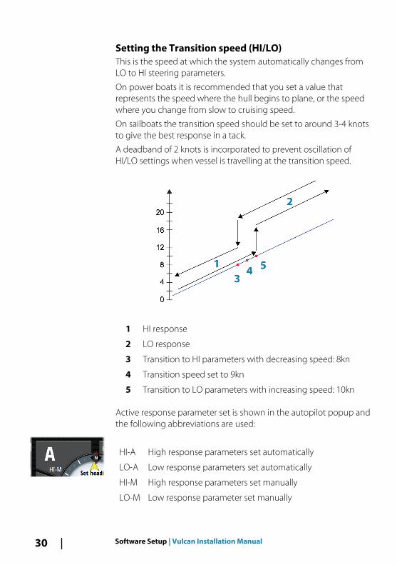
Setting the Transition speed (HI/LO)This is the speed at which the system automatically changes fromLO to HI steering parameters.
On power boats it is recommended that you set a value thatrepresents the speed where the hull begins to plane, or the speedwhere you change from slow to cruising speed.
On sailboats the transition speed should be set to around 3-4 knotsto give the best response in a tack.
A deadband of 2 knots is incorporated to prevent oscillation ofHI/LO settings when vessel is travelling at the transition speed.
1 HI response
2 LO response
3 Transition to HI parameters with decreasing speed: 8kn
4 Transition speed set to 9kn
5 Transition to LO parameters with increasing speed: 10kn
Active response parameter set is shown in the autopilot popup andthe following abbreviations are used:
HI-A High response parameters set automatically
LO-A Low response parameters set automatically
HI-M High response parameters set manually
LO-M Low response parameter set manually
30 Software Setup | Vulcan Installation Manual

AutotuningThe autotune feature runs the boat through several tests and thenautomatically sets the most important steering parameters.Autotune is not required for the autopilot to function, as it is presetwith steering parameters that should steer most boats in the 30-50foot range. All parameters that are set during autotuning can bemanually adjusted.
Seastate filterThe Seastate filter is used to reduce rudder activity and autopilotsensitivity in rough weather.
OFFSeastate filter is disabled. This is default.
AUTOReduces rudder activity and autopilot sensitivity in rough weatherby an adaptive process. The AUTO setting is recommended if youwant to use the seastate filter.
MANUALLinked to the steering response control settings describedpreviously. It may be used to manually find the optimumcombination of course keeping and low rudder activity in rough butsteady sea conditions.
Setting sailing parameters
Ú Note: Sailing parameter settings are only available if theboat type is set to Sail in the Autopilot Commissioningdialog.
Software Setup | Vulcan Installation Manual 31

Tack timeWhen performing a tack in WIND mode, the rate of turn (tack time)can be adjusted. This gives single-handed sailors time to handle theboat and the sails during a tack. A turn performed without shiftingwind side, is also made at a controlled turn rate.
Range: 2-50
Change per step: 1
Default: 12
Units: Seconds
Tack angleThis value is used to preset the course change used when tacking inAUTO mode. When you select the left or right arrow key on theAutopilot pop-up, the course changes as much as this value.
Range: 50-150
Change per step: 1
Default: 100
Units: Degrees
Wind functionWith wind function set to Auto, the autopilot automatically selectsbetween apparent and true wind steering. Auto is default andrecommended for cruising.
When the boat is running or on a broad reach, there is a greaterchance it will surf on the waves. This may lead to significantchanges in boat speed, and thereby changes in apparent windangle. True wind steering is therefore used to prevent undesiredcorrections by the autopilot when heading downwind (or close to),while steering to apparent wind is used when beating or reaching.
Apparent wind steering is preferred when you want to maintainmaximum boat speed without continuous trimming of the sails.
VMG optimizingYou can optimize the VMG to wind. When selected, the function willbe active for 5–10 minutes after a new wind angle has been set andonly when beating.
Layline steeringLayline steering is useful when navigating. Cross Track Error (XTE)from the navigator keeps the boat on the track line. If the XTE from
32 Software Setup | Vulcan Installation Manual

the navigator exceeds 0.15 nm, the autopilot calculates the laylineand track towards the waypoint.
Manually adjusting steering parametersThe autotune function in the autopilot is so refined that the majorityof boats need no further adjustments of the steering parameters.On some boats however, or in particular sea conditions, fine tuningof the steering parameters may improve the performance of theautopilot.
Transition speedRefer to "Setting the Transition speed (HI/LO)" on page 30.
RudderThis parameter determines the ratio between commanded rudderand the heading error. The higher rudder value the more rudder isapplied. If the value is too small it will take a long time tocompensate for a heading error, and the autopilot will fail to keep asteady course. If the value is set too high the overshoot will increaseand the steering will be unstable.
Counter rudderCounter rudder is the amount of rudder used to try to prevent theboat from yawing around the set course. Higher counter ruddersettings result in more rudder being applied.
The best way of checking the value of the Counter rudder setting iswhen making turns.
The following figures illustrate the effects of various Counter Ruddersettings:
1 Counter rudder too low; overshoot response.
Software Setup | Vulcan Installation Manual 33
2 Counter rudder too high; sluggish and creeping response.
3 Correct setting of counter rudder; ideal response.
Auto trimThis parameter defines how fast the autopilot shall correspond afterhaving registered a heading error.
The standard value is 40 seconds which should work well on mostboats. Rule of thumb: Set to same value (seconds) as the boat’slength in feet. On boats operating on VRF, the value should be setto 20 seconds.
Rate limitSets the maximum allowed rate of turn.
The value should be kept at 6.0°/second unless there is a need formore rapid response in turns.
Minimum rudderThis parameter filters small rudder commands to prevent highrudder activity.
Some boats may have a tendency to not respond to small ruddercommands around the “course keeping” position because of a smallrudder, a rudder deadband, whirls/disturbance of the water-streampassing the rudder, or it is a single nozzle water jet boat.
By increasing the Minimum rudder parameter you may improve thecourse keeping performance on some boats. However, this willincrease the rudder activity.
Minimum wind angle to port and starboardThese parameters should be set identical to the minimum apparentwind angle that will keep the sails from stalling and maintain boatspeed. The parameters vary from boat to boat.
The settings are used for the tack-prevent function. They also applywhen the autopilot is operating in WindNAV mode.
You can select different minimum wind angles for port andstarboard. The difference between port and starboard is taken intoaccount when calculating the Distance To Turn (DTT).
Navigation change limitThis parameter defines the maximum course change that theautopilot is allowed to make when the Vulcan is following a route(NAV steering).
34 Software Setup | Vulcan Installation Manual

If the required course change to the next waypoint in a route ismore than the set limit, you are prompted and must acknowledgethe course change before the autopilot will turn the vessel.
Fuel setup
The fuel utility monitors a vessel's fuel consumption. Thisinformation is totaled to indicate trip and seasonal fuel usage, and isused to calculate fuel economy for display on instrument pages andthe data bar.
To use the utility, a Navico Fuel Flow sensor, or a NMEA 2000 engineadaptor cable/gateway with Navico Fuel Data Storage device mustbe fitted to the vessel. Neither the Navico Fuel Flow sensor, nor theSuzuki engine interface require the use of a separate Fuel Storagedevice. Refer to the engine manufacturer or dealer for informationon whether or not your engine provides a data output, and whatadaptor is available to connect to NMEA 2000.
Once the physical connection is made, ensure source selection iscompleted. Multiple engine installations using Fuel Flow sensors, orFuel Data Storage devices, require setup of related engine locationin the Device list. For general source selection information, refer to"Source selection" on page 22.
Ú Note: Multiple engines using a single gateway do not workwith the Navico Fuel Storage device.
Vessel setupThe Vessel setup dialog must be used to select the number ofengines, the number of tanks and vessel’s total fuel capacity acrossall tanks.
Software Setup | Vulcan Installation Manual 35

Fuel flow configuration
After the number of engines is set, it is required to set which fuelflow sensor is connected to which engine. Under Device list on theNetwork page, view the Device Configuration dialog for eachsensor, and set the Location to match the engine the device isconnected to.
Unconfigure - defaults the device which clears all user settings.
Reset Fuel Flow - restores only the Fuel K-Value setting, if set inCalibrate. Only Navico devices can be reset.
36 Software Setup | Vulcan Installation Manual

Calibrate
Calibration may be required to accurately match measured flowwith actual fuel flow. Access calibration from the Refuel dialog.Calibration is only possible on Navico’s Fuel Flow sensor.
1. Start with a full tank and run the engine as it would normally beoperated.
2. After at least several liters (a few gallons) have been used, thetank should be fully refilled, and the Set to full option selected.
3. Select the Calibrate option.4. Set the actual amount used based on amount of fuel added
to the tank.5. Select OK to save settings. The Fuel K-Value should now show
a new value.
Ú Note: To calibrate multiple engines repeat the steps above,one engine at a time. Alternatively, run all enginessimultaneously, and divide the Actual amount used by thenumber of engines. This assumes reasonably even fuelconsumption on all engines.
Ú Note: The Calibrate option is only available when Set tofull is selected, and a Fuel Flow is connected and set up asa source.
Ú Note: A maximum of 8 engines is supported using FuelFlow sensors.
Software Setup | Vulcan Installation Manual 37

Fuel LevelWith the use of a Navico Fluid Level device connected to a suitabletank level sensor, it is possible to measure the amount of fuelremaining in any equipped tank. The number of tanks must be setin Vessel Setup dialog, initiated from the Fuel setting options page,to allow discrete tank assignment of the Fluid Level devices. SelectDevice list on the Network page, and view the DeviceConfiguration dialog for each sensor, and set the Tank location,Fluid type, and Tank size.
For setting up the Instrument bar or a gauge on the Instrumentpage with Fluid Level device data, refer to the Operator Manual.
Ú Note: A maximum of 5 tanks is supported using Fluid Leveldevices.
Ú Note: Tank data that is output by a compatible enginegateway can also be displayed, however tank configurationfor such a data source is not possible from the Vulcan.
CZone setupIn order to communicate with the CZone modules connected tothe network, the Vulcan must be assigned a unique CZone DisplayDipswitch setting.
The functionality of the CZone system is determined by the CZoneConfig File (.zcf ), which is stored on all CZone modules and theVulcan. The file is created using the CZone Configuration Tool, a
38 Software Setup | Vulcan Installation Manual

specialized PC application available from BEP Marine Ltd, andassociated CZone distributors.
The Vulcan system provides a means to load the Config file, as wellas apply updates to module firmware, removing the need to take alaptop computer aboard the vessel.
Enabling CZone functionality
If the CZone device(s) are not automatically detected, it is possibleto manually enable CZone.
Assigning the dipswitch setting
Every product capable of controlling and viewing CZone devicesmust be assigned a virtual dipswitch setting. This setting is uniquefor each device. Typically it is set after the configuration file alreadyexists on the CZone system, but it may also be set in advance. To doso, access the CZone menu on the Settings page.
When the configuration is already available on the network, it willimmediately commence uploading to the Vulcan once thedipswitch is set. Allow this to complete, without interruption.
Setting CZone to display at startupWith this option selected, the CZone control page is shown first,every time the Vulcan is powered up.
Software Setup | Vulcan Installation Manual 39

CZone backlight controlEnabling this causes the Vulcan to synchronize its backlight settingwith that of any CZone Display Interfaces set up to share backlightsettings.
Ú Note: CZone Config also needs to have the Vulcan set as acontroller.
Import and backup a configuration fileThe files page may be used to import CZone configuration files, orexport a copy to a memory card in the card reader. Importingoverwrites the existing file on the Vulcan and all connected CZonedevices.
For further information, see "Backing up and Importing user data" on page43.
Upgrading module firmwareThe Files page also allows the loading of NMEA 2000 devicesfirmware upgrades. For example, CZone firmware updates. For moreinformation, refer to "NMEA 2000 device upgrades" on page 45.
Wifi setup
The Vulcan includes built-in wireless functionality that lets you use awireless device to remotely view (phone and tablet) and control thesystem (tablet only). The system is controlled from the wirelessdevice by Apps downloaded from their relevant Application store.Various 3rd party applications can also use the data stream.
Connecting the tablet1. Navigate to the wifi network connection page on the tablet, and
find the Vulcan, or GoFree Wifi xxxx network. If more than one isin range, review the Wireless Devices page on the Vulcan toconfirm which wireless device is connected to the unit.
2. Select a device on this page to show its network key.3. Enter the eight character (or longer) Network Key in to the tablet
to connect to the network.4. Open the GoFree application - the Vulcan should be
automatically detected. The name displayed will be either the
40 Software Setup | Vulcan Installation Manual
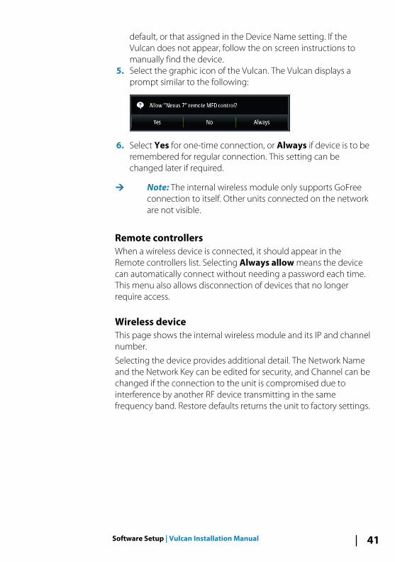
default, or that assigned in the Device Name setting. If theVulcan does not appear, follow the on screen instructions tomanually find the device.
5. Select the graphic icon of the Vulcan. The Vulcan displays aprompt similar to the following:
6. Select Yes for one-time connection, or Always if device is to beremembered for regular connection. This setting can bechanged later if required.
Ú Note: The internal wireless module only supports GoFreeconnection to itself. Other units connected on the networkare not visible.
Remote controllersWhen a wireless device is connected, it should appear in theRemote controllers list. Selecting Always allow means the devicecan automatically connect without needing a password each time.This menu also allows disconnection of devices that no longerrequire access.
Wireless deviceThis page shows the internal wireless module and its IP and channelnumber.
Selecting the device provides additional detail. The Network Nameand the Network Key can be edited for security, and Channel can bechanged if the connection to the unit is compromised due tointerference by another RF device transmitting in the samefrequency band. Restore defaults returns the unit to factory settings.
Software Setup | Vulcan Installation Manual 41

AdvancedTools are available within the Vulcan software to assist in fault-finding and setting up the wireless network.
IperfIperf is a commonly used network performance tool. It is providedfor testing wireless network performance around the vessel so weakspots or problem areas can be identified. The application must beinstalled on and run from a tablet device. The Vulcan must berunning Iperf server before initiating the test from the tablet. Onexiting the page, Iperf automatically stops running.
DHCP ProbeThe wireless module contains a DHCP server that allocates IPaddresses for all the MFDs, and Echosounder in a network. Ifintegrating with other devices, such as a 3G modem or satellitephone, other devices in the network may also be acting as DHCPservers. To make it easy to find all DHCP servers on a network,dhcp_probe may be run from the Vulcan. Only one DHCP devicemay be operational on the same network at a time. If a seconddevice is found, turn off its DHCP feature if possible. Refer to thedevice’s own instructions for further assistance.
Ú Note: Iperf and DHCP Probe are tools provided fordiagnostic purposes by users familiar with networkterminology and configuration. Navico is not the originaldeveloper of these tools, and cannot provide supportrelated to their use.
42 Software Setup | Vulcan Installation Manual

Internal WirelessSelect this option to enable or disable the internal wireless module.
Disabling wireless when not in use reduces the unit’s powerconsumption.
Software updates and data backupFrom time to time we release software updates to our existingproducts. Updates are created for a variety of reasons; to add orimprove features, to add support for new external devices, or to fixsoftware bugs.
Updates can be found on the website: bandg.com
The Vulcan may be used to apply software updates to itself, and tosupported NMEA 2000 network devices, with files read off amemory cord inserted in the card reader.
Before initiating an update to the Vulcan itself, be sure to back upany potentially valuable user data.
Backing up and Importing user data
There are two files that can be backed up that relate to userchanges made to the system:
• Waypoints, Routes, and Tracks database.• Settings database (includes preferences such as unit settings,
custom pages, and CZone configuration files).Insert a memory card into the unit's card reader as a storagelocation for backup data.
Waypoints, Routes, and Tracks database backupYou can export all Waypoints, Routes, and Tracks, or export onlythose contained within a specific region.
If Export Region is selected, the chart page will be displayed,centered on vessel location. Using the touch screen, adjust the redboundary box to outline the area to be exported. The export optionoffers different file formats to save as:
• User data file version 5: Use with current units (NSO evo2,NSS evo2, NSS, NSO, NSE, Zeus, Zeus Touch, HDS Gen2, HDSGen2 Touch, HDS Gen3). Offers most detail.
Software Setup | Vulcan Installation Manual 43

• User data file version 4: Use with current units (NSO evo2,NSS evo2, NSS, NSO, NSE, Zeus, Zeus Touch, HDS Gen2, HDSGen2 Touch, HDS Gen3).
• User data file version 3 (with depth): Use with legacy GPSchartplotters.
• User data file version 2 (no depth): Use with legacy GPSchartplotters.
• GPX (GPS Exchange, no depth): Use with some othermanufacturers’ GPS products, and PC applications.
After you select the file type, select Export and destination memorycard. The receiving GPS/PC will typically need to be set to allowimport of Waypoints.
Settings database exportSelect Setting database to export the Settings database, or exportCZone configuration (CZone installation dependent). Choose thedesired option and select the memory card destination.
Importing a databaseLater, if the Vulcan has been restored to factory defaults or user datais accidentally deleted, return to the files page, select the backed upfile, and then Import. View file details for creation date.
Software upgradesThe update file must be loaded to the root directory of the memorycard.
The update may be initiated at boot up: insert the memory card intothe card reader before turning the unit on, boot the unit, and followthe on-screen instructions.
Alternatively, in the Files menu, locate the update file on thememory card inserted in the card reader and select Upgrade,followed by This Display. Accept the prompt to reboot the unit,and wait a few moments as the unit restarts. Do not remove thememory card or repower the Vulcan until the process is completed(this typically takes no more than a couple of minutes).
Software upgrade of remote deviceIt is possible to run an update remotely from one unit and apply itto another, provided they are on the NMEA network. This is onlypossible for units without a card slot.
44 Software Setup | Vulcan Installation Manual
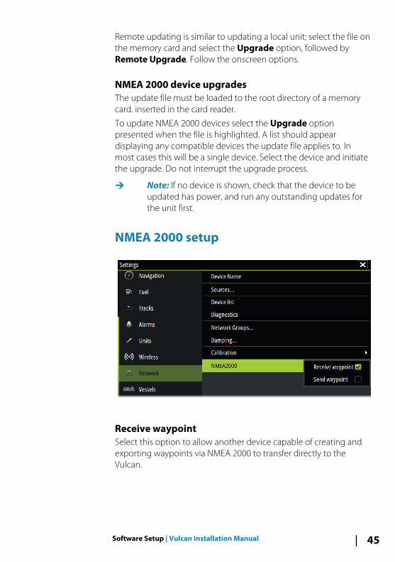
Remote updating is similar to updating a local unit; select the file onthe memory card and select the Upgrade option, followed byRemote Upgrade. Follow the onscreen options.
NMEA 2000 device upgradesThe update file must be loaded to the root directory of a memorycard. inserted in the card reader.
To update NMEA 2000 devices select the Upgrade optionpresented when the file is highlighted. A list should appeardisplaying any compatible devices the update file applies to. Inmost cases this will be a single device. Select the device and initiatethe upgrade. Do not interrupt the upgrade process.
Ú Note: If no device is shown, check that the device to beupdated has power, and run any outstanding updates forthe unit first.
NMEA 2000 setup
Receive waypointSelect this option to allow another device capable of creating andexporting waypoints via NMEA 2000 to transfer directly to theVulcan.
Software Setup | Vulcan Installation Manual 45

Send waypointSelect this option to allow another device to send waypoints viaNMEA 2000.
46 Software Setup | Vulcan Installation Manual

Accessories
Ú Note: The most up-to-date accessories list is available at:bandg.com
Part number Description
000-12366-001 Vulcan 7 Flush Mount Kit
000-12370-001 Vulcan 7 Flush Mount Sun Cover
000-12369-001 Vulcan 7 Bracket and Panel Mount SunCover
000-12371-001 Vulcan 7 Panel Mount Kit
000-12372-001 Vulcan 7 U Bracket
000-00128-001 Power Cable
6
Accessories | Vulcan Installation Manual 47

Supported data
NMEA 2000 compliant PGN List
NMEA 2000 PGN (receive)
59392 ISO Acknowledgement
59904 ISO Request
60928 ISO Address Claim
61184 Parameter Request/Command
65285 Temperature with Instance
65289 Trim Tab Insect Configuration
65291 Backlight Control
65292 Clear Fluid Level Warnings
65293 LGC-2000 Configuration
65323 Data User Group Request
65325 Reprogram Status
65341 Autopilot Mode
65480 Autopilot Mode
126208 ISO Command Group Function
126992 System Time
126996 Product Info
127237 Heading/Track Control
127245 Rudder
127250 Vessel Heading
127251 Rate of Turn
127257 Attitude
127258 Magnetic Variation
127488 Engine Parameters, Rapid Update
127489 Engine Parameters, Dynamic
127493 Transmission Parameters, Dynamic
7
48 Supported data | Vulcan Installation Manual
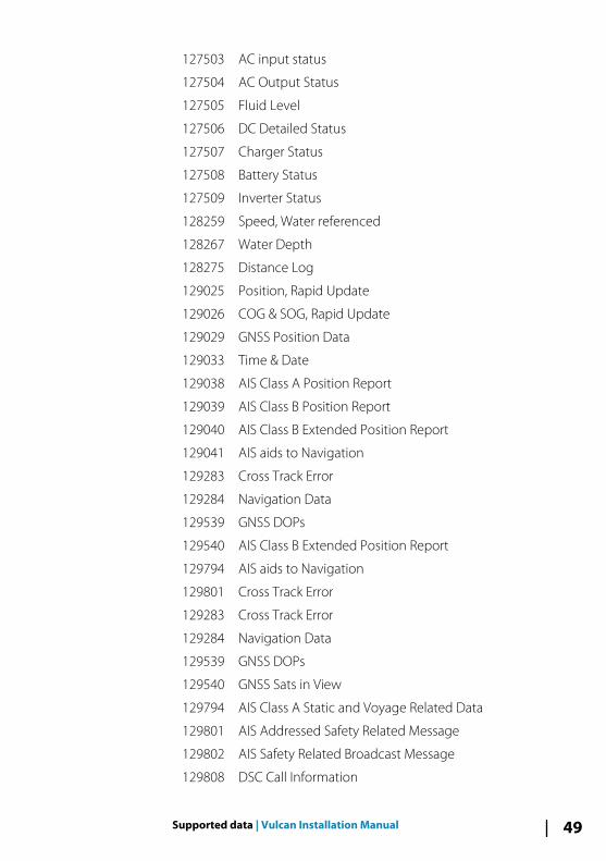
127503 AC input status
127504 AC Output Status
127505 Fluid Level
127506 DC Detailed Status
127507 Charger Status
127508 Battery Status
127509 Inverter Status
128259 Speed, Water referenced
128267 Water Depth
128275 Distance Log
129025 Position, Rapid Update
129026 COG & SOG, Rapid Update
129029 GNSS Position Data
129033 Time & Date
129038 AIS Class A Position Report
129039 AIS Class B Position Report
129040 AIS Class B Extended Position Report
129041 AIS aids to Navigation
129283 Cross Track Error
129284 Navigation Data
129539 GNSS DOPs
129540 AIS Class B Extended Position Report
129794 AIS aids to Navigation
129801 Cross Track Error
129283 Cross Track Error
129284 Navigation Data
129539 GNSS DOPs
129540 GNSS Sats in View
129794 AIS Class A Static and Voyage Related Data
129801 AIS Addressed Safety Related Message
129802 AIS Safety Related Broadcast Message
129808 DSC Call Information
Supported data | Vulcan Installation Manual 49

129809 AIS Class B “CS” Static Data Report, Part A
129810 AIS Class B “CS” Static Data Report, Part B
130074 Route and WP Service - WP List - WP Name & Position
130306 Wind Data
130310 Environmental Parameters
130311 Environmental Parameters
130312 Temperature
130313 Humidity
130314 Actual Pressure
130576 Small Craft Status
130577 Direction Data
130840 Data User Group Configuration
130842 SimNet DSC Message
130845 Parameter Handle
130850 Event Command
130851 Event Reply
130817 Product Info
130820 Reprogram Status
130831 Suzuki Engine and Storage Device Config
130832 Fuel Used - High Resolution
130834 Engine and Tank Configuration
130835 Set Engine And Tank Configuration
130838 Fluid Level Warn
130839 Pressure Insect Configuration
130840 Data User Group Config
130842 AIS and VHF Message Transport
130843 Sonar Status – Frequency and DSP Voltage
130845 Weather and Fish Prediction and Barometric PressureHistory
130850 Evinrude Engine Warnings
130851 Parameter (RC42 Compass and IS12 Wind Calibrationand Configuration)
50 Supported data | Vulcan Installation Manual

NMEA 2000 PGN (transmit)
61184 Parameter Request/Command
65287 Configure Temperature Insects
65289 Trim Tab Insect Calibration
65290 Paddle Wheel Speed Configuration
65291 Backlight Control
65292 Clear Fluid Level Warnings
65293 LGC-2000 Configuration
65323 Data User Group Request
126208 ISO Command Group Function
126992 System Time
126996 Product Info
127237 Heading/Track Control
127250 Vessel Heading
127258 Magnetic Variation
128259 Speed, Water referenced
128267 Water Depth
128275 Distance Log
129025 Position, Rapid Update
129026 COG & SOG, Rapid Update
129029 GNSS Position Data
129283 Cross Track Error
129284 Navigation Data
129285 Route/Waypoint Data
129539 GNSS DOPs
129540 GNSS Sats in View
130074 Route and WP Service - WP List - WP Name & Position
130306 Wind Data
130310 Environmental Parameters
130311 Environmental Parameters
Supported data | Vulcan Installation Manual 51

130312 Temperature
130577 Direction Data
130840 Data User Group Configuration
130845 Parameter Handle
130850 Event Command
130818 Reprogram Data
130819 Request Reprogram
130828 Set Serial Number
130831 Suzuki Engine and Storage Device Config
130835 Set Engine And Tank Configuration
130836 Fluid Level Insect Configuration
130837 Fuel Flow Turbine Configuration
130839 Pressure Insect Configuration
130845 Weather and Fish Prediction and Barometric PressureHistory
130850 Evinrude Engine Warnings
130851 Parameter (RC42 Compass and IS12 Wind Calibrationand Configuration)
52 Supported data | Vulcan Installation Manual

Specifications
Ú Note: The most up-to-date specifications list is available at:bandg.com
Mechanical/Environmental
Casing PC/ABS
Operating temp -15°C to +55°C (+5°F to +131°F)
Water ingress IPX6 and 7
Weight (excluding mountinghardware)
1.310 kg
Screen brightness 1200nits
Screen resolution 480 x 800 (H x W)
Viewing angle in degrees(typical value at contrast ratio =10)
L/R: 70, top: 50, bottom: 60
Dimensions (overall) See dimensioned drawings
Electrical
Operating voltage 10 - 17 V DC
Current draw at 13.6V (sonar off,max B/L)
1 A
Low power standby mode yes
Protection reverse polarity and temporaryover-voltage to 36V
Alarm output current 1 A max
Processor iMX61 single core
Conformity CE, C-Tick
Interfaces
NMEA 2000 (compliant) 1 port (Micro-C male)
Sonar 1 port (7 pin blue connector)
microSD card reader 1x microSD
8
Specifications | Vulcan Installation Manual 53

Dimensional drawings
9
54 Dimensional drawings | Vulcan Installation Manual


*988
-108
47-0
01*
0980


