Embed Size (px)
Citation preview
Contents lists available at ScienceDirect
Journal of Fluids and Structures
Journal of Fluids and Structures 50 (2014) 329–339
http://d0889-97
E-m
journal homepage: www.elsevier.com/locate/jfs
Wake-induced vibration of tandem cylindersof different diameters
Gustavo R.S. AssiDepartment of Naval Architecture & Ocean Engineering, University of São Paulo, NDF, Escola Politécnica, 05508-030 São Paulo, Brazil
a r t i c l e i n f o
Article history:Received 3 February 2014Accepted 2 July 2014Available online 22 August 2014
Keywords:Wake-induced vibrationCircular cylindersVortex wakeFlow interference
x.doi.org/10.1016/j.jfluidstructs.2014.07.00146/& 2014 Elsevier Ltd. All rights reserved.
ail address: [email protected]
a b s t r a c t
The wake-induced vibration (WIV) of the downstream cylinder of a tandem pair isinvestigated for different diameter ratios of D1=D2 ¼ 1=1, 1/2 and 1/3, where D1 and D2
refer to the upstream and downstream cylinders, respectively. The streamwise separationbetween the cylinders was L=D1 ¼ 3:5, 7.0 and 6.5, respectively, measured from the centreof the upstream cylinder to the forward stagnation point of the downstream cylinder.Experiments with low mass-damping cylinders have been conducted in a water channelat around Re¼25 000. The dynamic response showed that the downstream cylinderexperienced WIV for all diameter ratios investigated, with displacement amplitudesreaching more than 1.5 diameters for higher reduced velocities beyond the vortexresonance range. The frequency response showed a similar behaviour for all threeconfigurations, giving hints that a type of wake-stiffness mechanism might be governingthe frequency of oscillation for all diameter ratios. The response was found to bedependent on both D1=D2 and L=D1. In all cases, the static upstream cylinder was foundto shed vortices as an isolated cylinder, not influenced by the presence or movement ofthe downstream body. Lift and drag coefficients as well as measurements of velocityfluctuations in both wakes are presented for all cases.
& 2014 Elsevier Ltd. All rights reserved.
1. Introduction
When an elastic bluff body, like a circular cylinder, is immersed in the wake developed from an upstream body it willdynamically respond with wake-induced vibrations (WIVs). This hydroelastic mechanism has also been referred to as ‘wake-induced galloping’, ‘interference galloping’ or ‘wake-displacement excitation’ (Ruscheweyh, 1983; Bokaian and Geoola, 1984;Zdravkovich, 1988) and consists of the excitation of the downstream body by the interference of vortices developed in anunsteady wake generated upstream. The response of the downstream cylinder of a tandem pair is known to be severelyincreased by WIV when compared with that of an isolated cylinder under the resonant phenomenon of vortex-inducedvibration (VIV).
Assi et al. (2010) reported on the effect of flow interference in the response of two identical cylinders aligned with theflow with centre-to-centre separations as large as 20 diameters. They have shown that vortices in the upstream wake playan essential role in driving the high-amplitude vibrations of the downstream cylinder. In fact, they performed an idealisedexperiment in which the unsteady vortex wake was replaced by a steady shear flow of equivalent mean velocity profile.They showed that the downstream cylinder immersed in that shear flow responded with a distorted type VIV but not with

Fig. 1. Tandem configurations varying cylinders diameters. (a) D1=D2 ¼ 1=1, (b) 1/2 and (c) 1=3. Dimensions are in millimetres. Sketches drawn to scale.
G.R.S. Assi / Journal of Fluids and Structures 50 (2014) 329–339330
high-amplitude WIV. Their conclusion was that the unsteady interaction of coherent and periodic vortices from theupstream wake was necessary to input energy into the system and sustain the vibration.
The present work is a step further in the direction of understanding the vortex–structure interferences driving WIV oftwo bodies. This time we are concerned with varying the length and time scales of the wake involved in this kind of fluid–structure interaction. The downstream cylinder of a tandem pair is immersed in the wake developed from an upstreamcylinder with smaller diameter. Consequently, the length and the time scales of the vortices that come from the upstreamwake and reach the downstream cylinder vary proportionally. Three tandem configurations with the smaller cylinderpositioned upstream are investigated in the present study, as illustrated in Fig. 1. The subscripts 1 and 2 will always refer tothe upstream and downstream cylinders, hence D1 and D2 represent the respective cylinder diameters. Three diameterratios of D1=D2 ¼ 1=1, 1/2 and 1/3 were chosen for the experiments and the centre-to-centre separation was kept constant at200 mm in order to allow for the upstream wake to develop in the gap with no interference from the second body. As aconsequence, the wake reaching the second cylinder will be proportionately different in each case due to the scale of theupstream vortex shedding mechanism and wake diffusion in the gap.
(Note: The subscripts in the non-dimensional numbers follow the same convention. Reynolds numbers (Re1 and Re2) takethe diameter of the specified cylinder and Strouhal numbers are calculated employing the vortex shedding frequency (fs)and the diameter of the referred cylinder, i.e. St1 ¼ f s1D1=U for the upstream cylinder and St2 ¼ f s2D2=U for the downstreamcylinder.)
1.1. Flow interference between cylinders
Zdravkovich (1988) proposed a map of wake interference for two static cylinders with the same diameter arranged inseveral tandem and staggered configurations. The boundaries for each wake-interference zone clearly depend on thediameter of the two cylinders involved. It is expected that a smaller cylinder in the wake of a larger one will have to movemany diameters across the wider wake before being free from any flow interference from upstream. The opposite might alsohappen for a larger cylinder moving across the narrower wake of a smaller body; the wake-interference zone might bereduced. Hence, the wake-interference map proposed by Zdravkovich (1988) will probably be different for each diameter

G.R.S. Assi / Journal of Fluids and Structures 50 (2014) 329–339 331
ratio illustrated in Fig. 1. However, this thought exercise might only be valid for the wake-interference of two staticcylinders. Based on the results of Assi et al. (2010) we expect minute vortex impulses from upstream to have a considerableeffect on the excitation of the downstream cylinder, especially if it presents low structural mass and damping. Even thewake of a smaller cylinder placed upstream (with smaller vortices at a higher frequency) might be sufficient to inducesevere WIV of the second larger body. Assi (2014) showed that the flow interference from the upstream wake will have aneffect even if the downstream cylinder is initially positioned further out of the centreline of the wake, in what is called astaggered arrangement. An effect on the response of the downstream cylinder was observed for lateral separations up to 3diameters when S/D¼4 (both cylinders having the same diameter).
Most of the studies concerning interference of cylinders with different diameters are focussed on the effect that the wakeof a smaller cylinder has on the flow behaviour around a larger body. Studies of this kind can be classified as flow controlexperiments and some will go as far as to consider both the small and large cylinders as a coupled pair able to respond toflow-induced vibrations. Rahmanian et al. (2012) performed numerical simulations of the flow around two interferingcylinders with D1=D2 ¼ 0:1. The pair was mechanically coupled and able to respond to flow-induced vibrations in twodegrees of freedom, thus the investigation was aimed at understanding the interference effect of the smaller cylinder on thelarger one as the gap and the angular position were varied between them. Their main finding was that the maximumvibration observed for the coupled pair occurred when the cylinders were arranged in staggered configuration and notaligned with the flow. Tsutsui et al. (1997) also presented an experimental and numerical investigation employing a similararrangement of a very small cylinder positioned about the main body. But their investigation with static cylinders onlyshowed that the wake structure and fluid forces were strongly affected by the position of the small cylinder. Zhao et al.(2005) and Zhao and Yan (2013) both presented numerical investigations in the same lines.
The present investigation, however, is not concerned with the flow interference between a very small cylinder positionedin the vicinity or about a main body nor it is concerned with a mechanically coupled pair. In the present work we willinvestigate the flow interference from a fully developed upstream wake on the response of the downstream cylinder of atandem pair with relatively similar diameters. Thus, we are truly concerned with the effect that wakes of different scales willhave on the wake-induced vibration of the downstream body. The upstream cylinder is always static and only responsiblefor generating a vortex wake that reaches the second body. The downstream cylinder is free to respond with flow-inducedvibrations only one degree of freedom (1-dof) in the cross-flow direction. The in-line separation between the cylinders iskept constant at all times.
In our experiments, the upstream cylinder is always smaller than the downstream one. Nevertheless, it is worthmentioning the work done by Huang and Sworn (2011), in which they investigated the WIV of a cylinder when a lager bodywas placed upstream. In their experiments, performed in a water flume at subcritical Re, they employed a pair of rigidcylinders in tandem with D1=D2 ¼ 2:0 and in-line spacing varying between S=D1 ¼ 1 and 10. Both cylinders were elasticallysupported in a low-damping system, free to respond in both the cross-flow and streamwise directions. They observed thatthe signature of lift measured on the downstream cylinder had the frequency components from the upstream vortexshedding as well as from its own vortex shedding, with predominance depending on the in-line spacing. Independently ofthe separation, they observed that the upstream cylinder always showed a typical VIV response, while the downstreamcylinder presented WIV response reaching cross-flow displacements as high as 1.5 diameters in amplitude. In a later study,Huang and Sworn (2013) employed cylinders with D1=D2 ¼ 1, 2 and 4 and varied the in-line spacing between S=D1 ¼ 1and 15 to reach similar conclusions. As expected, when both cylinders were held static, the average drag measured onthe downstream cylinder showed the effect of a slower mean flow coming from the upstream body, which in turn wasdependent on the diameter ratio and the in-line separation.
Alam and Zhou (2008) performed wind-tunnel experiments with a pair of static cylinders with different diameters tomeasure forces and flow structures of the interfering flow. The diameter ratio varied between D1=D2 ¼ 0:24 and 1.0 and thein-line spacing was fixed at L=D1 ¼ 5:5, providing that a fully developed wake was generated in the gap for the range ofRe2 ¼ 0:6� 104–2:7� 104. The authors found two distinct frequencies of vortex shedding coexisting in the wake down-stream of the pair, which were attributed to the vortex shedding mechanisms of each of the cylinders. This was only verifiedfor certain diameter ratios for static cylinders.
In a recent study, Alam and Zhou (2014) investigated the flow-induced response of a similar pair of cylinders atRe2 ¼ 2:7� 104. The smaller, static cylinder was placed upstream of a cantilevered cylinder, with the ratio between the twodiameters also varying between D1=D2 ¼ 0:24 and 1.0. This time the tandem cylinders were arranged in close proximity,with in-line separation being set at L=D2 ¼ 1:0 and 2.0. Interestingly, Alam and Zhou (2014) only observed severe vibrationsof the downstream cylinder for D1=D2 ¼ 0:24–0.8 (considering both in-line separations tested) and not for cylinders with thesame diameter. In addition, vibrations were observed for reduced velocities in the range of 13–22.5, too high to be regardedas a result of resonant VIV. They explained that the smaller cylinder placed upstream would generate a narrower wakecapable of exciting vibrations as the shear layers flipped from one side to the other during the cross-flow displacement ofthe downstream body. For cylinders of equal diameters at close proximity, on the other hand, the wider upstream wakewould engulf the downstream cylinder making the side-to-side flipping mechanism rather difficult to occur. We believethese vibrations are better described by the ‘gap-flow switching’ mechanism explained in Zdravkovich (1988), since theclose proximity of the bodies prevents a developed wake to form in the gap. The fact that the downstream cylinder wasmounted as a cantilever may result that not its entire length is being excited by the same mechanism, especially knowingthat ‘gap-flow switching’ requires a considerable amount of transverse displacement to occur.

G.R.S. Assi / Journal of Fluids and Structures 50 (2014) 329–339332
2. Method
At first sight it seems rather simple to find a parameter to represent the in-line separation between the cylinders, but onemust not be mistaken by the effect that the apparent simplicity of the geometries in Fig. 1 has on the hydrodynamicmechanisms involved. Since both cylinders vary in diameter, the effective gap between the bodies changes from case to case.For example, to consider the centre-to-centre separation S to be the characteristic in-line distance of the problem will makethe gap between cylinders in Fig. 1(b) to appear larger than in the other two cases. Another way to interpret the actuallength scale affecting the flow interference would consider the gap Gmeasured between the cylinder walls, thus making thecylinders in Fig. 1(a) to look closer than the others. One can see that there are several ways to organise and interpret thedata. The physical characteristics of the wake interference phenomena must not be forgotten. On top of that, there is theproblem of choosing which diameter should be the reference for normalisation: that of the static upstream cylinder (D1),where the wake is generated, or that of the oscillatory downstream cylinder (D2), the object of WIV.
Perhaps the most reasonable interpretation would consider the distance measured from the centre of the upstreamcylinder to the wall (or forward stagnation point) of the downstream cylinder, defined by L in Fig. 1. Such an interpretationmight be possible because the separation points on the upstream cylinder are practically aligned with the centre of thecylinder; hence at roughly the same location for all three configurations independently of the dimension D1. Theinterference effect of the wake on the downstream cylinder, on the other hand, depends on D2 and the position ofthe forward stagnation point. Therefore, as far as wake interference is concerned, the most appropriate parameter to beemployed in the study appears to be L=D1, non-dimensionalised by the diameter of the upstream cylinder, where theupstream wake is being generated.
Table 1 presents all geometrical parameters and respective normalisations as explained in the paragraphs above. Allpossible normalisations of S, G and L were kept in the table to illustrate the variety of ways that could be employed ininterpreting the in-line separation. In the present work, however, L=D1 is considered to be the length scale representative ofthe wake interference phenomenon, thus special attention will be given to the penultimate column.
2.1. Experimental setup
Experiments were performed during a test campaign in the Department of Aeronautics at Imperial College, London. Testswere carried out in a recirculating water channel with a free surface and a test section 0.6 m wide, 0.7 m deep and 8.0 mlong. Flow speed was continuously variable up to U¼0.6 m/s and free stream turbulence intensity was around 3%. Circularcylinder models were made from acrylic tubes, giving a maximum Re¼30 000 based on a cylinder diameter of 50 mm.
The downstream cylinder was fixed at its upper end to a 1-dof elastic mounting represented in Fig. 2. The model wasaligned in the vertical direction passing through the free surface and mounted such that there was a 2 mm gap between the
Table 1Geometrical parameters for the tandem configurations illustrated in Fig. 1. Dimensional terms in columns 2–6 are in millimetres.
D1=D2 D1 D2 S G L S=D1 S=D2 G=D1 G=D2 L=D1 L=D2
1/1 50 50 200 150 175 4.0 4.0 3.0 3.0 3.5 3.51/2 25 50 200 162.5 175 4.0 4.0 6.5 3.25 7.0 3.51/3 25 75 200 150 162.5 8.0 2.7 6.0 2.0 6.5 2.17
Fig. 2. Representation of the downstream cylinder mounted on the 1-dof rig in the test section of the water channel. View of the cross-section. Dimensionsare in millimetres.

Table 2Structural properties for the downstream cylinder.
D1=D2 mn ζ(%) mnζ
1/1 2.6 0.35 0.00911/2 2.6 0.35 0.00911/3 1.2 0.35 0.0041
G.R.S. Assi / Journal of Fluids and Structures 50 (2014) 329–339 333
lower end of the cylinder and the floor of the test section. It was judged preferable not to install end plates on the cylinder inorder not to increase the fluid damping in the system. The support was firmly attached to the channel structure and slidingcylindrical guides were free to move in the transverse direction (y-axis) through air bearings. A pair of coil springsconnecting the moving base to the fixed supports provided the restoration force for the system.
It is known that the dynamic response of a cylinder is extremely sensitive to the structural characteristics of the system;therefore extra care was taken to determine the precise value of natural frequency, mass and damping of the structure. Theair bearings proved to be an effective way to reduce damping without compromising the stiffness of the structure, especiallyin resisting drag loads for higher flow speeds. By carrying out free decay tests in air it was possible to estimate the naturalfrequency (f0) and the structural damping parameter of the system (ζ, calculated as a percentage of the critical damping).They are presented in Table 2 along with the mass ratio (mn, calculated as the total mass divided by the mass of displacedwater), for the configurations tested.
A load cell was installed between the model and the platform to measure hydrodynamic forces acting on the cylinder(inertial components have been subtracted from the total force acquired by the load cell). An optical positioning sensormeasured the y-displacement without adding damping. Two hot-film probes were employed to measure velocityfluctuation in the wake of both cylinders in order to capture the frequency of vortex shedding close to the vortex formationregions. Probes were positioned at roughly 1D downstream of the cylinder centre and 1D to the side of the centreline;locations are marked by quartered-circle symbols in Fig. 1. More details about the apparatus, flow quality, design of the loadcell and operation of the 1-dof rig can be found in Assi (2009).
Measurements were made using one set of springs and the reduced velocity range covered was from U=D2f 0 ¼ 2 to 30,where reduced velocity is defined using f0 measured in air. The only flow variable changed during the course of theexperiments was U, which alters both the reduced velocity and the Reynolds number. Throughout the study, cylinderdisplacement amplitudes (y=D2) were found by measuring the root mean square (r.m.s.) value of response and multiplyingby
ffiffiffi
2p
(the so-called harmonic amplitude). Displacements were non-dimensionalised by dividing by the downstreamcylinder diameter.
3. Results and discussion
Fig. 3 presents the WIV response for the tandem configurations versus reduced velocity. Displacement and frequencycurves are compared with the response of a single cylinder with D¼50 mm, which will serve as a reference for thediscussion that follows. During the typical single-cylinder VIV excitation, as U increases, the frequency of vortex-shedding(fs) gets close enough to the body's natural frequency of oscillation (f0) in a way that the unsteady pressure fluctuation in thenear wake induces the body to respond in resonance. Once the cylinder starts to oscillate, high-amplitude movements willcontrol the vortex formation and fs will be locked in the response frequency (f) near f0. If U continues to increase the typicalvortex-shedding frequency will move far away from the natural frequency of the system, i.e. fs and fwill be uncoupled again.Refer to Bearman (1984) and Williamson and Govardhan (2004) for a detailed description of the VIV mechanism and typicalresponses.
Since reduced velocity was increased by changing U in the channel an extra horizontal axis has been introduced toindicate the equivalent Reynolds number scale calculated for a cylinder with D¼50 mm. All three experiments wereperformed until the maximum flow speed was reached in the channel, making the third dataset look shorter in the reducedvelocity scale; hence the Re scale is not true for the D1=D2 ¼ 1=3 curve.
Fig. 3(a) presents the harmonic amplitude of vibration of the downstream cylinder. It is evident that all threeconfigurations present the build-up of displacement for higher reduced velocities that are characteristic of WIV. ForU=D2f 0 ¼ 4–7 all tandem configurations present a local peak of vibration related to the resonance of vortex shedding; this isequivalent to the upper branch registered for the single cylinder under VIV. But for U=D2f 0412 it becomes clear that theresponses are not driven by resonance any longer, but sustained by the WIV mechanism.
The case D1=D2 ¼ 1=1 (with L=D1 ¼ 3:5) reaches a maximum y=D2 ¼ 1:8 at U=D2f 0 � 30. For D1=D2 ¼ 1=2 the maximumresponse reaches y=D2 ¼ 1:3 at around the same reduced velocity, but the effective separation is now L=D1 ¼ 7:0, twice asmuch as the previous case. Between the first two cases there is no variation of Reynolds number, so the decrease in the levelof response must be related to decreasing the diameter ratio and/or doubling the effective in-line separation.
On the other hand, when the diameter ratio was made even smaller in the D1=D2 ¼ 1=3 configuration the responseincreased when compared with the D1=D2 ¼ 1=2 case. A maximum y=D2 ¼ 1:4 was reached for the maximum reduced

Fig. 3. WIV response of cylinders with different diameters. (a) Displacement and (b) frequency of vibration versus reduced velocity. Key: ~, single cylinderVIV; ○, D1=D2 ¼ 1=1; □, D1=D2 ¼ 1=2; ▿, D1=D2 ¼ 1=3.
G.R.S. Assi / Journal of Fluids and Structures 50 (2014) 329–339334
velocity, now just above 20, but an amplification of the response was clear to be occurring for the whole range of reducedvelocities tested. In this case, decreasing D1=D2 produced stronger vibration of the downstream cylinder, which might berelated to the fact that the effective in-line separation decreased to L=D1 ¼ 6:5 when compared with the previous tandemconfiguration (it must be noted that Rehas also increased).
Comparing the three response curves in Fig. 3(a) we may conclude that both the diameter ratio and the effective in-lineseparation have a strong effect on the WIV response of the downstream cylinder. Nevertheless it is interesting to note thateven the smallest upstream cylinder with D1=D2 ¼ 1=3 is capable of inducing vibrations on the downstream body ofcomparable amplitude as a configuration with cylinders with equal diameters.
The mass ratio, however, might still be another factor playing some role in the amplification of response from caseD1=D2 ¼ 1=2 to 1/3. As seen in Table 2, the D1=D2 ¼ 1=3 case presents mn ¼ 1:2, less than half of the mn ¼ 2:6 for the othertwo configurations due to the larger diameter of the cylinder. Probably a relatively lighter cylinder would be morevulnerable to the upstream excitation even though it comes from a much smaller cylinder. This could produce higheramplitudes of response during the VIV resonance range, as it is known to occur for a single-cylinder VIV. Past the VIV range,say for reduced velocities above 15, the response for D1=D2 ¼ 1=3 is lower than that for D1=D2 ¼ 1. We suspect this is relatedto the width of the upstream wake relative to D2. In this case, the downstream cylinder moves out of the upstream wake atsmaller displacements and the unsteady excitation mechanism proposed in Assi et al. (2010) is therefore weakened.
The dominant frequency of response of the downstream cylinder normalised by the natural frequency of vibration (f =f 0)is presented in Fig. 3(b). An inclined dashed line indicates that the frequency associated with the vortex shedding of thedownstream cylinder was it to follow a typical Strouhal number of 0.2. Between U=D2f 0 ¼ 2 and 7, in the region associatedwith the stronger VIV resonance, all configurations vibrate with dominant frequency following close to the St2 ¼ 0:2 line, aswell as the single cylinder under VIV. As flow speed is increased towards the end of the VIV synchronisation range, thedominant frequencies for all cases depart from the St2 ¼ 0:2 towards the horizontal line of f =f 0 ¼ 1. Eventually, for evenhigher reduced velocities past the VIV influence, the frequency curves tend towards another dot-dashed line identified as

G.R.S. Assi / Journal of Fluids and Structures 50 (2014) 329–339 335
f w=f 0. Surprisingly, this line represents the frequency of wake stiffness introduced by Assi et al. (2013) as the characteristicWIV frequency of vibration of the downstream cylinder of a pair with equal diameters. (Note that the slope of this line wasdetermined in Assi et al., 2013 and is only valid for D1 ¼D2.)
The wake-stiffness concept explains that there is a natural frequency of oscillation of hydrodynamic nature (fw)dominating over the response of the cylinder immersed in the upstream wake (Refer to Assi et al., 2013 for details on theestimation of fw). We believe fw to be strongly dependent on the vortex interaction occurring in the wake, thus depending onthe width of the upstream wake as well as the length and time scales of the vortices being shed (wake topology). Tandempairs with different diameter ratios would probably produce different values of fw, but this was not measured in the presentinvestigation. What is surprising here is that the frequency of response for D1=D2 ¼ 1=2 was not expected to follow the f w=f 0line previously determined for D1=D2 ¼ 1=1, but as a matter of fact it falls very close to it. Unfortunately the response curvefor D1=D2 ¼ 1=3 does not go much further than U=D2f 0 ¼ 20, but up to that point it follows the other two curves pretty well.If wake stiffness is a function of wake topology and geometry, as believed, it is not a strong dependency as to makesignificant difference in these response curves, at least not in the present range of D1=D2 and L=D.
In summary, even with considerable variations of D1=D2, L=D1 and mn the frequency signatures of WIV for all tandemcases are remarkably similar and follow very closely the behaviour governed by the wake stiffness of WIV introduced by Assiet al. (2013) for D1 ¼D2. More striking is the fact that the dominant frequency of vibration of the downstream cylinder ishigher than the structural natural frequency of the system (line for f =f 0 ¼ 1), clearly different from the expected vortexshedding frequency of the cylinder (line for St2 ¼ 0:2) and probably very different from the expected shedding frequency ofthe upstream cylinder, which has a smaller diameter. In order to clarify that, we shall turn to the frequency signaturemeasured in both wakes and derived from the forces acting on the cylinders.
3.1. Frequency signatures of lift and wakes
Fig. 4 presents a series of contour plots representing the power spectrum signature of wakes and forces for theconfiguration D1=D2 ¼ 1=1. Each plot shows the frequency scale non-dimensionalised by f0 in the vertical axis versusreduced velocity in the horizontal axis. The intensity of the colour shade represents the power content for either velocityfluctuation in the wake or fluctuating force on the cylinder. Power spectra were normalised for each reduced velocity inorder to make it possible to follow through branches of dominant frequency along the horizontal axis. The dominantfrequency of oscillation presented in Fig. 3(b) is repeated as data points in each plot as a reference of the response.
Fig. 4. Power spectra for configuration D1=D2 ¼ 1=1. Frequency of lift on the (a) upstream and (b) downstream cylinders. Frequency of velocity fluctuationin the wake of the (c) upstream and (d) downstream cylinders.

G.R.S. Assi / Journal of Fluids and Structures 50 (2014) 329–339336
The frequency signature of lift measured on the upstream cylinder (f Cy=f 0) is presented in Fig. 4(a), revealing that the
upstream static cylinder is shedding vortices as an isolated cylinder following the typical St2 ¼ 0:2 dashed line (in this caseD1 ¼D2). As seen in Fig. 4(c), the behaviour is confirmed by the signature of velocity fluctuation in the wake (f u=f 0)measured by a hot-film probe downstream of the upstream cylinder. Hence, the upstream cylinder is shedding vortices asan isolated cylinder and no traces of the frequency of oscillation of the downstream cylinder are noticeable in the spectra ofthe wake or lift.
The spectrum of lift (f Cy=f 0) on the downstream cylinder, presented in Fig. 4(b), reveals that the second body indeed
experiences lift at the frequency of shedding coming from the upstream cylinder. This is a result of vortices impinging on thedownstream cylinder as it moves across the wake. However, a much stronger branch appears to dominate the spectrum, onewhich is associated with the frequency of vibration represented by the data points. Now, one cannot tell how much of thepower in that strong branch is a result of the unsteady flow excitation or simply the hydrodynamic inertia measured by theload cell as the cylinder moves across the wake. Perhaps it is a combination of both. A branch at that frequency would alsoappear if the cylinder were vibrating with f in still water. The fact is that this is the preferred frequency of vibration for thedownstream cylinder, the one associated with the wake stiffness. This happens to be the only frequency branch identified inthe wake of the downstream cylinder, as seen in Fig. 4(d), and no traces of vortex shedding following the Strouhal line wereregistered. Again, this might be the effect of the movement of the downstream cylinder dominating over the velocityfluctuations measured by the hot-film probe in the wake.
Moving on to the D1=D2 ¼ 1=2 configuration presented in Fig. 5, we notice that the frequency signature of lift on thedownstream cylinder (f Cy
=f 0), shown in Fig. 5(a), also presents a clear dominant branch coinciding with the frequency ofoscillation, as expected. Other secondary frequency branches, nonetheless, can be seen to occur at the shedding frequenciesof both cylinders, i.e. following the St1 ¼ 0:2 and St2 ¼ 0:2 dashed lines (represented by very light shades of colour in thecontour plots). Looking at the wake signature of the upstream cylinder in Fig. 5(b) it becomes clear that the first body isshedding vortices as an isolated static cylinder and no significant traces of the downstream oscillation are being propagatedupstream either. Once more, the wake signature (f u=f 0) of the downstream cylinder in Fig. 5(c) only captures weak traces ofthese higher frequencies, with the dominant frequency branch being associated with the frequency of vibration. As notedbefore, Alam and Zhou (2008) verified the existence of higher frequencies associated with the upstream shedding for twostatic cylinders. We believe that when the downstream cylinder is free to oscillate the frequency of oscillation will dominateover the shedding frequencies of the upstream body and the latter will not be very clear in the spectrum plots of thedownstream wake.
Fig. 5. Power spectra for configuration D1=D2 ¼ 1=2. (a) Frequency of lift on the downstream cylinder. Frequency of velocity fluctuation in the wake of the(b) upstream and (c) downstream cylinders.
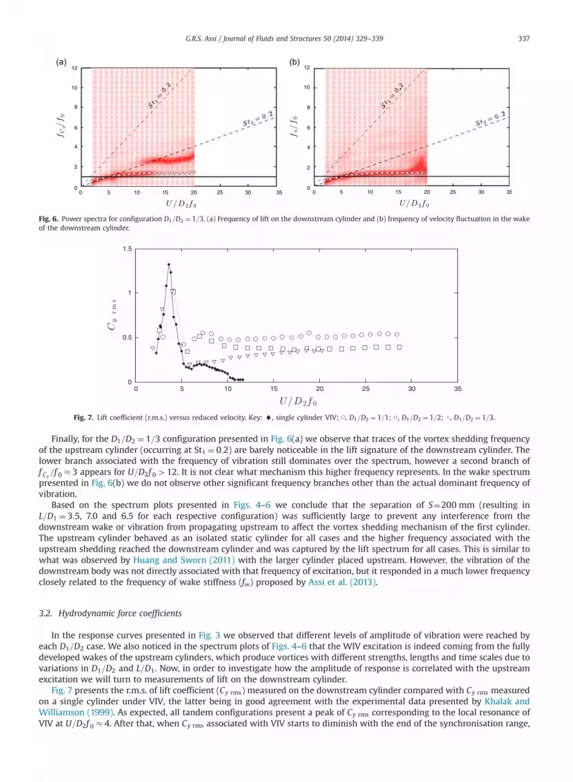
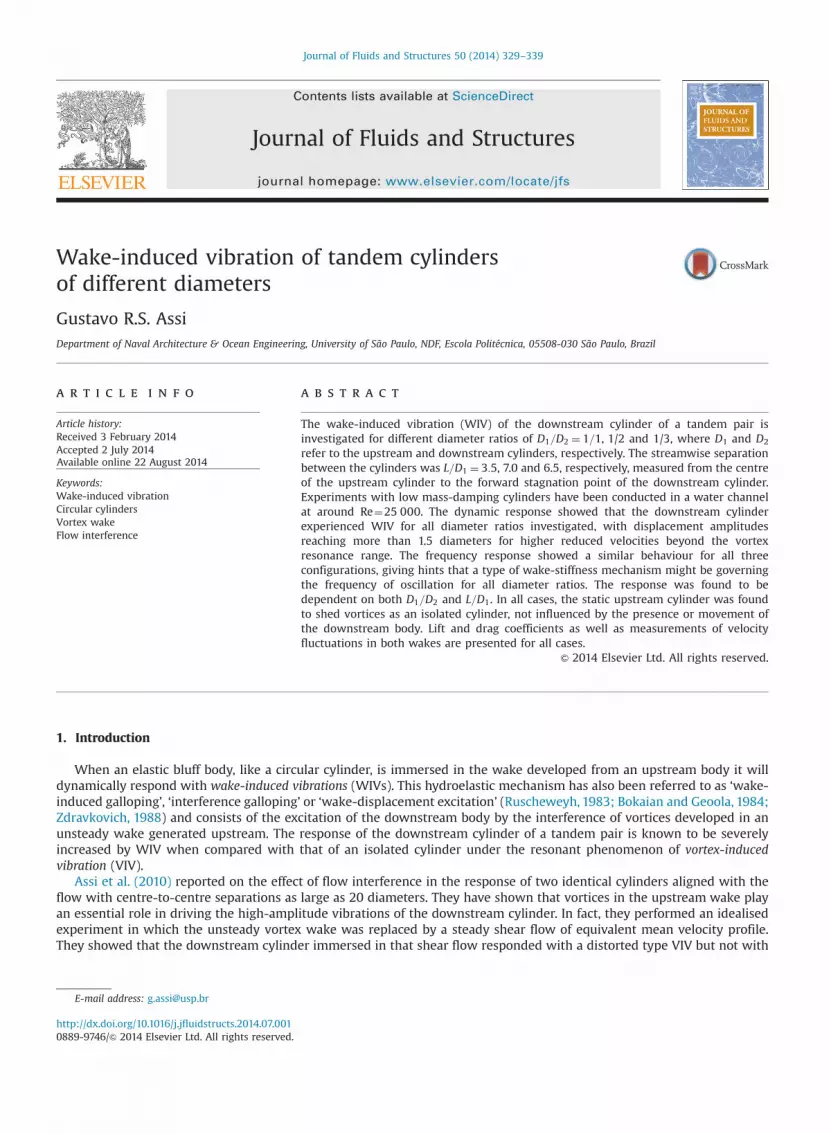
Fig. 6. Power spectra for configuration D1=D2 ¼ 1=3. (a) Frequency of lift on the downstream cylinder and (b) frequency of velocity fluctuation in the wakeof the downstream cylinder.
Fig. 7. Lift coefficient (r.m.s.) versus reduced velocity. Key: ~, single cylinder VIV; ◯, D1=D2 ¼ 1=1; □, D1=D2 ¼ 1=2; ▿, D1=D2 ¼ 1=3.
G.R.S. Assi / Journal of Fluids and Structures 50 (2014) 329–339 337
Finally, for the D1=D2 ¼ 1=3 configuration presented in Fig. 6(a) we observe that traces of the vortex shedding frequencyof the upstream cylinder (occurring at St1 ¼ 0:2) are barely noticeable in the lift signature of the downstream cylinder. Thelower branch associated with the frequency of vibration still dominates over the spectrum, however a second branch off Cy
=f 0 � 3 appears for U=D2f 0412. It is not clear what mechanism this higher frequency represents. In the wake spectrumpresented in Fig. 6(b) we do not observe other significant frequency branches other than the actual dominant frequency ofvibration.
Based on the spectrum plots presented in Figs. 4–6 we conclude that the separation of S¼200 mm (resulting inL=D1 ¼ 3:5, 7.0 and 6.5 for each respective configuration) was sufficiently large to prevent any interference from thedownstream wake or vibration from propagating upstream to affect the vortex shedding mechanism of the first cylinder.The upstream cylinder behaved as an isolated static cylinder for all cases and the higher frequency associated with theupstream shedding reached the downstream cylinder and was captured by the lift spectrum for all cases. This is similar towhat was observed by Huang and Sworn (2011) with the larger cylinder placed upstream. However, the vibration of thedownstream body was not directly associated with that frequency of excitation, but it responded in a much lower frequencyclosely related to the frequency of wake stiffness (fw) proposed by Assi et al. (2013).
3.2. Hydrodynamic force coefficients
In the response curves presented in Fig. 3 we observed that different levels of amplitude of vibration were reached byeach D1=D2 case. We also noticed in the spectrum plots of Figs. 4–6 that the WIV excitation is indeed coming from the fullydeveloped wakes of the upstream cylinders, which produce vortices with different strengths, lengths and time scales due tovariations in D1=D2 and L=D1. Now, in order to investigate how the amplitude of response is correlated with the upstreamexcitation we will turn to measurements of lift on the downstream cylinder.
Fig. 7 presents the r.m.s. of lift coefficient (Cy rms) measured on the downstream cylinder compared with Cy rms measuredon a single cylinder under VIV, the latter being in good agreement with the experimental data presented by Khalak andWilliamson (1999). As expected, all tandem configurations present a peak of Cy rms corresponding to the local resonance ofVIV at U=D2f 0 � 4. After that, when Cy rms associated with VIV starts to diminish with the end of the synchronisation range,

Fig. 8. Mean drag coefficient versus reduced velocity. Key: n, single static cylinder; ~, single cylinder VIV; ○, D1=D2 ¼ 1=1; □, D1=D2 ¼ 1=2; ▿, D1=D2 ¼ 1=3.
G.R.S. Assi / Journal of Fluids and Structures 50 (2014) 329–339338
Cy rms for the tandem cases increases to a much higher level, which is sustained until the end of the reduced velocity rangetestes.
Lift coefficient for D1=D2 ¼ 1=1 remains at Cy rms � 0:5 while the other two cases find levels slightly below that, withD1=D2 ¼ 1=3 showing the lowest Cy rms level. It appears that the level of Cy rms is more dependent on D1=D2 rather than onL=D1. The amplitude of response (y=D2), on the other hand, seems to be more dependent on L=D1 rather than on D1=D2, withD1=D2 ¼ 1=3 reaching amplitudes higher than D1=D2 ¼ 1=2. Nevertheless, as suggested before, this could also be related tothe fact that D1=D2 ¼ 1=3 presents half of the mn of the other two cases.
We have seen that the lift on the downstream cylinder will act at the frequency of wake stiffness (fw) and those of vortexshedding (fs), which will be sustained for an indefinite range of reduced velocities during the WIV mechanism. Assi et al.(2010) explained how this excitation mechanism depends on the unsteady interaction of the vortices coming from theupstream wake and the downstream cylinder. Therefore, the topology of the wake (width, vortex strength, length, timescales, etc.) modified by an upstream cylinder of smaller diameter must be playing a fundamentally different role in theexcitation mechanism.
Mean drag coefficients (Cx) on the downstream cylinder are presented in Fig. 8. The drag curve for a single cylinderreveals the amplification of drag normally observed during the synchronisation range of VIV, which agrees well with theresults presented by Khalak and Williamson (1999). A curve for the drag of a static single cylinder has also been added as areference.
All tandem configurations present a similar amplification of drag during the resonance range of VIV. Past thesynchronisation range, Cx due to WIV remains at slightly higher levels, but very close to the drag measured for a staticsingle cylinder. In general, Cx decreases as D1=D2 increases, perhaps due to the deficit of mean velocity in the wake comingfrom the upstream cylinder; i.e. a smaller D1 will create a wake with higher streamwise velocity reaching the secondcylinder.
4. Conclusion
In the present work we investigate the WIV response of the downstream cylinder of a pair with diameter ratiosD1=D2 ¼ 1=1, 1/2 and 1/3. For all tandem configurations, the static upstream cylinder appears to be shedding vortices asan isolated cylinder, not being affected by the presence or movement of the downstream body. This is true for effectiveseparations of L=D1 ¼ 3:5, 7.0 and 6.5, respectively.
The overall WIV response turned out to be dependent on several parameters: wake topology (Re), arrangement geometry(both D1=D2 and L=D1) and system dynamics (mn). Other dimensionless representations of the separation parametercan lead to different interpretations of the data. In the present work, the effective separation L=D1 was chosen as arepresentative of the effect of the upstream wake impinging on the downstream body.
The frequency response, on the other hand, turned out to be rather independent of both D1=D2 and L=D1. In fact, amechanism similar to the wake stiffness proposed by Assi et al. (2013) might be occurring for different diameter ratios butwith different intensities. Nevertheless, all frequency responses appeared to be very close to the wake stiffness frequencypreviously characterised for cylinders of equal diameters.
It is not clear from the present investigation if the enhanced response of D1=D2 ¼ 1=3 in relation to D1=D2 ¼ 1=2 is due tothe decrease of the effective separation L=D1, the decrease of mn or the increase of Re. Assi et al. (2010) have already shownthat Reynolds number plays a very important role in WIV. Maybe increasing the diameter of the downstream cylinder from50 mm to 75 mm from case D1=D2 ¼ 1=2 to 1/3 may include such a Re effect. Future experiments should be able to isolatesome of these parameters in order to achieve a better understanding of the phenomenon.

G.R.S. Assi / Journal of Fluids and Structures 50 (2014) 329–339 339
Acknowledgements
The author is grateful to the advice of Prof. Peter Bearman and the support from Imperial College (Dept. of Aeronautics)and CAPES (2668-04-1) at the time of the experiments. He also wishes to acknowledge the recent support from FAPESP(2013/07335-8) and CNPq (308916/2012-3) that allowed him time to revisit the data and write this manuscript.
References
Alam, M.M., Zhou, Y., 2008. Strouhal numbers, forces and flow structures around two tandem cylinders of different diameters. Journal of Fluids andStructures 24, 505–526.
Alam, M.M., Zhou, Y., 2014. Flow-induced vibrations of a circular cylinder interacting with another of different diameter. In: Zhou, Y., Liu, Y., Huang, L.,Hodges, D.H. (Eds.), Fluid–Structure–Sound Interactions and Control. Lecture Notes in Mechanical Engineering, Springer, Berlin, Heidelberg,pp. 385–390.
Assi, G.R.S., 2009. Mechanisms for Flow-Induced Vibration of Interfering Bluff Bodies (Ph.D. thesis). Imperial College London, London, UK, available from⟨www.ndf.poli.usp.br/�gassi⟩.
Assi, G.R.S., 2014. Wake-induced vibration of tandem and staggered cylinders with two degrees of freedom. Journal of Fluids and Structures, http://dx.doi.org/10.1016/j.jfluidstructs.2014.07.002, in press.
Assi, G.R.S., Bearman, P.W., Carmo, B., Meneghini, J., Sherwin, S., Willden, R., 2013. The role of wake stiffness on the wake-induced vibration of thedownstream cylinder of a tandem pair. Journal of Fluid Mechanics 718, 210–245.
Assi, G.R.S., Bearman, P.W., Meneghini, J., 2010. On the wake-induced vibration of tandem circular cylinders: the vortex interaction excitation mechanism.Journal of Fluid Mechanics 661, 365–401.
Bearman, P.W., 1984. Vortex shedding from oscillating bluff bodies. Annual Review of Fluid Mechanics 16, 195–222.Bokaian, A., Geoola, F., 1984. Wake-induced galloping of two interfering circular cylinders. Journal of Fluid Mechanics 146, 383–415.Huang, S., Sworn, A., 2011. Some observations of two interfering VIV circular cylinders of unequal diameters in tandem. Journal of Hydrodynamics 23,
535–543.Huang, S., Sworn, A., 2013. Interference between two stationary or elastically supported rigid circular cylinders of unequal diameters in tandem and stag-
gered arrangements. J. Shore Mech. Arctic Eng. 135, 021803. (February 25, 2013) (10).Khalak, A., Williamson, C.H.K., 1999. Motions, forces and mode transitions in vortex-induced vibrations at low mass-damping. Journal of Fluids and
Structures 13, 813–851.Rahmanian, M., Zhao, M., Cheng, L., Zhou, T., 2012. Two-degree-of-freedom vortex-induced vibration of two mechanically coupled cylinders of different
diameters in steady current. Journal of Fluids and Structures 35, 133–159.Ruscheweyh, H.P., 1983. Aeroelastic interference effects between slender structures. Journal of Wind Engineering and Industrial Aerodynamics 14, 129–140.Tsutsui, T., Igarashi, T., Kamemoto, K., 1997. Interactive flow around two circular cylinders of different diameters at close proximity. Experiment and
numerical analysis by vortex method. Journal of Wind Engineering and Industrial Aerodynamics 69–71, 279–291.Williamson, C.H.K., Govardhan, R., 2004. Vortex-induced vibrations. Annual Review of Fluid Mechanics 36, 413–455.Zdravkovich, M.M., 1988. Review of interference-induced oscillations in flow past two circular cylinders in various arrangements. Journal of Wind
Engineering and Industrial Aerodynamics 28, 183–200.Zhao, M., Cheng, L., Teng, B., Liang, D., 2005. Numerical simulation of viscous flow past two circular cylinders of different diameters. Applied Ocean Research
27, 39–55.Zhao, M., Yan, G., 2013. Numerical simulation of vortex-induced vibration of two circular cylinders of different diameters at low Reynolds number. Physics
of Fluids 25, 083601, /http://dx.doi.org/10.1063/1.4816637S.


