Embed Size (px)
Citation preview
ACTAUNIVERSITATIS
UPSALIENSISUPPSALA
2017
Digital Comprehensive Summaries of Uppsala Dissertationsfrom the Faculty of Science and Technology 1563
Wave Energy Converters
An experimental approach to onshore testing,deployments and offshore monitoring
LISELOTTE ULVGÅRD
ISSN 1651-6214ISBN 978-91-513-0077-1urn:nbn:se:uu:diva-329856

Dissertation presented at Uppsala University to be publicly examined in Siegbahnsalen,Ångströmlaboratoriet, Lägerhyddsvägen 1, Uppsala, Friday, 10 November 2017 at 09:15 forthe degree of Doctor of Philosophy. The examination will be conducted in English. Facultyexaminer: Professor Jonny Hylander (Halmstad University).
AbstractUlvgård, L. 2017. Wave Energy Converters. An experimental approach to onshore testing,deployments and offshore monitoring. Digital Comprehensive Summaries of UppsalaDissertations from the Faculty of Science and Technology 1563. 100 pp. Uppsala: ActaUniversitatis Upsaliensis. ISBN 978-91-513-0077-1.
The wave energy converter (WEC) concept developed at Uppsala University consists of a pointabsorbing buoy, directly connected to a permanent magnet linear generator. Since 2006, over adozen full scale WECs have been deployed at the Lysekil Research Site, on the west coast ofSweden. Beyond the development of the WEC concept itself, the full scale approach enables,and requires, experimental and multidisciplinary research within several peripheral areas, suchas instrumentation, offshore operations, and wave power infrastructure.
This thesis addresses technical challenges of testing, deploying and monitoring full scaleWECs. It is divided accordingly into three topics: offshore measurement systems, onshore WECtesting and deployments. Each topic presents new or improved technical solutions to enableoffshore wave power research.
For the offshore measurement systems, a new portable data acquisition unit was developed,together with a new sensor system to be installed inside the WEC. The developed system offersa cheap and flexible option for short term offshore measurement ventures, when or where siteinfrastructure is not available. The system has been developed and tested during both onshoreand offshore experiments, with promising results.
On the topic of onshore WEC testing, the thesis presents an experimental approach forassessing the power take-off (PTO) damping of the WEC. In previous experimental studies, ithas been measured via the generated electrical power, which neglects both mechanical lossesand iron losses. Consequently, the full PTO force acting on the WEC has been underestimated.The thesis presents experimentally attained trends for the speed dependence of the PTOdamping at different resistive loads, as measured from both generated electric power and frommeasurements of the buoy line force. A study was also performed on how the generator dampingis affected by partial stator overlap, which varies with the translator position. In order to assesshow the characterized damping behavior will affect the WEC operation at sea, two simulationcase studies were performed.
Finally, the thesis presents a new WEC deployment method, which has been developedthrough several deployment trials. By using only a tugboat, a WEC unit is transported anddeployed, together with its buoy, in less than half a day. The procedure has proven to be faster,cheaper and safer than the previously used methods.
Keywords: wave power, ocean energy, linear generator, measurements, sensors, pointabsorber, offshore, PTO, force
Liselotte Ulvgård, Department of Engineering Sciences, Electricity, Box 534, UppsalaUniversity, SE-75121 Uppsala, Sweden.
© Liselotte Ulvgård 2017
ISSN 1651-6214ISBN 978-91-513-0077-1urn:nbn:se:uu:diva-329856 (http://urn.kb.se/resolve?urn=urn:nbn:se:uu:diva-329856)

We got no troubles, life is the bubbles!Under the Sea
/Sebastian


List of papers
This thesis is based on the following papers, which are referred to in the textby their Roman numerals.
I Ulvgård, L., Kamf, T., Leijon, M. "Offshore Measurement System forWave Power – Using Current Loop Feedback", MDPI Electronics,2016, 5(4), 86. doi: 10.3390/electronics5040086
II Ulvgård, L., Kamf, T., Risberg, A., Leijon, M. "Portable DataAcquisition System for Offshore Applications", In review for IEEEJournal of Oceanic Engineering, submitted May 2017
III Lindblad*, L., Boudoin, A., Leijon, M. "Measurement System forWave Energy Converter - Design and Implementation", In proceedingsof the 33Rd International Conference on Ocean, Offshore and ArcticEngineering, San Francisco, California, June 8–13, 2014
IV Lindblad*, L., Hai, L., Leijon, M. "Measurement System forEvaluating Wanted and Unwanted Forces on a Point Absorbing WaveEnergy Converter during Offshore Operation", In proceedings of the25th International Ocean and Polar Engineering Conference, KhonaIsland, USA, 21–26 2015
V Ulvgård, L., Sjökvist, L., Göteman, M., Leijon, M. "Line Force andDamping at Full and Partial Stator Overlap in a Linear Generator forWave Power", MDPI Journal of Marine Science and Engineering,2017, 4(4), 81. doi: 10.3390/jmse4040081
VI Ulvgård, L., Sjökvist, L., Leijon, M. "Speed Dependent PTO Dampingin a Linear Generator for Wave Power - Measured Damping andSimulated WEC Behaviour", In revision for MDPI Journal of MarineScience and Engineering
VII Ulvgård, L., Frost, A., Sjökvist, L., Eriksson, S., Leijon, M. "PartialStator Overlap in a Linear Generator for Wave Power: AnExperimental Study", Submitted to MDPI Journal of Marine Scienceand Engineering, September 2017

VIII Frost, A., Ulvgård, L., Sjökvist, L., Eriksson, S., Leijon, M."Experimental Study of Generator Damping at Partial Stator Overlap ina Linear Generator for Wave Power", In proceedings of the 12thEuropean Wave and Tidal Energy Conference. Cork, Ireland, August27–31, 2017
IX Parwal, A., Remouit, F., Hong, Y., Francisco, F., Castellucci, V., Hai,L., Ulvgård, L., Li, W., Lejerskog, E., Baudoin, A., Chatzigiannakou,M., Haikonen, K., Ektröm, R., Boström, C., Göteman, M., Waters, R.,Svensson, O., Sundberg, J., Rahm, M., Strömstedt, E., Engström, J.,Savin, A., Leijon, M. "Wave Energy Research at Uppsala Universityand The Lysekil Research Site, Sweden: A Status Update", Inproceedings of the 11th European Wave and Tidal Energy Conference.Nantes, France, September 6–11, 2015
X Hong, Y.,Hultman, E., Castellucci, V., Ekergård, B., Sjökvist, L.,Elamalayil Soman, D., Krishna, R., Haikonen, K., Baudoin, A.,Lindblad*, L., Lejerskog, E., Käller, D., Rahm, M., Strömstedt, E.,Boströl, C., Waters, R., Leijon, M. "Status Update of the Wave EnergyResearch at Uppsala University", In proceedings of the 10th EuropeanWave and Tidal Energy Conference Series, Aalborg, Denmark,September 2–5, 2013
XI Chatzigiannakou, M., Ulvgård, L., Temiz, I., Leijon, M. "OffshoreDeployments of Wave Energy Converters by Uppsala University", Inrevision for Marine Systems & Ocean Technology,
Reprints were made with permission from the publishers.* The author changed her surname from Lindblad to Ulvgård 2014.

Contents
1 Introduction . . . . . . . . . . . . . . . . . . . . . . . . . . . . . . . . . . . . . . . . . . . . . . . . . . . . . . . . . . . . . . . . . . . . . . . . . . . . . . . . . . . . . . . . . . . . . . . . 111.1 Research Questions and Methodology . . . . . . . . . . . . . . . . . . . . . . . . . . . . . . . . . . . . . . . . . 121.2 Thesis Outline . . . . . . . . . . . . . . . . . . . . . . . . . . . . . . . . . . . . . . . . . . . . . . . . . . . . . . . . . . . . . . . . . . . . . . . . . . . . . . . . 13
2 Background . . . . . . . . . . . . . . . . . . . . . . . . . . . . . . . . . . . . . . . . . . . . . . . . . . . . . . . . . . . . . . . . . . . . . . . . . . . . . . . . . . . . . . . . . . . . . . . . 152.1 Wave Power Technologies . . . . . . . . . . . . . . . . . . . . . . . . . . . . . . . . . . . . . . . . . . . . . . . . . . . . . . . . . . . . . 15
2.1.1 Overview . . . . . . . . . . . . . . . . . . . . . . . . . . . . . . . . . . . . . . . . . . . . . . . . . . . . . . . . . . . . . . . . . . . . . . . . . . 152.1.2 The Uppsala University WEC Concept . . . . . . . . . . . . . . . . . . . . . . . . . 17
2.2 Forces Acting on the WEC . . . . . . . . . . . . . . . . . . . . . . . . . . . . . . . . . . . . . . . . . . . . . . . . . . . . . . . . . . . . 192.2.1 In theory . . . . . . . . . . . . . . . . . . . . . . . . . . . . . . . . . . . . . . . . . . . . . . . . . . . . . . . . . . . . . . . . . . . . . . . . . . . 192.2.2 In models . . . . . . . . . . . . . . . . . . . . . . . . . . . . . . . . . . . . . . . . . . . . . . . . . . . . . . . . . . . . . . . . . . . . . . . . . . 202.2.3 In practice . . . . . . . . . . . . . . . . . . . . . . . . . . . . . . . . . . . . . . . . . . . . . . . . . . . . . . . . . . . . . . . . . . . . . . . . . 22
2.3 The Direct Driven Linear Generator . . . . . . . . . . . . . . . . . . . . . . . . . . . . . . . . . . . . . . . . . . . . . 242.3.1 In theory . . . . . . . . . . . . . . . . . . . . . . . . . . . . . . . . . . . . . . . . . . . . . . . . . . . . . . . . . . . . . . . . . . . . . . . . . . . 242.3.2 Generator models . . . . . . . . . . . . . . . . . . . . . . . . . . . . . . . . . . . . . . . . . . . . . . . . . . . . . . . . . . . . . 252.3.3 Generator losses . . . . . . . . . . . . . . . . . . . . . . . . . . . . . . . . . . . . . . . . . . . . . . . . . . . . . . . . . . . . . . . 262.3.4 The differences between the L10 an L12 WEC . . . . . . . . . . . . . 28
2.4 Measurement Systems . . . . . . . . . . . . . . . . . . . . . . . . . . . . . . . . . . . . . . . . . . . . . . . . . . . . . . . . . . . . . . . . . . 292.4.1 Introduction . . . . . . . . . . . . . . . . . . . . . . . . . . . . . . . . . . . . . . . . . . . . . . . . . . . . . . . . . . . . . . . . . . . . . . 292.4.2 The Lysekil Research Site . . . . . . . . . . . . . . . . . . . . . . . . . . . . . . . . . . . . . . . . . . . . . . . 292.4.3 Development and testing of the Uppsala University
WEC . . . . . . . . . . . . . . . . . . . . . . . . . . . . . . . . . . . . . . . . . . . . . . . . . . . . . . . . . . . . . . . . . . . . . . . . . . . . . . . . . 30
3 Topic I: Offshore measurement systems . . . . . . . . . . . . . . . . . . . . . . . . . . . . . . . . . . . . . . . . . . . . . . . . . . 323.1 Introduction . . . . . . . . . . . . . . . . . . . . . . . . . . . . . . . . . . . . . . . . . . . . . . . . . . . . . . . . . . . . . . . . . . . . . . . . . . . . . . . . . . . . 323.2 The L10 Measurement System . . . . . . . . . . . . . . . . . . . . . . . . . . . . . . . . . . . . . . . . . . . . . . . . . . . . . . 33
3.2.1 Objective . . . . . . . . . . . . . . . . . . . . . . . . . . . . . . . . . . . . . . . . . . . . . . . . . . . . . . . . . . . . . . . . . . . . . . . . . . 333.2.2 Implementation . . . . . . . . . . . . . . . . . . . . . . . . . . . . . . . . . . . . . . . . . . . . . . . . . . . . . . . . . . . . . . . . 343.2.3 Results and evaluation . . . . . . . . . . . . . . . . . . . . . . . . . . . . . . . . . . . . . . . . . . . . . . . . . . . . . 38
3.3 The L12 Measurement System . . . . . . . . . . . . . . . . . . . . . . . . . . . . . . . . . . . . . . . . . . . . . . . . . . . . . . 403.3.1 Objective . . . . . . . . . . . . . . . . . . . . . . . . . . . . . . . . . . . . . . . . . . . . . . . . . . . . . . . . . . . . . . . . . . . . . . . . . . 403.3.2 Implementation . . . . . . . . . . . . . . . . . . . . . . . . . . . . . . . . . . . . . . . . . . . . . . . . . . . . . . . . . . . . . . . . 423.3.3 Results and evaluation . . . . . . . . . . . . . . . . . . . . . . . . . . . . . . . . . . . . . . . . . . . . . . . . . . . . . 463.3.4 Offshore operation . . . . . . . . . . . . . . . . . . . . . . . . . . . . . . . . . . . . . . . . . . . . . . . . . . . . . . . . . . . 51
3.4 Discussion and Conclusion . . . . . . . . . . . . . . . . . . . . . . . . . . . . . . . . . . . . . . . . . . . . . . . . . . . . . . . . . . . . 53

4 Topic II: Onshore WEC Testing . . . . . . . . . . . . . . . . . . . . . . . . . . . . . . . . . . . . . . . . . . . . . . . . . . . . . . . . . . . . . . . 554.1 Introduction . . . . . . . . . . . . . . . . . . . . . . . . . . . . . . . . . . . . . . . . . . . . . . . . . . . . . . . . . . . . . . . . . . . . . . . . . . . . . . . . . . . . 554.2 The L10 Onshore Tests . . . . . . . . . . . . . . . . . . . . . . . . . . . . . . . . . . . . . . . . . . . . . . . . . . . . . . . . . . . . . . . . . . 56
4.2.1 Objective . . . . . . . . . . . . . . . . . . . . . . . . . . . . . . . . . . . . . . . . . . . . . . . . . . . . . . . . . . . . . . . . . . . . . . . . . . 564.2.2 Experimental setup . . . . . . . . . . . . . . . . . . . . . . . . . . . . . . . . . . . . . . . . . . . . . . . . . . . . . . . . . . 564.2.3 Results and evaluation . . . . . . . . . . . . . . . . . . . . . . . . . . . . . . . . . . . . . . . . . . . . . . . . . . . . . 57
4.3 The L12 Onshore Tests . . . . . . . . . . . . . . . . . . . . . . . . . . . . . . . . . . . . . . . . . . . . . . . . . . . . . . . . . . . . . . . . . . 614.3.1 Objective . . . . . . . . . . . . . . . . . . . . . . . . . . . . . . . . . . . . . . . . . . . . . . . . . . . . . . . . . . . . . . . . . . . . . . . . . . 614.3.2 Method . . . . . . . . . . . . . . . . . . . . . . . . . . . . . . . . . . . . . . . . . . . . . . . . . . . . . . . . . . . . . . . . . . . . . . . . . . . . . 614.3.3 Experimental setup . . . . . . . . . . . . . . . . . . . . . . . . . . . . . . . . . . . . . . . . . . . . . . . . . . . . . . . . . . 624.3.4 Results and evaluation . . . . . . . . . . . . . . . . . . . . . . . . . . . . . . . . . . . . . . . . . . . . . . . . . . . . . 63
4.4 Consequence Analysis - A Simulation Case Study . . . . . . . . . . . . . . . . . . . . . 674.4.1 Objective . . . . . . . . . . . . . . . . . . . . . . . . . . . . . . . . . . . . . . . . . . . . . . . . . . . . . . . . . . . . . . . . . . . . . . . . . . 674.4.2 Method . . . . . . . . . . . . . . . . . . . . . . . . . . . . . . . . . . . . . . . . . . . . . . . . . . . . . . . . . . . . . . . . . . . . . . . . . . . . . 674.4.3 Results and evaluation . . . . . . . . . . . . . . . . . . . . . . . . . . . . . . . . . . . . . . . . . . . . . . . . . . . . . 67
4.5 Discussion and Conclusion . . . . . . . . . . . . . . . . . . . . . . . . . . . . . . . . . . . . . . . . . . . . . . . . . . . . . . . . . . . . 70
5 Topic III: Deployments . . . . . . . . . . . . . . . . . . . . . . . . . . . . . . . . . . . . . . . . . . . . . . . . . . . . . . . . . . . . . . . . . . . . . . . . . . . . . 735.1 Introduction . . . . . . . . . . . . . . . . . . . . . . . . . . . . . . . . . . . . . . . . . . . . . . . . . . . . . . . . . . . . . . . . . . . . . . . . . . . . . . . . . . . . 735.2 Method and Experimental Results . . . . . . . . . . . . . . . . . . . . . . . . . . . . . . . . . . . . . . . . . . . . . . . . 73
5.2.1 Deployment procedure . . . . . . . . . . . . . . . . . . . . . . . . . . . . . . . . . . . . . . . . . . . . . . . . . . . . 735.2.2 Deployment trials . . . . . . . . . . . . . . . . . . . . . . . . . . . . . . . . . . . . . . . . . . . . . . . . . . . . . . . . . . . . 74
5.3 Discussion and Conclusion . . . . . . . . . . . . . . . . . . . . . . . . . . . . . . . . . . . . . . . . . . . . . . . . . . . . . . . . . . . . 77
6 Discussion . . . . . . . . . . . . . . . . . . . . . . . . . . . . . . . . . . . . . . . . . . . . . . . . . . . . . . . . . . . . . . . . . . . . . . . . . . . . . . . . . . . . . . . . . . . . . . . . . . 796.1 Limitations . . . . . . . . . . . . . . . . . . . . . . . . . . . . . . . . . . . . . . . . . . . . . . . . . . . . . . . . . . . . . . . . . . . . . . . . . . . . . . . . . . . . . . 796.2 Findings . . . . . . . . . . . . . . . . . . . . . . . . . . . . . . . . . . . . . . . . . . . . . . . . . . . . . . . . . . . . . . . . . . . . . . . . . . . . . . . . . . . . . . . . . . 80
6.2.1 Regarding Offshore Measurement Systems . . . . . . . . . . . . . . . . . . . 806.2.2 Regarding Onshore Tests . . . . . . . . . . . . . . . . . . . . . . . . . . . . . . . . . . . . . . . . . . . . . . . . 816.2.3 Regarding Deployments . . . . . . . . . . . . . . . . . . . . . . . . . . . . . . . . . . . . . . . . . . . . . . . . . . 82
6.3 Possibilities . . . . . . . . . . . . . . . . . . . . . . . . . . . . . . . . . . . . . . . . . . . . . . . . . . . . . . . . . . . . . . . . . . . . . . . . . . . . . . . . . . . . . 82
7 Conclusions . . . . . . . . . . . . . . . . . . . . . . . . . . . . . . . . . . . . . . . . . . . . . . . . . . . . . . . . . . . . . . . . . . . . . . . . . . . . . . . . . . . . . . . . . . . . . . . . 84
8 Future Work . . . . . . . . . . . . . . . . . . . . . . . . . . . . . . . . . . . . . . . . . . . . . . . . . . . . . . . . . . . . . . . . . . . . . . . . . . . . . . . . . . . . . . . . . . . . . . . 858.1 The L12 buoy measurement system . . . . . . . . . . . . . . . . . . . . . . . . . . . . . . . . . . . . . . . . . . . . . . 858.2 Evaluate the need for new generator models . . . . . . . . . . . . . . . . . . . . . . . . . . . . . . . . 86
9 Svensk Sammanfattning . . . . . . . . . . . . . . . . . . . . . . . . . . . . . . . . . . . . . . . . . . . . . . . . . . . . . . . . . . . . . . . . . . . . . . . . . . . . 88
10 Acknowledgements . . . . . . . . . . . . . . . . . . . . . . . . . . . . . . . . . . . . . . . . . . . . . . . . . . . . . . . . . . . . . . . . . . . . . . . . . . . . . . . . . . . 90
11 Summary of Papers . . . . . . . . . . . . . . . . . . . . . . . . . . . . . . . . . . . . . . . . . . . . . . . . . . . . . . . . . . . . . . . . . . . . . . . . . . . . . . . . . . . . 91
References . . . . . . . . . . . . . . . . . . . . . . . . . . . . . . . . . . . . . . . . . . . . . . . . . . . . . . . . . . . . . . . . . . . . . . . . . . . . . . . . . . . . . . . . . . . . . . . . . . . . . . . . 97
Nomenclature
Symbol SI-unit Description
A m2 AreaAAir m2 Active airgap areaA f ac - Partial stator overlapBrad Ns/m Radiation dampingBmax T Magnetic flux density amplitudeC F Capacitanceδ rad Load angleEi V No-load voltageF N ForceFe N Excitation forceFendstop N Endstop forceFline N Line forceFPTO N Power take-off forceFel
PTO N Electromagnetic power take-off forcef Hz FrequencyΦ Wb Magnetic fluxg m/s2 Acceleration of gravityγ Ns/m PTO dampingI A CurrentIGenin A Generator output (measurement input)current
IPCBout mA Signal output current
K N/m Spring coefficientkh J/(m3T2) Hysteresis loss material constantked Js/(m3T2) Eddy current loss material constantkexc Js1/2/(m3T3/2) Excess loss material constantL H InductanceLg H Generator inductancem kg Massma kg Added massmb kg Buoy massmt kg Translator massN - Effective number of coil turnsω rad/s Angular frequencyp N/m2 PressurePabs W Absorbed powerPCu W Copper lossesPel W Electrical powerPFe W Iron lossesPmech W Mechanical lossesPout W Output power

Symbol SI-unit Description
R Ω ResistanceRg Ω Generator resistanceR f ix Ω Fix circuit resistanceRpot Ω Potentiometer resistanceRSG Ω Strain gauge resistanceR2 - Coefficient of determinationρ kg/m3 DensityS m3 Surfaceσ - Standard deviationVsub m3 Submerged VolumeV V VoltageV Gen
in V Generator output (measurement input) voltageV PCB
in mV Signal input voltageVl V Load voltagewcoil m Coil pitchwpole m Pole pitchx m Positionx m/s Speedx m/s2 AccelerationZ Ω Impedance
Abbreviations
Abbreviation Description
AC Alternating CurrentADC Analog-to-Digital ConverterAWS Archimedes Wave SwingCFD Computational Fluid DynamicDAQ Data AcquisitionDC Direct CurrentFEM Finite Element MethodFPGA Field-Programmable Gate ArrayLSB Least-Significant-BitL1–L12 WEC prototype namesOWC Oscilating Water ColumnPCB Printed Circuit BoardPTO Power Take-OffPTOpower Power Take-Off from-powerPTO f orce Power Take-Off from-forcePTOlinearized Linearized Power Take-OffSD (card) Secure Digital (card)SNR Signal-to-Noise RatioWEC Wave Energy Converter

1. Introduction
In the pursuit of sustainable energy systems, many have looked to the ocean.The theoretical potential for wave power has been estimated to 32 PWh/yr,which is twice the global electricity supply in 2008 [1]. Only a fraction of thishas the potential to become technically and economically feasible, which ismuch dependent of the future technology development. The International En-ergy Agency has estimated that ocean energy, including not only wave power,will contribute with 51–144 TWh in the year 2040, which is less than 0.4 % ofthe total electricity generation [2]. So, we have yet to prove that wave energysystems can be built to harvest, transfer and deliver reliable and economicallyviable electricity on a larger scale.
Although research has been done in the field for more than two centuries,there is still an abundance of concepts in play and there is yet no consensusof the best wave energy converter (WEC) design, even in theory. Beyondextracting as much energy as possible per unit cost, the viability of a WECconcept is also highly dependent on the short-term and long-term survivabilityof the construction, and the maintenance needed during its service life [3]. Sofar, the experiences of offshore operation are to few and to short to assess thefull lifetime cost for any WEC concept.
This thesis is part of the Uppsala University wave power research, whichstudies and develops technical solutions for all steps of wave power harvesting,from wave power extraction to grid connections. A specific WEC concepthas been suggested, consisting of a point absorbing buoy connected to directdriven linear generator. A picture and a schematic, naming the most importantparts, is found in Fig 1.1. The concept aspires for mechanical simplicity androbustness, with few moving parts and few energy conversion steps. Over adozen full scale WECs of this concept have been built and tested offshore atthe Lysekil research site, on the west coast of Sweden.
To deploy and test full scale WECs requires more than a concept for con-verting ocean waves to electricity. Due to the high forces, the uneven powerproduction and the harsh and inaccessible environment that the WECs operatein, there are many technical and multidisciplinary challenges surrounding theWEC. In many cases the testing, instrumentation, maintenance and infrastruc-ture has become research topics in themselves, since the specific requirementsand the harsh environment rules out commercially available equipment.
This thesis addresses a few of the technical challenges of testing, deploy-ing and monitoring the full scale WECs developed and tested at the Lysekilresearch site. This includes developing tests to asses the WEC’s damping
11

Figure 1.1. Photo and schematic of UU WEC. The translator and stator are around3 m and 2 mlong, respectively, and the whole structure stands just over 7 m tall.
characteristics during pre-deployment tests, to improve flexibility, cost andsafety of the WEC deployments and to evaluate and improve the measurementsystems used to gather data from the WECs during offshore operation.
1.1 Research Questions and MethodologyThe thesis has been built around the following research questions:
1. What onshore testing is needed to characterize the offshore behavior ofthe WEC?
3. How can WEC deployments be done in a better way?
2. How can offshore measurements on wave energy converters be done ina more flexible way?
Although separated into three research questions, which might seem detached,the work has been interlaced, with the overall goal to enable offshore WEC op-eration. Taking a WEC prototype from the factory floor to the sea floor is nota well-trodden path. It is a multidisciplinary task which requires a system per-spective, detailed technical knowledge, cooperation and timing. This thesiswill cover a few of the important pieces to this puzzle, with focus on the mea-surement systems needed to evaluate the onshore and offshore behavior of theWEC.
12

Regarding the first research question, the work with pre-deployment testingof WECs has mainly focused on developing onshore tests to characterize howthe linear generator will act as a power take-off (PTO) unit. The motion of theWEC, which affects both power production and survivability, depends both onthe ocean waves, the captor and the damping behavior of the PTO system. Topredict this behavior, different models are used to represent the PTO, whichcan be more or less true to the actual generator used. The methodology chosento test and improve these predictions of the offshore PTO behavior, has been tomeasure the actual input force, the output power and the translator motion ofthe linear generator, during onshore tests. From this, using Newton’s secondlaw of motion, the PTO damping, including both the wanted generator damp-ing and all losses, has been characterized as a function of translator positionand speed. To evaluate the importance of doing such PTO characterization, atime domain simulation case study of the consequences for the WEC motionduring offshore operation in high waves was performed. This work has beenpresented in Paper V–VIII.
For each WEC deployment, there has been a continuous drive to improvethe deployment procedure. The goal is always to lower the cost and to increasethe flexibility and safety of the operation. The authors contribution to thiswork, covered by the second research question, has been to help develop andevaluate a new deployment procedure, presented in Paper XI.
Regarding the third research question about offshore measurements duringWEC operation, the thesis work started out with finalizing and testing a mea-surement system developed to operate together with the signal infrastructurealready existing on in the Lysekil Research Site. This work is presented inPaper III–IV. The lessons learned from this work was then used to develop anew stand-alone measurement system, including measurements, logging, datastorage and battery supply, which were to operate independently of the siteinfrastructure. Driving forces were robustness, operation time and flexibility.This work is presented in Paper I–II.
Beyond what is covered by the research questions, the overall developmentof the Lysekil project, which the author has taken active part in, is presentedin Paper IX–X.
1.2 Thesis OutlineThe thesis is structured in three separate topics: Offshore Measurement Sys-tems, Onshore WEC Testing, and Deployments. Each topic has been given aseparate chapter which gathers the affiliated objective, method, results, dis-cussion and conclusion. The Background chapter provides introduction andtheory to wave power in general, and to the Uppsala University wave powerresearch in particular. After the background and topic chapters, the overallresults and insights are discussed and concluded.
13

2. Background
This chapter reviews the research and development accomplished in the fieldof wave power, upon which the work presented in this thesis is built. It startswith a short introduction to the field of wave power development, with focuson different technologies, together with an introduction to the Uppsala Univer-sity WEC concept. After that, a theoretical background regarding the forcesacting on the WEC during operation is given, focusing on the WEC motionas described by theory, by commonly used models and in practice. Lastly, abackground to offshore measurement systems is given, with special attentionto the site infrastructure and experimental work at the Lysekil research site.
2.1 Wave Power Technologies2.1.1 OverviewMany ideas and concepts have been suggested for how to extract energy fromocean waves. A list of wave power concepts, dated 2015, is found in [4]. Thewave energy conversion is separated into two parts, as illustrated in Fig. 2.1,assuming a wave-to-wire model. The captor is the devise that interacts with,and thus extracts power from, the ocean waves. This power is transferred to thePTO, via typically a pneumatic, hydraulic or mechanical link. The PTO con-verts the received power into electricity, in one or multiple conversion steps.
The captor
Fig. 2.2 illustrates three categories of captors, as defined by Falnes [5]: os-cillating water columns (OWCs), oscillating bodies and overtopping devices.Focusing on the oscillating body, Fig. 2.2 also presents three common types ofoscillating bodies, which are often categorized by the orientation of the captorin relation to the predominant wave direction [6]. Attenuators lie parallel tothe predominant wave direction, as seen in Fig. 2.2i. A well known WEC con-cept of the attenuator type is the Pelamis, [7]. Terminator captors have theirprincipal axis perpendicular to the wave direction, as seen in Fig. 2.2ii. A wellknown example is the Salter’s Duck [8]. A point absorber, seen in Fig. 2.2iii isa captor which is small compared to the incident wavelength, making it inde-pendent of wave direction. They can be floating structures that heave up anddown on the ocean surface or submerged below the surface. A well knownpoint absorber concept is the Archimedes Wave Swing (AWS) [9].
14
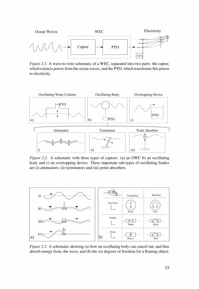
Figure 2.1. A wave-to-wire schematic of a WEC, separated into two parts: the captor,which extracts power from the ocean waves, and the PTO, which transforms this powerto electricity.
Figure 2.2. A schematic with three types of captors: (a) an OWC b) an oscillatingbody and c) an overtopping device. Three important sub-types of oscillating bodiesare (i) attenuators, (ii) terminators and (iii) point absorbers.
Figure 2.3. A schematic showing (a) how an oscillating body can cancel out, and thusabsorb energy from, the wave, and (b) the six degrees of freedom for a floating object.
15
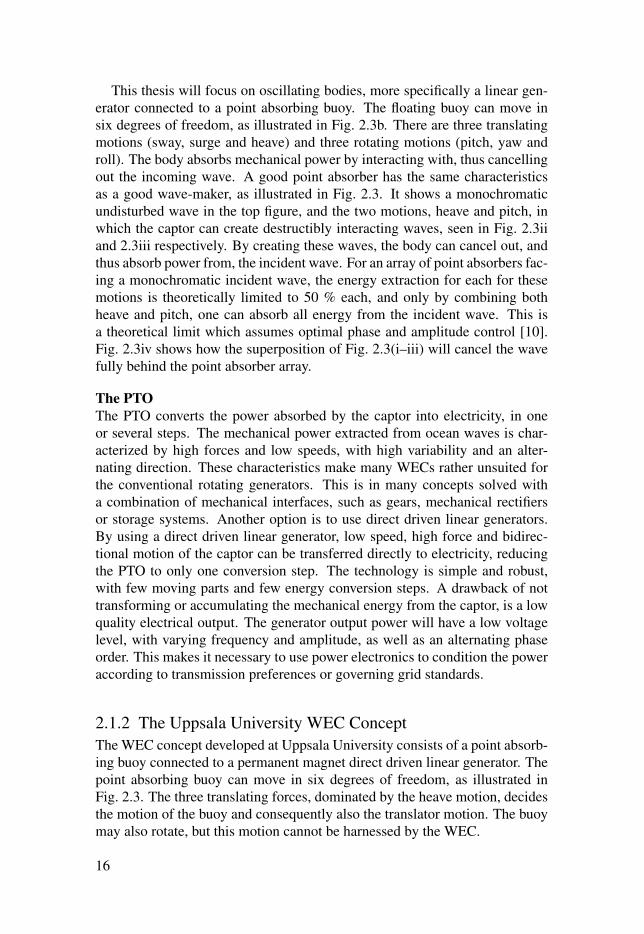
This thesis will focus on oscillating bodies, more specifically a linear gen-erator connected to a point absorbing buoy. The floating buoy can move insix degrees of freedom, as illustrated in Fig. 2.3b. There are three translatingmotions (sway, surge and heave) and three rotating motions (pitch, yaw androll). The body absorbs mechanical power by interacting with, thus cancellingout the incoming wave. A good point absorber has the same characteristicsas a good wave-maker, as illustrated in Fig. 2.3. It shows a monochromaticundisturbed wave in the top figure, and the two motions, heave and pitch, inwhich the captor can create destructibly interacting waves, seen in Fig. 2.3iiand 2.3iii respectively. By creating these waves, the body can cancel out, andthus absorb power from, the incident wave. For an array of point absorbers fac-ing a monochromatic incident wave, the energy extraction for each for thesemotions is theoretically limited to 50 % each, and only by combining bothheave and pitch, one can absorb all energy from the incident wave. This isa theoretical limit which assumes optimal phase and amplitude control [10].Fig. 2.3iv shows how the superposition of Fig. 2.3(i–iii) will cancel the wavefully behind the point absorber array.
The PTO
The PTO converts the power absorbed by the captor into electricity, in oneor several steps. The mechanical power extracted from ocean waves is char-acterized by high forces and low speeds, with high variability and an alter-nating direction. These characteristics make many WECs rather unsuited forthe conventional rotating generators. This is in many concepts solved witha combination of mechanical interfaces, such as gears, mechanical rectifiersor storage systems. Another option is to use direct driven linear generators.By using a direct driven linear generator, low speed, high force and bidirec-tional motion of the captor can be transferred directly to electricity, reducingthe PTO to only one conversion step. The technology is simple and robust,with few moving parts and few energy conversion steps. A drawback of nottransforming or accumulating the mechanical energy from the captor, is a lowquality electrical output. The generator output power will have a low voltagelevel, with varying frequency and amplitude, as well as an alternating phaseorder. This makes it necessary to use power electronics to condition the poweraccording to transmission preferences or governing grid standards.
2.1.2 The Uppsala University WEC ConceptThe WEC concept developed at Uppsala University consists of a point absorb-ing buoy connected to a permanent magnet direct driven linear generator. Thepoint absorbing buoy can move in six degrees of freedom, as illustrated inFig. 2.3. The three translating forces, dominated by the heave motion, decidesthe motion of the buoy and consequently also the translator motion. The buoymay also rotate, but this motion cannot be harnessed by the WEC.
16
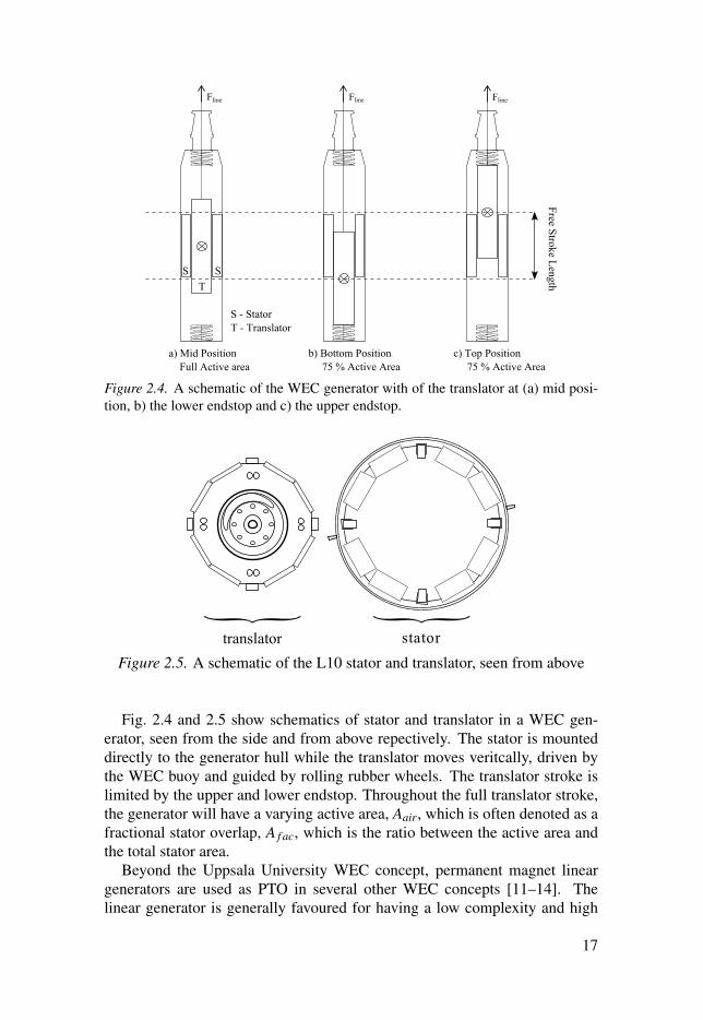
Figure 2.4. A schematic of the WEC generator with of the translator at (a) mid posi-tion, b) the lower endstop and c) the upper endstop.
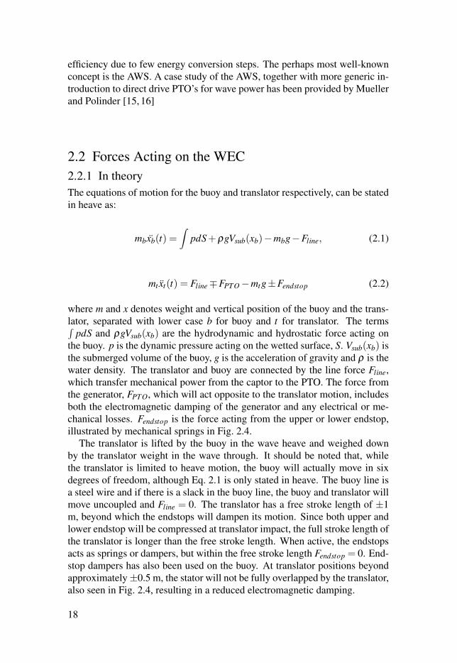
Figure 2.5. A schematic of the L10 stator and translator, seen from above
Fig. 2.4 and 2.5 show schematics of stator and translator in a WEC gen-erator, seen from the side and from above repectively. The stator is mounteddirectly to the generator hull while the translator moves veritcally, driven bythe WEC buoy and guided by rolling rubber wheels. The translator stroke islimited by the upper and lower endstop. Throughout the full translator stroke,the generator will have a varying active area, Aair, which is often denoted as afractional stator overlap, A f ac, which is the ratio between the active area andthe total stator area.
Beyond the Uppsala University WEC concept, permanent magnet lineargenerators are used as PTO in several other WEC concepts [11–14]. Thelinear generator is generally favoured for having a low complexity and high
17
efficiency due to few energy conversion steps. The perhaps most well-knownconcept is the AWS. A case study of the AWS, together with more generic in-troduction to direct drive PTO’s for wave power has been provided by Muellerand Polinder [15, 16]
2.2 Forces Acting on the WEC2.2.1 In theoryThe equations of motion for the buoy and translator respectively, can be statedin heave as:
mbxb(t) =∫
pdS+ρgVsub(xb)−mbg−Fline, (2.1)
mtxt(t) = Fline∓FPTO−mtg±Fendstop (2.2)
where m and x denotes weight and vertical position of the buoy and the trans-lator, separated with lower case b for buoy and t for translator. The terms∫
pdS and ρgVsub(xb) are the hydrodynamic and hydrostatic force acting onthe buoy. p is the dynamic pressure acting on the wetted surface, S. Vsub(xb) isthe submerged volume of the buoy, g is the acceleration of gravity and ρ is thewater density. The translator and buoy are connected by the line force Fline,which transfer mechanical power from the captor to the PTO. The force fromthe generator, FPTO, which will act opposite to the translator motion, includesboth the electromagnetic damping of the generator and any electrical or me-chanical losses. Fendstop is the force acting from the upper or lower endstop,illustrated by mechanical springs in Fig. 2.4.
The translator is lifted by the buoy in the wave heave and weighed downby the translator weight in the wave through. It should be noted that, whilethe translator is limited to heave motion, the buoy will actually move in sixdegrees of freedom, although Eq. 2.1 is only stated in heave. The buoy line isa steel wire and if there is a slack in the buoy line, the buoy and translator willmove uncoupled and Fline = 0. The translator has a free stroke length of ±1m, beyond which the endstops will dampen its motion. Since both upper andlower endstop will be compressed at translator impact, the full stroke length ofthe translator is longer than the free stroke length. When active, the endstopsacts as springs or dampers, but within the free stroke length Fendstop = 0. End-stop dampers has also been used on the buoy. At translator positions beyondapproximately±0.5 m, the stator will not be fully overlapped by the translator,also seen in Fig. 2.4, resulting in a reduced electromagnetic damping.
18
2.2.2 In modelsThis section will cover different types of models that have been used to studythe force dynamics of the WEC, based on Eq. 2.1 and Eq. 2.2.
Fully non-linear models
The most detailed studies of the WEC are performed with simulations of thefully non-linear behavior of Eq. 2.1 and Eq. 2.2, where the hydrodynamicforce,
∫pdS is found by solving the Reynolds Average Navier-Stokes equa-
tions numerically in time domain. Such simulations are computationally ex-pensive; they are often used to study specific extreme events where the discon-tinuous and non-linear behavior of Eq. 2.1 and Eq. 2.2 is especially important,such as peak forces during endstop hits, waves overtopping the buoy or snapforces in the connection line. This type of events are mainly important tounderstand, and design for, in order to ensure survivability during offshoreoperation.
A specific fully non-linear model has been used in this thesis for studyinghow different PTO behaviors will affect the WEC’s dynamic behavior in highwaves. It is implemented in a Computational Fluid Dynamic (CFD) softwareand has been validated against physical scale experiments [17].
Compared to the other models described in this section, using fully non-linear models is the only approach that solves
∫pdS in time domain, that al-
lows the buoy to move in six degrees of freedom and that considers non-lineareffects such as turbulence, green-water and overtopping.
Linearized models
For studies where some, or all, of the non-linear and discontinuous behaviorof Eq. 2.1 and Eq. 2.2 can be neglected, they are often simplified in order tobuild more applicable models. A commonly used linearization is:
(mb +ma)xb = Fe−Bradxb−ρgSx+FPTO, (2.3)
where the buoy and translator moves together, assuming a rigid connectionbetween buoy and translator, as stated by Falcao [5]. ma, Fe and Brad repre-sent the added mass at infinity, the excitation force and the radiation damping.These are hydromechanical constants which can be determined numericallyfor a specific buoy geometry. S is the cross-sectional area of the buoy, makingρgSx a linearization of the hydrostatic force. By linearizing the buoy-wave in-teraction, adopting linear potential flow theory, the WEC models become lesscomputationally expensive. These models can be coupled to different typesof linear or non-linear PTO models, in order to simulate the WEC behaviorin either time domain or in frequency domain, as described further by Eriks-son [18].
19

In order to study Eq. 2.1 and Eq. 2.2 in frequency domain, which is oftenconvenient to do, the PTO force must also be linearized, as:
FPTO = γ x+Kx, (2.4)
where γ and K are assumed damping and spring constants. For cases wherethere is no retracting force on the translator, as for the Uppsala Universityconcept, the PTO model is further simplified as FPTO = γ x. Retracting springswere used in the first prototypes of the Uppsala University WEC concept,in order to force down the translator during the wave through. They werelater removed, instead compensated with a heavier translator, since mechanicalsprings would not endure the high number of cycles expected for the WEC’sservice life.
It should be emphasized that it is a simplification to assume γ , which iscommonly used to denote the damping of a PTO unit, as constant. In reality,the PTO damping is a function of different state variables, which needs to becharacterized for the PTO unit studied.
If the PTO system can be linearized in this way, and linear potential the-ory can be used for the hydromechanical forces, the full WEC system can besimulated in the frequency domain, which has a lower computational cost andallows for optimization of many parameters in varying sea states. Examplesof such models are found in [19, 20].
The linearized system interpreted as lumped element models
A seen in the linearized equation of motion, Eq. 2.3, the hydrodynamic forcesacting on the buoy has been described as an inertia force, max, a radiationdamping force, Bx, and a hydrostatic force, ρgSx, which can be mechanicallyinterpreted as a mass, a damper and a spring. Adding also the linearized PTOforce, FPTO = γ x+Kx, Eq. 2.3 can be expanded as:
(mb +ma)x = Fe +(Brad + γ)x+(ρgS+K)x. (2.5)
By separating all the forces into a speed dependent term F(x) and a positiondependent term, F(x), a mechanical spring-damper-mass model can be used,as illustrated in Fig. 2.6a.
An analogous model is presented in Fig. 2.6b, where the system is insteadunderstood as a electric circuit. Table 2.1 connects parameters from the me-chanical model to the circuit model. The source voltage, V , corresponding tothe excitation force, is the entity driving the circuit, while the current, I, corre-sponds to the mechanical speed. The circuit shows separate impedance for thecaptor, Zcapt , and the PTO, ZPTO. A circuit resistance, R corresponds to me-chanical damping, γ , inductance correspond to system mass and capacitancecorrespond to hydrostatic force. ZPTO will be studied in more detail in section2.3.
20
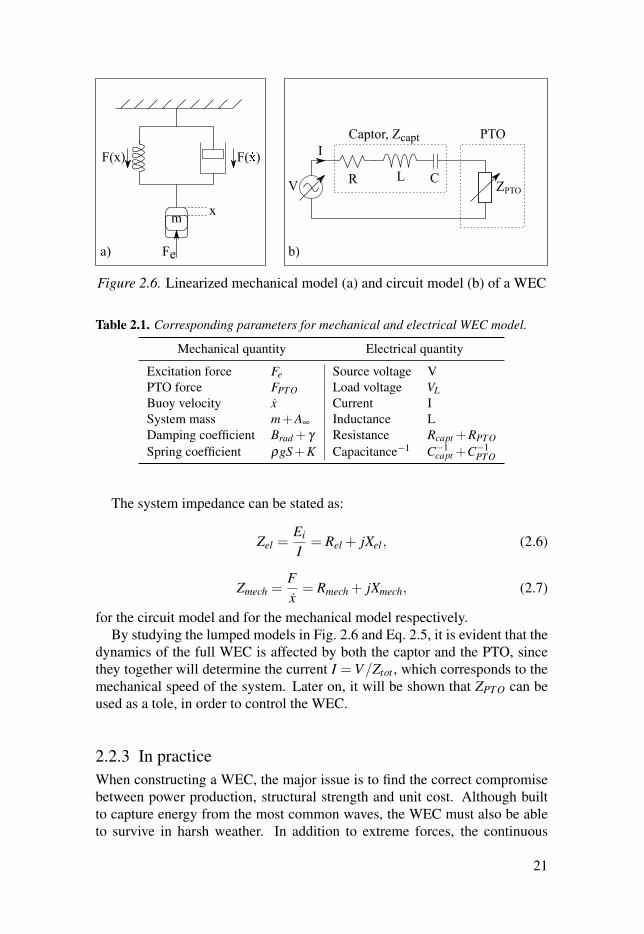
Figure 2.6. Linearized mechanical model (a) and circuit model (b) of a WEC
Table 2.1. Corresponding parameters for mechanical and electrical WEC model.
Mechanical quantity Electrical quantity
Excitation force Fe Source voltage VPTO force FPTO Load voltage VLBuoy velocity x Current ISystem mass m+A∞ Inductance LDamping coefficient Brad + γ Resistance Rcapt +RPTO
Spring coefficient ρgS+K Capacitance−1 C−1capt +C−1
PTO
The system impedance can be stated as:
Zel =Ei
I= Rel + jXel , (2.6)
Zmech =Fx= Rmech + jXmech, (2.7)
for the circuit model and for the mechanical model respectively.By studying the lumped models in Fig. 2.6 and Eq. 2.5, it is evident that the
dynamics of the full WEC is affected by both the captor and the PTO, sincethey together will determine the current I =V/Ztot , which corresponds to themechanical speed of the system. Later on, it will be shown that ZPTO can beused as a tole, in order to control the WEC.
2.2.3 In practiceWhen constructing a WEC, the major issue is to find the correct compromisebetween power production, structural strength and unit cost. Although builtto capture energy from the most common waves, the WEC must also be ableto survive in harsh weather. In addition to extreme forces, the continuous
21

never-ending cyclic forces and the corrosive environment will also add tothe constructional challenges. At the same time, especially when consider-ing the point absorber technologies which are inherently limited in size andthus power production, excessive over-dimensioning will not be economicallyviable.
In order to assess both the short-term and long-term survivability, one mustidentify and estimate both the magnitude and the frequency of different forcesacting on the WEC during operation.
For the extreme forces, design calculations are often performed on the high-est foreseeable wave, for example the 100-year wave, for the site considered.Since constructed with a limited stroke length, a high wave will result in animpulse impact as the translator hits the upper endstop of the generator hull.The magnitude of the impact force depends on the excitation force from thewave, the construction of the WEC and the damping of the PTO. To soften theimpact, mechanical springs and rubber dampers are used to absorb and thuseven out the high forces. Another important extreme force is the so calledsnap load, occurring when the connection line is exposed to a high impulseforce after having been slack. This can typically happen when the translator isstanding on the lower endstop and the buoy is lifted fast upwards, or when thebuoy moves faster than the translator in a wave through.
Regarding the long-term wear, one must study how cyclic forces mightcause fatigue on the construction materials. The Wöhler curve, also knownas the S-N diagram, is an experimentally attained diagram showing the mag-nitude of a cyclic stress against the number cycles until failure for a specificmaterial specimen. The number of cycles before failure drops quickly withhigher force magnitudes. For most material stress tests, if the material doesnot break after 107 cycles at a certain stress level, that stress level is referredto as the material’s endurance limit, below which it is assumed to hold for aninfinite number of cycles [21]. A challenge with wave power is that the num-ber of expected load cycles is much higher than for the typical product. Thenumber of wave cycles on a offshore site is in the range of 107 (ten million) peryear [22]. Considering that many forces experienced by the WEC may havean even higher frequency than that of the wave frequency, and that the WEC isexpected to survive for many years, the long term survivability is complicatedand important to consider.
One especially important structural force to consider is the sideways forcesfrom when the buoy is moving in surge. A sideway movement of the buoy willgive a useful contribution to lifting the translator, but also an unwanted side-way force on the WEC structure. Since the WEC is tall and cylinder-shaped,and the force transferred on the line will act on the upper guiding funnel, abending strain will act on the structure. This must be considered when design-ing the generator hull, taking both short term and long term survivability intoaccount. A bending in the generator hull may also affect the generator air gap,
22
which will unbalance the strong magnetic forces acting between the translatorand stator. It might also inflict the sealing of the generator housing.
In addition to the forces acting on the generator from the buoy, the lineargenerator also struggles with high internal forces. There are high radial attrac-tion forces between the stator and the translator. Given perfect symmetry inthe assembly, the translator should experience no resulting radial force. Sincethis is not achievable in practice, the translator is guided by rubber wheels. Forgenerator designs where each electrical phase is gathered in a separate statorsides, a non centered translator might also result in an uneven power produc-tion, causing oscillations. Another important force to consider is cogging,which is a force caused by the interaction between the permanent magnets ofthe translator and the stator slots, resulting in a repetitive vertical force as thetranslator moves.
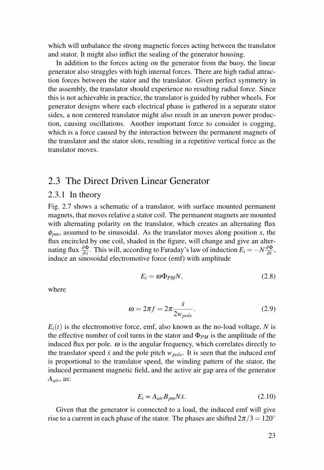
2.3 The Direct Driven Linear Generator2.3.1 In theoryFig. 2.7 shows a schematic of a translator, with surface mounted permanentmagnets, that moves relative a stator coil. The permanent magnets are mountedwith alternating polarity on the translator, which creates an alternating fluxφpm, assumed to be sinusoidal. As the translator moves along position x, theflux encircled by one coil, shaded in the figure, will change and give an alter-nating flux ∂Φ
∂x . This will, according to Faraday’s law of induction Ei =−N ∂Φ∂ t ,
induce an sinosoidal electromotive force (emf) with amplitude
Ei = ωΦPMN, (2.8)
where
ω = 2π f = 2πx
2wpole. (2.9)
Ei(t) is the electromotive force, emf, also known as the no-load voltage, N isthe effective number of coil turns in the stator and ΦPM is the amplitude of theinduced flux per pole. ω is the angular frequency, which correlates directly tothe translator speed x and the pole pitch wpole. It is seen that the induced emfis proportional to the translator speed, the winding pattern of the stator, theinduced permanent magnetic field, and the active air gap area of the generatorAair, as:
Ei ∝ AairBpmNx. (2.10)
Given that the generator is connected to a load, the induced emf will giverise to a current in each phase of the stator. The phases are shifted 2π/3= 120◦
23
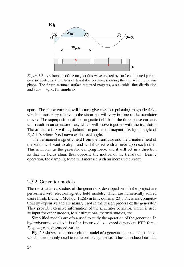
Figure 2.7. A schematic of the magnet flux wave created by surface mounted perma-nent magnets, as a function of translator position, showing the coil winding of onephase. The figure assumes surface mounted magnets, a sinusoidal flux distributionand wcoil = wpole, for simplicity.
apart. The phase currents will in turn give rise to a pulsating magnetic field,which is stationary relative to the stator but will vary in time as the translatormoves. The superposition of the magnetic field from the three phase currentswill result in an armature flux, which will move together with the translator.The armature flux will lag behind the permanent magnet flux by an angle ofπ/2+δ , where δ is known as the load angle.
The permanent magnetic field from the translator and the armature field ofthe stator will want to align, and will thus act with a force upon each other.This is known as the generator damping force, and it will act in a directionso that the fields align, thus opposite the motion of the translator. Duringoperation, the damping force will increase with an increased current.
2.3.2 Generator modelsThe most detailed studies of the generators developed within the project areperformed with electromagnetic field models, which are numerically solvedusing Finite Element Method (FEM) in time domain [23]. These are computa-tionally expensive and are mainly used in the design process of the generator.They provide extensive information of the generator behavior, which is usedas input for other models, loss estimations, thermal studies, etc.
Simplified models are often used to study the operation of the generator. Inhydrodynamic studies it is often linearized as a speed dependent PTO force,FPTO = γ x, as discussed earlier.
Fig. 2.8 shows a one-phase circuit model of a generator connected to a load,which is commonly used to represent the generator. It has an induced no-load
24
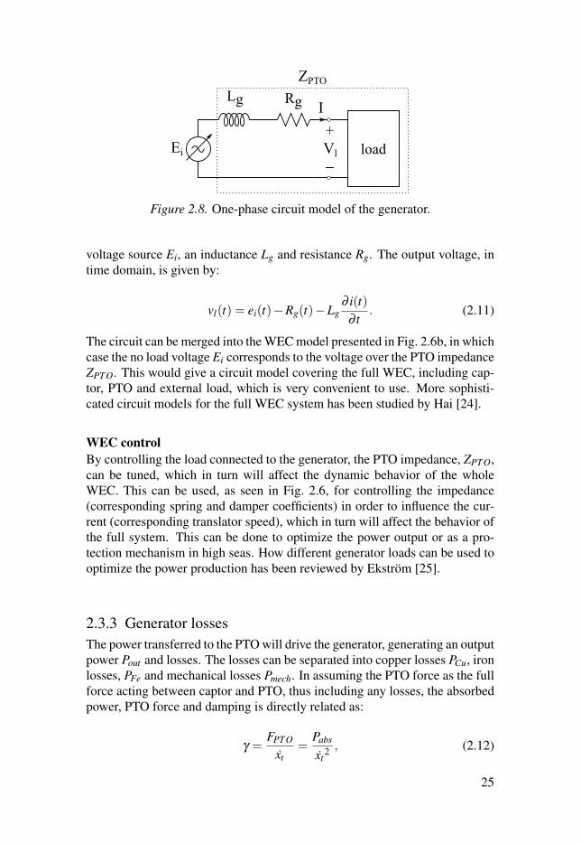
Figure 2.8. One-phase circuit model of the generator.
voltage source Ei, an inductance Lg and resistance Rg. The output voltage, intime domain, is given by:
vl(t) = ei(t)−Rg(t)−Lg∂ i(t)
∂ t. (2.11)
The circuit can be merged into the WEC model presented in Fig. 2.6b, in whichcase the no load voltage Ei corresponds to the voltage over the PTO impedanceZPTO. This would give a circuit model covering the full WEC, including cap-tor, PTO and external load, which is very convenient to use. More sophisti-cated circuit models for the full WEC system has been studied by Hai [24].
WEC control
By controlling the load connected to the generator, the PTO impedance, ZPTO,can be tuned, which in turn will affect the dynamic behavior of the wholeWEC. This can be used, as seen in Fig. 2.6, for controlling the impedance(corresponding spring and damper coefficients) in order to influence the cur-rent (corresponding translator speed), which in turn will affect the behavior ofthe full system. This can be done to optimize the power output or as a pro-tection mechanism in high seas. How different generator loads can be used tooptimize the power production has been reviewed by Ekström [25].
2.3.3 Generator lossesThe power transferred to the PTO will drive the generator, generating an outputpower Pout and losses. The losses can be separated into copper losses PCu, ironlosses, PFe and mechanical losses Pmech. In assuming the PTO force as the fullforce acting between captor and PTO, thus including any losses, the absorbedpower, PTO force and damping is directly related as:
γ =FPTO
xt=
Pabs
xt2 , (2.12)
25

where Pabs is the mechanical power transferred between captor and PTO, in-cluding both power output and losses:
Pabs = Pout +PCu +PFe +Pmech. (2.13)
The power output of the generator is a function of the induced voltage Ei,which is speed dependent, the internal impedance of the generator and theconnected load. The power output, delivered to the load, can be measured intime domain as:
pout(t) =3
∑n=1
vl,i(t)ii(t), (2.14)
where vl(t) and i(t) are the terminal voltage and current delivered to the load,in phase n. The phases are shifted 120◦ apart and if assuming a balancedload and perfect geometric symmetry between stator and translator, the poweroutput, and consequently also generator damping force, will be constant for aconstant speed.
The copper losses due to heat in the windings of the stator, thus copperlosses, are measured as:
PCu =3
∑n=1
Rg,iii(t)2, (2.15)
where Rg,i is the resistance in each phase.Iron losses are associated with the varying magnetic fields in the stator and
the yoke of the translator, independent of the power generated. The losses canbe separated into three parts with different frequency dependencies; hysteresis,eddy currents, and excess losses:
PFe = khB2max f + ked(Bmax f )2 + kexc(Bmax f )3/2, (2.16)
where kh, ked and kexc constants dependent on material and geometry Bmaxis the amplitude of the varying magnetic flux density, and f is the frequencyof the varying flux, which is equal to the electrical frequency and thus alsoproportional to the translator speed. It should be noted that iron losses are notincluded in the model presented in 2.6, and are often neglected due to the lowfrequencies considered for the WEC, which are in the order of 0–10 Hz.
Mechanical losses, friction, is found in all moving parts of the PTO. Forthe studied WEC concept, highest mechanical losses are expected from theguiding of the translator and the sealing of the generator housing. The fric-tion losses from the guiding rubber wheels depend on the pressure they aremounted with, the geometric design of the wheels and the visco-elastic behav-ior of the coating material. It will also vary along the stroke, depending onthe number of wheels rolling. There will also be mechanical losses from thesealing between piston and seal housing. This friction is expected to depend
26

Figure 2.9. A schematic of stator and translator with (a) surface mounted magnets, asused for the L10 WEC, and (b) sandwich mounted magnets, as used for the L12 WEC.Red arrow mark out magnet polarity.
on both the dimensions of the seal system, the viscosity of the lubricant andthe speed and force of the translator [34].
2.3.4 The differences between the L10 an L12 WECThe experimental work presented in this thesis is from the L10 WEC and theL12 WEC, which belong to the second and third generation of WEC develop-ment at Uppsala University. The most important difference between the twoconcepts is the translator design, illustrated in Fig 2.9. The L10 generator,and all WEC models before it, is built with surface mounted NdFeB magnets,as illustrated in 2.9a, while the L12 is built with ferrite magnets mounted in asandwich structure, as depicted in 2.9b. The NdFeB magnets are oriented radi-ally, while the ferrite magnets are oriented vertically. By driving the magneticfield out through steel pole-shoes and into the stator, the sandwich construc-tion will concentrate the magnetic field. By using this design, a higher amountof ferrite magnets, which are cheaper and free of rare-earth metals, can beused to compensate for their lower remanence. Further description of the twotranslator concepts can be found in [26].
The ferrite translator has a shorter pole-width than the NdFeB type, increas-ing the electric frequency for a given translator speed. The transition betweenthe two generator designs is accounted for mainly in [27]. The major drive fordeveloping the ferrite-based generators was to reduce the cost. Although theNeFeB generator has been deemed superior in comparisons, the ferrite designcan still be competitive, when considering the low availability and unstableprice development for NdFeB [28].
The NdFeB generator is a non-salient machine, whereas the ferrite gen-erator is a salient-pole machine. Saliency is a measure of the difference inreluctance, and thus inductance, between stator and translator along the stroke
27

of the translator. Studies of this has not been published for this WEC applica-tion, but a comparisons between the two generator types has been made for awind power application by Eriksson [29].
Another important difference between the two generators is that the L12generator keeps the three phases in separate stator packages, while the L10 hasthe phases mixed. Separating the phases is practical from a production pointof view, since it is easier to wind and to mount the stator packages into thegenerator hull. It does, however, increase the risks of getting uneven electricaloutput from the generator if the translator is not perfectly centered.
2.4 Measurement Systems2.4.1 IntroductionDifferent types of measurements and tests are necessary to validate and under-stand the function and behavior of both subsystems and the full WEC. Thereare few standards and best-practices established in the field of wave powertesting, which is understandable when considering the high diversity in con-cept technologies. Most often measurements are made of wave climate at siteand the power transfer in different power conversion steps between mechani-cal force to electricity [30]. Beyond this, numerous measurements for modelvalidation, operation status, conditioning monitoring, etc, are needed to testand validate the different subsystems used [31]. Although several sea trialshave been reported, few choose to share much details of the measurementsetup [32]. From the experiences gathered, it could be concluded that the seaenvironment has proven a challenging environment for most developers.
This section reviews the experimental work done to test the Uppsala Uni-versity WEC concept.
2.4.2 The Lysekil Research SitePoint absorbing WEC system are hydrodynamically limited in size and power,making it important to keep each unit simple, robust and cost efficient. Theyare preferably placed together in farms with a substation where the outputfrom several WECs is gathered before transmitted on-shore. Having the gen-erators placed on the ocean bed will, besides keeping them sheltered from therough sea surface environment, limit the access for maintenance. This, again,stresses the need for a simple and robust design for each unit.
Fig. 2.10 shows the schematic of the research site outside the west coast ofSweden. It is placed 2 km off the Swedish west coast, where it faces mostlywesterly winds and waves. It was partly chosen due to the stable seabed andthe low depth, around 25 m, which allows for easier diving access. The sitehas a wave measuring buoy, a Waverider, to monitor the sea state. The aver-age wave climate at the Lysekil research site, based on a eight year study of
28
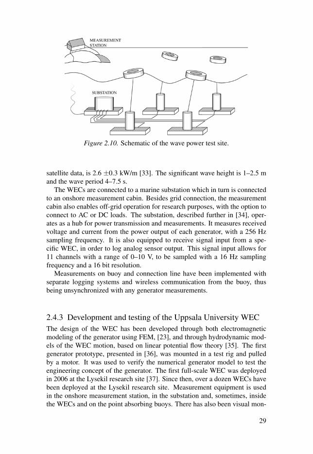
Figure 2.10. Schematic of the wave power test site.
satellite data, is 2.6 ±0.3 kW/m [33]. The significant wave height is 1–2.5 mand the wave period 4–7.5 s.
The WECs are connected to a marine substation which in turn is connectedto an onshore measurement cabin. Besides grid connection, the measurementcabin also enables off-grid operation for research purposes, with the option toconnect to AC or DC loads. The substation, described further in [34], oper-ates as a hub for power transmission and measurements. It measures receivedvoltage and current from the power output of each generator, with a 256 Hzsampling frequency. It is also equipped to receive signal input from a spe-cific WEC, in order to log analog sensor output. This signal input allows for11 channels with a range of 0–10 V, to be sampled with a 16 Hz samplingfrequency and a 16 bit resolution.
Measurements on buoy and connection line have been implemented withseparate logging systems and wireless communication from the buoy, thusbeing unsynchronized with any generator measurements.
2.4.3 Development and testing of the Uppsala University WECThe design of the WEC has been developed through both electromagneticmodeling of the generator using FEM, [23], and through hydrodynamic mod-els of the WEC motion, based on linear potential flow theory [35]. The firstgenerator prototype, presented in [36], was mounted in a test rig and pulledby a motor. It was used to verify the numerical generator model to test theengineering concept of the generator. The first full-scale WEC was deployedin 2006 at the Lysekil research site [37]. Since then, over a dozen WECs havebeen deployed at the Lysekil research site. Measurement equipment is usedin the onshore measurement station, in the substation and, sometimes, insidethe WECs and on the point absorbing buoys. There has also been visual mon-
29

itoring of the WEC buoys from an observation tower placed on an islet closeto the site [38]. Further description of previous measurement systems imple-mented within this research project is found in [39,40] for the first and secondsubstations, and in [41–46] for the WECs.
WEC measurement systems have been built for the WECs L2, L3, L10 andL12, while the other WECs were only studied from the output power mea-sured in the substation or in the onshore measurement cabin. The measure-ment system for the L10 and L12 will be described in this thesis, while themeasurement system for L2 and L3 has been described by Svensson [44].
Thanks to the relatively low complexity and cost of a single WEC unit, andthe access to an offshore site protected from the most extreme wave climatesand with a relatively low water depth, full scale development has been favored.Due to the high costs and high risks involved, many other developers adopta development scheme including scale tests to verify the concept in steps.This include experiments in dry test rigs and in wave basins. Besides thetest rig experiments of the first generator prototype, some wave basin testshave been made for model verification of array operation, but then with afriction PTO [47]. The majority of the research has been performed on full-scale prototypes deployed at the Lysekil research site.
30

3. Topic I: Offshore measurement systems
The development of new and improved measurement systems has been a con-tinuous process during the thesis work. This section will present objectives,implementation, results and discussion of the measurements system developedfor offshore operation.
3.1 IntroductionOffshore operation is the ultimate test of a WEC’s performance and surviv-ability, which makes relevant, accurate and reliable measurements crucial. Itis needed to verify the power transferred in each power conversion step, gatherdata for model validation and to identify causes or risks of failure and fatigue.
The measurement systems developed are named after the WECs that theywere designed for. This thesis will cover the measurement systems built forthe L10 and L12 WEC. It should be noted that more than one prototype of theL12 (both WEC and sensor system) has been built, while there was only oneL10.
The author entered the L10 project in the stage of assembly, installation andtesting, and has mainly focused on the force measurements, which is reflectedin the account of the L10 measurement system.
When designing the L12 measurement system, there was a desire to re-design a number of aspects, partly due to lessons learned from shortcomingsof the L10 measurement system and partly due to changes in the availableinfrastructure at the Lysekil test site. It was decided to develop a more inde-pendent and flexible measurement system that could operate independently ofsite infrastructure. To do this, the data acquisition, data storage and powersupply would need to be included in the measurement system, unlike for theL10 measurement system where the substation provided those tasks, as shownin Fig. 3.1.
An additional vision with the L12 measurement system was to connect thebuoy and generator measurements, so that the measurement data from bothgenerator and buoy could be logged together and sent onshore via the WECbuoy. Since this part of the project was never realized, it is presented in FutureWorks. The L12 section will instead focus only on the generator measurementsystem.
31
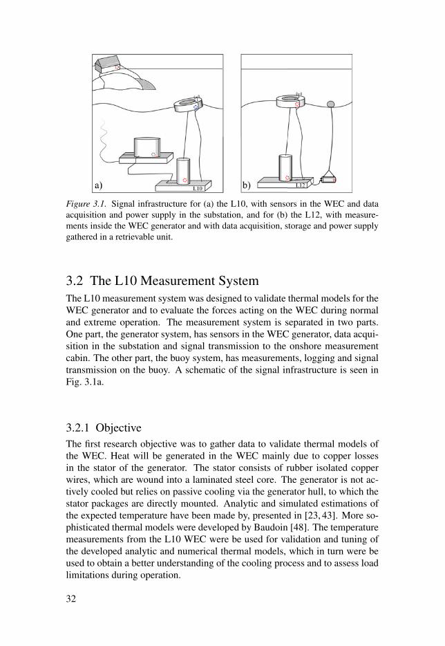
Figure 3.1. Signal infrastructure for (a) the L10, with sensors in the WEC and dataacquisition and power supply in the substation, and for (b) the L12, with measure-ments inside the WEC generator and with data acquisition, storage and power supplygathered in a retrievable unit.
3.2 The L10 Measurement SystemThe L10 measurement system was designed to validate thermal models for theWEC generator and to evaluate the forces acting on the WEC during normaland extreme operation. The measurement system is separated in two parts.One part, the generator system, has sensors in the WEC generator, data acqui-sition in the substation and signal transmission to the onshore measurementcabin. The other part, the buoy system, has measurements, logging and signaltransmission on the buoy. A schematic of the signal infrastructure is seen inFig. 3.1a.
3.2.1 ObjectiveThe first research objective was to gather data to validate thermal models ofthe WEC. Heat will be generated in the WEC mainly due to copper lossesin the stator of the generator. The stator consists of rubber isolated copperwires, which are wound into a laminated steel core. The generator is not ac-tively cooled but relies on passive cooling via the generator hull, to which thestator packages are directly mounted. Analytic and simulated estimations ofthe expected temperature have been made by, presented in [23, 43]. More so-phisticated thermal models were developed by Baudoin [48]. The temperaturemeasurements from the L10 WEC were be used for validation and tuning ofthe developed analytic and numerical thermal models, which in turn were beused to obtain a better understanding of the cooling process and to assess loadlimitations during operation.
32
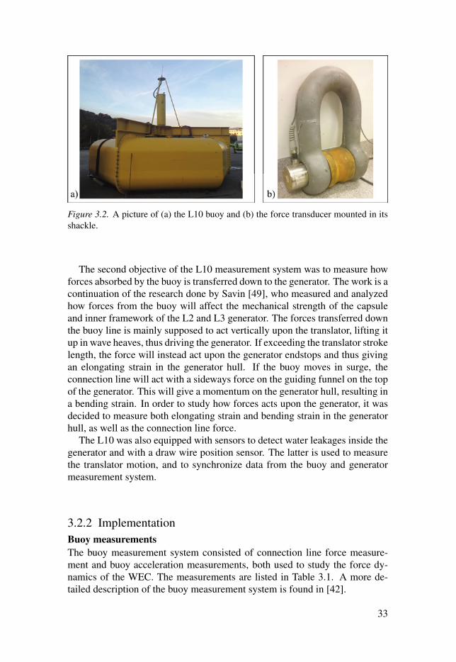
Figure 3.2. A picture of (a) the L10 buoy and (b) the force transducer mounted in itsshackle.
The second objective of the L10 measurement system was to measure howforces absorbed by the buoy is transferred down to the generator. The work is acontinuation of the research done by Savin [49], who measured and analyzedhow forces from the buoy will affect the mechanical strength of the capsuleand inner framework of the L2 and L3 generator. The forces transferred downthe buoy line is mainly supposed to act vertically upon the translator, lifting itup in wave heaves, thus driving the generator. If exceeding the translator strokelength, the force will instead act upon the generator endstops and thus givingan elongating strain in the generator hull. If the buoy moves in surge, theconnection line will act with a sideways force on the guiding funnel on the topof the generator. This will give a momentum on the generator hull, resulting ina bending strain. In order to study how forces acts upon the generator, it wasdecided to measure both elongating strain and bending strain in the generatorhull, as well as the connection line force.
The L10 was also equipped with sensors to detect water leakages inside thegenerator and with a draw wire position sensor. The latter is used to measurethe translator motion, and to synchronize data from the buoy and generatormeasurement system.
3.2.2 ImplementationBuoy measurements
The buoy measurement system consisted of connection line force measure-ment and buoy acceleration measurements, both used to study the force dy-namics of the WEC. The measurements are listed in Table 3.1. A more de-tailed description of the buoy measurement system is found in [42].
33
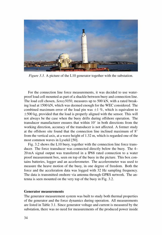
Figure 3.3. A picture of the L10 generator together with the substation.
For the connection line force measurements, it was decided to use water-proof load cell mounted as part of a shackle between buoy and connection line.The load cell chosen, Sensy5050, measures up to 500 kN, with a rated break-ing load at 1500 kN, which was deemed enough for the WEC considered. Thecombined maximum error of the load pin was ±1 %, which is equivalent to±500 kg, provided that the load is properly aligned with the sensor. This willnot always be the case when the buoy drifts during offshore operation. Thetransducer manufacturer ensures that within 10◦ in both directions from theworking direction, accuracy of the transducer is not affected. A former studyat the offshore site found that the connection line inclined maximum of 8◦from the vertical axis, at a wave height of 1.32 m, which is regarded one of themost common waves in Lysekil [50].
Fig. 3.2 shows the L10 buoy, together with the connection line force trans-ducer. The force transducer was connected directly below the buoy. The 4–20 mA signal output was transferred in a IP68 rated connection to a waterproof measurement box, seen on top of the buoy in the picture. This box con-tains batteries, logger and an accelerometer. The accelerometer was used tomeasure the heave motion of the buoy, in one degree of freedom. Both theforce and the acceleration data was logged with 32 Hz sampling frequency.The data is transmitted onshore via antenna through GPRS network. The an-tenna is seen mounted on the very top of the buoy in Fig. 3.2.
Generator measurements
The generator measurement system was built to study both thermal propertiesof the generator and the force dynamics during operation. All measurementsare listed in Table 3.1. Since generator voltage and current is measured by thesubstation, there was no need for measurements of the produced power inside
34
the generator. Fig. 3.3 shows a picture of the L10 generator together with thesubstation, before deployment 2015.
For the thermal studies, measurements were made of temperature and cur-rent produced in the stator. Hall effect current transducers with a range of±1000 A were used to measure current. Although the range is high abovethe normal operation range of the generator, it was chosen to test the genera-tor during extra-ordinary operation conditions. To test the operation limits ofthe generator, it was equipped with a short circuiting box, which could short-circuit the stator. Six temperature sensors were used: four were placed on andinside the stator, one was used to measure the air temperature and one wasplaced to measure the temperature on the generator hull. Because of the rel-atively slow temperature changes, there was no need to log the temperaturesensors with a frequency higher than 1 Hz. By using time multiplexing the6 temperature signals were gathered sent via the same signal to the substa-tion. This way, only one conductor pair was needed between the WEC andthe substation for the temperature measurements, leaving room for other mea-surements.
For the force studies, the strain exerted on the generator hull was measuredwith resistive strain gauges. Strain gauge bridges were used to measure bothtensile strain from vertical forces acting on the generator hull, and bendingstrain from horizontal forces acting on the generator hull. The measurementrange cover axial forces up to 400 kN and radial forces up to 98.1 kN. In orderto get better resolution for the average forces a second setup for bending strainwas added, covering axial forces up to 9.81 kN. To get the combined forces incylindrical coordinates, two bending strain gauge circuits were used, mounted90◦ apart, as shown in Fig. 3.4a. This way the direction of the buoy line forcecan be determined as well as the bending moment exerted on the generatorhull in different directions.
Fig. 3.4b shows the strain gauge bridge setup used to measure tensile strainin the generator hull; for bending strain the active strain gauges, RActive
SG areplaced on adjacent legs instead of opposite legs. The bridge configuration alsoadds temperature compensation, by adding dummy strain gauges, RDummy
SG . Thedummy strain gauges will, when glued to an unstrained piece of metal, expe-riences the same temperature and thermal strain as the active strain gauge,which can then be canceled out by the bridge configuration. The bridge setupalso has a bridge calibration feature; by connecting a fixed resistor and a po-tentiometer, R f ix and Rpot , to two adjacent sides of the bridge, adjustments canbe made to the resistance on both sides, in order to balance the bridge. A listcontaining different strain gauge bridge circuits is found in [51].
The strain gauges were calibrated together with the force transducer duringonshore tests. By pulling the connection line via the force transducer with aninclination angle in different directions, as indicated in Fig. 3.4, a combinationof both vertical and horizontal force were exerted on the generator, which
35
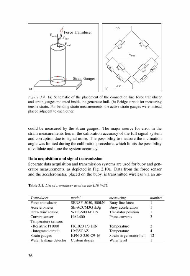
Figure 3.4. (a) Schematic of the placement of the connection line force transducerand strain gauges mounted inside the generator hull. (b) Bridge circuit for measuringtensile strain. For bending strain measurements, the active strain gauges were insteadplaced adjacent to each other.
could be measured by the strain gauges. The major source for error in thestrain measurements lies in the calibration accuracy of the full signal systemand corruption due to signal noise. The possibility to measure the inclinationangle was limited during the calibration procedure, which limits the possibilityto validate and tune the system accuracy.
Data acquisition and signal transmission
Separate data acquisition and transmission systems are used for buoy and gen-erator measurements, as depicted in Fig. 2.10a. Data from the force sensorand the accelerometer, placed on the buoy, is transmitted wireless via an an-
Table 3.1. List of transducer used on the L10 WEC
Transducer model measuring numberForce transducer SENSY 5050, 500kN Buoy line force 1Accelerometer SE-ACCM3G ±3g Buoy acceleration 1Draw wire sensor WDS-5000-P115 Translator position 1Current sensor HAL400 Phase currents 3Temperature sensors- Resistive Pt1000 FK1020 1/3 DIN Temperature 2- Integrated circuit LM35CAZ Temperature 4Strain gauges KFN-5-350-C9-16 Strain in generator hull 12Water leakage detector Custom design Water level 1
36
tenna. The generator measurements are sent analogously to a substation fordata acquisition and then onshore via a signal cable. To time synchronize thetwo data sets, accelerometer data from the buoy is matched with translatorposition data from the generator. Besides the added complexity with doubleinstrumentation setup, the post-synchronization of data sets requires manualdata processing and adds a source of error to the analysis. Still, it could not beavoided since there is no reliable way of transmitting data from the generator,placed on the sea-floor, and the buoy, floating on the surface.
The generator measurement system is dependent on the substation, whichoffers both data sampling and power supply. The substation also performsvoltage and current measurements on the output of each generator. Beforeleaving the WEC, the signals are amplified to±10 V. Once transferred via sub-sea contacts to the substation, the signals are logged with 16 bit resolution anda 16 Hz sampling frequency, using a CompactRio for data acquisition. Weakor noise-sensitive signals, such as strain measurements, are pre-amplified di-rectly adjacent to the measurements in order to increase the signal to noise-ratio. The substation provides the WEC measurement system with a supplyDC voltage of 24 V and logs the measurement output signals. It can receiveand log eleven differential analogue sensor signals, which limits the numberof measurements possible in the WEC.
3.2.3 Results and evaluationThe L10 was never deployed and the generator measurement system was neverput to use. The buoy was used together with another generator in the summerof 2015, but there were problems with the communication system. Before thiscould be resolved, the buoy broke during a storm. Consequently, there is littleresults to present from the L10 measurement system. Although never put touse, some important lessons were learned from the project, which were laterused to develop the L12 measurement system:
Signal noise: Using voltage signals to carry the analogue signals from WECto substation proved to be unacceptably noisy.
Data set synchronization: The time synchronization of gathered data fromseparate measurement systems (buoy and generator) would prove un-gainly and imprecise, which was also concluded by Svensson et. al [39].A connected system or better time-stamping would be required. Thishas been further studied in [52].
Strain calibrations: The strain gauges needed extensive calibration, whichcould only be performed after the final assembly of the WEC genera-tor. This was impractical is two ways. Firstly, there is no possibilityfor changes or tuning to the measurement system once the generator isassembled. Secondly, the calibration technique proved imprecise. It was
37

complicated to measure the inclination angle, which determines verti-cal and horizontal component of the line force, and the azimuth angle,which determines the radial direction of the force. It is the author’s beliefthat analysis based on line force measurements from the buoy measure-ment system, and strain measurements from the generator measurementsystem, would be hard to interpret.
Hull model Since the stator packages were mounted to the generator hull, theassumption that the generator hull can be modeled as a steel cylinder, aswas done in [50], does not hold. Instead, the experimental results need tobe analyzed and interpreted by using more sophisticated stress analysismodels of the specific WEC design.
System vulnerability: There are risks with having the measurements depen-dent on many different system units (generator, buoy, substation, signalcable, measurement cabin). A simpler, redundant and more flexible sys-tem would be preferable.
38

3.3 The L12 Measurement SystemWhile the L10 measurement system was built to operate as a part of the siteinfrastructure, utilizing power supply and logging from the substation, the L12measurement system was to operate as a stand-alone system. It was built intwo parts: one part with sensors inside the generator, and another part withdata acquisition, data storage and power supply in a retrievable unit outsidethe generator, as seen in Fig. 3.1b.
In addition to the overall change in signal infrastructure, some other impor-tant changes were made in the L12 measurement system, based on the lessonslearned from previous measurement systems. It was decided to change the sig-nal carrier between sensor system and logger, from 0–10 V voltage signals to4–20 mA current signals, mainly to improve the Signal-to-Noise Ratio (SNR).The signal quality could probably be improved further if the data acquisitionwas placed inside the WEC, closer to the measurements, and implementingdigital communication. Due to the limited generator accessibility, and to keepthe system compatible with the substation data acquisition system, it was de-cided to stick with analogue signal transfer from the WEC and to place as fewcomponents as possible inside the WEC.
3.3.1 ObjectiveThe overall goal with building this measurement system was to evaluate how,and for how long, measurements can be achieved with a small, flexible andbattery driven system dedicated to offshore measurements at low depth. Also,how should it be operated to achieve maximum operation time, depending onnumber of measurements, logging schedule and settings?
There are off-the-shelf products that meet the specification stated for thismeasurement system, regarding accuracy, speed and robustness. There arealso more sophisticated field-programmable gate array (FPGA)-based indus-trial control systems that offer a wide flexibility for both measurements anddata acquisition and control [53]. However, using such systems would requirea combination of modules that together offer functionality, cost and powerconsumption far beyond what is actually needed for this application. In or-der to build a distributed measurement system that simultaneously monitorsparameters in several generators and buoys during long term operation, thecost, complexity and power consumption of each measurement unit must beminimized.
Overall priorities
The overall priorities for the design of both sensor system and data acquisitionunit was robustness, low power consumption and flexibility.
Robustness is essential due to the low accessibility during offshore oper-ation. After final assembly, the sensor system installed in the generator will
39
never be accessed again. Since the data acquisition unit is retrievable, im-provements can be made between measurement ventures, but any critical faultsrisk costing weeks of offshore data. For the sensor system, robustness also in-cludes that it under no circumstances may compromise or affect the operationof the generator. This makes proper isolation between measurement objectand measurement electronics important.
A low power consumption, in both sensor system and data acquisition unit,is the first and foremost mean of maximizing the operation time of the fullsystem during battery operation.
Flexibility is partly connected to the independence of site infrastructure, andsuggests that the measurement system can be used at different sites for differ-ent measurement tasks and that it can be handled and put to use with simplemeans. It should have the capacity to operate and store data continuously forat least a few weeks without external power supply or data transfer.
The data acquisition unit
The technical objective for the data acquisition system was to sample and store16 bit data from 16 individual channels with a sampling frequency of 1 kHzfor multiple weeks. To further increase the operation time, the data acquisitionsystem should be programmable so that it can control the logging according topredefined logging patterns. The data acquisition system was to be placed in aretrievable unit, which can be connected and deployed next to the WEC gen-erator without any diving work or hoisting equipment. This puts restrictionson the size and weight of the unit. Besides an overall low power consumption,the battery operation also requires a wide voltage supply range.
The sensor system
Two version of the L12 sensor system was built and installed in two differentL12 generators. For both, the objective was voltage and current measurementsin each phase, together with translator position measurements. Later on, alarger number of measurements can be added to the system, such as structuralforces, thermal properties, air gap measurements, etc., all in order to study thegenerator operation in better detail.
The sensor system consists on transducers that reads a physical signal andsignal conditioning circuits, implemented on printed circuit boards (PCBs),that transfers the measurement to a current signal which is sent to the logger.The measurement ranges for voltage and current transducers were decidedfrom generator specification and from the wave climate at the offshore testsite. To ensure minimum damping and phase shift within the 1 kHz bandwidthof the full system, the cut-off frequency was set to around 10 kHz for the PCBsdeveloped. The data will later be post-processed with digital filters to removehigh-frequency noise. A bandwidth of 1 kHz is well beyond the need for themeasurements implemented in this initial version, since the expected electricalfrequency will be in the 0–10 Hz region. It is still implemented in order to
40
enable more dynamic measurements in future versions of the measurementsystem.
A 4–20 mA signal carrier with a 12 mA zero offset was chosen for trans-mission between measurement system and logger. 4–20 mA signals are con-sidered the industrial standard, favored for being simple, noise-proof and goodfor long distance communication.
3.3.2 ImplementationThe data acquisition unit
As seen in Fig. 3.1b, the sensor signals will be sent from the generator to a re-trievable data acquisition unit, which also hold the batteries that supply the fullsystem. The pressure vessel, seen in Fig. 3.5a, was chosen with considerationto battery choice, depth rating and deployment procedure. It was equippedwith two 16-pin subsea signal cables. The battery chosen, normally used forbuoy lantern applications, is of alkaline type and supplies 220 Ah at 15 V. To-gether, the pressure vessel and battery weighs around 40 kg in air and -7 kgin water, thus requiring extra weights to stay anchored to the sea floor. Dueto the relatively low weight and small size of the unit, commissioning and de-commissioning can be done from a small boat, without any divers or hoistingequipment, as suggested in Fig. 3.5b.
The logger reads the analogue signals received from the sensor systemplaced inside the WEC, transfers them to digital data and stores this data onsecure digital (SD) cards. Three separate SD cards were used since the SDwriting protocol does not enable 1 kHz logging of small data quantities to asingle card. Each millisecond the logger samples and stores 16 readings á 16bit, stored distributed on three 32 GB micro SD cards. The sampling frequencyand the data resolution can be set (to any lower value) in the logger software.The logger can also be programmed to run in predefined intervals, for exam-ple ten minutes every hour or half an hour per day, which would correspond toduty cycles of 25 % and 2 % respectively. Connected in between the batteryand the sensor system, the logger also has functionality to apply the prede-fined logging schedule to control the voltage supply to the sensor system, thussaving power when not logging. The Analog-to-Digital Converters (ADCs)read each channel successively, with at sample delay of 12 μs between adja-cent channels, which means that the time delay between the first and the lastreading is 180 μs. The logger is clocked by a 16 MHz crystal oscillator witha frequency tolerance of 10 ppm (± 160 Hz).
The L12 sensor system
Fig. 3.6 and 3.8 show schematics of the first and the second L12 sensor sys-tems, together with the circuit layout for the signal conditioning PCB’s used.Fig. 3.7 and 3.9 show pictures of the corresponding measurement systems.
41
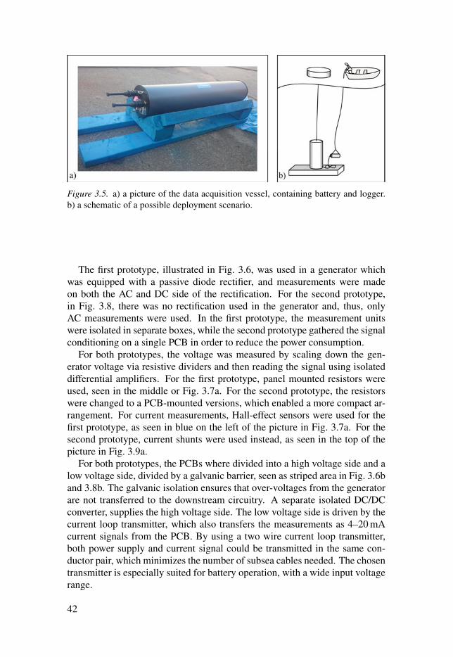
Figure 3.5. a) a picture of the data acquisition vessel, containing battery and logger.b) a schematic of a possible deployment scenario.
The first prototype, illustrated in Fig. 3.6, was used in a generator whichwas equipped with a passive diode rectifier, and measurements were madeon both the AC and DC side of the rectification. For the second prototype,in Fig. 3.8, there was no rectification used in the generator and, thus, onlyAC measurements were used. In the first prototype, the measurement unitswere isolated in separate boxes, while the second prototype gathered the signalconditioning on a single PCB in order to reduce the power consumption.
For both prototypes, the voltage was measured by scaling down the gen-erator voltage via resistive dividers and then reading the signal using isolateddifferential amplifiers. For the first prototype, panel mounted resistors wereused, seen in the middle or Fig. 3.7a. For the second prototype, the resistorswere changed to a PCB-mounted versions, which enabled a more compact ar-rangement. For current measurements, Hall-effect sensors were used for thefirst prototype, as seen in blue on the left of the picture in Fig. 3.7a. For thesecond prototype, current shunts were used instead, as seen in the top of thepicture in Fig. 3.9a.
For both prototypes, the PCBs where divided into a high voltage side and alow voltage side, divided by a galvanic barrier, seen as striped area in Fig. 3.6band 3.8b. The galvanic isolation ensures that over-voltages from the generatorare not transferred to the downstream circuitry. A separate isolated DC/DCconverter, supplies the high voltage side. The low voltage side is driven by thecurrent loop transmitter, which also transfers the measurements as 4–20 mAcurrent signals from the PCB. By using a two wire current loop transmitter,both power supply and current signal could be transmitted in the same con-ductor pair, which minimizes the number of subsea cables needed. The chosentransmitter is especially suited for battery operation, with a wide input voltagerange.
42
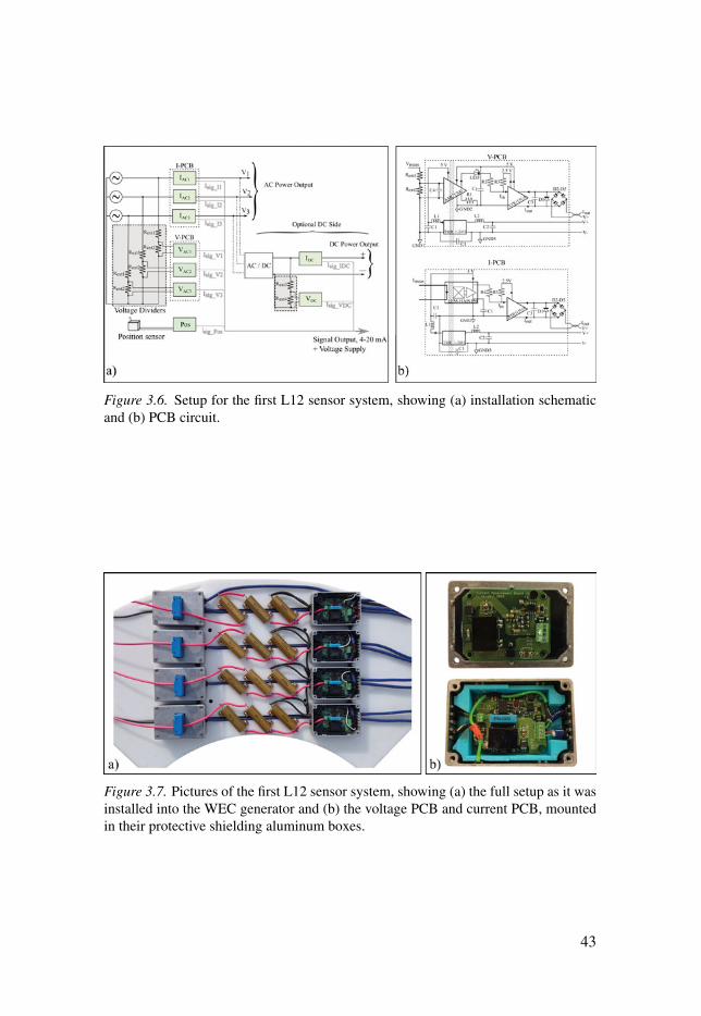
Figure 3.6. Setup for the first L12 sensor system, showing (a) installation schematicand (b) PCB circuit.
Figure 3.7. Pictures of the first L12 sensor system, showing (a) the full setup as it wasinstalled into the WEC generator and (b) the voltage PCB and current PCB, mountedin their protective shielding aluminum boxes.
43
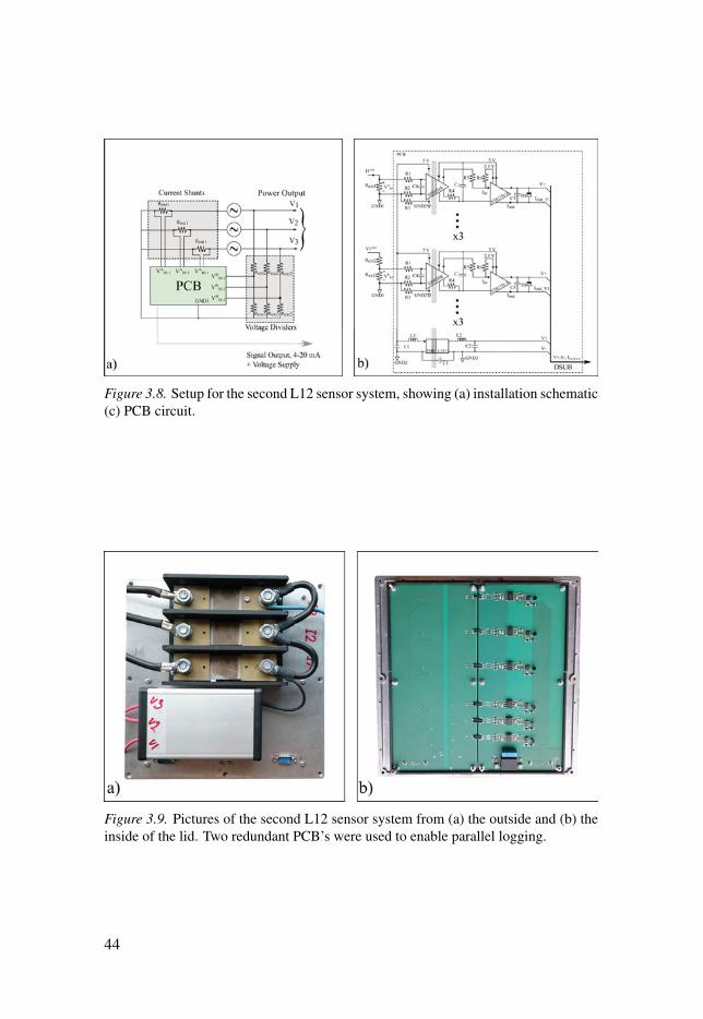
Figure 3.8. Setup for the second L12 sensor system, showing (a) installation schematic(c) PCB circuit.
Figure 3.9. Pictures of the second L12 sensor system from (a) the outside and (b) theinside of the lid. Two redundant PCB’s were used to enable parallel logging.
44
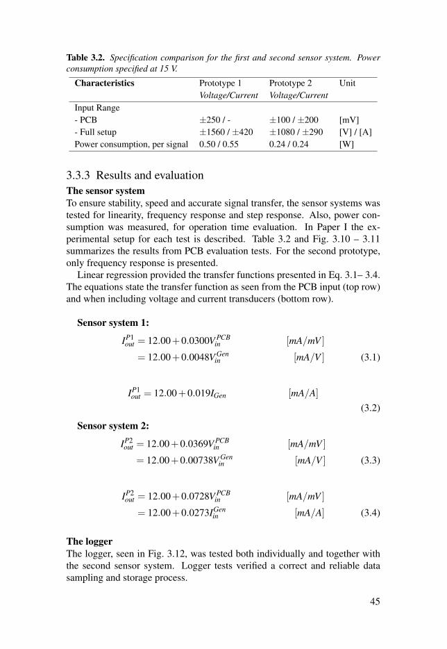
Table 3.2. Specification comparison for the first and second sensor system. Powerconsumption specified at 15 V.
Characteristics Prototype 1 Prototype 2 UnitVoltage/Current Voltage/Current
Input Range- PCB ±250 / - ±100 / ±200 [mV]- Full setup ±1560 / ±420 ±1080 / ±290 [V] / [A]Power consumption, per signal 0.50 / 0.55 0.24 / 0.24 [W]
3.3.3 Results and evaluationThe sensor system
To ensure stability, speed and accurate signal transfer, the sensor systems wastested for linearity, frequency response and step response. Also, power con-sumption was measured, for operation time evaluation. In Paper I the ex-perimental setup for each test is described. Table 3.2 and Fig. 3.10 – 3.11summarizes the results from PCB evaluation tests. For the second prototype,only frequency response is presented.
Linear regression provided the transfer functions presented in Eq. 3.1– 3.4.The equations state the transfer function as seen from the PCB input (top row)and when including voltage and current transducers (bottom row).
Sensor system 1:
IP1out = 12.00+0.0300V PCB
in [mA/mV ]
= 12.00+0.0048V Genin [mA/V ] (3.1)
IP1out = 12.00+0.019IGen [mA/A]
(3.2)
Sensor system 2:
IP2out = 12.00+0.0369V PCB
in [mA/mV ]
= 12.00+0.00738V Genin [mA/V ] (3.3)
IP2out = 12.00+0.0728V PCB
in [mA/mV ]
= 12.00+0.0273IGenin [mA/A] (3.4)
The logger
The logger, seen in Fig. 3.12, was tested both individually and together withthe second sensor system. Logger tests verified a correct and reliable datasampling and storage process.
45
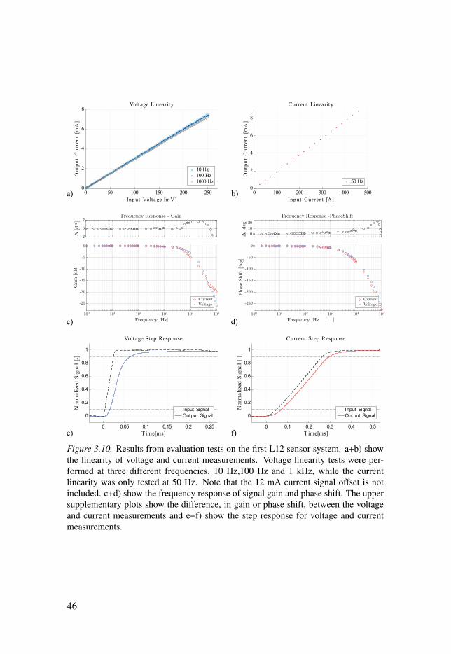
Figure 3.10. Results from evaluation tests on the first L12 sensor system. a+b) showthe linearity of voltage and current measurements. Voltage linearity tests were per-formed at three different frequencies, 10 Hz,100 Hz and 1 kHz, while the currentlinearity was only tested at 50 Hz. Note that the 12 mA current signal offset is notincluded. c+d) show the frequency response of signal gain and phase shift. The uppersupplementary plots show the difference, in gain or phase shift, between the voltageand current measurements and e+f) show the step response for voltage and currentmeasurements.
46
-2
0
2
Δ[dB]
Frequency Response - Gain
100 101 102 103 104 105
Frequency [Hz]
-25
-20
-15
-10
-5
0
Gain
[dB]
CurrentVoltage
0
10
20
Δ[deg]
Frequency Response -PhaseShift
100 101 102 103 104 105
Frequency [Hz ]
-250
-200
-150
-100
-50
0
Phase
Shift[deg]
CurrentVoltage
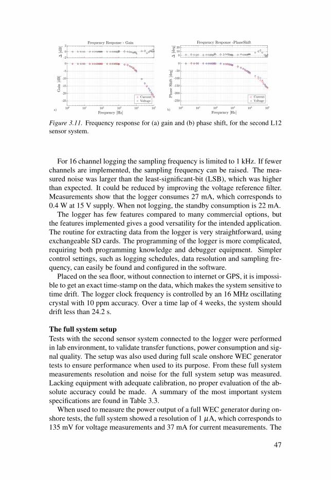
-2
0
2
Δ[dB]
Frequency Response - Gain
100 101 102 103 104 105
Frequency [Hz]
-25
-20
-15
-10
-5
0
Gain
[dB]
CurrentVoltage
a)
01020
Δ[deg]
Frequency Response -PhaseShift
100 101 102 103 104 105
Frequency [Hz]
-250
-200
-150
-100
-50
0
Phase
Shift[deg]
CurrentVoltage
b)
Figure 3.11. Frequency response for (a) gain and (b) phase shift, for the second L12sensor system.
For 16 channel logging the sampling frequency is limited to 1 kHz. If fewerchannels are implemented, the sampling frequency can be raised. The mea-sured noise was larger than the least-significant-bit (LSB), which was higherthan expected. It could be reduced by improving the voltage reference filter.Measurements show that the logger consumes 27 mA, which corresponds to0.4 W at 15 V supply. When not logging, the standby consumption is 22 mA.
The logger has few features compared to many commercial options, butthe features implemented gives a good versatility for the intended application.The routine for extracting data from the logger is very straightforward, usingexchangeable SD cards. The programming of the logger is more complicated,requiring both programming knowledge and debugger equipment. Simplercontrol settings, such as logging schedules, data resolution and sampling fre-quency, can easily be found and configured in the software.
Placed on the sea floor, without connection to internet or GPS, it is impossi-ble to get an exact time-stamp on the data, which makes the system sensitive totime drift. The logger clock frequency is controlled by an 16 MHz oscillatingcrystal with 10 ppm accuracy. Over a time lap of 4 weeks, the system shoulddrift less than 24.2 s.
The full system setup
Tests with the second sensor system connected to the logger were performedin lab environment, to validate transfer functions, power consumption and sig-nal quality. The setup was also used during full scale onshore WEC generatortests to ensure performance when used to its purpose. From these full systemmeasurements resolution and noise for the full system setup was measured.Lacking equipment with adequate calibration, no proper evaluation of the ab-solute accuracy could be made. A summary of the most important systemspecifications are found in Table 3.3.
When used to measure the power output of a full WEC generator during on-shore tests, the full system showed a resolution of 1 μA, which corresponds to135 mV for voltage measurements and 37 mA for current measurements. The
47
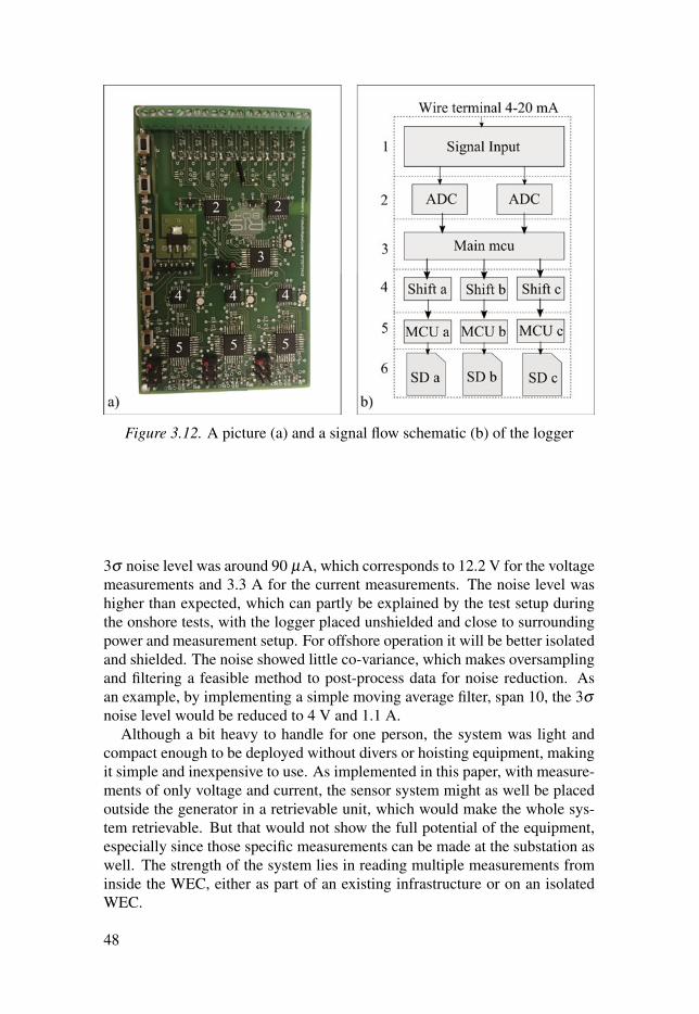
Figure 3.12. A picture (a) and a signal flow schematic (b) of the logger
3σ noise level was around 90 μA, which corresponds to 12.2 V for the voltagemeasurements and 3.3 A for the current measurements. The noise level washigher than expected, which can partly be explained by the test setup duringthe onshore tests, with the logger placed unshielded and close to surroundingpower and measurement setup. For offshore operation it will be better isolatedand shielded. The noise showed little co-variance, which makes oversamplingand filtering a feasible method to post-process data for noise reduction. Asan example, by implementing a simple moving average filter, span 10, the 3σnoise level would be reduced to 4 V and 1.1 A.
Although a bit heavy to handle for one person, the system was light andcompact enough to be deployed without divers or hoisting equipment, makingit simple and inexpensive to use. As implemented in this paper, with measure-ments of only voltage and current, the sensor system might as well be placedoutside the generator in a retrievable unit, which would make the whole sys-tem retrievable. But that would not show the full potential of the equipment,especially since those specific measurements can be made at the substation aswell. The strength of the system lies in reading multiple measurements frominside the WEC, either as part of an existing infrastructure or on an isolatedWEC.
48
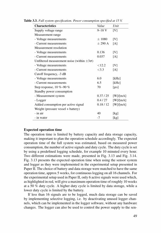
Table 3.3. Full system specification. Power consumption specified at 15 V.
Characteristics Value UnitSupply voltage range 9–18 V [V]Measurement range- Voltage measurements ± 1080 [V]- Current measurements ± 290 A [A]Measurement resolution- Voltage measurements 0.136 [V]- Current measurements 0.037 [A]Unfiltered measurement noise (within ±3σ )- Voltage measurements <12.2 [V]- Current measurements <3.3 [A]Cutoff frequency, -3 dB- Voltage measurements 6.0 [kHz]- Current measurements 6.5 [kHz]Step response, 10 %–90 % 70 [μs]Standby power consumption- Measurement system 0.37 / 25 [W]/[mA]- Logger 0.4 / 27 [W]/[mA]Added consumption per active signal 0.18 / 12 [W]/[mA]Weight (pressure vessel + battery)- in air 40 [kg]- in water -7 [kg]
Expected operation time
The operation time is limited by battery capacity and data storage capacity,making it important to plan the operation schedule accordingly. The expectedoperation time of the full system was estimated, based on measured powerconsumption, the number of active signals and duty cycle. The duty cycle is setby using a predefined logging schedule, for example 10 minuted every hour.Two different estimations were made, presented in Fig. 3.13 and Fig. 3.14.Fig. 3.13 presents the expected operation time when using the sensor systemand logger as they were implemented in the experimental setup presented inPaper II. The choice of battery and data storage were matched to have the sameoperation time, approx 5 weeks, for continuous logging on all 16 channels. Forthe experimental setup used in Paper II, only 6 active signals were used which,as highlighted in red, will give a maximum operation time of roughly 10 weeksat a 50 % duty cycle. A higher duty cycle is limited by data storage, while alower duty cycle is limited by the battery.
If less than 16 signals are to be logged, much data storage can be savedby implementing selective logging, i.e. by deactivating unused logger chan-nels, which can be implemented in the logger software, without any hardwarechanges. The logger can also be used to control the power supply to the sen-
49
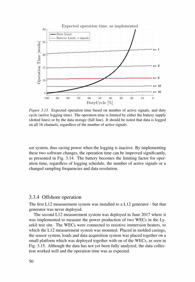
0102030405060708090100
DutyCycle [%]
5
10
15
20
25
30
OperationTim
e[weeks]
Expected operation time, as implemented
s= 1
s= 3
s= 6
s= 10
s= 16
s= 1
s= 3
s= 6
s= 10
s= 16
Data LimitBattery Limit, s signals
Figure 3.13. Expected operation time based on number of active signals, and dutycycle (active logging time). The operation time is limited by either the battery supply(dotted lines) or by the data storage (full line). It should be noted that data is loggedon all 16 channels, regardless of the number of active signals.
sor system, thus saving power when the logging is inactive. By implementingthese two software changes, the operation time can be improved significantly,as presented in Fig. 3.14. The battery becomes the limiting factor for oper-ation time, regardless of logging schedule, the number of active signals or achanged sampling frequencies and data resolution.
3.3.4 Offshore operationThe first L12 measurement system was installed to a L12 generator - but thatgenerator was never deployed.
The second L12 measurement system was deployed in June 2017 where itwas implemented to measure the power production of two WECs in the Ly-sekil test site. The WECs were connected to resistive immersion heaters, towhich the L12 measurement system was mounted. Placed in molded casings,the sensor system, loads and data acquisition system was placed together on asmall platform which was deployed together with on of the WECs, as seen inFig. 3.15. Although the data has not yet been fully analyzed, the data collec-tion worked well and the operation time was as expected.
50
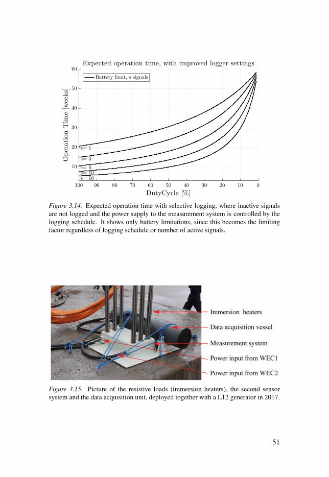
0102030405060708090100
DutyCycle [%]
10
20
30
40
50
60OperationTim
e[weeks]
Expected operation time, with improved logger settings
s= 1
s= 3
s= 6s= 10s= 16
Battery limit, s signals
Figure 3.14. Expected operation time with selective logging, where inactive signalsare not logged and the power supply to the measurement system is controlled by thelogging schedule. It shows only battery limitations, since this becomes the limitingfactor regardless of logging schedule or number of active signals.
Figure 3.15. Picture of the resistive loads (immersion heaters), the second sensorsystem and the data acquisition unit, deployed together with a L12 generator in 2017.
51

3.4 Discussion and ConclusionAlthough it was never put to use, some lessons were learned from the L10measurement system, already listed in section 3.2.3, which lead to the devel-opment of the L12 measurements system. The initial plan was to continueutilizing the existing site infrastructure and only develop the sensor systemsinstalled in the WEC. The portable data acquisition unit was only developedwhen the existing signal infrastructure proved out of order, and the need fora more reliable and flexible option was evident. It is the authors opinion thatthe work presented shows that much can be done with a relatively small andsimple unit. There are several features that could be improved, but for beinga first prototype it performs well, which it proved when used as the only datacollector during offshore operation of two WECs during summer 2017. Thesystem developed could never compete with a functional on-site infrastruc-ture, but could play an important role as a backup system or as a complementwhen or where there is no infrastructure.
The programmable logger offers important flexibility for the usage of themeasurement system. By setting a logging schedule, which can also be usedto control the power supply to the sensor system, the operation time can beincreased. While continuous 1 kHz logging of 16 channels gives 5 weeksoperation time, setting a 20 % duty cycle (for example 12 minutes every hour),will raise the operation time to 20 weeks. It should be mentioned again that thesampling frequency is far beyond what is needed for the voltage and currentmeasurements implemented for this system, with an electrical frequency inthe range of 10 Hz. The sampling frequency is also beyond what has beenused earlier on the site, but might come in use if implementing more transientmeasurements, such as peak forces or vibrations. Until then, the samplingfrequency can be set lower to save data space, or oversampling and digitalpost-filtering of the data can be used in order to reduce noise.
The L12 sensor systems were only equipped with the most fundamentalgenerator measurements: voltage, current and translator position measure-ments. The system is meant to be extended with a wider range of measure-ments, without any big changes to the circuit design, which is important forfuture usability. Thanks to the double cable output on the portable data acqui-sition unit, it could be used for 16 measurements in one WEC, or 8 measure-ments in two separate WECs. If the number of measurements were to becomesa limitation, there are ways of utilizing them in smarter ways, such as signalmultiplexing for slow changing measurements.
In Future Works, a vision of the full system, including a buoy measurementsystem is presented, which was designed but never realized. Implementing thefull system would take the measurement system to another level, where the re-trievable data acquisition unit is merly a backup system for the full system.It would enable continuous operation of both measurement systems and in-crease the physical access. It would also enable data synchronization between
52

generator and buoy, since both systems would use the same logger. This datasynchronization is now performed by post-processing of the two data-sets,which is sub-optimal. The communication link could potentially also be usedto control the generator operation.
53

4. Topic II: Onshore WEC Testing
This section will present the onshore tests performed to characterize the damp-ing behavior of the WEC PTO. Pictures of the WECs tested, the L10 and theL12, are shown in Fig. 4.1.
4.1 IntroductionThanks to the relatively low complexity and cost of a single WEC unit, andthe access to an offshore site with suitable wave climate and a relatively lowdepth, full scale WEC development has been favored in the Uppsala Universitywave power research. Prioritizing full scale development over scale-modeltests has both advantages and disadvantages. Due to the big size, high forces,many unknowns and the higher risk of unforeseen machine behavior, it makesonshore pre-deployment tests both especially important and complicated. Thissection will focus on the importance of measuring and comparing the actualPTO forces in the generator to those expected from theory. The ideal PTOforce, from electromagnetic damping of the generator, is well established bothfrom theory and simulation [23]. It has not, however, been established whetherthe sum of other, often neglected, effects are in fact negligible, such as ironlosses, demagnetization, friction, vibrations and mechanical asymmetries dueto assembly tolerances. Although some of these effects could be modeled andpredicted in theory, the sum of them is hard to estimate and will probably varybetween different WEC units due to manufacturing differences.
To know the full dynamic behavior of the PTO prior to deployment is im-portant for a number of reasons. It helps with building more realistic modelsto predict the offshore behavior of the WEC. This is important for estimatingpower production as well as forces acting on the WEC. The later is crucial forthe dimensioning of buoy and connection line and for deciding generator loadand ratings for power electronics. It also offers important input to evaluate thepossibilities and limitations for different control strategies.
The work presented in this topic is aimed at studying how an already builtPTO unit should be tested in order to prepare it for offshore testing. Specialattention has been given to the input force needed to drive the generator, andhow that relates to the expected behavior of the WEC. In previous experimen-tal studies of the PTO force, it has mainly been determined by measuring theelectrical power delivered to resistive loads during offshore operation, addingfor copper losses [54]. These results have been used to build numerical WEC
54

models [55], and circuit models used to simulate the generator speed depen-dence for other types of loads [56,57]. Damping measured through the gener-ated electricity will not give the full damping behavior of the generator, sincesome losses are neglected, as seen in Eq. 2.13.
To measure the full PTO force from the generator, measurements of theconnection line force are necessary. Although there have been offshore mea-surements of connection line force within the Lysekil project it has been usedfor research questions other than generator damping [50, 58, 59]. Looking toother linear generator developers, there are many studies presented on the gen-erator behavior based on test rig experiments of scaled prototypes [14,60–62],but few present measurements of the input force.
Two different PTO units where tested: the L10 with surface mounted Nd-FeB magnets and the L12 with sandwich mounted ferrite magnets, describedfurther in the Background section. Both have been tested onshore, driven bya mobile crane, while connected to resistive loads. For the L10 tests, the lineforce and PTO damping was studied as a function of translator position fortwo different translator speeds. For the L12 tests, the experimental setup wasdeveloped to enable a continuous range of translator speeds, making it possi-ble to determine FPTO(xt) for different load cases. To further study the effectsof a partial stator overlap, the L12 was tested before the upper structure of thegenerator was installed, to allow for a longer partial stator overlap range.
In order to evaluate how the measured generator behavior would affect thedynamic behavior of the full WEC, two simulation case studies were per-formed. They focused on how the expected and measured speed dependenceof FPTO will affect the WEC’s behavior, presented in Paper VI, and on theconsequences of different dependencies of partial stator overlap, presented inPaper VII–VIII.
4.2 The L10 Onshore Tests4.2.1 ObjectiveIn this first study, onshore generator tests were performed in order to measureand evaluate the line force and PTO damping throughout the full stroke of thetranslator, including the full stator overlap, partial stator overlap and duringendstop hits. The study also compares the generator’s behavior during upwardand downward motion, studies oscillations during the stroke and calculates theno-load losses at two different speeds.
4.2.2 Experimental setupThe L10 generator was put through onshore crane tests after final assembly,using a crane to pull the translator. A force transducer, the same as to be used
55
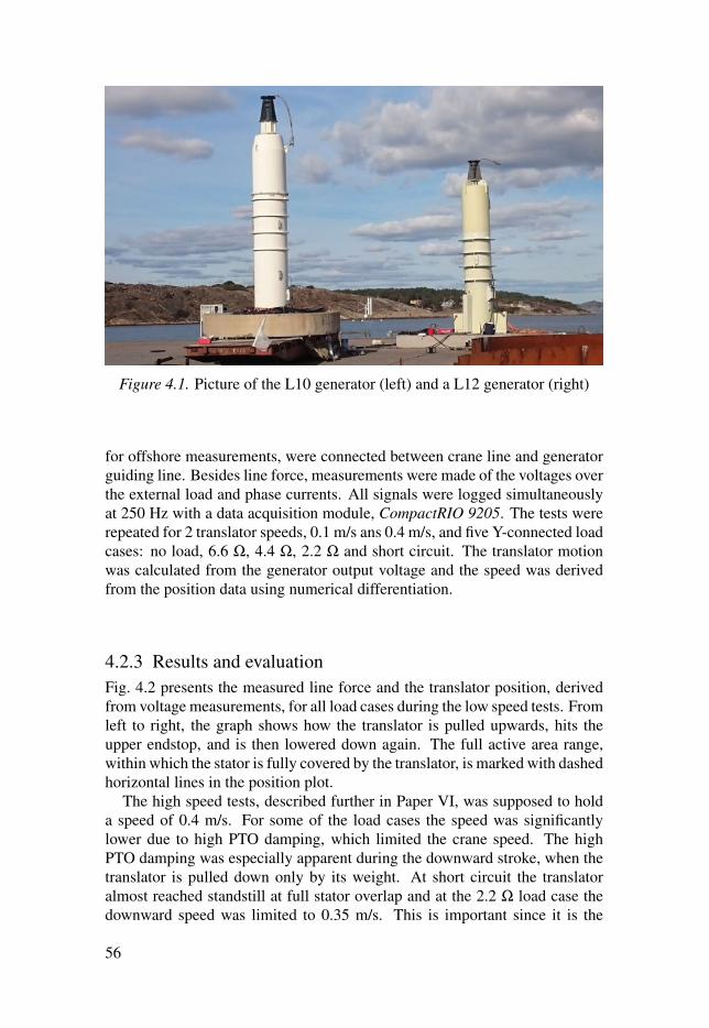
Figure 4.1. Picture of the L10 generator (left) and a L12 generator (right)
for offshore measurements, were connected between crane line and generatorguiding line. Besides line force, measurements were made of the voltages overthe external load and phase currents. All signals were logged simultaneouslyat 250 Hz with a data acquisition module, CompactRIO 9205. The tests wererepeated for 2 translator speeds, 0.1 m/s ans 0.4 m/s, and five Y-connected loadcases: no load, 6.6 Ω, 4.4 Ω, 2.2 Ω and short circuit. The translator motionwas calculated from the generator output voltage and the speed was derivedfrom the position data using numerical differentiation.
4.2.3 Results and evaluationFig. 4.2 presents the measured line force and the translator position, derivedfrom voltage measurements, for all load cases during the low speed tests. Fromleft to right, the graph shows how the translator is pulled upwards, hits theupper endstop, and is then lowered down again. The full active area range,within which the stator is fully covered by the translator, is marked with dashedhorizontal lines in the position plot.
The high speed tests, described further in Paper VI, was supposed to holda speed of 0.4 m/s. For some of the load cases the speed was significantlylower due to high PTO damping, which limited the crane speed. The highPTO damping was especially apparent during the downward stroke, when thetranslator is pulled down only by its weight. At short circuit the translatoralmost reached standstill at full stator overlap and at the 2.2 Ω load case thedownward speed was limited to 0.35 m/s. This is important since it is the
56
maximum speed that the translator can expect to reach during the downwardstroke, at stated load.
Fig. 4.3 presents the measured line force with upward and downward strokespresented together along the stroke length. Solid lines represent the upwardstroke, from bottom position to upper endstop, and dotted lines represent thedownward stroke. The vertical dotted lines mark out the full stator overlaprange. The upward strokes show a higher line force than the downward stroke.This is due to the direction of the PTO force, which will work in the oppositedirection of the line force during the upward stroke and in the same direc-tion as the line force during the downward stroke. Meanwhile, the translatorweight, which can be seen as the average no-load force within the full statoroverlap, will always weigh downwards and the friction force will work op-posite the direction of movement. The difference in line force, between eachload case and the corresponding no load case, in Fig. 4.3, represents the PTOforce going into the generator. The no load loss was calculated to 4.15 kNfor the slow stroke, at 0.1 m/s, and to 4.84 kN for the fast stroke, at 0.4 m/s.This is a sum of the friction and the iron losses at no load. The iron lossesdepend on both electrical frequency and load, and should be small in the noload case [63], suggesting that the measured loss mainly derives from friction.A speed dependence of the friction was expected, and the losses measured atthese two speeds support this.
There is a distinct drop in line force before the endstop for all cases exceptat no load, as seen in Fig. 4.2. A corresponding line force peak can be seenduring the downward stroke just before the bottom endstop. This is due todecreasing active area, which decreases the PTO force. The decrease in lineforce before the upper endstop is also matched by a small increase in speedin the short circuit case, which is a reasonable consequence when the craneexperiences a lower force.
Fig. 4.4 shows the PTO force and the damping, γ , calculated from lineforce measurements, together with the translator speed. It should be notedthat the friction losses has been excluded in the PTO force. It can be seen thatγ decreases with a decreasing active area, as the translator moves outside thevertical dotted lines in Fig. 4.4c. It can also be seen that the γ value during thepartial stator overlap is higher when the translator leaves the stator, and lowerwhen it enters the stator.
57
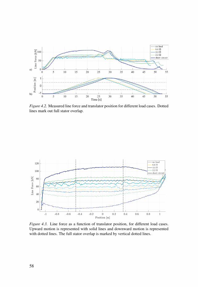
Figure 4.2. Measured line force and translator position for different load cases. Dottedlines mark out full stator overlap.
-1 -0.8 -0.6 -0.4 -0.2 0 0.2 0.4 0.6 0.8 1
Position [m]
0
20
40
60
80
100
120
LineForce
[kN]
no load6.6 Ω
4.4 Ω
2.2 Ω
short circuit
Figure 4.3. Line force as a function of translator position, for different load cases.Upward motion is represented with solid lines and downward motion is representedwith dotted lines. The full stator overlap is marked by vertical dotted lines.
58
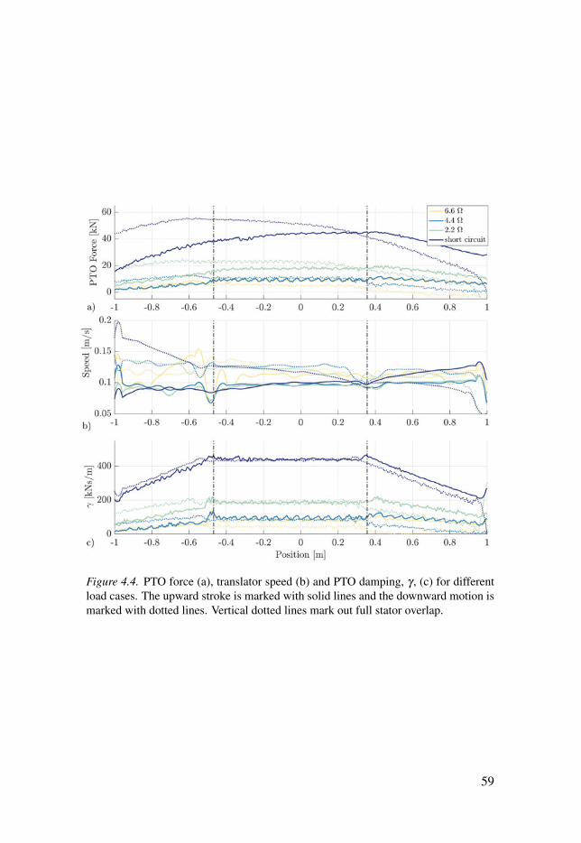
Figure 4.4. PTO force (a), translator speed (b) and PTO damping, γ , (c) for differentload cases. The upward stroke is marked with solid lines and the downward motion ismarked with dotted lines. Vertical dotted lines mark out full stator overlap.
59
4.3 The L12 Onshore Tests4.3.1 ObjectiveThe L12 onshore tests aimed to study the PTO force needed to drive the gen-erator, measured via the connection line force as stated in Eq. 2.2, and com-paring this to the expected PTO damping. Special attention was given to thespeed dependence of the generator damping, presented in Paper VI, and howthe damping will change with partial stator overlap, presented in Paper VIIand VIII.
4.3.2 MethodTo catch the full dynamics of the translator motion, improvements were madeto the measurements of the translator motion, compared to the L10 tests. Also,a stronger crane was used which could provide a wider speed range for thetests, compared to the L10 test where only two constant speeds were studied.Knowing that there is an inherent variation in the generator construction, dueto manufacturing tolerances, some variation in the friction of the generatorwas expected. To assess this, pressure sensitive film was used to measure thepressure on the rolling wheels that guide the translator’s motion. Apart fromcopper losses, mechanical losses from guiding friction is expected to be thedominant source of losses, although never modeled or measured.
Regarding the expected speed dependence of the PTO force, the simplestand perhaps most often used model is linear dependence, FPTO = γ x, whereγ is a constant. This assumption has been used mainly for hydromechanicalstudies of the WEC operation in frequency domain. The circuit model pre-sented in Fig. 2.8 offers a better representation of the generator. Assuming aresistive load, Rl , the PTO damping force for the circuit model becomes:
FelPTO(x) =
Pel
xt=
3Ei(xt)2Rtot
xt(R2tot +X(xt)2)
, (4.1)
where the resistance Rtot = Rg +Rl and the reactance X = ωL = 2πL( xt2wpole
),where L is the generator inductance and wpole is the pole pitch of the generator.The translator speed and the pole pitch determines the electrical frequency ofthe generator, which will vary throughout the generator stroke. It should benoted that the model includes copper losses, due losses in Rg, but neglects ironlosses and mechanical losses, and will thus underestimate the connection lineforce needed to drive the generator.
As stated in Eq. 2.10, the no-load voltage Ei should depend linearly on thetranslator speed, and the resistance and inductance terms are assumed con-stant. Studying Eq. 4.1 in a case of low speed or low inductance, making thereactance term negligible, a linear speed dependence of FPTO is supported, re-sulting in a constant damping factor γ = FPTO/x. This assumption could to
60
some extent be valid for the surface mounted generators, L1–L10, as statedin [64]. The same is, however, not necessarily true for the later generatormodels, such as the L12, since the have a higher inductance and a shorterpole width, thus operating at a higher frequency. It was therefore of interestto compare measured trends of FPTO(x) for the L12 generator with the corre-sponding trends given from Eq. 4.1, which was done in Paper VI. The linearcase, FPTO = γ x was also studied.
Regarding the dependence on active area, it has in several studies been as-sumed linear, that is, if the stator overlap decreases with 20 %, then the PTOforce will also reduce with 20 %. This idea was first introduced by Erikssonet al. [55], and has been reprinted by several other references, e.g. [24,65,66].Also from the onshore experiments on the L10, the relationship between γ andtranlator position, which corresponds to stator overlap, was concluded linear.Looking at it again, see Fig. 4.4c, it is hard to discern whether it is linear,and not qadratic, since it only covers such a short range or partial stator over-lap, from A f ac ∈ [0.75,1). From theory, presented in Paper VII, it could bereasoned that the relationship is quadratic, which was also assumed by Lejer-skog et al. [67]. It was decided to study the relationship between the generatedelectrical power and the partial stator overlap, using an experimental approach.Based on the assumption that
FelPTO ∝ Ac
f rac, (4.2)
linear regression was used to find the best fit for different values of c, tested ina range between 0 and 5.
4.3.3 Experimental setupMuch similar to the L10 onshore tests, the L12 generator was tested onshoreusing a crane to lift the translator up and down. The tests were performed priorto final assembly, in order to study a longer range of partial stator overlap. Asshown in Fig. 4.5b, the upper part of the generator was left open, removing theupper endstop and any mechanical friction from the funnel and mechanicallead-through system. The load cases tested were (in Y-connection): no load,6.6 Ω, 4.4 Ω, 2.2 Ω, 1.1 Ω, 0.7 Ω and short circuit. The 2.2 Ω case was ex-cluded from the speed dependence study, since a connection fault affected thedamping characteristic. In order to reach a higher and wider range of transla-tor speeds, a stronger crane was used. Due to the short generator stroke lengthfrom bottom position and due to safety features of the crane, the speed waslimited to 0.6 m/s. The measurement setup was improved with a better suitedforce transducer and measurements of the translator position and acceleration.A data logger, CompactRIO 9205, was used to sample the data with a 1 kHzsampling frequency. Pressure sensitive film was used to measure the pressureon the support wheels.
61
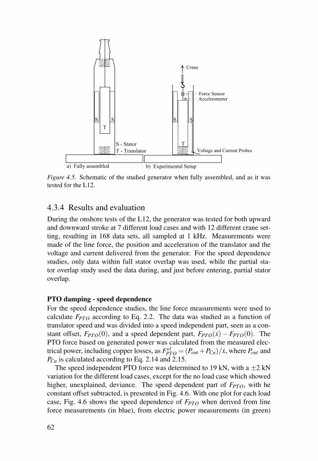
Figure 4.5. Schematic of the studied generator when fully assembled, and as it wastested for the L12.
4.3.4 Results and evaluationDuring the onshore tests of the L12, the generator was tested for both upwardand downward stroke at 7 different load cases and with 12 different crane set-ting, resulting in 168 data sets, all sampled at 1 kHz. Measurements weremade of the line force, the position and acceleration of the translator and thevoltage and current delivered from the generator. For the speed dependencestudies, only data within full stator overlap was used, while the partial sta-tor overlap study used the data during, and just before entering, partial statoroverlap.
PTO damping - speed dependence
For the speed dependence studies, the line force measurements were used tocalculate FPTO according to Eq. 2.2. The data was studied as a function oftranslator speed and was divided into a speed independent part, seen as a con-stant offset, FPTO(0), and a speed dependent part, FPTO(x)−FPTO(0). ThePTO force based on generated power was calculated from the measured elec-trical power, including copper losses, as Fel
PTO = (Pout +PCu)/x, where Pout andPCu is calculated according to Eq. 2.14 and 2.15.
The speed independent PTO force was determined to 19 kN, with a ±2 kNvariation for the different load cases, except for the no load case which showedhigher, unexplained, deviance. The speed dependent part of FPTO, with heconstant offset subtracted, is presented in Fig. 4.6. With one plot for each loadcase, Fig. 4.6 shows the speed dependence of FPTO when derived from lineforce measurements (in blue), from electric power measurements (in green)
62
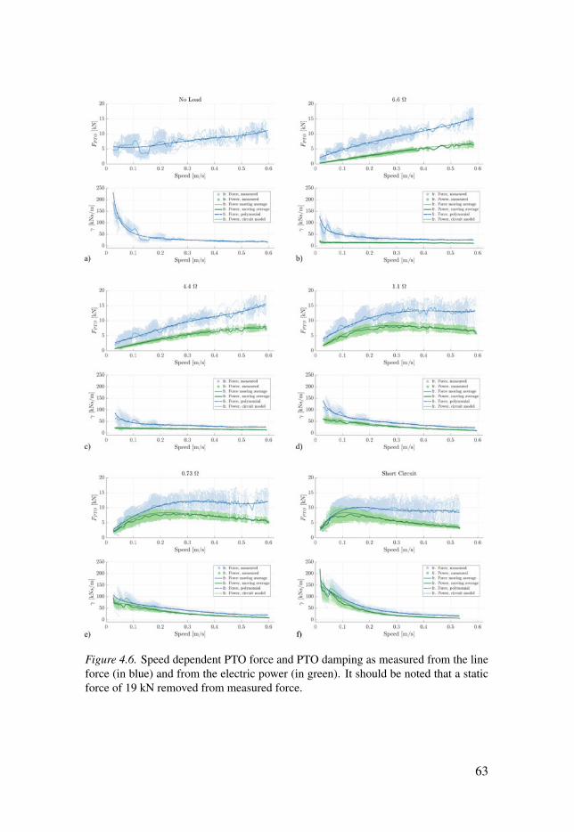
Figure 4.6. Speed dependent PTO force and PTO damping as measured from the lineforce (in blue) and from the electric power (in green). It should be noted that a staticforce of 19 kN removed from measured force.
63

and as modeled with the lumped circuit model as stated in Eq. 4.1 (dottedgreen line). The solid lines in each plot are moving averages of the measureddotted data. The dashed line in each plot is a polynomial representation of themeasured force, which is later used for the case study. It should be noted thatthe high FPTO offset, which has been subtracted from the force data in blue,strongly influence characteristics of the full γ .
The PTO force predicted from the lumped circuit model, represented withgreen dashed line, shows good correlation with the generated power, presentedas Fel
PTO = Pel/(x) in pale green. This confirms that the model used predictsgenerated power, including copper losses, with good accuracy. This is how-ever not enough to predict the PTO damping seen by the WEC connectionline. The discrepancy is due to mechanical losses and iron losses, which arenot included in the circuit model. Most of the losses are believed to originatefrom mechanical losses due to friction from the guiding wheels, a hypothesiswhich was supported by the measured wheel pressure. The pressure betweenthe support wheels and the steel guiding rail was 25 MPa, measured at threedifferent heights along the guiding rail. The measurement represent the max-imum pressure exerted during a full stroke of the translator. This was con-siderably higher than expected, indicating that the guiding wheel have beenmounted too tightly between translator and generator hull. Mounted with atoo high compressive tension, the rubber wheels will deform as they roll, andwill thereby experience visco-elastic friction as well as rolling friction, whichincreases mechanical losses and shortens the life time of the wheels.
Fig. 4.7 summarizes the results from Fig. 4.6, with the measured forcetrends in blue and the modeled circuit trends in green, corresponding to dashedand dotted lines respectively in Fig. 4.6. The speed independent force offsethas been included, which strongly affects the shape of measured γ comparedto modeled γ . As seen by the modeled PTO forces in Fig. 4.7, each load casehas a PTO force maxima which moves towards higher speeds for higher valuesof Rl , with approximately the same maximum force.
PTO damping - stator overlap dependence
Linear regression analysis was performed on the experimental data during par-tial overlap to determine the best fit for Eq. 4.2, for different values of c. Thefit was evaluated by the R2 value, which moves towards 1 as the fit improves.The analysis was performed on all load cases expect no-load, separated inupward and downward strokes. It was performed for both the summed three-phase power and for the envelope of each separate phase. This is motivatedsince the phases, mounted in separate stator packages, are physically shifted,which affects the stator overlap somewhat. The analysis was also performedfor γ = Pel/x, in an attempt to compensate for the strong speed dependence ofpower and force. It should be noted γ is also speed dependent, as was shownin Paper VI and as can be seen in Fig. 4.6. Consequently, most reliable re-
64
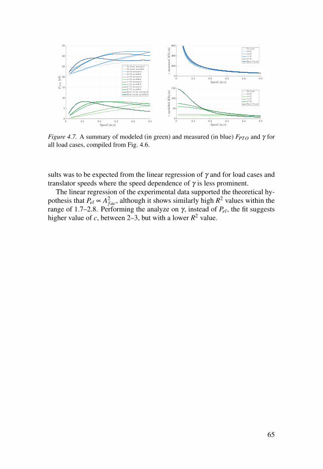
0 0.1 0.2 0.3 0.4 0.5
Speed [m/s]
0
5
10
15
20
25
30
35
FPTO[kN]
No Load, measuredNo Load, modelled6.6 Ω, measured6.6 Ω, modelled4.4 Ω, measured4.4 Ω, modelled1.1 Ω, measured1.1 Ω, modelled0.7 Ω, measured0.7 Ω, modelledShort circuit, measuredShort circuit, modelled
0 0.1 0.2 0.3 0.4 0.5
Speed [m/s]
0
200
400
600
γmeasured[kNs/m]
No Load6.6 Ω
4.4 Ω
1.1 Ω
0.7 Ω
Short Circuit
0 0.1 0.2 0.3 0.4 0.5
Speed [m/s]
0
50
100
150
γmodelled[kNs/m] No Load
6.6 Ω
4.4 Ω
1.1 Ω
0.7 Ω
Short Circuit
Figure 4.7. A summary of modeled (in green) and measured (in blue) FPTO and γ forall load cases, compiled from Fig. 4.6.
sults was to be expected from the linear regression of γ and for load cases andtranslator speeds where the speed dependence of γ is less prominent.
The linear regression of the experimental data supported the theoretical hy-pothesis that Pel ∝ A2
f ac, although it shows similarly high R2 values within therange of 1.7–2.8. Performing the analyze on γ , instead of Pel , the fit suggestshigher value of c, between 2–3, but with a lower R2 value.
65
4.4 Consequence Analysis - A Simulation Case Study4.4.1 ObjectiveBased on the experimental results, two case studies were performed to simu-late how different damping behaviors will affect the dynamic behavior of theWEC during offshore operation in high waves. The simulations were per-formed in time domain using a fully non-linear CFD model, as further de-scribed in Paper VI. The two separate case studies were performed to assessthe consequences of (i) γ’s speed dependence, according to modeled and mea-sured PTO damping and (ii) γ’s dependence on partial stator overlap.
4.4.2 MethodBoth studies were performed with the same buoy, the same wave and the samePTO unit, but with different functions to describe the generator damping. Theincident wave was chosen with a wave height of 5.9 m and a period of 10 s,corresponding to a high storm wave at the Lysekil test site. The highest wave,statistically appearing once per 100 years, at the test site is 6.2 m [33].
For the first study, concerning γ’s speed dependence, three types of PTOfunctions were modeled, as illustrated in Fig. 4.8. The first type, 1: PTOForce,depicted in blue, was chosen according to the FPTO derived from force mea-surements. Polynomials were fitted to the measured data for the implemen-tation as restraints in the CFD model, seen as dotted lines in Fig. 4.6. Thesecond type, 2: PTOPower, depicted in green, was chosen according to thePTO damping derived from the circuit model, as determined by Eq. 4.1. Itshould be noted that this neglects any friction losses or iron losses. For thethird type, 3: PTOLinearized , depicted in yellow, the simulation was run withan assumed constant γ . This correspond to a linearized PTO system wherethe force increases linearly with speed, FPTO = γ x, including a constant offset.The specific damping value was chosen as the one measured at a translatorspeed of 0.1 m/s, the same speed used for measurement of γ in reference [68].The simulations were repeated for three different load cases: 6.6 Ω, 1.1 Ω andshort circuit, in order to separate speed and load dependence.
For the second study, concerning γ’s dependence on stator overlap, thustranslator position, the damping was modeled according to Eq. 4.2, with aconstant γ = 28 kNs/m and c = [0,1,1.5,2.0,2.5,3.0].
4.4.3 Results and evaluationSpeed dependence of the PTO damping
Fig. 4.9 shows the simulated connection line force together with the positionand the speed of the translator, when moving in high waves. The surfaceelevation directly above the WEC is represented by a dashed line. It should
66
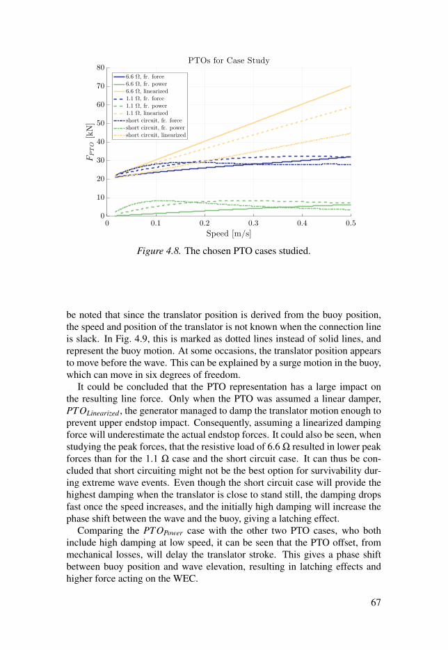
0 0.1 0.2 0.3 0.4 0.5
Speed [m/s]
0
10
20
30
40
50
60
70
80
FPTO[kN]
PTOs for Case Study
6.6 Ω, fr. force6.6 Ω, fr. power6.6 Ω, linearized1.1 Ω, fr. force1.1 Ω, fr. power1.1 Ω, linearizedshort circuit, fr. forceshort circuit, fr. powershort circuit, linearized
Figure 4.8. The chosen PTO cases studied.
be noted that since the translator position is derived from the buoy position,the speed and position of the translator is not known when the connection lineis slack. In Fig. 4.9, this is marked as dotted lines instead of solid lines, andrepresent the buoy motion. At some occasions, the translator position appearsto move before the wave. This can be explained by a surge motion in the buoy,which can move in six degrees of freedom.
It could be concluded that the PTO representation has a large impact onthe resulting line force. Only when the PTO was assumed a linear damper,PTOLinearized , the generator managed to damp the translator motion enough toprevent upper endstop impact. Consequently, assuming a linearized dampingforce will underestimate the actual endstop forces. It could also be seen, whenstudying the peak forces, that the resistive load of 6.6 Ω resulted in lower peakforces than for the 1.1 Ω case and the short circuit case. It can thus be con-cluded that short circuiting might not be the best option for survivability dur-ing extreme wave events. Even though the short circuit case will provide thehighest damping when the translator is close to stand still, the damping dropsfast once the speed increases, and the initially high damping will increase thephase shift between the wave and the buoy, giving a latching effect.
Comparing the PTOPower case with the other two PTO cases, who bothinclude high damping at low speed, it can be seen that the PTO offset, frommechanical losses, will delay the translator stroke. This gives a phase shiftbetween buoy position and wave elevation, resulting in latching effects andhigher force acting on the WEC.
67
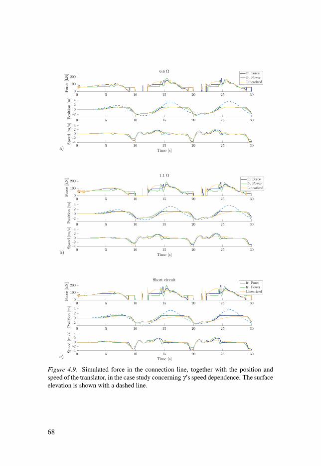
0 5 10 15 20 25 300
100
200
Force[kN]
6.6 Ω fr. Forcefr. PowerLinearized
0 5 10 15 20 25 30
-2
0
2
4
Position[m
]
0 5 10 15 20 25 30
Time [s]
-4-2024
Speed[m
/s]
a)
0 5 10 15 20 25 300
100
200
Force
[kN]
1.1 Ωfr. Forcefr. PowerLinearized
0 5 10 15 20 25 30
-2
0
2
4
Position[m
]
0 5 10 15 20 25 30
Time [s]
-4-2024
Speed[m
/s]
b)
0 5 10 15 20 25 300
100
200
Force
[kN]
Short circuitfr. Forcefr. PowerLinearized
0 5 10 15 20 25 30
-2
0
2
4
Position[m
]
0 5 10 15 20 25 30
Time [s]
-4-2024
Speed[m
/s]
c)
Figure 4.9. Simulated force in the connection line, together with the position andspeed of the translator, in the case study concerning γ’s speed dependence. The surfaceelevation is shown with a dashed line.
68
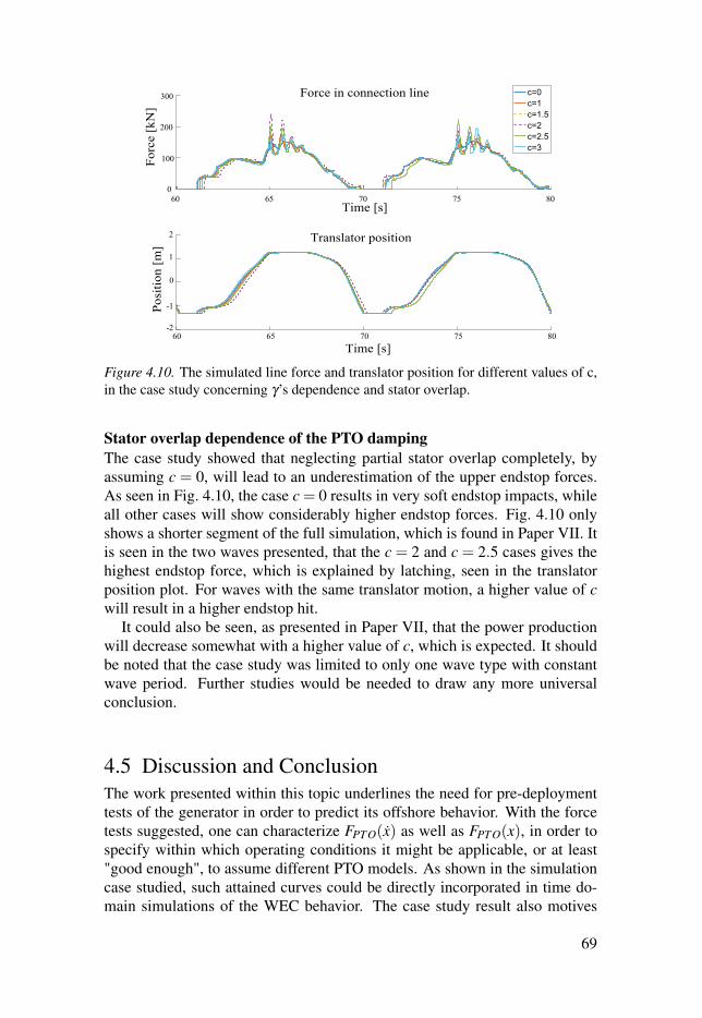
Figure 4.10. The simulated line force and translator position for different values of c,in the case study concerning γ’s dependence and stator overlap.
Stator overlap dependence of the PTO damping
The case study showed that neglecting partial stator overlap completely, byassuming c = 0, will lead to an underestimation of the upper endstop forces.As seen in Fig. 4.10, the case c = 0 results in very soft endstop impacts, whileall other cases will show considerably higher endstop forces. Fig. 4.10 onlyshows a shorter segment of the full simulation, which is found in Paper VII. Itis seen in the two waves presented, that the c = 2 and c = 2.5 cases gives thehighest endstop force, which is explained by latching, seen in the translatorposition plot. For waves with the same translator motion, a higher value of cwill result in a higher endstop hit.
It could also be seen, as presented in Paper VII, that the power productionwill decrease somewhat with a higher value of c, which is expected. It shouldbe noted that the case study was limited to only one wave type with constantwave period. Further studies would be needed to draw any more universalconclusion.
4.5 Discussion and ConclusionThe work presented within this topic underlines the need for pre-deploymenttests of the generator in order to predict its offshore behavior. With the forcetests suggested, one can characterize FPTO(x) as well as FPTO(x), in order tospecify within which operating conditions it might be applicable, or at least"good enough", to assume different PTO models. As shown in the simulationcase studied, such attained curves could be directly incorporated in time do-main simulations of the WEC behavior. The case study result also motives
69
the use of these measurements, especially the speed characterization, sincethey clearly showed the high impact on the WEC behavior during operation.Regarding the modeling of partial stator overlap, it is important to include,although the specific value for c > 1 will have relatively small impact on theWEC’s survivability and power production. This could be of interest for mod-eling purposes since a linear stator overlap dependence may be less computa-tionally expensive to implement.
The linear PTO model can only be assumed at limited speeds for WECs withrelatively small inductance and negligible mechanical losses. For the L10 gen-erator, with surface mounted NdFeB magnets, this could neither be confirmedor rejected, due to the limited speed range studied. For the L12, with sand-wich mounted ferrite magnets, it was concluded that the linear assumptionis not applicable. A commonly used circuit model could be used to predictthe produced power with fairly good accuracy, but the force needed to drivethe generator was very much underestimated, due to added friction. No trueattempt was made to separate iron losses from friction losses, which wouldbe interesting. The iron losses are generally assumed low due to the low fre-quencies, but this should be further studied. While modeling of iron lossesshould be fairly straight forward, the friction from rolling wheels and sealedguiding will depend on many different parameters which are complicated todetermine. Measuring and characterizing the rolling friction could be donewith a similar approach as presented, if the translator is moved along the guid-ing wheels without the stator installed. This does, however, require sidestepsfrom the generator assembly procedure. The same could be done for the seal-ing friction, which was not done due to the lack suitable force transducer anddrive. Although it would be interesting to separate the generator losses furtherin this way, the most practical approach is probably to measure the full damp-ing characteristics once everything is assembled, since the friction is expectedto vary between different WEC units, due to assembly variations.
As a complement, or in the long run perhaps a substitute, using pressuresensitive film to measure the pressure on the guiding wheels can be recom-mended. Although crude in comparison to force and motion measurements,they have merit in being easy to use and easy to read. Considering the highimpact guiding wheel pressure has on the generator friction, and also its ef-fect on the wheels technical service life, wheel pressure should be measuredan compared between generators. Also, beyond of using it after assembly toasses the friction, it could be incorporated in the generator assembly process totune the wheel pressure, and in that way compensate for some of the toleranceissues currently at hand in the assembly process.
The thesis only presents work from two WECs, the L10 and one of the L12s,which are quite different in their design and therefore not entirely comparable.In addition to this, tests were also performed on other WECs, alike or similar
70

to the L12. The tolerances and procedures used for assembling the generatorsresults in construction variations between WECs, which affect their behavior.The most sensitive part of the construction, in this regard, is the generatorairgap. Small changes in the airgap will have significant impact on the no-loadvoltage of the generator, Ei(x). Small asymmetries in the airgap will give largeradial forces between stator and translator, which risk breaking the generator,which was studied by Ekergård [40]. The results from this thesis emphasizesthe effect these construction variations also will have on the friction in themachine. When presented, in Paper VI, focus lay mainly of the consequencesfor the WEC damping behavior during operation. An even more importantaspect of this is the wear and service life of the translator guiding.
The L12 generator differs a lot from the previous WECs, L1–L10, due tothe new stator and translator design. Further work is needed to fully explorethe behavior and features of this new design, a venture found beyond the scopeof this thesis. It is clear, though, that some of the old truths about the lineargenerator as a PTO needs to be re-examined. One example of this is the as-sumption that the best load for survivability mode is short circuiting, whichwas disproved. Also, from the onshore tests on the L12, presented in PaperVI, it turned out that the circuit model parameters for generator resistance andinductance that fitted the experimental data best, were not the same values asstated for the generator, which is troublesome. Whether this was due to incor-rect generator characteristics or an insufficient model is yet to be determined.It should be noted that the simple circuit model used, does not consider gener-ator saliency, which is expected but has not been studied, in the ferrite magnetmachine. A further investigation on the strong translator oscillations, whichwere also seen in the power output, is also needed.
Onshore tests are limited, especially when performed on such a big machine,since there are no drives available that can supply the same power character-istics as an ocean wave. For the test performed in this thesis, a mobile cranewas used. Although strong enough, it cannot, will not, provide the accelera-tion needed to reach the rated speed within the generator stroke length. Theachieved speed range, covering most speeds between standstill and 0.6 m/s, ismuch better than what has previously been achieved. But in order to study thefull speed range expected during offshore operation, a speed range up to 2 m/swould have been preferable. The setup does also not agree to endstop impacts,translator free-falls or tilted lifting angles, which needs testing. These specificevents are important to study for the survivability and water integrity of theWEC construction. Testing such features offshore, is testing too late. Testingit on-shore would require a custom test rig.
71
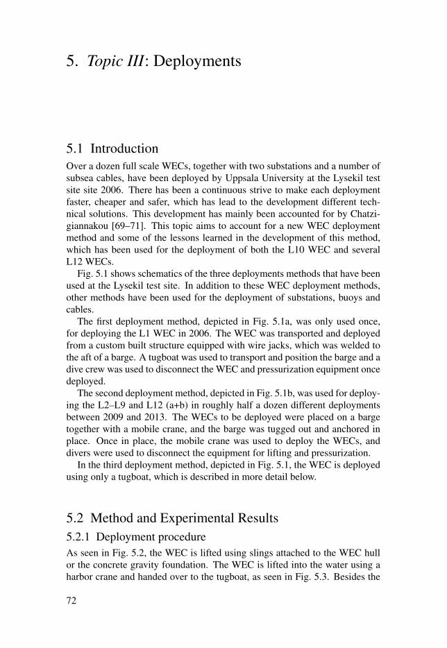
5. Topic III: Deployments
5.1 IntroductionOver a dozen full scale WECs, together with two substations and a number ofsubsea cables, have been deployed by Uppsala University at the Lysekil testsite site 2006. There has been a continuous strive to make each deploymentfaster, cheaper and safer, which has lead to the development different tech-nical solutions. This development has mainly been accounted for by Chatzi-giannakou [69–71]. This topic aims to account for a new WEC deploymentmethod and some of the lessons learned in the development of this method,which has been used for the deployment of both the L10 WEC and severalL12 WECs.
Fig. 5.1 shows schematics of the three deployments methods that have beenused at the Lysekil test site. In addition to these WEC deployment methods,other methods have been used for the deployment of substations, buoys andcables.
The first deployment method, depicted in Fig. 5.1a, was only used once,for deploying the L1 WEC in 2006. The WEC was transported and deployedfrom a custom built structure equipped with wire jacks, which was welded tothe aft of a barge. A tugboat was used to transport and position the barge and adive crew was used to disconnect the WEC and pressurization equipment oncedeployed.
The second deployment method, depicted in Fig. 5.1b, was used for deploy-ing the L2–L9 and L12 (a+b) in roughly half a dozen different deploymentsbetween 2009 and 2013. The WECs to be deployed were placed on a bargetogether with a mobile crane, and the barge was tugged out and anchored inplace. Once in place, the mobile crane was used to deploy the WECs, anddivers were used to disconnect the equipment for lifting and pressurization.
In the third deployment method, depicted in Fig. 5.1, the WEC is deployedusing only a tugboat, which is described in more detail below.
5.2 Method and Experimental Results5.2.1 Deployment procedureAs seen in Fig. 5.2, the WEC is lifted using slings attached to the WEC hullor the concrete gravity foundation. The WEC is lifted into the water using aharbor crane and handed over to the tugboat, as seen in Fig. 5.3. Besides the
72
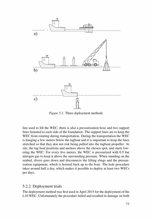
Figure 5.1. Three deployment methods
line used to lift the WEC, there is also a pressurization hose and two supportlines fastened to each side of the foundation. The support lines are to keep theWEC from rotating during transportation. During the transportation the WECis hanging a few meters below the tugboat and it is important to keep the linesstretched so that they don not risk being pulled into the tugboat propeller. Atsite, the tug boat positions and anchors above the chosen spot, and starts low-ering the WEC. For every five meters, the WEC is pressurized with 0.5 barnitrogen gas to keep it above the surrounding pressure. When standing on theseabed, divers goes down and disconnects the lifting slings and the pressur-ization equipment, which is hoisted back up to the boat. The hole proceduretakes around half a day, which makes it possible to deploy at least two WECsper days.
5.2.2 Deployment trialsThe deployment method was first used in April 2015 for the deployment of theL10 WEC. Unfortunately the procedure failed and resulted in damage on both
73

WEC and equipment. The fault lie with the steel wire used to lift the WEC,which was not rotation-free, which means that it wants to twist when stretched.This is not a problem for ordinary tugging, since it is then connected betweentwo objects that will not allow it to rotate. But as the wire unstretched whenthe WEC was placed the seafloor at site, it started rotating and tangled up thelifting sling, pressure hose and support wires. This was not noticed from thesea surface until the pressure cable ripped and gas started leaking out of theWEC. The deployment was aborted and the WEC was tugged back to shore.After this failed attempt, the wire was replaced with a rotation free steel wire,and later or a synthetic fiber line, made from dyneema, which has worked wellsince.
A second attempt to deploy the L10 WEC was made later in August 2015.Again, the deployment had to be aborted, this time due to material failurein the pressure inlet of the WEC. The transportation to site went fine, butwhen maneuvering into position, the pressure hose, together with gas inletcame off, probably due to the force of the flowing water acting on the pressureconnection, seen in Fig. 5.2a. The material had been worn out, during this andthe precedent deployment, from the vibrating load of moving in water. Forthe subsequent WECs, the gas inlet was built with an angled gas connection tominimize the levering, and with an additional support structure.
In September 2015, the WEC named L12c, much similar to the one seenin Fig. 5.2b was deployed using the same method. As seen in the figure, thelifting points were now attached to the generator instead of the foundation,using two lifting points instead of three. The deployment was successful, andthe L10 buoy, seen in Fig. 3.2, was connected separately the next day.
The next and latest deployment was performed in June 2017, when an-other L12 WEC was deployed together with a later WEC model developed bySeabased Industry AB. To further ensure a smooth procedure, a few improve-ments were made. The pressure hose was more firmly attached to the gravityfoundation and attached along one of the support lines. This was partly to re-duce the number of lines, and to keep the pressure hose from folding, whichmight choke the gas flow. In addition to this, the lifting points for tugging wasmoved to the top or the WEC. These lifting point, seen just beneath the fun-nel in Fig. 5.2b, are not strong enough to carry the WEC in air, but sufficientfor underwater tugging. As a next step to the deployment development, theWEC was now deployed together with its buoy. This is advantageous for threereasons: it saves half a day of diving work, it decreases the required weatherwindow for deployment, and it is safer. In previous deployments, the buoy hasbeen attached after the generator deplyment, except for the L1 which was alsodeployed together with buoy. Deploying the buoy separately is very weatherdependent, expensive and has in the last few years grown more complicated,as the translators have become heavier.
74
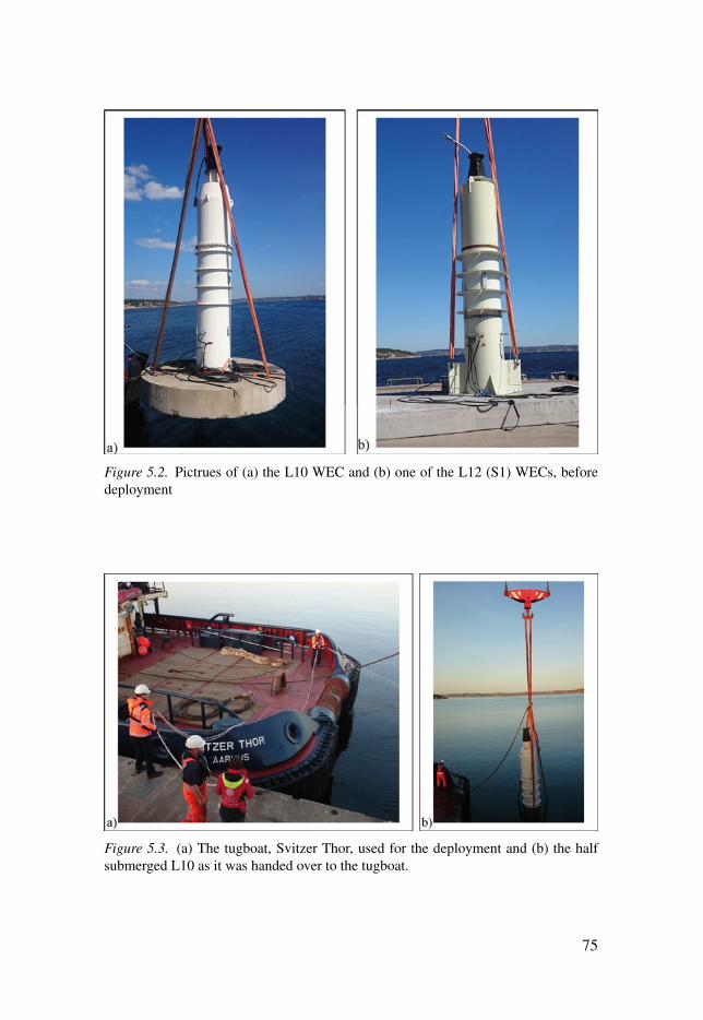
Figure 5.2. Pictrues of (a) the L10 WEC and (b) one of the L12 (S1) WECs, beforedeployment
Figure 5.3. (a) The tugboat, Svitzer Thor, used for the deployment and (b) the halfsubmerged L10 as it was handed over to the tugboat.
75

Figure 5.4. WEC deployed together with buoy, seen from tugboat.
5.3 Discussion and ConclusionIt can be concluded that the new deployment method, after a few costly lessons,is working well. A comparative estimation of the cost and time for deployinga certain number of WECs are presented in Paper XI. It was decided that thetugboat method is always the most cost-efficient and most often also the moretime-efficient option. The barge-crane method can be more time-efficient ifmany WECs are to be deployed. Beyond this, the new method has other ad-vantages worth mentioning. Since it only includes one deployment vessel, thetugboat, the planning and timing of the deployment is easier to manage, whichis helpful due to the strong weather dependence. Having fewer actors involvedalso made the communication, both before and during the deployment, easier.
There is much to be gained from deploying the generator and buoy together,since it reduces cost, time and weather dependence. There are several stepsthat should be taken to develop the method further. One important step is toinclude some sort of winch system to adjust the buoy line length after deploy-ment. This is especially important when deploying buoy and generator to-gether, since the buoy line length is pre-calculated and fixed. When deployingthe buoy manually, there is some room for adjustment during the connection.A solution for this, developed to be used for tidal compensation, has been sug-gested by Castellucci [20]. Another problem is the electrical connection of thegenerator, which is usually preformed by divers before the buoy deployment.By deploying the buoy together with the generator, the power cables mightbe energized during power cable connection. For the deployment performed2017, this was not an issue since the WEC was deployed together with an al-ready connected load. A long enough winch system, enabling the translator tostand on the bottom endstop, would be a solution.
76

The last, and perhaps most important, conclusion to be drawn regarding thework with WEC deployments, is that the value of working with an experi-enced and resourceful deployment crew, for both tugging and diving, cannotbe overstated.
77

6. Discussion
This chapter will discuss the limitations, findings and possibilities of the workpresented in this thesis, with a somewhat broader perspective than in the dis-cussion given within each topic.
6.1 LimitationsThe work upon which this thesis is built has ranged over a wide selection oftechnical issues, from the construction of the WEC, via testing and deploy-ment, to experiments at sea. In order to present this in a comprehensible way,certain limitations have been made in the scope of the thesis, which should bediscussed and motivated.
Regarding the WEC, focus has been on developing onshore and offshoremeasurement systems to enable the assessment of the WEC’s behavior duringoperation as sea. The choice was made to not include the design and testingof the generator in this thesis project. Such studies are needed, which shouldbe emphasized, but would require a more focused study with better tools andexpertise. Accordingly, the measurements and test methods presented in thisthesis are not to be seen as sufficient to evaluate the generator design or per-formance. Another chosen limitation was to use purely resistive external loadson the generator during onshore tests. This is not the optimum load for max-imum power extraction, but a simple straightforward and often used load forresearch purposes. And, as concluded by Ekström in a review on dampingstrategies, the selection of damping circuit must be based on individual casestudies of the specific WEC [25].
It is also important to discuss the practical limitations to what can, and cannot,be measured onshore and offshore respectively. For onshore measurements,the limitation generally lies in the possibility to mimic the forces of the oceanwave. For offshore measurements, the limitation lies in the limited access andthe high costs. Everything that can be studied onshore, should be studied on-shore, while offshore studies should be restricted to everything still unknown,that cannot be modeled or tested well enough onshore.
One such feature is the structural strength of the WEC, which requires mea-surements of both magnitude and frequency of the forces acting upon andwithin the WEC. As already discussed, extreme forces are hard to recreateonshore and often it is also difficult to estimate how strong or how frequent
78

different forces will be. For the L10, which had strain sensors for that pur-pose, the onshore test limitations also complicated the calibration procedure,which would have reduced the accuracy and reliability of those offshore mea-surements. The solution would be to build a test-rig which can enable high,fast and non vertical forces to be exerted on the full-scale WEC. To some ex-tent, it might also be possible to develop experiments with available tools thatare limited, but good enough to build and feed approximate models. In gen-eral, there needs to be a closer connection between the creation and usage ofmodels and the experimental testing of the WECs.
6.2 FindingsThis section summarizes and discusses the most important results and findingsof the research work, structured around the three research topics.
6.2.1 Regarding Offshore Measurement SystemsIn order to enable WEC measurmeents when or where a site infrastructure isnot available, it was decided to test the possibilities and limitation of a sim-pler and more straight-forward data acquisition system. The goal was to builda stand-alone measurement unit which could be deployed without divers orspecial hoisting equipment, with as long operation time as possible. The sys-tem was built in two parts, with sensors and analog signal conversion insidethe WEC, and with logging, data storage and power supply in a portable dataacquisition unit. The full system, as implemented, enables 5 weeks of contin-uous logging of 16 channels with a sampling frequency up to 1 kHz and a 16bit resolution. The operation time, limited by battery and data capacity, can beincreased further through logger settings. As an example, logging 10 channelsat 1 kHz for ten minutes every hour, would give an operation time of 30 weeks.The implemented measurements were tested for linearity, frequency response,step response and power consumption, with satisfactory results. The full sys-tem has been tested in lab, during onshore generator tests and during offshoreoperation.
The system is only meant as a complement to proper site infrastructure. Itwill not offer the same level of sophistication or convenience in long-term op-eration, but has proven to be a flexible and straightforward option for shortermeasurement ventures of one or two WECs. The main drawback of the sys-tem is that the data can only be accessed when the portable data acquisitionunit has been retrieved. If the system could be extended to also include a buoymeasurement system, as suggested and described in Future Works, the fulldynamics of the WEC could be monitored. This would enable continuous log-ging and data transfer, and data synchronization between buoy and generatormeasurements.
79
6.2.2 Regarding Onshore TestsThe thesis presents an onshore experimental approach, developed in two steps,to characterize the PTO damping as a function of both translator position andtranslator speed, measured both via the buoy line force and via the gener-ated power. The first setup, used on the L10 generator, lacked accelerationmeasurements and was, due to the crane choice, limited to only two transla-tor speeds. For the second setup, used on the L12 generator, characterizationwithin a continuous speed range was enabled by adding acceleration measure-ments together with a better crane.
From the tests performed, it could be concluded that the power productioncan be estimated fairly well with existing circuit models. In some cases, muchdepending on the generator inductance and external load, the PTO damping, asmeasures from produced power, could even support a linearized model withincertain speed ranges, which is often desirable in WEC models. This can how-ever not be said for the full PTO damping as measured from the connectionline force. Since it is the full force, including all system losses, which deter-mines the dynamic behavior of the WEC, it is this force that needs to be usedwhen modeling the WEC. The most prominent deviation identified is a con-stant offset in FPTO, which corresponds to a x−1-dependence in the dampingγ . For the specific L12 generator on which most testing was performed, thisoffset was considerable, probably much higher than what is to be expected forthe average generator. Although tests on a wider range of generators wouldbe needed, it could be concluded that the offset depends mainly on friction,which seems do vary considerably between different generator units due to as-sembly differences. This further emphasizes the need to perform similar PTOcharacterization tests on each unit built.
Regarding the speed dependence of the PTO damping, as measured fromthe line force on the L12 WEC, it could be seen that it correlates with theFel
PTO(x) curve predicted from the circuit model, but with an added and increas-ing damping for higher speeds. This is probably also due to friction losses,although iron losses could not be excluded. A simulation case study was per-formed to asses what consequences different speed dependencies, includingthe constant FPTO offset, could have on the WEC dynamics in high waves. Itproved to have a high impact on the generator survivability. Assuming a lineardamping will clearly under-estimate the extreme forces. The high friction willhave a latching effect of the translator motion. Regarding the different loadcases tested for the L12 generator, it could be seen that short-circuiting thegenerator is not the best option for survivability-mode operation, due to thelimited damping. In general, the L10 showed a considerably higher electro-magnetic damping. It even limited the translator speed during the downwardstroke, which is important to consider for offshore operation since it mightlead to a limited stroke length and unwanted snap loads.
80

Regarding the dependence on translator position, the damping was affirmedconstant within full stator overlap. At partial stator overlap the damping de-creases, partly due to a decrease in generator damping, and partly due to adecrease in friction losses, since fewer guiding wheels are active. Focusing onthe electromagnetic damping, experiments confirmed that it should decreasewith the stator overlap squared, Fel
PTO ∝ A2f ac, instead of Fel
PTO ∝ A f ac as previ-ously assumed. A simulation case study was performed which assessed howthe partial stator dependence would affect the WEC’s power production andsurvivability in high waves. The results suggested that neglecting partial sta-tor overlap entirely, will lead to an underestimation of the extreme forces andan overestimation of the power production. Whether the dependence betweendamping and stator overlap is modeled as linear or quadratic, has only a minorimpact on the WEC offshore behavior. This could in some cases motivate thelinear assumption as an acceptable simplification.
6.2.3 Regarding DeploymentsA cheaper and more flexible method for WEC deployments have been devel-oped and evaluated. Instead of deploying WECs with a mobile crane from abarge, the WECs are deployed one by one using only a tug boat. The methodallows the WEC buoy to be deployed together with, directly connected to, thegenerator. Besides saving the cost and work of deploying the buoy separately,it also shortens the needed weather window and makes the deployment safer.After a few trial lessons, the method is working well and is both cheaper andfaster than the old method.
6.3 PossibilitiesThe lack of offshore experience is perhaps the most important bottle neckfor wave power development today. The research community is in dire needof offshore experiences and data in order to validate or discard ideas, feedmodels, set design criteria, etc. Considering the size and complexity of manyWEC concepts, the path to offshore testing is long, and due to the high costsand high risks, many chose to focus on more isolated subsystem scale-testingin wave tanks. The Uppsala University research stands out in this regard, withthe full scale, in ocean, wave-to-wire approach from the very beginning of theproject. This has been enabled by the relatively low cost and low complexityof the WEC, a multidisciplinary and applied research approach and the earlyestablishment of a suitable and accessible test site. This has, beyond the WECconcept itself, enabled the research of many other important aspects, suchas environmental impact, power electronics, farm studies, control strategies,deployments, ROVs, etc, as well as it has provided a full-system perspective,which has great value in itself. Having a simple, cheap and straight forward
81

WEC concept could, regardless of its commercial potential, have great valuefor more generic research on wave power subsystems.
A relatively simple, cheap and flexible measurement system could also con-tribute to enable more wave power research, without the immense investmentcost of signal infrastructure. During the test in 2017, the measurement sys-tem proved that it can be used for short-term measurement ventures at siteswhere there is no available infrastructure. It even offered more channels and ahigher sampling frequency than what has been offered by the existing infras-tructure at the Lysekil Research Site. When fully developed, with the buoymeasurement system and a full set of sensors, and extensively tested, it mightalso replace parts of the infrastructure on sites where a full infrastructure isnot economically viable.
82
7. Conclusions
This chapter summarizes the most important conclusions of the research workpresented in this thesis, structured around the three research topics. Pleasenote that more elaborate conclusions are given within each topic.
Regarding offshore measurement systemsA portable stand-alone measurement unit has been developed, to be used foroffshore WEC measurments. The system is built in two parts, with sensors andanalog signal conditioning inside the WEC, and with logging, data storage andpower supply in a retrievable data acquisition unit. The developed system of-fers a cheap and flexible option for short term offshore measurement ventures,when or where site infrastructure is not available. It is battery-driven and smallenough to be deployed and retrieved without diving or hoisting equipment, of-fering 5–50 weeks of 1 kHz, 16 bit measurements on 16 channels.
Regarding onshore testingIn order to predict and prepare for the WEC’s operation at sea, it is impor-tant to know the full damping behavior of the PTO. The PTO damping, γ ,is not a constant, but a function of different state variables, which should becharacterized for the specific PTO unit studied. The thesis has presented anexperimental approach to characterize the full damping behavior, includinglosses, as a function of translator speed and position. It has also showed howsuch experimentally attained damping functions can be implemented in WECmodeling, in order to predict the WECs offshore behavior. The simulationsperformed clearly showed that measuring the full PTO damping behavior isimportant to correctly predict the forces acting on the WEC during operation.Measuring it via the generated power will lead to an underestimation of theforces acting on the WEC.
Regarding deploymentsIn order to make the WEC deployments cheaper, faster and safer, a new de-ployment method has been developed. By using a single tugboat to deploy aWEC, with the buoy already connected, the deployment cost for one unit canbe cut in half, compared to the previously used method. The new method alsodecreases the time and complexity of the procedure, which in turn decreasesthe weather dependence and the risk of unforeseen costs.
83

8. Future Work
This section provides a short introduction to upcoming challenges within on-shore and offshore WEC measurements.
8.1 The L12 buoy measurement systemThe full vision of the L12 measurement system was never realized. This sec-tion will describe and discuss the design of a buoy measurement system, whichwere to be built and connected to the generator measurement system.
As previously stated, one of the most fundamentally important things tomeasure during offshore operation is the power conversion steps between wave,captor and PTO output. This requires measurements of the mechanical powertransferred between the buoy and the linear generator. The plan was to do thisby measuring the connection line force, with the same force transducer used inthe L10 test, and to measure the buoy motion with a number of accelerometersmounted on the buoy. By using a set of accelerometers instead of only one,as for the L10 measurement system, the six-degrees-of-freedom motion of thebuoy can be studied. The onshore communication and data transfer were to beperformed via a buoy antenna, utilizing the 3G grid which offers a large com-munication bandwidth. The buoy would also be equipped with solar panels,batteries and a hard-drive data backup.
The main novel part of the system is a communication cable between thebuoy measurement system and the portable data acquisition system, whichis connected to the generator and standing on the sea floor. This connectionis complicated, since the buoy is moving freely and is exposed to very highforces. The solution suggested is to fasten a signal cable along the WEC safetyline, which is basically a non-strained anchoring line to keep the buoy fromdrifting away in the event of connection line failure. Implementing this isa risky venture, which is why both the buoy measurement system and thegenerator measurement system would have redundant backups. This is whythe generator measurment system, as seen in Fig. 3.9, was equipped with tworedundant PCBs for signal transfer. One would be connected to the buoy andthe other to the portable data acquisition unit, which would operate as backup.The connected measurement system would be controlled from the buoy, witha myRio data acquisition system and a Raspberry Pi for system control. TheRaspberry Pi would also be the onshore communication link, via the antenna,
84
enabling real-time control of the power supply and data acquisition of the fullsystem.
If proved feasible, much could be gained from using such a system. Itwould mean that all WEC measurements, both buoy and generator, is sampledsynchronously and sent onshore in real-time. It would also enable a wholeother level of access and communication, since the buoy has a direct commu-nication link, which could be used to optimize operation time, chose when tomeasure and plan for maintenance and exchange of battery and hard-drives. Itcould potentially also be used for WEC control.
8.2 Evaluate the need for new generator modelsIt was seen from the results in Paper VI that the commonly used generatorcircuit model, seen in Fig. 2.6, could be used to predict the produced powerwell enough, although not with the resistance and inductance parameters ex-pected. For estimating the full generator damping, when generator losses arealso included, the model is off target, both due to a high constant offset anddue to losses increasing with speed.
There are two sides to this problem. The first is that loss terms need to beadded to the model when simulating the motion of the WEC. Once character-ized, preferably on a wider range of generators and with a better loss sepa-ration than presented in this thesis, this should not be to complicated to add,depending on the simulation type. The thesis has shown that the character-ized damping behavior can be implemented in the CFD model used for time-domain studies. Implementation in frequency domain models might provemore complicated.
The other part is the generator characterization. From a machine perspec-tive, the circuit model used is very simple, but have merit in being easy to useand usually rather accurate when considering normal operation of a generator.More work is needed to re-evaluate to what extent this model is valid for theferrite-magnet generator and whether other models should be used instead.
Some first attempts were made to evaluate the resistance, inductance andsaliency of the generator, using the simple circuit model as a base for study.It should be noted that using simple hand-held LCR-meter will not suffice forthis type of measurements, since it operates with very low currents. Using suchtools will result in a considerable under-estimation of the machine inductance[72]. An amplification circuit was built to externally excite each stator phasewith both DC supply and sinusoidal AC supply at 1 Hz, 5 Hz and 10 Hz.The phase impedance was determined by measuring the voltage and current intime domain. This was repeated for different translator positions, both in smallsteps over a full magnetic period, in order to test saliency, and in larger stepsat partial stator overlap to test how the impedance is affected by partial stator
85

overlap. From this, the resistance and inductance parameters, as modeled inFig. 2.8, was studied as a function of frequency and translator position.
From the limited analysis performed, few conclusions could be drawn, be-yond the need for further study. Both resistance and inductance varied withfrequency. The inductance varied within the magnetic period, as expected fora salient machine, although no clear trend could be distinguished. The in-ductance did not change significantly with partial active area. Further studiesbased on a model including iron losses and saliency should be performed.
86

9. Svensk Sammanfattning
Det finns enorma mängder energi att hämta från världens hav, som skullekunna användas för att ställa om till ett mer hållbart energisystem. Den teo-retiska potentialen för vågkraft har uppskattats till 32 PW/år, enligt en utred-ning gjord på uppdrag av FNs klimatpanel, vilket är ca 2 ggr världen elpro-duktion [1]. Det är dock en väldigt liten andel av detta som har potential attbli tekniskt möjlig, eller ekonomiskt lönsam, att utvinna. I en utredning frånInternationella Energiorganet, IEA, har man simulerat olika framtidsscenar-ion och kommit fram till att energi från havet, vilken innefattar bl.a. vågkraft,kommer att stå för 51–144 TWh producerad el år 2040 [2]. Detta kommerutgöra mindre än en 0,4 % av den totala elproduktionen. Energi från havet haralltså en enorm potential, men kräver stora tekniska framsteg.
Det finns idag en uppsjö av olika vågkraftskoncept, med en enorm spridningi de tekniska lösningarna. Konceptet som utvecklas vid Uppsala univestitetbestår av en boj vid havsytan som är direkt kopplad till en generator på havs-botten. När bojen rör sig upp och ned med havsvågorna så kommer generatornatt dämpa dess rörelse och på så vis absorbera effekt från vågen.
Att driftsätta ett vågraftverk kräver mycket mer än ett koncept för att om-vandla vågörelser till el. På grund av de stora krafterna, den ojämna elproduk-tionen samt den otillgängliga och hårda miljön som vågkraftverken arbetar i,krävs nya tekniska lösningar för flera av vågkraftsforkningens kringsystem.I den här avandlingen behandlas ett par av dessa tekniska lösningar, med ettövergripande fokus på mätsystem. Avhandlingen har delats in i tre delar: mät-ningar till havs, sjösättningar och karaktärisering av generatorns dämpkraft.De knyts samman av det gemensamma målet att skapa förutsättningar för attstudera vågkraftverkets beteende till havs.
Innan man sjösätter ett vågkraftverk måste man ha en modell för hur detkommer att röra sig och vilka krafter som det kommer att utsättas för un-der drift. Detta är viktigt för att kunna dimensionera för den mekaniska ochelektriska belastningen på konstruktion, kraftöverföring och mästsystem. Attbygga fullständiga modeller av vågkraftverkets interaktion med en havsvåg ärkomplicerat, då de byger på sammanlänkade, icke-linjära och icke-koninuerligasamband för bojens och translatorns rörelse. Dessutom finns det flera fak-torer som är svåra att modellera och som kommer variera från vågkraftverk tillvågkraftverk. För att utforska hur den faktiska dämpkraften från ett vågkratverkförhåller sig till den som förväntas från vanligt förekommande modeller, genom-fördes experiement för att mäta generatorernas dämpkraft som en funktion avtranslatorns position och hastighet. Gällande dämpkraftens positionsberoende,
87

kunde ett samband bestämmas över hur dämpkraft och elproduktion avtar närtranslatorn endast delvis överlappar statorn, som till viss del skiljer sig fråntidigare antaganden. Gällande dämpkraftens hastighetberoende, visade det sigatt de kretsmodeller som använts för att uppskatta elproduktion korreleradeväl med uppmätt elproduktion. Däremot var det en stor, och till viss väntad,avvikelsen mellan den modellerade och den uppmätta kraft som behövs för attdriva generatorn, till stor del pga. friktion. Avvikelen i dämpbeteende kom-mer att påverka vågkraftverkets dynamiska beteende och överlevnadförmågatill havs, vilket visades i en simuleringsstudie.
Gällande mätningar på vågkraftverken till havs påvisar avhandlingen ett be-hov av att komplettera den befintliga mätinfrastrukturen med ett mer flexibelt,robust och lättanvänt alternativ. För att utforska möjligheterna och begrän-sningarna med ett sådant system, byggdes ett batteridrivet mätsystem somarbetar helt fristående från test-sitens infrastruktur. Mätsystemet byggdes itvå delar, med sensorer och strömsignal-omvandlare inuti vågkraftverket, ochen portabel datainsamlare utanför vågkraftverket. Datainsamlaren består aven specialbyggd logger samt ett batteri, inneslutna av ett tryckkärl som kop-plas till vågkraftverket med undervattenskontakter. Målet var att den portabladatainsamlaren ska kunna sjösattas och hämtas in utan någon särskild lyft-eller dykutrustning, vilket satte begränsningar för dess vikt och storlek. Förden prototyp som byggdes och testades uppnåddes 5 veckors kontinuerligdatainsamling av 16 signaler, med samplingfrekvens på 1 kHz och upplös-ning på 16 bit. Drifttiden begränsas av tillgängligt batteri- och datautrymme.Genom att logga ett färre antal kanaler, eller med lägre samplingsfrekvens, kandatakapaciteten höjas. Genom att låta loggern arbeta efter ett förprogramerattidsschema kan både batteri- och datakapaciteten höjas.
Arbetet med sjösättningar har främst handlat om att utveckla ett enklare,billigare och säkrare sätt att sjösätta enskilda vågkraftverk på. Tidigare harvågkraftverken bogserats ut till site tillsammans med en mobilkran som sedanlyft ner vågkraftverken. Med den nya tekniken används istället en bogserbåtsom transporterar och sjösätter ett vågkraftverk, tillsammans med boj. Meto-den har visat sig smidig och är både billigare, snabbare och säkrare än dentidigare sjösättningsmetoden.
88

10. Acknowledgements
I would like to acknowledge the Swedish Energy Agency, Vargöns ResearchFoundation, StandUP for energy, Fortum, Seabased and Uppsala Universityfor their financial support of my work. I would also like to thank AnnaMariaLundins Stipendiefond, ÅForsk and the J Gust Riechert foundation, for allow-ing me to travel and present my work at conferences.
For giving me the opportunity to work with wave power and for allowing meto explore the field, and my capacity within the field, freely, I would like tothank my supervisor Mats Leijon. I am also grateful to Rafael Waters, myassistant supervisor, for your stoic work with the Lysekil project and for ourgood cooperation.
For always performing beyond their responsibility, I would like to thank thepeople at Seabased, Marine Works, Svitzer and Lysekil Hamn. I also offer mysincere gratitude to everyone in the extended wave group who contributed tothe experimental work in Lysekil. Thank you for all the late, cold and wethours spent in the measurement cabin, on Grötö, in the factory and on the sea.
For taking my ideas from, well ideas, to PCBs, loggers, harpuns and gener-ators, I would like to thank Tobias Kamf, Daniel Käller, Anders Kronberg andAlexander Risberg. You alone know where my experimental setups would bewithout you.
I have had many teachers, in theory and practice, that helped me to help my-self, for which I am grateful. For always doing it with a patient smile, I wouldespecially like to thank Rickard Ekström, Senad Apelfröjd, Robert Leanders-son, Håkan Berntsson, Roy Holm, Sandra Eriksson and Anders Hagneståhl.
A special thanks also goes out to my most hard-working co-authors, LinneaSjökvist, Tobias Kamf, Ling Hai and Anna Frost, for bringing you expertise,sharp minds and good sense of humor into our shared work.
Life is not the days that pass by, it’s the days you remember. These five yearshave given me many days to remember, which I have many to thank for. So,to everyone who was ever part of the Wednesday fika, the conferences, thesomewhere-it’s-five-o’clock beer, the after-four-o’clock experiments, the de-partment choir, the coffee-trains, the six-hour-drive, etc., Thank You!
Finally, I want to thank my family and friends for their support and under-standing, and most of all my husband, for keeping me strong.
89
11. Summary of Papers
This section presents a summary of the papers presented in this thesis, togetherwith a note regarding the authors contribution to each paper.
Paper IOffshore Measurement System for Wave Power - Using Current Loop
Feedback
This paper presents the design and evaluation of a sensor system for opera-tion measurements of the L12 WEC. It was implemented for measuring volt-age and current in the three-phased generator, with a range of ±1560 V and±420 A. The signals are transmitted from the WEC by using a current loopfeedback, with a 4–20 mA output. The sensor system was designed to be partof a larger stand-alone WEC monitoring system, presented in Paper II, whichmade power consumption and robustness key priorities. The paper gives athorough description of the tests performed to evaluate the system built, test-ing for linearity, frequency response, step response ans power consumption.Results are also presented from onshore test, when the sensor system was in-stalled into the WEC.
The author designed, built and installed the sensor system, performed andanalyzed all evaluation tests and wrote the paper. The second author super-vised throughout the project, and helped with PCB design, testing and me-chanical construction.
This journal paper has been published in MDPI Electronics, 2016, 5(4), 86.doi: 10.3390/electronics5040086
Paper IIPortable Data Acquisition System for Offshore Applications
This paper presents a stand-alone measurement unit to be used for offshoreWEC measurments, when or where on-site signal infrastructure is not avail-able. The system was built in two parts, with sensors and analog signal con-version inside the WEC, and with logging, data storage and power supply in aportable data acquisition unit. The sensor system is a continuation of the workpresented in Paper I, with improvements made to further reduce the power con-sumption. The data acquisition unit was built to be placed on the sea-bottomand connected to one or two WECs. It is battery-driven and small enough to
90
be deployed and retrieved without diving or hoisting equipment. The loggingand data storage is performed by a custom developed programmable logger,which stores the data to SD-cards. The full system, as implemented, enables5 weeks of continuous logging of 16 channels with a sampling frequency upto 1 kHz and a 16 bit resolution. The operation time, limited by battery anddata capacity, can be increased further through logger settings. As an exam-ple, logging 10 channels at 1 kHz for ten minutes every hour, would give anoperation time of 30 weeks. The full system has been tested in lab, duringonshore generator tests and during offshore operation.
The author did most of the design and implementation of the experimen-tal setup, designed and performed the evaluation tests, analyzed the data andwrote the paper. Help was received for the design and implementation of thelogger, together with overall assistance in the electrical and mechanical imple-mentation of the measurement system and performance evaluation.
This journal paper is in review for IEEE Journal of Oceanic Engineering,submitted in May 2017
Paper IIIMeasurement System for Wave Energy Converter - Design and Imple-
mentation
This paper presents the sensor system installed into the L10 WEC. The keyresearch objectives were to study the risk of overheating due to high currentsin the stator windings, to evaluate how the WEC’s outer structure withstandsdrag and bending forces from the buoy line and to construct a detection sys-tem which indicates if water leaks into the generator. The measurements im-plemented to study the forces acting on the WEC during operation is alsodescribed in Paper IV, where the buoy-part of the system is also included.
The author helped finalize and evaluate the sensor system, as well as build-ing and preparing the L10 WEC for operation.
This peer reviewed conference paper was presented Ulvgård, L. and isfound in the proceedings of the 33rd International Conference On Ocean, Off-shore And Arctic Engineering, San Francisco, California, June 8–13, 2014
Paper IVMeasurement System for Evaluating Wanted and Unwanted Forces on a
Point Absorbing Wave Energy Converter during Offshore Operation
This paper presents the objectives, design and implementation of a two-partmeasurement system for the L10 WEC, to be used during offshore operation.It was built to evaluate how forces from the ocean waves are absorbed by thebuoy and transferred down to the WEC generator, resulting in both wanted
91
vertical, and unwanted horizontal forces. The generator measurements arealso described in Paper III.
The author took part in the experimental work and wrote most of the paper.This peer reviewed conference paper was presented Ulvgård, L. and is
found in the proceedings of the 25th International Ocean and Polar Engi-neering Conference, Khona Island, USA, June 21–26 2015
Paper VLine Force and Damping at Full and Partial Stator Overlap in a Linear
Generator for Wave Power
This paper presents an experimental study of the connection line force andthePTO damping of a NdFeB linear generator, focusing on how the PTO forcevaries with translator position. The generator was tested using a mobile craneto drive the fully assembled generator, while measuring the connection lineforce, the translator position and generated power. The data was used to studythe PTO force and damping as a function of translator position for two dif-ferent speeds and with different resistive loads, including both upward anddownward stroke as well upper endstop impact.
The experimental setup was later improved with a stronger crane, a betterforce transducer and measurements of the translator acceleration, which wasused for the work presented in Paper VI–VIII.
The author performed the experimental work, data analysis and wrote thepaper.
This journal paper has been published in MDPI Journal of Marine Scienceand Engineering, 2017, 4(4), 81. doi: 10.3390/jmse4040081
Paper VISpeed Dependent PTO Damping in a Linear Generator for Wave Power -
Measured Damping and Simulated WEC Behaviour
This paper presents an experimental study on the speed dependent PTO damp-ing of a ferrite magnet linear generator for wave power conversion. It presentsand compares the PTO force, FPTO(x) and PTO damping, γ(x), as measuredvia both the buoy line force and the generated electrical power, when con-nected to different resisitive loads during onshore testing. To know the fulldamping characteristics of the PTO is important, since it will affect the mo-tion of the WEC, and consequently also its power production and survivability.The results showed considerable deviations between measured and modeleddamping, due to generator losses, both in form of a large offset in the PTOforce, FPTO(0), and in losses increasing with speed. To asses which conse-quences the identified discrepancies would have on the WEC during offshoreoperation, a time domain simulation case study was performed, using a CFD
92
model of the WEC when operating in high waves, with different PTO dampingcharacteristics and different resistive loads.
The author performed most of the experimental work, data analysis andwrote the paper.
This journal paper currently in revision for MDPI Journal of Marine Sci-ence and Engineering
Paper VIIPartial Stator Overlap in a Linear Generator for Wave Power: An Exper-
imental Study
The paper studies a ferrite magnet linear generator for wave power conver-sion and how its power absorption is affected by partial stator overlap, whichcorrelates to the translator position. Simplified theory suggests a quadraticrelationship, i.e. Pe ∝ A2
f rac, but the generator design is known to have longitu-dinal end-effects which affects the damping dynamics as the translator leavesthe stator, which has also been seen in previous generator tests. In previousstudies, the relationship has most often been assumed linear, if not neglectedentirely. Onshore generator tests were performed, and different linear regres-sion methods were used to determine the best fitting value of c for Pe ∝ Ac
f rac.The results confirmed the quadratic relationship derived from theory. To asseswhich consequences the stator overlap dependence will have on the offshoreoperation of the WEC, a time domain simulation case study was performed,using a CFD model of the WEC when operating in high waves, with differentPTO damping characteristics and different resistive loads. The study suggeststhat neglecting partial stator overlap will give an underestimation of the end-stop forces, and an overestimation of the power absorption. The differencebetween assuming a linear relationship instead of a quadratic relationship isvisible but relatively small, which could motivate the linear assumption as anacceptable simplification.
The author performed the experimental work and helped with the data anal-ysis and paper writing
This journal paper is submitted to MDPI Journal of Marine Science andEngineering, in September 2017
93
Paper VIIIExperimental Study of Generator Damping at Partial Stator Overlap in
a Linear Generator for Wave Power
This paper presents an experimental study of how the PTO damping in a per-manent magnet linear generator for wave power will change with partial statoroverlap. The study was later extended and presented in paper VII.
The author performed most of the experimental work and helped with thedata analysis and paper writing.
This peer reviewed conference paper was presented by Frost, A. and isfound in the proceedings of the 12th European Wave and Tidal Energy Con-ference, Cork, Ireland, August 27–31, 2017
Paper IXWave Energy Research at Uppsala University and The Lysekil Research
Site, Sweden: A Status Update
This paper presents a status update of the Lysekil wave power project for2013–2015. It reviews the work on a new and extended project permit, the de-ployment of a new marine substation, tests of several heaving buoy concepts,grid connections, improvements on the site measuring station, improved mod-eling of wave power farms, implementations of remote operated vehicles forunderwater cable connection and environmental monitoring studies.
The author helped with parts of the experimental work.This peer reviewed conference paper was presented Parwal, A. and is found
in the proceedings of the 11th European Wave and Tidal Energy Conference,Nantes, France, September 6–11, 2015
Paper XStatus Update of the Wave Energy Research at Uppsala University
This paper presents a status update of the Lysekil wave power project for2011–2013. Among other things, it describes the advances made on the de-sign, assembly and installation of a new WEC prototype, experiments with aresonance-rectifier circuit and a tidal effect compensator.
The author helped with parts of the experimental work.This peer reviewed conference paper was presented Hong, Y. and is found
in the proceedings of the 10th European Wave and Tidal Energy Conference,Aalborg, Denmark, September 2–5, 2013
94
Paper XIOffshore Deployments of Wave Energy Converters by Uppsala University
This paper reviews the offshore WEC deployments performed by UppsalaUniversity within their wave power research. Three different deploymentmethods are described and compared in terms of cost, time and safety. Fo-cusing on the third and currently used deployment method, a single tug boatis used to deploy a WEC, as compared to the previously used method whichused a combination of tug boat, mobile crane and barge. The paper concludesthat new method is the most efficient in terms of both cost and time, and that itrequires much less coordination work than the first two deployment methods.
In 2017, thus not covered by the paper, the new deployment method wasalso used to deploy a WEC with its buoy already connected. Besides savingthe time and cost for deploying the buoy separately, this increases the safetyand reduces the complexity and weather dependence for the buoy deployment.
The author has helped to develop the currently used deployment method,participated the deployments and assisted in writing the paper.
This journal is currently in revision for Marine Systems and Ocean Tech-nology.
95
References
[1] G. Mork, A. Kabuth, and M. Pontes, “Assessing the global wave energypotential,” in International Conference on Offshore Mechanics and ArcticEngineering, 29th International Conference on Ocean, Offshore and ArcticEngineering, pp. 447–454, ASME, 2010.
[2] M. Hannon, J. Griffiths, A. Vantoch-Wood, M. Carcas, S. Bradley, R. Boud, andS. Wyatt, “World Energy Resources Marine Energy 2016,” tech. rep., WorldEnergy Counsil, 2016.
[3] SI Ocean, “Ocean Energy: Cost of Energy and Cost Reduction Opportunities,”tech. rep., SI OCEAN, 2013.
[4] D. Magagna and A. Uihlein, “Ocean energy development in Europe: Currentstatus and future perspectives,” International Journal of Marine Energy, vol. 11,pp. 84–104, 2015.
[5] A. Falcao, “Wave energy utilization: A review of the technologies,” Renewableand Sustainable Energy Reviews, vol. 14, no. 3, pp. 899–918, 2010.
[6] B. Drew, A. Plummer, and M. N. Sahinkaya, “A review of wave energyconverter technology,” Journal of Power and Energy, vol. 223, no. 8,pp. 887–902, 2009.
[7] Ocean Power Delivery Ltd, “Pelamis WEC- Conclusion of Primary R&D,”Tech. Rep. 02, ETSU, 2010.
[8] S. Salter, “Wave energy: Nostalgic Ramblings, future hopes and hereticalsuggestions,” Journal of Ocean Engineering and Marine Energy, vol. 2, no. 4,pp. 399–428, 2016.
[9] H. Polinder, M. E. C. Damen, and F. Gardner, “Design, modelling and testresults of the AWS PM linear generator,” European Transactions on ElectricalPower, vol. 15, no. 3, pp. 245–256, 2005.
[10] J. Falnes, Ocean waves and Oscillating systems, vol. 30. 2003.[11] F. Wu, P. Ju, X.-P. Zhang, C. Qin, G. J. Peng, H. Huang, and J. Fang,
“Modeling, Control Strategy, and Power Conditioning for Direct-Drive WaveEnergy Conversion to Operate With Power Grid,” Proceedings of the IEEE,vol. 101, no. 4, pp. 925–941, 2013.
[12] K. Rhinefrank, E. B. Agamloh, A. Von Jouanne, A. K. Wallace, J. Prudell,K. Kimble, J. Aills, E. Schmidt, P. Chan, B. Sweeny, and A. Schacher, “Novelocean energy permanent magnet linear generator buoy,” Renewable Energy,vol. 31, no. 9, pp. 1279–1298, 2006.
[13] D. Elwood, S. C. Yim, J. Prudell, C. Stillinger, A. von Jouanne, T. Brekken,A. Brown, and R. Paasch, “Design, construction, and ocean testing of ataut-moored dual-body wave energy converter with a linear generator powertake-off,” Renewable Energy, vol. 35, no. 2, pp. 348–354, 2010.
[14] P. McKeever, R. Crozier, M. Mueller, E. Spooner, and H. Bailey, “Analysis,design and testing of a novel direct-drive wave energy converter system,” IETRenewable Power Generation, vol. 7, pp. 565–573, sep 2013.
96

[15] M. Mueller and H. Polinder, Electrical drives for direct drive renewable energysystems. 2013.
[16] M. Mueller, “Electrical generator for direct drive wave energy converters,”IEEE Proc. On Generation, Transmission and Distribution, vol. 149,pp. 446–456, 2002.
[17] Sjökvist Linnea, Wu J, Engström Jens, Eriksson Mikael, and Göteman Malin,“Numerical models for the motion and forces of point-absorbing wave energyconverters in non-linear waves,” Ocean Engineering, 2017.
[18] M. Eriksson, Modelling and Experimental Verification of Direct Drive WaveEnergy Conversion. PhD thesis, Uppsala University, 2007.
[19] Y. Hong, Numerical Modelling and Mechanical Studies on a Point AbsorberType Wave Energy Converter. PhD thesis, Uppsala University, 2016.
[20] V. Castellucci, Sea Level Compensation System for Wave Energy Converters.Ph.d. dissertation, Uppsala University, 2016.
[21] E. R. Sestafe, J. L. Mendia, and F.-X. Faÿ, “D2.11 Best practice manual forPTO testing,” MARINET Report, pp. 1–39, 2015.
[22] J. Manwell, J. G. McGowan, and A. L. Rogers, Wind Energy Explained:Theory, Design and Application. John Wiley and Sons Ltd, 2009.
[23] O. Danielsson, M. Eriksson, and M. Leijon, “Study of a longitudinal fluxpermanent magnet linear generator for wave energy converters,” no. May,pp. 1130–1145, 2006.
[24] L. Hai, Modelling Wave Power by Equivalent Circuit Theory. PhD thesis,Uppsala University, 2015.
[25] R. Ekström, B. Ekergård, and M. Leijon, “Electrical damping of lineargenerators for wave energy converters - A review,” Renewable and SustainableEnergy Reviews, vol. 42, pp. 116–128, 2015.
[26] O. Danielsson, K. Thorburn, M. Eriksson, and M. Leijon, “Permanent magnetfixation concepts for linear generator Permanent magnet fixation concepts forlinear generator,” in Fifth European Wave Energy Conference, EWTEC,no. July, (Cork), 2015.
[27] B. Ekergård, Full Scale Applications of Permanent Magnet ElectromagneticEnergy Converters. PhD thesis, Uppsala University, 2013.
[28] S. Eriksson and H. Bernhoff, “Rotor design for PM generators reflecting theunstable neodymium price,” Proceedings - 2012 20th International Conferenceon Electrical Machines, ICEM 2012, no. July 2011, pp. 1419–1423, 2012.
[29] S. Eriksson, “Inherent Difference in Saliency for Generators with,” Journal ofRenewable Energy, vol. 2014, 2014.
[30] B. Holmes and K. Nielsen, “Guidelines for the development & testing of waveenergy systems,” Tech. Rep. June, OES-IA Annex II Task 2.1, 2010.
[31] B. Holmes, “Exuitable Testing and Evaluation of Marine Energy ExtractionDevices in tems of Performance, Cost, and Environmental Impact,” tech. rep.,Equimar, 2011.
[32] S. Lindroth, Buoy and Generator Interaction with Ocean Waves - Studies of aWave Energy Conversion System. PhD thesis, Uppsala University, 2011.
[33] R. Waters, J. Engström, J. Isberg, and M. Leijon, “Wave Climate off theSwedish West Coast,” Renewable Energy, vol. 34, pp. 1600–1606, 2009.
[34] R. Ekström, A. Baudoine, M. Rahm, and M. Leijon, “Marine substation design
97

for grid-connection of a research wave power plant on the Swedish West coast,”EWTEC 2013 Proceedings, 2013.
[35] M. Eriksson, J. Isberg, and M. Leijon, “Hydrodynamic Modelling of a DirectDrive Wave Energy Converter,” International Journal of Engineering Science,vol. 43, pp. 1377–1387, 2005.
[36] R. Waters, Energy from Ocean Waves - Full Scale Experimental Verification of aWave Energy Converter. PhD thesis, Uppsala University, 2008.
[37] R. Waters, M. Stålberg, O. Danielsson, O. Svensson, S. Gustafsson,E. Strömstedt, M. Eriksson, J. Sundberg, and M. Leijon, “Experimental resultsfrom sea trials of an offshore wave energy system,” Applied Physics Letters,vol. 90, no. 3, p. 034105, 2007.
[38] S. Tyrberg, H. Gravrakmo, and M. Leijon, “Tracking a Wave Power Buoy Usinga Network Camera: System Analysis and First Results,” in ASME 2009 28thInternational Conference on Ocean, Offshore and Arctic Engineering, 2009.
[39] O. Svensson and C. Boström, “Description of the control and measurementsystem used in the Low Voltage Marine Substation at the Lysekil research site,”Proceedings of the 8th European Wave and Tidal Energy Conference, Uppsala,Sweden, pp. 44–50, 2009.
[40] R. Ekström, V. Kurupath, O. Svensson, and M. Leijon, “Measurement systemdesign and implementation for grid-connected marine substation,” RenewableEnergy, vol. 55, pp. 338–346, 2013.
[41] O. Svensson and M. Leijon, “Peak force measurements on a cylindrical buoywith limited elastic mooring,” IEEE Journal of Oceanic Engineering, vol. 39,no. 2, pp. 398–403, 2014.
[42] L. Hai, O. Svensson, V. Castellucci, E. Lejerskog, R. Waters, and M. Leijon,“Force in the Connection Line for a Wave Energy Converter: Simulation andMeasurement Experimental Setup,” in Volume 9A: Ocean Renewable Energy,p. V09AT09A007, 2014.
[43] C. Boström, B. Ekergård, and M. Leijon, “Electric resonance-rectifier circuit forrenewable energy conversion,” Applied Physics Letters, vol. 100, no. 4,p. 043511, 2012.
[44] O. Svensson, E. Strömstedt, A. Savin, and M. Leijon, “Sensors andMeasurements Inside the Second and Third Wave Energy Converter at theLysekil Research Site,” in Proceedings of the 9th European Wave and TidalEnergy Conference, 2011.
[45] S. Tyrberg, O. Svensson, V. Kurupath, J. Engström, E. Strömstedt, andM. Leijon, “Wave buoy and translator motions-on-site measurements andsimulations,” IEEE Journal of Oceanic Engineering, vol. 36, pp. 377–385, jul2011.
[46] E. Strömstedt, A. Savin, O. Svensson, and M. Leijon, “Time Series-,Time-Frequency- and Spectral Analyses of Sensor Measurements in anOffshore Wave Energy Converter Based on Linear Generator Technology,”Energy and Power Engineering, vol. 05, no. 01, pp. 70–91, 2013.
[47] M. Göteman, J. Engström, M. Eriksson, M. Hann, E. Ransley, D. Greaves, andM. Leijon, “Wave Loads on a Point-Absorbing Wave Energy Device in ExtremeWaves c Engineering,” Journal of Ocean andWind Energy, vol. 2, no. 3,pp. 944–950, 2015.
98

[48] A. Baudoin, Cooling Strategies for Wave Power Conversion Systems. PhDthesis, Uppsala University, 2016.
[49] A. Savin, Experimental Measurement of Lateral Force in a Submerged SingleHeaving Buoy Wave Energy Converter. phdthesis, Uppsala University, 2012.
[50] M. Savin, Andrej; Svensson, Olle; Leijon, “Azimuth-inclination angles andsnatch load on a tight mooring system,” Ocean Engineering, vol. 40, pp. 40–49,2012.
[51] Kyowa, “Technical Notes 9: How to Form Strain-gauge Bridges,” tech. rep.[52] G. Borgström and M. Hagelin, “Hårdvarubaserad tidssynkronisering i
vågkraftverk,” tech. rep., infromationsteknologi, Uppsala, 2013.[53] E. Monmasson and M. Cirstea, “FPGA Design Methodology for Industrial
Control Systems - A Review,” IEEE Transactions on Industrial Electronics,vol. 54, pp. 1824–1842, aug 2007.
[54] M. Stålberg, R. Waters, O. Danielsson, and M. Leijon, “Influence of GeneratorDamping on Peak Power for a Direct Drive Wave Energy Converter,” Journal ofOffshore Mechanics and Arctic Engineering, vol. 130, 2008.
[55] M. Eriksson, R. Waters, O. Svensson, J. Isberg, and M. Leijon, “Wave PowerAbsorption: Experiments in Open Sea and Simulation,” Journal of AppliedPhysics, vol. 102, 2007.
[56] C. Boström, O. Svensson, M. Rahm, E. Lejerskog, A. Savin, E. Strömstedt,J. Engström, H. Gravråkmo, K. Haikonen, R. Waters, D. Björklöf, T. Johansson,J. Sundberg, and M. Leijon, “Design proposal of electrical system for lineargenerator wave power plants,” in IECON Proceedings (Industrial ElectronicsConference), pp. 4393–4398, IEEE, nov 2009.
[57] C. Boström and M. Leijon, “Operation analysis of a wave energy converterunder different load conditions,” IET Renewable Power Generation, vol. 5,no. 3, p. 245, 2011.
[58] A. Savin, O. Svensson, and M. Leijon, “Estimation of stress in the innerframework structure of a single heaving buoy wave energy converter,” apr 2012.
[59] H. Gravråkmo, E. Strömstedt, A. Savin, O. Svensson, and M. Leijon,“Measurements of Extreme Forces on a Wave Energy Converter of PointAbsorber Type and Estimation of Added Mass of Cylindrical Buoy,” in Volume9B: Ocean Renewable Energy, p. V09BT09A037, ASME, jun 2014.
[60] N. J. Baker, M. A. Mueller, L. Ran, P. J. Tavner, and S. McDonald,“Development of a linear test rig for electrical power take off from waves,”Proceedings of the Institute of Marine Engineering, Science and TechnologyPart A: Journal of Marine Engineering and Technology, vol. 4177, no. 10,pp. 3–15, 2007.
[61] J. Prudell, M. Stoddard, E. Amon, T. K. A. Brekken, and A. Von Jouanne, “Apermanent-magnet tubular linear generator for ocean wave energy conversion,”IEEE Transactions on Industry Applications, vol. 46, no. 6, pp. 2392–2400,2010.
[62] M. Mueller and N. J. Baker, “A low speed reciprocating permanent magnetgenerator for direct drive wave energy converters,” in International Conferenceon Power Electronics Machines and Drives, vol. 2002, pp. 468–473, IEE, 2002.
[63] J. Shek, D. Macpherson, M. Mueller, and J. Xiang, “Reaction force control of alinear electrical generator for direct drive wave energy conversion,” IET
99

Renewable Power Generation, vol. 1, no. 1, pp. 17–24, 2007.[64] R. Waters, M. Rahm, M. Eriksson, O. Svensson, E. Stromstedt, C. Bostrom,
J. Sundberg, and M. Leijon, “Ocean wave energy absorption in response towave period and amplitude - offshore experiments on a wave energy converter,”IET Renewable Power Generation, vol. 5, no. 6, p. 465, 2011.
[65] M. Rahm, O. Svensson, C. Bodström, R. Waters, and M. Leijon, “ExperimentalResults from the Operation of Aggregated Wave Energy Converters,” IETRenewable Power Generation, vol. 6, pp. 149–160, 2012.
[66] Y. Hong, M. Eriksson, V. Castellucci, C. Bodström, and R. Waters, “Lineargenerator-based wave energy converter model with experimental verificationand three loading strategies,” IET Renewable Power Generation, vol. 10, no. 2,pp. 349–359, 2015.
[67] E. Lejerskog, E. Strömstedt, A. Savin, C. Boström, and M. Leijon, “Study of theoperation characteristics of a point absorbing direct driven permanent magnetlinear generator deployed in the Baltic Sea,” IET Renewable Power Generation,2016.
[68] L. Ulvgård, L. Sjökvist, M. Göteman, and M. Leijon, “Line Force and Dampingat Full and Partial Stator Overlap in a Linear Generator for Wave Power,”Journal of Marine Science and Engineering, vol. 4, 2016.
[69] M. A. Chatzigiannakou, I. Dolguntseva, and M. Leijon, “Offshore Deploymentof Point Absorbing Wave Energy Converters with a Direct Driven LinearGenerator Power Take-Off at the Lysekil Test Site,” in 33Rd InternationalConference On Ocean, Offshore And Arctic Engineering, 2014, Vol 9A : OceanRenewable Energy, 2014.
[70] M. A. Chatzigiannakou, I. Dolguntseva, R. Ektrsöm, and M. Leijon, “Offshoredeployment of marine substation in the Lysekil research site.,” in Int. OffshorePolar Eng.Conf.,, (Kona), 2015.
[71] M. A. Chatzigiannakou, I. Dolguntseva, and M. Leijon, “Offshore Deploymentsof Wave Energy Converters by Seabased Industry AB,” Journal of MarineScience and Engineering, vol. 5, no. 2, p. 15, 2017.
[72] W. L. Soong, “Inductance Measurements for Synchronous Machines,” PowerEngineering Briefing Note Series, vol. 2, no. May, pp. 7–8, 2008.
100


Acta Universitatis UpsaliensisDigital Comprehensive Summaries of Uppsala Dissertationsfrom the Faculty of Science and Technology 1563
Editor: The Dean of the Faculty of Science and Technology
A doctoral dissertation from the Faculty of Science andTechnology, Uppsala University, is usually a summary of anumber of papers. A few copies of the complete dissertationare kept at major Swedish research libraries, while thesummary alone is distributed internationally throughthe series Digital Comprehensive Summaries of UppsalaDissertations from the Faculty of Science and Technology.(Prior to January, 2005, the series was published under thetitle “Comprehensive Summaries of Uppsala Dissertationsfrom the Faculty of Science and Technology”.)
Distribution: publications.uu.seurn:nbn:se:uu:diva-329856
ACTAUNIVERSITATIS
UPSALIENSISUPPSALA
2017