Embed Size (px)
Citation preview
Welcome to the growing family of new NIS-SAN owners. This vehicle has been deliv-ered to you with confidence. It was producedusing the latest techniques and strict qualitycontrol.This manual was prepared to help you un-derstand the operation and maintenance ofyour vehicle so that you may enjoy manymiles (kilometers) of driving pleasure.Please read through this manual before op-erating your vehicle.In the U.S., a separate Warranty Informa-tion and Maintenance Log Booklet or inCanada, a Warranty and Roadside Assis-tance Information Booklet explains de-tails about the warranties covering yourvehicle and vehicle maintenance sched-ules. Additionally, a separate CustomerCare/Lemon Law Booklet (U.S. only) willexplain how to resolve any concerns youmay have with your vehicle, as well asclarify your rights under your state’slemon law.Your NISSAN dealership knows your vehiclebest. When you require any service or haveany questions, they will be glad to assist youwith the extensive resources available tothem.
READ FIRST - THEN DRIVESAFELYBefore driving your vehicle please read this
owner’s manual carefully. This will ensurefamiliarity with controls and maintenancerequirements, assisting you in the safe op-eration of your vehicle.
WARNING
IMPORTANT SAFETY INFORMATION
REMINDERS FOR SAFETY!
Follow these important driving rules tohelp ensure a safe and complete trip foryou and your passengers!
• NEVER drive under the influence ofalcohol or drugs.
• ALWAYS observe posted speed lim-its and never drive too fast for con-ditions.
• ALWAYS use your seat belts andappropriate child restraint systems.Pre-teen children should be seatedin the rear seat.
• ALWAYS provide information aboutthe proper use of vehicle safety fea-tures to all occupants of the vehicle.
• ALWAYS review this owner’s manualfor important safety information.
For descriptions specified for four-wheeldrive models, a mark is placed atthe beginning of the applicablesections/items.
As with other vehicles with features foroff-road use, failure to operate four-wheel drive models correctly may resultin loss of control or an accident. Be sureto read ‘‘Driving safety precautions’’ inthe ‘‘Starting and driving’’ section of thismanual.
ON-PAVEMENT AND OFF-ROAD DRIV-INGThis vehicle will handle and maneuverdifferently from an ordinary passengercar because it has a higher center ofgravity for off-road use. As with othervehicles with features of this type, fail-ure to operate this vehicle correctlymay result in loss of control or anaccident.Be sure to read “On-pavement and off-road driving precautions”, and ‘‘Avoid-ing collision and rollover’’, and “Driv-ing safety precautions”, in the“Starting and driving” section of thismanual.
The inside pages of this manual containa minimum of 50% recycled fibers,including 10% post-consumer fibers.Foreword
Z X
MODIFICATION OF YOUR VEHICLEThis vehicle should not be modified.Modification could affect its perfor-mance, safety or durability, and mayeven violate governmental regulations.In addition, damage or performanceproblems resulting from modificationmay not be covered under NISSAN war-ranties.
All information, specifications and illustra-tions in this manual are those in effect at thetime of printing. NISSAN reserves the right tochange specifications or design without no-tice and without obligation.
You will see various symbols in this manual.They are used in the following ways:
WARNINGThis is used to indicate the presence ofa hazard that could cause death orserious personal injury. To avoid orreduce the risk, the procedures mustbe followed precisely.
CAUTIONThis is used to indicate the presence ofa hazard that could cause minor ormoderate personal injury or damage toyour vehicle. To avoid or reduce therisk, the procedures must be followedcarefully.
If you see this symbol, it means ‘‘Do not dothis’’ or ‘‘Do not let this happen.’’
CALIFORNIA PROPOSITION 65WARNING
WARNINGEngine Exhaust, some of its constitu-ents, and certain vehicle componentscontain or emit chemicals known toState of California to cause cancer andbirth defects or reproductive harm.
The inside pages of this manual containa minimum of 50% recycled fibers,including 10% post-consumer fibers.
APD1005
IMPORTANT INFORMATIONABOUT THIS MANUAL
Z X
© 2000 NISSAN NORTH AMERICA, INC.GARDENA, CALIFORNIA.
All rights reserved. No part of this Owner’sManual may be reproduced or stored in aretrieval system, or transmitted in any form,or by any means, electronic, mechanical,photocopying, recording or otherwise, with-out the prior written permission of NissanNorth America, Inc., Gardena, California.
Z X
Welcome To The World Of NISSAN
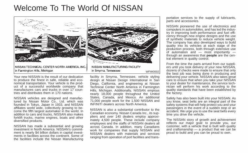
Your new NISSAN is the result of our dedicationto produce the finest in safe, reliable and eco-nomical transportation. Your vehicle is the prod-uct of a successful worldwide company thatmanufactures cars and trucks in over 17 coun-tries and distributes them in 170 nations.
NISSAN vehicles are designed and manufac-tured by Nissan Motor Co., Ltd. which wasfounded in Tokyo, Japan in 1933, and NISSANaffiliates world wide, collectively growing to be-come the fifth largest automaker in the world. Inaddition to cars and trucks, NISSAN also makesforklift trucks, marine engines, boats and otherdiversified products.
NISSAN has made a substantial and growinginvestment in North America. NISSAN’s commit-ment is nearly $4 billion dollars in capital invest-ments in facilities across the continent. Some ofthe facilities include the Nissan Manufacturing
facility in Smyrna, Tennessee, vehicle stylingdesign at Nissan Design International in SanDiego, California, and engineering at NissanTechnical Center North America in FarmingtonHills, Michigan. Additionally, NISSAN employsnearly 18,000 people throughout the UnitedStates, Canada, and Mexico. An additional71,000 people work for the 1,500 NISSAN andINFINITI dealers across North America.
NISSAN is also a substantial contributor to theCanadian economy. Nissan Canada Inc., its sup-pliers and over 140 dealers employ approxi-mately 4,500 people. These include companyemployees and the staffs of NISSAN dealers allacross Canada. In addition, many Canadianswork for companies that supply NISSAN andNISSAN dealers with materials and servicesranging from operation of port facilities and trans-
portation services to the supply of lubricants,parts and accessories.
NISSAN pioneered the use of electronics andcomputers in automobiles, and has led the indus-try in improving both performance and fuel effi-ciency through new engine designs and the useof synthetic materials to reduce vehicle weight.The company has also developed ways to buildquality into its vehicles at each stage of theproduction process, both through extensive useof automation and — most importantly —through an awareness that people are the cen-tral element in quality control.
From the time the parts arrived from our suppli-ers until you took delivery of your new NISSAN,dozens of checks were made to ensure that onlythe best job was being done in producing anddelivering your vehicle. NISSAN also takes greatcare to ensure that when you take your NISSANto your dealer for maintenance, the service tech-nician will perform his work according to thequality standards that have been established bythe factory.
Safety has also been built into your NISSAN. Asyou know, seat belts are an integral part of thesafety systems that will help protect you and yourpassengers in the event of a sudden stop or anaccident. We urge you to use the seat belts everytime you drive the vehicle.
The NISSAN story of growth and achievementreflects our major goal: to provide you, ourcustomer, with a vehicle that is built with qualityand craftsmanship — a product that we can beproud to build and you can be proud to own.
WFW0002
Z X
NISSAN CUSTOMER CARE PROGRAMNISSAN CARES ...
Both NISSAN and your NISSAN dealer are dedicated to serving all your automotive needs. Your satisfaction withyour vehicle and your NISSAN dealer are our primary concerns. Your NISSAN dealer is always available to assistyou with all your automobile sales and service needs.
However, if there is something that yourNISSAN dealer cannot assist you with oryou would like to provide NISSAN directlywith comments or questions, please con-tact our (NISSAN’s) Consumer Affairs De-partment using our toll-free number:
For U.S. mainland customers1-800-NISSAN-1(1-800-647-7261)
For Hawaii customers(808) 836-0888 (Oahu Number)
For CANADIAN customers1-800-387-0122
The Consumer Affairs Department will askfor the following information:— Your name, address, and telephone
number— Vehicle identification number (on dash-
board)— Date of purchase— Current odometer reading— Your NISSAN dealer’s name— Your comments or questions
OR
You can write to NISSAN with the informa-
tion on the left at:
For U.S. mainland and Alaska custom-ers
Nissan North America, Inc.Consumer Affairs DepartmentP.O. Box 191Gardena, California 90248-0191
For Hawaii customersNissan Motor Corporation in Hawaii2880 Kilihau St.Honolulu, Hawaii 96819
For Canada customersNissan Canada Inc.5290 Orbitor DriveMississauga, Ontario L4W 4Z5
We appreciate your interest in NISSAN and thank you for buying a quality NISSAN vehicle.
Z X
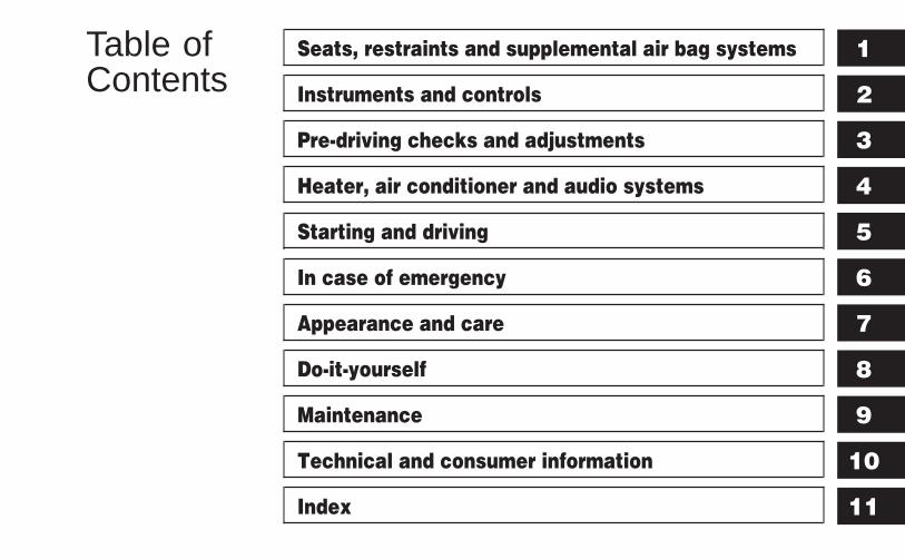
Table ofContents
Seats, restraints and supplemental air bag systems
Instruments and controls
Pre-driving checks and adjustments
Heater, air conditioner and audio systems
Starting and driving
In case of emergency
Appearance and care
Do-it-yourself
Maintenance
Technical and consumer information
Index
1
2
3
4
5
6
7
8
9
10
11

Z X
1 Seats, restraints and supplemental airbag systems
Seats ......................................................................1-2Front manual seat adjustment...........................1-2Rear seat adjustment ........................................1-3Head restraint adjustment .................................1-5
Supplemental restraint system...............................1-6Precautions on supplemental restraintsystem ...............................................................1-6Supplemental air bag warning labels ..............1-12Supplemental air bag warning light.................1-13
Seat belts .............................................................1-14Precautions on seat belt usage ......................1-14Child safety......................................................1-16Pregnant women .............................................1-17
Injured persons................................................1-17Three-point type seat belt with retractor .........1-17Two-point type seat belt withoutretractor (center of rear seat) ..........................1-20Seat belt extenders .........................................1-22Seat belt maintenance ....................................1-22
Child restraints .....................................................1-22Precautions on child restraints ........................1-22Installation on rear seat center position..........1-24Installation on rear seat outboardpositions ..........................................................1-27Top tether strap child restraint.........................1-32Installation on front passenger seat ................1-33
Z X
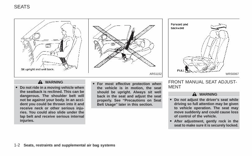
WARNINGO Do not ride in a moving vehicle when
the seatback is reclined. This can bedangerous. The shoulder belt willnot be against your body. In an acci-dent you could be thrown into it andreceive neck or other serious inju-ries. You could also slide under thelap belt and receive serious internalinjuries.
O For most effective protection whenthe vehicle is in motion, the seatshould be upright. Always sit wellback in the seat and adjust the seatproperly. See ‘‘Precautions on SeatBelt Usage’’ later in this section.
FRONT MANUAL SEAT ADJUST-MENT
WARNINGO Do not adjust the driver’s seat while
driving so full attention may be givento vehicle operation. The seat maymove suddenly and could cause lossof control of the vehicle.
O After adjustment, gently rock in theseat to make sure it is securely locked.
ARS1152 WRS0067
SEATS
1-2 Seats, restraints and supplemental air bag systems
Z X
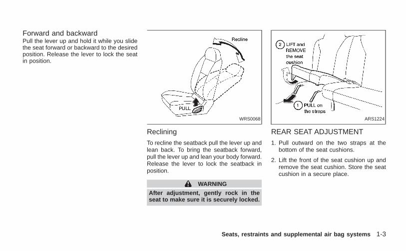
Forward and backwardPull the lever up and hold it while you slidethe seat forward or backward to the desiredposition. Release the lever to lock the seatin position.
Reclining
To recline the seatback pull the lever up andlean back. To bring the seatback forward,pull the lever up and lean your body forward.Release the lever to lock the seatback inposition.
WARNING
After adjustment, gently rock in theseat to make sure it is securely locked.
REAR SEAT ADJUSTMENT
1. Pull outward on the two straps at thebottom of the seat cushions.
2. Lift the front of the seat cushion up andremove the seat cushion. Store the seatcushion in a secure place.
WRS0068 ARS1224
Seats, restraints and supplemental air bag systems 1-3
Z X
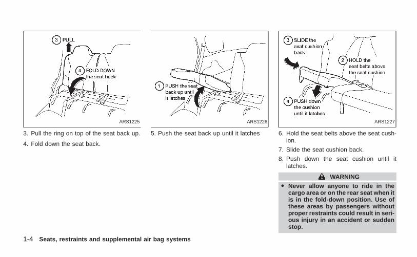
3. Pull the ring on top of the seat back up.
4. Fold down the seat back.
5. Push the seat back up until it latches 6. Hold the seat belts above the seat cush-ion.
7. Slide the seat cushion back.
8. Push down the seat cushion until itlatches.
WARNING
O Never allow anyone to ride in thecargo area or on the rear seat when itis in the fold-down position. Use ofthese areas by passengers withoutproper restraints could result in seri-ous injury in an accident or suddenstop.
ARS1225 ARS1226 ARS1227
1-4 Seats, restraints and supplemental air bag systems
Z X
O It is extremely dangerous to ride in acargo area inside of a vehicle. In acollision, people riding in these ar-eas are more likely to be seriouslyinjured or killed.
O Do not allow people to ride in anyarea of your vehicle that is notequipped with seats and seat belts.Be sure everyone in your vehicle isin a seat and using a seat belt prop-erly. Never ride in the rear seat un-less the seat bottom cushions are inplace and latched.
O Properly secure all cargo to helpprevent it from sliding or shifting. Donot place cargo higher than the seat-backs. In a sudden stop or collision,unsecured cargo could cause per-sonal injury.
O When returning the seatbacks to theupright position, be certain they arecompletely secured in the latchedposition. If they are not completelysecured in the latched position, pas-sengers may be injured in an acci-dent or sudden stop.
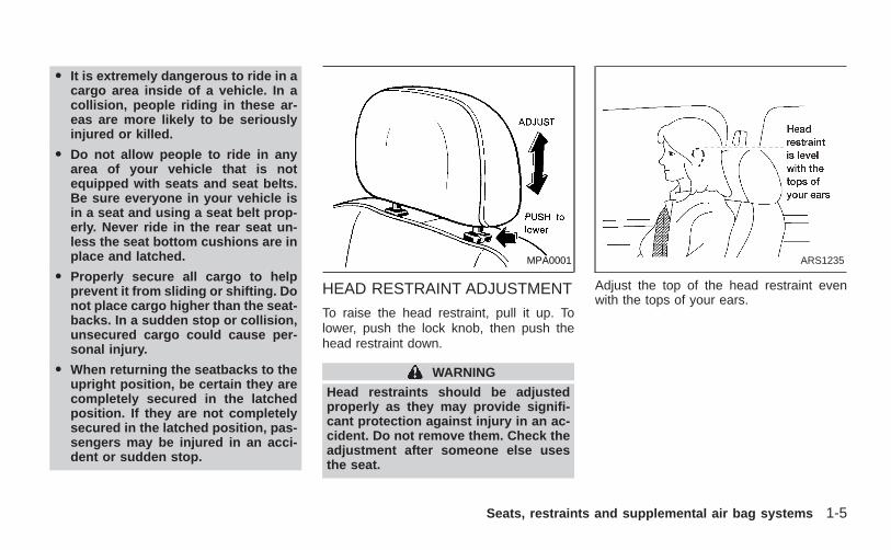
HEAD RESTRAINT ADJUSTMENT
To raise the head restraint, pull it up. Tolower, push the lock knob, then push thehead restraint down.
WARNING
Head restraints should be adjustedproperly as they may provide signifi-cant protection against injury in an ac-cident. Do not remove them. Check theadjustment after someone else usesthe seat.
Adjust the top of the head restraint evenwith the tops of your ears.
MPA0001 ARS1235
Seats, restraints and supplemental air bag systems 1-5
Z X
PRECAUTIONS ON SUPPLE-MENTAL RESTRAINT SYSTEM
This supplemental restraint system sectioncontains important information concerningthe driver and passenger supplemental airbags. The supplemental restraint system airbags can help reduce impact force to thedriver and front passenger in certain frontalcollisions. The supplemental air bags aredesigned to supplement the crash protec-tion provided by the driver and front passen-ger seat belts and are not a substitute forthem. Seat belts should always be correctlyworn and the driver and front passengerseated a suitable distance away from thesteering wheel and instrument panel. See‘‘Seat belts’’ for instructions and precautionson seat belt usage later in this section.
The supplemental air bags operate onlywhen the ignition switch is in the ON orSTART position.
After turning the ignition key to the ONposition, the supplemental air bag warn-ing light illuminates. The supplementalair bag warning light will turn off afterabout 7 seconds if the system is opera-tional.
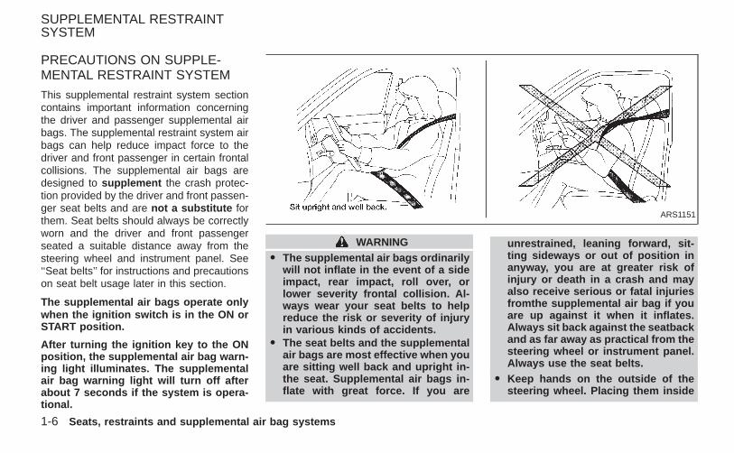
WARNINGO The supplemental air bags ordinarily
will not inflate in the event of a sideimpact, rear impact, roll over, orlower severity frontal collision. Al-ways wear your seat belts to helpreduce the risk or severity of injuryin various kinds of accidents.
O The seat belts and the supplementalair bags are most effective when youare sitting well back and upright in-the seat. Supplemental air bags in-flate with great force. If you are
unrestrained, leaning forward, sit-ting sideways or out of position inanyway, you are at greater risk ofinjury or death in a crash and mayalso receive serious or fatal injuriesfromthe supplemental air bag if youare up against it when it inflates.Always sit back against the seatbackand as far away as practical from thesteering wheel or instrument panel.Always use the seat belts.
O Keep hands on the outside of thesteering wheel. Placing them inside
ARS1151
SUPPLEMENTAL RESTRAINTSYSTEM
1-6 Seats, restraints and supplemental air bag systems
Z X
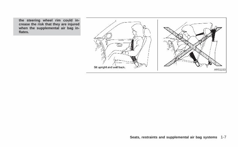
the steering wheel rim could in-crease the risk that they are injuredwhen the supplemental air bag in-flates.
ARS1153
Seats, restraints and supplemental air bag systems 1-7
Z X
ARS1041
ARS1042
ARS1043
ARS1044
ARS1098
ARS1099
1-8 Seats, restraints and supplemental air bag systems
Z X
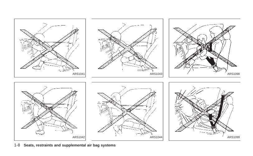
WARNINGO Never let children ride unrestrained.
Do not attempt to hold them in yourlap or arms. Some examples of dan-gerous riding positions are shown inthe illustrations.
O Children may be severely injured orkilled when the supplemental air baginflates if they are not properly re-strained.
O Never install a rear-facing child re-straint in the front seat. An inflatingsupplemental air bag could seri-ously injure or kill your child. See‘‘Child restraints’’ later in this sec-tion for details.
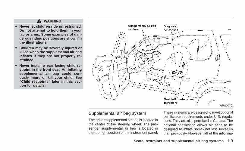
Supplemental air bag system
The driver supplemental air bag is located inthe center of the steering wheel. The pas-senger supplemental air bag is located inthe top right section of the instrument panel.
These systems are designed to meet optionalcertification requirements under U.S. regula-tions. They are also permitted in Canada. Theoptional certification allows air bags to bedesigned to inflate somewhat less forcefullythan previously. However, all of the informa-
WRS0079
Seats, restraints and supplemental air bag systems 1-9
Z X
tion, cautions and warnings in this manualstill apply and must be followed.
The supplemental air bag system is de-signed to inflate in higher severity frontalcollisions, although it may inflate if theforces in another type of collision are similarto those of a higher severity frontal impact. Itmay not inflate in certain frontal collisions.Vehicle damage (or lack of it) is not alwaysan indication of proper supplemental air bagsystem operation.When the supplemental air bag inflates, afairly loud noise may be heard, followed bythe release of smoke. This smoke is notharmful and does not indicate a fire, butcare should be taken not to intentionallyinhale it, as it may cause irritation andchoking. Those with a history of a breathingcondition should get fresh air promptly.The supplemental air bags, along with theuse of the seat belts, helps to cushion theimpact force on the face and chest of theoccupant. It can help save lives and reduceserious injuries. However, an inflating sup-plemental air bag may cause facial abrasionsor other injuries. Supplemental air bags donot provide restraint to the lower body.Seat belts should be correctly worn and the
driver and passenger seated upright as faras practical away from the steering wheel orinstrument panel. Since the supplemental airbags inflate quickly in order to help protectthe front occupants, the force of the supple-mental air bags inflating can increase therisk of injury if the occupant is too close to oragainst the supplemental air bag moduleduring inflation.The supplemental air bags deflate quicklyafter a collision.The supplemental air bags operate onlywhen the ignition switch is in the ON orSTART position.
WARNINGO Do not place any objects on the
steering wheel pad or on the instru-ment panel. Also, do not place anyobjects between any occupant andthe steering wheel or on the instru-ment panel. Such objects may be-come dangerous projectiles, andcause injury if the supplemental airbag inflates.
O Right after inflation, several supple-mental air bag system components
will be hot. Do not touch them; you-may severely burn yourself.
O No unauthorized changes should bemade to any components or wiring ofthe supplemental air bag system. Thisis to prevent accidental inflation ofthe supplemental air bag or damageto the supplemental air bag system.
O Do not make unauthorized changes toyour vehicle’s electrical system, sus-pension system or front end structure.This could affect proper operation ofthe supplemental air bag system.
O Tampering with the supplemental airbag system may result in seriouspersonal injury. Tampering includeschanges to the steering wheel andthe instrument panel assembly, byplacing material over the steeringwheel pad and above the instrumentpanel, or by installing additional trimmaterial around the supplemental airbag system.
O Work around and on the supplemen-tal air bag system should be done byan authorized NISSAN dealer.
1-10 Seats, restraints and supplemental air bag systems
Z X
Installation of electrical equipmentshouldalso be done by an authorizedNISSAN dealer. The yellow Supple-mental Restraint System (SRS) wir-ing should not be modified or dis-connected. Unauthorized electricaltest equipment and probing devicesshould not be used on the supple-mental air bag system.
O The SRS wiring harnesses (exceptthe pre-tensioner seat belt system)are covered with yellow insulationeither just before the harness con-nectors or over the complete har-ness for easy identification.
When selling your vehicle, we request thatyou inform the buyer about the supplementalair bag system and guide the buyer to theappropriate sections in this owner’s manual.
Pre-tensioner seat belt system(For front seats)
WARNING
O The pre-tensioner seat belt cannotbe reused after activation. It must be
replaced together with the retractorand buckle as a unit.
O If the vehicle becomes involved in afrontal collision but the pre-tensioner is not activated, be sure tohave the pre-tensioner systemchecked and, if necessary, replacedby your NISSAN dealer.
O No unauthorized changes should bemade to any components or wiringof the pre-tensioner seat belt sys-tem. This is to prevent accidentalactivation of the pre-tensioner seatbelt or damage to the pre-tensionerseat belt operation. Tampering withthe pre-tensioner seat belt systemmay result in serious personal in-jury.
O Work around and on the pre-tensioner system should be done byan authorized NISSAN dealer.
Installation of electrical equipmentshould also be done by an autho-rized NISSAN dealer. Unauthorizedelectrical test equipment and prob-ing devices should not be used on
the pre-tensioner seat belt system.
O If you need to dispose of the pre-tensioner or scrap the vehicle, con-tact an authorized NISSAN dealer.Correct pre-tensioner disposal pro-cedures are set forth in the appropri-ate NISSAN Service Manual. Incor-rect disposal procedures couldcause personal injury.
The front seat pre-tensioner seat belt sys-tem activates in conjuction with the supple-mental air bag. Working with the seat beltretractor, it helps tighten the seat belt theinstant the vehicle becomes involved incertain types of collisions.
The pre-tensioner is encased with the seatbelt’s retractor. These seat belts are usedthe same as conventional seat belts.
When the pre-tensioner seat belt activates,smoke is released and a loud noise may beheard. The smoke is not harmful, but careshould be taken not to intentionally inhale itas it may cause irritation and choking.
If any abnormality occurs in the pre-tensioner system, the supplemental air bagwarning light will flash intermit-
Seats, restraints and supplemental air bag systems 1-11
Z X
tently after the ignition key is turned to theON or START position. In this case, thepre-tensioner seat belt will not functionproperly.
When selling your vehicle, we request thatyou inform the buyer about the pre-tensioner seat belt system and guide thebuyer to the appropriate sections in thisOwner’s Manual.
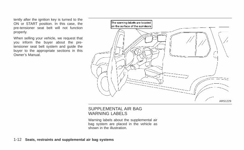
SUPPLEMENTAL AIR BAGWARNING LABELSWarning labels about the supplemental airbag system are placed in the vehicle asshown in the illustration.
ARS1229
1-12 Seats, restraints and supplemental air bag systems
Z X
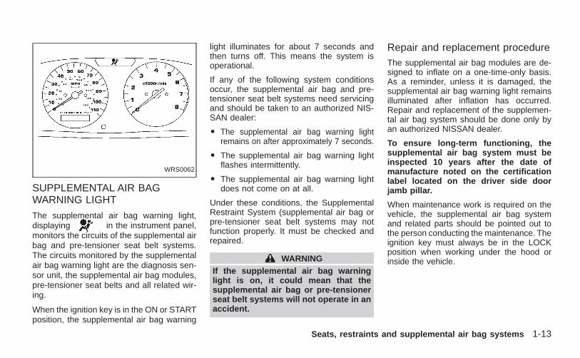
SUPPLEMENTAL AIR BAGWARNING LIGHT
The supplemental air bag warning light,displaying in the instrument panel,monitors the circuits of the supplemental airbag and pre-tensioner seat belt systems.The circuits monitored by the supplementalair bag warning light are the diagnosis sen-sor unit, the supplemental air bag modules,pre-tensioner seat belts and all related wir-ing.
When the ignition key is in the ON or STARTposition, the supplemental air bag warning
light illuminates for about 7 seconds andthen turns off. This means the system isoperational.
If any of the following system conditionsoccur, the supplemental air bag and pre-tensioner seat belt systems need servicingand should be taken to an authorized NIS-SAN dealer:
O The supplemental air bag warning lightremains on after approximately 7 seconds.
O The supplemental air bag warning lightflashes intermittently.
O The supplemental air bag warning lightdoes not come on at all.
Under these conditions, the SupplementalRestraint System (supplemental air bag orpre-tensioner seat belt systems may notfunction properly. It must be checked andrepaired.
WARNINGIf the supplemental air bag warninglight is on, it could mean that thesupplemental air bag or pre-tensionerseat belt systems will not operate in anaccident.
Repair and replacement procedureThe supplemental air bag modules are de-signed to inflate on a one-time-only basis.As a reminder, unless it is damaged, thesupplemental air bag warning light remainsilluminated after inflation has occurred.Repair and replacement of the supplemen-tal air bag system should be done only byan authorized NISSAN dealer.
To ensure long-term functioning, thesupplemental air bag system must beinspected 10 years after the date ofmanufacture noted on the certificationlabel located on the driver side doorjamb pillar.
When maintenance work is required on thevehicle, the supplemental air bag systemand related parts should be pointed out tothe person conducting the maintenance. Theignition key must always be in the LOCKposition when working under the hood orinside the vehicle.
WRS0062
Seats, restraints and supplemental air bag systems 1-13
Z X
WARNINGO Once the supplemental air bag in-
flates, the supplemental air bagmodule will not function again andshould be replaced by an authorizedNISSAN dealer. The supplemental airbag module cannot be repaired.
O The supplemental air bag systemshould be inspected by an autho-rized NISSAN dealer if there is anydamage to the front end portion ofthe vehicle, or replaced if the supple-mental air bag has inflated.
O If you need to dispose of the supple-mental air bag or scrap the vehicle,contact an authorized NISSANdealer. Correct supplemental air bagdisposal procedures are set forth inthe appropriate NISSAN ServiceManual. Incorrect disposal proce-dures could cause personal injury.
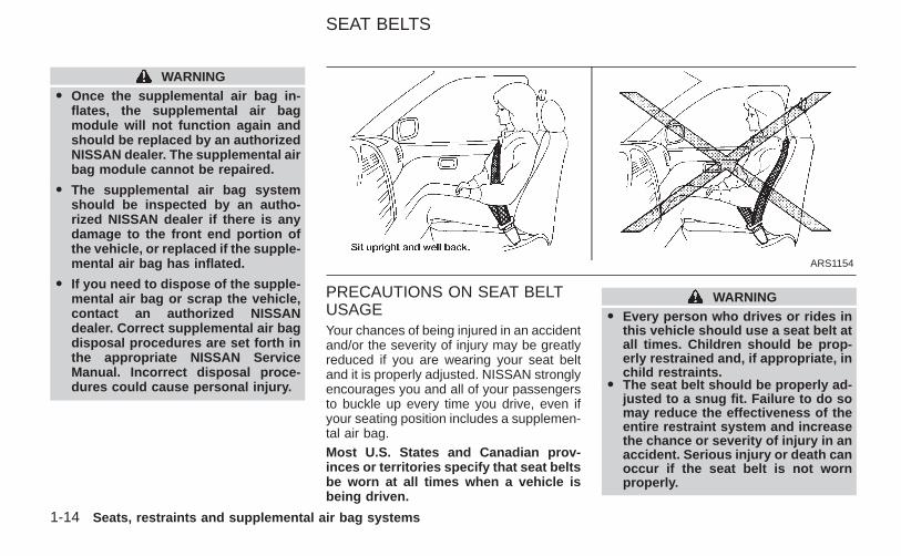
PRECAUTIONS ON SEAT BELTUSAGEYour chances of being injured in an accidentand/or the severity of injury may be greatlyreduced if you are wearing your seat beltand it is properly adjusted. NISSAN stronglyencourages you and all of your passengersto buckle up every time you drive, even ifyour seating position includes a supplemen-tal air bag.Most U.S. States and Canadian prov-inces or territories specify that seat beltsbe worn at all times when a vehicle isbeing driven.
WARNINGO Every person who drives or rides in
this vehicle should use a seat belt atall times. Children should be prop-erly restrained and, if appropriate, inchild restraints.
O The seat belt should be properly ad-justed to a snug fit. Failure to do somay reduce the effectiveness of theentire restraint system and increasethe chance or severity of injury in anaccident. Serious injury or death canoccur if the seat belt is not wornproperly.
ARS1154
SEAT BELTS
1-14 Seats, restraints and supplemental air bag systems
Z X
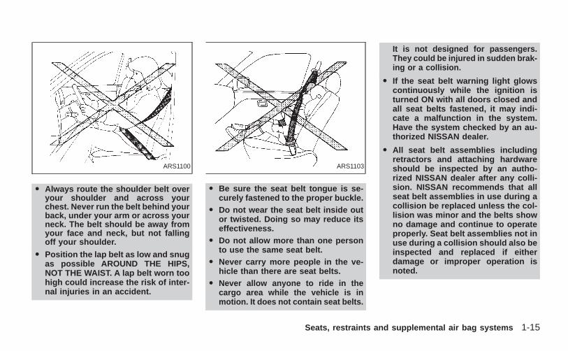
O Always route the shoulder belt overyour shoulder and across yourchest. Never run the belt behind yourback, under your arm or across yourneck. The belt should be away fromyour face and neck, but not fallingoff your shoulder.
O Position the lap belt as low and snugas possible AROUND THE HIPS,NOT THE WAIST. A lap belt worn toohigh could increase the risk of inter-nal injuries in an accident.
O Be sure the seat belt tongue is se-curely fastened to the proper buckle.
O Do not wear the seat belt inside outor twisted. Doing so may reduce itseffectiveness.
O Do not allow more than one personto use the same seat belt.
O Never carry more people in the ve-hicle than there are seat belts.
O Never allow anyone to ride in thecargo area while the vehicle is inmotion. It does not contain seat belts.
It is not designed for passengers.They could be injured in sudden brak-ing or a collision.
O If the seat belt warning light glowscontinuously while the ignition isturned ON with all doors closed andall seat belts fastened, it may indi-cate a malfunction in the system.Have the system checked by an au-thorized NISSAN dealer.
O All seat belt assemblies includingretractors and attaching hardwareshould be inspected by an autho-rized NISSAN dealer after any colli-sion. NISSAN recommends that allseat belt assemblies in use during acollision be replaced unless the col-lision was minor and the belts showno damage and continue to operateproperly. Seat belt assemblies not inuse during a collision should also beinspected and replaced if eitherdamage or improper operation isnoted.
ARS1100 ARS1103
Seats, restraints and supplemental air bag systems 1-15
Z X
CHILD SAFETYChildren need adults to help protect them.They need to be properly restrained.
The proper restraint depends on the child’ssize. Generally, infants up to about 1 yearand less than 20 pounds (9 kg) should beplaced in rear facing child restraints. Frontfacing child restraints are available for chil-dren who outgrow rear facing child re-straints.
WARNINGO Infants and children need special
protection. The vehicle’s seat beltsmay not fit them properly. The shoul-der belt may come too close to theface or neck. The lap belt may not fitover their small hip bones. In anaccident, an improperly fitting seatbelt could cause serious or fatal in-jury. Always use appropriate childrestraints.
All U.S. states and Canadian provinces orterritories require the use of approved childrestraints for infants and small children. See‘‘Child restraints’’ later in this section formore information.
In addition, there are many types of childrestraints available for larger children whichshould be used for maximum protection.
NISSAN recommends that all pre-teenchildren be restrained in the rear seat ifpossible. According to accident statis-tics, children are safer when properlyrestrained in the rear seat than in thefront seat.
This is especially important becauseyour vehicle has a supplemental re-straint system (Supplemental air bagsystem) for the front passenger (For pre-cautions, see ‘‘Supplemental restraintsystem’’ earlier in this section).
Infants and small children
NISSAN recommends that infants and smallchildren be seated in child restraints thatcomply with Federal Motor Vehicle SafetyStandards or Canadian Motor VehicleSafety Standards. You should choose achild restraint which fits your vehicle andalways follow the manufacturer’s instruc-tions for installation and use.
Larger children
Children who are too large for child re-straints should be seated and restrained bythe seat belts which are provided.
If the child’s seating position has a shoulderbelt that fits close to the face or neck, theuse of a booster seat (commercially avail-able) may help overcome this. The boosterseat should raise the child so the shoulderbelt is properly positioned across the top,middle portion of the shoulder and the lapbelt is low on the hips. The booster seatshould fit the vehicle seat and have a labelcertifying that it complies with Federal MotorVehicle Safety Standards or Canadian Mo-tor Vehicle Safety Standards. Once the childhas grown so the shoulder belt is no longeron or near the face and neck, use theshoulder belt without the booster seat.
WARNING
Never let a child stand or kneel on anyseat and do not allow a child in thecargo areas while the vehicle is moving.The child could be seriously injured orkilled in an accident or sudden stop.
1-16 Seats, restraints and supplemental air bag systems
Z X
PREGNANT WOMENNISSAN recommends that pregnant womenuse seat belts. The seat belt should be wornsnug, and always position the lap belt aslow as possible around the hips, not thewaist. Place the shoulder belt over yourshoulder and across your chest. Never runthe lap/shoulder belt over your abdominalarea. Contact your doctor for specific rec-ommendations.
INJURED PERSONSNISSAN recommends that injured personsuse seat belts, depending on the injury.Check with your doctor for specific recom-mendations.
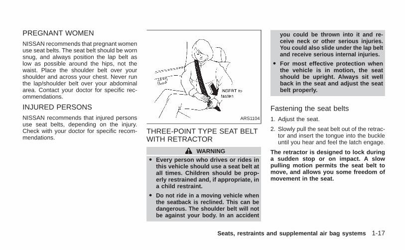
THREE-POINT TYPE SEAT BELTWITH RETRACTOR
WARNINGO Every person who drives or rides in
this vehicle should use a seat belt atall times. Children should be prop-erly restrained and, if appropriate, ina child restraint.
O Do not ride in a moving vehicle whenthe seatback is reclined. This can bedangerous. The shoulder belt will notbe against your body. In an accident
you could be thrown into it and re-ceive neck or other serious injuries.You could also slide under the lap beltand receive serious internal injuries.
O For most effective protection whenthe vehicle is in motion, the seatshould be upright. Always sit wellback in the seat and adjust the seatbelt properly.
Fastening the seat belts1. Adjust the seat.
2. Slowly pull the seat belt out of the retrac-tor and insert the tongue into the buckleuntil you hear and feel the latch engage.
The retractor is designed to lock duringa sudden stop or on impact. A slowpulling motion permits the seat belt tomove, and allows you some freedom ofmovement in the seat.
ARS1104
Seats, restraints and supplemental air bag systems 1-17
Z X
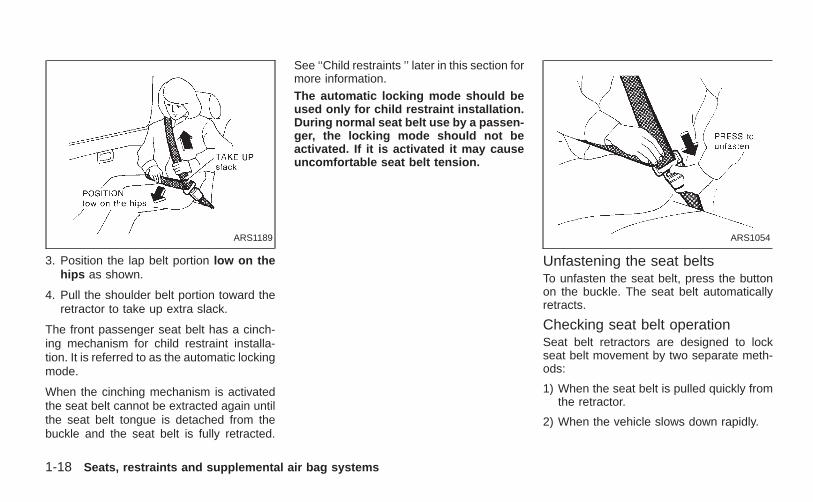
3. Position the lap belt portion low on thehips as shown.
4. Pull the shoulder belt portion toward theretractor to take up extra slack.
The front passenger seat belt has a cinch-ing mechanism for child restraint installa-tion. It is referred to as the automatic lockingmode.
When the cinching mechanism is activatedthe seat belt cannot be extracted again untilthe seat belt tongue is detached from thebuckle and the seat belt is fully retracted.
See ‘‘Child restraints ’’ later in this section formore information.The automatic locking mode should beused only for child restraint installation.During normal seat belt use by a passen-ger, the locking mode should not beactivated. If it is activated it may causeuncomfortable seat belt tension.
Unfastening the seat beltsTo unfasten the seat belt, press the buttonon the buckle. The seat belt automaticallyretracts.
Checking seat belt operationSeat belt retractors are designed to lockseat belt movement by two separate meth-ods:
1) When the seat belt is pulled quickly fromthe retractor.
2) When the vehicle slows down rapidly.
ARS1189 ARS1054
1-18 Seats, restraints and supplemental air bag systems
Z X
To increase your confidence in the seatbelts, check the operation as follows.
O Grasp the shoulder belt and pull quicklyforward. The retractor should lock andrestrict further belt movement.
If the retractor does not lock during thischeck, or if you have any questions aboutseat belt operation, see an authorizedNISSAN dealer.
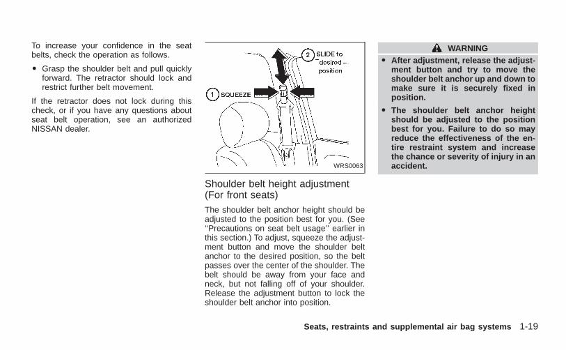
Shoulder belt height adjustment(For front seats)The shoulder belt anchor height should beadjusted to the position best for you. (See‘‘Precautions on seat belt usage’’ earlier inthis section.) To adjust, squeeze the adjust-ment button and move the shoulder beltanchor to the desired position, so the beltpasses over the center of the shoulder. Thebelt should be away from your face andneck, but not falling off of your shoulder.Release the adjustment button to lock theshoulder belt anchor into position.
WARNINGO After adjustment, release the adjust-
ment button and try to move theshoulder belt anchor up and down tomake sure it is securely fixed inposition.
O The shoulder belt anchor heightshould be adjusted to the positionbest for you. Failure to do so mayreduce the effectiveness of the en-tire restraint system and increasethe chance or severity of injury in anaccident.WRS0063
Seats, restraints and supplemental air bag systems 1-19
Z X
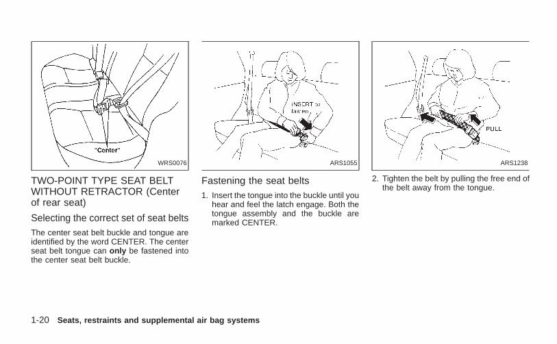
TWO-POINT TYPE SEAT BELTWITHOUT RETRACTOR (Centerof rear seat)
Selecting the correct set of seat beltsThe center seat belt buckle and tongue areidentified by the word CENTER. The centerseat belt tongue can only be fastened intothe center seat belt buckle.
Fastening the seat belts1. Insert the tongue into the buckle until you
hear and feel the latch engage. Both thetongue assembly and the buckle aremarked CENTER.
2. Tighten the belt by pulling the free end ofthe belt away from the tongue.
WRS0076 ARS1055 ARS1238
1-20 Seats, restraints and supplemental air bag systems
Z X
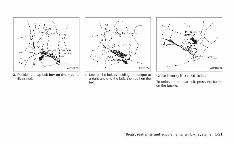
3. Position the lap belt low on the hips asillustrated.
4. Loosen the belt by holding the tongue ata right angle to the belt, then pull on thebelt.
Unfastening the seat beltsTo unfasten the seat belt, press the buttonon the buckle.
ARS1076 ARS1057 ARS1058
Seats, restraints and supplemental air bag systems 1-21
Z X
SEAT BELT EXTENDERSIf, because of body size or driving position,it is not possible to properly fit the lap-shoulder belt and fasten it, an extender isavailable which is compatible with the in-stalled seat belts. The extender adds ap-proximately 8 inches (200 mm) of lengthand may be used for either the driver or frontpassenger seating position. See an autho-rized NISSAN dealer for assistance if theextender is required.
WARNINGO Only NISSAN seat belt extenders,
made by the same company whichmade the original equipment seatbelts, should be used with NISSANseat belts.
O Persons who can use the standardseat belt should not use an extender.Such unnecessary use could resultin serious personal injury in theevent of an accident.
SEAT BELT MAINTENANCEO To clean the seat belt webbings, apply
a mild soap solution or any solution rec-ommended for cleaning upholstery orcarpet. Then wipe with a cloth and allowthe seat belts to dry in the shade. Do notallow the seat belts to retract until theyare completely dry.
O If dirt builds up in the shoulder beltguide of the seat belt anchors, the seatbelts may retract slowly. Wipe the shoul-der belt guide with a clean, dry cloth.
O Periodically check to see that the seatbelt and the metal components, suchas buckles, tongues, retractors, flexiblewires and anchors, work properly. If looseparts, deterioration, cuts or other damageon the webbing is found, the entire seatbelt assembly should be replaced.
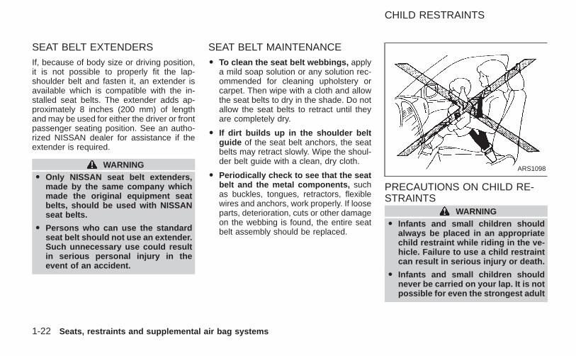
PRECAUTIONS ON CHILD RE-STRAINTS
WARNINGO Infants and small children should
always be placed in an appropriatechild restraint while riding in the ve-hicle. Failure to use a child restraintcan result in serious injury or death.
O Infants and small children shouldnever be carried on your lap. It is notpossible for even the strongest adult
ARS1098
CHILD RESTRAINTS
1-22 Seats, restraints and supplemental air bag systems
Z X
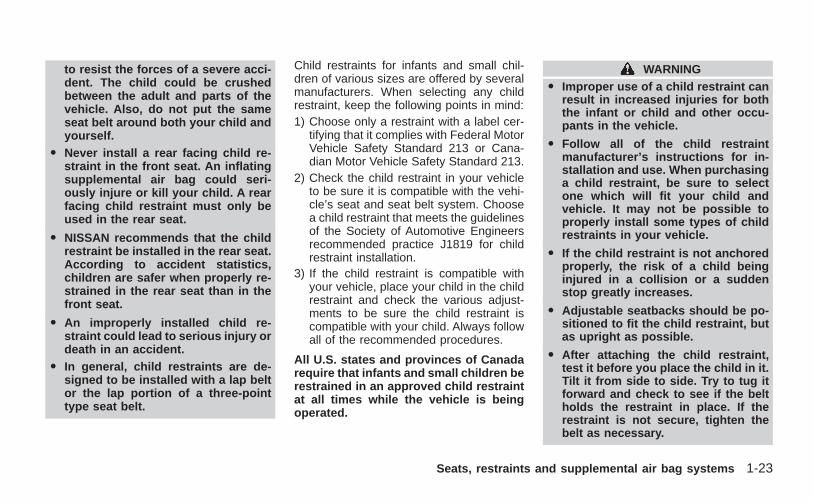
to resist the forces of a severe acci-dent. The child could be crushedbetween the adult and parts of thevehicle. Also, do not put the sameseat belt around both your child andyourself.
O Never install a rear facing child re-straint in the front seat. An inflatingsupplemental air bag could seri-ously injure or kill your child. A rearfacing child restraint must only beused in the rear seat.
O NISSAN recommends that the childrestraint be installed in the rear seat.According to accident statistics,children are safer when properly re-strained in the rear seat than in thefront seat.
O An improperly installed child re-straint could lead to serious injury ordeath in an accident.
O In general, child restraints are de-signed to be installed with a lap beltor the lap portion of a three-pointtype seat belt.
Child restraints for infants and small chil-dren of various sizes are offered by severalmanufacturers. When selecting any childrestraint, keep the following points in mind:1) Choose only a restraint with a label cer-
tifying that it complies with Federal MotorVehicle Safety Standard 213 or Cana-dian Motor Vehicle Safety Standard 213.
2) Check the child restraint in your vehicleto be sure it is compatible with the vehi-cle’s seat and seat belt system. Choosea child restraint that meets the guidelinesof the Society of Automotive Engineersrecommended practice J1819 for childrestraint installation.
3) If the child restraint is compatible withyour vehicle, place your child in the childrestraint and check the various adjust-ments to be sure the child restraint iscompatible with your child. Always followall of the recommended procedures.
All U.S. states and provinces of Canadarequire that infants and small children berestrained in an approved child restraintat all times while the vehicle is beingoperated.
WARNINGO Improper use of a child restraint can
result in increased injuries for boththe infant or child and other occu-pants in the vehicle.
O Follow all of the child restraintmanufacturer’s instructions for in-stallation and use. When purchasinga child restraint, be sure to selectone which will fit your child andvehicle. It may not be possible toproperly install some types of childrestraints in your vehicle.
O If the child restraint is not anchoredproperly, the risk of a child beinginjured in a collision or a suddenstop greatly increases.
O Adjustable seatbacks should be po-sitioned to fit the child restraint, butas upright as possible.
O After attaching the child restraint,test it before you place the child in it.Tilt it from side to side. Try to tug itforward and check to see if the beltholds the restraint in place. If therestraint is not secure, tighten thebelt as necessary.
Seats, restraints and supplemental air bag systems 1-23
Z X
O For a front-facing child restraint, ifthe seat position where it is installedhas a 3-point type lap/shoulder belt,check to make sure the shoulder beltdoes not go in front of the child’sface or neck. If it does, put the shoul-der belt behind the child restraint. Ifyou must install a front-facing childrestraint in the front seat, see “Instal-lation on front passenger seat” laterin this section for details.
O When your child restraint is not inuse, keep it secured with a seat beltto prevent it from being thrownaround in case of a sudden stop oraccident.
CAUTIONO Remember that a child restraint left
in a closed vehicle can become veryhot. Check the seating surface andbuckles before placing your child inthe child restraint.
O The three-point belt in your vehicleis equipped with an automatic lock-ing mode retractor which must beused when installing a child re-straint.
O Failure to use the retractor’s lockingmode will result in the child restraintnot being properly secured. The re-straint could tip over or otherwise beunsecured and cause injury to thechild in a sudden stop or collision.
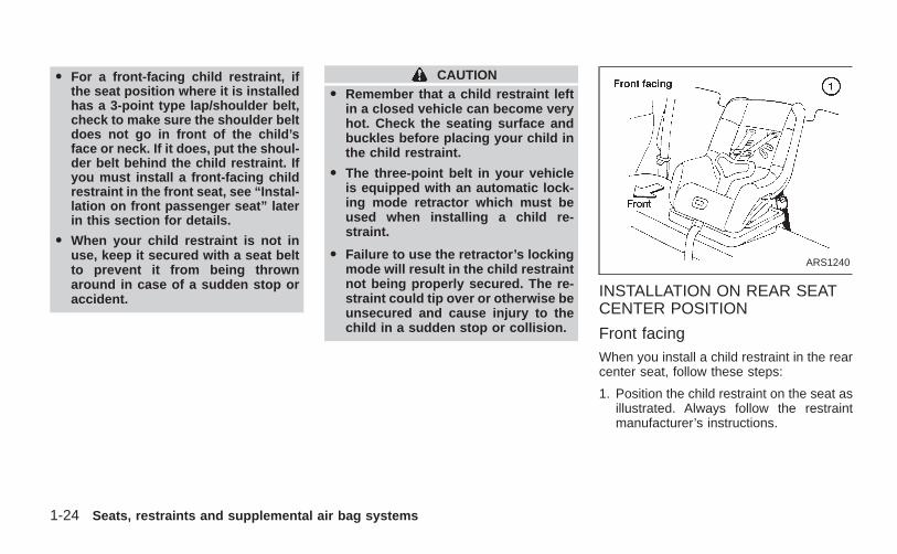
INSTALLATION ON REAR SEATCENTER POSITION
Front facingWhen you install a child restraint in the rearcenter seat, follow these steps:
1. Position the child restraint on the seat asillustrated. Always follow the restraintmanufacturer’s instructions.
ARS1240
1-24 Seats, restraints and supplemental air bag systems
Z X
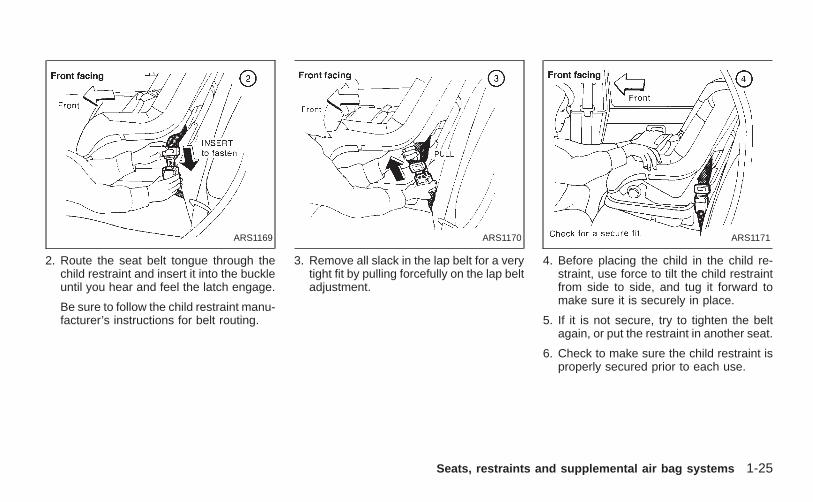
2. Route the seat belt tongue through thechild restraint and insert it into the buckleuntil you hear and feel the latch engage.
Be sure to follow the child restraint manu-facturer’s instructions for belt routing.
3. Remove all slack in the lap belt for a verytight fit by pulling forcefully on the lap beltadjustment.
4. Before placing the child in the child re-straint, use force to tilt the child restraintfrom side to side, and tug it forward tomake sure it is securely in place.
5. If it is not secure, try to tighten the beltagain, or put the restraint in another seat.
6. Check to make sure the child restraint isproperly secured prior to each use.
ARS1169 ARS1170 ARS1171
Seats, restraints and supplemental air bag systems 1-25
Z X
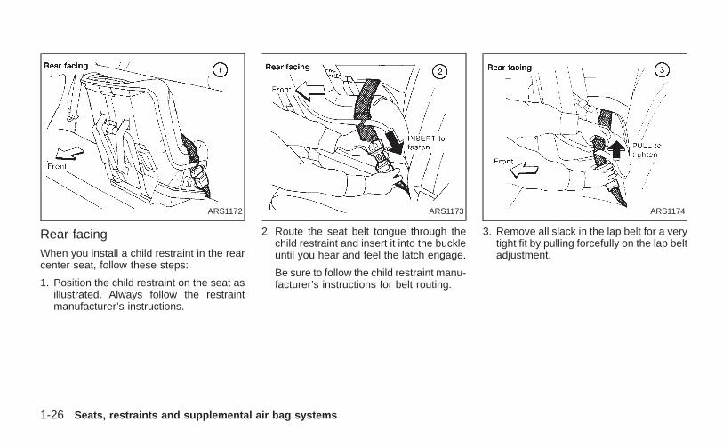
Rear facingWhen you install a child restraint in the rearcenter seat, follow these steps:
1. Position the child restraint on the seat asillustrated. Always follow the restraintmanufacturer’s instructions.
2. Route the seat belt tongue through thechild restraint and insert it into the buckleuntil you hear and feel the latch engage.
Be sure to follow the child restraint manu-facturer’s instructions for belt routing.
3. Remove all slack in the lap belt for a verytight fit by pulling forcefully on the lap beltadjustment.
ARS1172 ARS1173 ARS1174
1-26 Seats, restraints and supplemental air bag systems
Z X
4. Before placing the child in the child re-straint, use force to tilt the child restraintfrom side to side, and tug it forward tomake sure it is securely in place.
5. If it is not secure, try to tighten the beltagain, or put the restraint in another seat.
6. Check to make sure the child restraint isproperly secured prior to each use.
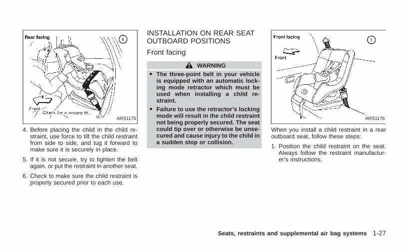
INSTALLATION ON REAR SEATOUTBOARD POSITIONS
Front facing
WARNINGO The three-point belt in your vehicle
is equipped with an automatic lock-ing mode retractor which must beused when installing a child re-straint.
O Failure to use the retractor’s lockingmode will result in the child restraintnot being properly secured. The seatcould tip over or otherwise be unse-cured and cause injury to the child ina sudden stop or collision.
When you install a child restraint in a rearoutboard seat, follow these steps:
1. Position the child restraint on the seat.Always follow the restraint manufactur-er’s instructions.
ARS1175 ARS1176
Seats, restraints and supplemental air bag systems 1-27
Z X
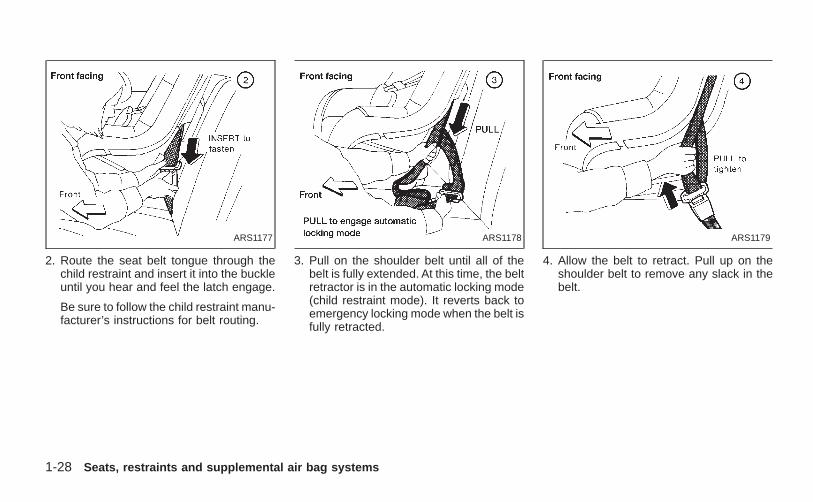
2. Route the seat belt tongue through thechild restraint and insert it into the buckleuntil you hear and feel the latch engage.
Be sure to follow the child restraint manu-facturer’s instructions for belt routing.
3. Pull on the shoulder belt until all of thebelt is fully extended. At this time, the beltretractor is in the automatic locking mode(child restraint mode). It reverts back toemergency locking mode when the belt isfully retracted.
4. Allow the belt to retract. Pull up on theshoulder belt to remove any slack in thebelt.
ARS1177 ARS1178 ARS1179
1-28 Seats, restraints and supplemental air bag systems
Z X
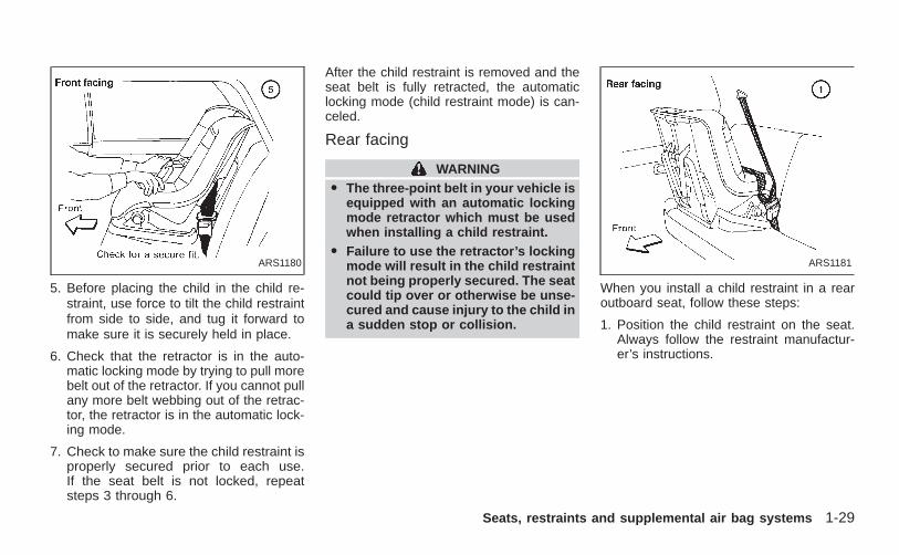
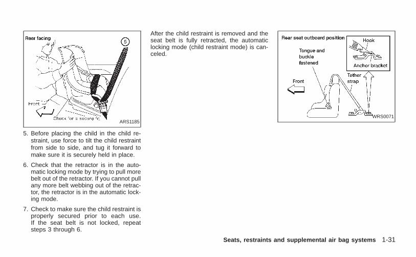
5. Before placing the child in the child re-straint, use force to tilt the child restraintfrom side to side, and tug it forward tomake sure it is securely held in place.
6. Check that the retractor is in the auto-matic locking mode by trying to pull morebelt out of the retractor. If you cannot pullany more belt webbing out of the retrac-tor, the retractor is in the automatic lock-ing mode.
7. Check to make sure the child restraint isproperly secured prior to each use.If the seat belt is not locked, repeatsteps 3 through 6.
After the child restraint is removed and theseat belt is fully retracted, the automaticlocking mode (child restraint mode) is can-celed.
Rear facing
WARNINGO The three-point belt in your vehicle is
equipped with an automatic lockingmode retractor which must be usedwhen installing a child restraint.
O Failure to use the retractor’s lockingmode will result in the child restraintnot being properly secured. The seatcould tip over or otherwise be unse-cured and cause injury to the child ina sudden stop or collision.
When you install a child restraint in a rearoutboard seat, follow these steps:
1. Position the child restraint on the seat.Always follow the restraint manufactur-er’s instructions.
ARS1180 ARS1181
Seats, restraints and supplemental air bag systems 1-29
Z X
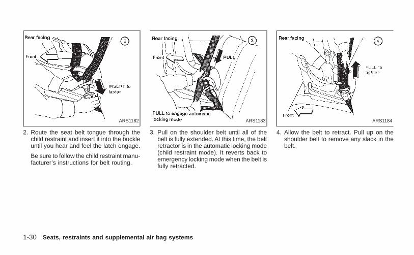
2. Route the seat belt tongue through thechild restraint and insert it into the buckleuntil you hear and feel the latch engage.
Be sure to follow the child restraint manu-facturer’s instructions for belt routing.
3. Pull on the shoulder belt until all of thebelt is fully extended. At this time, the beltretractor is in the automatic locking mode(child restraint mode). It reverts back toemergency locking mode when the belt isfully retracted.
4. Allow the belt to retract. Pull up on theshoulder belt to remove any slack in thebelt.
ARS1182 ARS1183 ARS1184
1-30 Seats, restraints and supplemental air bag systems
Z X
5. Before placing the child in the child re-straint, use force to tilt the child restraintfrom side to side, and tug it forward tomake sure it is securely held in place.
6. Check that the retractor is in the auto-matic locking mode by trying to pull morebelt out of the retractor. If you cannot pullany more belt webbing out of the retrac-tor, the retractor is in the automatic lock-ing mode.
7. Check to make sure the child restraint isproperly secured prior to each use.If the seat belt is not locked, repeatsteps 3 through 6.
After the child restraint is removed and theseat belt is fully retracted, the automaticlocking mode (child restraint mode) is can-celed.
ARS1185WRS0071
Seats, restraints and supplemental air bag systems 1-31
Z X
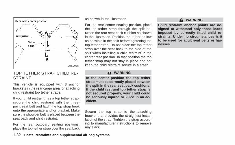
TOP TETHER STRAP CHILD RE-STRAINT
This vehicle is equipped with 3 anchorbrackets in the rear cargo area for attachingchild restraint top tether straps.
If your child restraint has a top tether strap,secure the child restraint with the three-point seat belt and latch the top strap hookonto the appropriate anchor bracket. Makesure the shoulder belt is placed between theseat back and child restraint.
For the rear outboard seating positions,place the top tether strap over the seat back
as shown in the illustration.
For the rear center seating position, placethe top tether strap through the split be-tween the rear seat back cushion as shownin the illustration. Position the tether as lowas possible in the split before tightening thetop tether strap. Do not place the top tetherstrap over the seat back to the side of thesplit when installing a child restraint in thecenter rear position. In that position the toptether strap may not stay in place and notkeep the child restraint secure in a crash.
WARNING
In the center position the top tetherstrap must be correctly placed betweenthe split in the rear seat back cushions.If the child restraint top tether strap isnot secured properly, your child couldbe seriously injured or killed in an ac-cident.
Secure the top strap to the attachingbracket that provides the straightest instal-lation of the strap. Tighten the strap accord-ing to manufacturer instructions to removeany slack.
WARNINGChild restraint anchor points are de-signed to withstand only those loadsimposed by correctly fitted child re-straints. Under no circumstances is itto be used for adult seat belts or har-nesses.
LRS0085
1-32 Seats, restraints and supplemental air bag systems
Z X
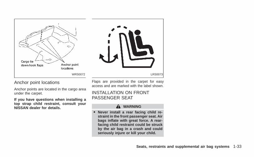
Anchor point locationsAnchor points are located in the cargo areaunder the carpet.
If you have questions when installing atop strap child restraint, consult yourNISSAN dealer for details.
Flaps are provided in the carpet for easyaccess and are marked with the label shown.
INSTALLATION ON FRONTPASSENGER SEAT
WARNING
O Never install a rear facing child re-straint in the front passenger seat. Airbags inflate with great force. A rear-facing child restraint could be struckby the air bag in a crash and couldseriously injure or kill your child.
WRS0072 LRS0073
Seats, restraints and supplemental air bag systems 1-33
Z X
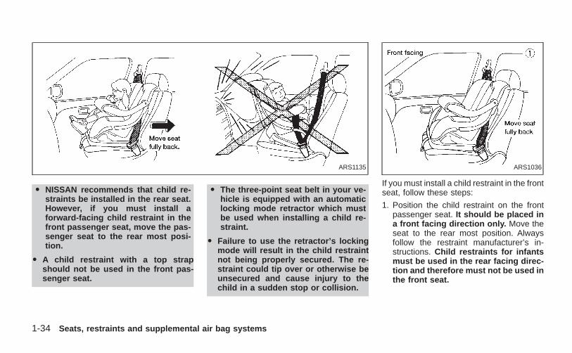
O NISSAN recommends that child re-straints be installed in the rear seat.However, if you must install aforward-facing child restraint in thefront passenger seat, move the pas-senger seat to the rear most posi-tion.
O A child restraint with a top strapshould not be used in the front pas-senger seat.
O The three-point seat belt in your ve-hicle is equipped with an automaticlocking mode retractor which mustbe used when installing a child re-straint.
O Failure to use the retractor’s lockingmode will result in the child restraintnot being properly secured. The re-straint could tip over or otherwise beunsecured and cause injury to thechild in a sudden stop or collision.
If you must install a child restraint in the frontseat, follow these steps:
1. Position the child restraint on the frontpassenger seat. It should be placed ina front facing direction only. Move theseat to the rear most position. Alwaysfollow the restraint manufacturer’s in-structions. Child restraints for infantsmust be used in the rear facing direc-tion and therefore must not be used inthe front seat.
ARS1135 ARS1036
1-34 Seats, restraints and supplemental air bag systems
Z X
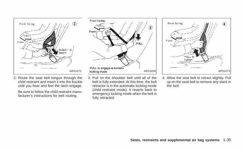
2. Route the seat belt tongue through thechild restraint and insert it into the buckleuntil you hear and feel the latch engage.
Be sure to follow the child restraint manu-facturer’s instructions for belt routing.
3. Pull on the shoulder belt until all of thebelt is fully extended. At this time, the beltretractor is in the automatic locking mode(child restraint mode). It reverts back toemergency locking mode when the belt isfully retracted.
4. Allow the seat belt to retract slightly. Pullup on the seat belt to remove any slack inthe belt.
ARS1073 ARS1034 ARS1074
Seats, restraints and supplemental air bag systems 1-35
Z X
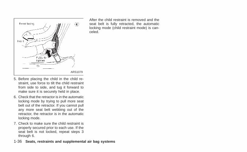
5. Before placing the child in the child re-straint, use force to tilt the child restraintfrom side to side, and tug it forward tomake sure it is securely held in place.
6. Check that the retractor is in the automaticlocking mode by trying to pull more seatbelt out of the retractor. If you cannot pullany more seat belt webbing out of theretractor, the retractor is in the automaticlocking mode.
7. Check to make sure the child restraint isproperly secured prior to each use. If theseat belt is not locked, repeat steps 3through 6.
After the child restraint is removed and theseat belt is fully retracted, the automaticlocking mode (child restraint mode) is can-celed.
ARS1079
1-36 Seats, restraints and supplemental air bag systems
Z X
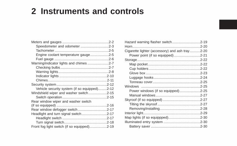
2 Instruments and controls
Meters and gauges ................................................2-2Speedometer and odometer .............................2-3Tachometer ........................................................2-5Engine coolant temperature gauge...................2-5Fuel gauge ........................................................2-6
Warning/indicator lights and chimes ......................2-7Checking bulbs..................................................2-7Warning lights....................................................2-8Indicator lights .................................................2-10Chimes.............................................................2-11
Security system....................................................2-12Vehicle security system (if so equipped).........2-12
Windshield wiper and washer switch...................2-15Switch operation..............................................2-15
Rear window wiper and washer switch(if so equipped) ....................................................2-16Rear window defogger switch..............................2-17Headlight and turn signal switch..........................2-17
Headlight switch ..............................................2-17Turn signal switch............................................2-18
Front fog light switch (if so equipped)..................2-19
Hazard warning flasher switch.............................2-19Horn......................................................................2-20Cigarette lighter (accessory) and ash tray...........2-20
Power point (if so equipped) ...........................2-21Storage.................................................................2-22
Map pocket ......................................................2-22Cup holders .....................................................2-22Glove box ........................................................2-23Luggage hooks................................................2-24Tonneau cover .................................................2-25
Windows .............................................................2-25Power windows (if so equipped) .....................2-25Manual windows..............................................2-27
Skyroof (if so equipped) .......................................2-27Tilting the skyroof ............................................2-27Removing/installing..........................................2-28
Interior light...........................................................2-29Map lights (if so equippped).................................2-30Illuminated entry system ......................................2-30
Battery saver ...................................................2-30
Z X
WIC0073
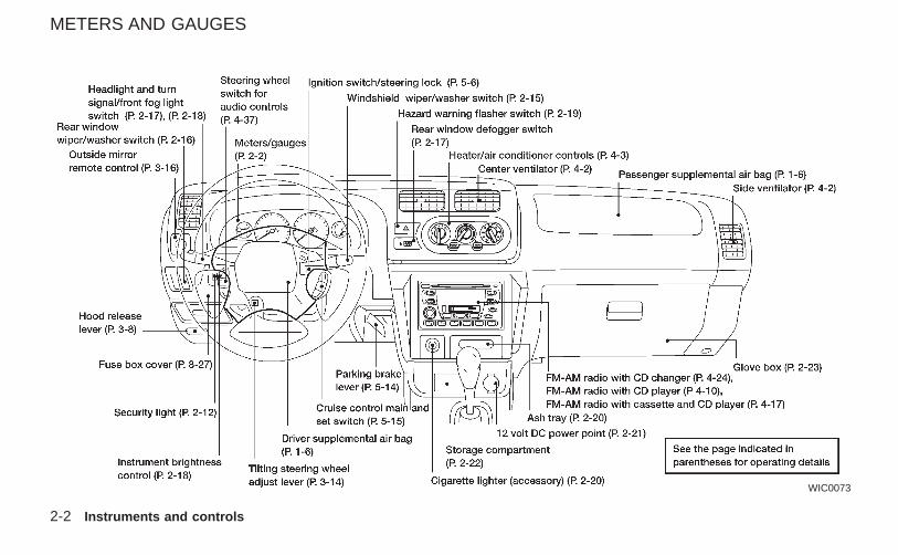
METERS AND GAUGES
2-2 Instruments and controls
Z X
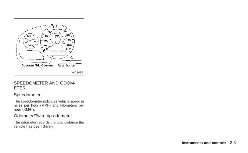
SPEEDOMETER AND ODOM-ETER
SpeedometerThe speedometer indicates vehicle speed inmiles per hour (MPH) and kilometers perhour (KM/H).
Odometer/Twin trip odometerThe odometer records the total distance thevehicle has been driven.
AIC1099
Instruments and controls 2-3
Z X
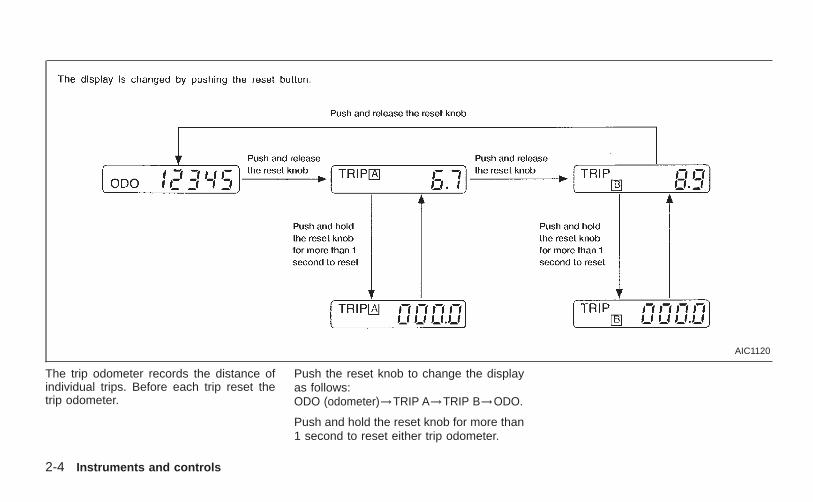
The trip odometer records the distance ofindividual trips. Before each trip reset thetrip odometer.
Push the reset knob to change the displayas follows:ODO (odometer)→TRIP A→TRIP B→ODO.
Push and hold the reset knob for more than1 second to reset either trip odometer.
AIC1120
2-4 Instruments and controls
Z X
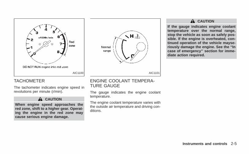
TACHOMETERThe tachometer indicates engine speed inrevolutions per minute (r/min).
CAUTIONWhen engine speed approaches thered zone, shift to a higher gear. Operat-ing the engine in the red zone maycause serious engine damage.
ENGINE COOLANT TEMPERA-TURE GAUGEThe gauge indicates the engine coolanttemperature.
The engine coolant temperature varies withthe outside air temperature and driving con-ditions.
CAUTIONIf the gauge indicates engine coolanttemperature over the normal range,stop the vehicle as soon as safely pos-sible. If the engine is overheated, con-tinued operation of the vehicle mayse-riously damage the engine. See the ‘‘Incase of emergency’’ section for imme-diate action required.
AIC1100 AIC1101
Instruments and controls 2-5
Z X
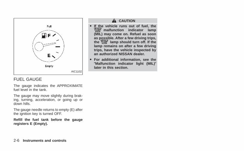
FUEL GAUGEThe gauge indicates the APPROXIMATEfuel level in the tank.
The gauge may move slightly during brak-ing, turning, acceleration, or going up ordown hills.
The gauge needle returns to empty (E) afterthe ignition key is turned OFF.
Refill the fuel tank before the gaugeregisters E (Empty).
CAUTIONO If the vehicle runs out of fuel, the
malfunction indicator lamp(MIL) may come on. Refuel as soonas possible. After a few driving trips,the lamp should turn off. If thelamp remains on after a few drivingtrips, have the vehicle inspected byan authorized NISSAN dealer.
O For additional information, see the(Malfunction indicator light (MIL) (later in this section.
AIC1102
2-6 Instruments and controls
Z X
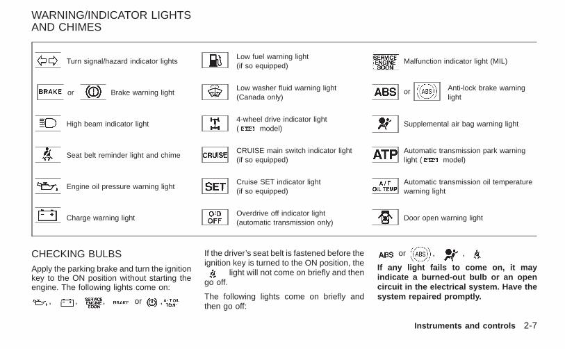
Turn signal/hazard indicator lightsLow fuel warning light(if so equipped)
Malfunction indicator light (MIL)
or Brake warning lightLow washer fluid warning light(Canada only)
or Anti-lock brake warninglight
High beam indicator light4-wheel drive indicator light( model)
Supplemental air bag warning light
Seat belt reminder light and chimeCRUISE main switch indicator light(if so equipped)
Automatic transmission park warninglight ( model)
Engine oil pressure warning lightCruise SET indicator light(if so equipped)
Automatic transmission oil temperaturewarning light
Charge warning lightOverdrive off indicator light(automatic transmission only)
Door open warning light
CHECKING BULBSApply the parking brake and turn the ignitionkey to the ON position without starting theengine. The following lights come on:
, , , or ,
If the driver’s seat belt is fastened before theignition key is turned to the ON position, the
light will not come on briefly and thengo off.
The following lights come on briefly andthen go off:
or , ,
If any light fails to come on, it mayindicate a burned-out bulb or an opencircuit in the electrical system. Have thesystem repaired promptly.
WARNING/INDICATOR LIGHTSAND CHIMES
Instruments and controls 2-7
Z X
WARNING LIGHTS
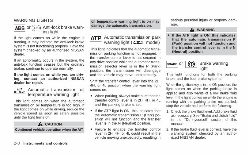
or Anti-lock brake warn-ing light
If the light comes on while the engine isrunning, it may indicate the anti-lock brakesystem is not functioning properly. Have thesystem checked by an authorized NISSANdealer.
If an abnormality occurs in the system, theanti-lock function ceases but the ordinarybrakes continue to operate normally.
If the light comes on while you are driv-ing, contact an authorized NISSANdealer for repair.
Automatic transmission oiltemperature warning light
This light comes on when the automatictransmission oil temperature is too high. Ifthe light comes on while driving, reduce thevehicle speed as soon as safely possibleuntil the light turns off.
CAUTIONContinued vehicle operation when the A/T
oil temperature warning light is on maydamage the automatic transmission.
Automatic transmission parkwarning light ( model)
This light indicates that the automatic trans-mission parking function is not engaged. Ifthe transfer control lever is not secured inany drive position while the automatic trans-mission selector lever is in the P (Park)position, the transmission will disengageand the vehicle may move unexpectedly.
Shift the transfer control lever into the 2H,4H, or 4L position when the warning lightcomes on.
O When parking, always make sure that thetransfer control lever is in 2H, 4H, or 4Land the parking brake is set.
O If the ATP light is ON, this indicates thatthe automatic transmission P (Park) po-sition will not function and the transferlever is in the N (Neutral) position.
O Failure to engage the transfer controllever in 2H, 4H, or 4L could result in thevehicle moving unexpectedly, resulting in
serious personal injury or property dam-age.
WARNING
O If the ATP light is ON, this indicatesthat the automatic transmission P(Park) position will not function andthe transfer control lever is in the N(Neutral) position.
or Brake warninglight
This light functions for both the parkingbrake and the foot brake systems.
When the ignition key is in the ON position, thelight comes on when the parking brake isapplied and also warns of a low brake fluidlevel. If the light comes on while the engine isrunning with the parking brake not applied,stop the vehicle and perform the following.
1. Check the brake fluid level. Add brake fluidas necessary. See ‘‘Brake and clutch fluid’’in the ‘‘Do-it-yourself’’ section of thismanual.
2. If the brake fluid level is correct, have thewarning system checked by an autho-rized NISSAN dealer.
2-8 Instruments and controls
Z X
WARNING
O Your brake system may not be workingproperly if the warning light is on.Driving could be dangerous. If youjudge it to be safe, drive carefully tothe nearest service station for repairs.Otherwise have your vehicle towed be-cause driving it could be dangerous.
O Pressing the brake pedal with theengine stopped and/or low brakefluid level may increase your stop-ping distance and require greaterpedal effort as well as pedal travel.
O If the brake fluid level is below theMINIMUM or MIN mark on the brakefluid reservoir, do not drive until thebrake system has been checked atan authorized NISSAN dealer.
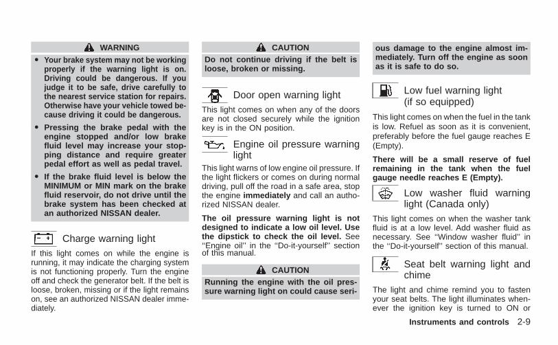
Charge warning lightIf this light comes on while the engine isrunning, it may indicate the charging systemis not functioning properly. Turn the engineoff and check the generator belt. If the belt isloose, broken, missing or if the light remainson, see an authorized NISSAN dealer imme-diately.
CAUTIONDo not continue driving if the belt isloose, broken or missing.
Door open warning lightThis light comes on when any of the doorsare not closed securely while the ignitionkey is in the ON position.
Engine oil pressure warninglight
This light warns of low engine oil pressure. Ifthe light flickers or comes on during normaldriving, pull off the road in a safe area, stopthe engine immediately and call an autho-rized NISSAN dealer.
The oil pressure warning light is notdesigned to indicate a low oil level. Usethe dipstick to check the oil level. See‘‘Engine oil’’ in the ‘‘Do-it-yourself’’ sectionof this manual.
CAUTIONRunning the engine with the oil pres-sure warning light on could cause seri-
ous damage to the engine almost im-mediately. Turn off the engine as soonas it is safe to do so.
Low fuel warning light(if so equipped)
This light comes on when the fuel in the tankis low. Refuel as soon as it is convenient,preferably before the fuel gauge reaches E(Empty).
There will be a small reserve of fuelremaining in the tank when the fuelgauge needle reaches E (Empty).
Low washer fluid warninglight (Canada only)
This light comes on when the washer tankfluid is at a low level. Add washer fluid asnecessary. See ‘‘Window washer fluid’’ inthe ‘‘Do-it-yourself’’ section of this manual.
Seat belt warning light andchime
The light and chime remind you to fastenyour seat belts. The light illuminates when-ever the ignition key is turned to ON or
Instruments and controls 2-9
Z X
START and remains illuminated until thedriver’s seat belt is fastened. At the sametime, the chime sounds for about sevenseconds unless the driver seat belt is se-curely fastened.
Refer to ‘‘Seat belts’’ in the ‘‘Seats, re-straints and supplemental air bag systems’’section for precautions on seat belt usage.
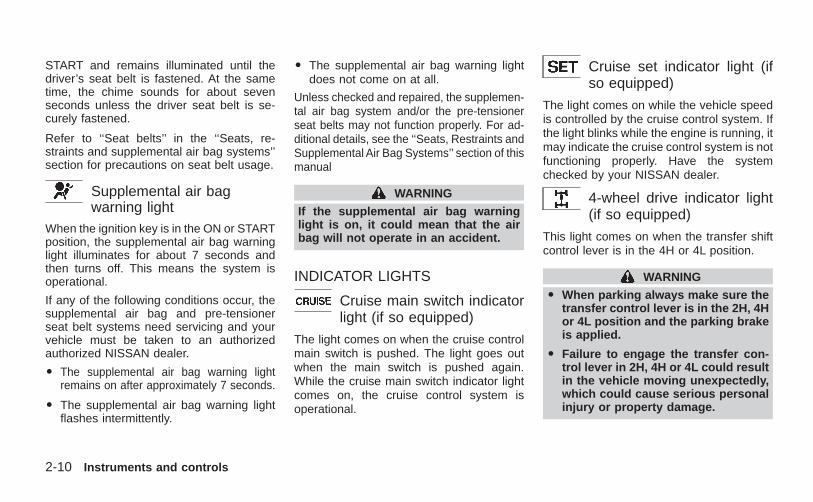
Supplemental air bagwarning light
When the ignition key is in the ON or STARTposition, the supplemental air bag warninglight illuminates for about 7 seconds andthen turns off. This means the system isoperational.
If any of the following conditions occur, thesupplemental air bag and pre-tensionerseat belt systems need servicing and yourvehicle must be taken to an authorizedauthorized NISSAN dealer.
O The supplemental air bag warning lightremains on after approximately 7 seconds.
O The supplemental air bag warning lightflashes intermittently.
O The supplemental air bag warning lightdoes not come on at all.
Unless checked and repaired, the supplemen-tal air bag system and/or the pre-tensionerseat belts may not function properly. For ad-ditional details, see the ‘‘Seats, Restraints andSupplemental Air Bag Systems’’ section of thismanual
WARNING
If the supplemental air bag warninglight is on, it could mean that the airbag will not operate in an accident.
INDICATOR LIGHTS
Cruise main switch indicatorlight (if so equipped)
The light comes on when the cruise controlmain switch is pushed. The light goes outwhen the main switch is pushed again.While the cruise main switch indicator lightcomes on, the cruise control system isoperational.
Cruise set indicator light (ifso equipped)
The light comes on while the vehicle speedis controlled by the cruise control system. Ifthe light blinks while the engine is running, itmay indicate the cruise control system is notfunctioning properly. Have the systemchecked by your NISSAN dealer.
4-wheel drive indicator light(if so equipped)
This light comes on when the transfer shiftcontrol lever is in the 4H or 4L position.
WARNING
O When parking always make sure thetransfer control lever is in the 2H, 4Hor 4L position and the parking brakeis applied.
O Failure to engage the transfer con-trol lever in 2H, 4H or 4L could resultin the vehicle moving unexpectedly,which could cause serious personalinjury or property damage.
2-10 Instruments and controls
Z X
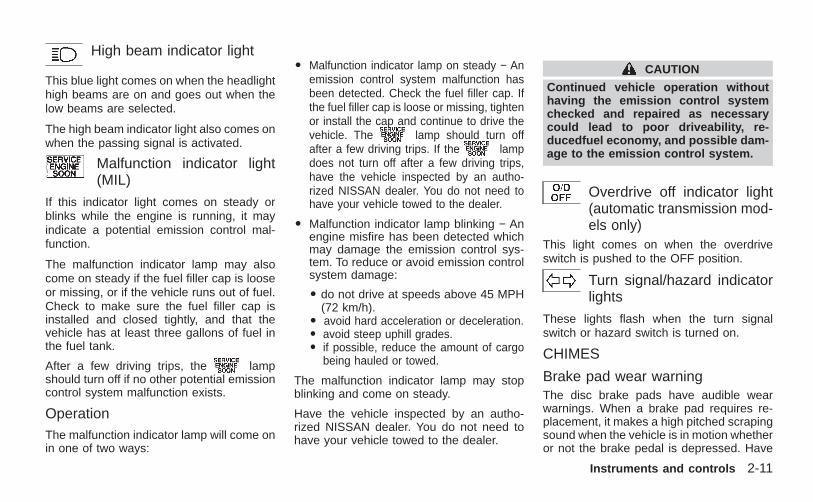
High beam indicator light
This blue light comes on when the headlighthigh beams are on and goes out when thelow beams are selected.
The high beam indicator light also comes onwhen the passing signal is activated.
Malfunction indicator light(MIL)
If this indicator light comes on steady orblinks while the engine is running, it mayindicate a potential emission control mal-function.
The malfunction indicator lamp may alsocome on steady if the fuel filler cap is looseor missing, or if the vehicle runs out of fuel.Check to make sure the fuel filler cap isinstalled and closed tightly, and that thevehicle has at least three gallons of fuel inthe fuel tank.
After a few driving trips, the lampshould turn off if no other potential emissioncontrol system malfunction exists.
OperationThe malfunction indicator lamp will come onin one of two ways:
O Malfunction indicator lamp on steady − Anemission control system malfunction hasbeen detected. Check the fuel filler cap. Ifthe fuel filler cap is loose or missing, tightenor install the cap and continue to drive thevehicle. The lamp should turn offafter a few driving trips. If the lampdoes not turn off after a few driving trips,have the vehicle inspected by an autho-rized NISSAN dealer. You do not need tohave your vehicle towed to the dealer.
O Malfunction indicator lamp blinking − Anengine misfire has been detected whichmay damage the emission control sys-tem. To reduce or avoid emission controlsystem damage:
O do not drive at speeds above 45 MPH(72 km/h).
O avoid hard acceleration or deceleration.O avoid steep uphill grades.O if possible, reduce the amount of cargo
being hauled or towed.
The malfunction indicator lamp may stopblinking and come on steady.
Have the vehicle inspected by an autho-rized NISSAN dealer. You do not need tohave your vehicle towed to the dealer.
CAUTION
Continued vehicle operation withouthaving the emission control systemchecked and repaired as necessarycould lead to poor driveability, re-ducedfuel economy, and possible dam-age to the emission control system.
Overdrive off indicator light(automatic transmission mod-els only)
This light comes on when the overdriveswitch is pushed to the OFF position.
Turn signal/hazard indicatorlights
These lights flash when the turn signalswitch or hazard switch is turned on.
CHIMES
Brake pad wear warningThe disc brake pads have audible wearwarnings. When a brake pad requires re-placement, it makes a high pitched scrapingsound when the vehicle is in motion whetheror not the brake pedal is depressed. Have
Instruments and controls 2-11
Z X
the brakes checked as soon as possible ifthe warning sound is heard.
Key reminder chimeThe chime sounds when the driver’s door isopened and the key is in the ignition switch.Take the ignition key when you leave thevehicle.
Light reminder chimeA chime sounds if the driver’s door isopened with the headlight switch on unlessthe ignition key is in the ON position. Turnthe headlight switch off when you leave thevehicle.
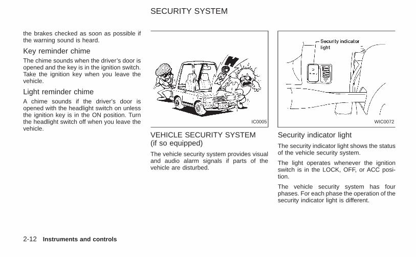
VEHICLE SECURITY SYSTEM(if so equipped)The vehicle security system provides visualand audio alarm signals if parts of thevehicle are disturbed.
Security indicator lightThe security indicator light shows the statusof the vehicle security system.
The light operates whenever the ignitionswitch is in the LOCK, OFF, or ACC posi-tion.
The vehicle security system has fourphases. For each phase the operation of thesecurity indicator light is different.
IC0005 WIC0072
SECURITY SYSTEM
2-12 Instruments and controls
Z X
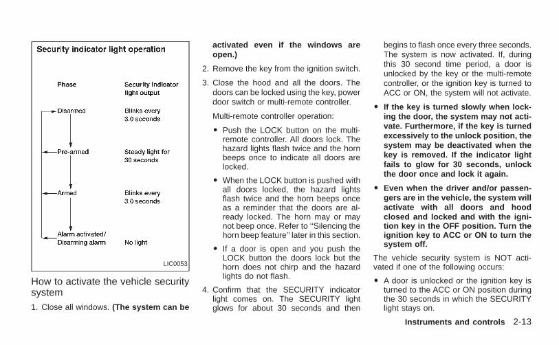
How to activate the vehicle securitysystem1. Close all windows. (The system can be
activated even if the windows areopen.)
2. Remove the key from the ignition switch.
3. Close the hood and all the doors. Thedoors can be locked using the key, powerdoor switch or multi-remote controller.
Multi-remote controller operation:
O Push the LOCK button on the multi-remote controller. All doors lock. Thehazard lights flash twice and the hornbeeps once to indicate all doors arelocked.
O When the LOCK button is pushed withall doors locked, the hazard lightsflash twice and the horn beeps onceas a reminder that the doors are al-ready locked. The horn may or maynot beep once. Refer to ‘‘Silencing thehorn beep feature’’ later in this section.
O If a door is open and you push theLOCK button the doors lock but thehorn does not chirp and the hazardlights do not flash.
4. Confirm that the SECURITY indicatorlight comes on. The SECURITY lightglows for about 30 seconds and then
begins to flash once every three seconds.The system is now activated. If, duringthis 30 second time period, a door isunlocked by the key or the multi-remotecontroller, or the ignition key is turned toACC or ON, the system will not activate.
O If the key is turned slowly when lock-ing the door, the system may not acti-vate. Furthermore, if the key is turnedexcessively to the unlock position, thesystem may be deactivated when thekey is removed. If the indicator lightfails to glow for 30 seconds, unlockthe door once and lock it again.
O Even when the driver and/or passen-gers are in the vehicle, the system willactivate with all doors and hoodclosed and locked and with the igni-tion key in the OFF position. Turn theignition key to ACC or ON to turn thesystem off.
The vehicle security system is NOT acti-vated if one of the following occurs:
O A door is unlocked or the ignition key isturned to the ACC or ON position duringthe 30 seconds in which the SECURITYlight stays on.
LIC0053
Instruments and controls 2-13
Z X
O The SECURITY light blinks at a steady1/2 second on - 1/2 second off rate (adoor, or the hood is open and the key isnot in the ACC or ON position). When theignition key is turned to the ACC or ONposition, the SECURITY light turns off.
Vehicle security system operation
The vehicle security system emits the fol-lowing alarm:
O The headlights blink and the horn soundsintermittently. In addition, the starter mo-tor does not operate.
O The alarm automatically turns off after 50seconds. However, the alarm reactivatesif the vehicle is tampered with again. Thealarm can be shut off by unlocking a doorwith the key or by pressing the UNLOCKbutton on the multi-remote controller.
The alarm is activated by:
O opening a door without using the key(even if the door is unlocked by releasingthe inside lock knob).
O opening the hood.
How to stop the alarmThe alarm stops only by unlocking a door withthe key or by pressing the UNLOCK buttonon the multi-remote controller. The alarmdoes not stop if the ignition switch is turned toACC or ON position.
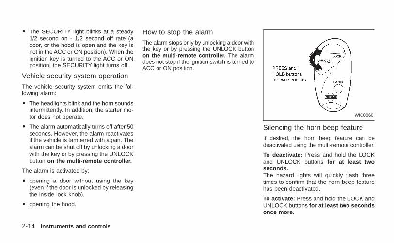
Silencing the horn beep feature
If desired, the horn beep feature can bedeactivated using the multi-remote controller.
To deactivate: Press and hold the LOCKand UNLOCK buttons for at least twoseconds.The hazard lights will quickly flash threetimes to confirm that the horn beep featurehas been deactivated.
To activate: Press and hold the LOCK andUNLOCK buttons for at least two secondsonce more.
WIC0060
2-14 Instruments and controls
Z X
The hazard lights will quickly flash once andthe horn will sound once to confirm that thehorn beep feature has been reactivated.
Deactivating the horn beep feature does notsilence the horn if the alarm is triggered.
If the system does not operate as de-scribed above, have it checked by anauthorized NISSAN dealer.
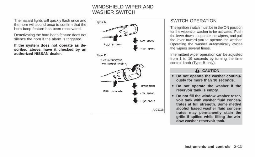
SWITCH OPERATIONThe ignition switch must be in the ON positionfor the wipers or washer to be activated. Pushthe lever down to operate the wipers, and pullthe lever toward you to operate the washer.Operating the washer automatically cyclesthe wipers several times.
Intermittent wiper operation can be adjustedfrom 1 to 19 seconds by turning the timecontrol knob (Type B only).
CAUTIONO Do not operate the washer continu-
ously for more than 30 seconds.
O Do not operate the washer if thereservoir tank is empty.
O Do not fill the window washer reser-voir tank with washer fluid concen-trates at full strength. Some methylalcohol based washer fluid concen-trates may permanently stain thegrille if spilled while filling the win-dow washer reservoir tank.
AIC1118
WINDSHIELD WIPER ANDWASHER SWITCH
Instruments and controls 2-15
Z X
O Pre-mix washer fluid concentrateswith water to the manufacturer’s rec-ommended levels before pouring thefluid into the window washer reser-voir tank. Do not use the windowwasher reservoir tank to mix thewasher fluid concentrate and water.
WARNINGIn freezing temperatures the washersolution may freeze on the windshieldand obscure your vision which maylead to an accident. Warm the wind-shield with the defroster before youwash the windshield.
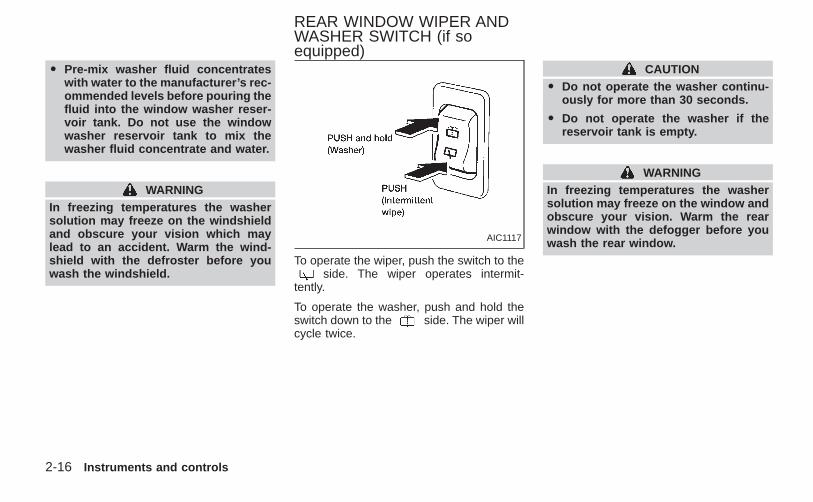
To operate the wiper, push the switch to theside. The wiper operates intermit-
tently.
To operate the washer, push and hold theswitch down to the side. The wiper willcycle twice.
CAUTIONO Do not operate the washer continu-
ously for more than 30 seconds.
O Do not operate the washer if thereservoir tank is empty.
WARNINGIn freezing temperatures the washersolution may freeze on the window andobscure your vision. Warm the rearwindow with the defogger before youwash the rear window.AIC1117
REAR WINDOW WIPER ANDWASHER SWITCH (if soequipped)
2-16 Instruments and controls
Z X
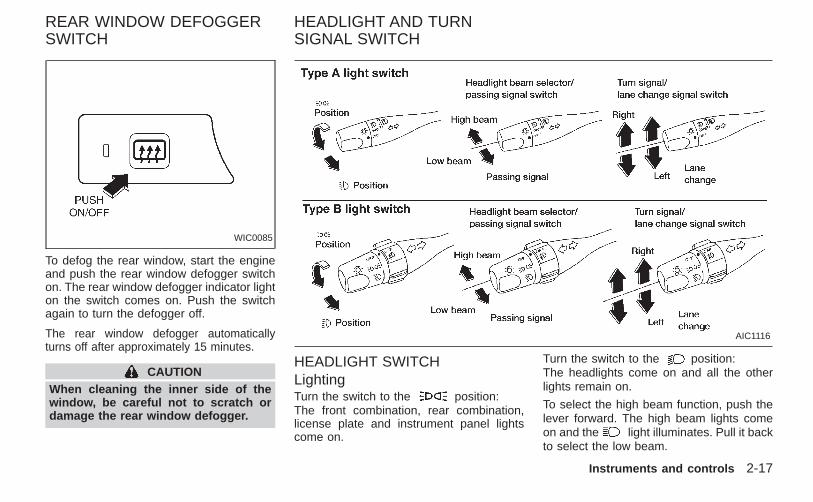
To defog the rear window, start the engineand push the rear window defogger switchon. The rear window defogger indicator lighton the switch comes on. Push the switchagain to turn the defogger off.
The rear window defogger automaticallyturns off after approximately 15 minutes.
CAUTIONWhen cleaning the inner side of thewindow, be careful not to scratch ordamage the rear window defogger.
HEADLIGHT SWITCHLightingTurn the switch to the position:The front combination, rear combination,license plate and instrument panel lightscome on.
Turn the switch to the position:The headlights come on and all the otherlights remain on.
To select the high beam function, push thelever forward. The high beam lights comeon and the light illuminates. Pull it backto select the low beam.
WIC0085
AIC1116
REAR WINDOW DEFOGGERSWITCH
HEADLIGHT AND TURNSIGNAL SWITCH
Instruments and controls 2-17
Z X
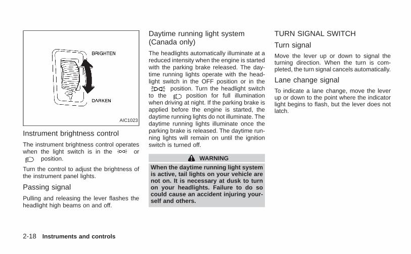
Instrument brightness control
The instrument brightness control operateswhen the light switch is in the or
position.
Turn the control to adjust the brightness ofthe instrument panel lights.
Passing signal
Pulling and releasing the lever flashes theheadlight high beams on and off.
Daytime running light system(Canada only)
The headlights automatically illuminate at areduced intensity when the engine is startedwith the parking brake released. The day-time running lights operate with the head-light switch in the OFF position or in the
position. Turn the headlight switchto the position for full illuminationwhen driving at night. If the parking brake isapplied before the engine is started, thedaytime running lights do not illuminate. Thedaytime running lights illuminate once theparking brake is released. The daytime run-ning lights will remain on until the ignitionswitch is turned off.
WARNING
When the daytime running light systemis active, tail lights on your vehicle arenot on. It is necessary at dusk to turnon your headlights. Failure to do socould cause an accident injuring your-self and others.
TURN SIGNAL SWITCH
Turn signalMove the lever up or down to signal theturning direction. When the turn is com-pleted, the turn signal cancels automatically.
Lane change signalTo indicate a lane change, move the leverup or down to the point where the indicatorlight begins to flash, but the lever does notlatch.
AIC1023
2-18 Instruments and controls
Z X
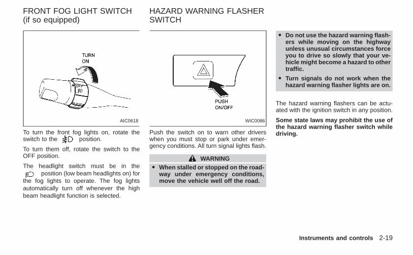
To turn the front fog lights on, rotate theswitch to the position.
To turn them off, rotate the switch to theOFF position.
The headlight switch must be in theposition (low beam headlights on) for
the fog lights to operate. The fog lightsautomatically turn off whenever the highbeam headlight function is selected.
Push the switch on to warn other driverswhen you must stop or park under emer-gency conditions. All turn signal lights flash.
WARNINGO When stalled or stopped on the road-
way under emergency conditions,move the vehicle well off the road.
O Do not use the hazard warning flash-ers while moving on the highwayunless unusual circumstances forceyou to drive so slowly that your ve-hicle might become a hazard to othertraffic.
O Turn signals do not work when thehazard warning flasher lights are on.
The hazard warning flashers can be actu-ated with the ignition switch in any position.
Some state laws may prohibit the use ofthe hazard warning flasher switch whiledriving.
AIC0618 WIC0086
FRONT FOG LIGHT SWITCH(if so equipped)
HAZARD WARNING FLASHERSWITCH
Instruments and controls 2-19
Z X
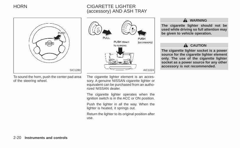
To sound the horn, push the center pad areaof the steering wheel.
The cigarette lighter element is an acces-sory. A genuine NISSAN cigarette lighter orequivalent can be purchased from an autho-rized NISSAN dealer.
The cigarette lighter operates when theignition switch is in the ACC or ON position.
Push the lighter in all the way. When thelighter is heated, it springs out.
Return the lighter to its original position afteruse.
WARNINGThe cigarette lighter should not beused while driving so full attention maybe given to vehicle operation.
CAUTIONThe cigarette lighter socket is a powersource for the cigarette lighter elementonly. The use of the cigarette lightersocket as a power source for any otheraccessory is not recommended.
SIC1280 AIC1024
HORN CIGARETTE LIGHTER(accessory) AND ASH TRAY
2-20 Instruments and controls
Z X
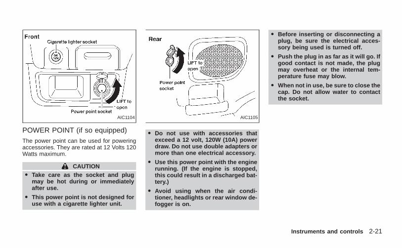
POWER POINT (if so equipped)The power point can be used for poweringaccessories. They are rated at 12 Volts 120Watts maximum.
CAUTIONO Take care as the socket and plug
may be hot during or immediatelyafter use.
O This power point is not designed foruse with a cigarette lighter unit.
O Do not use with accessories thatexceed a 12 volt, 120W (10A) powerdraw. Do not use double adapters ormore than one electrical accessory.
O Use this power point with the enginerunning. (If the engine is stopped,this could result in a discharged bat-tery.)
O Avoid using when the air condi-tioner, headlights or rear window de-fogger is on.
O Before inserting or disconnecting aplug, be sure the electrical acces-sory being used is turned off.
O Push the plug in as far as it will go. Ifgood contact is not made, the plugmay overheat or the internal tem-perature fuse may blow.
O When not in use, be sure to close thecap. Do not allow water to contactthe socket.
AIC1104 AIC1105
Instruments and controls 2-21
Z X
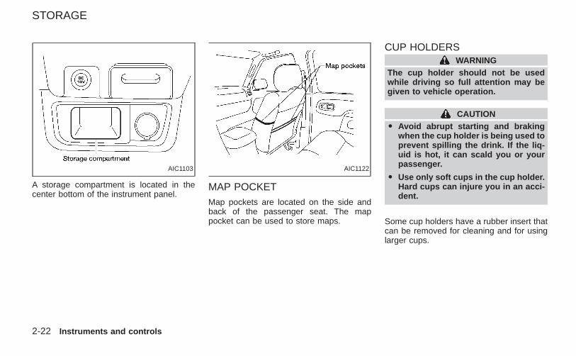
A storage compartment is located in thecenter bottom of the instrument panel.
MAP POCKETMap pockets are located on the side andback of the passenger seat. The mappocket can be used to store maps.
CUP HOLDERSWARNING
The cup holder should not be usedwhile driving so full attention may begiven to vehicle operation.
CAUTIONO Avoid abrupt starting and braking
when the cup holder is being used toprevent spilling the drink. If the liq-uid is hot, it can scald you or yourpassenger.
O Use only soft cups in the cup holder.Hard cups can injure you in an acci-dent.
Some cup holders have a rubber insert thatcan be removed for cleaning and for usinglarger cups.
AIC1103 AIC1122
STORAGE
2-22 Instruments and controls
Z X
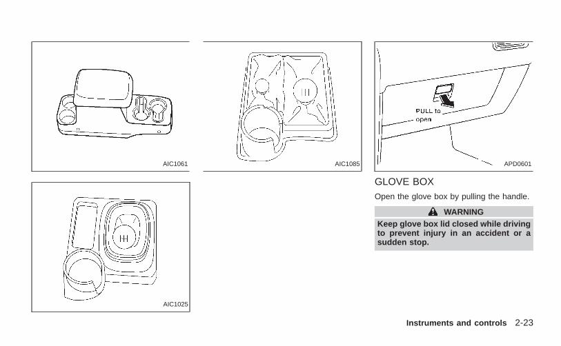
GLOVE BOXOpen the glove box by pulling the handle.
WARNINGKeep glove box lid closed while drivingto prevent injury in an accident or asudden stop.
AIC1061
AIC1025
AIC1085 APD0601
Instruments and controls 2-23
Z X
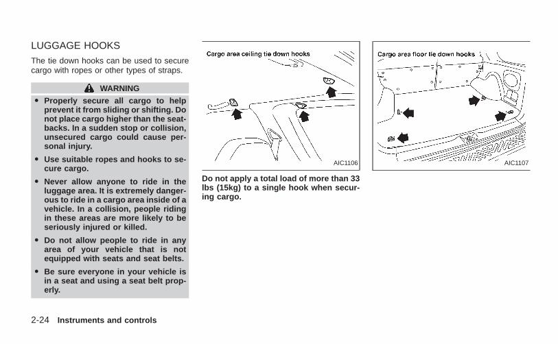
LUGGAGE HOOKS
The tie down hooks can be used to securecargo with ropes or other types of straps.
WARNING
O Properly secure all cargo to helpprevent it from sliding or shifting. Donot place cargo higher than the seat-backs. In a sudden stop or collision,unsecured cargo could cause per-sonal injury.
O Use suitable ropes and hooks to se-cure cargo.
O Never allow anyone to ride in theluggage area. It is extremely danger-ous to ride in a cargo area inside of avehicle. In a collision, people ridingin these areas are more likely to beseriously injured or killed.
O Do not allow people to ride in anyarea of your vehicle that is notequipped with seats and seat belts.
O Be sure everyone in your vehicle isin a seat and using a seat belt prop-erly.
Do not apply a total load of more than 33lbs (15kg) to a single hook when secur-ing cargo.
AIC1106 AIC1107
2-24 Instruments and controls
Z X
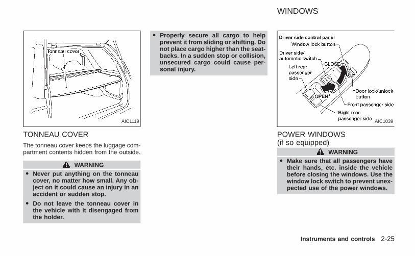
TONNEAU COVERThe tonneau cover keeps the luggage com-partment contents hidden from the outside.
WARNINGO Never put anything on the tonneau
cover, no matter how small. Any ob-ject on it could cause an injury in anaccident or sudden stop.
O Do not leave the tonneau cover inthe vehicle with it disengaged fromthe holder.
O Properly secure all cargo to helpprevent it from sliding or shifting. Donot place cargo higher than the seat-backs. In a sudden stop or collision,unsecured cargo could cause per-sonal injury.
POWER WINDOWS(if so equipped)
WARNINGO Make sure that all passengers have
their hands, etc. inside the vehiclebefore closing the windows. Use thewindow lock switch to prevent unex-pected use of the power windows.
AIC1119 AIC1039
WINDOWS
Instruments and controls 2-25
Z X
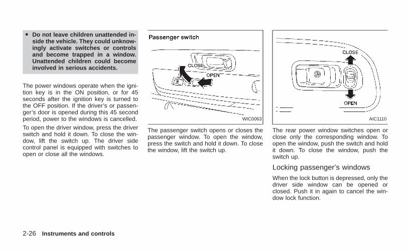
O Do not leave children unattended in-side the vehicle. They could unknow-ingly activate switches or controlsand become trapped in a window.Unattended children could becomeinvolved in serious accidents.
The power windows operate when the igni-tion key is in the ON position, or for 45seconds after the ignition key is turned tothe OFF position. If the driver’s or passen-ger’s door is opened during this 45 secondperiod, power to the windows is cancelled.To open the driver window, press the driverswitch and hold it down. To close the win-dow, lift the switch up. The driver sidecontrol panel is equipped with switches toopen or close all the windows.
The passenger switch opens or closes thepassenger window. To open the window,press the switch and hold it down. To closethe window, lift the switch up.
The rear power window switches open orclose only the corresponding window. Toopen the window, push the switch and holdit down. To close the window, push theswitch up.
Locking passenger’s windowsWhen the lock button is depressed, only thedriver side window can be opened orclosed. Push it in again to cancel the win-dow lock function.
WIC0063 AIC1110
2-26 Instruments and controls
Z X
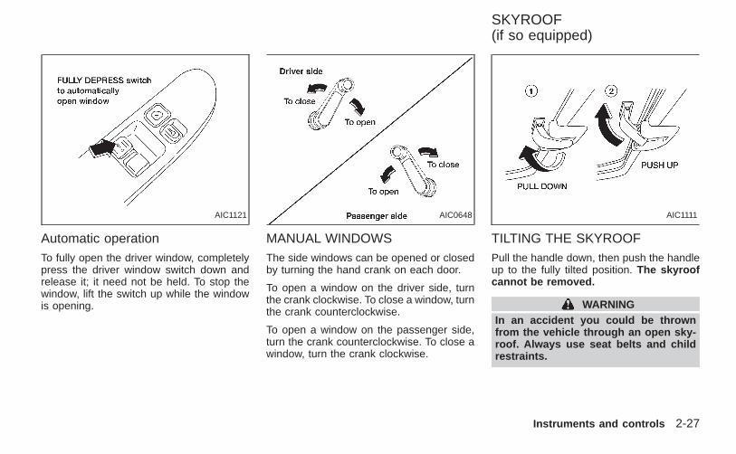
Automatic operationTo fully open the driver window, completelypress the driver window switch down andrelease it; it need not be held. To stop thewindow, lift the switch up while the windowis opening.
MANUAL WINDOWSThe side windows can be opened or closedby turning the hand crank on each door.
To open a window on the driver side, turnthe crank clockwise. To close a window, turnthe crank counterclockwise.
To open a window on the passenger side,turn the crank counterclockwise. To close awindow, turn the crank clockwise.
TILTING THE SKYROOFPull the handle down, then push the handleup to the fully tilted position. The skyroofcannot be removed.
WARNINGIn an accident you could be thrownfrom the vehicle through an open sky-roof. Always use seat belts and childrestraints.
AIC1121 AIC0648 AIC1111
SKYROOF(if so equipped)
Instruments and controls 2-27
Z X
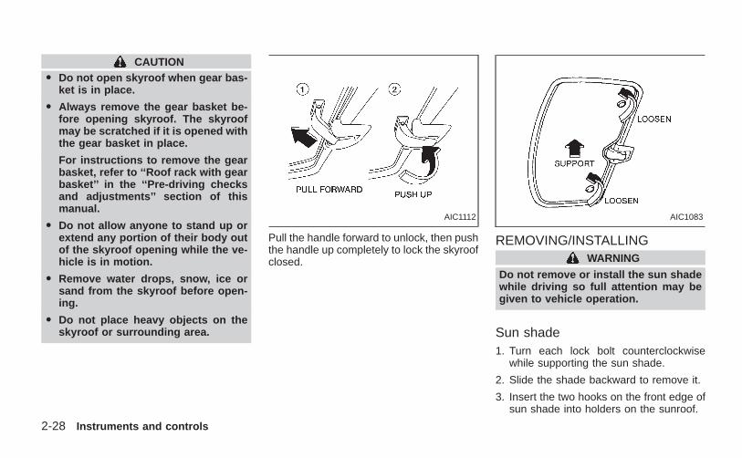
CAUTIONO Do not open skyroof when gear bas-
ket is in place.
O Always remove the gear basket be-fore opening skyroof. The skyroofmay be scratched if it is opened withthe gear basket in place.
For instructions to remove the gearbasket, refer to ‘‘Roof rack with gearbasket’’ in the ‘‘Pre-driving checksand adjustments’’ section of thismanual.
O Do not allow anyone to stand up orextend any portion of their body outof the skyroof opening while the ve-hicle is in motion.
O Remove water drops, snow, ice orsand from the skyroof before open-ing.
O Do not place heavy objects on theskyroof or surrounding area.
Pull the handle forward to unlock, then pushthe handle up completely to lock the skyroofclosed.
REMOVING/INSTALLINGWARNING
Do not remove or install the sun shadewhile driving so full attention may begiven to vehicle operation.
Sun shade1. Turn each lock bolt counterclockwise
while supporting the sun shade.
2. Slide the shade backward to remove it.
3. Insert the two hooks on the front edge ofsun shade into holders on the sunroof.
AIC1112 AIC1083
2-28 Instruments and controls
Z X
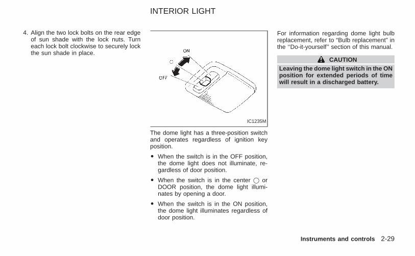
4. Align the two lock bolts on the rear edgeof sun shade with the lock nuts. Turneach lock bolt clockwise to securely lockthe sun shade in place.
The dome light has a three-position switchand operates regardless of ignition keyposition.
O When the switch is in the OFF position,the dome light does not illuminate, re-gardless of door position.
O When the switch is in the center j orDOOR position, the dome light illumi-nates by opening a door.
O When the switch is in the ON position,the dome light illuminates regardless ofdoor position.
For information regarding dome light bulbreplacement, refer to “Bulb replacement” inthe ‘‘Do-it-yourself’’ section of this manual.
CAUTIONLeaving the dome light switch in the ONposition for extended periods of timewill result in a discharged battery.
IC1235M
INTERIOR LIGHT
Instruments and controls 2-29
Z X
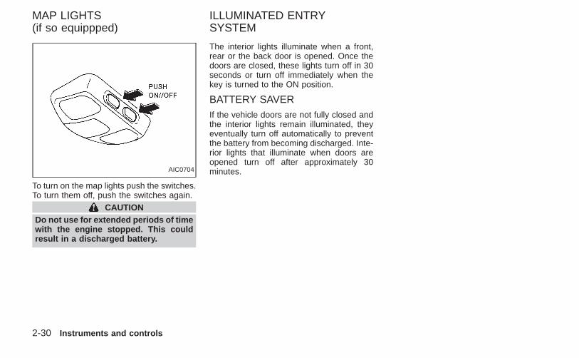
To turn on the map lights push the switches.To turn them off, push the switches again.
CAUTIONDo not use for extended periods of timewith the engine stopped. This couldresult in a discharged battery.
The interior lights illuminate when a front,rear or the back door is opened. Once thedoors are closed, these lights turn off in 30seconds or turn off immediately when thekey is turned to the ON position.
BATTERY SAVERIf the vehicle doors are not fully closed andthe interior lights remain illuminated, theyeventually turn off automatically to preventthe battery from becoming discharged. Inte-rior lights that illuminate when doors areopened turn off after approximately 30minutes.AIC0704
MAP LIGHTS(if so equippped)
ILLUMINATED ENTRYSYSTEM
2-30 Instruments and controls
Z X
3 Pre-driving checks and adjustments
Key .........................................................................3-2Doors......................................................................3-2
Locking with key................................................3-2Locking with inside lock knob............................3-3Locking with power door lock switch.................3-3Child safety rear door lock ................................3-4
Multi-remote control system (if so equipped).........3-4How to use multi-remote control system...........3-4Battery replacement ..........................................3-7
Hood.......................................................................3-8Rear door ...............................................................3-9Roof rack with gear basket (if so equipped)........3-10
Step rail ................................................................3-12Fuel filler lid ..........................................................3-13
Fuel filler cap...................................................3-13Steering wheel .....................................................3-14
Tilt operation....................................................3-14Sun visors.............................................................3-14
Vanity mirror ....................................................3-14Mirrors ..................................................................3-15
Inside mirror.....................................................3-15Outside mirrors ................................................3-15Outside mirror remote control(if so equipped)................................................3-16
Z X
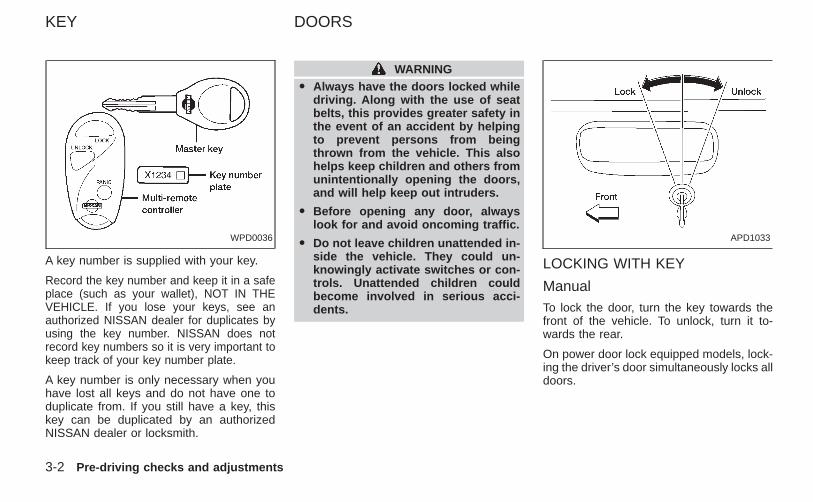
A key number is supplied with your key.
Record the key number and keep it in a safeplace (such as your wallet), NOT IN THEVEHICLE. If you lose your keys, see anauthorized NISSAN dealer for duplicates byusing the key number. NISSAN does notrecord key numbers so it is very important tokeep track of your key number plate.
A key number is only necessary when youhave lost all keys and do not have one toduplicate from. If you still have a key, thiskey can be duplicated by an authorizedNISSAN dealer or locksmith.
WARNINGO Always have the doors locked while
driving. Along with the use of seatbelts, this provides greater safety inthe event of an accident by helpingto prevent persons from beingthrown from the vehicle. This alsohelps keep children and others fromunintentionally opening the doors,and will help keep out intruders.
O Before opening any door, alwayslook for and avoid oncoming traffic.
O Do not leave children unattended in-side the vehicle. They could un-knowingly activate switches or con-trols. Unattended children couldbecome involved in serious acci-dents.
LOCKING WITH KEY
ManualTo lock the door, turn the key towards thefront of the vehicle. To unlock, turn it to-wards the rear.
On power door lock equipped models, lock-ing the driver’s door simultaneously locks alldoors.
WPD0036 APD1033
KEY DOORS
3-2 Pre-driving checks and adjustments
Z X
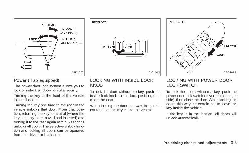
Power (if so equipped)The power door lock system allows you tolock or unlock all doors simultaneously.Turning the key to the front of the vehiclelocks all doors.Turning the key one time to the rear of thevehicle unlocks that door. From that posi-tion, returning the key to neutral (where thekey can only be removed and inserted) andturning it to the rear again within 5 secondsunlocks all doors. The selective unlock func-tion and locking all doors can be operatedfrom the driver, or back door.
LOCKING WITH INSIDE LOCKKNOBTo lock the door without the key, push theinside lock knob to the lock position, thenclose the door.
When locking the door this way, be certainnot to leave the key inside the vehicle.
LOCKING WITH POWER DOORLOCK SWITCHTo lock the doors without a key, push thepower door lock switch (driver or passengerside), then close the door. When locking thedoors this way, be certain not to leave thekey inside the vehicle.
If the key is in the ignition, all doors willunlock automatically.
APD1077 AIC1012 APD1014
Pre-driving checks and adjustments 3-3
Z X
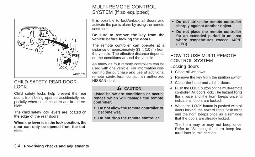
CHILD SAFETY REAR DOORLOCKChild safety locks help prevent the reardoors from being opened accidentally, es-pecially when small children are in the ve-hicle.
The child safety lock levers are located onthe edge of the rear doors.
When the lever is in the lock position, thedoor can only be opened from the out-side.
It is possible to lock/unlock all doors andactivate the panic alarm by using the remotecontroller.
Be sure to remove the key from thevehicle before locking the doors.
The remote controller can operate at adistance of approximately 33 ft (10 m) fromthe vehicle. The effective distance dependson the conditions around the vehicle.
As many as four remote controllers can beused with one vehicle. For information con-cerning the purchase and use of additionalremote controllers, contact an authorizedNISSAN dealer.
CAUTIONListed below are conditions or occur-rences which will damage the remotecontroller:
O Do not allow the remote controller tobecome wet.
O Do not drop the remote controller.
O Do not strike the remote controllersharply against another object.
O Do not place the remote controllerfor an extended period in an areawhere temperatures exceed 140°F(60°C).
HOW TO USE MULTI-REMOTECONTROL SYSTEMLocking doors1. Close all windows.2. Remove the key from the ignition switch.3. Close the hood and all the doors.4. Push the LOCK button on the multi-remote
controller. All doors lock. The hazard lightsflash twice and the horn beeps once toindicate all doors are locked.
O When the LOCK button is pushed with alldoors locked, the hazard lights flash twiceand the horn beeps once as a reminderthat the doors are already locked.
The horn may or may not beep once.Refer to “Silencing the horn beep fea-ture” later in this section.
APD1078
MULTI-REMOTE CONTROLSYSTEM (if so equipped)
3-4 Pre-driving checks and adjustments
Z X
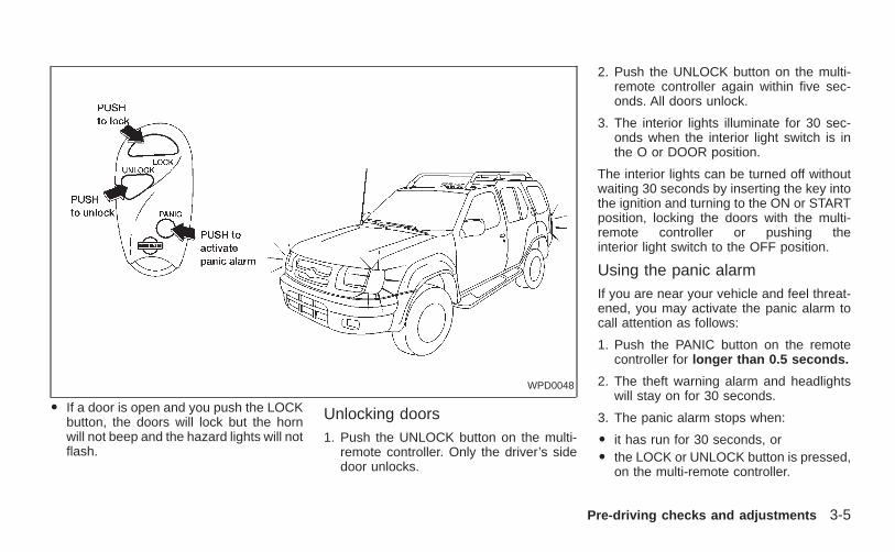
O If a door is open and you push the LOCKbutton, the doors will lock but the hornwill not beep and the hazard lights will notflash.
Unlocking doors1. Push the UNLOCK button on the multi-
remote controller. Only the driver’s sidedoor unlocks.
2. Push the UNLOCK button on the multi-remote controller again within five sec-onds. All doors unlock.
3. The interior lights illuminate for 30 sec-onds when the interior light switch is inthe O or DOOR position.
The interior lights can be turned off withoutwaiting 30 seconds by inserting the key intothe ignition and turning to the ON or STARTposition, locking the doors with the multi-remote controller or pushing theinterior light switch to the OFF position.
Using the panic alarmIf you are near your vehicle and feel threat-ened, you may activate the panic alarm tocall attention as follows:
1. Push the PANIC button on the remotecontroller for longer than 0.5 seconds.
2. The theft warning alarm and headlightswill stay on for 30 seconds.
3. The panic alarm stops when:
O it has run for 30 seconds, orO the LOCK or UNLOCK button is pressed,
on the multi-remote controller.
WPD0048
Pre-driving checks and adjustments 3-5
Z X
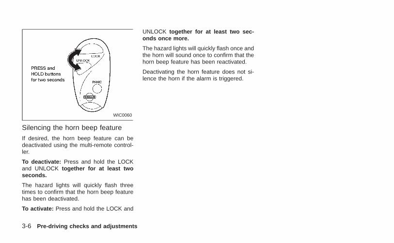
Silencing the horn beep feature
If desired, the horn beep feature can bedeactivated using the multi-remote control-ler.
To deactivate: Press and hold the LOCKand UNLOCK together for at least twoseconds.
The hazard lights will quickly flash threetimes to confirm that the horn beep featurehas been deactivated.
To activate: Press and hold the LOCK and
UNLOCK together for at least two sec-onds once more.
The hazard lights will quickly flash once andthe horn will sound once to confirm that thehorn beep feature has been reactivated.
Deactivating the horn feature does not si-lence the horn if the alarm is triggered.
WIC0060
3-6 Pre-driving checks and adjustments
Z X
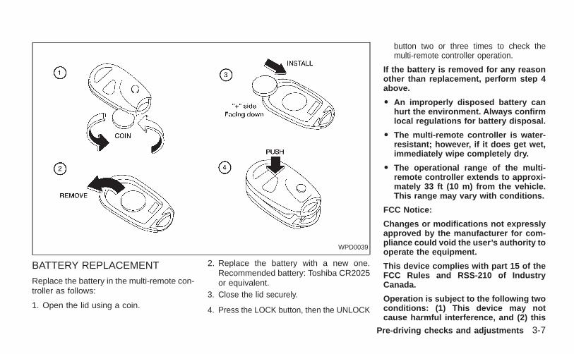
BATTERY REPLACEMENT
Replace the battery in the multi-remote con-troller as follows:
1. Open the lid using a coin.
2. Replace the battery with a new one.Recommended battery: Toshiba CR2025or equivalent.
3. Close the lid securely.
4. Press the LOCK button, then the UNLOCK
button two or three times to check themulti-remote controller operation.
If the battery is removed for any reasonother than replacement, perform step 4above.
O An improperly disposed battery canhurt the environment. Always confirmlocal regulations for battery disposal.
O The multi-remote controller is water-resistant; however, if it does get wet,immediately wipe completely dry.
O The operational range of the multi-remote controller extends to approxi-mately 33 ft (10 m) from the vehicle.This range may vary with conditions.
FCC Notice:
Changes or modifications not expresslyapproved by the manufacturer for com-pliance could void the user’s authority tooperate the equipment.
This device complies with part 15 of theFCC Rules and RSS-210 of IndustryCanada.
Operation is subject to the following twoconditions: (1) This device may notcause harmful interference, and (2) this
WPD0039
Pre-driving checks and adjustments 3-7
Z X
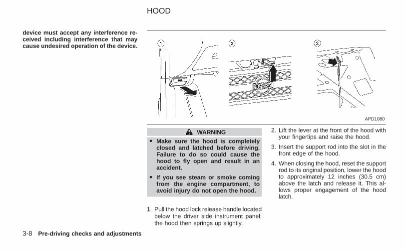
device must accept any interference re-ceived including interference that maycause undesired operation of the device.
WARNING
O Make sure the hood is completelyclosed and latched before driving.Failure to do so could cause thehood to fly open and result in anaccident.
O If you see steam or smoke comingfrom the engine compartment, toavoid injury do not open the hood.
1. Pull the hood lock release handle locatedbelow the driver side instrument panel;the hood then springs up slightly.
2. Lift the lever at the front of the hood withyour fingertips and raise the hood.
3. Insert the support rod into the slot in thefront edge of the hood.
4. When closing the hood, reset the supportrod to its original position, lower the hoodto approximately 12 inches (30.5 cm)above the latch and release it. This al-lows proper engagement of the hoodlatch.
APD1080
HOOD
3-8 Pre-driving checks and adjustments
Z X
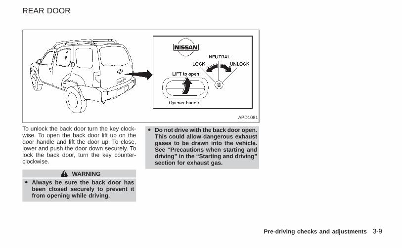
To unlock the back door turn the key clock-wise. To open the back door lift up on thedoor handle and lift the door up. To close,lower and push the door down securely. Tolock the back door, turn the key counter-clockwise.
WARNINGO Always be sure the back door has
been closed securely to prevent itfrom opening while driving.
O Do not drive with the back door open.This could allow dangerous exhaustgases to be drawn into the vehicle.See “Precautions when starting anddriving” in the “Starting and driving”section for exhaust gas.
APD1081
REAR DOOR
Pre-driving checks and adjustments 3-9
Z X
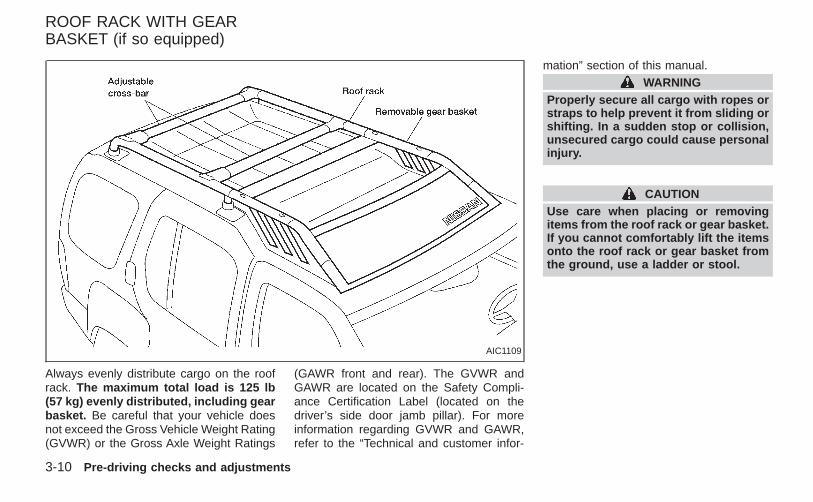
Always evenly distribute cargo on the roofrack. The maximum total load is 125 lb(57 kg) evenly distributed, including gearbasket. Be careful that your vehicle doesnot exceed the Gross Vehicle Weight Rating(GVWR) or the Gross Axle Weight Ratings
(GAWR front and rear). The GVWR andGAWR are located on the Safety Compli-ance Certification Label (located on thedriver’s side door jamb pillar). For moreinformation regarding GVWR and GAWR,refer to the “Technical and customer infor-
mation” section of this manual.WARNING
Properly secure all cargo with ropes orstraps to help prevent it from sliding orshifting. In a sudden stop or collision,unsecured cargo could cause personalinjury.
CAUTIONUse care when placing or removingitems from the roof rack or gear basket.If you cannot comfortably lift the itemsonto the roof rack or gear basket fromthe ground, use a ladder or stool.
AIC1109
ROOF RACK WITH GEARBASKET (if so equipped)
3-10 Pre-driving checks and adjustments
Z X
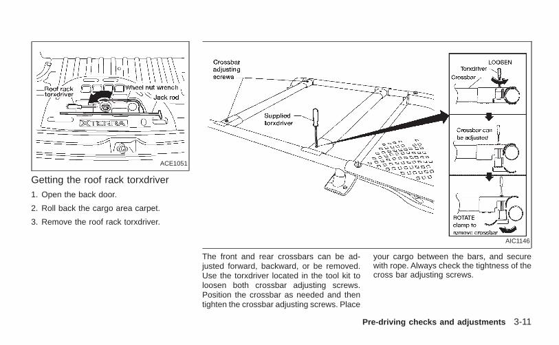
Getting the roof rack torxdriver1. Open the back door.
2. Roll back the cargo area carpet.
3. Remove the roof rack torxdriver.
The front and rear crossbars can be ad-justed forward, backward, or be removed.Use the torxdriver located in the tool kit toloosen both crossbar adjusting screws.Position the crossbar as needed and thentighten the crossbar adjusting screws. Place
your cargo between the bars, and securewith rope. Always check the tightness of thecross bar adjusting screws.
ACE1051
AIC1146
Pre-driving checks and adjustments 3-11
Z X
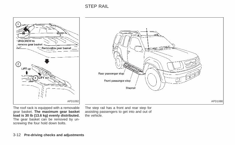
The roof rack is equipped with a removablegear basket. The maximum gear basketload is 30 lb (13.6 kg) evenly distributed.The gear basket can be removed by un-screwing the four hold down bolts.
The step rail has a front and rear step forassisting passengers to get into and out ofthe vehicle.
APD1092 APD1088
STEP RAIL
3-12 Pre-driving checks and adjustments
Z X
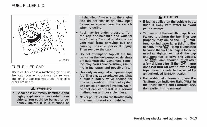
FUEL FILLER CAPThe fuel filler cap is a ratcheting type. Turnthe cap counter clockwise to remove.Tighten the cap clockwise until ratchetingclicks are heard.
WARNINGO Gasoline is extremely flammable and
highly explosive under certain con-ditions. You could be burned or se-riously injured if it is misused or
mishandled. Always stop the engineand do not smoke or allow openflames or sparks near the vehiclewhen refueling.
O Fuel may be under pressure. Turnthe cap one-half turn and wait forany ‘‘hissing’’ sound to stop to pre-vent fuel from spraying out andcausing possible personal injury.Then remove the cap.
O Do not attempt to top off the fueltank after the fuel pump nozzle shutsoff automatically. Continued refuel-ing may cause fuel overflow, result-ing in fuel spray and possibly fire.
O Use only an original equipment typefuel filler cap as a replacement. It hasa built-in safety valve needed forproper operation of the fuel systemand emission control system. An in-correct cap can result in a seriousmalfunction and possible injury.
O Never pour fuel into the throttle bodyto attempt to start your vehicle.
CAUTIONO If fuel is spilled on the vehicle body,
flush it away with water to avoidpaint damage.
O Tighten until the fuel filler cap clicks.Failure to tighten the fuel filler capproperly may cause the mal-function indicator lamp (MIL) to illu-minate. If the lamp illuminatesbecause the fuel filler cap is loose ormissing, tighten or install the capand continue to drive the vehicle.The lamp should turn off aftera few driving trips. If the lampdoes not turn off after a few drivingtrips, have the vehicle inspected byan authorized NISSAN dealer.
O For additional information, see the(Malfunction indicator light (MIL) ( inthe (Instruments and Controls ( sec-tion earlier in this manual.
APD1082
FUEL FILLER LID
Pre-driving checks and adjustments 3-13
Z X
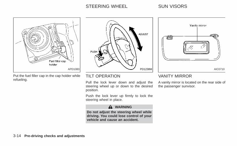
Put the fuel filler cap in the cap holder whilerefueling.
TILT OPERATIONPull the lock lever down and adjust thesteering wheel up or down to the desiredposition.
Push the lock lever up firmly to lock thesteering wheel in place.
WARNINGDo not adjust the steering wheel whiledriving. You could lose control of yourvehicle and cause an accident.
VANITY MIRRORA vanity mirror is located on the rear side ofthe passenger sunvisor.
APD1083 PD1238M AIC0710
STEERING WHEEL SUN VISORS
3-14 Pre-driving checks and adjustments
Z X
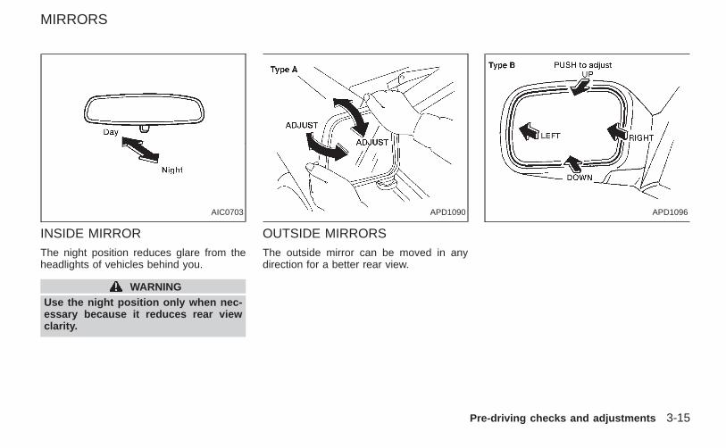
INSIDE MIRRORThe night position reduces glare from theheadlights of vehicles behind you.
WARNINGUse the night position only when nec-essary because it reduces rear viewclarity.
OUTSIDE MIRRORSThe outside mirror can be moved in anydirection for a better rear view.
AIC0703 APD1090 APD1096
MIRRORS
Pre-driving checks and adjustments 3-15
Z X
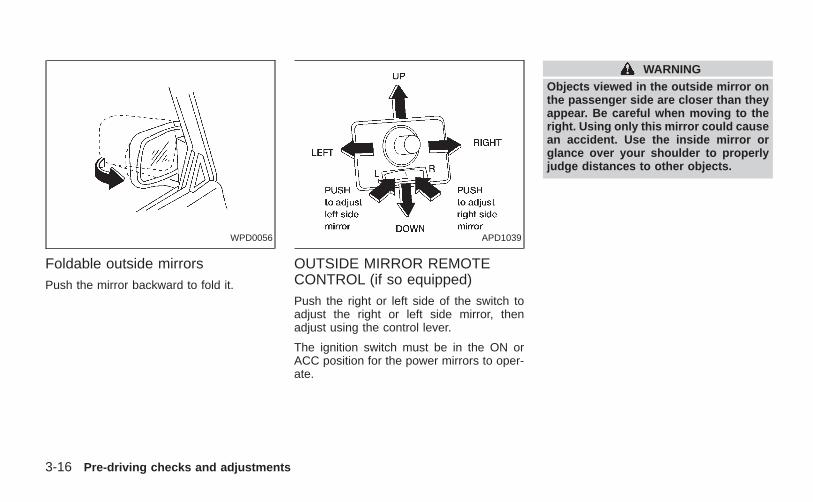
Foldable outside mirrorsPush the mirror backward to fold it.
OUTSIDE MIRROR REMOTECONTROL (if so equipped)Push the right or left side of the switch toadjust the right or left side mirror, thenadjust using the control lever.
The ignition switch must be in the ON orACC position for the power mirrors to oper-ate.
WARNINGObjects viewed in the outside mirror onthe passenger side are closer than theyappear. Be careful when moving to theright. Using only this mirror could causean accident. Use the inside mirror orglance over your shoulder to properlyjudge distances to other objects.
WPD0056 APD1039
3-16 Pre-driving checks and adjustments
Z X
4 Heater, air conditioner and audio systems
Ventilators...............................................................4-2Heater and air conditioner......................................4-3
Controls .............................................................4-3Heater operation................................................4-4Air conditioner operation(if so equipped)..................................................4-5Air flow charts....................................................4-6
Servicing air conditioner.........................................4-9Audio system........................................................4-10
FM-AM radio with compact disc (CD)player (if so equipped).....................................4-10
FM-AM radio with cassette player andcompact disc (CD) player(if so equipped)................................................4-17FM-AM radio with compact disc (CD)changer (if so equipped) .................................4-24Steering wheel switch for audio controls ........4-37Antenna ...........................................................4-37
Car phone or CB radio.........................................4-38
Z X
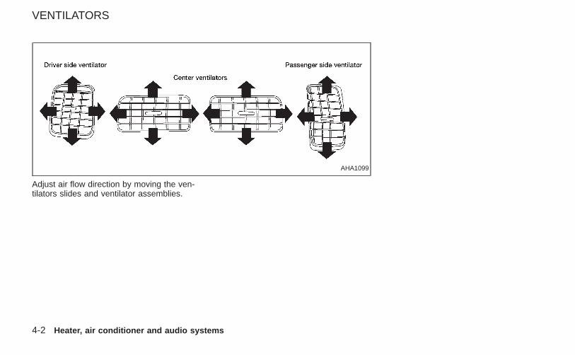
Adjust air flow direction by moving the ven-tilators slides and ventilator assemblies.
AHA1099
VENTILATORS
4-2 Heater, air conditioner and audio systems
Z X
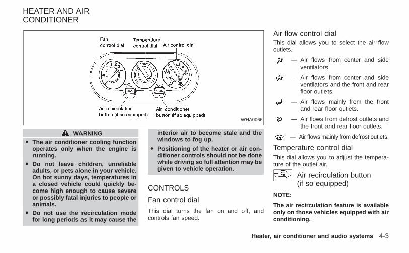
WARNINGO The air conditioner cooling function
operates only when the engine isrunning.
O Do not leave children, unreliableadults, or pets alone in your vehicle.On hot sunny days, temperatures ina closed vehicle could quickly be-come high enough to cause severeor possibly fatal injuries to people oranimals.
O Do not use the recirculation modefor long periods as it may cause the
interior air to become stale and thewindows to fog up.
O Positioning of the heater or air con-ditioner controls should not be donewhile driving so full attention may begiven to vehicle operation.
CONTROLS
Fan control dial
This dial turns the fan on and off, andcontrols fan speed.
Air flow control dialThis dial allows you to select the air flowoutlets.
— Air flows from center and sideventilators.
— Air flows from center and sideventilators and the front and rearfloor outlets.
— Air flows mainly from the frontand rear floor outlets.
— Air flows from defrost outlets andthe front and rear floor outlets.
— Air flows mainly from defrost outlets.
Temperature control dialThis dial allows you to adjust the tempera-ture of the outlet air.
Air recirculation button(if so equipped)
NOTE:
The air recirculation feature is availableonly on those vehicles equipped with airconditioning.
WHA0066
HEATER AND AIRCONDITIONER
Heater, air conditioner and audio systems 4-3
Z X
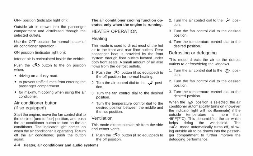
OFF position (indicator light off):
Outside air is drawn into the passengercompartment and distributed through theselected outlets.
Use the OFF position for normal heater orair conditioner operation.
ON position (indicator light on):
Interior air is recirculated inside the vehicle.
Push the button to the on positionwhen:
O driving on a dusty road.
O to prevent traffic fumes from entering thepassenger compartment.
O for maximum cooling when using the airconditioner.
Air conditioner button(if so equipped)Start the engine, move the fan control dial tothe desired (one to four) position, and pushthe air conditioner button to turn on the airconditioner. The indicator light comes onwhen the air conditioner is operating. To turnoff the air conditioner, push the buttonagain.
The air conditioner cooling function op-erates only when the engine is running.
HEATER OPERATION
Heating
This mode is used to direct most of the hotair to the front and rear floor outlets. Rearpassenger heat is provided by the frontsystem through floor outlets located underboth front seats. A small amount of air alsoflows from the defrost outlets.
1. Push the button (if so equipped) tothe off position for normal heating.
2. Turn the air control dial to the posi-tion.
3. Turn the fan control dial to the desiredposition.
4. Turn the temperature control dial to thedesired position between the middle andthe hot position.
VentilationThis mode directs outside air from the sideand center vents.
1. Push the button (if so equipped) tothe off position.
2. Turn the air control dial to the posi-tion.
3. Turn the fan control dial to the desiredposition.
4. Turn the temperature control dial to thedesired position.
Defrosting or defogging
This mode directs the air to the defrostoutlets to defrost/defog the windows.
1. Turn the air control dial to the posi-tion.
2. Turn the fan control dial to the desiredposition.
3. Turn the temperature control dial to thedesired position.
When the position is selected, the airconditioner automatically turns on (howeverthe indicator light will not illuminate) if theoutside temperature is more than45°F(7°C). This dehumidifies the air whichhelps defog the windshield. The
mode automatically turns off, allow-ing outside air to be drawn into the passen-ger compartment to further improve thedefogging performance.
4-4 Heater, air conditioner and audio systems
Z X
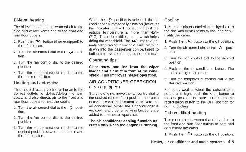
Bi-level heating
The bi-level mode directs warmed air to theside and center vents and to the front andrear floor outlets.
1. Push the button (if so equipped) tothe off position.
2. Turn the air control dial to the posi-tion.
3. Turn the fan control dial to the desiredposition.
4. Turn the temperature control dial to thethe desired position.
Heating and defoggingThis mode directs a portion of the air to thedefrost outlets to defrost/defog the win-dows, and also directs air to the front andrear floor outlets to heat the cabin.
1. Turn the air control dial to the posi-tion.
2. Turn the fan control dial to the desiredposition.
3. Turn the temperature control dial to thedesired position between the middle andthe hot position.
When the position is selected, the airconditioner automatically turns on (howeverthe indicator light will not illuminate) if theoutside temperature is more than 45°F(7°C). This dehumidifies the air which helpsdefog the windshield. The mode auto-maticallly turns off, allowing outside air to bedrawn into the passenger compartment tofurther improve the defogging performance.
Operating tips
Clear snow and ice from the wiperblades and air inlet in front of the wind-shield. This improves heater operation.
AIR CONDITIONER OPERATION(if so equipped)
Start the engine, move the fan control dial tothe desired (one to four) position, and pushin the air conditioner button to activate theair conditioner. When the air conditioner ison, cooling and dehumidifying functions areadded to the heater operation.
The air conditioner cooling function op-erates only when the engine is running.
Cooling
This mode directs cooled and dryed air tothe side and center vents to cool and dehu-midify the cabin.
1. Push the button to the off position.
2. Turn the air control dial to the posi-tion.
3. Turn the fan control dial to the desiredposition.
4. Push on the air conditioner button. Theindicator light comes on.
5. Turn the temperature control dial to thedesired position.
For quick cooling when the outside tem-perature is high, push the button tothe ON position. Be sure to return the airrecirculation button to the OFF position fornormal cooling.
Dehumidified heating
This mode directs warmed and dryed air tothe front and rear floor outlets to heat anddehumidify the cabin.
1. Push the button to the off position.
Heater, air conditioner and audio systems 4-5
Z X
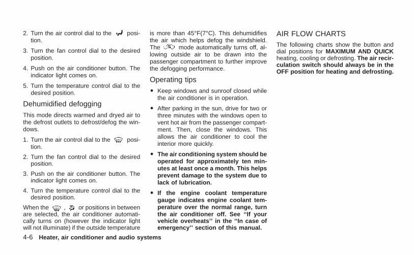
2. Turn the air control dial to the posi-tion.
3. Turn the fan control dial to the desiredposition.
4. Push on the air conditioner button. Theindicator light comes on.
5. Turn the temperature control dial to thedesired position.
Dehumidified defogging
This mode directs warmed and dryed air tothe defrost outlets to defrost/defog the win-dows.
1. Turn the air control dial to the posi-tion.
2. Turn the fan control dial to the desiredposition.
3. Push on the air conditioner button. Theindicator light comes on.
4. Turn the temperature control dial to thedesired position.
When the , or positions in betweenare selected, the air conditioner automati-cally turns on (however the indicator lightwill not illuminate) if the outside temperature
is more than 45°F(7°C). This dehumidifiesthe air which helps defog the windshield.The mode automatically turns off, al-lowing outside air to be drawn into thepassenger compartment to further improvethe defogging performance.
Operating tips
O Keep windows and sunroof closed whilethe air conditioner is in operation.
O After parking in the sun, drive for two orthree minutes with the windows open tovent hot air from the passenger compart-ment. Then, close the windows. Thisallows the air conditioner to cool theinterior more quickly.
O The air conditioning system should beoperated for approximately ten min-utes at least once a month. This helpsprevent damage to the system due tolack of lubrication.
O If the engine coolant temperaturegauge indicates engine coolant tem-perature over the normal range, turnthe air conditioner off. See ‘‘If yourvehicle overheats’’ in the ‘‘In case ofemergency’’ section of this manual.
AIR FLOW CHARTSThe following charts show the button anddial positions for MAXIMUM AND QUICKheating, cooling or defrosting. The air recir-culation switch should always be in theOFF position for heating and defrosting.
4-6 Heater, air conditioner and audio systems
Z X
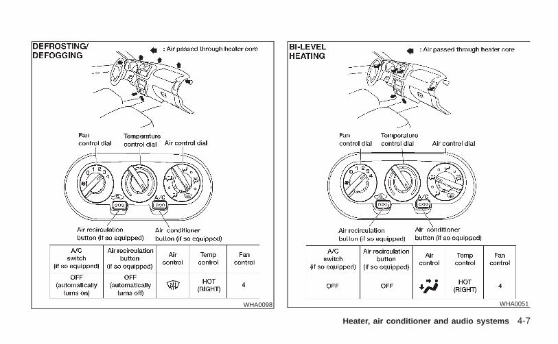
WHA0051WHA0098
Heater, air conditioner and audio systems 4-7
Z X
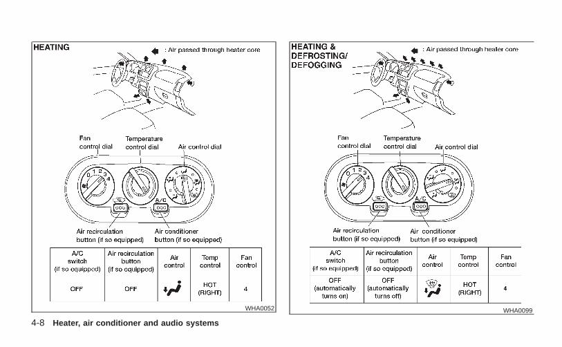
WHA0099WHA0052
4-8 Heater, air conditioner and audio systems
Z X
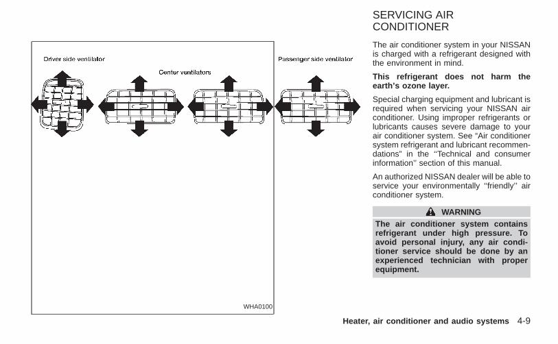
The air conditioner system in your NISSANis charged with a refrigerant designed withthe environment in mind.
This refrigerant does not harm theearth’s ozone layer.
Special charging equipment and lubricant isrequired when servicing your NISSAN airconditioner. Using improper refrigerants orlubricants causes severe damage to yourair conditioner system. See “Air conditionersystem refrigerant and lubricant recommen-dations” in the ‘‘Technical and consumerinformation’’ section of this manual.
An authorized NISSAN dealer will be able toservice your environmentally ‘‘friendly’’ airconditioner system.
WARNINGThe air conditioner system containsrefrigerant under high pressure. Toavoid personal injury, any air condi-tioner service should be done by anexperienced technician with properequipment.
WHA0100
SERVICING AIRCONDITIONER
Heater, air conditioner and audio systems 4-9
Z X
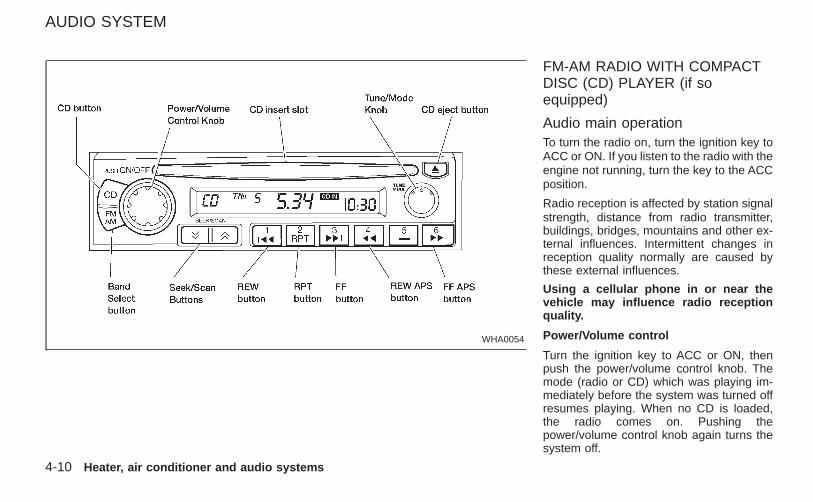
FM-AM RADIO WITH COMPACTDISC (CD) PLAYER (if soequipped)
Audio main operationTo turn the radio on, turn the ignition key toACC or ON. If you listen to the radio with theengine not running, turn the key to the ACCposition.
Radio reception is affected by station signalstrength, distance from radio transmitter,buildings, bridges, mountains and other ex-ternal influences. Intermittent changes inreception quality normally are caused bythese external influences.
Using a cellular phone in or near thevehicle may influence radio receptionquality.
Power/Volume control
Turn the ignition key to ACC or ON, thenpush the power/volume control knob. Themode (radio or CD) which was playing im-mediately before the system was turned offresumes playing. When no CD is loaded,the radio comes on. Pushing thepower/volume control knob again turns thesystem off.
WHA0054
AUDIO SYSTEM
4-10 Heater, air conditioner and audio systems
Z X
Turn the power/volume control knob to theright to increase volume or to the left todecrease volume.
Adjusting tone quality and speaker bal-ance
To adjust Bass, Treble, Fader or Balance,press the knob for less than 1.5 sec-onds. A beep signals entry into the audioadjustment mode and BASS will appear inthe display. Rotate the knob to adjustBass (BASS) to the desired level.
Press the knob a second time andTREB appears in the display. Rotate the
knob to adjust Treble (TREB) to thedesired level.
Press the knob a third time and FADappears in the display. Fader (FAD) adjuststhe sound between the front and rearspeaker. Rotate the knob to adjustFader (FAD) to the desired level.
Press the knob a fourth time and BALappears in the display. Balance (BAL) ad-justs the sound between the right and leftspeakers. Rotate the knob to adjustBalance (BAL) to the desired level.
After 10 seconds, the radio or CD display
will reappear. Once the sound quality is setto the desired level, press the knobrepeatedly until the radio or CD displayreappears.
Heater, air conditioner and audio systems 4-11
Z X
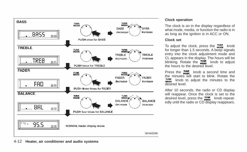
Clock operation
The clock is on in the display regardless ofwhat mode, media, or function the radio is inas long as the ignition is in ACC or ON.
Clock set
To adjust the clock, press the knobfor longer than 1.5 seconds. A beep signalsentry into the clock adjustment mode andCL appears in the display. The hours will beblinking. Rotate the knob to adjustthe hours to the desired level.
Press the knob a second time andthe minutes will start to blink. Rotate the
knob to adjust the minutes to thedesired level.
After 10 seconds, the radio or CD displaywill reappear. Once the clock is set to thedesired level, press the knob repeat-edly until the radio or CD display reappears.
WHA0096
4-12 Heater, air conditioner and audio systems
Z X
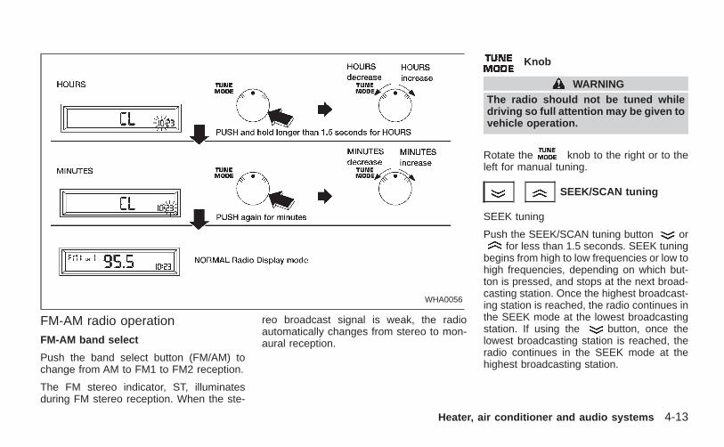
FM-AM radio operationFM-AM band select
Push the band select button (FM/AM) tochange from AM to FM1 to FM2 reception.
The FM stereo indicator, ST, illuminatesduring FM stereo reception. When the ste-
reo broadcast signal is weak, the radioautomatically changes from stereo to mon-aural reception.
Knob
WARNINGThe radio should not be tuned whiledriving so full attention may be given tovehicle operation.
Rotate the knob to the right or to theleft for manual tuning.
SEEK/SCAN tuning
SEEK tuning
Push the SEEK/SCAN tuning button orfor less than 1.5 seconds. SEEK tuning
begins from high to low frequencies or low tohigh frequencies, depending on which but-ton is pressed, and stops at the next broad-casting station. Once the highest broadcast-ing station is reached, the radio continues inthe SEEK mode at the lowest broadcastingstation. If using the button, once thelowest broadcasting station is reached, theradio continues in the SEEK mode at thehighest broadcasting station.
WHA0056
Heater, air conditioner and audio systems 4-13
Z X
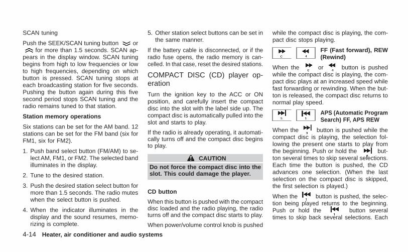
SCAN tuning
Push the SEEK/SCAN tuning button orfor more than 1.5 seconds. SCAN ap-
pears in the display window. SCAN tuningbegins from high to low frequencies or lowto high frequencies, depending on whichbutton is pressed. SCAN tuning stops ateach broadcasting station for five seconds.Pushing the button again during this fivesecond period stops SCAN tuning and theradio remains tuned to that station.
Station memory operations
Six stations can be set for the AM band. 12stations can be set for the FM band (six forFM1, six for FM2).
1. Push band select button (FM/AM) to se-lect AM, FM1, or FM2. The selected bandilluminates in the display.
2. Tune to the desired station.
3. Push the desired station select button formore than 1.5 seconds. The radio muteswhen the select button is pushed.
4. When the indicator illuminates in thedisplay and the sound resumes, memo-rizing is complete.
5. Other station select buttons can be set inthe same manner.
If the battery cable is disconnected, or if theradio fuse opens, the radio memory is can-celled. In that case, reset the desired stations.
COMPACT DISC (CD) player op-eration
Turn the ignition key to the ACC or ONposition, and carefully insert the compactdisc into the slot with the label side up. Thecompact disc is automatically pulled into theslot and starts to play.
If the radio is already operating, it automati-cally turns off and the compact disc beginsto play.
CAUTIONDo not force the compact disc into theslot. This could damage the player.
CD button
When this button is pushed with the compactdisc loaded and the radio playing, the radioturns off and the compact disc starts to play.
When power/volume control knob is pushed
while the compact disc is playing, the com-pact disc stops playing.
FF (Fast forward), REW(Rewind)
When the or button is pushedwhile the compact disc is playing, the com-pact disc plays at an increased speed whilefast forwarding or rewinding. When the but-ton is released, the compact disc returns tonormal play speed.
APS (Automatic ProgramSearch) FF, APS REW
When the button is pushed while thecompact disc is playing, the selection fol-lowing the present one starts to play fromthe beginning. Push or hold the but-ton several times to skip several selections.Each time the button is pushed, the CDadvances one selection. (When the lastselection on the compact disc is skipped,the first selection is played.)
When the button is pushed, the selec-tion being played returns to the beginning.Push or hold the button severaltimes to skip back several selections. Each
4-14 Heater, air conditioner and audio systems
Z X
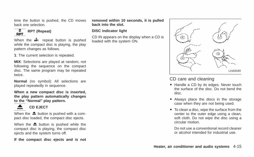
time the button is pushed, the CD movesback one selection.
RPT (Repeat)
When the repeat button is pushedwhile the compact disc is playing, the playpattern changes as follows.
1: The current selection is repeated.
MIX: Selections are played at random, notfollowing the sequence on the compactdisc. The same program may be repeatedtwice.
Normal (no symbol): All selections areplayed repeatedly in sequence.
When a new compact disc is inserted,the play pattern automatically changesto the ‘‘Normal’’ play pattern.
CD EJECT
When the button is pushed with a com-pact disc loaded, the compact disc ejects.
When the button is pushed while thecompact disc is playing, the compact discejects and the system turns off.
If the compact disc ejects and is not
removed within 10 seconds, it is pulledback into the slot.
DISC indicator light
CD IN appears on the display when a CD isloaded with the system ON.
CD care and cleaningO Handle a CD by its edges. Never touch
the surface of the disc. Do not bend thedisc.
O Always place the discs in the storagecase when they are not being used.
O To clean a disc, wipe the surface from thecenter to the outer edge using a clean,soft cloth. Do not wipe the disc using acircular motion.
Do not use a conventional record cleaneror alcohol intended for industrial use.
LHA0049
Heater, air conditioner and audio systems 4-15
Z X
O A new disc may be rough on the innerand outer edges. Remove the roughedges by rubbing the inner and outeredges with the side of a pen or pencil asillustrated.
CAUTIONO During cold weather or rainy days,
the player may malfunction due tothe humidity. If this occurs, removethe CD and dehumidify or ventilatethe player completely.
O The player may skip while driving onrough roads.
O The CD player sometimes cannotfunction when the passenger com-partment temperature is extremelyhigh. Decrease the temperature be-fore use.
O Do no expose the CD to direct sun-light.
O Do not touch the playing surface ofthe disc.
O Do not use 8cm discs. They maycause player damage even if usingwith the optional adapter.
O Recordable compact discs (CD-R)may not function properly in the CDplayer.
4-16 Heater, air conditioner and audio systems
Z X
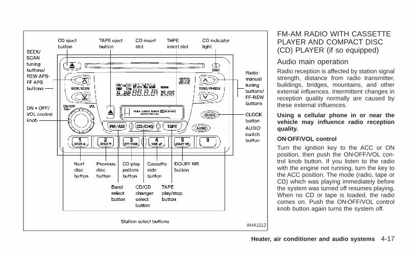
FM-AM RADIO WITH CASSETTEPLAYER AND COMPACT DISC(CD) PLAYER (if so equipped)
Audio main operationRadio reception is affected by station signalstrength, distance from radio transmitter,buildings, bridges, mountains, and otherexternal influences. Intermittent changes inreception quality normally are caused bythese external influences.
Using a cellular phone in or near thevehicle may influence radio receptionquality.
ONzOFF/VOL controlTurn the ignition key to the ACC or ONposition, then push the ONzOFF/VOL con-trol knob button. If you listen to the radiowith the engine not running, turn the key tothe ACC position. The mode (radio, tape orCD) which was playing immediately beforethe system was turned off resumes playing.When no CD or tape is loaded, the radiocomes on. Push the ONzOFF/VOL controlknob button again turns the system off.
AHA1112
Heater, air conditioner and audio systems 4-17
Z X
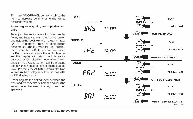
Turn the ONzOFF/VOL control knob to theright to increase volume or to the left todecrease volume.
Adjusting tone quality and speaker bal-ance
To adjust the audio levels for bass, treble,fader, and balance, push the AUDIO buttonand adjust the level with the TUNE/FF-REW
or buttons. Press the audio buttononce for BAS (bass), twice for TRE (treble),three times for FAD (fader) and four timesfor BAL (balance). Once the audio level isset the display will return back to radio,cassette or CD display mode after 7 sec-onds or the AUDIO button can be pressedagain within 7 seconds to set the next audiolevel. Pressing the AUDIO button a fifth timewill return the display back to radio, cassetteor CD display mode.
Fader adjusts the sound level between thefront and rear speakers, balance adjusts thesound level between the right and leftspeakers.
AHA1128
4-18 Heater, air conditioner and audio systems
Z X
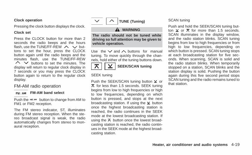
Clock operation
Pressing the clock button displays the clock.
Clock set
Press the CLOCK button for more than 2seconds the radio beeps and the hoursflash, use the TUNE/FF-REW but-tons to set the hour, press the CLOCKbutton again until the radio beeps and theminutes flash, use the TUNE/FF-REW
buttons to set the minutes. Thedisplay will return to regular clock display in7 seconds or you may press the CLOCKbutton again to return to the regular clockdisplay.
FM-AM radio operationFM-AM band select
Push the button to change from AM toFM1 or FM2 reception.
The FM stereo indicator, ST, illuminatesduring FM stereo reception. When the ste-reo broadcast signal is weak, the radioautomatically changes from stereo to mon-aural reception.
TUNE (Tuning)
WARNING
The radio should not be tuned whiledriving so full attention may be given tovehicle operation.
Use the and buttons for manualtuning. To move quickly through the chan-nels, hold either of the tuning buttons down.
SEEK/SCAN tuning
SEEK tuning
Push the SEEK/SCAN tuning button orfor less than 1.5 seconds. SEEK tuning
begins from low to high frequencies or highto low frequencies, depending on whichbutton is pressed, and stops at the nextbroadcasting station. If using the buttononce the highest broadcasting station isreached, the radio continues in the SEEKmode at the lowest broadcasting station. Ifusing the button once the lowest broad-casting station is reached, the radio contin-ues in the SEEK mode at the highest broad-casting station.
SCAN tuning
Push and hold the SEEK/SCAN tuning but-ton or for more than 1.5 seconds.SCAN illuminates in the display window,and the radio station blinks. SCAN tuningbegins from low to high frequencies or fromhigh to low frequencies, depending onwhich button is pressed. SCAN tuning stopsat each broadcasting station for five sec-onds. When scanning, SCAN is solid andthe radio station blinks. When temporarilystopped on a station, SCAN blinks and thestation display is solid. Pushing the buttonagain during this five second period stopsSCAN tuning and the radio remains tuned tothat station.
Heater, air conditioner and audio systems 4-19
Z X
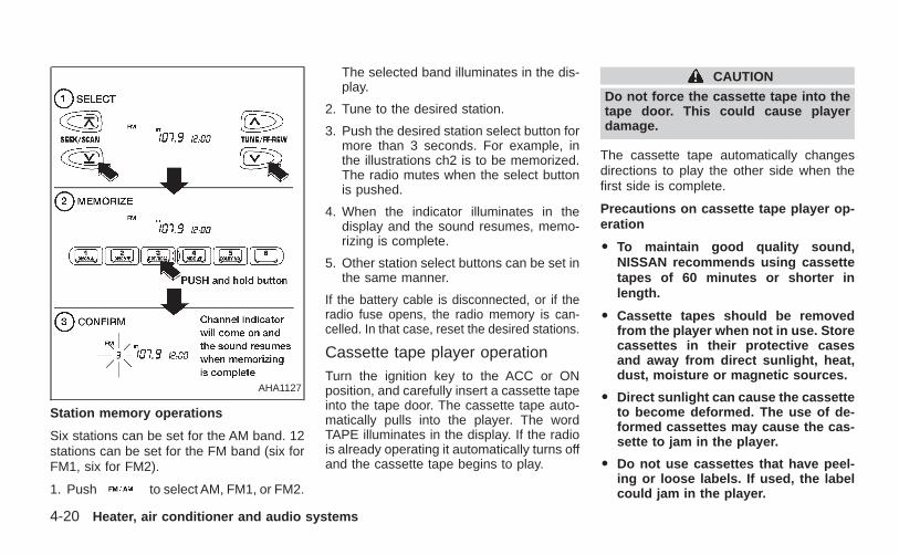
Station memory operations
Six stations can be set for the AM band. 12stations can be set for the FM band (six forFM1, six for FM2).
1. Push to select AM, FM1, or FM2.
The selected band illuminates in the dis-play.
2. Tune to the desired station.
3. Push the desired station select button formore than 3 seconds. For example, inthe illustrations ch2 is to be memorized.The radio mutes when the select buttonis pushed.
4. When the indicator illuminates in thedisplay and the sound resumes, memo-rizing is complete.
5. Other station select buttons can be set inthe same manner.
If the battery cable is disconnected, or if theradio fuse opens, the radio memory is can-celled. In that case, reset the desired stations.
Cassette tape player operationTurn the ignition key to the ACC or ONposition, and carefully insert a cassette tapeinto the tape door. The cassette tape auto-matically pulls into the player. The wordTAPE illuminates in the display. If the radiois already operating it automatically turns offand the cassette tape begins to play.
CAUTION
Do not force the cassette tape into thetape door. This could cause playerdamage.
The cassette tape automatically changesdirections to play the other side when thefirst side is complete.
Precautions on cassette tape player op-eration
O To maintain good quality sound,NISSAN recommends using cassettetapes of 60 minutes or shorter inlength.
O Cassette tapes should be removedfrom the player when not in use. Storecassettes in their protective casesand away from direct sunlight, heat,dust, moisture or magnetic sources.
O Direct sunlight can cause the cassetteto become deformed. The use of de-formed cassettes may cause the cas-sette to jam in the player.
O Do not use cassettes that have peel-ing or loose labels. If used, the labelcould jam in the player.
AHA1127
4-20 Heater, air conditioner and audio systems
Z X
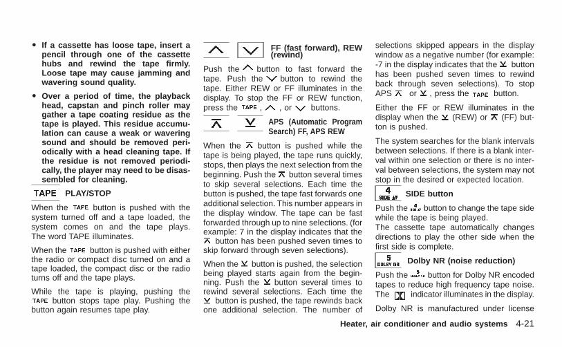
O If a cassette has loose tape, insert apencil through one of the cassettehubs and rewind the tape firmly.Loose tape may cause jamming andwavering sound quality.
O Over a period of time, the playbackhead, capstan and pinch roller maygather a tape coating residue as thetape is played. This residue accumu-lation can cause a weak or waveringsound and should be removed peri-odically with a head cleaning tape. Ifthe residue is not removed periodi-cally, the player may need to be disas-sembled for cleaning.
PLAY/STOP
When the button is pushed with thesystem turned off and a tape loaded, thesystem comes on and the tape plays.The word TAPE illuminates.
When the button is pushed with eitherthe radio or compact disc turned on and atape loaded, the compact disc or the radioturns off and the tape plays.
While the tape is playing, pushing thebutton stops tape play. Pushing the
button again resumes tape play.
FF (fast forward), REW(rewind)
Push the button to fast forward thetape. Push the button to rewind thetape. Either REW or FF illuminates in thedisplay. To stop the FF or REW function,press the , , or buttons.
APS (Automatic ProgramSearch) FF, APS REW
When the button is pushed while thetape is being played, the tape runs quickly,stops, then plays the next selection from thebeginning. Push the button several timesto skip several selections. Each time thebutton is pushed, the tape fast forwards oneadditional selection. This number appears inthe display window. The tape can be fastforwarded through up to nine selections. (forexample: 7 in the display indicates that the
button has been pushed seven times toskip forward through seven selections).
When the button is pushed, the selectionbeing played starts again from the begin-ning. Push the button several times torewind several selections. Each time the
button is pushed, the tape rewinds backone additional selection. The number of
selections skipped appears in the displaywindow as a negative number (for example:-7 in the display indicates that the buttonhas been pushed seven times to rewindback through seven selections). To stopAPS or , press the button.
Either the FF or REW illuminates in thedisplay when the (REW) or (FF) but-ton is pushed.
The system searches for the blank intervalsbetween selections. If there is a blank inter-val within one selection or there is no inter-val between selections, the system may notstop in the desired or expected location.
SIDE button
Push the button to change the tape sidewhile the tape is being played.The cassette tape automatically changesdirections to play the other side when thefirst side is complete.
Dolby NR (noise reduction)
Push the button for Dolby NR encodedtapes to reduce high frequency tape noise.The indicator illuminates in the display.
Dolby NR is manufactured under license
Heater, air conditioner and audio systems 4-21
Z X
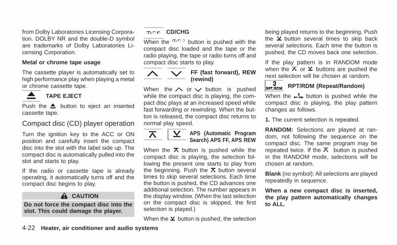
from Dolby Laboratories Licensing Corpora-tion. DOLBY NR and the double-D symbolare trademarks of Dolby Laboratories Li-censing Corporation.
Metal or chrome tape usage
The cassette player is automatically set tohigh performance play when playing a metalor chrome cassette tape.
TAPE EJECT
Push the button to eject an insertedcassette tape.
Compact disc (CD) player operation
Turn the ignition key to the ACC or ONposition and carefully insert the compactdisc into the slot with the label side up. Thecompact disc is automatically pulled into theslot and starts to play.
If the radio or cassette tape is alreadyoperating, it automatically turns off and thecompact disc begins to play.
CAUTIONDo not force the compact disc into theslot. This could damage the player.
CD/CHG
When the button is pushed with thecompact disc loaded and the tape or theradio playing, the tape or radio turns off andcompact disc starts to play.
FF (fast forward), REW(rewind)
When the or button is pushedwhile the compact disc is playing, the com-pact disc plays at an increased speed whilefast forwarding or rewinding. When the but-ton is released, the compact disc returns tonormal play speed.
APS (Automatic ProgramSearch) APS FF, APS REW
When the button is pushed while thecompact disc is playing, the selection fol-lowing the present one starts to play fromthe beginning. Push the button severaltimes to skip several selections. Each timethe button is pushed, the CD advances oneadditional selection. The number appears inthe display window. (When the last selectionon the compact disc is skipped, the firstselection is played.)
When the button is pushed, the selection
being played returns to the beginning. Pushthe button several times to skip backseveral selections. Each time the button ispushed, the CD moves back one selection.
If the play pattern is in RANDOM modewhen the or buttons are pushed thenext selection will be chosen at random.
RPT/RDM (Repeat/Random)
When the button is pushed while thecompact disc is playing, the play patternchanges as follows.
1. The current selection is repeated.
RANDOM: Selections are played at ran-dom, not following the sequence on thecompact disc. The same program may berepeated twice. If the button is pushedin the RANDOM mode, selections will bechosen at random.
Blank (no symbol): All selections are playedrepeatedly in sequence.
When a new compact disc is inserted,the play pattern automatically changesto ALL.
4-22 Heater, air conditioner and audio systems
Z X
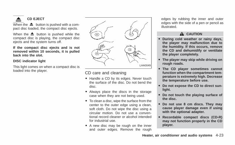
CD EJECT
When the button is pushed with a com-pact disc loaded, the compact disc ejects.
When the button is pushed while thecompact disc is playing, the compact discejects and the system turns off.
If the compact disc ejects and is notremoved within 10 seconds, it is pulledback into the slot.
DISC indicator light
This light comes on when a compact disc isloaded into the player.
CD care and cleaningO Handle a CD by its edges. Never touch
the surface of the disc. Do not bend thedisc.
O Always place the discs in the storagecase when they are not being used.
O To clean a disc, wipe the surface from thecenter to the outer edge using a clean,soft cloth. Do not wipe the disc using acircular motion. Do not use a conven-tional record cleaner or alcohol intendedfor industrial use.
O A new disc may be rough on the innerand outer edges. Remove the rough
edges by rubbing the inner and outeredges with the side of a pen or pencil asillustrated.
CAUTIONO During cold weather or rainy days,
the player may malfunction due tothe humidity. If this occurs, removethe CD and dehumidify or ventilatethe player completely.
O The player may skip while driving onrough roads.
O The CD player sometimes cannotfunction when the compartment tem-perature is extremely high. Decreasethe temperature before use.
O Do not expose the CD to direct sun-light.
O Do not touch the playing surface ofthe disc.
O Do not use 8 cm discs. They maycause player damage even if usingwith the optional adapter.
O Recordable compact discs (CD-R)may not function properly in the CDplayer.
LHA0049
Heater, air conditioner and audio systems 4-23
Z X
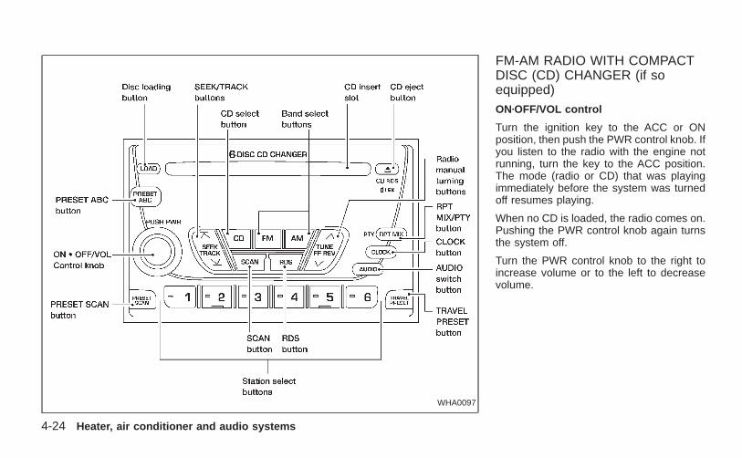
FM-AM RADIO WITH COMPACTDISC (CD) CHANGER (if soequipped)ONzOFF/VOL control
Turn the ignition key to the ACC or ONposition, then push the PWR control knob. Ifyou listen to the radio with the engine notrunning, turn the key to the ACC position.The mode (radio or CD) that was playingimmediately before the system was turnedoff resumes playing.
When no CD is loaded, the radio comes on.Pushing the PWR control knob again turnsthe system off.
Turn the PWR control knob to the right toincrease volume or to the left to decreasevolume.
WHA0097
4-24 Heater, air conditioner and audio systems
Z X
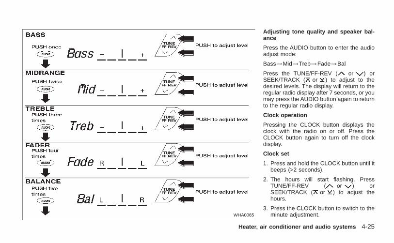
Adjusting tone quality and speaker bal-ance
Press the AUDIO button to enter the audioadjust mode:
Bass→Mid→Treb→Fade→Bal
Press the TUNE/FF-REV ( or ) orSEEK/TRACK ( or ) to adjust to thedesired levels. The display will return to theregular radio display after 7 seconds, or youmay press the AUDIO button again to returnto the regular radio display.
Clock operation
Pressing the CLOCK button displays theclock with the radio on or off. Press theCLOCK button again to turn off the clockdisplay.
Clock set
1. Press and hold the CLOCK button until itbeeps (>2 seconds).
2. The hours will start flashing. PressTUNE/FF-REV ( or ) orSEEK/TRACK ( or ) to adjust thehours.
3. Press the CLOCK button to switch to theminute adjustment.WHA0065
Heater, air conditioner and audio systems 4-25
Z X
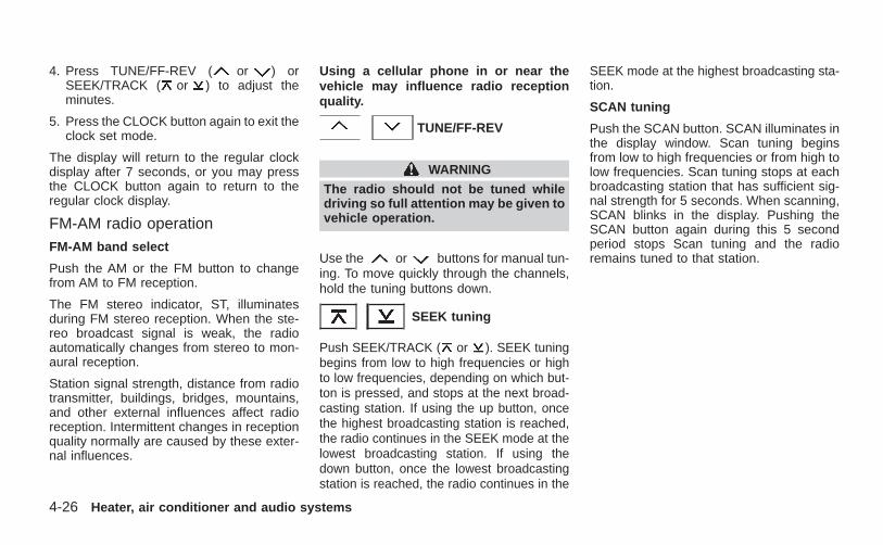
4. Press TUNE/FF-REV ( or ) orSEEK/TRACK ( or ) to adjust theminutes.
5. Press the CLOCK button again to exit theclock set mode.
The display will return to the regular clockdisplay after 7 seconds, or you may pressthe CLOCK button again to return to theregular clock display.
FM-AM radio operationFM-AM band select
Push the AM or the FM button to changefrom AM to FM reception.
The FM stereo indicator, ST, illuminatesduring FM stereo reception. When the ste-reo broadcast signal is weak, the radioautomatically changes from stereo to mon-aural reception.
Station signal strength, distance from radiotransmitter, buildings, bridges, mountains,and other external influences affect radioreception. Intermittent changes in receptionquality normally are caused by these exter-nal influences.
Using a cellular phone in or near thevehicle may influence radio receptionquality.
TUNE/FF-REV
WARNING
The radio should not be tuned whiledriving so full attention may be given tovehicle operation.
Use the or buttons for manual tun-ing. To move quickly through the channels,hold the tuning buttons down.
SEEK tuning
Push SEEK/TRACK ( or ). SEEK tuningbegins from low to high frequencies or highto low frequencies, depending on which but-ton is pressed, and stops at the next broad-casting station. If using the up button, oncethe highest broadcasting station is reached,the radio continues in the SEEK mode at thelowest broadcasting station. If using thedown button, once the lowest broadcastingstation is reached, the radio continues in the
SEEK mode at the highest broadcasting sta-tion.
SCAN tuning
Push the SCAN button. SCAN illuminates inthe display window. Scan tuning beginsfrom low to high frequencies or from high tolow frequencies. Scan tuning stops at eachbroadcasting station that has sufficient sig-nal strength for 5 seconds. When scanning,SCAN blinks in the display. Pushing theSCAN button again during this 5 secondperiod stops Scan tuning and the radioremains tuned to that station.
4-26 Heater, air conditioner and audio systems
Z X
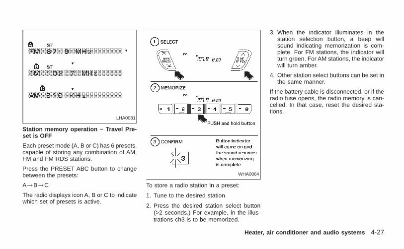
Station memory operation − Travel Pre-set is OFF
Each preset mode (A, B or C) has 6 presets,capable of storing any combination of AM,FM and FM RDS stations.
Press the PRESET ABC button to changebetween the presets:
A→B→C
The radio displays icon A, B or C to indicatewhich set of presets is active.
To store a radio station in a preset:
1. Tune to the desired station.
2. Press the desired station select button(>2 seconds.) For example, in the illus-trations ch3 is to be memorized.
3. When the indicator illuminates in thestation selection button, a beep willsound indicating memorization is com-plete. For FM stations, the indicator willturn green. For AM stations, the indicatorwill turn amber.
4. Other station select buttons can be set inthe same manner.
If the battery cable is disconnected, or if theradio fuse opens, the radio memory is can-celled. In that case, reset the desired sta-tions.
LHA0081
WHA0064
Heater, air conditioner and audio systems 4-27
Z X
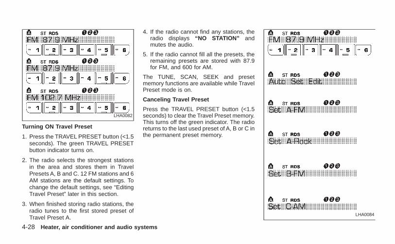
Turning ON Travel Preset
1. Press the TRAVEL PRESET button (<1.5seconds). The green TRAVEL PRESETbutton indicator turns on.
2. The radio selects the strongest stationsin the area and stores them in TravelPresets A, B and C. 12 FM stations and 6AM stations are the default settings. Tochange the default settings, see “EditingTravel Preset” later in this section.
3. When finished storing radio stations, theradio tunes to the first stored preset ofTravel Preset A.
4. If the radio cannot find any stations, theradio displays “NO STATION” andmutes the audio.
5. If the radio cannot fill all the presets, theremaining presets are stored with 87.9for FM, and 600 for AM.
The TUNE, SCAN, SEEK and presetmemory functions are available while TravelPreset mode is on.
Canceling Travel Preset
Press the TRAVEL PRESET button (<1.5seconds) to clear the Travel Preset memory.This turns off the green indicator. The radioreturns to the last used preset of A, B or C inthe permanent preset memory.
LHA0084
LHA0082
4-28 Heater, air conditioner and audio systems
Z X
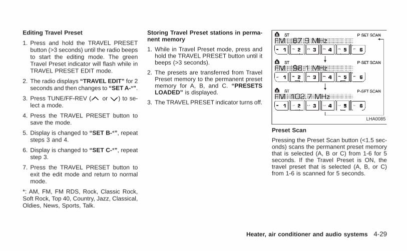
Editing Travel Preset
1. Press and hold the TRAVEL PRESETbutton (>3 seconds) until the radio beepsto start the editing mode. The greenTravel Preset indicator will flash while inTRAVEL PRESET EDIT mode.
2. The radio displays “TRAVEL EDIT” for 2seconds and then changes to “SET A- *” .
3. Press TUNE/FF-REV ( or ) to se-lect a mode.
4. Press the TRAVEL PRESET button tosave the mode.
5. Display is changed to “SET B- *” , repeatsteps 3 and 4.
6. Display is changed to “SET C- *” , repeatstep 3.
7. Press the TRAVEL PRESET button toexit the edit mode and return to normalmode.
*: AM, FM, FM RDS, Rock, Classic Rock,Soft Rock, Top 40, Country, Jazz, Classical,Oldies, News, Sports, Talk.
Storing Travel Preset stations in perma-nent memory
1. While in Travel Preset mode, press andhold the TRAVEL PRESET button until itbeeps (>3 seconds).
2. The presets are transferred from TravelPreset memory to the permanent presetmemory for A, B, and C. “PRESETSLOADED” is displayed.
3. The TRAVEL PRESET indicator turns off.
Preset Scan
Pressing the Preset Scan button (<1.5 sec-onds) scans the permanent preset memorythat is selected (A, B or C) from 1-6 for 5seconds. If the Travel Preset is ON, thetravel preset that is selected (A, B, or C)from 1-6 is scanned for 5 seconds.
LHA0085
Heater, air conditioner and audio systems 4-29
Z X
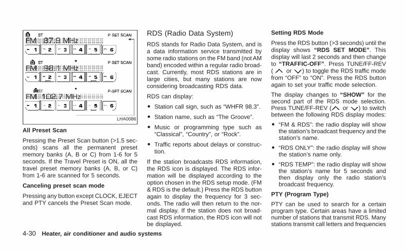
All Preset Scan
Pressing the Preset Scan button (>1.5 sec-onds) scans all the permanent presetmemory banks (A, B or C) from 1-6 for 5seconds. If the Travel Preset is ON, all thetravel preset memory banks (A, B, or C)from 1-6 are scanned for 5 seconds.
Canceling preset scan mode
Pressing any button except CLOCK, EJECTand PTY cancels the Preset Scan mode.
RDS (Radio Data System)
RDS stands for Radio Data System, and isa data information service transmitted bysome radio stations on the FM band (not AMband) encoded within a regular radio broad-cast. Currently, most RDS stations are inlarge cities, but many stations are nowconsidering broadcasting RDS data.
RDS can display:
O Station call sign, such as “WHFR 98.3”.
O Station name, such as “The Groove”.
O Music or programming type such as“Classical”, “Country”, or “Rock”.
O Traffic reports about delays or construc-tion.
If the station broadcasts RDS information,the RDS icon is displayed. The RDS infor-mation will be displayed according to theoption chosen in the RDS setup mode. (FM& RDS is the default.) Press the RDS buttonagain to display the frequency for 3 sec-onds. The radio will then return to the nor-mal display. If the station does not broad-cast RDS information, the RDS icon will notbe displayed.
Setting RDS Mode
Press the RDS button (>3 seconds) until thedisplay shows “RDS SET MODE” . Thisdisplay will last 2 seconds and then changeto “TRAFFIC-OFF” . Press TUNE/FF-REV( or ) to toggle the RDS traffic modefrom “OFF” to “ON”. Press the RDS buttonagain to set your traffic mode selection.
The display changes to “SHOW” for thesecond part of the RDS mode selection.Press TUNE/FF-REV ( or ) to switchbetween the following RDS display modes:
O “FM & RDS”: the radio display will showthe station’s broadcast frequency and thestation’s name.
O “RDS ONLY”: the radio display will showthe station’s name only.
O “RDS TEMP”: the radio display will showthe station’s name for 5 seconds andthen display only the radio station’sbroadcast frequency.
PTY (Program Type)
PTY can be used to search for a certainprogram type. Certain areas have a limitednumber of stations that transmit RDS. Manystations transmit call letters and frequencies
LHA0086
4-30 Heater, air conditioner and audio systems
Z X
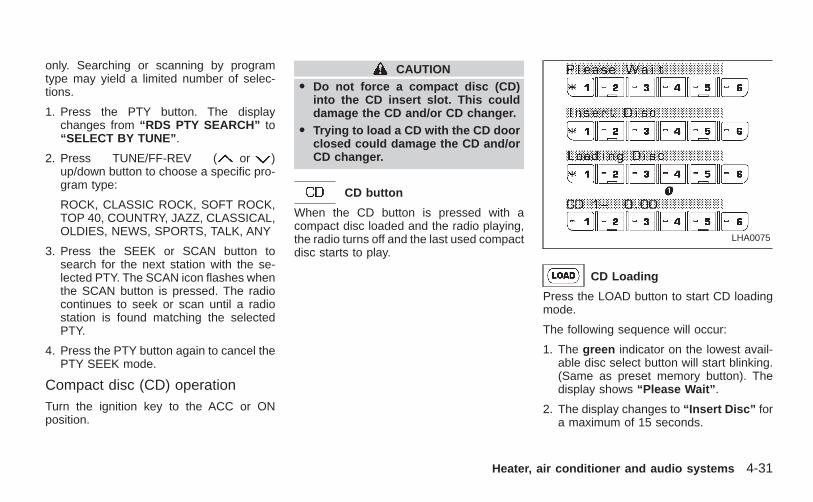
only. Searching or scanning by programtype may yield a limited number of selec-tions.
1. Press the PTY button. The displaychanges from “RDS PTY SEARCH” to“SELECT BY TUNE” .
2. Press TUNE/FF-REV ( or )up/down button to choose a specific pro-gram type:
ROCK, CLASSIC ROCK, SOFT ROCK,TOP 40, COUNTRY, JAZZ, CLASSICAL,OLDIES, NEWS, SPORTS, TALK, ANY
3. Press the SEEK or SCAN button tosearch for the next station with the se-lected PTY. The SCAN icon flashes whenthe SCAN button is pressed. The radiocontinues to seek or scan until a radiostation is found matching the selectedPTY.
4. Press the PTY button again to cancel thePTY SEEK mode.
Compact disc (CD) operationTurn the ignition key to the ACC or ONposition.
CAUTIONO Do not force a compact disc (CD)
into the CD insert slot. This coulddamage the CD and/or CD changer.
O Trying to load a CD with the CD doorclosed could damage the CD and/orCD changer.
CD button
When the CD button is pressed with acompact disc loaded and the radio playing,the radio turns off and the last used compactdisc starts to play.
CD Loading
Press the LOAD button to start CD loadingmode.
The following sequence will occur:
1. The green indicator on the lowest avail-able disc select button will start blinking.(Same as preset memory button). Thedisplay shows “Please Wait” .
2. The display changes to “Insert Disc” fora maximum of 15 seconds.
LHA0075
Heater, air conditioner and audio systems 4-31
Z X
3. During the 15 second interval, insert thedisc. The display changes to “LoadingDisc” .
4. The CD will play after the disc is set to aplay position.
5. The indicator changes from blinkinggreen to solid green and the displaychanges to show the Disc number icon,Disc number, Track number and Elapsedtime.
All disc loading
1. Press and hold the LOAD button until theradio beeps (>1.5 seconds).
2. The green indicator on the lowest avail-able disc select button will start blinking.(Same as preset memory button). Thedisplay shows “Please Wait” .
3. The display changes to “Insert Disc” fora maximum of 15 seconds.
4. During the 15 second interval, insert thedisc. The display changes to “LoadingDisc” .
5. The indicator changes from blinkinggreen to solid green .
6. The disc number icon is turned on.
7. Steps 2-5 are repeated until all discs areloaded, then the last loaded disc willbegin to play. The display shows the Discnumber, Track number and ElapsedTime.
Selected disc loading
1. Press a disc select button whose indica-tor is off. The display shows “PleaseWait” .
2. The green indicator starts blinking andthe display shows “Insert Disc” for 15seconds.
3. Insert the CD. The display shows “Load-ing Disc” .
4. The CD will play after the disc is set to aplay position.
5. The indicator color changes from blink-ing green to solid green and the displayshows the Disc icon, Disc number, Tracknumber and Elapsed Time.
If a disc is not inserted within 15 seconds orif the load button is pressed during loadsequence, the entire disc load sequence willbe canceled.
Disc Play
Press the CD button. If a CD is loaded andthe radio is playing, the radio turns off andthe last loaded disc starts to play.
4-32 Heater, air conditioner and audio systems
Z X
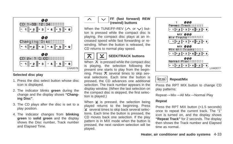
Selected disc play
1. Press the disc select button whose discicon is displayed.
2. The indicator blinks green during thechange and the display shows “Chang-ing Disc” .
3. The CD plays after the disc is set to aplay position.
4. The indicator changes from blinkinggreen to solid green and the displayshows the Disc number, Track numberand Elapsed Time.
FF (fast forward) REW(rewind) buttons
When the TUNE/FF-REV ( or ) but-ton is pressed while the compact disc isplaying, the compact disc plays at an in-creased speed while fast forwarding or re-winding. When the button is released, theCD returns to normal play speed.
SEEK/TRACK buttons
When is pressed while the compact discis playing, the selection following thepresent one starts to play from the begin-ning. Press several times to skip sev-eral selections. Each time the button ispressed, the CD advances one additionalselection. The track number appears in thedisplay window. (When the last selection onthe compact disc is skipped, the first selec-tion is played.)
When is pressed, the selection beingplayed returns to the beginning. Press
several times to skip back several selec-tions. Each time the button is pressed, theCD moves back one selection. If the playpattern is in MIX mode when the button ispressed, the next random selection will beplayed.
Repeat/Mix
Press the RPT MIX button to change CDplay patterns:
Repeat→Mix→All Mix→Normal Play
Repeat
Press the RPT MIX button (<1.5 seconds)once to repeat the current track. The “1”icon is turned on, and the display shows“Repeat Track” for 2 seconds. The displaythen shows the Track number and Elapsedtime as normal.
LHA0076 LHA0077
Heater, air conditioner and audio systems 4-33
Z X
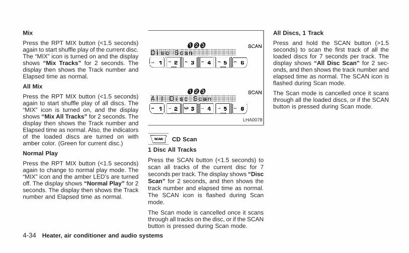
Mix
Press the RPT MIX button (<1.5 seconds)again to start shuffle play of the current disc.The “MIX” icon is turned on and the displayshows “Mix Tracks” for 2 seconds. Thedisplay then shows the Track number andElapsed time as normal.
All Mix
Press the RPT MIX button (<1.5 seconds)again to start shuffle play of all discs. The“MIX” icon is turned on, and the displayshows “Mix All Tracks” for 2 seconds. Thedisplay then shows the Track number andElapsed time as normal. Also, the indicatorsof the loaded discs are turned on withamber color. (Green for current disc.)
Normal Play
Press the RPT MIX button (<1.5 seconds)again to change to normal play mode. The“MIX” icon and the amber LED’s are turnedoff. The display shows “Normal Play” for 2seconds. The display then shows the Tracknumber and Elapsed time as normal.
CD Scan
1 Disc All Tracks
Press the SCAN button (<1.5 seconds) toscan all tracks of the current disc for 7seconds per track. The display shows “DiscScan” for 2 seconds, and then shows thetrack number and elapsed time as normal.The SCAN icon is flashed during Scanmode.
The Scan mode is cancelled once it scansthrough all tracks on the disc, or if the SCANbutton is pressed during Scan mode.
All Discs, 1 Track
Press and hold the SCAN button (>1.5seconds) to scan the first track of all theloaded discs for 7 seconds per track. Thedisplay shows “All Disc Scan” for 2 sec-onds, and then shows the track number andelapsed time as normal. The SCAN icon isflashed during Scan mode.
The Scan mode is cancelled once it scansthrough all the loaded discs, or if the SCANbutton is pressed during Scan mode.
LHA0078
4-34 Heater, air conditioner and audio systems
Z X
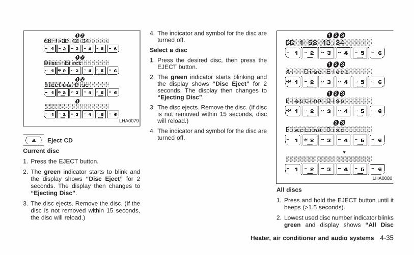
Eject CD
Current disc
1. Press the EJECT button.
2. The green indicator starts to blink andthe display shows “Disc Eject” for 2seconds. The display then changes to“Ejecting Disc” .
3. The disc ejects. Remove the disc. (If thedisc is not removed within 15 seconds,the disc will reload.)
4. The indicator and symbol for the disc areturned off.
Select a disc
1. Press the desired disc, then press theEJECT button.
2. The green indicator starts blinking andthe display shows “Disc Eject” for 2seconds. The display then changes to“Ejecting Disc” .
3. The disc ejects. Remove the disc. (If discis not removed within 15 seconds, discwill reload.)
4. The indicator and symbol for the disc areturned off.
All discs
1. Press and hold the EJECT button until itbeeps (>1.5 seconds).
2. Lowest used disc number indicator blinksgreen and display shows “All Disc
LHA0079
LHA0080
Heater, air conditioner and audio systems 4-35
Z X
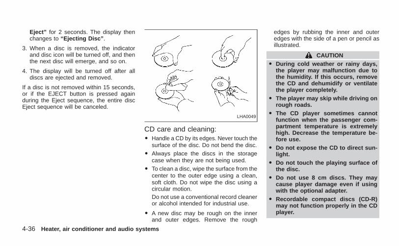
Eject” for 2 seconds. The display thenchanges to “Ejecting Disc” .
3. When a disc is removed, the indicatorand disc icon will be turned off, and thenthe next disc will emerge, and so on.
4. The display will be turned off after alldiscs are ejected and removed.
If a disc is not removed within 15 seconds,or if the EJECT button is pressed againduring the Eject sequence, the entire discEject sequence will be canceled.
CD care and cleaning:O Handle a CD by its edges. Never touch the
surface of the disc. Do not bend the disc.O Always place the discs in the storage
case when they are not being used.O To clean a disc, wipe the surface from the
center to the outer edge using a clean,soft cloth. Do not wipe the disc using acircular motion.Do not use a conventional record cleaneror alcohol intended for industrial use.
O A new disc may be rough on the innerand outer edges. Remove the rough
edges by rubbing the inner and outeredges with the side of a pen or pencil asillustrated.
CAUTIONO During cold weather or rainy days,
the player may malfunction due tothe humidity. If this occurs, removethe CD and dehumidify or ventilatethe player completely.
O The player may skip while driving onrough roads.
O The CD player sometimes cannotfunction when the passenger com-partment temperature is extremelyhigh. Decrease the temperature be-fore use.
O Do not expose the CD to direct sun-light.
O Do not touch the playing surface ofthe disc.
O Do not use 8 cm discs. They maycause player damage even if usingwith the optional adapter.
O Recordable compact discs (CD-R)may not function properly in the CDplayer.
LHA0049
4-36 Heater, air conditioner and audio systems
Z X
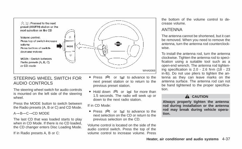
STEERING WHEEL SWITCH FORAUDIO CONTROLS
The steering wheel switch for audio controlsis mounted on the left side of the steeringwheel.
Press the MODE button to switch betweenthe Radio presets (A, B or C) and CD Mode.
A→B→C→CD MODE
The last CD that was loaded starts to playwhen in CD Mode. If there is no CD loaded,the CD changer enters Disc Loading Mode.
If in Radio presets A, B or C:
O Press or to advance to thenext preset station or to return to theprevious preset station.
O Hold down or for more than1.5 seconds. The radio will seek up ordown to the next radio station.
If in CD Mode:
O Press or to advance to thenext selection on the CD or return to theprevious selection on the CD.
Volume control is located on the side of theaudio control switch. Press the top of thevolume control to increase volume. Press
the bottom of the volume control to de-crease volume.
ANTENNAThe antenna cannot be shortened, but it canbe removed. When you need to remove theantenna, turn the antenna rod counterclock-wise.
To install the antenna rod, turn the antennaclockwise. Tighten the antenna rod to speci-fication using a suitable tool such as aopen-end wrench. The antenna rod tighten-ing specification is 2.0 - 2.6 Nzm (18 - 23in-lb). Do not use pliers to tighten the an-tenna as they can leave marks on theantenna surface. The antenna rod can notbe hand tightened to the proper specifica-tion.
CAUTIONAlways properly tighten the antennarod during installation or the antennarod may break during vehicle opera-tion.
WHA0069
Heater, air conditioner and audio systems 4-37
Z X
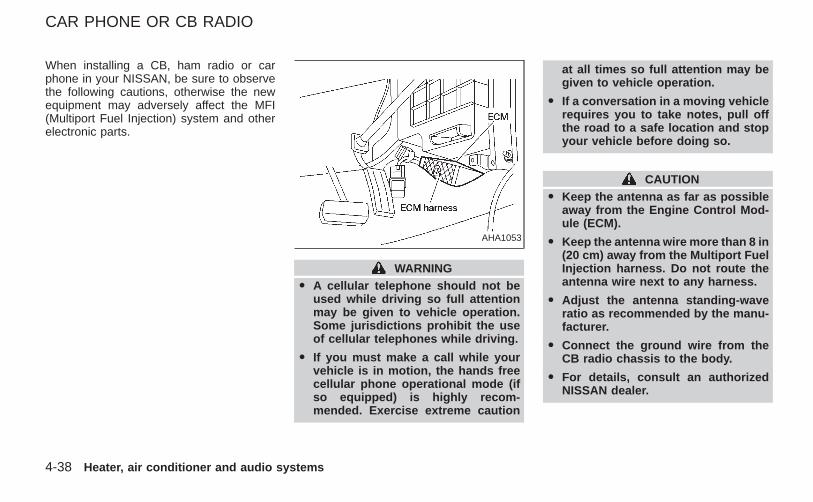
When installing a CB, ham radio or carphone in your NISSAN, be sure to observethe following cautions, otherwise the newequipment may adversely affect the MFI(Multiport Fuel Injection) system and otherelectronic parts.
WARNINGO A cellular telephone should not be
used while driving so full attentionmay be given to vehicle operation.Some jurisdictions prohibit the useof cellular telephones while driving.
O If you must make a call while yourvehicle is in motion, the hands freecellular phone operational mode (ifso equipped) is highly recom-mended. Exercise extreme caution
at all times so full attention may begiven to vehicle operation.
O If a conversation in a moving vehiclerequires you to take notes, pull offthe road to a safe location and stopyour vehicle before doing so.
CAUTIONO Keep the antenna as far as possible
away from the Engine Control Mod-ule (ECM).
O Keep the antenna wire more than 8 in(20 cm) away from the Multiport FuelInjection harness. Do not route theantenna wire next to any harness.
O Adjust the antenna standing-waveratio as recommended by the manu-facturer.
O Connect the ground wire from theCB radio chassis to the body.
O For details, consult an authorizedNISSAN dealer.
AHA1053
CAR PHONE OR CB RADIO
4-38 Heater, air conditioner and audio systems
Z X
5 Starting and driving
Precautions when starting and driving...................5-2Exhaust gas (carbon monoxide) .......................5-2Three-way catalyst ............................................5-3On-pavement and off-road drivingprecautions ........................................................5-3Avoiding collision and rollover...........................5-3Drinking alcohol/drugs and driving....................5-4Driving safety precautions.................................5-4
Ignition switch.........................................................5-6Automatic transmission .....................................5-6Manual transmission..........................................5-7Key positions .....................................................5-7
Before starting the engine......................................5-8Starting the engine.................................................5-8Driving the vehicle..................................................5-9
Automatic transmission (if so equipped) ...........5-9Manual transmission........................................5-13
Parking brake .......................................................5-14Cruise control (if so equipped).............................5-15
Precautions on cruise control..........................5-15Cruise control operations ................................5-16
Break-in schedule ................................................5-17Increasing fuel economy ......................................5-17Using four-wheel drive .........................................5-18........................5-18
Transfer case shifting procedures...................5-18Auto-lock free-running hubs ............................5-19
Parking/parking on hills ........................................5-22Power steering .....................................................5-23Brake system........................................................5-23
Braking precautions.........................................5-23Anti-lock brake system (ABS) .........................5-24
Cold weather driving ............................................5-25Freeing a frozen door lock ..............................5-25Anti-freeze .......................................................5-25Battery .............................................................5-25Draining of coolant water ................................5-25Tire equipment.................................................5-26Special winter equipment ................................5-26Driving on snow or ice.....................................5-26Engine block heater (if so equipped) ..............5-27
Z X
WARNING
O Do not leave children, unreliableadults, or pets alone in your vehicle.They could accidentally injure them-selves or others through inadvertentoperation of the vehicle. Also, onhot, sunny days, temperatures in aclosed vehicle could quickly becomehigh enough to cause severe or pos-sibly fatal injuries to people or ani-mals.
O Properly secure all cargo to helpprevent it from sliding or shifting. Donot place cargo higher than the seat-backs. In a sudden stop or collision,unsecured cargo could cause per-sonal injury.
EXHAUST GAS (carbon monoxide)
WARNING
O Do not breathe exhaust gases; theycontain colorless and odorless car-bon monoxide. Carbon monoxide isa dangerous. It can cause uncon-sciousness or death.
O If you suspect that exhaust fumesare entering the vehicle, drive withall windows fully open, and have thevehicle inspected immediately.
O Do not run the engine in closedspaces such as a garage.
O Do not park the vehicle with theengine running for any extendedlength of time.
O Keep the back door and rear win-dows closed while driving, other-wise exhaust gases could be drawninto the passenger compartment. Ifyou must drive with the back door orrear windows open, follow these pre-cautions:
1. Open all the windows.
2. Set the air recirculation switchOFF and the fan control at 4 (high)to circulate the air.
O If electrical wiring or other cableconnections must pass to a trailerthrough the seal on the back door orthe body, follow the manufacturer’srecommendation to prevent carbonmonoxide entry into the vehicle.
O If a special body, camper, or otherequipment is added for recreationalor other usage, follow the manufac-turer’s recommendation to preventcarbon monoxide entry into the ve-hicle. Do not occupy these areaswhile the engine is running even if thevehicle is parked. Some recreationalvehicle appliances such as stoves,refrigerators, heaters, etc. may alsogenerate carbon monoxide.
O The exhaust system and bodyshould be inspected by a qualifiedmechanic whenever:
a. The vehicle is raised for service.
b. You suspect that exhaust fumesare entering into the passengercompartment.
c. You notice a change in the soundof the exhaust system.
d. You have had an accident involv-ing damage to the exhaust system,underbody, or rear of the vehicle.
PRECAUTIONS WHENSTARTING AND DRIVING
5-2 Starting and driving
Z X
THREE-WAY CATALYSTThe three-way catalyst is an emission controldevice installed in the exhaust system. Ex-haust gases in the converter are burned athigh temperatures to help reduce pollutants.
WARNINGO The exhaust gas and the exhaust
system are very hot. Keep people,animals or flammable materialsaway from the exhaust system com-ponents.
O Do not stop or park the vehicle overflammable materials such as drygrass, waste paper or rags. Theymay ignite and cause a fire.
CAUTIONO Do not use leaded gasoline. Depos-
its from leaded gasoline will seri-ously reduce the three-way cata-lyst’s ability to help reduce exhaustpollutants.
O Keep your engine tuned up. Malfunc-tions in the ignition, fuel injection, orelectrical systems can cause over-
rich fuel flow into the three-way cata-lyst, causing it to overheat. Do notkeep driving if the engine misfires,or if noticeable loss of performanceor other unusual operating condi-tions are detected. Have the vehicleinspected promptly by an authorizedNISSAN dealer.
O Avoid driving with an extremely lowfuel level. Running out of fuel couldcause the engine to misfire, damag-ing the three-way catalyst.
O Do not race the engine while warm-ing it up.
O Do not push or tow your vehicle tostart the engine.
ON-PAVEMENT AND OFF-ROADDRIVING PRECAUTIONSUtility vehicles have a significantlyhigher rollover rate than other types ofvehicles.
They have higher ground clearance thanpassenger cars to make them capable ofperforming in a variety of on-pavement andoff-road applications. This gives them a
higher center of gravity than ordinary cars.An advantage of higher ground clearance isa better view of the road, allowing you toanticipate problems. However, they are notdesigned for cornering at the same speedsas conventional two-wheel drive vehiclesany more than low-slung sports cars aredesigned to perform satisfactorily underoff-road conditions. If at all possible, avoidsharp turns or abrupt maneuvers particu-larly at high speeds. As with other vehiclesof this type, failure to operate this vehiclecorrectly may result in loss of control orvehicle rollover.
Be sure to read the driving safety precau-tions later in this section.
AVOIDING COLLISION ANDROLLOVER
WARNINGFailure to operate this vehicle in a safeand prudent manner may result in lossof control or an accident.
Be alert and drive defensively at all times.Obey all traffic regulations. Avoid excessivespeed, high speed cornering, or suddensteering maneuvers, because these driving
Starting and driving 5-3
Z X
practices could cause you to lose control ofyour vehicle. As with any vehicle, a lossof control could result in a collision withother vehicles or objects, or cause thevehicle to rollover, particularly if the lossof control causes the vehicle to slidesideways. Be attentive at all times, andavoid driving when tired. Never drive whenunder the influence of alcohol or drugs(including prescription or over-the-counterdrugs which may cause drowsiness). Al-ways wear your seat belt as outlined in the‘‘Seats, restraints and supplemental air bagsystems’’ section of this manual, and in-struct your passengers to do so.
Seat belts help reduce the risk of injury incollisions and rollovers. In a rollover crash,an unbelted person is significantly morelikely to die than a person wearing a seatbelt.
DRINKING ALCOHOL/DRUGSAND DRIVING
WARNINGNever drive under the influence of alco-hol or drugs. Alcohol in the blood-stream reduces coordination, delays
reaction time and impairs judgement.Driving after drinking alcohol increasesthe likelihood of being involved in anaccident injuring yourself and others.Additionally, if you are injured in theaccident, alcohol can increase the se-verity of injury.
Nissan is committed to safe driving. But,you must choose not to drive under theinfluence of alcohol. Every year thousandsof people are injured or killed in alcoholrelated accidents. Although the local lawsvary on what is considered to be legallyintoxicated, the fact is that alcohol affects allpeople differently and most people underes-timate the effects of alcohol.
Remember, drinking and driving don’t mix!
And that’s true for drugs too (over thecounter, prescription, and illegal drugs).Don’t drive if your ability to operate yourvehicle is impaired by alcohol, drugs, orsome other physical condition.
DRIVING SAFETY PRECAUTIONSYour NISSAN is designed for both normaland off-road use. However, avoid driving in
deep water or mud as your NISSAN ismainly designed for leisure use, unlike aconventional offroad vehicle.
Remember that two-wheel drive models areless capable than four-wheel drive modelsfor rough road driving and extrication whenstuck in deep snow or mud, or the like.Please observe the following precautions:
WARNINGO Drive carefully when off the road and
avoid dangerous areas. Every personwho drives or rides in this vehicleshould be seated with their seat beltfastened. This will keep you and yourpassengers in position when drivingover rough terrain.
O Do not drive across steep slopes. In-stead drive either straight up orstraight down the slopes. Off-road ve-hicles can tip over sideways muchmore easily than they can forward orbackward.
5-4 Starting and driving
Z X
O Many hills are too steep for any ve-hicle. If you drive up them, you maystall. If you drive down them, you maynot be able to control your speed. Ifyou drive across them, you may rollover.
O Do not shift gears while driving ondownhill grades as this could causeloss of control of the vehicle.
O Stay alert when driving to the top ofa hill. At the top there could be adrop-off or other hazard that couldcause an accident.
O If your engine stalls or you cannotmake it to the top of a steep hill,never attempt to turn around. Yourvehicle could tip or roll over. Alwaysback straight down in R (Reverse)gear. Never back down in N (Neutral)or with the clutch depressed(manual transmission vehicles), us-ing only the brake, as this couldcause loss of control.
O Heavy braking going down a hill-could cause your brakes to over heat
and fade, resulting in loss of controland an accident. Apply brakes lightlyand use a low gear to control yourspeed.
O Unsecured cargo can be thrownaround when driving over rough ter-rain. Properly secure all cargo so itwill not be thrown forward and causeinjury to you or your passengers.
O To avoid raising the center of gravityexcessively, do not exceed the ratedcapactiy of the roof rack/gear bin (ifso equipped) and evenly distributethe load. Secure heavy loads in thecargo area as far forward and as lowas possible. Do not equip the vehiclewith tires larger than specified in thismanual. This could cause your ve-hicle to roll over.
O Do not grip the inside or spokes ofthe steering wheel when drivingoffroad. The steering wheel couldmove suddenly and injure yourhands. Instead drive with your fin-gers and thumbs on the outside ofthe rim.
O Before operating the vehicle, ensurethat the driver and all passengershave their seat belts fastened.
O Always drive with the floor mats inplace as the floor may become hot.
O Lower your speed when encouteringstrong crosswinds. With a highercenter of gravity, your NISSAN ismore affected by strong side winds.Slower speeds ensure better vehiclecontrol.
O Do not drive beyond the perfor-mance of the tires, even with 4WDengaged.
O Accelerating quickly, sharp steeringmaneuvers or sudden braking maycause loss of control.
O If at all possible, avoid sharp turningmaneuvers, particularly at highspeeds. Your NISSAN four wheeldrive vehicle has a higher center ofgravity than a two-wheel drive ve-hicle. The vehicle is not designed forcornering at the same speeds asconventional two-wheel drive ve-hicles. Failure to operate this vehicle
Starting and driving 5-5
Z X
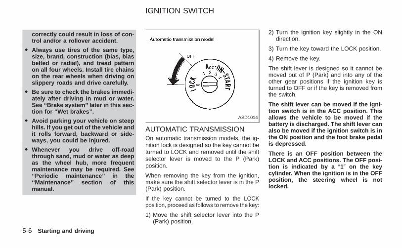
correctly could result in loss of con-trol and/or a rollover accident.
O Always use tires of the same type,size, brand, construction (bias, biasbelted or radial), and tread patternon all four wheels. Install tire chainson the rear wheels when driving onslippery roads and drive carefully.
O Be sure to check the brakes immedi-ately after driving in mud or water.See ‘‘Brake system’’ later in this sec-tion for ‘‘Wet brakes’’.
O Avoid parking your vehicle on steephills. If you get out of the vehicle andit rolls forward, backward or side-ways, you could be injured.
O Whenever you drive off-roadthrough sand, mud or water as deepas the wheel hub, more frequentmaintenance may be required. See‘‘Periodic maintenance’’ in the‘‘Maintenance’’ section of thismanual.
AUTOMATIC TRANSMISSIONOn automatic transmission models, the ig-nition lock is designed so the key cannot beturned to LOCK and removed until the shiftselector lever is moved to the P (Park)position.
When removing the key from the ignition,make sure the shift selector lever is in the P(Park) position.
If the key cannot be turned to the LOCKposition, proceed as follows to remove the key:
1) Move the shift selector lever into the P(Park) position.
2) Turn the ignition key slightly in the ONdirection.
3) Turn the key toward the LOCK position.
4) Remove the key.
The shift lever is designed so it cannot bemoved out of P (Park) and into any of theother gear positions if the ignition key isturned to OFF or if the key is removed fromthe switch.
The shift lever can be moved if the igni-tion switch is in the ACC position. Thisallows the vehicle to be moved if thebattery is discharged. The shift lever canalso be moved if the ignition switch is inthe ON position and the foot brake pedalis depressed.
There is an OFF position between theLOCK and ACC positions. The OFF posi-tion is indicated by a (1( on the keycylinder. When the ignition is in the OFFposition, the steering wheel is notlocked.
ASD1014
IGNITION SWITCH
5-6 Starting and driving
Z X
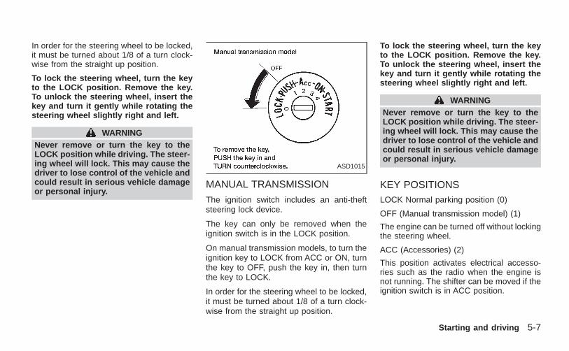
In order for the steering wheel to be locked,it must be turned about 1/8 of a turn clock-wise from the straight up position.
To lock the steering wheel, turn the keyto the LOCK position. Remove the key.To unlock the steering wheel, insert thekey and turn it gently while rotating thesteering wheel slightly right and left.
WARNINGNever remove or turn the key to theLOCK position while driving. The steer-ing wheel will lock. This may cause thedriver to lose control of the vehicle andcould result in serious vehicle damageor personal injury.
MANUAL TRANSMISSION
The ignition switch includes an anti-theftsteering lock device.
The key can only be removed when theignition switch is in the LOCK position.
On manual transmission models, to turn theignition key to LOCK from ACC or ON, turnthe key to OFF, push the key in, then turnthe key to LOCK.
In order for the steering wheel to be locked,it must be turned about 1/8 of a turn clock-wise from the straight up position.
To lock the steering wheel, turn the keyto the LOCK position. Remove the key.To unlock the steering wheel, insert thekey and turn it gently while rotating thesteering wheel slightly right and left.
WARNINGNever remove or turn the key to theLOCK position while driving. The steer-ing wheel will lock. This may cause thedriver to lose control of the vehicle andcould result in serious vehicle damageor personal injury.
KEY POSITIONSLOCK Normal parking position (0)
OFF (Manual transmission model) (1)
The engine can be turned off without lockingthe steering wheel.
ACC (Accessories) (2)
This position activates electrical accesso-ries such as the radio when the engine isnot running. The shifter can be moved if theignition switch is in ACC position.
ASD1015
Starting and driving 5-7
Z X
ON (Normal operating position) (3)
This position turns on the ignition systemand electrical accessories.
START (4)
This position starts the engine. As soon asthe engine has started, release the key. Itautomatically returns to the ON position.
O Make sure the area around the vehicle isclear.
O Check fluid levels such as engine oil,coolant, brake and clutch fluid, and win-dow washer fluid as frequently as pos-sible, at least whenever you refuel.
O Check that all windows and lights areclean.
O Visually inspect tires for their appearanceand condition. Also check tires for properinflation.
O Lock all doors.
O Position seat and adjust head restraints.
O Adjust inside and outside mirrors.
O Fasten seat belts and ask all passengersto do likewise.
O Check the operation of warning lightswhen key is turned to the ON (3) position.See 9Warning/Indicator lights andchimes9 in the 9Instruments and controls9section.
1. Apply the parking brake.
2. Automatic transmission:
Move the selector lever to P (Park) or N(Neutral). P (Park) is preferred.
The shift lever cannot be moved out ofP (Park) and into any of the other gearpositions if the ignition key is turnedto OFF or if the key is removed fromthe ignition switch.
The starter is designed not to operateif the selector lever is in one of thedriving positions.
Manual transmission:
Move the gearshift lever to N (Neutral),and fully depress the clutch pedal to thefloor while starting the engine.
The starter is designed not to operateunless the clutch pedal is fully de-pressed.
3. With your foot off the acceleratorpedal, turn the ignition key to START.Release the key when the engine starts.If the engine starts, but fails to run, repeatthe above procedure.
BEFORE STARTING THEENGINE
STARTING THE ENGINE
5-8 Starting and driving
Z X
O If the engine is very hard to start inextremely cold or hot weather, depressthe accelerator pedal fully and hold itto help start the engine.
O In the summer, when restarting theengine within 30 minutes after it hasbeen stopped, keep the acceleratorpedal fully depressed while starting.
CAUTIONDo not operate the starter for more than15 seconds at a time. If the engine doesnot start, turn the key off and wait 10seconds before cranking again, other-wise the starter could be damaged.
4. Warm-up
Always allow the engine to idle for atleast 30 seconds after starting. Drive at amoderate speed for a short distance first,especially in cold weather.
AUTOMATIC TRANSMISSION (ifso equipped)
WARNING
O Do not depress the accelerator pedalwhile shifting from P (Park) or N(Neutral) to R (Reverse), D (Drive), 2or 1. Always depress the brake pedaluntil shifting is completed. Failure todo so could cause you to lose con-trol and have an accident.
O Cold engine idle speed is high, souse caution when shifting into a for-ward or reverse gear before the en-gine has warmed up.
O Never shift to P (Park) or R (Reverse)while the vehicle is moving. Thiscould cause an accident.
CAUTION
O When stopping the vehicle on anuphill grade, do not hold the vehicleby depressing the accelerator pedal.The foot brake should be used forthis purpose.
O On slippery roads, do not downshift.This may cause a loss of control.
The automatic transmission in your vehicleis electronically controlled by a transmissioncontrol module to produce maximum powerand smooth operation.
The recommended operating procedures forthis transmission are shown on the followingpages. Follow these procedures for maximumvehicle performance and driving enjoyment.
Starting the vehicleO After starting the engine, fully depress
the foot brake pedal to ensure the ve-hicle is at a complete stop before at-tempting to shift the selector lever.
O Keep the foot brake pedal depressedand shift the selector lever into a drivinggear.
O Release the foot brake, then graduallystart the vehicle in motion.
This automatic transmission is designedso the foot brake pedal MUST be de-pressed before shifting from P (Park) toany drive position while the ignitionswitch is ON.
DRIVING THE VEHICLE
Starting and driving 5-9
Z X
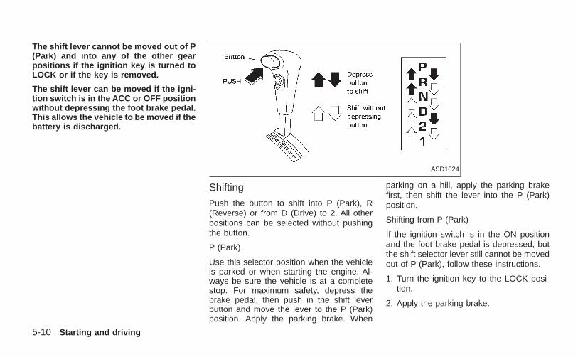
The shift lever cannot be moved out of P(Park) and into any of the other gearpositions if the ignition key is turned toLOCK or if the key is removed.
The shift lever can be moved if the igni-tion switch is in the ACC or OFF positionwithout depressing the foot brake pedal.This allows the vehicle to be moved if thebattery is discharged.
Shifting
Push the button to shift into P (Park), R(Reverse) or from D (Drive) to 2. All otherpositions can be selected without pushingthe button.
P (Park)
Use this selector position when the vehicleis parked or when starting the engine. Al-ways be sure the vehicle is at a completestop. For maximum safety, depress thebrake pedal, then push in the shift leverbutton and move the lever to the P (Park)position. Apply the parking brake. When
parking on a hill, apply the parking brakefirst, then shift the lever into the P (Park)position.
Shifting from P (Park)
If the ignition switch is in the ON positionand the foot brake pedal is depressed, butthe shift selector lever still cannot be movedout of P (Park), follow these instructions.
1. Turn the ignition key to the LOCK posi-tion.
2. Apply the parking brake.
ASD1024
5-10 Starting and driving
Z X
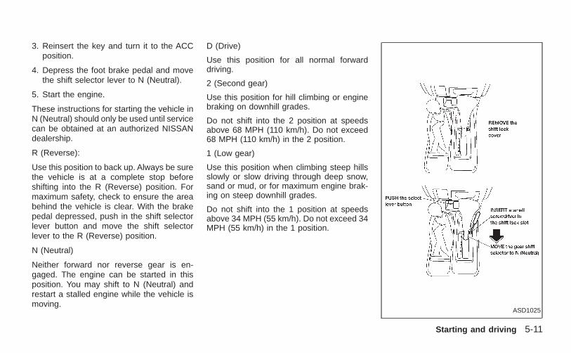
3. Reinsert the key and turn it to the ACCposition.
4. Depress the foot brake pedal and movethe shift selector lever to N (Neutral).
5. Start the engine.
These instructions for starting the vehicle inN (Neutral) should only be used until servicecan be obtained at an authorized NISSANdealership.
R (Reverse):
Use this position to back up. Always be surethe vehicle is at a complete stop beforeshifting into the R (Reverse) position. Formaximum safety, check to ensure the areabehind the vehicle is clear. With the brakepedal depressed, push in the shift selectorlever button and move the shift selectorlever to the R (Reverse) position.
N (Neutral)
Neither forward nor reverse gear is en-gaged. The engine can be started in thisposition. You may shift to N (Neutral) andrestart a stalled engine while the vehicle ismoving.
D (Drive)
Use this position for all normal forwarddriving.
2 (Second gear)
Use this position for hill climbing or enginebraking on downhill grades.
Do not shift into the 2 position at speedsabove 68 MPH (110 km/h). Do not exceed68 MPH (110 km/h) in the 2 position.
1 (Low gear)
Use this position when climbing steep hillsslowly or slow driving through deep snow,sand or mud, or for maximum engine brak-ing on steep downhill grades.
Do not shift into the 1 position at speedsabove 34 MPH (55 km/h). Do not exceed 34MPH (55 km/h) in the 1 position.
ASD1025
Starting and driving 5-11
Z X
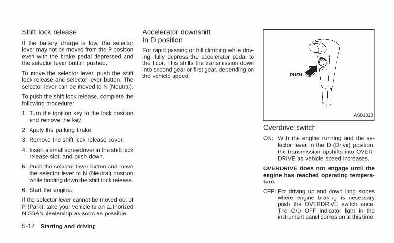
Shift lock release
If the battery charge is low, the selectorlever may not be moved from the P positioneven with the brake pedal depressed andthe selector lever button pushed.
To move the selector lever, push the shiftlock release and selector lever button. Theselector lever can be moved to N (Neutral).
To push the shift lock release, complete thefollowing procedure:
1. Turn the ignition key to the lock positionand remove the key.
2. Apply the parking brake.
3. Remove the shift lock release cover.
4. Insert a small screwdriver in the shift lockrelease slot, and push down.
5. Push the selector lever button and movethe selector lever to N (Neutral) positionwhile holding down the shift lock release.
6. Start the engine.
If the selector lever cannot be moved out ofP (Park), take your vehicle to an authorizedNISSAN dealership as soon as possible.
Accelerator downshiftIn D positionFor rapid passing or hill climbing while driv-ing, fully depress the accelerator pedal tothe floor. This shifts the transmission downinto second gear or first gear, depending onthe vehicle speed.
Overdrive switch
ON: With the engine running and the se-lector lever in the D (Drive) position,the transmission upshifts into OVER-DRIVE as vehicle speed increases.
OVERDRIVE does not engage until theengine has reached operating tempera-ture.
OFF: For driving up and down long slopeswhere engine braking is necessarypush the OVERDRIVE switch once.The O/D OFF indicator light in theinstrument panel comes on at this time.
ASD1023
5-12 Starting and driving
Z X
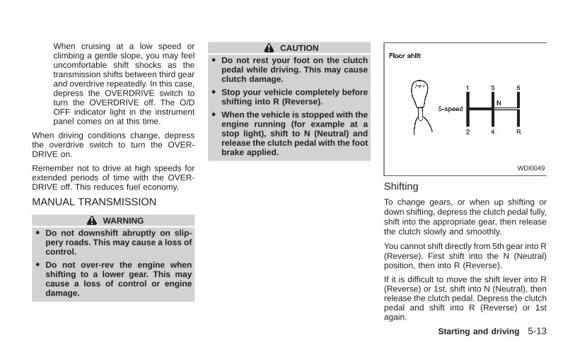
When cruising at a low speed orclimbing a gentle slope, you may feeluncomfortable shift shocks as thetransmission shifts between third gearand overdrive repeatedly. In this case,depress the OVERDRIVE switch toturn the OVERDRIVE off. The O/DOFF indicator light in the instrumentpanel comes on at this time.
When driving conditions change, depressthe overdrive switch to turn the OVER-DRIVE on.
Remember not to drive at high speeds forextended periods of time with the OVER-DRIVE off. This reduces fuel economy.
MANUAL TRANSMISSION
WARNINGO Do not downshift abruptly on slip-
pery roads. This may cause a loss ofcontrol.
O Do not over-rev the engine whenshifting to a lower gear. This maycause a loss of control or enginedamage.
CAUTIONO Do not rest your foot on the clutch
pedal while driving. This may causeclutch damage.
O Stop your vehicle completely beforeshifting into R (Reverse).
O When the vehicle is stopped with theengine running (for example at astop light), shift to N (Neutral) andrelease the clutch pedal with the footbrake applied.
Shifting
To change gears, or when up shifting ordown shifting, depress the clutch pedal fully,shift into the appropriate gear, then releasethe clutch slowly and smoothly.
You cannot shift directly from 5th gear into R(Reverse). First shift into the N (Neutral)position, then into R (Reverse).
If it is difficult to move the shift lever into R(Reverse) or 1st, shift into N (Neutral), thenrelease the clutch pedal. Depress the clutchpedal and shift into R (Reverse) or 1stagain.
WDI0049
Starting and driving 5-13
Z X
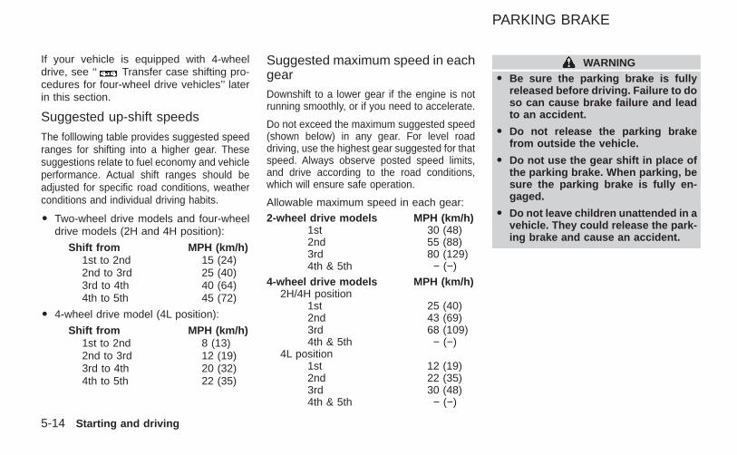
If your vehicle is equipped with 4-wheeldrive, see ‘‘ Transfer case shifting pro-cedures for four-wheel drive vehicles’’ laterin this section.
Suggested up-shift speeds
The folllowing table provides suggested speedranges for shifting into a higher gear. Thesesuggestions relate to fuel economy and vehicleperformance. Actual shift ranges should beadjusted for specific road conditions, weatherconditions and individual driving habits.
O Two-wheel drive models and four-wheeldrive models (2H and 4H position):
Shift from MPH (km/h)1st to 2nd 15 (24)2nd to 3rd 25 (40)3rd to 4th 40 (64)4th to 5th 45 (72)
O 4-wheel drive model (4L position):
Shift from MPH (km/h)1st to 2nd 8 (13)2nd to 3rd 12 (19)3rd to 4th 20 (32)4th to 5th 22 (35)
Suggested maximum speed in eachgearDownshift to a lower gear if the engine is notrunning smoothly, or if you need to accelerate.
Do not exceed the maximum suggested speed(shown below) in any gear. For level roaddriving, use the highest gear suggested for thatspeed. Always observe posted speed limits,and drive according to the road conditions,which will ensure safe operation.
Allowable maximum speed in each gear:2-wheel drive models MPH (km/h)
1st 30 (48)2nd 55 (88)3rd 80 (129)4th & 5th − (−)
4-wheel drive models MPH (km/h)2H/4H position
1st 25 (40)2nd 43 (69)3rd 68 (109)4th & 5th − (−)
4L position1st 12 (19)2nd 22 (35)3rd 30 (48)4th & 5th − (−)
WARNINGO Be sure the parking brake is fully
released before driving. Failure to doso can cause brake failure and leadto an accident.
O Do not release the parking brakefrom outside the vehicle.
O Do not use the gear shift in place ofthe parking brake. When parking, besure the parking brake is fully en-gaged.
O Do not leave children unattended in avehicle. They could release the park-ing brake and cause an accident.
PARKING BRAKE
5-14 Starting and driving
Z X
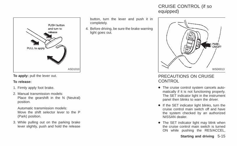
To apply: pull the lever out.
To release:
1. Firmly apply foot brake.
2. Manual transmission models:Place the gearshift in the N (Neutral)position.
Automatic transmission models:Move the shift selector lever to the P(Park) position.
3. While pulling out on the parking brakelever slightly, push and hold the release
button, turn the lever and push it incompletely.
4. Before driving, be sure the brake warninglight goes out.
PRECAUTIONS ON CRUISECONTROL
● The cruise control system cancels auto-matically if it is not functioning properly.The SET indicator light in the instrumentpanel then blinks to warn the driver.
● If the SET indicator light blinks, turn thecruise control main switch off and havethe system checked by an authorizedNISSAN dealer.
● The SET indicator light may blink whenthe cruise control main switch is turnedON while pushing the RES/ACCEL,
ASD1010 WSD0013
CRUISE CONTROL (if soequipped)
Starting and driving 5-15
Z X
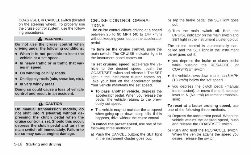
COAST/SET, or CANCEL switch (locatedon the steering wheel). To properly usethe cruise control system, use the follow-ing procedures.
WARNINGDo not use the cruise control whendriving under the following conditions.● When it is not possible to keep the
vehicle at a set speed.● In heavy traffic or in traffic that var-
ies in speed.
● On winding or hilly roads.
● On slippery roads (rain, snow, ice, etc.).● In very windy areas.Doing so could cause a loss of vehiclecontrol and result in an accident.
CAUTIONOn manual transmission models, donot shift into N (Neutral) without de-pressing the clutch pedal when thecruise control is set. Should this occur,depress the clutch pedal and turn themain switch off immediately. Failure todo so may cause engine damage.
CRUISE CONTROL OPERA-TIONSThe cruise control allows driving at a speedbetween 25 to 90 MPH (40 to 144 km/h)without keeping your foot on the acceleratorpedal.
To turn on the cruise control, push themain switch. The CRUISE indicator light inthe instrument panel comes on.
To set cruising speed, accelerate the ve-hicle to the desired speed, push theCOAST/SET switch and release it. The SETlight in the instrument cluster comes on.Take your foot off the accelerator pedal.Your vehicle maintains the set speed.
● To pass another vehicle, depress theaccelerator pedal. When you release thepedal, the vehicle returns to the previ-ously set speed.
● The vehicle may not maintain the set speedwhen going up or down steep hills. If thishappens, drive without the cruise control.
To cancel the preset speed, use one of thefollowing three methods:
a) Push the CANCEL button; the SET lightin the instrument cluster goes out.
b) Tap the brake pedal; the SET light goesout.
c) Turn the main switch off. Both theCRUISE indicator on the main switch andSET light in the instrument cluster go out.
The cruise control is automatically can-celled and the SET light in the instrumentpanel goes out if:
● you depress the brake or clutch pedalwhile pushing the RES/ACCEL orCOAST/SET switch.
● the vehicle slows down more than 8 MPH(13 km/h) below the set speed.
● you depress the clutch pedal (manualtransmission), or move the shift selectorlever to N (Neutral) (automatic transmis-sion).
To reset at a faster cruising speed, useone of the following three methods.
a) Depress the accelerator pedal. When thevehicle attains the desired speed, pushand release the COAST/SET switch.
b) Push and hold the RES/ACCEL switch.When the vehicle attains the speed youdesire, release the switch.
5-16 Starting and driving
Z X
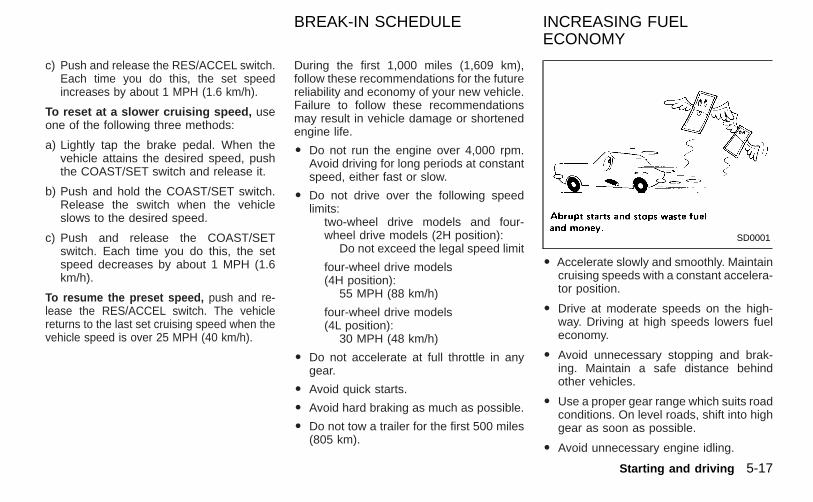
c) Push and release the RES/ACCEL switch.Each time you do this, the set speedincreases by about 1 MPH (1.6 km/h).
To reset at a slower cruising speed, useone of the following three methods:
a) Lightly tap the brake pedal. When thevehicle attains the desired speed, pushthe COAST/SET switch and release it.
b) Push and hold the COAST/SET switch.Release the switch when the vehicleslows to the desired speed.
c) Push and release the COAST/SETswitch. Each time you do this, the setspeed decreases by about 1 MPH (1.6km/h).
To resume the preset speed, push and re-lease the RES/ACCEL switch. The vehiclereturns to the last set cruising speed when thevehicle speed is over 25 MPH (40 km/h).
During the first 1,000 miles (1,609 km),follow these recommendations for the futurereliability and economy of your new vehicle.Failure to follow these recommendationsmay result in vehicle damage or shortenedengine life.
O Do not run the engine over 4,000 rpm.Avoid driving for long periods at constantspeed, either fast or slow.
O Do not drive over the following speedlimits:
two-wheel drive models and four-wheel drive models (2H position):
Do not exceed the legal speed limit
four-wheel drive models(4H position):
55 MPH (88 km/h)
four-wheel drive models(4L position):
30 MPH (48 km/h)
O Do not accelerate at full throttle in anygear.
O Avoid quick starts.
O Avoid hard braking as much as possible.
O Do not tow a trailer for the first 500 miles(805 km).
O Accelerate slowly and smoothly. Maintaincruising speeds with a constant accelera-tor position.
O Drive at moderate speeds on the high-way. Driving at high speeds lowers fueleconomy.
O Avoid unnecessary stopping and brak-ing. Maintain a safe distance behindother vehicles.
O Use a proper gear range which suits roadconditions. On level roads, shift into highgear as soon as possible.
O Avoid unnecessary engine idling.
SD0001
BREAK-IN SCHEDULE INCREASING FUELECONOMY
Starting and driving 5-17
Z X
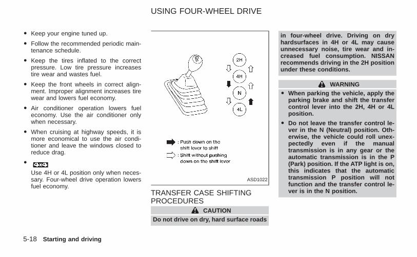
O Keep your engine tuned up.
O Follow the recommended periodic main-tenance schedule.
O Keep the tires inflated to the correctpressure. Low tire pressure increasestire wear and wastes fuel.
O Keep the front wheels in correct align-ment. Improper alignment increases tirewear and lowers fuel economy.
O Air conditioner operation lowers fueleconomy. Use the air conditioner onlywhen necessary.
O When cruising at highway speeds, it ismore economical to use the air condi-tioner and leave the windows closed toreduce drag.
O
Use 4H or 4L position only when neces-sary. Four-wheel drive operation lowersfuel economy.
TRANSFER CASE SHIFTINGPROCEDURES
CAUTIONDo not drive on dry, hard surface roads
in four-wheel drive. Driving on dryhardsurfaces in 4H or 4L may causeunnecessary noise, tire wear and in-creased fuel consumption. NISSANrecommends driving in the 2H positionunder these conditions.
WARNINGO When parking the vehicle, apply the
parking brake and shift the transfercontrol lever into the 2H, 4H or 4Lposition.
O Do not leave the transfer control le-ver in the N (Neutral) position. Oth-erwise, the vehicle could roll unex-pectedly even if the manualtransmission is in any gear or theautomatic transmission is in the P(Park) position. If the ATP light is on,this indicates that the automatictransmission P position will notfunction and the transfer control le-ver is in the N position.
ASD1022
USING FOUR-WHEEL DRIVE
5-18 Starting and driving
Z X
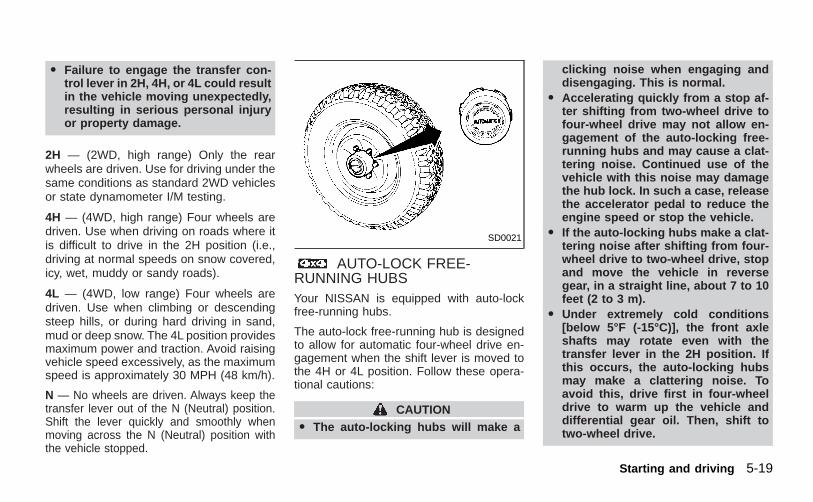
O Failure to engage the transfer con-trol lever in 2H, 4H, or 4L could resultin the vehicle moving unexpectedly,resulting in serious personal injuryor property damage.
2H — (2WD, high range) Only the rearwheels are driven. Use for driving under thesame conditions as standard 2WD vehiclesor state dynamometer I/M testing.
4H — (4WD, high range) Four wheels aredriven. Use when driving on roads where itis difficult to drive in the 2H position (i.e.,driving at normal speeds on snow covered,icy, wet, muddy or sandy roads).
4L — (4WD, low range) Four wheels aredriven. Use when climbing or descendingsteep hills, or during hard driving in sand,mud or deep snow. The 4L position providesmaximum power and traction. Avoid raisingvehicle speed excessively, as the maximumspeed is approximately 30 MPH (48 km/h).
N — No wheels are driven. Always keep thetransfer lever out of the N (Neutral) position.Shift the lever quickly and smoothly whenmoving across the N (Neutral) position withthe vehicle stopped.
AUTO-LOCK FREE-RUNNING HUBSYour NISSAN is equipped with auto-lockfree-running hubs.
The auto-lock free-running hub is designedto allow for automatic four-wheel drive en-gagement when the shift lever is moved tothe 4H or 4L position. Follow these opera-tional cautions:
CAUTIONO The auto-locking hubs will make a
clicking noise when engaging anddisengaging. This is normal.
O Accelerating quickly from a stop af-ter shifting from two-wheel drive tofour-wheel drive may not allow en-gagement of the auto-locking free-running hubs and may cause a clat-tering noise. Continued use of thevehicle with this noise may damagethe hub lock. In such a case, releasethe accelerator pedal to reduce theengine speed or stop the vehicle.
O If the auto-locking hubs make a clat-tering noise after shifting from four-wheel drive to two-wheel drive, stopand move the vehicle in reversegear, in a straight line, about 7 to 10feet (2 to 3 m).
O Under extremely cold conditions[below 5°F (-15°C)], the front axleshafts may rotate even with thetransfer lever in the 2H position. Ifthis occurs, the auto-locking hubsmay make a clattering noise. Toavoid this, drive first in four-wheeldrive to warm up the vehicle anddifferential gear oil. Then, shift totwo-wheel drive.
SD0021
Starting and driving 5-19
Z X
O In cold weather, it may be necessaryto reduce speed or stop the vehiclein order to shift from two-wheel driveto four-wheel drive.
O When shifting into or out of four-wheel drive while driving, do notstop shift lever movement midway.An incomplete shift may cause aclattering noise from the auto-locking hubs. Continued use of thevehicle with this noise may damagethe hub lock. Drive in four-wheeldrive to stop the noise. Shift to two-wheel drive as described.
5-20 Starting and driving
Z X
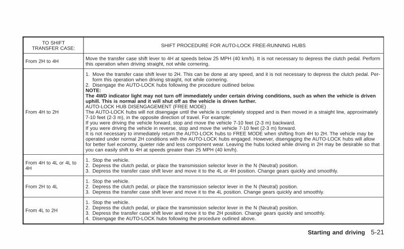
TO SHIFTTRANSFER CASE: SHIFT PROCEDURE FOR AUTO-LOCK FREE-RUNNING HUBS
From 2H to 4H Move the transfer case shift lever to 4H at speeds below 25 MPH (40 km/h). It is not necessary to depress the clutch pedal. Performthis operation when driving straight, not while cornering.
From 4H to 2H
1. Move the transfer case shift lever to 2H. This can be done at any speed, and it is not necessary to depress the clutch pedal. Per-form this operation when driving straight, not while cornering.
2. Disengage the AUTO-LOCK hubs following the procedure outlined below.NOTE:The 4WD indicator light may not turn off immediately under certain driving conditions, such as when the vehicle is drivenuphill. This is normal and it will shut off as the vehicle is driven further.AUTO-LOCK HUB DISENGAGEMENT (FREE MODE)The AUTO-LOCK hubs will not disengage until the vehicle is completely stopped and is then moved in a straight line, approximately7-10 feet (2-3 m), in the opposite direction of travel. For example:If you were driving the vehicle forward, stop and move the vehicle 7-10 feet (2-3 m) backward.If you were driving the vehicle in reverse, stop and move the vehicle 7-10 feet (2-3 m) forward.It is not necessary to immediately return the AUTO-LOCK hubs to FREE MODE when shifting from 4H to 2H. The vehicle may beoperated under normal 2H conditions with the AUTO-LOCK hubs engaged. However, disengaging the AUTO-LOCK hubs will allowfor better fuel economy, quieter ride and less component wear. Leaving the hubs locked while driving in 2H may be desirable so thatyou can easily shift to 4H at speeds greater than 25 MPH (40 km/h).
From 4H to 4L or 4L to4H
1. Stop the vehicle.2. Depress the clutch pedal, or place the transmission selector lever in the N (Neutral) position.3. Depress the transfer case shift lever and move it to the 4L or 4H position. Change gears quickly and smoothly.
From 2H to 4L1. Stop the vehicle.2. Depress the clutch pedal, or place the transmission selector lever in the N (Neutral) position.3. Depress the transfer case shift lever and move it to the 4L position. Change gears quickly and smoothly.
From 4L to 2H
1. Stop the vehicle.2. Depress the clutch pedal, or place the transmission selector lever in the N (Neutral) position.3. Depress the transfer case shift lever and move it to the 2H position. Change gears quickly and smoothly.4. Disengage the AUTO-LOCK hubs following the procedure outlined above.
Starting and driving 5-21
Z X
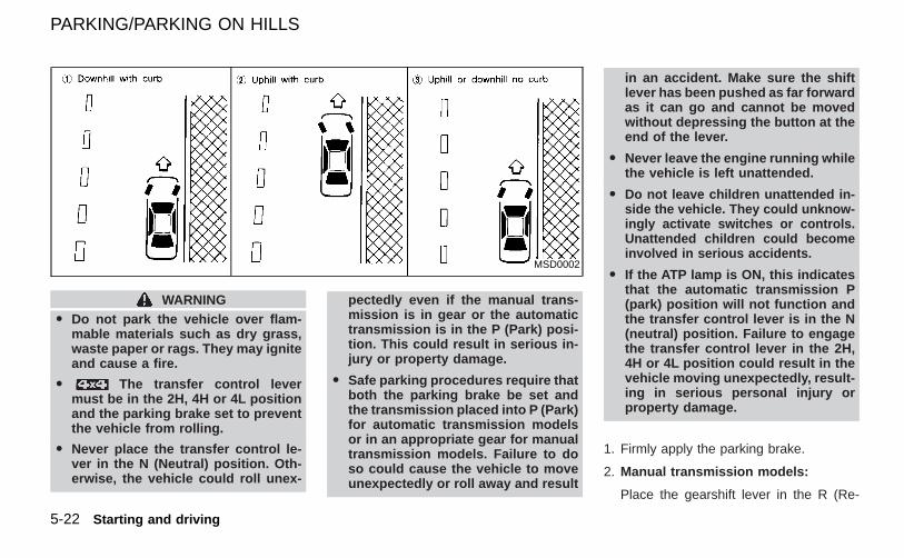
WARNINGO Do not park the vehicle over flam-
mable materials such as dry grass,waste paper or rags. They may igniteand cause a fire.
O The transfer control levermust be in the 2H, 4H or 4L positionand the parking brake set to preventthe vehicle from rolling.
O Never place the transfer control le-ver in the N (Neutral) position. Oth-erwise, the vehicle could roll unex-
pectedly even if the manual trans-mission is in gear or the automatictransmission is in the P (Park) posi-tion. This could result in serious in-jury or property damage.
O Safe parking procedures require thatboth the parking brake be set andthe transmission placed into P (Park)for automatic transmission modelsor in an appropriate gear for manualtransmission models. Failure to doso could cause the vehicle to moveunexpectedly or roll away and result
in an accident. Make sure the shiftlever has been pushed as far forwardas it can go and cannot be movedwithout depressing the button at theend of the lever.
O Never leave the engine running whilethe vehicle is left unattended.
O Do not leave children unattended in-side the vehicle. They could unknow-ingly activate switches or controls.Unattended children could becomeinvolved in serious accidents.
O If the ATP lamp is ON, this indicatesthat the automatic transmission P(park) position will not function andthe transfer control lever is in the N(neutral) position. Failure to engagethe transfer control lever in the 2H,4H or 4L position could result in thevehicle moving unexpectedly, result-ing in serious personal injury orproperty damage.
1. Firmly apply the parking brake.
2. Manual transmission models:
Place the gearshift lever in the R (Re-
MSD0002
PARKING/PARKING ON HILLS
5-22 Starting and driving
Z X
verse) position. When parking on an up-hill grade, place the gearshift lever in the1st position.
Automatic transmission models:
Move the gearshift lever to the P (Park)position.
3. To help prevent the vehicle from rollinginto the street when parked on an incline,it is a good practice to turn the wheels asillustrated.
O HEADED DOWNHILL WITH CURB: ➀s1
Turn the wheels into the curb and movethe vehicle forward until the curb sidewheel gently touches the curb.
O HEADED UPHILL WITH CURB: s2
Turn the wheels away from the curb andmove the vehicle back until the curb sidewheel gently touches the curb.
O HEADED UPHILL OR DOWNHILL, NOCURB: s3
Turn the wheels toward the side of theroad so the vehicle will move away fromthe center of the road if it moves.
4. Turn the ignition key to the LOCK posi-tion and remove the key.
The power assisted steering is designed touse a hydraulic pump, driven by the engine,to assist steering.
If the engine stops or drive belt breaks, youwill still have control of the vehicle. How-ever, much greater steering effort is needed,especially in sharp turns and at low speeds.
WARNINGIf the engine is not running or is turnedoff while driving, the power assist forthe steering will not work. Steering willbe much harder to operate.
The brake system has two separate hydrau-lic circuits. If one circuit malfunctions, youwill still have braking at two wheels.
BRAKING PRECAUTIONS
Vacuum assisted brakesThe brake booster aids braking by usingengine vacuum. If the engine stops, you canstop the vehicle by depressing the brakepedal. However, greater foot pressure onthe brake pedal will be required to stop thevehicle and stopping distance will be longer.
Using the brakesAvoid resting your foot on the brake pedalwhile driving. This will overheat the brakes,wear out the brake linings and pads faster,and reduce gas mileage.
To help reduce brake wear, and to preventthe brakes from overheating, reduce speedand downshift to a lower gear before goingdown a slope or long grade.
POWER STEERING BRAKE SYSTEM
Starting and driving 5-23
Z X
WARNINGO While driving on a slippery surface,
be careful when braking, accelerat-ing or downshifting. Abrupt brakingor accelerating could cause thewheels to skid and result in an acci-dent.
O If the engine is not running or isturned off while driving, the powerassist for the brakes will not work.Braking will be harder.
Wet brakesWhen the vehicle is washed or driventhrough water, the brakes may get wet. As aresult, your braking distance will be longerand the vehicle may pull to one side duringbraking.
To dry the brakes, drive the vehicle at a safespeed while lightly pressing the brake pedalto heat the brakes. Do this until the brakesreturn to normal. Avoid driving the vehicle athigh speeds until the brakes function cor-rectly.
ANTI-LOCK BRAKE SYSTEM (ABS)
Using the System
Depress the brake pedal and hold it down.
WARNING
Do not pump the brake pedal. Doing somay result in increased stopping dis-tances.
Normal operationThe anti-lock brake system does not oper-ate at speeds below 3 to 6 MPH (5 to 10km/h). (The speeds vary according to roadconditions.)
When driving, the anti-lock brake systemcontrols the wheels so they will not lockwhen braking abruptly or when braking on aslippery road. Thus, difficult steering andswerving of the vehicle due to lockedwheels is minimized. The system detectsthe wheel rotation rate and electronicallycontrols the pressure applied to each brake.Slight vibration on the brake pedal accom-panied by noise usually occurs while theABS system is operating. Such vibrationand noise encountered during abrupt brak-
ing is not a problem, but indicates that thesystem is functioning.
Self-test featureThe anti-lock brake system consists of elec-tronic sensors and hydraulic solenoids con-trolled by a computer. The computer has abuilt-in diagnostic feature that tests the sys-tem each time you start the engine andmove the vehicle at a low speed in forwardor reverse. When the self-test occurs, youmay hear a ‘‘clunk’’ noise and/or feel apulsation in the brake pedal. This is normaland is not an indication of any malfunction. Ifthe computer senses any malfunction, itswitches the anti-lock brake system off andturns on the ABS brake warning light in thedashboard. The brake system then operatesnormally, but without anti-lock assistance.
If an abnormality occurs in the system, theanti-lock function will cease but the ordinarybrakes will continue to operate normally. TheABS brake warning light will then come on.
If the light comes on while you are driving,contact an authorized NISSAN dealer forrepair.
5-24 Starting and driving
Z X
WARNINGO The anti-lock brake system is a
sophisticated device, but it cannotprevent accidents resulting fromcareless or dangerous driving tech-niques. It can help maintain vehiclecontrol under braking on slipperysurfaces, but remember that thestopping distance on slippery sur-faces will be longer than on normalsurfaces even with the anti-lockbrake system. Stopping distancesmay also be longer on rough, gravel,or snow covered roads, or if you areusing tire chains. Always maintain asafe distance from the vehicle infront of you. Ultimately, the respon-sibility for safety of self and othersrests in the hands of the driver.
Tire type and condition may also affectbraking effectiveness.
O When replacing tires, install thespecified tire size on all four wheels.
O When installing a spare tire, makesure it is the proper size and type asspecified on the tire placard. For tire
placard location information refer to‘‘Tire placard’’ in the ‘‘Technical andconsumer information’’ section ofthis manual.
FREEING A FROZEN DOORLOCK
To prevent a door lock from freezing, applyde-icer or glycerin through the key hole. Ifthe lock becomes frozen, heat the key be-fore inserting it in the key hole.
ANTI-FREEZE
In the winter when it is anticipated that thetemperature will drop below 32°F (0°C),check anti-freeze (ethylene glycol base) toassure proper winter protection. For details,see ‘‘Engine cooling system’’ in the ‘‘Do-it-yourself’’ section of this manual.
BATTERYIf the battery is not fully charged duringextremely cold weather conditions, the bat-tery fluid may freeze and damage the bat-tery. To maintain maximum efficiency, thebattery should be checked regularly. Fordetails, see ‘‘Battery’’ in the ‘‘Do-it-yourself’’section of this manual.
DRAINING OF COOLANT WATERIf the vehicle is to be left outside withoutanti-freeze, drain the cooling system by open-ing the drain valves located under the radiator
COLD WEATHER DRIVING
Starting and driving 5-25
Z X
and on the engine block. Refill before operat-ing the vehicle. For details, see ‘‘Changingengine coolant’’ in the ‘‘Do-it-yourself’’ sectionof this manual.
TIRE EQUIPMENT1. SUMMER tires have a tread designed to
provide superior performance on drypavement. However, the performance ofthese tires will be substantially reducedin snowy and icy conditions. If you oper-ate your vehicle on snowy or icy roads,NISSAN recommends the use on all fourwheels of MUD & SNOW or ALL SEA-SON tires. Please consult your NISSANdealer for the tire type, size, speed ratingand availability information.
2. For additional traction on icy roads, stud-ded tires may be used. However, someU.S. states and Canadian provinces pro-hibit their use. Check local, state and pro-vincial laws before installing studded tires.
Skid and traction capabilities of studdedsnow tires on wet or dry surfaces may bepoorer than that of non-studded snowtires.
3. Tire chains may be used. Use of tirechains may be prohibited according to
location. Check the local laws beforeinstalling tire chains. When installing tirechains, make sure they are of proper sizefor the tires on your vehicle and areinstalled according to the chain manufac-turer’s suggestions. Use only SAEClass ‘‘S’’ chains. Other types maydamage your vehicle. Use chain tension-ers when recommended by the tire chainmanufacturer to ensure a tight fit. Looseend links of the tire chain must be se-cured or removed to prevent the possi-bility of whipping action damage to thefenders or undercarriage. If possible,avoid fully loading your vehicle whenusing tire chains. In addition, drive at areduced speed, otherwise, your vehiclemay be damaged and/or vehicle handlingand performance may be adversely af-fected. Never install tire chains on aTEMPORARY USE ONLY spare tire. Donot use tire chains on dry roads.
SPECIAL WINTER EQUIPMENTIt is recommended that the following itemsbe carried in the vehicle during winter:
1. A scraper and stiff-bristled brush to re-move ice and snow from the windowsand wiper blades.
2. A sturdy, flat board to be placed underthe jack to give it firm support.
3. A shovel to dig the vehicle out of snow-drifts.
4. Extra window washer fluid to refill thereservoir tank.
DRIVING ON SNOW OR ICE
WARNINGO Wet ice (32°F, 0°C and freezing rain),
very cold snow, or ice can be slickand very hard to drive on. The ve-hicle will have much less traction or‘‘grip’’ under these conditions. Try toavoid driving on wet ice until theroad is salted or sanded.
O Whatever the condition, drive withcaution. Accelerate and slow downwith care. If accelerating or down-shifting too fast, the drive wheelswill lose even more traction.
O Allow more stopping distance underthese conditions. Braking should bestarted sooner than on dry pavement.
O Allow greater following distances onslippery roads.
5-26 Starting and driving
Z X
O Watch for slippery spots (glare ice).These may appear on an otherwiseclear road in shaded areas. If a patchof ice is seen ahead, brake beforereaching it. Try not to brake while onthe ice, and avoid any sudden steer-ing maneuvers.
O Do not use the cruise control onslippery roads.
O Snow can trap dangerous exhaustgases under your vehicle. Keepsnow clear of the exhaust pipe andfrom around your vehicle.
ENGINE BLOCK HEATER (if soequipped)An engine block heater to assist extremecold temperature starting is availablethrough an authorized NISSAN dealer.
WARNINGDo not use your heater with an un-grounded electrical system or two-pronged (cheater) adapters. You can beinjured by an electrical shock if you usean ungrounded connection.
Starting and driving 5-27
Z X

MEMO
5-28 Starting and driving
Z X
6 In case of emergency
First aid kit..............................................................6-2Flat tire ...................................................................6-2
Changing a flat tire ............................................6-2Jump starting..........................................................6-8Push starting ........................................................6-10
If your vehicle overheats ......................................6-10Towing your vehicle..............................................6-11
Towing recommended by Nissan ....................6-12Vehicle recovery (freeing a stuckvehicle) ............................................................6-14
Z X
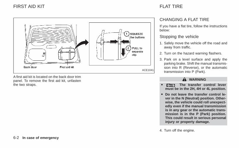
A first aid kit is located on the back door trimpanel. To remove the first aid kit, unfastenthe two straps.
CHANGING A FLAT TIRE
If you have a flat tire, follow the instructionsbelow:
Stopping the vehicle
1. Safely move the vehicle off the road andaway from traffic.
2. Turn on the hazard warning flashers.
3. Park on a level surface and apply theparking brake. Shift the manual transmis-sion into R (Reverse), or the automatictransmission into P (Park).
WARNING
O The transfer control levermust be in the 2H, 4H or 4L position.
O Do not leave the transfer control le-ver in the N (Neutral) position. Other-wise, the vehicle could roll unexpect-edly even if the manual transmissionis in any gear or the automatic trans-mission is in the P (Park) position.This could result in serious personalinjury or property damage.
4. Turn off the engine.
ACE1041
FIRST AID KIT FLAT TIRE
6-2 In case of emergency
Z X
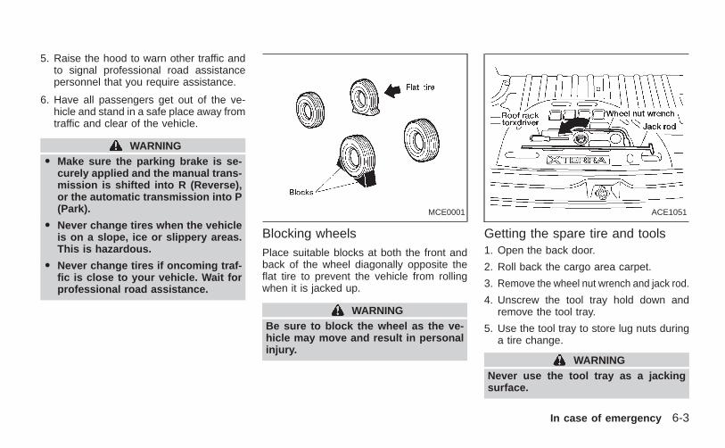
5. Raise the hood to warn other traffic andto signal professional road assistancepersonnel that you require assistance.
6. Have all passengers get out of the ve-hicle and stand in a safe place away fromtraffic and clear of the vehicle.
WARNINGO Make sure the parking brake is se-
curely applied and the manual trans-mission is shifted into R (Reverse),or the automatic transmission into P(Park).
O Never change tires when the vehicleis on a slope, ice or slippery areas.This is hazardous.
O Never change tires if oncoming traf-fic is close to your vehicle. Wait forprofessional road assistance.
Blocking wheelsPlace suitable blocks at both the front andback of the wheel diagonally opposite theflat tire to prevent the vehicle from rollingwhen it is jacked up.
WARNINGBe sure to block the wheel as the ve-hicle may move and result in personalinjury.
Getting the spare tire and tools1. Open the back door.
2. Roll back the cargo area carpet.
3. Remove the wheel nut wrench and jack rod.
4. Unscrew the tool tray hold down andremove the tool tray.
5. Use the tool tray to store lug nuts duringa tire change.
WARNINGNever use the tool tray as a jackingsurface.
MCE0001 ACE1051
In case of emergency 6-3
Z X
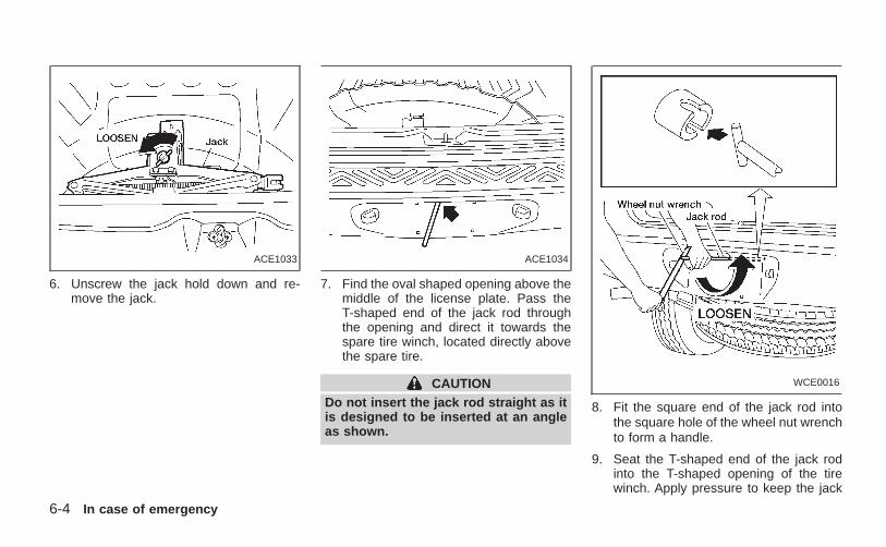
6. Unscrew the jack hold down and re-move the jack.
7. Find the oval shaped opening above themiddle of the license plate. Pass theT-shaped end of the jack rod throughthe opening and direct it towards thespare tire winch, located directly abovethe spare tire.
CAUTIONDo not insert the jack rod straight as itis designed to be inserted at an angleas shown.
8. Fit the square end of the jack rod intothe square hole of the wheel nut wrenchto form a handle.
9. Seat the T-shaped end of the jack rodinto the T-shaped opening of the tirewinch. Apply pressure to keep the jack
ACE1033 ACE1034
WCE0016
6-4 In case of emergency
Z X
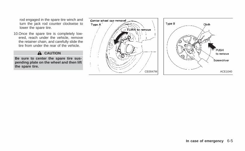
rod engaged in the spare tire winch andturn the jack rod counter clockwise tolower the spare tire.
10.Once the spare tire is completely low-ered, reach under the vehicle, removethe retainer chain, and carefully slide thetire from under the rear of the vehicle.
CAUTIONBe sure to center the spare tire sus-pending plate on the wheel and then liftthe spare tire.
CE0047M ACE1040
In case of emergency 6-5
Z X
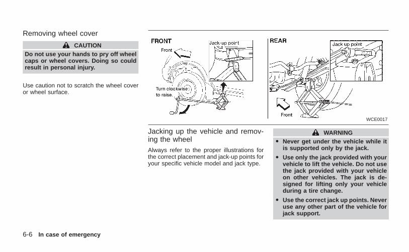
Removing wheel cover
CAUTIONDo not use your hands to pry off wheelcaps or wheel covers. Doing so couldresult in personal injury.
Use caution not to scratch the wheel coveror wheel surface.
Jacking up the vehicle and remov-ing the wheelAlways refer to the proper illustrations forthe correct placement and jack-up points foryour specific vehicle model and jack type.
WARNINGO Never get under the vehicle while it
is supported only by the jack.
O Use only the jack provided with yourvehicle to lift the vehicle. Do not usethe jack provided with your vehicleon other vehicles. The jack is de-signed for lifting only your vehicleduring a tire change.
O Use the correct jack up points. Neveruse any other part of the vehicle forjack support.
WCE0017
6-6 In case of emergency
Z X
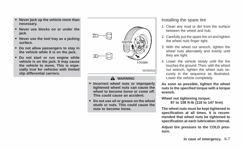
O Never jack up the vehicle more thannecessary.
O Never use blocks on or under thejack.
O Never use the tool tray as a jackingsurface.
O Do not allow passengers to stay inthe vehicle while it is on the jack.
O Do not start or run engine whilevehicle is on the jack. It may causethe vehicle to move. This is espe-cially true for vehicles with limitedslip differential carriers.
WARNINGO Incorrect wheel nuts or improperly
tightened wheel nuts can cause thewheel to become loose or come off.This could cause an accident.
O Do not use oil or grease on the wheelstuds or nuts. This could cause thenuts to become loose.
Installing the spare tire
1. Clean any mud or dirt from the surfacebetween the wheel and hub.
2. Carefully put the spare tire on and tightenthe wheel nuts finger tight.
3. With the wheel nut wrench, tighten thewheel nuts alternately and evenly untilthey are tight.
4. Lower the vehicle slowly until the tiretouches the ground. Then, with the wheelnut wrench, tighten the wheel nuts se-curely in the sequence as illustrated.Lower the vehicle completely.
As soon as possible, tighten the wheelnuts to the specified torque with a torquewrench.
Wheel nut tightening torque:87 to 108 ft-lb (118 to 147 N zm)
The wheel nuts must be kept tightened tospecification at all times. It is recom-mended that wheel nuts be tightened tospecification at each lubrication interval.
Adjust tire pressure to the COLD pres-sure.
WCE0015
In case of emergency 6-7
Z X
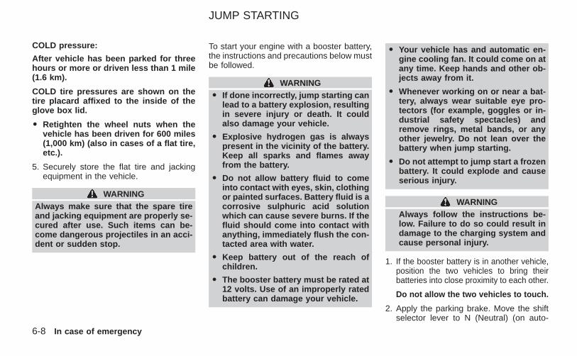
COLD pressure:
After vehicle has been parked for threehours or more or driven less than 1 mile(1.6 km).
COLD tire pressures are shown on thetire placard affixed to the inside of theglove box lid.
O Retighten the wheel nuts when thevehicle has been driven for 600 miles(1,000 km) (also in cases of a flat tire,etc.).
5. Securely store the flat tire and jackingequipment in the vehicle.
WARNINGAlways make sure that the spare tireand jacking equipment are properly se-cured after use. Such items can be-come dangerous projectiles in an acci-dent or sudden stop.
To start your engine with a booster battery,the instructions and precautions below mustbe followed.
WARNINGO If done incorrectly, jump starting can
lead to a battery explosion, resultingin severe injury or death. It couldalso damage your vehicle.
O Explosive hydrogen gas is alwayspresent in the vicinity of the battery.Keep all sparks and flames awayfrom the battery.
O Do not allow battery fluid to comeinto contact with eyes, skin, clothingor painted surfaces. Battery fluid is acorrosive sulphuric acid solutionwhich can cause severe burns. If thefluid should come into contact withanything, immediately flush the con-tacted area with water.
O Keep battery out of the reach ofchildren.
O The booster battery must be rated at12 volts. Use of an improperly ratedbattery can damage your vehicle.
O Your vehicle has and automatic en-gine cooling fan. It could come on atany time. Keep hands and other ob-jects away from it.
O Whenever working on or near a bat-tery, always wear suitable eye pro-tectors (for example, goggles or in-dustrial safety spectacles) andremove rings, metal bands, or anyother jewelry. Do not lean over thebattery when jump starting.
O Do not attempt to jump start a frozenbattery. It could explode and causeserious injury.
WARNINGAlways follow the instructions be-low. Failure to do so could result indamage to the charging system andcause personal injury.
1. If the booster battery is in another vehicle,position the two vehicles to bring theirbatteries into close proximity to each other.
Do not allow the two vehicles to touch.
2. Apply the parking brake. Move the shiftselector lever to N (Neutral) (on auto-
JUMP STARTING
6-8 In case of emergency
Z X
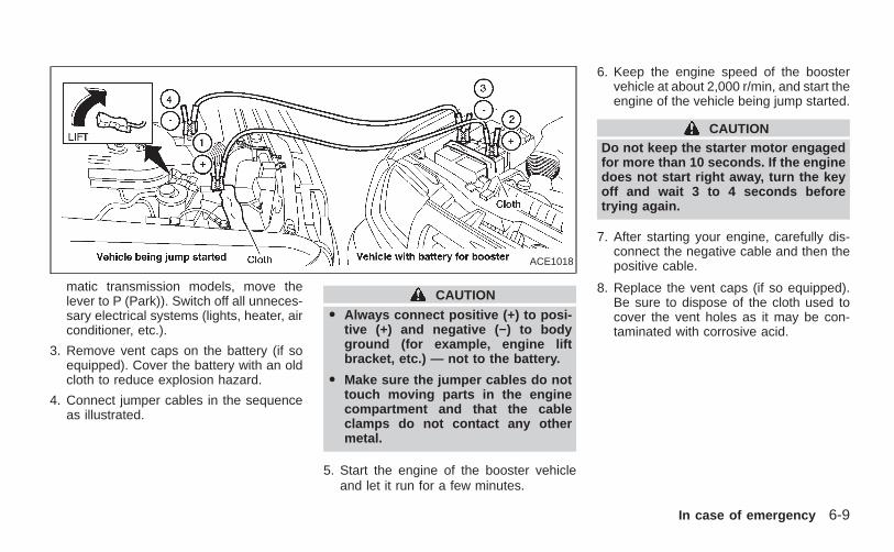
matic transmission models, move thelever to P (Park)). Switch off all unneces-sary electrical systems (lights, heater, airconditioner, etc.).
3. Remove vent caps on the battery (if soequipped). Cover the battery with an oldcloth to reduce explosion hazard.
4. Connect jumper cables in the sequenceas illustrated.
CAUTION
O Always connect positive (+) to posi-tive (+) and negative (−) to bodyground (for example, engine liftbracket, etc.) — not to the battery.
O Make sure the jumper cables do nottouch moving parts in the enginecompartment and that the cableclamps do not contact any othermetal.
5. Start the engine of the booster vehicleand let it run for a few minutes.
6. Keep the engine speed of the boostervehicle at about 2,000 r/min, and start theengine of the vehicle being jump started.
CAUTIONDo not keep the starter motor engagedfor more than 10 seconds. If the enginedoes not start right away, turn the keyoff and wait 3 to 4 seconds beforetrying again.
7. After starting your engine, carefully dis-connect the negative cable and then thepositive cable.
8. Replace the vent caps (if so equipped).Be sure to dispose of the cloth used tocover the vent holes as it may be con-taminated with corrosive acid.
ACE1018
In case of emergency 6-9
Z X
CAUTIONO Automatic transmission models can-
not be push or tow started. This maycause transmission or other vehicledamage.
O Never try to start the vehicle by tow-ing it. When the engine starts, theforward surge could cause the ve-hicle to collide with the tow vehicle.
If your vehicle is overheating (indicated byan extremely high temperature gauge read-ing), or if you feel a lack of engine power, ordetect abnormal noise, etc., take the follow-ing steps:
WARNINGO Do not continue to drive if your ve-
hicle overheats. Doing so couldcause a vehicle fire.
O To avoid the danger of beingscalded, never remove the radiatorcap while the engine is still hot.When the radiator cap is removed,pressurized hot water will spurt out,possibly causing serious injury.
O Do not open the hood if steam iscoming out.
1. Move the vehicle safely off the road,apply the parking brake and move thegearshift lever to N (Neutral), or the au-tomatic transmission into P (Park).
Do not stop the engine.
2. Turn off the air conditioner (if soequipped). Open all of the windows,move the heater or air conditioner tem-
perature control to maximum hot and fancontrol to high speed.
3. If engine overheating is caused by climb-ing a long hill on a hot day, run the engineat a fast idle (approximately 1,500 r/min)until the temperature gauge indicator re-turns to normal.
4. Get out of the vehicle. Look and listen forsteam or coolant escaping from the ra-diator before opening the hood. Wait untilno steam or coolant can be seen beforeproceeding.
5. Open the hood.
WARNINGIf steam or water is coming from theengine, stand clear to prevent gettingburned.
6. Visually check drive belts for damage orlooseness. Also check if the cooling fan isrunning. The radiator hoses and radiatorshould not leak water. If coolant is leak-ing, or the water pump belt is missing orloose, or the cooling fan does not run,stop the engine.
PUSH STARTING IF YOUR VEHICLEOVERHEATS
6-10 In case of emergency
Z X
WARNINGBe careful not to allow your hands, hair,jewelry or clothing to come into contactwith, or get caught in, engine belts orthe engine cooling fan. The enginecooling fan can start at any time whenthe coolant temperature is high.
7. After the engine cools down, check thecoolant level in the reservoir tank with theengine running. Add coolant to the reser-voir tank if necessary. Have your vehiclerepaired at an authorized NISSANdealer.
When towing your vehicle, all State (Provinialin Canada) and local regulations for towingmust be followed. Incorrect towing equipmentcould damage your vehicle. Towing instruc-tions are available from an authorized NIS-SAN dealer. Local service operators are gen-erally familiar with the applicable laws andprocedures for towing. To assure proper tow-ing and to prevent accidental damage to yourvehicle, NISSAN recommends having a ser-vice operator tow your vehicle. It is advisableto have the service operator carefully readthe following precautions:
WARNINGO Never ride in a vehicle that is being
towed.
O Never get under your vehicle after ithas been lifted by a tow truck.
CAUTIONO When towing, make sure that the
transmission, axles, steering systemand powertrain are in working con-dition. If any unit is damaged, dolliesmust be used.
O Always attach safety chains beforetowing.
TOWING YOUR VEHICLE
In case of emergency 6-11
Z X
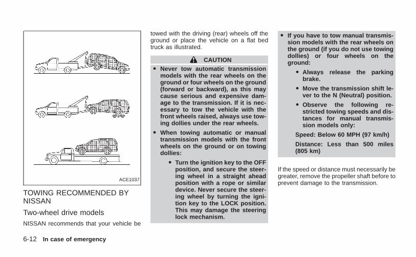
TOWING RECOMMENDED BYNISSAN
Two-wheel drive modelsNISSAN recommends that your vehicle be
towed with the driving (rear) wheels off theground or place the vehicle on a flat bedtruck as illustrated.
CAUTIONO Never tow automatic transmission
models with the rear wheels on theground or four wheels on the ground(forward or backward), as this maycause serious and expensive dam-age to the transmission. If it is nec-essary to tow the vehicle with thefront wheels raised, always use tow-ing dollies under the rear wheels.
O When towing automatic or manualtransmission models with the frontwheels on the ground or on towingdollies:
O Turn the ignition key to the OFFposition, and secure the steer-ing wheel in a straight aheadposition with a rope or similardevice. Never secure the steer-ing wheel by turning the igni-tion key to the LOCK position.This may damage the steeringlock mechanism.
O If you have to tow manual transmis-sion models with the rear wheels onthe ground (if you do not use towingdollies) or four wheels on theground:
O Always release the parkingbrake.
O Move the transmission shift le-ver to the N (Neutral) position.
O Observe the following re-stricted towing speeds and dis-tances for manual transmis-sion models only:
Speed: Below 60 MPH (97 km/h)
Distance: Less than 500 miles(805 km)
If the speed or distance must necessarily begreater, remove the propeller shaft before toprevent damage to the transmission.
ACE1037
6-12 In case of emergency
Z X
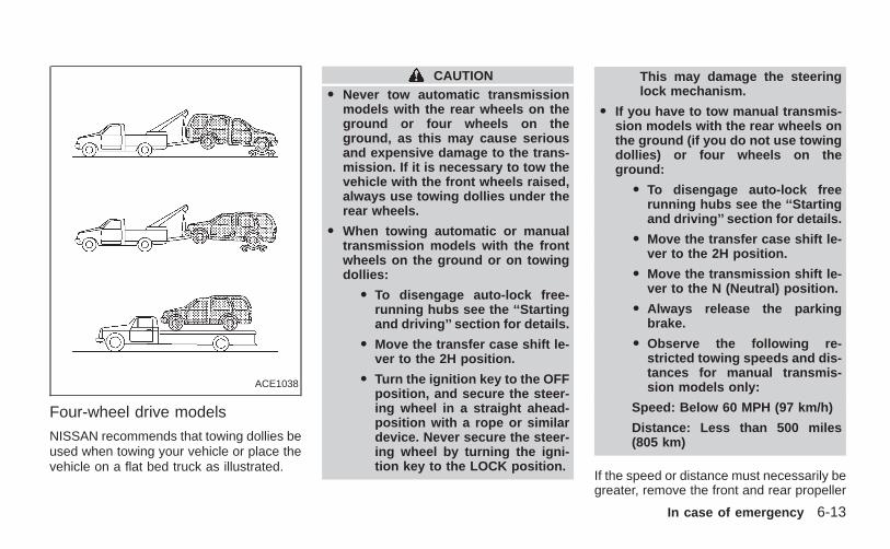
Four-wheel drive models
NISSAN recommends that towing dollies beused when towing your vehicle or place thevehicle on a flat bed truck as illustrated.
CAUTIONO Never tow automatic transmission
models with the rear wheels on theground or four wheels on theground, as this may cause seriousand expensive damage to the trans-mission. If it is necessary to tow thevehicle with the front wheels raised,always use towing dollies under therear wheels.
O When towing automatic or manualtransmission models with the frontwheels on the ground or on towingdollies:
O To disengage auto-lock free-running hubs see the ‘‘Startingand driving’’ section for details.
O Move the transfer case shift le-ver to the 2H position.
O Turn the ignition key to the OFFposition, and secure the steer-ing wheel in a straight ahead-position with a rope or similardevice. Never secure the steer-ing wheel by turning the igni-tion key to the LOCK position.
This may damage the steeringlock mechanism.
O If you have to tow manual transmis-sion models with the rear wheels onthe ground (if you do not use towingdollies) or four wheels on theground:
O To disengage auto-lock freerunning hubs see the ‘‘Startingand driving’’ section for details.
O Move the transfer case shift le-ver to the 2H position.
O Move the transmission shift le-ver to the N (Neutral) position.
O Always release the parkingbrake.
O Observe the following re-stricted towing speeds and dis-tances for manual transmis-sion models only:
Speed: Below 60 MPH (97 km/h)
Distance: Less than 500 miles(805 km)
If the speed or distance must necessarily begreater, remove the front and rear propeller
ACE1038
In case of emergency 6-13
Z X
shafts before towing to prevent damage tothe transmission.
VEHICLE RECOVERY (freeing astuck vehicle)
O Tow chains or cables must be attachedonly to the main structural members ofthe vehicle.
O Pulling devices should be routed so theydo not touch any part of the suspension,steering, brake or cooling systems.
O Always pull the cable straight out fromthe front or rear of the vehicle. Never pullthe vehicle at an angle.
O Pulling devices such as ropes or canvasstraps are not recommended for use invehicle towing or recovery.
O Stand clear of a stuck vehicle.
WARNING
Do not spin your tires at high speed.This could cause them to explode andresult in serious injury. Parts of yourvehicle could also overheat and bedamaged.
6-14 In case of emergency
Z X
7 Appearance and care
Cleaning exterior ....................................................7-2Washing.............................................................7-2Waxing...............................................................7-2Removing spots.................................................7-3Underbody .........................................................7-3Glass..................................................................7-3Aluminum alloy wheels......................................7-3Chrome parts.....................................................7-3
Cleaning interior .....................................................7-4
Floor mats..........................................................7-4Seat belts ..........................................................7-5
Corrosion protection...............................................7-5Most common factors contributing tovehicle corrosion................................................7-5Environmental factors influence the rateof corrosion........................................................7-5To protect your vehicle from corrosion..............7-5
Z X
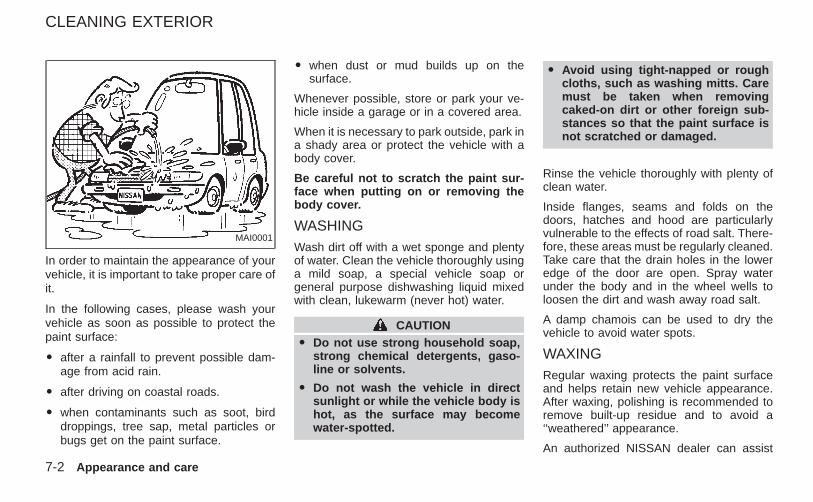
In order to maintain the appearance of yourvehicle, it is important to take proper care ofit.
In the following cases, please wash yourvehicle as soon as possible to protect thepaint surface:
O after a rainfall to prevent possible dam-age from acid rain.
O after driving on coastal roads.
O when contaminants such as soot, birddroppings, tree sap, metal particles orbugs get on the paint surface.
O when dust or mud builds up on thesurface.
Whenever possible, store or park your ve-hicle inside a garage or in a covered area.
When it is necessary to park outside, park ina shady area or protect the vehicle with abody cover.
Be careful not to scratch the paint sur-face when putting on or removing thebody cover.
WASHINGWash dirt off with a wet sponge and plentyof water. Clean the vehicle thoroughly usinga mild soap, a special vehicle soap orgeneral purpose dishwashing liquid mixedwith clean, lukewarm (never hot) water.
CAUTIONO Do not use strong household soap,
strong chemical detergents, gaso-line or solvents.
O Do not wash the vehicle in directsunlight or while the vehicle body ishot, as the surface may becomewater-spotted.
O Avoid using tight-napped or roughcloths, such as washing mitts. Caremust be taken when removingcaked-on dirt or other foreign sub-stances so that the paint surface isnot scratched or damaged.
Rinse the vehicle thoroughly with plenty ofclean water.
Inside flanges, seams and folds on thedoors, hatches and hood are particularlyvulnerable to the effects of road salt. There-fore, these areas must be regularly cleaned.Take care that the drain holes in the loweredge of the door are open. Spray waterunder the body and in the wheel wells toloosen the dirt and wash away road salt.
A damp chamois can be used to dry thevehicle to avoid water spots.
WAXINGRegular waxing protects the paint surfaceand helps retain new vehicle appearance.After waxing, polishing is recommended toremove built-up residue and to avoid a‘‘weathered’’ appearance.
An authorized NISSAN dealer can assist
MAI0001
CLEANING EXTERIOR
7-2 Appearance and care
Z X
you in choosing the proper product.
O Wax your vehicle only after a thoroughwashing. Follow the instructions suppliedwith the wax.
O Do not use a wax containing any abra-sives, cutting compounds or cleanersthat may damage the vehicle finish.
O If the surface does not polish easily, usea ‘‘road tar’’ remover and wax again.
Machine compounding or aggressive pol-ishing on a base coat/clear coat paint finishmay dull the finish or leave swirl marks.
REMOVING SPOTSRemove tar and oil spots, industrial dust,insects and tree sap as quickly as possiblefrom the surface of the paint to avoid per-manent damage or staining. Special clean-ing products are available at an authorizedNISSAN dealer or any automotive accesso-ries store.
UNDERBODYIn areas where road salt is used in winter, itis necessary to clean the underbody regu-larly in order to prevent dirt and salt frombuilding up and causing corrosion on the
underbody and suspension. Before the win-ter period and again in the spring, theunderseal must be checked and, if neces-sary, retreated.
GLASS
Use glass cleaner to remove smoke anddust film from the glass surfaces. It is nor-mal for glass to be coated with a film afterthe vehicle is parked in the hot sun. Glasscleaner and a soft cloth easily remove thisfilm.
CAUTION
When cleaning the inside of the win-dow, do not use sharp-edged tools orabrasive cleaners or chlorine-baseddisinfectant cleaners. They could dam-age the electrical conductors, radio an-tenna elements or rear window defog-ger elements.
ALUMINUM ALLOY WHEELS
Wash regularly, especially during wintermonths in areas where road salt is used.Salt could discolor the wheel if not removed.
CHROME PARTSClean all chrome parts regularly with anon-abrasive chrome polish to maintain thefinish.
Appearance and care 7-3
Z X
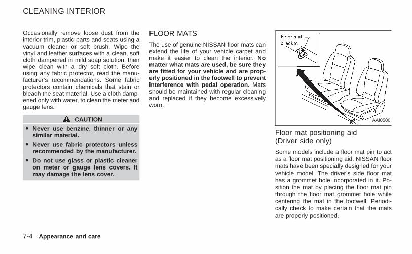
Occasionally remove loose dust from theinterior trim, plastic parts and seats using avacuum cleaner or soft brush. Wipe thevinyl and leather surfaces with a clean, softcloth dampened in mild soap solution, thenwipe clean with a dry soft cloth. Beforeusing any fabric protector, read the manu-facturer’s recommendations. Some fabricprotectors contain chemicals that stain orbleach the seat material. Use a cloth damp-ened only with water, to clean the meter andgauge lens.
CAUTIONO Never use benzine, thinner or any
similar material.
O Never use fabric protectors unlessrecommended by the manufacturer.
O Do not use glass or plastic cleaneron meter or gauge lens covers. Itmay damage the lens cover.
FLOOR MATSThe use of genuine NISSAN floor mats canextend the life of your vehicle carpet andmake it easier to clean the interior. Nomatter what mats are used, be sure theyare fitted for your vehicle and are prop-erly positioned in the footwell to preventinterference with pedal operation. Matsshould be maintained with regular cleaningand replaced if they become excessivelyworn.
Floor mat positioning aid(Driver side only)
Some models include a floor mat pin to actas a floor mat positioning aid. NISSAN floormats have been specially designed for yourvehicle model. The driver’s side floor mathas a grommet hole incorporated in it. Po-sition the mat by placing the floor mat pinthrough the floor mat grommet hole whilecentering the mat in the footwell. Periodi-cally check to make certain that the matsare properly positioned.
AAI0500
CLEANING INTERIOR
7-4 Appearance and care
Z X
SEAT BELTSThe seat belts can be cleaned by wipingthem with a sponge dampened in a mildsoap solution. Allow the belts to dry com-pletely in the shade before using them. See‘‘Seat belt maintenance’’ in the ‘‘Seats, re-straints and supplemental air bag systems’’section of this owner’s manual.
WARNINGDo not allow wet seat belts to roll up inthe retractor. NEVER use bleach, dye orchemical solvents to clean the seatbelt,since these materials may severelyweaken the seat belt webbing.
MOST COMMON FACTORSCONTRIBUTING TO VEHICLECORROSION
1. The accumulation of moisture-retainingdirt and debris in body panel sections,cavities, and other areas.
2. Damage to paint and other protectivecoatings caused by gravel and stonechips or minor traffic accidents.
ENVIRONMENTAL FACTORS IN-FLUENCE THE RATE OF COR-ROSION
MoistureThe accumulation of sand, dirt and water onthe underside of the body accelerates corro-sion. Floor sections which have snow and icetrapped under the floor matting will not dry.
Relative humidityCorrosion will be accelerated:
O in areas of high relative humidity.
O in areas where the temperatures stayabove freezing.
O where atmospheric pollution exists.
O where road salt is used.
TemperatureA temperature increase accelerates the rateof corrosion to those parts which are notwell ventilated.
Air pollutionIndustrial pollution, the presence of salt inthe air in coastal areas, or heavy road saltuse will accelerate the corrosion process.Road salt will also accelerate the disintegra-tion of paint surfaces.
TO PROTECT YOUR VEHICLEFROM CORROSIONO wash and wax your vehicle often to keep
the vehicle clean.
O always check for minor damage to thepaint and repair it as soon as possible.
O keep drain holes at the bottom of thedoors and tailgate open to avoid wateraccumulation.
O check the underbody and inside thepick-up box. If any sand, dirt or salt isaccumulated, wash it off with water assoon as possible.
CORROSION PROTECTION
Appearance and care 7-5
Z X
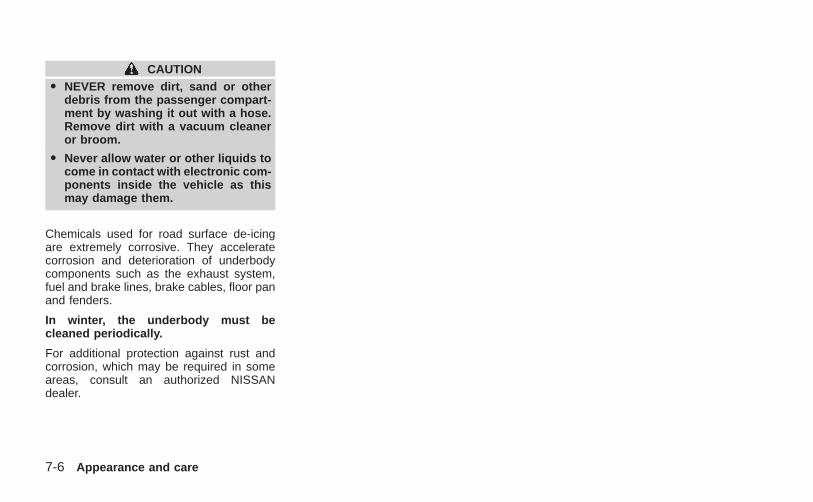
CAUTIONO NEVER remove dirt, sand or other
debris from the passenger compart-ment by washing it out with a hose.Remove dirt with a vacuum cleaneror broom.
O Never allow water or other liquids tocome in contact with electronic com-ponents inside the vehicle as thismay damage them.
Chemicals used for road surface de-icingare extremely corrosive. They acceleratecorrosion and deterioration of underbodycomponents such as the exhaust system,fuel and brake lines, brake cables, floor panand fenders.
In winter, the underbody must becleaned periodically.
For additional protection against rust andcorrosion, which may be required in someareas, consult an authorized NISSANdealer.
7-6 Appearance and care
Z X
8 Do-it-yourself
Maintenance precautions .......................................8-2Engine compartment check locations ....................8-3Engine cooling system ...........................................8-5
Checking engine coolant level ..........................8-5Changing engine coolant ..................................8-6
Engine oil ...............................................................8-9Checking engine oil level ..................................8-9Changing engine oil ........................................8-10Changing engine oil filter.................................8-12
Automatic transmission fluid ................................8-13Temperature conditions for checking ..............8-13
Power steering fluid..............................................8-14Brake and clutch fluid...........................................8-15Window washer fluid ............................................8-16
Window washer fluid reservoir ........................8-16Battery ..................................................................8-16
Jump starting...................................................8-17Drive belts ............................................................8-18Spark plugs ..........................................................8-19
Replacing spark plugs.....................................8-19Air cleaner ............................................................8-20
Windshield wiper blades ......................................8-22Cleaning ..........................................................8-22Replacing.........................................................8-22
Parking brake and brake pedal............................8-24Checking parking brake...................................8-24Checking brake pedal .....................................8-24Brake booster ..................................................8-25
Clutch pedal .........................................................8-26Checking clutch pedal .....................................8-26
Fuses....................................................................8-27Passenger compartment .................................8-27
Multi-remote controller battery replacement ........8-28Lights ....................................................................8-29
Headlights........................................................8-29Fog lights (if so equipped)...............................8-31Exterior and interior lights ...............................8-32
Wheels and tires ..................................................8-34Tire pressure ...................................................8-34Types of tires...................................................8-34Tire chains .......................................................8-35Changing wheels and tires..............................8-36
Z X
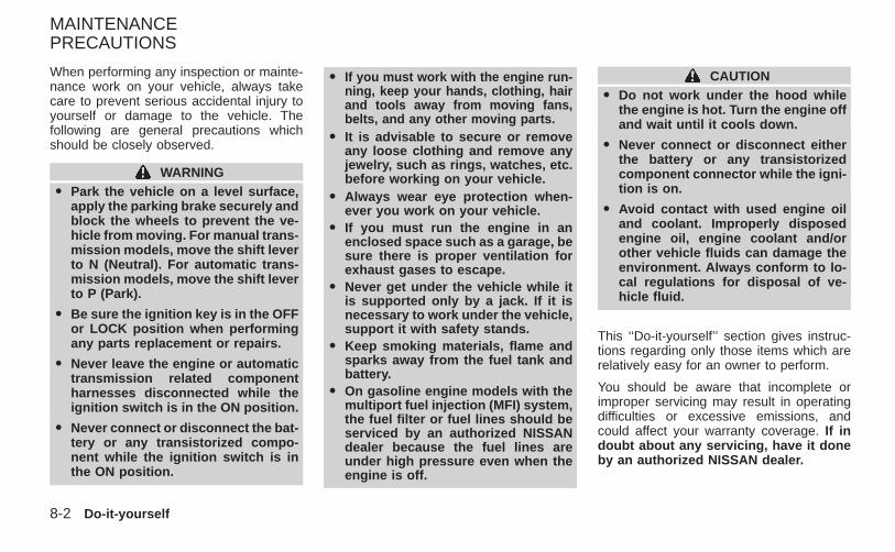
When performing any inspection or mainte-nance work on your vehicle, always takecare to prevent serious accidental injury toyourself or damage to the vehicle. Thefollowing are general precautions whichshould be closely observed.
WARNINGO Park the vehicle on a level surface,
apply the parking brake securely andblock the wheels to prevent the ve-hicle from moving. For manual trans-mission models, move the shift leverto N (Neutral). For automatic trans-mission models, move the shift leverto P (Park).
O Be sure the ignition key is in the OFFor LOCK position when performingany parts replacement or repairs.
O Never leave the engine or automatictransmission related componentharnesses disconnected while theignition switch is in the ON position.
O Never connect or disconnect the bat-tery or any transistorized compo-nent while the ignition switch is inthe ON position.
O If you must work with the engine run-ning, keep your hands, clothing, hairand tools away from moving fans,belts, and any other moving parts.
O It is advisable to secure or removeany loose clothing and remove anyjewelry, such as rings, watches, etc.before working on your vehicle.
O Always wear eye protection when-ever you work on your vehicle.
O If you must run the engine in anenclosed space such as a garage, besure there is proper ventilation forexhaust gases to escape.
O Never get under the vehicle while itis supported only by a jack. If it isnecessary to work under the vehicle,support it with safety stands.
O Keep smoking materials, flame andsparks away from the fuel tank andbattery.
O On gasoline engine models with themultiport fuel injection (MFI) system,the fuel filter or fuel lines should beserviced by an authorized NISSANdealer because the fuel lines areunder high pressure even when theengine is off.
CAUTIONO Do not work under the hood while
the engine is hot. Turn the engine offand wait until it cools down.
O Never connect or disconnect eitherthe battery or any transistorizedcomponent connector while the igni-tion is on.
O Avoid contact with used engine oiland coolant. Improperly disposedengine oil, engine coolant and/orother vehicle fluids can damage theenvironment. Always conform to lo-cal regulations for disposal of ve-hicle fluid.
This ‘‘Do-it-yourself’’ section gives instruc-tions regarding only those items which arerelatively easy for an owner to perform.
You should be aware that incomplete orimproper servicing may result in operatingdifficulties or excessive emissions, andcould affect your warranty coverage. If indoubt about any servicing, have it doneby an authorized NISSAN dealer.
MAINTENANCEPRECAUTIONS
8-2 Do-it-yourself
Z X
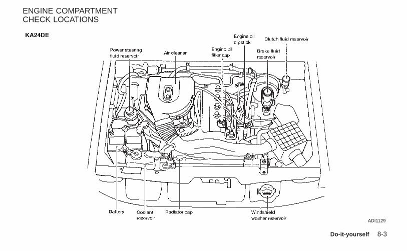
ADI1129
ENGINE COMPARTMENTCHECK LOCATIONS
Do-it-yourself 8-3
Z X
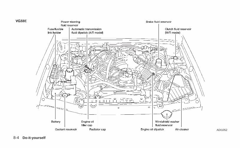
ADI1052
8-4 Do-it-yourself
Z X
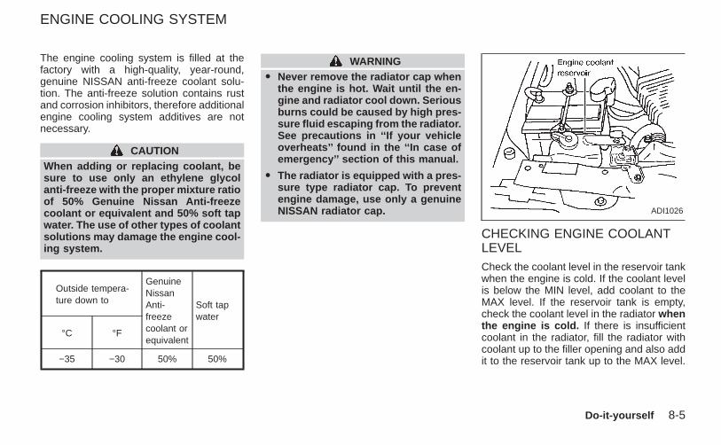
The engine cooling system is filled at thefactory with a high-quality, year-round,genuine NISSAN anti-freeze coolant solu-tion. The anti-freeze solution contains rustand corrosion inhibitors, therefore additionalengine cooling system additives are notnecessary.
CAUTIONWhen adding or replacing coolant, besure to use only an ethylene glycolanti-freeze with the proper mixture ratioof 50% Genuine Nissan Anti-freezecoolant or equivalent and 50% soft tapwater. The use of other types of coolantsolutions may damage the engine cool-ing system.
Outside tempera-ture down to
GenuineNissanAnti-freezecoolant orequivalent
Soft tapwater
°C °F
−35 −30 50% 50%
WARNINGO Never remove the radiator cap when
the engine is hot. Wait until the en-gine and radiator cool down. Seriousburns could be caused by high pres-sure fluid escaping from the radiator.See precautions in ‘‘If your vehicleoverheats’’ found in the ‘‘In case ofemergency’’ section of this manual.
O The radiator is equipped with a pres-sure type radiator cap. To preventengine damage, use only a genuineNISSAN radiator cap.
CHECKING ENGINE COOLANTLEVELCheck the coolant level in the reservoir tankwhen the engine is cold. If the coolant levelis below the MIN level, add coolant to theMAX level. If the reservoir tank is empty,check the coolant level in the radiator whenthe engine is cold. If there is insufficientcoolant in the radiator, fill the radiator withcoolant up to the filler opening and also addit to the reservoir tank up to the MAX level.
ADI1026
ENGINE COOLING SYSTEM
Do-it-yourself 8-5
Z X
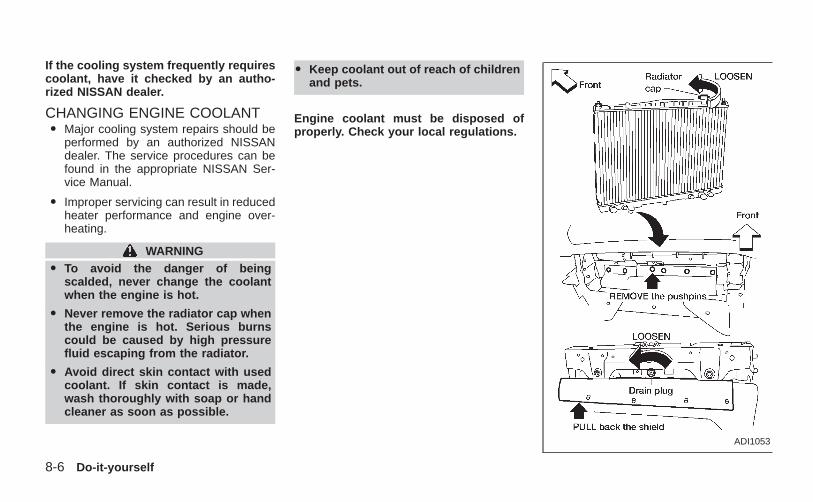
If the cooling system frequently requirescoolant, have it checked by an autho-rized NISSAN dealer.
CHANGING ENGINE COOLANTO Major cooling system repairs should be
performed by an authorized NISSANdealer. The service procedures can befound in the appropriate NISSAN Ser-vice Manual.
O Improper servicing can result in reducedheater performance and engine over-heating.
WARNINGO To avoid the danger of being
scalded, never change the coolantwhen the engine is hot.
O Never remove the radiator cap whenthe engine is hot. Serious burnscould be caused by high pressurefluid escaping from the radiator.
O Avoid direct skin contact with usedcoolant. If skin contact is made,wash thoroughly with soap or handcleaner as soon as possible.
O Keep coolant out of reach of childrenand pets.
Engine coolant must be disposed ofproperly. Check your local regulations.
ADI1053
8-6 Do-it-yourself
Z X
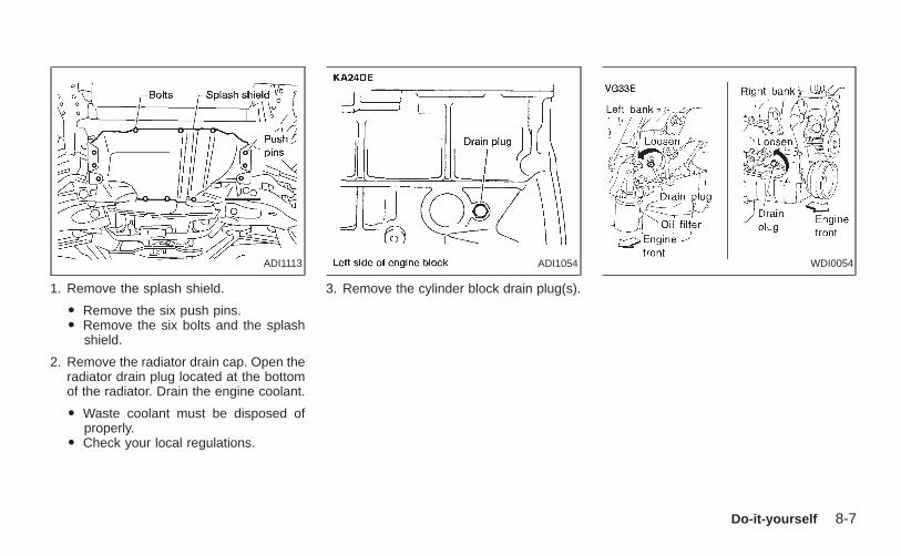
1. Remove the splash shield.
O Remove the six push pins.O Remove the six bolts and the splash
shield.
2. Remove the radiator drain cap. Open theradiator drain plug located at the bottomof the radiator. Drain the engine coolant.
O Waste coolant must be disposed ofproperly.
O Check your local regulations.
3. Remove the cylinder block drain plug(s).
ADI1113 ADI1054 WDI0054
Do-it-yourself 8-7
Z X
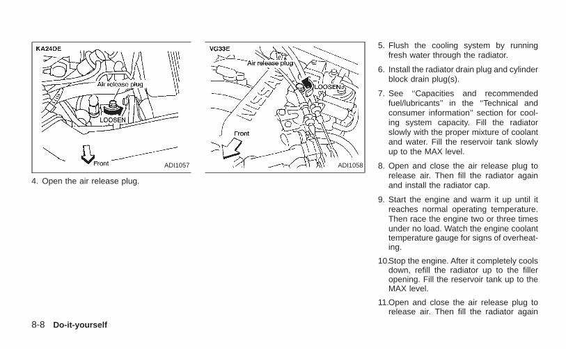
4. Open the air release plug.
5. Flush the cooling system by runningfresh water through the radiator.
6. Install the radiator drain plug and cylinderblock drain plug(s).
7. See ‘‘Capacities and recommendedfuel/lubricants’’ in the ‘‘Technical andconsumer information’’ section for cool-ing system capacity. Fill the radiatorslowly with the proper mixture of coolantand water. Fill the reservoir tank slowlyup to the MAX level.
8. Open and close the air release plug torelease air. Then fill the radiator againand install the radiator cap.
9. Start the engine and warm it up until itreaches normal operating temperature.Then race the engine two or three timesunder no load. Watch the engine coolanttemperature gauge for signs of overheat-ing.
10.Stop the engine. After it completely coolsdown, refill the radiator up to the filleropening. Fill the reservoir tank up to theMAX level.
11.Open and close the air release plug torelease air. Then fill the radiator again
ADI1057 ADI1058
8-8 Do-it-yourself
Z X

and install the radiator cap.
12.Check the drain valve on the radiator anddrain plugs on the engine block for anysign of leakage.
CHECKING ENGINE OIL LEVEL
1. Park the vehicle on a level surface andapply the parking brake.
2. Start the engine and let it idle until itreaches operating temperature.
3. Turn off the engine. Wait a few minutesfor the oil to drain back into the oilpan.
4. Remove the dipstick and wipe it clean.Reinsert it all the way.
ADI1059 ADI1060
ENGINE OIL
Do-it-yourself 8-9
Z X
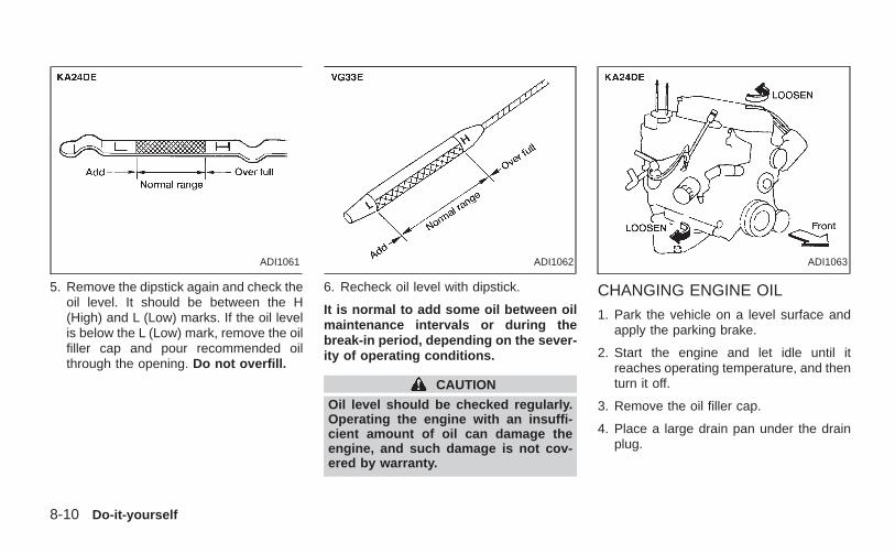
5. Remove the dipstick again and check theoil level. It should be between the H(High) and L (Low) marks. If the oil levelis below the L (Low) mark, remove the oilfiller cap and pour recommended oilthrough the opening. Do not overfill.
6. Recheck oil level with dipstick.
It is normal to add some oil between oilmaintenance intervals or during thebreak-in period, depending on the sever-ity of operating conditions.
CAUTION
Oil level should be checked regularly.Operating the engine with an insuffi-cient amount of oil can damage theengine, and such damage is not cov-ered by warranty.
CHANGING ENGINE OIL
1. Park the vehicle on a level surface andapply the parking brake.
2. Start the engine and let idle until itreaches operating temperature, and thenturn it off.
3. Remove the oil filler cap.
4. Place a large drain pan under the drainplug.
ADI1061 ADI1062 ADI1063
8-10 Do-it-yourself
Z X
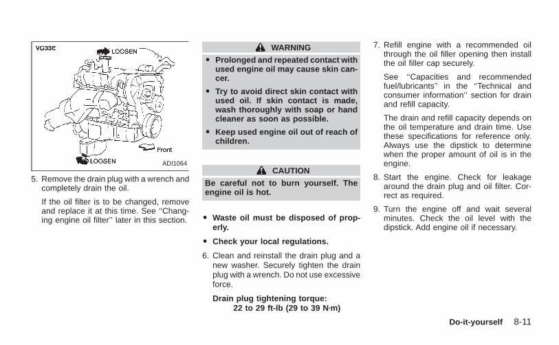
5. Remove the drain plug with a wrench andcompletely drain the oil.
If the oil filter is to be changed, removeand replace it at this time. See ‘‘Chang-ing engine oil filter’’ later in this section.
WARNING
O Prolonged and repeated contact withused engine oil may cause skin can-cer.
O Try to avoid direct skin contact withused oil. If skin contact is made,wash thoroughly with soap or handcleaner as soon as possible.
O Keep used engine oil out of reach ofchildren.
CAUTION
Be careful not to burn yourself. Theengine oil is hot.
O Waste oil must be disposed of prop-erly.
O Check your local regulations.
6. Clean and reinstall the drain plug and anew washer. Securely tighten the drainplug with a wrench. Do not use excessiveforce.
Drain plug tightening torque:22 to 29 ft-lb (29 to 39 N zm)
7. Refill engine with a recommended oilthrough the oil filler opening then installthe oil filler cap securely.
See ‘‘Capacities and recommendedfuel/lubricants’’ in the ‘‘Technical andconsumer information’’ section for drainand refill capacity.
The drain and refill capacity depends onthe oil temperature and drain time. Usethese specifications for reference only.Always use the dipstick to determinewhen the proper amount of oil is in theengine.
8. Start the engine. Check for leakagearound the drain plug and oil filter. Cor-rect as required.
9. Turn the engine off and wait severalminutes. Check the oil level with thedipstick. Add engine oil if necessary.
ADI1064
Do-it-yourself 8-11
Z X
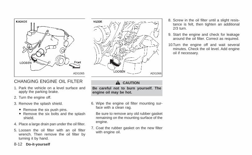
CHANGING ENGINE OIL FILTER1. Park the vehicle on a level surface and
apply the parking brake.
2. Turn the engine off.
3. Remove the splash shield.
O Remove the six push pins.O Remove the six bolts and the splash
shield.
4. Place a large drain pan under the oil filter.
5. Loosen the oil filter with an oil filterwrench. Then remove the oil filter byturning it by hand.
CAUTIONBe careful not to burn yourself. Theengine oil may be hot.
6. Wipe the engine oil filter mounting sur-face with a clean rag.
Be sure to remove any old rubber gasketremaining on the mounting surface of theengine.
7. Coat the rubber gasket on the new filterwith engine oil.
8. Screw in the oil filter until a slight resis-tance is felt, then tighten an additional2/3 turn.
9. Start the engine and check for leakagearound the oil filter. Correct as required.
10.Turn the engine off and wait severalminutes. Check the oil level. Add engineoil if necessary.
ADI1065 ADI1066
8-12 Do-it-yourself
Z X
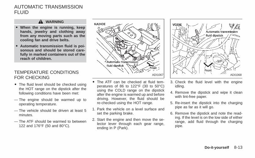
WARNING
O When the engine is running, keephands, jewelry and clothing awayfrom any moving parts such as thecooling fan and drive belts.
O Automatic transmission fluid is poi-sonous and should be stored care-fully in marked containers out of thereach of children.
TEMPERATURE CONDITIONSFOR CHECKING
O The fluid level should be checked usingthe HOT range on the dipstick after thefollowing conditions have been met:
— The engine should be warmed up tooperating temperature.
— The vehicle should be driven at least 5minutes.
— The ATF should be warmed to between122 and 176°F (50 and 80°C).
O The ATF can be checked at fluid tem-peratures of 86 to 122°F (30 to 50°C)using the COLD range on the dipstickafter the engine is warmed up and beforedriving. However, the fluid should bere-checked using the HOT range.
1. Park the vehicle on a level surface andset the parking brake.
2. Start the engine and then move the se-lector lever through each gear range,ending in P (Park).
3. Check the fluid level with the engineidling.
4. Remove the dipstick and wipe it cleanwith lint-free paper.
5. Re-insert the dipstick into the chargingpipe as far as it will go.
6. Remove the dipstick and note the read-ing. If the level is on the low side of eitherrange, add fluid through the chargingpipe.
ADI1067 ADI1068
AUTOMATIC TRANSMISSIONFLUID
Do-it-yourself 8-13
Z X
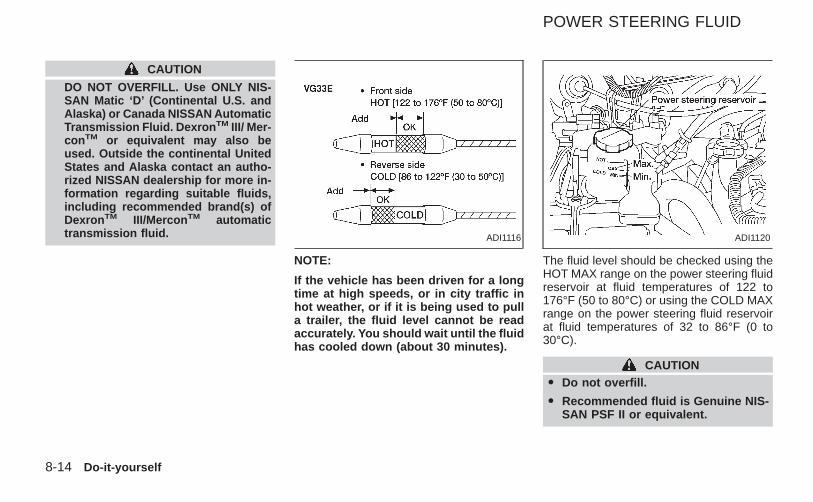
CAUTION
DO NOT OVERFILL. Use ONLY NIS-SAN Matic ‘D’ (Continental U.S. andAlaska) or Canada NISSAN AutomaticTransmission Fluid. Dexron TM III/ Mer-con TM or equivalent may also beused. Outside the continental UnitedStates and Alaska contact an autho-rized NISSAN dealership for more in-formation regarding suitable fluids,including recommended brand(s) ofDexron TM III/Mercon TM automatictransmission fluid.
NOTE:
If the vehicle has been driven for a longtime at high speeds, or in city traffic inhot weather, or if it is being used to pulla trailer, the fluid level cannot be readaccurately. You should wait until the fluidhas cooled down (about 30 minutes).
The fluid level should be checked using theHOT MAX range on the power steering fluidreservoir at fluid temperatures of 122 to176°F (50 to 80°C) or using the COLD MAXrange on the power steering fluid reservoirat fluid temperatures of 32 to 86°F (0 to30°C).
CAUTIONO Do not overfill.
O Recommended fluid is Genuine NIS-SAN PSF II or equivalent.
ADI1116 ADI1120
POWER STEERING FLUID
8-14 Do-it-yourself
Z X
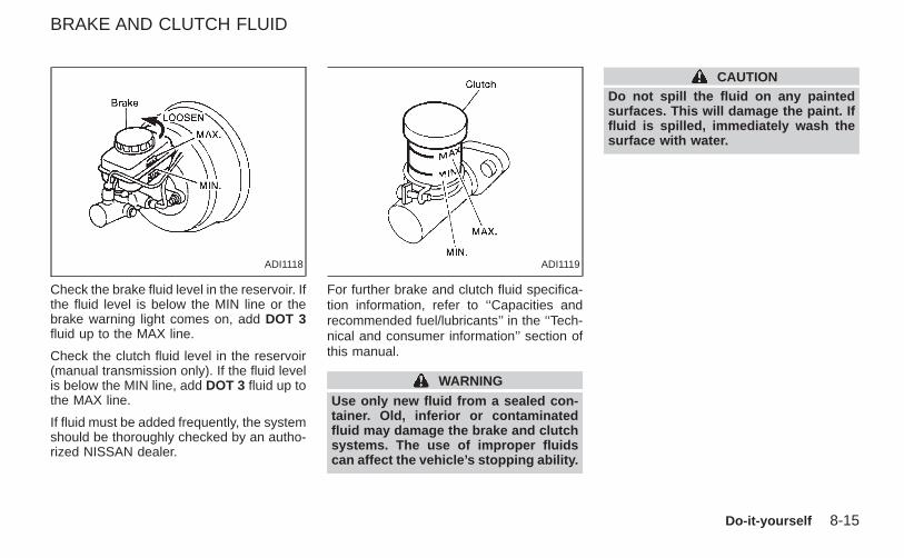
Check the brake fluid level in the reservoir. Ifthe fluid level is below the MIN line or thebrake warning light comes on, add DOT 3fluid up to the MAX line.
Check the clutch fluid level in the reservoir(manual transmission only). If the fluid levelis below the MIN line, add DOT 3 fluid up tothe MAX line.
If fluid must be added frequently, the systemshould be thoroughly checked by an autho-rized NISSAN dealer.
For further brake and clutch fluid specifica-tion information, refer to ‘‘Capacities andrecommended fuel/lubricants’’ in the ‘‘Tech-nical and consumer information’’ section ofthis manual.
WARNING
Use only new fluid from a sealed con-tainer. Old, inferior or contaminatedfluid may damage the brake and clutchsystems. The use of improper fluidscan affect the vehicle’s stopping ability.
CAUTIONDo not spill the fluid on any paintedsurfaces. This will damage the paint. Iffluid is spilled, immediately wash thesurface with water.
ADI1118 ADI1119
BRAKE AND CLUTCH FLUID
Do-it-yourself 8-15
Z X
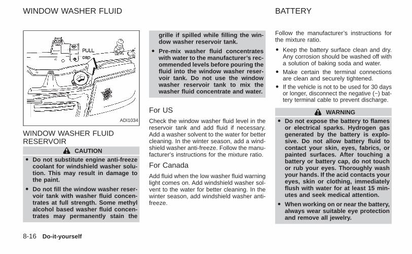
WINDOW WASHER FLUIDRESERVOIR
CAUTIONO Do not substitute engine anti-freeze
coolant for windshield washer solu-tion. This may result in damage tothe paint.
O Do not fill the window washer reser-voir tank with washer fluid concen-trates at full strength. Some methylalcohol based washer fluid concen-trates may permanently stain the
grille if spilled while filling the win-dow washer reservoir tank.
O Pre-mix washer fluid concentrateswith water to the manufacturer’s rec-ommended levels before pouring thefluid into the window washer reser-voir tank. Do not use the windowwasher reservoir tank to mix thewasher fluid concentrate and water.
For USCheck the window washer fluid level in thereservoir tank and add fluid if necessary.Add a washer solvent to the water for bettercleaning. In the winter season, add a wind-shield washer anti-freeze. Follow the manu-facturer’s instructions for the mixture ratio.
For CanadaAdd fluid when the low washer fluid warninglight comes on. Add windshield washer sol-vent to the water for better cleaning. In thewinter season, add windshield washer anti-freeze.
Follow the manufacturer’s instructions forthe mixture ratio.
O Keep the battery surface clean and dry.Any corrosion should be washed off witha solution of baking soda and water.
O Make certain the terminal connectionsare clean and securely tightened.
O If the vehicle is not to be used for 30 daysor longer, disconnect the negative (−) bat-tery terminal cable to prevent discharge.
WARNINGO Do not expose the battery to flames
or electrical sparks. Hydrogen gasgenerated by the battery is explo-sive. Do not allow battery fluid tocontact your skin, eyes, fabrics, orpainted surfaces. After touching abattery or battery cap, do not touchor rub your eyes. Thoroughly washyour hands. If the acid contacts youreyes, skin or clothing, immediatelyflush with water for at least 15 min-utes and seek medical attention.
O When working on or near the battery,always wear suitable eye protectionand remove all jewelry.
ADI1034
WINDOW WASHER FLUID BATTERY
8-16 Do-it-yourself
Z X
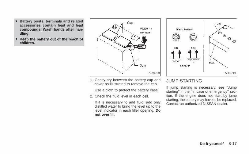
O Battery posts, terminals and relatedaccessories contain lead and leadcompounds. Wash hands after han-dling.
O Keep the battery out of the reach ofchildren.
1. Gently pry between the battery cap andcover as illustrated to remove the cap.
Use a cloth to protect the battery case.
2. Check the fluid level in each cell.
If it is necessary to add fluid, add onlydistilled water to bring the level up to thelevel indicator in each filler opening. Donot overfill.
JUMP STARTINGIf jump starting is necessary, see ‘‘Jumpstarting’’ in the ‘‘In case of emergency’’ sec-tion. If the engine does not start by jumpstarting, the battery may have to be replaced.Contact an authorized NISSAN dealer.
ADI0709 ADI0710
Do-it-yourself 8-17
Z X
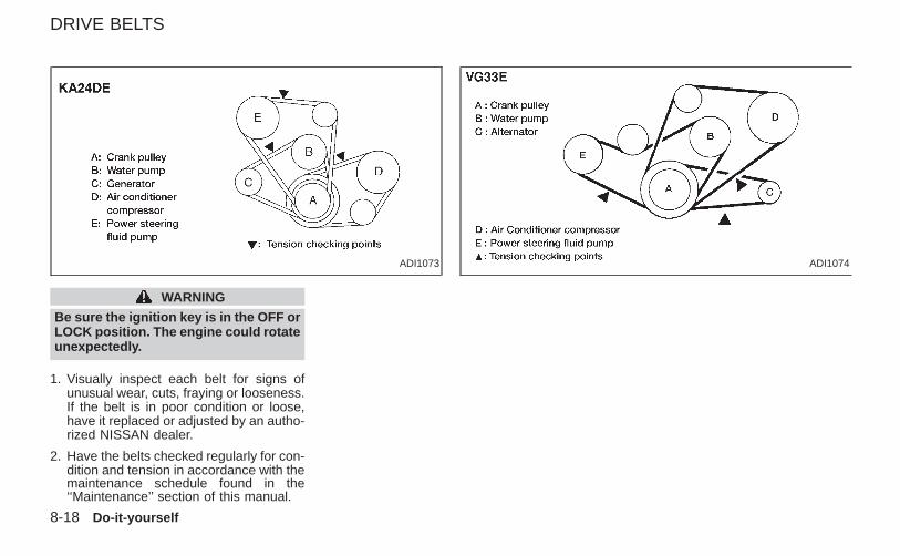
WARNING
Be sure the ignition key is in the OFF orLOCK position. The engine could rotateunexpectedly.
1. Visually inspect each belt for signs ofunusual wear, cuts, fraying or looseness.If the belt is in poor condition or loose,have it replaced or adjusted by an autho-rized NISSAN dealer.
2. Have the belts checked regularly for con-dition and tension in accordance with themaintenance schedule found in the‘‘Maintenance’’ section of this manual.
ADI1074ADI1073
DRIVE BELTS
8-18 Do-it-yourself
Z X
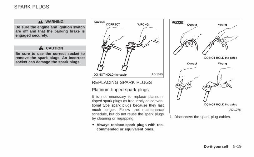
WARNINGBe sure the engine and ignition switchare off and that the parking brake isengaged securely.
CAUTIONBe sure to use the correct socket toremove the spark plugs. An incorrectsocket can damage the spark plugs.
REPLACING SPARK PLUGS
Platinum-tipped spark plugs
It is not necessary to replace platinum-tipped spark plugs as frequently as conven-tional type spark plugs because they lastmuch longer. Follow the maintenanceschedule, but do not reuse the spark plugsby cleaning or regapping.
O Always replace spark plugs with rec-commended or equivalent ones.
1. Disconnect the spark plug cables.
ADI1075
ADI1076
SPARK PLUGS
Do-it-yourself 8-19
Z X
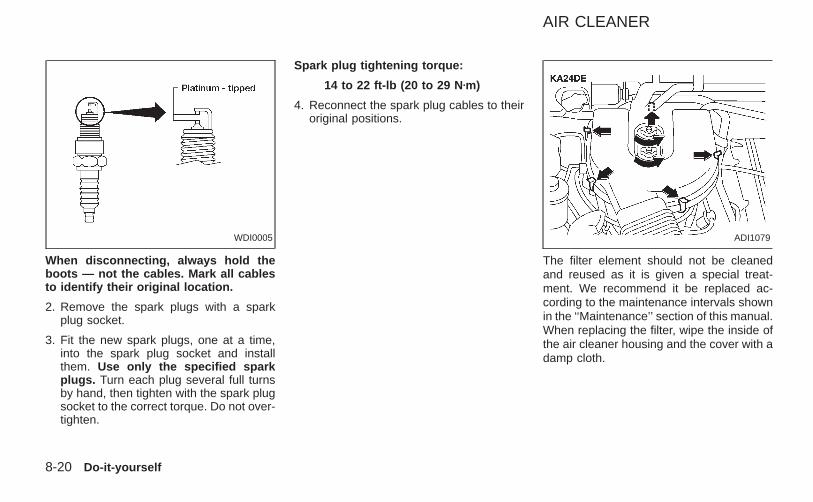
When disconnecting, always hold theboots — not the cables. Mark all cablesto identify their original location.
2. Remove the spark plugs with a sparkplug socket.
3. Fit the new spark plugs, one at a time,into the spark plug socket and installthem. Use only the specified sparkplugs. Turn each plug several full turnsby hand, then tighten with the spark plugsocket to the correct torque. Do not over-tighten.
Spark plug tightening torque:
14 to 22 ft-lb (20 to 29 N zm)
4. Reconnect the spark plug cables to theiroriginal positions.
The filter element should not be cleanedand reused as it is given a special treat-ment. We recommend it be replaced ac-cording to the maintenance intervals shownin the ‘‘Maintenance’’ section of this manual.When replacing the filter, wipe the inside ofthe air cleaner housing and the cover with adamp cloth.
WDI0005 ADI1079
AIR CLEANER
8-20 Do-it-yourself
Z X
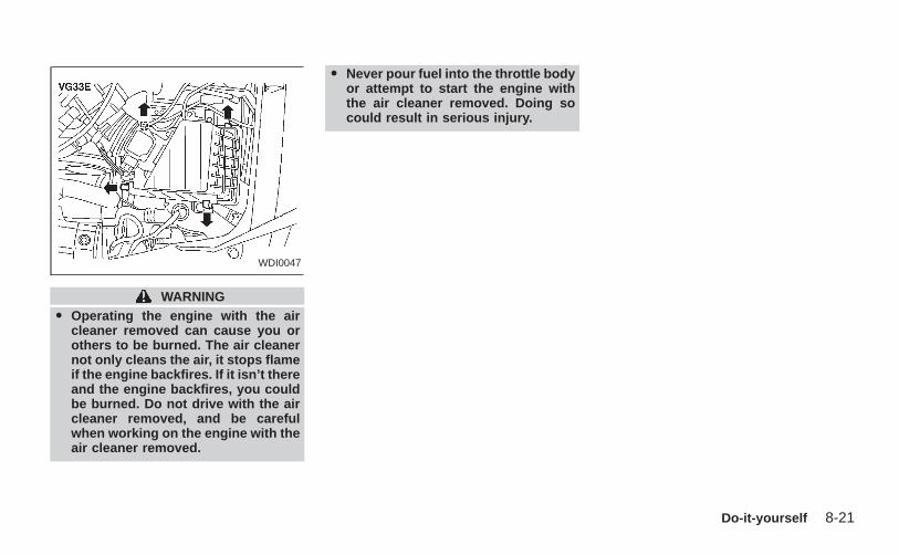
WARNINGO Operating the engine with the air
cleaner removed can cause you orothers to be burned. The air cleanernot only cleans the air, it stops flameif the engine backfires. If it isn’t thereand the engine backfires, you couldbe burned. Do not drive with the aircleaner removed, and be carefulwhen working on the engine with theair cleaner removed.
O Never pour fuel into the throttle bodyor attempt to start the engine withthe air cleaner removed. Doing socould result in serious injury.
WDI0047
Do-it-yourself 8-21
Z X
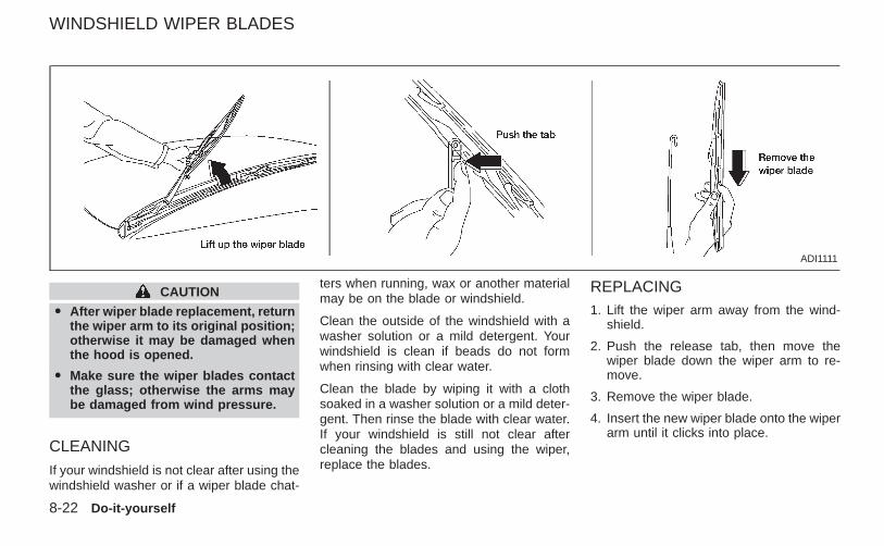
CAUTION
O After wiper blade replacement, returnthe wiper arm to its original position;otherwise it may be damaged whenthe hood is opened.
O Make sure the wiper blades contactthe glass; otherwise the arms maybe damaged from wind pressure.
CLEANING
If your windshield is not clear after using thewindshield washer or if a wiper blade chat-
ters when running, wax or another materialmay be on the blade or windshield.
Clean the outside of the windshield with awasher solution or a mild detergent. Yourwindshield is clean if beads do not formwhen rinsing with clear water.
Clean the blade by wiping it with a clothsoaked in a washer solution or a mild deter-gent. Then rinse the blade with clear water.If your windshield is still not clear aftercleaning the blades and using the wiper,replace the blades.
REPLACING1. Lift the wiper arm away from the wind-
shield.
2. Push the release tab, then move thewiper blade down the wiper arm to re-move.
3. Remove the wiper blade.
4. Insert the new wiper blade onto the wiperarm until it clicks into place.
ADI1111
WINDSHIELD WIPER BLADES
8-22 Do-it-yourself
Z X
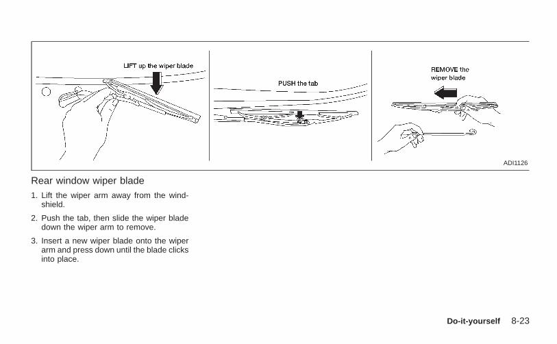
Rear window wiper blade1. Lift the wiper arm away from the wind-
shield.
2. Push the tab, then slide the wiper bladedown the wiper arm to remove.
3. Insert a new wiper blade onto the wiperarm and press down until the blade clicksinto place.
ADI1126
Do-it-yourself 8-23
Z X
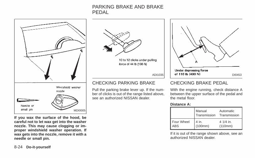
If you wax the surface of the hood, becareful not to let wax get into the washernozzle. This may cause clogging or im-proper windshield washer operation. Ifwax gets into the nozzle, remove it with aneedle or small pin.
CHECKING PARKING BRAKEPull the parking brake lever up. If the num-ber of clicks is out of the range listed above,see an authorized NISSAN dealer.
CHECKING BRAKE PEDALWith the engine running, check distance Abetween the upper surface of the pedal andthe metal floor.
Distance A:
ManualTransmission
AutomaticTransmission
Four WheelABS
4 in.(100mm)
4 1/4 in.(110mm)
If it is out of the range shown above, see anauthorized NISSAN dealer.
MDI0005
ADI1035 DI0453
PARKING BRAKE AND BRAKEPEDAL
8-24 Do-it-yourself
Z X
Self-adjusting brakes
Your vehicle is equipped with self-adjustingbrakes.
The front disc-type brakes self-adjust everytime the brake pedal is applied. The reardrum-type brakes on two-wheel drive trucksself-adjust every time the parking brake isapplied. The rear drum-type brakes on four-wheel drive trucks self-adjust every time thebrake pedal is applied. If the brake pedalgoes down farther than normal, it may bedue to a lack of adjustment of the rear drumbrakes. Apply the parking brake severaltimes.
WARNINGIf the brake pedal height does not re-turn to normal, see an authorized NIS-SAN dealer and have it checked.
Brake pad wear indicatorsThe disc brake pads on your vehicle haveaudible wear indicators. When a brake padrequires replacement, it will make a highpitched scraping or screeching sound whenthe vehicle is in motion whether or not thebrake pedal is depressed. Have the brakes
checked as soon as possible if the wearindicator sound is heard.
Under some driving or climate conditions,occasional brake squeak, squeal or othernoise may be heard. Occasional brakenoise during light to moderate stops is nor-mal and does not affect the function orperformance of the brake system.
The rear drum brakes (if so equipped) donot have audible wear indicators. Shouldyou ever hear an unusually loud noise fromthe rear drum brakes, have them inspectedas soon as possible by an authorized NIS-SAN dealer.
Proper brake inspection intervals shouldbe followed. For more information regard-ing brake inspections, see the appropriatemaintenance schedule information in the‘‘Maintenance Schedule’’ section of thismanual.
BRAKE BOOSTERCheck the brake booster function with thefollowing steps:
1. With the engine off, press and releasethe brake pedal several times. Whenbrake pedal movement (distance of
travel) remains the same from one pedalapplication to the next, continue on tonext step.
2. While depressing the brake pedal, startthe engine. The pedal height should dropa little.
3. With the brake pedal depressed, stop theengine. Keeping the pedal depressed forabout 30 seconds, the pedal heightshould not change.
4. Run the engine for one minute withoutdepressing the brake pedal, then turn itoff. Depress the brake pedal severaltimes. The pedal travel distance will de-crease gradually with each depressionas the vacuum is released from thebooster.
If the brakes do not operate properly, havethe brakes checked by an authorizedNISSAN dealer.
Do-it-yourself 8-25
Z X
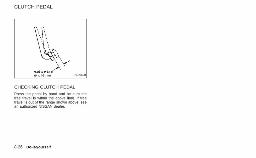
CHECKING CLUTCH PEDALPress the pedal by hand and be sure thefree travel is within the above limit. If freetravel is out of the range shown above, seean authorized NISSAN dealer.
ADI0528
CLUTCH PEDAL
8-26 Do-it-yourself
Z X
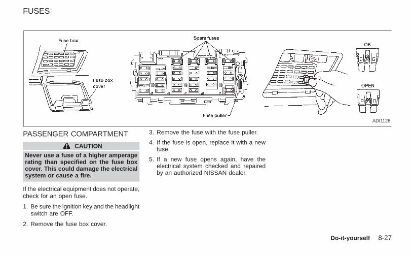
PASSENGER COMPARTMENT
CAUTION
Never use a fuse of a higher amperagerating than specified on the fuse boxcover. This could damage the electricalsystem or cause a fire.
If the electrical equipment does not operate,check for an open fuse.
1. Be sure the ignition key and the headlightswitch are OFF.
2. Remove the fuse box cover.
3. Remove the fuse with the fuse puller.
4. If the fuse is open, replace it with a newfuse.
5. If a new fuse opens again, have theelectrical system checked and repairedby an authorized NISSAN dealer.
ADI1128
FUSES
Do-it-yourself 8-27
Z X
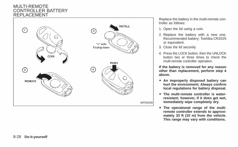
Replace the battery in the multi-remote con-troller as follows:
1. Open the lid using a coin.
2. Replace the battery with a new one.Recommended battery: Toshiba CR2025or equivalent.
3. Close the lid securely.
4. Press the LOCK button, then the UNLOCKbutton two or three times to check themulti-remote controller operation.
If the battery is removed for any reasonother than replacement, perform step 4above.
O An improperly disposed battery canhurt the environment. Always confirmlocal regulations for battery disposal.
O The multi-remote controller is water-resistant; however, if it does get wet,immediately wipe completely dry.
O The operational range of the multi-remote controller extends to approxi-mately 33 ft (10 m) from the vehicle.This range may vary with conditions.
WPD0039
MULTI-REMOTECONTROLLER BATTERYREPLACEMENT
8-28 Do-it-yourself
Z X
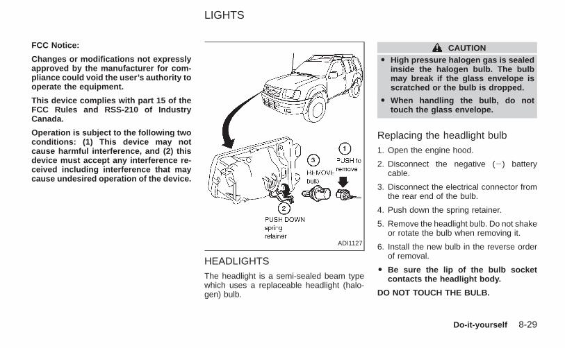
FCC Notice:
Changes or modifications not expresslyapproved by the manufacturer for com-pliance could void the user’s authority tooperate the equipment.
This device complies with part 15 of theFCC Rules and RSS-210 of IndustryCanada.
Operation is subject to the following twoconditions: (1) This device may notcause harmful interference, and (2) thisdevice must accept any interference re-ceived including interference that maycause undesired operation of the device.
HEADLIGHTSThe headlight is a semi-sealed beam typewhich uses a replaceable headlight (halo-gen) bulb.
CAUTIONO High pressure halogen gas is sealed
inside the halogen bulb. The bulbmay break if the glass envelope isscratched or the bulb is dropped.
O When handling the bulb, do nottouch the glass envelope.
Replacing the headlight bulb1. Open the engine hood.
2. Disconnect the negative (2) batterycable.
3. Disconnect the electrical connector fromthe rear end of the bulb.
4. Push down the spring retainer.
5. Remove the headlight bulb. Do not shakeor rotate the bulb when removing it.
6. Install the new bulb in the reverse orderof removal.
O Be sure the lip of the bulb socketcontacts the headlight body.
DO NOT TOUCH THE BULB.
ADI1127
LIGHTS
Do-it-yourself 8-29
Z X
CAUTION
O Use the same number and wattageas originally installed:
Wattage 65/55Bulb No. HB5/9007*
*: Always check with the Parts Depart-ment at an authorized NISSAN dealerfor the latest parts information.
O Aiming is not necessary after replac-ing the bulb.
O Do not leave the bulb out of theheadlight reflector for a long periodof time as dust, moisture, and smokemay enter the headlight body andaffect the performance of the head-light.
O When aiming adjustment is neces-sary, contact an authorized NISSANdealer.
8-30 Do-it-yourself
Z X
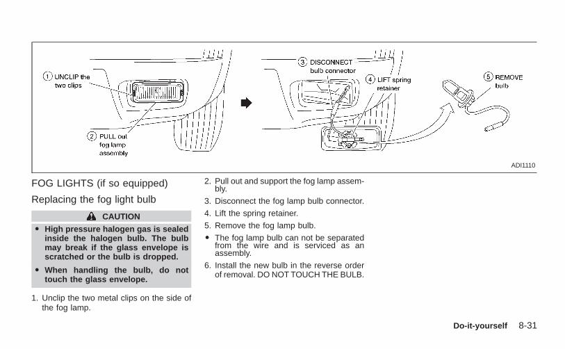
FOG LIGHTS (if so equipped)
Replacing the fog light bulb
CAUTION
O High pressure halogen gas is sealedinside the halogen bulb. The bulbmay break if the glass envelope isscratched or the bulb is dropped.
O When handling the bulb, do nottouch the glass envelope.
1. Unclip the two metal clips on the side ofthe fog lamp.
2. Pull out and support the fog lamp assem-bly.
3. Disconnect the fog lamp bulb connector.
4. Lift the spring retainer.
5. Remove the fog lamp bulb.
O The fog lamp bulb can not be separatedfrom the wire and is serviced as anassembly.
6. Install the new bulb in the reverse orderof removal. DO NOT TOUCH THE BULB.
ADI1110
Do-it-yourself 8-31
Z X
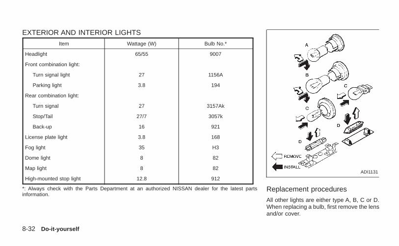
EXTERIOR AND INTERIOR LIGHTS
Item Wattage (W) Bulb No.*
Headlight 65/55 9007
Front combination light:
Turn signal light 27 1156A
Parking light 3.8 194
Rear combination light:
Turn signal 27 3157Ak
Stop/Tail 27/7 3057k
Back-up 16 921
License plate light 3.8 168
Fog light 35 H3
Dome light 8 82
Map light 8 82
High-mounted stop light 12.8 912
*: Always check with the Parts Department at an authorized NISSAN dealer for the latest partsinformation.
Replacement procedures
All other lights are either type A, B, C or D.When replacing a bulb, first remove the lensand/or cover.
ADI1131
8-32 Do-it-yourself
Z X
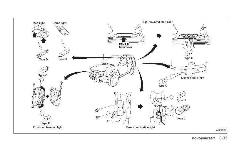
ADI1130
Do-it-yourself 8-33
Z X
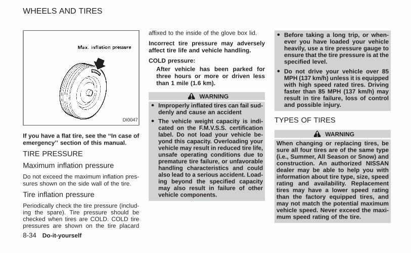
If you have a flat tire, see the ‘‘In case ofemergency’’ section of this manual.
TIRE PRESSURE
Maximum inflation pressure
Do not exceed the maximum inflation pres-sures shown on the side wall of the tire.
Tire inflation pressure
Periodically check the tire pressure (includ-ing the spare). Tire pressure should bechecked when tires are COLD. COLD tirepressures are shown on the tire placard
affixed to the inside of the glove box lid.
Incorrect tire pressure may adverselyaffect tire life and vehicle handling.
COLD pressure:After vehicle has been parked forthree hours or more or driven lessthan 1 mile (1.6 km).
WARNING
O Improperly inflated tires can fail sud-denly and cause an accident
O The vehicle weight capacity is indi-cated on the F.M.V.S.S. certificationlabel. Do not load your vehicle be-yond this capacity. Overloading yourvehicle may result in reduced tire life,unsafe operating conditions due topremature tire failure, or unfavorablehandling characteristics and couldalso lead to a serious accident. Load-ing beyond the specified capacitymay also result in failure of othervehicle components.
O Before taking a long trip, or when-ever you have loaded your vehicleheavily, use a tire pressure gauge toensure that the tire pressure is at thespecified level.
O Do not drive your vehicle over 85MPH (137 km/h) unless it is equippedwith high speed rated tires. Drivingfaster than 85 MPH (137 km/h) mayresult in tire failure, loss of controland possible injury.
TYPES OF TIRES
WARNING
When changing or replacing tires, besure all four tires are of the same type(i.e., Summer, All Season or Snow) andconstruction. An authorized NISSANdealer may be able to help you withinformation about tire type, size, speedrating and availability. Replacementtires may have a lower speed ratingthan the factory equipped tires, andmay not match the potential maximumvehicle speed. Never exceed the maxi-mum speed rating of the tire.
DI0047
WHEELS AND TIRES
8-34 Do-it-yourself
Z X
All season tires
NISSAN specifies All Season tires on somemodels to provide good performance foruse all year around, including snowy and icyroad conditions. All Season Tires are iden-tified by ‘‘ALL SEASON’’ and/or ‘‘M&S’’ onthe tire sidewall. Snow tires have bettersnow traction than All Season tires and maybe more appropriate in some areas.
Summer tiresNISSAN specifies summer tires on somemodels to provide superior performance ondry roads. Summer tire performance insnow and ice will be substantially reduced.Summer tires do not have the tire tractionrating ‘‘M&S’’ on the tire sidewall.
If you plan to operate your vehicle in snowyor icy conditions, NISSAN recommends theuse of ‘‘SNOW’’ or ‘‘ALL SEASON’’ tires onall four wheels.
Snow tiresIf snow tires are needed, it is necessary toselect tires equivalent in size and load ratingto the original equipment tires. If you do not,it can adversely affect the safety and han-dling of your vehicle.
If you install snow tires, they must be thesame size, brand, construction and treadpattern on all four wheels.
Generally, snow tires will have lower speedratings than factory equipped tires and maynot match the potential maximum vehiclespeed. Never exceed the maximum speedrating of the tire.
For additional traction on icy roads, studdedtires may be used. However, some U.S.States and Canadian provinces prohibittheir use. Check local, state and provinciallaws before installing studded tires. Skidand traction capabilities of studded snowtires on wet or dry surfaces may be poorerthan that of non-studded snow tires.
TIRE CHAINSUse of tire chains may be prohibited accord-ing to location. Check the local laws beforeinstalling tire chains. When installing tirechains, make sure they are the proper sizefor the tires on your vehicle and are installedaccording to the chain manufacturer’s sug-gestions. Use only SAE class ‘‘S’’ chains.Other types may damage your vehicle. Usechain tensioners when recommended bythe tire chain manufacturer to ensure a tight
fit. Loose end links of the tire chain must besecured or removed to prevent the possibil-ity of whipping action damage to the fendersor undercarriage. If possible, avoid fullyloading your vehicle when using tire chains.In addition, drive at a reduced speed. Oth-erwise, your vehicle may be damagedand/or vehicle handling and performancemay be adversely affected.
Never install tire chains on a TEMPORARYUSE ONLY spare tire.
Tire chains must be installed only on therear wheels and not on the front wheels.
Do not use tire chains on dry roads. Drivingwith chains in such conditions can causedamage to the various mechanisms of thevehicle due to some overstress. When driv-ing on clear paved roads, be sure to changeto 2WD.
Do-it-yourself 8-35
Z X
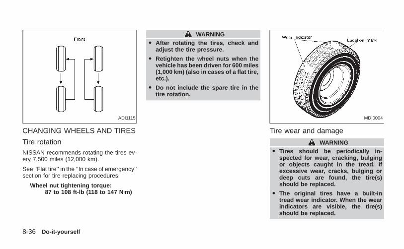
CHANGING WHEELS AND TIRES
Tire rotationNISSAN recommends rotating the tires ev-ery 7,500 miles (12,000 km).
See ‘‘Flat tire’’ in the ‘‘In case of emergency’’section for tire replacing procedures.
Wheel nut tightening torque:87 to 108 ft-lb (118 to 147 N zm)
WARNINGO After rotating the tires, check and
adjust the tire pressure.
O Retighten the wheel nuts when thevehicle has been driven for 600 miles(1,000 km) (also in cases of a flat tire,etc.).
O Do not include the spare tire in thetire rotation.
Tire wear and damage
WARNINGO Tires should be periodically in-
spected for wear, cracking, bulgingor objects caught in the tread. Ifexcessive wear, cracks, bulging ordeep cuts are found, the tire(s)should be replaced.
O The original tires have a built-intread wear indicator. When the wearindicators are visible, the tire(s)should be replaced.
ADI1115 MDI0004
8-36 Do-it-yourself
Z X
O Improper service of the spare tiremay result in serious personal in-jury. If it is necessary to repair thespare tire, contact an authorizedNISSAN dealer.
Replacing tires and wheelsWhen replacing a tire, use the same size,tread design, speed rating and load carryingcapacity as originally equipped. Recom-mended types and sizes are shown in‘‘Wheel/tire size’’ in the ‘‘Technical and con-sumer information’’ section of this manual.
WARNINGO The use of tires other than those
recommended or the mixed use oftires of different brands, construction(bias, bias-belted or radial), or treadpatterns can adversely affect the ride,braking, handling, ground clearance,body-to-tire clearance, tire chainclearance, speedometer calibration,headlight aim and bumper height.Some of these effects may lead toaccidents and could result in seriouspersonal injury.
O If the wheels are changed for anyreason, always replace with wheelswhich have the same offset dimen-sion. Wheels of a different offsetcould cause pre-mature tire wear, de-grade vehicle handling characteris-tics and/or interference with thebrake discs/drums. Such interferencecan lead to decreased braking effi-ciency and/or early brake pad/shoewear. Refer to “Wheel/tire size” in the“Technical and consumer informa-tion” section of this manual for wheeloff-set dimensions.
O Do not install a deformed wheel ortire even if it has been repaired. Suchwheels or tires could have unknownstructural damage and could failwithout warning.
O The use of retread tires is not recom-mended.
Four-wheel drive modelsCAUTION
Always use tires of the same type, size,brand, construction (bias, bias-beltedor radial), and tread pattern on all fourwheels. Failure to do so may result in acircumference difference between tireson the front and rear axles which willcause excessive tire wear and maydamage the transmission, transfercase and differential gears.
If excessive tire wear is found, it is recom-mended that all four tires be replaced withtires of the same size, brand, constructionand tread pattern. The tire pressure andwheel alignment should also be checkedand corrected as necessary. Contact anauthorized NISSAN dealer.
Wheel balance
Unbalanced wheels may affect vehicle han-dling and tire life. Even with regular use,wheels can get out of balance. Therefore,they should be balanced as required.
Wheel balance service should be performedwith the wheels off the vehicle. Spin balanc-
Do-it-yourself 8-37
Z X
ing the front wheels on the vehicle couldlead to transmission damage.
Care of wheelsO Wash the wheels when washing the ve-
hicle to maintain their appearance.
O Clean the inner side of the wheels whenthe wheel is changed or the underside ofthe vehicle is washed.
O Do not use abrasive cleaners whenwashing the wheels.
O Inspect wheel rims regularly for dents orcorrosion. This may cause loss of pres-sure or damage the tire bead.
O NISSAN recommends waxing the roadwheels to protect against road salt inareas where it is used during winter.
8-38 Do-it-yourself
Z X
9 Maintenance
Maintenance precautions .......................................9-2General maintenance.............................................9-2
Explanation of maintenance items ....................9-2Exterior maintenance.........................................9-2Interior maintenance..........................................9-3
Periodic maintenance schedules ...........................9-5Schedule 1 ........................................................9-5Schedule 2 ........................................................9-5Explanation of maintenance items ..................9-10
Z X
Your new NISSAN has been designed tohave minimum maintenance requirementswith longer service intervals to save youboth time and money. However, some day-to-day and regular maintenance is essentialto maintain your NISSAN’s good mechani-cal condition, as well as its emission andengine performance.
It is the owner’s responsibility to make surethat the specified maintenance, as well asgeneral maintenance, is performed.
As the vehicle owner, you are the only onewho can ensure that your vehicle receivesproper maintenance. You are a vital link inthe maintenance chain.
General maintenance
General maintenance includes those itemswhich should be checked during normalday-to-day operation of the vehicle. Theyare essential if your vehicle is to continue tooperate properly. It is your responsibility toperform these maintenance proceduresregularly as prescribed.
These checks or inspections can be doneby yourself, a qualified technician or, if youprefer, an authorized NISSAN dealer.
Periodic maintenance
The maintenance items listed under peri-odic maintenance in this section are re-quired to be serviced at regular intervals.
However, under severe driving conditions,additional or more frequent maintenancewill be required.
Where to go for service
If maintenance service is required or yourvehicle appears to malfunction, have thesystems checked and tuned by an autho-rized NISSAN dealer.
NISSAN technicians are well-trained spe-cialists who and are kept up-to-date with thelatest service information through technicalbulletins, service tips, and in-dealershiptraining programs. They are completelyqualified to work on NISSAN vehiclesbefore they work on your vehicle, ratherthan after they have worked on it.
You can be confident that an authorizedNISSAN dealer’s service department per-forms the best job to meet the maintenancerequirements on your vehicle — in a reliableand economic way.
During the normal day-to-day operation ofthe vehicle, general maintenance should beperformed regularly as prescribed in thissection. If you detect any unusual sounds,vibrations or smells, be sure to check for thecause or have an authorized NISSANdealer do it promptly. In addition, you shouldnotify an authorized NISSAN dealer if youthink that repairs are required.
When performing any checks or mainte-nance work, closely observe the precau-tions in the ‘‘Do-it-yourself’’ section of thismanual.
EXPLANATION OF MAINTE-NANCE ITEMSAdditional information on the followingitems with ‘‘*’’ is found in the ‘‘Do-it-yourself’’ section of this manual.
EXTERIOR MAINTENANCE
Outside the vehicleThe maintenance items listed here shouldbe performed from time to time, unlessotherwise specified.
Tires* Check the pressure with a gaugeperiodically when at a service station, in-
MAINTENANCEPRECAUTIONS
GENERAL MAINTENANCE
9-2 Maintenance
Z X
cluding the spare, and adjust to the speci-fied pressure if necessary. Check carefullyfor damage, cuts or excessive wear.
Wheel nuts* When checking the tires, makesure no wheel nuts are missing, and check forany loose wheel nuts. Tighten if necessary.
Tire rotation* Tires should be rotated every7,500 miles (12,000 km).
Wheel alignment and balance If the ve-hicle should pull to either side while drivingon a straight and level road, or if you detectuneven or abnormal tire wear, there may bea need for wheel alignment.
If the steering wheel or seat vibrates atnormal highway speeds, wheel balancingmay be needed.
Windshield wiper blades* Check forcracks or wear if they do not wipe properly.
Doors and hood Check that all doors andthe hood operate properly. Also ensure thatall latches lock securely. Lubricate hinges,latches, rollers and links if necessary. Makesure that the secondary latch keeps thehood from opening when the primary latchis released.
When driving in areas using road salt or
other corrosive materials, check lubricationfrequently.
Lights* Make sure that the headlights, stoplights, tail lights, turn signal lights, and otherlights are all operating properly and installedsecurely. Also check headlight aim.
INTERIOR MAINTENANCE
The maintenance items listed here shouldbe checked on a regular basis, such aswhen performing periodic maintenance,cleaning the vehicle, etc.
Additional information on the followingitems with an ‘‘*’’ is found in the ‘‘Do-it-yourself’’ section of this manual.
Warning lights and chimes Make sure allwarning lights and chimes are operatingproperly.
Windshield wiper and washer* Check thatthe wipers and washer operate properly andthat the wipers do not streak.
Windshield defroster Check that the aircomes out of the defroster outlets properlyand in sufficient quantity when operating theheater or air conditioner.
Steering wheel Check for changes in the
steering conditions, such as excessive free-play, hard steering or strange noises.
Seats Check seat position controls such asseat adjusters, seatback recliner, etc. toensure they operate smoothly and alllatches lock securely in every position.Check that the head restraints move up anddown smoothly and the locks (if soequipped) hold securely in all latched posi-tions.
Seat belts Check that all parts of the seatbelt system (e.g., buckles, anchors, adjust-ers and retractors) operate properly andsmoothly, and are installed securely. Checkthe belt webbing for cuts, fraying, wear ordamage.
Accelerator pedal Check the pedal forsmooth operation and make sure the pedaldoes not catch or require uneven effort.Keep the floor mat away from the pedal.
Clutch pedal* Make sure the pedal oper-ates smoothly and check that it has theproper free travel.
Brakes Check that the brakes do not pullthe vehicle to one side when applied.
Brake pedal and booster* Check the pedal
Maintenance 9-3
Z X
for smooth operation and make sure it hasthe proper distance under it when de-pressed fully. Check the brake booster func-tion. Be certain to keep the floor mat awayfrom the pedal.
Parking brake* Check that the lever hasthe proper travel and confirm that yourvehicle is held securely on a fairly steep hillwith only the parking brake applied.
Automatic transmission P (Park) posi-tion mechanism Check that the lock re-lease button on the selector lever operatesproperly and smoothly. On a fairly steep hillcheck that your vehicle is held securely withthe selector lever in the P position withoutapplying any brakes.
Under the hood and vehicleThe maintenance items listed here shouldbe checked periodically (e.g., each time youcheck the engine oil or refuel).
Additional information on the followingitems with an ‘‘*’’ is found in the ‘‘Do-it-yourself operations’’ section.
Windshield washer fluid* Check that thereis adequate fluid in the reservoir.
Engine oil level* Check the level after
parking the vehicle on a level surface withthe engine off. Wait a few minutes for the oilto drain back into the oil pan.
Brake and clutch fluid levels* Make surethat the brake and clutch fluid level is be-tween the MIN and MAX lines on the reser-voir.
Power steering fluid level* and linesCheck the level when the fluid is cold, withthe engine off. Check the lines for properattachment, leaks, cracks, etc.
Automatic transmission fluid level*Check the level after putting the selectorlever in P with the engine idling at operatingtemperature.
Engine coolant level* Check the coolantlevel when the engine is cold.
Radiator and hoses Check the front of theradiator and clean off any dirt, insects,leaves, etc., that may have accumulated.Make sure the hoses have no cracks, de-formation, rot or loose connections.
Engine drive belts* Make sure the drivebelts are not frayed, worn, cracked or oily.
Battery* Check the fluid level in each cell. Itshould be between the MAX and MIN lines.
Exhaust system Make sure there are noloose supports, cracks or holes. If the soundof the exhaust seems unusual or there is asmell of exhaust fumes, immediately havethe exhaust system inspected by an autho-rized NISSAN dealer. See the carbon mon-oxide warning in the ‘‘Starting and driving’’section of this manual.
Underbody The underbody is frequentlyexposed to corrosive substances such asthose used on icy roads or to control dust. Itis very important to remove these sub-stances from the underbody, otherwise rustmay form on the floor pan, frame, fuel linesand exhaust system. At the end of winter,the underbody should be thoroughly flushedwith plain water, in those areas where mudand dirt may have accumulated. See the‘‘Appearance and care’’ section of thismanual.
Fluid leaks Check under the vehicle forfuel, oil, water or other fluid leaks after thevehicle has been parked for a while. Waterdripping from the air conditioner after use isnormal. If you should notice any leaks or ifgasoline fumes are evident, check for thecause and have it corrected immediately.
9-4 Maintenance
Z X
To ensure smooth, trouble-free, safe andeconomical driving, NISSAN provides twoperiodic maintenance schedules that maybe used, depending upon the conditions inwhich you usually drive. These schedulescontain both distance and time intervals, upto 60,000 miles (96,000 km)/48 months. Formost people, the odometer reading will in-dicate when service is needed. However, ifyou drive very little, your vehicle should beserviced at the regular time intervals shownin the schedule.
After 60,000 miles (96,000 km)/48months, continue periodic maintenanceat the same mileage/time intervals.
SCHEDULE 1
Follow Periodic Maintenance Schedule oneif your driving habits frequently include oneor more of the following driving conditions:
O Repeated short trips of less than 5miles (8 km).
O Repeated short trips of less than 10miles (16 km) with outside tempera-tures below freezing.
O Operating the vehicle in hot weather
during stop-and-go ‘‘rush hour’’ traf-fic.
O Extensive idling and/or low speeddriving for long distances, such aspolice, taxi or door-to-door deliveryuse.
O Driving in dusty conditions.
O Driving on rough, muddy, or saltspread roads.
O Towing a trailer, using a camper or acar-top carrier.
SCHEDULE 2Follow Periodic Maintenance Schedule twoif none of the driving conditions shown inSchedule one apply to your driving habits.
PERIODIC MAINTENANCESCHEDULES
Maintenance 9-5
Z X
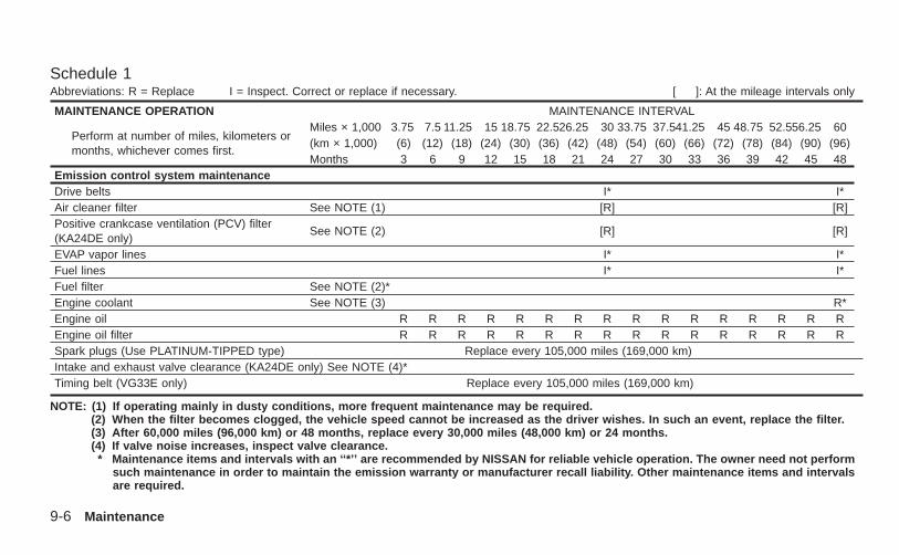
Schedule 1Abbreviations: R = Replace I = Inspect. Correct or replace if necessary. [ ]: At the mileage intervals only
MAINTENANCE OPERATION MAINTENANCE INTERVAL
Perform at number of miles, kilometers ormonths, whichever comes first.
Miles × 1,000 3.75 7.5 11.25 15 18.75 22.526.25 30 33.75 37.541.25 45 48.75 52.556.25 60(km × 1,000) (6) (12) (18) (24) (30) (36) (42) (48) (54) (60) (66) (72) (78) (84) (90) (96)Months 3 6 9 12 15 18 21 24 27 30 33 36 39 42 45 48
Emission control system maintenanceDrive belts I* I*Air cleaner filter See NOTE (1) [R] [R]Positive crankcase ventilation (PCV) filter(KA24DE only)
See NOTE (2) [R] [R]
EVAP vapor lines I* I*Fuel lines I* I*Fuel filter See NOTE (2)*Engine coolant See NOTE (3) R*Engine oil R R R R R R R R R R R R R R R REngine oil filter R R R R R R R R R R R R R R R RSpark plugs (Use PLATINUM-TIPPED type) Replace every 105,000 miles (169,000 km)Intake and exhaust valve clearance (KA24DE only) See NOTE (4)*Timing belt (VG33E only) Replace every 105,000 miles (169,000 km)
NOTE: (1) If operating mainly in dusty conditions, more frequent maintenance may be required.(2) When the filter becomes clogged, the vehicle speed cannot be increased as the driver wishes. In such an event, replace the filter.(3) After 60,000 miles (96,000 km) or 48 months, replace every 30,000 miles (48,000 km) or 24 months.(4) If valve noise increases, inspect valve clearance.
* Maintenance items and intervals with an ‘‘*’’ are recommended by NISSAN for reliable vehicle operation. The owner need not performsuch maintenance in order to maintain the emission warranty or manufacturer recall liability. Other maintenance items and intervalsare required.
9-6 Maintenance
Z X
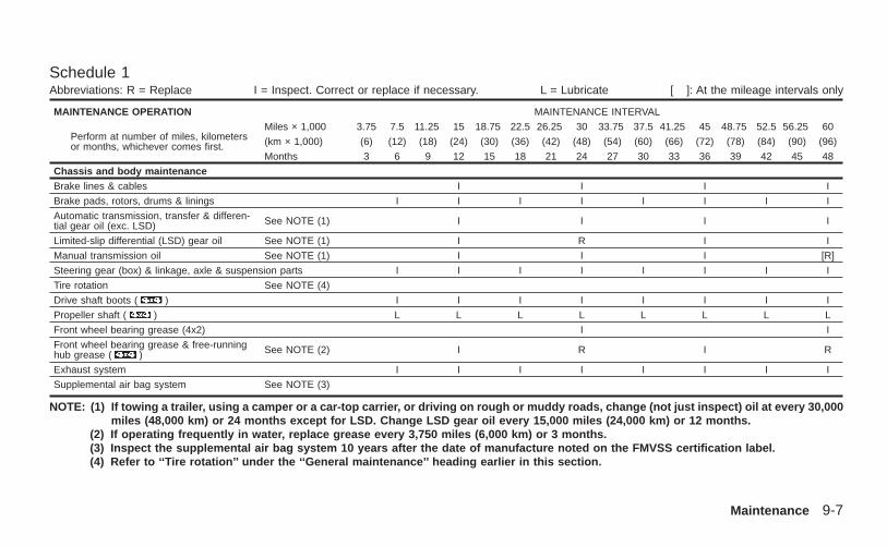
Schedule 1Abbreviations: R = Replace I = Inspect. Correct or replace if necessary. L = Lubricate [ ]: At the mileage intervals only
MAINTENANCE OPERATION MAINTENANCE INTERVAL
Perform at number of miles, kilometersor months, whichever comes first.
Miles × 1,000 3.75 7.5 11.25 15 18.75 22.5 26.25 30 33.75 37.5 41.25 45 48.75 52.5 56.25 60
(km × 1,000) (6) (12) (18) (24) (30) (36) (42) (48) (54) (60) (66) (72) (78) (84) (90) (96)
Months 3 6 9 12 15 18 21 24 27 30 33 36 39 42 45 48
Chassis and body maintenanceBrake lines & cables I I I I
Brake pads, rotors, drums & linings I I I I I I I I
Automatic transmission, transfer & differen-tial gear oil (exc. LSD) See NOTE (1) I I I I
Limited-slip differential (LSD) gear oil See NOTE (1) I R I I
Manual transmission oil See NOTE (1) I I I [R]
Steering gear (box) & linkage, axle & suspension parts I I I I I I I I
Tire rotation See NOTE (4)
Drive shaft boots ( ) I I I I I I I I
Propeller shaft ( ) L L L L L L L L
Front wheel bearing grease (4x2) I I
Front wheel bearing grease & free-runninghub grease ( ) See NOTE (2) I R I R
Exhaust system I I I I I I I I
Supplemental air bag system See NOTE (3)
NOTE: (1) If towing a trailer, using a camper or a car-top carrier, or driving on rough or muddy roads, change (not just inspect) oil at every 30,000miles (48,000 km) or 24 months except for LSD. Change LSD gear oil every 15,000 miles (24,000 km) or 12 months.
(2) If operating frequently in water, replace grease every 3,750 miles (6,000 km) or 3 months.(3) Inspect the supplemental air bag system 10 years after the date of manufacture noted on the FMVSS certification label.(4) Refer to ‘‘Tire rotation’’ under the ‘‘General maintenance’’ heading earlier in this section.
Maintenance 9-7
Z X
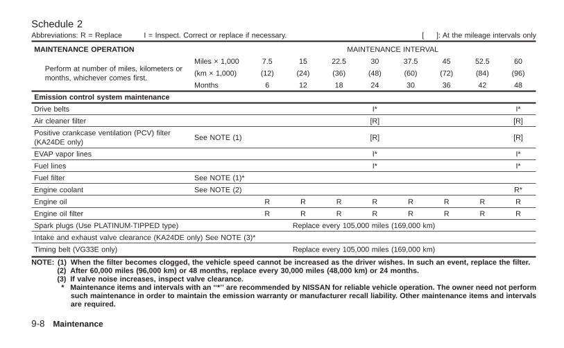
Schedule 2Abbreviations: R = Replace I = Inspect. Correct or replace if necessary. [ ]: At the mileage intervals only
MAINTENANCE OPERATION MAINTENANCE INTERVAL
Perform at number of miles, kilometers ormonths, whichever comes first.
Miles × 1,000 7.5 15 22.5 30 37.5 45 52.5 60
(km × 1,000) (12) (24) (36) (48) (60) (72) (84) (96)
Months 6 12 18 24 30 36 42 48
Emission control system maintenance
Drive belts I* I*
Air cleaner filter [R] [R]
Positive crankcase ventilation (PCV) filter(KA24DE only)
See NOTE (1) [R] [R]
EVAP vapor lines I* I*
Fuel lines I* I*
Fuel filter See NOTE (1)*
Engine coolant See NOTE (2) R*
Engine oil R R R R R R R R
Engine oil filter R R R R R R R R
Spark plugs (Use PLATINUM-TIPPED type) Replace every 105,000 miles (169,000 km)
Intake and exhaust valve clearance (KA24DE only) See NOTE (3)*
Timing belt (VG33E only) Replace every 105,000 miles (169,000 km)
NOTE: (1) When the filter becomes clogged, the vehicle speed cannot be increased as the driver wishes. In such an event, replace the filter.(2) After 60,000 miles (96,000 km) or 48 months, replace every 30,000 miles (48,000 km) or 24 months.(3) If valve noise increases, inspect valve clearance.
* Maintenance items and intervals with an ‘‘*’’ are recommended by NISSAN for reliable vehicle operation. The owner need not performsuch maintenance in order to maintain the emission warranty or manufacturer recall liability. Other maintenance items and intervalsare required.
9-8 Maintenance
Z X
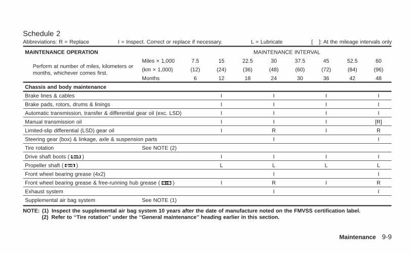
Schedule 2Abbreviations: R = Replace I = Inspect. Correct or replace if necessary. L = Lubricate [ ]: At the mileage intervals only
MAINTENANCE OPERATION MAINTENANCE INTERVAL
Perform at number of miles, kilometers ormonths, whichever comes first.
Miles × 1,000 7.5 15 22.5 30 37.5 45 52.5 60
(km × 1,000) (12) (24) (36) (48) (60) (72) (84) (96)
Months 6 12 18 24 30 36 42 48
Chassis and body maintenance
Brake lines & cables I I I I
Brake pads, rotors, drums & linings I I I I
Automatic transmission, transfer & differential gear oil (exc. LSD) I I I I
Manual transmission oil I I I [R]
Limited-slip differential (LSD) gear oil I R I R
Steering gear (box) & linkage, axle & suspension parts I I
Tire rotation See NOTE (2)
Drive shaft boots ( ) I I I I
Propeller shaft ( ) L L L L
Front wheel bearing grease (4x2) I I
Front wheel bearing grease & free-running hub grease ( ) I R I R
Exhaust system I I
Supplemental air bag system See NOTE (1)
NOTE: (1) Inspect the supplemental air bag system 10 years after the date of manufacture noted on the FMVSS certification label.(2) Refer to ‘‘Tire rotation’’ under the ‘‘General maintenance’’ heading earlier in this section.
Maintenance 9-9
Z X
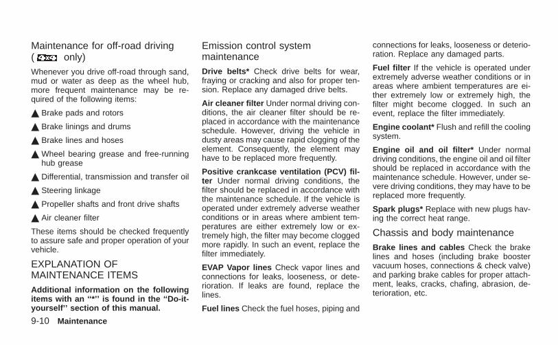
Maintenance for off-road driving( only)Whenever you drive off-road through sand,mud or water as deep as the wheel hub,more frequent maintenance may be re-quired of the following items:
¶ Brake pads and rotors
¶ Brake linings and drums
¶ Brake lines and hoses
¶ Wheel bearing grease and free-runninghub grease
¶ Differential, transmission and transfer oil
¶ Steering linkage
¶ Propeller shafts and front drive shafts
¶ Air cleaner filter
These items should be checked frequentlyto assure safe and proper operation of yourvehicle.
EXPLANATION OFMAINTENANCE ITEMSAdditional information on the followingitems with an ‘‘*’’ is found in the ‘‘Do-it-yourself’’ section of this manual.
Emission control systemmaintenanceDrive belts* Check drive belts for wear,fraying or cracking and also for proper ten-sion. Replace any damaged drive belts.
Air cleaner filter Under normal driving con-ditions, the air cleaner filter should be re-placed in accordance with the maintenanceschedule. However, driving the vehicle industy areas may cause rapid clogging of theelement. Consequently, the element mayhave to be replaced more frequently.
Positive crankcase ventilation (PCV) fil-ter Under normal driving conditions, thefilter should be replaced in accordance withthe maintenance schedule. If the vehicle isoperated under extremely adverse weatherconditions or in areas where ambient tem-peratures are either extremely low or ex-tremely high, the filter may become cloggedmore rapidly. In such an event, replace thefilter immediately.
EVAP Vapor lines Check vapor lines andconnections for leaks, looseness, or dete-rioration. If leaks are found, replace thelines.
Fuel lines Check the fuel hoses, piping and
connections for leaks, looseness or deterio-ration. Replace any damaged parts.
Fuel filter If the vehicle is operated underextremely adverse weather conditions or inareas where ambient temperatures are ei-ther extremely low or extremely high, thefilter might become clogged. In such anevent, replace the filter immediately.
Engine coolant* Flush and refill the coolingsystem.
Engine oil and oil filter* Under normaldriving conditions, the engine oil and oil filtershould be replaced in accordance with themaintenance schedule. However, under se-vere driving conditions, they may have to bereplaced more frequently.
Spark plugs* Replace with new plugs hav-ing the correct heat range.
Chassis and body maintenanceBrake lines and cables Check the brakelines and hoses (including brake boostervacuum hoses, connections & check valve)and parking brake cables for proper attach-ment, leaks, cracks, chafing, abrasion, de-terioration, etc.
9-10 Maintenance
Z X
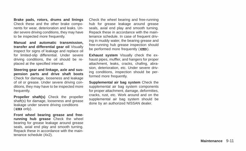
Brake pads, rotors, drums and liningsCheck these and the other brake compo-nents for wear, deterioration and leaks. Un-der severe driving conditions, they may haveto be inspected more frequently.
Manual and automatic transmission,transfer and differential gear oil Visuallyinspect for signs of leakage and replace oilfor limited-slip differential. Under severedriving conditions, the oil should be re-placed at the specified interval.
Steering gear and linkage, axle and sus-pension parts and drive shaft bootsCheck for damage, looseness and leakageof oil or grease. Under severe driving con-ditions, they may have to be inspected morefrequently.
Propeller shaft(s) Check the propellershaft(s) for damage, looseness and greaseleakage under severe driving conditions( only).
Front wheel bearing grease and free-running hub grease Check the wheelbearing for grease leakage around greaseseals, axial end play and smooth turning.Repack these in accordance with the main-tenance schedule (4x2).
Check the wheel bearing and free-runninghub for grease leakage around greaseseals, axial end play and smooth turning.Repack these in accordance with the main-tenance schedule. In case of frequent driv-ing in muddy water, the bearing grease andfree-running hub grease inspection shouldbe performed more frequently ( ).
Exhaust system Visually check the ex-haust pipes, muffler, and hangers for properattachment, leaks, cracks, chafing, abra-sion, deterioration, etc. Under severe driv-ing conditions, inspection should be per-formed more frequently.
Supplemental air bag system Check thesupplemental air bag system componentsfor proper attachment, damage, deformities,cracks, rust, etc. Work around and on thesupplemental air bag system should bedone by an authorized NISSAN dealer.
Maintenance 9-11
Z X

MEMO
9-12 Maintenance
Z X
10 Technical and consumer information
Capacities and recommended fuel/lubricants......10-2Fuel recommendation......................................10-4Engine oil and oil filter recommendation.........10-6Recommended SAE viscosity number............10-7Air conditioner system refrigerant andlubricant recommendations .............................10-8
Specifications .......................................................10-9Engine .............................................................10-9Wheels and tires............................................10-10Dimensions and weights ...............................10-11
When traveling or registering your vehicle inanother country ..................................................10-12Vehicle identification...........................................10-12
Vehicle identification number (VIN) plate......10-12Vehicle identification number(chassis number) ...........................................10-12Engine serial number ....................................10-13F.M.V.S.S. certification label..........................10-13Emission control information label ................10-14Tire placard....................................................10-14Air conditioner specification label..................10-14
Installing front license plate................................10-15Vehicle loading information ................................10-15
Terms.............................................................10-15Determining vehicle load capacity.................10-16Securing the load ..........................................10-16Loading tips ...................................................10-17Payload weight ratings ..................................10-18Measurement of weights ...............................10-19
Towing a trailer ...................................................10-19Maximum load limits......................................10-19Towing load/specification chart .....................10-21Towing safety.................................................10-22Trailer tow harness and module(if so equipped)..............................................10-23
Uniform tire quality grading................................10-25Emission control system warranty .....................10-26Reporting safety defects (US only) ....................10-27Readiness for inspection/maintenance (I/M)test (US only) .....................................................10-27
In the event of a collision ..............................10-30
Z X

The following are approximate capacities. The actual refill capacities may be a little different. When refilling, follow the proceduredescribed in the ‘‘Do-it-yourself’’ section to determine the proper refill capacity.
Capacity (Approximate)Recommended Fluids & LubricantsUS
measureImp
measure Liter
Fuel 19-3/8 gal 16-1/8 gal 73.4 Unleaded gasoline with an octane rating ofat least 87 AKI (RON 91)*1
Engine oilDrain and Refill
KA24DE With oil filter 3-3/4 qt 3-1/8 qt 3.5 O API Certification Mark *2
Without oil filter 3-1/2 qt 2-7/8 qt 3.3 O API grade SG/SH, Energy Conserving I &II or API grade SJ, Energy Conserving *2
VG33E With oil filter 3-1/2 qt 2-7/8 qt 3.3 O ILSAC grade GF-I & II
Without oil filter 3-1/8 qt 2-5/8 qt 3.0
Cooling system (with heater and reservoir tank)
KA24DE M/T 4X2 7-3/4 qt 6-3/8 7.3 50% Genuine NISSAN Anti-freeze coolantor equivalent
VG33E A/T & M/T 11-5/8 qt 9-5/8 qt 10.95 50% Soft tap water
*1: For further details, see ‘‘Fuel recommendation’’.*2: For further details, see ‘‘Recommended SAE engine oil viscosity’’.
CAPACITIES ANDRECOMMENDED FUEL/LUBRICANTS
10-2 Technical and consumer information
Z X
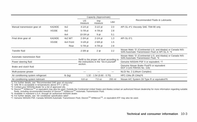
Capacity (Approximate)Recommended Fluids & LubricantsUS
measureImp
measure Liter
Manual transmission gear oil KA24DE 4x2 4-1/4 pt 3-1/2 pt 2.0 API GL-4*1 Viscosity SAE 75W-90 only
VG33E 4x2 5-7/8 pt 4-7/8 pt 2.8
4x4 10-3/4 pt 9 pt 5.1
Final drive gear oil KA24DE 4x2 M/T 2-3/4 pt 2-1/4 pt 1.3 API GL-5*1
VG33E 4x4 Front 3-1/8 pt 2-5/8 pt 1.5
Rear 5-7/8 pt 4-7/8 pt 2.8
Transfer fluid 2-3/8 qt 2 qt 2.2 Nissan Matic ‘D’ (Continental U.S. and Alaska) or Canada NIS-SAN Automatic Transmission Fluid or API GL-4. *4
Automatic transmission fluidRefill to the proper oil level according tothe instructions in the ‘‘Do-it-yourself’’section.
Nissan Matic ‘D’ (Continental U.S. and Alaska) or Canada NIS-SAN Automatic Transmission Fluid. *4
Power steering fluid Genuine NISSAN PSF II or equivalent. *7
Brake and clutch fluid Genuine Nissan Brake Fluid*5 or equivalentDOT 3 (US FMVSS No. 116)
Multi-purpose grease — — — NLGI No. 2 (Lithium Complex)
Air conditioning system refrigerant lb (kg) 1.32 - 1.54 (0.60 - 0.70) HFC-134a (R-134a)*6
Air conditioning system lubricant 6.8 oz 7.0 oz 200 ml Nissan A/C System Oil Type R or equivalent*6
*1: For further details, see ‘‘Recommended SAE gear oil viscosity’’.*2: SAE 90 is acceptable in temperatures above 0°F (−18°C).*3: Contact your NISSAN dealer for a list of approved oils.*4: DexronTM III/MerconTM or equivalent may also be used. Outside the Continental United States and Alaska contact an authorized Nissan dealership for more information regarding suitable
fluids, including recommended brand(s) of DexronTM III/MerconTM Automatic Transmission Fluid.*5: Available in mainland U.S.A. through an authorized NISSAN dealer.*6: For further details, see ‘‘Air conditioner specification label’’.*7: Genuine NISSAN PSF, Canada NISSAN Automatic Transmission Fluid, DexronTM III/MerconTM, or equivalent ATF may also be used.
Technical and consumer information 10-3
Z X
FUEL RECOMMENDATIONYour vehicle is designed to operate onunleaded gasoline with an octane ratingof at least 87 AKI (Anti-Knock Index)(Research octane number 91).
CAUTIONO Using a fuel other than that specified
could adversely affect the emissioncontrol system, and may also affectthe warranty coverage.
O Under no circumstances should aleaded gasoline be used, since thiswill damage the three-way catalyst.
Reformulated GasolineSome fuel suppliers are now producing re-formulated gasolines. These gasolines arespecially designed to reduce vehicle emis-sions. NISSAN supports efforts towardscleaner air and suggests that you use refor-mulated gasoline when available.
Gasoline containing oxygenatesSome fuel suppliers sell gasoline containingoxygenates such as ethanol, MTBE andmethanol with or without advertising their
presence. Nissan does not recommend theuse of fuels of which the oxygenate contentand the fuel compatibility for your NISSANcannot be readily determined. If in doubt,ask your service station manager.
If you use oxygenate-blend gasoline, pleasetake the following precautions as the usageof such fuels may cause vehicle perfor-mance problems and/or fuel system dam-age.
O The fuel should be unleaded and havean octane rating no lower than thatrecommended for unleaded gasoline.
O If an oxygenate-blend, excepting amethanol blend, is used, it shouldcontain no more than 10% oxygenate.(MTBE may, however, be added up to15%.)
O If a methanol blend is used, it shouldcontain no more than 5% methanol(methyl alcohol, wood alcohol). Itshould also contain a suitable amountof appropriate cosolvents and corro-sion inhibitors. If not properly formu-lated with appropriate cosolvents andcorrosion inhibitors, such methanolblends may cause fuel system damage
and/or vehicle performance problems.At this time, sufficient data is not avail-able to ensure that all methanol blendsare suitable for use in NISSAN ve-hicles.
If any driveability problems such as enginestalling and hard hot starting are experi-enced after using oxygenate-blend fuels,immediately change to a non-oxygenatefuel or a fuel with a low blend of MTBE.
Take care not to spill gasoline duringrefueling. Gasoline containing oxygen-ates can cause paint damage.
After Market Fuel AdditivesNISSAN does not recommend the use ofany fuel additives (i.e., fuel injector cleaner,octane booster, intake valve deposit remov-ers, etc.) which are sold commercially. Manyof these additives intended for gum, varnishor deposit removal may contain active sol-vents or similar ingredients that can beharmful to the fuel system and engine.
Octane rating tipsIn most parts of North America, you shoulduse unleaded gasoline with an octane ratingof at least 87 AKI (Anti-Knock Index). How-
10-4 Technical and consumer information
Z X
ever, you may use unleaded gasoline withan octane rating as low as 85 AKI in highaltitude areas (over 4,000 ft [1,219 m]) suchas: Colorado, Montana, New Mexico, Utah,Wyoming, northeastern Nevada, southernIdaho, western South Dakota, western Ne-braska, and the part of Texas which isdirectly south of New Mexico.
Using unleaded gasoline with an octanerating lower than stated above can causepersistent, heavy ‘‘spark knock.’’ (‘‘Sparkknock’’ is a metallic rapping noise.) Ifsevere, this can lead to engine damage. Ifyou detect a persistent heavy sparkknock even when using gasoline of thestated octane rating, or if you hear steadyspark knock while holding a steady speedon level roads, have an authorized NIS-SAN dealer correct the condition. Failureto correct the condition is misuse of thevehicle, for which NISSAN is not respon-sible.
Incorrect ignition timing may result in sparkknock, after-run and/or overheating, whichmay cause excessive fuel consumption orengine damage. If any of the above symp-toms are encountered, have your vehiclechecked at an authorized NISSAN dealer.
However, now and then you may noticelight spark knock for a short time whileaccelerating or driving up hills. This isno cause for concern, because you getthe greatest fuel benefit when there islight spark knock for a short time underheavy engine load.
Technical and consumer information 10-5
Z X
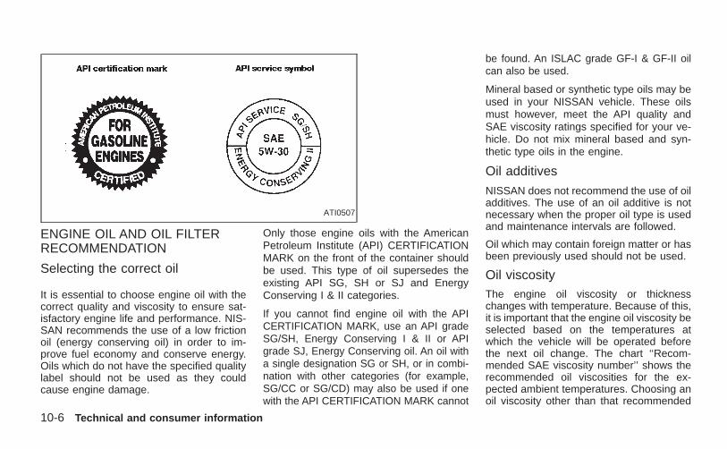
ENGINE OIL AND OIL FILTERRECOMMENDATION
Selecting the correct oil
It is essential to choose engine oil with thecorrect quality and viscosity to ensure sat-isfactory engine life and performance. NIS-SAN recommends the use of a low frictionoil (energy conserving oil) in order to im-prove fuel economy and conserve energy.Oils which do not have the specified qualitylabel should not be used as they couldcause engine damage.
Only those engine oils with the AmericanPetroleum Institute (API) CERTIFICATIONMARK on the front of the container shouldbe used. This type of oil supersedes theexisting API SG, SH or SJ and EnergyConserving I & II categories.
If you cannot find engine oil with the APICERTIFICATION MARK, use an API gradeSG/SH, Energy Conserving I & II or APIgrade SJ, Energy Conserving oil. An oil witha single designation SG or SH, or in combi-nation with other categories (for example,SG/CC or SG/CD) may also be used if onewith the API CERTIFICATION MARK cannot
be found. An ISLAC grade GF-I & GF-II oilcan also be used.
Mineral based or synthetic type oils may beused in your NISSAN vehicle. These oilsmust however, meet the API quality andSAE viscosity ratings specified for your ve-hicle. Do not mix mineral based and syn-thetic type oils in the engine.
Oil additives
NISSAN does not recommend the use of oiladditives. The use of an oil additive is notnecessary when the proper oil type is usedand maintenance intervals are followed.
Oil which may contain foreign matter or hasbeen previously used should not be used.
Oil viscosityThe engine oil viscosity or thicknesschanges with temperature. Because of this,it is important that the engine oil viscosity beselected based on the temperatures atwhich the vehicle will be operated beforethe next oil change. The chart ‘‘Recom-mended SAE viscosity number’’ shows therecommended oil viscosities for the ex-pected ambient temperatures. Choosing anoil viscosity other than that recommended
ATI0507
10-6 Technical and consumer information
Z X
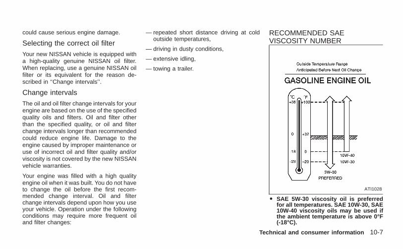
could cause serious engine damage.
Selecting the correct oil filter
Your new NISSAN vehicle is equipped witha high-quality genuine NISSAN oil filter.When replacing, use a genuine NISSAN oilfilter or its equivalent for the reason de-scribed in ‘‘Change intervals’’.
Change intervals
The oil and oil filter change intervals for yourengine are based on the use of the specifiedquality oils and filters. Oil and filter otherthan the specified quality, or oil and filterchange intervals longer than recommendedcould reduce engine life. Damage to theengine caused by improper maintenance oruse of incorrect oil and filter quality and/orviscosity is not covered by the new NISSANvehicle warranties.
Your engine was filled with a high qualityengine oil when it was built. You do not haveto change the oil before the first recom-mended change interval. Oil and filterchange intervals depend upon how you useyour vehicle. Operation under the followingconditions may require more frequent oiland filter changes:
— repeated short distance driving at coldoutside temperatures,
— driving in dusty conditions,
— extensive idling,
— towing a trailer.
RECOMMENDED SAEVISCOSITY NUMBER
O SAE 5W-30 viscosity oil is preferredfor all temperatures. SAE 10W-30, SAE10W-40 viscosity oils may be used ifthe ambient temperature is above 0°F(-18°C).
ATI1028
Technical and consumer information 10-7
Z X
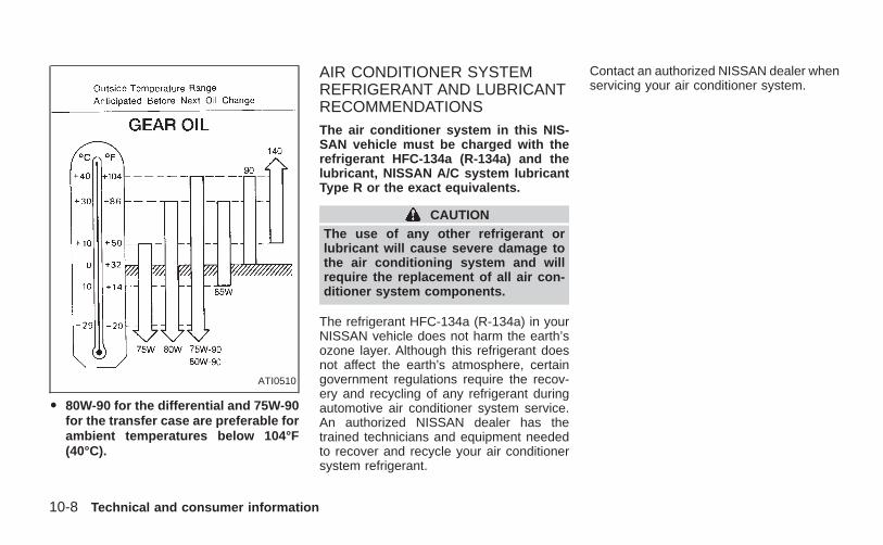
O 80W-90 for the differential and 75W-90for the transfer case are preferable forambient temperatures below 104°F(40°C).
AIR CONDITIONER SYSTEMREFRIGERANT AND LUBRICANTRECOMMENDATIONSThe air conditioner system in this NIS-SAN vehicle must be charged with therefrigerant HFC-134a (R-134a) and thelubricant, NISSAN A/C system lubricantType R or the exact equivalents.
CAUTIONThe use of any other refrigerant orlubricant will cause severe damage tothe air conditioning system and willrequire the replacement of all air con-ditioner system components.
The refrigerant HFC-134a (R-134a) in yourNISSAN vehicle does not harm the earth’sozone layer. Although this refrigerant doesnot affect the earth’s atmosphere, certaingovernment regulations require the recov-ery and recycling of any refrigerant duringautomotive air conditioner system service.An authorized NISSAN dealer has thetrained technicians and equipment neededto recover and recycle your air conditionersystem refrigerant.
Contact an authorized NISSAN dealer whenservicing your air conditioner system.
ATI0510
10-8 Technical and consumer information
Z X
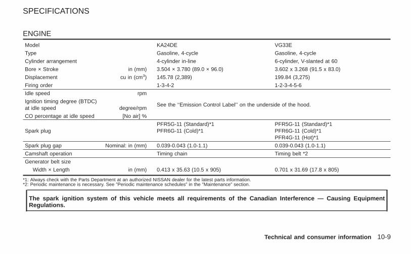
ENGINE
Model KA24DE VG33E
Type Gasoline, 4-cycle Gasoline, 4-cycle
Cylinder arrangement 4-cylinder in-line 6-cylinder, V-slanted at 60
Bore × Stroke in (mm) 3.504 × 3.780 (89.0 × 96.0) 3.602 x 3.268 (91.5 x 83.0)
Displacement cu in (cm3) 145.78 (2,389) 199.84 (3,275)
Firing order 1-3-4-2 1-2-3-4-5-6
Idle speed rpm
See the ‘‘Emission Control Label’’ on the underside of the hood.Ignition timing degree (BTDC)at idle speed degree/rpm
CO percentage at idle speed [No air] %
Spark plugPFR5G-11 (Standard)*1PFR6G-11 (Cold)*1
PFR5G-11 (Standard)*1PFR6G-11 (Cold)*1PFR4G-11 (Hot)*1
Spark plug gap Nominal: in (mm) 0.039-0.043 (1.0-1.1) 0.039-0.043 (1.0-1.1)
Camshaft operation Timing chain Timing belt *2
Generator belt size
Width × Length in (mm) 0.413 x 35.63 (10.5 x 905) 0.701 x 31.69 (17.8 x 805)
*1: Always check with the Parts Department at an authorized NISSAN dealer for the latest parts information.*2: Periodic maintenance is necessary. See 9Periodic maintenance schedules9 in the 9Maintenance9 section.
The spark ignition system of this vehicle meets all requirements of the Canadian Interference — Causing EquipmentRegulations.
SPECIFICATIONS
Technical and consumer information 10-9
Z X
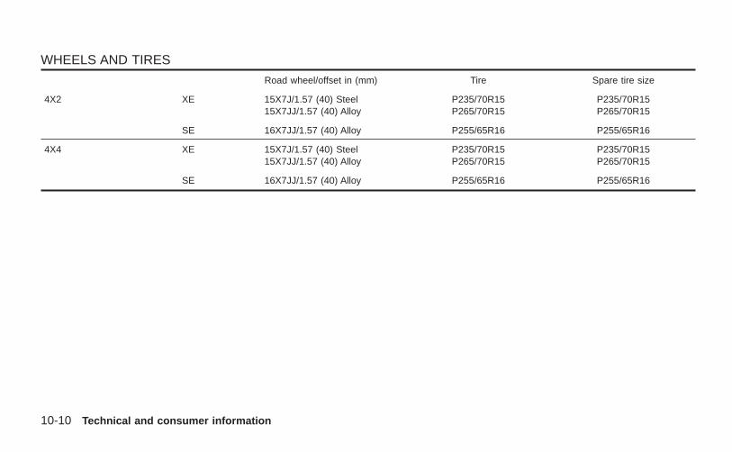
WHEELS AND TIRES
Road wheel/offset in (mm) Tire Spare tire size
4X2 XE 15X7J/1.57 (40) Steel15X7JJ/1.57 (40) Alloy
P235/70R15P265/70R15
P235/70R15P265/70R15
SE 16X7JJ/1.57 (40) Alloy P255/65R16 P255/65R16
4X4 XE 15X7J/1.57 (40) Steel15X7JJ/1.57 (40) Alloy
P235/70R15P265/70R15
P235/70R15P265/70R15
SE 16X7JJ/1.57 (40) Alloy P255/65R16 P255/65R16
10-10 Technical and consumer information
Z X
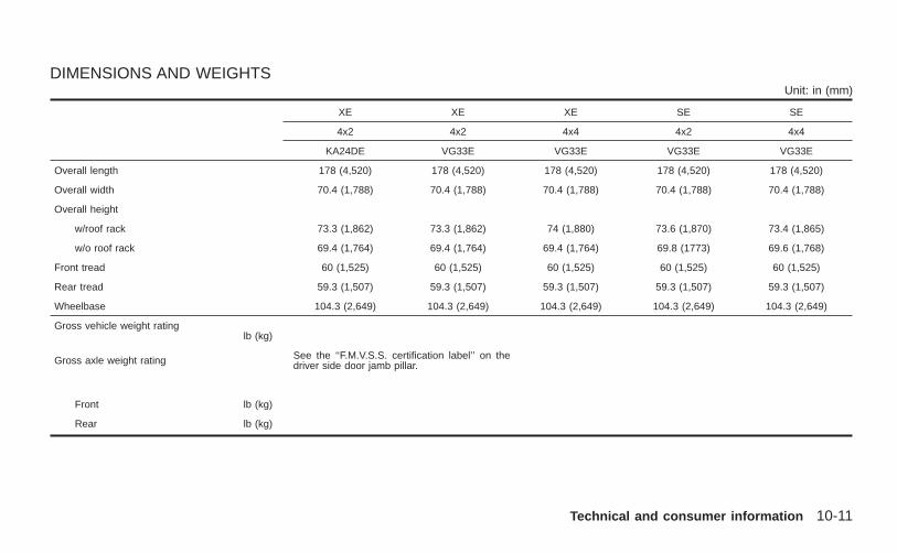
DIMENSIONS AND WEIGHTSUnit: in (mm)
XE XE XE SE SE
4x2 4x2 4x4 4x2 4x4
KA24DE VG33E VG33E VG33E VG33E
Overall length 178 (4,520) 178 (4,520) 178 (4,520) 178 (4,520) 178 (4,520)
Overall width 70.4 (1,788) 70.4 (1,788) 70.4 (1,788) 70.4 (1,788) 70.4 (1,788)
Overall height
w/roof rack 73.3 (1,862) 73.3 (1,862) 74 (1,880) 73.6 (1,870) 73.4 (1,865)
w/o roof rack 69.4 (1,764) 69.4 (1,764) 69.4 (1,764) 69.8 (1773) 69.6 (1,768)
Front tread 60 (1,525) 60 (1,525) 60 (1,525) 60 (1,525) 60 (1,525)
Rear tread 59.3 (1,507) 59.3 (1,507) 59.3 (1,507) 59.3 (1,507) 59.3 (1,507)
Wheelbase 104.3 (2,649) 104.3 (2,649) 104.3 (2,649) 104.3 (2,649) 104.3 (2,649)
Gross vehicle weight ratinglb (kg)
Gross axle weight rating See the ‘‘F.M.V.S.S. certification label’’ on thedriver side door jamb pillar.
Front lb (kg)
Rear lb (kg)
Technical and consumer information 10-11
Z X
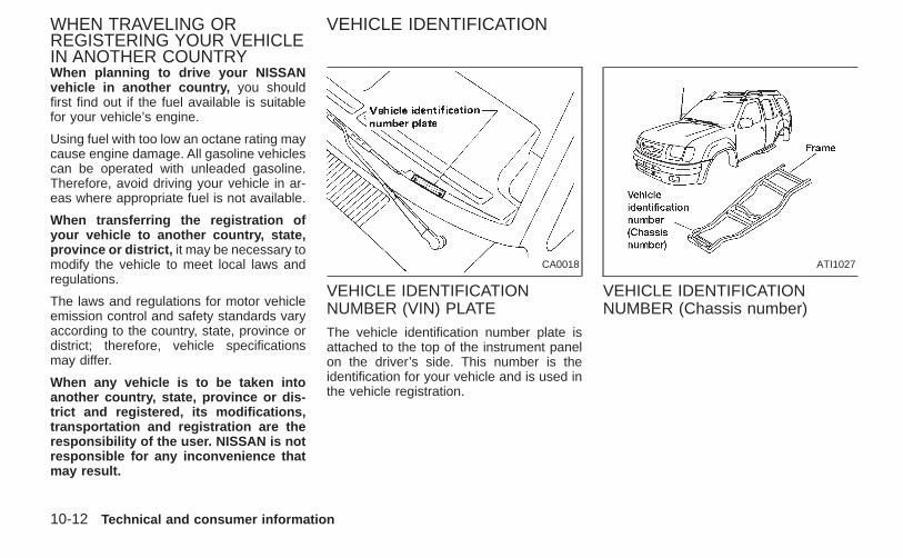
When planning to drive your NISSANvehicle in another country, you shouldfirst find out if the fuel available is suitablefor your vehicle’s engine.
Using fuel with too low an octane rating maycause engine damage. All gasoline vehiclescan be operated with unleaded gasoline.Therefore, avoid driving your vehicle in ar-eas where appropriate fuel is not available.
When transferring the registration ofyour vehicle to another country, state,province or district, it may be necessary tomodify the vehicle to meet local laws andregulations.
The laws and regulations for motor vehicleemission control and safety standards varyaccording to the country, state, province ordistrict; therefore, vehicle specificationsmay differ.
When any vehicle is to be taken intoanother country, state, province or dis-trict and registered, its modifications,transportation and registration are theresponsibility of the user. NISSAN is notresponsible for any inconvenience thatmay result.
VEHICLE IDENTIFICATIONNUMBER (VIN) PLATEThe vehicle identification number plate isattached to the top of the instrument panelon the driver’s side. This number is theidentification for your vehicle and is used inthe vehicle registration.
VEHICLE IDENTIFICATIONNUMBER (Chassis number)
CA0018 ATI1027
WHEN TRAVELING ORREGISTERING YOUR VEHICLEIN ANOTHER COUNTRY
VEHICLE IDENTIFICATION
10-12 Technical and consumer information
Z X
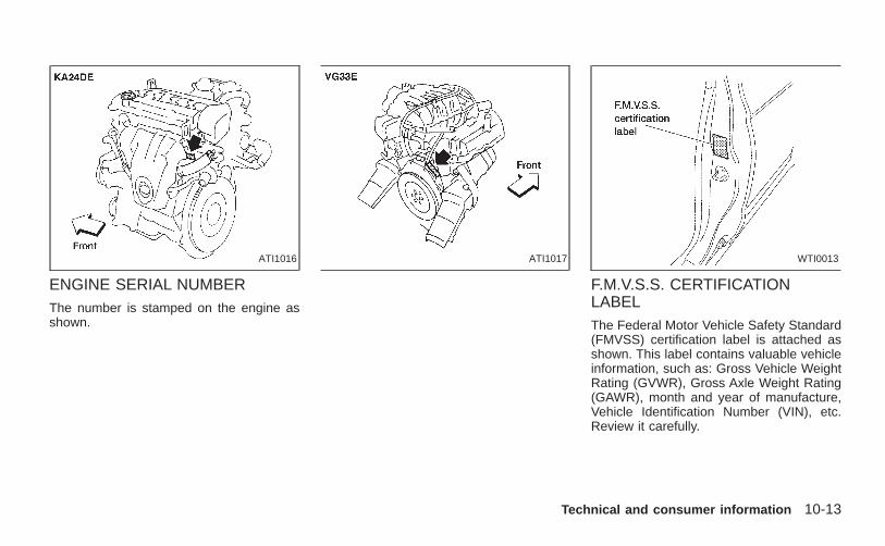
ENGINE SERIAL NUMBERThe number is stamped on the engine asshown.
F.M.V.S.S. CERTIFICATIONLABELThe Federal Motor Vehicle Safety Standard(FMVSS) certification label is attached asshown. This label contains valuable vehicleinformation, such as: Gross Vehicle WeightRating (GVWR), Gross Axle Weight Rating(GAWR), month and year of manufacture,Vehicle Identification Number (VIN), etc.Review it carefully.
ATI1016 ATI1017 WTI0013
Technical and consumer information 10-13
Z X
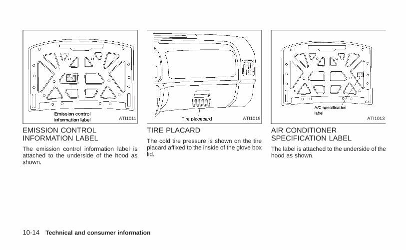
EMISSION CONTROLINFORMATION LABELThe emission control information label isattached to the underside of the hood asshown.
TIRE PLACARDThe cold tire pressure is shown on the tireplacard affixed to the inside of the glove boxlid.
AIR CONDITIONERSPECIFICATION LABELThe label is attached to the underside of thehood as shown.
ATI1011 ATI1019 ATI1013
10-14 Technical and consumer information
Z X
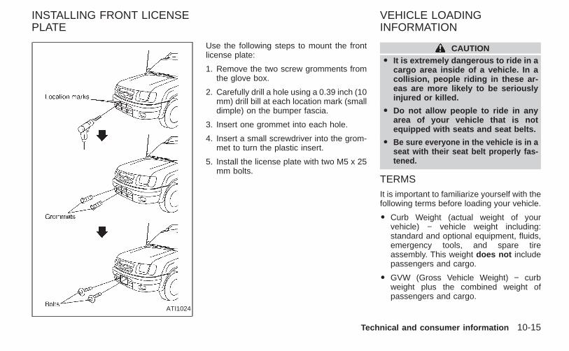
Use the following steps to mount the frontlicense plate:
1. Remove the two screw gromments fromthe glove box.
2. Carefully drill a hole using a 0.39 inch (10mm) drill bill at each location mark (smalldimple) on the bumper fascia.
3. Insert one grommet into each hole.
4. Insert a small screwdriver into the grom-met to turn the plastic insert.
5. Install the license plate with two M5 x 25mm bolts.
CAUTIONO It is extremely dangerous to ride in a
cargo area inside of a vehicle. In acollision, people riding in these ar-eas are more likely to be seriouslyinjured or killed.
O Do not allow people to ride in anyarea of your vehicle that is notequipped with seats and seat belts.
O Be sure everyone in the vehicle is in aseat with their seat belt properly fas-tened.
TERMSIt is important to familiarize yourself with thefollowing terms before loading your vehicle.
O Curb Weight (actual weight of yourvehicle) − vehicle weight including:standard and optional equipment, fluids,emergency tools, and spare tireassembly. This weight does not includepassengers and cargo.
O GVW (Gross Vehicle Weight) − curbweight plus the combined weight ofpassengers and cargo.
ATI1024
INSTALLING FRONT LICENSEPLATE
VEHICLE LOADINGINFORMATION
Technical and consumer information 10-15
Z X
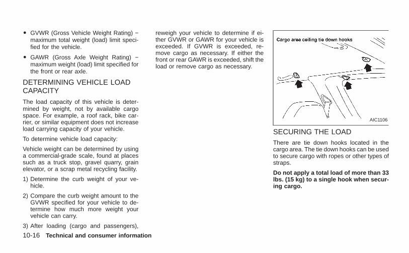
O GVWR (Gross Vehicle Weight Rating) −maximum total weight (load) limit speci-fied for the vehicle.
O GAWR (Gross Axle Weight Rating) −maximum weight (load) limit specified forthe front or rear axle.
DETERMINING VEHICLE LOADCAPACITY
The load capacity of this vehicle is deter-mined by weight, not by available cargospace. For example, a roof rack, bike car-rier, or similar equipment does not increaseload carrying capacity of your vehicle.
To determine vehicle load capacity:
Vehicle weight can be determined by usinga commercial-grade scale, found at placessuch as a truck stop, gravel quarry, grainelevator, or a scrap metal recycling facility.
1) Determine the curb weight of your ve-hicle.
2) Compare the curb weight amount to theGVWR specified for your vehicle to de-termine how much more weight yourvehicle can carry.
3) After loading (cargo and passengers),
reweigh your vehicle to determine if ei-ther GVWR or GAWR for your vehicle isexceeded. If GVWR is exceeded, re-move cargo as necessary. If either thefront or rear GAWR is exceeded, shift theload or remove cargo as necessary.
SECURING THE LOADThere are tie down hooks located in thecargo area. The tie down hooks can be usedto secure cargo with ropes or other types ofstraps.
Do not apply a total load of more than 33lbs. (15 kg) to a single hook when secur-ing cargo.
AIC1106
10-16 Technical and consumer information
Z X
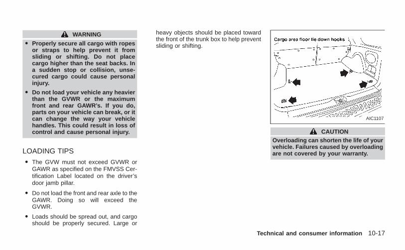
WARNING
O Properly secure all cargo with ropesor straps to help prevent it fromsliding or shifting. Do not placecargo higher than the seat backs. Ina sudden stop or collision, unse-cured cargo could cause personalinjury.
O Do not load your vehicle any heavierthan the GVWR or the maximumfront and rear GAWR’s. If you do,parts on your vehicle can break, or itcan change the way your vehiclehandles. This could result in loss ofcontrol and cause personal injury.
LOADING TIPS
O The GVW must not exceed GVWR orGAWR as specified on the FMVSS Cer-tification Label located on the driver’sdoor jamb pillar.
O Do not load the front and rear axle to theGAWR. Doing so will exceed theGVWR.
O Loads should be spread out, and cargoshould be properly secured. Large or
heavy objects should be placed towardthe front of the trunk box to help preventsliding or shifting.
CAUTIONOverloading can shorten the life of yourvehicle. Failures caused by overloadingare not covered by your warranty.
AIC1107
Technical and consumer information 10-17
Z X
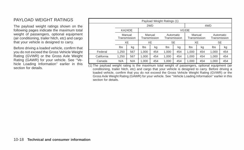
PAYLOAD WEIGHT RATINGSThe payload weight ratings shown on thefollowing pages indicate the maximum totalweight of passengers, optional equipment(air conditioning, trailer hitch, etc) and cargothat your vehicle is designed to carry.
Before driving a loaded vehicle, confirm thatyou do not exceed the Gross Vehicle WeightRating (GVWR) or the Gross Axle WeightRating (GAWR) for your vehicle. See ‘‘Ve-hicle Loading Information’’ earlier in thissection for details.
Payload Weight Ratings (1)
2WD 4WD
KA24DE VG33E
ManualTransmission
ManualTransmission
AutomaticTransmission
ManualTransmission
AutomaticTransmission
XE XE SE XE SE
lbs kg lbs kg lbs kg lbs kg lbs kg
Federal 1,250 567 1,000 454 1,000 454 1,000 454 1,000 454
California 1,250 567 1,000 454 1,000 454 1,000 454 1,000 454
Canada N/A N/A 1,000 454 1,000 454 1,000 454 1,000 454
(1) The payload weight rating is the maximum total weight of passengers, optional equipment (airconditioning, trailer hitch, etc) and cargo that your vehicle is designed to carry. Before driving aloaded vehicle, confirm that you do not exceed the Gross Vehicle Weight Rating (GVWR) or theGross Axle Weight Rating (GAWR) for your vehicle. See ‘‘Vehicle Loading Information’’ earlier in thissection for details.
10-18 Technical and consumer information
Z X
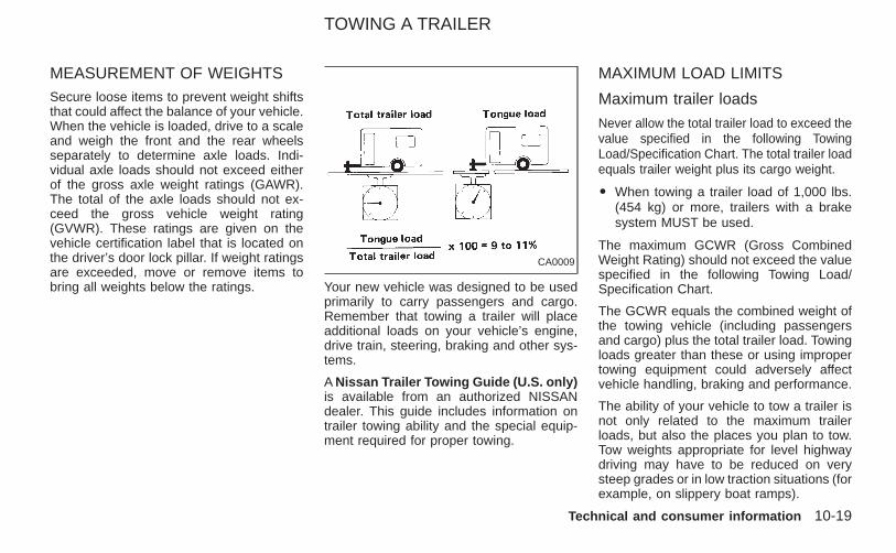
MEASUREMENT OF WEIGHTSSecure loose items to prevent weight shiftsthat could affect the balance of your vehicle.When the vehicle is loaded, drive to a scaleand weigh the front and the rear wheelsseparately to determine axle loads. Indi-vidual axle loads should not exceed eitherof the gross axle weight ratings (GAWR).The total of the axle loads should not ex-ceed the gross vehicle weight rating(GVWR). These ratings are given on thevehicle certification label that is located onthe driver’s door lock pillar. If weight ratingsare exceeded, move or remove items tobring all weights below the ratings. Your new vehicle was designed to be used
primarily to carry passengers and cargo.Remember that towing a trailer will placeadditional loads on your vehicle’s engine,drive train, steering, braking and other sys-tems.
A Nissan Trailer Towing Guide (U.S. only)is available from an authorized NISSANdealer. This guide includes information ontrailer towing ability and the special equip-ment required for proper towing.
MAXIMUM LOAD LIMITS
Maximum trailer loads
Never allow the total trailer load to exceed thevalue specified in the following TowingLoad/Specification Chart. The total trailer loadequals trailer weight plus its cargo weight.
O When towing a trailer load of 1,000 lbs.(454 kg) or more, trailers with a brakesystem MUST be used.
The maximum GCWR (Gross CombinedWeight Rating) should not exceed the valuespecified in the following Towing Load/Specification Chart.
The GCWR equals the combined weight ofthe towing vehicle (including passengersand cargo) plus the total trailer load. Towingloads greater than these or using impropertowing equipment could adversely affectvehicle handling, braking and performance.
The ability of your vehicle to tow a trailer isnot only related to the maximum trailerloads, but also the places you plan to tow.Tow weights appropriate for level highwaydriving may have to be reduced on verysteep grades or in low traction situations (forexample, on slippery boat ramps).
CA0009
TOWING A TRAILER
Technical and consumer information 10-19
Z X
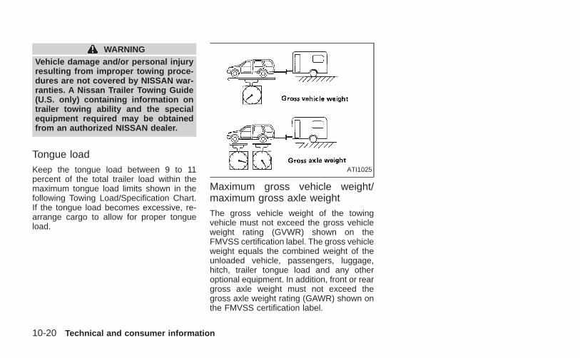
WARNINGVehicle damage and/or personal injuryresulting from improper towing proce-dures are not covered by NISSAN war-ranties. A Nissan Trailer Towing Guide(U.S. only) containing information ontrailer towing ability and the specialequipment required may be obtainedfrom an authorized NISSAN dealer.
Tongue loadKeep the tongue load between 9 to 11percent of the total trailer load within themaximum tongue load limits shown in thefollowing Towing Load/Specification Chart.If the tongue load becomes excessive, re-arrange cargo to allow for proper tongueload.
Maximum gross vehicle weight/maximum gross axle weightThe gross vehicle weight of the towingvehicle must not exceed the gross vehicleweight rating (GVWR) shown on theFMVSS certification label. The gross vehicleweight equals the combined weight of theunloaded vehicle, passengers, luggage,hitch, trailer tongue load and any otheroptional equipment. In addition, front or reargross axle weight must not exceed thegross axle weight rating (GAWR) shown onthe FMVSS certification label.
ATI1025
10-20 Technical and consumer information
Z X
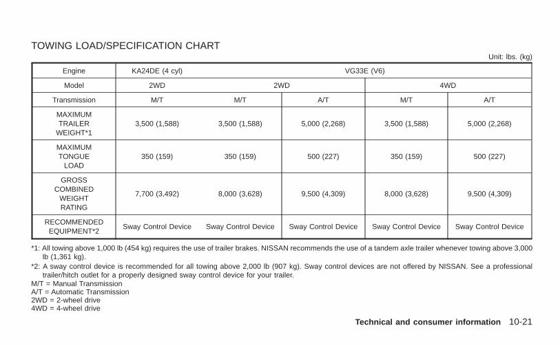
TOWING LOAD/SPECIFICATION CHARTUnit: lbs. (kg)
Engine KA24DE (4 cyl) VG33E (V6)
Model 2WD 2WD 4WD
Transmission M/T M/T A/T M/T A/T
MAXIMUMTRAILER
WEIGHT*13,500 (1,588) 3,500 (1,588) 5,000 (2,268) 3,500 (1,588) 5,000 (2,268)
MAXIMUMTONGUE
LOAD350 (159) 350 (159) 500 (227) 350 (159) 500 (227)
GROSSCOMBINED
WEIGHTRATING
7,700 (3,492) 8,000 (3,628) 9,500 (4,309) 8,000 (3,628) 9,500 (4,309)
RECOMMENDEDEQUIPMENT*2
Sway Control Device Sway Control Device Sway Control Device Sway Control Device Sway Control Device
*1: All towing above 1,000 lb (454 kg) requires the use of trailer brakes. NISSAN recommends the use of a tandem axle trailer whenever towing above 3,000lb (1,361 kg).
*2: A sway control device is recommended for all towing above 2,000 lb (907 kg). Sway control devices are not offered by NISSAN. See a professionaltrailer/hitch outlet for a properly designed sway control device for your trailer.
M/T = Manual TransmissionA/T = Automatic Transmission2WD = 2-wheel drive4WD = 4-wheel drive
Technical and consumer information 10-21
Z X
TOWING SAFETY
Trailer hitchCheck the towing capacity of your bumperhitch or receiver-type frame mounted hitch.Choose a proper hitch for your vehicle andtrailer. A genuine Nissan trailer hitch is avail-able from your NISSAN dealer. Make surethe trailer hitch is securely attached to thevehicle to help avoid personal injury orproperty damage due to sway caused bycrosswinds, rough road surfaces or passingtrucks.
CAUTIONO Special hitches which include frame
reinforcements are required for tow-ing above 2,000 lb (907 kg). Suitablegenuine NISSAN hitches for pickuptrucks and sport utility vehicles areavailable at an authorized NISSANdealer.
O The hitch should not be attached toor affect the operation of the impact-absorbing bumper.
O Do not use axle-mounted hitches.
O Do not modify the vehicle exhaustsystem, brake system, etc. to installa trailer hitch.
O To reduce the possibility of addi-tional damage if your vehicle isstruck from the rear, where practical,remove the hitch and/or receiverwhen not in use.
O After the hitch is removed, seal thebolt holes to prevent exhaust fumes,water or dust from entering the pas-senger compartment.
O Regularly check that all trailer hitchmounting bolts are securelymounted.
Tire pressures
O When towing a trailer, inflate the vehicletires to the recommended cold tire pres-sure indicated on the tire placard (affixedto the inside of the glove box lid).
O Trailer tire condition, size, load rating andproper inflation pressure should be inaccordance with the trailer and tiremanufacturers’ specifications.
Safety chainAlways use suitable safety chains betweenyour vehicle and the trailer. Safety chainsshould be crossed and should be attachedto the hitch, not to the vehicle bumper oraxle. Be sure to leave enough slack in thechain to permit turning corners.
Trailer lightsTrailer lights should comply with Federaland/or local regulations. For assistance inhooking up trailer lights, contact an autho-rized NISSAN dealer.
10-22 Technical and consumer information
Z X
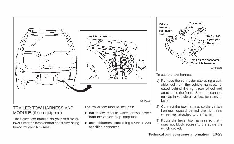
TRAILER TOW HARNESS ANDMODULE (if so equipped)
The trailer tow module on your vehicle al-lows turn/stop lamp control of a trailer beingtowed by your NISSAN.
The trailer tow module includes:
● trailer tow module which draws powerfrom the vehicle stop lamp fuse
● one subharness containing a SAE J1239specified connector
To use the tow harness:
1) Remove the connector cap using a suit-able tool from the vehicle harness, lo-cated behind the right rear wheel wellattached to the frame. Store the connec-tor cap in vehicle glove box for reinstal-lation.
2) Connect the tow harness so the vehicleharness located behind the right rearwheel well attached to the frame.
3) Route the trailer tow harness so that itdoes not block access to the spare tirewinch socket.
LTI0019
WTI0020
Technical and consumer information 10-23
Z X
4) Connect the tow harness connector(SAE J1239) to your trailer.
5) Confirm proper vehicle and trailerstop/turn lamp operation.
6) When towing is completed, disconnectthe tow harness from the trailer and thevehicle. Store the tow harness in theglove box. Reinstall the connector cap tothe vehicle harness.
If you need further assistance in wiringa trailer to your NISSAN, contact an autho-rized NISSAN dealer.
Always confirm proper vehicle andtrailer stop/turn lamp operation everytime the trailer light circuits are con-nected for use.
Trailer brakesIf your trailer is equipped with a brakingsystem, make sure it conforms to Federaland/or local regulations and that it is prop-erly installed.
WARNINGNever connect a trailer brake systemdirectly to the vehicle brake system.
Pre-towing tipsO Be certain your vehicle maintains a level
position when a loaded and/or unloadedtrailer is hitched. Do not drive the vehicleif it has an abnormal nose-up or nose-down condition; check for impropertongue load, overload, worn suspensionor other possible causes of either condi-tion.
O Always secure items in the trailer toprevent load shift while driving.
O Be certain your outside mirrors conformto all federal, state or local regulations. Ifnot, install any mirrors required for towingbefore driving the vehicle.
Trailer towing tipsIn order to gain skill and an understandingof the vehicle’s behavior, you should prac-tice turning, stopping and backing up in anarea which is free from traffic. Steering,stability and braking performance will besomewhat different than under normal driv-ing conditions.
O Always secure items in the trailer toprevent load shift while driving.
O Avoid abrupt starts, acceleration or stops.
O Avoid sharp turns or lane changes.
O Always drive your vehicle at a moderatespeed.
O Always block the wheels on both vehicleand trailer when parking. Parking on aslope is not recommended; however, ifyou must do so, and if your vehicle isequipped with automatic transmission,first block the wheels and apply the park-ing brake, and then move the transmis-sion shift selector lever into the P (Park)position. If you move the shift lever to theP (Park) position before blocking thewheels and applying the parking brake,transmission damage could occur.
O When going down a hill, shift into a lowergear and use the engine braking effect.When ascending a long grade, downshiftthe transmission to a lower gear andreduce speed to reduce chances of en-gine overloading and/or overheating.However, for long steep grades, do notstay in 1st or 2nd gear when drivingabove 35 MPH (56 km/h).
O If the engine coolant rises to an ex-tremely high temperature when the airconditioning system is on, turn off the airconditioner. Coolant heat can be addi-
10-24 Technical and consumer information
Z X
tionally vented by opening the windows,switching the fan control to high andsetting the temperature control to theHOT position.
O Trailer towing requires more fuel thannormal circumstances.
O Avoid towing a trailer for your vehicle’sfirst 500 miles (805 km).
O Have your vehicle serviced more oftenthan at intervals specified in the recom-mended Maintenance Schedule.
O When making a turn, your trailer wheelswill be closer to the inside of the turn thanyour vehicle wheels. To compensate forthis, make a larger than normal turningradius during the turn.
O Crosswinds and rough roads adverselyaffect vehicle/trailer handling, possiblycausing vehicle sway. When beingpassed by larger vehicles, be preparedfor possible changes in crosswinds thatcould affect vehicle handling. If swayingdoes occur, firmly grip the steeringwheel, steer straight ahead, and immedi-ately (but gradually) reduce vehiclespeed. This combination helps to stabi-lize the vehicle. Never increase speed.
O Be careful when passing other vehicles.Passing while towing a trailer requiresconsiderably more distance than normalpassing. Remember the length of thetrailer must also pass the other vehiclebefore you can safely change lanes.
O To maintain engine braking efficiencyand electrical charging performance, donot use fifth gear (manual transmission)or overdrive (automatic transmission).
O Avoid holding the brake pedal down toolong or too frequently. This could causethe brakes to overheat, resulting in re-duced braking efficiency.
When towing a trailer, change oil in thetransmission more frequently. For addi-tional information see the ‘‘Mainte-nance’’ section earlier in this manual.
DOT (Department of Transportation) QualityGrades: All passenger car tires must con-form to Federal Safety Requirements inaddition to these grades.
Quality grades can be found where appli-cable on the tire sidewall between treadshoulder and maximum section width. Forexample:
Treadwear 200 Traction AA Temperature A
Treadwear
Treadwear grade is a comparative ratingbased on tire wear rate when tested undercontrolled conditions on specified govern-ment test courses. For example, a tiregraded 150 would wear one and a half(1-1/2) times as well on the governmentcourse as a tire graded 100. However, rela-tive tire performance depends on actualdriving conditions, and may vary signifi-cantly due to variations in driving habits,service practices and differences in roadcharacteristics and climate.
Traction AA, A, B and C
The traction grades from highest to lowestare AA, A, B, and C. Those grades repre-sent the tire’s ability to stop on wet pave-
UNIFORM TIRE QUALITYGRADING
Technical and consumer information 10-25
Z X
ment as measured under controlled condi-tions on specified government test surfacesof asphalt and concrete. A tire marked Cmay have poor traction performance.
WARNINGThe traction grade assigned to your ve-hicle tires is based on straight-aheadbraking traction tests, and does not in-clude acceleration, cornering, hydro-planing, or peak traction characteristics.
Temperature A, B and CTemperature grades are A (the highest), B,and C. They represent a tire’s resistance toheat build-up, and its ability to dissipate heatwhen tested under controlled conditions ona specified indoor laboratory test wheel.Sustained high temperature can cause tirematerial to degenerate, reducing tire life.Excessive temperatures can lead to suddentire failure. Grade C corresponds to a per-formance level which all passenger car tiresmust meet under the Federal Motor VehicleSafety Standard No. 109. Grades A and Brepresent higher levels of performance onlaboratory test wheels than the minimumrequired by law.
WARNINGThe temperature grade for this tire isestablished for a tire that is properlyinflated and not overloaded. Excessivespeed, under inflation, or excessiveloading, either separately or in combi-nation, can cause heat build-up andpossible tire failure.
Your NISSAN is covered by the followingemission warranties.
For US
1) Emission Defects Warranty
2) Emission Performance Warranty
For Canada
Emission Control System Warranty
Details of these warranties may be foundwith other vehicle warranties in your War-ranty and Roadside Assistance InformationBooklet which comes with your NISSAN. Ifyou did not receive a Warranty and Road-side Assistance Information Booklet, or itbecomes lost, you may obtain a replace-ment by writing to:
O Nissan North America, Inc.Consumer Affairs DepartmentP.O. Box 191Gardena, CA 90248-0191
O Nissan Canada Inc.5290 Orbitor DriveMississauga, Ontario L4W 4Z5
EMISSION CONTROLSYSTEM WARRANTY
10-26 Technical and consumer information
Z X
If you believe that your vehicle has a defectwhich could cause a crash or could causeinjury or death, you should immediatelyinform the National Highway Traffic SafetyAdministration (NHTSA) in addition to no-tifying NISSAN.
If NHTSA receives similar complaints, itmay open an investigation, and if it findsthat a safety defect exists in a group ofvehicles, it may order a recall and remedycampaign. However, NHTSA cannot be-come involved in individual problems be-tween you, your dealer, or NISSAN.
To contact NHTSA, you may either call theAuto Safety Hotline toll-free at 1-800-424-9393 (or 366-0123 in the Washington, D.C.area) or write to: NHTSA, U.S. Depart-ment of Transportation, Washington, D.C.20590. You can also obtain other informa-tion about motor vehicle safety from theHotline.
You may notify NISSAN by contacting ourConsumer Affairs Department, toll-free, at1-800-NISSAN-1.
In Hawaii call (808) 836-0888.
Due to legal requirements in some statesand Canadian provinces, your vehicle maybe required to be in the ready condition foran Inspection/Maintenance (I/M) test of theemission control system.
The vehicle is set to the ready conditionwhen it is driven through certain drivingpatterns. Usually, the ready condition canbe obtained by ordinary usage of the ve-hicle.
If a powertrain system component is re-paired or the battery is disconnected, thevehicle may be reset to a not ready condi-tion. Before taking the I/M test, drive thevehicle through the following pattern to setthe vehicle to the ready condition.
WARNINGAlways drive the vehicle in a safe andprudent manner according to trafficconditions and obey all traffic laws.
1. Start the engine when the engine coolanttemperature gauge needle points to C.Allow the engine to idle until the gaugeneedle points between the C and H (nor-mal operating temperature).
2. Accelerate the vehicle to 55 mph (88km/h), then quickly release the accelera-tor pedal completely and keep it releasedfor at least 6 seconds.
3. Quickly depress the accelerator pedal fora moment, then drive the vehicle at aspeed of 53 to 60 mph (85 to 97 km/h) forat least 5 minutes.
4. Stop the vehicle.
5. Accelerate the vehicle to 35 mph (55km/h) and maintain the speed for 20seconds.
6. Repeat steps four through five at leastthree times.
7. Accelerate the vehicle to 55 mph (88km/h) and maintain the speed for at least3 minutes.
8. Stop the vehicle and turn the engine off.
9. Repeat steps one through eight at leastone more time.
REPORTING SAFETYDEFECTS (US only)
READINESS FORINSPECTION/MAINTENANCE(I/M) TEST (US only)
Technical and consumer information 10-27
Z X
If steps one through seven are interrupted,repeat the preceding step. Any safe drivingmode is acceptable between steps. Do notstop the engine until step seven is com-pleted. If you cannot or do not want toperform the driving pattern, an authorizedNISSAN dealer can conduct it for you.
Dynamometer testing forInspection/Maintenance (I/M) test(US only)Due to legal requirements in somestates/areas, your vehicle may be tested foremissions on a dynamometer. The transfercontrol lever (if so equipped) MUST be inthe 2H position for I/M testing on a twowheel dynamometer.
WARNINGO If the transfer control lever is not in
the 2H position during the dyna-momter I/M testing, the vehicle couldcome off the dynamometer andcause serious personal injury and/orbody damage to the vehicle.
O Serious damage will occur to the4WD system if the transfer controllever is not in the 2H position.
10-28 Technical and consumer information
Z X
A genuine NISSAN Service Manual is the bestsource of service and repair information foryour vehicle. Filled with wiring diagrams, illus-trations and step-by-step diagnostic and ad-justment procedures, this manual is the sameone used by the factory trained techniciansworking at authorized NISSAN dealerships.Also available are genuine NISSAN Owner’sManuals, and genuine NISSAN Service andOwner’s Manuals for older NISSAN models.
In the USA:
For current pricing and availability of genuineNISSAN Service Manuals for the 2000 modelyear and later, contact:
Tweddle Litho Company1-800-639-8841www.nissan-techinfo.com
For current pricing and availability of genuineNISSAN Service Manuals for the 1999 modelyear and prior, see an authorized NISSANdealer, or contact:
Dyment Distribution Services20770 Westwood Dr.Strongsville OH 441361-800-247-5321
Technical and consumer information 10-29
Z X
For current pricing and availability of genuineNISSAN Owner’s Manuals for the 2001model year and prior, see an authorized NIS-SAN dealer, or contact:
Dyment Distribution Services20770 Westwood Dr.Strongsville OH 441361-800-247-5321
In Canada:To purchase a copy of a genuine NISSANService Manual or Owner’s Manual pleasecontact your nearest NISSAN dealer. For thephone number and location of a NISSANDealer in your area call the NISSAN Satisfac-tion Center at 1-800-387-0122 and a bilingualNISSAN representative will assist you.Also available are genuine NISSAN Serviceand Owner’s Manuals for older NISSANmodels.
IN THE EVENT OF A COLLISION
Unfortunately, accidents do occur. In thisunlikely event, there is some important in-formation you should know.
Many insurance companies routinely autho-rize the use of non-genuine collision parts inorder to cut costs, among other reasons.
Insist on the use of GenuineNissan Collision Parts!
If you want your vehicle to be restored usingparts made to Nissan’s original exactingspecifications - if you want to help it to lastand hold its resale value, the solution issimple. Tell your insurance agent andyour repair shop to only use GenuineNissan Collision Parts. Nissan does notwarrant non-Nissan parts, nor does Nis-san’s warranty apply to damage caused bya non-genuine part.
Using Genuine Nissan Parts can help pro-tect your personal safety, preserve yourwarranty protection and maintain the resalevalue of your vehicle. And if your vehiclewas leased, using Genuine Nissan Partsmay prevent or limit unnecessary excesswear and tear expenses at the end of yourlease.
Nissan designs its hoods with crumplezones to minimize the risk that the hood willpenetrate the windshield of your vehicle inan accident. Non-genuine (imitation) partsmay not provide such built in safeguards.Also, non-genuine parts often show prema-ture wear, rust and corrosion.
Why should you take a chance?In over 40 states, the law says you must beadvised if non-genuine parts are used torepair your vehicle. And some states haveenacted laws that restrict insurance compa-nies from authorizing the use of non-genuine collision parts during the new ve-hicle warranty. These laws help protect you,so you can take action to protect yourself.
It’s your right!If you should need further information visitus at: www.nissandriven.com.
10-30 Technical and consumer information
Z X
11 Index
A
Air bag (See supplemental restraintsystem) ........................................................ 1-9Air bag warning light.................................. 1-13Air cleaner housing filter............................ 8-20Air conditioner
Air conditioner operation ........................ 4-5Air conditioner service ............................ 4-9Air conditioner specification label ....... 10-14Air conditioner system refrigerant andlubrication recommendations................ 10-8Heater and air conditioner controls ........ 4-3
Air flow charts .............................................. 4-6Alarm system (See theft warning) ............. 2-12Anchor point locations ............................... 1-33Antenna...................................................... 4-37Anti-lock brake system (ABS).................... 5-24Anti-lock brake warning light ....................... 2-8Ashtray (See cigarette lighter andashtray) ...................................................... 2-20Audio system
FM-AM radio with cassette player andcompact disc (CD) player ..................... 4-17FM-AM radio with compact disc (CD)changer................................................. 4-24FM-AM radio with compact disc (CD)player .................................................... 4-10Steering wheel audio control switch..... 4-37
Auto-lock free-running hubs ...................... 5-19Automatic
Automatic power window switch .......... 2-27Automatic transmission fluid (ATF)....... 8-13Driving with automatic transmission....... 5-9Transmission selector lever lockrelease .................................................. 5-12
B
Battery........................................................ 8-16Battery replacement (See multi-remotecontrol system) ............................................ 3-7Before starting the engine ........................... 5-8Belts (See drive belts) ............................... 8-18Brake
Anti-lock brake system (ABS) .............. 5-24Brake booster ....................................... 8-25Brake fluid ................................... 10-3, 8-15Brake pedal .......................................... 8-24Brake system........................................ 5-23Brake warning light ................................. 2-8Brake wear indicators.................. 2-11, 8-25Parking brake check............................. 8-24Parking brake operation ....................... 5-14
Break-in schedule ...................................... 5-17Bulb check/instrument panel ....................... 2-7
C
Capacities and recommended fuel/lubricants.................................................... 10-2Car phone or CB radio .............................. 4-38Cargo (See vehicle loadinginformation) .............................................. 10-15Check engine indicator light(See malfunction indicator light) ................ 2-11Child restraint with top tether strap ........... 1-32Child restraints........................................... 1-22Child safety rear door lock .......................... 3-4Cigarette lighter (accessory) andashtray ....................................................... 2-20Cleaning exterior and interior ...................... 7-2Clock .......................................................... 4-12Clutch
Clutch fluid............................................ 8-15Clutch pedal.......................................... 8-26
Cold weather driving.................................. 5-25Controls
Audio controls (steering wheel) ............ 4-37Heater and air conditioner controls ........ 4-3
CoolantCapacities and recommended fuel/lubricants .............................................. 10-2Changing engine coolant........................ 8-6Checking engine coolant level ............... 8-5
Z X
Engine coolant temperature gauge ........ 2-5Corrosion protection .................................... 7-5Cover
Tonneau cover ...................................... 2-25Cruise control............................................. 5-15Cup holders ............................................... 2-22
D
Daytime running light system(Canada only) ............................................ 2-18Defogger switch
Rear window defogger switch .............. 2-17Dimensions and weights.......................... 10-11Door locks.................................................... 3-2Drive belts.................................................. 8-18Driving
Auto-lock free-running hubs ................. 5-19Cold weather driving............................. 5-25Driving with automatic transmission....... 5-9Driving with manual transmission......... 5-13Precautions when starting and driving ... 5-2
E
Economy - fuel........................................... 5-17Emission control information label........... 10-14Emission control system warranty........... 10-26Engine
Before starting the engine ...................... 5-8
Capacities and recommended fuel/lubricants .............................................. 10-2Changing engine coolant........................ 8-6Changing engine oil.............................. 8-10Changing engine oil filter...................... 8-12Checking engine coolant level ............... 8-5Checking engine oil level ....................... 8-9Engine compartment check locations .... 8-3Engine coolant temperature gauge ........ 2-5Engine cooling system ........................... 8-5Engine oil ................................................ 8-9Engine oil and oil filterrecommendation ................................... 10-6Engine oil pressure warning light ........... 2-9Engine oil viscosity ............................... 10-7Engine serial number ......................... 10-13Engine specifications............................ 10-9Starting the engine ................................. 5-8
Exhaust gas (Carbon monoxide)................. 5-2
F
First aid kitFirst aid kit .............................................. 6-2
Flashers (See hazard warning flasherswitch)........................................................ 2-19Floor mat positioning aid ............................. 7-4Fluid
Automatic transmission fluid (ATF)....... 8-13Brake fluid ................................... 10-3, 8-15Capacities and recommended fuel/lubricants .............................................. 10-2
Clutch fluid............................................ 8-15Engine coolant........................................ 8-5Engine oil ................................................ 8-9Power steering fluid.............................. 8-14Window washer fluid ............................ 8-16
F.M.V.S.S. certification label .................... 10-13Front seats
Separate ................................................. 1-2Fuel
Capacities and recommended fuel/lubricants .............................................. 10-2Fuel economy ....................................... 5-17Fuel filler cap ........................................ 3-13Fuel gauge.............................................. 2-6Fuel octane rating................................. 10-4Fuel recommendation........................... 10-4
Fuses ......................................................... 8-27
G
GaugeEngine coolant temperature gauge ........ 2-5Fuel gauge.............................................. 2-6Odometer................................................ 2-3Speedometer .......................................... 2-3Tachometer ............................................. 2-5
Gear Basket (see roof rack with gearbasket) ....................................................... 3-10General maintenance .................................. 9-2
11-2
Z X
H
Hazard warning flasher switch .................. 2-19Headlight and turn signal switch ............... 2-17Headlights .................................................. 8-29Heater
Heater and air conditioner controls ........ 4-3Heater operation..................................... 4-4
Hood release ............................................... 3-8Hubs
Auto-lock free-running hubs ................. 5-19
I
Ignition switch .............................................. 5-6Indicator lights and chimes (See warning/indicator lights and chimes)......................... 2-7Inside mirror............................................... 3-15Instrument brightness control .................... 2-18Interior light and cargo light....................... 2-29
J
Jump starting ............................................... 6-8
K
Key............................................................... 3-2Keyless entry system (See multi-remotecontrol system) ............................................ 3-4
L
LabelsAir conditioner specification label ....... 10-14Emission control information label...... 10-14Engine serial number ......................... 10-13F.M.V.S.S. certification label ............... 10-13Vehicle identification number (VIN)plate .................................................... 10-12Warning labels (for SRS)...................... 1-12
LightAir bag warning light............................. 1-13Bulb check/instrument panel .................. 2-7Headlight and turn signal switch .......... 2-17Headlights............................................. 8-29Interior light and cargo light.................. 2-29Light bulbs ............................................ 8-29Spotlights (See map light) .................... 2-30Warning/indicator lights and chimes....... 2-7
LockChild safety rear door lock ..................... 3-4Door locks............................................... 3-2Power door locks.................................... 3-3Rear door lock ........................................ 3-9
Luggage rack ............................................. 3-10Luggage rack (see roof rack) .................... 3-10Luggage rack (see roof rack with gearbasket) ....................................................... 3-10Luggage (See vehicle loadinginformation) .............................................. 10-15
M
MaintenanceGeneral maintenance ............................. 9-2Inside the vehicle.................................... 9-3Maintenance precautions ....................... 8-2Outside the vehicle................................. 9-2Periodic maintenance schedules............ 9-5Seat belt maintenance.......................... 1-22Under the hood and vehicle ................... 9-4
Malfunction indicator lamp (MIL) ............... 2-11Manual windows ........................................ 2-27Map lights .................................................. 2-30Meters and gauges...................................... 2-2Mirror
Inside mirror.......................................... 3-15Outside mirror control ........................... 3-16
Multi-remote control system ........................ 3-4
O
Octane rating (See fuel octane rating) ...... 10-4Odometer ..................................................... 2-3Oil
Capacities and recommended fuel/lubricants .............................................. 10-2Changing engine oil.............................. 8-10Changing engine oil filter...................... 8-12Checking engine oil level ....................... 8-9Engine oil ................................................ 8-9
11-3
Z X
Engine oil and oil filterrecommendation ................................... 10-6Engine oil viscosity ............................... 10-7
Outside mirror control ................................ 3-16Overheat
If your vehicle overheats ...................... 6-10Owner’s manual order form..................... 10-29
P
ParkingParking brake check............................. 8-24Parking brake operation ....................... 5-14Parking/parking on hills ........................ 5-22
Periodic maintenance schedules................. 9-5Power
Power door locks.................................... 3-3Power steering fluid.............................. 8-14Power steering system ......................... 5-23Power windows..................................... 2-25
PrecautionsMaintenance precautions ....................... 8-2On-pavement and off-road drivingprecautions ............................................. 5-3Precautions on seat belt usage............ 1-14Precautions when starting and driving ... 5-2
Push starting.............................................. 6-10
R
RadioCar phone or CB radio ......................... 4-38FM-AM radio with cassette player andcompact disc (CD) player ..................... 4-17FM-AM radio with compact disc (CD)changer................................................. 4-24FM-AM radio with compact disc (CD)player .................................................... 4-10Steering wheel audio control switch..... 4-37
Readiness for inspection maintenance(I/M) test................................................... 10-27Rear anti-lock brake warning light............... 2-8Rear door lock ............................................. 3-9Rear seat ..................................................... 1-3Rear window defogger switch ................... 2-17Rear window wiper and washerswitches ..................................................... 2-16Registering your vehicle in anothercountry ..................................................... 10-12Remote keyless entry system(See multi-remote control system) .............. 3-4Reporting safety defects (USA)............... 10-27Roof rack with gear basket........................ 3-10
S
SafetyChild safety rear door lock ..................... 3-4Reporting safety defects (USA).......... 10-27
Seat beltPrecautions on seat belt usage............ 1-14Seat belt extenders .............................. 1-22Seat belt maintenance.......................... 1-22Seat belts.............................................. 1-14Three-point type with retractor ............. 1-17Two-point type without retractor(rear center lap belt) ............................. 1-20
Seat belt warning light ................................. 2-9Seats
Adjustment.............................................. 1-2Rear seat ................................................ 1-3Separate seats ....................................... 1-2
Service manual order form ...................... 10-29Shifting
Manual transmission............................. 5-13Skyroof....................................................... 2-27Spark plug replacement............................. 8-19Speedometer ............................................... 2-3Spotlights (See map light) ......................... 2-30SRS warning label ..................................... 1-12Starting
Before starting the engine ...................... 5-8Jump starting .......................................... 6-8Precautions when starting and driving ... 5-2Push starting......................................... 6-10Starting the engine ................................. 5-8
SteeringPower steering fluid.............................. 8-14Power steering system ......................... 5-23Tilting steering wheel............................ 3-14
11-4
Z X
Steering wheel audio control switch.......... 4-37Step rail...................................................... 3-12Sun shade.................................................. 2-28Supplemental restraint system(Supplemental air bag system).................... 1-6Switch
Automatic power window switch .......... 2-27Hazard warning flasher switch ............. 2-19Headlight and turn signal switch .......... 2-17Ignition switch ......................................... 5-6Rear window defogger switch .............. 2-17Rear window wiper and washerswitches ................................................ 2-16Windshield wiper and washer switch ... 2-15
T
Tachometer .................................................. 2-5Theft warning ............................................. 2-12Three-way catalyst....................................... 5-3Tie down hooks.......................................... 2-24Tilting steering wheel ................................. 3-14Tire
Tire chains ............................................ 8-35Tire placard......................................... 10-14Tire pressure......................................... 8-34Tire rotation........................................... 8-36Tires of 4-wheel drive ........................... 8-37Types of tires ........................................ 8-34Uniform tire quality grading ................ 10-25Wheels and tires................................... 8-34Wheel/tire size .................................... 10-10
Towing2-wheel drive models ........................... 6-124-wheel drive models ........................... 6-13Tow truck towing ................................... 6-11Towing load/specification chart........... 10-21Trailer towing ...................................... 10-19
Transfer case............................................. 5-18Transmission
Automatic transmission fluid (ATF)....... 8-13Driving with automatic transmission....... 5-9Driving with manual transmission......... 5-13Selector lever lock release ................... 5-12
Travel (See registering your vehicle inanother country)....................................... 10-12Turn signal switch (See headlight and turnsignal switch) ............................................. 2-17
U
Uniform tire quality grading ..................... 10-25
V
Vehicle dimensions and weights.............. 10-11Vehicle identification number (VIN)(chassis number) ..................................... 10-12Vehicle identification number (VIN)plate ......................................................... 10-12Vehicle loading information...................... 10-15Vehicle recovery ........................................ 6-14Ventilators .................................................... 4-2
W
WarningAir bag warning light............................. 1-13Hazard warning flasher switch ............. 2-19Theft warning........................................ 2-12Warning labels (for SRS)...................... 1-12Warning/indicator lights and chimes....... 2-7
Weights (See dimensions and weights) .. 10-11Wheels and tires........................................ 8-34Wheel/tire size ......................................... 10-10When traveling or registering your vehiclein another country.................................... 10-12Window washer fluid.................................. 8-16Windows
Manual windows ................................... 2-27Power windows..................................... 2-25
Windshield wiper and washer switch ........ 2-15Wiper
Rear window wiper and washerswitches ................................................ 2-16Windshield wiper and washer switch ... 2-15Wiper blades......................................... 8-22
11-5
Z X

MEMO
Z X
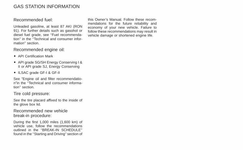
Recommended fuel:
Unleaded gasoline, at least 87 AKI (RON91). For further details such as gasohol ordiesel fuel grade, see ‘‘Fuel recommenda-tion’’ in the ‘‘Technical and consumer infor-mation’’ section.
Recommended engine oil:
O API Certification Mark
O API grade SG/SH Energy Conserving I &II or API grade SJ, Energy Conserving
O ILSAC grade GF-I & GF-II
See 9Engine oil and filter recommendatio-n9in the ‘‘Technical and consumer informa-tion’’ section.
Tire cold pressure:
See the tire placard affixed to the inside ofthe glove box lid.
Recommended new vehiclebreak-in procedure:During the first 1,000 miles (1,600 km) ofvehicle use, follow the recommendationsoutlined in the ‘‘BREAK-IN SCHEDULE’’found in the ‘‘Starting and Driving’’ section of
this Owner’s Manual. Follow these recom-mendations for the future reliability andeconomy of your new vehicle. Failure tofollow these recommendations may result invehicle damage or shortened engine life.
GAS STATION INFORMATION
Z X
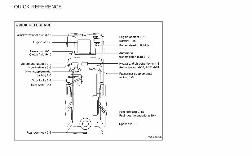
WGS0006
QUICK REFERENCE
Z X


