Embed Size (px)
Citation preview
16
3456789
what should be meant by a “biorefinery” and in the next section we provide some of the defini-tions and additional meaning that has been attached to the concept. To give a more in-depth understanding of what a biorefinery might be, the following sections describe process technolo-gies that are often considered as key constituent parts of biorefineries and some opportunities for integration in existing processing industry that also can be viewed as biorefining.
DEFINITIONS AND CONNOTATIONSThere exist several definitions of a biorefinery and biorefining. The preference for one over the other often depends on context. Two widely used definitions are formulated by IEA and NREL, respectively:
“Biorefining is the sustainable processing of biomass into a spectrum of marketable products and energy.”1
“A biorefinery is a facility that integrates biomass conversion processes and equipment to produce fuels, power, and chemicals from biomass.”2
1 IEA (International Energy Agency) Bioenergy Task 42 on Biorefineries. Minutes of the third Task meeting, Copenha-gen, Denmark, 25 and 26 March (2008).2 NREL Biomass Research, accessed 2011-11-07
INTRODUCTIONThe term “biorefinery” appeared in the 1990’s in response to a least four industry trends. First, there was an increased awareness in industry of the need to use biomass resources in a more rational way both economically and environmen-tally. The environmental issue was both policy and consumer driven. Second, there was a growing interest in upgrading more low-quality lignocel-lulosic biomass to valuable products. Third, there was an increased attention to the production of starch for energy applications. Finally, there was a perceived need to develop more high-value products and diversify the product mix in order to meet global competition and, in some cases, utilise an excess of biomass (especially in the pulp and paper industry).
In a biorefinery, biomass is upgraded to one or more valuable products such as transport fuels, materials, chemicals, electricity and, as byprod-uct, heat (Chapter 3). In principle all types of biomass can be used, e.g. wood, straw, starch, sugars, waste and algae (Chapter 4). But there is more to it than that. The aim of this chapter is to explain in some more detail what a biorefinery is or could be.
There have been many attempts to determine
1
w
2 WHAT IS A BIOREFINERY?Thore Berntsson, Björn Sandén Department of Energy and Environment, Chalmers University of Technology*
Lisbeth Olsson, Department of Chemical and Biological Engineering Chalmers University of Technology*
Anders Åsblad, Chalmers Industriteknik
*Divisions of Heat and Power Technology (T. Berntsson), Environmental Systems Analysis (B. Sandén), Industrial Biotechnology (L. Olsson). Chapter reviewers: Hans Theliander, Forest Products and Chemical Engineering, Chemical and Biological Engineering; Fredrik Hedenus, Physical Resource Theory, Energy and Environment, Chalmers.
brought to you by COREView metadata, citation and similar papers at core.ac.uk
provided by Chalmers Publication Library

17
123456789
a broad range of technical systems, there are several “grey zones” with configurations that some would consider to be biorefineries while others would not.
A biorefinery can produce traditional products from biomass, e g electricity and heat. Some would not consider a plant that only produces electricity and heat to be a biorefinery. If these traditional products are produced with a higher efficiency or if the system for some other reason is considerably improved through a non-traditional upgrading of the biomass (e.g. via gasification), more people would probably accept the biore-finery label. Thus, the biorefinery concept also connotes novelty, something “non-traditional” or even something more “efficient” or “better”.
In contrast, some technologies are so novel that they for this reason are excluded from lists of biorefinery concepts. On example of a new tech-nology under development is biodiesel from algal production and fermentation. This technology is still at the research stage but can be an alterna-tive to other vegetable as well as fossil oils. There is still a lack of knowledge about possible plant configurations and their technical and economic characteristics.
Most definitions allude to processes that upgrade biomass all the way to some type of end product (see Chapter 1 for discussion of end products and system delineation). In some industrial applications, however, upgraded biomass is used as an energy carrier or in an intermediate process and is not a part of the end product. Obvious examples are from the iron and steel industry, in which biomass in the future could be used for chemical reduction instead of coal. Is this a biorefinery? As discussed below, in order to use biomass it must first be upgraded to e.g. “bio-coke” or gas. This means that “biorefining” is needed, and this refining can be integrated with subsequent processes. Hence one can argue that this type of system should be included in a complete list of biorefinery concepts.
Two definitions related specifically to biorefiner-ies in the forest industry add the requirement of economic optimisation:
“Full utilization of the incoming biomass and other raw materials for simultaneous and eco-nomically optimized production of fibres, chemi-cals and energy.”3
“Maximising the economic value from trees,” which requires “an improved business model and corporate transformation”.4
In his speech on the Biorefinery Joint Call Info Day (Brussels, 16 September 2008), the European commissioner for environment Janez Potočnik defined sustainable biorefineries as:
“Facilities that can combine biomass conversion processes and equipment to generate fuels, power and new materials … in an economically, socially and environmentally sustainable way.”5
All definitions include biomass upgrading. The incentives for upgrading differ, for some the sustainability of the system and of the biomass use is enough, for some the combination of sustainability and high-value products (economic incentive or optimisation) is included. The use of “system” only means the biorefinery system itself, not necessarily any integration with a process industry or other large energy system (e.g. district heating). Furthermore, a biorefinery can be a “polygeneration plant” that produces many products simultaneously, but not necessarily so. With the definitions available, a biorefinery can be anything from one single machine for conver-sion of biomass up to a complex, polygeneration plant integrated with other industries and energy systems.
Since the concept of a biorefinery can cover
3 Swedish Pulp Mill Biorefineries, Swedish Energy Agency, ER 2008:264 Paul Stuart, Biorefinery 101: Maximizing Benefits and Minimizing Risks Associated with Implementing the Forest Biorefinery”, PIRA webinar, 2011-04-13.5 http://circa.europa.eu/Public/irc/rtd/susbioref/library?l=/biorefinery_info/commissionerpdf/_EN_1.0_&a=d , accessed 2011-11-07.
18
123456789
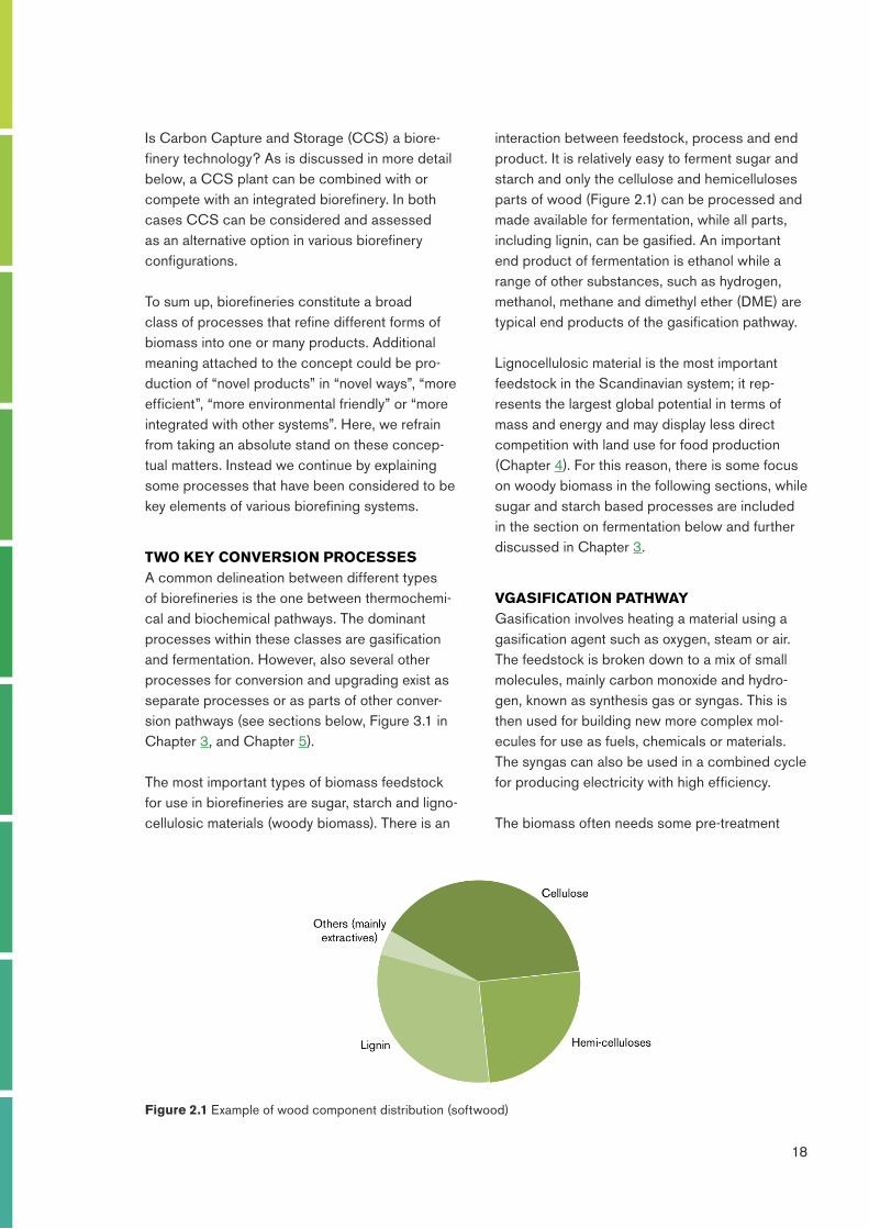
interaction between feedstock, process and end product. It is relatively easy to ferment sugar and starch and only the cellulose and hemicelluloses parts of wood (Figure 2.1) can be processed and made available for fermentation, while all parts, including lignin, can be gasified. An important end product of fermentation is ethanol while a range of other substances, such as hydrogen, methanol, methane and dimethyl ether (DME) are typical end products of the gasification pathway.
Lignocellulosic material is the most important feedstock in the Scandinavian system; it rep-resents the largest global potential in terms of mass and energy and may display less direct competition with land use for food production (Chapter 4). For this reason, there is some focus on woody biomass in the following sections, while sugar and starch based processes are included in the section on fermentation below and further discussed in Chapter 3.
VGASIFICATION PATHWAYGasification involves heating a material using a gasification agent such as oxygen, steam or air. The feedstock is broken down to a mix of small molecules, mainly carbon monoxide and hydro-gen, known as synthesis gas or syngas. This is then used for building new more complex mol-ecules for use as fuels, chemicals or materials. The syngas can also be used in a combined cycle for producing electricity with high efficiency.
The biomass often needs some pre-treatment
Is Carbon Capture and Storage (CCS) a biore-finery technology? As is discussed in more detail below, a CCS plant can be combined with or compete with an integrated biorefinery. In both cases CCS can be considered and assessed as an alternative option in various biorefinery configurations.
To sum up, biorefineries constitute a broad class of processes that refine different forms of biomass into one or many products. Additional meaning attached to the concept could be pro-duction of “novel products” in “novel ways”, “more efficient”, “more environmental friendly” or “more integrated with other systems”. Here, we refrain from taking an absolute stand on these concep-tual matters. Instead we continue by explaining some processes that have been considered to be key elements of various biorefining systems.
TWO KEY CONVERSION PROCESSESA common delineation between different types of biorefineries is the one between thermochemi-cal and biochemical pathways. The dominant processes within these classes are gasification and fermentation. However, also several other processes for conversion and upgrading exist as separate processes or as parts of other conver-sion pathways (see sections below, Figure 3.1 in Chapter 3, and Chapter 5).
The most important types of biomass feedstock for use in biorefineries are sugar, starch and ligno-cellulosic materials (woody biomass). There is an
Figure 2.1 Example of wood component distribution (softwood)
19
123456789
require different feedstock quality with respect to moisture and particle size. A dry fuel is always advantageous from an efficiency point of view (Chapter 6), but is not always required from a practical perspective.
The fixed bed gasifier requires a coarse biomass feed. Particle diameters in the range 3-50 mm are preferred. Some biomass material needs to be pelletized before use. Moisture in the fuel can be handled although, according to some sources, the moisture content should not exceed 40% for optimal performance.
In fludized bed gasifiers, the particle diameter is normally in the range 0.1- 5 mm. Moisture is normally not a practical problem although high moisture content leads to lower process efficien-cies. Dried biomass is therefore preferred.
Entrained flow gasifiers normally require dried material. It is not primarily the gasifier that sets the drying requirements, but the crushers, conveyors and gasifier charging systems that needs a dry fuel to maintain a continuous flow of biomass to the gasifier. The particles must be small, typically diameters below 0.1 mm for coal. However, since biomass is more reactive than coal there are studies indicating that particle sizes up to 1 mm, or even 2 mm, can be accepted.
Hence, depending on the type of gasifier, differ-ent pre-treatment methods are required such as drying, crushing and grinding. It could be noted that disintegration of wood into small particles by crushing and grinding6 requires substantially more power than disintegration of coal to the same particle size.
6 Comminution is the professional term for this operation.
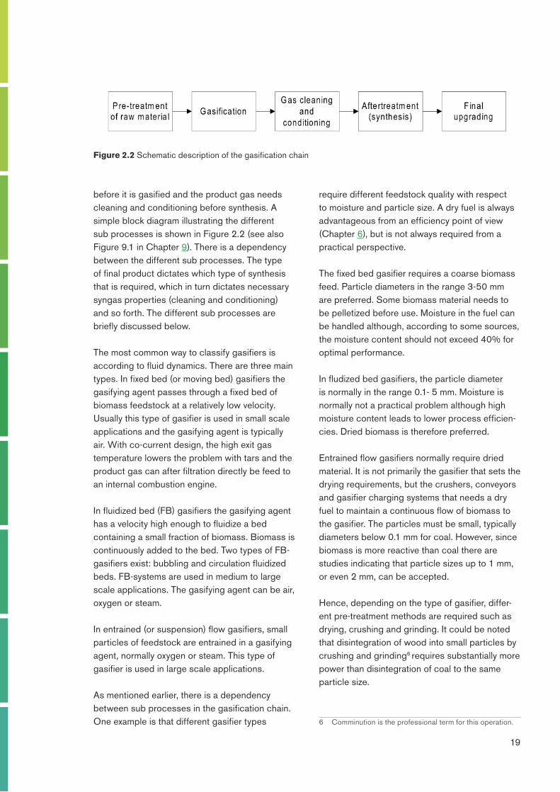
before it is gasified and the product gas needs cleaning and conditioning before synthesis. A simple block diagram illustrating the different sub processes is shown in Figure 2.2 (see also Figure 9.1 in Chapter 9). There is a dependency between the different sub processes. The type of final product dictates which type of synthesis that is required, which in turn dictates necessary syngas properties (cleaning and conditioning) and so forth. The different sub processes are briefly discussed below.
The most common way to classify gasifiers is according to fluid dynamics. There are three main types. In fixed bed (or moving bed) gasifiers the gasifying agent passes through a fixed bed of biomass feedstock at a relatively low velocity. Usually this type of gasifier is used in small scale applications and the gasifying agent is typically air. With co-current design, the high exit gas temperature lowers the problem with tars and the product gas can after filtration directly be feed to an internal combustion engine.
In fluidized bed (FB) gasifiers the gasifying agent has a velocity high enough to fluidize a bed containing a small fraction of biomass. Biomass is continuously added to the bed. Two types of FB-gasifiers exist: bubbling and circulation fluidized beds. FB-systems are used in medium to large scale applications. The gasifying agent can be air, oxygen or steam.
In entrained (or suspension) flow gasifiers, small particles of feedstock are entrained in a gasifying agent, normally oxygen or steam. This type of gasifier is used in large scale applications.
As mentioned earlier, there is a dependency between sub processes in the gasification chain. One example is that different gasifier types
Figure 2.2 Schematic description of the gasification chain
20
123456789
90% of the energy content is retained in the solid product.
The cleaning and conditioning requirements depend on the type of gasifier used and on downstream processing. Both simple filters and chemical reactors (e.g. water gas shift reactors) are included in this category. Low temperature gasifiers (below 1000°C) often need some kind of tar conversion process. Besides carbon mon-oxide and hydrogen, the product gas contains water, methane and higher hydrocarbons. If the final product is not substitute natural gas (SNG), a reformer is often included to reduce the amount of methane and increase the amount of hydrogen in the syngas. Catalysts in the synthesis are often sensitive for impurities like sulphur and for some synthesis reactions it is also necessary to remove carbon dioxide. This necessitates the inclusion of absorption processes like Rectisol or Selexol. The carbon dioxide from these processes could be sent to storage (CCS).
FERMENTATION PATHWAYThe fermentation pathway in a biorefinery concept offers a versatile possibility to convert the sugar-containing polymers, cellulose and hemicellulose, to a range of products. The lignin part of the biomass cannot be converted via the fermentation route.
The core in the fermentation pathway is the fer-mentation step in which microorganisms are used to convert the sugar to a specific product. One of the benefits of microbial sugar conversion is that the microorganisms act as specific catalysts that can produce a range of products. The metabolic capacity of the cell enables microorganisms to produce compounds that cannot be produced, or can be produced only with difficulty, via chemical routes. There are also examples were biochemical and chemical routes are close competitors.
Fermentation processes are traditional pro-cesses, for thousands of years used to preserve food. Since the World War I, fermentation pro-cesses have been used for industrial production of energy carriers and chemicals. The last years’
Another factor to consider is logistics. Untreated biomass is a bulky material and expensive to transport. Therefore, decentralised energy densification could be advantageous when trans-portation distances are long, which is not unlikely considering the size required to enable good economies of scale in gasification. Technologies for energy densification include pyrolysis, lique-faction and torrefaction.
Pyrolysis is a conversion process that produces a liquid oil and char. The oil can be used for elec-tricity or heat production or can be processed further into transportation fuels or chemicals. Fast pyrolysis is a process where biomass is heated rapidly to around 500°C in the absence of oxygen, thereby forming bio-oil, char and some gas. The total energy losses in this process are approximately 20%. Pyrolysis can be of interest in connection with large gasification plants, since converting biomass into a liquid could be a way to reduce transportation costs of feedstock to gasification plants not located close to harbours. It could also facilitate feeding in pressurized (especially entrained flow) gasification plants. Pyrolysis as a biorefining technology is also of interest for other reasons in process industries. For example, the pulp and paper industry can use pyrolysis to convert by-products into bio-oil. The oil refining industry can use it to produce biobased diesel through hydrotreating or crack-ing and the iron and steel industry can use the pyrolysis products, both the oil and the char, as reducing agents in the blast furnace.
Liquefaction is another technology which, like pyrolysis, converts solid biomass feedstock into a liquid. The difference is that liquefaction occurs under high pressure at a lower temperature and in the presence of hydrogen and a catalyst. This technology has a higher reactor complexity, which makes it more expensive and the technology is not as developed as pyrolysis. Torrefaction is a slow thermal degradation of biomass at low temperatures in the absence of oxygen. During the process about 70% of the mass is retained as a solid product resulting in a stable coal-like material and the rest is obtained as gases. About
21
123456789
for this purpose (see Chapter 4). Before such raw material streams can be fermented they need to be converted to a monosaccharide solution.
Major efforts have been made in developing bioethanol production via the fermentation route. Different process concepts have been developed. Below we discuss how such a process may look like as a show-case for how a number of other fermentation products can be produced. The experience from developing the bioethanol process will be very important for the further development of different fermentation pathways and biorefinery concepts.
The lignocellulosic material is first mechanically degraded, i.e. chipped, grinded or milled in order to increase the surface area. Over the years, a number of different methods have been proposed for hydrolysis of the lignocellulosic material. Generally, two routes are employed to hydrolyse the lignocellulosic material. The first route is the
development in life science has further advanced the possibility to design microorganisms for production of selected chemicals that cannot be produced efficiently by microorganisms found in nature.
From a biorefinery perspective, it is of particular interest to use microorganisms to produce chemicals and energy carriers. Examples of fermentation products produced today at an industrial scale are ethanol, lactate, amino acids and citric acid. Several studies show the potential to produce a large range of chemicals in fermen-tation processes, pointing to the possibility to produce all necessary platform chemicals by a fermentation route (see also Chapter 3).
Sugar and starch can easily be fermented with traditional methods. However, also lignocel-lulosic feedstock can be used in more advanced biorefinery concepts, including different waste streams and plants and trees grown especially
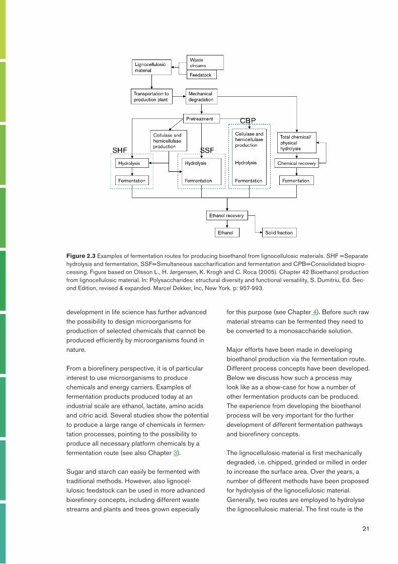
Figure 2.3 Examples of fermentation routes for producing bioethanol from lignocellulosic materials. SHF =Separate hydrolysis and fermentation, SSF=Simultaneous saccharification and fermentation and CPB=Consolidated biopro-cessing. Figure based on Olsson L., H. Jørgensen, K. Krogh and C. Roca (2005). Chapter 42 Bioethanol production from lignocellulosic material. In: Polysaccharides: structural diversity and functional versatility, S. Dumitriu, Ed. Sec-ond Edition, revised & expanded. Marcel Dekker, Inc, New York. p: 957-993.
22
123456789
may either be addressed by optimising the processing steps to decrease the release and production of these compounds or by adapting the microorganism to the fermentation media. A strong research effort is taking place to design microorganisms at the genetic level.
After the fermentation step, the ethanol is recovered in a distillation step. The solid fraction containing lignin and other components can be used to either produce heat and electricity for the production plant or for external energy use, or alternatively be converted to high value co-products (see Chapter 6 for a discussion on how the valuation of byproducts affect the energy conversion efficiency of the process and Chapter 8 for the value of heat).
INTEGRATION OF BIOREFINING IN THE PROCESSING INDUSTRY
In many cases biorefining would benefit from being integrated with a processing industry. This may be crucial in order to achieve reasonable energy efficiency and economy. With the excep-tion of some concepts for producing specialty chemicals in certain pulp mills (Chapter 5), implemented biorefineries in process industries are very rare. This section therefore provides an overview of suggested or planned biorefinery concepts in some process industries.
The pulp and paper industry is, for obvious reasons, a key industry when it comes to biore-finery integration. There are several ongoing and planned projects for implementation of biorefinery options in this industry. Examples are extraction of hemicelluloses and lignin in the pulping process, black liquor gasification, biomass gasification and ethanol production as a part of the pulping process. This is further discussed in Chapter 5.
Most of the metallurgical processes of iron and steel-making industry are energy intensive and are conducted at temperatures above 1,000°C. Steel can be produced from scrap in an electric arc furnace while steel production from iron ore is often carried out in a blast furnace. Raw material
use of acid hydrolysis and the second is the use of a pretreatment process prior to enzymatic hydrolysis. In both cases, there are several possible methods or operation modes and the choice of method has to be based on a number of considerations, e.g., type of feedstock, organ-ism used for fermentation of the released sugars, process integration and overall economics.
Figure 2.3 depicts three different configura-tions of the enzymatic route: (i) SHF, separate hydrolysis and fermentation (ii) SSF, simultane-ous saccharification and fermentation, and (iii) CBP, consolidated bioprocessing. A requisite process step for SHF and SSF is the production of cellulytic and hemicellulytic enzymes (either on-site or in specialised production plants located elsewhere). In SHF, the stream from pretreatment is completely hydrolysed enzymatically before fermentation. SHF offers the opportunity of choosing operating conditions optimised for each step. In SSF, hydrolysis and fermentation occur at the same time. SSF confers a lesser product inhi-bition in the hydrolysis than SHF does, because of concurrent sugar consumption in the fermenta-tion.7 CBP is the most elegant and efficient way of producing ethanol since production of cellulytic and hemicellulytic enzymes, complete hydrolysis and fermentation only demand one process step.
In all fermentation routes, it is of utmost impor-tance that all sugar residues are fermented with high product yield in order to use resources effi-ciently and reach good economic performance. Consequently, the fermentation microorganism must be able to convert all monosaccharides present in the stream to the wanted product with high efficiency. An additional challenge is that the streams are not streams of only monosaccha-rides, but different by-products have accumulated during the processing, including acids (released from the raw material, added as process chemi-cals or stemming from the sugar degradation), furans (sugar degradation product) and phenolics (lignin degradation products). These compounds influence the cellular metabolism and may hamper efficient fermentation. Solutions to this challenge
7 “Product inhibition” means that the product of an enzyme reaction binds to the enzyme and inhibits its activity.
23
123456789
alternative is carbonisation of biomass to enrich the carbon content and remove oxygen. The resulting biomass charcoal can then be injected into the blast furnace.
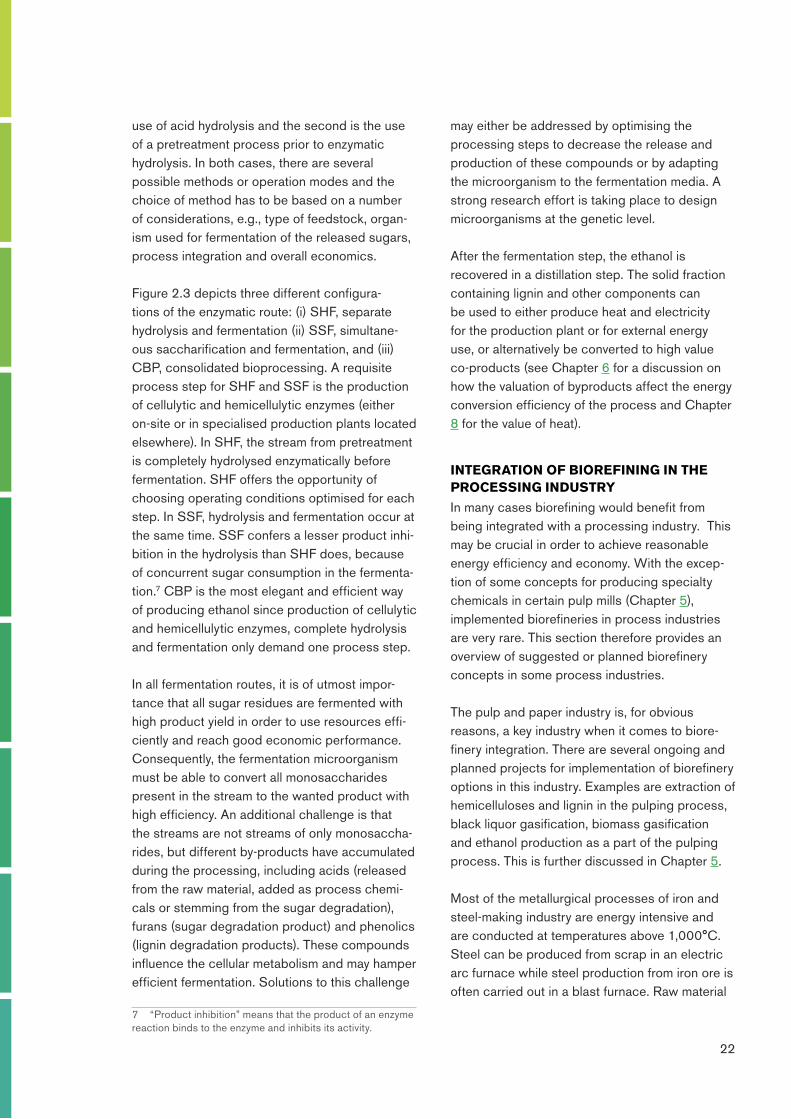
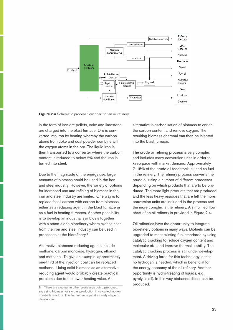
The crude oil refining process is very complex and includes many conversion units in order to keep pace with market demand. Approximately 7- 15% of the crude oil feedstock is used as fuel in the refinery. The refinery process converts the crude oil using a number of different processes depending on which products that are to be pro-duced. The more light products that are produced and the less heavy residues that are left the more conversion units are included in the process and the more complex is the refinery. A simplified flow chart of an oil refinery is provided in Figure 2.4.
Oil refineries have the opportunity to integrate biorefinery options in many ways. Biofuels can be upgraded to meet existing fuel standards by using catalytic cracking to reduce oxygen content and molecular size and improve thermal stability. The catalytic cracking process is still under develop-ment. A driving force for this technology is that no hydrogen is needed, which is beneficial for the energy economy of the oil refinery. Another opportunity is hydro-treating of liquids, e.g. pyrolysis oil). In this way biobased diesel can be produced.
in the form of iron ore pellets, coke and limestone are charged into the blast furnace. Ore is con-verted into iron by heating whereby the carbon atoms from coke and coal powder combine with the oxygen atoms in the ore. The liquid iron is then transported to a converter where the carbon content is reduced to below 2% and the iron is turned into steel.
Due to the magnitude of the energy use, large amounts of biomass could be used in the iron and steel industry. However, the variety of options for increased use and refining of biomass in the iron and steel industry are limited. One way is to replace fossil carbon with carbon from biomass, either as a reducing agent in the blast furnace or as a fuel in heating furnaces. Another possibility is to develop an industrial symbiosis together with a stand-alone biorefinery where excess heat from the iron and steel industry can be used in processes at the biorefinery.8
Alternative biobased reducing agents include methane, carbon monoxide, hydrogen, ethanol and methanol. To give an example, approximately one-third of the injection coal can be replaced methane. Using solid biomass as an alternative reducing agent would probably create practical problems due to the lower heating value. An
8 There are also some other processes being proposed, e g using biomass for syngas production in so called molten iron-bath reactors. This technique is yet at an early stage of development.
Figure 2.4 Schematic process flow chart for an oil refinery
24
123456789
CCS AND BIOREFINERIESCCS (Carbon Capture and Storage) means that CO2 in e.g. flue gases from an industry is captured in an absorption medium and then desorbed in a separate vessel, pressurized and transported to an onshore or offshore storage. To reach very low CO2 emission levels, or even negative emissions, such processes can become important components in future biorefineries and complement or compete with other biorefinery processes.
Currently four CO2 capture processes are developed: post-combustion, pre-combustion, oxy-combustion and chemical looping. All four processes can be of interest in different types of industrial plants. The post-combustion is most commonly discussed for industrial applications and is therefore presented here in some more detail.
Separating CO2 after combustion implies that the CO2 is removed from the flue gases. Several methods are available and the composition and properties of the flue gas decides which method to select. These parameters are in turn depend-ent on the fuel and combustion process used. The post-combustion process can be applied to all combustion plants and is the only method available for retrofit.
The most common method for post-combustion is chemical absorption, since it can handle low partial pressures of CO2. Other methods for post-combustion capture include cryogen and membrane technologies. In chemical absorp-tion, the separation efficiency is relatively high, above 85 %, and an almost pure CO2 stream is produced. The CO2 is then compressed and cooled to liquid state. The process requires large amounts of energy for the regeneration of the absorbent. There are many absorbents being discussed. The two most common ones are MEA (monoethanolamine) and ammonia.
Several studies have shown that the most expen-sive part is the heating for desorption of the CO2.
Transesterification is a process for converting vegetable oils into biodiesel. This process is interesting for industries that have oil residues that can be converted into a biodiesel, such as raw tall oil in the pulp and paper industry, or for industries interested in using biodiesel to blend into petroleum products, such as the oil refining industry.
To meet the increasing demand for hydrogen and at the same time introduce biomass into the petroleum processes, one option could be to produce hydrogen through on-site gasification of biomass. One such pathway could be to co-feed byproducts from the oil refinery, such as coke, with biomass, or biobased energy commodities, into a gasification plant for hydrogen production. Another option is gasification followed by Fischer-Tropsch synthesis of the syngas. Products from the Fischer Tropsch process are naphtha, diesel and wax. To maximise the amount of diesel the wax can be is cracked at the refinery. The naphtha fraction can be converted into gasoline through isomerisation to improve the octane number.
There are large amounts of excess heat at rela-tively high temperature levels in an oil refinery. If there is no district heating system (Chapter 8) or other heat-consuming industry in the vicinity and no planned internal novel use, the heat can be used for biomass drying (to be shipped and finally used elsewhere) or for desorption in a CCS unit (see below).
There are at least two existing biorefinery con-cepts in the oil refinery industry. In 2010, Preem started producing diesel with a 30% renewable content in a modified mild hydrocracker unit. This unit has a capacity of 330,000 m3 diesel per year (11 PJ per year). The renewable feedstock is raw tall oil, which is a by-product from kraft pulp mills (Chapter 5). Neste Oil in Finland is another oil refining company that produces diesel from biobased feedstock (NExBTL) by modifying an existing hydrotreater. NExBTL is to 100% based on palm oil.

25
123456789
into one or many products or services. Additional meaning attached to the concept could be pro-duction of “novel products” in “novel ways”, “more efficient”, “more environmental friendly”, “sustain-able” or “more integrated with other systems”. In this book we embrace this somewhat vague and open umbrella definition.
The biorefinery concept can be filled with real world examples of processes that make use of biomass to produce useful products and services. In this chapter we have discussed gasification and fermentation pathways and a range of possibilities to integrate biorefining in the processing industry to fill the concept with some meaning. In other chapters more content will be added to the concept.
In many industrial applications, this heat could be supplied from available excess heat (tempera-ture levels of 90-120 °C are needed), thereby considerably decreasing the total cost for the whole CCS system. This is a reason why CCS in industry sometimes could achieve the same economy as in coal condensing plants, despite the smaller sizes. On the other hand, the use of excess heat for CCS may compete with other ways of using excess heat in a biorefinery (see Chapters 5 and 8).
CONCLUDING REMARKSDifferent definitions of “biorefinery” have been suggested. We can conclude that “biorefineries” is a concept that represents a broad class of processes that refine different forms of biomass


