Embed Size (px)
Citation preview
Operator’s Manual
Domestic English (EN)
Form No. 3323-139
Wheel Horse 48” Bladefor 5xi Garden TractorsModel 79355—200000001
�The Toro Company – 1999All Rights Reserved Printed in USA2
ContentsPage
Introduction 2. . . . . . . . . . . . . . . . . . . . . . . . . . . . . . . . Installation 3. . . . . . . . . . . . . . . . . . . . . . . . . . . . . . . . .
Loose Parts 3. . . . . . . . . . . . . . . . . . . . . . . . . . . . . . Assembling the Blade 3. . . . . . . . . . . . . . . . . . . . . Tractor Set–up 4. . . . . . . . . . . . . . . . . . . . . . . . . . . Installing the Blade to the Tractor 5. . . . . . . . . . . . Removing the Blade 8. . . . . . . . . . . . . . . . . . . . . . .
Operation 8. . . . . . . . . . . . . . . . . . . . . . . . . . . . . . . . . . Attachment Lift Lever 8. . . . . . . . . . . . . . . . . . . . . Adjusting the Blade Angle 9. . . . . . . . . . . . . . . . . . Adjusting the Blade Trip Springs 10. . . . . . . . . . . . Tips for Using the Blade 10. . . . . . . . . . . . . . . . . . .
Maintenance 10. . . . . . . . . . . . . . . . . . . . . . . . . . . . . . . . Service Interval Chart 10. . . . . . . . . . . . . . . . . . . . . Greasing and Lubrication 11. . . . . . . . . . . . . . . . . . . Reversing the Scraper Blade 11. . . . . . . . . . . . . . . . Storage 12. . . . . . . . . . . . . . . . . . . . . . . . . . . . . . . . .
IntroductionWe want you to be completely satisfied with your newproduct, so feel free to contact your local AuthorizedService Dealer for help with service, genuine replacementparts, or other information you may require.
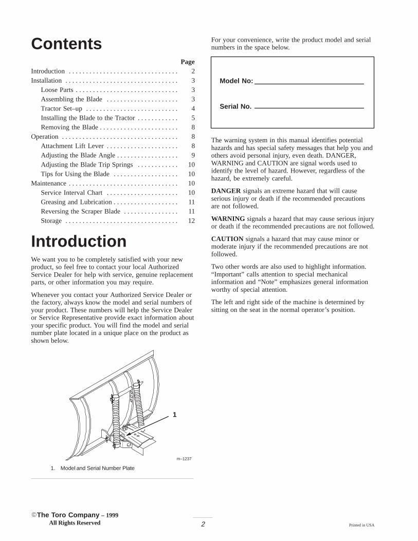
Whenever you contact your Authorized Service Dealer orthe factory, always know the model and serial numbers ofyour product. These numbers will help the Service Dealeror Service Representative provide exact information aboutyour specific product. You will find the model and serialnumber plate located in a unique place on the product asshown below.
m–1237
1
1. Model and Serial Number Plate
For your convenience, write the product model and serialnumbers in the space below.
Model No:
Serial No.
The warning system in this manual identifies potentialhazards and has special safety messages that help you andothers avoid personal injury, even death. DANGER,WARNING and CAUTION are signal words used toidentify the level of hazard. However, regardless of thehazard, be extremely careful.
DANGER signals an extreme hazard that will causeserious injury or death if the recommended precautionsare not followed.
WARNING signals a hazard that may cause serious injuryor death if the recommended precautions are not followed.
CAUTION signals a hazard that may cause minor ormoderate injury if the recommended precautions are notfollowed.
Two other words are also used to highlight information.“Important” calls attention to special mechanicalinformation and “Note” emphasizes general informationworthy of special attention.
The left and right side of the machine is determined bysitting on the seat in the normal operator’s position.
3
InstallationLoose PartsNote: A rear-mount Attach–A–Matic�, which must be purchased separately, is required for this blade. Use the chartbelow to identify other parts used for assembly.
Note: Skids are available for the blade. They can be useful on rough or broken surfaces to keep the blade above theground. Contact your authorized Toro dealer for more information.
DESCRIPTION QTY. USE
Blade assembly
Rod
Cotter pin, 1–1/4 in. (30 mm)
Frame assembly
Bolt, 3/4–16 x 3-3/4 in. (95 mm)
Lock nut, 3/4 in.
Control handle
Cable
Angle control rod
Cable bracket
Hairpin cotter—large
Cotter pin, 1 in. (25 mm)
1
1
1
1
1
1
1
1
1
1
1
3
Assembling the blade
Lift link—slotted
Lift link—two hole
Clevis pin, 3/8 x 1 in. (25 mm)
Clevis pin, 3/8 x 3/4 in. (19 mm)
Hairpin cotter—medium
1
1
2
2
2
Attaching the center of the blade frame to thetractor
Stabilizer
Bolt, 5/16 x 1–1/4 in. (32 mm)
Locknut, 5/16 in.
1
1
1
Attaching the stabilizer
Clevis pin, 3/8 x 1 in. (25 mm)
Hairpin cotter—small
2
2Preparing the tractor attachment lift
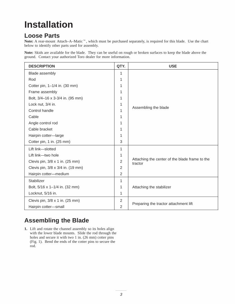
Assembling the Blade1. Lift and rotate the channel assembly so its holes align
with the lower blade mounts. Slide the rod through theholes and secure it with two 1 in. (26 mm) cotter pins(Fig. 1). Bend the ends of the cotter pins to secure therod.
4
13
2
m–3269
3
4
Figure 11. Channel assembly2. Rod
3. Cotter pin 1 in. (25 mm)4. Lower blade mounts
2. Insert one end of the angle control rod up through thehole in the bottom plate of the channel weldment (Fig. 2). Insert a cotter pin and bend the ends of thepin to secure the rod.
2
1
3
m–3271
Figure 21. Angle control rod2. Channel weldment
3. Cotter pin 1 in. (25 mm)
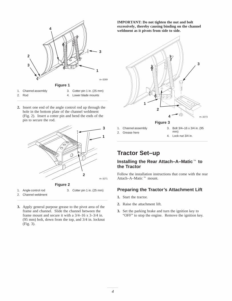
3. Apply general purpose grease to the pivot area of theframe and channel. Slide the channel between theframe mount and secure it with a 3/4–16 x 3–3/4 in.(95 mm) bolt, down from the top, and 3/4 in. locknut(Fig. 3).
IMPORTANT: Do not tighten the nut and boltexcessively, thereby causing binding on the channelweldment as it pivots from side to side.
m–3273
1
2
3
4
Figure 31. Channel assembly2. Grease here
3. Bolt 3/4–16 x 3/4 in. (95mm)
4. Lock nut 3/4 in.
Tractor Set–upInstalling the Rear Attach–A–Matic � tothe Tractor
Follow the installation instructions that come with the rearAttach–A–Matic� mount.
Preparing the Tractor’s Attachment Lift
1. Start the tractor.
2. Raise the attachment lift.
3. Set the parking brake and turn the ignition key to“OFF” to stop the engine. Remove the ignition key.
5
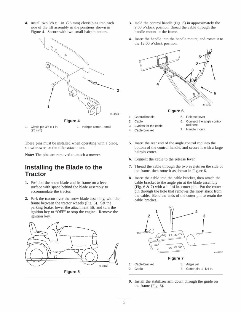
4. Install two 3/8 x 1 in. (25 mm) clevis pins into eachside of the lift assembly in the positions shown inFigure 4. Secure with two small hairpin cotters.
2
1
m–3433
Figure 41. Clevis pin 3/8 x 1 in.
(25 mm)2. Hairpin cotter—small
These pins must be installed when operating with a blade,snowthrower, or the tiller attachment.
Note: The pins are removed to attach a mower.
Installing the Blade to theTractor1. Position the snow blade and its frame on a level
surface with space behind the blade assembly toaccommodate the tractor.
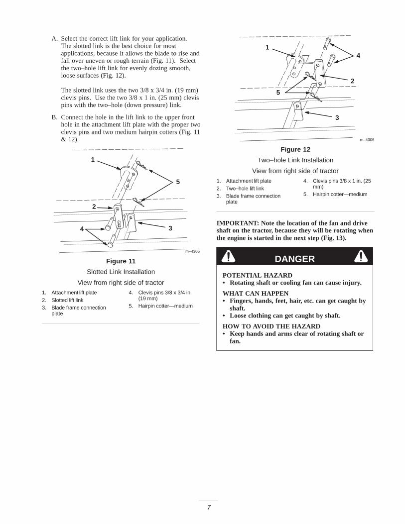
2. Park the tractor over the snow blade assembly, with theframe between the tractor wheels (Fig. 5). Set theparking brake, lower the attachment lift, and turn theignition key to “OFF” to stop the engine. Remove theignition key.
m–3362
Figure 5
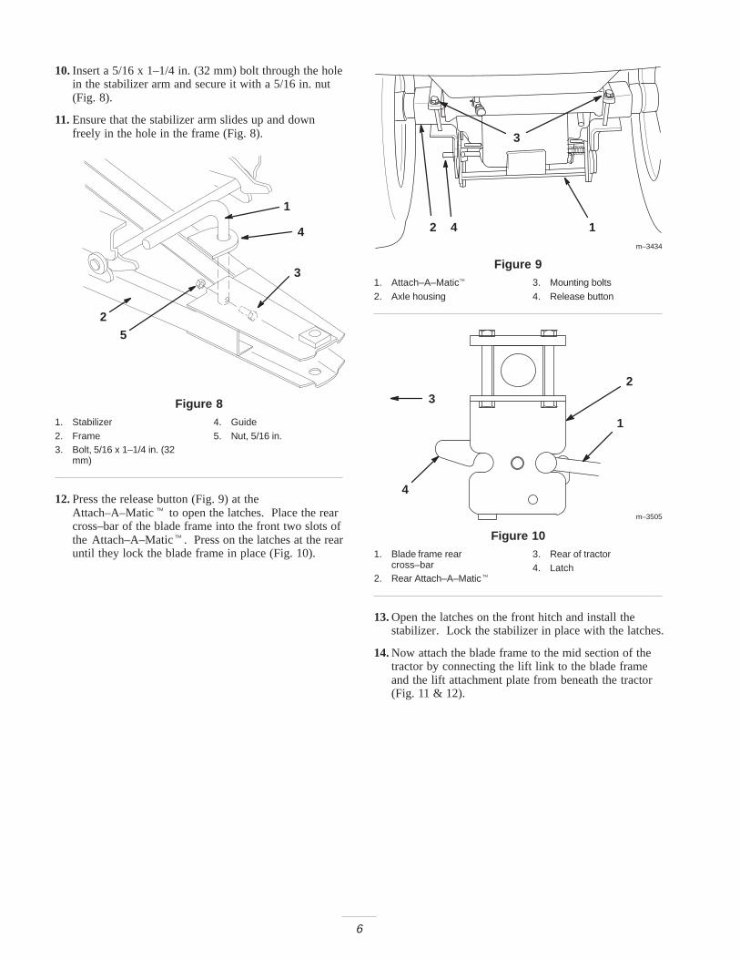
3. Hold the control handle (Fig. 6) in approximately the9:00 o’clock position, thread the cable through thehandle mount in the frame.
4. Insert the handle into the handle mount, and rotate it tothe 12:00 o’clock position.
m–3359
1
2
3
4
5
6
7
Figure 61. Control handle2. Cable3. Eyelets for the cable4. Cable bracket
5. Release lever6. Connect the angle control
rod here7. Handle mount
5. Insert the rear end of the angle control rod into thebottom of the control handle, and secure it with a largehairpin cotter.
6. Connect the cable to the release lever.
7. Thread the cable through the two eyelets on the side ofthe frame, then route it as shown in Figure 6.
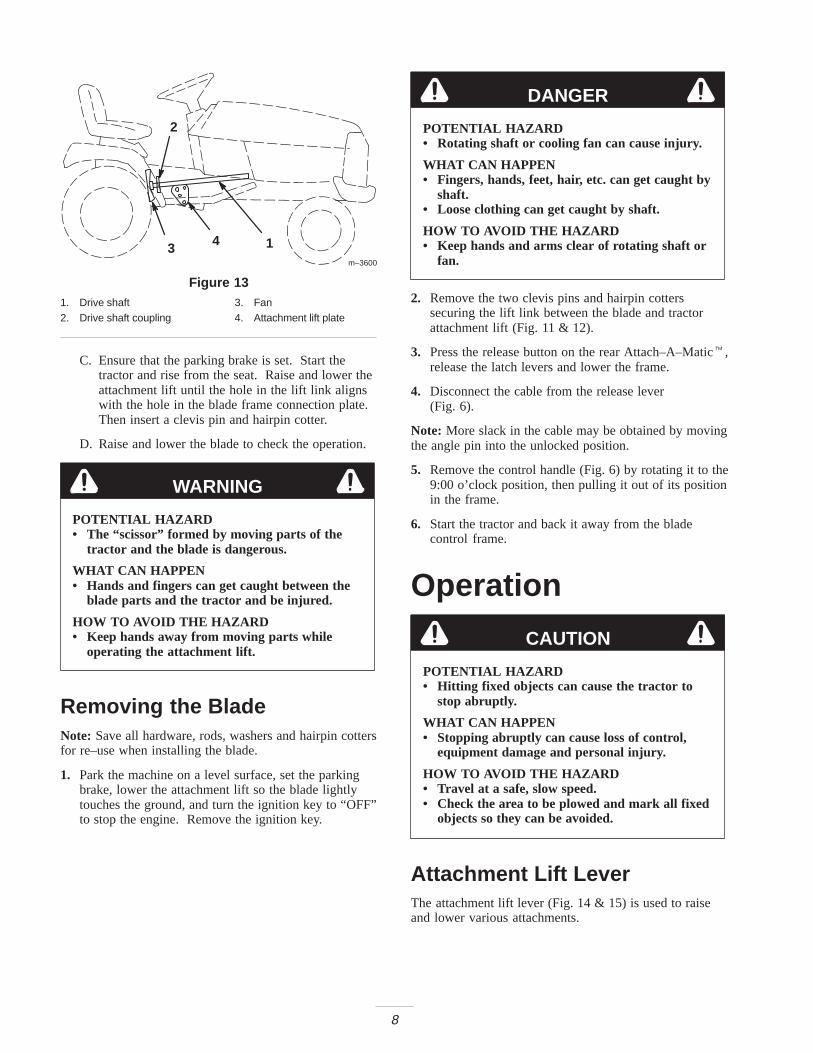
8. Insert the cable into the cable bracket, then attach thecable bracket to the angle pin at the blade assembly(Fig. 6 & 7) with a 1–1/4 in. cotter pin. Put the cotterpin through the hole that removes the most slack fromthe cable. Bend the ends of the cotter pin to retain thecable bracket.
m–3432
1
2 341 4
Figure 71. Cable bracket2. Cable
3. Angle pin4. Cotter pin, 1–1/4 in.
9. Install the stabilizer arm down through the guide onthe frame (Fig. 8).
6
10.Insert a 5/16 x 1–1/4 in. (32 mm) bolt through the holein the stabilizer arm and secure it with a 5/16 in. nut(Fig. 8).
11.Ensure that the stabilizer arm slides up and downfreely in the hole in the frame (Fig. 8).
2
3
4
1
5
Figure 81. Stabilizer2. Frame3. Bolt, 5/16 x 1–1/4 in. (32
mm)
4. Guide5. Nut, 5/16 in.
12.Press the release button (Fig. 9) at theAttach–A–Matic� to open the latches. Place the rearcross–bar of the blade frame into the front two slots ofthe Attach–A–Matic�. Press on the latches at the rearuntil they lock the blade frame in place (Fig. 10).
1m–3434
2
3
4
Figure 91. Attach–A–Matic�2. Axle housing
3. Mounting bolts4. Release button
m–3505
1
23
4
Figure 101. Blade frame rear
cross–bar2. Rear Attach–A–Matic�
3. Rear of tractor4. Latch
13.Open the latches on the front hitch and install thestabilizer. Lock the stabilizer in place with the latches.
14.Now attach the blade frame to the mid section of thetractor by connecting the lift link to the blade frameand the lift attachment plate from beneath the tractor(Fig. 11 & 12).
7
A. Select the correct lift link for your application.The slotted link is the best choice for mostapplications, because it allows the blade to rise andfall over uneven or rough terrain (Fig. 11). Selectthe two–hole lift link for evenly dozing smooth,loose surfaces (Fig. 12).
The slotted link uses the two 3/8 x 3/4 in. (19 mm)clevis pins. Use the two 3/8 x 1 in. (25 mm) clevispins with the two–hole (down pressure) link.
B. Connect the hole in the lift link to the upper fronthole in the attachment lift plate with the proper twoclevis pins and two medium hairpin cotters (Fig. 11& 12).
m–4305
1
2
3
5
4
Figure 11
Slotted Link Installation
View from right side of tractor1. Attachment lift plate2. Slotted lift link3. Blade frame connection
plate
4. Clevis pins 3/8 x 3/4 in.(19 mm)
5. Hairpin cotter—medium
m–4306
1
2
4
5
3
Figure 12
Two–hole Link Installation
View from right side of tractor1. Attachment lift plate2. Two–hole lift link3. Blade frame connection
plate
4. Clevis pins 3/8 x 1 in. (25mm)
5. Hairpin cotter—medium
IMPORTANT: Note the location of the fan and driveshaft on the tractor, because they will be rotating whenthe engine is started in the next step (Fig. 13).
DANGER
POTENTIAL HAZARD• Rotating shaft or cooling fan can cause injury.
WHAT CAN HAPPEN• Fingers, hands, feet, hair, etc. can get caught by
shaft.• Loose clothing can get caught by shaft.
HOW TO AVOID THE HAZARD• Keep hands and arms clear of rotating shaft or
fan.
8
m–3600
1
2
3 4
Figure 131. Drive shaft2. Drive shaft coupling
3. Fan4. Attachment lift plate
C. Ensure that the parking brake is set. Start thetractor and rise from the seat. Raise and lower theattachment lift until the hole in the lift link alignswith the hole in the blade frame connection plate.Then insert a clevis pin and hairpin cotter.
D. Raise and lower the blade to check the operation.
WARNING
POTENTIAL HAZARD• The “scissor” formed by moving parts of the
tractor and the blade is dangerous.
WHAT CAN HAPPEN• Hands and fingers can get caught between the
blade parts and the tractor and be injured.
HOW TO AVOID THE HAZARD• Keep hands away from moving parts while
operating the attachment lift.
Removing the BladeNote: Save all hardware, rods, washers and hairpin cottersfor re–use when installing the blade.
1. Park the machine on a level surface, set the parkingbrake, lower the attachment lift so the blade lightlytouches the ground, and turn the ignition key to “OFF”to stop the engine. Remove the ignition key.
DANGER
POTENTIAL HAZARD• Rotating shaft or cooling fan can cause injury.
WHAT CAN HAPPEN• Fingers, hands, feet, hair, etc. can get caught by
shaft.• Loose clothing can get caught by shaft.
HOW TO AVOID THE HAZARD• Keep hands and arms clear of rotating shaft or
fan.
2. Remove the two clevis pins and hairpin cotterssecuring the lift link between the blade and tractorattachment lift (Fig. 11 & 12).
3. Press the release button on the rear Attach–A–Matic�,release the latch levers and lower the frame.
4. Disconnect the cable from the release lever (Fig. 6).
Note: More slack in the cable may be obtained by movingthe angle pin into the unlocked position.
5. Remove the control handle (Fig. 6) by rotating it to the9:00 o’clock position, then pulling it out of its positionin the frame.
6. Start the tractor and back it away from the bladecontrol frame.
Operation
CAUTION
POTENTIAL HAZARD• Hitting fixed objects can cause the tractor to
stop abruptly.
WHAT CAN HAPPEN• Stopping abruptly can cause loss of control,
equipment damage and personal injury.
HOW TO AVOID THE HAZARD• Travel at a safe, slow speed.• Check the area to be plowed and mark all fixed
objects so they can be avoided.
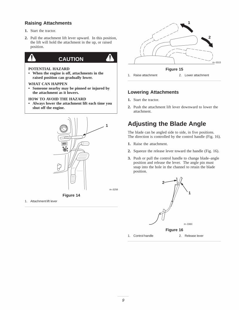
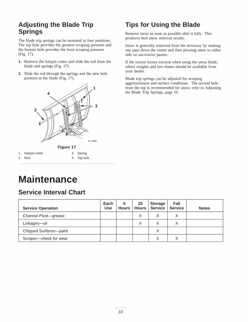
Attachment Lift LeverThe attachment lift lever (Fig. 14 & 15) is used to raiseand lower various attachments.
9
Raising Attachments
1. Start the tractor.
2. Pull the attachment lift lever upward. In this position,the lift will hold the attachment in the up, or raisedposition.
CAUTION
POTENTIAL HAZARD• When the engine is off, attachments in the
raised position can gradually lower.
WHAT CAN HAPPEN• Someone nearby may be pinned or injured by
the attachment as it lowers.
HOW TO AVOID THE HAZARD• Always lower the attachment lift each time you
shut off the engine.
m–3258
1
Figure 141. Attachment lift lever
m–3315
1
2
Figure 151. Raise attachment 2. Lower attachment
Lowering Attachments
1. Start the tractor.
2. Push the attachment lift lever downward to lower theattachment.
Adjusting the Blade AngleThe blade can be angled side to side, in five positions.The direction is controlled by the control handle (Fig. 16).
1. Raise the attachment.
2. Squeeze the release lever toward the handle (Fig. 16).
3. Push or pull the control handle to change blade–angleposition and release the lever. The angle pin mustsnap into the hole in the channel to retain the bladeposition.
m–3360
1
2
Figure 161. Control handle 2. Release lever
10
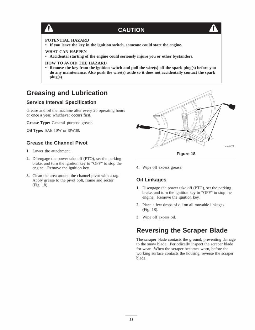
Adjusting the Blade TripSpringsThe blade trip springs can be mounted in four positions.The top hole provides the greatest scraping pressure andthe bottom hole provides the least scraping pressure (Fig. 17).
1. Remove the hairpin cotter and slide the rod from theblade and springs (Fig. 17).
2. Slide the rod through the springs and the new holeposition in the blade (Fig. 17).
m–3395
1
23
4
Figure 171. Hairpin cotter2. Rod
3. Spring4. Top hole
Tips for Using the BladeRemove snow as soon as possible after it falls. Thisproduces best snow removal results.
Snow is generally removed from the driveway by makingone pass down the center and then plowing snow to eitherside on successive passes.
If the tractor looses traction when using the snow blade,wheel weights and tire chains should be available fromyour dealer.
Blade trip springs can be adjusted for scrapingaggressiveness and surface conditions. The second holefrom the top is recommended for snow; refer to Adjustingthe Blade Trip Springs, page 10.
MaintenanceService Interval Chart
Service OperationEachUse
5Hours
25Hours
StorageService
FallService Notes
Channel Pivot—grease X X X
Linkages—oil X X X
Chipped Surfaces—paint X
Scraper—check for wear X X
11
CAUTION
POTENTIAL HAZARD• If you leave the key in the ignition switch, someone could start the engine.
WHAT CAN HAPPEN• Accidental starting of the engine could seriously injure you or other bystanders.
HOW TO AVOID THE HAZARD• Remove the key from the ignition switch and pull the wire(s) off the spark plug(s) before you
do any maintenance. Also push the wire(s) aside so it does not accidentally contact the sparkplug(s).
Greasing and LubricationService Interval Specification
Grease and oil the machine after every 25 operating hoursor once a year, whichever occurs first.
Grease Type: General–purpose grease.
Oil Type: SAE 10W or l0W30.
Grease the Channel Pivot
1. Lower the attachment.
2. Disengage the power take off (PTO), set the parkingbrake, and turn the ignition key to “OFF” to stop theengine. Remove the ignition key.
3. Clean the area around the channel pivot with a rag.Apply grease to the pivot bolt, frame and sector (Fig. 18).
m–1473
Figure 18
4. Wipe off excess grease.
Oil Linkages
1. Disengage the power take off (PTO), set the parkingbrake, and turn the ignition key to “OFF” to stop theengine. Remove the ignition key.
2. Place a few drops of oil on all movable linkages (Fig. 18).
3. Wipe off excess oil.
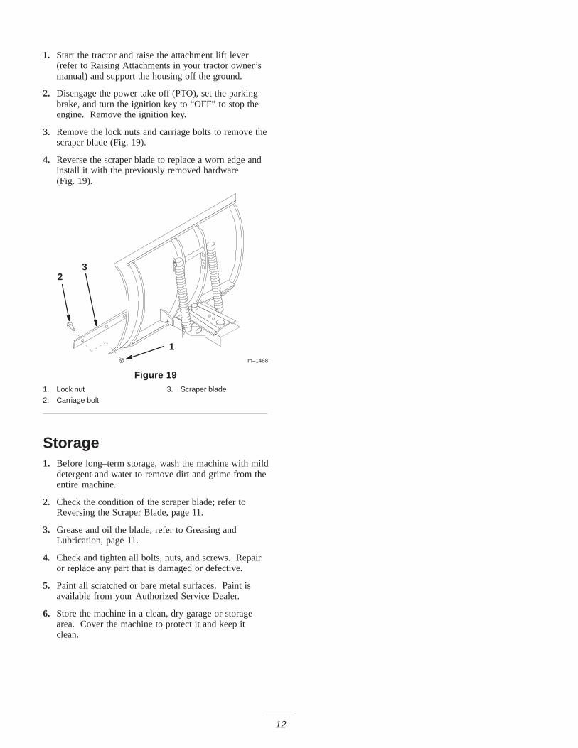
Reversing the Scraper BladeThe scraper blade contacts the ground, preventing damageto the snow blade. Periodically inspect the scraper bladefor wear. When the scraper becomes worn, before theworking surface contacts the housing, reverse the scraperblade.
12
1. Start the tractor and raise the attachment lift lever(refer to Raising Attachments in your tractor owner’smanual) and support the housing off the ground.
2. Disengage the power take off (PTO), set the parkingbrake, and turn the ignition key to “OFF” to stop theengine. Remove the ignition key.
3. Remove the lock nuts and carriage bolts to remove thescraper blade (Fig. 19).
4. Reverse the scraper blade to replace a worn edge andinstall it with the previously removed hardware (Fig. 19).
m–1468
1
23
Figure 191. Lock nut2. Carriage bolt
3. Scraper blade
Storage1. Before long–term storage, wash the machine with mild
detergent and water to remove dirt and grime from theentire machine.
2. Check the condition of the scraper blade; refer toReversing the Scraper Blade, page 11.
3. Grease and oil the blade; refer to Greasing andLubrication, page 11.
4. Check and tighten all bolts, nuts, and screws. Repairor replace any part that is damaged or defective.
5. Paint all scratched or bare metal surfaces. Paint isavailable from your Authorized Service Dealer.
6. Store the machine in a clean, dry garage or storagearea. Cover the machine to protect it and keep itclean.