Embed Size (px)
Citation preview
© 2012 Wi-Fi Alliance. All Rights Reserved. Used with the permission of the Wi-Fi Alliance under the terms set forth above.
1
Wi-Fi Alliance® Technical Committee 2
WMM®-Admission Control Technical Task Group 3
Wi-Fi Multimedia™
Technical Specification 4
(with WMM-Power Save and WMM-Admission Control) 5
Version 1.2.0 6
7
This document is the specification for the Wi-Fi Alliance® Wi-Fi Multimedia (WMM®), a quality of 8
service (QoS) solution for Wi-Fi® networks. Updates to the original specification have added 9
feature sets for WMM-Power Save and WMM-Admission Control. 10
11
12
WI-FI ALLIANCE PROPRIETARY – SUBJECT TO CHANGE WITHOUT NOTICE 13
This document may be used with the permission of the Wi-Fi Alliance under the terms set forth herein. 14 By your use of the document, you are agreeing to these terms. 15
Unless this document is clearly designated as an approved specification, this document is a work in process and is not an 16 approved Wi-Fi Alliance specification. This document is subject to revision or removal at any time without notice. 17
Information contained in this document may be used at your sole risk. The Wi-Fi Alliance assumes no responsibility for 18 errors or omissions in this document. 19
This copyright permission does not constitute an endorsement of the products or services. The Wi-Fi Alliance trademarks 20 and certification marks may not be used unless specifically allowed by the Wi-Fi Alliance. 21
The Wi-Fi Alliance has not conducted an independent intellectual property rights ("IPR") review of this document and the 22 information contained herein, and makes no representations or warranties regarding IPR, including without limitation 23
patents, copyrights or trade secret rights. This document may contain inventions for which you must obtain licenses from 24 third parties before making, using or selling the inventions. 25
The Wi-Fi Alliance owns the copyright in this document and reserves all rights therein. A user of this document may 26 duplicate and distribute copies of the document in connection with the authorized uses described herein, provided any 27 duplication in whole or in part includes the copyright notice and the disclaimer text set forth herein. Unless prior written 28
permission has been received from the Wi-Fi Alliance, any other use of this document and all other duplication and 29 distribution of this document are prohibited. Unauthorized use, duplication, or distribution is an infringement of the Wi-Fi 30
Alliance’s copyright. 31 32
NO REPRESENTATIONS OR WARRANTIES (WHETHER EXPRESS OR IMPLIED) ARE MADE BY THE WI-FI 33 ALLIANCE AND THE WI-FI ALLIANCE IS NOT LIABLE FOR AND HEREBY DISCLAIMS ANY DIRECT, INDIRECT, 34 PUNITIVE, SPECIAL, INCIDENTAL, CONSEQUENTIAL, OR EXEMPLARY DAMAGES ARISING OUT OF OR IN 35
CONNECTION WITH THE USE OF THIS DOCUMENT AND ANY INFORMATION CONTAINED IN THIS DOCUMENT. 36
37
Wi-Fi Multimedia Technical Specification - Version 1.2.0
© 2012 Wi-Fi Alliance. All Rights Reserved. Used with the permission of the Wi-Fi Alliance under the terms as stated in this document.
Page 2 of 45
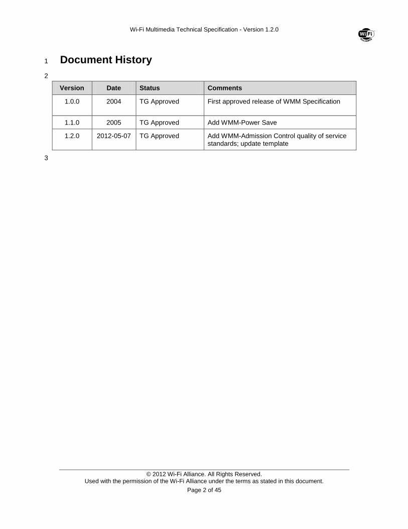
Document History 1
2
Version Date Status Comments
1.0.0 2004 TG Approved
First approved release of WMM Specification
1.1.0 2005 TG Approved Add WMM-Power Save
1.2.0 2012-05-07 TG Approved Add WMM-Admission Control quality of service standards; update template
3
Wi-Fi Multimedia Technical Specification - Version 1.2.0
© 2012 Wi-Fi Alliance. All Rights Reserved. Used with the permission of the Wi-Fi Alliance under the terms as stated in this document.
Page 3 of 45
Contents 1
Contents .......................................................................................................................................... 3 2
List of Figures .................................................................................................................................. 5 3
List of Tables ................................................................................................................................... 6 4
1.0 Overview ............................................................................................................................... 7 5
1.1 References ........................................................................................................................ 7 6
1.2 Terms and Definitions ....................................................................................................... 7 7
1.3 WMM Features .................................................................................................................. 8 8
2.0 WMM Frame Formats ......................................................................................................... 10 9
2.1 Data Frame Formats ....................................................................................................... 10 10
2.1.1 Fields........................................................................................................................ 10 11
2.1.2 Frame Control Field ................................................................................................. 10 12
2.1.3 Duration Field ........................................................................................................... 11 13
2.1.4 Addresses ................................................................................................................ 11 14
2.1.5 Sequence Control Field ........................................................................................... 11 15
2.1.6 QoS Control Field .................................................................................................... 12 16
2.2 Management Frame Formats.......................................................................................... 12 17
2.2.1 WMM Information Element ...................................................................................... 12 18
2.2.2 WMM Parameter Element ....................................................................................... 14 19
2.2.3 Beacon Frame ......................................................................................................... 16 20
2.2.4 Probe Request Frame.............................................................................................. 16 21
2.2.5 Probe Response Frame ........................................................................................... 16 22
2.2.6 Association Request Frame ..................................................................................... 17 23
2.2.7 Association Response Frame .................................................................................. 17 24
2.2.8 Re-Association Request Frame ............................................................................... 17 25
2.2.9 Re-Association Response Frame ............................................................................ 17 26
2.2.10 Management Action Frame ..................................................................................... 17 27
2.2.11 WMM TSPEC Element ............................................................................................ 19 28
3.0 WMM Protocol Specification ............................................................................................... 23 29
3.1 Association and Capability Negotiation ........................................................................... 23 30
3.1.1 Procedure at an AP .................................................................................................. 23 31
3.1.2 Procedure at a STA in an Infrastructure Network .................................................... 23 32
3.1.3 Procedure at a STA in an IBSS ............................................................................... 23 33
3.2 Setting of WMM Parameters ........................................................................................... 24 34
3.2.1 Default WMM parameters ........................................................................................ 24 35
3.2.2 WMM Parameters in an Infrastructure Network ...................................................... 24 36
3.2.3 WMM Parameters in an IBSS .................................................................................. 24 37
3.3 Assignment of Frames to Queues .................................................................................. 25 38
3.3.1 Mappings for Unicast Frames .................................................................................. 25 39
3.3.2 Mappings for Received Unicast Frames at an AP ................................................... 25 40
3.3.3 Mappings for Group Addressed and Buffered Frames at an AP ............................. 26 41
Wi-Fi Multimedia Technical Specification - Version 1.2.0
© 2012 Wi-Fi Alliance. All Rights Reserved. Used with the permission of the Wi-Fi Alliance under the terms as stated in this document.
Page 4 of 45
3.4 Channel Access Protocol ................................................................................................ 26 1
3.4.1 Reference Implementation ....................................................................................... 26 2
3.4.2 Transmit Opportunities & TXOP Limits .................................................................... 27 3
3.4.3 Obtaining an EDCA TXOP ....................................................................................... 27 4
3.4.4 Obtaining a Continuation of TXOP .......................................................................... 29 5
3.4.5 Backoff Procedure ................................................................................................... 30 6
3.4.6 Retransmit Procedures ............................................................................................ 30 7
3.5 ADDTS and DELTS Procedures ..................................................................................... 31 8
3.5.1 Admission Control Procedures ................................................................................ 32 9
3.5.2 Procedures at the AP ............................................................................................... 32 10
3.5.3 Procedure at STAs ................................................................................................... 33 11
3.6 WMM-Power Save Procedures ....................................................................................... 34 12
3.6.1 U-APSD General Operation ..................................................................................... 34 13
3.6.2 U-APSD AP Operation ............................................................................................. 35 14
3.6.3 U-APSD STA Operation........................................................................................... 36 15
A.1 QoS Parameter Updates ................................................................................................. 38 16
A.2 Use of Admission Control and Downgrading .................................................................. 38 17
A.3 Deriving Medium Time .................................................................................................... 38 18
A.4 WMM AP Default Parameter ........................................................................................... 39 19
A.5 Changes to WPA for WMM ............................................................................................. 39 20
A.5.1 Michael MIC Generation .......................................................................................... 39 21
A.5.2 TKIP Replay Counters ............................................................................................. 39 22
A.6 Conveyance of 802.1Q VLAN tags ................................................................................. 40 23
A.7 CCMP processing with QC ............................................................................................. 41 24
A.7.1 AAD Construction with QC ...................................................................................... 41 25
A.7.2 CCM Nonce with Priority Octet ................................................................................ 41 26
A.8 Differences between Legacy DCF Formulation and WMM ............................................. 41 27
A.9 Configuration Procedure (Informative) ............................................................................ 43 28
29
Wi-Fi Multimedia Technical Specification - Version 1.2.0
© 2012 Wi-Fi Alliance. All Rights Reserved. Used with the permission of the Wi-Fi Alliance under the terms as stated in this document.
Page 5 of 45
List of Figures 1
2
Figure 1 WMM QoS Data Frame Format ...................................................................................... 10 3
Figure 2 Frame Control Field [1] .................................................................................................... 10 4
Figure 3 Sequence Control Field ................................................................................................... 11 5
Figure 4 QoS Control Field ............................................................................................................ 12 6
Figure 5 WMM Information Element .............................................................................................. 12 7
Figure 6 QoS Info field when sent from WMM AP ......................................................................... 13 8
Figure 7 QoS Info field when sent from WMM STA ...................................................................... 13 9
Figure 8 WMM Parameter Element ............................................................................................... 14 10
Figure 9 AC Parameters Record Format ....................................................................................... 15 11
Figure 10 ACI/AIFSN Field ............................................................................................................ 15 12
Figure 11 ECWmin/ECWmax field ................................................................................................ 16 13
Figure 12 Management Action Frame Format .............................................................................. 17 14
Figure 13 WMM TSPEC Element .................................................................................................. 19 15
Figure 14 WMM TSPEC Body format............................................................................................ 19 16
Figure 15 TS Info Field in WMM TSPEC Element ........................................................................ 20 17
Figure 16 Nominal MSDU Size Field ............................................................................................. 21 18
Figure 17 Reference Implementation Model ................................................................................. 26 19
Figure 18 EDCA Mechanism Timing ............................................................................................. 29 20
Figure 19 TKIP MIC Processing Format ....................................................................................... 39 21
Figure 20 Frame Format with 802.1Q VLAN tag ........................................................................... 40 22
Figure 21 Frame Format without 802.1Q VLAN Tag..................................................................... 40 23
Figure 22 AAD Construction with QC ............................................................................................ 41 24
Figure 23 Backoff Behavior ........................................................................................................... 42 25
26
Wi-Fi Multimedia Technical Specification - Version 1.2.0
© 2012 Wi-Fi Alliance. All Rights Reserved. Used with the permission of the Wi-Fi Alliance under the terms as stated in this document.
Page 6 of 45
List of Tables 1
2
Table 1 Additional WMM Data Subtype Codes ............................................................................. 11 3
Table 2 Ack Policy Field Values .................................................................................................... 12 4
Table 3 WMM Information Element Field Values .......................................................................... 13 5
Table 4 Max SP Length Usage ...................................................................................................... 14 6
Table 5 WMM Parameter Element Field Values ........................................................................... 15 7
Table 6 ACI to AC coding .............................................................................................................. 16 8
Table 7 Management Action Frame Fields ................................................................................... 18 9
Table 8 Management Action Frame Action Codes ........................................................................ 18 10
Table 9 ADDTS Response Status Codes ..................................................................................... 18 11
Table 10 WMM TSPEC Element Field Values .............................................................................. 20 12
Table 11 Direction Field Values ..................................................................................................... 21 13
Table 12 Power Save Behavior Field Values ................................................................................ 21 14
Table 13 Default WMM Parameters .............................................................................................. 24 15
Table 14 802.1D Priority to AC mappings ..................................................................................... 25 16
Table 15 Default EDCA Parameters for the AP ............................................................................ 39 17
18
Wi-Fi Multimedia Technical Specification - Version 1.2.0
© 2012 Wi-Fi Alliance. All Rights Reserved. Used with the permission of the Wi-Fi Alliance under the terms as stated in this document.
Page 7 of 45
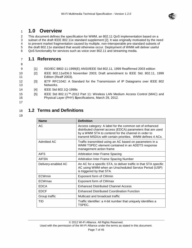
1.0 Overview 1
This document defines the specification for WMM, an 802.11 QoS implementation based on a 2 subset of the draft IEEE 802.11e standard supplement [2]. It was originally motivated by the need 3 to prevent market fragmentation caused by multiple, non-interoperable pre-standard subsets of 4 the draft 802.11e standard that would otherwise occur. Deployment of WMM will deliver useful 5 QoS functionality for services such as voice over 802.11 and streaming media. 6
1.1 References 7
8
[1] ISO/IEC 8802-11:1999(E) ANSI/IEEE Std 802.11, 1999 Reaffirmed 2003 edition 9
[2] IEEE 802.11e/D6.0 November 2003; Draft amendment to IEEE Std. 802.11, 1999 10 Edition (Reaff 2003). 11
[3] IETF RFC1042: A Standard for the Transmission of IP Datagrams over IEEE 802 12 Networks. 13
[4] IEEE Std 802.1Q-1998s 14
[5] IEEE Std 802.11™-2012 Part 11: Wireless LAN Medium Access Control (MAC) and 15 Physical Layer (PHY) Specifications, March 29, 2012. 16
17
1.2 Terms and Definitions 18
19
Name Definition
AC Access category: A label for the common set of enhanced distributed channel access (EDCA) parameters that are used by a WMM STA to contend for the channel in order to transmit MSDUs with certain priorities. WMM defines 4 ACs.
Admitted AC Traffic transmitted using an AC based on parameters in a WMM TSPEC element contained in an ADDTS response management action frame
AIFS Arbitration Inter Frame Spacing
AIFSN Arbitration Inter Frame Spacing Number
Delivery-enabled AC An AC for a specific STA, to deliver traffic in that STA specific AC using WMM when an Unscheduled Service Period (USP) is triggered by that STA.
ECWmin Exponent form of CWmin
ECWmax Exponent form of CWmax
EDCA Enhanced Distributed Channel Access
EDCF Enhanced Distributed Coordination Function
Group traffic Multicast and broadcast traffic
TID Traffic Identifier: a 4-bit number that uniquely identifies a TSPEC.
Wi-Fi Multimedia Technical Specification - Version 1.2.0
© 2012 Wi-Fi Alliance. All Rights Reserved. Used with the permission of the Wi-Fi Alliance under the terms as stated in this document.
Page 8 of 45
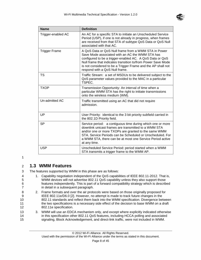
Name Definition
Trigger-enabled AC An AC for a specific STA to initiate an Unscheduled Service Period (USP), if one is not already in progress, when frames are received from that STA of subtype QoS Data or QoS Null associated with that AC.
Trigger Frame A QoS Data or QoS Null frame from a WMM STA in Power Save Mode associated with an AC the WMM STA has configured to be a trigger-enabled AC. A QoS Data or QoS Null frame that indicates transition to/from Power Save Mode is not considered to be a Trigger Frame and the AP shall not respond with a QoS Null frame.
TS Traffic Stream: a set of MSDUs to be delivered subject to the QoS parameter values provided to the MAC in a particular TSPEC.
TXOP Transmission Opportunity: An interval of time when a particular WMM STA has the right to initiate transmissions onto the wireless medium (WM).
Un-admitted AC Traffic transmitted using an AC that did not require admission.
UP User Priority: identical to the 3 bit priority subfield carried in the 802.1D Priority field.
SP Service period: a contiguous time during which one or more downlink unicast frames are transmitted to a WMM STA and/or one or more TXOPs are granted to the same WMM STA. Service Periods can be Scheduled or Unscheduled. For a WMM STA, there can be at most one Service Period active at any time.
USP Unscheduled Service Period: period started when a WMM STA transmits a trigger frame to the WMM AP.
1
1.3 WMM Features 2
The features supported by WMM in this phase are as follows: 3
1. Capability negotiation independent of the QoS capabilities of IEEE 802.11-2012. That is, 4 WMM devices will not advertise 802.11 QoS capability unless they also support those 5 features independently. This is part of a forward compatibility strategy which is described 6 in detail in a subsequent paragraph. 7
2. Frame formats and over the air protocols were based on those originally proposed for 8 IEEE 802.11e/D6.0 [2]. However, no attempt is made to track future changes in the 9 802.11 standards and reflect them back into the WMM specification. Divergence between 10 the two specifications is a necessary side effect of the decision to base WMM on a draft 11 802.11e specification. 12
3. WMM will use an EDCA mechanism only, and except where explicitly indicated otherwise 13 in this specification other 802.11 QoS features, including HCCA polling and associated 14 signaling, Block Acknowledgement, and direct-link traffic, were not included in WMM. 15
Wi-Fi Multimedia Technical Specification - Version 1.2.0
© 2012 Wi-Fi Alliance. All Rights Reserved. Used with the permission of the Wi-Fi Alliance under the terms as stated in this document.
Page 9 of 45
4. Interfaces to the MAC which signal per-packet priority will be consistent with those used 1 for Ethernet, both in terms of the driver API and bridging to other 802 link layers via an 2 802.1D bridge. 3
5. The number of exposed queues will be fixed at four. A fixed mapping of priority 4 information carried in the 802.1D Priority field to those four queues will be defined, 5 together with suggested uses for each priority consistent with the suggested uses in 6 802.1D. 7
Capability negotiation is designed to permit ultimate forward compatibility with 802.11 QoS, taking 8 into account the fact that the formats used for QoS data frames cannot be assumed to remain 9 consistent. It is important feature that, on receipt of a frame, it is possible to uniquely decode it. 10
An AP or STA may support both WMM and 802.11 QoS. Only one may be in use for a specific 11 association at any time, but an AP may permit both 802.11 QoS and WMM associations from 12 different STAs at the same time. 13
A WMM-only AP or STA does not set the “QoS” bit in the capability field of association, beacon 14 and probe management frames. A new WMM Information Element is defined in this specification 15 and is carried in those frames. An AP may support and advertise both 802.11 QoS and WMM in 16 probe responses and beacons, but both association requests and responses must only request or 17 specify one of these capabilities. As a result, a given association uses either WMM or 802.11 18 QoS, but not both, and this defines how data frames with QoS subtypes must be interpreted. 19
Wi-Fi Multimedia Technical Specification - Version 1.2.0
© 2012 Wi-Fi Alliance. All Rights Reserved. Used with the permission of the Wi-Fi Alliance under the terms as stated in this document.
Page 10 of 45
2.0 WMM Frame Formats 1
2.1 Data Frame Formats 2
2.1.1 Fields 3
Data, Control and Management frames are indicated by a type subfield in the frame control field, 4 as defined for [1]. Data frames include additional WMM-specified subtypes and conditional fields. 5
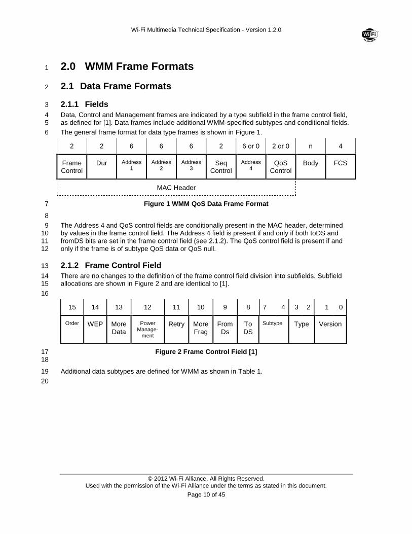
The general frame format for data type frames is shown in Figure 1. 6
2 2 6 6 6 2 6 or 0 2 or 0 n 4
Frame Control
Dur Address 1
Address 2
Address 3
Seq Control
Address 4
QoS Control
Body FCS
MAC Header
Figure 1 WMM QoS Data Frame Format 7
8
The Address 4 and QoS control fields are conditionally present in the MAC header, determined 9 by values in the frame control field. The Address 4 field is present if and only if both toDS and 10 fromDS bits are set in the frame control field (see 2.1.2). The QoS control field is present if and 11 only if the frame is of subtype QoS data or QoS null. 12
2.1.2 Frame Control Field 13
There are no changes to the definition of the frame control field division into subfields. Subfield 14 allocations are shown in Figure 2 and are identical to [1]. 15
16
15 14 13 12 11 10 9 8 7 4 3 2 1 0
Order WEP More Data
Power Manage-
ment
Retry More Frag
From Ds
To DS
Subtype Type Version
Figure 2 Frame Control Field [1] 17 18
Additional data subtypes are defined for WMM as shown in Table 1. 19
20
Wi-Fi Multimedia Technical Specification - Version 1.2.0
© 2012 Wi-Fi Alliance. All Rights Reserved. Used with the permission of the Wi-Fi Alliance under the terms as stated in this document.
Page 11 of 45
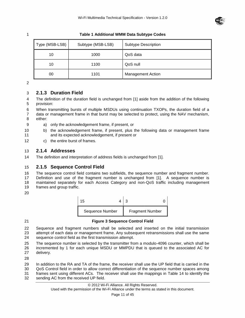
Table 1 Additional WMM Data Subtype Codes 1
Type (MSB-LSB) Subtype (MSB-LSB) Subtype Description
10 1000 QoS data
10 1100 QoS null
00 1101 Management Action
2
2.1.3 Duration Field 3
The definition of the duration field is unchanged from [1] aside from the addition of the following 4 provision: 5
When transmitting bursts of multiple MSDUs using continuation TXOPs, the duration field of a 6 data or management frame in that burst may be selected to protect, using the NAV mechanism, 7 either: 8
a) only the acknowledgement frame, if present, or 9
b) the acknowledgement frame, if present, plus the following data or management frame 10 and its expected acknowledgement, if present or 11
c) the entire burst of frames. 12
2.1.4 Addresses 13
The definition and interpretation of address fields is unchanged from [1]. 14
2.1.5 Sequence Control Field 15
The sequence control field contains two subfields, the sequence number and fragment number. 16 Definition and use of the fragment number is unchanged from [1]. A sequence number is 17 maintained separately for each Access Category and non-QoS traffic including management 18 frames and group traffic. 19
20
15 4 3 0
Sequence Number Fragment Number
Figure 3 Sequence Control Field 21
Sequence and fragment numbers shall be selected and inserted on the initial transmission 22 attempt of each data or management frame. Any subsequent retransmissions shall use the same 23 sequence control field as the first transmission attempt. 24
The sequence number is selected by the transmitter from a modulo-4096 counter, which shall be 25 incremented by 1 for each unique MSDU or MMPDU that is queued to the associated AC for 26 delivery. 27
28
In addition to the RA and TA of the frame, the receiver shall use the UP field that is carried in the 29 QoS Control field in order to allow correct differentiation of the sequence number spaces among 30 frames sent using different ACs. The receiver shall use the mappings in Table 14 to identify the 31 sending AC from the received UP field. 32
Wi-Fi Multimedia Technical Specification - Version 1.2.0
© 2012 Wi-Fi Alliance. All Rights Reserved. Used with the permission of the Wi-Fi Alliance under the terms as stated in this document.
Page 12 of 45
2.1.6 QoS Control Field 1
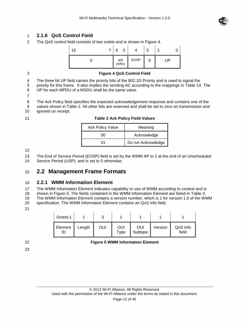
The QoS control field consists of two octets and is shown in Figure 4. 2
15 7 6 5 4 3 2 0
0 ack policy
EOSP 0 UP
Figure 4 QoS Control Field 3
The three bit UP field carries the priority bits of the 802.1D Priority and is used to signal the 4 priority for this frame. It also implies the sending AC according to the mappings in Table 14. The 5 UP for each MPDU of a MSDU shall be the same value. 6
7
The Ack Policy field specifies the expected acknowledgement response and contains one of the 8 values shown in Table 2. All other bits are reserved and shall be set to zero on transmission and 9 ignored on receipt. 10
Table 2 Ack Policy Field Values 11
Ack Policy Value Meaning
00 Acknowledge
01 Do not Acknowledge
12
The End of Service Period (EOSP) field is set by the WMM AP to 1 at the end of an Unscheduled 13 Service Period (USP), and is set to 0 otherwise. 14
2.2 Management Frame Formats 15
2.2.1 WMM Information Element 16
The WMM Information Element indicates capability or use of WMM according to context and is 17 shown in Figure 5. The fields contained in the WMM Information Element are listed in Table 3. 18 The WMM Information Element contains a version number, which is 1 for version 1.0 of the WMM 19 specification. The WMM Information Element contains an QoS Info field. 20
21
Octets:1 1 3 1 1 1 1
Element ID
Length OUI OUI Type
OUI Subtype
Version QoS Info field
Figure 5 WMM Information Element 22
23
Wi-Fi Multimedia Technical Specification - Version 1.2.0
© 2012 Wi-Fi Alliance. All Rights Reserved. Used with the permission of the Wi-Fi Alliance under the terms as stated in this document.
Page 13 of 45
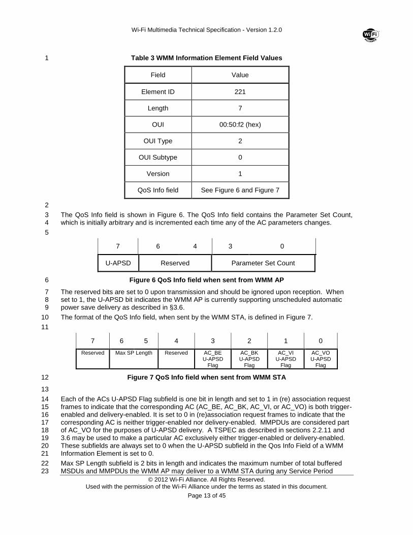
Table 3 WMM Information Element Field Values 1
Field Value
Element ID 221
Length 7
OUI 00:50:f2 (hex)
OUI Type 2
OUI Subtype 0
Version 1
QoS Info field See Figure 6 and Figure 7
2
The QoS Info field is shown in Figure 6. The QoS Info field contains the Parameter Set Count, 3 which is initially arbitrary and is incremented each time any of the AC parameters changes. 4
5
7 6 4 3 0
U-APSD Reserved Parameter Set Count
Figure 6 QoS Info field when sent from WMM AP 6
The reserved bits are set to 0 upon transmission and should be ignored upon reception. When 7 set to 1, the U-APSD bit indicates the WMM AP is currently supporting unscheduled automatic 8 power save delivery as described in §3.6. 9
The format of the QoS Info field, when sent by the WMM STA, is defined in Figure 7. 10
11
7 6 5 4 3 2 1 0
Reserved Max SP Length Reserved AC_BE U-APSD
Flag
AC_BK U-APSD
Flag
AC_VI U-APSD
Flag
AC_VO U-APSD
Flag
Figure 7 QoS Info field when sent from WMM STA 12
13
Each of the ACs U-APSD Flag subfield is one bit in length and set to 1 in (re) association request 14 frames to indicate that the corresponding AC (AC_BE, AC_BK, AC_VI, or AC_VO) is both trigger-15 enabled and delivery-enabled. It is set to 0 in (re)association request frames to indicate that the 16 corresponding AC is neither trigger-enabled nor delivery-enabled. MMPDUs are considered part 17 of AC_VO for the purposes of U-APSD delivery. A TSPEC as described in sections 2.2.11 and 18 3.6 may be used to make a particular AC exclusively either trigger-enabled or delivery-enabled. 19 These subfields are always set to 0 when the U-APSD subfield in the Qos Info Field of a WMM 20 Information Element is set to 0. 21
Max SP Length subfield is 2 bits in length and indicates the maximum number of total buffered 22 MSDUs and MMPDUs the WMM AP may deliver to a WMM STA during any Service Period 23
Wi-Fi Multimedia Technical Specification - Version 1.2.0
© 2012 Wi-Fi Alliance. All Rights Reserved. Used with the permission of the Wi-Fi Alliance under the terms as stated in this document.
Page 14 of 45
triggered by the WMM STA. This subfield is reserved when the U-APSD subfield in the QoS Info 1 Field of a WMM Information Element is set to 0. This subfield is also reserved when all four U-2 APSD flags are set to 0. If the U-APSD subfield in the QoS Info Field of a WMM Information 3 Element sent by a WMM AP is set to 1 and at least one of the four AC U-APSD flags is set to 1, 4 the settings of the values in the Max SP Length subfield are defined in the following Table 4 5
6
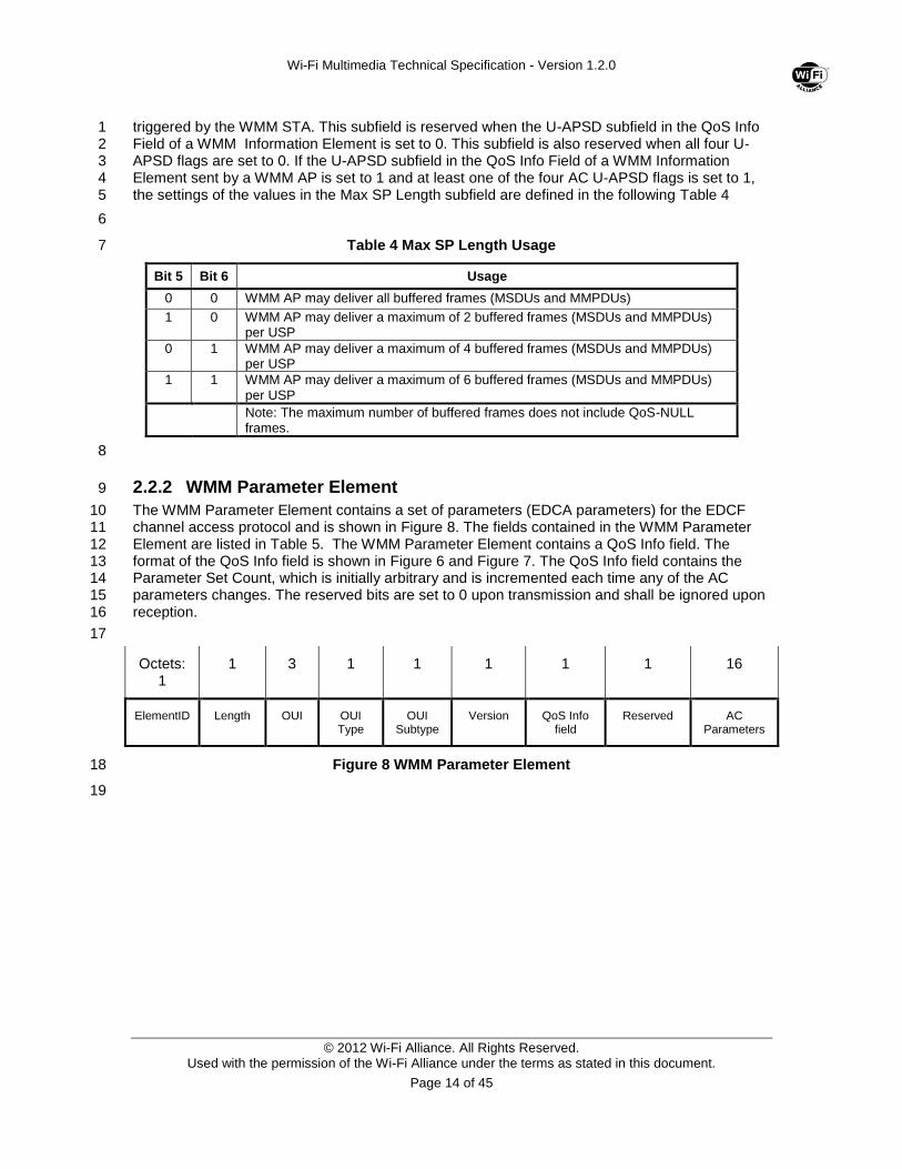
Table 4 Max SP Length Usage 7
Bit 5 Bit 6 Usage
0 0 WMM AP may deliver all buffered frames (MSDUs and MMPDUs)
1 0 WMM AP may deliver a maximum of 2 buffered frames (MSDUs and MMPDUs) per USP
0 1 WMM AP may deliver a maximum of 4 buffered frames (MSDUs and MMPDUs) per USP
1 1 WMM AP may deliver a maximum of 6 buffered frames (MSDUs and MMPDUs) per USP
Note: The maximum number of buffered frames does not include QoS-NULL frames.
8
2.2.2 WMM Parameter Element 9
The WMM Parameter Element contains a set of parameters (EDCA parameters) for the EDCF 10 channel access protocol and is shown in Figure 8. The fields contained in the WMM Parameter 11 Element are listed in Table 5. The WMM Parameter Element contains a QoS Info field. The 12 format of the QoS Info field is shown in Figure 6 and Figure 7. The QoS Info field contains the 13 Parameter Set Count, which is initially arbitrary and is incremented each time any of the AC 14 parameters changes. The reserved bits are set to 0 upon transmission and shall be ignored upon 15 reception. 16
17
Octets: 1
1 3 1 1 1 1 1 16
ElementID Length OUI OUI Type
OUI Subtype
Version QoS Info field
Reserved AC Parameters
Figure 8 WMM Parameter Element 18
19
Wi-Fi Multimedia Technical Specification - Version 1.2.0
© 2012 Wi-Fi Alliance. All Rights Reserved. Used with the permission of the Wi-Fi Alliance under the terms as stated in this document.
Page 15 of 45
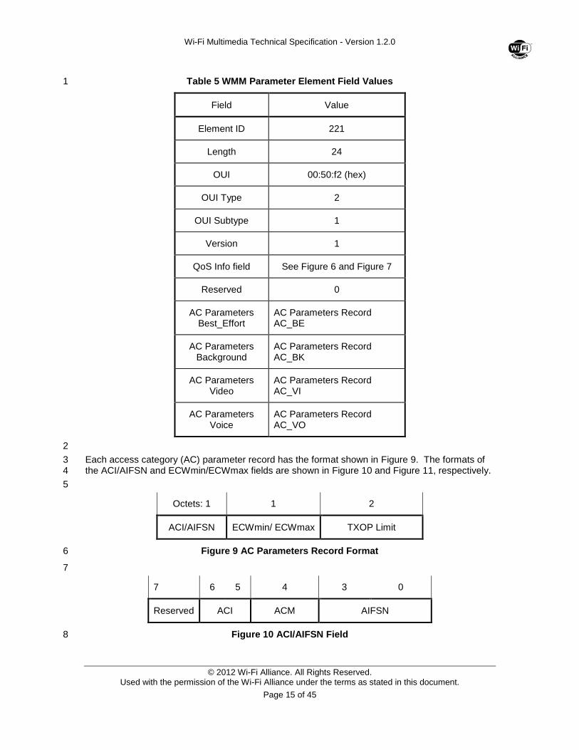
Table 5 WMM Parameter Element Field Values 1
Field Value
Element ID 221
Length 24
OUI 00:50:f2 (hex)
OUI Type 2
OUI Subtype 1
Version 1
QoS Info field See Figure 6 and Figure 7
Reserved 0
AC Parameters Best_Effort
AC Parameters Record AC_BE
AC Parameters Background
AC Parameters Record AC_BK
AC Parameters Video
AC Parameters Record AC_VI
AC Parameters Voice
AC Parameters Record AC_VO
2
Each access category (AC) parameter record has the format shown in Figure 9. The formats of 3 the ACI/AIFSN and ECWmin/ECWmax fields are shown in Figure 10 and Figure 11, respectively. 4
5
Octets: 1 1 2
ACI/AIFSN ECWmin/ ECWmax TXOP Limit
Figure 9 AC Parameters Record Format 6
7
7 6 5 4 3 0
Reserved ACI ACM AIFSN
Figure 10 ACI/AIFSN Field 8

Wi-Fi Multimedia Technical Specification - Version 1.2.0
© 2012 Wi-Fi Alliance. All Rights Reserved. Used with the permission of the Wi-Fi Alliance under the terms as stated in this document.
Page 16 of 45
The value of TXOP limit is specified as an unsigned integer, with the least significant octet 1 transmitted first, in units of 32 microseconds. A TXOP limit value of 0 indicates that a single 2 MPDU, in addition to a possible RTS/CTS exchange or CTS to itself, may be transmitted at any 3 rate for each TXOP. The value of the ACI references the AC to which all parameters in this 4 record correspond. The mapping between AC index (ACI) and AC is defined in Table 6. The 5 AIFSN value indicates the number of time slots inside the Arbitration Interframe space to be used. 6 The minimum value for AIFSN shall be 2. 7
Table 6 ACI to AC coding 8
ACI AC Access Category
00 AC_BE Best Effort
01 AC_BK Background
10 AC_VI Video
11 AC_VO Voice
9
The ACM (Admission Control Mandatory) flag indicates that Admission Control is required for the 10 AC. If bit ACM is set to 0, the AC may be used without Admission Control. If bit ACM is set to 1, 11 admission control must be performed prior to transmission with the parameters of the 12 corresponding AC Parameter Record. 13
14
7 4 3 0
ECWmax ECWmin
Figure 11 ECWmin/ECWmax field 15
The fields ECWmin and ECWmax encode the values of CWmin and CWmax respectively in an 16 exponent form. The values ECWmin and ECWmax are defined such that: 17
12
12
max
min
max
min
ECW
ECW
CW
CW 18
Hence the minimum encoded value of CWmin is 0, and the maximum value is 32767. 19
2.2.3 Beacon Frame 20
Every beacon frame transmitted by a WMM-enabled AP shall contain, in addition to those 21 elements specified in [1], either a WMM Information Element or a WMM Parameter Element. 22
2.2.4 Probe Request Frame 23
Probe request frames transmitted by a WMM-enabled STA are unchanged from [1]. 24
2.2.5 Probe Response Frame 25
A probe response frame transmitted by a WMM-enabled AP shall contain a WMM Parameter 26 Element. A probe response frame transmitted by a WMM-enabled STA shall contain a WMM 27 Parameter Element if the corresponding probe request was transmitted by a member of the same 28 (I)BSS as the transmitter of the probe response, otherwise, the probe response frame transmitted 29 by a WMM-enabled STA shall not contain a WMM Parameter Element. 30
Wi-Fi Multimedia Technical Specification - Version 1.2.0
© 2012 Wi-Fi Alliance. All Rights Reserved. Used with the permission of the Wi-Fi Alliance under the terms as stated in this document.
Page 17 of 45
2.2.6 Association Request Frame 1
A WMM association request frame contains a WMM Information Element in addition to the 2 information elements specified in [1]. 3
2.2.7 Association Response Frame 4
An association response frame shall contain a WMM Parameter Element in addition to the 5 information specified elements in Error! Reference source not found. if the corresponding 6 ssociation request contained a WMM Information element and shall not contain a WMM 7 Parameter Element if the corresponding association request did NOT contain a WMM Information 8 element. 9
2.2.8 Re-Association Request Frame 10
A re-association request frame contains a WMM Information Element in addition to the 11 information elements specified in [1]. 12
2.2.9 Re-Association Response Frame 13
A re-association response frame shall contain a WMM Parameter Element in addition to the 14 information specified elements in [1] if the corresponding re-association request contained a 15 WMM Information element and shall not contain a WMM Parameter Element if the corresponding 16 re-association request did NOT contain a WMM Information element. 17
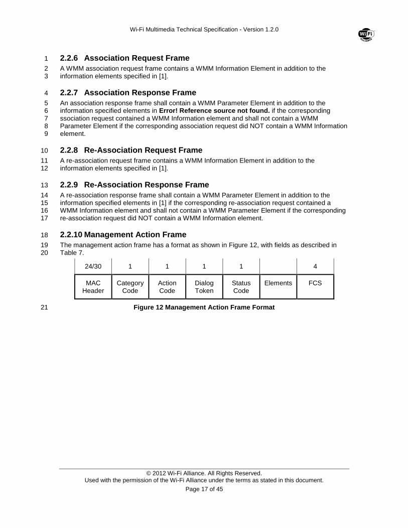
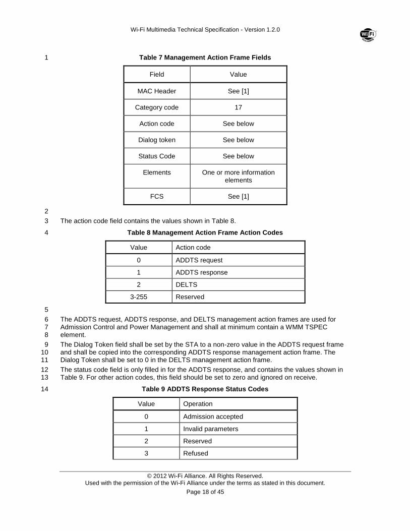
2.2.10 Management Action Frame 18
The management action frame has a format as shown in Figure 12, with fields as described in 19 Table 7. 20
24/30 1 1 1 1 4
MAC Header
Category Code
Action Code
Dialog Token
Status Code
Elements FCS
Figure 12 Management Action Frame Format 21
Wi-Fi Multimedia Technical Specification - Version 1.2.0
© 2012 Wi-Fi Alliance. All Rights Reserved. Used with the permission of the Wi-Fi Alliance under the terms as stated in this document.
Page 18 of 45
Table 7 Management Action Frame Fields 1
Field Value
MAC Header See [1]
Category code 17
Action code See below
Dialog token See below
Status Code See below
Elements One or more information elements
FCS See [1]
2
The action code field contains the values shown in Table 8. 3
Table 8 Management Action Frame Action Codes 4
Value Action code
0 ADDTS request
1 ADDTS response
2 DELTS
3-255 Reserved
5
The ADDTS request, ADDTS response, and DELTS management action frames are used for 6 Admission Control and Power Management and shall at minimum contain a WMM TSPEC 7 element. 8
The Dialog Token field shall be set by the STA to a non-zero value in the ADDTS request frame 9 and shall be copied into the corresponding ADDTS response management action frame. The 10 Dialog Token shall be set to 0 in the DELTS management action frame. 11
The status code field is only filled in for the ADDTS response, and contains the values shown in 12 Table 9. For other action codes, this field should be set to zero and ignored on receive. 13
Table 9 ADDTS Response Status Codes 14
Value Operation
0 Admission accepted
1 Invalid parameters
2 Reserved
3 Refused
Wi-Fi Multimedia Technical Specification - Version 1.2.0
© 2012 Wi-Fi Alliance. All Rights Reserved. Used with the permission of the Wi-Fi Alliance under the terms as stated in this document.
Page 19 of 45
Value Operation
4-255 Reserved
1
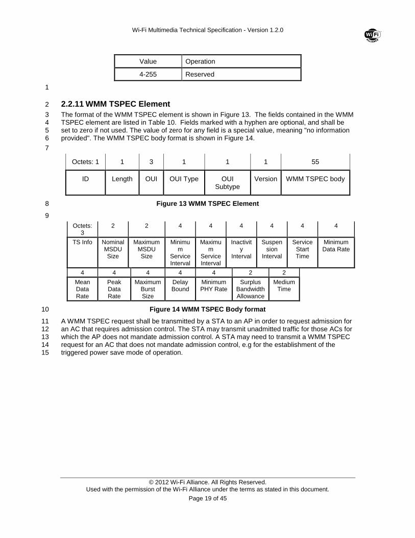
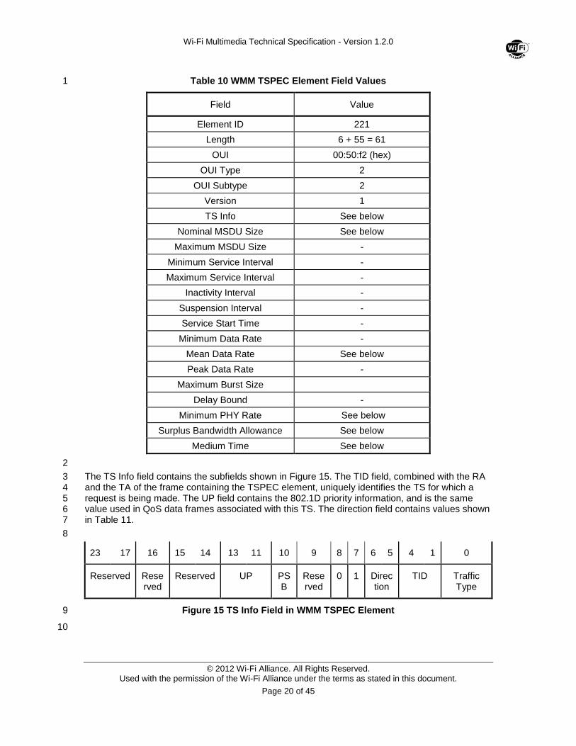
2.2.11 WMM TSPEC Element 2
The format of the WMM TSPEC element is shown in Figure 13. The fields contained in the WMM 3 TSPEC element are listed in Table 10. Fields marked with a hyphen are optional, and shall be 4 set to zero if not used. The value of zero for any field is a special value, meaning "no information 5 provided". The WMM TSPEC body format is shown in Figure 14. 6
7
Octets: 1 1 3 1 1 1 55
ID Length OUI OUI Type OUI Subtype
Version WMM TSPEC body
Figure 13 WMM TSPEC Element 8
9
Octets: 3
2 2 4 4 4 4 4 4
TS Info
Nominal MSDU Size
Maximum MSDU Size
Minimum
Service Interval
Maximum
Service Interval
Inactivity
Interval
Suspension
Interval
Service Start Time
Minimum Data Rate
4 4 4 4 4 2 2
Mean Data Rate
Peak Data Rate
Maximum Burst Size
Delay Bound
Minimum PHY Rate
Surplus Bandwidth Allowance
Medium Time
Figure 14 WMM TSPEC Body format 10
A WMM TSPEC request shall be transmitted by a STA to an AP in order to request admission for 11 an AC that requires admission control. The STA may transmit unadmitted traffic for those ACs for 12 which the AP does not mandate admission control. A STA may need to transmit a WMM TSPEC 13 request for an AC that does not mandate admission control, e.g for the establishment of the 14 triggered power save mode of operation. 15
Wi-Fi Multimedia Technical Specification - Version 1.2.0
© 2012 Wi-Fi Alliance. All Rights Reserved. Used with the permission of the Wi-Fi Alliance under the terms as stated in this document.
Page 20 of 45
Table 10 WMM TSPEC Element Field Values 1
Field Value
Element ID 221
Length 6 + 55 = 61
OUI 00:50:f2 (hex)
OUI Type 2
OUI Subtype 2
Version 1
TS Info See below
Nominal MSDU Size See below
Maximum MSDU Size -
Minimum Service Interval -
Maximum Service Interval -
Inactivity Interval -
Suspension Interval -
Service Start Time -
Minimum Data Rate -
Mean Data Rate See below
Peak Data Rate -
Maximum Burst Size
Delay Bound -
Minimum PHY Rate See below
Surplus Bandwidth Allowance See below
Medium Time See below
2
The TS Info field contains the subfields shown in Figure 15. The TID field, combined with the RA 3 and the TA of the frame containing the TSPEC element, uniquely identifies the TS for which a 4 request is being made. The UP field contains the 802.1D priority information, and is the same 5 value used in QoS data frames associated with this TS. The direction field contains values shown 6 in Table 11. 7
8
23 17 16 15 14 13 11 10 9 8 7 6 5 4 1 0
Reserved Reserved
Reserved UP PSB
Reserved
0 1 Direction
TID Traffic Type
Figure 15 TS Info Field in WMM TSPEC Element 9
10
Wi-Fi Multimedia Technical Specification - Version 1.2.0
© 2012 Wi-Fi Alliance. All Rights Reserved. Used with the permission of the Wi-Fi Alliance under the terms as stated in this document.
Page 21 of 45
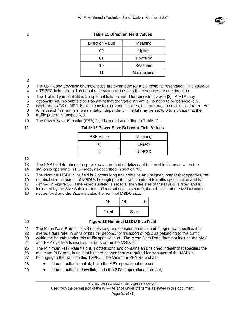
Table 11 Direction Field Values 1
Direction Value Meaning
00 Uplink
01 Downlink
10 Reserved
11 Bi-directional
2
The uplink and downlink characteristics are symmetric for a bidirectional reservation. The value of 3 a TSPEC field for a bidirectional reservation represents the resources for one direction. 4
The Traffic Type subfield is an optional field provided for consistency with [2]. A STA may 5 optionally set this subfield to 1 as a hint that the traffic stream is intended to be periodic (e.g. 6 isochronous TS of MSDUs, with constant or variable sizes, that are originated at a fixed rate). An 7 AP’s use of this hint is implementation dependent. The bit may be set to 0 to indicate that the 8 traffic pattern is unspecified. 9
The Power Save Behavior (PSB) field is coded according to Table 12. 10
Table 12 Power Save Behavior Field Values 11
PSB Value Meaning
0 Legacy
1 U-APSD
12
The PSB bit determines the power save method of delivery of buffered traffic used when the 13 station is operating in PS-mode, as described in section 3.6. 14
The Nominal MSDU Size field is 2 octets long and contains an unsigned integer that specifies the 15 nominal size, in octets, of MSDUs belonging to the traffic under this traffic specification and is 16 defined in Figure 16. If the Fixed subfield is set to 1, then the size of the MSDU is fixed and is 17 indicated by the Size Subfield. If the Fixed subfield is set to 0, then the size of the MSDU might 18 not be fixed and the Size indicates the nominal MSDU size. 19
15 14 0
Fixed Size
Figure 16 Nominal MSDU Size Field 20
The Mean Data Rate field is 4 octets long and contains an unsigned integer that specifies the 21 average data rate, in units of bits per second, for transport of MSDUs belonging to this traffic 22 within the bounds under this traffic specification. The Mean Data Rate does not include the MAC 23 and PHY overheads incurred in transferring the MSDUs. 24
The Minimum PHY Rate field is 4 octets long and contains an unsigned integer that specifies the 25 minimum PHY rate, in units of bits per second that is required for transport of the MSDUs 26 belonging to the traffic in this TSPEC. The Minimum PHY Rate shall: 27
if the direction is uplink, be in the AP’s operational rate set; 28
if the direction is downlink, be in the STA’s operational rate set; 29
Wi-Fi Multimedia Technical Specification - Version 1.2.0
© 2012 Wi-Fi Alliance. All Rights Reserved. Used with the permission of the Wi-Fi Alliance under the terms as stated in this document.
Page 22 of 45
if the direction is bi-directional, be in the AP’s operational rate set and the STA’s 1 operational rate set. 2
The Surplus Bandwidth Allowance Factor field is 2 octets long and specifies the excess allocation 3 of time (and bandwidth) over and above the stated rates required to transport an MSDU 4 belonging to the traffic in this TSPEC. This field is represented as an unsigned binary number 5 with an implicit binary point after the leftmost 3 bits. For example, an SBA of 1.75 is represented 6 as 0x3800. This field is included to account for retransmissions. As such, the value of this field 7 must be greater than unity. 8
Medium Time is a 16-bit unsigned integer that describes the amount of time admitted to access 9 the medium, in units of 32 microsecond periods per second. 10

Wi-Fi Multimedia Technical Specification - Version 1.2.0
© 2012 Wi-Fi Alliance. All Rights Reserved. Used with the permission of the Wi-Fi Alliance under the terms as stated in this document.
Page 23 of 45
3.0 WMM Protocol Specification 1
3.1 Association and Capability Negotiation 2
3.1.1 Procedure at an AP 3
An AP that supports WMM shall include either a WMM Information Element or a WMM Parameter 4 Element in every beacon. In response to a probe request, a WMM-enabled AP shall include a 5 WMM Parameter Element in its probe response. 6
On receipt of an association request and subsequent transmission of a corresponding association 7 response: the AP shall include a WMM Parameter Element in the association response if the 8 corresponding association request contained a WMM Information element and shall treat the 9 association as WMM association. The same applies to re-association request / re-association 10 response. 11
If the destination address of a data frame to be transmitted on the wireless medium corresponds 12 to a STA with a WMM association, the AP shall use WMM QoS data subtype frame formats when 13 transmitting the frame to it. If the destination address corresponds to a STA associated as a non-14 WMM STA, the AP shall not use QoS subtype data frames. 15
3.1.2 Procedure at a STA in an Infrastructure Network 16
A WMM-enabled STA shall determine the WMM capability of an AP with which it wishes to 17 associate before transmitting an association request to it. It may do this either passively, by 18 receiving a beacon frame, or actively, by transmitting a probe request to it. 19
From the most recently received probe response or beacon from a specific AP, the STA shall 20 determine whether the AP supports WMM. 21
A STA shall include a WMM Information Element in an association request if it has determined 22 that the recipient AP supports WMM and shall treat the association as a WMM association if the 23 association response contained a WMM Parameter element. A STA shall not include a WMM 24 Information Element in an association request if it has determined that the recipient AP does not 25 support WMM and shall treat the association as legacy (i.e. non-WMM) association if the 26 association response did not contain a WMM Parameter element. The same applies to re-27 association request / re-association response. 28
3.1.3 Procedure at a STA in an IBSS 29
WMM may be used in an IBSS, but since there is no negotiation of capability via association in 30 this case, any STA wishing to use QoS data frame subtypes when transmitting to each STA must 31 first infer the capability at that STA by other means. 32
A WMM-capable STA operating in an IBSS shall maintain an inferred WMM capability state for 33 each destination address in the IBSS that it is aware of. It may set WMM capability state to 34 “supported” for a given destination address on receipt of a beacon frame from that STA 35 containing a WMM element, or on receipt of a probe response frame from that STA containing a 36 WMM Information Element. The WMM capability state for each other STA shall be set to “not 37 supported” until receipt of such a beacon or probe response. 38
WMM STAs operating in an IBSS shall respond to probe request frames from other STAs in the 39 same IBSS by transmitting a probe response frame to that STA, containing a WMM Information 40 Element. WMM STA operating in an IBSS shall respond to unicast directed probe request frames 41 (provided that they are the target of the unicast) even if they were not the last STA in the IBSS to 42 have transmitted a beacon. 43
Wi-Fi Multimedia Technical Specification - Version 1.2.0
© 2012 Wi-Fi Alliance. All Rights Reserved. Used with the permission of the Wi-Fi Alliance under the terms as stated in this document.
Page 24 of 45
3.2 Setting of WMM Parameters 1
3.2.1 Default WMM parameters 2
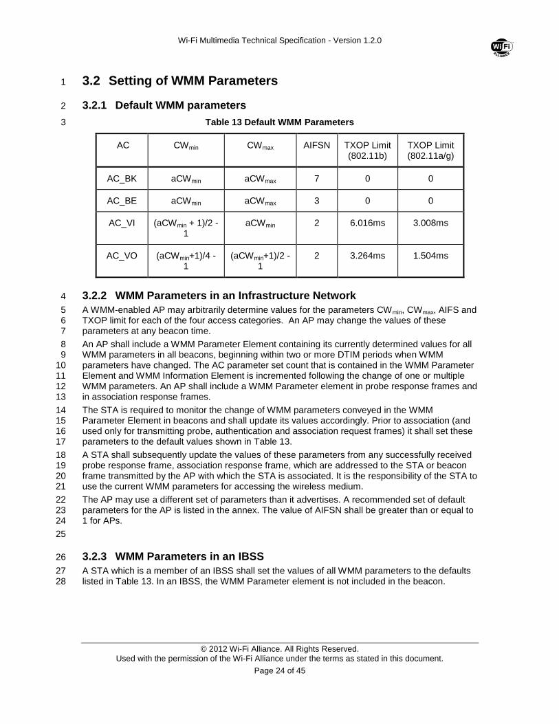
Table 13 Default WMM Parameters 3
AC CWmin CWmax AIFSN TXOP Limit (802.11b)
TXOP Limit (802.11a/g)
AC_BK aCWmin aCWmax 7 0 0
AC_BE aCWmin aCWmax 3 0 0
AC_VI (aCWmin + 1)/2 -1
aCWmin 2 6.016ms 3.008ms
AC_VO (aCWmin+1)/4 - 1
(aCWmin+1)/2 -1
2 3.264ms 1.504ms
3.2.2 WMM Parameters in an Infrastructure Network 4
A WMM-enabled AP may arbitrarily determine values for the parameters CWmin, CWmax, AIFS and 5 TXOP limit for each of the four access categories. An AP may change the values of these 6 parameters at any beacon time. 7
An AP shall include a WMM Parameter Element containing its currently determined values for all 8 WMM parameters in all beacons, beginning within two or more DTIM periods when WMM 9 parameters have changed. The AC parameter set count that is contained in the WMM Parameter 10 Element and WMM Information Element is incremented following the change of one or multiple 11 WMM parameters. An AP shall include a WMM Parameter element in probe response frames and 12 in association response frames. 13
The STA is required to monitor the change of WMM parameters conveyed in the WMM 14 Parameter Element in beacons and shall update its values accordingly. Prior to association (and 15 used only for transmitting probe, authentication and association request frames) it shall set these 16 parameters to the default values shown in Table 13. 17
A STA shall subsequently update the values of these parameters from any successfully received 18 probe response frame, association response frame, which are addressed to the STA or beacon 19 frame transmitted by the AP with which the STA is associated. It is the responsibility of the STA to 20 use the current WMM parameters for accessing the wireless medium. 21
The AP may use a different set of parameters than it advertises. A recommended set of default 22 parameters for the AP is listed in the annex. The value of AIFSN shall be greater than or equal to 23 1 for APs. 24
25
3.2.3 WMM Parameters in an IBSS 26
A STA which is a member of an IBSS shall set the values of all WMM parameters to the defaults 27 listed in Table 13. In an IBSS, the WMM Parameter element is not included in the beacon. 28
Wi-Fi Multimedia Technical Specification - Version 1.2.0
© 2012 Wi-Fi Alliance. All Rights Reserved. Used with the permission of the Wi-Fi Alliance under the terms as stated in this document.
Page 25 of 45
3.3 Assignment of Frames to Queues 1
3.3.1 Mappings for Unicast Frames 2
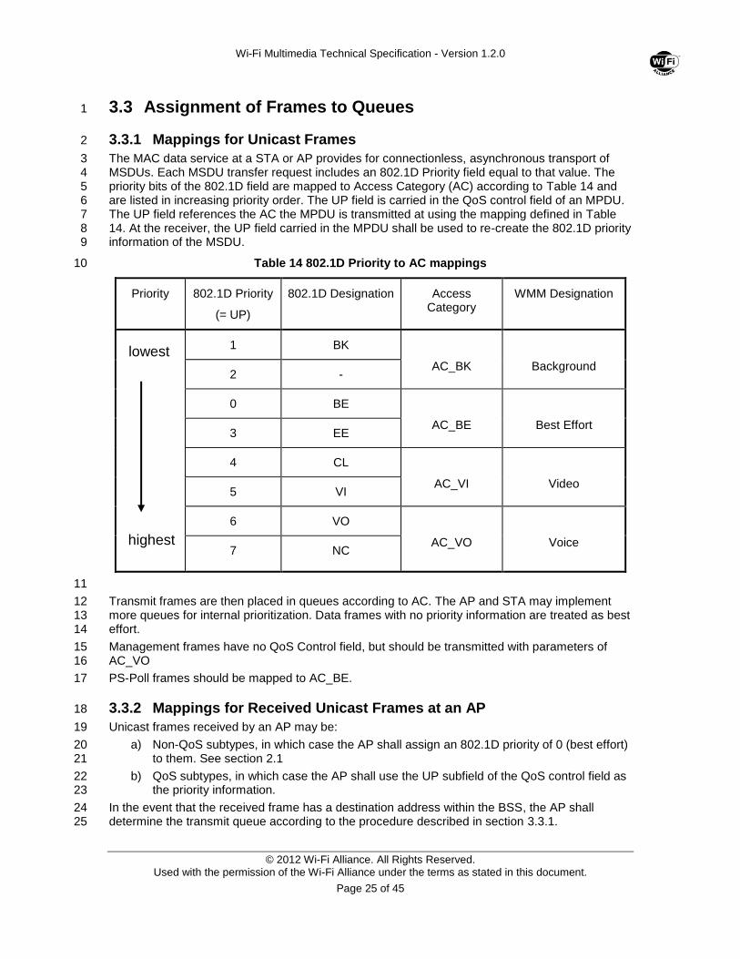
The MAC data service at a STA or AP provides for connectionless, asynchronous transport of 3 MSDUs. Each MSDU transfer request includes an 802.1D Priority field equal to that value. The 4 priority bits of the 802.1D field are mapped to Access Category (AC) according to Table 14 and 5 are listed in increasing priority order. The UP field is carried in the QoS control field of an MPDU. 6 The UP field references the AC the MPDU is transmitted at using the mapping defined in Table 7 14. At the receiver, the UP field carried in the MPDU shall be used to re-create the 802.1D priority 8 information of the MSDU. 9
Table 14 802.1D Priority to AC mappings 10
Priority 802.1D Priority
(= UP)
802.1D Designation Access Category
WMM Designation
1 BK
AC_BK
Background 2 -
0 BE
AC_BE
Best Effort 3 EE
4 CL
AC_VI
Video 5 VI
6 VO
AC_VO
Voice 7 NC
11
Transmit frames are then placed in queues according to AC. The AP and STA may implement 12 more queues for internal prioritization. Data frames with no priority information are treated as best 13 effort. 14
Management frames have no QoS Control field, but should be transmitted with parameters of 15 AC_VO 16
PS-Poll frames should be mapped to AC_BE. 17
3.3.2 Mappings for Received Unicast Frames at an AP 18
Unicast frames received by an AP may be: 19
a) Non-QoS subtypes, in which case the AP shall assign an 802.1D priority of 0 (best effort) 20 to them. See section 2.1 21
b) QoS subtypes, in which case the AP shall use the UP subfield of the QoS control field as 22 the priority information. 23
In the event that the received frame has a destination address within the BSS, the AP shall 24 determine the transmit queue according to the procedure described in section 3.3.1. 25
highest
lowest
Wi-Fi Multimedia Technical Specification - Version 1.2.0
© 2012 Wi-Fi Alliance. All Rights Reserved. Used with the permission of the Wi-Fi Alliance under the terms as stated in this document.
Page 26 of 45
3.3.3 Mappings for Group Addressed and Buffered Frames at an AP 1
The AP forwards all group addressed frames (Multicast/Broadcast) using non-QoS data frame 2 subtypes, if not all the recipients are WMM capable STAs. The AP may forward Power Save 3 frames that are buffered with QoS Data frame subtype only to WMM capable STAs. Otherwise, 4 the frames must be sent using non-QoS data frame subtypes. The AP is not required to 5 implement multiple AC queues for transmission of group addressed and buffered Power Save 6 frames, and may use a single dedicated queue for this purpose. If the AP uses a single queue for 7 pending group addressed frames, then the AP should maintain the queue in priority order if 8 possible. 9
3.4 Channel Access Protocol 10
3.4.1 Reference Implementation 11
The channel access protocol is derived from the DCF procedures described in [1]. This document 12 specifies only differences between the WMM channel access protocol and the reference. 13
14
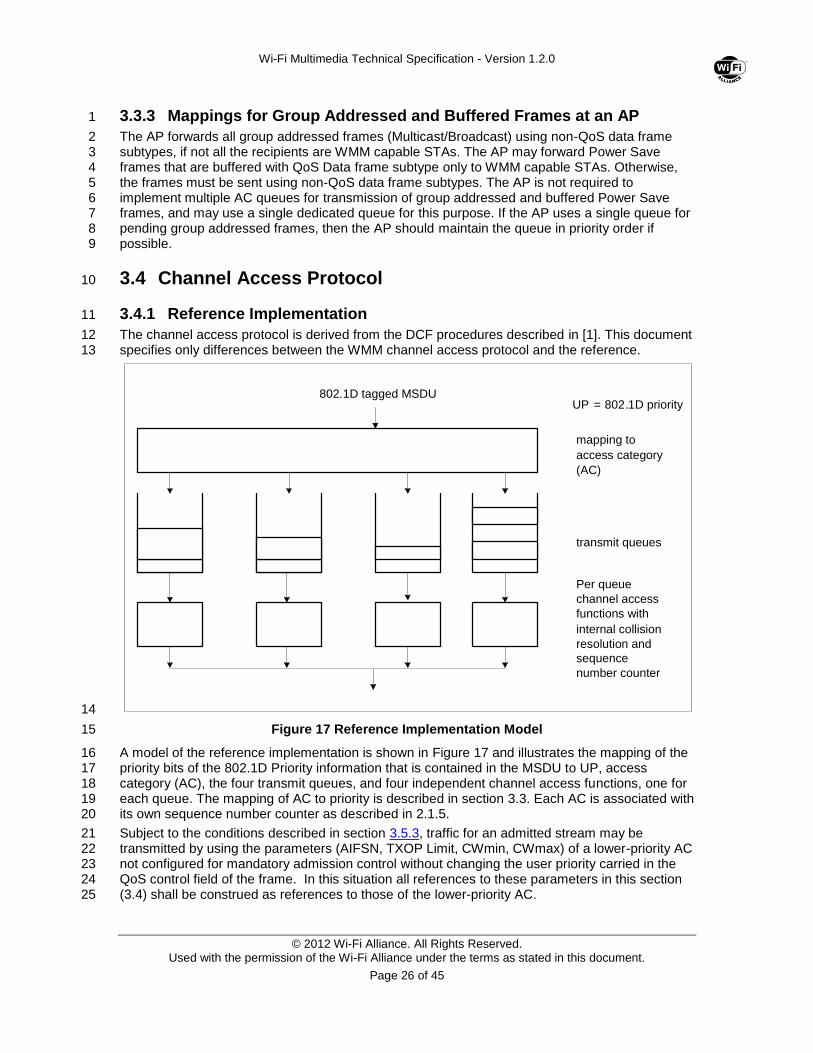
Figure 17 Reference Implementation Model 15
A model of the reference implementation is shown in Figure 17 and illustrates the mapping of the 16 priority bits of the 802.1D Priority information that is contained in the MSDU to UP, access 17 category (AC), the four transmit queues, and four independent channel access functions, one for 18 each queue. The mapping of AC to priority is described in section 3.3. Each AC is associated with 19 its own sequence number counter as described in 2.1.5. 20
Subject to the conditions described in section 3.5.3, traffic for an admitted stream may be 21 transmitted by using the parameters (AIFSN, TXOP Limit, CWmin, CWmax) of a lower-priority AC 22 not configured for mandatory admission control without changing the user priority carried in the 23 QoS control field of the frame. In this situation all references to these parameters in this section 24 (3.4) shall be construed as references to those of the lower-priority AC. 25
mapping to access category ( AC )
transmit queues
Per queue channel access functions with
internal collision resolution and sequence number counter
802 . 1 D tagged MSDU UP = 802 . 1 D priority
Wi-Fi Multimedia Technical Specification - Version 1.2.0
© 2012 Wi-Fi Alliance. All Rights Reserved. Used with the permission of the Wi-Fi Alliance under the terms as stated in this document.
Page 27 of 45
3.4.2 Transmit Opportunities & TXOP Limits 1
There are two modes of TXOP defined, EDCA TXOP and continuation TXOP. 2
An EDCA TXOP occurs when the EDCA rules permit access to the medium. 3
A continuation TXOP occurs when a channel access function retains the right to access the 4 medium following the completion of a frame exchange sequence, such as on receipt of an Ack 5 frame. 6
The TXOP limit duration values for each AC are advertised by the QAP in the WMM Parameter 7 Element in Beacons, Probe response, and Association response frames. A TXOP limit value of 0 8 indicates that a single MSDU or MMPDU in addition to a possible RTS/CTS or CTS to itself may 9 be transmitted at any PHY rate for each TXOP. 10
STAs shall ensure that the duration of TXOPs obtained using the EDCA rules do not exceed the 11 TXOP limit. The duration of a TXOP is the time the TXOP holder maintains uninterrupted control 12 of the medium, and it includes the time required to transmit frames sent as an immediate 13 response to TXOP holder transmissions. 14
An STA shall fragment an MSDU so that the transmission of the first MPDU of the TXOP does 15 not cause the TXOP limit to be exceeded at the PHY rate selected for the initial transmission 16 attempt of that MPDU. The TXOP limit may be exceeded, when using a lower PHY rate than 17 selected for the initial transmission attempt of the first MPDU, for a retransmission of an MPDU, 18 or for the initial transmission of an MPDU if any previous MPDU in the current MSDU has been 19 retransmitted. When the TXOP limit is exceeded due to the retransmission of a MPDU at a 20 reduced PHY rate, the STA shall not transmit more than one MPDU in the TXOP. 21
3.4.3 Obtaining an EDCA TXOP 22
Each channel access timer shall maintain a backoff function timer, which has a value measured 23 in backoff slots. 24
The duration AIFS[AC] is a duration derived from the value AIFSN[AC] by the relation 25
AIFS[AC] = AIFSN[AC] × aSlotTime + aSIFSTime 26
An EDCA TXOP is granted to a channel access function when the channel access function 27 determines that it shall initiate the transmission of a frame exchange sequence. Transmission 28 initiation shall be determined according to the following rules: 29
On specific slot boundaries, each channel access function shall make a determination to perform 30 one and only one of the following functions: 31
a) Initiate the transmission of a frame exchange sequence for that access function 32
b) Decrement the backoff timer for that access function 33
c) Invoke the backoff procedure due to an internal collision 34
d) Do nothing for that access function. 35
The specific slot boundaries at which exactly one of these operations shall be performed are 36 defined as follows, for each channel access function: 37
a) Following AIFSN[AC] * aSlotTime – aRxTxTurnaraoundTime of medium idle indication 38 after SIFS (not necessarily idle time) after the last busy medium on the antenna, if the 39 last busy medium indication was the result of a frame reception with a correct FCS ; or 40
b) Following EIFS – DIFS + AIFSN[AC] * aSlotTime of medium idle indication after the last 41 indicated busy medium as determined by the carrier sense mechanism if the last busy 42 medium indication was the result of a frame reception with an FCS error or PHY-43 RXEND.indication (RXERROR), where the value of RXERROR is not NoError. 44
c) When any other channel access function at this QSTA transmitted a frame requiring 45 acknowledgement, the earlier of: 46
Wi-Fi Multimedia Technical Specification - Version 1.2.0
© 2012 Wi-Fi Alliance. All Rights Reserved. Used with the permission of the Wi-Fi Alliance under the terms as stated in this document.
Page 28 of 45
a. the end of the ACK-Timeout interval timed from the PHY_TXEND.confirm, 1 followed by AIFSN[AC] * aSlotTime – aTxRxTurnaraoundTime of IDLE Time 2
b. at the end of the first AIFSN[AC] * aSlotTime – aTxRxTurnaraoundTime of IDLE 3 medium after the PHY-RXEND.indication when a PHY-RXSTART.indication 4 occurs as specified in subclause 9.2.8 of [1], 5
d) following AIFSN[AC] * aSlotTime– aTxRxTurnaraoundTime of medium idle indication 6 after SIFS (not necessarily idle time) after the last indicated busy medium on the antenna 7 that was the result of a transmission of a frame for any channel access function and 8 which did not require an acknowledgement; or 9
e) following AIFSN[AC] * aSlotTimeof medium idle time indication after the last indicated idle 10 medium as indicated by the carrier sense mechanism that is not covered by a) through 11 d). 12
f) following aSlotTime of medium idle indication which occurs immediately after a 13 decrement of the backoff counter for that channel access function. 14
At each of the above-described specific slot boundaries, each channel access function shall 15 initiate a transmission sequence, if: 16
a) there is a frame available for transmission at that channel access function, and 17
b) the backoff timer for that channel access function has a value of zero, and 18
c) initiation of a transmission sequence is not allowed to commence at this time for a 19 channel access function of higher UP. 20
At each of the above-described specific slot boundaries, each channel access function shall 21 decrement the backoff timer by one, if: 22
a) The backoff timer for that channel access function has a value which is greater than zero. 23
At each of the above-described specific slot boundaries, each channel access function shall 24 invoke the backoff procedure due to an internal collision, if: 25
a) There is a frame available for transmission at that channel access function, and 26
b) the backoff timer for that channel access function has a value of zero, and 27
c) initiation of a transmission sequence is allowed to commence at this time for a channel 28 access function of higher UP. 29
At each of the above-described specific slot boundaries, each channel access function shall do 30 nothing, if none of the above actions is taken. 31
32
Wi-Fi Multimedia Technical Specification - Version 1.2.0
© 2012 Wi-Fi Alliance. All Rights Reserved. Used with the permission of the Wi-Fi Alliance under the terms as stated in this document.
Page 29 of 45
1
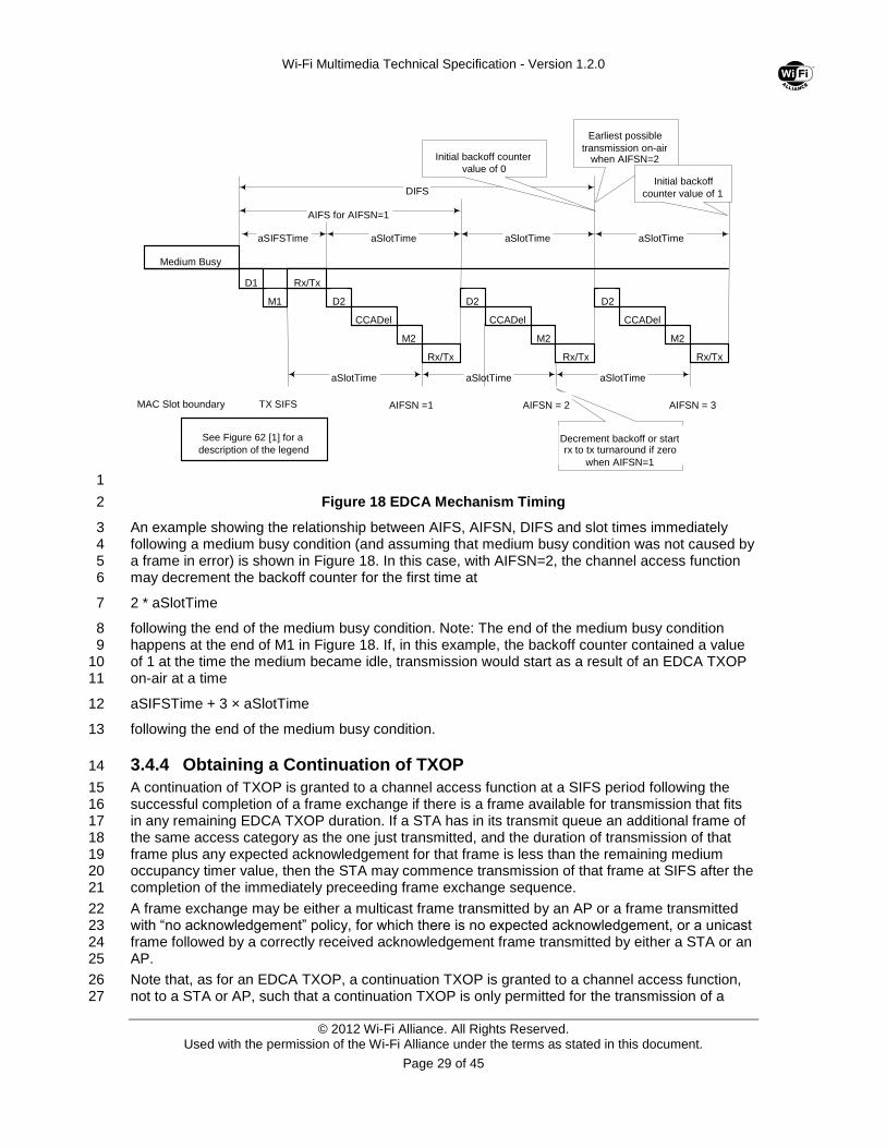
Figure 18 EDCA Mechanism Timing 2
An example showing the relationship between AIFS, AIFSN, DIFS and slot times immediately 3 following a medium busy condition (and assuming that medium busy condition was not caused by 4 a frame in error) is shown in Figure 18. In this case, with AIFSN=2, the channel access function 5 may decrement the backoff counter for the first time at 6
2 * aSlotTime 7
following the end of the medium busy condition. Note: The end of the medium busy condition 8 happens at the end of M1 in Figure 18. If, in this example, the backoff counter contained a value 9 of 1 at the time the medium became idle, transmission would start as a result of an EDCA TXOP 10 on-air at a time 11
aSIFSTime + 3 × aSlotTime 12
following the end of the medium busy condition. 13
3.4.4 Obtaining a Continuation of TXOP 14
A continuation of TXOP is granted to a channel access function at a SIFS period following the 15 successful completion of a frame exchange if there is a frame available for transmission that fits 16 in any remaining EDCA TXOP duration. If a STA has in its transmit queue an additional frame of 17 the same access category as the one just transmitted, and the duration of transmission of that 18 frame plus any expected acknowledgement for that frame is less than the remaining medium 19 occupancy timer value, then the STA may commence transmission of that frame at SIFS after the 20 completion of the immediately preceeding frame exchange sequence. 21
A frame exchange may be either a multicast frame transmitted by an AP or a frame transmitted 22 with “no acknowledgement” policy, for which there is no expected acknowledgement, or a unicast 23 frame followed by a correctly received acknowledgement frame transmitted by either a STA or an 24 AP. 25
Note that, as for an EDCA TXOP, a continuation TXOP is granted to a channel access function, 26 not to a STA or AP, such that a continuation TXOP is only permitted for the transmission of a 27
Medium Busy
D1
M1
Rx/Tx
D2
CCADel
M2
Rx/Tx
D2
CCADel
M2
Rx/Tx
D2
CCADel
M2
Rx/Tx
aSIFSTime aSlotTime aSlotTime aSlotTime
DIFS
AIFS for AIFSN=1
aSlotTime aSlotTime aSlotTime
Decrement backoff or start rx to tx turnaround if zero
when AIFSN=1
Earliest possible transmission on-air
when AIFSN=2
See Figure 62 [1] for a description of the legend
Initial backoff counter value of 0
AIFSN =1 AIFSN = 2 AIFSN = 3 TX SIFS MAC Slot boundary
Initial backoff counter value of 1
Wi-Fi Multimedia Technical Specification - Version 1.2.0
© 2012 Wi-Fi Alliance. All Rights Reserved. Used with the permission of the Wi-Fi Alliance under the terms as stated in this document.
Page 30 of 45
frame of the same access category as the access category of the frame that was granted the 1 EDCA TXOP. 2
3.4.5 Backoff Procedure 3
Each channel access function shall maintain a state variable CW[AC], which shall be initialized to 4 the value of the parameter CWmin[AC] (see section 3.2). 5
If a frame is successfully transmitted for a specific channel access function, indicated by either 6 the successful reception of a CTS in response to an RTS, or the successful reception of an Ack in 7 response to a unicast MPDU, or by transmitting a multicast frame or a frame with “no 8 acknowledgement” policy, CW[AC] shall be reset to CWmin[AC]. 9
The backoff procedure shall be invoked for a channel access function when either: 10
a) A frame with that AC is requested to be transmitted and the medium is busy as indicated 11 by either physical or virtual carrier sense, and the backoff timer has a value of zero for 12 that AC. 13
b) The final transmission by the TXOP holder initiated during the TXOP for that AC was 14 successful 15
c) The transmission of a frame of that AC fails, indicated by a failure to receive a CTS in 16 response to an RTS, or a failure to receive an Ack that was expected in response to a 17 unicast MPDU or MMPDU. 18
d) The transmission attempt collides internally with another channel access function of an 19 AC that has higher priority, that is, two or more channel access functions in the same 20 STA or AP are granted a TXOP at the same time. 21
If the backoff procedure is invoked because of reason a) above the value of CW[AC] shall be left 22 unchanged. If the backoff procedure is invoked because of reason b) above, the value of CW[AC] 23 shall be reset to CWmin[AC]. 24
If the backoff procedure is invoked because of a failure event (either reason c) or d) above) the 25 value of CW[AC] shall be updated as follows before invoking the backoff procedure: 26
a) if the short or long retry count for the STA has reached aShortRetryLimit or 27 aLongRetryLimit[AC] respectively, CW[AC] will be reset to CWmin[AC]. 28
b) Otherwise, 29
1) if CW[AC] is less than CWmax[AC], CW[AC] shall be set to the value 30 (CW[AC]+1)*2-1 31
2) if CW[AC] is equal to CWmax[AC], CW[AC] shall remain unchanged 32 for the remainder of any retries 33
Following the update of the value of CW[AC], the backoff timer is set to an integer value chosen 34 randomly with a uniform distribution taking values in the range (0,CW[AC]) inclusive. 35
3.4.6 Retransmit Procedures 36
If a STA or AP, in an infrastructure BSS or an IBSS, transmits frames to a destination using QoS 37 data types, it may following a failed transmission of a frame attempt to transmit another frame 38 with a different access category to the same or any other destination. The STA has to contend for 39 the medium when transmitting another frame with a different access category to the same or any 40 other destination using the rules defined in [1]. 41
If a STA or an AP does not use QoS data types when transmitting frames to a particular receiver 42 address, once an initial attempt, excluding internal collisions, has been made to transmit a frame, 43 it shall not transmit other data frames to that receiver address until the first frame is either 44 successfully transmitted or discarded. It may, however, transmit other frames to different receiver 45 addresses. 46
Wi-Fi Multimedia Technical Specification - Version 1.2.0
© 2012 Wi-Fi Alliance. All Rights Reserved. Used with the permission of the Wi-Fi Alliance under the terms as stated in this document.
Page 31 of 45
3.5 ADDTS and DELTS Procedures 1
A STA uses an ADDTS request frame to setup a Traffic Stream (TS) between it and an AP. 2 DELTS may be used by the STA or AP to discontinue and delete the use of a TS. 3
A TS serves two purposes within WMM: 4
For the modification of AC parameters used for APSD. (§3.6) 5
For the STA to gain admission to use an AC within a BSS. (§3.5.1) 6
A TS is identified uniquely by its TID value within the context of the RA and TA. The TID is 7 contained within the TS Info Field in the WMM TSPEC Element of ADDTS and DELTS frames 8 (Figure 15). Within a WMM STA in an infrastructure BSS, the RA and TA are constant. 9
TSs may be unidirectional, STA to AP or AP to STA, or bi-directional (Table 11). 10
In WMM, TSs are identified with TIDs values 0 through 7. Any TID may map onto any UP and 11 thus onto any AC, however for each AC used between an RA and TA, only the following 12 combinations are valid: 13
No TS, 14
One unidirectional uplink TS 15
One unidirectional downlink TS., 16
One unidirectional uplink TS and one unidirectional downlink TS 17
or 18
One bi-directional TS. 19
A TS is admitted when an ADDTS Response frame with the Status Code equal to 0 is received 20 from the AP in response to an ADDTS Request frame sent by the STA to the AP. If the Status 21 Code is not equal to 0, any existing TSs remain admitted and are unaffected. 22
TS replacement rules are as follows: 23
When there is an existing unidirectional TS admitted with the AP for a given AC, then an 24 ADDTS request frame for either a unidirectional TS in the same direction or a 25 bidirectional TS initiates the replacement of the existing TS with a new TS.. 26
When there is an existing bi-directional TS with the AP for a given AC, then an ADDTS 27 request frame for, either a bi-directional or unidirectional TS, initiates the replacement of 28 the existing TS with a new TS. 29
When there are two existing, admitted unidirectional TSs with the AP for a given AC, then 30 an ADDTS request frame for a bi-directional TS initiates the replacement of the two 31 existing TSs with the new TS. 32
The admission of any TS on the same AC having the same TID value as an admitted TS 33 deletes the existing TS and replaces it with the new TS. 34
An AP shall reject requests with a TID corresponding to an existing TS but in a different 35 AC. 36
In any scenario other than those listed above, any existing unidirectional TS is unaffected 37 by the admission of a unidirectional TS in the other direction. 38
An existing TS is deleted by: 39
Receiving a DELTS frame with the corresponding TID and transmission of its 40 acknowledgement, or 41
Receiving the acknowledgement to the transmission of a DELTS frame with the 42 corresponding TID. 43
Either the STA or the AP may transmit a DELTS frame. 44
Wi-Fi Multimedia Technical Specification - Version 1.2.0
© 2012 Wi-Fi Alliance. All Rights Reserved. Used with the permission of the Wi-Fi Alliance under the terms as stated in this document.
Page 32 of 45
TSs may only be setup after successful association. All TSs between a STA and AP are 1 discontinued and deleted upon disassociation. Re-association to the same AP has no effect on 2 TSs. 3
3.5.1 Admission Control Procedures 4
WMM STA may support admission control procedures. APs shall support admission control 5 procedures, at least to the minimal extent of advertising that admission is not mandatory on its 6 ACs. 7
The AP uses the ACM (admission control mandatory) flags advertised in the WMM Parameter 8 element to indicate whether admission control is required for each of the ACs, as a matter of 9 policy. While the CWmin, CWmax, AIFS, TXOP limit parameters may be adjusted over time by 10 the AP, the ACM bit shall be static for the duration of the lifetime of the BSS. A WMM TSPEC 11 request shall be transmitted by a STA to an AP in order to request admission of a TS in any 12 direction (uplink, downlink, or bidirectional) using the AC parameters of those ACs that require 13 admission control. 14
A WMM STA may choose to aggregate data flows locally by combining the parameters of multiple 15 flows into a single TSPEC, thereby allowing more than one data flow to exist per TS. The STA 16 may transmit unadmitted traffic using AC parameters of those ACs which the AP does not require 17 admission control. 18
Each channel access function shall maintain two variables. The first of these is the admitted time, 19 and the second is the used time. The admitted time and used time shall be set at association time 20 to zero. 21
The channel access function shall update the value of used time: 22
a) at one second intervals 23
used_time = max((used_time - admitted_time), 0) 24
b) after each frame exchange 25
used_time = used_time + FrameExchangeTime. 26
The FrameExchangeTime equals the time required to transmit the frame plus one ACK frame 27 plus one SIFS interval. If the used time reaches or exceeds the admitted time value, the 28 corresponding channel access function shall no longer transmit using the EDCA parameters for 29 that AC as specified in the QoS parameter set element. 30
If an explicit admission for a bi-directional TS or an uplink unidirectional TS is deleted via a 31 DELTS frame, the admitted time and the used time for the AC shall both be set to zero. 32
A Setup request (ADDTS) for a TS (TID) that has an established explicit admission shall be 33 regarded as a request for a change to the existing admitted TS. 34
If a request for a change to an admitted TS is refused, the previously accepted admission for the 35 same TS remains valid. 36
Admitted time for a STA’s channel access function is the medium time returned in the most 37 recent, successful ADDTS Response for a bi-directional TS or an uplink uni-directional TS. 38
It should be noted that acceptance by an AP of a STA association request that specifies U-APSD 39 flags does not constitute admission to the corresponding ACs. Uplink traffic from a STA must still 40 be admitted using the ADDTS request mechanism in order to transmit in an AC for which the 41 ACM bit is set to 1. 42
3.5.2 Procedures at the AP 43
The AP shall respond to requests for admission conveyed in the WMM TSPEC request elements 44 for those AC(s) with ACM flag set to 1. If the AP supports delivery-enabled-only or trigger-45 enabled-only U-APSD operation it shall respond to requests for admission conveyed in the WMM 46 TSPEC request elements even if the ACM flag is set to 0. If the ACM flag is set to 0 for an AC, 47
Wi-Fi Multimedia Technical Specification - Version 1.2.0
© 2012 Wi-Fi Alliance. All Rights Reserved. Used with the permission of the Wi-Fi Alliance under the terms as stated in this document.
Page 33 of 45
the AP is not required to respond to a TSPEC request on that AC if the AP only supports bi-1 directional U-APSD settings (does not support delivery-enabled only or trigger-enabled only 2 state). On receipt of a WMM TSPEC request element conveyed in an ADDTS Request Frame 3 from an associated STA, the AP shall make a determination as to whether to 4
a) accept the request 5
b) deny the request 6
The AP may use any algorithm in making such a determination. If the AP decides to accept the 7 request, the AP shall also derive the Medium Time from the information conveyed in the WMM 8 TSPEC request element. The AP may use any algorithm in deriving the Medium Time, but 9 normally it will use the procedure described in the Annex. Having made such a determination, the 10 AP shall transmit a WMM TSPEC element to the requesting STA contained in a ADDTS response 11 management action frame. If the AP is accepting the request, the Medium Time field shall be 12 specified. An AP shall return a Medium Time equal to zero when accepting a unidirectional, 13 downlink TS request. 14
The AP may choose at any time to tear down an explicit admission by sending a management 15 action frame with the action code set to DELTS. 16
By observing the used time and the admitted time variables for admitted traffic destined to an 17 STA, the AP may drop MPDUs that are in excess of the admitted traffic using an unspecified 18 algorithm. 19
3.5.3 Procedure at STAs 20
At any point, following association, the STA may decide, to explicitly request admission of traffic 21 to be transmitted or/and received on a specific AC. The STA shall use the mappings in Table 14 22 to identify the sending AC from the UP field 23
In order to make such a request, the STA shall transmit a WMM TSPEC element contained in a 24 ADDTS request management action frame with the following fields specified (i.e. non-zero): 25 Nominal MSDU Size, Mean Data Rate, Minimum PHY Rate, and Surplus Bandwidth Allowance. 26 The Medium Time field is not used in the request frame and shall be set to zero. 27
The STA or AP may choose to tear down the explicit request at any time. In order for the STA to 28 tear down an explicit admission, the STA shall transmit a DELTS management action frame 29 containing the WMM TSPEC element to the AP. 30
If the STA receives a DELTS frame with TID corresponding to a bi-directional TS or an uplink uni-31 directional TS it shall disable the use of the specified AC. 32
If an explicit admission for a bi-directional TS or an uplink unidirectional TS is torn down, the STA 33 shall disable the use of the AC. 34
The STA shall observe the used time and the admitted time variables for an admitted traffic 35 stream. If the used time value reaches or exceeds the admitted time value, the corresponding 36 channel access function shall no longer transmit using the AC parameters for that AC for the 37 remainder of the one-second update interval. However, a STA may choose to replace the AC 38 parameters for that channel access function with those specified for an AC of lower priority, if no 39 admission control is required for that AC, and transmit the frame without changing the user 40 priority carried in the QoS control field of that frame. 41
If, for example, a STA has made and had accepted an explicit admission for a TS, and the 42 channel conditions subsequently worsen, possibly including a change in PHY layer data rate, 43 such that it requires more time to send the same data, the STA may make a request for more 44 admitted time to the AP and at the same time downgrade the AC parameters for that AC. 45
Wi-Fi Multimedia Technical Specification - Version 1.2.0
© 2012 Wi-Fi Alliance. All Rights Reserved. Used with the permission of the Wi-Fi Alliance under the terms as stated in this document.
Page 34 of 45
3.6 WMM-Power Save Procedures 1
3.6.1 U-APSD General Operation 2
3.6.0.1 The procedures defined in this section apply to unicast QoS-Data and QoS-Null frames 3 that are to be delivered to a WMM STA when the STA is in Power Save mode. U-APSD shall 4 only be used to deliver unicast frames to a WMM STA. Broadcast/multicast frame delivery shall 5 follow the frame delivery rules defined for broadcast/multicast frames (See 11.2.1.4 in [1]). 6
The WMM power-save procedures are based on the legacy procedures defined in [1], but an 7 option for unscheduled automatic power-save delivery (U-APSD) is added. WMM APs capable of 8 supporting U-APSD (“U-APSD-capable WMM AP”) shall signal this capability through the use of 9 the U-APSD subfield (b7) in the QoS Info Field in Beacon, Probe Response and (Re)Association 10 Response management frames. 11
In order to configure a WMM AP to deliver frames, the WMM STA designates one or more of its 12 ACs to be delivery-enabled ACs and one or more of its AC to be trigger-enabled ACs. A WMM 13 STA may configure a WMM AP to use U-APSD using two methods. 14
First, a WMM STA may set individual U-APSD Flag bits (b3~b0) in the QoS Info field of the WMM 15 Information element carried in (re) association request frames (see §2.2.1). When a U-APSD Flag 16 bit is set to 1, it indicates that the corresponding AC is both a delivery-enabled AC and trigger-17 enabled AC. When a U-APSD Flag bit is set to 0, it indicates that the corresponding AC is neither 18 a deliver-enabled AC nor a trigger-enabled AC. When all four U-APSD Flag subfields are set to 1 19 in the most recent (re) association request frames, all the ACs associated with the WMM STA are 20 trigger-enabled ACs and delivery-enabled ACs upon successful (re) association. When all four U-21 APSD Flag subfields are set to 0 in (re) association request frames, the ACs associated with the 22 WMM STA are neither trigger-enabled ACs nor delivery-enabled ACs upon successful (re) 23 association. 24
Alternatively, a WMM STA may request one or more AC as a trigger-enabled AC and one or 25 more AC as delivery-enabled ACs by sending an ADDTS request per AC to the WMM AP with 26 the PSB subfield (b10) in the TS Info field in the TSPEC element. In an ADDTS Response, a 27 WMM AP must preserve the setting of the PSB subfield from the ADDTS Request. Requests to 28 designate an AC as a delivery-enabled AC or trigger-enabled AC are admitted when the Status 29 Code is equal to 0 in an ADDTS response. A WMM STA may request an AC to be a trigger-30 enabled AC with a TSPEC with the PSB subfield set to 1 in the uplink direction. A WMM STA may 31 request an AC to be a delivery-enabled AC with a TSPEC with the PSB subfield set to 1 in the 32 downlink direction. A bi-directional TSPEC with the PSB subfield set to 1, makes an AC both a 33 trigger-enabled AC and delivery-enabled AC. A bi-directional TSPEC with the PSB subfield set to 34 0, makes that AC neither a trigger-enabled AC nor a delivery-enabled AC. 35
APSD settings in an admitted TSPEC (i.e., Status Code equal to 0 in an ADDTS response) take 36 precedence over the static U-APSD settings carried in the WMM Information element in the most 37 recent (re) association request. In other words, an admitted TSPEC overwrites any previous U-38 APSD setting of an AC. An acknowledged DELTS for a bi-directional TS or a sole uni-directional 39 TS for an AC reverts that AC to the static U-APSD settings carried in the WMM Information 40 element in the most recent (re) association request. If there are two admitted unidirectional TSs in 41 an AC, an acknowledged DELTS for one of the TSs results in a U-APSD setting for the AC per 42 the PSB bit from the TSPEC of the remaining TS. 43
WMM STAs use the Power Management field (b12) in the frame control field (§2.1.2) of a frame 44 to indicate whether it is in active or power-save mode. As U-APSD is a mechanism for the 45 delivery of downlink frames to powersaving stations, the uplink frames sent by a WMM STA using 46 U-APSD shall have the Power Management bit in the frame control field set to 1 for buffering to 47 take place at the WMM AP. WMM STAs may use U-APSD to have some or all frames of 48 delivery-enabled ACs delivered during Unscheduled Service Periods (USPs). A WMM STA 49 chooses legacy versus U-APSD behavior on a per-AC basis. 50
Wi-Fi Multimedia Technical Specification - Version 1.2.0
© 2012 Wi-Fi Alliance. All Rights Reserved. Used with the permission of the Wi-Fi Alliance under the terms as stated in this document.
Page 35 of 45
If, for a particular WMM STA, an AC is not a delivery-enabled AC, then all downlink frames 1 destined to that WMM STA that map to that AC are buffered and delivered using the procedures 2 described in [1]. The buffer used to hold these frames will be referred to as the legacy Power 3 Save buffer. The WMM AP uses the TIM and the More Data bit (b13) carried in Frame Control 4 Field to indicate the status of the legacy Power Save buffer as specified in [1]. 5
Transmission of a Trigger Frame is not implicitly allowed by admission of a downlink TS. If the 6 Trigger Frame maps to an AC that has ACM=1, then the WMM STA must establish a suitable 7 uplink TS before sending Trigger Frames. 8
The WMM STA must remain awake as long as an USP is still in progress. 9
3.6.2 U-APSD AP Operation 10
3.6.1.1 WMM APs shall maintain a Power Management status for each currently associated STA 11 that indicates in which Power Management mode the STA is currently operating. U-APSD-12 capable WMM APs shall maintain the per-AC U-APSD status for each currently associated WMM 13 STA. 14
If a WMM STA is in power-save mode, as indicated by a 1 in the power management field (b12) 15 in the frame control field (§2.1.2), an AP shall temporarily buffer the MSDUs or MMPDUs 16 destined to the STA. If a WMM STA is in Active mode, as indicated by a 0 in the power 17 management field (b12) in the frame control field (§2.1.2), MSDUs or MMPDUs destined to that 18 STA shall not be buffered for power management reasons by the WMM AP. 19
MSDUs or MMPDUs in delivery-enabled ACs (as described in §3.6) destined for a particular 20 WMM STA using APSD shall be temporarily buffered in the U-APSD-capable WMM AP. The 21 algorithm to manage this buffering is beyond the scope of this standard, with the exception that 22 since the AP is WMM-enabled, it shall preserve the order of arrival of frames on a per TID, per 23 STA basis. 24
At every beacon interval, the U-APSD-capable WMM AP shall assemble the Partial Virtual 25 Bitmap containing the buffer status of non delivery-enabled ACs (if there exists at least one non 26 delivery-enabled AC) per destination for WMM STAs in Power Save mode, and shall send this 27 out in the TIM field of the beacon. In case all ACs are delivery-enabled ACs, the U-APSD-capable 28 WMM AP shall assemble the Partial Virtual Bitmap containing the buffer status for all ACs per 29 destination for WMM STAs. . 30
If the WMM STA has set up to use USPs by configuring trigger-enabled ACs, the WMM AP shall 31 buffer frames belonging to delivery-enabled ACs until it has received a Trigger Frame associated 32 with a trigger-enabled AC from the WMM STA, which indicates the start of an USP. A Trigger 33 Frame received by the WMM AP from a WMM STA that already has an USP underway shall not 34 trigger the start of a new USP. The WMM AP transmits frames destined for the WMM STA and 35 associated with delivery-enabled ACs during an USP. 36
For a WMM STA using U-APSD, the WMM AP transmits one frame destined for the WMM STA 37 from any AC that is not a delivery-enabled AC in response to a PS-Poll from the WMM STA. In 38 case all ACs associated with the WMM STA are delivery-enabled ACs, then no ACs have been 39 selected for legacy power-save, and the AP shall immediately send either an ACK frame, a Null 40 function Data frame with the More Data bit set to zero, or a Null function QoS Data frame with the 41 More Data bit and the EOSP bit set to zero in response to the receipt of a PS-Poll frame. If the 42 AP sends an ACK frame in immediate response to the PS-Poll frame, it also shall later send a 43 Null Function Data frame with the More Data bit set to zero or a Null function QoS Data frame 44 with the More Data bit set to zero and the EOSP bit set to zero. In MSDUs sent in response to 45
Wi-Fi Multimedia Technical Specification - Version 1.2.0
© 2012 Wi-Fi Alliance. All Rights Reserved. Used with the permission of the Wi-Fi Alliance under the terms as stated in this document.
Page 36 of 45
PS-Poll from a WMM STA using U-APSD, the More Data bit (b13) field shall be set to indicate the 1 presence of further buffered MSDUs or MMPDUs that do not belong to delivery-enabled ACs. 2
At each USP for a WMM STA, the WMM AP shall attempt to transmit at least one MSDU or 3 MMPDU, but no more than the value encoded in the Max SP Length field in the QoS Info Field of 4 a WMM Information Element from delivery-enabled ACs, that are destined for the WMM STA. 5 Each buffered frame shall be delivered using the access parameters of its AC. The More Data bit 6 (b13) of the directed MSDU or MMPDU associated with delivery-enabled ACs and destined for 7 that WMM STA indicates that more frames are buffered for the delivery-enabled ACs. The More 8 Data bit set in MSDUs or MMPDUs associated with non delivery-enabled ACs and destined for 9 that STA indicates that more frames are buffered for the non delivery-enabled ACs. For all frames 10 except for the final frame of the SP, the EOSP subfield of the QoS Control field of the QoS data 11 frame shall be set to 0 to indicate the continuation of the SP. MMPDUs also indicate the 12 continuation of an SP because they do not contain an EOSP subfield. If the WMM AP has no 13 buffered MSDU or MMPDU to transmit or needs to otherwise terminate a USP, the WMM AP may 14 generate an extra QoS Null frame, with the EOSP set to 1. When the WMM AP has transmitted a 15 directed frame to the WMM STA with the EOSP subfield set to 1 during the SP except for 16 retransmissions of that frame, the WMM AP shall not transmit any more frames using this 17 mechanism until the next SP. The WMM AP shall set EOSP subfield to 1 to indicate the end of 18 SP in APSD. 19
If the WMM AP does not receive an Ack to a directed MSDU sent with the EOSP subfield set to 1, 20 it shall retransmit that frame at least once within the same USP - subject to applicable retry or 21 lifetime limit. The maximum number of retransmissions within the same USP is the lesser of the 22 Max Retry Limit and the MIB attribute dot11QAPMissingAckRetryLimit. If an Ack to the 23 retransmission of this last frame in the same USP is not received, it may wait until the next USP 24 to further retransmit that frame subject to its applicable retry or lifetime limit. 25
A WMM AP shall have an aging function to delete pending traffic when it is buffered for an 26 excessive time period. The WMM AP may base the aging function on the listen interval specified 27 by the WMM STA in the most recent (re)association request. The AP may discard buffered 28 frames during power save mode transitions between APSD and legacy power save or vice versa. 29
The AP shall deliver all frames from the legacy Power Save buffer using the power management 30 procedures described in [1]. 31
3.6.3 U-APSD STA Operation 32
3.6.2.1 WMM STAs in Power Save mode shall operate as follows to receive buffered frames 33 from the WMM AP. 34
WMM STAs shall use the power management procedures defined in [1] to retrieve frames held in 35 the legacy Power Save buffer. 36
In case one or more ACs are not delivery-enabled ACs, the WMM STA may retrieve MSDUs and 37 MMPDUs belonging to those ACs by sending PS-Polls to the WMM AP. In case all ACs are 38 delivery enabled ACs, WMM STA should only use trigger frames to retrieve MSDUs and 39 MMPDUs belonging to those ACs, and it should not send PS-Poll frames. 40
To initiate an USP to retrieve MSDUs and MMPDUs from delivery-enabled ACs, a WMM STA 41 shall wake up and transmit a Trigger Frame to the WMM AP. . Frames of delivery-enabled ACs 42 are delivered during a USP that begins after the WMM AP acknowledges the trigger frame 43
Wi-Fi Multimedia Technical Specification - Version 1.2.0
© 2012 Wi-Fi Alliance. All Rights Reserved. Used with the permission of the Wi-Fi Alliance under the terms as stated in this document.
Page 37 of 45
transmitted by the WMM STA. The WMM STA shall remain awake until it receives a QoS Data or 1 Null frame addressed to it, with the EOSP subfield in QoS Control field set to 1. 2
A WMM STA may send additional PS-Polls if the More Data subfield is set to 1 in downlink 3 unicast MSDU or MMPDUs that do not belong to any deliver-enabled ACs. WMM STA may send 4 additional trigger frames if the More Data subfield is set to 1 in downlink unicast MSDUs or 5 MMPDUs that belong to delivery-enabled ACs. 6
The WMM STA is recommended to go into active mode to receive buffered frames before 7 transitioning between APSD and legacy power save modes because the WMM AP may discard 8 buffered frames during power save mode transitions between APSD and legacy power save. 9
10
Wi-Fi Multimedia Technical Specification - Version 1.2.0
© 2012 Wi-Fi Alliance. All Rights Reserved. Used with the permission of the Wi-Fi Alliance under the terms as stated in this document.
Page 38 of 45
WMM (Informative) Recommended Practices Annex 1
A.1 QoS Parameter Updates 2
It is recommended that the mechanism to update QoS parameters by way of the WMM 3 Parameter Element in beacon frames be used infrequently. It is not the intent of the designers of 4 the protocol to specify this as a dynamic adaptation mechanism, but rather as a means of auto-5 configuring policy at different locations. 6
However, in the event that the number of associated STAs changes or some other event occurs 7 that significantly alters the conditions, it is expected that the AP may change the policy settings. 8 There is no expectation of rapid update by the STAs, which may take of the order of seconds or 9 tens of seconds if necessary to update their parameter settings. 10
To assure that all STAs use the proper QoS parameters following modification of AC parameters, 11 the WMM Parameter Element should be present for multiple beacon intervals as specified in 12 3.2.2. 13
A.2 Use of Admission Control and Downgrading 14
It is recommended not to require Admission Control for the access categories AC_BE (Best 15 Effort) and AC_BK (Background). The Admission Control Mandatory Bit (ACM) for these 16 categories should be cleared to "0". The AC parameters chosen by the AP should account for 17 unadmitted traffic in these access categories. 18
In the case the QBSS requires admission control, i.e. ACM bit is set for an AC, and the WMM AP 19 or STA has an MSDU to send on that AC, but the TS to which the MSDU belongs has not been 20 admitted, the following options exist: 21
(1) The MSDU is dropped 22
(2) The access parameters of the access function corresponding to the AC are adjusted to 23 match the parameters of a lower AC that does not require admission control. As a result, 24 there will be two access functions with identical admission control parameters within the 25 WMM STA competing for medium access. The cumulative throughput of this WMM STA 26 may be higher. The UP in the QoS control field is not changed when the AC parameters 27 are changed to those of a lower AC. 28
(3) The MSDU is sent using a different UP. The UP is changed to map to a lower AC that 29 does not require admission control. The UP has to be changed prior to calculating the 30 MIC, assignment of the TSC and mixing the keys. Changing of the UP is performed 31 outside the MAC and is out of the scope of this spec. 32
A WMM STA should only use option (1) or (3) since, in an AC for which the admission control 33 mandatory flag is set to 1, it is not permitted to use an AC for which there is no admitted TS (see 34 section 3.5.1). It is the responsibility of the application invoking the SAP to assure consistency of 35 traffic that is mapped to one AC, i.e. Admitted and non-admitted traffic mapped to one AC shall 36 not be mixed. 37
In an AC for which the admission control mandatory flag is set to 1, a WMM AP should use option 38 (3) 39
A.3 Deriving Medium Time 40
It is recommended that the AP use the following procedure to derive Medium Time in its ADDTS 41 response. 42
There are two requirements to consider: 1) the traffic requirements of the application, and 2) the 43 expected error performance of the medium. The application requirements are captured by two 44 TSPEC parameters: Nominal MSDU Size and Mean Data Rate. The medium requirements are 45 captured by two TSPEC parameters: Surplus Bandwidth Allowance and Minimum PHY Rate. 46 The following formula describes how Medium Time may be calculated: 47
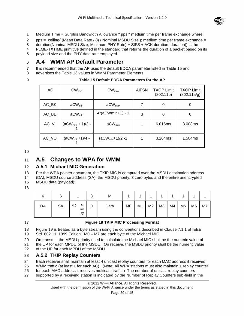
Wi-Fi Multimedia Technical Specification - Version 1.2.0
© 2012 Wi-Fi Alliance. All Rights Reserved. Used with the permission of the Wi-Fi Alliance under the terms as stated in this document.
Page 39 of 45
Medium Time = Surplus Bandwidth Allowance * pps * medium time per frame exchange where: 1
pps = ceiling( (Mean Data Rate / 8) / Nominal MSDU Size ); medium time per frame exchange = 2 duration(Nominal MSDU Size, Minimum PHY Rate) + SIFS + ACK duration; duration() is the 3 PLME-TXTIME primitive defined in the standard that returns the duration of a packet based on its 4 payload size and the PHY data rate employed. 5
A.4 WMM AP Default Parameter 6
It is recommended that the AP uses the default EDCA parameter listed in Table 15 and 7 advertises the Table 13 values in WMM Parameter Elements. 8
Table 15 Default EDCA Parameters for the AP 9
AC CWmin CWmax AIFSN TXOP Limit (802.11b)
TXOP Limit (802.11a/g)
AC_BK aCWmin aCWmax 7 0 0
AC_BE aCWmin 4*(aCWmin+1) - 1 3 0 0
AC_VI (aCWmin + 1)/2 -1
aCWmin 1 6.016ms 3.008ms
AC_VO (aCWmin+1)/4 - 1
(aCWmin+1)/2 -1 1 3.264ms 1.504ms
10
A.5 Changes to WPA for WMM 11
A.5.1 Michael MIC Generation 12
Per the WPA pointer document, the TKIP MIC is computed over the MSDU destination address 13 (DA), MSDU source address (SA), the MSDU priority, 3 zero bytes and the entire unencrypted 14 MSDU data (payload): 15
16
6 6 1 3 M 1 1 1 1 1 1 1 1
DA SA 4.0 Priority
0 Data M0 M1 M2 M3 M4 M5 M6 M7
Figure 19 TKIP MIC Processing Format 17
Figure 19 is treated as a byte stream using the conventions described in Clause 7.1.1 of IEEE 18 Std. 802.11, 1999 Edition. M0 – M7 are each byte of the Michael MIC. 19
On transmit, the MSDU priority used to calculate the Michael MIC shall be the numeric value of 20 the UP for each MPDU of the MSDU. On receive, the MSDU priority shall be the numeric value 21 of the UP for each MPDU of the MSDU. 22
A.5.2 TKIP Replay Counters 23
Each receiver shall maintain at least 4 unicast replay counters for each MAC address it receives 24 WMM traffic (at least 1 for each AC). (Note: All WPA stations must also maintain 1 replay counter 25 for each MAC address it receives multicast traffic.) The number of unicast replay counters 26 supported by a receiving station is indicated by the Number of Replay Counters sub-field in the 27
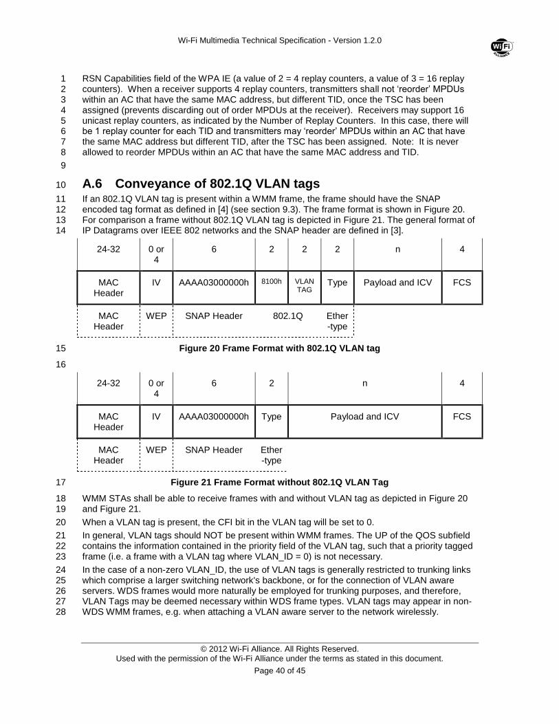
Wi-Fi Multimedia Technical Specification - Version 1.2.0
© 2012 Wi-Fi Alliance. All Rights Reserved. Used with the permission of the Wi-Fi Alliance under the terms as stated in this document.
Page 40 of 45
RSN Capabilities field of the WPA IE (a value of 2 = 4 replay counters, a value of 3 = 16 replay 1 counters). When a receiver supports 4 replay counters, transmitters shall not ‘reorder’ MPDUs 2 within an AC that have the same MAC address, but different TID, once the TSC has been 3 assigned (prevents discarding out of order MPDUs at the receiver). Receivers may support 16 4 unicast replay counters, as indicated by the Number of Replay Counters. In this case, there will 5 be 1 replay counter for each TID and transmitters may ‘reorder’ MPDUs within an AC that have 6 the same MAC address but different TID, after the TSC has been assigned. Note: It is never 7 allowed to reorder MPDUs within an AC that have the same MAC address and TID. 8
9
A.6 Conveyance of 802.1Q VLAN tags 10
If an 802.1Q VLAN tag is present within a WMM frame, the frame should have the SNAP 11 encoded tag format as defined in [4] (see section 9.3). The frame format is shown in Figure 20. 12 For comparison a frame without 802.1Q VLAN tag is depicted in Figure 21. The general format of 13 IP Datagrams over IEEE 802 networks and the SNAP header are defined in [3]. 14
24-32 0 or 4
6 2 2 2 n 4
MAC Header
IV AAAA03000000h 8100h VLAN TAG
Type Payload and ICV FCS
MAC Header
WEP SNAP Header 802.1Q Ether-type
Figure 20 Frame Format with 802.1Q VLAN tag 15
16
24-32 0 or 4
6 2 n 4
MAC Header
IV AAAA03000000h Type Payload and ICV FCS
MAC Header
WEP SNAP Header Ether-type
Figure 21 Frame Format without 802.1Q VLAN Tag 17
WMM STAs shall be able to receive frames with and without VLAN tag as depicted in Figure 20 18 and Figure 21. 19
When a VLAN tag is present, the CFI bit in the VLAN tag will be set to 0. 20
In general, VLAN tags should NOT be present within WMM frames. The UP of the QOS subfield 21 contains the information contained in the priority field of the VLAN tag, such that a priority tagged 22 frame (i.e. a frame with a VLAN tag where VLAN_ID = 0) is not necessary. 23
In the case of a non-zero VLAN_ID, the use of VLAN tags is generally restricted to trunking links 24 which comprise a larger switching network's backbone, or for the connection of VLAN aware 25 servers. WDS frames would more naturally be employed for trunking purposes, and therefore, 26 VLAN Tags may be deemed necessary within WDS frame types. VLAN tags may appear in non-27 WDS WMM frames, e.g. when attaching a VLAN aware server to the network wirelessly. 28
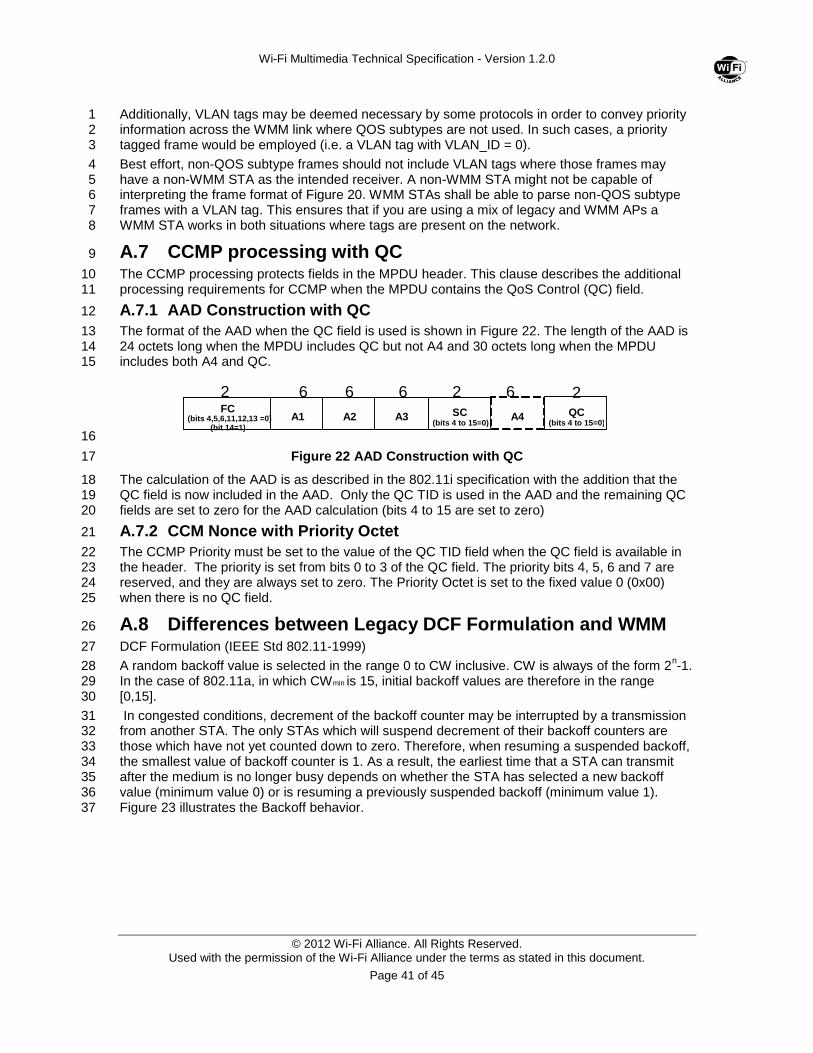
Wi-Fi Multimedia Technical Specification - Version 1.2.0
© 2012 Wi-Fi Alliance. All Rights Reserved. Used with the permission of the Wi-Fi Alliance under the terms as stated in this document.
Page 41 of 45
Additionally, VLAN tags may be deemed necessary by some protocols in order to convey priority 1 information across the WMM link where QOS subtypes are not used. In such cases, a priority 2 tagged frame would be employed (i.e. a VLAN tag with VLAN_ID = 0). 3
Best effort, non-QOS subtype frames should not include VLAN tags where those frames may 4 have a non-WMM STA as the intended receiver. A non-WMM STA might not be capable of 5 interpreting the frame format of Figure 20. WMM STAs shall be able to parse non-QOS subtype 6 frames with a VLAN tag. This ensures that if you are using a mix of legacy and WMM APs a 7 WMM STA works in both situations where tags are present on the network. 8
A.7 CCMP processing with QC 9
The CCMP processing protects fields in the MPDU header. This clause describes the additional 10 processing requirements for CCMP when the MPDU contains the QoS Control (QC) field. 11
A.7.1 AAD Construction with QC 12
The format of the AAD when the QC field is used is shown in Figure 22. The length of the AAD is 13 24 octets long when the MPDU includes QC but not A4 and 30 octets long when the MPDU 14 includes both A4 and QC. 15
16
Figure 22 AAD Construction with QC 17
The calculation of the AAD is as described in the 802.11i specification with the addition that the 18 QC field is now included in the AAD. Only the QC TID is used in the AAD and the remaining QC 19 fields are set to zero for the AAD calculation (bits 4 to 15 are set to zero) 20
A.7.2 CCM Nonce with Priority Octet 21
The CCMP Priority must be set to the value of the QC TID field when the QC field is available in 22 the header. The priority is set from bits 0 to 3 of the QC field. The priority bits 4, 5, 6 and 7 are 23 reserved, and they are always set to zero. The Priority Octet is set to the fixed value 0 (0x00) 24 when there is no QC field. 25
A.8 Differences between Legacy DCF Formulation and WMM 26
DCF Formulation (IEEE Std 802.11-1999) 27
A random backoff value is selected in the range 0 to CW inclusive. CW is always of the form 2n-1. 28
In the case of 802.11a, in which CWmin is 15, initial backoff values are therefore in the range 29 [0,15]. 30
In congested conditions, decrement of the backoff counter may be interrupted by a transmission 31 from another STA. The only STAs which will suspend decrement of their backoff counters are 32 those which have not yet counted down to zero. Therefore, when resuming a suspended backoff, 33 the smallest value of backoff counter is 1. As a result, the earliest time that a STA can transmit 34 after the medium is no longer busy depends on whether the STA has selected a new backoff 35 value (minimum value 0) or is resuming a previously suspended backoff (minimum value 1). 36 Figure 23 illustrates the Backoff behavior. 37
A1 FC
(bits 4,5,6,11,12,13 =0) (bit 14=1)
2 6
A2
6
SC (bits 4 to 15=0)
6
A3
2 6
A4 QC (bits 4 to 15=0)
2
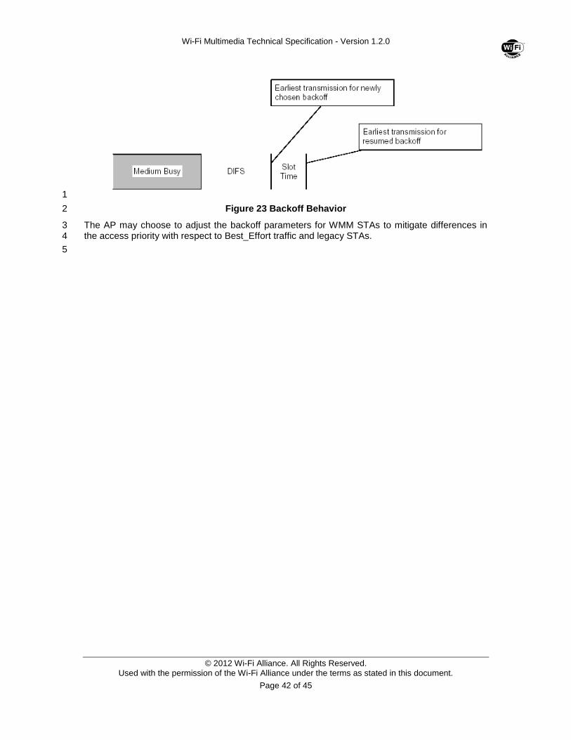
Wi-Fi Multimedia Technical Specification - Version 1.2.0
© 2012 Wi-Fi Alliance. All Rights Reserved. Used with the permission of the Wi-Fi Alliance under the terms as stated in this document.
Page 42 of 45
1
Figure 23 Backoff Behavior 2
The AP may choose to adjust the backoff parameters for WMM STAs to mitigate differences in 3 the access priority with respect to Best_Effort traffic and legacy STAs. 4
5
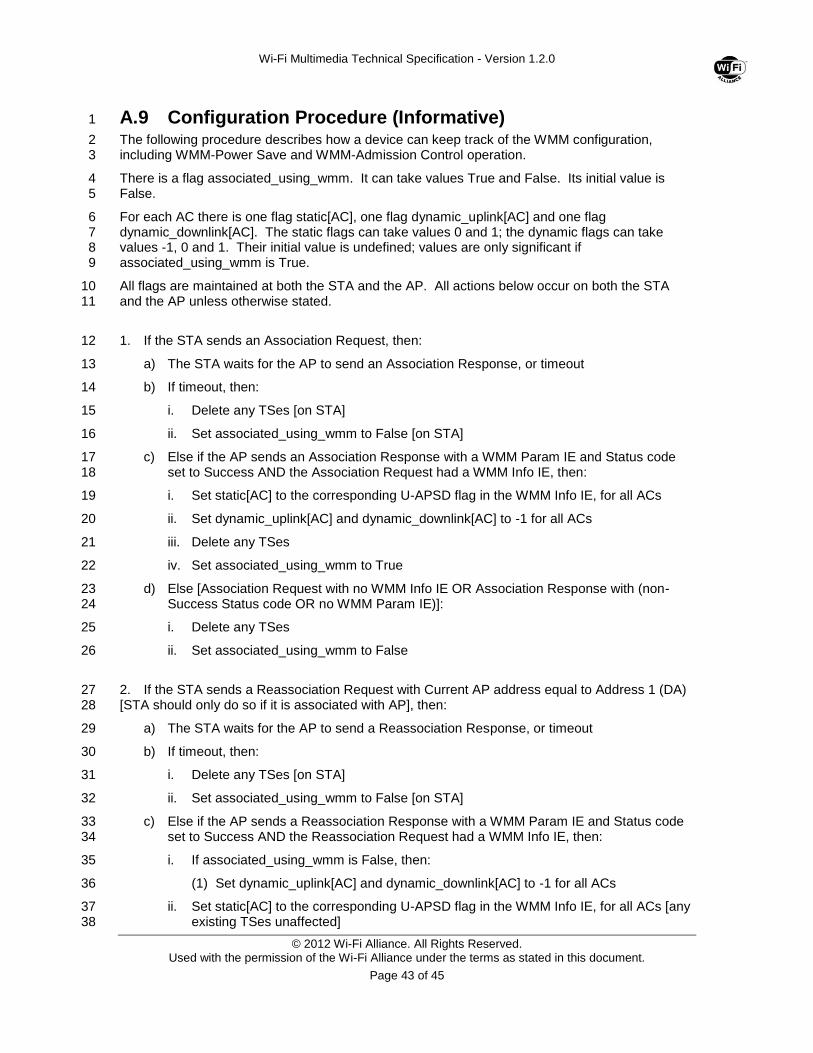
Wi-Fi Multimedia Technical Specification - Version 1.2.0
© 2012 Wi-Fi Alliance. All Rights Reserved. Used with the permission of the Wi-Fi Alliance under the terms as stated in this document.
Page 43 of 45
A.9 Configuration Procedure (Informative) 1
The following procedure describes how a device can keep track of the WMM configuration, 2 including WMM-Power Save and WMM-Admission Control operation. 3
There is a flag associated_using_wmm. It can take values True and False. Its initial value is 4 False. 5
For each AC there is one flag static[AC], one flag dynamic_uplink[AC] and one flag 6 dynamic_downlink[AC]. The static flags can take values 0 and 1; the dynamic flags can take 7 values -1, 0 and 1. Their initial value is undefined; values are only significant if 8 associated_using_wmm is True. 9
All flags are maintained at both the STA and the AP. All actions below occur on both the STA 10 and the AP unless otherwise stated. 11
1. If the STA sends an Association Request, then: 12
a) The STA waits for the AP to send an Association Response, or timeout 13
b) If timeout, then: 14
i. Delete any TSes [on STA] 15
ii. Set associated_using_wmm to False [on STA] 16
c) Else if the AP sends an Association Response with a WMM Param IE and Status code 17 set to Success AND the Association Request had a WMM Info IE, then: 18
i. Set static[AC] to the corresponding U-APSD flag in the WMM Info IE, for all ACs 19
ii. Set dynamic_uplink[AC] and dynamic_downlink[AC] to -1 for all ACs 20
iii. Delete any TSes 21
iv. Set associated_using_wmm to True 22
d) Else [Association Request with no WMM Info IE OR Association Response with (non-23 Success Status code OR no WMM Param IE)]: 24
i. Delete any TSes 25
ii. Set associated_using_wmm to False 26
2. If the STA sends a Reassociation Request with Current AP address equal to Address 1 (DA) 27 [STA should only do so if it is associated with AP], then: 28
a) The STA waits for the AP to send a Reassociation Response, or timeout 29
b) If timeout, then: 30
i. Delete any TSes [on STA] 31
ii. Set associated_using_wmm to False [on STA] 32
c) Else if the AP sends a Reassociation Response with a WMM Param IE and Status code 33 set to Success AND the Reassociation Request had a WMM Info IE, then: 34
i. If associated_using_wmm is False, then: 35
(1) Set dynamic_uplink[AC] and dynamic_downlink[AC] to -1 for all ACs 36
ii. Set static[AC] to the corresponding U-APSD flag in the WMM Info IE, for all ACs [any 37 existing TSes unaffected] 38
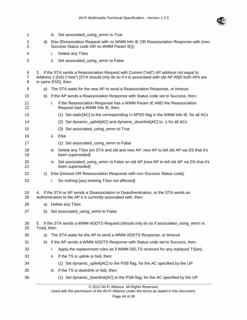
Wi-Fi Multimedia Technical Specification - Version 1.2.0
© 2012 Wi-Fi Alliance. All Rights Reserved. Used with the permission of the Wi-Fi Alliance under the terms as stated in this document.
Page 44 of 45
iii. Set associated_using_wmm to True 1
d) Else [Ressociation Request with no WMM Info IE OR Reassociation Response with (non-2 Success Status code OR no WMM Param IE)]: 3
i. Delete any TSes 4
ii. Set associated_using_wmm to False 5
3. If the STA sends a Reassociation Request with Current ("old") AP address not equal to 6 Address 1 (DA) ("new") [STA should only do so if it is associated with old AP AND both APs are 7 in same ESS], then: 8
a) The STA waits for the new AP to send a Reassociation Response, or timeout 9
b) If the AP sends a Reassociation Response with Status code set to Success, then: 10
i. If the Reassociation Response has a WMM Param IE AND the Reassociation 11 Request had a WMM Info IE, then: 12
(1) Set static[AC] to the corresponding U-APSD flag in the WMM Info IE, for all ACs 13
(2) Set dynamic_uplink[AC] and dynamic_downlink[AC] to -1 for all ACs 14
(3) Set associated_using_wmm to True 15
ii. Else 16
(1) Set associated_using_wmm to False 17
iii. Delete any TSes [on STA and old and new AP; new AP to tell old AP via DS that it's 18 been superseded] 19
iv. Set associated_using_wmm to False on old AP [new AP to tell old AP via DS that it's 20 been superseded] 21
c) Else [timeout OR Reassociation Response with non-Success Status code]: 22
i. Do nothing [any existing TSes not affected] 23
4. If the STA or AP sends a Disassociation or Deauthentication, or the STA sends an 24 Authentication to the AP it is currently associated with, then: 25
a) Delete any TSes 26
b) Set associated_using_wmm to False 27
5. If the STA sends a WMM ADDTS Request [should only do so if associated_using_wmm is 28 True], then: 29
a) The STA waits for the AP to send a WMM ADDTS Response, or timeout 30
b) If the AP sends a WMM ADDTS Response with Status code set to Success, then: 31
i. Apply the replacement rules as if WMM DELTS received for any replaced TS(es) 32
ii. If the TS is uplink or bidi, then: 33
(1) Set dynamic_uplink[AC] to the PSB flag, for the AC specified by the UP 34
iii. If the TS is downlink or bidi, then: 35
(1) Set dynamic_downlink[AC] to the PSB flag, for the AC specified by the UP 36
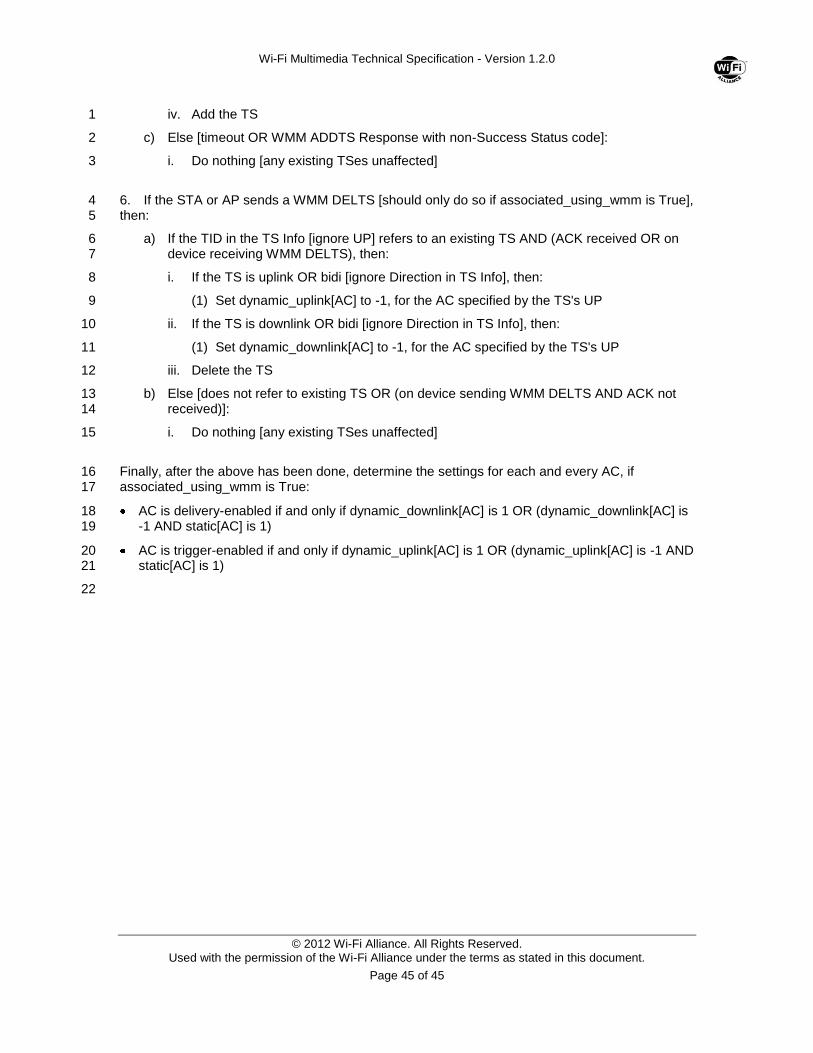
Wi-Fi Multimedia Technical Specification - Version 1.2.0
© 2012 Wi-Fi Alliance. All Rights Reserved. Used with the permission of the Wi-Fi Alliance under the terms as stated in this document.
Page 45 of 45
iv. Add the TS 1
c) Else [timeout OR WMM ADDTS Response with non-Success Status code]: 2
i. Do nothing [any existing TSes unaffected] 3
6. If the STA or AP sends a WMM DELTS [should only do so if associated_using_wmm is True], 4 then: 5
a) If the TID in the TS Info [ignore UP] refers to an existing TS AND (ACK received OR on 6 device receiving WMM DELTS), then: 7
i. If the TS is uplink OR bidi [ignore Direction in TS Info], then: 8
(1) Set dynamic_uplink[AC] to -1, for the AC specified by the TS's UP 9
ii. If the TS is downlink OR bidi [ignore Direction in TS Info], then: 10
(1) Set dynamic_downlink[AC] to -1, for the AC specified by the TS's UP 11
iii. Delete the TS 12
b) Else [does not refer to existing TS OR (on device sending WMM DELTS AND ACK not 13 received)]: 14
i. Do nothing [any existing TSes unaffected] 15
Finally, after the above has been done, determine the settings for each and every AC, if 16 associated_using_wmm is True: 17
AC is delivery-enabled if and only if dynamic_downlink[AC] is 1 OR (dynamic_downlink[AC] is 18 -1 AND static[AC] is 1) 19
AC is trigger-enabled if and only if dynamic_uplink[AC] is 1 OR (dynamic_uplink[AC] is -1 AND 20 static[AC] is 1) 21
22


