Embed Size (px)
Citation preview
(12) INTERNATIONAL APPLICATION PUBLISHED UNDER THE PATENT COOPERATION TREATY (PCT)
(19) World Intellectual PropertyOrganization
International Bureau(10) International Publication Number
(43) International Publication Date WO 2013/148138 Al3 October 2013 (03.10.2013) P O P C T
(51) International Patent Classification: CA 94563 (US). EAGLESHAM, David [US/US]; 8 CutH01M 10/054 (2010.01) H01M 6/14 (2006.01) ler Farm Road, Lexington, MA 02421 (US).H01M 4/46 (2006.01) H01M 10/38 (2006.01)
(74) Agent: MILSTEIN, Joseph, B.; Milstein Zhang & Wu(21) International Application Number: LLC, 2000 Commonwealth Avenue, Suite 400, Newton,
PCT/US20 13/030224 MA 02466-2004 (US).
(22) International Filing Date: (81) Designated States (unless otherwise indicated, for every11 March 2013 ( 11.03.2013) kind of national protection available): AE, AG, AL, AM,
AO, AT, AU, AZ, BA, BB, BG, BH, BN, BR, BW, BY,(25) Filing Language: English BZ, CA, CH, CL, CN, CO, CR, CU, CZ, DE, DK, DM,
(26) Publication Language: English DO, DZ, EC, EE, EG, ES, FI, GB, GD, GE, GH, GM, GT,HN, HR, HU, ID, IL, IN, IS, JP, KE, KG, KM, KN, KP,
(30) Priority Data: KR, KZ, LA, LC, LK, LR, LS, LT, LU, LY, MA, MD,61/617,5 12 29 March 2012 (29.03.2012) US ME, MG, MK, MN, MW, MX, MY, MZ, NA, NG, NI,
(71) Applicant (for all designated States except US): PEL- NO, NZ, OM, PA, PE, PG, PH, PL, PT, QA, RO, RS, RU,
LION TECHNOLOGIES, INC. [US/US]; 625 Mount RW, SC, SD, SE, SG, SK, SL, SM, ST, SV, SY, TH, TJ,
Auburn Street, Suite 105, Cambridge, MA 02138 (US). TM, TN, TR, TT, TZ, UA, UG, US, UZ, VC, VN, ZA,ZM, ZW.
(72) Inventors; and(71) Applicants (for US only): DOE, Robert, Ellis [US/US]; (84) Designated States (unless otherwise indicated, for every
26 Independence Way, Norwood, MA 02062 (US). kind of regional protection available): ARIPO (BW, GH,
DOWNIE, Craig, Michael [US/US]; 184 Ridge Lane, GM, KE, LR, LS, MW, MZ, NA, RW, SD, SL, SZ, TZ,
Apt. 301, Waltham, MA 02452 (US). FISCHER, Chris¬ UG, ZM, ZW), Eurasian (AM, AZ, BY, KG, KZ, RU, TJ,
topher [US/US]; 27 Fairfax Street, Somerville, MA 02144 TM), European (AL, AT, BE, BG, CH, CY, CZ, DE, DK,
(US). LANE, George, Hamilton [AU/AU]; 6 Quail St, St. EE, ES, FI, FR, GB, GR, HR, HU, IE, IS, ΓΓ , LT, LU, LV,MC, MK, MT, NL, NO, PL, PT, RO, RS, SE, SI, SK, SM,Helens, Tasmania, 7216 (AU). MORGAN, DaneTR), OAPI (BF, BJ, CF, CG, CI, CM, GA, GN, GQ, GW,[US/US]; 6422 Wydown Circle, Middleton, WI 53562-ML, MR, NE, SN, TD, TG).
3847 (US). NEVIN, Josh [US/US]; 582 Trapelo Road,Belmont, MA 02478 (US). CEDER, Gerbrand [BE/US]; Published:28 High Ledge Avenue, Wellesley, MA 02482 (US).
— with international search report (Art. 21(3))PERSSON, Kristin, Aslaug [SE/US]; 212 Ivy Dr, Orinda,
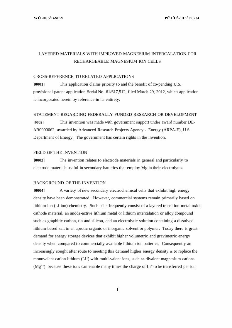
(54) Title: LAYERED MATERIALS WITH IMPROVED MAGNESIUM INTERCALATION FOR RECHARGEABLE MAGNESIUM ION CELLS
00
00FIG. 1A
2 7) Abstract: Electrochemical devices which incorporate cathode materials that include layered crystalline compounds for which astructural modification has been achieved which increases the diffusion rate of multi-valent ions into and out of the cathode materials. Examples in which the layer spacing of the layered electrode materials is modified to have a specific spacing range such that thespacing is optimal for diffusion of magnesium ions are presented. An electrochemical cell comprised of a positive intercalation elec -trode, a negative metal electrode, and a separator impregnated with a nonaqeuous electrolyte solution containing multi-valent ions
S and arranged between the positive electrode and the negative electrode active material is described.
LAYERED MATERIALS WITH IMPROVED MAGNESIUM INTERCALATION FOR
RECHARGEABLE MAGNESIUM ION CELLS
CROSS-REFERENCE TO RELATED APPLICATIONS
[0001] This application claims priority to and the benefit of co-pending U.S.
provisional patent application Serial No. 61/617,512, filed March 29, 2012, which application
is incorporated herein by reference in its entirety.
STATEMENT REGARDING FEDERALLY FUNDED RESEARCH OR DEVELOPMENT
[0002] This invention was made with government support under award number DE-
AR0000062, awarded by Advanced Research Projects Agency - Energy (ARPA-E), U.S.
Department of Energy. The government has certain rights in the invention.
FIELD OF THE INVENTION
[0003] The invention relates to electrode materials in general and particularly to
electrode materials useful in secondary batteries that employ Mg in their electrolytes.
BACKGROUND OF THE INVENTION
[0004] A variety of new secondary electrochemical cells that exhibit high energy
density have been demonstrated. However, commercial systems remain primarily based on
lithium ion (Li-ion) chemistry. Such cells frequently consist of a layered transition metal oxide
cathode material, an anode-active lithium metal or lithium intercalation or alloy compound
such as graphitic carbon, tin and silicon, and an electrolytic solution containing a dissolved
lithium-based salt in an aprotic organic or inorganic solvent or polymer. Today there is great
demand for energy storage devices that exhibit higher volumetric and gravimetric energy
density when compared to commercially available lithium ion batteries. Consequently an
increasingly sought after route to meeting this demand higher energy density is to replace the
monovalent cation lithium (Li+) with multi-valent ions, such as divalent magnesium cations
(Mg +), because these ions can enable many times the charge of Li+ to be transferred per ion.
ATTORNEY DOCKET No. PEL-0001PCT
[0005] Furthermore, alkali metals, and lithium in particular, have numerous
disadvantages. Alkali metals are expensive. Alkali metals are highly reactive. Alkali metals
are also highly flammable, and fire resulting from the reaction of alkali metals with oxygen,
water or other active materials is extremely difficult to extinguish. Lithium is poisonous and
compounds thereof are known for their severe physiological effects, even in minute quantities.
As a result, the use of alkali metals requires specialized facilities, such as dry rooms,
specialized equipment and specialized procedures.
[0006] Gregory et al, "Nonaqueous Electrochemistry of Magnesium; Applications to
Energy Storage" J . Electrochem. Soc, Vol. 137, No. 3, March 1990 discloses Co30 4, Mn20 3,
Mn30 4, Mo0 3, Pb0 2, Pb30 4, Ru0 2, V20 , W0 3, TiS2, VS2, ZrS2, MoB2, TiB2, and ZrB2 as
positive electrode materials for a magnesium battery. However, only the first cycle discharge is
shown and all materials exhibit significant polarization for medium current densities.
[0007] Novak et al, "Electrochemical Insertion of Magnesium in Metal Oxides and
Sulfides from Aprotic Electrolytes," JECS 140 (1) 1993 discloses TiS2, ZrS2, Ru0 2, Co30 4 and
V20 as positive electrode materials of a magnesium battery. However, only layered V2O
shows promising capacity and reversibility. Furthermore, Novak et al. show that Mg +
insertion into this oxide depends on the ratio between the amounts of H20 and Mg + as well as
on the absolute amount of H20 in the electrolyte. According to Novak, water molecules
preferentially solvate Mg + ions, which facilitate the insertion process by co-intercalation.
[0008] Novak et al, "Electrochemical Insertion of Magnesium into Hydrated
Vanadium Bronzes" Electrochem. Soc, Vol. 142, No. 8, 1995 discloses Mg + insertion into
layered vanadium bronzes, MeV30s(H20) y where (Me = Li, Na, K, Ca0 .5, and Mgo.5).
Variations in the content of bound lattice water in the bronzes were found to be responsible for
a difference in the electrochemical properties of the same starting material dried at different
temperatures. The presence of this water was deemed essential but the lattice water is removed
during cycling after which the capacity deteriorates. Furthermore, attempts to cycle the
compounds in dry electrolytes failed. The beneficial effect of water was speculated to be due to
its solvation of the Mg + ion.
[0009] Le et al, "Intercalation of Polyvalent Cations into V2O Aerogels" Chem.
Mater. 1998, 10, 682-684 discloses multi-valent ion insertion into V2O areogels where the
small diffusion distances and high surface area are regarded as beneficial for multi-valent
ATTORNEY DOCKET No. PEL-0001PCT
intercalation. X-ray diffraction of the aerogel shows an interlayer spacing of 12.5 A (due to
retaining acetone), as compared to the 8.8 A characteristic of the V2O *0.5H2O xerogel.
[0010] Amatucci et al, "Investigation of Yttrium and Polyvalent Ion Intercalation into
Nanocrystalline Vanadium Oxide," J Electrochem Soc, 148(8), A940-A950, July 13, 2001,
show reversible intercalation of several multi-valent cations (Mg +, Ca +, Y +) into nano-metric
layered V 2O but with significant polarization (e.g., energy loss) and at a low rate of 0.04C
which signifies the low diffusivity of the Mg ions.
[0011] The current, proven state of the art high energy, rechargeable Mg cell is
described by Aurbach et al, U.S. Pat. No. 6,3 16,141, issued November 13, 2001, as a cell
comprised of a magnesium metal anode, a "Chevrel" phase active material cathode, and an
electrolyte solution derived from an organometallic complex containing Mg. Chevrel
compounds are a series of ternary molybdenum chalcogenide compounds first reported by R.
Chevrel, M. Sergent, and J . Prigent in J . Solid State Chem. 3, 515-519 (1971). The Chevrel
compounds have the general formula MxMo6Xs, where M represents any one of a number of
metallic elements throughout the periodic table; x has values between 1 and 4, depending on
the M element; and X is a chalcogen (sulfur, selenium or tellurium). Furthermore, in E. Levi et
al, "New Insight on the Unusually High Ionic Mobility in Chevrel Phases," Chem Mat 2 1 (7),
1390-1399, 2009, the Chevrel phases are described as unique materials which allow for a fast
and reversible insertion of various cations at room temperature.
[0012] Michot et al., U.S. Pat. No. 6,395,367, issued May 28, 2002, is said to disclose
ionic compounds in which the anionic load has been delocalized. A compound disclosed by
the invention includes an anionic portion combined with at least one cationic portion Mm+ in
sufficient numbers to ensure overall electronic neutrality; the compound is further comprised
of M as a hydroxonium, a nitrosonium NO+, an ammonium Ν Η4+, a metallic cation with the
valence m, an organic cation with the valence m, or an organometallic cation with the valence
m. The anionic load is carried by a pentacyclical nucleus of tetrazapentalene derivative
bearing electroattractive substituents. The compounds can be used notably for ionic
conducting materials, electronic conducting materials, colorant, and the catalysis of various
chemical reactions.
[0013] U.S. Pat. No. 6,426,164 B l to Yamaura et al, issued July 30, 2002, is said to
disclose a non-aqueous electrolyte battery capable of quickly diffusing magnesium ions and
ATTORNEY DOCKET No. PEL-0001PCT
improving cycle operation resistance, incorporating a positive electrode containing LixM0 2
(where M is an element containing at least Ni or Co) as a positive-electrode active material
thereof; a negative electrode disposed opposite to the positive electrode and containing a
negative-electrode active material which permits doping/dedoping magnesium ions: and a non
aqueous electrolyte disposed between the positive electrode and the negative electrode and
containing non-aqueous solvent and an electrolyte constituted by magnesium salt, wherein the
value of x of LixM0 2 satisfies a range 0.1 < x < 0.5. It is also said that for Li concentrations x <
0.1, the host material becomes unstable and for higher Li concentrations x > 0.5, there are not
enough available Mg lattice sites available. Specifically, there is no mention of interlayer
distance.
[0014] Michot et al., U.S. Pat. No. 6,841,304, issued January 11, 2005, is said to
disclose novel ionic compounds with low melting point whereof the onium type cation having
at least a heteroatom such as N, O, S or P bearing the positive charge and whereof the anion
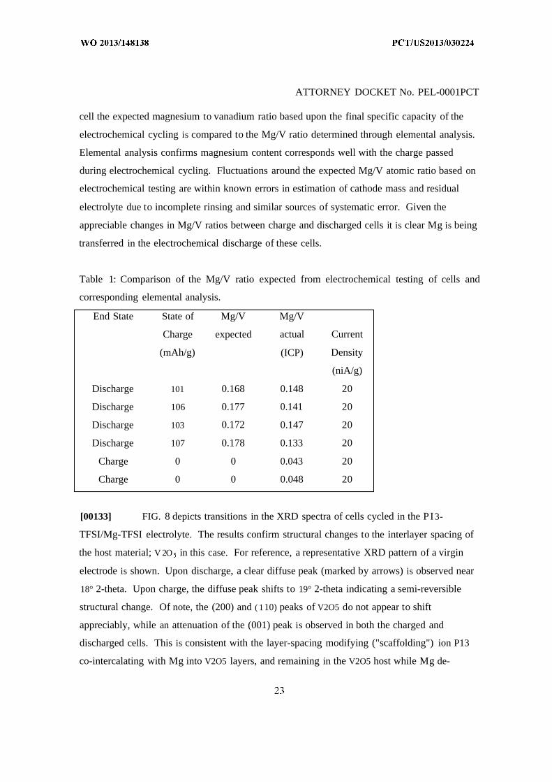
includes, wholly or partially, at least an ion imide such as (FX 1 0)N (OX2 F) wherein X 1 and
X2 are identical or different and comprise SO or PF, and their use as solvent in electrochemical
devices. Said composition comprises a salt wherein the anionic charge is delocalised, and can
be used, inter alia, as electrolyte.
[0015] U.S. Patent Application Publication No. 20090068568 A l (Yamamoto et al.
inventors), published on March 12, 2009, is said to disclose a magnesium ion containing non
aqueous electrolyte in which magnesium ions and aluminum ions are dissolved in an organic
etheric solvent, and which is formed by: adding metal magnesium, a halogenated hydrocarbon
RX, an aluminum halide AIY3, and a quaternary ammonium salt R R R R4N+Z to an organic
etheric solvent; and applying a heating treatment while stirring them (in the general formula
RX representing the halogenated hydrocarbon, R is an alkyl group or an aryl group, X is
chlorine, bromine, or iodine, in the general formula AIY3 representing the aluminum halide, Y
is chlorine, bromine, or iodine, in the general formula R1R R R4N Z_ representing the
quaternary ammonium salt, R1, R2, R , and R4 represent each an alkyl group or an aryl group,
and Z represents chloride ion, bromide ion, iodide ion, acetate ion, perchlorate ion, tetrafluoro
borate ion, hexafluoro phosphate ion, hexafluoro arsenate ion, perfluoroalkyl sulfonate ion, or
perfluoroalkyl sulfonylimide ion. These additives are aimed at increasing the stability of the
electrolyte in atmospheric air and facilitate the production process for said electrolytes.
ATTORNEY DOCKET No. PEL-0001PCT
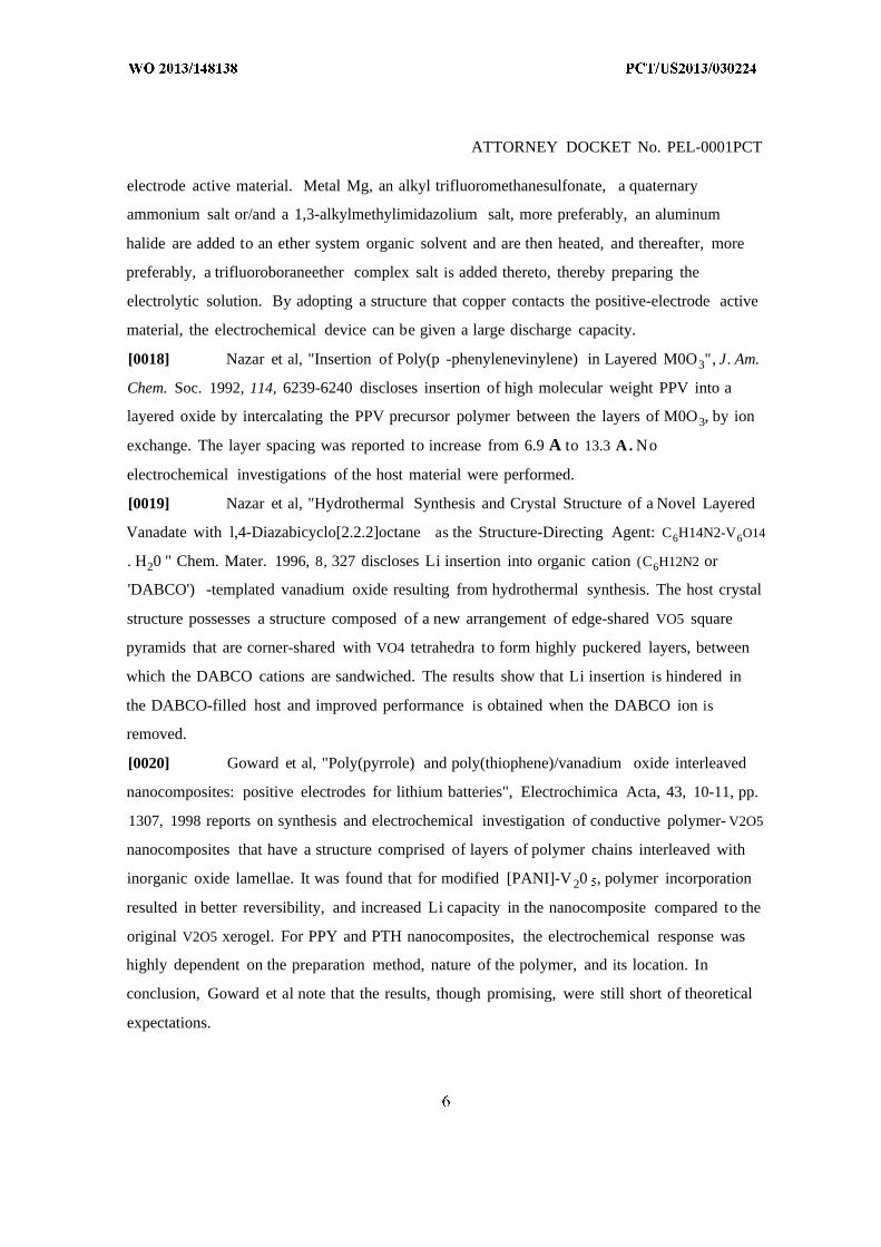
[0016] U.S. Patent Application Publication No. 20100136438 A l (Nakayama et al.
inventors), published June 3, 2010, is said to disclose a magnesium battery that is constituted
of a negative electrode, a positive electrode and an electrolyte. The negative electrode is
formed of metallic magnesium and can also be formed of an alloy. The positive electrode is
composed of a positive electrode active material, for example, a metal oxide, graphite fluoride
((CF)n) or the like, etc. The electrolytic solution is, for example, a magnesium ion containing
nonaqueous electrolytic solution prepared by dissolving magnesium(II) chloride (MgC^) and
dimethylaluminum chloride ((C AlCT) in tetrahydrofuran (THF). In the case of dissolving
and depositing magnesium by using this electrolytic solution, they indicate that the following
reaction proceeds in the normal direction or reverse direction.
c ¾ c i2 Mg2+ 6THF
/ \
According to this, there are provided a magnesium ion-containing nonaqueous electrolytic
solution having a high oxidation potential and capable of sufficiently bringing out excellent
characteristics of metallic magnesium as a negative electrode active material and a method for
manufacturing the same, and an electrochemical device with high performances using this
electrolytic solution.
[0017] U.S. Patent Application Publication No. 201 1011 1286 A l (Yamamoto el at.
inventors), published on May 12, 201 1, is said to disclose a nonaqueous electrolytic solution
containing magnesium ions which shows excellent electrochemical characteristics and which
can be manufactured in a general manufacturing environment such as a dry room, and an
electrochemical device using the same are provided. A Mg battery has a positive-electrode can,
a positive-electrode pellet made of a positive-electrode active material or the like, a positive
electrode composed of a metallic net supporting body, a negative-electrode cup, a negative
electrode made of a negative-electrode active material, and a separator impregnated with an
electrolytic solution and disposed between the positive-electrode pellet and the negative-
ATTORNEY DOCKET No. PEL-0001PCT
electrode active material. Metal Mg, an alkyl trifluoromethanesulfonate, a quaternary
ammonium salt or/and a 1,3-alkylmethylimidazolium salt, more preferably, an aluminum
halide are added to an ether system organic solvent and are then heated, and thereafter, more
preferably, a trifluoroboraneether complex salt is added thereto, thereby preparing the
electrolytic solution. By adopting a structure that copper contacts the positive-electrode active
material, the electrochemical device can be given a large discharge capacity.
[0018] Nazar et al, "Insertion of Poly(p -phenylenevinylene) in Layered M0O3", J. Am.
Chem. Soc. 1992, 114, 6239-6240 discloses insertion of high molecular weight PPV into a
layered oxide by intercalating the PPV precursor polymer between the layers of M0O3, by ion
exchange. The layer spacing was reported to increase from 6.9 A to 13.3 A. No
electrochemical investigations of the host material were performed.
[0019] Nazar et al, "Hydrothermal Synthesis and Crystal Structure of a Novel Layered
Vanadate with l,4-Diazabicyclo[2.2.2]octane as the Structure-Directing Agent: C6H14N2-V6O14
. H20 " Chem. Mater. 1996, 8, 327 discloses Li insertion into organic cation (C6H12N2 or
'DABCO') -templated vanadium oxide resulting from hydrothermal synthesis. The host crystal
structure possesses a structure composed of a new arrangement of edge-shared VO5 square
pyramids that are corner-shared with VO4 tetrahedra to form highly puckered layers, between
which the DABCO cations are sandwiched. The results show that Li insertion is hindered in
the DABCO-filled host and improved performance is obtained when the DABCO ion is
removed.
[0020] Goward et al, "Poly(pyrrole) and poly(thiophene)/vanadium oxide interleaved
nanocomposites: positive electrodes for lithium batteries", Electrochimica Acta, 43, 10-11, pp.
1307, 1998 reports on synthesis and electrochemical investigation of conductive polymer- V2O5
nanocomposites that have a structure comprised of layers of polymer chains interleaved with
inorganic oxide lamellae. It was found that for modified [PANI]-V 20 , polymer incorporation
resulted in better reversibility, and increased Li capacity in the nanocomposite compared to the
original V2O5 xerogel. For PPY and PTH nanocomposites, the electrochemical response was
highly dependent on the preparation method, nature of the polymer, and its location. In
conclusion, Goward et al note that the results, though promising, were still short of theoretical
expectations.
ATTORNEY DOCKET No. PEL-0001PCT
[0021] Chirayil et al, 'Synthesis and characterization of a new vanadium oxide, TMA-
V 8O2O' J . Mater. Chem., 1997, 7(11), 2193-2195 discloses synthesis of a layered vanadium
oxide with a new monoclinic structure in which the tetramethylammonium ions reside between
the vanadium oxide layers. The powder X-ray diffraction pattern indicate that this new
vanadium oxide has an interlayer spacing of 11.5 Angstrom. Electrochemical investigation of
the compound indicates that Li insertion is hindered due to the TMA ions between the layers.
[0022] Lutta et al, "Solvothermal synthesis and characterization of a layered
pyridinium vanadate, C H6N-V307" J . Mater. Chem., 2003, 13, 1424-1428 reports on
synthesis and properties of a layered vanadate which has an aromatic intercalate (pyridinium
ion) between the vanadium oxide layers: pyH-VsO . Chemical lithiation show some reactivity
with Li but better performance was obtained when the pyridinium was removed from the
vanadate. Indeed, Lutta et al concludes with saying that none of the aromatic V 3O 7 based
structures (TMA-V3O7, MA-V3O7, pyH-VsO ) or their decomposition products lead to
electrochemically interesting materials.
[0023] The results described above show that slow diffusion of multi-valent ions in
layered cathode materials is a limiting factor in rechargeable multi-valent electrochemical
cells.
[0024] Furthermore, the results above also show that it is commonly believed that
organic-inorganic hybrid host materials do not improve intercalation performance, specifically
for lithium ions.
[0025] There is a need for systems and methods for making improved positive
electrode layered materials with high energy density as well as facile Mg ion diffusion.
SUMMARY OF THE INVENTION
[0026] According to one aspect, the invention features an energy-storage apparatus.
The energy-storage apparatus comprises an anode configured to accept Mg ions from an
electrolyte and to release Mg-ions to the electrolyte, the anode having at least one anode
electrical connection on an external surface of the energy-storage apparatus, and having at least
one anode surface within the energy-storage apparatus; a cathode comprising a layered
crystalline compound comprising a deliberately added specie or species so that a layer spacing
of the layered crystalline compound is modified to allow for magnesium ion diffusion
ATTORNEY DOCKET No. PEL-0001PCT
sufficient to support at least a C/5 discharge rate of the energy storage apparatus, the layered
crystalline compound having at least one cathode electrical connection on an external surface
of the energy-storage apparatus and having at least one cathode surface within the energy-
storage apparatus; and the electrolyte comprising a magnesium-bearing electrolyte in contact
with the at least one anode surface within the energy-storage apparatus, and in contact with the
at least one cathode surface within the energy-storage apparatus.
[0027] In one embodiment, a layer spacing of the layered crystalline compound is
modified to allow for magnesium ion diffusion sufficient to support at least a C/15 discharge
rate of the energy storage apparatus.
[0028] In another embodiment, a shortest metal-metal inter-layer distance in the
layered crystalline compound is 4.8 Angstrom or more.
[0029] In yet another embodiment, a shortest metal-metal inter-layer distance in the
layered crystalline compound is smaller than 8 Angstrom
[0030] In still another embodiment, a shortest metal-metal inter-layer distance in the
layered crystalline compound is smaller than 1 Angstrom.
[0031] In a further embodiment, the cathode comprising a layered crystalline
compound comprises a compound having the chemical formula MgaMbXy, wherein M is a
metal cation or a mixture of metal cations, X is an anion or mixture of anions, a is in the range
of 0 to about 2, b is in the range of about 1 to about 2, and y < 9.
[0032] In yet a further embodiment, at least one of the anode and the cathode further
comprises an electronically conductive additive.
[0033] In an additional embodiment, at least one of the anode and the cathode further
comprises a polymer binder.
[0034] In one more embodiment, the anode configured to accept and release Mg-ions
comprises a material selected from the group consisting of Mg, Mg alloys AZ3 1, AZ61, AZ63,
AZ80, AZ81, AZ91, AM50, AM60, Elektron 675, ZK51, ZK60, ZK61, ZC63, MIA, ZC71,
Elektron 21, Elektron 675, Elektron, Magnox, and Mg alloys containing at least one of the
elements Al, Ca, Bi, Sb, Sn, Ag, Cu, and Si.
[0035] In still a further embodiment, the anode configured to accept and release Mg-
ions comprises insertion materials including one or more of Anatase T1O2, rutile T1O2, Mo6Ss,
FeS2, T1S2, and M0S2 and combinations thereof.
ATTORNEY DOCKET No. PEL-0001PCT
[0036] In one embodiment, the at least one of the cathode and the anode comprises a
carbonaceous material.
[0037] In yet another embodiment, the energy-storage apparatus is a secondary battery.
[0038] According to another aspect, the invention relates to a multi-valent ion battery.
The multi-valent ion battery, comprises an anode configured to accept and release a multi
valent positive ion, the anode having at least one electrical connection on an external surface of
the energy-storage apparatus, and having at least one anode surface within the energy-storage
apparatus; a cathode containing a layered compound comprising a first plurality of layers of
inorganic material separated by a second plurality of units of an organic species situated on
intervening planes, the cathode having at least one electrical connection on an external surface
of the energy-storage apparatus and having at least one cathode surface within the energy-
storage apparatus, and an electrolyte bearing the multi-valent positive ion in contact with the at
least one anode surface and the at least one cathode surface.
[0039] In one embodiment, the multi-valent positive ion is a Mg + ion.
[0040] In another embodiment, the electrolyte is a magnesium-bearing electrolyte
comprising a magnesium salt and an onium ion.
[0041] In yet another embodiment, the cathode comprising a layered compound
comprises a compound having the chemical formula MgaMbXy, wherein M is a metal cation or
a mixture of metal cations, X is an anion or a mixture of anions, a is in the range of 0 to about
2, b is in the range of about 1 to about 2, and y < 9.
[0042] In still another embodiment, the anode configured to accept and release the
Mg + ion comprises a material selected from the group consisting of Mg, Mg alloys AZ31,
AZ61, AZ63, AZ80, AZ81, AZ91, AM50, AM60, Elektron 675, ZK51, ZK60, ZK61, ZC63,
MIA, ZC71, Elektron 21, Elektron 675, Elektron, Magnox, and Mg alloys containing Mg
alloys containing at least one of the elements Al, Ca, Bi, Sb, Sn, Ag, Cu, and Si.
[0043] In a further embodiment, the anode configured to accept and release the multi
valent positive ion comprises insertion materials including Anatase Ti0 2, rutile T1O2, Mo6Ss,
FeS2, T1S2, and M0S2 and combinations thereof.
[0044] In yet a further embodiment, the anode configured to accept and release the
multi-valent positive ion comprises an electronically conductive additive.
ATTORNEY DOCKET No. PEL-0001PCT
[0045] In an additional embodiment, the anode configured to accept the multi-valent
positive ion comprises a polymer binder.
[0046] In one more embodiment, the energy-storage apparatus is a secondary battery.
[0047] In still a further embodiment, the plurality of units of the organic species
comprises a selected one of an organic neutral molecule, an organic anion, an organic cation,
and an onium cation.
[0048] In one embodiment, the cathode further comprises an electronically conductive
additive.
[0049] In another embodiment, the cathode further comprises a polymer binder.
[0050] According to another aspect, the invention relates to a multivalent-ion battery
containing an electrode produced by a method. The method comprises the steps of forming an
inorganic material having a layered structure; and exposing the inorganic material to an organic
chemistry so that an organic substance becomes inserted into the layered structure of the
inorganic material, the organic substance causing a modification of the layered structure of the
inorganic material so as to allow efficient intercalation of a multivalent ionic species.
[0051] In one embodiment, the multivalent ion is magnesium.
[0052] In another embodiment, the organic substance is an organic molecule.
[0053] In yet another embodiment, the organic substance is an onium ion.
[0054] In still another embodiment, the onium ion is a selected one of a tetra-alkyl-
ammonium ion, a tetra-alkyl-phosphonium ion, a di-alkyl-pyrrolidinium ion, a di-alkyl-
imidazolium ion, and a di-alkyl-piperidinium ion.
[0055] In a further embodiment, the inorganic material having a layered structure is a
layered metal oxide compound.
[0056] In yet a further embodiment, the inorganic material having a layered structure
has the chemical formula MgaMbXy, wherein M is a metal cation or a mixture of metal cations,
X is an anion or mixture of anions, a is in the range of 0 to about 2, b is in the range of about 1
to about 2, and y < 9.
[0057] In an additional embodiment, M and X are given by one of the following:
(a) M is Mo or a mixture of metal cations including Mo, and X is O;
(b) M is V and Li or a mixture of metal cations including V and Li, and X is O;
(c) M is Mn or a mixture of metal cations including Mn, and X is O;
ATTORNEY DOCKET No. PEL-0001PCT
(d) M is Co or a mixture of metal cations including Co, and X is O;
(e) M is Ni or a mixture of metal cations including Ni, and X is O;
(f) -M is Ni and H or a mixture of cations including Ni and H, and X is O;
(g) M is V or a mixture of metal cations including V, and X is 0(P0 4); or
(h) M is V or a mixture of metal cations including V, and X is O, F, or a mixture
thereof.
[0058] In one more embodiment, the exposing step involves an electrochemical step.
[0059] In still a further embodiment, the exposing step involves a chemical reaction.
[0060] The foregoing and other objects, aspects, features, and advantages of the
invention will become more apparent from the following description and from the claims.
BRIEF DESCRIPTION OF THE DRAWINGS
[0061] The objects and features of the invention can be better understood with
reference to the drawings described below, and the claims. The drawings are not necessarily to
scale, emphasis instead generally being placed upon illustrating the principles of the invention.
In the drawings, like numerals are used to indicate like parts throughout the various views.
[0062] FIG. 1A is a schematic diagram of a layered material with Mg ions situated in
the layer and the shortest metal-metal inter-layer center distance indicated.
[0063] FIG. IB is a schematic diagram of a layered material having a first plurality of
layers of inorganic material separated by a second plurality of units of an organic species
situated on intervening planes.
[0064] FIG. 2 is a graph of calculated diffusivity by first principles nudged elastic band
calculations for a single Mg ion in layered V 2O as a function of the metal-metal center layer
distance. The equilibrium un-modified materials layer distance is specified as well as the
estimated 1C rate performance for a representative 100 nm radius electrode particle.
[0065] FIG. 3 is a graph of calculated diffusivity by first principles nudged elastic band
calculations for a single Mg ion in layered Mn0 2 as a function of the metal-metal center layer
distance. The equilibrium un-modified materials layer distance is specified as well as the
estimated 1C rate performance for a representative 100 nm radius electrode particle.
ATTORNEY DOCKET No. PEL-0001PCT
[0066] FIG. 4 is a graph of calculated diffusivity by first principles nudged elastic band
calculations for a single Li ion in layered V 2O as a function of the metal-metal center layer
distance. The equilibrium un-modified materials slab layer distance is specified as well as the
estimated 1C rate performance for a representative 100 nm radius particle.
[0067] FIG. 5 is a schematic diagram of an example onium ion. The moieties R1, R2,
R , and R4 each represent an alkyl, aryl, alkenyl, alkynyl group, or mixture thereof, and N+ can
be substituted for other cation centers including, but not limited, to P, As, Sb, Bi, F, and S.
[0068] FIG. 6 is a diagram of a pyrrolidinium ion.
[0069] FIG. 7 is a graph of the behavior of a three electrode pouch cell containing a
increased-layer spacing modified V2O5 material incorporated into a working electrode and
displaying nucleation of a new "scaffolded" phase due to P13 onium cation co-intercalation
during discharge one as compared to subsequent voltage profiles demonstrating facile Mg
intercalation. The cell was cycled between -1.2 and 0.7 V versus the Ag/Ag+ quasi-reference at
80°C.
[0070] FIG. 8 is a diagram showing the X-ray diffraction (XRD) spectra of increased-
layer spacing V2O5 cathodes cycled in P13-TFSI/Mg-TFSI electrolyte indicating the structural
changes corresponding to the modification of the material. For reference, a representative XRD
pattern of an electrode containing the un-modified V2O5 material is shown in comparison to the
intercalated (discharged) and de-intercalated (charged) cathode. The cathodes containing the
modified materials show a new peak at 18° corresponding to the spreading of the layers within
this cathode host structure.
[0071] FIG. 9 is a graph that shows the comparison of capacity of discharged cells
containing modified layered cathode material to the transient magnesium quantified by
elemental analysis.
[0072] FIG. 10 is a graph that shows the comparison of the scaffolding P13 ion content
and the transient magnesium content in charge and discharged cells.
[0073] FIG. 11 is a graph that demonstrates the voltage profile of a cell with a V 2O
layered cathode material in an electrolyte containing only the scaffolding ion P13 in TFSI, and
no magnesium salt. The voltage is measured versus the Ag/Ag+ quasi-reference.
[0074] FIG. 12 is a graph that shows the voltage profile for the first discharge and
subsequent charge of a cell with a V2O5 layered cathode material in an electrolyte containing
ATTORNEY DOCKET No. PEL-0001PCT
P13-TFSI in the electrolyte, but no magnesium salt. The voltage is measured vs. an Ag/Ag+
quasi-reference electrode. The cell was discharged to - 1 V (vs. Ag quasi) and charged to 0.7 V
(vs. Ag quasi) galvanostatically at 200 mA/g. A discharge capacity of approximately 60
mAh/g, and a subsequent charge of 20 mAh/g are observed, which are attributed to semi-
reversible intercalation of the onium cation (PI 3).
[0075] FIG. 13 is a graph that shows a comparison of the nitrogen content in cathodes
of cycled cells (ending in both discharged and charged states) and non-cycled cells (i.e., only
soaked in electrolyte containing P13-TFSI). Nitrogen content is quantified using LECO time-
of-flight mass spectrometry.
[0076] FIG. 14 is a graph that provides an estimate for the quantity of P13 onium
cation (i.e., P13 V20s) in the V2O5 host derived from the ppm level of nitrogen relative to the
vanadium content in the electrode. It is compared to the amount of P13 estimated to be in the
cathode based upon residing cell capacity (i.e. capacity associated with Coulombic
inefficiency).
[0077] FIG. 15 is a graph that depicts the voltage profile of an electrode pouch cell
containing a V O working electrode and displaying nucleation of a new phase due to ethyl-
dimethyl-propyl-ammonium "Nl 123" scaffolding ion co-intercalation during discharge one as
compared to subsequent voltage profiles demonstrating facile Mg intercalation. The cell was
cycled between -1.2 and 0.7 V versus the Ag/Ag+ quasi-reference at room temperature.
[0078] FIG. 16 is a graph that depicts the voltage profile of a electrode pouch cell
containing a O working electrode and displaying nucleation of a new phase due to 1-butyl-
2, 3-dimethylimidazolium "BDMI" scaffolding (onium) cation co-intercalation during
discharge one as compared to subsequent voltage profiles demonstrating facile Mg
intercalation. The cell was cycled between -1.2 and 0.7 V versus the Ag/Ag+ quasi-reference at
room temperature.
[0079] FIG. 17 is a graph that depicts the voltage profile of a electrode pouch cell
containing a layered M0O3 working electrode and displaying nucleation of a new phase due to
structural modification ("scaffolding") of the layered structure using the P13 co-intercalation
during the first discharge and subsequent voltage profiles demonstrating facile Mg
intercalation. The cell was cycled between -1.2 and 0.7 V versus the Ag/Ag+ quasi-reference at
room temperature.
ATTORNEY DOCKET No. PEL-0001PCT
[0080] FIG. 18 is a graph that depicts the voltage profile of a pouch cell containing a
layered L1V O8 working electrode and displaying nucleation of a new modified PI3-L1V O8
due to co-intercalation with the scaffolding P 13 onium cation of the layered structure during
the first discharge. Subsequent voltage profiles demonstrating facile Mg intercalation. The cell
was cycled between -1.2 and 0.7 V versus the Ag/Ag+ quasi-reference at room temperature.
[0081] FIG. 19 is a graph that depicts the voltage profile of a pouch cell containing a
scaffolded layered P13 V20 synthesized via ex-situ reaction, which demonstrates high
specific capacity during galvanostatic cycling. Note this electrolyte contains no additional
onium ion.
[0082] FIG. 20 is a diagram showing a bi-cell design.
[0083] FIG. 2 1 is a diagram showing a pouch cell design
[0084] FIG. 22 is a diagram showing a spiral-wound cylindrical cell design.
[0085] FIG. 23 is a diagram showing a single layer button cell design.
DETAILED DESCRIPTION
[0086] The present invention relates to layered materials with a slab spacing of said
layered material being within a specific range of values optimal for multi-valent ion diffusion.
More specifically, the invention is directed to rechargeable magnesium batteries with high
energy density and high power and the method described herein aims to increase the diffusivity
of magnesium ions inside a host layered positive electrode material, while still maintaining
structural integrity and stable cycling performance of said electrode material.
[0087] Multi-valent ion intercalation is expected to increase the accessible energy
density of the positive electrode material as more than one electron per intercalated ion can be
utilized.
[0088] In contrast to lithium and other alkali metals, the abundance of some alkaline
earth metals, such as Mg metal and readily available compounds containing Mg, is expected to
provide significant cost reduction relative to Li-ion batteries, and are expected to provide
superior safety and waste disposal characteristics.
[0089] Positive electrode layered materials that allow facilitated diffusion of multi
valent ions are described. Improved layered cathode materials are expected to provide for the
production of a practical, rechargeable multi-valent (e.g., magnesium) battery, which are
ATTORNEY DOCKET No. PEL-0001PCT
expected to be safer and cleaner, and more durable, efficient and economical than heretofore
known.
[0090] The present invention successfully addresses the shortcomings in terms of
multi-valent ionic mobility inside layered positive electrode materials and provides the basis
for the production of a viable, rechargeable high-energy density magnesium battery.
[0091] In this description is provided a specific range of inter-layer distances in layered
electrode materials which optimize the mobility of the multi-valent ion (as distinct from a uni
valent ion, such as Li+, Na+ or K+) that can be chosen from the alkaline earth, scandium or
boron family (e.g., Mg +, Ca +, Al +, Y +, etc) within the host electrode material and thus
improves the operation of a multi-valent electrochemical cell. To achieve this, according to
one aspect of the invention, there is provided a positive electrode containing a positive-
electrode active material with a layered structure; a negative electrode disposed opposite to the
positive electrode and containing a negative-electrode active material which allows plating and
dissolution of multi-valent ions; and a non-aqueous electrolyte disposed between the positive
and negative electrode, containing a non-aqueous solvent as well as a multi-valent cation salt.
According to another aspect of the invention, there is a modification of the positive electrode
material such that the layer spacing of the modified structure is larger than 4.8 A.
[0092] The layered active-electrode material has a structure that permits diffusion paths
of multi-valent ions in two-dimensional shapes while still maintaining high energy density per
volume unit. According to another aspect of the invention, the modified layer spacing of the
positive electrode material is not larger than 8 A.
[0093] According to one aspect of the invention, modified layered cathode materials
with expanded spacing using a scaffolding agent inside the layers in two-dimensional multi
valent diffusing positive electrode materials are described. An expanded interlayer spacing is
expected to improve multi-valent ionic diffusion in layered materials. Slow diffusion of ions in
layered materials is believed to represent a limitation for practical use as positive electrode
materials in rechargeable multi-valent ion electrochemical cells.
[0094] In use, the layered cathode material can be treated to have a modified interlayer
spacing at any time, including at a time before the electrode material is placed in a
rechargeable electrochemical cell, at a time after the electrode material is placed in an
ATTORNEY DOCKET No. PEL-0001PCT
electrochemical cell, and at such time that the material is made operational within an
electrochemical cell.
[0095] The scaffolding agent can be inorganic molecules or cations that are
electrochemically inactive in the cell operating voltage.
[0096] The scaffolding agent can be an organic molecule or organic cation.
[0097] One such family of scaffolding agents are onium compounds. Onium
compounds are cations derived by the protonation of mononuclear parent hydrides of elements
of the nitrogen group (Group 15 of the Periodic Table of the Elements), chalcogens (Group
16), or halogens (Group 17), and similar cations derived by the substitution of hydrogen atoms
in the former by other groups, such as organic radicals, or halogens, for example
tetramethylammonium, and further derivatives having polyvalent additions, such as iminium
and nitrilium.
[0098] Onium ions can contain a long (C6+) chain radical. Examples of such suitable
organic C6+ onium ion molecules include primary, secondary, tertiary, or quaternary
ammonium, sulfonium, phosphonium, oxonium or any ion of an element in Groups V or VI of
the periodic table of elements. An example of an organic onium cation is presented in FIG. 5.
[0099] The long chain can act as a spacing/compartmentalization agent. According to
one embodiment, the spacing agent has at least one binding site capable of ion-exchanging or
replacing Li+, Na+, K+, Ca +, Mg + or other inorganic cations that may occur within the layer
spacing of the target material.
[00100] In one embodiment, the modification of the layered cathode material involves
co-intercalation of an onium ion, such as N-methyl-N-propylpyrrolidinium (known as "PI 3"),
together with an alkaline earth ion, such as Mg +, into the host material during the first
discharge. The intercalation increases the layer spacing of the host positive electrode material
and thereby facilitates magnesium diffusion.
[00101] In another embodiment, the active layered cathode material can be
electrochemically pre-treated in an electrolyte solution containing onium ions, discharged to a
desirable degree and then transferred to the battery cell. In either embodiment, an
advantageous result of the process is a positive layered electrode host material with expanded
layer spacing, which enables fast diffusion of multi-valent ions for rechargeable
electrochemical cells.
ATTORNEY DOCKET No. PEL-0001PCT
[00102] In yet another embodiment, the active layered cathode material can be
chemically pre-treated in a solution containing onium ions, so as to chemically intercalate
within the layers enabling a host material with expanded layer spacing and fast diffusion of
multi-valent ions.
[00103] Hence, according to further features in preferred embodiments of the invention
described below, the electrolyte containing onium ions according to the present invention is
incorporated into specific electrochemical cells containing an appropriate anode and layered
cathode pair.
[00104] In one aspect, a compound of formula MgaMbXy for use as electrode material in a
magnesium battery is described, wherein the material is a layered crystalline compound having
the general formula MgaMbXy, wherein "M" is a metal cation, or mixture of metal cations and
"X" is an anion or mixture of anions. In some embodiments, X is oxygen (O), sulfur (S),
selenium (Se) or fluoride (F), or mixtures thereof. The structures can have a close-packed
lattice of O, S, Se, or F, with layers of octahedrally-coordinated metals that are capable of
being oxidized during Mg extraction (for example, selected from the group consisting of V, Cr,
Mn, Fe, Co, Ni, Cu, Mo, Nb, Sn, Sb, Bi Ag, or mixtures thereof) alternating with layers of
fully or partially occupied magnesium sites. In certain embodiments, M is one or more
transitional metals selected from the group consisting of Cr, Mn, Ni, Co, and mixtures thereof;
and X is one or more anions selected from the group consisting of O, S, F, and mixtures
thereof. In other embodiments, M is one or more transitional metals selected from the group
consisting of V, Cr, Mn, Fe, Ni, Co, Cu, Mo, Nb, Sn, Sb, Bi Ag and mixtures thereof; and X is
one or more anions selected from the group consisting of O, S, F, and mixtures thereof.
[00105] In some embodiments, the compound is in an oxidized state and a is about 0. In
some embodiments, the compound is in a reduced state and a is in the range of 1 to 2. In some
embodiments, b is about 1 and y is about 2. In other embodiments, b is about 2 and y is about
4. In yet other embodiments, b is about 1 and y is in the range of 2 to 9.
[00106] In one or more embodiments, the material includes layered transition metal oxides,
sulfides, fluorides, chlorides and selenides, or any mixtures thereof with layers of octahedrally-
coordinated transition metals alternating with layers of fully or partially occupied magnesium
sites. In particular embodiments, the layered compound include oxides containing transition
metals such as V, Cr, Ni, Mn, Co, or mixtures thereof on the transition metal site. Examples of
ATTORNEY DOCKET No. PEL-0001PCT
compositions that are able to insert nearly one magnesium ion per two transition metal ions
include CoMn 20 6 and CrS2. In other embodiments, the material includes sulfides and
selenides containing V, Mn, or Cr as the transition metals. These sulfide and selenide
materials provide lower voltage (-0.25 V to -2.25 V vs. Mg/Mg +) and may also be useful in
magnesium insertion anodes or exhibit superior stability in certain electrolytes.
[00107] According to another embodiment, the scaffolding ion is N-propyl-N-
methylpyrrolidinium (P13) which is electrochemically inserted into layered V 2O whereby the
layer spacing, relevant for Mg + diffusion, of the V2O5 host is expanded.
[00108] While various metals are suitable as anodes for the electrolytic solution,
including magnesium, aluminum, calcium, yttrium and zirconium, a particularly preferred
embodiment of a battery according to the present invention includes the electrolyte according
to the present invention, a magnesium metal anode and a magnesium insertion compound
cathode.
[00109] In some embodiments, the positive electrode layer further comprises an
electronically conductive additive. Non-limiting examples of electronically conductive
additives include carbon black, Super P, Super C65, Ensaco black, Ketjen black, acetylene
black, synthetic graphite such as Timrex SFG -6, Timrex SFG -15, Timrex SFG -44, Timrex
KS -6, Timrex KS -15, Timrex KS -44, natural flake graphite, carbon nanotubes, fullerenes,
hard carbon, or mesocarbon microbeads.
[00110] In some embodiments, the positive electrode layer further comprises a polymer
binder. Non-limiting examples of polymer binders include poly-vinylidene fluoride (PVdF),
poly(vinylidene fluoride-co-hexafluoropropene) (PVdF-HFP), Polytetrafluoroethylene (PTFE),
Kynar Flex 2801, Kynar Powerflex LBG, and Kynar HSV 900, or Teflon.
[00111] Negative electrodes used in conjunction with the present invention comprise a
negative electrode active material that can accept Mg-ions. Non-limiting examples of negative
electrode active material for the Mg battery include Mg, common Mg alloys such as AZ3 1,
AZ61, AZ63, AZ80, AZ81, AZ91, AM50, AM60, Elektron 675, ZK51, ZK60, ZK61, ZC63,
MIA, ZC71, Elektron 21, Elektron 675, Elektron, Magnox, or insertion materials such as
Anatase T1O2, rutile T1O2, Mo6Ss, FeS2, T1S2, M0S2. It is believed that alloys of Mg with one
or more of the elements Al, Ca, Bi, Sb, Sn, Ag, Cu, and Si can also be used.
ATTORNEY DOCKET No. PEL-0001PCT
[00112] In some embodiments, the negative electrode layer further comprises an
electronically conductive additive. Non-limiting examples of electronically conductive
additives include carbon black, Super P, Super C65, Ensaco black, Ketjen black, acetylene
black, synthetic graphite such as Timrex SFG -6, Timrex SFG -15, Timrex SFG -44, Timrex
KS -6, Timrex KS -15, Timrex KS-44, natural flake graphite, carbon nanotubes, fullerenes,
hard carbon, or mesocarbon microbeads.
[00113] In some embodiments, the negative electrode layer further comprises a polymer
binder. Non-limiting examples of polymer binders include poly-vinylidene fluoride (PVdF),
poly(vinylidene fluoride-co-hexafluoropropene) (PVdF-HFP), Polytetrafluoroethylene (PTFE),
Kynar Flex 2801, Kynar Powerflex LBG, and Kynar HSV 900, or Teflon.
[00114] In some embodiments, the electrochemical cell used in conjunction with an
inorganic electrolyte described herein comprises a positive electrode current collector
comprising carbonaceous material or metal coated with carbonaceous material or metal coated
with a barrier over-layer providing improved chemical and electrochemical inertness.. In some
embodiments, the electrochemical cell described herein comprises a negative electrode current
collector comprising carbonaceous material or metal coated with carbonaceous material or
metal coated with a barrier over-layer providing improved chemical and electrochemical
inertness.
[00115] In other embodiments, the electrochemical cell described herein comprises
positive and negative electrode current collectors comprising carbonaceous material or metal
coated with carbonaceous material.
[00116] FIG. 20 is a diagram showing a bi-cell design. FIG. 2 1 is a diagram showing a
pouch cell design In some embodiments, the electrochemical cell disclosed herein is a
prismatic, or pouch, bi-cell consisting of one or more stacks of a positive electrode which is
coated with active material on both sides and wrapped in porous polypropylene or glass fiber
separator, and a negative electrode folded around the positive electrode wherein one or both
current collectors comprise carbonaceous materials. The stack(s) are folded within a polymer
coated aluminum foil pouch, dried under heat and/or vacuum, filled with electrolyte, and
vacuum and heat sealed. In some embodiments of the prismatic or pouch cells used in
conjunction with the electrolyte described herein, an additional tab composed of a metal foil or
carbonaceous material of the same kind as current collectors described herein, is affixed to the
ATTORNEY DOCKET No. PEL-0001PCT
current collector by laser or ultrasonic welding, adhesive, or mechanical contact, in order to
connect the electrodes to the device outside the packaging.
[00117] FIG. 22 is a diagram showing a spiral-wound cylindrical cell design. In some
embodiments, the electrochemical cell used in conjunction with the electrolyte disclosed herein
is a wound or cylindrical cell consisting of wound layers of one or more stacks of a positive
electrode which is coated with active material on one or both sides, sandwiched between layers
of porous polypropylene or glass fiber separator, and a negative electrode wherein one or both
current collectors comprise carbonaceous materials. The stack(s) are wound into a cylindrical
roll, inserted into the can, dried under heat and/or vacuum, filled with electrolyte, and vacuum
and welded shut. In some embodiments of the cylindrical cells described herein, an additional
tab composed of a metal foil or carbonaceous material, or metal coated with carbonaceous
material of the same kind as current collectors described herein, is affixed to the current
collector by laser or ultrasonic welding, adhesive, or mechanical contact, in order to connect
the electrodes to the device outside the packaging.
[00118] FIG. 23 is a diagram showing a single layer button cell design. In some
embodiments, the electrochemical cell disclosed herein is a button or coin cell battery
consisting of a stack of negative electrode, porous polypropylene or glass fiber separator, and
positive electrode disks sit in a can base onto which the can lid is crimped. In other
embodiments, the electrochemical cell used in conjunction with the electrolyte disclosed herein
is a stacked cell battery. In other embodiments, the electrochemical cell disclosed herein is a
prismatic, or pouch, cell consisting of one or more stacks of negative electrode, porous
polypropylene or glass fiber separator, and positive electrode sandwiched between current
collectors wherein one or both current collectors comprise carbonaceous materials. The
stack(s) are folded within a polymer coated aluminum foil pouch, vacuum and heat dried, filled
with electrolyte, and vacuum and heat-sealed.
EXAMPLE 1
[00119] This example provides ionic diffusivity data estimated from first-principles
nudged-elastic band calculations of Mg mobility in layered V2O5.
ATTORNEY DOCKET No. PEL-0001PCT
[00120] FIG. 1A shows a schematic illustration of a typical layered electrode material
where the Mg ions are indicated and the slab inter-layer distance as measured by the metal-
metal center distance (slab space) is defined.
[00121] FIG. IB is a schematic diagram of a layered material having a first plurality of
layers of inorganic material 105, 105', 105" separated by a second plurality of units of an
organic species situated on intervening planes 110, 110'. The units of the organic species do
not necessarily have to provide a layer of contiguous organic units, but rather there need to be
enough of such units of the organic species that layers of inorganic material are separated by a
distance that is sufficient to allow rapid insertion and removal of multi-valent positive ions
such as Mg +, Al + and other such ions so that charging and discharging of an energy storage
device (such as a secondary battery) can be performed at suitable rates, such as C/15, C/10,
C/5, or C discharge rates.
[00122] FIG. 2 shows the estimated dilute-limit diffusivity of a Mg ion moving through
the layer of V 2O as a function of the slab (layer) space distance. The unmodified slab distance
as well as the diffusivity corresponding to 1C rate for a 100 nm electrode particle are indicated.
[00123] FIG. 2 exemplifies the strong influence of layer space distance on the Mg
diffusivity and that there exist a specific range of layer spacing in V2O5, e.g., 4.8 A to 6 A, for
which sufficient Mg mobility (1C) for energy storage applications is enabled. In a preferred
embodiment for V2O5, the range of layer spacing is in the range of 4.8 A to 6 A.
EXAMPLE 2
[00124] This example provides ionic diffusivity data estimated from first-principles
nudged-elastic band calculations of Mg mobility in layered Mn02.
[00125] FIG. 3 shows the estimated dilute-limit diffusivity of a Mg ion moving through
the layer of Mn02 as a function of the slab (layer) space distance (as defined by FIG. 1A). The
unmodified slab distance as well as the diffusivity corresponding to 1C rate for a 100 nm
electrode particle are indicated.
[00126] FIG. 3 exemplifies the strong influence of layer spacing distance on the Mg
diffusivity and that there exist a specific range of layer spacing in Mn02, e.g., 4 A to 12 A, for
which sufficient Mg mobility (1C) for energy storage applications is enabled.
ATTORNEY DOCKET No. PEL-0001PCT
EXAMPLE 3
[00127] This example provides diffusivity data estimated from first-principles nudged-
elastic band calculations of Li ion mobility in layered V2O5.
[00128] FIG. 4 shows the estimated dilute-limit diffusivity of a Li ion moving through
the layer of V2O5 as a function of the slab (layer) space distance (as defined by FIG. 1A) The
unmodified slab distance as well as the diffusivity corresponding to 1C rate for a 100 nm
electrode particle are indicated.
[00129] FIG. 4 exemplifies the that Li ions have good diffusivity irrespective of large
changes in layer space distance and that, in contrast to Mg ions, sufficient Li ionic mobility
(1C) for energy storage applications is enabled for all reasonable layer space distances. In a
preferred embodiment, the range of layer spacing is in the range of 4.8 A to 5.5 A.
EXAMPLE 4
[00130] This example provides a combined electrochemical, structural, and elemental
analysis of cycled cells demonstrating modification of layered V2O5 through co-intercalation of
P13 scaffolding ions which facilitates magnesium intercalation into V2O5 upon discharge.
Thereafter, the electrochemical specific capacity is largely associated with reversible
intercalation of Mg.
[00131] FIG. 7 shows a representative voltage profile of a three electrode pouch cell
containing a V 2O working electrode in an electrolyte containing both magnesium salt and the
scaffolding ion. Cycle 1 discharge demonstrates the nucleation (i.e., temporary 'dip' in
voltage) of a new phase due to P13 scaffolding ion co-intercalation. This is in contrast to the
subsequent two to four cycles, which no longer demonstrate the nucleation feature, and appear
to correspond with facile Mg intercalation. The cell was cycled between -1.2 and 0.7 V versus
the Ag/Ag+ quasi-reference.
[00132] To confirm that the majority of capacity is due to Mg intercalation six cells
containing V 2O cathodes and 0.4M Mg-TFSI in P13-TFSI electrolyte were constructed and
cycled five times between -1.2 and 0.7 V versus the Ag/Ag+ quasi-reference at 80°C. After
cycling each cathode was structurally analyzed with X-ray diffraction (XRD) and elemental
analysis (DCP-AES) for quantification of Mg and V. Table 1 shows that four cells were
terminated in the discharged state and two cells were terminated in the charged state. For each
ATTORNEY DOCKET No. PEL-0001PCT
cell the expected magnesium to vanadium ratio based upon the final specific capacity of the
electrochemical cycling is compared to the Mg/V ratio determined through elemental analysis.
Elemental analysis confirms magnesium content corresponds well with the charge passed
during electrochemical cycling. Fluctuations around the expected Mg/V atomic ratio based on
electrochemical testing are within known errors in estimation of cathode mass and residual
electrolyte due to incomplete rinsing and similar sources of systematic error. Given the
appreciable changes in Mg/V ratios between charge and discharged cells it is clear Mg is being
transferred in the electrochemical discharge of these cells.
Table 1: Comparison of the Mg/V ratio expected from electrochemical testing of cells and
corresponding elemental analysis.
End State State of Mg/V Mg/V
Charge expected actual Current
(mAh/g) (ICP) Density
(niA/g)
Discharge 101 0.168 0.148 20
Discharge 106 0.177 0.141 20
Discharge 103 0.172 0.147 20
Discharge 107 0.178 0.133 20
Charge 0 0 0.043 20
Charge 0 0 0.048 20
[00133] FIG. 8 depicts transitions in the XRD spectra of cells cycled in the PI3-
TFSI/Mg-TFSI electrolyte. The results confirm structural changes to the interlayer spacing of
the host material; V 2O in this case. For reference, a representative XRD pattern of a virgin
electrode is shown. Upon discharge, a clear diffuse peak (marked by arrows) is observed near
18° 2-theta. Upon charge, the diffuse peak shifts to 19° 2-theta indicating a semi-reversible
structural change. Of note, the (200) and ( 110) peaks of V2O5 do not appear to shift
appreciably, while an attenuation of the (001) peak is observed in both the charged and
discharged cells. This is consistent with the layer-spacing modifying ("scaffolding") ion P13
co-intercalating with Mg into V2O5 layers, and remaining in the V2O5 host while Mg de-
ATTORNEY DOCKET No. PEL-0001PCT
intercalates during charge. Such an effect would modify all (001) reflections more significantly
than (hkO) reflections. Additionally, the V 2O starting material is clearly not recovered on
charge. XRD patterns of charged cells display a diffuse peak at 19° 2-theta.
EXAMPLE 5
[00134] This example provides a combined electrochemical and elemental analysis of
cycled cells demonstrating intercalation of the P13 scaffolding ion into layered cathodes such
as V2O5 is largely irreversible in the presence of magnesium ions and therefore constitutes a
stable modification of the cathode host layered structure even during Mg ion cycling.
Pouch cells were constructed using layered V2O5 as the working electrode and an electrolyte
containing 0.4 M Magnesium bis(trifluoromethanesulfonyl)imide (MgTFSI) in N-propyl-N-
methylpyrrolidinium bis(trifluoromethanesulfonyl)imide (PI 3 TFSI) as the electrolyte. All
cells underwent five galvanostatic cycles at 10 mA/g between -1.2 V and +0.7 V vs. an
Ag/Ag+ quasi-reference electrode. The water content was below 150 ppm in the electrolyte.
After cycling, or sitting while the remainder of the test set was cycled, the charged, discharged,
and non-cycled cells were opened in an Argon filled glovebox, and the cathodes removed and
rinsed. All cathodes were analyzed for both nitrogen (by LECO) and magnesium (by DCP-
AES) content. For each discharged cell, the amount of magnesium that was actually involved
in cycling was calculated from the difference in magnesium content of the particular
discharged cathode and the average magnesium content of all the charged cathodes. This
difference is known as the transient magnesium content. The amount of transient magnesium
in the discharged cathodes (expressed as a capacity) is compared to the actual final discharge
capacity that was measured electrochemically in FIG. 9.
[00135] The nitrogen content was also measured for the same cathodes (from charged,
discharged and non-cycled cells). The charged and discharged cells are expected to contain
nitrogen due to intercalated P13 ions. Although the samples are rinsed, trace electrolyte and
sorption of atmospheric nitrogen will influence the quantification of nitrogen content.
Therefore non-cycled cells serve as a blank, so the average nitrogen content of the non-cycled
cells was subtracted from the nitrogen detected in the charged and discharged cells, to give the
amount of nitrogen solely due to intercalated P13 for each of the charged and discharged cells.
Note that, as expected, XRD indicates that non-cycled cells did not intercalate P 13 simply by
ATTORNEY DOCKET No. PEL-0001PCT
immersion in solution. The P13 content derived from the presence of nitrogen in the cathodes
can be expressed as specific capacity (mAh/g) by assuming a one electron per P 13 inserting
into the layered host. FIG. 10 depicts the amount of P13 in the cathodes compared to the
amount of transient magnesium. Note that charged cells by definition do not contain any
transient magnesium. This data demonstrates that the amount of P13 in the cathodes is very
low relative to the amount of transient magnesium.
EXAMPLE 6
[00136] This example provides a combined electrochemical and elemental analysis of
cycled cells demonstrating intercalation of the P13 onium ion into layered cathodes such as
V 2O is largely irreversible even in the absence of magnesium ions.
[00137] Pouch cells were constructed using layered V2O5 as the working electrode and
an electrolyte containing N-propyl-N-methylpyrrolidinium bis(trifluoromethanesulfonyl)imide
(PI 3 TFSI) as the electrolyte with no Mg salt in the electrolyte. An Ag/Ag+ quasi-reference
electrode was also employed.
[00138] FIG. 11 shows the discharge of the cell containing V2O5 in electrolyte
containing P 13, but no Mg salt. This cell is discharged to - 1 V vs. Ag/Ag+ quasi-reference
electrode. The discharge capacity is approximately 60 mAh/g and is attributed to intercalation
of the onium ion (PI 3) as no Mg was present in the cell.
[00139] Similarly FIG. 12 shows the discharge and subsequent charge of a cell
containing V2O5 cathode. The cell is first discharged to - 1 V vs. Ag/Ag+ quasi-reference
electrode and subsequently charged to 0.7 V vs. Ag/Ag+ quasi-reference galvanostatically at
200 mA/g. The discharge capacity is approximately 60 mAh/g while the subsequent charge
capacity is 20 mAh/g thus demonstrating that the majority of intercalation due to the P 13
onium ion is irreversible.
[00140] Subsequently, the V2O5 cathodes from the cells with voltage profiles displayed
in FIG. 11 and FIG. 12 were analyzed along with similar cells for nitrogen content using
LECO time-of-flight-mass spectrometry. The aim was is to determine if there are elevated
nitrogen levels in the cathode due to intercalation of P13. Each P13 ion contains one nitrogen
atom and there is no other appreciable nitrogen source within these cells. FIG. 13 illustrates
that cycled cells (both those that end in discharge and charge) contain significantly more
ATTORNEY DOCKET No. PEL-0001PCT
nitrogen than the non-cycled cells thus providing additional evidence that P13 and other onium
ions irreversibly intercalate into layered materials.
[00141] The amount of P13 in the V 2O host can be estimated and expressed as
P13 V20 by converting the measured quantity (ppm) of nitrogen to an absolute amount
assuming the mass of the cathode is known and entirely consumed during LECO analysis.
FIG. 14 provides comparison of these P13 content values to the amount of P13 estimated to be
in the cathode based on cell capacity. It should be noted that these estimates of x in P13 V20
constitute a maximum bound because the specific capacities may be inflated by side (parasitic)
electrochemical reactions while the N content may be high if residual electrolyte remains on
the sample, or by the sorption of N2 from the atmosphere. Note that the non-cycled cells also
returned positive N values. Nonetheless, as an approximation, FIG. 14 demonstrates that x ~
0.16, or 0.1 if one corrects for the N levels detected in the non-cycled cells.
EXAMPLE 7
[00142] This example provides evidence of that the desired modifications of the layer
spacing can be achieved using a variety of different ions that scaffold the host electrode layer.
Similarly, after co-intercalation the electrochemical specific capacity is largely associated with
reversible intercalation of Mg while the scaffolding ion remains within the layers of V2O5.
[00143] FIG. 15 shows a representative voltage profile of a three electrode pouch cell
containing a layered V2O5 working electrode in an electrolyte containing both a magnesium
salt and scaffolding ions that can modify the layer spacing by irreversible intercalation. The
cycle 1 discharge shows nucleation of a new phase due to the scaffolding ion co-intercalation.
This is in contrast to the subsequent two to ten cycles, which no longer demonstrate the
nucleation feature, and appear to correspond with facile Mg intercalation. The cell was cycled
between -1.2 and 0.7 V versus the Ag/Ag+ quasi-reference. The ion utilized to modify the
layer spacing (scaffold) of the electrode material in this cell is ethyl-dimethyl-propyl-
ammonium "Nl 123."
[00144] FIG. 16 shows a representative voltage profile of a three electrode pouch cell
containing a layered V2O5 working electrode in an electrolyte containing both a magnesium
salt and ions that can scaffold the layer spacing by irreversible intercalation. The cycle 1
discharge shows nucleation of a new phase due to the scaffolding ion co-intercalation. This is
ATTORNEY DOCKET No. PEL-0001PCT
in contrast to the subsequent two to ten cycles, which no longer demonstrate the nucleation
feature, and appear to correspond with facile Mg intercalation. The cell was cycled between -
1.2 and 0.7 V versus the Ag/Ag+ quasi-reference. The scaffolding ion utilized in this cell is 1-
butyl-2, 3-dimethylimidazolium "BDMI."
EXAMPLE 8
[00145] This example provides evidence of concomitant scaffolding ion and magnesium
cation intercalation into layered cathode materials other than V 2O using scaffolding ions (i.e.,
PI3). Similar to the V2O5 cells, after co-intercalation the electrochemical specific capacity is
expected to be largely associated with reversible intercalation of Mg while the scaffolding ion
remains within the layers of V2O5.
[00146] FIG. 17 shows a representative voltage profile of a three electrode pouch cell
containing a layered, orthorhombic phase, M0O3 working electrode in an electrolyte containing
both magnesium salt and the P13 scaffolding ion. The cycle 1 discharge shows nucleation of a
new phase due to the P 13 scaffolding ion co-intercalation. This is in contrast to the subsequent
cycles two and three, which also no longer demonstrate the nucleation feature, and appear to
correspond with facile Mg intercalation. The cell was cycled between -1.6 and 0.6 V versus
the Ag/Ag+ quasi-reference.
[00147] FIG. 18 shows a representative voltage profile of a three electrode pouch cell
containing a layered L1V O8 working electrode in an electrolyte containing both a magnesium
salt and scaffolding ions. The cycle 1 discharge shows nucleation of a new phase due to the
P13 scaffolding cation co-intercalation. This is in contrast to the subsequent two to ten cycles,
which no longer demonstrate the nucleation feature, and appear to correspond with facile Mg
intercalation. The cell was cycled between -1.2 and 0.7 V versus the Ag/Ag+ quasi-reference.
EXAMPLE 9
[00148] This example presents demonstration of a process for ex-situ structural
modification of a layered cathode material wherein scaffolding ions insert between the layers
of a material such as V2O5. A typical reaction involves adding 0.50 grams (0.0027moles) of
V2O5, 0.56 grams (0.0014moles) of N-methyl, N-propyl pyrrolidinium
bis(triflouromethanesulfonyl)imide (P13TFSI) and 3ml of Ethanol in a 500ml beaker.
ATTORNEY DOCKET No. PEL-0001PCT
Subsequently, with vigorous stirring, 10ml of 35wt% H2O2 is added dropwise to the mixture at
room temperature. The reaction is very exothermic and is completed in less than 5 minutes.
The product is then collected and allowed to air dry overnight. FIG. 19 depicts the voltage
profile for the first ten cycles of a cell containing ex-situ synthesized P13 V20 as the active
cathode material and an electrolyte containing only MgTFSI salt (i.e., no scaffolding ions).
Note that no nucleation features are observed during the first cycle discharge and facile
magnesium intercalation is observed. This data was collected employing galvanostatic cycling
and the voltage is measure using an Ag/Ag+ quasi-reference electrode was also employed.
THEORETICAL DISCUSSION
[00149] Although the theoretical description given herein is thought to be correct, the
operation of the devices described and claimed herein does not depend upon the accuracy or
validity of the theoretical description. That is, later theoretical developments that may explain
the observed results on a basis different from the theory presented herein will not detract from
the inventions described herein.
[00150] Any patent, patent application, or publication identified in the specification is
hereby incorporated by reference herein in its entirety. Any material, or portion thereof, that is
said to be incorporated by reference herein, but which conflicts with existing definitions,
statements, or other disclosure material explicitly set forth herein is only incorporated to the
extent that no conflict arises between that incorporated material and the present disclosure
material. In the event of a conflict, the conflict is to be resolved in favor of the present
disclosure as the preferred disclosure.
[00151] While the present invention has been particularly shown and described with
reference to the preferred mode as illustrated in the drawing, it will be understood by one
skilled in the art that various changes in detail may be affected therein without departing from
the spirit and scope of the invention as defined by the claims.
What is claimed is:
1. An energy-storage apparatus, comprising:
an anode configured to accept Mg ions from an electrolyte and to release
Mg-ions to said electrolyte, said anode having at least one anode
electrical connection on an external surface of said energy-storage
apparatus, and having at least one anode surface within said energy-
storage apparatus;
a cathode comprising a layered crystalline compound comprising a
deliberately added specie or species so that a layer spacing of said
layered crystalline compound is modified to allow for magnesium ion
diffusion sufficient to support at least a C/5 discharge rate of said energy
storage apparatus, said layered crystalline compound having at least one
cathode electrical connection on an external surface of said energy-
storage apparatus and having at least one cathode surface within said
energy-storage apparatus; and
said electrolyte comprising a magnesium-bearing electrolyte in contact
with said at least one anode surface within said energy-storage apparatus,
and in contact with said at least one cathode surface within said energy-
storage apparatus.
2. The energy-storage apparatus of claim 1, wherein a layer spacing of said
layered crystalline compound is modified to allow for magnesium ion diffusion
sufficient to support at least a C/15 discharge rate of said energy storage apparatus.
3. The energy-storage apparatus of claims 1 and 2, wherein a shortest metal-
metal inter-layer distance in said layered crystalline compound is 4.8 Angstrom or
more.
4. The energy-storage apparatus of claims 1 and 2, wherein a shortest metal-
metal inter-layer distance in said layered crystalline compound is smaller than 8
Angstrom.
5. The energy-storage apparatus of claims 1 and 2, wherein a shortest metal-
metal inter-layer distance in said layered crystalline compound is smaller than 12
Angstrom.
6. The energy-storage apparatus of any of claims 1-5, wherein said cathode
comprising a layered crystalline compound comprises a compound having the
chemical formula MgaMbXy, wherein M is a metal cation or a mixture of metal
cations, X is an anion or mixture of anions, a is in the range of 0 to about 2, b is in
the range of about 1 to about 2, and y < 9.
7 . The energy-storage apparatus of any of claims 1-5, wherein at least one of
said anode and said cathode further comprises an electronically conductive additive.
8. The energy-storage apparatus of any of claims 1-5, wherein at least one of
said anode and said cathode further comprises a polymer binder.
9. The energy-storage apparatus of any of claims 1-5, wherein said anode
configured to accept and release Mg-ions comprises a material selected from the
group consisting of Mg, Mg alloys AZ31, AZ61, AZ63, AZ80, AZ81, AZ91, AM50,
AM60, Elektron 675, ZK51, ZK60, ZK61, ZC63, MIA, ZC71, Elektron 21,
Elektron 675, Elektron, Magnox, and Mg alloys containing at least one of the
elements Al, Ca, Bi, Sb, Sn, Ag, Cu, and Si.
10. The energy-storage apparatus of any of claims 1-5, wherein said anode
configured to accept and release Mg-ions comprises insertion materials including
one or more of Anatase T1O2, rutile T1O2, Mo6Ss, FeS2, T1S2, and M0S2 and
combinations thereof.
11. The energy-storage apparatus of any of claims 1-5, wherein at least one of
said cathode and said anode comprises a carbonaceous material.
12. The energy-storage apparatus of any of claims 1-5, wherein said energy-
storage apparatus is a secondary battery.
13. A multi-valent ion battery, comprising:
an anode configured to accept and release a multi-valent positive ion,
said anode having at least one electrical connection on an external
surface of said energy-storage apparatus, and having at least one anode
surface within said energy-storage apparatus;
a cathode containing a layered compound comprising a first plurality of
layers of inorganic material separated by a second plurality of units of
an organic species situated on intervening planes, said cathode having
at least one electrical connection on an external surface of said energy-
storage apparatus and having at least one cathode surface within said
energy-storage apparatus, and
an electrolyte bearing said multi-valent positive ion in contact with said
at least one anode surface and said at least one cathode surface.
14. The energy-storage apparatus of claim 13, wherein said multi-valent positive
ion is a Mg + ion.
15. The energy-storage apparatus of claim 14, wherein said electrolyte is a
magnesium-bearing electrolyte comprising a magnesium salt and an onium ion.
16. The energy-storage apparatus of claim 14, wherein said cathode comprising a
layered compound comprises a compound having the chemical formula MgaMbXy,
wherein M is a metal cation or a mixture of metal cations, X is an anion or a mixture
of anions, a is in the range of 0 to about 2, b is in the range of about 1 to about 2, and
y < 9.
17. The energy-storage apparatus of claim 14, wherein said anode configured to
accept and release said Mg + ion comprises a material selected from the group
consisting of Mg, Mg alloys AZ31, AZ61, AZ63, AZ80, AZ81, AZ91, AM50,
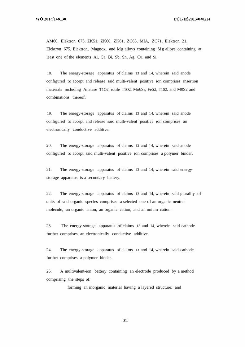
AM60, Elektron 675, ZK51, ZK60, ZK61, ZC63, MIA, ZC71, Elektron 21,
Elektron 675, Elektron, Magnox, and Mg alloys containing Mg alloys containing at
least one of the elements Al, Ca, Bi, Sb, Sn, Ag, Cu, and Si.
18. The energy-storage apparatus of claims 13 and 14, wherein said anode
configured to accept and release said multi-valent positive ion comprises insertion
materials including Anatase T1O2, rutile T1O2, Mo6Ss, FeS2, T1S2, and M0S2 and
combinations thereof.
19. The energy-storage apparatus of claims 13 and 14, wherein said anode
configured to accept and release said multi-valent positive ion comprises an
electronically conductive additive.
20. The energy-storage apparatus of claims 13 and 14, wherein said anode
configured to accept said multi-valent positive ion comprises a polymer binder.
21. The energy-storage apparatus of claims 13 and 14, wherein said energy-
storage apparatus is a secondary battery.
22. The energy-storage apparatus of claims 13 and 14, wherein said plurality of
units of said organic species comprises a selected one of an organic neutral
molecule, an organic anion, an organic cation, and an onium cation.
23. The energy-storage apparatus of claims 13 and 14, wherein said cathode
further comprises an electronically conductive additive.
24. The energy-storage apparatus of claims 13 and 14, wherein said cathode
further comprises a polymer binder.
25. A multivalent-ion battery containing an electrode produced by a method
comprising the steps of:
forming an inorganic material having a layered structure; and
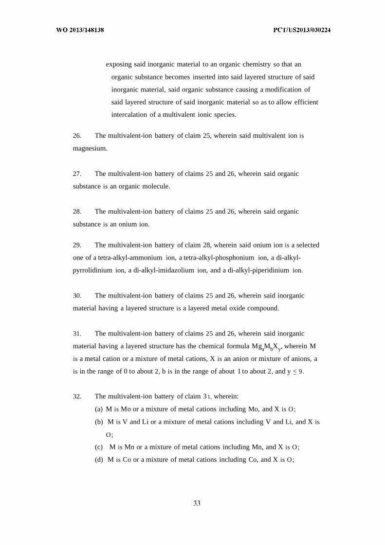
exposing said inorganic material to an organic chemistry so that an
organic substance becomes inserted into said layered structure of said
inorganic material, said organic substance causing a modification of
said layered structure of said inorganic material so as to allow efficient
intercalation of a multivalent ionic species.
26. The multivalent-ion battery of claim 25, wherein said multivalent ion is
magnesium.
27. The multivalent-ion battery of claims 25 and 26, wherein said organic
substance is an organic molecule.
28. The multivalent-ion battery of claims 25 and 26, wherein said organic
substance is an onium ion.
29. The multivalent-ion battery of claim 28, wherein said onium ion is a selected
one of a tetra-alkyl-ammonium ion, a tetra-alkyl-phosphonium ion, a di-alkyl-
pyrrolidinium ion, a di-alkyl-imidazolium ion, and a di-alkyl-piperidinium ion.
30. The multivalent-ion battery of claims 25 and 26, wherein said inorganic
material having a layered structure is a layered metal oxide compound.
31. The multivalent-ion battery of claims 25 and 26, wherein said inorganic
material having a layered structure has the chemical formula MgaMbXy, wherein M
is a metal cation or a mixture of metal cations, X is an anion or mixture of anions, a
is in the range of 0 to about 2, b is in the range of about 1 to about 2, and y < 9.
32. The multivalent-ion battery of claim 31, wherein:
(a) M is Mo or a mixture of metal cations including Mo, and X is O;
(b) M is V and Li or a mixture of metal cations including V and Li, and X is
O;
(c) M is Mn or a mixture of metal cations including Mn, and X is O;
(d) M is Co or a mixture of metal cations including Co, and X is O;
(e) M is Ni or a mixture of metal cations including Ni, and X is O;
(f) -M is Ni and H or a mixture of cations including Ni and H, and X is O;
(g) M is V or a mixture of metal cations including V, and X is 0(P0 4); or
(h) M is V or a mixture of metal cations including V, and X is O, F, or a
mixture thereof.
33. The multivalent-ion battery of claim 25, wherein said exposing step involves
an electrochemical step.
34. The multivalent-ion battery of claim 25, wherein said exposing step involves
a chemical reaction.
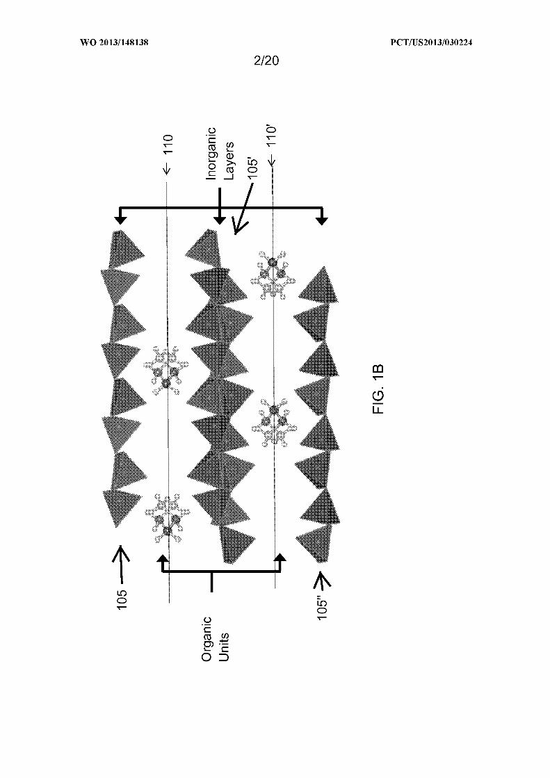
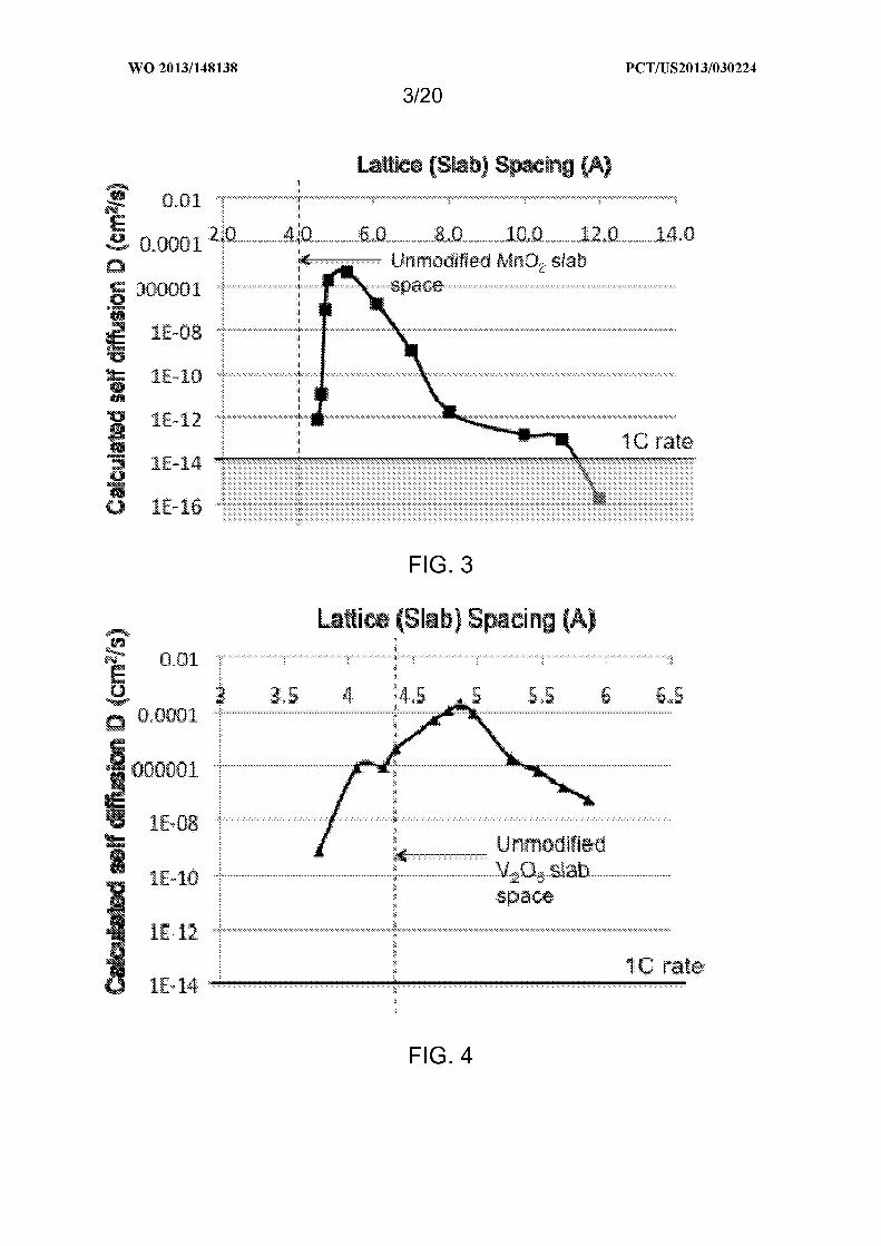
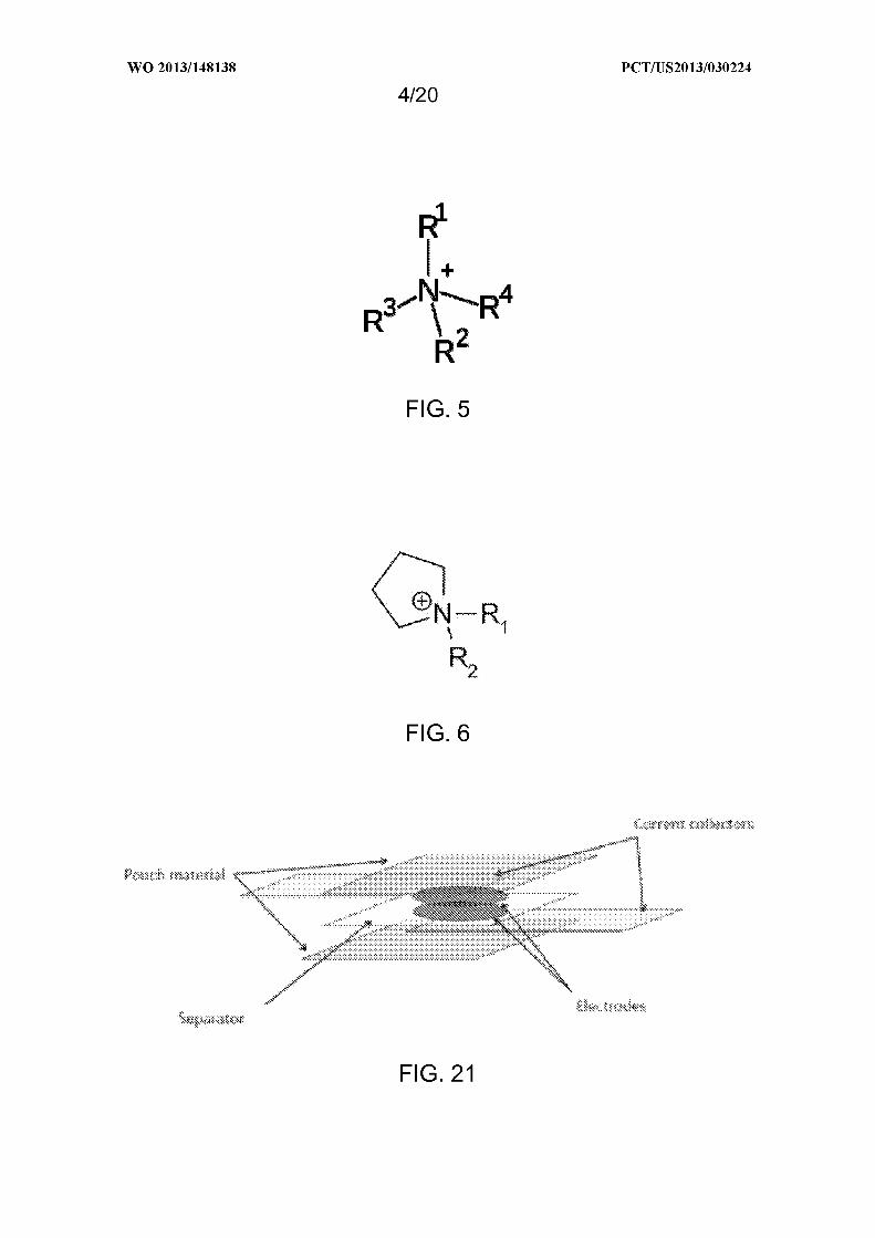
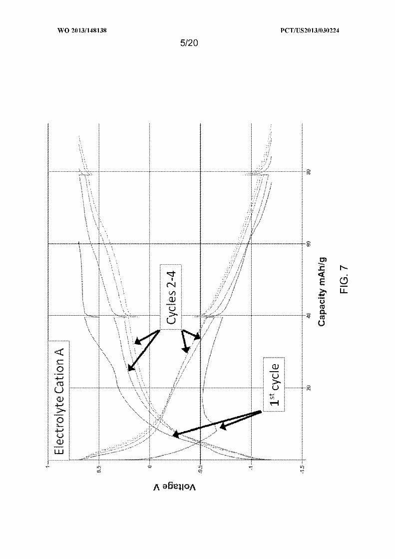
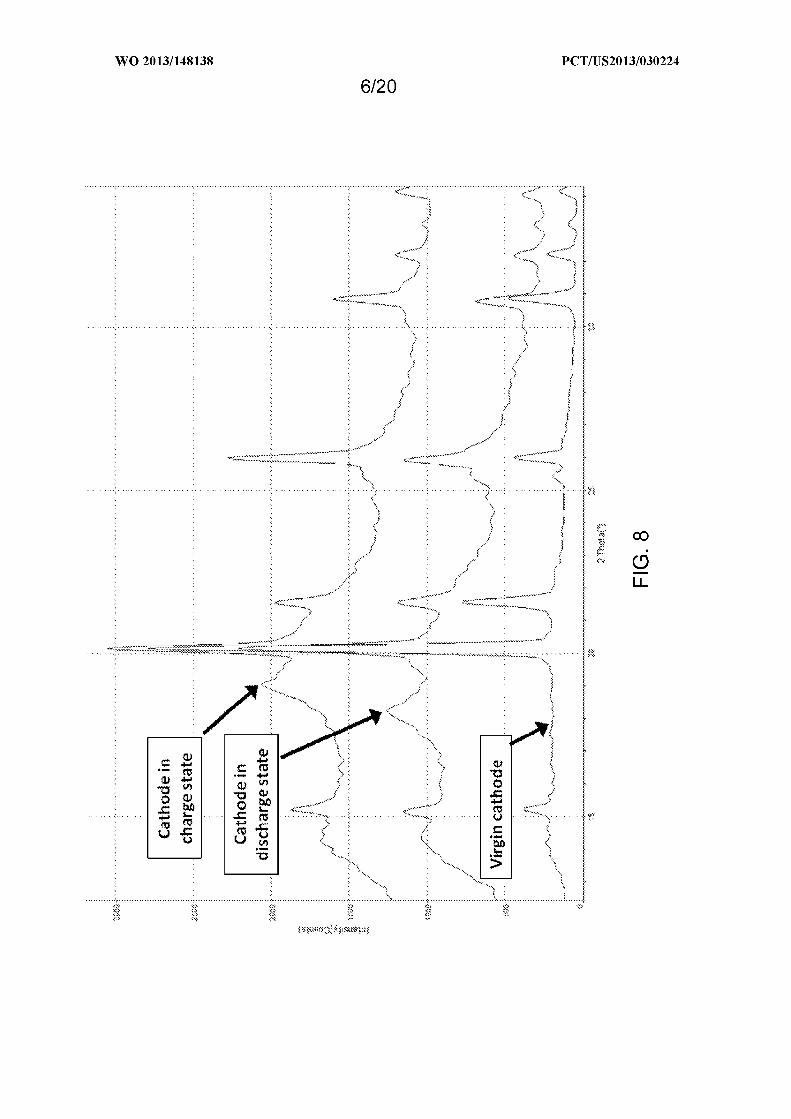
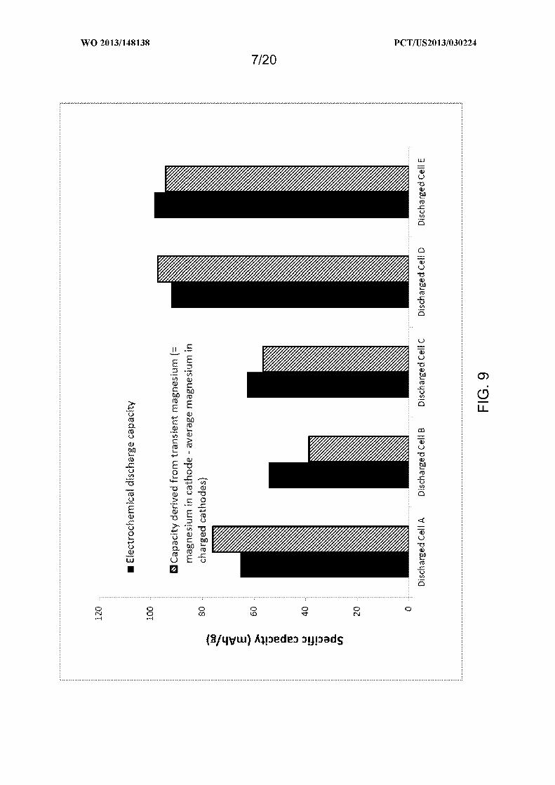
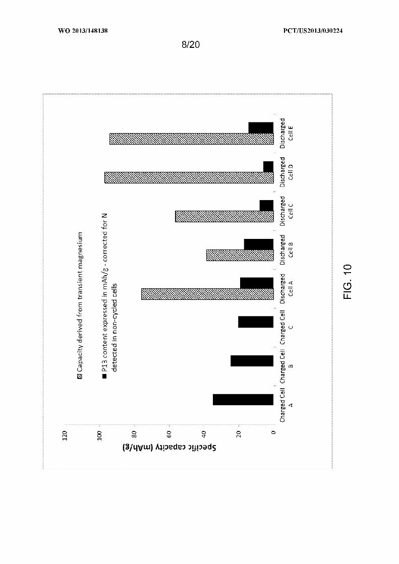
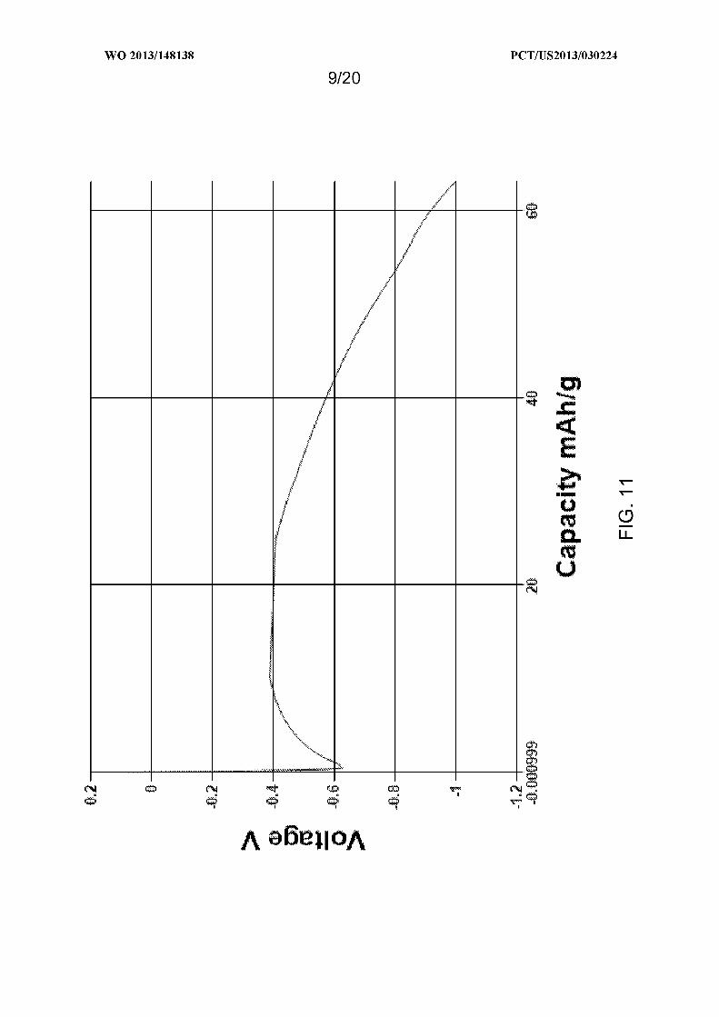
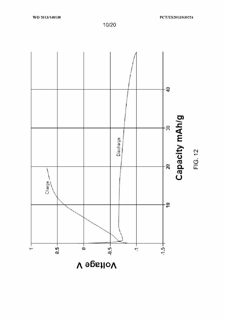
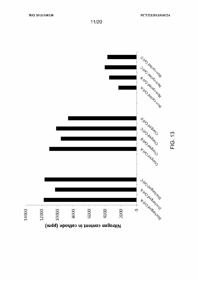
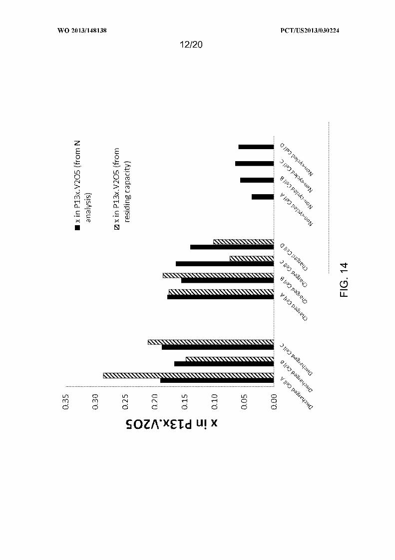
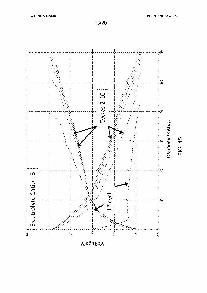
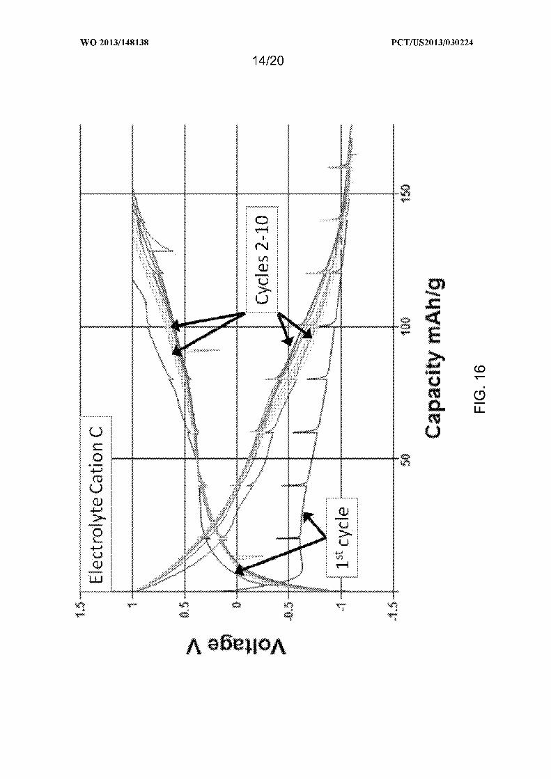
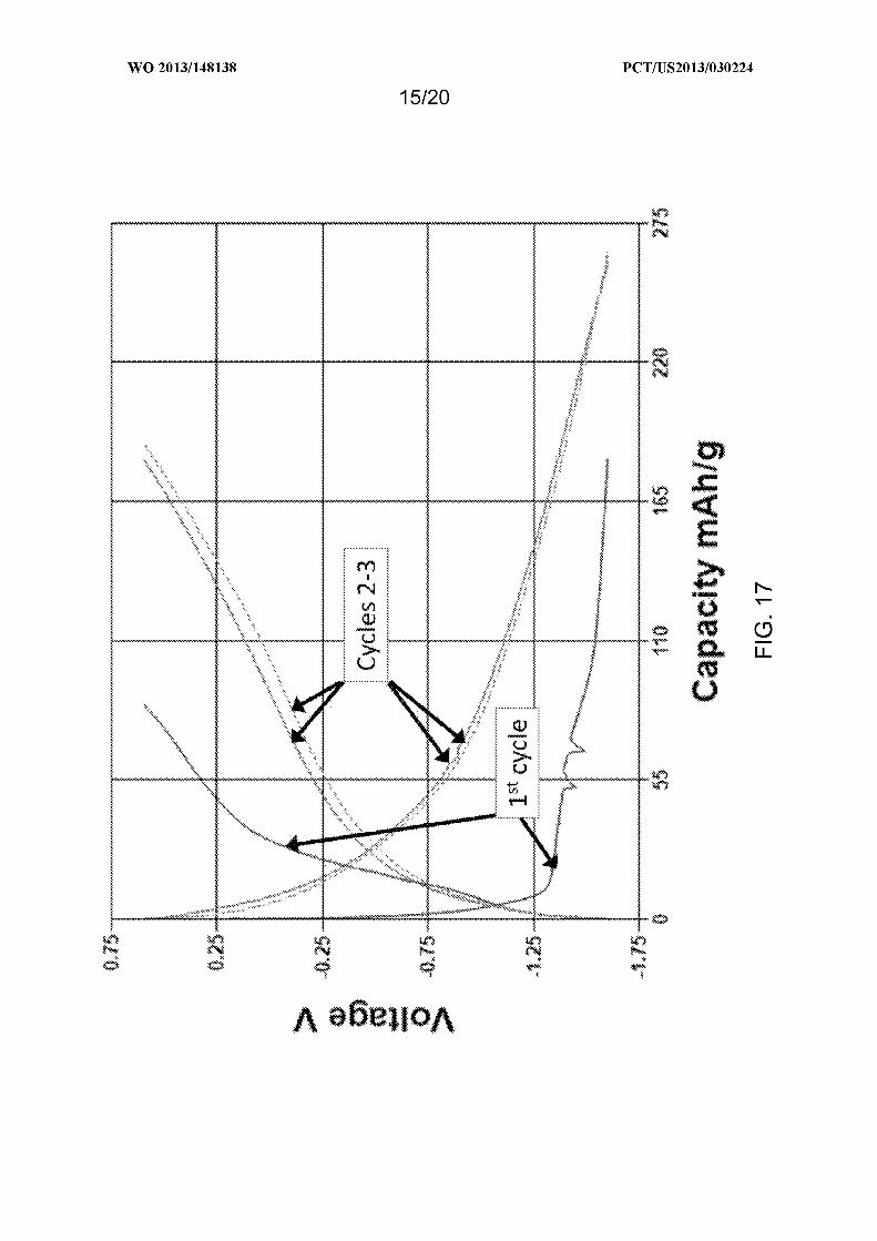
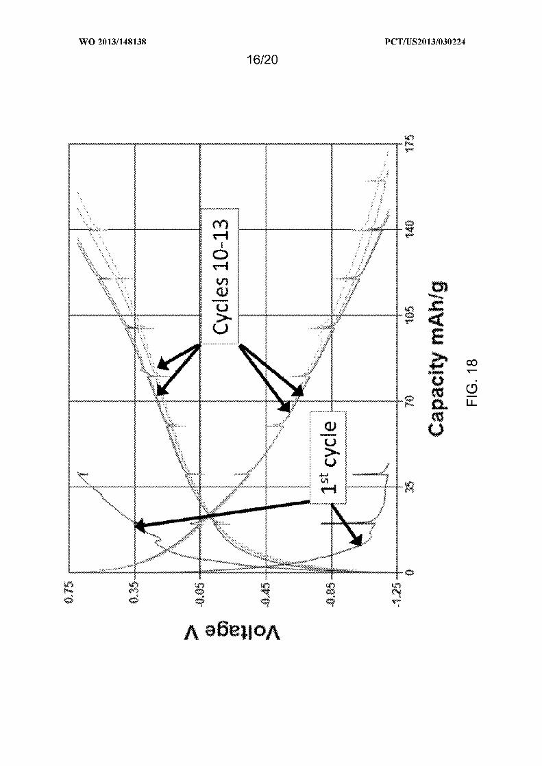
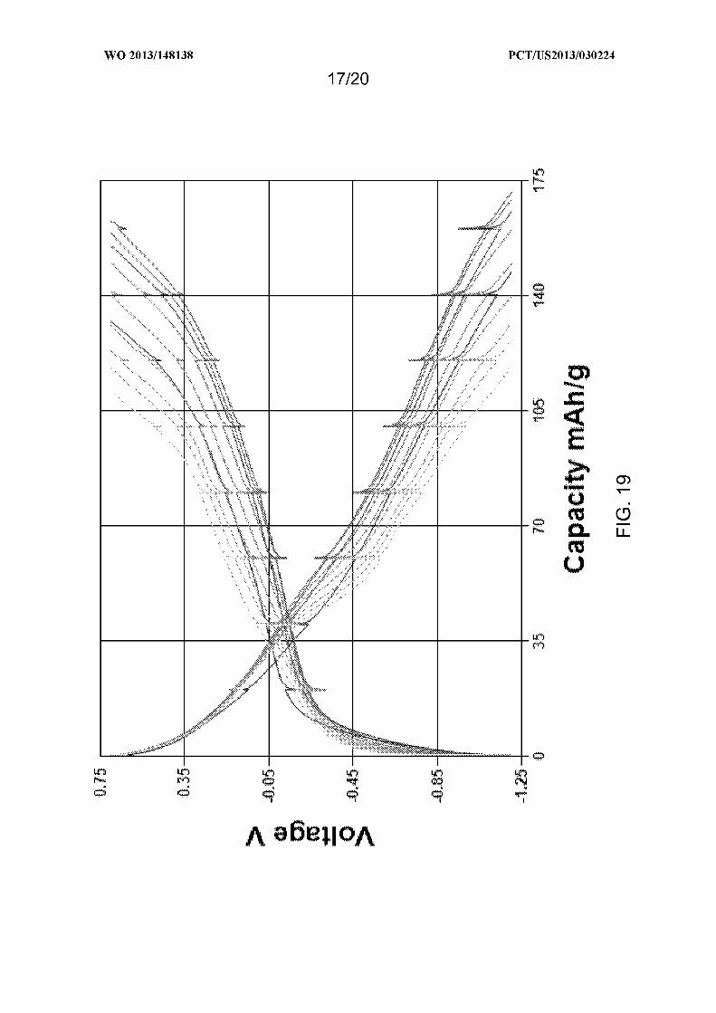
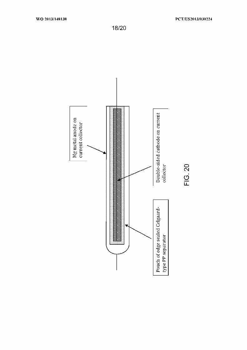
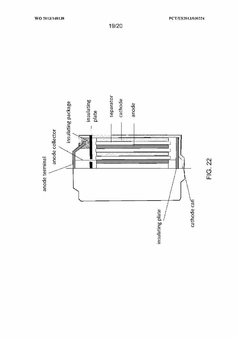
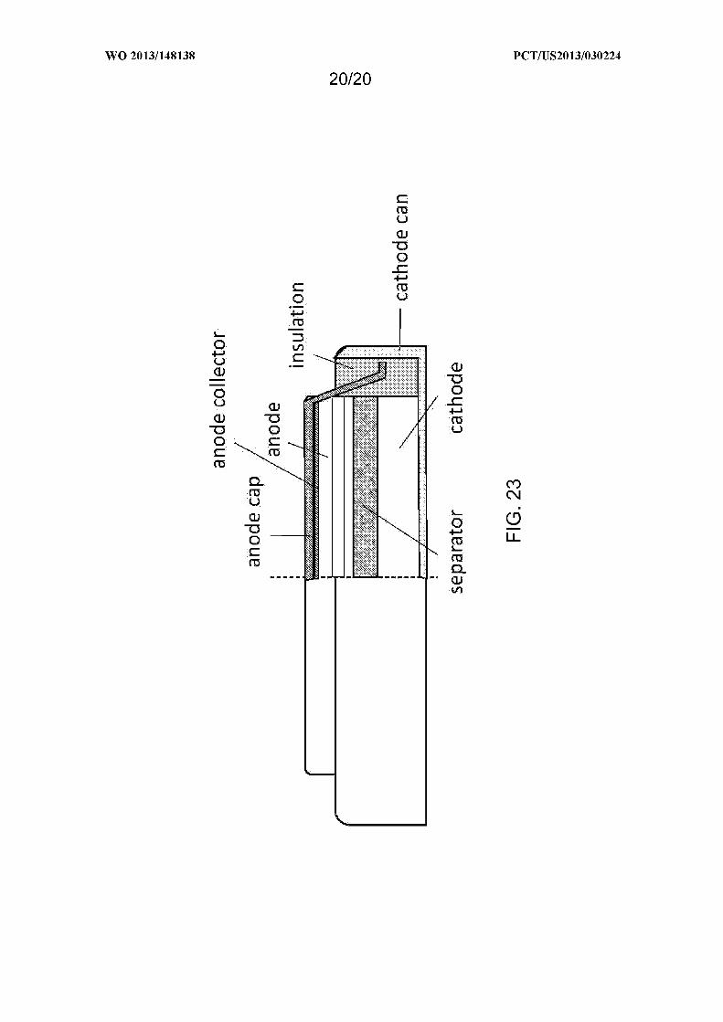
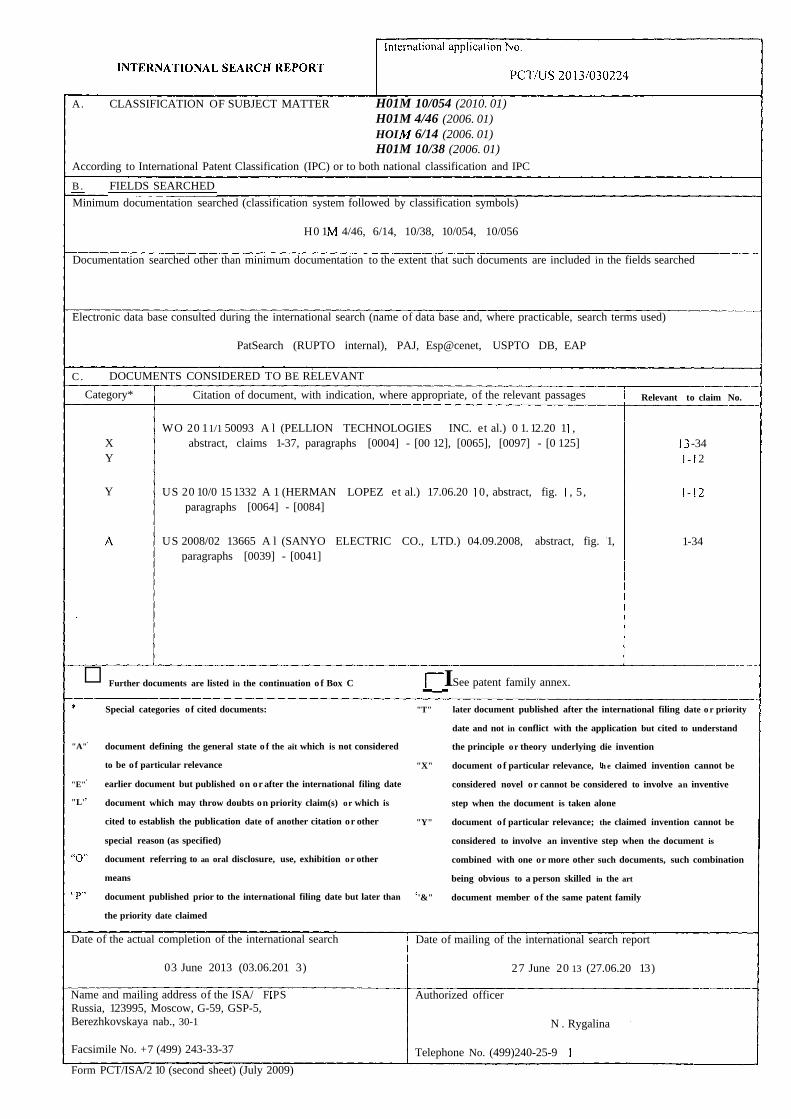
A. CLASSIFICATION OF SUBJECT MATTER H01M 10/054 (2010. 01)H01M 4/46 (2006. 01)HOI 6/14 (2006. 01)H01M 10/38 (2006. 01)
According to International Patent Classification (IPC) or to both national classification and IPC
B . FIELDS SEARCHED
Minimum documentation searched (classification system followed by classification symbols)
H0 1 4/46, 6/14, 10/38, 10/054, 10/056
Documentation searched other than minimum documentation to the extent that such documents are included in the fields searched
Electronic data base consulted during the international search (name of data base and, where practicable, search terms used)
PatSearch (RUPTO internal), PAJ, Esp@cenet, USPTO DB, EAP
C . DOCUMENTS CONSIDERED TO BE RELEVANT
Category* Citation of document, with indication, where appropriate, of the relevant passages Relevant to claim No.
WO 20 11/1 50093 A l (PELLION TECHNOLOGIES INC. et al.) 0 1. 12.20 1 ,X abstract, claims 1-37, paragraphs [0004] - [00 12], [0065], [0097] - [0 125] -34Y 2
Y US 20 10/0 15 1332 A 1 (HERMAN LOPEZ et al.) 17.06.20 0, abstract, fig. , 5 ,paragraphs [0064] - [0084]
US 2008/02 13665 A l (SANYO ELECTRIC CO., LTD.) 04.09.2008, abstract, fig. 1, 1-34paragraphs [0039] - [0041]
□ Further documents are listed in the continuation o f Box C ISee patent family annex.
Special categories of cited documents: "T" later document published after the international filing date o r priority
date and not in conflict with the application but cited to understand
"A" document defining the general state o f the ait which is not considered the principle or theory underlying die invention
to be of particular relevance "X" document o f particular relevance, h e claimed invention cannot be
"E" earlier document but published on or after the international filing date considered novel or cannot be considered to involve an inventive
"L' document which may throw doubts on priority claim(s) or which is step when the document is taken alone
cited to establish the publication date of another citation or other "Y" document of particular relevance; the claimed invention cannot be
special reason (as specified) considered to involve an inventive step when the document is
document referring to an oral disclosure, use, exhibition or other combined with one or more other such documents, such combination
means being obvious to a person skilled in the art
document published prior to the international filing date but later than '&" document member o f the same patent family
the priority date claimed
Date of the actual completion of the international search Date of mailing of the international search report
03 June 2013 (03.06.201 3) 27 June 20 13 (27.06.20 13)
Name and mailing address of the ISA/ F PS Authorized officerRussia, 123995, Moscow, G-59, GSP-5,Berezhkovskaya nab., 30-1 N . Rygalina
Facsimile No. +7 (499) 243-33-37 Telephone No. (499)240-25-9
Form PCT/ISA/2 10 (second sheet) (July 2009)


