Embed Size (px)
Citation preview
WunderBot III
2006 Intelligent Ground Vehicle Competition
Design Report
Elizabethtown College
Thomas Yeager
Brian Moran-Bernard
Justin Shade
Shane Rosencrance
David Coleman
Arindam Kanjilal
Amlan Banerjee
James Painter
Juan Pablo Rodriguez
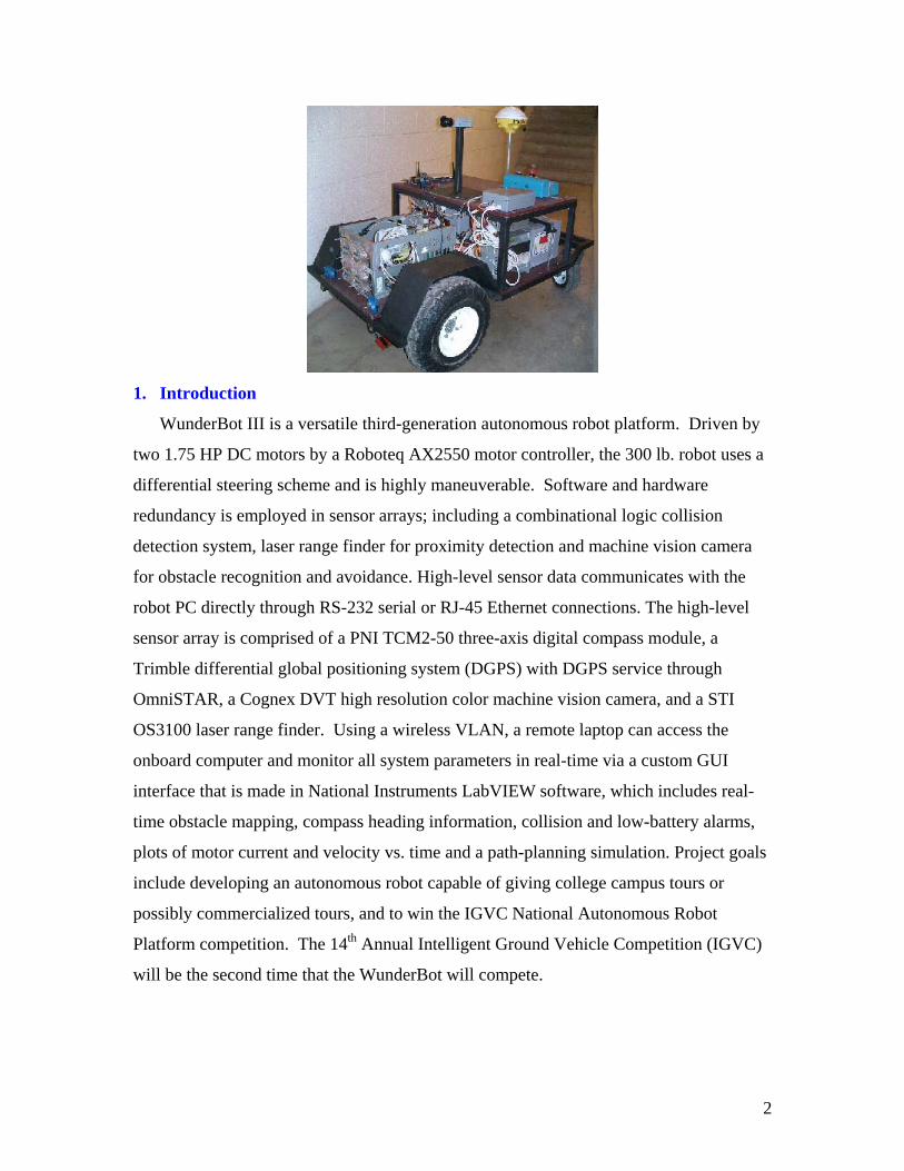
1. Introduction
WunderBot III is a versatile third-generation autonomous robot platform. Driven by
two 1.75 HP DC motors by a Roboteq AX2550 motor controller, the 300 lb. robot uses a
differential steering scheme and is highly maneuverable. Software and hardware
redundancy is employed in sensor arrays; including a combinational logic collision
detection system, laser range finder for proximity detection and machine vision camera
for obstacle recognition and avoidance. High-level sensor data communicates with the
robot PC directly through RS-232 serial or RJ-45 Ethernet connections. The high-level
sensor array is comprised of a PNI TCM2-50 three-axis digital compass module, a
Trimble differential global positioning system (DGPS) with DGPS service through
OmniSTAR, a Cognex DVT high resolution color machine vision camera, and a STI
OS3100 laser range finder. Using a wireless VLAN, a remote laptop can access the
onboard computer and monitor all system parameters in real-time via a custom GUI
interface that is made in National Instruments LabVIEW software, which includes real-
time obstacle mapping, compass heading information, collision and low-battery alarms,
plots of motor current and velocity vs. time and a path-planning simulation. Project goals
include developing an autonomous robot capable of giving college campus tours or
possibly commercialized tours, and to win the IGVC National Autonomous Robot
Platform competition. The 14th Annual Intelligent Ground Vehicle Competition (IGVC)
will be the second time that the WunderBot will compete.
2
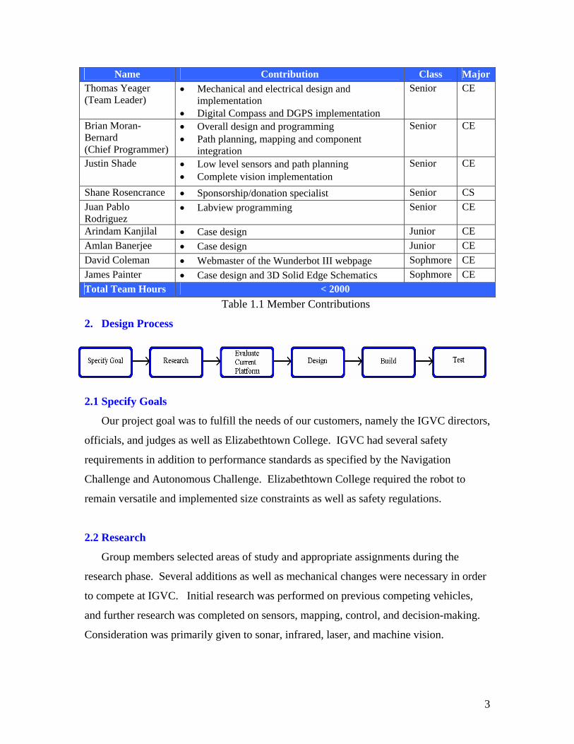
Name Contribution Class MajorThomas Yeager (Team Leader)
• Mechanical and electrical design and implementation
• Digital Compass and DGPS implementation
Senior CE
Brian Moran-Bernard (Chief Programmer)
• Overall design and programming • Path planning, mapping and component
integration
Senior CE
Justin Shade • Low level sensors and path planning • Complete vision implementation
Senior CE
Shane Rosencrance • Sponsorship/donation specialist Senior CS Juan Pablo Rodriguez
• Labview programming Senior CE
Arindam Kanjilal • Case design Junior CE Amlan Banerjee • Case design Junior CE David Coleman • Webmaster of the Wunderbot III webpage Sophmore CE James Painter • Case design and 3D Solid Edge Schematics Sophmore CE Total Team Hours < 2000
Table 1.1 Member Contributions
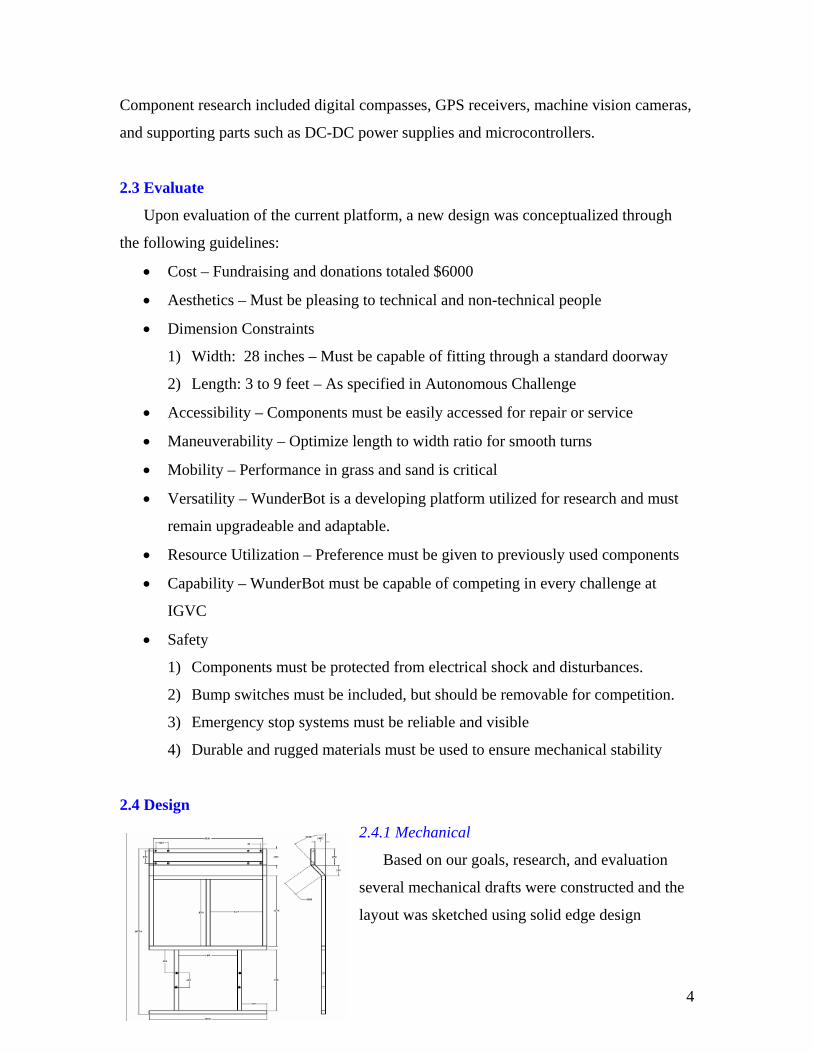
2. Design Process
2.1 Specify Goals
Our project goal was to fulfill the needs of our customers, namely the IGVC directors,
officials, and judges as well as Elizabethtown College. IGVC had several safety
requirements in addition to performance standards as specified by the Navigation
Challenge and Autonomous Challenge. Elizabethtown College required the robot to
remain versatile and implemented size constraints as well as safety regulations.
2.2 Research
Group members selected areas of study and appropriate assignments during the
research phase. Several additions as well as mechanical changes were necessary in order
to compete at IGVC. Initial research was performed on previous competing vehicles,
and further research was completed on sensors, mapping, control, and decision-making.
Consideration was primarily given to sonar, infrared, laser, and machine vision.
3
Component research included digital compasses, GPS receivers, machine vision cameras,
and supporting parts such as DC-DC power supplies and microcontrollers.
2.3 Evaluate
Upon evaluation of the current platform, a new design was conceptualized through
the following guidelines:
• Cost – Fundraising and donations totaled $6000
• Aesthetics – Must be pleasing to technical and non-technical people
• Dimension Constraints
1) Width: 28 inches – Must be capable of fitting through a standard doorway
2) Length: 3 to 9 feet – As specified in Autonomous Challenge
• Accessibility – Components must be easily accessed for repair or service
• Maneuverability – Optimize length to width ratio for smooth turns
• Mobility – Performance in grass and sand is critical
• Versatility – WunderBot is a developing platform utilized for research and must
remain upgradeable and adaptable.
• Resource Utilization – Preference must be given to previously used components
• Capability – WunderBot must be capable of competing in every challenge at
IGVC
• Safety
1) Components must be protected from electrical shock and disturbances.
2) Bump switches must be included, but should be removable for competition.
3) Emergency stop systems must be reliable and visible
4) Durable and rugged materials must be used to ensure mechanical stability
2.4 Design
2.4.1 Mechanical
Based on our goals, research, and evaluation
several mechanical drafts were constructed and the
layout was sketched using solid edge design
4
software. The chosen design involved a two tier rectangular frame constructed out of
solid aluminum. The raised rear casters are a result of the bump switch requirement
desired by Elizabethtown College. Dimensions were optimized based on component
size, component placement, and maneuverability. Optimum maneuverability was
achieved by creating the width to be 62% of the length [2]. For mobility purposes weight
was distributed evenly such that the batteries, electronics, and second level offset the
motors, drive wheels, and PC. In order to achieve traction in wet grass and sand, 14”
NPC Flat Proof tires are driven by two NPC 1.75Hp motors. Eight-inch pneumonic rear
casters were selected to prevent over complicating the drive system. To facilitate proper
airflow the ATX PC case was modified, and intake and exhaust fans were added to the
fiberglass body.
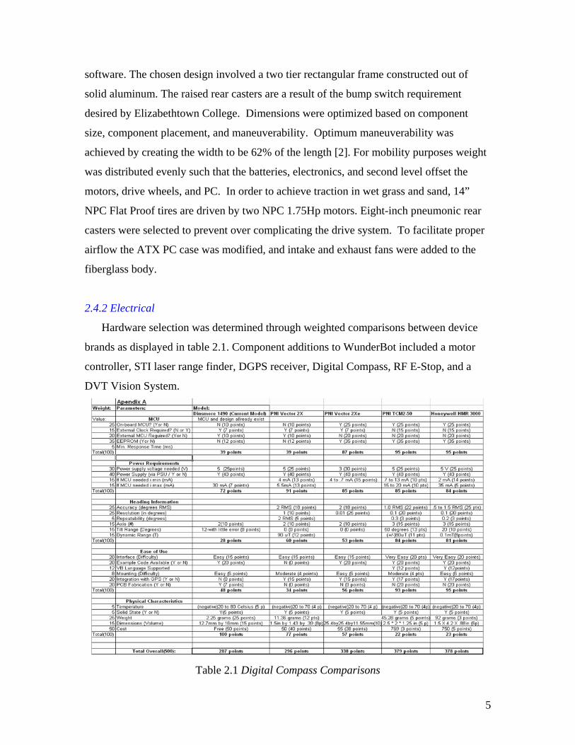
2.4.2 Electrical
Hardware selection was determined through weighted comparisons between device
brands as displayed in table 2.1. Component additions to WunderBot included a motor
controller, STI laser range finder, DGPS receiver, Digital Compass, RF E-Stop, and a
DVT Vision System.
Table 2.1 Digital Compass Comparisons
5
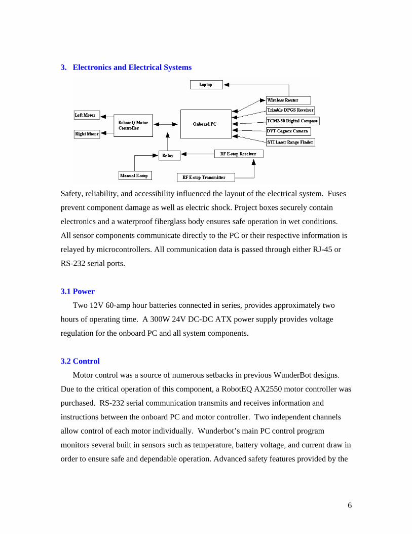
3. Electronics and Electrical Systems
Safety, reliability, and accessibility influenced the layout of the electrical system. Fuses
prevent component damage as well as electric shock. Project boxes securely contain
electronics and a waterproof fiberglass body ensures safe operation in wet conditions.
All sensor components communicate directly to the PC or their respective information is
relayed by microcontrollers. All communication data is passed through either RJ-45 or
RS-232 serial ports.
3.1 Power
Two 12V 60-amp hour batteries connected in series, provides approximately two
hours of operating time. A 300W 24V DC-DC ATX power supply provides voltage
regulation for the onboard PC and all system components.
3.2 Control
Motor control was a source of numerous setbacks in previous WunderBot designs.
Due to the critical operation of this component, a RobotEQ AX2550 motor controller was
purchased. RS-232 serial communication transmits and receives information and
instructions between the onboard PC and motor controller. Two independent channels
allow control of each motor individually. Wunderbot’s main PC control program
monitors several built in sensors such as temperature, battery voltage, and current draw in
order to ensure safe and dependable operation. Advanced safety features provided by the
6
motor controller include automatic shutdown due to electrical or software failure,
programmable output current limit, and emergency stop notification.
3.3 Emergency Stop
The Emergency Stop System includes an onboard push button and a RF remote stop.
The RF receiver board controls a power relay, which along with the push button is placed
in parallel between the control line of the motor controller and ground. When the e-stop
is pressed or the relay tripped, the control line is shorted, the motors are halted, and the
motor controller shuts off immediately. This system was thoroughly tested and has
proven to be reliable.
3.4 Sensors
A PNI TCM2-50 three-axis digital compass provides heading with 1.5º accuracy (at
0.1º resolution), and tilt information with 0.4º accuracy (at 0.3º resolution). The optical
encoders are used in a proportional closed-loop control system, adjusting the speed every
50ms. The current speed and distance traveled are considered when adjusting the speed to
the motor controller. For safety, the motor controller is on watchdog mode, which stops
driving the motors if a new command is not received for more than a second.
The closed loop system is software implemented in LabVIEW. The closed loop
system first seeks to match the wheel speeds to a goal speed, through a gain proportional
to the error. In certain modes of travel the closed loop system attempts to make the
distance traveled by the right wheel equal to the distance traveled by the left wheel.
Implementing the vision specifically for the IGVC competition is the first step in this
subsystem’s development. Obstacles can be recognized and calculated by using given
information about dimensions and color. Intellect software 1.2.2 used with Cognex DVT
EX544C machine vision camera will be used to filter an image and apply edge detection.
Direction bearing to objects will be calculated by aligning the center of the picture with
the current direction heading. Any deviation off center will be measured as the direction
heading to the obstacle. Using distance and heading, along with our current DGPS
location, a virtual map will be built and obstacles plotted with DGPS coordinates. This
map will be used in path planning and optimization.
7
Line following will also be implemented for IGVC. Wunderbot will evade obstacles
while remaining within bounds of a fixed path represented by dashed white lines. This is
achieved through edge detection, shape analysis, and vanishing point detection.
The Trimble AgGPS 114, a differential GPS receiver, offers positional output
accurate within 30 centimeters. Important information about location, speed, and
distance is interpreted from DGPS data.
Parameters for the onboard computer included cost, efficiency, and expandability.
The system consists of an AMD Athlon XP Barton 2500+ CPU, 512MB of DDR Ram,
60GB IDE hard drive with 8mb cache, and a Netgear wireless router. Wireless access
provides monitoring capabilities and critical debugging information.
4. Software
LabVIEW 7.1 is programming software we have decided to use this year, rather than
the Visual Basic code used in competition last time. Our LabVIEW 7.1 programs create
a graphical programming environment that can be used for test and measurement, data
acquisition, instrument control, data logging, measurement analysis, and report
generation [1]. Intellect software 1.2.2 with Cognex DVT EX544C machine vision
camera will be used to filter an image and apply edge detection in LabVIEW format.
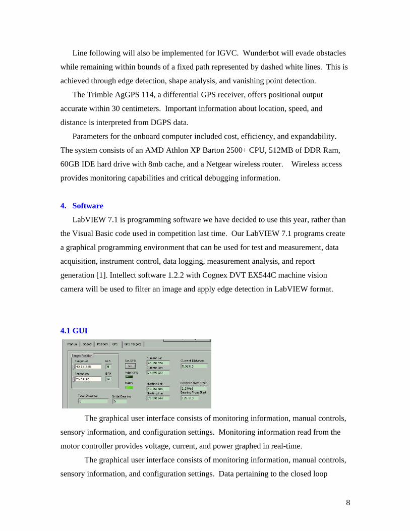
4.1 GUI
The graphical user interface consists of monitoring information, manual controls,
sensory information, and configuration settings. Monitoring information read from the
motor controller provides voltage, current, and power graphed in real-time.
The graphical user interface consists of monitoring information, manual controls,
sensory information, and configuration settings. Data pertaining to the closed loop
8
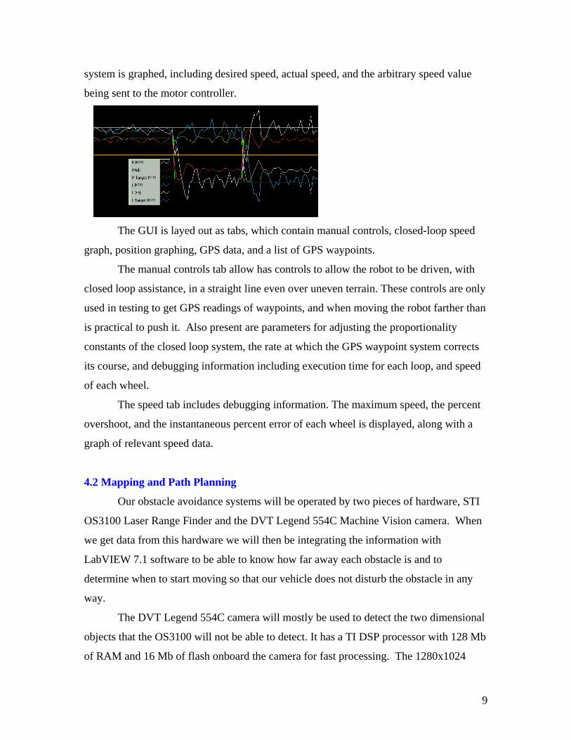
system is graphed, including desired speed, actual speed, and the arbitrary speed value
being sent to the motor controller.
The GUI is layed out as tabs, which contain manual controls, closed-loop speed
graph, position graphing, GPS data, and a list of GPS waypoints.
The manual controls tab allow has controls to allow the robot to be driven, with
closed loop assistance, in a straight line even over uneven terrain. These controls are only
used in testing to get GPS readings of waypoints, and when moving the robot farther than
is practical to push it. Also present are parameters for adjusting the proportionality
constants of the closed loop system, the rate at which the GPS waypoint system corrects
its course, and debugging information including execution time for each loop, and speed
of each wheel.
The speed tab includes debugging information. The maximum speed, the percent
overshoot, and the instantaneous percent error of each wheel is displayed, along with a
graph of relevant speed data.
4.2 Mapping and Path Planning
Our obstacle avoidance systems will be operated by two pieces of hardware, STI
OS3100 Laser Range Finder and the DVT Legend 554C Machine Vision camera. When
we get data from this hardware we will then be integrating the information with
LabVIEW 7.1 software to be able to know how far away each obstacle is and to
determine when to start moving so that our vehicle does not disturb the obstacle in any
way.
The DVT Legend 554C camera will mostly be used to detect the two dimensional
objects that the OS3100 will not be able to detect. It has a TI DSP processor with 128 Mb
of RAM and 16 Mb of flash onboard the camera for fast processing. The 1280x1024
9
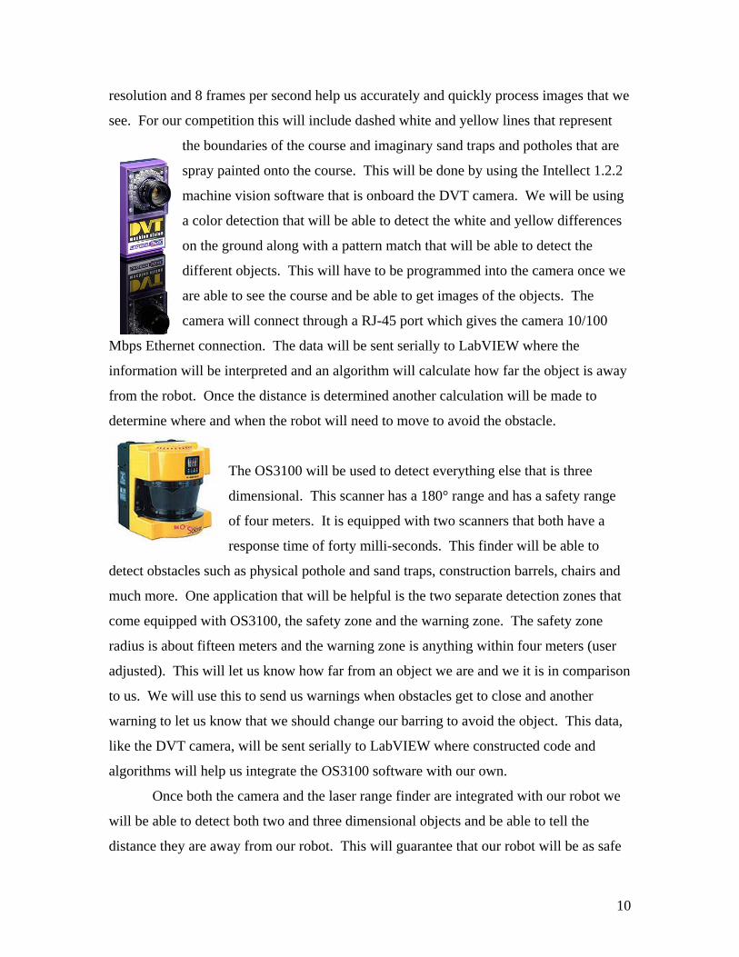
resolution and 8 frames per second help us accurately and quickly process images that we
see. For our competition this will include dashed white and yellow lines that represent
the boundaries of the course and imaginary sand traps and potholes that are
spray painted onto the course. This will be done by using the Intellect 1.2.2
machine vision software that is onboard the DVT camera. We will be using
a color detection that will be able to detect the white and yellow differences
on the ground along with a pattern match that will be able to detect the
different objects. This will have to be programmed into the camera once we
are able to see the course and be able to get images of the objects. The
camera will connect through a RJ-45 port which gives the camera 10/100
Mbps Ethernet connection. The data will be sent serially to LabVIEW where the
information will be interpreted and an algorithm will calculate how far the object is away
from the robot. Once the distance is determined another calculation will be made to
determine where and when the robot will need to move to avoid the obstacle.
The OS3100 will be used to detect everything else that is three
dimensional. This scanner has a 180° range and has a safety range
of four meters. It is equipped with two scanners that both have a
response time of forty milli-seconds. This finder will be able to
detect obstacles such as physical pothole and sand traps, construction barrels, chairs and
much more. One application that will be helpful is the two separate detection zones that
come equipped with OS3100, the safety zone and the warning zone. The safety zone
radius is about fifteen meters and the warning zone is anything within four meters (user
adjusted). This will let us know how far from an object we are and we it is in comparison
to us. We will use this to send us warnings when obstacles get to close and another
warning to let us know that we should change our barring to avoid the object. This data,
like the DVT camera, will be sent serially to LabVIEW where constructed code and
algorithms will help us integrate the OS3100 software with our own.
Once both the camera and the laser range finder are integrated with our robot we
will be able to detect both two and three dimensional objects and be able to tell the
distance they are away from our robot. This will guarantee that our robot will be as safe
10
as possible and will give us a great chance in being competitive in the IGVC and giving
us a good prototype for our autonomous tour guide.
4.3 Simulation
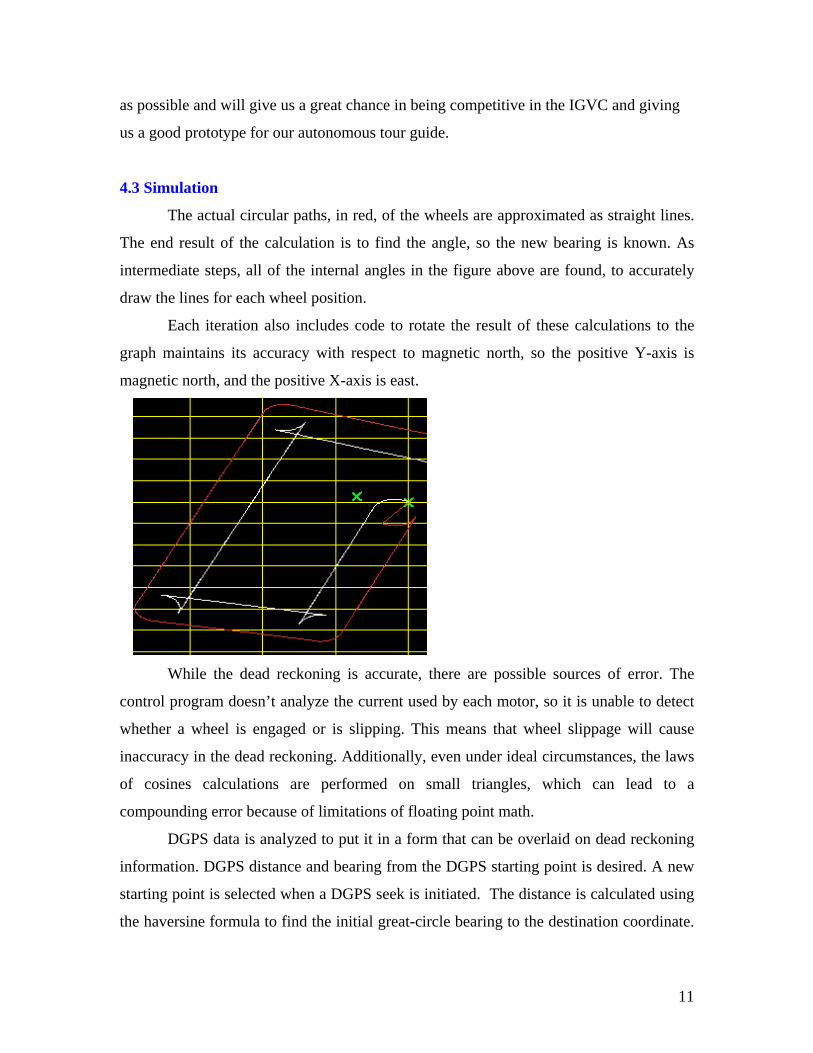
The actual circular paths, in red, of the wheels are approximated as straight lines.
The end result of the calculation is to find the angle, so the new bearing is known. As
intermediate steps, all of the internal angles in the figure above are found, to accurately
draw the lines for each wheel position.
Each iteration also includes code to rotate the result of these calculations to the
graph maintains its accuracy with respect to magnetic north, so the positive Y-axis is
magnetic north, and the positive X-axis is east.
While the dead reckoning is accurate, there are possible sources of error. The
control program doesn’t analyze the current used by each motor, so it is unable to detect
whether a wheel is engaged or is slipping. This means that wheel slippage will cause
inaccuracy in the dead reckoning. Additionally, even under ideal circumstances, the laws
of cosines calculations are performed on small triangles, which can lead to a
compounding error because of limitations of floating point math.
DGPS data is analyzed to put it in a form that can be overlaid on dead reckoning
information. DGPS distance and bearing from the DGPS starting point is desired. A new
starting point is selected when a DGPS seek is initiated. The distance is calculated using
the haversine formula to find the initial great-circle bearing to the destination coordinate.
11
A perfectly spherical earth with a diameter of 6,378,135 meters is used for our
calculations. The distance between the points is necessarily small because of the nature of
the application, so it is assumed that following this bearing will lead directly to the
destination coordinates. The bearing calculation, which requires the use of the arctangent,
must be corrected with conditional statements to insure that the correct quadrant is
selected for the bearing.
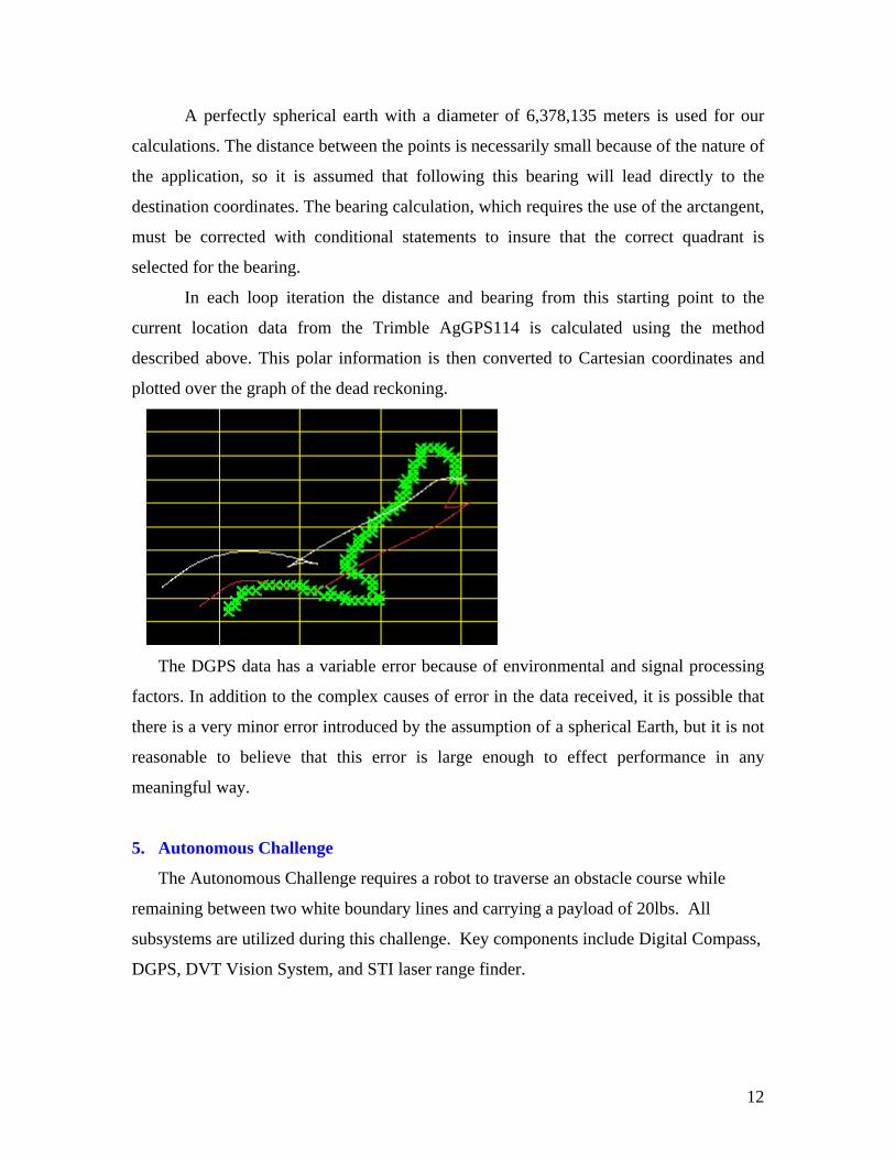
In each loop iteration the distance and bearing from this starting point to the
current location data from the Trimble AgGPS114 is calculated using the method
described above. This polar information is then converted to Cartesian coordinates and
plotted over the graph of the dead reckoning.
The DGPS data has a variable error because of environmental and signal processing
factors. In addition to the complex causes of error in the data received, it is possible that
there is a very minor error introduced by the assumption of a spherical Earth, but it is not
reasonable to believe that this error is large enough to effect performance in any
meaningful way.
5. Autonomous Challenge
The Autonomous Challenge requires a robot to traverse an obstacle course while
remaining between two white boundary lines and carrying a payload of 20lbs. All
subsystems are utilized during this challenge. Key components include Digital Compass,
DGPS, DVT Vision System, and STI laser range finder.
12
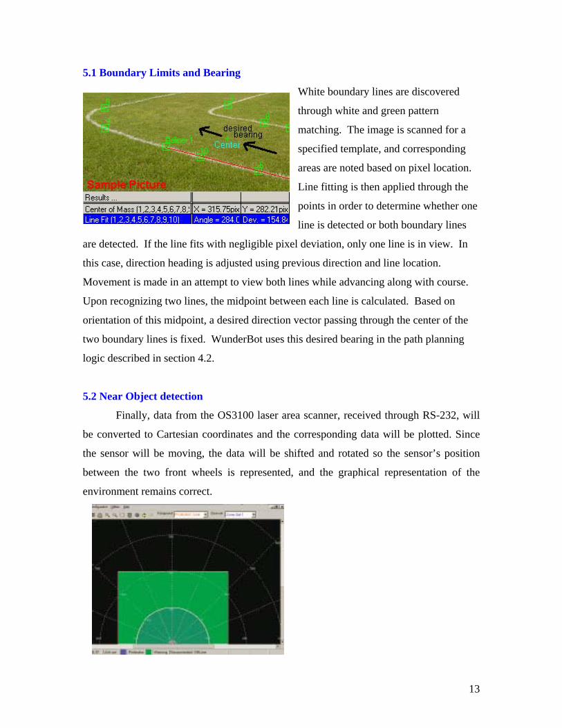
5.1 Boundary Limits and Bearing
White boundary lines are discovered
through white and green pattern
matching. The image is scanned for a
specified template, and corresponding
areas are noted based on pixel location.
Line fitting is then applied through the
points in order to determine whether one
line is detected or both boundary lines
are detected. If the line fits with negligible pixel deviation, only one line is in view. In
this case, direction heading is adjusted using previous direction and line location.
Movement is made in an attempt to view both lines while advancing along with course.
Upon recognizing two lines, the midpoint between each line is calculated. Based on
orientation of this midpoint, a desired direction vector passing through the center of the
two boundary lines is fixed. WunderBot uses this desired bearing in the path planning
logic described in section 4.2.
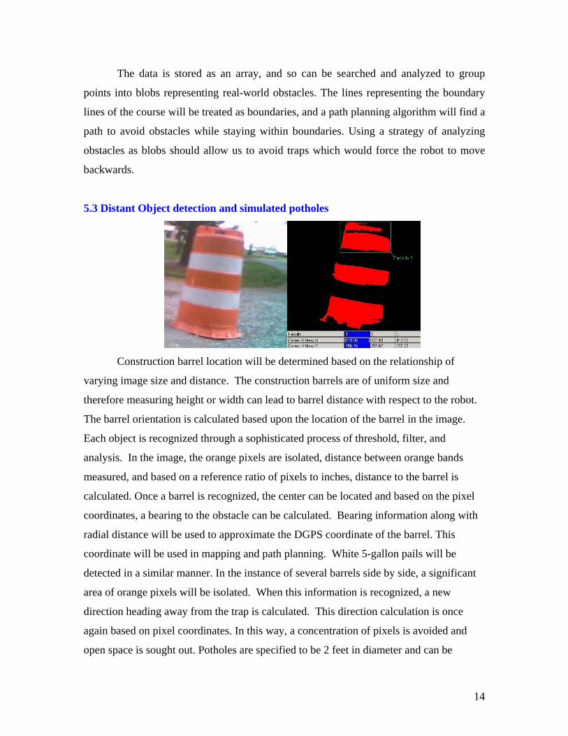
5.2 Near Object detection
Finally, data from the OS3100 laser area scanner, received through RS-232, will
be converted to Cartesian coordinates and the corresponding data will be plotted. Since
the sensor will be moving, the data will be shifted and rotated so the sensor’s position
between the two front wheels is represented, and the graphical representation of the
environment remains correct.
13
The data is stored as an array, and so can be searched and analyzed to group
points into blobs representing real-world obstacles. The lines representing the boundary
lines of the course will be treated as boundaries, and a path planning algorithm will find a
path to avoid obstacles while staying within boundaries. Using a strategy of analyzing
obstacles as blobs should allow us to avoid traps which would force the robot to move
backwards.
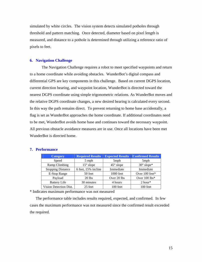
5.3 Distant Object detection and simulated potholes
Construction barrel location will be determined based on the relationship of
varying image size and distance. The construction barrels are of uniform size and
therefore measuring height or width can lead to barrel distance with respect to the robot.
The barrel orientation is calculated based upon the location of the barrel in the image.
Each object is recognized through a sophisticated process of threshold, filter, and
analysis. In the image, the orange pixels are isolated, distance between orange bands
measured, and based on a reference ratio of pixels to inches, distance to the barrel is
calculated. Once a barrel is recognized, the center can be located and based on the pixel
coordinates, a bearing to the obstacle can be calculated. Bearing information along with
radial distance will be used to approximate the DGPS coordinate of the barrel. This
coordinate will be used in mapping and path planning. White 5-gallon pails will be
detected in a similar manner. In the instance of several barrels side by side, a significant
area of orange pixels will be isolated. When this information is recognized, a new
direction heading away from the trap is calculated. This direction calculation is once
again based on pixel coordinates. In this way, a concentration of pixels is avoided and
open space is sought out. Potholes are specified to be 2 feet in diameter and can be
14
simulated by white circles. The vision system detects simulated potholes through
threshold and pattern matching. Once detected, diameter based on pixel length is
measured, and distance to a pothole is determined through utilizing a reference ratio of
pixels to feet.
6. Navigation Challenge
The Navigation Challenge requires a robot to meet specified waypoints and return
to a home coordinate while avoiding obstacles. WunderBot’s digital compass and
differential GPS are key components in this challenge. Based on current DGPS location,
current direction bearing, and waypoint location, WunderBot is directed toward the
nearest DGPS coordinate using simple trigonometric relations. As WunderBot moves and
the relative DGPS coordinate changes, a new desired bearing is calculated every second.
In this way the path remains direct. To prevent returning to home base accidentally, a
flag is set as WunderBot approaches the home coordinate. If additional coordinates need
to be met, WunderBot avoids home base and continues toward the necessary waypoint.
All previous obstacle avoidance measures are in use. Once all locations have been met
WunderBot is directed home.
7. Performance
Category Required Results Expected Results Confirmed Results Speed 5 mph 5mph 5mph
Ramp Climbing 15° slope 45° slope 30° slope* Stopping Distance 6 feet, 15% incline Immediate Immediate
E-Stop Range 50 feet 1000 feet Over 100 feet* Payload 20 lbs Over 20 lbs Over 100 lbs*
Battery Life 30 minutes 4 hours 2 hour* Vision Detection Dist. 25 feet 100 feet 100 feet
* Indicates maximum performance was not measured
The performance table includes results required, expected, and confirmed. In few
cases the maximum performance was not measured since the confirmed result exceeded
the required.
15
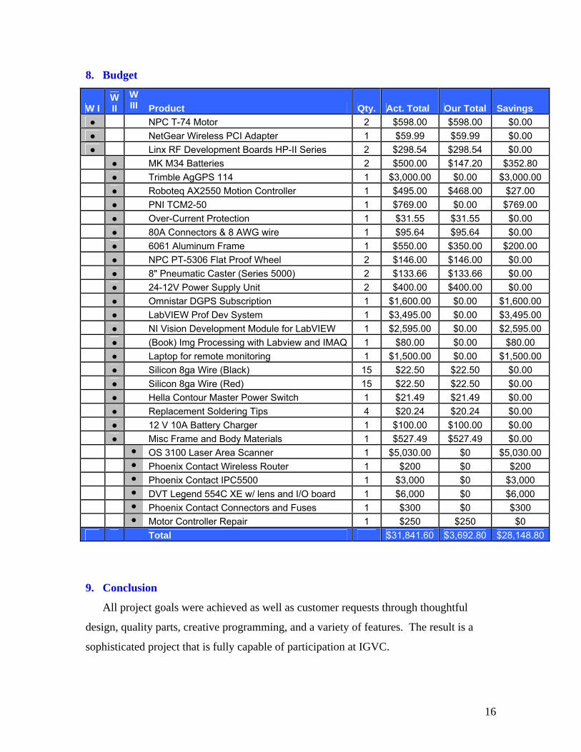
8. Budget
W I W II
W III Product Qty. Act. Total Our Total Savings
● NPC T-74 Motor 2 $598.00 $598.00 $0.00 ● NetGear Wireless PCI Adapter 1 $59.99 $59.99 $0.00 ● Linx RF Development Boards HP-II Series 2 $298.54 $298.54 $0.00
● MK M34 Batteries 2 $500.00 $147.20 $352.80 ● Trimble AgGPS 114 1 $3,000.00 $0.00 $3,000.00 ● Roboteq AX2550 Motion Controller 1 $495.00 $468.00 $27.00
● PNI TCM2-50 1 $769.00 $0.00 $769.00 ● Over-Current Protection 1 $31.55 $31.55 $0.00 ● 80A Connectors & 8 AWG wire 1 $95.64 $95.64 $0.00
● 6061 Aluminum Frame 1 $550.00 $350.00 $200.00 ● NPC PT-5306 Flat Proof Wheel 2 $146.00 $146.00 $0.00 ● 8" Pneumatic Caster (Series 5000) 2 $133.66 $133.66 $0.00 ● 24-12V Power Supply Unit 2 $400.00 $400.00 $0.00 ● Omnistar DGPS Subscription 1 $1,600.00 $0.00 $1,600.00 ● LabVIEW Prof Dev System 1 $3,495.00 $0.00 $3,495.00 ● NI Vision Development Module for LabVIEW 1 $2,595.00 $0.00 $2,595.00 ● (Book) Img Processing with Labview and IMAQ 1 $80.00 $0.00 $80.00 ● Laptop for remote monitoring 1 $1,500.00 $0.00 $1,500.00 ● Silicon 8ga Wire (Black) 15 $22.50 $22.50 $0.00 ● Silicon 8ga Wire (Red) 15 $22.50 $22.50 $0.00 ● Hella Contour Master Power Switch 1 $21.49 $21.49 $0.00
● Replacement Soldering Tips 4 $20.24 $20.24 $0.00 ● 12 V 10A Battery Charger 1 $100.00 $100.00 $0.00 ● Misc Frame and Body Materials 1 $527.49 $527.49 $0.00
● OS 3100 Laser Area Scanner 1 $5,030.00 $0 $5,030.00 ● Phoenix Contact Wireless Router 1 $200 $0 $200 ● Phoenix Contact IPC5500 1 $3,000 $0 $3,000
● DVT Legend 554C XE w/ lens and I/O board 1 $6,000 $0 $6,000 ● Phoenix Contact Connectors and Fuses 1 $300 $0 $300
● Motor Controller Repair 1 $250 $250 $0 Total $31,841.60 $3,692.80 $28,148.80
9. Conclusion
All project goals were achieved as well as customer requests through thoughtful
design, quality parts, creative programming, and a variety of features. The result is a
sophisticated project that is fully capable of participation at IGVC.
16

REFERENCES [1] National Instruments, "LabVIEW 7 Express User Manual," Austin Texas:
National Instruments, April 2003. [2] P. E. Sandin, “Robot Mechanisms and Mechanical Devices” New York:McGraw-
Hill, 2003, pp..237.
17


