Embed Size (px)
Citation preview
1
X-series HVAC System
X500 CoolingX500 Heating & Cooling
TK 60690-3-MM Revision 0.1 (Print Date: February 28, 2011)
Copyright © 2011 Ingersoll Rand Corporation, Thermo King
Electronically Printed in Czech Republic
Maintenance Manual
2
The maintenance information in this manual covers unit model:
X500 N - 1000, 24V 901717
X500 W - 1000, 24V 901719
X500 N - 1004, 24V 901718
X500 W - 1004, 24V 901721
For further information, refer to:
X500 Parts Manual TK 60680
Stocking Guide X500 N - 1000, 24V, 901717 TK 60673
Stocking Guide X500 W - 1000, 24V, 901719 TK 60675
Stocking Guide X500 N - 1004, 24V, 901718 TK 60674
Stocking Guide X500 W - 1004, 24V, 901721 TK 60676
ClimaAIRE ID Service Manual TK 60020
Evacuation Station Operation and Field Application TK 40612
Silver Brazing and Soft Soldering TK 7949
Tool Catalog TK 5955
Transport Temperature Control Systems TK 50951
This manual is published for informational purposes only and the information so providedshould not be considered as all-inclusive or covering all contingencies. If further information isrequired, Ingersoll Rand / Thermo King Corporation should be consulted. The above manualsmay be purchased from your local Thermo King dealer.
Sale of product shown in this manual is subject to Thermo King’s terms and conditionsincluding, but not limited to, the Thermo King Limited Express Warranty. Such terms andconditions are available upon request. Thermo King’s warranty will not apply to any equipmentwhich has been “so repaired or altered outside the manufacturer’s plants as, in themanufacturer’s judgment, to effect its stability.”
No warranties, express or implied, including warranties of fitness for a particular purpose ormerchantability, or warranties arising from course of dealing or usage of trade, are maderegarding the information, recommendations, and descriptions contained herein. Manufactureris not responsible and will not be held liable in contract or in tort (including negligence) for anyspecial, indirect or consequential damages, including injury or damage caused to vehicles,contents or persons, by reason of the installation of any Thermo King product or itsmechanical failure.
3
Recover Refrigerant
At Thermo King, we recognize the need to preserve the environment and limitthe potential harm to the ozone layer that can result from allowing refrigerant to
escape into the atmosphere.
We strictly adhere to a policy that promotes the recovery and limits the loss ofrefrigerant into the atmosphere.
In addition, service personnel must be aware of Federal regulations concerningthe use of refrigerants and the certification of technicians. For additional
information on regulations and technician certification programs, contact yourlocal THERMO KING dealer.
R-134a
WARNING: Use only Polyol Ester-based refrigeration compressor oil in R-134a.See Thermo King Parts Manual for part number.
Do not mix Polyol Ester and standard synthetic compressor oils. KeepPolyol Ester compressor oil in tightly sealed containers. If Polyol Ester
oil becomes contaminated with moisture or standard oils, dispose ofproperly – DO NOT USE.
When servicing Thermo King R-134a unit, use only those service toolscertified for and dedicated to R-134a refrigerant and Polyol Ester
compressor oils. Residual non-HFC refrigerants or oils willcontaminate R-134a systems.
4
1. About This Manual
Purpose
The purpose of this manual is to provide general maintenance information necessary to operate andmaintain the climate control unit (HVAC unit, A/C unit) at peak operating standards and best lifetime.This includes safety information, unit information such as technical specification, general unitdescription, maintenance procedures and some diagnostic and troubleshooting information.
Before you call Thermo King Service
Before you call Thermo King Service, have the following information on hand (for exact data see serialplate on your unit):
Unit type (commonly typed on serial plate after code DESC)
System or Model number (commonly coded on serial plate after code ITEM)
System number has usually six digits format (example 901902)
Model number is the same as System number but with M letter at the end (example 901902M)
Serial number
Who to call: your Thermo King Dealer Representative or Thermo King Service Center.
Blank Pages
This manual may contain blank pages at the end of chapters. This is normal. There is no informationmissing from the manual.
Roadside/Curbside Terminology
Roadside/Curbside terminology: These terms can be confusing because of differences between NorthAmerica and Europe. Please note:
Curbside: The side of the bus to the driver right when the driver is in his seat and facingforward.
Roadside: The side of the bus to the driver left when the driver is in his seat and facing forward.
5
2. Table of Contents1. About This Manual ...................................................................................................................................4
2. Table of Contents.....................................................................................................................................5
3. List of Figures ..........................................................................................................................................7
4. List of Abbreviations................................................................................................................................8
5. Safety Precautions...................................................................................................................................9
5.1. General Practices ...........................................................................................................................9
5.2. Electrical Hazards.........................................................................................................................10
5.3. Refrigerant Hazards......................................................................................................................11
5.4. Compressor Oil Hazards...............................................................................................................12
5.5. First Aid........................................................................................................................................13
6. System Description................................................................................................................................14
7. Specifications.........................................................................................................................................15
7.1. HVAC System...............................................................................................................................15
7.2. Electrical System ..........................................................................................................................16
7.3. Compressor (Optional)..................................................................................................................17
7.4. Weight and dimensions.................................................................................................................18
8. Rooftop Unit Description .......................................................................................................................19
8.1. General description.......................................................................................................................19
8.2. Main parts of rooftop units.............................................................................................................20
8.3. Photos and Illustrations.................................................................................................................23
9. Compressor Description........................................................................................................................25
9.1. General description.......................................................................................................................25
9.2. TM compressors ...........................................................................................................................25
9.3. Small Compressor Oil Charge Specifications - R134a...................................................................26
10. Operating Instructions ........................................................................................................................27
10.1. Basic A/C System - Theory of Operation.......................................................................................27
10.2. Control System .............................................................................................................................29
10.3. ClimaAIRE ID and ClimaAIRE II....................................................................................................30
10.4. ClimaAIRE ID controller ................................................................................................................30
10.5. Inspection Recommendations .......................................................................................................46
10.6. Maintenance Inspection Schedule.................................................................................................47
10.7. Special Tools, Equipments and Supplies.......................................................................................49
10.8. Tightening Torque Requirements ..................................................................................................50
11. Refrigeration System Maintenance.....................................................................................................52
11.1. Service Tools................................................................................................................................53
11.2. Contamination ..............................................................................................................................54
11.3. Compressor Oil Color Code ..........................................................................................................55
11.4. Refrigerant Recovery....................................................................................................................55
11.5. Refrigerant Leak Test Procedure ..................................................................................................56
11.6. Evacuation....................................................................................................................................57
11.7. System Charging from an Evacuated Condition ............................................................................61
11.8. Using Pressurized Nitrogen...........................................................................................................61
12. Refrigeration/Heating Repairs ............................................................................................................63
6
12.1. Filter-Drier Replacement...............................................................................................................63
12.2. Thermostatic Expansion Valve Replacement ................................................................................64
12.3. Pressure Switches Replacement ..................................................................................................68
12.4. Relief Valve Replacement.............................................................................................................69
13. Electrical Maintenance & Repairs.......................................................................................................70
13.1. Relays and fuses replacement......................................................................................................70
13.2. Evaporator Blower Replacement...................................................................................................72
13.3. Condenser Fan Replacement .......................................................................................................73
13.4. Fresh Air Damper Motor Replacement..........................................................................................75
13.5. Ambient Temperature Sensor Replacement..................................................................................76
14. Mechanical Maintenance & Repairs ...................................................................................................78
14.1. Unit Maintenance..........................................................................................................................78
14.2. Cleaning.......................................................................................................................................78
14.3. Fresh Air Filter Replacement ........................................................................................................79
14.4. Return Air Filter Replacement.......................................................................................................80
14.5. Coil Air Filter Replacement ........................................................................................................81
15. Troubleshooting..................................................................................................................................82
15.1. Air Conditioning Diagnosis and Analysis .......................................................................................82
15.2. Causes for Failure to Stay Within Temperature Range..................................................................83
15.3. Compressor suction pressure conditions.......................................................................................85
15.4. Compressor discharge pressure conditions...................................................................................86
16. Temperature-Pressure Chart ..............................................................................................................87
17. Index ....................................................................................................................................................89
18. Schemes, Diagrams and Drawings Index...........................................................................................91
19. Appendix .............................................................................................................................................92
7
3. List of Figures
Figure 1: X500 Unit dimensions .................................................................................................................... 18
Figure 2: X500 Rooftop unit .......................................................................................................................... 19
Figure 3: X500 Outside view......................................................................................................................... 23
Figure 4: X500 Inside view............................................................................................................................ 24
Figure 5: TM compressors (Illustration photo) ............................................................................................... 25
Figure 6: A/C refrigeration system (example) ................................................................................................ 27
Figure 7: Application diagram ....................................................................................................................... 29
Figure 8: CAID Driver panel.......................................................................................................................... 30
Figure 9: CAID Keys in Setup/Calibration/Test mode .................................................................................... 34
Figure 10: CAID Function menu structure ................................................................................................... 34
Figure 11: CAID List of functions................................................................................................................. 35
Figure 12: CAID Test mode 1 - Cooling/Heating control .............................................................................. 35
Figure 13: CAID Test mode 1- Blower control ............................................................................................. 35
Figure 14: CAID Test mode 1- Fresh air control .......................................................................................... 36
Figure 15: CAID Scheme of relay test procedure ........................................................................................ 36
Figure 16: CAID List of calibrations............................................................................................................. 37
Figure 17: CAID Calibration function structure............................................................................................. 38
Figure 18: CAID Setup function structure.................................................................................................... 39
Figure 19: CAID Controller parameters ....................................................................................................... 40
Figure 20: CAID Scheme of hourmeter ....................................................................................................... 42
Figure 21: CAID List of alarm codes............................................................................................................ 44
Figure 22: CAID Driver panel connectors .................................................................................................... 44
Figure 23: CAID List of inputs ..................................................................................................................... 45
Figure 24: CAID List of outputs ................................................................................................................... 45
Figure 25: Special Tools ............................................................................................................................. 49
Figure 26: Testing for Refrigeration Leaks .................................................................................................. 56
Figure 27: Evacuation Station and Unit Hookup (example).......................................................................... 58
Figure 28: Constant Pressure Rise After Evacuation Indicates System Leak............................................... 59
Figure 29: Pressure Rise that Levels Off After Evacuation Indicates Moisture in System............................. 60
Figure 30: Typical pressurized gas bottle with pressure regulator and gauges............................................. 62
Figure 31: Filter-Drier Installation (example)................................................................................................ 63
Figure 32: Thermostatic expansion valve installation (example) .................................................................. 64
Figure 33: Example of solder type valve and sensor bulb position............................................................... 65
Figure 34: Pressure switches installation (example) .................................................................................... 68
Figure 35: Electrical switchboard (example)................................................................................................ 70
Figure 36: Fuse extractor............................................................................................................................ 71
Figure 37: Evaporator blower installation (example) .................................................................................... 72
Figure 38: Condenser fan assembly (example) ........................................................................................... 73
Figure 39: Condenser fan (example)........................................................................................................... 74
Figure 40: Damper Connector Plug Wiring Diagram.................................................................................... 75
Figure 41: Fresh Air Damper Motor............................................................................................................. 76
Figure 42: Ambient temperature sensor (example)...................................................................................... 77
Figure 43: Fresh air filter (example) ............................................................................................................ 79
Figure 44: Return air filter (example)........................................................................................................... 80
Figure 45: Coil Air filter installation (illustrative picture)................................................................................ 81
Figure 46: Typical Operating Pressures ...................................................................................................... 82
8
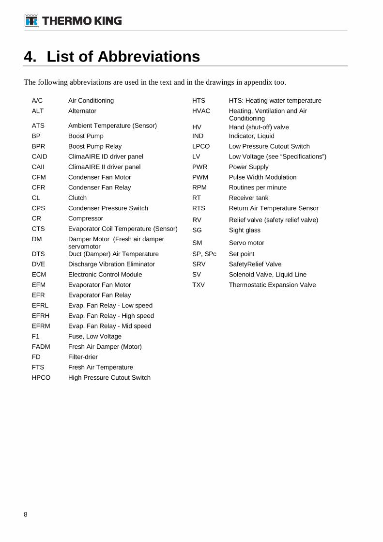
4. List of Abbreviations
The following abbreviations are used in the text and in the drawings in appendix too.
A/C Air Conditioning HTS HTS: Heating water temperature
ALT Alternator HVAC Heating, Ventilation and AirConditioning
ATS Ambient Temperature (Sensor) HV Hand (shut-off) valve
BP Boost Pump IND Indicator, Liquid
BPR Boost Pump Relay LPCO Low Pressure Cutout Switch
CAID ClimaAIRE ID driver panel LV Low Voltage (see “Specifications”)
CAII ClimaAIRE II driver panel PWR Power Supply
CFM Condenser Fan Motor PWM Pulse Width Modulation
CFR Condenser Fan Relay RPM Routines per minute
CL Clutch RT Receiver tank
CPS Condenser Pressure Switch RTS Return Air Temperature Sensor
CR Compressor RV Relief valve (safety relief valve)
CTS Evaporator Coil Temperature (Sensor) SG Sight glass
DM Damper Motor (Fresh air damperservomotor
SM Servo motor
DTS Duct (Damper) Air Temperature SP, SPc Set point
DVE Discharge Vibration Eliminator SRV SafetyRelief Valve
ECM Electronic Control Module SV Solenoid Valve, Liquid Line
EFM Evaporator Fan Motor TXV Thermostatic Expansion Valve
EFR Evaporator Fan Relay
EFRL Evap. Fan Relay - Low speed
EFRH Evap. Fan Relay - High speed
EFRM Evap. Fan Relay - Mid speed
F1 Fuse, Low Voltage
FADM Fresh Air Damper (Motor)
FD Filter-drier
FTS Fresh Air Temperature
HPCO High Pressure Cutout Switch
9
5. Safety Precautions
Thermo King recommends that all services be performed by a Thermo King dealer. However, youshould be aware of several general safety practices:
The exclamation symbol appears next to a point that is particularly important.
DANGER: Denotes the possibility of serious injury or death.
WARNING: Denotes the possibility of serious equipment damage or serious personalinjury.
CAUTION: Denotes the possibility of minor to severe equipment damage or personalinjury.
5.1. General Practices
WARNING: Before any repair or similar action the side covers must be completelyremoved from the unit to access interior of unit. Insure you are using best practice forworking at height paying special attention during removal of cover as it could movedue to the influence of the wind.
DANGER: Do not operate the compressor with the discharge valve closed. Thiscondition increases internal pressure, which can cause an explosion
DANGER: Never apply heat to a sealed refrigeration system or container. Heatincreases internal pressure, which will cause an explosion.
DANGER: Refrigerant in the presence of an open flame, spark or electrical shortproduces toxic gases that are severe respiratory irritants.
DANGER: Keep your hands, clothing and tools clear of fans, pulleys, or belts whenworking on a unit that is running. Loose clothing might entangle moving fans, pulleys,or belts, causing serious injury or possible death.
DANGER: Do not inhale refrigerant. Use caution when working with refrigerant ora refrigeration system in any confined area with a limited air supply, such as a bus orgarage. Refrigerant displaces air and can cause oxygen depletion, resulting insuffocation and possible death
WARNING: Make sure your gauge manifold hoses are in good condition beforeusing them. Never let them come in contact with moving belts, motors, pulleys or hotsurfaces. Defective gauge equipment can damage components or cause serious injury.
WARNING: Wear goggles or safety glasses when working around air conditioningsystems or batteries. Refrigerant liquid, oil and battery acid can permanently damageyour eyes.
10
WARNING: Use extreme caution when drilling. Holes might weaken structuralcomponents. Holes drilled into electrical wiring can cause a fire or explosion.
WARNING: Exposed coil fins can cause lacerations. Service work on the evaporatoror condenser coils is best left to a certified Thermo King technician.
WARNING: Be careful when using ladders or scaffolding to install or service airconditioning systems. A work platform is recommended for servicing rooftop units.Follow the manufacturer's instructions, safety labels and warnings.
CAUTION: Make sure all mounting bolts are tight and are the correct length fortheir applications. Improper torque and incorrect bolt lengths can damage equipment.
CAUTION: If soldering is required, use dry nitrogen to purge the system during anysolder operations. Refer to “Using Pressurized Nitrogen” at the end of theRefrigeration Maintenance chapter
5.2. Electrical Hazards
DANGER: Any time anybody entering the roof must be sure, that the main powerlines are OFF and nobody can switch it on if somebody is on the roof.
When servicing or repairing an air conditioning unit, the possibility of serious or even fatal injury fromelectrical shock exists. Extreme care must be used when working with a air conditioning unit that isconnected to a source of operating power, even if the unit is not running. Lethal voltage potentials canexist at the unit power cord, inside the electric switchboard box, at the motors, at any junction box andwithin the wiring harnesses.
Precautions
Always turn the A/C Unit OFF. Then disconnect the unit from the primary power source (powersupply) before attempting repair or replacement of major components.
Use tools with insulated handles. Use tools that are in good condition. Never hold metal tools inyour hand if exposed, energized conductors are within reach.
Do not make any rapid moves when working with high voltage circuits. Do not grab a fallingtool or other object. People do not contact high voltage wires on purpose. It occurs from anunplanned movement.
Treat all wires and connections as high voltage until ammeter and wiring diagram showotherwise.
Never work alone on high voltage circuits on the refrigeration unit. Another person shouldalways be standing by in the event of an accident to shut OFF the refrigeration unit and to aid avictim.
Have electrically insulated gloves, cable cutters and safety glasses available in the immediatevicinity in the event of an accident.
11
WARNING: Control circuits used by air conditioners are low voltage (24 VDC forexample). This voltage is not dangerous, but the large amount of amperage availablefrom the alternator will cause severe burns if accidentally shorted to ground with metalobjects, such as tools.
WARNING: Do not wear jewelry, watches or rings because they increase the risk ofshorting out electrical circuits and damaging equipment or causing severe burns
WARNING: Use caution when working with electrical circuits that have capacitors.Some capacitors hold a significant charge that will cause burns or shocks ifaccidentally discharged. Make sure capacitors are discharged before working onelectrical circuits.
CAUTION: When working with electrical circuits that contain microprocessors,always wear an ESD wrist strap (TK No. 204-622) and connect the opposite end to thechassis ground or CH terminal. This precaution will prevent electrostatic dischargefrom damaging circuits.
CAUTION: Certain service procedures on air conditioning equipment require thatthe system be de-energized. When this precaution is necessary, ensure the battery’smaster switch or service switch is turned OFF. Confirm that power has been removedbefore servicing. Equipment that is connected to power is dangerous to service.
5.3. Refrigerant Hazards
DANGER: Do not use a Halide torch. When a flame comes in contact withrefrigerant, toxic gases are produced that will cause suffocation, even death
DANGER: Store refrigerant in proper containers, out of direct sunlight and awayfrom intense heat. Heat increases pressure inside storage containers, which will causethem to burst.
DANGER: Do not use oxygen (O2) or compressed air for leak testing systems.Oxygen mixed with refrigerant is combustible.
WARNING: Wear protective garments and goggles or safety glasses when workingwith refrigerant to prevent frostbite and eye injuries.
WARNING: Wear butyl lined gloves when handling refrigerant to help preventfrostbite.
CAUTION: All charging using the newer refrigerants (Azeotropic blends) must bedone in liquid state. Failure to do this will decrease system operating efficiency. Referto the charging procedures found in this manual for your unit
CAUTION: When recovering or transferring refrigerant, use a process that prevents
12
refrigerant from escaping into the atmosphere. Refrigerant damages the earth’s upperozone layer.
CAUTION: Refrigerant in a liquid state evaporates rapidly when exposed to theatmosphere, freezing anything it contacts. Be careful when handling refrigerant toprotect your skin from frostbite.
5.4. Compressor Oil Hazards
WARNING: Protect your eyes from contact with compressor oil. The oil will causeserious eye injuries. Avoid prolonged or repeated contact with compressor oil. Toprevent irritation, wash your hands and clothing thoroughly after handling the oil.
CAUTION: Do not mix compressor oils because that will cause system damage.
CAUTION: Use dedicated equipment to prevent contaminating the system with thewrong type of oil or refrigerant.
CAUTION: Thermo King uses a variety of compressor oils. Oil used in the systemmust be verified. Check “Specification” chapter in this manual for correct oil. Usingincorrect oil will invalidate the warranty.
CAUTION: When servicing TK units, do not use equipment that might becontaminated with PAG oils.
CAUTION: Store compressor oil in an approved sealed container to avoid moisturecontamination.
CAUTION: Do not expose compressor oil to the air any longer than necessary. Theoil will absorb moisture, which results in much longer evacuation times and possiblesystem contamination.
CAUTION: Wipe up spills immediately. Compressor oil can damage paints andrubber materials.
13
5.5. First Aid
Compressor Oil
Eyes
Immediately flush with water for at least 15 minutes. CALL A PHYSICIAN. Wash skin with soap andwater.
Ingestion
Do not induce vomiting. Immediately contact local poison control center or physician.
Refrigerant
In the event of frostbite, protect the frozen area from further injury, warm the area rapidly and maintainrespiration.
Eyes
Immediately flush eyes with large amounts of water. CALL A PHYSICIAN.
Skin
Flush area with large amounts of warm water. Do not apply heat. Remove contaminated clothing andshoes. Wrap burns with dry, sterile, bulky dressing to protect from infection. CALL A PHYSICIAN.Wash contaminated clothing before reuse.
Inhalation
Move victim to fresh air and use CPR (cardio pulmonary resuscitation) or mouth-to-mouth resuscitationto restore breathing, if necessary. Stay with victim until emergency personnel arrives.
14
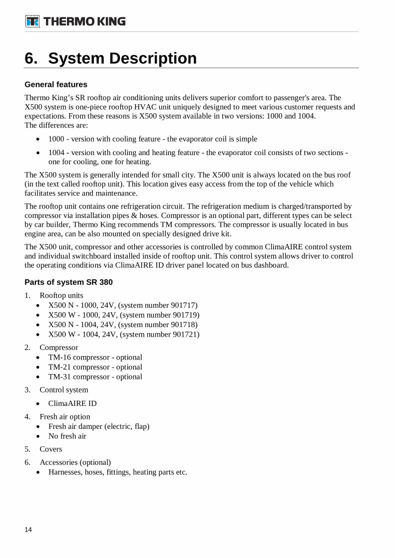
6. System Description
General features
Thermo King’s SR rooftop air conditioning units delivers superior comfort to passenger's area. TheX500 system is one-piece rooftop HVAC unit uniquely designed to meet various customer requests andexpectations. From these reasons is X500 system available in two versions: 1000 and 1004.The differences are:
1000 - version with cooling feature - the evaporator coil is simple
1004 - version with cooling and heating feature - the evaporator coil consists of two sections -one for cooling, one for heating.
The X500 system is generally intended for small city. The X500 unit is always located on the bus roof(in the text called rooftop unit). This location gives easy access from the top of the vehicle whichfacilitates service and maintenance.
The rooftop unit contains one refrigeration circuit. The refrigeration medium is charged/transported bycompressor via installation pipes & hoses. Compressor is an optional part, different types can be selectby car builder, Thermo King recommends TM compressors. The compressor is usually located in busengine area, can be also mounted on specially designed drive kit.
The X500 unit, compressor and other accessories is controlled by common ClimaAIRE control systemand individual switchboard installed inside of rooftop unit. This control system allows driver to controlthe operating conditions via ClimaAIRE ID driver panel located on bus dashboard.
Parts of system SR 380
1. Rooftop units X500 N - 1000, 24V, (system number 901717) X500 W - 1000, 24V, (system number 901719) X500 N - 1004, 24V, (system number 901718) X500 W - 1004, 24V, (system number 901721)
2. Compressor TM-16 compressor - optional TM-21 compressor - optional TM-31 compressor - optional
3. Control system
ClimaAIRE ID
4. Fresh air option Fresh air damper (electric, flap) No fresh air
5. Covers
6. Accessories (optional) Harnesses, hoses, fittings, heating parts etc.
15
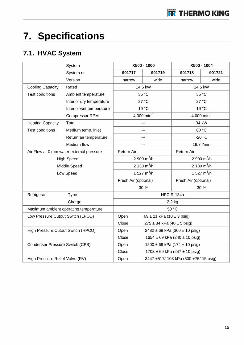
7. Specifications
7.1. HVAC System
System X500 - 1000 X500 - 1004
System nr. 901717 901719 901718 901721
Version narrow wide narrow wide
Cooling Capacity Rated 14.5 kW 14.5 kW
Test conditions Ambient temperature 35 °C 35 °C
Interior dry temperature 27 °C 27 °C
Interior wet temperature 19 °C 19 °C
Compressor RPM 4 000 min-1
4 000 min-1
Heating Capacity Total --- 34 kW
Test conditions Medium temp. inlet --- 80 °C
Return air temperature --- -20 °C
Medium flow --- 16.7 l/min
Air Flow at 0 mm water external pressure Return Air Return Air
High Speed 2 900 m3/h 2 900 m
3/h
Middle Speed 2 130 m3/h 2 130 m
3/h
Low Speed 1 527 m3/h 1 527 m
3/h
Fresh Air (optional) Fresh Air (optional)
30 % 30 %
Refrigerant Type HFC R-134a
Charge 2.2 kg
Maximum ambient operating temperature 50 °C
Low Pressure Cutout Switch (LPCO) Open 69 ± 21 kPa (10 ± 3 psig)
Close 275 ± 34 kPa (40 ± 5 psig)
High Pressure Cutout Switch (HPCO) Open 2482 ± 69 kPa (360 ± 10 psig)
Close 1654 ± 69 kPa (240 ± 10 psig)
Condenser Pressure Switch (CPS) Open 1200 ± 69 kPa (174 ± 10 psig)
Close 1703 ± 69 kPa (247 ± 10 psig)
High Pressure Relief Valve (RV) Open 3447 +517/-103 kPa (500 +75/-15 psig)
16
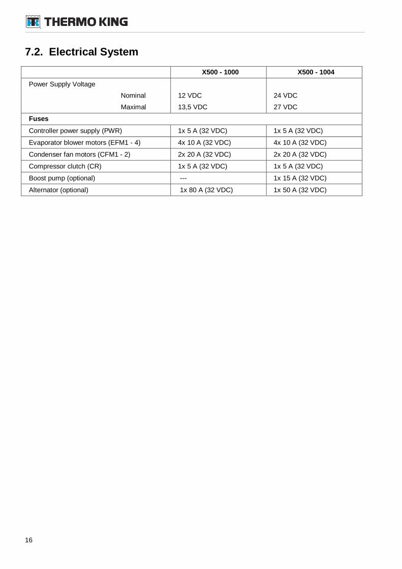
7.2. Electrical System
X500 - 1000 X500 - 1004
Power Supply Voltage
Nominal 12 VDC 24 VDC
Maximal 13,5 VDC 27 VDC
Fuses
Controller power supply (PWR) 1x 5 A (32 VDC) 1x 5 A (32 VDC)
Evaporator blower motors (EFM1 - 4) 4x 10 A (32 VDC) 4x 10 A (32 VDC)
Condenser fan motors (CFM1 - 2) 2x 20 A (32 VDC) 2x 20 A (32 VDC)
Compressor clutch (CR) 1x 5 A (32 VDC) 1x 5 A (32 VDC)
Boost pump (optional) --- 1x 15 A (32 VDC)
Alternator (optional) 1x 80 A (32 VDC) 1x 50 A (32 VDC)
17
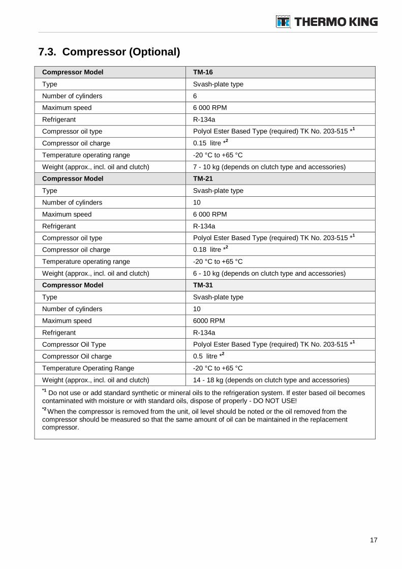
7.3. Compressor (Optional)
Compressor Model TM-16
Type Svash-plate type
Number of cylinders 6
Maximum speed 6 000 RPM
Refrigerant R-134a
Compressor oil type Polyol Ester Based Type (required) TK No. 203-515 *1
Compressor oil charge 0.15 litre *2
Temperature operating range -20 °C to +65 °C
Weight (approx., incl. oil and clutch) 7 - 10 kg (depends on clutch type and accessories)
Compressor Model TM-21
Type Svash-plate type
Number of cylinders 10
Maximum speed 6 000 RPM
Refrigerant R-134a
Compressor oil type Polyol Ester Based Type (required) TK No. 203-515 *1
Compressor oil charge 0.18 litre *2
Temperature operating range -20 °C to +65 °C
Weight (approx., incl. oil and clutch) 6 - 10 kg (depends on clutch type and accessories)
Compressor Model TM-31
Type Svash-plate type
Number of cylinders 10
Maximum speed 6000 RPM
Refrigerant R-134a
Compressor Oil Type Polyol Ester Based Type (required) TK No. 203-515 *1
Compressor Oil charge 0.5 litre *2
Temperature Operating Range -20 °C to +65 °C
Weight (approx., incl. oil and clutch) 14 - 18 kg (depends on clutch type and accessories)
*1Do not use or add standard synthetic or mineral oils to the refrigeration system. If ester based oil becomes
contaminated with moisture or with standard oils, dispose of properly - DO NOT USE!*2
When the compressor is removed from the unit, oil level should be noted or the oil removed from thecompressor should be measured so that the same amount of oil can be maintained in the replacementcompressor.
18
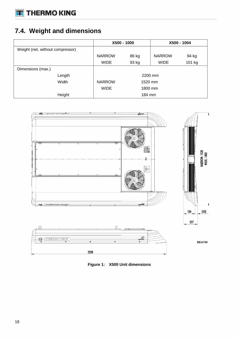
7.4. Weight and dimensions
X500 - 1000 X500 - 1004
Weight (net, without compressor)
NARROW 86 kg NARROW 94 kg
WIDE 93 kg WIDE 101 kg
Dimensions (max.)
Length 2200 mm
Width NARROW 1520 mm
WIDE 1800 mm
Height 184 mm
Figure 1: X500 Unit dimensions
BEA730
19
8. Rooftop Unit Description
8.1. General description
The X500 air conditioning cooling or cooling & heating system provides the cooling, dehumidifyingand heating of the air for passenger area to keep the conditions comfortable.
The X500 unit can be easily accessed from the top of the vehicle which facilitates service andmaintenance. Important components (e.g. filter-drier) are arranged for easy access and service throughside covers.
The X500 system is equipped with refrigeration circuits with one compressor. Can be used severaldifferent models of compressor. For details see Section 9.
Control system consists of ClimaAIRE driver panel in versions ClimaAIRE ID, located on driver'sdashboard, and electrical switchboard installed in the rooftop unit.
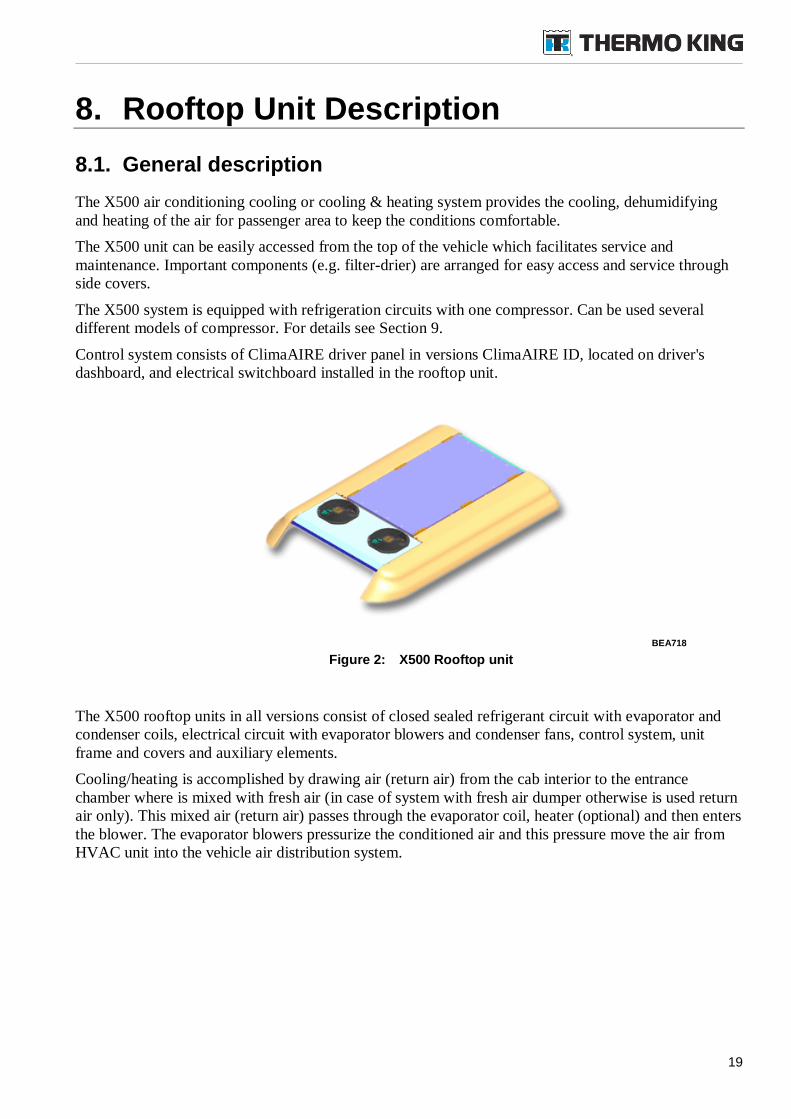
Figure 2: X500 Rooftop unit
The X500 rooftop units in all versions consist of closed sealed refrigerant circuit with evaporator andcondenser coils, electrical circuit with evaporator blowers and condenser fans, control system, unitframe and covers and auxiliary elements.
Cooling/heating is accomplished by drawing air (return air) from the cab interior to the entrancechamber where is mixed with fresh air (in case of system with fresh air dumper otherwise is used returnair only). This mixed air (return air) passes through the evaporator coil, heater (optional) and then entersthe blower. The evaporator blowers pressurize the conditioned air and this pressure move the air fromHVAC unit into the vehicle air distribution system.
BEA718
20
8.2. Main parts of rooftop units
The primary assemblies are: Condenser coil with integrated liquid receiver tank Condenser fans Refrigeration circuit components
o Filter-driero Sight glasso Liquid solenoid valveo Evaporator coil assemblies incl. thermostatic expansion valveo Heating coils - incorporated to evaporator coil (version 1004 only)
Evaporator blowers Fresh air damper (optional) Air filters (optional) Control system - see Section 10.2, page 29. Unit protections devices Structural frame and covers
The complete HVAC system consists of rooftop unit and compressor. For compressor see Section 9,page 25. For more information see also refrigerant circuit diagrams on page 27.
8.2.1. Condenser Coil
The rooftop unit contains two aluminum micro-channel wavy fin condenser coil assembliesthat mountsin front part of rooftop unit.
Pressurized refrigerant gas is discharged by the compressors into the condenser coil for the condensingphase of the refrigeration cycle. Air is drawn through the coils by one propeller type fan. Refrigerantgas condenses in the condenser coil, returning the refrigerant to the liquid state.
The condenser coil has liquid receiver tank holds reserve liquid refrigerant that is needed to supportvariable system demands.
8.2.2. Condenser Fan
The rooftop unit contains two condenser fan assemblies. The fans are designed for pulling of fresh airfrom internal area of HVAC unit and this function effect the air flow through the condenser coils.
The condenser fan assembly is one-piece equipment consists of electrical motor, rotor with blades,permanently sealed ball bearings and plastic protective grille.
The fans are located in the top cover above condenser coil and are mounted via grille and bolts to thecondenser cover.
8.2.3. Filter-Drier
The filter-drier (dehydrator) is a cartridge soldered type unit intended for protection the refrigerantagainst:
moisture - by absorbing and retaining it deep within the desiccant
foreign matter - the filter-drier will filter out scale, solder particles, carbon, sludge, dirt or anyother foreign matter with negligible pressure drop. Fine particles that would go through anordinary strainer are removed down to a minimum size in one pass filtration.
acid - the hydrochloric, hydrofluoric, and various organic acids are adsorbed and held by thedesiccant in a manner similar to the adsorption of moisture
21
oil sludge and varnish - all refrigeration oils break down to produce varnish, sludge and organicacids and here are removed
For location of the filter-drier see "Figure 4: X500 Inside view" in following section, page 24.
8.2.4. Evaporator/Heating Coil Assemblies
The evaporator coil is an aluminum, wavy fin, copper tube type. Liquid refrigerant flows from thereceiver tank to the evaporator coil through the expansion valve. The expansion valve restricts andcontrols the flow of liquid refrigerant to the evaporator. The pressure and temperature condition insideof the evaporator (refrigerant side) and outside of evaporator (air side) results in heat transfer from therefrigerated air to the evaporator. X500 units contain two evaporator coils located on left and right sideof unit.
In the versions 1004 (cooling and heating) the evaporator/heating coils are divided into cooling sectionand separate heating section both connected to refrigeration and heating system too. To assist inpreventing corrosion buildup and freezing the heating coil(s) should be operated with a particularcoolant mixture. For coolant specification follow the instruction of the bus engine manufacturer.
The X500 system contains two evaporator or evaporator/heating coils. The drain pan underneath theevaporator coil is intended to capture any water condensation from the coil surface. Drain lines allowthe water to flow away from the unit.
8.2.5. Evaporator Blowers
The blowers draw the air from vehicle area and/or fresh air from outside and discharge the conditionedair back into the vehicle air distribution system.
The blowers are located on sides of unit and are accessible under side covers.
8.2.6. Fresh Air Damper (optional)
The fresh air damper controls an amount of fresh air from outside. Air damper consists of damper motorand air flap. This flap can regulate ratio between return air (entering from bottom, from passengers area)and fresh air (entering from upside through air intake, from outside). This air mixture runs to the air coilfilters, evaporator/ heating coil and by blowers is discharged back to the vehicle air distribution system.
The X500 system can contains one fresh air damper located in rear section.
8.2.7. Air Filters (optional)
Inside the rooftop unit are located coil filters (in front of evaporator filters) intended to filter return ormixed air to prevent impurities accumulation on coils.
Rooftop unit in version with fresh air damper is equipped with fresh air filters to remove impuritiesfrom the ambient air running through evaporator coils. This filter is located on behind the fresh airdamper.
On the bus ceiling can be mounted (as recommended) return air grilles contains return air filter. See busmanufacturer documentation for more information.
The filters are disposable only, for changing frequency refer to maintenance chapter in this manual.
8.2.8. Unit Protection Devices
High Pressure Switch (HPCO)
The high pressure switch is located on the high pressure line in refrigeration circuit. The relay-typecontact of this switch is a part of low voltage (control) circuit, under normal operation is the contactclosed.
22
If the discharge pressure rises above limit value (see “Specifications”), the switch/contact will open andthe compressor will stop immediately. At the same time the control system will receive the informationabout this situation.
Low Pressure (LPCO) Switch
The low high pressure switch is located on the low pressure line in refrigeration circuit. The relay-typecontact of this switch is a part of low voltage (control) circuit, under normal operation is the contactclosed.
If the suction pressure drops below limit value (see “Specifications”), the switch/contact will open andthe compressor will stop immediately. At the same time the control system will receive the informationabout this situation.
Safety Relief Valve (SRV)
A safety (high pressure) relief valve is installed in the refrigeration circuit on the high pressure(compressor output) line to avoid excessive pressure build-up within the refrigeration system fromextraordinary and unforeseen circumstances.
The valve is a spring-loaded piston type that opens when refrigerant pressure exceeds limit value.
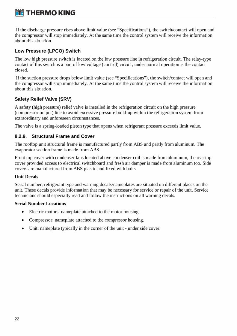
8.2.9. Structural Frame and Cover
The rooftop unit structural frame is manufactured partly from ABS and partly from aluminum. Theevaporator section frame is made from ABS.
Front top cover with condenser fans located above condenser coil is made from aluminum, the rear topcover provided access to electrical switchboard and fresh air damper is made from aluminum too. Sidecovers are manufactured from ABS plastic and fixed with bolts.
Unit Decals
Serial number, refrigerant type and warning decals/nameplates are situated on different places on theunit. These decals provide information that may be necessary for service or repair of the unit. Servicetechnicians should especially read and follow the instructions on all warning decals.
Serial Number Locations
Electric motors: nameplate attached to the motor housing.
Compressor: nameplate attached to the compressor housing.
Unit: nameplate typically in the corner of the unit - under side cover.
23
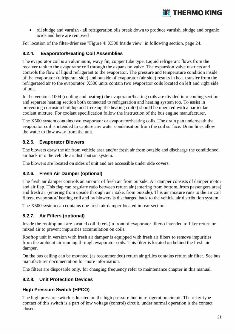
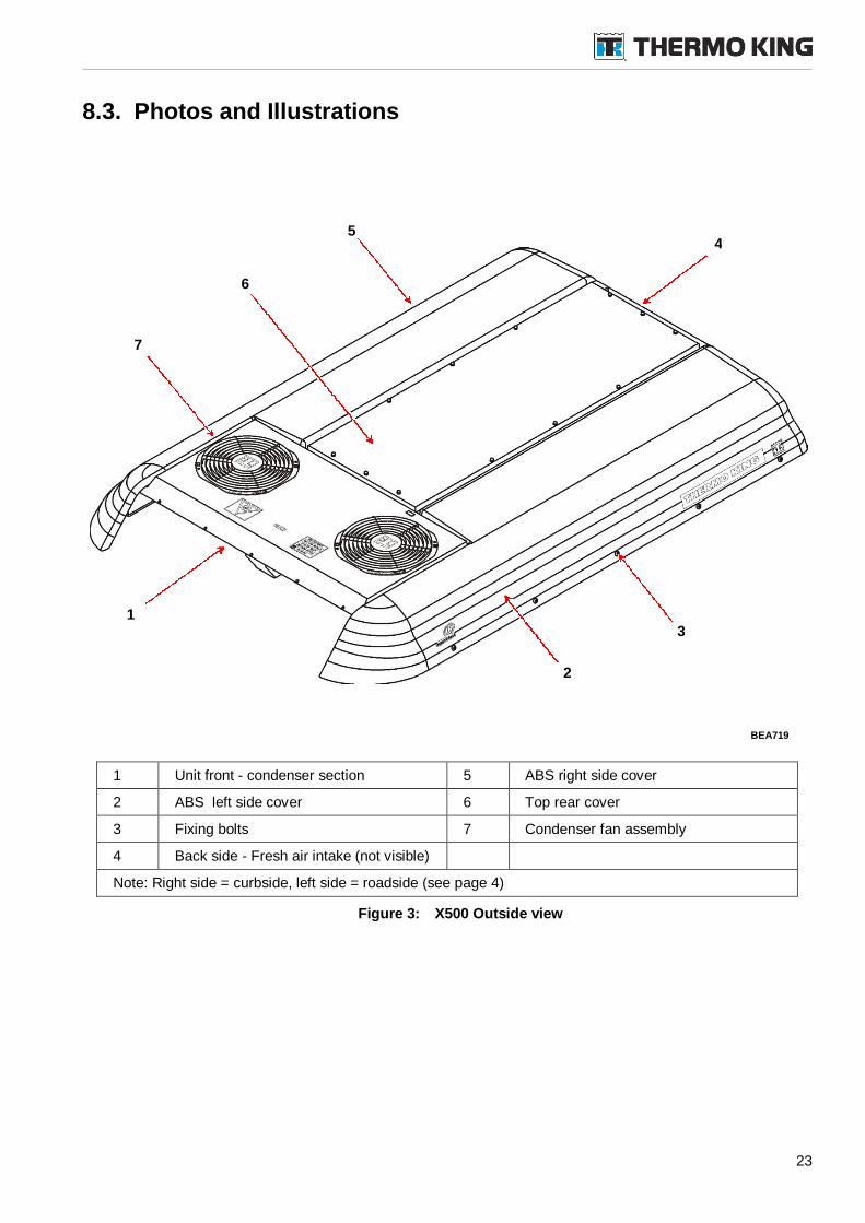
8.3. Photos and Illustrations
1 Unit front - condenser section 5 ABS right side cover
2 ABS left side cover 6 Top rear cover
3 Fixing bolts 7 Condenser fan assembly
4 Back side - Fresh air intake (not visible)
Note: Right side = curbside, left side = roadside (see page 4)
Figure 3: X500 Outside view
BEA719
1
2
7
6
54
3
24
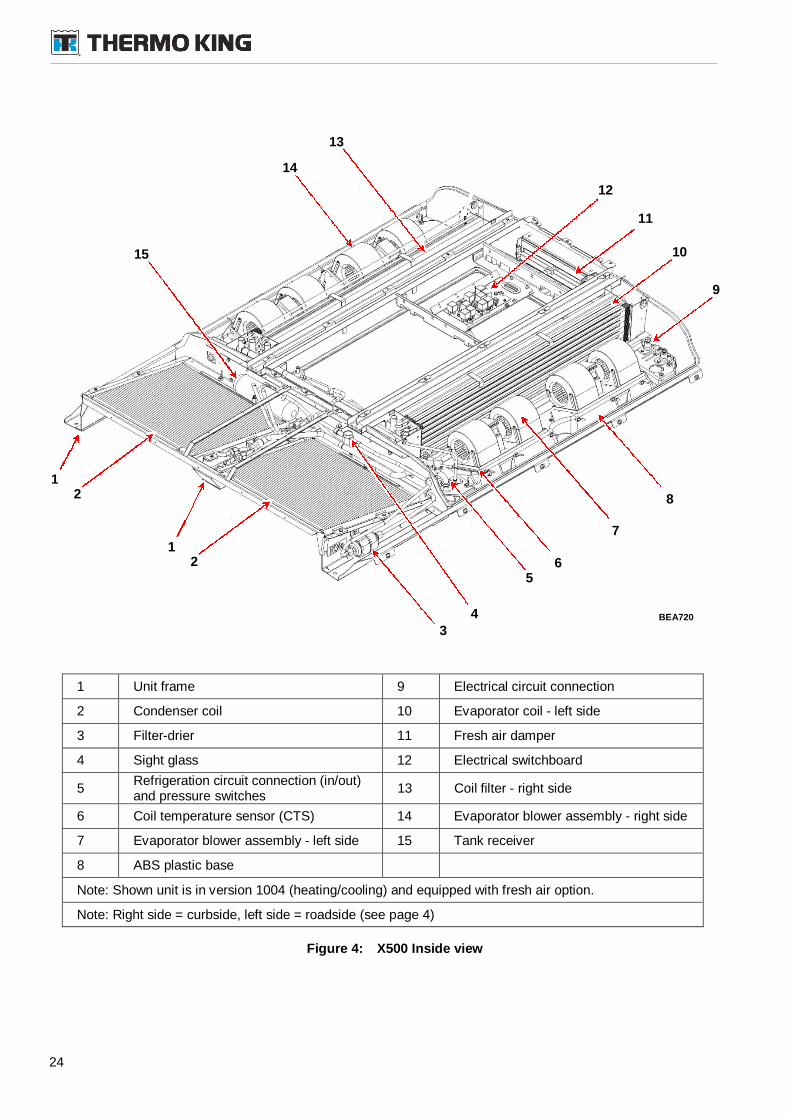
1 Unit frame 9 Electrical circuit connection
2 Condenser coil 10 Evaporator coil - left side
3 Filter-drier 11 Fresh air damper
4 Sight glass 12 Electrical switchboard
5Refrigeration circuit connection (in/out)and pressure switches
13 Coil filter - right side
6 Coil temperature sensor (CTS) 14 Evaporator blower assembly - right side
7 Evaporator blower assembly - left side 15 Tank receiver
8 ABS plastic base
Note: Shown unit is in version 1004 (heating/cooling) and equipped with fresh air option.
Note: Right side = curbside, left side = roadside (see page 4)
Figure 4: X500 Inside view
BEA720
1
3
13
11
4
6
7
8
12
14
2
15
12
5
10
9
25
9. Compressor Description
9.1. General description
For X500 systems can be used different models of compressor (see "Specification"). Model/type ofcompressor depends on your HVAC system configuration and bus manufacturer. For exactdetermination of used type and model see the nameplate on body of compressor.
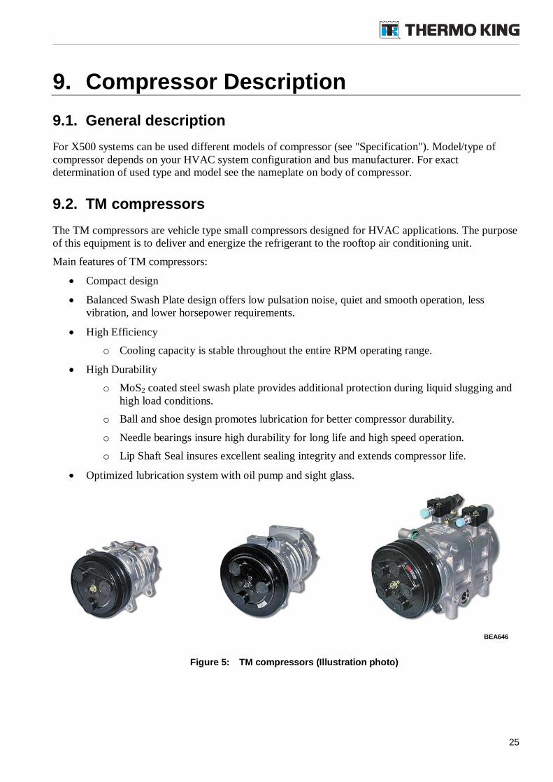
9.2. TM compressors
The TM compressors are vehicle type small compressors designed for HVAC applications. The purposeof this equipment is to deliver and energize the refrigerant to the rooftop air conditioning unit.
Main features of TM compressors:
Compact design
Balanced Swash Plate design offers low pulsation noise, quiet and smooth operation, lessvibration, and lower horsepower requirements.
High Efficiency
o Cooling capacity is stable throughout the entire RPM operating range.
High Durability
o MoS2 coated steel swash plate provides additional protection during liquid slugging andhigh load conditions.
o Ball and shoe design promotes lubrication for better compressor durability.
o Needle bearings insure high durability for long life and high speed operation.
o Lip Shaft Seal insures excellent sealing integrity and extends compressor life.
Optimized lubrication system with oil pump and sight glass.
Figure 5: TM compressors (Illustration photo)
BEA646
26
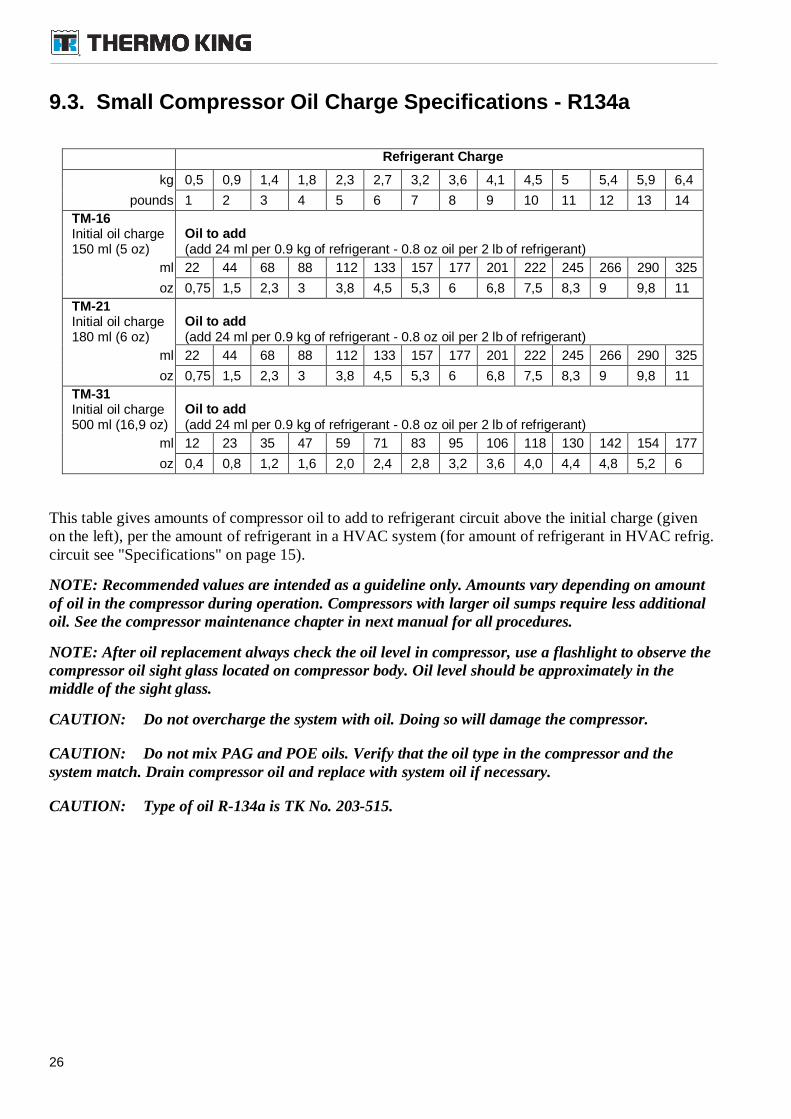
9.3. Small Compressor Oil Charge Specifications - R134a
Refrigerant Charge
kg 0,5 0,9 1,4 1,8 2,3 2,7 3,2 3,6 4,1 4,5 5 5,4 5,9 6,4
pounds 1 2 3 4 5 6 7 8 9 10 11 12 13 14
TM-16Initial oil charge150 ml (5 oz)
Oil to add(add 24 ml per 0.9 kg of refrigerant - 0.8 oz oil per 2 lb of refrigerant)
ml 22 44 68 88 112 133 157 177 201 222 245 266 290 325
oz 0,75 1,5 2,3 3 3,8 4,5 5,3 6 6,8 7,5 8,3 9 9,8 11
TM-21Initial oil charge180 ml (6 oz)
Oil to add(add 24 ml per 0.9 kg of refrigerant - 0.8 oz oil per 2 lb of refrigerant)
ml 22 44 68 88 112 133 157 177 201 222 245 266 290 325
oz 0,75 1,5 2,3 3 3,8 4,5 5,3 6 6,8 7,5 8,3 9 9,8 11
TM-31Initial oil charge500 ml (16,9 oz)
Oil to add(add 24 ml per 0.9 kg of refrigerant - 0.8 oz oil per 2 lb of refrigerant)
ml 12 23 35 47 59 71 83 95 106 118 130 142 154 177
oz 0,4 0,8 1,2 1,6 2,0 2,4 2,8 3,2 3,6 4,0 4,4 4,8 5,2 6
This table gives amounts of compressor oil to add to refrigerant circuit above the initial charge (givenon the left), per the amount of refrigerant in a HVAC system (for amount of refrigerant in HVAC refrig.circuit see "Specifications" on page 15).
NOTE: Recommended values are intended as a guideline only. Amounts vary depending on amountof oil in the compressor during operation. Compressors with larger oil sumps require less additionaloil. See the compressor maintenance chapter in next manual for all procedures.
NOTE: After oil replacement always check the oil level in compressor, use a flashlight to observe thecompressor oil sight glass located on compressor body. Oil level should be approximately in themiddle of the sight glass.
CAUTION: Do not overcharge the system with oil. Doing so will damage the compressor.
CAUTION: Do not mix PAG and POE oils. Verify that the oil type in the compressor and thesystem match. Drain compressor oil and replace with system oil if necessary.
CAUTION: Type of oil R-134a is TK No. 203-515.
27
10.Operating Instructions
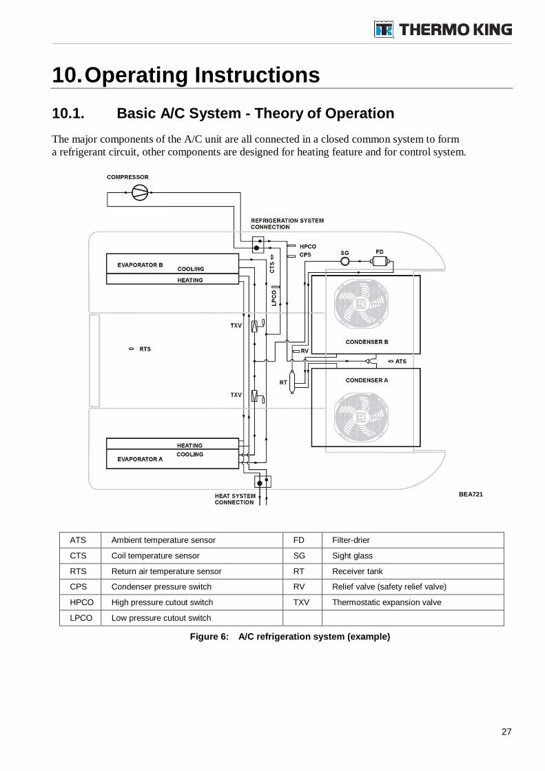
10.1. Basic A/C System - Theory of Operation
The major components of the A/C unit are all connected in a closed common system to forma refrigerant circuit, other components are designed for heating feature and for control system.
ATS Ambient temperature sensor FD Filter-drier
CTS Coil temperature sensor SG Sight glass
RTS Return air temperature sensor RT Receiver tank
CPS Condenser pressure switch RV Relief valve (safety relief valve)
HPCO High pressure cutout switch TXV Thermostatic expansion valve
LPCO Low pressure cutout switch
Figure 6: A/C refrigeration system (example)
BEA721
28
The refrigerant system circulates refrigerant (energized by compressor) between the evaporator coilsand the condenser coils to provide the requested exchange of heat energy.
The evaporator blowers drives the air with higher temperature (return air or mixed air) across theevaporator coils. The heat energy is absorbed by the refrigerant (a low pressure, low temperature liquid)that inside of the coils evaporates. The cooled air is discharged into vehicle air distribution system.
As the refrigerant evaporates, a low pressure, low temperature, heat-laden vapour is formed. Therefrigerant needs to release the heat energy. Compressor's suction continuously draws the heat-ladenvapours from the evaporator coils. As the vapours are compressed, it increases its pressure, changing itto high pressure, high temperatured vapour. This increases the vapour temperature and pressure tofacilitate heat transfer to the ambient air and establish a condensing temperature.
As the high-temperature vapours travels through the condenser coils, the heat is dispersed into thecooling fins, and ambient air is circulated by the condenser fans. As the heat is removed, the vapourscondenses back into a liquid. Thus, the heat absorbed by the refrigerant from the evaporator, istransferred to the condenser and given off to ambient air.
The high temperature liquid is maintained under high pressure in the small receiver installed after thecondensers, where it is stored until needed. The receiver serves as a reservoir for the variable demandsof liquid refrigerant from the system.
From the receiver tank liquid refrigerant flows through the filter-drier (dehydrator), where impurities,solids, and moisture are removed. From the filter-drier, the high temperature, high pressured liquidflows through to the expansion valves. The expansion valves restrict and control the flow of liquidrefrigerant to the evaporator coils where it again absorbs heat from bus interior air (return air).
Before expansion valves can be added feeder branch designed for FrontBox (optional equipment)connection.
Beside evaporator coils can be added heating coils (for cooling/heating 1004 systems only) intended forheating feature, connected to bus heating system.
29
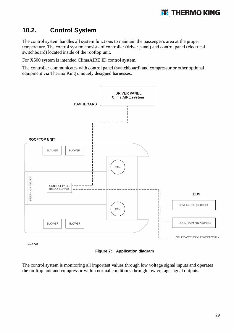
10.2. Control System
The control system handles all system functions to maintain the passenger's area at the propertemperature. The control system consists of controller (driver panel) and control panel (electricalswitchboard) located inside of the rooftop unit.
For X500 system is intended ClimaAIRE ID control system.
The controller communicates with control panel (switchboard) and compressor or other optionalequipment via Thermo King uniquely designed harnesses.
Figure 7: Application diagram
The control system is monitoring all important values through low voltage signal inputs and operatesthe rooftop unit and compressor within normal conditions through low voltage signal outputs.
BEA722
30
10.3. ClimaAIRE ID and ClimaAIRE II
The driver panel in X500 system usually works like a terminal (bus driver panel, HMI - HumanMachine Interface) and controller too. Collects and sends bus driver commands to the rooftop unitswitchboard (and compressor and other optional auxiliary equipment), and it conversely receives anddisplays HVAC system status to her/him.
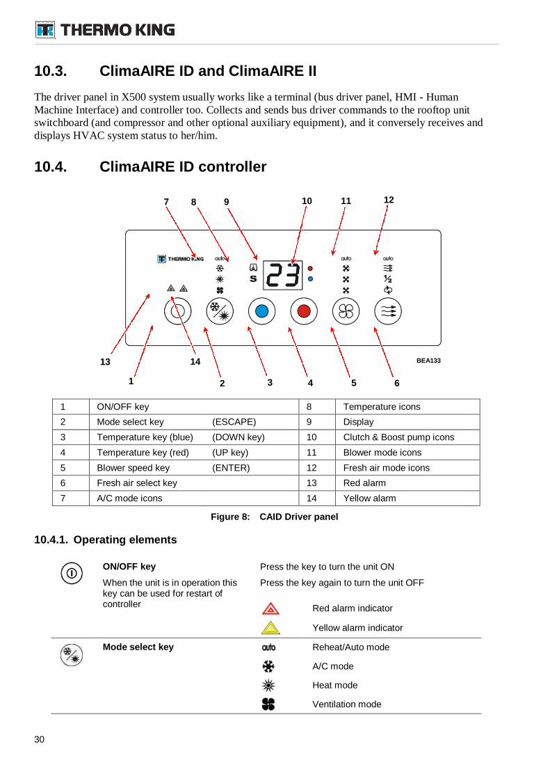
10.4. ClimaAIRE ID controller
1 ON/OFF key 8 Temperature icons
2 Mode select key (ESCAPE) 9 Display
3 Temperature key (blue) (DOWN key) 10 Clutch & Boost pump icons
4 Temperature key (red) (UP key) 11 Blower mode icons
5 Blower speed key (ENTER) 12 Fresh air mode icons
6 Fresh air select key 13 Red alarm
7 A/C mode icons 14 Yellow alarm
Figure 8: CAID Driver panel
10.4.1. Operating elements
ON/OFF key Press the key to turn the unit ON
When the unit is in operation thiskey can be used for restart ofcontroller
Press the key again to turn the unit OFF
Red alarm indicator
Yellow alarm indicator
Mode select key Reheat/Auto mode
A/C mode
Heat mode
Ventilation mode
BEA133
9 121110
13 14
1 2 3 64 5
7 8
31
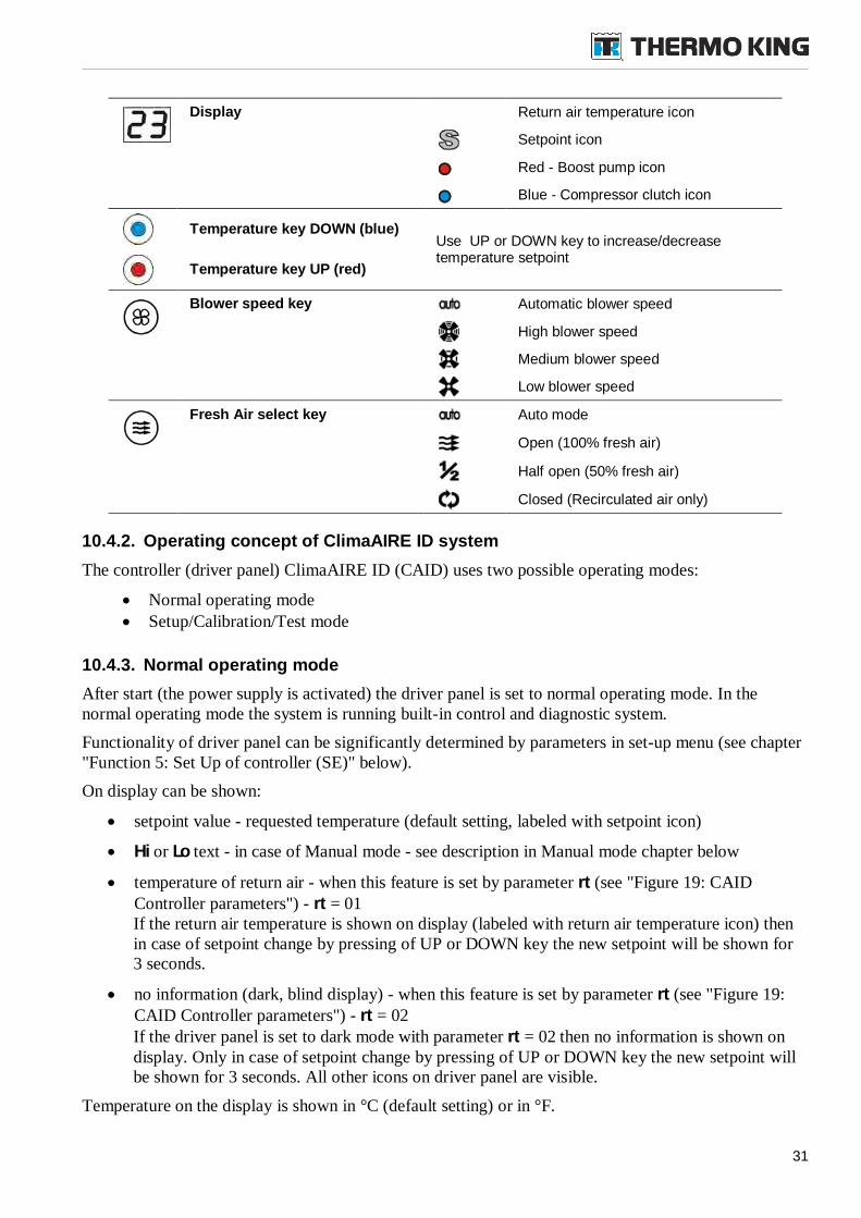
Display Return air temperature icon
Setpoint icon
Red - Boost pump icon
Blue - Compressor clutch icon
Temperature key DOWN (blue)Use UP or DOWN key to increase/decreasetemperature setpoint
Temperature key UP (red)
Blower speed key Automatic blower speed
High blower speed
Medium blower speed
Low blower speed
Fresh Air select key Auto mode
Open (100% fresh air)
Half open (50% fresh air)
Closed (Recirculated air only)
10.4.2. Operating concept of ClimaAIRE ID system
The controller (driver panel) ClimaAIRE ID (CAID) uses two possible operating modes:
Normal operating mode Setup/Calibration/Test mode
10.4.3. Normal operating mode
After start (the power supply is activated) the driver panel is set to normal operating mode. In thenormal operating mode the system is running built-in control and diagnostic system.
Functionality of driver panel can be significantly determined by parameters in set-up menu (see chapter"Function 5: Set Up of controller (SE)" below).
On display can be shown:
setpoint value - requested temperature (default setting, labeled with setpoint icon)
Hi or Lo text - in case of Manual mode - see description in Manual mode chapter below
temperature of return air - when this feature is set by parameter rt (see "Figure 19: CAIDController parameters") - rt = 01If the return air temperature is shown on display (labeled with return air temperature icon) thenin case of setpoint change by pressing of UP or DOWN key the new setpoint will be shown for3 seconds.
no information (dark, blind display) - when this feature is set by parameter rt (see "Figure 19:CAID Controller parameters") - rt = 02If the driver panel is set to dark mode with parameter rt = 02 then no information is shown ondisplay. Only in case of setpoint change by pressing of UP or DOWN key the new setpoint willbe shown for 3 seconds. All other icons on driver panel are visible.
Temperature on the display is shown in °C (default setting) or in °F.
32
Mode select
In normal operating mode - Auto mode - the controller selects the right mode (cool or heat orventilation) automatically.
Reheat/Auto mode - unit will operate in cool or heat mode based on operating conditions toensure proper air temperature and humidity. The cooling and heating function can be usedsimultaneously (this is "Reheat mode")
A/C mode - unit will operate in cool mode (based on operating conditions) or ventilation Heat mode - unit will operate in heat mode (based on operating conditions) or ventilation Ventilation mode - unit will be in ventilation only, cooling or heating will be disabled
NOTE: The Heat mode can be applicable only for HVAC units in 1004 version (cooling/heating).
Blower speed select
The evaporator blowers move the conditioned air from HVAC unit into bus interior. Selection of blowerspeed determines air flow (amount of air) from HVAC unit into vehicle. In AUTO position the blowerspeeds are controlled automatically.
NOTE: When CA ID controller is used in HVAC system equipped with two speeds blowers the LOWand HIGH blower speeds are applicable - the MEDIUM speed position is not used and if selectedthan blowers run in low speed only.
Fresh air / Smog
Using fresh air key driver can control amount of fresh air flows through HVAC unit or can close airdamper in case of smog. This "smog mode" can be easily set by pressing fresh air button.
Automatic mode - the fresh air damper is controlled automatically
Fresh air damper open (100 % FA)
Half open - fresh air damper at 50% position (50 % FA)
Recirculated air - fresh air damper closed (0 % FA)
If no key was pressed in last 2 seconds and fresh air button is pressed once, the FA symbol andrecirculated air symbol lights up together and the fresh air damper is closed for next 10 minutes. Afterthis period the controller returns to previous FA state (indicated by FA symbol).
If FA key is pressed once more than the "smog mode" is canceled and FA damper position can beselected.
Automatic ON feature
Depending on Ao parameter (see "Figure 19: CAID Controller ") the controller (driver panel) will beswitched ON or stays OFF depending on state when power supply was switched OFF:
If the driver panel was ON when power supply was switched OFF; on next system start -power supply ON - the driver panel will also start (internal memory keeps the last operatingstatus; parameter Ao is set to 00)
If the driver panel was OFF when power supply was switched OFF; on next system start -power supply ON - the driver panel will stay OFF (internal memory keeps the last operatingstatus; parameter Ao is set to 00)
OR the driver panel always will be switched ON when the power supply is switched ON(parameter Ao is set to 01)
33
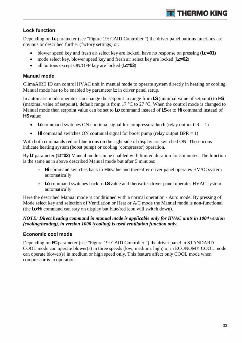
Lock function
Depending on Lc parameter (see "Figure 19: CAID Controller ") the driver panel buttons functions areobvious or described further (factory settings) or:
blower speed key and fresh air select key are locked, have no response on pressing (Lc =01)
mode select key, blower speed key and fresh air select key are locked (Lc=02)
all buttons except ON/OFF key are locked (Lc=03)
Manual mode
ClimaAIRE ID can control HVAC unit in manual mode to operate system directly in heating or cooling.Manual mode has to be enabled by parameter Lt in driver panel setup.
In automatic mode operator can change the setpoint in range from LS (minimal value of setpoint) to HS(maximal value of setpoint), default range is from 17 °C to 27 °C. When the control mode is changed toManual mode then setpoint value can be set to Lo command instead of LS or to Hi command instead ofHS value:
Lo command switches ON continual signal for compressor/clutch (relay output CR = 1)
Hi command switches ON continual signal for boost pump (relay output BPR = 1)
With both commands red or blue icons on the right side of display are switched ON. These iconsindicate heating system (boost pump) or cooling (compressor) operation.
By Lt parameter (Lt=02) Manual mode can be enabled with limited duration for 5 minutes. The functionis the same as in above described Manual mode but after 5 minutes:
o Hi command switches back to HS value and thereafter driver panel operates HVAC systemautomatically
o Lo command switches back to LS value and thereafter driver panel operates HVAC systemautomatically
Here the described Manual mode is conditioned with a normal operation - Auto mode. By pressing ofMode select key and selection of Ventilation or Heat or A/C mode the Manual mode is non-functional(the Lo/Hi command can stay on display but blue/red icon will switch down).
NOTE: Direct heating command in manual mode is applicable only for HVAC units in 1004 version(cooling/heating), in version 1000 (cooling) is used ventilation function only.
Economic cool mode
Depending on EC parameter (see "Figure 19: CAID Controller ") the driver panel in STANDARDCOOL mode can operate blower(s) in three speeds (low, medium, high) or in ECONOMY COOL modecan operate blower(s) in medium or high speed only. This feature affect only COOL mode whencompressor is in operation.
34
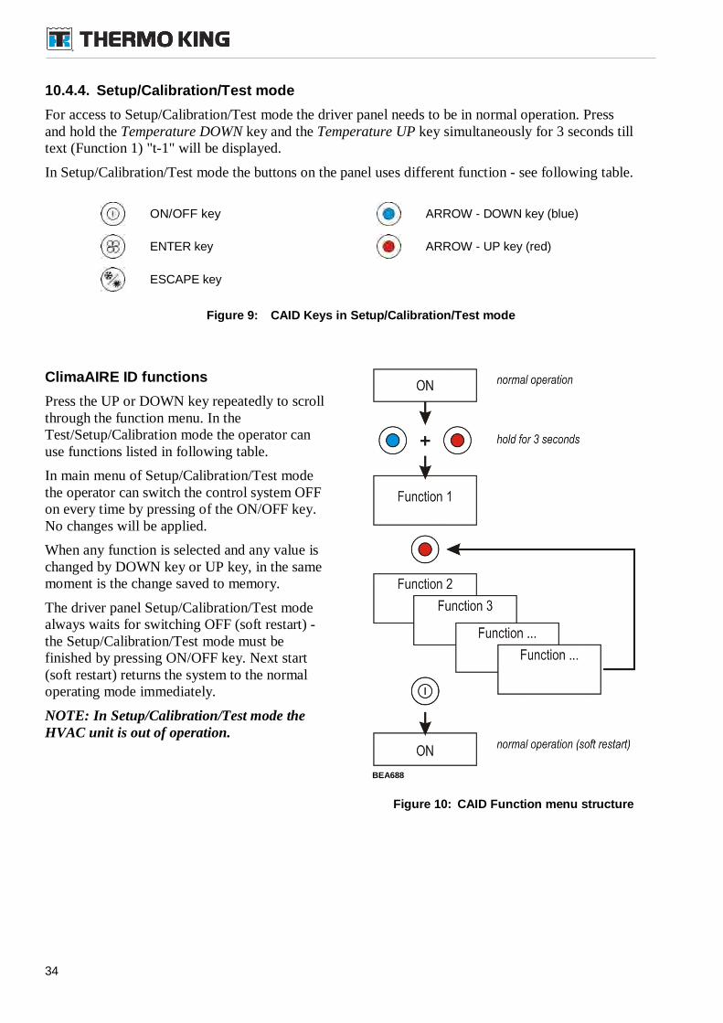
10.4.4. Setup/Calibration/Test mode
For access to Setup/Calibration/Test mode the driver panel needs to be in normal operation. Pressand hold the Temperature DOWN key and the Temperature UP key simultaneously for 3 seconds tilltext (Function 1) "t-1" will be displayed.
In Setup/Calibration/Test mode the buttons on the panel uses different function - see following table.
ON/OFF key ARROW - DOWN key (blue)
ENTER key ARROW - UP key (red)
ESCAPE key
Figure 9: CAID Keys in Setup/Calibration/Test mode
ClimaAIRE ID functions
Press the UP or DOWN key repeatedly to scrollthrough the function menu. In theTest/Setup/Calibration mode the operator canuse functions listed in following table.
In main menu of Setup/Calibration/Test modethe operator can switch the control system OFFon every time by pressing of the ON/OFF key.No changes will be applied.
When any function is selected and any value ischanged by DOWN key or UP key, in the samemoment is the change saved to memory.
The driver panel Setup/Calibration/Test modealways waits for switching OFF (soft restart) -the Setup/Calibration/Test mode must befinished by pressing ON/OFF key. Next start(soft restart) returns the system to the normaloperating mode immediately.
NOTE: In Setup/Calibration/Test mode theHVAC unit is out of operation.
Figure 10: CAID Function menu structure
BEA688
35
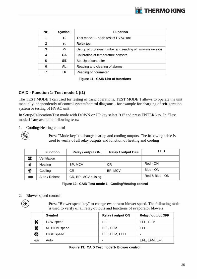
Nr. Symbol Function
1 t1 Test mode 1 - basic test of HVAC unit
2 rt Relay test
3 Pr Set up of program number and reading of firmware version
4 CA Calibration of temperature sensors
5 SE Set Up of controller
6 AL Reading and clearing of alarms
7 Hr Reading of hourmeter
Figure 11: CAID List of functions
CAID - Function 1: Test mode 1 (t1)
The TEST MODE 1 can used for testing of basic operations. TEST MODE 1 allows to operate the unitmanually independently of control system/control diagrams - for example for charging of refrigerationsystem or testing of HVAC unit.
In Setup/Calibration/Test mode with DOWN or UP key select "t1" and press ENTER key. In "Testmode 1" are available following tests:
1. Cooling/Heating control
Press "Mode key" to change heating and cooling outputs. The following table isused to verify of all relay outputs and function of heating and cooling
Function Relay / output ON Relay / output OFF LED
Ventilation
Heating BP, MCV CR Red - ON
Cooling CR BP, MCV Blue - ON
Auto / Reheat CR, BP, MCV pulsing Red & Blue - ON
Figure 12: CAID Test mode 1 - Cooling/Heating control
2. Blower speed control
Press "Blower speed key" to change evaporator blower speed. The following tableis used to verify of all relay outputs and functions of evaporator blowers.
Symbol Relay / output ON Relay / output OFF
LOW speed EFL EFH, EFM
MEDIUM speed EFL, EFM EFH
HIGH speed EFL, EFM, EFH -
Auto - EFL, EFM, EFH
Figure 13: CAID Test mode 1- Blower control
36
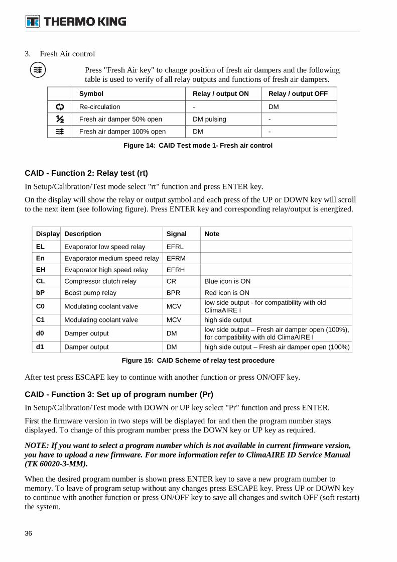
3. Fresh Air control
Press "Fresh Air key" to change position of fresh air dampers and the followingtable is used to verify of all relay outputs and functions of fresh air dampers.
Symbol Relay / output ON Relay / output OFF
Re-circulation - DM
Fresh air damper 50% open DM pulsing -
Fresh air damper 100% open DM -
Figure 14: CAID Test mode 1- Fresh air control
CAID - Function 2: Relay test (rt)
In Setup/Calibration/Test mode select "rt" function and press ENTER key.
On the display will show the relay or output symbol and each press of the UP or DOWN key will scrollto the next item (see following figure). Press ENTER key and corresponding relay/output is energized.
Display Description Signal Note
EL Evaporator low speed relay EFRL
En Evaporator medium speed relay EFRM
EH Evaporator high speed relay EFRH
CL Compressor clutch relay CR Blue icon is ON
bP Boost pump relay BPR Red icon is ON
C0 Modulating coolant valve MCVlow side output - for compatibility with oldClimaAIRE I
C1 Modulating coolant valve MCV high side output
d0 Damper output DMlow side output – Fresh air damper open (100%),for compatibility with old ClimaAIRE I
d1 Damper output DM high side output – Fresh air damper open (100%)
Figure 15: CAID Scheme of relay test procedure
After test press ESCAPE key to continue with another function or press ON/OFF key.
CAID - Function 3: Set up of program number (Pr)
In Setup/Calibration/Test mode with DOWN or UP key select "Pr" function and press ENTER.
First the firmware version in two steps will be displayed for and then the program number staysdisplayed. To change of this program number press the DOWN key or UP key as required.
NOTE: If you want to select a program number which is not available in current firmware version,you have to upload a new firmware. For more information refer to ClimaAIRE ID Service Manual(TK 60020-3-MM).
When the desired program number is shown press ENTER key to save a new program number tomemory. To leave of program setup without any changes press ESCAPE key. Press UP or DOWN keyto continue with another function or press ON/OFF key to save all changes and switch OFF (soft restart)the system.
37
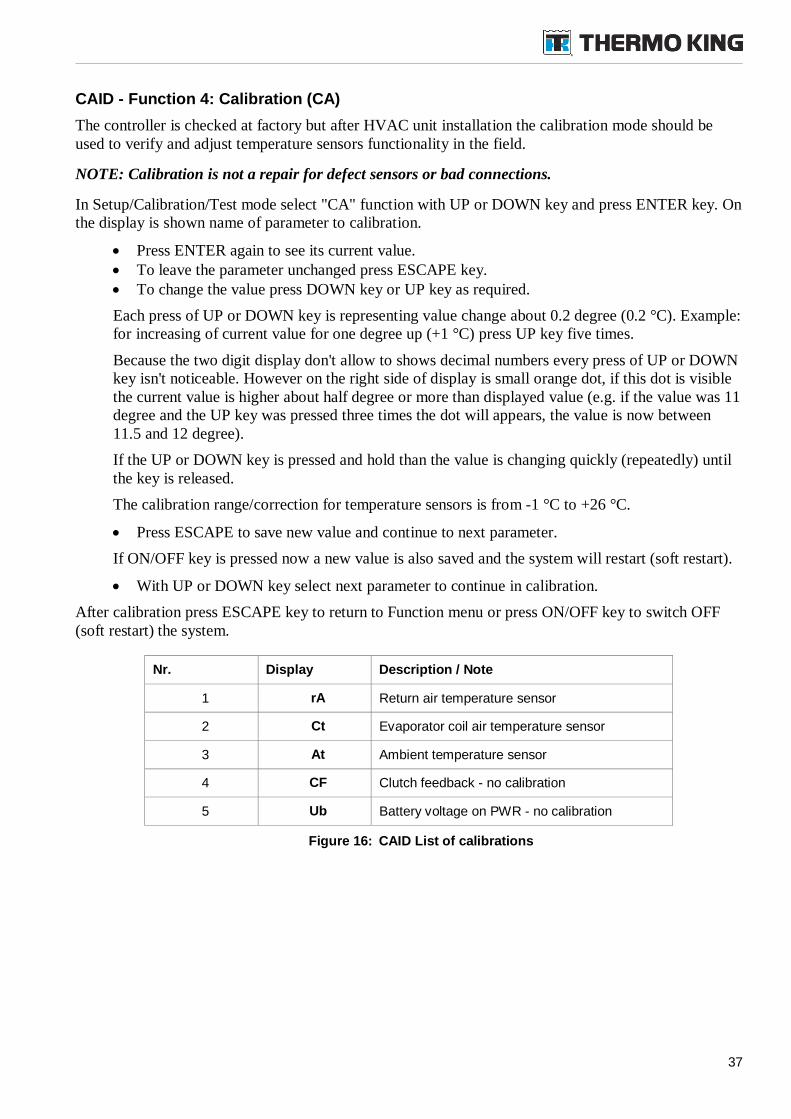
CAID - Function 4: Calibration (CA)
The controller is checked at factory but after HVAC unit installation the calibration mode should beused to verify and adjust temperature sensors functionality in the field.
NOTE: Calibration is not a repair for defect sensors or bad connections.
In Setup/Calibration/Test mode select "CA" function with UP or DOWN key and press ENTER key. Onthe display is shown name of parameter to calibration.
Press ENTER again to see its current value. To leave the parameter unchanged press ESCAPE key. To change the value press DOWN key or UP key as required.
Each press of UP or DOWN key is representing value change about 0.2 degree (0.2 °C). Example:for increasing of current value for one degree up (+1 °C) press UP key five times.
Because the two digit display don't allow to shows decimal numbers every press of UP or DOWNkey isn't noticeable. However on the right side of display is small orange dot, if this dot is visiblethe current value is higher about half degree or more than displayed value (e.g. if the value was 11degree and the UP key was pressed three times the dot will appears, the value is now between11.5 and 12 degree).
If the UP or DOWN key is pressed and hold than the value is changing quickly (repeatedly) untilthe key is released.
The calibration range/correction for temperature sensors is from -1 °C to +26 °C.
Press ESCAPE to save new value and continue to next parameter.
If ON/OFF key is pressed now a new value is also saved and the system will restart (soft restart).
With UP or DOWN key select next parameter to continue in calibration.
After calibration press ESCAPE key to return to Function menu or press ON/OFF key to switch OFF(soft restart) the system.
Nr. Display Description / Note
1 rA Return air temperature sensor
2 Ct Evaporator coil air temperature sensor
3 At Ambient temperature sensor
4 CF Clutch feedback - no calibration
5 Ub Battery voltage on PWR - no calibration
Figure 16: CAID List of calibrations
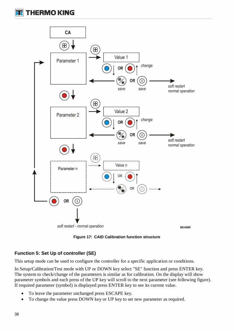
38
Figure 17: CAID Calibration function structure
Function 5: Set Up of controller (SE)
This setup mode can be used to configure the controller for a specific application or conditions.
In Setup/Calibration/Test mode with UP or DOWN key select "SE" function and press ENTER key.The system to check/change of the parameters is similar as for calibration. On the display will showparameter symbols and each press of the UP key will scroll to the next parameter (see following figure).If required parameter (symbol) is displayed press ENTER key to see its current value.
To leave the parameter unchanged press ESCAPE key. To change the value press DOWN key or UP key to set new parameter as required.
BEA689
39
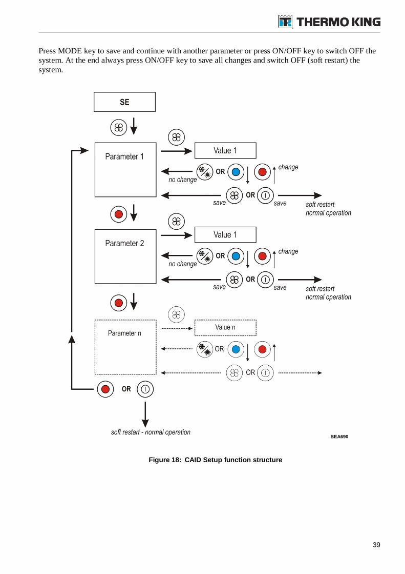
Press MODE key to save and continue with another parameter or press ON/OFF key to switch OFF thesystem. At the end always press ON/OFF key to save all changes and switch OFF (soft restart) thesystem.
Figure 18: CAID Setup function structure
BEA690
40
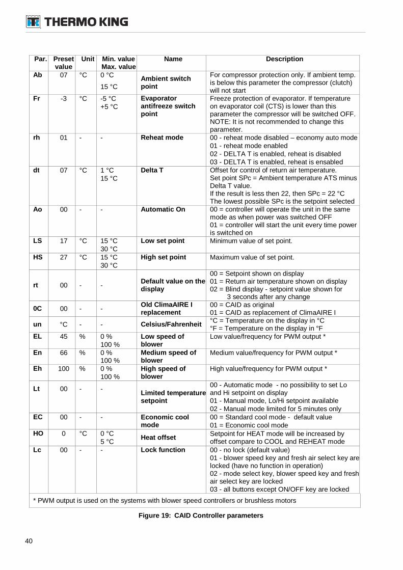
Par. Presetvalue
Unit Min. valueMax. value
Name Description
Ab 07 °C 0 °CAmbient switchpoint
For compressor protection only. If ambient temp.is below this parameter the compressor (clutch)will not start
15 °C
Fr -3 °C -5 °C Evaporatorantifreeze switchpoint
Freeze protection of evaporator. If temperatureon evaporator coil (CTS) is lower than thisparameter the compressor will be switched OFF.NOTE: It is not recommended to change thisparameter.
+5 °C
rh 01 - - Reheat mode 00 - reheat mode disabled – economy auto mode01 - reheat mode enabled02 - DELTA T is enabled, reheat is disabled03 - DELTA T is enabled, reheat is ensabled
dt 07 °C 1 °C Delta T Offset for control of return air temperature.Set point SPc = Ambient temperature ATS minusDelta T value.If the result is less then 22, then SPc = 22 °CThe lowest possible SPc is the setpoint selected
15 °C
Ao 00 - - Automatic On 00 = controller will operate the unit in the samemode as when power was switched OFF01 = controller will start the unit every time poweris switched on
LS 17 °C 15 °C Low set point Minimum value of set point.30 °C
HS 27 °C 15 °C High set point Maximum value of set point.30 °C
rt 00 - -Default value on thedisplay
00 = Setpoint shown on display01 = Return air temperature shown on display02 = Blind display - setpoint value shown for
3 seconds after any change
0C 00 - -Old ClimaAIRE Ireplacement
00 = CAID as original01 = CAID as replacement of ClimaAIRE I
un °C - - Celsius/Fahrenheit°C = Temperature on the display in °C°F = Temperature on the display in °F
EL 45 % 0 % Low speed ofblower
Low value/frequency for PWM output *100 %
En 66 % 0 %100 %
Medium speed ofblower
Medium value/frequency for PWM output *
Eh 100 % 0 % High speed ofblower
High value/frequency for PWM output *100 %
Lt 00 - -Limited temperaturesetpoint
00 - Automatic mode - no possibility to set Loand Hi setpoint on display01 - Manual mode, Lo/Hi setpoint available02 - Manual mode limited for 5 minutes only
EC 00 - - Economic coolmode
00 = Standard cool mode - default value01 = Economic cool mode
HO 0 °C 0 °CHeat offset
Setpoint for HEAT mode will be increased byoffset compare to COOL and REHEAT mode5 °C
Lc 00 - - Lock function 00 - no lock (default value)01 - blower speed key and fresh air select key arelocked (have no function in operation)02 - mode select key, blower speed key and freshair select key are locked03 - all buttons except ON/OFF key are locked
* PWM output is used on the systems with blower speed controllers or brushless motors
Figure 19: CAID Controller parameters

41
CAID - Function 6: Reading and clearing of Alarms (AL)
In Setup/Calibration/Test mode select "AL" function with UP or DOWN key and press ENTER key. Allalarm codes will be displayed for 2 seconds and at the end will be displayed "dE".
For list of alarm codes see "Figure 21: CAID List of alarm codes"
If no alarm is stored (e.g. previously alarms were cleared) the "no" label will be displayed for 1second and no more action will be executed.
NOTE: If necessary to keep the alarm codes in memory readable by this way, press ON/OFF key, thedriver panel will be switched OFF and the alarms remains recorded.
Press the ENTER key to clear all alarms. On the display appears "00" for a short time and thenthe system returns to Function menu, on the display will show "AL".
NOTE: Alarms cleared through driver panel remain in internal memory - in history - and can beread through connected PC with Service software.
At the end always press ON/OFF key to switch OFF (soft restart) the system.
42
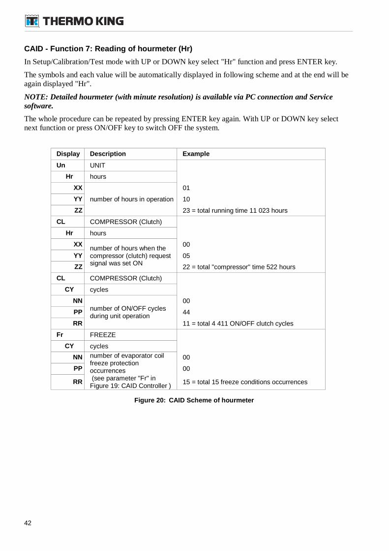
CAID - Function 7: Reading of hourmeter (Hr)
In Setup/Calibration/Test mode with UP or DOWN key select "Hr" function and press ENTER key.
The symbols and each value will be automatically displayed in following scheme and at the end will beagain displayed "Hr".
NOTE: Detailed hourmeter (with minute resolution) is available via PC connection and Servicesoftware.
The whole procedure can be repeated by pressing ENTER key again. With UP or DOWN key selectnext function or press ON/OFF key to switch OFF the system.
Display Description Example
Un UNIT
Hr hours
XX
number of hours in operation
01
YY 10
ZZ 23 = total running time 11 023 hours
CL COMPRESSOR (Clutch)
Hr hours
XXnumber of hours when thecompressor (clutch) requestsignal was set ON
00
YY 05
ZZ 22 = total "compressor" time 522 hours
CL COMPRESSOR (Clutch)
CY cycles
NNnumber of ON/OFF cyclesduring unit operation
00
PP 44
RR 11 = total 4 411 ON/OFF clutch cycles
Fr FREEZE
CY cycles
NN number of evaporator coilfreeze protectionoccurrences(see parameter "Fr" in
Figure 19: CAID Controller )
00
PP 00
RR 15 = total 15 freeze conditions occurrences
Figure 20: CAID Scheme of hourmeter
43
10.4.5. ClimaAIRE ID Diagnostic System
After start the driver panel is in normal operating mode. In the normal operating mode is running thebuilt-in diagnostic system.
The ClimaAIRE I D driver panel uses dual alarm system with two levels of signals:
WARNING (yellow alarm symbol) ALARM (red alarm symbol)
When any red alarm (ALARM) appears the alarm code will be blinking on the display until some buttonis pushed. If any yellow alarm (WARNING) appears the alarm code will be blinking on the displayfor 5 sec.
The alarm codes are stored in the memory to identify possible fault conditions. Up to 40 alarms codescan be stored. The records can be displayed on the driver panel with the procedure described above. Thecomplete history can be read by the PC only.
Alarms description
The WARNING (yellow alarm) symbol will be ON in the case of:
Low value of any temperature sensor:
o temperature sensor defect
o short circuit of the harness to sensors
o temperature is lower than -35 °C (-31 °F) – resistance of the sensor or of the total circuitis lower than 1,25 kOhm
High value of any temperature sensor:
o temperature sensor defect
o open circuit of the harness to sensors
o temperature is higher than 75 °C (167 °F) – resistance of the sensor or of the total circuitis higher than 2,9 kOhm
With yellow alarm conditions the unit will continue in operation with the wrong data from the sensor.
The ALARM (red alarm) symbol will be ON or blinking in the case of:
HPCO or LPCO switch is open longer than 10 minutes (alarm code 6)
HPCO or LPCO switch is cycling - switched OFF 5 times per 10 minutes (alarm code 5)
Inverter alarm (alarm code 31 - 37, special program for electric bus units only)
Any red alarm will switch the unit to the VENTILATION mode with automatic blower speed. Thedriver can change the blower speed manually. The compressor and condenser fans are stopped.
The alarm symbols can be removed by restart of control system (use the ON/OFF key to switch OFF,wait for 2 seconds, switch ON). After restart - if the reason for alarm is still in existence - the alarmsymbol can appears again. If the alarm comes up again, don't restart the unit more times. In that caseimmediately contact the service department or Thermo King representative.
For detail list and description of alarms refer to ClimaAIRE ID Service Manual (TK 60020-3-MM).
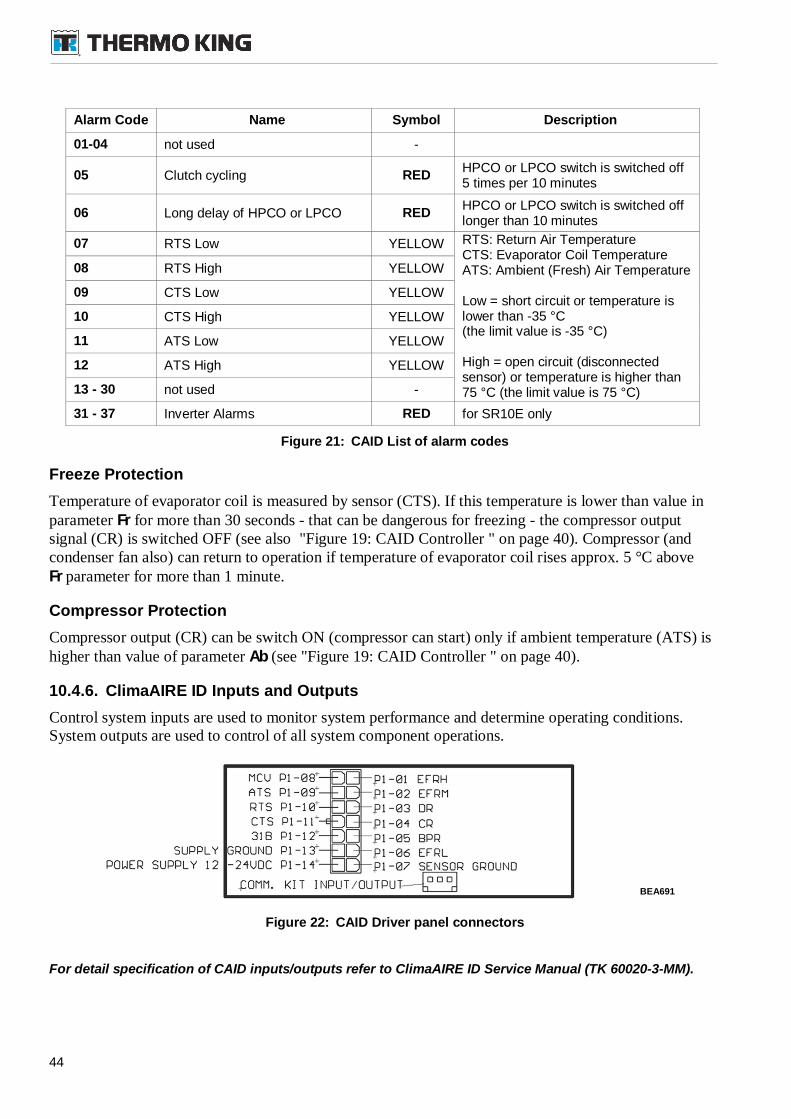
44
Alarm Code Name Symbol Description
01-04 not used -
05 Clutch cycling REDHPCO or LPCO switch is switched off5 times per 10 minutes
06 Long delay of HPCO or LPCO REDHPCO or LPCO switch is switched offlonger than 10 minutes
07 RTS Low YELLOW RTS: Return Air TemperatureCTS: Evaporator Coil TemperatureATS: Ambient (Fresh) Air Temperature
Low = short circuit or temperature islower than -35 °C(the limit value is -35 °C)
High = open circuit (disconnectedsensor) or temperature is higher than75 °C (the limit value is 75 °C)
08 RTS High YELLOW
09 CTS Low YELLOW
10 CTS High YELLOW
11 ATS Low YELLOW
12 ATS High YELLOW
13 - 30 not used -
31 - 37 Inverter Alarms RED for SR10E only
Figure 21: CAID List of alarm codes
Freeze Protection
Temperature of evaporator coil is measured by sensor (CTS). If this temperature is lower than value inparameter Fr for more than 30 seconds - that can be dangerous for freezing - the compressor outputsignal (CR) is switched OFF (see also "Figure 19: CAID Controller " on page 40). Compressor (andcondenser fan also) can return to operation if temperature of evaporator coil rises approx. 5 °C aboveFr parameter for more than 1 minute.
Compressor Protection
Compressor output (CR) can be switch ON (compressor can start) only if ambient temperature (ATS) ishigher than value of parameter Ab (see "Figure 19: CAID Controller " on page 40).
10.4.6. ClimaAIRE ID Inputs and Outputs
Control system inputs are used to monitor system performance and determine operating conditions.System outputs are used to control of all system component operations.
Figure 22: CAID Driver panel connectors
For detail specification of CAID inputs/outputs refer to ClimaAIRE ID Service Manual (TK 60020-3-MM).
BEA691
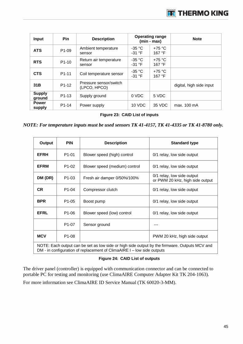
45
Input Pin DescriptionOperating range
(min - max)Note
ATS P1-09Ambient temperaturesensor
-35 °C-31 °F
+75 °C167 °F
RTS P1-10Return air temperaturesensor
-35 °C-31 °F
+75 °C167 °F
CTS P1-11 Coil temperature sensor-35 °C-31 °F
+75 °C167 °F
31B P1-12Pressure sensor/switch(LPCO, HPCO)
digital, high side input
Supplyground
P1-13 Supply ground 0 VDC 5 VDC
Powersupply
P1-14 Power supply 10 VDC 35 VDC max. 100 mA
Figure 23: CAID List of inputs
NOTE: For temperature inputs must be used sensors TK 41-4157, TK 41-4335 or TK 41-8780 only.
Output PIN Description Standard type
EFRH P1-01 Blower speed (high) control 0/1 relay, low side output
EFRM P1-02 Blower speed (medium) control 0/1 relay, low side output
DM (DR) P1-03 Fresh air damper 0/50%/100%0/1 relay, low side outputor PWM 20 kHz, high side output
CR P1-04 Compressor clutch 0/1 relay, low side output
BPR P1-05 Boost pump 0/1 relay, low side output
EFRL P1-06 Blower speed (low) control 0/1 relay, low side output
P1-07 Sensor ground ---
MCV P1-08 PWM 20 kHz, high side output
NOTE: Each output can be set as low side or high side output by the firmware. Outputs MCV andDM - in configuration of replacement of ClimaAIRE I – low side outputs
Figure 24: CAID List of outputs
The driver panel (controller) is equipped with communication connector and can be connected toportable PC for testing and monitoring (use ClimaAIRE Computer Adapter Kit TK 204-1063).
For more information see ClimaAIRE ID Service Manual (TK 60020-3-MM).
46
10.5. Inspection Recommendations
To keep the correct functions of the A/C unit you must periodically execute the following maintenanceprocedures. The schedules should be used during the initial service periods (at least during warrantyperiod).
WARNING: When inspecting or servicing the A/C system, follow all safety rules andoperating procedures, otherwise physical harm could result.
Thermo King reserves the right to deny warranty coverage on claims due to lack of maintenance orneglect. Claims in question must be supported by maintenance records.
If you are not really experienced in following actions please call for help Thermo King Service Centerotherwise is here risk of damage or complications. In case of any question or unclear situation pleasecontact your supplier or directly Thermo King manufacturer.
All maintenance intervals are based on normal operating conditions. Unusual or extraordinaryconditions require more frequent service intervals. For example, high air pollution could require morefrequent replacement of air filters. Coordinate the maintenance inspection schedule with the BusPreventive Maintenance Schedule.
Off Season Operation Of Bus Air Conditioning System
In order for the A/C system to be ready for operation, normal preventive maintenance isnecessary operate all systems periodically, especially during the off season. By operating thesystem weekly for short intervals (5 to 10 minutes) year round, the internal parts of thecompressor will remain lubricated. Offseason operation also helps to reduce compressor shaftseal leakage and allows early detection of refrigerant loss.
Wintertime Operation
The A/C system is operating in wintertime with heating and fresh air functions, periodicalmaintenance also in off season is necessary to maintain the functions of the A/C system. Priorto operating the compressor during winter months, you must warm up the coach interior tonormal operating temperature (15 to 21°C [60 to 76°F]). Unless this precaution is taken, liquidrefrigerant might be forced into the compressor, causing severe damage.
WARNING: Covers must be completely removed from the unit to access interior ofunit. Insure you are using best practice for working at height paying special attentionduring removal of cover as it could move due to the influence of the wind.
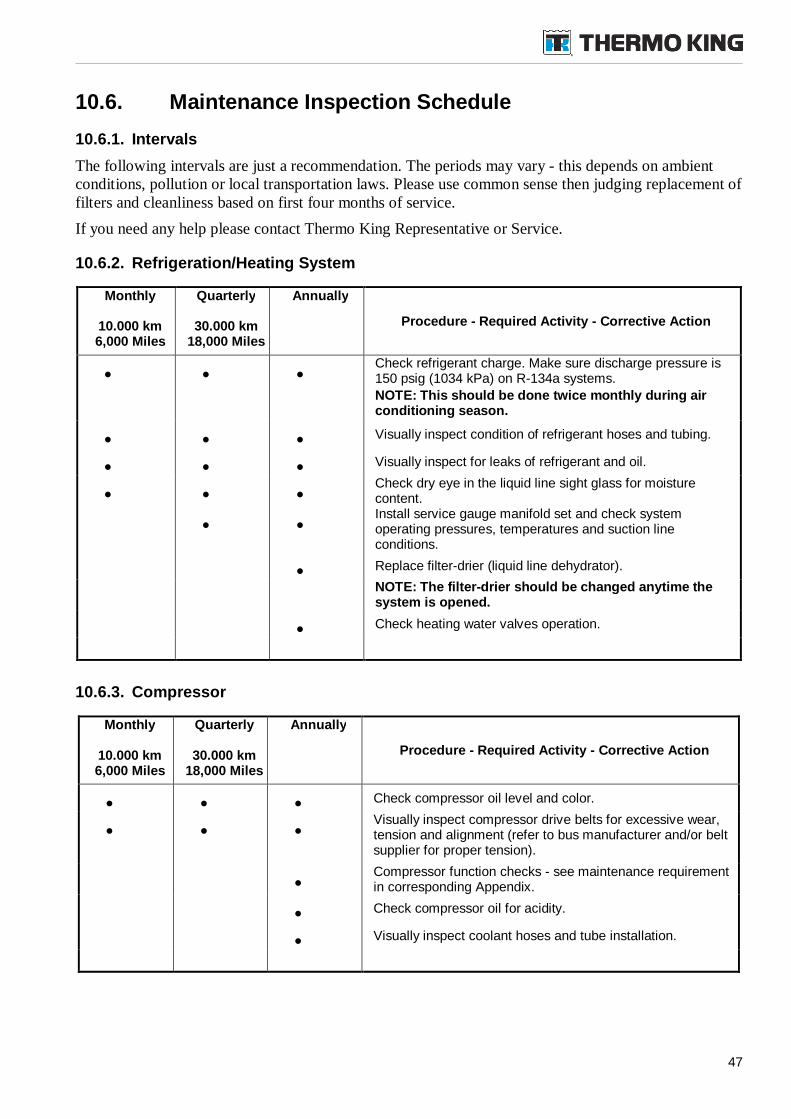
47
10.6. Maintenance Inspection Schedule
10.6.1. Intervals
The following intervals are just a recommendation. The periods may vary - this depends on ambientconditions, pollution or local transportation laws. Please use common sense then judging replacement offilters and cleanliness based on first four months of service.
If you need any help please contact Thermo King Representative or Service.
10.6.2. Refrigeration/Heating System
Monthly
10.000 km6,000 Miles
Quarterly
30.000 km18,000 Miles
Annually
Procedure - Required Activity - Corrective Action
Check refrigerant charge. Make sure discharge pressure is150 psig (1034 kPa) on R-134a systems.
NOTE: This should be done twice monthly during airconditioning season.
Visually inspect condition of refrigerant hoses and tubing.
Visually inspect for leaks of refrigerant and oil.
Check dry eye in the liquid line sight glass for moisturecontent.
Install service gauge manifold set and check systemoperating pressures, temperatures and suction lineconditions.
Replace filter-drier (liquid line dehydrator).
NOTE: The filter-drier should be changed anytime thesystem is opened.
Check heating water valves operation.
10.6.3. Compressor
Monthly
10.000 km6,000 Miles
Quarterly
30.000 km18,000 Miles
Annually
Procedure - Required Activity - Corrective Action
Check compressor oil level and color.
Visually inspect compressor drive belts for excessive wear,tension and alignment (refer to bus manufacturer and/or beltsupplier for proper tension).
Compressor function checks - see maintenance requirementin corresponding Appendix.
Check compressor oil for acidity.
Visually inspect coolant hoses and tube installation.
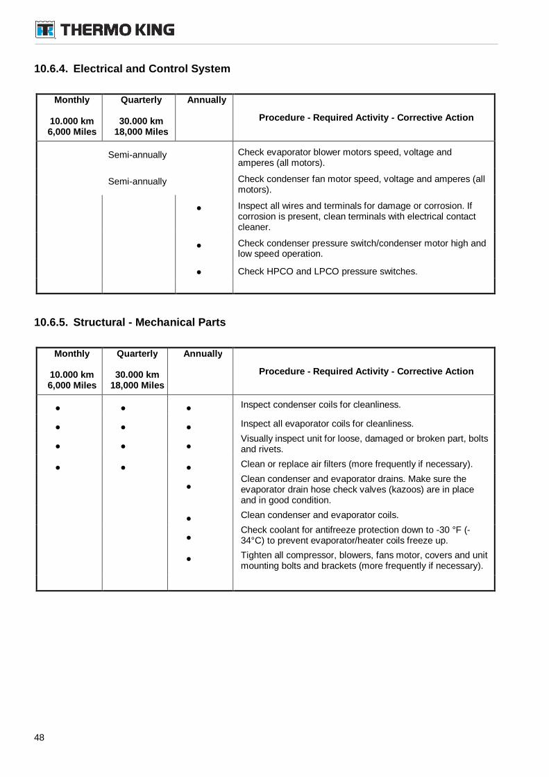
48
10.6.4. Electrical and Control System
Monthly
10.000 km6,000 Miles
Quarterly
30.000 km18,000 Miles
Annually
Procedure - Required Activity - Corrective Action
Semi-annually Check evaporator blower motors speed, voltage andamperes (all motors).
Semi-annually Check condenser fan motor speed, voltage and amperes (allmotors).
Inspect all wires and terminals for damage or corrosion. Ifcorrosion is present, clean terminals with electrical contactcleaner.
Check condenser pressure switch/condenser motor high andlow speed operation.
Check HPCO and LPCO pressure switches.
10.6.5. Structural - Mechanical Parts
Monthly
10.000 km6,000 Miles
Quarterly
30.000 km18,000 Miles
Annually
Procedure - Required Activity - Corrective Action
Inspect condenser coils for cleanliness.
Inspect all evaporator coils for cleanliness.
Visually inspect unit for loose, damaged or broken part, boltsand rivets.
Clean or replace air filters (more frequently if necessary).
Clean condenser and evaporator drains. Make sure theevaporator drain hose check valves (kazoos) are in placeand in good condition.
Clean condenser and evaporator coils.
Check coolant for antifreeze protection down to -30 °F (-34°C) to prevent evaporator/heater coils freeze up.
Tighten all compressor, blowers, fans motor, covers and unitmounting bolts and brackets (more frequently if necessary).
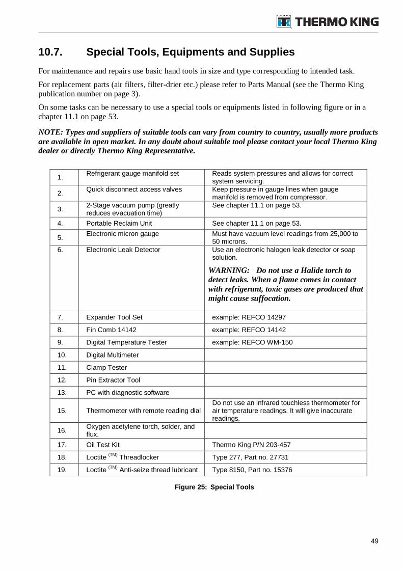
49
10.7. Special Tools, Equipments and Supplies
For maintenance and repairs use basic hand tools in size and type corresponding to intended task.
For replacement parts (air filters, filter-drier etc.) please refer to Parts Manual (see the Thermo Kingpublication number on page 3).
On some tasks can be necessary to use a special tools or equipments listed in following figure or in achapter 11.1 on page 53.
NOTE: Types and suppliers of suitable tools can vary from country to country, usually more productsare available in open market. In any doubt about suitable tool please contact your local Thermo Kingdealer or directly Thermo King Representative.
1.Refrigerant gauge manifold set Reads system pressures and allows for correct
system servicing.
2.Quick disconnect access valves Keep pressure in gauge lines when gauge
manifold is removed from compressor.
3.2-Stage vacuum pump (greatlyreduces evacuation time)
See chapter 11.1 on page 53.
4. Portable Reclaim Unit See chapter 11.1 on page 53.
5.Electronic micron gauge Must have vacuum level readings from 25,000 to
50 microns.6. Electronic Leak Detector Use an electronic halogen leak detector or soap
solution.
WARNING: Do not use a Halide torch todetect leaks. When a flame comes in contactwith refrigerant, toxic gases are produced thatmight cause suffocation.
7. Expander Tool Set example: REFCO 14297
8. Fin Comb 14142 example: REFCO 14142
9. Digital Temperature Tester example: REFCO WM-150
10. Digital Multimeter
11. Clamp Tester
12. Pin Extractor Tool
13. PC with diagnostic software
15. Thermometer with remote reading dialDo not use an infrared touchless thermometer forair temperature readings. It will give inaccuratereadings.
16.Oxygen acetylene torch, solder, andflux.
17. Oil Test Kit Thermo King P/N 203-457
18. Loctite(TM)
Threadlocker Type 277, Part no. 27731
19. Loctite(TM)
Anti-seize thread lubricant Type 8150, Part no. 15376
Figure 25: Special Tools
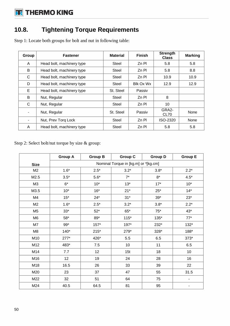
50
10.8. Tightening Torque Requirements
Step 1: Locate both groups for bolt and nut in following table:
Group Fastener Material FinishStrength
ClassMarking
A Head bolt, machinery type Steel Zn Pl 5.8 5.8
B Head bolt, machinery type Steel Zn Pl 5.8 8.8
C Head bolt, machinery type Steel Zn Pl 10.9 10.9
D Head bolt, machinery type Steel Blk Ox Wx 12.9 12.9
E Head bolt, machinery type St. Steel Passiv
B Nut, Regular Steel Zn Pl 8
C Nut, Regular Steel Zn Pl 10
- Nut, Regular St. Steel PassivGRA2-CL70
None
- Nut, Prev Torq Lock Steel Zn Pl ISO-2320 None
A Head bolt, machinery type Steel Zn Pl 5.8 5.8
Step 2: Select bolt/nut torque by size & group:
Size
Group A Group B Group C Group D Group E
Nominal Torque in [kg.m] or *[kg.cm]
M2 1.6* 2.5* 3.2* 3.8* 2.2*
M2.5 3.5* 5.6* 7* 8* 4.5*
M3 6* 10* 13* 17* 10*
M3.5 10* 16* 21* 25* 14*
M4 15* 24* 31* 39* 23*
M2 1.6* 2.5* 3.2* 3.8* 2.2*
M5 33* 52* 65* 75* 43*
M6 58* 89* 115* 135* 77*
M7 99* 157* 197* 232* 132*
M8 140* 215* 279* 328* 188*
M10 277* 426* 5.5 6.5 373*
M12 483* 7.5 10 11 6.5
M14 7.7 12 15t 18 10
M16 12 19 24 28 16
M18 16.5 26 33 39 22
M20 23 37 47 55 31.5
M22 32 51 64 75 -
M24 40.5 64.5 81 95 -
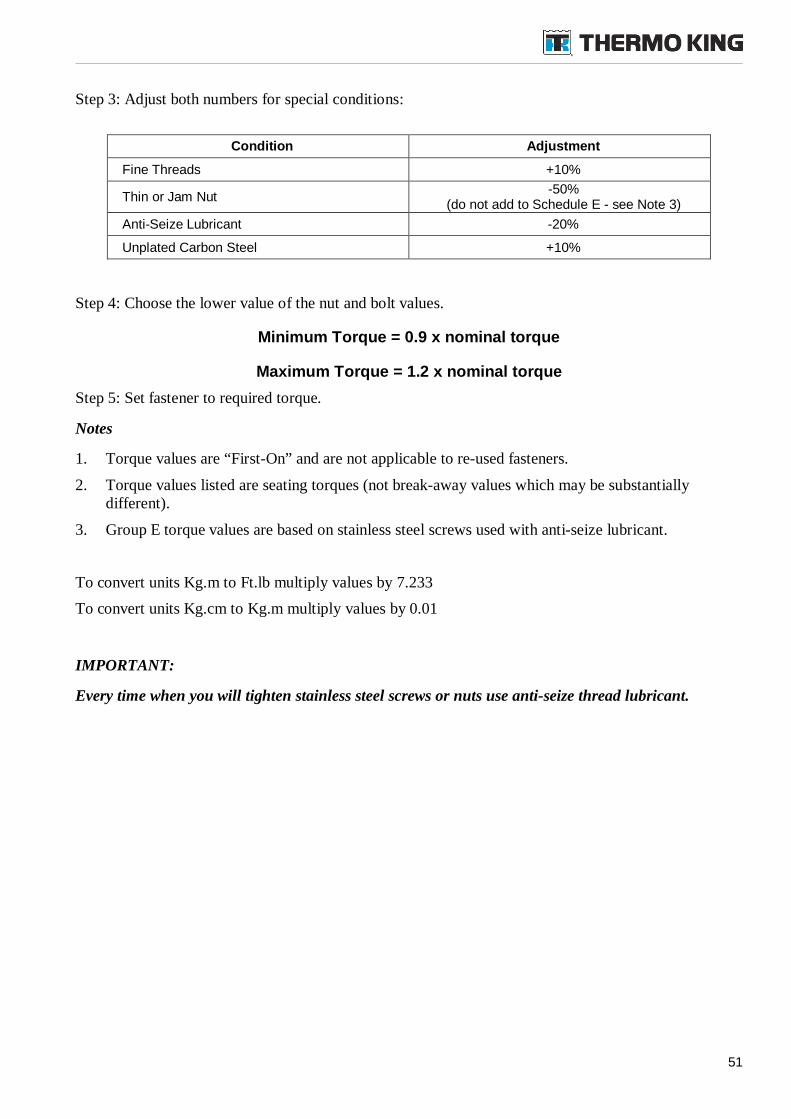
51
Step 3: Adjust both numbers for special conditions:
Condition Adjustment
Fine Threads +10%
Thin or Jam Nut-50%
(do not add to Schedule E - see Note 3)
Anti-Seize Lubricant -20%
Unplated Carbon Steel +10%
Step 4: Choose the lower value of the nut and bolt values.
Minimum Torque = 0.9 x nominal torque
Maximum Torque = 1.2 x nominal torque
Step 5: Set fastener to required torque.
Notes
1. Torque values are “First-On” and are not applicable to re-used fasteners.
2. Torque values listed are seating torques (not break-away values which may be substantiallydifferent).
3. Group E torque values are based on stainless steel screws used with anti-seize lubricant.
To convert units Kg.m to Ft.lb multiply values by 7.233
To convert units Kg.cm to Kg.m multiply values by 0.01
IMPORTANT:
Every time when you will tighten stainless steel screws or nuts use anti-seize thread lubricant.
52
11.Refrigeration System Maintenance
Some these service procedures on the refrigeration system can be regulated by Federal, State or Locallaws. Please check the situation and coordinate all the actions with this regulations and Health&Safetyrules.
All regulated refrigeration service procedures must be performed by an EPA certified technician, usingapproved equipment and complying with all Federal, State and Local laws.
WARNING: Make sure the unit and bus cannot start while servicing the system.
WARNING: Covers must be completely removed from the unit to access interior ofunit. Insure you are using best practice for working at height paying special attentionduring removal of cover as it could move due to the influence of the wind.
IMPORTANT:
When charging the refrigeration system, always charge from liquid side and use the refrigerant in aliquid state. Don't charge vapor in the system!
Thermo King recommend always to replace the whole (remaining) refrigerant and recycle theretrieved portion properly per governing laws. Then use new refrigeration charge by correctrecommended weight in liquid state. In case of leak do not “top off” the refrigeration system.
Basic steps in case of troubles with refrigeration system:
4. Recovery (disposal) of remaining refrigerant Vapor recovery Liquid recovery
5. Leak Test - identification, location of point of trouble
6. Repair & Check
7. Evacuation System preparation and hookup Evacuation Pressure rise test
8. Charging
9. Functional test of system
General information
If refrigerant has leaked or been removed from the system, check entire system for possible componentdamage and compressor oil loss.
If any system leak or damage was found, repair the system, recheck the system after repair and conductsystem evacuation.
If the system has some remaining pressure (some refrigerant is present in the system), and the leak isNOT found, using a leak detector is recommended. Soap and bubbles is the best tool to check minuteleaks that the electronic leak detectors cannot find.
53
If the leak is already found and the system is almost flat (empty), we recommend evacuating the systemAFTER the repair is done (for example after tightening a fitting).
After any repair we recommend to execute the Leak Test to be sure that system is tight.
As the oil used in scroll compressor is very viscous, rarely an oil charge would be lost. If this happens,the compressor would have failed already and it that case we recommend replacing the compressor (ortwo compressors in sets of 2, depending on unit design), charging the proper oil charge for newcompressor(s) and do the evacuation and charging procedures described further. After compressorreplacement recheck the system again.
It is generally good practice to replace the filter-drier whenever the system is opened and exposed toambient for an extended period of time. Refer to the Refrigeration Manual (Thermo King Manual TK50951) for system cleanup after a compressor failure or repair or replacement of basic components.
IF THERE IS A SUSPICION OF BIG LEAK, IT IS RECOMMENDED THE WHOLE CHARGE ISRETRIEVED (REMOVED) AND A NEW CHARGE IS PLACED INTO THE SYSTEM AFTERPERFORMING THE EVACUATION AND CLEANUP STEPS - SEE IMPORTANT NOTE ABOVE.
In the following text are procedures usually described by using of Thermo King evacuation station.Always follow the safety instructions, procedures and working instructions in specific equipmentmanufacturer’s documentation.
11.1. Service Tools
CAUTION: When servicing Thermo King R-134a refrigeration systems, use onlyservice tools (i.e., vacuum pump, refrigerant recovery equipment, gauge hoses, andgauge manifold set) certified for and dedicated to R-134a refrigerant and Polyol Esterbased compressor oils. Residual non-HFC refrigerants or non-Ester based oils willcontaminate HFC systems.
Unit Service Fittings
The unit uses a hermetically sealed refrigeration system. If you need to recover the refrigerant charge,you must use the appropriate fittings to connection on service (access) ports (if no service (access) portsare present then fittings under low (LPCO) or high (HPCO) pressure switches can be used). Install theservice fittings on the suction line and discharge line process tubes located in the compressorcompartment.
Leak Detectors
Detect leaks with soap bubbles and with Halogen leak detector such us model H10G (TK 204-712) orportable model H10N (TK 204-756) Or certified 407C leak detector from respectable suppliers.
Manifold Gauge Set and Hoses
Use a manifold gauge set and hoses dedicated for use with R-134a only.
Evacuation Station
A key element in maintaining high efficiency and low maintenance cost in a transport refrigerationsystem is the ability to keep the system free of moisture a non condensable materials. Contaminants andmoisture are best removed by a vacuum system. The Thermo King Evacuation Station TK 204-725 hasbeen designed to efficiently evacuate the refrigeration system for all Thermo King products.
54
Vacuum Pump
Use a two-stage (for example TK 204-713 or TK 204-699), three-stage, or five-stage pump forevacuation. Because residual refrigerant may be present in used vacuum pumps, a new pump should beused and dedicated strictly as an R-134a refrigerant pump. Use only recommended vacuum pump oilsand change oil after every major evacuation. Because vacuum pump oils are highly refined to obtainlow vacuums, failure to follow these recommendations may result in acidic conditions that will destroythe pump.
System Cleanup Devices
Use cleanup devices such as suction line filters if they are properly cleaned with new filters andcartridges. Remove all standard petroleum and synthetic compressor oils to prevent contamination of R-134a systems.
Refrigerant Recovery
Use only refrigerant recovery equipment approved for and dedicated to R-134a recovery.
Compressor Oil Acid Test
Perform an oil acid test (oil test kit TK203-457) whenever a system has a substantial refrigerant loss, anoisy compressor, or dark/dirty oil - see chapter „Compressor Oil Color Code“.
11.2. Contamination
When contaminants have entered the system, a thorough cleanup is required to prevent damage or lossof compressor. The purpose of evacuation is to remove moisture and air from the refrigeration system.Even small quantities of air or moisture in a system can cause severe problems.
The presence of moisture, oxygen, and heat under certain conditions can result in many forms ofdrainage. Corrosion, sludge, copper plating, oil breakdown, carbon formation, and eventual compressorfailure can be caused by these contaminants. Things that will contaminate a system are (in order ofimportance):
Air (oxygen as a contaminant). Oxygen in the air reacts with the oil. The oil begins to breakdown and can eventually lead to carbonization in the compressor and acid buildup. The longerthis breakdown process goes on, the darker the compressor oil becomes until finally the color isblack, indicating major system contamination.
Moisture in a system will cause metal corrosion and plating. It can freeze in the expansion valveand cause intermittent operational problems. It reacts in the oil to begin acid buildup.
Dirt, dust, metal particles, other foreign materials. Particles in the system will cause severedamage to all close tolerance items. Don't leave a system open to the infiltration of dirt. If youmust open a system for any reason, seal off the open areas as soon as possible. Don't work in adirty environment.
Acid. Air and moisture cause a chemical breakdown of the oil and the refrigerant. The acid willaccelerate the deterioration of the softer metals (i.e., copper) and cause metal plating as thesofter material begins to cover the inside of the system. This condition can result in the totaldestruction of your equipment.
IF ANY OF THE ABOVE CONDITIONS ARE PRESENT PLEASE RECYCLE THE REFRIGERANT,PERFORM A REFRIGERATION SYSTEM CLEANUP - USE A NEW REFRIGERANT THAT HAS NOTBEEN CONTAMINATED.
55
11.3. Compressor Oil Color Code
When unusual color of oil is detected or presence of moisture is signalized by moisture indicator thenperform a compressor oil acid test.
Black oil indicates carbonization caused by air in the system.
Brown oil indicates copper plating caused by moisture in the system.
Gray or metallic oil indicates bearing wear or piston scoring.
IF THE COMPRESSOR OIL SHOWS AN ACID CONDITION, CHANGE THE OIL, THE IN-LINEOIL FILTER, THE FILTER-DRIER AND PERFORM A REFRIGERATION SYSTEM CLEANUP.
11.4. Refrigerant Recovery
CAUTION: Use only refrigerant recovery equipment approved for and dedicated toR-134a recovery.
It is recommended the whole charge is retrieved and a new charge is placed into the system afterperforming the leak and evacuation steps.
When removing refrigerant from a Thermo King refrigeration system, use a recovery process thatprevents or absolutely minimizes the refrigerant that can escape to the atmosphere. Typical serviceprocedures that require removal of refrigerant from the system include:
Reducing the refrigerant pressure to a safe working level when maintenance must be performedon high-pressure side components.
Emptying the system of refrigerant when an unknown amount of charge is in the system and aproper charge is required.
Emptying the system of contaminated refrigerant when the system has become contaminated.
Procedure
1. Locate the service (access) ports on high pressure side (compressor output pipe) and low pressureside (compressor input line). Carefully remove the caps from ports. If no service (access) ports arepresent then fittings under low (LPCO) or high (HPCO) pressure switches can be used.
2. Install a gauge manifold low pressure line to the service (access) ports on low pressure side(compressor input pipe). Attach the gauge manifold high pressure line to the service (access) portson high pressure side (discharge line - compressor output pipe). Attach the service line to therecovery station. Purge the lines.
Vapor Recovery
1. Install a gauge manifold on the system. Attach the service line to the recovery machine and purgethe lines. Set the recovery machine for vapor recovery.
2. Keep the system OFF and partially open (mid-seat) the discharge line service valve.
3. Turn on the recovery machine and open (back seat) both gauge manifold and hand valves.
4. Continue to operate the recovery machine until system pressures drop to 0 kPa (0 bar, 0 psig)pressure. Follow the liquid recovery instruction in next section.
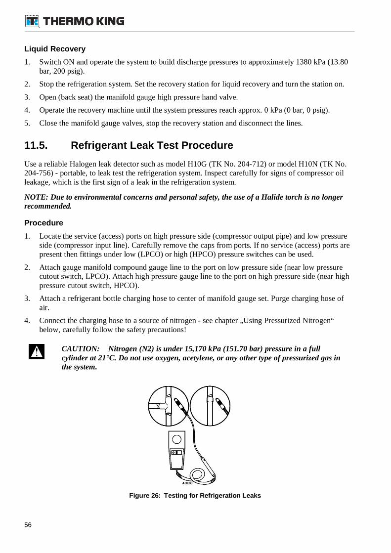
56
Liquid Recovery
1. Switch ON and operate the system to build discharge pressures to approximately 1380 kPa (13.80bar, 200 psig).
2. Stop the refrigeration system. Set the recovery station for liquid recovery and turn the station on.
3. Open (back seat) the manifold gauge high pressure hand valve.
4. Operate the recovery machine until the system pressures reach approx. 0 kPa (0 bar, 0 psig).
5. Close the manifold gauge valves, stop the recovery station and disconnect the lines.
11.5. Refrigerant Leak Test Procedure
Use a reliable Halogen leak detector such as model H10G (TK No. 204-712) or model H10N (TK No.204-756) - portable, to leak test the refrigeration system. Inspect carefully for signs of compressor oilleakage, which is the first sign of a leak in the refrigeration system.
NOTE: Due to environmental concerns and personal safety, the use of a Halide torch is no longerrecommended.
Procedure
1. Locate the service (access) ports on high pressure side (compressor output pipe) and low pressureside (compressor input line). Carefully remove the caps from ports. If no service (access) ports arepresent then fittings under low (LPCO) or high (HPCO) pressure switches can be used.
2. Attach gauge manifold compound gauge line to the port on low pressure side (near low pressurecutout switch, LPCO). Attach high pressure gauge line to the port on high pressure side (near highpressure cutout switch, HPCO).
3. Attach a refrigerant bottle charging hose to center of manifold gauge set. Purge charging hose ofair.
4. Connect the charging hose to a source of nitrogen - see chapter „Using Pressurized Nitrogen“below, carefully follow the safety precautions!
CAUTION: Nitrogen (N2) is under 15,170 kPa (151.70 bar) pressure in a fullcylinder at 21°C. Do not use oxygen, acetylene, or any other type of pressurized gas inthe system.
Figure 26: Testing for Refrigeration Leaks
57
5. Pressurize the system with neutral Nitrogen (gas) until 345 kPa (3.45 bar) vapor pressure isachieved.
6. Close both hand valves on manifold gauge (front seated).
7. Close the supply valve on the nitrogen bottle.
8. Disconnect the refrigerant charging hose.
9. Check the system with an electronic leak detector to inspect all joints and connections. (Use soapsolution as an alternative test component.)
10. Release pressure and reclaim nitrogen back from system.
11.6. Evacuation
Before performing an evacuation be sure you have conducted the leak check and the system is repairedand no leaks are found.
System Preparation and Connecting to Evacuation Station
CAUTION: Do not evacuate a system until you are certain that the system is leakfree. A system with less than a full charge of refrigerant should be thoroughly leaktested. Leaks found must be repaired.
1. Recover refrigerant from the system - see Chapter „Refrigerant Recovery“ and reduce the systempressure to the proper level (US Federal Law requires a -17 to -34 kPa [-0.17 to -0.34 bar, 5 to 10in. Hg] vacuum that is dependent upon the recovery equipment used).
2. Break vacuum with refrigerant and equalize system pressure to 0 kPa (0 bar, 0 psig). Replace theliquid line filter-drier (dehydrator) in refrigeration system.
3. Confirm that the evacuation station functions properly and determine “Blank Off” Pressure. TheBlank Off Pressure of the Vacuum Pump is the deepest vacuum that the vacuum pump an attainwhen isolated from the rest of the system. If a vacuum pump (isolated from a system) is started andthe micron meter responds quickly by going to a deep vacuum, the operator can be confident thatthe pump and oil are in good condition. If the vacuum pump fails to reach a deep vacuum within 5minutes, the operator should suspect the condition of the oil or the pump. It is recommended thatthe pump oil be changed first to see if the rate of reaching a deep vacuum is improved.
4. Connect the evacuation station and refrigerant tank with manifold gauge set (optional) to thesystem as indicated in example on the diagram on Figure 29 on page 58. Connect evacuation hosesto the fittings (service access ports) installed on the suction line and liquid line - see high pressureside (compressor output pipe) and low pressure side (discharge line - compressor output pipe). Ifno service (access) ports are present then fittings under low (LPCO) or high (HPCO) pressureswitches can be used.
5. Open evacuation station valves (V1, V3 and V4). It is only necessary to open valve V2 when areading on the Micron Meter is desired. This is especially true when starting to evacuate a systemand large amounts of moisture and oil will be passing by the sensor.
6. Open the vacuum pump „Iso Valve“ built into the pump housing below the handle. It isrecommended that the valve be kept open at all times.
7. If connecting a refrigerant tank and gauge manifold to the evacuation station, close the manifoldgauge and refrigerant tank valves to prevent refrigerant from being drawn from the tank.
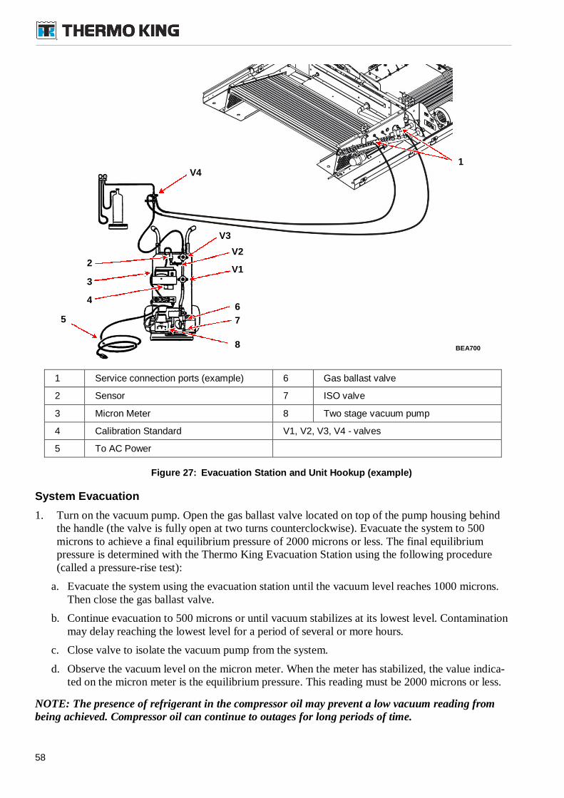
58
1 Service connection ports (example) 6 Gas ballast valve
2 Sensor 7 ISO valve
3 Micron Meter 8 Two stage vacuum pump
4 Calibration Standard V1, V2, V3, V4 - valves
5 To AC Power
Figure 27: Evacuation Station and Unit Hookup (example)
System Evacuation
1. Turn on the vacuum pump. Open the gas ballast valve located on top of the pump housing behindthe handle (the valve is fully open at two turns counterclockwise). Evacuate the system to 500microns to achieve a final equilibrium pressure of 2000 microns or less. The final equilibriumpressure is determined with the Thermo King Evacuation Station using the following procedure(called a pressure-rise test):
a. Evacuate the system using the evacuation station until the vacuum level reaches 1000 microns.Then close the gas ballast valve.
b. Continue evacuation to 500 microns or until vacuum stabilizes at its lowest level. Contaminationmay delay reaching the lowest level for a period of several or more hours.
c. Close valve to isolate the vacuum pump from the system.
d. Observe the vacuum level on the micron meter. When the meter has stabilized, the value indica-ted on the micron meter is the equilibrium pressure. This reading must be 2000 microns or less.
NOTE: The presence of refrigerant in the compressor oil may prevent a low vacuum reading frombeing achieved. Compressor oil can continue to outages for long periods of time.
BEA700
V41
V3
V2
V1
7
6
8
5
3
4
2
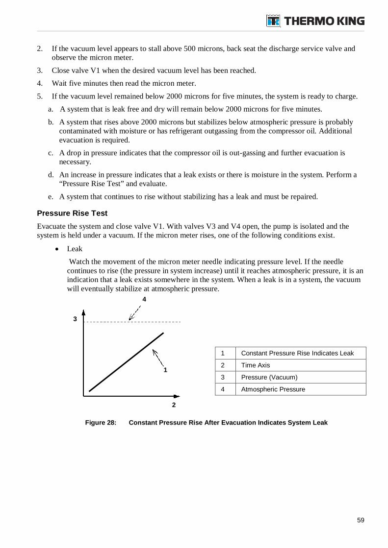
59
1
3
2
4
2. If the vacuum level appears to stall above 500 microns, back seat the discharge service valve andobserve the micron meter.
3. Close valve V1 when the desired vacuum level has been reached.
4. Wait five minutes then read the micron meter.
5. If the vacuum level remained below 2000 microns for five minutes, the system is ready to charge.
a. A system that is leak free and dry will remain below 2000 microns for five minutes.
b. A system that rises above 2000 microns but stabilizes below atmospheric pressure is probablycontaminated with moisture or has refrigerant outgassing from the compressor oil. Additionalevacuation is required.
c. A drop in pressure indicates that the compressor oil is out-gassing and further evacuation isnecessary.
d. An increase in pressure indicates that a leak exists or there is moisture in the system. Perform a“Pressure Rise Test” and evaluate.
e. A system that continues to rise without stabilizing has a leak and must be repaired.
Pressure Rise Test
Evacuate the system and close valve V1. With valves V3 and V4 open, the pump is isolated and thesystem is held under a vacuum. If the micron meter rises, one of the following conditions exist.
Leak
Watch the movement of the micron meter needle indicating pressure level. If the needlecontinues to rise (the pressure in system increase) until it reaches atmospheric pressure, it is anindication that a leak exists somewhere in the system. When a leak is in a system, the vacuumwill eventually stabilize at atmospheric pressure.
Figure 28: Constant Pressure Rise After Evacuation Indicates System Leak
1 Constant Pressure Rise Indicates Leak
2 Time Axis
3 Pressure (Vacuum)
4 Atmospheric Pressure
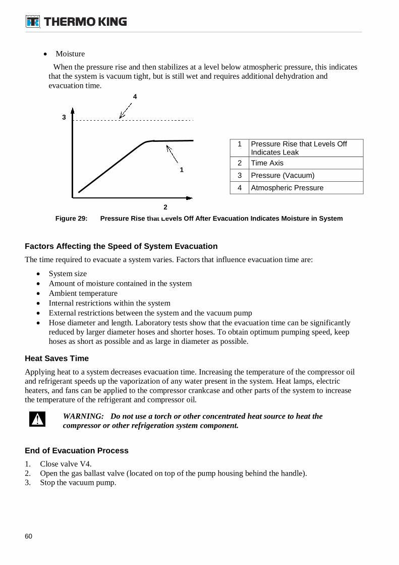
60
Moisture
When the pressure rise and then stabilizes at a level below atmospheric pressure, this indicatesthat the system is vacuum tight, but is still wet and requires additional dehydration andevacuation time.
Figure 29: Pressure Rise that Levels Off After Evacuation Indicates Moisture in System
Factors Affecting the Speed of System Evacuation
The time required to evacuate a system varies. Factors that influence evacuation time are:
System size Amount of moisture contained in the system Ambient temperature Internal restrictions within the system External restrictions between the system and the vacuum pump Hose diameter and length. Laboratory tests show that the evacuation time can be significantly
reduced by larger diameter hoses and shorter hoses. To obtain optimum pumping speed, keephoses as short as possible and as large in diameter as possible.
Heat Saves Time
Applying heat to a system decreases evacuation time. Increasing the temperature of the compressor oiland refrigerant speeds up the vaporization of any water present in the system. Heat lamps, electricheaters, and fans can be applied to the compressor crankcase and other parts of the system to increasethe temperature of the refrigerant and compressor oil.
WARNING: Do not use a torch or other concentrated heat source to heat thecompressor or other refrigeration system component.
End of Evacuation Process
1. Close valve V4.2. Open the gas ballast valve (located on top of the pump housing behind the handle).3. Stop the vacuum pump.
1 Pressure Rise that Levels OffIndicates Leak
2 Time Axis
3 Pressure (Vacuum)
4 Atmospheric Pressure
1
3
2
4
61
11.7. System Charging from an Evacuated Condition
IMPORTANT:
When charging the system, always charge from liquid side and use the refrigerant in a liquidstate. Do not charge vapor in the system!
In case of leak do not “top off” the refrigeration system. Always reclaim all remaining charge(and send it to special recycling stores) and use new refrigeration charge by correctrecommended weight in liquid state.
1. Connect the charging hose to the port on high pressure side (on liquid line, near high pressurecutout switch, HPCO). if no service (access) port is present then fitting under high (HPCO)pressure switch can be used.
2. Charge the proper amount of liquid refrigerant into system, for example by using a „push/pull“reclaim unit. For amount of the R-134a refrigerant see “Specifications”.
3. Close the refrigerant tank valve when the correct amount (by weight) of refrigerant has been added.
4. Remove charging hose and reinstall caps on service (access) ports (or high pressure cutout HPCOvalve if necessary). Check this connecting points with an electronic leak detector.
5. Perform a system functional check out.
11.8. Using Pressurized Nitrogen
WARNING: Nitrogen (N2) is under 15,170 kPa (151.70 bar, 2200 psig) or greaterpressure. Pressure is for full cylinder at 21 C (70 F). Do not use Oxygen (02),acetylene, or any other pressurized gas on refrigeration systems or any component of asystem.
Safety Precautions
Observe the proper handling of cylinders:
Keep protective cap on cylinder when not in use.
Secure cylinder in proper storage area or fastened to cart.
Do not expose to excessive heat or direct sun light.
Do not drop, dent, or damage cylinder.
Use a pressure regulator and a safety pressure relief valve as part of the pressure testingequipment. The safety pressure relief valve should be the non- adjustable, non-tempering type.The valve should bypass any time the pressure exceeds its setting.
Open valve slowly. Use regulators and safety valves that are in good working order.
The regulator should have two gauges: one to read tank pressure, the other to read line pressure.Properly maintained equipment will allow leak testing, purging, and dehydration to be donesafely.
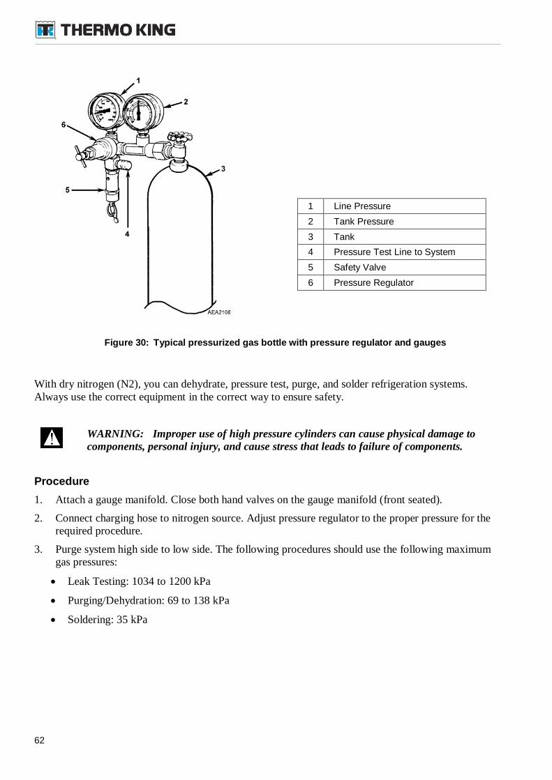
62
Figure 30: Typical pressurized gas bottle with pressure regulator and gauges
With dry nitrogen (N2), you can dehydrate, pressure test, purge, and solder refrigeration systems.Always use the correct equipment in the correct way to ensure safety.
WARNING: Improper use of high pressure cylinders can cause physical damage tocomponents, personal injury, and cause stress that leads to failure of components.
Procedure
1. Attach a gauge manifold. Close both hand valves on the gauge manifold (front seated).
2. Connect charging hose to nitrogen source. Adjust pressure regulator to the proper pressure for therequired procedure.
3. Purge system high side to low side. The following procedures should use the following maximumgas pressures:
Leak Testing: 1034 to 1200 kPa
Purging/Dehydration: 69 to 138 kPa
Soldering: 35 kPa
1 Line Pressure
2 Tank Pressure
3 Tank
4 Pressure Test Line to System
5 Safety Valve
6 Pressure Regulator
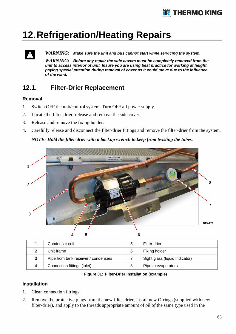
63
12.Refrigeration/Heating Repairs
WARNING: Make sure the unit and bus cannot start while servicing the system.
WARNING: Before any repair the side covers must be completely removed from theunit to access interior of unit. Insure you are using best practice for working at heightpaying special attention during removal of cover as it could move due to the influenceof the wind.
12.1. Filter-Drier Replacement
Removal
1. Switch OFF the unit/control system. Turn OFF all power supply.
2. Locate the filter-drier, release and remove the side cover.
3. Release and remove the fixing holder.
4. Carefully release and disconnect the filter-drier fittings and remove the filter-drier from the system.
NOTE: Hold the filter-drier with a backup wrench to keep from twisting the tubes.
1 Condenser coil 5 Filter-drier
2 Unit frame 6 Fixing holder
3 Pipe from tank receiver / condensers 7 Sight glass (liquid indicator)
4 Connection fittings (inlet) 8 Pipe to evaporators
Figure 31: Filter-Drier Installation (example)
Installation
1. Clean connection fittings.
2. Remove the protective plugs from the new filter-drier, install new O-rings (supplied with newfilter-drier), and apply to the threads appropriate amount of oil of the same type used in the
BEA723
2
1
7
3
5
8
4 6
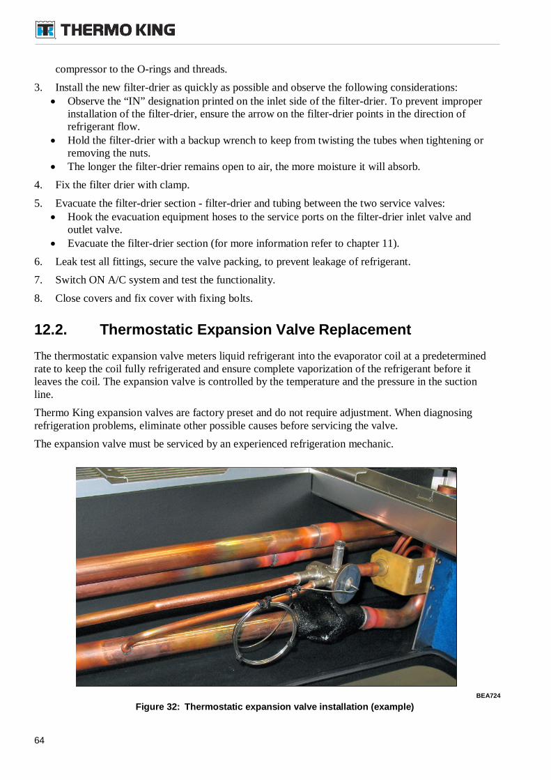
64
compressor to the O-rings and threads.
3. Install the new filter-drier as quickly as possible and observe the following considerations: Observe the “IN” designation printed on the inlet side of the filter-drier. To prevent improper
installation of the filter-drier, ensure the arrow on the filter-drier points in the direction ofrefrigerant flow.
Hold the filter-drier with a backup wrench to keep from twisting the tubes when tightening orremoving the nuts.
The longer the filter-drier remains open to air, the more moisture it will absorb.
4. Fix the filter drier with clamp.
5. Evacuate the filter-drier section - filter-drier and tubing between the two service valves: Hook the evacuation equipment hoses to the service ports on the filter-drier inlet valve and
outlet valve. Evacuate the filter-drier section (for more information refer to chapter 11).
6. Leak test all fittings, secure the valve packing, to prevent leakage of refrigerant.
7. Switch ON A/C system and test the functionality.
8. Close covers and fix cover with fixing bolts.
12.2. Thermostatic Expansion Valve Replacement
The thermostatic expansion valve meters liquid refrigerant into the evaporator coil at a predeterminedrate to keep the coil fully refrigerated and ensure complete vaporization of the refrigerant before itleaves the coil. The expansion valve is controlled by the temperature and the pressure in the suctionline.
Thermo King expansion valves are factory preset and do not require adjustment. When diagnosingrefrigeration problems, eliminate other possible causes before servicing the valve.
The expansion valve must be serviced by an experienced refrigeration mechanic.
Figure 32: Thermostatic expansion valve installation (example)
BEA724
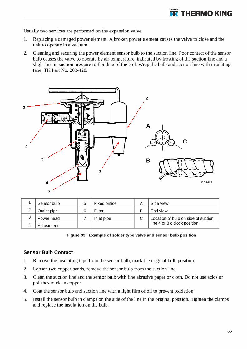
65
Usually two services are performed on the expansion valve:
1. Replacing a damaged power element. A broken power element causes the valve to close and theunit to operate in a vacuum.
2. Cleaning and securing the power element sensor bulb to the suction line. Poor contact of the sensorbulb causes the valve to operate by air temperature, indicated by frosting of the suction line and aslight rise in suction pressure to flooding of the coil. Wrap the bulb and suction line with insulatingtape, TK Part No. 203-428.
1 Sensor bulb 5 Fixed orifice A Side view
2 Outlet pipe 6 Filter B End view
3 Power head 7 Inlet pipe C Location of bulb on side of suctionline 4 or 8 o’clock position4 Adjustment
Figure 33: Example of solder type valve and sensor bulb position
Sensor Bulb Contact
1. Remove the insulating tape from the sensor bulb, mark the original bulb position.
2. Loosen two copper bands, remove the sensor bulb from the suction line.
3. Clean the suction line and the sensor bulb with fine abrasive paper or cloth. Do not use acids orpolishes to clean copper.
4. Coat the sensor bulb and suction line with a light film of oil to prevent oxidation.
5. Install the sensor bulb in clamps on the side of the line in the original position. Tighten the clampsand replace the insulation on the bulb.
4
A
B
C
1
4
2
3
5
6
7
BEA427
66
Superheat: Measurement and Adjustment
NOTE: Be sure the temperature reading instrument and compound pressure gauge are calibrated.
Measurement
1. Install a pressure gauge in the expansion valve external equalizer line. This will indicate thepressure.
2. Run the unit. Allow the system to run until the interior of the bus has cooled to within 5 degrees ofthermostat set point.
3. Subtract the temperature reading obtained from the suction line near the expansion valve sensorbulb on the unit suction line to obtain the expansion valve superheat setting. Using the Pressure-Temperature Chart in this manual, convert the pressure measured at the equalizer line to theequivalent temperature.
Example:
Sensor Bulb Suction Line Temperature (°C/F)
-Suction Pressure Temperature Conversion (°C/F)
=Superheat (K)
NOTE: To properly check the superheat, you must have a stable condition. To establish a stableoperating condition, run the unit at least 15 minutes so the evaporator air inlet temperature reaches21 °C to 27 °C (70 °F to 80 °F). Read the pressure and temperature difference simultaneously.Temperature difference should be 5.5 to 8 K.
CAUTION: Thermo King expansion valves are factory preset and do not requireadjustment. Establishing controlled conditions in the field is difficult. Before adjustingthe expansion valve, check the following causes for an out-of-range reading.
4. Check the following:
Dirty air filters or other cause of reduced air flow.
Sensor bulb leaking, bulb placed improperly on refrigerant line, or bulb not properly wrappedwith insulating tape.
Kinked capillary tube.
5. After the above items have been checked, replace the expansion valve with a factory preset part ifnecessary.
Adjustment
1. Remove the cap over the adjusting stem.
2. To reduce superheat, turn the adjusting stem counterclockwise.
3. Make no more than one turn of the stem at one time. Observe the change in superheat closely toprevent overshooting the desired setting. As much as 30 minutes may be required to obtain the newbalance after the adjustment has been made.
4. Remove the pressure gauge and thermometer from the equalizer line.
5. Return bus to service.
67
Thermostatic Expansion Valve Removal
DANGER: Do not solder on a closed system. Pressure can build up and may causean explosion. If soldering is required, use dry nitrogen to purge the system during anysolder operations. Refer to “Using Pressurized Nitrogen”.
Removal
1. Switch OFF the unit/control system. Turn OFF all power supply.
2. Locate the expansion valve, release and remove the cover from top or side cover (always removethe cover to avoid any damage).
3. Recover the refrigerant from the system. See chapter 11 and refer to “Evacuation procedure”.
4. Remove the insulation.
5. Remove the sensor bulb from the clamps, taking care not to kink the capillary tube.
6. Unsolder the equalizer and the inlet and outlet line connections. Remove the expansion valve.
Installation
1. Clean tubing connections before installing the valve.
2. Compare the new valve to the one removed. Adjust the length of the sensor bulb capillary tube.Secure it to the valve body in the same manner as the original valve. This prevents damage to thetube by vibration-induced chafing. Once the length is adjusted, feed the bulb through the requiredrouting.
3. Position the valve in the unit, insert the grommet if necessary and solder the equalizer and the inletand outlet lines. Use a heat sink to prevent damage to the valve.
4. Taking care not to kink the capillary tube, position the remote sensor bulb in the clamp on the sideof the suction line in exactly the same spot from which it was removed.
5. Charge the system, once the charging has been completed pressurize the unit and check for leaks.
6. Add insulation where necessary.
7. Switch ON A/C system, start the unit and test the functionality.
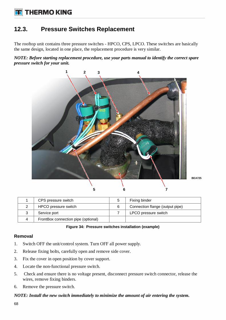
68
12.3. Pressure Switches Replacement
The rooftop unit contains three pressure switches - HPCO, CPS, LPCO. These switches are basicallythe same design, located in one place, the replacement procedure is very similar.
NOTE: Before starting replacement procedure, use your parts manual to identify the correct sparepressure switch for your unit.
1 CPS pressure switch 5 Fixing binder
2 HPCO pressure switch 6 Connection flange (output pipe)
3 Service port 7 LPCO pressure switch
4 FrontBox connection pipe (optional)
Figure 34: Pressure switches installation (example)
Removal
1. Switch OFF the unit/control system. Turn OFF all power supply.
2. Release fixing bolts, carefully open and remove side cover.
3. Fix the cover in open position by cover support.
4. Locate the non-functional pressure switch.
5. Check and ensure there is no voltage present, disconnect pressure switch connector, release thewires, remove fixing binders.
6. Remove the pressure switch.
NOTE: Install the new switch immediately to minimize the amount of air entering the system.
BEA725
21 3 4
765
69
Installation
1. Clean connection thread from rests of sealing.
2. Apply threadlocker Loctite(TM) to the threads of the new switch.
3. Install new switch, connect the wires, fix the wires with binders.
4. Pressurize the unit and check for leaks.
5. Switch ON A/C system and test the functionality.
6. Insert and close side cover, fix the cover with fixing bolts.
12.4. Relief Valve Replacement
The relief valve contains a spring loaded piston that lifts when the refrigerant pressure exceeds thespring force. When pressure drops below set point, the valve will reset. The valve might leak refrigerantafter it has relieved excess pressure. Tapping the valve lightly may help the valve reseat and sealproperly.
The valve is non-repairable and requires no adjustment. If the valve fails to reseat properly, the valvemust be replaced.
NOTE: Before starting replacement procedure, use your parts manual to identify the correct valvefor your unit.
Removal
1. Switch OFF the unit/control system. Turn OFF all power supply.
2. Carefully open and remove both side covers.
3. Release, disconnect and remove both condenser fans, unrivet the condenser cover (remove allrivets on perimeter and 6 rivets from central part of cover), remove the condenser cover.
4. Recover the refrigerant from the system. See chapter 11 and refer to “Evacuation procedure”.
5. Remove the valve.
NOTE: Install the new switch immediately to minimize the amount of air entering the system
Installation
1. Apply threadlocker Loctite(TM) to the threads of the new sensor.
2. Install and tighten new valve.
3. Evacuate the system (for more information refer to chapter 11 Refrigeration System Maintenance).
4. Charge the system - see chapter 12 on page 61.
5. Once the charging has been completed pressurize the unit and check for leaks.
6. Return the condenser cover in original position, use appropriate rivets to fix the cover, insert andconnect the condenser fans, fix the fans with bolts.
7. Close and fix both side cover with fixing bolts.
8. Switch ON A/C system and test the functionality.
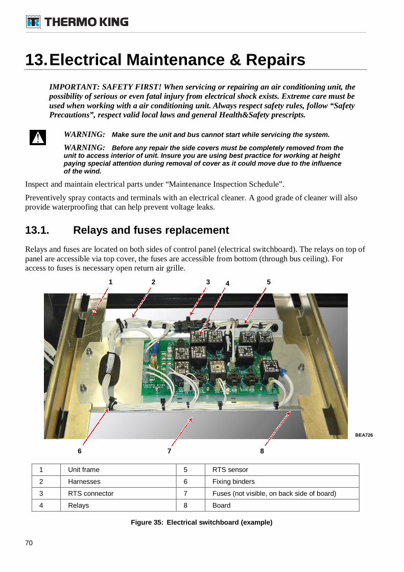
70
13.Electrical Maintenance & Repairs
IMPORTANT: SAFETY FIRST! When servicing or repairing an air conditioning unit, thepossibility of serious or even fatal injury from electrical shock exists. Extreme care must beused when working with a air conditioning unit. Always respect safety rules, follow “SafetyPrecautions”, respect valid local laws and general Health&Safety prescripts.
WARNING: Make sure the unit and bus cannot start while servicing the system.
WARNING: Before any repair the side covers must be completely removed from theunit to access interior of unit. Insure you are using best practice for working at heightpaying special attention during removal of cover as it could move due to the influenceof the wind.
Inspect and maintain electrical parts under “Maintenance Inspection Schedule”.
Preventively spray contacts and terminals with an electrical cleaner. A good grade of cleaner will alsoprovide waterproofing that can help prevent voltage leaks.
13.1. Relays and fuses replacement
Relays and fuses are located on both sides of control panel (electrical switchboard). The relays on top ofpanel are accessible via top cover, the fuses are accessible from bottom (through bus ceiling). Foraccess to fuses is necessary open return air grille.
1 Unit frame 5 RTS sensor
2 Harnesses 6 Fixing binders
3 RTS connector 7 Fuses (not visible, on back side of board)
4 Relays 8 Board
Figure 35: Electrical switchboard (example)
BEA726
4
6
31 2
7 8
5
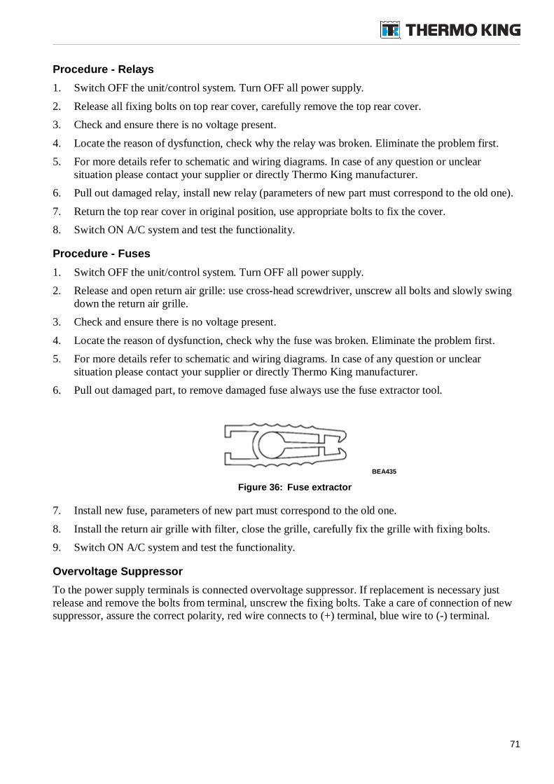
71
Procedure - Relays
1. Switch OFF the unit/control system. Turn OFF all power supply.
2. Release all fixing bolts on top rear cover, carefully remove the top rear cover.
3. Check and ensure there is no voltage present.
4. Locate the reason of dysfunction, check why the relay was broken. Eliminate the problem first.
5. For more details refer to schematic and wiring diagrams. In case of any question or unclearsituation please contact your supplier or directly Thermo King manufacturer.
6. Pull out damaged relay, install new relay (parameters of new part must correspond to the old one).
7. Return the top rear cover in original position, use appropriate bolts to fix the cover.
8. Switch ON A/C system and test the functionality.
Procedure - Fuses
1. Switch OFF the unit/control system. Turn OFF all power supply.
2. Release and open return air grille: use cross-head screwdriver, unscrew all bolts and slowly swingdown the return air grille.
3. Check and ensure there is no voltage present.
4. Locate the reason of dysfunction, check why the fuse was broken. Eliminate the problem first.
5. For more details refer to schematic and wiring diagrams. In case of any question or unclearsituation please contact your supplier or directly Thermo King manufacturer.
6. Pull out damaged part, to remove damaged fuse always use the fuse extractor tool.
Figure 36: Fuse extractor
7. Install new fuse, parameters of new part must correspond to the old one.
8. Install the return air grille with filter, close the grille, carefully fix the grille with fixing bolts.
9. Switch ON A/C system and test the functionality.
Overvoltage Suppressor
To the power supply terminals is connected overvoltage suppressor. If replacement is necessary justrelease and remove the bolts from terminal, unscrew the fixing bolts. Take a care of connection of newsuppressor, assure the correct polarity, red wire connects to (+) terminal, blue wire to (-) terminal.
BEA435
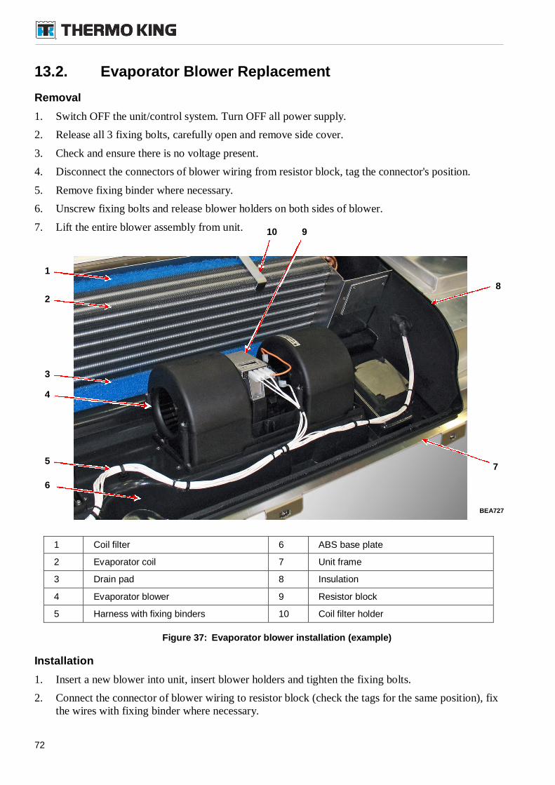
72
13.2. Evaporator Blower Replacement
Removal
1. Switch OFF the unit/control system. Turn OFF all power supply.
2. Release all 3 fixing bolts, carefully open and remove side cover.
3. Check and ensure there is no voltage present.
4. Disconnect the connectors of blower wiring from resistor block, tag the connector's position.
5. Remove fixing binder where necessary.
6. Unscrew fixing bolts and release blower holders on both sides of blower.
7. Lift the entire blower assembly from unit.
1 Coil filter 6 ABS base plate
2 Evaporator coil 7 Unit frame
3 Drain pad 8 Insulation
4 Evaporator blower 9 Resistor block
5 Harness with fixing binders 10 Coil filter holder
Figure 37: Evaporator blower installation (example)
Installation
1. Insert a new blower into unit, insert blower holders and tighten the fixing bolts.
2. Connect the connector of blower wiring to resistor block (check the tags for the same position), fixthe wires with fixing binder where necessary.
BEA727
3
8
7
10
1
2
5
4
9
6
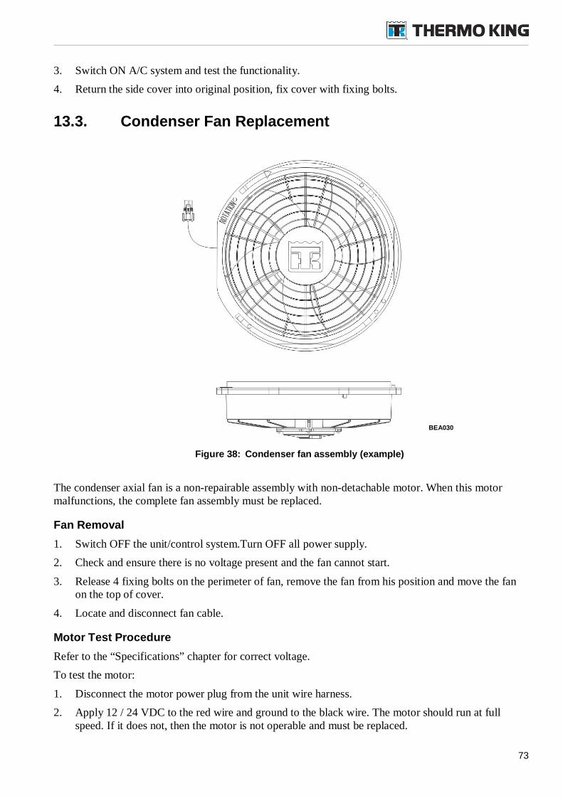
73
3. Switch ON A/C system and test the functionality.
4. Return the side cover into original position, fix cover with fixing bolts.
13.3. Condenser Fan Replacement
Figure 38: Condenser fan assembly (example)
The condenser axial fan is a non-repairable assembly with non-detachable motor. When this motormalfunctions, the complete fan assembly must be replaced.
Fan Removal
1. Switch OFF the unit/control system.Turn OFF all power supply.
2. Check and ensure there is no voltage present and the fan cannot start.
3. Release 4 fixing bolts on the perimeter of fan, remove the fan from his position and move the fanon the top of cover.
4. Locate and disconnect fan cable.
Motor Test Procedure
Refer to the “Specifications” chapter for correct voltage.
To test the motor:
1. Disconnect the motor power plug from the unit wire harness.
2. Apply 12 / 24 VDC to the red wire and ground to the black wire. The motor should run at fullspeed. If it does not, then the motor is not operable and must be replaced.
BEA030
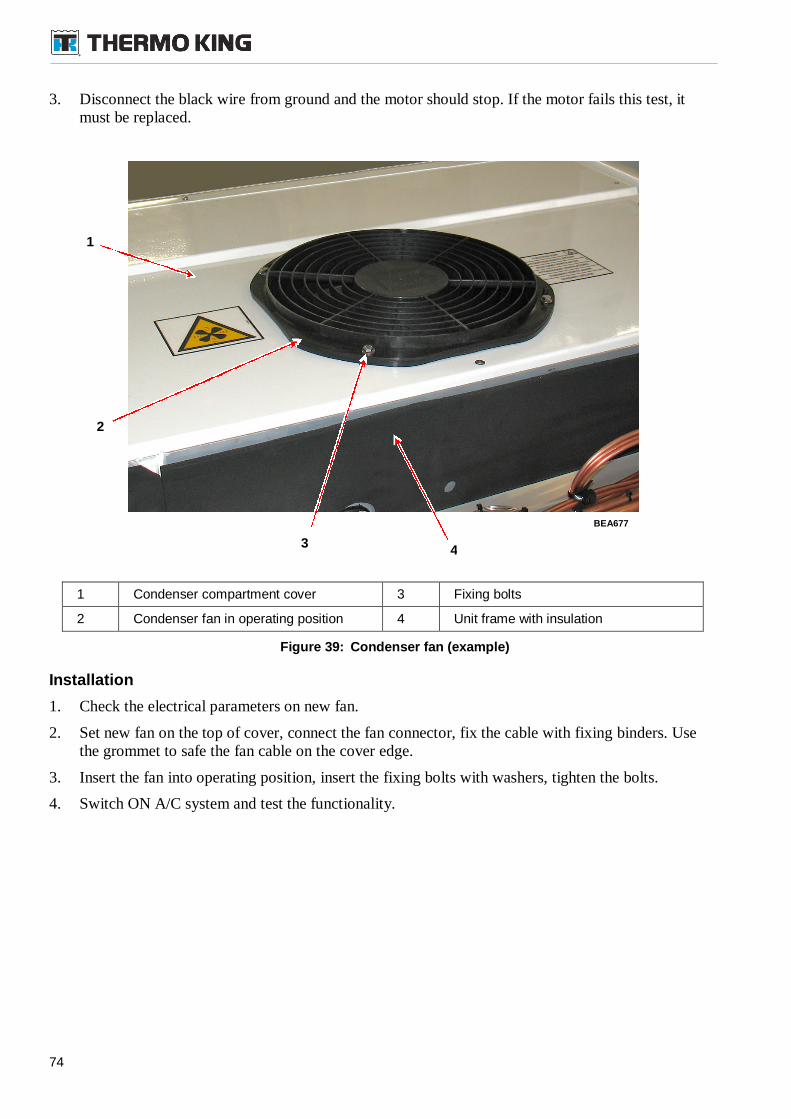
74
3. Disconnect the black wire from ground and the motor should stop. If the motor fails this test, itmust be replaced.
1 Condenser compartment cover 3 Fixing bolts
2 Condenser fan in operating position 4 Unit frame with insulation
Figure 39: Condenser fan (example)
Installation
1. Check the electrical parameters on new fan.
2. Set new fan on the top of cover, connect the fan connector, fix the cable with fixing binders. Usethe grommet to safe the fan cable on the cover edge.
3. Insert the fan into operating position, insert the fixing bolts with washers, tighten the bolts.
4. Switch ON A/C system and test the functionality.
BEA677
1
43
2
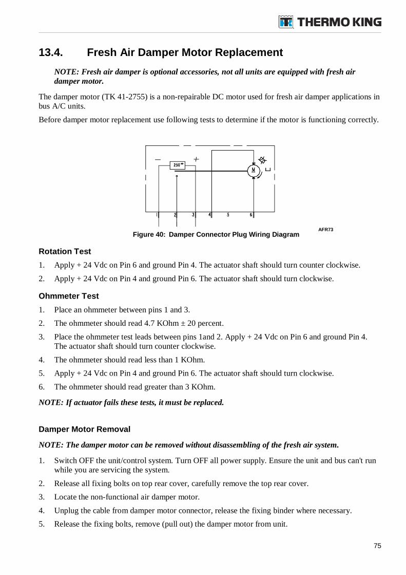
75
13.4. Fresh Air Damper Motor Replacement
NOTE: Fresh air damper is optional accessories, not all units are equipped with fresh airdamper motor.
The damper motor (TK 41-2755) is a non-repairable DC motor used for fresh air damper applications inbus A/C units.
Before damper motor replacement use following tests to determine if the motor is functioning correctly.
Figure 40: Damper Connector Plug Wiring Diagram
Rotation Test
1. Apply + 24 Vdc on Pin 6 and ground Pin 4. The actuator shaft should turn counter clockwise.
2. Apply + 24 Vdc on Pin 4 and ground Pin 6. The actuator shaft should turn clockwise.
Ohmmeter Test
1. Place an ohmmeter between pins 1 and 3.
2. The ohmmeter should read 4.7 KOhm ± 20 percent.
3. Place the ohmmeter test leads between pins 1and 2. Apply + 24 Vdc on Pin 6 and ground Pin 4.The actuator shaft should turn counter clockwise.
4. The ohmmeter should read less than 1 KOhm.
5. Apply + 24 Vdc on Pin 4 and ground Pin 6. The actuator shaft should turn clockwise.
6. The ohmmeter should read greater than 3 KOhm.
NOTE: If actuator fails these tests, it must be replaced.
Damper Motor Removal
NOTE: The damper motor can be removed without disassembling of the fresh air system.
1. Switch OFF the unit/control system. Turn OFF all power supply. Ensure the unit and bus can't runwhile you are servicing the system.
2. Release all fixing bolts on top rear cover, carefully remove the top rear cover.
3. Locate the non-functional air damper motor.
4. Unplug the cable from damper motor connector, release the fixing binder where necessary.
5. Release the fixing bolts, remove (pull out) the damper motor from unit.
AFR73
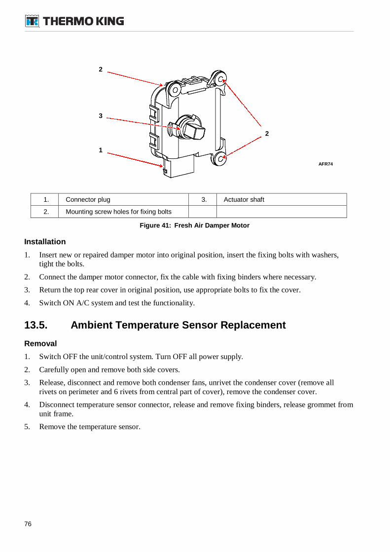
76
1. Connector plug 3. Actuator shaft
2. Mounting screw holes for fixing bolts
Figure 41: Fresh Air Damper Motor
Installation
1. Insert new or repaired damper motor into original position, insert the fixing bolts with washers,tight the bolts.
2. Connect the damper motor connector, fix the cable with fixing binders where necessary.
3. Return the top rear cover in original position, use appropriate bolts to fix the cover.
4. Switch ON A/C system and test the functionality.
13.5. Ambient Temperature Sensor Replacement
Removal
1. Switch OFF the unit/control system. Turn OFF all power supply.
2. Carefully open and remove both side covers.
3. Release, disconnect and remove both condenser fans, unrivet the condenser cover (remove allrivets on perimeter and 6 rivets from central part of cover), remove the condenser cover.
4. Disconnect temperature sensor connector, release and remove fixing binders, release grommet fromunit frame.
5. Remove the temperature sensor.
AFR74
2
2
3
1
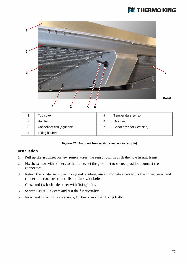
77
1 Top cover 5 Temperature sensor
2 Unit frame 6 Grommet
3 Condenser coil (right side) 7 Condenser coil (left side)
4 Fixing binders
Figure 42: Ambient temperature sensor (example)
Installation
1. Pull up the grommet on new sensor wires, the sensor pull through the hole in unit frame.
2. Fix the sensor with binders to the frame, set the grommet to correct position, connect theconnectors.
3. Return the condenser cover in original position, use appropriate rivets to fix the cover, insert andconnect the condenser fans, fix the fans with bolts.
4. Close and fix both side cover with fixing bolts.
5. Switch ON A/C system and test the functionality.
6. Insert and close both side covers, fix the covers with fixing bolts.
BEA728
1
4
2
3
2
7
5 6
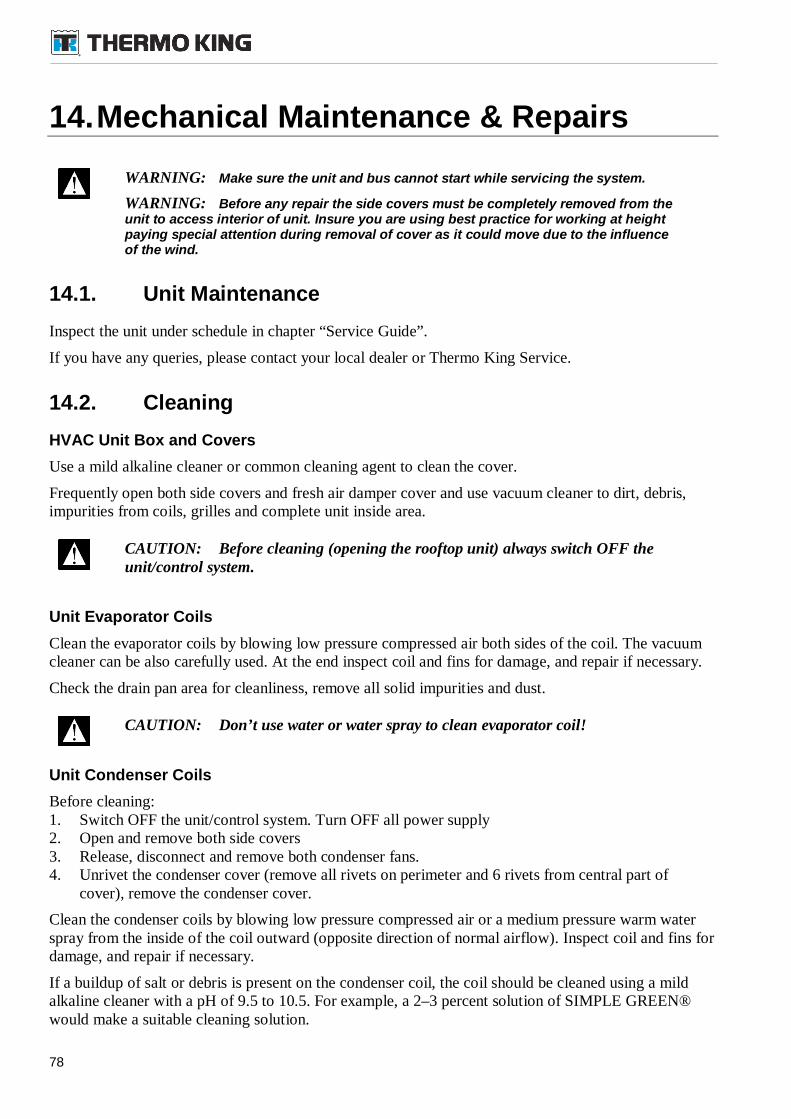
78
14.Mechanical Maintenance & Repairs
WARNING: Make sure the unit and bus cannot start while servicing the system.
WARNING: Before any repair the side covers must be completely removed from theunit to access interior of unit. Insure you are using best practice for working at heightpaying special attention during removal of cover as it could move due to the influenceof the wind.
14.1. Unit Maintenance
Inspect the unit under schedule in chapter “Service Guide”.
If you have any queries, please contact your local dealer or Thermo King Service.
14.2. Cleaning
HVAC Unit Box and Covers
Use a mild alkaline cleaner or common cleaning agent to clean the cover.
Frequently open both side covers and fresh air damper cover and use vacuum cleaner to dirt, debris,impurities from coils, grilles and complete unit inside area.
CAUTION: Before cleaning (opening the rooftop unit) always switch OFF theunit/control system.
Unit Evaporator Coils
Clean the evaporator coils by blowing low pressure compressed air both sides of the coil. The vacuumcleaner can be also carefully used. At the end inspect coil and fins for damage, and repair if necessary.
Check the drain pan area for cleanliness, remove all solid impurities and dust.
CAUTION: Don’t use water or water spray to clean evaporator coil!
Unit Condenser Coils
Before cleaning:1. Switch OFF the unit/control system. Turn OFF all power supply2. Open and remove both side covers3. Release, disconnect and remove both condenser fans.4. Unrivet the condenser cover (remove all rivets on perimeter and 6 rivets from central part of
cover), remove the condenser cover.
Clean the condenser coils by blowing low pressure compressed air or a medium pressure warm waterspray from the inside of the coil outward (opposite direction of normal airflow). Inspect coil and fins fordamage, and repair if necessary.
If a buildup of salt or debris is present on the condenser coil, the coil should be cleaned using a mildalkaline cleaner with a pH of 9.5 to 10.5. For example, a 2–3 percent solution of SIMPLE GREEN®would make a suitable cleaning solution.
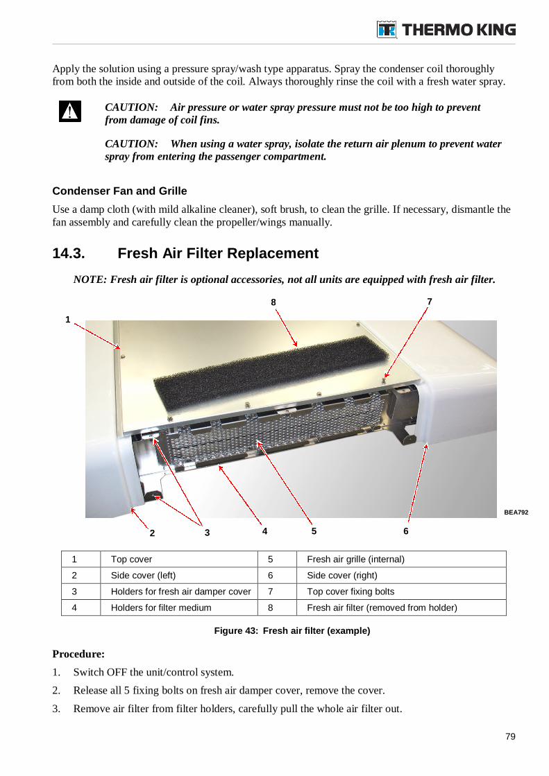
79
Apply the solution using a pressure spray/wash type apparatus. Spray the condenser coil thoroughlyfrom both the inside and outside of the coil. Always thoroughly rinse the coil with a fresh water spray.
CAUTION: Air pressure or water spray pressure must not be too high to preventfrom damage of coil fins.
CAUTION: When using a water spray, isolate the return air plenum to prevent waterspray from entering the passenger compartment.
Condenser Fan and Grille
Use a damp cloth (with mild alkaline cleaner), soft brush, to clean the grille. If necessary, dismantle thefan assembly and carefully clean the propeller/wings manually.
14.3. Fresh Air Filter Replacement
NOTE: Fresh air filter is optional accessories, not all units are equipped with fresh air filter.
1 Top cover 5 Fresh air grille (internal)
2 Side cover (left) 6 Side cover (right)
3 Holders for fresh air damper cover 7 Top cover fixing bolts
4 Holders for filter medium 8 Fresh air filter (removed from holder)
Figure 43: Fresh air filter (example)
Procedure:
1. Switch OFF the unit/control system.
2. Release all 5 fixing bolts on fresh air damper cover, remove the cover.
3. Remove air filter from filter holders, carefully pull the whole air filter out.
BEA792
2 5 64
8
1
3
7
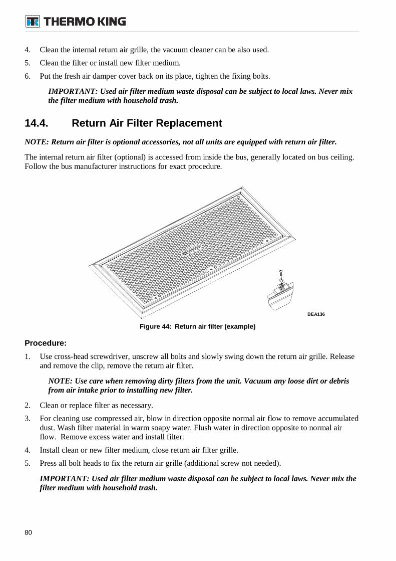
80
4. Clean the internal return air grille, the vacuum cleaner can be also used.
5. Clean the filter or install new filter medium.
6. Put the fresh air damper cover back on its place, tighten the fixing bolts.
IMPORTANT: Used air filter medium waste disposal can be subject to local laws. Never mixthe filter medium with household trash.
14.4. Return Air Filter Replacement
NOTE: Return air filter is optional accessories, not all units are equipped with return air filter.
The internal return air filter (optional) is accessed from inside the bus, generally located on bus ceiling.Follow the bus manufacturer instructions for exact procedure.
Figure 44: Return air filter (example)
Procedure:
1. Use cross-head screwdriver, unscrew all bolts and slowly swing down the return air grille. Releaseand remove the clip, remove the return air filter.
NOTE: Use care when removing dirty filters from the unit. Vacuum any loose dirt or debrisfrom air intake prior to installing new filter.
2. Clean or replace filter as necessary.
3. For cleaning use compressed air, blow in direction opposite normal air flow to remove accumulateddust. Wash filter material in warm soapy water. Flush water in direction opposite to normal airflow. Remove excess water and install filter.
4. Install clean or new filter medium, close return air filter grille.
5. Press all bolt heads to fix the return air grille (additional screw not needed).
IMPORTANT: Used air filter medium waste disposal can be subject to local laws. Never mix thefilter medium with household trash.
BEA136
81
14.5. Coil Air Filter Replacement
1 Evaporator coil 3 Air filter holder
2 Coil sir filter 4 Evaporator blower
Figure 45: Coil Air filter installation (illustrative picture)
Procedure:
1. Switch OFF the unit/control system. Turn OFF all power supply.
2. Carefully open and remove left or right side cover.
3. Locate the coil air filter, remove filter holders and carefully pull the whole air filter out.
4. Clean the filter or install new filter medium.
NOTE: Use care when removing dirty filters from the unit. Vacuum any loose dirt or debrisfrom air intake prior to installing new filter.
5. Put the filter back on its place.
IMPORTANT: Used air filter medium waste disposal can be subject to local laws. Never mixthe filter medium with household trash.
6. Switch ON A/C system and test the functionality.
7. Insert and close side cover, fix the cover with fixing bolts.
3
1
2
4
BEA443
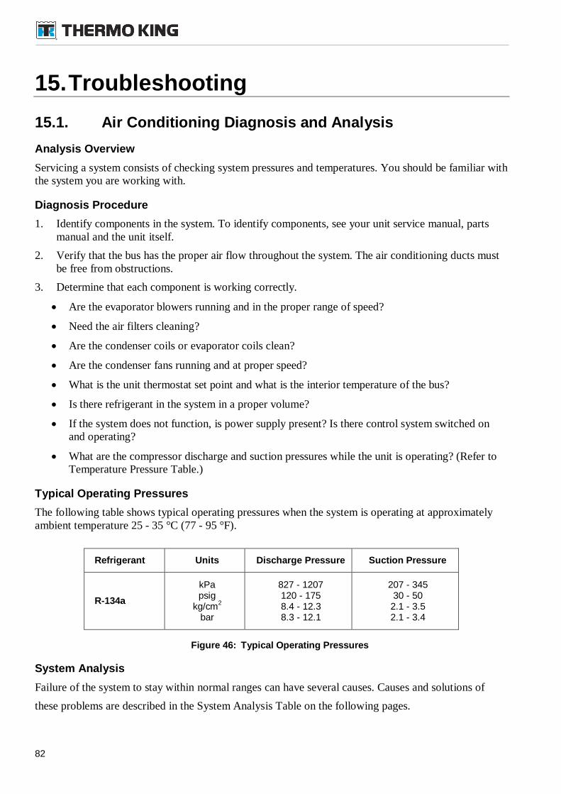
82
15.Troubleshooting
15.1. Air Conditioning Diagnosis and Analysis
Analysis Overview
Servicing a system consists of checking system pressures and temperatures. You should be familiar withthe system you are working with.
Diagnosis Procedure
1. Identify components in the system. To identify components, see your unit service manual, partsmanual and the unit itself.
2. Verify that the bus has the proper air flow throughout the system. The air conditioning ducts mustbe free from obstructions.
3. Determine that each component is working correctly.
Are the evaporator blowers running and in the proper range of speed?
Need the air filters cleaning?
Are the condenser coils or evaporator coils clean?
Are the condenser fans running and at proper speed?
What is the unit thermostat set point and what is the interior temperature of the bus?
Is there refrigerant in the system in a proper volume?
If the system does not function, is power supply present? Is there control system switched onand operating?
What are the compressor discharge and suction pressures while the unit is operating? (Refer toTemperature Pressure Table.)
Typical Operating Pressures
The following table shows typical operating pressures when the system is operating at approximatelyambient temperature 25 - 35 °C (77 - 95 °F).
Refrigerant Units Discharge Pressure Suction Pressure
R-134a
kPapsig
kg/cm2
bar
827 - 1207120 - 1758.4 - 12.38.3 - 12.1
207 - 34530 - 50
2.1 - 3.52.1 - 3.4
Figure 46: Typical Operating Pressures
System Analysis
Failure of the system to stay within normal ranges can have several causes. Causes and solutions of
these problems are described in the System Analysis Table on the following pages.
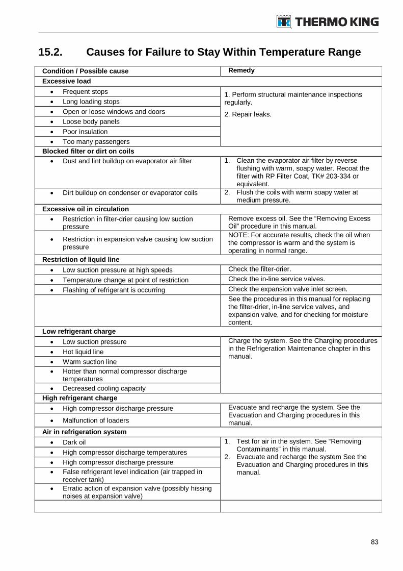
83
15.2. Causes for Failure to Stay Within Temperature Range
Condition / Possible cause Remedy
Excessive load
Frequent stops 1. Perform structural maintenance inspectionsregularly.
2. Repair leaks.
Long loading stops
Open or loose windows and doors
Loose body panels
Poor insulation
Too many passengers
Blocked filter or dirt on coils
Dust and lint buildup on evaporator air filter 1. Clean the evaporator air filter by reverseflushing with warm, soapy water. Recoat thefilter with RP Filter Coat, TK# 203-334 orequivalent.
Dirt buildup on condenser or evaporator coils 2. Flush the coils with warm soapy water atmedium pressure.
Excessive oil in circulation
Restriction in filter-drier causing low suctionpressure
Remove excess oil. See the “Removing ExcessOil” procedure in this manual.
Restriction in expansion valve causing low suctionpressure
NOTE: For accurate results, check the oil whenthe compressor is warm and the system isoperating in normal range.
Restriction of liquid line
Low suction pressure at high speeds Check the filter-drier.
Temperature change at point of restriction Check the in-line service valves.
Flashing of refrigerant is occurring Check the expansion valve inlet screen.
See the procedures in this manual for replacingthe filter-drier, in-line service valves, andexpansion valve, and for checking for moisturecontent.
Low refrigerant charge
Low suction pressure Charge the system. See the Charging proceduresin the Refrigeration Maintenance chapter in thismanual.
Hot liquid line
Warm suction line
Hotter than normal compressor dischargetemperatures
Decreased cooling capacity
High refrigerant charge
High compressor discharge pressure Evacuate and recharge the system. See theEvacuation and Charging procedures in thismanual. Malfunction of loaders
Air in refrigeration system
Dark oil 1. Test for air in the system. See “RemovingContaminants” in this manual.
2. Evacuate and recharge the system See theEvacuation and Charging procedures in thismanual.
High compressor discharge temperatures
High compressor discharge pressure
False refrigerant level indication (air trapped inreceiver tank)
Erratic action of expansion valve (possibly hissingnoises at expansion valve)
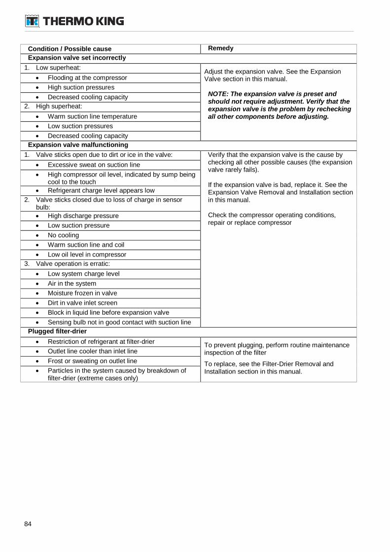
84
Condition / Possible cause Remedy
Expansion valve set incorrectly
1. Low superheat:Adjust the expansion valve. See the ExpansionValve section in this manual.
NOTE: The expansion valve is preset andshould not require adjustment. Verify that theexpansion valve is the problem by recheckingall other components before adjusting.
Flooding at the compressor
High suction pressures
Decreased cooling capacity
2. High superheat:
Warm suction line temperature
Low suction pressures
Decreased cooling capacity
Expansion valve malfunctioning
1. Valve sticks open due to dirt or ice in the valve: Verify that the expansion valve is the cause bychecking all other possible causes (the expansionvalve rarely fails).
If the expansion valve is bad, replace it. See theExpansion Valve Removal and Installation sectionin this manual.
Check the compressor operating conditions,repair or replace compressor
Excessive sweat on suction line
High compressor oil level, indicated by sump beingcool to the touch
Refrigerant charge level appears low
2. Valve sticks closed due to loss of charge in sensorbulb:
High discharge pressure
Low suction pressure
No cooling
Warm suction line and coil
Low oil level in compressor
3. Valve operation is erratic:
Low system charge level
Air in the system
Moisture frozen in valve
Dirt in valve inlet screen
Block in liquid line before expansion valve
Sensing bulb not in good contact with suction line
Plugged filter-drier
Restriction of refrigerant at filter-drierTo prevent plugging, perform routine maintenanceinspection of the filter
To replace, see the Filter-Drier Removal andInstallation section in this manual.
Outlet line cooler than inlet line
Frost or sweating on outlet line
Particles in the system caused by breakdown offilter-drier (extreme cases only)
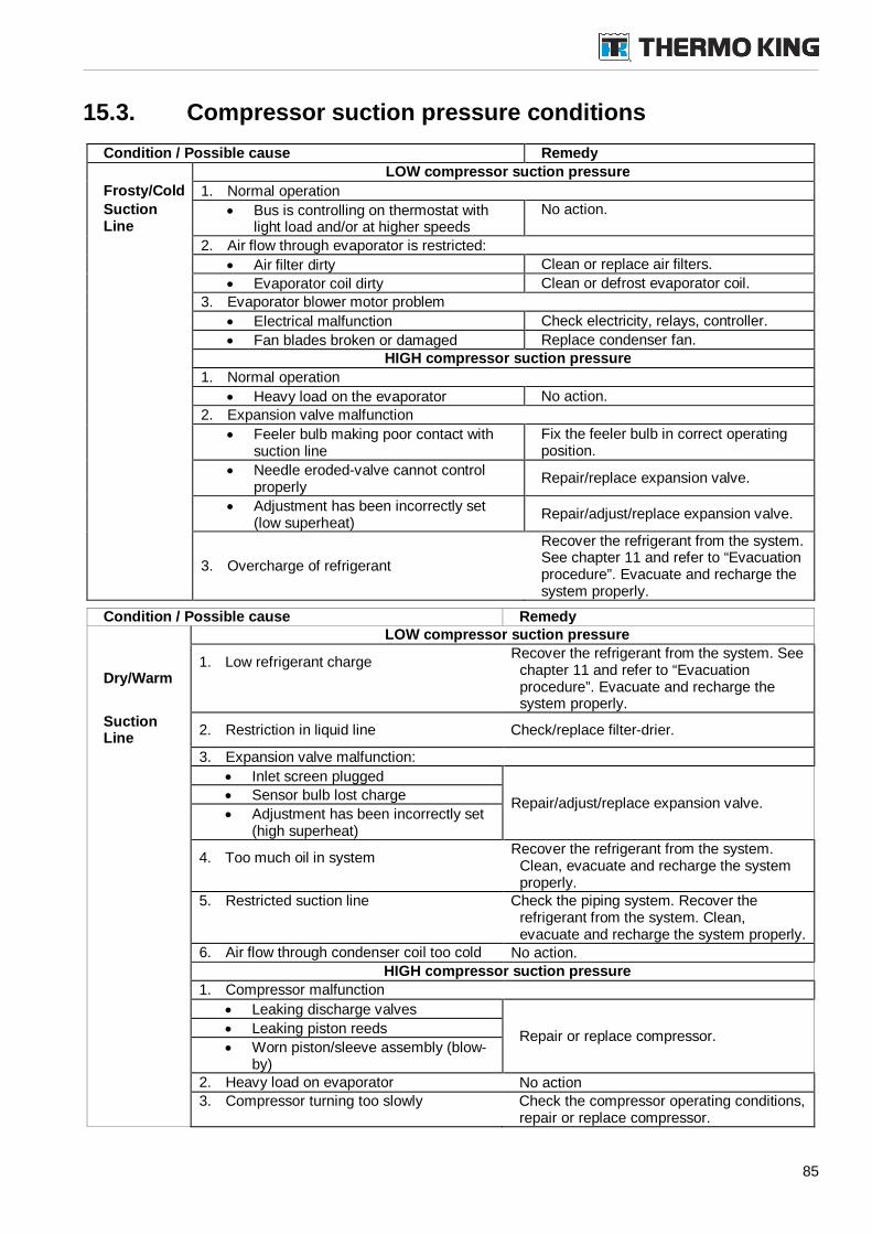
85
15.3. Compressor suction pressure conditions
Condition / Possible cause Remedy
LOW compressor suction pressure
Frosty/Cold 1. Normal operationSuctionLine
Bus is controlling on thermostat withlight load and/or at higher speeds
No action.
2. Air flow through evaporator is restricted:
Air filter dirty Clean or replace air filters.
Evaporator coil dirty Clean or defrost evaporator coil.
3. Evaporator blower motor problem
Electrical malfunction Check electricity, relays, controller.
Fan blades broken or damaged Replace condenser fan.HIGH compressor suction pressure
1. Normal operation
Heavy load on the evaporator No action.
2. Expansion valve malfunction
Feeler bulb making poor contact withsuction line
Fix the feeler bulb in correct operatingposition.
Needle eroded-valve cannot controlproperly
Repair/replace expansion valve.
Adjustment has been incorrectly set(low superheat)
Repair/adjust/replace expansion valve.
3. Overcharge of refrigerant
Recover the refrigerant from the system.See chapter 11 and refer to “Evacuationprocedure”. Evacuate and recharge thesystem properly.
Condition / Possible cause RemedyLOW compressor suction pressure
Dry/Warm1. Low refrigerant charge
Recover the refrigerant from the system. Seechapter 11 and refer to “Evacuationprocedure”. Evacuate and recharge thesystem properly.
SuctionLine
2. Restriction in liquid line Check/replace filter-drier.
3. Expansion valve malfunction:
Inlet screen plugged
Repair/adjust/replace expansion valve. Sensor bulb lost charge
Adjustment has been incorrectly set(high superheat)
4. Too much oil in systemRecover the refrigerant from the system.
Clean, evacuate and recharge the systemproperly.
5. Restricted suction line Check the piping system. Recover therefrigerant from the system. Clean,evacuate and recharge the system properly.
6. Air flow through condenser coil too cold No action.HIGH compressor suction pressure
1. Compressor malfunction
Leaking discharge valves
Repair or replace compressor. Leaking piston reeds
Worn piston/sleeve assembly (blow-by)
2. Heavy load on evaporator No action3. Compressor turning too slowly Check the compressor operating conditions,
repair or replace compressor.
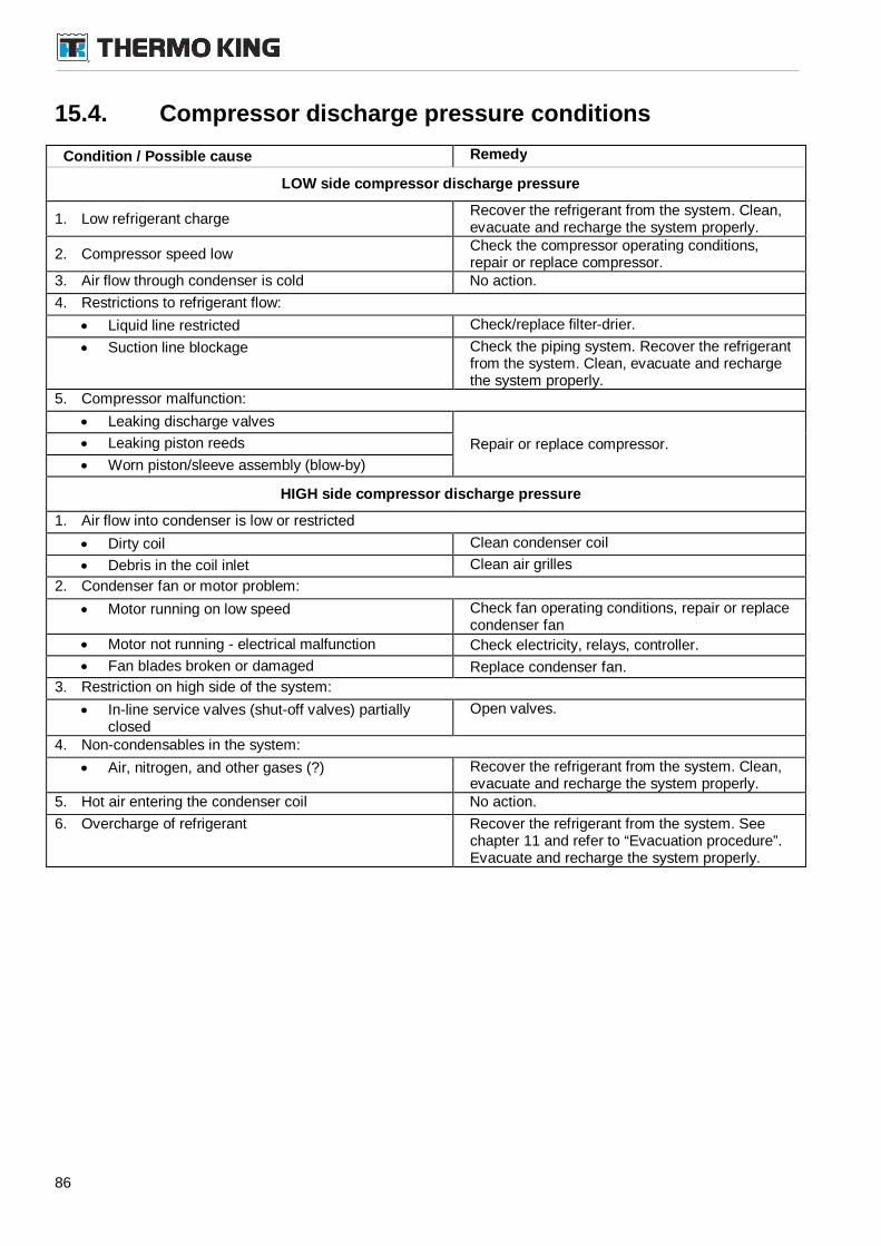
86
15.4. Compressor discharge pressure conditions
Condition / Possible cause Remedy
LOW side compressor discharge pressure
1. Low refrigerant chargeRecover the refrigerant from the system. Clean,evacuate and recharge the system properly.
2. Compressor speed lowCheck the compressor operating conditions,repair or replace compressor.
3. Air flow through condenser is cold No action.
4. Restrictions to refrigerant flow:
Liquid line restricted Check/replace filter-drier.
Suction line blockage Check the piping system. Recover the refrigerantfrom the system. Clean, evacuate and rechargethe system properly.
5. Compressor malfunction:
Leaking discharge valves
Repair or replace compressor. Leaking piston reeds
Worn piston/sleeve assembly (blow-by)
HIGH side compressor discharge pressure
1. Air flow into condenser is low or restricted
Dirty coil Clean condenser coil
Debris in the coil inlet Clean air grilles
2. Condenser fan or motor problem:
Motor running on low speed Check fan operating conditions, repair or replacecondenser fan
Motor not running - electrical malfunction Check electricity, relays, controller.
Fan blades broken or damaged Replace condenser fan.
3. Restriction on high side of the system:
In-line service valves (shut-off valves) partiallyclosed
Open valves.
4. Non-condensables in the system:
Air, nitrogen, and other gases (?) Recover the refrigerant from the system. Clean,evacuate and recharge the system properly.
5. Hot air entering the condenser coil No action.
6. Overcharge of refrigerant Recover the refrigerant from the system. Seechapter 11 and refer to “Evacuation procedure”.Evacuate and recharge the system properly.
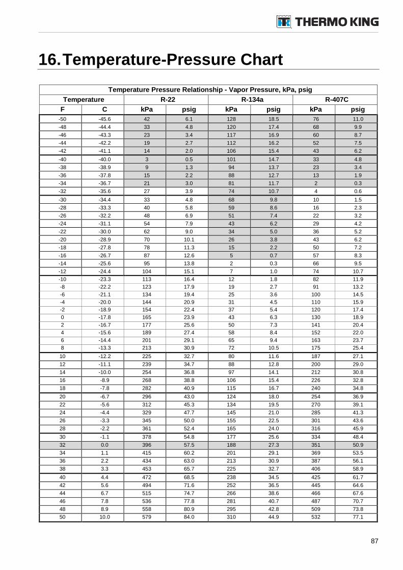
87
16.Temperature-Pressure Chart
Temperature Pressure Relationship - Vapor Pressure, kPa, psig
Temperature R-22 R-134a R-407C
F C kPa psig kPa psig kPa psig
-50 -45.6 42 6.1 128 18.5 76 11.0
-48 -44.4 33 4.8 120 17.4 68 9.9
-46 -43.3 23 3.4 117 16.9 60 8.7
-44 -42.2 19 2.7 112 16.2 52 7.5
-42 -41.1 14 2.0 106 15.4 43 6.2
-40 -40.0 3 0.5 101 14.7 33 4.8
-38 -38.9 9 1.3 94 13.7 23 3.4
-36 -37.8 15 2.2 88 12.7 13 1.9
-34 -36.7 21 3.0 81 11.7 2 0.3
-32 -35.6 27 3.9 74 10.7 4 0.6
-30 -34.4 33 4.8 68 9.8 10 1.5
-28 -33.3 40 5.8 59 8.6 16 2.3
-26 -32.2 48 6.9 51 7.4 22 3.2
-24 -31.1 54 7.9 43 6.2 29 4.2
-22 -30.0 62 9.0 34 5.0 36 5.2
-20 -28.9 70 10.1 26 3.8 43 6.2
-18 -27.8 78 11.3 15 2.2 50 7.2
-16 -26.7 87 12.6 5 0.7 57 8.3
-14 -25.6 95 13.8 2 0.3 66 9.5
-12 -24.4 104 15.1 7 1.0 74 10.7
-10 -23.3 113 16.4 12 1.8 82 11.9
-8 -22.2 123 17.9 19 2.7 91 13.2
-6 -21.1 134 19.4 25 3.6 100 14.5
-4 -20.0 144 20.9 31 4.5 110 15.9
-2 -18.9 154 22.4 37 5.4 120 17.4
0 -17.8 165 23.9 43 6.3 130 18.9
2 -16.7 177 25.6 50 7.3 141 20.4
4 -15.6 189 27.4 58 8.4 152 22.0
6 -14.4 201 29.1 65 9.4 163 23.7
8 -13.3 213 30.9 72 10.5 175 25.4
10 -12.2 225 32.7 80 11.6 187 27.1
12 -11.1 239 34.7 88 12.8 200 29.0
14 -10.0 254 36.8 97 14.1 212 30.8
16 -8.9 268 38.8 106 15.4 226 32.8
18 -7.8 282 40.9 115 16.7 240 34.8
20 -6.7 296 43.0 124 18.0 254 36.9
22 -5.6 312 45.3 134 19.5 270 39.1
24 -4.4 329 47.7 145 21.0 285 41.3
26 -3.3 345 50.0 155 22.5 301 43.6
28 -2.2 361 52.4 165 24.0 316 45.9
30 -1.1 378 54.8 177 25.6 334 48.4
32 0.0 396 57.5 188 27.3 351 50.9
34 1.1 415 60.2 201 29.1 369 53.5
36 2.2 434 63.0 213 30.9 387 56.1
38 3.3 453 65.7 225 32.7 406 58.9
40 4.4 472 68.5 238 34.5 425 61.7
42 5.6 494 71.6 252 36.5 445 64.6
44 6.7 515 74.7 266 38.6 466 67.6
46 7.8 536 77.8 281 40.7 487 70.7
48 8.9 558 80.9 295 42.8 509 73.8
50 10.0 579 84.0 310 44.9 532 77.1
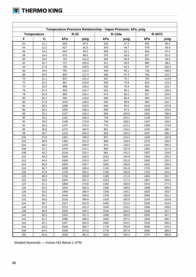
88
Temperature Pressure Relationship - Vapor Pressure, kPa, psig
Temperature R-22 R-134a R-407C
F C kPa psig kPa psig kPa psig
52 11.1 603 87.5 326 47.3 554 80.4
54 12.2 627 91.0 343 49.7 578 83.9
56 13.3 652 94.5 359 52.1 603 87.4
58 14.4 676 98.0 376 54.5 627 91.0
60 15.6 701 101.6 392 56.9 654 94.8
62 16.7 727 105.5 411 59.6 680 98.6
64 17.8 755 109.5 430 62.4 707 102.5
66 18.9 782 113.4 449 65.1 734 106.5
68 20.0 809 117.4 468 67.9 763 110.7
70 21.1 837 121.4 487 70.7 792 114.9
72 22.2 867 125.8 509 73.8 823 119.3
74 23.3 898 130.2 530 76.9 853 123.7
76 24.4 929 134.7 552 80.1 885 128.3
78 25.6 959 139.1 574 83.2 917 133.0
80 26.7 990 143.6 596 86.4 950 137.8
82 27.8 1024 148.5 620 89.9 984 142.7
84 28.9 1058 153.5 645 93.5 1019 147.8
86 30.0 1092 158.4 669 97.0 1055 153.0
88 31.1 1127 163.4 694 100.6 1091 158.3
90 32.2 1161 168.4 718 104.2 1129 163.7
92 33.3 1199 173.9 746 108.2 1167 169.2
94 34.4 1237 179.4 774 112.2 1206 174.9
96 35.6 1275 184.9 801 116.2 1246 180.7
98 36.7 1313 190.4 829 120.2 1287 186.7
100 37.8 1351 195.9 857 124.3 1329 192.8
102 38.9 1392 201.9 889 128.9 1372 199.0
104 40.0 1434 208.0 919 133.3 1415 205.3
106 41.1 1476 214.1 950 137.8 1461 211.9
108 42.2 1518 220.2 981 142.3 1507 218.5
110 43.3 1560 226.3 1012 146.8 1553 225.3
112 44.4 1606 233.0 1047 151.8 1602 232.3
114 45.6 1653 239.7 1081 156.8 1651 239.4
116 46.7 1699 246.4 1116 161.8 1701 246.7
118 47.8 1745 253.1 1150 166.8 1752 254.1
120 48.9 1792 259.9 1185 171.9 1804 261.7
122 50.0 1842 267.2 1223 177.4 1857 269.4
124 51.1 1893 274.6 1262 183.0 1913 277.4
126 52.2 1944 282.0 1300 188.6 1968 285.5
128 53.3 1995 289.4 1339 194.2 2025 293.7
130 54.4 2046 296.8 1378 199.8 2084 302.2
132 55.6 2102 304.8 1420 205.9 2143 310.8
134 56.7 2157 312.9 1462 212.0 2204 319.6
136 57.8 2213 321.0 1504 218.2 2266 328.6
138 58.9 2269 329.1 1546 224.3 2328 337.7
140 60.0 2325 337.2 1589 230.5 2393 347.1
142 61.1 2386 346.0 1635 237.2 2459 356.7
144 62.2 2447 354.9 1682 244.0 2526 366.4
146 63.3 2508 363.7 1729 250.8 2595 376.4
148 64.4 2569 372.6 1776 257.6 2665 386.5
150 65.6 2630 381.5 1823 264.4 2737 396.9
Shaded Numerals — Inches HG Below 1 ATM
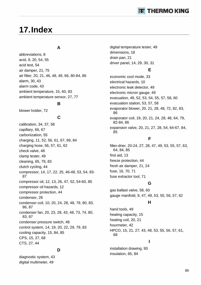
89
17.Index
A
abbreviations, 8
acid, 9, 20, 54, 55
acid test, 54
air damper, 21, 75
air filter, 20, 21, 46, 48, 49, 66, 80-84, 86
alarm, 30, 43
alarm code, 43
ambient temperature, 15, 60, 83
ambient temperature sensor, 27, 77
B
blower holder, 72
C
calibration, 34, 37, 58
capillary, 66, 67
carbonization, 55
charging, 11, 52, 56, 61, 67, 69, 84
charging hose, 56, 57, 61, 62
check valve, 48
clamp tester, 49
cleaning, 65, 79, 83
clutch cycling, 44
compressor, 14, 17, 22, 25, 46-48, 53, 54, 83-87
compressor oil, 12, 13, 26, 47, 52, 54-60, 85
compressor oil hazards, 12
compressor protection, 44
condenser, 28
condenser coil, 10, 20, 24, 28, 48, 79, 80, 83,86, 87
condenser fan, 20, 23, 28, 43, 48, 73, 74, 80,83, 87
condenser pressure switch, 48
control system, 14, 19, 20, 22, 29, 79, 83
cooling capacity, 15, 84, 85
CPS, 15, 27, 68
CTS, 27, 44
D
diagnostic system, 43
digital multimeter, 49
digital temperature tester, 49
dimensions, 18
drain pan, 21
driver panel, 14, 29, 30, 31
E
economic cool mode, 33
electrical hazards, 10
electronic leak detector, 49
electronic micron gauge, 49
evacuation, 49, 52, 53, 54, 55, 57, 58, 60
evacuation station, 53, 57, 58
evaporator blower, 20, 21, 28, 48, 72, 82, 83,86
evaporator coil, 19, 20, 21, 24, 28, 48, 64, 79,82-84, 86
expansion valve, 20, 21, 27, 28, 54, 64-67, 84,85
F
filter-drier, 20-24, 27, 28, 47, 49, 53, 55, 57, 63,64, 84, 85
first aid, 13
freeze protection, 44
fresh air damper, 21, 24
fuse, 16, 70, 71
fuse extractor tool, 71
G
gas ballast valve, 58, 60
gauge manifold, 9, 47, 49, 53, 55, 56, 57, 62
H
hand tools, 49
heating capacity, 15
heating coil, 20, 21
hourmeter, 42
HPCO, 15, 21, 27, 43, 48, 53, 55, 56, 57, 61,68
I
installation drawing, 93
insulation, 65, 84
90
L
leak detector, 53, 56
leak test, 52
liquid receiver, 20
liquid recovery, 52, 56
lock function, 33, 40
low suction pressure, 84, 85
LPCO, 15, 22, 27, 43, 48, 53-57, 68
M
maintenance, 52
maintenance intervals, 46
maintenance procedures, 46
maintenance records, 46
manual mode, 31, 33
mode select, 32
moisture, 12, 17, 20, 28, 47, 53-60, 64, 84, 85
N
nitrogen, 10, 56, 57, 61, 67
normal operating mode, 43
O
off season, 46
oil test kit, 49, 54
overvoltage suppressor, 71
oxygen, 9, 11, 54, 56
P
power supply, 16
pressure relief valve, 15
pressure rise test, 59
program number, 36
R
receiver tank, 20, 21, 27, 28, 84
recovery station, 55, 56
red alarm, 43
refrigerant hazards, 11
reheat mode, 32
relay, 70, 71
relay test, 36
return air filter, 21
return air grille, 21
rooftop unit, 14, 19, 20, 22, 79
RTS, 27
S
safety, 9, 52, 61, 62, 70
safety relief valve, 22, 27, 61, 69
schematics diagram, 93
sensor bulb, 65, 66, 67, 85
serial number, 22
set point, 83
sight glass, 20, 27, 47
solenoid valve, 20
specifications, 15
superheat, 66, 85, 86
T
tank receiver, 24
temperature sensor, 43, 77
temperature tester, 49
theory of operation, 27
thermometer, 49, 66
threadlocker, 49, 69
TM compressor, 25
tools, 10, 49, 53
torque special conditions, 51
torques, 50
U
unit decals, 22
unit protection devices, 20, 21
V
vacuum, 49, 53, 54, 57-60, 65, 79
vacuum cleaner, 79, 81
vacuum pump, 49, 54, 57, 60
vapor recovery, 52, 55
ventilation mode, 43
W
warranty, 2, 12, 46
water valve, 47
weight, 18
wintertime, 46
wiring diagram, 93
Y
yellow alarm, 43
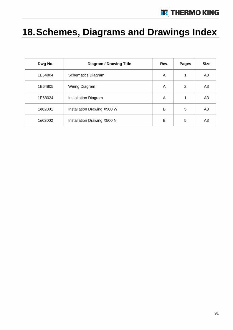
91
18.Schemes, Diagrams and Drawings Index
Dwg No. Diagram / Drawing Title Rev. Pages Size
1E64804 Schematics Diagram A 1 A3
1E64805 Wiring Diagram A 2 A3
1E68024 Installation Diagram A 1 A3
1e62001 Installation Drawing X500 W B 5 A3
1e62002 Installation Drawing X500 N B 5 A3

92
19.Appendix
Appendix Title Rev. Pages
ACompressor maintenance manual(TM compressors 51068)
2a 12/03 62
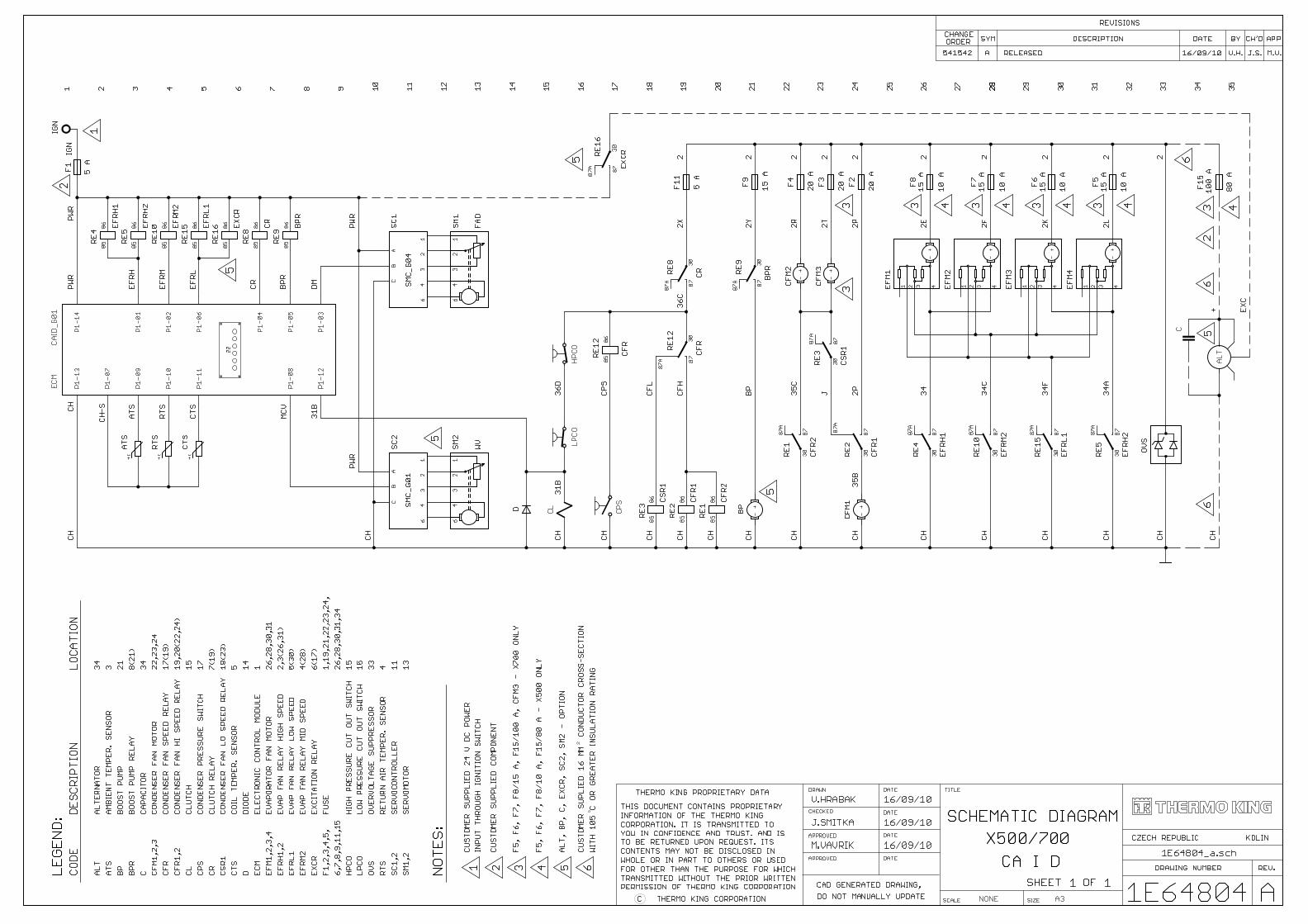
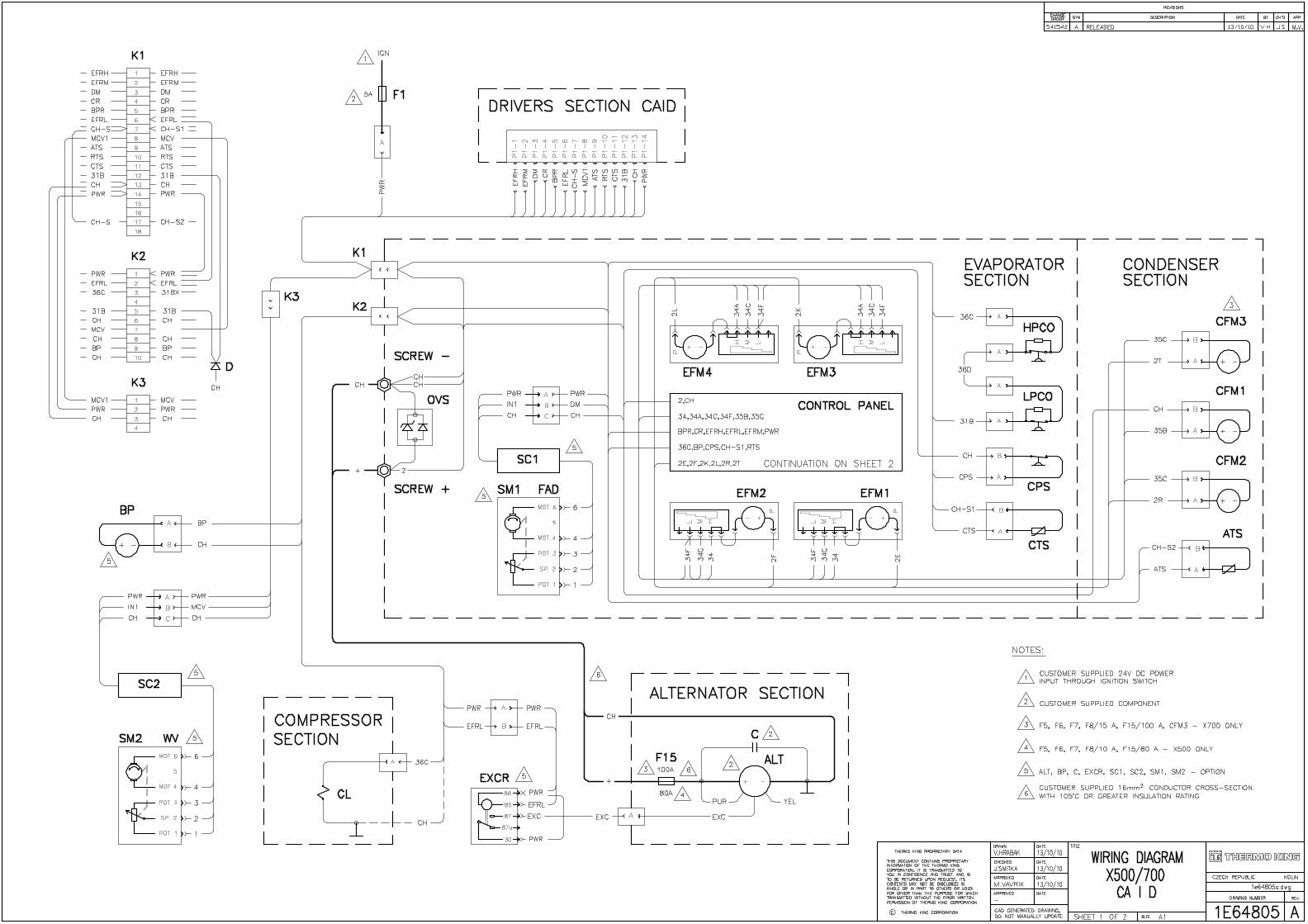
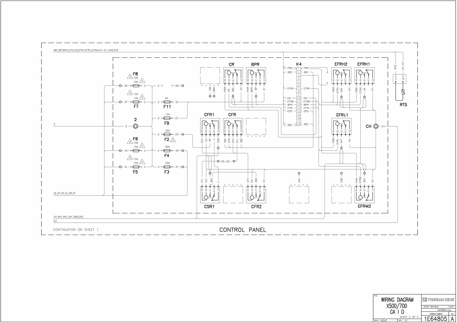
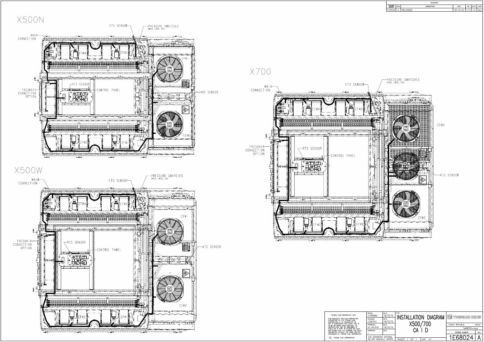
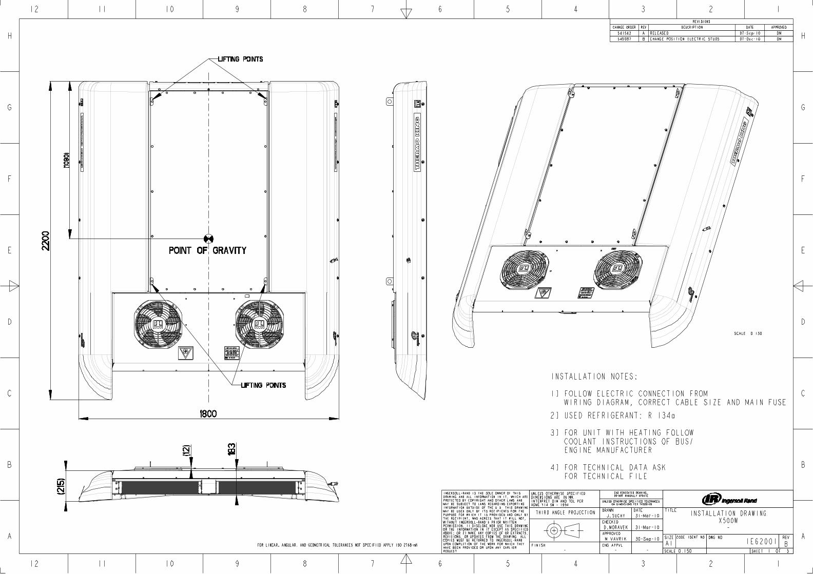
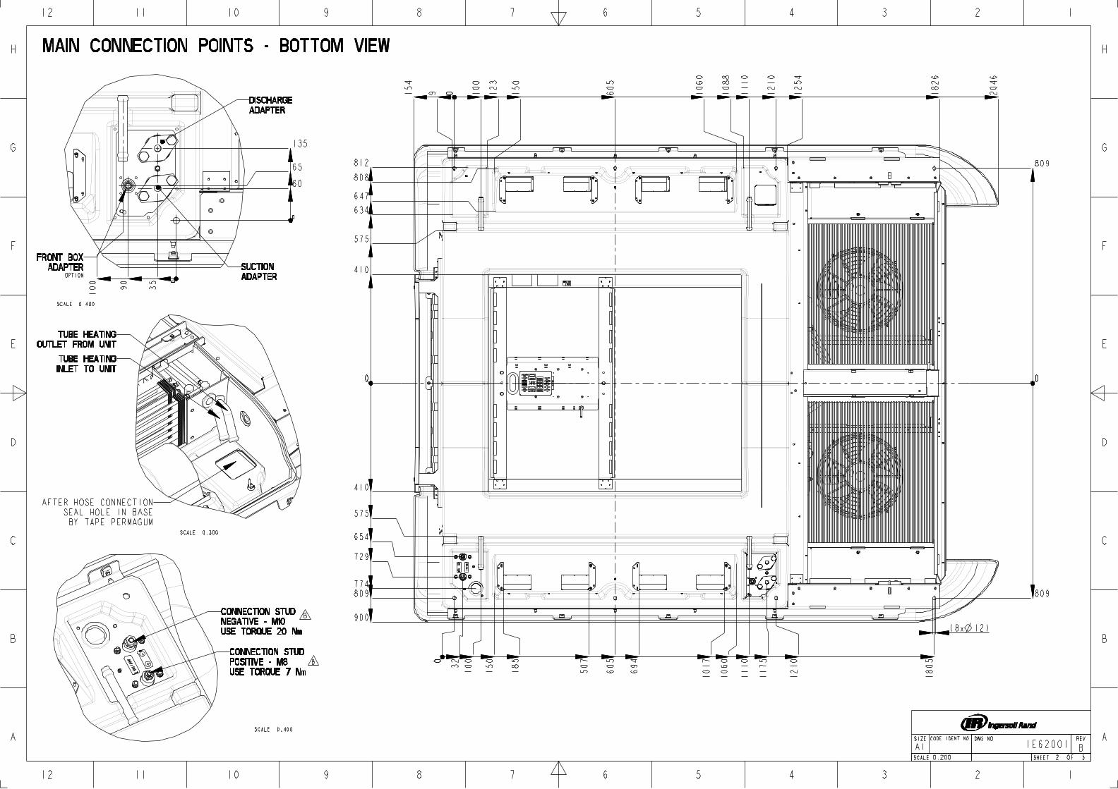
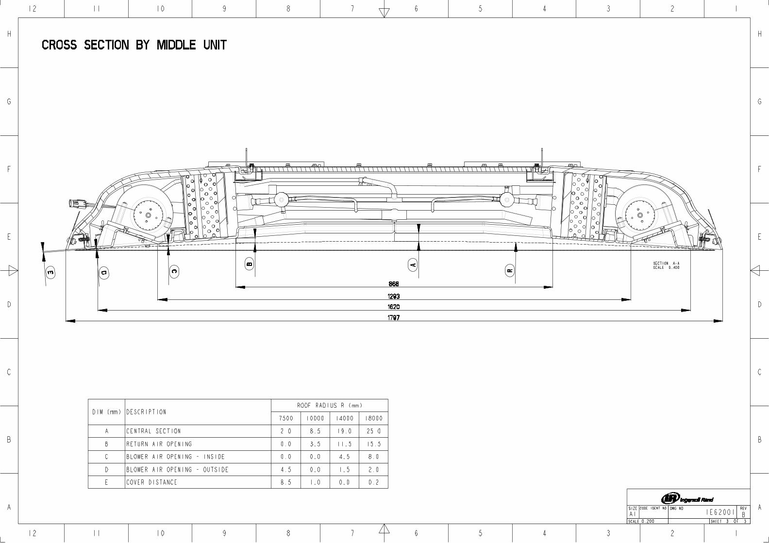
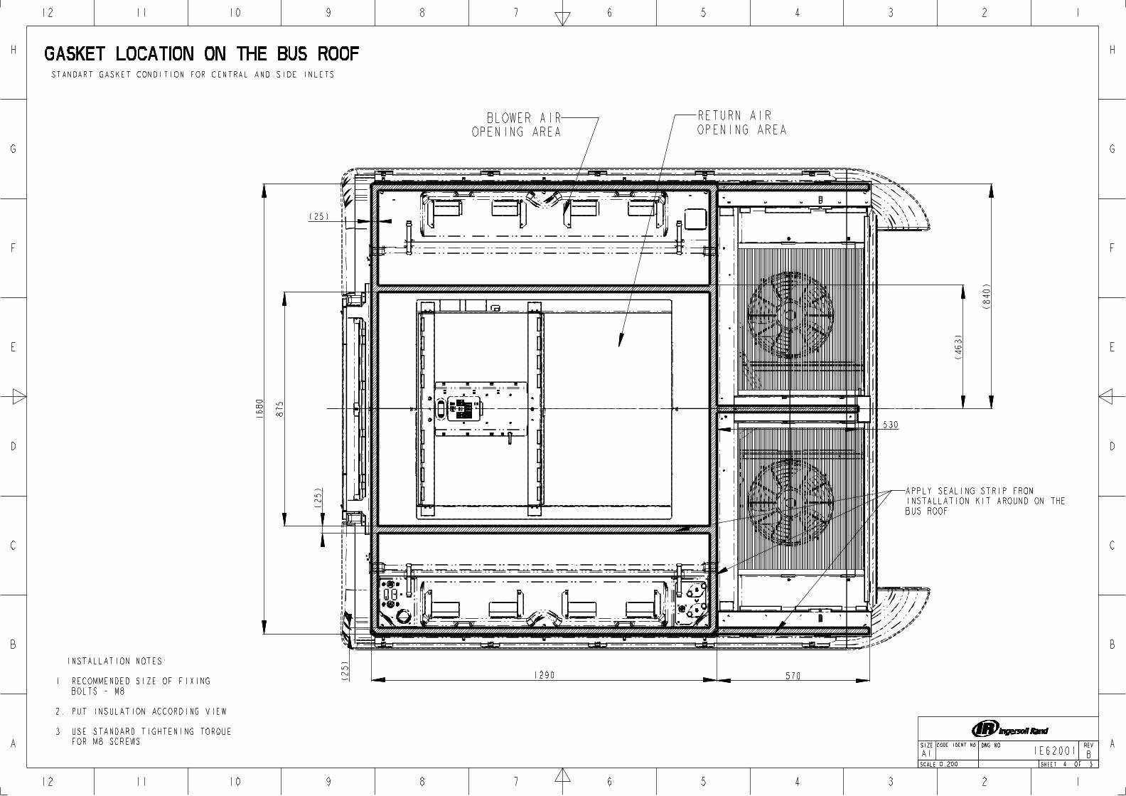
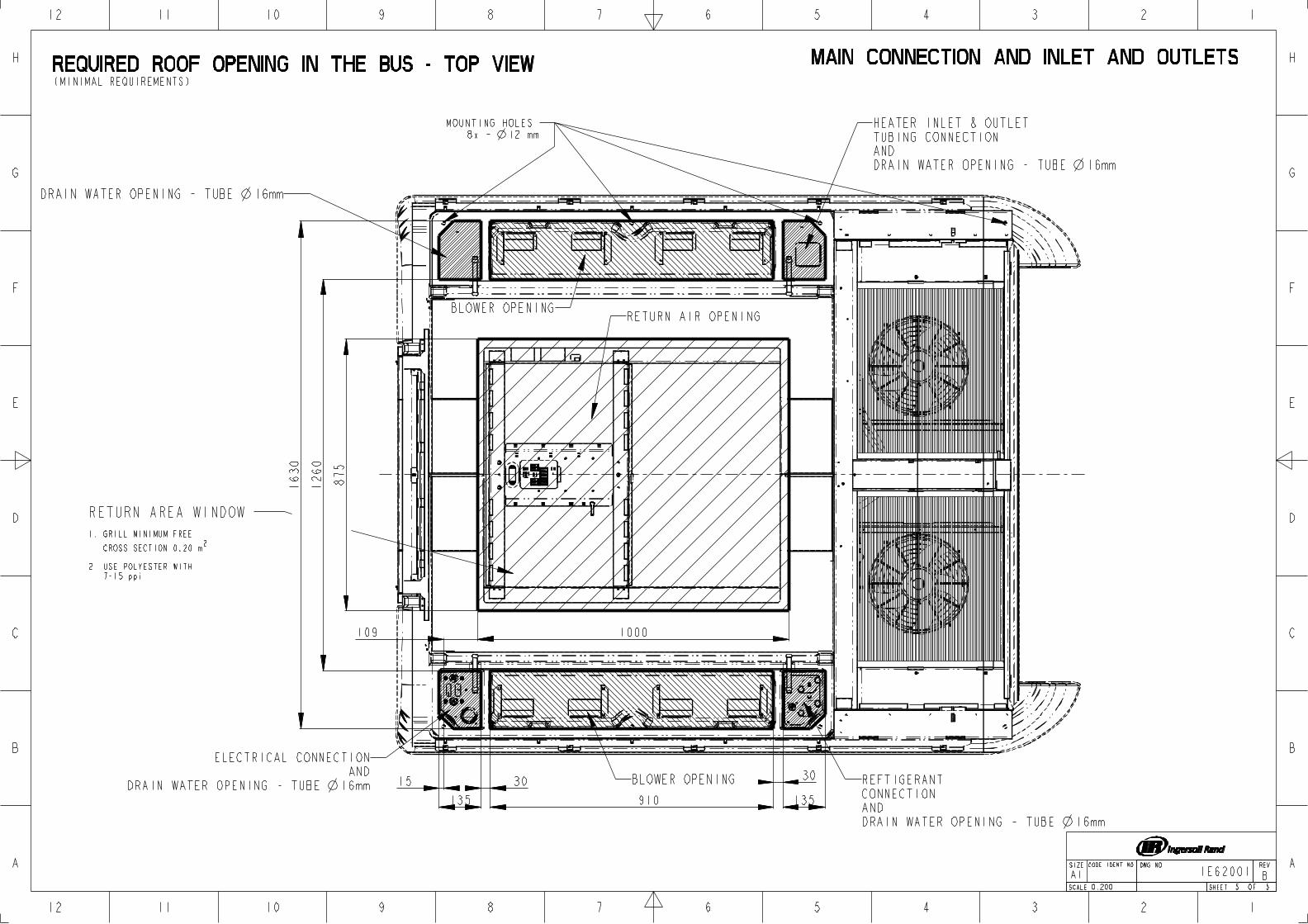
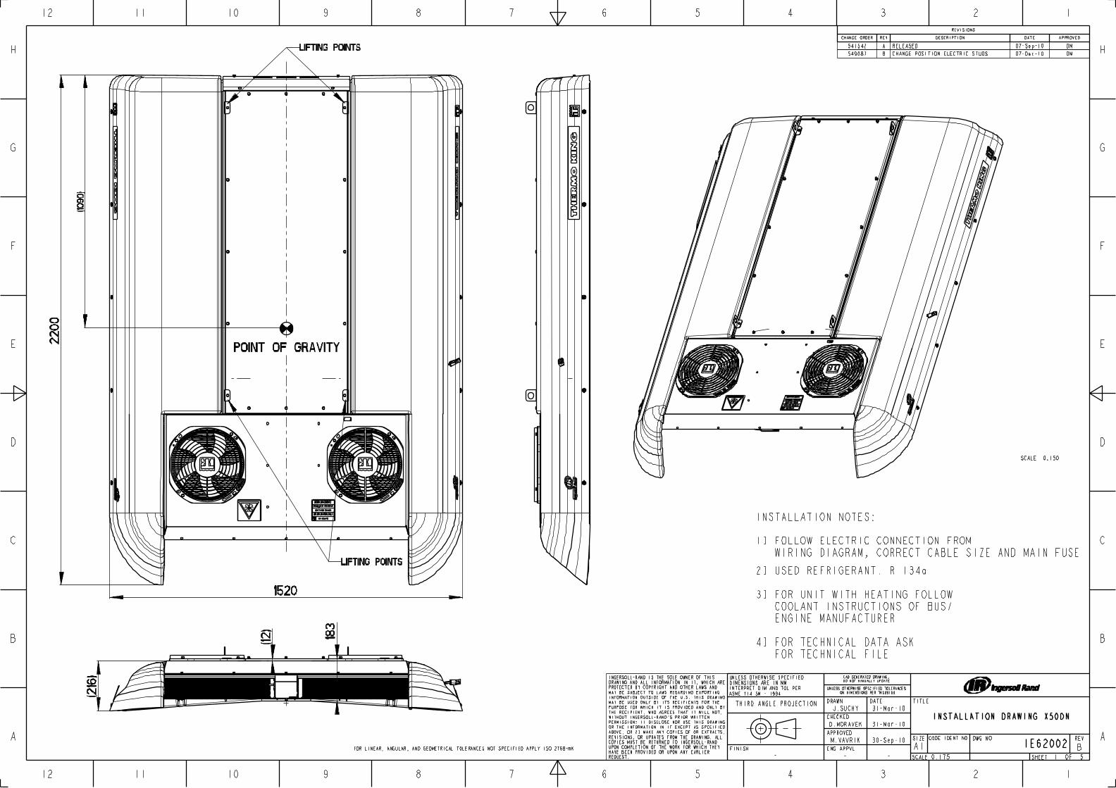
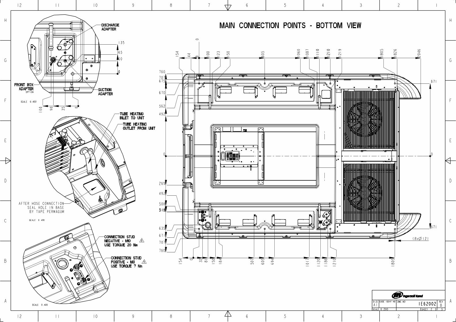
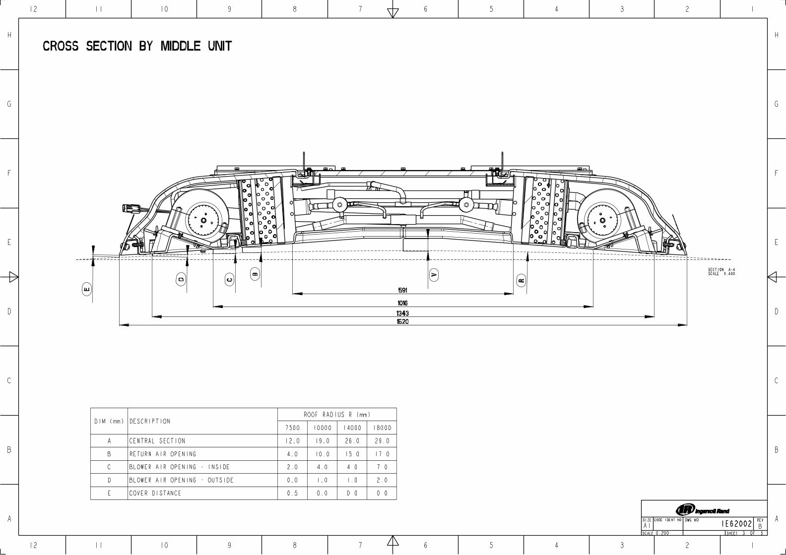
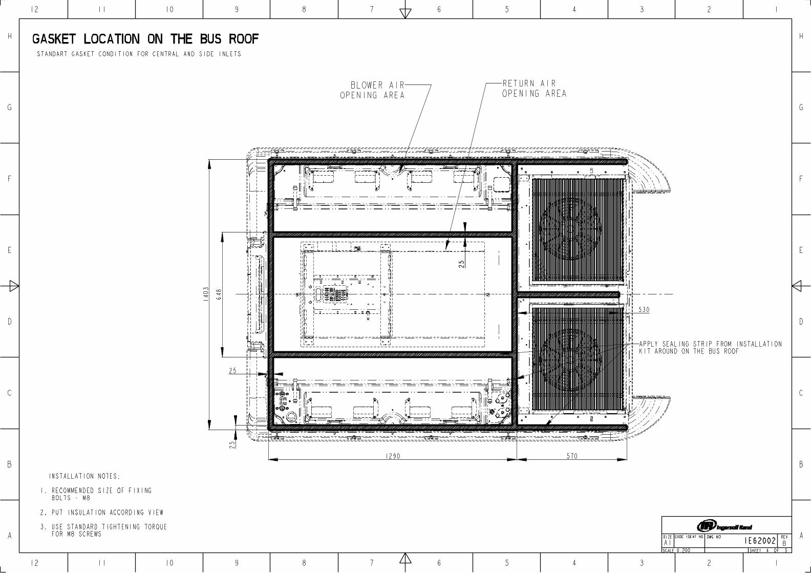
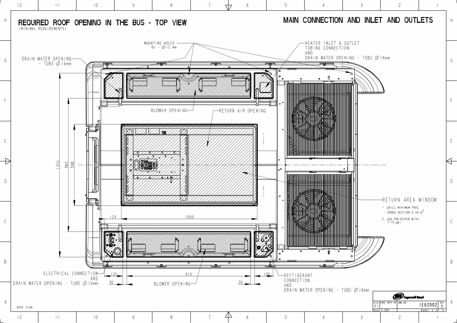
CompressorServiceManual
Copyright 2003 • International Components EngineeringMinneapolis, MN, U.S.A. • Printed in U.S.A.
ICE No. 51068 (Rev. 2a, 12/03)
forTM-08TM-13TM-15TM-16TM-21TM-31
Compressors
INTERNATIONALCOMPONENTS ENGINEERING
This manual is published for informational purposes only and the information so provided should not be considered as all-inclusive or covering all contingencies. If further information is required, International Components Engineering should be consulted.
Sale of product shown in this manual is subject to International Components Engineering terms and conditions including, but not limited to, the International Components Engineering Limited Express Warranty. Such terms and conditions are available upon request.
International Components Engineering warranty will not apply to any equipment which has been “so repaired or altered outside the manufacturer’s plants as, in the manufacturer’s judgment, to effect its stability.”
No warranties, express or implied, including warranties of fitness for a particular purpose or merchantability, or warranties arising from course of dealing or usage of trade, are made regarding the information, recommendations, and descriptions contained herein. Manufacturer is not responsible and will not be held liable in contract or in tort (including negligence) for any special, indirect or consequential damages, including injury or damage caused to vehicles, contents or persons, by reason of the installation of any product or its mechanical failure.
The compressor is designed for use with R-12 and R-134a for vehicle air conditioning only. Use with other refrigerants will void any warranty.
The ICE compressor is not intended nor designed for use on aircraft.
2
TM Advantages
Wide Range of Applications
• Single Operator Cabs to Large Trucks, Buses, RVs, and other Specialty Applications.
Smooth Operation
• Balanced Swash Plate design offers low pulsation noise, quiet and smooth operation, less vibration, and lower horsepower requirements.
High Efficiency
• Cooling capacity is stable throughout the entire RPM operating range.
High Durability
• MoS2 coated steel swash plate provides additional protection during liquid slugging and high load conditions.
• Ball and shoe design promotes lubrication for better compressor durability.
• Needle bearings insure high durability for long life and high speed operation.
• Lip Shaft Seal insures excellent sealing integrity and extends compressor life.
TM-31 ALSO INCLUDES
TM-31 Compressor with Oil Sight Glass
• Ease of maintenance.
Optimized Lubrication System
• Pressure lubrication system provides superior lubrication to cylinder walls, pistons, bearings, and shaft seals.
3
Recover Refrigerant
At International Components Engineering, we recognize the need to preserve the environment and limit potential harm to the ozone layer that can result from allowing refrigerant to escape into the atmosphere.
We strictly adhere to a policy that promotes the responsible use and handling of CFC/HCFC/HFC refrigerants by using approved recovery and recycling methods and equipment that limits the loss of refrigerant into the atmosphere.
4
Table of Contents
Safety Precautions . . . . . . . . . . . . . . . . . . . . . . . . . . . . . . . . . . . . . . . . . . . . . . . . . . . . . . . . . . . . . . . . . . . . . . . 7Safety Definitions . . . . . . . . . . . . . . . . . . . . . . . . . . . . . . . . . . . . . . . . . . . . . . . . . . . . . . . . . . . . . . . . . . . . . . . . . 7General Safety . . . . . . . . . . . . . . . . . . . . . . . . . . . . . . . . . . . . . . . . . . . . . . . . . . . . . . . . . . . . . . . . . . . . . . . . . . . 7Refrigerant . . . . . . . . . . . . . . . . . . . . . . . . . . . . . . . . . . . . . . . . . . . . . . . . . . . . . . . . . . . . . . . . . . . . . . . . . . . . . . 8
First Aid . . . . . . . . . . . . . . . . . . . . . . . . . . . . . . . . . . . . . . . . . . . . . . . . . . . . . . . . . . . . . . . . . . . . . . . . . . . . . 8Refrigerant Handling . . . . . . . . . . . . . . . . . . . . . . . . . . . . . . . . . . . . . . . . . . . . . . . . . . . . . . . . . . . . . . . . . . . . 8
Refrigerant Oil . . . . . . . . . . . . . . . . . . . . . . . . . . . . . . . . . . . . . . . . . . . . . . . . . . . . . . . . . . . . . . . . . . . . . . . . . . . . 8First Aid . . . . . . . . . . . . . . . . . . . . . . . . . . . . . . . . . . . . . . . . . . . . . . . . . . . . . . . . . . . . . . . . . . . . . . . . . . . . . 8
Leak Detection . . . . . . . . . . . . . . . . . . . . . . . . . . . . . . . . . . . . . . . . . . . . . . . . . . . . . . . . . . . . . . . . . . . . . . . . . . . 8R-134a Applications . . . . . . . . . . . . . . . . . . . . . . . . . . . . . . . . . . . . . . . . . . . . . . . . . . . . . . . . . . . . . . . . . . . . . . . 9
Oil Handling Procedures . . . . . . . . . . . . . . . . . . . . . . . . . . . . . . . . . . . . . . . . . . . .. . . . . . . . . . . . . . . . . . . . . 9Equipment for R-134a Use Only . . . . . . . . . . . . . . . . . . . . . . . . . . . . . . . . . . . . . . . . . . . . . . . . . . . . . . . . . . . 9
Compressor Identification Label . . . . . . . . . . . . . . . . . . . . . . . . . . . . . . . . . . . . . . . . . . . . . . . . . . . . . . . . . . . . . 10
Introduction . . . . . . . . . . . . . . . . . . . . . . . . . . . . . . . . . . . . . . . . . . . . . . . . . . . . . . . . . . . . . . . . . . . . . . . . . . . . 11Swash Plate System . . . . . . . . . . . . . . . . . . . . . . . . . . . . . . . . . . . . . . . . . . . . . . . . . . . . . . . . . . . . . . . . . . . . . . 11Piston Drive System . . . . . . . . . . . . . . . . . . . . . . . . . . . . . . . . . . . . . . . . . . . . . . . . . . . . . . . . . . . . . . . . . . . . . . 11Compressor System Guidelines . . . . . . . . . . . . . . . . . . . . . . . . . . . . . . . . . . . . . . . . . . . . . . . . . . . . . . . . . . . . . 11Suggested Operating Region . . . . . . . . . . . . . . . . . . . . . . . . . . . . . . . . . . . . . . . . . . . . . . . . . . . . . . . . . . . . . . . 12Clutch Application Guidelines . . . . . . . . . . . . . . . . . . . . . . . . . . . . . . . . . . . . . . . . . . . . . . . . . . . . . . . . . . . . . . . 13
Compressor Clutch and Fitting Options . . . . . . . . . . . . . . . . . . . . . . . . . . . . . . . . . . . . . . . . . . . . . . . . . . . . . 15
Dimensions and Specifications . . . . . . . . . . . . . . . . . . . . . . . . . . . . . . . . . . . . . . . . . . . . . . . . . . . . . . . . . . . . 17TM-08 Ear Mount Dimensions and Specifications . . . . . . . . . . . . . . . . . . . . . . . . . . . . . . . . . . . . . . . . . . . . . . . 17TM-08 Alternator Mount Dimensions and Specifications . . . . . . . . . . . . . . . . . . . . . . . . . . . . . . . . . . . . . . . . . . 18TM-08 Ear Mount Pad-Type Fittings . . . . . . . . . . . . . . . . . . . . . . . . . . . . . . . . . . . . . . . . . . . . . . . . . . . . . . . . . . 19TM-13 Dimensions and Specifications . . . . . . . . . . . . . . . . . . . . . . . . . . . . . . . . . . . . . . . . . . . . . . . . . . . . . . . . 20TM-15 Dimensions and Specifications . . . . . . . . . . . . . . . . . . . . . . . . . . . . . . . . . . . . . . . . . . . . . . . . . . . . . . . . 21TM-15 Direct Mount Dimensions and Specifications . . . . . . . . . . . . . . . . . . . . . . . . . . . . . . . . . . . . . . . . . . . . . 22TM-16 Dimensions and Specifications . . . . . . . . . . . . . . . . . . . . . . . . . . . . . . . . . . . . . . . . . . . . . . . . . . . . . . . . 23TM-21 Dimensions and Specifications . . . . . . . . . . . . . . . . . . . . . . . . . . . . . . . . . . . . . . . . . . . . . . . . . . . . . . . . 24TM-31HD Dimensions and Specifications . . . . . . . . . . . . . . . . . . . . . . . . . . . . . . . . . . . . . . . . . . . . . . . . . . . . . . 25TM-08 Exploded View . . . . . . . . . . . . . . . . . . . . . . . . . . . . . . . . . . . . . . . . . . . . . . . . . . . . . . . . . . . . . . . . . . . . . 28TM-13, TM-15, TM-16, TM-21 Exploded View . . . . . . . . . . . . . . . . . . . . . . . . . . . . . . . . . . . . . . . . . . . . . . . . . . 29TM-31 Exploded View . . . . . . . . . . . . . . . . . . . . . . . . . . . . . . . . . . . . . . . . . . . . . . . . . . . . . . . . . . . . . . . . . . . . . 30Tightening Torques . . . . . . . . . . . . . . . . . . . . . . . . . . . . . . . . . . . . . . . . . . . . . . . . . . . . . . . . . . . . . . . . . . . . . . . 31
Compressor Maintenance: TM-08, TM-13, TM-15, TM-16, TM-21 . . . . . . . . . . . . . . . . . . . . . . . . . . . . . . . . . 33Safety . . . . . . . . . . . . . . . . . . . . . . . . . . . . . . . . . . . . . . . . . . . . . . . . . . . . . . . . . . . . . . . . . . . . . . . . . . . . . . . . . 33Refrigerant Recovery . . . . . . . . . . . . . . . . . . . . . . . . . . . . . . . . . . . . . . . . . . . . . . . . . . . . . . . . . . . . . . . . . . . . . 33Compressor Handling . . . . . . . . . . . . . . . . . . . . . . . . . . . . . . . . . . . . . . . . . . . . . . . . . . . . . . . . . . . . . . . . . . . . . 34Compressor Storage . . . . . . . . . . . . . . . . . . . . . . . . . . . . . . . . . . . . . . . . . . . . . . . . . . . . . . . . . . . . . . . . . . . . . . 34Compressor Removal . . . . . . . . . . . . . . . . . . . . . . . . . . . . . . . . . . . . . . . . . . . . . . . . . . . . . . . . . . . . . . . . . . . . . 34
Operating Compressor . . . . . . . . . . . . . . . . . . . . . . . . . . . . . . . . . . . . . . . . . . . . . . . . . . . . . . . . . . . . . . . . . 34Non-Operating Compressor . . . . . . . . . . . . . . . . . . . . . . . . . . . . . . . . . . . . . . . . . . . . . . . . . . . . . . . . . . . . . 34
Compressor Installation . . . . . . . . . . . . . . . . . . . . . . . . . . . . . . . . . . . . . . . . . . . . . . . . . . . . . . . . . . . . . . . . . . . 34Installation Precautions . . . . . . . . . . . . . . . . . . . . . . . . . . . . . . . . . . . . . . . . . . . . . . . . . . . . . . . . . . . . . . . . 34Installation Position . . . . . . . . . . . . . . . . . . . . . . . . . . . . . . . . . . . . . . . . . . . . . . . . . . . . . . . . . . . . . . . . . . . . 35Mounting Compressors . . . . . . . . . . . . . . . . . . . . . . . . . . . . . . . . . . . . . . . . . . . . . . . . . . . . . . . . . . . . . . . . 35
Leak Testing the Compressor . . . . . . . . . . . . . . . . . . . . . . . . . . . . . . . . . . . . . . . . . . . . . . . . . . . . . . . . . . . . . . . 36Compressor Oil Procedures . . . . . . . . . . . . . . . . . . . . . . . . . . . . . . . . . . . . . . . . . . . . . . . . . . . . . . . . . . . . . . . . 36
Compressor Oil Caution Statements . . . . . . . . . . . . . . . . . . . . . . . . . . . . . . . . . . . . . . . . . . . . . . . . . . . . . . 36Oil Charge Considerations . . . . . . . . . . . . . . . . . . . . . . . . . . . . . . . . . . . . . . . . . . . . . . . . . . . . . . . . . . . . . . 36Oil Type Considerations . . . . . . . . . . . . . . . . . . . . . . . . . . . . . . . . . . . . . . . . . . . . . . . . . . . . . . . . . . . . . . . . 36Oil Check Interval . . . . . . . . . . . . . . . . . . . . . . . . . . . . . . . . . . . . . . . . . . . . . . . . . . . . . . . . . . . . . . . . . . . . . 37Oil Check Procedure . . . . . . . . . . . . . . . . . . . . . . . . . . . . . . . . . . . . . . . . . . . . . . . . . . . . . . . . . . . . . . . . . . 37
5
Table of Contents
Compressor Maintenance: TM-08, TM-13, TM-15, TM-16, TM-21 (continued)Clutch Procedures . . . . . . . . . . . . . . . . . . . . . . . . . . . . . . . . . . . . . . . . . . . . . . . . . . . . . . . . . . . . . . . . . . . . . . . . 39
Clutch Run-In . . . . . . . . . . . . . . . . . . . . . . . . . . . . . . . . . . . . . . . . . . . . . . . . . . . . . . . . . . . . . . . . . . . . . . . . 39Clutch Test . . . . . . . . . . . . . . . . . . . . . . . . . . . . . . . . . . . . . . . . . . . . . . . . . . . . . . . . . . . . . . . . . . . . . . . . . . 39Clutch Removal . . . . . . . . . . . . . . . . . . . . . . . . . . . . . . . . . . . . . . . . . . . . . . . . . . . . . . . . . . . . . . . . . . . . . . . 39Clutch Inspection . . . . . . . . . . . . . . . . . . . . . . . . . . . . . . . . . . . . . . . . . . . . . . . . . . . . . . . . . . . . . . . . . . . . . 40Clutch Installation . . . . . . . . . . . . . . . . . . . . . . . . . . . . . . . . . . . . . . . . . . . . . . . . . . . . . . . . . . . . . . . . . . . . . 41Electrical Connection . . . . . . . . . . . . . . . . . . . . . . . . . . . . . . . . . . . . . . . . . . . . . . . . . . . . . . . . . . . . . . . . . . 42
Shaft Seal Procedures . . . . . . . . . . . . . . . . . . . . . . . . . . . . . . . . . . . . . . . . . . . . . . . . . . . . . . . . . . . . . . . . . . . . . 42Shaft Seal Removal . . . . . . . . . . . . . . . . . . . . . . . . . . . . . . . . . . . . . . . . . . . . . . . . . . . . . . . . . . . . . . . . . . . 42Shaft Seal Inspection . . . . . . . . . . . . . . . . . . . . . . . . . . . . . . . . . . . . . . . . . . . . . . . . . . . . . . . . . . . . . . . . . . 43Shaft Seal Installation . . . . . . . . . . . . . . . . . . . . . . . . . . . . . . . . . . . . . . . . . . . . . . . . . . . . . . . . . . . . . . . . . . 43Shaft Seal Cover Installation (When Equipped) . . . . . . . . . . . . . . . . . . . . . . . . . . . . . . . . . . . . . . . . . . . . . . 44
Cylinder Head Procedures . . . . . . . . . . . . . . . . . . . . . . . . . . . . . . . . . . . . . . . . . . . . . . . . . . . . . . . . . . . . . . . . . 44Cylinder Head Disassembly–Front and Rear . . . . . . . . . . . . . . . . . . . . . . . . . . . . . . . . . . . . . . . . . . . . . . . . 44Cylinder Head Inspection . . . . . . . . . . . . . . . . . . . . . . . . . . . . . . . . . . . . . . . . . . . . . . . . . . . . . . . . . . . . . . . 46Cylinder Head Reassembly . . . . . . . . . . . . . . . . . . . . . . . . . . . . . . . . . . . . . . . . . . . . . . . . . . . . . . . . . . . . . 47
Compressor Maintenance: TM-31 . . . . . . . . . . . . . . . . . . . . . . . . . . . . . . . . . . . . . . . . . . . . . . . . . . . . . . . . . . 51Safety . . . . . . . . . . . . . . . . . . . . . . . . . . . . . . . . . . . . . . . . . . . . . . . . . . . . . . . . . . . . . . . . . . . . . . . . . . . . . . . . . 51Refrigerant Recovery . . . . . . . . . . . . . . . . . . . . . . . . . . . . . . . . . . . . . . . . . . . . . . . . . . . . . . . . . . . . . . . . . . . . . . 51Compressor Handling . . . . . . . . . . . . . . . . . . . . . . . . . . . . . . . . . . . . . . . . . . . . . . . . . . . . . . . . . . . . . . . . . . . . . 52Compressor Storage . . . . . . . . . . . . . . . . . . . . . . . . . . . . . . . . . . . . . . . . . . . . . . . . . . . . . . . . . . . . . . . . . . . . . . 52Compressor Removal . . . . . . . . . . . . . . . . . . . . . . . . . . . . . . . . . . . . . . . . . . . . . . . . . . . . . . . . . . . . . . . . . . . . . 52Compressor Installation . . . . . . . . . . . . . . . . . . . . . . . . . . . . . . . . . . . . . . . . . . . . . . . . . . . . . . . . . . . . . . . . . . . . 52Oil Procedures . . . . . . . . . . . . . . . . . . . . . . . . . . . . . . . . . . . . . . . . . . . . . . . . . . . . . . . . . . . . . . . . . . . . . . . . . . . 53Clutch Procedures . . . . . . . . . . . . . . . . . . . . . . . . . . . . . . . . . . . . . . . . . . . . . . . . . . . . . . . . . . . . . . . . . . . . . . . . 53
Clutch Run-In . . . . . . . . . . . . . . . . . . . . . . . . . . . . . . . . . . . . . . . . . . . . . . . . . . . . . . . . . . . . . . . . . . . . . . . . 53Clutch Removal . . . . . . . . . . . . . . . . . . . . . . . . . . . . . . . . . . . . . . . . . . . . . . . . . . . . . . . . . . . . . . . . . . . . . . . 53Clutch Inspection . . . . . . . . . . . . . . . . . . . . . . . . . . . . . . . . . . . . . . . . . . . . . . . . . . . . . . . . . . . . . . . . . . . . . 54Clutch Installation . . . . . . . . . . . . . . . . . . . . . . . . . . . . . . . . . . . . . . . . . . . . . . . . . . . . . . . . . . . . . . . . . . . . . 55
Shaft Seal Procedures . . . . . . . . . . . . . . . . . . . . . . . . . . . . . . . . . . . . . . . . . . . . . . . . . . . . . . . . . . . . . . . . . . . . . 56Shaft Seal Removal . . . . . . . . . . . . . . . . . . . . . . . . . . . . . . . . . . . . . . . . . . . . . . . . . . . . . . . . . . . . . . . . . . . 56Shaft Seal Installation . . . . . . . . . . . . . . . . . . . . . . . . . . . . . . . . . . . . . . . . . . . . . . . . . . . . . . . . . . . . . . . . . . 56
Appendix – Tools and Kits . . . . . . . . . . . . . . . . . . . . . . . . . . . . . . . . . . . . . . . . . . . . . . . . . . . . . . . . . . . . . . . . 59
6
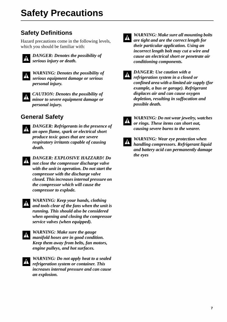
Safety Precautions
Safety DefinitionsHazard precautions come in the following levels, which you should be familiar with:
General Safety
DANGER: Denotes the possibility of serious injury or death.
WARNING: Denotes the possibility of serious equipment damage or serious personal injury.
CAUTION: Denotes the possibility of minor to severe equipment damage or personal injury.
DANGER: Refrigerants in the presence of an open flame, spark or electrical short produce toxic gases that are severe respiratory irritants capable of causing death.
DANGER: EXPLOSIVE HAZZARD! Do not close the compressor discharge valve with the unit in operation. Do not start the compressor with the discharge valve closed. This increases internal pressure on the compressor which will cause the compressor to explode.
WARNING: Keep your hands, clothing and tools clear of the fans when the unit is running. This should also be considered when opening and closing the compressor service valves (when equipped).
WARNING: Make sure the gauge manifold hoses are in good condition. Keep them away from belts, fan motors, engine pulleys, and hot surfaces.
WARNING: Do not apply heat to a sealed refrigeration system or container. This increases internal pressure and can cause an explosion.
WARNING: Make sure all mounting bolts are tight and are the correct length for their particular application. Using an incorrect length bolt may cut a wire and cause an electrical short or penetrate air conditioning components.
DANGER: Use caution with a refrigeration system in a closed or confined area with a limited air supply (for example, a bus or garage). Refrigerant displaces air and can cause oxygen depletion, resulting in suffocation and possible death.
WARNING: Do not wear jewelry, watches or rings. These items can short out, causing severe burns to the wearer.
WARNING: Wear eye protection when handling compressors. Refrigerant liquid and battery acid can permanently damage the eyes
7
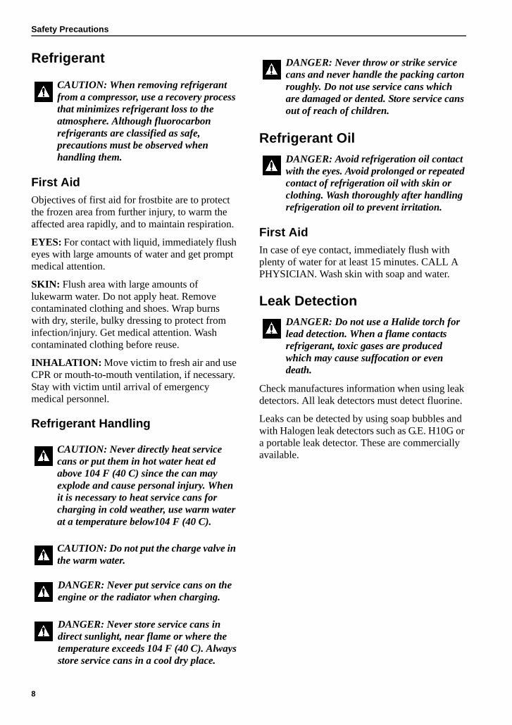
Safety Precautions
Refrigerant
First AidObjectives of first aid for frostbite are to protect the frozen area from further injury, to warm the affected area rapidly, and to maintain respiration.
EYES: For contact with liquid, immediately flush eyes with large amounts of water and get prompt medical attention.
SKIN: Flush area with large amounts of lukewarm water. Do not apply heat. Remove contaminated clothing and shoes. Wrap burns with dry, sterile, bulky dressing to protect from infection/injury. Get medical attention. Wash contaminated clothing before reuse.
INHALATION: Move victim to fresh air and use CPR or mouth-to-mouth ventilation, if necessary. Stay with victim until arrival of emergency medical personnel.
Refrigerant Handling
Refrigerant Oil
First AidIn case of eye contact, immediately flush with plenty of water for at least 15 minutes. CALL A PHYSICIAN. Wash skin with soap and water.
Leak Detection
Check manufactures information when using leak detectors. All leak detectors must detect fluorine.
Leaks can be detected by using soap bubbles and with Halogen leak detectors such as G.E. H10G or a portable leak detector. These are commercially available.
CAUTION: When removing refrigerant from a compressor, use a recovery process that minimizes refrigerant loss to the atmosphere. Although fluorocarbon refrigerants are classified as safe, precautions must be observed when handling them.
CAUTION: Never directly heat service cans or put them in hot water heat ed above 104 F (40 C) since the can may explode and cause personal injury. When it is necessary to heat service cans for charging in cold weather, use warm water at a temperature below104 F (40 C).
CAUTION: Do not put the charge valve in the warm water.
DANGER: Never put service cans on the engine or the radiator when charging.
DANGER: Never store service cans in direct sunlight, near flame or where the temperature exceeds 104 F (40 C). Always store service cans in a cool dry place.
DANGER: Never throw or strike service cans and never handle the packing carton roughly. Do not use service cans which are damaged or dented. Store service cans out of reach of children.
DANGER: Avoid refrigeration oil contact with the eyes. Avoid prolonged or repeated contact of refrigeration oil with skin or clothing. Wash thoroughly after handling refrigeration oil to prevent irritation.
DANGER: Do not use a Halide torch for lead detection. When a flame contacts refrigerant, toxic gases are produced which may cause suffocation or even death.
8
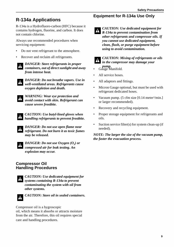
Safety Precautions
R-134a ApplicationsR-134a is a Hydrofluoro-carbon (HFC) because it contains hydrogen, fluorine, and carbon. It does not contain chlorine.
Always use recommended procedures when servicing equipment:
• Do not vent refrigerant to the atmosphere.
• Recover and reclaim all refrigerants.
Compressor Oil Handling Procedures
Compressor oil is a hygroscopic oil, which means it absorbs or attracts moisture from the air. Therefore, this oil requires special care and handling procedures.
Equipment for R-134a Use Only
• Gauge Manifold.
• All service hoses.
• All adaptors and fittings.
• Micron Gauge optional, but must be used with refrigerant dedicated hoses.
• Vacuum pump. (5 cfm size [0.14 meter3/min.] or larger recommended).
• Recovery and recycling equipment.
• Proper storage equipment for refrigerants and oils.
• Suction service filter(s) for system clean-up (if needed).
NOTE: The larger the size of the vacuum pump, the faster the evacuation process.
DANGER: Store refrigerants in proper containers, out of direct sunlight and away from intense heat.
DANGER: Do not breathe vapors. Use in well-ventilated areas. Refrigerants cause oxygen depletion and death.
WARNING: Wear eye protection and avoid contact with skin. Refrigerant can cause severe frostbite.
CAUTION: Use butyl-lined gloves when handling refrigerants to prevent frostbite.
DANGER: Do not use open flame near refrigerant. Do not burn it as toxic fumes may be released.
DANGER: Do not use Oxygen (O2) or compressed air for leak testing. An explosion may occur.
CAUTION: Use dedicated equipment for systems containing R-134a to prevent contaminating the system with oil from other systems.
CAUTION: Store oil in sealed containers.
CAUTION: Use dedicated equipment for R-134a to prevent contamination from other refrigerants and compressor oils. If you cannot use dedicated equipment, clean, flush, or purge equipment before using to avoid contamination.
CAUTION: Mixing of refrigerants or oils in the compressor may damage your pump.
9
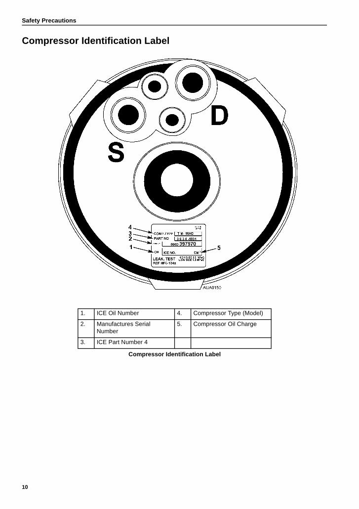
Safety Precautions
Compressor Identification Label
1. ICE Oil Number 4. Compressor Type (Model)
2. Manufactures Serial Number
5. Compressor Oil Charge
3. ICE Part Number 4
Compressor Identification Label
10
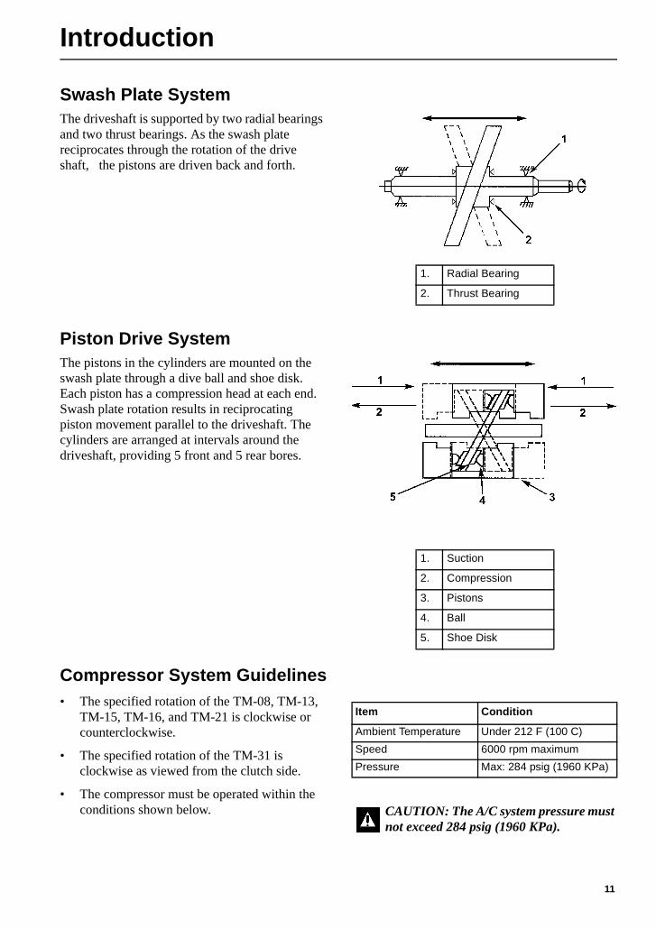
Introduction
Swash Plate SystemThe driveshaft is supported by two radial bearings and two thrust bearings. As the swash plate reciprocates through the rotation of the drive shaft, the pistons are driven back and forth.
Piston Drive SystemThe pistons in the cylinders are mounted on the swash plate through a dive ball and shoe disk. Each piston has a compression head at each end. Swash plate rotation results in reciprocating piston movement parallel to the driveshaft. The cylinders are arranged at intervals around the driveshaft, providing 5 front and 5 rear bores.
Compressor System Guidelines• The specified rotation of the TM-08, TM-13,
TM-15, TM-16, and TM-21 is clockwise or counterclockwise.
• The specified rotation of the TM-31 is clockwise as viewed from the clutch side.
• The compressor must be operated within the conditions shown below.
1. Radial Bearing
2. Thrust Bearing
1. Suction
2. Compression
3. Pistons
4. Ball
5. Shoe Disk
Item Condition
Ambient Temperature Under 212 F (100 C)
Speed 6000 rpm maximum
Pressure Max: 284 psig (1960 KPa)
CAUTION: The A/C system pressure must not exceed 284 psig (1960 KPa).
11
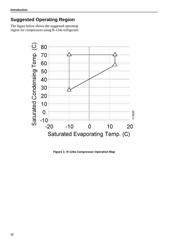
Introduction
Suggested Operating RegionThe figure below shows the suggested operating region for compressors using R-134a refrigerant:
Figure 1: R-134a Compressor Operation Map
12
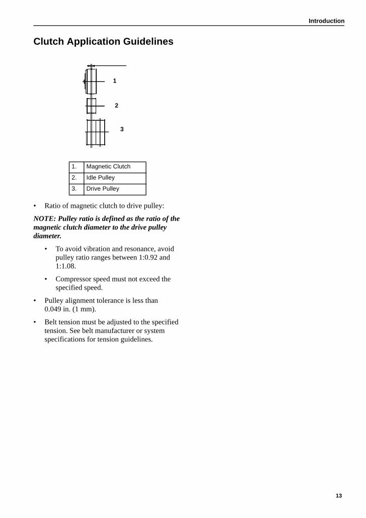
Introduction
Clutch Application Guidelines
• Ratio of magnetic clutch to drive pulley:
NOTE: Pulley ratio is defined as the ratio of the magnetic clutch diameter to the drive pulley diameter.
• To avoid vibration and resonance, avoid pulley ratio ranges between 1:0.92 and 1:1.08.
• Compressor speed must not exceed the specified speed.
• Pulley alignment tolerance is less than 0.049 in. (1 mm).
• Belt tension must be adjusted to the specified tension. See belt manufacturer or system specifications for tension guidelines.
1. Magnetic Clutch
2. Idle Pulley
3. Drive Pulley
2
3
4
AEA1878
4
3
1
2
3
13

Introduction
14
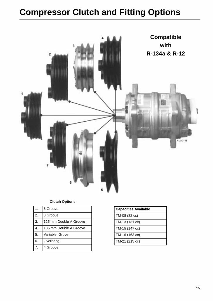
Compressor Clutch and Fitting Options
Compatiblewith
R-134a & R-12
Clutch Options
1. 6 Groove
2. 8 Groove
3. 125 mm Double A Groove
4. 135 mm Double A Groove
5. Variable Grove
6. Overhang
7. 4 Groove
Capacities Available
TM-08 (82 cc)
TM-13 (131 cc)
TM-15 (147 cc)
TM-16 (163 cc)
TM-21 (215 cc)
15
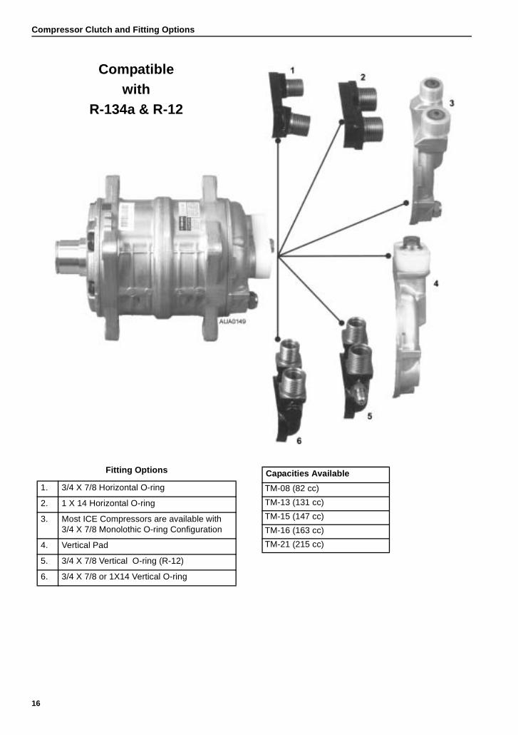
Compressor Clutch and Fitting Options
Compatiblewith
R-134a & R-12
Fitting Options
1. 3/4 X 7/8 Horizontal O-ring
2. 1 X 14 Horizontal O-ring
3. Most ICE Compressors are available with 3/4 X 7/8 Monolothic O-ring Configuration
4. Vertical Pad
5. 3/4 X 7/8 Vertical O-ring (R-12)
6. 3/4 X 7/8 or 1X14 Vertical O-ring
Capacities Available
TM-08 (82 cc)
TM-13 (131 cc)
TM-15 (147 cc)
TM-16 (163 cc)
TM-21 (215 cc)
16
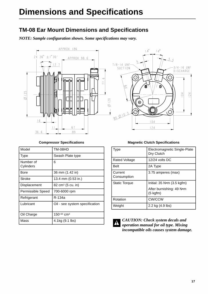
Dimensions and Specifications
TM-08 Ear Mount Dimensions and SpecificationsNOTE: Sample configuration shown. Some specifications may vary.
Compressor Specifications
Model TM-08HD
Type Swash Plate type
Number of Cylinders
6
Bore 36 mm (1.42 in)
Stroke 13.4 mm (0.53 in.)
Displacement 82 cm3 (5 cu. in)
Permissible Speed 700-6000 rpm
Refrigerant R-134a
Lubricant Oil see system specification
Oil Charge 150+20 cm3
Mass 4.1kg (9.1 lbs)
Magnetic Clutch Specifications
Type Electromagnetic Single-Plate Dry Clutch
Rated Voltage 12/24 volts DC
Belt 2A Type
Current Consumption
3.75 amperes (max)
Static Torque Initial: 35 N•m (3.5 kgfm)
After burnishing: 49 N•m (5 kgfm)
Rotation CW/CCW
Weight 2.2 kg (4.9 lbs)
CAUTION: Check system decals and operation manual for oil type. Mixing incompatible oils causes system damage.
17
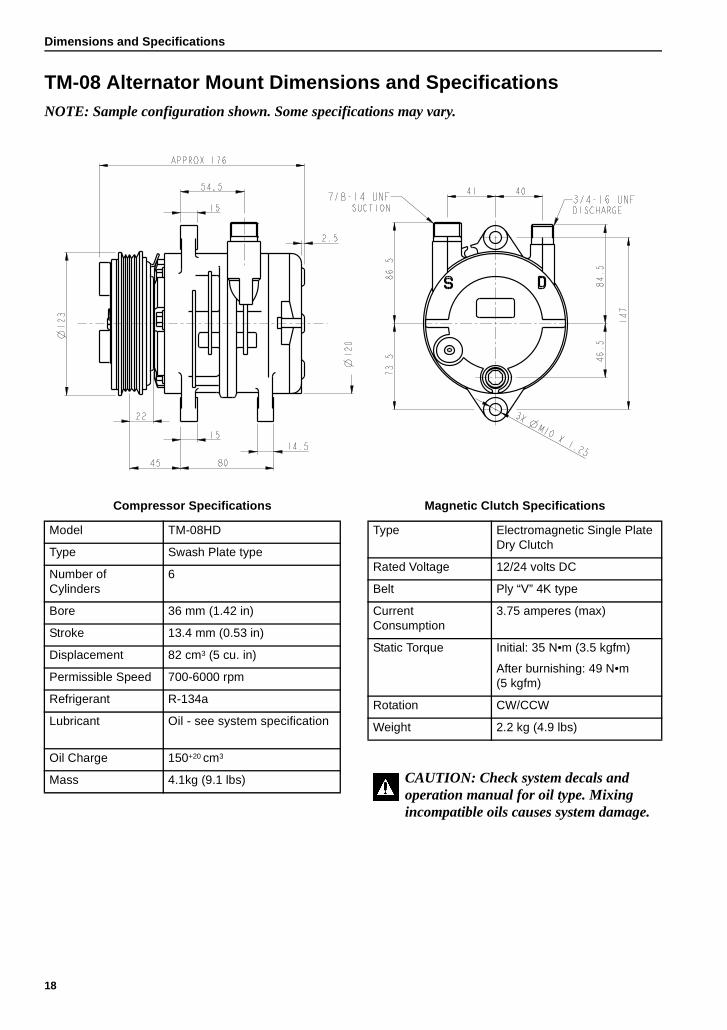
Dimensions and Specifications
TM-08 Alternator Mount Dimensions and SpecificationsNOTE: Sample configuration shown. Some specifications may vary.
Compressor Specifications
Model TM-08HD
Type Swash Plate type
Number of Cylinders
6
Bore 36 mm (1.42 in)
Stroke 13.4 mm (0.53 in)
Displacement 82 cm3 (5 cu. in)
Permissible Speed 700-6000 rpm
Refrigerant R-134a
Lubricant Oil see system specification
Oil Charge 150+20 cm3
Mass 4.1kg (9.1 lbs)
Magnetic Clutch Specifications
Type Electromagnetic Single Plate Dry Clutch
Rated Voltage 12/24 volts DC
Belt Ply “V” 4K type
Current Consumption
3.75 amperes (max)
Static Torque Initial: 35 N•m (3.5 kgfm)
After burnishing: 49 N•m(5 kgfm)
Rotation CW/CCW
Weight 2.2 kg (4.9 lbs)
CAUTION: Check system decals and operation manual for oil type. Mixing incompatible oils causes system damage.
18
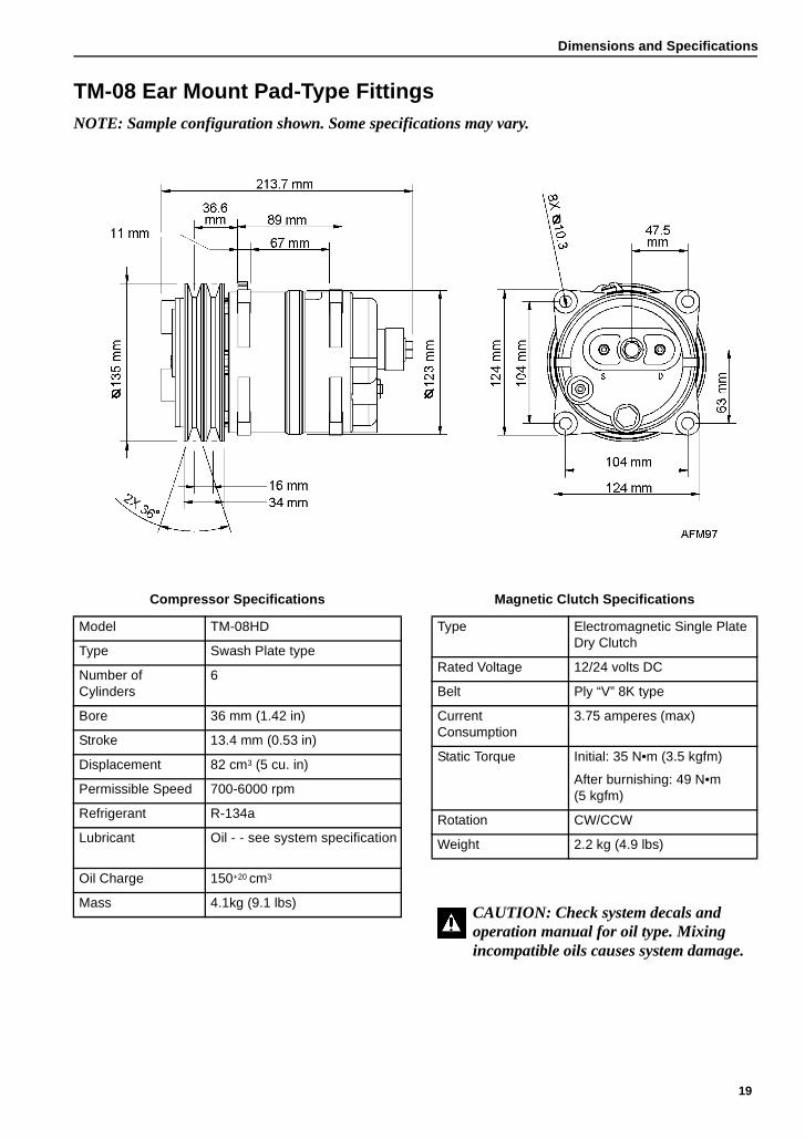
Dimensions and Specifications
TM-08 Ear Mount Pad-Type FittingsNOTE: Sample configuration shown. Some specifications may vary.
Compressor Specifications
Model TM-08HD
Type Swash Plate type
Number of Cylinders
6
Bore 36 mm (1.42 in)
Stroke 13.4 mm (0.53 in)
Displacement 82 cm3 (5 cu. in)
Permissible Speed 700-6000 rpm
Refrigerant R-134a
Lubricant Oil - see system specification
Oil Charge 150+20 cm3
Mass 4.1kg (9.1 lbs)
Magnetic Clutch Specifications
Type Electromagnetic Single Plate Dry Clutch
Rated Voltage 12/24 volts DC
Belt Ply “V” 8K type
Current Consumption
3.75 amperes (max)
Static Torque Initial: 35 N•m (3.5 kgfm)
After burnishing: 49 N•m(5 kgfm)
Rotation CW/CCW
Weight 2.2 kg (4.9 lbs)
CAUTION: Check system decals and operation manual for oil type. Mixing incompatible oils causes system damage.
19
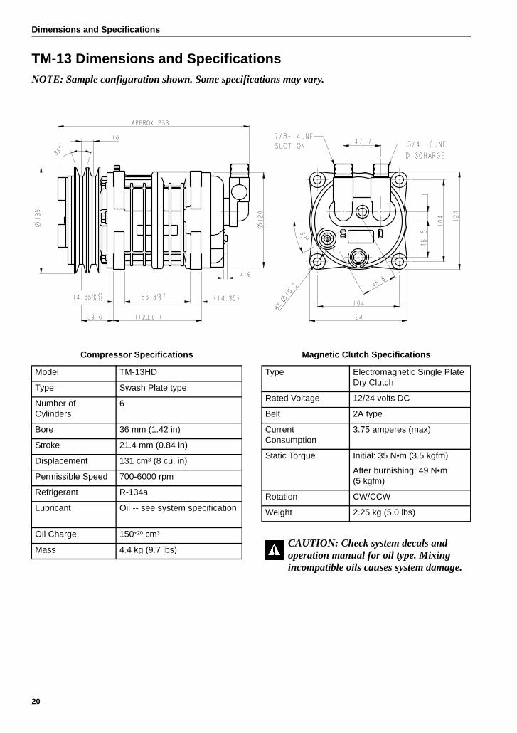
Dimensions and Specifications
TM-13 Dimensions and SpecificationsNOTE: Sample configuration shown. Some specifications may vary.
Compressor Specifications
Model TM-13HD
Type Swash Plate type
Number of Cylinders
6
Bore 36 mm (1.42 in)
Stroke 21.4 mm (0.84 in)
Displacement 131 cm3 (8 cu. in)
Permissible Speed 700-6000 rpm
Refrigerant R-134a
Lubricant Oil - see system specification
Oil Charge 150+20 cm3
Mass 4.4 kg (9.7 lbs)
Magnetic Clutch Specifications
Type Electromagnetic Single Plate Dry Clutch
Rated Voltage 12/24 volts DC
Belt 2A type
Current Consumption
3.75 amperes (max)
Static Torque Initial: 35 N•m (3.5 kgfm)
After burnishing: 49 N•m(5 kgfm)
Rotation CW/CCW
Weight 2.25 kg (5.0 lbs)
CAUTION: Check system decals and operation manual for oil type. Mixing incompatible oils causes system damage.
20
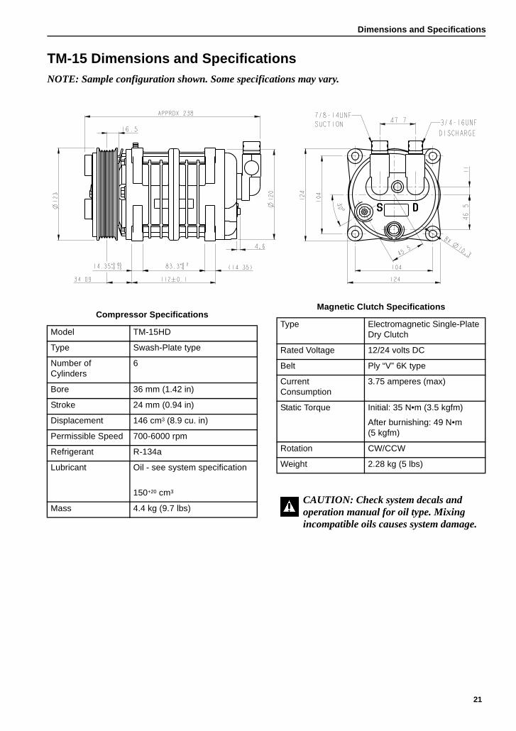
Dimensions and Specifications
TM-15 Dimensions and SpecificationsNOTE: Sample configuration shown. Some specifications may vary.
Compressor Specifications
Model TM-15HD
Type Swash-Plate type
Number of Cylinders
6
Bore 36 mm (1.42 in)
Stroke 24 mm (0.94 in)
Displacement 146 cm3 (8.9 cu. in)
Permissible Speed 700-6000 rpm
Refrigerant R-134a
Lubricant Oil - see system specification
150+20 cm3
Mass 4.4 kg (9.7 lbs)
Magnetic Clutch Specifications
Type Electromagnetic Single-Plate Dry Clutch
Rated Voltage 12/24 volts DC
Belt Ply “V” 6K type
Current Consumption
3.75 amperes (max)
Static Torque Initial: 35 N•m (3.5 kgfm)
After burnishing: 49 N•m(5 kgfm)
Rotation CW/CCW
Weight 2.28 kg (5 lbs)
CAUTION: Check system decals and operation manual for oil type. Mixing incompatible oils causes system damage.
21
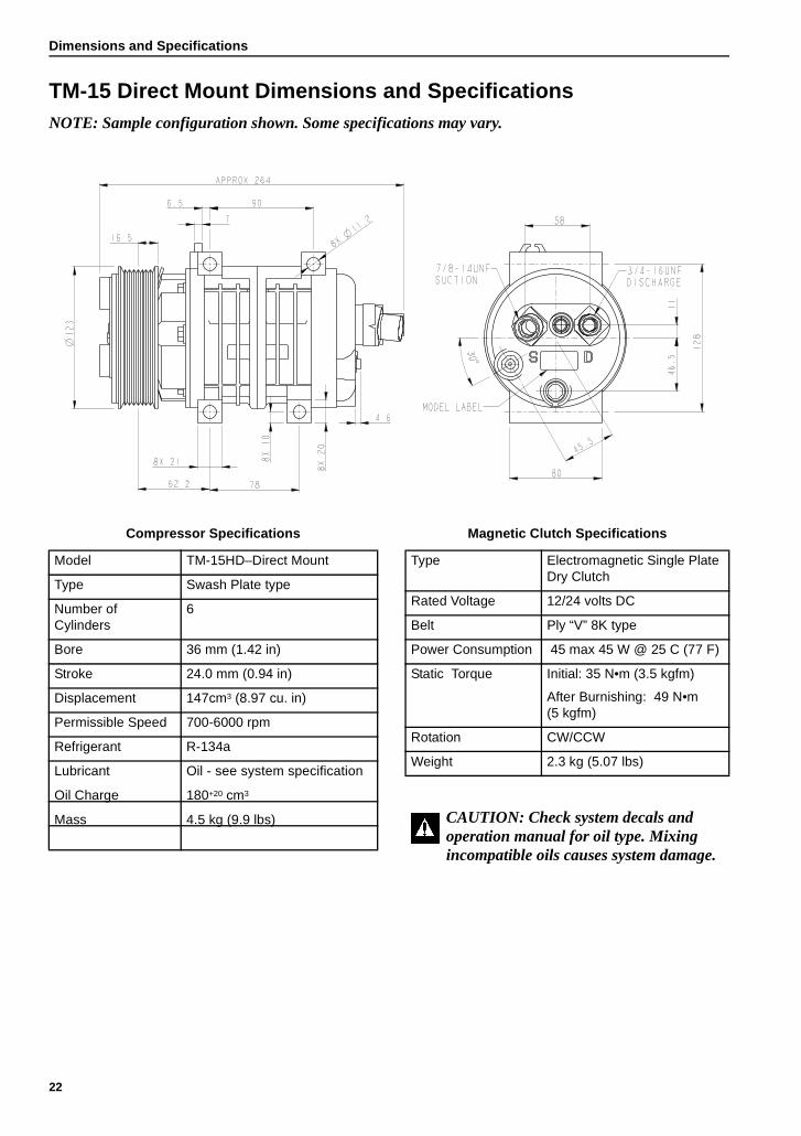
Dimensions and Specifications
TM-15 Direct Mount Dimensions and SpecificationsNOTE: Sample configuration shown. Some specifications may vary.
Compressor Specifications
Model TM-15HD–Direct Mount
Type Swash Plate type
Number of Cylinders
6
Bore 36 mm (1.42 in)
Stroke 24.0 mm (0.94 in)
Displacement 147cm3 (8.97 cu. in)
Permissible Speed 700-6000 rpm
Refrigerant R-134a
Lubricant Oil see system specification
Oil Charge 180+20 cm3
Mass 4.5 kg (9.9 lbs)
Magnetic Clutch Specifications
Type Electromagnetic Single Plate Dry Clutch
Rated Voltage 12/24 volts DC
Belt Ply “V” 8K type
Power Consumption 45 max 45 W @ 25 C (77 F)
Static Torque Initial: 35 N•m (3.5 kgfm)
After Burnishing: 49 N•m (5 kgfm)
Rotation CW/CCW
Weight 2.3 kg (5.07 lbs)
CAUTION: Check system decals and operation manual for oil type. Mixing incompatible oils causes system damage.
22
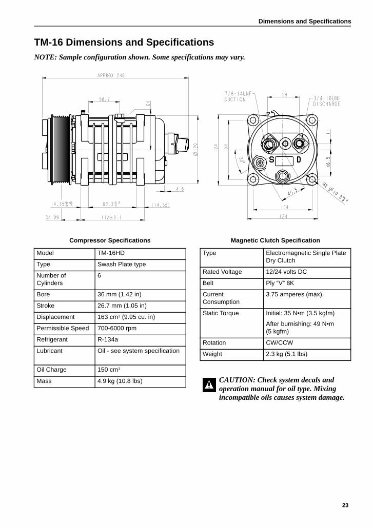
Dimensions and Specifications
TM-16 Dimensions and SpecificationsNOTE: Sample configuration shown. Some specifications may vary.
Compressor Specifications
Model TM-16HD
Type Swash Plate type
Number of Cylinders
6
Bore 36 mm (1.42 in)
Stroke 26.7 mm (1.05 in)
Displacement 163 cm3 (9.95 cu. in)
Permissible Speed 700-6000 rpm
Refrigerant R-134a
Lubricant Oil see system specification
Oil Charge 150 cm3
Mass 4.9 kg (10.8 lbs)
Magnetic Clutch Specification
Type Electromagnetic Single Plate Dry Clutch
Rated Voltage 12/24 volts DC
Belt Ply “V” 8K
Current Consumption
3.75 amperes (max)
Static Torque Initial: 35 N•m (3.5 kgfm)
After burnishing: 49 N•m(5 kgfm)
Rotation CW/CCW
Weight 2.3 kg (5.1 lbs)
CAUTION: Check system decals and operation manual for oil type. Mixing incompatible oils causes system damage.
23
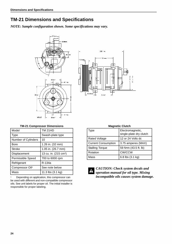
Dimensions and Specifications
TM-21 Dimensions and SpecificationsNOTE: Sample configuration shown. Some specifications may vary.
TM-21 Compressor Dimensions
Model TM 21HD
Type Swash-plate type
Number of Cylinders 10
Bore 1.26 in. (32 mm)
Stroke 1.05 in. (26.7 mm)
Displacement 13 cu. in. (215 cm3)
Permissible Speed 700 to 6000 rpm
Refrigerant R-134a
Compressor Oil1
1 Depending on application, this compressor can be used with different and non-compatible compressor oils. See unit labels for proper oil. The initial installer is responsible for proper labeling.
See note below
Mass 11.3 lbs (3.1 kg)
Magnetic Clutch
Type Electromagnetic, single-plate dry clutch
Rated Voltage 12 or 24 Volts dc
Current Consumption 3.75 amperes (MAX)
Stalling Torque 59 N•m (43.5 ft. lb)
Rotation CW/CCW
Mass 6.8 lbs (3.1 kg)
CAUTION: Check system decals and operation manual for oil type. Mixing incompatible oils causes system damage.
24
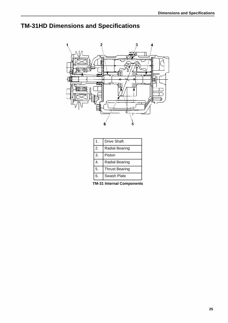
Dimensions and Specifications
TM-31HD Dimensions and Specifications
1. Drive Shaft
2. Radial Bearing
3. Piston
4. Radial Bearing
5. Thrust Bearing
6. Swash Plate
TM-31 Internal Components
25
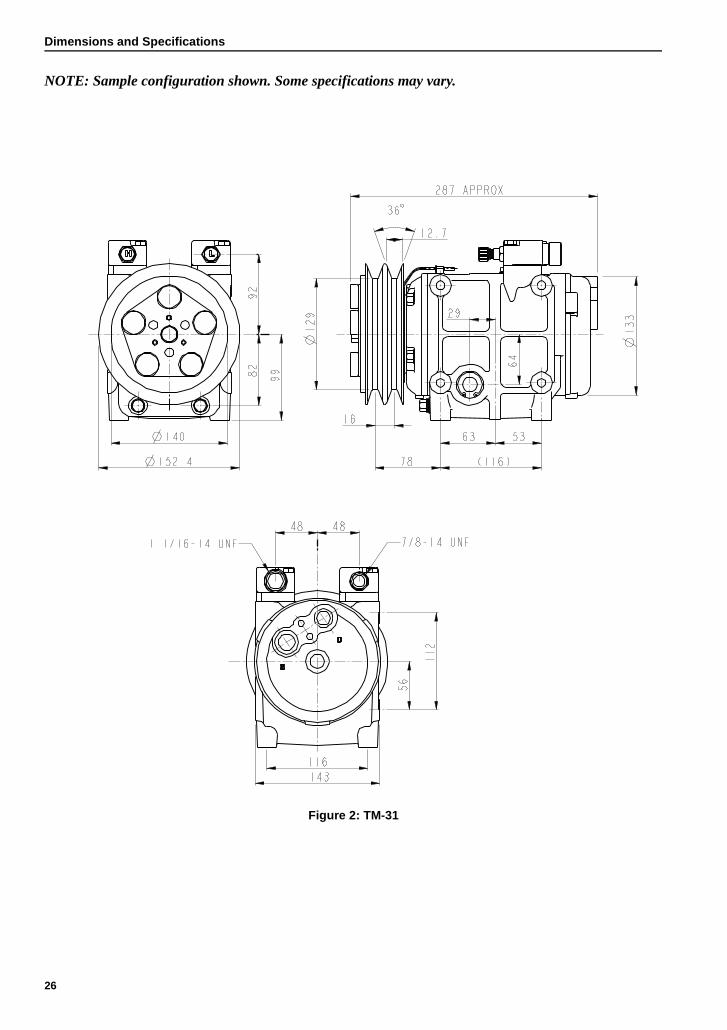
Dimensions and Specifications
NOTE: Sample configuration shown. Some specifications may vary.
Figure 2: TM-31
26
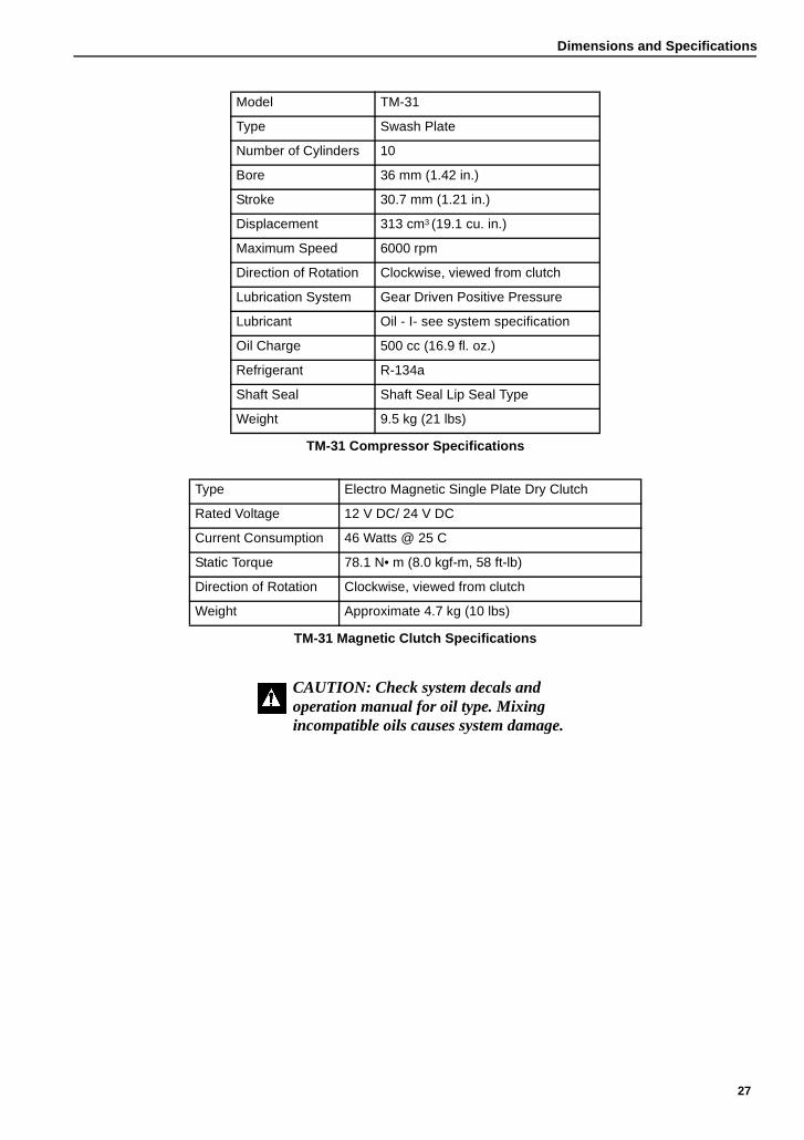
Dimensions and Specifications
Model TM-31
Type Swash Plate
Number of Cylinders 10
Bore 36 mm (1.42 in.)
Stroke 30.7 mm (1.21 in.)
Displacement 313 cm3 (19.1 cu. in.)
Maximum Speed 6000 rpm
Direction of Rotation Clockwise, viewed from clutch
Lubrication System Gear Driven Positive Pressure
Lubricant Oil - I see system specification
Oil Charge 500 cc (16.9 fl. oz.)
Refrigerant R-134a
Shaft Seal Shaft Seal Lip Seal Type
Weight 9.5 kg (21 lbs)
TM-31 Compressor Specifications
Type Electro Magnetic Single Plate Dry Clutch
Rated Voltage 12 V DC/ 24 V DC
Current Consumption 46 Watts @ 25 C
Static Torque 78.1 N• m (8.0 kgf-m, 58 ft-lb)
Direction of Rotation Clockwise, viewed from clutch
Weight Approximate 4.7 kg (10 lbs)
TM-31 Magnetic Clutch Specifications
CAUTION: Check system decals and operation manual for oil type. Mixing incompatible oils causes system damage.
27
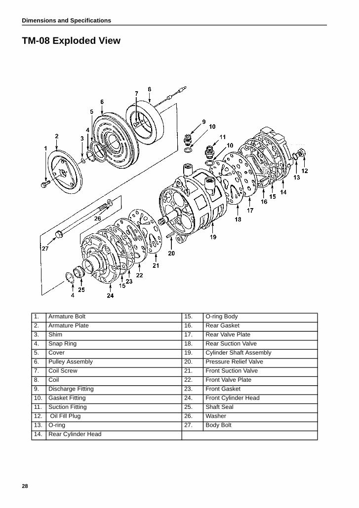
Dimensions and Specifications
TM-08 Exploded View
1. Armature Bolt 15. O-ring Body
2. Armature Plate 16. Rear Gasket
3. Shim 17. Rear Valve Plate
4. Snap Ring 18. Rear Suction Valve
5. Cover 19. Cylinder Shaft Assembly
6. Pulley Assembly 20. Pressure Relief Valve
7. Coil Screw 21. Front Suction Valve
8. Coil 22. Front Valve Plate
9. Discharge Fitting 23. Front Gasket
10. Gasket Fitting 24. Front Cylinder Head
11. Suction Fitting 25. Shaft Seal
12. Oil Fill Plug 26. Washer
13. O-ring 27. Body Bolt
14. Rear Cylinder Head
28
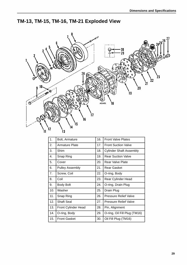
Dimensions and Specifications
TM-13, TM-15, TM-16, TM-21 Exploded View
1. Bolt, Armature 16. Front Valve Plates
2. Armature Plate 17. Front Suction Valve
3. Shim 18. Cylinder Shaft Assembly
4. Snap Ring 19. Rear Suction Valve
5. Cover 20. Rear Valve Plate
6. Pulley Assembly 21. Rear Gasket
7. Screw, Coil 22. O-ring, Body
8. Coil 23. Rear Cylinder Head
9. Body Bolt 24. O-ring, Drain Plug
10. Washer 25. Drain Plug
11. Snap Ring 26. Pressure Relief Valve
12. Shaft Seal 27. Pressure Relief Valve
13. Front Cylinder Head 28. Pin, Alignment
14. O-ring, Body 29. O-ring, Oil Fill Plug (TM16)
15. Front Gasket 30. Oil Fill Plug (TM16)
29
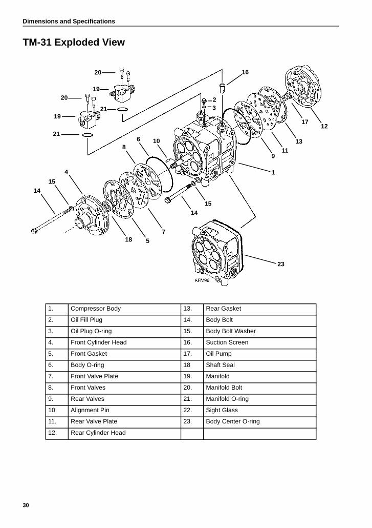
Dimensions and Specifications
TM-31 Exploded View
20
20
21
21
19
1415
4
86 10
32
16
12
18 57
1415
23
1
911
13
17
19
1. Compressor Body 13. Rear Gasket
2. Oil Fill Plug 14. Body Bolt
3. Oil Plug O-ring 15. Body Bolt Washer
4. Front Cylinder Head 16. Suction Screen
5. Front Gasket 17. Oil Pump
6. Body O-ring 18 Shaft Seal
7. Front Valve Plate 19. Manifold
8. Front Valves 20. Manifold Bolt
9. Rear Valves 21. Manifold O-ring
10. Alignment Pin 22. Sight Glass
11. Rear Valve Plate 23. Body Center O-ring
12. Rear Cylinder Head
30
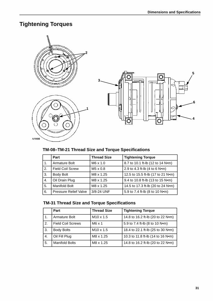
Dimensions and Specifications
Tightening Torques
1
2
3
5
6
4
TM-08–TM-21 Thread Size and Torque Specifications
Part Thread Size Tightening Torque
1. Armature Bolt M6 x 1.0 8.7 to 10.1 ft-lb (12 to 14 N•m)
2. Field Coil Screw M5 x 0.8 2.9 to 4.3 ft-lb (4 to 6 N•m)
3. Body Bolt M8 x 1.25 12.5 to 15.5 ft-lb (17 to 21 N•m)
4. Oil Drain Plug M8 x 1.25 9.4 to 10.8 ft-lb (13 to 15 N•m)
5. Manifold Bolt M8 x 1.25 14.5 to 17.3 ft-lb (20 to 24 N•m)
6. Pressure Relief Valve 3/8-24 UNF 5.9 to 7.4 ft-lb (8 to 10 N•m)
TM-31 Thread Size and Torque Specifications
Part Thread Size Tightening Torque
1. Armature Bolt M10 x 1.5 14.8 to 16.2 ft-lb (20 to 22 N•m)
2. Field Coil Screws M6 x 1 5.9 to 7.4 ft-lb (8 to 10 N•m)
3. Body Bolts M10 x 1.5 18.4 to 22.1 ft-lb (25 to 30 N•m)
4. Oil Fill Plug M8 x 1.25 10.3 to 11.8 ft-lb (14 to 16 N•m)
5. Manifold Bolts M8 x 1.25 14.8 to 16.2 ft-lb (20 to 22 N•m)
31

Dimensions and Specifications
32
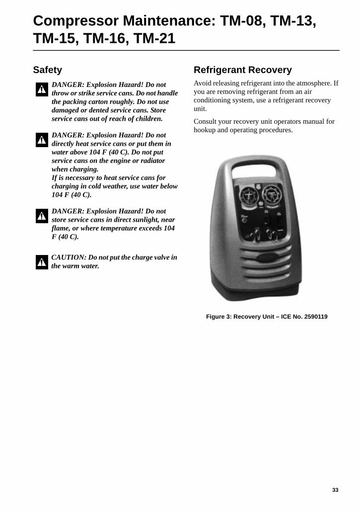
Compressor Maintenance: TM-08, TM-13, TM-15, TM-16, TM-21
Safety Refrigerant RecoveryAvoid releasing refrigerant into the atmosphere. If you are removing refrigerant from an air conditioning system, use a refrigerant recovery unit.
Consult your recovery unit operators manual for hookup and operating procedures.
Figure 3: Recovery Unit – ICE No. 2590119
DANGER: Explosion Hazard! Do not throw or strike service cans. Do not handle the packing carton roughly. Do not use damaged or dented service cans. Store service cans out of reach of children.
DANGER: Explosion Hazard! Do not directly heat service cans or put them in water above 104 F (40 C). Do not put service cans on the engine or radiator when charging. If is necessary to heat service cans for charging in cold weather, use water below 104 F (40 C).
DANGER: Explosion Hazard! Do not store service cans in direct sunlight, near flame, or where temperature exceeds 104 F (40 C).
CAUTION: Do not put the charge valve in the warm water.
33
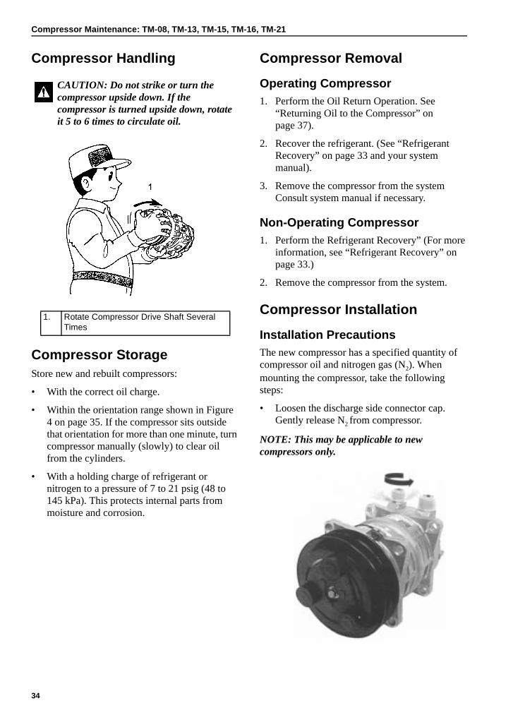
Compressor Maintenance: TM-08, TM-13, TM-15, TM-16, TM-21
Compressor Handling
Compressor StorageStore new and rebuilt compressors:
• With the correct oil charge.
• Within the orientation range shown in Figure 4 on page 35. If the compressor sits outside that orientation for more than one minute, turn compressor manually (slowly) to clear oil from the cylinders.
• With a holding charge of refrigerant or nitrogen to a pressure of 7 to 21 psig (48 to 145 kPa). This protects internal parts from moisture and corrosion.
Compressor Removal
Operating Compressor1. Perform the Oil Return Operation. See
“Returning Oil to the Compressor” on page 37).
2. Recover the refrigerant. (See “Refrigerant Recovery” on page 33 and your system manual).
3. Remove the compressor from the system Consult system manual if necessary.
Non-Operating Compressor1. Perform the Refrigerant Recovery” (For more
information, see “Refrigerant Recovery” on page 33.)
2. Remove the compressor from the system.
Compressor Installation
Installation PrecautionsThe new compressor has a specified quantity of compressor oil and nitrogen gas (N2). When mounting the compressor, take the following steps:
• Loosen the discharge side connector cap. Gently release N2 from compressor.
NOTE: This may be applicable to new compressors only.
CAUTION: Do not strike or turn the compressor upside down. If the compressor is turned upside down, rotate it 5 to 6 times to circulate oil.
1. Rotate Compressor Drive Shaft Several Times
34
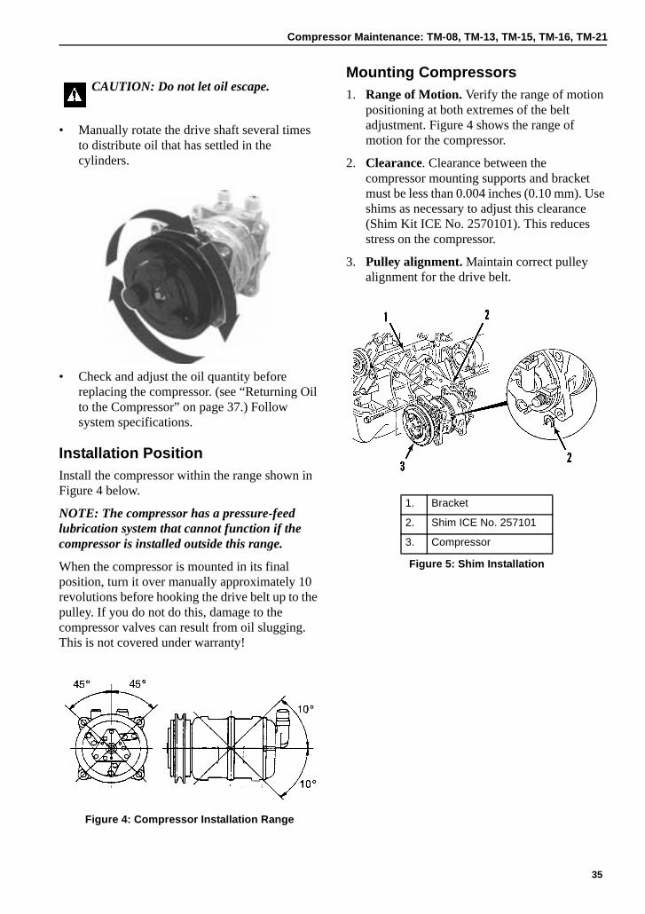
Compressor Maintenance: TM-08, TM-13, TM-15, TM-16, TM-21
• Manually rotate the drive shaft several times to distribute oil that has settled in the cylinders.
• Check and adjust the oil quantity before replacing the compressor. (see “Returning Oil to the Compressor” on page 37.) Follow system specifications.
Installation PositionInstall the compressor within the range shown in Figure 4 below.
NOTE: The compressor has a pressure-feed lubrication system that cannot function if the compressor is installed outside this range.
When the compressor is mounted in its final position, turn it over manually approximately 10 revolutions before hooking the drive belt up to the pulley. If you do not do this, damage to the compressor valves can result from oil slugging. This is not covered under warranty!
Figure 4: Compressor Installation Range
Mounting Compressors1. Range of Motion. Verify the range of motion
positioning at both extremes of the belt adjustment. Figure 4 shows the range of motion for the compressor.
2. Clearance. Clearance between the compressor mounting supports and bracket must be less than 0.004 inches (0.10 mm). Use shims as necessary to adjust this clearance (Shim Kit ICE No. 2570101). This reduces stress on the compressor.
3. Pulley alignment. Maintain correct pulley alignment for the drive belt.
CAUTION: Do not let oil escape.
1. Bracket
2. Shim ICE No. 257101
3. Compressor
Figure 5: Shim Installation
35
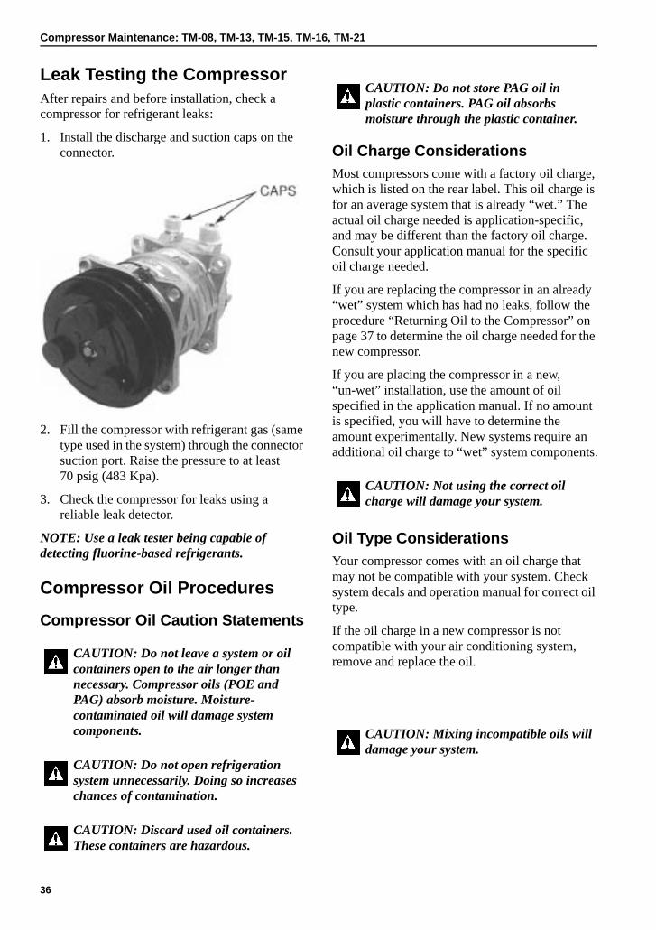
Compressor Maintenance: TM-08, TM-13, TM-15, TM-16, TM-21
Leak Testing the CompressorAfter repairs and before installation, check a compressor for refrigerant leaks:
1. Install the discharge and suction caps on the connector.
2. Fill the compressor with refrigerant gas (same type used in the system) through the connector suction port. Raise the pressure to at least 70 psig (483 Kpa).
3. Check the compressor for leaks using a reliable leak detector.
NOTE: Use a leak tester being capable of detecting fluorine-based refrigerants.
Compressor Oil Procedures
Compressor Oil Caution Statements
Oil Charge ConsiderationsMost compressors come with a factory oil charge, which is listed on the rear label. This oil charge is for an average system that is already “wet.” The actual oil charge needed is application-specific, and may be different than the factory oil charge. Consult your application manual for the specific oil charge needed.
If you are replacing the compressor in an already “wet” system which has had no leaks, follow the procedure “Returning Oil to the Compressor” on page 37 to determine the oil charge needed for the new compressor.
If you are placing the compressor in a new, “un-wet” installation, use the amount of oil specified in the application manual. If no amount is specified, you will have to determine the amount experimentally. New systems require an additional oil charge to “wet” system components.
Oil Type ConsiderationsYour compressor comes with an oil charge that may not be compatible with your system. Check system decals and operation manual for correct oil type.
If the oil charge in a new compressor is not compatible with your air conditioning system, remove and replace the oil.
CAUTION: Do not leave a system or oil containers open to the air longer than necessary. Compressor oils (POE and PAG) absorb moisture. Moisture- contaminated oil will damage system components.
CAUTION: Do not open refrigeration system unnecessarily. Doing so increases chances of contamination.
CAUTION: Discard used oil containers. These containers are hazardous.
CAUTION: Do not store PAG oil in plastic containers. PAG oil absorbs moisture through the plastic container.
CAUTION: Not using the correct oil charge will damage your system.
CAUTION: Mixing incompatible oils will damage your system.
36
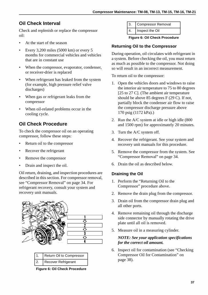
Compressor Maintenance: TM-08, TM-13, TM-15, TM-16, TM-21
Oil Check IntervalCheck and replenish or replace the compressor oil:
• At the start of the season
• Every 3,200 miles (5000 km) or every 5 months for commercial vehicles and vehicles that are in constant use
• When the compressor, evaporator, condenser, or receiver-drier is replaced
• When refrigerant has leaked from the system (for example, high pressure relief valve discharges)
• When gas or refrigerant leaks from the compressor
• When oil-related problems occur in the cooling cycle.
Oil Check ProcedureTo check the compressor oil on an operating compressor, follow these steps:
• Return oil to the compressor
• Recover the refrigerant
• Remove the compressor
• Drain and inspect the oil.
Oil return, draining, and inspection procedures are described in this section. For compressor removal, see “Compressor Removal” on page 34. For refrigerant recovery, consult your system and recovery unit manuals.
Returning Oil to the Compressor
During operation, oil circulates with refrigerant in a system. Before checking the oil, you must return as much as possible to the compressor. Not doing so will result in an incorrect measurement.
To return oil to the compressor:
1. Open the vehicles doors and windows to raise the interior air temperature to 75 to 80 degrees [25 to 27 C]. (The ambient air temperature should be above 85 degrees F (29 C). If not, partially block the condenser air flow to raise the compressor discharge pressure above 170 psig (1172 kPa).)
2. Run the A/C system at idle or high idle (800 and 1500 rpm) for approximately 20 minutes.
3. Turn the A/C system off.
4. Recover the refrigerant. See your system and recovery unit manuals for this procedure.
5. Remove the compressor from the system. See “Compressor Removal” on page 34.
6. Drain the oil as described below.
Draining the Oil
1. Perform the “Returning Oil to the Compressor” procedure above.
2. Remove the drain plug from the compressor.
3. Drain oil from the compressor drain plug and all other ports.
4. Remove remaining oil through the discharge side connector by manually rotating the drive plate until all oil is removed.
5. Measure oil in a measuring cylinder.
NOTE: See your application specifications for the correct oil amount.
6. Inspect oil for contamination (see “Checking Compressor Oil for Contamination” on page 38).
1. Return Oil to Compressor
2. Recover Refrigerant
Figure 6: Oil Check Procedure
3. Compressor Removal
4. Inspect the Oil
Figure 6: Oil Check Procedure
37
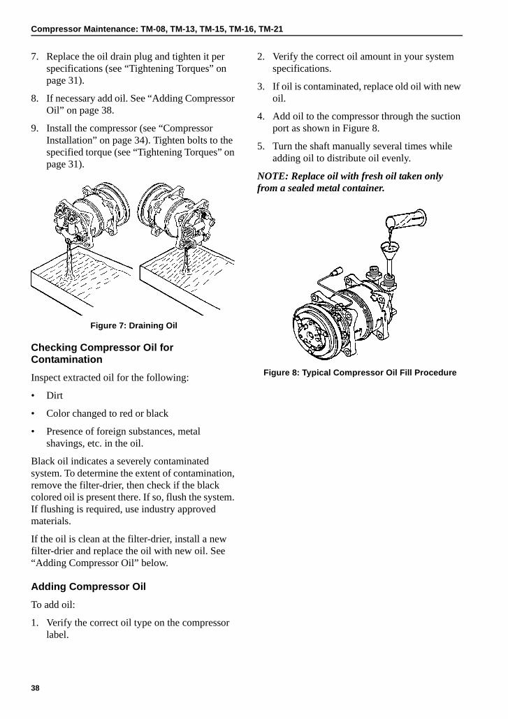
Compressor Maintenance: TM-08, TM-13, TM-15, TM-16, TM-21
7. Replace the oil drain plug and tighten it per specifications (see “Tightening Torques” on page 31).
8. If necessary add oil. See “Adding Compressor Oil” on page 38.
9. Install the compressor (see “Compressor Installation” on page 34). Tighten bolts to the specified torque (see “Tightening Torques” on page 31).
Figure 7: Draining Oil
Checking Compressor Oil for Contamination
Inspect extracted oil for the following:
• Dirt
• Color changed to red or black
• Presence of foreign substances, metal shavings, etc. in the oil.
Black oil indicates a severely contaminated system. To determine the extent of contamination, remove the filter-drier, then check if the black colored oil is present there. If so, flush the system. If flushing is required, use industry approved materials.
If the oil is clean at the filter-drier, install a new filter-drier and replace the oil with new oil. See “Adding Compressor Oil” below.
Adding Compressor Oil
To add oil:
1. Verify the correct oil type on the compressor label.
2. Verify the correct oil amount in your system specifications.
3. If oil is contaminated, replace old oil with new oil.
4. Add oil to the compressor through the suction port as shown in Figure 8.
5. Turn the shaft manually several times while adding oil to distribute oil evenly.
NOTE: Replace oil with fresh oil taken only from a sealed metal container.
Figure 8: Typical Compressor Oil Fill Procedure
38
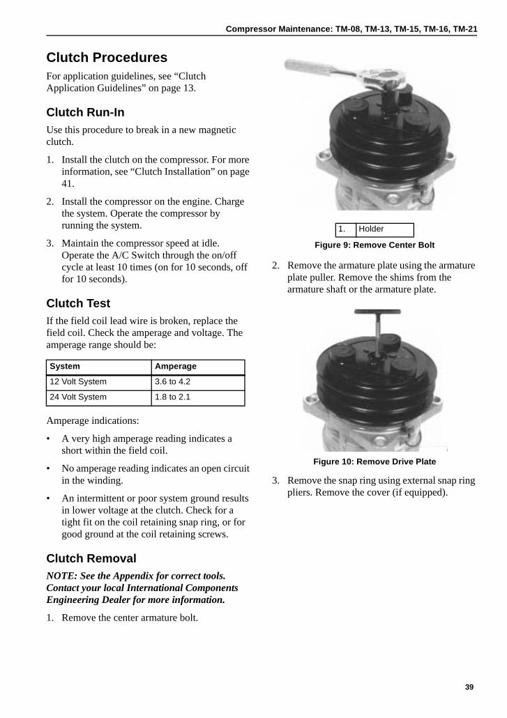
Compressor Maintenance: TM-08, TM-13, TM-15, TM-16, TM-21
Clutch ProceduresFor application guidelines, see “Clutch Application Guidelines” on page 13.
Clutch Run-InUse this procedure to break in a new magnetic clutch.
1. Install the clutch on the compressor. For more information, see “Clutch Installation” on page 41.
2. Install the compressor on the engine. Charge the system. Operate the compressor by running the system.
3. Maintain the compressor speed at idle. Operate the A/C Switch through the on/off cycle at least 10 times (on for 10 seconds, off for 10 seconds).
Clutch TestIf the field coil lead wire is broken, replace the field coil. Check the amperage and voltage. The amperage range should be:
Amperage indications:
• A very high amperage reading indicates a short within the field coil.
• No amperage reading indicates an open circuit in the winding.
• An intermittent or poor system ground results in lower voltage at the clutch. Check for a tight fit on the coil retaining snap ring, or for good ground at the coil retaining screws.
Clutch RemovalNOTE: See the Appendix for correct tools. Contact your local International Components Engineering Dealer for more information.
1. Remove the center armature bolt.
2. Remove the armature plate using the armature plate puller. Remove the shims from the armature shaft or the armature plate.
Figure 10: Remove Drive Plate
3. Remove the snap ring using external snap ring pliers. Remove the cover (if equipped).
System Amperage
12 Volt System 3.6 to 4.2
24 Volt System 1.8 to 2.1
1. Holder
Figure 9: Remove Center Bolt
39
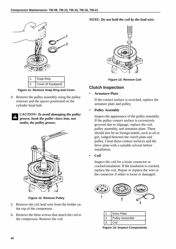
Compressor Maintenance: TM-08, TM-13, TM-15, TM-16, TM-21
4. Remove the pulley assembly using the pulley remover and the spacer positioned on the cylinder head hub.
Figure 12: Remove Pulley
5. Remove the coil lead wire from the holder on the top of the compressor.
6. Remove the three screws that attach the coil to the compressor. Remove the coil.
NOTE: Do not hold the coil by the lead wire.
Figure 13: Remove Coil
Clutch Inspection• Armature Plate
If the contact surface is scorched, replace the armature plate and pulley.
• Pulley Assembly
Inspect the appearance of the pulley assembly. If the pulley contact surface is excessively grooved due to slippage, replace the coil, pulley assembly, and armature plate. There should also be no foreign matter, such as oil or grit, lodged between the clutch plate and pulley. Clean these contact surfaces and the drive plate with a suitable solvent before installation.
• Coil
Inspect the coil for a loose connector or cracked insulation. If the insulation is cracked, replace the coil. Repair or replace the wire or the connector if either is loose or damaged.
1. Snap Ring
2. Cover (If Equipped)
Figure 11: Remove Snap Ring and Cover
CAUTION: To avoid damaging the pulley groove, hook the puller claws into, not under, the pulley groove.
1. Drive Plate
2. Pulley Assemble
3. Coil
Figure 14: Inspect Components
40
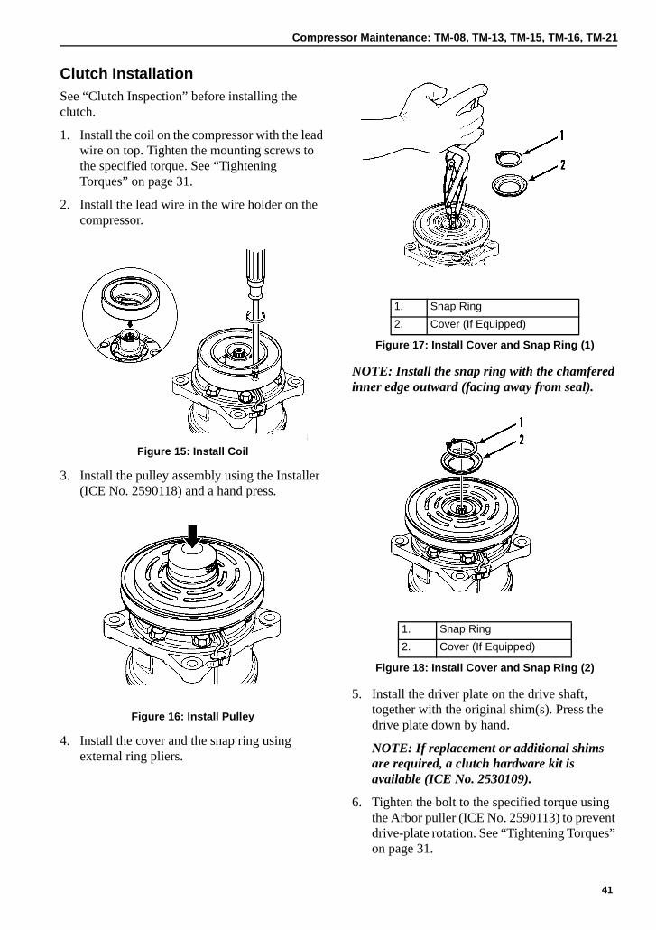
Compressor Maintenance: TM-08, TM-13, TM-15, TM-16, TM-21
Clutch InstallationSee “Clutch Inspection” before installing the clutch.
1. Install the coil on the compressor with the lead wire on top. Tighten the mounting screws to the specified torque. See “Tightening Torques” on page 31.
2. Install the lead wire in the wire holder on the compressor.
Figure 15: Install Coil
3. Install the pulley assembly using the Installer (ICE No. 2590118) and a hand press.
Figure 16: Install Pulley
4. Install the cover and the snap ring using external ring pliers.
NOTE: Install the snap ring with the chamfered inner edge outward (facing away from seal).
5. Install the driver plate on the drive shaft, together with the original shim(s). Press the drive plate down by hand.
NOTE: If replacement or additional shims are required, a clutch hardware kit is available (ICE No. 2530109).
6. Tighten the bolt to the specified torque using the Arbor puller (ICE No. 2590113) to prevent drive-plate rotation. See “Tightening Torques” on page 31.
1. Snap Ring
2. Cover (If Equipped)
Figure 17: Install Cover and Snap Ring (1)
1. Snap Ring
2. Cover (If Equipped)
Figure 18: Install Cover and Snap Ring (2)
41
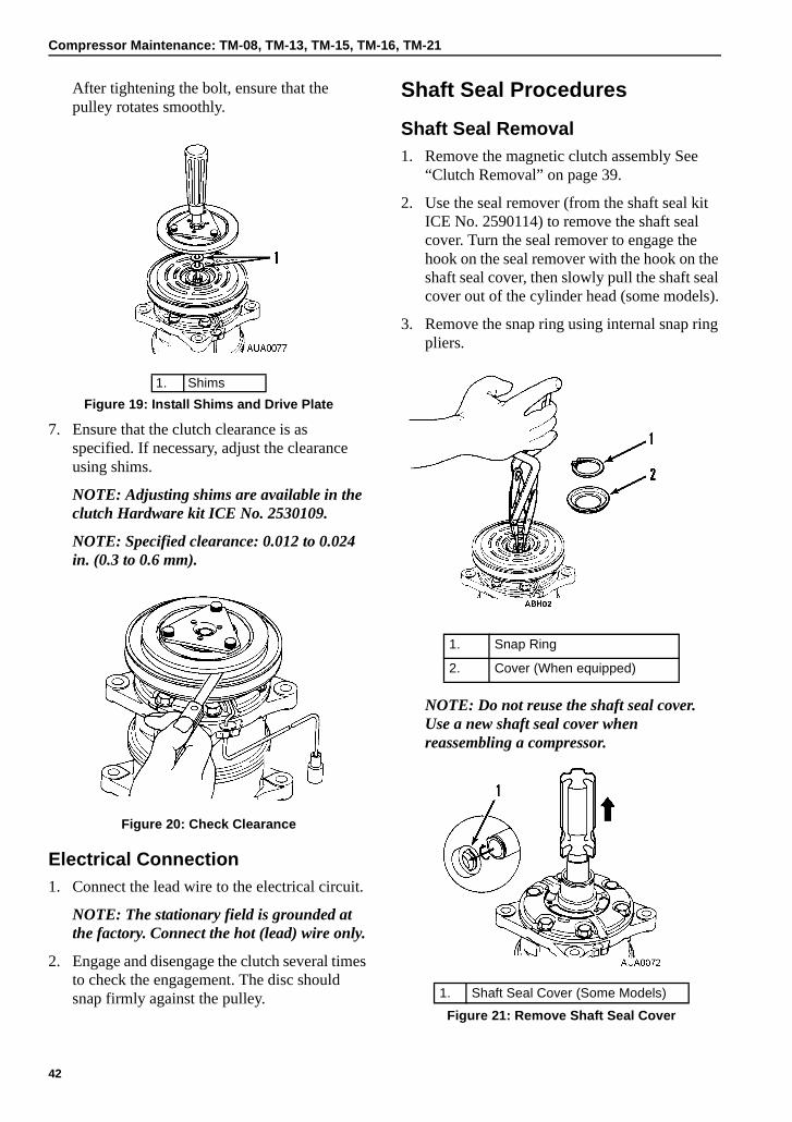
Compressor Maintenance: TM-08, TM-13, TM-15, TM-16, TM-21
After tightening the bolt, ensure that the pulley rotates smoothly.
7. Ensure that the clutch clearance is as specified. If necessary, adjust the clearance using shims.
NOTE: Adjusting shims are available in the clutch Hardware kit ICE No. 2530109.
NOTE: Specified clearance: 0.012 to 0.024 in. (0.3 to 0.6 mm).
Figure 20: Check Clearance
Electrical Connection1. Connect the lead wire to the electrical circuit.
NOTE: The stationary field is grounded at the factory. Connect the hot (lead) wire only.
2. Engage and disengage the clutch several times to check the engagement. The disc should snap firmly against the pulley.
Shaft Seal Procedures
Shaft Seal Removal1. Remove the magnetic clutch assembly See
“Clutch Removal” on page 39.
2. Use the seal remover (from the shaft seal kit ICE No. 2590114) to remove the shaft seal cover. Turn the seal remover to engage the hook on the seal remover with the hook on the shaft seal cover, then slowly pull the shaft seal cover out of the cylinder head (some models).
3. Remove the snap ring using internal snap ring pliers.
NOTE: Do not reuse the shaft seal cover. Use a new shaft seal cover when reassembling a compressor.
1. Shims
Figure 19: Install Shims and Drive Plate
1. Snap Ring
2. Cover (When equipped)
1. Shaft Seal Cover (Some Models)
Figure 21: Remove Shaft Seal Cover
42
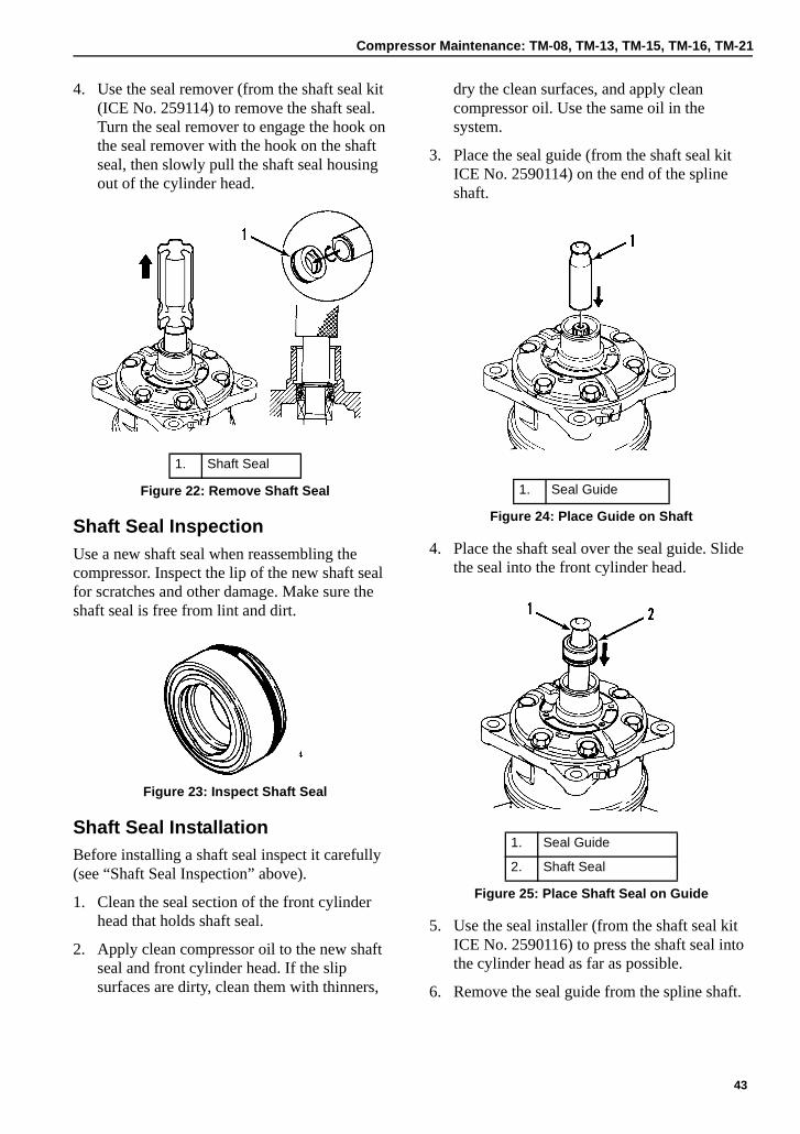
Compressor Maintenance: TM-08, TM-13, TM-15, TM-16, TM-21
4. Use the seal remover (from the shaft seal kit (ICE No. 259114) to remove the shaft seal. Turn the seal remover to engage the hook on the seal remover with the hook on the shaft seal, then slowly pull the shaft seal housing out of the cylinder head.
Shaft Seal InspectionUse a new shaft seal when reassembling the compressor. Inspect the lip of the new shaft seal for scratches and other damage. Make sure the shaft seal is free from lint and dirt.
Figure 23: Inspect Shaft Seal
Shaft Seal InstallationBefore installing a shaft seal inspect it carefully (see “Shaft Seal Inspection” above).
1. Clean the seal section of the front cylinder head that holds shaft seal.
2. Apply clean compressor oil to the new shaft seal and front cylinder head. If the slip surfaces are dirty, clean them with thinners,
dry the clean surfaces, and apply clean compressor oil. Use the same oil in the system.
3. Place the seal guide (from the shaft seal kit ICE No. 2590114) on the end of the spline shaft.
4. Place the shaft seal over the seal guide. Slide the seal into the front cylinder head.
5. Use the seal installer (from the shaft seal kit ICE No. 2590116) to press the shaft seal into the cylinder head as far as possible.
6. Remove the seal guide from the spline shaft.
1. Shaft Seal
Figure 22: Remove Shaft Seal 1. Seal Guide
Figure 24: Place Guide on Shaft
1. Seal Guide
2. Shaft Seal
Figure 25: Place Shaft Seal on Guide
43
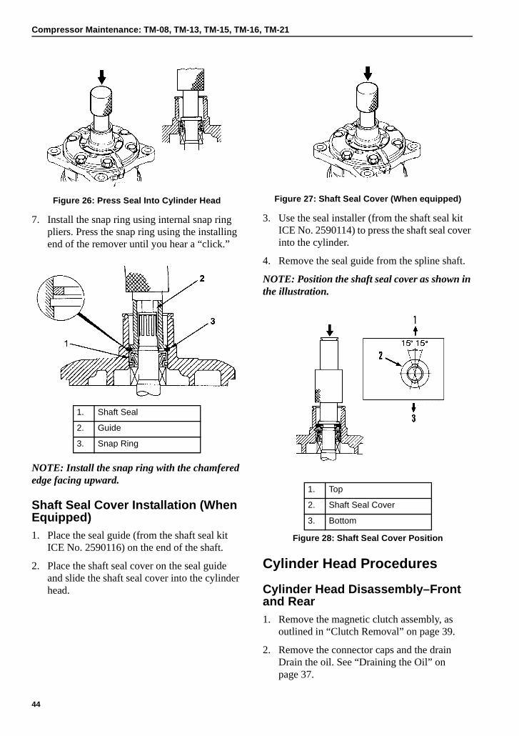
Compressor Maintenance: TM-08, TM-13, TM-15, TM-16, TM-21
Figure 26: Press Seal Into Cylinder Head
7. Install the snap ring using internal snap ring pliers. Press the snap ring using the installing end of the remover until you hear a “click.”
NOTE: Install the snap ring with the chamfered edge facing upward.
Shaft Seal Cover Installation (When Equipped)1. Place the seal guide (from the shaft seal kit
ICE No. 2590116) on the end of the shaft.
2. Place the shaft seal cover on the seal guide and slide the shaft seal cover into the cylinder head.
Figure 27: Shaft Seal Cover (When equipped)
3. Use the seal installer (from the shaft seal kit ICE No. 2590114) to press the shaft seal cover into the cylinder.
4. Remove the seal guide from the spline shaft.
NOTE: Position the shaft seal cover as shown in the illustration.
Cylinder Head Procedures
Cylinder Head Disassembly–Front and Rear1. Remove the magnetic clutch assembly, as
outlined in “Clutch Removal” on page 39.
2. Remove the connector caps and the drain Drain the oil. See “Draining the Oil” on page 37.
1. Shaft Seal
2. Guide
3. Snap Ring
1. Top
2. Shaft Seal Cover
3. Bottom
Figure 28: Shaft Seal Cover Position
44
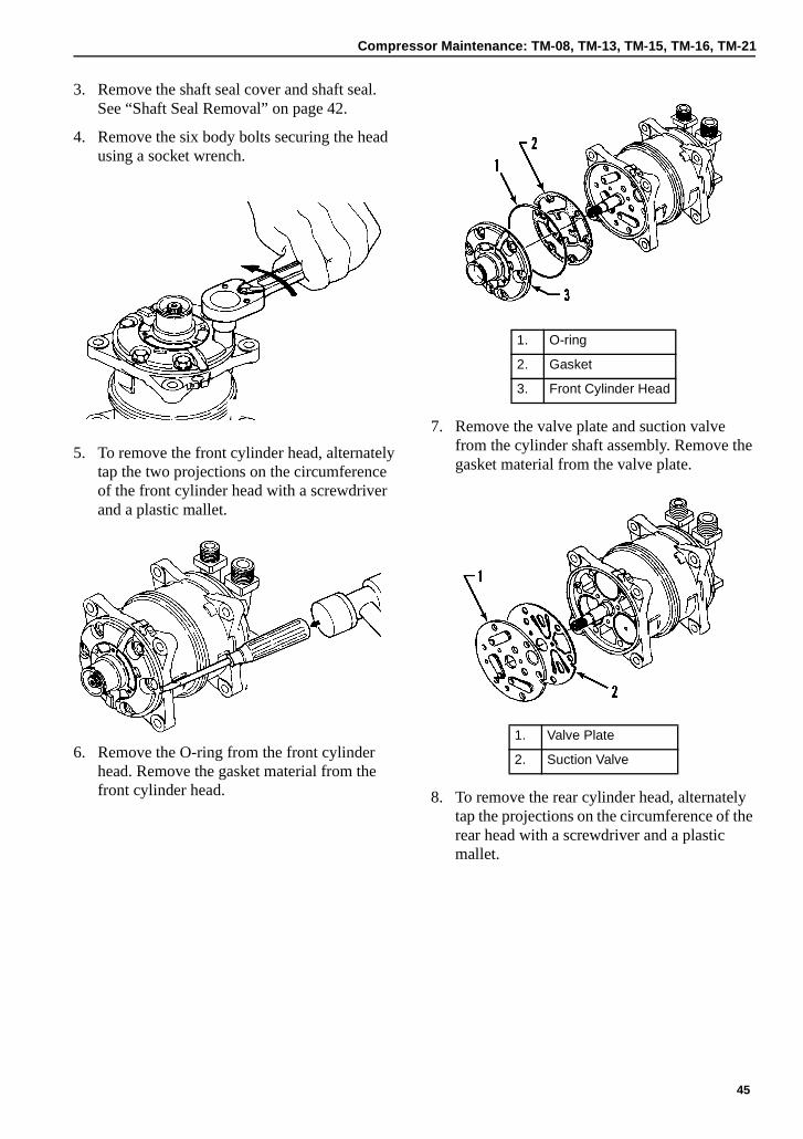
Compressor Maintenance: TM-08, TM-13, TM-15, TM-16, TM-21
3. Remove the shaft seal cover and shaft seal. See “Shaft Seal Removal” on page 42.
4. Remove the six body bolts securing the head using a socket wrench.
5. To remove the front cylinder head, alternately tap the two projections on the circumference of the front cylinder head with a screwdriver and a plastic mallet.
6. Remove the O-ring from the front cylinder head. Remove the gasket material from the front cylinder head.
7. Remove the valve plate and suction valve from the cylinder shaft assembly. Remove the gasket material from the valve plate.
8. To remove the rear cylinder head, alternately tap the projections on the circumference of the rear head with a screwdriver and a plastic mallet.
1. O-ring
2. Gasket
3. Front Cylinder Head
1. Valve Plate
2. Suction Valve
45
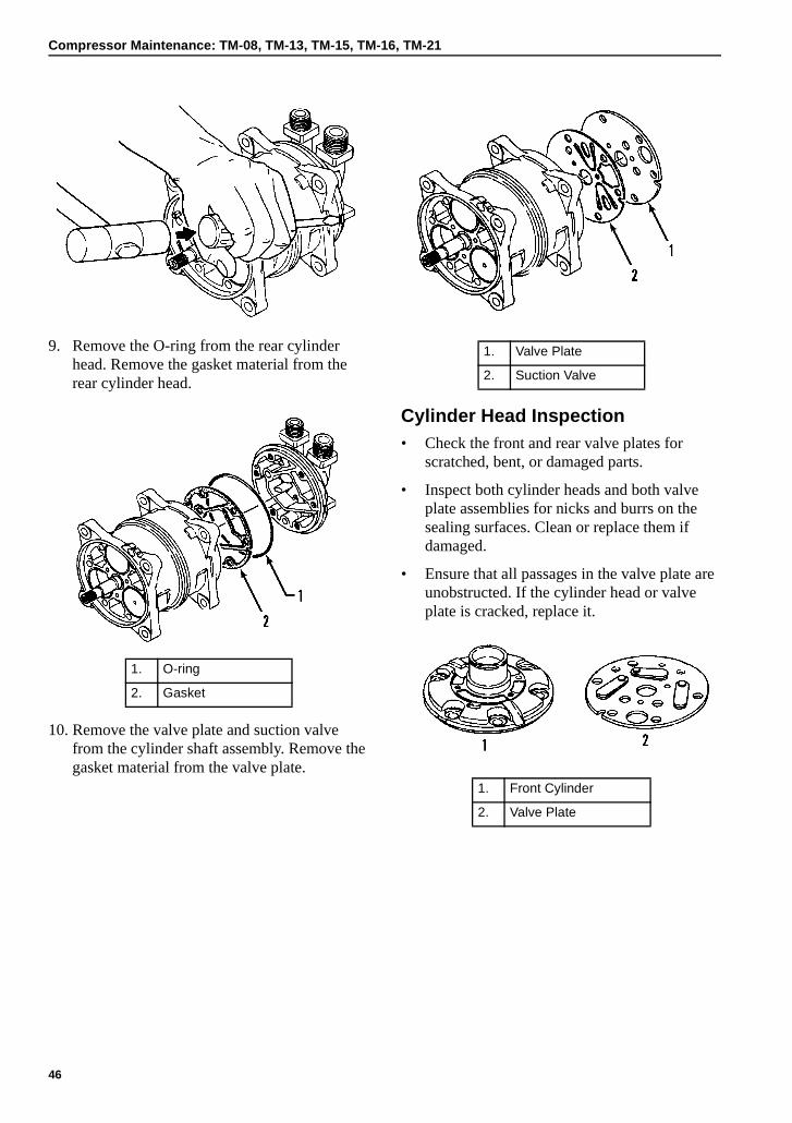
Compressor Maintenance: TM-08, TM-13, TM-15, TM-16, TM-21
9. Remove the O-ring from the rear cylinder head. Remove the gasket material from the rear cylinder head.
10. Remove the valve plate and suction valve from the cylinder shaft assembly. Remove the gasket material from the valve plate.
Cylinder Head Inspection• Check the front and rear valve plates for
scratched, bent, or damaged parts.
• Inspect both cylinder heads and both valve plate assemblies for nicks and burrs on the sealing surfaces. Clean or replace them if damaged.
• Ensure that all passages in the valve plate are unobstructed. If the cylinder head or valve plate is cracked, replace it.
1. O-ring
2. Gasket
1. Valve Plate
2. Suction Valve
1. Front Cylinder
2. Valve Plate
46
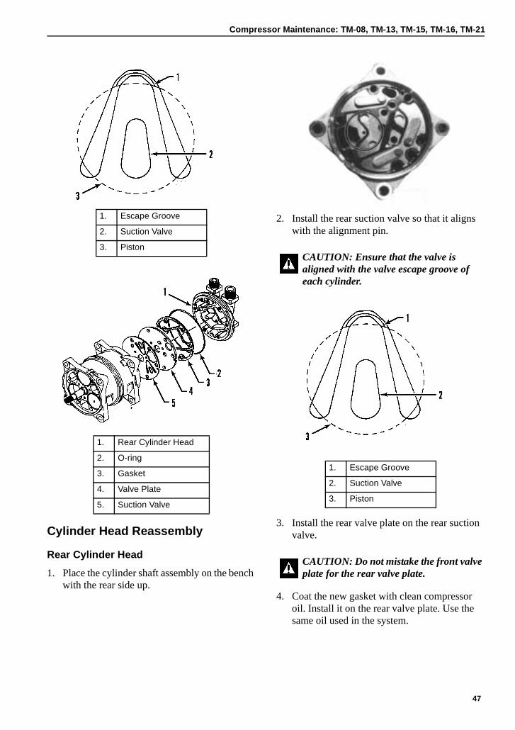
Compressor Maintenance: TM-08, TM-13, TM-15, TM-16, TM-21
Cylinder Head Reassembly
Rear Cylinder Head
1. Place the cylinder shaft assembly on the bench with the rear side up.
2. Install the rear suction valve so that it aligns with the alignment pin.
3. Install the rear valve plate on the rear suction valve.
4. Coat the new gasket with clean compressor oil. Install it on the rear valve plate. Use the same oil used in the system.
1. Escape Groove
2. Suction Valve
3. Piston
1. Rear Cylinder Head
2. O-ring
3. Gasket
4. Valve Plate
5. Suction Valve
CAUTION: Ensure that the valve is aligned with the valve escape groove of each cylinder.
1. Escape Groove
2. Suction Valve
3. Piston
CAUTION: Do not mistake the front valve plate for the rear valve plate.
47
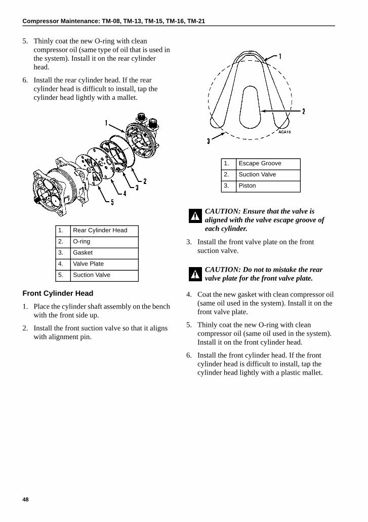
Compressor Maintenance: TM-08, TM-13, TM-15, TM-16, TM-21
5. Thinly coat the new O-ring with clean compressor oil (same type of oil that is used in the system). Install it on the rear cylinder head.
6. Install the rear cylinder head. If the rear cylinder head is difficult to install, tap the cylinder head lightly with a mallet.
Front Cylinder Head
1. Place the cylinder shaft assembly on the bench with the front side up.
2. Install the front suction valve so that it aligns with alignment pin.
3. Install the front valve plate on the front suction valve.
4. Coat the new gasket with clean compressor oil (same oil used in the system). Install it on the front valve plate.
5. Thinly coat the new O-ring with clean compressor oil (same oil used in the system). Install it on the front cylinder head.
6. Install the front cylinder head. If the front cylinder head is difficult to install, tap the cylinder head lightly with a plastic mallet.
1. Rear Cylinder Head
2. O-ring
3. Gasket
4. Valve Plate
5. Suction Valve
1. Escape Groove
2. Suction Valve
3. Piston
CAUTION: Ensure that the valve is aligned with the valve escape groove of each cylinder.
CAUTION: Do not to mistake the rear valve plate for the front valve plate.
48
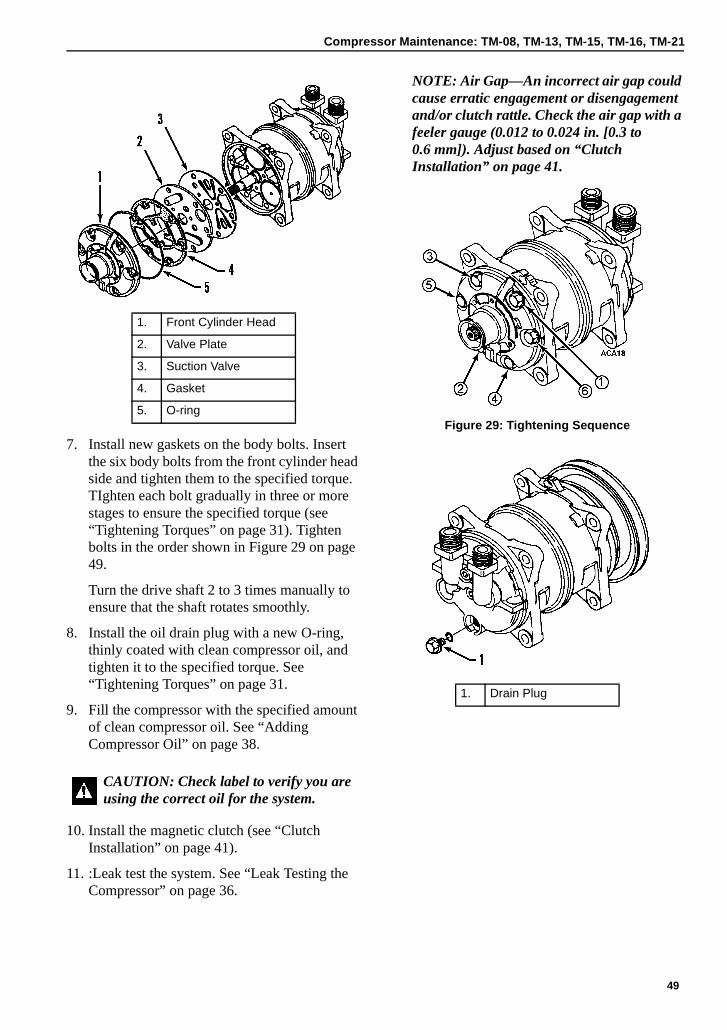
Compressor Maintenance: TM-08, TM-13, TM-15, TM-16, TM-21
7. Install new gaskets on the body bolts. Insert the six body bolts from the front cylinder head side and tighten them to the specified torque. TIghten each bolt gradually in three or more stages to ensure the specified torque (see “Tightening Torques” on page 31). Tighten bolts in the order shown in Figure 29 on page 49.
Turn the drive shaft 2 to 3 times manually to ensure that the shaft rotates smoothly.
8. Install the oil drain plug with a new O-ring, thinly coated with clean compressor oil, and tighten it to the specified torque. See “Tightening Torques” on page 31.
9. Fill the compressor with the specified amount of clean compressor oil. See “Adding Compressor Oil” on page 38.
10. Install the magnetic clutch (see “Clutch Installation” on page 41).
11. :Leak test the system. See “Leak Testing the Compressor” on page 36.
NOTE: Air Gap—An incorrect air gap could cause erratic engagement or disengagement and/or clutch rattle. Check the air gap with a feeler gauge (0.012 to 0.024 in. [0.3 to 0.6 mm]). Adjust based on “Clutch Installation” on page 41.
Figure 29: Tightening Sequence
1. Front Cylinder Head
2. Valve Plate
3. Suction Valve
4. Gasket
5. O-ring
CAUTION: Check label to verify you are using the correct oil for the system.
1. Drain Plug
49

Compressor Maintenance: TM-08, TM-13, TM-15, TM-16, TM-21
50
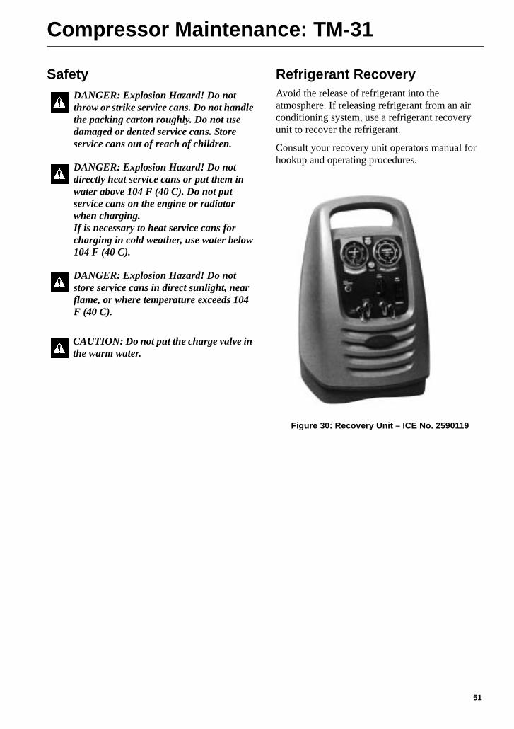
Compressor Maintenance: TM-31
Safety Refrigerant RecoveryAvoid the release of refrigerant into the atmosphere. If releasing refrigerant from an air conditioning system, use a refrigerant recovery unit to recover the refrigerant.
Consult your recovery unit operators manual for hookup and operating procedures.
Figure 30: Recovery Unit – ICE No. 2590119
DANGER: Explosion Hazard! Do not throw or strike service cans. Do not handle the packing carton roughly. Do not use damaged or dented service cans. Store service cans out of reach of children.
DANGER: Explosion Hazard! Do not directly heat service cans or put them in water above 104 F (40 C). Do not put service cans on the engine or radiator when charging. If is necessary to heat service cans for charging in cold weather, use water below 104 F (40 C).
DANGER: Explosion Hazard! Do not store service cans in direct sunlight, near flame, or where temperature exceeds 104 F (40 C).
CAUTION: Do not put the charge valve in the warm water.
51
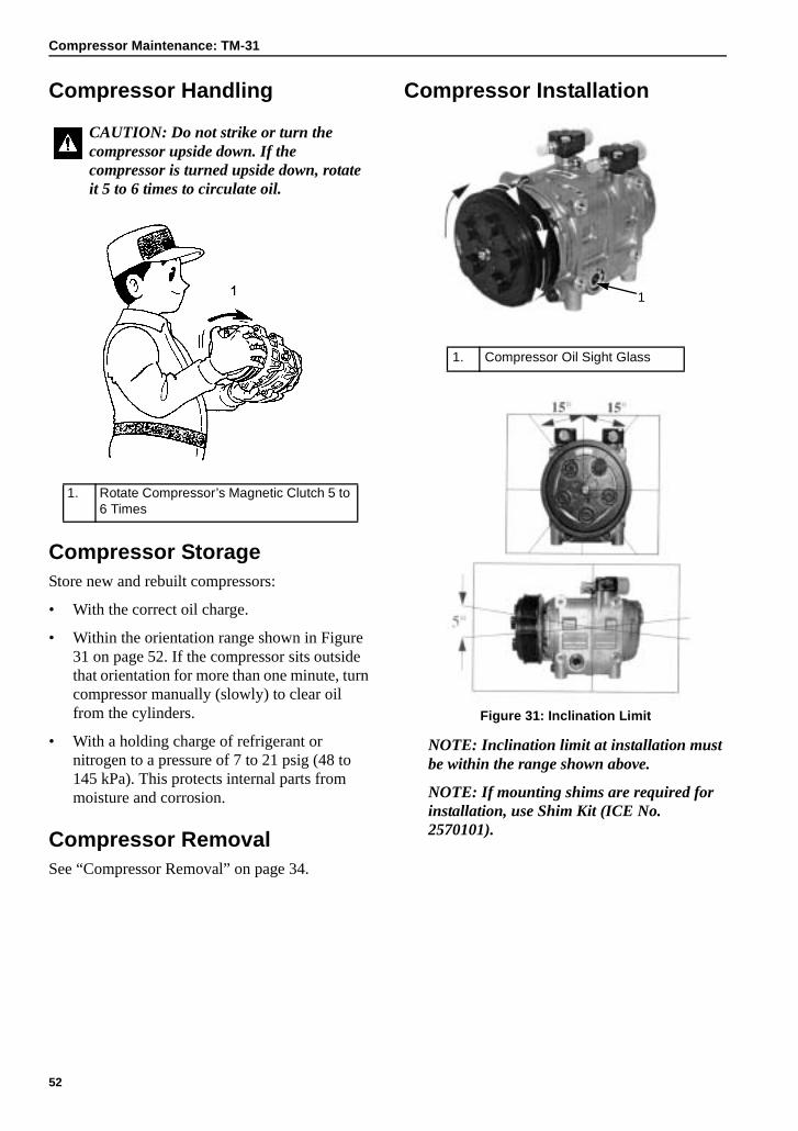
Compressor Maintenance: TM-31
Compressor Handling
Compressor StorageStore new and rebuilt compressors:
• With the correct oil charge.
• Within the orientation range shown in Figure 31 on page 52. If the compressor sits outside that orientation for more than one minute, turn compressor manually (slowly) to clear oil from the cylinders.
• With a holding charge of refrigerant or nitrogen to a pressure of 7 to 21 psig (48 to 145 kPa). This protects internal parts from moisture and corrosion.
Compressor RemovalSee “Compressor Removal” on page 34.
Compressor Installation
Figure 31: Inclination Limit
NOTE: Inclination limit at installation must be within the range shown above.
NOTE: If mounting shims are required for installation, use Shim Kit (ICE No. 2570101).
CAUTION: Do not strike or turn the compressor upside down. If the compressor is turned upside down, rotate it 5 to 6 times to circulate oil.
1. Rotate Compressor’s Magnetic Clutch 5 to 6 Times
1. Compressor Oil Sight Glass
1
52
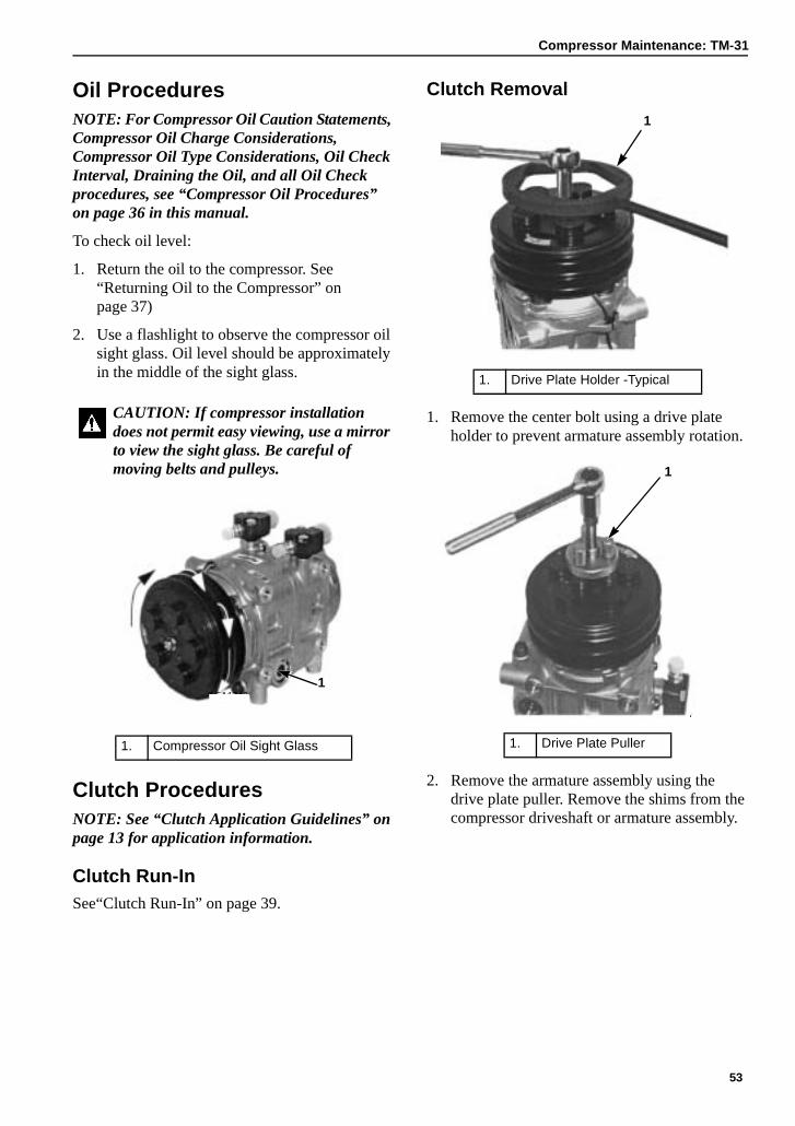
Compressor Maintenance: TM-31
Oil ProceduresNOTE: For Compressor Oil Caution Statements, Compressor Oil Charge Considerations, Compressor Oil Type Considerations, Oil Check Interval, Draining the Oil, and all Oil Check procedures, see “Compressor Oil Procedures” on page 36 in this manual.
To check oil level:
1. Return the oil to the compressor. See “Returning Oil to the Compressor” on page 37)
2. Use a flashlight to observe the compressor oil sight glass. Oil level should be approximately in the middle of the sight glass.
Clutch ProceduresNOTE: See “Clutch Application Guidelines” on page 13 for application information.
Clutch Run-InSee“Clutch Run-In” on page 39.
Clutch Removal
1. Remove the center bolt using a drive plate holder to prevent armature assembly rotation.
2. Remove the armature assembly using the drive plate puller. Remove the shims from the compressor driveshaft or armature assembly.
CAUTION: If compressor installation does not permit easy viewing, use a mirror to view the sight glass. Be careful of moving belts and pulleys.
1. Compressor Oil Sight Glass
AEA17421
1. Drive Plate Holder -Typical
1. Drive Plate Puller
AEA1879
1
AEA1880
1
53
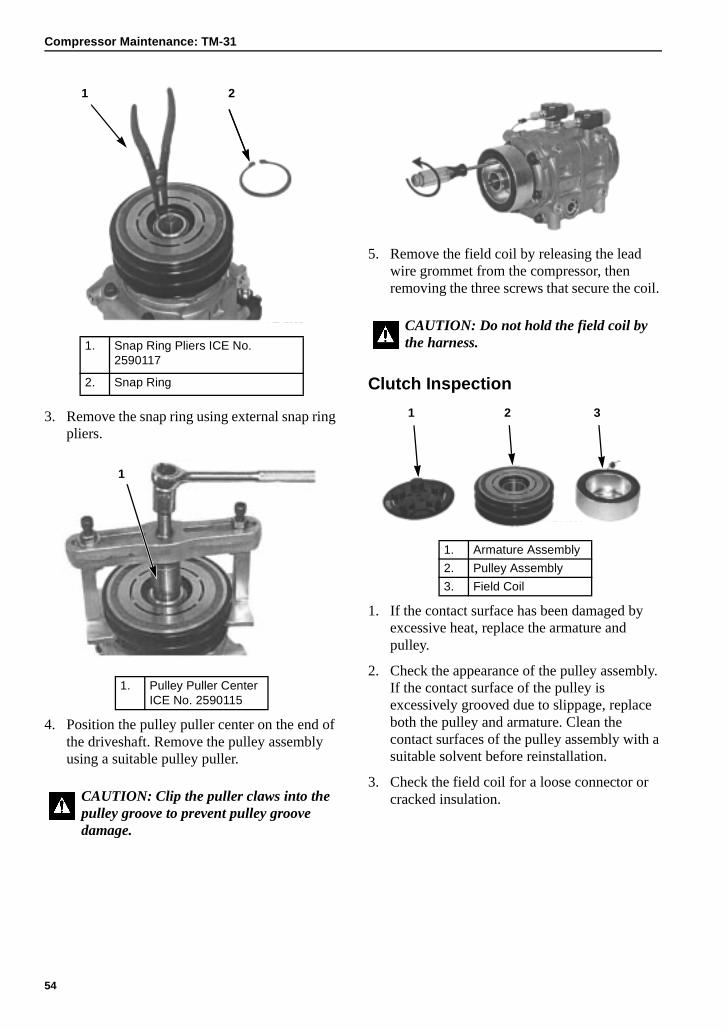
Compressor Maintenance: TM-31
3. Remove the snap ring using external snap ring pliers.
4. Position the pulley puller center on the end of the driveshaft. Remove the pulley assembly using a suitable pulley puller.
5. Remove the field coil by releasing the lead wire grommet from the compressor, then removing the three screws that secure the coil.
Clutch Inspection
1. If the contact surface has been damaged by excessive heat, replace the armature and pulley.
2. Check the appearance of the pulley assembly. If the contact surface of the pulley is excessively grooved due to slippage, replace both the pulley and armature. Clean the contact surfaces of the pulley assembly with a suitable solvent before reinstallation.
3. Check the field coil for a loose connector or cracked insulation.
1. Snap Ring Pliers ICE No. 2590117
2. Snap Ring
1. Pulley Puller Center ICE No. 2590115
CAUTION: Clip the puller claws into the pulley groove to prevent pulley groove damage.
AEA1881
1 2
AEA1882
1
CAUTION: Do not hold the field coil by the harness.
1. Armature Assembly
2. Pulley Assembly
3. Field Coil
AEA1884
1 2 3
54
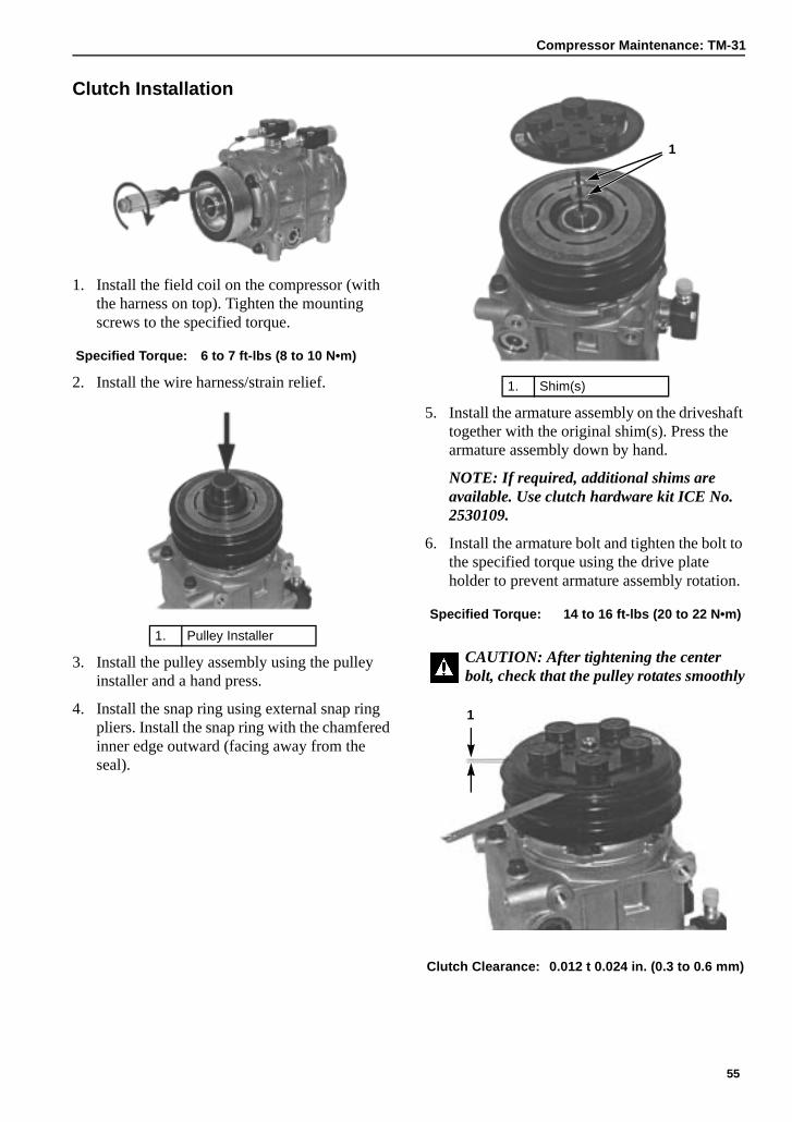
Compressor Maintenance: TM-31
Clutch Installation
1. Install the field coil on the compressor (with the harness on top). Tighten the mounting screws to the specified torque.
2. Install the wire harness/strain relief.
3. Install the pulley assembly using the pulley installer and a hand press.
4. Install the snap ring using external snap ring pliers. Install the snap ring with the chamfered inner edge outward (facing away from the seal).
5. Install the armature assembly on the driveshaft together with the original shim(s). Press the armature assembly down by hand.
NOTE: If required, additional shims are available. Use clutch hardware kit ICE No. 2530109.
6. Install the armature bolt and tighten the bolt to the specified torque using the drive plate holder to prevent armature assembly rotation.
Specified Torque: 6 to 7 ft-lbs (8 to 10 N•m)
1. Pulley Installer
AEA1885
AEA1886
1
1. Shim(s)
Specified Torque: 14 to 16 ft-lbs (20 to 22 N•m)
CAUTION: After tightening the center bolt, check that the pulley rotates smoothly
Clutch Clearance: 0.012 t 0.024 in. (0.3 to 0.6 mm)
1
AEA1887
AEA1888
1
55
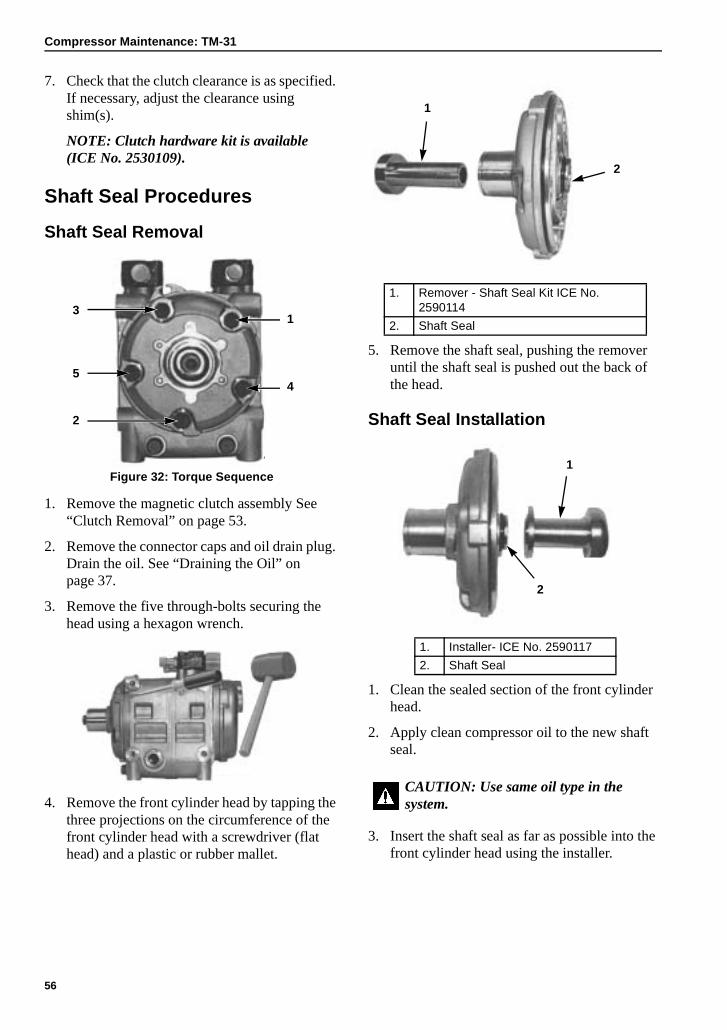
Compressor Maintenance: TM-31
7. Check that the clutch clearance is as specified. If necessary, adjust the clearance using shim(s).
NOTE: Clutch hardware kit is available (ICE No. 2530109).
Shaft Seal Procedures
Shaft Seal Removal
Figure 32: Torque Sequence
1. Remove the magnetic clutch assembly See “Clutch Removal” on page 53.
2. Remove the connector caps and oil drain plug. Drain the oil. See “Draining the Oil” on page 37.
3. Remove the five through-bolts securing the head using a hexagon wrench.
4. Remove the front cylinder head by tapping the three projections on the circumference of the front cylinder head with a screwdriver (flat head) and a plastic or rubber mallet.
5. Remove the shaft seal, pushing the remover until the shaft seal is pushed out the back of the head.
Shaft Seal Installation
1. Clean the sealed section of the front cylinder head.
2. Apply clean compressor oil to the new shaft seal.
3. Insert the shaft seal as far as possible into the front cylinder head using the installer.
AEA1889
1
4
2
5
3
AEA1890
1. Remover - Shaft Seal Kit ICE No. 2590114
2. Shaft Seal
1. Installer- ICE No. 2590117
2. Shaft Seal
CAUTION: Use same oil type in the system.
AEA1891
1
2
AEA1892
1
2
56
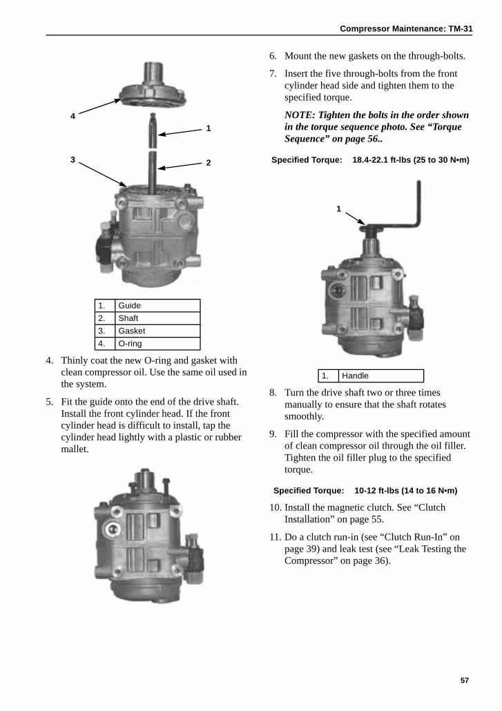
Compressor Maintenance: TM-31
4. Thinly coat the new O-ring and gasket with clean compressor oil. Use the same oil used in the system.
5. Fit the guide onto the end of the drive shaft. Install the front cylinder head. If the front cylinder head is difficult to install, tap the cylinder head lightly with a plastic or rubber mallet.
6. Mount the new gaskets on the through-bolts.
7. Insert the five through-bolts from the front cylinder head side and tighten them to the specified torque.
NOTE: Tighten the bolts in the order shown in the torque sequence photo. See “Torque Sequence” on page 56..
8. Turn the drive shaft two or three times manually to ensure that the shaft rotates smoothly.
9. Fill the compressor with the specified amount of clean compressor oil through the oil filler. Tighten the oil filler plug to the specified torque.
10. Install the magnetic clutch. See “Clutch Installation” on page 55.
11. Do a clutch run-in (see “Clutch Run-In” on page 39) and leak test (see “Leak Testing the Compressor” on page 36).
1. Guide
2. Shaft
3. Gasket
4. O-ring
AEA1893
1
23
4
AEA1894
Specified Torque: 18.4-22.1 ft-lbs (25 to 30 N•m)
1. Handle
Specified Torque: 10-12 ft-lbs (14 to 16 N•m)
AEA1895
1
57

Compressor Maintenance: TM-31
58
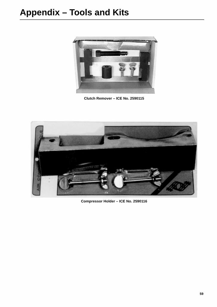
Appendix – Tools and Kits
Clutch Remover – ICE No. 2590115
Compressor Holder – ICE No. 2590116
59
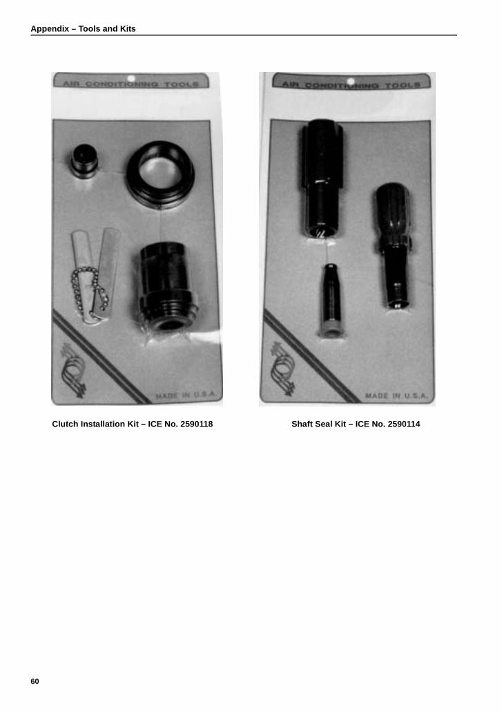
Appendix – Tools and Kits
Clutch Installation Kit – ICE No. 2590118 Shaft Seal Kit – ICE No. 2590114
60
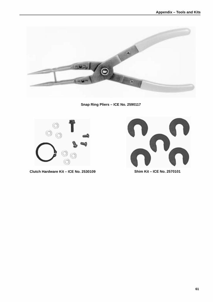
Appendix – Tools and Kits
Clutch Hardware Kit – ICE No. 2530109 Shim Kit – ICE No. 2570101
Snap Ring Pliers – ICE No. 2590117
61
Appendix – Tools and Kits
Customer Service: Phone 952-886-6088Visit our Web site at www.intl-comp.comor contact our Customer Service at 952-886-6088Fax: 952-886-6099
62


