Embed Size (px)
Citation preview

x:! xxxxx XXXXXXXXXlOOOOtXXXXXXXXXXXXXXXXXXXXXXXXXXXXXXX Da~XD~QX~~~~~a~
~ax~~~ax~~~~ox~XXXX~~
~~ax~~OX~XQax~~ax~xa.xxxa
xxxxxxxxxxxxxx xxx XXXXXXXXXX~XXXXXXXXX
XXXXXXXXXXXXXXXXlCXXXXXXXXXXXXXXXXXXXX XXXXXXXXXXXXXXXXXXXXXXXXXXXXXX XXXXlCOOOCXXXXXXXXXXXXXXXXXXXXXXXX XXXXXXXXXXXXXXXXXXXXXXXXXXXXXXX XXXXXXXXXXXXXXXXXXXXXXXXXXXXX XXXlOOCXXXXlOCXXXXXXXXXXXXXX XXXXXXXXXXXXXXXXXXXXXXXXX xxxxxxxxxxxxxxxxxxxxxxx XXXXXXXXXXXXXXXXXXXXX XXXXXXXXXXXXXXXXXXX X1(XXXXXXXXXXXXXXX xxxxxxxxxxxxxxx XXXXXXXXXXXXX XXXXXXXXXXX XXXXXXXXX xxxxxxx XXXXX xxx x
x xxx
xxxxx XXXXXXX
xxxxxxxxx XXXXXXXXxxX
XXXXXXXXXXxxX xxxxxxxxxxxxxxx
xxxxxxxxxxxxxxxxx xxxxxxxxxxxxxxxxxxx
XXXXXXXXXXXXXXXXXXXXX XXXXXXXXXXXXXXXXXXXXXXX
XXXXXXXXXXXXXXXXXXXXXXXXX XXXXXXXXXXXXXXXXXXXXXXXXXXX
XXXXXXXXXXXXXXXXXXXXXXXXXXXXX XXXXXXXXXXXXXXXXXXXXXXXXXXXXXXX
XXXXXXXXXXXXXXXXXXXXXXXXXXXXXXXXX UXXXXXXXXXXXXXXXXXXXXXXXXXXXXXXXXX
XXXXXXXXXXXXXXXXXXXXXXXXXXXXXXXXXXXXX XXXXXXXXXXXXXXXXXXXXXXXXXXXXXXXXXXXXXXX
~XXXXXXXXXXXXXXXXXXXXXXXXXXXXXXXXXXXXXXX
~XXXXXXXXXXXXXXXXXXXXXXXXXXXXXXXXXXXXXXX
XXXXXXXXXXXXXXXX~XXXXXXXXXXXXXXXXXXXXXXXXX
xxxxxxxxxxxxxxxxxxxxxxxxxxxxxxxxxxxxxxxxxxxxxxx XXXXxxnxxDXXXXXXXXXXUDXXXXXXXXXX~XXXXXXXXXXX
XXXXXXXXXXXXXXnnXJCXXXXXXXXXXXXXXXXXXXXXXXXXXlOClOCX

Educational Services
KFQSA Module Installation and User Manual
EK-KFQSA-IN-003
Digital Equipment Corporation

The information in this document ill subjact to change without notice and .mould not be consb'uecl .. a commitment by Digital Equipment Corporation. Digital Equipmpnt Corporation auum&8 no reeponaibility for any errors that mAy appear in this document.
Copyright C Digital Equipment Corporation 1992
All Rights Reserved. Printed in U.S.A
The following are tl ademarke of Digital Equipment Corporation: Digital, DEQNA, 08SI, HBC, KDA, MicroVAX, MicroVAX II, MS630, MSCP, Q-bua, Q22-bu., RA, RQC25, ;r'tQDX3, RRDOO, BTl, TK, TMBCP. TQK, TQK50, ULTRIX·32m, UNIBUS, VAX, VAXclWlter, VAXELN, VMS, and the DIGITAL logo.
LEGAL NOTICEs TMSCP and BTl protocols and documentation are proprietary information of Digital Equipment Corporation. UNIBUS and Q-bu8 port drivers and documentation of MSCP and TMSCP products are alllO proprietary information of OigitaJ Equipment Corporation.

Contents
About This Manual .. V1l
1 General Information 1.1 KFQSA Module Overview ........................... 1-1 1.2 BA440 System Enclosure .......................... " 1-5 1.3 BA213 System Enclosure . . . . . . . . . . . . . . . . . . . . . . . . . . .. 1-7 1.4 BAl23 System Enclosure. . . . . . . . . . . . . . . . . . . . . . . . . . .. 1-10 1.6 BA23 System Enclosure. . . . . . . . . . . . . . . . . . . . . . . . . . . .. 1-12 1.6 nssl VAXcluster Configurations . . . . . . . . . . . . . . . . . . . . .. 1-14
2 Unpacking Instructions 2.1 Option Kits ...................................... 2-1 2.2 Inspection. . . . . . . . . . . . . . . . . . . . . . . . . . . . . . . . . . . . . .. 2-3
3 Planning the System Installation
4 KFQSA Sw~tches
5 Installation ProcedurQs 5.1 BA440 Installation Procedure Using the KFQSA-SG Option
Kit ........................................... " 5-2 6.2 BA213 Installation Procedure Using the KFQSA-SG Option
Kit . . . . . . . . . . . . . . . . . . . . . . . . . . . . . . . . . . . . . . . . . . . .. 5-6 5.3 BAl23 Installation Procedure Using the KFQSA-BA Option
Kit ........................................... " 5-9 5.4 BA23 Installation Procedure Using the KFQSA-AA Option
Kit ............................................. 5-14 5.5 Installing DSSI VAXcluster Configurations ............ " 5-17 5.5.1 Types of DSSI Bus Configurations. . . . . . . . . . . . . . . . . .. 5-17 6.6 Rules for Installing nSSI VAXcluster Systems. . . . . . . . . . .. 5-18
III

Iv Contents
6 Programming the DSSI Subsystem Using Console Commands
6.1 Determining CBR Addresses ........................ ' 6-1 6.2 Programming the KFQSA Configuration Table .......... , 6-3 6.3 Programming the KFQSA Module for a DBBI VAXcluster
Configuration . . . . . . . . . . . . . . . . . . . . . . . . . . . . ........ , 6-7 6.4 Setting the IBE Allocation Class .. , . . . . . . . . . . . . . . . . . .. 6-11
7 Configuring the DSSI Subsystem Using MDM Commands 7.1 Determining CBR Addresses. . . . . . . . . . . . . . . . . . . . . . . . . 7-1 7.1.1 Overview. . . . . . . . . . . . . . . . . . . . . . . . . . . . . . . . . . . . . . 7-1 7.1.2 Using MDM to Determine CSR Addresses. . . . . . . . . . . . . 7-2 7.2 Programming the KFQSA Configuration Table . . . . . . . . . . . 7-4 7.2.1 Programming a Blank or Unknown Configuration Table. . 7-4 7.2.2 Adding a Device to the Configuration Table ........... , 7-10 7.2.3 Removing a Device from the Configuration Table ....... 7-13 7.3 Programming the KFQSA for a DBSI VAXcluster
Configuration. . . . . . . . . . . . . . . . . . . . . . . . . . . . . . . . . . . .. 7-16 7.4 Setting the ISE Allocation Class ..................... , 7-17
8 Diagnostics 8.1 Power-On Self-Test Diagnostics . . . . . . . . . . . . . . ........ . 8.2 LED Error Codes ................................. . 8.3 Using MDM to Run NAKFA Diagnostics . . . . . . . . . . . .. .. 8.3.1 Loading NAKFA ................................ . 8.3.2 Testing the KFQSA Subsyste&n Using NAKFA in Menu
Mode ........................................ .
8-1 8-2 8-5 8-5
8.3.3 Halting Test Execution ........................... ' ~10 8.4 Using Console Commands for Testing DSSI Devices ...... ' ~11

Contents v
9 KFQSA Troubleshooting
Index
Figures 1-1 DSSI Single Host Configuration. . . . . . . . . . . .. ......... 1-2 1-2 DSSI VAXcluster with Dual Hosts . . . . . . . .. ........... 1-3 1-3 DSSI VAXeluster with Three Hosts . . .. ............... 1-4 1-4 BA440 Enclosure . . . . . . . . . . . . . . . . . . . . . . . . . . . . . . . . .. 1-5 1-5 BA440 Backplane. . . . . . . . . . . . . . . . . . . . . . . . . . . . . . . . .. 1-6 1-6 BA213 Enclosure. . . . . . . . . . . . . . . . . . . . . . . . . . . . . . . . . . 1-7 1-7 BA213 Btlckplane Bus Grant Continuity Path. . . . . . . . . . .. 1-9 1-8 BAI23 Enclosure. . . . . . . . . . . . . . . . . . . . . . . . . . . . . . . . .. 1-10 1-9 BAI23 Backplane Bus Grant Continuity Path ...... " . . . .. 1-11 1-10 BA23 Enclosure .................................. , 1-12 1-11 BA23 Backplane Bus Grant Continuity Path. . . . . . . . . . . .. 1-13 1-12 Two-System nBSI VAXcluster Configuration . . . . . . . . . . . .. 1-16 1-13 Tbree--System DSSI VAXcluster Configuration. . . . . . . . . . .. 1-17 1-14 DSSI VAXcluster with an Expansion Cabinet. . . . . . . . . . .. 1-17 2~1 KFQSA Jumper Location . . . . . . . . . . . . . . . . . . . . . . . . . . .. 2-3 3-1 BA440 Configuration Worksheet ... . ............. ,... 3-2 3-2 BA213 Configuration Worksheet. . . . . . . . . . . . . . . . . . . . .. ~ 3-3 BAl23 Configuration Worksheet. . . . . . . . . . . . . . . . . . . . .. 3-4 3-4 BA23 Configuration Worksheet . . . . . . . . . . . . . . . . . . . . . .. 3-5 4-1 KFQSA Adapter Module Switches . . . . . . . . . . . . . . . . . . . .. 4-2 5-1 BA440 Cabling for a ItFQSA in a VAX 4000 System . . . . . .. 5-4 5-2 Installing the Gap Filler Asp moly ..... . . . . . . . . . . . . . .' 5-5 5-3 Cabling for a KFQSA in a H08~ System Using a BA213
Enclosure . . . . . . . . . . . . . . . . . . . . . . . . . . . . . . . . . . . . . . .. 5-7 5-4 KFQSA Installation in a BAI23 Enclosure .............. 5-9 5-5 Removing the Right Side Panel. . . . . . . . . . . . . . . . . . . . . .. 5-11 5-6 Removing the Card Cage Door . . . . . . . . . . . . .. ......... 5-12 5-7 KFQSA Installation in a BA23 Enclosure ............... 5-15 6-~ KFQSA Modules in a DSSI VAXcluster - 1wo-System
Configuration. . . . . . . . . . . . . . . . . . . . . . . . . . . . . . . . . . . .. 6-8

vi Contents
6-2
7-1 &-1
KFQSA Modules in a DSSI VAXcluster - Three-System Configuration. . . . . . . .. . ......................... . Two-System DSSI VAXd'lSter Configuration ............ . KFQSA MODULE LEOS ~'tion .................... .
Tables
6-9 7-16 8-2
2-1 KFQSA Option Kits . . . . . . . . . . . . . . . . . . . . . . . . . . . . . . .. 2-2 3-1 Power and Bus Load Data . . . . . . . . . . . . . . . . . . . . . . . . . .. 3-6 4-1 KFQSA Switch Settings. . . . . . . . . . . . . . . . . . . . . . . . . . . .. 4-3 4-2 Selecting a Dedicated KFQSA CBR Address ............. 4-4 4-3 Selecting an MSCP or TMSCP eSR Address . . . . . . . . . . . .. 4-4 7-1 Device Abbreviations Used with IOADDRES .. .......... 7-3 &-1 POST LED Nonfatal Error Codes ..................... 8-3 8-2 POST LED Fatal Error Codes . . . . . . . . . . . . . . . . . . . . . . .. 8-4 9-1 KFQSA Troubleshooting Symptom Analysis ............. 9-2

About This Manual
This manual provides the infonnation and procedures necessary to install a KFQSA module and DBS} cabling into a MicroVAX system in a BA440, BA213, BA123, or BA23 enclosure. It also provides instructions for configuring a system using the MicroVAX Diagnostic Monitor (MDM) or console commands, and for programming the Control and Status Register (CSR) addresses of the connected DSSI integrated storage elements.
Intended Audience
This document is intended to be used by Digital Services personnel or by qualified self-maintenance customers.
Customers not qualified to install the KFQSA module and th~ DSSI cabling should call Digital Services to schedule an installation.
For the Customer
The customer is respl}nsible to back up software before the arrival of Digital Services personnel at the site. This step is important to ensure that data is not lost during the installation process.
CAUTION Make sure you are wearing an antistatie wrist strap eonnected to a grounded antistatie workstation before you handle the module. The KFQSA module is susceptible to damage by static diBCbarge.
To install the KFQSA adapter and nBSI cable, carefully follow the procedures outlined in this manual. If you have any difficulty perfonning the installation, call Digital Services for assistance.
Be sure the bus grant continuity path is intact after the installation. No vacant backplane elots should exist between modules.
For O;gtal Services
Be sure to take antistatic precautions when unpacking and installing the module. Use the groundstrap and antistatic mat found in the Arltistatic Kit (PN 29-26246).
'1b install the KFQSA and DSSI cable. tarefully follow the installation procedures outlined in thi.s manual. When you have completed the installation, submit a labor activity reporting system (LARS) fonn. For infonnation on completing this form, contact your unit manager.
vii

XXlOOCXXXXXXXXXXXXXXXXXXXXXXXxxxxxxxxxxxxxxxxxxxxxxX XXXXXXlOOOOOOOCXXXXlQClOOfXJOOOCXX)C:XXXX}OOOC.lQCXXXXX xxnxxxxxxxxunxxxxxxn~~xxxx~XXXX~
lOOOOOOCXXXXXXXXXXXXXXXXXx:.cxxxxxxxxxxxxxxxxxxx ~XXXXXX~XXXX~XXX:XXXXXxxXXXXXXXXX
~XXUDXXXXXXXXXXXXXXXX~XXXXx
KJOQOao{Xxxxxxxxxxxxxxxxxxxxxxxxxxxxxxxx XX~XXXXXXXXXXXXXXXXXXXX~~XXXXXXX
xx~xxxxxxxxxxn~xxxxxxxxxxXXX
~xx~xxx:xxxxxxxxxxxxxxx~xxx
xxxxxxxxxxxxxxxxxxxxxxxxxxxxxxx xxxxxxxxxxxxxxxxxxxxxxxxxxxxx xxxxxxxxxxxxxxxxxxxxxxxxxxx xxxxxxxxxxxxxxxxxxxxxxxxx nxxxxxxxxxxxxxxxxxxxxx XXXXXXXXXXXXXXXXlOOOCX xxxxxxxxxxxxxxxxxxx xxxxxxxxxxxxxxxxx lOCXXXXXXXXXXXXX XXXXXXXXXXXXX XXXXXXXXXXX XXXXXXlQ(X XXXXXXX lOCXXX XXX X
x xxx
xx xxx XX xx xxx
XX xxxx xxx KXXXXXXXXXX
xx lCX XXXXXX xxx xxxxxxxxxxxxxxx
xx xx XX xx xx XX xxxxx xxxxxxxxxxxxxxxxxxx
XXXXXXXXXXXXXXXXXXl(XX XXXXXXXXXXXXXXXXXXXXXXX
xxxxxxxxxxxxxxxxxxxxxxxxx xxxxxxxxxxXXXXXXXXXXXXlOCXXX
xxxxxxxxxxxxxxxxxxxxxxxxxxxxx )Q(XXxx xxxxxxxxxxxx.' ~#XXXXXX}COOCl(
XXlC(XXXXXXAXXXXXXXXXXl~XXlCXxXXXx;,cX
xxxxxxxxxxxxxxxxxxxxxxxxxxxxxxxxxxx xx xx xx XX xx xxxxxxxx xxxxxxxxxx xxxxxxxxx
xxxxxxXXXX~XXXXXXXXXXXXXXXXXXXXXXXXXXX
xx xx xx xx XX XX xx xx xx xx xx xx XX xx xx xx xx xx xxxxx xx xx XX XXXXXX xx xx XX xx XX xx xx xx xx xx xx xx xx xx xx x
xx xx XX xx XX xx xx xx xx xx xx xxxx xx xx XX xx xx xx xxxxxxx xxxxxxxxxxxxxxxxxxxxxxxxxxxxxxxx:a xx xx xxxxxxxxx
xxxxxxxx~XXXXXXXXXXXXXXXXXXXXXXxxxxx:xxxXXXXXXXXX
XXXXXXXXXXXXXXXXXXXXXXXXXXXXXXXXXXXX>OCJC:XXXX)f"'XXXXX
1 General Information
This chapter describes the KFQSA module and the enclol!Jures into which it can be installed.
1.1 KFQSA Module Overview The KFQSA module is an adapter that allows Q-bus based host systems like the MicroVAX system to communicate with Integrated Storage Elements (lSEs) connected through the DSSI bus. ISEs are intelligent storage peripherals such as disk and tape devices. In a OSSI single host corafiguration, the KFQSA can connect up to seven ISEs to the host comput.;er through the DSSI bus. In a DSSI VAXc1uater configuration with a dua~ host configuration two KFQSAs can connect up to six ISEs to the two hosts through the DSSI bus. In a OSSI VAXcluster configuration with a three host configuration and three KFQSAs, the DSSI bus can connect up to five ISEs.
Each DSSI ISE has its own controller, which contains the intelligence and logic necessary to control data transfers over the DSSI bus. The KFQSA contains the addressing logic required to make a connection between the host and a requested ISE on the OSSI bus.
The KFQSA module is supported by the following operating systems and diagnostic utilities:
• VMS Version 5.1 or laterl
• ULTRIX-32m Version 3.0 or later
• VAXELN Version 3.0 or latf~r
• ~ 'OM Version 3.0 or later
1 KFQSA DSSI VAXcluster (;OnfiguTations must use VMS Vel"8ion 5.1-1 or later.
1-1

1-2 General Information
Figure 1-1, Figure 1-2, and Figw-e 1-3 display some of the typical DSSI VAXcluster host c'llnfigurations and KFQSAs to ISEs relationships.
Figure 1-1 DSSI Single Host Configuration
Host System Backplane
Memory Interconnect Q·BUS
LJ·01721·TIO

Generallnformation 1-3
Figure 1-2 DSSI VAXcluster with Dual Hosts
Host System Backplane
Memory Interconnect a-BUS
DSSIBUS
Host System Backplane
Memory interconnect Q-BUS
LJ·OI120·TIO

1-4 Generallnformatlon
FlgUf81-3 OSSI VAXcluster wHh Three Hosts
Q·aus
HOI' .y.t.~ •. ckpIU.
Dasllua
Mlmor, Inllrconnlcl Q·BUS
lJ C~"t' TtO

Generallnformation 1-5
1.2 BA440 System Enclosure The BA440 pedestal enclosure (Figure 1-4) is used in VAX 4000 systems; it is a free standing enclosUN for use in an office environment.
Figure 1-4 BA440 Enclosure
o
Mlo-OOtOn
The BA440 enclosure has a 12-slott quad-hOC,!ight backplane (Figure 1-5). The backplane is a 21 x 16 inch assembly. The space between each backplane slot varies. The backplanets printed circuit board is an eightlayer, two-sided etch board.
From right to left, the first five backplane slots are for the MS670 memories and the KA670 CPU, while the other seven slots are Q-bus or CD bus slots.
Modules installed in the BA400 and BA200 series enclosures that connect to external devices have bulkhf!ad handles with the 110 connector on the handle. The handles replace the insert panels and internal cabling fOWld in other enclosures. This design is easier to maintain since it eliminates problems caused by faulty intemal cabling.

1-6 Generallnformation
Figure 1-5 BA440 Backplane
Vterm Module
~=!~:.~~{ I~_m _I~OU U I' r~-v-a--=.-..-..-....I,;;·',I----·~---r:l
Modull' Cor-nee'or! I
:\\\\ u. ~--r rr .
Power Supply Connectors
• I I
I
I
I
I
I
I
I I
I
I I I
I
I I
I

Generallnformation 1-7
1.3 BA213 System Enclosure The BA213 enclosure has a 12-slot, Q-bus backplane and two modular power supplies. Figure 1-6 shows the BA213 enclosure.
The backplane implements the Q-bus on the AB rows of each slot. The CD interconnect is implemented in all slots. MicroVAX systems use the CD rows of slots 1 through 5 for their high-speed memory interconnect.
Figure 1-6 BA213 Enclosure
s .... ,. 011~ .• '

1-8 (~neral Information
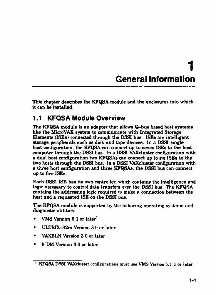
Bus grant signal., pass through each installed module through the A connectors of each slot. Figure 1-7 shows the bus grant routing for the BA213 backplane. Use bus grant continuity cards (M904 7) in vacant backplane slots to ensure bus continuity.
The BA213 encl08W"e holds up to four standard 5.25-inch storage devices. Fixed disk drives face the rear of the enclosure, providing easy access to the drive signal and power cables. Tape drives face the front of the enclosure.
The m~or difference between the BA213 and other Ulicroaystem enclosures is in the way you connect modules to external devices. Other enclosures have an VO panel in the rear of the enclosure. The BA213 uses bulkhead handles or covers that fit over the front of the module. Standard modules have bulkhead handles that are an integral part of the module. Option modules, such as the KFQSA, have a bulkhead cover that performs the same function, but are not attached to the module.
The bulkhead handles and covers fonn an electrical seal that complies with FCC regulations for keeping radio frequency interference (RFI) generated by the system inside the enclosure, and for keeping externally generated RFI out of the enclosure. They also help guarantee proper airflow through the system for module cooling.
General Information 1-9
Figure 1-7 BA213 Backplane Bus Grant Continuity Path
POWER SUPPLY CONNECTOR
TO SIGNAL OlSTfll8UTlON BOARD
POWER SUPPLY CONNECTOR
TO r:ANS

1-10 General Information
1.4 BA123 System Enclosure The BAl23 enclosure has a l3-slot, Q-bus backplane and holds up to five 6.26-inch storage devices. Figure 1-8 shows the BA123 enclosure.
The first 12 slots are for dual or quad-height modules. The CD rows of slot 13 are for the signal distribution board. If needed, a second signal distribution board can be installed in the AB rows of slot 13.
Figure 1-8 BA123 Enclosure

General Information 1-11
The backplane implements the Q-bus modules on the AB rows of each slot. MicroVAX systems use the CD rows of slots 1 through 4 for their high-speed memory interconnects. Figure 1-9 shows the bus grant continuity path for the BAl23 backplane.
You can install the KFQSA and other Q-bus modules in slots 5 through 12. As a rule, if you install a dual-height module in either the AD rows or the CD rows of a slot, you must install another dual-height module or a bus grant continuity card in the other two rows of the slot. The exception to this rule occurs when the dual-height module is installed in the last occupied slot in the card cage.
Figure 1-9 BA123 Backplane Bus Grant Continuity Path
J'
J3 __ 1

1-12 General Information
1.5 BA23 System Enclosure The BA23 enclosure has an 8--s1ot, Q-bus backplane and holds up to two 5.25-ilJch storage devices. Figure 1-10 shows the BA23 enclosure.
Figure 1-10 8A23 Enclosure
w • • ,'a,

Generai Information 1-13
The backplane implements the Q-bus module on the AB rows of each slot. The CD rows of slots 1 through 3 form the MicroVAX memory int-ereonnect. You should install only MS630 memory modules in the CD n»ws of slots 2 and 3. You caD install any dual-height modules in the AB rows of slots 2 and 3. Slot 1 is reserved for the CPU module. Figure 1-11 shows the bus grant continuity path for the BA23 backpla,ne.
You cal' install the KFQSA and other Q-bus modules in slots 4 through 8. As a ruJe, if you install a dual· height module in either the AD rows or the CD rows of a slot, you must install 8nother dual-height module or a bus grant continuity card in the other two rows of the slot. The exceptio" to this rule occurs when the dual-height module is installed in the last occupied slot in the card cage.
Figure 1-11 BA2:' Backplane Bus Grant Continuity Path

1-14 General Infonnation
1.6 DSSI VAXcluster Configurations nssl ISEs have a capability built into their finn ware that allows the ISE to maintain simultaneous connections with more than one host system.
A DSSI VAXduster configuration uses nSSI cables as the interconnect. Q-bus modulee for VAX or MicroVAX systems interface to DSSI cables by means of a DSSI adapter, such as a KFQSA module. Some adapter modules are embedded in the processor module.
As many as 8 DSSI nodes may use the same intelTonnect. A DSSI node is any device to which DSSI transports infonnatiofl and for which DSSI therefore needs an address, including ISEs and KFQSA modules on VAX or MicroVAX systems.
In a DSSI VAXcluster configuration, the host systems (and possibly an expansion cabinet such as the R215F) are connected together through an external nBSI cable. Each system is a boot server in a Local Area VAXclueter configuration. The host systems may share a common system disk ISE or may have independent system disk ISEe. Each BYstem bas direct and equal access to the common system disk ISE through its KFQSA module, and to any other ISE in either enclosure.
Figure 1-12, Figure 1-13, and F'igure 1-14 are examples of DSSI VAX ... luster configurations using the KFQSA module.
The benefits of a KFQSA-based DSSI VAXcluster configurations are:
• VAXcluster features, such as shared data across systems and satellite nodes
• Simplified system management due to ~l shared system disk (see the following page)
o Shared batch and print queueR
• Higher system availability

Gttneral Information 1-15
NOTE Systema that UN the KFQSA module can only form DSSI VAXeI .... ccm8gurations with other KFQU.baaed eystellUl.
NOTE Dasl VAXeIw.;ter confttruration8 are only supportAMl under VMS VenioD 1.1-1 and later, ad only when the systelllfl are conftaurecl into the IllUDe Local Area VAXelusler conftguration.
NOTE Due to IimitatiOD8 in the MicroVAX D boot ROM., two MieroVAX 0 ay8tem8 in a D881 VAXcluater confttruration ClUUlot automatieally boot from a COlDlllon system eIi.k ISK If a common .,stem eliak is ued, each node in the DSSI VAXcluater eonftpratioD muat boot I!rom a different root (SYSO, SYSl). But the MieroVAX D system CaD 0&11y boot automatically from SYSO. It is !"8COUImended that each MieroVAX D eyRem have ita own locally connected .yatem eli ... (aucb as an RD54 or RA82). When a COIIUIIOD ayatem disk ISE ia a requirement, one MicroVA~ D system may automatically boot from SYSO but the other must. De booted manually from SYSI.
When a MieroVAX JJ SYltem il clustered (oSSI VAXclulter eonfttruration) with a MicroV .. U 300 &eri_ ayatem, the MieroVAX D aystem should boot from SYSO and the MicroVAX 300 fieri_ sy.tem should boot from an alternate root.

1-16 General Information
Figure 1-12 Two-Syatem DSSI VAXcluater Configuration
Sy.'em 8 Sy.'em A
IS;5 I IISE4~ ISE2111SE1 I IISEO I t t
P"""- ~
I K K F F
:h 0 s A
7
L I r 1
LJ-0I736·TIO

General Information 1-17
FIQure 1-13 Th ..... System DSSI VAXcluster Configuration
.,a.a. A
K , .... -...1
Q
• A
1
_,a'a ...
K F ,-"--...., o • A
•
_,ltIM C
I(
F .... _..J
Q
• A
5
Figure 1-14 ossa VAXcl\.e"Ster with an Expansion cabinet
1,1'1" • ..,.nl'on CollI no' 1,ltolll "
,...- ~ fir. ! , Q
S A
• 7 . I
'------------
II ., ". "'
I
I ,'" "~I 'If)

n~UDn~~n~~Dauu~~nax
~XlOCOQ(XXXXXXXXJOOO(XXJOOO(XXXXX
XXXXXlOOClOoOnCOOOQOOOCOotlOOOOlXXXXXXXXXlotXXX ~DXXlO(~nn~XXXXXXUXXXXlQ(XXXXXXXXX
nu~XXDUlQ(lQ(DU~lQ(XXXXXXlQ(X
XXlOOQOOOO[xxnxx)Q{}O{)Q(}~XXXXXXXXXXXXXX
lQOC(lCOOtXXXXxxxxXXJO(l(X XXJOOO(XXXX XX X
nnX:XXXXXlQ(XXxxnXXXXXX~XXlQ(XXX
XX)Q{)Q{XXXX xx lOOOnO(lOOOOtx XX xx xx x lQ{XXXX xx xx lOGO!XXXXXXlOOO(XXXXX
XXXXXXXXXXXXXXXXXXXXXXXXUX xxnxxXXXXlOQCXXXXXXXlQ(XXX
XlOOOOOOOOQO(XXXXXXXXXXX
XXXXXXXXXXXXXXXXlOCXXX XXXXXXXXXXXXXXXXXXX XltXXXXXXXXXXXXlOCl(
XXlOCXXXXXXXXltX)(
:OCXX10ClOO!J{XXX
:OCXXXXXXXXX
XXXXlOOOO( XXlOOQ()(
KiOO{Ji(
XXX X
X
XXX XAXXX
)(}()()()Or)C
xxxxxxxxx XXXXXXXXxxl(
XX xx XX>O(XX){X x XX)(XXXXXXXXXXXX
XXXXXXXXxxxy.XXXXX XXXXXXlO(XX)!XlOCloooeJ(
XXXXXXXXXX;l)(XXXXXXXXX XXJQ(XXXXXXJO(XXXXXX)(J(XXX
xx XX xx XX XX xx XXXX XX XX xxxxx xx XX XXXXXXXXXX xx xx XXXXlOtXX X
lO{XXXXXXXXXXXXXXJO(XXXJ(XXXXXXX
xx xx xx xx xx XXlooooex xx XXXX XXJO(XXX XXXXXXDnDxxnxxJO(XXXXxxxxxxxxx
D~XXXXXXlQ{XX)QCXXXXXXXXXXXXXXXXJO(X
DXXDXXXXKXXXXX~XXXXXXXXXXXXXXXX~
xxxxxxxxxxxxxxaxxxxnxxxxxxxxxxxxKXXXX
lO(XXXX XX xx xx xx XXXXlQ(XXXXXX X1<XXXXXXlQ(XX)!Xl(
xx xxxxxxxx~~xxxxXXXXXXXXXXXXXXX)(XXlCX}o;XXXXX UXXXXXXXXXXXXXXUXXXXXXXXXXDDXXDXXXXXXXXX
XXXXXXXX~XX~XXXXXXXXlQ(XXXXXXXXXXXXXXXXXXXXX
XXXXXJ(XX)Q{XXlOC~XX){)(XXXY.XXXXXXXXXXXXXXXXXXXXXXXXX
XXXXXX)QQQ()Q(lO(;O<XXXXXXXXiO(XXXXXXXXXXXXXXXXXXXXXY.X>CX

2 Unpacking Instructions
Unpacking consists of removing the adapter and cables from the shipping container, verifying that there are no missing parts, and inspecting for damage. Report any damages or shortages to the shipper, and notify DIgital Services.
Befo"" opening the container, check fOT external damage luch as dents, holes. or crushed corners Open and unpack the shipping container. Inventory the contents of your option kit using Table 2-1.
NOTe The KPQ8A qaodule ia in aD antiatatie wrappinl with a ainea ,ei packet to prevent moiature damage. Do not unpack the module until autiatatic precautions have been taken. Save the wrappiq and the 181 packet to protect any modulea that are heiDI atored or traDsportecL
2.1 Option Kits The KFQSA is shipped as part of an option kit. Each optio., kit includes an adapter board, preconfigured cabling. a tenninator. mounting hardware, and documentation Table 2-1 hats the option iutR that are offered for field installation, and the parts that are mc1udt>d In pach klt
2-1

2-2 UnpackIng instructions
Table 2-1 KFQSA Option Kits
Optioa Kit Part DeaeriptioD Part Numbe ..
KFQSA-SA IO'QSA wuJu1~ Mii69 (factory inlJtalled, for DSSI device cable (flat l 17-01836-01 reference only) nSSI adapter cable (round) 17-01931-01
External terminator 12-29258-01 KFQSA installation manual EK-KFQSA-IN
~SA-SG KFQSA module M7769 """'.I • 'n KFQSA add-on cable 7~26020-02 \h... -~
BA218. with cable _ L "-nal terminator 12-29258-01 for external ISEe KFQ...A module label 36-26883-96 only) Gap filler panel 7~24071-O1
KFQSA installation manuel EK-KFQSA-IN
KFQSA-BA KFQSA module M7769 (fOIl' BA123. with KFQSA aJd-on cable 17-01835-02 cable for external External terminator 12-29258-0J ISEa only) Mounting screw8 «Q-buB 90-09701-00
mounting plate) KFQSA installation manual EK-KFQSA-IN
KFQSA-AA. KFQSA module M7769 (for 8A23, with cable KFQSA add-on cable (BA23)1 17-01835--01 for external ISEs KFQSA add-on caMe (H9642)1 17-0183D-04 only) External terminator 12-29258-01
Mounting BcreWB (Q-bUB 90-09701-00 m~ Ilting plat~) KFQSA insta Hation manual EK-KF'QSA-IN
I U. only one of thHe cables, as appropriate- for the Ul8tall.bon.

Unpacking Instructions 2-3
2.2 Inspection CAUTION
Printed eireuit boarda can be damapel by static eleetri~ity. When handlin, the KFQSA module, wear an antistatic wrist strap and WI8 a JrOWlded work surface such u the !)ne in the Antistatic Kit (PN ____ ).
1. Visually iNSpect the KFQSA for damage. Check the components and connectors for broken. bent. or missing pins. If there is any damage. do not continue with the installation.
2. Check for the presence of the jumper shown in Figure 2-1. The KFQSA should never be installed with this jumper in place. If it is on the m:ldule. remove it.
Figure 2-1 KFQSA Jumper Location
rt!J~ Romove this Jumper
W 01733-TIO

XXX){j()o(XXXXXXXXXXXXXXXX xx xx XX xx XX xx xx xx xx xx xx xxxxxx
x XXXXXX XX xx XX xx XXXXXXXX xx xx xx xx XX xx xx xx XiC){X Xlf xx XX
XXXXXXXXXXXXXXXXXXXXXXXDXXDXXXXXXXXDDDDD
XXXXXXXXXXXXXXXXXXXXXXXXXXXXXXXXXXXXXXXXXXXXX
XXXXXXXXXXXDXXXXXXXXXXXXxxxxnnxxxxxxxxxx
XXXXXXXXXxxxxxxxxxxxxn~xxxxxxxxxxnxxxx
XXXXXXXxxXXXXDxxnXXXXXXXXXXDxxnxxn
XX}{XXXXXXXXXXXXXXXXXXXXXXXXXXDXXXXXY.
XUXXXX xx XX XX XX XX XX xx XX XX XX XX xx XX XX XXXXXXXXXXXXXXXXXXXXXXX)-':xxxxxxn
XXXXXXXXX XX XX XX XX XX xx XX XX XX X )( XX
XXXXXXXXX XX XX XX XX XXXX XX XX XX x') XXXXXXX XX XXXXXXXXXXXX XX XX XX
XXXXXXXXXXX XXXXXXXXXX xx XX
XXXXXXXXXXXXXXXXXXXXXXX
XXXXXXXXXXXXXXXXXXXXX
XXXXXXXXXXXXX}Q(XXXX
XXXXXXXXXXXXXXXXX
XXXXXXXXXXXXXXX
XXXXXXXXXXXXX
XXXXXXXXXXX X)'1000QCXX
)(XXXXXX
XXXXX
XXX x
X
XXX :\lOiJOi
X>O\.XXXX XXXXXXX~
XXXXXXY.XXXX
XXXXXXXXXXXXX
XXXXXXXXXXXXXXX XXXXXXXXXXXlOClC:XX
XXXXJ(XXXXXXXXXXXXlrn XXXXXXXXXXXXXXXXXJOOO(
XXXXXXXXXXXXXXXXXXXXXXX XXXXXXXXXXXXXXXXXXXXXXXXX
XXlOOOOCKXXXXXXXXXXXXXXXXXXX Xxx xxxxxxxxxxxx XX xx XX XlOexXXXX
KXXXXXXXXX10OCXXXXXXXA1OCXXXX)OOOl:
xxxxxxxnuuxxu~~~nn~~n
X~~~~~~~~~~u~~nuun
X~~n~nDn~~~~n~nn~
x~~n~~n~~~~nnxxxx
~~XXnUnnDnUnUUn~~nun
x~nnnnnXXXXDn~Dn~~
xnxx~XXXXXXXXXXXXXXXXXXXX~XXXXlOtXXXXXXlOOOt
XXXUXXXXXX~UXXXXXXX)'Xi/;XXXXXXXXXXXXXXXXXJOO\:)Qt
)rXXXXXXXXXXXXXXXXk"XXXJOOClOO{~..x:!{!OOO!xlO"JI"_"txy.)anOCY.;x
x xx XX XXXXXXXXXXXXXXXXXXXXXXXlOOOO{XXXXXXXXXXXXXXXXlO!

3 Planning the System Installation
It is important to carefully plan the system installation before putting any new modules into the system. Thi!'! involves checking the power and bWl load requirements, and checking to make sure you have everything yo~ need to make the configuration work.
Fill out a configuration worksheet before proceeding with the installation A configuration worksheet lets you track the parameters that limit system configuration such as space, power requirements. and bus loads.
Figure 3-1, Figure 3-2, Figure 3-3, and Figure 3-4 are examples of a configuration worksheets for the BA440, BA213, BAIZ3. and BA23 enclosures, respectively. Table 3-1 lists power and bus load data for all cUlTently supported modules and storage devices
Complete the configur'ation worksheet by perfonning the followintJ steps:
1. List al1 devices already installed in the aystem.
2. List all devices you plan to install in the system.
3. Fill in the power and bus load data from Table 3-1 for each device you have listed.
4. Add the columns and make sure the totals are ",thm rhp limIt'" specified for the enclosure
3-1

3-2 PMMing the System Installation
Figure 3-1 BA440 Configuration Worksheet
SLOT MODULE CutteIiIt tAmpa) ...... • ... L. .... .. VtIC .tlVdc ~ -II ~. AI: DC
1
2
3
4 l400'-BA 2.52 00 12. , l4000·AI·8 7.4 035 42.1 .
• 1 -I
D
lG
11
12
H-. f 7 0.5 ,,5 IMM lTOtUaE:
0 TK10 ,5 24 :teo
1
2 --:I t. __ GOiU"'ftS
MuIIl flO' •• 0Md· toOA f' 0 A 5I40W
Not. Toa.. output powe, trom +33 Vdc and .5 Vdc must not exceed 330 W ML0-003130

Planning the System InstaUation 3-3
F'gure 3-2 BA213 Configuration Worksheet
RIGHT POWER SUPPLY Current (Amps) Power
SLOT MODULE .S \Ide .12 Vdc (Wans) , 2
3
4
5
6
MASS STORAGE
TK Olive
fiXED DISK
T Dill ihese COlumns
Musl nOI elceed 330 A lOA 2300W
LEFT POWER SUPPLY
SLOT I Current 'Amps' Power MODULE .s Vde .12 Vdc (Wans'
7
9 ------- ---===--------------------- --------_ .. - -_ .. _------9
10
, 1
12
MASS STORAGE-
fIXED DISKCSI 1
2
, olal,hese columns
Mus' nc t exceed 330 A 70 A 1300W

3-4 P1anning the System Installation
Figure 3-3 SA 123 ConfiguratiOn Worksheet
SlOt MODUli , AS
CO 2 11.1\
CO J A8
CO .. AS
to ~ .e.B
co 6 AS
CO 7 11.0
CO 9 11.8
[0
9 <\0 CD
'0 11.8 CO
" 11.8 CO
12 11.8 CO
'3 AS SIGf>tAl co DIST
MASS ORAG{ SHHf Of VICE
5' 4 :9 '2
COLUMN 10TAl5
MUST NOT £l'CHO
ADD TIf(Sf COLUMNS , .A.
~ , ~ • t REGULAYOR A REGULATOR 8
052 , , ,
1 A ,10 '" 31; {I. 7 A
,
730 '(oj
·n{COMMENOfD JOUR t)R'VI,) MII.'M,'M TII\,; "; ""flVf', , ANt' J ~I/II():~ 3 4 rJR.,
"\
~ ~ 110 'NSERTS
12]1( 31 II )It 41 8 A
4"
·'Qf MORE THAN fOU~ 1 Yo <8 IIQ PIINH <; AlH RfOI!,RI fl Po/lj 110jlPH R HMPLAH MAV 8£ US[O
..... '\".

Planning the System Installation 3-5
Figure 3-4 BA23 Configuration Worksheet
ADO THESE COLUMNS
t A
8ACt(PLAHE -..OOUL.E CURRENT III.) POWER I/O PANEL INSERTS
SLOT +5V .'2 v (WI B A
, AB CO
2 AS CO
J A8 CO
I. AI CO
5AB co
6 AB CO
7 A8 CO
II Art CD
MASS STORAGE ,
2 l l COLUMN TOTALS
MUST NOT EXCEED 360 7.0 no
• If MORE THAN YWO l)'pE A fiLTER CONNECTORS ARE REQUIRE" AN ADAPT l R TEMPLATE (PH 74-27740·011 MAYBE USEO THIS ALLOWS lHRH AOOITIONAI TYPE A FILTER CONNECTORS BUT REDUCES THE AVAILABLE TYPE '3 CUTOUTS TO TWO
2'
,

3-6 Planning the System Installation
Table 3-1 Power and Bus Load Data CUlT8Dt (Amp.) Power BuaLo.4h
Option Module +5V +12V Watt. AC DC
AAVU-D 1 Al 009 1.8 0.0 9.0 1.0 1.0
ADQ32-8A A030 4.45 0.0 22.26 2.5 0.5
ADVll-Dl Al008 3.2 0.0 16.0 1.0 1.0
AXVll-SA A026-PA 2.0 0.0 10.0 1.2 0.3
CleA16 M311S-VA 1.4 0.11 8.3 3.0 1.5
CXBl6-M M311S-YB 2.0 0.0 10.0 3.0 0.5
CXY08 M3119-YA 1.4 0.35 11.2 3.0 1.5
DEQl,,'A M7604 3.6 0.5 23.5 2.8 0.5
DES~A M3127-PA 2.4 0.22 14.64 2.2 0.5
DFA01-AA M3121-PA 1.97 0.04 10.30 3.0 1.0
DHVll M31N 4.6 0.56 29.1 2.9 0.5
DLVJl M8043 1.0 0.25 8.0 1.0 1.0
DMVll-M M8063 3.4 0.4 21.8 2.0 1.0
DMVll-N M8064 3.4 0.4 21.8 2.0 1.0
DPVll M8020 1.2 0.3 9.6 1.0 :i..0
DRQ3B-SA M7658-PA 4.6 0.0 22.50 2.0 0.6
DRVll M7941 0.9 0.0 4.5 2.8 1.0
DRVll-J M8049 1.8 0.0 9.0 2.0 1.0
DRVIW-8A M7661-PA 1.8 0.0 9.00 2.0 1.0
DSVl1 M3tOS 5.43 0.69 35.43 ~.9 1.0
DTQNA-BC M7130 6.0 2.0 54.00 :1.9 0.5
DZQll M310S 1.0 0.36 9.32 1.n 1.0
DZVll M7957 1.2 0.39 10.7 3.9 1.0
lUeually connected througb 8 univel"8a1 data input panel (uDIPI using a 5.25-inch maM storage slot

Planning the System Installation 3-7
Table 3-1 (Continued) Power and Bus Load Data
Current (Ampe) Power Su.Loads
OptiOD Modale +5V +12V Watts AC DC
H36042 1.70 "1,50 14,50
IBQOl-SA M3125-PA 5,00 0,03 28,60 4,6 1.0
IEQll M8634 3,0 0,0 15,0 2,0 1.0
KA83O-AA M7606 6.2 0,14 32,7 2.7 1.0
KA67O-AIBB fAOOO-AIB 7,4 0,35 41,20 4,0 1,0
KDA6O-Q M7164 6.93 0,0 34,66 3,0 0.6
KDA6O-Q M7165 6.67 0,03 33,21 0,0 0.0
KFQSA M7769 5,5 0,0 27.0 3.8 0.5
KLESJ M7740 3.0 0.0 16,0 2,3 1.0
KMVll M7500 2.6 0.2 16,4 3,0 1.0
KRQ50-SA M7552 2,7 0,0 13,50 2.7 1,0
KWVU-C1 M4002 2.2 0.013 11.2 1.0 1.0
KXJU-SF M7616 6.0 1,4 46.80 2,7 1.0
LPVll-SA M8086-PA 2.8 0.0 14.00 1.8 0,6
LPVll M8027 0,8 0.0 4,0 1.4 1.0
MRVll-D M7942 2.8 0.0 14.0 1,8 1,0
MS63O-AA M7607 1.0 0,0 5.0
MS63O-BA M7608 1.3 0.0 6,6
MS63O-CA M7609 2,1 0.0 10,5
MS670-BA fAOOt-BA 2.52 0.0 12.60
RC25 1.0 2.5 35.0
R051 1.0 1.6 24.2
RD52 1.0 2.5 35.0
R063 0.9 2.5 34.5
lUsually connected through a univenal data input panel (VDW, using 8 5.25-mch me88 storage alot
2Also include ·12 Vdc • 0,25 A, 3 W
BAlao include 3,3 Vdc. 0,27 A, 0.9 Wand ·12 Vdc. 0.04 A, 0.5 W

• 3-8 Planning the System Installation I
I Table 3-1 (Continued) Power and Bus Load Data
Current (Amps) Power BuLoacle I Option Module +SV +12V Watt. AC DC I RD64 1.3 1.34 23.7
RF30 1.25 2.85 18.3 I RF31E-AA 1.0 2.8 38.60 I RF71 1.25 4.54 26.5
RQDX2 M8639-YB 6.4 0.1 33.2 2.0 1.0 I RQDX3 M7566 2.48 0.06 13.2 1.0 1.0 I RQDXE M7513 0.8 0.0 4.0 1.0 0.0
RRD50 M7552 I RX33 0.5 0.3 5.6 I RX50 0.85 1.8 25.9
TK60 1.35 2.4 33.55 I TK70E-AA 1.5 2.4 36.30 I TQK50 M7546 2.9 0.0 14.5 2.0 1.0
TQK7O-SA M7559 3.5 0.0 17.60 4.3 0.6 I TSV05 M7196 6.5 0.0 32.5 3.0 1.0 I TSV06-SA M7530 6.5 0.0 32.50 1.5 1.6
TSV05-SA M7206 6.5 0.0 32.60 2.4 1.0 I VeDOl M7602 5.0 0.0 25.0 3.0 1.0 I VCB02 M7169 5.8 0.75 38.0 3.5 1.0
VCB02 M7168 3.4 0.0 17.0 0.0 0.0 I
I
I
I I
I
I
I
I

KXXXlOOOOOOOOCXXXXXXXXXXXXXXXXXXXXXXXXXXXXXXXlO(XXXXX
JOOaXXlOOClOOOOOCXXXXXXXXXXKXXXXXXXXXXXXXXlOCXXXXXXX
XX~UXXXXXXXX~XXXXXXUXXXXX
XXXXXXXXXXXXXXlQ':XXXXXXXXXXXXXXXXXlOCXXXXXXJOOX
lO lOOCOCXlOOOOOOOXXXXXXXXUXXXXXXXXXXXXXXXXX
XXXXXX~XXXXXXXXXXXXDXXUUXXXXXXUX
XXXXlOOOOOOQ{XXXXXXXXXXXXXXXXXXXXXXXX XX X XXXXXXXXDnXXXXXXXXXX~XXXXXXXXX
XXXXXXXXXXXXXXXXXXXX~XXXXXXX
XXXXXX~XXXXXXXX~XXXX~XXXXX
XXXXXi(XXXXXXXXXKXXXXXXXXXXXXXXX
XXXXXXXXXXXXXXXXXXXAXXXXXXXX)(
XXXXXXXXXXXXXXXXXXXXXXXXXXX
XXXXXXXXDUXXXXXXXXXXXXX
XXXXXXXXXXXXXXXXXXXXXXX
XXlOOOCXXXXXXXXXXXXXXX
XXXXXXXXXXXXXXXXXXX
XXXXXXXXXXXXXXXXX
XXXXXXXXXXXXXXX XXXXXX)CXXXXXX
XXXXAXXXXXX
XXXXXXXXX
XXXXXXX }Q(XXX
XXX
X
K
XXX KXXXK
){X)QOOO(
XXXXXXXXX
xx xx XX XXXXX
xx XX XX xx XXXX X
XXXXXXXXXXXXXXX
XXXXXXXXXXXX)(xXXX
XXXXXXXXXXXXXX)(x)(xX
XX)Q(XXXXXXXXXXXXXXXXX
XXXXXXXXXXXXXXXXXXXXXXX
XX xx XX XX XX XX XltXXXXXXXXXXX
XX XX XX XX xx XX XX xx XX XX KXXX XX X xx XXXX XX XX)(XXX XXXXXX XX XX XX XXX
XXXXXXXX)(XXXXXXXXXY.J(XXXXXXXXXXX
xx XX xx XX XX XX xx XX xx XX XX XX XXXX)(xXXX
xx XX XX XX XX XX XX XX xx XX XX XX XX XX xx XX XXX
XXXXXXXXXXXXXXXXXX)(xXXXXXXXXXXXXXXXXX
xxxxxx XX KX XX XX XX XX xx XX XX XX XXXX XX XXXXXXX xx xx XX XX xx XX XX XX XX XXXXXX XX XX XX XX XX XX XXXXX
XX xx XX XXXX XX xx xx XX XX XX XX XX XX XX XX XXXXXXXXXXX
xx XX XX XX XX xx XX XX XX XX xx XX XX XX XX XX XX XX xx XX XXXXX
XXXXXXXXXXXXXXXXXXXXXXXXXXXXXXXXXXXXXXXXXXXXXXX
XXXXXXXXXXXXXXXXXXXXXXXXXXXXXX XX XXXX XX XX XX XX XXXXX
xxxxxxxxxxxxxxxxxxxxxxxxxxxxxxnxxxxxxxxxx~XXXXXXX

4 KFQSA S~/itches
Before installing the KFQSA. you must choose a control and status register address (CSR) that will allow the host to access the adapter. A four-position DIP switchpack is provided for this purpose. Figure 4-1 shows the location of the switchpack. Table 4-1 explains the function of each switch.
In most cases you should use one of the dedicated CSR addresses. 8S this allows a programming addrpqg to be selected without the possibility of conflict with other modules in the system. 10 do this. set the switches &8
follows:
• Switch l-ON
• Switch 2-OFF
• Switches 3 and 4-as specified in Table 4-2
4-1

4-2 KFOSA Switches I
figure 4-1 KFQSA Adapter Module SWItches I
I
I
I 13·38234-01 TermInator I
I
I
I
I
I
I I
I
I
I I
U.()'722·TI)

KFOSA Switches 4-3
Table 4-1 KFQSA Switch Settings
Switch POilitiOD Function
1 OFF
ON
2 OFF
ON
3 and 4
With Switch 1 in the OFF position (toward the number 1" the other switchefl are ignored and CSR addresBes are read from the configuration table. After the configuration table has been programmed (Chapter 7l, the system should be powered down and this switch ahould be set to the OFF position, where it should remain unless the configuration table il!l corrupted and needl!l to he reprogrammed.
Putting Switch 1 in the ON position enables the selection of a CSR address for programming the configuration table. This is the switch poeition for the initial installation. The CSR addreas Belected for programming depends on the position of the other three switches.
Putting Switch 2 in the OFF position enables the selection of one of four CSR addresses that have been dedicated for programming the KFQSA. Table 4-2 show! how the remaining two switches are used to select one of these addresses. These addreoses should be used only for initially accessing the KFQSA to program the EEROM.
Putting Switch 2 in the ON position enables the selection of one of four addres8e8 normally reserved for MSCP or TMSCP devices. Table 4-3 shows how the remaining two switches are used to 88lect one of these addresses. I
When SwitcheD 1 and 2 are ON and OFF. respectively. these switches are used to select one of four dedicated CSR addresseR (Table 4-2).
When Switches 1 and 3 us both ON. these switches are used to lIelen either a disk (MSCP) addr888 or a tape (TMSCP) addres8 (Table 4-31.
IAvoid uaing these adcireellM!8 at dUll time; they may c"nflict with other moou)PFI in the lI}'atem. They are provided for future llIK'.

4-4 KFOSA SwItches
Table 4-2 Selecting a Dedicated KFQSA CSR Address
Switch Switch Switch Switch 1 I 3 " eSR AddrM8 (Octal)
ON OFF ON ON 0774420 (fixed)
ON OFF ON OFF 0774424 (fixed)
ON OFF OFF ON 0774430 (fixed)
ON OFF OFF OFF 0774434 (fixed)
Table 4-3 Selecting an MSCP or TMSCP CSR Address
Switeb Switch Switch Switch 1 .2 3 4 eSR Addrea8 (Octal)
ON ON ON ON 0760444 (secondary TMSCP address)
ON ON ON OFF 0774500 (primary TMSCP address)
ON ON OFF ON 0760334 (8econdary MSCP address)
ON ON OFF OFF 0772150 (primary MSCP address)

:KlOQ[XXXXXXXXXXXXXXXXXXXXXXXXXXXXXXXXXXXXXXXXXXXXXXX
~XX~XXXXXXXXXXDX:XXXXX~~XXnxxxxx
~XX~~XXXXXXx:xx:xxx~xxxxxxnax
XXlOOOOQOOOOCXXXXXXXXXXXXXXXXXXXXXXXXXXXXXXXXX
XXXXXXXXX:XX:X~XX~X:XXXXXXXXXxxXXX
XXXXXXXXXXXXXXXXXXXXDDnXX~XXXXXXXXX
>oocxXXXXXXXXXXXXXXXXXXXXXXXXXXXXXXXXXXX XXXXXX~XXXXXXXXXXXXXXXXXXXXXXXXxxX
XXXXXXXXXXXXXXXXXXXXXXUXXXXXXXXXXX
XX~XXXXXXXXxxxxxxxxxxxxxxnxxx
XXXXXXXXXXXXXXXXXXXXXXXXXXXXXXX
xxxxxxxxxxxxxxxx xxxxxxxxxx XX X XXXXXXXXXXXXXXXXXXXXXXXXXXX XXXXXXXXXXXXXXXXXXXXXXXXX XXXXXXXXXXXXXXXXXXXXXXX
XXXXXXXXXXXXXXXXXXXXX XXXXXXXXXXXXXXXXXXX
xxxxxxxxxxxxxxxxx XXXXXXX)(XXXXXXX
XX100IXXXX}f XX X XXXY.KXXXlrnX
XXXXXXXXl\ XXXXXXX
XX xxx xxx x
x XXX
X)(XXX
XX XX XX X
xx XX XX XXX
xx XX xxxx XXX
XJ{XXXXXXXXXXX
xx xx xx XX XX XX XXX
XXXXXXXXXXXXXXXXX
XX XX XX XXXXXX XXXXXXX
XX XX XXXX)"'XXXXXXXXXXXX
XX XX XX XX XX XX>.'XXXXXXXXXX
XXXXXXXXXXXXXXXXYXXXJO(XXX
XXXXXXXXXXXX>G<XXXXXXXXXXXXX
XX XX.'OCXXXX XXXXXX XX XX XXXXXXXXX
xx XX xx XX xx XX XX XX XX XX XXXX XX XXXXX
QDDDXXXXXXXXXXXX~XXXXXXXXXXX
DXXXXXXXXXXXXXXXXXXXXXXXX~XXXXXXX
xx XX XX XX XX XX XX XXXXXXXXXX XX XX xx XX XX XX X
xx XX XX XX XX XX xx XX XX XX XX XX xx XX XX XX XX XXXXX
XXXXXXXXXXXXXXXXXXXXXXXXXXXXXXXXXXXXXXXXX
XX XX xx XX XXXXXX XXXX XXXXXXXX XX XX XX XX XX XX XXXXX
XXXXXXXXXXXXXXXXXXXXXXXXDr~aXXXXXXxxxxxxX
XXXXXXXXXXXXXXXXXXXXXXXXXXXXXXXXXXXXXXXXXXXXXXX
XXXXXXXXXXXXXXXXXXXXXXXXXXXXXXXXXXXXXXXXXXXXXXXXX
XXXXXXXXXXXXXXXXXXXXXXXXXXXXXXXXXXXXXXXXXXXXXXXXXXX

5 Installation Procedures
This chapter explains how to install the KFQSA module into a host enclosure.
CAUTION Only qualified Digital Service personnel should attempt to instaU the KFQSA module. Before starting the procedure. make sure that the system manager has backed up all Bles. Have the system manager perform a system shutdown of the operating system before turning off power. Itfake sure the customer has taken thes'! steps before removing any panels from the enclosure.
CAUTION Static electricity can damage integrated circuits. Always wear a grounded wrist strap and use a grounded work surface. such 88
the one found in th(~ Antistatic Kit (PN 29-28246) when installin, modules.
Before beginning the KFQSA module installation, the system should be tested to verify that it is working correctly. The following procedure is recommended, but may be altered due to on·site circumstances at the discretion of the installer
1. Have the system manager halt the operating system
CAUTION Ensure that aU necessary system software is backed up at this time.
2. Initiate the system power-on self·test. (POST). and venfy that these run successfully. Refer to your system documentation for the appropriate procedures.
5-1

5-2 Installation Procedures
3. Boot the appropriate diagnostic monitor, and perform a complete system level diagnostic test. Verify that these run successfully.
Once the previous tests have run successfully, power down the system and proceed to the appropriate section for KFQSA module installation procedures.
5.1 BA440 Installation Procedure Using the KFQSA-SG Option Kit
'1b gain access to the BA440 enclosure, there is a three-position lock that determines which controls you can access. The level of access is as follows:
1. Top position opens the upper door only.
2. Middle position locks both doors.
3. Bottom position opens both doors together.
1b install the KFQSA adapter module, do the following:
1. Insert the key into the lock on the front door. Turn the key to the bottom position.
2. Slide down the window.
3. Put the power switch <rn in the OFF position (0).
4. Pull the release latch on the front door out and use it as a hand grip to remove the door from the system.
5. Remove the blank cover from the slot where the KFQSA is going to be installed by releasing the lA·tum captive screws holding it to the card cage. (Check your system documentation for the correct placement of modules in the card cage. The KFQSA is usually installed as the last device on the Q-bus module.)
6. Check the KFQSA module switches to ensure that they are in the correct position to select an appropriate CSR address (Chapter 4).
7. Connect the add-on cable connected to the bulkhead handle to the connector on the KFQSA module (Figure 5-1).
a. If using the bulkhead handle (PN 70-26020-02), ensure the on-board SIP terminators (PN 13-38234-(1) are removed (Figure 4-1), and connect an external DSSI terminator (PN 12-29258-01) to one of the connectors on the bulkhead covers. SIP terminator removal is supported on KFQSA Revison K04 or later.

Installation Procedures 5-3
b. If using the bulkhead handle (PN 70-26020-01) enBure the on-board SIP tenninators are on the KFQSA module.
8. Slide the KFQSA into the card cage slot, and push in the levers to lock the module into place.
9. Connect the extemal DSSI cable(s) to the bulkhead cover.
10. Before attaching the bulkhead cover over the KFQSA module, run the POST diagnostics. Make sure that the red LEDs aU go out, indicating that the POST diagnostics have completed successfully.
11. Configure the DSSI subsystem following the procedures outlined in the next two chapters. Make sure that Switch 1 on the KFQSA is returned to the OFF position once the configuration procedure is completed.
12. Place the bulkhead cover over the module and attach it to the card cage enclosure. If the KFQSA is installed in a slot next to a module with a recessed handle. install the gap filler assembly as follows.
a. Using two screws and one gap filler (PN 70-24071-01), attach the gap finer to the top and bottom of the side of the KFQSA bulkhead cover (Figure 5-2). Make sure the gap filler fits into the tab indentations on the KFQSA bulkhead cover.
b. Place the bulkhead cover with the gap filler over the card cage slot.
c. Make sure there is correct ground (no open spaces) between the KFQSA and the neighboring module.

5-4 Installation Procedures
I=lgure 5-1 BA440 cabling for a KFQSA In a VAX 4000 Sys~cfm
W-Ol 724· no

Installation Procedures 5-5
Figure 5-2 Installing the Gap Filler Assembly
.... OIOIA"
, .. " 00,. ..

s-e Installation Procedures
5.2 BA213 Installation Procedure Using the KFQSA-8G Option Kit
The front door of the BA213 enclosure has a 3·position lock that limits access to the system controls. The controls are behind a plastic window at the upper right of t.he cover.
1. Insert the key into the lock on the front door. Turn the key to the bottom position.
2. Slide down the window.
3. Turn the power switch to the OFF position.
4. Pull the release latch on the front door out and use it as a hand grip to remove the door from the system.
5. Remove the blank cover from the slot where the KFQSA is going to be installed by releasing the 14-turn captive screws holding it to the card cage. (Check your system documentation for the correct placement of modules in the card cage. The KFQSA is usually installed as the last device on the Q-bus module.)
6. Check the KFQSA module switches to ensure that they are in the correct position to select an appropriate CSR address (Chapter 4).
7. Connect the add-on cable connected to the bulkhead handle to the connector on the KFQSA module (Figure 5-3).
a. If using the bulkhead handle (PN 70-26020-09), ensure the on-board SIP terminators (PN 13-38234-01) are removed (Figure 4-1), and connect an external DSSI tenninator (PN 12-29258-01) to one of the connectors on the bulkhead cover. SIP terminator removal is supported on KFQSA revision K04 and later.
h. If using the bulkhead handle (PN 70-26020-01), ensure the on-board SIP terminators are on the KFQSA module.
S. Slide the KFQSA into the card cage slot, and push in the levers to lock the module into place.
9. Connect the DSSI cable(s) to the bulkhead cover.
10. Before attaching the bulkhead cover over the KFQSA module, run the POST diagnostics. Make sure that the red LEOs all go out, indicating that the POST diagnostics have completed successfully.

Installation Procedures 5-7
Figure 5-3 Cabling for a KFQSA In a Host System USing a BA213 Enclosure
lJ-01716- SCAN
11. Configure the KFQSA ISE subsystem {oHowing the procedures outlined in the next two chapters. Make sure that Switch 1 on the KFQSA is returned to the OFF position once the configuration procedure is completed.
12. Place the bulkhead cover over the module and attach it to the card cage enclosure. If the KFQSA is installed in a s]ot next to a modu1e with a recessed hand1e. install the gap filler assembly as follows.
a. Using two screws and one gap finer (PN 70-24071-01 '. attach the gap filler to the top and bottom of the side of the KFQSA bu1khead cover (Figure 5-2). Make sure the gap filler fits into the tah indentations on the KFQSA bulkhead cover.

5-8 Installation Procedures
b. Place the bulkhead cover with the gap filler over the card cage slot.
c. Make sure there is correct ground (no open spaces) between the KFQSA and the neighboring module. If necessary, install a gap filler between modules (Figure 6-2).
Installation Procedures 5-Q
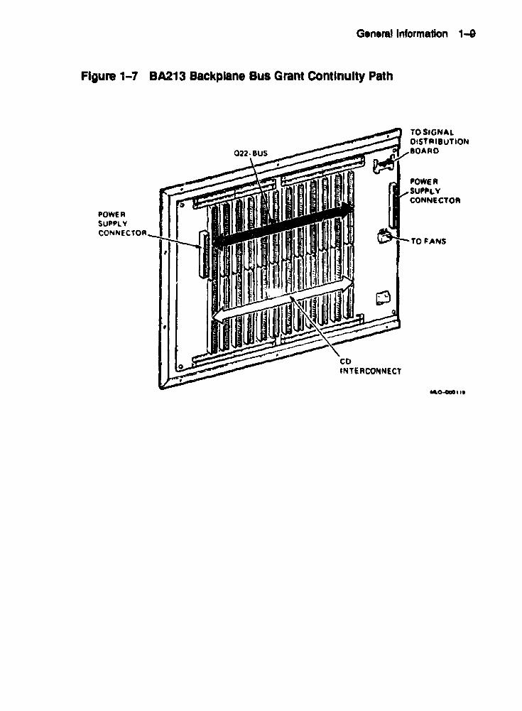
5.3 BA 123 Installation Procedure Using the KFQSA-BA Option Kit
Refer to Figure 5-4 while performing this procedure.
1. Shut down the enclosure. and remove the ae power cord from the wall outlet.
2. Open the tear door of the enclosure.
Figure 5-4 KFQSA Installation In a BA 123 Enclosure
, .... Ol)() "III

5-10 Inndatlon Procedur ••
3. Loosen the captive screw that connects the right aide panel to the rear of the enclosure (Figure 5-5) .
• 4. The panel is attached to the bottom of the enclosure frame by two snap fasteners. Pull the bottom of the panel out until the panel detaches from the bottom of the enclosure.
6. Lift the panel slightly to release it from the lip at the top of the frame, and remove the panel.

Installation PrOO8dures 5-11
Figure 5-5 Removing the Right Side Panel
r

5-12 Installation Procedures
6. Remove the card cage door by releasing the two clasps at the front end of the door, and swing the door open (Figure 5-6).
Figure 5-6 Removing the Card Cage Door
..... I'tl"···

InstallatIon Procedures 5-13
7. Check to make sure that the KFQSA switches are in the correct position (Chapter 4).
8. Slide the KFQSA module into the appropriate card cage slot and push in the levers to lock the module in place. Refer to your system documentation for the recommended module order.
9. Connect the DSSI cable to the KFQSA module.
10. Install the mounting plate onto the 1/0 panel, and attach the external DSSI connoctor to it.
11. Connect the DBSI cable as shown in Figu.re 5-4.
12. Connect the external tenninator, and run the POST diagnostics. Make sure that the red LEDs all go out, indicating that the POST diagnostics have completed successfully.
13. Configure the DSSI subsystem fonowing t.he procet1ureA outlined in the next two chapters. Make sure that Switch 1 on the KF'QSA itl returned to the OFF position onct! the configuratIOn procedure is completed.
14. Assemble the enclosure by reversing Steps 1-6.
15. Remove the external terminator, and t.'Onn~t the DSSI cable from an other host or expansion cabinet tl} the connector.

5-14 Installation Pr~u' ••
5 .. 4 BA23lnstaliatic~1 Procedure Using the KFQSA-AA Option Kit
Refer to Figut'El5-7 while perfonning this procedure.
1. Shut down the enclosure. and remove the ae power cable from the wall c:ltlet.
2. Remove the rear cover and all cables. Label all cablee for replacement later.
3. Loosen the two &crews retaining the rear VO panel assembly. Swing the aS8embly open and remove the ground stra;> screW8.
I
I
I
I
I
I
I
I
I
I
i I
I
I
I
I
I

Installation Procedures 5-15
Figure 5-7 KFQSA Installation In a BA23 Enclosure

1>-16 Installation Procedures
4. Disconnect any cables attached to the back of the 110 panel assembly. Note their specific locations and the orientation of the red stripe (keying) on each cable.
6. Make sure the KFQSA switches are correctly set (Chapter 4).
6. Slide the KFQSA module into the appropriate slot in the backplane. Refer to your system documentation for the recommended module order.
7. J. ttach the DSSI cable to the module.
8. Install the mounting plat.e onto the 110 panel, and attach the extemal DSSI connector to it.
9. Connect the extemal terminator, and run the POST diagnostics. Make sure that the red LEDs all go out, indicating that the POST diagnostics have completed successfully.
10. Replace the 110 panel.
11. Configure the nSSI subsystem following the procedures outlined in the next two chapters.
12. Remove the 110 panel. Make sure that Switch 1 on the KFQSA module is returned to the OFF position once the config'.lTation procedure is completed.
l3. Replace the 110 panel and rear cover of the BA23 enclosure.
14. Remove the external terminator, and attach the DSSI cable from an other host expansion cabinet to the connector.
Installation Procedures 5-17
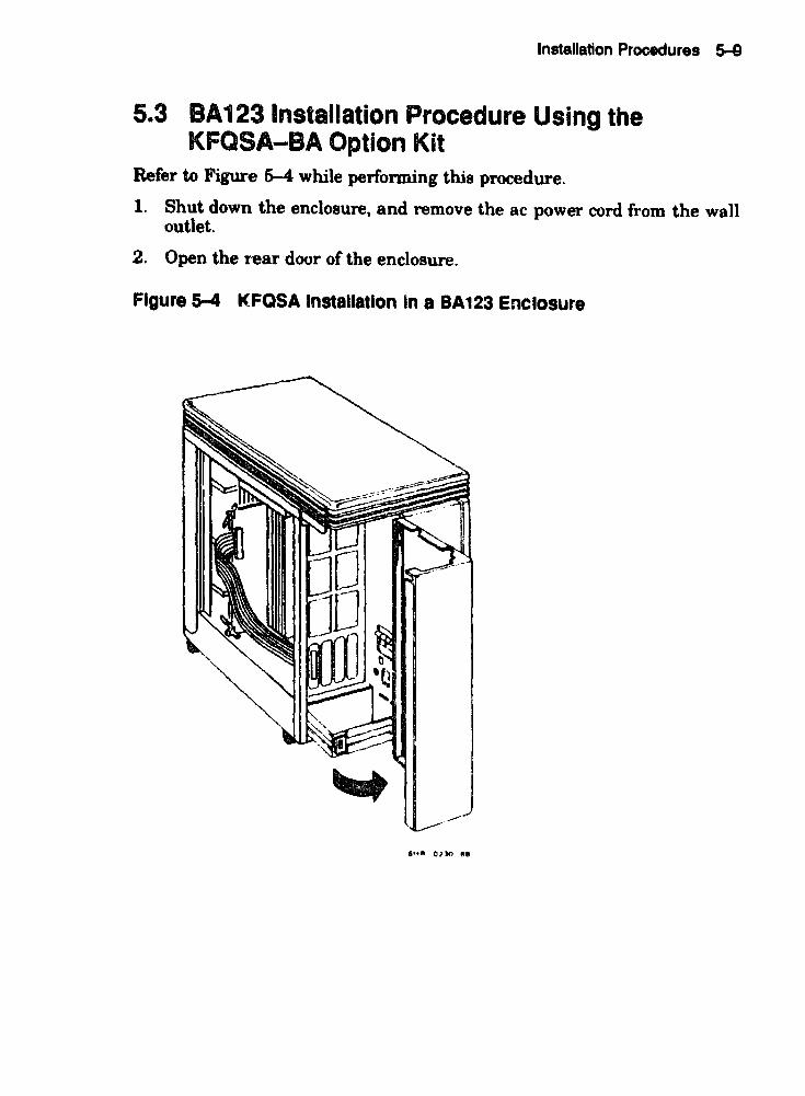
5.5 Installing DSSI VAXcluster Configurations A DSSI VAXcluster configul'ation is a highly integrated organization of VAX computers. As members of a DSSI VAXcluster, computers can share processing resources, disks and queues under single VMS security and management software, and can boot and fail independently. DSSI VAXc1uster configurations provide a high level of processing and data ac('~ss.
5.5.1 Types of DSSI Bus Configurations DBSI Single Boat Configuration uses DSSI bus as the interconned. Q-bus or MicroVAX systems interlace to a DSSI bus by means of a DBSI adapter (KFQSA). As many as 8 DSSI nodes may use the same interconnect. A DSSI node is any device to which DSSI transports information, and therefore needs an address. In a DSSI single host configuration, the node number for the KFQSA is usually 7.
Two-System DSSI VAXcluster configurations use two host systems to share RF-series ISEs. The maximum number of ISEs that can be accessed by the hosts is 6. The ISEs can be located within each host, within an expander enclosure, or both. A two-ho:'t systeJT'. provides high disk availability for critical applications. In a two-~YBtem DSSI VAXcluster configuration, the node numbers for the I01QSAs are 7 and 6.
Three-Syatem nssl VAXcluater configurations allow the common DSSI bus to share all the reSOUt'ces among the three hosts. In a three host configuration, the middle node (KFQSA6), all the internal terminators are removed from the board (Figure 4-1). The unterminated KFQSA adapter has both an IN and OUT bulkhead connector that allows DSSI bus signals to travel through the adapter to the other hosts. The maximum number of ISEs to be accessed in this configuration is 5.

5-18 Installation Procedures
5.6 Rules for Installing DSSI VAXcluster Systems There are some restrictions that apply to DSSI VAXcluster systems using the KFQSA module:
• Adapter modules connected to the same DSSI bus when running VMS Version 5.3-1 and earlier must be of the same type.
• The host systems must be in close proximity to each othl-T, due to DSSI bus cable length limitations (measured from end terminator to end terminator). The maximum distance in a three-system configuration is 82 feet in a computer room environment and 65 feet in an office environment.
• All enclosures in a DSSI VAXcluster configuration must be powered from the same ac feed. That is, they must either be powered from the same ac circuit, or if they are powered from different ac circuits, then those circuits must not power any other equipment, must share a Bingle ground point, and must have a dedicated ground wire between the outlet and the single point ground.
• 'Thnninators must reside at the ends of the nSS} bus when configured for multiple hosts.
• All systems must be using VMS Version 5.1-1 or later.
• The maximum of 5 enclosures can be configured on a DSSI VAXcluster; for example, two VAX or MicroVAX systems and three expansion enclosures or three VAX systems and two expansion enclosures.
• Each ISE on a DSSi VAXcluster configuration must appear with the Bame device name and address on all host nodes.
• A maximum of 3 Q-bus VAX or MicroVAX systems can be present on a DSS} VAXcluster configuration. The middle KFQSA adapter board is untenninated.
• Each node on a single DSSI interconnect must have a unique DSSI 10 number, which allows the software to communicate with the storage devices. Numbers lDust be between 0 and 7; these numbers are permanently associated with the hardware. Node numbers may be l"t'peated on different DSSI interconnects that are connected to the Bame host systems.

Installation Procedures &-19
• The length of any single cable between the connectors on nSSI VAXcluster buses is 25 feet.
NOTE Due to limitatioD8 in the Micl'OVAX n boot ROMI, two MicroVAX n systems in • DSSI VAXclultar configuration cannot automatically boot from a common system disk I8E. If a common system disk is used, each node in the DSSI VAXclusler confiJUl"ation must boot from a different root (SYSO, SYSl). But the MicroVAX n system can only boot .u~tical1y from SYSO. It is recommended that each MicroVAX D system have ita own locally connected system disk (such .s an RDlW or RA82). When a common system disk ISE is a requirement, one MicroVAX D system may automatically boot from 8YSO but the other must be booted manually from SY81.
When a MicroVAX n system is in a DSSI VAXcluater configuration with a MicroVAX 3000 or higher serieslystem, the MicroVAX n system should boot from SYSO and the MicroVAX 3000 or higher series system should boot from an alternate root.
If you are inJtalling more than one system into a nSSI VAXcluster configuration, install each system individually and test it to make sure it is working correctly. When you complete the installation and testing of each system, then reconfigure each system using the procedures in either Chapter 6 or Chapter 7.
This includes:
• Detennining correct CSR addresses for all modules in each system
• Repl'Ogramming the KFQSA configuration table for the new configuration
• Reconfiguring any modules whose CSR addresses changed as a result of the new ('onfiguration
• Changing the allocation class of the ISEs so they are the same as both hosts
After reconfiguring, remove the tenninators and connect thf' DSSI extension cables between the hosts or expansion cabinets.

XXXXXXXXXXXXXXXXXXXXXXXXXXXXXXXXXXXXXXXXXXXXXXXXXXX
XXXXXXXXXXXXXXXXXXXXXXXXXXXXXXXXXXXXXXXXXXXXXXXXX
XXXXXXXXXXXXXXXXXXXXXXXXXXXXXXXXX'lO(XXXXXXXXXXXX
XXXXXXXXXXXXXXXXXXXXXXXXXXXXXXXXXXXXXXXXXXXXX XXXXXXXXXXXXXXXXXXXXX)Q{XXXXXXXXXXXXXXXXXXXX
XXXXXXX XX XXXX XXXXXXXXXXXX XX xx xx XX xx XX xx xx
x xx xx XX XX XX xxxxxxxx XXXX XXXXXXXXXXXXXX xx XXXXXXXXX xx XXXXXXXX xx XX xx XXXXXXXX xx xx XXXXXXXXXXX)ocXXXXXXXXXXXXXXXXXXXXXX
xxxxxxxxx xx XXXXXXXX xx XX xx xx xx xx xx x xx xx XX xx XXXXXJCxxxxxx XXXXXXXXXX
XXXXXXXXXXXXXXXXXXXXXXXXXXXXX
XXXXXXXXXXXXXXX XX XX xx XX XX XX
XXXXXXXXXXXXXXXXXXXXXXXXX
XXXXXXXXXXXXXXXXXXXXXXX
XXXXXXXXX XXXXXX XX XX XX
XXXXXXXXXXXXXXXXXXX XXXXXXXXXXXXXXXXX
XXXXXXXXXXXXXXX
XXXXXXXXXXXXX
XXXXXXXXXXX
XXXXX XX xx XXXXXXX
XXXXX
xxx x
x XXX
XXXXX
XXXXXXX
XXXXXXXXX
XXXXXXXXXXX
xXXXXlOOCXXXXX XXXXXXXXXXXXXXX
XXXXXXXXXXXXXXXXX
XXXXXXXXXXXXXXXXXXX XXXXXXXXXXXXXXXXXXXXX
XXXXXXXXXXXXXXXXXXXXXXX XXXXXXXXXXXXXXXXXXXXXXXXX
XXXXXXXXXXXXXXXXXXXXXXXXXXX XXXXXXXXXXXXXXXXXXXXXXXXXXXXX
XJQCXXXXXXXXXXXXXXXXXXXXXXXXXXXX XXXXXXXXXXXXXXXXXXXXXXXXXXXXXXX)CX
XXXXXXXXXXXXXXXXXXXXXXXXXXXXX~XX
XXXXXXX~XXXXXXXXXXXXXXXXXXXXXXXXXX
XXXXXXXXXXX~XXXXXXXXXXXXXXXXXXXKXXXX
XXXXXXXXXXXXXXXXXXXXXXXXXXXXXXXXXXXXXv.xxx JCXXXXXXXXXXXXXXXXXXXXXXXXXXXXXXXXXXXXXXXXXX
XXXXXXXXXXXXXXXXXXXXXXXXXXXXXXXXX~~
XXXXXXXXXXXXXXXXXXXXXXXXX~XXXX~XX~
X~XXXX~XX~XX~~XXXXU~~~~U~
~XXDD~~~~~XX~~~~~~D~

6 Programming the DSSI Subsystem Using
Console Commands
The KFQSA configuration table may be programmed in two ways, either by using console commands or by using the MicroVAX Diagnostic Monitor (MDM). Using the console commands is the recommended choice if your system has this «:apability.
'1b find out if you can use console commandf!l for programming thf: configuration table, reinitialize the system and read the microcode version that is displayed on the console. If the microcode version is 4.1 or later, the console commands may be used for programming the KFQSA configuration table.
If your system does not have this capability, refer to Chapter 7 for the MDM procedure. If your system does have console commands, perform the procedure deecribed in this chapter.
To find the console commands available, type HELP at the console prompt (»». 1b program the KFQSA configuration table, use these commands.
6.1 Determining CSR Addresses Each module in a Q-bus based !\yetem must use a set of unique Q-bus addres8as and interrupt vectors. One of these, generally the lowest of the set, is known as the CSR address. The KFQSA emulates an SSP controllerl for each ISE connected, and presents a separate CSR address for each emulated controller. You must program the KFQSA with a correctly chosen CSR address for every ISE on the DSSI hus. Interrupt
1 SSP controllers also include the RQDX3, KDA50, RRD50, RQC25, TQK50, and TQK70 controllers. All such porte are identical, and are operated by the same PUDRIVER.
6-1

&-2 Programming the DSSI Subsystem Using Console Commands
vectors for the KFQSA (and other SSP controllers) are programmed automatically by the operating system.
Unlike moat other Q--bus controllers, KFQSA CSR addresses are not set with switches or jumpers. They are contained in nonvolatile memory on the KFQSA module in the form of a configuration table. To access the configuration table, you must set the switches on the KFQSA to select one of the dedicated addresses shown in Table 4-2. You must ensure the KFQSA is terminated either through on-board SIP terminators or through external nSSI terminators.
Before programming the configuration table, first determine what the CSR address~s should be for all devices on the system. Calculating CSR addresses is a complex procedure because some devices are asBi~ned floating addresses. Floating addresses vary with each module installed on the system.
At the console prompt (»», type CONFIGURE.
The CONFIGURE console command is similar to the VMS SYSGEN CONFIGURE utility. It permits the user to enter Q-bus device names, and then generates a table of recommended Q-bus CSR addresses.
After entering the command, the syntem prompts you for a device and a number. 'lb find which responses are valid, type HELP. The system displays:
»>configure Enter device configuration, HELP, or EXIT Device, Number? help Devices:
LPVll KXJll DLVllJ DZQll DZVll DFAOl RLV12 TSVOS RXV21 DRVllW DRVllS DPVll DMVll DELQA DEQNA RQDX3 KDASO RRD50 RQC25 KFQSA-DISK TQRSO TQK70 TUBIE RV20 KFQSA-TAPE KMVll lEQ11 DHQll DAVII CXA16 CXB16 CXY08 VCSOI QVSS LNVII LNV21 QPSS DSVll ADVllC AAVllC AXVllC KWVIIC ADVllD AAV11D VCS02 QDSS DRV11J DP.Q38 VSV21 ISQ01 IDVl1A IDV118 IDVllC 1DV11D IAVIIA lAVllS MIRA ADQ32 DTC04 DESNA IGOll KWV32 KZQSA DIV32 DESQA KIV32
DTCN5 DTC05
Numbers: 1 to 255, default is 1
Device, Number?
I
I

Programming the DSSI Subsystem Using Console Commands 6-3
Respond by entering the device name and number of each device. After all the devices have been entered. type EXIT. For example. if your system has a TK70, three RF30s, and DEQNA devices, you would respond as follows:
Oevice,Number? tk70 Oevice,Number? kfqsa-disk,3 Device,Number? deqna Device,Number1 exit
The system responds with eSR address/vector assignments for all entered devices. For the previous example, the response is:
Address/Vector ~s8i9nments -174440/120 OEQNA -772150/154 KFQSA-DISK -160334/300 KFQSA-DISK -160340/304 KFQSA-DISK -774500/260 TK70 »>
Record the address/vector assignments for use in the next procedure.
6.2 Programming the KFQSA Configuration Table To program the eSR addresses assigned to the DSSI devices in the previous section, type the following command at the console prompt.
»> set host/uqssp/maintenance/service n
NorE The 'service n parameter specifies the Controller Number of 8 KFQSA in SERVICE mode, where n is from 0 to S (Table 4-2):
o is for eSR address 774420 1 is for eSR addreu 774424 2 is for eSR address 7'74430 3 is for eSR address 7'74434
Typing the following command. displays the current contents IJf the configuration table. For example. suppose the first address is selected. and the configuration table is currently blank.

6-4 Programming the DSSI Subsystem Using Console t 'mmands
»> set host/uqssp/maintenance/service 0 UQSSP Controller (774420)
Enter SET, CLEAR, SHOW, HELP, EXIT, or QUIT
Node CSR Address Model 7 -.------- KFQSA ------
?
NOTE If you ClIIlJlot aee._ the configuration table, check for correct KFQaA termination. Refer to Chapter 9.
~ HELP for a quick reference of the available commands at the? prompt.
1 help
Commands: SET <node> \KFQSA SET <node> <CSR address><model> CLEAR <node> SHOW HELP EXIT QUIT
Parameters: <node> <CSR address> <model>
1
set KFQSA DSSI node 10 enable a DSSI device disable a DSSI device show current configuration print this text program the KFQSA don't program the KFQSA
o to 7 760010 to 777774 21 (disk) or 22 (tape)
To add the three RF30 ISEs from the example in the previous section, type the following at the? prompt:
? set 0 772150 21 ? set 1 760334 21 ? set 2 760340 .21 ?
NOTE Make lUre you enter the addreues in the same order they were given when you used the CONFIGURE command.
Type SROW to display what you just entered.
• I
I
I
I
I
I I
I
I
I
I
I
I
I

Programming the DSSI Subsystem Using Console Commands 6-5
1 show Node CSR Address Model
o 772150 21 1 760334 21 2 760340 21 7 -------- KFQSA ------
?
'lb delete an entry from the table. use the CLEAR command. For example, to delete the entry for the ISE with a DSSI node ID of 2, type CLEAR 2 at the? prompt.
Type EX!1' when you have finished programming to WRITE the entries to th" configuration table.
? exit
Proqramming the KFQSA ..•
»>
Power down the system, remove the KFQSA module, and set Switch 1 to the OFF position, enabling the addresses programmed into the configuration table to be read. Then. power the system back up.
'lb view devices on the Q-bus module, type either SHOW QBUS or SHOW UQSSP at the console prompt.
The SHOW QBUS command displays all Q-bus 110 addresses that respond to a word aligned read. For each address the console displays the address in VAX I/O space (in hex), the address as it would appear in the Q-bus I/O space (in octa}). and the word data that was read (in hex).
An example of the SHOW QBUS command is as follows:
»> show qbus Scan of Qbus I/O Space -200000DC (760334) == 0000 (300) RQDX3/KOASu/RRD50/RQC25/KFQSA-DISK -2000000£ (760336) "" OAAO -200000£0 (760340) == 0000 (304) RQDX3/KDA50/RR050!RQC25/KFQSA-OISK -200000E2 (760342) .. OAAO -20001468 (772150) '"' 0000 (154) RQDX3/KDA50/RRD:O,PQC~~. KFQSA-DISK -2000146A (772152) "" OAAO -20001910 (774420) == 0000 (000) KFQSA -20001912 (774422) ... OAAO -20001920 (774440) :0: FFOe (120) DELQA/DEQNA -20001922 ('774442) ... FFOO -20001940 (774500) = 0000 (260) TQK50/TQK70/TU81E/RV20/KFQSA-TAPE -20001942 (774502) '"' OBCO
Scan of Qbus Memory Space »>

6-8 Programming the DSSI Subsystem Using Console Commands
The SHOW UQSSP command displays the statas of all disk and tape devices that can be found on the Q-bus which supports the SSP protocol. For. each device the controller number, CSR address, boot name, and type of device is displayed.
An example of the SHOW UQSSP command is:
»> show uqssp
ugsSP Disk Controller 0 (772150) -DUAO (RF30)
UQSSP Disk Controller 1 (760334) -DUBl (RF30)
UQSSP Disk Controller 2 (760340) -DUC2 (RF30)
UQS3P T~pe Controller 0 (774500) -MUAO (TK70) »:..
Programming the DSSI Subsystem Using Console Commands 6-7
6.3 Programming the KFQSA Module for a DSSI VAXcluster Configuration
This section describes how to program the KFQSA module when setting up a DSSI VAXcluster configuration. This configuration will always involve two to three KFQSA adapters.
This procedure has three objectives:
1. 1b configure all KFQSA modules so that they can access all of the ISEa connected on the DSSI bus
2. 1b give each KFQSA a unique DSSI node ID
3. To configure the KFQSAs and ISEs 80 that each ISE has a device name that is unique and universal throughmlt the DSSI VAXcluster configuration
NOTE All ayllteml should be powered up and displaying the conlole prompt. The DSSI cables between the hOlt .y.teml Ihould not be connected at thil time.
Figure 6-1 and Figure S-2 are typical block diagrams of DBSI VAXcluster configurations. Using these examples, perfonn the following procedure on System A.
1. Display the current addresses and devices as follows:
NOTE Make hardcopy printouts of the displaYI or write down the information obtained in this .tep. It will be needed later in thil procedure.
B. Type SHOW UQSSP for a display of all SSP controllers currently on the system. This display lists the ~bU8 address (octal I and port name of each SSP device on the system. An example of this display is shown in Section 6.2.

8-8 Programming the DSSI Subsystem Using Consol. Commands
Figure 6-1 KFQSA Modules In a DSSI VAXcluster - Two-System Configuration
SYSTEM B (SECOND KfOSAI
SYSTEM A (fiRST KFOSA)
r NODE 5 I NODE 4 I NODE 3 J... ... ---~..( NODE 2 I NODE I I NODE 0 I _ 0551 _
:,.AI
KFQSA/ (NOOE 6) i--
~ ______________ J
NODE AOD~E';)S
o I 2 J 4 5 6
712150 760334 760340 760344 760350 760354 KrQSA
BUS
~ kfOSA/
(NOO£. 7)
NODE ADDRESS
o 1 2 3 4 5 7
772150 760334 160340 760344 160150 760354 kfQSA
,t.'" GO",.
b. Type SHOW QBUS for a display of the eight-digit VAX address (hex) for each device. An example of this display is shown in Section 6.2.
c. Find the eight-digit VAX address 'hex) that corresponds to the Q-bus address for each ISE in the system. Record this infonnation; it win be needed in a later step.
NOTE In the examples given in Section 6.2 for the SHOW UQSSP and SHOW QBUS commands, the Q-bU8 addres~ (772150) for ISE 0 has a corresponding VAX addres~ (bel() ()f 20001488.
2. Run the Configure utility to determine the correct address for each device and KFQSA modules in the two-system nSSI VAXcluster configuration by performing the following steps. The Configure utility is explained in detail in Section 6.1.
a. At the console prompt, type CONFIGURE.
I
I
I
I
I
I
I
I
I
I
I
I
I
I
I
I

Programming the DSSI Subsystem Using Console Commands 6-8
Figure 6-2 KFQSA Modules In 8 DSSI VAXCluster - Th .... System Configuration
KFoaA _ ~ (Node 5;
',"em C (Third KF08A)
-Nod, Addr, ••
0 771'50 , 780114 2 7101'0 3 7803 ... , 180350 S KF08A
KFOIA (Nodi II
S~"lm 8 (Second K1=0811)
DSSI
IY"lm A (Flr.' KFOaA)
aUF .I II Nodi 3 ..... ----·· ... Nodi 'INode 'J Node 0
r--
KFQ8A _ fto (Nodi 71
10...
Nodi Addre .. Nodi Addre ..
0 772,50 0 772150 , 7'013. , 7'0'14 2 7,OUO 2 7.0,.0 3 7.03 ... 1 7.03 .... , 7'0360 " 7.0350
• KFOSA 7 KFQSA
11·0"" TI~
b. Then type HELP at the Device, Number? prompt for a list of devices that can be configured.
NOTE Some devices listed in the HELP display are not supported by the KA8M-AA CPU.
c. For each device in the system. type the device name at the Device, Number? prompt. If there is more than one of the same device type, enter the device name, a comma, and the total number of devices at that type.
Be sure you list all devices in all systems inc1uded in the nSSI VAXcluster configuration ..
d. Type EXIT. The Configure utility displays address/vector assignments for all devices entered.
3. Cum pare the addresses displayed from running the Configure utility with those displayed from the SHOW QBUS display.
Adding the ISEs from the remaining systems in the nssl VAXchu.ter configuration may bump the address of another Q-bliB device. Make sure that all device addresses, other than those of the ISEs, have not changed. If the device address differs between the two displays, you must reconfigure your system.

6-10 Programming the DSSI Subsystem Using Consol. Commands
4. Program the KF'QSA configuration table in System A by following the procedures outlined in Section 6.2. Make sure to include all ISEs connected to the DSSI bus in the configuration table. Assign a DSSI node ID of 7 to this KFQSA.
5. Repeat Steps 1 through 4 for System B, anf~ if applicable for System C.
6. Program the KFQSA in System Band C by following the procedures outlined in Section 6.2. Make sure to include all ISEs in all systems in the configuration table. Assign a DSSI node ID of 6 to thfl KFQSA in System B, and 5 to the KFQSA in System C.
'1. Power down all Bystems.
8. Remove the KFQSA modules from all systems, and set Switch 1 to the OFF position.
9. Connect the DSSI cable between all systems.
10. Replace any necessary DSSI writ ID plugs in the Operator Control Panels of each system to make them match the nssl node IDs assigned to the ISEs for the DBSI VAXcluster configuration.
NOTE Make aure aU DSSI m aoekete in all Operator Control Panela have plugs in them. Use blank plug. in any sockets that do Dot have corresponding ISEs connected.
1l. Power up all systems.
12. Fo~ each systffln:
a. Type SHOW QBUS to verify that all addresses are present and COlTf!ttt.
b. Type SHOW UQSSP to verify that all ISEs are displayed cOlToctly.
NOTE Make 8Ul"e that the ISEs have been assigned the same DSSI node IDa in all KFQSA configuration tB.bles.
13. Boot one node and note the device names reported by VMS software.
14. Shut down the nod(! and boot another one. Note the device names to ascertain t.hat both systems see the same set of 18K device names. If wring a three-system DSSI VAXcluster c",nfiguration, repeat this step on the third system.

Programming the DSSI Subsystem Using Console Commands 6-11
CAUTION Make sure that the device name of each ISE il identical on all nod.ea. Failure to do so can result in a partitioned cluster, aDd cODsequently data corruption.
6.4 Setting the ISE Allocation Class This section describes how to change the ISE allocation class. In a nBSI VAXc1uster configuration, you must assign the same nonzero allocation class to both hoat systems and all connected ISEs. The ISEs are shipped with the allocation class set to zero.
Change the allocation class by using the followine .,rocedure.
1. Determine the conoect allocation class according to the rules on clustering.
NOTE In a DSSI VAXcluster configuration, the same allocation clasl mUllt be aasiped to both aysteDl8 and to all connected ISEa. This allocation class muat be different from that of other systems or HSC controllers in a cluster.
2. At the console prompt, type SET HOSTIDUPIUQSSP/DvqK 4# PARAMS.
Where I is the DSSI node ID of the ISE to which the allocation class is to be set.
3. At the PARAMS> promplt, type SHOW ALLCLASS to check the current allocatinn class.
The system responds with the following display.
Parameter Current Default
ALLCLASS
PARAMS>
o
Type Radix
Byte Dec B
4. Type SET ALLCLASS I, where # is the allocation class to which you want the ISE set.
Example: SET ALLCLASS ~~ sets the allocation claFls to 2.
5. Type SHOW ALLCLASS to check the new allocation class.

&-12 Programming the OSSI Subsystem Using Console Commands
'Ole system responds with the following display.
Parameter Current Default Type Radix
ALLC LAS S
PARAMS>
2 o Byte Dec B
6. Type WRITE at the PRAMS> prompt. The system responds with:
Changes require controller initialization, ok? [Y/ (N)]
7. 'JYpe Y to save the new allocation class value.
8. Repeat Steps 3 through 8 for each ISE on the DSSI bus.

~~~~~~n~~~u~n~n~u~~~nx
KXXXKXlOOOOCXXXXXXXXXXXXXXXXXXXnXX~~xxxxnxxxxx
XXXXXXxx~xxxxxxxxnxxxx~~XXXXXXXXXX~XXX
~~XXxx~~~~~nXXXXXXXXXXXXX
~~xxxxuxxxxxxnnxxxxnnxxxxxxxxnxxxxx
nxxxxXX~XXXXXXXXXXDUXXXXXXXXXXXXX
~XX~xxxxxxxxxxunxxxxxxxxxxx
~XXXXXXXXXXXXXXXXXXXXXXXXXXXXxxX
XXXXXX~XXXXXXXXxxXXXXXXXXXXXXX
XXXXXXXXXXXXXXXXXXXXXXXXXXXXXXXXX
XXXXXXXXXXXXlOClOCXXXXXXXXXXXXXXX
xx XX XX XX XX XXXXXXXXXXXX XX XXXXX
XXXXXXXXXXXXJOCXXXXXXXXXXXXX
XXXXXXXXXXXXXXXXXXXXXXXXX
XAKAXY .. 'O'_'IOtXXXXXXXXXXXXX
XXXXXXXXXXXXXXXXXXXXX
XXXXXX~XXXXXXXXXXX
XXXXXXXXXXXXXXXXX
XXXXXXXXXXXXXXX
XXXXXXXXXXXXX
XXXXXXXXXXX
XXXXXXXXX
XXXXXXX
XX XX X XXl(
X
x xxx
XXXXX
XXXXXXX
XXXXXXXXX
xx xx XX XXXXX
XXXXXXXXXXXXX
XXXXXXXXXXXXXXX
"<x XX XX XXXXXXXX XX X XXXXXXXXXXXXXXXXXXX
XXXXXXXXXXXXXXXJCXXXXX
XXXXXXXXXXXXXX XX XX XXXXX
XXXXXXXXXX XX XX XXXXXXXXXXX
XXXXXXXXXXXXXXXXXXXXXXXXXXX
XXXXXXXXXXXXXXXXXXXXXXXXXXXXX
XXXXXXXXXXXXXXXXXXXXXXXXXXXXXXX
XXXXXXXXXXXXXXXXXXXXXXXXXXXXXXXXX
XX XX XX XX XX XXXXXXXXXXXX XX XX XX XXXXXXJ(
xx XX XX XX XX XX XXXXXXXXXXXXXX xx XX XXXXXXX
XXXXXXXXXXlOCXXXXXXXXXXXXXXXXXXXXXXXXXXX
XXXXXXXXXXXX XXXXXXaXXlC<XXXX XX XX XX XX XXXXX
XXXXXXXX XX XX XX XX XXXXXXXXXXXXXXXX XXXX xx XX XX X
xx XX XX XX XX XX XX XXXXXXXXXX XX XXXXXXXXXX XX XXXXXXX
XXXXXXXXXXXXXXXXXXXXXXXXXXXXXXXXXXXXXXXXXXXXXXX
XXXXXXXXXXXXXXXXXXXXXXXXXXXXXXXXXXXXXXXXXXXXXXXXX
XXXXXXXXXXXXXXXXXXXXXXXXXXXXXXXXXXXXXXXXXXXXXXXXXXX
7 Configuring the DSSI Subsystem Using
MOM Commands
This chao _ discusses how to assign CSR addresses as a preparation for programming the KFQSA configuration table.
7.1 Determining CSR Addresses Each module in a Q-bus based system must use a set of unique Q-bus addresses and interrupt vectors. One of these. generally the lowest of the set, is known as the CSR address.
7.1.1 Overview The KFQSA emulates an SSP controllerl for each connected ISE. Therefore, you must program the KFQSA with a correctly chosen CSR address for every ISE on the DSSI bus. Interrupt vectors for the KFQSA (and other SSP controllers) are programmed automatically by the operating system.
Unlike most other Q-bus controllers. KfQSA CSR addresses are not set with switches or jumpers. They are contained in nonvolatile memory on the KFQSA module in the form of a configuration table The configuration table is programmed using an MDM program, as explain~d in S€'('tlon 7.2.
NOTE KFQSA modules installed in Micro~AX 3000 and 4000 series systems are more easily configured using the procedures given in Chapter 8.
1 SSP controllers a180 include the RQDX3, 1IDA50. RRD50. RQC25, TQK50, and TQK70. All such ports are identical and are operated by the 8ame PUDRIVER.
7-1

7-2 Configuring the DSSI Subsystem Using MOM Commands
NOTe 1b acce .. the conflguration table you must set the switches on the KFQSA to select one of the dedicated addresses shown in Table 4-2.
Before you probJ'8m the configuration table you must first detennine what the CSR addresses are going to be for all devices on the system. Calculating CBR addresses is a complex procedurf because some devices are assigned floating addresses. Floating addresses vary depending on which modules are installed on the system.
Use an MDM utility called IOADDBES to determine what the CSR addresses and interrupt vectors should be for all devices on the system. This utility is supported in MDM Version 3.0, Release 125 or later. The next section describes hew to use IOADDRES. You should already have a working knowledge of MDM. If you need detailed infonnation on how to use MDM refer to the MDM User's Guide (AA-FM7A-DM>.
7.1.2 Using MOM to Determine CSR Addresses
1. BootMDM.
2. Enter the correct date and time.
3. Select the command line mode (Option 2). The system issues a caution and instructs you to enter 1 for the menu mode or 2 to proceed with the command line mode.
4. Enter 2 and press I Return I. The system diRplays the MDM» prompt.
5. Type the command Run IOADDRES. The system responds with:
Configuring utility for IOADDRES
The display prompts you to enter a number for each class of devices it supports. Table 7-1 shows the abbreviations for supported devices.
6. At each quers. enter the number of devices from that class that are installed in th& sysjm. If no devices of that class are instCll1ed in the system, press Rsturn (the default value of zero is entered,
After you have responded to all queries, the system display~ a summary of the classes and the number of devices in each class. lt then displays a table containing the fonowing infonnation.
• Device class and number of devices selected for that class
• eSR address and interrupt vector

Configuring the CSSI Subsystem Using MOM Commands 7-3
• First available floating CSR address and vector
Table 7-1 Device Abbreviations Used with lOAD ORES
Device Device Device Clue Device CI ...
AAVll-DA AAA IDVll-A IDA AAVll-C Me mVll-B IDB ADQ32 AQA IDVll-C me ADVll-C ADC IDVII-D IDD ADVll-DA ADA IEQl1 lEA AXVll-C AXA KDA60 132. CXA16 DRA KFQSA 'CCl CXF32 DHF KMVIA 1.ZY DEQNA XQA KMVIB zzy DESNA CQA KWVll-C KWA DFA01 1.ZQ KXJll KXA DHFll DHF LNVll LAA DHVll DR' LNV21 LNA DLVll DL LPVll LPA DMVll DM. MIRA MIA DPVl1 DPA QCA QCA DRQ3B QBA RC25 132. DRQll-C DQA RQDXn 1.2.Z DRVll-J ORB RRD50 ZZZ DRVll-W IDRllW model 'l:lW TQK50 1.2.T DRVll-W IDRUB model ZZB rsV05 TSA DSVll DSA VCBOl VCA DTC04 DTA VCB02 VCB DZQll 1.ZQ VSV21 VVA DZVll ZZQ 1bken Bus ZQA IAVll-A IAA Adapter IAVll-B lAB IBQOt rnA
7. Print the infonnation provided about the DSSI devices (01' make a note of it) for programming the configuration table.
8. Type EXIT and presp I Return I. Once the CSR values are determined for a11 modules in th€> ~V"ltem. the addresses for the DSSI devices must be programmed into th~ KFQSA configuration table using the procedure detailed in the next section. If any other modules in the system require reconfiguration. refer to the installation manual for that module, or to your system maintenance documentation for the configuration instructions.
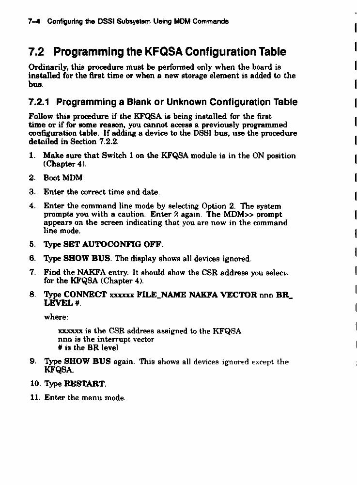
7-4 Configuring the DSSI Subsystem Using MOM Commands
7.2 Programming the KFQSA Configuration Table Ordinarily, this procedure must be perfonned only when the board is installed for the first time or when a new storage element is added to the bus.
7.2.1 Programming a Blank or Unknown Configuration Table Follow this procedure if the KFQSA is being installed for the first time or if for some reason, you cannot access a previously programmed configuration table. If adding a device to the DSSI bus, UBe the procedure detciled in Section 7.2.2.
1. Make sure that Switch Ion the K.FQSA module is in the ON position (Chapter 4).
2. BootMDM.
3. Enter the correct time and date.
4. Enter the command line mode by selecting Option 2. The system prompts you with a caution. Enter? again. The MDM» prompt appears on the screen indicating that you are now in the command line mode.
5. Type SET AUTOCONFIG OFF.
6. Type SHOW BUS. The display shows all devices ignored.
7. Find the NAKFA entry. It should show the CSR address you selec"" for the KFQSA (Chapter 4).
8. Type CONNECT xxxxxx FILE_NAME NAKFA VECTOR nnn BR_ LEVEL#.
where:
xxxxxx is the CSR address assigned to the K.FQSA nnn is the interrupt vector # is the BR level
9. Type SHOW BUS again. This shows all devices ignored except the KFQSA
10. Type RESTART.
11. Enter the menu mode.

Configuring the DSSI Subsystem Using MDM Commands 7-5
12. At the main menu, select Option 2, Display System Configuration and Devices. The system displays the following:
The .y.t.m i. preparin9 for testing.
Thi. may take .everal minutes. Ple .... W.it .. ,
The system will then display a line for each diagnostic it loads and configures. Then it will display the following:
The .y.tem i. r.ady for te.tinq.
Pre •• the RETURN key to continue. >
13. Press I Retrrn I to display the System and Configuration Devices Menu. This disp aye information about each devicA loaded and configured in the system.
14. Press maturnl again to return to the Main Menu.
15. Select Option 4. Display the Service Menu.
16. Select Option 3. Display the Device Menu.
17. Select KFQSAA, KFQSA Subsystem (option number will depend on your system configuration).
18. Select Option 4. Display the Device Utilities Menu.
1P. Select Option 1. KFQSA Configuration Utility.
~ system displays the KF'QSA configuration table .
..

7-8 Configuring the DSSI Subsystem Using MOM Commands
KFQSA DSSI Node 10
Entry '0 0
CSR Address OSSI Node 10
----------- ------------Entry tl 000000 0
----------- ------------Entry '2 000000 0
------_ ... _-- ------------Entry '3 000000 0
----------- ------------Entry '4 000000 0
----------- --------_ .. _-Entry '5 000000 0
----------- ------------Entry 16 000000 0
----------- ------------Entry ,7 000000 0
----------- ----------- ...
Change KFQSA Configuration Table? Valid response - [(yes) or no] :
NOTE
Model Number
------------0
------------0
------------a ------------a ------------
0 I ------------a
------------0
------------
The configuration table may have been previously programmed for manufacturing testing or other purposes. In this case, it will contain information other than zeros for one or more entries. If this occurs, make sure that you clear any UDused entries to zero while performing this procedure. Do so by following the steps in Section 7.2.8. If you cannot aCCe88 the configuration table, check for correct nSSI termination.
I
I I
I
I
I
I
I
I
I
I
I
I
I
I
I
I
I
I
I
I
I

Configuring the U$SI Subsystem Using MOM Commands 7-7
20. Type yes and press I Retum ~
The system responds:
Enter the number of the entry to change (0-7):
21. Type 0 and press [~eturnl to change the KFQSA DSSI node ID.
The system responds by displaying the entry #0 portion of the table.
KFQSA OSS1 Node 10
Entry to 0
Change the KFQSA DSS1 Node IO? Valid response - [(yes) or no] :
22. Type yea and press I Return I. The system responds with:
Enter a decimal value (0-1) for the KFQSA DSS1 Node 10:
23. The KFQSA is nonnally set at DSSI node 10 7. Type 7 and press I Return I. The system displays the configuration table with the newly entered infonnation, along with the following:
Change another entry? Valid response - yes or no:
24. Respond by typing ye8 and pressing I Return I. The system displays the following:
Enter the number of the entry to change (0-1):
25. Here. you select an entry numbe'l' for one of the storage devices on your system DSSI bus, As an example. let us select Entry #1 hy typing 1 and pressing I Return]'
The system displays the following:
CSR Address DSS1 Node 10 Model Number
Entry #'1 000000 o o ------------ I ------------
Change CSR address or clear this entry ? Valid response - [(yes) or no] :

7-8 Configuring the DSSI Subsystem Using MOM Commands
26. Respond by typing yel, and preIs I Return ~
'11le system displays the following:
Valid CSR addresses: Floating space: 760100 - 763776 Disk fixed address: 772150 Tape fixed address: 774500
Enter a 0 to clear this entry or a 18 bit octal number:
27. ~he address assigned to this device by IOADDRES, and press
The system responds:
Change DSS! node 10 ? Valid response - [(yes) or no]
28. Type yes, and pressl8aturn ].
The system responds with the following;
Enter a decimal numb.r (0-7) for the OSSI Node 10:
29. Type in the DSSI node ID number you want to assign to that particular device followed by I Return I. Each entry must have a unique DSSI node ID assigned to it.
NOTE Entries that are all zeros are ignored by the system. It is acceptable to assign nSSI node m 0 to aD entry with 8 valid CSR address, 81 IODg as it is only 8aiIDed to one device on the DSBI bus.
The system automatically adds the model number and displays the updated configuration table. It then displays the following query:
Change another entry? Valid response - yes or no
30. Repeat Steps 21 through 26 until all devices on the DSSJ hus have been assigned a CSR address, nSSI node ID. and model number. Any unused entries that have values assigned to them should be cleared to zero using the procedure outlined in Section 7.2.3.

Configuring the OSSI Subsystem Using MOM Commands 7-9 .
31. Once you have entered all infonnation into the configuration table, exit the table by typing DO and pressing l£t0!!.Ui!iJ in response to the message:
Change an~ther entry ? Valid response - [(yea) or n01 :
The system displays one of the following messages:
This KFQSA is in CONFIGURE ONLY mode. Power down and place the board in NORMAL mode via KFQSA switches.
or
The manufacturing jumper is in.
32. PresslRetum~ The system responds with:
KFQSAA passed. Press the RETURN key to return to the previous menu.
33. Press [Return I. The prompt puts you at the Utility Programs and Tests menu.
34. Exit MOM by pressing I Break I. 35. Power down the system and remove the KFQSA from its backplane
slot.
36. Put Switch 1 in the OFF position.
If the message in Step 28 indicated that the manufacturing jumper is in, remove it before replacing the board. Refer to Chapter 2 for information on removing this jumper.
37. Replace the KFQSA board in its backplane slot.
3B. Power up the system.
39. Reboot MDM and repeat Steps 1 through 16. Read the eRR tahle to make sure that everything you entered is correct
40. If everything is as it should be, respond no to the query
Change KFQSA Configuration Table? Valid response - [(yes) or no] :
TIlen. press I Return I. If further modifications are reqUlr~d. repeat Steps 17 through 27 to make the desired modifications.
41. Repeat Steps 28 through 32.

7-10 Configuring the OSSI Subsystem Using MOM Commands
7.2.2 Adding a Device to the Configuration Table
NOTE Adding a device to the KFQSA COnftlUJ'8tiOD table may change the CSR address of other devices in the Q-bus floatilll address space.
1. Leave Switch 1 on the KFQSA module in the OFF position.
2. Perlonn Steps 2 through 17 of Section 7.2.1. In this case. the configuration table will already contain information that was previously entered. As an example, let us asswne there was a KFQSA with two ISEs already on the system and you are adding another ISE. The configuration table would then be displayed with infonnation already in Entries 0, 1, and 2.
KFQSA eSSI Node 10
Entry '0 i
CSR Address eSSI Node ID Model Nurnber
I ----------- ------------ I ------------Entry .1 772150 o 21
----------- I ------------ -----------~ I Entry '2 160334 1 21
------------ I ------------ I Entry '3 000000 o a
I ----------- ------------ I Entry '4 000000 o o
------------ I ------------ I Entry '5 000000 o o
Entry '6 000000 o o ------------ I ------------ I
Entry '7 000000 o o ------------ I ------------ I
Change KFQSA Configuration Table ? Valid Re~ponse - [(yes) or no] :
3. Type yes, and press IRetur~l. The system displays the followmg·
Enter the number of the entry to change (0-7):
4. Select the next available entry. For our example we select Entry #3 by typing 3 and pressing \ RetumI. The system displays the following:

Configuring the DSSI Subsystem Using MOM Commands 7-11
CSR Address DSSl Node IO
Entry 13 000000 o
Change CSR address or clear this entry ? Valid response - [(yes) or no] :
5. Respond by typing yes and pressing I Return I. The system diaplays the following:
Model Number
o
Valid CSR addresses; Floating space: 760100 - 763776 Disk fixed address: 772150 Tape fixed addrosa: 774500
Enter a 0 t,o clear this entry or a 18 bit octal number:
6. ~.!he address assigned to this device by IOADDRES, and press ~ For purposes of our example, let us say the CSR address is supposed to be 760444.
The sygtem responds with the following:
Change DSSI node 10 1 Valid response - [(yes) or no] :
7. Type yes. and press I Retur~ I. The system responds with the following:
Enter a decimal number (0-7) for the OSSI Node 10:
8. Type in the DSSI node ID number you want to assign to that particular device followed by [Retum\. Each entry must have a unique DSSI node ID assigned to it. For purposes of our example, let us assign DSSI node ID 2.
The system automatically enters the model number and displays the updated configuration table as follows:

7-12 Configuring the OSSI Subsystem Using MOM Commands
KFQSA DSSI Node ID
Entry '0 7
CSR Address DSSI Node ID Model Number
----------- ------------ ------------Entry tl 772150 a 21
----------- ------------ ------------Fntry '2 760334 1 21 --- ... ------- ------------ ------------Entry '3 760444 2 21
-----------_________ -.]0 __
------------Entry '4 oooaoo 0 a
----------- --------- ... -- ------------Entry '5 000000 0 a
----------- ------------ ------------Entry '6 000000 a a
----------- ------------ ------------Entry #7 000000 0 0
----------- ---------_ ... - ------------Change another entry ? Valid response - [ (yes) or no) :
9. If you are adding more devices, repeat Steps 3 through 8 for each device you are adding. Follow the procedure outlined in Section 7.2.3 to clear any unused entries.
When you have filled in the table for each device on the DSSI bus, type DO and press I Return I. The system responds with:
KFQSAA passed. Press the RETURN key to return to the previous reenu.
10. Press I Retuml. The prompt returns to the Utility Programs and Tests menu.
11. Exit MDM by pressing I Break I· 12. Power down the system. Then power it back up to writ~ th*? changes
you made to the configuration table.

Configuring tho OSSI Subsystem Using MOM Commands 7-13
7.2.3 Removing a Device from the Configuration Table
NOTE Removing a device to the KFQSA configuration table may change the CSR addrel88 of other devices in the Q-bU8 ftoating addres8 space.
When taking a DBSI device off the bus, you need to clear the infonnation in the configuration table for that device. As an example, let us remove the ISE we added in Section 7.2.2.
1. Leave Switch i on the KFQSA in the OFF position.
2. Perform Steps 2 through 17 of Section 7.2.1. The system displays the following:
KFQSA OSSI Node 10
, -------------------~-----~-----------------Entry to 7
I -------------------------------------------CSR Address DSSI Node ID
! ----------- I ------------Entry 11 77 150 0
----------- ------------Entry '2 760334 1
----------- ------------Entry '3 760444 2
----------- ------------Entry '4 000000 0
I ----------- ------------Entry *S 000000 a
----------- I ------------Entry '6 000000 0
I ----------- ------------Entry 1'1 000000 0
----------- ------------Change KFQSA Configuration Table ? Valid response - [(yes) or no] :
Model Number
------------21
------------21
I ------------21
..... _----------a
------------0
I ------.. ~-----0
I ------------0
I ------------
3. Type yes, and press I Return I. The system displays the foHowmg,
Enter the number of the entry to change (0-7 ):
I
I
4. Select the entry number for the device you are removing. For our example. we will select Entry #3 by typing 3 and pressing I~. The system displays the following:

7-14 Configuring the OSSI Subsystem Using MOM Commands
esa Address DSSI Node 10
Entry '3 760444 2
Chanqe eSR address or clear this entry ? Valid response - [(yes) or no] :
5. Respond by typing ye8 and pressing I ~eturn J. The system displays the following:
Model Number
21
Valid esa addresses: Floating space 760100 - 763776 Disk fixed address: 172150 Tape fixed address: 774500
Enter a 0 to clear this entry or a 18 bit octal number:
6. Type 0 and press I Return ~ The system responds with the message:
The DSSI Node ID and Model Number are automatically zeroed. Press RETURN to continue
When you press I Return ~ the configuration table is displayed with the CSR address. DSSI node ID. and model number reset to zeros fllr the selected entry number. as fonowa:
KFQSA DSSI Node 10
Entry 10 7
esa Address DSS! Node 10 Model Number -----_ .... _--- ------------
Entry II 772150 0 21 ... _--------- I ------------
Entry .2 760334 1 21
----------- --_._- -------Entry '3 000000 a o
----------- ------------ --------~.--- I Entry '4 000000 0 o
----------- ------------ I
Entry '5 000000 0
----------- ------------ I
Entry 16 000000 r;
----------- ------------ I Entry 17 000000 r, 'J
----------- ------------ I
Change another entry ? Valid Response - [ (yes) or no] :
I
I
~
I
r I
I
I
I
I
I
I I

Configuring the DSSI Subsystem Using MOM Commands 7-15
7. Repeat the procedure for each device you want to delete from the table. When you have finished editing the table, type no and press I Retum ~ The system responds with:
KFQSAA passed. Press the RETURN key to return to the previous menu.
8. Press I Return I. The prompt returns to the Utility Programs and Tests menu.
9. Exit MDM by pressing ~.
10. Power down the system. Then power it back up to write the changes you made to the configuration table.
7.3 Programming the KFQSA for a DSSI VAXcluster Configuration
This section describes how to program the KFQSA modules in a DSSI VAXc1uster.
NOTE In a DSSI VAXcluster environment, a three-system configuration's llUUdmum length of cable(s) (measured from the two end KFQSAB) ill 82 feet in a computer room environment and 85 feet in an oftice onvironment.
The maximum number of enclosures in a DBSI VAXcluster coDillJW"8tion is 5. For example, two VAX or MicroVAX systems and three ezpaneion enclosures.
Figure 7-1 is a diagram of a typical two-system DSSI VAXcluster application. which will be used as an example during this procedure.
NOTE The DSSI cable(s) should be connected between the two systems, and power to both systems should be turned on before programming.
Perform the following procedure on System A:
1. Determine the con-ect CSR address for each dp,vice and module in the system by performing the steps outlined in Sect:Jn 7.1.2. Make sure to include all devices residing in the system and all ISEs connected to the DSSI bus.

7-16 Configuring the DSSI Subsystem Using MOM Commands
Figure 7-1 Two-System DSSI VAXcluster Configuration
SYSTEM A ,rhjT SYSTEMI
EXPANSION CABINET
SYSTEM B ,SECOND SYSTEMJ
r-- I NODE 0 ] I NODE 1 I -I NODE 2 J
'-- "-"
NODE ADDRESS NODE ADDRESS NODE ADDRESS
7 kFOSA o 1 2
772150 760334 760340
6 kFQSA
2. Progr am the KFQSA configuration table to add the CSR addresses. DSSI node ID, and model number for the ISEs, as detailed in Section 7.2.
NOTE Make lure aD nBSI node IDs prop'ammed. into the conftguration table are sequential and in increasing order. Do not skip any numbers.
3. Reprogram any modules whose CSR addresses were bumped as a result of including the ISEs.
4. Assign a DSSI node ID of7 to the KFQSA in System A
5. Repeat the proce<jure in Steps 1 through 3 for System B ASSlgrt a DSSI node ID of ~ to the KFQSA in this system.
NOTE Make sure that the ISEs have been assigned the same DSSI node IDs ~.D both KFQSA conftguration tables.

Configuring the DSSI Subsystem Using MOM Commands 1-11
CAUTION Make sure that the device name of each ISE ia identical on both nodes. Failure to do 80 can result in a partitioned cluster, and co-uequently data corruption.
6. Replace any nece8s 'Y DBSI unit ID plugs in the Operator Control Panel for each ISE to make them match the DBSI node IDa assigned to the ISEs for a DBSI VAXcluater configuration.
7. Boot one node and note the device names reported by VMS Boftware.
8. Shut down the node and boot the other one. Note the device names to ascertain that both systems see the same set of device names.
7.4 Setting the ISE Allocation Class This section describes how to change the ISE allocation class. In a DBSI VAXcluster configuration. you must assign the same nonzero allocation class to all host systems and to all ISEs on the DBSI bus.
NOTE DSSIISEs are shipped with the allocation class set to zero.
Change the allocation class by using the following procedure. This procedure only needs to be performed from one of the host systems.
1. Determine the correct allocation class for the ISEs according to the rules on clustering.
NOTE In a DBSI VAXcluater couftguration, the same allocation clasa must be aaBiped to allayslema and to all connected ISE .. This allocation claas must be different from that of other systems or HSC in a cluster.
2. Set Switch 1 on the K.FQSA to OFF.
3. Enter MDM and select the menu mode. The screen displays the fonowing:
MAIN MENU
1 - Teat the system 2 - Display System Configuration and Devices 3 - DisplRY the System Utilities Menu 4 - Display the Service Menu 5 - Display the Connect/lgnor~ Menu 6 - Select single device tests

7-18 Configuring the DSSI Subayotem Using MOM Commands
Type the number; then pre •• the RETURN key.
4. Select the Service Menu (H). The screen displays:
Service Menu
CAUTION: Thi. menu i. intended for u.e by qualified .ervice personnel ~nly. Mi.u.e of the commands could destroy data.
1 - Set test and me •• age parameters 2 - Exerci.e system continuously 3 - Display the device menu 4 - Enter command line mode
Type the number; then pre •• the RETURN key, or type 0 and press the RETURN key to return to the Main Menu.
5. Select the device menu (,S). In this example. there are other device diagnostics loaded. The aaeen displays:
MAIN SERVICE DEVICE
This menu lets you .elect a device tor testing.
1 CPUA - MicroVAX/rtVAX CPU 2 MEMA - MicroVAX memory .ystem 3 RQDXA - Winche.ter diskette controller 4 TKXXA - T~SO/TK70 contro~ler 5 KFQSAA - ~FQSA subsystem
6. Select the device-specific KFQSA subsystem ('5) menu. The screen displays:
DEVICE MENU KFQSAA - KFQSA subsystem menu
Testing i. Enabled
1 - Enable/Disable testing for device 2 - Perform all functional tests 3 - Perform the exerciser test 4 - Display the device utilities menu
7. Select H. the device utilities menu.
The KFQSA DEVICE UTILITY MF"W displays utilities and special Bubsystem tests:

Configuring the DSSI Subsystem Using MOM Commands 7-19
MAIN MENU SERVICE MENU DEVICE MENU KFQSAA - KFQSA SUBSYSTEM MENU UTILITY PROGRAM AND TESTS MENU
Utility selections are:
1 - KFQSA Configuration Utility 2 - DSSI Device Data Erase Utility 3 - Select Device Resident Programs 4 - KFQSA Information Gathering Service 5 - Customize Diagnostic Functionality Utility
8. Select '3, the Device Resident Programs menu. The system displays:
RUNNING A UTILITY SERVICE TEST
To halt the teat at any time and return to the previous menu, type CTRL-C by holding down the CTRL key and pressing the C key.
KFQSAB started. KFQSAB pass 1 test number 3 started. Copyright 1988 Digital Equipment Corl_oration Completed. EXIT HISTRY DIRECT
DRVEXR ERASE VERIFY
DRVTST PARAMS DKUTIL
Please choose a local program or press <RETURN> to continue.
NOTE The Select Device Resident PrOfr&DlI Utility works only when Switch 1 on the KFQSA module is OFF.
9. Type PARAMS, and pre8S I Return I. 10. At the PARAMS> prompt, type SHOW ALLCLASS to check the
CUlTent allocation clasB.
The system responds with the following display.
Parameter Current Default Type Padi;..~
--------- ----------- ----- ... _---- ------ -------ALLCLASS 1 0 Byte Dec
PARAMS>
B
11. Type SET ALLCLASS I, where # is the allocation class you want to set the ISE to.
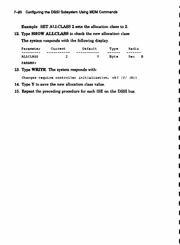
7-20 Configuring the DSSI Subsystem Using MOM Commands
Example: SET AIJ;CLASS 2 sets the allocation class to 2.
12. Type SHOW ALLCLASS to check the new allocation class.
The system responds with the following display.
Parameter Current Default Type Radix
ALLCLASS 2 0 Byte Dec B
PARAHS>
13. Type WRITE. The system responds with:
Changes require controller initialization, ok? [Y/ (N»)
14. Type Y to save the new allocation class value.
15. Repeat the preceding procedure for each ISE on the DSSI bus.
• I
I
I
I
I
I
I
I
• •• I
I
I
I
I
I
I
I
I
I
I
I
I
I
I

XXXXXXlOOOOCXlOCXXlOCKXXXXXXXJOCXXXXXXXXXXXXXXXXXXXX)CXX
XXXXXXXXXXXXXXXXXXXXXXXXXX}:KXXXXXXXXXXXXXXXX xx XX X
XXXXXXXXXXXXXXXXXXXXXXXXXXXXXXXXXXXXXXXXXXXXXXX
xxxxnxx~XXXXXXXXXXXXXX~XXXXXXXXXXXXXXXXX
XXXXXXXXXXXX~XXXXXXXXXXXX~XXXXXXXXXXX
nXXXXDXXXXXXXXXXXXXXXXXXXXXXXXXXXXXXXXX
XXXXXX~XXXXXXXXXXXXXXXXXXXXXXXXXXX
XXXXXXXXXXXXXXXXXX~XXXXXXXXXXXXXXXXX
JQOCX}QCXXXXXXXXXXXXXXXXXXXXXXXXXXXXX
XXXX}:XXXlOf~XXXXXXXXXXXXXXXXXXlQ(X
XXXXXXXXXXXXXXXXXXXXXXXXXXXXXXX
xx xx XX XJ{XX XX XXXXXXXXXXXXXX X}{..i{
XXXXXXXXXXXXXXXXXXXXXXXXXXX
XXXXXXXXXXXXXXXXXXXXXXXXX
XXXXXXXXXXXXXXXXXXXXXXX
XXXXXXXXXXXXXXXXXXXXX
XXXXXXXXXXXXXXXXXXX
XXXXXXXXXXXXXXXXX
XXXXXXXXXXXXXXX
XXXXXXXXXXXXX
XXXXXXXXXXX
XXXXXXXXX
XXXXXXX
XXXXX
xxx x
x xxx
XXXXX
XXXXXXX
XXXXXXXXX
xx xxxx XX XXX
XXXXXXXXXXXXX
XXXXXXXXXXXXXXX
,:XXXXXXXXXXXXXXXX
~~XXXXXXXXXXXXXXXXX
XXXXXXXXXXXXXXXXXXXXX
XXXXXXXXXX)u{XXXXXXXXXXX
xx XXXXXXXXXX XX XX XX XXXXXXX
XXXXXXXXXXXXXXXXXXXXXXXXXXX
XXXXXXXXXX XX xx XX XX XX XIC XXXX XXX
XXXXXXXXXXXXXXXXXXXXXXXXXXXXXXX
xx XX XX xx XX XX XX XX XX XX XX XX XX XXXXXXX
XXXXXXXXXXXXXXXXXXXXXXXXXXXXXXXXXXX
XXXXXXXXXXXXXXXXXXXXXXXXXXXXXXXXXXXXX
XXXXXXXXXXXX~XXXXXXXXXXXXXXXXXXXXXXXXX
XXXXXXXXXXX"}{XXXXXXXXXXXXXXXXXXXXXXXXXXXXX
XX xx xx XX XX XX XX XX XX XX XX xx XX XX XX XX XX XX XXXXXXX
XXUXX XX XX xx XX XX XX XXXXXXXX XX XX XX XX xx XX XX XX XXX
XX~XXXXXXXXXXXXXXXXXXXXXXXXXXXXXXXXXXXKXXXXXXXX
KX XXXX xx XX XXKXXXXXXXXXXXXXXXXX XXXXXXXX XX xx XX XX XX X
XX XX XX XXXXXXXX XX XX XX XX XXXXXXXXXX XX XX XX XX XX XXXXXXXXX

8 Diagnostics
This chaI ter describes the diagnostics for testing the KFQSA module and the conne\ ted DSSI ISEs.
8.1 Power- On Self· Test Diagnostics The KFQSA module has a power-on self·test (POST) that performs a comprehensive set of logic tests whenever power is applied to the module, or when the host issues a Q-bus BUS INIT. POST tests about 95 percent of the KFQSA module'~ logic and executes in less than ten seconds. It executes whether or not any other DSSI devices are connected to the KFQSA module.
The KFQSA module has one green and five red LEDs mounted on the edge of the board <Figure S-l). When power is applied, all five LEDs light. The red LEDs go out as POST routines are executed successfully. After the successful completion of all POST routines only the green LED remains lit.
NOTE In some cases. the red LEDs go out 80 quickly that you may think they never came on. If the green LED is on when you look at the module after applying power, POST ran successfully.
8-1

8-2 Diagnostics
figure 8-1 KFQSA MODULE LEOS Location
UoOI1D-TlD
8.2 LED Error Codes The two types of errors detected by POST are fatal errors and nonfatal errors. Fatal errors cause the adapter to abort service and walt for reinitialization. Nonfatal errors are recoverable.
A POST failure also causes an error code to be sent to the SA registers. When the error is fatal. the microprocessors are forced into an infinite loop sequence that can only be broken by receiving an INIT from the host.
If a nonfatal error is detected, the green LED remains lit and the red LEOs display an error code for approximately ten seconds. Table 8-1 shows the POST LED nonfatal etTOr codes.
If a fatal error is detected, the green LED goes out and a sequence of red LEDs remains lit. Table 8-2 shows the POST LED fatal error codes.

Diagnostics 8-3
Table 8-1 POST LED Nonfatal Error Codes
GreeD RedLBD.
" a I 1 0 LED Me.Dius
0 0 0 0 • • At least one (but not all) CSR address parity elTor'
0 0 0 • 0 • At least one (but not all> discrete port error in the QMI chip'
0 0 • 0 0 • Successful ret.ry during a RAM test 1
0 • 0 0 0 • Watchdog timer non-fatal error'
0 0 0 0 0 • POST paIRed.
o = LED off, • = LED on
'The nonfatal error code is displayed for ten _cond. hninimum).

Table 8-2 POST LED Fatal Error Codes
GreeD Red LED. LED " 8 2 1 0 Me.DiD,
0 • • 0 • • Never got started or 8096 CPU error
0 0 0 0 0 0 8096 letup error
0 0 0 0 0 • CSRD chip test error
0 0 0 0 • 0 QMI Chip test error
0 0 0 0 0 • Fatal configuration table elTOr1
0 0 0 0 0 0 8096 EPROM test error
0 0 () 0 0 • 8096 DPRAM teat error (low byte)
0 0 0 • • 0 8096 DPRAM teat error (high byte)
0 0 0 0 • • 68ooo's CPU teat elTor
(l 0 • 0 0 0 68ooo's 10 U8ee BERR timer te8t error
0 0 • 0 0 • 68000'8 EPROM te8t error
0 0 • 0 • 0 68ooo'a local RAM test error (low byte)
0 0 • 0 • • 68000'a local RAM teat error (high byte)
0 0 • • 0 0 68000 interrupt vector te8t error
0 0 • 0 0 • DSSI timer f .. Jat error
0 0 • • • 0 FIFO chi p teat error
0 0 • 0 0 • Buffer RAM parity teat elTOr
0 • 0 0 0 0 Buffer RAM te8t error (fint MK. bita 0 ... 3)
0 • 0 0 ') • Buffer RAM teat error (tint 64K, bite 4 ... 7)
0 • 0 0 • 0 Buffer RAM test error (first 64K. bits 8 ... 11)
0 • l) 0 • • Buffer RAM tent error (first 64K. bits 12 ... 15)
0 • 0 • 0 0 Buffer RAM test error (second ()4K hlt~ 0 ... 3)
0 • 0 • 0 • Buffer RAM test error (second 64K. bIts 4 ... 71
0 • 0 • • 0 Buffer RAM teet error (second 64K. hits 8 ... 11)
0 • 0 • • • Buffer RAM te8t error (second 64K. hits 12 ... 15)
lIt i8 pouible to 1lO1ve fatal configuration table 8rTOl'a without replac:inR the KFQSA module. S.t Switch 1 t.o the ON poeition. boot, and attempt to reconfigure the table.

Diagnostics 8-6
Table 8-2 (Continued) POST LED Fatal Error Codes
GreeD RedLBD. LED .. 3 2 1 0 M.-ninK
0 • • 0 0 0 sn chip teat elTOr
0 • • 0 0 • 68OOO's DPRAM test elTOr (low byte)
0 • • 0 • 0 68000'8 DPRAM teet error (high byte)
0 • • 0 • • Microprocessor interrupt teat error
0 • • • 0 0 68000 bU8 error
0 • • • 0 • Unexpected interrupt (68000 side)
0 • • • • 0 8096 setup complete eJTor
" • • • • • Parity error during BRAM test
0= LED off, • = LED on
8.3 Using MOM to Run NAKFA Diagnostics NAKFA is a KFQSA functional diagnostic that is executed using the MicroVAX Diagnostic Monitor (MDM) utility. The MDM utility seaDS for individual devices on the bus, and loads one image of NAKFA for each device it sees on the DSSI bus. Like all MDM diagnostics, NAKFA is menu driven.
NOTE This .action i. written for ullen with a workiDIJlmowledge of the MDM utility.
8.3.1 Loading NAKFA
There are several ways to load and execute MDM diagnostics. This section describes one way in which only the device being tested is selected. This allows more time for KFQSA module or DSSI device tnmhleshooting.
1. LoadMDM.
(For example: »>B DUAl.)
The system displays the following:

8-6 DIagnostic.
HicroVAX Diagnostic Monitor initi.lizing ••.••• Pl.as. wait
HicroVAX DiAgnostic Monitor - Version 3.0
CONFIDENTIAL DIAGNOSTIC SOFTWARE PROPERTY OF
DIGITAL EQUIPMENT CORPORATION
Use Authorized Only Pursuant to a Valid Right-to-use License
Copyright (0) 1986, 1988 Digit.l Equipment Corpor.tion
The current date and time is: l2-JAN-19S9 13:30
Press the RETURN key to continue, ,)r enter the n.w date and tim.; then press the RETURN key.
~DD-MMM-YYYY HH:MM1:
The current date and tim. is: 12-JAN-1989 13:30
2. Enter the correct date and time, then press I Return I. The following text is displayed on the screen:
00 you want to us. menu mod. or command line mode?
1 - m.nu mode 2 - command line mode
Type the numb.r; then press the RETURN key.
3. Select command line mode.
4. At the prompt, type the following:
HDM»SHOW BUS
This shows you infonnation about deviceB that can be tested. For example:
Autoconfigure set ON
Filenam.
NAKAA NAMSA
NAKFA
CSR
160000 160002
160334
VECTOR BR LEVEL
000 0 000 0
300 4
STATUS
CONNECTED CONNECTED
CONNECTED

Diagnostics 8-7
The bus display defaults are AutoconfWure set ON and STATUS CONNECTED. These defaults mean that the diagnostics are loaded automatically when the system is configured.
5. At the promptt type the following:
MDl~>SET AUTOCONFIGURATION OFF
This command reverses the status of diagnostics t(' lGNORED. This means that the diagnostics are not loaded when the system is configured.
6. At the promptt type the following:
MDM»oonnect 160334 file name NAKFA vector 300 br level 4
7. At the prompt, type the following:
MDH»SHOW BUS
The system displays new configuration and status. For example:
Autoconfigure set OFF
Filename
NAKAA NAMSA
NAKFA
CSR
160000 160002
160334
VECTOR BR LEVEL
000 0 000 0
300 4
8. At the prompt, type the following:
MDM»CONFIGURE
9. At the prompt. type the following:
MDM»SPOW CONFIGURATION BRIEF
STATUS
IGNORED IGNORED
CONNECTED
The following list of enabled diagnostics is displayed:
1 NO Ld KAA Disabled 2 NO Ld MSA Di~abled
5 KFQSAA - KFQSA subsystem
HOM»

8-8 DIagnostics
8.3.2 Testing the KFQSA Subsystem Using NAKFA In Menu Mode
This section explains how to US6 the MDM utility to access the MDM device menu, NAKFA's KFQSA subsystem menu, and NAKFA's KFQSA utility tests and program menu.
Use the following procedure to access the KFQSA device menu:
1. Boot MDM. Select menu mode in response to menu mode or command line mode query.
The following is displayed on the screen:
MAIN MENU
1 - Test the system 2 - Display System Configuration and Devices 3 - Display the System Utilities Menu 4 - Display the Service Menu 5 - Display the Connect/Ignore Menu 6 - Select single device tests
Type the number, then press the RETURN key.
2. Select the service menu.
The follOwing is displayed on the screen:
Service Menu
CAUTION: This menu is intended for use by qualified service personnel only. Misuse of the commands could destroy data.
1 - Set test and message parameters 2 - Exercise system continuously 3 - Display the device menu 4 - Enter command line mode
Type the number: then press the RETURN key, or type 0 and press the RETURN key to return to the Mai.~ ~)enu.
3. Select the device menu. In tms example, other device dlagrtoshcs are loaded. The following text is displayed on the screen:
MAIN SERVICE DEVICE
This menu lets you select a device for testing.

1 CPUA - MicroVAX/rtVAX CPU 2 MEMA - MicroVAX memory system 3 RQDXA - Winchester diskette controller 4 TKXXA - TK50/TK70 controller 5 KFQSAA - KFQSA subsystem
4. Select KFQSAA, KFQSA subsystem menu (#5).
The following text is displayed on the screen:
DEVICE MENU KFQSAA - KFQSA subsystem menu
Testing is Enabled
1 - Enable/Disable testing for device 2 - Perform all functional tests 3 - Perform the exercis~r test 4 - Display the device utilities menu
5. Select the device utilities menu.
Diagnostics 8-9
The KFQSA device utility menu displays the following utilities and special subsystem tests:
MAIN MENU SERVICE MENU DEVICE MENU KFQSAA - KFQSA SUBSYSTEM MENU UTILITY PROGRAM AND TESTS MENU
Utility selections are:
1 - KFQSA Configuration Utility 2 - DSSI Device Data Erase Utility 3 - Select Device Re~ident Programs 4 - KFQSA Information Gathering Service 5 - Customize Diagnostic Functionality Utility
The KFQSA configuration utility is used to program the KFQSA configuration table, as described in Chapter 6.
You can use this utility to install nSSI add-on devices if ~f le~st one nSSI device is attached and has a valid address in the configuration table. and the KFQSA mc~ule is in its nonnal operating m(}de {that iR, Switch 1 on the KFQSA module is set to the OFF position l. However. if the configuration table is corrupted, you must set Switch 1 to the ON position, reboot the KFQSA module, and reconfigure EEROM using this utility.

8-10 Diagnostics
The select device resident programs utility is used to select the following device-resident programs:
• EXIT
• HISTRY
• DIRECT
• DRVEXR
• ERASE
• DRVTST
• PARAMS
• VERIFY
• DKUTIL
NOTE The select device resident programs utility works only when Switch 1 on the KFQSA module is set to OFF.
Refer to yOW' ISE manual or system documentation for further information on using local programPl to test the ISE.
CAUTION The remainder of the utilities in the Utility Program and Tests Menu are tor Digital Services use only. Do n.ot attempt to use any of these unless you are properly trained. Erasure or corruption of data may result from incorrect use.
8.3.3 Halting Test Execution To halt NAKFA, type ICtrVcl. NAKFA stops running, and the MDM utility reports any errors that were detected during testing.

Diagnostics 8-11
8.4 Using Console Commands for Testing DSSI Devices
For systems having console command capability. the ISEs on the DSSI bus may be tested by using a simple command.
At the console prompt (»» type:
»> SET HOST/DUP/UQSSP/OISK • xxxxxx
where:
• ## is the DSSI node ID of the ISE you want to test.
• xxxxxx is the name of the ISE local program you want to access. The following local programs are available.
• EXIT
• HlSTRY
• DIRECT
• DRVEXR
• ERASE
• DRVTST
• PARAMS
• VERIFY
• DKUTIL
Refer to your ISE manual or system documentation for further information on using local programs to test the ISE.

XXXXXXXXXXXXXXXJQOeXXKXXXxxxxxxxxxxr.lC<Y.';.JOCXXXXXXXXX
XXXXXXXXXXXXXXXXXXlOOOOOC)(X.)fl{XXXXY'AXXXXXXXXXXXXXXX
XXXXXXXXXXXXXX~XXXX~XXXXXXUXXXX~XXXXXXXXX
XXXXXXXXXXXX~XX~XXXXXX~XXXXXXXXXXXXXXX
XXXXXXXXXXXXXXXXXXXXXXXXXXXX)Q':Y')(XXXXXXXXXXX
lDtXYxxxxxxxxxxxxxxxxxxxxxxxxxxxxxxxxxxxxx XXXXXXK.Xxx~~nxxxxxxxxxxxxXXXXXXX
xxxxxxxxxxxxxxxxxxxxxxxxxxxxxxXXXXXXX XXXXXXXXXXXXXXXXXXXXXXXXXXXXXXXXXXX
XXX)(XXKXXX XXXXXXXXXXXXXXXXXX lOC xx X
lOCXXXXXX)Q{XXXXXXlOCXXXXXXXXXXXXX
X)()Q(XXXXXXXXXXXXXXXXXXXXXXXXX
XXXXXXXXXXXXXXXXXXXXXXXXXXX
XXXXXXXXXXXXXXXXXXXXlCXXXX
XKXXlCXXXXXXXXXXXXXXXXXX
XXXXlCXXXXXXXXXlOCXXXXX
XXXXlCXXXXXXXXXXXXXX
XXlOCXXXXXXXXXXlOCX
XXlOCXXXXXXXXXXX
lOCXXKXXXXXXXX
lOOOCKXXXXXX
lOCXXXXXXX
XX)Q(XXX XX)Q(X
X)(X X
x XXX
xxxxx XXXXXX;
xxxxxxxxx XXXXXXXXXX~
xxxxxxxxxxxxx KX xx Y.XXX xxxx xxx
XXXXXXXXXXXXXXXXX
xxxxxxxxxxxxxxxxxx~:
XXXXXXXXXXXXXXXXXXXXX
XXlOClono(XXXXXXXXXXXxxxx
XXXXXXXAXXXXXXXXlOCXXXXXXX
XXlOClOCXXXXXX)(XXXXXXXXXXXXXX
XXXXXXXXXXXXXXXXXXXXXY.XXXXXXX
xx xx XX xx XX xx xx xx xx xx xx XXXXlOC lOCX
xx xx XXXXXXXXXX xx xx xx XX xx XX xxxxxxx xx xx xx xx XX XX XX XX XX xx xx xx xx XXXXXXXXX
XXlOCXXXXXX xx XX XX xx xx xx XX xx XXXXXXXXXXX
XX)Q(XXXXXXXXXX XXXX)Q(XX}(X xx xx X)(XXXXXX XXX
xxxxxxxxxxxxxx oooocxxxxxxxxxxxxxxxxxxxxxx XXXXXXXXXXXXXXXXXXXXXXXXXXXXXXXXXXXXXXXXXXX
xx xx XXXXXXXXXXXXXX xx xx xx xx xx xx xx xx XXXXXXXXXXX XXXXXXXXXXXXXXXXXXXXXXXXXXXXXXXXXXXXXXXXXXXXXXX
XXXXXXXXXXXXXXXXXXXXXXXXXXXXXXXXXXXXXXX)(XXXXXXXXX
XXXXXXXXXXXXXXXXXX>OCXXXXXXXX>OCXXXXXXXXXXXXxxXXXXXXX

9 KFQSA Troubleshooting
The tools used to diagnose the KFQSA module and connected ISEs are:
• POST, power-on self test. described in Section 8.1.
• NAKFA, KFQSA module's functional diagnostic, described in Section 8.3 or the SET HOSTIDUP console command described in Section 8.4.
Generally, KFQSA module failures fall into one of two categories:
• The system fails to boot because of a KFQSA module problem.
• The system boots, but the KFQSA module fails.
In the case of a boot failure, verify the installation again using the procedures outlined in Chapter 5. Then verify the configuration using the procedures outlined in Chapter 6 or Chapter 7. Most boot problems are caused by incorrectly setting up the device configuration or addressing.
If the system boots but the KFQSA module fails, reapply power to cause POST to run, and cl".eck for the presence of a LED error code.
Always perform a visual inspection of the KFQSA module and al1 connected nssl devices before troubleshooting. Some KFQSA module problems that can be solved by visual inspection arE" listed in TahlE" 9-1.
9-1

9-2 KFOSA Troubleshooting
Table 9-1 KFQSA Troubleshooting Symptom Analysis
Symptom
Green LED on external DBSI terminator is extinguished.
Continually blowing fuses on the KFQSA module.
Cannot access Configuration Table.
Error Code 03 on KFQSA LEDs (red LEOs 0 and 1 are lit)
With Switch 1 in the OFF position, MDM displays IP WRITE FAILURE.
Excessive VMS error logs.
No DSSI devices Been by operating system.
Cannot boot MDM with KFQBA on the bus.
Undeterminable fatal or nonfatal errore.
NAKFA or VMS error logs display NO VC.
Po •• ible Resolution
Blown fuse on KFQSA module or de power problem on DSSI bus. Includes cables and KFQSA and DSBI ISE controller modules.
Incorrectly plugged or cables that are not DSSI cables.
IncoJTeCt termination on the KFQSA module. Make sure KFQSA is terminated either through on-board SIP terminators or external DSSI terminators.
Fatal configuration tahle error. Uee procedures in Chapter 6 or Chapter 7 to reprogram the configuration table.
A NAKFA image has been corrupted. Reload NAKFA.
Nonoxistent or powered-off device on the DSSI bUB.
Attempting to boot DSSI devices when Switch 1 is set to ON. Set Switch 1 to OFF.
Conflicting boot addresses. Use KFQSA module switches to choose a dedicated addrese.
Incorrect bus termination, incorrect DBSI cable connections, or improper grounding. Make Bure the DSSI bus is terminated and the terminator LED is ht to avoid incorrect bus termination.
Incorrect device connection on the DSSI bUB. The KFQSA module must have at least one DSSI device that can be addressed. connected and available on the bus. Also, the confiflUTAtion table must accurately reflect th~ d~\ ... {"c:>" pTef.:ent. boU, CSR and DSSI node ID.
• I
I I
I I
I
I
I
I
I
I
I
I
I
I
I
I
I
I
I
I
I
I

~~~~nn~u~n~~~~~~n~~~~x
~~uu~~~~~~~~~~n~u~~~n~x
~~~~~~~~~~nnn~u~~~nx
~~u~un~~~~~nn~~~~~~x
~XXXXXXXXXX~XXXXXXXXXXXXXX~XX~KXKX~XXx
~~~KXXXXXnnXXKXKXUXXXX~~~XX~KXX
~XXKXKXXX~XXXX~KXXXXXXX~XX~~XXKXx
~~~KXXXXXXXXX~XXKX~XX~XXXXXXXXx
lQ{l\'1{)Q(lOCXXXXXXXX~)Q{~XXXXXXXXlOClOCX
}Q{XXXXXXXXXXXXXXXXXXXXXXXXXXXXXXX
XXXXXX~XXXXXXXXXXKXXXXXXXXXXXX
XXlOCXXY.XXXXXXX~XXXXXXXXXXXXx
~XXXXXXXXXXXXXXKXXXXXUXXX
xxxxxxxxxxxxnxxxxxxxxxxx ~XXXXXXXXXXXX~XXXXXXX
~XXXXXXXX~XX~KXKXX
~XXXXKXXXXXXXXXXXX
xxxxxxxxxxxxnxxx
XXXXXXXXXX~~X
~XXXXXXXXXXx
XXXXXXXXXXX
XXXXXXXXX
xx XX XX x
XXXXX
xxx x
x XXX
X'XXXJ( XXXXXXX
XXXXXXXXX
XXXX~XXXXX
XXXXXX~XXXXX
xx XX xx XX XX XXXXX
XXXXXXXXXX~XXXXX
XXXXXXXX)Q(~~lO()OCX
XXXXXXXXXXXX~XlCXXXXX
XXXXXXlOCXXXXXXXX~lOClOCX
XXXXXXXXXXXXXX:XXXX~XXXXX
xx)cOOnOOCKXXXX xx XX XXXX)Q(XXX
XXXXXXXXXXXXXXXXXXXX~XXXXXXX
XXXX~~XXXXXXXXXXXXXXXXXXXXXXX
xx xx XX XXXXXXXX XX XX XX XX xx XX XXXXXX X
XXXXXXXXXXXXXXXXXXXXXXXXXXXXXXlOCXXX
XXXXXXXXXXXXXXXXXXXXXXXXXXXXXXXXXXXXX
KXXXXXKXXXXXXXXXXXX'XX'X~XXXXXXXXXXXXXXX
XXXXXXXXXXXXXXXXXXln'~l(XXXXX~XXXXXXXXXXX
XXXXXXX'XX'XX'XXXXXXXXXXXXXX'XXXXXXXXXX)(XXXXXXX XXXXXXXXlOCXXXXXXXXXXXXXXX'XXXXXXXXXXXXXXXXXXXX
XXXXXXXXXXlOCXXXXXXXXXXXXXXXXXXXXXXXXXXXXXXXXXXX
XXXXXXXXXXXXXXXXXXXXXXXXXXXXXXXXXXXXXXXXXXXXX'XXXX
XXXXXXXXXXXXXXXXXXXXXXXXXXXXXXXXXXXXXXXXXXXXXXXXXXX

A Allocation elaas, 6-11, 7-17
B BA123 enclosure, 1-10
Installation procedure, 5-9 BA213 enclosure, 1-7
Installation procedure, 5-6 BA23 enclosure, 1-12
Installation procedure. 5-14 BA440 enclosure
Installation procedure, 5-2 BA440 Enclosure, 1-5 Bulkhead cover, 1-8,5-3,5--6
c Configuration table. 4-3. 7-1
DSSI VAXclulJter, 7-15 DSSI VAXclulJter systema, S-8 Programming using console
commands, 6-3 Programming using MDM, 7-4
Configuration worksheet, 3--1 Console commands, 6-1
CONFIGURE. 6-2, 6-8 EXIT. 6-3 HELP. 6-2, 6-9 SET HOSTIDUP, 8-11 SHOW QBUS, 6-5, 6-8 SHOW UQSSP, 6-6,6-7
CSR address, 4-1. 6-1, 7-1 Dedicated KFQSA address, 4-3 Floating addres8, 6-2, 7-2 MSCP or TMSCP generic address,
4-4
Index
o Diagnostics, 8-1 DBSI,I-1 DSSI node ID, 6-4, S-5, 6-10, 6-11.
7-7,7-11.7-16.8-11 DBSI VAXcluster, 1-14 nSSI VAXcluster configuration. 6-7,
7-15
G Gap filler a8sembly, 5-3.6-7
I IOADDRES, 7-2 IP WRITE FAILURE. 9-2 ISE, 1-1 ISE local programs, 8-10, 8-11
J Jumper, 2-3
K KFQSA fUBe, 9-2 KFQSA switches. 4-1
M MDM
Command hne mode. 8-6 CONFIGURE. 8-7 Menu mode. 8-R NAKFA,8-5
Index 1

2 Index
MDM (cont'dl SET AUTOCONFIGURATION
OFF. 8-7 SHOW BUS, 8-6 SHOW CONFIGURATION
BRIEF,8-7 Multihost restriction!, 1>-18
N NAKFA, 7-4, 9-1 NO VC, 9-2
o Operator control panel. 6-10.7-17 Option kits, 2-2
p
PARAMS, 7-19 SET ALLCLASS, 6-11, 7-19
SHOW ALLCLASS. 6-11. 7-19 VVRrTE,6-12,7-20
POST, 8-1, 9-1 Fatal error codes, 8.-4 Fatal errors, 8-2 Nonfatal error codes, 8-2 Nonfatal errors, 8-2
POST LED eTTor codes, 8-2 POST LEDa, 8-1
s SET HOSTIDUP. 9-1 SET HOST" 1QSSPIMAINT
ISERVICE,6-3 SSP controller, 6-1, 7-1
T
Terminator. 2-2, 5-13, 5-16 Trouble8hooting, 9-1


![VOL. XXX, No. 40 [PEICE TWELVE CENTS] AUGUST, 1928](https://img.pdfslide.net/doc/110x75/63134540aca2b42b580d1e40/vol-xxx-no-40-peice-twelve-cents-august-1928.jpg)


 XXX](https://img.pdfslide.net/doc/110x75/6333b1ef4cd921f2410cfc3a/european-commission-brussels-xxx-2022-xxx-.jpg)


