Embed Size (px)
Citation preview
1
Stud, Ferrule & Accessory Catalog
www.NelsonStud.com
September 2017
2
2017 Nelson® Stud Welding
Stud, Ferrule & Accessory Catalog
This catalog is designed to be a user-friendly source of online information about the Nelson Stud Welding line of studs, anchors, pins, and the standard accessories used to weld them. Many features have been incorporated into the pages of this catalog to enable you, the customer, to find the information you need quickly and easily.
Many studs, pins, anchors, and ferrules are featured to provide the greatest range of possible solutions to your stud welding applications.
Bookmarks have been added to make navigation through the catalog quick and easy.
Text explanations have been added to clarify some of the potential uses of each stud.
Suggestions for similar use studs will assist you in making the correct stud choice for your stud
welding application.
PDF format creates a quicker downloading, more informative catalog that is readable on both IBM
and Macintosh platforms. Security features assure that the information you download from our
web site is genuine Nelson information.
Links embedded in each page take you right to the information you need, making the stud
information more easily accessible.
Detailed ferrule and accessory information allows you to identify and specify the exact parts you need
to execute the job.
Clickable table of contents and indexes quickly locates the stud information you need.
Studs are indexed by welding process and use in industry to make finding the stud you need faster
and easier.
Company contact information is provided on every specification sheet to make communication with
Nelson Stud Welding faster than ever before!
Your questions, comments, and suggestions are welcome and appreciated. Please follow the bookmark at left.
Thank you for choosing to download this catalog. We think you will find it the most useful and informative method to explore the Nelson Stud Welding product line.

3
Using the 2017 Nelson Stud Welding, Inc. Electronic Catalog
© 2017, Nelson Stud Welding, Inc., All rights reserved
All information contained herein is the property of Nelson Stud Welding, Inc. and is intended for the use of our customers. This information pertains solely to Nelson studs and related accessories. Use of this information in conjunction with non-Nelson studs and related accessories is not recommended by Nelson Stud Welding, Inc. Nelson Stud Welding, Inc. assumes no financial or physical responsibility for damage or harm resulting from this information’s use with non-Nelson studs and related accessories. No part of this publication (whether in hard copy or electronic form) may be reproduced or transmitted, in any form or by any means, electronic, mechanical, photocopying, recording, or otherwise, without prior written consent of Nelson Stud Welding, Inc.
Stored Arc™ and Tranquil Arc™ are registered trademarks of Nelson Stud Welding, Inc. All instances of the names Stored
Arc™ or Tranquil Arc™ in the text are references to the Stored Arc™ stud welding process or Tranquil Arc™ accessory kit,
as defined by Nelson Stud Welding, Inc., unless otherwise indicated.
CrimpLok™ and Setlok™ are registered trademarks of Nelson Stud Welding, Inc. All instances of the names CrimpLok™ or
Setlok™ in the text are references to the CrimpLok™ style of cable hangers or Setlok™studs and caps, as defined by
Nelson Stud Welding, Inc., unless otherwise indicated.
The Nelson name, logos, and the Nelson eagle are all trademarks of Nelson Stud Welding, Inc. Adobe and Adobe Acrobat are trademarks of Adobeystems Incorporated.
All other trademarks or name brands are trademarks of their respective holders.
This publication and the information herein is furnished AS IS, is subject to change without notice, and should not be construed as a commitment by Nelson Stud Welding, Inc. Nelson Stud Welding, Inc. assumes no responsibility or liability for any errors or inaccuracies, makes no warranty of any kind (express, implied, or statutory) with respect to this publication, and expressly disclaims any and all warranties of merchantability, fitness for particular purposes, and non-infringement of third party rights.
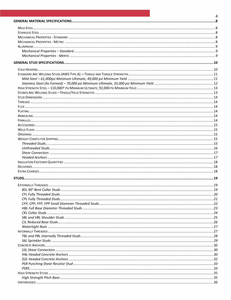
4 GENERAL MATERIAL SPECIFICATIONS ................................................................................................................................................ 8
MILD STEEL ............................................................................................................................................................................................... 8 STAINLESS STEEL ........................................................................................................................................................................................ 8 MECHANICAL PROPERTIES - STANDARD .......................................................................................................................................................... 8 MECHANICAL PROPERTIES - METRIC .............................................................................................................................................................. 8 ALUMINUM ............................................................................................................................................................................................... 9
Mechanical Properties – Standard .................................................................................................................................................... 9 Mechanical Properties - Metric ......................................................................................................................................................... 9
GENERAL STUD SPECIFICATIONS ...................................................................................................................................................... 10
COLD HEADING ........................................................................................................................................................................................ 10 STANDARD ARC WELDING STUDS (AWS TYPE A) —TENSILE AND TORQUE STRENGTHS ......................................................................................... 11
Mild Steel – 61,000psi Minimum Ultimate, 49,000 psi Minimum Yield .......................................................................................... 11 Stainless Steel (As Formed) – 70,000 psi Minimum Ultimate, 35,000 psi Minimum Yield .............................................................. 12
HIGH STRENGTH STEEL – 110,000† PSI MINIMUM ULTIMATE, 92,000 PSI MINIMUM YIELD ................................................................................ 13 STORED ARC WELDING STUDS—TENSILE/YIELD STRENGTHS ............................................................................................................................ 13 STUD DIMENSIONS ................................................................................................................................................................................... 14 THREADS ................................................................................................................................................................................................ 14 FLUX ...................................................................................................................................................................................................... 14 PLATING ................................................................................................................................................................................................. 14 ANNEALING ............................................................................................................................................................................................. 14 FERRULES ................................................................................................................................................................................................ 14 ACCESSORIES ........................................................................................................................................................................................... 15 WELD FLASH ........................................................................................................................................................................................... 15 ORDERING .............................................................................................................................................................................................. 15 WEIGHT CHARTS FOR SHIPPING ................................................................................................................................................................... 15
Threaded Studs ................................................................................................................................................................................ 15 Unthreaded Studs ............................................................................................................................................................................ 16 Shear Connectors ............................................................................................................................................................................ 17 Headed Anchors .............................................................................................................................................................................. 17
INSULATION FASTENER QUANTITIES ............................................................................................................................................................. 18 DELIVERIES .............................................................................................................................................................................................. 18 EXTRA CHARGES ....................................................................................................................................................................................... 18
STUDS .............................................................................................................................................................................................. 19
EXTERNALLY THREADED ............................................................................................................................................................................. 19 B5L 90° Bent Collar Studs ................................................................................................................................................................ 19 CFL Fully Threaded Studs ................................................................................................................................................................. 20 CPL Fully Threaded Studs ................................................................................................................................................................. 21 CFP, CPP, FFP, FPP Small Diameter Threaded Studs ........................................................................................................................ 22 HBL Full Base Diameter Threaded Studs ......................................................................................................................................... 23 CKL Collar Studs ............................................................................................................................................................................... 24 SBL and VBL Shoulder Studs ............................................................................................................................................................ 25 CJL Reduced Base Studs ................................................................................................................................................................... 26 Watertight Nuts .............................................................................................................................................................................. 27
INTERNALLY THREADED .............................................................................................................................................................................. 27 TBL and PBL Internally Threaded Studs ........................................................................................................................................... 28 S6L Sprinkler Studs .......................................................................................................................................................................... 29
CONCRETE ANCHORS................................................................................................................................................................................. 30 S3L Shear Connectors ...................................................................................................................................................................... 30 H4L Headed Concrete Anchors ........................................................................................................................................................ 30 D2L Headed Concrete Anchors ........................................................................................................................................................ 32 PSR Punching Shear Resistor Stud ................................................................................................................................................... 33 PSRS ................................................................................................................................................................................................. 33
HIGH STRENGTH STUDS ............................................................................................................................................................................. 35 High Strength Pitch Base ................................................................................................................................................................. 35
UNTHREADED .......................................................................................................................................................................................... 36
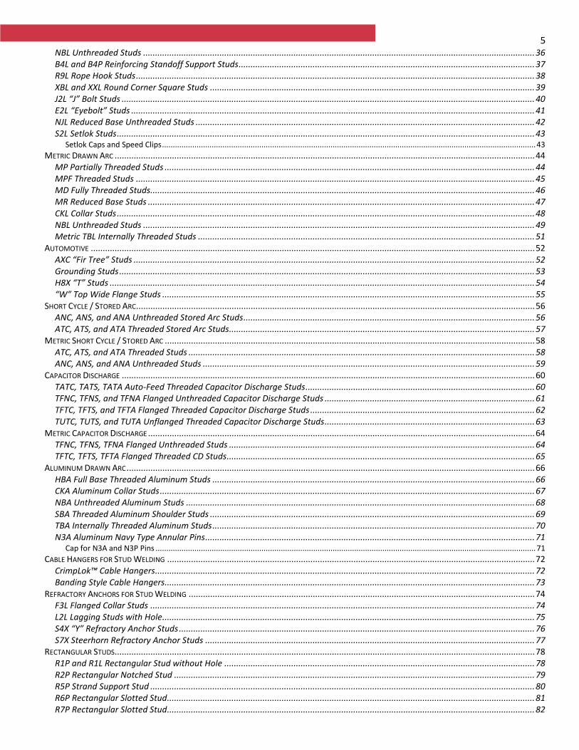
5 NBL Unthreaded Studs .................................................................................................................................................................... 36 B4L and B4P Reinforcing Standoff Support Studs ............................................................................................................................ 37 R9L Rope Hook Studs ....................................................................................................................................................................... 38 XBL and XXL Round Corner Square Studs ........................................................................................................................................ 39 J2L “J” Bolt Studs ............................................................................................................................................................................. 40 E2L “Eyebolt” Studs ......................................................................................................................................................................... 41 NJL Reduced Base Unthreaded Studs .............................................................................................................................................. 42 S2L Setlok Studs ............................................................................................................................................................................... 43
Setlok Caps and Speed Clips ............................................................................................................................................................................. 43 METRIC DRAWN ARC ................................................................................................................................................................................ 44
MP Partially Threaded Studs ........................................................................................................................................................... 44 MPF Threaded Studs ....................................................................................................................................................................... 45 MD Fully Threaded Studs................................................................................................................................................................. 46 MR Reduced Base Studs .................................................................................................................................................................. 47 CKL Collar Studs ............................................................................................................................................................................... 48 NBL Unthreaded Studs .................................................................................................................................................................... 49 Metric TBL Internally Threaded Studs ............................................................................................................................................. 51
AUTOMOTIVE .......................................................................................................................................................................................... 52 AXC “Fir Tree” Studs ........................................................................................................................................................................ 52 Grounding Studs .............................................................................................................................................................................. 53 H8X “T” Studs .................................................................................................................................................................................. 54 “W” Top Wide Flange Studs ............................................................................................................................................................ 55
SHORT CYCLE / STORED ARC ....................................................................................................................................................................... 56 ANC, ANS, and ANA Unthreaded Stored Arc Studs .......................................................................................................................... 56 ATC, ATS, and ATA Threaded Stored Arc Studs................................................................................................................................ 57
METRIC SHORT CYCLE / STORED ARC ........................................................................................................................................................... 58 ATC, ATS, and ATA Threaded Studs ................................................................................................................................................. 58 ANC, ANS, and ANA Unthreaded Studs ........................................................................................................................................... 59
CAPACITOR DISCHARGE ............................................................................................................................................................................. 60 TATC, TATS, TATA Auto-Feed Threaded Capacitor Discharge Studs ................................................................................................ 60 TFNC, TFNS, and TFNA Flanged Unthreaded Capacitor Discharge Studs ........................................................................................ 61 TFTC, TFTS, and TFTA Flanged Threaded Capacitor Discharge Studs .............................................................................................. 62 TUTC, TUTS, and TUTA Unflanged Threaded Capacitor Discharge Studs ........................................................................................ 63
METRIC CAPACITOR DISCHARGE .................................................................................................................................................................. 64 TFNC, TFNS, TFNA Flanged Unthreaded Studs ................................................................................................................................ 64 TFTC, TFTS, TFTA Flanged Threaded CD Studs ................................................................................................................................. 65
ALUMINUM DRAWN ARC ........................................................................................................................................................................... 66 HBA Full Base Threaded Aluminum Studs ....................................................................................................................................... 66 CKA Aluminum Collar Studs ............................................................................................................................................................. 67 NBA Unthreaded Aluminum Studs .................................................................................................................................................. 68 SBA Threaded Aluminum Shoulder Studs ........................................................................................................................................ 69 TBA Internally Threaded Aluminum Studs ....................................................................................................................................... 70 N3A Aluminum Navy Type Annular Pins .......................................................................................................................................... 71
Cap for N3A and N3P Pins ................................................................................................................................................................................ 71 CABLE HANGERS FOR STUD WELDING .......................................................................................................................................................... 72
CrimpLok™ Cable Hangers............................................................................................................................................................... 72 Banding Style Cable Hangers........................................................................................................................................................... 73
REFRACTORY ANCHORS FOR STUD WELDING ................................................................................................................................................. 74 F3L Flanged Collar Studs ................................................................................................................................................................. 74 L2L Lagging Studs with Hole ............................................................................................................................................................ 75 S4X “Y” Refractory Anchor Studs ..................................................................................................................................................... 76 S7X Steerhorn Refractory Anchor Studs .......................................................................................................................................... 77
RECTANGULAR STUDS ................................................................................................................................................................................ 78 R1P and R1L Rectangular Stud without Hole .................................................................................................................................. 78 R2P Rectangular Notched Stud ....................................................................................................................................................... 79 R5P Strand Support Stud ................................................................................................................................................................. 80 R6P Rectangular Slotted Stud .......................................................................................................................................................... 81 R7P Rectangular Slotted Stud .......................................................................................................................................................... 82
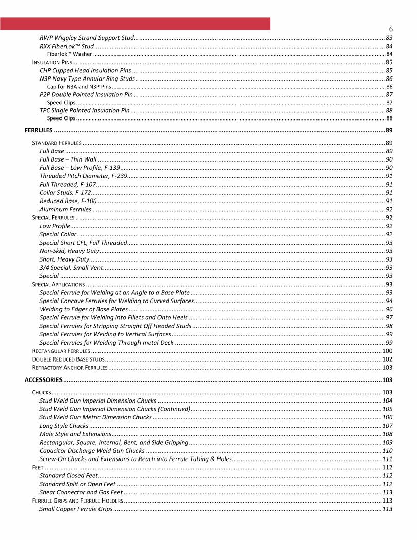
6 RWP Wiggley Strand Support Stud .................................................................................................................................................. 83 RXX FiberLok™ Stud ......................................................................................................................................................................... 84
Fiberlok™ Washer ............................................................................................................................................................................................ 84 INSULATION PINS ...................................................................................................................................................................................... 85
CHP Cupped Head Insulation Pins ................................................................................................................................................... 85 N3P Navy Type Annular Ring Studs ................................................................................................................................................. 86
Cap for N3A and N3P Pins ................................................................................................................................................................................ 86 P2P Double Pointed Insulation Pin .................................................................................................................................................. 87
Speed Clips ....................................................................................................................................................................................................... 87 TPC Single Pointed Insulation Pin .................................................................................................................................................... 88
Speed Clips ....................................................................................................................................................................................................... 88
FERRULES ........................................................................................................................................................................................ 89
STANDARD FERRULES ................................................................................................................................................................................ 89 Full Base .......................................................................................................................................................................................... 89 Full Base – Thin Wall ....................................................................................................................................................................... 90 Full Base – Low Profile, F-139 .......................................................................................................................................................... 90 Threaded Pitch Diameter, F-239 ...................................................................................................................................................... 91 Full Threaded, F-107 ........................................................................................................................................................................ 91 Collar Studs, F-172 ........................................................................................................................................................................... 91 Reduced Base, F-106 ....................................................................................................................................................................... 91 Aluminum Ferrules .......................................................................................................................................................................... 92
SPECIAL FERRULES .................................................................................................................................................................................... 92 Low Profile ....................................................................................................................................................................................... 92 Special Collar ................................................................................................................................................................................... 92 Special Short CFL, Full Threaded ...................................................................................................................................................... 93 Non-Skid, Heavy Duty ...................................................................................................................................................................... 93 Short, Heavy Duty ............................................................................................................................................................................ 93 3/4 Special, Small Vent .................................................................................................................................................................... 93 Special ............................................................................................................................................................................................. 93
SPECIAL APPLICATIONS .............................................................................................................................................................................. 93 Special Ferrule for Welding at an Angle to a Base Plate ................................................................................................................. 93 Special Concave Ferrules for Welding to Curved Surfaces ............................................................................................................... 94 Welding to Edges of Base Plates ..................................................................................................................................................... 96 Special Ferrule for Welding into Fillets and Onto Heels .................................................................................................................. 97 Special Ferrules for Stripping Straight Off Headed Studs ................................................................................................................ 98 Special Ferrules for Welding to Vertical Surfaces ............................................................................................................................ 99 Special Ferrules for Welding Through metal Deck .......................................................................................................................... 99
RECTANGULAR FERRULES ......................................................................................................................................................................... 100 DOUBLE REDUCED BASE STUDS ................................................................................................................................................................. 102 REFRACTORY ANCHOR FERRULES ............................................................................................................................................................... 103
ACCESSORIES ................................................................................................................................................................................. 103
CHUCKS ................................................................................................................................................................................................ 103 Stud Weld Gun Imperial Dimension Chucks .................................................................................................................................. 104 Stud Weld Gun Imperial Dimension Chucks (Continued) ............................................................................................................... 105 Stud Weld Gun Metric Dimension Chucks ..................................................................................................................................... 106 Long Style Chucks .......................................................................................................................................................................... 107 Male Style and Extensions ............................................................................................................................................................. 108 Rectangular, Square, Internal, Bent, and Side Gripping ................................................................................................................ 109 Capacitor Discharge Weld Gun Chucks ......................................................................................................................................... 110 Screw-On Chucks and Extensions to Reach into Ferrule Tubing & Holes ....................................................................................... 111
FEET .................................................................................................................................................................................................... 112 Standard Closed Feet ..................................................................................................................................................................... 112 Standard Split or Open Feet .......................................................................................................................................................... 112 Shear Connector and Gas Feet ...................................................................................................................................................... 113
FERRULE GRIPS AND FERRULE HOLDERS ...................................................................................................................................................... 113 Small Copper Ferrule Grips ............................................................................................................................................................ 113

7 Medium Copper Ferrule Grips ....................................................................................................................................................... 114 Larger Copper Ferrule Grips .......................................................................................................................................................... 114
MISCELLANEOUS STUD WELDING ACCESSORIES ............................................................................................................................................ 115 MISCELLANEOUS CAPACITOR DISCHARGE ACCESSORIES.................................................................................................................................. 116 MISCELLANEOUS STORED ARC ACCESSORIES ................................................................................................................................................ 117
8
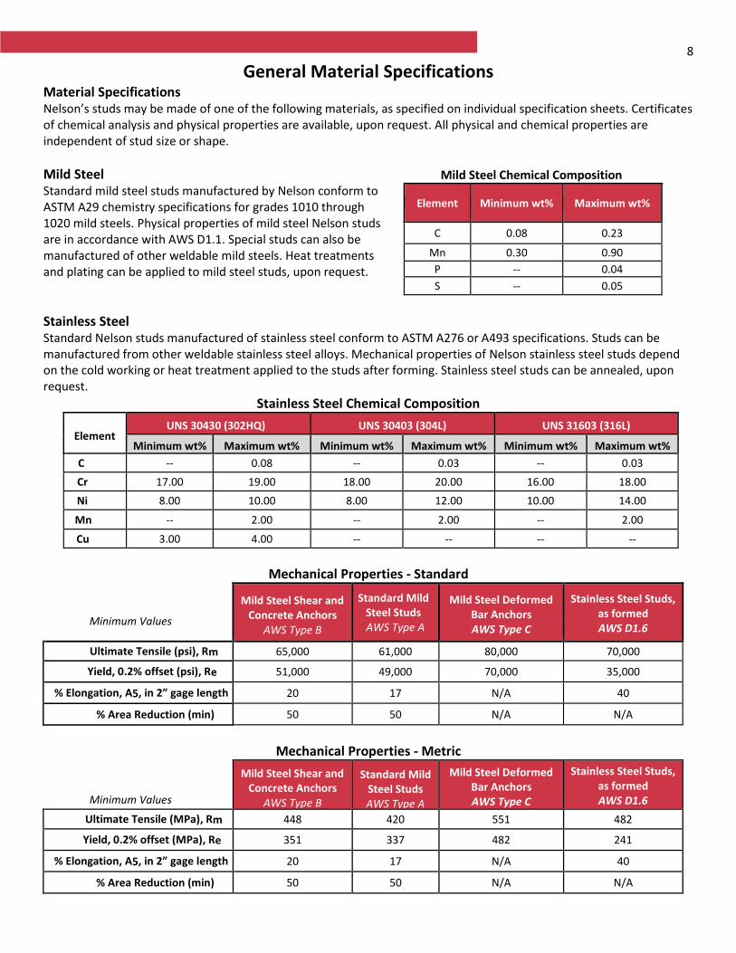
General Material Specifications Material Specifications Nelson’s studs may be made of one of the following materials, as specified on individual specification sheets. Certificates of chemical analysis and physical properties are available, upon request. All physical and chemical properties are independent of stud size or shape.
Mild Steel Standard mild steel studs manufactured by Nelson conform to ASTM A29 chemistry specifications for grades 1010 through 1020 mild steels. Physical properties of mild steel Nelson studs are in accordance with AWS D1.1. Special studs can also be manufactured of other weldable mild steels. Heat treatments and plating can be applied to mild steel studs, upon request.
Stainless Steel Standard Nelson studs manufactured of stainless steel conform to ASTM A276 or A493 specifications. Studs can be manufactured from other weldable stainless steel alloys. Mechanical properties of Nelson stainless steel studs depend on the cold working or heat treatment applied to the studs after forming. Stainless steel studs can be annealed, upon request.
Stainless Steel Chemical Composition
Element UNS 30430 (302HQ) UNS 30403 (304L) UNS 31603 (316L)
Minimum wt% Maximum wt% Minimum wt% Maximum wt% Minimum wt% Maximum wt%
C -- 0.08 -- 0.03 -- 0.03
Cr 17.00 19.00 18.00 20.00 16.00 18.00
Ni 8.00 10.00 8.00 12.00 10.00 14.00
Mn -- 2.00 -- 2.00 -- 2.00
Cu 3.00 4.00 -- -- -- --
Mechanical Properties - Standard
Minimum Values
Mild Steel Shear and Concrete Anchors
AWS Type B
Standard Mild Steel Studs AWS Type A
Mild Steel Deformed Bar Anchors AWS Type C
Stainless Steel Studs, as formed AWS D1.6
Ultimate Tensile (psi), Rm 65,000 61,000 80,000 70,000
Yield, 0.2% offset (psi), Re 51,000 49,000 70,000 35,000
% Elongation, A5, in 2” gage length 20 17 N/A 40
% Area Reduction (min) 50 50 N/A N/A
Mechanical Properties - Metric
Minimum Values
Mild Steel Shear and Concrete Anchors
AWS Type B
Standard Mild Steel Studs AWS Type A
Mild Steel Deformed Bar Anchors AWS Type C
Stainless Steel Studs, as formed AWS D1.6
Ultimate Tensile (MPa), Rm 448 420 551 482
Yield, 0.2% offset (MPa), Re 351 337 482 241
% Elongation, A5, in 2” gage length 20 17 N/A 40
% Area Reduction (min) 50 50 N/A N/A
Mild Steel Chemical Compositioni
Element Minimum wt% Maximum wt%
C 0.08 0.23
Mn 0.30 0.90
P -- 0.04
S -- 0.05
9
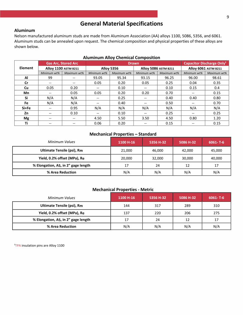
General Material Specifications Aluminum Nelson manufactured aluminum studs are made from Aluminum Association (AA) alloys 1100, 5086, 5356, and 6061. Aluminum studs can be annealed upon request. The chemical composition and physical properties of these alloys are shown below.
Aluminum Alloy Chemical Composition
Element Gas Arc, Stored Arc Drawn Capacitor Discharge Only¹
Alloy 1100 ASTM B211 Alloy 5356 Alloy 5086 ASTM B211 Alloy 6061 ASTM B211 Minimum wt% Maximum wt% Minimum wt% Maximum wt% Minimum wt% Maximum wt% Minimum wt% Maximum wt%
Al 99 -- 93.05 95.34 93.15 96.25 96.00 98.61
Cr -- -- 0.05 0.20 0.05 0.25 0.04 0.35
Cu 0.05 0.20 -- 0.10 -- 0.10 0.15 0.4
Mn -- 0.05 0.05 0.20 0.20 0.70 -- 0.15
Si N/A N/A -- 0.25 -- 0.40 0.40 0.80
Fe N/A N/A -- 0.40 -- 0.50 -- 0.70
Si+Fe -- 0.95 N/A N/A N/A N/A N/A N/A Zn -- 0.10 -- 0.10 -- 0.25 -- 0.25
Mg -- -- 4.50 5.50 3.50 4.50 0.80 1.20
Ti -- -- 0.06 0.20 -- 0.15 -- 0.15
Mechanical Properties – Standard
Minimum Values 1100 H-16 5356 H-32 5086 H-32 6061- T-6
Ultimate Tensile (psi), Rm 21,000 46,000 42,000 45,000
Yield, 0.2% offset (MPa), Re 20,000 32,000 30,000 40,000
% Elongation, A5, in 2” gage length 17 24 12 17
% Area Reduction N/A N/A N/A N/A
Mechanical Properties - Metric
Minimum Values 1100 H-16 5356 H-32 5086 H-32 6061- T-6
Ultimate Tensile (psi), Rm 144 317 289 310
Yield, 0.2% offset (MPa), Re 137 220 206 275
% Elongation, A5, in 2” gage length 17 24 12 17
% Area Reduction N/A N/A N/A N/A
¹TPA insulation pins are Alloy 1100
10
General Stud Specifications
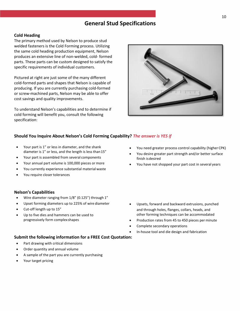
Cold Heading The primary method used by Nelson to produce stud welded fasteners is the Cold Forming process. Utilizing the same cold heading production equipment, Nelson produces an extensive line of non-welded, cold- formed parts. These parts can be custom designed to satisfy the specific requirements of individual customers. Pictured at right are just some of the many different cold-formed parts and shapes that Nelson is capable of producing. If you are currently purchasing cold-formed or screw-machined parts, Nelson may be able to offer cost savings and quality improvements. To understand Nelson’s capabilities and to determine if cold forming will benefit you, consult the following specification:
Should You Inquire About Nelson’s Cold Forming Capability? The answer is YES if Your part is 1” or less in diameter, and the shank
diameter is 1” or less, and the length is less than 15”
Your part is assembled from several components
Your annual part volume is 100,000 pieces or more
You currently experience substantial material waste
You require closer tolerances
You need greater process control capability (higher CPK)
You desire greater part strength and/or better surface finish is desired
You have not shopped your part cost in several years
Nelson’s Capabilities Wire diameter ranging from 1/8” (0.125”) through 1”
Upset forming diameters up to 225% of wire diameter
Cut-off length up to 15”
Up to five dies and hammers can be used to progressively form complex shapes
Upsets, forward and backward extrusions, punched
and through holes, flanges, collars, heads, and other forming techniques can be accommodated
Production rates from 45 to 450 pieces per minute
Complete secondary operations
In-house tool and die design and fabrication
Submit the following information for a FREE Cost Quotation:
Part drawing with critical dimensions
Order quantity and annual volume
A sample of the part you are currently purchasing
Your target pricing
11
General Stud Specifications
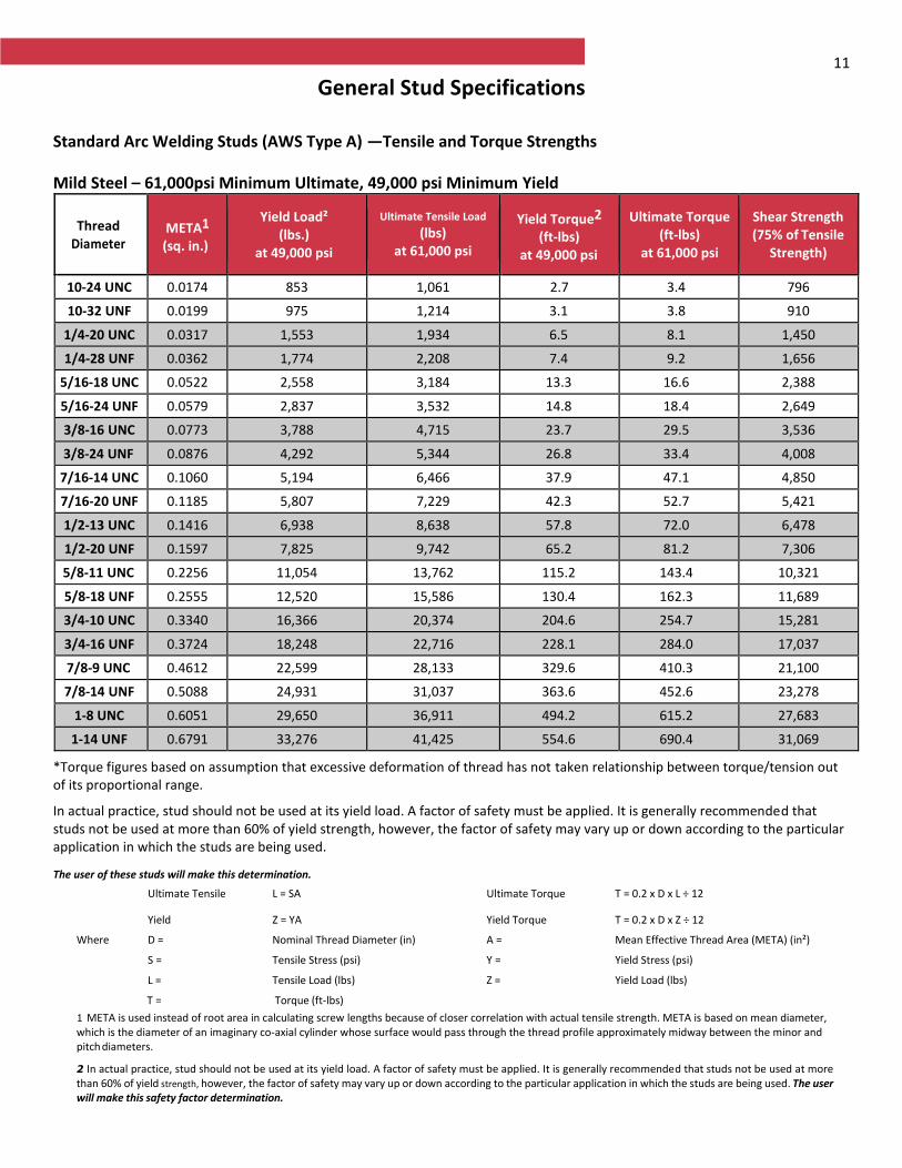
Standard Arc Welding Studs (AWS Type A) —Tensile and Torque Strengths
Mild Steel – 61,000psi Minimum Ultimate, 49,000 psi Minimum Yield
Thread Diameter
META1 (sq. in.)
Yield Load² (lbs.)
at 49,000 psi
Ultimate Tensile Load (lbs)
at 61,000 psi
Yield Torque2
(ft-lbs) at 49,000 psi
Ultimate Torque (ft-lbs)
at 61,000 psi
Shear Strength (75% of Tensile
Strength)
10-24 UNC 0.0174 853 1,061 2.7 3.4 796
10-32 UNF 0.0199 975 1,214 3.1 3.8 910
1/4-20 UNC 0.0317 1,553 1,934 6.5 8.1 1,450
1/4-28 UNF 0.0362 1,774 2,208 7.4 9.2 1,656
5/16-18 UNC 0.0522 2,558 3,184 13.3 16.6 2,388
5/16-24 UNF 0.0579 2,837 3,532 14.8 18.4 2,649
3/8-16 UNC 0.0773 3,788 4,715 23.7 29.5 3,536
3/8-24 UNF 0.0876 4,292 5,344 26.8 33.4 4,008
7/16-14 UNC 0.1060 5,194 6,466 37.9 47.1 4,850
7/16-20 UNF 0.1185 5,807 7,229 42.3 52.7 5,421
1/2-13 UNC 0.1416 6,938 8,638 57.8 72.0 6,478
1/2-20 UNF 0.1597 7,825 9,742 65.2 81.2 7,306
5/8-11 UNC 0.2256 11,054 13,762 115.2 143.4 10,321
5/8-18 UNF 0.2555 12,520 15,586 130.4 162.3 11,689
3/4-10 UNC 0.3340 16,366 20,374 204.6 254.7 15,281
3/4-16 UNF 0.3724 18,248 22,716 228.1 284.0 17,037
7/8-9 UNC 0.4612 22,599 28,133 329.6 410.3 21,100
7/8-14 UNF 0.5088 24,931 31,037 363.6 452.6 23,278
1-8 UNC 0.6051 29,650 36,911 494.2 615.2 27,683
1-14 UNF 0.6791 33,276 41,425 554.6 690.4 31,069
*Torque figures based on assumption that excessive deformation of thread has not taken relationship between torque/tension out of its proportional range.
In actual practice, stud should not be used at its yield load. A factor of safety must be applied. It is generally recommended that studs not be used at more than 60% of yield strength, however, the factor of safety may vary up or down according to the particular application in which the studs are being used.
The user of these studs will make this determination.
Ultimate Tensile L = SA Ultimate Torque T = 0.2 x D x L ÷ 12
Yield Z = YA Yield Torque T = 0.2 x D x Z ÷ 12
Where D = Nominal Thread Diameter (in) A = Mean Effective Thread Area (META) (in²)
S = Tensile Stress (psi) Y = Yield Stress (psi)
L = Tensile Load (lbs) Z = Yield Load (lbs)
T = Torque (ft-lbs)
1 META is used instead of root area in calculating screw lengths because of closer correlation with actual tensile strength. META is based on mean diameter, which is the diameter of an imaginary co-axial cylinder whose surface would pass through the thread profile approximately midway between the minor and pitch diameters.
2 In actual practice, stud should not be used at its yield load. A factor of safety must be applied. It is generally recommended that studs not be used at more than 60% of yield strength, however, the factor of safety may vary up or down according to the particular application in which the studs are being used. The user will make this safety factor determination.
12
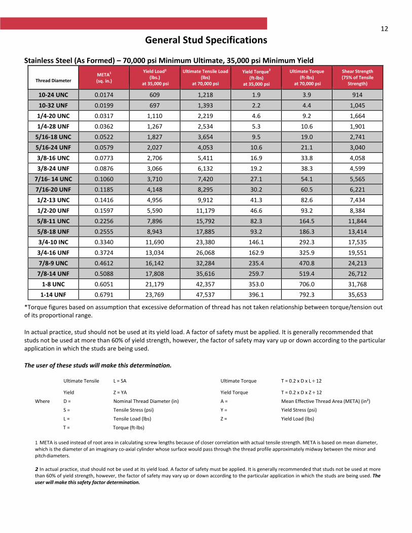
General Stud Specifications
Stainless Steel (As Formed) – 70,000 psi Minimum Ultimate, 35,000 psi Minimum Yield
Thread Diameter
META1
(sq. in.)
Yield Load² (lbs.)
at 35,000 psi
Ultimate Tensile Load (lbs)
at 70,000 psi
Yield Torque2
(ft-lbs) at 35,000 psi
Ultimate Torque (ft-lbs)
at 70,000 psi
Shear Strength (75% of Tensile
Strength)
10-24 UNC 0.0174 609 1,218 1.9 3.9 914
10-32 UNF 0.0199 697 1,393 2.2 4.4 1,045
1/4-20 UNC 0.0317 1,110 2,219 4.6 9.2 1,664
1/4-28 UNF 0.0362 1,267 2,534 5.3 10.6 1,901
5/16-18 UNC 0.0522 1,827 3,654 9.5 19.0 2,741
5/16-24 UNF 0.0579 2,027 4,053 10.6 21.1 3,040
3/8-16 UNC 0.0773 2,706 5,411 16.9 33.8 4,058
3/8-24 UNF 0.0876 3,066 6,132 19.2 38.3 4,599
7/16- 14 UNC 0.1060 3,710 7,420 27.1 54.1 5,565
7/16-20 UNF 0.1185 4,148 8,295 30.2 60.5 6,221
1/2-13 UNC 0.1416 4,956 9,912 41.3 82.6 7,434
1/2-20 UNF 0.1597 5,590 11,179 46.6 93.2 8,384
5/8-11 UNC 0.2256 7,896 15,792 82.3 164.5 11,844
5/8-18 UNF 0.2555 8,943 17,885 93.2 186.3 13,414
3/4-10 INC 0.3340 11,690 23,380 146.1 292.3 17,535
3/4-16 UNF 0.3724 13,034 26,068 162.9 325.9 19,551
7/8-9 UNC 0.4612 16,142 32,284 235.4 470.8 24,213
7/8-14 UNF 0.5088 17,808 35,616 259.7 519.4 26,712
1-8 UNC 0.6051 21,179 42,357 353.0 706.0 31,768
1-14 UNF 0.6791 23,769 47,537 396.1 792.3 35,653
*Torque figures based on assumption that excessive deformation of thread has not taken relationship between torque/tension out of its proportional range.
In actual practice, stud should not be used at its yield load. A factor of safety must be applied. It is generally recommended that studs not be used at more than 60% of yield strength, however, the factor of safety may vary up or down according to the particular application in which the studs are being used.
The user of these studs will make this determination.
Ultimate Tensile L = SA Ultimate Torque T = 0.2 x D x L ÷ 12
Yield Z = YA Yield Torque T = 0.2 x D x Z ÷ 12
Where D = Nominal Thread Diameter (in) A = Mean Effective Thread Area (META) (in²)
S = Tensile Stress (psi) Y = Yield Stress (psi)
L = Tensile Load (lbs) Z = Yield Load (lbs)
T = Torque (ft-lbs)
1 META is used instead of root area in calculating screw lengths because of closer correlation with actual tensile strength. META is based on mean diameter, which is the diameter of an imaginary co-axial cylinder whose surface would pass through the thread profile approximately midway between the minor and pitch diameters.
2 In actual practice, stud should not be used at its yield load. A factor of safety must be applied. It is generally recommended that studs not be used at more than 60% of yield strength, however, the factor of safety may vary up or down according to the particular application in which the studs are being used. The user will make this safety factor determination.
13
General Stud Specifications
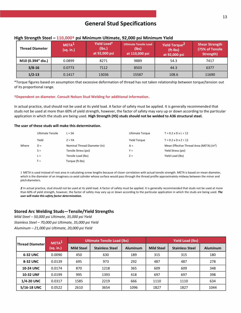
High Strength Steel – 110,000† psi Minimum Ultimate, 92,000 psi Minimum Yield
Thread Diameter META1 (sq. in.)
Yield Load² (lbs.)
at 92,000 psi
Ultimate Tensile Load
(lbs) at 110,000 psi
Yield Torque2
(ft-lbs) at 92,000 psi
Shear Strength (75% of Tensile
Strength)
M10 (0.394” dia.) 0.0899 8271 9889 54.3 7417
3/8-16 0.0773 7112 8503 44.3 6377
1/2-13 0.1417 13036 15587 108.6 11690
*Torque figures based on assumption that excessive deformation of thread has not taken relationship between torque/tension out of its proportional range. †Dependent on diameter. Consult Nelson Stud Welding for additional information. In actual practice, stud should not be used at its yield load. A factor of safety must be applied. It is generally recommended that studs not be used at more than 60% of yield strength, however, the factor of safety may vary up or down according to the particular application in which the studs are being used. High Strength (HS) studs should not be welded to A36 structural steel. The user of these studs will make this determination.
Ultimate Tensile L = SA Ultimate Torque T = 0.2 x D x L ÷ 12
Yield Z = YA Yield Torque T = 0.2 x D x Z ÷ 12
Where D = Nominal Thread Diameter (in) A = Mean Effective Thread Area (META) (in²)
S = Tensile Stress (psi) Y = Yield Stress (psi)
L = Tensile Load (lbs) Z = Yield Load (lbs)
T = Torque (ft-lbs)
1 META is used instead of root area in calculating screw lengths because of closer correlation with actual tensile strength. META is based on mean diameter, which is the diameter of an imaginary co-axial cylinder whose surface would pass through the thread profile approximately midway between the minor and pitch diameters.
2 In actual practice, stud should not be used at its yield load. A factor of safety must be applied. It is generally recommended that studs not be used at more than 60% of yield strength, however, the factor of safety may vary up or down according to the particular application in which the studs are being used. The user will make this safety factor determination.
Stored Arc Welding Studs—Tensile/Yield Strengths Mild Steel – 50,000 psi Ultimate, 35,000 psi Yield
Stainless Steel – 70,000 psi Ultimate, 35,000 psi Yield
Aluminum – 21,000 psi Ultimate, 20,000 psi Yield
Thread Diameter META1 (sq. in.)
Ultimate Tensile Load (lbs) Yield Load (lbs)
Mild Steel Stainless Steel Aluminum Mild Steel Stainless Steel Aluminum
6-32 UNC 0.0090 450 630 189 315 315 180
8-32 UNC 0.0139 695 973 292 487 487 278
10-24 UNC 0.0174 870 1218 365 609 609 348
10-32 UNF 0.0199 995 1393 418 697 697 398
1/4-20 UNC 0.0317 1585 2219 666 1110 1110 634
5/16-18 UNC 0.0522 2610 3654 1096 1827 1827 1044
14
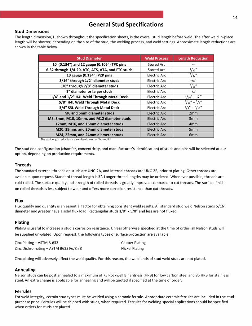
General Stud Specifications Stud Dimensions The length dimension, L, shown throughout the specification sheets, is the overall stud length before weld. The after weld in-place length will be shorter, depending on the size of the stud, the welding process, and weld settings. Approximate length reductions are shown in the table below.
Stud Diameter Weld Process Length Reduction
10 (0.134”) and 12 gauge (0.105”) TPC pins Stored Arc --
6-32 through 1/4-20, ATC, ATS, ATA, and FTC studs Stored Arc 1/32”
10 gauge (0.134”) P2P pins Electric Arc 3/32”
3/16” through 1/2" diameter studs Electric Arc 1/8”
5/8” through 7/8” diameter studs Electric Arc 3/16”
1” diameter or larger studs Electric Arc 1/4"
1/4" and 1/2" H4L Weld Through Metal Deck Electric Arc 3/16” – ¼ ”
5/8” H4L Weld Through Metal Deck Electric Arc 5/16” – 3/8”
3/4" S3L Weld Through Metal Deck Electric Arc 3/8” – 7/16”
M6 and 6mm diameter studs Electric Arc 2mm
M8, 8mm, M10, 10mm, and M12 diameter studs Electric Arc 3mm
12mm, M16, and 16mm diameter studs Electric Arc 4mm
M20, 19mm, and 20mm diameter studs Electric Arc 5mm
M24, 22mm, and 24mm diameter studs Electric Arc 6mm The stud length reduction is also often known as “burn-off.”
The stud end configuration (chamfer, concentricity, and manufacturer’s identification) of studs and pins will be selected at our option, depending on production requirements.
Threads The standard external threads on studs are UNC-2A, and internal threads are UNC-2B, prior to plating. Other threads are
available upon request. Standard thread length is 3”. Longer thread lengths may be ordered. Whenever possible, threads are
cold-rolled. The surface quality and strength of rolled threads is greatly improved compared to cut threads. The surface finish
on rolled threads is less subject to wear and offers more corrosion resistance than cut threads.
Flux Flux quality and quantity is an essential factor for obtaining consistent weld results. All standard stud weld Nelson studs 5/16” diameter and greater have a solid flux load. Rectangular studs 1/8” x 5/8” and less are not fluxed.
Plating Plating is useful to increase a stud’s corrosion resistance. Unless otherwise specified at the time of order, all Nelson studs will
be supplied un-plated. Upon request, the following types of surface protection are available:
Zinc Plating – ASTM B-633 Copper Plating
Zinc Dichromating – ASTM B633 Fe/Zn 8 Nickel Plating
Zinc plating will adversely affect the weld quality. For this reason, the weld ends of stud weld studs are not plated.
Annealing Nelson studs can be post annealed to a maximum of 75 Rockwell B hardness (HRB) for low carbon steel and 85 HRB for stainless steel. An extra charge is applicable for annealing and will be quoted if specified at the time of order.
Ferrules For weld integrity, certain stud types must be welded using a ceramic ferrule. Appropriate ceramic ferrules are included in the stud purchase price. Ferrules will be shipped with studs, when required. Ferrules for welding special applications should be specified when orders for studs are placed.
15
General Stud Specifications Accessories Accessories depend on the stud type, diameter, length, and the ferrule being used, along with any specific fixturing or job conditions or restrictions. For accessory information, please refer to the stud, ferrule, and accessory specifications.
Weld Flash When a stud is end-welded, weld metal forms around its base. The weld flash dimension is controlled by the design of the ferrule used. The diameter of the weld metal is generally larger than the diameter of the stud. Consideration is required in the design of mating parts that involve weld flash. Refer to the appropriate stud specification sheets for recommended weld flash clearance hole diameters.
Ordering Each stud ordered from Nelson Stud Welding should be listed separately along with the appropriate ferrule. The stud style should be specified as well as the length, diameter, material, quantity, and any other information according to the stud specification sheet. Your Nelson representative will be happy to advise you on the accessories required for welding the stud ordered, and is also available to aid in determining the proper stud for your application requirements.
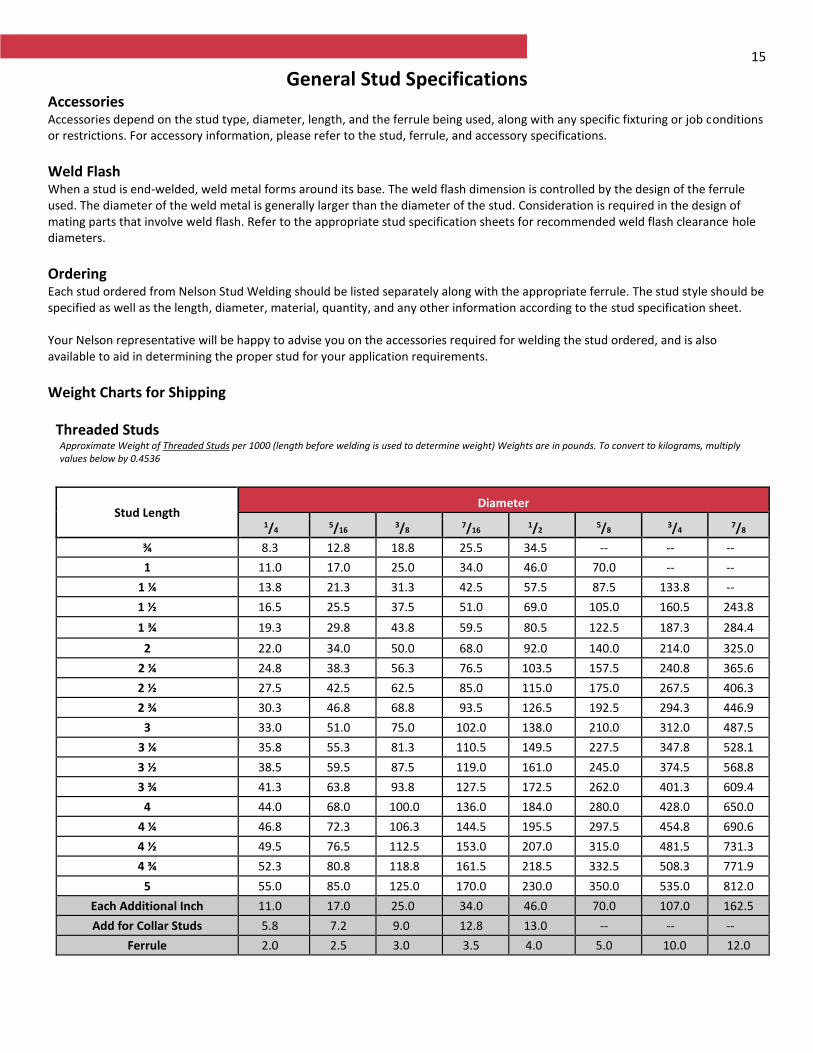
Weight Charts for Shipping
Threaded Studs Approximate Weight of Threaded Studs per 1000 (length before welding is used to determine weight) Weights are in pounds. To convert to kilograms, multiply values below by 0.4536
Stud Length Diameter
1/4 5/16 3/8 7/16 1/2 5/8 3/4 7/8
¾ 8.3 12.8 18.8 25.5 34.5 -- -- --
1 11.0 17.0 25.0 34.0 46.0 70.0 -- --
1 ¼ 13.8 21.3 31.3 42.5 57.5 87.5 133.8 --
1 ½ 16.5 25.5 37.5 51.0 69.0 105.0 160.5 243.8
1 ¾ 19.3 29.8 43.8 59.5 80.5 122.5 187.3 284.4
2 22.0 34.0 50.0 68.0 92.0 140.0 214.0 325.0
2 ¼ 24.8 38.3 56.3 76.5 103.5 157.5 240.8 365.6
2 ½ 27.5 42.5 62.5 85.0 115.0 175.0 267.5 406.3
2 ¾ 30.3 46.8 68.8 93.5 126.5 192.5 294.3 446.9
3 33.0 51.0 75.0 102.0 138.0 210.0 312.0 487.5
3 ¼ 35.8 55.3 81.3 110.5 149.5 227.5 347.8 528.1
3 ½ 38.5 59.5 87.5 119.0 161.0 245.0 374.5 568.8
3 ¾ 41.3 63.8 93.8 127.5 172.5 262.0 401.3 609.4
4 44.0 68.0 100.0 136.0 184.0 280.0 428.0 650.0
4 ¼ 46.8 72.3 106.3 144.5 195.5 297.5 454.8 690.6
4 ½ 49.5 76.5 112.5 153.0 207.0 315.0 481.5 731.3
4 ¾ 52.3 80.8 118.8 161.5 218.5 332.5 508.3 771.9
5 55.0 85.0 125.0 170.0 230.0 350.0 535.0 812.0
Each Additional Inch 11.0 17.0 25.0 34.0 46.0 70.0 107.0 162.5
Add for Collar Studs 5.8 7.2 9.0 12.8 13.0 -- -- --
Ferrule 2.0 2.5 3.0 3.5 4.0 5.0 10.0 12.0
16
General Stud Specifications
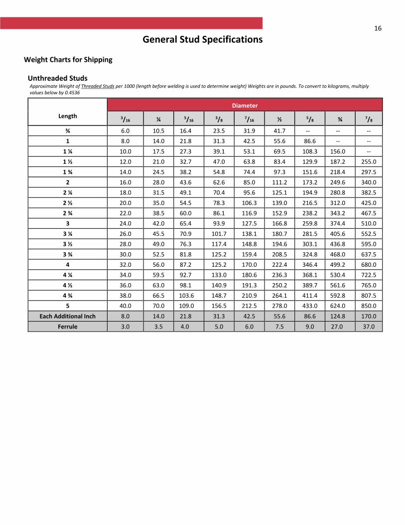
Weight Charts for Shipping
Unthreaded Studs Approximate Weight of Threaded Studs per 1000 (length before welding is used to determine weight) Weights are in pounds. To convert to kilograms, multiply values below by 0.4536
Length
Diameter
3/16 ¼ 5/16 3/8 7/16 ½ 5/8 ¾ 7/8
¾ 6.0 10.5 16.4 23.5 31.9 41.7 -- -- --
1 8.0 14.0 21.8 31.3 42.5 55.6 86.6 -- --
1 ¼ 10.0 17.5 27.3 39.1 53.1 69.5 108.3 156.0 --
1 ½ 12.0 21.0 32.7 47.0 63.8 83.4 129.9 187.2 255.0
1 ¾ 14.0 24.5 38.2 54.8 74.4 97.3 151.6 218.4 297.5
2 16.0 28.0 43.6 62.6 85.0 111.2 173.2 249.6 340.0
2 ¼ 18.0 31.5 49.1 70.4 95.6 125.1 194.9 280.8 382.5
2 ½ 20.0 35.0 54.5 78.3 106.3 139.0 216.5 312.0 425.0
2 ¾ 22.0 38.5 60.0 86.1 116.9 152.9 238.2 343.2 467.5
3 24.0 42.0 65.4 93.9 127.5 166.8 259.8 374.4 510.0
3 ¼ 26.0 45.5 70.9 101.7 138.1 180.7 281.5 405.6 552.5
3 ½ 28.0 49.0 76.3 117.4 148.8 194.6 303.1 436.8 595.0
3 ¾ 30.0 52.5 81.8 125.2 159.4 208.5 324.8 468.0 637.5
4 32.0 56.0 87.2 125.2 170.0 222.4 346.4 499.2 680.0
4 ¼ 34.0 59.5 92.7 133.0 180.6 236.3 368.1 530.4 722.5
4 ½ 36.0 63.0 98.1 140.9 191.3 250.2 389.7 561.6 765.0
4 ¾ 38.0 66.5 103.6 148.7 210.9 264.1 411.4 592.8 807.5
5 40.0 70.0 109.0 156.5 212.5 278.0 433.0 624.0 850.0
Each Additional Inch 8.0 14.0 21.8 31.3 42.5 55.6 86.6 124.8 170.0
Ferrule 3.0 3.5 4.0 5.0 6.0 7.5 9.0 27.0 37.0
17
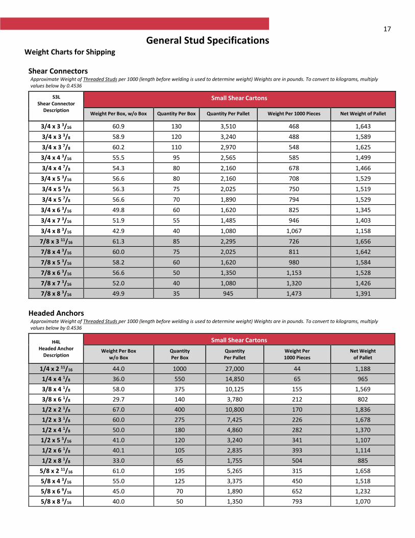
General Stud Specifications Weight Charts for Shipping
Shear Connectors Approximate Weight of Threaded Studs per 1000 (length before welding is used to determine weight) Weights are in pounds. To convert to kilograms, multiply values below by 0.4536
S3L Shear Connector
Description
Small Shear Cartons
Weight Per Box, w/o Box Quantity Per Box Quantity Per Pallet Weight Per 1000 Pieces Net Weight of Pallet
3/4 x 3 3/16 60.9 130 3,510 468 1,643
3/4 x 3 3/8 58.9 120 3,240 488 1,589
3/4 x 3 7/8 60.2 110 2,970 548 1,625
3/4 x 4 3/16 55.5 95 2,565 585 1,499
3/4 x 4 7/8 54.3 80 2,160 678 1,466
3/4 x 5 3/16 56.6 80 2,160 708 1,529
3/4 x 5 3/8 56.3 75 2,025 750 1,519
3/4 x 5 7/8 56.6 70 1,890 794 1,529
3/4 x 6 3/16 49.8 60 1,620 825 1,345
3/4 x 7 3/16 51.9 55 1,485 946 1,403
3/4 x 8 3/16 42.9 40 1,080 1,067 1,158
7/8 x 3 11/16 61.3 85 2,295 726 1,656
7/8 x 4 3/16 60.0 75 2,025 811 1,642
7/8 x 5 3/16 58.2 60 1,620 980 1,584
7/8 x 6 3/16 56.6 50 1,350 1,153 1,528
7/8 x 7 3/16 52.0 40 1,080 1,320 1,426
7/8 x 8 3/16 49.9 35 945 1,473 1,391
Headed Anchors Approximate Weight of Threaded Studs per 1000 (length before welding is used to determine weight) Weights are in pounds. To convert to kilograms, multiply values below by 0.4536
H4L Headed Anchor
Description
Small Shear Cartons
Weight Per Box w/o Box
Quantity Per Box
Quantity Per Pallet
Weight Per 1000 Pieces
Net Weight of Pallet
1/4 x 2 11/16 44.0 1000 27,000 44 1,188
1/4 x 4 1/8 36.0 550 14,850 65 965
3/8 x 4 1/8 58.0 375 10,125 155 1,569
3/8 x 6 1/8 29.7 140 3,780 212 802
1/2 x 2 1/8 67.0 400 10,800 170 1,836
1/2 x 3 1/8 60.0 275 7,425 226 1,678
1/2 x 4 1/8 50.0 180 4,860 282 1,370
1/2 x 5 5/16 41.0 120 3,240 341 1,107
1/2 x 6 1/8 40.1 105 2,835 393 1,114
1/2 x 8 1/8 33.0 65 1,755 504 885
5/8 x 2 11/16 61.0 195 5,265 315 1,658
5/8 x 4 3/16 55.0 125 3,375 450 1,518
5/8 x 6 9/16 45.0 70 1,890 652 1,232
5/8 x 8 3/16 40.0 50 1,350 793 1,070
18
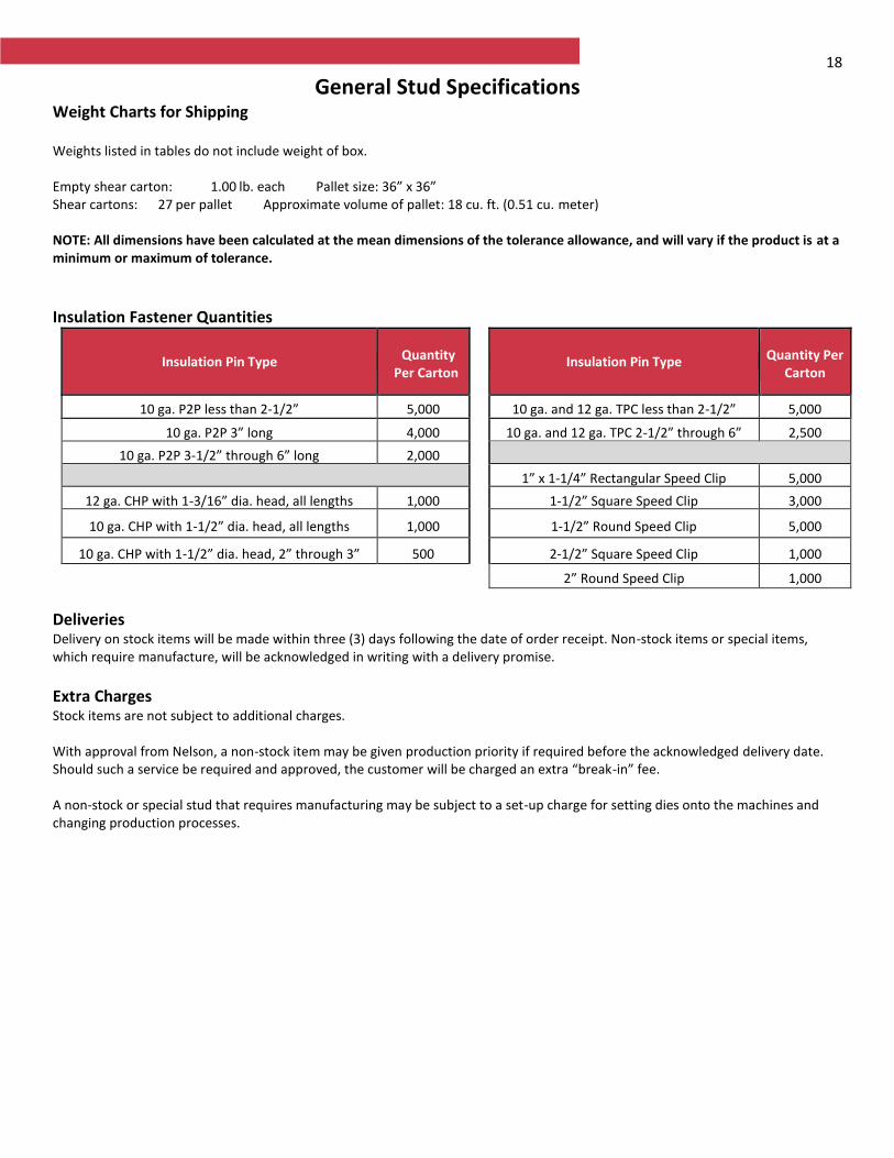
General Stud Specifications Weight Charts for Shipping Weights listed in tables do not include weight of box. Empty shear carton: 1.00 lb. each Pallet size: 36” x 36” Shear cartons: 27 per pallet Approximate volume of pallet: 18 cu. ft. (0.51 cu. meter) NOTE: All dimensions have been calculated at the mean dimensions of the tolerance allowance, and will vary if the product is at a minimum or maximum of tolerance.
Insulation Fastener Quantities
Insulation Pin Type Quantity Per Carton
Insulation Pin Type Quantity Per Carton
10 ga. P2P less than 2-1/2” long
5,000 10 ga. and 12 ga. TPC less than 2-1/2” long
5,000
10 ga. P2P 3” long 4,000 10 ga. and 12 ga. TPC 2-1/2” through 6” long
2,500
10 ga. P2P 3-1/2” through 6” long 2,000
1” x 1-1/4” Rectangular Speed Clip 5,000
12 ga. CHP with 1-3/16” dia. head, all lengths 1,000 1-1/2” Square Speed Clip 3,000
10 ga. CHP with 1-1/2” dia. head, all lengths 1,000 1-1/2” Round Speed Clip 5,000
10 ga. CHP with 1-1/2” dia. head, 2” through 3” long
500 2-1/2” Square Speed Clip 1,000
2” Round Speed Clip 1,000
Deliveries Delivery on stock items will be made within three (3) days following the date of order receipt. Non-stock items or special items, which require manufacture, will be acknowledged in writing with a delivery promise.
Extra Charges Stock items are not subject to additional charges. With approval from Nelson, a non-stock item may be given production priority if required before the acknowledged delivery date. Should such a service be required and approved, the customer will be charged an extra “break-in” fee. A non-stock or special stud that requires manufacturing may be subject to a set-up charge for setting dies onto the machines and changing production processes.
19
Studs Externally Threaded NELSON STUD WELDING SPECIFICATION
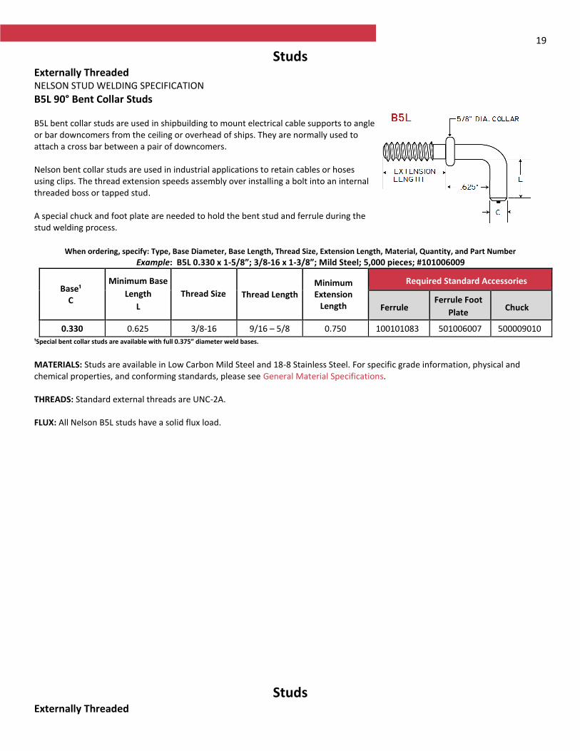
B5L 90° Bent Collar Studs B5L bent collar studs are used in shipbuilding to mount electrical cable supports to angle or bar downcomers from the ceiling or overhead of ships. They are normally used to attach a cross bar between a pair of downcomers. Nelson bent collar studs are used in industrial applications to retain cables or hoses using clips. The thread extension speeds assembly over installing a bolt into an internal threaded boss or tapped stud. A special chuck and foot plate are needed to hold the bent stud and ferrule during the stud welding process.
For similar function studs, see Nelson CKL Collar studs and CPL Partially Threaded studs.
When ordering, specify: Type, Base Diameter, Base Length, Thread Size, Extension Length, Material, Quantity, and Part Number
Example: B5L 0.330 x 1-5/8”; 3/8-16 x 1-3/8”; Mild Steel; 5,000 pieces; #101006009
Base¹ C
Minimum Base
Length
L
Thread Size Thread Length Minimum Extension
Length
Required Standard Accessories
Ferrule Ferrule Foot
Plate Chuck
0.330 0.625 3/8-16 9/16 – 5/8 0.750 100101083 501006007 500009010
¹Special bent collar studs are available with full 0.375” diameter weld bases.
MATERIALS: Studs are available in Low Carbon Mild Steel and 18-8 Stainless Steel. For specific grade information, physical and chemical properties, and conforming standards, please see General Material Specifications. THREADS: Standard external threads are UNC-2A. FLUX: All Nelson B5L studs have a solid flux load.
Studs Externally Threaded
20 NELSON STUD WELDING SPECIFICATION
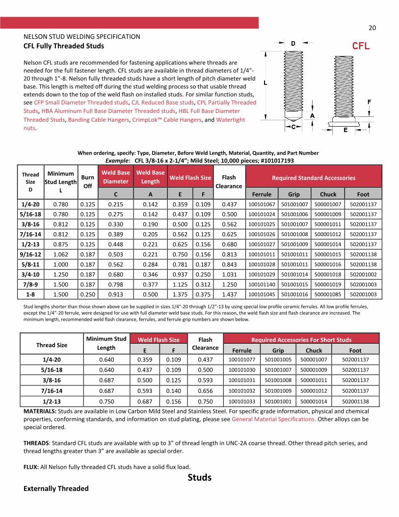
CFL Fully Threaded Studs Nelson CFL studs are recommended for fastening applications where threads are needed for the full fastener length. CFL studs are available in thread diameters of 1/4"- 20 through 1”-8. Nelson fully threaded studs have a short length of pitch diameter weld base. This length is melted off during the stud welding process so that usable thread extends down to the top of the weld flash on installed studs. For similar function studs, see CFP Small Diameter Threaded studs, CJL Reduced Base studs, CPL Partially Threaded
Studs, HBA Aluminum Full Base Diameter Threaded studs, HBL Full Base Diameter
Threaded Studs, Banding Cable Hangers, CrimpLok™ Cable Hangers, and Watertight
nuts.
When ordering, specify: Type, Diameter, Before Weld Length, Material, Quantity, and Part Number
Example: CFL 3/8-16 x 2-1/4”; Mild Steel; 10,000 pieces; #101017193
Thread Size
D
Minimum
Stud Length
L
Burn
Off
Weld Base
Diameter
Weld Base
Length Weld Flash Size Flash
Clearance
Required Standard Accessories
C A E F Ferrule Grip Chuck Foot
1/4-20 0.780 0.125 0.215 0.142 0.359 0.109 0.437 100101067 501001007 500001007 502001137
5/16-18 0.780 0.125 0.275 0.142 0.437 0.109 0.500 100101024 501001006 500001009 502001137
3/8-16 0.812 0.125 0.330 0.190 0.500 0.125 0.562 100101025 501001007 500001011 502001137
7/16-14 0.812 0.125 0.389 0.205 0.562 0.125 0.625 100101026 501001008 500001012 502001137
1/2-13 0.875 0.125 0.448 0.221 0.625 0.156 0.680 100101027 501001009 500001014 502001137
9/16-12 1.062 0.187 0.503 0.221 0.750 0.156 0.813 100101011 501001011 500001015 502001138
5/8-11 1.000 0.187 0.562 0.284 0.781 0.187 0.843 100101028 501001011 500001016 502001138
3/4-10 1.250 0.187 0.680 0.346 0.937 0.250 1.031 100101029 501001014 500001018 502001002
7/8-9 1.500 0.187 0.798 0.377 1.125 0.312 1.250 100101140 501001015 500001019 502001003
1-8 1.500 0.250 0.913 0.500 1.375 0.375 1.437 100101045 501001016 500001085 502001003
Stud lengths shorter than those shown above can be supplied in sizes 1/4"-20 through 1/2"-13 by using special low profile ceramic ferrules. All low profile ferrules, except the 1/4”-20 ferrule, were designed for use with full diameter weld base studs. For this reason, the weld flash size and flash clearance are increased. The minimum length, recommended weld flash clearance, ferrules, and ferrule grip numbers are shown below.
Thread Size Minimum Stud
Length Weld Flash Size Flash
Clearance Required Accessories For Short Studs
E F Ferrule Grip Chuck Foot
1/4-20 0.640 0.359 0.109 0.437 100101077 501001005 500001007 502001137
5/16-18 0.640 0.437 0.109 0.500 100101030 501001007 500001009 502001137
3/8-16 0.687 0.500 0.125 0.593 100101031 501001008 500001011 502001137
7/16-14 0.687 0.593 0.140 0.656 100101032 501001009 500001012 502001137
1/2-13 0.750 0.687 0.156 0.750 100101033 501001001 500001014 502001138
MATERIALS: Studs are available in Low Carbon Mild Steel and Stainless Steel. For specific grade information, physical and chemical properties, conforming standards, and information on stud plating, please see General Material Specifications. Other alloys can be special ordered. THREADS: Standard CFL studs are available with up to 3” of thread length in UNC-2A coarse thread. Other thread pitch series, and thread lengths greater than 3” are available as special order. FLUX: All Nelson fully threaded CFL studs have a solid flux load.
Studs Externally Threaded
21 NELSON STUD WELDING SPECIFICATION
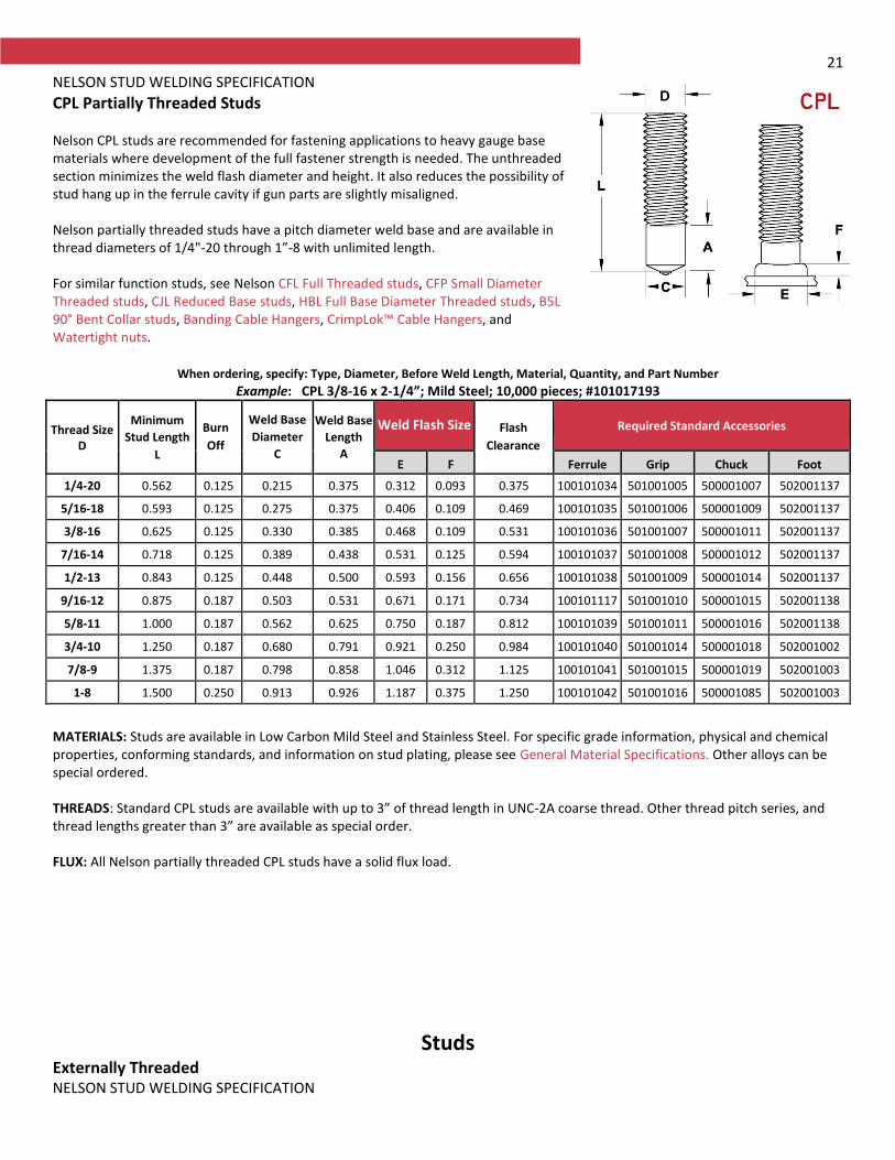
CPL Partially Threaded Studs Nelson CPL studs are recommended for fastening applications to heavy gauge base materials where development of the full fastener strength is needed. The unthreaded section minimizes the weld flash diameter and height. It also reduces the possibility of stud hang up in the ferrule cavity if gun parts are slightly misaligned. Nelson partially threaded studs have a pitch diameter weld base and are available in thread diameters of 1/4"-20 through 1”-8 with unlimited length. For similar function studs, see Nelson CFL Full Threaded studs, CFP Small Diameter Threaded studs, CJL Reduced Base studs, HBL Full Base Diameter Threaded studs, B5L 90° Bent Collar studs, Banding Cable Hangers, CrimpLok™ Cable Hangers, and Watertight nuts.
When ordering, specify: Type, Diameter, Before Weld Length, Material, Quantity, and Part Number
Example: CPL 3/8-16 x 2-1/4”; Mild Steel; 10,000 pieces; #101017193
Thread Size D
Minimum
Stud Length
L
Burn
Off
Weld Base
Diameter
C
Weld Base
Length
A
Weld Flash Size Flash
Clearance
Required Standard Accessories
E F Ferrule Grip Chuck Foot
1/4-20 0.562 0.125 0.215 0.375 0.312 0.093 0.375 100101034 501001005 500001007 502001137
5/16-18 0.593 0.125 0.275 0.375 0.406 0.109 0.469 100101035 501001006 500001009 502001137
3/8-16 0.625 0.125 0.330 0.385 0.468 0.109 0.531 100101036 501001007 500001011 502001137
7/16-14 0.718 0.125 0.389 0.438 0.531 0.125 0.594 100101037 501001008 500001012 502001137
1/2-13 0.843 0.125 0.448 0.500 0.593 0.156 0.656 100101038 501001009 500001014 502001137
9/16-12 0.875 0.187 0.503 0.531 0.671 0.171 0.734 100101117 501001010 500001015 502001138
5/8-11 1.000 0.187 0.562 0.625 0.750 0.187 0.812 100101039 501001011 500001016 502001138
3/4-10 1.250 0.187 0.680 0.791 0.921 0.250 0.984 100101040 501001014 500001018 502001002
7/8-9 1.375 0.187 0.798 0.858 1.046 0.312 1.125 100101041 501001015 500001019 502001003
1-8 1.500 0.250 0.913 0.926 1.187 0.375 1.250 100101042 501001016 500001085 502001003
MATERIALS: Studs are available in Low Carbon Mild Steel and Stainless Steel. For specific grade information, physical and chemical properties, conforming standards, and information on stud plating, please see General Material Specifications. Other alloys can be special ordered. THREADS: Standard CPL studs are available with up to 3” of thread length in UNC-2A coarse thread. Other thread pitch series, and thread lengths greater than 3” are available as special order. FLUX: All Nelson partially threaded CPL studs have a solid flux load.
Studs Externally Threaded NELSON STUD WELDING SPECIFICATION

22
CFP, CPP, FFP, FPP Small Diameter Threaded Studs These Nelson threaded stud welding studs, which are less than 1/4" in diameter, are supplied with ceramic ferrules but without the flux loads used in larger diameter studs. The first letter in the stud type designates the thread series: “C” for coarse threaded studs, “F” for fine threaded studs. The second letter describes the length of the thread or the weld base diameter: “P” for a pitch diameter weld, and “F” for a fully threaded stud. After welding a fully threaded stud, the threads will start at the top of the weld flash. The last letter, “P” indicates that the stud has a pointed weld end as opposed to the flux-loaded weld ends used on larger diameter studs. Flux loaded studs are designated by the letter “L”. For similar function studs, see Nelson CFL Full Threaded studs, CJL Reduced Base studs, CPL Partially Threaded studs, HBA Aluminum Full Base Threaded Studs, and HBL Full Base Diameter Threaded studs.
When ordering, specify: Type, Description, Thread Size, Length, Material, Quantity, and Part Number
Example: CFP #10-24 x 1-1/4”; Mild Steel; 10,000 pieces; #101010492
Thread Size
D
Major Diameter
D
Burn Off
Minimum Length
Weld Flash
Size Weld Flash
Clearance Ferrule
Required Standard Accessories
L E F Chuck Ferrule Grip Foot Assembly
#6-32 0.132 0.062 0.625 0.218 0.093 0.265 10010100 50000100 50100100 50200113
#8-32 0.164 0.062 0.625 0.234 0.093 0.281 10010100 50000100 50100100 50200113
#10-24 0.187 0.062 0.625 0.281 0.093 0.328 10010100 50000100 50100100 50200113
#10-32 0.187 0.062 0.625 0.281 0.093 0.328 10010100 50000100 50100100 50200113
MATERIALS: Studs are available in Low Carbon Mild Steel and 18-8 Stainless Steel. For specific grade information and physical and chemical properties, and conforming standards, please see General Material Specifications. THREADS: Standard external threads are UNC-2A, or UNF-2A for #10-32.
Studs Externally Threaded NELSON STUD WELDING SPECIFICATION
23
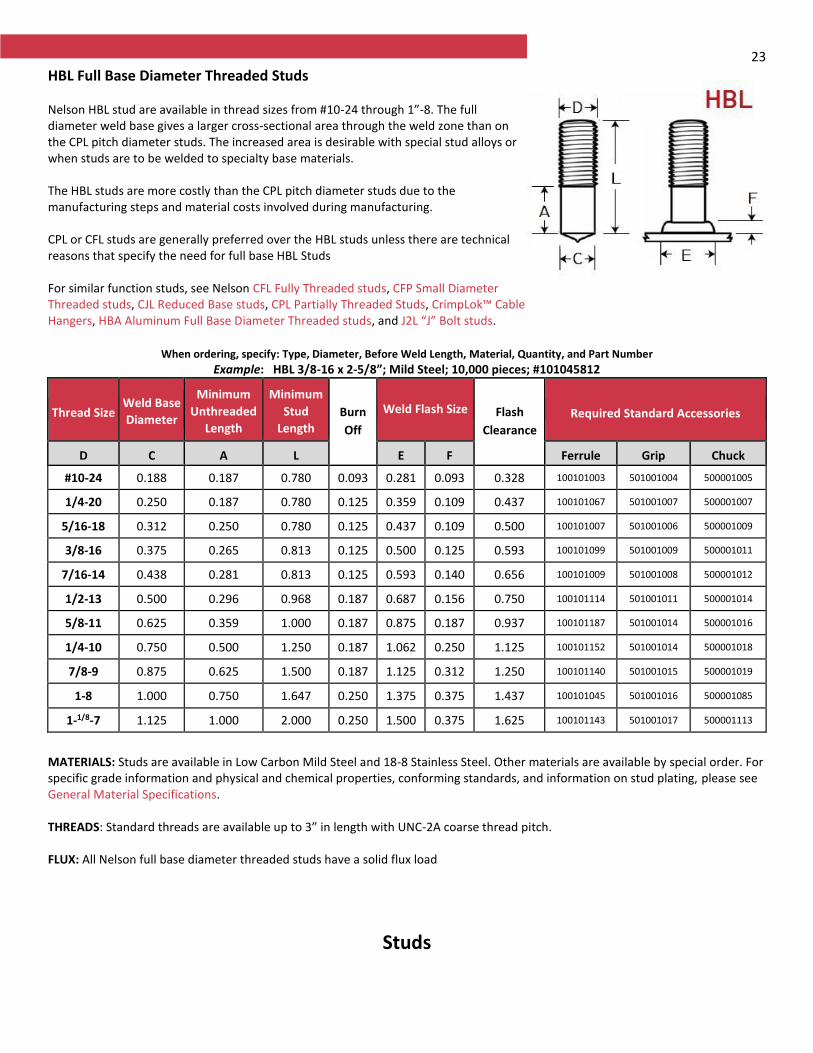
HBL Full Base Diameter Threaded Studs Nelson HBL stud are available in thread sizes from #10-24 through 1”-8. The full diameter weld base gives a larger cross-sectional area through the weld zone than on the CPL pitch diameter studs. The increased area is desirable with special stud alloys or when studs are to be welded to specialty base materials. The HBL studs are more costly than the CPL pitch diameter studs due to the manufacturing steps and material costs involved during manufacturing. CPL or CFL studs are generally preferred over the HBL studs unless there are technical reasons that specify the need for full base HBL Studs For similar function studs, see Nelson CFL Fully Threaded studs, CFP Small Diameter Threaded studs, CJL Reduced Base studs, CPL Partially Threaded Studs, CrimpLok™ Cable Hangers, HBA Aluminum Full Base Diameter Threaded studs, and J2L “J” Bolt studs.
When ordering, specify: Type, Diameter, Before Weld Length, Material, Quantity, and Part Number
Example: HBL 3/8-16 x 2-5/8”; Mild Steel; 10,000 pieces; #101045812
Thread Size Weld Base
Diameter
Minimum
Unthreaded
Length
Minimum
Stud
Length Burn
Off
Weld Flash Size Flash
Clearance
Required Standard Accessories
D C A L E F Ferrule Grip Chuck
#10-24 0.188 0.187 0.780 0.093 0.281 0.093 0.328 100101003 501001004 500001005
1/4-20 0.250 0.187 0.780 0.125 0.359 0.109 0.437 100101067 501001007 500001007
5/16-18 0.312 0.250 0.780 0.125 0.437 0.109 0.500 100101007 501001006 500001009
3/8-16 0.375 0.265 0.813 0.125 0.500 0.125 0.593 100101099 501001009 500001011
7/16-14 0.438 0.281 0.813 0.125 0.593 0.140 0.656 100101009 501001008 500001012
1/2-13 0.500 0.296 0.968 0.187 0.687 0.156 0.750 100101114 501001011 500001014
5/8-11 0.625 0.359 1.000 0.187 0.875 0.187 0.937 100101187 501001014 500001016
1/4-10 0.750 0.500 1.250 0.187 1.062 0.250 1.125 100101152 501001014 500001018
7/8-9 0.875 0.625 1.500 0.187 1.125 0.312 1.250 100101140 501001015 500001019
1-8 1.000 0.750 1.647 0.250 1.375 0.375 1.437 100101045 501001016 500001085
1-1/8-7 1.125 1.000 2.000 0.250 1.500 0.375 1.625 100101143 501001017 500001113
MATERIALS: Studs are available in Low Carbon Mild Steel and 18-8 Stainless Steel. Other materials are available by special order. For specific grade information and physical and chemical properties, conforming standards, and information on stud plating, please see General Material Specifications. THREADS: Standard threads are available up to 3” in length with UNC-2A coarse thread pitch. FLUX: All Nelson full base diameter threaded studs have a solid flux load
Studs
24
Externally Threaded NELSON STUD WELDING SPECIFICATION
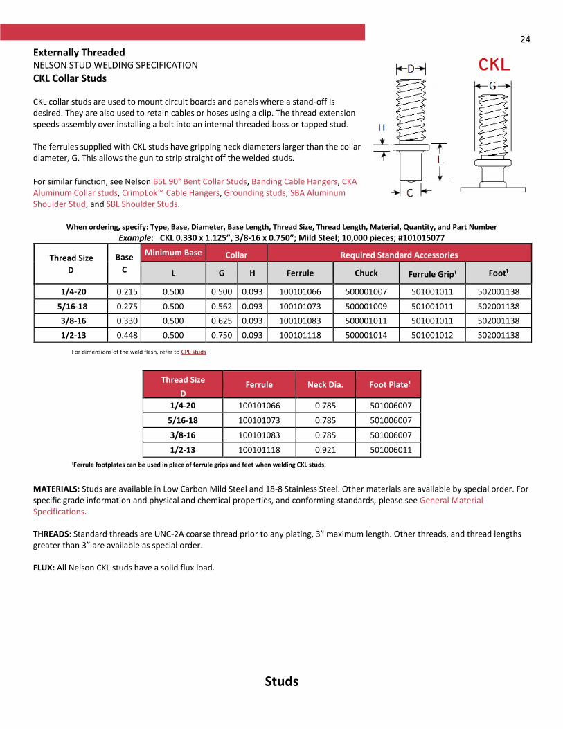
CKL Collar Studs CKL collar studs are used to mount circuit boards and panels where a stand-off is desired. They are also used to retain cables or hoses using a clip. The thread extension speeds assembly over installing a bolt into an internal threaded boss or tapped stud. The ferrules supplied with CKL studs have gripping neck diameters larger than the collar diameter, G. This allows the gun to strip straight off the welded studs. For similar function, see Nelson B5L 90° Bent Collar Studs, Banding Cable Hangers, CKA Aluminum Collar studs, CrimpLok™ Cable Hangers, Grounding studs, SBA Aluminum Shoulder Stud, and SBL Shoulder Studs.
When ordering, specify: Type, Base, Diameter, Base Length, Thread Size, Thread Length, Material, Quantity, and Part Number
Example: CKL 0.330 x 1.125”, 3/8-16 x 0.750”; Mild Steel; 10,000 pieces; #101015077
Thread Size
D
Base
C
Minimum Base
Length Collar Required Standard Accessories
L G H Ferrule Chuck Ferrule Grip¹ Foot¹
1/4-20 0.215 0.500 0.500 0.093 100101066 500001007 501001011 502001138
5/16-18 0.275 0.500 0.562 0.093 100101073 500001009 501001011 502001138
3/8-16 0.330 0.500 0.625 0.093 100101083 500001011 501001011 502001138
1/2-13 0.448 0.500 0.750 0.093 100101118 500001014 501001012 502001138
For dimensions of the weld flash, refer to CPL studs
Thread Size
D Ferrule Neck Dia. Foot Plate¹
1/4-20 100101066 0.785 501006007
5/16-18 100101073 0.785 501006007
3/8-16 100101083 0.785 501006007
1/2-13 100101118 0.921 501006011
¹Ferrule footplates can be used in place of ferrule grips and feet when welding CKL studs.
MATERIALS: Studs are available in Low Carbon Mild Steel and 18-8 Stainless Steel. Other materials are available by special order. For specific grade information and physical and chemical properties, and conforming standards, please see General Material Specifications. THREADS: Standard threads are UNC-2A coarse thread prior to any plating, 3” maximum length. Other threads, and thread lengths greater than 3” are available as special order. FLUX: All Nelson CKL studs have a solid flux load.
Studs
25
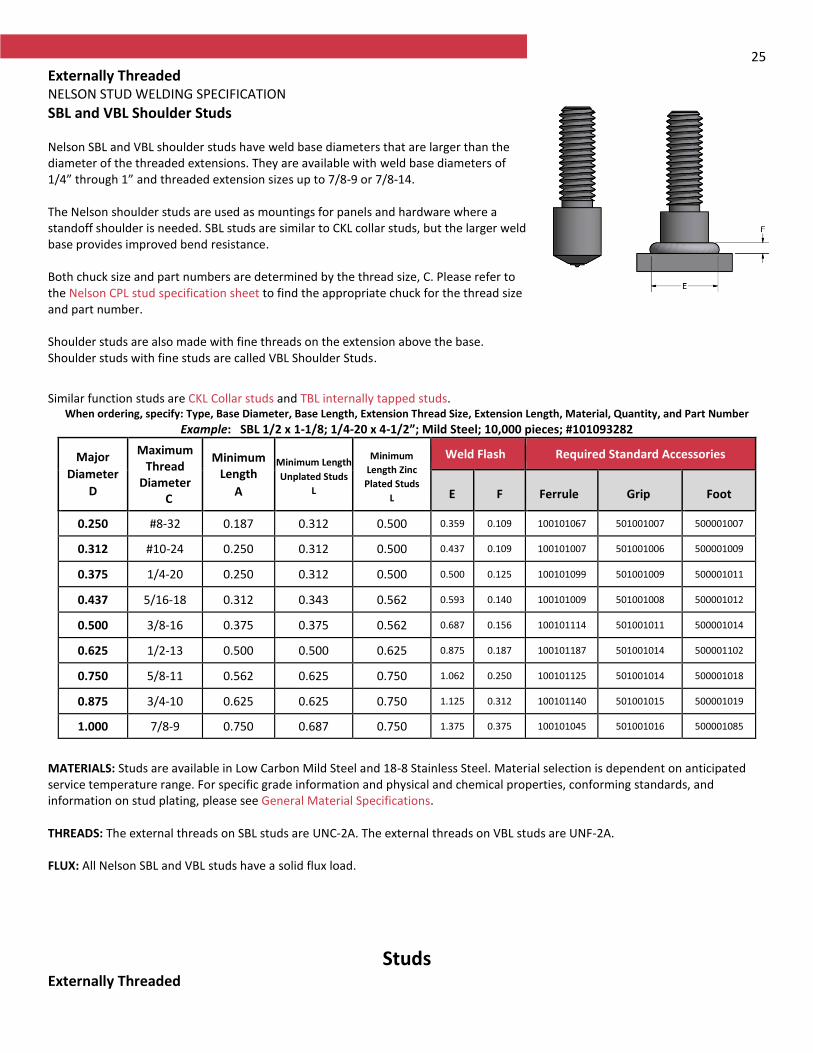
Externally Threaded NELSON STUD WELDING SPECIFICATION
SBL and VBL Shoulder Studs Nelson SBL and VBL shoulder studs have weld base diameters that are larger than the diameter of the threaded extensions. They are available with weld base diameters of 1/4” through 1” and threaded extension sizes up to 7/8-9 or 7/8-14. The Nelson shoulder studs are used as mountings for panels and hardware where a standoff shoulder is needed. SBL studs are similar to CKL collar studs, but the larger weld base provides improved bend resistance. Both chuck size and part numbers are determined by the thread size, C. Please refer to the Nelson CPL stud specification sheet to find the appropriate chuck for the thread size and part number. Shoulder studs are also made with fine threads on the extension above the base. Shoulder studs with fine studs are called VBL Shoulder Studs.
Similar function studs are CKL Collar studs and TBL internally tapped studs.
When ordering, specify: Type, Base Diameter, Base Length, Extension Thread Size, Extension Length, Material, Quantity, and Part Number
Example: SBL 1/2 x 1-1/8; 1/4-20 x 4-1/2”; Mild Steel; 10,000 pieces; #101093282
Major
Diameter
D
Maximum Thread
Diameter C
Minimum Length
A
Minimum Length
Unplated Studs
L
Minimum
Length Zinc
Plated Studs
L
Weld Flash Required Standard Accessories
E F Ferrule Grip Foot
0.250 #8-32 0.187 0.312 0.500 0.359 0.109 100101067 501001007 500001007
0.312 #10-24 0.250 0.312 0.500 0.437 0.109 100101007 501001006 500001009
0.375 1/4-20 0.250 0.312 0.500 0.500 0.125 100101099 501001009 500001011
0.437 5/16-18 0.312 0.343 0.562 0.593 0.140 100101009 501001008 500001012
0.500 3/8-16 0.375 0.375 0.562 0.687 0.156 100101114 501001011 500001014
0.625 1/2-13 0.500 0.500 0.625 0.875 0.187 100101187 501001014 500001102
0.750 5/8-11 0.562 0.625 0.750 1.062 0.250 100101125 501001014 500001018
0.875 3/4-10 0.625 0.625 0.750 1.125 0.312 100101140 501001015 500001019
1.000 7/8-9 0.750 0.687 0.750 1.375 0.375 100101045 501001016 500001085
MATERIALS: Studs are available in Low Carbon Mild Steel and 18-8 Stainless Steel. Material selection is dependent on anticipated service temperature range. For specific grade information and physical and chemical properties, conforming standards, and information on stud plating, please see General Material Specifications. THREADS: The external threads on SBL studs are UNC-2A. The external threads on VBL studs are UNF-2A. FLUX: All Nelson SBL and VBL studs have a solid flux load.
Studs Externally Threaded

26 NELSON STUD WELDING SPECIFICATION
CJL Reduced Base Studs CJL threaded studs have a reduced weld base diameter, C, to produce a smaller weld flash diameter than when Nelson CPL studs weld base are used. The smaller weld flash allows the use of smaller clearance holes. The strength of the assembly is determined by the area of the reduced weld base rather than the thread area.
For similar function studs, see Nelson CFL Fully Threaded studs, CFP Small Diameter
Threaded Studs, CPL Partially Threaded studs, HBA Full Base Diameter Aluminum studs,
and HBL Full Base Diameter studs.
When ordering, specify: Type, Diameter, Before Weld Length, Material, Quantity, and Part Number Example: CJL 1/2-13 x 2-1/4”; Stainless Steel; 10,000 pieces; #10101408
Thread
Size
Minimum
Length L
Weld Base
Diameter
C
Weld Base
Length A
Weld Flash Dimensions
Burn Off
Required Standard Accessories
Diameter
E
Height
F Clearance Diameter
Ferrule Ferrule
Grip Chuck Foot
1/4-20 0.827 0.187 0.187 0.281 0.093 0.328 0.093 100101016 501001005 500001007 502001137
5/16-18 0.827 0.218 0.203 0.343 0.093 0.390 0.093 100101017 501001006 500001009 502001137
3/8-16 0.827 0.275 0.218 0.437 0.109 0.469 0.125 100101018 501001007 500001011 502001137
7/16-14 0.922 0.343 0.250 0.531 0.125 0.546 0.125 100101019 501001008 500001012 502001137
1/2-13 0.922 0.390 0.281 0.548 0.140 0.609 0.125 100101020 501001009 500001014 502001137
5/8-11 0.968 0.500 0.312 0.656 0.156 0.718 0.156 100101021 501001011 500001016 502001138
3/4-10 1.172 0.625 0.343 0.813 0.187 0.875 0.187 100101022 501001014 500001018 502001002
MATERIALS: Studs are available in Low Carbon Mild Steel and Stainless Steel. Other materials are available by special order. For specific grade information and physical and chemical properties, conforming standards, and information on stud plating, please see General Material Specifications. THREADS: Standard threads are UNC-2A coarse thread prior to any plating, 3” maximum length. Other threads, and thread lengths greater than 3” are available as special order. FLUX: All Nelson CJL studs have a solid flux load.
Studs Externally Threaded NELSON STUD WELDING SPECIFICATION
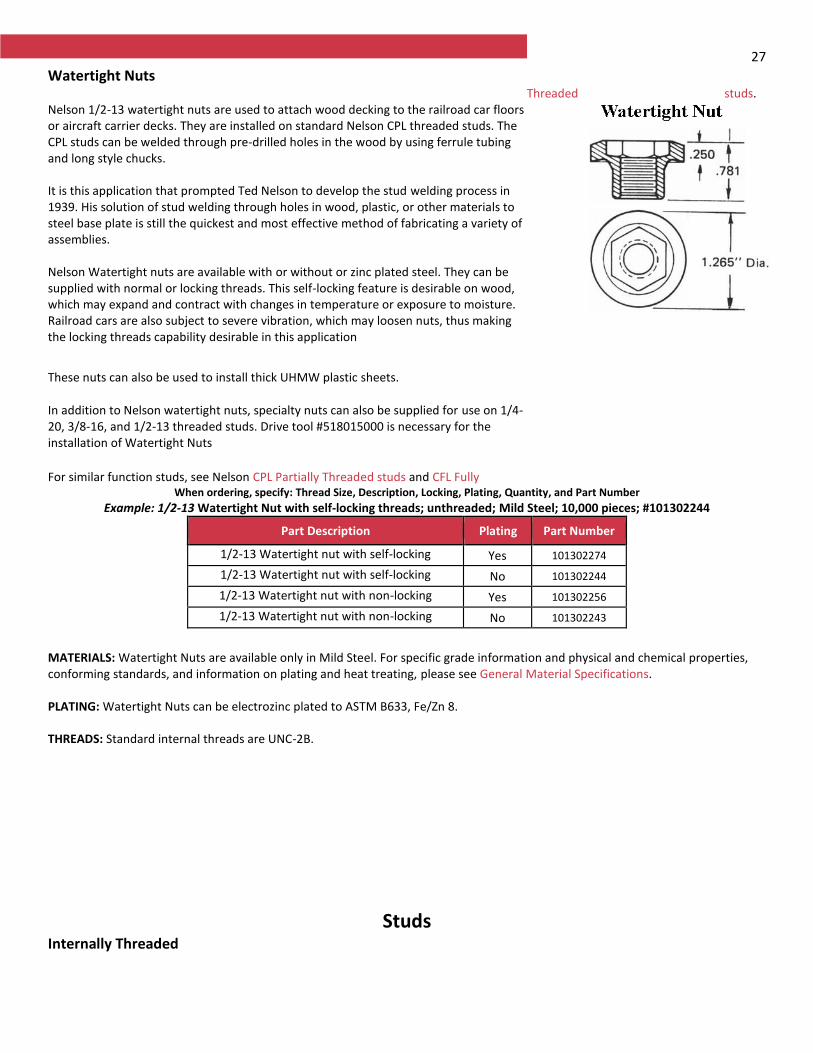
27
Watertight Nuts Nelson 1/2-13 watertight nuts are used to attach wood decking to the railroad car floors or aircraft carrier decks. They are installed on standard Nelson CPL threaded studs. The CPL studs can be welded through pre-drilled holes in the wood by using ferrule tubing and long style chucks. It is this application that prompted Ted Nelson to develop the stud welding process in 1939. His solution of stud welding through holes in wood, plastic, or other materials to steel base plate is still the quickest and most effective method of fabricating a variety of assemblies. Nelson Watertight nuts are available with or without or zinc plated steel. They can be supplied with normal or locking threads. This self-locking feature is desirable on wood, which may expand and contract with changes in temperature or exposure to moisture. Railroad cars are also subject to severe vibration, which may loosen nuts, thus making the locking threads capability desirable in this application
These nuts can also be used to install thick UHMW plastic sheets.
In addition to Nelson watertight nuts, specialty nuts can also be supplied for use on 1/4-20, 3/8-16, and 1/2-13 threaded studs. Drive tool #518015000 is necessary for the installation of Watertight Nuts For similar function studs, see Nelson CPL Partially Threaded studs and CFL Fully
Threaded studs.
When ordering, specify: Thread Size, Description, Locking, Plating, Quantity, and Part Number
Example: 1/2-13 Watertight Nut with self-locking threads; unthreaded; Mild Steel; 10,000 pieces; #101302244
Part Description Plating Part Number
1/2-13 Watertight nut with self-locking thread
Yes 101302274
1/2-13 Watertight nut with self-locking thread
No 101302244
1/2-13 Watertight nut with non-locking thread
Yes 101302256
1/2-13 Watertight nut with non-locking thread
No 101302243
MATERIALS: Watertight Nuts are available only in Mild Steel. For specific grade information and physical and chemical properties, conforming standards, and information on plating and heat treating, please see General Material Specifications. PLATING: Watertight Nuts can be electrozinc plated to ASTM B633, Fe/Zn 8. THREADS: Standard internal threads are UNC-2B.
Studs Internally Threaded
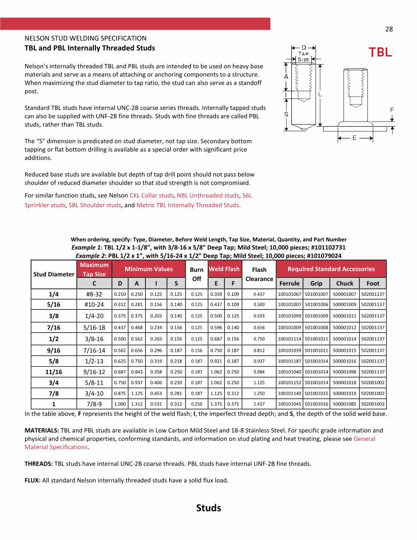
28 NELSON STUD WELDING SPECIFICATION
TBL and PBL Internally Threaded Studs Nelson’s internally threaded TBL and PBL studs are intended to be used on heavy base materials and serve as a means of attaching or anchoring components to a structure. When maximizing the stud diameter to tap ratio, the stud can also serve as a standoff post. Standard TBL studs have internal UNC-2B coarse series threads. Internally tapped studs can also be supplied with UNF-2B fine threads. Studs with fine threads are called PBL studs, rather than TBL studs. The “S” dimension is predicated on stud diameter, not tap size. Secondary bottom tapping or flat bottom drilling is available as a special order with significant price additions. Reduced base studs are available but depth of tap drill point should not pass below shoulder of reduced diameter shoulder so that stud strength is not compromised.
For similar function studs, see Nelson CKL Collar studs, NBL Unthreaded studs, S6L
Sprinkler studs, SBL Shoulder studs, and Metric TBL Internally Threaded Studs.
When ordering, specify: Type, Diameter, Before Weld Length, Tap Size, Material, Quantity, and Part Number
Example 1: TBL 1/2 x 1-1/8”, with 3/8-16 x 5/8” Deep Tap; Mild Steel; 10,000 pieces; #101102731 Example 2: PBL 1/2 x 1”, with 5/16-24 x 1/2” Deep Tap; Mild Steel; 10,000 pieces; #101079024
Stud Diameter
Maximum
Tap Size Minimum Values Burn
Off
Weld Flash Flash
Clearance
Required Standard Accessories
C D A I S E F Ferrule Grip Chuck Foot
1/4 #8-32 0.250 0.250 0.125 0.125 0.125 0.359 0.109 0.437 100101067 501001007 500001007 502001137
5/16 #10-24 0.312 0.281 0.156 0.140 0.125 0.437 0.109 0.500 100101007 501001006 500001009 502001137
3/8 1/4-20 0.375 0.375 0.203 0.140 0.125 0.500 0.125 0.593 100101099 501001009 500001011 502001137
7/16 5/16-18 0.437 0.468 0.234 0.156 0.125 0.596 0.140 0.656 100101009 501001008 500001012 502001137
1/2 3/8-16 0.500 0.562 0.265 0.156 0.125 0.687 0.156 0.750 100101114 501001011 500001014 502001137
9/16 7/16-14 0.562 0.656 0.296 0.187 0.156 0.750 0.187 0.812 100101039 501001011 500001015 502001137
5/8 1/2-13 0.625 0.750 0.319 0.218 0.187 0.921 0.187 0.937 100101187 501001014 500001016 502001137
11/16 9/16-12 0.687 0.843 0.358 0.250 0.187 1.062 0.250 0.984 100101040 501001014 500001098 502001137
3/4 5/8-11 0.750 0.937 0.406 0.250 0.187 1.062 0.250 1.125 100101152 501001014 500001018 502001002
7/8 3/4-10 0.875 1.125 0.453 0.281 0.187 1.125 0.312 1.250 100101140 501001015 500001019 502001002
1 7/8-9 1.000 1.312 0.531 0.312 0.250 1.375 0.375 1.437 100101045 501001016 500001085 502001002
In the table above, F represents the height of the weld flash; I, the imperfect thread depth; and S, the depth of the solid weld base. MATERIALS: TBL and PBL studs are available in Low Carbon Mild Steel and 18-8 Stainless Steel. For specific grade information and physical and chemical properties, conforming standards, and information on stud plating and heat treating, please see General Material Specifications. THREADS: TBL studs have internal UNC-2B coarse threads. PBL studs have internal UNF-2B fine threads. FLUX: All standard Nelson internally threaded studs have a solid flux load.
Studs
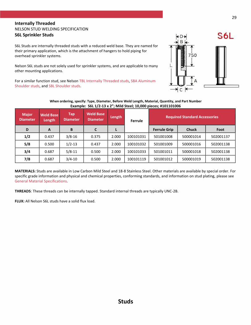
29
Internally Threaded NELSON STUD WELDING SPECIFICATION
S6L Sprinkler Studs S6L Studs are internally threaded studs with a reduced weld base. They are named for their primary application, which is the attachment of hangers to hold piping for overhead sprinkler systems. Nelson S6L studs are not solely used for sprinkler systems, and are applicable to many other mounting applications. For a similar function stud, see Nelson TBL Internally Threaded studs, SBA Aluminum Shoulder studs, and SBL Shoulder studs.
When ordering, specify: Type, Diameter, Before Weld Length, Material, Quantity, and Part Number
Example: S6L 1/2-13 x 2”; Mild Steel; 10,000 pieces; #101101006
Major Diameter
Weld Base Length
Tap
Diameter
Weld Base
Diameter Length
Ferrule Required Standard Accessories
D A B C L Ferrule Grip Chuck Foot
1/2 0.437 3/8-16 0.375 2.000 100101031 501001008 500001014 502001137
5/8 0.500 1/2-13 0.437 2.000 100101032 501001009 500001016 502001138
3/4 0.687 5/8-11 0.500 2.000 100101033 501001011 500001018 502001138
7/8 0.687 3/4-10 0.500 2.000 100101119 501001012 500001019 502001138
MATERIALS: Studs are available in Low Carbon Mild Steel and 18-8 Stainless Steel. Other materials are available by special order. For specific grade information and physical and chemical properties, conforming standards, and information on stud plating, please see General Material Specifications. THREADS: These threads can be internally tapped. Standard internal threads are typically UNC-2B. FLUX: All Nelson S6L studs have a solid flux load.
Studs
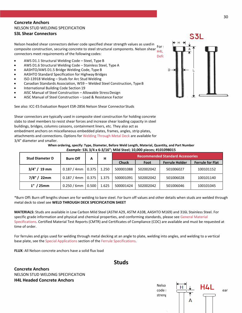
30
Concrete Anchors NELSON STUD WELDING SPECIFICATION
S3L Shear Connectors Nelson headed shear connectors deliver code specified shear strength values as used in composite construction, securing concrete to steel structural components. Nelson shear connectors meet requirements of the following codes:
AWS D1.1 Structural Welding Code – Steel, Type B AWS D1.6 Structural Welding Code – Stainless Steel, Type A AASHTO/AWS D1.5 Bridge Welding Code, Type B AASHTO Standard Specification for Highway Bridges ISO-13918 Welding – Studs for Arc Stud Welding Canadian Standards Association, W59 – Welded Steel Construction, Type B International Building Code Section 19 AISC Manual of Steel Construction – Allowable Stress Design AISC Manual of Steel Construction – Load & Resistance Factor See also: ICC-ES Evaluation Report ESR-2856 Nelson Shear Connector Studs Shear connectors are typically used in composite steel construction for holding concrete slabs to steel members to resist shear forces and increase shear loading capacity in steel buildings, bridges, columns caissons, containment liners, etc. They also act as embedment anchors on miscellaneous embedded plates, frames, angles, strip plates, attachments and connections. Options for Welding Through Metal Deck are available for 3/4” diameter and smaller.
For similar function studs, see Nelson H4L Headed Concrete Anchors and D2L Deformed Bar Anchors.
When ordering, specify: Type, Diameter, Before Weld Length, Material, Quantity, and Part Number
Example: S3L 3/4 x 6-3/16”; Mild Steel; 10,000 pieces; #101098015
Stud Diameter D Burn Off A H Recommended Standard Accessories
Chuck Foot Ferrule Holder Ferrule for Flat
3/4" / 19 mm 0.187 / 4mm 0.375 1.250 500001088 502002042 501006027 100101152
7/8” / 22mm 0.187 / 4mm 0.375 1.375 500001091 502002042 501006028 100101140
1” / 25mm 0.250 / 6mm 0.500 1.625 500001424 502002042 501006046 100101045
*Burn Off: Burn off lengths shown are for welding to bare steel. For burn off values and other details when studs are welded through metal deck to steel see WELD THROUGH DECK SPECIFICATION SHEET MATERIALS: Studs are available in Low Carbon Mild Steel (ASTM A29, ASTM A108, AASHTO M169) and 316L Stainless Steel. For specific grade information and physical and chemical properties, and conforming standards, please see General Material Specifications. Certified Material Test Reports (CMTR) and Certificates of Compliance (COC) are available and must be requested at time of order. For ferrules and grips used for welding through metal decking at an angle to plate, welding into angles, and welding to a vertical base plate, see the Special Applications section of the Ferrule Specifications. FLUX: All Nelson concrete anchors have a solid flux load
Studs Concrete Anchors NELSON STUD WELDING SPECIFICATION
H4L Headed Concrete Anchors Nelson headed concrete anchors deliver
code specified embedded tension and shear strength values between steel and

31 concrete. These anchors meet requirements of the following codes:
AWS D1.1 Structural Welding Code – Steel, Type B AWS D1.6 Structural Welding Code – Stainless Steel, Type A AASHTO/AWS D1.5 Bridge Welding Code ISO-13918 Welding – Studs for Arc Stud Welding Canadian Standards Association, W59 – Welded Steel Construction, Type B International Building Code Section 19 See also: ICC-ES Evaluation Report ESR-2856 Nelson Shear Connectors Headed anchors are widely used in precast, cast-in-place or composite steel construction for miscellaneous embedded plates, frames, curbing, attachments and connections.
For similar function studs, see Nelson S3L Shear Connectors and D2L Deformed Bar Anchors.
When ordering, specify: Type, Diameter, Before Weld Length, Material, Quantity, and Part Number
Example: H4L 1/2 x 4-1/8”; Mild Steel; 5000 pieces; #101053003
Stud Diameter D Burn Off A H Ferrule to
Flat
Required Standard Accessories
Chuck Foot* Grip for Flat
1/4 / 6 mm 0.125 3 mm
0.187 0.500 100101067 500001014 502002001 501003007
3/8 / 10 mm 0.125 3 mm
0.281 0.750 100101099 500001018 502002001 501003009
1/2 / 13 mm 0.125 3 mm
0.312 1.000 100101114 500001085 502002002 501003010
5/8 / 16 mm 0.187 4 mm
0.312 1.250 100101187 500001088 502002002 501003014
*Feet 502002001 and 502002002 are used with Nelson’s heavy duty gun. Feet 502002045 and 502002046 are used with Nelson’s standard duty gun. MATERIALS: Studs are available in Low Carbon Mild Steel and 316L Stainless Steel. For specific grade information and physical and chemical properties, and conforming standards, please see General Material Specifications. Certified Material Test Reports (CMTR) and Certificates of Compliance (COC) are available and must be requested at time of order. For ferrules and grips used in welding at an angle to plate, welding to angles, and welding to a vertical base plate, see the Special Applications section of the Ferrule Specifications. FLUX: All Nelson concrete anchors have a solid flux load.
Studs
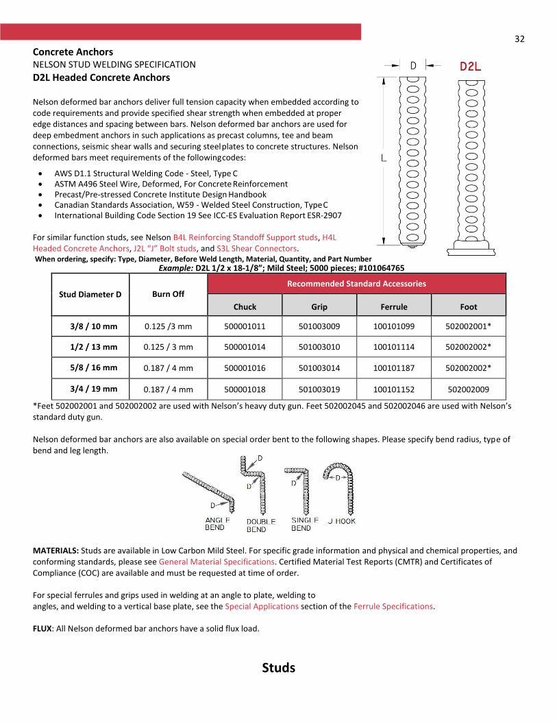
32
Concrete Anchors NELSON STUD WELDING SPECIFICATION
D2L Headed Concrete Anchors Nelson deformed bar anchors deliver full tension capacity when embedded according to code requirements and provide specified shear strength when embedded at proper edge distances and spacing between bars. Nelson deformed bar anchors are used for deep embedment anchors in such applications as precast columns, tee and beam connections, seismic shear walls and securing steel plates to concrete structures. Nelson deformed bars meet requirements of the following codes:
AWS D1.1 Structural Welding Code - Steel, Type C ASTM A496 Steel Wire, Deformed, For Concrete Reinforcement Precast/Pre-stressed Concrete Institute Design Handbook Canadian Standards Association, W59 - Welded Steel Construction, Type C International Building Code Section 19 See ICC-ES Evaluation Report ESR-2907
For similar function studs, see Nelson B4L Reinforcing Standoff Support studs, H4L Headed Concrete Anchors, J2L “J” Bolt studs, and S3L Shear Connectors.
When ordering, specify: Type, Diameter, Before Weld Length, Material, Quantity, and Part Number Example: D2L 1/2 x 18-1/8”; Mild Steel; 5000 pieces; #101064765
Stud Diameter D Burn Off Recommended Standard Accessories
Chuck Grip Ferrule Foot
3/8 / 10 mm 0.125 /3 mm 500001011 501003009 100101099 502002001*
1/2 / 13 mm 0.125 / 3 mm 500001014 501003010 100101114 502002002*
5/8 / 16 mm 0.187 / 4 mm 500001016 501003014 100101187 502002002*
3/4 / 19 mm 0.187 / 4 mm 500001018 501003019 100101152 502002009
*Feet 502002001 and 502002002 are used with Nelson’s heavy duty gun. Feet 502002045 and 502002046 are used with Nelson’s standard duty gun. Nelson deformed bar anchors are also available on special order bent to the following shapes. Please specify bend radius, type of bend and leg length. MATERIALS: Studs are available in Low Carbon Mild Steel. For specific grade information and physical and chemical properties, and conforming standards, please see General Material Specifications. Certified Material Test Reports (CMTR) and Certificates of Compliance (COC) are available and must be requested at time of order. For special ferrules and grips used in welding at an angle to plate, welding to angles, and welding to a vertical base plate, see the Special Applications section of the Ferrule Specifications. FLUX: All Nelson deformed bar anchors have a solid flux load.
Studs
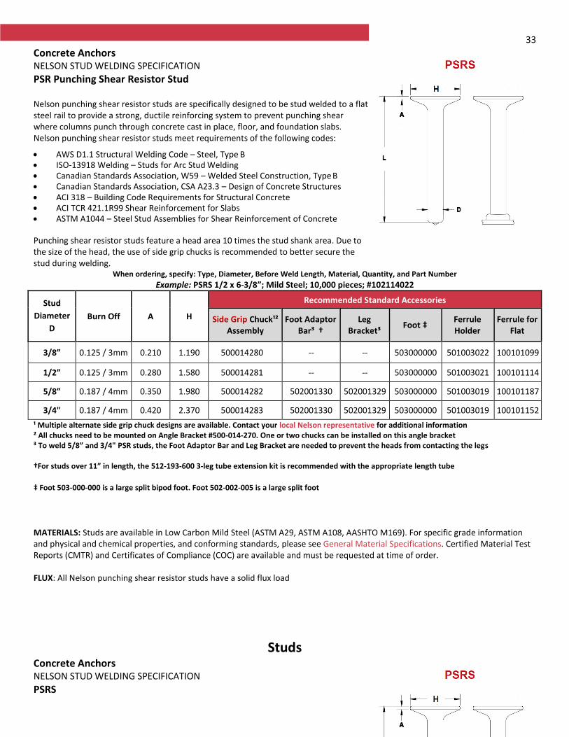
33
Concrete Anchors NELSON STUD WELDING SPECIFICATION
PSR Punching Shear Resistor Stud Nelson punching shear resistor studs are specifically designed to be stud welded to a flat steel rail to provide a strong, ductile reinforcing system to prevent punching shear where columns punch through concrete cast in place, floor, and foundation slabs. Nelson punching shear resistor studs meet requirements of the following codes:
AWS D1.1 Structural Welding Code – Steel, Type B ISO-13918 Welding – Studs for Arc Stud Welding Canadian Standards Association, W59 – Welded Steel Construction, Type B Canadian Standards Association, CSA A23.3 – Design of Concrete Structures ACI 318 – Building Code Requirements for Structural Concrete ACI TCR 421.1R99 Shear Reinforcement for Slabs ASTM A1044 – Steel Stud Assemblies for Shear Reinforcement of Concrete Punching shear resistor studs feature a head area 10 times the stud shank area. Due to the size of the head, the use of side grip chucks is recommended to better secure the stud during welding.
For similar function studs, see Nelson H4L Headed Concrete Anchors, S3L Shear Connectors, D2L Deformed Bar Anchors.
When ordering, specify: Type, Diameter, Before Weld Length, Material, Quantity, and Part Number
Example: PSRS 1/2 x 6-3/8”; Mild Steel; 10,000 pieces; #102114022
Stud
Diameter
D
Burn Off A H
Recommended Standard Accessories
Side Grip Chuck¹² Assembly
Foot Adaptor Bar³ †
Leg Bracket³
Foot ‡ Ferrule Holder
Ferrule for Flat
3/8” 0.125 / 3mm 0.210 1.190 500014280 -- -- 503000000 501003022 100101099
1/2” 0.125 / 3mm 0.280 1.580 500014281 -- -- 503000000 501003021 100101114
5/8” 0.187 / 4mm 0.350 1.980 500014282 502001330 502001329 503000000 501003019 100101187
3/4" 0.187 / 4mm 0.420 2.370 500014283 502001330 502001329 503000000 501003019 100101152
¹ Multiple alternate side grip chuck designs are available. Contact your local Nelson representative for additional information ² All chucks need to be mounted on Angle Bracket #500-014-270. One or two chucks can be installed on this angle bracket ³ To weld 5/8” and 3/4" PSR studs, the Foot Adaptor Bar and Leg Bracket are needed to prevent the heads from contacting the legs †For studs over 11” in length, the 512-193-600 3-leg tube extension kit is recommended with the appropriate length tube
‡ Foot 503-000-000 is a large split bipod foot. Foot 502-002-005 is a large split foot
MATERIALS: Studs are available in Low Carbon Mild Steel (ASTM A29, ASTM A108, AASHTO M169). For specific grade information and physical and chemical properties, and conforming standards, please see General Material Specifications. Certified Material Test Reports (CMTR) and Certificates of Compliance (COC) are available and must be requested at time of order. FLUX: All Nelson punching shear resistor studs have a solid flux load
Studs Concrete Anchors NELSON STUD WELDING SPECIFICATION
PSRS

34 Nelson punching shear resistor studs are specifically designed to be stud welded to a flat steel rail to provide a strong, ductile reinforcing system to prevent punching shear where columns punch through concrete cast in place, floor, and foundation slabs. Nelson punching shear resistor studs meet requirements of the following codes:
AWS D1.1 Structural Welding Code – Steel, Type B ISO-13918 Welding – Studs for Arc Stud Welding Canadian Standards Association, W59 – Welded Steel Construction, Type B Canadian Standards Association, CSA A23.3 – Design of Concrete Structures ACI 318 – Building Code Requirements for Structural Concrete ACI TCR 421.1R99 Shear Reinforcement for Slabs ASTM A1044 – Steel Stud Assemblies for Shear Reinforcement of Concrete Punching shear resistor studs feature a head area 10 times the stud shank area. Due to the size of the head, the use of side grip chucks is recommended to better secure the stud during welding.
For similar function studs, see Nelson H4L Headed Concrete Anchors, S3L Shear Connectors, D2L Deformed Bar Anchors.
When ordering, specify: Type, Diameter, Before Weld Length, Material, Quantity, and Part Number
Example: PSRS 1/2 x 6-3/8”; Mild Steel; 10,000 pieces; #102114022
Stud
Diameter
D
Burn Off A H
Recommended Standard Accessories
Side Grip Chuck¹² Assembly
Foot Adaptor Bar³ †
Leg Bracket³
Foot ‡ Ferrule Holder
Ferrule for Flat
3/8” 0.125 / 3mm 0.210 1.190 500014280 -- -- 503000000 501003022 100101099
1/2” 0.125 / 3mm 0.280 1.580 500014281 -- -- 503000000 501003021 100101114
5/8” 0.187 / 4mm 0.350 1.980 500014282 502001330 502001329 503000000 501003019 100101187
3/4" 0.187 / 4mm 0.420 2.370 500014283 502001330 502001329 503000000 501003019 100101152
¹ Multiple alternate side grip chuck designs are available. Contact your local Nelson representative for additional information ² All chucks need to be mounted on Angle Bracket #500-014-270. One or two chucks can be installed on this angle bracket ³ To weld 5/8” and 3/4" PSR studs, the Foot Adaptor Bar and Leg Bracket are needed to prevent the heads from contacting the legs †For studs over 11” in length, the 512-193-600 3-leg tube extension kit is recommended with the appropriate length tube
‡ Foot 503-000-000 is a large split bipod foot. Foot 502-002-005 is a large split foot
MATERIALS: Studs are available in Low Carbon Mild Steel (ASTM A29, ASTM A108, AASHTO M169). For specific grade information and physical and chemical properties, and conforming standards, please see General Material Specifications. Certified Material Test Reports (CMTR) and Certificates of Compliance (COC) are available and must be requested at time of order.
FLUX: All Nelson punching shear resistor studs have a solid flux load
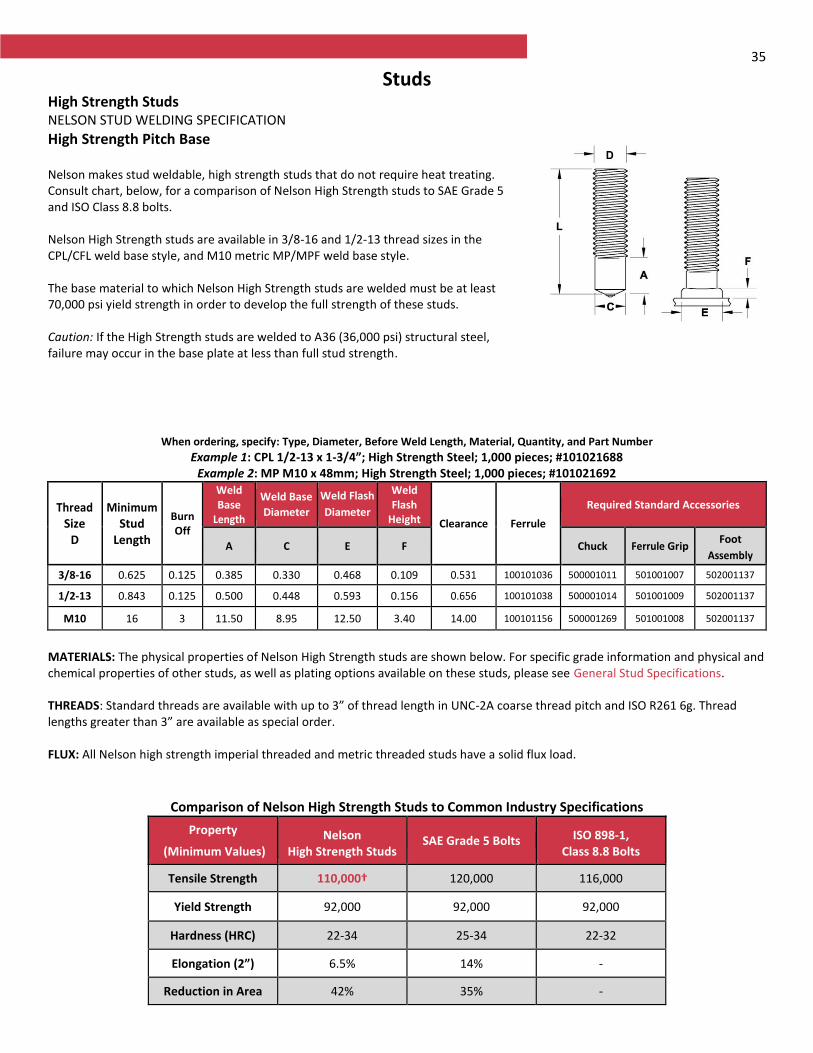
35
Studs High Strength Studs NELSON STUD WELDING SPECIFICATION
High Strength Pitch Base Nelson makes stud weldable, high strength studs that do not require heat treating. Consult chart, below, for a comparison of Nelson High Strength studs to SAE Grade 5 and ISO Class 8.8 bolts. Nelson High Strength studs are available in 3/8-16 and 1/2-13 thread sizes in the CPL/CFL weld base style, and M10 metric MP/MPF weld base style. The base material to which Nelson High Strength studs are welded must be at least 70,000 psi yield strength in order to develop the full strength of these studs. Caution: If the High Strength studs are welded to A36 (36,000 psi) structural steel, failure may occur in the base plate at less than full stud strength.
When ordering, specify: Type, Diameter, Before Weld Length, Material, Quantity, and Part Number
Example 1: CPL 1/2-13 x 1-3/4”; High Strength Steel; 1,000 pieces; #101021688 Example 2: MP M10 x 48mm; High Strength Steel; 1,000 pieces; #101021692
Thread Size
D
Minimum Stud
Length
Burn Off
Weld Base
Length
Weld Base
Diameter
Weld Flash
Diameter
Weld Flash
Height Clearance Ferrule
Required Standard Accessories
A C E F Chuck Ferrule Grip Foot
Assembly
3/8-16 0.625 0.125 0.385 0.330 0.468 0.109 0.531 100101036 500001011 501001007 502001137
1/2-13 0.843 0.125 0.500 0.448 0.593 0.156 0.656 100101038 500001014 501001009 502001137
M10 16 3 11.50 8.95 12.50 3.40 14.00 100101156 500001269 501001008 502001137
MATERIALS: The physical properties of Nelson High Strength studs are shown below. For specific grade information and physical and chemical properties of other studs, as well as plating options available on these studs, please see General Stud Specifications. THREADS: Standard threads are available with up to 3” of thread length in UNC-2A coarse thread pitch and ISO R261 6g. Thread lengths greater than 3” are available as special order. FLUX: All Nelson high strength imperial threaded and metric threaded studs have a solid flux load.
Comparison of Nelson High Strength Studs to Common Industry Specifications
Property
(Minimum Values) Nelson
High Strength Studs SAE Grade 5 Bolts ISO 898-1,
Class 8.8 Bolts
Tensile Strength 110,000† 120,000 116,000
Yield Strength 92,000 92,000 92,000
Hardness (HRC) 22-34 25-34 22-32
Elongation (2”) 6.5% 14% -
Reduction in Area 42% 35% -
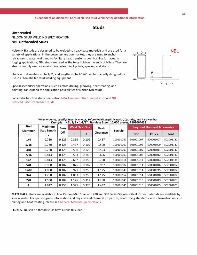
36 †Dependent on diameter. Consult Nelson Stud Welding for additional information.
Studs Unthreaded NELSON STUD WELDING SPECIFICATION
NBL Unthreaded Studs Nelson NBL studs are designed to be welded to heavy base materials and are used for a variety of applications. In the power generation market, they are used to anchor refractory to water walls and to facilitate heat transfer in coal burning furnaces. In forging applications, NBL studs are used as the tong hold on the ends of billets. They are also commonly used as locator pins, axles, pivot points, spacers, and stops. Studs with diameters up to 1/2", and lengths up to 1-1/4” can be specially designed for use in automatic fed stud welding equipment. Special secondary operations, such as cross-drilling, grooving, heat treating, and pointing, can expand the application possibilities of Nelson NBL studs
For similar function studs, see Nelson NBA Aluminum Unthreaded studs and NJL Reduced Base Unthreaded studs.
When ordering, specify: Type, Diameter, Before Weld Length, Material, Quantity, and Part Number Example: NBL 3/8 x 1-1/8”; Stainless Steel; 10,000 pieces; #101064458
Stud
Diameter
D
Minimum Stud Length
L
Burn
Off
Weld Flash Size Flash
Clearance Ferrule
Required Standard Accessories
E F Grip Chuck Foot
1/4 0.780 0.125 0.359 0.109 0.437 100101067 501001007 500001007 502001137
5/16 0.780 0.125 0.437 0.109 0.500 100101007 501001006 500001009 502001137
3/8 0.780 0.125 0.500 0.125 0.593 100101099 501001009 500001011 502001137
7/16 0.813 0.125 0.593 0.140 0.656 100101009 501001008 500001012 502001137
1/2 0.813 0.125 0.687 0.156 0.750 100101114 501001011 500001014 502001138
5/8 0.968 0.187 0.875 0.187 0.937 100101187 501001014 500001016 502001002
0.680 1.000 0.187 0.921 0.250 1.125 100101040 501001014 500001245 502001002
3/4 1.250 0.187 1.063 0.250 1.125 100101152 501001014 500001018 502001002
7/8 1.500 0.187 1.125 0.312 1.250 100101140 501001015 500001019 502001003
1 1.647 0.250 1.375 0.375 1.437 100101045 501001016 500001085 502001003
MATERIALS: Studs are available in Low Carbon Mild Steel and 430 and 300 Series Stainless Steel. Other materials are available by special order. For specific grade information and physical and chemical properties, conforming standards, and information on stud plating and heat treating, please see General Material Specifications. FLUX: All Nelson no thread studs have a solid flux load.
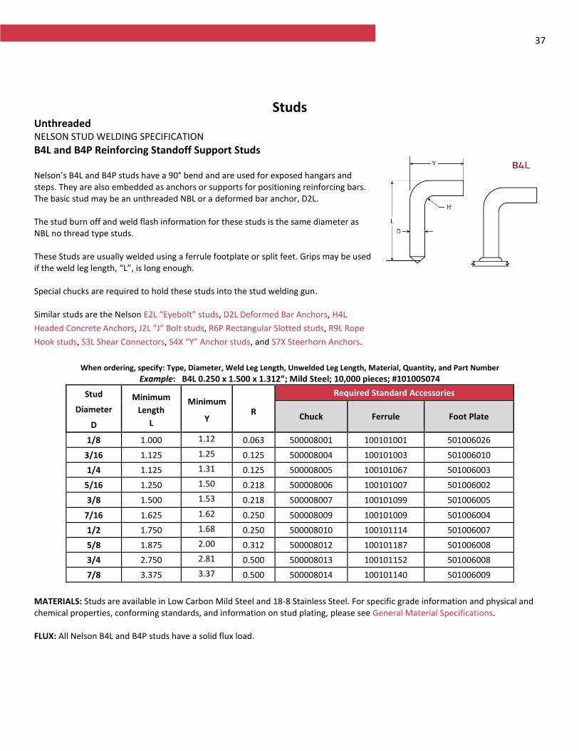
37
Studs Unthreaded NELSON STUD WELDING SPECIFICATION
B4L and B4P Reinforcing Standoff Support Studs Nelson’s B4L and B4P studs have a 90° bend and are used for exposed hangars and steps. They are also embedded as anchors or supports for positioning reinforcing bars. The basic stud may be an unthreaded NBL or a deformed bar anchor, D2L. The stud burn off and weld flash information for these studs is the same diameter as NBL no thread type studs. These Studs are usually welded using a ferrule footplate or split feet. Grips may be used if the weld leg length, “L”, is long enough. Special chucks are required to hold these studs into the stud welding gun. Similar studs are the Nelson E2L “Eyebolt” studs, D2L Deformed Bar Anchors, H4L
Headed Concrete Anchors, J2L “J” Bolt studs, R6P Rectangular Slotted studs, R9L Rope
Hook studs, S3L Shear Connectors, S4X “Y” Anchor studs, and S7X Steerhorn Anchors.
When ordering, specify: Type, Diameter, Weld Leg Length, Unwelded Leg Length, Material, Quantity, and Part Number
Example: B4L 0.250 x 1.500 x 1.312”; Mild Steel; 10,000 pieces; #101005074
Stud
Diameter
D
Minimum
Length
L
Minimum
Y R
Required Standard Accessories
Chuck Ferrule Foot Plate
1/8 1.000 1.125
0.063 500008001 100101001 501006026
3/16 1.125 1.250
0.125 500008004 100101003 501006010
1/4 1.125 1.312
0.125 500008005 100101067 501006003
5/16 1.250 1.500
0.218 500008006 100101007 501006002
3/8 1.500 1.530
0.218 500008007 100101099 501006005
7/16 1.625 1.625
0.250 500008009 100101009 501006004
1/2 1.750 1.687
0.250 500008010 100101114 501006007
5/8 1.875 2.000
0.312 500008012 100101187 501006008
3/4 2.750 2.812
0.500 500008013 100101152 501006008
7/8 3.375 3.375
0.500 500008014 100101140 501006009
MATERIALS: Studs are available in Low Carbon Mild Steel and 18-8 Stainless Steel. For specific grade information and physical and chemical properties, conforming standards, and information on stud plating, please see General Material Specifications. FLUX: All Nelson B4L and B4P studs have a solid flux load.
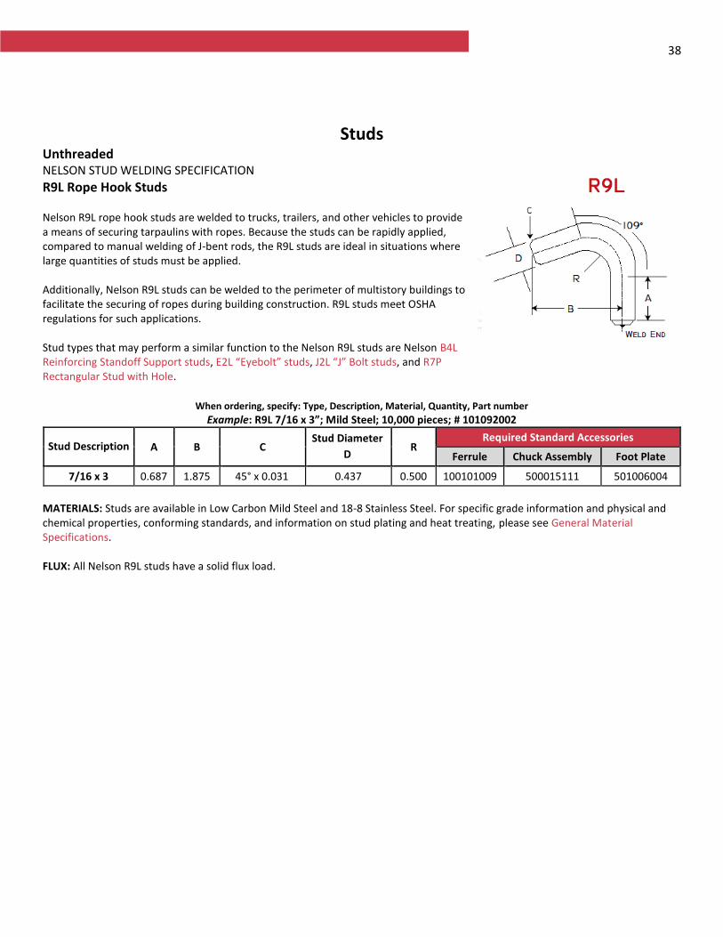
38
Studs Unthreaded NELSON STUD WELDING SPECIFICATION
R9L Rope Hook Studs Nelson R9L rope hook studs are welded to trucks, trailers, and other vehicles to provide a means of securing tarpaulins with ropes. Because the studs can be rapidly applied, compared to manual welding of J-bent rods, the R9L studs are ideal in situations where large quantities of studs must be applied. Additionally, Nelson R9L studs can be welded to the perimeter of multistory buildings to facilitate the securing of ropes during building construction. R9L studs meet OSHA regulations for such applications. Stud types that may perform a similar function to the Nelson R9L studs are Nelson B4L Reinforcing Standoff Support studs, E2L “Eyebolt” studs, J2L “J” Bolt studs, and R7P Rectangular Stud with Hole.
When ordering, specify: Type, Description, Material, Quantity, Part number
Example: R9L 7/16 x 3”; Mild Steel; 10,000 pieces; # 101092002
Stud Description A B C Stud Diameter
D R
Required Standard Accessories
Ferrule Chuck Assembly Foot Plate
7/16 x 3 0.687 1.875 45° x 0.031 0.437 0.500 100101009 500015111 501006004
MATERIALS: Studs are available in Low Carbon Mild Steel and 18-8 Stainless Steel. For specific grade information and physical and chemical properties, conforming standards, and information on stud plating and heat treating, please see General Material Specifications. FLUX: All Nelson R9L studs have a solid flux load.
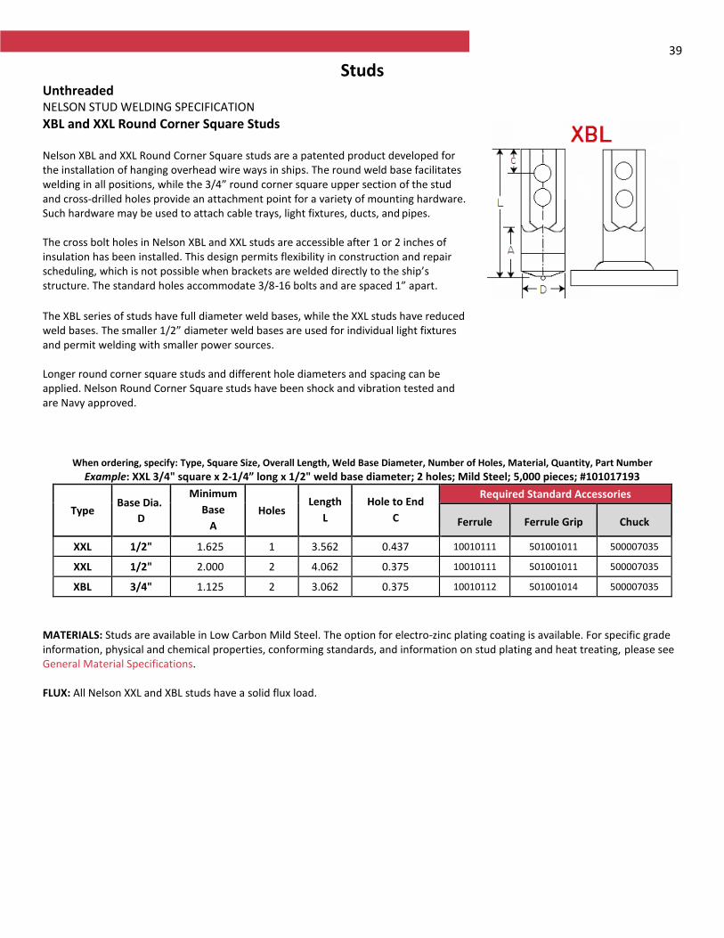
39
Studs Unthreaded NELSON STUD WELDING SPECIFICATION
XBL and XXL Round Corner Square Studs Nelson XBL and XXL Round Corner Square studs are a patented product developed for the installation of hanging overhead wire ways in ships. The round weld base facilitates welding in all positions, while the 3/4” round corner square upper section of the stud and cross-drilled holes provide an attachment point for a variety of mounting hardware. Such hardware may be used to attach cable trays, light fixtures, ducts, and pipes. The cross bolt holes in Nelson XBL and XXL studs are accessible after 1 or 2 inches of insulation has been installed. This design permits flexibility in construction and repair scheduling, which is not possible when brackets are welded directly to the ship’s structure. The standard holes accommodate 3/8-16 bolts and are spaced 1” apart. The XBL series of studs have full diameter weld bases, while the XXL studs have reduced weld bases. The smaller 1/2” diameter weld bases are used for individual light fixtures and permit welding with smaller power sources. Longer round corner square studs and different hole diameters and spacing can be applied. Nelson Round Corner Square studs have been shock and vibration tested and are Navy approved.
When ordering, specify: Type, Square Size, Overall Length, Weld Base Diameter, Number of Holes, Material, Quantity, Part Number
Example: XXL 3/4" square x 2-1/4” long x 1/2" weld base diameter; 2 holes; Mild Steel; 5,000 pieces; #101017193
Type Base Dia.
D
Minimum
Base
A
Holes Length
L
Hole to End
C
Required Standard Accessories
Ferrule Ferrule Grip Chuck
XXL 1/2" 1.625 1 3.562 0.437 10010111 501001011 500007035
XXL 1/2" 2.000 2 4.062 0.375 10010111 501001011 500007035
XBL 3/4" 1.125 2 3.062 0.375 10010112 501001014 500007035
MATERIALS: Studs are available in Low Carbon Mild Steel. The option for electro-zinc plating coating is available. For specific grade information, physical and chemical properties, conforming standards, and information on stud plating and heat treating, please see General Material Specifications. FLUX: All Nelson XXL and XBL studs have a solid flux load.
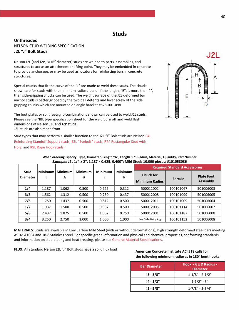
40
Studs Unthreaded NELSON STUD WELDING SPECIFICATION
J2L “J” Bolt Studs Nelson J2L (and J2P, 3/16” diameter) studs are welded to parts, assemblies, and structures to act as an attachment or lifting point. They may be embedded in concrete to provide anchorage, or may be used as locators for reinforcing bars in concrete structures. Special chucks that fit the curve of the “J” are made to weld these studs. The chucks shown are for studs with the minimum radius J bend. If the length, “E”, is more than 4”, then side-gripping chucks can be used. The weight surface of the J2L deformed bar anchor studs is better gripped by the two ball detents and lever screw of the side gripping chucks which are mounted on angle bracket #528-001-098. The foot plates or split feet/grip combinations shown can be used to weld J2L studs. Please see the NBL type specification sheet for the weld burn off and weld flash dimensions of Nelson J2L and J2P studs. J2L studs are also made from
Stud types that may perform a similar function to the J2L “J” Bolt studs are Nelson B4L
Reinforcing Standoff Support studs, E2L “Eyebolt” studs, R7P Rectangular Stud with
Hole, and R9L Rope Hook studs.
When ordering, specify: Type, Diameter, Length “A”, Length “C”, Radius, Material, Quantity, Part Number
Example: J2L 1/4 x 2”, 1.187 x 0.625, 0.400”; Mild Steel; 10,000 pieces; #101058036
Stud
Diameter
Minimum
L
Minimum
A
Minimum
B
Minimum
E
Minimum
R
Required Standard Accessories
Chuck for
Minimum Radius Ferrule
Plate Foot Assembly
1/4 1.187 1.062 0.500 0.625 0.312 500012002 100101067 501006003
3/8 1.562 1.312 0.500 0.750 0.437 500012008 100101099 501006005
7/6 1.750 1.437 0.500 0.812 0.500 500012011 100101009 501006004
1/2 1.937 1.500 0.500 0.937 0.500 500012005 100101114 501006007
5/8 2.437 1.875 0.500 1.062 0.750 500012001 100101187 501006008
3/4 3.250 2.750 1.000 1.000 1.000 See Side Gripping 100101152 501006008
MATERIALS: Studs are available in Low Carbon Mild Steel (with or without deformations), high strength deformed steel bars meeting ASTM A1064 and 18-8 Stainless Steel. For specific grade information and physical and chemical properties, conforming standards, and information on stud plating and heat treating, please see General Material Specifications. FLUX: All standard Nelson J2L “J” Bolt studs have a solid flux load
Bar Diameter Hook - 6 x D Radius -
Diameter
#3 - 3/8” 1-1/8” - 2-1/2”
#4 - 1/2” 1-1/2” - 3”
#5 - 5/8” 1-7/8” - 3-3/4”
American Concrete Institute ACI 318 calls for
the following minimum radiuses in 180° bent hooks:
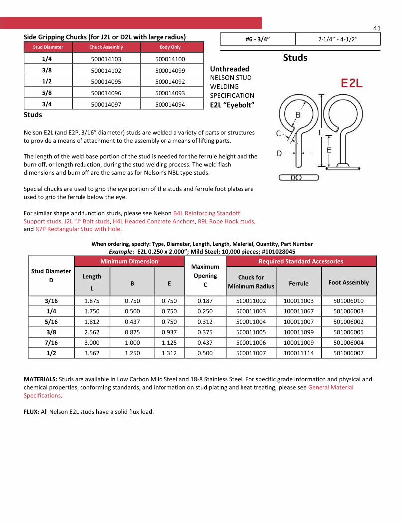
41 Side Gripping Chucks (for J2L or D2L with large radius)
Studs Unthreaded NELSON STUD WELDING SPECIFICATION
E2L “Eyebolt” Studs Nelson E2L (and E2P, 3/16” diameter) studs are welded a variety of parts or structures to provide a means of attachment to the assembly or a means of lifting parts. The length of the weld base portion of the stud is needed for the ferrule height and the burn off, or length reduction, during the stud welding process. The weld flash dimensions and burn off are the same as for Nelson’s NBL type studs. Special chucks are used to grip the eye portion of the studs and ferrule foot plates are used to grip the ferrule below the eye. For similar shape and function studs, please see Nelson B4L Reinforcing Standoff Support studs, J2L “J” Bolt studs, H4L Headed Concrete Anchors, R9L Rope Hook studs, and R7P Rectangular Stud with Hole.
When ordering, specify: Type, Diameter, Length, Length, Material, Quantity, Part Number
Example: E2L 0.250 x 2.000”; Mild Steel; 10,000 pieces; #101028045
Stud Diameter
D
Minimum Dimension Maximum
Opening
C
Required Standard Accessories
Length
L B E
Chuck for
Minimum Radius Ferrule Foot Assembly
3/16 1.875 0.750 0.750 0.187 500011002 100011003 501006010
1/4 1.750 0.500 0.750 0.250 500011003 100011067 501006003
5/16 1.812 0.437 0.750 0.312 500011004 100011007 501006002
3/8 2.562 0.875 0.937 0.375 500011005 100011099 501006005
7/16 3.000 1.000 1.125 0.437 500011006 100011009 501006004
1/2 3.562 1.250 1.312 0.500 500011007 100011114 501006007
MATERIALS: Studs are available in Low Carbon Mild Steel and 18-8 Stainless Steel. For specific grade information and physical and chemical properties, conforming standards, and information on stud plating and heat treating, please see General Material Specifications. FLUX: All Nelson E2L studs have a solid flux load.
#6 - 3/4” 2-1/4” - 4-1/2”
Stud Diameter Chuck Assembly Body Only
1/4 500014103 500014100
3/8 500014102 500014099
1/2 500014095 500014092
5/8 500014096 500014093
3/4 500014097 500014094
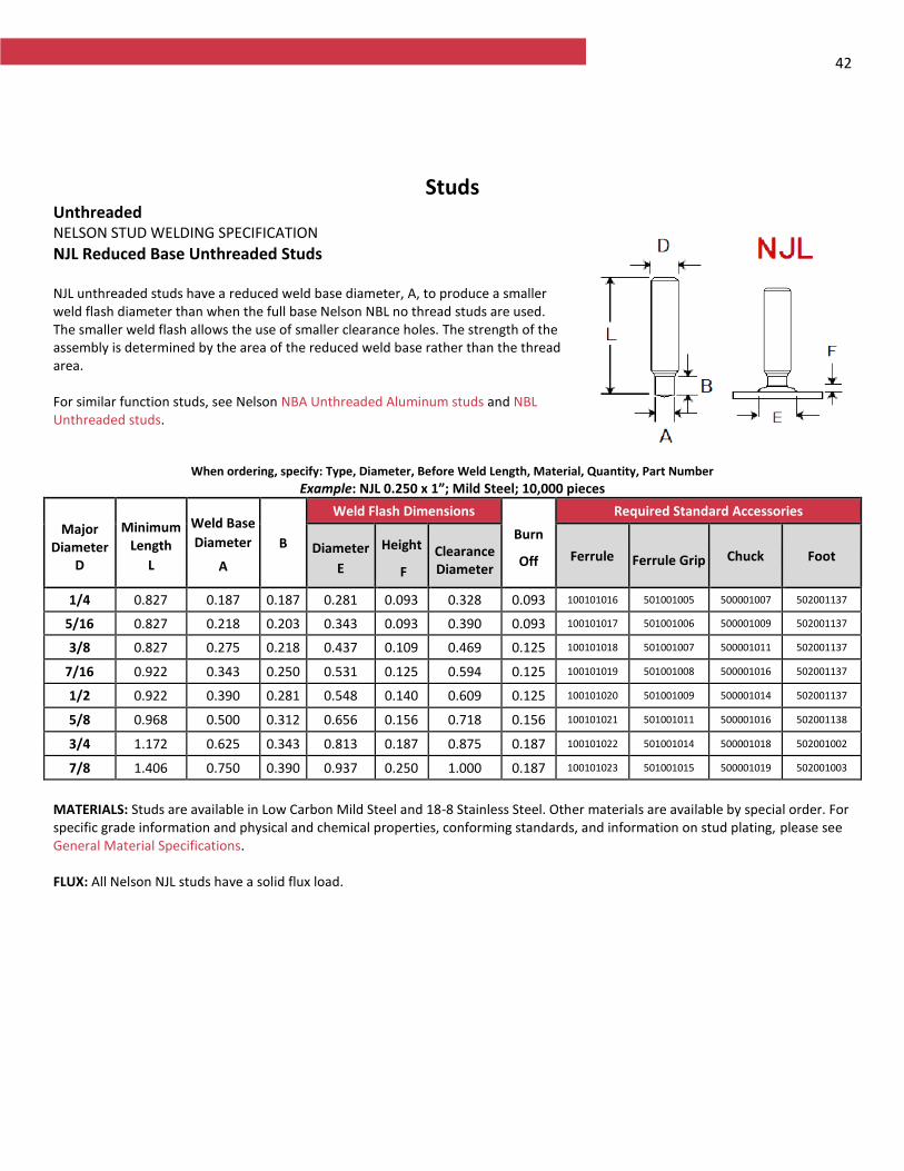
42
Studs Unthreaded NELSON STUD WELDING SPECIFICATION
NJL Reduced Base Unthreaded Studs NJL unthreaded studs have a reduced weld base diameter, A, to produce a smaller weld flash diameter than when the full base Nelson NBL no thread studs are used. The smaller weld flash allows the use of smaller clearance holes. The strength of the assembly is determined by the area of the reduced weld base rather than the thread area. For similar function studs, see Nelson NBA Unthreaded Aluminum studs and NBL Unthreaded studs.
When ordering, specify: Type, Diameter, Before Weld Length, Material, Quantity, Part Number
Example: NJL 0.250 x 1”; Mild Steel; 10,000 pieces
Major Diameter
D
Minimum Length
L
Weld Base
Diameter
A
B
Weld Flash Dimensions
Burn
Off
Required Standard Accessories
Diameter
E
Height
F
Clearance Diameter
Ferrule Ferrule Grip Chuck Foot
1/4 0.827 0.187 0.187 0.281 0.093 0.328 0.093 100101016 501001005 500001007 502001137
5/16 0.827 0.218 0.203 0.343 0.093 0.390 0.093 100101017 501001006 500001009 502001137
3/8 0.827 0.275 0.218 0.437 0.109 0.469 0.125 100101018 501001007 500001011 502001137
7/16 0.922 0.343 0.250 0.531 0.125 0.594 0.125 100101019 501001008 500001016 502001137
1/2 0.922 0.390 0.281 0.548 0.140 0.609 0.125 100101020 501001009 500001014 502001137
5/8 0.968 0.500 0.312 0.656 0.156 0.718 0.156 100101021 501001011 500001016 502001138
3/4 1.172 0.625 0.343 0.813 0.187 0.875 0.187 100101022 501001014 500001018 502001002
7/8 1.406 0.750 0.390 0.937 0.250 1.000 0.187 100101023 501001015 500001019 502001003
MATERIALS: Studs are available in Low Carbon Mild Steel and 18-8 Stainless Steel. Other materials are available by special order. For specific grade information and physical and chemical properties, conforming standards, and information on stud plating, please see General Material Specifications. FLUX: All Nelson NJL studs have a solid flux load.
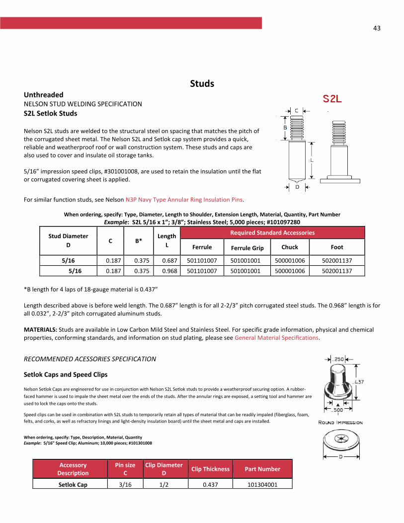
43
Studs Unthreaded NELSON STUD WELDING SPECIFICATION
S2L Setlok Studs Nelson S2L studs are welded to the structural steel on spacing that matches the pitch of the corrugated sheet metal. The Nelson S2L and Setlok cap system provides a quick, reliable and weatherproof roof or wall construction system. These studs and caps are also used to cover and insulate oil storage tanks. 5/16” impression speed clips, #301001008, are used to retain the insulation until the flat or corrugated covering sheet is applied.
For similar function studs, see Nelson N3P Navy Type Annular Ring Insulation Pins.
When ordering, specify: Type, Diameter, Length to Shoulder, Extension Length, Material, Quantity, Part Number
Example: S2L 5/16 x 1”; 3/8”; Stainless Steel; 5,000 pieces; #101097280
Stud Diameter
D C B*
Length
L
Required Standard Accessories
Ferrule Ferrule Grip Chuck Foot
5/16 0.187 0.375 0.687 501101007 501001001 500001006 502001137
5/16 0.187 0.375 0.968 501101007 501001001 500001006 502001137
*B length for 4 laps of 18-gauge material is 0.437” Length described above is before weld length. The 0.687” length is for all 2-2/3” pitch corrugated steel studs. The 0.968” length is for all 0.032”, 2-2/3” pitch corrugated aluminum studs. MATERIALS: Studs are available in Low Carbon Mild Steel and Stainless Steel. For specific grade information, physical and chemical properties, conforming standards, and information on stud plating, please see General Material Specifications.
RECOMMENDED ACESSORIES SPECIFICATION
Setlok Caps and Speed Clips Nelson Setlok Caps are engineered for use in conjunction with Nelson S2L Setlok studs to provide a weatherproof securing option. A rubber-
faced hammer is used to impale the sheet metal over the ends of the studs. After the annular rings are exposed, a setting tool and hammer are
used to lock the caps onto the studs.
Speed clips can be used in combination with S2L studs to temporarily retain all types of material that can be readily impaled (fiberglass, foam,
felts, and corks, as well as refractory linings and light-density insulation board) until the sheet metal and caps are installed.
When ordering, specify: Type, Description, Material, Quantity Example: 5/16” Speed Clip; Aluminum; 10,000 pieces; #101301008
Accessory Description
Pin size C
Clip Diameter D
Clip Thickness Part Number
Setlok Cap
Setlo
3/16
5/16
1/2 0.437 101304001
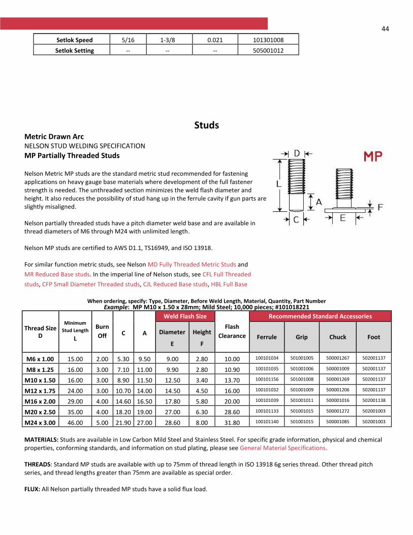
44
Studs Metric Drawn Arc NELSON STUD WELDING SPECIFICATION
MP Partially Threaded Studs Nelson Metric MP studs are the standard metric stud recommended for fastening applications on heavy gauge base materials where development of the full fastener strength is needed. The unthreaded section minimizes the weld flash diameter and height. It also reduces the possibility of stud hang up in the ferrule cavity if gun parts are slightly misaligned. Nelson partially threaded studs have a pitch diameter weld base and are available in thread diameters of M6 through M24 with unlimited length. Nelson MP studs are certified to AWS D1.1, TS16949, and ISO 13918. For similar function metric studs, see Nelson MD Fully Threaded Metric Studs and
MR Reduced Base studs. In the imperial line of Nelson studs, see CFL Full Threaded
studs, CFP Small Diameter Threaded studs, CJL Reduced Base studs, HBL Full Base
Diameter Threaded studs, B5L 90° Bent
Collar studs, Banding Cable Hangers,
CrimpLok™ Cable Hangers, and
Watertight nuts.
When ordering, specify: Type, Diameter, Before Weld Length, Material, Quantity, Part Number
Example: MP M10 x 1.50 x 28mm; Mild Steel; 10,000 pieces; #101018221
Thread Size D
Minimum
Stud Length
L
Burn
Off C A
Weld Flash Size
Flash
Clearance
Recommended Standard Accessories
Diameter
E
Height
F Ferrule Grip Chuck Foot
M6 x 1.00 15.00 2.00 5.30 9.50 9.00 2.80 10.00 100101034 501001005 500001267 502001137
M8 x 1.25 16.00 3.00 7.10 11.00 9.90 2.80 10.90 100101035 501001006 500001009 502001137
M10 x 1.50 16.00 3.00 8.90 11.50 12.50 3.40 13.70 100101156 501001008 500001269 502001137
M12 x 1.75 24.00 3.00 10.70 14.00 14.50 4.50 16.00 100101032 501001009 500001206 502001137
M16 x 2.00 29.00 4.00 14.60 16.50 17.80 5.80 20.00 100101039 501001011 500001016 502001138
M20 x 2.50 35.00 4.00 18.20 19.00 27.00 6.30 28.60 100101133 501001015 500001272 502001003
M24 x 3.00 46.00 5.00 21.90 27.00 28.60 8.00 31.80 100101140 501001015 500001085 502001003
MATERIALS: Studs are available in Low Carbon Mild Steel and Stainless Steel. For specific grade information, physical and chemical properties, conforming standards, and information on stud plating, please see General Material Specifications. THREADS: Standard MP studs are available with up to 75mm of thread length in ISO 13918 6g series thread. Other thread pitch series, and thread lengths greater than 75mm are available as special order. FLUX: All Nelson partially threaded MP studs have a solid flux load.
Setlok Speed 5/16 1-3/8 0.021 101301008
Setlok Setting -- -- -- 505001012
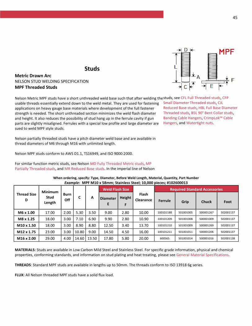
45
Studs Metric Drawn Arc NELSON STUD WELDING SPECIFICATION
MPF Threaded Studs Nelson Metric MPF studs have a short unthreaded weld base such that after welding the usable threads essentially extend down to the weld metal. They are used for fastening applications on heavy gauge base materials where development of the full fastener strength is needed. The short unthreaded section minimizes the weld flash diameter and height. It also reduces the possibility of stud hang up in the ferrule cavity if gun parts are slightly misaligned. Ferrules with a special low profile and large diameter are sued to weld MPF style studs. Nelson partially threaded studs have a pitch diameter weld base and are available in thread diameters of M6 through M16 with unlimited length. Nelson MPF studs conform to AWS D1.1, TS16949, and ISO 9000:2000. For similar function metric studs, see Nelson MD Fully Threaded Metric studs, MP Partially Threaded studs, and MR Reduced Base studs. In the imperial line of Nelson
studs, see CFL Full Threaded studs, CFP Small Diameter Threaded studs, CJL Reduced Base studs, HBL Full Base Diameter Threaded studs, B5L 90° Bent Collar studs, Banding Cable Hangers, CrimpLok™ Cable Hangers, and Watertight nuts.
When ordering, specify: Type, Diameter, Before Weld Length, Material, Quantity, Part Number
Example: MPF M10 x 58mm; Stainless Steel; 10,000 pieces; #102600013
Thread Size
D
Minimum
Stud
Length
Burn
Off C A
Weld Flash Size Flash
Clearance
Required Standard Accessories
Diameter
E
Height
F Ferrule Grip Chuck Foot
M6 x 1.00 17.00 2.00 5.30 3.50 9.00 2.80 10.00 100101188 501001005 500001267 502001137
M8 x 1.25 18.00 3.00 7.10 6.90 9.90 2.80 10.90 100101209 501001008 500001009 502001137
M10 x 1.50 18.00 3.00 8.90 8.80 12.50 3.40 13.70 100101210 501001009 500001269 502001137
M12 x 1.75 23.00 3.00 10.80 9.00 14.50 4.50 16.00 100101211 501001011 500001206 502001137
M16 x 2.00 29.00 4.00 14.60 13.50 17.80 5.80 20.00 600565 501001014 500001016 502001138
MATERIALS: Studs are available in Low Carbon Mild Steel and Stainless Steel. For specific grade information, physical and chemical properties, conforming standards, and information on stud plating and heat treating, please see General Material Specifications. THREADS: Standard MPF studs are available in lengths up to 50mm. The threads conform to ISO 13918 6g series. FLUX: All Nelson threaded MPF studs have a solid flux load.
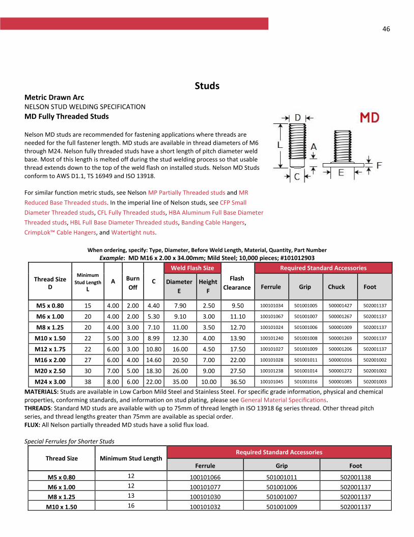
46
Studs Metric Drawn Arc NELSON STUD WELDING SPECIFICATION
MD Fully Threaded Studs Nelson MD studs are recommended for fastening applications where threads are needed for the full fastener length. MD studs are available in thread diameters of M6 through M24. Nelson fully threaded studs have a short length of pitch diameter weld base. Most of this length is melted off during the stud welding process so that usable thread extends down to the top of the weld flash on installed studs. Nelson MD Studs conform to AWS D1.1, TS 16949 and ISO 13918. For similar function metric studs, see Nelson MP Partially Threaded studs and MR
Reduced Base Threaded studs. In the imperial line of Nelson studs, see CFP Small
Diameter Threaded studs, CFL Fully Threaded studs, HBA Aluminum Full Base Diameter
Threaded studs, HBL Full Base Diameter Threaded studs, Banding Cable Hangers,
CrimpLok™ Cable Hangers, and Watertight nuts.
When ordering, specify: Type, Diameter, Before Weld Length, Material, Quantity, Part Number
Example: MD M16 x 2.00 x 34.00mm; Mild Steel; 10,000 pieces; #101012903
Thread Size D
Minimum
Stud Length
L A Burn
Off C
Weld Flash Size
Flash
Clearance
Required Standard Accessories
Diameter
E
Height
F Ferrule Grip Chuck Foot
M5 x 0.80 15 4.00 2.00 4.40 7.90 2.50 9.50 100101034 501001005 500001427 502001137
M6 x 1.00 20 4.00 2.00 5.30 9.10 3.00 11.10 100101067 501001007 500001267 502001137
M8 x 1.25 20 4.00 3.00 7.10 11.00 3.50 12.70 100101024 501001006 500001009 502001137
M10 x 1.50 22 5.00 3.00 8.99 12.30 4.00 13.90 100101240 501001008 500001269 502001137
M12 x 1.75 22 6.00 3.00 10.80 16.00 4.50 17.50 100101027 501001009 500001206 502001137
M16 x 2.00 27 6.00 4.00 14.60 20.50 7.00 22.00 100101028 501001011 500001016 502001002
M20 x 2.50 30 7.00 5.00 18.30 26.00 9.00 27.50 100101238 501001014 500001272 502001002
M24 x 3.00 38 8.00 6.00 22.00 35.00 10.00 36.50 100101045 501001016 500001085 502001003
MATERIALS: Studs are available in Low Carbon Mild Steel and Stainless Steel. For specific grade information, physical and chemical properties, conforming standards, and information on stud plating, please see General Material Specifications. THREADS: Standard MD studs are available with up to 75mm of thread length in ISO 13918 6g series thread. Other thread pitch series, and thread lengths greater than 75mm are available as special order. FLUX: All Nelson partially threaded MD studs have a solid flux load. Special Ferrules for Shorter Studs
Thread Size Minimum Stud Length Required Standard Accessories
Ferrule Grip Foot
M5 x 0.80 12 100101066 501001011 502001138
M6 x 1.00 12 100101077 501001006 502001137
M8 x 1.25 13 100101030 501001007 502001137
M10 x 1.50 16 100101032 501001009 502001137
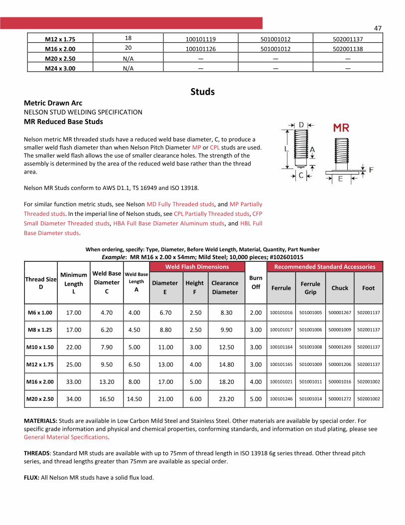
47
M12 x 1.75 18 100101119 501001012 502001137
M16 x 2.00 20 100101126 501001012 502001138
M20 x 2.50 N/A — — —
M24 x 3.00 N/A — — —
Studs
Metric Drawn Arc NELSON STUD WELDING SPECIFICATION
MR Reduced Base Studs Nelson metric MR threaded studs have a reduced weld base diameter, C, to produce a smaller weld flash diameter than when Nelson Pitch Diameter MP or CPL studs are used. The smaller weld flash allows the use of smaller clearance holes. The strength of the assembly is determined by the area of the reduced weld base rather than the thread area. Nelson MR Studs conform to AWS D1.1, TS 16949 and ISO 13918. For similar function metric studs, see Nelson MD Fully Threaded studs, and MP Partially
Threaded studs. In the imperial line of Nelson studs, see CPL Partially Threaded studs, CFP
Small Diameter Threaded studs, HBA Full Base Diameter Aluminum studs, and HBL Full
Base Diameter studs.
When ordering, specify: Type, Diameter, Before Weld Length, Material, Quantity, Part Number
Example: MR M16 x 2.00 x 54mm; Mild Steel; 10,000 pieces; #102601015
Thread Size D
Minimum
Length L
Weld Base
Diameter
C
Weld Base
Length
A
Weld Flash Dimensions
Burn
Off
Recommended Standard Accessories
Diameter
E
Height
F
Clearance
Diameter Ferrule
Ferrule Grip
Chuck Foot
M6 x 1.00 17.00 4.70 4.00 6.70 2.50 8.30 2.00
100101016
501001005
500001267
502001137
M8 x 1.25 17.00 6.20 4.50 8.80 2.50 9.90 3.00
100101017
501001006
500001009
502001137
M10 x 1.50 22.00 7.90 5.00 11.00 3.00 12.50 3.00
100101164
501001008
500001269
502001137
M12 x 1.75 25.00 9.50 6.50 13.00 4.00 14.80 3.00
100101165
501001009
500001206
502001137
M16 x 2.00 33.00 13.20 8.00 17.00 5.00 18.20 4.00
100101021
501001011
500001016
502001002
M20 x 2.50 34.00 16.50 14.50 21.00 6.00 23.20 5.00
100101246
501001014
500001272
502001002
MATERIALS: Studs are available in Low Carbon Mild Steel and Stainless Steel. Other materials are available by special order. For specific grade information and physical and chemical properties, conforming standards, and information on stud plating, please see General Material Specifications. THREADS: Standard MR studs are available with up to 75mm of thread length in ISO 13918 6g series thread. Other thread pitch series, and thread lengths greater than 75mm are available as special order. FLUX: All Nelson MR studs have a solid flux load.
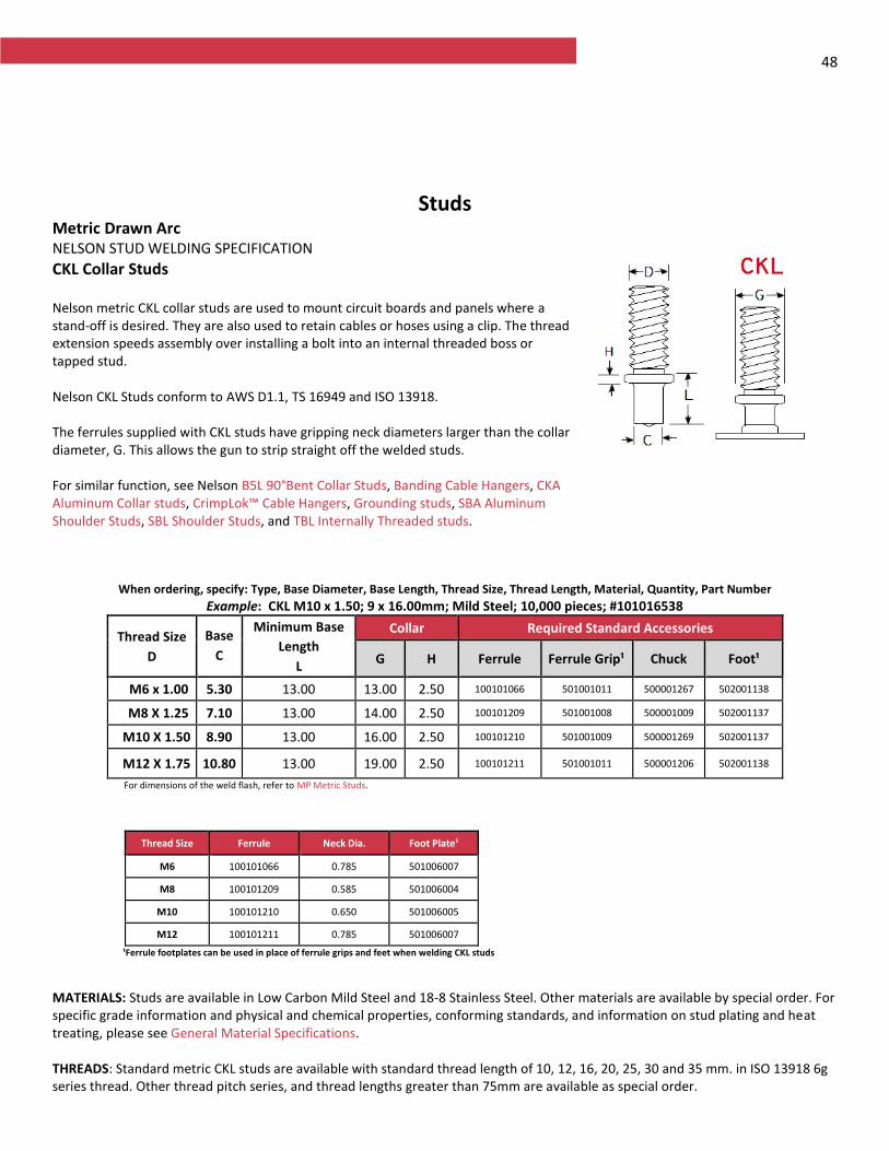
48
Studs Metric Drawn Arc NELSON STUD WELDING SPECIFICATION
CKL Collar Studs Nelson metric CKL collar studs are used to mount circuit boards and panels where a stand-off is desired. They are also used to retain cables or hoses using a clip. The thread extension speeds assembly over installing a bolt into an internal threaded boss or tapped stud. Nelson CKL Studs conform to AWS D1.1, TS 16949 and ISO 13918. The ferrules supplied with CKL studs have gripping neck diameters larger than the collar diameter, G. This allows the gun to strip straight off the welded studs. For similar function, see Nelson B5L 90°Bent Collar Studs, Banding Cable Hangers, CKA Aluminum Collar studs, CrimpLok™ Cable Hangers, Grounding studs, SBA Aluminum Shoulder Studs, SBL Shoulder Studs, and TBL Internally Threaded studs.
When ordering, specify: Type, Base Diameter, Base Length, Thread Size, Thread Length, Material, Quantity, Part Number
Example: CKL M10 x 1.50; 9 x 16.00mm; Mild Steel; 10,000 pieces; #101016538
Thread Size
D
Base
C
Minimum Base
Length
L
Collar Required Standard Accessories
G H Ferrule Ferrule Grip¹ Chuck Foot¹
M6 x 1.00 5.30 13.00 13.00 2.50 100101066 501001011 500001267 502001138
M8 X 1.25 7.10 13.00 14.00 2.50 100101209 501001008 500001009 502001137
M10 X 1.50 8.90 13.00 16.00 2.50 100101210 501001009 500001269 502001137
M12 X 1.75 10.80 13.00 19.00 2.50 100101211 501001011 500001206 502001138
For dimensions of the weld flash, refer to MP Metric Studs.
Thread Size Ferrule Neck Dia. Foot Plate¹
M6 100101066 0.785 501006007
M8 100101209 0.585 501006004
M10 100101210 0.650 501006005
M12 100101211 0.785 501006007
¹Ferrule footplates can be used in place of ferrule grips and feet when welding CKL studs
MATERIALS: Studs are available in Low Carbon Mild Steel and 18-8 Stainless Steel. Other materials are available by special order. For specific grade information and physical and chemical properties, conforming standards, and information on stud plating and heat treating, please see General Material Specifications. THREADS: Standard metric CKL studs are available with standard thread length of 10, 12, 16, 20, 25, 30 and 35 mm. in ISO 13918 6g series thread. Other thread pitch series, and thread lengths greater than 75mm are available as special order.
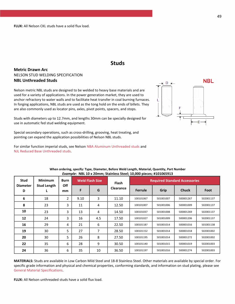
49 FLUX: All Nelson CKL studs have a solid flux load.
Studs Metric Drawn Arc NELSON STUD WELDING SPECIFICATION
NBL Unthreaded Studs Nelson metric NBL studs are designed to be welded to heavy base materials and are used for a variety of applications. In the power generation market, they are used to anchor refractory to water walls and to facilitate heat transfer in coal burning furnaces. In forging applications, NBL studs are used as the tong hold on the ends of billets. They are also commonly used as locator pins, axles, pivot points, spacers, and stops. Studs with diameters up to 12.7mm, and lengths 30mm can be specially designed for use in automatic fed stud welding equipment. Special secondary operations, such as cross-drilling, grooving, heat treating, and pointing can expand the application possibilities of Nelson NBL studs. For similar function imperial studs, see Nelson NBA Aluminum Unthreaded studs and NJL Reduced Base Unthreaded studs.
When ordering, specify: Type, Diameter, Before Weld Length, Material, Quantity, Part Number
Example: NBL 10 x 20mm; Stainless Steel; 10,000 pieces; #101065913
Stud
Diameter
D
Minimum
Stud Length
L
Burn
Off
mm
Weld Flash Size Flash
Clearance
Required Standard Accessories
F G Ferrule Grip Chuck Foot
6 18 2 9.10 3 11.10 100101067 501001007 500001267 502001137
8 23 3 11 4 12.50 100101007 501001006 500001009 502001137
10 mmmm
23 3 13 4 14.50 100101037 501001008 500001269 502001137
12 24 3 16 4.5 17.50 100101027 501001009 500001206 502001137
16 29 4 21 6 22.50 100101187 501001014 500001016 501001138
19 30 5 27 7 28.50 100101152 501001014 500001018 502001002
20 30 5 26 8 27.50 100101195 501001014 500001272 502001002
22 35 6 28 9 30.50 100101140 501001015 500001019 502001003
24 36 6 35 10 36.50 100101197 501001016 500001274 502001003
MATERIALS: Studs are available in Low Carbon Mild Steel and 18-8 Stainless Steel. Other materials are available by special order. For specific grade information and physical and chemical properties, conforming standards, and information on stud plating, please see General Material Specifications. FLUX: All Nelson unthreaded studs have a solid flux load.

50
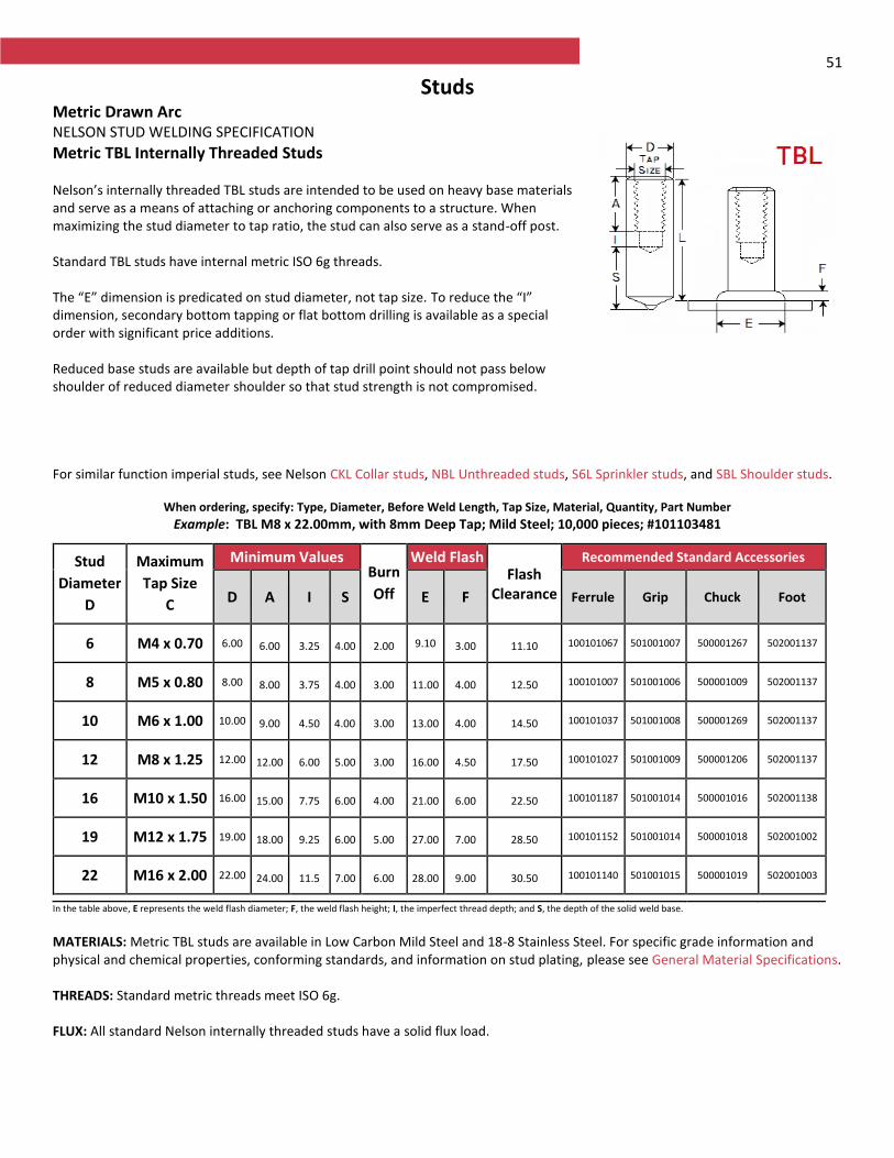
51
Studs Metric Drawn Arc NELSON STUD WELDING SPECIFICATION
Metric TBL Internally Threaded Studs Nelson’s internally threaded TBL studs are intended to be used on heavy base materials and serve as a means of attaching or anchoring components to a structure. When maximizing the stud diameter to tap ratio, the stud can also serve as a stand-off post. Standard TBL studs have internal metric ISO 6g threads. The “E” dimension is predicated on stud diameter, not tap size. To reduce the “I” dimension, secondary bottom tapping or flat bottom drilling is available as a special order with significant price additions. Reduced base studs are available but depth of tap drill point should not pass below shoulder of reduced diameter shoulder so that stud strength is not compromised.
For similar function imperial studs, see Nelson CKL Collar studs, NBL Unthreaded studs, S6L Sprinkler studs, and SBL Shoulder studs.
When ordering, specify: Type, Diameter, Before Weld Length, Tap Size, Material, Quantity, Part Number
Example: TBL M8 x 22.00mm, with 8mm Deep Tap; Mild Steel; 10,000 pieces; #101103481
In the table above, E represents the weld flash diameter; F, the weld flash height; I, the imperfect thread depth; and S, the depth of the solid weld base.
MATERIALS: Metric TBL studs are available in Low Carbon Mild Steel and 18-8 Stainless Steel. For specific grade information and physical and chemical properties, conforming standards, and information on stud plating, please see General Material Specifications. THREADS: Standard metric threads meet ISO 6g. FLUX: All standard Nelson internally threaded studs have a solid flux load.
Stud
Diameter
D
Maximum
Tap Size
C
Minimum Values Burn
Off
Weld Flash Flash
Clearance
Recommended Standard Accessories
D A I S E F Ferrule Grip Chuck Foot
6 M4 x 0.70 6.00
6.00
3.25 4.00
2.00 9.10
3.00
11.10
100101067
501001007
500001267
502001137
8 M5 x 0.80 8.00
8.00
3.75 4.00
3.00
11.00
4.00
12.50
100101007
501001006
500001009
502001137
10 M6 x 1.00 10.00
9.00
4.50 4.00
3.00
13.00
4.00
14.50
100101037
501001008
500001269
502001137
12 M8 x 1.25 12.00 12.00
6.00
5.00
3.00
16.00
4.50
17.50
100101027
501001009
500001206
502001137
16 M10 x 1.50 16.00 15.00
7.75
6.00
4.00
21.00
6.00
22.50
100101187
501001014
500001016
502001138
19 M12 x 1.75 19.00 18.00
9.25
6.00
5.00
27.00
7.00
28.50
100101152
501001014
500001018
502001002
22 M16 x 2.00 22.00 24.00
11.5
7.00
6.00
28.00
9.00
30.50
100101140
501001015
500001019
502001003
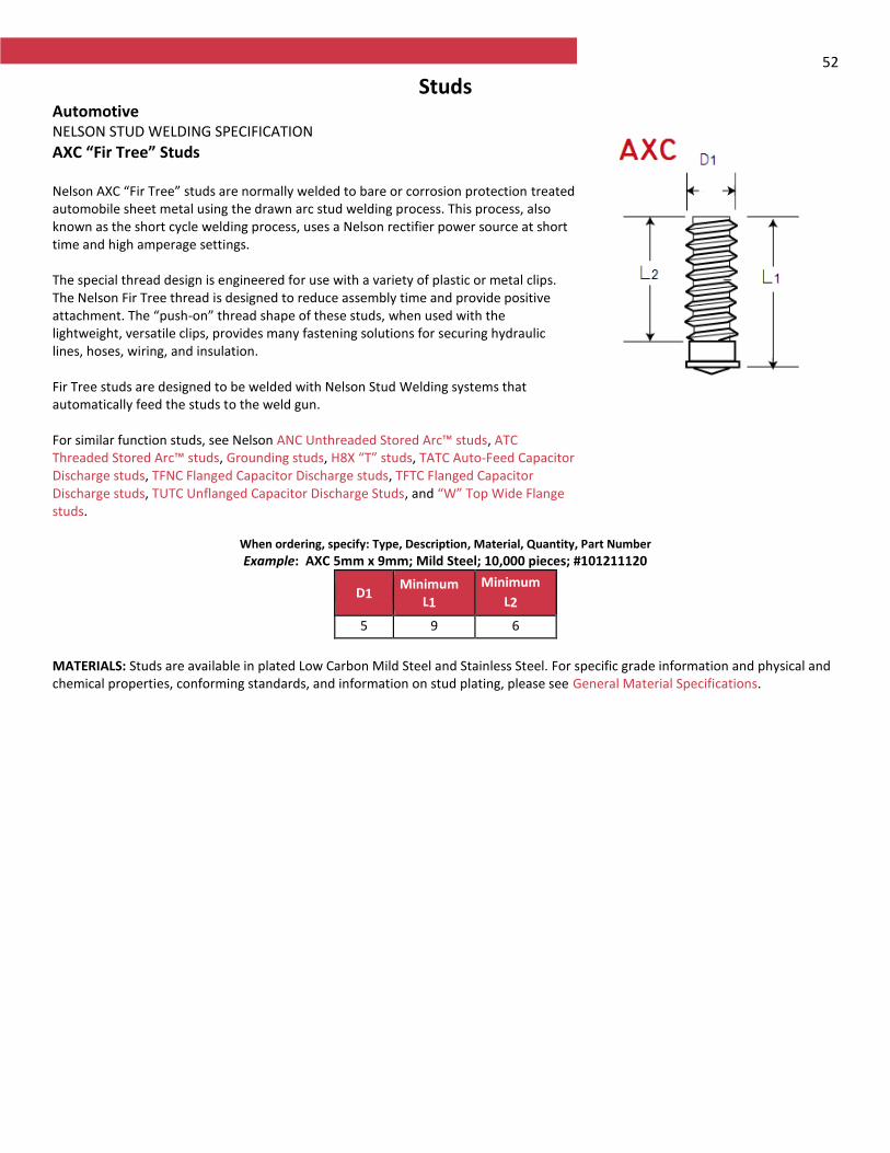
52
Studs Automotive NELSON STUD WELDING SPECIFICATION
AXC “Fir Tree” Studs Nelson AXC “Fir Tree” studs are normally welded to bare or corrosion protection treated automobile sheet metal using the drawn arc stud welding process. This process, also known as the short cycle welding process, uses a Nelson rectifier power source at short time and high amperage settings. The special thread design is engineered for use with a variety of plastic or metal clips. The Nelson Fir Tree thread is designed to reduce assembly time and provide positive attachment. The “push-on” thread shape of these studs, when used with the lightweight, versatile clips, provides many fastening solutions for securing hydraulic lines, hoses, wiring, and insulation. Fir Tree studs are designed to be welded with Nelson Stud Welding systems that automatically feed the studs to the weld gun. For similar function studs, see Nelson ANC Unthreaded Stored Arc™ studs, ATC Threaded Stored Arc™ studs, Grounding studs, H8X “T” studs, TATC Auto-Feed Capacitor Discharge studs, TFNC Flanged Capacitor Discharge studs, TFTC Flanged Capacitor Discharge studs, TUTC Unflanged Capacitor Discharge Studs, and “W” Top Wide Flange studs.
When ordering, specify: Type, Description, Material, Quantity, Part Number
Example: AXC 5mm x 9mm; Mild Steel; 10,000 pieces; #101211120
D1 Minimum
L1
Minimum
L2
5 9 6
MATERIALS: Studs are available in plated Low Carbon Mild Steel and Stainless Steel. For specific grade information and physical and chemical properties, conforming standards, and information on stud plating, please see General Material Specifications.
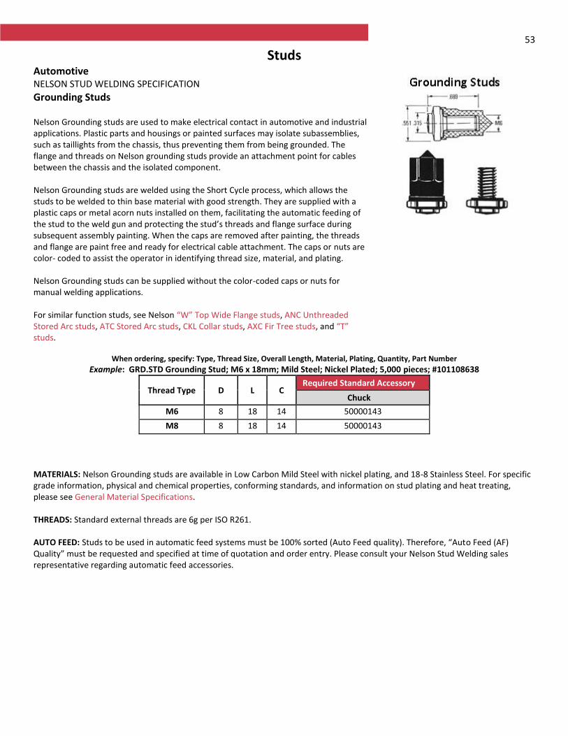
53
Studs Automotive NELSON STUD WELDING SPECIFICATION
Grounding Studs Nelson Grounding studs are used to make electrical contact in automotive and industrial applications. Plastic parts and housings or painted surfaces may isolate subassemblies, such as taillights from the chassis, thus preventing them from being grounded. The flange and threads on Nelson grounding studs provide an attachment point for cables between the chassis and the isolated component. Nelson Grounding studs are welded using the Short Cycle process, which allows the studs to be welded to thin base material with good strength. They are supplied with a plastic caps or metal acorn nuts installed on them, facilitating the automatic feeding of the stud to the weld gun and protecting the stud’s threads and flange surface during subsequent assembly painting. When the caps are removed after painting, the threads and flange are paint free and ready for electrical cable attachment. The caps or nuts are color- coded to assist the operator in identifying thread size, material, and plating. Nelson Grounding studs can be supplied without the color-coded caps or nuts for manual welding applications. For similar function studs, see Nelson “W” Top Wide Flange studs, ANC Unthreaded Stored Arc studs, ATC Stored Arc studs, CKL Collar studs, AXC Fir Tree studs, and “T” studs.
When ordering, specify: Type, Thread Size, Overall Length, Material, Plating, Quantity, Part Number
Example: GRD.STD Grounding Stud; M6 x 18mm; Mild Steel; Nickel Plated; 5,000 pieces; #101108638
Thread Type D L C Required Standard Accessory
Chuck
M6 8 18 14 500001436 M8 8 18 14 500001436
MATERIALS: Nelson Grounding studs are available in Low Carbon Mild Steel with nickel plating, and 18-8 Stainless Steel. For specific grade information, physical and chemical properties, conforming standards, and information on stud plating and heat treating, please see General Material Specifications. THREADS: Standard external threads are 6g per ISO R261. AUTO FEED: Studs to be used in automatic feed systems must be 100% sorted (Auto Feed quality). Therefore, “Auto Feed (AF) Quality” must be requested and specified at time of quotation and order entry. Please consult your Nelson Stud Welding sales representative regarding automatic feed accessories.
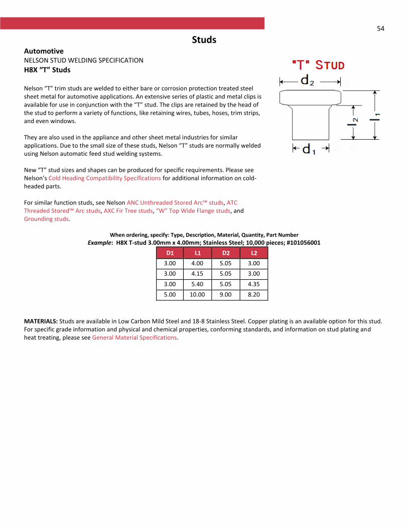
54
Studs Automotive NELSON STUD WELDING SPECIFICATION
H8X “T” Studs
Nelson “T” trim studs are welded to either bare or corrosion protection treated steel sheet metal for automotive applications. An extensive series of plastic and metal clips is available for use in conjunction with the “T” stud. The clips are retained by the head of the stud to perform a variety of functions, like retaining wires, tubes, hoses, trim strips, and even windows. They are also used in the appliance and other sheet metal industries for similar applications. Due to the small size of these studs, Nelson “T” studs are normally welded using Nelson automatic feed stud welding systems. New “T” stud sizes and shapes can be produced for specific requirements. Please see Nelson’s Cold Heading Compatibility Specifications for additional information on cold-headed parts. For similar function studs, see Nelson ANC Unthreaded Stored Arc™ studs, ATC Threaded Stored™ Arc studs, AXC Fir Tree studs, “W” Top Wide Flange studs, and Grounding studs.
When ordering, specify: Type, Description, Material, Quantity, Part Number
Example: H8X T-stud 3.00mm x 4.00mm; Stainless Steel; 10,000 pieces; #101056001
D1 L1 D2 L2
3.00 4.00 5.05 3.00
3.00 4.15 5.05 3.00
3.00 5.40 5.05 4.35
5.00 10.00 9.00 8.20
MATERIALS: Studs are available in Low Carbon Mild Steel and 18-8 Stainless Steel. Copper plating is an available option for this stud. For specific grade information and physical and chemical properties, conforming standards, and information on stud plating and heat treating, please see General Material Specifications.
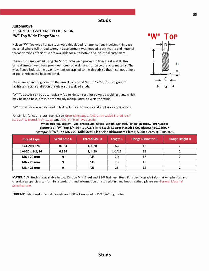
55
Studs Automotive NELSON STUD WELDING SPECIFICATION
“W” Top Wide Flange Studs Nelson “W” Top wide flange studs were developed for applications involving thin base material where full thread strength development was needed. Both metric and imperial thread versions of this stud are available for automotive and industrial customers. These studs are welded using the Short Cycle weld process to thin sheet metal. The large diameter weld base provides increased weld area fusion to the base material. The wide flange isolates the assembly tension applied to the threads so that it cannot dimple or pull a hole in the base material. The chamfer and dog point on the unwelded end of Nelson “W”-Top studs greatly facilitates rapid installation of nuts on the welded studs. “W” Top studs can be automatically fed to Nelson rectifier powered welding guns, which may be hand held, press, or robotically manipulated, to weld the studs. “W” Top studs are widely used in high volume automotive and appliance applications. For similar function studs, see Nelson Grounding studs, ANC Unthreaded Stored Arc™ studs, ATC Stored Arc™ studs, and AXC “Fir Tree” type studs.
When ordering, specify: Type, Thread Size, Overall Length, Material, Plating, Quantity, Part Number
Example 1: “W”-Top 1/4-20 x 1-1/16”; Mild Steel; Copper Plated; 5,000 pieces; #101056077 Example 2: “W”-Top M6 x 20; Mild Steel; Clear Zinc Dichromate Plated; 5,000 pieces; #101056075
Thread Type Weld base C Thread Size D Length L Flange Diameter G Flange Height H
1/4-20 x 3/4 0.354 1/4-20 3/4 13 2
1/4-20 x 1-1/16 0.354 1/4-20 1-1/16 13 2
M6 x 20 mm 9 M6 20 13 2
M6 x 25 mm 9 M6 25 13 2
M8 x 25 mm 9 M6 25 13 2
MATERIALS: Studs are available in Low Carbon Mild Steel and 18-8 Stainless Steel. For specific grade information, physical and chemical properties, conforming standards, and information on stud plating and heat treating, please see General Material Specifications. THREADS: Standard external threads are UNC-2A imperial or ISO R261, 6g metric.
Studs
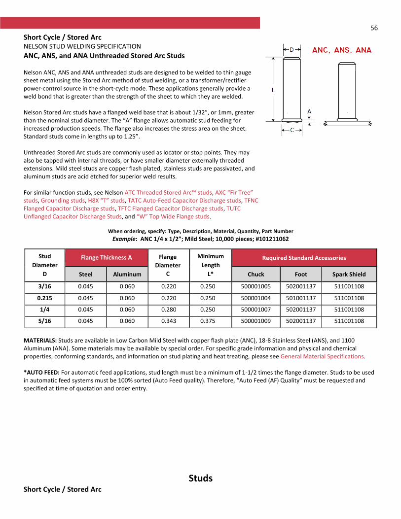
56
Short Cycle / Stored Arc NELSON STUD WELDING SPECIFICATION
ANC, ANS, and ANA Unthreaded Stored Arc Studs Nelson ANC, ANS and ANA unthreaded studs are designed to be welded to thin gauge sheet metal using the Stored Arc method of stud welding, or a transformer/rectifier power-control source in the short-cycle mode. These applications generally provide a weld bond that is greater than the strength of the sheet to which they are welded. Nelson Stored Arc studs have a flanged weld base that is about 1/32”, or 1mm, greater than the nominal stud diameter. The “A” flange allows automatic stud feeding for increased production speeds. The flange also increases the stress area on the sheet. Standard studs come in lengths up to 1.25”. Unthreaded Stored Arc studs are commonly used as locator or stop points. They may also be tapped with internal threads, or have smaller diameter externally threaded extensions. Mild steel studs are copper flash plated, stainless studs are passivated, and aluminum studs are acid etched for superior weld results. For similar function studs, see Nelson ATC Threaded Stored Arc™ studs, AXC “Fir Tree” studs, Grounding studs, H8X “T” studs, TATC Auto-Feed Capacitor Discharge studs, TFNC Flanged Capacitor Discharge studs, TFTC Flanged Capacitor Discharge studs, TUTC Unflanged Capacitor Discharge Studs, and “W” Top Wide Flange studs.
When ordering, specify: Type, Description, Material, Quantity, Part Number
Example: ANC 1/4 x 1/2”; Mild Steel; 10,000 pieces; #101211062
MATERIALS: Studs are available in Low Carbon Mild Steel with copper flash plate (ANC), 18-8 Stainless Steel (ANS), and 1100 Aluminum (ANA). Some materials may be available by special order. For specific grade information and physical and chemical properties, conforming standards, and information on stud plating and heat treating, please see General Material Specifications. *AUTO FEED: For automatic feed applications, stud length must be a minimum of 1-1/2 times the flange diameter. Studs to be used in automatic feed systems must be 100% sorted (Auto Feed quality). Therefore, “Auto Feed (AF) Quality” must be requested and specified at time of quotation and order entry.
Studs Short Cycle / Stored Arc
Stud
Diameter
D
Flange Thickness A Flange
Diameter
C
Minimum
Length
L*
Required Standard Accessories
Steel Aluminum Chuck Foot Spark Shield
3/16 0.045 0.060 0.220 0.250 500001005 502001137 511001108
0.215 0.045 0.060 0.220 0.250 500001004 501001137 511001108
1/4 0.045 0.060 0.280 0.250 500001007 502001137 511001108
5/16 0.045 0.060 0.343 0.375 500001009 502001137 511001108
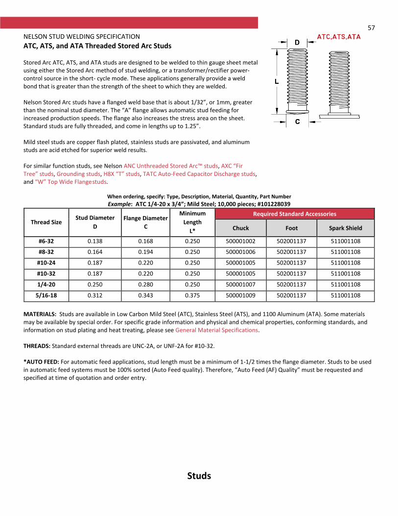
57 NELSON STUD WELDING SPECIFICATION
ATC, ATS, and ATA Threaded Stored Arc Studs Stored Arc ATC, ATS, and ATA studs are designed to be welded to thin gauge sheet metal using either the Stored Arc method of stud welding, or a transformer/rectifier power-control source in the short- cycle mode. These applications generally provide a weld bond that is greater than the strength of the sheet to which they are welded. Nelson Stored Arc studs have a flanged weld base that is about 1/32”, or 1mm, greater than the nominal stud diameter. The “A” flange allows automatic stud feeding for increased production speeds. The flange also increases the stress area on the sheet. Standard studs are fully threaded, and come in lengths up to 1.25”. Mild steel studs are copper flash plated, stainless studs are passivated, and aluminum studs are acid etched for superior weld results. For similar function studs, see Nelson ANC Unthreaded Stored Arc™ studs, AXC “Fir Tree” studs, Grounding studs, H8X “T” studs, TATC Auto-Feed Capacitor Discharge studs, and “W” Top Wide Flange studs.
When ordering, specify: Type, Description, Material, Quantity, Part Number
Example: ATC 1/4-20 x 3/4”; Mild Steel; 10,000 pieces; #101228039
Thread Size Stud Diameter
D
Flange Diameter
C
Minimum
Length
L*
Required Standard Accessories
Chuck Foot Spark Shield
#6-32 0.138 0.168 0.250 500001002 502001137 511001108
#8-32 0.164 0.194 0.250 500001006 502001137 511001108
#10-24 0.187 0.220 0.250 500001005 502001137 511001108
#10-32 0.187 0.220 0.250 500001005 502001137 511001108
1/4-20 0.250 0.280 0.250 500001007 502001137 511001108
5/16-18 0.312 0.343 0.375 500001009 502001137 511001108
MATERIALS: Studs are available in Low Carbon Mild Steel (ATC), Stainless Steel (ATS), and 1100 Aluminum (ATA). Some materials may be available by special order. For specific grade information and physical and chemical properties, conforming standards, and information on stud plating and heat treating, please see General Material Specifications. THREADS: Standard external threads are UNC-2A, or UNF-2A for #10-32. *AUTO FEED: For automatic feed applications, stud length must be a minimum of 1-1/2 times the flange diameter. Studs to be used in automatic feed systems must be 100% sorted (Auto Feed quality). Therefore, “Auto Feed (AF) Quality” must be requested and specified at time of quotation and order entry.
Studs

58
Metric Short Cycle / Stored Arc NELSON STUD WELDING SPECIFICATION
ATC, ATS, and ATA Threaded Studs Nelson metric Stored Arc ATC, ATS, and ATA studs are designed to be welded to thin gauge sheet metal using either the Stored-Arc method of stud welding, or a transformer/ rectifier power-control source in the short-cycle mode. These applications generally provide a weld bond that is greater than the strength of the sheet to which they are welded. Nelson Stored Arc studs have a flanged weld base that is about 1mm greater than the nominal stud diameter. The mini flange diameter “C” allows automatic stud feeding for increased production speeds. The flange also increases the stress area on the sheet. Standard studs are fully threaded, and come in lengths up to 32mm. Mild steel studs are copper flash plated, stainless studs are passivated, and aluminum studs are acid etched for superior weld results. For similar function metric studs, see Nelson ANC Unthreaded Stored Arc™ studs, AXC “Fir Tree” studs, Grounding studs, H8X “T” studs, and “W” Top Wide Flange studs. In the imperial line of Nelson studs, see TATC Auto-Feed Capacitor Discharge studs.
When ordering, specify: Type, Description, Material, Quantity, Part Number
Example: ATC M6 x 16mm; Mild Steel; 10,000 pieces; #101228124
MATERIALS: Studs are available in Low Carbon Mild Steel (ATC), Stainless Steel (ATS), and 1100 Aluminum (ATA). Some materials may be available by special order. For specific grade information and physical and chemical properties, conforming standards, and information on stud plating, please see General Material Specifications. THREADS: Standard metric threads meet ISO 6g. *AUTO FEED: For automatic feed applications, stud length must be a minimum of 1-1/2 times the flange diameter. Studs to be used in automatic feed systems must be 100% sorted (Auto Feed quality). Therefore, “Auto Feed (AF) Quality” must be requested and specified at time of quotation and order entry.
Thread Size Stud Diameter
D
Flange Diameter
C
Minimum Length
L*
Required Standard Accessories
Chuck Foot Spark Shield
M3 x 0.50 3.00 4 8.00 500001135 502001137 511001108
M4 x 0.70 4.00 5 8.00 500001003 502001137 511001108
M5 x 0.80 5.00 6 8.00 500001005 502001137 511001108
M6 x 1.00 6.00 7 10.00 500001267 502001137 511001108
M8 x 1.25 8.00 9 12.00 500001009 502001137 511001108
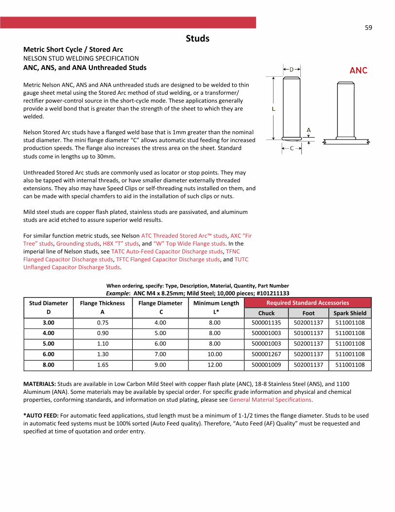
59
Studs Metric Short Cycle / Stored Arc NELSON STUD WELDING SPECIFICATION
ANC, ANS, and ANA Unthreaded Studs Metric Nelson ANC, ANS and ANA unthreaded studs are designed to be welded to thin gauge sheet metal using the Stored Arc method of stud welding, or a transformer/ rectifier power-control source in the short-cycle mode. These applications generally provide a weld bond that is greater than the strength of the sheet to which they are welded. Nelson Stored Arc studs have a flanged weld base that is 1mm greater than the nominal stud diameter. The mini flange diameter “C” allows automatic stud feeding for increased production speeds. The flange also increases the stress area on the sheet. Standard
studs come in lengths up to 30mm. Unthreaded Stored Arc studs are commonly used as locator or stop points. They may also be tapped with internal threads, or have smaller diameter externally threaded extensions. They also may have Speed Clips or self-threading nuts installed on them, and can be made with special chamfers to aid in the installation of such clips or nuts. Mild steel studs are copper flash plated, stainless studs are passivated, and aluminum studs are acid etched to assure superior weld results. For similar function metric studs, see Nelson ATC Threaded Stored Arc™ studs, AXC “Fir Tree” studs, Grounding studs, H8X “T” studs, and “W” Top Wide Flange studs. In the imperial line of Nelson studs, see TATC Auto-Feed Capacitor Discharge studs, TFNC Flanged Capacitor Discharge studs, TFTC Flanged Capacitor Discharge studs, and TUTC Unflanged Capacitor Discharge Studs.
When ordering, specify: Type, Description, Material, Quantity, Part Number
Example: ANC M4 x 8.25mm; Mild Steel; 10,000 pieces; #101211133
Stud Diameter
D
Flange Thickness
A
Flange Diameter
C
Minimum Length
L*
Required Standard Accessories
Chuck Foot Spark Shield
3.00 0.75 4.00 8.00 500001135 502001137 511001108
4.00 0.90 5.00 8.00 500001003 501001137 511001108
5.00 1.10 6.00 8.00 500001003 502001137 511001108
6.00 1.30 7.00 10.00 500001267 502001137 511001108
8.00 1.65 9.00 12.00 500001009 502001137 511001108
MATERIALS: Studs are available in Low Carbon Mild Steel with copper flash plate (ANC), 18-8 Stainless Steel (ANS), and 1100 Aluminum (ANA). Some materials may be available by special order. For specific grade information and physical and chemical properties, conforming standards, and information on stud plating, please see General Material Specifications. *AUTO FEED: For automatic feed applications, stud length must be a minimum of 1-1/2 times the flange diameter. Studs to be used in automatic feed systems must be 100% sorted (Auto Feed quality). Therefore, “Auto Feed (AF) Quality” must be requested and specified at time of quotation and order entry.
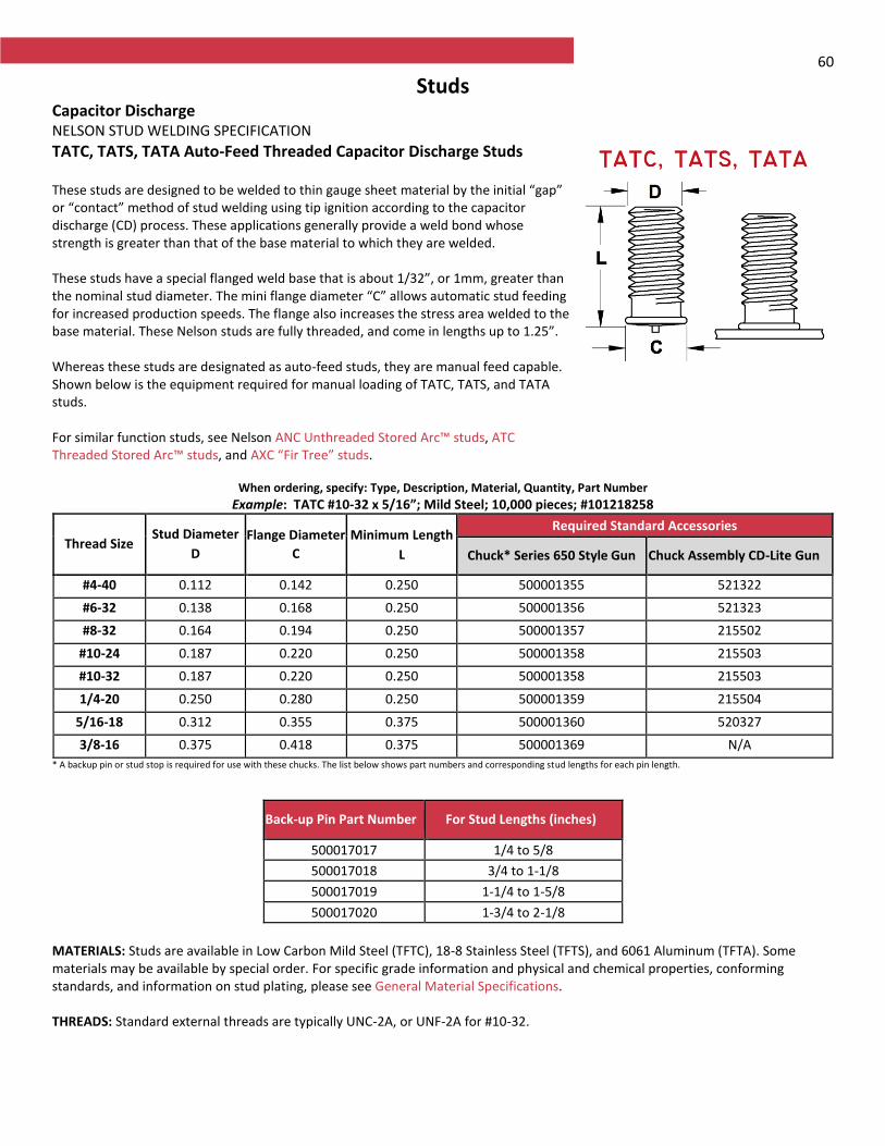
60
Studs Capacitor Discharge NELSON STUD WELDING SPECIFICATION
TATC, TATS, TATA Auto-Feed Threaded Capacitor Discharge Studs These studs are designed to be welded to thin gauge sheet material by the initial “gap” or “contact” method of stud welding using tip ignition according to the capacitor discharge (CD) process. These applications generally provide a weld bond whose strength is greater than that of the base material to which they are welded. These studs have a special flanged weld base that is about 1/32”, or 1mm, greater than the nominal stud diameter. The mini flange diameter “C” allows automatic stud feeding for increased production speeds. The flange also increases the stress area welded to the base material. These Nelson studs are fully threaded, and come in lengths up to 1.25”. Whereas these studs are designated as auto-feed studs, they are manual feed capable. Shown below is the equipment required for manual loading of TATC, TATS, and TATA studs. For similar function studs, see Nelson ANC Unthreaded Stored Arc™ studs, ATC Threaded Stored Arc™ studs, and AXC “Fir Tree” studs.
When ordering, specify: Type, Description, Material, Quantity, Part Number
Example: TATC #10-32 x 5/16”; Mild Steel; 10,000 pieces; #101218258
Thread Size Stud Diameter
D
Flange Diameter
C
Minimum Length
L
Required Standard Accessories
Chuck* Series 650 Style Gun Chuck Assembly CD-Lite Gun
#4-40 0.112 0.142 0.250 500001355 521322
#6-32 0.138 0.168 0.250 500001356 521323
#8-32 0.164 0.194 0.250 500001357 215502
#10-24 0.187 0.220 0.250 500001358 215503
#10-32 0.187 0.220 0.250 500001358 215503
1/4-20 0.250 0.280 0.250 500001359 215504
5/16-18 0.312 0.355 0.375 500001360 520327
3/8-16 0.375 0.418 0.375 500001369 N/A
* A backup pin or stud stop is required for use with these chucks. The list below shows part numbers and corresponding stud lengths for each pin length.
MATERIALS: Studs are available in Low Carbon Mild Steel (TFTC), 18-8 Stainless Steel (TFTS), and 6061 Aluminum (TFTA). Some materials may be available by special order. For specific grade information and physical and chemical properties, conforming standards, and information on stud plating, please see General Material Specifications. THREADS: Standard external threads are typically UNC-2A, or UNF-2A for #10-32.
Back-up Pin Part Number For Stud Lengths (inches)
500017017 1/4 to 5/8
500017018 3/4 to 1-1/8
500017019 1-1/4 to 1-5/8
500017020 1-3/4 to 2-1/8
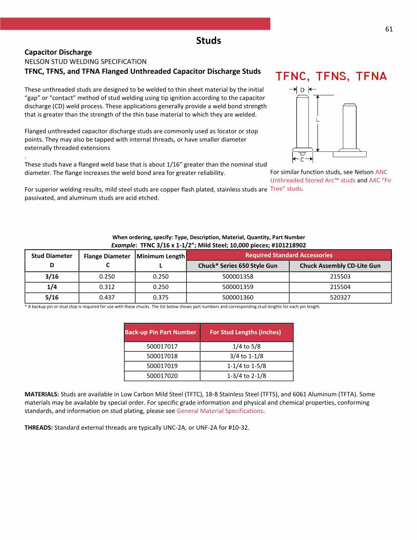
61
Studs Capacitor Discharge NELSON STUD WELDING SPECIFICATION
TFNC, TFNS, and TFNA Flanged Unthreaded Capacitor Discharge Studs These unthreaded studs are designed to be welded to thin sheet material by the initial “gap” or “contact” method of stud welding using tip ignition according to the capacitor discharge (CD) weld process. These applications generally provide a weld bond strength that is greater than the strength of the thin base material to which they are welded. Flanged unthreaded capacitor discharge studs are commonly used as locator or stop points. They may also be tapped with internal threads, or have smaller diameter externally threaded extensions . These studs have a flanged weld base that is about 1/16” greater than the nominal stud diameter. The flange increases the weld bond area for greater reliability. For superior welding results, mild steel studs are copper flash plated, stainless studs are passivated, and aluminum studs are acid etched.
For similar function studs, see Nelson ANC Unthreaded Stored Arc™ studs and AXC “Fir Tree” studs.
When ordering, specify: Type, Description, Material, Quantity, Part Number
Example: TFNC 3/16 x 1-1/2”; Mild Steel; 10,000 pieces; #101218902
Stud Diameter
D
Flange Diameter
C
Minimum Length
L
Required Standard Accessories
Chuck* Series 650 Style Gun Chuck Assembly CD-Lite Gun
3/16 0.250 0.250 500001358 215503
1/4 0.312 0.250 500001359 215504
5/16 0.437 0.375 500001360 520327
* A backup pin or stud stop is required for use with these chucks. The list below shows part numbers and corresponding stud lengths for each pin length.
MATERIALS: Studs are available in Low Carbon Mild Steel (TFTC), 18-8 Stainless Steel (TFTS), and 6061 Aluminum (TFTA). Some materials may be available by special order. For specific grade information and physical and chemical properties, conforming standards, and information on stud plating, please see General Material Specifications. THREADS: Standard external threads are typically UNC-2A, or UNF-2A for #10-32.
Back-up Pin Part Number For Stud Lengths (inches)
500017017 1/4 to 5/8
500017018 3/4 to 1-1/8
500017019 1-1/4 to 1-5/8
500017020 1-3/4 to 2-1/8
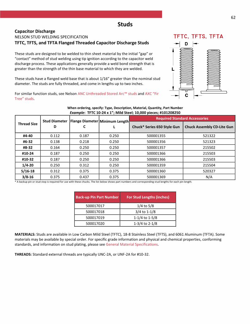
62
Studs Capacitor Discharge NELSON STUD WELDING SPECIFICATION
TFTC, TFTS, and TFTA Flanged Threaded Capacitor Discharge Studs These studs are designed to be welded to thin sheet material by the initial “gap” or “contact” method of stud welding using tip ignition according to the capacitor weld discharge process. These applications generally provide a weld bond strength that is greater than the strength of the thin base material to which they are welded. These studs have a flanged weld base that is about 1/16” greater than the nominal stud diameter. The studs are fully threaded, and come in lengths up to two inches. For similar function studs, see Nelson ANC Unthreaded Stored Arc™ studs and AXC “Fir Tree” studs.
When ordering, specify: Type, Description, Material, Quantity, Part Number
Example: TFTC 10-24 x 1”; Mild Steel; 10,000 pieces; #101208250
Thread Size Stud Diameter
D
Flange Diameter
C
Minimum Length
L
Required Standard Accessories
Chuck* Series 650 Style Gun Chuck Assembly CD-Lite Gun
#4-40 0.112 0.187 0.250 500001355 521322
#6-32 0.138 0.218 0.250 500001356 521323
#8-32 0.164 0.250 0.250 500001357 215502
#10-24 0.187 0.250 0.250 500001366 215503
#10-32 0.187 0.250 0.250 500001366 215503
1/4-20 0.250 0.312 0.250 500001359 215504
5/16-18 0.312 0.375 0.375 500001360 520327
3/8-16 0.375 0.437 0.375 500001369 N/A * A backup pin or stud stop is required for use with these chucks. The list below shows part numbers and corresponding stud lengths for each pin length.
MATERIALS: Studs are available in Low Carbon Mild Steel (TFTC), 18-8 Stainless Steel (TFTS), and 6061 Aluminum (TFTA). Some materials may be available by special order. For specific grade information and physical and chemical properties, conforming standards, and information on stud plating, please see General Material Specifications. THREADS: Standard external threads are typically UNC-2A, or UNF-2A for #10-32.
Back-up Pin Part Number For Stud Lengths (inches)
500017017 1/4 to 5/8
500017018 3/4 to 1-1/8
500017019 1-1/4 to 1-5/8
500017020 1-3/4 to 2-1/8
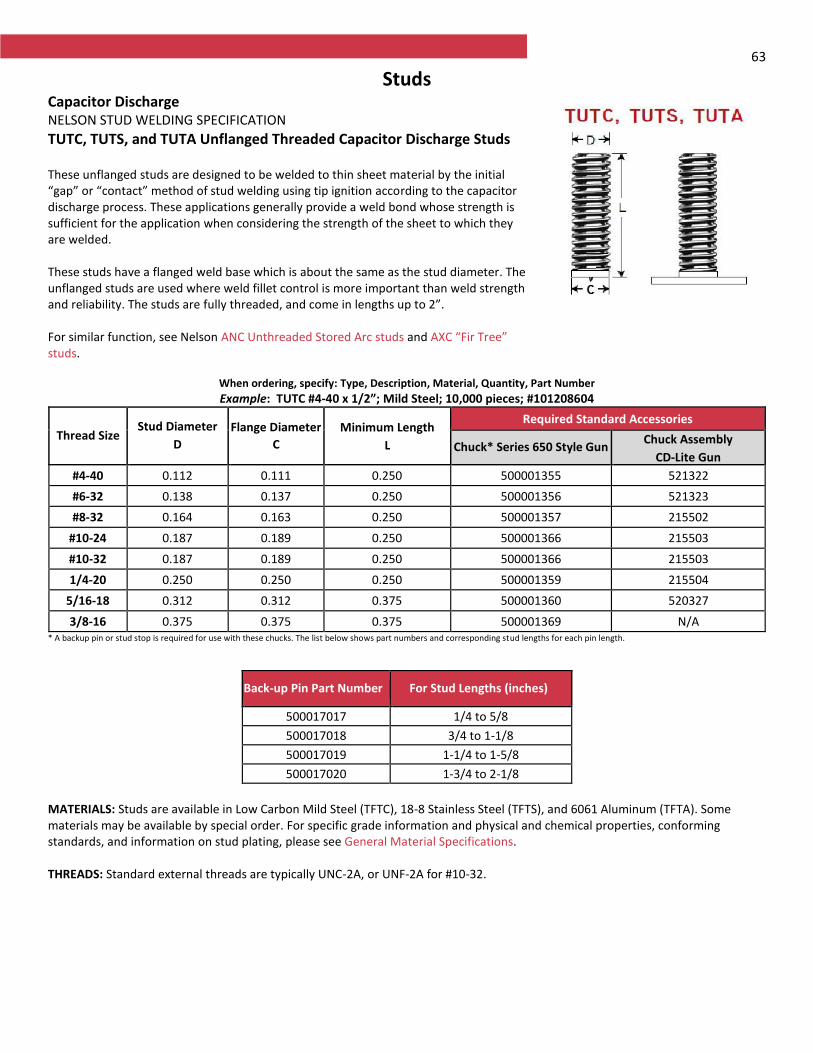
63
Studs Capacitor Discharge NELSON STUD WELDING SPECIFICATION
TUTC, TUTS, and TUTA Unflanged Threaded Capacitor Discharge Studs These unflanged studs are designed to be welded to thin sheet material by the initial “gap” or “contact” method of stud welding using tip ignition according to the capacitor discharge process. These applications generally provide a weld bond whose strength is sufficient for the application when considering the strength of the sheet to which they are welded. These studs have a flanged weld base which is about the same as the stud diameter. The unflanged studs are used where weld fillet control is more important than weld strength and reliability. The studs are fully threaded, and come in lengths up to 2”. For similar function, see Nelson ANC Unthreaded Stored Arc studs and AXC “Fir Tree” studs.
When ordering, specify: Type, Description, Material, Quantity, Part Number
Example: TUTC #4-40 x 1/2”; Mild Steel; 10,000 pieces; #101208604
Thread Size Stud Diameter
D
Flange Diameter
C
Minimum Length
L
Required Standard Accessories
Chuck* Series 650 Style Gun Chuck Assembly
CD-Lite Gun
#4-40 0.112 0.111 0.250 500001355 521322
#6-32 0.138 0.137 0.250 500001356 521323
#8-32 0.164 0.163 0.250 500001357 215502
#10-24 0.187 0.189 0.250 500001366 215503
#10-32 0.187 0.189 0.250 500001366 215503
1/4-20 0.250 0.250 0.250 500001359 215504
5/16-18 0.312 0.312 0.375 500001360 520327
3/8-16 0.375 0.375 0.375 500001369 N/A * A backup pin or stud stop is required for use with these chucks. The list below shows part numbers and corresponding stud lengths for each pin length.
MATERIALS: Studs are available in Low Carbon Mild Steel (TFTC), 18-8 Stainless Steel (TFTS), and 6061 Aluminum (TFTA). Some materials may be available by special order. For specific grade information and physical and chemical properties, conforming standards, and information on stud plating, please see General Material Specifications. THREADS: Standard external threads are typically UNC-2A, or UNF-2A for #10-32.
Back-up Pin Part Number For Stud Lengths (inches)
500017017 1/4 to 5/8
500017018 3/4 to 1-1/8
500017019 1-1/4 to 1-5/8
500017020 1-3/4 to 2-1/8
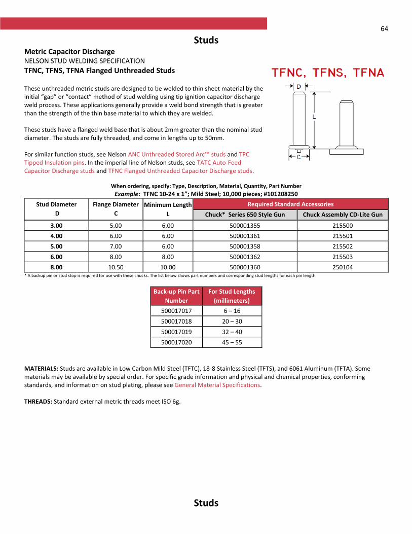
64
Studs Metric Capacitor Discharge NELSON STUD WELDING SPECIFICATION
TFNC, TFNS, TFNA Flanged Unthreaded Studs These unthreaded metric studs are designed to be welded to thin sheet material by the initial “gap” or “contact” method of stud welding using tip ignition capacitor discharge weld process. These applications generally provide a weld bond strength that is greater than the strength of the thin base material to which they are welded. These studs have a flanged weld base that is about 2mm greater than the nominal stud diameter. The studs are fully threaded, and come in lengths up to 50mm. For similar function studs, see Nelson ANC Unthreaded Stored Arc™ studs and TPC Tipped Insulation pins. In the imperial line of Nelson studs, see TATC Auto-Feed Capacitor Discharge studs and TFNC Flanged Unthreaded Capacitor Discharge studs.
When ordering, specify: Type, Description, Material, Quantity, Part Number
Example: TFNC 10-24 x 1”; Mild Steel; 10,000 pieces; #101208250
Stud Diameter
D
Flange Diameter
C
Minimum Length
L
Required Standard Accessories
Chuck* Series 650 Style Gun Chuck Assembly CD-Lite Gun
3.00 5.00 6.00 500001355 215500
4.00 6.00 6.00 500001361 215501
5.00 7.00 6.00 500001358 215502
6.00 8.00 8.00 500001362 215503
8.00 10.50 10.00 500001360 250104 * A backup pin or stud stop is required for use with these chucks. The list below shows part numbers and corresponding stud lengths for each pin length.
Back-up Pin Part
Number
For Stud Lengths
(millimeters)
500017017 6 – 16
500017018 20 – 30
500017019 32 – 40
500017020 45 – 55
MATERIALS: Studs are available in Low Carbon Mild Steel (TFTC), 18-8 Stainless Steel (TFTS), and 6061 Aluminum (TFTA). Some materials may be available by special order. For specific grade information and physical and chemical properties, conforming standards, and information on stud plating, please see General Material Specifications. THREADS: Standard external metric threads meet ISO 6g.
Studs
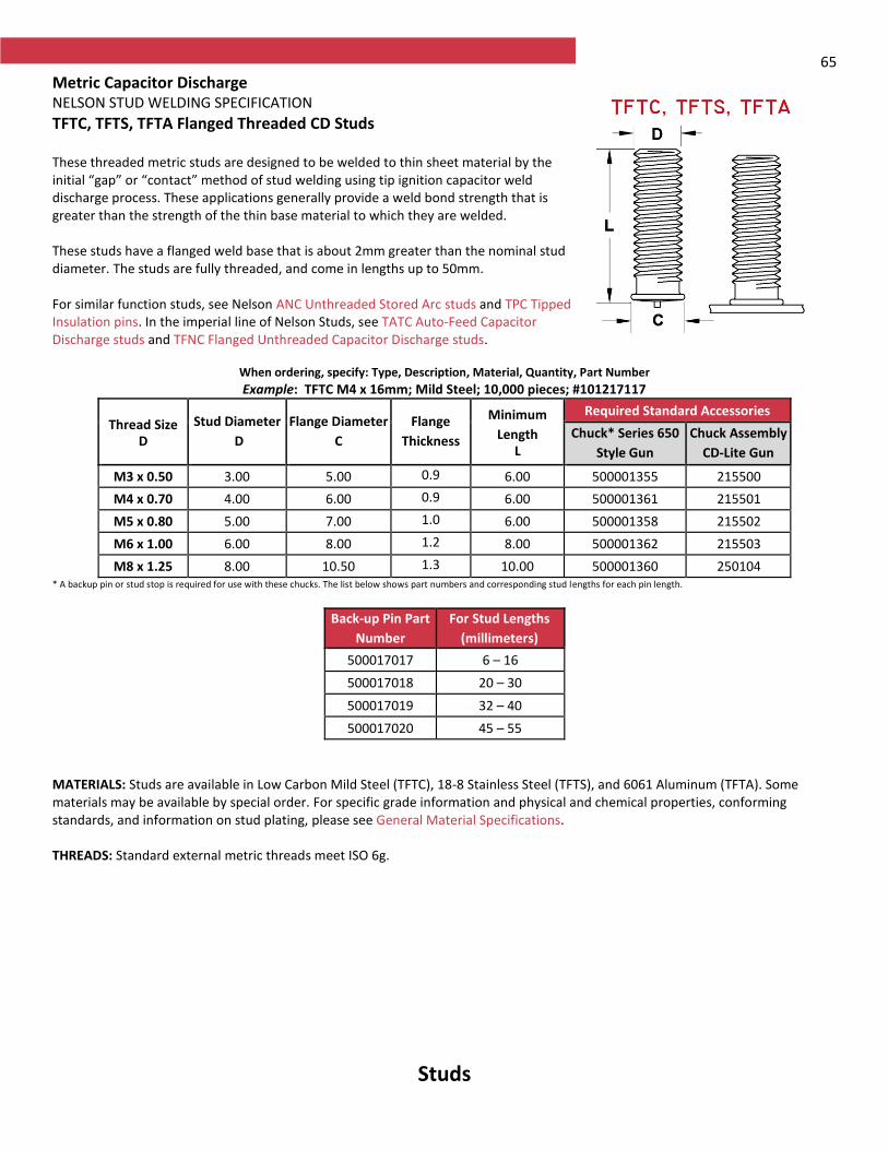
65
Metric Capacitor Discharge NELSON STUD WELDING SPECIFICATION
TFTC, TFTS, TFTA Flanged Threaded CD Studs These threaded metric studs are designed to be welded to thin sheet material by the initial “gap” or “contact” method of stud welding using tip ignition capacitor weld discharge process. These applications generally provide a weld bond strength that is greater than the strength of the thin base material to which they are welded. These studs have a flanged weld base that is about 2mm greater than the nominal stud diameter. The studs are fully threaded, and come in lengths up to 50mm. For similar function studs, see Nelson ANC Unthreaded Stored Arc studs and TPC Tipped Insulation pins. In the imperial line of Nelson Studs, see TATC Auto-Feed Capacitor Discharge studs and TFNC Flanged Unthreaded Capacitor Discharge studs.
When ordering, specify: Type, Description, Material, Quantity, Part Number
Example: TFTC M4 x 16mm; Mild Steel; 10,000 pieces; #101217117
Thread Size D
Stud Diameter
D
Flange Diameter
C
Flange
Thickness
Minimum
Length L
Required Standard Accessories
Chuck* Series 650
Style Gun
Chuck Assembly
CD-Lite Gun
M3 x 0.50 3.00 5.00 0.9 6.00 500001355 215500
M4 x 0.70 4.00 6.00 0.9 6.00 500001361 215501
M5 x 0.80 5.00 7.00 1.0 6.00 500001358 215502
M6 x 1.00 6.00 8.00 1.2 8.00 500001362 215503
M8 x 1.25 8.00 10.50 1.3 10.00 500001360 250104 * A backup pin or stud stop is required for use with these chucks. The list below shows part numbers and corresponding stud lengths for each pin length.
Back-up Pin Part
Number
For Stud Lengths
(millimeters)
500017017 6 – 16
500017018 20 – 30
500017019 32 – 40
500017020 45 – 55
MATERIALS: Studs are available in Low Carbon Mild Steel (TFTC), 18-8 Stainless Steel (TFTS), and 6061 Aluminum (TFTA). Some materials may be available by special order. For specific grade information and physical and chemical properties, conforming standards, and information on stud plating, please see General Material Specifications. THREADS: Standard external metric threads meet ISO 6g.
Studs
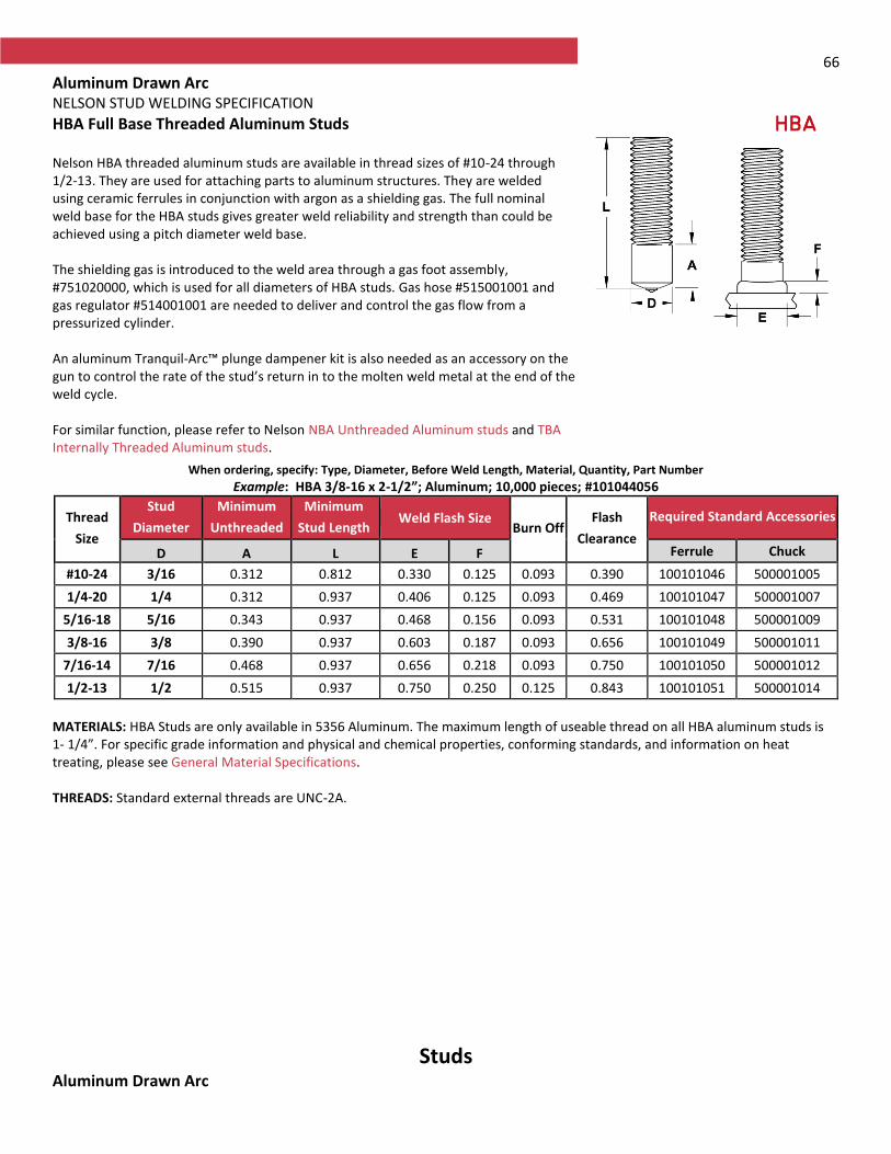
66
Aluminum Drawn Arc NELSON STUD WELDING SPECIFICATION
HBA Full Base Threaded Aluminum Studs Nelson HBA threaded aluminum studs are available in thread sizes of #10-24 through 1/2-13. They are used for attaching parts to aluminum structures. They are welded using ceramic ferrules in conjunction with argon as a shielding gas. The full nominal weld base for the HBA studs gives greater weld reliability and strength than could be achieved using a pitch diameter weld base. The shielding gas is introduced to the weld area through a gas foot assembly, #751020000, which is used for all diameters of HBA studs. Gas hose #515001001 and gas regulator #514001001 are needed to deliver and control the gas flow from a pressurized cylinder. An aluminum Tranquil-Arc™ plunge dampener kit is also needed as an accessory on the gun to control the rate of the stud’s return in to the molten weld metal at the end of the weld cycle. For similar function, please refer to Nelson NBA Unthreaded Aluminum studs and TBA Internally Threaded Aluminum studs.
When ordering, specify: Type, Diameter, Before Weld Length, Material, Quantity, Part Number
Example: HBA 3/8-16 x 2-1/2”; Aluminum; 10,000 pieces; #101044056
Thread
Size
Stud
Diameter
Minimum
Unthreaded
Minimum
Stud Length Weld Flash Size
Burn Off Flash
Clearance
Required Standard Accessories
D A L E F Ferrule Chuck
#10-24 3/16 0.312 0.812 0.330 0.125 0.093 0.390 100101046 500001005
1/4-20 1/4 0.312 0.937 0.406 0.125 0.093 0.469 100101047 500001007
5/16-18 5/16 0.343 0.937 0.468 0.156 0.093 0.531 100101048 500001009
3/8-16 3/8 0.390 0.937 0.603 0.187 0.093 0.656 100101049 500001011
7/16-14 7/16 0.468 0.937 0.656 0.218 0.093 0.750 100101050 500001012
1/2-13 1/2 0.515 0.937 0.750 0.250 0.125 0.843 100101051 500001014
MATERIALS: HBA Studs are only available in 5356 Aluminum. The maximum length of useable thread on all HBA aluminum studs is 1- 1/4”. For specific grade information and physical and chemical properties, conforming standards, and information on heat treating, please see General Material Specifications. THREADS: Standard external threads are UNC-2A.
Studs Aluminum Drawn Arc
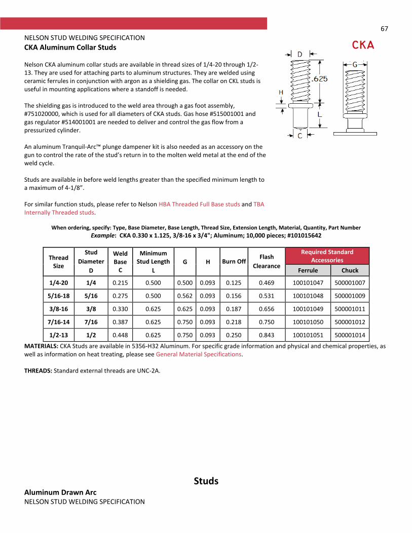
67 NELSON STUD WELDING SPECIFICATION
CKA Aluminum Collar Studs Nelson CKA aluminum collar studs are available in thread sizes of 1/4-20 through 1/2-13. They are used for attaching parts to aluminum structures. They are welded using ceramic ferrules in conjunction with argon as a shielding gas. The collar on CKL studs is useful in mounting applications where a standoff is needed. The shielding gas is introduced to the weld area through a gas foot assembly, #751020000, which is used for all diameters of CKA studs. Gas hose #515001001 and gas regulator #514001001 are needed to deliver and control the gas flow from a pressurized cylinder. An aluminum Tranquil-Arc™ plunge dampener kit is also needed as an accessory on the gun to control the rate of the stud’s return in to the molten weld metal at the end of the weld cycle. Studs are available in before weld lengths greater than the specified minimum length to a maximum of 4-1/8”. For similar function studs, please refer to Nelson HBA Threaded Full Base studs and TBA Internally Threaded studs.
When ordering, specify: Type, Base Diameter, Base Length, Thread Size, Extension Length, Material, Quantity, Part Number
Example: CKA 0.330 x 1.125, 3/8-16 x 3/4"; Aluminum; 10,000 pieces; #101015642
MATERIALS: CKA Studs are available in 5356-H32 Aluminum. For specific grade information and physical and chemical properties, as well as information on heat treating, please see General Material Specifications. THREADS: Standard external threads are UNC-2A.
Studs Aluminum Drawn Arc NELSON STUD WELDING SPECIFICATION
Thread Size
Stud
Diameter
D
Weld Base
C
Minimum Stud Length
L
G H Burn Off Flash
Clearance
Required Standard Accessories
Ferrule Chuck
1/4-20 1/4 0.215 0.500 0.500 0.093 0.125 0.469 100101047 500001007
5/16-18 5/16 0.275 0.500 0.562 0.093 0.156 0.531 100101048 500001009
3/8-16 3/8 0.330 0.625 0.625 0.093 0.187 0.656 100101049 500001011
7/16-14 7/16 0.387 0.625 0.750 0.093 0.218 0.750 100101050 500001012
1/2-13 1/2 0.448 0.625 0.750 0.093 0.250 0.843 100101051 500001014
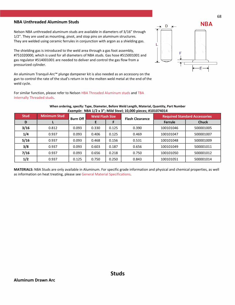
68
NBA Unthreaded Aluminum Studs Nelson NBA unthreaded aluminum studs are available in diameters of 3/16” through 1/2". They are used as mounting, pivot, and stop pins on aluminum structures. They are welded using ceramic ferrules in conjunction with argon as a shielding gas. The shielding gas is introduced to the weld area through a gas foot assembly, #751020000, which is used for all diameters of NBA studs. Gas hose #515001001 and gas regulator #514001001 are needed to deliver and control the gas flow from a pressurized cylinder. An aluminum Tranquil-Arc™ plunge dampener kit is also needed as an accessory on the gun to control the rate of the stud’s return in to the molten weld metal at the end of the weld cycle. For similar function, please refer to Nelson HBA Threaded Aluminum studs and TBA Internally Threaded studs.
When ordering, specify: Type, Diameter, Before Weld Length, Material, Quantity, Part Number
Example: NBA 1/2 x 3”; Mild Steel; 10,000 pieces; #101074014
Stud
Diameter
Minimum Stud Length Burn Off
Weld Flash Size Flash Clearance
Required Standard Accessories
D L E F Ferrule Chuck
3/16 0.812 0.093 0.330 0.125 0.390 100101046 500001005
1/4 0.937 0.093 0.406 0.125 0.469 100101047 500001007
5/16 0.937 0.093 0.468 0.156 0.531 100101048 500001009
3/8 0.937 0.093 0.603 0.187 0.656 100101049 500001011
7/16 0.937 0.093 0.656 0.218 0.750 100101050 500001012
1/2 0.937 0.125 0.750 0.250 0.843 100101051 500001014
MATERIALS: NBA Studs are only available in Aluminum. For specific grade information and physical and chemical properties, as well as information on heat treating, please see General Material Specifications.
Studs Aluminum Drawn Arc
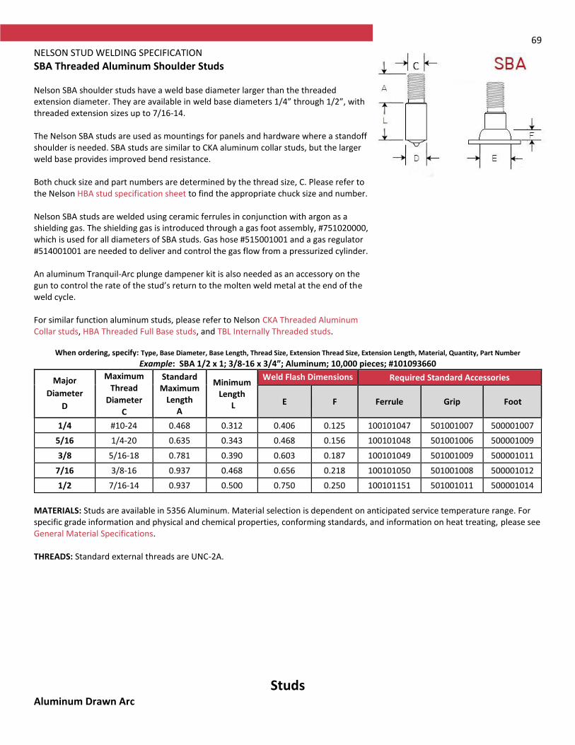
69 NELSON STUD WELDING SPECIFICATION
SBA Threaded Aluminum Shoulder Studs Nelson SBA shoulder studs have a weld base diameter larger than the threaded extension diameter. They are available in weld base diameters 1/4” through 1/2”, with threaded extension sizes up to 7/16-14. The Nelson SBA studs are used as mountings for panels and hardware where a standoff shoulder is needed. SBA studs are similar to CKA aluminum collar studs, but the larger weld base provides improved bend resistance. Both chuck size and part numbers are determined by the thread size, C. Please refer to the Nelson HBA stud specification sheet to find the appropriate chuck size and number. Nelson SBA studs are welded using ceramic ferrules in conjunction with argon as a shielding gas. The shielding gas is introduced through a gas foot assembly, #751020000, which is used for all diameters of SBA studs. Gas hose #515001001 and a gas regulator #514001001 are needed to deliver and control the gas flow from a pressurized cylinder. An aluminum Tranquil-Arc plunge dampener kit is also needed as an accessory on the gun to control the rate of the stud’s return to the molten weld metal at the end of the weld cycle. For similar function aluminum studs, please refer to Nelson CKA Threaded Aluminum Collar studs, HBA Threaded Full Base studs, and TBL Internally Threaded studs.
When ordering, specify: Type, Base Diameter, Base Length, Thread Size, Extension Thread Size, Extension Length, Material, Quantity, Part Number
Example: SBA 1/2 x 1; 3/8-16 x 3/4”; Aluminum; 10,000 pieces; #101093660
Major
Diameter
D
Maximum
Thread
Diameter
C
Standard Maximum
Length A
Minimum Length
L
Weld Flash Dimensions Required Standard Accessories
E F Ferrule Grip Foot
1/4 #10-24 0.468 0.312 0.406 0.125 100101047 501001007 500001007
5/16 1/4-20 0.635 0.343 0.468 0.156 100101048 501001006 500001009
3/8 5/16-18 0.781 0.390 0.603 0.187 100101049 501001009 500001011
7/16 3/8-16 0.937 0.468 0.656 0.218 100101050 501001008 500001012
1/2 7/16-14 0.937 0.500 0.750 0.250 100101151 501001011 500001014
MATERIALS: Studs are available in 5356 Aluminum. Material selection is dependent on anticipated service temperature range. For specific grade information and physical and chemical properties, conforming standards, and information on heat treating, please see General Material Specifications. THREADS: Standard external threads are UNC-2A.
Studs Aluminum Drawn Arc
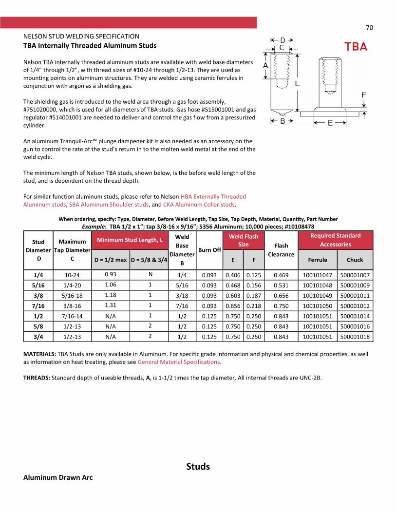
70 NELSON STUD WELDING SPECIFICATION
TBA Internally Threaded Aluminum Studs Nelson TBA internally threaded aluminum studs are available with weld base diameters of 1/4” through 1/2", with thread sizes of #10-24 through 1/2-13. They are used as mounting points on aluminum structures. They are welded using ceramic ferrules in conjunction with argon as a shielding gas. The shielding gas is introduced to the weld area through a gas foot assembly, #751020000, which is used for all diameters of TBA studs. Gas hose #515001001 and gas regulator #514001001 are needed to deliver and control the gas flow from a pressurized cylinder. An aluminum Tranquil-Arc™ plunge dampener kit is also needed as an accessory on the gun to control the rate of the stud’s return in to the molten weld metal at the end of the weld cycle. The minimum length of Nelson TBA studs, shown below, is the before weld length of the stud, and is dependent on the thread depth. For similar function aluminum studs, please refer to Nelson HBA Externally Threaded Aluminum studs, SBA Aluminum Shoulder studs, and CKA Aluminum Collar studs.
When ordering, specify: Type, Diameter, Before Weld Length, Tap Size, Tap Depth, Material, Quantity, Part Number
Example: TBA 1/2 x 1”; tap 3/8-16 x 9/16”; 5356 Aluminum; 10,000 pieces; #10108478
Stud
Diameter
D
Maximum
Tap Diameter
C
Minimum Stud Length, L Weld
Base
Diameter
B
Burn Off
Weld Flash Size Flash
Clearance
Required Standard
Accessories
D = 1/2 max D = 5/8 & 3/4 E F Ferrule Chuck
1/4 10-24 0.937
N/A
1/4 0.093 0.406 0.125 0.469 100101047 500001007
5/16 1/4-20 1.062
1.500
5/16 0.093 0.468 0.156 0.531 100101048 500001009
3/8 5/16-18 1.187
1.593
3/18 0.093 0.603 0.187 0.656 100101049 500001011
7/16 3/8-16 1.312
1.718
7/16 0.093 0.656 0.218 0.750 100101050 500001012
1/2 7/16-14 N/A 1.906
1/2 0.125 0.750 0.250 0.843 100101051 500001014
5/8 1/2-13 N/A 2.000
1/2 0.125 0.750 0.250 0.843 100101051 500001016
3/4 1/2-13 N/A 2.000
1/2 0.125 0.750 0.250 0.843 100101051 500001018
MATERIALS: TBA Studs are only available in Aluminum. For specific grade information and physical and chemical properties, as well as information on heat treating, please see General Material Specifications. THREADS: Standard depth of useable threads, A, is 1-1/2 times the tap diameter. All internal threads are UNC-2B.
Studs Aluminum Drawn Arc

71 NELSON STUD WELDING SPECIFICATION
N3A Aluminum Navy Type Annular Pins N3A Navy pins are welded for the attachment of insulation. The insulation is impaled over the welded studs and retained with caps that are driven onto the studs, and lock onto the annular rings. The 5/16” diameter welded end on Nelson N3A pins permits welding without the use of inert gas shielding, which is normally required when welding aluminum studs. The flat top caps for use with N3A studs are usually supplied in aluminum. They can also be supplied in plated mild steel or stainless steel, per the N3P Annular Ring stud. The standard N3A cap is shown below and is supplied in aluminum. For similar function studs, see Nelson N3P Annular Ring Navy Pin, P2P Double Pointed Insulation Pins, TPC Single Pointed Insulation Pins, and CHP Cupped Headed Insulation Pins.
When ordering, specify: Type, Description, Material, Quantity, Part Number
Example: N3A 3/16 x 1”; Mild Steel; 10,000 pieces; #101074014
Stud
Description
Minimum
Length
L
D A B C
Required Standard Accessories
Ferrule Chuck Grip Foot
3/16 x L 1.000 0.178 0.250 0.176 0.312 100101007 500001005 501001006 502001137
MATERIALS: Studs are available in Aluminum. For specific grade information and physical and chemical properties, and conforming standards, please see General Material Specifications.
RECOMMENDED ACCESSORIES SPECIFICATION
Cap for N3A and N3P Pins Caps are used in conjunction with Nelson N3A and N3P pins to secure many types of insulation to steel plate.
When ordering, specify: Type, Description, Material, Quantity Example: N3A Insulation Cap Aluminum 10,000 pieces
Description Part Number
Insulation Cap 101304002
Materials: The Navy pin cap is supplied in Aluminum. For specific grade information and physical and chemical properties, and conforming standards, please see General Material Specifications.
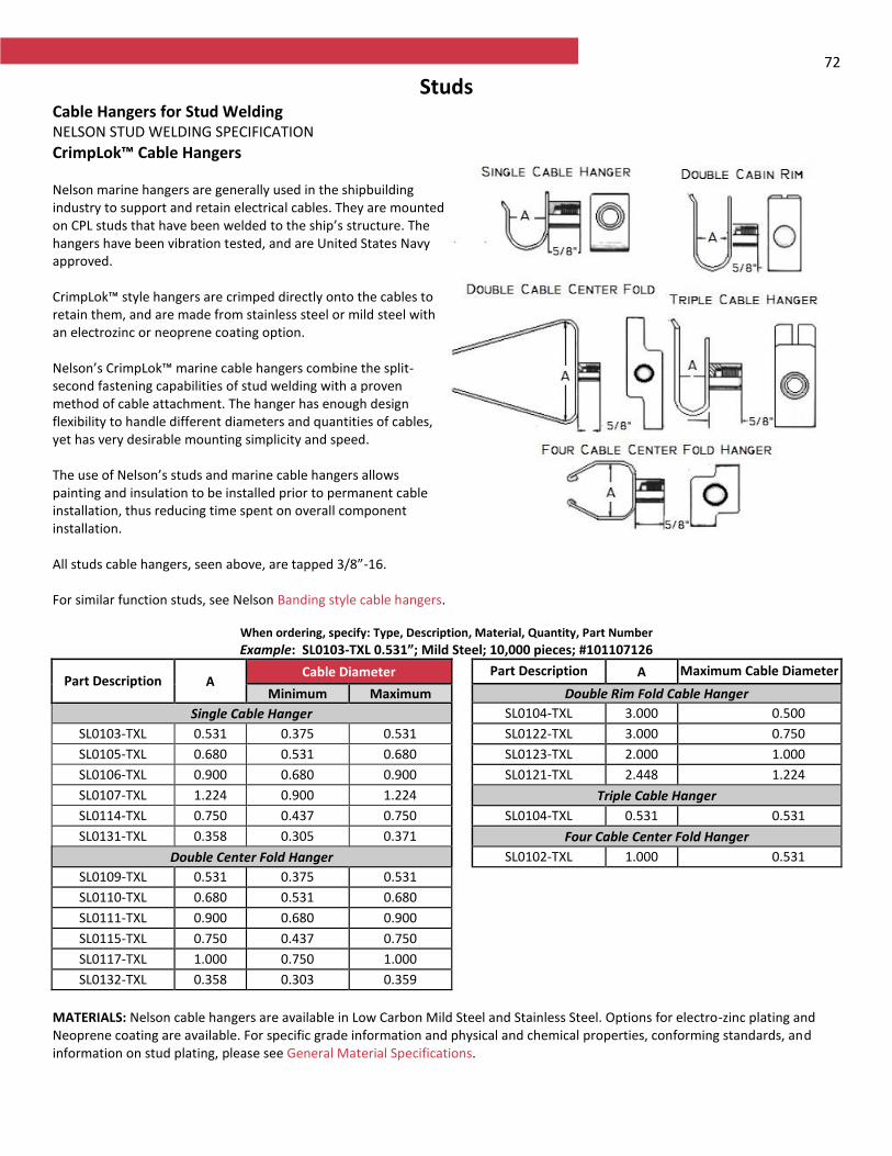
72
Studs Cable Hangers for Stud Welding NELSON STUD WELDING SPECIFICATION
CrimpLok™ Cable Hangers Nelson marine hangers are generally used in the shipbuilding industry to support and retain electrical cables. They are mounted on CPL studs that have been welded to the ship’s structure. The hangers have been vibration tested, and are United States Navy approved. CrimpLok™ style hangers are crimped directly onto the cables to retain them, and are made from stainless steel or mild steel with an electrozinc or neoprene coating option. Nelson’s CrimpLok™ marine cable hangers combine the split- second fastening capabilities of stud welding with a proven method of cable attachment. The hanger has enough design flexibility to handle different diameters and quantities of cables, yet has very desirable mounting simplicity and speed. The use of Nelson’s studs and marine cable hangers allows painting and insulation to be installed prior to permanent cable installation, thus reducing time spent on overall component installation. All studs cable hangers, seen above, are tapped 3/8”-16. For similar function studs, see Nelson Banding style cable hangers.
When ordering, specify: Type, Description, Material, Quantity, Part Number
Example: SL0103-TXL 0.531”; Mild Steel; 10,000 pieces; #101107126
Part Description A Cable Diameter Part Description A Maximum Cable Diameter
Minimum Maximum Double Rim Fold Cable Hanger
Single Cable Hanger SL0104-TXL 3.000 0.500
SL0103-TXL 0.531 0.375 0.531 SL0122-TXL 3.000 0.750
SL0105-TXL 0.680 0.531 0.680 SL0123-TXL 2.000 1.000
SL0106-TXL 0.900 0.680 0.900 SL0121-TXL 2.448 1.224
SL0107-TXL 1.224 0.900 1.224 Triple Cable Hanger
SL0114-TXL 0.750 0.437 0.750 SL0104-TXL 0.531 0.531
SL0131-TXL 0.358 0.305 0.371 Four Cable Center Fold Hanger
Double Center Fold Hanger SL0102-TXL 1.000 0.531
SL0109-TXL 0.531 0.375 0.531
SL0110-TXL 0.680 0.531 0.680
SL0111-TXL 0.900 0.680 0.900
SL0115-TXL 0.750 0.437 0.750
SL0117-TXL 1.000 0.750 1.000
SL0132-TXL 0.358 0.303 0.359
MATERIALS: Nelson cable hangers are available in Low Carbon Mild Steel and Stainless Steel. Options for electro-zinc plating and Neoprene coating are available. For specific grade information and physical and chemical properties, conforming standards, and information on stud plating, please see General Material Specifications.
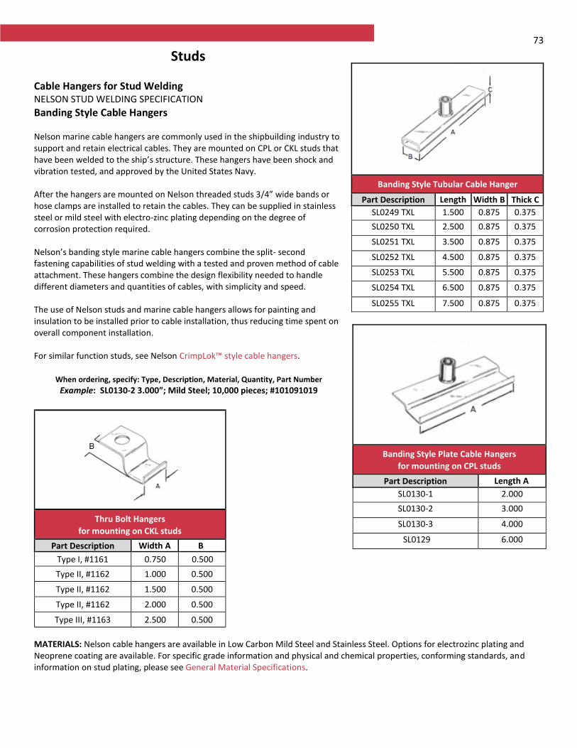
73
Studs Cable Hangers for Stud Welding NELSON STUD WELDING SPECIFICATION
Banding Style Cable Hangers Nelson marine cable hangers are commonly used in the shipbuilding industry to support and retain electrical cables. They are mounted on CPL or CKL studs that have been welded to the ship’s structure. These hangers have been shock and vibration tested, and approved by the United States Navy. After the hangers are mounted on Nelson threaded studs 3/4” wide bands or hose clamps are installed to retain the cables. They can be supplied in stainless steel or mild steel with electro-zinc plating depending on the degree of corrosion protection required. Nelson’s banding style marine cable hangers combine the split- second fastening capabilities of stud welding with a tested and proven method of cable attachment. These hangers combine the design flexibility needed to handle different diameters and quantities of cables, with simplicity and speed. The use of Nelson studs and marine cable hangers allows for painting and insulation to be installed prior to cable installation, thus reducing time spent on overall component installation. For similar function studs, see Nelson CrimpLok™ style cable hangers.
When ordering, specify: Type, Description, Material, Quantity, Part Number
Example: SL0130-2 3.000”; Mild Steel; 10,000 pieces; #101091019
MATERIALS: Nelson cable hangers are available in Low Carbon Mild Steel and Stainless Steel. Options for electrozinc plating and Neoprene coating are available. For specific grade information and physical and chemical properties, conforming standards, and information on stud plating, please see General Material Specifications.
Banding Style Tubular Cable Hanger
Part Description Length Width B Thick C
SL0249 TXL 1.500 0.875 0.375
SL0250 TXL 2.500 0.875 0.375
SL0251 TXL 3.500 0.875 0.375
SL0252 TXL 4.500 0.875 0.375
SL0253 TXL 5.500 0.875 0.375
SL0254 TXL 6.500 0.875 0.375
SL0255 TXL 7.500 0.875 0.375
Banding Style Plate Cable Hangers
for mounting on CPL studs
Part Description Length A
SL0130-1 2.000
SL0130-2 3.000
SL0130-3 4.000
SL0129 6.000
Thru Bolt Hangers
for mounting on CKL studs
Part Description Width A B
. Type I, #1161 0.750 0.500
Type II, #1162 1.000 0.500
Type II, #1162 1.500 0.500
Type II, #1162 2.000 0.500
Type III, #1163 2.500 0.500
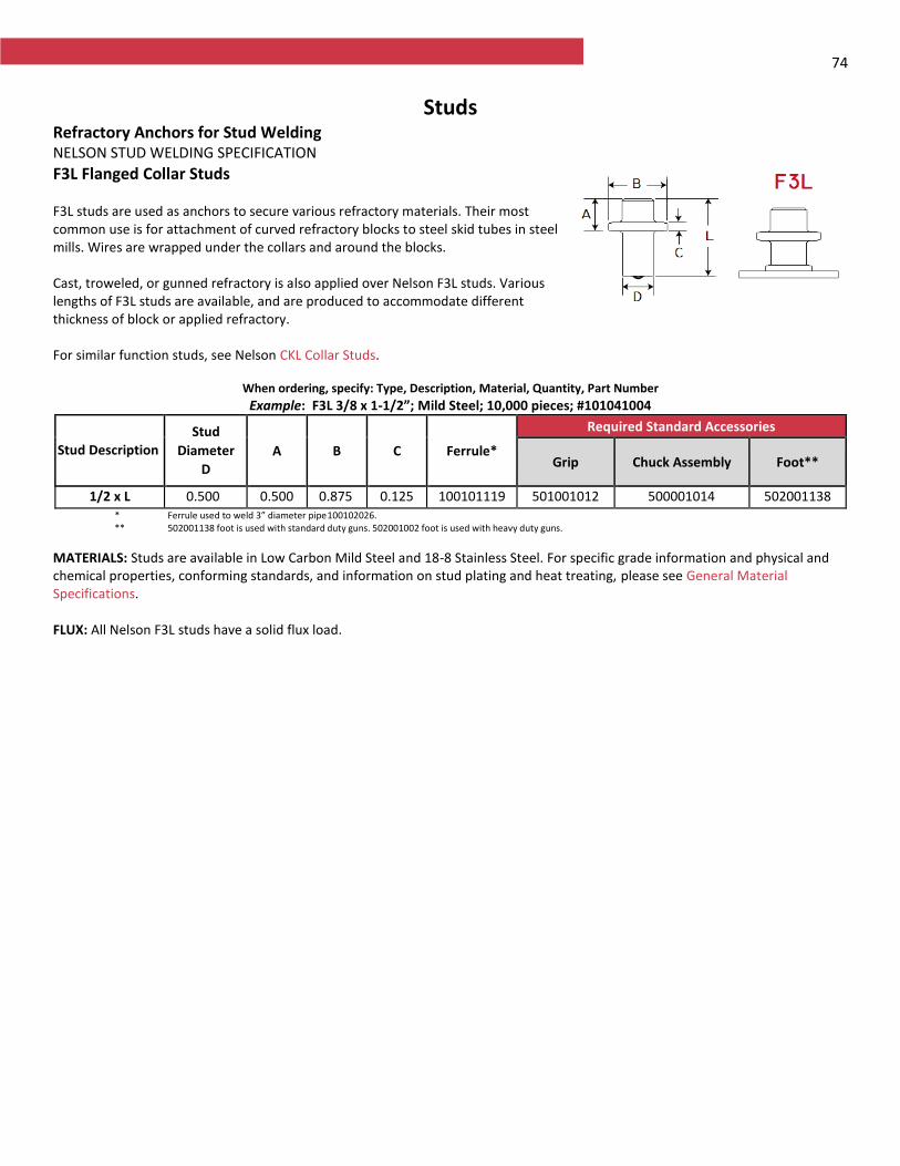
74
Studs Refractory Anchors for Stud Welding NELSON STUD WELDING SPECIFICATION
F3L Flanged Collar Studs F3L studs are used as anchors to secure various refractory materials. Their most common use is for attachment of curved refractory blocks to steel skid tubes in steel mills. Wires are wrapped under the collars and around the blocks. Cast, troweled, or gunned refractory is also applied over Nelson F3L studs. Various lengths of F3L studs are available, and are produced to accommodate different thickness of block or applied refractory. For similar function studs, see Nelson CKL Collar Studs.
When ordering, specify: Type, Description, Material, Quantity, Part Number
Example: F3L 3/8 x 1-1/2”; Mild Steel; 10,000 pieces; #101041004
Stud Description
Stud
Diameter
D
A B C Ferrule*
Required Standard Accessories
Grip Chuck Assembly Foot**
1/2 x L 0.500 0.500 0.875 0.125 100101119 501001012 500001014 502001138 * Ferrule used to weld 3” diameter pipe 100102026. ** 502001138 foot is used with standard duty guns. 502001002 foot is used with heavy duty guns.
MATERIALS: Studs are available in Low Carbon Mild Steel and 18-8 Stainless Steel. For specific grade information and physical and chemical properties, conforming standards, and information on stud plating and heat treating, please see General Material Specifications. FLUX: All Nelson F3L studs have a solid flux load.
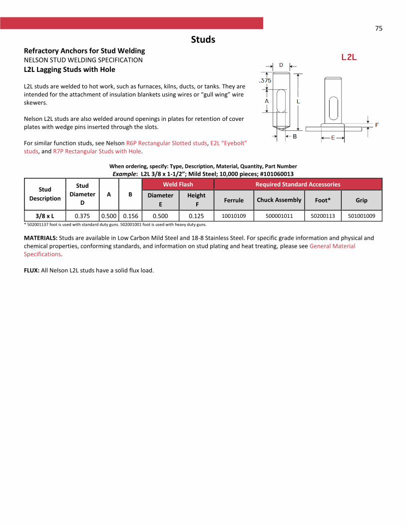
75
Studs Refractory Anchors for Stud Welding NELSON STUD WELDING SPECIFICATION
L2L Lagging Studs with Hole L2L studs are welded to hot work, such as furnaces, kilns, ducts, or tanks. They are intended for the attachment of insulation blankets using wires or “gull wing” wire skewers. Nelson L2L studs are also welded around openings in plates for retention of cover plates with wedge pins inserted through the slots. For similar function studs, see Nelson R6P Rectangular Slotted studs, E2L “Eyebolt” studs, and R7P Rectangular Studs with Hole.
When ordering, specify: Type, Description, Material, Quantity, Part Number
Example: L2L 3/8 x 1-1/2”; Mild Steel; 10,000 pieces; #101060013
Stud
Description
Stud
Diameter
D
A B
Weld Flash Required Standard Accessories
Diameter
E
Height
F Ferrule Chuck Assembly Foot* Grip
3/8 x L 0.375 0.500 0.156 0.500 0.125 10010109 500001011 50200113 501001009
* 502001137 foot is used with standard duty guns. 502001001 foot is used with heavy duty guns.
MATERIALS: Studs are available in Low Carbon Mild Steel and 18-8 Stainless Steel. For specific grade information and physical and chemical properties, conforming standards, and information on stud plating and heat treating, please see General Material Specifications. FLUX: All Nelson L2L studs have a solid flux load.
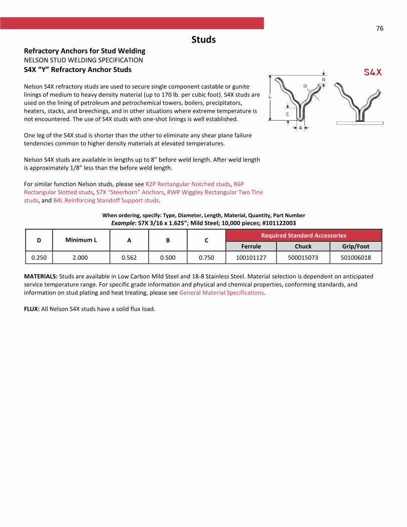
76
Studs Refractory Anchors for Stud Welding NELSON STUD WELDING SPECIFICATION
S4X “Y” Refractory Anchor Studs Nelson S4X refractory studs are used to secure single component castable or gunite linings of medium to heavy density material (up to 170 lb. per cubic foot). S4X studs are used on the lining of petroleum and petrochemical towers, boilers, precipitators, heaters, stacks, and breechings, and in other situations where extreme temperature is not encountered. The use of S4X studs with one-shot linings is well established. One leg of the S4X stud is shorter than the other to eliminate any shear plane failure tendencies common to higher density materials at elevated temperatures. Nelson S4X studs are available in lengths up to 8” before weld length. After weld length is approximately 1/8” less than the before weld length. For similar function Nelson studs, please see R2P Rectangular Notched studs, R6P Rectangular Slotted studs, S7X “Steerhorn” Anchors, RWP Wiggley Rectangular Two Tine studs, and B4L Reinforcing Standoff Support studs.
When ordering, specify: Type, Diameter, Length, Material, Quantity, Part Number
Example: S7X 3/16 x 1.625”; Mild Steel; 10,000 pieces; #101122003
D Minimum L A B C Required Standard Accessories
Ferrule Chuck Grip/Foot
0.250 2.000 0.562 0.500 0.750 100101127 500015073 501006018
MATERIALS: Studs are available in Low Carbon Mild Steel and 18-8 Stainless Steel. Material selection is dependent on anticipated service temperature range. For specific grade information and physical and chemical properties, conforming standards, and information on stud plating and heat treating, please see General Material Specifications. FLUX: All Nelson S4X studs have a solid flux load.
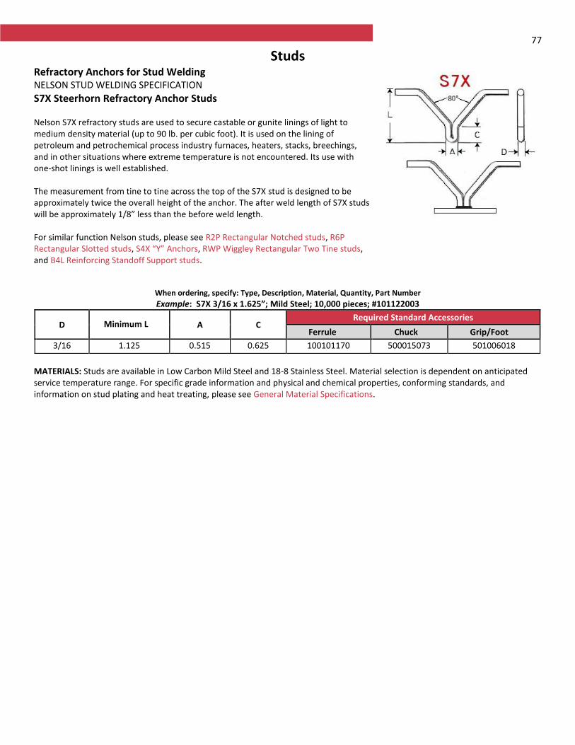
77
Studs Refractory Anchors for Stud Welding NELSON STUD WELDING SPECIFICATION
S7X Steerhorn Refractory Anchor Studs Nelson S7X refractory studs are used to secure castable or gunite linings of light to medium density material (up to 90 lb. per cubic foot). It is used on the lining of petroleum and petrochemical process industry furnaces, heaters, stacks, breechings, and in other situations where extreme temperature is not encountered. Its use with one-shot linings is well established. The measurement from tine to tine across the top of the S7X stud is designed to be approximately twice the overall height of the anchor. The after weld length of S7X studs will be approximately 1/8” less than the before weld length. For similar function Nelson studs, please see R2P Rectangular Notched studs, R6P Rectangular Slotted studs, S4X “Y” Anchors, RWP Wiggley Rectangular Two Tine studs, and B4L Reinforcing Standoff Support studs.
When ordering, specify: Type, Description, Material, Quantity, Part Number
Example: S7X 3/16 x 1.625”; Mild Steel; 10,000 pieces; #101122003
D Minimum L A C Required Standard Accessories
Ferrule Chuck Grip/Foot
3/16 1.125 0.515 0.625 100101170 500015073 501006018
MATERIALS: Studs are available in Low Carbon Mild Steel and 18-8 Stainless Steel. Material selection is dependent on anticipated service temperature range. For specific grade information and physical and chemical properties, conforming standards, and information on stud plating and heat treating, please see General Material Specifications.
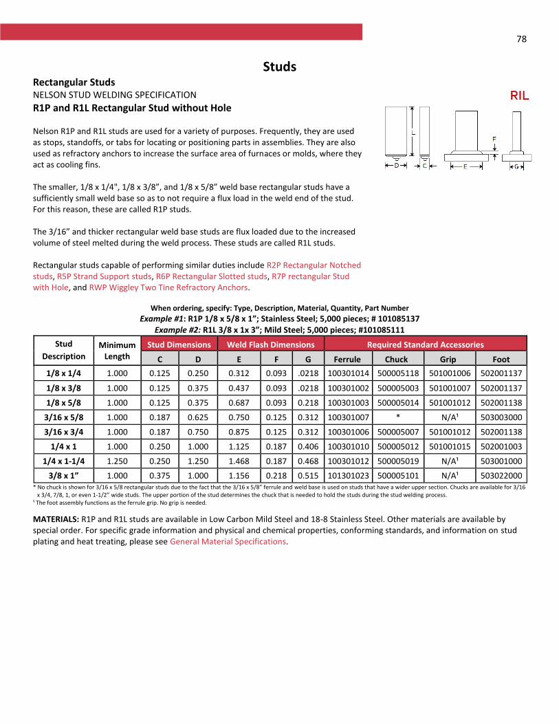
78
Studs Rectangular Studs NELSON STUD WELDING SPECIFICATION
R1P and R1L Rectangular Stud without Hole Nelson R1P and R1L studs are used for a variety of purposes. Frequently, they are used as stops, standoffs, or tabs for locating or positioning parts in assemblies. They are also used as refractory anchors to increase the surface area of furnaces or molds, where they act as cooling fins. The smaller, 1/8 x 1/4", 1/8 x 3/8”, and 1/8 x 5/8” weld base rectangular studs have a sufficiently small weld base so as to not require a flux load in the weld end of the stud. For this reason, these are called R1P studs. The 3/16” and thicker rectangular weld base studs are flux loaded due to the increased volume of steel melted during the weld process. These studs are called R1L studs. Rectangular studs capable of performing similar duties include R2P Rectangular Notched studs, R5P Strand Support studs, R6P Rectangular Slotted studs, R7P rectangular Stud with Hole, and RWP Wiggley Two Tine Refractory Anchors.
When ordering, specify: Type, Description, Material, Quantity, Part Number
Example #1: R1P 1/8 x 5/8 x 1”; Stainless Steel; 5,000 pieces; # 101085137 Example #2: R1L 3/8 x 1x 3”; Mild Steel; 5,000 pieces; #101085111
Stud
Description Minimum
Length
Stud Dimensions Weld Flash Dimensions Required Standard Accessories
C D E F G Ferrule Chuck Grip Foot
1/8 x 1/4 1.000 0.125 0.250 0.312 0.093 .0218 100301014 500005118 501001006 502001137
1/8 x 3/8 1.000 0.125 0.375 0.437 0.093 .0218 100301002 500005003 501001007 502001137
1/8 x 5/8 1.000 0.125 0.375 0.687 0.093 0.218 100301003 500005014 501001012 502001138
3/16 x 5/8 1.000 0.187 0.625 0.750 0.125 0.312 100301007 * N/A¹ 503003000
3/16 x 3/4 1.000 0.187 0.750 0.875 0.125 0.312 100301006 500005007 501001012 502001138
1/4 x 1 1.000 0.250 1.000 1.125 0.187 0.406 100301010 500005012 501001015 502001003
1/4 x 1-1/4 1.250 0.250 1.250 1.468 0.187 0.468 100301012 500005019 N/A¹ 503001000
3/8 x 1” 1.000 0.375 1.000 1.156 0.218 0.515 101301023 500005101 N/A¹ 503022000 * No chuck is shown for 3/16 x 5/8 rectangular studs due to the fact that the 3/16 x 5/8” ferrule and weld base is used on studs that have a wider upper section. Chucks are available for 3/16
x 3/4, 7/8, 1, or even 1-1/2” wide studs. The upper portion of the stud determines the chuck that is needed to hold the studs during the stud welding process. ¹ The foot assembly functions as the ferrule grip. No grip is needed.
MATERIALS: R1P and R1L studs are available in Low Carbon Mild Steel and 18-8 Stainless Steel. Other materials are available by special order. For specific grade information and physical and chemical properties, conforming standards, and information on stud plating and heat treating, please see General Material Specifications.
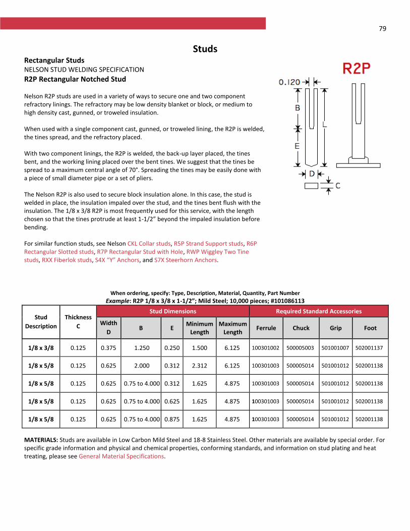
79
Studs Rectangular Studs NELSON STUD WELDING SPECIFICATION
R2P Rectangular Notched Stud Nelson R2P studs are used in a variety of ways to secure one and two component refractory linings. The refractory may be low density blanket or block, or medium to high density cast, gunned, or troweled insulation. When used with a single component cast, gunned, or troweled lining, the R2P is welded, the tines spread, and the refractory placed. With two component linings, the R2P is welded, the back-up layer placed, the tines bent, and the working lining placed over the bent tines. We suggest that the tines be spread to a maximum central angle of 70°. Spreading the tines may be easily done with a piece of small diameter pipe or a set of pliers. The Nelson R2P is also used to secure block insulation alone. In this case, the stud is welded in place, the insulation impaled over the stud, and the tines bent flush with the insulation. The 1/8 x 3/8 R2P is most frequently used for this service, with the length chosen so that the tines protrude at least 1-1/2” beyond the impaled insulation before bending. For similar function studs, see Nelson CKL Collar studs, R5P Strand Support studs, R6P Rectangular Slotted studs, R7P Rectangular Stud with Hole, RWP Wiggley Two Tine studs, RXX Fiberlok studs, S4X “Y” Anchors, and S7X Steerhorn Anchors.
When ordering, specify: Type, Description, Material, Quantity, Part Number
Example: R2P 1/8 x 3/8 x 1-1/2”; Mild Steel; 10,000 pieces; #101086113
Stud
Description
Thickness
C
Stud Dimensions Required Standard Accessories
Width
D B E
Minimum Length
Maximum Length
Ferrule Chuck Grip Foot
1/8 x 3/8 0.125 0.375 1.250 0.250 1.500 6.125 100301002 500005003 501001007 502001137
1/8 x 5/8 0.125 0.625 2.000 0.312 2.312 6.125 100301003 500005014 501001012 502001138
1/8 x 5/8 0.125 0.625 0.75 to 4.000 0.312 1.625 4.875 100301003 500005014 501001012 502001138
1/8 x 5/8 0.125 0.625 0.75 to 4.000 0.625 1.625 4.875 100301003 500005014 501001012 502001138
1/8 x 5/8 0.125 0.625 0.75 to 4.000 0.875 1.625 4.875 100301003 500005014 501001012 502001138
MATERIALS: Studs are available in Low Carbon Mild Steel and 18-8 Stainless Steel. Other materials are available by special order. For specific grade information and physical and chemical properties, conforming standards, and information on stud plating and heat treating, please see General Material Specifications.
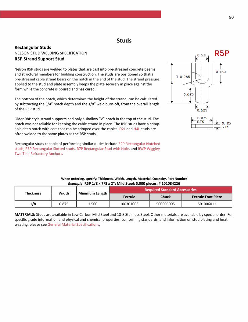
80
Studs Rectangular Studs NELSON STUD WELDING SPECIFICATION
R5P Strand Support Stud Nelson R5P studs are welded to plates that are cast into pre-stressed concrete beams and structural members for building construction. The studs are positioned so that a pre-stressed cable strand bears on the notch in the end of the stud. The strand pressure applied to the stud and plate assembly keeps the plate securely in place against the form while the concrete is poured and has cured. The bottom of the notch, which determines the height of the strand, can be calculated by subtracting the 3/4” notch depth and the 1/8” weld burn-off, from the overall length of the R5P stud. Older R8P style strand supports had only a shallow “V” notch in the top of the stud. The notch was not reliable for keeping the cable strand in place. The R5P studs have a crimp-able deep notch with ears that can be crimped over the cables. D2L and H4L studs are often welded to the same plates as the R5P studs. Rectangular studs capable of performing similar duties include R2P Rectangular Notched studs, R6P Rectangular Slotted studs, R7P Rectangular Stud with Hole, and RWP Wiggley Two Tine Refractory Anchors.
When ordering, specify: Thickness, Width, Length, Material, Quantity, Part Number
Example: R5P 1/8 x 7/8 x 2”; Mild Steel; 5,000 pieces; # 101084226
Thickness Width Minimum Length Required Standard Accessories
Ferrule Chuck Ferrule Foot Plate
1/8 0.875 1.500 100301003 500005005 501006011
MATERIALS: Studs are available in Low Carbon Mild Steel and 18-8 Stainless Steel. Other materials are available by special order. For specific grade information and physical and chemical properties, conforming standards, and information on stud plating and heat treating, please see General Material Specifications.
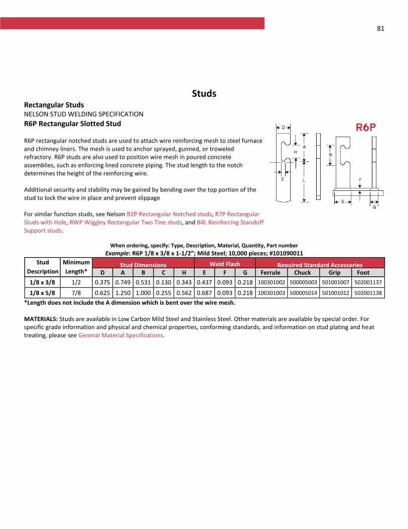
81
Studs Rectangular Studs NELSON STUD WELDING SPECIFICATION
R6P Rectangular Slotted Stud R6P rectangular notched studs are used to attach wire reinforcing mesh to steel furnace and chimney liners. The mesh is used to anchor sprayed, gunned, or troweled refractory. R6P studs are also used to position wire mesh in poured concrete assemblies, such as enforcing lined concrete piping. The stud length to the notch determines the height of the reinforcing wire. Additional security and stability may be gained by bending over the top portion of the stud to lock the wire in place and prevent slippage For similar function studs, see Nelson R2P Rectangular Notched studs, R7P Rectangular Studs with Hole, RWP Wiggley Rectangular Two Tine studs, and B4L Reinforcing Standoff Support studs.
When ordering, specify: Type, Description, Material, Quantity, Part number
Example: R6P 1/8 x 3/8 x 1-1/2”; Mild Steel; 10,000 pieces; #101090011
Stud
Description
Minimum
Length* Stud Dimensions Weld Flash
Dimensions Required Standard Accessories
D A B C H E F G Ferrule Chuck Grip Foot
1/8 x 3/8 1/2 0.375 0.749 0.531 0.130 0.343 0.437 0.093 0.218 100301002 500005003 501001007 502001137
1/8 x 5/8 7/8 0.625 1.250 1.000 0.255 0.562 0.687 0.093 0.218 100301003 500005014 501001012 502001138
*Length does not include the A dimension which is bent over the wire mesh. MATERIALS: Studs are available in Low Carbon Mild Steel and Stainless Steel. Other materials are available by special order. For specific grade information and physical and chemical properties, conforming standards, and information on stud plating and heat treating, please see General Material Specifications.
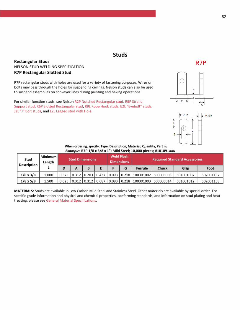
82
Studs Rectangular Studs NELSON STUD WELDING SPECIFICATION
R7P Rectangular Slotted Stud R7P rectangular studs with holes are used for a variety of fastening purposes. Wires or bolts may pass through the holes for suspending ceilings. Nelson studs can also be used to suspend assemblies on conveyor lines during painting and baking operations. For similar function studs, see Nelson R2P Notched Rectangular stud, R5P Strand Support stud, R6P Slotted Rectangular stud, R9L Rope Hook studs, E2L “Eyebolt” studs, J2L “J” Bolt studs, and L2L Lagged stud with Hole.
When ordering, specify: Type, Description, Material, Quantity, Part number
Example: R7P 1/8 x 3/8 x 1”; Mild Steel; 10,000 pieces; #101091008
Stud
Description
Minimum
Length
L
Stud Dimensions Weld Flash
Dimensions Required Standard Accessories
D A B E F G Ferrule Chuck Grip Foot
1/8 x 3/8 1.000 0.375 0.312 0.203 0.437 0.093 0.218 100301002 500005003 501001007 502001137
1/8 x 5/8 1.500 0.625 0.312 0.312 0.687 0.093 0.218 100301003 500005014 501001012 502001138
MATERIALS: Studs are available in Low Carbon Mild Steel and Stainless Steel. Other materials are available by special order. For specific grade information and physical and chemical properties, conforming standards, and information on stud plating and heat treating, please see General Material Specifications.
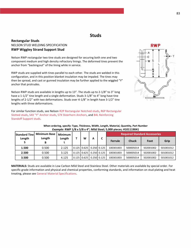
83
Studs Rectangular Studs NELSON STUD WELDING SPECIFICATION
RWP Wiggley Strand Support Stud Nelson RWP rectangular two tine studs are designed for securing both one and two component medium and high density refractory linings. The deformed tines prevent the anchor from “backing out” of the lining while in service. RWP studs are supplied with tines parallel to each other. The studs are welded in this configuration, and in this position blanket insulation may be impaled. The tines may then be spread, and cast or gunned insulation may be further applied to the wiggled “Y” anchor that protrudes. Nelson RWP studs are available in lengths up to 13”. The studs up to 2-1/8” to 3” long have a 1-1/2” tine length and a single deformation. Studs 3-1/8” to 4” long have tine lengths of 2-1/2” with two deformations. Studs over 4-1/8” in length have 3-1/2” tine lengths with three deformations. For similar function studs, see Nelson R2P Rectangular Notched studs, R6P Rectangular Slotted studs, S4X “Y” Anchor studs, S7X Steerhorn Anchors, and B4L Reinforcing Standoff Support studs.
When ordering, specify: Type, Thickness, Width, Length, Material, Quantity, Part Number
Example: RWP 1/8 x 5/8 x 4”; Mild Steel; 5,000 pieces; #101119041
Standard Tine Length
S
Minimum Base
Length
B
Minimum Length
L T W A C
Required Standard Accessories
Ferrule Chuck Foot Grip
1.500 0.500 2.125 0.125 0.625 0.250 0.125 100301003 500005014 502001002 501001012
2.500 0.500 3.125 0.125 0.625 0.250 0.125 100301003 500005014 502001002 501001012
3.500 0.500 4.125 0.125 0.625 0.250 0.125 100301003 500005014 502001002 501001012
MATERIALS: Studs are available in Low Carbon Mild Steel and Stainless Steel. Other materials are available by special order. For specific grade information and physical and chemical properties, conforming standards, and information on stud plating and heat treating, please see General Material Specifications.
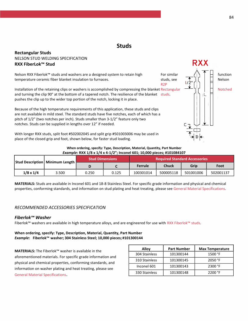
84
Studs Rectangular Studs NELSON STUD WELDING SPECIFICATION
RXX FiberLok™ Stud Nelson RXX Fiberlok™ studs and washers are a designed system to retain high temperature ceramic fiber blanket insulation to furnaces. Installation of the retaining clips or washers is accomplished by compressing the blanket and turning the clip 90° at the bottom of a tapered notch. The resilience of the blanket pushes the clip up to the wider top portion of the notch, locking it in place. Because of the high temperature requirements of this application, these studs and clips are not available in mild steel. The standard studs have five notches, each of which has a pitch of 1/2" (two notches per inch). Studs smaller than 3-1/2” feature only two notches. Studs can be supplied in lengths over 12” if needed. With longer RXX studs, split foot #502002045 and split grip #501003006 may be used in place of the closed grip and foot, shown below, for faster stud loading.
For similar function studs, see Nelson R2P Rectangular Notched studs.
When ordering, specify: Type, Description, Material, Quantity, Part Number
Example: RXX 1/8 x 1/4 x 4-1/2”; Inconel 601; 10,000 pieces; #101084107
Stud Description Minimum Length Stud Dimensions Required Standard Accessories
D C Ferrule Chuck Grip Foot
1/8 x 1/4 3.500 0.250 0.125 100301014 500005118 501001006 502001137
MATERIALS: Studs are available in Inconel 601 and 18-8 Stainless Steel. For specific grade information and physical and chemical properties, conforming standards, and information on stud plating and heat treating, please see General Material Specifications.
RECOMMENDED ACCESSORIES SPECIFICATION
Fiberlok™ Washer Fiberlok™ washers are available in high temperature alloys, and are engineered for use with RXX Fiberlok™ studs.
When ordering, specify: Type, Description, Material, Quantity, Part Number Example: Fiberlok™ washer; 304 Stainless Steel; 10,000 pieces; #101300144
MATERIALS: The Fiberlok™ washer is available in the
aforementioned materials. For specific grade information and
physical and chemical properties, conforming standards, and
information on washer plating and heat treating, please see
General Material Specifications.
Alloy Part Number Max Temperature
304 Stainless 101300144 1500 °F 310 Stainless 101300145 2050 °F
Inconel 601 101300143 2300 °F
330 Stainless 101300148 2200 °F
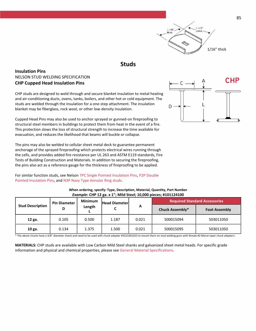
85
Studs Insulation Pins NELSON STUD WELDING SPECIFICATION
CHP Cupped Head Insulation Pins CHP studs are designed to weld through and secure blanket insulation to metal heating and air-conditioning ducts, ovens, tanks, boilers, and other hot or cold equipment. The studs are welded through the insulation for a one-step attachment. The insulation blanket may be fiberglass, rock wool, or other low-density insulation. Cupped Head Pins may also be used to anchor sprayed or gunned-on fireproofing to structural steel members in buildings to protect them from heat in the event of a fire. This protection slows the loss of structural strength to increase the time available for evacuation, and reduces the likelihood that beams will buckle or collapse. The pins may also be welded to cellular sheet metal deck to guarantee permanent anchorage of the sprayed fireproofing which protects electrical wires running through the cells, and provides added fire resistance per UL 263 and ASTM E119 standards, Fire Tests of Building Construction and Materials. In addition to securing the fireproofing, the pins also act as a reference gauge for the thickness of fireproofing to be applied. For similar function studs, see Nelson TPC Single Pointed Insulation Pins, P2P Double Pointed Insulation Pins, and N3P Navy Type Annular Ring studs.
When ordering, specify: Type, Description, Material, Quantity, Part Number
Example: CHP 12 ga. x 1”; Mild Steel; 10,000 pieces; #101124100
Stud Description Pin Diameter
D
Minimum
Length L
Head Diameter
C A
Required Standard Accessories
Chuck Assembly* Foot Assembly
12 ga. 0.105 0.500 1.187 0.021 500015094 503011050
10 ga. 0.134 1.375 1.500 0.021 500015095 503011050
* The above chucks have a 3/8” diameter shank and need to be used with chuck adapter #3521001023 to mount them on stud welding guns with female #2 Morse taper chuck adapters.
MATERIALS: CHP studs are available with Low Carbon Mild Steel shanks and galvanized sheet metal heads. For specific grade information and physical and chemical properties, please see General Material Specifications.
1/16” thick
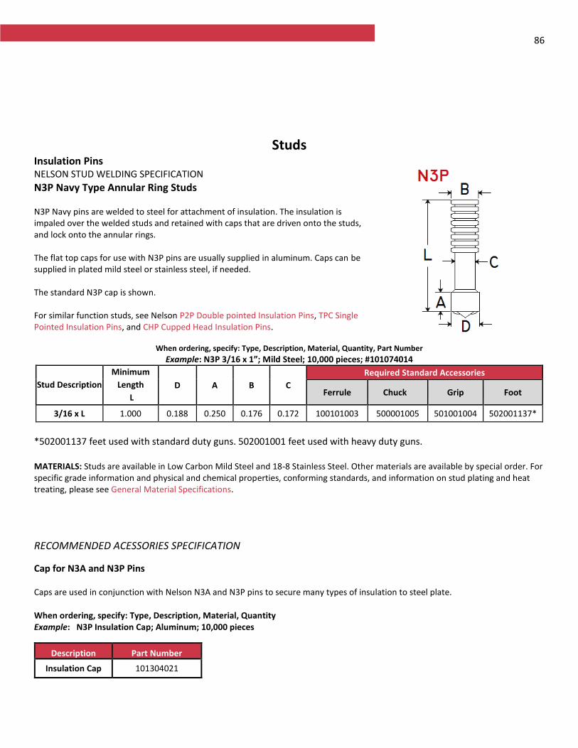
86
Studs Insulation Pins NELSON STUD WELDING SPECIFICATION
N3P Navy Type Annular Ring Studs N3P Navy pins are welded to steel for attachment of insulation. The insulation is impaled over the welded studs and retained with caps that are driven onto the studs, and lock onto the annular rings. The flat top caps for use with N3P pins are usually supplied in aluminum. Caps can be supplied in plated mild steel or stainless steel, if needed. The standard N3P cap is shown. For similar function studs, see Nelson P2P Double pointed Insulation Pins, TPC Single Pointed Insulation Pins, and CHP Cupped Head Insulation Pins.
When ordering, specify: Type, Description, Material, Quantity, Part Number
Example: N3P 3/16 x 1”; Mild Steel; 10,000 pieces; #101074014
Stud Description
Minimum
Length
L
D A B C
Required Standard Accessories
Ferrule Chuck Grip Foot
3/16 x L 1.000 0.188 0.250 0.176 0.172 100101003 500001005 501001004 502001137*
*502001137 feet used with standard duty guns. 502001001 feet used with heavy duty guns. MATERIALS: Studs are available in Low Carbon Mild Steel and 18-8 Stainless Steel. Other materials are available by special order. For specific grade information and physical and chemical properties, conforming standards, and information on stud plating and heat treating, please see General Material Specifications.
RECOMMENDED ACESSORIES SPECIFICATION
Cap for N3A and N3P Pins Caps are used in conjunction with Nelson N3A and N3P pins to secure many types of insulation to steel plate.
When ordering, specify: Type, Description, Material, Quantity Example: N3P Insulation Cap; Aluminum; 10,000 pieces
Description Part Number
Insulation Cap 101304021
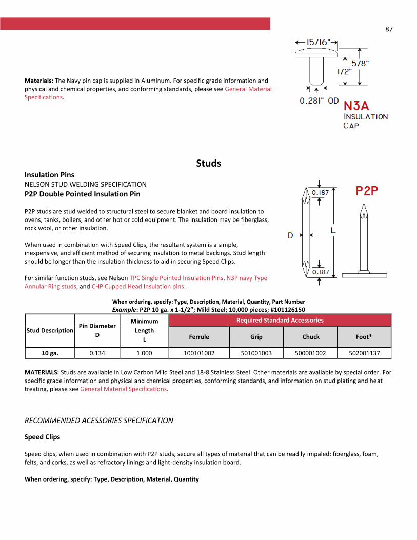
87
Materials: The Navy pin cap is supplied in Aluminum. For specific grade information and physical and chemical properties, and conforming standards, please see General Material Specifications.
Studs Insulation Pins NELSON STUD WELDING SPECIFICATION
P2P Double Pointed Insulation Pin P2P studs are stud welded to structural steel to secure blanket and board insulation to ovens, tanks, boilers, and other hot or cold equipment. The insulation may be fiberglass, rock wool, or other insulation. When used in combination with Speed Clips, the resultant system is a simple, inexpensive, and efficient method of securing insulation to metal backings. Stud length should be longer than the insulation thickness to aid in securing Speed Clips. For similar function studs, see Nelson TPC Single Pointed Insulation Pins, N3P navy Type Annular Ring studs, and CHP Cupped Head Insulation pins.
When ordering, specify: Type, Description, Material, Quantity, Part Number
Example: P2P 10 ga. x 1-1/2”; Mild Steel; 10,000 pieces; #101126150
Stud Description Pin Diameter
D
Minimum
Length
L
Required Standard Accessories
Ferrule Grip Chuck Foot*
10 ga. 0.134 1.000 100101002 501001003 500001002 502001137
MATERIALS: Studs are available in Low Carbon Mild Steel and 18-8 Stainless Steel. Other materials are available by special order. For specific grade information and physical and chemical properties, conforming standards, and information on stud plating and heat treating, please see General Material Specifications.
RECOMMENDED ACESSORIES SPECIFICATION
Speed Clips Speed clips, when used in combination with P2P studs, secure all types of material that can be readily impaled: fiberglass, foam, felts, and corks, as well as refractory linings and light-density insulation board.
When ordering, specify: Type, Description, Material, Quantity
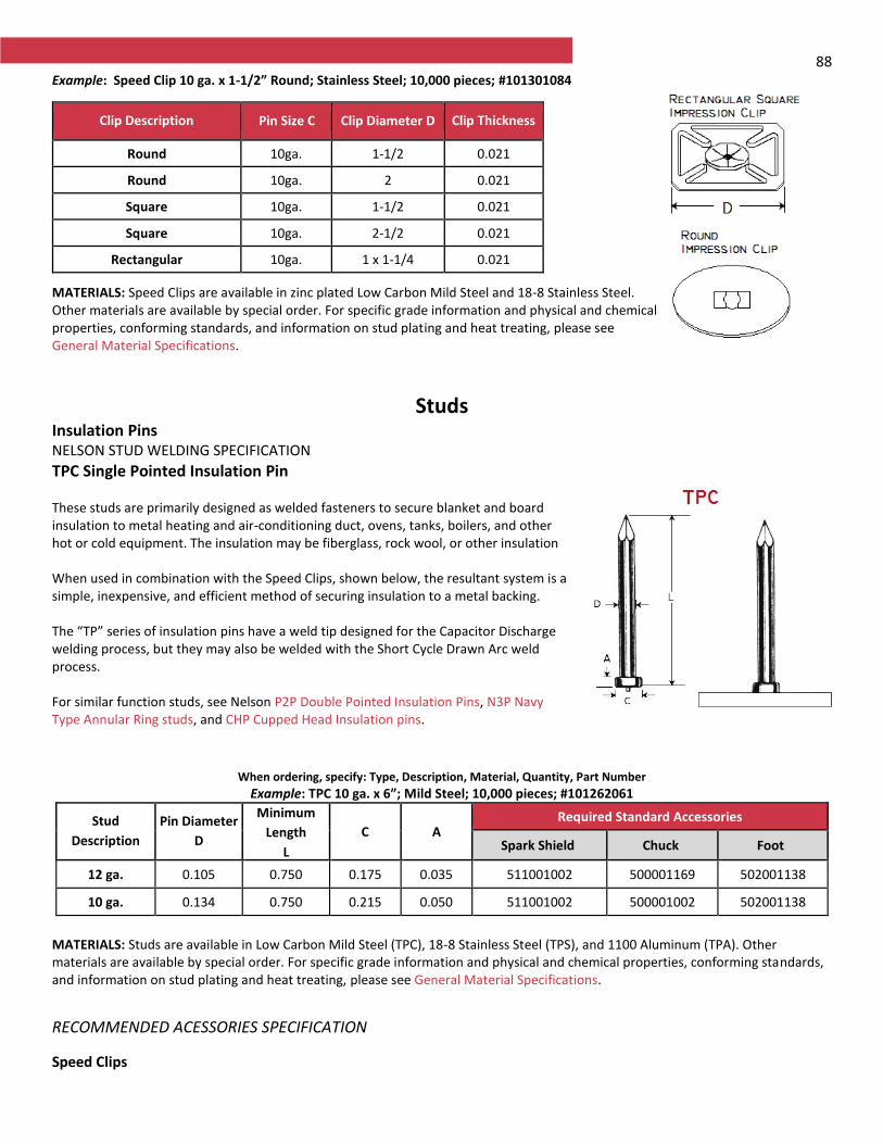
88 Example: Speed Clip 10 ga. x 1-1/2” Round; Stainless Steel; 10,000 pieces; #101301084
MATERIALS: Speed Clips are available in zinc plated Low Carbon Mild Steel and 18-8 Stainless Steel. Other materials are available by special order. For specific grade information and physical and chemical properties, conforming standards, and information on stud plating and heat treating, please see General Material Specifications.
Studs Insulation Pins NELSON STUD WELDING SPECIFICATION
TPC Single Pointed Insulation Pin These studs are primarily designed as welded fasteners to secure blanket and board insulation to metal heating and air-conditioning duct, ovens, tanks, boilers, and other hot or cold equipment. The insulation may be fiberglass, rock wool, or other insulation When used in combination with the Speed Clips, shown below, the resultant system is a simple, inexpensive, and efficient method of securing insulation to a metal backing. The “TP” series of insulation pins have a weld tip designed for the Capacitor Discharge welding process, but they may also be welded with the Short Cycle Drawn Arc weld process. For similar function studs, see Nelson P2P Double Pointed Insulation Pins, N3P Navy Type Annular Ring studs, and CHP Cupped Head Insulation pins.
When ordering, specify: Type, Description, Material, Quantity, Part Number
Example: TPC 10 ga. x 6”; Mild Steel; 10,000 pieces; #101262061
Stud
Description
Pin Diameter
D
Minimum
Length
L
C A Required Standard Accessories
Spark Shield Chuck Foot
12 ga. 0.105 0.750 0.175 0.035 511001002 500001169 502001138
10 ga. 0.134 0.750 0.215 0.050 511001002 500001002 502001138
MATERIALS: Studs are available in Low Carbon Mild Steel (TPC), 18-8 Stainless Steel (TPS), and 1100 Aluminum (TPA). Other materials are available by special order. For specific grade information and physical and chemical properties, conforming standards, and information on stud plating and heat treating, please see General Material Specifications.
RECOMMENDED ACESSORIES SPECIFICATION
Speed Clips
Clip Description Pin Size C Clip Diameter D Clip Thickness
Round 10ga. 1-1/2 0.021
Round 10ga. 2 0.021
Square 10ga. 1-1/2 0.021
Square 10ga. 2-1/2 0.021
Rectangular 10ga. 1 x 1-1/4 0.021
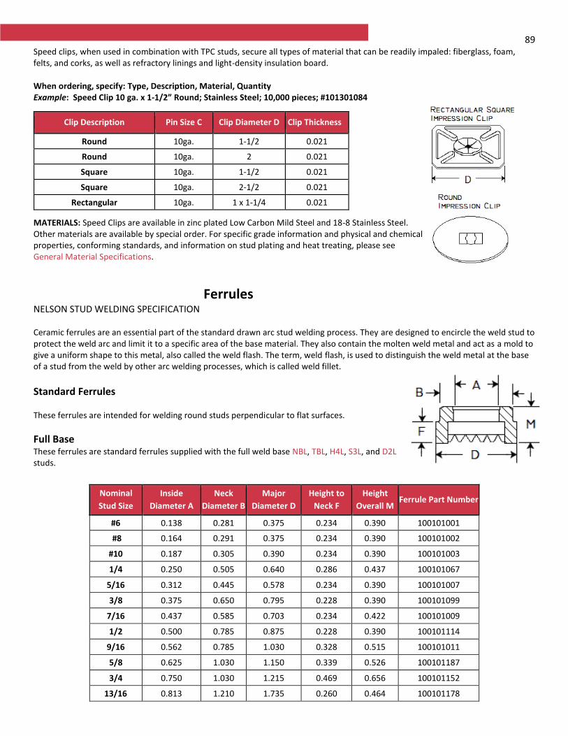
89 Speed clips, when used in combination with TPC studs, secure all types of material that can be readily impaled: fiberglass, foam, felts, and corks, as well as refractory linings and light-density insulation board.
When ordering, specify: Type, Description, Material, Quantity Example: Speed Clip 10 ga. x 1-1/2” Round; Stainless Steel; 10,000 pieces; #101301084
MATERIALS: Speed Clips are available in zinc plated Low Carbon Mild Steel and 18-8 Stainless Steel. Other materials are available by special order. For specific grade information and physical and chemical properties, conforming standards, and information on stud plating and heat treating, please see General Material Specifications.
Ferrules NELSON STUD WELDING SPECIFICATION Ceramic ferrules are an essential part of the standard drawn arc stud welding process. They are designed to encircle the weld stud to protect the weld arc and limit it to a specific area of the base material. They also contain the molten weld metal and act as a mold to give a uniform shape to this metal, also called the weld flash. The term, weld flash, is used to distinguish the weld metal at the base of a stud from the weld by other arc welding processes, which is called weld fillet.
Standard Ferrules These ferrules are intended for welding round studs perpendicular to flat surfaces.
Full Base These ferrules are standard ferrules supplied with the full weld base NBL, TBL, H4L, S3L, and D2L studs.
Clip Description Pin Size C Clip Diameter D Clip Thickness
Round 10ga. 1-1/2 0.021
Round 10ga. 2 0.021
Square 10ga. 1-1/2 0.021
Square 10ga. 2-1/2 0.021
Rectangular 10ga. 1 x 1-1/4 0.021
Nominal
Stud Size
Inside
Diameter A
Neck
Diameter B
Major
Diameter D
Height to
Neck F
Height
Overall M Ferrule Part Number
#6 0.138 0.281 0.375 0.234 0.390 100101001
#8 0.164 0.291 0.375 0.234 0.390 100101002
#10 0.187 0.305 0.390 0.234 0.390 100101003
1/4 0.250 0.505 0.640 0.286 0.437 100101067
5/16 0.312 0.445 0.578 0.234 0.390 100101007
3/8 0.375 0.650 0.795 0.228 0.390 100101099
7/16 0.437 0.585 0.703 0.234 0.422 100101009
1/2 0.500 0.785 0.875 0.228 0.390 100101114
9/16 0.562 0.785 1.030 0.328 0.515 100101011
5/8 0.625 1.030 1.150 0.339 0.526 100101187
3/4 0.750 1.030 1.215 0.469 0.656 100101152
13/16 0.813 1.210 1.735 0.260 0.464 100101178
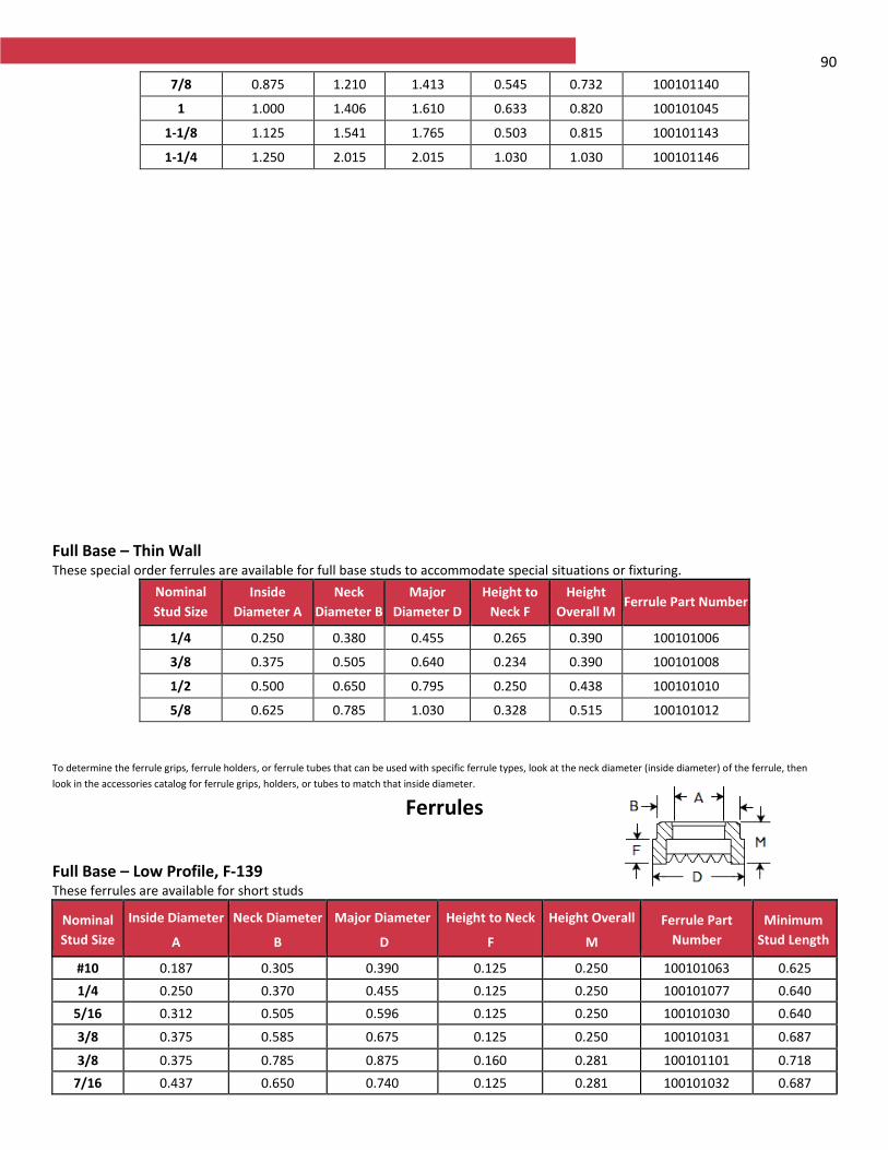
90
Full Base – Thin Wall These special order ferrules are available for full base studs to accommodate special situations or fixturing.
Nominal
Stud Size
Inside
Diameter A
Neck
Diameter B
Major
Diameter D
Height to
Neck F
Height
Overall M Ferrule Part Number
1/4 0.250 0.380 0.455 0.265 0.390 100101006
3/8 0.375 0.505 0.640 0.234 0.390 100101008
1/2 0.500 0.650 0.795 0.250 0.438 100101010
5/8 0.625 0.785 1.030 0.328 0.515 100101012
To determine the ferrule grips, ferrule holders, or ferrule tubes that can be used with specific ferrule types, look at the neck diameter (inside diameter) of the ferrule, then
look in the accessories catalog for ferrule grips, holders, or tubes to match that inside diameter.
Ferrules
Full Base – Low Profile, F-139 These ferrules are available for short studs
Nominal
Stud Size
Inside Diameter
A
Neck Diameter
B
Major Diameter
D
Height to Neck
F
Height Overall
M
Ferrule Part
Number
Minimum
Stud Length
#10 0.187 0.305 0.390 0.125 0.250 100101063 0.625
1/4 0.250 0.370 0.455 0.125 0.250 100101077 0.640
5/16 0.312 0.505 0.596 0.125 0.250 100101030 0.640
3/8 0.375 0.585 0.675 0.125 0.250 100101031 0.687
3/8 0.375 0.785 0.875 0.160 0.281 100101101 0.718
7/16 0.437 0.650 0.740 0.125 0.281 100101032 0.687
7/8 0.875 1.210 1.413 0.545 0.732 100101140
1 1.000 1.406 1.610 0.633 0.820 100101045
1-1/8 1.125 1.541 1.765 0.503 0.815 100101143
1-1/4 1.250 2.015 2.015 1.030 1.030 100101146

91
1/2 0.500 0.785 0.875 0.174 0.281 100101115 0.750
1/2 0.500 0.921 1.030 0.125 0.312 100101119 0.718
1/2 0.500 1.030 1.187 0.125 0.281 100101122 0.718
5/8 0.625 0.921 1.030 0.187 0.375 100101126 0.813
3/4 0.750 1.210 1.413 0.203 0.390 100101133 0.875
Threaded Pitch Diameter, F-239 These ferrules are used with CPL type studs
Nominal
Stud Size
Inside Diameter
A
Neck Diameter
B
Major Diameter
D
Height to Neck
F
Height Overall
M
Ferrule Part Number
1/4-20 0.215 0.380 0.455 0.125 0.250 100101034
5/16-18 0.275 0.445 0.535 0.125 0.250 100101035
3/8-16 0.330 0.505 0.595 0.139 0.264 100101036
7/16-14 0.388 0.585 0.675 0.173 0.329 100101037
1/2-13 0.448 0.650 0.740 0.206 0.362 100101038
5/8-11 0.562 0.785 0.905 0.277 0.433 100101039
3/4-10 0.680 1.030 1.150 0.339 0.526 100101040
7/8-9 0.797 1.210 1.330 0.406 0.593 100101041
1-8 0.915 1.406 1.526 1.474 0.661 100101042
Full Threaded, F-107 These ferrules are used with CFL studs. For short studs, see low profile options in CFL catalog sheet.
Nominal
Stud Size
Inside Diameter
A
Neck Diameter
B
Major Diameter
D
Height to Neck
F
Height Overall
M
Ferrule Part Number
5/16-18 0.312 0.445 0.578 0.281 0.437 100101024
3/8-16 0.375 0.505 0.640 0.281 0.437 100101025
7/16-14 0.437 0.585 0.703 0.281 0.469 100101026
1/2-13 0.500 0.650 0.795 0.281 0.469 100101027
5/8-11 0.625 0.785 1.030 0.390 0.579 100101028
3/4-10 0.750 1.030 1.180 0.390 0.595 100101029
To determine the ferrule grips, ferrule holders, or ferrule tubes that can be used with specific ferrule types, look at the neck diameter (inside diameter) of the ferrule, then
look in the accessories catalog for ferrule grips, holders, or tubes to match that inside diameter.
Ferrules
Collar Studs, F-172 These ferrules are used with CKL type studs
Nominal
Stud Size
Inside Diameter
A
Neck Diameter
B
Major Diameter
D
Height to Neck
F
Height Overall
M
Ferrule Part Number
#10-24, 32 0.187 0.650 0.740 0.090 0.195 100101060
1/4-20 0.215 0.785 0.875 0.095 0.235 100101066
5/16-18 0.275 0.785 0.875 0.095 0.235 100101073
3/8-16 0.330 0.785 0.875 0.095 0.250 100101083
1/2-13 0.448 0.921 1.030 0.125 0.250 100101118
Reduced Base, F-106
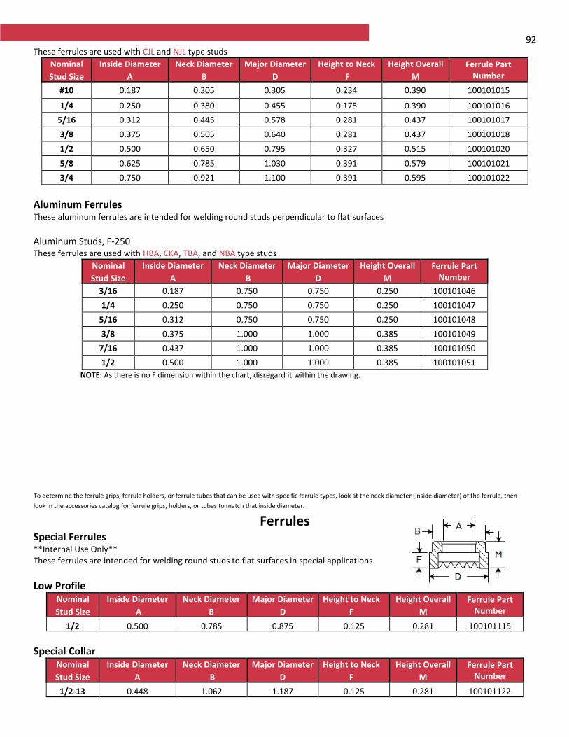
92 These ferrules are used with CJL and NJL type studs
Nominal
Stud Size
Inside Diameter
A
Neck Diameter
B
Major Diameter
D
Height to Neck
F
Height Overall
M
Ferrule Part Number
#10 0.187 0.305 0.305 0.234 0.390 100101015
1/4 0.250 0.380 0.455 0.175 0.390 100101016
5/16 0.312 0.445 0.578 0.281 0.437 100101017
3/8 0.375 0.505 0.640 0.281 0.437 100101018
1/2 0.500 0.650 0.795 0.327 0.515 100101020
5/8 0.625 0.785 1.030 0.391 0.579 100101021
3/4 0.750 0.921 1.100 0.391 0.595 100101022
Aluminum Ferrules These aluminum ferrules are intended for welding round studs perpendicular to flat surfaces
Aluminum Studs, F-250 These ferrules are used with HBA, CKA, TBA, and NBA type studs
Nominal
Stud Size
Inside Diameter
A
Neck Diameter
B
Major Diameter
D
Height Overall
M
Ferrule Part Number
3/16 0.187 0.750 0.750 0.250 100101046
1/4 0.250 0.750 0.750 0.250 100101047
5/16 0.312 0.750 0.750 0.250 100101048
3/8 0.375 1.000 1.000 0.385 100101049
7/16 0.437 1.000 1.000 0.385 100101050
1/2 0.500 1.000 1.000 0.385 100101051
NOTE: As there is no F dimension within the chart, disregard it within the drawing.
To determine the ferrule grips, ferrule holders, or ferrule tubes that can be used with specific ferrule types, look at the neck diameter (inside diameter) of the ferrule, then
look in the accessories catalog for ferrule grips, holders, or tubes to match that inside diameter.
Ferrules Special Ferrules**Internal Use Only** These ferrules are intended for welding round studs to flat surfaces in special applications.
Low Profile Nominal
Stud Size
Inside Diameter
A
Neck Diameter
B
Major Diameter
D
Height to Neck
F
Height Overall
M
Ferrule Part Number
1/2 0.500 0.785 0.875 0.125 0.281 100101115
Special Collar Nominal
Stud Size
Inside Diameter
A
Neck Diameter
B
Major Diameter
D
Height to Neck
F
Height Overall
M
Ferrule Part Number
1/2-13 0.448 1.062 1.187 0.125 0.281 100101122
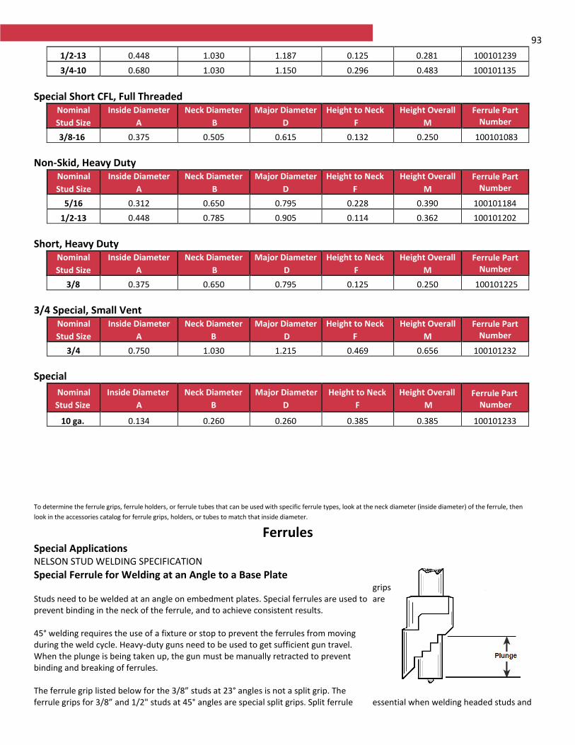
93
1/2-13 0.448 1.030 1.187 0.125 0.281 100101239
3/4-10 0.680 1.030 1.150 0.296 0.483 100101135
Special Short CFL, Full Threaded Nominal
Stud Size
Inside Diameter
A
Neck Diameter
B
Major Diameter
D
Height to Neck
F
Height Overall
M
Ferrule Part Number
3/8-16 0.375 0.505 0.615 0.132 0.250 100101083
Non-Skid, Heavy Duty Nominal
Stud Size
Inside Diameter
A
Neck Diameter
B
Major Diameter
D
Height to Neck
F
Height Overall
M
Ferrule Part Number
5/16 0.312 0.650 0.795 0.228 0.390 100101184
1/2-13 0.448 0.785 0.905 0.114 0.362 100101202
Short, Heavy Duty Nominal
Stud Size
Inside Diameter
A
Neck Diameter
B
Major Diameter
D
Height to Neck
F
Height Overall
M
Ferrule Part Number
3/8 0.375 0.650 0.795 0.125 0.250 100101225
3/4 Special, Small Vent Nominal
Stud Size
Inside Diameter
A
Neck Diameter
B
Major Diameter
D
Height to Neck
F
Height Overall
M
Ferrule Part Number
3/4 0.750 1.030 1.215 0.469 0.656 100101232
Special
Nominal
Stud Size
Inside Diameter
A
Neck Diameter
B
Major Diameter
D
Height to Neck
F
Height Overall
M
Ferrule Part Number
10 ga. 0.134 0.260 0.260 0.385 0.385 100101233
To determine the ferrule grips, ferrule holders, or ferrule tubes that can be used with specific ferrule types, look at the neck diameter (inside diameter) of the ferrule, then
look in the accessories catalog for ferrule grips, holders, or tubes to match that inside diameter.
Ferrules Special Applications NELSON STUD WELDING SPECIFICATION
Special Ferrule for Welding at an Angle to a Base Plate Studs need to be welded at an angle on embedment plates. Special ferrules are used to prevent binding in the neck of the ferrule, and to achieve consistent results. 45° welding requires the use of a fixture or stop to prevent the ferrules from moving during the weld cycle. Heavy-duty guns need to be used to get sufficient gun travel. When the plunge is being taken up, the gun must be manually retracted to prevent binding and breaking of ferrules. The ferrule grip listed below for the 3/8” studs at 23° angles is not a split grip. The ferrule grips for 3/8” and 1/2" studs at 45° angles are special split grips. Split ferrule
grips are
essential when welding headed studs and
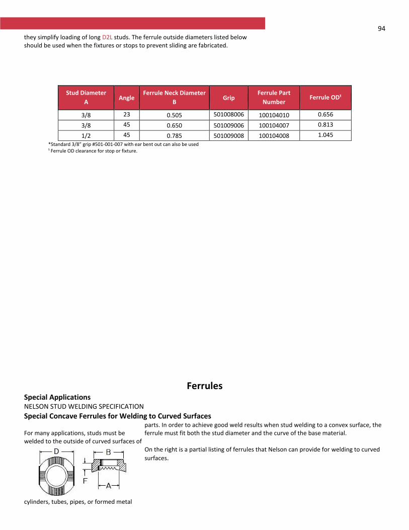
94 they simplify loading of long D2L studs. The ferrule outside diameters listed below should be used when the fixtures or stops to prevent sliding are fabricated.
Stud Diameter
A Angle
Ferrule Neck Diameter
B Grip
Ferrule Part
Number Ferrule OD¹
3/8 23
0.505 501008006*
100104010 0.656
3/8 45
0.650 501009006 100104007 0.813
1/2 45
0.785 501009008 100104008 1.045
*Standard 3/8” grip #501-001-007 with ear bent out can also be used ¹ Ferrule OD clearance for stop or fixture.
Ferrules Special Applications NELSON STUD WELDING SPECIFICATION
Special Concave Ferrules for Welding to Curved Surfaces For many applications, studs must be welded to the outside of curved surfaces of
cylinders, tubes, pipes, or formed metal
parts. In order to achieve good weld results when stud welding to a convex surface, the ferrule must fit both the stud diameter and the curve of the base material. On the right is a partial listing of ferrules that Nelson can provide for welding to curved
surfaces.
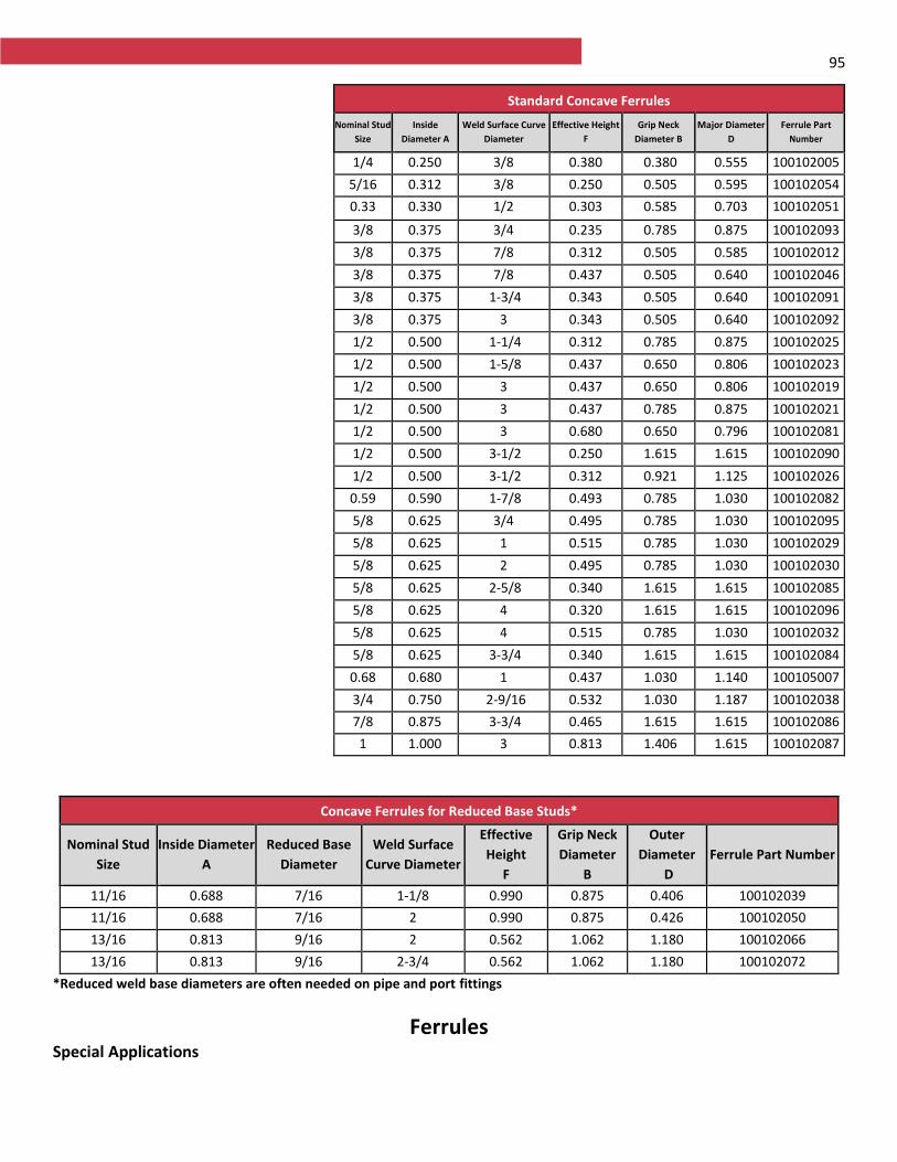
95
Concave Ferrules for Reduced Base Studs*
Nominal Stud
Size
Inside Diameter
A
Reduced Base
Diameter
Weld Surface
Curve Diameter
Effective
Height
F
Grip Neck
Diameter
B
Outer
Diameter
D
Ferrule Part Number
11/16 0.688 7/16 1-1/8 0.990 0.875 0.406 100102039
11/16 0.688 7/16 2 0.990 0.875 0.426 100102050
13/16 0.813 9/16 2 0.562 1.062 1.180 100102066
13/16 0.813 9/16 2-3/4 0.562 1.062 1.180 100102072
*Reduced weld base diameters are often needed on pipe and port fittings
Ferrules Special Applications
Standard Concave Ferrules
Nominal Stud
Size
Inside
Diameter A
Weld Surface Curve
Diameter
Effective Height
F
Grip Neck
Diameter B
Major Diameter
D
Ferrule Part
Number
1/4 0.250 3/8 0.380 0.380 0.555 100102005
5/16 0.312 3/8 0.250 0.505 0.595 100102054
0.330
0.330 1/2 0.303 0.585 0.703 100102051
3/8 0.375 3/4 0.235 0.785 0.875 100102093
3/8 0.375 7/8 0.312 0.505 0.585 100102012
3/8 0.375 7/8 0.437 0.505 0.640 100102046
3/8 0.375 1-3/4 0.343 0.505 0.640 100102091
3/8 0.375 3 0.343 0.505 0.640 100102092
1/2 0.500 1-1/4 0.312 0.785 0.875 100102025
1/2 0.500 1-5/8 0.437 0.650 0.806 100102023
1/2 0.500 3 0.437 0.650 0.806 100102019
1/2 0.500 3 0.437 0.785 0.875 100102021
1/2 0.500 3 0.680 0.650 0.796 100102081
1/2 0.500 3-1/2 0.250 1.615 1.615 100102090
1/2 0.500 3-1/2 0.312 0.921 1.125 100102026
0.590
0.590 1-7/8 0.493 0.785 1.030 100102082
5/8 0.625 3/4 0.495 0.785 1.030 100102095
5/8 0.625 1 0.515 0.785 1.030 100102029
5/8 0.625 2 0.495 0.785 1.030 100102030
5/8 0.625 2-5/8 0.340 1.615 1.615 100102085
5/8 0.625 4 0.320 1.615 1.615 100102096
5/8 0.625 4 0.515 0.785 1.030 100102032
5/8 0.625 3-3/4 0.340 1.615 1.615 100102084
0.680
0.680 1 0.437 1.030 1.140 100105007
3/4 0.750 2-9/16 0.532 1.030 1.187 100102038
7/8 0.875 3-3/4 0.465 1.615 1.615 100102086
1 1.000 3 0.813 1.406 1.615 100102087
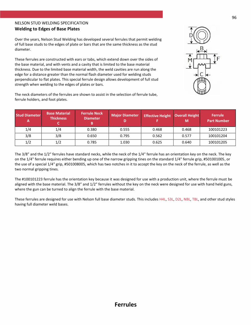
96 NELSON STUD WELDING SPECIFICATION
Welding to Edges of Base Plates Over the years, Nelson Stud Welding has developed several ferrules that permit welding of full base studs to the edges of plate or bars that are the same thickness as the stud diameter. These ferrules are constructed with ears or tabs, which extend down over the sides of the base material, and with vents and a cavity that is limited to the base material thickness. Due to the limited base material width, the weld cavities are run along the edge for a distance greater than the normal flash diameter used for welding studs perpendicular to flat plates. This special ferrule design allows development of full stud strength when welding to the edges of plates or bars. The neck diameters of the ferrules are shown to assist in the selection of ferrule tube, ferrule holders, and foot plates.
The 3/8” and the 1/2" ferrules have standard necks, while the neck of the 1/4" ferrule has an orientation key on the neck. The key on the 1/4" ferrule requires either bending up one of the narrow gripping tines on the standard 1/4" ferrule grip, #501001005, or the use of a special 1/4" grip, #501008005, which has two notches in it to accept the key on the neck of the ferrule, as well as the two normal gripping tines. The #100101223 ferrule has the orientation key because it was designed for use with a production unit, where the ferrule must be aligned with the base material. The 3/8” and 1/2" ferrules without the key on the neck were designed for use with hand held guns, where the gun can be turned to align the ferrule with the base material. These ferrules are designed for use with Nelson full base diameter studs. This includes H4L, S3L, D2L, NBL, TBL, and other stud styles having full diameter weld bases.
Ferrules
Stud Diameter
A
Base Material Thickness
C
Ferrule Neck Diameter
B
Major Diameter
D Effective Height
F
Overall Height
M
Ferrule
Part Number
1/4 1/4 0.380 0.555 0.468 0.468 100101223
3/8 3/8 0.650 0.795 0.562 0.577 100101204
1/2 1/2 0.785 1.030 0.625 0.640 100101205
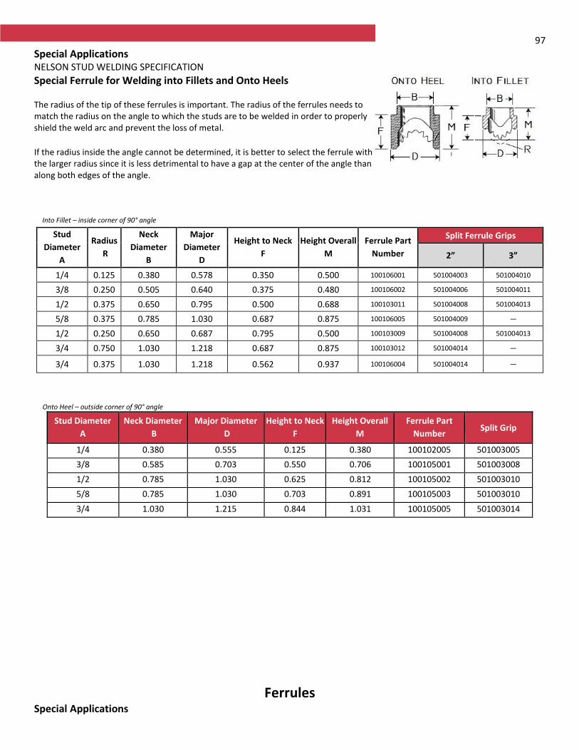
97
Special Applications NELSON STUD WELDING SPECIFICATION
Special Ferrule for Welding into Fillets and Onto Heels The radius of the tip of these ferrules is important. The radius of the ferrules needs to match the radius on the angle to which the studs are to be welded in order to properly shield the weld arc and prevent the loss of metal.
If the radius inside the angle cannot be determined, it is better to select the ferrule with the larger radius since it is less detrimental to have a gap at the center of the angle than along both edges of the angle.
Into Fillet – inside corner of 90° angle
Stud
Diameter
A
Radius
R
Neck
Diameter
B
Major
Diameter
D
Height to Neck
F
Height Overall
M
Ferrule Part
Number
Split Ferrule Grips
2” 3”
1/4 0.125 0.380 0.578 0.350 0.500 100106001 501004003 501004010
3/8 0.250 0.505 0.640 0.375 0.480 100106002 501004006 501004011
1/2 0.375 0.650 0.795 0.500 0.688 100103011 501004008 501004013
5/8 0.375 0.785 1.030 0.687 0.875 100106005 501004009 —
1/2 0.250 0.650 0.687 0.795 0.500 100103009 501004008 501004013
3/4 0.750 1.030 1.218 0.687 0.875 100103012 501004014 —
3/4 0.375 1.030 1.218 0.562 0.937 100106004 501004014 —
Onto Heel – outside corner of 90° angle
Stud Diameter
A
Neck Diameter
B
Major Diameter
D
Height to Neck
F
Height Overall
M
Ferrule Part
Number Split Grip
1/4 0.380 0.555 0.125 0.380 100102005 501003005
3/8 0.585 0.703 0.550 0.706 100105001 501003008
1/2 0.785 1.030 0.625 0.812 100105002 501003010
5/8 0.785 1.030 0.703 0.891 100105003 501003010
3/4 1.030 1.215 0.844 1.031 100105005 501003014
Ferrules Special Applications

98 NELSON STUD WELDING SPECIFICATION
Special Ferrules for Stripping Straight Off Headed Studs Welding of concrete anchors and shear connectors into holes through concrete, masonry, or wood, is a special application of Nelson studs. For these applications, a ferrule is needed with a neck diameter that is larger than the head on the stud. This allows the gun to be stripped straight off the welded studs. The ferrules listed below have gripping neck diameters that are larger than the heads of the concrete anchors or shear anchors. The 3/8” and 1/2” ferrules can also be used as Low Profile ferrules with special Collar studs that have full diameter weld bases.
Stud Diameter
A Stud Head Diameter
Ferrule Gripping
Neck Diameter*
B
Major Diameter
D
Overall Height
M
Ferrule Part
Number
3/8 0.750 0.785 0.875 0.281 100101101
1/2** 1.000 - - - -
5/8 1.250 1.406 1.531 0.531 100101182
3/4 1.250 1.406 1.531 0.656 100101228
7/8 1.375 1.406 1.531 0.732 100101215
* The neck diameters of the ferrules are shown to assist in the selection of ferrule tube, ferrule holders, and foot plates.
** Due to lack of demand production of the straight strip-off ferrule for 1/2" headed studs has been discontinued. The 1/2" WTD ferrule, #100-101-237, has a neck diameter of 1.030" - so it can be used to strip straight off 1/2" diameter studs with 1" diameter head. The larger cavity and coarse vents of the #100-101-237 ferrule require hotter than normal weld settings.
Ferrules Special Applications
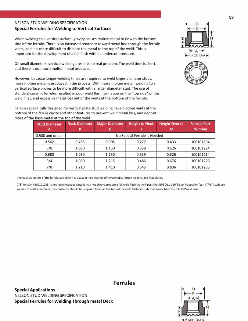
99 NELSON STUD WELDING SPECIFICATION
Special Ferrules for Welding to Vertical Surfaces When welding to a vertical surface, gravity causes molten metal to flow to the bottom side of the ferrule. There is an increased tendency toward metal loss through the ferrule vents, and it is more difficult to displace the metal to the top of the weld. This is important for the development of a full flash with no undercut produced. On small diameters, vertical welding presents no real problem. The weld time is short, and there is not much molten metal produced. However, because longer welding times are required to weld larger diameter studs, more molten metal is produced in the process. With more molten metal, welding to a vertical surface proves to be more difficult with a larger diameter stud. The use of standard ceramic ferrules resulted in poor weld flash formation on the “top side” of the weld fillet, and excessive metal loss out of the vents at the bottom of the ferrule. Ferrules specifically designed for vertical plate stud welding have blocked vents at the bottom of the ferule cavity and other features to prevent weld metal loss, and deposit more of the flash metal at the top of the weld.
Stud Diameter A
Neck Diameter
B
Major Diameter
D
Height to Neck
F
Height Overall
M
Ferrule Part
Number
0.500 and under No Special Ferrule is Needed
0.562 0.785 0.905 0.277 0.433 100101234
5/8 1.030 1.150 0.339 0.526 100101224
0.680 1.030 1.150 0.339 0.526 100101214
3/4 1.030 1.215 0.486 0.676 100101226
7/8 1.210 1.410 0.545 0.836 100101235
The neck diameters of the ferrules are shown to assist in the selection of ferrule tube, ferrule holders, and foot plates.
7/8” ferrule, #100101235, is not recommended since it may not always produce a full weld flash that will pass the AWS D1.1 360°Visual Inspection Test. If 7/8” studs are
welded to vertical surfaces, the contractor should be prepared to repair the tops of the weld flash on studs that do not have the full 360°weld flash.
Ferrules Special Applications NELSON STUD WELDING SPECIFICATION
Special Ferrules for Welding Through metal Deck
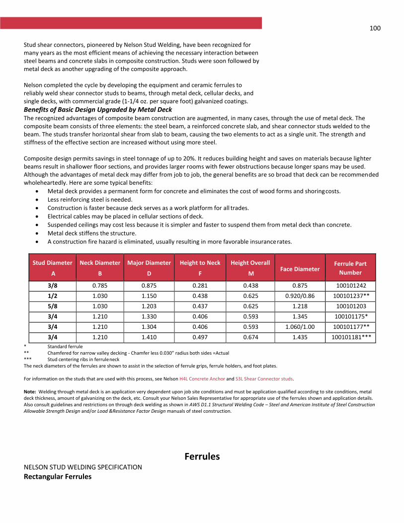
100 Stud shear connectors, pioneered by Nelson Stud Welding, have been recognized for many years as the most efficient means of achieving the necessary interaction between steel beams and concrete slabs in composite construction. Studs were soon followed by metal deck as another upgrading of the composite approach. Nelson completed the cycle by developing the equipment and ceramic ferrules to reliably weld shear connector studs to beams, through metal deck, cellular decks, and single decks, with commercial grade (1-1/4 oz. per square foot) galvanized coatings.
Benefits of Basic Design Upgraded by Metal Deck The recognized advantages of composite beam construction are augmented, in many cases, through the use of metal deck. The composite beam consists of three elements: the steel beam, a reinforced concrete slab, and shear connector studs welded to the beam. The studs transfer horizontal shear from slab to beam, causing the two elements to act as a single unit. The strength and stiffness of the effective section are increased without using more steel. Composite design permits savings in steel tonnage of up to 20%. It reduces building height and saves on materials because lighter beams result in shallower floor sections, and provides larger rooms with fewer obstructions because longer spans may be used. Although the advantages of metal deck may differ from job to job, the general benefits are so broad that deck can be recommended wholeheartedly. Here are some typical benefits:
Metal deck provides a permanent form for concrete and eliminates the cost of wood forms and shoring costs.
Less reinforcing steel is needed.
Construction is faster because deck serves as a work platform for all trades.
Electrical cables may be placed in cellular sections of deck.
Suspended ceilings may cost less because it is simpler and faster to suspend them from metal deck than concrete.
Metal deck stiffens the structure.
A construction fire hazard is eliminated, usually resulting in more favorable insurance rates.
Stud Diameter
A
Neck Diameter
B
Major Diameter
D
Height to Neck
F
Height Overall
M Face Diameter
Ferrule Part
Number
3/8 0.785 0.875 0.281 0.438 0.875 100101242
1/2 1.030 1.150 0.438 0.625 0.920/0.860
100101237**
5/8 1.030 1.203 0.437 0.625 1.218 100101203
3/4 1.210 1.330 0.406 0.593 1.345 100101175*
3/4 1.210 1.304 0.406 0.593 1.060/1.00 100101177**
3/4 1.210 1.410 0.497 0.674 1.435 100101181***
* Standard ferrule ** Chamfered for narrow valley decking - Chamfer less 0.030” radius both sides = Actual *** Stud centering ribs in ferrule neck The neck diameters of the ferrules are shown to assist in the selection of ferrule grips, ferrule holders, and foot plates. For information on the studs that are used with this process, see Nelson H4L Concrete Anchor and S3L Shear Connector studs. Note: Welding through metal deck is an application very dependent upon job site conditions and must be application qualified according to site conditions, metal deck thickness, amount of galvanizing on the deck, etc. Consult your Nelson Sales Representative for appropriate use of the ferrules shown and application details. Also consult guidelines and restrictions on through deck welding as shown in AWS D1.1 Structural Welding Code – Steel and American Institute of Steel Construction Allowable Strength Design and/or Load &Resistance Factor Design manuals of steel construction.
Ferrules NELSON STUD WELDING SPECIFICATION
Rectangular Ferrules
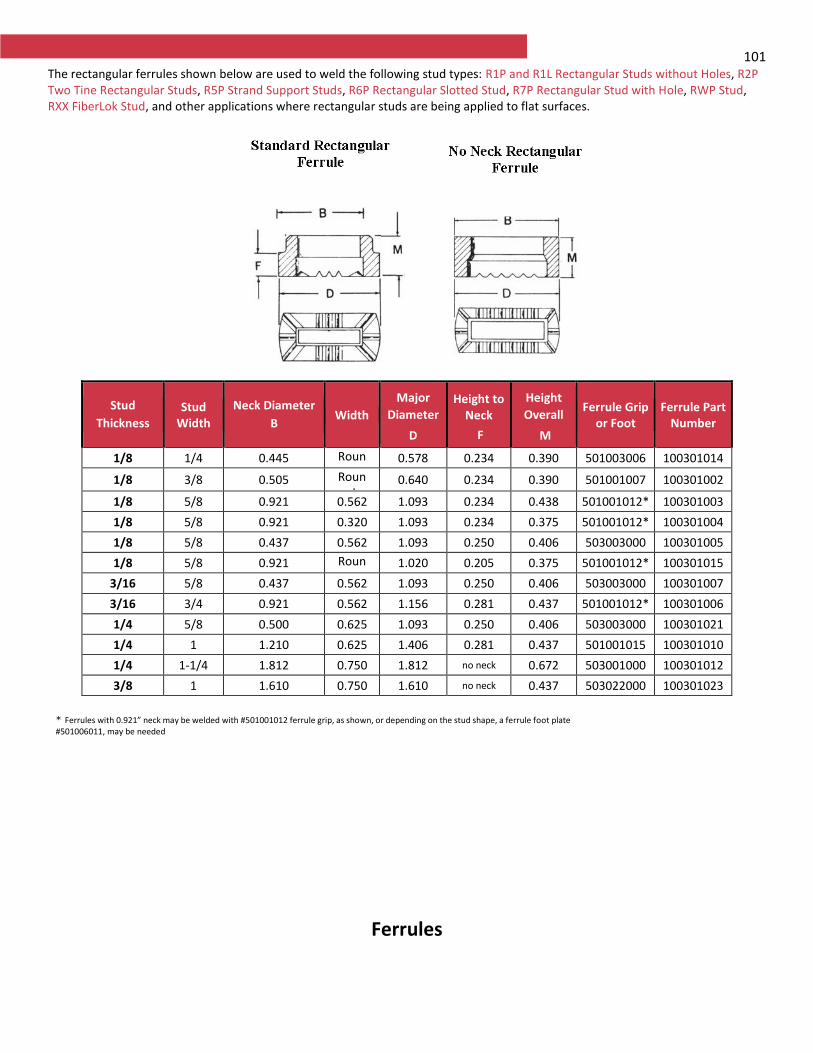
101 The rectangular ferrules shown below are used to weld the following stud types: R1P and R1L Rectangular Studs without Holes, R2P Two Tine Rectangular Studs, R5P Strand Support Studs, R6P Rectangular Slotted Stud, R7P Rectangular Stud with Hole, RWP Stud, RXX FiberLok Stud, and other applications where rectangular studs are being applied to flat surfaces.
Stud
Thickness Stud
Width
Neck Diameter
B Width
Major
Diameter
D
Height to Neck
F
Height
Overall
M
Ferrule Grip or Foot
Ferrule Part Number
1/8 1/4 0.445 Round
0.578 0.234 0.390 501003006 100301014
1/8 3/8 0.505 Round
0.640 0.234 0.390 501001007 100301002
1/8 5/8 0.921 0.562 1.093 0.234 0.438 501001012* 100301003
1/8 5/8 0.921 0.320 1.093 0.234 0.375 501001012* 100301004
1/8 5/8 0.437 0.562 1.093 0.250 0.406 503003000 100301005
1/8 5/8 0.921 Round
1.020 0.205 0.375 501001012* 100301015
3/16 5/8 0.437 0.562 1.093 0.250 0.406 503003000 100301007
3/16 3/4 0.921 0.562 1.156 0.281 0.437 501001012* 100301006
1/4 5/8 0.500 0.625 1.093 0.250 0.406 503003000 100301021
1/4 1 1.210 0.625 1.406 0.281 0.437 501001015 100301010
1/4 1-1/4 1.812 0.750 1.812 no neck 0.672 503001000 100301012
3/8 1 1.610 0.750 1.610 no neck 0.437 503022000 100301023
* Ferrules with 0.921” neck may be welded with #501001012 ferrule grip, as shown, or depending on the stud shape, a ferrule foot plate #501006011, may be needed
Ferrules
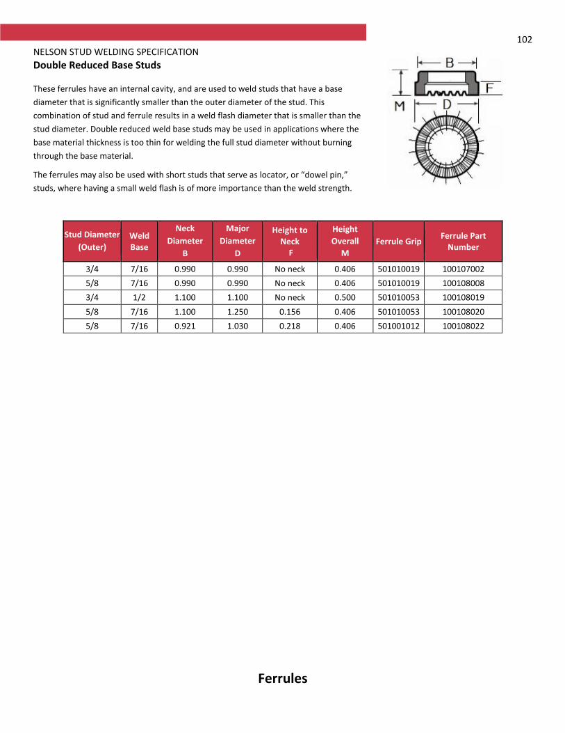
102 NELSON STUD WELDING SPECIFICATION
Double Reduced Base Studs These ferrules have an internal cavity, and are used to weld studs that have a base
diameter that is significantly smaller than the outer diameter of the stud. This
combination of stud and ferrule results in a weld flash diameter that is smaller than the
stud diameter. Double reduced weld base studs may be used in applications where the
base material thickness is too thin for welding the full stud diameter without burning
through the base material.
The ferrules may also be used with short studs that serve as locator, or “dowel pin,”
studs, where having a small weld flash is of more importance than the weld strength.
Stud Diameter
(Outer) Weld Base
Neck
Diameter
B
Major
Diameter
D
Height to Neck
F
Height
Overall
M
Ferrule Grip Ferrule Part
Number
3/4 7/16 0.990 0.990 No neck 0.406 501010019 100107002
5/8 7/16 0.990 0.990 No neck 0.406 501010019 100108008
3/4 1/2 1.100 1.100 No neck 0.500 501010053 100108019
5/8 7/16 1.100 1.250 0.156 0.406 501010053 100108020
5/8 7/16 0.921 1.030 0.218 0.406 501001012 100108022
Ferrules
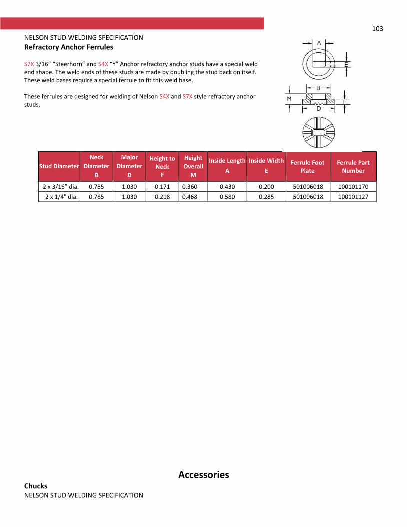
103 NELSON STUD WELDING SPECIFICATION Refractory Anchor Ferrules S7X 3/16” “Steerhorn” and S4X “Y” Anchor refractory anchor studs have a special weld end shape. The weld ends of these studs are made by doubling the stud back on itself. These weld bases require a special ferrule to fit this weld base. These ferrules are designed for welding of Nelson S4X and S7X style refractory anchor studs.
Stud Diameter
Neck
Diameter
B
Major
Diameter
D
Height to Neck
F
Height
Overall
M
Inside Length
A
Inside Width
E Ferrule Foot
Plate Ferrule Part
Number
2 x 3/16” dia. 0.785 1.030 0.171 0.360 0.430 0.200 501006018 100101170
2 x 1/4" dia. 0.785 1.030 0.218 0.468 0.580 0.285 501006018 100101127
Accessories Chucks NELSON STUD WELDING SPECIFICATION
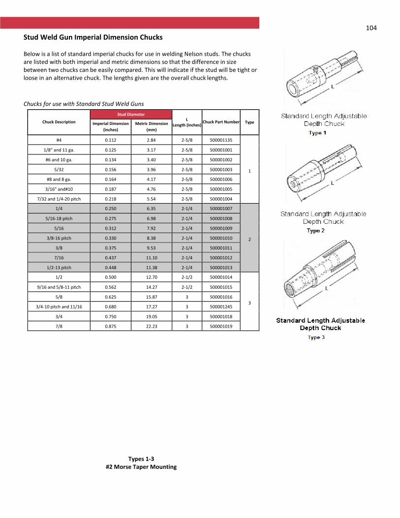
104
Stud Weld Gun Imperial Dimension Chucks Below is a list of standard imperial chucks for use in welding Nelson studs. The chucks are listed with both imperial and metric dimensions so that the difference in size between two chucks can be easily compared. This will indicate if the stud will be tight or loose in an alternative chuck. The lengths given are the overall chuck lengths.
Chucks for use with Standard Stud Weld Guns
Chuck Description
Stud Diameter L
Length (inches) Chuck Part Number Type Imperial Dimension
(inches)
Metric Dimension
(mm)
#4 0.112 2.84 2-5/8 500001135
1
1/8” and 11 ga. 0.125 3.17 2-5/8 500001001
#6 and 10 ga. 0.134 3.40 2-5/8 500001002
5/32 0.156 3.96 2-5/8 500001003
#8 and 8 ga. 0.164 4.17 2-5/8 500001006
3/16” and#10 0.187 4.76 2-5/8 500001005
7/32 and 1/4-20 pitch 0.218 5.54 2-5/8 500001004
1/4 0.250 6.35 2-1/4 500001007
2
5/16-18 pitch 0.275 6.98 2-1/4 500001008
5/16 0.312 7.92 2-1/4 500001009
3/8-16 pitch 0.330 8.38 2-1/4 500001010
3/8 0.375 9.53 2-1/4 500001011
7/16 0.437 11.10 2-1/4 500001012
1/2-13 pitch 0.448 11.38 2-1/4 500001013
1/2 0.500 12.70 2-1/2 500001014
3
9/16 and 5/8-11 pitch 0.562 14.27 2-1/2 500001015
5/8 0.625 15.87 3 500001016
3/4-10 pitch and 11/16 0.680 17.27 3 500001245
3/4 0.750 19.05 3 500001018
7/8 0.875 22.23 3 500001019
Types 1-3 #2 Morse Taper Mounting
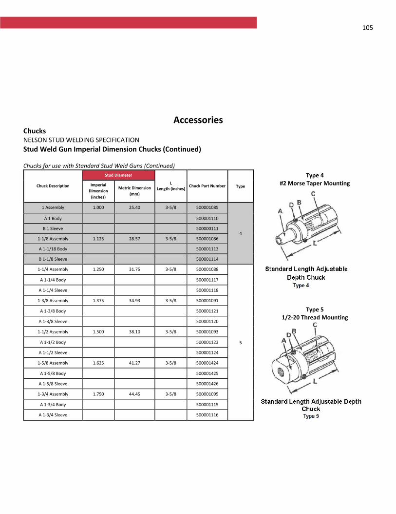
105
Accessories Chucks NELSON STUD WELDING SPECIFICATION
Stud Weld Gun Imperial Dimension Chucks (Continued) Chucks for use with Standard Stud Weld Guns (Continued)
Chuck Description
Stud Diameter
L Length (inches)
Chuck Part Number Type Imperial
Dimension
(inches)
Metric Dimension
(mm)
1 Assembly 1.000 25.40 3-5/8 500001085
4
A 1 Body 500001110
B 1 Sleeve 500000111
1-1/8 Assembly 1.125 28.57 3-5/8 500001086
A 1-1/18 Body 500001113
B 1-1/8 Sleeve 500001114
1-1/4 Assembly 1.250 31.75 3-5/8 500001088
5
A 1-1/4 Body 500001117
A 1-1/4 Sleeve 500001118
1-3/8 Assembly 1.375 34.93 3-5/8 500001091
A 1-3/8 Body 500001121
A 1-3/8 Sleeve 500001120
1-1/2 Assembly 1.500 38.10 3-5/8 500001093
A 1-1/2 Body 500001123
A 1-1/2 Sleeve 500001124
1-5/8 Assembly 1.625 41.27 3-5/8 500001424
A 1-5/8 Body 500001425
A 1-5/8 Sleeve 500001426
1-3/4 Assembly 1.750 44.45 3-5/8 500001095
A 1-3/4 Body 500001115
A 1-3/4 Sleeve 500001116
Type 4 #2 Morse Taper Mounting
Type 5
1/2-20 Thread Mounting
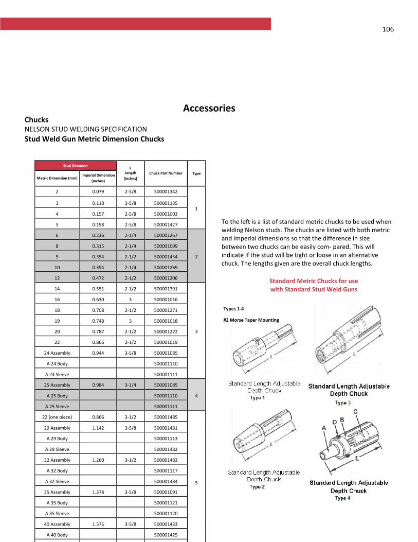
106
Accessories Chucks NELSON STUD WELDING SPECIFICATION
Stud Weld Gun Metric Dimension Chucks
To the left is a list of standard metric chucks to be used when welding Nelson studs. The chucks are listed with both metric and imperial dimensions so that the difference in size between two chucks can be easily com- pared. This will indicate if the stud will be tight or loose in an alternative chuck. The lengths given are the overall chuck lengths.
Standard Metric Chucks for use with Standard Stud Weld Guns
Types 1-4
#2 Morse Taper Mounting
Stud Diameter L Length
(inches)
Chuck Part Number Type Metric Dimension (mm)
Imperial Dimension
(inches)
2 0.079 2-5/8 500001342
1 3 0.118 2-5/8 500001135
4 0.157 2-5/8 500001003
5 0.198 2-5/8 500001427
6 0.236 2-1/4 500001267
2
8 0.315 2-1/4 500001009
9 0.354 2-1/2 500001434
10 0.394 2-1/4 500001269
12 0.472 2-1/2 500001206
14 0.551 2-1/2 500001391
3
16 0.630 3 500001016
18 0.708 2-1/2 500001271
19 0.748 3 500001018
20 0.787 2-1/2 500001272
22 0.866 2-1/2 500001019
24 Assembly 0.944 3-5/8 500001085
A 24 Body 500001110
A 24 Sleeve 500001111
25 Assembly 0.984 3-1/4 500001085
4 A 25 Body 500001110
A 25 Sleeve 500001111
22 (one piece) 0.866 3-1/2 500001485
5
29 Assembly 1.142 3-5/8 500001481
A 29 Body 500001113
A 29 Sleeve 500001482
32 Assembly 1.260 3-1/2 500001483
A 32 Body 500001117
A 32 Sleeve 500001484
35 Assembly 1.378 3-5/8 500001091
A 35 Body 500001121
A 35 Sleeve 500001120
40 Assembly 1.575 3-5/8 500001433
A 40 Body 500001425
A 40 Sleeve 500001426
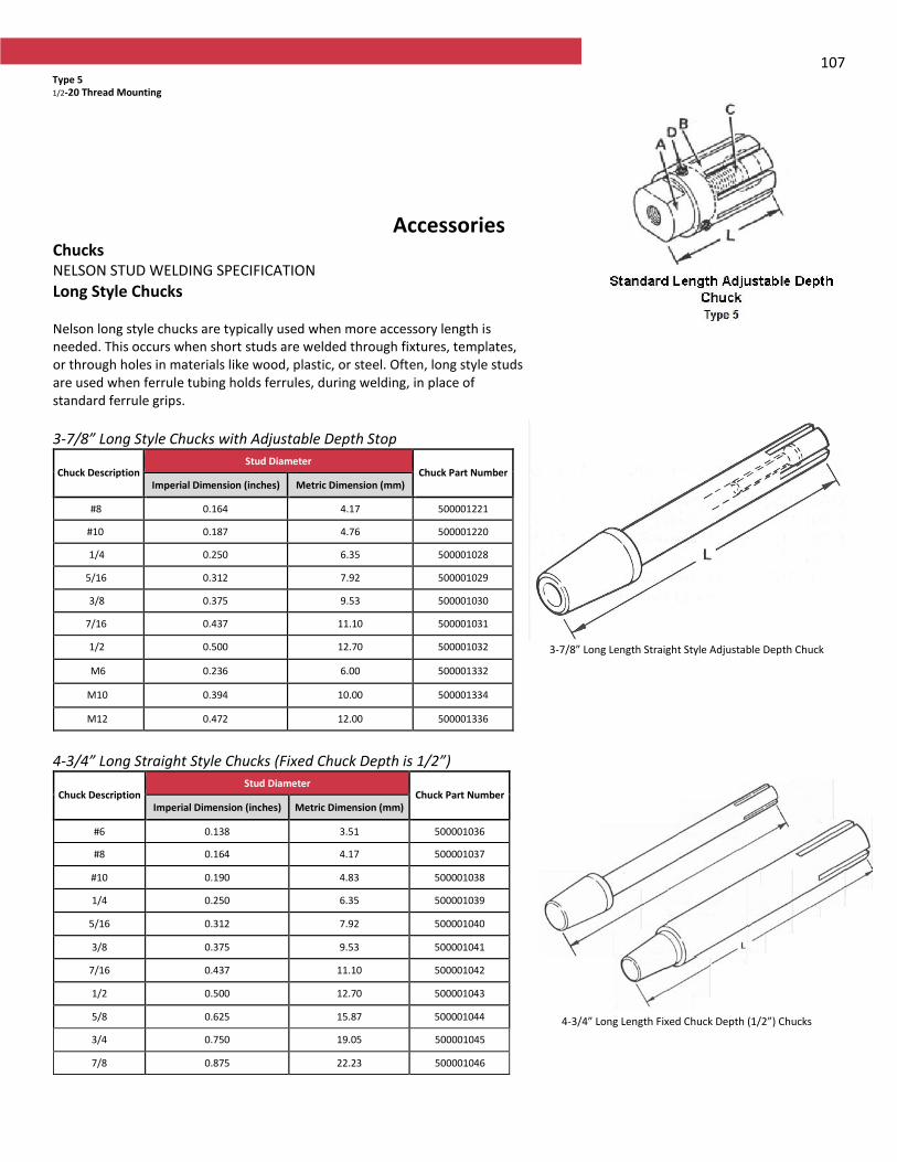
107
Accessories Chucks NELSON STUD WELDING SPECIFICATION
Long Style Chucks Nelson long style chucks are typically used when more accessory length is needed. This occurs when short studs are welded through fixtures, templates, or through holes in materials like wood, plastic, or steel. Often, long style studs are used when ferrule tubing holds ferrules, during welding, in place of standard ferrule grips.
3-7/8” Long Style Chucks with Adjustable Depth Stop
Chuck Description Stud Diameter
Chuck Part Number Imperial Dimension (inches) Metric Dimension (mm)
#8 0.164 4.17 500001221
#10 0.187 4.76 500001220
1/4 0.250 6.35 500001028
5/16 0.312 7.92 500001029
3/8 0.375 9.53 500001030
7/16 0.437 11.10 500001031
1/2 0.500 12.70 500001032
M6 0.236 6.00 500001332
M10 0.394 10.00 500001334
M12 0.472 12.00 500001336
4-3/4” Long Straight Style Chucks (Fixed Chuck Depth is 1/2”)
Chuck Description Stud Diameter
Chuck Part Number Imperial Dimension (inches) Metric Dimension (mm)
#6 0.138 3.51 500001036
#8 0.164 4.17 500001037
#10 0.190 4.83 500001038
1/4 0.250 6.35 500001039
5/16 0.312 7.92 500001040
3/8 0.375 9.53 500001041
7/16 0.437 11.10 500001042
1/2 0.500 12.70 500001043
5/8 0.625 15.87 500001044
3/4 0.750 19.05 500001045
7/8 0.875 22.23 500001046
3-7/8” Long Length Straight Style Adjustable Depth Chuck
4-3/4” Long Length Fixed Chuck Depth (1/2”) Chucks
Type 5 1/2-20 Thread Mounting
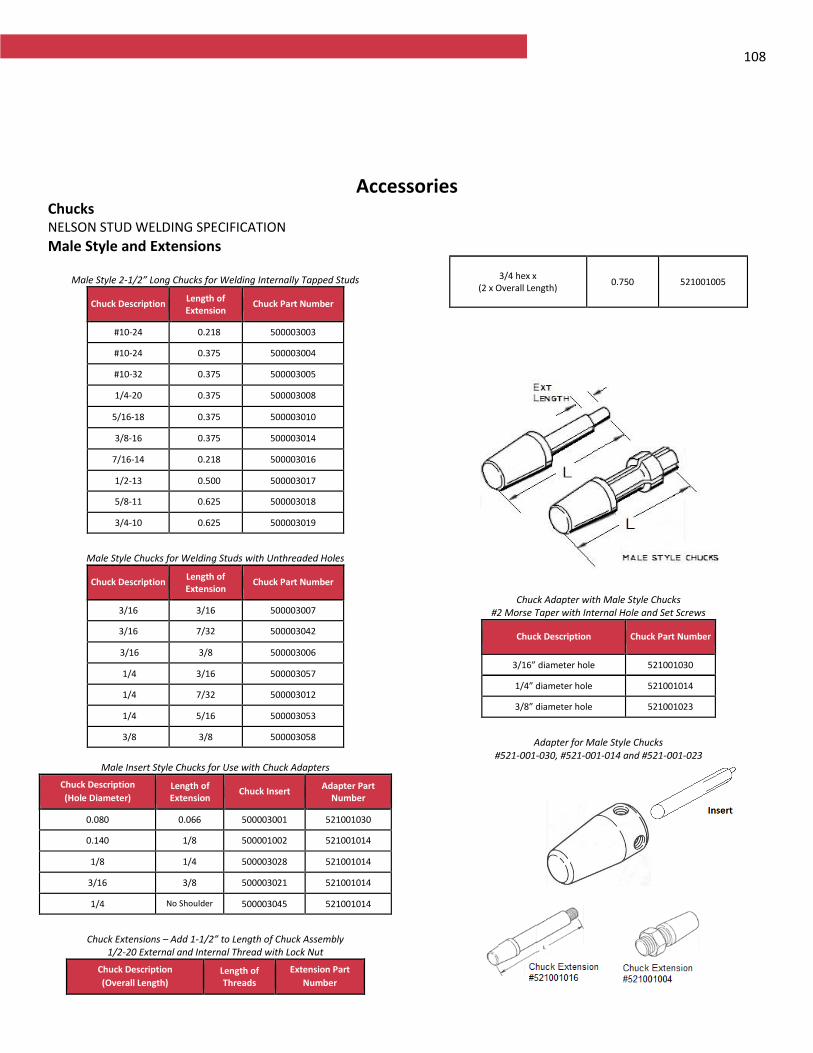
108
Accessories Chucks NELSON STUD WELDING SPECIFICATION
Male Style and Extensions
Male Style 2-1/2” Long Chucks for Welding Internally Tapped Studs
Chuck Description Length of Extension
Chuck Part Number
#10-24 0.218 500003003
#10-24 0.375 500003004
#10-32 0.375 500003005
1/4-20 0.375 500003008
5/16-18 0.375 500003010
3/8-16 0.375 500003014
7/16-14 0.218 500003016
1/2-13 0.500 500003017
5/8-11 0.625 500003018
3/4-10 0.625 500003019
Male Style Chucks for Welding Studs with Unthreaded Holes
Chuck Description Length of Extension
Chuck Part Number
3/16 3/16 500003007
3/16 7/32 500003042
3/16 3/8 500003006
1/4 3/16 500003057
1/4 7/32 500003012
1/4 5/16 500003053
3/8 3/8 500003058
Male Insert Style Chucks for Use with Chuck Adapters
Chuck Description
(Hole Diameter) Length of Extension
Chuck Insert Adapter Part
Number
0.080 0.066 500003001 521001030
0.140 1/8 500001002 521001014
1/8 1/4 500003028 521001014
3/16 3/8 500003021 521001014
1/4 No Shoulder 500003045 521001014
Chuck Extensions – Add 1-1/2” to Length of Chuck Assembly
1/2-20 External and Internal Thread with Lock Nut Chuck Description
(Overall Length) Length of Threads
Extension Part
Number
3/4 hex x (2 x Overall Length)
0.750 521001005
Chuck Adapter with Male Style Chucks #2 Morse Taper with Internal Hole and Set Screws
Chuck Description Chuck Part Number
3/16” diameter hole 521001030
1/4” diameter hole 521001014
3/8” diameter hole 521001023
Adapter for Male Style Chucks
#521-001-030, #521-001-014 and #521-001-023
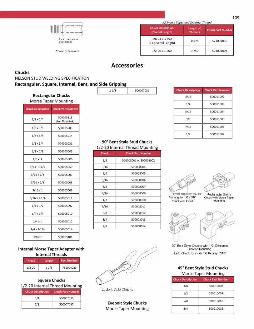
109
Chuck Extensions
#2 Morse Taper and External Thread
Chuck Description
(Overall Length) Length of Threads
Chuck Part Number
3/8-24 x 3.750 (2 x Overall Length)
0.375 521001016
1/2-20 x 1.500 0.750 521001004
Accessories Chucks NELSON STUD WELDING SPECIFICATION
Rectangular, Square, Internal, Bent, and Side Gripping
Rectangular Chucks Morse Taper Mounting
Chuck Description Chuck Part Number
1/8 x 1/4 500005118
(for Fiber-Lok)
1/8 x 3/8 500005003
1/8 x 5/8 500005014
1/8 x 3/4 500005021
1/8 x 7/8 500005005
1/8 x 1 500005006
1/8 x 1-1/2 500005059
3/16 x 3/4 500005007
3/16 x 7/8 500005008
3/16 x 1 500005009
3/16 x 1-1/4 500005011
1/4 x 1/2 500005092
1/4 x 3/4 500005010
1/4 x 1 500005012
1/4 x 1-1/4 500005019
3/8 x 1 500005101
Internal Morse Taper Adapter with
Internal Threads Thread Length Part Number
1/2-20 1-7/8 751004029
Square Chucks
1/2-20 Internal Thread Mounting Chuck Description Chuck Part Number
3/4 500007035
7/8 500007037
1-1/8 500007039
90° Bent Style Stud Chucks 1/2-20 Internal Thread Mounting
Chuck Chuck Part Number
1/8 500008001 or 500008002
3/16 500008004
1/4 500008005
5/16 500008006
3/8 500008007
7/16 500008009
1/2 500008010
9/16 500008011
5/8 500008012
3/4 500008013
7/8 500008014
Eyebolt Style Chucks
Morse Taper Mounting
Chuck Description Chuck Part Number
3/16 500011002
1/4 500011003
5/16 500011004
3/8 500011005
7/16 500011006
1/2 500011007
45° Bent Style Stud Chucks Morse Taper Mounting
Chuck Description Chuck Part Number
3/8 500010002
1/2 500010008
5/8 500010010
3/4 500010016

110 7/8 500010037
Side Gripping Chuck Assemblies (LEGACY)
Chuck Description Chuck Part Number
1/4 500014103
3/8 500014102
1/2 500014095
5/8 500014096
3/4 500014097
7/8 500014101
Nelson Side Gripping chucks have two ball detents and a screw lever to grip the studs. Chuck adapter offset, #500014088, and other parts are needed to mount these chucks on the stud welding gun. Alternate side gripping chuck designs are available. See PSR Studs
Accessories Chucks NELSON STUD WELDING SPECIFICATION
Capacitor Discharge Weld Gun Chucks
Standard and Metric Capacitor Discharge Stud Welding Chucks for Use with NCD and NCD+ Stud Welding Guns
Chuck Description 3/8”
O.D.
Stud Diameter
Length
(inches)
Chuck Part
Number Imperial
Dimension
(inches)
Metric
Dimension
(mm)
13ga. 0.095 2.41 2-3/8 500001374
12ga. 0.109 2.77 2-3/8 500001363
0.118 and #4 threaded 0.112 2.84 2-3/8 500001355
1/8 and #5 threaded 0.125 3.17 2-3/8 500001390
10ga. and #6 threaded 0.134 3.40 2-3/8 500001356
M4 0.157 3.99 2-3/8 500001361
#8 threaded 0.164 4.17 2-3/8 500001357
3/16 Annular Ring 0.178 4.75 2-3/8 500001373
3/16” and #10 threaded 0.190 4.83 2-3/8 500001366
M5 0.197 5.00 2-3/8 500001358
M6 0.236 6.00 2-3/8 500001362
1/4 0.250 6.35 2-3/8 500001359
M7 0.275 7.00 2-3/8 500001368
5/16 and M8 0.312 7.92 2-3/8 500001360
3/8 0.375 9.53 2-3/8 500001369
M10 0.394 10.00 2 3/8 500001369
Standard Capacitor Discharge Stud Welding Chucks for use with
CD Lite-G and CD Lite-C Stud Welding Guns for Welding 1/4 to 1-1/2” (6 to 40mm) long studs*
Chuck Description
10mm O.D.
Stud Diameter
Length inches (mm) Chuck Assembly
Part Number Imperial
Dimension
(inches)
Metric Dimension
(mm)
#4 & 12 ga 0.112 2.84 1-3/4 (45) 500001515
M3 0.118 3.00 1-3/4 (45) 500001510
#6 & 10 ga 0.134 3.40 1-3/4 (45) 500001516
M4 0.157 4.00 1-3/4 (45) 500001511
#8 0.164 4.17 1-3/4 (45)
M5 0.198 5.00 1-3/4 (45)
#10 & 3/16 0.190 4.83 1-3/4 (45)
M6 0.236 6.00 1-3/4 (45)
1/4 0.250 6.35 1-3/4 (45)
5/16 & M8 0.312 7.92 1-3/4 (45)
*Welding of studs longer than 1-1/2” (40mm), or through a template, requires special accessories
Stud Stop Pin Assembly for NCD and NCD+ Stud Welding Guns
Stud Length
(inches) Part Number
1/4 to 5/8 500017017
3/4 to 1-1/8
500017018
1-1/4 to 1-5/8 500017019
1-3/4 to 2-1/8 500017020
Pencil Gun 500017063
Note: NCD and CD Lite chucks are NOT interchangeable due to the difference in the 3/8” and 10mm outside diameter of these chucks
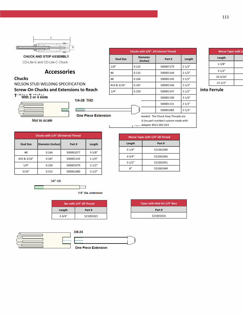
111
Accessories Chucks NELSON STUD WELDING SPECIFICATION
Screw-On Chucks and Extensions to Reach into Ferrule Tubing & Holes
Chucks with 1/4”-28 Internal Thread
Stud Size Diameter (inches) Part # Length
#8 0.164 500001077 3-5/8”
#10 & 3/16” 0.187 500001142 1-1/4”
1/4” 0.250 500001079 2-1/2”
5/16” 0.312 500001080 2-1/2”
Morse Taper with 1/4”-28 Thread
Length Part #
3-1/4” 521001040
4-3/4” 521001063
5-1/2” 521001051
8” 521001049
Bar with 1/4”-28 Thread
Length Part #
3-3/4” 521001021
Taper with Hole for 1/4” Bars
Part #
521001014
Chucks with 3/8”- 24 Internal Thread
Stud Size Diameter (inches)
Part # Length
1/8” 0.125 500007179 2-1/2”
#6 0.132 500001144 2-1/2”
#8 0.164 500001145 2-1/2”
#10 & 3/16” 0.187 500001146 2-1/2”
1/4” 0.250 500001147 2-1/2”
5/16” 0.312 500001190 3-1/4”
3/8” 0.375 500001131 2-1/2”
1/2” 0.500 500001083 2-1/2”
5/8” & 3/4” None needed: The Chuck Stop Threads are
3/8”-16 (no part number) custom made with
Taper Adaptor #521-001-023
Morse Taper with 3/8”-24 Thread
Length Part #
1-3/8” 521001056
3-1/2” 521001016
10-3/16” 521001039
21-1/2” 521001046
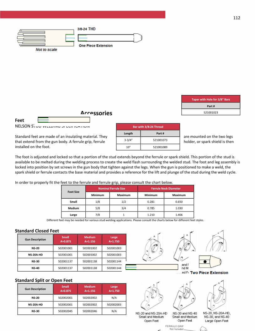
112
Accessories FeetNELSON STUD WELDING SPECIFICATION Standard feet are made of an insulating material. They are mounted on the two legs that extend from the gun body. A ferrule grip, ferrule holder, or spark shield is then installed on the foot. The foot is adjusted and locked so that a portion of the stud extends beyond the ferrule or spark shield. This portion of the stud is available to be melted during the welding process to create the weld flash surrounding the welded stud. The foot and leg assembly is locked into position by set screws in the gun body that tighten against the legs. When the gun is positioned to make a weld, the spark shield or ferrule contacts the base material and provides a reference for the lift and plunge of the stud during the weld cycle. In order to properly fit the feet to the ferrule and ferrule grip, please consult the chart below.
Foot Size Nominal Ferrule Size Ferrule Neck Diameter
Minimum Maximum Minimum Maximum
Small 1/8 1/2 0.281 0.650
Medium 5/8 3/4 0.785 1.030
Large 7/8 1 1.210 1.406
Different feet may be needed for various stud welding applications. Please consult the charts below for different feet styles.
Standard Closed Feet
Gun Description Small
A=0.875
Medium
A=1.156
Large
A=1.750
NS-20 502001001 502001002 502001003
NS-20A-HD 502001001 502001002 502001003
NS-30 502001137 502001138 502001144
NS-40 502001137 502001138 502001144
Standard Split or Open Feet
Gun Description Small
A=0.875
Medium
A=1.156
Large
A=1.750
NS-20 502002001 502002002 N/A
NS-20A-HD 502002001 502002002 502002003
NS-30 502002045 502002046 N/A
Bar with 3/8-24 Thread
Length Part #
3-3/4” 521001073
10” 521001089
Taper with Hole for 3/8” Bars
Part #
521001023
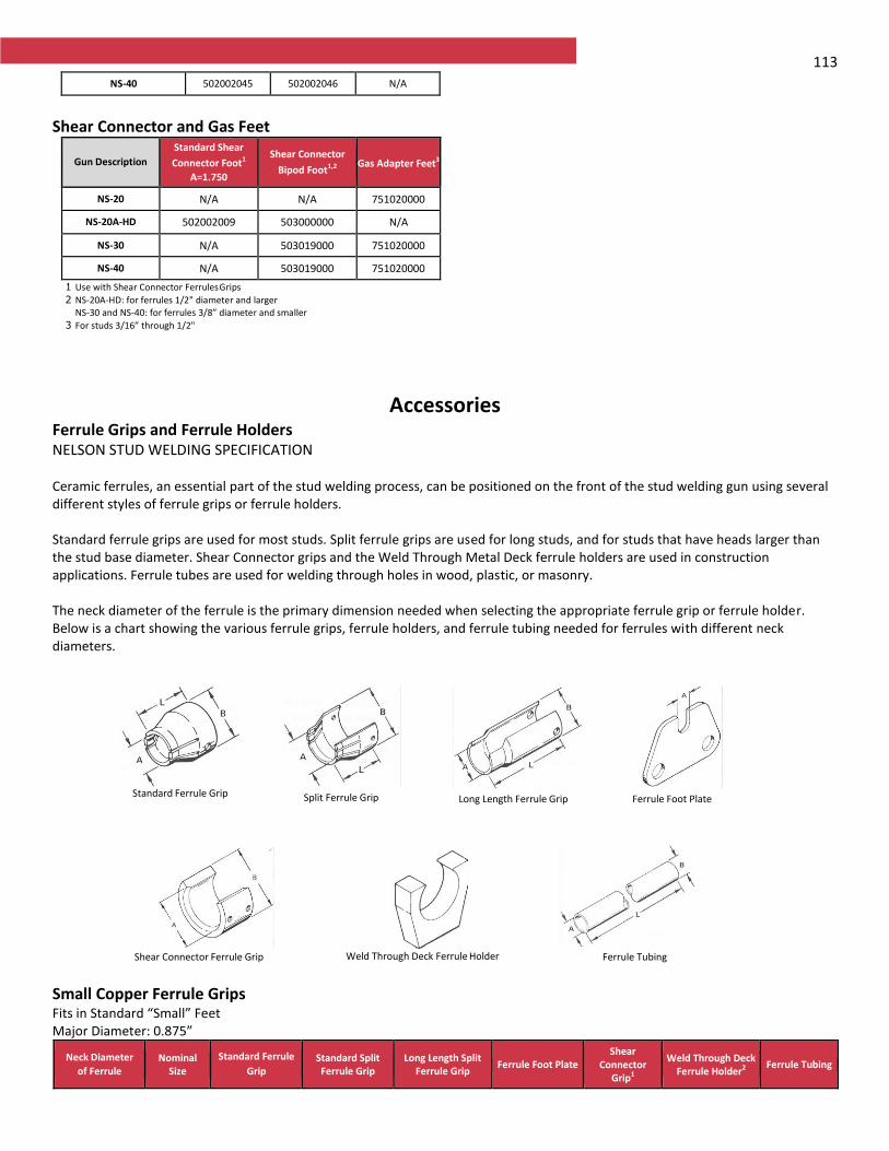
113 NS-40 502002045 502002046 N/A
Shear Connector and Gas Feet
Gun Description
Standard Shear
Connector Foot1
A=1.750
Shear Connector
Bipod Foot1,2
Gas Adapter Feet3
NS-20 N/A N/A 751020000
NS-20A-HD 502002009 503000000 N/A
NS-30 N/A 503019000 751020000
NS-40 N/A 503019000 751020000
1 Use with Shear Connector Ferrules Grips
2 NS-20A-HD: for ferrules 1/2" diameter and larger NS-30 and NS-40: for ferrules 3/8” diameter and smaller
3 For studs 3/16” through 1/2"
Accessories Ferrule Grips and Ferrule HoldersNELSON STUD WELDING SPECIFICATION Ceramic ferrules, an essential part of the stud welding process, can be positioned on the front of the stud welding gun using several different styles of ferrule grips or ferrule holders. Standard ferrule grips are used for most studs. Split ferrule grips are used for long studs, and for studs that have heads larger than the stud base diameter. Shear Connector grips and the Weld Through Metal Deck ferrule holders are used in construction applications. Ferrule tubes are used for welding through holes in wood, plastic, or masonry. The neck diameter of the ferrule is the primary dimension needed when selecting the appropriate ferrule grip or ferrule holder. Below is a chart showing the various ferrule grips, ferrule holders, and ferrule tubing needed for ferrules with different neck diameters.
Standard Ferrule Grip Split Ferrule Grip Long Length Ferrule Grip Ferrule Foot Plate
Shear Connector Ferrule Grip Weld Through Deck Ferrule Holder Ferrule Tubing
Small Copper Ferrule Grips Fits in Standard “Small” Feet Major Diameter: 0.875”
Neck Diameter
of Ferrule Nominal
Size
Standard Ferrule
Grip Standard Split Ferrule Grip
Long Length Split Ferrule Grip
Ferrule Foot Plate Shear
Connector Grip1
Weld Through Deck Ferrule Holder2
Ferrule Tubing
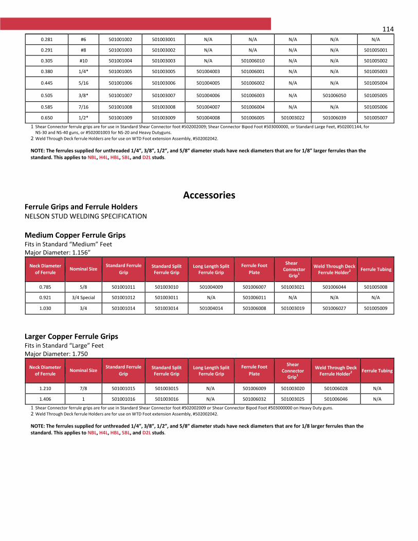
114
0.281 #6 501001002 501003001 N/A N/A N/A N/A N/A
0.291 #8 501001003 501003002 N/A N/A N/A N/A 501005001
0.305 #10 501001004 501003003 N/A 501006010 N/A N/A 501005002
0.380 1/4* 501001005 501003005 501004003 501006001 N/A N/A 501005003
0.445 5/16 501001006 501003006 501004005 501006002 N/A N/A 501005004
0.505 3/8* 501001007 501003007 501004006 501006003 N/A 501006050 501005005
0.585 7/16 501001008 501003008 501004007 501006004 N/A N/A 501005006
0.650 1/2* 501001009 501003009 501004008 501006005 501003022 501006039 501005007
1 Shear Connector ferrule grips are for use in Standard Shear Connector foot #502002009; Shear Connector Bipod Foot #503000000, or Standard Large Feet, #502001144, for NS-30 and NS-40 guns, or #502001003 for NS-20 and Heavy Duty guns.
2 Weld Through Deck ferrule Holders are for use on WTD Foot extension Assembly, #502002042.
NOTE: The ferrules supplied for unthreaded 1/4”, 3/8”, 1/2”, and 5/8” diameter studs have neck diameters that are for 1/8” larger ferrules than the standard. This applies to NBL, H4L, HBL, SBL, and D2L studs.
Accessories Ferrule Grips and Ferrule HoldersNELSON STUD WELDING SPECIFICATION
Medium Copper Ferrule Grips Fits in Standard “Medium” Feet Major Diameter: 1.156”
Neck Diameter
of Ferrule Nominal Size
Standard Ferrule
Grip Standard Split Ferrule Grip
Long Length Split Ferrule Grip
Ferrule Foot
Plate
Shear Connector
Grip1
Weld Through Deck Ferrule Holder2
Ferrule Tubing
0.785 5/8 501001011 501003010 501004009 501006007 501003021 501006044 501005008
0.921 3/4 Special 501001012 501003011 N/A 501006011 N/A N/A N/A
1.030 3/4 501001014 501003014 501004014 501006008 501003019 501006027 501005009
Larger Copper Ferrule Grips Fits in Standard “Large” Feet Major Diameter: 1.750
Neck Diameter
of Ferrule Nominal Size
Standard Ferrule
Grip Standard Split Ferrule Grip
Long Length Split Ferrule Grip
Ferrule Foot
Plate
Shear Connector
Grip1
Weld Through Deck Ferrule Holder2
Ferrule Tubing
1.210 7/8 501001015 501003015 N/A 501006009 501003020 501006028 N/A
1.406 1 501001016 501003016 N/A 501006032 501003025 501006046 N/A
1 Shear Connector ferrule grips are for use in Standard Shear Connector foot #502002009 or Shear Connector Bipod Foot #503000000 on Heavy Duty guns.
2 Weld Through Deck ferrule Holders are for use on WTD Foot extension Assembly, #502002042.
NOTE: The ferrules supplied for unthreaded 1/4”, 3/8”, 1/2”, and 5/8” diameter studs have neck diameters that are for 1/8 larger ferrules than the standard. This applies to NBL, H4L, HBL, SBL, and D2L studs.
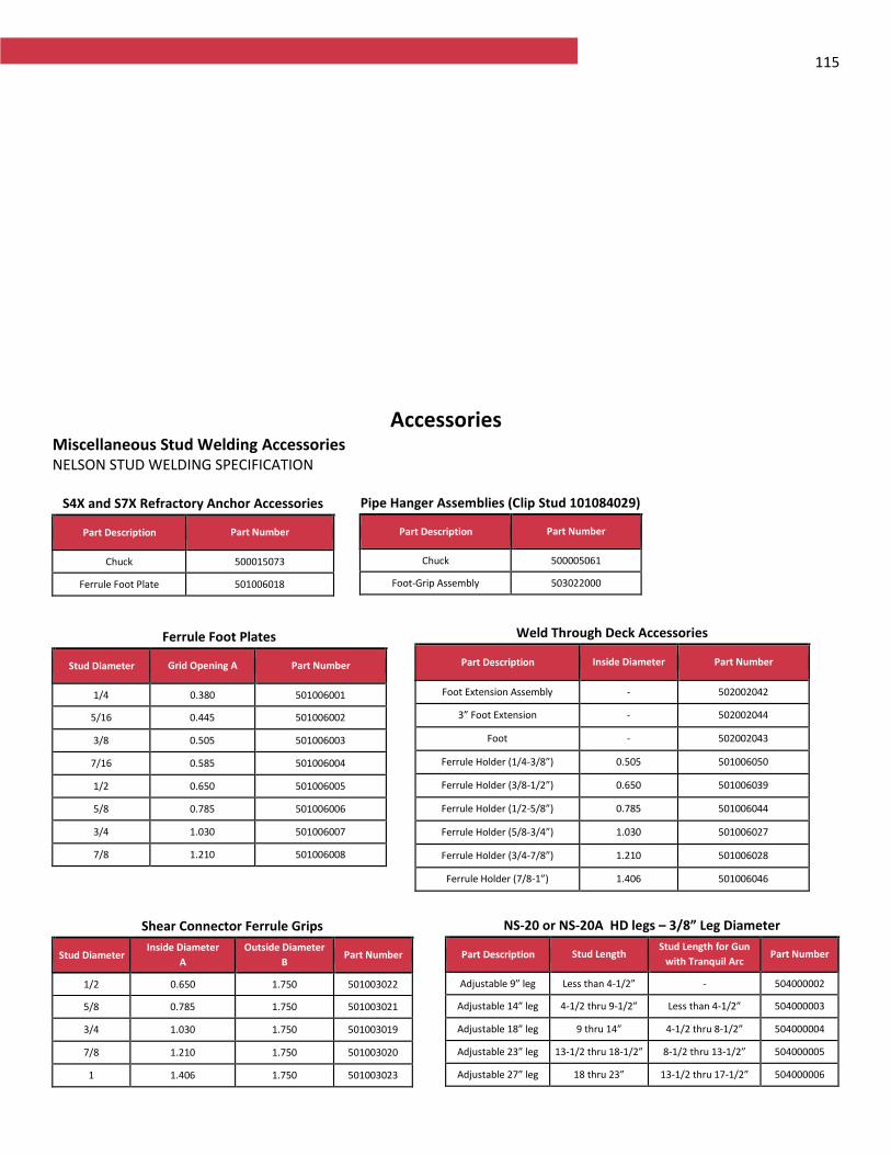
115
Accessories Miscellaneous Stud Welding AccessoriesNELSON STUD WELDING SPECIFICATION
S4X and S7X Refractory Anchor Accessories
Part Description Part Number
Chuck
500015073
Ferrule Foot Plate 501006018
Pipe Hanger Assemblies (Clip Stud 101084029)
Part Description Part Number
Chuck
500005061
Foot-Grip Assembly 503022000
Ferrule Foot Plates
Stud Diameter Grid Opening A Part Number
1/4
0.380 501006001
5/16 0.445 501006002
3/8 0.505 501006003
7/16 0.585 501006004
1/2 0.650 501006005
5/8 0.785 501006006
3/4 1.030 501006007
7/8 1.210 501006008
Weld Through Deck Accessories
Part Description Inside Diameter Part Number
Foot Extension Assembly
- 502002042
3” Foot Extension - 502002044
Foot - 502002043
Ferrule Holder (1/4-3/8”) 0.505 501006050
Ferrule Holder (3/8-1/2”) 0.650 501006039
Ferrule Holder (1/2-5/8”) 0.785 501006044
Ferrule Holder (5/8-3/4”) 1.030 501006027
Ferrule Holder (3/4-7/8”) 1.210 501006028
Ferrule Holder (7/8-1”) 1.406 501006046
Shear Connector Ferrule Grips
Stud Diameter Inside Diameter
A
Outside Diameter
B Part Number
1/2
0.650 1.750 501003022
5/8 0.785 1.750 501003021
3/4 1.030 1.750 501003019
7/8 1.210 1.750 501003020
1 1.406 1.750 501003023
NS-20 or NS-20A HD legs – 3/8” Leg Diameter
Part Description Stud Length Stud Length for Gun
with Tranquil Arc Part Number
Adjustable 9” leg
Less than 4-1/2” - 504000002
Adjustable 14” leg 4-1/2 thru 9-1/2” Less than 4-1/2” 504000003
Adjustable 18” leg 9 thru 14” 4-1/2 thru 8-1/2” 504000004
Adjustable 23” leg 13-1/2 thru 18-1/2” 8-1/2 thru 13-1/2” 504000005
Adjustable 27” leg 18 thru 23” 13-1/2 thru 17-1/2” 504000006
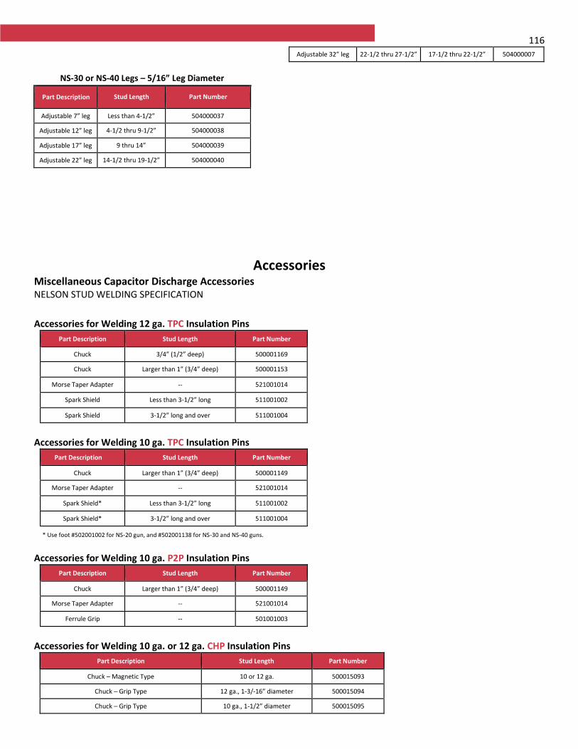
116
Accessories
Miscellaneous Capacitor Discharge AccessoriesNELSON STUD WELDING SPECIFICATION
Accessories for Welding 12 ga. TPC Insulation Pins
Part Description Stud Length Part Number
Chuck 3/4” (1/2” deep) 500001169
Chuck Larger than 1” (3/4” deep) 500001153
Morse Taper Adapter -- 521001014
Spark Shield Less than 3-1/2” long 511001002
Spark Shield 3-1/2” long and over 511001004
Accessories for Welding 10 ga. TPC Insulation Pins
Part Description Stud Length Part Number
Chuck Larger than 1” (3/4” deep) 500001149
Morse Taper Adapter -- 521001014
Spark Shield* Less than 3-1/2” long 511001002
Spark Shield* 3-1/2” long and over 511001004
* Use foot #502001002 for NS-20 gun, and #502001138 for NS-30 and NS-40 guns.
Accessories for Welding 10 ga. P2P Insulation Pins
Part Description Stud Length Part Number
Chuck Larger than 1” (3/4” deep) 500001149
Morse Taper Adapter -- 521001014
Ferrule Grip -- 501001003
Accessories for Welding 10 ga. or 12 ga. CHP Insulation Pins
Part Description Stud Length Part Number
Chuck – Magnetic Type 10 or 12 ga. 500015093
Chuck – Grip Type 12 ga., 1-3/-16” diameter 500015094
Chuck – Grip Type 10 ga., 1-1/2” diameter 500015095
Adjustable 32” leg 22-1/2 thru 27-1/2” 17-1/2 thru 22-1/2” 504000007
NS-30 or NS-40 Legs – 5/16” Leg Diameter
Part Description Stud Length Part Number
Adjustable 7” leg
Less than 4-1/2” 504000037
Adjustable 12” leg
4-1/2 thru 9-1/2” 504000038
Adjustable 17” leg
9 thru 14” 504000039
Adjustable 22” leg
14-1/2 thru 19-1/2” 504000040
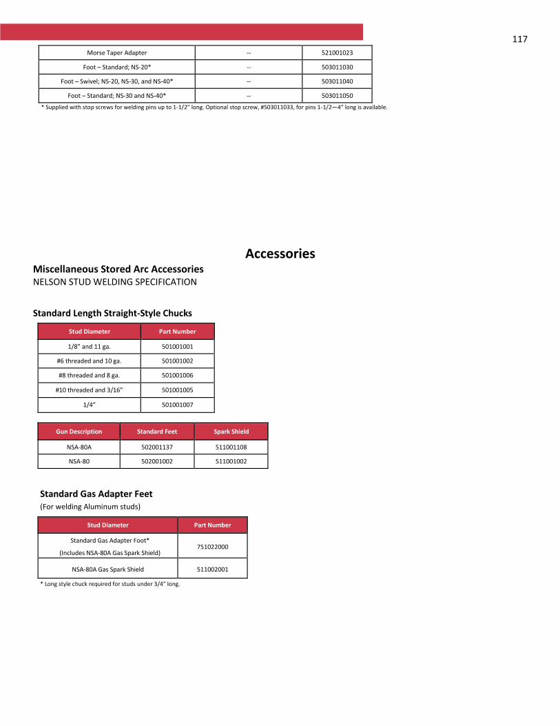
117 Morse Taper Adapter -- 521001023
Foot – Standard; NS-20* -- 503011030
Foot – Swivel; NS-20, NS-30, and NS-40* -- 503011040
Foot – Standard; NS-30 and NS-40* -- 503011050
* Supplied with stop screws for welding pins up to 1-1/2” long. Optional stop screw, #503011033, for pins 1-1/2—4” long is available.
Accessories Miscellaneous Stored Arc AccessoriesNELSON STUD WELDING SPECIFICATION
Standard Length Straight-Style Chucks
Stud Diameter Part Number
1/8” and 11 ga. 501001001
#6 threaded and 10 ga. 501001002
#8 threaded and 8 ga. 501001006
#10 threaded and 3/16” 501001005
1/4” 501001007
Gun Description Standard Feet Spark Shield
NSA-80A 502001137 511001108
NSA-80 502001002 511001002
Standard Gas Adapter Feet (For welding Aluminum studs)
Stud Diameter Part Number
Standard Gas Adapter Foot*
(Includes NSA-80A Gas Spark Shield) 751022000
NSA-80A Gas Spark Shield 511002001
* Long style chuck required for studs under 3/4” long.
118
Nelson® Stud Welding 7900 W. Ridge Rd. Elyria, OH 44035 USA PH: +1 (440)-329-0400 Fax: +1-(440) 329-0526 www.NelsonStud.com
USA Canada Mexico Germany China France Italy UK India © 2017, Nelson Stud Welding A Nelson Fastener Systems Company