Embed Size (px)
Citation preview

�������������������� �� ���������� ���� ����

������������
������������������ ���������� ��������������������������������������������� ��������������������������������������������������������������������������������������������� ������������������ ����������������������������������������������������������������
���������� ������������������������������������������� ��������!��"#�$�������������������������������������������������%�������������������&����������� #����������'�� #�����������������%�������� ��������������������������&��������������������������������������� �
(������)�
�������� ��������!��"�"��������"���������*+,�'++-.�$�����

������������������� ��������
����������/������0�����)
���������������
�1������������������������������#���������������������������������������������� �����������������2
������ ���� ���� ������������������������������������ �����������!


Table of contents
1. Safety instructions.......................................................................................................................... 2
2. Principles of Knifemaking.............................................................................................................. 3
2.1 The Balanced Break method (Fig. 1) ...................................................................................... 3
2.2 Scoring and breaking principles ................................................................................................. 3
2.3 The real knife angle .................................................................................................................... 5
2.4 Length of useful edge................................................................................................................. 6
3. Unpacking and Installation ............................................................................................................ 7
3.1 Unpacking................................................................................................................................... 7
3.2 Installation .................................................................................................................................. 7
4. Description of the Leica EM KMR3................................................................................................ 8
5. Knifemaking................................................................................................................................... 11
5.1 Hints.......................................................................................................................................... 11
5.2 Making squares ........................................................................................................................ 13
5.3 Making knives from a square ................................................................................................... 15
5.4 Evaluation of the knife edge ..................................................................................................... 17
6. Knife shoulder fine adjustment ................................................................................................... 19
7. Care and maintenance.................................................................................................................. 21
7.1 Replacement of the scoring wheel cartridge ............................................................................ 21
7.2 Adjusting the scoring pressure ................................................................................................. 22
8. Breaking 10mm thick glass strips............................................................................................... 22
9. Mounting plastic boats (trufs) onto the knife............................................................................. 23
10. Accessories and consumables ................................................................................................... 24
11. Technical specifications .............................................................................................................. 25
...
Page 1 Leica EM KMR3 Operating Manual 04/10

1. Safety instructions
Prior to the operation of the Leica EM KMR3 please read the instruction manual carefully. Always use safety goggles during operation to avoid eye injury. Use lint free gloves, thus to avoid finger prints onto the glass strip Clean the instrument regularly with a brush to remove glass splinters. Store broken knives safely in the knife boxes provided. Do not leave knives laying around or on the Leica EM KMR3. Used knives should be put into a marked “sharps” box for safe disposal
Symbols in this manual and their meaning
a care.
Important information for the user.
Identification
Product:
Leica EM KMR3
Manufactured by:
Leica Mikrosysteme GmbH Hernalser Hauptstrasse 219 A-1170 Vienna
Tel.: +43 1 488 99-0 Fax: +43 1 488 99-350
Internet: http://www.leica-microsystems.com
Warning:
take extr
Notes:
Page 2 Leica EM KMR3 Operating Manual 04/10

2. Principles of Knifemaking
2.1 The Balanced Break method (Fig. 1)
In the balanced break method, an original Leica glass strip 400mm in length (6.4, 8 or 10mm thick), is scored and broken into two equal halves, each 200mm long. With an equal mass of glass on each side of the score the break is balanced and the freshly fractured surfaces are plane. By continuing to divide each piece produced into two equal halves, up to 16 squares can be made. All squares produced have straight sides and precise right angled corners unlike squares produced from sequential breaking of a glass strip which have curved surfaces.
Fig. 1
2.2 Scoring and breaking principles
Producing good glass knives routinely depends on a supply of reproducible squares, an accurately positioned score and controlled pressure precisely applied to make the break. The LEICA EM KMR3 gives the user a choice of two different score lengths, each one factory set to produce the optimum break. The short score (glass strip symbol) is used to break the glass strips into squares. The long score (square symbol) is used to break the final knives. As a general rule, the knife edge is straighter and the counterpiece (knife shoulder) is small when the fracture occurs close to the corner (long score). Using a short score was in the past suggested for cryo knives as the free break is longer resulting in the sharpest, longest useable knife edge (Griffiths et al 1983: Tokuyasu 1986).
Each score is preset and equidistant from the corners of the square. During the break the glass sits on two steel hemispheres and is held from above by two pins. The design of the EM KMR3 allows a simultaneous movement of the two breaking pins to apply exactly the same force to each side of the glass strip ore square. The break follows the score line as far as it goes and then a free break occurs. The direction of this free break is determined by the mass of the glass on either side of the break and the breaking forces.
Page 3 Leica EM KMR3 Operating Manual 04/10

Page 4 Leica EM KMR3 Operating Manual 04/10
The free break curves to the edge of the square resulting in one knife and one flat-edge counterpiece (knife shoulder) opposite the knife edge Fig. 2.When the score runs centrally through a square a very small counterpice is obtained and the knife angle is very close to 45° (Fig. 2a).
This is the optimal result for cryo knives. For resin sectioning, the user sets
the knife shoulder adjustment a little larger (~ 0.5mm), to produce a larger
knife angle which is more stable for resin sectioning.
Fig. 2 Fig. 2a
Knife edge of the left knife
Counterpiece/Knife shoulder
Counterpiece/Knife shoulder
Knife edge of the right knife
Knife edge
Counterpi / Knife shoulder ece

2.3 The real knife angle
When scoring the square all scores stop some distance from the corner. When pressure is applied under the score, the fracture is initiated and is seen first as a deepening of the score. The fracture extends towards the corners of the square following the line of the score. Where the score ends and the break is free. the fracture deviates from the line of the score to curve away from the corner, towards one of the edges of the square. This results in the real angle of the knife being somewhat greater than the angle of scoring. The real angle of the knife increases as the score is moved further from the diagonal. This is when the knife shoulder becomes larger. For example, when preparing knives from a square, the real angle of the knife is close to 45° when the knife shoulder is smaller (< 0.5mm). Increasing the size of the knife shoulder (|> 0.5mm) results in an even larger knife angle which can be over 55° (Fig. 3).
Fig. 3
Scoring angle
Real knife angle
Page 5 Leica EM KMR3 Operating Manual 04/10

2.4 Length of useful edge
When a glass knife edge is examined under darkfield illumination using a stereo microscope (or on LEICA Ultramicrotomes using the back light, chapter 5.4), it can be seen that the central part is most useful for ultrathin sectioning. The right side of the edge has visible marks (saw teeth) which reduce the quality of the knife, and the left corner is also unsuitable for sectioning because of the stress line (Fig. 4).The useful knife edge starts where the stress line moves away form the knife edge until the part where the stress marks (saw teeth) can be seen.
Fig. 4
Note:
The useful knife edge is 30% longer on knives produced from 8mm thick glass
compared to 6.4mm thick glass!
s force has been used to break the knife, the stress line falls away
from the knife edge and fewer saw teeth can be seen. Resulting in a
e knife edge.
Stress line
Note:
When les
rapidly
longer usabl
Page 6 Leica EM KMR3 Operating Manual 04/10

3. Unpacking and Installation
3.1 Unpacking
The Leica EM KMR3 is packed in a single carton. Before unpacking ensure that the box is the correct way up. Carefully remove the Knifemaker together with the plastic foam Check all items against the packing list (enclosed in the shipping) and examine each item for transport damage.
3.2 Installation
Place the Leica EM KMR3 on a sturdy laboratory bench or a table where it will not be affected by movement from other laboratory equipment, such as a centrifuge. The Leica EM KMR3 is completely assembled in the factory, so the instrument is ready to use out of the box.
Page 7 Leica EM KMR3 Operating Manual 04/10

4. Description of the Leica EM KMR3
The scoring and breaking mechanism for knife making are assembled on a heavy, vibration-absorbing base.
The parts are shown in Fig. 5:
1
2
3
45 6
7
8
9
Page 8 Leica EM KMR3 Operating Manual 04/10
1. Clamping lever:
used to lower, clamp and raise scoring head. The clamping leaver has a defined stop to ensure equal clamp force at any time.
2. Breaking wheel:
is used to break the glass after scoring. By turning the wheel slowly clockwise, two breaking pins apply exactly the same force to each side of the glass. The breaking wheel features defined positions and automatically resets after the break.
3. Scoring mark selector:
can be set by rotating to two different scoring lengths. The short score (12mm) – glass strip symbol, is for scoring the glass strips to break squares. The long score (22mm) – square symbol, is used to score squares for making high quality knives.
4. Reference guide:
acts generally as a stop for the glass strip. The glass strip is pressed against the reference guide before it is clamped. The left hand reference guide acts also as a track for the moveable stop with its four click stop positions.
5. Moveable click stop:
with its four click positions is mounted on the left hand reference guide and is used to position the 400 mm long glass strips according the balanced break method.
6. Scoring device:
the knob is pushed inwards until it reaches the magnetic end stop where it is held until after the break. It is then automatically released. The score itself is performed by a tungsten carbide scoring wheel.
7. Scoring pressure adjustment:
is used to change the scoring pressure if necessary (when 6.4, 8mm or 10mm glass strips are used). A scale indicates the scoring pressure.
8. Knife drawer:
is used to press the glass strip against the reference guide, for positioning the square and for convenient removal of the glass knives. It also holds the front fork with the knife shoulder adjustment.
9. Rear fork:
is used to hold and position the glass square against the front fork. It also holds the knife shoulder adjustment.
Page 9 Leica EM KMR3 Operating Manual 04/10

Page 10 Leica EM KMR3 Operating Manual 04/10

5. Knifemaking
5.1 Hints
For the best Leica EM KMR3 performance, it is recommended that glass strips supplied by Leica are always used. Leica glass strips for ultramicrotomy are produced from specially selected glass, the thickness and quality of which is precisely controlled. Only strict tolerances ensured by careful quality control allow breaking of two high quality knives from one square. All strips supplied by Leica are 400mm long and 25.4mm wide. They are available in thicknesses of 6.4mm, 8mm and 10mm. Leica glass strips are washed, individually wrapped in tissue paper, and packed in a strong carton. When handling the strips, avoid contacting the narrow edges as these may finally form the knife edge. The strips and squares can be held by the wide upper and lower surfaces. Wear lint free cotton gloves to avoid finger prints on the glass surface. Finger prints (grease) can negatively influence the score. Never touch the corners of a partly broken strip or square as these will form the knife edge. Cleaning the glass strips is in general not necessary because the strips are pre-cleaned wrapped in tissue paper and kept away from dust in the carton. However, if there is a need to clean the glass: wash each strip separately in cool tap water which has a low concentration of a mild laboratory detergent added to it. Completely rinse off all detergent, then rinse thoroughly with distilled water. Dry gently with a clean, soft and lint free cloth or place it in a drying oven.
Wear always lint free cotton gloves when handling the glass!
Glass knives and glass strips have sharp edges - handle with great
Note:
Warning:
care!
Page 11 Leica EM KMR3 Operating Manual 04/10
Page 12 Leica EM KMR3 Operating Manual 04/10
Fig. 6 Fig. 7
Fig. 8
Fig. 9 Fig. 10

5.2 Making squares
Raise the scoring head by using the clamping lever (Fig. 5, No.1).
Set the scoring mark selector to the glass strip symbol (Fig. 5, No.3).
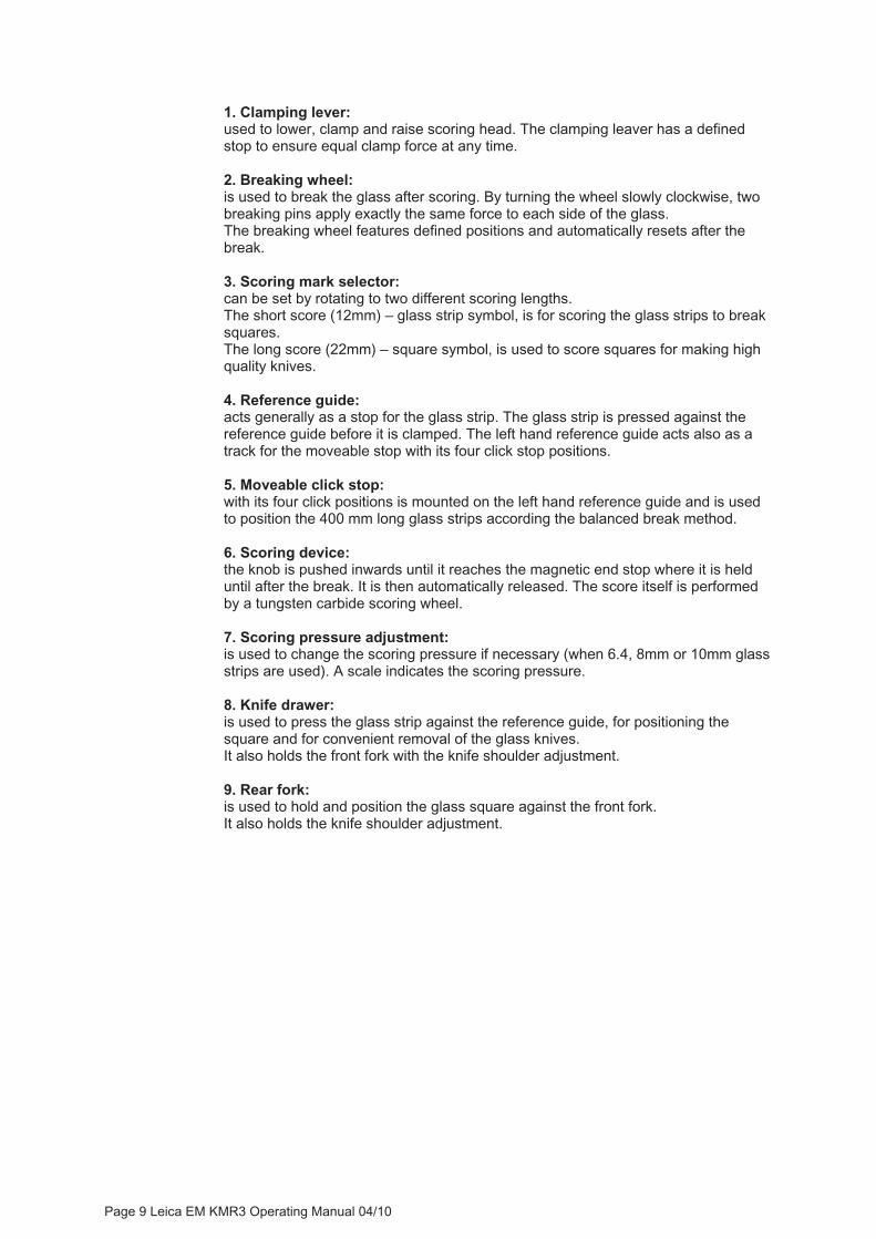
Press down on the click stop (Fig. 5, No.5) and slide it to the far left hole until it clicks in. Press the 400mm glass strip against it and push the knife drawer (Fig. 5, No.8) away from you until it reaches the end stop, this will align the glass strip against the reference guide. Lower the scoring head and clamp it to its defined stop (Fig. 6).
The weight of the scoring head holds the glass strip in position. Press the white knob of the scoring device (Fig. 7) to sore the glass. Move the click stop away from the glass, this will allow a `free break’. Turn the breaking wheel slowly to initiate the break (Fig. 8).
6.4mm glass will break approx. at indication number 3 8mm glass will break approx. at indication number 5 10mm glass will break approx. at indication number 8 (Upgrade kit for 10mm is optional! Oder number 16706911110).
After the break, the breaking wheel is automatically reset to its home position. Raise the scoring head by using the clamping lever. The scoring device is also automatically reset to its home position. Pull the knife drawer towards you until it reaches the click stop (after a few mm of moving). Remove the right glass strip and place it onto the foam glass storage area. Turn the left glass strip and place it with the fresh broken end facing the click
stop.Slide the click stop to the right to its next click position. Press the glass strip against it and move the drawer towards the glass until it stops. Repeat steps as described above, halving the glass strip each time, until two 25mm squares are produced (Fig. 9).
Do not use the right end square of both 200mm glass strips as the ends are machine broken and therefore geometrically not perfect. (Fig. 10)
Page 13 Leica EM KMR3 Operating Manual 04/10

Page 14 Leica EM KMR3 Operating Manual 04/10
Fig. 11 Fig. 12
Fig. 13 Fig. 14
Fig. 15 Fig. 16

Page 15 Leica EM KMR3 Operating Manual 04/10
5.3 Making knives from a square
Move the click stop to the left as it is not used for breaking knives. Raise the scoring head by using the clamping lever Rotate the square a quarter turn clockwise in order to produce the knife edges from the freshly broken side of the glass. Position the square into the notch of the front fork (Fig. 11).
Push the knife drawer slowly direction rear fork (Fig. 12) and place the square into the notch of the rear fork. Push the knife drawer until it reaches the end stop and the square is securely positioned (Fig. 13).
Set the scoring mark selector to the square symbol. Lower the scoring head, score and break according description in chapter 5.2.
To break the final knives it is recommended to break as slow as possible. For a reproducible break use the numbers on the breaking wheel as force indication.Raise the scoring head and pull the knife drawer towards you until it reaches the end stop (Fig. 14).
With both hands remove left and right knife simultaneously (Fig. 15).
Or, press both together and remove with one hand. Do not allow the knives to touch while removing.
Each of the knives has a knife edge and a knife shoulder
Turn the right knife to bring the knife edge side by side with knife edge of the left knife (Fig. 16).
t knives are made using the lowest breaking pressure.
y take a minute or more to break!
Knife edge of the left hand knife Knife shoulder of
the right hand knife
Right hand knife
Knife edge of the right hand knife
Knife shoulder of the left hand knife
Left hand knife
Note:
The bes
They ma

Page 16 Leica EM KMR3 Operating Manual 04/10
Fig. 17 Fig. 18
Fig. 19
Fig. 20
Fig. 21
Right knife Left knife

5.4 Evaluation of the knife edge
After making a pair of knives, evaluation of the quality can be carried out with the Ultramicrotome (Leica Ultracut UC7). Using the backlight illumination and setting the clearance angle to maximum a fine white line can be seen (Fig. 17).The image of the line indicates the quality of the knife edge, which must be straight, free of any dirt such as dust, grease and finger prints and free of glass splinters. The top light of the ultramicrotome can also be used for checking knife quality (Fig. 18). An example of a knife which should not be used is shown in Fig. 19.This has been picked up incorrectly leaving a finger print over the knife edge.
In Fig. 20 a pair of knives is shown, broken and placed side by side according to chapter 5.3.The detail (Fig. 21) shows the knife shoulder of both knives. The right hand knife edge was opposite the left hand knife shoulder during breaking and the left hand knife edge was opposite the right hand knife shoulder.
arpest knife edge is the one opposite the smaller knife shoulder!
The knife edge opposite a small knife shoulder (< 0.2mm) has a knife angle very close to 45°, as recommended for cryo-ultramicrotomy (Fig. 22).(Griffiths et al. 1983: Tokuyasu 1986).
For resin sectioning a larger knife shoulder (approx. 1mm) is recommended.
Fig. 22
Note: the sh
Knife angle close to 45°
Page 17 Leica EM KMR3 Operating Manual 04/10

Page 18 Leica EM KMR3 Operating Manual 04/10
Fig. 23
Fig. 24

6. Knife shoulder fine adjustment
The adjustments shown in Fig. 22 and 23 are used to adjust the size of the knife shoulder. As mentioned earlier in this user manual, the sharpest knife edge is found opposite a very small knife shoulder. The fine adjustment allows setting the knife shoulder size according to the application: For resin sections knife shoulder should be between 0.5mm and 1mm. For cryo sections the knife shoulder should be smaller than 0.3mm.
Knife shoulder adjustment of the left knife (Fig. 23):
Use a 2mm Allen key and turn the adjusting knob Counter clockwise - knife shoulder becomes bigger. Turn it clockwise – knife shoulder becomes smaller.
Knife shoulder adjustment of the right knife (Fig. 24):
Raise the scoring head by using the clamping lever and remove the head. Use a 2mm Allen key and turn the adjusting knob Counter clockwise – knife shoulder becomes bigger. Turn it clockwise – knife shoulder becomes smaller.
Fine adjustments are very sensitive – only a very small
Note:
turn within the scale is
sary to change the size of the knife shoulder.neces
Page 19 Leica EM KMR3 Operating Manual 04/10

Page 20 Leica EM KMR3 Operating Manual 04/10
Fig. 25 Fig. 26
Sliding surfaces
Fig. 27 Fig. 28

7. Care and maintenance
The Leica EM KMR3 should always be kept clean. The breaking pins and steel hemispheres (glass strip support area) must be free of any glass particles when a glass break is performed. Use a brush or Dust-off to clean after each glass break. The sliding surfaces of the scoring and clamping head (Fig. 25 and Fig. 26) mustalso be kept clean and dry.Raise the scoring head using the clamping lever and remove the head. Use a dry lint-free cloth and clean the sliding surfaces. After cleaning, re-place the scoring head.
ase or oil should be applied!
7.1 Replacement of the scoring wheel cartridge
With the original Leica scoring wheel, approx. 5000 glass strips (6.4 and 8mm) can be scored to produce glass knives (if the scoring pressure is adjusted correctly). To replace the scoring wheel, raise the scoring head completely, remove and place it on a table upside down. Using the TORAX Allen Key (provided with the spare scoring wheel shipment), open the clamping screw for the scoring wheel shaft (Fig. 27) and pull out the shaft (Fig. 28).
Insert a new scoring wheel, re-insert the shaft, replace the screw and tighten it. Replace the scoring head and make a ‘test’ score on a piece of glass strip. The scoring pressure with the new scoring wheel cartridge will probably be too strong or maybe not enough. For adjustment see chapter 7.2.
No gre
Page 21 Leica EM KMR3 Operating Manual 04/10

7.2 Adjusting the scoring pressure
By turning the wheel beneath the pressure scale (Fig. 29/30) to the left, pressure can be decreased.Turning to the right the pressure can be increased.
The pressure is correct when one faint smooth line without glass splinters is produced on the glass surface.
The pressure is too strong when a groove and glass splinters can be seen.
The pressure is too low when the scoring line is faint and interrupted.
Factory set scoring pressure for 6.4 and 8mm glass (Fig. 29), scale position approx. at 0,5.
User set scoring pressure for 10mm glass (Fig. 30), scale position approx. at 1,5. (Upgrade kit for 10mm is optional! Order number: 16706911110).
Fig. 29 Fig. 30
8. Breaking 10mm thick glass strips
When breaking 10mm glass, make sure the ‘upgrade kit for 10mm’ (order number 16706911110) has been ordered together with your KMR3. This built-in kit allows applying a clamping pressure suitable for breaking 10mm glass.
Set the scoring pressure to scale position 2 (Fig. 30).
Follow the sequences described in chapter 5.2 and 5.3.
10mm glass strip will break approx. at indication number 8 (scale indicator on the breaking wheel).
Page 22 Leica EM KMR3 Operating Manual 04/10

9. Mounting plastic boats (trufs) onto the knife
Water boats (trufs) are used to hold distilled water where ultrathin sections can then float on the surface after room temperature sectioning.
Fitting a truf is simple using the Leica EM MP is used (Fig. 31).Wax is melted in the wax bath (2/3 full) and the glass knives are gently warmed on the hotplate with the knife edge overhanging the edge of the hotplate as shown in Fig. 32.The attachment surfaces of the truf are coated with molten wax by putting it onto the wax bath as shown in Fig 32.The truf is then brought into contact with the pre-warmed knife and slid up until the rim of the truf is at the same level as the knife edge (Fig. 33).
The truf is held in this position for a second or two until the wax has hardened. Additional wax is applied on the right side of the truf using the spatula supplied with the Leica EM MP for further protection against leaks (Fig. 34).
For detailed description please see the user manual of the Leica EM MP.
Fig. 31 Fig. 32
Fig. 33 Fig. 34
Hotplate Wax bath
Page 23 Leica EM KMR3 Operating Manual 04/10
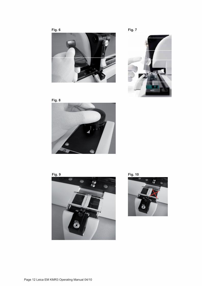
10. Accessories and consumables
16840031 Glass strips 6.4 x 400 x 25.4mm (box of 30 strips) 16840032 Glass strips 8 x 400 x 25.4mm (box of 24 strips) 16840079 Glass strips 10 x 400 x 25.4mm (box of 18 strips) 16840042 Trufs 6.4mm (500 pcs.) 16840045 Trufs 8mm (500 pcs.) 16895032 Dust cover 16705225 Knife boxes (3 pcs.) 16706980 Scoring wheel for EM KMR3
Recommended accessories
16705403 LEICA EM MP 115/230VAC
complete with metal spatula and 500g dental wax. Hotplate with 3 different temperatures for mounting TRUFS on glass knives and for staining and drying of semithin sections on glass slides.
Leica - best solution for EM sample preparation: www.leica-microsystems.com/products/electron-microscope-sample-preparation
Leica EM AMW Automatic Microwave Tissue Processor for EM Samples
Leica EM UC7 Ultramicrotome Leica EM AC20 Automatic Contrasting
Page 24 Leica EM KMR3 Operating Manual 04/10
Page 25 Leica EM KMR3 Operating Manual 04/10
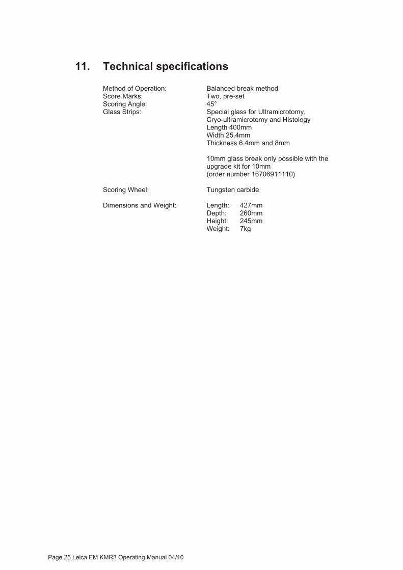
11. Technical specifications
Method of Operation: Balanced break method Score Marks: Two, pre-set Scoring Angle: 45°Glass Strips: Special glass for Ultramicrotomy, Cryo-ultramicrotomy and Histology Length 400mm Width 25.4mm
Thickness 6.4mm and 8mm
10mm glass break only possible with the upgrade kit for 10mm (order number 16706911110)
Scoring Wheel: Tungsten carbide
Dimensions and Weight: Length: 427mm Depth: 260mm Height: 245mm Weight: 7kg

��������
�� ����
�����������
�����
��������
������
����
�������
�������
�!���
����"
�����
�#�$��%�&
'(���
'))�
���*�
+�&'(
���')
)��(
, ��
-.�"���
/��
� ����
�����
��������
�����
�/���/
��������0� �
�����.1
�����
�%2�/����
���0�
���/����
3�2���������
����
�� ���
��-��4�
1(��!
�����
���5�
�' (
��� '
6� �
�����
��������������������������