Embed Size (px)
Citation preview
© 2005 by Prentice Hall© 2005 by Prentice Hall 11
Chapter 2:Chapter 2: The Database The Database
Development Process Development Process
Modern Database Modern Database ManagementManagement
77thth Edition EditionGeorge LampertiGeorge Lamperti
22© 2005 by Prentice Hall© 2005 by Prentice HallChapter 2
ObjectivesObjectives Definition of termsDefinition of terms Describe Describe system development life cyclesystem development life cycle Explain Explain prototypingprototyping approach approach Explain roles of individualsExplain roles of individuals Explain three-schema approachExplain three-schema approach Explain role of packaged data modelsExplain role of packaged data models Explain three-tiered architecturesExplain three-tiered architectures Draw simple data modelsDraw simple data models

33© 2005 by Prentice Hall© 2005 by Prentice HallChapter 2
Enterprise Data ModelEnterprise Data Model
First step in database developmentFirst step in database development Specifies scope and general contentSpecifies scope and general content Overall picture of organizational data at Overall picture of organizational data at
high level of abstractionhigh level of abstraction Entity-relationship diagramEntity-relationship diagram Descriptions of entity typesDescriptions of entity types Relationships between entitiesRelationships between entities Business rulesBusiness rules

44© 2005 by Prentice Hall© 2005 by Prentice HallChapter 2
Figure 2-1 Segment from enterprise data model (Pine Valley Furniture Company) [simplified E-R diagram, repeat of figure 1.3]
Enterprise data model describes the high-level entities in an organization and the relationship between these entities
Homework Assignment 2-1

55© 2005 by Prentice Hall© 2005 by Prentice HallChapter 2
Information Systems Information Systems ArchitectureArchitecture
(ISA)(ISA) Conceptual blueprint for organization’s desired Conceptual blueprint for organization’s desired
information systems structureinformation systems structure Consists of:Consists of:
Data (e.g. Enterprise Data Model – simplified ER Diagram)Data (e.g. Enterprise Data Model – simplified ER Diagram) Processes – data flow diagrams, process decomposition, Processes – data flow diagrams, process decomposition,
etc.etc. Data Network – topology diagram (like fig 1.9)Data Network – topology diagram (like fig 1.9) People – people management using project management People – people management using project management
tools (Gantt charts, etc.)tools (Gantt charts, etc.) Events and points in time (when processes are Events and points in time (when processes are
performed)performed) Reasons for events and rules (e.g. decision tables)Reasons for events and rules (e.g. decision tables)

66© 2005 by Prentice Hall© 2005 by Prentice HallChapter 2
Information EngineeringInformation Engineering A data-oriented methodology to create and A data-oriented methodology to create and
maintain information systemsmaintain information systems Top-down planning: a generic IS planning Top-down planning: a generic IS planning
methodology for obtaining a broad methodology for obtaining a broad understanding of the IS needed by the understanding of the IS needed by the entire organizationentire organization
Four steps to Top-Down planning:Four steps to Top-Down planning: PlanningPlanning AnalysisAnalysis DesignDesign ImplementationImplementation

77© 2005 by Prentice Hall© 2005 by Prentice HallChapter 2
Information Systems Information Systems PlanningPlanning
(Table 2-1) (Table 2-1) Purpose: align information Purpose: align information
technology with organization’s technology with organization’s business strategiesbusiness strategies
Three steps:Three steps:1.1. Identify strategic planning factors Identify strategic planning factors
2.2. Identify corporate planning objectsIdentify corporate planning objects
3.3. Develop enterprise modelDevelop enterprise model

88© 2005 by Prentice Hall© 2005 by Prentice HallChapter 2
Identify Strategic Planning Identify Strategic Planning Factors (Table 2-2)Factors (Table 2-2)
Organization goalsOrganization goals – what we hope to – what we hope to accomplishaccomplish
Critical success factorsCritical success factors – what MUST – what MUST work in order for us to survivework in order for us to survive
Problem areasProblem areas – weaknesses we now – weaknesses we now havehaveHomework Assignment 2-2

99© 2005 by Prentice Hall© 2005 by Prentice HallChapter 2
Identify Corporate Planning Identify Corporate Planning Objects (Table 2-3)Objects (Table 2-3)
Organizational units – departmentsOrganizational units – departments Organizational locationsOrganizational locations Business functions – groups of Business functions – groups of
business processesbusiness processes Entity types – the things we are Entity types – the things we are
trying to model for the databasetrying to model for the database Information systems – application Information systems – application
programsprograms

1010© 2005 by Prentice Hall© 2005 by Prentice HallChapter 2
Develop Enterprise ModelDevelop Enterprise Model
Functional decompositionFunctional decomposition See Figure 2-2See Figure 2-2
Enterprise data model Enterprise data model See Figure 2-1See Figure 2-1
Planning matrixes Planning matrixes See Figure 2-3See Figure 2-3

1111© 2005 by Prentice Hall© 2005 by Prentice HallChapter 2
Figure 2-2 -- Example of process decomposition of an order fulfillment function (Pine Valley Furniture)
Decomposition -- breaking large tasks into smaller tasks in a hierarchical structure chart

1212© 2005 by Prentice Hall© 2005 by Prentice HallChapter 2
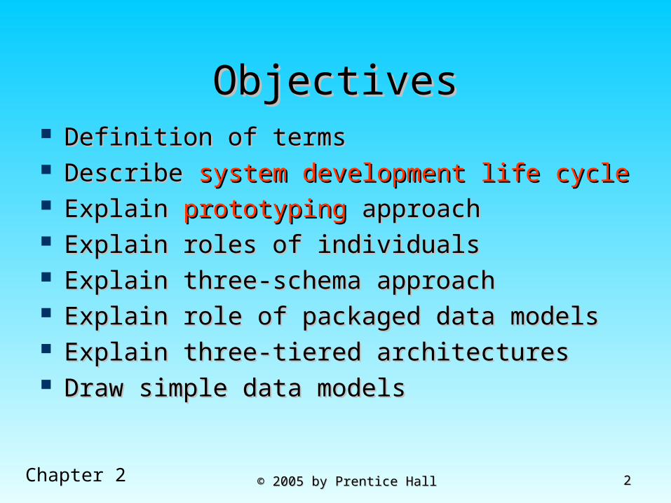
Planning MatrixesPlanning Matrixes Describe relationships between Describe relationships between
planning objects in the organizationplanning objects in the organization Types of matrixes:Types of matrixes:
Function-to-data entityFunction-to-data entity Location-to-functionLocation-to-function Unit-to-functionUnit-to-function IS-to-data entityIS-to-data entity Supporting function-to-data entitySupporting function-to-data entity IS-to-business objectiveIS-to-business objective
1313© 2005 by Prentice Hall© 2005 by Prentice HallChapter 2
Example business function-Example business function-to-data entity matrix (Fig. 2-to-data entity matrix (Fig. 2-
3)3)
Business Planning X X X XProduct Development X X X XMaterials Management X X X X X XOrder Fulfillment X X X X X X X X XOrder Shipment X X X X X XSales Summarization X X X X XProduction Operations X X X X X X XFinance and Accounting X X X X X X X X
Cus
tom
er
Pro
duct
Raw
Mat
eria
l
Ord
er
Wor
k C
ente
r
Wor
k O
rder
Invo
ice
Equ
ipm
ent
Em
ploy
ee
BusinessFunction (users)
Data Entity Types

1414© 2005 by Prentice Hall© 2005 by Prentice HallChapter 2
Two Approaches to Two Approaches to Database and IS Database and IS
DevelopmentDevelopment SDLCSDLC System Development Life CycleSystem Development Life Cycle Detailed, well-planned development processDetailed, well-planned development process Time-consuming, but comprehensiveTime-consuming, but comprehensive Long development cycleLong development cycle
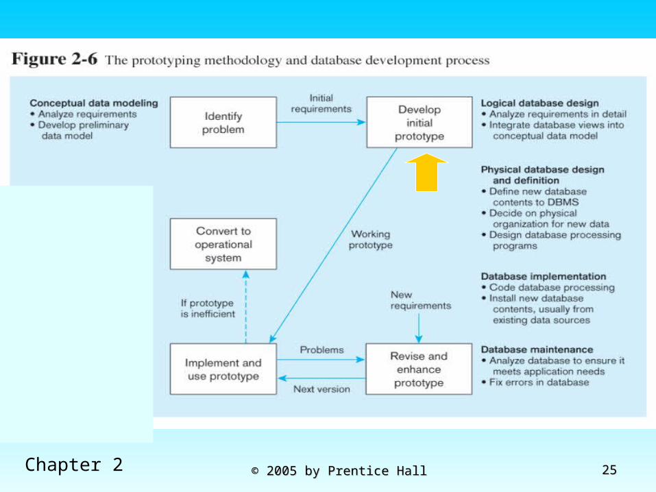
PrototypingPrototyping Rapid application development (RAD)Rapid application development (RAD) Cursory attempt at conceptual data modeling.Cursory attempt at conceptual data modeling. Define database during development of initial prototypeDefine database during development of initial prototype Repeat implementation and maintenance activities with Repeat implementation and maintenance activities with
new prototype versionsnew prototype versions

1515© 2005 by Prentice Hall© 2005 by Prentice HallChapter 2
Systems Development Life Cycle Systems Development Life Cycle (Figures 2-4, 2-5)(Figures 2-4, 2-5)
Project Identification and Selection
Project Initiation and Planning
Analysis
Physical Design
Implementation
Maintenance
Logical Design

1616© 2005 by Prentice Hall© 2005 by Prentice HallChapter 2
Systems Development Life Cycle (cont.) Systems Development Life Cycle (cont.)
(Figures 2-4, 2-5)(Figures 2-4, 2-5)
Maintenance
Purpose --preliminary understandingDeliverable –request for project
Database activity – enterprise modeling
Project Identification and Selection
Project Initiation and Planning
Analysis
Physical Design
Implementation
Maintenance
Logical Design
Project Identification and Selection

1717© 2005 by Prentice Hall© 2005 by Prentice HallChapter 2
Systems Development Life Cycle (cont.) Systems Development Life Cycle (cont.)
(figures 2-4, 2-5)(figures 2-4, 2-5)Purpose – state business situation and solutionDeliverable – request for analysis
Database activity – conceptual data modeling
Project Identification and Selection
Project Initiation and Planning
Analysis
Physical Design
Implementation
Maintenance
Logical Design
Project Initiation and Planning

1818© 2005 by Prentice Hall© 2005 by Prentice HallChapter 2
Systems Development Life Cycle Systems Development Life Cycle (cont.)(cont.)
(figures 2-4, 2-5)(figures 2-4, 2-5)Purpose – thorough analysisDeliverable – functional system specifications
Database activity – conceptual data modeling
Project Identification and Selection
Project Initiation and Planning
Analysis
Physical Design
Implementation
Maintenance
Logical Design
Analysis

1919© 2005 by Prentice Hall© 2005 by Prentice HallChapter 2
Systems Development Life Cycle Systems Development Life Cycle (cont.) (figures 2-4, 2-5)(cont.) (figures 2-4, 2-5)
Maintenance
Purpose – information requirements structureDeliverable – detailed design specifications
Database activity – logical database design
Project Identification and Selection
Project Initiation and Planning
Analysis
Physical Design
Implementation
Maintenance
Logical DesignLogical Design

2020© 2005 by Prentice Hall© 2005 by Prentice HallChapter 2
Systems Development Life Cycle Systems Development Life Cycle (cont.)(cont.)
(figures 2-4, 2-5)(figures 2-4, 2-5)Purpose – develop technology specsDeliverable – program/data structures, technology purchases, organization redesigns
Database activity – physical database design
Project Identification and Selection
Project Initiation and Planning
Analysis
Physical Design
Implementation
Maintenance
Logical Design
Physical Design

2121© 2005 by Prentice Hall© 2005 by Prentice HallChapter 2
Systems Development Life Cycle Systems Development Life Cycle (cont.)(cont.)
(figures 2-4, 2-5)(figures 2-4, 2-5)Purpose – programming, testing, training, installation, documentingDeliverable – operational programs, documentation, training materials
Database activity – database implementation
Project Identification and Selection
Project Initiation and Planning
Analysis
Physical Design
Implementation
Maintenance
Logical Design
Implementation

2222© 2005 by Prentice Hall© 2005 by Prentice HallChapter 2
Systems Development Life Cycle Systems Development Life Cycle (cont.)(cont.)
(figures 2-4, 2-5)(figures 2-4, 2-5)Purpose – monitor, repair, enhanceDeliverable – periodic audits
Database activity – database maintenance
Project Identification and Selection
Project Initiation and Planning
Analysis
Physical Design
Implementation
Maintenance
Logical Design
Maintenance

2323© 2005 by Prentice Hall© 2005 by Prentice HallChapter 2

2424© 2005 by Prentice Hall© 2005 by Prentice HallChapter 2
2525© 2005 by Prentice Hall© 2005 by Prentice HallChapter 2

2626© 2005 by Prentice Hall© 2005 by Prentice HallChapter 2

2727© 2005 by Prentice Hall© 2005 by Prentice HallChapter 2

2828© 2005 by Prentice Hall© 2005 by Prentice HallChapter 2
Packaged Data ModelsPackaged Data Models
Model components that can be purchased, Model components that can be purchased, customized, and assembled into full-scale customized, and assembled into full-scale data modelsdata models
AdvantagesAdvantages Reduced development timeReduced development time Higher model quality and reliabilityHigher model quality and reliability
Two types:Two types: Universal data modelsUniversal data models Industry-specific data modelsIndustry-specific data models

2929© 2005 by Prentice Hall© 2005 by Prentice HallChapter 2
CASECASE Computer-Aided Software Engineering Computer-Aided Software Engineering
(CASE) – software tools providing (CASE) – software tools providing automated support for systems automated support for systems developmentdevelopment
Three database features:Three database features: Data modeling – entity-relationship diagramsData modeling – entity-relationship diagrams Code generation – SQL code for table creationCode generation – SQL code for table creation Repositories – knowledge base of enterprise Repositories – knowledge base of enterprise
informationinformation

3030© 2005 by Prentice Hall© 2005 by Prentice HallChapter 2
Managing ProjectsManaging Projects Project – a planned undertaking of related Project – a planned undertaking of related
activities to reach an objective that has a activities to reach an objective that has a beginning and an endbeginning and an end
Involves use of review points for:Involves use of review points for: Validation of satisfactory progressValidation of satisfactory progress Step back from detail to overall viewStep back from detail to overall view Renew commitment of stakeholdersRenew commitment of stakeholders
Incremental commitment – review of Incremental commitment – review of systems development project after each systems development project after each development phase with rejustification after development phase with rejustification after each phaseeach phase

3131© 2005 by Prentice Hall© 2005 by Prentice HallChapter 2
Managing Projects: Managing Projects: People InvolvedPeople Involved
Systems analystsSystems analysts Database analystsDatabase analysts UsersUsers ProgrammersProgrammers Database/data administratorsDatabase/data administrators Systems programmers, network Systems programmers, network
administrators, testers, technical administrators, testers, technical writerswriters

3232© 2005 by Prentice Hall© 2005 by Prentice HallChapter 2
Figure 2-8a Gantt Chart
Shows time estimates of tasks

3333© 2005 by Prentice Hall© 2005 by Prentice HallChapter 2
Figure 2-8b PERT chart
Shows dependencies between tasks

3434© 2005 by Prentice Hall© 2005 by Prentice HallChapter 2
Database SchemaDatabase Schema Physical Schema Physical Schema
Physical structures – covered in chapters 5 and 6Physical structures – covered in chapters 5 and 6 Conceptual SchemaConceptual Schema
E-R models – covered in chapters 3 and 4E-R models – covered in chapters 3 and 4 External SchemaExternal Schema
User ViewsUser Views Subsets of Conceptual SchemaSubsets of Conceptual Schema Can be determined from business-function/data Can be determined from business-function/data
entity matricesentity matrices DBA determines schema for different usersDBA determines schema for different users

3535© 2005 by Prentice Hall© 2005 by Prentice HallChapter 2
Different people have different views of the database…these are the external schema
The internal schema is the underlying design and implementation

3636© 2005 by Prentice Hall© 2005 by Prentice HallChapter 2
Figure 2-11 Three-tiered client/server database architecture

3737© 2005 by Prentice Hall© 2005 by Prentice HallChapter 2
Pine Valley FurniturePine Valley Furniture
Preliminary data model(Figure 2-12)
Homework Assignment 1-2

3838© 2005 by Prentice Hall© 2005 by Prentice HallChapter 2

3939© 2005 by Prentice Hall© 2005 by Prentice HallChapter 2
QuestionsQuestions