Embed Size (px)
Citation preview

© 2008 McGraw-Hill Higher Education. All Rights Reserved.
Chapter 12:The Conditions of
Linear Motion
KINESIOLOGY
Scientific Basis of Human Motion, 11th edition
Hamilton, Weimar & LuttgensPresentation Created by
TK Koesterer, Ph.D., ATC
Humboldt State University
Revised by Hamilton & Weimar
KINESIOLOGY
Scientific Basis of Human Motion, 11th edition
Hamilton, Weimar & LuttgensPresentation Created by
TK Koesterer, Ph.D., ATC
Humboldt State University
Revised by Hamilton & Weimar

© 2008 McGraw-Hill Higher Education. All Rights Reserved.
Objectives
1. Name, define, and use the terms of linear motion.
2. Define magnitude, direction, and point of application of force and use terms properly.
3. Explain changes magnitude, direction, and point of application of force on the motion state of a body.
4. Define and give examples of linear forces, concurrent forces, and parallel forces.
5. Determine magnitude, direction, and point of application of muscles forces.
6. State Newton’s laws as they apply to linear motion.

© 2008 McGraw-Hill Higher Education. All Rights Reserved.
Objectives
7. Explain cause and effect relationship between forces of linear motion and objects experiencing the motion.
8. Name & define basic external forces that modify motion.
9. Draw and analyze a 2D free-body diagram.
10. Explain the work-energy relationship applied to a body experiencing linear motion.
11. Define and use properly the terms work, power, kinetic energy, and potential energy.
12. Perform a mechanical analysis of a motor skill.

© 2008 McGraw-Hill Higher Education. All Rights Reserved.
THE NATURE OF FORCE
• Force is that which pushes or pulls through direct mechanical contact or through the force of gravity to alter the motion of an object.
• Internal forces are muscle forces that act on various structures of the body.
• External forces are those outside the body:– Weight, gravity, air or water resistance,
friction, or forces of other objects acting on the body.

© 2008 McGraw-Hill Higher Education. All Rights Reserved.
Aspects of Force
• Force is a vector quantity:– Magnitude and direction– Also has a point of application
• All three characteristics must be identified. – For a weight lifter to lift a 250 N barbell:
• Lifter must apply a force greater than 250 N, in an upward direction, through the center of gravity of the barbell.

© 2008 McGraw-Hill Higher Education. All Rights Reserved.
Magnitude
• Amount of force being applied.– Force exerted by the barbell had a
magnitude of 250 N.– This force was the result of gravity acting
on the mass of the barbell.• In this case, the force is referred to as weight.• Weight is mass times acceleration due to
gravity:w = mg
© 2008 McGraw-Hill Higher Education. All Rights Reserved.
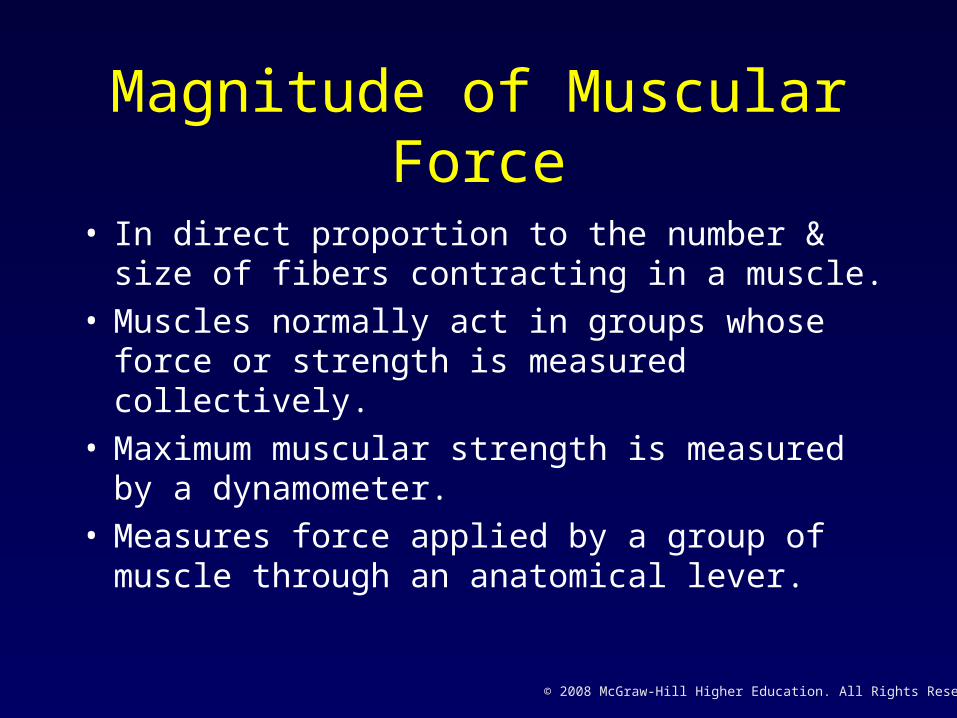
Magnitude of Muscular Force
• In direct proportion to the number & size of fibers contracting in a muscle.
• Muscles normally act in groups whose force or strength is measured collectively.
• Maximum muscular strength is measured by a dynamometer.
• Measures force applied by a group of muscle through an anatomical lever.

© 2008 McGraw-Hill Higher Education. All Rights Reserved.
Point of Application
• Point at which force is applied to an object.• Where gravity is concerned this point is
always through the center of gravity. • For muscular force, this point is assumed to
be the muscle’s attachment to a bony lever.• Technically, it is the point of intersection of
the line of force and the mechanical axis of the bone.

© 2008 McGraw-Hill Higher Education. All Rights Reserved.
Direction
• Direction of a force is along its action line.– Gravity is a downward-directed vector
starting at the center of gravity of the object.
– Direction of a muscular force vector is the direction of line of pull of the muscle.
© 2008 McGraw-Hill Higher Education. All Rights Reserved.
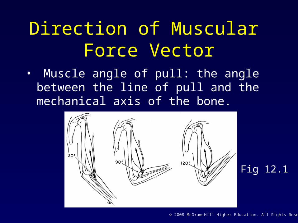
Direction of Muscular Force Vector
• Muscle angle of pull: the angle between the line of pull and the mechanical axis of the bone.
Fig 12.1

© 2008 McGraw-Hill Higher Education. All Rights Reserved.
Resolution of Forces
• Magnitude is line A.• Point of application is at
point B.• Direction is represented
by the arrowhead and the angle .
Fig 12.2

© 2008 McGraw-Hill Higher Education. All Rights Reserved.
Angle of Pull
• Force may be resolved into vertical and a horizontal components.
• Size of each depends on angle of pull.• Since a muscle’s angle of pull changes with
every degree of joint motion, so do the horizontal & vertical components .
• The larger the angle (0° - 90°), the greater the vertical and less the horizontal component.
© 2008 McGraw-Hill Higher Education. All Rights Reserved.
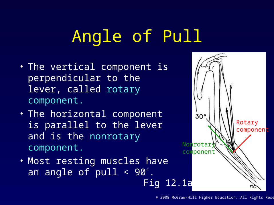
Angle of Pull
• The vertical component is perpendicular to the lever, called rotary component.
• The horizontal component is parallel to the lever and is the nonrotary component.
• Most resting muscles have an angle of pull < 90°.
Fig 12.1a
Rotary component
Nonrotary component

© 2008 McGraw-Hill Higher Education. All Rights Reserved.
Rotary vs. Nonrotary Components
Angle of pull < 900
• Nonrotary force is directed toward fulcrum.
• Helps maintain integrity of the joint (stabilizes).
Fig 12.1a
Rotary component
Nonrotary component

© 2008 McGraw-Hill Higher Education. All Rights Reserved.
Rotary vs. Nonrotary Components
Angle of pull > 900
• Dislocating force is directed away fulcrum.
• Does not occur often.• Muscle is at limit of
shortening range and not exerting much force.
Fig 12.1c

© 2008 McGraw-Hill Higher Education. All Rights Reserved.
Rotary vs. Nonrotary Components
Angle of pull = 90°
• Force is all rotary.
Angle of pull = 45°
• Rotary & nonrotary components are equal.
Muscular force functions:• Movement• Stabilization
Fig 12.1b
© 2008 McGraw-Hill Higher Education. All Rights Reserved.
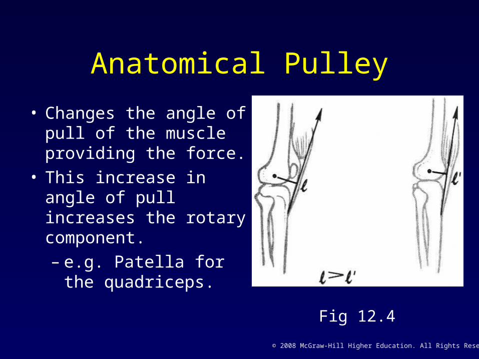
Anatomical Pulley
• Changes the angle of pull of the muscle providing the force.
• This increase in angle of pull increases the rotary component.– e.g. Patella for the
quadriceps.
Fig 12.4

© 2008 McGraw-Hill Higher Education. All Rights Reserved.
Resolution of External Forces
• Accomplished in the same manner as muscular forces applied at an oblique angle.
• Only horizontal force will move the table.
• Vertical force serves to increase friction.
Fig 12.7

© 2008 McGraw-Hill Higher Education. All Rights Reserved.
Composite Effects of Two or More Forces
• Two or more forces can be applied to objects.– A punted ball’s path is the result of force of
the kick, force of gravity, and force of wind.– Muscles work in groups, e.g. the 3
hamstrings.• Composite forces on the body may be
classified according to their direction and application as linear, concurrent, or parallel.

© 2008 McGraw-Hill Higher Education. All Rights Reserved.
Linear Forces
• For forces applied in the same direction, the resultant is the sum of the forces:
a + b = c
• For forces applied in the opposite directions, the resultant is the sum of the forces:
a + (-b) = c
=+a b c
=+a b c

© 2008 McGraw-Hill Higher Education. All Rights Reserved.
Concurrent Forces
• Act at the same point of application at different angles.
• Resultant of two or more concurrent forces depends on both the magnitude of each force and the angle of application. Fig 12.8

© 2008 McGraw-Hill Higher Education. All Rights Reserved.
Parallel Forces
• Forces not in the same action line, but parallel to each other.
• Three parallel forces:– two upward– one downward
Fig 12.9

© 2008 McGraw-Hill Higher Education. All Rights Reserved.
Parallel Forces
• 10 N weight at 90°.
• Gravity acts at points B & C.
• A is the force of biceps.• Effect of parallel forces
on an object depends on magnitude, direction & application point of each force.
Fig 12.10

© 2008 McGraw-Hill Higher Education. All Rights Reserved.
NEWTONS’ LAWS OF MOTIONLaw of Inertia
A body continues in its state of rest or of uniform
motion unless an unbalanced force acts on it.– An object at rest remains at rest.– An object in motion remains in same motion– Unless acted upon by an outside force.
• Friction & air resistance effect objects in motion.

© 2008 McGraw-Hill Higher Education. All Rights Reserved.
Law of Inertia
• A body continues in its state of rest or of uniform motion unless an outside, unbalanced force acts on it.
Fig 12.11
Gravity
Vy
Vx

© 2008 McGraw-Hill Higher Education. All Rights Reserved.
Law of Acceleration F = ma
The acceleration of an object is directly proportional to the force causing it and inversely proportional to the mass of the object.
What is the force needed to produce a given linear acceleration?
• Since m = w/g, F = (w/g) x a• Force to accelerate a 300 N object 2 m/sec2
• F = (300 N / 9.8m/s2) x 2 m/s2 = 61 N

© 2008 McGraw-Hill Higher Education. All Rights Reserved.
Impulse Ft = m(vf – vi)
The product of force and the time it is applied.F = ma
• Substitute (vf – vi) / t for a:
F= m (vf – vi) / t• Multiply both sides by
time:
Ft = m (vf – vi)
Fig 12.12

© 2008 McGraw-Hill Higher Education. All Rights Reserved.
Momentum Ft = mvf - mvi
The product of mass and velocity• 20 N force applied for 5 sec has equal
momentum to a 100 N force falling for 1 sec. Why?
• Any change in momentum is equal to the impulse that produces it.
• Force applied in direction of motion will increase momentum.
• Force applied opposite to direction of motion will decrease momentum.

© 2008 McGraw-Hill Higher Education. All Rights Reserved.
Law of Reaction
For every action there is an equal and opposite reaction.
Fig 12.13 & 12.14
© 2008 McGraw-Hill Higher Education. All Rights Reserved.
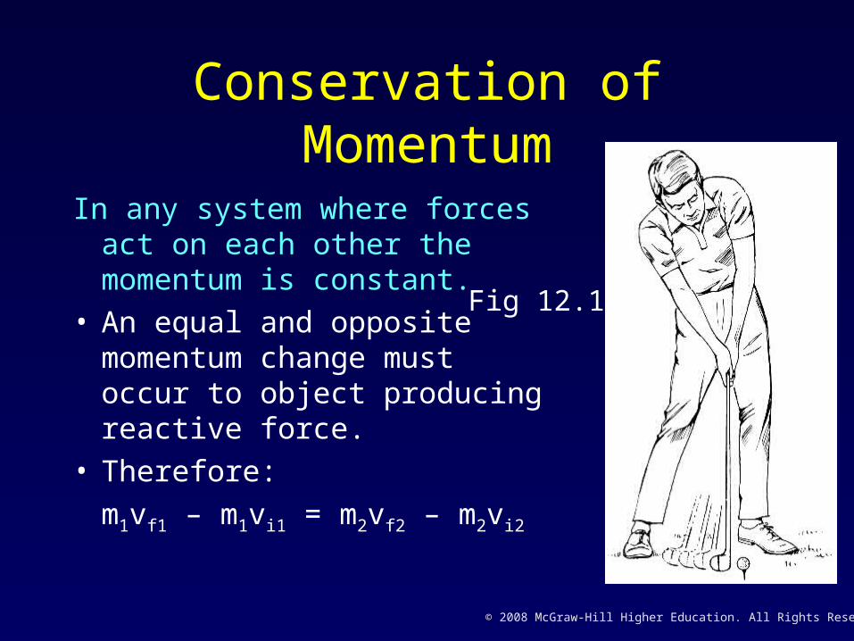
Conservation of Momentum
In any system where forces act on each other the momentum is constant.
• An equal and opposite momentum change must occur to object producing reactive force.
• Therefore:
m1vf1 – m1vi1 = m2vf2 – m2vi2
Fig 12.15

© 2008 McGraw-Hill Higher Education. All Rights Reserved.
Summation of ForcesForce generated by muscle may be summated from one
segment to another.
Typical throwing pattern• Force from legs is transferred to the trunk.• Further muscular force increases momentum and is
transferred to upper arm.– Mainly as an increase velocity because mass is
smaller.• Sequential transfer of momentum continues with mass
decreasing and velocity increasing. • Finally momentum is transferred to thrown ball.

© 2008 McGraw-Hill Higher Education. All Rights Reserved.
FORCES THAT MODIFY MOTIONWeight
• The force of gravity is measured as the weight of the body applied through the center of gravity of the body and directed toward the earth’s axis.
W = mg
Fig 12.16
Weight

© 2008 McGraw-Hill Higher Education. All Rights Reserved.
Contact Forces:Normal Reaction
• For every action there is an equal and opposite reaction.– The jumper pushes
off the ground and the ground pushes back.
Fig 12.17
Reaction
Action

© 2008 McGraw-Hill Higher Education. All Rights Reserved.
Contact Forces:Friction
• Friction is the force that opposes efforts to slide or roll one body over another.– In some cases we try to increase friction
for a more effective performance.– In other cases we try to decrease friction
for a more effective performance.• The amount of friction depends on the nature
of the surfaces and the forces pressing them together.

© 2008 McGraw-Hill Higher Education. All Rights Reserved.
Friction
Friction is proportional to the force pressing two surfaces together.
• Force of friction acts parallel to the surfaces and opposite to the direction of motion. W = weight
T = reactive force of tableP = force needed to moveF = force resisting motion
Fig 12.18

© 2008 McGraw-Hill Higher Education. All Rights Reserved.
Coefficient of friction,
• The ratio of force needed to overcome the friction, P, to the force holding the surface together, W:
= P / W or
= Fmax/FN– Large coefficient surfaces cling together.– Small coefficient surfaces slide easily.– Coefficient of 0.0 = frictionless surface.

© 2008 McGraw-Hill Higher Education. All Rights Reserved.
Coefficient of Friction• May be found by:
– Placing one object on a second and tilt the second until first begins to slide.
– The tangent of the angle with horizontal is the coefficient of friction.
Fig 12.19

© 2008 McGraw-Hill Higher Education. All Rights Reserved.
Elasticity and Rebound
• Objects rebound in a predictable manner.• The nature of rebound is governed by
elasticity, mass, and velocity of rebounding surface, friction between surfaces, and angle of contact.
• Elasticity is the ability to resist distorting influences and to return to the original size and shape.

© 2008 McGraw-Hill Higher Education. All Rights Reserved.
Elasticity and Rebound
• Stress is the force that acts to distort.
• Strain is the distortion that occurs.
• Stress may take the form of tension, compression, bending, or torsion.
Fig 12.21b

© 2008 McGraw-Hill Higher Education. All Rights Reserved.
Coefficient of Elasticity
• Is defined as the stress divided by the strain.• Most commonly determined in the
compression of balls by comparing drop height with the bounce height.
• The closer to 1.0 the more perfect the elasticity.
e = bounce height drop height

© 2008 McGraw-Hill Higher Education. All Rights Reserved.
Coefficient of Elasticity
• Also may be found using the Law of Conservation of Momentum: – Using the change in velocity of the two
objects, assuming masses remain constant:
Where vf2 and vf1 are velocities after impact, and vi1 and vi2 are velocities before impact.
e = (vf1 – vf2) / (vi1 – vi2)

© 2008 McGraw-Hill Higher Education. All Rights Reserved.
Angle of Rebound• For a perfectly elastic object, the angle of
incidence (striking) is equal to the angle of reflection (rebound).
• As coefficient of elasticity varies variations will occur.
Fig 12.22

© 2008 McGraw-Hill Higher Education. All Rights Reserved.
Effects of Spin on Bounce
• A ball with topspin will rebound from horizontal surface lower and with more horizontal velocity.
• A ball with backspin will rebound higher and with less horizontal velocity.
• A ball with no spin will develop topspin.• A ball with topspin will gain more topspin.• A ball with backspin may be stopped or reversed.• Spinning balls hitting vertical surfaces will react in the
same manner as with horizontal surfaces, but in relation to the vertical surface.

© 2008 McGraw-Hill Higher Education. All Rights Reserved.
Fluid Forces
• Water and air are both fluids and as such are subject to many of the same laws and principles.
• The fluid forces of buoyancy, drag, and lift apply in both mediums and have considerable effect on the movements of the human body.

© 2008 McGraw-Hill Higher Education. All Rights Reserved.
Buoyancy
• Archimedes’ Principle states: a body immersed in a liquid is buoyed up by a force equal to the weight of the liquid displaced.
• This explains why some things float and some things sink.
• Density is a ratio of the weight of an object to its volume.

© 2008 McGraw-Hill Higher Education. All Rights Reserved.
Specific gravity
• Ratio of the density of an object to the density of water.
• An object the same weight for volume as water has a specific gravity of 1.0.
• An object with specific gravity > 1.0 will sink.• An object with specific gravity < 1.0 will float.

© 2008 McGraw-Hill Higher Education. All Rights Reserved.
Lift and Drag
Drag is the resistance to forward motion through a fluid.
Result of :• fluid pressure on the
leading edge of the object.
• amount of backward pull produced by turbulence on the trailing edge.
Fig 12.24 b

© 2008 McGraw-Hill Higher Education. All Rights Reserved.
Lift and Drag
Laminar flow is a smooth, unbroken flow of fluid around an object.
• A smooth surface will have better laminar flow than a rough surface, resulting in less drag.
Fig 12.24 a

© 2008 McGraw-Hill Higher Education. All Rights Reserved.
Lift and DragLift is the result of changes in fluid pressure as the
result of difference in air flow velocities.
Bernoulli’s Principle states: the pressure in a moving fluid decreases as the speed increases.
Fig 12.24 c
V P
V P Lift
Drag

© 2008 McGraw-Hill Higher Education. All Rights Reserved.
Ball Spin (Magnus Effect)• Bernoulli’s Principle
applies here also.• A ball will move in the
direction of least air pressure.
• A ball spinning drags a boundary layer of air with it, causing air to move faster & reducing pressure on one side.
Fig 12.25

© 2008 McGraw-Hill Higher Education. All Rights Reserved.
FREE BODY DIAGRAMS
• In analyzing any technique, one should consider all external forces, by accounting for effect of each one of the body.
• The isolated body is considered a separate mechanical system.
• Easier to identify forces & represent as vectors.
• Can help determine the application and direction of forces acting on the body.

© 2008 McGraw-Hill Higher Education. All Rights Reserved.
Direction & Point of Application of External Forces
Force Direction of Force Point of Application
Weight (W) Downward Center of Gravity
Normal (R) Perpendicular Point of contact
Friction (F) Along surface Point of Contact
Buoyancy (B) Upward Center of buoyancy
Drag (D) Opposite flow Center of Gravity
Lift (L) Perpendicular to drag Center of Gravity
© 2008 McGraw-Hill Higher Education. All Rights Reserved.
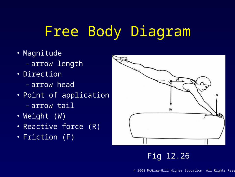
Free Body Diagram• Magnitude
– arrow length• Direction
– arrow head• Point of application
– arrow tail• Weight (W)• Reactive force (R)• Friction (F)
Fig 12.26
© 2008 McGraw-Hill Higher Education. All Rights Reserved.
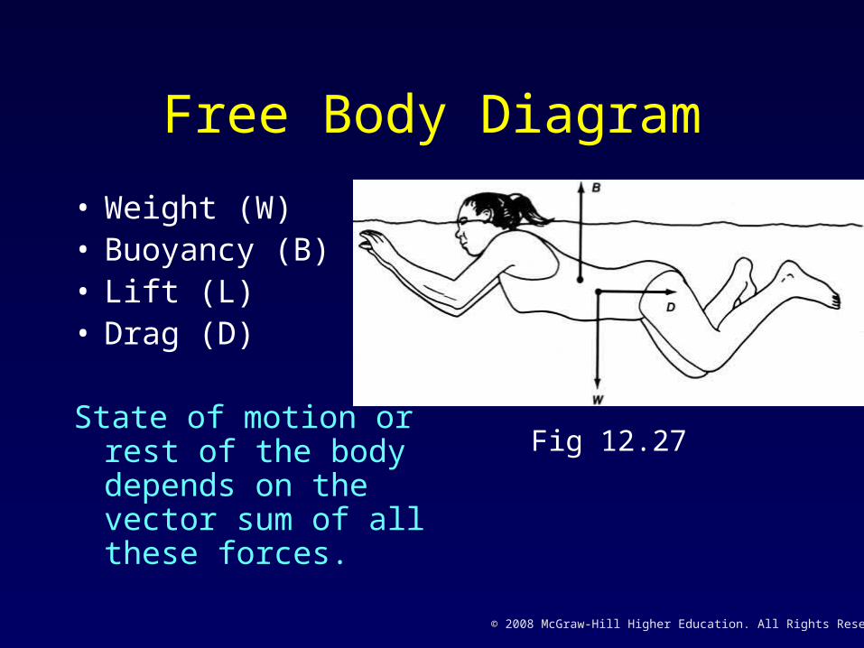
Free Body Diagram
• Weight (W)• Buoyancy (B)• Lift (L)• Drag (D)
State of motion or rest of the body depends on the vector sum of all these forces.
Fig 12.27

© 2008 McGraw-Hill Higher Education. All Rights Reserved.
Free Body Diagram• Also used to show forces
on a body segment.• Thigh is isolated:
– Weight of thigh (W)
– Muscle force Hip (MH)
– Reactive Forces
• Hip (Hx & Hy)
• Knee (Kx & Ky))
Fig 12.28

© 2008 McGraw-Hill Higher Education. All Rights Reserved.
WORK, POWER, AND ENERGYWork
• Work is the product of force expended and the distance over which force is applied.
W = Fs– Work (W), Force (F), Distance (s)
• Units are any combination of force & distance:– foot/pounds,– joule = 107 x 1 gram / 1 centimeter

© 2008 McGraw-Hill Higher Education. All Rights Reserved.
Work• A 20 N suitcase is place on a shelf 2 m above
the ground:– Work done against gravity= 40 Nm
• Same suitcase lifted along a 4 m incline is still 40 Nm of work against gravity.– Horizontal distance not included.
30o
4 m2 m
© 2008 McGraw-Hill Higher Education. All Rights Reserved.
Positive & Negative Work
• Positive work – force acts in the same direction to that of the objects motion.
• Negative work – force acts in the opposite direction to that of the objects motion.

© 2008 McGraw-Hill Higher Education. All Rights Reserved.
Mechanical Muscular Work
Example: a rectangular muscle 10 cm x 3 cm, that exerts 240N of force.
• Average muscle fiber shortens 1/2 its length.
W = Fs
W = 240N x 5cm
W = 1200N•cm or 120 Nm

© 2008 McGraw-Hill Higher Education. All Rights Reserved.
Force per Muscle Cross Section
• If force of the muscle is not known, it is computed form the muscle’s cross section.
Example: Assume same muscle is 1cm thick:
Cross section = width x thickness
3 cm X 1 cm = 3 sq cm
Average force = 360 N per sq cm
F = 360 x 3 = 1080N
W = Fs
W = 1080N x 5cm = 5400 N cm or 540 Nm

© 2008 McGraw-Hill Higher Education. All Rights Reserved.
Muscular Work
• If the internal structure of the muscle is rectangular, a simple geometric cross-sectional measure can be used.
• For penniform & bipenniform muscle, physiological cross section must be determined.
• “s” represents 1/2 the length of the average fiber.
• Force per square inch depends on whose research the student accepts.

© 2008 McGraw-Hill Higher Education. All Rights Reserved.
Muscle Work by Physiological Cross Section (PCS)
W = Average force x PCS (sq cm) x .5 length of fibers (cm)
Divide by 100 to convert N-cm to Nm
W (Nm) = 360 x PCS (sq cm) x .5 fiber length (cm)
100

© 2008 McGraw-Hill Higher Education. All Rights Reserved.
Power
• The rate at which work is done.
P = Fs / t or P = W / t or P = Fv
P = Power t = time
W = work v = velocity = s / t

© 2008 McGraw-Hill Higher Education. All Rights Reserved.
Energy
• The capacity to do work.
Law of Conservation of Energy:The total amount of energy possessed by a body or an isolated system remains constant.

© 2008 McGraw-Hill Higher Education. All Rights Reserved.
Potential Energy
• Potential energy: energy based on position.• Potential energy is the product of the weight
of an object and the distance over which it can act:
PE = mgh
m = mass, g = gravity, h = height

© 2008 McGraw-Hill Higher Education. All Rights Reserved.
Kinetic Energy
• Energy based on motion:
KE = 1/2 mv2
m = mass, v = velocity
• Work done is equal to the kinetic energy acquired, or
Fs = 1/2 mv2

© 2008 McGraw-Hill Higher Education. All Rights Reserved.
ANALYSIS OF LINEAR MOTION
• First identify the nature of the forces involved in the motion of interest:
– Weight
– Propulsive forces
– Ground Reaction Force
– Friction
– Buoyancy, Drag, & Lift

© 2008 McGraw-Hill Higher Education. All Rights Reserved.
ANALYSIS OF LINEAR MOTION
• The principles that govern the mechanical aspects of a movement can be summarized by examining some of the basic concepts involved in the kinetics of linear motion:– Inertia– Impulse– Work & Power– Potential & Kinetic Energy

© 2008 McGraw-Hill Higher Education. All Rights Reserved.
Chapter 12:The Conditions of
Linear Motion