Embed Size (px)
Citation preview

© 2011 Autodesk
Stressed Up: From Inventor Simulation to Simulation Mechanical
Wasim YounisSenior Application Engineer, Symetri UK
James HerzingTechnical Consultant, Autodesk USA
© 2011 Autodesk
Class Summary
In this class, you will learn how to take analysis beyond Inventor Simulation into Simulation Mechanical (formerly Algor® Simulation). The examples selected for this class are common to many industries and include assembly stress analysis, linear dynamics, large-scale models made up of beams/shells/solids, bolted connections, plastic deformation and composites.
© 2011 Autodesk
Learning Objectives
At the end of this class, you will be able to: Create and analyze Snap-fit/Bolted Connection type parts/assemblies Determine permanent failure/plastic deformation of parts Create composite models using surface parts Create and analyze models with mixed elements, such as beams and plates
© 2011 Autodesk
Agenda
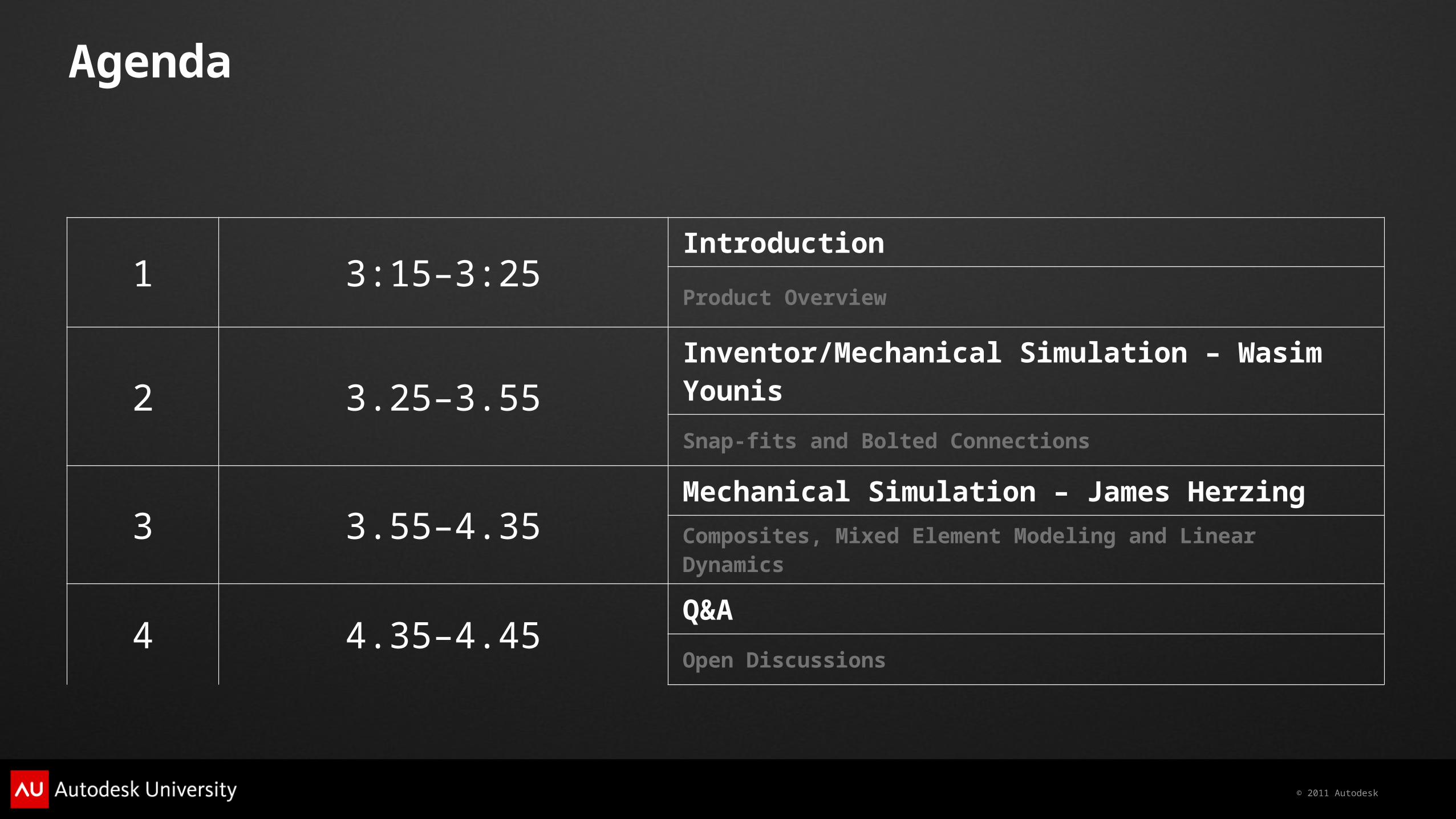
1 3:15–3:25Introduction
Product Overview
2 3.25–3.55Inventor/Mechanical Simulation – Wasim Younis
Snap-fits and Bolted Connections
3 3.55–4.35Mechanical Simulation – James Herzing
Composites, Mixed Element Modeling and Linear Dynamics
4 4.35–4.45Q&A
Open Discussions

© 2011 Autodesk
Product Overview
© 2011 Autodesk
Product Overview
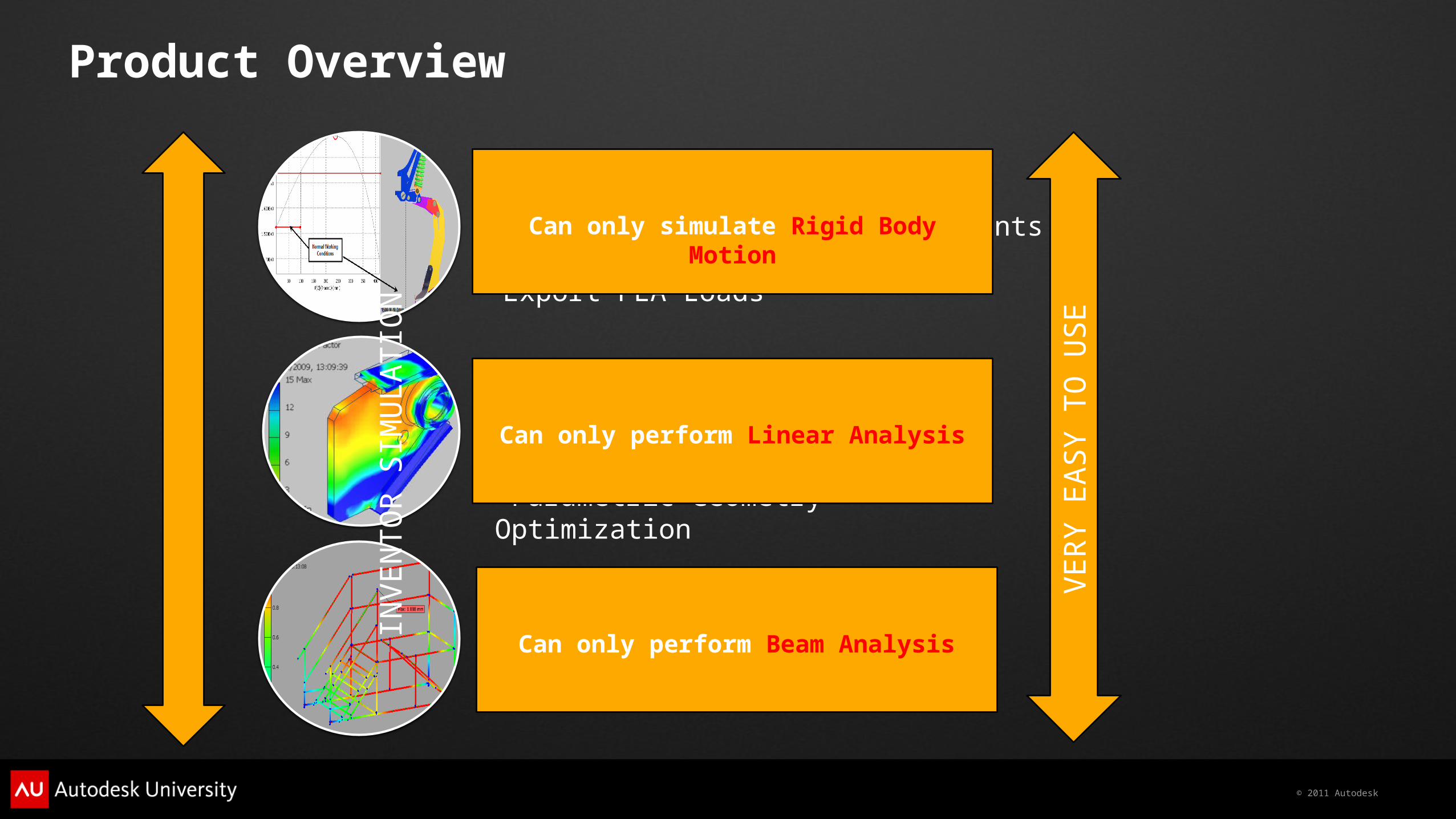
Dynamic Simulation Automatic transfer of constraints to Joints Export FEA Loads
Stress Analysis Automatic creation of contacts Parametric Geometry Optimization
Frame Analysis Automatic creation of beams Automatically connects beam ends
Can only simulate Rigid Body Motion
Can only perform Linear Analysis
Can only perform Beam Analysis
INV
EN
TO
R S
IMU
LAT
ION
VE
RY
EA
SY
TO
US
E
© 2011 Autodesk
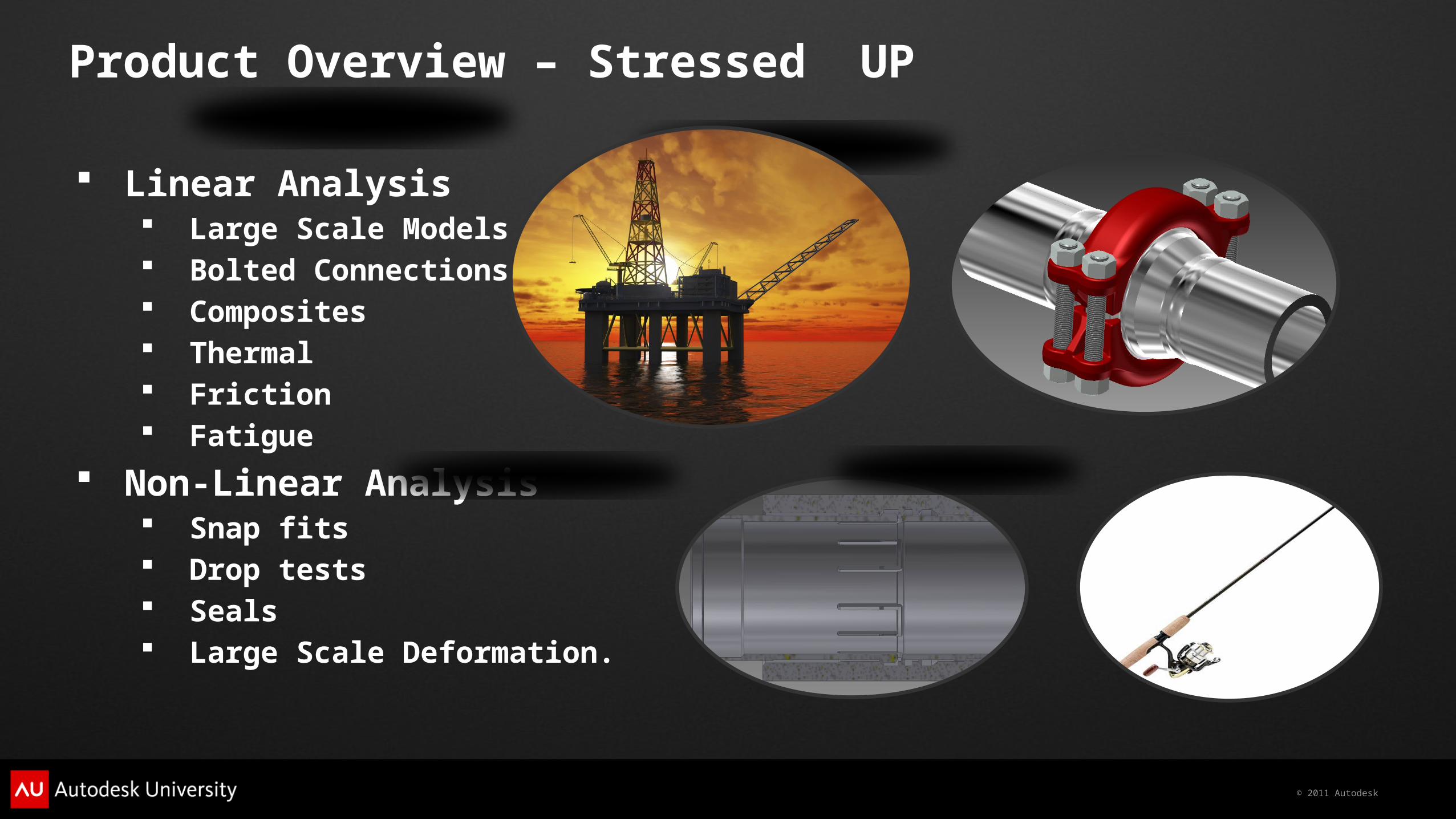
Product Overview – Stressed UP
Linear Analysis Large Scale Models Bolted Connections Composites Thermal Friction Fatigue
Non-Linear Analysis Snap fits Drop tests Seals Large Scale Deformation.
© 2011 Autodesk
Snap-fit – Inventor & Simulation Mechanical
© 2011 Autodesk
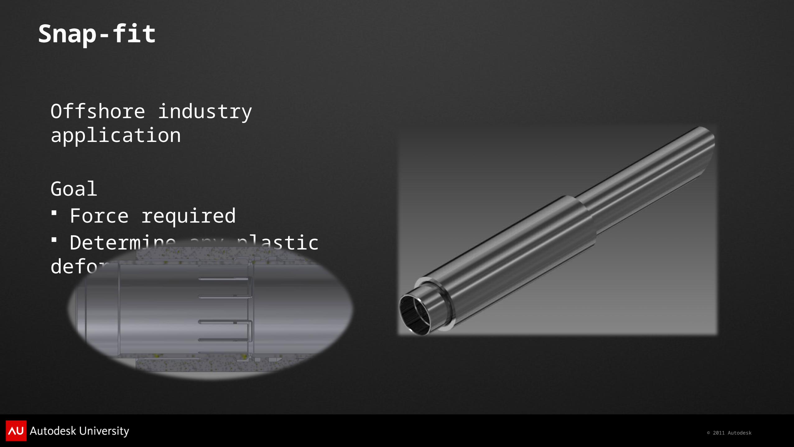
Snap-fit
Offshore industry application
Goal Force required Determine any plastic deformation
© 2011 Autodesk
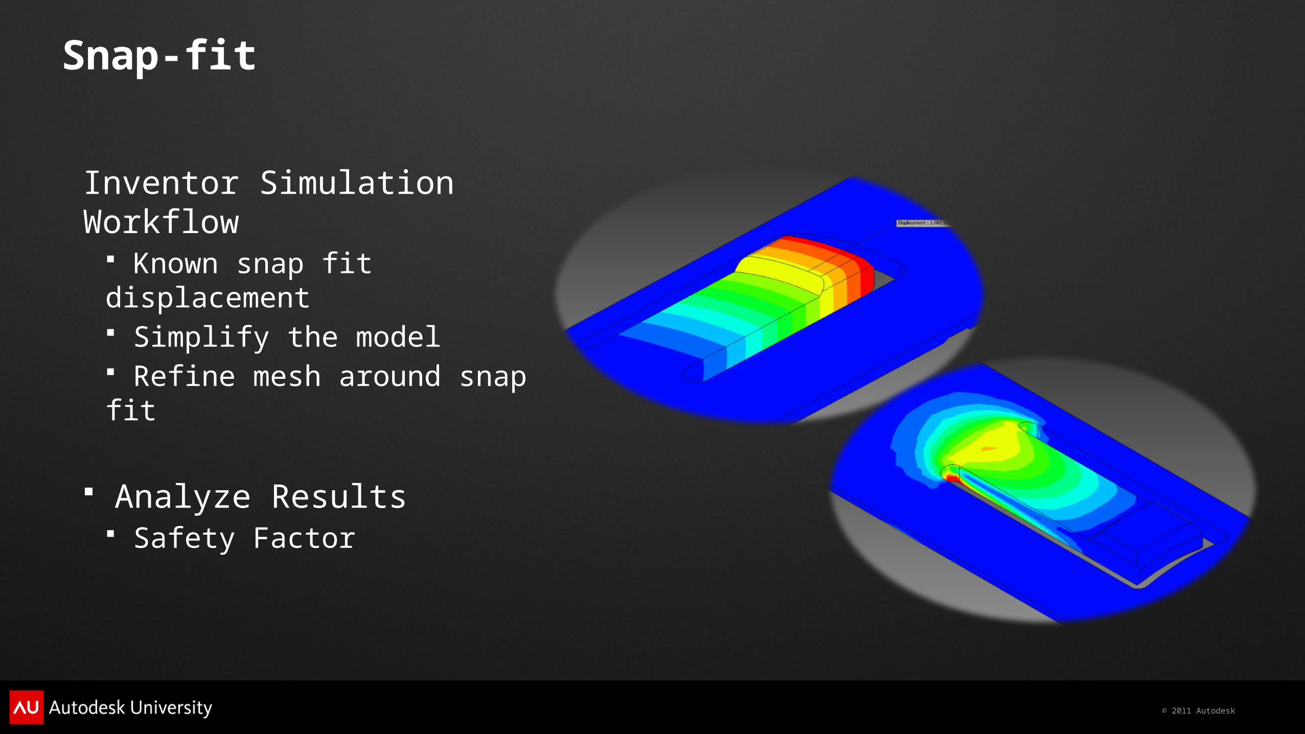
Snap-fit
Inventor Simulation Workflow Known snap fit displacement Simplify the model Refine mesh around snap fit
Analyze Results Safety Factor
© 2011 Autodesk
Snap-fit
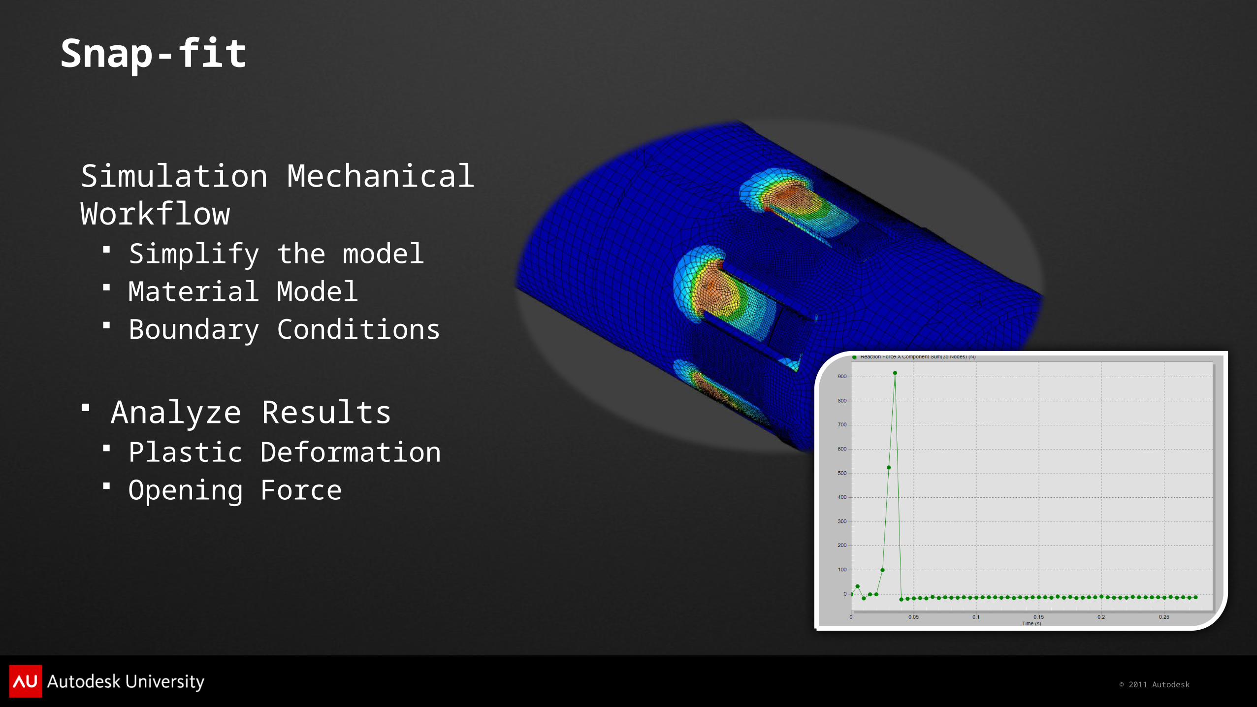
Simulation Mechanical Workflow Simplify the model Material Model Boundary Conditions
Analyze Results Plastic Deformation Opening Force
© 2011 Autodesk
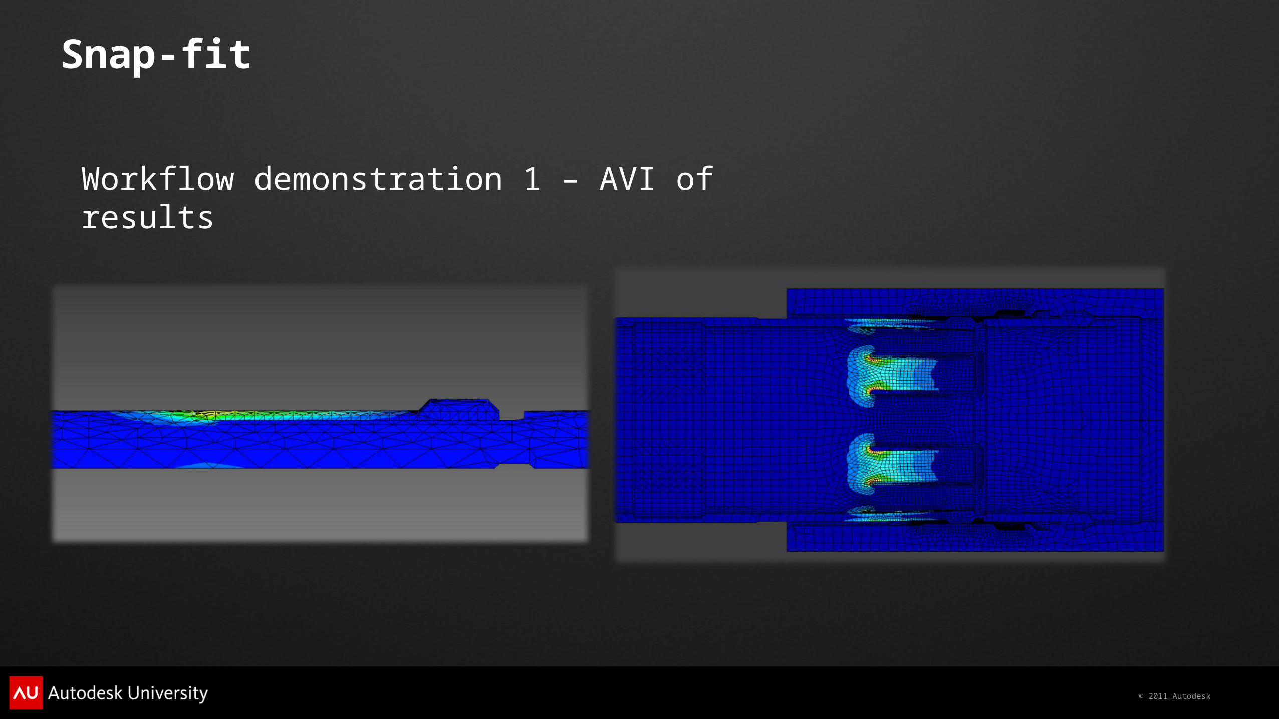
Snap-fit
Workflow demonstration 1 – AVI of results
© 2011 Autodesk
Bolts – Inventor & Simulation Mechanical
© 2011 Autodesk
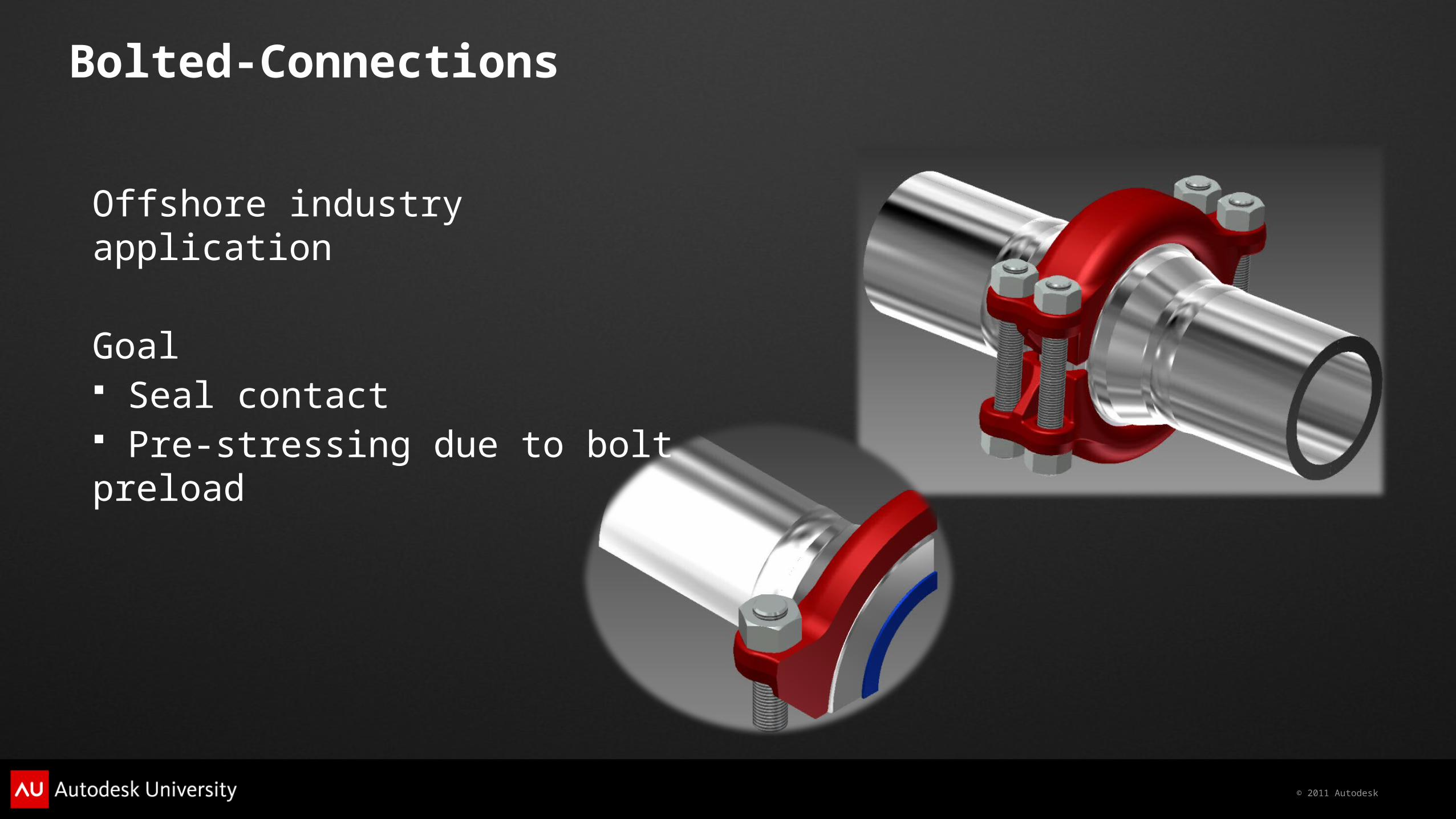
Bolted-Connections
Offshore industry application
Goal Seal contact Pre-stressing due to bolt preload
© 2011 Autodesk
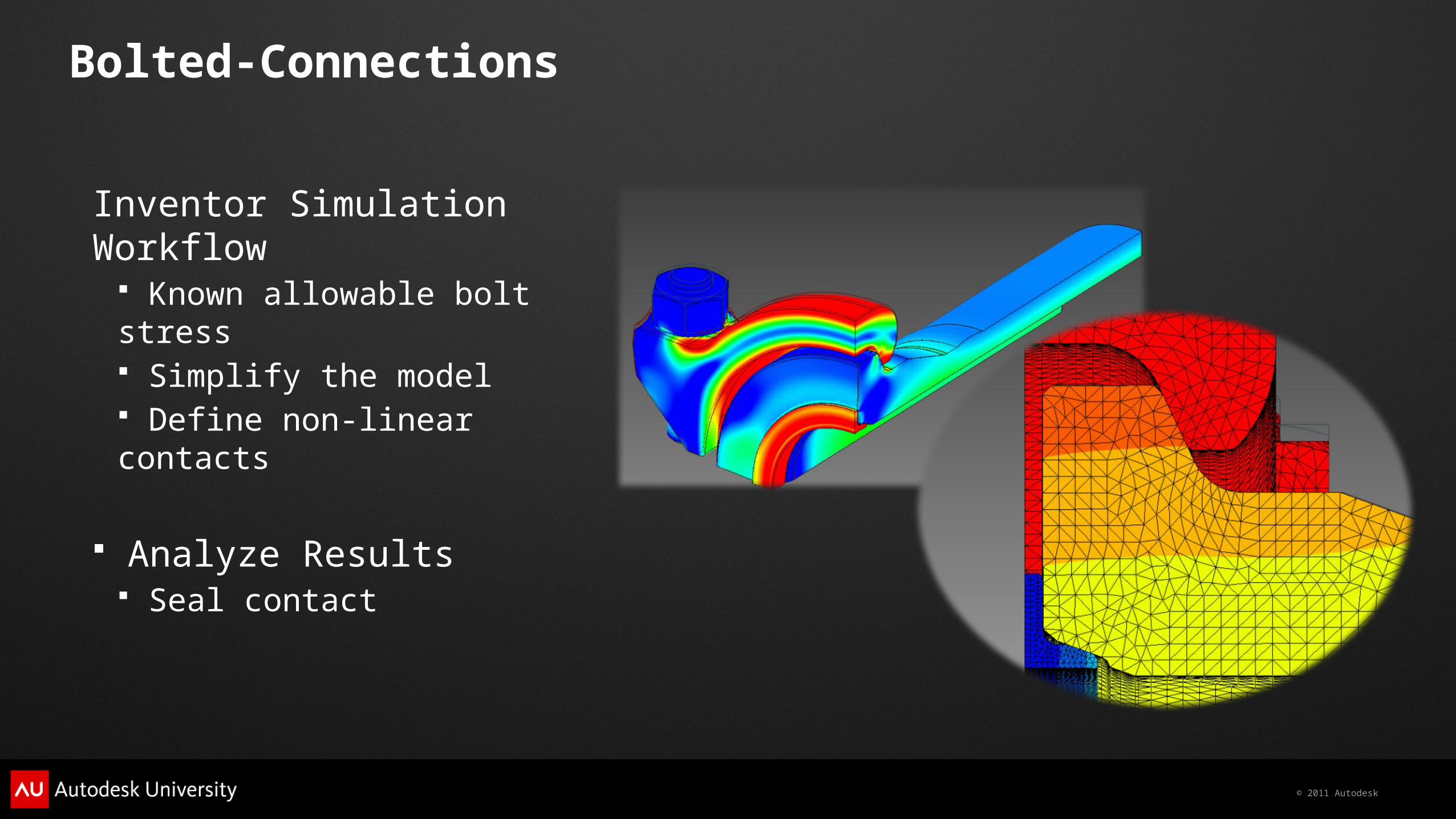
Bolted-Connections
Inventor Simulation Workflow Known allowable bolt stress Simplify the model Define non-linear contacts
Analyze Results Seal contact
© 2011 Autodesk
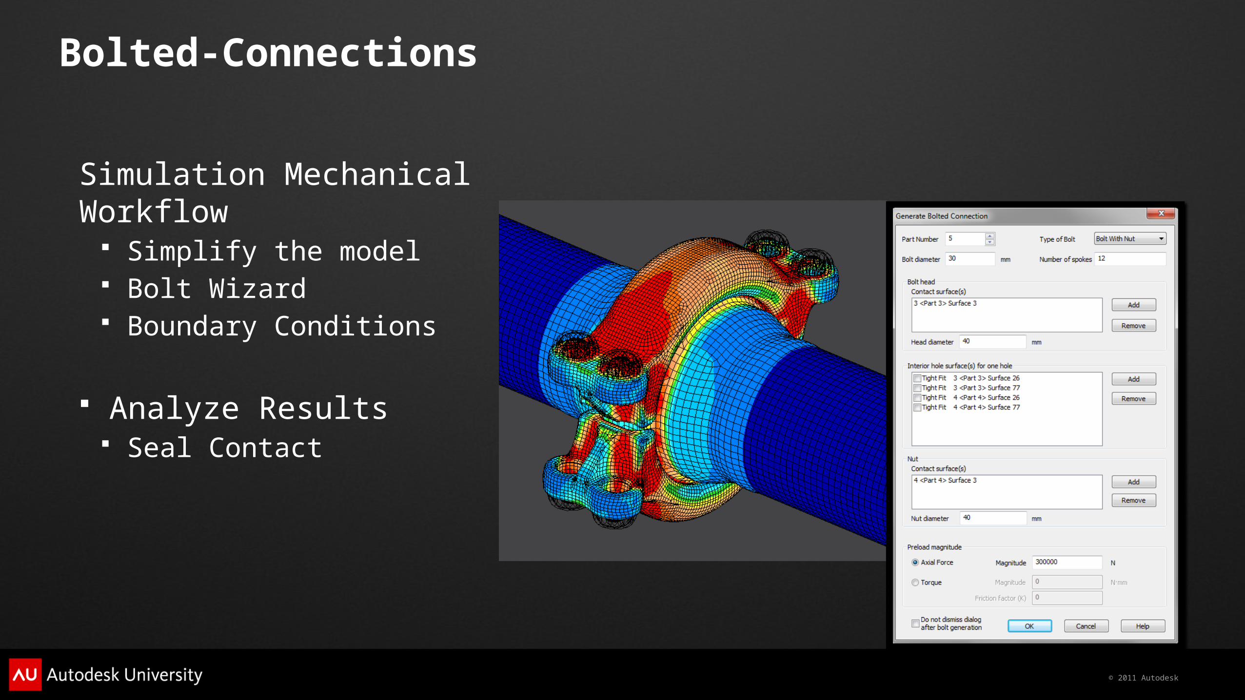
Bolted-Connections
Simulation Mechanical Workflow Simplify the model Bolt Wizard Boundary Conditions
Analyze Results Seal Contact
© 2011 Autodesk
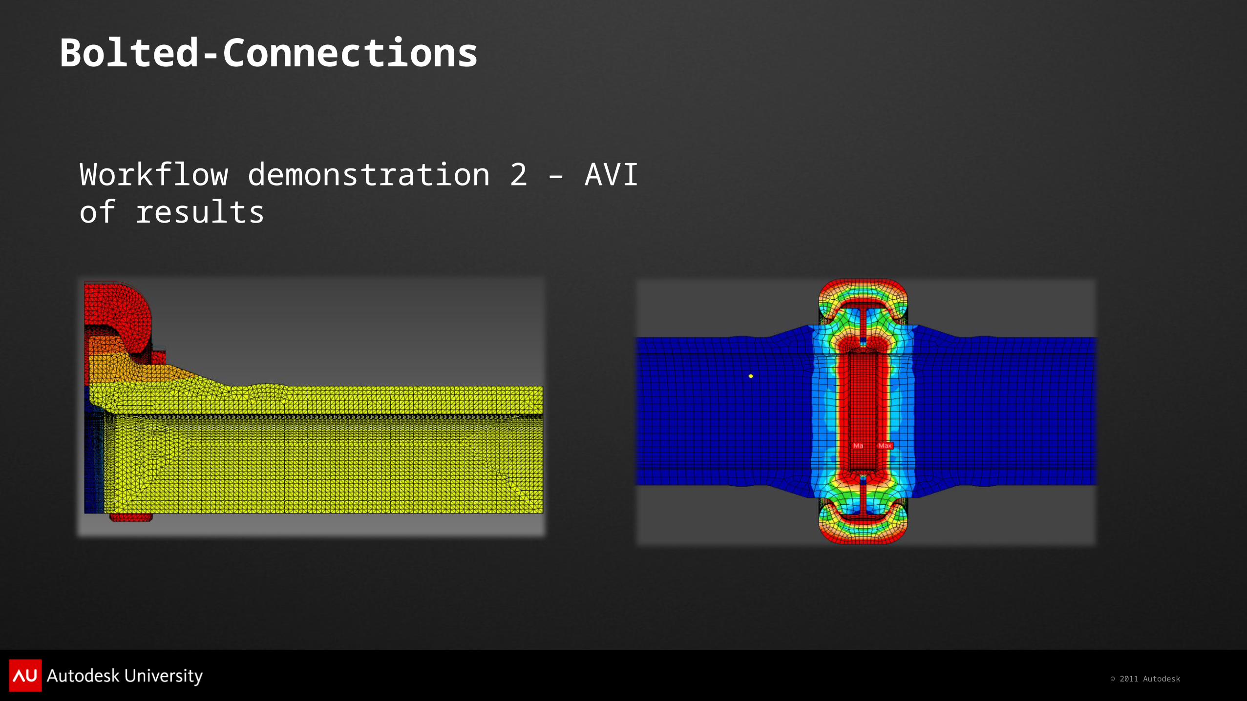
Bolted-Connections
Workflow demonstration 2 – AVI of results

© 2011 Autodesk
© 2011 Autodesk
Working with Composites
© 2011 Autodesk
Modeling Composites
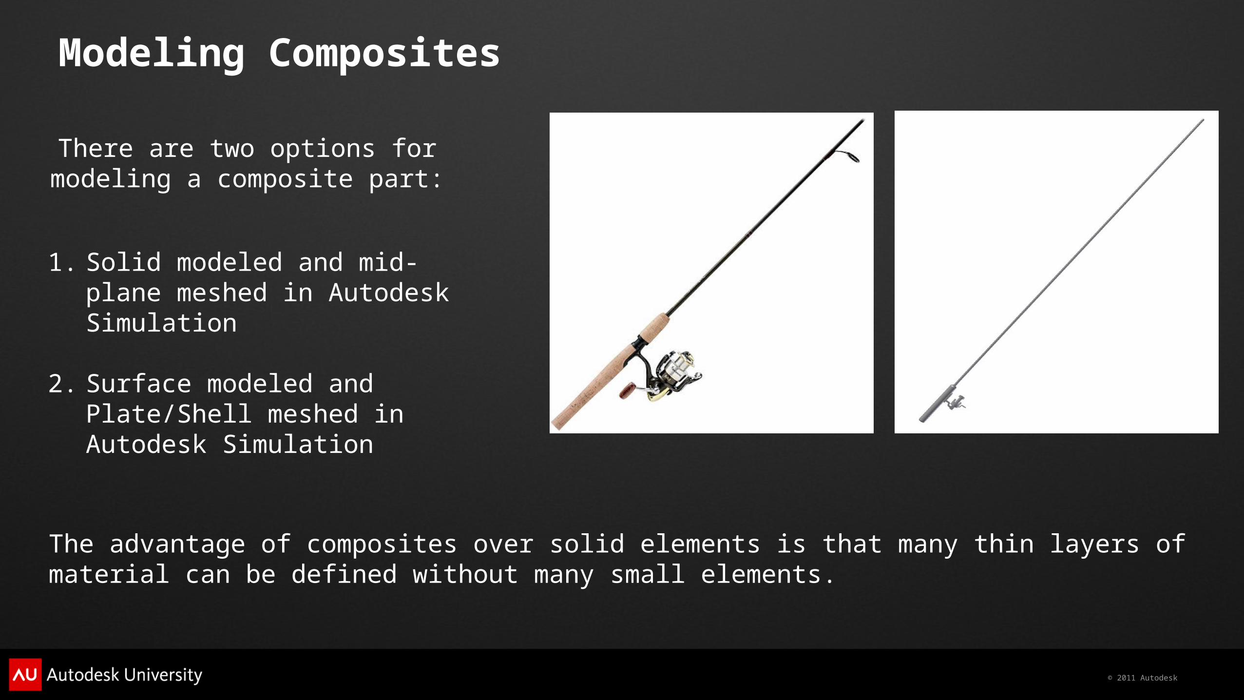
There are two options for modeling a composite part:
1. Solid modeled and mid-plane meshed in Autodesk Simulation
2. Surface modeled and Plate/Shell meshed in Autodesk Simulation
The advantage of composites over solid elements is that many thin layers of material can be defined without many small elements.
© 2011 Autodesk
Defining Your Composite Properties
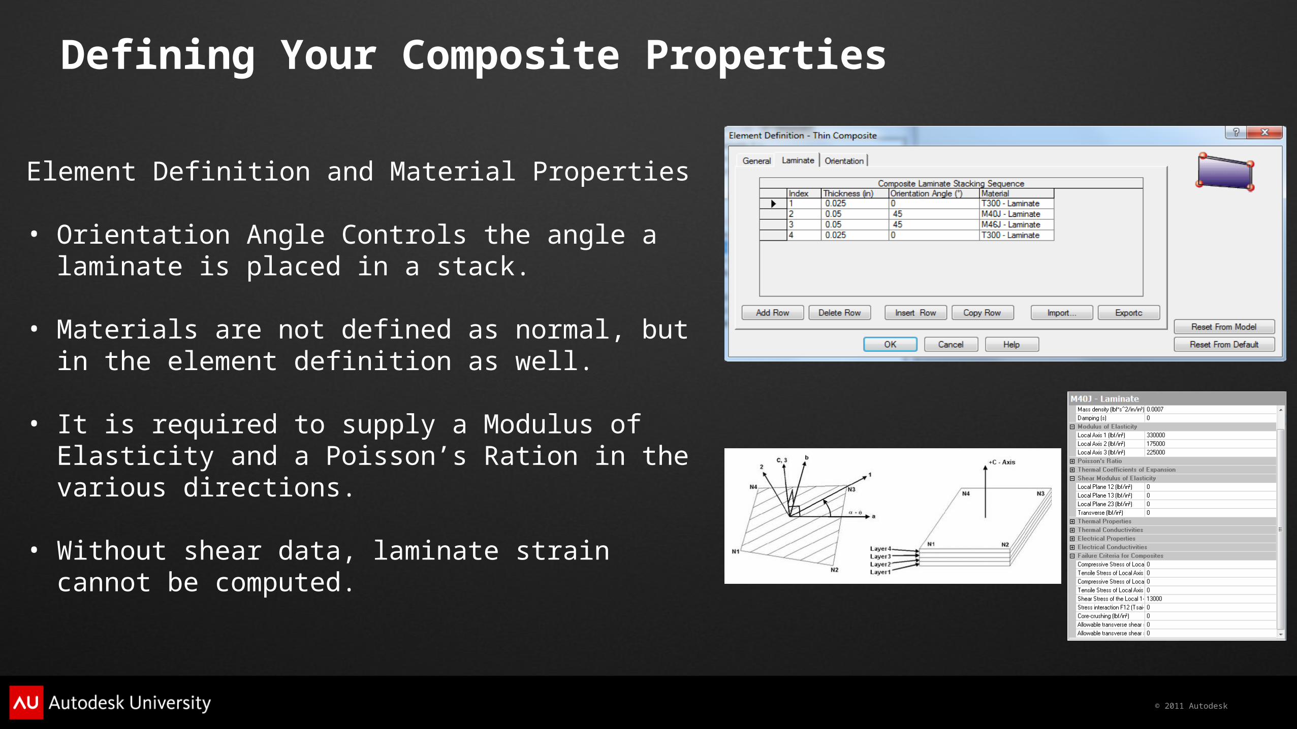
Element Definition and Material Properties
• Orientation Angle Controls the angle a laminate is placed in a stack.
• Materials are not defined as normal, but in the element definition as well.
• It is required to supply a Modulus of Elasticity and a Poisson’s Ration in the various directions.
• Without shear data, laminate strain cannot be computed.
© 2011 Autodesk
Reviewing Composite Results
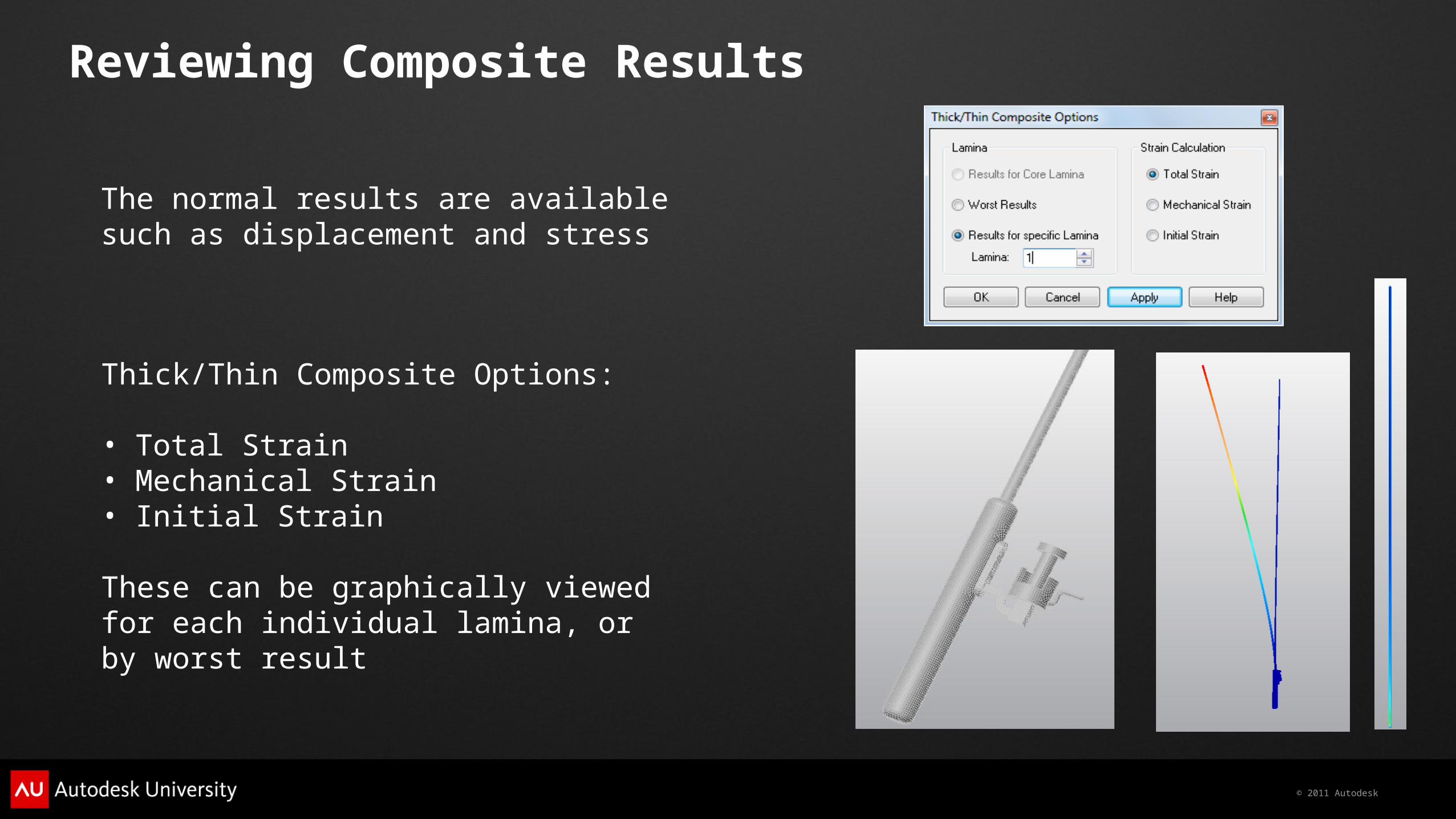
The normal results are available such as displacement and stress
Thick/Thin Composite Options:
• Total Strain• Mechanical Strain• Initial Strain
These can be graphically viewed for each individual lamina, or by worst result
© 2011 Autodesk
Mixed Element Modeling and Dynamic Analyses
© 2011 Autodesk
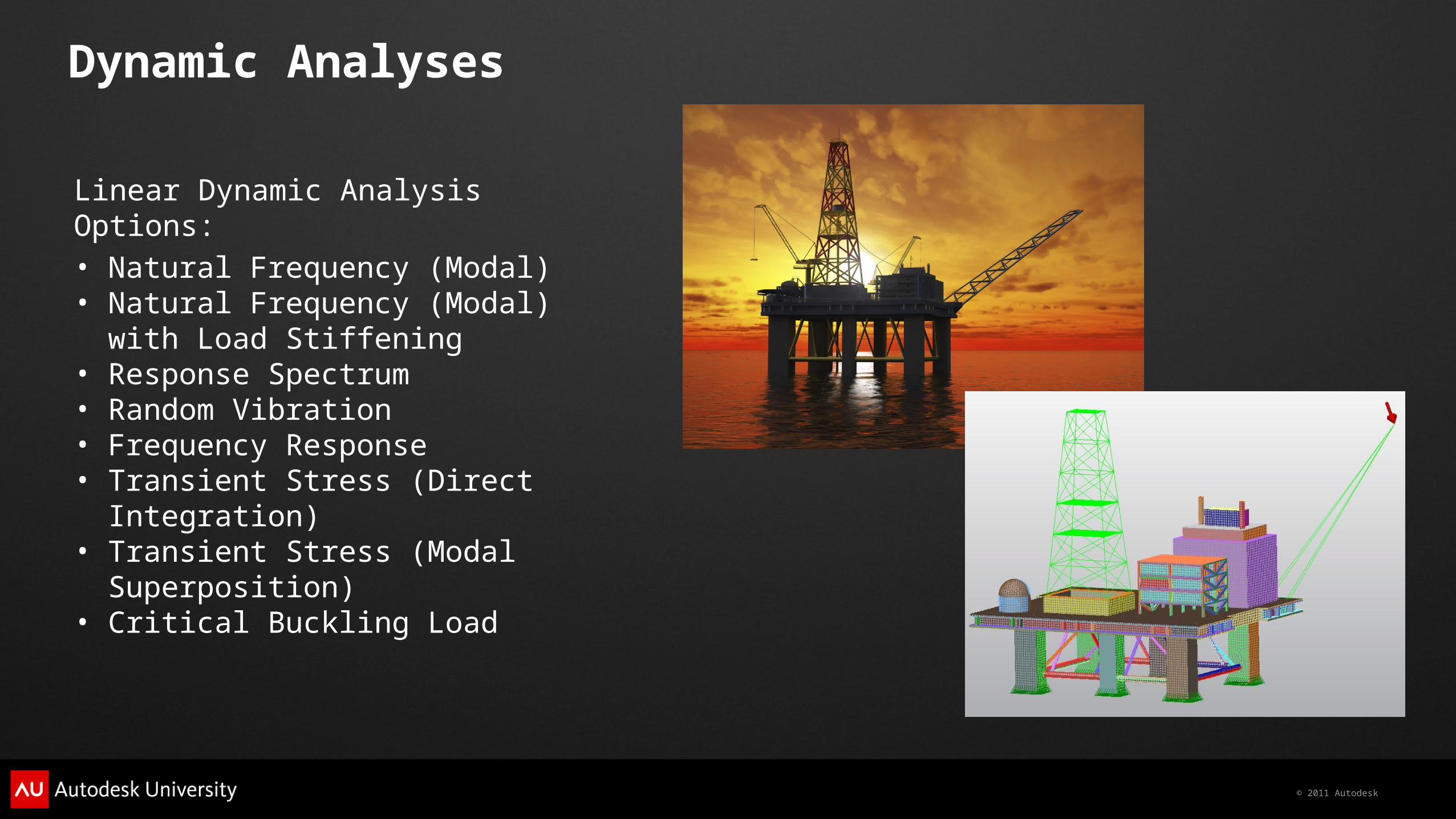
Dynamic Analyses
Linear Dynamic Analysis Options:
• Natural Frequency (Modal)• Natural Frequency (Modal) with Load
Stiffening• Response Spectrum• Random Vibration• Frequency Response• Transient Stress (Direct Integration)• Transient Stress (Modal Superposition)• Critical Buckling Load
© 2011 Autodesk
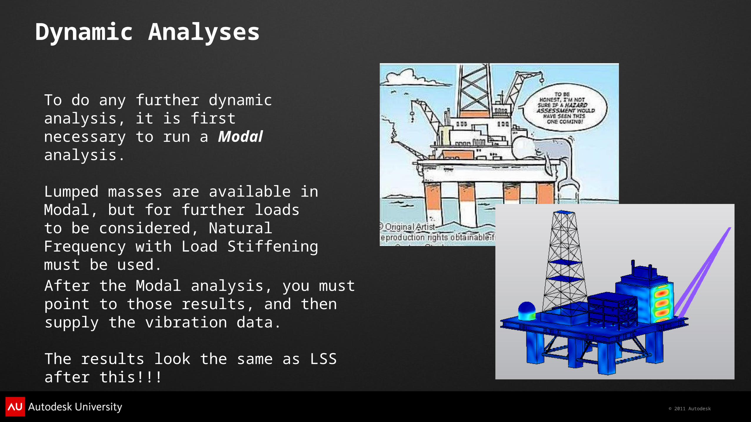
Dynamic Analyses
To do any further dynamic analysis, it is first necessary to run a Modal analysis.
Lumped masses are available in Modal, but for further loads to be considered, Natural Frequency with Load Stiffening must be used.
After the Modal analysis, you must point to those results, and then supply the vibration data.
The results look the same as LSS after this!!!

© 2011 Autodesk
Questions
Wasim YounisSenior Applications EngineerSymetri [email protected]
James HerzingTechnical ConsultantAutodesk [email protected]
© 2011 Autodesk
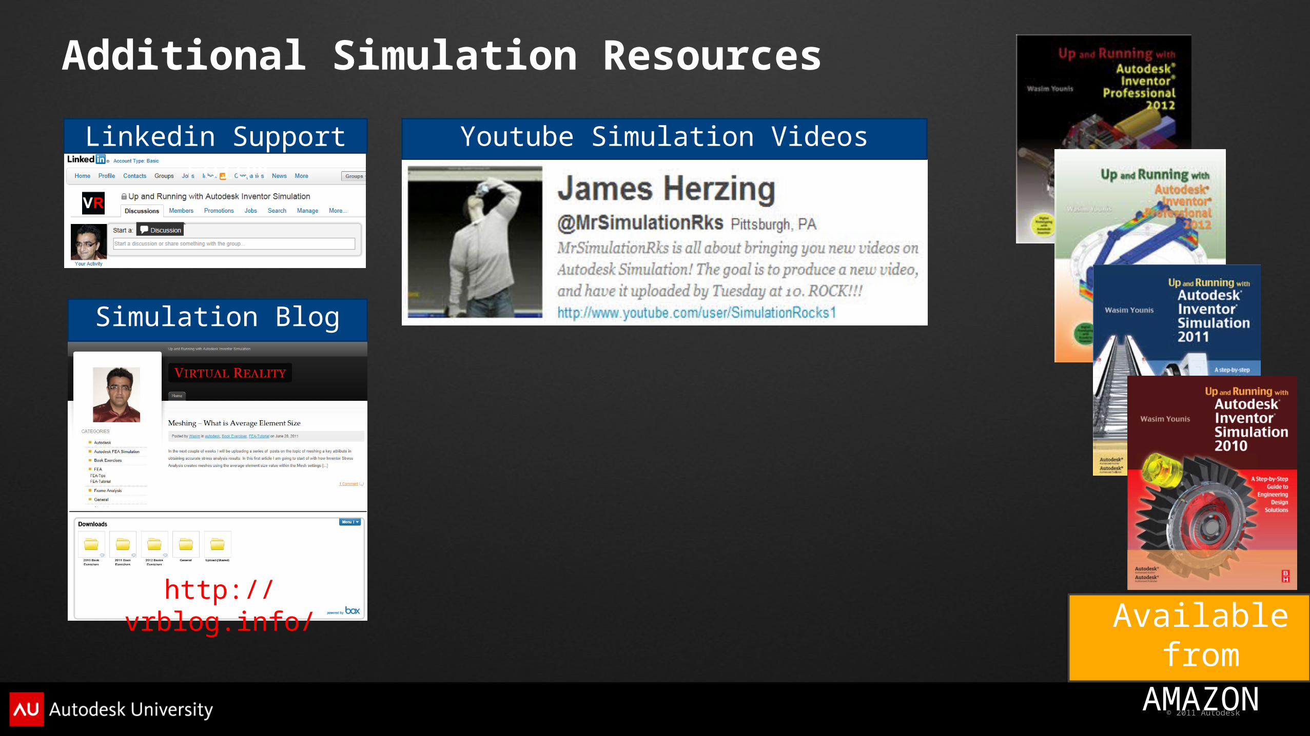
Additional Simulation Resources
Available fromAMAZON
Linkedin Support Forum
Simulation Blog
http://vrblog.info/
Youtube Simulation Videos

© 2011 Autodesk
Autodesk, AutoCAD* [*if/when mentioned in the pertinent material, followed by an alphabetical list of all other trademarks mentioned in the material] are registered trademarks or trademarks of Autodesk, Inc., and/or its subsidiaries and/or affiliates in the USA and/or other countries. All other brand names, product names, or trademarks belong to their respective holders. Autodesk reserves the right to alter product and services offerings, and specifications and pricing at any time without notice, and is not responsible for typographical or graphical errors that may appear in this document. © 2011 Autodesk, Inc. All rights reserved.