Embed Size (px)
Citation preview
2012. UK Power Networks. All rights reserved
Demonstrating the benefits of energy storage on an 11 kV Distribution Network
Matthieu Michel –
Technology Innovation and Co-ordination Manager
2012. UK Power Networks. All rights reserved
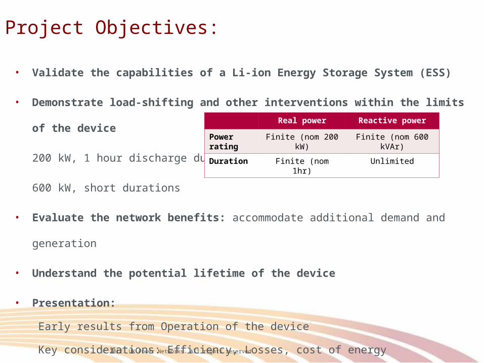
• Validate the capabilities of a Li-ion Energy Storage System (ESS)
• Demonstrate load-shifting and other interventions within the limits of the device
200 kW, 1 hour discharge duration
600 kW, short durations
• Evaluate the network benefits: accommodate additional demand and generation
• Understand the potential lifetime of the device
• Presentation:
Early results from Operation of the device
Key considerations: Efficiency, Losses, cost of energy
Real power Reactive power
Power rating Finite (nom 200 kW) Finite (nom 600 kVAr)
Duration Finite (nom 1hr) Unlimited
Project Objectives:
2012. UK Power Networks. All rights reserved
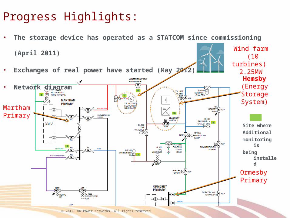
Progress Highlights:
• The storage device has operated as a STATCOM since commissioning (April 2011)
• Exchanges of real power have started (May 2012)
• Network diagram
MarthamPrimary
OrmesbyPrimary
Hemsby(Energy Storage System)
Wind farm (10 turbines)
2.25MW
Site where
Additional
monitoring is
being installed
2012. UK Power Networks. All rights reserved
-0.2
0
0.2
0.4
0.6
0.8
1
1.2
10.6
10.7
10.8
10.9
11
11.1
18-Apr-11 19-Apr-11 20-Apr-11 21-Apr-11
Reac
tive
Pow
er (M
VAr)
/ W
indf
arm
out
put (
MW
)
Volt
age
(kV)
ESS Volts (kV) [Model] ESS Volts (kV) [Model] ESS_Q (MVAr) [Data] Windfarm (MW)
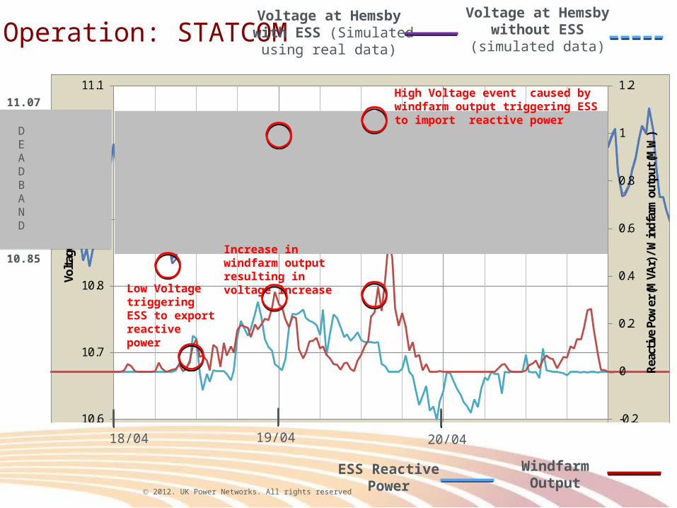
Operation: STATCOMVoltage at
Hemsby without ESS
(simulated data)
Voltage at Hemsby with ESS (Simulated
using real data)
18/04 19/04 20/04
WindfarmOutput
ESS Reactive Power
Low Voltage triggering ESS to export reactive power
Increase in windfarm output resulting in voltage increase
High Voltage event caused by windfarm output triggering ESS to import reactive power
DEADBAND
11.07
10.85
2012. UK Power Networks. All rights reserved
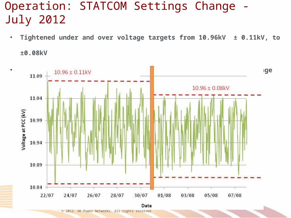
Operation: STATCOM Settings Change - July 2012
BEFORE SETTING CHANGES
10.96kV ± 0.11kV
AFTER SETTING CHANGES
10.96kV ± 0.08kV
Week 1 Week 2 Week 3 Week 4 Week 5 Week 6 Week 7 Week 8
• Tightened under and over voltage targets from 10.96kV ± 0.11kV, to ±0.08kV
• kVAr exchanged with the network (Number of occurrences) / Voltage band
2012. UK Power Networks. All rights reserved
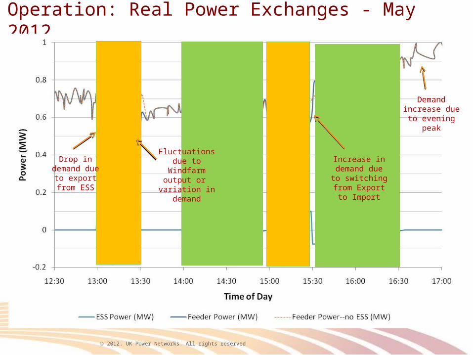
Operation: Real Power Exchanges - May 2012
Increase in demand due to switching from
Export to Import
Demand increase due to evening
peak
Drop in demand due to export
from ESS
Fluctuations due to Windfarm
output or variation in
demand
2012. UK Power Networks. All rights reserved
Li-ION BATTERIES
SVC LightPOWER
CONVERSION SYSTEM(DC to AC)
1MVA STEP UP TRANSFORMER(2.2kV to 11kV) AND CIRCUIT
BREAKER
AUXILIARIES
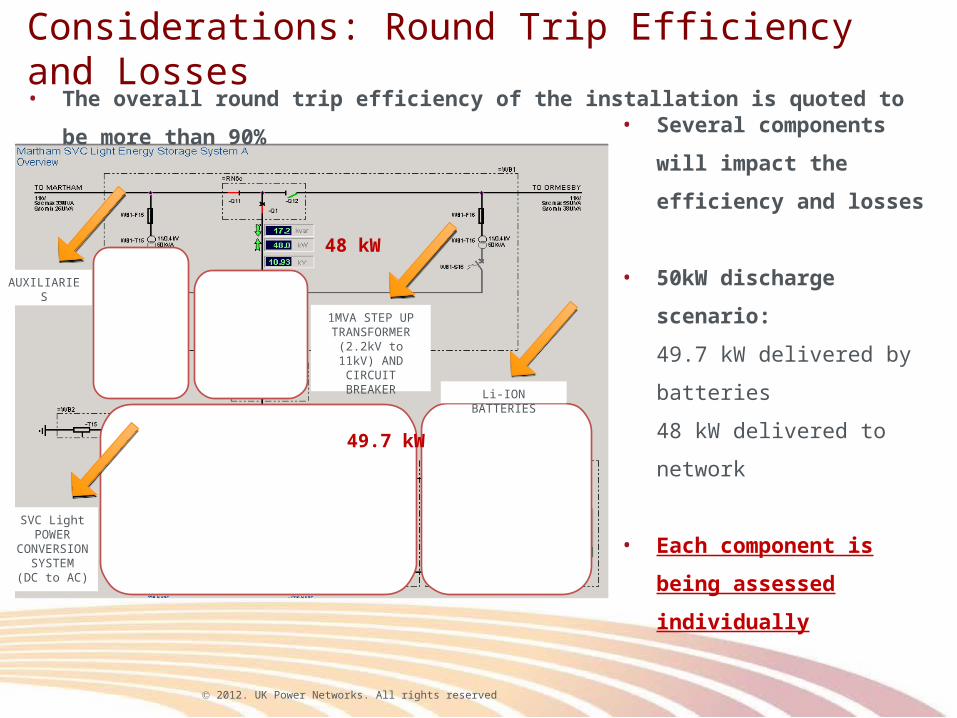
Considerations: Round Trip Efficiency and Losses
• The overall round trip efficiency of the installation is quoted to be more than 90%
• Several components will
impact the efficiency and
losses
• 50kW discharge scenario:
49.7 kW delivered by batteries
48 kW delivered to network
• Each component is being
assessed individually
49.7 kW
48 kW
2012. UK Power Networks. All rights reserved
£0
£10
£20
£30
£40
£50
£60
£70
£80
£90
Scenario 1: Optimised charge / discharge time
Scenario 2: Example of a worst case charge / discharge time
Impo
rt ch
age
/ Ex
port
reve
nue
(£)
Financial impact of an example daily operation:2 full charges / discharges @ 100kW
Import charge
Export revenue
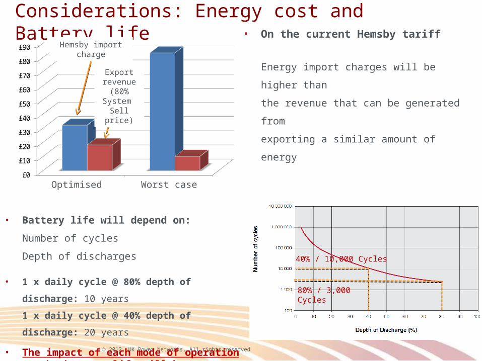
Considerations: Energy cost and Battery life
• On the current Hemsby tariff
Energy import charges will be higher than
the revenue that can be generated from
exporting a similar amount of energy
• Battery life will depend on:
Number of cycles
Depth of discharges
• 1 x daily cycle @ 80% depth of discharge: 10 years
1 x daily cycle @ 40% depth of discharge: 20 years
• The impact of each mode of operation on the battery life will be considered
Hemsby import charge
Export revenue
(80% System
Sell price)
Optimised Worst case
80% / 3,000 Cycles
40% / 10,000 Cycles
2012. UK Power Networks. All rights reserved
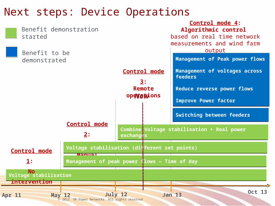
Management of Peak power flows
Management of voltages across feeders
Reduce reverse power flows
Improve Power factor
Management of Peak power flows
Management of voltages across feeders
Reduce reverse power flows
Improve Power factor
Switching between feedersSwitching between feeders
Next steps: Device Operations
Control mode
2:
On-site
Manual
Control mode
3:Remote
operations
Management of peak power flows – Time of dayManagement of peak power flows – Time of day
Voltage stabilisationVoltage stabilisation
Voltage stabilisation (different set points)Voltage stabilisation (different set points)
July 12May 12 Jan 13 Oct 13
Benefit demonstration started
Control mode
1:
No
intervention
Control mode 4:Algorithmic control
based on real time network measurements and wind farm
output
Now
Benefit to be demonstrated
Apr 11
Combine Voltage stabilisation + Real power exchangesCombine Voltage stabilisation + Real power exchanges
2012. UK Power Networks. All rights reserved
Conclusions:• The storage device is performing as expected: Reduce voltage fluctuations and manage
power flows
• The early stages of the project have been challenging:
Energy contract, IT connections, troubleshooting issues following commissioning.
• Submitted request for extension: October 2013
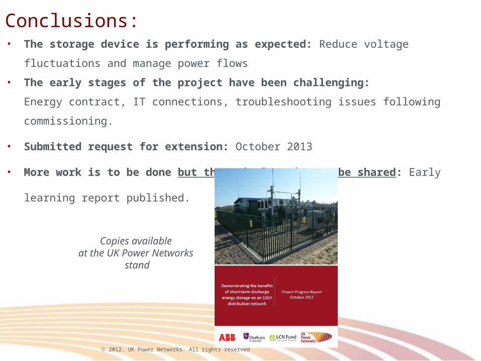
• More work is to be done but there is learning to be shared: Early learning report published.
Copies available at the UK Power Networks
stand