Embed Size (px)
Citation preview
© 2013 The McGraw-Hill Companies, Inc. All rights reserved.McGraw-Hill
13-1
ElectronicsElectronics
Principles & ApplicationsPrinciples & ApplicationsEighth EditionEighth Edition
Chapter 13Integrated Circuits(student version)
Charles A. Schuler
©2013
© 2013 The McGraw-Hill Companies, Inc. All rights reserved.McGraw-Hill
13-2
• IC fabrication• The 555 Timer• Analog ICs• Mixed-signal ICs• Troubleshooting
INTRODUCTION
© 2013 The McGraw-Hill Companies, Inc. All rights reserved.McGraw-Hill
13-3
Dear Student:
This presentation is arranged in segments. Each segmentis preceded by a Concept Preview slide and is followed by aConcept Review slide. When you reach a Concept Reviewslide, you can return to the beginning of that segment byclicking on the Repeat Segment button. This will allow youto view that segment again, if you want to.
© 2013 The McGraw-Hill Companies, Inc. All rights reserved.McGraw-Hill
13-4
Concept Preview• Photolithography is the base process used in
making monolithic integrated circuits.• Impurities are diffused into the substrate to form
PN junctions.• ICs are batch processed. One wafer will yield
many devices.• A probe test identifies defective ICs before the
wafer is cut apart.• An aluminum metalization layer interconnects the
various IC components.
© 2013 The McGraw-Hill Companies, Inc. All rights reserved.McGraw-Hill
13-5
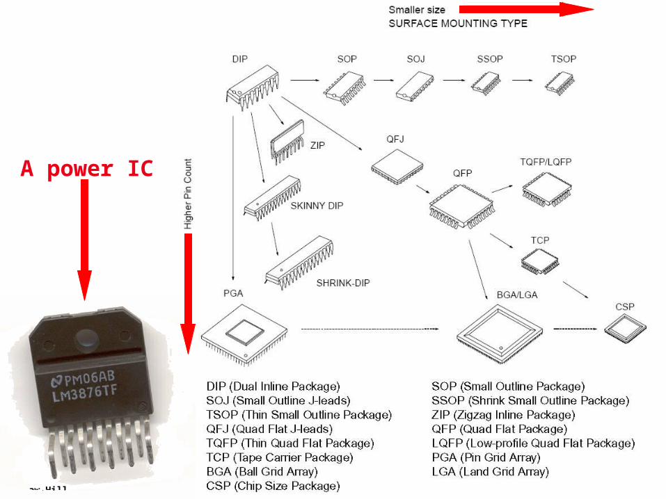
A power IC
© 2013 The McGraw-Hill Companies, Inc. All rights reserved.McGraw-Hill
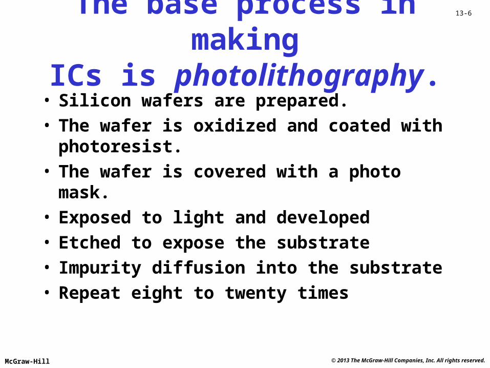
13-6The base process in makingICs is photolithography.
• Silicon wafers are prepared. • The wafer is oxidized and coated with
photoresist.• The wafer is covered with a photo mask.• Exposed to light and developed• Etched to expose the substrate• Impurity diffusion into the substrate• Repeat eight to twenty times
© 2013 The McGraw-Hill Companies, Inc. All rights reserved.McGraw-Hill
13-7
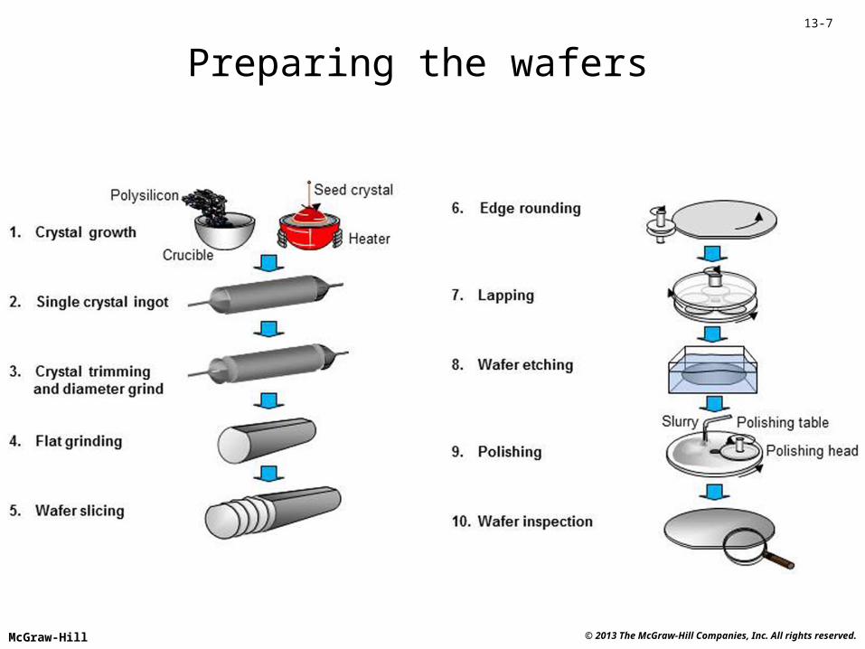
Preparing the wafers
© 2013 The McGraw-Hill Companies, Inc. All rights reserved.McGraw-Hill
13-8
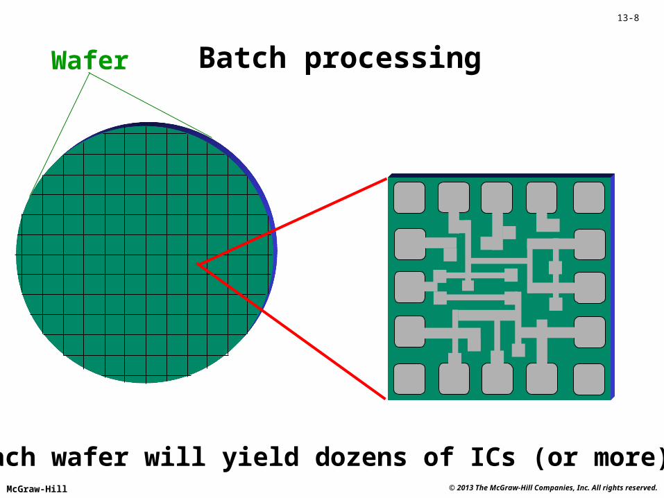
Batch processing
Each wafer will yield dozens of ICs (or more).
Wafer
© 2013 The McGraw-Hill Companies, Inc. All rights reserved.McGraw-Hill
13-9
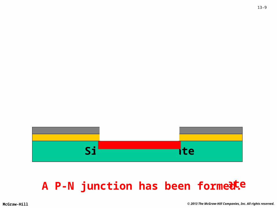
Silicon substrate
Start with a silicon substrateCoat with silicon dioxideCoat with photoresistCover with photo maskExpose with lightDevelopEtchDiffusion
Dopant
A P-N junction has been formed.
© 2013 The McGraw-Hill Companies, Inc. All rights reserved.McGraw-Hill
13-10
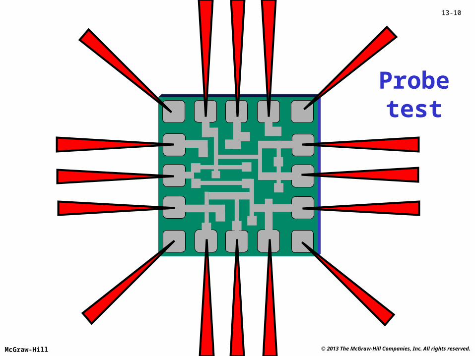
Probetest
© 2013 The McGraw-Hill Companies, Inc. All rights reserved.McGraw-Hill
13-11
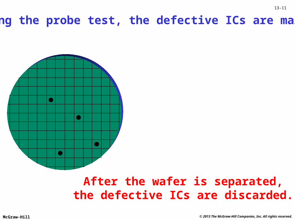
During the probe test, the defective ICs are marked.
After the wafer is separated,the defective ICs are discarded.
© 2013 The McGraw-Hill Companies, Inc. All rights reserved.McGraw-Hill
13-12
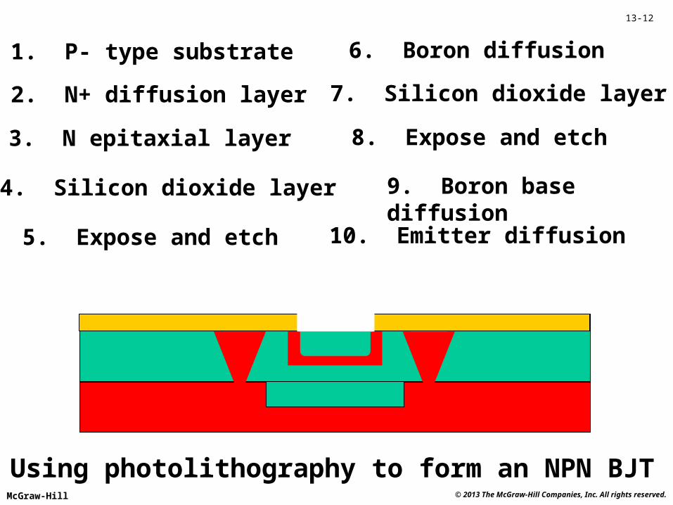
Using photolithography to form an NPN BJT
1. P- type substrate
2. N+ diffusion layer
3. N epitaxial layer
4. Silicon dioxide layer
5. Expose and etch
6. Boron diffusion
7. Silicon dioxide layer
8. Expose and etch
9. Boron base diffusion
10. Emitter diffusion
© 2013 The McGraw-Hill Companies, Inc. All rights reserved.McGraw-Hill
13-13
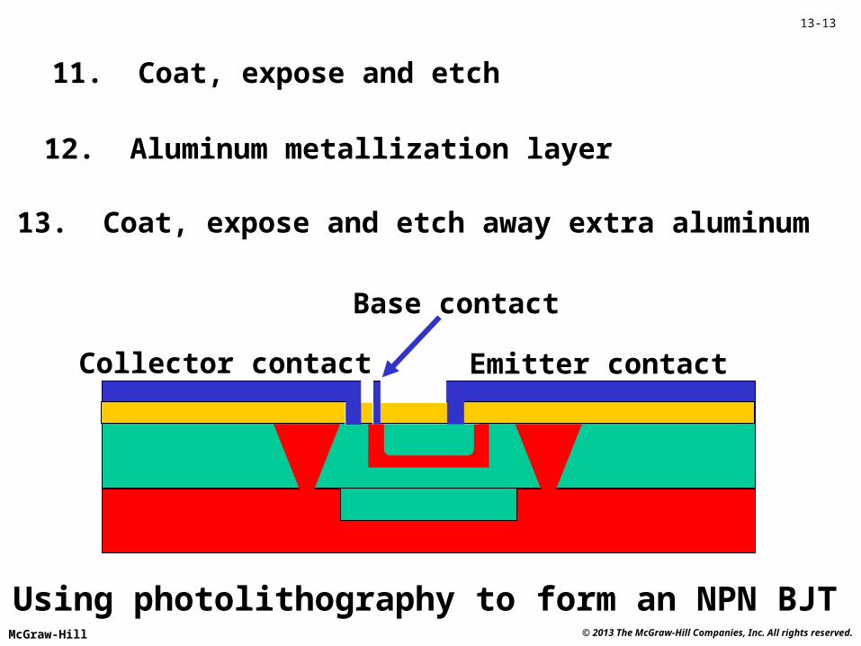
Using photolithography to form an NPN BJT
11. Coat, expose and etch
12. Aluminum metallization layer
13. Coat, expose and etch away extra aluminum
Collector contact Emitter contact
Base contact
© 2013 The McGraw-Hill Companies, Inc. All rights reserved.McGraw-Hill
13-14
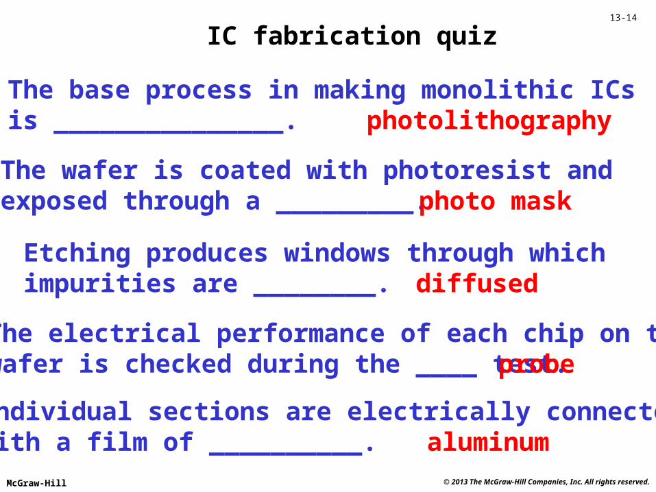
IC fabrication quiz
The base process in making monolithic ICsis _______________. photolithography
The wafer is coated with photoresist andexposed through a _________. photo mask
Etching produces windows through whichimpurities are ________. diffused
The electrical performance of each chip on thewafer is checked during the ____ test. probe
Individual sections are electrically connectedwith a film of __________. aluminum
© 2013 The McGraw-Hill Companies, Inc. All rights reserved.McGraw-Hill
13-15
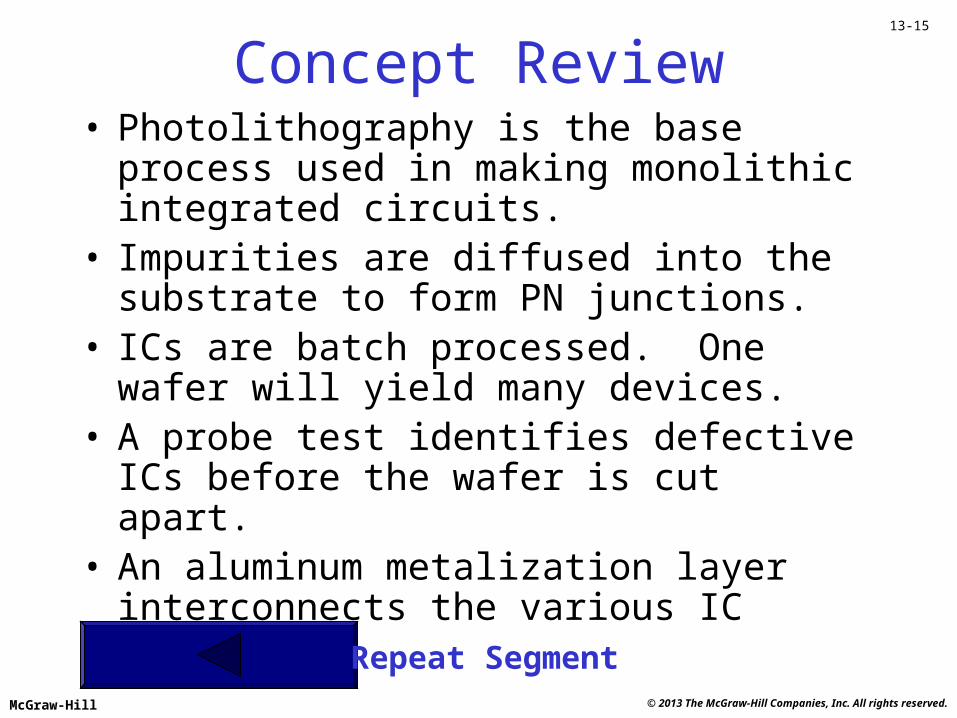
Concept Review• Photolithography is the base process used in
making monolithic integrated circuits.• Impurities are diffused into the substrate to form
PN junctions.• ICs are batch processed. One wafer will yield
many devices.• A probe test identifies defective ICs before the
wafer is cut apart.• An aluminum metalization layer interconnects the
various IC components.
Repeat Segment
© 2013 The McGraw-Hill Companies, Inc. All rights reserved.McGraw-Hill
13-16
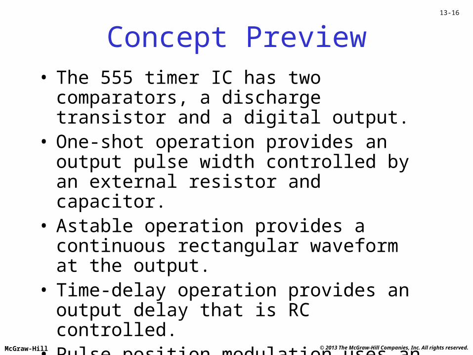
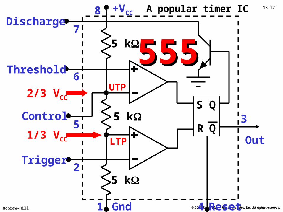
Concept Preview• The 555 timer IC has two comparators, a
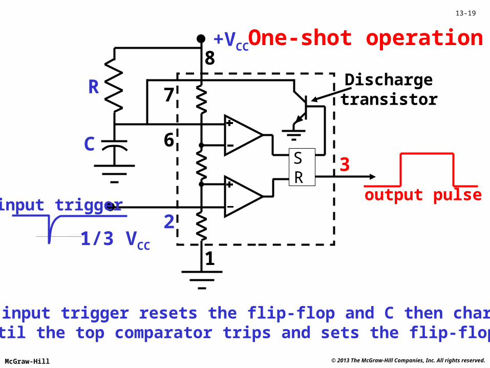
discharge transistor and a digital output.• One-shot operation provides an output pulse width
controlled by an external resistor and capacitor.• Astable operation provides a continuous
rectangular waveform at the output.• Time-delay operation provides an output delay
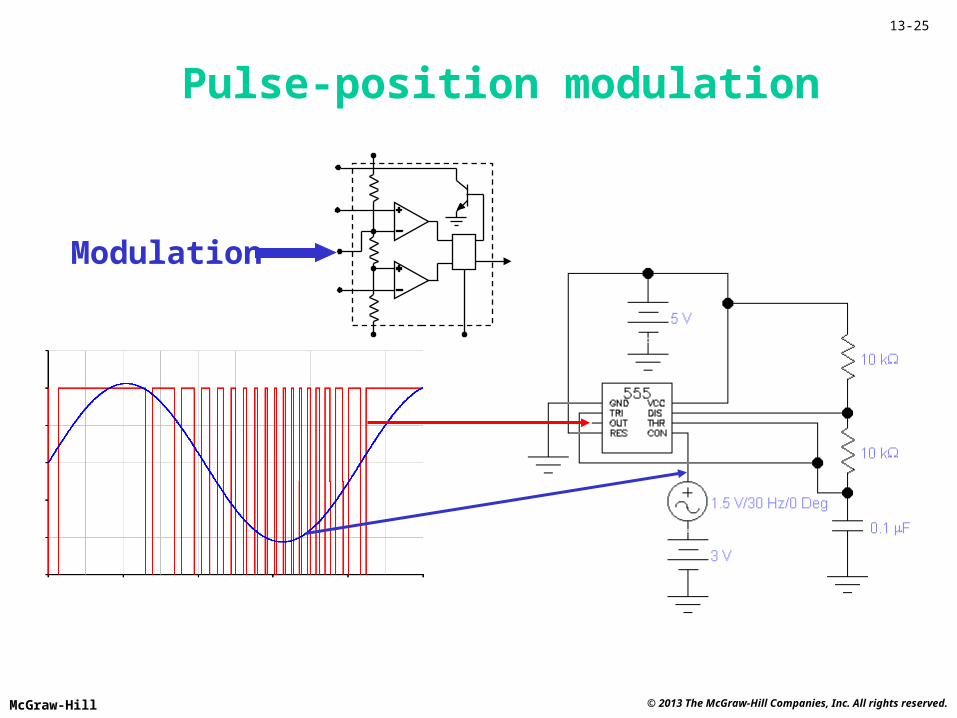
that is RC controlled.• Pulse position modulation uses an external signal
to control the comparator trip points.
© 2013 The McGraw-Hill Companies, Inc. All rights reserved.McGraw-Hill
13-17
5 k
R
S Q
Q5 k
5 k
Gnd1
Out
3
+VCC8Discharge
Threshold
Control
Trigger
7
6
5
2
555555
Reset4
UTP2/3 VCC
LTP1/3 VCC
A popular timer IC
© 2013 The McGraw-Hill Companies, Inc. All rights reserved.McGraw-Hill
13-18
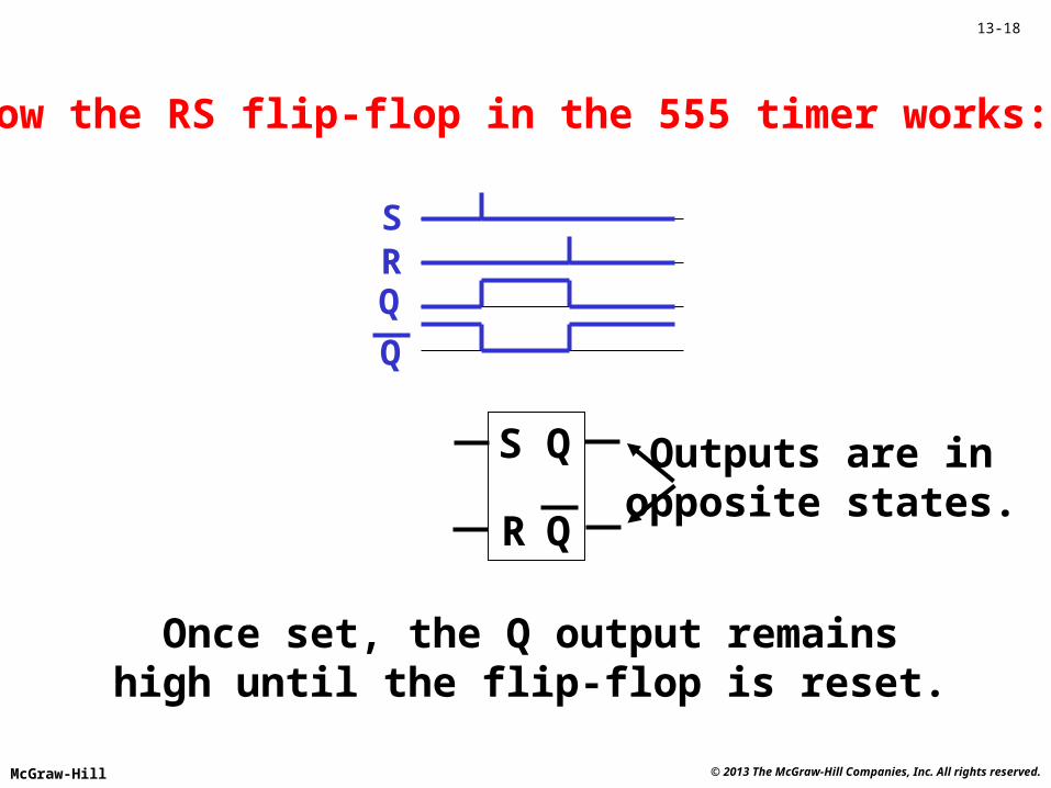
SRQ
Q
R
S Q
Q
How the RS flip-flop in the 555 timer works:
Once set, the Q output remainshigh until the flip-flop is reset.
Outputs are inopposite states.
© 2013 The McGraw-Hill Companies, Inc. All rights reserved.McGraw-Hill
13-19
1
3
+VCC
7
6
2
8One-shot operation
R
C
1/3 VCC
The input trigger resets the flip-flop and C then chargesuntil the top comparator trips and sets the flip-flop.
SR
input triggeroutput pulse
Dischargetransistor
© 2013 The McGraw-Hill Companies, Inc. All rights reserved.McGraw-Hill
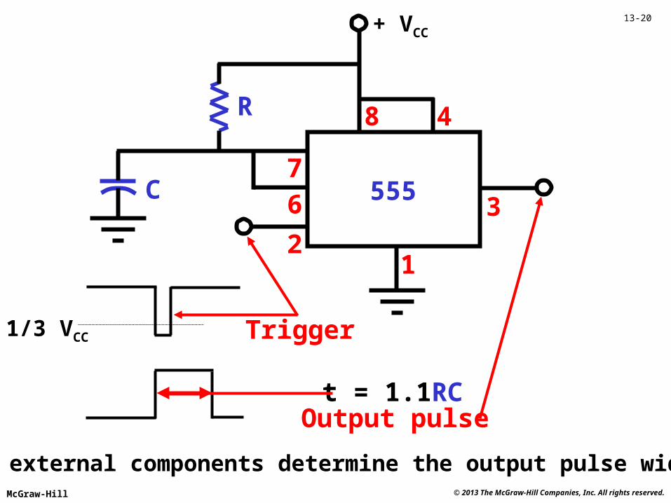
13-20+ VCC
555
48
7
6
1
3
2
R
C
t = 1.1RCOutput pulse
Trigger1/3 VCC
The external components determine the output pulse width.
© 2013 The McGraw-Hill Companies, Inc. All rights reserved.McGraw-Hill
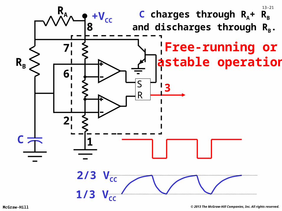
13-21
1
3
+VCC
7
6
2
8
Free-running orastable operationRB
C
RA
SR
2/3 VCC
1/3 VCC
C charges through RA+ RB
and discharges through RB.
© 2013 The McGraw-Hill Companies, Inc. All rights reserved.McGraw-Hill
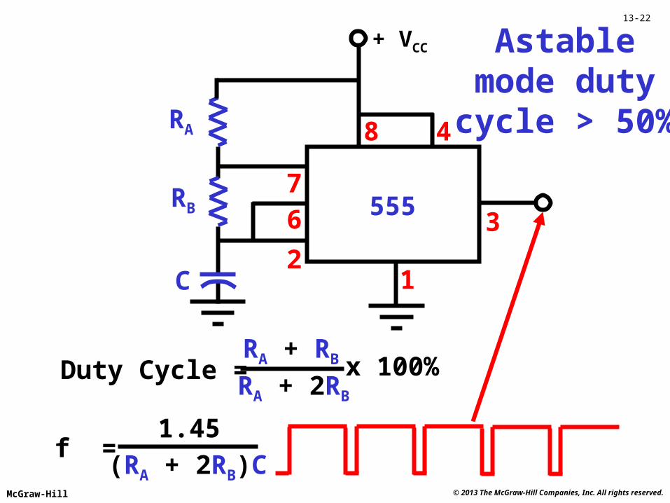
13-22
+ VCC
555
48
7
6
1
3
2
RA
C
Astablemode duty
cycle > 50%
RB
f =1.45
(RA + 2RB)C
Duty Cycle = RA + 2RB
x 100%RA + RB
© 2013 The McGraw-Hill Companies, Inc. All rights reserved.McGraw-Hill
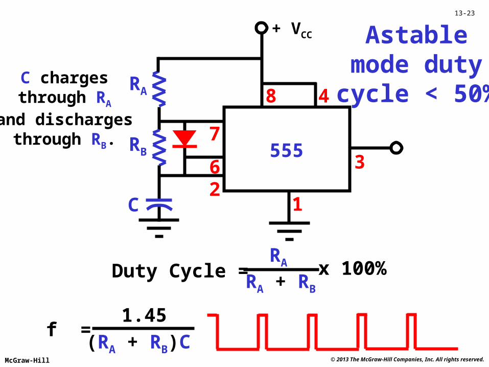
13-23
+ VCC
555
48
7
6
1
3
2
RA
C
Astablemode duty
cycle < 50%
RB
f =1.45
(RA + RB)C
RADuty Cycle =
RA + RB
x 100%
C chargesthrough RA
and dischargesthrough RB.
© 2013 The McGraw-Hill Companies, Inc. All rights reserved.McGraw-Hill
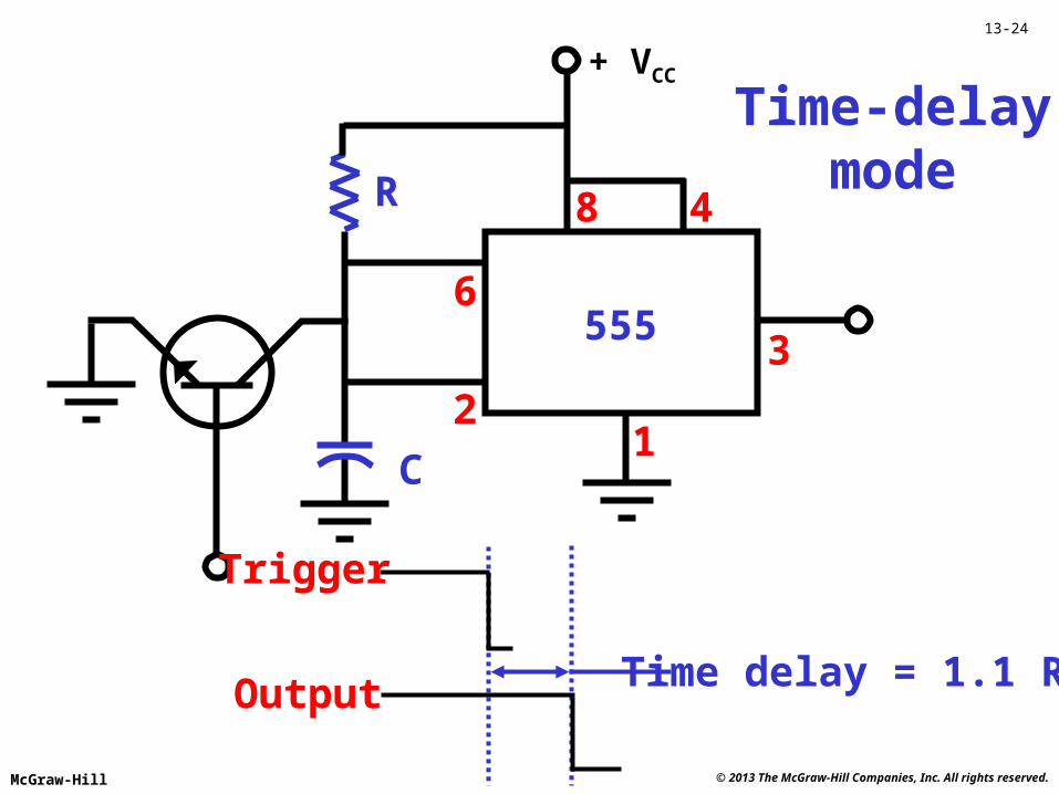
13-24
+ VCC
555
48
6
1
3
2
R
C
Trigger
Time-delaymode
Time delay = 1.1 RCOutput
© 2013 The McGraw-Hill Companies, Inc. All rights reserved.McGraw-Hill
13-25
Pulse-position modulation
Modulation
© 2013 The McGraw-Hill Companies, Inc. All rights reserved.McGraw-Hill
13-26
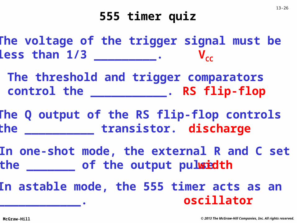
555 timer quiz
The voltage of the trigger signal must beless than 1/3 _________. VCC
The threshold and trigger comparatorscontrol the ___________. RS flip-flop
The Q output of the RS flip-flop controlsthe __________ transistor. discharge
In one-shot mode, the external R and C setthe _______ of the output pulse. width
In astable mode, the 555 timer acts as an____________. oscillator
© 2013 The McGraw-Hill Companies, Inc. All rights reserved.McGraw-Hill
13-27
Concept Review• The 555 timer IC has two comparators, a
discharge transistor and a digital output.• One-shot operation provides an output pulse width
controlled by an external resistor and capacitor.• Astable operation provides a continuous
rectangular waveform at the output.• Time-delay operation provides an output delay
that is RC controlled.• Pulse position modulation uses an external signal
to control the comparator trip points.
Repeat Segment
© 2013 The McGraw-Hill Companies, Inc. All rights reserved.McGraw-Hill
13-28
Concept Preview• There are three IC categories: analog, digital and
mixed signal.• The most widely applied analog ICs are amplifiers
and voltage regulators.• Phase locked loops can be used for FM detection
and for frequency synthesis.• A sample and hold circuit is usually required for
analog to digital conversion.• The number of bits sets the output resolution for
digital to analog converters.• Switched capacitor ICs can provide voltage
conversion and integration.
© 2013 The McGraw-Hill Companies, Inc. All rights reserved.McGraw-Hill
13-29
Analog ICs include:
• Linear voltage regulators• Differential amps• High-speed amps• Op amps• RF and IF amps• Modulators and mixers• Demodulators• Power amps
© 2013 The McGraw-Hill Companies, Inc. All rights reserved.McGraw-Hill
13-30
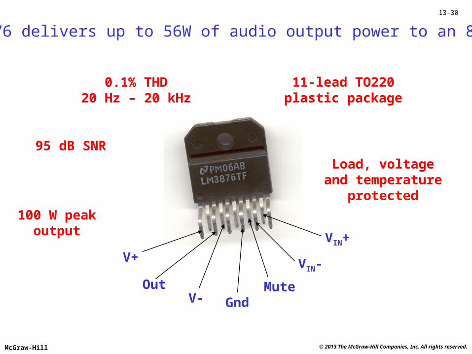
The LM3876 delivers up to 56W of audio output power to an 8 load.
V+
V-Out
VIN+
VIN-
MuteGnd
11-lead TO220plastic package
0.1% THD20 Hz – 20 kHz
95 dB SNR
Load, voltageand temperature
protected
100 W peakoutput
© 2013 The McGraw-Hill Companies, Inc. All rights reserved.McGraw-Hill
13-31
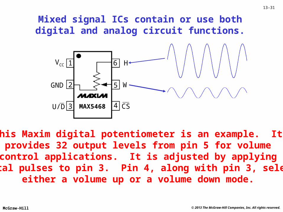
Mixed signal ICs contain or use bothdigital and analog circuit functions.
1
2
3 4
5
6
GND
U/D CS
W
HVCC
MAX5468
This Maxim digital potentiometer is an example. Itprovides 32 output levels from pin 5 for volumecontrol applications. It is adjusted by applying
digital pulses to pin 3. Pin 4, along with pin 3, selectseither a volume up or a volume down mode.
© 2013 The McGraw-Hill Companies, Inc. All rights reserved.McGraw-Hill
13-32
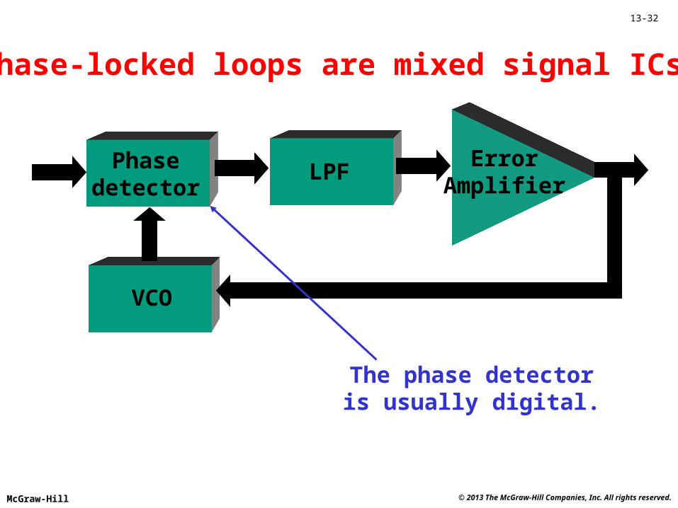
ErrorAmplifier
Phasedetector
LPF
VCO
Phase-locked loops are mixed signal ICs.
The phase detectoris usually digital.
© 2013 The McGraw-Hill Companies, Inc. All rights reserved.McGraw-Hill
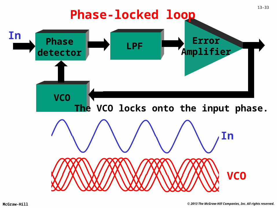
13-33
ErrorAmplifier
Phasedetector
LPF
VCO
Phase-locked loop
In
In
VCO
The VCO locks onto the input phase.
© 2013 The McGraw-Hill Companies, Inc. All rights reserved.McGraw-Hill
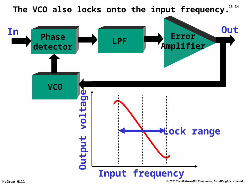
13-34
ErrorAmplifier
Phasedetector
LPF
VCO
In
The VCO also locks onto the input frequency.
Out
Ou
tpu
t vo
ltag
e
Input frequency
Lock range
© 2013 The McGraw-Hill Companies, Inc. All rights reserved.McGraw-Hill
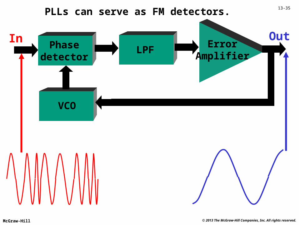
13-35
ErrorAmplifier
Phasedetector
LPF
VCO
In
PLLs can serve as FM detectors.
Out
© 2013 The McGraw-Hill Companies, Inc. All rights reserved.McGraw-Hill
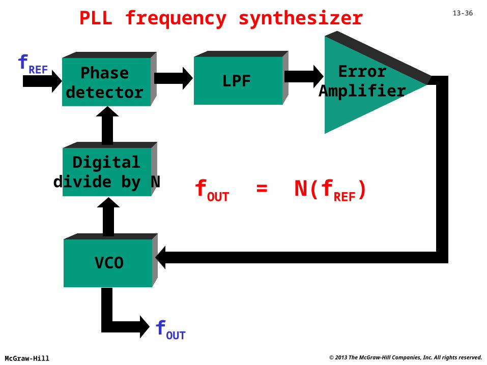
13-36
ErrorAmplifier
Phasedetector
LPF
VCO
fREF
PLL frequency synthesizer
fOUT
Digitaldivide by N fOUT = N(fREF)
© 2013 The McGraw-Hill Companies, Inc. All rights reserved.McGraw-Hill
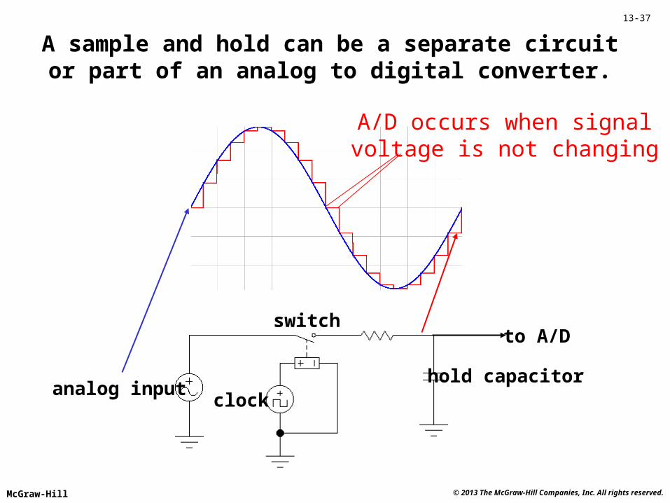
13-37
A sample and hold can be a separate circuitor part of an analog to digital converter.
hold capacitoranalog input
clock
switch
A/D occurs when signalvoltage is not changing
to A/D
© 2013 The McGraw-Hill Companies, Inc. All rights reserved.McGraw-Hill
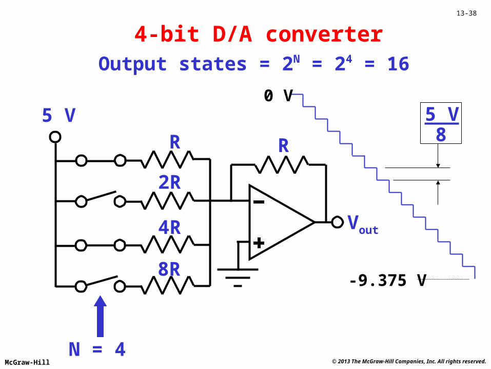
13-38
4-bit D/A converter
Vout
R R
2R
4R
8R
Output states = 2N = 24 = 16
N = 4
5 V8
5 V0 V
-9.375 V
© 2013 The McGraw-Hill Companies, Inc. All rights reserved.McGraw-Hill
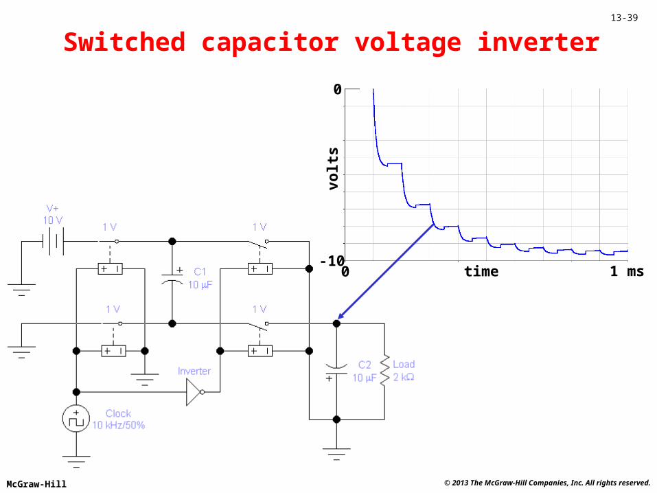
13-39
1 ms-10
0
time
volt
s
0
Switched capacitor voltage inverter
© 2013 The McGraw-Hill Companies, Inc. All rights reserved.McGraw-Hill
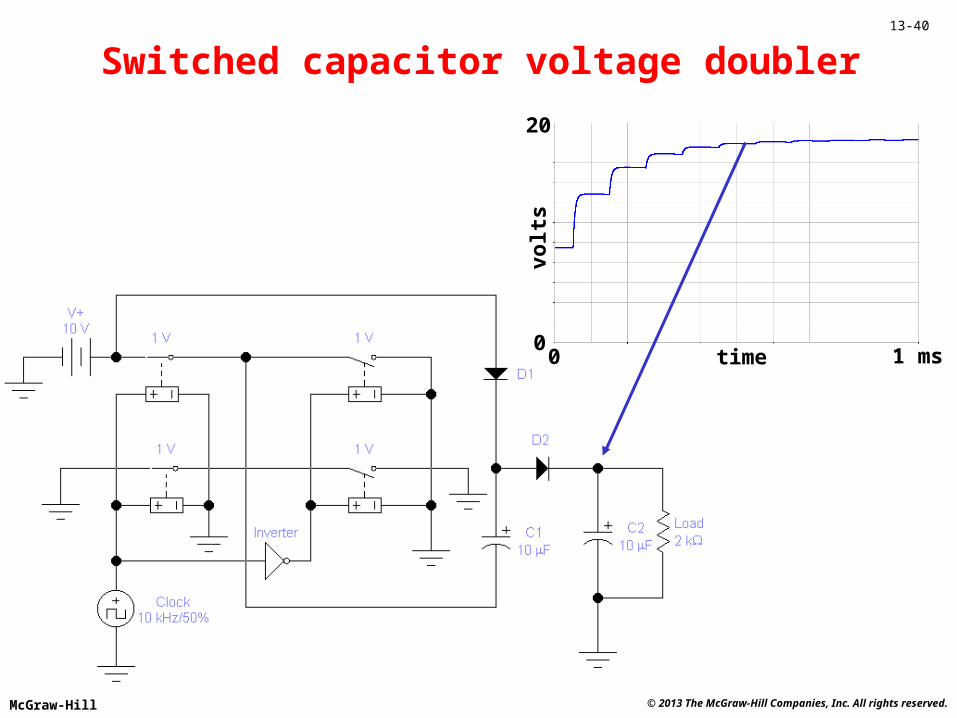
13-40
1 ms0
20
time
volt
s
0
Switched capacitor voltage doubler
© 2013 The McGraw-Hill Companies, Inc. All rights reserved.McGraw-Hill
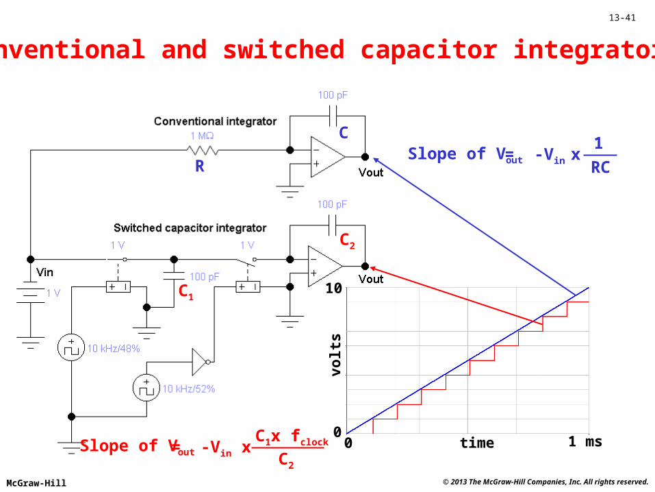
13-41
Conventional and switched capacitor integrators
1 ms
10
time
volt
s
00
C1
C2
C
RSlope of Vout = -Vin x
RC
1
Slope of Vout = -Vin x C2
C1x fclock
© 2013 The McGraw-Hill Companies, Inc. All rights reserved.McGraw-Hill
13-42
Mixed signal IC quiz
When a PLL is locked, the VCO tracks theinput _________. signal
PLLs can be used as FM _________.detectors
With a divide by N, a PLL serves as afrequency _____________. synthesizer
The output of a 6-bit D/A converter has_______ possible output levels. 64
The output slope of a switched capacitor_______ depends on the clock frequency.
integrator
© 2013 The McGraw-Hill Companies, Inc. All rights reserved.McGraw-Hill
13-43
Concept Review• There are three IC categories: analog, digital and
mixed signal.• The most widely applied analog ICs are amplifiers
and voltage regulators.• Phase locked loops can be used for FM detection
and for frequency synthesis.• A sample and hold circuit is usually required for
analog to digital conversion.• The number of bits sets the output resolution for
digital to analog converters.• Switched capacitor ICs can provide voltage
conversion and integration.
Repeat Segment
© 2013 The McGraw-Hill Companies, Inc. All rights reserved.McGraw-Hill
13-44
Troubleshooting• Be sure to take a system point of view.
• Is there any software involved?
• Supply voltages may be critical.
• Check the clock signal frequency.
• Waveform analysis is often used (a
mixed-signal oscilloscope can be
very helpful).

© 2013 The McGraw-Hill Companies, Inc. All rights reserved.McGraw-Hill
13-45
Technician using a mixed-signal oscilloscope (Agilent)
© 2013 The McGraw-Hill Companies, Inc. All rights reserved.McGraw-Hill
13-46
REVIEW• IC fabrication• The 555 Timer• Analog ICs• Mixed-signal ICs• Troubleshooting