Embed Size (px)
Citation preview

w w w . t s u n a m i . u s . c o m
TSUNAMI COMPRESSED AIR SOLUTIONS ™
Superior Filtration Products. Pure & Simple.
Tsunami Compressed Air Solutions™, a division of
Suburban Manufacturing, offers a complete line of
products engineered to give customers dry, clean air
for their specific application demands. Our systems
use the latest technology to provide the highest
quality compressed air available.
MADE IN THE USA
“Engineering Value
through Quality and Innovation”
Follow us on Facebook Check us out on YouTube Connect with us on Google +
www.tsunami.us.com | 800-782-5752 | [email protected]
a division of

Air Dryers
PRODUCT GUIDE
Filtration
Specialty Filtration
Drains
Hose, Couplers & Air Monitoring Equipment
Parts & Accessories
.……………………………………….. 4-5
………………………………………….. 6-7
………………………………….. 9
…..………………………………………….. 10
…… 11
……………...……...….. 12-13
Breathing Air ...……………………………………… 8
Compressed Air Facts ..……………...…………14
Facility Analysis …....……………………….…....15
Air Dryers …………….……..…......…………16-17
Filtration ……………………….…...…………18-19
Drains ……………………………....…………20-21
Custom Configuring Dryers .....…...…………22-23
Mobile & Industrial ..……………...…...…………23
Paint, Body & Equipment …………..…………24-27
TECHNICAL INFORMATION
APPLICATION GUIDE

TSUNAMI REGENERATIVE DRYERS
Mounted Units 10Hp - 30Hp Complete Drying Systems
2-Stage Tsunami Filtration
Economical solution for low air demand
Manual control valve may be mounted up to 50’ away
Max Flow @ 100% Duty Cycle Part Number
28 CFM 21999-0788
Wall Mounted units come complete with pre-filters, PLC, mounting rail and automatic drains.
Size Max Flow
@ 100% Duty Cycle Max Flow
@ 70% Duty Cycle Height Width Depth
Inlet/Outlet NPT
Part Number Std Orifice
Ø
10Hp 28 CFM 40 CFM 31” 23” 12” 1” 21999-0710 .030
15Hp 42 CFM 60 CFM 31” 30” 12” 1” 21999-0715 .045
20Hp 56 CFM 80 CFM 31” 35” 12” 1” 21999-0720 .030
30Hp 84 CFM 120 CFM 31” 35” 12” 1” 21999-0730 .060
Size Max Flow
@ 100% Duty Cycle Max Flow
@ 70% Duty Cycle Height Width Depth
Inlet/Outlet NPT
Part Number Std Orifice
Ø
10Hp 28 CFM 40 CFM 71” 51” 28” 1” 21999-0810 .030
15Hp 42 CFM 60 CFM 71” 51” 28” 1” 21999-0815 .045
20Hp 56 CFM 80 CFM 71” 51” 28” 1” 21999-0820 .030 30Hp 84 CFM 120 CFM 71” 51” 28” 1” 21999-0830 .060
Ultra Drying System 10Hp - 30Hp Tank Mounted Drying Systems
Fully assembled solutions complete with pre-filters, PLC, automatic drains and outlet regulator. Ultra Systems come mounted on an 80 gallon tank for storing ultra dry air.
Max Flow @ 100% Duty Cycle Part Number
28 CFM 21999-0722
Portable Regenerative Dryer Single Tower Regenerative Dryer
Up to 20 Minutes of clean, dry air between manual regeneration cycles.
Up to 20 minutes of clean, dry air between manual regeneration cycles.
Oil coalescing pre-filter with regulator
Provides dry air where you need it
35’ Tsunami Ultra-flo Hose
All contained in one case with wheels
4
COMPLETE DRYING SYSTEMS
Dryer flow rates based on 100° F inlet air @ 175 psi inlet pressure. Lower inlet pressure and higher temperatures affect the performance and quality of the downstream air.
Standard orifice configuration - See pg. 22
3 Year Warranty on all Complete Drying Systems
Low Dew Points - down to –80°F Low Relative Humidity - down to .01% RH
Expandable Drying Technology - Increase dryer capacity without buying a new system
Easy, Low Cost Maintenance - Simply replace oil coalescing filter element every six months
Dual Inlet/Outlet Ports - Allows for multiple installation configurations
For Maximum Performance size dryer at 100% duty cycle flow rate
The Tsunami Regenerative Dryer uses the latest technology to provide your application with the cleanest, driest compressed air available. Our systems are complete packages and include Tsunami water separators, oil coalescing filters and Moisture Minder® automatic drains to assure proper draining of water and oils. Tsunami Regenerative Dryers are available in a variety of sizes and configurations to fit your specific application requirements. For more information on Regenerative Dryers, see Technical Information - Air Drying on pgs. 16-17.
Air Dryers
- AIR DRYERS
Global units sent outside North America have special power adaptors: part number should be followed by –G
UNIQUE APPLICATION SOLUTIONS
Patent Pending
800.782.5752
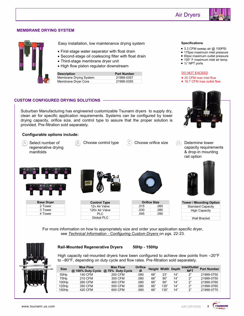
DO NOT EXCEED
20 CFM max inlet flow 16.7 CFM max outlet flow
3.3 CFM sweep air @ 100PSI 175psi maximum inlet pressure 60psi maximum outlet pressure 100° F maximum inlet air temp ½” NPT ports
Size Max Flow
@ 100% Duty Cycle Max Flow
@ 70% Duty Cycle Height Width Depth
Inlet/Outlet NPT
Part Number Orifice
Ø
50Hp 140 CFM 200 CFM 66” 23” 14” 2” 21999-0750 .080
75Hp 210 CFM 300 CFM 66” 90” 14” 2” 21999-0755 .080
100Hp 280 CFM 400 CFM 66” 90” 14” 2” 21999-0760 .080
125Hp 350 CFM 500 CFM 66” 135” 14” 2” 21999-0765 .080
150Hp 420 CFM 600 CFM 66” 135” 14” 2” 21999-0770 .080
First-stage water separator with float drain
Second-stage oil coalescing filter with float drain
Third-stage membrane dryer unit
High flow piston regulator downstream
MEMBRANE DRYING SYSTEM
Easy installation, low maintenance drying system
Description Part Number
Membrane Drying System 21999-0357
Membrane Dryer Core 21999-0355
CUSTOM CONFIGURED DRYING SOLUTIONS
5
Specifications
Air Dryers
AIR DRYERS -
Suburban Manufacturing has engineered customizable Tsunami dryers to supply dry, clean air for specific application requirements. Systems can be configured by tower drying capacity, orifice size, and control type to assure that the proper solution is provided. Pre-filtration sold separately.
Base Dryer
2 Tower
3 Tower
4 Tower
Control Type
12v Air Valve
120v Air Valve
PLC
Global PLC
Orifice Size
.015 .060
.030 .080
.045 .090
Tower / Mounting Option
Standard Capacity
High Capacity
Wall Bracket
Select number of regenerative drying manifolds
Choose control type Choose orifice size Determine tower capacity requirements & drop-in mounting rail option
For more information on how to appropriately size and order your application specific dryer, see Technical Information - Configuring Custom Dryers on pgs. 22-23.
High capacity rail-mounted dryers have been configured to achieve dew points from –20°F to –80°F, depending on duty cycle and flow rates. Pre-filtration sold separately.
Rail-Mounted Regenerative Dryers 50Hp - 150Hp
Configurable options include:
A B D C
www.tsunami.us.com

WATER SEPARATORS
The Tsunami water separator removes water, up to 1 quart per minute, and filters particulate down to 10 micron.
ACTIVATED CARBON FILTERS
OIL COALESCING FILTERS
The Tsunami oil coalescing filter removes oil aerosols down to .001 ppm and traps particulates down to .01 micron.
The Tsunami activated carbon filter removes oil vapor down to .003 ppm, removing odor and taste from the air.
Drain Type 20 SCFM 50 SCFM 120 SCFM 200 SCFM 240 SCFM Float Drain 21999-0390 21999-0131 21999-0082 N/A 21999-0288
Electronic Drain N/A 21999-0131-ED 21999-0082-ED 21999-0859-ED 21999-0288-ED
Pneumatic Drain 21999-0390-MM 21999-0131-MM 21999-0082-MM 21999-0850-MM N/A
The most important part of filtration is on the inside. Today, many manufacturers use die cast housings which collect chemicals from your compressed air and will eventually oxidize and create a white rust inside your filtration. What separates Tsunami from other manufacturers is that our filters are machined from 6061 aircraft aluminum. They are anodized for maximum corrosion resistance, inside and out. This prevents rust and corrosion from forming inside the filter housings unlike filters manufactured out of die cast materials. To further understand the technology behind our filtration, see Technical Information - Filtration on pgs. 18-19.
Drain Type 20 SCFM 50 SCFM 120 SCFM 200 SCFM 240 SCFM
N/A 21999-0390-AC 21999-0131-AC 21999-0082-AC N/A 21999-0289-AC
Drain Type 20 SCFM 50 SCFM 120 SCFM 200 SCFM 240 SCFM Float Drain 21999-0390-Z-FD 21999-0131-Z-FD 21999-0082-Z-FD N/A 21999-0289
Electronic Drain N/A 21999-0131-Z-ED 21999-0082-Z-ED 21999-0850-Z-ED N/A
Pneumatic Drain 21999-0390-Z-MM 21999-0131-Z-MM 21999-0082-Z-MM 21999-0850-Z-MM N/A
6
Tsunami water separators and oil coalescing filters are designed to accommodate multiple drain types for specific application needs. Draining options include float drains, our patented Moisture Minder Electronic Drain and our patent pending pneumatic drain. To best select the appropriate drain type for your application, see Drains on pg. 10
FILTER DRAIN OPTIONS
Filtration
- FILTRATION
TSUNAMI FILTRATION
20 Series 120 Series 50 Series
Specifications - Filters are available from 20 SCFM to 240 SCFM. Multiple draining options available. Mounting brackets sold separately. See page 12.
240 Series 200 Series
Filter Series Maximum Flow Rate Maximum Pressure Maximum Temperature Port Size
20 Series 20 SCFM 250 PSI 175˚F 1/4” NPT
50 Series 50 SCFM 250 PSI 175˚F 1/2” NPT
120 Series 120 SCFM 250 PSI 175˚F 1” NPT
200 Series 200 SCFM 250 PSI 175˚F 1-1/2” NPT
240 Series 240 SCFM 250 PSI 175˚F 1-1/4 NPT
800.782.5752
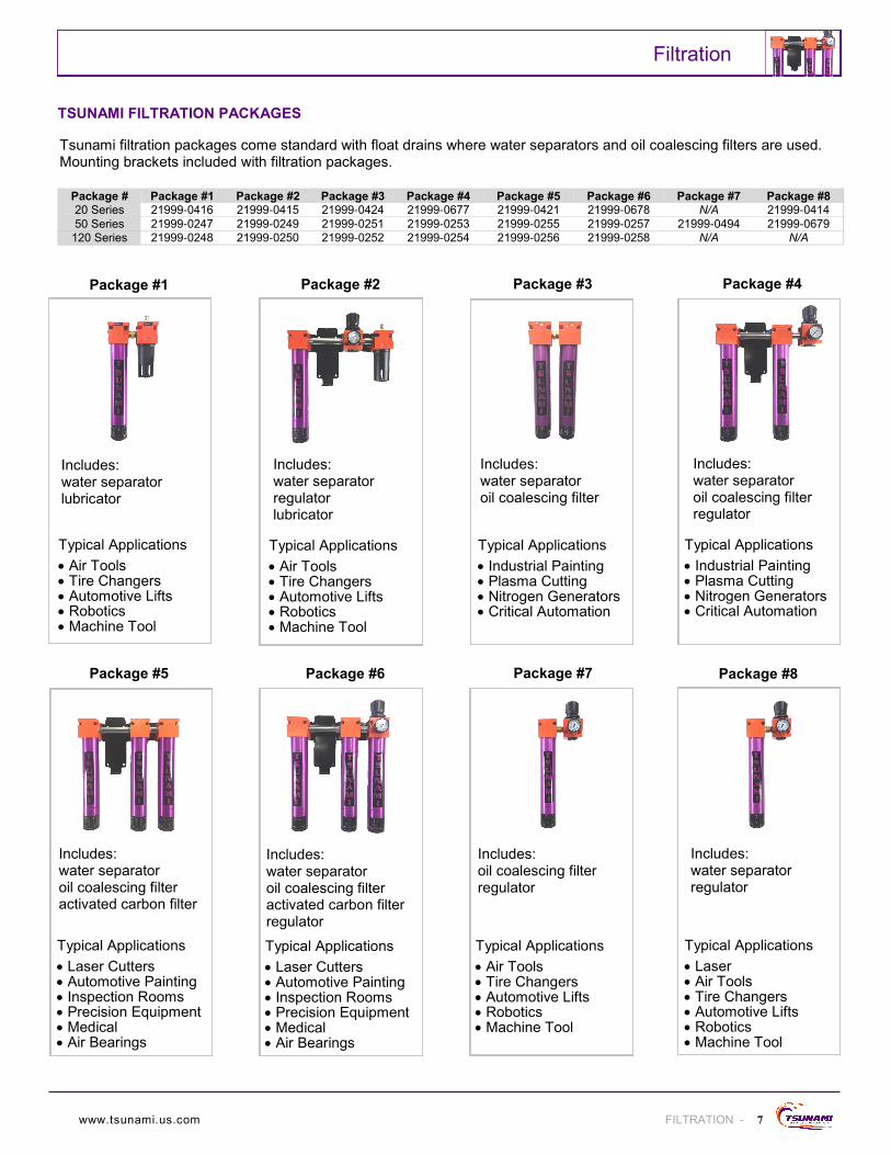
Package #1
Includes: water separator lubricator
Package #2
Typical Applications
Air Tools Tire Changers Automotive Lifts Robotics Machine Tool
TSUNAMI FILTRATION PACKAGES
7
Includes: water separator regulator lubricator
Package #3
Includes: water separator oil coalescing filter
Typical Applications
Air Tools Tire Changers Automotive Lifts Robotics Machine Tool
Package #4
Typical Applications
Industrial Painting Plasma Cutting Nitrogen Generators Critical Automation
Includes: water separator oil coalescing filter regulator
Package #5
Includes: water separator oil coalescing filter activated carbon filter
Package #6
Typical Applications
Laser Cutters Automotive Painting Inspection Rooms Precision Equipment Medical Air Bearings
Includes: water separator oil coalescing filter activated carbon filter regulator
Package #7
Includes: oil coalescing filter regulator
Typical Applications
Laser Cutters Automotive Painting Inspection Rooms Precision Equipment Medical Air Bearings
Typical Applications
Air Tools Tire Changers Automotive Lifts Robotics Machine Tool
Package #8
Typical Applications
Laser Air Tools Tire Changers Automotive Lifts Robotics Machine Tool
Includes: water separator regulator
Typical Applications
Industrial Painting Plasma Cutting Nitrogen Generators Critical Automation
Package #1 Package #2 Package #3 Package #4 Package #5 Package #6 Package #7 Package #8 Package # 21999-0416 21999-0415 21999-0424 21999-0677 21999-0421 21999-0678 N/A 21999-0414 20 Series
21999-0247 21999-0249 21999-0251 21999-0253 21999-0255 21999-0257 21999-0494 21999-0679 50 Series
21999-0248 21999-0250 21999-0252 21999-0254 21999-0256 21999-0258 N/A N/A 120 Series
Tsunami filtration packages come standard with float drains where water separators and oil coalescing filters are used. Mounting brackets included with filtration packages.
Filtration
FILTRATION - www.tsunami.us.com

8
Breathing Air
- BREATHING AIR
ENGINEERED TO OSHA REQUIREMENTS FOR GRADE “D” AIR . OSHA Regulations (Standard-29 CFR) Respiratory Protection– 1910.134
**Use only with electric driven compressors* !! Follow all your state and local OSHA rules and regulations !!
Please allow 2-3 week lead time on all breathing air products.
2-stage Tsunami filtration - 50 Series
Mounting bracket
50ft Tsunami Ultra-flo hose
Belt unit includes: - Dual regulators - Carbon filter - CO monitor - 5’ whip hose
Single User Breathable Air System 1 - 4 Person Breathable Air Panel
3-stage Tsunami filtration
Digital readout
Automatic float drains
Less faulty readings with continuous carbon monoxide monitoring
Calibration made easy with Autocal®
Port Size NPT
Max Flow
Max Pressure
Setting Range Part Number
1/2” 25 CFM 250 PSI 0-120 PSI 21999-0791
1/4” 21999-0790 Belt Unit Only
Port Size NPT
Max Flow
Max Pressure
Setting Range Part Number
1/2” 50 CFM 250 - 21999-0265
BREATHING AIR ACCESSORIES
Bullard Breathing Air Accessories Part Number 25’ Starter Hose & Quick Connectors (mandatory) 21999-0276 25’ Extension Hose & Quick Connectors 21999-0277 50’ Extension Hose & Quick Connectors 21999-0278 100’ Extension Hose & Quick Connectors 21999-0279 Full Hood Set (includes regulator and belt) 21999-0275 Mylar Lens Covers - Full Hood - (25pk) 21999-0273 Cooling Tube w/ Belt - Hood Only 21999-0274 Replacement Hood w/o Head Band - (10pk) 21999-0281 Full Mask Set - Spectrum Series w/ belt & regulator 21999-0285 Mylar Lens Covers - Full Mask - (25pk) 21999-0272 Replacement Lens for Full Mask 21999-0282 Cooling Vest - Medium - Large 21999-0286 Cooling Vest - X-Large - XX-Large 21999-0287 Cooling Tube for Vest 21999-0280
SAS Breathing Air Accessories Part Number Activated Carbon Filter Replacement Element 21999-0399 Gen-Nex Supplied Air Hood Assembly 21999-0396 Peel Off Lens Covers for Gen-Nex Hoods - 10 pk 21999-0417 Replacement Hoods w/o Headband or Hose - 3pk 21999-0400 50’ Hose for Breathing Air 21999-0397
GFG Breathing Air Accessories Part Number Calibration Kit for CO Monitor 21999-0264 CO Monitor for Tsunami Breathing Air Panel 21999-0263 CO Monitor for Tsunami Single User Systems RAM1418-017 110/120v Wall Pack Adaptor Replacement 21999-0267
GRADE “D” BREATHING AIR SYSTEMS
Hood and calibration kit sold separately Hoses, hoods, and calibration kit sold separately
Single User Breathable Air Accessories Part Number Replacement Belt SW-0946 Replacement Spring LC 125N 01 S
800.782.5752
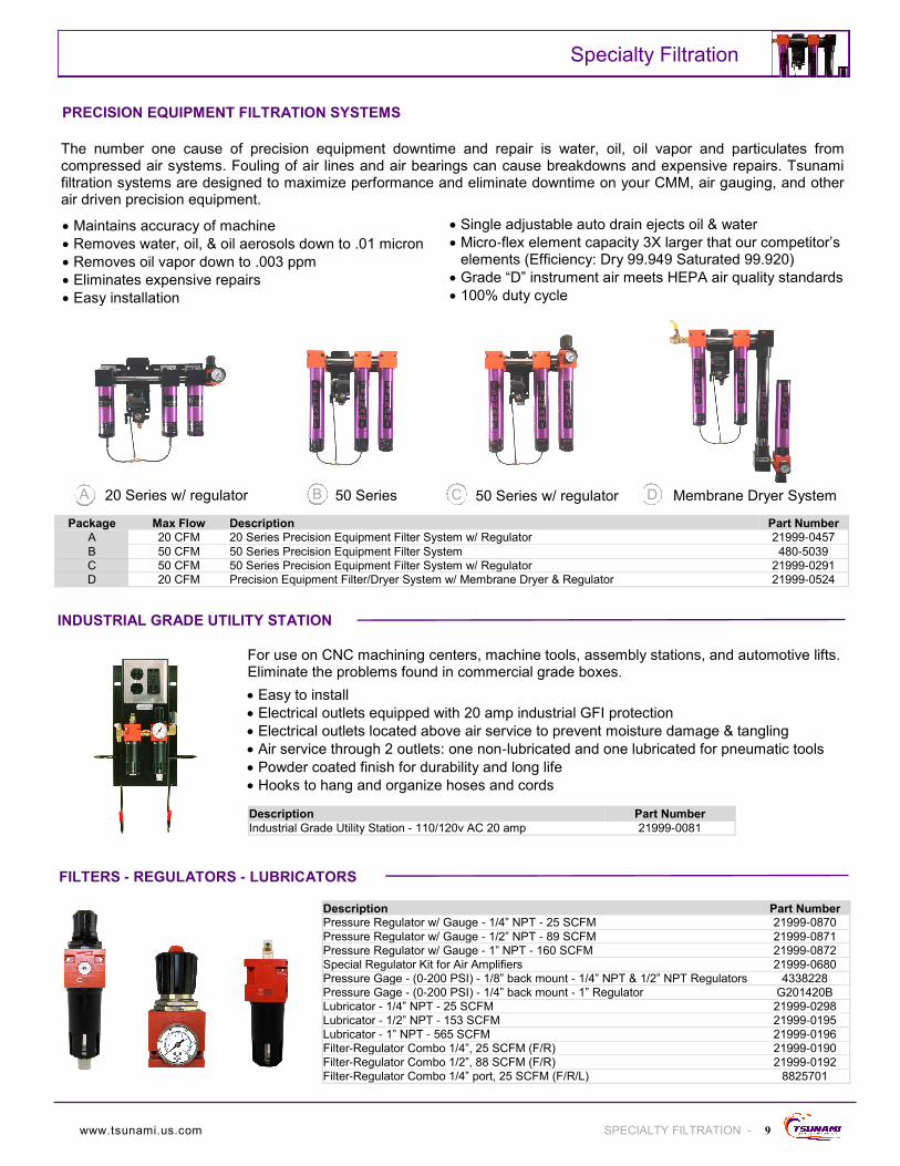
The number one cause of precision equipment downtime and repair is water, oil, oil vapor and particulates from compressed air systems. Fouling of air lines and air bearings can cause breakdowns and expensive repairs. Tsunami filtration systems are designed to maximize performance and eliminate downtime on your CMM, air gauging, and other air driven precision equipment.
INDUSTRIAL GRADE UTILITY STATION
Maintains accuracy of machine
Removes water, oil, & oil aerosols down to .01 micron
Removes oil vapor down to .003 ppm
Eliminates expensive repairs
Easy installation
Single adjustable auto drain ejects oil & water
Micro-flex element capacity 3X larger that our competitor’s elements (Efficiency: Dry 99.949 Saturated 99.920)
Grade “D” instrument air meets HEPA air quality standards
100% duty cycle
A B C D
9
Package Max Flow Description Part Number
A 20 CFM 20 Series Precision Equipment Filter System w/ Regulator 21999-0457
B 50 CFM 50 Series Precision Equipment Filter System 480-5039
C 50 CFM 50 Series Precision Equipment Filter System w/ Regulator 21999-0291
D 20 CFM Precision Equipment Filter/Dryer System w/ Membrane Dryer & Regulator 21999-0524
20 Series w/ regulator 50 Series 50 Series w/ regulator Membrane Dryer System
Specialty Filtration
SPECIALTY FILTRATION -
PRECISION EQUIPMENT FILTRATION SYSTEMS
For use on CNC machining centers, machine tools, assembly stations, and automotive lifts. Eliminate the problems found in commercial grade boxes.
Easy to install
Electrical outlets equipped with 20 amp industrial GFI protection
Electrical outlets located above air service to prevent moisture damage & tangling
Air service through 2 outlets: one non-lubricated and one lubricated for pneumatic tools
Powder coated finish for durability and long life
Hooks to hang and organize hoses and cords
Description Part Number
Industrial Grade Utility Station - 110/120v AC 20 amp 21999-0081
FILTERS - REGULATORS - LUBRICATORS
Description Part Number Pressure Regulator w/ Gauge - 1/4” NPT - 25 SCFM 21999-0870
Pressure Regulator w/ Gauge - 1/2” NPT - 89 SCFM 21999-0871
Pressure Regulator w/ Gauge - 1” NPT - 160 SCFM 21999-0872
Special Regulator Kit for Air Amplifiers 21999-0680
Pressure Gage - (0-200 PSI) - 1/8” back mount - 1/4” NPT & 1/2” NPT Regulators 4338228
Pressure Gage - (0-200 PSI) - 1/4” back mount - 1” Regulator G201420B
Lubricator - 1/4” NPT - 25 SCFM 21999-0298
Lubricator - 1/2” NPT - 153 SCFM 21999-0195
Lubricator - 1” NPT - 565 SCFM 21999-0196
Filter-Regulator Combo 1/4”, 25 SCFM (F/R) 21999-0190
Filter-Regulator Combo 1/2”, 88 SCFM (F/R) 21999-0192
Filter-Regulator Combo 1/4” port, 25 SCFM (F/R/L) 8825701
www.tsunami.us.com

Tsunami Drain Minder II Controller
Compressed air systems can become severely contaminated when the simple duty of draining compressor tanks and filters gets neglected. Failure to complete this task will eventually lead to catastrophic results. The solution… A complete line of Moisture Minder® automatic drains. Moisture Minder® drains are available in standalone or filter-mounted units. For a better understanding of how our pneumatic drains operate, see Technical Information - Drains on pg. 20.
Automatic; only requires intermittent pilot signal
No electricity required
Seals made of Teflon® and Viton®
Standard valve rated at 300psi
Operates without pressure drop in air system
Features
No manual adjustments required
Saves money - no additional wiring
Long life - can be used with synthetic oils
Compatible with most systems
Benefits
A B C
Drain Rating Description Part Number
A 30 Hp Moisture Minder I Automatic Drain - External Stainless Steel Reservoir 152-0000
B 5 Hp Moisture Minder II Automatic Drain - Internal Reservoir 142-0000
C 20 CFM 20 Series - Moisture Minder Filter Drain Assembly (OEM / high volume only) 21999-0792
C 50 CFM 50 Series - Moisture Minder Filter Drain Assembly 21999-0795
C 120/240 CFM 120 Series - Moisture Minder Filter Drain Assembly 21999-0805
Moisture Minder® Electronic Drain Valve
ELECTRONIC DRAINS
The Moisture Minder® EDV incorporates a self-cleaning feature where a fixed strainer screen removes contaminants before reaching the valve orifice. See Technical Information - Electronic Drains on pg. 21.
Dual size inlet - 1/4” I.D. - 1/2” O.D.
Large 4mm internal orifice
Internal armature and shaft made from stainless steel
Solid state adjustable timer with test button
Ball valve for self-cleaning strainer or manual drain
U.S. Patent # 6571830 EPO # 01306857.2
The Drain Minder II provides the air pilot signal to multiple pneumatic drains for maximizing the performance and efficiency of your compressed air system. See Technical Information - Electronic Drains on pg. 21.
Adjustable from 30 sec to 120 min
Drains can be located 100’ from controller
Drains can be installed in explosion proof rooms because of air pilot signal
Increases standard drain capacity to expel more condensate
Description Part Number
Drain Minder II Controller 144-0001
Description Part Number
EDV Timed Solenoid w/ Strainer - 120/120v 21999-0177
EDV Timed Solenoid w/ Strainer - 220/230v 21999-0177-230
EDV Timed Solenoid w/ Strainer - 24v DC (minimum order quantity 100pc on 24v)
21999-0177-24
10
Moisture Minder I Moisture Minder II Moisture Minder Filter Drain
Drains
- DRAINS
PNEUMATIC DRAINS
Patent Pending
800.782.5752

11
Defend your work in the booth and take your air system into the future with Tsunami Ultra-flo technology.
Engineered for high temperature exposure
Proprietary internal coating prevents contamination
Advanced engineering allows hose to lay flat - not prone to coil
Extremely lightweight
Built in anti static strip reduces static build up
3/8” ID
Ultra-flo Spray Hose - sold individually Part Number
5’ Ultra-flo Spray Hose - work line replacement 21999-0495
35’ Ultra-flo Hose 21999-0449
50’ Ultra-flo Hose 21999-0450
Ultra-flo Spray Hose - sold in packs
15’ Ultra-flo Spray Hose - 10 pack 21999-0836
25’ Ultra-flo Spray Hose - 10 pack 21999-0837
35’ Ultra-flo Spray Hose - 10 pack 21999-0783
50’ Ultra-flo Spray Hose - 5 pack 21999-0784
Anti-static strip
Reduces or eliminates static build up
Great solution for all tool applications
AIR MONITORING EQUIPMENT
Tsunami CFM Test Kit
Measure the CFM usage at any air drop Easy to use; simply plug into air connection Complete with regulator and CFM flow meter Easy to read graph
Tsunami Air Survey Kit
Measure humidity, dew point and air temperature Easy to use; simply plug into air connection Complete with sensor filtration Easy to read LCD screen
Description Part Number
CFM Test Kit 21999-0447
Description Part Number
Air Survey Kit 21999-0440
COUPLERS - PLUGS - BLOW GUNS
*Energy Efficient* Couplers - sold in 10 packs Part Number
High Flow Hose Coupler - 1/4” NPT Female Thread 21999-0831
High Flow Hose Coupler - 1/4” NPT Male Thread 21999-0832
Hose, Couplers, & Air Monitoring Equipment
HOSE, COUPLERS & AIR MONITORING EQUIPMENT -
ULTRA-FLO SPRAY HOSE
Plugs - sold in 10 packs Part Number
High Flow Hose Plug - 1/4” NPT Female Thread 21999-0833
High Flow Hose Plug - 1/4” NPT Male Thread 21999-0834
Blow Gun - sold in 10 packs Part Number
Nylon Tip OSHA Compliant Blow Gun 21999-0835
www.tsunami.us.com
Safety push button couplings
Venting-action eliminates hose-whip
Leak-free design reduces energy cost
One-hand connection is easy to operate

Replacement Parts & Accessories
12 - PARTS & ACCESSORIES
REGENERATIVE DRYER REPLACEMENT PARTS
Part Number Tsunami Regenerative Dryer Maintenance Parts
A Piston Rebuild Kit for Tsunami Regenerative Dryer 21999-0707 B Tower Replacement - standard capacity - purple 21999-0349 B Tower Replacement - standard capacity - black 21999-0349-BK B Tower Replacement - high capacity - black 4055A001 C PLC for 10Hp Tsunami Regenerative Dryer 21999-0672-10 C PLC for 15Hp Tsunami Regenerative Dryer 21999-0672-15 C PLC for 20Hp Tsunami Regenerative Dryer 21999-0672-20 C PLC for 30Hp Tsunami Regenerative Dryer 21999-0672-30 D Custom Dryer PLC - no drains 21999-0672-BK Mobile Dryer PLC 21999-0718
E PLC Power Supply for Tsunami Regenerative Dryer 21999-0714 E PLC Power Supply for Global Tsunami Regenerative Dryer 21999-0714-G F Tower Mounting Stud / Dryer Regenerative Valve (.015) 21999-0650-15 F Tower Mounting Stud / Dryer Regenerative Valve (.030) 21999-0650-30 F Tower Mounting Stud / Dryer Regenerative Valve (.045) 21999-0650-45 F Tower Mounting Stud / Dryer Regenerative Valve (.060) 21999-0650-60 F Tower Mounting Stud / Dryer Regenerative Valve (.080) 21999-0650-80
Part Number Accessories
G Drain Tube Kit - 10 pack 21999-0201 H Mounting Bracket - 20 Series 21999-0867 H Mounting Bracket - 50 & 120 Series 21999-0144
Outer Tube Replacement Part Number
I 20 Series 21999-0386 I 50 Series 21999-0125 I 120 / 240 Series 21999-0078
Bottom Cap Replacement Part Number
J 20 Series 21999-0388 J 50 Series 21999-0127 J 120 / 240 Series 21999-0182
Heater Wraps Part Number
K Heater Wrap - 20 Series & 50 Series Tsunami Filters - 110/120v AC 163-0644 K Heater Wrap - 20 Series & 50 Series Tsunami Filters - 12v DC 163-0648 K Heater Wrap - 20 Series & 50 Series Tsunami Filters - 24v DC 163-0646 K Heater Wrap - 120 Series Tsunami Filters - 110/120v AC 163-0649 K Heater Wrap - 120 Series Tsunami Filters - 12v DC 163-0651 Heater Band - 120 Series Tsunami Filters - 24v DC 163-0650
FILTRATION REPLACEMENT PARTS & ACCESSORIES
DRAIN REPLACEMENT PARTS & ACCESSORIES
Pneumatic and Electronic Drain Parts and Accessories Part Number
L Deluxe Drain Installation Kit - best solution for installing pneumatic drains 21999-0317 M Basic Drain Installation Kit - best solution for installing EDV drain 21999-0316 N Strainer w/ 50 Mesh Screen 21999-0300
A B C D E F
M L K J I H
G
N
800.782.5752
Service & Maintenance Kits
13 PARTS AND ACCESSORIES -
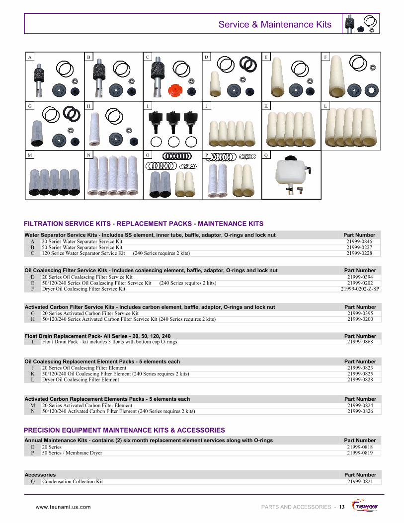
Water Separator Service Kits - Includes SS element, inner tube, baffle, adaptor, O-rings and lock nut Part Number
A 20 Series Water Separator Service Kit 21999-0846 B 50 Series Water Separator Service Kit 21999-0227 C 120 Series Water Separator Service Kit (240 Series requires 2 kits) 21999-0228
Oil Coalescing Filter Service Kits - Includes coalescing element, baffle, adaptor, O-rings and lock nut Part Number
D 20 Series Oil Coalescing Filter Service Kit 21999-0394 E 50/120/240 Series Oil Coalescing Filter Service Kit (240 Series requires 2 kits) 21999-0202 F Dryer Oil Coalescing Filter Service Kit 21999-0202-Z-SP
Activated Carbon Filter Service Kits - Includes carbon element, baffle, adaptor, O-rings and lock nut Part Number G 20 Series Activated Carbon Filter Service Kit 21999-0395 H 50/120/240 Series Activated Carbon Filter Service Kit (240 Series requires 2 kits) 21999-0200
Float Drain Replacement Pack- All Series - 20, 50, 120, 240 Part Number I Float Drain Pack - kit includes 3 floats with bottom cap O-rings 21999-0868
Oil Coalescing Replacement Element Packs - 5 elements each Part Number J 20 Series Oil Coalescing Filter Element 21999-0823 K 50/120/240 Oil Coalescing Filter Element (240 Series requires 2 kits) 21999-0825 L Dryer Oil Coalescing Filter Element 21999-0828
Activated Carbon Replacement Elements Packs - 5 elements each Part Number
M 20 Series Activated Carbon Filter Element 21999-0824 N 50/120/240 Activated Carbon Filter Element (240 Series requires 2 kits) 21999-0826
Annual Maintenance Kits - contains (2) six month replacement element services along with O-rings Part Number
O 20 Series 21999-0818 P 50 Series / Membrane Dryer 21999-0819
Accessories Part Number
Q Condensation Collection Kit 21999-0821
FILTRATION SERVICE KITS - REPLACEMENT PACKS - MAINTENANCE KITS
A B C D F E
L K J I H G
M N O P Q
PRECISION EQUIPMENT MAINTENANCE KITS & ACCESSORIES
www.tsunami.us.com
14
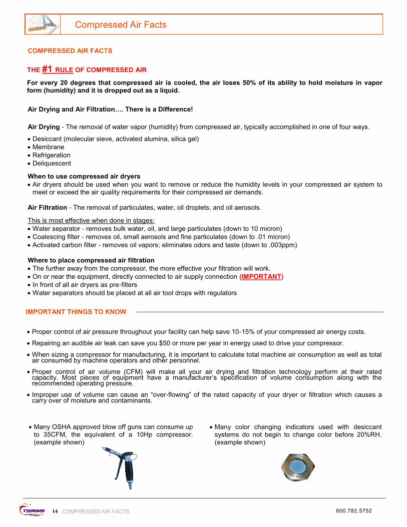
THE #1 RULE OF COMPRESSED AIR For every 20 degrees that compressed air is cooled, the air loses 50% of its ability to hold moisture in vapor form (humidity) and it is dropped out as a liquid.
Air Drying and Air Filtration…. There is a Difference!
Air Drying - The removal of water vapor (humidity) from compressed air, typically accomplished in one of four ways.
Desiccant (molecular sieve, activated alumina, silica gel)
Membrane
Refrigeration
Deliquescent
When to use compressed air dryers
Air dryers should be used when you want to remove or reduce the humidity levels in your compressed air system to meet or exceed the air quality requirements for their compressed air demands.
Air Filtration - The removal of particulates, water, oil droplets, and oil aerosols.
This is most effective when done in stages:
Water separator - removes bulk water, oil, and large particulates (down to 10 micron)
Coalescing filter - removes oil, small aerosols and fine particulates (down to .01 micron)
Activated carbon filter - removes oil vapors; eliminates odors and taste (down to .003ppm) Where to place compressed air filtration
The further away from the compressor, the more effective your filtration will work.
On or near the equipment, directly connected to air supply connection (IMPORTANT)
In front of all air dryers as pre-filters
Water separators should be placed at all air tool drops with regulators
Proper control of air pressure throughout your facility can help save 10-15% of your compressed air energy costs.
Repairing an audible air leak can save you $50 or more per year in energy used to drive your compressor.
When sizing a compressor for manufacturing, it is important to calculate total machine air consumption as well as total air consumed by machine operators and other personnel.
Proper control of air volume (CFM) will make all your air drying and filtration technology perform at their rated capacity. Most pieces of equipment have a manufacturer’s specification of volume consumption along with the recommended operating pressure.
Improper use of volume can cause an “over-flowing” of the rated capacity of your dryer or filtration which causes a carry over of moisture and contaminants.
Many color changing indicators used with desiccant systems do not begin to change color before 20%RH. (example shown)
Many OSHA approved blow off guns can consume up to 35CFM, the equivalent of a 10Hp compressor. (example shown)
Compressed Air Facts
COMPRESSED AIR FACTS
COMPRESSED AIR FACTS
800.782.5752
IMPORTANT THINGS TO KNOW

Facility Analysis
15 FACILITY ANALYSIS
How many compressors are in your facility? ________
If multiple compressors are available, are they set up in series or parallel? _________________
Are any of the compressors used for backup? ___________
What is the system air pressure in the main receiver tank? ________PSI At furthest air drop? ________PSI
Do the compressor(s) or receiver tank(s) have automatic drains? _____Y _____N
Are the drains working? _____Y _____N
Where are the compressor(s) located? (in a closed room, outside, on a mezzanine, etc.) _____________________
Is there a pressure regulator located at or near the compressor for the whole system? _____Y _____N
If yes, what pressure is it set at? (look at pressure gauge) _______PSI
Is the compressor room ventilated? _____Y _____N
If yes, inlet/outlet ventilated? ________ manual or electronic vent control? ___________________
Does the receiver tank of the compressor feel warm to the touch? _____Y _____N
Is there a refrigerated dryer? _____Y _____N
If yes, is it working? _____Y _____N
(This can be determined by grasping the inlet air line and the outlet air line with your hand, one should be warm and
the other should be cool. If there is no difference, it probably is not working.)
Does the refrigerated dryer have pre-filters installed before the unit? _____Y _____N
If there is no refrigerated dryer, is there another type of drying technology being used? _____Y _____N
If yes, what type? _______________________________
Does the drying technology (refrigerated or other) have pre-filters installed before the unit? _____Y _____N
Is the air system a loop system or a “dead end/dead stick” system? ____________________
What is the line size of the main air supply lines in the facility? ______ Line size of air drops off main? ______
Are there air leaks in the piping, at air fittings, or air hose? _____Y _____N
What material is the piping made from? _____Copper _____Black Iron_____ Galvanized _____PVC
Note: Tsunami Compressed Air Solutions™ does not recommend PVC or other plastic piping
How many employees will be using the air system? ________
How many machines consume compressed air? _______ Total CFM required to operate? _______
UNDERSTANDING YOUR COMPRESSED AIR SYSTEM
HP Manufacturer Model Number Piston / Rotary Vane / Rotary Screw
Understanding your facility's compressed air requirements is essential to efficiently and effectively managing the system. By supplying the following information, Tsunami Compressed Air Solutions™ can provide recommendations that will save you money and eliminate costly down time.
www.tsunami.us.com

16
Technical Information - Air Drying
- TECHNICAL INFORMATION - AIR DRYING
REGENERATIVE DRYERS - HOW THEY WORK
Wet Incoming Air - supply air from compressor or from the compressor system
Dry Outgoing Air - air that has had the water vapor removed
Dry Outgoing Air - small amount of dry air used to “sweep” or regenerate the towers
Wet Discharge Air - water vapor which was removed during the drying cycle
THE DRYING PROCESS THE REGENERATION PROCESS
800.782.5752
The technology functions by passing contaminated compressed air through the Tsunami water separator where bulk water and oil is removed down to 10 micron. The air then passes through the oil coalescing filter which further removes oil and particulates down to .01 micron.
The pretreated air enters the dryer and passes through the desiccant canister(s). Molecular sieve desiccant forms a bed encapsulated within a 10 micron filter bag. The molecular sieve bed is spring loaded, under tight compression, virtually eliminating bead movement which causes breakdown of the media.
As the wet air passes through the tower(s), the molecular sieve draws the water vapor in while under pressure. At the same time, one or more tower(s) become depressurized. With the use of sweep air, the towers discharge water vapor through the mufflers located below the dryer manifolds.
The PLC sends out a pilot signal shifting an internal spool. When the spool shifts, air is redirected from the saturated tower(s) to the dried tower(s).
A small amount of air from the dry outlet flow is then directed backward through the wet towers via a small orifice in the regeneration valve. (This is referred to as “sweep air” or the “regeneration process”) The desiccant is dried as the sweep air passes back through the canister(s). The tower is now ready to be cycled again. It’s like changing your desiccant every few minutes.

Technical Information - Air Drying
The Drying Process
17 TECHNICAL INFORMATION - AIR DRYING -
TSUNAMI REGENERATIVE DRYER REFRIGERANT DRYER
Can handle high inlet temperature up to 150°F Max Inlet temperature 100°F
Performs well with high demand surge flows Moisture will carry over during high demand surge flows
No Aftercooler Required Requires Aftercooler
Complete with Tsunami 2-stage pre-filters and automatic drains Must purchase pre-filters and automatic drains separately
Dew points … down to –80°F Dew points … 35-50°F
No refrigerant to maintain Refrigerant to maintain
Works great with low flow rates Low flow rates may allow water carry over at separator
Minimal maintenance required
Change oil coalescing element every 6 months
Regular Maintenance required:
Clean Heat Exchanger
Electric Motor
Refrigerant Compressor
Replace Separator Elements and Float Drain
VS.
Dryer housings are machined from solid aluminum billet. Hard coat anodizing provides superior strength and corrosion resistance.
Dual inlet ports and outlet ports provide for easier installation. The unique design of this modular system also allows compressed air to bypass through the inlet chamber for use of filtered air downstream without having to pass through the drying media.
PLC controller allows for more consistent air flow by staggering tower sequencing.
Tower mounting stud with built-in regeneration valve. The size of the regeneration orifice controls how much air is used by the system to dry the towers. Reducing air volume and increasing orifice size can provide even lower dew points; down to -80°F. See pg. 22 for orifice flow chart.
Moisture Minder® pneumatic drains automatically actuate with the dryer to eliminate any water and oil trapped by the Tsunami pre-filters. Eliminates the need for float drains on our pre-filtration.
Pre-filtration consists of a Tsunami water separator and oil coalescing filter. These units can handle up to a quart of liquid per minute for extremely wet and dirty air systems.
Single piston spool per tower reduces the number of moving components. Allows for easy maintenance.
www.tsunami.us.com
Oil & Liquid Aerosols
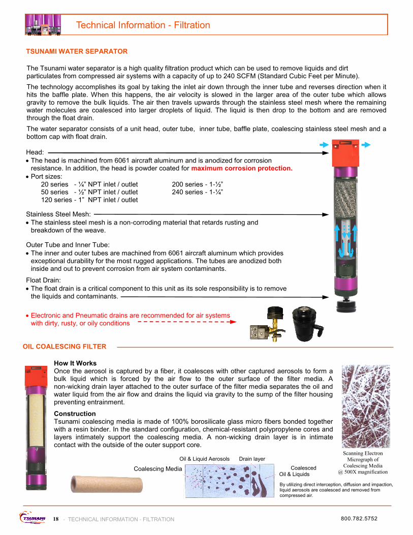
How It Works Once the aerosol is captured by a fiber, it coalesces with other captured aerosols to form a bulk liquid which is forced by the air flow to the outer surface of the filter media. A non-wicking drain layer attached to the outer surface of the filter media separates the oil and water liquid from the air flow and drains the liquid via gravity to the sump of the filter housing preventing entrainment.
Construction Tsunami coalescing media is made of 100% borosilicate glass micro fibers bonded together with a resin binder. In the standard configuration, chemical-resistant polypropylene cores and layers intimately support the coalescing media. A non-wicking drain layer is in intimate contact with the outside of the outer support core.
Scanning Electron
Micrograph of
Coalescing Media @ 500X magnification
Coalesced Oil & Liquids
Drain layer
Coalescing Media
By utilizing direct interception, diffusion and impaction, liquid aerosols are coalesced and removed from compressed air.
OIL COALESCING FILTER
18
Head:
The head is machined from 6061 aircraft aluminum and is anodized for corrosion resistance. In addition, the head is powder coated for maximum corrosion protection.
Port sizes: 20 series - ¼” NPT inlet / outlet 200 series - 1-½” 50 series - ½” NPT inlet / outlet 240 series - 1-¼” 120 series - 1” NPT inlet / outlet
Outer Tube and Inner Tube:
The inner and outer tubes are machined from 6061 aircraft aluminum which provides exceptional durability for the most rugged applications. The tubes are anodized both inside and out to prevent corrosion from air system contaminants.
Stainless Steel Mesh:
The stainless steel mesh is a non-corroding material that retards rusting and breakdown of the weave.
Float Drain:
The float drain is a critical component to this unit as its sole responsibility is to remove the liquids and contaminants.
Electronic and Pneumatic drains are recommended for air systems
with dirty, rusty, or oily conditions
Technical Information - Filtration
- TECHNICAL INFORMATION - FILTRATION
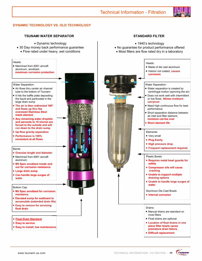
TSUNAMI WATER SEPARATOR
The Tsunami water separator is a high quality filtration product which can be used to remove liquids and dirt particulates from compressed air systems with a capacity of up to 240 SCFM (Standard Cubic Feet per Minute).
The technology accomplishes its goal by taking the inlet air down through the inner tube and reverses direction when it hits the baffle plate. When this happens, the air velocity is slowed in the larger area of the outer tube which allows gravity to remove the bulk liquids. The air then travels upwards through the stainless steel mesh where the remaining water molecules are coalesced into larger droplets of liquid. The liquid is then drop to the bottom and are removed through the float drain.
The water separator consists of a unit head, outer tube, inner tube, baffle plate, coalescing stainless steel mesh and a bottom cap with float drain.
800.782.5752
19
STANDARD FILTER
Heads:
Made of die cast aluminum
Interior not coated, causes
corrosion.
Water Separation:
Water separation is created by
centrifugal motion (spinning the air)
Does not work well with intermittent
or low flows. Allows moisture carryover
Need high continuous flow for best
performance.
Short separation distance between
air inlet and filter element, moisture carries over
Short element life
Elements:
Very small
Plug Easily
High pressure drop
Frequent replacement required
Plastic Bowls:
Requires metal bowl guards for
safety
Compressor oils will cause
cracking
Unable to support multiple
draining options
Unable to handle large surges of
water Aluminum Die Cast Bowls:
Internal corrosion
Drains:
Manual drains are standard on
most filters
Float drains are optional
Location of float drains in one
piece filter bowls cause premature drain failure
Difficult replacement
TSUNAMI WATER SEPARATOR
Heads:
Machined from 6061 aircraft
aluminum, anodized. maximum corrosion protection
Water Separation:
Air flows thru center air channel
tube to the bottom of Tsunami
It hits the baffle plate depositing
the liquid and particulate in the large drain sump
The air is then redirected 180°
and flows up thru the oversized Stainless Steel mesh element
Any remaining water droplets
and aerosols to 10 micron are forced to the outside and will run down to the drain sump.
Up-flow gravity separation
Performance is 100%
consistent at all flows
Barrel:
Oversize length and diameter
Machined from 6061 aircraft
aluminum
Mil Spec anodized inside and
out for corrosion resistance
Large drain sump
Can handle large surges of
water
Bottom Cap:
Mil Spec anodized for corrosion
resistance
Elevated sump for sediment to
accumulate (extended drain life)
Easy to remove for servicing
float drain
Float Drain Standard:
Easy to service
Easy to install; low maintenance
Dynamic Technology vs. Old Technology
Dynamic technology
30 Day money back performance guarantee
Flow rated under heavy, wet conditions
1940’s technology
No guarantee for product performance offered
Most filters are flow rated dry in a laboratory
Technical Information - Filtration
TECHNICAL INFORMATION - FILTRATION -
DYNAMIC TECHNOLOGY VS. OLD TECHNOLOGY
www.tsunami.us.com

1) Pilot Signal Received
Condensation enters left hand, or water inlet of valve.
3) Valve at Rest 2) Pilot Signal From Unloader
Pilot signal is applied to air inlet. Piston will shift, closing off drain port. As piston continues to move it will open up the stainless ball check allowing condensate to be forced into the internal or external reservoir creating a discharge pressure.
When pilot signal is relieved, piston returns to relaxed position. The ball check closes first preventing zero pressure loss in the system. The drain port then opens and stored condensate is ejected from the drain port.
20
Moisture Minder I
Technical Information - Pneumatic Drains
- TECHNICAL INFORMATION - PNEUMATIC DRAINS
MOISTURE MINDER FILTER DRAIN ASSEMBLY
1) Pilot Signal Received
Condensation rests in the bottom of the filter housing, waiting for the drain to be actuated.
3) Valve at Rest 2) Pilot Signal From Unloader
Pilot signal causes piston to shift, closing off drain port. As piston continues to move it will open up the stainless ball check allowing condensate to be forced into the internal reservoir creating a discharge pressure.
MOISTURE MINDER I - MOISTURE MINDER II
When pilot signal is relieved, piston returns to relaxed position. The ball check closes, preventing zero pressure loss in system. The drain port opens and stored condensate is ejected from the drain port.
800.782.5752

21
Condensate enters through the inlet side of the valve. Debris is captured inside the internal strainer.
Only open 1/4” ball valve to clean strainer or to manually drain the tank.
MOISTURE MINDER EDV ELECTRIC SOLENOID VALVE
Technical Information - Electronic Drains
TECHNICAL INFORMATION - ELECTRONIC DRAINS -
1) Timer actuates 3) Manual Straining 2) Debris is ejected
When valve activates condensate flows thru strainer up to the orifice and out the back discharge port. Debris is captured by internal strainer which prevents fouling of orifice.
DRAIN MINDER II AUTOMATIC TIMER
Supply Air
Pilot Signal
The Drain Minder II can deliver the pilot signal needed to operate the Moisture Minder pneumatic drain valves when no other intermittent pilot signal is available. The control is installed in the typical system by teeing into a filtered air supply and connecting the supply line to the inlet side of the controller solenoid.
www.tsunami.us.com

Technical Information - Configuring Custom Dryers
22 - TECHNICAL INFORMATION - CONFIGURING CUSTOM DRYERS
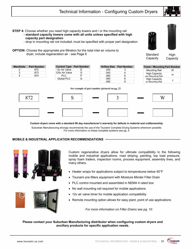
HOW TO CREATE YOUR CUSTOM DRYER P/N
STEP 3: Choose the orifice size for the appropriate amount of regeneration air needed - High capacity towers require a minimum .060 orifice size . - 3 tower dryers should use minimum .045 orifice size
STEP 1: Choose the number of dryer manifolds needed; this is determined by the number of towers required; tower quantity based on tower air flow capacity. - Standard capacity towers rated @ 28 cfm each - High capacity towers rated @ 40 cfm each
*** Important: You must subtract the regeneration volume from the dryer capacity to properly size a dryer, see orifice chart in step 3***
STEP 2: Choose your control type:
- 3 tower dryers require a PLC control:
(2 towers in drying cycle and 1 tower in regeneration cycle)
- 4 tower dryers regenerate either 1 or 2 towers
- 4 tower dryer with air valve:
(2 towers in drying cycle and 2 towers in regeneration cycle)
- 4 tower dryer with PLC:
(3 towers in drying cycle and 1 tower in regeneration cycle)
CUSTOM REGENERATIVE DRYERS
Our custom regenerative dryers allow flexibility for your specific application: transportation, industrial, medical/dental, agricultural, and other uses. When space is limited for dryer installations, our regenerative dryers allow for versatile installation options too.
Specific information is needed when customizing a dryer to make certain that the dryer’s performance will meet the air quality requirements.
Do you need exceptionally dry air for the entire facility?
If YES: What is the dew point / relative humidity desired? What is the air output flow of compressor system? What is the maximum outlet pressure of compressor system? What is the system pressure needed for the facility? What is the duty cycle of the compressor(s)?
If NO: What is the dew point / relative humidity desired for the specific application requiring dry air? What is the air consumption (flow rate) of the application or process? What is the system pressure in the facility? What is the pressure required for the specific application or process? What is the duty cycle of the application or process?
P/N 872 - S - 3 - W
0.015 0.030 0.045 0.060 0.080 0.090
100 psi 0.4 1.5 3.4 6 10.7 13.5
125 psi 0.5 1.9 4.1 7.3 13 16.4
150 psi 0.6 2.2 5 8.6 15.3 19.5
175 psi 0.7 2.5 5.6 10 17.5 22.3
Dryer Inlet Pressure
Orifice Diameter
Regeneration Volume Consumed by Dryer - CFM
PLC Air Valve
Example shown in
ordering matrix on pg. 23
Dryer Manifolds
Regeneration Valve Orifice
800.782.5752
Technical Information - Configuring Custom Dryers
23 TECHNICAL INFORMATION - MOBILE & INDUSTRIAL -
Manifolds Part Number
2 872
3 873
4 874
Control Type Part Number
12v Air Valve D
120v Air Valve S
PLC P
Global PLC G
Orifice Size Part Number
.030 3
.045 4
.060 6
.080 8
.090 9
Tower / Mounting Part Number
Mounting Rail W
High Capacity w/o Mounting Rail
H
High Capacity w/ Mounting Rail
J
872 S 3 W
Custom dryers come with a standard 90 day manufacturer’s warranty for defects in material and craftsmanship.
Suburban Manufacturing strongly recommends the use of the Tsunami Complete Drying Systems whenever possible. For more information on these complete systems see pg. 4.
STEP 4: Choose whether you need high capacity towers and / or the mounting rail - standard capacity towers come with all units unless specified with high capacity part designation - drop in mounting rail not included; must be specified with proper part designation
OPTION: Choose the appropriate pre-filtration for the total inlet air volume to dryer; include regeneration air - see Page 6
Custom regenerative dryers allow for ultimate compatibility in the following mobile and industrial applications: road striping, painting, top load pressure, spray foam trailers, inspection rooms, process equipment, assembly lines, and many others.
Standard Capacity
High Capacity
MOBILE & INDUSTRIAL APPLICATION RECOMMENDATIONS
See example of part number pictured on pg. 22
Heater wraps for applications subject to temperatures below 40°F
Tsunami pre-filters equipment with Moisture Minder Filter Drain
PLC control mounted and assembled in NEMA 4 rated box
No wall mounting rail required for mobile applications
12v air valve timer for mobile application compatibility
Remote mounting option allows for easy plant, point of use applications
For more information on Filter Drains see pg. 10
Please contact your Suburban Manufacturing distributor when configuring custom dryers and ancillary products for specific application needs.
www.tsunami.us.com
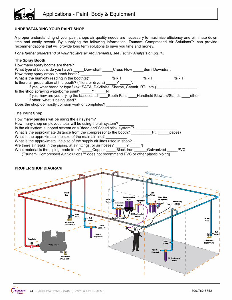
The Spray Booth
How many spray booths are there? __________ What type of booths do you have? _____Downdraft _____Cross Flow _____Semi Downdraft How many spray drops in each booth? __________ What is the humidity reading in the booth(s)? __________%RH __________%RH __________%RH Is there air preparation at the booth? (filters or dryers) _____Y _____N If yes, what brand or type? (ex: SATA, DeVilbiss, Sharpe, Camair, RTI, etc.) ___________________ Is the shop spraying waterborne paint? _____Y _____N If yes, how are you drying the basecoats? ____Booth Fans ____Handheld Blowers/Stands ____other If other, what is being used? ____________________ Does the shop do mostly collision work or completes? ____________________
The Paint Shop
How many painters will be using the air system? _______ How many shop employees total will be using the air system? _______ Is the air system a looped system or a “dead end”/”dead stick system”? ____________________ What is the approximate distance from the compressor to the booth? __________Ft. (_____paces) What is the approximate line size of the main air line? __________ What is the approximate line size of the supply air lines used in shop? ________ Are there air leaks in the piping, at air fittings, or air hoses? _____Y _____N What material is the piping made from? _____Copper _____Black Iron ______Galvanized _____PVC (Tsunami Compressed Air Solutions™ does not recommend PVC or other plastic piping)
A proper understanding of your paint shops air quality needs are necessary to maximize efficiency and eliminate down time and costly rework. By supplying the following information, Tsunami Compressed Air Solutions™ can provide recommendations that will provide long term solutions to save you time and money.
UNDERSTANDING YOUR PAINT SHOP
PROPER SHOP DIAGRAM
24 - APPLICATIONS - PAINT, BODY & EQUIPMENT
Applications - Paint, Body & Equipment
800.782.5752
For a further understand of your facility's air requirements, see Facility Analysis on pg. 15
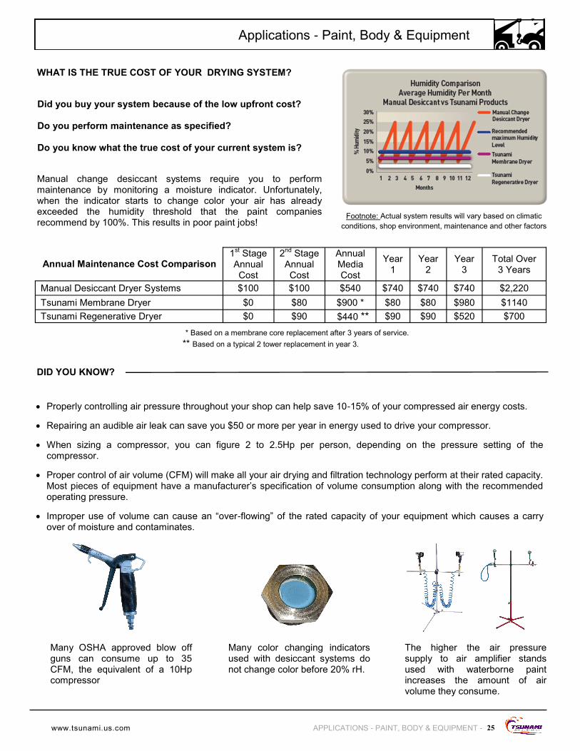
Manual change desiccant systems require you to perform maintenance by monitoring a moisture indicator. Unfortunately, when the indicator starts to change color your air has already exceeded the humidity threshold that the paint companies recommend by 100%. This results in poor paint jobs!
Footnote: Actual system results will vary based on climatic
conditions, shop environment, maintenance and other factors
Did you buy your system because of the low upfront cost? Do you perform maintenance as specified? Do you know what the true cost of your current system is?
DID YOU KNOW?
The higher the air pressure supply to air amplifier stands used with waterborne paint increases the amount of air volume they consume.
WHAT IS THE TRUE COST OF YOUR DRYING SYSTEM?
Annual Maintenance Cost Comparison 1
st Stage
Annual Cost
2nd
Stage Annual Cost
Annual Media Cost
Year 1
Year 2
Year 3
Total Over 3 Years
Manual Desiccant Dryer Systems $100 $100 $540 $740 $740 $740 $2,220
Tsunami Membrane Dryer $0 $80 $900 * $80 $80 $980 $1140
Tsunami Regenerative Dryer $0 $90 $440 ** $90 $90 $520 $700
Many color changing indicators used with desiccant systems do not change color before 20% rH.
Many OSHA approved blow off guns can consume up to 35 CFM, the equivalent of a 10Hp compressor
Properly controlling air pressure throughout your shop can help save 10-15% of your compressed air energy costs.
Repairing an audible air leak can save you $50 or more per year in energy used to drive your compressor.
When sizing a compressor, you can figure 2 to 2.5Hp per person, depending on the pressure setting of the compressor.
Proper control of air volume (CFM) will make all your air drying and filtration technology perform at their rated capacity. Most pieces of equipment have a manufacturer’s specification of volume consumption along with the recommended operating pressure.
Improper use of volume can cause an “over-flowing” of the rated capacity of your equipment which causes a carry over of moisture and contaminates.
25 APPLICATIONS - PAINT, BODY & EQUIPMENT -
Applications - Paint, Body & Equipment
www.tsunami.us.com
* Based on a membrane core replacement after 3 years of service.
** Based on a typical 2 tower replacement in year 3.

Waterborne Ready Systems
Low Relative Humidity - down to .01%
Low Dew Points - down to –80°F
Low cost to maintain - under $100/yr on average
Easy maintenance - replace coalescing filter every 6 months
Expandable Drying Technology - Does not require buying new,
larger dryer to increase shop’s capacity
Single Booth Package - 1 Drop - Waterborne
Double Booth Package - 2 Drops - Solvent *
Recommended P/Ns:
(1) 21999-0710 10Hp Tsunami Regenerative Drying System
(1) 21999-0494 Tsunami Filtration Package #7
(1) 21999-0449 35’ Tsunami Ultra-flo Spray Hose
Double Booth Package - 2 Drops - Waterborne
Triple Booth Package - 3 Drops - Solvent *
Recommended P/Ns:
(1) 21999-0715 15Hp Tsunami Regenerative Drying System
(2) 21999-0494 Tsunami Filtration Package #7
(2) 21999-0449 35’ Tsunami Ultra-flo Spray Hose
4+ Booth Package - Up to 6 Drops - Waterborne
Recommended P/Ns:
(1) 21999-0830 30Hp Tsunami Ultra Drying System
(4+) 21999-0494 Tsunami Filtration Package #7
(4+) 21999-0449 35’ Tsunami Ultra-flo Spray Hose
Applications - Paint, Body & Equipment
26 - APPLICATIONS - PAINT, BODY & EQUIPMENT
SOLVENT & WATERBORNE SPRAY BOOTH PACKAGES
P/N: 21999-0677 P/N: 21999-0678
These filter systems should only be used for light use applications such as air brushing, waterborne gun cleaners, and spot welders. For normal to heavy use conditions, use our 50 CFM Filter packages.
SPECIALTY SPRAY PACKAGES
Special spray package with water separator, oil coalescing filter and regulator
Package #4 - 20CFM
Special spray package with water separator, oil coalescing filter, activated carbon filter and regulator
Package #6 - 20CFM
For more information on 20 CFM filtration packages see pg. 7
* Additional filter and hose needed for 2 drop solvent application
* Additional filter and hose needed for 3 drop solvent application
For more information on Complete Tsunami Drying Systems see pgs. 4-5
800.782.5752

Applications - Paint, Body & Equipment
27 APPLICATIONS - PAINT, BODY & EQUIPMENT -
PAINT SHOP SOLUTIONS
3-year Warranty
Built-in bypass circuit
80 gallon storage tank for storing exceptionally dry air
Large Tsunami water separator and oil coalescing filter to pre-filter incoming air
Moisture Minder automatic piston drains for pre-filters
Outlet regulator allows for air conservation throughout facility
Easy installation - unit comes preassembled (as shown)
Maximizing your shop’s performance is one of Suburban Manufacturing's main focuses. Whether drying the air for the paint shop or the entire facility, the Tsunami Ultra Drying Systems provide “the solution” for clean, dry air. Our Ultra Systems provide easy installation and additional storage which helps reduce the shop’s ability to overrun the drying system.
Wall mounted units provide the best solution for your facility when space is limited.
Systems are available from 10-30Hp.
**REMINDER**
Add Your Booth Filtration Package, Spray Hose and Compressor Drain Kit **Components must be ordered separately from drying systems**
P/N: 21999-0494
Package #7 - 50CFM
Oil coalescing filter and regulator
P/N: 21999-0253
Package #4 - 50CFM
Water separator, oil coalescing filter and regulator
P/N: 21999-0257
Package #6 - 50CFM
Water separator, oil coalescing filter, activated carbon filter and regulator
GOOD FILTRATION BETTER FILTRATION BEST FILTRATION
For more information on Complete Tsunami Drying Systems see pgs. 4-5
P/N: 21999-0449
35’ Tsunami Ultra-flo Spray Hose
P/N: 21999-0450
50’ Tsunami Ultra-flo Spray Hose
P/N: 21999-0177
Moisture Minder EDV
P/N: 21999-0316
EDV Basic Installation Kit
www.tsunami.us.com

application-based products . Suburban is an engineering driven organization that partners with our customers to design and develop unique and specific solutions for multiple application specific needs in the Defense, Hydraulics, Oil & Gas, Automotive, Agriculture, Construction & Utility and Industrial markets. In addition to custom engineered solutions, Suburban offers a complete line of standard products sold under the Protective Coverings, Lubrication Systems and Tsunami brands.
Distributed By:
Offers a complete line of protective sleeves, straps and
engine blankets manufactured from a variety of custom fabrics to provide
equipment and operator protection. The division manufactures custom engi-
neered-to-order solutions per customer specifications for a wide variety of industries and specific application
needs.
Toll Free: 800.782.5752 Phone: 763.295.5635 Fax: 763.295.5752
web: www.gosuburban.com e-mail: [email protected]
Offers a compete line of automatic chain oilers and grease
systems. In addition, the division provides custom engineered solutions to a
multitude of customers with unique applications.
Offers a complete line of products engineered to give customers dry clean air for their specific application
demands. Our systems use the latest technology to provide the highest quality
compressed air available.
At Suburban.Manufacturing,.Inc., our mission is to build value for our customers by producing quality, innovative, engineered,