Embed Size (px)
Citation preview

© 2018 Oskitone For OKAY Synth DIY Kit Version 1.1.1 http://www.oskitone.com/product/okay-synth-diy-kit OKAY 2 Synth DIY Kit Version 2.1 http://www.oskitone.com/product/okay-2-synth-diy-kit Last updated 2018-02-18 All rights reserved. This book or any portion thereof may not be reproduced or used in any manner whatsoever without the express written permission of the publisher except for the use of brief quotations in a book review. http://www.oskitone.com/ Instagram/Twitter: @oskitone
Hello! Thank you and congrats on your new OKAY DIY Kit! Please let me know how it goes, what you think, and/or if you run into any trouble. Reach me at [email protected]. You can also find last minute guide updates, extra assembly information, and videos at http://www.oskitone.com/guides Otherwise, good luck, take your time, and have fun! -Tommy
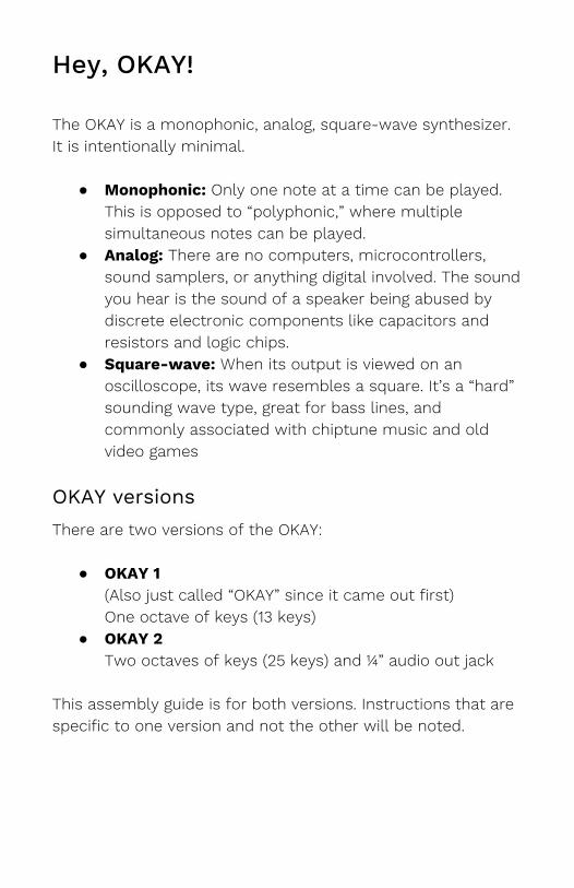
Hey, OKAY! The OKAY is a monophonic, analog, square-wave synthesizer. It is intentionally minimal.
● Monophonic: Only one note at a time can be played. This is opposed to “polyphonic,” where multiple simultaneous notes can be played.
● Analog: There are no computers, microcontrollers, sound samplers, or anything digital involved. The sound you hear is the sound of a speaker being abused by discrete electronic components like capacitors and resistors and logic chips.
● Square-wave: When its output is viewed on an oscilloscope, its wave resembles a square. It’s a “hard” sounding wave type, great for bass lines, and commonly associated with chiptune music and old video games
OKAY versions There are two versions of the OKAY:
● OKAY 1 (Also just called “OKAY” since it came out first) One octave of keys (13 keys)
● OKAY 2 Two octaves of keys (25 keys) and ¼” audio out jack
This assembly guide is for both versions. Instructions that are specific to one version and not the other will be noted.
Table of Contents
1. 3D-Printing instructions a. Slicing b. Post-printing
2. What’s in the box a. Inventory b. Tools (not in the box)
3. Enclosure assembly 4. PCB assembly
a. General tips b. Connecting wires c. Wiring diagram d. 386 0.1.1
i. Wiring the ¼” jack (for OKAY 2 only) e. 555_4040 01.1.1
i. Wiring the rotary switch f. bus 0.1.1
i. Polarity on middle pads g. SPST_VR 0.2.2
i. Wiring for OKAY 2 5. Putting it all together
a. Testing and debugging b. Final assembly c. Tuning d. Care
6. Appendix: Circuit schematics
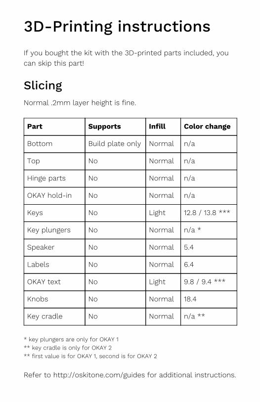
3D-Printing instructions If you bought the kit with the 3D-printed parts included, you can skip this part!
Slicing Normal .2mm layer height is fine.
Part Supports Infill Color change
Bottom Build plate only Normal n/a
Top No Normal n/a
Hinge parts No Normal n/a
OKAY hold-in No Normal n/a
Keys No Light 12.8 / 13.8 ***
Key plungers No Normal n/a *
Speaker No Normal 5.4
Labels No Normal 6.4
OKAY text No Light 9.8 / 9.4 ***
Knobs No Normal 18.4
Key cradle No Normal n/a **
* key plungers are only for OKAY 1 ** key cradle is only for OKAY 2 ** first value is for OKAY 1, second is for OKAY 2
Refer to http://oskitone.com/guides for additional instructions.
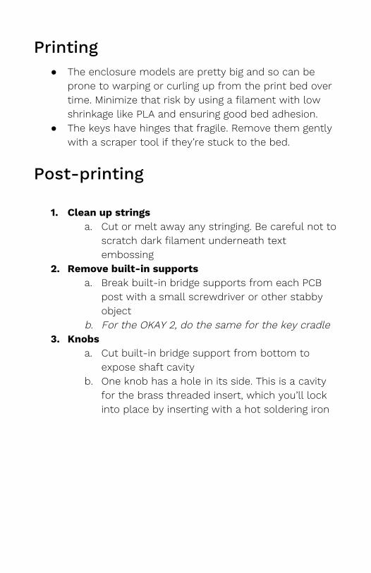
Printing ● The enclosure models are pretty big and so can be
prone to warping or curling up from the print bed over time. Minimize that risk by using a filament with low shrinkage like PLA and ensuring good bed adhesion.
● The keys have hinges that fragile. Remove them gently with a scraper tool if they’re stuck to the bed.
Post-printing
1. Clean up strings
a. Cut or melt away any stringing. Be careful not to scratch dark filament underneath text embossing
2. Remove built-in supports a. Break built-in bridge supports from each PCB
post with a small screwdriver or other stabby object
b. For the OKAY 2, do the same for the key cradle 3. Knobs
a. Cut built-in bridge support from bottom to expose shaft cavity
b. One knob has a hole in its side. This is a cavity for the brass threaded insert, which you’ll lock into place by inserting with a hot soldering iron
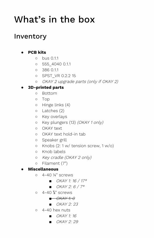
What’s in the box
Inventory
● PCB kits ○ bus 0.1.1 ○ 555_4040 0.1.1 ○ 386 0.1.1 ○ SPST_VR 0.2.2 15 ○ OKAY 2 upgrade parts (only if OKAY 2)
● 3D-printed parts ○ Bottom ○ Top ○ Hinge links (4) ○ Latches (2) ○ Key overlays ○ Key plungers (13) (OKAY 1 only) ○ OKAY text ○ OKAY text hold-in tab ○ Speaker grill ○ Knobs (2: 1 w/ tension screw, 1 w/o) ○ Knob labels ○ Key cradle (OKAY 2 only) ○ Filament (7”)
● Miscellaneous ○ 4-40 ¼” screws
■ OKAY 1: 16 / 17* ■ OKAY 2: 6 / 7*
○ 4-40 ⅜” screws ■ OKAY 1: 0 ■ OKAY 2: 23
○ 4-40 hex nuts ■ OKAY 1: 16 ■ OKAY 2: 29
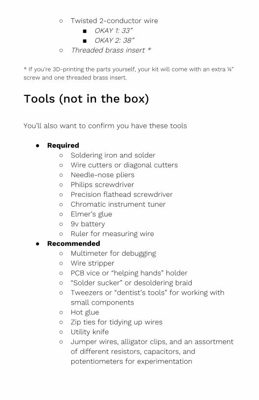
○ Twisted 2-conductor wire ■ OKAY 1: 33” ■ OKAY 2: 38”
○ Threaded brass insert * * If you’re 3D-printing the parts yourself, your kit will come with an extra ¼” screw and one threaded brass insert.
Tools (not in the box) You’ll also want to confirm you have these tools
● Required ○ Soldering iron and solder ○ Wire cutters or diagonal cutters ○ Needle-nose pliers ○ Philips screwdriver ○ Precision flathead screwdriver ○ Chromatic instrument tuner ○ Elmer’s glue ○ 9v battery ○ Ruler for measuring wire
● Recommended ○ Multimeter for debugging ○ Wire stripper ○ PCB vice or “helping hands” holder ○ “Solder sucker” or desoldering braid ○ Tweezers or “dentist’s tools” for working with
small components ○ Hot glue ○ Zip ties for tidying up wires ○ Utility knife ○ Jumper wires, alligator clips, and an assortment
of different resistors, capacitors, and potentiometers for experimentation
Enclosure assembly
1. Back hinges a. With one hand, hold an anchor link into its
cavity on the enclosure bottom b. With the other hand, thread filament through
holes c. Repeat for all hinge links, cutting filament with a
small amount of slack (maybe 1/16”) d. Put the enclosure top on, and repeat
2. Front clasps a. Just like you did for the hinges on the back,
thread the clasps onto the front with filament. There are no separate link parts
3. OKAY text a. Place the OKAY text into its place on the
enclosure top b. Secure its underside with the hold-in tab
4. Keys a. For the OKAY 1:
i. Pull the key overlays in through the top of the enclosure and affix onto the row of dovetails. Gently push into place
ii. Using a smalls screwdriver in its holed tabs, pull the keys more securely onto the enclosure top
b. For the OKAY 2: i. You’ll first need to solder the SPST_VR
PCBs, so skip this part for now and follow assembly instructions later.
5. Key plunger pegs (for OKAY 1 only) a. With the lid open and the key underside facing
up, carefully drop a small amount of glue into each of the peg cavities
b. Gently twist each peg into its cavity (The plastic on these pegs is thin and fragile. If
you break one, the glue will still hold it in place, but still try not to!)
6. Secure hinge and clasp filament a. Optionally, secure the hinge and clasp filament
in place with either a dab of glue or by melting it in place with a soldering iron. (Do the latter in a well-ventilated space, please.)
7. Finish OKAY text a. With the enclosure closed and the OKAY text
secured by both its hold-in tab and the key overlays, put a small amount of glue in the cavities in its “O” and “A” letters
b. Place the corresponding filler pieces into each cavity
c. Wipe up any residue glue and leave to dry
PCB assembly
General tips
● Soldering This guide assumes you already know how to solder. If you don’t, don’t worry! There are plenty of really good guides online; I recommend the “Adafruit Guide To Excellent Soldering”.
● IC chips are static-sensitive The included IC chips, especially the CD4040, can be damaged by static electricity. Leave them in their packaging until ready to install. Before handling, discharge any static electricity on your body by touching a large piece of metal
● Ceramic and electrolytic capacitors There are two kinds of “caps” used in this kit. Ceramic capacitors are small, circular, and have no polarity; they can be placed in either direction. Electrolytic caps are bigger, cylindrical, and have marked +/- polarities.
● Component naming conventions For these PCBS, C = capacitor, R = resistor. Headers are typically labelled what they are.
● Vertical resistors To save space, all the resistors stand vertically instead of lay flat on the PCB
● Capacitor footprints are small Also to save space, the capacitors all have soldering holes that are just slightly too close. You’ll have to pull them through from the PCB’s underside with pliers. I’ll fix this in future iterations.
● Component polarities Some components like LEDs, batteries, and electrolytic capacitors have positive and negative leads. The PCB will be labeled where each lead goes, if applicable.
● Wire polarity This kit includes 2 conductor twisted wire, which you’ll use to connect the various boards together. To ensure polarities match between connections, a good convention is to have the lighter wire be positive and the darker wire negative.
● Resistor and capacitor labeling Resistors use a color code to denote their value and ceramic capacitors have a number system. Where appropriate, the color or number will be noted for your reference so you can choose the right one.
● Bypass capacitors All the ICs use what’s called a bypass or decoupling capacitor to prevent noise from other parts of the circuit or even from the power itself from affecting its IC.
● ICs in sockets Each IC chip comes with a corresponding socket with the same number of pins. You will solder the socket to the PCB, not the chip itself. This prevents overheating the IC with the soldering iron and makes it easier to switch a faulty one out.
● Stripping and twisting stranded wire All wires in this kit are stranded (instead of solid core) to bend more easily without fatigue. To make inserting into PCB holes easier, twist the strands together immediately after stripping off the plastic coating.
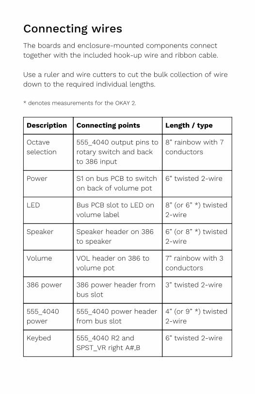
Connecting wires The boards and enclosure-mounted components connect together with the included hook-up wire and ribbon cable. Use a ruler and wire cutters to cut the bulk collection of wire down to the required individual lengths. * denotes measurements for the OKAY 2.
Description Connecting points Length / type
Octave selection
555_4040 output pins to rotary switch and back to 386 input
8” rainbow with 7 conductors
Power S1 on bus PCB to switch on back of volume pot
6” twisted 2-wire
LED Bus PCB slot to LED on volume label
8” (or 6” *) twisted 2-wire
Speaker Speaker header on 386 to speaker
6” (or 8” *) twisted 2-wire
Volume VOL header on 386 to volume pot
7” rainbow with 3 conductors
386 power 386 power header from bus slot
3” twisted 2-wire
555_4040 power
555_4040 power header from bus slot
4” (or 9” *) twisted 2-wire
Keybed 555_4040 R2 and SPST_VR right A#,B
6” twisted 2-wire
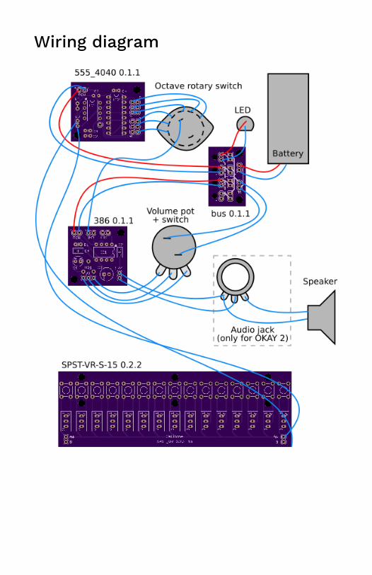
Wiring diagram
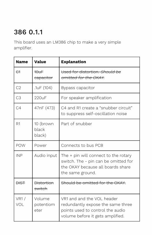
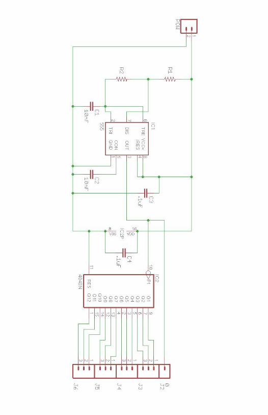
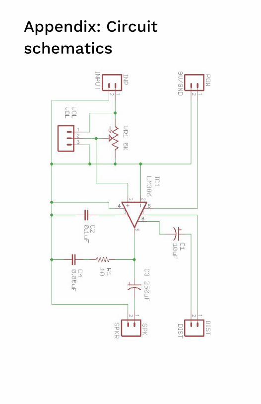
386 0.1.1 This board uses an LM386 chip to make a very simple amplifier.
Name Value Explanation
C1 10uF capacitor
Used for distortion. Should be omitted for the OKAY.
C2 .1uF (104) Bypass capacitor
C3 220uF For speaker amplification
C4 47nF (473) C4 and R1 create a “snubber circuit” to suppress self-oscillation noise
R1 10 (brown black black)
Part of snubber
POW Power Connects to bus PCB
INP Audio input The + pin will connect to the rotary switch. The - pin can be omitted for the OKAY because all boards share the same ground.
DIST Distortion switch
Should be omitted for the OKAY.
VR1 / VOL
Volume potentiometer
VR1 and and the VOL header redundantly expose the same three points used to control the audio volume before it gets amplified.
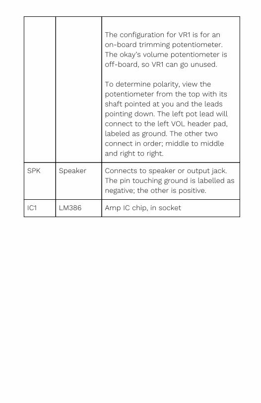
The configuration for VR1 is for an on-board trimming potentiometer. The okay’s volume potentiometer is off-board, so VR1 can go unused. To determine polarity, view the potentiometer from the top with its shaft pointed at you and the leads pointing down. The left pot lead will connect to the left VOL header pad, labeled as ground. The other two connect in order; middle to middle and right to right.
SPK Speaker Connects to speaker or output jack. The pin touching ground is labelled as negative; the other is positive.
IC1 LM386 Amp IC chip, in socket
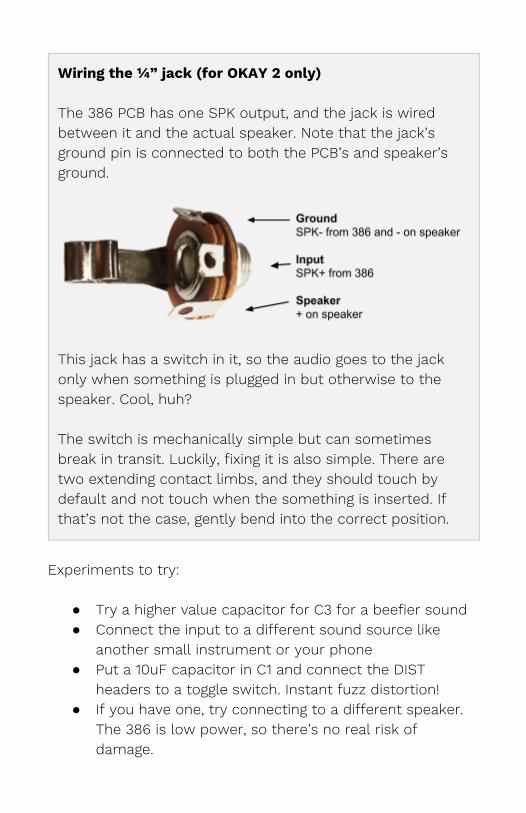
Wiring the ¼” jack (for OKAY 2 only) The 386 PCB has one SPK output, and the jack is wired between it and the actual speaker. Note that the jack’s ground pin is connected to both the PCB’s and speaker’s ground.
This jack has a switch in it, so the audio goes to the jack only when something is plugged in but otherwise to the speaker. Cool, huh? The switch is mechanically simple but can sometimes break in transit. Luckily, fixing it is also simple. There are two extending contact limbs, and they should touch by default and not touch when the something is inserted. If that’s not the case, gently bend into the correct position.
Experiments to try:
● Try a higher value capacitor for C3 for a beefier sound ● Connect the input to a different sound source like
another small instrument or your phone ● Put a 10uF capacitor in C1 and connect the DIST
headers to a toggle switch. Instant fuzz distortion! ● If you have one, try connecting to a different speaker.
The 386 is low power, so there’s no real risk of damage.
● The included potentiometer is linear but would actually be better if it were logarithmic, due to the way humans interpret volume. Luckily, it’s easy to to approximate a logarithmic response by connecting the ground and output pins (left and middle, when viewed from the top) with a smaller resistor. Further investigation is left as an exercise for the reader. (Hint: google “fake log pot”)
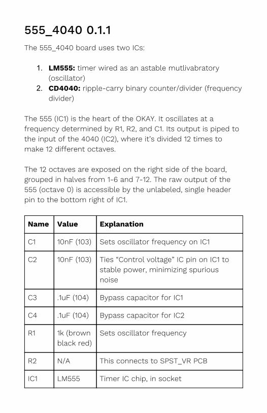
555_4040 0.1.1 The 555_4040 board uses two ICs:
1. LM555: timer wired as an astable mutlivabratory (oscillator)
2. CD4040: ripple-carry binary counter/divider (frequency divider)
The 555 (IC1) is the heart of the OKAY. It oscillates at a frequency determined by R1, R2, and C1. Its output is piped to the input of the 4040 (IC2), where it’s divided 12 times to make 12 different octaves. The 12 octaves are exposed on the right side of the board, grouped in halves from 1-6 and 7-12. The raw output of the 555 (octave 0) is accessible by the unlabeled, single header pin to the bottom right of IC1.
Name Value Explanation
C1 10nF (103) Sets oscillator frequency on IC1
C2 10nF (103) Ties “Control voltage” IC pin on IC1 to stable power, minimizing spurious noise
C3 .1uF (104) Bypass capacitor for IC1
C4 .1uF (104) Bypass capacitor for IC2
R1 1k (brown black red)
Sets oscillator frequency
R2 N/A This connects to SPST_VR PCB
IC1 LM555 Timer IC chip, in socket
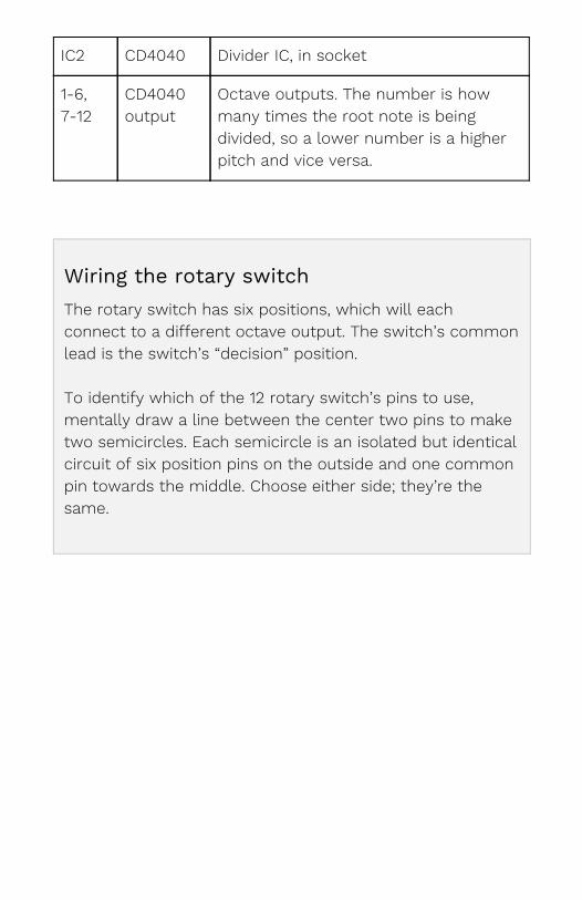
IC2 CD4040 Divider IC, in socket
1-6, 7-12
CD4040 output
Octave outputs. The number is how many times the root note is being divided, so a lower number is a higher pitch and vice versa.
Wiring the rotary switch The rotary switch has six positions, which will each connect to a different octave output. The switch’s common lead is the switch’s “decision” position. To identify which of the 12 rotary switch’s pins to use, mentally draw a line between the center two pins to make two semicircles. Each semicircle is an isolated but identical circuit of six position pins on the outside and one common pin towards the middle. Choose either side; they’re the same.
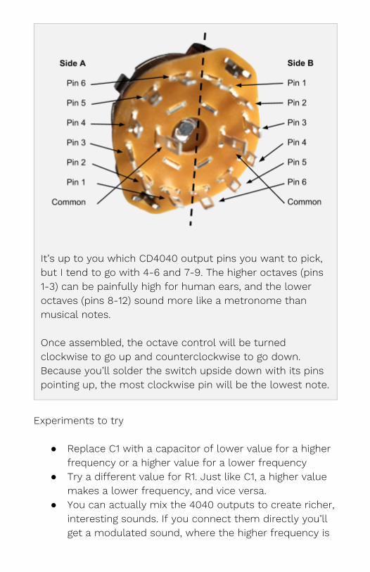
It’s up to you which CD4040 output pins you want to pick, but I tend to go with 4-6 and 7-9. The higher octaves (pins 1-3) can be painfully high for human ears, and the lower octaves (pins 8-12) sound more like a metronome than musical notes. Once assembled, the octave control will be turned clockwise to go up and counterclockwise to go down. Because you’ll solder the switch upside down with its pins pointing up, the most clockwise pin will be the lowest note.
Experiments to try
● Replace C1 with a capacitor of lower value for a higher frequency or a higher value for a lower frequency
● Try a different value for R1. Just like C1, a higher value makes a lower frequency, and vice versa.
● You can actually mix the 4040 outputs to create richer, interesting sounds. If you connect them directly you’ll get a modulated sound, where the higher frequency is
only audible when the lower frequency allows. If you send each output through its own resistor (maybe around 10k ohm), their sounds will mix together instead of modulate.
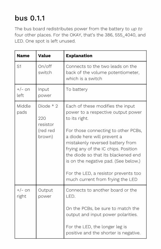
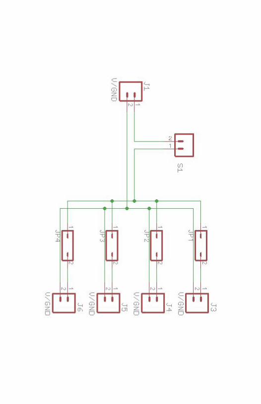
bus 0.1.1 The bus board redistributes power from the battery to up to four other places. For the OKAY, that’s the 386, 555_4040, and LED. One spot is left unused.
Name Value Explanation
S1 On/off switch
Connects to the two leads on the back of the volume potentiometer, which is a switch
+/- on left
Input power
To battery
Middle pads
Diode * 2 220 resistor (red red brown)
Each of these modifies the input power to a respective output power to its right. For those connecting to other PCBs, a diode here will prevent a mistakenly reversed battery from frying any of the IC chips. Position the diode so that its blackened end is on the negative pad. (See below.) For the LED, a resistor prevents too much current from frying the LED
+/- on right
Output power
Connects to another board or the LED. On the PCBs, be sure to match the output and input power polarities. For the LED, the longer leg is positive and the shorter is negative.
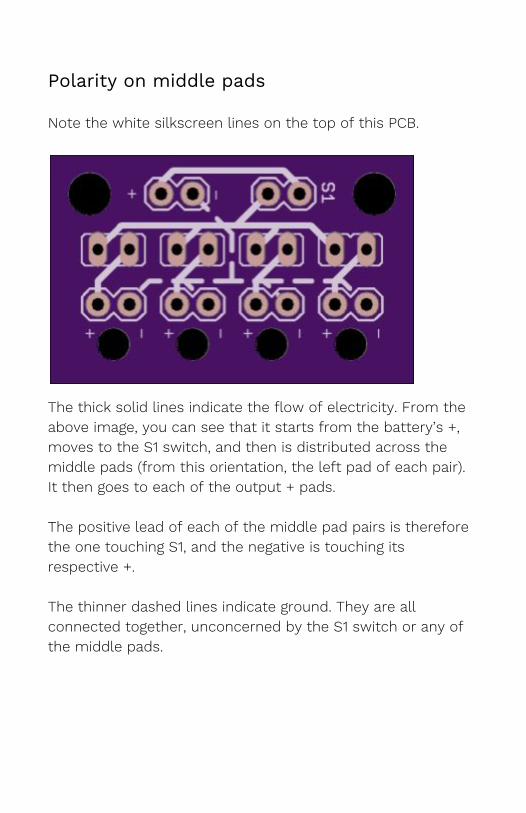
Polarity on middle pads
Note the white silkscreen lines on the top of this PCB.
The thick solid lines indicate the flow of electricity. From the above image, you can see that it starts from the battery’s +, moves to the S1 switch, and then is distributed across the middle pads (from this orientation, the left pad of each pair). It then goes to each of the output + pads. The positive lead of each of the middle pad pairs is therefore the one touching S1, and the negative is touching its respective +. The thinner dashed lines indicate ground. They are all connected together, unconcerned by the S1 switch or any of the middle pads.
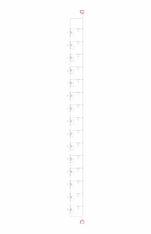
SPST_VR 0.2.2 This board effectively functions as one big potentiometer. Its name derives from the Single Pole Single Throw (SPST) pushbuttons and Variable Resistor (VR) trimming potentiometers.
Name Value Explanation
SPST (top)
Pushbuttons * 13 Key button, each to a specific note on the scale
VR (middle)
Trimming potentiometers (or trimpots) * 13
Tunes each note For the OKAY 1, the buttons and potentiometers are soldered onto the same side of the PCB. On the OKAY 2, the potentiometers are soldered on the underside. Orientation doesn’t actually matter, but it’s helpful to have them all in the same direction.
A#, B Output pins The ones on the right side connect to R2 on 555_4040. The left ones are used when daisy-chaining multiple SPST_VRs together. The OKAY doesn’t, so these pads are unused.
No polarity, so connection order doesn’t matter.
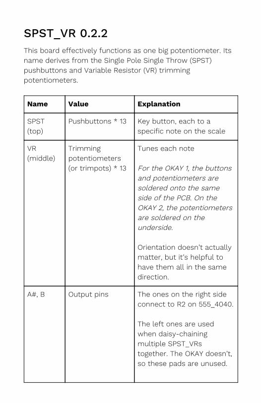
Before you start soldering, notice that there are 15 columns but you only have 13 buttons and 13 trimpots. That’s because you’ll skip the 6th and 14th columns. The skipped pushbuttons remain unchanged, but the skipped pots should have their pins shorted together, as indicated below. The remaining third pad is already connected from the PCB’s routing and doesn’t need to be manually connected (or “shorted”).
To short the pads, apply generous solder to each, then solder the middle until the two connect. You can do this on either side of the PCB. If shorting the pot pads with solder alone is too difficult, supplement with a short scrap of wire. Or try putting a small piece of tape on the other side before soldering.
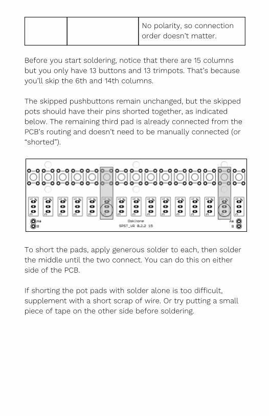
Wiring for OKAY 2 See how the A# and B pads are mirrored on the left and right sides of the PCB? That’s so multiple boards can daisy-chain together and extend the keyboard’s range. The OKAY 2 does this for its two octaves. Solder the two boards together as indicated. It may help to first assemble them into the key cradle for stability.
Note that the left side of the left board has been trimmed off. This allows it to fit snugly into the key cradle. Remember to put the trimpots on the opposite side too.
Putting it all together
Testing and debugging With everything connected, plug in the IC chips to their sockets, add a 9v battery, turn it on, and press one of the buttons. If it made a sound, it works! Now go through all the buttons and make sure that they each make a sound. The notes won’t be in tune yet and will be incredibly low, but they should get lower in pitch as you move left. If not, try these debugging steps:
● Turn the boards over and check all solder joints. A majority of problems are caused by insufficient or errant soldering. Familiarize yourself with what a good joint looks like in the “Adafruit Guide To Excellent Soldering”
● Using a multimeter’s voltage meter, check that each board is getting power. Then refer to the circuit diagrams in the appendix to make sure the power is getting to the appropriate IC pins.
● If the LED light turns on but the two IC boards aren’t getting power or working, check to see that the bus diodes are in the right direction.
● Check that SPST_VR is acting like a potentiometer by measuring its output resistance with a multimeter. The resistance should get lower as you press buttons from right to left.
● If there’s buzzing, check for any metal scraps stuck to the speaker’s magnet
● If you’ve got the OKAY 2 and its output jack is behaving inconsistently, review its diagram from before and make sure it’s contacts are working and wired correctly
● Failing those and if you have an oscilloscope, you can find where the circuit is breaking by methodically checking it at each step while holding down a button (or temporarily replacing 555_4040’s R2 with a resistor). As soon as one of these is not true, everything thereafter will not be true.
○ The 0 header by the 555 should have a very high frequency pulse wave
○ 4040 will output lower frequency square waves ○ The 4040 outputs will all match their pins on
the octave selector’s rotary switch ○ The rotary switch’s common pin will match the
386 input pad, marked + ○ The right VOL pad connects to board’s input. Its
middle pad goes to the IC’s input. Its left pad goes to ground. The volume potentiometer should match these pads.
○ The 386 IC’s output and speaker output will have a large voltage square wave
● If all else fails, contact your friendly Oskitone representative! :)
Final assembly If all is well and the electronics are working correctly, we assembly them into the enclosure.
1. PCBs a. Slide a hex nut into each of the PCB posts on
the enclosure bottom half b. Screw PCBs onto their posts. From left to right:
555_4040, 386, bus. Tighten just enough to hold the boards in place without rattling. Don’t over-tighten!
c. For the OKAY 1, screw SPST_VR onto posts like the other boards.
d. For the OKAY 2, screw SPST_VR boards into key cradle and secure with hex nut on cradle underside.
2. Keys (for OKAY 2) a. The keys have matching screw holes for the top
row of the key cradle. Secure each together with a screw and nut.
3. Speaker and grill a. Temporarily unsolder the speaker b. Thread its wire through the speaker hole c. Resolder speaker d. Place speaker in hole and cover with grill e. Mount grill to enclosure top with 4 screws and 4
hex nuts 4. Controls
a. Insert control labels (the piece with “OCT” and “VOL” text) into its spot on enclosure top. If the fit is too tight, carefully trim away excess plastic from the enclosure with a utility knife.
b. Insert LED into its hole on the “VOL” label c. The octave selector rotary switch and volume
potentiometer may have tabs that protrude parallel to the shafts. These are designed to hold the component in place. We won’t be using them; bend or break them off with pliers
d. Insert the octave selector rotary switch and volume potentiometer. Tighten the volume pot but leave the switch loose
e. Place the knob with a tension screw in its side onto the volume potentiometer, and gently tighten its screw until it holds
f. Place the other knob on the rotary switch. Note that the switch’s shaft has ridges (called “knurls”) that make the knob push on better at certain angles
g. Rotate the rotary switch and its knob to an angle that you like. Then remove knob, tighten switch to enclosure top, and reapply knob
h. Optionally, fix label into place with some hot glue or other permanent adhesive
Tuning For the OKAY 1, the notes are arranged C to C, from left to right: C, C#, D, D#, E, F, F#, G, G#, A, A#, B, C. The OKAY 2 has two octaves: C, C#, D, D#, E, F, F#, G, G#, A, A#, B, C, C#, D, D#, E, F, F#, G, G#, A, A#, B, C
1. Turn on your chromatic tuner and place it by the speaker. Find a volume and octave setting that the tuner can hear and responds to.
2. Starting with the rightmost potentiometer, hold its button and adjust its pot until the note registers as a high C. The pot will have a two or three octave range, so just choose the highest C you can accurately get to. If you reach the end of the pot’s range, it will make a small clicking sound but won’t be damaged.
3. Once that C is set, move to the next note on its left. This will be B.
4. Repeat until you’re at the end on the far left You’re done!! Take a selfie with your brand new and very incredible OKAY synthesizer. Feel good!
Care ● The trim potentiometers will hold their positions and
the 555 chip is similarly resilient, but the OKAY is an analog instrument and may still lose tune over time. When that happens, re-tune normally.
● Like arcade console buttons, the pushbuttons are mechanical and will eventually wear out over time and

vigorous usage. You can try to substitute for a new pushbutton (just search for “6x6x6 tactical switch”) but may find replacing the entire SPST_VR board easier. Contact Oskitone for help.
● The OKAY’s 3D-printed plastic is susceptible to warping under hot temperatures. Keep it out of prolonged direct sunlight.
Appendix: Circuit schematics