Embed Size (px)
Citation preview
**************************************************************************USACE / NAVFAC / AFCEC / NASA UFGS- 23 70 01. 00 10 ( Januar y 2008) Change 1 - 08/ 17 - - - - - - - - - - - - - - - - - - - - - - - - - - - - - - - - - -Pr epar i ng Act i v i t y: USACE Super sedi ng UFGS- 23 70 01. 00 10 ( Oct ober 2007)
UNI FI ED FACI LI TI ES GUI DE SPECI FI CATI ONS
Ref er ences ar e i n agr eement wi t h UMRL dat ed Januar y 2018**************************************************************************
SECTI ON TABLE OF CONTENTS
DI VI SI ON 23 - HEATI NG, VENTI LATI NG, AND AI R CONDI TI ONI NG ( HVAC)
SECTI ON 23 70 01. 00 10
CENTRAL STEAM- GENERATI NG SYSTEM, COAL- FI RED
01/08
PART 1 GENERAL
1. 1 REFERENCES 1. 2 SUBMI TTALS 1. 3 QUALI TY ASSURANCE 1. 3. 1 Wel di ng 1. 3. 2 Use of Asbest os Pr oduct s 1. 4 DELI VERY, STORAGE, AND HANDLI NG 1. 5 EXTRA MATERI ALS
PART 2 PRODUCTS
2. 1 MATERI ALS AND EQUI PMENT 2. 1. 1 St andar d Pr oduct s 2. 1. 2 Namepl at es 2. 1. 3 Pr event i on of Rust 2. 1. 4 Equi pment Guar ds and Access 2. 2 BOI LERS 2. 2. 1 Capaci t y 2. 2. 2 El ect r i cal Equi pment 2. 2. 2. 1 Mot or Rat i ngs 2. 2. 2. 2 Mot or St ar t er s 2. 2. 3 Boi l er Desi gn Requi r ement s 2. 2. 3. 1 Radi ant Heat i ng 2. 2. 3. 2 Heat I nput 2. 2. 3. 3 Combust i on Gas 2. 2. 3. 4 Ash Di schar ge 2. 2. 3. 5 Radi ant Heat i ng Sur f ace 2. 2. 3. 6 Fur nace Vol ume 2. 2. 3. 7 Boi l er Oper at i ng Capaci t y 2. 2. 3. 8 Boi l er Out put Capaci t y 2. 2. 3. 9 Boi l er Mar ki ngs 2. 3 BOI LER DETAI LS 2. 3. 1 Packaged St eam- Gener at i ng Uni t s 2. 3. 1. 1 Fi r ebox Type ( f or Boi l er Capaci t i es Less Than 2. 9 Mega
SECTI ON 23 70 01. 00 10 Page 1
wat t s 10, 000, 000 Bt uh) 2. 3. 1. 2 Wat er t ube, Wat er wal l Type ( Boi l er Capaci t i es Over 2. 9 Mega
wat t s 10, 000, 000 Bt uh) 2. 3. 2 Wat er t ube Boi l er s 2. 3. 2. 1 Dr ums 2. 3. 2. 2 Tubes 2. 3. 2. 3 Baf f l es 2. 3. 2. 4 Access Door s 2. 3. 2. 5 Mi scel l aneous Pi pe Connect i ons 2. 3. 2. 6 Super heat er Desi gn 2. 3. 2. 7 Boi l er s and Fi r i ng Equi pment 2. 3. 3 Boi l er Set t i ngs 2. 3. 3. 1 Boi l er Mat er i al 2. 3. 3. 1. 1 Fi r ebr i ck 2. 3. 3. 1. 2 I nsul at i ng Br i ck 2. 3. 3. 1. 3 Cast abl e Ref r act or y 2. 3. 3. 1. 4 Mor t ar , Ai r - Set t i ng, Ref r act or y 2. 3. 3. 1. 5 Br i ck, Common 2. 3. 3. 1. 6 Gal vani zed St eel Sheet s 2. 3. 3. 1. 7 Uncoat ed St eel Sheet s and St r i ps, Low Car bon 2. 3. 3. 2 Fi r ebox, Packaged Type 2. 3. 3. 3 Wat er t ube, Wat er wal l Type 2. 3. 3. 3. 1 Boi l er Roof 2. 3. 3. 3. 2 Br i dge Wal l s 2. 3. 3. 3. 3 Set t l i ng Chamber 2. 3. 3. 3. 4 Expansi on Joi nt s 2. 3. 3. 3. 5 Fi r ebr i ck 2. 3. 3. 3. 6 Pl ast i c Ref r act or y 2. 3. 3. 4 Wat er t ube, Wat er wal l ( Packaged Type) Uni t 2. 3. 4 Boi l er Fi t t i ngs and Appur t enances 2. 3. 4. 1 Wat er col umn 2. 3. 4. 2 Wat er Gauge 2. 3. 4. 3 Low Wat er Cut of f 2. 3. 4. 4 Bypass But t on 2. 3. 4. 5 St eam Gauge 2. 3. 4. 6 Feed and Check Val ves 2. 3. 4. 7 Cont i nuous Bl owdown Val ve 2. 3. 4. 8 Saf et y Val ves 2. 3. 4. 9 Bl owof f Val ves 2. 3. 4. 10 St eam Nonr et ur n Val ve 2. 3. 4. 11 Feedwat er Regul at or 2. 3. 4. 12 Soot Bl ower s 2. 4 STOKER EQUI PMENT 2. 4. 1 Spr eader St oker s 2. 4. 1. 1 Spr eader St oker Gr at es 2. 4. 1. 2 Tr avel i ng Gr at es 2. 4. 1. 3 Vi br at i ng Gr at e 2. 4. 1. 4 St oker Cont r ol s 2. 4. 1. 5 Hopper s 2. 4. 1. 6 Over - Fi r e Tur bul ence and Ci nder and Dust Rei nj ect i on Syst em 2. 4. 2 Under f eed St oker s 2. 4. 2. 1 Si ngl e Ret or t , Heavy- Dut y Ram- Type St oker s 2. 4. 2. 1. 1 Gr at e Sur f ace 2. 4. 2. 1. 2 Ram Feed 2. 4. 2. 1. 3 Hopper s 2. 4. 2. 2 Si ngl e Ret or t Scr ew Type St oker s 2. 4. 3 Conveyor St oker s 2. 4. 3. 1 Gr at es 2. 4. 3. 2 Gr at e Oper at i on
SECTI ON 23 70 01. 00 10 Page 2
2. 4. 3. 3 Hopper s 2. 4. 4 Vi br at i ng Gr at e St oker s 2. 4. 4. 1 Gr at es 2. 4. 4. 2 St oker Cont r ol s 2. 4. 4. 3 Hopper s 2. 5 PULVERI ZED COAL BOI LERS 2. 5. 1 Coal Pul ver i zer s 2. 5. 2 Bur ner s 2. 5. 3 Fur nace Ash Syst em 2. 5. 4 Pul ver i zer Rej ect s 2. 5. 5 Cont r ol Syst ems 2. 5. 5. 1 Coal Mast er Cont r ol Syst em 2. 5. 5. 2 Pr i mar y Ai r 2. 5. 5. 3 Ai r Temper at ur e Cont r ol 2. 5. 5. 4 Fl ame Saf et y Syst em 2. 6 FLUI DI ZED BED COMBUSTI ON BOI LERS 2. 6. 1 Gener al 2. 6. 2 Fur nace and Boi l er 2. 6. 3 For ced Ci r cul at i on Syst em 2. 6. 4 I n- Bed Tube Sur f ace ( AFB Desi gns) 2. 6. 5 Coal and Sor bent Feed Syst ems 2. 6. 5. 1 AFB Coal Feed Syst em 2. 6. 5. 2 CFB Coal Feed Syst ems 2. 6. 6 Fl ui di zed Bed Combust i on Ar ea 2. 6. 7 Bed Mat er i al Let down Syst em 2. 6. 8 Bur ner s and Fuel Pi pi ng 2. 6. 9 Ai r Di st r i but i on Syst em 2. 6. 10 Mechani cal Col l ect or and Sol i ds Recycl e Syst em f or AFB Boi l er s 2. 7 I GNI TI ON OI L SYSTEM 2. 7. 1 I gni t i on Oi l Pumps 2. 7. 2 Bur ner s 2. 7. 3 Abovegr ound Oi l St or age Tanks 2. 7. 4 Under gr ound Oi l St or age Tanks 2. 8 COMBUSTI ON CONTROL EQUI PMENT 2. 8. 1 Posi t i oni ng Type 2. 8. 2 Met er i ng Type Combust i on Cont r ol Equi pment 2. 8. 2. 1 Fuel - Fl ow, Ai r - Fl ow Type Combust i on Cont r ol 2. 8. 2. 2 Two El ement ( St eam Pr essur e, St eam Fl ow) 2. 8. 2. 2. 1 Mast er Pr essur e Tr ansmi t t er 2. 8. 2. 2. 2 [ Fuel Feed] [ St eam- Fl ow] Tr ansmi t t er 2. 8. 2. 2. 3 Ai r - Fl ow Tr ansmi t t er 2. 8. 2. 2. 4 Aut omat i c Cont r ol l er 2. 8. 2. 2. 5 Power Uni t s 2. 8. 2. 2. 6 Fur nace Dr af t Cont r ol l er 2. 8. 3 Combust i on Cont r ol s wi t h Oxygen Tr i m 2. 8. 4 Boi l er Li mi t Cont r ol s 2. 8. 5 Bur ner Cont r ol / Fuel Saf et y Syst em 2. 8. 5. 1 Desi gn Requi r ement s 2. 8. 5. 1. 1 Mai nt enance and Rel i abi l i t y Requi r ement s 2. 8. 5. 1. 2 Adver se El ect r i cal Condi t i ons 2. 8. 5. 2 Syst em Desi gn 2. 8. 5. 3 Syst em Funct i onal Requi r ement s 2. 8. 5. 3. 1 Oper at i ng Modes 2. 8. 5. 3. 2 Fur nace Pur ge and Boi l er Moni t or 2. 8. 5. 3. 3 Mi l l St ar t - St op Sequences 2. 8. 5. 3. 4 I gni t or Cont r ol 2. 8. 5. 3. 5 Fuel Saf et y Subsyst em 2. 8. 5. 3. 6 Fl ame Moni t or i ng 2. 8. 5. 3. 7 Encl osur es
SECTI ON 23 70 01. 00 10 Page 3
2. 8. 5. 3. 8 Local Ter mi nat i on Boxes 2. 8. 5. 3. 9 I nt er connect i ng Cabl e Requi r ement s 2. 8. 5. 3. 10 Buf f er ed Out put Si gnal s 2. 9 BOI LER ROOM PANELS AND I NSTRUMENTS 2. 9. 1 I nst r ument Cont r ol Panel 2. 9. 2 I ndi cat or s 2. 9. 3 Recor der s 2. 9. 4 Panel Di spl ay 2. 9. 5 Panel Pi pi ng and Wi r i ng 2. 9. 6 Pi l ot Li ght s 2. 9. 7 Cl ock 2. 9. 8 Al ar m Annunci at or Panel 2. 9. 9 Combust i on Cont r ol Component s 2. 9. 10 St eam and Feedwat er Fl ow Measur ement 2. 9. 11 Fl ue Gas Opaci t y Moni t or 2. 9. 12 Sampl e Cool er 2. 9. 13 Oxygen Anal yzer 2. 9. 14 Cont i nuous Bl owdown 2. 9. 15 Cont i nuous Emi ssi ons Moni t or i ng 2. 10 WASTE HEAT RECOVERY EQUI PMENT 2. 10. 1 Economi zer s 2. 10. 2 Ai r Pr eheat er s 2. 11 DRAFT FANS 2. 11. 1 Dr af t Fan Cont r ol 2. 11. 2 Dr af t Fan Dr i ves 2. 12 AI R DUCTS 2. 13 BREECHI NG 2. 14 STACKS 2. 15 BLOWOFF TANK 2. 16 PUMPS 2. 16. 1 Boi l er Feed Pumps 2. 16. 1. 1 Casi ngs 2. 16. 1. 2 Base 2. 16. 1. 3 Coupl i ngs 2. 16. 1. 4 Aut omat i c Reci r cul at i on 2. 16. 1. 5 Tur bi nes 2. 16. 1. 6 El ect r i c Mot or s 2. 16. 1. 7 Shop Hydr ost at i c Test i ng 2. 16. 2 Condensat e Pumps 2. 17 CONDENSATE TANK AND ACCESSORI ES 2. 17. 1 Condensat e Tank 2. 17. 2 Feedwat er Makeup Val ve 2. 18 HEAT EXCHANGERS 2. 19 DEAERATI NG FEEDWATER HEATER 2. 20 STEAM TRAPS 2. 20. 1 Bucket Tr aps 2. 20. 2 I mpact - Oper at ed Tr aps 2. 20. 3 Ther most at i c Tr aps 2. 20. 4 Fl oat and Ther most at i c Tr aps 2. 21 PRESSURE GAUGES 2. 22 THERMOMETERS 2. 23 WATER METER 2. 24 CHEMI CAL TREATMENT AND WATER SOFTENI NG EQUI PMENT 2. 24. 1 Chemi cal Feeder 2. 24. 2 Wat er Sof t eni ng Equi pment 2. 24. 2. 1 Wat er Anal ysi s 2. 24. 2. 2 Zeol i t e 2. 24. 2. 3 React or Tank 2. 24. 2. 4 Sof t eni ng Syst em
SECTI ON 23 70 01. 00 10 Page 4
2. 24. 2. 5 Wat er Test Ki t 2. 24. 2. 6 Tr eat ed Wat er St or age Tank 2. 25 BUI LDI NG HEATI NG EQUI PMENT 2. 25. 1 Uni t Heat er s 2. 25. 1. 1 Gener al 2. 25. 1. 2 Pr opel l er Type Uni t Heat er 2. 25. 1. 3 Cabi net Uni t Heat er s 2. 25. 1. 4 Heat i ng El ement s 2. 25. 1. 5 Manual Sel ect i on Swi t ches 2. 25. 1. 6 Aut omat i c Oper at i on 2. 25. 1. 6. 1 Ther most at i c Cont r ol by Fan Regul at i on 2. 25. 1. 6. 2 Ther most at i c Cont r ol by St eam Val ve Regul at i on 2. 25. 2 Radi at or and Convect or 2. 26 AI R COMPRESSOR UNI TS 2. 26. 1 Ser vi ce Ai r Compr essor s 2. 26. 2 I nst r ument Ai r Compr essor s 2. 27 PI PI NG 2. 27. 1 Pi pe 2. 27. 2 Fi t t i ngs 2. 27. 3 Ni ppl es 2. 27. 4 Uni ons 2. 27. 5 Pi pe Thr eads 2. 27. 6 Expansi on Joi nt s 2. 27. 6. 1 Gui ded, Sl i p- Tube Type Expansi on Joi nt s 2. 27. 6. 2 Bel l ows Type Expansi on Joi nt s 2. 27. 6. 3 Fl exi bl e Bal l Type Expansi on Joi nt s 2. 27. 7 Val ves 2. 27. 7. 1 Check Val ves 2. 27. 7. 2 Gat e Val ves 2. 27. 7. 3 Gl obe Val ves and Angl e Val ves 2. 27. 7. 4 St eam Pr essur e Reduci ng Val ves 2. 27. 7. 5 Ther most at i c Regul at i ng Val ves 2. 27. 7. 6 Back Pr essur e Rel i ef Val ves 2. 27. 7. 7 Boi l er Aut omat i c Feedwat er Reci r cul at i ng Cont r ol Val ve 2. 27. 8 Exhaust Heads 2. 27. 9 St r ai ner s 2. 27. 10 Pi pe Hanger s, I nser t s, and Suppor t s 2. 28 I NSULATI ON 2. 29 TOOLS 2. 29. 1 Tube Br ush 2. 29. 2 Smoke Pi pe Cl eaner 2. 29. 3 Fi r i ng Tool s 2. 29. 4 Wr enches and Gasket s 2. 30 COAL HANDLI NG EQUI PMENT 2. 30. 1 Scr ew Conveyor 2. 30. 2 Bel t Conveyor 2. 30. 3 Fl i ght Conveyor 2. 30. 4 Bucket El evat or s 2. 30. 5 Vi br at i ng Conveyor 2. 30. 6 Gr avi met r i c Wei gh Feeder 2. 30. 7 Tr ack Hopper s 2. 30. 7. 1 Hopper Gat es 2. 30. 7. 2 Hopper Feeder s 2. 30. 8 Tr uck Hopper s 2. 30. 8. 1 Hopper Gat es 2. 30. 8. 2 Hopper Feeder s 2. 30. 9 Vi br at or 2. 30. 10 Car Heat er s 2. 30. 10. 1 Gas- Fi r ed Heat er s
SECTI ON 23 70 01. 00 10 Page 5
2. 30. 10. 2 El ect r i c I nf r ar ed Radi ant Heat er s 2. 30. 11 Coal Spout s, Chut es, I nl et Boxes, and Out l et Hopper s 2. 30. 12 Car Spot t er 2. 30. 13 Coal Bunker s 2. 30. 14 Coal St or age Si l os 2. 30. 14. 1 Si l o Desi gn 2. 30. 14. 2 Si l o I nt er i or Fi ni sh 2. 30. 14. 3 Si l o Ext er i or Fi ni sh 2. 30. 14. 4 Si l o Level Cont r ol s 2. 30. 15 Coal Cr usher 2. 30. 16 Vi br at i ng Feeder s 2. 30. 17 Tr i pper 2. 30. 18 Tr ackmobi l e 2. 30. 19 En- Masse Chai n Conveyor s 2. 31 ASH HANDLI NG SYSTEM 2. 31. 1 Boi l er Room Ash Handl i ng Syst em 2. 31. 1. 1 Ash Hopper 2. 31. 1. 2 Cl i nker Gr i nder 2. 31. 1. 3 Conveyor Pi pi ng 2. 31. 1. 4 Vacuum and Combi nat i on Vacuum/ Pr essur e Syst ems 2. 31. 1. 4. 1 Vacuum Syst em 2. 31. 1. 4. 2 Combi nat i on Vacuum/ Pr essur e Syst ems 2. 31. 1. 4. 3 Pump Uni t 2. 31. 1. 4. 4 Cont r ol Cabi net 2. 31. 1. 4. 5 Cont r ol s 2. 31. 1. 4. 6 Aut omat i c Ai r Val ve 2. 31. 1. 5 Ash Si l o 2. 31. 1. 6 Conveyor Type Ash Handl i ng Syst em 2. 31. 1. 6. 1 Dr ag Chai n Conveyor 2. 31. 1. 6. 2 Casi ng 2. 31. 2 Ash Handl i ng Cont r ol s 2. 31. 3 Submer ged Dr ag Chai n Conveyor ( SDCC) 2. 31. 4 Dense Phase Ash Handl i ng 2. 31. 5 Fl y Ash Col l ect or s
PART 3 EXECUTI ON
3. 1 EXAMI NATI ON 3. 2 EARTHWORK 3. 3 EQUI PMENT ERECTI ON 3. 4 STORAGE TANK I NSTALLATI ON 3. 5 PI PI NG I NSTALLATI ON 3. 5. 1 Pi pe Sl eeves 3. 5. 1. 1 Pi pes Passi ng Thr ough Wat er pr oof i ng Membr anes 3. 5. 1. 2 Opt i onal Count er f l ashi ng 3. 5. 2 Pi pe Joi nt s 3. 5. 2. 1 Thr eaded Joi nt s 3. 5. 2. 2 Wel ded Joi nt s 3. 5. 2. 2. 1 Bevel i ng 3. 5. 2. 2. 2 Al i gnment 3. 5. 2. 2. 3 Er ect i on 3. 5. 2. 2. 4 Def ect i ve Wel di ng 3. 5. 2. 2. 5 El ect r odes 3. 5. 2. 3 Fl anges and Uni ons 3. 5. 3 Suppor t s 3. 5. 3. 1 Gener al 3. 5. 3. 2 Sei smi c Requi r ement s 3. 5. 3. 3 St r uct ur al At t achment s 3. 5. 4 Anchor s
SECTI ON 23 70 01. 00 10 Page 6
3. 5. 5 Pi pe Expansi on 3. 5. 5. 1 Expansi on Loops 3. 5. 5. 2 Expansi on Joi nt s 3. 5. 6 Val ves 3. 6 BURI ED PI PI NG I NSTALLATI ON 3. 6. 1 Pr ot ect i ve Coat i ng f or Under gr ound St eel Pi pe 3. 6. 2 Cl eani ng of Sur f aces t o be Coat ed 3. 6. 3 Coat i ng Mat er i al s 3. 6. 3. 1 Bi t umi nous Pi pe Coat i ng 3. 6. 3. 2 Pol yet hyl ene Pi pe Coat i ng 3. 6. 3. 3 Tape- Wr ap Pi pe Coat i ng 3. 6. 3. 4 Epoxy Coat i ng Syst em 3. 6. 3. 5 Coat i ng I nspect i on and Test i ng 3. 6. 4 I nst al l i ng Bur i ed Pi pi ng 3. 6. 5 Fi ber gl ass Rei nf or ced Pl ast i c ( FRP) Pi pe 3. 6. 5. 1 I nst al l at i on 3. 6. 5. 2 Thr ust Bl ocks 3. 6. 5. 3 Cur i ng of Fi el d- Bonded Joi nt s 3. 6. 5. 4 Met al t o FRP Connect i ons 3. 6. 6 Bur i ed Fuel Pi pi ng 3. 7 CATHODI C PROTECTI ON 3. 8 FI ELD PAI NTI NG 3. 9 CLEANI NG OF BOI LERS AND PI PI NG FOR TESTI NG 3. 9. 1 Boi l er Cl eani ng 3. 9. 2 Boi l er Wat er Condi t i oni ng 3. 10 MANUFACTURERS' FI ELD SERVI CES 3. 11 FI ELD TRAI NI NG 3. 12 FRAMED I NSTRUCTI ONS 3. 13 TESTS 3. 13. 1 Hydr ost at i c Test s 3. 13. 2 Ef f i c i ency and Oper at i ng Test s 3. 13. 3 Test of Fuel Bur ni ng Equi pment 3. 13. 4 Test of Deaer at i ng Feedwat er Heat er 3. 13. 5 Test of Wat er Tr eat ment Equi pment 3. 13. 6 Test f or St eam Pur i t y and Wat er Level St abi l i t y 3. 13. 6. 1 Conduct i v i t y Test s f or Boi l er s wi t hout Super heat er s 3. 13. 6. 2 Conduct i v i t y Test , Boi l er s wi t h or wi t hout Super heat er s 3. 13. 6. 3 Wat er Level St abi l i t y Test
- - End of Sect i on Tabl e of Cont ent s - -
SECTI ON 23 70 01. 00 10 Page 7
**************************************************************************USACE / NAVFAC / AFCEC / NASA UFGS- 23 70 01. 00 10 ( Januar y 2008) Change 1 - 08/ 17 - - - - - - - - - - - - - - - - - - - - - - - - - - - - - - - - - -Pr epar i ng Act i v i t y: USACE Super sedi ng UFGS- 23 70 01. 00 10 ( Oct ober 2007)
UNI FI ED FACI LI TI ES GUI DE SPECI FI CATI ONS
Ref er ences ar e i n agr eement wi t h UMRL dat ed Januar y 2018**************************************************************************
SECTI ON 23 70 01. 00 10
CENTRAL STEAM- GENERATI NG SYSTEM, COAL- FI RED01/08
**************************************************************************NOTE: Thi s gui de speci f i cat i on cover s t he r equi r ement s f or coal - f i r ed cent r al st eam- gener at i ng systems.
Adher e t o UFC 1- 300- 02 Uni f i ed Faci l i t i es Gui de Speci f i cat i ons ( UFGS) For mat St andar d when edi t i ng t hi s gui de speci f i cat i on or pr epar i ng new pr oj ect speci f i cat i on sect i ons. Edi t t hi s gui de speci f i cat i on f or pr oj ect speci f i c r equi r ement s by addi ng, del et i ng, or r evi s i ng t ext . For br acket ed i t ems, choose appl i cabl e i t em( s) or i nser t appr opr i at e i nf or mat i on.
Remove i nf or mat i on and r equi r ement s not r equi r ed i n r espect i ve pr oj ect , whet her or not br acket s ar e present.
Comment s, suggest i ons and r ecommended changes f or t hi s gui de speci f i cat i on ar e wel come and shoul d be submi t t ed as a Cr i t er i a Change Request ( CCR) .
**************************************************************************
PART 1 GENERAL
1. 1 REFERENCES
**************************************************************************NOTE: Thi s par agr aph i s used t o l i s t t he publ i cat i ons c i t ed i n t he t ext of t he gui de speci f i cat i on. The publ i cat i ons ar e r ef er r ed t o i n t he t ext by basi c desi gnat i on onl y and l i s t ed i n t hi s par agr aph by or gani zat i on, desi gnat i on, dat e, and t i t l e.
Use t he Ref er ence Wi zar d' s Check Ref er ence f eat ur e when you add a Ref er ence I dent i f i er ( RI D) out s i de of t he Sect i on' s Ref er ence Ar t i c l e t o aut omat i cal l y pl ace t he r ef er ence i n t he Ref er ence Ar t i c l e. Al so use t he Ref er ence Wi zar d' s Check Ref er ence f eat ur e
SECTI ON 23 70 01. 00 10 Page 8
t o updat e t he i ssue dat es.
Ref er ences not used i n t he t ext wi l l aut omat i cal l y be del et ed f r om t hi s sect i on of t he pr oj ect speci f i cat i on when you choose t o r econci l e r ef er ences i n t he publ i sh pr i nt pr ocess.
**************************************************************************
The publ i cat i ons l i s t ed bel ow f or m a par t of t hi s speci f i cat i on t o t he ext ent r ef er enced. The publ i cat i ons ar e r ef er r ed t o wi t hi n t he t ext by t he basi c desi gnat i on onl y.
ACOUSTI CAL SOCI ETY OF AMERI CA ( ASA)
ASA S1. 13 ( 2005; R 2010) Met hods f or t he Measur ement of Sound Pr essur e Level s i n Ai r ( ASA 118)
AI R MOVEMENT AND CONTROL ASSOCI ATI ON I NTERNATI ONAL ( AMCA)
AMCA 801 ( 2001; R 2008) I ndust r i al Pr ocess/ Power Gener at i on Fans: Speci f i cat i on Gui del i nes
AMERI CAN BEARI NG MANUFACTURERS ASSOCI ATI ON ( ABMA)
ABMA 11 ( 2014) Load Rat i ngs and Fat i gue Li f e f or Rol l er Bear i ngs
ABMA 9 ( 2015) Load Rat i ngs and Fat i gue Li f e f or Bal l Bear i ngs
AMERI CAN BOI LER MANUFACTURERS ASSOCI ATI ON ( ABMA/ BOI L)
ABMA Boi l er 203 ( 2002) A Gui de t o Cl ean and Ef f i c i ent Oper at i on of Coal - St oker - Fi r ed Boi l er s
ABMA Boi l er 402 ( 2012) Boi l er Wat er Qual i t y Requi r ement s and Associ at ed St eam Qual i t y f or I ndust r i al / Commer ci al and I nst i t ut i onal Boilers
AMERI CAN GAS ASSOCI ATI ON ( AGA)
AGA XR0603 ( 2006; 8t h Ed) AGA Pl ast i c Pi pe Manual f or Gas Ser vi ce
AMERI CAN GEAR MANUFACTURERS ASSOCI ATI ON ( AGMA)
AGMA 6013 ( 2016) St andar d f or I ndust r i al Encl osed Gear Dr i ves
ANSI / AGMA 6113 ( 2016B) St andar d f or I ndust r i al Encl osed Gear Dr i ves ( Met r i c Edi t i on)
AMERI CAN NATI ONAL STANDARDS I NSTI TUTE ( ANSI )
ANSI Z83. 19/ CSA 2. 35 ( 2017) Gas- Fi r ed Hi gh- I nt ensi t y I nf r ar ed Heaters
SECTI ON 23 70 01. 00 10 Page 9
AMERI CAN PETROLEUM I NSTI TUTE ( API )
API Spec 15LR ( 2001; R 2013) Speci f i cat i on f or Low Pr essur e Fi ber gl ass Li ne Pi pe and Fi t t i ngs
API St d 610 ( 2010; Er r at a 2011) Cent r i f ugal Pumps f or Pet r ol eum, Pet r ochemi cal , and Nat ur al Gas Industries
AMERI CAN RAI LWAY ENGI NEERI NG AND MAI NTENANCE- OF- WAY ASSOCI ATI ON (AREMA)
AREMA Eng Man ( 2017) Manual f or Rai l way Engi neer i ng
AMERI CAN WATER WORKS ASSOCI ATI ON ( AWWA)
AWWA C203 ( 2008) Coal - Tar Pr ot ect i ve Coat i ngs and Li ni ngs f or St eel Wat er Pi pel i nes - Enamel and Tape - Hot - Appl i ed
AWWA C213 ( 2015) Fusi on- Bonded Epoxy Coat i ng f or t he I nt er i or and Ext er i or of St eel Wat er Pipelines
AWWA C700 ( 2015) Col d- Wat er Met er s - Di spl acement Type, Met al Al l oy Mai n Case
ASME I NTERNATI ONAL ( ASME)
ASME B1. 20. 1 ( 2013) Pi pe Thr eads, Gener al Pur pose ( I nch)
ASME B1. 20. 2M ( 2006; R 2011) Pi pe Thr eads, 60 Deg. Gener al Pur pose ( Met r i c)
ASME B16. 11 ( 2016) For ged Fi t t i ngs, Socket - Wel di ng and Threaded
ASME B16. 15 ( 2013) Cast Copper Al l oy Thr eaded Fi t t i ngs Cl asses 125 and 250
ASME B16. 18 ( 2012) Cast Copper Al l oy Sol der Joi nt Pr essur e Fi t t i ngs
ASME B16. 21 ( 2011) Nonmet al l i c Fl at Gasket s f or Pi pe Flanges
ASME B16. 26 ( 2013) St andar d f or Cast Copper Al l oy Fi t t i ngs f or Fl ar ed Copper Tubes
ASME B16. 3 ( 2011) Mal l eabl e I r on Thr eaded Fi t t i ngs, Cl asses 150 and 300
ASME B16. 34 ( 2017) Val ves - Fl anged, Thr eaded and Wel di ng End
ASME B16. 39 ( 2014) St andar d f or Mal l eabl e I r on Thr eaded Pi pe Uni ons; Cl asses 150, 250, and 300
SECTI ON 23 70 01. 00 10 Page 10
ASME B16. 4 ( 2011) St andar d f or Gr ay I r on Thr eaded Fi t t i ngs; Cl asses 125 and 250
ASME B16. 5 ( 2017) Pi pe Fl anges and Fl anged Fi t t i ngs NPS 1/ 2 Thr ough NPS 24 Met r i c/ I nch St andar d
ASME B16. 9 ( 2012) St andar d f or Fact or y- Made Wr ought St eel But t wel di ng Fi t t i ngs
ASME B31. 1 ( 2016; Er r at a 2016) Power Pi pi ng
ASME BPVC SEC I ( 2010) BPVC Sect i on I - Rul es f or Const r uct i on of Power Boi l er s
ASME BPVC SEC I X ( 2010) BPVC Sect i on I X- Wel di ng and Br azi ng Qualifications
ASME BPVC SEC VI I I D1 ( 2015) BPVC Sect i on VI I I - Rul es f or Const r uct i on of Pr essur e Vessel s Di v i s i on 1
ASME CSD- 1 ( 2016) Cont r ol and Saf et y Devi ces f or Aut omat i cal l y Fi r ed Boi l er s
ASME PTC 10 ( 1997; R 2014) Per f or mance Test Code on Compr essor s and Exhaust er s
ASME PTC 19. 11 ( 2008; R 2013) St eam and Wat er Sampl i ng, Condi t i oni ng, and Anal ysi s i n t he Power Cycle
ASME PTC 4 ( 2013) Fi r ed St eam Gener at or s
ASTM I NTERNATI ONAL ( ASTM)
ASTM A106/ A106M ( 2014) St andar d Speci f i cat i on f or Seaml ess Car bon St eel Pi pe f or Hi gh- Temper at ur e Service
ASTM A167 ( 2011) St andar d Speci f i cat i on f or St ai nl ess and Heat - Resi st i ng Chr omi um- Ni ckel St eel Pl at e, Sheet , and Strip
ASTM A179/ A179M ( 1990; R 2012) St andar d Speci f i cat i on f or Seaml ess Col d- Dr awn Low- Car bon St eel Heat - Exchanger and Condenser Tubes
ASTM A242/ A242M ( 2013) St andar d Speci f i cat i on f or Hi gh- St r engt h Low- Al l oy St r uct ur al St eel
ASTM A249/ A249M ( 2016a) St andar d Speci f i cat i on f or Wel ded Aust eni t i c St eel Boi l er , Super heat er , Heat - Exchanger , and Condenser Tubes
ASTM A285/ A285M ( 2017) St andar d Speci f i cat i on f or Pr essur e Vessel Pl at es, Car bon St eel , Low- and I nt er medi at e- Tensi l e St r engt h
ASTM A350/ A350M ( 2017) St andar d Speci f i cat i on f or Car bon
SECTI ON 23 70 01. 00 10 Page 11
and Low- Al l oy St eel For gi ngs, Requi r i ng Not ch Toughness Test i ng f or Pi pi ng Components
ASTM A36/ A36M ( 2014) St andar d Speci f i cat i on f or Car bon St r uct ur al St eel
ASTM A514/ A514M ( 2014) St andar d Speci f i cat i on f or Hi gh- Yi el d- St r engt h, Quenched and Temper ed Al l oy St eel Pl at e, Sui t abl e f or Wel di ng
ASTM A516/ A516M ( 2017) St andar d Speci f i cat i on f or Pr essur e Vessel Pl at es, Car bon St eel , f or Moder at e- and Lower - Temper at ur e Ser vi ce
ASTM A53/ A53M ( 2012) St andar d Speci f i cat i on f or Pi pe, St eel , Bl ack and Hot - Di pped, Zi nc- Coat ed, Wel ded and Seaml ess
ASTM A568/ A568M ( 2017a) St andar d Speci f i cat i on f or St eel , Sheet , Car bon, St r uct ur al , and Hi gh- St r engt h, Low- Al l oy, Hot - Rol l ed and Col d- Rol l ed, Gener al Requi r ement s f or
ASTM A653/ A653M ( 2017) St andar d Speci f i cat i on f or St eel Sheet , Zi nc- Coat ed ( Gal vani zed) or Zi nc- I r on Al l oy- Coat ed ( Gal vanneal ed) by t he Hot - Di p Pr ocess
ASTM A659/ A659M ( 2012; R 2017) St andar d Speci f i cat i on f or Commer ci al St eel ( CS) , Sheet and St r i p, Car bon ( 0. 16 Maxi mum t o 0. 25 Maxi mum Per cent ) , Hot - Rol l ed
ASTM A688/ A688M ( 2015) St andar d Speci f i cat i on f or Wel ded Aust eni t i c St ai nl ess St eel Feedwat er Heat er Tubes
ASTM A733 ( 2013) St andar d Speci f i cat i on f or Wel ded and Seaml ess Car bon St eel and Aust eni t i c St ai nl ess St eel Pi pe Ni ppl es
ASTM B111/ B111M ( 2011) St andar d Speci f i cat i on f or Copper and Copper - Al l oy Seaml ess Condenser Tubes and Fer r ul e St ock
ASTM B42 ( 2015a) St andar d Speci f i cat i on f or Seaml ess Copper Pi pe, St andar d Si zes
ASTM B68/ B68M ( 2011) St andar d Speci f i cat i on f or Seaml ess Copper Tube, Br i ght Anneal ed ( Met r i c)
ASTM B88 ( 2016) St andar d Speci f i cat i on f or Seaml ess Copper Wat er Tube
ASTM B88M ( 2016) St andar d Speci f i cat i on f or Seaml ess Copper Wat er Tube ( Met r i c)
ASTM C155 ( 1997; R 2013) St andar d Speci f i cat i on f or
SECTI ON 23 70 01. 00 10 Page 12
I nsul at i ng Fi r ebr i ck
ASTM C27 ( 1998; R 2008) Fi r ecl ay and Hi gh- Al umi na Ref r act or y Br i ck
ASTM C401 ( 2012) Al umi na and Al umi na- Si l i cat e Cast abl e Ref r act or i es
ASTM C62 ( 2017) St andar d Speci f i cat i on f or Bui l di ng Br i ck ( Sol i d Masonr y Uni t s Made f r om Cl ay or Shal e)
ASTM D1066 ( 2011) Sampl i ng St eam
ASTM D888 ( 2012; E 2013) Di ssol ved Oxygen i n Wat er
ASTM F1139 ( 1988; R 2015) St eam Tr aps and Dr ai ns
ASTM G21 ( 2015) St andar d Pr act i ce f or Det er mi ni ng Resi st ance of Synt het i c Pol ymer i c Mat er i al s t o Fungi
COMPRESSED AI R AND GAS I NSTI TUTE ( CAGI )
CAGI B19. 1 ( 2010) Saf et y St andar d f or Compr essor Systems
CONVEYOR EQUI PMENT MANUFACTURERS ASSOCI ATI ON ( CEMA)
CEMA B105. 1 ( 2015) Wel ded St eel Conveyor Pul l eys
CEMA Bel t Book ( 2014; Er r at a 2016; Tech St at ement 1 2016) Bel t Conveyor s f or Bul k Mat er i al s
EXPANSI ON JOI NT MANUFACTURERS ASSOCI ATI ON ( EJMA)
EJMA St ds ( 10t h Ed) EJMA St andar ds
HEAT EXCHANGE I NSTI TUTE ( HEI )
HEI 2622 ( 2009) St andar ds f or Cl osed Feedwat er Heat er s; 8t h Edi t i on
HEI 2623 ( 2004) St andar ds f or Power Pl ant Heat Exchangers
HYDRONI CS I NSTI TUTE DI VI SI ON OF AHRI ( HYI )
HYI-005 ( 2008) I =B=R Rat i ngs f or Boi l er s, Baseboar d Radi at i on and Fi nned Tube (Commercial)
I NSTI TUTE OF ELECTRI CAL AND ELECTRONI CS ENGI NEERS ( I EEE)
I EEE C37. 90 ( 2005; R 2011) St andar d f or Rel ays and Rel ay Syst ems Associ at ed Wi t h El ect r i c Power Appar at us
SECTI ON 23 70 01. 00 10 Page 13
MANUFACTURERS STANDARDI ZATI ON SOCI ETY OF THE VALVE AND FI TTI NGS I NDUSTRY ( MSS)
MSS SP- 58 ( 1993; Reaf f i r med 2010) Pi pe Hanger s and Suppor t s - Mat er i al s, Desi gn and Manuf act ur e, Sel ect i on, Appl i cat i on, and Installation
MSS SP- 70 ( 2011) Gr ay I r on Gat e Val ves, Fl anged and Thr eaded Ends
MSS SP- 71 ( 2011; Er r at a 2013) Gr ay I r on Swi ng Check Val ves, Fl anged and Thr eaded Ends
MSS SP- 80 ( 2013) Br onze Gat e, Gl obe, Angl e and Check Valves
MSS SP- 85 ( 2011) Gr ay I r on Gl obe & Angl e Val ves Fl anged and Thr eaded Ends
NACE I NTERNATI ONAL ( NACE)
NACE SP0185 ( 2007) Ext r uded Pol yol ef i n Resi n Coat i ng Syst ems wi t h Sof t Adhesi ves f or Under gr ound or Submer ged Pi pe
NATI ONAL BOARD OF BOI LER AND PRESSURE VESSEL I NSPECTORS ( NBBI )
NBBI NB- 23 PART 1 ( 2013) Nat i onal Boar d I nspect i on Code - Par t 1 I nst al l at i on
NATI ONAL ELECTRI CAL MANUFACTURERS ASSOCI ATI ON ( NEMA)
NEMA I CS 1 ( 2000; R 2015) St andar d f or I ndust r i al Cont r ol and Syst ems: Gener al Requi r ement s
NEMA MG 1 ( 2016; SUPP 2016) Mot or s and Gener at or s
NEMA SM 23 ( 1991; R 2002) St eam Tur bi nes f or Mechani cal Dr i ve Ser vi ce
NATI ONAL FI RE PROTECTI ON ASSOCI ATI ON ( NFPA)
NFPA 329 ( 2015) Recommended Pr act i ce f or Handl i ng Rel eases of Fl ammabl e and Combust i bl e Li qui ds and Gases
NFPA 70 ( 2017; ERTA 1- 2 2017; TI A 17- 1; TI A 17- 2; TI A 17- 3; TI A 17- 4; TI A 17- 5; TI A 17- 6; TI A 17- 7; TI A 17- 8; TI A 17- 9; TI A 17- 10; TI A 17- 11; TI A 17- 12; TI A 17- 13; TI A 17- 14) Nat i onal El ect r i cal Code
NFPA 85 ( 2015; Er r at a 1 2015; ERTA 2 2016) Boi l er and Combust i on Syst ems Hazar ds Code
NATI ONAL I NSTI TUTE OF STANDARDS AND TECHNOLOGY ( NI ST)
NI ST HB 44 ( 2016) Speci f i cat i ons, Tol er ances, and
SECTI ON 23 70 01. 00 10 Page 14
Ot her Techni cal Requi r ement s f or Wei ghi ng and Measur i ng Devi ces
RUBBER MANUFACTURERS ASSOCI ATI ON ( RMA)
RMA I P- 1 ( 2011) Conveyor and El evat or Bel t Handbook; 3r d Edi t i on
SOCI ETY FOR PROTECTI VE COATI NGS ( SSPC)
SSPC Pai nt 16 ( 2006; R 2015; E 2015) Coal Tar Epoxy- Pol yami de Bl ack ( or Dar k Red) Pai nt
SSPC SP 6/ NACE No. 3 ( 2007) Commer ci al Bl ast Cl eani ng
U. S. DEPARTMENT OF DEFENSE ( DOD)
UFC 3- 310- 04 ( 2013; wi t h Change 1) Sei smi c Desi gn f or Buildings
U. S. NATI ONAL ARCHI VES AND RECORDS ADMI NI STRATI ON ( NARA)
30 CFR 1 Mi ne Saf et y and Heal t h Admi ni st r at i on; Est abl i shment and Use of Of f i c i al Embl em
UNDERWRI TERS LABORATORI ES ( UL)
UL 296 ( 2017) UL St andar d f or Saf et y Oi l Bur ner s
UL 726 ( 1995; Repr i nt Oct 2013) Oi l - Fi r ed Boi l er Assemblies
UL 795 ( 2016) UL St andar d f or Saf et y Commer ci al - I ndust r i al Gas Heat i ng Equi pment
1. 2 SUBMITTALS
**************************************************************************NOTE: Revi ew submi t t al descr i pt i on ( SD) def i ni t i ons i n Sect i on 01 33 00 SUBMI TTAL PROCEDURES and edi t t he f ol l owi ng l i s t t o r ef l ect onl y t he submi t t al s r equi r ed f or t he pr oj ect .
The Gui de Speci f i cat i on t echni cal edi t or s have desi gnat ed t hose i t ems t hat r equi r e Gover nment appr oval , due t o t hei r compl exi t y or cr i t i cal i t y , wi t h a " G. " Gener al l y, ot her submi t t al i t ems can be r evi ewed by t he Cont r act or ' s Qual i t y Cont r ol Syst em. Onl y add a “ G” t o an i t em, i f t he submi t t al i s suf f i c i ent l y i mpor t ant or compl ex i n cont ext of t he pr oj ect .
For submi t t al s r equi r i ng Gover nment appr oval on Ar my pr oj ect s, a code of up t o t hr ee char act er s wi t hi n t he submi t t al t ags may be used f ol l owi ng t he " G" desi gnat i on t o i ndi cat e t he appr ovi ng aut hor i t y. Codes f or Ar my pr oj ect s usi ng t he Resi dent Management Syst em ( RMS) ar e: " AE" f or Ar chi t ect - Engi neer ; " DO" f or Di st r i c t Of f i ce
SECTI ON 23 70 01. 00 10 Page 15
( Engi neer i ng Di v i s i on or ot her or gani zat i on i n t he Di st r i c t Of f i ce) ; " AO" f or Ar ea Of f i ce; " RO" f or Resi dent Of f i ce; and " PO" f or Pr oj ect Of f i ce. Codes f ol l owi ng t he " G" t ypi cal l y ar e not used f or Navy, Ai r For ce, and NASA pr oj ect s.
Use t he " S" c l assi f i cat i on onl y i n SD- 11 Cl oseout Submi t t al s. The " S" f ol l owi ng a submi t t al i t em i ndi cat es t hat t he submi t t al i s r equi r ed f or t he Sust ai nabi l i t y eNot ebook t o f ul f i l l f eder al l y mandat ed sust ai nabl e r equi r ement s i n accor dance wi t h Sect i on 01 33 29 SUSTAI NABI LI TY REPORTI NG.
Choose t he f i r st br acket ed i t em f or Navy, Ai r For ce and NASA pr oj ect s, or choose t he second br acket ed i t em f or Ar my pr oj ect s.
**************************************************************************
Gover nment appr oval i s r equi r ed f or submi t t al s wi t h a " G" desi gnat i on; submi t t al s not havi ng a " G" desi gnat i on ar e f or [ Cont r act or Qual i t y Cont r ol appr oval . ] [ i nf or mat i on onl y. When used, a desi gnat i on f ol l owi ng t he " G" desi gnat i on i dent i f i es t he of f i ce t hat wi l l r evi ew t he submi t t al f or t he Gover nment . ] Submi t t al s wi t h an " S" ar e f or i ncl usi on i n t he Sust ai nabi l i t y eNot ebook, i n conf or mance t o Sect i on 01 33 29 SUSTAI NABI LI TY REPORTI NG. Submi t t he f ol l owi ng i n accor dance wi t h Sect i on 01 33 00 SUBMI TTAL PROCEDURES:
SD- 02 Shop Dr awi ngs
St eam- Gener at i ng Uni t s; G[ , [ _____] ]Equi pment Er ect i on; G[ , [ _____] ]
SD- 03 Pr oduct Dat a
St eam- Gener at i ng Uni t sSpar e Par t sFr amed I nst r uct i onsWelding
SD- 06 Test Repor t s
Tests
SD- 10 Oper at i on and Mai nt enance Dat a
St eam- Gener at i ng Uni t s; G[ , [ _____] ]
1. 3 QUALI TY ASSURANCE
1. 3. 1 Welding
**************************************************************************NOTE: Wher e pi pel i ne, st r uct ur al , or ot her wel di ng i s r equi r ed on t he same pr oj ect , t est s wi l l be r equi r ed accor di ngl y. Test i ng may be by t he coupon met hod as pr escr i bed i n t he wel di ng code or by speci al r adi ogr aphi c met hods. I f t he need exi st s f or mor e st r i ngent r equi r ement s f or wel dment s, del et e t he f i r st br acket ed st at ement and del et e t he
SECTI ON 23 70 01. 00 10 Page 16
wel di ng submi t t al .**************************************************************************
[ Submi t a copy of qual i f i ed pr ocedur es and a l i s t of names and i dent i f i cat i on symbol s of qual i f i ed wel der s and wel di ng oper at or s, and a pr oposed per f or mance t est pr ocedur e, 30 days pr i or t o t he pr oposed t est dat e, cont ai ni ng a compl et e descr i pt i on of t he pr oposed t est al ong wi t h cal i br at i on cur ves or t est r esul t s f ur ni shed by an i ndependent t est i ng l abor at or y of each i nst r ument , met er , gauge, and t her momet er t o be used i n t he t est s. The t est shal l not commence unt i l t he pr ocedur e has been appr oved. Submi t compl et e pl an f or wat er t r eat ment , i ncl udi ng pr oposed chemi cal s t o be used and nat i onal l y r ecogni zed t est i ng codes appl i cabl e t o t he syst em, pr i or t o syst em st ar t up. Pi pi ng shal l be wel ded i n accor dance wi t h qual i f i ed pr ocedur es usi ng per f or mance qual i f i ed wel der s and wel di ng oper at or s. Pr ocedur es and wel der s shal l be qual i f i ed i n accor dance wi t h ASME BPVC SEC I X. Wel di ng pr ocedur es qual i f i ed by ot her s, and wel der s and wel di ng oper at or s qual i f i ed by anot her empl oyer may be accept ed as per mi t t ed by ASME B31. 1. The Cont r act i ng Of f i cer shal l be not i f i ed 24 hour s i n advance of t est s and t he t est s shal l be per f or med at t he wor k s i t e i f pr act i cabl e. The wel der or wel di ng oper at or shal l appl y hi s assi gned symbol near each wel d he makes as a per manent r ecor d. ] [ St r uct ur al member s shal l be wel ded i n accor dance wi t h Sect i on 05 05 23. 16 STRUCTURAL WELDI NG. Wel di ng and nondest r uct i ve t est i ng pr ocedur es ar e speci f i ed i n Sect i on 40 05 13. 96 WELDI NG, PRESSURE PI PI NG. ]
1. 3. 2 Use of Asbest os Pr oduct s
**************************************************************************NOTE: The f i r st c l ause i n br acket s shoul d be used when i t i s known t hat subst i t ut es ar e avai l abl e f or any asbest os pr oduct s whi ch mi ght be i ncl uded wi t h t he equi pment . The second cl ause i n br acket s shoul d be used when i t i s possi bl e or def i ni t el y known t hat asbest os pr oduct s f or whi ch no t echni cal l y accept abl e subst i t ut e exi st s may be i ncl uded wi t h t he equi pment .
**************************************************************************
[ Pr oduct s whi ch cont ai n asbest os ar e pr ohi bi t ed. Thi s pr ohi bi t i on i ncl udes i t ems such as packi ngs or gasket s, even t hough t he i t em i s encapsul at ed or t he asbest os f i ber s ar e i mpr egnat ed wi t h bi nder mat er i al . ] [ Except as pr ovi ded bel ow, pr oduct s whi ch cont ai n asbest os ar e pr ohi bi t ed. Thi s pr ohi bi t i on i ncl udes i t ems such as packi ngs and gasket s, even t hough t he i t em i s encapsul at ed or t he asbest os f i ber s ar e i mpr egnat ed wi t h bi nder mat er i al . Asbest os pr oduct s ar e accept abl e onl y i n except i onal cases wher e t he Cont r act or st at es i n wr i t i ng t hat no sui t abl e subst i t ut e mat er i al exi st s, and, i n addi t i on, t he Cont r act or f ur ni shes t o t he Cont r act i ng Of f i cer a copy of U. S. Depar t ment of Labor , Occupat i onal Saf et y and Heal t h Admi ni st r at i on, " Saf et y Dat a Sheet " ( For m OSHA- 20) , compl et ed by t he asbest os manuf act ur er st at i ng t hat t he pr oduct i s not an asbest os heal t h hazard.]
1. 4 DELI VERY, STORAGE, AND HANDLI NG
Pr ot ect al l equi pment del i ver ed and pl aced i n st or age f r om t he weat her , humi di t y and t emper at ur e var i at i on, di r t and dust , or ot her cont ami nant s.
SECTI ON 23 70 01. 00 10 Page 17
1. 5 EXTRA MATERI ALS
Submi t spar e par t s dat a f or each i t em of equi pment speci f i ed, af t er appr oval of t he det ai l dr awi ngs and not l at er t han [ _____] mont hs bef or e t he dat e of benef i c i al occupancy. I ncl ude i n t he dat a a compl et e l i s t of spar e par t s and suppl i es, wi t h cur r ent uni t pr i ces and sour ce of suppl y, and a l i s t of t he par t s r ecommended by t he manuf act ur er t o be r epl aced af t er [ 1] and [ 3] year s of ser vi ce.
PART 2 PRODUCTS
2. 1 MATERI ALS AND EQUI PMENT
2. 1. 1 St andar d Pr oduct s
Pr ovi de mat er i al s and equi pment whi ch ar e t he st andar d pr oduct s of a manuf act ur er r egul ar l y engaged i n t he manuf act ur e of t he pr oduct s and t hat essent i al l y dupl i cat e i t ems t hat have been i n sat i sf act or y use f or at l east 2 year s pr i or t o bi d openi ng. Equi pment shal l be suppor t ed by a ser vi ce or gani zat i on t hat i s , i n t he opi ni on of t he Cont r act i ng Of f i cer , r easonabl y conveni ent t o t he s i t e.
2. 1. 2 Nameplates
Each maj or i t em of equi pment shal l have t he manuf act ur er ' s name, addr ess, t ype or st y l e, model or ser i al number , and cat al og number on a pl at e secur ed t o t he i t em of equi pment .
2. 1. 3 Pr event i on of Rust
Unl ess ot her wi se speci f i ed, sur f aces of f er r ous met al subj ect t o cor r osi on shal l be f act or y pr i me pai nt ed wi t h a r ust i nhi bi t i ng coat i ng and subsequent l y f act or y f i ni sh pai nt ed i n accor dance wi t h t he manuf act ur er ' s st andar d pr act i ce. Equi pment exposed t o hi gh t emper at ur e when i n ser vi ce shal l be pr i me and f i ni sh pai nt ed wi t h t he manuf act ur er ' s st andar d heat r esi st ant pai nt t o a mi ni mum t hi ckness of 0. 025 mm 1 mi l .
2. 1. 4 Equi pment Guar ds and Access
Bel t s, pul l eys, chai ns, gear s, coupl i ngs, pr oj ect i ng set scr ews, keys, and ot her r ot at i ng par t s exposed t o per sonnel cont act shal l be f ul l y encl osed or guar ded. Hi gh t emper at ur e equi pment and pi pi ng exposed t o cont act by per sonnel or wher e i t cr eat es a f i r e hazar d shal l be pr oper l y guar ded or cover ed wi t h i nsul at i on of a t ype speci f i ed. I t ems such as cat wal ks, oper at i ng pl at f or ms, l adder s, and guar dr ai l s shal l be pr ovi ded wher e shown and shal l be const r uct ed i n accor dance wi t h Sect i on [ 05 50 13 MI SCELLANEOUS METAL FABRI CATI ONS] [ 05 51 33 METAL LADDERS] .
2. 2 BOILERS
**************************************************************************NOTE: Speci f y st eam out l et t emper at ur e i n cases wher e t he boi l er i ncl udes a super heat er .
**************************************************************************
Each boi l er shal l have t he capaci t y i ndi cat ed. The equi pment desi gn and accessor y i nst al l at i ons shal l per mi t accessi bi l i t y f or mai nt enance and ser vi ce. Boi l er s shal l be desi gned f or a maxi mum al l owabl e wor ki ng pr essur e of [ _____] Pa psi g wi t h an oper at i ng pr essur e of [ _____] Pa psi g.
SECTI ON 23 70 01. 00 10 Page 18
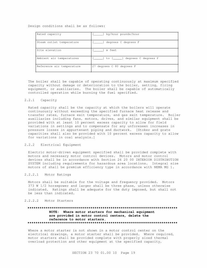
Desi gn condi t i ons shal l be as f ol l ows:
Rat ed capaci t y [ _____] kg/ hour pounds/ hour
St eam out l et t emper at ur e [ _____] degr ees C degr ees F
Si t e el evat i on [ _____] m f eet
Ambi ent ai r t emper at ur es [ _____] t o [ _____] degr ees C degr ees F
Ref er ence ai r t emper at ur e 27 degr ees C 80 degr ees F
The boi l er shal l be capabl e of oper at i ng cont i nuousl y at maxi mum speci f i ed capaci t y wi t hout damage or det er i or at i on t o t he boi l er , set t i ng, f i r i ng equi pment , or auxi l i ar i es. The boi l er shal l be capabl e of aut omat i cal l y cont r ol l ed oper at i on whi l e bur ni ng t he f uel speci f i ed.
2. 2. 1 Capacity
Rat ed capaci t y shal l be t he capaci t y at whi ch t he boi l er s wi l l oper at e cont i nuousl y wi t hout exceedi ng t he speci f i ed f ur nace heat r el ease and t r ansf er r at es, f ur nace exi t t emper at ur e, and gas exi t t emper at ur e. Boi l er auxi l i ar i es i ncl udi ng f ans, mot or s, dr i ves, and si mi l ar equi pment shal l be pr ovi ded wi t h at l east 10 per cent excess capaci t y t o al l ow f or f i el d var i at i ons i n set t i ngs and t o compensat e f or any unf or eseen i ncr eases i n pr essur e l osses i n appur t enant pi pi ng and duct wor k. [ St oker and gr at e capaci t i es shal l al so be pr ovi ded wi t h 10 per cent excess capaci t y t o al l ow f or var i at i ons i n coal anal ysi s. ]
2. 2. 2 El ect r i cal Equi pment
El ect r i c mot or - dr i ven equi pment speci f i ed shal l be pr ovi ded compl et e wi t h mot or s and necessar y mot or cont r ol devi ces. Mot or s and mot or cont r ol devi ces shal l be i n accor dance wi t h Sect i on 26 20 00 I NTERI OR DI STRI BUTI ON SYSTEM i ncl udi ng r equi r ement s f or hazar dous ar ea l ocat i ons. I nt egr al s i ze mot or s of shal l be pr emi um ef f i c i ency t ype i n accor dance wi t h NEMA MG 1.
2. 2. 2. 1 Mot or Rat i ngs
Mot or s shal l be sui t abl e f or t he vol t age and f r equency pr ovi ded. Mot or s 373 W 1/ 2 hor sepower and l ar ger shal l be t hr ee phase, unl ess ot her wi se i ndi cat ed. Rat i ngs shal l be adequat e f or t he dut y i mposed, but shal l not be l ess t han i ndi cat ed.
2. 2. 2. 2 Mot or St ar t er s
**************************************************************************NOTE: Wher e mot or st ar t er s f or mechani cal equi pment ar e pr ovi ded i n mot or cont r ol cent er s, del et e t he r ef er ence t o mot or st ar t er s.
**************************************************************************
Wher e a mot or st ar t er i s not shown i n a mot or cont r ol cent er on t he el ect r i cal dr awi ngs, a mot or st ar t er shal l be pr ovi ded. Wher e r equi r ed, mot or st ar t er s shal l be pr ovi ded compl et e wi t h pr oper l y s i zed t her mal over l oad pr ot ect i on and ot her equi pment at t he speci f i ed capaci t y,
SECTI ON 23 70 01. 00 10 Page 19
i nc l udi ng an al l owabl e ser vi ce f act or and ot her appur t enances necessar y f or t he mot or st ar t er speci f i ed. Manual or aut omat i c cont r ol and pr ot ect i ve or s i gnal devi ces r equi r ed f or oper at i on speci f i ed and any wi r i ng r equi r ed t o such devi ces not shown on t he el ect r i cal dr awi ngs shal l be pr ovi ded. Wher e t wo- speed or var i abl e- speed mot or s ar e i ndi cat ed, sol i d- st at e var i abl e- speed cont r ol l er s may be pr ovi ded t o accompl i sh t he same f unct i on.
2. 2. 3 Boi l er Desi gn Requi r ement s
2. 2. 3. 1 Radi ant Heat i ng
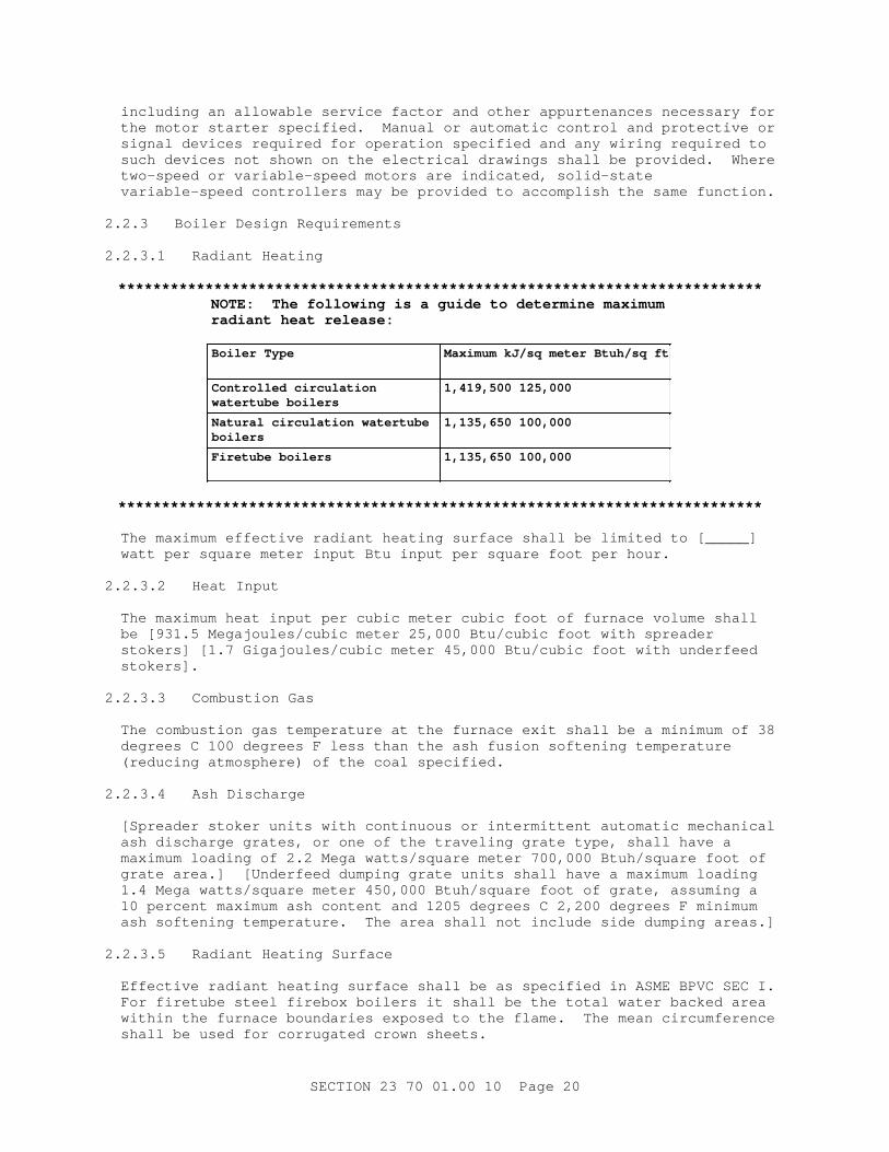
**************************************************************************NOTE: The f ol l owi ng i s a gui de t o det er mi ne maxi mum r adi ant heat r el ease:
Boi l er Type Maxi mum kJ/ sq met er Bt uh/ sq f t
Cont r ol l ed ci r cul at i on wat er t ube boi l er s
1, 419, 500 125, 000
Nat ur al c i r cul at i on wat er t ube boilers
1, 135, 650 100, 000
Fi r et ube boi l er s 1, 135, 650 100, 000
**************************************************************************
The maxi mum ef f ect i ve r adi ant heat i ng sur f ace shal l be l i mi t ed t o [ _____] wat t per squar e met er i nput Bt u i nput per squar e f oot per hour .
2. 2. 3. 2 Heat I nput
The maxi mum heat i nput per cubi c met er cubi c f oot of f ur nace vol ume shal l be [ 931. 5 Megaj oul es/ cubi c met er 25, 000 Bt u/ cubi c f oot wi t h spr eader st oker s] [ 1. 7 Gi gaj oul es/ cubi c met er 45, 000 Bt u/ cubi c f oot wi t h under f eed stokers].
2. 2. 3. 3 Combust i on Gas
The combust i on gas t emper at ur e at t he f ur nace exi t shal l be a mi ni mum of 38 degr ees C 100 degr ees F l ess t han t he ash f usi on sof t eni ng t emper at ur e ( r educi ng at mospher e) of t he coal speci f i ed.
2. 2. 3. 4 Ash Di schar ge
[ Spr eader st oker uni t s wi t h cont i nuous or i nt er mi t t ent aut omat i c mechani cal ash di schar ge gr at es, or one of t he t r avel i ng gr at e t ype, shal l have a maxi mum l oadi ng of 2. 2 Mega wat t s/ squar e met er 700, 000 Bt uh/ squar e f oot of gr at e ar ea. ] [ Under f eed dumpi ng gr at e uni t s shal l have a maxi mum l oadi ng 1. 4 Mega wat t s/ squar e met er 450, 000 Bt uh/ squar e f oot of gr at e, assumi ng a 10 per cent maxi mum ash cont ent and 1205 degr ees C 2, 200 degr ees F mi ni mum ash sof t eni ng t emper at ur e. The ar ea shal l not i nc l ude si de dumpi ng ar eas. ]
2. 2. 3. 5 Radi ant Heat i ng Sur f ace
Ef f ect i ve r adi ant heat i ng sur f ace shal l be as speci f i ed i n ASME BPVC SEC I . For f i r et ube st eel f i r ebox boi l er s i t shal l be t he t ot al wat er backed ar ea wi t hi n t he f ur nace boundar i es exposed t o t he f l ame. The mean ci r cumf er ence shal l be used f or cor r ugat ed cr own sheet s.
SECTI ON 23 70 01. 00 10 Page 20
2. 2. 3. 6 Fur nace Vol ume
Fur nace vol ume f or wat er t ube or f i r et ube boi l er s i s def i ned as t he cubi cal vol ume bet ween t he t op of t he gr at e and t he f i r st pl ane of ent r y i nt o, or bet ween, t he t ubes. I f scr een t ubes ar e ut i l i zed, t hey const i t ut e t he pl ane of ent r y.
2. 2. 3. 7 Boi l er Oper at i ng Capaci t y
The boi l er shal l mai nt ai n cont i nuous capaci t y wi t hi n t he speci f i ed r ange at t he speci f i ed pr essur e wi t h boi l er f eedwat er at a t emper at ur e of appr oxi mat el y [ _____] degr ees C degr ees F. The f l ue gas out l et t emper at ur e shal l be [ _____] degr ees C degr ees F, based on excess ai r of [ _____] per cent and car bon l oss of [ _____] per cent at maxi mum cont i nuous capaci t y. Moi st ur e i n st eam and boi l er wat er concent r at i ons shal l be i n accor dance with ABMA Boi l er 402.
2. 2. 3. 8 Boi l er Out put Capaci t y
Out put capaci t y of t he boi l er shal l be based on t est s of t he boi l er as a unit.
2. 2. 3. 9 Boi l er Mar ki ngs
**************************************************************************NOTE: Del et e br acket s i f t he boi l er does not i ncl ude a super heat er .
**************************************************************************
Each boi l er shal l be st amped wi t h:
a. Maxi mum cont i nuous capaci t y i n Wat t s Bt uh.
b. Radi ant heat i ng sur f ace i n squar e met er s f eet .
c. Tot al heat i ng sur f ace i n squar e met er s f eet .
d. Fur nace vol ume i n cubi c met er s f eet .
e. Boi l er uni t desi gn maxi mum al l owabl e wor ki ng pr essur e.
[ f . Super heat er f i nal st eam t emper at ur e i n degr ees C degr ees F. ]
[ g. Super heat er heat i ng sur f ace i n squar e met er s f eet . ]
2. 3 BOI LER DETAI LS
2. 3. 1 Packaged St eam- Gener at i ng Uni t s
Submi t manuf act ur er ' s desi gn dat a and st r uct ur al comput at i ons f or wal l s, r oof , f oundat i ons, and ot her f eat ur es, f or speci al t y t ype of const r uct i on. I ncl ude desi gn dat a f or l at er al f or ces t hat may be encount er ed due t o wi nd l oads and sei smi c f or ces.
Submi t [ 6] [ _____] compl et e copi es of oper at i ng i nst r uct i ons, pr i or t o t he t r ai ni ng cour se, out l i ni ng t he st ep- by- st ep pr ocedur es r equi r ed f or syst em st ar t up, oper at i on, and shut down. The i nst r uct i ons shal l i ncl ude t he manuf act ur er ' s name, model number , ser vi ce manual , par t s l i s t , and br i ef descr i pt i on of al l equi pment and t hei r basi c oper at i ng f eat ur es. Submi t
SECTI ON 23 70 01. 00 10 Page 21
[ 6] [ _____] compl et e copi es of mai nt enance i nst r uct i ons, pr i or t o t he t r ai ni ng cour se l i s t i ng r out i ne mai nt enance pr ocedur es, possi bl e br eakdowns and r epai r s, and t r oubl eshoot i ng gui des. The i nst r uct i ons shal l i ncl ude pi pi ng l ayout , equi pment l ayout , and s i mpl i f i ed wi r i ng, and cont r ol di agr ams of t he syst em as i nst al l ed.
2. 3. 1. 1 Fi r ebox Type ( f or Boi l er Capaci t i es Less Than 2. 9 Mega wat t s 10, 000, 000 Bt uh)
Uni t s shal l be f ur ni shed compl et e wi t h coal bur ni ng equi pment , [ f l y ash col l ect or , ] br i ckwor k, i nsul at i on wi t h st eel j acket , saf et y and oper at i ng cont r ol s, f or ced- and i nduced- dr af t f ans, l ow wat er cut of f and al ar m, and ot her r equi r ed appur t enances. The uni t shal l be compl et e, sel f - cont ai ned, f ul l y aut omat i c, and r eady f or ser vi ce upon compl et i on of ut i l i t y connect i ons except t hat f i r i ng equi pment , saf et y and oper at i ng cont r ol s may be packaged separ at el y f r om t he boi l er , f ul l y assembl ed, f act or y wi r ed, and compl et el y r eady f or f i el d mount i ng. The f i r ebox boi l er shal l be of t he wat er t ube or f i r et ube t ype i n conf or mance wi t h ASME BPVC SEC I . Cont r ol panel shal l be pr ewi r ed and t ot al l y encl osed. Over - f i r e ai r j et s shal l be pr ovi ded f or f ur nace t ur bul ence. Posi t i oni ng cont r ol s shal l be pr ovi ded. [ The boi l er shal l be equi pped wi t h soot bl ower s. ]
2. 3. 1. 2 Wat er t ube, Wat er wal l Type ( Boi l er Capaci t i es Over 2. 9 Mega wat t s 10, 000, 000 Bt uh)
Except as modi f i ed, t he st eam- gener at i ng uni t shal l compl y wi t h t he r equi r ement s of ASME BPVC SEC I . St eam gener at i ng uni t shal l be f ur ni shed compl et e wi t h st oker , [ f l y ash col l ect or , ] f or ced- and i nduced- dr af t f ans, cont r ol and i nst r ument panel wi t h l i mi t and aut omat i c cont r ol s, soot bl ower s, over - f i r e ai r syst em f eedwat er r egul at or , l ow wat er cut of f and al ar m, f eed pi pi ng and al l ot her f i t t i ngs, auxi l i ar i es, and appur t enances necessar y f or saf e and ef f i c i ent oper at i on. The st eam gener at or shal l be f act or y f abr i cat ed and [ assembl ed on a st eel f oundat i on or f oundat i ons] [ t op suppor t ed] .
2. 3. 2 Wat er t ube Boi l er s
Wat er t ube t ype boi l er s shal l be of t he [ s i t e assembl ed] [ shop assembl ed] t ype wi t h ei t her t wo or t hr ee dr ums and ar r anged t o sui t t he f uel bur ni ng equi pment speci f i ed. Boi l er s shal l be capabl e of cont i nuous oper at i on at t he i ndi cat ed capaci t y.
2. 3. 2. 1 Drums
Dr ums shal l be st eel pl at e, f usi on wel ded i n conf or mance wi t h ASME BPVC SEC I , i ncl udi ng st r ess r el i evi ng and x- r ayi ng of wel ded seams. The mai n st eam dr ums shal l be of suf f i c i ent s i ze t o accommodat e st eam separ at or s and dr um i nt er nal s wi t h pr ovi s i ons and space f or accompl i shment of mai nt enance. Baf f l i ng shal l be pr ovi ded t o separ at e t he st eam f r om t he wat er i n t he dr um and t o mai nt ai n a st abl e wat er l evel under a f l uct uat i ng l oad. Var i at i ons i n nor mal wat er l evel shal l not exceed 50 mm 2 i nches, wi t h an i ncr easi ng l oad change of 20 per cent of r at ed capaci t y per mi nut e. St eam separ at or s shal l be pr ovi ded t o del i ver sat ur at ed st eam wi t h maxi mum speci f i ed moi st ur e cont ent . Each dr um shal l have t wo 304. 8 x 406. 4 mm 12 x 16 i nch el l i pt i cal manhol es, wi t h t he except i on of t he mud dr um whi ch shal l have at l east one 304. 8 x 406. 4 mm 12 x 16 i nch el l i pt i cal manhol e. Each manhol e shal l have cover , yoke, and gasket s.
SECTI ON 23 70 01. 00 10 Page 22
2. 3. 2. 2 Tubes
Tubes shal l be not l ess t han 50 mm 2 i nches i n di amet er , shal l be el ect r i c wel ded or seaml ess st eel , and shal l be connect ed t o t he dr ums and header s by expandi ng i nt o bor ed t ube seat s. Boi l er s shal l have wat er - cool ed f ur nace wal l s of a desi gn sui t abl e f or t he appl i cat i on. Lower header of s i dewal l s shal l be r ound desi gn wi t h t ubes wel ded t o header st ubs. Each wat er wal l header shal l have enough suppl y and r i ser t ubes t o ensur e t hat no por t i on of t he wat er wal l s wi l l become wat er st ar ved at maxi mum capaci t y.
2. 3. 2. 3 Baffles
Baf f l es shal l be ar r anged t o br i ng t he pr oduct s of combust i on i nt o cont act wi t h t he heat i ng sur f aces wi t hout excessi ve l oss of dr af t . Baf f l es shal l be gas- t i ght and shal l be ei t her a r ef r act or y mat er i al or met al sui t abl e f or t emper at ur es encount er ed.
2. 3. 2. 4 Access Door s
Access door s i n suf f i c i ent number , of adequat e s i ze, and pr oper l y l ocat ed shal l be pr ovi ded f or c l eani ng, i nspect i on, and r epai r of al l ar eas i n t he compl et e assembl y. Door s shal l be gas- t i ght and i nt er i or sur f aces exposed t o di r ect r adi at i on and hi gh t emper at ur es shal l be l i ned wi t h appr oved r ef r act or y mat er i al t o pr event excessi ve heat l osses and war pi ng of door s. Door s t oo l ar ge or bul ky f or hand r emoval shal l be hi nged. At l east one obser vat i on por t wi t h cast - i r on cover shal l be pr ovi ded on t he f r ont and r ear wal l of t he f ur nace.
2. 3. 2. 5 Mi scel l aneous Pi pe Connect i ons
Mi scel l aneous pi pe connect i ons shal l be pr ovi ded f or st eam out l et , saf et y val ves, f eedwat er , f eedwat er r egul at or , wat er col umn, bl owof f , st eam suppl y t o soot bl ower s, st eam gauge and vent , cont i nuous bl owdown, cont i nuous chemi cal f eed, and i nst r ument connect i ons. Boi l er s shal l be pr ovi ded wi t h necessar y j et s f or f ur nace t ur bul ence, t he number and ar r angement of whi ch shal l be as r ecommended by t he boi l er manuf act ur er . Soot bl ower s shal l be pr ovi ded, i f r equi r ed by t he manuf act ur er . A sui t abl e smoke out l et wi t h st eel f r ame, damper , and damper shaf t shal l be pr ovi ded. Damper shal l have ext er nal hi gh t emper at ur e r ol l er or bal l bear i ngs at bot h ends of t he shaf t , and shal l have a sui t abl e oper at i ng ar m and r od.
2. 3. 2. 6 Super heat er Desi gn
**************************************************************************NOTE: Del et e i f t he boi l er does not i ncl ude a superheater.
**************************************************************************
The desi gn of t he super heat er shal l be such t hat at any gi ven l oad, and t o t he ext ent f easi bl e, al l el ement s have t he same out l et t emper at ur e. The super heat er t ube and suppor t mat er i al s shal l be chosen so t hat wi t h any r easonabl y expect abl e excess ai r and t he wor st expect ed unbal ance i n ai r , st eam, and f uel di st r i but i on, t her e i s an ampl e and conser vat i ve mar gi n of saf et y t o pr event damage by over heat i ng or cor r osi on t o t he component s. Pad- t ype per manent t her mocoupl es shal l be i nst al l ed on super heat er t ubes i n suf f i c i ent number and so l ocat ed as t o i ndi cat e t he var i at i on i n, and maxi mum val ue of , t he t ube t emper at ur e acr oss t he f ur nace wi dt h. The t her mocoupl es shal l be l ocat ed out s i de of t he gas st r eam. The super heat er out l et header shal l be capabl e of absor bi ng t he r eact i ons f r om t he mai n
SECTI ON 23 70 01. 00 10 Page 23
st eam pi pi ng. The super heat er t er mi nal s shal l be ext ended suf f i c i ent l y c l ear of t he boi l er wal l s t o f aci l i t at e connect i ng t her et o. Any super heat er pi pi ng must be ext ended beyond t he boi l er f r ont wal l l i ne, 900 mm 3 f eet beyond casi ng. Header penet r at i ons t hr ough t he casi ng shal l be mi ni mi zed. Adequat e super heat er pi pi ng t o mount t he saf et y val ves shal l be pr ovi ded. The desi gn shal l be such as t o mi ni mi ze ext er nal cor r osi on on t he super heat er and r eheat er due t o mol t en s l ag or f oul i ng. The l ocat i on of header s i n t he gas st r eam shal l be mi ni mi zed. Spr ay desuper heat er s shal l be compl et e wi t h t her mal s l eeves of suf f i c i ent l engt h t o pr event dr opl et s of wat er f r om comi ng i n cont act wi t h t he hot wal l of t he pi pe. The sl eeves shal l be ar r anged f or at t achi ng secur el y t o t he pi pe, but i n a manner t hat wi l l per mi t di f f er ent i al expansi on.
2. 3. 2. 7 Boi l er s and Fi r i ng Equi pment
Boi l er s and f i r i ng equi pment shal l be suppor t ed f r om t he f oundat i ons wi t h st r uct ur al st eel i ndependent of al l br i ckwor k. Boi l er suppor t s shal l per mi t f r ee expansi on and cont r act i on of each por t i on of t he boi l er wi t hout pl aci ng undue st r ess of any par t of t he boi l er or set t i ng.
2. 3. 3 Boi l er Set t i ngs
2. 3. 3. 1 Boi l er Mat er i al
Mat er i al s shal l conf or m t o t he f ol l owi ng:
2. 3. 3. 1. 1 Firebrick
ASTM C27, c l ass as r ecommended by t he boi l er manuf act ur er .
2. 3. 3. 1. 2 I nsul at i ng Br i ck
ASTM C155
2. 3. 3. 1. 3 Cast abl e Ref r act or y
ASTM C401. The mi ni mum modul us of r upt ur e f or t r ansver se st r engt h shal l not be l ess t han 4. 1 MPa 600 psi af t er bei ng heat - soaked f or 5 hour s or mor e at a t emper at ur e i n excess of 1371 degr ees C 2, 500 degr ees F.
2. 3. 3. 1. 4 Mor t ar , Ai r - Set t i ng, Ref r act or y
As r ecommended by t he boi l er manuf act ur er .
2. 3. 3. 1. 5 Br i ck, Common
ASTM C62
2. 3. 3. 1. 6 Gal vani zed St eel Sheet s
ASTM A659/ A659M, ASTM A653/ A653M. Gauges speci f i ed ar e manuf act ur er ' s st andar d gauge.
2. 3. 3. 1. 7 Uncoat ed St eel Sheet s and St r i ps, Low Car bon
ASTM A36/ A36M. Gauges speci f i ed ar e manuf act ur er ' s st andar d gauge.
SECTI ON 23 70 01. 00 10 Page 24
2. 3. 3. 2 Fi r ebox, Packaged Type
Boi l er r ef r act or i es and i nsul at i on shal l be i nst al l ed t o per mi t f r ee expansi on wi t hout pl aci ng undue st r ess on t he boi l er or r ef r act or y. I nsul at i on and j acket shal l pr ovi de a casi ng t emper at ur e not exceedi ng 77 degr ees C 170 degr ees F i n an ambi ent t emper at ur e of 38 degr ees C 100 degr ees F wi t h a sur f ace wi nd vel oci t y not exceedi ng 254. 0 mm/ second 50 f pm whi l e oper at i ng at f ul l l oad.
2. 3. 3. 3 Wat er t ube, Wat er wal l Type
**************************************************************************NOTE: On wat er t ube t ype boi l er s t hat wi l l be used i nt er mi t t ent l y, wel ded wal l const r uct i on i s r ecommended t o mi ni mi ze cor r osi on. I n ot her appl i cat i ons or wi t h f uel s cont ai ni ng not mor e t han 0. 5 per cent sul f ur , a casi ng t ype encl osur e i s suitable.
**************************************************************************
Boi l er wal l s shal l be [ st eel - encased wal l const r uct i on wi t h f abr i cat i on det ai l s as r ecommended by t he boi l er manuf act ur er . Boi l er wal l and boi l er r oof l i ni ng shal l consi st of a cont i nuous scr een of c l osel y spaced f i nned, t angent , or i nt er mi t t ent wat er t ubes. St eel - encased wal l s shal l have casi ng const r uct ed of not t hi nner t han 3. 416 mm 10 gauge bl ack st eel sheet s, ei t her bol t ed or wel ded. Casi ng shal l be gas- t i ght and shal l be r ei nf or ced wi t h st r uct ur al st eel t o pr ovi de r i gi di t y and pr event buckl i ng. Pr ovi s i on shal l be made f or expansi on and cont r act i on. [ Ref r act or y behi nd t he wat er wal l t ubes shal l be hi gh- dut y r ef r act or y, not l ess t han 63. 5 mm 2- 1/ 2 i nches t hi ck. ] Hi gh t emper at ur e bl ock and mi ner al wool bl anket i nsul at i on shal l be pr ovi ded bet ween t he r ef r act or y backup and st eel casi ng, or bet ween an i nner and out er casi ng, and shal l be of suf f i c i ent t hi ckness t o l i mi t t he maxi mum casi ng t emper at ur e i n t he f ur nace ar ea t o [ 54] [ _____] degr ees C [ 130] [ _____] degr ees F wi t h a sur f ace ai r vel oci t y of 508. 0 mm/ second 100 f pm and an ambi ent ai r t emper at ur e of 27 degr ees C 80 degr ees F when oper at i ng at f ul l capaci t y . When boi l er s ar e pr ovi ded wi t h doubl e casi ngs, t he i nner casi ng shal l be const r uct ed of not t hi nner t han 1. 897 mm 14 gauge st eel sheet s. Al l oy st eel conf or mi ng t o ASTM A568/ A568M shal l be used wher e t emper at ur es over 370 degr ees C 700 degr ees F occur . ] [ of wel ded wal l const r uct i on. The wi dt h of t he f i ns shal l be l i mi t ed t o 19 mm 3/ 4 i nch t o pr event over heat i ng of t he f i ns under al l oper at i ng condi t i ons. Desi gns exceedi ng 19 mm 3/ 4 i nch may onl y be used when pr ovi ded wi t h suppor t i ng cal cul at i ons and subj ect t o t he appr oval of t he Cont r act i ng Of f i cer . Tubes shal l be seaml ess t ype. The f i n- t o- t ube wel d shal l be cont i nuous and on bot h t he f r ont ( f i r esi de) and back s i de of t he f i n. The f i n shal l not be l ess t han 6. 4 mm 1/ 4 i nch t hi ck. The const r uct i on shal l f or m a pr essur e- t i ght st r uct ur e capabl e of t r ansf er r i ng a maxi mum amount of heat t o t he t ube. Al l wel ded j oi nt s and openi ngs shal l be checked by a pr essur e t est . Any casi ng l eakage shal l be r epai r ed and made pr essur e- t i ght . The maxi mum def l ect i on of t he r ei nf or ced panel s shal l not exceed 1/ 360 of t he l engt h of t he maxi mum span. The st r uct ur e t est ed shal l be capabl e of hol di ng a pr essur e of 1. 5 t i mes t he pr edi ct ed maxi mum f ur nace oper at i ng pr essur e. ]
**************************************************************************NOTE: For per sonnel saf et y, t he desi gn t emper at ur e of t he casi ng sur f ace shoul d not exceed 66 degr ees C 150 degr ees F. Shoul d t he desi gner wi sh t o use a desi gn sur f ace t emper at ur e bet ween 54 and 66 degr ees
SECTI ON 23 70 01. 00 10 Page 25
C 130 and 150 degr ees F, an economi c eval uat i on must be per f or med. The eval uat i on must det er mi ne i f t he addi t i onal capi t al cost s f or i nsul at i on out wei gh t he cost savi ngs due t o r educed boi l er r adi at i on l osses.
**************************************************************************
2. 3. 3. 3. 1 Boi l er Roof
Boi l er r oof shal l have a casi ng const r uct ed of not t hi nner t han 3. 416 mm 10 gauge bl ack st eel sheet . Ref r act or y l i ni ng shal l consi st of 63. 5 mm 2- 1/ 2 i nches, mi ni mum, of hi gh- dut y r ef r act or y backup behi nd t he r oof t ubes and suf f i c i ent t hi ckness of hi gh t emper at ur e bl ock i nsul at i on or mi ner al wool bl anket t o l i mi t t he maxi mum casi ng t emper at ur e i n t he f ur nace ar ea t o [ 54] [ _____] degr ees C [ 130] [ _____] degr ees F wi t h a sur f ace ai r vel oci t y of 508. 0 mm/ second 100 f pm and an ambi ent ai r - t emper at ur e of 27 degr ees C 80 degr ees F when oper at i ng at f ul l capaci t y. Exposed por t i ons of t he boi l er dr ums shal l be i nsul at ed wi t h 75 mm 3 i nches of sui t abl e mi ner al wool bl anket or bl ock i nsul at i on. Manhol es and ot her i nspect i on and access openi ngs, i dent i f i cat i on pl at es, and st amps shal l have i nsul at i on f i ni shed neat l y agai nst a met al r i ng pr ovi ded f or t hi s pur pose.
2. 3. 3. 3. 2 Br i dge Wal l s
Br i dge wal l s exposed on al l s i des t o r adi ant heat and t o t he pr oduct s of combust i on shal l be const r uct ed of super - dut y r ef r act or y not l ess t han 450 mm 18 i nches t hi ck, conf or mi ng t o t he boi l er manuf act ur er ' s r equi r ement s; wal l s havi ng onl y t he f r ont s i de exposed t o r adi ant heat and t o t he pr oduct s of combust i on shal l have f r ont f aci ng and cap const r uct ed of 225 mm 9 i nches of super - dut y r ef r act or y and a back f aci ng of not l ess t han 225 mm 9 i nches of l ow- dut y f i r ebr i ck. Base of t he wal l shal l be common br i ck.
2. 3. 3. 3. 3 Set t l i ng Chamber
Set t l i ng chamber [ , equi pped wi t h sui t abl e means f or f r equent c l eani ng wi t hout shut t i ng down t he boi l er s, ] shal l be pr ovi ded bel ow t he l ast pass of each boi l er f or t he r emoval of f l y ash.
2. 3. 3. 3. 4 Expansi on Joi nt s
Expansi on j oi nt s shal l be pr ovi ded wher e i ndi cat ed and el se- wher e as r equi r ed t o per mi t al l br i ckwor k t o expand f r eel y wi t hout i nt er f er ence wi t h t he boi l er . Joi nt s shal l be of adequat e wi dt h, t i ght l y seal ed agai nst l eakage, and f r ee f r om mor t ar , wi t h t he out er 100 mm 4 i nches seal ed wi t h r esi l i ent mi ner al wool sui t abl e f or 930 t o 1095 degr ees C 1, 700 t o 2, 000 degr ees F. I n addi t i on, t o al l ow f or expansi on of t he i nner f ace, a ser i es of 3. 2 mm 1/ 8 i nch wi de ver t i cal openi ngs spaced 1. 8 m 6 f eet apar t shal l be pr ovi ded on t he f ur nace si de of t he wal l . Pr oper pr ovi s i on shal l be made f or expansi on and cont r act i on bet ween boi l er f oundat i on and f l oor .
2. 3. 3. 3. 5 Firebrick
Fi r ebr i ck shal l be l ai d up i n ai r - set t i ng mor t ar . Each br i ck shal l be di pped i n mor t ar , r ubbed, shoved i nt o i t s f i nal pl ace, and t hen t apped wi t h a wooden mal l et unt i l i t t ouches t he adj acent br i cks. Mor t ar t hi ck enough t o l ay wi t h a t r owel wi l l not be per mi t t ed. Maxi mum mor t ar j oi nt t hi ckness shal l not exceed 3. 2 mm 1/ 8 i nch and aver age j oi nt t hi ckness shal l not exceed 1. 6 mm 1/ 16 i nch.
SECTI ON 23 70 01. 00 10 Page 26
2. 3. 3. 3. 6 Pl ast i c Ref r act or y
I nst al l pl ast i c r ef r act or y i n accor dance wi t h t he manuf act ur er ' s r ecommendat i ons and by wor kmen ski l l ed i n i t s appl i cat i on.
2. 3. 3. 4 Wat er t ube, Wat er wal l ( Packaged Type) Uni t
Boi l er set t i ng, r ef r act or y, i nsul at i on, and casi ng shal l be i n accor dance with ASME BPVC SEC I .
2. 3. 4 Boi l er Fi t t i ngs and Appur t enances
Boi l er f i t t i ngs and appur t enances sui t abl e f or a st eam wor ki ng pr essur e of [ _____] Pa psi g and [ _____] degr ees C degr ees F shal l be i nst al l ed wi t h each boi l er i n accor dance wi t h ASME BPVC SEC I .
2. 3. 4. 1 Wat er col umn
Wat er col umn wi t h st r ai ght - t hr ough t ype dr ai n val ve shal l be pr ovi ded. Wat er col umn shal l be compl et e wi t h gauge gl ass, hi gh- and l ow- wat er al ar m, and t hr ee qui ck- c l osi ng gauge val ves and t r y cocks f i t t ed wi t h t he necessar y chai ns and handl es f or oper at i on f r om t he boi l er r oom f l oor . [ Wat er col umn l i ght i ng shal l be pr ovi ded f or ease of r eadi ng at al l t i mes. ]
2. 3. 4. 2 Wat er Gauge
Wat er gauge dr ai n val ve of t he st r ai ght - t hr ough t ype shal l be pr ovi ded.
2. 3. 4. 3 Low Wat er Cut of f
Low wat er cut of f wi t h al ar m l ocat ed on i nst r ument panel shal l i ncl ude ei t her a f l oat - act uat ed swi t ch as a means of maki ng el ect r i cal cont act or an el ect r i cal l y- act uat ed pr obe t ype l ow wat er cut of f . The f l oat chamber shal l be pr ovi ded wi t h a bl owdown connect i on. The cut of f shal l cause a saf et y shut down and sound an al ar m when t he boi l er wat er l evel dr ops bel ow a saf e mi ni mum l evel . A saf et y shut down due t o l ow wat er cut of f shal l r equi r e a manual r eset bef or e oper at i on can be r esumed and shal l pr event r ecycl i ng of t he [ bur ner ] [ st oker ] .
2. 3. 4. 4 Bypass But t on
A spr i ng- l oaded shunt bypass but t on shal l be pr ovi ded t o pr event nui sance shut downs dur i ng s i ght gl ass bl owdown.
2. 3. 4. 5 St eam Gauge
St eam gauge shal l be pr ovi ded f or each boi l er i n a v i s i bl e l ocat i on on t he boiler.
2. 3. 4. 6 Feed and Check Val ves
Feed and check val ves shal l be pr ovi ded adj acent t o each boi l er f eed nozzl e.
2. 3. 4. 7 Cont i nuous Bl owdown Val ve
**************************************************************************NOTE: Cont i nuous bl owdown equi pment wi l l be pr ovi ded i f r equi r ed by UFC 3- 410- 01 or UFC 3- 410- 02. I f a f i r et ube boi l er i s speci f i ed, t hese
SECTI ON 23 70 01. 00 10 Page 27
par agr aphs wi l l be del et ed.**************************************************************************
Cont i nuous bl owdown val ve shal l be manual pr opor t i oni ng t ype f abr i cat ed of cor r osi on- r esi st ant st eel . The val ve shal l be equi pped wi t h a mi cr omet er di al and poi nt er t o i ndi cat e t he pr opor t i onal set t i ng.
2. 3. 4. 8 Saf et y Val ves
Saf et y val ves of pr oper s i ze and of t he r equi r ed number and const r uct i on and set pr essur es shal l be i n accor dance wi t h of t he ASME BPVC SEC I and shal l be i nst al l ed so t hat t he exhaust st eam wi l l di schar ge t hr ough pi pes ext endi ng t hr ough t he r oof . Each exhaust r i ser shal l have a dr i p- pan el bow t o pr event t he accumul at i on of wat er on t he val ve. A sui t abl e s l i p j oi nt shal l be pr ovi ded bet ween t he dr i p- pan el bow and t he r i ser .
2. 3. 4. 9 Bl owof f Val ves
Bl owof f val ves i n t andem shal l be pr ovi ded at each poi nt of bl owdown as r ecommended by t he boi l er manuf act ur er . Pi pi ng shal l be ext r a- heavy wei ght , mi ni mum, st eel pi pe conf or mi ng t o ASTM A106/ A106M Gr ade B. Bl owof f val ves shal l be t he bal anced seat l ess t ype unl ess ot her wi se appr oved.
2. 3. 4. 10 St eam Nonr et ur n Val ve
St eam nonr et ur n val ve of s i ze and pr essur e r at i ng shown shal l be i nst al l ed i n t he st eam suppl y l i ne f r om each boi l er . Val ves shal l be ar r anged t o c l ose aut omat i cal l y when t her e i s a pr essur e di f f er ent i al of 34. 5 kPa 5 psi bet ween t he boi l er s and st eam header s and shal l al so be ar r anged t o oper at e as st op val ves. Val ves shal l be set wi t h t he st em up, ei t her i ncl i ned or ver t i cal , and shal l be of t he r i s i ng st em t ype. Val ves shal l be of t he angl e or st r ai ght - way t ype and shal l oper at e wi t hout chat t er i ng, hammer i ng, or st i ck i ng. Val ves shal l be cast st eel .
2. 3. 4. 11 Feedwat er Regul at or
Feedwat er r egul at or , s i zed f or t he appl i cat i on, shal l be connect ed compl et e wi t h al l necessar y pi pi ng and accessor i es f or aut omat i c oper at i on. Val ved bypass shal l be pr ovi ded ar ound cont r ol val ve. [ Uni t s shal l be pr ovi ded wi t h devi ce t o l ock r egul at or i n exi st i ng posi t i on i n case of power f ai l ur e. ] [ Uni t s shal l be pr ovi ded wi t h manual / aut omat i c sel ect or panel l ocat ed on i nst r ument panel . ] Feedwat er cont r ol el ement shal l be pr ovi ded wi t h a dr ai n val ve. The f eedwat er l i ne shal l be f i t t ed wi t h a t her momet er wel l .
2. 3. 4. 12 Soot Bl ower s
**************************************************************************NOTE: Manual l y oper at ed r ot ar y soot bl ower s ar e nor mal l y suppl i ed on boi l er s up t o 6 Megawat t s 20 mi l l i on Bt uh. Del et e t he i nappr opr i at e t ype of soot blower.
**************************************************************************
Soot bl ower s shal l be f ur ni shed as r equi r ed t o ef f ect i vel y c l ean al l t ube sur f aces wi t hi n t he boi l er . St eam bl owi ng pr essur e shal l be adj ust abl e. El ement s wi t hi n t he boi l er shal l be const r uct ed of heat - r esi st i ng al l oys sui t abl e f or t he f l ue gas t emper at ur e encount er ed and shal l be r emovabl e wi t hout di st ur bi ng t he boi l er t ubes. Soot bl ower s shal l be f ur ni shed
SECTI ON 23 70 01. 00 10 Page 28
compl et e wi t h necessar y auxi l i ar i es and shal l be connect ed i n accor dance wi t h t he manuf act ur er ' s r ecommendat i ons. Soot bl ower s shal l be [ per manent l y- mount ed, r ot ar y t ype manual l y- oper at ed by a s i ngl e chai n. Val ve shal l be qui ck- openi ng, posi t i ve- c l osi ng t ype l ocat ed i n t he bl ower head, ext er nal t o t he boi l er , wi t h t he wor ki ng par t s pr ot ect ed f r om t he f ur nace gases, and val ve shal l be oper at ed by t he same chai n t hat r ot at es t he el ement . Chai ns shal l be cont i nuous ext endi ng t o wi t hi n easy r each of t he oper at i ng f l oor s. Bl ower s shal l be f ur ni shed compl et e wi t h necessar y auxi l i ar i es and shal l be connect ed i n accor dance wi t h t he manuf act ur er ' s r ecommendat i ons. ] [ el ect r i cal l y- oper at ed r ot ar y or r et r act abl e t ype, except t hat soot bl ower s exposed t o f l ue gas t emper at ur es over 815 degr ees C 1, 500 degr ees F shal l be r et r act abl e t ype onl y. Rot ar y t ype soot bl ower s shal l be pr ovi ded wi t h a qui ck- openi ng, posi t i ve c l osi ng t ype val ve l ocat ed i n t he bl ower head, ext er nal t o t he boi l er , wi t h t he wor ki ng par t s pr ot ect ed f r om t he f ur nace gases, and val ve shal l be oper at ed by t he same mot or t hat r ot at es t he el ement . El ect r i cal l y- oper at ed r et r act abl e t ype soot bl ower s shal l have ei t her s i ngl e mot or - dr i ven, t ot al l y- encl osed dr i ve car r i age wi t h dual r ack- and- pi ni on dr i ves or dual - mot or el ect r i c dr i ve encl osed i n a pr ot ect i ve st eel housi ng. El ect r i cal l y- oper at ed soot bl ower s shal l i ncl ude st ar t er s and pushbut t on st at i ons. ]
2. 4 STOKER EQUI PMENT
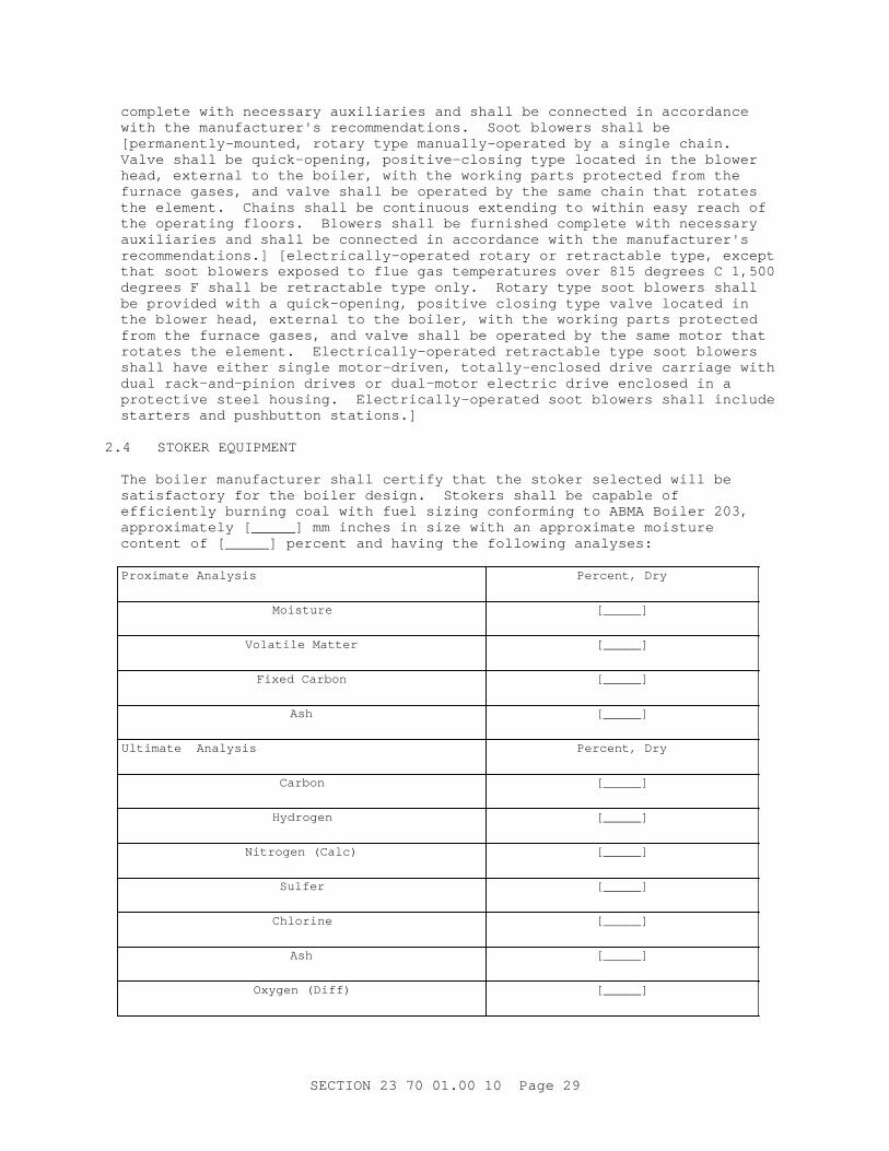
The boi l er manuf act ur er shal l cer t i f y t hat t he st oker sel ect ed wi l l be sat i sf act or y f or t he boi l er desi gn. St oker s shal l be capabl e of ef f i c i ent l y bur ni ng coal wi t h f uel s i z i ng conf or mi ng t o ABMA Boi l er 203, appr oxi mat el y [ _____] mm i nches i n s i ze wi t h an appr oxi mat e moi st ur e cont ent of [ _____] per cent and havi ng t he f ol l owi ng anal yses:
Pr oxi mat e Anal ysi s Per cent , Dr y
Moisture [_____]
Vol at i l e Mat t er [_____]
Fi xed Car bon [_____]
Ash [_____]
Ul t i mat e Anal ysi s Per cent , Dr y
Carbon [_____]
Hydrogen [_____]
Ni t r ogen ( Cal c) [_____]
Sulfer [_____]
Chlorine [_____]
Ash [_____]
Oxygen ( Di f f ) [_____]
SECTI ON 23 70 01. 00 10 Page 29
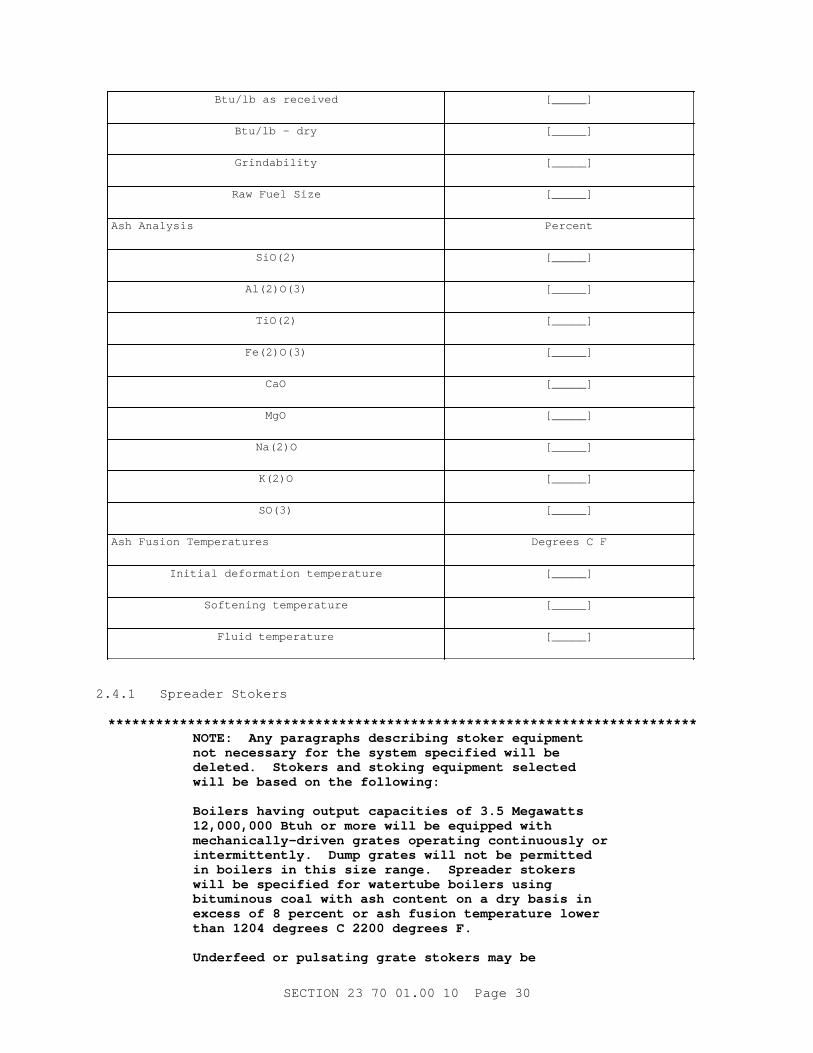
Bt u/ l b as r ecei ved [_____]
Bt u/ l b - dr y [_____]
Grindability [_____]
Raw Fuel Si ze [_____]
Ash Anal ysi s Percent
SiO(2) [_____]
Al(2)O(3) [_____]
TiO(2) [_____]
Fe(2)O(3) [_____]
CaO [_____]
MgO [_____]
Na(2)O [_____]
K(2)O [_____]
SO(3) [_____]
Ash Fusi on Temper at ur es Degr ees C F
I ni t i al def or mat i on t emper at ur e [_____]
Sof t eni ng t emper at ur e [_____]
Fl ui d t emper at ur e [_____]
2. 4. 1 Spr eader St oker s
**************************************************************************NOTE: Any par agr aphs descr i bi ng st oker equi pment not necessar y f or t he syst em speci f i ed wi l l be del et ed. St oker s and st oki ng equi pment sel ect ed wi l l be based on t he f ol l owi ng:
Boi l er s havi ng out put capaci t i es of 3. 5 Megawat t s 12, 000, 000 Bt uh or mor e wi l l be equi pped wi t h mechani cal l y- dr i ven gr at es oper at i ng cont i nuousl y or i nt er mi t t ent l y. Dump gr at es wi l l not be per mi t t ed i n boi l er s i n t hi s s i ze r ange. Spr eader st oker s wi l l be speci f i ed f or wat er t ube boi l er s usi ng bi t umi nous coal wi t h ash cont ent on a dr y basi s i n excess of 8 per cent or ash f usi on t emper at ur e l ower t han 1204 degr ees C 2200 degr ees F.
Under f eed or pul sat i ng gr at e st oker s may be
SECTI ON 23 70 01. 00 10 Page 30
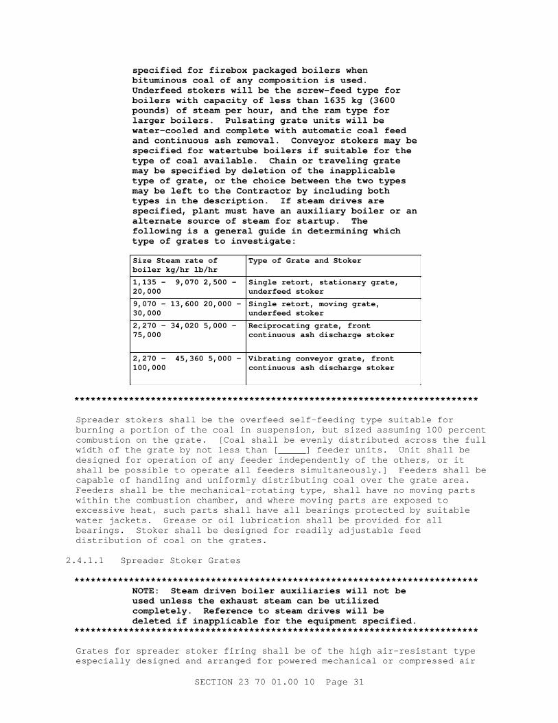
speci f i ed f or f i r ebox packaged boi l er s when bi t umi nous coal of any composi t i on i s used. Under f eed st oker s wi l l be t he scr ew- f eed t ype f or boi l er s wi t h capaci t y of l ess t han 1635 kg ( 3600 pounds) of st eam per hour , and t he r am t ype f or l ar ger boi l er s. Pul sat i ng gr at e uni t s wi l l be wat er - cool ed and compl et e wi t h aut omat i c coal f eed and cont i nuous ash r emoval . Conveyor st oker s may be speci f i ed f or wat er t ube boi l er s i f sui t abl e f or t he t ype of coal avai l abl e. Chai n or t r avel i ng gr at e may be speci f i ed by del et i on of t he i nappl i cabl e t ype of gr at e, or t he choi ce bet ween t he t wo t ypes may be l ef t t o t he Cont r act or by i ncl udi ng bot h t ypes i n t he descr i pt i on. I f s t eam dr i ves ar e speci f i ed, pl ant must have an auxi l i ar y boi l er or an al t er nat e sour ce of st eam f or st ar t up. The f ol l owi ng i s a gener al gui de i n det er mi ni ng whi ch t ype of gr at es t o i nvest i gat e:
Si ze St eam r at e of boi l er kg/ hr l b/ hr
Type of Gr at e and St oker
1, 135 - 9, 070 2, 500 - 20,000
Si ngl e r et or t , st at i onar y gr at e, under f eed st oker
9, 070 - 13, 600 20, 000 - 30,000
Si ngl e r et or t , movi ng gr at e, under f eed st oker
2, 270 - 34, 020 5, 000 - 75,000
Reci pr ocat i ng gr at e, f r ont cont i nuous ash di schar ge st oker
2, 270 - 45, 360 5, 000 - 100,000
Vi br at i ng conveyor gr at e, f r ont cont i nuous ash di schar ge st oker
**************************************************************************
Spr eader st oker s shal l be t he over f eed sel f - f eedi ng t ype sui t abl e f or bur ni ng a por t i on of t he coal i n suspensi on, but s i zed assumi ng 100 per cent combust i on on t he gr at e. [ Coal shal l be evenl y di st r i but ed acr oss t he f ul l wi dt h of t he gr at e by not l ess t han [ _____] f eeder uni t s. Uni t shal l be desi gned f or oper at i on of any f eeder i ndependent l y of t he ot her s, or i t shal l be possi bl e t o oper at e al l f eeder s s i mul t aneousl y. ] Feeder s shal l be capabl e of handl i ng and uni f or ml y di st r i but i ng coal over t he gr at e ar ea. Feeder s shal l be t he mechani cal - r ot at i ng t ype, shal l have no movi ng par t s wi t hi n t he combust i on chamber , and wher e movi ng par t s ar e exposed t o excessi ve heat , such par t s shal l have al l bear i ngs pr ot ect ed by sui t abl e wat er j acket s. Gr ease or oi l l ubr i cat i on shal l be pr ovi ded f or al l bear i ngs. St oker shal l be desi gned f or r eadi l y adj ust abl e f eed di st r i but i on of coal on t he gr at es.
2. 4. 1. 1 Spr eader St oker Gr at es
**************************************************************************NOTE: St eam dr i ven boi l er auxi l i ar i es wi l l not be used unl ess t he exhaust st eam can be ut i l i zed compl et el y. Ref er ence t o st eam dr i ves wi l l be del et ed i f i nappl i cabl e f or t he equi pment speci f i ed.
**************************************************************************
Gr at es f or spr eader st oker f i r i ng shal l be of t he hi gh ai r - r esi st ant t ype especi al l y desi gned and ar r anged f or power ed mechani cal or compr essed ai r
SECTI ON 23 70 01. 00 10 Page 31
act uat ed dumpi ng i n sect i ons. Openi ngs shal l pr ovi de pr oper di st r i but i on of ai r under t he f uel bed. [ Gr at es shal l be i n sect i ons t o mat ch t he f eeder s wi t h pr ovi s i ons f or shut t i ng of f t he f or ced dr af t t o each sect i on so t hat any sect i on of t he gr at e can be c l eaned whi l e t he ot her s r emai n i n ser vi ce. ] Gr at es shal l be heavy- dut y, heat - r esi st i ng cast - i r on. Mechani cal dumpi ng shal l be wi t h [ st eam- ] [ ai r - ] [ wat er - ] act uat ed power cyl i nder s connect ed t o t he gr at es, and gr at es shal l be f ur ni shed compl et e wi t h cyl i nder s, l i nkages, val ves, and pi pi ng as r equi r ed. Each sect i on shal l dump i ndependent l y of ot her sect i ons. Necessar y over - f i r e ai r j et s compl et e wi t h f ans, duct s, and ai r cont r ol val ves shal l be pr ovi ded as r equi r ed f or pr oper t ur bul ence and combust i on. Gr at e dr i ves shal l be i ndependent of f eeder dr i ves t o pr ovi de i ndependent speed var i at i on of f eeder s and gr at es.
2. 4. 1. 2 Tr avel i ng Gr at es
Tr avel i ng gr at es shal l be hi gh ai r - r esi st ant t ype especi al l y desi gned f or spr eader st oker f i r i ng and f or cont i nuous ash di schar ge. Openi ngs shal l pr ovi de pr oper di st r i but i on of ai r under t he f uel bed. Gr at es shal l be heavy- dut y, heat - r esi st i ng cast - i r on, and i ndi v i dual sect i ons shal l be r epl aceabl e wi t hout t aki ng t he gr at e out of ser vi ce. Ai r seal s ar ound gr at e shal l hol d ai r l eakage t o a mi ni mum. Movi ng gr at es shal l be f ur ni shed compl et e wi t h suppor t i ng st eel , shaf t s, spr ocket s, chai n, gear s, ski d bar s, and bear i ngs as r equi r ed. The f r ont end of t he gr at es wher e t he ash i s di schar ged shal l be encl osed wi t h a dust - t i ght encl osur e made of heavy cast - i r on pl at es not l ess t han 15. 9 mm 5/ 8 i nch t hi ck and pr oper l y pr ot ect ed wi t h f i r ebr i ck wher e exposed t o t he f ur nace, or shal l be of r ef r act or y- l i ned st eel pl at e. The ver t i cal f r ont s of t he encl osur e shal l be f i t t ed wi t h r ef r act or y- l i ned i nspect i on and access door s, one f or each f eeder . The r oof of t he encl osur e shal l be seal ed wi t h r ef r act or y t o pr ot ect t he met al par t s f r om t he f ur nace t emper at ur e. The under si de of t he gr at es shal l be encl osed t o f or m a chamber . Hopper f or r ecei v i ng t he ashes shal l be const r uct ed as i ndi cat ed or as r ecommended by t he manuf act ur er . Over - f i r e ai r j et s shal l be pr ovi ded as r equi r ed f or pr oper t ur bul ence and combustion.
2. 4. 1. 3 Vi br at i ng Gr at e
Vi br at i ng gr at e of hi gh ai r - r esi st ant t ype shal l be especi al l y desi gned f or spr eader st oker f i r i ng and f or cont i nuous ash di schar ge. Gr at es shal l be ei t her ai r - or wat er - cool ed wi t h openi ngs t o pr ovi de pr oper di st r i but i on of ai r under t he f uel bed. Gr at es shal l be heavy- dut y, heat - r esi st i ng cast i r on and i ndi v i dual sect i ons shal l be r epl aceabl e. A manual adj ust ment shal l be pr ovi ded t o r egul at e t he ash bed t hi ckness and ashes shal l be aut omat i cal l y di schar ged t o t he ash pi t . The f r ont of t he gr at es wher e t he ash i s di schar ged shal l be encl osed wi t h a dust - t i ght encl osur e of heavy cast - i r on pl at es not l ess t han 15. 9 mm 5/ 8 i nch t hi ck and pr oper l y pr ot ect ed wi t h f i r ebr i ck wher e exposed t o t he f ur nace, or shal l be of r ef r act or y- l i ned st eel pl at e. The ver t i cal f r ont s of t hi s encl osur e shal l be f i t t ed wi t h r ef r act or y- l i ned i nspect i on and access door s, one t o each f eeder . Roof of t hi s encl osur e shal l be seal ed wi t h r ef r act or y f or pr ot ect i ng t he met al par t s f r om t he f ur nace t emper at ur e. The under si de of t he gr at es shal l be encl osed t o f or m a chamber wi t h a hopper f or r ecei v i ng t he ashes. Over - f i r e ai r j et s shal l be pr ovi ded f or t ur bul ence and combustion.
2. 4. 1. 4 St oker Cont r ol s
St oker cont r ol s t hat accur at el y r egul at e t he coal f eed r at e shal l be of t he
SECTI ON 23 70 01. 00 10 Page 32
t ype r equi r ed f or connect i on t o t he combust i on cont r ol syst em. Manual set t i ng of t he coal f eed r at e wi t h var i at i on of st oker f eed, as r equi r ed t o mai nt ai n any desi r ed capaci t y bet ween 50 and 110 per cent of boi l er capaci t y, shal l be possi bl e wi t hout di sconnect i ng l i nkage. Separ at e f eeder and gr at e dr i ves shal l be pr ovi ded. Gr at e shal l be dr i ven t hr ough a var i abl e speed t r ansmi ssi on wi t h devi ces f or changi ng speed i nt er l ocked wi t h f uel f eed r egul at i on. Manual adj ust ment of gr at e speed shal l onl y be f or al l owi ng synchr oni zat i on wi t h f uel f eed. Al l gear s and chai ns of t he var i abl e speed t r ansmi ssi on and gear r educt i on uni t s, as r equi r ed, shal l r un i n a bat h of oi l and be encl osed i n a dust - t i ght and oi l - t i ght case. Fr ont and r ear shaf t s of t he gr at es shal l be f i t t ed wi t h a f or ced l ubr i cat i on syst em wi t h f i t t i ngs l ocat ed out s i de t he set t i ng. Al l bear i ngs shal l be of t he ant i f r i c t i on t ype wi t h har dened i nner and out er r aces f i t t ed wi t h dust seal s and easi l y accessi bl e f or ced l ubr i cat i on f i t t i ngs. St oker [ and gr at e] shal l be pr ovi ded wi t h saf et y r el ease devi ces t o pr ot ect t he mechani sm f r om f or ei gn mat er i al s or obst r uct i ons. St oker shal l be dr i ven by [ el ect r i c mot or ] [ st eam t ur bi ne] . [ El ect r i c mot or shal l be t ot al l y encl osed f an- cool ed f or i nst al l at i on i n Cl ass I I , Di v i s i on 1, Gr oup F hazar dous l ocat i on i n accor dance wi t h NFPA 70. Mot or st ar t er shal l be magnet i c [ acr oss- t he- l i ne] [ r educed vol t age st ar t ] t ype wi t h [ gener al - pur pose] [ dust - t i ght ] [ expl osi on- pr oof ] encl osur e. ] [ St eam t ur bi nes ut i l i zed f or st oker dr i ves shal l conf or m t o NEMA SM 23.]
2. 4. 1. 5 Hoppers
Hopper s shal l be const r uct ed of s t eel pl at es not l ess t han 6. 4 mm 1/ 4 i nch t hi ck and shal l have a capaci t y of not l ess t han [ _____] kg pounds per f eeder . Hopper s shal l be pr ovi ded wi t h c l ean- out door s i n t he f r ont of each f eeder . Coal f eed t o t he hopper s shal l be f i t t ed wi t h concave t ype t r ansi t i ons t o ensur e t he pr oper di st r i but i on of coal and coal f i nes acr oss t he wi dt h of t he hopper s. St oker f r ont pl at e shal l f or m t he f r ont of t he boi l er f or t he f ul l wi dt h of t he boi l er and f r om t he f i r i ng f l oor t o some poi nt above t he st oker wher e i t shal l connect t o t he boi l er st r uct ur al f r ami ng. Fr ont shal l be cast - i r on or st eel pl at e r ef r act or y l i ned wi t h [ auxi l i ar y f i r i ng door s and] c l ean- out door s of r ef r act or y l i ned cast - i r on. St r uct ur al f r ami ng as r equi r ed shal l suppor t t he st oker and i t s component s f r om t he boi l er f oundat i on or boi l er r oom f l oor . The ar ea under t he gr at es shal l be di v i ded i nt o not l ess t han f our ai r t i ght zones f or suppl y of f or ced dr af t havi ng zone cont r ol damper s wi t h ext er nal i ndi cat i ng oper at i ng and l ocki ng devi ces. Al l pr essur e par t s f or wat er - cool ed gr at es i ncl udi ng wat er t ubes, header s, and val ves f ur ni shed by t he st oker manuf act ur er shal l be f or boi l er pr essur e speci f i ed and shal l be const r uct ed i n conf or mance wi t h ASME BPVC SEC I .
2. 4. 1. 6 Over - Fi r e Tur bul ence and Ci nder and Dust Rei nj ect i on Syst em
Spr eader st oker s shal l be pr ovi ded wi t h over - f i r e t ur bul ence and ci nder - and- dust r ei nj ect i on syst ems. Ei t her ai r or st eam may be used as t he t r anspor t medi um. Ai r syst ems shal l be pr ovi ded wi t h oper at i ng ai r by a s i ngl e, l ow vol ume, hi gh- pr essur e f an, dr i ven by a spl ashpr oof el ect r i c mot or . The r ei nj ect i on syst em ej ect or s shal l be pr oper l y desi gned, l ocat ed, and si zed f or maxi mum f l y ash pi ckup f r om al l poi nt s. Nozzl es f or each syst em shal l be equi pped wi t h manomet er connect i ons and heavy- dut y adj ust abl e damper s f i t t ed wi t h l ocki ng devi ces and posi t i on i ndi cat or s. Nozzl es shal l pr ovi de maxi mum combust i on ef f i c i ency and f ur nace t ur bul ence. A manomet er connect i on and a per manent manomet er shal l be pr ovi ded i mmedi at el y downst r eam f r om t he mai n r ei nj ect i on ai r suppl y damper . A por t abl e manomet er shal l be pr ovi ded.
SECTI ON 23 70 01. 00 10 Page 33
2. 4. 2 Under f eed St oker s
**************************************************************************NOTE: Any par agr aphs descr i bi ng st oker equi pment not necessar y f or t he syst em speci f i ed wi l l be deleted.
**************************************************************************
2. 4. 2. 1 Si ngl e Ret or t , Heavy- Dut y Ram- Type St oker s
Si ngl e r et or t , heavy- dut y r am- t ype st oker s shal l be equi pped wi t h st at i onar y or movi ng gr at es and s i de dump pl at es, and shal l be pr ovi ded wi t h [ st eam] [ el ect r i c mot or ] dr i ve and al l necessar y auxi l i ar y equi pment . Dumpi ng power cy l i nder s shal l be compr essed ai r act uat ed. Coal shal l be f ed f r om t he hopper i nt o t he r et or t by means of a r am and shal l be evenl y di st r i but ed al ong t he f ul l l engt h of t he r et or t wi t h auxi l i ar y pusher bl ocks on a pusher r od l ocat ed at t he bot t om of t he r et or t and act uat ed by t he coal r am. Damper s shal l be pr ovi ded bet ween ash pi t s and mai n ai r chamber under st oker t o per mi t cont r ol of ai r di st r i but i on t o t he gr at e sur f ace. Damper s shal l be ar r anged f or oper at i on f r om t he f r ont pl at e of t he boi l er . Ai r di st r i but i on shal l be such t hat t he ai r pr essur e i s gr eat est wher e t he f uel bed i s t he t hi ckest . Ai r quant i t y shal l var y i n di r ect pr opor t i on wi t h coal f eed r at e and shal l be cont r ol l ed aut omat i cal l y .
2. 4. 2. 1. 1 Gr at e Sur f ace
Gr at e sur f ace shal l i ncl ude t he under f eed r et or t ar ea, ai r admi t t i ng t uyer es, s i de combust i on gr at es, and t he s i de dumpi ng pl at es. Ret or t s shal l be sect i onal const r uct i on of l ar ge capaci t y and pr oper shape t o di st r i but e coal uni f or ml y over t he ent i r e gr at e sur f ace wi t h a mi ni mum of movi ng par t s wi t hi n t he f ur nace. St oker s havi ng t ot al gr at e wi dt h of mor e t han 2. 1 m 7 f eet shal l have movabl e gr at es pr ovi di ng posi t i ve l at er al f eedi ng of t he coal f r om t he r et or t t owar d t he dump pl at es. Ret or t and gr at e sect i ons shal l be const r uct ed of heavy- dut y, heat - r esi st i ng cast i r on, shal l be cor ed f or pr oper ai r di st r i but i on, and shal l be desi gned f or easy r epl acement of i ndi v i dual sect i ons. Ash dump pl at es shal l be pr ovi ded wi t h necessar y l ever s and l i nkage f or hand oper at i on f r om t he f r ont of t he boiler.
2. 4. 2. 1. 2 Ram Feed
Ram f eed shal l be mechani cal [ st eam] [ pneumat i c or hydr aul i c] [ dr i ven by an el ect r i c mot or connect ed t hr ough an ef f i c i ent gear r educt i on uni t , cr ankshaf t , and connect i ng r od] . [ Mot or s shal l be t ot al l y encl osed f an- cool ed t ype [ f or i nst al l at i on i n a Cl ass I I , Di v i s i on 1, Gr oup F hazar dous l ocat i on i n accor dance wi t h NFPA 70] ] . [ Mot or st ar t er shal l be magnet i c [ acr oss- t he- l i ne] [ r educed vol t age st ar t ] t ype wi t h [ gener al - pur pose] [ dust - t i ght ] [ expl osi on- pr oof ] encl osur e. ] St oker cont r ol s shal l be f or connect i on t o t he combust i on cont r ol syst em t o accur at el y r egul at e t he coal f eed r at e. Manual set t i ng of t he coal f eed r at e shal l be possi bl e wi t hout di sconnect i ng l i nkage, wi t h var i at i on of st oker f eed as r equi r ed t o mai nt ai n any desi r ed capaci t y bet ween 25 and 110 per cent of boi l er capaci t y i n 10 or mor e equal i ncr ement s. Regul at i on of t he coal f eed r at e shal l be by var yi ng t he t i me i ncr ement s bet ween st r okes of t he r am. A t hr ow- out r el ease shal l pr ot ect t he coal f eedi ng mechani sm f r om i nj ur y i n case f or ei gn mat er i al s obst r uct nor mal oper at i on.
SECTI ON 23 70 01. 00 10 Page 34
2. 4. 2. 1. 3 Hoppers
Hopper s shal l be const r uct ed of s t eel pl at es not l ess t han 6. 4 mm 1/ 4 i nch t hi ck and shal l have a capaci t y of not l ess t han [ _____] kg pounds. Hopper s shal l be pr ovi ded wi t h c l ean- out door s. St oker f r ont pl at e shal l f or m t he f r ont of t he boi l er f or t he f ul l wi dt h of t he boi l er and ext end f r om t he f i r i ng f l oor t o some poi nt above t he st oker wher e i t shal l connect t o t he boi l er st r uct ur al f r ami ng. Fr ont shal l be cast - i r on or st eel pl at e, r ef r act or y l i ned wi t h [ auxi l i ar y f i r i ng door s and] c l ean- out door s of r ef r act or y l i ned cast - i r on. St r uct ur al f r ami ng, as r equi r ed, shal l suppor t t he st oker and i t s component s f r om t he boi l er f oundat i on or boi l er r oom f l oor . Wat er spr ay pi pes and nozzl es shal l be pr ovi ded f or quenchi ng t he ashes i n t he ash pi t .
2. 4. 2. 2 Si ngl e Ret or t Scr ew Type St oker s
Si ngl e r et or t , heavy- dut y, scr ew f eed st oker s shal l be equi pped wi t h r ect angul ar f i r epot , s i de dump gr at es, f or ced- dr af t f an, el ect r i c- mot or dr i ve, and al l necessar y auxi l i ar y equi pment . Coal shal l be f ed f r om t he hopper i nt o t he r et or t wi t h a spi r al wor m conveyor desi gned t o f eed a const ant amount of coal and t o pr event coal f r om packi ng i n t he wor m. [ Damper s shal l be pr ovi ded bet ween ash pi t s and mai n ai r chamber under st oker t o per mi t cont r ol of ai r di st r i but i on t o t he gr at e sur f ace. Damper s shal l be ar r anged t o be oper at ed manual l y f r om t he f r ont pl at e of t he boi l er . ] The st oker shal l be pr ovi ded wi t h an i nt egr al , f or ced- dr af t f an dr i ven by t he st oker mot or . Ai r quant i t y shal l var y i n di r ect pr opor t i on wi t h t he coal f eed r at e and shal l be cont r ol l ed aut omat i cal l y . Ret or t s and gr at es shal l be const r uct ed of heavy- dut y, heat - r esi st i ng cast - i r on, shal l be cor ed f or pr oper ai r di st r i but i on, and shal l be desi gned f or easy r epl acement of i ndi v i dual sect i ons. Ret or t s shal l be of pr oper s i ze and shape t o di st r i but e coal uni f or ml y over t he ent i r e gr at e sur f ace. St at i onar y gr at es shal l be pr ovi ded on al l s i des of t he r et or t as r equi r ed t o sui t t he f i r ebox. [ Ash dump gr at es shal l be pr ovi ded on each si de of t he r et or t compl et e wi t h necessar y l ever s and l i nkages f or hand oper at i on f r om t he f r ont of t he boi l er . ] El ect r i c mot or shal l be bel t - connect ed t o an ef f i c i ent gear r educt i on uni t whi ch shal l dr i ve t he f eed scr ew and f or ced- dr af t f an. Gear r educt i on uni t shal l be i mmer sed i n oi l i n a dust pr oof housi ng. St oker cont r ol s shal l be sui t abl e f or connect i on t o t he combust i on cont r ol syst em t o accur at el y r egul at e t he coal f eed r at e. Feed r at e cont r ol shal l al l ow manual set t i ng f or not l ess t han t hr ee speeds and neut r al , i n equal i ncr ement s, wi t h speed changes possi bl e whi l e st oker i s r unni ng. A sui t abl e r el ease shal l pr ot ect t he coal f eedi ng mechani sm f r om i nj ur y i n case f or ei gn mat er i al s obst r uct nor mal oper at i on. Mot or s shal l be t ot al l y encl osed f an- cool ed t ype [ f or i nst al l at i on i n a Cl ass I I , Di v i s i on 1, Gr oup F hazar dous l ocat i on i n accor dance wi t h NFPA 70] . Mot or st ar t er shal l be [ manual ] [ [ magnet i c] [ acr oss- t he- l i ne] [ r educed vol t age st ar t ] t ype wi t h [ gener al - pur pose] [ dust - t i ght ] [ expl osi on- pr oof ] encl osur e. ] Hopper s shal l be const r uct ed of 6. 4 mm 1/ 4 i nch st eel sheet , mi ni mum, shal l be r ei nf or ced, and shal l have a capaci t y of not l ess t han [ _____] kg pounds. Hopper s shal l be pr ovi ded wi t h sui t abl e c l eanout . Feed scr ew shal l be r emovabl e and conveyor compar t ment shal l have c l eanout . St oker shal l r est on boi l er r oom f l oor .
2. 4. 3 Conveyor St oker s
**************************************************************************NOTE: Any par agr aphs descr i bi ng st oker equi pment not necessar y f or t he syst em speci f i ed wi l l be deleted.
SECTI ON 23 70 01. 00 10 Page 35
**************************************************************************
Conveyor st oker s shal l be of t he gr at e l evel f eed, f or ced- dr af t [ chai n gr at e] [ t r avel i ng gr at e] t ype wi t h hopper s, f eed gat e, dr i ve shaf t , spr ocket wheel s, gr at e, [ el ect r i c mot or ] [ st eam] dr i ve, and al l necessar y auxi l i ar y equi pment . Coal shal l be f ed aut omat i cal l y at a const ant r at e f r om t he hopper ont o t he movi ng gr at e and shal l be evenl y di st r i but ed acr oss t he f ul l wi dt h of t he gr at e. The st oker f r ame shal l be pr ovi ded wi t h not l ess t han f our ai r - t i ght zones f or suppl y of f or ced dr af t and shal l have sui t abl e zone cont r ol damper s wi t h ext er nal i ndi cat i ng, oper at i ng, and l ocki ng devi ces.
2. 4. 3. 1 Grates
Gr at es shal l have i ndi v i dual sect i ons const r uct ed of heavy- dut y, heat - r esi st i ng cast - i r on, shal l be f i t t ed or cor ed f or pr oper ai r di st r i but i on, and shal l be desi gned f or easy r epl acement of i ndi v i dual sect i ons. [ Chai n gr at es shal l have st agger ed l i nks connect ed by pi ns t o f or m a cont i nuous f l at chai n t he f ul l wi dt h of t he f ur nace. ] [ Tr avel i ng gr at es shal l have gr at e bl ocks mount ed on car r i er bar s whi ch, i n t ur n, shal l be f ast ened t o t wo or mor e dr i ve chai ns t o f or m a cont i nuous f l at gr at e sur f ace t he f ul l wi dt h of t he f ur nace. ] Cont i nuous gr at es shal l be suppor t ed at t he ends by sui t abl e spr ocket s and at i nt er medi at e poi nt s on sui t abl e t r acks or ski ds.
2. 4. 3. 2 Gr at e Oper at i on
**************************************************************************NOTE: St eam dr i ven boi l er auxi l i ar i es wi l l not be used unl ess t he exhaust st eam can be ut i l i zed compl et el y. Ref er ence t o st eam dr i ves wi l l be del et ed i f i nappl i cabl e f or t he equi pment speci f i ed.
**************************************************************************
Conveyor gr at e shal l be dr i ven by [ el ect r i c mot or connect ed t hr ough a sui t abl e speed r educt i on uni t ] [ s t eam] [ hydr aul i cal l y oper at ed var i abl e speed dr i ve] . Gear s and chai ns r equi r ed f or t he dr i ve shal l be encl osed i n a dust pr oof and oi l - t i ght housi ng. Mai n shaf t s f or t he gr at es shal l have a f or ced syst em of l ubr i cat i on wi t h f i t t i ngs l ocat ed out s i de t he casi ng or have sel f l ubr i cat i ng bear i ngs. I f t he f or ced l ubr i cat i on syst em i s suppl i ed, bear i ngs shal l be f i t t ed wi t h dust seal s and easi l y accessi bl e f or ced l ubr i cat i on f i t t i ngs. St oker cont r ol s shal l be sui t abl e f or connect i on t o t he combust i on cont r ol syst em t o accur at el y r egul at e t he coal f eed r at e. Manual set t i ng of t he coal f eed r at e by var yi ng st oker f eed, as r equi r ed t o mai nt ai n any desi r ed capaci t y bet ween 25 t o 125 per cent of boi l er capaci t y, shal l be possi bl e wi t hout di sconnect i ng l i nkage. Feed r at e shal l be changed by var yi ng t he speed of t he gr at e. Ai r vol ume shal l aut omat i cal l y var y i n di r ect pr opor t i on wi t h t he f eed r at e. Possi bl e f eed r at e shal l var y i n not l ess t han 10 equal i ncr ement s. [ El ect r i c mot or shal l be t ot al l y encl osed f an- cool ed t ype [ f or i nst al l at i on i n a Cl ass I I , Di v i s i on 1, Gr oup F hazar dous l ocat i on i n accor dance wi t h NFPA 70. ] ] [ Mot or st ar t er shal l be [ manual ] [ magnet i c] [ acr oss- t he- l i ne] [ r educed vol t age st ar t ] t ype wi t h [ gener al - pur pose] [ dust - t i ght ] [ expl osi on- pr oof ] enclosure.]
2. 4. 3. 3 Hoppers
Hopper s shal l be const r uct ed of s t eel pl at es not l ess t han 6. 4 mm 1/ 4 i nch t hi ck, shal l have a capaci t y of not l ess t han [ _____] kg pounds, and shal l
SECTI ON 23 70 01. 00 10 Page 36
be pr ovi ded wi t h sui t abl e c l eanout door s. Coal f eed t o t he hopper s shal l be f i t t ed wi t h concave t ype t r ansi t i ons t o ensur e t he pr oper di st r i but i on of coal and coal f i nes acr oss t he wi dt h of t he hopper s. St oker f r ame shal l be const r uct ed of cast - i r on, cast st eel , or f or gi ngs, and al l par t s of t he st oker , except t he gr at es, shal l be pr oper l y cool ed or ot her wi se pr ot ect ed f r om t he f ur nace heat t o pr event damage by war pi ng or undue expansi on. Fur nace ar r angement and shape shal l be as r ecommended by t he st oker manuf act ur er t o ensur e pr oper combust i on of t he f uel . St oker f r ont pl at e shal l f or m t he f r ont of t he boi l er f or t he f ul l wi dt h of t he boi l er and ext end f r om t he f i r i ng f l oor t o some poi nt above t he st oker wher e i t shal l connect t o t he boi l er st r uct ur al f r ami ng. Fr ont shal l be cast - i r on or st eel pl at e, r ef r act or y l i ned wi t h c l eanout door s of r ef r act or y l i ned cast i r on. St r uct ur al f r ami ng, as r equi r ed, shal l suppor t t he st oker and i t s component s f r om t he boi l er f oundat i on or boi l er r oom f l oor . At t he end of t he gr at e, t he ash shal l be di schar ged i nt o a bunker or pi t as i ndi cat ed. The bunker shal l have a dust - t i ght encl osur e made of st eel pl at es not l ess t han 15. 9 mm 5/ 8 i nch t hi ck, pr oper l y pr ot ect ed wi t h f i r ebr i ck wher e exposed t o t he f ur nace; shal l be f i t t ed wi t h cast - i r on, r ef r act or y l i ned i nspect i on and access door s; and shal l have pr ovi s i ons f or ash r emoval .
2. 4. 4 Vi br at i ng Gr at e St oker s
**************************************************************************NOTE: Any par agr aphs descr i bi ng st oker equi pment not necessar y f or t he syst em speci f i ed wi l l be deleted.
**************************************************************************
Vi br at i ng gr at e st oker s shal l be t he gr at e l evel f eed, f or ced- dr af t t ype wi t h t he v i br at i ng act i on of t he gr at e used t o f eed t he coal f r om t he hopper t hr ough t he f ur nace and di schar ge t he ashes i nt o t he ash pi t . St oker s shal l be compl et e wi t h hopper , f eed gat e, gr at e, dr i ve mechani sm, and al l necessar y auxi l i ar y equi pment . Coal shal l be aut omat i cal l y f ed f r om t he hopper ont o t he gr at e and shal l be evenl y di st r i but ed acr oss t he f ul l wi dt h of t he gr at e. A manual adj ust ment shal l be pr ovi ded t o r egul at e t he f uel bed t hi ckness. Ashes shal l be aut omat i cal l y and cont i nuousl y di schar ged t o t he ash pi t . The ar ea under t he gr at es shal l be di v i ded i nt o not l ess t han f our ai r t i ght zones f or f or ced dr af t suppl y and shal l have sui t abl e zone cont r ol damper s wi t h ext er nal i ndi cat i ng, oper at i ng, and l ocki ng devi ces.
2. 4. 4. 1 Grates
Gr at es shal l be ei t her ai r cool ed or wat er cool ed wi t h gr at e bar s i n i nt i mat e cont act wi t h t he wat er t ubes. Gr at es shal l have i ndi v i dual l y r epl aceabl e sect i ons of i r on or st eel sui t abl e f or t he t emper at ur es encount er ed. Pr essur e par t s, i nc l udi ng wat er t ubes, header s, and val ves shal l be sui t abl e f or boi l er pr essur e speci f i ed and shal l be const r uct ed i n accor dance wi t h ASME BPVC SEC I . Gr at e sect i ons shal l be pr oper l y desi gned f or even ai r di s t r i but i on over t he ent i r e gr at e ar ea.
2. 4. 4. 2 St oker Cont r ol s
St oker cont r ol s shal l be desi gned f or connect i on t o t he combust i on cont r ol syst em t o accur at el y r egul at e t he coal f eed r at e and shal l be ar r anged f or manual oper at i on i ndependent of t he combust i on cont r ol syst em. Var i at i on of coal f eed r at e shal l be accompl i shed by changi ng t he l engt h of t i me of v i br at i ons. Vi br at i on gener at or shal l be bel t connect ed or gear connect ed t o t he el ect r i c mot or . Uni t shal l be f r ee of any v i br at i on t hat may damage
SECTI ON 23 70 01. 00 10 Page 37
ot her par t s of t he boi l er or t he bui l di ng st r uct ur e. Bear i ngs r equi r i ng l ubr i cat i on shal l be pr ovi ded wi t h easi l y accessi bl e l ubr i cat i on f i t t i ngs. Combust i on ai r vol ume shal l aut omat i cal l y var y i n di r ect pr opor t i on wi t h t he coal f eed r at e. St oker shal l be dr i ven by [ el ect r i c mot or ] [ st eam t ur bi ne] . [ Mot or shal l be hi gh- st ar t i ng t or que [ t ot al l y encl osed, nonvent i l at ed] [ t ot al l y encl osed, f an- cool ed] [ t ot al l y encl osed, f an- cool ed sui t abl e f or i nst al l at i on i n a Cl ass I I , Di v i s i on 1, Gr oup F hazar dous l ocat i on i n accor dance wi t h t he NFPA 70] . ] [ Mot or st ar t er shal l be magnet i c, r ever s i ng, [ acr oss- t he- l i ne] [ r educed vol t age st ar t ] t ype wi t h [ gener al - pur pose] [ dust - t i ght ] [ expl osi on- pr oof ] encl osur e. ]
2. 4. 4. 3 Hoppers
Hopper s shal l be const r uct ed of s t eel pl at es not l ess t han 6. 4 mm 1/ 4 i nch t hi ck, shal l have a capaci t y not l ess t han [ _____] kg pounds, and shal l be pr ovi ded wi t h a sui t abl e met hod of c l eanout . Fur nace ar ches of a desi gn sui t abl e f or t he i nt ended use and a t ype t hat wi l l ensur e pr oper combust i on of t he f uel shal l be pr ovi ded. Lower f ur nace si dewal l header s i n a wat er wal l boi l er shal l be i ncl i ned t o accommodat e t he i ncl i ned gr at e ar r angement . St oker f r ont shal l f or m t he f r ont of t he boi l er f or t he f ul l wi dt h of t he boi l er and shal l ext end f r om t he f i r i ng f l oor t o some poi nt above t he st oker wher e i t shal l connect t o t he boi l er st r uct ur al f r ami ng. Fr ont shal l be cast - i r on or st eel pl at e r ef r act or y l i ned wi t h c l eanout and access door s of r ef r act or y l i ned cast - i r on. St r uct ur al f r ami ng, as r equi r ed, shal l suppor t t he st oker and i t s component s f r om t he boi l er f oundat i on or boi l er r oom f l oor . At t he end of t he gr at e t he ash shal l be di schar ged i nt o a bunker or pi t as i ndi cat ed. The bunker shal l have a dust - t i ght encl osur e made of st eel pl at es not l ess t han 15. 9 mm 5/ 8 i nch t hi ck pr oper l y pr ot ect ed wi t h f i r ebr i ck wher e exposed t o t he f ur nace and shal l be f i t t ed wi t h cast - i r on, r ef r act or y l i ned i nspect i on and access door s, and pr ovi s i ons f or ash r emoval as i ndi cat ed.
2. 5 PULVERI ZED COAL BOI LERS
**************************************************************************NOTE: Pul ver i zed coal boi l er s r equi r e speci al consi der at i on s i nce t hey ar e usual l y desi gned t o oper at e on one speci f i c t ype of coal and usual l y ar e ut i l i zed f or l ar ge uni t s wher e a st eady mi ni mum l oad of 68, 040 t o 90, 720 kg per hour 150, 000 t o 200, 000 pounds per hour i s assur ed.
Smal l hor i zont al t ype uni t s down t o 36, 290 kg per hour 80, 000 pounds per hour of st eam ar e avai l abl e, but hor i zont al uni t s al so wi l l r ange up t o 113, 400 kg per hour 250, 000 pounds per hour of st eam. Lar ger uni t s ar e usual l y t he ver t i cal t ype.
The t ype of pul ver i zer wi l l be det er mi ned f r om t he coal anal ysi s and t he boi l er manuf act ur er ' s r equi r ement s. The pul ver i zer sel ect ed al so af f ect s t he cont r ol syst em r equi r ement s. The f ur nace ash di sposal syst em component s wi l l depend on t he ash char act er i st i cs and EPA r equi r ement s. Vol umet r i c heat r el ease shoul d be 745. 2 Megaj oul es/ cubi c met er 20, 000 Bt u/ per cubi c f oot of f ur nace vol ume. Coal i s cr ushed i n a cent r al pl ant and st or ed i n bunker s. Each boi l er has t wo pul ver i zer s, f ed by a dr ag t ype coal f eeder , and i n t ur n f eed t he
SECTI ON 23 70 01. 00 10 Page 38
bur ner s. Thi s syst em r equi r es r oom wi t hi n t he pl ant t o accommodat e t he coal pul ver i zer s. Fi neness of pul ver i zed coal may var y wi t h di f f er ent desi gns, and f i ne pul ver i zed coal wi l l s i gni f i cant l y af f ect t he sel ect i on of ash handl i ng and pol l ut i on cont r ol equi pment and wi l l r equi r e speci al consi der at i on f or er osi on cont r ol on i nduced- dr af t f an. Wher e pul ver i zed coal boi l er s ar e speci f i ed, r ef er ence t o st oker f i r ed boi l er s wi l l be del et ed.
**************************************************************************
Wher e i ndi cat ed, pul ver i zed coal boi l er s shal l be pr ovi ded. Boi l er and boi l er accessor i es shal l be speci f i cal l y desi gned t o oper at e on t he f uel speci f i ed. Boi l er s shal l be compl et e wi t h coal f eeder s, cr usher s, dr yer s, bur ner s, i gni t i on syst em, ai r pr eheat er , economi zer , soot bl ower s, cont r ol s, and compl et e f ur nace ash handl i ng f aci l i t i es. Fl y ash col l ect i on and pol l ut i on cont r ol equi pment i s speci f i ed i n Sect i on 44 10 00 AI R POLLUTI ON CONTROL. Boi l er s shal l be [ hor i zont al ] [ ver t i cal ] t ype and shal l be [ t op] [ bot t om] suppor t ed. Ash hopper s shal l be dr y, r ef r act or y- l i ned t ype di v i ded i nt o compar t ment s, each of whi ch shal l have a hydr aul i cal l y- oper at ed c l ean- out door . The hopper shal l be suppor t ed f r om t he boi l er and a dr y seal shal l pr ovi de gast i ght connect i on. For ced dr af t and i nduced dr af t f ans shal l be f ur ni shed wi t h t he boi l er .
2. 5. 1 Coal Pul ver i zer s
Each boi l er shal l be pr ovi ded wi t h a mi ni mum of t wo pul ver i zer s ar r anged t o al l ow oper at i on of boi l er at r educed capaci t y when one pul ver i zer i s t aken out of ser vi ce ei t her f or mai nt enance or f or oper at i on of l ow l oads. Coal pul ver i zer shal l be pr ovi ded compl et e wi t h al l r equi r ed accessor i es such as r ot ar y dr um f eeder uni t , ai r pr eheat er , f ans f or dr y i ng coal by ei t her t he pr i mar y ai r or suct i on syst em, coal c l assi f i er di s t r i but or uni t , and shut of f coal val ves t o al l ow i sol at i on of i ndi v i dual bur ner s. Dr um f eeder uni t shal l have a t r amp met al r ej ect i on devi ce i ncor por at ed i n t he uni t .
2. 5. 2 Burners
Pul ver i zed coal bur ner s shal l be speci f i cal l y desi gned f or t he boi l er pr ovi ded. Bur ner shal l i ncl ude an i gni t i on syst em desi gned f or i gni t i on of pul ver i zed coal .
2. 5. 3 Fur nace Ash Syst em
**************************************************************************NOTE: Det ai l of pi pi ng suppor t ed i n t r enches wi l l appear on t he dr awi ngs.
**************************************************************************
The boi l er shal l be t he dr y bot t om t ype, di schar gi ng ash t o t he hopper compar t ment s. Pul ver i zed coal boi l er ash shal l be handl ed hydr aul i cal l y r at her t han pneumat i cal l y . Faci l i t i es f or pul ver i zed coal boi l er ash handl i ng shal l be as i ndi cat ed. Fl y ash shal l not be mi xed wi t h f ur nace ash but economi zer ash can be combi ned wi t h f ur nace ash as i ndi cat ed. Dual ash dewat er i ng bi ns t o al l ow r eci r cul at i on of ash conveyi ng wat er shal l be as i ndi cat ed. Each bi n shal l be pr ovi ded wi t h aut omat i c cont r ol s and hydr aul i cal l y oper at ed gat e f or ash unl oadi ng t o t r ucks or r ai l r oad car s. Hopper shal l be mai nt ai ned i n f l ooded condi t i on and hydr aul i cal l y oper at ed s l ui ce gat es shal l al l ow f or per i odi c r emoval of ash. Each ash hopper compar t ment shal l be f i t t ed wi t h doubl e- r ol l , el ect r i c mot or dr i ven c l i nker
SECTI ON 23 70 01. 00 10 Page 39
gr i nder s f i t t ed wi t h manganese st eel cr usher r ol l s and t eet h. Di schar ge f r om t he gr i nder s shal l be t o an adapt or or t o a sump f or f eed t o t he cent r i f ugal pump. Cent r i f ugal pump f or each hopper compar t ment shal l be pr ovi ded and shal l i ncor por at e speci al abr asi ve r esi st ant met al s and speci al seal s f or abr asi ve s l ur r y handl i ng. Dr i ves shal l be t ot al l y encl osed el ect r i c mot or s as i ndi cat ed. Ash s l ur r y conveyi ng pi pel i nes shal l be made of abr asi ve r esi st ant al l oy met al wi t h a Br i nel l har dness number of appr oxi mat el y 280. Wal l t hi ckness shal l be not l ess t han 13 mm 1/ 2 i nch and pi pe l engt hs shal l not exceed 5. 5 m 18 f eet . Fi t t i ngs shal l be of t he t angent end t ype. Fi t t i ngs shal l have a Br i nel l har dness number of appr oxi mat el y 400 and shal l have r emovabl e wear backs, wher e appl i cabl e, or shal l be of t he i nt egr al wear back t ype. Loadi ng f aci l i t i es f or ash r emoval of dewat er i ng bi ns shal l be as i ndi cat ed.
2. 5. 4 Pul ver i zer Rej ect s
Pul ver i zer r ej ect s such as t r amp i r on or pyr i t es shal l be col l ect ed i n hopper s adj acent t o each mi l l di schar ge spout . Hi gh- l evel hopper i ndi cat or s shal l be pr ovi ded t o i ni t i at e r ej ect r emoval , i n sequence, f r om each hopper t o t he cent r al hol di ng bi n by pr oper l y s i zed j et pumps. Mi l l di schar ge cont r ol gat es shal l be pr ovi ded and t he cont r ol syst em shal l be i nt er l ocked wi t h t he f ur nace ash r emoval syst em t o pr ovi de a compl et el y aut omat i c di sposal syst em. Di schar ge of mi l l r ej ect s i nt o t he ash hopper i s not accept abl e. The cent r al hol di ng bi n and l oadi ng f aci l i t i es shal l be as i ndi cat ed.
2. 5. 5 Cont r ol Syst ems
Pul ver i zed coal pl ant cont r ol syst ems shal l be i n accor dance wi t h NFPA 85 and shal l be i nt er l ocked t o pr ovi de f or a compl et el y aut omat i c boi l er oper at i on. Aut omat i c cont r ol s f or coal f eed, pul ver i zer oper at i on, combust i on, and ash di sposal syst ems shal l be coor di nat ed.
2. 5. 5. 1 Coal Mast er Cont r ol Syst em
Coal mast er cont r ol syst em shal l r egul at e t he t ot al coal f eed f r om t he coal [ bunker s] [ s i l os] t o t he pul ver i zer s i n r esponse t o changi ng demand. A par al l el met er i ng combust i on cont r ol syst em t hat l i mi t s t he f i r i ng r at e t o t he act ual t ot al ai r f l ow avai l abl e shal l be pr ovi ded. The cr oss l i mi t i ng of ai r and f uel shal l be ar r anged so t he ai r l eads t he f uel on l oad i ncr ease and t r ai l s t he f uel on a l oad decr ease. A gai n changer shal l be pr ovi ded t o compensat e t he f uel syst em f or t he number of pul ver i zer s i n ser vi ce. Dependi ng on t he r equi r ement s of t he pul ver i zer , t he coal mast er cont r ol syst em shal l be act uat ed by t he coal f eeder speed or by t he coal / ai r mi xt ur e. The t ot al f uel cont r ol l er shal l be a st andar d, pr opor t i onal pl us i nt egr al cont r ol l er wi t h a der i vat i ve or r at e t er m on t he mast er demand onl y. Change i n mast er demand shal l be mul t i pl i ed by t he der i vat i ve c i r cui t t o assi st i n over f i r i ng on l oad i ncr ease and under f i r i ng on a l oad decr ease. Pr ovi s i on shal l be made f or t aki ng any one of t he pul ver i zer s f or each boi l er out of ser vi ce wi t h f i r i ng cont i nui ng at r educed r at es f or ext ended per i ods dur i ng mai nt enance or dur i ng l ow demand i nt er val s. Al ar ms and i nt er l ocks of t he f uel mast er cont r ol shal l be as r equi r ed by t he boi l er but shal l i ncl ude, as a mi ni mum, a uni t t r i p t o r un t he f uel mast er t o zer o and al ar m cont act s f or " f uel mast er at maxi mum, " " f uel mast er at mi ni mum, " " f uel gr eat er t han ai r , " and " ai r demand l i mi t i ng fuel."
SECTI ON 23 70 01. 00 10 Page 40
2. 5. 5. 2 Pr i mar y Ai r
Pr i mar y ai r f an or suct i on ai r f an cont r ol f or each syst em shal l be pr ovi ded wi t h al l r equi r ed damper oper at i ng and sensi ng cont r ol devi ces. Pr i mar y ai r syst em f ans shal l exhaust i nt o a duct common wi t h i ndi v i dual pul ver i zer pr i mar y ai r f l ow damper s i n or der t o cont r ol t he f l ow r equi r ed by each pul ver i zer . Common duct pr essur e shal l be mai nt ai ned at a gi ven set poi nt by modul at i ng f an i nl et damper s. Gai n compensat i on shal l be pr ovi ded t o mai nt ai n syst em r esponse wi t h a di f f er ent number of f ans i n oper at i on. Bi asi ng bet ween f ans shal l be pr ovi ded.
2. 5. 5. 3 Ai r Temper at ur e Cont r ol
Pul ver i zer coal ai r t emper at ur e cont r ol , f or each pul ver i zer coal ai r exi t , shal l assume t he maxi mum saf e mi xt ur e t emper at ur e r equi r ed t o i ncr ease t he f i r i ng ef f i c i ency at t he f ur nace and t o r emove addi t i onal r esi dual moi st ur e t hat may be pr esent i n t he coal . Temper i ng ai r i nl et wi t h cont r ol s shal l be pr ovi ded t o pr event combust i on i n t he pul ver i zer .
2. 5. 5. 4 Fl ame Saf et y Syst em
A bur ner cont r ol / f l ame saf et y syst em shal l be pr ovi ded wi t h t he boi l er . The syst em shal l meet t he r equi r ement s speci f i ed i n NFPA 85 as a mi ni mum. An i nt er f ace shal l be pr ovi ded bet ween t he anal og cont r ol syst em and t he f l ame saf et y syst em or bur ner cont r ol syst em. As a mi ni mum, coal f eeder s and pul ver i zer ai r damper s shal l be posi t i oned t o r espond t o " uni t t r i pped" and " pul ver i zer t r i pped" s i gnal s. Bur ner cont r ol s shal l i ncor por at e a pul ver i zed coal i gni t i on syst em. The bur ner cont r ol syst em shal l i ncor por at e boi l er shut down as wel l as nor mal moni t or i ng of st ar t up sequenci ng and nor mal oper at i on. Each bur ner shal l have a scanner f or t he l i ght i ng syst em as wel l as a scanner f or t he mai n f l ame.
2. 6 FLUI DI ZED BED COMBUSTI ON BOI LERS
**************************************************************************NOTE: The desi gner wi l l per f or m an economi c anal ysi s t o compar e t he i nst al l at i on and oper at i ng cost s of a f l ui di zed bed combust i on boi l er agai nst t he use of a convent i onal boi l er and i t s associ at ed ai r pol l ut i on cont r ol equi pment .
**************************************************************************
Wher e i ndi cat ed, f l ui di zed bed combust i on boi l er s shal l be pr ovi ded. The Cont r act or may pr ovi de ei t her bubbl i ng bed ( AFB) or c i r cul at i ng bed ( CFB) boi l er s. Fl ui di z i ng vel oci t i es shal l r ange f r om 1. 2 t o 3. 7 m/ second 4 t o 12 f ps f or AFB boi l er s and r ange f r om 4. 3 t o 9. 1 m/ second 14 t o 30 f ps f or CFB boi l er s. Each boi l er shal l be i n compl i ance wi t h sul f ur di oxi de, ni t r ogen oxi des, par t i cul at e, car bon monoxi de, and al l ot her emi ssi on r egul at i ons, as speci f i ed. The bed t emper at ur e shal l be cont r ol l ed wi t hi n t he appr opr i at e r ange, nor mal l y 815 t o 900 degr ees C 1500 t o 1650 degr ees F t o enhance sul f ur capt ur e, i nhi bi t t he f or mat i on of ni t r ogen oxi des, enhance combust i on ef f i c i ency, and l i mi t car bon monoxi de f or mat i on. I n AFBs, gener al l y al l t he ai r r equi r ed f or combust i on shal l be i nt r oduced t hr ough t he nozzl es i n t he di st r i but i on pl at e i n or der t o r educe t he pot ent i al of f or mi ng r educi ng condi t i ons wi t hi n t he bed t hat coul d cause sever e cor r osi on of i n- bed sur f aces. The use of over - f i r e ai r i n appl i cat i ons wher e i t i s needed t o compl et e t he bur nout of car bon monoxi de and t he combust i on of f i nes i n t he f r eeboar d shal l r equi r e t he appr oval of t he Cont r act i ng Of f i cer who shal l be sat i sf i ed t hat r educi ng condi t i ons
SECTI ON 23 70 01. 00 10 Page 41
wi l l not exi st . CFB boi l er s may i nt r oduce as much as 40 t o 50 per cent of t he combust i on ai r as secondar y ai r i n one or mor e st ages at var i ous l ocat i ons above t he di st r i but i on pl at e. The boi l er and boi l er accessor i es shal l be speci f i cal l y desi gned t o oper at e wi t h t he speci f i ed f uel and sor bent . The boi l er s shal l be compl et e wi t h t he r equi r ed cr usher s, dr yer s, coal and sor bent handl i ng syst ems, bur ner s, i gni t or s, ai r pr eheat er , economi zer , soot bl ower s, boi l er cont r ol s and i nst r ument at i on, f ur nace ash handl i ng syst em, dr af t syst ems, and super heat er , wher e r equi r ed.
2. 6. 1 General
The desi gn, mat er i al s, and const r uct i on of equi pment f ur ni shed shal l conf or m t o t he appl i cabl e r equi r ement s of ASME BPVC SEC I and NFPA 85. Fur ni sh t he Manuf act ur er ' s Dat a Repor t r equi r ed by ASME BPVC SEC I cer t i f i ed by t he Aut hor i zed I nspect or l ocat ed i n t he manuf act ur er ' s shop. Ful l pr ovi s i on shal l be made so t hat each component can expand and cont r act under t he oper at i ng cycl e of t emper at ur es wi t hout damage t o i t sel f or t o any adj oi ni ng component , and wi t hout t he l eakage of any cont ai ned f l ui d out war ds, or of ai r ei t her i nwar ds or out war ds. The desi gn of t he uni t shal l accommodat e t her mal movement wi t hout s i de ef f ect s such as t ear i ng, buckl i ng, di st or t i on, or v i br at i on. The desi gn of t he uni t shal l pr event dest r uct i ve v i br at i on dur i ng nor mal oper at i on. The f ur nace shal l be of t he bal anced dr af t t ype. The duct s and equi pment f r om t he f or ced dr af t f an, i ncl udi ng t he f l ui di zed bed pl enums, shal l be desi gned f or pr essur es i n accor dance wi t h NFPA 85. Access and obser vat i on door s shal l be pr ovi ded t o per mi t access t o compar t ment s and t he obser vat i on of cr i t i cal por t i ons of t he f ur nace and f l ui d bed. Door f r ames shal l be secur el y anchor ed. Door s shal l have a sui t abl e dur abl e gasket , a devi ce whi ch when cl osed wi l l f or ce t he door t o an ai r - or gas- t i ght seal , and an i nt er i or desi gn whi ch wi l l mi ni mi ze er osi on or det er i or at i on of t he i nner sur f ace f r om exposur e t o t he i nt er nal condi t i ons at t hat poi nt . Ref r act or y shal l be an i nt egr al par t of t he door . Access door s shal l be t he manuf act ur er ' s st andar d t hat appr oaches i n s i ze 450 mm 18 i nch wi de by 400 mm 16 i nch hi gh. Al l obser vat i on por t s and l ance door s shal l be pr ovi ded wi t h seal i ng and aspi r at i ng ai r f aci l i t i es. The convect i on pass vel oci t y shal l not be gr eat er t han 15. 2 m/ second 50 f ps. The convect i on pass vel oci t y shal l be based on maxi mum guar ant eed excess ai r at Maxi mum Cont i nuous Rat i ng ( MCR) pl us f i ve per cent age poi nt s ( i . e. , i f excess ai r i s 20 per cent , t he convect i on pass vel oci t y shal l be based on 25 per cent excess ai r ) . I n CFB desi gns wher e convect i on sur f ace exi st s i n t he hi gh sol i ds c i r cul at i on passes, a vel oci t y not gr eat er t han 4. 6 m/ second 15 f ps i s per mi t t ed bet ween t he t ubes, based on 25 per cent excess ai r . The desi gn of t he equi pment shal l be such t hat t he i nt er i or sur f aces of al l wat er - f i l l ed pr essur e par t s and super heat er sect i ons shal l be capabl e of bei ng chemi cal l y c l eaned. Fur ni sh, as r equi r ed, f i l l and dr ai n connect i ons. Each header shal l be dr ai nabl e. Pr ovi de t he secondar y ai r and f l ue gas syst em r esi st ance cur ves.
2. 6. 2 Fur nace and Boi l er
The boi l er shal l be of t he wat er - t ube wel ded- wal l t ype, havi ng i n- bed t ube sur f ace f or AFB of f er i ngs wi t h nat ur al and/ or f or ced ci r cul at i on. Tubes shal l be seaml ess and al l connect i ons shal l be wel ded. Tubes of t he el ect r i c r esi st ance wel di ng pr ocess, wher e used, shal l be i dent i f i ed by t he Cont r act or and shal l be ul t r asoni cal l y t est ed al ong t hei r ent i r e l engt h by t he Cont r act or . Pr ovi de per manent t her mocoupl es, as r equi r ed, r un t o a t er mi nal box out s i de t he boi l er casi ng. As a mi ni mum, t hese t her mocoupl es shal l i ndi cat e:
SECTI ON 23 70 01. 00 10 Page 42
a. Wat er wal l t emper at ur e i n cr i t i cal l ocat i ons ( r i ser s, et c. ) .
b. Heat absor pt i on r at es ( cor di al t ype t / c) .
c. Ai r and gas t emper at ur es.
d. Wat er and st eam t emper at ur es.
Dr ums shal l be f usi on wel ded t hr oughout and f i t t ed wi t h manhol es and hi nged cover s at bot h ends. The hydr ost at i c t est t emper at ur e shal l be car ef ul l y moni t or ed, as i ndi cat ed i n par agr aph " TESTS, " t o avoi d br i t t l e f ai l ur e. Boi l er dr ai ns shal l be f ur ni shed suf f i c i ent i n s i ze and number t o compl et el y dr ai n t he wat er f r om t he ent i r e uni t i n not mor e t han 1 hour at 0 kPa psi g pr essur e. The dr um shal l be equi pped wi t h i nt er nal s f or st eam separation.
2. 6. 3 For ced Ci r cul at i on Syst em
Boi l er desi gns ut i l i z i ng hor i zont al i n- bed evapor at i ng sur f aces shal l be pr ovi ded wi t h a f or ced ci r cul at i on syst em. The number and capaci t y of t he pumps i nst al l ed shal l be such t hat wi t h one pump out of ser vi ce, t he maxi mum r at i ng of t he boi l er can be car r i ed wi t h compl et e saf et y. I n addi t i on, l oss of al l pumps, wi t h t he uni t at MCR, shal l al l ow f or a saf e and or der l y shut down ( wi t hout f ans) wi t hout damage t o t he boi l er . The pumps shal l be s i ngl e st age, cent r i f ugal , dr i ven by const ant speed mot or s. Pumps shal l be compl et e wi t h al l necessar y accessor i es, i ncl udi ng wel ded suct i on and di schar ge connect i ons, l ubr i cat i on syst em, casi ng dr ai n val ves i n dupl i cat e, and any necessar y auxi l i ar y pumps, heat exchanger s, or ot her equi pment . The pumps shal l wi t hst and t he boi l er t est pr essur e and al l oper at i ng pr essur es and t emper at ur es wi t hout di st or t i on, bi ndi ng, or ot her ef f ect s. The casi ngs shal l wi t hst and t he f or ces and moment s i mposed upon t hem by t he connect i ng pi pi ng wi t hout di st ur bi ng t he al i gnment or successf ul oper at i on of t he pumpi ng uni t s. The const r uct i on shal l be such as t o per mi t i nspect i on of t he r ot at i ng par t s wi t hout di smant l i ng t he suct i on and di schar ge pi pi ng. The pumps shal l oper at e sat i sf act or i l y at al l l oads, ei t her by t hemsel ves or i n par al l el wi t h t he ot her pumps f ur ni shed. The pump suct i on val ves shal l be mot or oper at ed. Bypasses wi t h val ves shal l be f ur ni shed ar ound t he pump i sol at i ng val ves t o mai nt ai n oper at i ng t emper at ur e i n t he i dl e pumps and pi pi ng. The di schar ge val ves shal l have i mpact or handwheel s and l ugs f or ai r mot or dr i ve. Or i f i ces, wi t h pr ot ect i ng st r ai ner s as r equi r ed, shal l be pr ovi ded t o assur e adequat e c i r cul at i on t o al l par t s of t he boi l er c i r cui t s. Al l mat er i al s t hat may come i n cont act t her ewi t h shal l be sui t abl e t o wi t hst and aci d and caust i c boi l er c l eani ng sol ut i ons. Connect i ng l i nes wi t h st op val ves shal l be pr ovi ded bet ween t he mai n di st r i but i ng header and t he economi zer i nl et header f or use as a c i r cul at i ng l i ne t o t he economi zer when t he boi l er i s aci d c l eaned.
2. 6. 4 I n- Bed Tube Sur f ace ( AFB Desi gns)
I n- bed t ube sur f ace shal l be pr ovi ded as r equi r ed t o achi eve st eam gener at i on or super heat t emper at ur e as def i ned i n t he dat a sheet s. The i n- bed t ubes shal l be compl et el y c l ear of bed mat er i al when t he f l ui d bed ( at t he bed wei ght speci f i ed by t he manuf act ur er at boi l er MCR) i s s l umped. Al t er nat i vel y, t he manuf act ur er shal l ensur e t hat t he t ubes ar e pr ot ect ed f r om over heat i ng due t o cont act wi t h a s l umped bed and/ or mai nt enance pr obl ems due t o moi st ur e i n a s l umped bed.
SECTI ON 23 70 01. 00 10 Page 43
2. 6. 5 Coal and Sor bent Feed Syst ems
Al l equi pment r equi r ed t o pr ovi de a boi l er f eed syst em t o convey coal and sor bent t o t he boi l er i nj ect i on i nl et s shal l be f ur ni shed. Al l component s of t hese syst ems shal l be s i zed t o pr ovi de f l ow of f uel and sor bent based on MCR condi t i on i n t he boi l er and t he desi gn coal and sor bent speci f i ed. The syst em shal l be desi gned t o mi ni mi ze t he segr egat i on or gener at i on of fines.
2. 6. 5. 1 AFB Coal Feed Syst em
Coal f eed syst ems f or AFB may be ei t her pneumat i c under bed or spr eader st oker over - bed. For pneumat i c under - bed f eed syst ems, a f eed poi nt ever y 1. 7 t o 2. 3 squar e met er s 18 t o 24 squar e f eet shal l be pr ovi ded. The syst em shal l consi st of a compl et e i nt egr at ed syst em i ncl udi ng wei gh bel t f eeder , l ock hopper s, and/ or ot her component s necessar y f or t he pneumat i c f uel i nj ect i on syst em. Rot ar y t ype f eeder s shal l not be used as t he pr i mar y pr essur e seal i ng devi ce. The conveyi ng ai r shal l be consi der ed par t of t he combust i on ai r . Coal f eed shal l be cr ushed t o appr oxi mat el y 6. 4 mm 1/ 4 i nch and shal l be capabl e of bei ng used wi t h f l ui di z i ng vel oci t i es r angi ng f r om 1. 2 t o 3. 7 m/ second 4 t o 12 f ps. For t hese syst ems, sor bent may be mi xed wi t h t he coal i n t he appr opr i at e pr opor t i on and f ed wi t h t he f uel . However , a separ at e sor bent f eed syst em i s accept abl e. Over - bed f eed syst ems shal l be desi gned t o pr ovi de even di st r i but i on over t he ent i r e bed. Heavy dut y st andar d pr oduct i on spr eader / i nj ect or / f eeder s shal l be pr ovi ded f or di sper si ng t he speci f i ed f uel s i nt o t he boi l er . The spr eader / f eeder s shal l be t he chai n t ype or equal , as appr oved by t he Cont r act i ng Of f i cer . The f eeder por t i on shal l be of t he chai n t ype wi t h i nf i ni t el y adj ust abl e f eed r at e f r om 0 t o 100 per cent of r at ed capaci t y. The spr eader s shal l consi st of adj ust abl e r ot at i ng paddl es on a shaf t desi gned t o di sper se t he speci f i ed coal s i nt o t he boi l er at t he r equi r ed l ocat i ons and t o mi ni mi ze s i de t hr ow i nt o adj acent bed compar t ment s whi ch may not be i n oper at i on. The spr eader s shal l be capabl e of r ot at i ng at var i abl e r at es of speed. The spr eader / f eeder s shal l have over f i r e capabi l i t y t o t he ext ent r equi r ed by t he desi gn f or use i n compensat i ng f or a spr eader / f eeder out of ser vi ce. For spr eader st oker coal f eed syst ems, sor bent f eed shal l be by separ at e syst ems. These syst ems shal l consi st of a met hod t o f eed t he cor r ect pr opor t i on of sor bent over t he l oad r ange t o keep t he sul f ur oxi des emi ssi on i n compl i ance. These syst ems shal l f eed over - bed or i n- bed and may be gr avi t y, pneumat i c, or a combi nat i on. Under - bed coal f eed syst ems shal l be pr ovi ded wi t h coal dr yer s unl ess appr oved.
2. 6. 5. 2 CFB Coal Feed Syst ems
For CFB syst ems, f eed syst ems capabl e of pr ovi di ng t he appr opr i at e coal f eed over t he l oad r ange shal l be pr ovi ded. These syst ems shal l i ncl ude wei gh bel t f eeder s, r ot ar y f eeder s, scr ew conveyor s or ai r swept f eeder s, or gr avi t y- f eed met er ed by wei gh bel t . Rot ar y t ype f eeder s shal l not be used as t he pr i mar y pr essur e seal i ng devi ce. The f l ui di z i ng vel oci t y i n syst ems r anges f r om 4. 3 t o 9. 1 m/ second 14 t o 30 f ps. The desi gn shal l per mi t mai nt enance of f ul l l oad wi t h l oss of a s i ngl e f eed poi nt . Scr ew conveyor s shal l be desi gned t o oper at e cont i nuousl y. Sor bent f eed f or CFB syst ems shal l be capabl e of pr ovi di ng t he r equi r ed pr opor t i on of sor bent over t he l oad r ange. These syst ems shal l consi st of a sor bent met er i ng devi ce wei gh bel t f eeder and be f ed by gr avi t y, pneumat i c i nj ect i on, or ai r swept f eeder . The sor bent shal l be f ed i n- bed, under - bed, or over - bed, and shal l be f ed separ at el y f r om t he f uel .
SECTI ON 23 70 01. 00 10 Page 44
2. 6. 6 Fl ui di zed Bed Combust i on Ar ea
Par t s subj ect t o sever e wear or det er i or at i on shal l be r epl aceabl e wi t h a mi ni mum of di smant l i ng. The f l ui d bed combust or shal l be desi gned t o i nsur e t hat no combust i on ai r ent er i ng t he bed i s al l owed t o bypass cont act wi t h bed sol i ds. Ai r di st r i but i on t o t he f l ui d bed wi l l be t hr ough a number of nozzl es l ocat ed i n t he bed suppor t pl at e. Aver age super f i c i al vel oci t y above t he bed at t he poi nt of f uel and l i mest one f eed shal l be bet ween 1. 2 t o 3. 7 m/ second 4 t o 12 f ps at bed t emper at ur e and mi x zone pr essur e. The pr essur e dr op t hr ough t he ai r di st r i but or pl at e shal l be 3. 7 kPa 15 i nches wat er gauge mi ni mum. The wal l s of t he f l ui d bed combust or shal l be const r uct ed of wat er - cool ed t ubes whi ch f or m a par t of t he st eam wat er c i r cui t of t he boi l er . These wal l s shal l be of membr ane wal l t ype of const r uct i on. The di st r i but or shal l be desi gnat ed t o assi st wi t h r emoval of l ar ge t r amp mat er i al , wher e expect ed.
2. 6. 7 Bed Mat er i al Let down Syst em
The bed mat er i al l et down syst em shal l be capabl e of r emovi ng and cool i ng sol i ds f r om t he bed i ncl udi ng spent sor bent , unf i r ed f uel , bot t om ash, r ocks, and debr i s. The syst em shal l be desi gned t o oper at e cont i nuousl y and t o cool al l t he sol i ds goi ng t o di sposal t o 135 degr ees C 275 degr ees F or l ess. The syst em shal l be s i zed t o cont i nuousl y r emove at l east 80 per cent of t he t ot al sol i ds gener at ed f r om t he boi l er , unl ess ot her wi se appr oved. The desi gn of t he bed l et down syst em shal l i ncl ude per sonnel saf et y consi der at i ons such as pr event i on of spi l l age of hot bed mat er i al f r om t he uni t .
2. 6. 8 Bur ner s and Fuel Pi pi ng
The bur ner s and bur ner equi pment shal l be sui t abl e f or cont i nuous ser vi ce. Par t s subj ect t o sever e wear or det er i or at i on shal l be r epl aceabl e wi t h a mi ni mum of di smant l i ng. Al l val ves or cont r ol s shal l be mount ed out s i de t he boi l er f r ont and ai r housi ng. The bur ner desi gn shal l pr ovi de posi t i ve and uni f or m mi xi ng of t he ai r and f uel at al l l oads, and shal l pr oduce suf f i c i ent t ur bul ence t o pr ecl ude st r at i f i cat i on. The bur ner desi gn shal l per mi t t he f i r i ng of No. 2 f uel oi l . I n- duct / over - bed bur ner s shal l be of t he ai r at omi zi ng t ype. The bur ner s and/ or i gni t or s shal l have an aggr egat e capaci t y capabl e of br i ngi ng a col d uni t up t o i gni t i on t emper at ur e usi ng ei t her pr ecal c i ned l i mest one or spent bed mat er i al i n 4 hour s f or AFBs, and 8 t o 12 hour s f or CFBs, dependi ng upon r ef r act or y l i mi t at i ons. Equi pment f or r emot e posi t i oni ng shal l be f ur ni shed, i f r equi r ed, of each bur ner gun at ei t her t he f ul l y r et r act ed or f ul l y i nser t ed posi t i on. The posi t i oni ng equi pment shal l be ai r oper at ed; shal l i ncl ude l i mi t swi t ches t o i ndi cat e t he posi t i on of t he gun and al l necessar y dr i ves, l i nkages, and mechani sms; and shal l aut omat i cal l y pur ge t he f uel f r om t he guns bef or e r et r act i ng.
2. 6. 9 Ai r Di st r i but i on Syst em
The ai r di st r i but i on syst em shal l pr ovi de uni f or m ai r di st r i but i on t o t he f l ui d bed under any mode of oper at i on. The syst em must al so meet t he mechani cal and st r uct ur al r equi r ement s of t he boi l er such as bed mat er i al dead l oad suppor t , ef f ect i ve seal wi t h t he encl osur e wal l , and nonsi f t i ng ai r nozzl es.
2. 6. 10 Mechani cal Col l ect or and Sol i ds Recycl e Syst em f or AFB Boi l er s
A mechani cal cycl one dust col l ect or at t he out l et of t he boi l er shal l be
SECTI ON 23 70 01. 00 10 Page 45
pr ovi ded. The mechani cal dust col l ect or shal l be of t he hi gh ef f i c i ency mul t i cycl one t ype desi gned f or maxi mum oper at i ng t emper at ur es encount er ed under al l oper at i ng condi t i ons. The col l ect or s shal l be desi gned t o r esi st er osi on and mi ni mi ze pl uggi ng, shal l be gas- t i ght , and shal l have a col l ect i on ef f i c i ency of 85 t o 95 per cent on par t i c l es gr eat er t han 20 mi cr ons aer odynami c di amet er , dependi ng upon t he r ecycl e r at e sel ect ed by t he manuf act ur er . No r ef r act or y l i ni ng wi l l be accept abl e i n t he mechani cal dust col l ect or . The col l ect i on hopper shal l have a val l ey angl e of at l east 60 degr ees bel ow t he hor i zont al . The l i ne car r y i ng r ecycl e sol i ds back t o t he bed shal l be f abr i cat ed of car bon st eel wi t h an al l owance f or wear and be i nst al l ed at an angl e of no l ess t han 60 degr ees bel ow t he hor i zont al . The sol i ds col l ect i on hopper and di pl eg shal l be pr ovi ded wi t h pr essur e di f f er ent i al measur ement t o i ndi cat e pl uggage. The desi gn shal l i nc l ude pr ovi s i ons f or sampl i ng of r ecycl e sol i ds hopper cont ent s. The hopper shal l be f abr i cat ed of mat er i al capabl e of endur i ng t he condi t i ons i mposed by a f l ue gas at mospher e. Pr ovi s i on f or cont i nuous di sposal of ash f r om t he r ecycl e hopper s shal l be pr ovi ded.
2. 7 I GNI TI ON OI L SYSTEM
**************************************************************************NOTE: Wher ever l i ght oi l i s r equi r ed as a suppor t and/ or i gni t i on f uel , a compl et e i gni t i on oi l syst em must be pr ovi ded. The syst em shoul d i ncl ude t wo f ul l - s i ze r ai l / t r uck unl oadi ng pumps, capabl e of unl oadi ng a r ai l shi pment i n one 8 hour shi f t or a t r uck shi pment i n 1 hour ; one i gni t i on oi l s t or age t ank capabl e of st or i ng ei t her 88 hour s cont i nuous pl ant i gni t i on f uel demand or one r ai l shi pment , whi chever i s l ar ger ; t wo f ul l s i ze i gni t i on oi l suppl y pumps per boi l er uni t , each capabl e of suppl y i ng t he maxi mum i gni t i on oi l demand f or each boi l er uni t ; and one i gni t i on oi l day t ank per boi l er uni t capabl e of st or i ng 8 hour s of cont i nuous boi l er i gni t i on oi l demand. Bot h t he i gni t i on oi l t r ansf er and boi l er i gni t i on suppl y pumps shoul d be cent r i f ugal t ype, wher e al l owed by suct i on condi t i ons and di schar ge f l ow/ pr essur e r equi r ement s; ot her wi se, posi t i ve di spl acement pumps shal l be used.
**************************************************************************
2. 7. 1 I gni t i on Oi l Pumps
I gni t i on oi l pumps shal l be f ur ni shed as dupl ex t ypes assur i ng 100 per cent st andby. Pumps shal l be pr ovi ded compl et e wi t h coupl i ng, coupl i ng guar d, and el ect r i c mot or shop- mount ed and al i gned on a common ski d.
2. 7. 2 Burners
Wher e i ndi cat ed and speci f i ed, each boi l er shal l be pr ovi ded wi t h oi l - f i r ed bur ner or bur ner s. The bur ner assembl y and cont r ol syst ems shal l conf or m to UL 296, UL 726 and NFPA 85, except as ot her wi se speci f i ed. Super vi sed manual semi aut omat i c and f ul l y aut omat i c combust i on saf et y cont r ol s shal l conf or m t o, NFPA 85 and ASME CSD- 1.
2. 7. 3 Abovegr ound Oi l St or age Tanks
Abovegr ound oi l s t or age t anks and associ at ed pi pi ng syst ems shal l be i n accor dance wi t h Sect i on 33 56 10 FACTORY- FABRI CATED FUEL STORAGE TANKS.
SECTI ON 23 70 01. 00 10 Page 46
2. 7. 4 Under gr ound Oi l St or age Tanks
Under gr ound oi l s t or age t anks and associ at ed pi pi ng shal l be i n accor dance wi t h Sect i on 33 56 10 FACTORY- FABRI CATED FUEL STORAGE TANKS.
2. 8 COMBUSTI ON CONTROL EQUI PMENT
**************************************************************************NOTE: Subpar agr aphs descr i bi ng i nappl i cabl e t ypes of combust i on cont r ol equi pment wi l l be del et ed. Posi t i oni ng t ype combust i on cont r ol equi pment wi l l be speci f i ed f or boi l er s wi t h capaci t y of 13. 2 MW 45, 000, 000 Bt uh or l ess. Met er i ng t ype equi pment wi l l be used f or l ar ger boi l er s. Posi t i oni ng t ype cont r ol s wi t h oxygen compensat i on may be f ur ni shed f or boi l er s wi t h capaci t y of 13. 2 MW 45, 000, 000 Bt uh or mor e i n l i eu of met er i ng t ype. Oxygen compensat ed cont r ol s may be speci f i ed f or boi l er s havi ng out put capaci t i es of 7. 3 MW 25, 000, 000 Bt uh and gr eat er i f a l i f e cycl e cost anal ysi s i ndi cat es i t t o be f avor abl e.
**************************************************************************
Combust i on cont r ol equi pment shal l be pr ovi ded as a syst em by a s i ngl e manuf act ur er . An aut omat i c combust i on cont r ol syst em shal l be i nst al l ed f or each boi l er i n accor dance wi t h t he manuf act ur er ' s r ecommendat i ons. The cont r ol l er s shal l be l ocat ed on t he boi l er r oom panel speci f i ed i n par agr aph BOI LER ROOM PANELS AND I NSTRUMENTS. The equi pment shal l oper at e ei t her pneumat i cal l y , el ect r i cal l y , or el ect r oni cal l y . Pneumat i c cont r ol syst ems shal l conf or m t o CAGI B19. 1. Ai r f i l t er r egul at or set s shal l be i nst al l ed at each cont r ol val ve and t r ansmi t t er i n t he syst em. The mast er ai r f i l t er r egul at or set on t he cont r ol panel shal l be of t he dual t ype wher e one si de can be c l eaned and r epai r ed whi l e t he ot her i s i n oper at i on. Ext er i or cont r ol ai r pi pi ng and devi ces shal l be pr ot ect ed f r om f r eezi ng by use of a r egener at i ve desi ccant dr yer . Each syst em shal l be pr ovi ded wi t h a sel ect or swi t ch or ot her means of manual cont r ol of t he f i r i ng r at e when r equi r ed. El ect r i cal cont r ol devi ces shal l be r at ed at 120 vol t s and shal l be connect ed as speci f i ed i n Sect i on 26 20 00 I NTERI OR DI STRI BUTI ON SYSTEM. Oper at i ng and l i mi t cont r ol s shal l be wi r ed t o i nt er r upt t he ungr ounded ci r cui t conduct or . [ St eam and ener gy gener at i ng equi pment shal l i ncl ude i nst r ument at i on and suf f i c i ent met er i ng f or account abi l i t y i nt er f ace wi t h a f ut ur e Ener gy Moni t or i ng and Cont r ol Syst em (EMCS).]
2. 8. 1 Posi t i oni ng Type
Posi t i oni ng t ype combust i on cont r ol equi pment shal l be capabl e of mai nt ai ni ng boi l er st eam pr essur e wi t hi n pl us or mi nus 2 per cent of t he set pr essur e over t he compl et e r ange of boi l er oper at i on. The syst em shal l mai nt ai n excess ai r wi t hi n pl us or mi nus 10 per cent of t he or i gi nal cont r ol set t i ng. The ef f i c i ency wi l l be mai nt ai ned wi t hout appr eci abl e manual adj ust ment . The syst em shal l be capabl e of mai nt ai ni ng t he speci f i ed pr essur e pr ovi ded t hat t he l oad does not exceed a 15 per cent per mi nut e change i n capaci t y at any one t i me. The mast er t r ansmi t t er shal l be connect ed t o t he mai n st eam header wher e t he st eam pr essur e i s t o be cont r ol l ed. The si gnal t r ansmi t t ed f r om t hi s poi nt t o t he mast er cont r ol l er shal l be a f unct i on of st eam pr essur e. On mul t i pl e boi l er i nst al l at i ons, a means shal l be pr ovi ded t o base l oad on i ndi v i dual boi l er s
SECTI ON 23 70 01. 00 10 Page 47
whi l e on aut omat i c, and each boi l er uni t shal l be i ndi v i dual l y cont r ol l ed. Pr ovi s i on shal l be made on t he cont r ol syst em f or addi ng on ot her boi l er s t o t he syst em wi t h onl y mi nor wi r i ng or pi pi ng changes on t he panel . The f uel - t o- ai r r at i o on t hi s syst em shal l be adj ust abl e f r om one knob t hat i ndi cat es i ncr ease and decr ease of ai r i n pr opor t i on t o f uel . The r ange of t hi s adj ust ment shal l be l i mi t ed t o pr event oper at i on bel ow saf e combust i on limits.
2. 8. 2 Met er i ng Type Combust i on Cont r ol Equi pment
**************************************************************************NOTE: Thi s par agr aph wi l l be del et ed i f cont r ol s wi t h oxygen compensat i on speci f i ed i n par agr aph COMBUSTI ON CONTROLS WI TH OXYGEN TRI M ar e used.
**************************************************************************
2. 8. 2. 1 Fuel - Fl ow, Ai r - Fl ow Type Combust i on Cont r ol
**************************************************************************NOTE: Thi s par agr aph wi l l be used f or spr eader stokers.
**************************************************************************
[ Fuel - f l ow, ai r - f l ow t ype combust i on cont r ol equi pment shal l be t he pr opor t i oni ng and r eset t ype, and shal l posi t i on t he f uel f eed or ai r f l ow and t hen adj ust one t o t he ot her by a r at i o cont r ol l er oper at i ng f r om ai r f l ow and f uel f eed. The cont r ol s shal l i ncl ude f uel - f l ow measur i ng el ement s and ai r - f l ow measur i ng el ement s. Separ at e f uel f eed and ai r - f l ow cont r ol l er s shal l be panel - mount ed al ong wi t h a f uel - t o- ai r r at i o cont r ol l er . The ai r - f l ow i ndex shal l be set by a measur i ng el ement i n t he ai r st r eam. Syst ems cont r ol l i ng f uel and ai r by l i ne shaf t i ng and mechani cal connect i ons wi l l not be accept abl e. ]
2. 8. 2. 2 Two El ement ( St eam Pr essur e, St eam Fl ow)
**************************************************************************NOTE: I f under f eed, t r avel i ng gr at e, or v i br at i ng gr at e st oker s ar e speci f i ed, use t hi s par agr aph.
**************************************************************************
[ Two el ement ( st eam pr essur e, st eam f l ow) combust i on cont r ol equi pment shal l be t he pr opor t i oni ng and r eset t ype, and shal l cont r ol t he f uel f eed or ai r f l ow ei t her i n par al l el or ser i es. The cont r ol s shal l i ncl ude measur i ng el ement s f or st eam f l ow, f uel f eed, and ai r f l ow. Separ at e st eam pr essur e, f uel f l ow, and ai r f l ow cont r ol l er s shal l be panel - mount ed al ong wi t h a f uel - t o- ai r r at i o cont r ol l er . The act ual s t eam f l ow shal l be measur ed by an or i f i ce or ot her f l ow measur i ng devi ce i n t he st eam l i ne. The ai r - f l ow shal l be set by a measur i ng el ement i n t he combust i on ai r st r eam. Syst ems cont r ol l i ng f uel and ai r by l i ne shaf t i ng and mechani cal connect i ons wi l l not be accept abl e. ]
2. 8. 2. 2. 1 Mast er Pr essur e Tr ansmi t t er
A mast er pr essur e t r ansmi t t er shal l be pr ovi ded and connect ed t o t he mai n st eam header at a poi nt wher e t he st eam pr essur e i s t o be cont r ol l ed. The mast er cont r ol l er , whi ch i s l ocat ed on t he panel , shal l l oad t he var i ous i ndi v i dual boi l er cont r ol l er s accor di ng t o st eam pr essur e changes. On mul t i pl e boi l er i nst al l at i ons, an oper at or st at i on shal l be pr ovi ded t o base l oad or bi as each i ndi v i dual boi l er whi l e keepi ng i t s f uel and ai r
SECTI ON 23 70 01. 00 10 Page 48
cont r ol l er s on aut omat i c. Thi s boi l er mast er st at i on shal l be mount ed on t he cont r ol panel bet ween t he mast er cont r ol l er and t he r emai nder of t he cont r ol syst em. I ndi cat or s shal l be pr ovi ded t o show t he l oadi ng i mpul se f r om t he mast er cont r ol l er t o t he boi l er mast er st at i on and each boi l er mast er st at i on out put .
2. 8. 2. 2. 2 [ Fuel Feed] [ St eam- Fl ow] Tr ansmi t t er
A [ f uel f eed] [ s t eam- f l ow] t r ansmi t t er shal l be pr ovi ded f or each boi l er and shal l f eed a s i gnal t o a f uel f eed cont r ol l er . Each f uel f eed cont r ol l er shal l be l oaded by t he mast er cont r ol l er f or t he r at e of [ f uel f eed] [ st eam- f l ow] cor r espondi ng t o t he r at i ng of t he r espect i ve boi l er . The cont r ol l er shal l oper at e t he f uel devi ce cont r ol l i ng t he r at e of f uel f eed. The cont r ol l er shal l i ncor por at e pr opor t i onal pl us r eset cont r ol f eat ur es.
2. 8. 2. 2. 3 Ai r - Fl ow Tr ansmi t t er
Ai r - f l ow t r ansmi t t er shal l be pr ovi ded f or each boi l er . The ai r - f l ow cont r ol l er shal l cont r ol f r om t hi s s i gnal or i n such ot her manner as t o mai nt ai n a pr edet er mi ned r at i o of ai r t o f uel . An i ndi cat or shal l be pr ovi ded showi ng t he amount of any manual adj ust ment t o t he ai r - t o- f uel r at i o. The cont r ol l er shal l have pr opor t i onal pl us r eset modes of cont r ol .
2. 8. 2. 2. 4 Aut omat i c Cont r ol l er
Each aut omat i c cont r ol l er shal l have a manual - t o- aut omat i c st at i on and i ndi cat or on t he cont r ol panel t hat wi l l pr ovi de f or sel ect i ng ei t her aut omat i c cont r ol or manual cont r ol and al so wi l l pr ovi de f or manual oper at i on. The manual cont r ol s shal l be ar r anged t o al l ow any one or mor e of t he f unct i ons of t he cont r ol syst em t o be cont r ol l ed manual l y whi l e t he ot her f unct i ons r emai n on aut omat i c cont r ol . The manual cont r ol st at i on shal l be compl et e wi t h al l necessar y i ndi cat or s and pr ovi de bumpl ess bal ancel ess t r ansf er f r om aut omat i c cont r ol t o manual cont r ol and v i ce ver sa.
2. 8. 2. 2. 5 Power Uni t s
Power uni t s f or t he movement of damper s and f uel f eed l ever s shal l be s i zed t o oper at e t he devi ce t o be posi t i oned and shal l be so mount ed t hat a r i gi d mechani cal connect i on t o t he devi ce bei ng oper at ed can be used. The uni t s shal l r emai n i n t he l ast posi t i on t o whi ch t hey moved i n event of f ai l ur e of t he oper at i ng medi um. Manual oper at i on of t he cont r ol l er shal l not necessi t at e di sconnect i ng t he l i nkages dur i ng power f ai l ur e or ot her emer gency. Posi t i on swi t ches shal l be i ncl uded on f uel and ai r - dr i ve uni t s f or i nt er l ock wi t h saf et y syst ems. Ret r ansmi t t i ng devi ces shal l be pl aced on al l power uni t s f or r emot e i ndi cat i on on t he boi l er panel of t he posi t i on of t he oper at or at any t i me. I f el ect r i c oper at or s ar e ut i l i zed, gear t r ai ns on t he uni t s shal l be oi l - i mmer sed.
2. 8. 2. 2. 6 Fur nace Dr af t Cont r ol l er
Fur nace dr af t cont r ol l er of t he modul at i ng t ype shal l be pr ovi ded wi t h each boi l er . The dr af t cont r ol l er shal l be desi gned t o mai nt ai n aut omat i cal l y wi t hi n 2. 5 Pa 0. 01 i nch wat er col umn t he desi r ed f ur nace dr af t f or whi ch i t has been set manual l y. The dr af t cont r ol l er shal l f i x t he posi t i on of t he boi l er out l et damper t hr ough a power oper at or . An i ndi cat or shal l be pr ovi ded t o show t he amount of any manual adj ust ment t hat mi ght be made. The dr af t r egul at or shal l be equi pped wi t h a manual - aut omat i c swi t ch.
SECTI ON 23 70 01. 00 10 Page 49
[ 2. 8. 3 Combust i on Cont r ol s wi t h Oxygen Tr i m
Fl ue gas oxygen t r i m may be f ur ni shed wi t h combust i on cont r ol s speci f i ed. An oxygen anal yzer and oxygen cont r ol l er shal l be pr ovi ded. The oxygen cont r ol l er shal l be of t he pr opor t i onal band and r eset t ype and shal l f eed i t s s i gnal i n a bi asi ng f ashi on i nt o t he f uel - t o- ai r r at i o syst em. The oxygen set poi nt shal l be a f unct i on of boi l er l oad wi t h oper at or bi asi ng capabi l i t y . The amount of oxygen cont r ol l er t r i m shal l be l i mi t ed t o pr event pot ent i al l y hazar dous condi t i ons caused by equi pment f ai l ur e or misoperation.
] 2. 8. 4 Boi l er Li mi t Cont r ol s
a. Two l ow- wat er cut of f s shal l be pr ovi ded t o pr event st ar t up and t o shut down t he f uel i f t he boi l er wat er l evel i s bel ow t he pr eset saf e l evel . The pr i mar y i nt er l ock may be aut omat i c or manual r eset t ype. The secondar y i nt er l ock shal l be t he manual r eset t ype.
b. A hi gh- pr essur e l i mi t swi t ch shal l be pr ovi ded t o shut down t he f uel when st eam pr essur e exceeds t he pr eset saf e l i mi t . Thi s equi pment shal l be addi t i onal t o t he oper at i ng cont r ol s.
c. A dr af t l oss i nt er l ock and ai r - f l ow swi t ch or a suct i on swi t ch shal l be pr ovi ded t o pr event st ar t up and t o shut down f uel suppl y when ai r i s i nadequat e t o saf el y suppor t combust i on. Li mi t and oper at i ng cont r ol s shal l be pr ovi ded f or oper at i on on a t wo- wi r e gr ounded br anch ci r cui t .
d. Saf et y i nt er l ocks r equi r ed by t he appl i cabl e NFPA st andar d shal l be provided.
2. 8. 5 Bur ner Cont r ol / Fuel Saf et y Syst em
2. 8. 5. 1 Desi gn Requi r ement s
The cont r ol syst em shal l be of t he mi cr opr ocessor - based ( di st r i but ed di gi t al or pr ogr ammabl e cont r ol l er ) or r el ay t ype. A dedi cat ed har dwi r ed i nser t panel shal l be f ur ni shed f or moni t or i ng and oper at or i nt er f ace wi t h t he bur ner cont r ol / f uel saf et y syst em. Thi s i nser t panel shal l al so pr ovi de t he oper at or wi t h di r ect f uel t r i ppi ng capabi l i t y i n emer gency s i t uat i ons. The bur ner cont r ol syst em shal l be suf f i c i ent l y subdi v i ded t o per mi t i nser vi ce checkout and mai nt enance wi t hout i mpai r i ng t he r el i abi l i t y of t he over al l cont r ol syst em. The l ogi c cabi net s shal l i ncl ude st at us i ndi cat i ng l i ght s f or l ogi c i nput s and out put s, and f or moni t or i ng avai l abi l i t y of cont r ol power t o subsyst ems as r equi r ed t o f aci l i t at e t r oubl eshoot i ng. I ndi cat i on of equi pment st at us and syst em per mi ssi ves shal l be pr ovi ded at t he oper at or i nt er f aces. Wher e common power suppl i es i nt er nal t o t he syst em ar e f ur ni shed, a f ul l - capaci t y on- l i ne backup suppl y shal l be i ncl uded. Fai l ur e of ei t her power suppl y shal l be al ar med.
2. 8. 5. 1. 1 Mai nt enance and Rel i abi l i t y Requi r ement s
I n gener al , mai nt enance shal l be accompl i shed on- l i ne and wi t hout i mposi ng any speci al r est r i c t i ons on over al l pl ant oper at i on. Di agnost i c r out i nes, i nt er changeabl e el ect r oni c car ds or boar ds, and cl ear wr i t t en pr ocedur es shal l be pr ovi ded. Rel i abi l i t y , bot h sof t war e and har dwar e, shal l be i ncor por at ed i nt o t he syst em desi gn. Thi s shal l i ncl ude r edundancy, l oop di st r i but i on, component speci f i cat i ons and t est i ng, and qual i t y cont r ol t o assur e t he hi ghest l evel of syst em r el i abi l i t y .
SECTI ON 23 70 01. 00 10 Page 50
2. 8. 5. 1. 2 Adver se El ect r i cal Condi t i ons
Equi pment shal l be capabl e of oper at i ng as speci f i ed and wi t hout damage wi t hi n t he el ect r i cal envi r onment of t he pl ant . Thi s envi r onment i ncl udes hi gh- vol t age, hi gh- f r equency sur ges caused by el ect r omechani cal equi pment , ener gy coupl ed bet ween conduct or s by capaci t ance and mut ual i nduct ance, and i mper f ect gr ounds. I nput and out put i sol at i on, shi el di ng, separ at i on of c i r cui t s, sur ge suppr essi on, or ot her measur es whi ch may be r equi r ed t o meet t hese pr ovi s i ons shal l be pr ovi ded. I nput s, out put s, and ot her connect i ons shal l meet t he sur ge t o wi t hst and r equi r ement s of I EEE C37. 90.
2. 8. 5. 2 Syst em Desi gn
The bur ner cont r ol syst em shal l be compat i bl e i n al l r espect s wi t h t he boi l er and auxi l i ar y equi pment . The syst em desi gn shal l meet t he r equi r ement s speci f i ed i n NFPA 85. The bur ner cont r ol syst em shal l i ncor por at e a cont i nuous pur ge of t he f ur nace t o i nsur e t hat t he boi l er i s f r ee of any accumul at i on of combust i bl es. The bur ner cont r ol syst em shal l al so super vi se t he oper at i on of t he f uel - ai r equi pment associ at ed wi t h t he pul ver i zer and f uel oi l bur ner s. The syst em shal l accept oper at or commands and, i f t he r equi r ed per mi ssi ves ar e met , per f or m t he r equi r ed oper at i on. Equi pment shal l be cont i nuousl y moni t or ed, and any devi at i on shal l be al ar med whi l e t he syst em ei t her cor r ect s t he devi at i on or shut s down equi pment as necessar y t o avoi d hazar dous f ur nace condi t i ons or equi pment damage. The syst em shal l moni t or t he oper at i on of t he f uel equi pment and, i f t he equi pment f ai l s t o r espond t o commands f r om t he bur ner cont r ol syst em, t he equi pment t r i p sequence shal l be i ni t i at ed. I ndi cat i ons shal l be pr ovi ded t o al l ow t he oper at or t o det er mi ne t he equi pment whi ch i ni t i at ed a t r i p of f uel equi pment . Tr i pped equi pment shal l be successf ul l y shut down bef or e r eset of t he t r i p i s per mi t t ed. The bur ner cont r ol syst em shal l i ncl ude a f uel saf et y subsyst em whi ch shal l i ncl ude a mast er f uel t r i p ( MFT) syst em, i gni t or f uel t r i p syst em, and pul ver i zer mi l l t r i p syst ems. Each syst em shal l i ncl ude a har dwi r ed r el ay whi ch may be di r ect l y oper at ed f r om t he oper at or i nser t panel . I nput s t o t he MFT shal l i ncl ude, i n addi t i on t o t hose associ at ed wi t h t he bur ner cont r ol , t hose t hat ar e r equi r ed t o pr ovi de over al l boi l er pr ot ect i on. Al so, t he syst em shal l i nt er f ace wi t h t he combust i on cont r ol syst em t o posi t i on and moni t or devi ces f or st ar t up and shut down whi ch ar e nor mal l y modul at ed dur i ng on- l i ne oper at i on. The bur ner cont r ol syst em shal l be desi gned t o oper at e r el i abl y and t o mi ni mi ze t he number of f al se t r i ps.
2. 8. 5. 3 Syst em Funct i onal Requi r ement s
2. 8. 5. 3. 1 Oper at i ng Modes
The oper at or shal l have t he r esponsi bi l i t y f or i ni t i at i ng t he st ar t and st op sequence l i s t ed bel ow. Once i ni t i at ed, t he bur ner cont r ol syst em shal l aut omat i cal l y pl ace t he mi l l or oi l bur ner i n ser vi ce or r emove i t f r om ser vi ce. The st eps, each of whi ch r equi r es oper at or i ni t i at i on, ar e:
( 1) Pur ge
( 2) I gni t er cont r ol
( 3) Pul ver i zer cont r ol
( 4) Feeder cont r ol
SECTI ON 23 70 01. 00 10 Page 51
2. 8. 5. 3. 2 Fur nace Pur ge and Boi l er Moni t or
The f ur nace pur ge cont r ol shal l i ncor por at e pr el i ght of f and post pur ges of t he f ur nace t o ensur e t hat t he boi l er i s f r ee of any accumul at i on of combust i bl es. Compl et i on of t he f ur nace pur ge shal l be i ndi cat ed t o t he oper at or , af t er whi ch t he oper at or shal l r eset t he mast er f uel t r i p r el ay. A f ur nace pur ge shal l be r equi r ed on any mast er f uel t r i p. The boi l er moni t or shal l pr event st ar t i ng any f uel equi pment i f t he f ur nace f i r i ng per mi ssi ves ar e not met . The f ur nace pur ge cont r ol shal l pr ovi de i ndi cat i ons t o t he oper at or of t he st at us and t he pr ogr ess of t he f ur nace pur ge. Per mi ssi ve i ndi cat i ons shal l be ext i ngui shed when t he MFT i s r eset .
2. 8. 5. 3. 3 Mi l l St ar t - St op Sequences
The oper at or shal l s t ar t and st op t he mi l l i n t hr ee st eps ( i gni t or , pul ver i zer , f eeder ) f ol l owi ng f i xed sequences. The syst em shal l be capabl e of t r ansf er r i ng bet ween t he st ar t up and shut down sequences at any t i me. Each mi l l shal l be moni t or ed and shoul d any unsaf e condi t i ons occur , t hat mi l l shal l be t r i pped. A mi l l f i r st out i ndi cat i on shal l be pr ovi ded t o i ndi cat e t he i ni t i at i ng cause of t r i p. The f i r st out i ndi cat i on shal l be del et ed onl y upon r eset of t he mi l l t r i p r el ay. St ar t up and shut down sequence i ndi cat i ons shal l be pr ovi ded t o al l ow t he oper at or t o f ol l ow t he pr ogr ess of t he mi l l s t ar t up or shut down sequences. These i ndi cat i ons shal l show t he next st ep t o be per f or med, as wel l as t he pr ogr ess t hr ough t he sequences.
2. 8. 5. 3. 4 I gni t or Cont r ol
An i gni t or gr oup consi st s of t he i gni t or s associ at ed wi t h a pul ver i zer bur ner gr oup. I gni t or s associ at ed wi t h a bur ner gr oup shal l be cont r ol l ed f r om a separ at e el ect r opneumat i c i gni t or cont r ol package. Sequent i al st ar t i ng of i gni t or s bet ween bur ner gr oups shal l be pr ovi ded. The i gni t or s associ at ed wi t h a bur ner gr oup shal l be st ar t ed and st opped f r om t he i nser t panel and l ocal push but t ons. An i gni t or f uel t r i p ( I FT) f i r st out i ndi cat i on shal l be pr ovi ded t o i ndi cat e t he i ni t i at i ng cause of t he I FT. Thi s i ndi cat i on shal l be ext i ngui shed onl y when t he I FT r el ay i s r eset .
2. 8. 5. 3. 5 Fuel Saf et y Subsyst em
The f uel saf et y subsyst em compr i ses t he MFT syst em, I FT syst em, and pul ver i zer mi l l t r i p ( MT) syst ems. A mi l l t r i p syst em shal l be pr ovi ded f or each mi l l . Each f uel saf et y syst em shal l pr ovi de t he pr ot ect i on f or i t s r espect i ve f uel and shal l i nc l ude a dedi cat ed har dwi r ed r el ay whi ch may be di r ect l y oper at ed f r om t he oper at or i nser t panel . The mast er f uel t r i p syst em shal l pr ovi de over al l boi l er pr ot ect i on, shal l al so i ncl ude a dedi cat ed har dwi r ed r el ay, and shal l di r ect l y t r i p al l ot her f uel saf et y syst em r el ays. The syst em shal l be desi gned t o deener gi ze t o t r i p.
2. 8. 5. 3. 6 Fl ame Moni t or i ng
I ndi v i dual sel f - checki ng f l ame scanner s ar e r equi r ed f or each bur ner . I gni t or f l ame saf et y devi ces shal l di scr i mi nat e i ndi v i dual l y f r om any f l ame t hat may exi st at ot her bur ner l ocat i ons. Bur ner f l ame shal l be di scr i mi nat ed i ndi v i dual l y f r om t he associ at ed i gni t or f l ame and any ot her f l ame t hat may exi st i n t he f ur nace. I gni t or and bur ner f l ame di scr i mi nat i on shal l cover t he r ange f r om st ar t up t o f ul l l oad oper at i on. Bl ocki ng i nt er l ocks f r om cl osed val ves i n f l ame di scr i mi nat i on c i r cui t s t o avoi d f al se f l ame i ndi cat i on ar e not accept abl e. I f r equi r ed t o obt ai n sat i sf act or y f l ame di scr i mi nat i on, ext ended t ube scanner s shal l be
SECTI ON 23 70 01. 00 10 Page 52
i nc l uded. I ndi v i dual f l ame det ect or out put l evel i ndi cat or s ar e r equi r ed. Pr ovi s i ons f or cool i ng and cl eani ng shal l be pr ovi ded, i f r equi r ed.
2. 8. 5. 3. 7 Enclosures
The syst em l ogi c cabi net s shal l cont ai n cont r ol devi ces, power suppl i es, c i r cui t pr ot ect i ve devi ces, cabl e pl ugs, and t er mi nal bl ocks. Spar e space shal l be pr ovi ded t o accommodat e a mi ni mum of 20 per cent addi t i onal devi ces. The cabi net s shal l be accessi bl e f r om bot h f r ont and back, and each shal l have gasket ed hi nged door s wi t h l at ches. Each door shal l not exceed 600 mm 24 i nches i n wi dt h. Nat ur al dr af t cool i ng of t he cont r ol syst em cabi net s i s pr ef er r ed. I f cabi net cool i ng f ans ar e f ur ni shed, t he l oss of any f an shal l be al ar med.
2. 8. 5. 3. 8 Local Ter mi nat i on Boxes
The syst em shal l i ncl ude l ocal j unct i on boxes, one at each bur ner l evel and one at each pul ver i zer . Bur ner l evel j unct i on boxes shal l cont ai n separ at e push but t ons and i ndi cat i ng l i ght s f or l ocal cont r ol of each i gni t or gr oup. I n addi t i on, t he t er mi nal boxes shal l cont ai n t er mi nal s f or f i el d wi r i ng, i nt er nal wi r i ng, cabl e connect or s f or i nt er syst em wi r i ng, c i r cui t br eaker s and, i f r equi r ed by t he syst em, r el ays and r ever si ng st ar t er s. Ter mi nal boar ds f or f i el d wi r i ng shal l i ncl ude 20 per cent spar e connect i ons. Al so, t he syst em shal l i ncl ude l ocal pul ver i zer j unct i on boxes f or t er mi nat i ng f i el d wi r i ng associ at ed wi t h each mi l l . These j unct i on boxes shal l meet t he r equi r ement s descr i bed above, except l ocal cont r ol i s not r equi r ed.
2. 8. 5. 3. 9 I nt er connect i ng Cabl e Requi r ement s
I nt er connect i ng cabl es bet ween t he l ogi c cabi net , i nser t panel , l ocal bur ner j unct i on boxes, and l ocal mi l l j unct i on boxes shal l be v i a pr ef abr i cat ed pl ug- i n cabl es, i nc l udi ng connect or s. Fl ame scanner cabl es shal l al so be f ur ni shed.
2. 8. 5. 3. 10 Buf f er ed Out put Si gnal s
Out put s i gnal s r equi r ed f or t r i ppi ng, cont r ol , and moni t or i ng shal l be f ul l y i sol at ed f r om each ot her . The i sol at i on shal l be such t hat an open or shor t c i r cui t i n t he r el at ed equi pment shal l not af f ect ot her cont r ol systems.
2. 9 BOI LER ROOM PANELS AND I NSTRUMENTS
2. 9. 1 I nst r ument Cont r ol Panel
I nst r ument and cont r ol panel shal l be s i zed t o cont ai n al l cont r ol s, i nst r ument s, gauges, and met er s. The panel shal l be f r ee- st andi ng wi t h f acepl at e of not l ess t han 4. 8 mm 3/ 16 i nch st eel , pr oper l y r ei nf or ced, and shal l be f i ni shed wi t h t he manuf act ur er ' s st andar d f i ni sh coat i ng. The uni t s shal l be mount ed f l ush on t he panel as f ar as pr act i cabl e. Cont r ol s, i nst r ument s, and ot her equi pment shal l be f l ush mount ed, each f i t t i ng neat l y i nt o a cut out , and compl et el y cover i ng t he cut out and any mount i ng scr ews or bol t s. The back of t he panel shal l be encl osed wi t h sheet met al and wi t h adequat e r emovabl e access panel s or door s f or mai nt enance and r emoval of any uni t wi t hout i nt er f er i ng wi t h ot her uni t s. Pr oper l at chi ng equi pment and har dwar e shal l be pr ovi ded. Each r ecor der , i ndi cat or , and cont r ol uni t shal l be i dent i f i ed wi t h namepl at es secur el y f ast ened t o t he panel . Namepl at es shal l be bl ack over whi t e l ami nat ed pl ast i c wi t h t he
SECTI ON 23 70 01. 00 10 Page 53
l et t er i ng penet r at i ng t he bl ack sur f ace t o expose t he whi t e. Namepl at es shal l be mount ed not mor e t han 25 mm 1 i nch bel ow t he i nst r ument or gauge, on t he cent er l i ne. The panel shal l have cont i nuous, r api d- st ar t , f l uor escent l i ght f i x t ur es mount ed wi t h r ef l ect or s pr ovi di ng sui t abl e shi el di ng t o i l l umi nat e cont r ol s, i nst r ument s, gauges, and met er s. Fi el d pi pi ng connect i ons shal l t er mi nat e i n one bul khead- mount ed mani f ol d, l ocat ed t o conf or m wi t h t he i nst al l at i on r equi r ement s of t he syst em. Fi el d el ect r i cal wi r i ng shal l t er mi nat e i n a col or - coded t er mi nal st r i p so l ocat ed as t o conf or m wi t h t he i nst al l at i on r equi r ement s of t he syst em. El ect r i cal t ubi ng or pi pi ng connect i ons t o cont r ol s, i nst r ument s, or ot her devi ces on t he panel shal l be i ns i de t he panel and not v i s i bl e f r om t he panel f r ont . A sui t abl e pl ug- i n st r i p shal l be pr ovi ded i n t he r ear of t he panel f or any r equi r ed pl ug- i n el ect r i cal connect i ons of t he i nst r ument s. Necessar y t r ansf or mer s, separ at e r el ays, swi t ches, and f uses shal l be i nst al l ed i n a f ul l y encl osed j unct i on box. A f used saf et y swi t ch shal l ser ve t he 120- vol t power suppl y r equi r ed f or cont r ol c i r cui t s. I f a pneumat i c cont r ol syst em i s pr ovi ded, t he panel shal l i ncl ude dupl ex ai r suppl y f i l t er and r egul at or set mount ed on t he r ear of t he panel wi t h pr oper l y i dent i f i ed pneumat i c t er mi nal bl ocks and l ow poi nt dr ai n. No hi gh- pr essur e l i nes wi l l be al l owed t o ent er t he panel . [ I f packaged boi l er bur ner uni t s wi t h i nt egr al cont r ol s ar e f ur ni shed, t he cont r ol equi pment may be mount ed on a separ at e f r ee- st andi ng panel f or each boi l er . Cont r ol l er s and i ndi cat or s speci f i ed or r equi r ed shal l be panel - mount ed and t est ed at t he f act or y compl et e wi t h r el ays, t r ansf or mer s, swi t ches, wi r i ng, val ves, pi pi ng, and ot her appur t enances. Wi r i ng and pi pi ng wi t hi n t he panel shal l be col or - coded or ot her wi se i dent i f i ed. ]
2. 9. 2 Indicators
I ndi cat or shal l be f l ush mount ed wi t h a ver t i cal scal e of 100 t o 150 mm 4 t o 6 i nch l engt h. I ndi cat or s may be ei t her el ect r oni c or pneumat i c wi t h zer o adj ust ment , r ecei v i ng st andar d s i gnal s f or m l ocal l y mount ed t r ansmi t t er s. Scal es shal l be i n engi neer i ng uni t s wi t h an accur acy of pl us or mi nus 1 per cent .
2. 9. 3 Recorders
Recor der s shal l be ser vo mechani sm t ype, or mul t i pl e pen t ype. [ Ci r cul ar ] [ St r i p] char t t ype shal l be pr ovi ded. Mi ni mum char t wi dt h i s 100 mm 4 i nches. Accur acy shal l be pl us or mi nus 0. 5 per cent . Each pen shal l have a separ at e scal e cal i br at ed i n engi neer i ng uni t s. Char t dr i ve shal l be 120 vol t s ac. One year ' s suppl y of char t paper shal l be pr ovi ded.
2. 9. 4 Panel Di spl ay
**************************************************************************NOTE: St eam f l ow met er s wi l l be speci f i ed f or boi l er s havi ng a cont i nuous st eam capaci t y of 4, 540 kg 10, 000 pounds or mor e per hour and shal l be i nt egr at i ng t ype wher e i ndi cat ed. Feedwat er met er wi l l be pr ovi ded on i ndi v i dual boi l er s not havi ng st eam f l ow met er .
**************************************************************************
As a mi ni mum, t he f ol l owi ng par amet er s shal l be di spl ayed on t he panel :
SECTI ON 23 70 01. 00 10 Page 54
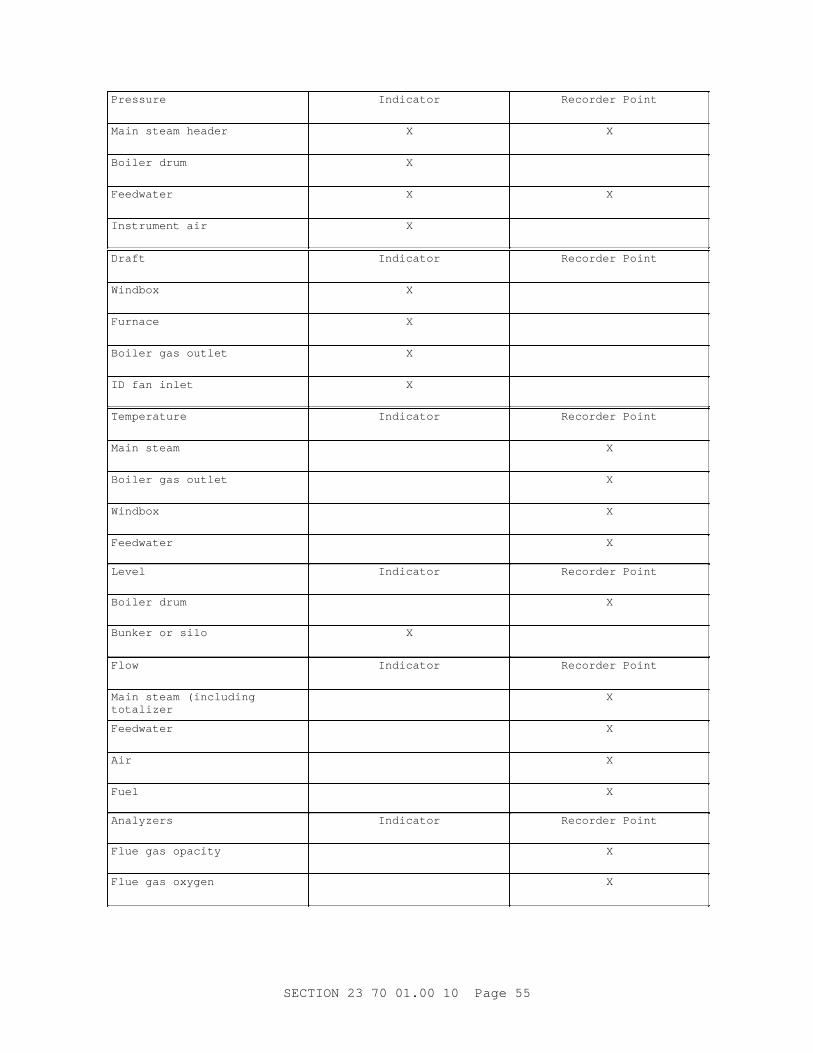
Pressure Indicator Recor der Poi nt
Mai n st eam header X X
Boi l er dr um X
Feedwater X X
I nst r ument ai r X
Draft Indicator Recor der Poi nt
Windbox X
Furnace X
Boi l er gas out l et X
I D f an i nl et X
Temperature Indicator Recor der Poi nt
Mai n st eam X
Boi l er gas out l et X
Windbox X
Feedwater X
Level Indicator Recor der Poi nt
Boi l er dr um X
Bunker or s i l o X
Flow Indicator Recor der Poi nt
Mai n st eam ( i ncl udi ng totalizer
X
Feedwater X
Air X
Fuel X
Analyzers Indicator Recor der Poi nt
Fl ue gas opaci t y X
Fl ue gas oxygen X
SECTI ON 23 70 01. 00 10 Page 55
2. 9. 5 Panel Pi pi ng and Wi r i ng
Hi gh- pr essur e and hi gh t emper at ur e val ues shal l be pneumat i cal l y or el ect r i cal l y t r ansmi t t er , or bot h, t o t he panel . Pneumat i c s i gnal s shal l be 21 t o 103 kPa 3 t o 15 psi g. Pi pi ng connect or s t o i ndi cat or s shal l be 6 mm 1/ 4 i nch OD copper t ubi ng conf or mi ng t o ASTM B68/ B68M. Fl ow si gnal s shal l be t r ansmi t t ed ei t her pneumat i cal l y or el ect r i cal l y t o t he panel - mount ed r ecei ver . Copper t ubi ng connect i ons and el ect r i c wi r i ng shal l be r un t o a t er mi nal bl ock l ocat ed on t he i ns i de of t he panel f r ont near t he bot t om. Wi r i ng shal l be t er mi nat ed at an i dent i f i ed t er mi nal st r i p. Wi r i ng shal l be sui t abl e f or boi l er r oom r equi r ement s and i nst al l ed accor di ng t o NFPA 70.
2. 9. 6 Pi l ot Li ght s
Pi l ot l i ght s shal l be assembl ed i n a f act or y- bui l t cabi net , sui t abl e f or f l ush mount i ng i n cut out s i n boi l er cont r ol panel , compl et e wi t h ext r uded t r i m, c l amps, and sheet met al r ear housi ng, and f i ni shed i n baked bl ack enamel . Lens shal l be whi t e pl ast i c and engr aved i n bl ack i nk. Let t er i ng shal l be 19 mm 3/ 4 i nch hi gh and bl ack. Two l amps per pi l ot shal l be pr ovi ded and i ndependent l y wi r ed. Lamps shal l be 6 wat t s, 24 vol t s dc, S- 6 i ncandescent t ype, suppl i ed wi t h col or caps, one r ed and one gr een per pi l ot l i ght . Lens bezel s shal l be bl ack unl ess ot her wi se i ndi cat ed.
2. 9. 7 Clock
The cl ock shal l be el ect r i c synchr onous mot or t ype. The cl ock shal l be f or sur f ace mount i ng and sui t abl e f or oper at i on on 115- vol t , 60 Hz s i ngl e- phase el ect r i c ser vi ce. The cl ock shal l have a whi t e di al , easy- t o- r ead bl ack numer al s, bl ack hands, r ed sweep second hand, and ext er nal manual r eset knob at bot t om of case. The mot or gear t r ai n shal l be seal ed i n a per manent oi l bat h. The cl ock di al shal l be 381. 0 mm 15 i nch s i ze.
2. 9. 8 Al ar m Annunci at or Panel
Layout of annunci at or panel shal l be as shown. Panel shal l consi st of a f l ush- mount ed cabi net , mount i ng t r i m wi t h c l amps, r emovabl e r ear cover , and al ar m modul es. Cabi net shal l be f i ni shed wi t h bl ack baked enamel , al umi num t r i m, and bl ack al ar m bezel s. Namepl at e s i ze of al ar m modul es shal l be nomi nal 70 mm 2- 3/ 4 i nches hi gh by 75 mm 3 i nches wi de i n t r ansl ucent whi t e acr yl i c pl exi gl ass and al l nomencl at ur e shal l be engr aved on f r ont sur f ace i n bl ack l et t er i ng. Pl ug- i n al ar m modul e shal l i ncl ude epoxy c i r cui t boar d, one r ever si bl e pl ug- i n r el ay, one gener al - pur pose pl ug- i n r el ay, r el ays wi t h dust cover s, t wo sel ect or swi t ches f or r el ay cont act sel ect i on, and t wo l amps wi r ed i n par al l el at 24 vol t s dc, 6 wat t s. Fl asher modul e shal l be mount ed and pr ewi r ed wi t h s i l ence and t est pushbut t ons. Al ar m hor n shal l be r emot el y mount ed and of gener al - pur pose const r uct i on. I nput vol t age shal l be 120 vol t s ac, 60 cycl e. Power suppl y of 120 vol t s t o 24 vol t s dc out put of vol t - amper e capaci t y shal l be pr ovi ded t o sui t l oad. Al ar m sequences of panel shal l pr ovi de f or " f i r st al er t " sequence, wi t h manual r eset and r i ngback sequences. Annunci at or panel shal l be pr ewi r ed i nt er nal l y t o a r ear t er mi nal st r i p.
2. 9. 9 Combust i on Cont r ol Component s
Component s shal l conf or m t o t he r equi r ement s of par agr aph COMBUSTI ON CONTROL EQUI PMENT.
SECTI ON 23 70 01. 00 10 Page 56
2. 9. 10 St eam and Feedwat er Fl ow Measur ement
Fl ow nozzl es shal l be pr ovi ded t o measur e t he st eam f l ow f r om each boi l er and each mai n st eam header out l et . Or i f i ce pl at es shal l be pr ovi ded t o measur e f eedwat er f l ow t o each boi l er . Nozzl es and or i f i ce pl at es shal l be f l ange- mount i ng t ype and made of st ai nl ess st eel . Or i f i ce pl at es shal l be of t he squar e edge, concent r i c, paddl e t ype desi gned f or f l ange t aps. Mi ni mum st r ai ght pi pe r uns shal l be i n accor dance wi t h AGA XR0603. Condensat e pot s shal l be pr ovi ded f or st eam ser vi ce.
2. 9. 11 Fl ue Gas Opaci t y Moni t or
A f l ue gas moni t or i ng syst em shal l pr ovi de cont i nuous measur ement , i ndi cat i on, and r ecor di ng of smoke opaci t y f r om each boi l er . The st ack uni t s shal l i ncl ude a l i ght sour ce and a l i ght det ect i ng or r ecei v i ng uni t mount ed i n t he st ack or mai n br eechi ng as r ecommended by t he manuf act ur er . The cont r ol or t r ansmi t t er uni t shal l have el ect r oni c sol i d- st at e c i r cui t r y and met er or di gi t al t ype i ndi cat or , and pr ovi de an out put s i gnal of 4 t o 20 mA dc f or 0 t o 100 per cent opaci t y. I n addi t i on, t he cont r ol uni t shal l have cal i br at i on and al ar m adj ust ment s f or compl i ance wi t h Feder al , St at e, and l ocal envi r onment al r egul at i ons. The cont r ol or t r ansmi t t er uni t and r ecor der shal l have dust - t i ght met al encl osur e. A pur gi ng ai r syst em shal l be pr ovi ded t o c l ean l i ght sour ce l ens and l i ght det ect or l ens. The cont r ol uni t shal l have adj ust abl e al ar m out put cont act s f or var i ous smoke densities.
2. 9. 12 Sampl e Cool er
Sampl e cool er shal l be a wat er cool ed shel l and t ube or shel l and coi l t ype heat exchanger wi t h st ai nl ess st eel t ubes and cast - i r on or st eel shel l sui t abl e f or cool i ng t he bl owof f bef or e sampl i ng. The cool er shal l be connect ed t o a header and val ved so t hat t he oper at or can obt ai n a sampl e of pr oper l y cool ed bl owof f f r om any boi l er as desi r ed. The cool er shal l be pr oper l y suppor t ed and shal l have a br ass or br onze sampl i ng cock wi t h l ever or compr essi on handl e. A sampl i ng gl ass cont ai ner sui t abl e f or handl i ng t he wat er t emper at ur e t o be encount er ed and a hydr omet er or equi val ent devi ce sui t abl e f or measur i ng t he concent r at i on of sol i ds i n t he wat er and r eadi ng i n par t s per mi l l i on shal l be pr ovi ded.
2. 9. 13 Oxygen Anal yzer
I f oxygen compensat i on cont r ol s ar e f ur ni shed, an oxygen anal yzer shal l be pr ovi ded t o i ndi cat e, r ecor d, and cont r ol t he per cent age of net excess oxygen i n, and t he aver age t emper at ur e of t he f l ue gas l eavi ng, t he boi l er . The oxygen anal yzer shal l be of t he di r ect pr obe t ype ut i l i z i ng an i n s i t u z i r coni um sensi ng el ement . The el ement shal l be i nser t ed di r ect l y i nt o t he pr ocess f l ue gas st r eam and shal l di r ect l y cont act t he pr ocess gases. The sensi ng el ement shal l be cont ai ned wi t hi n a pr ot ect i ve shi el d mount ed t o t he duct wor k by an adapt er pl at e, f ur ni shed by t he manuf act ur er . The anal yzer shal l be equi pped t o al l ow dai l y aut omat i c cal i br at i on check wi t hout r emovi ng t he anal yzer f r om t he pr ocess. That i s , sampl e gases may be i nj ect ed di r ect l y on t he sensi ng el ement whi l e t he anal yzer i s i n t he pr ocess. The anal yzer shal l i ncl ude any t emper at ur e compensat i on of cont r ol r equi r ed. The out put s i gnal r ange shal l be 4 t o 20 mA dc and shal l r epr esent 0 t o 10 per cent as a l i near f unct i on.
2. 9. 14 Cont i nuous Bl owdown
**************************************************************************
SECTI ON 23 70 01. 00 10 Page 57
NOTE: Cont i nuous bl owdown equi pment wi l l be pr ovi ded i f r equi r ed by UFC 3- 410- 01 or UFC 3- 410- 02. I f a f i r et ube boi l er i s speci f i ed, t hese par agr aphs wi l l be del et ed.
Bl owdown syst em wi l l be del et ed i f not r equi r ed f or t he pr oj ect .
**************************************************************************
Package t ype bl owdown syst em shal l be r at ed as i ndi cat ed. The syst em shal l aut omat i cal l y pr opor t i on bl owdown t o amount of makeup. The uni t shal l i ncl ude [ t he heat exchanger ' s f l ow cont r ol val ve, ] st r ai ner , sampl e cool er ( i f r equi r ed) , sol enoi d val ve, and sur ge t ank. [ An ext r a- heavy bl owdown heat exchanger shal l be pr ovi ded. Tubes shal l be of st ai nl ess st eel . A r emovabl e t ube bundl e shal l be pr ovi ded wi t h U- t ubes havi ng bends t wi ce t he t hi ckness of t he t ubi ng. A r ear baf f l e shal l suppor t al l t ubes at t he r et ur n bend. ] A sampl e cool er shal l be i nst al l ed so t hat shel l and t ubi ng can be r emoved wi t hout di st ur bi ng pi pi ng or mount i ng. Cont i nuous bl owdown val ve shal l be t he manual pr opor t i oni ng t ype f abr i cat ed of cor r osi on- r esi st ant st eel . The val ve shal l be equi pped wi t h a mi cr omet er di al and poi nt er t o i ndi cat e t he pr opor t i onal set t i ng.
2. 9. 15 Cont i nuous Emi ssi ons Moni t or i ng
**************************************************************************NOTE: A cont i nuous emi ssi ons moni t or i ng syst em ( CEMS) i s r equi r ed by t he Cl ean Ai r Act Amendment ( CAAA) of 1990 i f t he f uel ut i l i zed i s oi l or coal and t he heat i nput i s 3 megawat t s 10 mi l l i on BTU/ HR or gr eat er . A CEMS may al so be r equi r ed by st at e or l ocal l aws. I f a CEMS i s necessar y t he desi gner shal l r evi ew t he CAAA and t he r el evant st at e or l ocal l aw ear l y i n t he pr oj ect t o al l ow t i me t o i ncor por at e t he r equi r ed CEMS speci f i cat i on and t o det er mi ne whi ch f l ue gas emi ssi ons wi l l be i ncl uded i n t he r equi r ed r epor t s. Bef or e accept ance of t he i nst al l at i on, t he Cont r act i ng Of f i cer shal l be f ur ni shed a wr i t t en t est r epor t whi ch pr ovi des document at i on t hat t he CEMS equi pment has passed f act or y and f i el d cer t i f i cat i on t est s r equi r ed by f eder al , st at e and l ocal r egul at i ons. The i nvest i gat i on wi l l det er mi ne i f t he r epor t ed val ues may be cal cul at ed or shoul d be di r ect measur ement s. Fi l l i n t he dat a t o st at e what met hod of measur ement or cal cul at i on wi l l be ut i l i zed f or t he det er mi nat i on of t he r epor t var i abl e.
Emer gi ng f l ue gas f l ow moni t or t echnol ogi es ar e avai l abl e. The t r adi t i onal di f f er ent i al pr essur e t echni que speci f i ed uses f ami l i ar equi pment t hat can be mai nt ai ned by pl ant per sonnel . Thi s t ype of measur ement devi ce has r el i abl y sat i sf i ed r egul at or y r equi r ement s. The possi bl e use of ot her t echnol ogi es shoul d i ncl ude a t hor ough i nvest i gat i on of f l ue gas f l ow moni t or r egul at or y r equi r ement s and i n- house mai nt enance capabi l i t i es.
**************************************************************************
a. Cont i nuous emi ssi ons moni t or i ng syst em ( CEMS) equi pment shal l be
SECTI ON 23 70 01. 00 10 Page 58
pr ovi ded as a syst em by a s i ngl e manuf act ur er . A CEMS, meet i ng t he r equi r ement s of appl i cabl e f eder al r egul at i ons, St at e of [ _____] and l ocal r egul at i ons, shal l be pr ovi ded f or each boi l er i n accor dance wi t h manuf act ur er ' s r ecommendat i ons and under t he di r ect super vi s i on of t he CEMS equi pment manuf act ur er .
b. The r epor t ed dat a shal l i ncl ude [ sul f ur di oxi de ( SO2) ] [ oxi des of ni t r ogen ( NOx) ] [ car bon di oxi de ( CO2) ] [ par t i cul at e mat t er ( PM) ] and ot her i nf or mat i on r equi r ed by f eder al , st at e, and l ocal r egul at i ons. SO2 r epor t i ng shal l be based on [ anal yzer measur ement ] [ f uel f l ow and per cent sul f ur cal cul at i on] [ dai l y heat i nput cal cul at i on] . Ni t r ous oxi des, car bon di oxi de and par t i cul at e mat t er r epor t i ng shal l be based on anal yzer s.
c. The CEMS equi pment shal l i ncl ude t he cent r al pr ocessi ng uni t , pr i nt er , har d di sk dr i ve, and f l oppy di sk dr i ve. The f l oppy di sk dr i ve shal l f unct i on as a r ecor der . The manuf act ur er shal l pr ovi de t he sof t war e t o gener at e t he r equi r ed r epor t s i n a f or mat accept abl e t o t he f eder al , st at e and l ocal r egul at or y agenci es. The oper at or i nt er f ace t o t he CEMS equi pment shal l be v i a CRT scr een.
2. 10 WASTE HEAT RECOVERY EQUI PMENT
**************************************************************************NOTE: Economi zer or pr eheat er wi l l be sel ect ed t o be compat i bl e wi t h pol l ut i on cont r ol equi pment bei ng utilized.
**************************************************************************
Each boi l er shal l be equi pped wi t h [ an economi zer ] [ an ai r pr eheat er ] . Uni t s may be separ at e f r om or i nt egr al wi t h t he boi l er and shal l be compl et e wi t h i nsul at i on and j acket s, casi ngs, suppor t s and access door s, and shal l have pr ovi s i on f or t ube or t ube bundl e r emoval and f or c l eani ng. Soot bl ower s shal l be pr ovi ded as speci f i ed i n par agr aph BOI LERS.
2. 10. 1 Economizers
Economi zer s shal l be of a t ype nor mal l y pr ovi ded by t he boi l er manuf act ur er and shal l i ncl ude [ f i nned t ubes] [ bar e t ubes] baf f l es and header s and shal l have pr ovi s i on f or c l eani ng and t ube bundl e r emoval . At maxi mum l oad, economi zer exi t wat er shal l not be wi t hi n 17 degr ees C 30 degr ees F l ower t han sat ur at i on t emper at ur e. Mat er i al s shal l be capabl e of wi t hst andi ng t he maxi mum boi l er exi t gas t emper at ur e pl us 28 degr ees C 50 degr ees F. The t ubes shal l conf or m t o ASME BPVC SEC I . The over al l desi gn and i nst al l at i on shal l pr ecl ude col d- end cor r osi on under any l oad condi t i on. Economi zer t ube met al t emper at ur e shal l be above t he maxi mum f l ue gas dewpoi nt f or t he f uel bei ng f i r ed under al l l oad condi t i ons.
2. 10. 2 Ai r Pr eheat er s
Ai r pr eheat er s shal l be a t ype nor mal l y pr ovi ded by t he boi l er manuf act ur er and shal l be t he r ecuper at i ve t ube pl at e or r egener at i ve t ype const r uct ed of mat er i al s adequat e t o wi t hst and t he cor r osi on ef f ect s of t he f l ue gases. The over al l i nst al l at i on shal l pr ecl ude col d- end cor r osi on of t he ai r pr eheat er under any l oad condi t i on. Temper at ur es of met al s i n cont act wi t h f l ue gas shal l be above t he f l ue gas maxi mum dewpoi nt t emper at ur e f or t he f uel bei ng f i r ed under al l l oad condi t i ons. Cont r ol shal l be by st eam- pr eheat or by aut omat i c bypass and shal l be i nt egr at ed wi t h t he combust i on cont r ol syst em.
SECTI ON 23 70 01. 00 10 Page 59
2. 11 DRAFT FANS
**************************************************************************NOTE: Wher e f ans ar e not pr ot ect ed by el ect r ost at i c pr eci pi t at or s or baghouse f i l t er s on boi l er s of 4540 kg per hour 10, 000 pounds per hour and l ar ger , pr ovi de l i ner s f or scr ol l sheet s and r ot or bl ades.
I nduced dr af t f an out l et damper s may not be r equi r ed i n s i ngl e f an/ s i ngl e boi l er i nst al l at i ons, except t o el i mi nat e t he st ack ef f ect dur i ng out ages.
**************************************************************************
Cent r i f ugal f ans conf or mi ng t o AMCA 801 [ Type I ] [ Type I I ] [ f or ced- dr af t ] [ and] [ i nduced- dr af t ] shal l be f ur ni shed as an i nt egr al par t of boi l er desi gn. Fans shal l be cent r i f ugal wi t h [ backwar d cur ved bl ades] [ r adi al t i p bl ades] [ or ] [ axi al f l ow t ype] . Each f an shal l be s i zed f or an out put vol ume and st at i c pr essur e r at i ng suf f i c i ent f or pr essur e l osses, excess ai r r equi r ement s at t he bur ner or gr at e, l eakages, t emper at ur e and el evat i on cor r ect i ons f or a di r t y boi l er wi t h wor st ambi ent condi t i ons, al l at f ul l combust i on t o meet net r at ed out put at nor mal f i r i ng condi t i on. I n addi t i on, f an s i z i ng shal l i ncl ude mar gi ns of 10 per cent vol ume and 21 per cent st at i c pr essur e, pl us mar gi ns of 5 degr ees C 10 degr ees F f or f or ced dr af t f ans and 22 degr ees C 40 degr ees F f or i nduced dr af t f ans. I nduced- dr af t f ans shal l be desi gned f or handl i ng hot f l ue gas at t he maxi mum boi l er out l et t emper at ur e adj ust ed f or boi l er sur f ace f oul i ng. [ I nduced dr af t f ans shal l be pr ovi ded wi t h out l et damper s. ] Noi se l evel s f or f ans shal l not exceed 85 deci bel s at 914. 4 mm 3 f oot st at i on. Fan bear i ngs shal l be [ ai r - cool ed] [ or ] [ wat er - cool ed] , and backwar d cur ved f an bl ade t ype wi t h bear i ngs not r equi r i ng wat er cool i ng may be of t he sel f - al i gni ng ant i f r i c t i on t ype. [ Scr ol l sheet s and r ot or bl ades shal l have l i ner s. ]
2. 11. 1 Dr af t Fan Cont r ol
**************************************************************************NOTE: Var i abl e speed cont r ol , i nl et vane cont r ol , and i nl et damper cont r ol ar e, i n descendi ng or der of ef f i c i ency, capabl e of cont r ol dr af t f an condi t i ons. The choi ce i s based on economi cs. However , i n er osi ve ser vi ces, i nl et vane cont r ol i s not desi r abl e.
**************************************************************************
For ced- dr af t cent r i f ugal f ans shal l have [ i nl et vane cont r ol s] [ var i abl e speed cont r ol ] wher e i ndi cat ed. I nduced- dr af t cent r i f ugal f ans shal l have [ i nl et vane cont r ol ] [ i nl et damper cont r ol ] [ var i abl e speed cont r ol ] . [ Axi al pr opel l er f ans shal l have var i abl e pr opel l er pi t ch cont r ol . ] I nl et vanes or damper s shal l be sui t abl e f or use wi t h combust i on cont r ol equipment.
2. 11. 2 Dr af t Fan Dr i ves
**************************************************************************NOTE: Wher e mot or st ar t er s f or mechani cal equi pment ar e pr ovi ded i n mot or cont r ol cent er s, del et e t he r ef er ence t o mot or st ar t er s.
SECTI ON 23 70 01. 00 10 Page 60

St eam dr i ven boi l er auxi l i ar i es wi l l not be used unl ess t he exhaust st eam can be ut i l i zed compl et el y. Ref er ence t o st eam dr i ves wi l l be del et ed i f i nappl i cabl e f or t he equi pment speci f i ed.
**************************************************************************
Fan shal l be dr i ven by [ an el ect r i c mot or ] [ or ] [ a st eam t ur bi ne] . [ El ect r i c mot or shal l be [ dr i p- pr oof ] [ t ot al l y encl osed nonvent i l at ed] [ t ot al l y encl osed f an- cool ed] [ t ot al l y encl osed f an- cool ed, sui t abl e f or i nst al l at i on i n a Cl ass I I , Di v i s i on 1, Gr oup F, hazar dous l ocat i on conf or mi ng t o NFPA 70] . ] [ Mot or st ar t er shal l be magnet i c [ acr oss- t he- l i ne] [ r educed vol t age st ar t ] t ype wi t h [ gener al - pur pose] [ weat her - r esi st ant ] [ wat er t i ght ] [ dust - t i ght ] [ expl osi on- pr oof ] encl osur e and shal l be f ur ni shed wi t h f our auxi l i ar y i nt er l ock cont act s. ] [ St eam t ur bi nes shal l oper at e pr oper l y i n a st eam pr essur e r ange of [ _____] Pa psi g wi t h st eam back pr essur e of [ _____] Pa psi g. Tur bi nes shal l have hor i zont al l y- spl i t , cent er l i ne suppor t ed casi ngs, wat er - cool ed bear i ng housi ngs wi t h r i ng- oi l ed, babbi t t - l i ned, br onze packed sl eeve bear i ngs. Tur bi nes shal l al so be equi pped wi t h a mechani cal shaf t speed gover nor and val ve, and i ndependent emer gency over speed gover nor and t r i p val ve, r eed t achomet er , const ant pr essur e t ype gover nor , i nsul at i on wi t h r emovabl e met al j acket , oi l - s i ght gl asses wi t h guar ds, r emovabl e st ai nl ess st eel st eam st r ai ner [ wi t hout di sconnect i ng pi pi ng] , any speci al wr enches and t ool s r equi r ed f or ser vi c i ng t ur bi ne, and a sent i nel war ni ng on t he exhaust casi ngs. Tur bi nes shal l conf or m t o NEMA SM 23.]
2. 12 AI R DUCTS
Ai r duct s connect i ng t he f or ced- dr af t f an uni t s wi t h t he pl enum chamber shal l chamber shal l be desi gned t o convey ai r wi t h a mi ni mum of pr essur e l oss due t o f r i c t i on. Duct wor k shal l be gal vani zed sheet met al conf or mi ng to ASTM A653/ A653M. Duct s shal l be st r ai ght and smoot h on t he i nsi de wi t h l aps made i n di r ect i on of ai r f l ow. Duct s shal l be ext er nal l y br aced and shal l be so i nst al l ed and anchor ed as t o be f r ee of v i br at i on. Access and i nspect i on door s shal l be pr ovi ded as i ndi cat ed and r equi r ed. Duct s shal l be const r uct ed wi t h l ong r adi us el bows havi ng a cent er l i ne r adi us 1- 1/ 2 t i mes t he duct wi dt h, or wher e t he space does not per mi t t he use of l ong r adi us el bows, shor t r adi us or squar e el bows wi t h f act or y- f abr i cat ed t ur ni ng vanes may be used. Duct j oi nt s shal l be subst ant i al l y ai r - t i ght and shal l have adequat e st r engt h f or t he ser vi ce, wi t h 38. 1 x 38. 1 x 3. 2 mm 1- 1/ 2 x 1- 1/ 2 x 1/ 8 i nch st r uct ur al st eel angl es used wher e r equi r ed f or st r engt h or r i gi di t y. Duct wal l s t hi ckness shal l be as f ol l ows:
Duct s, Maxi mum Di mensi on St eel Sheet , Mi ni mum Thi ckness
Up t hr u 1. 5 m ( 60 i nches) Up t hr ough 60 i nches
1. 519 mm ( 16 gauge) 16 gauge
1. 6 m ( 60 i nches) 61 i nches and l ar ger
2. 657 mm ( 12 gauge) 12 gauge
2. 13 BREECHING
Br eechi ng shal l be const r uct ed of not l ess t han 3. 416 mm 10 gauge st eel sheet s conf or mi ng t o ASTM A36/ A36M. Br eechi ng shal l be adequat el y r ei nf or ced and br aced wi t h st r uct ur al st eel angl es not smal l er t han 50 x 50 x 6. 4 mm 2 x 2 x 1/ 4 i nches, and al l j oi nt s and seams i n t he sheet s and angl es shal l be wel ded. Expansi on j oi nt s shal l be i nst al l ed as i ndi cat ed and as r equi r ed t o sui t t he i nst al l at i on and shal l be f l exi bl e t ype
SECTI ON 23 70 01. 00 10 Page 61
r equi r i ng no packi ng. Br eechi ng shal l have angl e f l anges and gasket s f or connect i on t o boi l er s, f ans, equi pment , or st acks. Br eechi ng connect i ons shal l be gas- t i ght and be caul ked t i ght al l ar ound and seal ed wi t h cement t o f or m an ai r - t i ght j oi nt . Cl ean- out openi ngs of sui t abl e s i ze and at appr oved l ocat i ons shal l be pr ovi ded f or access t o al l sect i ons of t he br eechi ng and shal l have t i ght - f i t t i ng, hi nged, cast - i r on door s wi t h cast - i r on f r ames. Pl ast i c mat er i al s pol yet her i mi de ( PEI ) and pol yet her sul f one ( PES) ar e f or bi dden t o be used f or vent pi pi ng f or combust i on gases.
2. 14 STACKS
St acks f or i ndi v i dual boi l er s shal l be sel f - suppor t i ng doubl e- wal l i nsul at ed t ype. Unl ess ot her wi se i ndi cat ed, each st ack shal l be compl et e wi t h st r uct ur al st eel base, base pl at es, anchor bol t s and nut s, c l ean- out door , [ i nduced- dr af t f an] [ boi l er ] connect i on and a t her momet er wel l . St ub st acks f or packaged boi l er uni t s may be suppor t ed di r ect l y on t he boi l er pr ovi di ng t he boi l er st r uct ur e i s desi gned t o accommodat e such an ar r angement . I nsul at i on shal l be sui t abl e f or sust ai ned f l ue gas t emper at ur e of 480 degr ees C 900 degr ees F wi t h i nt er mi t t ent t emper at ur es up t o 650 degr ees C 1200 degr ees F and t he wal l sect i on shal l pr ovi de a " U" f act or of appr oxi mat el y 0. 26. St acks shal l be f abr i cat ed of st eel conf or mi ng t o ASTM A242/ A242M f or bot h i nner and out er shel l . I nner shel l s of each sect i on shal l be pr ovi ded wi t h an ai r - seal ed and conceal ed expansi on and cont r act i on devi ce t o al l ow f or di f f er ent i al expansi on of i nner and out er shel l s. St acks shal l be ext ended above t he r oof t o t he hei ght i ndi cat ed. Pl ast i c mat er i al s pol yet her i mi de ( PEI ) and pol yet her sul f one ( PES) ar e f or bi dden t o be used f or vent pi pi ng f or combust i on gases.
2. 15 BLOWOFF TANK
Bl owof f t ank [ shal l be const r uct ed of 28 MPa 4000 psi r ei nf or ced concr et e as speci f i ed i n Sect i on 03 30 00. 00 10 CAST- I N- PLACE CONCRETE, and shal l be f i t t ed wi t h a bol t ed st eel manhol e cover and f r ame. Bl owof f pi pe, vent pi pe, and dr ai n pi pe t o sewer shal l be i nst al l ed i n pi pe s l eeves bui l t i nt o t he concr et e. The space bet ween t he pi pe and sl eeves shal l be f i l l ed and caul ked wi t h l ead wool or s i mi l ar mat er i al t o make a wat er - t i ght connect i on. The t ank shal l be di v i ded i nt o t wo sect i ons by a baf f l e t o f or m a sedi ment chamber ] [ shal l be const r uct ed of st eel i n accor dance wi t h NBBI NB- 23 PART 1.]
2. 16 PUMPS
2. 16. 1 Boi l er Feed Pumps
Boi l er f eed pumps shal l be s i zed and desi gned f or t he speci f i c appl i cat i on. Pumps havi ng a combi ned r at i ng of f l ow and head t hat r esul t s i n a wat t age hor sepower r at i ng l ess t han 185 kW 250 bhp shal l be f ur ni shed t o meet t he desi gn r equi r ement s of API St d 610. The pump shal l be end- suct i on, t op di schar ge and be suppor t ed at i t s cent er l i ne. Pump si zes wi t h hi gher r at i ngs t han t he above shal l be hor i zont al - spl i t case, mul t i s t age cent r i f ugal pumps. Casi ng const r uct i on shal l be ei t her vol ut e or di f f user desi gn and shal l al so be suppor t ed at i t s casi ng cent er l i ne. Al l pump r at i ngs shal l have, nomi nal l y, an excess i n capaci t y of 10 per cent above t he maxi mum cont i nuous r at i ng of t he ser vi ce. The r equi r ed net posi t i ve suct i on head ( NPSH) at t he pump desi gn f l ow, head, and speed shal l not exceed 80 per cent of t he avai l abl e syst em NPSH at t he same f l ow, assumi ng a l ow l evel i n t he st or age t ank. The pump' s suct i on speci f i c speed shal l not
SECTI ON 23 70 01. 00 10 Page 62
exceed 9000 at t he pump' s best ef f i c i ency poi nt ( BEP) . The guar ant eed NPSH r equi r ement s shal l r ef l ect 3 per cent br eakdown cr i t er i a. The pump' s head- capaci t y ( H- Q) cur ve shal l be const ant l y r i s i ng t o shut of f wi t h no poi nt of i nf l ect i on. Ther e shal l be no r est r i c t i on t o oper at i on at any poi nt f r om mi ni mum cont i nuous f l ow t o desi gn f l ow.
2. 16. 1. 1 Casings
Pumps shal l have i nt egr al l y cast suct i on and di schar ge f l anges t hat shal l be dr i l l ed t o meet t he desi gn pr essur e of t he appl i cat i on. The maxi mum oper at i ng t emper at ur e, f or desi gn pur poses, of any f eedpump shal l not be l ess t han 204 degr ees C 400 degr ees F. Casi ngs shal l be dr i l l ed, t apped, and pr ovi ded wi t h vent and dr ai n connect i ons. Pumps desi gned f or t hi s ser vi ce shal l not r equi r e cool i ng at r at i ngs bel ow 375 kW 500 bhp. Thi s appl i es t o bot h f r ame cool i ng or seal cool i ng. Bel ow 375 kW 500 bhp, pumps shal l empl oy ant i f r i c t i on r adi al and t hr ust bear i ngs l ubr i cat ed by f l i nger r i ngs i n a seal ed housi ng. Seal s shal l be mechani cal and ai r - cool ed f l ush pi pi ng conf or mi ng t o API St d 610, Pl an 23. Above 375 kW 500 bhp, pumps shal l empl oy a s i ngl e cool i ng c i r cui t f or bot h cool i ng t he oi l bei ng del i ver ed by a f or ced oi l syst em t o s l eeve r adi al bear i ngs and a f l oat i ng shoe t hr ust bear i ng, coupl ed wi t h t he seal cool er s f or bot h st uf f i ng boxes. Mechani cal seal s shal l al so be pr ovi ded. I n bot h cases, st uf f i ng boxes shal l be s i t e- conver t i bl e t o a packed box. Leakage shal l be no mor e t han 25 mm/ hour 25 cc/ hr f or a seal l i f e of no l ess t han 25, 000 hour s. Bear i ng r at i ng shal l be not l ess t han 100, 000 hour s ( L- 10 l i f e) at t he poi nt of maxi mum l oad, as def i ned by ABMA 9.
2. 16. 1. 2 Base
Pumps shal l be suppor t ed on st r uct ur al st eel bases t hat do not r equi r e gr out i ng i n or der t o i mpar t st r engt h t o t he pump f or st at i c and dynami c l oadi ng f r om t he pi pi ng syst em. The bases shal l be pi t ched t o a l ow poi nt dr ai n. The compl et e pump and mot or assembl y shal l be shop- al i gned usi ng shi ms on bot h t he pump and t he mot or .
2. 16. 1. 3 Couplings
Al l pumps shal l be f ur ni shed wi t h nonl ubr i cat ed f l exi bl e- di sc coupl i ngs and a coupl i ng guar d f ur ni shed t o OSHA r equi r ement s. Coupl i ngs shal l be spacer - t ype t o per mi t r emoval of t he mechani cal seal s and l i mi t ed- end- f l oat - t ype f or pumps wi t h s l eeve bear i ngs.
2. 16. 1. 4 Aut omat i c Reci r cul at i on
**************************************************************************NOTE: I f aut omat i c r eci r cul at i on val ve i s ut i l i zed, del et e t hi s par agr aph.
**************************************************************************
Al l pumps shal l be f ur ni shed wi t h a sel f - cont ai ned aut omat i c r eci r cul at i on cont r ol val ve t hat shal l be s i zed f or nomi nal l y 25 per cent of t he pump' s BEP f l ow.
2. 16. 1. 5 Turbines
St eam t ur bi nes f or boi l er f eed pump shal l oper at e t he pump pr oper l y i n a st eam pr essur e r ange of [ _____] Pa psi g wi t h st eam backpr essur e of [ _____] Pa psi g. Tur bi nes shal l have hor i zont al l y- spl i t , t wo- pi ece, cent er l i ne suppor t ed casi ngs, wat er - cool ed bear i ng cases wi t h r i ng- oi l ed,
SECTI ON 23 70 01. 00 10 Page 63
babi t t - l i ned, br onze packed sl eeve bear i ngs. Tur bi nes shal l al so be equi pped wi t h a mechani cal shaf t speed gover nor and val ve, i ndependent over speed emer gency gover nor and t r i p val ve, r eed t achomet er , const ant pr essur e t ype gover nor , i nsul at i on wi t h r emovabl e met al j acket , oi l - s i ght gl asses wi t h guar ds, st ai nl ess st eel st eam st r ai ner t hat i s r emovabl e wi t hout di sconnect i ng pi pi ng, any speci al wr enches and t ool s r equi r ed f or ser vi c i ng t he t ur bi ne, and a sent i nel war ni ng on t he exhaust casi ngs. Tur bi nes shal l conf or m t o NEMA SM 23.
2. 16. 1. 6 El ect r i c Mot or s
El ect r i c mot or s shal l be sel ect ed f or cont i nuous dut y and non- over l oadi ng char act er i st i cs sui t abl e f or t he power char act er i s t i cs avai l abl e. Mot or s shal l be [ spl ashpr oof ] [ t ot al l y encl osed, nonvent i l at ed] [ t ot al l y encl osed, f an- cool ed t ype] [ t ot al l y encl osed, f an- cool ed t ype, sui t abl e f or i nst al l at i on i n a Cl ass I I , Di v i s i on 1, Gr oup F hazar dous l ocat i on i n accor dance wi t h t he NFPA 70] . [ Mot or st ar t er shal l be [ manual ] [ [ magnet i c] [ acr oss- t he- l i ne] [ r educed vol t age st ar t ] ] t ype wi t h [general-purpose][weather-resistant][water-tight][dust-tight][explosion-proof] encl osur e. ] I nt egr al s i ze mot or s shal l be t he pr emi um ef f i c i ency t ype i n accor dance wi t h NEMA MG 1.
2. 16. 1. 7 Shop Hydr ost at i c Test i ng
Al l pumps shal l be subj ect ed t o shop hydr ost at i c t est i ng. One pump i n each ser vi ce shal l be subj ect ed t o a compl et e shop per f or mance t est t o demonst r at e t hat , at r at ed capaci t y, head i s wi t hi n a mar gi n of pl us 3 per cent and mi nus 0 per cent of desi gn; ef f i c i ency i s wi t hi n a t ol er ance of mi nus 0 per cent ; NPSH at t he pump' s BEP and at t he r at ed condi t i on i s wi t hi n a mar gi n of pl us 0 per cent and mi nus 10 per cent . Per f or mance t est s shal l be i n accor dance wi t h API St d 610. Pr ocedur es and r esul t s shal l be subj ect t o t he appr oval of t he Cont r act i ng Of f i cer .
2. 16. 2 Condensat e Pumps
**************************************************************************NOTE: I f i nadequat e NPSH i s avai l abl e, t he desi gner shal l gi ve consi der at i on t o subst i t ut i ng ei t her a doubl e suct i on or posi t i ve di spl acement pump.
**************************************************************************
Condensat e pumps shal l be hor i zont al , end suct i on, s i ngl e st age, cent r i f ugal , mot or - dr i ven pumps. Pumps shal l have st ai nl ess st eel shaf t s and br onze i mpel l er s. Pumps shal l be pr ovi ded wi t h st uf f i ng boxes. Lubr i cat i on shal l be by spl ash oi l wi t h oi l l evel s i ght gl ass pr ovi ded. Pumps shal l be subj ect ed t o t he same t est s speci f i ed f or t he Boi l er Feedpumps.
2. 17 CONDENSATE TANK AND ACCESSORI ES
2. 17. 1 Condensat e Tank
Condensat e t ank shal l be desi gned f or a wor ki ng pr essur e of 103 kPa 15 psi g and shal l conf or m t o ASME BPVC SEC VI I I D1. The t ank shal l have a st or age capaci t y equal t o or gr eat er t han i ndi cat ed and shal l be i nst al l ed compl et e wi t h pi pi ng and accessor i es.
SECTI ON 23 70 01. 00 10 Page 64
2. 17. 2 Feedwat er Makeup Val ve
Fl oat - cont r ol l ed val ve shal l be pr ovi ded f or emer gency f eedwat er makeup t o t he t ank. The val ve shal l be oper at ed by a f l oat - cont r ol mechani sm connect ed t o t he sur ge t ank and shal l mai nt ai n a sui t abl e mi ni mum wat er l evel i n t he t ank. The f l oat box shal l be out s i de t he t ank and t he connect i ons shal l be pr oper l y val ved t o per mi t bl owdown and ser vi c i ng.
2. 18 HEAT EXCHANGERS
Heat exchanger s shal l be desi gned, f abr i cat ed, t est ed, and st amped i n accor dance wi t h ASME BPVC SEC VI I I D1. Addi t i onal l y, heat exchanger desi gns shal l meet t he r equi r ement s of HEI 2623. Cl osed f eedwat er heat er desi gns shal l meet t he r equi r ement s of HEI 2622. Heat exchanger s shal l be pr ovi ded wi t h r el i ef val ves as r equi r ed by ASME BPVC SEC VI I I D1 and t he HEI St andar ds. Heat exchanger s usi ng ser vi ce wat er shal l be desi gned t o have t he ser vi ce wat er i nsi de t he t ubes. The exchanger s shal l be of st r ai ght t ube desi gns wi t h bol t ed f ul l di amet er access channel cover s t o f aci l i t at e t ube mai nt enance as r equi r ed. Ret ur n bonnet s ar e accept abl e when t her e ar e no t ubesi de nozzl e connect i ons at t he f ar end. Mat er i al s of const r uct i on shal l be al l car bon st eel , except t he ser vi ce wat er s i de whi ch shal l r ef l ect t he ser vi ce wat er avai l abl e. When t he wat er qual i t y per mi t s, t he t ubes shal l be st ai nl ess st eel i n accor dance wi t h ASTM A249/ A249M, Gr ade TP 304, t he r emai nder of t he t ube si de shal l be al l car bon st eel . When t he ser vi ce wat er i s known t o cont ai n chl or i de l evel s har mf ul t o st ai nl ess st eel s, t he t ubes shal l be 90- 10 Copper - Ni ckel i n accor dance wi t h ASTM B111/ B111M Al l oy 706; t he r emai nder of t he ser vi ce wat er s i de shal l be as f ol l ows: t ubesheet s, monel - c l ad st eel ; channel cover s, car bon st eel l i ned wi t h monel ; channel s and bonnet s, monel . Fi xed t ubesheet desi gns ar e pr ef er r ed when oper at i ng condi t i ons do not i mpose a l ar ge di f f er ent i al movement t hat cannot be r eadi l y accommodat ed wi t h a s i mpl e t hi n- wal l met al bel l ows expansi on j oi nt . For l ar ger di f f er ent i al s , a packed f l oat i ng t ubesheet wi t h l ant er n r i ng i s accept abl e up t o 1. 03 MPa 150 psi g desi gn pr essur e. For pr essur es above 1. 03 MPa 150 psi g, a spl i t r i ng f l oat i ng head desi gn shal l be used. Heat exchanger s usi ng st eam t o heat domest i c wat er or ot her f l ui ds such as gl ycol - wat er mi xt ur es or f uel oi l shal l have t he st eam i n t he shel l s i de. The exchanger s shal l be of U- t ube desi gns wi t h bol t ed f ul l di amet er channel cover s t o f aci l i t at e t ube mai nt enance as r equi r ed. The t ubesheet shal l be t he f ul l di amet er t o mat ch t he shel l f l ange and shal l have suf f i c i ent t hr eaded bol t hol es so t hat a shel l hydr o t est may be appl i ed wi t hout t he channel i n pl ace. Mat er i al s of const r uct i on shal l be of al l car bon st eel wi t h t he except i on of t he t ubes whi ch shoul d t ypi cal l y be speci f i ed as st ai nl ess st eel i n accor dance wi t h ASTM A688/ A688M, Gr ade TP 304, st r ess r el i ef anneal ed t emper wi t h t he U- bends st r ess r el i eved af t er bendi ng. Fuel oi l heat er s shal l have car bon st eel t ubes i n accor dance wi t h ASTM A179/ A179M and be f ur ni shed i n t he st r ess r el i ef anneal ed t emper wi t h t he U- bends st r ess r el i eved af t er bendi ng. Feedwat er heat er s shal l be of al l wel ded const r uct i on wi t h bol t ed f ul l di amet er channel cover s t o f aci l i t at e t ube mai nt enance as r equi r ed. The channel bar r el shal l be i nt egr al wi t h t he t ubesheet and have an i nt er nal pass par t i t i on bol t ed cover desi gn t hat shal l be r eadi l y r emovabl e when t he channel cover i s r emoved. Pass par t i t i ons t hat ar e seal ed wi t h a gasket ed gr oove i n t he channel cover ar e pr ohi bi t ed. Mat er i al s of const r uct i on shal l be al l car bon st eel except t he t ubes. Pr essur e boundar y mat er i al shal l be i n accor dance wi t h ASTM A516/ A516M, Gr ade C, when pl at e mat er i al i s r equi r ed, or ASTM A350/ A350M when f or gi ng mat er i al i s r equi r ed. Shr oud pl at e mat er i al f or desuper heat i ng and subcool i ng zones shal l be i n accor dance wi t h ASTM A285/ A285M, Gr ade C. Tubes shal l be st ai nl ess st eel i n accor dance wi t h ASTM A688/ A688M, Gr ade TP 304, st r ess
SECTI ON 23 70 01. 00 10 Page 65
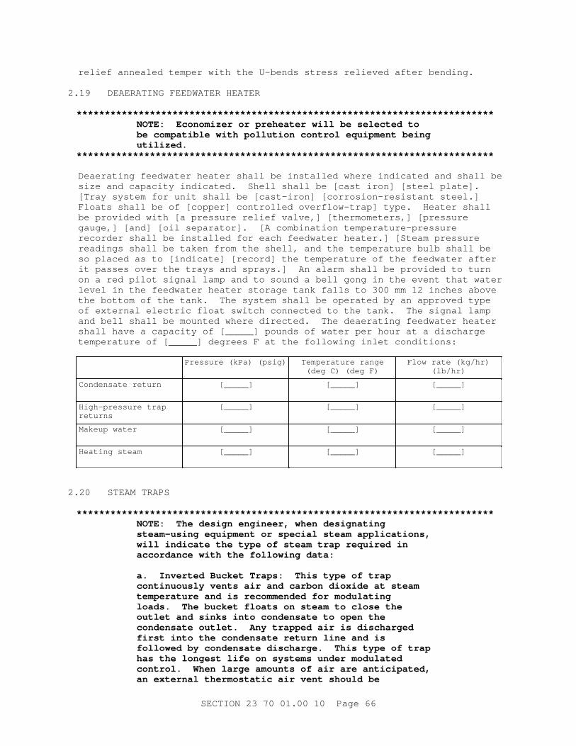
r el i ef anneal ed t emper wi t h t he U- bends st r ess r el i eved af t er bendi ng.
2. 19 DEAERATI NG FEEDWATER HEATER
**************************************************************************NOTE: Economi zer or pr eheat er wi l l be sel ect ed t o be compat i bl e wi t h pol l ut i on cont r ol equi pment bei ng utilized.
**************************************************************************
Deaer at i ng f eedwat er heat er shal l be i nst al l ed wher e i ndi cat ed and shal l be s i ze and capaci t y i ndi cat ed. Shel l shal l be [ cast i r on] [ st eel pl at e] . [ Tr ay syst em f or uni t shal l be [ cast - i r on] [ cor r osi on- r esi st ant st eel . ] Fl oat s shal l be of [ copper ] cont r ol l ed over f l ow- t r ap] t ype. Heat er shal l be pr ovi ded wi t h [ a pr essur e r el i ef val ve, ] [ t her momet er s, ] [ pr essur e gauge, ] [ and] [ oi l separ at or ] . [ A combi nat i on t emper at ur e- pr essur e r ecor der shal l be i nst al l ed f or each f eedwat er heat er . ] [ St eam pr essur e r eadi ngs shal l be t aken f r om t he shel l , and t he t emper at ur e bul b shal l be so pl aced as t o [ i ndi cat e] [ r ecor d] t he t emper at ur e of t he f eedwat er af t er i t passes over t he t r ays and spr ays. ] An al ar m shal l be pr ovi ded t o t ur n on a r ed pi l ot s i gnal l amp and t o sound a bel l gong i n t he event t hat wat er l evel i n t he f eedwat er heat er st or age t ank f al l s t o 300 mm 12 i nches above t he bot t om of t he t ank. The syst em shal l be oper at ed by an appr oved t ype of ext er nal el ect r i c f l oat swi t ch connect ed t o t he t ank. The si gnal l amp and bel l shal l be mount ed wher e di r ect ed. The deaer at i ng f eedwat er heat er shal l have a capaci t y of [ _____] pounds of wat er per hour at a di schar ge t emper at ur e of [ _____] degr ees F at t he f ol l owi ng i nl et condi t i ons:
Pr essur e ( kPa) ( psi g) Temper at ur e r ange( deg C) ( deg F)
Fl ow r at e ( kg/ hr )(lb/hr)
Condensat e r et ur n [_____] [_____] [_____]
Hi gh- pr essur e t r ap returns
[_____] [_____] [_____]
Makeup wat er [_____] [_____] [_____]
Heat i ng st eam [_____] [_____] [_____]
2. 20 STEAM TRAPS
**************************************************************************NOTE: The desi gn engi neer , when desi gnat i ng st eam- usi ng equi pment or speci al st eam appl i cat i ons, wi l l i ndi cat e t he t ype of st eam t r ap r equi r ed i n accor dance wi t h t he f ol l owi ng dat a:
a. I nver t ed Bucket Tr aps: Thi s t ype of t r ap cont i nuousl y vent s ai r and car bon di oxi de at st eam t emper at ur e and i s r ecommended f or modul at i ng l oads. The bucket f l oat s on st eam t o c l ose t he out l et and s i nks i nt o condensat e t o open t he condensat e out l et . Any t r apped ai r i s di schar ged f i r st i nt o t he condensat e r et ur n l i ne and i s f ol l owed by condensat e di schar ge. Thi s t ype of t r ap has t he l ongest l i f e on syst ems under modul at ed cont r ol . When l ar ge amount s of ai r ar e ant i c i pat ed, an ext er nal t her most at i c ai r vent shoul d be
SECTI ON 23 70 01. 00 10 Page 66
i nst al l ed on a l i ne bypassi ng t he t r ap t o bl eed ai r f r om t he st eam l i ne and di schar ge i t t o t he condensat e r et ur n l i ne. Thi s syst em wi l l gi ve opt i mum per f or mance at l ow st eam pr essur es wi t h maxi mum dependabi l i t y . These t r aps wi l l handl e condensat e f r om f an coi l uni t s wher e condensat e must be l i f t ed t o r et ur n l i nes l ocat ed above t he equi pment . They oper at e best at near f ul l l oad condi t i ons wher e l oads do not var y over a wi de r ange. Bef or e oper at i on, t r aps must be pr i med by f i l l i ng t hem wi t h wat er .
b. Ver t i cal Open- Top Bucket Tr ap: Tr ap const r uct i on i s mor e compl ex t han i nver t ed bucket t ype but i s sui t abl e f or appl i cat i ons havi ng wi de var i at i on of l oad and pr essur e, and i s r ecommended f or const ant pr essur e syst ems. Bucket s i nks i nt o condensat e when condensat e r eaches t op of t r ap and t he di schar ge por t opens. Af t er di schar ge, t he bucket f l oat s on i ncomi ng condensat e keepi ng t he di schar ge por t c l osed.
c. I mpact - Oper at ed Tr aps: These t r aps depend on st eam vel oci t y t o keep t he di sc c l osed. As st eam vel oci t y decr eases, t he di sc l i f t s of f t he seat and al l ows f l ow of condensat e. These t r aps al l ow some st eam l eakage and do not vent ai r at l ow pr essur e. They ar e not r ecommended f or ser v i ce l ower t han 70 kPa 10 psi g or wher e back pr essur e may exceed 50 per cent of i nl et pr essur e. These t r aps ar e l ess expensi ve and have poor per f or mance i n t he pr esence of di r t .
d. Ther most at i c Tr aps: These t r aps ar e bel l ows- act uat ed and cont r act i on of bel l ows at a f ew degr ees bel ow sat ur at ed st eam pr essur e al l ows condensat e ai r and noncondensabl e gases t o be di schar ged. As st eam r eaches t he bel l ows, t he expansi on of t he bel l ows cl oses t he di schar ge por t . These t r aps can al so be ut i l i zed t o vent ai r f r om a st eam syst em and can be used i n conj unct i on wi t h an i nver t ed bucket t ype st eam t r ap pr evi ousl y descr i bed.
e. Fl oat and Ther most at i c Tr ap: These t r aps pr ovi de opt i mum per f or mance on modul at i ng syst ems at l owest f i r st cost . Wher e st eam pr essur es modul at e down t o zer o, l ar ge amount s of ai r may be l i ber at ed. They ar e i deal f or dr i ppi ng ends of st eam r i ser s, heel s of up- f eed st eam r i ser s, bot t oms of down- f eed st eam r i ser s. These t r aps ar e al so i deal f or f an coi l uni t s and uni t heat er s.
f . Any t r ap sel ect ed must be s i zed f or t he expect ed condensat e l oad wi t h an appl i cabl e saf et y f act or appl i ed f or t he par t i cul ar t ype of equi pment ser vi ced. Manuf act ur er ' s appl i cat i on manual s shoul d be consul t ed t o assi st i n s i z i ng t r aps. Saf et y f act or s var y f r om 2: 1 t o 10: 1. An aver age 3: 1 saf et y f act or val ue wi l l cover most appl i cat i ons.
SECTI ON 23 70 01. 00 10 Page 67
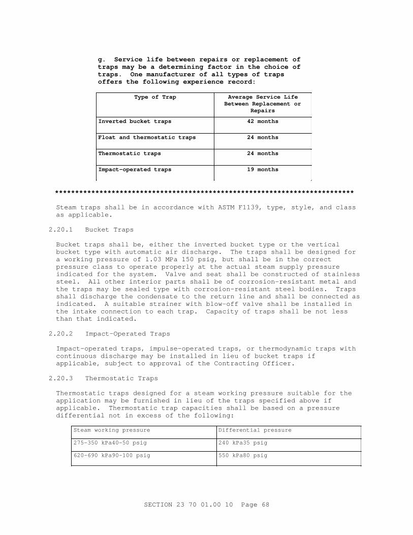
g. Ser vi ce l i f e bet ween r epai r s or r epl acement of t r aps may be a det er mi ni ng f act or i n t he choi ce of t r aps. One manuf act ur er of al l t ypes of t r aps of f er s t he f ol l owi ng exper i ence r ecor d:
Type of Tr ap Aver age Ser vi ce Li f eBet ween Repl acement or
Repairs
I nver t ed bucket t r aps 42 mont hs
Fl oat and t her most at i c t r aps 24 mont hs
Ther most at i c t r aps 24 mont hs
I mpact - oper at ed t r aps 19 mont hs
**************************************************************************
St eam t r aps shal l be i n accor dance wi t h ASTM F1139, t ype, st y l e, and c l ass as appl i cabl e.
2. 20. 1 Bucket Tr aps
Bucket t r aps shal l be, ei t her t he i nver t ed bucket t ype or t he ver t i cal bucket t ype wi t h aut omat i c ai r di schar ge. The t r aps shal l be desi gned f or a wor ki ng pr essur e of 1. 03 MPa 150 psi g, but shal l be i n t he cor r ect pr essur e c l ass t o oper at e pr oper l y at t he act ual s t eam suppl y pr essur e i ndi cat ed f or t he syst em. Val ve and seat shal l be const r uct ed of s t ai nl ess st eel . Al l ot her i nt er i or par t s shal l be of cor r osi on- r esi st ant met al and t he t r aps may be seal ed t ype wi t h cor r osi on- r esi st ant st eel bodi es. Tr aps shal l di schar ge t he condensat e t o t he r et ur n l i ne and shal l be connect ed as i ndi cat ed. A sui t abl e st r ai ner wi t h bl ow- of f val ve shal l be i nst al l ed i n t he i nt ake connect i on t o each t r ap. Capaci t y of t r aps shal l be not l ess t han t hat i ndi cat ed.
2. 20. 2 I mpact - Oper at ed Tr aps
I mpact - oper at ed t r aps, i mpul se- oper at ed t r aps, or t her modynami c t r aps wi t h cont i nuous di schar ge may be i nst al l ed i n l i eu of bucket t r aps i f appl i cabl e, subj ect t o appr oval of t he Cont r act i ng Of f i cer .
2. 20. 3 Ther most at i c Tr aps
Ther most at i c t r aps desi gned f or a st eam wor ki ng pr essur e sui t abl e f or t he appl i cat i on may be f ur ni shed i n l i eu of t he t r aps speci f i ed above i f appl i cabl e. Ther most at i c t r ap capaci t i es shal l be based on a pr essur e di f f er ent i al not i n excess of t he f ol l owi ng:
St eam wor ki ng pr essur e Di f f er ent i al pr essur e
275- 350 kPa40- 50 psi g 240 kPa35 psi g
620- 690 kPa90- 100 psi g 550 kPa80 psi g
SECTI ON 23 70 01. 00 10 Page 68
2. 20. 4 Fl oat and Ther most at i c Tr aps
Fl oat and t her most at i c t r aps shal l be desi gned f or a st eam wor ki ng pr essur e of 103 kPa 15 psi g but shal l oper at e wi t h t he suppl y pr essur e i ndi cat ed f or t he syst em. The t r ap capaci t y shal l be based on a pr essur e di f f er ent i al of 15 kPa 2 psi . The i nl et t o each t r ap shal l be pr ovi ded wi t h a br ass or st ai nl ess st eel st r ai ner ei t her separ at el y or as an i nt egr al par t of t he trap.
2. 21 PRESSURE GAUGES
Pr essur e gauges shal l be heavy- dut y i ndust r i al t ype wi t h phenol i c case, sol i d f r ont , r ear bl owout , t hr eaded r i ng, shat t er pr oof gl ass, and 13 mm 1/ 2 i nch NPT bot t om connect i on sui t abl e f or speci f i ed pr essur e or vacuum wi t h mi ni mum 114. 3 mm 4- 1/ 2 i nch di amet er di al , except as ot her - wi se speci f i ed. Pr essur e gauges shal l be i nst al l ed on t he l ow- pr essur e s i de of each pr essur e r educi ng val ve, on t he suct i on and di schar ge s i de of each pump, on i nl et s and out l et s of heat exchanger s, on t he f eedwat er heat er , and wher e shown or r equi r ed f or pr oper oper at i on. Pr essur e gauge shal l be i nst al l ed on each boi l er and shal l have a [ 254. 0 mm 10 i nch di al ] [ 304. 8 mm 12 i nch di al ] f ace. Gauges shal l be i nst al l ed so as t o be accessi bl e and easi l y r ead f r om t he oper at i ng f l oor . Gauges shal l be equi pped wi t h i nt egr al or separ at e s i phons, and pul sat i on dampener s and shal l be connect ed by br ass pi pe and f i t t i ngs wi t h shut of f cocks. Wher e pr essur e r educi ng val ves ar e used, upst r eam and downst r eam gauges shal l be pl aced cl ose t o t he pr essur e r educi ng assembl y, but connect ed appr oxi mat el y 3 m 10 f eet t her ef r om. The oper at i ng r anges of t he gauges shal l be appr oxi mat el y t wi ce t he nor mal oper at i ng pr essur e.
2. 22 THERMOMETERS
Ther momet er s shal l be bi met al l i c t ype wi t h st ai nl ess st eel case and st em, separ abl e st em, separ abl e t her mowel l s, and t emper at ur e r ange sui t abl e f or t he use encount er ed. Ther momet er s shal l be i nst al l ed i n t he f eedwat er heat er st or age and st eam ar eas, boi l er f eed pump; i n t he mai n condensat e r et ur n l i ne bef or e ent er i ng t he sur ge t ank; i n t he combust i on ai r i nl et s and out l et s of ai r pr eheat er s, wat er i nl et s, and out l et s of economi zer s; i n t he suct i on and di schar ge of boi l er f eed pumps; i n ai r i nl et s t o f or ced and i nduced dr af t f ans; i n t he f l ue gas i nl et s and out l et s of economi zer s and ai r pr eheat er s; and el sewher e as i ndi cat ed or speci f i ed. Ther momet er s shal l have a uni ver sal j oi nt and shal l be easi l y r ead f r om t he oper at i ng f l oor . Ther momet er s shal l have 127. 0 mm 5 i nch scal es except wher e 304. 8 mm 12 i nch scal es ar e r equi r ed f or r emot e r eadi ng and pl us or mi nus 1 per cent accuracy.
2. 23 WATER METER
**************************************************************************NOTE: For boi l er s havi ng l ess t han 4, 540 kg 10, 000 l bs per hour st eami ng capaci t y, a mechani cal t ype f eedwat er met er may be pr ovi ded i n accor dance wi t h t hi s par agr aph. Pl ant s havi ng met er ed zeol i t e sof t ener s used excl usi vel y f or boi l er makeup pur poses wi l l not r equi r e an addi t i onal col d wat er makeup wat er met er . Boi l er s over 4, 540 kg 10, 000 l bs per hour capaci t y wi l l have i ndi cat i ng- r ecor di ng met er s and t hey shal l be i nt egr at i ng t ype wher e indicated.
**************************************************************************
SECTI ON 23 70 01. 00 10 Page 69
Wat er met er , i nc l udi ng t he t hr ee- val ve bypass and connect i ons, shal l be pr ovi ded i n t he col d wat er makeup l i ne [ and i n each boi l er f eedwat er l i ne] . Wat er met er s shal l be di sk t ype wi t h r ei nf or ced di sk f or hot wat er above 65 degr ees C 150 degr ees F and r ubber or synt het i c pol ymer di sk f or col d wat er , and shal l be const r uct ed of br onze composi t i on and cast - i r on pr ot ect ed by noncor r osi ve coat i ng. Movi ng par t s subj ect t o wear shal l be easi l y r emovabl e. Met er s shal l conf or m t o t he r equi r ement s of AWWA C700.
2. 24 CHEMI CAL TREATMENT AND WATER SOFTENI NG EQUI PMENT
**************************************************************************NOTE: I nappl i cabl e t ype of chemi cal f eeder wi l l be del et ed i n accor dance wi t h t he r equi r ement s of UFC 3- 410- 01 or UFC 3- 410- 02.
**************************************************************************
2. 24. 1 Chemi cal Feeder
A f eeder uni t shal l be pr ovi ded f or each boi l er . Chemi cal f eeder shal l be aut omat i c pr opor t i oni ng, shot , or pump t ype. Al l appur t enances necessar y f or sat i sf act or y oper at i on shal l be pr ovi ded. Si ze and capaci t y of f eeder shal l be based upon l ocal r equi r ement s and wat er anal ysi s. Chemi cal f eed pumps and t anks shal l be f ur ni shed as a package wi t h t he pumps mount ed on and pi pi ng connect ed t o t he t ank. The pump cyl i nder s, pl unger s, bal l check val ves, and check val ve bodi es shal l be of cor r osi on- r esi st ant mat er i al s sui t abl e f or t he chemi cal s bei ng pumped. Vol umet r i c accur acy of t he pumps shal l be wi t hi n one per cent over t he r ange i ndi cat ed. Pump capaci t i es shal l be adj ust abl e by posi t i oni ng cr ank pi n wi t h mi cr omet er set scr ews. St r oke l engt h scal e shal l be di v i ded i n per cent age gr aduat i ons engr aved on scal e. Cyl i nder s shal l be r epl aceabl e f or i ncr eased or r educed pr essur e or capaci t y r anges. Dr i ve mot or s shal l be sui t abl e f or t he el ect r i cal power avai l abl e and shal l have dr i p- pr oof encl osur es. Tanks shal l be made of pol ypr opyl ene and mount ed on l egs. Tanks shal l have f i l l i ng and dr ai n connect i ons and gauge gl ass. Each t ank shal l be f ur ni shed wi t h one pump, mount ed and pi ped wi t h bl ack i r on pi pe and f i t t i ngs, wi t h suct i on st r ai ner and st ai nl ess st eel scr een, and wi t h 13 mm 1/ 2 i nch r el i ef val ve wi t h st eel body and st ai nl ess st eel t r i m. Each t ank shal l have hi nged cover . Tank bot t om shal l be di shed concave t o a r adi us equal t o t he di amet er of t he t ank. Uni t s shal l be f or phosphat e or caust i c f eed and sul f i t e f eedi ng. Mot or - dr i ven agi t at or shal l be pr ovi ded. The pump shal l be desi gned t o f eed t he chemi cal sol ut i ons i nt o t he boi l er f eedwat er syst em.
2. 24. 2 Wat er Sof t eni ng Equi pment
**************************************************************************NOTE: Need f or sof t eni ng equi pment f or makeup wat er wi l l be as det er mi ned i n accor dance wi t h UFC 3- 410- 01 or UFC 3- 410- 02. I f wat er sof t eni ng i s not r equi r ed, del et e t he par agr aph.
**************************************************************************
A [ s i ngl e] [ doubl e] uni t aut omat i c wat er sof t ener syst em shal l be pr ovi ded as i ndi cat ed. The syst em shal l be desi gned f or a wor ki ng pr essur e of [ _____] Pa psi g. The syst em shal l be compl et e wi t h r aw and r egener at e wat er di st r i but i on; under dr ai n; i nl et and out l et connect i on i n upper and l ower header r espect i vel y; r esi n r emoval connect i ng pi pe l egs; cont r ol val ve f or ser vi ce, backwash, r egener at e, and r i nse; wat er met er s, pr essur e gauges, br i ne st or age, and measur i ng t ank and cont r ol s f or aut omat i c
SECTI ON 23 70 01. 00 10 Page 70
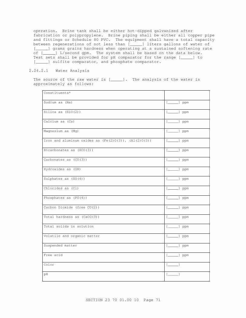
oper at i on. Br i ne t ank shal l be ei t her hot - di pped gal vani zed af t er f abr i cat i on or pol ypr opyl ene. Br i ne pi pi ng shal l be ei t her al l copper pi pe and f i t t i ngs or Schedul e 80 PVC. The equi pment shal l have a t ot al capaci t y bet ween r egener at i ons of not l ess t han [ _____] l i t er s gal l ons of wat er of [ _____] gr ams gr ai ns har dness when oper at i ng at a sust ai ned sof t eni ng r at e of [ _____] L/ second gpm. The syst em shal l be based on t he dat a bel ow. Test set s shal l be pr ovi ded f or pH compar at or f or t he r ange [ _____] t o [ _____] sul f i t e compar at or , and phosphat e compar at or .
2. 24. 2. 1 Wat er Anal ysi s
The sour ce of t he r aw wat er i s [ _____] . The anal ysi s of t he wat er i s appr oxi mat el y as f ol l ows:
Constituents*
Sodi um as ( Na) [ _____] ppm
Si l i ca as ( Si O( 2) ) [ _____] ppm
Cal ci um as ( Ca) [ _____] ppm
Magnesi um as ( Mg) [ _____] ppm
I r on and al umi num oxi des as ( Fe( 2) O( 3) ) , ( Al ( 2) O( 3) ) [ _____] ppm
Bi car bonat es as ( HCO( 3) ) [ _____] ppm
Car bonat es as ( CO( 3) ) [ _____] ppm
Hydr oxi des as ( OH) [ _____] ppm
Sul phat es as ( SO( 4) ) [ _____] ppm
Chl or i des as ( Cl ) [ _____] ppm
Phosphat es as ( PO( 4) ) [ _____] ppm
Car bon Di oxi de ( f r ee CO( 2) ) [ _____] ppm
Tot al har dness as ( CaCO( 3) ) [ _____] ppm
Tot al sol i ds i n sol ut i on [ _____] ppm
Vol at i l e and or gani c mat t er [ _____] ppm
Suspended mat t er [ _____] ppm
Fr ee aci d [ _____] ppm
Color [_____]
pH [_____]
SECTI ON 23 70 01. 00 10 Page 71
Constituents*
* Number s i n par ent heses ar e subscr i pt s.
2. 24. 2. 2 Zeolite
Zeol i t e shal l be t he hi gh capaci t y pol yst yr ene base sul phoni c synt het i c t ype. Not l ess t han [ _____] cubi c met er f eet of zeol i t e shal l be pr ovi ded wi t h each r eact or t ank.
2. 24. 2. 3 React or Tank
React or t ank s i zes shal l be based on al l owi ng a f r eeboar d above t he zeol i t e bed of not l ess t han 50 per cent of t he zeol i t e bed dept h, and a maxi mum f l ow r at e of 11. 3 mL/ squar e met er s per second one gal l on/ squar e f oot per mi nut e f or each 111 mm 4- 3/ 8 i nches of zeol i t e bed dept h.
2. 24. 2. 4 Sof t eni ng Syst em
The sof t eni ng syst em shal l be compl et e wi t h al l pi pi ng, cont r ol , and power wi r i ng. A compl et e i ni t i al char ge of r ock sal t shal l be i nst al l ed i n t he br i ne t ank as r ecommended by t he sof t ener manuf act ur er .
2. 24. 2. 5 Wat er Test Ki t
A k i t compl et e wi t h t est cont ai ner s, r eagent s, and i nst r uct i ons f or t est i ng t he r aw and ef f l uent wat er shal l be pr ovi ded i n a st r ong car r y i ng case.
2. 24. 2. 6 Tr eat ed Wat er St or age Tank
Tr eat ed wat er st or age t ank shal l be f abr i cat ed f r om st eel pl at es not l ess t han 4. 7625 mm 0. 1875 i nch t hi ck f or shel l and heads, and shal l be const r uct ed i n accor dance wi t h ASME BPVC SEC VI I I D1 f or unf i r ed pr essur e vessel s f or a desi gn wor ki ng pr essur e of 517 kPa 75 psi g. Heads shal l be di shed concave t o pr essur e t o a r adi us equal t o t he di amet er of t he t ank. The t ank shal l be pr ovi ded wi t h t he connect i ons i ndi cat ed, an 203. 2 mm 8 i nch copper bal l f l oat , l evel - oper at ed cont r ol val ve, val ve bypass and accessor i es, and a pr ot ect ed gauge gl ass. The t ank shal l be t he di amet er shown and shal l have a capaci t y of not l ess t han [ _____] l i t er s gal l ons. The t ank shal l be hydr ost at i cal l y t est ed at t he f act or y at not l ess t han 690 kPa 100 psi g.
2. 25 BUI LDI NG HEATI NG EQUI PMENT
2. 25. 1 Uni t Heat er s
2. 25. 1. 1 General
The manuf act ur er of t he uni t heat er s shal l not sel ect i ndi v i dual heat er s wi t h a capaci t y i n excess of 125 per cent of t he val ue speci f i ed f or t he heat er . Or i f i ce pl at es shal l be pr ovi ded t o r educe t he j oul e Bt u out put wher e r equi r ed. The noi se l evel of each uni t heat er shal l be appr opr i at e f or t he space i n whi ch t he heat er i s i nst al l ed. The sound power l evel [ _____] deci bel s r ef er ence shal l not exceed t he f ol l owi ng val ues i n each oct ave band at t he mi df r equency, cycl es per second:
SECTI ON 23 70 01. 00 10 Page 72
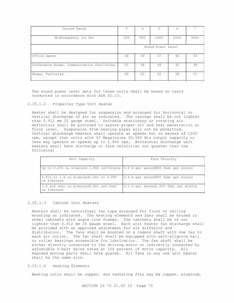
Oct ave Bands 3 4 5 6 7
Mi df r equency ( i n Hz) 250 500 1000 2000 4000
Sound Power Level
Of f i ce Space 54 50 47 45 43
Conf er ence Rooms, Communi cat i on Faci l i t i es 51 46 45 42 38
Shops, Fact or i es 69 62 61 58 57
The sound power l evel dat a f or t hese uni t s shal l be based on t est s conduct ed i n accor dance wi t h ASA S1. 13.
2. 25. 1. 2 Pr opel l er Type Uni t Heat er
Heat er shal l be desi gned f or suspensi on and ar r anged f or hor i zont al or ver t i cal di schar ge of ai r as i ndi cat ed. The casi ngs shal l be not l i ght er t han 0. 912 mm 20 gauge st eel . Sui t abl e st at i onar y or r ot at i ng ai r def l ect or s shal l be pr ovi ded t o assur e pr oper ai r and heat penet r at i on at f l oor l evel . Suspensi on f r om heat i ng pi pes wi l l not be per mi t t ed. Ver t i cal di schar ge heat er s shal l oper at e at speeds not i n excess of 1200 r pm, except t hat uni t s wi t h 53 Megaj oul es 50, 000 Bt u out put capaci t y or l ess may oper at e at speeds up t o 1, 800 r pm. Hor i zont al di schar ge uni t heat er s shal l have di schar ge or f ace vel oci t i es not gr eat er t han t he following:
Uni t Capaci t y Face Vel oci t y
Up t o 0. 472 cu m/ second 1, 000 cuf / mi nut e 4. 0 m per second800 f eet per mi nut e
0. 472 t o 1. 4 cu m/ second1. 001 t o 3, 000 cu f / mi nut e
4. 6 m per second900 f eet per mi nut e
1. 4 and over cu m/ second3. 001 and over cu f / mi nut e
5. 1 m per second1, 000 f eet per mi nut e
2. 25. 1. 3 Cabi net Uni t Heat er s
Heat er s shal l be cent r i f ugal f an t ype ar r anged f or f l oor or cei l i ng mount i ng as i ndi cat ed. The heat i ng el ement s and f ans shal l be housed i n st eel cabi net s wi t h angl e i r on f r ames. The cabi net s shal l be of not l i ght er t han 0. 912 mm 20 gauge st eel . Each uni t heat er f an di schar ge shal l be pr ovi ded wi t h an appr oved adj ust ment f or ai r di f f usi on and di st r i but i on. The f ans shal l be mount ed on a common shaf t wi t h one f an t o each ai r out l et . The f an shaf t shal l be equi pped wi t h sel f - al i gni ng bal l or r ol l er bear i ngs accessi bl e f or l ubr i cat i on. The f an shaf t shal l be ei t her di r ect l y connect ed t o t he dr i v i ng mot or or i ndi r ect l y connect ed by adj ust abl e V- bel t dr i ve r at ed at 150 per cent of mot or capaci t y. Al l exposed movi ng par t s shal l have guar ds. Al l f ans i n any one uni t heat er shal l be t he same si ze.
2. 25. 1. 4 Heat i ng El ement s
Heat i ng coi l s shal l be copper , and r adi at i ng f i ns may be copper , al umi num,
SECTI ON 23 70 01. 00 10 Page 73
or sui t abl e f er r ous al l oy. The heat i ng el ement s shal l be f r ee t o expand or cont r act wi t hout devel opi ng l eaks and shal l be pr oper l y pi t ched f or dr ai nage. The el ement s shal l be t est ed under a hydr ost at i c pr essur e of 1. 4 MPa 200 psi and a cer t i f i ed r epor t of t he t est shal l be submi t t ed t o t he Cont r act i ng Of f i cer .
2. 25. 1. 5 Manual Sel ect i on Swi t ches
Mot or s shal l be pr ovi ded wi t h manual sel ect i on swi t ches f or [ on, of f , and aut omat i c] [ on- of f ] oper at i on and shal l be equi pped wi t h t her mal - over l oad protection.
2. 25. 1. 6 Aut omat i c Oper at i on
2. 25. 1. 6. 1 Ther most at i c Cont r ol by Fan Regul at i on
The uni t heat er s shal l be cont r ol l ed aut omat i cal l y by t her most at s l ocat ed wher e i ndi cat ed. The t her most at s shal l be adj ust abl e and f i t t ed wi t h t her momet er s. Each t her most at shal l oper at e on not mor e t han a 2 degr ees C 3 degr ees F di f f er ent i al over a t emper at ur e r ange of appr oxi mat el y 13 t o 24 degr ees C 55 t o 75 degr ees F. The t her most at shal l s t ar t or st op t he r espect i ve uni t heat er f an mot or when t he r oom t emper at ur e f al l s bel ow or r i ses above t he t her most at set poi nt . Summer - wi nt er swi t ches f or f an oper at i on shal l be pr ovi ded adj acent t o t he t her most at f or each uni t heat er .
2. 25. 1. 6. 2 Ther most at i c Cont r ol by St eam Val ve Regul at i on
Cabi net t ype uni t heat er s shal l be cont r ol l ed aut omat i cal l y by pr opor t i oni ng t ype t her most at s and modul at i ng st eam val ves l ocat ed wher e i ndi cat ed. On- Of f swi t ches f or f an oper at i on shal l be pr ovi ded adj acent t o t he t her most at f or each f an uni t . The t her most at s and val ves shal l mai nt ai n t he desi r ed r oom t emper at ur e wi t hi n 1 degr ee C 2 degr ees F of t he t her most at set poi nt by r egul at i ng t he st eam suppl i ed t o t he coi l .
2. 25. 2 Radi at or and Convect or
Each [ r adi at or ] [ convect or ] uni t shal l be pr ovi ded wi t h a t op suppl y connect i on wi t h a cont r ol val ve and a bot t om r et ur n connect i on wi t h a t her most at i c t r ap. Each uni t shal l be t est ed hydr ost at i cal l y at t he f act or y and pr oved t i ght at a pr essur e of not l ess t han 690 kPa 100 pounds. Ext ended sur f ace t ube- t ype r adi at or s shal l consi st of sui t abl e met al f i ns per manent l y bonded t o copper or st eel pi pe cor es t hr eaded at each end f or connect i ng t o ext er nal pi pi ng. Radi at or capaci t i es shal l be det er mi ned i n accor dance wi t h t he HYI-005 Rat i ng Code. Radi at or s shal l be equi pped wi t h [ expanded met al cover gr i l l es f abr i cat ed f r om st eel sheet s not l i ght er t han 1. 519 mm 16 gauge, secur ed ei t her di r ect l y t o r adi at or s or t o i ndependent br acket s] [ sol i d f r ont , s l ot t ed, hor i zont al t op gr i l l es f abr i cat ed f r om st eel sheet s not l i ght er t han 1. 214 mm 0. 0478 i nch t hi ck, secur ed ei t her di r ect l y t o r adi at or s or t o i ndependent br acket s] [ sol i d f r ont , s l ot t ed, s l opi ng, t op cover gr i l l es f abr i cat ed f r om st eel sheet s not l i ght er t han 1. 214 mm 0. 0478 i nch t hi ck i ndependent l y secur ed t o masonr y wi t h br acket s] . [ Nonf er r ous convect or s shal l be t est ed hydr ost at i cal l y at t he f act or y and pr oved t i ght under a pr essur e of not l ess t han 585 kPa 85 psi g. ]
2. 26 AI R COMPRESSOR UNI TS
Ai r compr essor shal l conf or m t o ASME PTC 10, except as speci f i ed ot her wi se. Compr essor speed shal l not exceed 900 r pm. Mot or speed shal l not exceed 1750 r pm.
SECTI ON 23 70 01. 00 10 Page 74
2. 26. 1 Ser vi ce Ai r Compr essor s
The ser vi ce ai r r equi r ement s shal l be as i ndi cat ed wi t h r ecei ver s s i zed as i ndi cat ed. The uni t s shal l be sui t abl e f or heavy- dut y ser vi ce ( soot bl owi ng) . The compr essor s shal l be s i mpl ex t ype, s i ngl e- st age, doubl e- act i ng, wi t h wat er - j acket ed cyl i nder ; f i t t ed wi t h i nt ake and di schar ge val ves of t he l i ght wei ght f eat her , di sc, or pl at e t ype; and shal l be pr ovi ded wi t h necessar y cont r ol s, wat er - cool ed af t er cool er , moi st ur e separ at or , dr i ve, r ecei ver , r el i ef val ves, and cool i ng wat er cont r ol s as i ndi cat ed or r equi r ed. The compr essor ai r i nt ake shal l be pr ovi ded wi t h a l ow dr op- t ype ai r suct i on f i l t er / s i l encer sui t abl e f or out door i nst al l at i on. The af t er cool er shal l be t he shel l - and- t ube t ype desi gned f or ai r f l ow t hr ough t he t ubes wi t h st eel shel l i nt er nal baf f l e pl at es and Admi r al t y met al t ubes expanded i nt o Munt z met al t ube sheet s. The moi st ur e separ at or shal l be pr ovi ded wi t h an aut omat i c wat er di schar ge t r ap and l evel gauge. The ai r r ecei ver shal l be ver t i cal t ype, const r uct ed i n accordance ASME BPVC SEC VI I I D1 f or unf i r ed pr essur e vessel s f or 1. 4 MPa 200 psi wor ki ng pr essur e, and shal l be equi pped wi t h f l anged i nl et and out l et connect i ons, val ved dr ai n connect i on, 152 mm 6 i nch di al pr essur e gauge, pop saf et y val ves, and r egul at or connect i ons. Cool i ng wat er cont r ol s f or r egul at i ng compr essor cyl i nder wat er t emper at ur e and af t er cool er wat er t emper at ur e shal l be t her most at i c val ve t ype and shal l be i nst al l ed wi t h a t hr ee- val ve bypass i n t he wat er out l et l i nes ahead of open si ght dr ai n f unnel s. The compr essor shal l be equi pped wi t h adj ust abl e, pr essur e- t ype unl oader cont r ol s sui t abl e f or cont i nuous compr essor operation.
2. 26. 2 I nst r ument Ai r Compr essor s
**************************************************************************NOTE: The desi gner shoul d det er mi ne i f t wo r edundant f ul l - s i ze i nst r ument ai r compr essor s wi l l be r equi r ed as l oss of ai r wi l l cause uni t shut down unl ess ot her pr ovi s i ons ar e made, such as cr osst i es t o t he soot bl ower / ser vi ce ai r syst em. Del et e par agr aph i f not r equi r ed.
**************************************************************************
An el ect r i c mot or - dr i ven oi l - f r ee aut omat i c ai r compr essor uni t and a r ef r i ger at i ng dr y i ng uni t shal l be pr ovi ded. The ai r compr essor shal l be capabl e of del i ver i ng, at a pr essur e of [ _____] Pa psi g, not l ess t han 0. 00472 st andar d cubi c met er s/ second 10 scf m dr y ai r at an at mospher i c dew poi nt of - 23 degr ees C - 10 degr ees F wi t h ent er i ng ai r at 35 degr ees C 95 degr ees F, sat ur at ed. The ai r compr essor uni t shal l be s i zed t o r un not mor e t han 60 per cent of t he t i me when al l cont r ol s ar e i n ser vi ce. The ai r compr essor uni t shal l be compl et e wi t h al l necessar y accessor i es i ncl udi ng aut omat i c pr essur e cont r ol equi pment , r el i ef val ves, check val ves, ai r f i l t er s, moi st ur e t r aps, and a r ecei ver wi t h ampl e capaci t y f or emer gency oper at i on of t he cont r ol s f or 15 mi nut es af t er compr essor shut down. The r ecei ver shal l be of ver t i cal const r uct i on, i n accor dance, ASME BPVC SEC VI I I D1 wi t h r el i ef val ve and dr ai n f i t t i ngs. The ai r dr yer shal l be a sel f - cont ai ned, r ef r i ger at ed t ype, compl et e wi t h r ef r i ger at i on compr essor , heat exchanger , aut omat i c cont r ol s, and moi st ur e r emoval t r ap, or a r egener at i ve desi ccant t ype dr yer , as r equi r ed. The r ef r i ger at i on uni t shal l be t he her met i cal l y- seal ed t ype capabl e of cont i nuous oper at i on at maxi mum l oad condi t i ons.
SECTI ON 23 70 01. 00 10 Page 75
2. 27 PIPING
Unl ess ot her wi se speci f i ed her ei n, pi pe and f i t t i ngs shal l conf or m t o ASME B31. 1.
2. 27. 1 Pipe
Pi pe mat er i al shal l be as speci f i ed i n TABLE I .
2. 27. 2 Fittings
Pi pe f i t t i ngs shal l be as speci f i ed i n TABLE I I .
2. 27. 3 Nipples
Ni ppl es shal l conf or m t o ASTM A733, Type I or I I , as r equi r ed t o mat ch adj acent pi pi ng.
2. 27. 4 Unions
Uni ons shal l conf or m t o ASME B16. 39, t ype as r equi r ed t o mat ch adj acent piping.
2. 27. 5 Pi pe Thr eads
Pi pe t hr eads shal l conf or m t o ASME B1. 20. 2MASME B1. 20. 1, r i ght - or l ef t - hand t aper ed t hr ead as r equi r ed.
2. 27. 6 Expansi on Joi nt s
2. 27. 6. 1 Gui ded, Sl i p- Tube Type Expansi on Joi nt s
**************************************************************************NOTE: Wher ever possi bl e, pr ovi s i on f or expansi on of st eam suppl y and r et ur n pi pes wi l l be made by changes i n t he di r ect i on of t he r un of t he pi pe or by f i el d- f abr i cat ed expansi on bends. I f expansi on j oi nt s ar e not r equi r ed, appl i cabl e par agr aphs wi l l be del et ed. Wher e space l i mi t at i ons pr event such pr ovi s i ons f or expansi on, expansi on j oi nt s wi l l be installed.
**************************************************************************
Gui ded, s l i p- t ube expansi on j oi nt s shal l conf or m t o EJMA St ds and ASME B31. 1. End connect i ons shal l be f l anged. Anchor bases or suppor t bases shal l be pr ovi ded as i ndi cat ed or r equi r ed. The j oi nt s shal l be desi gned f or a st eam wor ki ng pr essur e not l ess t han [ _____] Pa psi g. Joi nt s shal l pr ovi de f or ei t her s i ngl e or doubl e s l i p of t he connect ed pi pes, as i ndi cat ed, and f or not l ess t han t he t r aver se i ndi cat ed. [ Ser vi ce out l et s shal l be pr ovi ded wher e i ndi cat ed or r equi r ed. ]
2. 27. 6. 2 Bel l ows Type Expansi on Joi nt s
Bel l ows t ype j oi nt s shal l be f l ex i bl e, gui ded expansi on j oi nt s conf or mi ng to EJMA St ds and ASME B31. 1. The expansi on el ement shal l be st ai nl ess st eel . Gui di ng of pi pi ng on bot h s i des of expansi on j oi nt shal l be i n accor dance wi t h t he publ i shed r ecommendat i ons of t he manuf act ur er of t he expansi on j oi nt . The j oi nt s shal l be desi gned f or t he wor ki ng t emper at ur e and pr essur e sui t abl e f or t he appl i cat i on, but desi gn pr essur e shal l not be
SECTI ON 23 70 01. 00 10 Page 76
l ess t han 1. 03 MPa 150 psi g.
2. 27. 6. 3 Fl exi bl e Bal l Type Expansi on Joi nt s
Fl exi bl e bal l j oi nt s shal l be [ st ai nl ess st eel ] [ mal l eabl e- i r on] [ duct i l e i r on] [ car bon st eel ] [ br onze] or ot her al l oys as appr opr i at e f or t he ser vi ce i nt ended. The j oi nt s may be t hr eaded, f l anged, or wel ded end, as r equi r ed, and shal l be capabl e of absor bi ng t he nor mal oper at i ng axi al , l at er al , or angul ar movement s or combi nat i on t her eof . The bal l - t ype j oi nt shal l be desi gned and const r uct ed i n accor dance wi t h ASME B31. 1 and EJMA St ds, wher e appl i cabl e. Fl anges shal l conf or m t o t he di amet er and dr i l l i ng pr ovi s i ons of ASME B16. 5. Mol ded gasket s f ur ni shed shal l be sui t abl e f or t he ser vi ce i nt ended.
2. 27. 7 Valves
Val ves shal l be i nst al l ed at i ndi cat ed l ocat i ons, wher e speci f i ed, and wher e r equi r ed f or pr oper f unct i oni ng and ser vi c i ng of t he syst em. Val ves shal l be of t he pr essur e c l ass shown. Mot or - oper at ed val ves shal l be capabl e of c l osi ng speeds of 2. 5 t o 5. 1 mm/ sec 6 t o 12 i nches/ mi nut e. Mot or oper at or s shal l be equi pped wi t h posi t i on i ndi cat or s, val ve st em pr ot ect or s above t he mot or oper at i ng uni t s, and auxi l i ar y handwheel s f or manual oper at i on of t he val ves i n t he event of power f ai l ur e. Mot or s shal l be sui t abl e f or oper at i on on t he el ect r i cal cur r ent char act er i st i cs indicated.
2. 27. 7. 1 Check Val ves
**************************************************************************NOTE: The desi gner shal l i ndi cat e t he t ype of val ves, ver t i cal l i f t or hor i zont al , on t he dr awi ngs.
**************************************************************************
a. Val ves f or 125 pound cl ass st eel pi pi ng shal l conf or m t o t he f ol l owi ng:
( 1) Si zes 65 mm 2- 1/ 2 i nches and l ess, br onze: MSS SP- 80, Type 3 or 4, Cl ass 125.
( 2) Si zes 80 mm 3 i nches t hr ough 600 mm 24 i nches, cast - i r on: MSS SP- 71, Type I I I or I V, Cl ass 125.
b. Val ves f or 150 pound cl ass st eel pi pi ng shal l conf or m t o t he f ol l owi ng:
( 1) Si zes 65 mm 2- 1/ 2 i nches and l ess, br onze: MSS SP- 80, Cl ass 150 minimum.
( 2) Si zes 80 mm 3 i nches t hr ough 600 mm 24 i nches, st eel : ASME B16. 34, Cl ass 150 mi ni mum, f l anged ends, swi ng di sc.
c. Val ves f or syst em oper at i ng pr essur e gr eat er t han 1. 4 MPa 200 psi shal l be swi ng check or l i f t check val ves havi ng a st eel body and shal l be sui t abl e f or speci f i ed oper at i ng pr essur e, but not l ess t han Cl ass 300 300 pound cl ass. Val ves 40 mm 1- 1/ 2 i nches and smal l er shal l be cast or f or ged st eel wi t h socket wel ded ends. Val ves 50 mm 2 i nch and l ar ger shal l be st eel wi t h but t wel ded ends. Check val ves shal l have r enewabl e composi t i on di scs or shal l have met al l i c di scs of t he r egr i ndabl e t ype whi ch per mi t s r egr i ndi ng wi t hout r emovi ng val ve f r om t he l i ne.
SECTI ON 23 70 01. 00 10 Page 77
2. 27. 7. 2 Gat e Val ves
Gat e val ves used as shut of f val ves i n t he boi l er l eads t o t he st eam header s, and el sewher e as i ndi cat ed, shal l be of t he chai n- oper at ed t ype, wi t h enough chai n f or easy oper at i on f r om t he oper at i ng f l oor or wal kway. Gat e val ves 200 mm 8 i nches and l ar ger used on hi gh- pr essur e st eam l i nes, and el sewher e as i ndi cat ed shal l be pr ovi ded wi t h a gl obe val ve bypass.
a. Val ves f or 125 pound cl ass st eel pi pi ng shal l conf or m t o t he f ol l owi ng:
( 1) Si zes 65 mm 2- 1/ 2 i nches and l ess, br onze: MSS SP- 80, Type 1 or 2, Cl ass 125.
( 2) Si zes 80 mm 3 i nches t hr ough 1200 mm 48 i nches, cast - i r on: MSS SP- 70, Type I , Cl ass 125, Desi gn OT or OF ( OS&Y) , br onze t r i m.
b. Val ves f or 150 pound cl ass st eel pi pi ng shal l conf or m t o t he f ol l owi ng:
( 1) Si zes 65 mm 2- 1/ 2 i nches and l ess, br onze: MSS SP- 80, Type 1 or 2, Cl ass 150 mi ni mum.
( 2) Si zes 80 mm 3 i nches t hr ough 600 mm 24 i nches, st eel : ASME B16. 34, Cl ass 150 mi ni mum, f l anged ends.
c. Val ves f or syst em oper at i ng pr essur e gr eat er t han 1. 4 MPa 200 psi shal l be spl i t wedge di sc t ype, out s i de scr ew and yoke, st eel and shal l be sui t abl e f or speci f i ed oper at i ng st eam pr essur e, but not l ess t han Cl ass 300 300 pound cl ass. Val ves 50 mm 2 i nch and smal l er shal l be f or ged st eel wi t h socket wel ded ends. Val ves 65 mm 2- 1/ 2 i nches and l ar ger shal l be st eel and shal l have but t wel ded ends.
2. 27. 7. 3 Gl obe Val ves and Angl e Val ves
Gl obe t ype val ves shal l have out s i de scr ew and yoke wi t h bol t ed bonnet s, st ai nl ess st eel t r i m, and f l at seat s, but shal l not be t he r ever sed cup t ype. The st uf f i ng boxes shal l be l ar ge and deep. Val ves shal l be i nst al l ed wi t h t he st em hor i zont al or above.
a. Val ves f or 125 pound cl ass st eel pi pi ng shal l conf or m t o t he f ol l owi ng:
( 1) Si zes 65 mm 2- 1/ 2 i nches and l ess, br onze: MSS SP- 80, Type 1, 2, or 3, Cl ass 125.
( 2) Si zes 80 mm 3 i nches t hr ough 300 mm 12 i nches, cast - i r on: MSS SP- 85, Type I I I and Type I V, Cl ass 125.
b. Val ves f or 150 pound cl ass st eel pi pi ng shal l conf or m t o t he f ol l owi ng:
( 1) Si zes 65 mm 2- 1/ 2 i nches and l ess, br onze: MSS SP- 80, Type 1, 2, or 3, Cl ass 150 mi ni mum.
( 2) Si zes 80 mm 3 i nches t hr ough 600 mm 24 i nches, st eel : ASME B16. 34, Cl ass 150 mi ni mum, f l anged ends.
c. Val ves f or syst em oper at i ng pr essur e gr eat er t han 1. 4 MPa 200 psi shal l be sui t abl e f or speci f i ed oper at i ng condi t i ons, but not l ess t han 300 pound cl ass. Val ves 50 mm 2 i nch and smal l er shal l be f or ged st eel wi t h socket wel ded ends. Val ves 65 mm 2- 1/ 2 i nches and l ar ger shal l be st eel and shal l have but t wel ded ends. Val ves shal l have r enewabl e
SECTI ON 23 70 01. 00 10 Page 78
f l at met al seat s.
2. 27. 7. 4 St eam Pr essur e Reduci ng Val ves
**************************************************************************NOTE: Si ngl e- seat ed val ves shoul d be used when a dead- end shut of f of t he st eam i s r equi r ed. When a t her most at i cal l y- cont r ol l ed val ve i s i nst al l ed af t er and near t he r educi ng val ve i n a manner t o cut of f t he passage of s t eam, t he s i ngl e- seat ed val ve shoul d be used. Doubl e- seat ed val ves may be used wher e t he l ow ( r educed) pr essur e l i nes wi l l condense enough st eam t o of f set nor mal l eakage t hr ough t he val ve. Under condi t i ons of wi del y var yi ng i ni t i al pr essur e, doubl e- seat ed val ves usual l y gi ve c l oser cont r ol of r educed pr essur e.
**************************************************************************
Reduci ng val ves desi gned f or t he wor ki ng pr essur e shown, but not f or l ess t han 1. 4 MPa 200 psi g, shal l be pr ovi ded wher ever i ndi cat ed or r equi r ed. Each r educi ng val ve shal l be adj ust ed t o mai nt ai n t he desi r ed t er mi nal pr essur e, r egar dl ess of f l uct uat i ons i n t he i ni t i al pr essur e. The val ves shal l be [ s i ngl e seat ed] [ doubl ed seat ed] , spr i ng- l oaded, qui et i n oper at i on, and shal l not st i ck i nt er nal l y. Pi l ot - oper at ed val ves or ot her cont r ol l er s usi ng st eam or compr essed ai r f or oper at i ng medi um shal l be pr ovi ded. Val ves 65 mm 2- 1/ 2 i nches and l ar ger shal l be cast st eel , cast - i r on, or semi st eel as r equi r ed f or t he st eam pr essur e. Val ves 50 mm 2 i nches and smal l er shal l be br onze. Val ve t r i m f or i r on body val ves shal l be st ai nl ess st eel , ni ckel copper , or ot her appr oved cor r osi on- r esi st i ng mat er i al . Al l par t s subj ect t o wear shal l be r eadi l y r enewabl e. Val ves shal l have seat s and pl ugs f aced wi t h a cobal t - t ungst en car bi de mi xt ur e, or made of heat - t r eat ed st ai nl ess st eel or a hi gh chr omi um st eel desi gned t o r esi st er osi on. Seat and pl ug f aci ng shal l have a Br i nel l har dness of not l ess t han 450. Each val ve shal l be i nst al l ed wi t h a st r ai ner , a t hr ee- val ve bypass, and a saf et y r el i ef val ve as i ndi cat ed. Wher e pr essur e r educi ng val ves ar e used f or r educi ng t he st eam pr essur e t o t he deaer at i ng heat er , t he val ves shal l be t he s i ngl e seat ed t ype. The sensi ng l i nes shal l be connect ed t o t he st eam space i n t he deaer at or or at l east 3 m 10 f eet downst r eam of t he pr essur e r educi ng val ve.
2. 27. 7. 5 Ther most at i c Regul at i ng Val ves
**************************************************************************NOTE: I f a hot wat er gener at or i s not i nst al l ed, t hi s subpar agr aph wi l l be del et ed.
**************************************************************************
Val ves of t he sel f - cont ai ned t ype t o cont r ol wat er t emper at ur e wi t hi n t he domest i c hot wat er gener at or by r egul at i ng t he st eam suppl i ed t o t he heat i ng coi l shal l be i nst al l ed i n t he st eam suppl y l i ne t o each gener at or . Ther most at i c r egul at i ng val ves shal l be desi gned f or a st eam wor ki ng pr essur e of 1. 4 MPa 200 psi g and shal l oper at e at t he pr essur e shown. The val ves shal l be adj ust abl e wi t hi n an oper at i ng r ange of appr oxi mat el y 38 t o 71 degr ees C 100 t o 160 degr ees F and shal l mai nt ai n t he desi r ed wat er t emper at ur e wi t hi n pl us or mi nus 3 degr ees C 5 degr ees F.
2. 27. 7. 6 Back Pr essur e Rel i ef Val ves
Val ves shal l have cast - i r on or st eel bodi es and shal l be equi pped wi t h
SECTI ON 23 70 01. 00 10 Page 79
cor r osi on- r esi st ant t r i m and val ve seat s. The val ves shal l be pr oper l y gui ded and shal l be posi t i ve c l osi ng t o pr event l eakage. Adj ust ment of t he desi r ed back pr essur e shal l cover a r ange bet ween 34 t o 103 kPa 5 t o 15 psi g. The adj ust ment shal l be ef f ect ed ext er nal l y, and any shaf t s ext endi ng t hr ough t he val ve body shal l be pr ovi ded wi t h adj ust abl e st uf f i ng boxes havi ng r enewabl e packi ng.
2. 27. 7. 7 Boi l er Aut omat i c Feedwat er Reci r cul at i ng Cont r ol Val ve
**************************************************************************NOTE: I f aut omat i c r eci r cul at i on val ve i s not ut i l i zed, del et e t hi s par agr aph.
**************************************************************************
Val ve shal l be t he sel f - cont ai ned sel f - power ed t ype. The uni t shal l aut omat i cal l y pr ogr am t he r eci r cul at i on f l ow when r equi r ed and assume al l f unct i ons f or pr event i on of t he backf l ow of t he mai n f eedwat er f l ow, f or det ect i on of l ow f l ow, f or cycl i ng of t he cont r ol val ve, and f or t he pr essur e r educt i on f or l i qui d del i ver y t o t he l ow- pr essur e f eedwat er heat er . The val ve assembl y shal l be f l anged t ype wi t h f l anged spool s pr ovi ded i n bot h t he mai n l i ne and r eci r cul at i on l i ne f or ease of disassembly.
2. 27. 8 Exhaust Heads
Exhaust heads f or t he di schar ge of st eam t o at mospher e shal l be one- pi ece pl at e st eel , semi st eel , or cast - i r on const r uct i on wi t h i nt er nal baf f l e ar r angement f or t he r emoval of ent r ai ned condensat e and oi l , and wi t h pr ovi s i on f or dr ai n connect i on. Fl ow ar ea t hr ough uni t shal l be l ar ger t han connect i ng pi pe.
2. 27. 9 Strainers
The st r ai ner body connect i ons shal l be of t he same si ze as t he pi pel i nes i n whi ch t he connect i ons ar e i nst al l ed. The st r ai ner bodi es shal l be heavy and dur abl e cast st eel [ or gr ay cast - i r on] . The bodi es shal l have ar r ows cl ear l y cast on t he s i des t o i ndi cat e t he di r ect i on of f l ow. Each st r ai ner shal l be equi pped wi t h an easi l y r emovabl e cover and sedi ment basket . The basket shal l be not l ess t han 0. 63 mm 0. 025 i nch t hi ck cor r osi on- r esi st ant st eel [ or sheet br ass] wi t h enough smal l per f or at i ons t o pr ovi de a net f r ee ar ea t hr ough t he basket of at l east 3. 30 t i mes t hat of t he di amet er of t he ent er i ng pi pe.
2. 27. 10 Pi pe Hanger s, I nser t s, and Suppor t s
Pi pe hanger s, i nser t s and suppor t s shal l conf or m t o MSS SP- 58, except as modi f i ed her ei n:
a. Types 5, 12, and 32 shal l not be used.
b. Type 3 shal l not be used on i nsul at ed pi pe whi ch has a vapor bar r i er . Type 3 may be used on i nsul at ed pi pe t hat does not have a vapor bar r i er i f c l amped di r ect l y t o t he pi pe and i f t he c l amp bot t om does not ext end t hr ough t he i nsul at i on and t he t op c l amp at t achment does not cont act t he i nsul at i on dur i ng pi pe movement .
c. Type 18 i nser t s shal l be secur ed t o concr et e f or ms bef or e concr et e i s pl aced. Cont i nuous i nser t s whi ch al l ow mor e adj ust ment may be used i f t hey ot her wi se meet t he r equi r ement s f or Type 18 i nser t s.
SECTI ON 23 70 01. 00 10 Page 80
d. Type 19 and 23 C- cl amps shal l be t or qued i n accor dance wi t h MSS SP- 58 and have bot h l ocknut s and r et ai ni ng devi ces f ur ni shed by t he manuf act ur er . Fi el d- f abr i cat ed C- cl amp bodi es or r et ai ni ng devi ces ar e not accept abl e.
e. Type 20 at t achment s used on angl es and channel s shal l be f ur ni shed wi t h an added mal l eabl e- i r on heel pl at e or adapt or .
f . Type 24 may be used onl y on t r apeze hanger syst ems or on f abr i cat ed frames.
g. Wher e Type 39 saddl e or Type 40 shi el d i s per mi t t ed f or a par t i cul ar pi pe at t achment appl i cat i on, t he Type 39 saddl e shal l be used on al l pi pe 100 mm 4 i nches and l ar ger .
h. Hor i zont al pi pe suppor t s shal l be spaced as speci f i ed i n MSS SP- 58 and a suppor t shal l be i nst al l ed not over 300 mm 1 f oot f r om t he pi pe f i t t i ng j oi nt at each change i n di r ect i on of t he pi pi ng. Pi pe suppor t s shal l be spaced not over 1. 5 m 5 f eet apar t at val ves. I n t he suppor t of mul t i pl e pi pe r uns on a common base member , a c l i p or c l amp shal l be used wher e each pi pe cr osses t he base suppor t member . Spaci ng of t he base suppor t member s shal l not exceed t he hanger and suppor t spaci ng r equi r ed f or any of t he i ndi v i dual pi pes i n t he mul t i pl e pi pe r un. The cl i ps or c l amps shal l be r i gi dl y connect ed t o t he common base member . A c l ear ance of 3 mm 1/ 8 i nch shal l be pr ovi ded bet ween t he pi pe and cl i p or c l amp f or al l pi pi ng whi ch may be subj ect ed t o t her mal expansion.
i . Ver t i cal pi pe shal l be suppor t ed at each f l oor , except at s l ab- on- gr ade, and at i nt er val s of not mor e t han 4. 5 m 15 f eet , not mor e t han 2. 4 m 8 f eet f r om end of r i ser s, and at vent t er mi nat i ons.
j . Type 35 gui des usi ng st eel , r ei nf or ced pol yt et r af l uor oet hyl ene ( PTFE) or gr aphi t e s l i des shal l be pr ovi ded, wher e r equi r ed, t o al l ow l ongi t udi nal pi pe movement . Lat er al r est r ai nt s shal l be pr ovi ded as r equi r ed. Sl i de mat er i al s shal l be sui t abl e f or t he syst em oper at i ng t emper at ur es, at mospher i c condi t i ons, and bear i ng l oads encount er ed.
( 1) Wher e st eel s l i des do not r equi r e pr ovi s i ons f or r est r ai nt of l at er al movement , an al t er nat e gui de met hod may be used. On pi pi ng 100 mm 4 i nches and l ar ger , a Type 39 saddl e may be wel ded t o t he pi pe and f r eel y r est on a st eel pl at e. On pi pi ng under 100 mm 4 i nches, a Type 40 pr ot ect i on shi el d may be at t ached t o t he pi pe or i nsul at i on and f r eel y r est on a st eel s l i de pl at e.
( 2) Wher e t her e ar e hi gh syst em t emper at ur es and wel di ng t o pi pi ng i s not desi r abl e, t hen t he Type 35 gui de shal l i ncl ude a pi pe cr adl e, wel ded t o t he gui de st r uct ur e and st r apped secur el y t o t he pi pe. The pi pe shal l be separ at ed f r om t he s l i de mat er i al by at l east 100 mm 4 i nches, or by an amount adequat e f or t he i nsul at i on, whi chever i s gr eat er .
k. Pi pe hanger s on hor i zont al i nsul at ed pi pes, except f or Type 3, shal l be t he s i ze of t he out s i de di amet er of t he i nsul at i on.
l . Pi pi ng i n t r enches shal l be suppor t ed as i ndi cat ed.
SECTI ON 23 70 01. 00 10 Page 81
2. 28 INSULATION
Shop and f i el d appl i ed i nsul at i on shal l be as speci f i ed i n Sect i on 23 07 00 THERMAL I NSULATI ON FOR MECHANI CAL SYSTEMS.
2. 29 TOOLS
Speci al t ool s onl y shal l be f ur ni shed and shal l i ncl ude al l uncommon t ool s necessar y f or t he oper at i on and mai nt enance of boi l er s, st oker s, pumps, f ans, cont r ol s, met er s, speci al pi pi ng syst ems, and ot her equi pment . Smal l hand t ool s shal l be f ur ni shed wi t h a sui t abl e cabi net , mount ed wher e di r ect ed. The f ol l owi ng t ool s shal l al so be f ur ni shed.
2. 29. 1 Tube Br ush
**************************************************************************NOTE: Appl i es t o f i r et ube boi l er s.
**************************************************************************
Tube br ush, wi t h st eel br i st l es and j oi nt ed handl e of suf f i c i ent l engt h t o c l ean f ul l l engt h of f i r et ubes, shal l be pr ovi ded.
2. 29. 2 Smoke Pi pe Cl eaner
Cl eaner shal l be pr ovi ded t o c l ean t he br eechi ng and smoke connect i ons. Cl eaner shal l have j oi nt ed handl e of suf f i c i ent l engt h t o c l ean br eechi ng and smoke connect i ons wi t hout di smant l i ng.
2. 29. 3 Fi r i ng Tool s
Fi r i ng t ool s i nc l udi ng hoe, poker , and s l i ce bar shal l be pr ovi ded f or each boiler.
2. 29. 4 Wr enches and Gasket s
Wr enches shal l be pr ovi ded as r equi r ed f or openi ng boi l er manhol es, handhol es, and c l eanout s. One set of ext r a gasket s shal l be pr ovi ded f or al l boi l er manhol es and handhol es, f or pump bar r el s, and ot her s i mi l ar i t ems of equi pment . Al l gasket s shal l be packaged and pr oper l y i dent i f i ed.
2. 30 COAL HANDLI NG EQUI PMENT
2. 30. 1 Scr ew Conveyor
**************************************************************************NOTE: Wher e mot or st ar t er s f or mechani cal equi pment ar e pr ovi ded i n mot or cont r ol cent er s, del et e t he r ef er ence t o mot or st ar t er s.
**************************************************************************
Scr ew conveyor f or t he l at er al di st r i but i on of coal shal l consi st of st eel scr ew conveyor wi t h capaci t y of not l ess t han [ _____] cubi c met er s/ second cubi c f eet / hour when handl i ng coal of t he speci f i ed maxi mum l ump si ze. Maxi mum capaci t y of t he conveyor shal l be based on t he scr ews car r y i ng not mor e t han 30 per cent of t hei r cr oss sect i on ( except f eeder conveyor s) , and t he maxi mum speed of conveyor shal l be 60 r pm. Conveyor and housi ng shal l be assembl ed i n sect i ons. The sect i onal f l i ght s shal l be mount ed on st eel pi pe and connect ed by coupl i ng shaf t s. A f eeder conveyor may be i nst al l ed t o assume t he pr oper di st r i but i on of t he l oad. Bot h t he f eeder scr ew and
SECTI ON 23 70 01. 00 10 Page 82
t he ext ended scr ew shal l have t hei r f l i ght s mount ed on t he same pi pe. The conveyor shal l be pr ovi ded wi t h sect i onal suppor t i ng hanger bear i ngs of t he babbi t t ed t ype. Conveyor l engt h bet ween bear i ngs shal l not exceed 3. 7 m 12 f eet . Tr ough ends shal l be f abr i cat ed cast - i r on t ype wi t h f eet and f i t t ed wi t h babbi t t ed bear i ngs. The dr i ve shal l be at t he di schar ge end of t he conveyor and shal l consi st of an el ect r i c gear mot or and chai n dr i ve. The chai n dr i ve f r om t he mot or t o t he r educer shal l be encl osed i n an oi l - t i ght casi ng. Thr ust i n ei t her di r ect i on shal l be absor bed by t he t hr ust bear i ngs. The mot or may be mount ed on t op of t he t r ough. The t r ough conveyor housi ng shal l be not l ess t han 4. 8 mm 3/ 16 i nch st eel wi t h a 1. 897 mm 14 gauge st eel cover and shal l be dust - pr oof . Di schar ge spout and coal gat e shal l be f ur ni shed as i ndi cat ed. An appr oved t ype of suppor t i ng saddl e shal l be pr ovi ded. Suppor t s shal l be spaced at not mor e t han 3 m 10 f oot i nt er val s. Mot or encl osur e shal l be [ t ot al l y encl osed, nonvent i l at ed] [ t ot al l y encl osed, f an- cool ed t ype sui t abl e f or i nst al l at i on i n a Cl ass I I , Di v i s i on 1, Gr oup F hazar dous l ocat i on i n conf or mance wi t h NFPA 70] . [ Mot or st ar t er shal l be [ manual ] [ [ magnet i c] [ acr oss- t he- l i ne] [ r educed vol t age st ar t ] ] t ype wi t h [ weat her - r esi st ant ] [ dust - t i ght ] [ expl osi on- pr oof ] encl osur e. ] Dust cont r ol l i ng cover s and i nl et and di schar ge encl osur es shal l be pr ovi ded f or each conveyor .
2. 30. 2 Bel t Conveyor
Bel t conveyor shal l be of t he t r ough t ype, as shown. Maxi mum i ncl i ne of t he bel t conveyor shal l not exceed 15 degr ees. The conveyor suppor t f r ame shal l have suf f i c i ent r i gi di t y t o mai nt ai n bel t al i gnment , at l east 75 mm 3 i nches c l ear ance t o pr event damage t o t he edge of t he bel t on i t s r et ur n r un, and adj ust ment s f or al i gni ng shaf t s. Decki ng t o pr ot ect t he r et ur n bel t f r om coal s i f t i ng and t o pr ovi de l at er al st i f f ness shal l be pl aced on t op of t he st r i nger s. I dl er s shal l be accur at el y made t o pr ovi de a r i gi d f r amewor k t hat wi l l mai nt ai n per manent al i gnment of wel l bal anced, smoot h- r unni ng, easy t ur ni ng i dl er r ol l s . Al l i dl er s and r et ur n r ol l s shal l be CEMA Bel t Book, Ser i es C5. Pr essur e l ubr i cat i on shal l be pr ovi ded t o bal l or r ol l er bear i ngs. I dl er s shal l be 20- degr ee or 35- degr ee t hr ee- r ol l t ype spaced on 1. 2 m 4 f oot cent er s, except under l oadi ng poi nt s and ski r t s. Ret ur n i dl er s shal l be spaced on 3 m 10 f oot cent er s. The bel t i ng shal l be Gr ade 2 as def i ned i n RMA I P- 1. The bel t i ng shal l have f i el d- vul cani zed spl i ces. Pul l eys shal l be desi gned i n accor dance wi t h CEMA B105. 1, shal l be heavy wel ded st eel , t r ue t o di amet er and accur at el y bor ed, key seat ed and t i ght l y f i t t ed t o t he shaf t s . Pul l ey f ace wi dt h f or bel t s 1067 mm 42- i nches wi de and smal l er , t hat ar e 150 m 500 f eet or mor e i n l engt h, shal l be bel t wi dt h pl us 100 mm 4 i nches; l ess t han 150 m 500 f eet i n l engt h, shal l be bel t wi dt h pl us 75 mm 3 i nches. Pul l ey f ace wi dt h f or bel t s 1. 2 m 48 i nches and l ar ger shal l be bel t wi dt h pl us 150 mm 6 i nches. Dr i ve pul l eys shal l be pr ovi ded wi t h 19 mm 3/ 4 i nch t hi ck vul cani zed and gr ooved l aggi ng. Snub pul l eys shal l be pr ovi ded wi t h 9. 5 mm 3/ 8 i nch vul cani zed smoot h l aggi ng. Al l conveyor pul l ey shaf t assembl i es shal l be suppor t ed by t wo heavy- dut y ant i f r i c t i on bear i ngs havi ng a mi ni mum l i f e expect ancy of 50, 000 hour s f or 90 per cent of bear i ngs i n accor dance with ABMA 11 f or r ol l er bear i ngs. The pul l ey di amet er shal l be suf f i c i ent l y l ar ge t o meet t he r equi r ement s of t he duck wei ght and pl y of t he bel t t o per mi t f l exi ng of t he bel t ar ound t he pul l ey c i r cumf er ence wi t hout damagi ng t he bel t or shor t eni ng t he bel t l i f e. The conveyor shal l be dr i ven by a [ t ot al l y encl osed, nonvent i l at ed t ype] [ t ot al l y encl osed, f an- cool ed t ype] [ t ot al l y encl osed, f an- cool ed t ype sui t abl e f or i nst al l at i on i n Cl ass I I , Di v i s i on 1, Gr oup F hazar dous l ocat i on i n conf or mance wi t h NFPA 70] el ect r i c mot or connect ed t o a dr i ve- shaf t - mount ed speed r educer uni t by a [ r ol l er chai n dr i ve] [ V- bel t dr i ve] [ f l exi bl e coupl i ng] . [ The mot or st ar t er shal l be [ manual ] [ [ magnet i c]
SECTI ON 23 70 01. 00 10 Page 83
[ acr oss- t he- l i ne] [ r educed vol t age st ar t ] ] t ype wi t h [ gener al - pur pose] [ weat her - r esi st ant ] [ wat er t i ght ] [ dust - t i ght ] [ expl osi on- pr oof ] encl osur e. ] Al l bel t conveyor s shal l be pr ovi ded wi t h bel t mi sal i gnment swi t ches, emer gency st op pul l cor ds and pul l swi t ches, gal vani zed expanded met al shi el ds over t ai l pul l ey, zer o speed swi t ches, l oadi ng ski r t s , pl ugged chut e swi t ches, wal kways, suppor t s, bel t t ake- ups, bel t c l eaner s, ski r t boar ds, and pul l ey scr aper s. Dust cont r ol l i ng cover s and i nl et and di schar ge encl osur es shal l be pr ovi ded f or each conveyor .
2. 30. 3 Fl i ght Conveyor
[ Scr aper ] [ Shoe- suspended] f l i ght conveyor ar r anged gener al l y as shown and of t he s i ngl e- st r and t ype shal l have capaci t y not l ess t han [ _____] met r i c t ons/ hour t ons/ hour when handl i ng coal wi t h appr oxi mat e wei ght of 800 kg/ cubi c met er 50 pcf and wi t h maxi mum l ump si ze of [ _____] mm i nches di amet er . Capaci t y shal l be based on a maxi mum speed of 0. 508 m/ sec 100 f pm wi t h conveyor oper at i ng up a [ _____] degr ee i ncl i ne. Chai n shal l be dr op- f or ged st eel t ype wi t h f l i ght s made of ei t her st eel or mal l eabl e- i r on, spaced at l east t hr ee t i mes t he l ar gest l ump si ze. Foot shaf t shal l have pr ot ect ed scr ew t ake- up wi t h adj ust ment of not l ess t han 300 mm 12 i nches. Tr ough shal l be made of 4. 8 mm 3/ 16 i nch st eel pl at e, mi ni mum. Al l s l i di ng sur f aces i n cont act wi t h t he chai n or f l i ght s shal l be l i ned wi t h 19 mm 3/ 4 i nch t hi ck, r emovabl e, ul t r a hi gh mol ecul ar wei ght pol yet hyl ene l i ner s. Bot h s i des of t r ough shal l be pr ovi ded wi t h a war ni ng s i gn " DANGER - DO NOT WELD - FLAMMABLE PLASTI C LI NER. " Si gns shal l be v i s i bl e on each f l oor l evel and at f r equent i nt er val s. Conveyor shal l be pr ovi ded wi t h di schar ge openi ngs as i ndi cat ed, each of whi ch shal l be pr ovi ded wi t h r ack- and- pi ni on- oper at ed gat es wi t h handwheel s. Mot or shal l dr i ve conveyor t hr ough a speed r educt i on uni t whi ch i s ei t her di r ect - connect ed or r ol l er - chai n- connect ed t o t he dr i ve shaf t . Mot or shal l be [ t ot al l y encl osed, nonvent i l at ed t ype] [ t ot al l y encl osed, f an- cool ed t ype] [ t ot al l y encl osed, f an- cool ed t ype sui t abl e f or i nst al l at i on i n a Cl ass I I , Di v i s i on 1, Gr oup F hazar dous l ocat i on i n accor dance wi t h NFPA 70] . [ Mot or st ar t er shal l be [ manual ] [ [ magnet i c] [ acr oss- t he- l i ne] [ r educed vol t age st ar t ] ] t ype wi t h [ gener al - pur pose] [ weat her - r esi st ant ] [ wat er - t i ght ] [ dust - t i ght ] [ expl osi on- pr oof ] encl osur e. ] Conveyor f r ame shal l be const r uct ed essent i al l y as i ndi cat ed, wi t h addi t i onal br aci ng as r equi r ed f or r i gi di t y. Dust cont r ol l i ng cover s and i nl et and di schar ge encl osur es shal l be pr ovi ded f or each conveyor .
2. 30. 4 Bucket El evat or s
Ver t i cal bucket el evat or s shal l be f ur ni shed dust t i ght , compl et e wi t h cont i nuous chai n and at t ached bucket s, upper and l ower spr ocket s, gear s, shaf t s, bear i ngs, casi ng wi t h f l anged connect i ons i ncl udi ng t op hood and di schar ge spout , bot t om boot , access door s, el ect r i c mot or dr i ve, and al l accessor i es. Bucket el evat or s shal l be [ ver t i cal spaced cent r i f ugal di schar ge] [ posi t i ve di schar ge] [ cont i nuous bucket t ype] . The capaci t y of t he el evat or shal l be not l ess t han [ _____] met r i c t ons/ hour t ons/ hour when handl i ng coal wei ghi ng appr oxi mat el y 800 kg/ cubi c met er 50 pcf . Li near vel oci t y shal l be as i ndi cat ed bel ow:
Type of Bucket El evat or Li near Vel oci t y ( met er s per second) ( f pm)
Cent r i f ugal di schar ge 1.1-1.6225-305
SECTI ON 23 70 01. 00 10 Page 84
Type of Bucket El evat or Li near Vel oci t y ( met er s per second) ( f pm)
Cont i nuous bucket 0.508-0.686100-135
Posi t i ve di schar ge 0. 610 120 Max
The head shaf t and f oot shaf t shal l be const r uct ed of col d- r ol l ed st eel wi t h t he shaf t di amet er s i n accor dance wi t h manuf act ur er s ' st andar ds. Bot h shaf t s shal l be mount ed i n r ol l er bear i ngs wi t h f or ced- t ype l ubr i cat i ng f i t t i ngs. Foot shaf t shal l have scr ew t ake- up wi t h adj ust ment of not l ess t han 225 mm 9 i nches. An aut omat i c backst op shal l be i nst al l ed on t he head shaf t t o pr event any backwar d mot i on of t he chai n. Boot pl at es [ , l oadi ng l egs of cont i nuous bucket el evat or , ] and bot t om pl at e of st ub di schar ge chut e shal l be 4. 8 mm 3/ 16 i nch t hi ck, mi ni mum. Al l ot her f l at casi ng member s shal l be 2. 657 mm 12 gauge st eel t hi ck, mi ni mum. Cor ner angl es and st i f f ener s shal l be pr ovi ded t o make t he el evat or sel f - suppor t i ng. I n addi t i on, t he el evat or shal l be t i ed t o t he adj oi ni ng st r uct ur e at c l ose enough spaci ng t o i ncr ease t he r i gi di t y of t he el evat or . The boot sect i on shal l be pr ovi ded wi t h c l ean- out door s, as wel l as f r ont and back r emovabl e panel s. An i nspect i on door l ar ge enough t o r emove a bucket f r om ei t her r un of t he chai n shal l be pr ovi ded i n t he i nt er medi at e sect i on at oper at i ng l evel . The el evat or shal l be dr i ven by an el ect r i c mot or i nst al l ed i n a sui t abl e housi ng at t he t op of t he f l i ght . Mot or s shal l be [ t ot al l y encl osed, nonvent i l at ed] [ t ot al l y encl osed, f an- cool ed t ype] [ t ot al l y encl osed, f an- cool ed t ype sui t abl e f or i nst al l at i on i n a Cl ass I I , Di v i s i on 1, Gr oup F hazar dous l ocat i on i n accor dance wi t h NFPA 70] . [ Mot or st ar t er shal l be [ manual ] [ [ magnet i c] [ acr oss- t he- l i ne] [ r educed vol t age st ar t ] ] t ype wi t h [ gener al - pur pose] [ weat her r esi st ant ] [ wat er - t i ght ] [ dust - t i ght ] [ expl osi on- pr oof ] encl osur e. ] A pl at f or m shal l be i nst al l ed adj acent t o t he mot or f or ser vi c i ng t he mot or and equi pment mount ed i n t he hood. Access t o t he pl at f or m shal l be by an appr oved t ype of saf et y l adder . Cont r ol s f or t he oper at i on of t he el evat or shal l be l ocat ed as i ndi cat ed. Dust cont r ol cover s and i nl et and di schar ge encl osur es shal l be pr ovi ded f or each conveyor .
2. 30. 5 Vi br at i ng Conveyor
Vi br at i ng conveyor shal l be t he el ect r i c- mot or dr i ven mechani cal v i br at i ng t ype wi t h a capaci t y of [ _____] met r i c t ons/ hour t ons/ hour when handl i ng coal wei ghi ng appr oxi mat el y 800 kg/ cubi c met er 50 pcf and wi t h maxi mum l ump si ze of [ _____] mm i nches i n di amet er . Conveyor shal l have a conveyi ng l engt h as shown. The conveyor t r ough shal l be f abr i cat ed of [ _____] mm gauge st eel , [ _____] mm i nches i n wi dt h and [ _____] mm i nches deep [ and pr ovi ded wi t h dust - t i ght cover ] . Conveyor pans of 9. 5 mm 3/ 8 i nch t hi ck, Type 304L sol i d st ai nl ess st eel pl at e shal l be pr ovi ded. The t r ough shal l be mount ed on v i br at or bar s, t or s i on bar s, or coi l spr i ngs at t ached t o yoker l egs of r i gi d cr oss br ace const r uct i on and f abr i cat ed of cor r osi on- r esi st ant mat er i al wi t h har dened st eel encased r ubber bushi ngs at ar t i cul at i on poi nt s. The base shal l be f abr i cat ed of st eel channel s or angl es bol t ed di r ect l y t o [ bui l di ng suppor t ] [ concr et e f oundat i ons] . The dr i ve shal l be t hr ough an eccent r i c shaf t suppor t ed by a doubl e r ow of sel f - al i gni ng bal l - or r ol l er - bear i ng pi l l ow bl ocks. Posi t i ve act i on mot i on shal l be i mpar t ed t o t he t r ough by a cast st eel connect i ng r od at t ached t o t he t r ough by r ubber - bushed wr i st pi n and secur el y l ocked by t aper l ock bushi ngs. The conveyor shal l be dr i ven by a [ t ot al l y encl osed, nonvent i l at ed t ype] [ t ot al l y encl osed, f an- cool ed t ype sui t abl e f or i nst al l at i on i n Cl ass I I , Di v i s i on 1, Gr oup F hazar dous l ocat i on i n
SECTI ON 23 70 01. 00 10 Page 85
accor dance wi t h NFPA 70] el ect r i c mot or connect ed t o t he eccent r i c shaf t by V- bel t dr i ve. [ The mot or st ar t er shal l be [ manual ] [ [ magnet i c] [ acr oss- t he- l i ne] [ r educed vol t age st ar t ] ] t ype wi t h [ gener al - pur pose] [ weat her - r esi st ant ] [ wat er - t i ght ] [ dust - t i ght ] [ expl osi on- pr oof ] encl osur e. ]
2. 30. 6 Gr avi met r i c Wei gh Feeder
The wei gh f eeder shal l be a met er i ng bel t t ype devi ce desi gned t o oper at e at a var i abl e r at e r angi ng f r om 10 per cent of maxi mum capaci t y t o [ _____] met r i c t ons/ hour t ons/ hour . Fl ow r at e shal l be aut omat i c. A s i l i con- cont r ol l ed, r ect i f i er dc dr i ve shal l aut omat i cal l y adj ust t he bel t speed t o mai nt ai n t he r at e of mat er i al f l ow, as set on t he cont r ol l er . The wei gh f eeder s shal l meet or exceed t he r equi r ement s of NI ST HB 44 [ Sout her n] [ East er n] [ West er n] Wei ghi ng and I nspect i on Bur eau. They shal l have an accur acy of 1/ 2 of 1 per cent of f l ow r at es over t hei r t ot al var i abl e r at ed capaci t y. The f eeder shal l be pr ovi ded wi t h a f l exi bl e boot f or connect i ng t he gat e t o t he f eeder i nl et chut e, whi ch i n t ur n shal l be f l ar ed t o pr oduce a f eed openi ng t aper i ng f r om [ _____] wi de t o [ _____] wi de wi t h t he di r ect i on of f l ow of mat er i al . The bel t s f or f eeder s shal l meet RMA I P- 1 r equi r ement s, conf or mi ng t o t he Conveyor and El evat or Bel t Handbook, f i r e- r esi st ant t ype conf or mi ng t o t he st andar ds of Par t 18. 65, of the 30 CFR 1. Top bel t cover t hi ckness shal l be 6. 4 mm 1/ 4 i nch wi t h bot t om cover 3. 2 mm 1/ 8 i nch t hi ck. Bel t edges shal l have mi ni mum 25 mm 1 i nch f l anges and shal l be seal ed by car r y i ng t he cover ar ound t he car cass edges dur i ng manuf act ur e. Cover and ski m coat mat er i al shal l be compar abl e t o t hose meet i ng t he r equi r ement s of t he RMA I P- 1 f or i mpact and abr asi on r esi st ance. The wei ght sensor shal l be a heavy- dut y, i ndust r i al , el ect r oni c f or ce t r ansducer f l exur e- mount ed t o t he f or ce col l ect i on syst em. Each sensor shal l have a r emot e i ndi cat i ng met er and a s i x- di gi t t ot al i z i ng count er l ocat ed, i nst al l ed, and connect ed i n t he boi l er cont r ol panel . Uni t f r ame shal l pr ovi de r i gi d suppor t f or t he mat er i al l oad, bel t , and i dl er s. The uni t shal l be shop assembl ed compl et e wi t h dr i ve and al l appur t enances, and shal l be dust - t i ght i n oper at i on.
2. 30. 7 Tr ack Hopper s
Tr ack hopper s shal l be st andar d doubl e hopper desi gn wi t h a bel t or v i br at i ng- t ype f eeder as i ndi cat ed. The hopper s shal l have a capaci t y of appr oxi mat el y [ _____] met r i c t ons t ons and shal l be const r uct ed of not l ess t han 9. 5 mm 3/ 8 i nch t hi ck, Type 304L st ai nl ess st eel pl at es, wi t h s l opes of not l ess t han 55 degr ees, and shal l be st i f f ened wi t h angl es. The hopper s may al so be of ASTM A36/ A36M mi l d st eel , mi ni mum 6. 4 mm 1/ 4 i nch t hi ck wi t h r epl aceabl e l i ner s 6. 4 mm 1/ 4 i nch t hi ck, ASTM A167, Type 304L st ai nl ess st eel . Al l r i vet s and f i el d bol t s i nsi de t he hopper shal l have f l at heads. The hopper shal l be suspended f r om t he t r ack gi r der s by heavy bol t s and cast washer s, or t he s i des shal l be car r i ed t o t he bot t om of t he t r ack and suppor t ed by f l anges f ast ened t o concr et e l edge cont i nuousl y ar ound t he hopper wi t h t he concr et e f or mi ng t he t op por t i on of hopper s i des. Tr ack gi r der s shal l consi st of wi de f l ange beams conf or mi ng t o t he AREMA Eng Man f or l oadi ng pl us i mpact . They shal l be compl et e wi t h bear i ng pl at es, WF cr oss st r ut s, and r ai l c l i ps. Top of hopper shal l be f i t t ed wi t h pr oper l y s i zed sect i ons of gr at i ng made wi t h st eel bar s s i zed [ _____] by [ _____] mm i nches, and cr oss r ods [ _____] mm i nches i n di amet er , t o f or m openi ngs [ _____] mm i nches squar e.
2. 30. 7. 1 Hopper Gat es
A r ack- and- pi ni on gat e shal l be pr ovi ded at each hopper out l et and shal l be a sel f - c l eani ng t ype. [ Hand- ] [ Mot or - ] oper at ed s l i di ng pl at e shal l be 9. 5
SECTI ON 23 70 01. 00 10 Page 86
mm 3/ 8 i nch t hi ck car bon st eel , f or med i nt o t he shape of a wi nged U. The gat e pl at e sur f ace shal l be compl et el y pr ot ect ed by an over l appi ng l i ner of 3. 2 mm 1/ 8 i nch t hi ck ASTM A167, Type 304 st ai nl ess st eel . The gat e body mat er i al , except f or t he dust cover , shal l be of 4. 5 mm 3/ 16 i nch t hi ck ASTM A167, Type 304L st ai nl ess st eel wher e i n cont act wi t h coal f l ow.
2. 30. 7. 2 Hopper Feeder s
The vi br at i ng or bel t f eeder s of manuf act ur er ' s st andar d desi gn shal l be pr ovi ded f or t he ser vi ce r equi r ed. Mot or shal l be [ t ot al l y encl osed, nonvent i l at ed] [ t ot al l y encl osed, f an- cool ed t ype] [ t ot al l y encl osed, f an- cool ed t ype sui t abl e f or i nst al l at i on i n a Cl ass I I , Di v i s i on 1, Gr oup F hazar dous l ocat i on i n accor dance wi t h NFPA 70] . [ Mot or st ar t er shal l be [ manual ] [ [ magnet i c] [ acr oss- t he- l i ne] [ r educed vol t age st ar t ] ] t ype wi t h [ weat her - r esi st ant ] [ dust - t i ght ] [ expl osi on- pr oof ] encl osur e. ]
2. 30. 8 Tr uck Hopper s
Tr uck hopper s shal l be of st andar d doubl e hopper desi gn wi t h a bel t or v i br at i ng t ype f eeder as i ndi cat ed. The hopper s shal l have a capaci t y of appr oxi mat el y [ _____] met r i c t ons t ons and shal l be const r uct ed of 9. 5 mm 3/ 8 i nch t hi ck Type 304L st ai nl ess st eel pl at es, mi ni mum, wi t h s l opes of at l east 55 degr ees, and shal l be st i f f ened wi t h 6. 4 mm 1/ 4 i nch angl es, mi ni mum. The hopper may al so be of ASTM A36/ A36M mi l d st eel , mi ni mum 6. 4 mm 1/ 4 i nch t hi ck, wi t h r epl aceabl e l i ner s 6. 4 mm 1/ 4 i nch t hi ck, ASTM A167, Type 304L st ai nl ess st eel . Ri vet s and f i el d bol t s i nsi de t he hopper shal l be f l at - head t ype. The hopper shal l be suppor t ed by a f l ange f ast ened t o t he concr et e l edge cont i nuousl y ar ound t he hopper , wi t h t he concr et e f or mi ng t he t op por t i on of hopper s i des. Top of hopper shal l be f i t t ed wi t h pr oper l y s i zed sect i on of bar gr at i ng made wi t h [ _____] by [ _____] mm i nch mi l d st eel bar s and [ _____] mm i nch di amet er cr oss r ods t o f or m openi ngs [ _____] mm i nches squar e. A suppor t i ng beam not l ess t han [ _____] mm i nches deep, [ _____] kg/ met er pounds/ f oot , i n a wi de f l ange member , shal l be pr ovi ded under t he gr at i ng.
2. 30. 8. 1 Hopper Gat es
A r ack- and- pi ni on gat e shal l be pr ovi ded at each hopper out l et and shal l be a sel f - c l eani ng t ype. [ Hand- ] [ Mot or - ] oper at ed s l i di ng pl at e shal l be 9. 5 mm 3/ 8 i nch t hi ck car bon st eel , f or med i nt o t he shape of a wi nged U. The gat e pl at e sur f ace shal l be compl et el y pr ot ect ed by an over l appi ng l i ner of 3. 2 mm 1/ 8 i nch t hi ck ASTM A167, Type 304 st ai nl ess st eel . The gat e body mat er i al , except f or t he dust cover , shal l be of 4. 5 mm 3/ 16 i nch t hi ck ASTM A167, Type 304L st ai nl ess st eel wher e i n cont act wi t h coal f l ow.
2. 30. 8. 2 Hopper Feeder s
The vi br at i ng or bel t f eeder s, compl et e wi t h cont r ol of manuf act ur er ' s st andar d desi gn f or t he ser vi ce r equi r ed, shal l be pr ovi ded. Mot or shal l be [ t ot al l y encl osed, nonvent i l at ed] [ t ot al l y encl osed, f an- cool ed] [ t ot al l y encl osed, f an- cool ed t ype, sui t abl e f or i nst al l at i on i n a Cl ass I I , Di v i s i on 1, Gr oup F hazar dous l ocat i on i n accor dance wi t h NFPA 70] . [ Mot or st ar t er shal l be [ manual ] [ [ magnet i c] [ acr oss- t he- l i ne] [ r educed vol t age st ar t ] ] t ype wi t h [ weat her - r esi st ant ] [ dust - t i ght ] [ expl osi on- pr oof ] encl osur e. ]
2. 30. 9 Vibrator
Vi br at or shal l be el ect r omagnet i c t ype wi t h var i abl e power cont r ol t hat
SECTI ON 23 70 01. 00 10 Page 87
pr oduces mechani cal pul sat i ng mot i on. The net wei ght of t he v i br at or shal l be [ _____] kg pounds and power i nput shal l be [ _____] wat t s, [ _____] amper es at [ _____] vol t s ac. Vi br at or shal l pr ovi de 3600 vi br at i ons per mi nut e or 7200 v i br at i ons f or heavy dut y appl i cat i ons. The vi br at or shal l be semi - noi sel ess and shal l be pr ovi ded wi t h mount i ng pl at es f or wel di ng t o hopper s, as i ndi cat ed, each compl et e wi t h an eye bol t f or at t achi ng a saf et y chai n. The el ect r i c cont r ol sui t abl e f or separ at e wal l mount i ng shal l be compl et e wi t h an el ect r oni c val ve f or changi ng al t er nat i ng cur r ent t o mechani cal pul sat i ng waves and a di al swi t ch or r heost at t o var y t he power of v i br at i on. Vi br at or s shal l be pr ovi ded wi t h Di v i s i on I , Cl ass I I , Gr oup F r at i ng i n t he ar eas wher e coal dust i s pr esent , i n accor dance wi t h NFPA 70.
2. 30. 10 Car Heat er s
**************************************************************************NOTE: The desi gner shal l det er mi ne i f el ect r i cal f aci l i t i es ar e suf f i c i ent t o pr ovi de t he power r equi r ement s of el ect r i c car heat er s or i f gas- f i r ed heat er s must be used. The desi gner wi l l det er mi ne i f t he l ocat i on and cl i mat i c condi t i ons wi l l r equi r e s i decar panel s or under car heat er s, or a combi nat i on of bot h t ypes of heat er s.
**************************************************************************
2. 30. 10. 1 Gas- Fi r ed Heat er s
Gas- f i r ed heat er s shal l be t he i nf r ar ed r adi ant t ype and shal l be l ocat ed bet ween r ai l s and al ong t he wal l s of t he shed. Heat er shal l have an i nput of appr oxi mat el y 90 kW 300, 000 Bt uh. Heat er shal l have per f or at ed, heavy- gauge st ai nl ess st eel cover t hat i s not af f ect ed by wat er or coal f al l i ng f r om t he car . Bur ner shal l have wi ndpr oof pi l ot , mai n gas sol enoi d val ve, and saf et y swi t ch t o i nt er r upt gas suppl y t o bur ner i f pi l ot i s not bur ni ng, and shal l be f ur ni shed wi t h manual cut of f val ves and pr essur e r egul at or . Heat er shal l be suppl i ed wi t h el ect r i c bl ower f or f ur ni shi ng combust i on ai r t o t he bur ner and wi t h al l ot her cont r ol s and accessor i es as r ecommended by t he heat er manuf act ur er f or a compl et e i nst al l at i on, and shal l compl y wi t h ANSI Z83. 19/ CSA 2. 35 and UL 795.
2. 30. 10. 2 El ect r i c I nf r ar ed Radi ant Heat er s
El ect r i c i nf r ar ed r adi ant heat er s shal l be weat her pr oof car t hawi ng equi pment wi t h r adi at i ng sur f aces of al l oy t ubi ng encl osi ng el ect r i cal l y i nsul at ed conduct or s. The equi pment shal l be i n modul ar l engt hs sui t abl e f or bot h 45 and 90 met r i c t ons 50 and 100 t ons capaci t y car s and shal l be desi gned f or [ manual ] [ aut omat i c] di sconnect i on of uni t s not r equi r ed dur i ng t hawi ng oper at i ons. Car heat er s shal l i ncl ude si decar or under car heat i ng banks, or bot h, capabl e of oper at i ng as i ndependent uni t s desi gned f or mai nt ai ni ng a bal anced t hr ee- phase di st r i but i on syst em. Heat er s shal l have heat i ng conduct or uni t s, i nc l udi ng f act or y assembl ed connect i ons f or at t achment t o wat er - t i ght t er mi nal boxes, suppor t ed on cor r osi on- r esi st ant met al f r ami ng and shal l have r ust - r esi st ant st eel r ef l ect or s wi t h an appr oved coat i ng. Heat er s and connect i ons shal l be wi r ed usi ng NEMA 4 encl osur es, i n accor dance wi t h NEMA I CS 1, sui t abl e f or c l eani ng by hosi ng down wi t h wat er .
2. 30. 11 Coal Spout s, Chut es, I nl et Boxes, and Out l et Hopper s
Coal spout s, chut es, i nl et boxes, and out l et hopper s shal l be const r uct ed
SECTI ON 23 70 01. 00 10 Page 88
of ASTM A36/ A36M st eel member s not l i ght er t han 3. 416 mm 10 gauge, adequat el y r ei nf or ced and br aced wi t h angl e f r ames, and wi t h al l j oi nt s dust t i ght . Sl opes shal l be as st eep as possi bl e, but not l ess t han 55 degr ees of f hor i zont al . Li ner s shal l be st ai nl ess st eel or ul t r a- hi gh mol ecul ar wei ght pol yet hyl ene ( UHMWP) . I f UHMWP l i ner s ar e used, each si de of chut e at each f l oor l evel shal l be pr ovi ded wi t h a war ni ng s i gn " DANGER DO NOT WELD - FLAMMABLE PLASTI C LI NER. " I mpact l i ner s shal l al so be used. Access openi ngs and i nspect i on openi ngs wi t h cover pl at es shal l be pr ovi ded as i ndi cat ed and r equi r ed. [ Si l o f r ames shal l be const r uct ed of heavy channel f r ames t he f ul l s i ze of t he s i l o openi ng and shal l be pr ovi ded wi t h conceal ed st eam pi pe and coi l ar ound openi ng. ] [ Out l et hopper s shal l be pr ovi ded wi t h r ack- and- pi ni on t ype gat es and shal l be l i ned wi t h aust eni t i c st ai nl ess st eel [ _____] mm i nches t hi ck, conf or mi ng t o ASTM A167, Type 304L] . Rack- and- pi ni on gat es shal l be of t he t ype speci f i ed f or t r ack hoppers.
2. 30. 12 Car Spot t er
Car spot t er shal l be el ect r i c- mot or dr i ven havi ng a capst an mount ed ver t i cal l y on a r i gi d housi ng t hat compl et el y encl oses t he gear s. The gear s shal l i ncl ude hel i cal gear s and wor m gear ; t he hel i cal gear s shal l be f abr i cat ed of hi gh gr ade st eel accur at el y f i ni shed and spl ash- l ubr i cat ed, and t he wor m gear shal l be f abr i cat ed of br onze. Al l of t he mechani sm shal l be mount ed on a st eel base r i gi dl y wel ded t o mai nt ai n al i gnment . The uni t shal l be coupl ed t o, and dr i ven by, a separ at e, [ _____] W hp, t ot al l y encl osed, nonvent i l at ed, hoi st - t ype mot or wi t h a f ul l - l oad speed of 1720 r pm. The coupl i ng shal l be r ol l er - chai n f l exi bl e t ype encl osed i n a r evol v i ng casi ng and pr ot ect ed by a heavy st eel guar d. The uni t shal l have a st ar t i ng pul l of 22 kN 5000 pounds, a r unni ng pul l of 11 kN 2500 pounds, and an aver age r ope speed not i n excess of 230 mm/ sec 45 f pm. The uni t shal l be compl et e wi t h [ _____] m f eet of [ 32 mm 1- 1/ 4 i nch di amet er mani l a r ope wi t h a br eaki ng st r engt h of 60 kN 13, 500 pounds, mi ni mum, ] [ 19 mm 3/ 4 i nch di amet er mar l i ne- cover ed st andar d st eel wi r e r ope wi t h a br eaki ng st r engt h of 170 kN 37, 600 pounds, mi ni mum, ] and a st eel car pul l i ng hook wi t h an al l owabl e r ope pul l of 45 kN 10, 000 pounds, so f abr i cat ed as t o be r eadi l y at t achabl e t o, and r emovabl e f r om, t he car f r ames.
2. 30. 13 Coal Bunker s
Suspensi on coal bunker s of s i ze and capaci t y i ndi cat ed shal l be const r uct ed of ASTM A36/ A36M st eel pl at e r ei nf or ced and br aced as r equi r ed and i nst al l ed dust - t i ght . Bunker s shal l be pr ovi ded of a desi gn opt i mi zed f or coal f l ow, not suscept i bl e t o r at - hol i ng or hangups. Cyl i ndr i cal or s i l o t ype bunker s t o r educe st agnat i on shal l be pr ovi ded f or each boi l er , each wi t h coni cal di schar ge hopper s and sl opes not l ess t han 70 degr ees. The out l et cone shal l be manuf act ur ed of , or l i ned wi t h, ASTM A167, Type 304 st ai nl ess st eel . Bunker s shal l be pr ovi ded wi t h r ack and pi ni on t ype coal shut of f val ves, sel f - c l eani ng, and dust t i ght . Val ve mat er i al s exposed t o f l owi ng- coal shal l be of cor r osi on r esi st ant st eel . An emer gency di ver t er shal l be pr ovi ded f or empt yi ng t he bunker .
2. 30. 14 Coal St or age Si l os
2. 30. 14. 1 Si l o Desi gn
Si l o wal l s may be s l i p- f or med, cast - i n- pl ace r ei nf or ced concr et e, pr ecast concr et e, or ot her appr oved const r uct i on mat er i al s . Concr et e shal l have a 28- day compr essi ve st r engt h i n accor dance wi t h Sect i on 03 30 00. 00 10 CAST- I N- PLACE CONCRETE. Si l o r oof shal l be r ei nf or ced concr et e compl et e
SECTI ON 23 70 01. 00 10 Page 89
wi t h 600 mm 24 i nch squar e, weat her pr oof , hi nged access door . Handr ai l and st eel t oe- boar d shal l be pr ovi ded al l ar ound t he r oof of t he s i l o. Li ve st or age shel f f or t he s i l o shal l be r ei nf or ced concr et e, s l oped not l ess t han 60 degr ees f r om hor i zont al and suppor t ed by st eel beams cor bel l ed f r om t he i nsi de wal l s of t he s i l o. Li ve st or age out l et hopper t o chut e and f eeder s shal l be bui l t of not l i ght er t han 9. 5 mm 3/ 8 i nch st eel . Si l o r eser ve st or age f l oor shal l be r ei nf or ced concr et e, s l oped not l ess t han 60 degr ees and l ai d on wel l - t amped f i l l mat er i al . Recl ai m out l et hopper t o t he chut e f eedi ng t he f l i ght f eeder shal l be bui l t of not l i ght er t han 9. 5 mm 3/ 8 i nch st eel .
2. 30. 14. 2 Si l o I nt er i or Fi ni sh
I n a concr et e st ave s i l o, t he i nt er i or f i ni sh shal l consi st of a t hr ee- coat concr et e par get . A br ush coat , scr at ch coat , and a f i ni sh t r owel coat shal l be appl i ed, one af t er t he ot her , t o pr oduce a smoot h monol i t hi c f i ni sh. The par get shal l be wor ked i nt o t he ver t i cal and hor i zont al gr ooves t o per manent l y i nt er l ock t he concr et e st aves.
2. 30. 14. 3 Si l o Ext er i or Fi ni sh
The ext er i or s of st ave and concr et e s i l os shal l be cover ed wi t h a br ush coat of gr ay cement . Thi s coat i ng shal l be appl i ed over al l hoops, l ugs, and st aves t o pr oduce a homogeneous f i ni sh.
2. 30. 14. 4 Si l o Level Cont r ol s
A nor mal hi gh- l evel and emer gency hi gh- l evel cont r ol swi t ch shal l be mount ed at t he t op of t he s i l o t o shut of f t he f eedi ng syst em when t he s i l o i s f ul l of coal . A l ow- l evel swi t ch shal l be f ur ni shed at t he l ow l evel of t he s i l o' s l i ve st or age shel f , as i ndi cat ed, t o s i gnal by l i ght t hat coal i s at a l ow l evel i n t he l i ve st or age compar t ment . Swi t ches shal l al so be f ur ni shed near t he bot t om of t he s i l o, as i ndi cat ed, t o s i gnal by l i ght t hat coal i s at a l ow l evel i n t he r eser ve st or age compar t ment . Swi t ches shal l be f or Cl ass I I , Di v i s i on 1, Gr oup F hazar dous l ocat i on i n accor dance with NFPA 70.
2. 30. 15 Coal Cr usher
**************************************************************************NOTE: The desi gner shal l sel ect t he appr opr i at e t ype of cr usher based on t he t hr oughput r equi r ement s and an economi c anal ysi s.
**************************************************************************
Coal cr usher shal l be [ r ol l cr usher ] [ hammer mi l l ] [ gr anul at or ] [ i mpact or ] desi gned t o r educe r un- of - mi ne or l ump coal t o a maxi mum l ump si ze of [ _____] mm i nches. Cr usher shal l have a mi ni mum capaci t y of [ _____] met r i c t ons/ hour t ons/ hour when handl i ng aver age si ze bi t umi nous coal . Housi ngs shal l be made of heavy cast i ngs or wel ded heavy st eel pl at e. I nt er i or of t he housi ng shal l have r epl aceabl e l i ner s, const r uct ed of abr asi on r esi st ant st eel . Br eaker pl at e, gr at es, r ol l i ng r i ngs, swi ng hammer s, and ot her par t s of t he uni t subj ect t o excessi ve wear i ng shal l be r epl aceabl e. Cr usher shal l have pr ovi s i ons t o t r ap and r ej ect har d f or ei gn obj ect s wi t hout damagi ng t he cr usher . Shaf t s shal l be f or ged, heat - t r eat ed al l oy st eel wi t h bear i ngs mount ed i n dust - t i ght housi ngs. Mot or shal l be [ t ot al l y encl osed, nonvent i l at ed t ype] [ t ot al l y encl osed, f an- cool ed t ype] [ t ot al l y encl osed, f an- cool ed t ype sui t abl e f or i nst al l at i on i n a Cl ass I I , Di v i s i on 1, Gr oup F hazar dous l ocat i on i n accor dance wi t h NFPA 70
SECTI ON 23 70 01. 00 10 Page 90
] . [ Mot or st ar t er shal l be [ manual ] [ [ magnet i c] [ acr oss- t he- l i ne] [ r educed vol t age st ar t ] ] t ype wi t h [ gener al - pur pose] [ weat her - r esi st ant ] [ wat er - t i ght ] [ dust - t i ght ] [ expl osi on- pr oof ] encl osur e. ] I nt egr al s i ze mot or s shal l be t he pr emi um ef f i c i ency t ype i n accor dance wi t h NEMA MG 1.
2. 30. 16 Vi br at i ng Feeder s
Vi br at i ng f eeder s shal l be t he [ el ect r omagnet i c] [ el ect r omechani cal ] [ s i ngl e i nput ( Br ut e For ce) ] t ype wi t h a capaci t y of 0 t o [ _____] met r i c t ons/ hourt ons/ hour when handl i ng coal wei ghi ng appr oxi mat el y 800 kg/ cubi c met er 50 pcf and wi t h maxi mum l ump si ze of [ _____] mm i nches i n di amet er . Feeder pans and ski r t s shal l be r epl aceabl e [ 6. 4] [ 9. 5] [ 12. 7] mm [ 1/ 4] [ 3/ 8] [ 1/ 2] i nch t hi ck, Type 304 sol i d st ai nl ess st eel pl at e wi t hout l i ner s. The f eeder pan shal l be f abr i cat ed [ _____] mm i nches i n wi dt h, [ _____] mm i nches i n l engt h and [ _____] mm i nches deep. Dust cont r ol cover s of 3. 416 mm No. 10 gauge t hi ck st eel shal l be pr ovi ded f or each uni t . [ Two] [ Four ] r ect angul ar poke hol es ( [ one] [ t wo] each si de) shal l be pr ovi ded wi t h 6. 4 mm 1/ 4 i nch t hi ck No. 304 st ai nl ess st eel s l i di ng cover s. Al l f eeder par t s comi ng i n cont act wi t h coal shal l be made of , or l i ned wi t h, Type 304 st ai nl ess st eel . Al l f eeder s shal l aut omat i cal l y compensat e f or mat er i al headl oads and wei ght ef f ect t o mai nt ai n a const ant f eed and must not damper out when oper at i ng under f ul l s i l os or bi ns. Sl opes on pan shal l not exceed 10 degr ees. The vi br at or y f eeder s shal l be [ f oot ] [ suspensi on] mount ed and shal l be compl et ed wi t h suppor t s. Suspended f eeder s shal l be pr ovi ded wi t h saf et y cabl es. The f eeder s shal l have t hei r dr i ves l ocat ed [ above] [ bel ow] t r ough. The mot or s shal l be [ t ot al l y encl osed, nonvent i l at ed t ype] [ t ot al l y encl osed, f an- cool ed t ype sui t abl e f or i nst al l at i on i n Cl ass I I , Di v i s i on I , Gr oup F hazar dous l ocat i on i n accor dance wi t h NFPA 70] . I nt egr al s i ze mot or s shal l be t he pr emi um ef f i c i ency t ype i n accor dance wi t h NEMA MG 1.
2. 30. 17 Tripper
The t r i pper shal l be of st eel const r uct i on, mot or - pr opel l ed, aut omat i cal l y r ever si bl e, or manual l y cont r ol l ed. I t shal l be equi pped wi t h ant i f r i c t i on bear i ngs t hr oughout , r ol l ed or f or ged st eel wheel s, hand- oper at ed r ai l c l amps f or opt i onal oper at i on i n a f i xed l ocat i on, scr aper , and cr ossover wal k wi t h handr ai l . The t r aver si ng speed shal l not exceed 127 mm/ sec 25 f pm, and t he mot or shal l i ncl ude a mot or br ake. The chut e shal l be one way t owar d t he cent er of t he s i l o and shal l s l ope at not l ess t han 55 degr ees. I t s seal shal l be pr ovi ded wi t h al l necessar y component s f or i nst al l at i on t o sui t t he bunker / s i l o s l ot . Seal shal l be of t he pl ow t ype. The t r i pper shal l be pr ovi ded wi t h [ _____] W hp mot or , al l r ever si ng and end t r avel l i mi t swi t ches, cabl e r eel , and 14 No. 12 AWG conduct or cabl e ( 13 s l i p r i ngs) and suppor t s f or t he st ar t er . Two pushbut t on st at i ons shal l be mount ed, one on each si de of t he t r i pper . Bot h st at i ons shal l i ncl ude f or war d- r ever se and t r i pper st op- r un pushbut t ons. The conveyor f r ame shal l i ncl ude a l adder t ype cabl e t r ay t o cont ai n t he cabl e f r om t he r eel . Rever si ng swi t ches shal l be mount ed on t he t r i pper and be act uat ed by t r ack dogs t o per mi t r ever sal of t he t r i pper over each ext r eme si l o. Li mi t swi t ches shal l be mount ed on t he t r i pper t o oper at e i mmedi at el y beyond bot h ext r eme l i mi t s of t r i pper r ever sal . A pl ugged chut e swi t ch shal l al so be f ur ni shed. Al l t r i pper cont r ol s, i ncl udi ng l i mi t swi t ches and r ever si ng swi t ches shal l be f ur ni shed i n expl osi on- pr oof encl osur es appr oved f or Cl ass I I , Di v i s i on 1, Gr oup F ser vi ce, i n accor dance wi t h NFPA 70. The compl et e t r i pper shal l al so i ncl ude pul l ey assembl i es, shaf t s, bear i ngs, car r y i ng and r et ur n i dl er s, t r i pper f r ami ng, and suppor t s.
SECTI ON 23 70 01. 00 10 Page 91
2. 30. 18 Trackmobile
Tr ackmobi l e shal l be pr ovi ded wi t h a [ _____] l i t er cubi c i nch i ndust r i al gasol i ne engi ne f or movi ng/ swi t chi ng [ _____] r ai l car s on t he t r ack and haul i ng car t s and ot her por t abl e vehi c l es whi l e t r avel i ng on i t s r oad wheel s. The t r ackmobi l e shal l be desi gned t o r i de on [ _____] mm i nch gauge t r ack. Rai l wheel s shal l be heat t r eat ed, cast st eel , keyed on t aper ed axl es, sol i dl y mount ed suspensi on syst em. Road wheel s shal l be, heavy dut y, [ _____] pl y, [ _____] by [ _____] t i r es, r ol l er - bear i ng mount ed wheel s, wi t h r et r act abl e suspensi on. The coupl er shal l be heavy- dut y, cast st eel , r emot el y cont r ol l ed f r om cab. Maxi mum speed shal l be pr ovi ded on r ai l km/ hour mph l ow [ _____] , hi gh [ _____] ; on r oad, l ow [ _____] , hi gh [ _____] . The t r ackmobi l e shal l be abl e t o oper at e on a maxi mum gr ade of [ _____] per cent and mi ni mum cur ve of [ _____] m f oot r adi us. Tr ackmobi l e shal l be al so equi pped wi t h [ ai r br akes] [ sel f - ener gi z i ng dr um and shoe t ype, hydr aul i c ser vi ce] , cab heat er and def r ost er , sander s, [ el ect r i c hor n] [ ai r hor n] st r obe l i ght , f r ont and r ear l i ght s, backup al ar m, [ encl osed cab] [ open cab] wi t h wi ndshi el d wi per s [ , r adi o r emot e cont r ol , ] and power steering.
2. 30. 19 En- Masse Chai n Conveyor s
These conveyor s shal l move mat er i al s hor i zont al l y and/ or ver t i cal l y , wi t h mul t i pl e di schar ge poi nt s and i n a dust - t i ght and compl et el y encl osed uni t . Conveyor s shal l have a l engt h as shown but not t o exceed 75 m 250 f eet . Conveyor capaci t y shal l be [ _____] met r i c t ons/ hour t ons/ hour when handl i ng coal wi t h appr oxi mat e wei ght of 800 kg/ cubi c met er 50 pcf and wi t h maxi mum l ump si ze of [ _____] mm i nches di amet er . Maxi mum capaci t y shal l be based on a chai n speed not t o exceed 813 mm/ second 160 f pm. Chai n shal l be dr op- f or ged, case har dened, st eel al l oy of t he s i ngl e- st r and t ype wi t h f l i ght s wel ded t o t he chai n l i nks or i nt egr al chai n and f l i ght s t ype. The har dness of t he l i nks shal l be 500- 600 BHN. The conveyor casi ng shal l be dust t i ght and shal l be of 6. 4 mm 1/ 4 i nch t hi ck ASTM A242/ A242M hi gh st r engt h, l ow al l oy st eel wi t h 3. 416 mm No. 10 gauge cover of t he same mat er i al . The casi ng shal l be pr ovi ded wi t h T- 1 st eel ( ASTM A514/ A514M Type B) r emovabl e l i ner s. The l i ner s shal l be 19 mm 3/ 4 i nch t hi ck on t he bot t om and 13 mm 1/ 2 i nch t hi ck on t he s i des, 19 mm 3/ 4 i nch T- 1 st eel wear bar s shal l be pr ovi ded f or t he empt y r un of t he conveyor . Li ner s and wear bar s shal l be at t ached t o t he casi ng usi ng count er sunk st ai nl ess st eel bol t s wi t h st ai nl ess st eel nut s and washer s. Dr i ve spr ocket shal l be heat t r eat ed, i nduct i on har dened t o a mi ni mum dept h of 6. 4 mm 1/ 4 i nch. Dr i ve shaf t shal l be heat t r eat ed, desi gned, and si zed based on ANSI / AGMA 6113AGMA 6013 r equi r ement s. Bear i ngs shal l be spher i cal doubl e r ol l er bear i ngs. A dust seal shal l be pr ovi ded wher e t he dr i ve shaf t ends go t hr ough t he casi ng. The conveyor shal l have i nl et and out l et spout s, i nspect i on door s gi v i ng access t o t he dr i ve spr ocket , c l eaner , and wear sur f aces. Chai n t ensi on i s achi eved by a scr ew t ake- up. Each di schar ge openi ng shal l be pr ovi ded wi t h r ack- and- pi ni on- oper at ed gat es wi t h [ hand wheel s] [ mot or oper at ed] [ ai r oper at ed] . Mot or shal l dr i ve conveyor t hr ough a speed r educt i on uni t whi ch i s ei t her di r ect connect ed or r ol l er chai n connect ed t o t he dr i ve shaf t . Mot or shal l be [ t ot al l y encl osed, nonvent i l at ed t ype] [ t ot al l y encl osed, f an cool ed t ype] [ t ot al l y encl osed, f an- cool ed t ype sui t abl e f or i nst al l at i on i n a Cl ass I I , Di v i s i on 1, Gr oup F hazar dous l ocat i on i n accor dance wi t h NFPA 70] . [ Mot or st ar t er shal l be [ manual ] [ [ magnet i c] [ acr oss- t he- l i ne] [ r educed vol t age st ar t ] ] t ype wi t h [ gener al - pur pose] [ weat her r esi st ant ] [ wat er - t i ght ] [ dust - t i ght ] [ expl osi on- pr oof ] encl osur e. ] Conveyor f r ame shal l be const r uct ed essent i al l y as i ndi cat ed, wi t h suppor t and addi t i onal br aci ng as r equi r ed f or r i gi di t y. I nt egr al s i ze mot or s shal l be t he
SECTI ON 23 70 01. 00 10 Page 92
pr emi um ef f i c i ency t ype i n accor dance wi t h NEMA MG 1.
2. 31 ASH HANDLI NG SYSTEM
2. 31. 1 Boi l er Room Ash Handl i ng Syst em
**************************************************************************NOTE: When speci f y i ng boi l er s wi t h capaci t y of 4. 1 MW 14, 000, 000 Bt uh per boi l er or l ess, t hi s par agr aph and subsequent par agr aphs wi l l be del et ed, except appl i cabl e por t i ons.
**************************************************************************
The ash handl i ng syst em shal l be t he dr y pneumat i c t ype i n st oker f i r ed boi l er s. Thi s syst em shal l gat her ash f r om t he boi l er f or war d ash di schar ge gr at e hopper and f r om [ economi zer ] [ ai r pr eheat er ] ash di schar ge hopper and ot her f i l t r at i on syst ems and shal l di schar ge t o t he ash st or age si l o l ocat ed out s i de of t he bui l di ng. The ent i r e syst em shal l be coor di nat ed t o f i t t he equi pment suppl i ed. Ash dust cont r ol condi t i oner s shal l be used t o r educe f ugi t i ve dust emi ssi ons dur i ng di schar ge of ash f r om t he st or age si l o.
2. 31. 1. 1 Ash Hopper
Ash r emoval hopper f or each boi l er shal l be const r uct ed of 6. 4 mm 1/ 4 i nch t hi ck st eel pl at e, mi ni mum, wi t h sui t abl e ext er nal st r uct ur al st eel suppor t s f or connect i on t o boi l er ash hopper and necessar y i nt er nal anchor s f or hol di ng r ef r act or y l i ni ng i n pl ace. Ref r act or y l i ni ng shal l be 225 mm 9 i nches t hi ck on ver t i cal wal l s and 150 mm 6 i nches t hi ck on f eed pl at es. Each hopper shal l be f ur ni shed wi t h a s l i di ng ash gat e. Each boi l er s l i di ng gat e uni t shal l be pr ovi ded wi t h an access compar t ment t o al l ow gat her i ng and cool i ng of ash. A cast - i r on gr at e shal l be pr ovi ded al ong wi t h a manual l y- oper at ed ai r - t i ght i nl et val ve f or f eedi ng ash i nt o t he pneumat i c gat her i ng l i ne. A hi nged, st eel access gat e shal l be pr ovi ded at each compar t ment . Spr i ng l oaded ai r i nt akes shal l be pr ovi ded at t he end of each header . The st r uct ur al i nt egr i t y of t he hopper shal l be based on t he ash wei ght of 1120 kg/ cubi c met er 70 pcf .
2. 31. 1. 2 Cl i nker Gr i nder
**************************************************************************NOTE: Del et e t hi s par agr aph i f coal anal ysi s i ndi cat es no possi bi l i t y of s l ag f or mat i on.
**************************************************************************
Cl i nker gr i nder uni t shal l be pr ovi ded wi t h [ _____] mm i nch wi de doubl e r ol l f or each hopper out l et gat e housi ng. The gr i nder s shal l have manganese st eel r ol l s and cast - i r on housi ngs wi t h gr i nder shaf t s mount ed on out boar d bear i ngs pr ot ect ed by a st uf f i ng box and gl and assembl y. Gr i nder shaf t s shal l pass t hr ough st uf f i ng boxes equi pped wi t h packi ng r i ngs and l ant er n r i ngs f or seal wat er f l ow. Cl i nker gr i nder shal l be pr ovi ded wi t h a r ever si ng mechani sm t o r ever se di r ect i on of t he gr i nder r ol l s shoul d an obst r uct i on st al l t he gr i nder . A 9. 5 mm 3/ 8 i nch st eel pl at e ej ect or f eed hopper shal l be f ur ni shed bel ow each cl i nker gr i nder t o f eed t he i nl et of t he pneumat i c ash gat her i ng syst em. Fi xed passages i n t he c l i nker gr i nder s shal l pr event di schar ge of par t i c l es t oo l ar ge t o be handl ed by t he pneumat i c conveyi ng syst em. Each cl i nker gr i nder shal l be dr i ven by a t ot al l y encl osed t ype mot or and shal l be pr ovi ded wi t h a r ever si ng st ar t er , pr essur e swi t ch f or seal wat er cont r ol , di aphr agm- oper at ed seal wat er
SECTI ON 23 70 01. 00 10 Page 93
val ve, and a sol enoi d val ve. Uni t s shal l be desi gned f or t he char act er i st i cs of t he coal speci f i ed and shal l be capabl e of handl i ng bot t om ash at a r at e exceedi ng t he conveyi ng syst em capaci t y.
2. 31. 1. 3 Conveyor Pi pi ng
Conveyor pi pe and f i t t i ngs shal l be made of an abr asi ve- r esi st i ng al l oy met al cast by t he sand- spun pr ocess, havi ng a mi ni mum Br i nel l har dness of 280. Wal l t hi ckness shal l not be l ess t han 13 mm 1/ 2 i nch and pi pe l engt hs shal l not exceed 5. 5 m 18 f eet . Joi nt s shal l be made wi t h f l anges or s l eeve pi pe coupl i ngs and shal l be ai r t i ght . Fi t t i ngs shal l have a Br i nel l har dness number of appr oxi mat el y 400 and shal l be pr ovi ded wi t h r emovabl e wear backs, wher e appl i cabl e, or shal l be of t he i nt egr al wear back t ype. Ash i nl et f i t t i ngs shal l be desi gned so t hat t he ash cannot over l oad or c l og t he conveyor pi pel i ne. Sui t abl e adj ust abl e suppor t s or hanger s shal l be pr ovi ded. Vacuum hose connect i ons shal l be pr ovi ded as i ndi cat ed. Pr ovi de 4. 6 met er s 15 f oot l engt hs of vacuum hose wi t h qui ck connect or s and f our f l oor sweep- up nozzl es.
2. 31. 1. 4 Vacuum and Combi nat i on Vacuum/ Pr essur e Syst ems
2. 31. 1. 4. 1 Vacuum Syst em
The ash conveyi ng equi pment shal l be pneumat i c suct i on t ype, compl et e wi t h vacuum pumps and al l component par t s necessar y f or compl et e and successf ul oper at i on. The ash conveyi ng equi pment shal l be s i zed appr oxi mat el y t wi ce t he pr edi ct ed accumul at i on r at e. The syst em shal l have t he capaci t y t o convey and empt y not l ess t han [ _____] met r i c t ons/ hour t ons/ hour of ash wei ghi ng appr oxi mat el y [ _____] kg/ cubi c met er pcf . The t onnage shal l be based on aver age handl i ng r at e and not on t he i nst ant aneous r at e.
2. 31. 1. 4. 2 Combi nat i on Vacuum/ Pr essur e Syst ems
Vacuum/ pr essur e equi pment shal l be commer ci al l y pr oduced f or t hi s par t i cul ar t ype of ser vi ce and shal l i ncl ude a pr essur e vessel equi pped wi t h a f i l t er sect i on at t he t op and an aer at i on r i ng at t he bot t om. Mat er i al shal l be dr awn i nt o t he uni t by vacuum, wi t h t he ai r separ at ed f r om t he mat er i al i n t he t op f i l t er sect i on and exhaust ed t hr ough a s i l encer . A hi gh l evel i ndi cat or wi t hi n t he vessel shal l t hen r ever se t he act i on of t he vacuum/ pr essur e pump by aspi r at i ng ai r t hr ough a s i l encer and f i l t er uni t and di schar gi ng t he pr essur i zed ai r i nt o t he vessel . Par t of t he ai r shal l be ut i l i zed t o c l ean t he f i l t er and par t of t he ai r shal l pass t hr ough t he aer at i on r i ng of t he vessel t o pi ck up mat er i al and convey i t under pr essur e t o t he st or age si l o. The uni t shal l be f ur ni shed compl et e wi t h al l aut omat i c ai r cont r ol val ves t o cont r ol ai r f l ow t o and f r om t he vessel cont i nuousl y t hr ough t he t wo modes of t he oper at i ng cycl e. Uni t oper at i on shal l cont i nue aut omat i cal l y unt i l swi t ched of f at t he cont r ol cabi net . Al l aut omat i c val ves, i nt er connect i ng pi pi ng, and t he vacuum/ pr essur e vessel shal l be ski d- mount ed. Vacuum/ pr essur e pump shal l be mount ed separ at el y. The cont r ol cabi net may be mount ed separ at el y or ski d- mount ed on t he vacuum/ pr essur e vessel ski d. Capaci t y of t he uni t shal l be appr oxi mat el y [ _____] met r i c t ons/ hour t ons/ hour of ash wei ghi ng appr oxi mat el y [ _____] kg/ cubi c met er pcf . Pi pi ng s i zes f or ash col l ect i on syst em shal l be desi gned t o f i t t he uni t suppl i ed. The vacuum/ pr essur e syst em shal l be used wher e st or age si l o i s mor e t han 150 m 500 f eet f r om t he boi l er pl ant . A vacuum syst em shoul d be used f or capaci t i es of l ess t han 45 met r i c t ons/ hour 50 t ons/ hour per syst em.
SECTI ON 23 70 01. 00 10 Page 94
2. 31. 1. 4. 3 Pump Uni t
**************************************************************************NOTE: Wher e char act er i st i cs of t he f l y ash r equi r e addi t i onal t r eat ment , a wat er spr ay shal l be i ncor por at ed i n t he f i l t er i ng uni t . I f not r equi r ed, del et e t he por t i on i ncl uded i n t he br acket s. Ai r di schar ged t o t he at mospher e must meet t he l ocal ai r pol l ut i on st andar ds.
**************************************************************************
Vacuum or vacuum/ pr essur e pump uni t shal l be s i zed t o mat ch syst em desi gn r equi r ement s. Pump uni t shal l be l i qui d- r i ng t ype havi ng r ound r ot or wi t h cur ved bl ades r ot at i ng i n an el l i pt i cal casi ng. Wat er al t er nat el y ent er i ng and l eavi ng t he chamber s wi t hi n t he r ot or vanes shal l pr ovi de t he r equi r ed pumpi ng act i on. Wat er wi t hi n t he casi ng shal l act as an ai r c l eansi ng agent and t he oper at i on and mai nt enance of t he uni t shal l not be af f ect ed by dust - l aden ai r . Uni t shal l be base- mount ed wi t h el ect r i c mot or dr i ve and al l r equi r ed heat exchanger s, separ at or s, and cont r ol val ves. The vacuum pump i nl et pi pi ng shal l be pr ovi ded wi t h a vacuum f i l t er uni t t o r emove t he f l y ash obt ai ned f r om t he economi zer ash hopper . The f i l t er uni t shal l i ncl ude a met al housi ng cont ai ni ng f i l t er bags and an aut omat i c ai r pur ge back- washi ng syst em. [ A wat er spr ay shal l be i ncor por at ed i nt o t he f i l t er i ng uni t . ] The f i l t er i ng uni t shal l r emove al l f l y ash bef or e di schar ge t o t he at mospher e.
2. 31. 1. 4. 4 Cont r ol Cabi net
Cont r ol cabi net f or t he compl et e oper at i on of t he syst em shal l be suppl i ed and shal l i ncl ude al l r unni ng i ndi cat i ng l i ght s as r equi r ed. A push- but t on swi t ch shal l be conveni ent l y l ocat ed i n t he boi l er house t o st ar t and st op t he syst em. A vacuum br eaker , oper at i ng aut omat i cal l y f r om a t i mer , shal l be pr ovi ded i n t he bot t om ash conveyor l i ne t o br eak t he syst em vacuum.
2. 31. 1. 4. 5 Controls
Cont r ol s f or a combi nat i on vacuum/ pr essur e syst em shal l have a sel ect or swi t ch set t o aut omat i c posi t i on t o st ar t t he uni t i n t he vacuum cycl e. Hi gh- l evel i ndi cat or i n vacuum/ pr essur e vessel shal l act uat e necessar y cont r ol s t o cut of f t he vacuum gat her i ng syst em and pr essur i ze t he vessel f or pr essur e di schar ge of col l ect ed mat er i al . A l ow- pr essur e swi t ch i n t he cont r ol panel shal l sense t he pr essur e dr op i n conveyi ng pr essur e and shal l r et ur n t he uni t t o vacuum oper at i on. The uni t shal l oper at e cont i nuousl y i n t hi s manner unt i l manual l y shut down. Set t i ng sel ect or swi t ch i n manual posi t i on shal l shut t he uni t down af t er f i l l i ng. Di schar ge shal l t hen be accompl i shed by pr essi ng t he manual di schar ge but t on. A hi gh vacuum swi t ch wi t h t i me del ay shal l be pr ovi ded t o shut t he syst em down aut omat i cal l y i n t he event none of t he i nl et val ves ar e act uat ed. Swi t ches and cont r ol s shal l be heavy- dut y t ype i n accor dance wi t h NEMA I CS 1.
2. 31. 1. 4. 6 Aut omat i c Ai r Val ve
Aut omat i c ai r val ve shal l be pr ovi ded at economi zer or ai r pr eheat er ash i nl et hopper di schar ge s l i de gat e t o al l ow ai r i nt o syst em wi t hout causi ng a vacuum wi t hi n t he boi l er ash hopper . Sl i de gat e shal l be pr ovi ded as par t of t he ash syst em and shal l be manual l y- oper at ed and i nt er l ocked t o act uat e t he aut omat i c ai r i nl et val ve.
SECTI ON 23 70 01. 00 10 Page 95
2. 31. 1. 5 Ash Si l o
The ash st or age si l o shal l have a capaci t y of not l ess t han [ _____] met r i c t ons t ons of ash and f l y ash consi der ed t o have an aver age wei ght of [ _____] kg/ cubi c met er pcf . Thi s capaci t y shal l be based on a mi ni mum of 24 hour s[ 60 hour s i f ash cannot be r emoved on weekends] . The si l o shal l be made of wel ded st eel wi t h a cone bot t om f or t r uck f i l l i ng and shal l be suppor t ed on a st r uct ur al st eel t ower . Al l el ement s exposed t o t he ext er i or shal l be desi gned f or wi nd l oads of [ _____] kg/ squar e met er psf . A 4. 3 m 14 f oot c l ear ance shal l be pr ovi ded under t he hopper out l et f i t t i ng or appur t enance. Si l o shal l be pr ovi ded wi t h st eel l adder and saf et y cage f r om t he gr ound l evel t o r oof , st eel l adder i nsi de st or age bi n, and an angl e r ai l i ng ar ound t he r oof per i met er . Mi ni mum pl at e t hi ckness shal l be 6. 4 mm 1/ 4 i nch. Si l o shal l be compl et e wi t h al l accessor i es r equi r ed f or an oper abl e i nst al l at i on i ncl udi ng, but not l i mi t ed t o, hi gh ash l evel det ect or , r oof manhol e, pr essur e and r el i ef val ve, and ot her r oof openi ngs, as necessar y. I nt er i or coat i ng shal l be coal - t ar epoxy conf or mi ng t o SSPC Pai nt 16.
a. Ash st or age si l o f or vacuum syst em shal l be pr ovi ded wi t h t wo st age separ at or s[ and a t er t i ar y bag f i l t er ] . The pr i mar y r ecei ver shal l be cyl i ndr i cal and shal l be const r uct ed ent i r el y of sect i onal st eel or cast pl at es sui t abl e f or t hi s speci al ser vi ce. The r ecei ver shal l be not l ess t han 900 mm 3 f eet i n di amet er . Fl anges and bol t s shal l be on t he out s i de, and t he i mpact of ash shal l be di r ect ed agai nst heavy i r on wear pl at es of abr asi ve- r esi st ant al l oy. The r ecei ver shal l be pr ovi ded wi t h an ai r - t i ght di schar ge passage not l ess t han 450 mm 18 i nches i n di amet er f or f r ee f l ow of c l i nker s. The r ecei ver shal l have means f or posi t i ve, per i odi c, and aut omat i c oper at i on i n dumpi ng i t s ent i r e cont ent s i nt o t he s i l o; i n addi t i on, t he syst em shal l be so desi gned t hat al l suct i on i s posi t i vel y shut of f f r om t he r ecei ver dur i ng i t s dumpi ng per i od so t hat no dust can be sucked out t hr ough t he exhaust whi l e t he di schar ge of t he r ecei ver i s open or openi ng. The ai r f r om t he pr i mar y r ecei ver shal l ent er an ext er nal secondar y separ at or whi ch shal l r emove 90 per cent of t he dust not col l ect ed by t he pr i mar y r ecei ver . The combi ned ef f i c i ency of t he pr i mar y and ext er nal secondar y separ at or s[ and t er t i ar y bag f i l t er ] shal l be not l ess t han 98 per cent . The secondar y separ at or shal l be s i mi l ar t o t he pr i mar y r ecei ver i n const r uct i on, but may be smal l er and of l i ght er mat er i al . No par t of t he di schar ger shal l ext end i nt o t he mai n st or age bi n. A housi ng const r uct ed of 6. 2 mm 1/ 4 i nch st eel pl at e wi t h a t i ght - c l osi ng access door shal l be pr ovi ded as an encl osur e f or t he discharger.
b. The si l o vent f i l t er uni t shal l be mount ed on t op of t he s i l o and shal l act as an ai r r el ease uni t t o separ at e t he ai r f r om t he ash. The ash shal l dr op i nt o t he s i l o. Back c l eani ng of t he bag f i l t er s shal l be aut omat i c, ut i l i z i ng pl ant ai r at appr oxi mat el y 690 t o 860 kPa 100 t o 125 psi g. Back c l eani ng uni t shal l be act uat ed whenever t he ash handl i ng syst em i s i n use. Dust r el eased f r om t he f i l t er bags i n t he back c l eani ng oper at i on shal l f al l i nt o t he st or age si l o. Housi ng shal l be pr ovi ded t o al l ow t he uni t t o oper at e exposed t o t he weat her i n ambi ent t emper at ur es r angi ng f r om mi nus 40 t o pl us 55 degr ees C mi nus 40 t o pl us 130 degr ees F.
c. A r ot ar y, dust l ess unl oader shal l be pr ovi ded t o el i mi nat e al l dust i n unl oadi ng ash and dust f r om t he ash st or age si l o. No wat er shal l be added t o t he ashes i n t he conveyor or i n t he st or age bi n. The dust l ess unl oader shal l add wat er t o t he ash i n cont r ol l ed quant i t i es so t hat no
SECTI ON 23 70 01. 00 10 Page 96
sur pl us wat er r uns or dr i ps f r om t he ash af t er di schar ge. The di schar ged ash shal l be muddy but l oose and f r ee f l owi ng. Wat er val ve shal l open onl y when dr i ve mot or i s r unni ng. Unl oader shal l have a capaci t y of not l ess t han 27 met r i c t ons 30 t ons of condi t i oned ash per hour . The r ot at i ng uni t shal l be desi gned so t hat al l bear i ngs ar e l ocat ed on t he out s i de and not i n cont act wi t h t he mat er i al handl ed. Pl at f or m shal l be pr ovi ded f or access t o uni t and shal l have a handr ai l and a saf et y l adder t o gr ade. Mot or shal l be t ot al l y encl osed t ype f or out door oper at i on. [ Mot or st ar t er shal l be [ manual ] [ [ magnet i c] [ acr oss- t he- l i ne] [ r educed vol t age st ar t ] ] t ype wi t h [ weat her - r esi st ant ] [ wat er - t i ght ] [ dust - t i ght ] encl osur e. ]
2. 31. 1. 6 Conveyor Type Ash Handl i ng Syst em
**************************************************************************NOTE: When speci f y i ng boi l er s wi t h capaci t y gr eat er t han 4. 1 Megawat t s 14 mi l l i on Bt uh per boi l er , t he f ol l owi ng par agr aphs wi l l be edi t ed.
**************************************************************************
Ash pi t s shal l be f unnel shaped, const r uct ed of 6. 2 mm 1/ 4 i nch st eel pl at e, mi ni mum, and cover ed wi t h a heavy gr at i ng wi t h openi ngs appr oxi mat el y 50 mm 2 i nches squar e. Ashes and cl i nker s shal l be di schar ged f r om t he boi l er ash hopper s i nt o ash pi t s l ocat ed di r ect l y bel ow t he ash hopper door s. A combi nat i on dr ag chai n conveyor f or hor i zont al conveyi ng and an el evat or conveyor f or ver t i cal conveyi ng of ashes shal l be ar r anged, as i ndi cat ed, t o t ake ashes f r om t he bot t om of t he ash pi t s f or di schar ge i nt o t he ash s i l o. Conveyor s shal l have a capaci t y of not l ess t han [ _____] met r i c t ons/ hour t ons/ hour when handl i ng ashes wei ghi ng appr oxi mat el y [ _____] kg/ cubi c met er pcf at a maxi mum speed of 508 mm/ sec 100 f pm. Door s shal l be pr ovi ded f or access t o al l par t s, as r equi r ed. Mot or shal l be [ t ot al l y encl osed, nonvent i l at ed t ype] [ t ot al l y encl osed, f an- cool ed t ype] [ t ot al l y encl osed, f an- cool ed t ype sui t abl e f or i nst al l at i on i n a Cl ass I I , Di v i s i on 1, Gr oup F hazar dous l ocat i on i n accor dance wi t h NFPA 70] . [ Mot or st ar t er shal l be [ manual ] [ [ magnet i c] [ acr oss- t he- l i ne] [ r educed vol t age st ar t ] ] t ype wi t h [general-purpose][weather-resistant][water-tight][dust-tight][explosion-proof] enclosure.]
2. 31. 1. 6. 1 Dr ag Chai n Conveyor
Dr ag chai n conveyor shal l be of a s i ngl e st r and of wi de, heat t r eat ed, hi gh al l oy, dr op f or ged, r i vet l ess dr ag chai n wi t h a [ _____] mm i nch pi t ch, [ _____] mm i nch over al l wi dt h, and [ _____] kg pounds wor ki ng st r engt h, and shal l have a har dness of 460- 510 Br i nel l . The upper st r and of t he chai n shal l convey t he ash i n a t r ough const r uct ed of 9. 5 mm 3/ 8 i nch cast - i r on ext endi ng f r om [ _____] mm i nches i n f r ont of t he f oot shaf t t o [ _____] mm i nches behi nd t he head shaf t and set f l ush wi t h t he f l oor . The r et ur n st r and of chai n shal l be car r i ed i n angl e r unways set f l ush wi t h t he t r ench f l oor . The dr ag chai n conveyor shal l be dr i ven by a [ _____] mm i nch pi t ch r ol l er chai n and [ _____] mm i nch pi t ch di amet er , [ _____] t oot h spr ocket on t he dr i ve shaf t , and a [ _____] mm i nch pi t ch di amet er , [ _____] t oot h spr ocket on t he el evat or f oot shaf t .
2. 31. 1. 6. 2 Casing
The casi ng shal l be const r uct ed of 2. 656 mm 12- gauge t hi ck st eel , mi ni mum, wi t h 9. 5 mm 3/ 8 i nch t hi ck boot pl at es. The head- end dr i ve shal l i ncl ude a gear mot or and st eel r ol l er chai n compl et e wi t h dr i ve br acket s, guar ds, and
SECTI ON 23 70 01. 00 10 Page 97
backst op. The el evat or shal l be equi pped wi t h head- end pl at f or m and l adder .
2. 31. 2 Ash Handl i ng Cont r ol s
The ash handl i ng syst em cont r ol panel shal l cont ai n al l necessar y i nst r ument at i on, i ncl udi ng sel ect or swi t ches, annunci at or s, push but t ons, and ammet er s r equi r ed f or moni t or i ng and oper at i on of t he ash handl i ng syst em. The panel shal l gr aphi cal l y di spl ay t he syst em. I n addi t i on, t he panel shal l cont ai n al l necessar y t i mer s, r el ays, and t er mi nal bl ocks t hat ar e r equi r ed f or t he cont r ol syst em. Cont r ol and moni t or i ng of t he ash r emoval syst em shal l be f r om a s i ngl e panel . Thi s panel shal l have push but t ons t o st ar t aut omat i c oper at i on of each syst em and al so push but t ons f or i ndi v i dual cont r ol of each component . The panel shal l have suf f i c i ent i nst r ument at i on t o obser ve t he r emoval oper at i ons and cont r ol s t o per mi t ef f ect i ve emer gency cont r ol . Local cont r ol st at i ons at each ash r emoval poi nt f or l ocal manual oper at i on shal l al so be pr ovi ded. Local sel ect or swi t ches shal l be pr ovi ded so t hat equi pment may be oper at ed manual l y f or t est and mai nt enance pur poses. The oper at i on of t he bot t om ash syst em shal l be cont r ol l ed by a mi cr opr ocessor - based cont r ol syst em, a sol i d- st at e pr ogr ammabl e cont r ol l er or an el ect r omechani cal syst em. Al l cont r ol s and i nst r ument at i on f or l ocat i on i ndoor s shal l have NEMA 12 r at i ng i n accor dance wi t h NEMA I CS 1. Al l out door component s shal l have NEMA 4 r at i ng, i n accor dance wi t h NEMA I CS 1. Al l maj or equi pment component s, i ncl udi ng cont r ol panel s and devi ces, shal l be f act or y- mount ed, pr ewi r ed, t ubed, and t est ed t o t he maxi mum pr act i cal ext ent . The syst em shal l i ncl ude cont r ol s f or f ul l y aut omat i c and sequent i al oper at i on of t he ash handl i ng syst em. These cont r ol s shal l be desi gned so t hat manual st eps, such as cont i nuous moni t or i ng and r egul at i on, wi l l not be r equi r ed. Sui t abl e saf et y i nt er l ocks shal l be i ncor por at ed t o assur e t hat pr oper per mi ssi ve condi t i ons have been met pr i or t o changi ng t he oper at i ng st at us of maj or syst em component s. Shut down of t he ash handl i ng syst em, or por t i on t her eof , shal l be aut omat i cal l y i ni t i at ed, wi t h al ar ms, shoul d unsaf e condi t i ons ar i se dur i ng oper at i on of t he syst em. Faci l i t i es f or moni t or i ng and cont r ol of t he ash handl i ng syst em shal l be pr ovi ded f or t he f ol l owi ng f unct i ons:
a. Manual st ar t of t he aut omat i c cont r ol oper at i ons.
b. Sel ect i on of oper at i ng component s.
c. Over r i de of t he aut omat i c cont r ol sequences, bot h at t he ash handl i ng cont r ol panel and l ocal l y.
d. Manual oper at i on, ei t her r emot el y f r om t he cont r ol cent er or l ocal l y.
e. Emer gency shut down on a uni t or syst em basi s.
f . St at us moni t or i ng at t he ash handl i ng cont r ol panel of t he oper at i on of t he ash handl i ng syst em and i t s component s.
The aut omat i c cont r ol s f or bot t om ash col l ect i on t r anspor t shal l oper at e as speci f i ed. When a st ar t command has been manual l y i ni t i at ed, t he aut omat i c ash col l ect i on and t r anspor t sequences f or t he uni t shal l pr ogr ess t hr ough t hei r compl et e cycl es, and af t er compl et i on of t he cycl es, t he syst em shal l aut omat i cal l y shut down. The syst em shal l i ncl ude an annunci at or syst em, compl et e wi t h audi o and vi sual al ar ms, as par t of t he ash handl i ng cont r ol panel . The annunci at or syst em shal l r ecei ve i nput s f r om devi ces and syst em l ogi c whi ch shal l i ndi cat e any out of speci f i cat i on or t r i p condi t i on. Recor der s shal l be f ur ni shed t o pr ovi de a per manent r ecor d of sel ect ed
SECTI ON 23 70 01. 00 10 Page 98
var i abl es t hat r el at e t o t he ash handl i ng syst em' s per f or mance and oper at i on. Cont r ol st at i ons suppl i ed wi t h anal og cont r ol l oops shal l pr ovi de bumpl ess t r ansf er bet ween t he manual and aut omat i c modes of oper at i on. The manual mode of oper at i on shal l pr ovi de di r ect cont r ol of t he end devi ce wi t h no i nt er veni ng anal og cont r ol component s unl ess t hose component s ar e power ed by t he same sour ce as t he end devi ce.
2. 31. 3 Submer ged Dr ag Chai n Conveyor ( SDCC)
Submer ged dr ag chai n conveyor shal l be desi gned t o ext r act ash at nor mal capaci t y [ _____] met r i c t ons/ hour TPH and maxi mum capaci t y [ _____] met r i c t ons/ hour TPH, based on a dr y ash densi t y of appr oxi mat el y [ _____] kg/ cubi c met er pcf . The maxi mum chai n speed shal l be 76 mm/ second 15 f pm. The SDCC shal l be desi gned f or cont i nuous oper at i on and shal l have a st or age capaci t y of [ _____] cubi c met er cu f t accumul at i on. The SDCC shal l have an upper compar t ment f i l l ed wi t h wat er and a dr y l ower compar t ment . The equi pment shal l be pr ovi ded t o mai nt ai n wat er t emper at ur e at appr oxi mat el y 60 degr ees C 140 degr ees F. The dewat er i ng s l ope shal l be at an angl e of [ _____] degr ees wi t h t he hor i zont al . The t op t r ough shal l be not l ess t han 9. 5 mm 3/ 8 i nch t hi ck car bon st eel pl at e, wel ded const r uct i on, l i ned wi t h r enewabl e abr asi on r esi st ant st eel wear pl at es, wi t h a mi ni mum t hi ckness of 13 mm 1/ 2 i nch and 300 BHN. Al l wel ds shal l be gr ound smoot h. The necessar y t r ack gui de angl es, hol d- down angl es, and car bon st eel chai n pr ot ect or s shal l be pr ovi ded. The mi ni mum dept h of wat er i n t he upper t r ough shal l be [ _____] m f eet . The r et ur n chai n bot t om t r ough shal l be dr y, const r uct ed of 9. 5 mm 3/ 8 i nch t hi ck st eel pl at e, st i f f ened and br aced wi t h st r uct ur al shapes and shal l be wat er - t i ght . Chai n t r ack angl es shal l be pr ovi ded wi t h a mi ni mum 13 mm 1/ 2 i nch t hi ck st eel r epl aceabl e wear f l at s wi t h a mi ni mum 300 BHN. Wear st r i ps shal l be al so pr ovi ded under t he r et ur n f l i ght s, mi ni mum 13 mm 1/ 2 i nch t hi ck and 50 mm 2 i nch wi de. The conveyor chai n shal l be a doubl e st r and r ound- l i nk or shi p- t ype chai n, case har dened, cor r osi on and abr asi on r esi st ant , chr ome- ni ckl e- al l oy, anneal ed and car bur i zed wi t h sur f ace har dness bet ween 500- 600 BHN. Desi gn st r engt h and pi t ch shal l be based on oper at i ng condi t i ons. The conveyor f l i ght s shal l be [ _____] mm i nches deep by [ _____] mm i nches t hi ck T- 1 st eel pl at es at t ached on bot h ends t o t he chai n. The f l i ght shal l be pr ovi ded wi t h t op wear pads and bot t om wear st r i ps of abr asi on r esi st ant st eel pl at e of 300 BHN mi ni mum. A chai n t ensi oner shal l be pr ovi ded at t he t ai l end of SDCC f or mai nt ai ni ng pr oper t ensi on i n bot h st r ands of t he chai n. The assembl y shal l i ncl ude cast - i r on i dl er wheel , bear i ngs, shaf t , gui de bl ock and bear i ng housi ng. I dl er assembl i es f or bot h t r oughs shal l i ncl ude heavy dut y spher i cal r ol l er t ype bear i ngs wi t h ext er nal l ubr i cat i on f i t t i ngs. The chai n dr i ve assembl y shal l i ncl ude cast - i r on wheel s wi t h r emovabl e, sur f ace har dened, t oot hed segment s, dr i ve shaf t , bear i ngs. The conveyor shal l be dr i ven by a hydr ost at i c dr i ve uni t coupl ed wi t h a l ow speed, hi gh t or que hydr aul i c mot or , bui l t - i n t or que l i mi t i ng val ves f or pr event i ng damage t o l oad t r ai n or el ect r i c mot or . Speed r egul at i on, sel f - l ubr i cat i on, i nt er nal cool i ng, and dynami c br aki ng shal l be pr ovi ded wi t h t hi s dr i ve. I nchi ng capabi l i t y shal l be pr ovi ded. Hi nged i nspect i on door s, wi ndows, and r emovabl e panel s shal l be pr ovi ded al ong t he conveyor t o per mi t access and obser vat i on at cr i t i cal poi nt s. Al l i nspect i on door s, wi ndows, and r emovabl e panel s i n mi l d st eel shal l be pr ovi ded wi t h st ai nl ess st eel har dwar e and must be made compl et el y wat er - t i ght . Wat er cool i ng and dr ai nage connect i ons shal l be pr ovi ded t hr ough f l anged connect i ons t o t he conveyor t r ough. Pr ovi s i on shal l be made f or cont i nuous wat er f l ow i nt o t he t op t r ough of t he conveyor i nc l udi ng t wo over f l ow connect i ons, one f or nor mal l evel and one hi gh l evel ; i ncl udi ng hi gh l evel al ar m and an over f l ow wei r box t o pr event dr ai n c l oggi ng. Chai n c l eani ng spr ay shal l al so be pr ovi ded.
SECTI ON 23 70 01. 00 10 Page 99
2. 31. 4 Dense Phase Ash Handl i ng
The ash conveyi ng syst em shal l be pneumat i c dense phase t ype, compl et e wi t h t r ansf er vessel s, sol enoi d val ves, ai r r ecei ver t ank, ai r pr oducer , and ash conveyi ng pi pi ng. The ash handl i ng syst em shal l be desi gned t o handl e [ _____] met r i c t ons/ hour t ons/ hour of ash wei ghi ng appr oxi mat el y [ _____] kg/ cubi c met er pcf . Each t r anspor t vessel shal l be bol t ed t o t he hopper di schar ge f l ange wher e ash shal l f l ow i nt o t he vessel by gr avi t y unt i l a l evel i ndi cat or i ndi cat es t he vessel i s f ul l . The t r anspor t vessel i nl et val ve t hen cl oses, and t r anspor t ai r bet ween 175 t o 350 kPa 25 t o 50 psi ent er s t he vessel t hr ough a f l ui di z i ng uni t l ocat ed at t he bot t om of t he vessel . When t he vessel has been br ought t o t r anspor t ai r pr essur e, t he t r anspor t l i ne val ve opens and a " s l ug" of f l y ash i s t r anspor t ed t o t he st or age si l o. The t r anspor t i ng pi pe shal l be Schedul e 40 st andar d bl ack i r on pi pe [ _____] mm i nches di amet er . The mat er i al vel oci t i es i n t he t r anspor t at i on pi pe shal l be [ _____] met er s/ second f pm. The syst em shal l be pr ovi ded wi t h 210 t o 410 kPa 30 t o 60 psi compr essed ai r t o f l ui di ze and t r ansmi t ash. The conveyi ng vel oci t y shal l not exceed 5. 1 met er s/ second 1000 f pm.
2. 31. 5 Fl y Ash Col l ect or s
Fl y ash col l ect or s shal l be as speci f i ed i n Sect i on 44 10 00 AI R POLLUTI ON CONTROL. Fl y ash col l ect or s shal l be s i zed t o handl e t ot al f l ue gas at maxi mum boi l er l oad and st ack t emper at ur e, and shal l be pr ovi ded al ong wi t h i nduced dr af t equi pment . Fl y ash col l ect or r equi r ement s shal l be coor di nat ed wi t h boi l er dr af t and cont r ol r equi r ement s.
PART 3 EXECUTI ON
3. 1 EXAMINATION
Af t er becomi ng f ami l i ar wi t h al l det ai l s of t he wor k, ver i f y al l di mensi ons i n t he f i el d, and advi se t he Cont r act i ng Of f i cer of any di scr epancy bef or e per f or mi ng t he wor k.
3. 2 EARTHWORK
Excavat i on and backf i l l i ng f or t anks and pi pi ng shal l be as speci f i ed i n Sect i on 31 00 00 EARTHWORK, except backf i l l f or f i ber gl ass r ei nf or ced f uel t anks shal l conf or m t o t he manuf act ur er ' s i nst al l at i on i nst r uct i ons.
3. 3 EQUI PMENT ERECTI ON
I nst al l boi l er and auxi l i ar y equi pment as i ndi cat ed and i n accor dance wi t h manuf act ur er s ' i nst r uct i ons. Submi t det ai l dr awi ngs, consi st i ng of schedul es, per f or mance char t s, br ochur es, di agr ams, dr awi ngs, and i nst r uct i ons necessar y f or i nst al l at i on of t he st eam- gener at i ng uni t s and associ at ed equi pment . I ncl ude dr awi ngs f or pi pi ng, pi pe anchor s, wi r i ng devi ces, t r enches and r el at ed f oundat i ons, and set t i ng pl ans cer t i f i ed by t he boi l er manuf act ur er and bur ner manuf act ur er i ncl udi ng coal and ash handl i ng equi pment . Dr awi ngs shal l i ndi cat e c l ear ances r equi r ed f or mai nt enance and oper at i on and shal l al so cont ai n compl et e wi r i ng and schemat i c di agr ams, equi pment l ayout and anchor age, and any ot her det ai l s r equi r ed t o demonst r at e t hat t he syst em has been coor di nat ed and wi l l pr oper l y f unct i on as a uni t . I nc l ude manuf act ur er ' s wr i t t en i nst r uct i ons i ndi cat i ng opt i mum pr essur es at al l manomet er connect or s.
SECTI ON 23 70 01. 00 10 Page 100
3. 4 STORAGE TANK I NSTALLATI ON
I nst al l s t or age t ank i n accor dance wi t h Sect i on 33 56 10 FACTORY- FABRI CATED FUEL STORAGE TANKS.
3. 5 PI PI NG I NSTALLATI ON
Pi pe shal l be cut accur at el y t o measur ement s est abl i shed at t he j obsi t e, shal l be i nst al l ed wi t hout col d spr i ngi ng, and shal l pr oper l y c l ear wi ndows, door s, and ot her openi ngs. Cut t i ng or ot her weakeni ng of t he bui l di ng st r uct ur e t o f aci l i t at e pi pi ng i nst al l at i on wi l l not be per mi t t ed. Pi pes shal l be f r ee of bur r s, oi l , gr ease, and ot her f or ei gn mat t er . Pi pes shal l be i nst al l ed t o per mi t f r ee expansi on and cont r act i on wi t hout damagi ng bui l di ng st r uct ur e, pi pe, j oi nt s, or hanger s. Changes i n di r ect i on shal l be made wi t h f i t t i ngs, except t hat bendi ng of pi pe 100 mm 4 i nches and smal l er wi l l be per mi t t ed pr ovi ded a pi pe bender i s used and wi de sweep bends ar e f or med. The cent er l i ne r adi us of bends shal l not be l ess t han 6 di amet er s of t he pi pe. Bent pi pe showi ng k i nks, wr i nkl es, f l at t eni ng, or ot her mal f or mat i ons wi l l not be accept ed. Car bon st eel pi pi ng t o be bent shal l conf or m t o ASTM A53/ A53M, Gr ade A, st andar d, or Gr ade B ext r a- heavy wei ght . Vent pi pes shal l be car r i ed t hr ough t he r oof as di r ect ed and shal l be pr oper l y f l ashed. Unl ess ot her wi se i ndi cat ed, hor i zont al suppl y mai ns shal l pi t ch down i n t he di r ect i on of f l ow, wi t h a gr ade of not l ess t han 25 mm i n 12 m 1 i nch i n 40 f eet . Open ends of pi pel i nes and equi pment shal l be pr oper l y capped or pl ugged dur i ng i nst al l at i on t o keep di r t or ot her f or ei gn mat er i al s out of t he syst ems. Pi pe not ot her wi se speci f i ed shal l be uncoat ed. Unl ess ot her wi se speci f i ed or shown, connect i ons t o equi pment shal l be made wi t h mal l eabl e- i r on uni ons f or st eel pi pe 65 mm 2- 1/ 2 i nches or l ess i n di amet er and wi t h f l anges f or pi pe 80 mm 3 i nches or mor e i n di amet er . Uni ons f or copper pi pe or t ubi ng shal l be br ass or br onze. Connect i ons bet ween f er r ous pi pi ng and copper pi pi ng shal l be el ect r i cal l y i sol at ed f r om each ot her wi t h di el ect r i c coupl i ngs or ot her appr oved met hods. Reduci ng f i t t i ngs shal l be used f or changes i n pi pe s i zes. I n hor i zont al st eam l i nes, r educi ng f i t t i ngs shal l be t he eccent r i c t ype t o mai nt ai n t he t op of t he l i nes at t he same l evel .
3. 5. 1 Pi pe Sl eeves
Pi pe passi ng t hr ough concr et e or masonr y wal l s or concr et e f l oor s or r oof s shal l be pr ovi ded wi t h pi pe s l eeves f i t t ed i nt o pl ace at t he t i me of const r uct i on. A wat er pr oof i ng c l ampi ng f l ange shal l be i nst al l ed as i ndi cat ed. Sl eeves shal l not be i nst al l ed i n st r uct ur al member s except wher e i ndi cat ed or appr oved. Al l r ect angul ar and squar e openi ngs shal l be as det ai l ed. Each sl eeve shal l ext end t hr ough i t s speci f i ed wal l , f l oor , or r oof , and shal l be cut f l ush wi t h each sur f ace, except t hat s l eeves t hr ough f l oor s and r oof s shal l ext end above t he t op sur f ace at l east 150 mm 6 i nches f or pr oper f l ashi ng or f i ni shi ng. Membr ane cl ampi ng r i ngs shal l be pr ovi ded wher e membr anes ar e penet r at ed. Unl ess ot her wi se i ndi cat ed, s l eeves shal l be s i zed t o pr ovi de a mi ni mum cl ear ance of 6 mm 1/ 4 i nch bet ween bar e pi pe and sl eeves or bet ween j acket over i nsul at i on and sl eeves. Sl eeves i n bear i ng wal l s, wat er pr oof i ng membr ane f l oor s, and wet ar eas shal l be gal vani zed st eel pi pe. Sl eeves i n nonbear i ng wal l s, f l oor s, or cei l i ngs may be gal vani zed st eel pi pe, or gal vani zed sheet met al wi t h l ock- t ype l ongi t udi nal seam. Except i n pi pe chases or i nt er i or wal l s, t he annul ar space bet ween pi pe and sl eeve or bet ween j acket over i nsul at i on and sl eeve i n nonf i r e r at ed wal l s and f l oor s shal l be seal ed as i ndi cat ed and speci f i ed i n Sect i on 07 92 00 JOI NT SEALANTS, and i n f i r e r at ed wal l s and f l oor s shal l be seal ed as i ndi cat ed and speci f i ed i n Sect i on 07 84 00 FI RESTOPPI NG. Met al j acket s f or i nsul at ed pi pes passi ng t hr ough ext er i or
SECTI ON 23 70 01. 00 10 Page 101

wal l s, f i r ewal l s , f i r e par t i t i ons, f l oor s, and r oof s shal l not be t hi nner t han 0. 15 mm 0. 006 i nch t hi ck al umi num i f cor r ugat ed, and 0. 41 mm 0. 016 i nch t hi ck al umi num i f smoot h, and shal l be secur ed wi t h al umi num or st ai nl ess st eel bands not l ess t han 9. 5 mm 3/ 8 i nch wi de and not mor e t han 200 mm 8 i nches apar t . Wher e penet r at i ng r oof s, bef or e f i t t i ng t he met al j acket i nt o pl ace, a 13 mm 1/ 2 i nch wi de st r i p of seal ant shal l be r un ver t i cal l y al ong t he i nsi de of t he l ongi t udi nal j oi nt of t he met al j acket f r om a poi nt bel ow t he backup mat er i al t o a mi ni mum of 900 mm 36 i nches above t he r oof . I f t he pi pe t ur ns f r om ver t i cal t o hor i zont al , t he seal ant st r i p shal l be r un t o a poi nt j ust beyond t he f i r st el bow. When penet r at i ng wat er pr oof i ng membr ane f or f l oor s, t he met al j acket shal l ext end f r om a poi nt bel ow t he backup mat er i al t o a mi ni mum di st ance of 50 mm 2 i nches above t he f l ashi ng. For ot her ar eas, t he met al j acket shal l ext end f r om a poi nt bel ow t he backup mat er i al t o a poi nt 300 mm 12 i nches above f l oor ; or when passi ng t hr ough wal l s above gr ade, j acket shal l ext end at l east 100 mm 4 i nches beyond each si de of t he wal l .
3. 5. 1. 1 Pi pes Passi ng Thr ough Wat er pr oof i ng Membr anes
I n addi t i on t o t he pi pe s l eeves r ef er r ed t o above, pi pes passi ng t hr ough r oof or f l oor wat er pr oof i ng membr ane shal l be pr ovi ded wi t h a 1. 8 kg 4 poundl ead f l ashi ng or a 448 g 16 ounce copper f l ashi ng, each wi t hi n an i nt egr al ski r t or f l ange. Fl ashi ng shal l be sui t abl y f or med, and t he ski r t or f l ange shal l ext end not l ess t han 200 mm 8 i nches f r om t he pi pe and shal l set over t he r oof or f l oor membr ane i n a t r owel ed coat i ng of bi t umi nous cement . The f l ashi ng shal l ext end up t he pi pe a mi ni mum of 250 mm 10 i nches above t he r oof or f l oor . The annul ar space bet ween t he f l ashi ng and t he bar e pi pe or bet ween t he f l ashi ng and t he met al - j acket - cover ed i nsul at i on shal l be seal ed as i ndi cat ed. Pi pes up t o and i nc l udi ng 250 mm 10 i nches i n di amet er passi ng t hr ough r oof or f l oor wat er pr oof i ng membr ane may be i nst al l ed t hr ough a gal vani zed st eel s l eeve wi t h caul k i ng r ecess, anchor l ugs, f l ashi ng c l amp devi ce, and pr essur e r i ng wi t h br ass bol t s. Wat er pr oof i ng membr ane shal l be c l amped i nt o pl ace and seal ant shal l be pl aced i n t he caul k i ng r ecess. I n l i eu of a wat er pr oof i ng c l ampi ng f l ange and caul k i ng and seal i ng of annul ar space bet ween pi pe and sl eeve or condui t and s l eeve, a modul ar mechani cal - t ype seal i ng assembl y may be i nst al l ed. The seal s shal l consi st of i nt er l ocki ng synt het i c r ubber l i nks shaped t o cont i nuousl y f i l l t he annul ar space bet ween t he pi pe/ condui t and s l eeve wi t h cor r osi on pr ot ect ed car bon st eel bol t s , nut s, and pr essur e pl at es. The l i nks shal l be l oosel y assembl ed wi t h bol t s t o f or m a cont i nuous r ubber bel t ar ound t he pi pe wi t h a pr essur e pl at e under each bol t head and each nut . Af t er t he seal assembl y i s pr oper l y posi t i oned i n t he s l eeve, t i ght eni ng of t he bol t s shal l cause t he r ubber seal i ng el ement s t o expand and pr ovi de a wat er - t i ght seal bet ween t he pi pe/ condui t and t he s l eeve. Each seal assembl y shal l be s i zed as r ecommended by t he manuf act ur er t o f i t t he pi pe/ condui t and s l eeve i nvol ved. The Cont r act or el ect i ng t o use t he modul ar mechani cal t ype seal s shal l pr ovi de s l eeves of t he pr oper di amet er s.
3. 5. 1. 2 Opt i onal Count er f l ashi ng
As al t er nat es t o caul k i ng and seal i ng t he annul ar space bet ween t he pi pe and f l ashi ng or met al - j acket - cover ed i nsul at i on and f l ashi ng, count er f l ashi ng may be accompl i shed by one of t he f ol l owi ng met hods:
a. St andar d r oof coupl i ng f or t hr eaded pi pe up t o 150 mm 6 i nches i n diameter.
b. Lead f l ashi ng s l eeve f or dr y vent s and t ur ni ng t he s l eeve down i nt o t he
SECTI ON 23 70 01. 00 10 Page 102
pi pe t o f or m a wat er pr oof j oi nt .
c. A t ack- wel ded or banded- met al r ai n shi el d ar ound t he pi pe and seal i ng as i ndi cat ed.
3. 5. 2 Pi pe Joi nt s
Joi nt s bet ween sect i ons of pi pe and f i t t i ngs shal l be wel ded or f l anged. Except as ot her wi se speci f i ed, f i t t i ngs 25 mm 1 i nch and smal l er shal l be t hr eaded; f i t t i ngs 32 mm 1- 1/ 4 i nches up t o, but not i ncl udi ng, 65 mm 2- 1/ 2 i nches may be ei t her t hr eaded or wel ded; and f i t t i ngs 65 mm 2- 1/ 2 i nches and l ar ger shal l be ei t her f l anged or wel ded. Pi pe and f i t t i ngs 32 mm 1- 1/ 4 i nches and l ar ger i nst al l ed i n i naccessi bl e condui t s or t r enches beneat h concr et e f l oor s l abs shal l be wel ded. Connect i ons t o equi pment shal l be made wi t h bl ack mal l eabl e- i r on uni ons f or pi pe 50 mm 2 i nches or smal l er i n di amet er , and wi t h f l anges f or pi pe 65 mm 2- 1/ 2 i nches or l ar ger i n di amet er .
3. 5. 2. 1 Thr eaded Joi nt s
Thr eaded j oi nt s shal l be made wi t h t aper ed t hr eads pr oper l y cut and shal l be made per f ect l y t i ght wi t h a st i f f mi xt ur e of gr aphi t e and oi l , or pol yt et r af l uor oet hyl ene t ape or equal , appl i ed t o t he mal e t hr eads onl y, and i n no case t o t he f i t t i ngs.
3. 5. 2. 2 Wel ded Joi nt s
Wel ded j oi nt s shal l be f usi on wel ded i n accor dance wi t h ASME B31. 1, unl ess ot her wi se r equi r ed. Changes i n di r ect i on of pi pi ng shal l be made wi t h wel di ng f i t t i ngs onl y; mi t er i ng or not chi ng pi pe t o f or m el bows and t ees or ot her s i mi l ar t ype const r uct i on wi l l not be accept abl e. Br anch connect i ons may be made wi t h ei t her wel di ng t ees or f or ged br anch out l et f i t t i ngs, ei t her bei ng accept abl e wi t hout s i ze l i mi t at i on. Br anch out l et f i t t i ngs, wher e used, shal l be f or ged, f l ar ed f or i mpr ovement f l ow wher e at t ached t o t he r un, r ei nf or ced agai nst ext er nal st r ai ns, and desi gned t o wi t hst and f ul l pi pe bur st i ng st r engt h.
3. 5. 2. 2. 1 Beveling
Fi el d and shop bevel s shal l be i n accor dance wi t h t he r ecogni zed st andar ds and shal l be done by mechani cal means or f l ame cut t i ng. Wher e bevel i ng i s done by f l ame cut t i ng, sur f aces shal l be c l eaned of scal e and oxi dat i on bef or e wel di ng.
3. 5. 2. 2. 2 Alignment
Par t s t o be wel ded shal l be al i gned so t hat no st r ai n i s pl aced on t he wel d when f i nal l y posi t i oned. Hei ght shal l be so al i gned t hat no par t of t he pi pe wal l i s of f set by mor e t han 20 per cent of t he wal l t hi ckness. Fl anges and br anches shal l be set t r ue. Thi s al i gnment shal l be pr eser ved dur i ng t he wel di ng oper at i on. Tack wel ds shal l be of t he same qual i t y and made by t he same pr ocedur e as t he compl et ed wel d; ot her wi se, t ack wel ds shal l be r emoved dur i ng t he f i nal wel di ng oper at i on.
3. 5. 2. 2. 3 Erection
Wher e t he t emper at ur e of t he component par t s bei ng wel ded r eaches 0 degr ees C 32 degr ees F or l ower , t he mat er i al shal l be heat ed t o appr oxi mat el y 38 degr ees C 100 degr ees F f or a di st ance of 900 mm 3 f eet on each si de of t he
SECTI ON 23 70 01. 00 10 Page 103
wel d bef or e wel di ng, and t he wel d shal l be f i ni shed bef or e t he mat er i al s cool t o 0 degr ees C 32 degr ees F.
3. 5. 2. 2. 4 Def ect i ve Wel di ng
Def ect i ve wel ds shal l be r emoved and r epl aced. Repai r i ng of def ect i ve wel ds shal l be i n accor dance wi t h ASME B31. 1.
3. 5. 2. 2. 5 Electrodes
Af t er f i l l er met al has been r emoved f r om i t s or i gi nal package, i t shal l be pr ot ect ed or st or ed so t hat i t s char act er i st i cs or wel di ng pr oper t i es ar e not af f ect ed. El ect r odes t hat have been wet t ed or t hat have l ost any of t hei r coat i ng shal l not be used.
3. 5. 2. 3 Fl anges and Uni ons
Fl anges and uni ons shal l be f aced t r ue and made squar e and t i ght . Gasket s shal l be nonasbest os compr essed mat er i al i n accor dance wi t h ASME B16. 21, 1. 6 mm 1/ 16 i nch t hi ckness, f ul l f ace or sel f - cent er i ng f l at r i ng t ype. The gasket s shal l cont ai n ar ami d f i ber s bonded wi t h st yr ene but adi ene r ubber ( SBR) or ni t r i l e but adi ene r ubber ( NBR) . NBR bi nder shal l be used f or hydr ocar bon ser vi ce. Uni on or f l ange j oi nt s shal l be pr ovi ded i n each l i ne i mmedi at el y pr ecedi ng t he connect i on t o each pi ece of equi pment or mat er i al r equi r i ng mai nt enance, such as coi l s, pumps, cont r ol val ves, and ot her s i mi l ar i t ems.
3. 5. 3 Supports
3. 5. 3. 1 General
**************************************************************************NOTE: Mechani cal and el ect r i cal l ayout dr awi ngs and speci f i cat i ons f or cei l i ng suspensi ons shoul d cont ai n not es i ndi cat i ng t hat hanger l oads bet ween panel poi nt s i n excess of 23 kg 50 pounds shal l have t he excess hanger l oads suspended f r om panel poi nt s.
**************************************************************************
Hanger s used t o suppor t pi pi ng 50 mm 2 i nches and l ar ger shal l be f abr i cat ed t o per mi t adequat e adj ust ment af t er er ect i on whi l e st i l l suppor t i ng t he l oad. Pi pe gui des and anchor s shal l be i nst al l ed t o keep pi pes i n accur at e al i gnment , t o di r ect t he expansi on movement , and t o pr event buckl i ng, swayi ng, and undue st r ai n. Al l pi pi ng subj ect ed t o ver t i cal movement when oper at i ng t emper at ur es exceed ambi ent t emper at ur es, shal l be suppor t ed by var i abl e spr i ng hanger s and suppor t s or by const ant suppor t hanger s. [ Pi pe hanger l oads suspended f r om st eel j oi st bet ween panel poi nt s shal l not exceed 23 kg 50 pounds. Loads exceedi ng 23 kg 50 pounds shal l be suspended f r om panel poi nt s. ]
3. 5. 3. 2 Sei smi c Requi r ement s
**************************************************************************NOTE: Pr ovi de sei smi c r equi r ement s i f a Gover nment desi gner ( ei t her Cor ps of f i ce or A/ E) i s t he Engi neer of Recor d, and show on t he dr awi ngs. Del et e t he br acket ed phr ase i f sei smi c det ai l s ar e not i ncl uded. Per t i nent por t i ons of UFC 3- 310- 04 and Sect i ons 13 48 00 and 13 48 00. 00 10, pr oper l y
SECTI ON 23 70 01. 00 10 Page 104
edi t ed, must be i ncl uded i n t he cont r act document s.**************************************************************************
Sei smi c Requi r ement s f or Pi pe Suppor t s and St r uct ur al Br aci ng: Al l pi pi ng and at t ached val ves shal l be suppor t ed and br aced t o r esi st sei smi c l oads as speci f i ed under UFC 3- 310- 04 and Sect i ons 13 48 00 SEI SMI C PROTECTI ON FOR MI SCELLANEOUS EQUI PMENT and 13 48 00. 00 10 SEI SMI C PROTECTI ON FOR MECHANI CAL EQUI PMENT[ as shown. ] St r uct ur al st eel r equi r ed f or r ei nf or cement t o pr oper l y suppor t pi pi ng, header s, and equi pment , but not shown, shal l be pr ovi ded under t hi s sect i on. Mat er i al used f or suppor t s shal l be as speci f i ed under Sect i on 05 12 00 STRUCTURAL STEEL.
3. 5. 3. 3 St r uct ur al At t achment s
St r uct ur al st eel br acket s r equi r ed t o suppor t pi pi ng, header s, and equi pment , but not shown, shal l be pr ovi ded under t hi s sect i on. Mat er i al used f or suppor t s shal l be as speci f i ed under Sect i on 05 12 00 STRUCTURAL STEEL.
3. 5. 4 Anchors
Anchor s shal l be pr ovi ded wher ever necessar y or i ndi cat ed t o l ocal i ze expansi on or pr event undue st r ai n on pi pi ng. Anchor s shal l consi st of heavy st eel col l ar s wi t h l ugs and bol t s f or c l ampi ng and at t achi ng anchor br aces, unl ess ot her wi se i ndi cat ed. Anchor br aces shal l be i nst al l ed i n t he most ef f ect i ve manner t o secur e t he desi r ed r esul t s, usi ng t ur nbuckl es wher e r equi r ed. Suppor t s, anchor s, or st ays shal l not be at t ached wher e t hey wi l l i nj ur e t he st r uct ur e or adj acent const r uct i on dur i ng i nst al l at i on or by t he wei ght of expansi on of t he pi pel i ne.
3. 5. 5 Pi pe Expansi on
3. 5. 5. 1 Expansi on Loops
**************************************************************************NOTE: Wher ever possi bl e, pr ovi s i on f or expansi on of st eam suppl y and r et ur n pi pes wi l l be made by changes i n t he di r ect i on of t he r un of t he pi pe or by f i el d- f abr i cat ed expansi on bends.
**************************************************************************
Expansi on l oops shal l pr ovi de adequat e expansi on of t he mai n st r ai ght r uns of t he syst em wi t hi n t he st r ess l i mi t s speci f i ed i n ASME B31. 1. The l oop shal l be col d- spr ung and i nst al l ed wher e i ndi cat ed. Pi pe gui des shal l be pr ovi ded as i ndi cat ed. Except wher e ot her wi se i ndi cat ed, expansi on l oops and bends shal l be ut i l i zed t o absor b and compensat e f or expansi on and cont r act i on i nst ead of expansi on j oi nt s.
3. 5. 5. 2 Expansi on Joi nt s
**************************************************************************NOTE: I f expansi on j oi nt s ar e not r equi r ed, t hi s par agr aphs wi l l be del et ed. Wher e space l i mi t at i ons pr event such pr ovi s i ons f or expansi on, expansi on j oi nt s wi l l be i nst al l ed, and bl anks wi l l be f i l l ed as appr opr i at e.
**************************************************************************
Expansi on j oi nt s shal l pr ovi de f or ei t her s i ngl e or doubl e s l i p of t he
SECTI ON 23 70 01. 00 10 Page 105
connect ed pi pes, as r equi r ed and i ndi cat ed. I ni t i al set t i ng shal l be made i n accor dance wi t h t he manuf act ur er ' s r ecommendat i ons t o al l ow f or ambi ent t emper at ur e at t i me of i nst al l at i on. Pi pe al i gnment gui des shal l be i nst al l ed as r ecommended by t he j oi nt manuf act ur er , but i n any case shal l not be mor e t han 1. 5 m 5 f eet f r om expansi on j oi nt , except i n l i nes 100 mm 4 i nches or smal l er wher e gui des shal l be i nst al l ed not mor e t han 600 mm 2 f eet f r om t he j oi nt .
3. 5. 6 Valves
Gat e or gl obe val ves shal l be i nst al l ed wi t h st ems hor i zont al or upr i ght . Swi ng check val ves shal l be i nst al l ed i n hor i zont al pi pi ng wi t h t he cap or bonnet up, or i n ver t i cal pi pi ng wi t h t he f l ow upwar d. Li f t or pi st on check val ves shal l be i nst al l ed i n hor i zont al pi pi ng wi t h t he cap or bonnet up.
3. 6 BURI ED PI PI NG I NSTALLATI ON
3. 6. 1 Pr ot ect i ve Coat i ng f or Under gr ound St eel Pi pe
Al l st eel pi pe i nst al l ed under gr ound shal l be gi ven a pr ot ect i ve cover i ng, mechani cal l y appl i ed i n a f act or y or f i el d pl ant especi al l y equi pped f or t he pur pose. Speci al s and ot her f i t t i ngs whi ch cannot be coat ed and wr apped mechani cal l y shal l have t he pr ot ect i ve cover i ng appl i ed by hand, pr ef er abl y at t he pl ant , appl y i ng t he cover i ng t o t he pi pe. Coat i ngs shal l not be f i el d appl i ed unt i l t he pi pi ng has sat i sf act or i l y passed t he l eak or hydr ost at i c t est . Al l f i el d j oi nt s shal l be coat ed and wr apped by hand. Al l hand coat i ng and wr appi ng shal l be done i n a manner and wi t h mat er i al s t hat wi l l pr oduce a cover i ng equal i n ef f ect i veness t o t hat of t he mechani cal l y- appl i ed cover i ng.
3. 6. 2 Cl eani ng of Sur f aces t o be Coat ed
St eel sur f aces shal l be sol vent - washed t o assur e an oi l - and- gr ease- f r ee sur f ace and bl ast - c l eaned t o bar e met al as speci f i ed i n SSPC SP 6/ NACE No. 3. Ar eas t hat cannot be c l eaned by bl ast i ng shal l be c l eaned t o bar e met al by power ed wi r e br ushi ng or ot her mechani cal means. The ai r suppl y f or bl ast i ng shal l be f r ee f r om oi l and moi st ur e. Fol l owi ng c l eani ng, t he sur f aces shal l be wi ped wi t h coal - t ar sol vent napht ha and al l owed t o dr y. The sur f aces t o be coat ed shal l be f r ee of al l mi l l scal e and f or ei gn mat t er such as r ust , di r t , gr ease, oi l , and ot her del et er i ous subst ances. Sur f aces shal l be coat ed as soon as pr act i cabl e af t er t he c l eani ng operation.
3. 6. 3 Coat i ng Mat er i al s
Bur i ed st eel pi pi ng shal l be coat ed wi t h one of t he f ol l owi ng met hods:
3. 6. 3. 1 Bi t umi nous Pi pe Coat i ng
**************************************************************************NOTE: I f coat i ng syst em si mi l ar t o coal t ar coat i ng and wr appi ng i s r equi r ed usi ng di f f er ent mat er i al s , t hi s par agr aph shal l be r ewr i t t en. I f doubl e wr ap syst em i s r equi r ed, t he desi gner shal l r emove t he brackets.
**************************************************************************
Bi t umi nous pr ot ect i ve syst em shal l be a coal - t ar enamel and pr i mer coat i ng
SECTI ON 23 70 01. 00 10 Page 106
syst em, and shal l consi st of a coal - t ar pr i mi ng coat , a coal - t ar enamel coat , a wr apper of coal t ar sat ur at ed f el t , and a wr apper of kr af t paper , or a coat of wat er - r esi st ant whi t ewash, appl i ed i n t he or der named and conf or mi ng t o t he r equi r ement s of AWWA C203 i n al l r espect s as t o mat er i al s, met hods of appl i cat i on, t est s, and handl i ng, except t hat an i nt er i or l i ni ng shal l not be appl i ed. [ I n addi t i on, wher e excessi vel y cor r osi ve soi l s ar e encount er ed, t he pi pi ng shal l be gi ven a second coat i ng of coal - t ar enamel and a second wr apper of f el t . ] Joi nt s and f i t t i ngs shal l be coat ed and wr apped.
3. 6. 3. 2 Pol yet hyl ene Pi pe Coat i ng
Cont i nuous ext r uded pol yet hyl ene coat i ng and adhesi ve under coat appl i cat i on pr ocedur e, i ncl udi ng sur f ace pr epar at i on, shal l be a f act or y- appl i ed syst em conf or mi ng t o NACE SP0185, Type A. Joi nt s, val ves, f l anges, and ot her i r r egul ar sur f aces shal l be t ape- wr apped as out l i ned under t he t ape- wr appi ng syst em, except t hat t he t ape shal l be appl i ed hal f - l apped, and al l ext r uded pol yet hyl ene coat i ng and adhesi ve under coat sur f aces t o be t ape- wr apped shal l be pr i med wi t h a compat i bl e pr i mer bef or e appl i cat i on of t ape. The pr i mer shal l be as r ecommended by t he t ape manuf act ur er and appr oved by t he appl i cat or of t he ext r uded pol yet hyl ene coat i ng. Damaged ar eas of ext r uded pol yet hyl ene coat i ng shal l be r epai r ed by t ape- wr appi ng as descr i bed under t he t ape- wr appi ng syst em, except t hat any r esi dual mat er i al f r om t he ext r uded pol yet hyl ene coat i ng shal l be pr essed i nt o t he br eak or shal l be t r i mmed of f . Al l ar eas t o be t aped shal l be pr i med and t he t ape shal l be appl i ed hal f - l apped.
3. 6. 3. 3 Tape- Wr ap Pi pe Coat i ng
Cl eaned sur f aces shal l be pr i med bef or e appl y i ng t ape as r ecommended by t he manuf act ur er of t he t ape. The t ape shal l be an appr oved, pr essur e- sensi t i ve, or gani c pl ast i c t ape wi t h a mi ni mum nomi nal t hi ckness of 0. 51 mm 0. 020 i nch. The t ape shal l conf or m t o ASTM G21 f or f ungus r esi st ance. Tape shal l be appl i ed t o c l ean, dr y, gr ease- f r ee, and dust - f r ee sur f aces onl y. Wel d beads shal l be wi r e- br ushed. Al l bur r s and wel d spat t er shal l be r emoved. Wel d beads shal l be cover ed wi t h one wr ap of t ape bef or e spi r al wr appi ng. At each end of st r ai ght r uns, a doubl e wr ap of one f ul l wi dt h of t ape shal l be appl i ed at r i ght angl es t o t he axi s of t he spi r al wr appi ng. Kr af t paper pr ot ect i ve wr appi ng, i f any, shal l be r emoved f r om t he pi pe bef or e t he t ape i s appl i ed. Mat er i al whi ch i s wr apped bef or e i t i s pl aced i n i t s f i nal posi t i on shal l have t he wr appi ng pr ot ect ed at s l i ng poi nt s wi t h r oof i ng f el t or ot her appr oved heavy shi el di ng mat er i al , or shal l be handl ed wi t h canvas s l i ngs. Damaged wr appi ng shal l be r epai r ed as speci f i ed. Pi pe i n st r ai ght r uns shal l be wr apped spi r al l y , hal f - l appi ng t he t ape as i t i s appl i ed. For pi pe smal l er t han 100 mm 4 i nches, one l ayer hal f - l apped shal l be used. For pi pe 100 mm 4 i nches and l ar ger , t wo l ayer s hal f - l apped shal l be used wi t h t he second l ayer wr apped opposi t e- hand t o t he f i r st . Joi nt s, coupl i ng f i t t i ngs, and si mi l ar uni t s, and damaged ar eas of wr appi ng, shal l be wr apped spi r al l y begi nni ng wi t h one compl et e wr ap 75 mm 3 i nches back f r om each edge of t he cor r espondi ng s i ze of st r ai ght pi pe. On i r r egul ar sur f aces such as val ves and ot her accessor i es, one l ayer hal f - l apped and st r et ched suf f i c i ent l y t o conf or m t o t he sur f ace shal l be appl i ed, f ol l owed by a second l ayer hal f - l apped and appl i ed wi t h t ensi on as i t comes of f t he r ol l .
3. 6. 3. 4 Epoxy Coat i ng Syst em
The epoxy coat i ng syst em shal l conf or m t o AWWA C213, Type I I . Fi t t i ngs, val ves, and j oi nt s shal l be f act or y coat ed wi t h mat er i al s i dent i cal t o
SECTI ON 23 70 01. 00 10 Page 107
t hose used on t he pi pe, or may be f i el d coat ed wi t h a t wo- par t epoxy syst em r ecommended by t he manuf act ur er of t he pi pe coat i ng syst em. Fi el d pr ot ect i on may al so be pr ovi ded f or j oi nt s and f i t t i ngs wi t h a coal t ar t ape hot - appl i ed over a compat i bl e pr i mer .
3. 6. 3. 5 Coat i ng I nspect i on and Test i ng
Af t er f i el d coat i ng of t he pi pe j oi nt s, t he ent i r e pi pe shal l be i nspect ed wi t h an el ect r i c hol i day det ect or havi ng an oper at i ng cr est vol t age of f r om 12, 000 t o 15, 000 vol t s when usi ng a f ul l - r i ng, spr i ng- t ype coi l el ect r ode. The hol i day det ect or shal l be equi pped wi t h a bel l , buzzer , or ot her audi bl e s i gnal whi ch oper at es when a hol i day i s det ect ed. Al l det ect ed hol i days i n t he pr ot ect i ve cover i ng shal l be r epai r ed. Occasi onal checks of hol i day det ect or pot ent i al wi l l be made by t he Cont r act i ng Of f i cer t o det er mi ne sui t abi l i t y of t he det ect or . The i nspect i on f or hol i days shal l be per f or med j ust bef or e cover i ng t he pi pe wi t h backf i l l and ever y pr ecaut i on shal l be t aken dur i ng backf i l l t o pr event damage t o t he pr ot ect i ve cover i ng. Equi pment and l abor necessar y f or i nspect i on shal l be f ur ni shed by t he Cont r act or .
3. 6. 4 I nst al l i ng Bur i ed Pi pi ng
Pi pe and accessor i es shal l be handl ed car ef ul l y t o assur e a sound, undamaged condi t i on. Car e shal l be t aken not t o damage coat i ng when l ower i ng pi pe i nt o a t r ench and when backf i l l i ng. Nonmet al l i c pi pe shal l be i nst al l ed i n accor dance wi t h pi pe manuf act ur er ' s i nst r uct i ons. Under gr ound pi pel i nes shal l be l ai d wi t h a mi ni mum pi t ch of 25 mm per 15 m 1 i nch per 50 f eet . Hor i zont al sect i ons shal l have a mi ni mum cover age of 450 mm 18 i nches. Pi pi ng shal l be f r ee of t r aps and shal l dr ai n t owar d t ank. The f ul l l engt h of each sect i on of under gr ound pi pe shal l r est sol i dl y on t he pi pe bed. Pi pi ng connect i ons t o equi pment shal l be as i ndi cat ed, or as r equi r ed, by t he equi pment manuf act ur er . Tank connect i ons shal l be made wi t h t wo el bow swi ng j oi nt s [ or f l ex i bl e connect or s] t o al l ow f or di f f er ent i al set t l ement . The i nt er i or of t he pi pe shal l be t hor oughl y c l eaned of al l f or ei gn mat t er bef or e bei ng l ower ed i nt o t he t r ench and shal l be kept c l ean dur i ng i nst al l at i on. The pi pe shal l not be l ai d i n wat er or when t he t r ench or weat her condi t i ons ar e unsui t abl e. When wor k i s not i n pr ogr ess, open ends of pi pe and f i t t i ngs shal l be secur el y c l osed so t hat wat er , ear t h, or ot her subst ances cannot ent er t he pi pe or f i t t i ngs. Any pi pe, f i t t i ngs, or appur t enances f ound def ect i ve af t er i nst al l at i on shal l be r epl aced. Thr eaded j oi nt s shal l be made wi t h t aper ed t hr eads and shal l be made per f ect l y t i ght wi t h j oi nt compound appl i ed t o t he mal e t hr eads onl y. Thi s r equi r ement shal l not appl y f or t he gaugi ng hat ch or s i mi l ar connect i ons di r ect l y over t he t ank wher e t he l i ne t er mi nat es i n a f i t t i ng wi t hi n a cast - i r on manhol e desi gned t o al l ow f or di f f er ent i al set t i ng. Wher e st eel pi pi ng i s t o be anchor ed, t he pi pe shal l be wel ded t o t he st r uct ur al st eel member of t he anchor and t he abr aded ar ea shal l be pat ched wi t h pr ot ect i ve coat i ng or cover i ng as speci f i ed. Pi pi ng passi ng t hr ough concr et e or masonr y const r uct i on shal l be f i t t ed wi t h s l eeves. Each s l eeve shal l be of suf f i c i ent l engt h t o pass t hr ough t he ent i r e t hi ckness of t he associ at ed st r uct ur al member and shal l be l ar ge enough t o pr ovi de a mi ni mum cl ear di st ance of 13 mm 1/ 2 i nch bet ween t he pi pe and sl eeve, except wher e ot her wi se i ndi cat ed. Sl eeves t hr ough concr et e may be 0. 912 mm 20 gauge met al , f i ber , or ot her appr oved mat er i al . Sl eeves shal l be accur at el y l ocat ed on cent er wi t h t he pi pi ng and shal l be secur el y f ast ened i n pl ace. The space bet ween t he s l eeves and t he pi pe shal l be caul ked and f i l l ed wi t h bi t umi nous pl ast i c cement or mechani cal caul k i ng uni t s desi gned f or such use.
SECTI ON 23 70 01. 00 10 Page 108
3. 6. 5 Fi ber gl ass Rei nf or ced Pl ast i c ( FRP) Pi pe
Fi el d assembl y of t he pi pe shal l be done i n conf or mance wi t h t he manuf act ur er ' s wr i t t en i nst r uct i ons and i nst al l at i on pr ocedur es. Sever al pi pe j oi nt s havi ng i nt er f er ence- f i t t ype coupl i ngs may be f i el d- bonded and cur ed s i mul t aneousl y. However , t he pi pe shal l not be moved nor shal l addi t i onal j oi nt s be made unt i l t he pr evi ousl y l ai d j oi nt s ar e compl et el y cur ed. Joi nt s not havi ng i nt er f er ence- f i t t ype coupl i ngs shal l be f i t t ed wi t h a c l amp whi ch shal l hol d t he j oi nt r i gi dl y i n pl ace unt i l t he j oi nt cement has compl et el y cur ed. The cl amps shal l have a pr ot ect i ve mat er i al on t he i nner sur f ace t o pr event damage t o t he pl ast i c pi pe when t he c l amp i s t i ght ened i n pl ace. The pi pe shal l be pr ovi ded wi t h a devi ce or met hod t o det er mi ne when t he j oi nt i s pul l ed agai nst t he pi pe st op. A gauge pr ovi ded by t he pi pe manuf act ur er shal l be used t o measur e t he di amet er of t he spi got ends t o i nsur e t he di amet er conf or ms t o t he t ol er ances speci f i ed by t he manuf act ur er . Al l pi pe ends shal l be gauged. FRP pi pe shal l be ut i l i zed f or bur i ed pi pi ng onl y. No abovegr ound FRP pi pe i s al l owed. Cut t i ng shal l be done wi t h a hacksaw or c i r cul ar saw wi t h an abr asi ve cut t i ng wheel .
3. 6. 5. 1 Installation
Pi pe shal l be bur i ed t o t he el evat i on shown on t he pr of i l es, except t hat i n no case shal l pi pe under r oadways be bur i ed l ess t han 900 mm 36 i nches. Backf i l l shal l not i ncl ude l ar ge or shar p- edged r ocks of any s i ze i n di r ect cont act wi t h t he pi pe sur f aces. Compact i ng shal l be done so as t o avoi d damage t o t he pi pel i ne. Condui t s or s l eeves of st eel pi pe at l east 50 mm 2 i nches i n di amet er l ar ger t han t he FRP pi pe s i ze shal l be pr ovi ded under heavy t r af f i c r oadways. Bendi ng of pi pe t o f ol l ow di t ch cont our s shal l be l i mi t ed t o l ong t r ench cur vat ur es and wi l l not be per mi t t ed f or abr upt changes i n pi pe di r ect i on. Bend r adi i shal l not be l ess t han shown i n t he manuf act ur er ' s i nst al l at i on pr ocedur es.
3. 6. 5. 2 Thr ust Bl ocks
Concr et e t hr ust bl ocks shal l be pr ovi ded at al l t ees, val ves, bl i nd f l anges, r educer s, or whenever t he pi pe al i gnment changes di r ect i on. They shal l be s i zed i n accor dance wi t h t he pi pe manuf act ur er ' s i nst r uct i ons t o sui t l ocal soi l condi t i ons, oper at i ng pr essur es, t est pr essur es, pi pe s i ze, and t her mal condi t i ons. I n case of a conf l i c t , t he most st r i ngent r equi r ement s shal l gover n.
3. 6. 5. 3 Cur i ng of Fi el d- Bonded Joi nt s
Al l f i el d- bonded epoxy- cement ed j oi nt s, r egar dl ess of ambi ent t emper at ur es, shal l be cur ed wi t h a sel f - r egul at i ng, t her most at i cal l y cont r ol l ed el ect r i cal heat i ng bl anket f or t he t i me and t emper at ur e r ecommended by t he manuf act ur er f or t he appl i cabl e s i ze and t ype of j oi nt , or by an al t er nat e appr oved heat i ng met hod. The j oi ned sect i ons shal l not be moved dur i ng heat i ng or bef or e t he j oi nt has cool ed t o 27 degr ees C 80 degr ees F or t o ambi ent t emper at ur e, whi chever i s hi gher .
3. 6. 5. 4 Met al t o FRP Connect i ons
Met al t o FRP connect i ons shal l be made wi t h f l anged connect i ons. St eel f l anges f or bol t i ng t o FRP f l anges shal l be f l at - f aced t ype. Wher e r ai sed- f ace st eel f l anges ar e used, spacer r i ngs shal l be ut i l i zed t o pr ovi de a f l at - f ace seat f or FRP f l anges. A f ul l - f ace Buna- N gasket , 3. 2 mm 1/ 8 i nch t hi ck wi t h a shor e har dness of 50 t o 60, shal l be used bet ween
SECTI ON 23 70 01. 00 10 Page 109
al l f l anged connect i ons. The FRP f l ange shal l have r ai sed seal i ng r i ngs. Fl at washer s shal l be used under al l nut s and bol t s on FRP f l anges. Bol t s and nut s shal l be of noncor r osi ve met al and t or qued t o not mor e t han 135 newt on met er s 100 f t - l bs. Fl anges shal l not be bur i ed. A concr et e pi t shal l be pr ovi ded f or al l f l anged connect i ons.
3. 6. 6 Bur i ed Fuel Pi pi ng
Bur i ed f uel pi pi ng shal l be i n accor dance wi t h Sect i on 33 56 10 FACTORY- FABRI CATED FUEL STORAGE TANKS.
3. 7 CATHODI C PROTECTI ON
Cat hodi c pr ot ect i on shal l be i n accor dance wi t h Sect i on 33 56 10 FACTORY- FABRI CATED FUEL STORAGE TANKS.
3. 8 FI ELD PAI NTI NG
**************************************************************************NOTE: Wher e i dent i f i cat i on of pi pi ng i s r equi r ed by t he usi ng ser vi ce, t hi s par agr aph wi l l be ampl i f i ed t o i ncl ude appr opr i at e r equi r ement s ei t her di r ect l y or by r ef er ence t o a separ at e sect i on. Ai r For ce r equi r ement s ar e cover ed i n AFM 88- 15.
**************************************************************************
Al l f er r ous met al s not speci f i ed t o be coat ed at t he f act or y shal l be c l eaned, pr epar ed, and pai nt ed as speci f i ed i n Sect i on 09 90 00 PAI NTS AND COATI NGS. Exposed pi pe cover i ng shal l be pai nt ed as speci f i ed i n Sect i on 09 90 00 PAI NTS AND COATI NGS. Al umi num sheat h over i nsul at i on shal l not be painted.
3. 9 CLEANI NG OF BOI LERS AND PI PI NG FOR TESTI NG
3. 9. 1 Boi l er Cl eani ng
Af t er t he hydr ost at i c t est s but bef or e t he oper at i ng t est s, t he boi l er s shal l be c l eaned of f or ei gn mat er i al s. Wher ever possi bl e, sur f aces i n cont act wi t h wat er shal l be wi r e- br ushed t o r emove l oose mat er i al . The Cont r act or may use t he f ol l owi ng pr ocedur e or may submi t hi s own st andar d pr ocedur e f or r evi ew and appr oval by t he Cont r act i ng Of f i cer . Boi l er s shal l be f i l l ed wi t h a sol ut i on consi st i ng of t he f ol l owi ng pr opor t i onal i ngr edi ent s f or ever y 3785 l i t er s 1000 gal l ons of wat er and oper at ed at appr oxi mat el y 207 t o 350 kPa 30 t o 50 psi g f or a per i od of 24 t o 48 hour s, exhaust i ng st eam t o t he at mospher e:
11 kg 24 pounds caust i c soda 3. 6 kg 8 pounds sodi um ni t r at e
11 kg 24 pounds di sodi um phosphat e, anhydr ous agent
230 mg 1/ 2 pound appr oved wet t i ng
Chemi cal s i n t he above pr opor t i ons or as ot her wi se appr oved shal l be t hor oughl y di ssol ved i n t he wat er bef or e bei ng pl aced i n t he boi l er s. Af t er t he speci f i ed boi l i ng per i od, t he boi l er s shal l be al l owed t o cool and t hen dr ai ned and t hor oughl y f l ushed. Pi pi ng shal l be c l eaned by oper at i ng t he boi l er s f or a per i od of appr oxi mat el y 48 hour s, wast i ng t he condensate.
SECTI ON 23 70 01. 00 10 Page 110
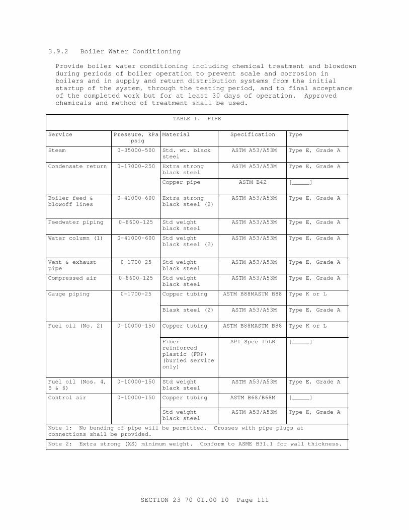
3. 9. 2 Boi l er Wat er Condi t i oni ng
Pr ovi de boi l er wat er condi t i oni ng i ncl udi ng chemi cal t r eat ment and bl owdown dur i ng per i ods of boi l er oper at i on t o pr event scal e and cor r osi on i n boi l er s and i n suppl y and r et ur n di st r i but i on syst ems f r om t he i ni t i al st ar t up of t he syst em, t hr ough t he t est i ng per i od, and t o f i nal accept ance of t he compl et ed wor k but f or at l east 30 days of oper at i on. Appr oved chemi cal s and met hod of t r eat ment shal l be used.
TABLE I . PI PE
Service Pr essur e, kPa psi g
Material Specification Type
Steam 0-35000-500 St d. wt . bl ack steel
ASTM A53/ A53M Type E, Gr ade A
Condensat e r et ur n 0-17000-250 Ext r a st r ong bl ack st eel
ASTM A53/ A53M Type E, Gr ade A
Copper pi pe ASTM B42 [_____]
Boi l er f eed & bl owof f l i nes
0-41000-600 Ext r a st r ong bl ack st eel ( 2)
ASTM A53/ A53M Type E, Gr ade A
Feedwat er pi pi ng 0-8600-125 St d wei ght bl ack st eel
ASTM A53/ A53M Type E, Gr ade A
Wat er col umn ( 1) 0-41000-600 St d wei ght bl ack st eel ( 2)
ASTM A53/ A53M Type E, Gr ade A
Vent & exhaust pipe
0-1700-25 St d wei ght bl ack st eel
ASTM A53/ A53M Type E, Gr ade A
Compr essed ai r 0-8600-125 St d wei ght bl ack st eel
ASTM A53/ A53M Type E, Gr ade A
Gauge pi pi ng 0-1700-25 Copper t ubi ng ASTM B88MASTM B88 Type K or L
Bl ask st eel ( 2) ASTM A53/ A53M Type E, Gr ade A
Fuel oi l ( No. 2) 0-10000-150 Copper t ubi ng ASTM B88MASTM B88 Type K or L
Fiber reinforced pl ast i c ( FRP) ( bur i ed ser vi ce only)
API Spec 15LR [_____]
Fuel oi l ( Nos. 4, 5 & 6)
0-10000-150 St d wei ght bl ack st eel
ASTM A53/ A53M Type E, Gr ade A
Cont r ol ai r 0-10000-150 Copper t ubi ng ASTM B68/ B68M [_____]
St d wei ght bl ack st eel
ASTM A53/ A53M Type E, Gr ade A
Not e 1: No bendi ng of pi pe wi l l be per mi t t ed. Cr osses wi t h pi pe pl ugs at connect i ons shal l be pr ovi ded.
Not e 2: Ext r a st r ong ( XS) mi ni mum wei ght . Conf or m t o ASME B31. 1 f or wal l t hi ckness.
SECTI ON 23 70 01. 00 10 Page 111
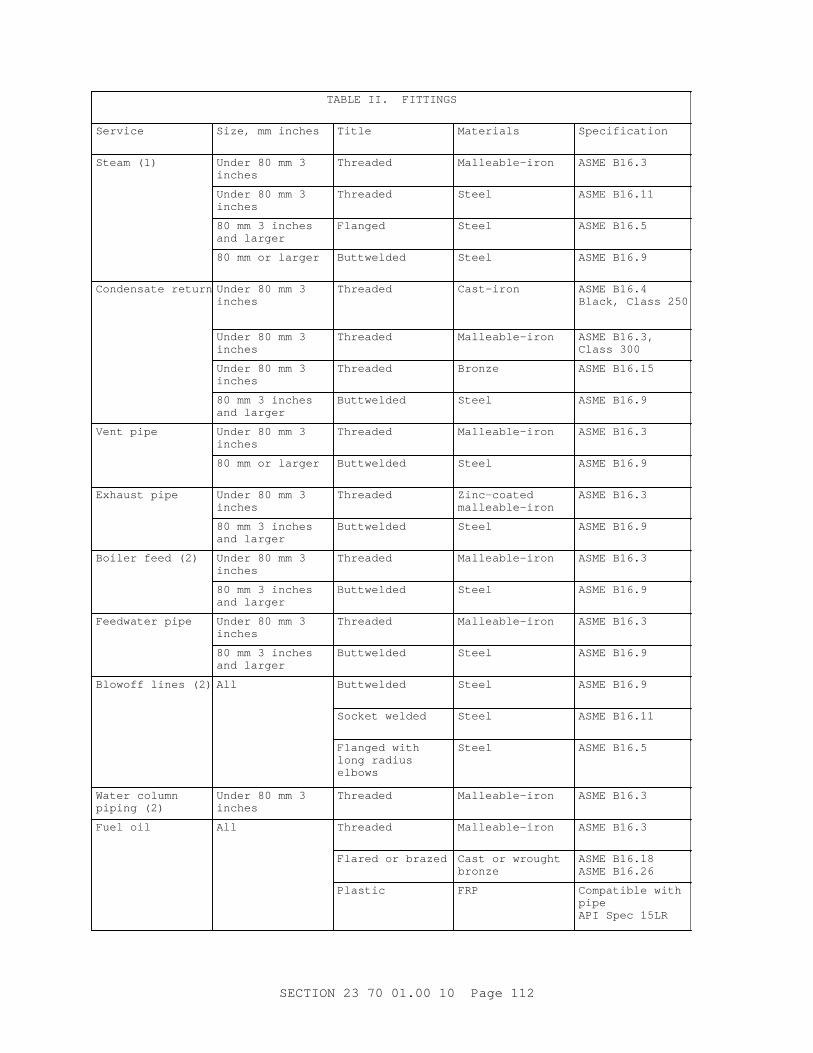
TABLE I I . FI TTI NGS
Service Si ze, mm i nches Title Materials Specification
St eam ( 1) Under 80 mm 3 inches
Threaded Malleable-iron ASME B16. 3
Under 80 mm 3 inches
Threaded Steel ASME B16. 11
80 mm 3 i nches and l ar ger
Flanged Steel ASME B16. 5
80 mm or l ar ger Buttwelded Steel ASME B16. 9
Condensat e r et ur n Under 80 mm 3 inches
Threaded Cast-iron ASME B16. 4 Bl ack, Cl ass 250
Under 80 mm 3 inches
Threaded Malleable-iron ASME B16. 3, Cl ass 300
Under 80 mm 3 inches
Threaded Bronze ASME B16. 15
80 mm 3 i nches and l ar ger
Buttwelded Steel ASME B16. 9
Vent pi pe Under 80 mm 3 inches
Threaded Malleable-iron ASME B16. 3
80 mm or l ar ger Buttwelded Steel ASME B16. 9
Exhaust pi pe Under 80 mm 3 inches
Threaded Zinc-coated malleable-iron
ASME B16. 3
80 mm 3 i nches and l ar ger
Buttwelded Steel ASME B16. 9
Boi l er f eed ( 2) Under 80 mm 3 inches
Threaded Malleable-iron ASME B16. 3
80 mm 3 i nches and l ar ger
Buttwelded Steel ASME B16. 9
Feedwat er pi pe Under 80 mm 3 inches
Threaded Malleable-iron ASME B16. 3
80 mm 3 i nches and l ar ger
Buttwelded Steel ASME B16. 9
Bl owof f l i nes ( 2) All Buttwelded Steel ASME B16. 9
Socket wel ded Steel ASME B16. 11
Fl anged wi t h l ong r adi us elbows
Steel ASME B16. 5
Wat er col umn pi pi ng ( 2)
Under 80 mm 3 inches
Threaded Malleable-iron ASME B16. 3
Fuel oi l All Threaded Malleable-iron ASME B16. 3
Fl ar ed or br azed Cast or wr ought bronze
ASME B16. 18 ASME B16. 26
Plastic FRP Compat i bl e wi t h pipe API Spec 15LR
SECTI ON 23 70 01. 00 10 Page 112
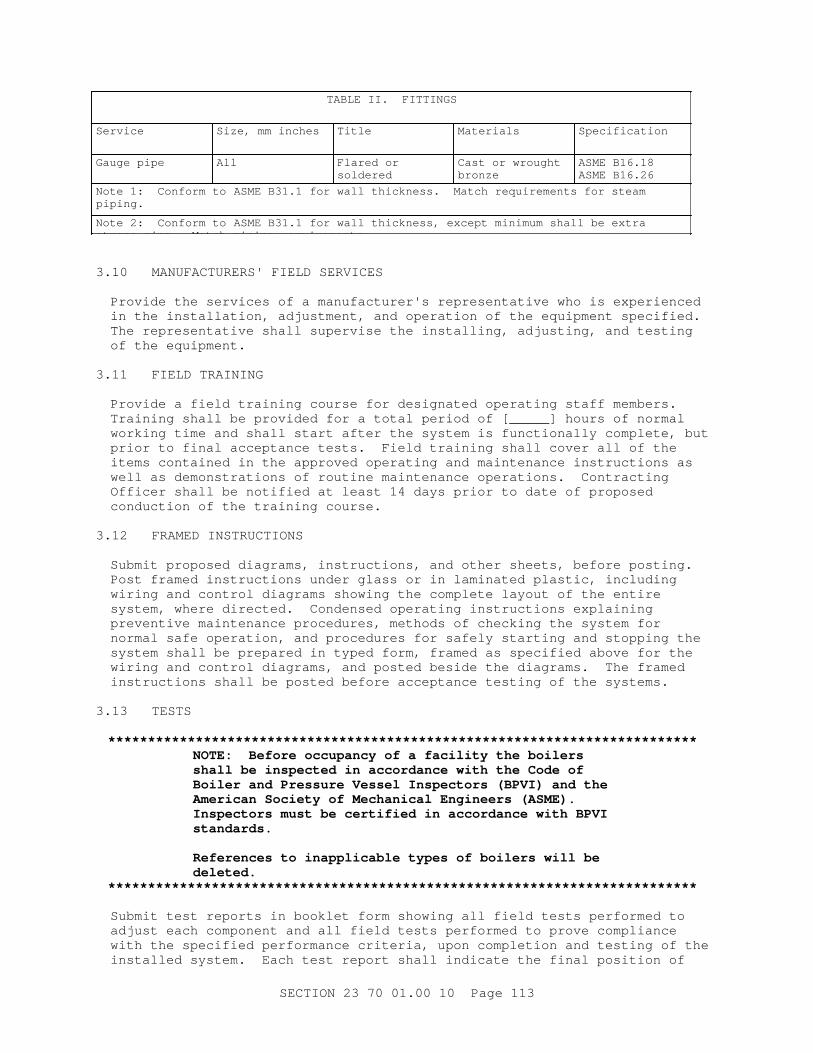
TABLE I I . FI TTI NGS
Service Si ze, mm i nches Title Materials Specification
Gauge pi pe All Fl ar ed or soldered
Cast or wr ought bronze
ASME B16. 18 ASME B16. 26
Not e 1: Conf or m t o ASME B31. 1 f or wal l t hi ckness. Mat ch r equi r ement s f or st eam piping.
Not e 2: Conf or m t o ASME B31. 1 f or wal l t hi ckness, except mi ni mum shal l be ext r a st r ong pi pe. Mat ch pi pi ng r equi r ement s.
3. 10 MANUFACTURERS' FI ELD SERVI CES
Pr ovi de t he ser v i ces of a manuf act ur er ' s r epr esent at i ve who i s exper i enced i n t he i nst al l at i on, adj ust ment , and oper at i on of t he equi pment speci f i ed. The r epr esent at i ve shal l super vi se t he i nst al l i ng, adj ust i ng, and t est i ng of t he equi pment .
3. 11 FI ELD TRAI NI NG
Pr ovi de a f i el d t r ai ni ng cour se f or desi gnat ed oper at i ng st af f member s. Tr ai ni ng shal l be pr ovi ded f or a t ot al per i od of [ _____] hour s of nor mal wor ki ng t i me and shal l s t ar t af t er t he syst em i s f unct i onal l y compl et e, but pr i or t o f i nal accept ance t est s. Fi el d t r ai ni ng shal l cover al l of t he i t ems cont ai ned i n t he appr oved oper at i ng and mai nt enance i nst r uct i ons as wel l as demonst r at i ons of r out i ne mai nt enance oper at i ons. Cont r act i ng Of f i cer shal l be not i f i ed at l east 14 days pr i or t o dat e of pr oposed conduct i on of t he t r ai ni ng cour se.
3. 12 FRAMED I NSTRUCTI ONS
Submi t pr oposed di agr ams, i nst r uct i ons, and ot her sheet s, bef or e post i ng. Post f r amed i nst r uct i ons under gl ass or i n l ami nat ed pl ast i c, i ncl udi ng wi r i ng and cont r ol di agr ams showi ng t he compl et e l ayout of t he ent i r e syst em, wher e di r ect ed. Condensed oper at i ng i nst r uct i ons expl ai ni ng pr event i ve mai nt enance pr ocedur es, met hods of checki ng t he syst em f or nor mal saf e oper at i on, and pr ocedur es f or saf el y st ar t i ng and st oppi ng t he syst em shal l be pr epar ed i n t yped f or m, f r amed as speci f i ed above f or t he wi r i ng and cont r ol di agr ams, and post ed besi de t he di agr ams. The f r amed i nst r uct i ons shal l be post ed bef or e accept ance t est i ng of t he syst ems.
3. 13 TESTS
**************************************************************************NOTE: Bef or e occupancy of a f aci l i t y t he boi l er s shal l be i nspect ed i n accor dance wi t h t he Code of Boi l er and Pr essur e Vessel I nspect or s ( BPVI ) and t he Amer i can Soci et y of Mechani cal Engi neer s ( ASME) . I nspect or s must be cer t i f i ed i n accor dance wi t h BPVI standards.
Ref er ences t o i nappl i cabl e t ypes of boi l er s wi l l be deleted.
**************************************************************************
Submi t t est r epor t s i n bookl et f or m showi ng al l f i el d t est s per f or med t o adj ust each component and al l f i el d t est s per f or med t o pr ove compl i ance wi t h t he speci f i ed per f or mance cr i t er i a, upon compl et i on and t est i ng of t he i nst al l ed syst em. Each t est r epor t shal l i ndi cat e t he f i nal posi t i on of
SECTI ON 23 70 01. 00 10 Page 113
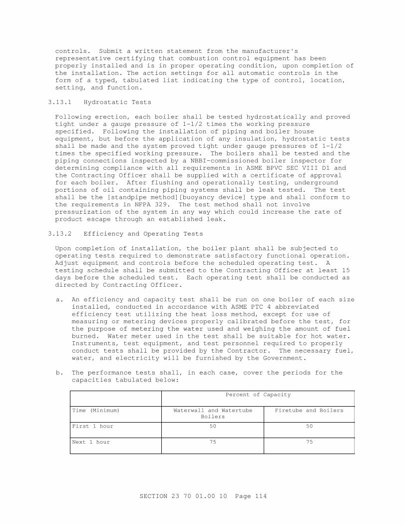
cont r ol s. Submi t a wr i t t en st at ement f r om t he manuf act ur er ' s r epr esent at i ve cer t i f y i ng t hat combust i on cont r ol equi pment has been pr oper l y i nst al l ed and i s i n pr oper oper at i ng condi t i on, upon compl et i on of t he i nst al l at i on. The act i on set t i ngs f or al l aut omat i c cont r ol s i n t he f or m of a t yped, t abul at ed l i s t i ndi cat i ng t he t ype of cont r ol , l ocat i on, set t i ng, and f unct i on.
3. 13. 1 Hydr ost at i c Test s
Fol l owi ng er ect i on, each boi l er shal l be t est ed hydr ost at i cal l y and pr oved t i ght under a gauge pr essur e of 1- 1/ 2 t i mes t he wor ki ng pr essur e speci f i ed. Fol l owi ng t he i nst al l at i on of pi pi ng and boi l er house equi pment , but bef or e t he appl i cat i on of any i nsul at i on, hydr ost at i c t est s shal l be made and t he syst em pr oved t i ght under gauge pr essur es of 1- 1/ 2 t i mes t he speci f i ed wor ki ng pr essur e. The boi l er s shal l be t est ed and t he pi pi ng connect i ons i nspect ed by a NBBI - commi ssi oned boi l er i nspect or f or det er mi ni ng compl i ance wi t h al l r equi r ement s i n ASME BPVC SEC VI I I D1 and t he Cont r act i ng Of f i cer shal l be suppl i ed wi t h a cer t i f i cat e of appr oval f or each boi l er . Af t er f l ushi ng and oper at i onal l y t est i ng, under gr ound por t i ons of oi l cont ai ni ng pi pi ng syst ems shal l be l eak t est ed. The t est shal l be t he [ st andpi pe met hod] [ buoyancy devi ce] t ype and shal l conf or m t o t he r equi r ement s i n NFPA 329. The t est met hod shal l not i nvol ve pr essur i zat i on of t he syst em i n any way whi ch coul d i ncr ease t he r at e of pr oduct escape t hr ough an est abl i shed l eak.
3. 13. 2 Ef f i c i ency and Oper at i ng Test s
Upon compl et i on of i nst al l at i on, t he boi l er pl ant shal l be subj ect ed t o oper at i ng t est s r equi r ed t o demonst r at e sat i sf act or y f unct i onal oper at i on. Adj ust equi pment and cont r ol s bef or e t he schedul ed oper at i ng t est . A t est i ng schedul e shal l be submi t t ed t o t he Cont r act i ng Of f i cer at l east 15 days bef or e t he schedul ed t est . Each oper at i ng t est shal l be conduct ed as di r ect ed by Cont r act i ng Of f i cer .
a. An ef f i c i ency and capaci t y t est shal l be r un on one boi l er of each si ze i nst al l ed, conduct ed i n accor dance wi t h ASME PTC 4 abbr evi at ed ef f i c i ency t est ut i l i z i ng t he heat l oss met hod, except f or use of measur i ng or met er i ng devi ces pr oper l y cal i br at ed bef or e t he t est , f or t he pur pose of met er i ng t he wat er used and wei ghi ng t he amount of f uel bur ned. Wat er met er used i n t he t est shal l be sui t abl e f or hot wat er . I nst r ument s, t est equi pment , and t est per sonnel r equi r ed t o pr oper l y conduct t est s shal l be pr ovi ded by t he Cont r act or . The necessar y f uel , wat er , and el ect r i c i t y wi l l be f ur ni shed by t he Gover nment .
b. The per f or mance t est s shal l , i n each case, cover t he per i ods f or t he capaci t i es t abul at ed bel ow:
Per cent of Capaci t y
Ti me ( Mi ni mum) Wat er wal l and Wat er t ubeBoilers
Fi r et ube and Boi l er s
Fi r st 1 hour 50 50
Next 1 hour 75 75
SECTI ON 23 70 01. 00 10 Page 114
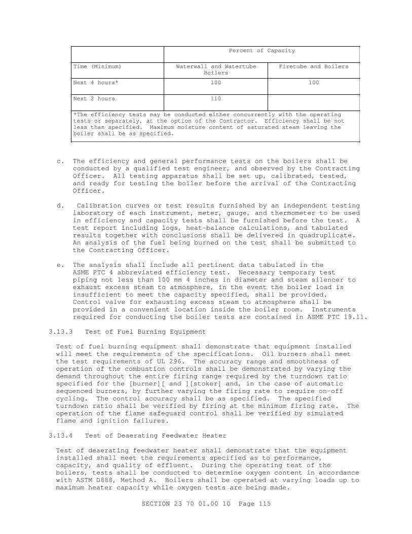
Per cent of Capaci t y
Ti me ( Mi ni mum) Wat er wal l and Wat er t ubeBoilers
Fi r et ube and Boi l er s
Next 4 hour s* 100 100
Next 2 hour s 110
* The ef f i c i ency t est s may be conduct ed ei t her concur r ent l y wi t h t he oper at i ng t est s or separ at el y, at t he opt i on of t he Cont r act or . Ef f i c i ency shal l be not l ess t han speci f i ed. Maxi mum moi st ur e cont ent of sat ur at ed st eam l eavi ng t he boi l er shal l be as speci f i ed.
c. The ef f i c i ency and gener al per f or mance t est s on t he boi l er s shal l be conduct ed by a qual i f i ed t est engi neer , and obser ved by t he Cont r act i ng Of f i cer . Al l t est i ng appar at us shal l be set up, cal i br at ed, t est ed, and r eady f or t est i ng t he boi l er bef or e t he ar r i val of t he Cont r act i ng Officer.
d. Cal i br at i on cur ves or t est r esul t s f ur ni shed by an i ndependent t est i ng l abor at or y of each i nst r ument , met er , gauge, and t her momet er t o be used i n ef f i c i ency and capaci t y t est s shal l be f ur ni shed bef or e t he t est . A t est r epor t i ncl udi ng l ogs, heat - bal ance cal cul at i ons, and t abul at ed r esul t s t oget her wi t h concl usi ons shal l be del i ver ed i n quadr upl i cat e. An anal ysi s of t he f uel bei ng bur ned on t he t est shal l be submi t t ed t o t he Cont r act i ng Of f i cer .
e. The anal ysi s shal l i ncl ude al l per t i nent dat a t abul at ed i n t he ASME PTC 4 abbr evi at ed ef f i c i ency t est . Necessar y t empor ar y t est pi pi ng not l ess t han 100 mm 4 i nches i n di amet er and st eam si l encer t o exhaust excess st eam t o at mospher e, i n t he event t he boi l er l oad i s i nsuf f i c i ent t o meet t he capaci t y speci f i ed, shal l be pr ovi ded. Cont r ol val ve f or exhaust i ng excess st eam t o at mospher e shal l be pr ovi ded i n a conveni ent l ocat i on i nsi de t he boi l er r oom. I nst r ument s r equi r ed f or conduct i ng t he boi l er t est s ar e cont ai ned i n ASME PTC 19. 11.
3. 13. 3 Test of Fuel Bur ni ng Equi pment
Test of f uel bur ni ng equi pment shal l demonst r at e t hat equi pment i nst al l ed wi l l meet t he r equi r ement s of t he speci f i cat i ons. Oi l bur ner s shal l meet t he t est r equi r ement s of UL 296. The accur acy r ange and smoot hness of oper at i on of t he combust i on cont r ol s shal l be demonst r at ed by var yi ng t he demand t hr oughout t he ent i r e f i r i ng r ange r equi r ed by t he t ur ndown r at i o speci f i ed f or t he [ bur ner ] [ and ] [ st oker ] and, i n t he case of aut omat i c sequenced bur ner s, by f ur t her var yi ng t he f i r i ng r at e t o r equi r e on- of f cycl i ng. The cont r ol accur acy shal l be as speci f i ed. The speci f i ed t ur ndown r at i o shal l be ver i f i ed by f i r i ng at t he mi ni mum f i r i ng r at e. The oper at i on of t he f l ame saf eguar d cont r ol shal l be ver i f i ed by s i mul at ed f l ame and i gni t i on f ai l ur es.
3. 13. 4 Test of Deaer at i ng Feedwat er Heat er
Test of deaer at i ng f eedwat er heat er shal l demonst r at e t hat t he equi pment i nst al l ed shal l meet t he r equi r ement s speci f i ed as t o per f or mance, capaci t y, and qual i t y of ef f l uent . Dur i ng t he oper at i ng t est of t he boi l er s, t est s shal l be conduct ed t o det er mi ne oxygen cont ent i n accor dance with ASTM D888, Met hod A. Boi l er s shal l be oper at ed at var yi ng l oads up t o maxi mum heat er capaci t y whi l e oxygen t est s ar e bei ng made.
SECTI ON 23 70 01. 00 10 Page 115
3. 13. 5 Test of Wat er Tr eat ment Equi pment
Test of wat er t r eat ment equi pment shal l meet t he r equi r ement s speci f i ed as t o capaci t y and qual i t y of ef f l uent . Test s f or i on- exchange uni t s shal l cover at l east t wo compl et e r egener at i ons and capaci t y r uns.
3. 13. 6 Test f or St eam Pur i t y and Wat er Level St abi l i t y
Test f or st eam pur i t y, i n accor dance wi t h ASTM D1066, and wat er l evel st abi l i t y shal l be s i mul t aneous under t he oper at i ng condi t i ons speci f i ed.
[ 3. 13. 6. 1 Conduct i v i t y Test s f or Boi l er s wi t hout Super heat er s
**************************************************************************NOTE: Del et e t he i nappl i cabl e par agr aph.
**************************************************************************
St eam t est s f or boi l er s wi t hout super heat er s, not used f or power gener at i on or l ar ge t ur bi ne dr i ve, shal l be made on st eam sampl ed i n accor dance wi t h ASTM D1066. The conduct i v i t y of t he st eam cor r ect ed f or car bon di oxi de and ammoni a cont ent shal l not exceed 30 mi cr ohms at 18 degr ees C65 degr ees F.
] 3. 13. 6. 2 Conduct i v i t y Test , Boi l er s wi t h or wi t hout Super heat er s
The st eam f or boi l er s, wi t h or wi t hout super heat , used f or power gener at i on or t ur bi ne dr i ve f or ai r - condi t i oni ng equi pment shal l be sampl ed i n accor dance wi t h ASTM D1066 wi t h t he conduct i v i t y of t he st eam cor r ect ed f or car bon di oxi de and ammoni a cont ent not t o exceed 4. 0 mi cr ohms at 18 degr ees C65 degr ees F.
3. 13. 6. 3 Wat er Level St abi l i t y Test
[ Wat er l evel st abi l i t y t est f i r st shal l be conduct ed by use of t he manual bypass ar ound t he f eedwat er r egul at or . Test t hen shal l be r epeat ed usi ng t he aut omat i c f eedwat er r egul at or . Boi l er shal l mai nt ai n speci f i ed wat er l evel st abi l i t y under bot h condi t i ons. ]
- - End of Sect i on - -
SECTI ON 23 70 01. 00 10 Page 116