Embed Size (px)
Citation preview
DTR.PCE.PRE-28 Safety(ENG)
APLISENS
MANUFACTURE OF PRESSURE TRANSMITTERS
AND CONTROL INSTRUMENTS
USER’S MANUAL
PRESSURE TRANSMITTERS
PCE-28 Safety, PCE-28Ex Safety
DIFFERENTIAL PRESSURE TRANSMITTERS
PRE-28 Safety, PRE-28Ex Safety
Edition A
WARSAW AUGUST 2015
APLISENS S.A., 03-192 Warszawa, ul. Morelowa 7 tel. +48 22 814 07 77; fax +48 22 814 07 78
www.aplisens.pl, e-mail: [email protected]
Symbol used
Symbol Description
Warning to proceed strictly in accordance with the information contained in the documentation in order to ensure the safety and full functionality of the device.
i Information particularly useful during installation and operation of the device.
Information particularly useful during installation and operation of a type Ex device.
Information on disposal of used equipment
BASIC REQUIREMENTS AND SAFE USE
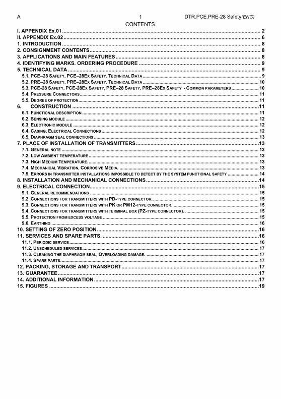
- The manufacturer will not be liable for damage resulting from incorrect installation, failure to maintain the device in a suitable technical condition, or use of the device other than for its intended purpose.
- Installation should be carried out by qualified personnel having the required authorizations to install electrical and pressure-measuring devices. The installer is responsible for performing the installation in accordance with these instructions and with the electromagnetic compatibility and safety regulations and standards applicable to the type of installation.
- Installation should be carried out by qualified staff having the required authorizations to install electrical and pressure-measuring devices. The installer is responsible for performing the installation in accordance with these instructions and with the electromagnetic compatibility and safety regulations and standards applicable to the type of installation.
- If a device is not functioning correctly, disconnect it and send it for repair to the manufacturer or to a firm authorized by the manufacturer.
In order to minimize the risk of malfunction and associated risks to personnel, the device is not to be installed or used in particularly unfavourable conditions, where the following dangers occur.
- possibility of mechanical impacts, excessive shocks and vibration.
- excessive temperature fluctuation,
- condensation of water vapour, dust, icing.
Installation of intrinsic safety versions should be performed with particular care, in accordance with the regulations and standards applicable to that type of installation
Changes to the products manufacturing documentation may forestall a paper user updating. Current Instruction Manual is available at Producer http. on www.aplisens.pl.
A DTR.PCE.PRE-28 Safety(ENG) 1
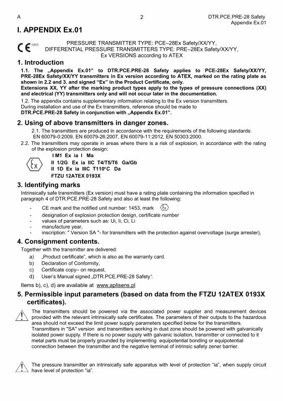
CONTENTS
I. APPENDIX Ex.01 ......................................................................................................................................... 2 II. APPENDIX Ex.02 ........................................................................................................................................ 6 1. INTRODUCTION ......................................................................................................................................... 8 2. CONSIGNMENT CONTENTS ...................................................................................................................... 8 3. APPLICATIONS AND MAIN FEATURES .................................................................................................... 8 4. IDENTIFYING MARKS. ORDERING PROCEDURE .................................................................................... 9 5. TECHNICAL DATA ..................................................................................................................................... 9
5.1. PCE–28 SAFETY, PCE–28EX SAFETY. TECHNICAL DATA ............................................................................................ 9 5.2. PRE–28 SAFETY, PRE–28EX SAFETY. TECHNICAL DATA .......................................................................................... 10 5.3. PCE-28 SAFETY, PCE-28EX SAFETY, PRE–28 SAFETY, PRE–28EX SAFETY - COMMON PARAMETERS ..................... 10 5.4. PRESSURE CONNECTORS ........................................................................................................................................... 11 5.5. DEGREE OF PROTECTION ............................................................................................................................................ 11
6. CONSTRUCTION .................................................................................................................................11 6.1. FUNCTIONAL DESCRIPTION ......................................................................................................................................... 11 6.2. SENSING MODULE ...................................................................................................................................................... 12 6.3. ELECTRONIC MODULE ................................................................................................................................................ 12 6.4. CASING, ELECTRICAL CONNECTIONS .......................................................................................................................... 12 6.5. DIAPHRAGM SEAL CONNECTIONS ................................................................................................................................ 13
7. PLACE OF INSTALLATION OF TRANSMITTERS .....................................................................................13 7.1. GENERAL NOTE ......................................................................................................................................................... 13 7.2. LOW AMBIENT TEMPERATURE .................................................................................................................................... 13 7.3. HIGH MEDIUM TEMPERATURE. .................................................................................................................................... 13 7.4. MECHANICAL VIBRATION, CORROSIVE MEDIA. ............................................................................................................ 13 7.5. ERRORS IN TRANSMITTER INSTALLATIONS IMPOSSIBLE TO DETECT BY THE SYSTEM FUNCTIONAL SAFETY ........................ 14
8. INSTALLATION AND MECHANICAL CONNECTIONS ..............................................................................14 9. ELECTRICAL CONNECTION.....................................................................................................................15
9.1. GENERAL RECOMMENDATIONS ................................................................................................................................... 15 9.2. CONNECTIONS FOR TRANSMITTERS WITH PD-TYPE CONNECTOR. .................................................................................. 15 9.3. CONNECTIONS FOR TRANSMITTERS WITH PK OR PM12-TYPE CONNECTOR. .................................................................. 15 9.4. CONNECTIONS FOR TRANSMITTERS WITH TERMINAL BOX (PZ-TYPE CONNECTOR). ......................................................... 15 9.5. PROTECTION FROM EXCESS VOLTAGE ......................................................................................................................... 15 9.6. EARTHING ................................................................................................................................................................. 16
10. SETTING OF ZERO POSITION ................................................................................................................16 11. SERVICES AND SPARE PARTS. ............................................................................................................16
11.1. PERIODIC SERVICE ................................................................................................................................................... 16 11.2. UNSCHEDULED SERVICES ......................................................................................................................................... 17 11.3. CLEANING THE DIAPHRAGM SEAL, OVERLOADING DAMAGE. ....................................................................................... 17 11.4. SPARE PARTS. ......................................................................................................................................................... 17
12. PACKING, STORAGE AND TRANSPORT ...............................................................................................17 13. GUARANTEE ...........................................................................................................................................17 14. ADDITIONAL INFORMATION ..................................................................................................................17 15. FIGURES .................................................................................................................................................19
A DTR.PCE.PRE-28 Safety Appendix Ex.01
2
I. APPENDIX Ex.01
PRESSURE TRANSMITTER TYPE: PCE–28Ex Safety/XX/YY, DIFFERENTIAL PRESSURE TRANSMITTERS TYPE: PRE–28Ex Safety/XX/YY,
Ex VERSIONS according to ATEX
1. Introduction 1.1. The „Appendix Ex.01” to DTR.PCE.PRE-28 Safety applies to PCE-28Ex Safety/XX/YY, PRE-28Ex Safety/XX/YY transmitters in Ex version according to ATEX, marked on the rating plate as shown in 2.2 and 3. and signed “Ex” in the Product Certificate, only. Extensions XX, YY after the marking product types apply to the types of pressure connections (XX) and electrical (YY) transmitters only and will not occur later in the documentation.
1.2. The appendix contains supplementary information relating to the Ex version transmitters. During installation and use of the Ex transmitters, reference should be made to DTR.PCE.PRE-28 Safety in conjunction with „Appendix Ex.01”.
2. Using of above transmitters in danger zones. 2.1. The transmitters are produced in accordance with the requirements of the following standards: EN 60079-0:2009, EN 60079-26:2007, EN 60079-11:2012, EN 50303:2000.
2.2. The transmitters may operate in areas where there is a risk of explosion, in accordance with the rating of the explosion protection design:
I M1 Ex ia I Ma
II 1/2G Ex ia IIC T4/T5/T6 Ga/Gb
II 1D Ex ia IIIC T110C Da
FTZU 12ATEX 0193X
3. Identifying marks Intrinsically safe transmitters (Ex version) must have a rating plate containing the information specified in paragraph 4 of DTR.PCE.PRE-28 Safety and also at least the following:
- CE mark and the notified unit number: 1453, mark
- designation of explosion protection design, certificate number - values of parameters such as: Ui, Ii, Ci, Li - manufacture year, - inscription: " Version SA "- for transmitters with the protection against overvoltage (surge arrester),
4. Consignment contents. Together with the transmitter are delivered:
a) „Product certificate”, which is also as the warranty card.
b) Declaration of Conformity,
c) Certificate copy– on request,
d) User’s Manual signed „DTR.PCE.PRE-28 Safety”.
Items b), c), d) are available at www.aplisens.pl
5. Permissible input parameters (based on data from the FTZU 12ATEX 0193X certificates).
The transmitters should be powered via the associated power supplier and measurement devices provided with the relevant intrinsically safe certificates. The parameters of their outputs to the hazardous area should not exceed the limit power supply parameters specified below for the transmitters. Transmitters in "SA" version and transmitters working in dust zone should be powered with galvanically isolated power supply. If there is no power supply with galvanic isolation, transmitter or connected to it metal parts must be properly grounded by implementing equipotential bonding or equipotential connection between the transmitter and the negative terminal of intrinsic safety zener barrier.
The pressure transmitter an intrinsically safe apparatus with level of protection “ia”, when supply circuit have level of protection “ia”.
1453
A DTR.PCE.PRE-28 Safety Appendix Ex.01
3
a) Permissible input parameters for power supply with a linear characteristic: Ui = 28V DC; Ii = 0,1A; Pi = 0,7W
b) Permissible input parameters for power supply with a “trapezial” and “rectangular” characteristic. Ui = 24V DC, Ii = 0,1A; Pi = 1,2W
c) Input inductance and capacity: Ci = 25nF*, Li = 0,4mH*
*It should take into account the capacity and inductance of the cable which in permanently connected cable are: Ck= 0.2nF/m i Lk=1µH/m. Input capacitance CW and input inductance LW of the transmitters with PK electrical connections, taking into account the parameters of the permanently connected cable are accordingly: Cw = Ci + a x Ck = 25nF + a x 0.2nF/m Lw= Li + a x Lk = 400µH + a x 1µH/m a - length of the mounted permanently cable in meters
Ta = -40C to ... see table Z1
Table Z1
Pi[W] Ta[ºC] Temperature classification
0,7 45 T6
80 T5, T4, Group I, Group III - 110°C
1,2 75 T5
80 T4 Group I, Group III - 110°C
Special conditions for safe use: - Ambient temperature range - see table Z1 - Process temperature (medium) at the diaphragm of the transmitter must be in range of ambient
temperature - In case of use the transmitter in dust atmosphere, supplying voltage could occur on transmitter
enclosure. It should be taken into consideration during transmitter installation.
- In case of use titan parts in diaphragm seal, during installation and operation of the device the diaphragm seal should be protected against mechanical impact.
- Version of transmitter with surge arrester, marked on the plate “Version SA”, does not meet the requirements of Section 6.3.13 of the EN 60079-11:2012 (test of isolation 500VAC). This must be taken into consideration during the installation of transmitter.
At the customer's request, elements of diaphragm seal can be made of titanium. This version of the transmitter has information on the label that the titanium elements are used. Then user should secure the diaphragm seal against the possibility of an impact.
When medium temperature is higher than Ta, use of a separating elements such a diaphragm seal, or looped siphon tube ect is necessary. Process temperature, close to the transmitter diaphragm seal, must be in the Ta range. (Ta = ambient temperature)
A DTR.PCE.PRE-28 Safety Appendix Ex.01
4
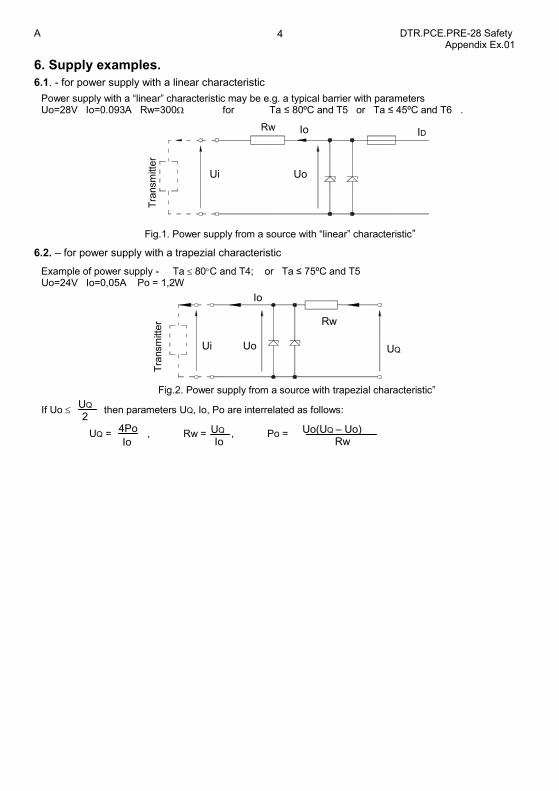
6. Supply examples.
6.1. - for power supply with a linear characteristic
Power supply with a “linear” characteristic may be e.g. a typical barrier with parameters Uo=28V Io=0.093A Rw=300 for Ta ≤ 80ºC and T5 or Ta ≤ 45ºC and T6 .
Fig.1. Power supply from a source with “linear” characteristic”
6.2. – for power supply with a trapezial characteristic
Example of power supply - Ta 80C and T4; or Ta ≤ 75ºC and T5 Uo=24V Io=0,05A Po = 1,2W
Fig.2. Power supply from a source with trapezial characteristic”
If Uo then parameters UQ, Io, Po are interrelated as follows:
UQ = , Rw = , Po = UQ Io
4Po
Io Uo(UQ – Uo)
Rw
UQ 2
Rw
Tra
nsm
itte
r
Ui
Io
Uo UQ
Tra
nsm
itte
r
Ui
Rw Io
Uo
ID
A DTR.PCE.PRE-28 Safety Appendix Ex.01
5
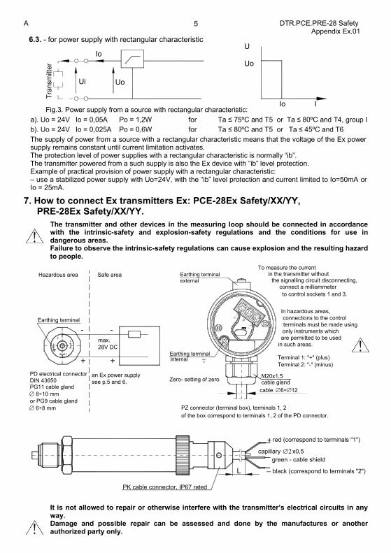
6.3. - for power supply with rectangular characteristic
Fig.3. Power supply from a source with rectangular characteristic:
a). Uo = 24V Io = 0,05A Po = 1,2W for Ta ≤ 75ºC and T5 or Ta ≤ 80ºC and T4, group I
b). Uo = 24V Io = 0,025A Po = 0,6W for Ta ≤ 80ºC and T5 or Ta ≤ 45ºC and T6
The supply of power from a source with a rectangular characteristic means that the voltage of the Ex power supply remains constant until current limitation activates. The protection level of power supplies with a rectangular characteristic is normally “ib”. The transmitter powered from a such supply is also the Ex device with “ib” level protection. Example of practical provision of power supply with a rectangular characteristic: – use a stabilized power supply with Uo=24V, with the “ib” level protection and current limited to Io=50mA or Io = 25mA.
7. How to connect Ex transmitters Ex: PCE-28Ex Safety/XX/YY, PRE-28Ex Safety/XX/YY.
The transmitter and other devices in the measuring loop should be connected in accordance with the intrinsic-safety and explosion-safety regulations and the conditions for use in dangerous areas. Failure to observe the intrinsic-safety regulations can cause explosion and the resulting hazard to people.
of the box correspond to terminals 1, 2 of the PD connector.
externalEarthing terminal
Earthing terminal
PZ connector (terminal box), terminals 1, 2
Zero- setting of zero
Earthing terminal
Hazardous area
PD electrical connector
DIN 43650
8÷10 mm
PG11 cable gland
see p.5 and 6.
an Ex power supply
32
1
28V DC
max.
internal
Safe area
in such areas.are permitted to be used only instruments which terminals must be made using
M20x1,5
cable 6÷ 12
Terminal 1: "+" (plus)
Terminal 2: "-" (minus)
the signalling circuit disconnecting,
To measure the current in the transmitter without
to control sockets 1 and 3.
connections to the control
connect a milliammeter
In hazardous areas,
cable gland
6÷8 mm
or PG9 cable gland
PK cable connector, IP67 rated
capillary x0,5
green - cable shield
red (correspond to terminals "1")
black (correspond to terminals "2")
+
_L
It is not allowed to repair or otherwise interfere with the transmitter’s electrical circuits in any way. Damage and possible repair can be assessed and done by the manufactures or another authorized party only.
Io I
U Uo
Uo
Io T
ransm
itte
r
Ui
A DTR.PCE.PRE-28 Safety Appendix Ex.02
6
II. APPENDIX Ex.02
PRESSURE TRANSMITTER TYPE: PCE–28Ex Safety/XX/YY, DIFFERENTIAL PRESSURE TRANSMITTERS TYPE: PRE–28Ex Safety/XX/YY,
Ex VERSIONS according to IECEx
1. Introduction 1.1. The „Appendix Ex.02” to DTR.PCE.PRE-28 Safety applies to PCE-28Ex Safety/XX/YY, PRE-28Ex Safety/XX/YY transmitters in Ex version according to IECEx, marked on the rating plate as shown in 2.2 and 3. and signed “Ex” in the Product Certificate, only. Extensions XX, YY in the marking product types apply to the types of pressure connections (XX) and electrical (YY) transmitters only and will not occur later in the documentation.
1.2. The appendix contains supplementary information relating to the Ex version transmitters. During installation and use of the Ex transmitters, reference should be made to DTR.PCE.PRE-28 Safety in conjunction with „Appendix Ex.02”.
2. Using of above transmitters in danger zones
2.1. The transmitters are produced in accordance with the requirements of the following standards: IEC 60079-0:2011, IEC 60079-26:2006, IEC 60079-11:2011.
2.2. The transmitters may operate in areas where there is a risk of explosion, in accordance with the rating of the explosion protection design:
Ex ia I Ma
Ex ia IIC T4/T5/T6 Ga/Gb
Ex ia IIIC T110C Da IECEx FTZÚ 13.0004X
3. Identifying marks
Intrinsically safe transmitters (Ex version) must have a rating plate containing the information specified in
paragraph 4 of DTR.PCE.PRE-28 Safety and also at least the following:
- values of parameters such as: Ui, Ii, Ci, Li
- manufacture year,
- inscription: " Version SA "- for transmitters with the protection against overvoltage (surge arrester),
4. Consignment contents. Together with the transmitter are delivered:
a) „Product certificate”, which is also as the warranty card.
b) Declaration of Conformity,
c) Certificate copy– on request,
d) User’s Manual signed „DTR.PCE.PRE-28 Safety”.
Items b), c), d) are available at www.aplisens.pl
5. Permissible input parameters (based on data from the IECEx FTZÚ 13.0004X certificates).
The transmitters should be powered via the associated power supplier and measurement devices provided with the relevant intrinsically safe certificates. The parameters of their outputs to the hazardous area should not exceed the limit power supply parameters specified below for the transmitters. Transmitters in "SA" version and transmitters working in dust zone should be powered with galvanically isolated power supply. If there is no power supply with galvanic isolation, transmitter or connected to it metal parts must be properly grounded by implementing equipotential bonding or equipotential connection between the transmitter and the negative terminal of intrinsic safety zener barrier.
The pressure transmitter an intrinsically safe apparatus with level of protection “ia”, when supply circuit have level of protection “ia”.
A DTR.PCE.PRE-28 Safety Appendix Ex.02
7
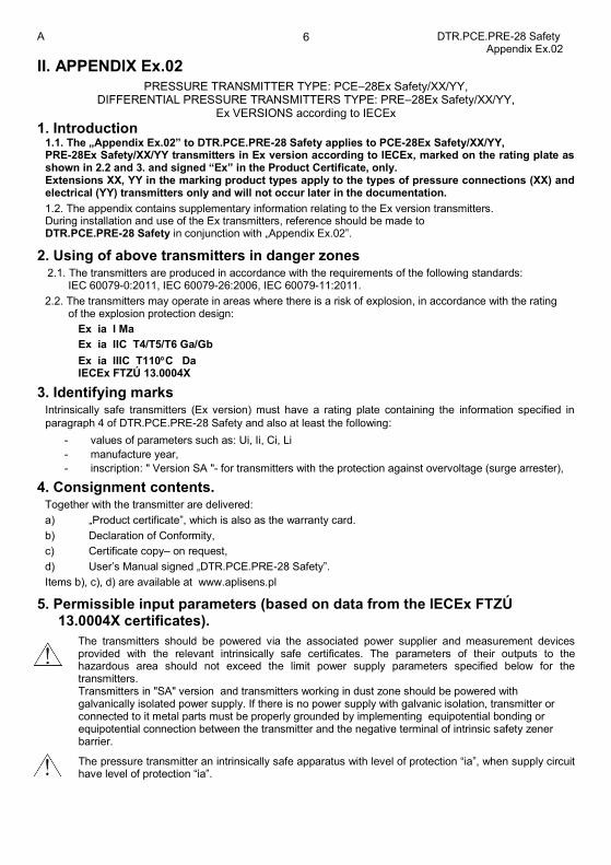
a) Permissible input parameters for power supply with a “linear” characteristic: Ui = 28V DC; Ii = 0,1A; Pi = 0,7W
b)Permissible input parameters for power supply with a “trapezial” and “rectangular” characteristic Ui = 24V DC; Ii = 0,1A; Pi = 1,2W
c) Input inductance and capacity: Ci = 25nF*, Li = 0,4mH*.
*It should take into account the capacity and inductance of the cable which in permanently connected cable are: Ck= 0.2nF/m i Lk=1µH/m. Input capacitance CW and input inductance LW of the transmitters with PK electrical connections, taking into account the parameters of the permanently connected cable are accordingly: Cw = Ci + a x Ck = 25nF + a x 0.2nF/m Lw= Li + a x Lk = 400µH + a x 1µH/m a - length of the mounted permanently cable in meters
Ta = -40C to ... see table Z2
Table Z2
Pi[W] Ta[ºC] Temperature classification
0,7 45 T6
80 T5, T4, Group I, Group III - 110°C
1,2 75 T5
80 T4 Group I, Group III - 110°C
Special conditions for safe use:
- Ambient temperature range - see table Z2 - Process temperature (medium) at the diaphragm of the transmitter must be in range of ambient
temperature - In case of use the transmitter in dust atmosphere, supplying voltage could occur on transmitter
enclosure. It should be taken into consideration during transmitter installation.
- In case of use titan parts in diaphragm seal, during installation and operation of the device the diaphragm seal should be protected against mechanical impact.
- Version of transmitter with surge arrester, marked on the plate “Version SA”, does not meet the requirements of Section 6.3.13 of the EN 60079-11:2012 (test of isolation 500VAC). This must be taken into consideration during the installation of transmitter.
At the customer's request, elements of diaphragm seal can be made of titanium. This version of the transmitter has information on the label that the titanium elements are used. Then user should secure the diaphragm seal against the possibility of an impact.
When medium temperature is higher than Ta, use of a separating elements such a diaphragm seal, or looped siphon tube ect is necessary. Process temperature, close to the transmitter diaphragm seal, must be in the Ta range. (Ta = ambient temperature)
6. Supply examples. Supply examples according to p.6. „Appendix Ex.01” – (ATEX).
7. How to connect Ex transmitters Ex: PCE–28Ex Safety/XX/YY, PRE-28Ex Safety/XX/YY.
- according to p.7 DTR.PCE.PRE-28. Appendix Ex.01
A DTR.PCE.PRE-28 Safety 8
1. INTRODUCTION 1.1. This user’s manual is intended for PCE–28 Safety, PCE–28Ex Safety electronic pressure transmitters, PRE–28 Safety, PRE–28Ex Safety differential pressure transmitters, containing data and hints indispensable to get acquainted with principles of operation and method of operation of the transducers in the intrinsically safe execution with safety integrity level SIL-1. It includes essential recommendations concerning installation and use, as well as emergency procedures.
PC-28 Safety, PC-28Ex safety series pressure transmitters and PR-28 Safety, PR-28Ex Safety series differential pressure transmitters have SIL-1 certificate for applications in the safe operation systems for continuous operation/with often or rare calling according to the standard PN-EN 61508 issued by the notified body UDT; 02-353 Warsaw, ul. Szczęśliwicka 34. Copies of the SIL certificates can be found on www.aplisens.pl. PC-28 Safety and PF-28 Safety series transducers fulfil the requirements of standards: EN 61508-1:2004, EN 61508-2:2005, EN 61508-3:2004, EN 61511-1:2007, EN 62061:2008 for safety integrity level SIL-1 with equipment defects tolerance HFT=0 for safety function performing pressure and differential pressure measurement. wherefore can be used in the protective installations or installations, where conformity with machine directive within the scope of functional safety of electric, electronic and electronic programmable control systems connected with the safety, is required.
1.2. Additional data on PCE–28Ex Safety, PRE–28Ex Safety transmitters in Ex versions covered by the common EC-type test certificate FTZU 12ATEX……, are contained in the appendix designated DTR.PCE.PRE-28 Safety. Appendix Ex.01. During installation and use of PCE–28Ex Safety, PRE–28Ex Safety transmitters, reference should be made to DTR.PCE.PRE-28 Safety in conjunction with Appendix Ex.01.
1.3. Additional data on PCE–28Ex Safety, PRE–28Ex Safety transmitters in Ex versions covered by the common EC-type test certificate IECEX FTZU 13.0004X, are contained in the appendix designated DTR.PCE.PRE-28 Safety. Appendix Ex.02. During installation and use of PCE–28Ex Safety, PRE–28Ex Safety transmitters, reference should be made to DTR.PCE.PRE-28 Safety in conjunction with Appendix Ex.02.
1.4. Technical literature for the PCE–28 Safety, PRE–28 Safety series transmitters with diaphragm seal connectors and technical data for seals are contained within a separate catalogue ”.
1.5. The transmitters comply with the requirements of EU directives as shown on the plate and with the relevant Declaration of Conformity.
1.6.The PCE–28 Safety, PCE–28Ex Safety transmitters are also made in a complies with the PED pressure version , meet the requirements for category IV, and then carry markings as in 4.5.
2. CONSIGNMENT CONTENTS Transmitters are delivered in single and/or multiple packs. Together with the transmitter are delivered:
a) „Product certificate, which is also as the warranty card
b) Declaration of Conformity, - on request,,
c) Certificate copy – on request,,
d) User’s Manual signed „DTR.PCE.PRE-28 Safety”.
Items b), c), d) are available at www.aplisens.pl
3. APPLICATIONS AND MAIN FEATURES
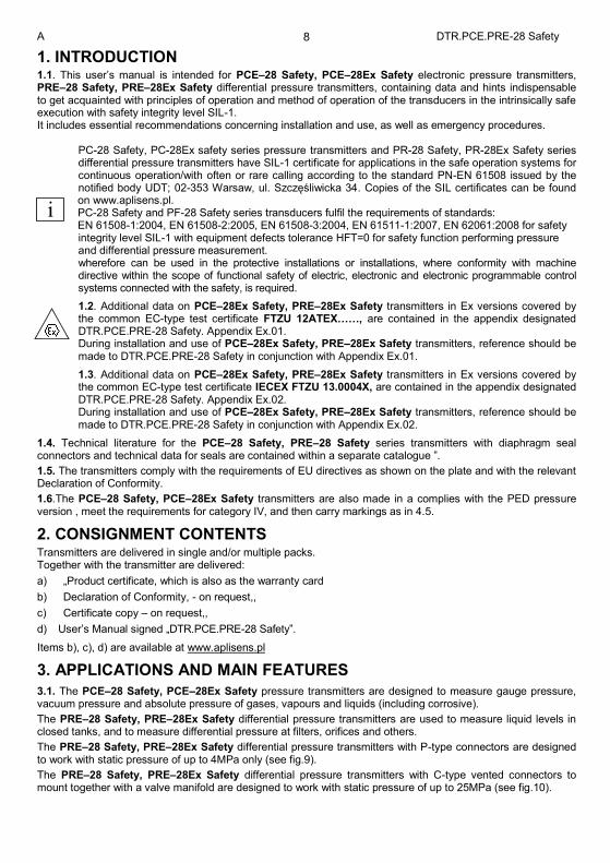
3.1. The PCE–28 Safety, PCE–28Ex Safety pressure transmitters are designed to measure gauge pressure, vacuum pressure and absolute pressure of gases, vapours and liquids (including corrosive).
The PRE–28 Safety, PRE–28Ex Safety differential pressure transmitters are used to measure liquid levels in closed tanks, and to measure differential pressure at filters, orifices and others.
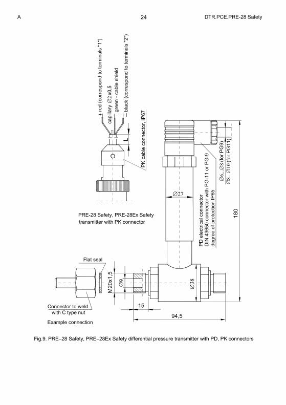
The PRE–28 Safety, PRE–28Ex Safety differential pressure transmitters with P-type connectors are designed to work with static pressure of up to 4MPa only (see fig.9).
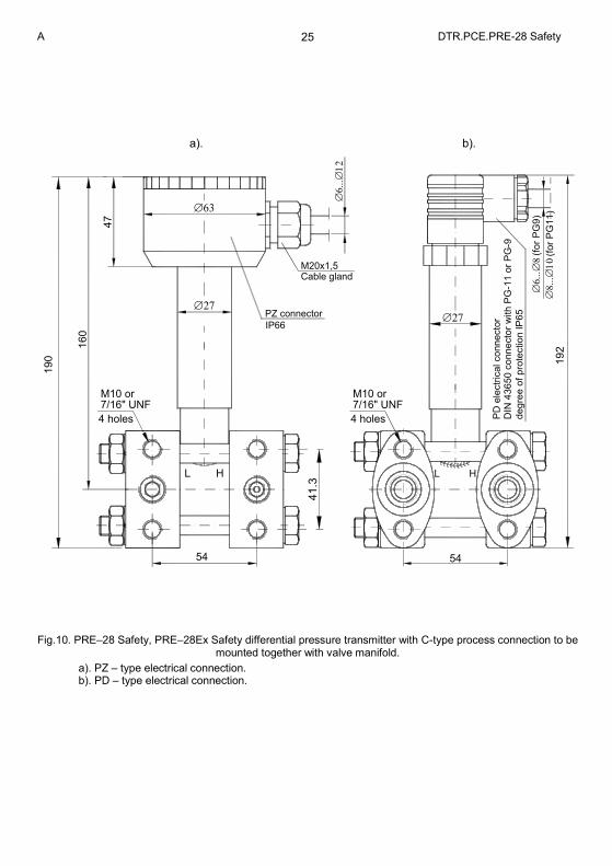
The PRE–28 Safety, PRE–28Ex Safety differential pressure transmitters with C-type vented connectors to mount together with a valve manifold are designed to work with static pressure of up to 25MPa (see fig.10).
i
A DTR.PCE.PRE-28 Safety 9
3.2. The PCE–28 Safety, PCE–28Ex Safety can be fitted with a range of additional process connectors, enabling them to be used in a conditions variety, such as dense media, reactive media, high and low temperature etc. Data on these connectors can be found in the catalogue cards “DIAPHRAGM SEALS”. To measure a medium which contains suspensions or impurities, or is viscous, hot, corrosive etc., use the PRE–28 Safety, PRE–28Ex Safety transmitter with a single diaphragm seal.
3.3. The PCE–28 Safety, PRE–28 Safety series transmitters generate a 4...20mA signal using two-wire transmission.
4. IDENTIFYING MARKS. ORDERING PROCEDURE 4.1. Every transmitter and probe carries a rating plate containing at least the following information: CE mark, manufacturer name, type, marking of electrical and process connections, manufacturer name, measurement range, permissible static pressure (for PRE-28 Safety only), output signal, power supply voltage.
4.2. The rating plates of PCE–28 Safety, PRE–28 Safety series transmitters contain: number of safety integrity levels (SIL1), the notified unit number UDT-CERT and 505/CW/001/07- certificate number.
4.3. The PCE–28 Safety, PRE–28 Safety series transmitters in accordance with the ATEX directive, have additional marks as described in DTR.PCE.PRE-28 Safety Appendix Ex.01 paragraph 3.
4.4. The PCE–28 Safety, PRE–28 Safety series transmitters in accordance with the IECEx requirements, have additional marks as described in DTR.PCE.PRE-28 Safety Appendix Ex.02 paragraph 3.
4.5. The rating plates of transmitters of types PCE–28 Safety, PCE–28Ex Safety, in versions compliant with the PED pressure directive contain the notified unit number 0062 next to the CE mark and also certificate number (H1).
The designations to be used when ordering can be found in the Catalogue Cards
5. TECHNICAL DATA
5.1. PCE–28 Safety, PCE–28Ex Safety. Technical Data
5.1.1. PCE–28 Safety, PCE–28Ex Safety . Measurement Ranges
The PC–28 Safety, PC–28Ex Safety transmitter can be produced with any desired range in the interval:
0...10mbar÷0...1000bar (over pressure, under pressure)
400mbar ÷ 80bar (absolute pressure).
Recommended standard ranges:
over, under pressure (0÷ -1; -0,4; -0,1; 0,1; 0,4; 1; 2,5; 6; 10; 16; 25; 60; 160; 250; 400, 600, 1000) bar absolute pressure (0 ÷ 0,4; 1; 2,5 6; 10; 16; 25; 60)bar
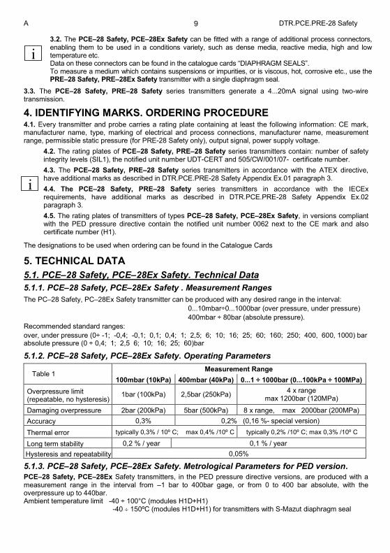
5.1.2. PCE–28 Safety, PCE–28Ex Safety. Operating Parameters
Table 1 Measurement Range
100mbar (10kPa) 400mbar (40kPa) 0...1 ÷ 1000bar (0...100kPa ÷ 100MPa)
Overpressure limit (repeatable, no hysteresis)
1bar (100kPa) 2,5bar (250kPa) 4 x range
max 1200bar (120MPa)
Damaging overpressure 2bar (200kPa) 5bar (500kPa) 8 x range, max 2000bar (200MPa)
Accuracy 0,3% 0,2% (0,16 %- special version)
Thermal error typically 0,3% / 10º C; max 0,4% /10º C typically 0,2% /10º C; max 0,3% /10º C
Long term stability 0,2 % / year 0,1 % / year
Hysteresis and repeatability 0,05%
5.1.3. PCE–28 Safety, PCE–28Ex Safety. Metrological Parameters for PED version.
PCE–28 Safety, PCE–28Ex Safety transmitters, in the PED pressure directive versions, are produced with a measurement range in the interval from –1 bar to 400bar gage, or from 0 to 400 bar absolute, with the overpressure up to 440bar. Ambient temperature limit -40 ÷ 100°C (modules H1D+H1) -40 150ºC (modules H1D+H1) for transmitters with S-Mazut diaphragm seal
i
i
A DTR.PCE.PRE-28 Safety 10
PCE–28 Safety, PCE–28Ex Safety transmitters with the S-Mazut seal pressure connection, assembled with the PED version can be produced within the range –1bar to 100 bar gage, or within the 0 - 100bar absolute, and the overpressure up to 110bar. Other parameters are as given in Tables 1, except that the ambient temperature error is 7mbar/10ºC. The value of the pressure measurement range and related overpressure are given on rating plate and at Product Certificate.
5.2. PRE–28 Safety, PRE–28Ex Safety. Technical Data
5.2.1 PRE–28 Safety, PRE–28Ex Safety. Measurement Ranges
The PRE–28 Safety, PRE–28Ex Safety differential pressure transmitters are manufactured with any desired range in the interval 1,6mbar to 25 bar. Recommended ranges: 0,4; 1; 2,5; 6; 10; 16; 25bar (-0,1...0,1); (-1...1) bar
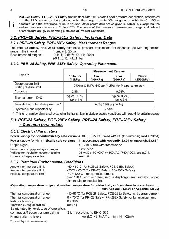
5.2.2. PRE–28 Safety, PRE–28Ex Safety. Operating Parameters
Table 2
Measurement Ranges
100mbar (10kPa)
1bar (100kPa)
2bar (200kPa)
25bar (2500kPa)
Overpressure limit Static pressure limit
250bar (25MPa) [40bar (4MPa) for P-type connector]
Accuracy 0,4% 0,25%
Thermal error / 10C typical 0,3%,
max 0,4% typical 0,2%,
max 0,3%
Zero shift error for static pressure * 0,1% / 10bar (1MPa)
Hysteresis and repeatability 0,05%
*- This error can be eliminated by zeroing the transmitter in static pressure conditions with zero differential pressure
5.3. PCE-28 Safety, PCE-28Ex Safety, PRE–28 Safety, PRE–28Ex Safety - Common parameters
5.3.1. Electrical Parameters
Power supply for non-intrinsically safe versions 10,5 ÷ 36V DC, rated 24V DC (for output signal 4 ÷ 20mA)
Power supply for –intrinsically safe versions in accordance with Appendix Ex.01 or Appendix Ex.02”
Output signal 4 ÷ 20mA two-wire transmission
Error due to supply voltage changes 0,005 %/V Voltage for insulation strength testing 75 VAC (110 VDC) or 500VAC (750V DC), see p.9.5. Excess voltage protection see p.9.5.
5.3.2. Permitted Environmental Conditions
Ambient temperature limit -40 ÷ 80°C (for PCE-28 Safety, PCE-28Ex Safety)
Ambient temperature limit -25ºC 80C (for PR–28 Safety, PR–28Ex Safety) Process temperature limit -40 ÷ 120°C – direct measurement, over 120ºC, only with the use of a diaphragm seal, radiator, looped
siphon tube or impulse line.
(Operating temperature range and medium temperature for intrinsically safe versions in accordance with Appendix Ex.01 or Appendix Ex.02)
Thermal compensation range -10÷80ºC (for PCE-28 Safety, PCE-28Ex Safety) or by arrangement
Thermal compensation range 0 ÷ 70ºC (for PR–28 Safety, PR–28Ex Safety) or by arrangement Relative humidity 0 ÷ 98%
Vibration during operation max 4g
Safety integrity level; type of operation:
continuous/frequent or rare calling SIL 1 according to EN 61508
Primary alarms levels low (LO) <3,3mA** or high (HI) >22mA
**) - set by the manufacturer).
i
A DTR.PCE.PRE-28 Safety 11
5.3.2. Construction Materials Diaphragm 1.4435 (316L) Hastelloy (for PCE-28 Safety, PCE-28Ex Safety only) ) (not applicable to PED version) Sensing module 1.4404 (316L)(for PED version too) Casing for electronic parts Steel pipe, 1.4301 (304) PZ-type terminal box Thick steel pipe, 1.4301 (304) Angular connector, DIN 43650, PD type Itamide
Internal sensor liquid fill Silicone oil, chemically inactive liquid for measurement of oxygen. Cable shield in PK connector Polyurethane, special version – teflon
5.4. Pressure Connectors
5.4.1. PCE-28 Safety, PCE-28Ex Safety. Pressure connectors M-type connector with M20x1.5 thread – see figure 5a - available for PED version. P-type connector with M20x1.5 thread – see figure 6a - available for PED version CM30x2 or CM20x1.5-type connector with flush diaphragm – see figure 7a. RM-type connector with M20x1.5 thread and radiator. G1/2 -type connector with G1/2” thread – see figure 8a - available for PED version GP -type connector with G1/2” thread CG1/2 -type connector with G1/2” thread and flush diaphragm – see figure 8c CG1-type connector with G1” thread and flush diaphragm – see figure 8e RG-type connector with G1/2” thread and radiator. 1/2"NPT-type connector with 1/2"NPT tread (male) and with internal G1/4” tread (female), available for PED version other connection types by arrangement
5.4.2. PRE–28 Safety, PRE–28Ex Safety. Pressure Connectors
P-type connectors with M20x1.5 thread – see fig. 9. C-type connector to mount together with a valve manifold see fig. 10. Diaphragm seal connectors: see the “Information Cards” for the diaphragm seals.
5.5. Degree of protection according to EN 60529:2003
IP65 - PCE–28 Safety, PRE–28 Safety series transmitters with PD-type connector, DIN 43650, PG-11 cable gland. IP66 - PCE–28 Safety, PRE–28 Safety series transmitters with PZ-type terminal box, M20x1,5 cable gland. IP67 - PCE–28 Safety, PCE–28Ex Safety with PK or PM12-type cable connector.
6. CONSTRUCTION
The basic component of the transmitter are: casing, sensing module, in which the input pressure is converted into an electrical signal and electronic unit which amplifies and standardizes the output signal.
6.1. Functional description
The PCE–28 Safety, PRE–28 Safety series transmitters operate by converting changes in the piezoresistive bridge, which are proportional to the measured pressure, into a standard current output signal. The active sensing device is a silicon diaphragm with diffused piezoresistors, separated from the medium by an isolating diaphragm and manometric oil. Measuring part of the PCE–28 Safety, PRE–28 Safety series transmitter is composed of the following elements (Figure 1):
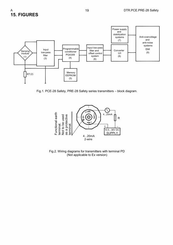
(1) piezoresistive pressure sensor (2) resistor intended for measurement of temperature of sensing module structure. (3) input low-pass filter (4) conditioning system - PGA309. (5) EEPROM memory containing correction coefficients. (6) low-pass filter and control system of offset (7) power supply, stabilisation systems. (8) voltage / current converter - XTR116. (9) EMI anti-overvoltage and anti-noise systems.
A DTR.PCE.PRE-28 Safety 12
Electric signal from piezoresistive pressure sensor (1) through low-pass passive filter RC (3) is provided to input of PGA309 (4) system. In PGA309 (4) system the measuring signal is provided to input of amplifier with amplification and offset depending on temperature of the pressure Voltage on resistor RT (2) - proportional to temperature of the sensor - is provided to input of the ADC converter located in the structure of the PGA309 (4) system. Proper algorithm implemented in the PGA309 sensor, depending on the measured temperature, controls coefficients downloaded from the cooperating EEPROM memory (5) controlling amplifications of line of the external PGA309 (4) amplifiers. As a result - non-linearities of the piezoresistive pressure sensor (1) in function of temperature are properly compensated and we will obtain on PGA309 (4) output a linearized electric signal, temperature compensated, proportional to the pressure.
Output voltage is provided successively on low-pass RC filter and analogue control system of the offset (6). Then, tuned voltage signal is provided to voltage / current converter (8) module and through a stage of EMI filters and overvoltage protections is provided as standardised current signal - available on the terminals of the converter. Proper supply of the transmitter systems is ensured by system of supply and stabilization of voltage (7).
Diagnostics systems - comparators connected to the appropriate points of the system - are in the structure of PGA309 (4) system. It allow to detect external, as well as internal, failure states with respect to the PGA309 (4) system. Failure states are signalled by alarm current which values, depending on the customer’s requirements are below 3.3 mA, Iwy <3.3 mA (LO) or above 22.0 mA, Iwy > 22.0 mA (HI). Values or alarm currents are outside the zone of normal operation of the transmitter.
6.2. Sensing module
The sensing module is part of a transmitter equipped with the silicone measuring membranę. This membrane is located in the space filled with silicone oil, closed from one side with seal wire lead outs isolated with glass and from the second side with separating membrane separated sensor unit from the medium (PRE-28 Safety series transmitters have two separating membranes). Sensing modules can be equipped with pressure connectors, see point 5.4. In case of PRE-28 Safety series the sensing module is equipped with two type P connectors (fig. 9) or type C process connectors (fig. 10) intended for assembly on the block valve.
6.3. Electronic module
Electronic module is composed of the systems which are intended to amplify and standardise output signal (4÷20mA). Electronic unit is equipped with potentiometer with “zero” set, enabling to move conversion characteristics upwards or downwards within the limits +/-3%.
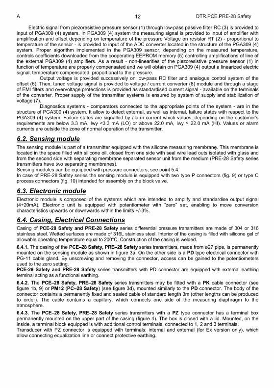
6.4. Casing, Electrical Connections
Casing of PCE-28 Safety and PRE-28 Safety series differential pressure transmitters are made of 304 or 316 stainless steel. Wetted surfaces are made of 316L stainless steel. Interior of the casing is filled with silicone gel of allowable operating temperature equal to 200°C. Construction of the casing is welded.
6.4.1. The casing of the PCE–28 Safety, PRE–28 Safety series transmitters, made from ø27 pipe, is permanently mounted on the sensing module as shown in figure 3a. On the other side is a PD type electrical connector with PG-11 cable gland. By unscrewing and removing the connector, access can be gained to the potentiometers used to the zero setting. PCE-28 Safety and PRE-28 Safety series transmitters with PD connector are equipped with external earthing terminal acting as a functional earthing.
6.4.2. The PCE–28 Safety, PRE–28 Safety series transmitters may be fitted with a PK cable connector (see figure 1b, 9) or PM12 (PC–28 Safety) (see figure 3d), mounted similarly to the PD connector. The body of the connector contains a permanently fixed and sealed cable of standard length 3m (other lengths can be produced to order). The cable contains a capillary, which connects one side of the measuring diaphragm to the atmosphere.
6.4.3. The PCE–28 Safety, PRE–28 Safety series transmitters with a PZ type connector has a terminal box permanently mounted on the upper part of the casing (figure 4). The box is closed with a lid. Mounted, on the inside, a terminal block equipped is with additional control terminals, connected to 1, 2 and 3 terminals. Transducer with PZ connector is equipped with terminals: internal and external (for Ex version only), which allow connecting equalization line or connect protective earthing.
A DTR.PCE.PRE-28 Safety 13
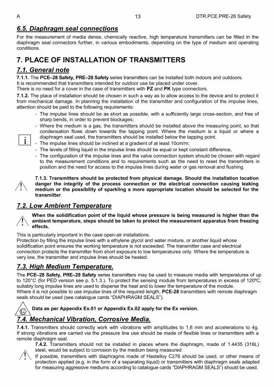
6.5. Diaphragm seal connections
For the measurement of media dense, chemically reactive, high temperature transmitters can be fitted in the diaphragm seal connectors further, in various embodiments, depending on the type of medium and operating conditions.
7. PLACE OF INSTALLATION OF TRANSMITTERS
7.1. General note 7.1.1. The PCE–28 Safety, PRE–28 Safety series transmitters can be installed both indoors and outdoors. It is recommended that transmitters intended for outdoor use be placed under cover. There is no need for a cover in the case of transmitters with PZ and PK type connectors.
7.1.2. The place of installation should be chosen in such a way as to allow access to the device and to protect it from mechanical damage. In planning the installation of the transmitter and configuration of the impulse lines, attention should be paid to the following requirements:
- The impulse lines should be as short as possible, with a sufficiently large cross-section, and free of sharp bends, in order to prevent blockages;
- Where the medium is a gas, the transmitters should be installed above the measuring point, so that condensation flows down towards the tapping point. Where the medium is a liquid or where a diaphragm seal used, the transmitters should be installed below the tapping point.
- The impulse lines should be inclined at a gradient of at least 10cm/m;
- The levels of filling liquid in the impulse lines should be equal or kept constant difference,
- The configuration of the impulse lines and the valve connection system should be chosen with regard to the measurement conditions and to requirements such as the need to reset the transmitters in position and the need for access to the impulse lines during water or gas removal and flushing.
7.1.3. Transmitters should be protected from physical damage. Should the installation location danger the integrity of the process connection or the electrical connection causing leaking medium or the possibility of sparkling a more appropriate location should be selected for the transmitter.
7.2. Low Ambient Temperature
When the solidification point of the liquid whose pressure is being measured is higher than the ambient temperature, steps should be taken to protect the measurement apparatus from freezing effects.
This is particularly important in the case open-air installations. Protection by filling the impulse lines with a ethylene glycol and water mixture, or another liquid whose solidification point ensures the working temperature is not exceeded. The transmitter case and electrical connection protects the transmitter from short exposure to low temperatures only. Where the temperature is very low, the transmitter and impulse lines should be heated.
7.3. High Medium Temperature.
The PCE–28 Safety, PRE–28 Safety series transmitters may be used to measure media with temperatures of up to 120°C (for PED version see p. 5.1.3.). To protect the sensing module from temperatures in excess of 120ºC, suitably long impulse lines are used to disperse the heat and to lower the temperature of the module. Where it is not possible to use impulse lines of the required length, PCE-28 transmitters with remote diaphragm seals should be used (see catalogue cards “DIAPHRAGM SEALS”).
Data as per Appendix Ex.01 or Appendix Ex.02 apply for the Ex version.
7.4. Mechanical Vibration, Corrosive Media.
7.4.1. Transmitters should correctly work with vibrations with amplitudes to 1,6 mm and accelerations to 4g. If strong vibrations are carried via the pressure line use should be made of flexible lines or transmitters with a remote diaphragm seal.
7.4.2. Transmitters should not be installed in places where the diaphragm, made of 1.4435 (316L) steel, would be subject to corrosion by the medium being measured
If possible, transmitters with diaphragms made of Hastelloy C276 should be used, or other means of protection applied (e.g. in the form of a separating liquid) or transmitters with diaphragm seals adapted for measuring aggressive mediums according to catalogue cards “DIAPHRAGM SEALS”) should be used.
i
A DTR.PCE.PRE-28 Safety 14
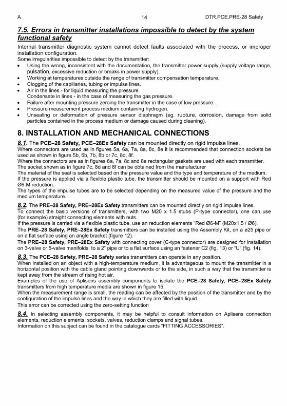
7.5. Errors in transmitter installations impossible to detect by the system functional safety
Internal transmitter diagnostic system cannot detect faults associated with the process, or improper installation configuration. Some irregularities impossible to detect by the transmitter:
Using the wrong, inconsistent with the documentation, the transmitter power supply (supply voltage range,
pulsation, excessive reduction or breaks in power supply).
Working at temperatures outside the range of transmitter compensation temperature.
Clogging of the capillaries, tubing or impulse lines.
Air in the lines - for liquid measuring the pressure Condensate in lines - in the case of measuring the gas pressure.
Failure after mounting pressure zeroing the transmitter in the case of low pressure.
Pressure measurement process medium containing hydrogen.
Unsealing or deformation of pressure sensor diaphragm (eg. rupture, corrosion, damage from solid particles contained in the process medium or damage caused during cleaning).
8. INSTALLATION AND MECHANICAL CONNECTIONS
8.1. The PCE–28 Safety, PCE–28Ex Safety can be mounted directly on rigid impulse lines. Where connectors are used as in figures 5a, 6a, 7a, 8a, 8c, 8e it is recommended that connection sockets be used as shown in figure 5b, 6b, 7b, 8b or 7c, 8d, 8f. Where the connectors are as in figures 6a, 7a, 8c and 8e rectangular gaskets are used with each transmitter. The socket shown as in figure 7c, 8d and 8f can be obtained from the manufacturer The material of the seal is selected based on the pressure value and the type and temperature of the medium. If the pressure is applied via a flexible plastic tube, the transmitter should be mounted on a support with Red Ø6-M reduction. The types of the impulse tubes are to be selected depending on the measured value of the pressure and the medium temperature.
8.2. The PRE–28 Safety, PRE–28Ex Safety transmitters can be mounted directly on rigid impulse lines.
To connect the basic versions of transmitters, with two M20 x 1.5 stubs (P-type connector), one can use (for example) straight connecting elements with nuts. If the pressure is carried via a flexible plastic tube, use an reduction elements “Red Ø6-M” (M20x1,5 / Ø6).
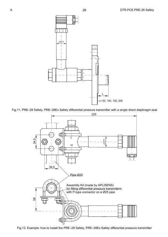
The PRE–28 Safety, PRE–28Ex Safety transmitters can be installed using the Assembly Kit, on a ø25 pipe or on a flat surface using an angle bracket (figure 12).
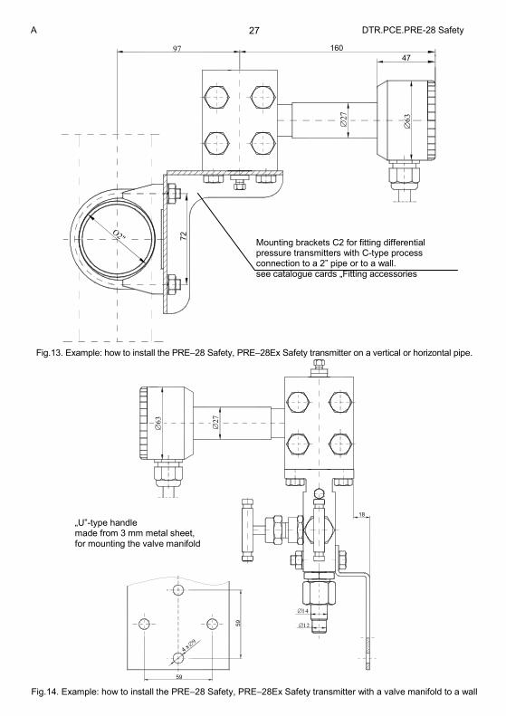
The PRE–28 Safety, PRE–28Ex Safety with connecting cover (C-type connector) are designed for installation on 3-valve or 5-valve manifolds, to a 2” pipe or to a flat surface using an fastener C2 (fig. 13) or “U” (fig. 14).
8.3. The PCE–28 Safety, PRE–28 Safety series transmitters can operate in any position.
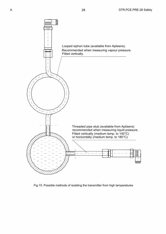
When installed on an object with a high-temperature medium, it is advantageous to mount the transmitter in a horizontal position with the cable gland pointing downwards or to the side, in such a way that the transmitter is kept away from the stream of rising hot air. Examples of the use of Aplisens assembly components to isolate the PCE–28 Safety, PCE–28Ex Safety transmitters from high temperature media are shown in figure 15. When the measurement range is small, the reading can be affected by the position of the transmitter and by the configuration of the impulse lines and the way in which they are filled with liquid.
This error can be corrected using the zero-setting function
8.4. In selecting assembly components, it may be helpful to consult information on Aplisens connection
elements, reduction elements, sockets, valves, reduction clamps and signal tubes. Information on this subject can be found in the catalogue cards “FITTING ACCESSORIES”.
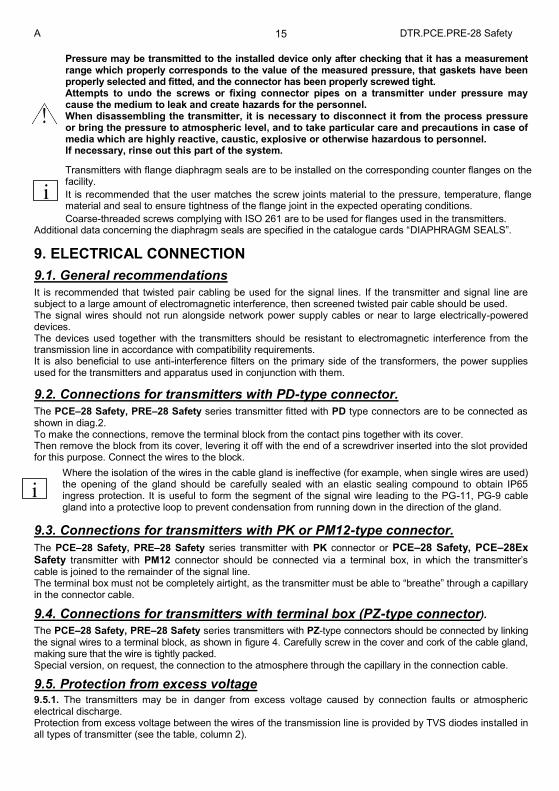
A DTR.PCE.PRE-28 Safety 15
Pressure may be transmitted to the installed device only after checking that it has a measurement range which properly corresponds to the value of the measured pressure, that gaskets have been properly selected and fitted, and the connector has been properly screwed tight. Attempts to undo the screws or fixing connector pipes on a transmitter under pressure may cause the medium to leak and create hazards for the personnel. When disassembling the transmitter, it is necessary to disconnect it from the process pressure or bring the pressure to atmospheric level, and to take particular care and precautions in case of media which are highly reactive, caustic, explosive or otherwise hazardous to personnel. If necessary, rinse out this part of the system.
Transmitters with flange diaphragm seals are to be installed on the corresponding counter flanges on the facility.
It is recommended that the user matches the screw joints material to the pressure, temperature, flange material and seal to ensure tightness of the flange joint in the expected operating conditions.
Coarse-threaded screws complying with ISO 261 are to be used for flanges used in the transmitters. Additional data concerning the diaphragm seals are specified in the catalogue cards “DIAPHRAGM SEALS”.
9. ELECTRICAL CONNECTION
9.1. General recommendations
It is recommended that twisted pair cabling be used for the signal lines. If the transmitter and signal line are subject to a large amount of electromagnetic interference, then screened twisted pair cable should be used. The signal wires should not run alongside network power supply cables or near to large electrically-powered devices. The devices used together with the transmitters should be resistant to electromagnetic interference from the transmission line in accordance with compatibility requirements. It is also beneficial to use anti-interference filters on the primary side of the transformers, the power supplies used for the transmitters and apparatus used in conjunction with them.
9.2. Connections for transmitters with PD-type connector.
The PCE–28 Safety, PRE–28 Safety series transmitter fitted with PD type connectors are to be connected as shown in diag.2. To make the connections, remove the terminal block from the contact pins together with its cover. Then remove the block from its cover, levering it off with the end of a screwdriver inserted into the slot provided for this purpose. Connect the wires to the block.
Where the isolation of the wires in the cable gland is ineffective (for example, when single wires are used) the opening of the gland should be carefully sealed with an elastic sealing compound to obtain IP65 ingress protection. It is useful to form the segment of the signal wire leading to the PG-11, PG-9 cable gland into a protective loop to prevent condensation from running down in the direction of the gland.
9.3. Connections for transmitters with PK or PM12-type connector.
The PCE–28 Safety, PRE–28 Safety series transmitter with PK connector or PCE–28 Safety, PCE–28Ex Safety transmitter with PM12 connector should be connected via a terminal box, in which the transmitter’s cable is joined to the remainder of the signal line. The terminal box must not be completely airtight, as the transmitter must be able to “breathe” through a capillary in the connector cable.
9.4. Connections for transmitters with terminal box (PZ-type connector).
The PCE–28 Safety, PRE–28 Safety series transmitters with PZ-type connectors should be connected by linking the signal wires to a terminal block, as shown in figure 4. Carefully screw in the cover and cork of the cable gland, making sure that the wire is tightly packed. Special version, on request, the connection to the atmosphere through the capillary in the connection cable.
9.5. Protection from excess voltage 9.5.1. The transmitters may be in danger from excess voltage caused by connection faults or atmospheric electrical discharge. Protection from excess voltage between the wires of the transmission line is provided by TVS diodes installed in all types of transmitter (see the table, column 2).
i
i
A DTR.PCE.PRE-28 Safety 16 9.5.2. Protection from overvoltage Transmitters in normal version and “ExSA” version. In order to protect against excess voltage between the transmission line and the casing or earth (not prevented by the diodes connected between the transmission wires), additional protection is provided in the form of plasma surge arresters (see the table, column 3).
Transmitters in “Ex” version - without protection Also external protective devices may be used, e.g. the UZ-2 Aplisens system, or others. When the transmission lines are long, it is advantageous to use one protective device near the transmitter (or inside it), and another near entry points to devices used in conjunction with it.
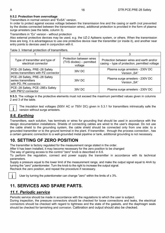
Table 3. Internal protection of transmitters.
1 2 3
Type of transmitter and type of electrical connector
Protection between wires (TVS diodes) – permitted
voltage
Protection between wires and earth and/or casing – type of protection, permitted voltage
PCE–28 Safety, PRE–28 Safety series transmitters with PZ connector
39V DC Plasma surge arresters - 230V DC
Version „SA”
PCE–28 Safety, PRE–28 Safety series transmitters with PD, PK connector.
39V DC Plasma surge arresters - 230V DC
Version „SA”
PCE–28 Safety, PCE–28Ex Safety with PM12 connector
39V DC Plasma surge arresters - 230V DC
9.5.3. The voltage in the protective elements must not exceed the maximum permitted values given in columns 2 and 3 of the table.
The insulation test voltages (500V AC or 750V DC) given in 5.3.1 for transmitters intrinsically safe the version without surge arresters.
9.6. Earthing
Transmitters, each solution, has terminals or wires for grounding that should be used in accordance with the design documentation installations. Shields of connecting cables are wired to the user's disposal. Do not use the cable shield to the grounding system, the cable shield should be connected only from one side: to a grounded transmitter or to the ground terminal in the plant. If transmitter, through the process connection , has a certain galvanic connection to a well-grounded metal pipeline or tank, additional grounding is not necessary.
10. SETTING OF ZERO POSITION The transmitter is factory regulated for the measurement range stated in the order. After it has been installed, it may become necessary for the zero position to be changed The way of gaining access to the control "zero" knob is described in 6.6. To perform the regulation, connect and power supply the transmitter in accordance with its technical parameters. Supply a pressure equal to the lower limit of the measurement range, and make the output signal equal to 4mA by turning the “zero” potentiometer. Turn the knob to the right to increase the output signal. Recheck the zero position, and repeat the procedure if necessary.
User by turning the potentiometer can change "zero" within the limits of ± 3%.
11. SERVICES AND SPARE PARTS.
11.1. Periodic service
Periodic service should be made in accordance with the regulations to which the user is subject. During inspection, the pressure connectors should be checked for loose connections and leaks, the electrical connectors should be checked with regard to tightness and the state of the gaskets, and the diaphragm seals
should be checked for tarnishing and corrosion. Calibration and output should also be checked.
i
i
A DTR.PCE.PRE-28 Safety 17
11.2. Unscheduled services
If the transmitters or probes are installed in a location where they may be exposed to mechanical damage, excess pressure, hydraulic impulses or excess voltage, or the diaphragm may be in danger from sedimentation, crystallization or erosion, inspections should be carried out as required.
The diaphragm should be inspected and cleaned, the protective diodes should be checked for shorting,
and the calibration and output should be checked. Where it is found that the signal in the transmission circuit is lost or its value is incorrect, a check should be made on the circuit and its terminal connections. Check whether the values of the supply voltage and load resistance are correct. If the circuit is in order, check the operation of the transmitter.
After checks have been made, take steps to eliminate the faults detected.
11.3. Cleaning the diaphragm seal, Overloading damage.
11.3.1. Sediment and dirt which have formed on the diaphragm in the course of operation must not be removed by mechanical means, as this may damage both the diaphragm and the transmitter itself. The only permitted method is the dissolving of sediment.
In connection with the stubs of M, G 1/2 "can be mounted gland. Before membrane cleaning, must unscrew the gland (see figure 5a and 8a).
11.3.2. . Sometimes transmitters malfunction due to damage caused by overloading, e.g. in case of:
- application of excessive pressure; - freezing or solidification of the medium;, - action of a hard object, such as a screwdriver, on the diaphragm.
Usually in such cases the symptoms are such that the output current falls below 4mA or rises above 20mA, and
the transmitter fails to respond to input pressure.
11.4. Spare parts.
The following transmitter parts may need replacing due to damage or normal wear: - PD connector – terminal block with angular cover and seal, connector base with seal, rating plate, case. - PK connector – the entire connector. - PZ connector – cover seal and cable gland.
Other parts, due to their special characteristics and anti-explosive requirements, may be replaced only by the manufacturer or an authorised firm.
12. PACKING, STORAGE AND TRANSPORT The transmitters should be packed singly or in sets, in such a way as to protect them from damage during transportation. The transmitters should be stored in multiple packs under cover, in a place free of vapours and reactive substances, with temperature and humidity not exceed the limits specified in p. 5.3.2. Transmitters with uncovered diaphragm or seal connectors, stored without packaging, should have covers to prevent damage to the diaphragm. During transportation, the transmitters should be packed and secured so as to prevent them from shifting. Any means of transport may be used, provided direct atmospheric effects are eliminated.
13. GUARANTEE Manufacturer warrants under the conditions specified in the Product Certificate which is also a guarantee card.
14. ADDITIONAL INFORMATION The manufacturer reserves the right to make constructional and technological changes which do not lower the quality of the transmitters.
14.1. Related documents
Catalogue Cards “Diaphragm seals”
i
i
A DTR.PCE.PRE-28 Safety 18
14.2. Related standards
PN-EN 60529:2003 Degrees of protection provided by enclosures (IP Code) PN-EN 61010-1 Safety requirements for electrical equipment for measurement, control and laboratory use. General requirements PN-82/M-42306 Screwed connectors of pressure gauges. PN-81/M-42009 Automatics and industrial measurements. The packing, the storage and transport of devices. General requirements PN-EN 1092-1:2010 Flanges and their joints - Circular flanges for pipes, valves, fittings and accessories, Pn designated - Part 1: Steel flanges. PN-EN 61508-1:2004 Flanges and their joints – Circular flanges for pipes, valves, fittings and
accessories. – Part 1: Steel flanges. PN-EN 61508-2:2005 Functional safety of electrical/electronic/programmable electronic safety-related systems - Part 2: Requirements for electrical/electronic/programmable electronic safety-related systems PN-EN 61508-3:2004 Functional safety of electrical/electronic/programmable electronicsafety-related systems -Part 3: Software requirements PN-EN 61511-1:2007 Functional safety - Safety instrumented systems for the process industry sector - Part 1: Framework, definitions, system, hardware nad software requirements PN-EN 62061:2008 Safety of machinery - Functional safety of electrical, electronic and programmable electric control systems.
A DTR.PCE.PRE-28 Safety 19
15. FIGURES
Input low-pass
filter
Sensingmodule
Programmable
conditioner
PGA309
RTMemory
EEPROM
filter and
Input low-pass
offset control system
U/IConverter
and Power supply
stabilizationAnti-overvoltage
anti-noise
EMI
(1)
(2)
(3) (4)
(5)
(6)
(7)
(8)
(9)
systems
and systems
Fig.1. PCE-28 Safety, PRE-28 Safety series transmitters – block diagram.
10,5...36V DC
R
SUPPLYFu
nctio
na
l e
art
h
term
ina
l.N
ot
to b
e u
sed
a
s a
pro
tective
te
rmin
al.
2-wire4...20mA
24...20mA3
1
_+
Fig.2. Wiring diagrams for transmitters with terminal PD (Not applicable to Ex version)
A DTR.PCE.PRE-28 Safety 20
max.128
max.142
max.131
IP67 ratedPK cable connector
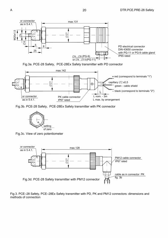
Fig.3b. PCE-28 Safety, PCE-28Ex Safety transmitter with PK connector
Fig.3d. PCE-28 Safety transmitter with PM12 connector
of zero
Fig.3c. View of zero potentiometer
as in 5.4.1.
or connector
or connector
setting
as in 5.4.1.
fig. 3b
PM12 cable connector
IP67 rated
cable as in connector PK
L max. by arrangement
L nom. - 3m
L
DIN 43650 connector PD electrical connector
with PG-11 or PG-9 cable gland
Fig.3a. PCE-28 Safety, PCE-28Ex Safety transmitter with PD connector
M20x1,5
25
5
8
as in 5.4.1.
or connector
black (correspond to terminals "2")
red (correspond to terminals "1")
green - cable shield
_
+
capillary x0,5
IP65 rated
or (PG-11)
(PG-9)
Fig.3. PCE–28 Safety, PCE–28Ex Safety transmitter with PD, PK and PM12 connectors: dimensions and methods of connection
A DTR.PCE.PRE-28 Safety 21
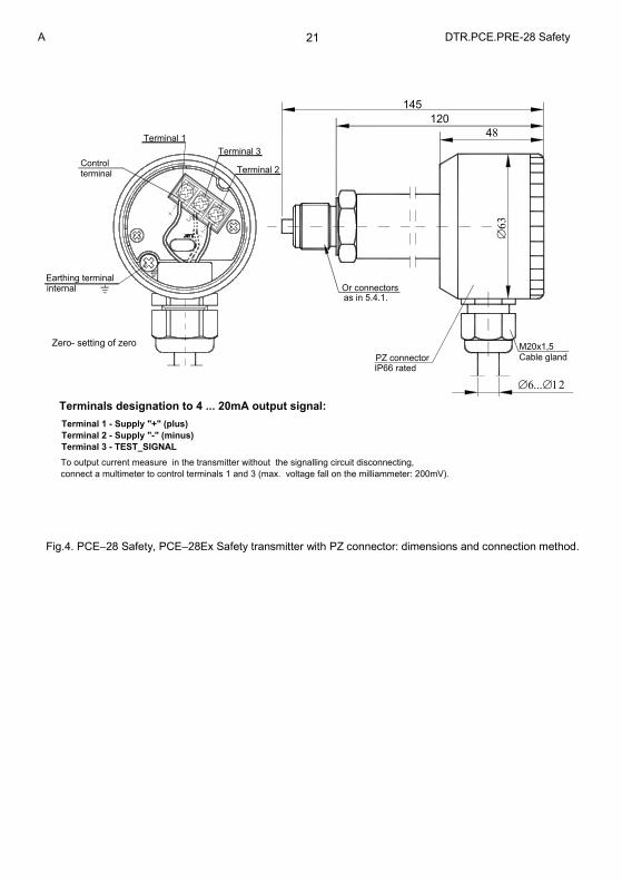
Zero- setting of zero
terminalControl
Terminal 2 - Supply "-" (minus)
Terminal 1 - Supply "+" (plus)
Terminal 3 - TEST_SIGNAL
Earthing terminal
connect a multimeter to control terminals 1 and 3 (max. voltage fall on the milliammeter: 200mV).
Terminals designation to 4 ... 20mA output signal:
To output current measure in the transmitter without the signalling circuit disconnecting,
internal
IP66 ratedPZ connector
Or connectors as in 5.4.1.
M20x1,5
Cable gland
145
Terminal 2
Terminal 3
Terminal 1
48
120
Fig.4. PCE–28 Safety, PCE–28Ex Safety transmitter with PZ connector: dimensions and connection method.
A DTR.PCE.PRE-28 Safety 22
seal
+0
.1 2
diaphragm seal
1.2
5
1.2
5
+0
.12
1.2
5
M20x1.5
M20x1.5
25
5
M20x1.5
193
M20x1.5
min.15
2 15
16
2
M30x2
M30x2
min.15
M30x2
30°
8
10
diaphragm SW36
(G1/2
")
SW27
SW27
(G1/2
")
1
1528
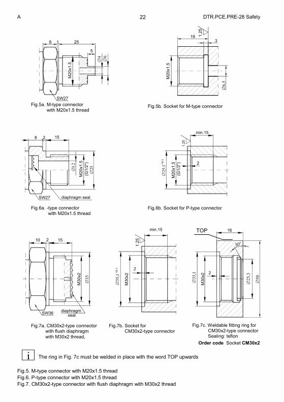
The ring in Fig. 7c must be welded in place with the word TOP upwards
Fig.5. M-type connector with M20x1.5 thread
Fig.6. P-type connector with M20x1.5 thread
Fig.7. CM30x2-type connector with flush diaphragm with M30x2 thread
TOP
Fig.5a. M-type connector
with M20x1.5 thread Fig.5b. Socket for M-type connector
Fig.6a. -type connector with M20x1.5 thread
Fig.6b. Socket for P-type connector
Fig.7a. CM30x2-type connector with flush diaphragm
with M30x2 thread,
Fig.7b. Socket for CM30x2-type connector
Fig.7c. Weldable fitting ring for CM30x2-type connector Sealing: teflon
Order code Socket CM30x2
i
A DTR.PCE.PRE-28 Safety 23
312,5 0.5 10,50,1
A
33,2 x 36,4 x 1,8
20.5
10
-0,0
5
G1
"
O-ring
26x2
2,5
+0,1
G1
2,5
90°
2,5
A
+0,1
Teflon ring
21,2 x 24,4 x 1,7
0,1
A
20,5
O-ring10
18
15x2
G1
/2A
.min
15
21.5
-0,2
-0,2
G1
/22
,52,5
90°
G1
/2
20
3
G1
/2
0.5 15
min.10,5
21,5-0,2
1,2
5
+1
min.
19
24,5
14,5
-0.5
A
2,5
+0,1
SW41
SW27
8 3
18
SW27
Teflon ring
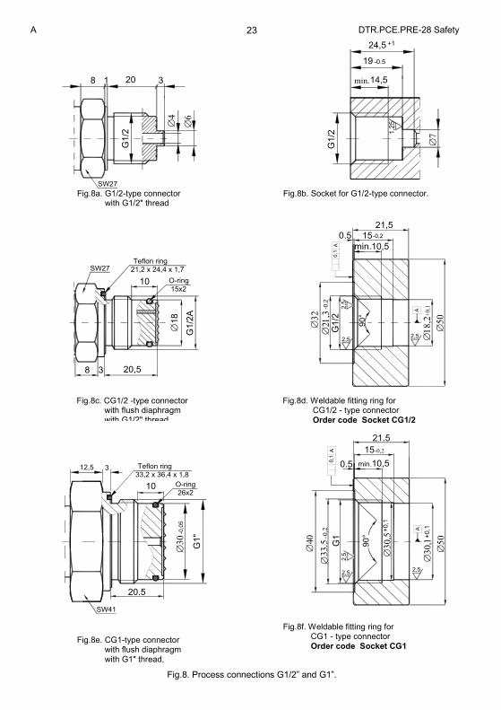
Fig.8. Process connections G1/2” and G1”.
Fig.8a. G1/2-type connector with G1/2" thread
Fig.8b. Socket for G1/2-type connector.
Fig.8c. CG1/2 -type connector with flush diaphragm with G1/2" thread
Fig.8d. Weldable fitting ring for CG1/2 - type connector Order code Socket CG1/2
Fig.8e. CG1-type connector with flush diaphragm with G1" thread,
Fig.8f. Weldable fitting ring for CG1 - type connector Order code Socket CG1
A DTR.PCE.PRE-28 Safety 24
Example connection
Connector to weld
Flat seal
with C type nut94,5
15
M2
0x1
,5
18
0
de
gre
e o
f p
rote
ctio
n I
P6
5
PD
ele
ctr
ica
l co
nn
ecto
rD
IN 4
36
50
co
nn
ecto
r w
ith
PG
-11
or
PG
-9
red
(corr
espond t
o term
inals
"1")
bla
ck (
corr
espond t
o term
inals
"2")
PK
cable
connecto
r, IP
67
_
capill
ary
x
0,5
L
gre
en -
cable
shie
ld
+
transmitter with PK connector
PRE-28 Safety, PRE-28Ex Safety
(fo
r P
G9
)
(fo
r P
G1
1)
Fig.9. PRE–28 Safety, PRE–28Ex Safety differential pressure transmitter with PD, PK connectors
A DTR.PCE.PRE-28 Safety 25
a). b).
54
L H
190
160
47
M20x1,5
PZ connector
IP66
192
Cable gland
41
.3
54
L H
7/16" UNF
4 holes
M10 or7/16" UNF
4 holes
M10 or
(f
or
PG
9)
(fo
r P
G11)
de
gre
e o
f p
rote
ction IP
65
PD
ele
ctr
ical co
nnecto
rD
IN 4
36
50
conn
ecto
r w
ith P
G-1
1 o
r P
G-9
Fig.10. PRE–28 Safety, PRE–28Ex Safety differential pressure transmitter with C-type process connection to be mounted together with valve manifold.
a). PZ – type electrical connection. b). PD – type electrical connection.
A DTR.PCE.PRE-28 Safety 26
L= 50, 100, 150, 200
L
Fig.11. PRE–28 Safety, PRE–28Ex Safety differential pressure transmitter with a single direct diaphragm seal
34
.55
8
34.5
H
L
220
Fig.12. Example: how to install the PRE–28 Safety, PRE–28Ex Safety differential pressure transmitter
Assembly Kit (made by APLISENS) for fitting differential pressure transmitters. with P-type connector on a Ø25 pipe
Pipe Ø25
A DTR.PCE.PRE-28 Safety 27
72O
2"
9747
160
Fig.13. Example: how to install the PRE–28 Safety, PRE–28Ex Safety transmitter on a vertical or horizontal pipe.
59
59
18
4 x
Fig.14. Example: how to install the PRE–28 Safety, PRE–28Ex Safety transmitter with a valve manifold to a wall
„U”-type handle made from 3 mm metal sheet, for mounting the valve manifold
Mounting brackets C2 for fitting differential pressure transmitters with C-type process connection to a 2” pipe or to a wall. see catalogue cards „Fitting accessories
A DTR.PCE.PRE-28 Safety 28
Looped siphon tube (available from Aplisens).
Fitted vertically.Recommended when measuring vapour pressure.
Threaded pipe stub (available from Aplisens) recommended when measuring liquid pressure.
Fitted vertically (medium temp. to 140°C) or horizontally (medium temp. to 180°C).
Fig.15. Possible methods of isolating the transmitter from high temperatures
A DTR.PCE.PRE-28 Safety 29
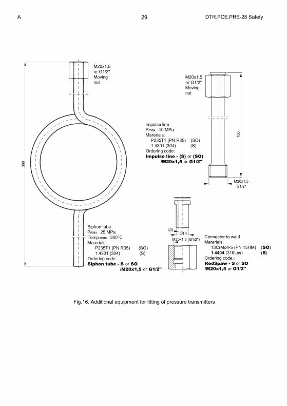
M20x1,5
or G1/2"
Moving
nut
M20x1,5
or G1/2"
Moving
nut
Impulse line
Pmax. 10 MPa
Marerials:
P235T1 (PN R35) (SO)
1.4301 (304) (S)
Ordering code:
Impulse line - (S) or (SO)
/M20x1,5 or G1/2"
Siphon tube
Pmax. 25 MPa
Temp.max. 300°C
Marerials:
P235T1 (PN R35) (SO)
1.4301 (304) (S)
Ordering code:
Siphon tube - S or SO
/M20x1,5 or G1/2"
360
Connector to weld
Marerials:
13CrMo4-5 (PN 15HM) (SO)
1.4404 (316Lss) (S)
Ordering code.:
RedSpaw - S or SO
/M20x1,5 or G1/2"
M20x1,5 (G1/2")
150
M20x1,5
G1/2"
Fig.16. Additional equipment for fitting of pressure transmitters


![APLISENS...A 3 DTR.PCE.PRE-28.SMART.01(ENG) Appendix Ex.01 Pi for all type of power supply; see the table below Pi[W] Ta[ºC] Temperature classification 0,7 60 T6 80 T5, T4](https://img.pdfslide.net/doc/110x75/5f778f89dc1cae1b590b8342/aplisens-a-3-dtrpcepre-28smart01eng-appendix-ex01-pi-for-all-type-of.jpg)