Embed Size (px)
Citation preview

w w w .castle.com.my
Introduction
Standalone Door Access
Networking Door Access
SmartGuard Series Softwares
Car Park Access Control
Lift Access Control
Alarm Monitoring System (CAMS)
Time Attendance Management
FingerPrint Access Control
Castle Electronic Safe (CES)
1
2 - 3
4 - 6
7 - 9
10
11
12 - 13
14 - 15
16
17
C o n t e n t s
R
is a registered trademark of CASS TECHNOLOGY SDN. BHD. ( 338857-X ) Copyright (C) 2001 Cass Technology Sdn. Bhd. Manufacturer & Exporter. All right reserved.
1
Introduction
Plugs Into a New Era of
Technology
P R O X B Y
As the leading building security solutions provider, we
offer cutting edged software and hardware technologies, includ-
ing fingerprints, smart cards and internet technology.
W e have successfully installed our systems in many leading
commercial and industrial buildings around the region.
Our demand customers depend on our integrated building
access control systems to manage and monitor their
critical facilities.
Contact us today and discover how our commitment and
professional services can assist your organization to
accelerate to a new height.
2
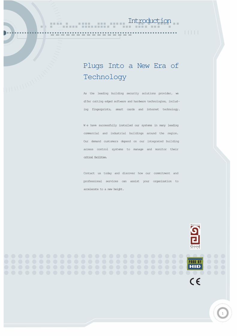
Features
12 keys polycarbonate keypad
3 LEDs for Valid, Error and Ready status indication
One relay output for door lock system
Door sensor input and door release button
16 Characters x 2 rows liquid crystal display
Door force open or door left open trigger reader buzzer
Adjustable buzzer volume
User definable 6 digits Master PIN for entering Programming Mode
User definable door open time and lock release time
User changeable card PIN ( 4 digits PIN )
2 sets PIN number for door PIN Access ( 4 digits PIN )
Keypad lockout after 5 invalid PIN violation for 25 seconds
( Applicable for CAS-SKA only )
Standalone Door Access (Castle-Knight)
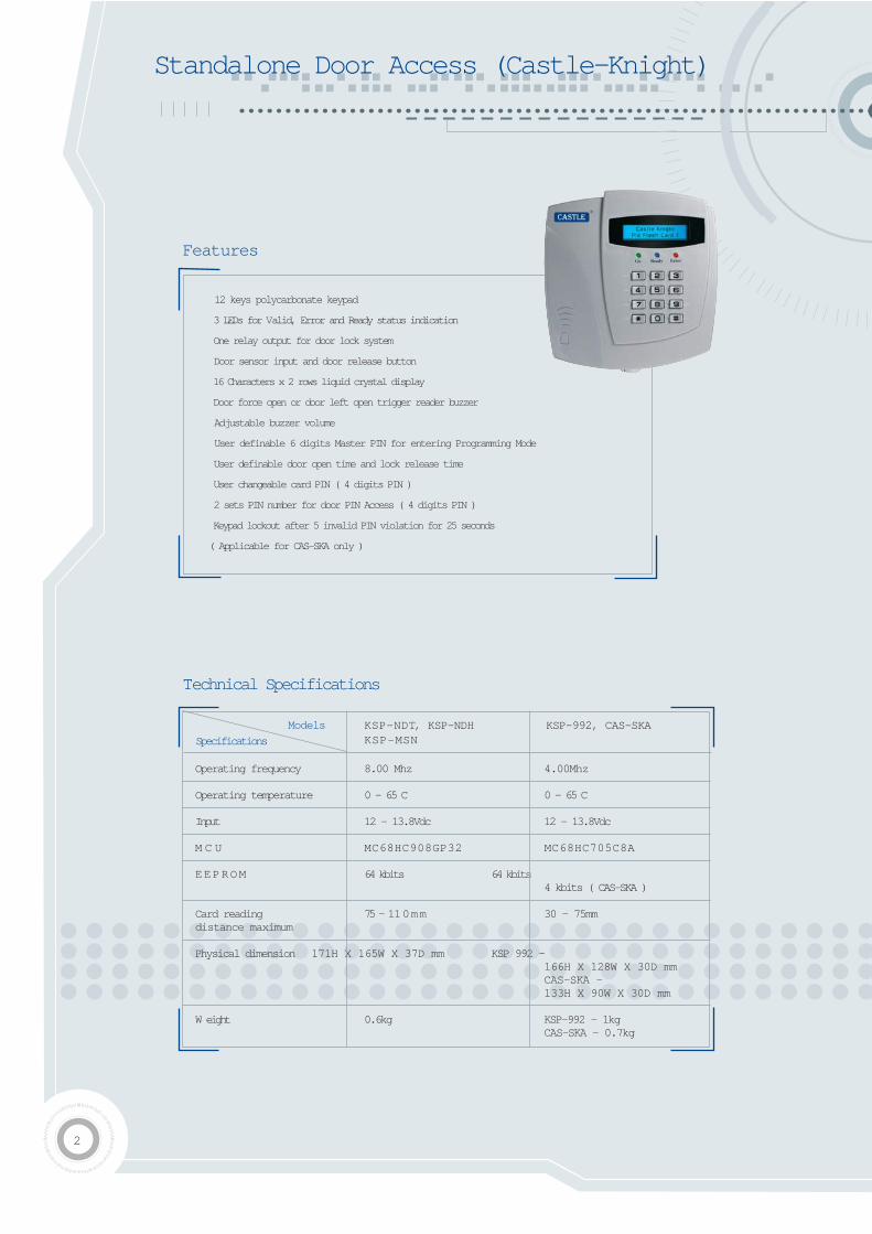
Technical Specifications
Operating frequency 8.00 Mhz 4.00Mhz
Operating temperature 0 - 65 C 0 - 65 C
Input 12 - 13.8Vdc 12 - 13.8Vdc
M C U MC68HC908GP32 MC68HC705C8A
EEPROM 64 kbits 64 kbits4 kbits ( CAS-SKA )
Card reading 75 - 110mm 30 - 75mm distance maximum
Physical dimension 171H X 165W X 37D mm KSP 992 -166H X 128W X 30D mmCAS-SKA -133H X 90W X 30D mm
W eight 0.6kg KSP-992 - 1kgCAS-SKA - 0.7kg
KSP-NDT, KSP-NDHKSP-MSN
KSP-992, CAS-SKA
Specifications
Models
3
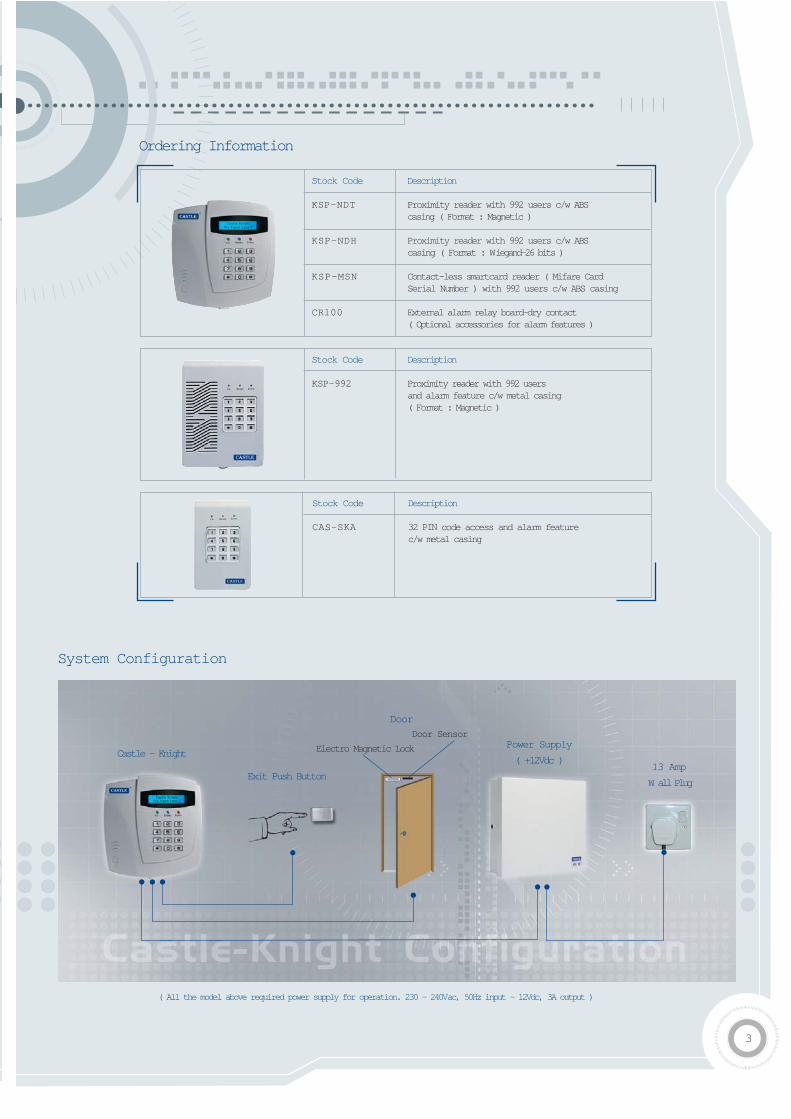
System Configuration
Castle - Knight
Exit Push Button
Door
Door Sensor
Electro Magnetic Lock Power Supply
( +12Vdc )13 Amp
W all Plug
Ordering Information
Stock Code Description
KSP-NDT Proximity reader with 992 users c/w ABScasing ( Format : Magnetic )
KSP-NDH Proximity reader with 992 users c/w ABScasing ( Format : Wiegand-26 bits )
KSP-MSN Contact-less smartcard reader ( Mifare CardSerial Number ) with 992 users c/w ABS casing
CR100 External alarm relay board-dry contact( Optional accessories for alarm features )
Stock Code Description
KSP-992 Proximity reader with 992 users and alarm feature c/w metal casing ( Format : Magnetic )
Stock Code Description
CAS-SKA 32 PIN code access and alarm featurec/w metal casing
( All the model above required power supply for operation. 230 - 240Vac, 50Hz input - 12Vdc, 3A output )
4
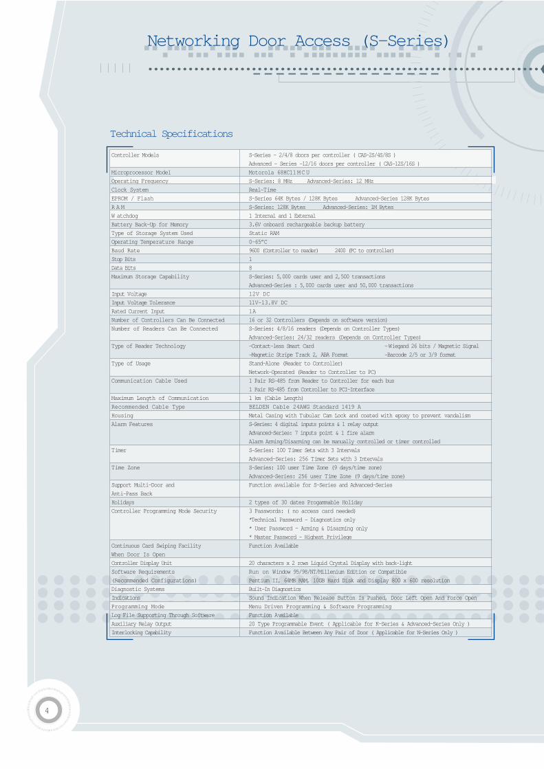
Controller Models S-Series - 2/4/8 doors per controller ( CAS-2S/4S/8S )
Advanced - Series -12/16 doors per controller ( CAS-12S/16S )
Microprocessor Model Motorola 68HC11MCU
Operating Frequency S-Series: 8 MHz Advanced-Series: 12 MHz
Clock System Real-Time
EPROM / Flash S-Series 64K Bytes / 128K Bytes Advanced-Series 128K Bytes
R A M S-Series: 128K Bytes Advanced-Series: 1M Bytes
W atchdog 1 Internal and 1 External
Battery Back-Up for Memory 3.6V onboard rechargeable backup battery
Type of Storage System Used Static RAM
Operating Temperature Range 0-65”C
Baud Rate 9600 (Controller to reader) 2400 (PC to controller)
Stop Bits 1
Data Bits 8
Maximum Storage Capability S-Series: 5,000 cards user and 2,500 transactions
Advanced-Series : 5,000 cards user and 50,000 transactions
Input Voltage 12V DC
Input Voltage Tolerance 11V-13.8V DC
Rated Current Input 1A
Number of Controllers Can Be Connected 16 or 32 Controllers (Depends on software version)
Number of Readers Can Be Connected S-Series: 4/8/16 readers (Depends on Controller Types)
Advanced-Series: 24/32 readers (Depends on Controller Types)
Type of Reader Technology -Contact-less Smart Card -Wiegand 26 bits / Magnetic Signal
-Magnetic Stripe Track 2, ABA Format -Barcode 2/5 or 3/9 format
Type of Usage Stand-Alone (Reader to Controller)
Network-Operated (Reader to Controller to PC)
Communication Cable Used 1 Pair RS-485 from Reader to Controller for each bus
1 Pair RS-485 from Controller to PCI-Interface
Maximum Length of Communication 1 km (Cable Length)
Recommended Cable Type BELDEN Cable 24AWG Standard 1419 A
Housing Metal Casing with Tubular Cam Lock and coated with epoxy to prevent vandalism
Alarm Features S-Series: 4 digital inputs points & 1 relay output
Advanced-Series: 7 inputs point & 1 fire alarm
Alarm Arming/Disarming can be manually controlled or timer controlled
Timer S-Series: 100 Timer Sets with 3 Intervals
Advanced-Series: 256 Timer Sets with 3 Intervals
Time Zone S-Series: 100 user Time Zone (9 days/time zone)
Advanced-Series: 256 user Time Zone (9 days/time zone)
Support Multi-Door and Function available for S-Series and Advanced-Series
Anti-Pass Back
Holidays 2 types of 30 dates Progammable Holiday
Controller Programming Mode Security 3 Passwords: ( no access card needed)
*Technical Password - Diagnostics only
* User Password - Arming & Disarming only
* Master Password - Highest Privilege
Continuous Card Swiping Facility Function Available
When Door Is Open
Controller Display Unit 20 characters x 2 rows Liquid Crystal Display with back-light
Software Requirements Run on Window 95/98/NT/Millenium Edition or Compatible
(Recommended Configurations) Pentium II, 64MB RAM, 10GB Hard Disk and Display 800 x 600 resolution
Diagnostic Systems Built-In Diagnostics
Indications Sound Indication When Release Button Is Pushed, Door Left Open And Force Open
Programming Mode Menu Driven Programming & Software Programming
Log File Supporting Through Software Function Available
Auxiliary Relay Output 20 Type Programmable Event ( Applicable for K-Series & Advanced-Series Only )
Interlocking Capability Function Available Between Any Pair of Door ( Applicable for N-Series Only )
Networking Door Access (S-Series)
Technical Specifications
5
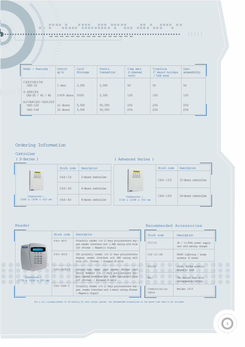
Model / Features Control Card Events Time sets TimeZone Userup to Strorage transaction (3 intervasl (7 days+2 holidays accessibility
each) / time zone)
CENTURION CAS-1S 1 door 2,500 2,500 50 50 50
S-SERIES CAS-2S / 4S / 8S 2/4/8 doors 5000 2,500 100 100 100
ADVANCED-SERIES CAS-12S 12 doors 5,000 50,000 256 256 256
CAS-16S 16 doors 5,000 50,000 256 256 256
Dimensions :310H x 220W x 55D mm
Stock code Description
CAS-12S 12-doors controller
CAS-16S 16-doors controller
Controller( S-Series )
Stock code
PRO-NDT
PRO-NDH
CAS-MSN26
PRO-4SM-T
Description
Proximity reader c/w 12 keys polycarbonate key-pad reader interface unit & ABS casing with blueLCD (Format : Magnetic Signal)
HID proximity reader c/w 12 keys polycarbonatekeypad, reader interface unit ABS casing withblue LCD. (Format : Wiegand 26 bits)
Contact-less smart card reader (Mifare CardSerial Number) c/w 12 keys polycarbonate key-pad, reader interface unit & ABS casing with blueLCD (Format : Wiegand 26 bits)
Proximity reader c/w 12 keys polycarbonate key-pad, reader interface unit & metal casing.(Format: Magnetic Signal)
Dimensions :170H x 185W x 35D mm
Stock code Description
CPC30 3A / 13.8Vdc power supply unit with battery charger
CLP-22-2W RS485 lightning / surge arrestor (2 wires)
600LB 12Vdc, 600lbs electric magnetic lock
Bat7 7AH sealed lead acid rechargeable battery
Communication Belden 1419Cable
Reader Recommended Accessories
For a full accomplishment of CE marking for door access system, the recommended accessories on the above item need to be included.
Dimensions :248H x 185W x 42D mm
Stock code Description
CAS-2S 2-doors controller
CAS-4S 4-doors controller
CAS-8S 8-doors controller
( Advanced Series )
Ordering Information
6
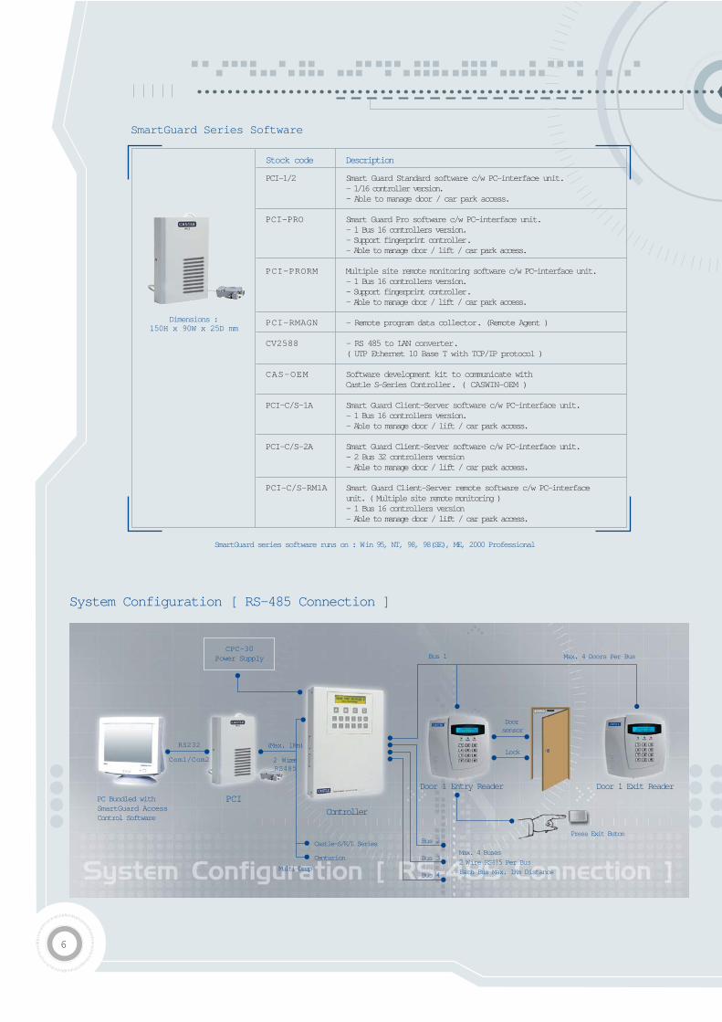
PC Bundled withSmartGuard AccessControl Software
CPC-30Power Supply
RS232
Com1/Com2
(Max. 1Km)
2 Wires RS485
PCI
Controller
Castle-S/K/L Series
Centurion
Bus 2
Bus 3
Bus 4
Max. 4 Buses
2 Wire RS485 Per Bus
Each Bus Max. 1Km Distance
Door 1 Entry Reader Door 1 Exit Reader
Press Exit Buton
Bus 1 Max. 4 Doors Per Bus
Multi-Drop
Door sensor
Lock
System Configuration [ RS-485 Connection ]
Stock code Description
PCI-1/2 Smart Guard Standard software c/w PC-interface unit.- 1/16 controller version.- Able to manage door / car park access.
PCI-PRO Smart Guard Pro software c/w PC-interface unit.- 1 Bus 16 controllers version.- Support fingerprint controller.- Able to manage door / lift / car park access.
PCI-PRORM Multiple site remote monitoring software c/w PC-interface unit.- 1 Bus 16 controllers version.- Support fingerprint controller.- Able to manage door / lift / car park access.
PCI-RMAGN - Remote program data collector. (Remote Agent )
CV2588 - RS 485 to LAN converter. ( UTP Ethernet 10 Base T with TCP/IP protocol )
CAS-OEM Software development kit to communicate with Castle S-Series Controller. ( CASWIN-OEM )
PCI-C/S-1A Smart Guard Client-Server software c/w PC-interface unit.- 1 Bus 16 controllers version.- Able to manage door / lift / car park access.
PCI-C/S-2A Smart Guard Client-Server software c/w PC-interface unit.- 2 Bus 32 controllers version- Able to manage door / lift / car park access.
PCI-C/S-RM1A Smart Guard Client-Server remote software c/w PC-interface unit. ( Multiple site remote monitoring )- 1 Bus 16 controllers version- Able to manage door / lift / car park access.
Dimensions :150H x 90W x 25D mm
SmartGuard series software runs on : Win 95, NT, 98, 98(SE), ME, 2000 Professional
SmartGuard Series Software
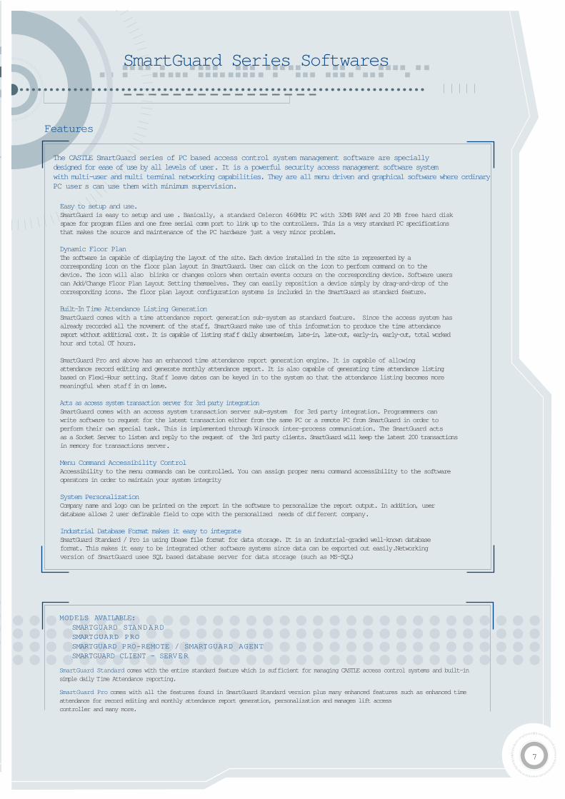
SmartGuard Series Softwares
The CASTLE SmartGuard series of PC based access control system management software are specially designed for ease of use by all levels of user. It is a powerful security access management software system with multi-user and multi terminal networking capabilities. They are all menu driven and graphical software where ordinaryPC user s can use them with minimum supervision.
Easy to setup and use.SmartGuard is easy to setup and use . Basically, a standard Celeron 466MHz PC with 32MB RAM and 20 MB free hard disk space for program files and one free serial comm port to link up to the controllers. This is a very standard PC specifications that makes the source and maintenance of the PC hardware just a very minor problem.
Dynamic Floor PlanThe software is capable of displaying the layout of the site. Each device installed in the site is represented by a corresponding icon on the floor plan layout in SmartGuard. User can click on the icon to perform command on to the device. The icon will also blinks or changes colors when certain events occurs on the corresponding device. Software users can Add/Change Floor Plan Layout Setting themselves. They can easily reposition a device simply by drag-and-drop of the corresponding icons. The floor plan layout configuration systems is included in the SmartGuard as standard feature.
Built-In Time Attendance Listing GenerationSmartGuard comes with a time attendance report generation sub-system as standard feature. Since the access system has already recorded all the movement of the staff, SmartGuard make use of this information to produce the time attendance report without additional cost. It is capable of listing staff daily absenteeism, late-in, late-out, early-in, early-out, total workedhour and total OT hours.
SmartGuard Pro and above has an enhanced time attendance report generation engine. It is capable of allowing attendance record editing and generate monthly attendance report. It is also capable of generating time attendance listing based on Flexi-Hour setting. Staff leave dates can be keyed in to the system so that the attendance listing becomes more meaningful when staff in on leave.
Acts as access system transaction server for 3rd party integrationSmartGuard comes with an access system transaction server sub-system for 3rd party integration. Programmmers can write software to request for the latest transaction either from the same PC or a remote PC from SmartGuard in order to perform their own special task. This is implemented through Winsock inter-process communication. The SmartGuard acts as a Socket Server to listen and reply to the request of the 3rd party clients. SmartGuard will keep the latest 200 transactions in memory for transactions server.
Menu Command Accessibility ControlAccessibility to the menu commands can be controlled. You can assign proper menu command accessibility to the softwareoperators in order to maintain your system integrity
System PersonalizationCompany name and logo can be printed on the report in the software to personalize the report output. In addition, user database allows 2 user definable field to cope with the personalized needs of different company.
Industrial Database Format makes it easy to integrateSmartGuard Standard / Pro is using Dbase file format for data storage. It is an industrial-graded well-known database format. This makes it easy to be integrated other software systems since data can be exported out easily.Networking version of SmartGuard usee SQL based database server for data storage (such as MS-SQL)
Features
MODELS AVAILABLE: SMARTGUARD STANDARD SMARTGUARD PRO SMARTGUARD PRO-REMOTE / SMARTGUARD AGENT SMARTGUARD CLIENT - SERVER
SmartGuard Standard comes with the entire standard feature which is sufficient for managing CASTLE access control systems and built-insimple daily Time Attendance reporting.
SmartGuard Pro comes with all the features found in SmartGuard Standard version plus many enhanced features such as enhanced timeattendance for record editing and monthly attendance report generation, personalization and manages lift access controller and many more.
7
8
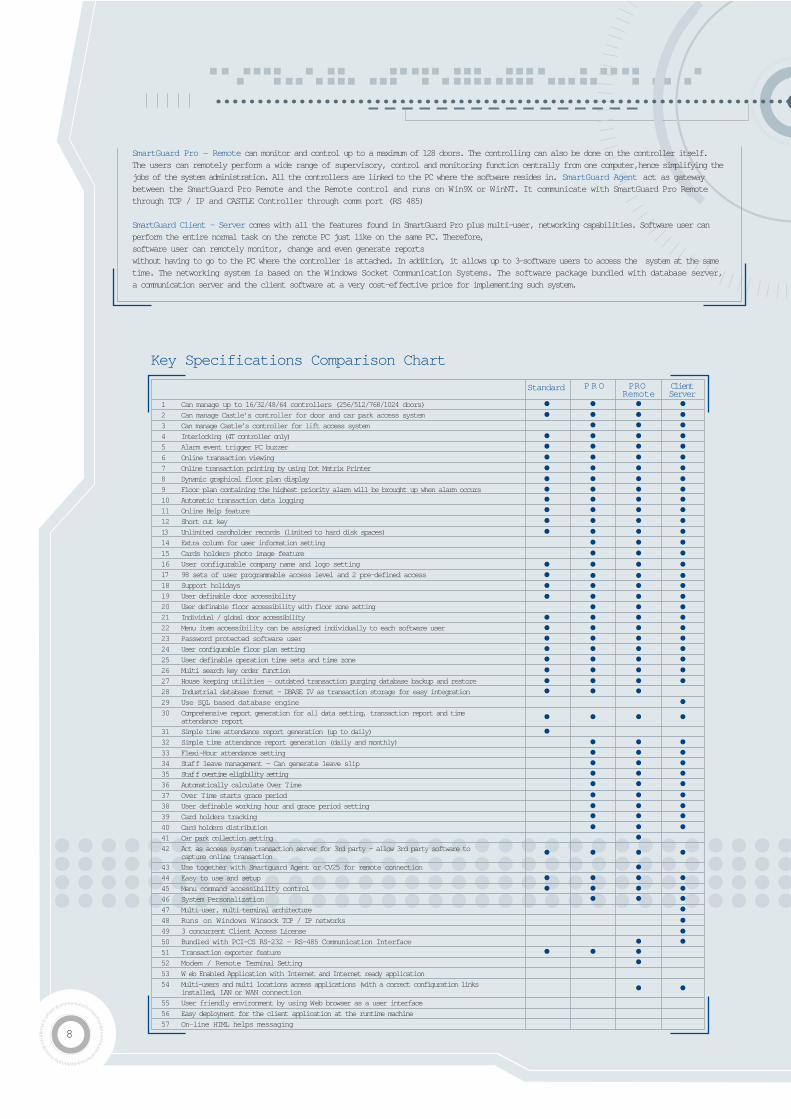
SmartGuard Pro - Remote can monitor and control up to a maximum of 128 doors. The controlling can also be done on the controller itself.The users can remotely perform a wide range of supervisory, control and monitoring function centrally from one computer,hence simplifying thejobs of the system administration. All the controllers are linked to the PC where the software resides in. SmartGuard Agent act as gatewaybetween the SmartGuard Pro Remote and the Remote control and runs on Win9X or WinNT. It communicate with SmartGuard Pro Remotethrough TCP / IP and CASTLE Controller through comm port (RS 485)
SmartGuard Client - Server comes with all the features found in SmartGuard Pro plus multi-user, networking capabilities. Software user canperform the entire normal task on the remote PC just like on the same PC. Therefore, software user can remotely monitor, change and even generate reports without having to go to the PC where the controller is attached. In addition, it allows up to 3-software users to access the system at the sametime. The networking system is based on the Windows Socket Communication Systems. The software package bundled with database server,a communication server and the client software at a very cost-effective price for implementing such system.
1 Can manage up to 16/32/48/64 controllers (256/512/768/1024 doors)
2 Can manage Castle’s controller for door and car park access system
3 Can manage Castle’s controller for lift access system
4 Interlocking (4T controller only)
5 Alarm event trigger PC buzzer
6 Online transaction viewing
7 Online transaction printing by using Dot Matrix Printer
8 Dynamic graphical floor plan display
9 Floor plan containing the highest priority alarm will be brought up when alarm occurs
10 Automatic transaction data logging
11 Online Help feature
12 Short cut key
13 Unlimited cardholder records (limited to hard disk spaces)
14 Extra column for user information setting
15 Cards holders photo image feature
16 User configurable company name and logo setting
17 98 sets of user programmable access level and 2 pre-defined access
18 Support holidays
19 User definable door accessibility
20 User definable floor accessibility with floor zone setting
21 Individual / global door accessibility
22 Menu item accessibility can be assigned individually to each software user
23 Password protected software user
24 User configurable floor plan setting
25 User definable operation time sets and time zone
26 Multi search key order function
27 House keeping utilities - outdated transaction purging database backup and restore
28 Industrial database format - DBASE IV as transaction storage for easy integration
29 Use SQL based database engine
30 Comprehensive report generation for all data setting, transaction report and time attendance report
31 Simple time attendance report generation (up to daily)
32 Simple time attendance report generation (daily and monthly)
33 Flexi-Hour attendance setting
34 Staff leave management - Can generate leave slip
35 Staff overtime eligibility setting
36 Automatically calculate Over Time
37 Over Time starts grace period
38 User definable working hour and grace period setting
39 Card holders tracking
40 Card holders distribution
41 Car park collection setting
42 Act as access system transaction server for 3rd party - allow 3rd party software to capture online transaction
43 Use together with Smartguard Agent or CV25 for remote connection
44 Easy to use and setup
45 Menu command accessibility control
46 System Personalization
47 Multi-user, multi-terminal architecture
48 Runs on Windows Winsock TCP / IP networks
49 3 concurrent Client Access License
50 Bundled with PCI-CS RS-232 - RS-485 Communication Interface
51 Transaction exporter feature
52 Modem / Remote Terminal Setting
53 W eb Enabled Application with Internet and Internet ready application
54 Multi-users and multi locations access applications (with a correct configuration links installed, LAN or WAN connection
55 User friendly environment by using Web browser as a user interface
56 Easy deployment for the client application at the runtime machine
57 On-line HTML helps messaging
Standard P R O PRO Remote
ClientServer
Key Specifications Comparison Chart
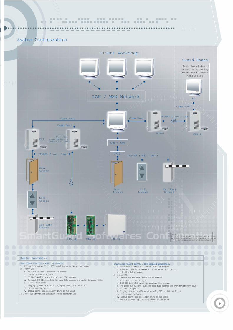
Computer Requirements :
SmartGuard Standard / Pro / Pro-Remote 1. Microsoft Windows 9x or NT4 (Workstation or Server) or higher2. PCAT with
a. Celeron 466 MHz Processor or betterb. 32 MB SDRAM or higherc. 20 MB free disk space for program file storaged. At least 500 MB free disk for data file storage and system temporary filee. 2 free comm portsf. Display system capable of displaying 800 x 600 resolutiong. Mouse and keyboardh. Backup drive (can be floppy drive or Zip Drive)
3. 1 UPS for preventing temporary power interruption
System Configuration
SmartGuard Client-Server / Web-Enabled Application1. a. Microsoft Windows NT4 Server (SP3) or higher b. Internet Information Server 4 ( W eb Server Application ) c. MS-SQL 6.5 or higher
2. PCAT with a. Pentium III 550 MHz Processor or better b. 128 MB SDRAM or higher c. 100 MB free disk space for program file storaged. At least 500 MB free disk for data file storage and system temporary filee. 2 free comm portsf. Display system capable of displaying 800 x 600 resolutiong. Mouse and keyboardh. Backup drive (can be floppy drive or Zip Drive)
3. 1 UPS for preventing temporary power interruption
9
P C P C P C
Guard House
Text Based GuardHouse Monitoring
SmartGuard RemoteMonitoring
PC
Comm Port
LAN / WAN Network
Client Workshop
Comm Port
Comm Port
Comm Port
PCI
DoorAccess
LiftAccess
Car ParkAccess
DoorAccess
LiftAccess
Car ParkAccess
RS485 ( Max. 1km )
RS485 ( Max. 1km )
RS485 ( Max. 1km )
PCI-FEPAlarm Monitoring
(Available in CAMS)
PCI-1 PCI-1
LAN / WAN
CV25
CTA 16 CTA 32 CG-16
Remark:1. This diagram shows the maximum configuration.2. Reduced functionalities / capabilities can be s through different models of SmartGuard.

10
Controls up to maximum 8 gates or barriers ( 4 entry & 4 entry ) per controllerCard only operation5,000 cards storage and 2,500 event transactions ( Upgrade 10,000 cards and 10,000 event transactions )Online printing by using Dot Matrix PrinterMax. 16 reader interface Uses 2 wires of RS-485 to link back to controller ( Reduce wiring )16 key keypad Menu Driven ProgrammingTo enter Programming mode with user definable 6 digit password ( No Master Card required )3 level password available : I) Technician password - diagnostic testing onlyII) Alarm password - alarm arming or disarming ( Not necessary )III) Master password - highest privilege100 user time set with 3 interval each100 user time zone ( 9 days per time zone )100 access level control set consist of time zone, reader and expiry date 2 types of holiday definable, each 30 datesStandalone or networked operation ( Max. 256 barriers )20 x 2 LCD with backlit menu driven displayBuilt in system diagnostic featureUser configure card expire date and temporary disable the cardBuilt in 12vdc power supply
Car Park Access Control (SP-Series)
Features
Ordering InformationController
System Configuration
Stock Code Description
CAS-2SP Controller for 2 gates or barries.(Built-in power supply)
CAS-4SP Controller for 4 gates or barries.(Built-in power supply)
CAS-8Sp Controller for 8 gates or barries.(Built-in power supply)
Stock Code Description
CPP-4SG-T Proximity reader c/w reader interfaceunit & gooseneck. (Height: 955m)(Format: Magnetic signal)
CPP-4SG-MSN Contact-less Smart Card reader(Mifare card serial number)c/w reader interface unit & gooseneck.(Height: 955m) (Format: wiegand 26 bits)
Reader
Dimensions :330H x 290W x 114D mm
Barrier1 to 4
Barrier1 to 4
ReaderReader
Downlink 1
Downlink 2
Uplink
Max. 1km
Max. 1km
PCI-Unit PC bundedwith SmartGuardAccess ControlSoftware
Controller
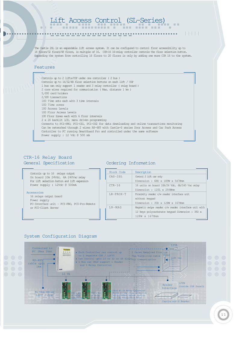
Lift Access Control (SL-Series)
The Castle 2SL is an expandable lift access system. It can be configured to control floor accessibility up to 16 floors/32 floors/48 floors, in multiple of 16. CTR-16 16-relay controller controls the floor selection button. Expanding the system from controlling 16 floors to 20 floors is only by adding one more CTR 16 to the system.
Controls up to 2 lifts/COP under one controller ( 2 bus )Controls up to 16/32/48 floor selection buttons on each lift / COP1 bus can only support 1 reader and 3 relay controller ( relay board )2 core wires required for communication ( Max. distance 1 km )5,000 card holders2,500 transactions 100 Time sets each with 3 time intervals100 Time zones100 Access Levels100 Floor Access Levels100 Floor Zones each with 6 floor intervals2 x 20 backlit LCD, menu driven programming Connects to PCI-PRO, PCI-CS1, PCI-CS2 for data downloading and online transactions monitoring Can be networked through 2 wires RS-485 with Castle-S series Door Access and Car Park Access Controller to PC running SmartGuard Pro and controlled under the same softwarePower supply : 12 Vdc @ 500 mA
Controls up to 16 relays outputOn board 10A 24Vdc, 6A 240Vac relayFor lift selection button and lift expansionPower supply : 12Vdc @ 500mA
Accessories16 relays output board
Power supplyPC-Interface unit - PCI-PRO, PCI-Pro-Remote or PCI-Client Server
Stock Code
CAS-2SL
CTR-16
LR-PROX-T
LR-MAG
Description
Control 2 lift car only
Dimension : 68D x 189W x 547Hmm
16 units on board 10A/24 Vdc, 6A/240 Vac relay
Dimension : 120L x 255Wmm
Proximity reader c/w reader interface unit
without keypad
Dimension : 35D x 128W x 167Hmm
Magnetic swipe reader c/w reader interface unit with
12 keys polycarbonate keypad Dimension : 35D x
128W x 167Hmm
Features
CTR-16 Relay Board General Specification Ordering Information
System Configuration Diagram
11
Connected toPC (Max 1km)
RS-485cable upto
1km
To the OtherLIFT / COP
12 VA
• Each Controller can control up
to 2 separate COP / LIFTS
• Can control upto 16 or 32 or 48 floor
• 1 Bus can ONLY support 1 Reader
and 3 Relay Controller
2 Cores Required From
The Travelling Cable
For Communication
COP Panel
Lift Car
CTR16 #316 RelayController
CTR16 #216 RelayController
CTR16 #1 16 Relay Controller(Wires to the floor selection button under access control will be terminated here)
Reader Interface
12VA(inside COP Panel)
12VA
Castle RTF-S Reader
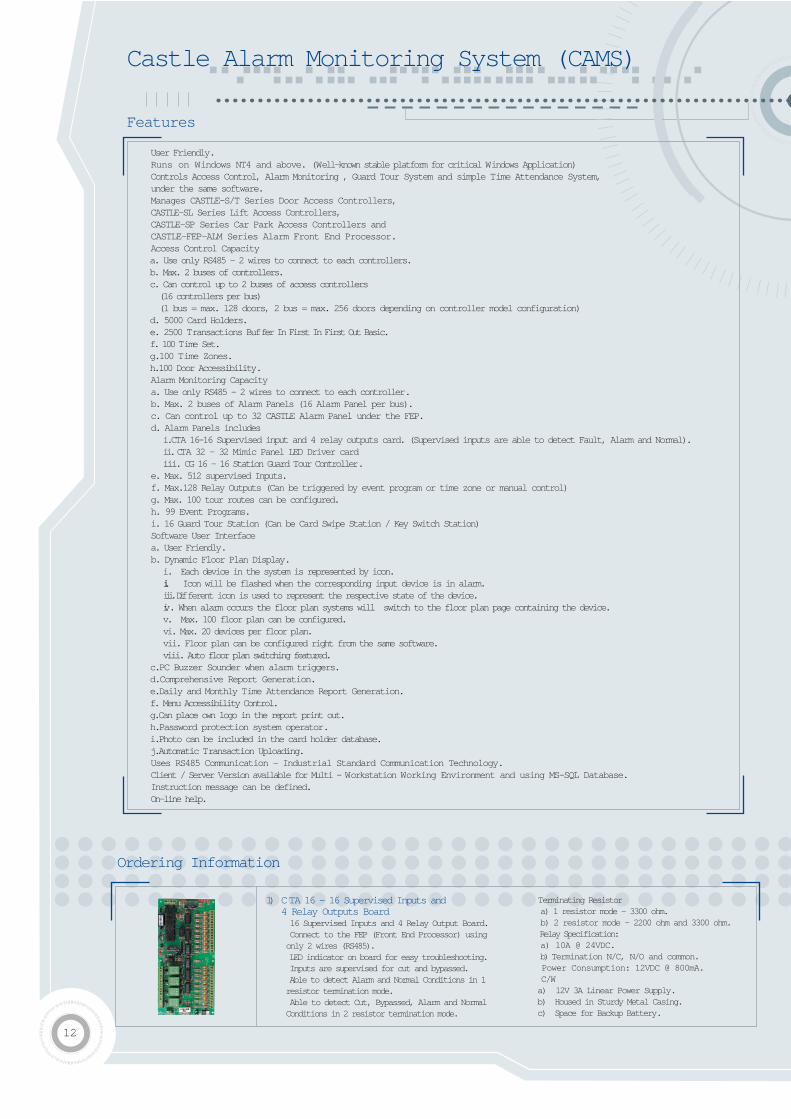
User Friendly.Runs on Windows NT4 and above. (Well-known stable platform for critical Windows Application)Controls Access Control, Alarm Monitoring , Guard Tour System and simple Time Attendance System, under the same software.Manages CASTLE-S/T Series Door Access Controllers,CASTLE-SL Series Lift Access Controllers,CASTLE-SP Series Car Park Access Controllers andCASTLE-FEP-ALM Series Alarm Front End Processor.Access Control Capacitya. Use only RS485 - 2 wires to connect to each controllers.b. Max. 2 buses of controllers.c. Can control up to 2 buses of access controllers (16 controllers per bus)(1 bus = max. 128 doors, 2 bus = max. 256 doors depending on controller model configuration)
d. 5000 Card Holders.e. 2500 Transactions Buffer In First In First Out Basic.f. 100 Time Set.g.100 Time Zones.h.100 Door Accessibility.Alarm Monitoring Capacitya. Use only RS485 - 2 wires to connect to each controller.b. Max. 2 buses of Alarm Panels (16 Alarm Panel per bus).c. Can control up to 32 CASTLE Alarm Panel under the FEP.d. Alarm Panels includes
i.CTA 16-16 Supervised input and 4 relay outputs card. (Supervised inputs are able to detect Fault, Alarm and Normal).ii. CTA 32 - 32 Mimic Panel LED Driver cardiii. CG 16 - 16 Station Guard Tour Controller.
e. Max. 512 supervised Inputs.f. Max.128 Relay Outputs (Can be triggered by event program or time zone or manual control)g. Max. 100 tour routes can be configured.h. 99 Event Programs.i. 16 Guard Tour Station (Can be Card Swipe Station / Key Switch Station)Software User Interfacea. User Friendly.b. Dynamic Floor Plan Display.
i. Each device in the system is represented by icon.ii. Icon will be flashed when the corresponding input device is in alarm.iii. Different icon is used to represent the respective state of the device.iv. When alarm occurs the floor plan systems will switch to the floor plan page containing the device.v. Max. 100 floor plan can be configured.vi. Max. 20 devices per floor plan.vii. Floor plan can be configured right from the same software.viii. Auto floor plan switching featured.
c.PC Buzzer Sounder when alarm triggers.d.Comprehensive Report Generation.e.Daily and Monthly Time Attendance Report Generation.f. Menu Accessibility Control.g.Can place own logo in the report print out.h.Password protection system operator.i.Photo can be included in the card holder database.j.Automatic Transaction Uploading.Uses RS485 Communication - Industrial Standard Communication Technology.Client / Server Version available for Multi - Workstation Working Environment and using MS-SQL Database.Instruction message can be defined.On-line help.
Castle Alarm Monitoring System (CAMS)
1) CTA 16 - 16 Supervised Inputs and 4 Relay Outputs Board 16 Supervised Inputs and 4 Relay Output Board. Connect to the FEP (Front End Processor) using only 2 wires (RS485). LED indicator on board for easy troubleshooting. Inputs are supervised for cut and bypassed. Able to detect Alarm and Normal Conditions in 1 resistor termination mode. Able to detect Cut, Bypassed, Alarm and Normal Conditions in 2 resistor termination mode.
Terminating Resistora) 1 resistor mode - 3300 ohm.b) 2 resistor mode - 2200 ohm and 3300 ohm. Relay Specification:a) 10A @ 24VDC.b) Termination N/C, N/O and common. Power Consumption: 12VDC @ 800mA. C/Wa) 12V 3A Linear Power Supply.b) Housed in Sturdy Metal Casing.c) Space for Backup Battery.
Ordering Information
12
Features
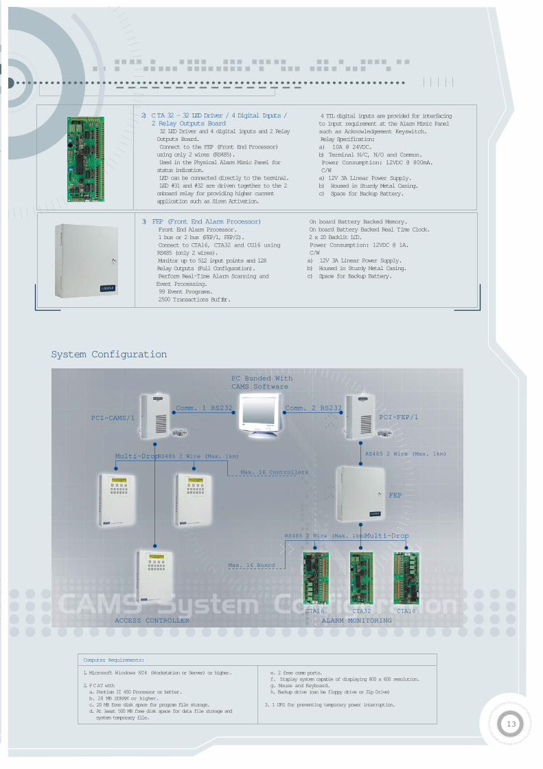
2) CTA 32 - 32 LED Driver / 4 Digital Inputs / 2 Relay Outputs Board 32 LED Driver and 4 digital inputs and 2 RelayOutputs Board. Connect to the FEP (Front End Processor)using only 2 wires (RS485). Used in the Physical Alarm Mimic Panel forstatus indication. LED can be connected directly to the terminal. LED #31 and #32 are driven together to the 2onboard relay for providing higher currentapplication such as Siren Activation.
4 TTL digital inputs are provided for interfacingto input requirement at the Alarm Mimic Panelsuch as Acknowledgement Keyswitch. Relay Specification:a) 10A @ 24VDC.b) Terminal N/C, N/O and Common. Power Consumption: 12VDC @ 800mA. C/Wa) 12V 3A Linear Power Supply.b) Housed in Sturdy Metal Casing.c) Space for Backup Battery.
3) FEP (Front End Alarm Processor) Front End Alarm Processor. 1 bus or 2 bus (FEP/1, FEP/2). Connect to CTA16, CTA32 and CG16 usingRS485 (only 2 wires). Monitor up to 512 input points and 128Relay Outputs (Full Configuration). Perform Real-Time Alarm Scanning and Event Processing. 99 Event Programs. 2500 Transactions Buffer.
On board Battery Backed Memory. On board Battery Backed Real Time Clock. 2 x 20 Backlit LCD. Power Consumption: 12VDC @ 1A. C/Wa) 12V 3A Linear Power Supply.b) Housed in Sturdy Metal Casing.c) Space for Backup Battery.
Computer Requirements:
1. Microsoft Windows NT4 (Workstation or Server) or higher.
2. PCAT witha. Pentium II 450 Processor or better.b. 28 MB SDRAM or higher.c. 20 MB free disk space for program file storage.d. At least 500 MB free disk space for data file storage and
system temporary file.
e. 2 free comm ports.f. Display system capable of displaying 800 x 600 resolution.g. Mouse and Keyboard.h. Backup drive (can be floppy drive or Zip Drive)
3. 1 UPS for preventing temporary power interruption.
System Configuration
13
Comm. 1 RS232
PCI-CAMS/1
Multi-Drop
Multi-Drop
Comm. 2 RS232
RS485 2 Wire (Max. 1km)
RS485 2 Wire (Max. 1km)
RS485 2 Wire (Max. 1km)
Max. 16 Controllers
Max. 16 Board
ACCESS CONTROLLER
PCI-FEP/1
PC Bunded WithCAMS Software
CTA16 CTA32 CTA16
ALARM MONITORING
FEP
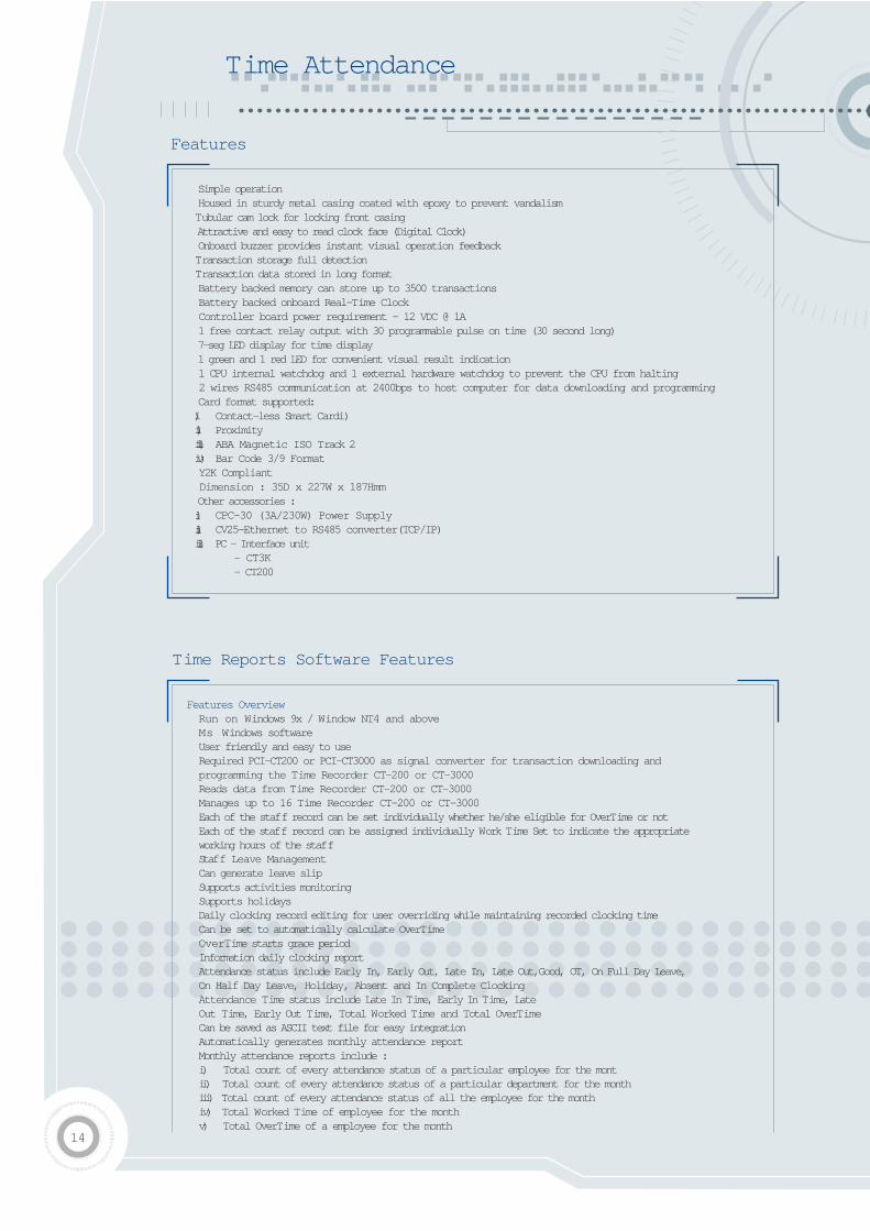
Simple operation Housed in sturdy metal casing coated with epoxy to prevent vandalism Tubular cam lock for locking front casing Attractive and easy to read clock face (Digital Clock) Onboard buzzer provides instant visual operation feedback Transaction storage full detection Transaction data stored in long format Battery backed memory can store up to 3500 transactions Battery backed onboard Real-Time Clock Controller board power requirement - 12 VDC @ 1A 1 free contact relay output with 30 programmable pulse on time (30 second long) 7-seg LED display for time display 1 green and 1 red LED for convenient visual result indication 1 CPU internal watchdog and 1 external hardware watchdog to prevent the CPU from halting 2 wires RS485 communication at 2400bps to host computer for data downloading and programming Card format supported:i) Contact-less Smart Cardi)ii) Proximityiii) ABA Magnetic ISO Track 2iv) Bar Code 3/9 Format Y2K Compliant Dimension : 35D x 227W x 187Hmm Other accessories :i) CPC-30 (3A/230W) Power Supplyii) CV25-Ethernet to RS485 converter(TCP/IP)iii) PC - Interface unit
- CT3K- CT200
Features
Time Attendance
Time Reports Software Features
Features OverviewRun on Windows 9x / Window NT4 and above
Ms Windows software User friendly and easy to use Required PCI-CT200 or PCI-CT3000 as signal converter for transaction downloading and programming the Time Recorder CT-200 or CT-3000
Reads data from Time Recorder CT-200 or CT-3000 Manages up to 16 Time Recorder CT-200 or CT-3000 Each of the staff record can be set individually whether he/she eligible for OverTime or not Each of the staff record can be assigned individually Work Time Set to indicate the appropriate working hours of the staff
Staff Leave Management Can generate leave slip Supports activities monitoring Supports holidays Daily clocking record editing for user overriding while maintaining recorded clocking time Can be set to automatically calculate OverTime OverTime starts grace period Information daily clocking report Attendance status include Early In, Early Out, Late In, Late Out,Good, OT, On Full Day Leave, On Half Day Leave, Holiday, Absent and In Complete ClockingAttendance Time status include Late In Time, Early In Time, LateOut Time, Early Out Time, Total Worked Time and Total OverTime
Can be saved as ASCII text file for easy integration Automatically generates monthly attendance report Monthly attendance reports include :i) Total count of every attendance status of a particular employee for the montii) Total count of every attendance status of a particular department for the monthiii) Total count of every attendance status of all the employee for the monthiv) Total Worked Time of employee for the monthv) Total OverTime of a employee for the month
14
vi) Total Late In time of an employee for the monthvii) Total Worked Time of a department for the monthviii) Can generate top 10 late in staff list for the monthix) Monthly analysis report whereby the monthly attendance statistic and all the daily clocking
record of a employees are printed on to the same page for easier analysis Password protected software user Menu Item Accessibility can be assigned individually to each software user Online help Transaction Purging utility Data Backup / Restore utility
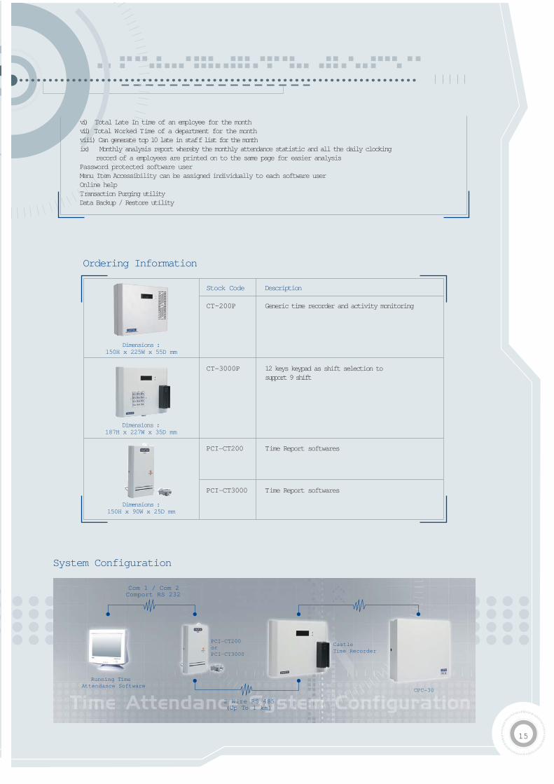
System Configuration
15
Stock Code Description
CT-200P Generic time recorder and activity monitoring
CT-3000P 12 keys keypad as shift selection tosupport 9 shift
PCI-CT200 Time Report softwares
PCI-CT3000 Time Report softwares
Ordering Information
Dimensions :187H x 227W x 35D mm
Dimensions :150H x 90W x 25D mm
Dimensions :150H x 225W x 55D mm
Running TimeAttendance Software
Com 1 / Com 2Comport RS 232
2 Wire RS 485(Up To 1 km)
PCI-CT200orPCI-CT3000
CastleTime Recorder
CPC-30
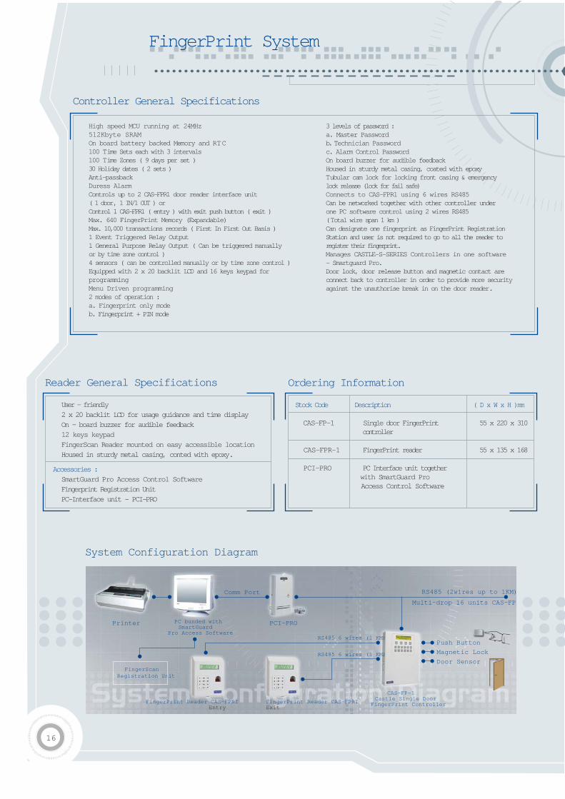
FingerPrint System
High speed MCU running at 24MHz512Kbyte SRAMOn board battery backed Memory and RTC100 Time Sets each with 3 intervals100 Time Zones ( 9 days per set )30 Holiday dates ( 2 sets )Anti-passbackDuress AlarmControls up to 2 CAS-FPR1 door reader interface unit ( 1 door, 1 IN/1 OUT ) or Control 1 CAS-FPR1 ( entry ) with exit push button ( exit )Max. 640 FingerPrint Memory (Expandable)Max. 10,000 transactions records ( First In First Out Basis )1 Event Triggered Relay Output1 General Purpose Relay Output ( Can be triggered manually or by time zone control )4 sensors ( can be controlled manually or by time zone control )Equipped with 2 x 20 backlit LCD and 16 keys keypad for programming Menu Driven programming2 modes of operation :a. Fingerprint only mode b. Fingerprint + PIN mode
3 levels of password :a. Master Passwordb. Technician Passwordc. Alarm Control Password On board buzzer for audible feedbackHoused in sturdy metal casing, coated with epoxy Tubular cam lock for locking front casing & emergency lock release (lock for fail safe)Connects to CAS-FPR1 using 6 wires RS485Can be networked together with other controller under one PC software control using 2 wires RS485 ( Total wire span 1 km )Can designate one fingerprint as FingerPrint Registration Station and user is not required to go to all the reader to register their fingerprint.Manages CASTLE-S-SERIES Controllers in one software - Smartguard Pro.Door lock, door release button and magnetic contact areconnect back to controller in order to provide more securityagainst the unauthorise break in on the door reader.
User - friendly2 x 20 backlit LCD for usage guidance and time displayOn - board buzzer for audible feedback12 keys keypadFingerScan Reader mounted on easy accessible locationHoused in sturdy metal casing, conted with epoxy.
Accessories :SmartGuard Pro Access Control SoftwareFingerprint Registration UnitPC-Interface unit - PCI-PRO
Stock Code Description ( D x W x H )mm
CAS-FP-1 Single door FingerPrint 55 x 220 x 310controller
CAS-FPR-1 FingerPrint reader 55 x 135 x 168
PCI-PRO PC Interface unit together with SmartGuard Pro Access Control Software
Controller General Specifications
Reader General Specifications Ordering Information
Printer
Comm Port
PCI-PROPC bunded withSmartGuard
Pro Access Software
CAS-FP-1Castle Single Door
FingerPrint ControllerFingerPrint Reader CAS-FPRIEntry
FingerPrint Reader CAS-FPRIExit
RS485 6 wires (1 KM)
RS485 (2wires up to 1KM)
Multi-drop 16 units CAS-FP
RS485 6 wires (1 KM)
Push Button
Magnetic Lock
Door SensorFingerScan
Registration Unit
System Configuration Diagram
16
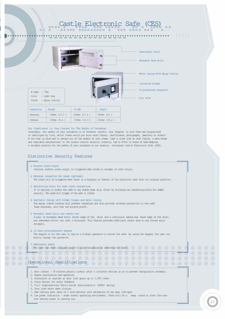
Castle Electronic Safe (CES)
17
Dimensions Height W idth Depth
External 338mm (13.3 ) 438mm (17.2 ) 380mm (15 )
Internal 238mm (9.4 ) 378mm (14.9 ) 260mm (10.2 )
W eight : 72kg
Color : Light Grey
Finish : Epoxy Coating
Our Commitment to Your Concern for The Safety of ValuablesInvariably, the safety of your valuables is of foremost concern. Just imagine, if your home was burglarized or destroyed by fire, which items would you miss most? Money, certificates, photographs, jewellery or others? W ith that in mind and to assure you of the safety of such items, take a close look at what Castle, a well-knownand reputable manufacturer in the access control security industry, has to offer in terms of safe-keeping. A reliable solution for the safety of your valuables is our recently introduced Castle Electronic Safe (CES).
1. Burglar alarm outputInternal audible alarm output is triggered when break-in attempt of safe occurs.
2. External connection for alarm (optional)The alarm will be triggered when there is a burglary or removal of the electronic safe from its original position.
3. Reinforcing bolts for home alarm connectionsIt is optional to anchor the safe to any stable base (e.g. floor) by utilizing two reinforcing bolts for added security. The alarm will trigger if the safe is lifted.
4. Aesthetic design with hidden hinges and metal casingThe epoxy coated surface will prevent vandalism and also provide ultimate protection to the safe (heat-resistant, anti-rust and scratch proof).
5. Moveable dead bolts and rebate barA pair of moveable dead bolts (front edge of the door) and a continuous rebate bar (back edge of the door), are embedded within the safe s structure. This feature provides additional resist ance to any forced entry attempts.
6. 12 keys polycarbonate keypadThe keypad is for the user to key-in a 6-digit password to unlock the safe. By using the keypad, the user can easily change the password.
7. Removable shelfThe user can have a bigger space to place valuables by removing the shelf.
1. Auto lockout - 30 minutes penalty lockout after 5 incorrect entries so as to prevent manipulation attempts.2. Simple installation and operation. 3. Accessible at anytime as door lock opens up to 1,000 times4. Piezo Buzzer for audio feedback5. Full Complementary Metal-Oxide Semiconductor (CMOS) design 6. Door slam shuts when closing 7. 6dvc battery pack (4pcs of C size battery) with estimation of one year life-span 8. Low power indication - under normal operating environment, there will be a beep sound to alert the userthat battery power is running low.
Operational Specifications
Distinctive Security Features
Removeable Shelf
Moveable Dead Bolts
Metal Casing With Epoxy Coating
Concealed Hinges
Polycarbonate Keyboard
Turn Knob
R
Cass Technology Sdn Bhd [ 338857 - X ]
No.28 Jalan PJU 3/48, PJU 3, Sunway Damansara Industrial Park, 47810 Petaling Jaya, Selangor Darul Ehsan, Malaysia.Tel : 603 - 7803 0011 Fax : 603 - 7803 0066 (Local) / 7806 4421 (Overseas)Showrooms : JPM Putra Jaya
W ebsite : www.castle.com.myMADE IN MALAYSIA
Specification are subjected to change without notification.
Supported by :