Embed Size (px)
Citation preview
time
captioning-.
Panel antennas
111111
itV
ideo switcher
update
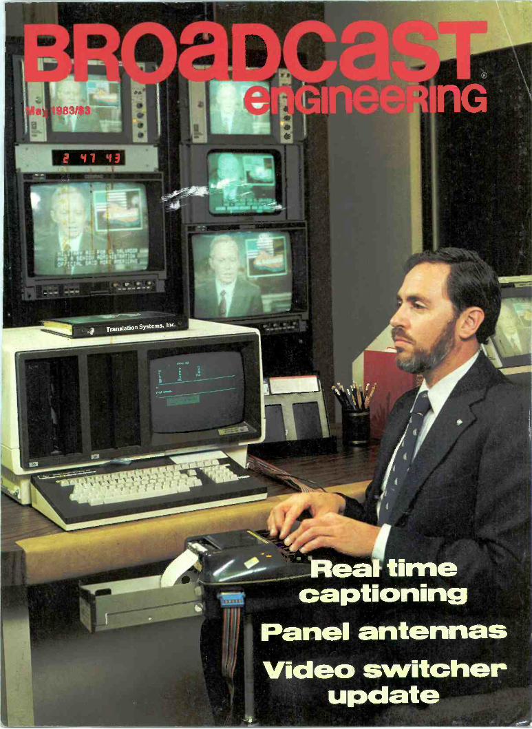
ADM most wanted...for first class performance and reliability
Now with four versions, the larger ADM® audio consoles are even more valuable intelevision production and post -production. These are the new ADM 2442, 2483, 3242and 3283 models. Each has a distinctive range of functions, which permit tailoring to
your specific requirements in a standard console mainframe. As with all ADM consolesthey are designed with up-to-the-minute audio technology and engineered to
provide years of maintenance free operation.What other console manufacturer is so confident in the quality and
reliability of their product that they can back every console withan exclusive 5 -year warranty? No one but ADM. Our con-
sistant innovation and up -grading of quality is yourassurance that whatever direction audio production
takes, ADM will continue to be on top of the"most wanted- list.
For spocif_c information, contactADM Technology, Inc.-The
Audio Company -1626 E.Big Beaver Road, Troy,
MI 48084, Phone(313) 524-2100.
TLX 23-1114.
WEST CENTRALSALES(817) 467-2990
MAIN OFFICE ANDEAST COAST SALES(313) 524-2100
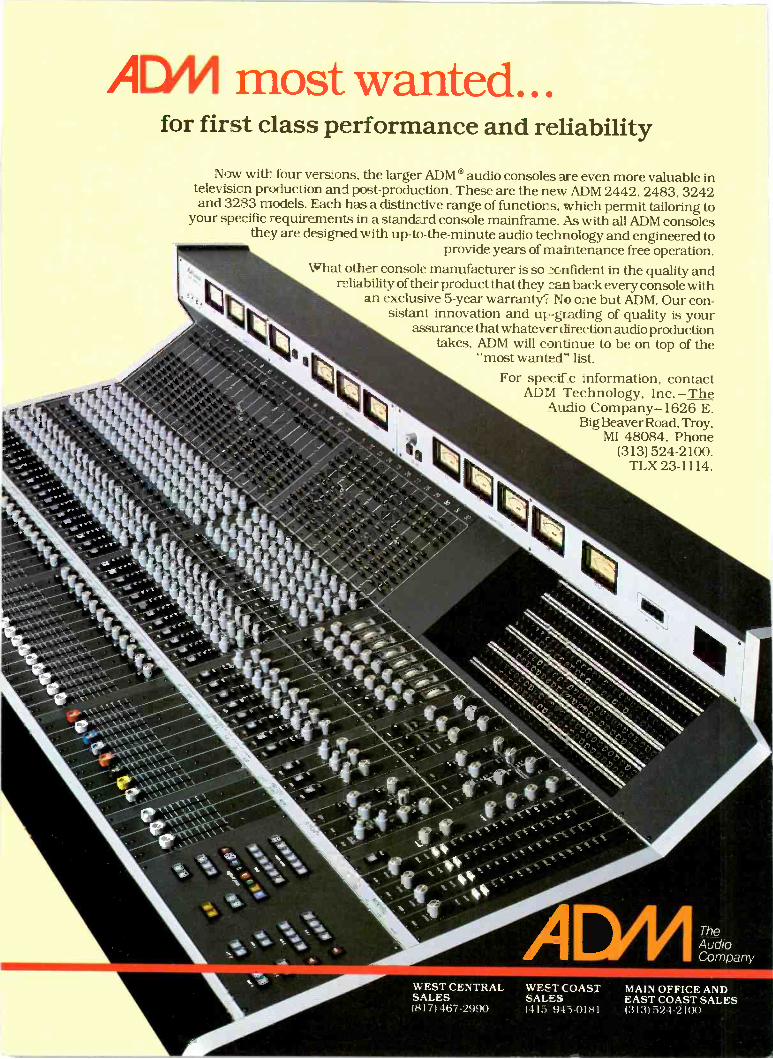
"Taft demands the best, and when itcomes to presenting to our viewers a
clear and accurate picture of the world,we turn to Ikegami cameras. Their
rugged durability, combined with the"studio" quality, that Ikegami delivers,
brings the news in focus for the millionsof viewers who depend on Taft news
operations to keep them informed.
That's also why Midwest designs andbuilds our mobile news gathering units.
Midwest custom designed the rightmobile units to meet our needs -and
our deadlines. They're tough, designedto take all the punishment that
on -location ENG can dish out. Midwestdelivered our Ikegami-equipped
mobile units on time.
"Whenthe newsbreaks,
we get ittogether
withMidwest
andIkegami:'
John Owen. Vice Presidentof Television Engineering
Taft Broadcasting.
Circle (2) on Reply Card
We're covering the news stories andMidwest covers our needs. Taftdemands the best, and we have it -withMidwest and Ikegami on our newsteam:'
For more information on how Midwestcan help you get it together with qualityequipment and mobile units, calltoll -free today: 1-800-543-1584(In Kentucky 606-331-8990).
MIDWESTCORPORATION
One Sperti DriveEdgewood, KY 41017
Cincinnati, OH Lexington, KY606-331-8990 606-277-4994Columbus, OH Nashvilie, TN614-476-2800 615-331-5791Dayton, OH Charleston, WV513-298-0421 304-722-2921Cleveland, OH Virginia Beach, VA216-447-9745 804-464-6256Pittsburgh, PA Washington, DC412-781-7707 301-577-4903Detroit, MI Charlotte. NC
313-689-9730 704-399-6336Indianapolis, IN Atlanta, GA317-251-5750 404-457-4300Louisville, KY Miami, FL502-491-2888 305-592-5355
BROaDCaSTenGineeRinG
The journal of broadcast technology
May 1983 Volume 25 No. 5
FEATURES19 Real time closed captioning at NCI
By Jeff Hutchins, director of systems development, National CaptioningInstitute, Falls Church, VA
32 The development of a panel antennaBy Robert A. Surette, manager, RF engineering, Shively LaboratoriesDivision, Howell Laboratories, Bridgton, ME
48 Video timing and phasingBy Edgar Lee Howard, supervisor of special projects, WOSU-AMIFM/TV,Columbus, OH
72 Video switcher updateBy Carl Bentz, technical editor
80 The evolution of TV production switchingBy Craig Birkmaier and Donald Lambert, Production Systems MarketingGroup, Grass Valley Group, Grass Valley, CA
90 Case study: Fiber-optic cable at Notre Dame
106 Case study: The Abuja TowerBy Edward R. Baldwin, architect, Toronto, Ontario, Canada
113 FM multipath and distortion reduction through RF amplifier optimizationBy Edward A. Schober, AFCEE, Radiotechniques, Haddon Heights, NJ
FIELD REPORTS98 Shure M267 mixer
By Brad Dick, chief engineer, KANU, Lawrence, KS
126 Hitachi SK -110 camera at WFAA-TV 8By Charlie Martin, chief engineer, WFAA-TV 8, Dallas, TX
DEPARTMENTS6 FCC update
10 EditorialIt's Greek to me
14 Satellite update
16 Feedback
135 Associations
140 New products
142 Business
144 News
145 Calendar
146 People
147 Index of advertisers
149 Classified ads
©Copyright 1983, by Intertec Publishing Corporation. All rights reserved. Photocopy rights: Permission tophotocopy for internal or personal use is granted by Intertec Publishing Corp. for libraries and others registeredwith Copyright Clearance Center (CCC), provided the base fee of $2.00 per copy of article is paid directly to CCC,21 Congress St., Salem, MA 01970. Special requests should be addressed to Cameron Bishop, publisher.
ISSN 0007-1994
BROADCAST ENGINEERING CUSPS 338-130) is published monthly by Intertec Publishing Corporation, 9221Ouivira Road, P.O. Box 12901, Overland Park, KS 66212-9981. Postmaster, return form 3579 to P.O. Box 12938 atthe above address.
timecaptioning
Panel antennas
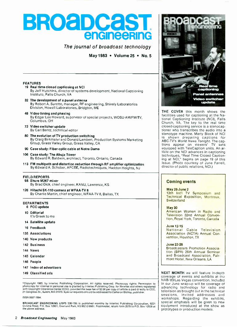
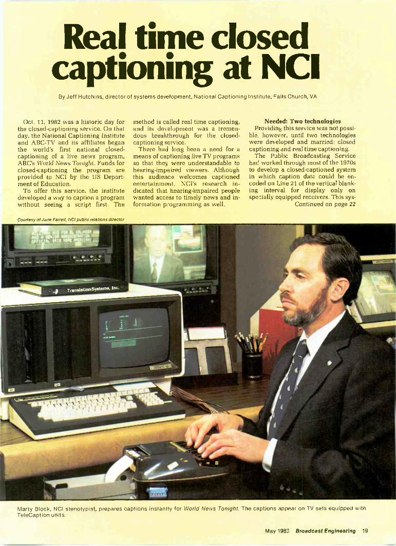
THE COVER this month shows thefacilities used for captioning at the Na-tional Captioning Institute (NCI), FallsChurch, VA. The key to the real timeclosed -captioning service is a stenocap-tioner who transcribes the audio into astenotype machine. Marty Block of NCIis shown preparing captions forABC -TV's World News Tonight. The cap-tions appear on viewers' TV setsequipped with TeleCaption units. An ar-ticle on the NCI advances in captioningtechniques, "Real Time Closed Caption-ing at NCI," begins on page 19 of thisissue. (Photo courtesy of June Farrell,director of public relations, NCI.)
Coming events
May 28 -June 213th Int'l TV Symposium andTechnical Exposition, Montreux,Switzerland
May 30American Women in Radio andTelevision 32nd Annual Conven-tion, Royal York, Toronto, Canada
June 12-15National Cable TelevisionAssociation (NCTA) Annual Con-vention, Houston, TX
June 22.26Broadcasters Promotion Associa-tion (BPA) 26th Annual Seminarand Broadcast Association, Fair-mont Hotel, New Orleans, LA
NEXT MONTH we will feature in-depthcoverage of events and exhibits at theNAB-'83/Las Vegas convention. Includedin our June wrap-up will be coverage ofadvancing technology for radio andtelevision as brought out in the technicalsessions, invited addresses andworkshops. Regarding the exhibits,special emphasis will be given to newequipment introduced at the show asprototypes or production models.
2 Broadcast Engineering May 1983
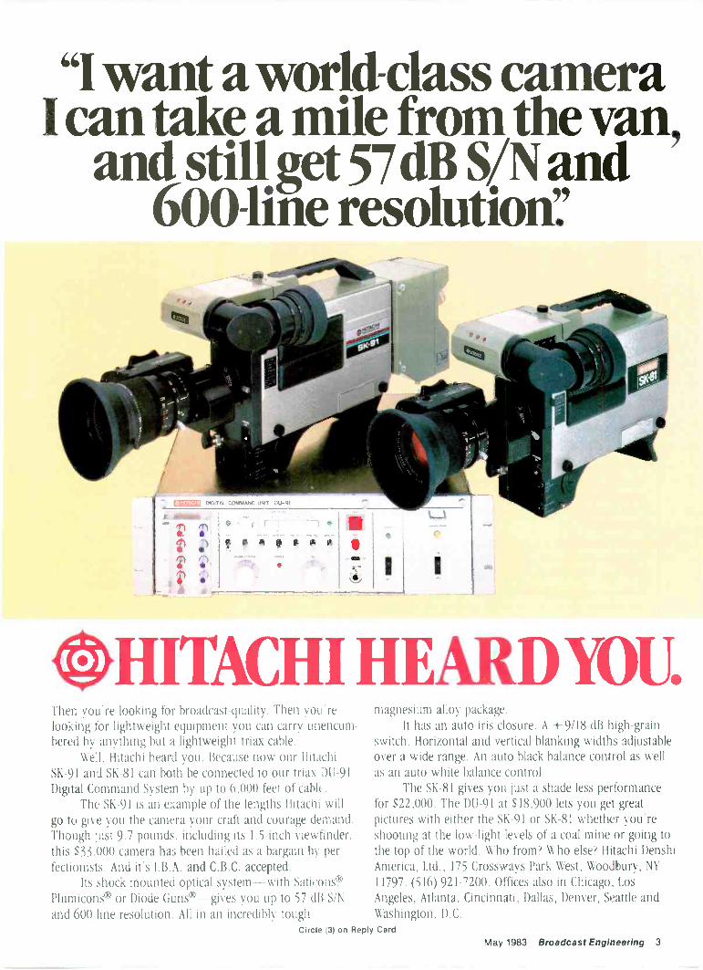
"I want aworld -class cameraI can take a mile from the van,
and still get 57dB SAN and600 -line resolution':
DIGITAL COMMAND UNIT DU 92
I
0 A 0 F a it
HITACHI HEARD YOU.Then you're looking for broadcast -quality. Then you relooking for lightweight equipment you can carry unencum-bered by anything but a lightweight triax cable.
Well, Hitachi heard you. Because now our HitachiSK -91 and SK -81 can both be connected to our triax DU -91Digital Command System by up to 6,000 feet of cable.
The SK -91 is an example of the lengths Hitachi willgo to give you the camera your craft and courage demand.Though just 9.7 pounds, including its 1.5 -inch viewfinder,this 533,000 camera has been hailed as a bargain by per-fectionists. And it's I.B.A. and C.B.C. accepted.
Its shock -mounted optical system with Saticons®,Plumicons® or Diode Guns®-gives you up to 57 dB SINand 600 -line resolution. All in an incredibly tough
magnesium alloy package.It has an auto -iris closure. A -4-9/18 dB high -grain
switch. Horizontal and vertical blanking widths adjustableover a wide range. An auto black balance control as wellas an auto white balance control.
The SK -81 gives you just a shade less performancefor S22,000. The DU -91 at 518,900 lets you get greatpictures with either the SK -91 or SK -81 whether you'reshooting at the low -light levels of a coal mine or going tothe top of the world. Who from? Who else? Hitachi DenshiAmerica, Ltd., 175 Crossways Park West, Woodbury, NY11797. (516) 921-7200. Offices also in Chicago, LosAngeles, Atlanta, Cincinnati, Dallas, Denver, Seattle andWashington, D.C.
Circle (3) on Reply CardMay 1983 Broadcast Engineering 3
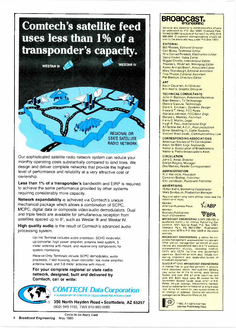
Comtech's satellite feeduses less than 1% of atransponder's capacity.
WESTAR III WESTAR IV
REGIONAL OR
STATE SATELLITE
RADIO NETWORK
Our sophisticated satellite radio network system can reduce yourmonthly operating costs substantially compared to land lines. Wedesign and deliver complete networks that provide the highestlevel of performance and reliability at a very attractive cost ofownership.
Less than 1% of a transponder's bandwidth and EIRP is requiredto achieve the same performance provided by other systemsrequiring considerably more capacity.
Network expandability is achieved via Comtech's uniquemechanical package which allows a combination of SCPC,MCPC, digital data or composite video/audio demodulators. Dualand triple feeds are available for simultaneous reception fromsatellites spaced up to 8°, such as Westar III and Westar IV.
High quality audio is the result of Comtech's advanced audioprocessing system.
Up -link Terminal includes audio processor, SCPC modulator,up -converter, high power amplifier, antenna feed system, 5meter antenna with mount, and receive -only components forsystem monitoring.
Receive -Only Terminals include SCPC demodulator, audioprocessor, 7 -slot housing, down converter, low noise amplifier,antenna feed, and 3.8 meter antenna with mount.
For your complete regional or state radionetwork, designed, built and delivered byComtech, call or write:
Crt® 350 North Hayden Road Scottsdale, AZ 85257(602) 949-1155, TWX 910-950-0085
COMTECH Data CorporationA SUBSIDIARY OF COMTECH TELECOMMUNICATIONS CORP
BROaDCaST®enGineeRinG
Editorial and advertising correspondence shouldbe addressed to: P.O. Box 12901, Overland Park,KS 66212-9981 (a suburb of Kansas City, MO); (913)888-4664. Circulation correspondence should besent to the above address, under P.O. Box 12937.
EDITORIALBill Rhodes, Editorial DirectorCarl Bentz, Technical EditorNils Conrad Persson, Electronics EditorDavid Hodes, Video EditorMiguel Chivite, International EditorRhonda L. Wickham, Managing EditorKaren Arnhart Booth. Associate EditorMary Thornbrugh, Editorial AssistantTina Thorpe, Editorial AssistantPat Blanton, Directory Editor
ARTKevin Callahan, Art DirectorKim Nettie, Graphic Designer
TECHNICAL CONSULTANTSJohn H. Battison, Antennas/RadiationBlair Benson, TV TechnologyDennis Ciapura, TechnologyDane E. Ericksen, Systems DesignHoward T. Head, FCC RulesWallace Johnson, FCC/Bdct. Engr.Donald L. Markley, FacilitiesHarry C. Martin, LegalHugh R. Paul, International Engr.Art Schneider, A.C.E., Post -productionElmer Smalling, Ill, Cable SystemsVincent Wasilewski, Communications Law
CORRESPONDING ASSOCIATIONSAmerican Society of TV CameramenAssn. for Bdct. Engr. StandardsNational Association of BroadcastersNational Radio Broadcasters Assn.
CIRCULATIONJohn C. Arnst, DirectorEvelynDee Manies, Reader Correspondent
ADMINISTRATIONR. J. Hancock, PresidentCameron Bishop, PublisherEric Jacobson, Associate Publisher
ADVERTISINGRobyn Kahn, Marketing CoordinatorMary Birnbaum, Production Manager
Regional advertising sales offices listed near theAdvertisers' Index.Member,American Business PressMember,Business PublicationsAudit of Circulation VBPABROADCAST ENGINEERING CUSPS 338-130) ispublished monthly by Intertec Publishing Cor-poration, 9221 Quivira Road, P.O. Box 12901,Overland Park, KS 66212-9981. Postmaster,return form 3579 to P.O. Box 12938 at the aboveaddress.
BROADCAST ENGINEERING is edited for cor-porate management, engineers/technicians andother station management personnel at com-mercial and educational radio and TV stations,teleproduction studios, recording studios,CAN and CCTV facilities and governmentagencies. Qualified persons also include con-sulting engineers and dealer/distributors ofbroadcast equipment.SUBSCRIPTIONS: BROADCAST ENGINEERINGis mailed free to qualified persons in occupa-tions described above. Non -qualified personsmay subscribe at the following rates: UnitedStates, one year, $25; all other countries, oneyear, $30. Back Issue rates, $5, except for theSeptember Buyers' Guide issue, which is $15.Rates include postage. Adjustments necessi-tated by subscription termination at single copyrate. Allow 6-8 weeks for new subscriptions orfor change of address. Controlled circulationpostage paid at Shawnee Mission, KS.
'1983. All rights reserved.Intertec Publishing Corp.
Circle (4) on Reply Card4 Broadcast Engineering May 1983
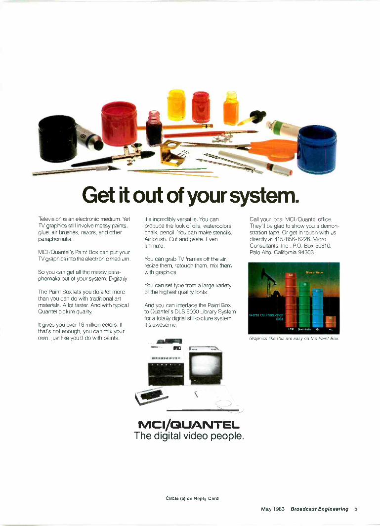
Get it out of your system.Television is an electronic medium. YetTV graphics still involve messy paints,glue, air brushes, razors, and otherparaphernalia.
MCI /Quantel's Paint Box can put yourTV graphics into the electronic medium.
So you can get all the messy para-phernalia out of your system. Digitally.
The Paint Box lets you do a lot morethan you can do with traditional artmaterials. A lot faster. And with typicalQuantel picture quality.
It gives you over 16 million colors. Ifthat's not enough, you can mix yourown, just like you'd do with paints.
It's incredibly versatile. You canproduce the look of oils, watercolors,chalk, pencil. You can make stencils.Air brush. Cut and paste. Evenanimate.
You can grab TV frames off the air,resize them, retouch them, mix themwith graphics.
You can set type from a large varietyof the highest quality fonts.
And you can interface the Paint Boxto Quantel's DLS 6000 Library Systemfor a totally digital still -picture system.It's awesome.
MCl/QUANTELThe digital video people.
Call your local MCI /Quantel office.They'll be glad to show you a demon-stration tape. Or get in touch with usdirectly at 415/856-6226. MicroConsultants, Inc., P.O. Box 50810,Palo Alto, California 94303.
Graphics like this are easy on the Paint Box.
Circle (5) on Reply Card
May 1983 Broadcast Engineering 5
FCCupdateHarry C. Martin, partner, Reddy, Begley & Martin, Washington, DC
Standards changed forapproval of dismissal agreementsThe FCC has interpreted a recent
revision to the Communications Actas permitting settlement payments toa dismissing broadcast applicant inexcess of "reasonable and prudent" ap-plication expenses.
In September 1982, Congressamended Section 311(c)(3) of the Com-munications Act, which deals withsettlement agreements in comparativehearing cases. Under the new law, theFCC may approve buy-out or mergeragreements if it is determined that ap-proval is consistent with the public in-terest and that no party to the agree-ment filed its application for the pur-pose of entering into such an agree-ment. Previously the act did not per-mit the FCC to approve agreementsthat involved reimbursement to dis-missing applicants in excess of theirdocumented application expenses.
Even after Congress amended theact, the commission's administrativelaw judges continued to enforce theold standard. This was because theMass Media Bureau issued a publicnotice in November indicating thatthe new law was not in conflict withFCC rules requiring submission ofdetailed expense accountings in con-nection with requests for approval ofsettlement agreements.
In December, however, the FCCReview Board ignored the bureau'spublic notice and approved a 10 -yearconsultancy arrangement in a case inwhich the judge found the consultan-cy amounted to a monetary settlementwith a value in excess of applicationexpenses. The board said that ap-proval of the settlement was permissi-ble because, as the new law specified,the agreement was consistent with thepublic interest and there was noevidence that any party to it had filedits application for the purpose ofreaching or carrying out the agree-ment. In March 1983, the commissionaffirmed the board's decision andrepealed the bureau's inconsistentpublic notice.
In two follow-up decisions, theboard has indicated that the FCC willapprove any settlement agreementthat meets the new, less restrictive
statutory standard. Thus, applicantsnow may offer to pay competitors incomparative proceedings any amountthey wish in order to induce them todismiss. Dismissal agreements offer-ing monetary reimbursement and ashare of equity, which were difficultto have approved under the old stan-dard, now are permissible as long asthe minimal statutory requirementsdiscussed previously are met.
Critics of the commission's new ap-proach claim that many persons willfile applications for the sole purposeof extracting monetary settlements.Others believe that the new liberalizedstandard will facilitate legitimatemerger and buy-out arrangements,thereby speeding the authorization ofnew facilities.
Proposed revision ofattribution rules
The commission has proposed torevise the standards for attributingownership interests in broadcast andCATV properties under its multipleownership rules. Major proposedchanges would include the following:increasing the attribution benchmarkup to 20% (interests above 20% as-sumed to be attributable); eliminatingthe distinction between closely heldand widely held corporations; using amultiplier for vertical ownership situa-tions to limit the reach of the rules tothose with a reasonable relationshipto the licensee; and using insulatingmechanisms for officers, directorsand others who have no equity in-terest in the licensee.
These revisions would impact uponthe national, regional and local multi-ple ownership rules, including thosedealing with the 7 -station limit, net-work/cable cross -ownership, news-paper/broadcast cross -ownership,regional concentration of control,duopoly and the one -to -a -market limit.
The commission is requesting com-ments on, and data relating to, thefollowing specific issues:
whether attribution of ownershipinterests of less than 20% is war-ranted;
whether using a definition and setof indicia of control applicable ona case -by -case basis is preferable
to the current practice of specify-ing particular entities as subjectto certain ownership bench-marks;
whether all investors should betreated in a similar fashion;
whether indirect interests shouldbe attributed;
whether minority groups and newentrants would have greater ac-cess to financing if the rules werechanged;
whether the attribution rulesshould be linked to other commis-sion requirements;
whether distinguishing betweenclosely held and widely heldcorporations is advisable;
whether subjecting private pen-sion funds to the same bench-marks as investment and insur-ance companies and other ap-parently passive investors is ad-visable; and
whether the commission shouldcontinue to monitor ownershipactivities through submission ofFCC reports (Forms 323 and 325).
LPTV statusProgress is being made in im-
plementing procedures to deal withthe backlog of 8000 LPTV applicationsfiled since 1980. The commission wasscheduled to consider adoption of
In briefAn amendment to Part 73 hasbeen proposed to permit TVbroadcast services to operatewith an aural power of less than10% of the visual power.
A request by the SBE to extendcomment dates on spectrumutilization policy for fixed andmobile services' use of certainbands between 947MHz and40GHz was denied.
A Notice of Inquiry and ProposedRulemaking was issued to re-examine certain technical regula-tions, to continue elimination ofunnecessary rules.
Subscription TV Association andWometco Home Theatre have peti-tioned the commission to recon-sider a Report and Order that willallow the sale of STV decoders tosubscribers. The commission hasdenied the petition.
Licensed broadcast station totalsfor February 1983 are as follows:
AM BroadcastFM BroadcastEducational RadioUHF TV BroadcastVHF TV BroadcastUHF TV EducationalVHF TV Educational
470434091093306527174111
Continued on page 138
6 Broadcast Engineering May 1983
MO
RE
VE
RS
AT
ILITY
!T
N
in the all -new program
quality 10x1 routing switcher by G
rass Valley G
roup...the TE
N -X
!
Now
the fast -selling new G
VG
TE
N -X
is also available in a tw-a-rack unit fram
ethat w
ill house one 10x1 video module, plus a com
bination of three 10x1 aucioand/or relay m
odules. This greater versatility lets you add the fcllow
ing -o yourvideo needs...
* Stereo audio and tim
e code, sr...* S
tereo audio and tally, or...* M
ono audio, intercom sw
itching and tally!! A
nd optional dual power supplies.
Rem
ember that both local and rem
ote control panels are available, and you haveversatility plus! T
he TE
N -X
Series from
Grass V
alley Group, w
crld leader intelevision sw
itching, signal processing and distribution systems
Circle (6) on R
eply Card
TH
E G
RA
SS
VA
LLEY
GR
OU
P, IN
C...
P.O
. BO
X r14 G
RA
SS
VA
LLEY
CA
LIFO
RN
IA 95945 U
SA
TE
L(916) 273 8421 T
WA
, 910 530 8280
rt1,
771
N11 P
11r
Offices: E
astern Regional:
499 Thornall S
t, Edison, N
J 0E817, (281) 549-9600 .
Southeastern District:
1644 Tullie C
irce N.E
. Ste 102, A
tlanta, 3A 30329
(404)321-4318 M
idwestern R
egional: 810 West B
ristol St, E
lkhz rt, IN 46514 (219) 264-0931
Northw
estern Distric':
3585 North Lexington A
ve, Ste 238,
Arden H
ills, MN
55112 (612) 483-2594 Southw
estern District:
316 Sem
inary South O
ffice Bldg, F
ort Worth, T
X 76115 (317) 921-9411 .
Western D
istrict:1032 E
lwell C
ourt, Ste 244, P
alo AI -o, C
A 94303 (4151968-6680
Western R
egional: 21243V
entura Blvd, S
te 206, Woc dland H
ills, CA
91364 (213) 999-2303
11111 I I I I I I I I I
F --/A 1kttll
1111VNIII
1116,\A111,
1116nummunom
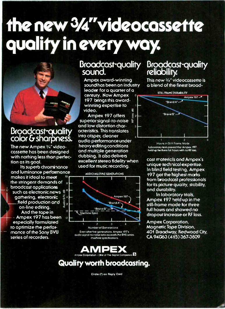
thenew3A"videocassetitequality in every way
Broadcast -qualitycolor &sharpness.The new Ampex 3/4" video-cassette has been designedwith nothing less than perfec-tion as its goal.
Its superb chromhanceand luminance performancemakes it ideal to meet 10
the stringent demands ofbroadcast applicationssuch as electronic newsgathering, electroni:
field production a -don-line editing.And the tape in
Ampex 197 has beenespecially formulated
to optimize the perfor-mance of the Sony BVUseries of recorders.
co 6-o
?40
cn
2
Broadcast -qualitysound.Ampex award -winningsound has been an industryleader for a quarter of acentury. Now Ampex o
197 brings this award -winning expertise tovideo.
Ampex 197 offerssuperior signal-to-noise
and low distortion char-acteristics. This translatesinto crisper, cleaneraudio performance underheavy editing conditionsand multiple generationdubbing. It also deliversexcellent stereo fidelity whenused for music recording.
Broadcast -qualityreliability.This rew 3/c" videocassette isa blend of the finest broad -
STILL FRAME DURABILITY
Ampex 197 -06
"Brand A"
"Brand B". ---E
AUDIO MUJIPLE GENERATIONS
0:1
2
U-a-
4
-BrEnd B"
Machine Spec
Ampex 197
"Brand A")
1 2 3
Number of GenerationsEven after five generations, Ampex 197's
audio signal-to-noise ratio exceeds the DVU seriesmachine specifications
4
AM PEXAmpex Corporation One of The Signal Companies a
5
1 2
H 3urs in St II Frame ModeLoborotcry tests proved tho- Ampex 197held up for three ful hours with no RF loss.
3
cost rratericls and Ampex'sunique techlical expertise.In blind field testing, Ampex197 got the highest marksfrom broadcast professionalsfor its picture quo ity, stcbility,and durabili-y.
In laboratory trials,Ampex 197 geld up in tnestill -frame mode for threefull hours and showed nodropout increase or RF loss.
Ampex Corporation,Magnetic Tape Division,401 Broadway, Redwood City,CA 94063 (415) 367-3809
Quality worth broadcasting.Circle (1 on Reply Card
editorial
It'sGreektomeGuest editorial by Art Schneider,post -production consultant
I know that most of you, at one time or another, have purchased a consumerproduct or a piece of electronic equipment, opened the instruction book andthought, "Now I'll find out how to operate this thing." But, to your chagrin, youhave stumbled onto a technical manual so complex that you think it has beenwritten by someone from outer space.
Although not all equipment manuals fall into this category, those that domake you wish you could shake the author of the manual and say, "Listen, I'mnot an engineering genius like you." Or you might say, "If you tried operatingone of these things before you wrote the manual, maybe other people would beable to understand what you are talking about."
I strongly believe that too many technical writers are not familiar enough withthe equipment they are writing about to accurately describe its operation in sim-ple terms to potential users.
I'm not a neophyte in television. I've been at it for more than 30 years, and I'verun across almost every kind of electronic equipment made, much of which I'mable to operate without reading the operating manual. There are times,however, when I have to use the manual.
For example, recently we purchased a time code generator. Not only could itgenerate and read time code, but also user bits, vertical interval time code, anddisplay time code characters in the video. The specs looked great. At firstglance, you would suspect that the unit might be easy to operate and that youcould muddle your way through the controls before reading the book. Not so. Ipoked and pushed the buttons and shifted and unshifted keys and not a thinghappened.
I finally opened the manual and tried to find out how to use the device. Even-tually, I figured it out, but the way that the manual was written was so confus-ing that I wasted a lot of time trying various combinations of buttons and keys toget the system to display what I wanted.
This leads to a question: Why is it necessary for technical writers to provehow smart they are and how stupid the user is? They should use plain, simplelanguage instead of complex technical terms. They should not assume that all ofus have the same technical background that they do.
It would be helpful if operating manuals for all technical equipment gave step-by-step instructions with examples of the results you could expect to see. Thenyou would know whether or not the system was working without wasting yourtime.
Obviously, there is a lot of complex equipment (becoming increasingly moreso) used in the TV industry today. However, there is no reason why manufac-turers of this equipment could not get inputs from some less technical users (orstaff members before finalizing their operating instructions.
Better yet would be field testing the manual in an operating environment. Asurvey report form could be filled out so that the manufacturer could correctany major operational errors before going into production, as well as make surethat the manual was clear and concise.
Incidentally, regarding the time code generator, we returned it -not becauseit did not work. Rather, the people who would be operating and maintainingthis equipment believed it was much too complex, and the potential for errorwhen using it in daily production was too great. As we all know, correcting amistake is much more costly in time, material and client relationships than do-ing it right the first time.
We cannot assume that everyone buying a piece of complex electronic equip-ment will be able to operate it with ease the first time. However, better instruc-tion manuals will help solve some of the frustrating problems associated withunderstanding, operating and maintaining new equipment. A spin-off will be better manufacturer/user relationships. I :I:3))11
10 Broadcast Engineering May 1983
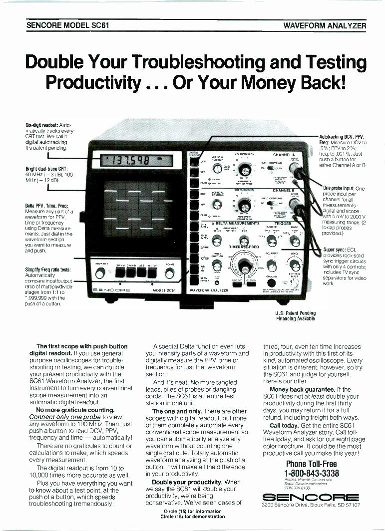
SENCORE MODEL SC61 WAVEFORM ANALYZER
Double Your Troubleshooting and TestingProductivity . Or Your Money Back!
Six -digit readout: Auto-matically tracks everyCRT test. We call itdigital autotracking.It's patent pending.
I
Bright dual -trace CRT:60 MHz ( -3 dB), 100MHz ( - 12 dB)
Delta PPV, Time, Freq:Measure any part of awaveform for PPV,time or frequencyusing Delta measure-ments. Just dial in thewaveform sectionyou want to measureand push.
Simplify Freq ratio tests:Automaticallycompare input/outputratio of multiply/dividestages from 1:1 to1:999,999 with thepush of a button.
Formriri
INNINNEN
INTENSITY
ENCORE
'NAN A CHAN R AAA VECTOR US
11MODE! SC61
The first scope with push buttondigital readout. If you use generalpurpose oscilloscopes for trouble-shooting or testing, we can doubleyour present productivity with theSC61 Waveform Analyzer, the firstinstrument to turn every conventionalscope measurement into anautomatic digital readout.
No more graticule counting.Connect only one probe to viewany waveform to 100 MHz. Then, justpush a button to read DCV, PPV,frequency and time - automatically!
There are no graticules to count orcalculations to make, which speedsevery measurement.
The digital readout is from 10 to10,000 times more accurate as well.
Plus you have everything you wantto know about a test point, at thepush of a button, which speedstroubleshooting tremendously.
DIGIT AtIN ADM
VERTICALPOSITION
NE/ITC:ALPOSITRON
CHANNEL A
INN(' COOK mt.
DC 4iff A C
CHANNEL El
INT COUPLING
DC (sir, AC
larcitelr" IKFRE° ...., .._, MADAN.,
AN IN
MORE! r.,,. PC ARI: Y '''' l':::11:11h11,
WM.. I. MOW
4. OELTA,MEASUREMENITS
A TIAN
RFC./ PORTION ENO
TIME8 FREO
C.1 AC IVO
...TRIGGER
CNB (1.1)
ETIUF
ALIT
NE. 7IVMOEN
WAVEFORM ANALYZER
A special Delta function even letsyou intensify parts of a waveform anddigitally measure the PPV, time orfrequercy for just that waveformsection.
And it's neat. No more tangledleads, piles of probes or danglingcords. The SC61 is an entire teststation n one unit.
The one and only. There are otherscopes with digital readout, but noneof them completely automate everyconventional scope measurement soyou car automatically analyze anywaveform without counting onesingle Taticule. Totally automaticwaveform analyzing at the push of abutton. It will make all the differencein your productivity.
Double your productivity. Whenwe say the SC61 will double yourproductivity, we're beingconservatve. We've seen cases of
Circe (15) for informationCircle (16) for demonstration
U.S. Patent PendingFinancing Available
Autotracking DCV, PPV,Freq: Measure DCV to.5%; PPV to 2% ;freq. to .001%. Justpush a button foreither Channel A or B.
One probe input: Oneprobe input perchannel for atmeasurements -digital and scope -
ith 5 mV to 2000 Vmeasuring range. (2lo -cap probesprovided.)
Super sync: ECLprovides rock -solidsync trigger circuitswith only 4 controls;includes TV syncseparators for videowork.
three, four, even ten time increasesin productivity with this first -of -its -kind, automated oscilloscope. Everysituation is different, however, so trythe SC61 and judge for yourself.Here's our offer.
Money back guarantee. If theSC61 does not at least double yourproductivity during the first thirtydays, you may return it for a fullrefund, including freight both ways.
Call today. Get the entire SC61Waveform Analyzer story. Call toll -free today, and ask for our eight pagecolor brochure. It could be the mostproductive call you make this year!
Phone Toll -Free1-800-843-3338Alaska. Ha wan. Canada andSouth Dakota call collect(605)3390100
3200 Sencore Drive, Sioux Falls, SD 57107
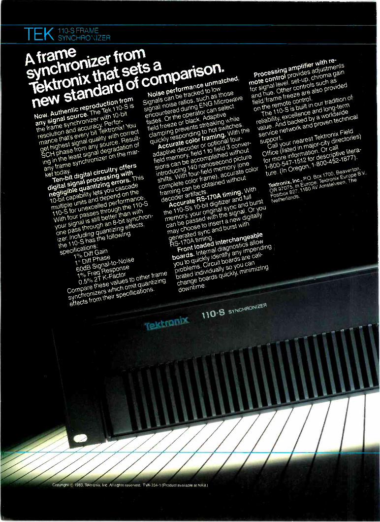
-rgi,(710 sFRAmE
\ SYNCHRON/ZER
A framesynchronizer fromTektronix that sets anew standard of comparison.Now. Authentic reproduction fromany signal source. The Tek 110-S isthe frame synchronizer with 10 -bitresolution and accuracy. Perfor-mance that s every bit Tektronix! Youget highest signal quality with correctSCH phase from any source. Result-ing in the least signal degradation ofany frame synchronizer on the mar-ket today.
Ten -bit digital circuitry offersdigital signal processing withnegligible quantizing errors. This10 -bit capability lets you cascademultiple units and depend on the110-S for unexcelled performance.With four passes through the 110-Syour signal is still better than withone pass through an 8 -bit synchron-izer. Including quantizing effects.the 110-S has the followingspecifications:
1°. Diff Gain1 Diff Phase60dB Signal -to -Noise1% Freq Response0.5% 2T K -Factor
Compare these values to other framesynchronizers which omit quantizingeffects from their specifications.
Noise performance unmatched.Signals can be tracked to lowsignal noise ratios. such as thoseencountered during ENG Microwavefades. Or the operator can selectfield freeze or black. Adaptiveclamping prevents streaking whilequickly responding to hot switches.
Accurate color framing. With theadaptive decoder or optional four -field memory, field 1 to field 3 conver-sions can be accomplished withoutintroducing 140 nanosecond pictureshifts. With four -field memory (onecomplete color frame). accurate colorframing can be obtained withoutdecoder artifacts.
Accurate RS -170A timing. Withthe 110 -Ss 10 -bit digitizer and fullmemory. your original sync and burstcan be passed with the signal. Or youmay choose to insert a new digitallygenerated sync and burst withRS -170A timing.
Front loaded interchangeableboards. Internal diagnostics allowyou to quickly identify any impendingproblems. Circuit boards are cali-brated individually so you canchange boards quickly. minimizingdowntime.
Tektronix 110-s SYNCHRONIZER
Processing amplifier with re-mote control provides adjustmentsfor signal level set-up chroma gainand hue. Other controls such asfield frame freeze are also providedon the remote control.
The 110-S is built in our tradition ofreliability. excellence and long-termvalue. And backed by a worldwideservice network and proven technicasupport.
Call your nearest Tektronix FieldOffice (listed in major -city directoriesfor more information. Or call1-800-547-1512 for descriptive litera-ture. (In Oregon. 1-800-452-1877).
Tektronix. Inc.. PO. Box 1700. Beaverton.OR 97075 In Europe: Tektronix Europe B V.Postbox 827. 1180 AV Amstelveen. TheNetherlands.
PPwRPPAIIV411,1983 Tektronix
/nc All rights reseividTVA -334-7
(Productavadabie
at NAB
WORKING HARD FORYOUR SIGNAL QUALITY
4111POWER
si u
TEktronixFor Literature Circle (9) on Reply Card
Satelliteupdate
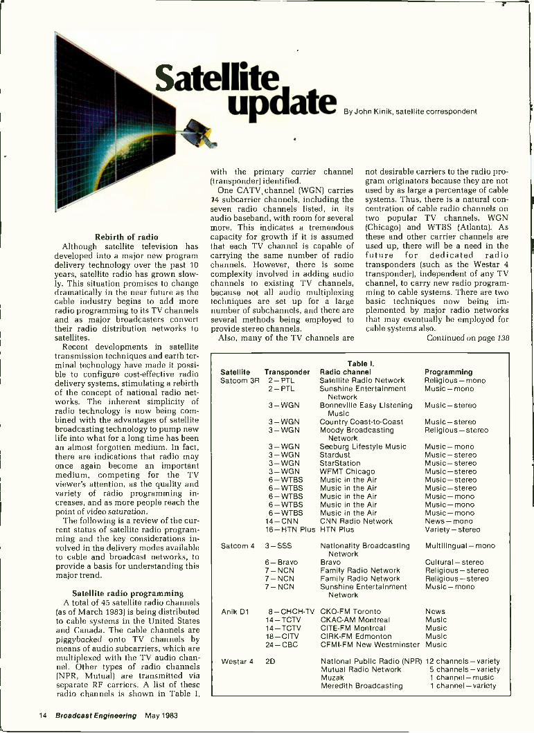
Rebirth of radioAlthough satellite television has
developed into a major new programdelivery technology over the past 10years, satellite radio has grown slow-ly. This situation promises to changedramatically in the near future as thecable industry begins to add moreradio programming to its TV channelsand as major broadcasters converttheir radio distribution networks tosatellites.
Recent developments in satellitetransmission techniques and earth ter-minal technology have made it possi-ble to configure cost-effective radiodelivery systems, stimulating a rebirthof the concept of national radio net-works. The inherent simplicity ofradio technology is now being com-bined with the advantages of satellitebroadcasting technology to pump newlife into what for a long time has beenan almost forgotten medium. In fact,there are indications that radio mayonce again become an importantmedium, competing for the TVviewer's attention, as the quality andvariety of radio programming in-creases, and as more people reach thepoint of video saturation.
The following is a review of the cur-rent status of satellite radio program-ming and the key considerations in-volved in the delivery modes availableto cable and broadcast networks, toprovide a basis for understanding thismajor trend.
Satellite radio programmingA total of 45 satellite radio channels
(as of March 1983) is being distributedto cable systems in the United Statesand Canada. The cable channels arepiggybacked onto TV channels bymeans of audio subcarriers, which aremultiplexed with the TV audio chan-nel. Other types of radio channels(NPR, Mutual) are transmitted viaseparate RF carriers. A list of theseradio channels is shown in Table I,
By John Kinik, satellite correspondent
with the primary carrier channel(transponder) identified.
One CATV channel (WGN) carries14 subcarrier channels, including theseven radio channels listed, in itsaudio baseband, with room for severalmore. This indicates a tremendouscapacity for growth if it is assumedthat each TV channel is capable ofcarrying the same number of radiochannels. However, there is somecomplexity involved in adding audiochannels to existing TV channels,because not all audio multiplexingtechniques are set up for a largenumber of subchannels, and there areseveral methods being employed toprovide stereo channels.
Also, many of the TV channels are
not desirable carriers to the radio pro-gram originators because they are notused by as large a percentage of cablesystems. Thus, there is a natural con-centration of cable radio channels ontwo popular TV channels, WGN(Chicago) and WTBS (Atlanta). Asthese and other carrier channels areused up, there will be a need in thefuture for dedicated radiotransponders (such as the Westar 4transponder), independent of any TVchannel, to carry new radio program-ming to cable systems. There are twobasic techniques now being im-plemented by major radio networksthat may eventually be employed forcable systems also.
Continued on page 138
Table I.Satellite Transponder Radio channelSatcom 3R 2 - PTL Satellite Radio Network
2 - PTL Sunshine EntertainmentNetwork
3 -WGN Bonneville Easy ListeningMusic
3 -WGN Country Coast -to -Coast3 -WGN Moody Broadcasting
NetworkSeeburg Lifestyle MusicStardustStarStationWFMT ChicagoMusic in the AirMusic in the AirMusic in the AirMusic in the AirMusic in the AirCNN Radio NetworkHTN Plus
3 - WGN3 - WGN3 -WGN3 -WGN6 - WTBS6 - WTBS6 -WTBS6 - WTBS6 -WTBS
14-CNN16-HTN Plus
Satcom 4 3 -SSS
Anik D1
6- Bravo7 - NCN7- NCN7- NCN
8 - CHCH-TV14 -TCTV14 - TCTV18 - CITV24 - CBC
Westar 4 2D
Nationality BroadcastingNetwork
BravoFamily Radio NetworkFamily Radio NetworkSunshine Entertainment
Network
CKO-FM TorontoCKAC-AM MontrealCITE -FM MontrealCIRK-FM EdmontonCFMI-FM New Westminster
National Public Radio (NPR)Mutual Radio NetworkMuzakMeredith Broadcasting
ProgrammingReligious - monoMusic-mono
Music-stereo
Music-stereoReligious - stereo
Music- monoMusic-stereoMusic - stereoMusic-stereoMusic- stereoMusic - stereoMusic-monoMusic-monoMusic-monoNews- monoVariety - stereo
Multilingual-mono
Cultural - stereoReligious-stereoReligious-stereoMusic-mono
NewsMusicMusicMusicMusic
12 channels-variety5 channels - variety1 channel-music1 channel-variety
14 Broadcast Engineering May 1983
TEK1910 DIGITAL TESTSIGNAL GENERATOR INSERTER WORKING HARD FOR
YOUR SIGNAL QUALITY
The newdigital generatorthatletsyo access and
contigurethe vertical interval
...youwant it.tc control
any viNow.
Four externalVII S inputs.
Non-volatilememory.
And 39 test
signals.All wrapped
up in one test
signal generatorwith all -digital
family features.lbenew 1910 from
Tektronixgives you the most access
offered to the vertical interval arson
and configuring the to
of test signals,Teletex,
closed
captioning,source
ID and More.
No other generatorgives you that
Plus, the proven performanceof
kind of capability.
the leadingfamily of digital test
signal gWith the 1910,
Tektronixhas combined
its 1900
Series Transmitter,1\1TC7
and Studio
Test Setsin one highly capable
unit
You get a lull signal complement,with
the accuracyand stability
10 -bit
digital signal generation.The digItal
code toreach signalis stored in
replaceablePROMs
so your 1910
won'tbecomeobsolete
Its F1S232control port adds even
more versatilityto the -1910 by pro-
viding a means for autorn
from such devicesas the Tektronix
1980 ANSWERAutomatic
Video
MeasurementSet, with added flexi
ility for prograMMing
and
VIRS in eitherfield on lines 10
through20, signal matrixing,\AIS
sequncin,redefining
signal selec
tion in moresup
re.
Solid support completesthe
package.Vie 1910 comes
with a
worldwideservice
networkand
proven technicalsupport,
plus the
'Tektronixreputation
for reliability,
excellenceand longterm
value.
Contactyour nearest 'Tektronix
Field Office(listed in maior city
directories)for more informaton.
Or
call 1-B00-547-1512for descriptive
lit-
erature(In Oregon,
1 -B00-45'2-W7)
'Tektronix,Inc., P 0 Box 1700 Beaverton
OR 97075In Europe
Tektronix EuropeB V
Postbox827
1180 Al PobstelveenThe
Netherlands
FULL FIELDSIGNAL
UPPER_mmSHIFT
NeKtronlY.1910 DIGITAL
GENERA0 ,zantgr.
PROGRAMLIRE
.1151r TEST
111. 9r1101005
VOW.rowan"Zr 41114;
CAUT19,1
4:Fa`:-OUTPUTS
0 0 0O
AdidelgrArffirAftwom,Copyright (c) 1983. Tektronix. Inc. All rights reserved. TVA -334-2(Product available at NAB.) itktro
I .1 /MIA I lI li lilt .611111 Ni-FnixFor Literature Circle (10) on Reply Card
feedbackNarrower definition
The SeaTel product line distributedby Mariped Sales Company should bemore narrowly defined than it was inthe November 1982 issue of BE (page64). SeaTel manufactures motion -stabilized antenna pedestals, radomesand related equipment for shipboardinstallations of satellite communica-tions systems. Its factory is at 895Howe Road, Martinez, CA 94553.
F.A.M. BuckMariped Sales Company
WNEV-TVI've completed reading the January
issue of Broadcast Engineering, andwanted to offer congratulations onrunning the fine article by Carl Ren-wanz, concerning WNEV-TV going to1/2 -inch (page 19).
Diane TalsmaCommunications ManagerConvergence Corporation
Delivery to IndiaAs the technical manager of one of
the leading distributors of electronicequipment in India, I have been aproud recipient of BroadcastEngineering. Your journal is doing agreat service to professionals involvedin broadcast technology all over theworld, and I want you to know that Ireally appreciate it.
Vish SahaiTechnical Manager
KATONIXNew Delhi, India
Unipole antennasA client is interested in making a
modification to his vertical AM anten-na and wants to explore the possibilityof using the unipole (sometimes calledmonopole) design. I remember thatBroadcast Engineering published anarticle on such an antenna in the early'60s. In the process of moving, some ofmy back issues of your splendidpublication have become lost, so I
cannot locate the article. Can you pro-vide me with a copy?
R. F. Van WickleConsulting Engineer
Columbia, MO
The article, titled "The FoldedUnipole Antenna for AM Broad-casting," appeared in our December1960 issue. A copy is on its way to VanWickle. This was the second requestthis year for the article.
Closed captioningWe are in the process of starting a
Patient Education Station at ourhospital. Due to the special interest of
our hospital-eye, ear, nose andthroat-we are looking for unique pro-grams and also information on closed -captioned television. Your recent in-stitution of closed -captioned televi-sion for the hearing -impaired onKCMO-TV 5 sounds very interesting.Please send me more information onthis project (BE March 1983, page 14).
Alys WeissmanMassachusetts Eye and Ear Infirmary
Testing AM stereoI am writing to you because of the
relative lack of published informationregarding the testing of various AMstereo transmission systems. Why hasthere been no information madepublic regarding the Delco tests madeat Radio Station WIRE? Has WIREbeen prevented from discussing theoutcome of the tests that occurred atits facility?
There are dozens of radio stations
throughout the country testing AMstereo systems. In fact, some of thestations are testing more than onesystem. Why have there been nopublished reports regarding the per-formance of the various systems in thefield? Are we to believe that with all ofthe tests occurring now that nomanufacturers have made any de-sign improvements in the systems thatthey are promoting?
Other questions I have pertain to themanufacturers of AM stereo equip-ment. The advertisements by thesecompanies list the stations that are us-ing their system, however none of theadvertisements describe any of therelative merits or performancespecifications of the equipment inquestion. Also, why are some selectmajor market facilities receivingpreferred treatment in the form ofloans of AM stereo equipment from
Continued on page 139
Editor's note: Our Marcheditorial cited broad-cast/printed media efforts toease the nation's joblessplight. When the issue was onthe press, we received thefollowing material from WSB-TV, Atlanta, showing anothereffort along the same lines.
Job programIn what is the most ambitious
community -sponsored effort of itskind, WSB Television devoted themonth of March to attacking theproblem of unemployment inAtlanta through its comprehen-sive campaign, WSB On The Job.
In explaining the objective ofthe month -long campaign, LesterStrong, executive producer, said,"Our goal is 2 -fold: One is to findmore metro Atlantans job oppor-tunities; and two, which may evenbe the most important goal, is toteach people how to creativelylook at their skills and marketthemselves to employers and findjobs on their own. That's whereour largest impact is in my judg-ment."
WSB On The Job officiallybegan Feb. 15 with the announce-ment of the On The Job hotline. Asclassified ads were broadcast onthe air listing actual job openings,viewers called the hotline numberand were directed to the GeorgiaDepartment of Labor job servicecenter in their area to apply forspecific jobs.
WSB-TV contacted 10,000Atlanta employers asking them todonate at least one position to thecampaign. All jobs were coor-
dinated through the GeorgiaDepartment of Labor. Employerswere encouraged to call if theyhad a job to offer or if they hadquestions about the campaign.
Unlike other job programs, WSBOn The Job encompassed an en-tire month of seminars, program-ming and news to help get the cityback to work.
Each weeknight in March on Ac-tion News at 6 p.m., WSBreporters looked at finding ajob-from how to get in the doorto how to act in the interview. Aspart of the project, on March 17and March 18, 4000 Atlantans hadthe opportunity to participate injob seminars at the Georgia WorldCongress Center. Each seminarwas specifically designed to meetthe needs of skilled and semi-skilled workers and professionals,clerical workers and technicians.
The culmination of WSB On TheJob was a telethon on March 26.As well as taking applications bytelephone for the classified adsthat were broadcast, jobcounselors demonstrated suchjob -seeking skills as knowingwhat employers look for, deter-mining how applicants arescreened out and using properbody language.
The station's efforts were com-mended by a letter from PresidentRonald Reagan. The job programwas a cooperative effort of WSB-TV, WSB Radio, The JuniorLeague of Atlanta; City of Atlanta,CETA; City of Atlanta; The JuniorLeague of DeKalb; Georgia StateEmployment Service; GeorgiaState University; Job Watch; Na-tional Alliance of Business; andPrivate Industry Council.
16 Broadcast Engineering May 1983
Acornpletelyautomated
audioanalyzer
packageandadvanced
portable
scopesto
simplifyyour
job
1,10v4.POW*
newproducts
from
touse.Priced
-rightperformance
for
Tektronix
delivermore
capability
tasksfrom
circuitcontinuity
testingto
andperlormance
thanever
before
gatedfrequency,
timeand
event
SG5010
PrograrnMable
160kHzcounting.
Standard
featuresinclude
Oscillator
IAA500iProgrammable
TVfieldand
IV linetriggering.
Distortion
Analyzer.
twonew
2.45150Wiz
Portable°sato-
meinbers
inourTM
5000family
ofscope.The
newindustry
standard
odulr,IEEE"
compatible
in-
withmore
performance
forthedollar
struments.
TheSG
5010sthefirst
thanyouve
everseen
foreFour-
osillatortooffer
bothGPI13
pro-
channelcapability.
Autolevel
grammability
benefitsand
lessthan
"hands-ofr
triggring.
Standard
0.001%(-10
di3)total
harmonic
timeand
delaysweep:
1 nsldPI
distortion.
Plusallthe
standardIMO
sweepspeed.
Overdrive
aberration
of
testsignals
and,high
level,fully
bal-only
0.5%.Extensive
CRTreadout.
anced,fully
floatingoutput.
Together,
Plusmore.
Andstate-of-the-art
theSG5010
andAA5001
makea
microprocessor
designkeeps
the
completely
automated
audioanalysis
2445
s tooperate.Itsevery
-
systemwith
thehighest
performance
thingthat
aportablescope
shouldbe
availabletoday.
Fullyautomatic
evenand
theonly
onethat
i
whentheoc:illator
andanalyzer
are
Contactyour
nearest'Tektronix
separated,
byyardsorbymiles.
fieldOffice
(listed
ins.alor city
2.23610tatz
PortableOscillo-
directories)
formoreinformation.
Or
SCOT,Measurements
thathad
cal11-800-547-1512
fordescriptivelit-
takenthree
or fourinstruments
can
eratureOnOregon,
1-800-45'2.-1877
)
WOWbedonewith
one:the2236
with
integrated
counter
meddigital
legtronix,lnc.,
PO.Box
1700,Beaverton,
multirneter.
Itsawholemeasurement
Oft97075.InEurope..
Tektronix
EuropeBV.,
Systempacked
in aportablescope
Postbox827,1190
POAmstelveen
:the
thatislightweight,
versatileand
easy
Netherlands.
Copyright c,1983, Tektronix,
Inc. All rights reserved.TVA -334-3
For Literaturefor TM 5000 Circle
(11) on Reply Card
For Literaturefor Portables
Circle(12) on Reply Card
t:In :Ili:HI;
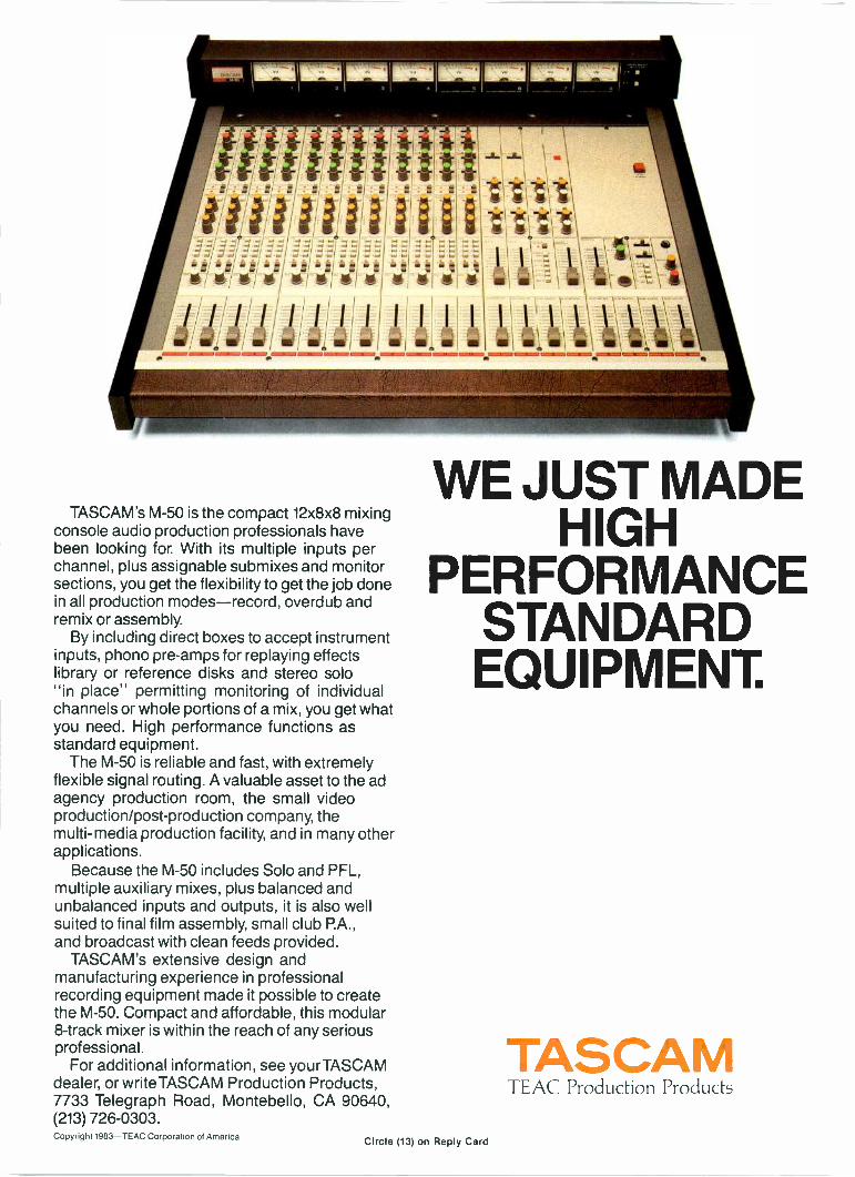
TASCAM's M-50 is the compact 12x8x8 mixingconsole audio production professionals havebeen looking for. With its multiple inputs perchannel, plus assignable submixes and monitorsections, you get the flexibility to get the job donein all production modes-record, overdub andremix or assembly.
By including direct boxes to accept instrumentinputs, phono pre -amps for replaying effectslibrary or reference disks and stereo solo"in place" permitting monitoring of individualchannels or whole portions of a mix, you get whatyou need. High performance functions asstandard equipment.
The M-50 is reliable and fast, with extremelyflexible signal routing. A valuable asset to the adagency production room, the small videoproduction/post-production company, themulti -media production facility, and in many otherapplications.
Because the M-50 includes Solo and PFL,multiple auxiliary mixes, plus balanced andunbalanced inputs and outputs, it is also wellsuited to final film assembly, small club P.A.,and broadcast with clean feeds provided.
TASCAM's extensive design andmanufacturing experience in professionalrecording equipment made it possible to createthe M-50. Compact and affordable, this modular8 -track mixer is within the reach of any seriousprofessional.
For additional information, see yourTASCAMdealer, or writeTASCAM Production Products,7733 Telegraph Road, Montebello, CA 90640,(213) 726-0303.
WE JUST MADEHIGH
PERFORMANCESTANDARDEQUIPMENT.
TASCAMTEAC Production Products
Copyright 1983-TEAC Corporation of AmericaCircle (13) on Reply Card
Real time closedcaptioning at NCI
By Jeff Hutchins, director of systems development, National Captioning Institute, Falls Church, VA
Oct. 11, 1982 was a historic day forthe closed -captioning service. On thatday, the National Captioning Instituteand ABC-TV and its affiliates beganthe world's first national closed -captioning of a live news program,ABC's World News Tonight. Funds forclosed -captioning the program areprovided to NCI by the US Depart-ment of Education.
To offer this service, the institutedeveloped a way to caption a programwithout seeing a script first. The
Courtesy of June Farrell, NCI public relations director
method is called real time captioning,and its development was a tremen-dous breakthrough for the closed -captioning service.
There had long been a need for ameans of captioning live TV programsso that they were understandable tohearing -impaired viewers. Althoughthis audience welcomes captionedentertainment, NCI's research in-dicated that hearing -impaired peoplewanted access to timely news and in-formation programming as well.
Needed: Two technologiesProviding this service was not possi-
ble, however, until two technologieswere developed and married: closedcaptioning and real time captioning.
The Public Broadcasting Servicehad worked through most of the 1970sto develop a closed -captioned systemin which caption data could be en-coded on Line 21 of the vertical blank-ing interval for display only onspecially equipped receivers. This sys-
Continued on page 22
Marty Block, NCI stenotypist, prepares captions instantly for World News Tonight. The captions appear on TV sets equipped withTeleCaption units.
May 1983 Broadcast Engineering 19
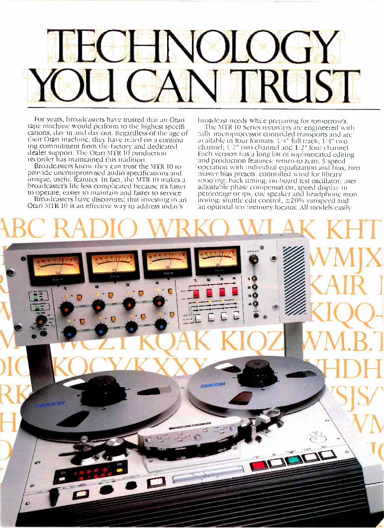
TECHNOLOGYYOU CAN TRUST
For years, broadcasters have trusted that an Otaritape machine would perform to the highest specifi-cations, day -in and day -out. Regardless of the age oftheir Otari machine, they have relied on a continu-ing commitment from the factory and dedicateddealer support. The Otari MTR-10 productionrecorder has maintained this tradition.
Broadcasters know they can trust the MTR-10 toprovide uncompromised audio specifications andunique, useful features. In fact, the MTR-10 makes abroadcaster's life less complicated because it's fasterto operate, easier to maintain and faster to service.
Broadcasters have discovered that investing in anOtari MTR-10 is an effective way to address today's
broadcast needs while preparing for tomorrow's.The MTR-10 Series recorders are engineered with
fully microprocessor -controlled transports and areavailable in four formats: 1/4" full -track; 1/4" twochannel; 1/2" two channel and 1/2" four channel.Each version has a long list of sophisticated editingand production features: return -to -zero; 3 speedoperation with individual equalization and bias; twomaster bias presets; controlled wind for libraryspooling; back timing; on -board test oscillator; useradjustable phase compensation; speed display inpercentage or ips; cue speaker and headphone mon-itoring; shuttle edit control; ±20% varispeed andan optional ten memory locator. All models easily
KHTvv_MJX'/AIROQQ-M.B.]
DHTSJS/1
I(
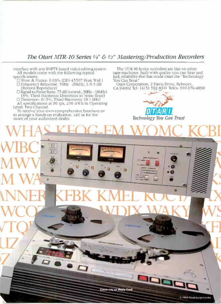
The Otari MTR-10 Series 1/4" & 1/2" Mastering/Production Recorders
interface with any SMPTE-based video editing system.All models come with the following typical
specifications: Wow & Flutter: 0.03% (DIN 45507 Peak Wtd.)El Frequency Response: 50Hz -20kHz, ± 0.5 dB
(Record/Reproduce)1:1Signal-to-Noise Ratio: 75 dB (unwtd., 30Hz -18kHz)
(3%, Third Harmonic Distortion to Noise floor)El Distortion: 0.15%, Third Harmonic (CO) 1 kHz)All specifications at 30 ips, 250 nWb/m Operating
Level, Two Channel.To receive your own comprehensive brochure or
to arrange a hands-on evaluation, call us for thename of your authorized dealer.
The MTR-10 Series recorders are like no othertape machines: built with quality you can hear andfeel, reliability that has made Otari the "TechnologyYou Can Trusty
Otari Corporation, 2 Davis Drive, Belmont,CA 94002 Tel: (415) 592-8311 Telex: 910-376-4890
ERGII211Technology You Can Trust
Continued from page 19
tem allows captions to be sent withany program during its original tele-cast without affecting the viewingpleasure of people who do not need orwant captions.
The breakthrough came in March1980 when Sears Roebuck offeredconsumers a decoder for the Line 21closed -captioning system; ABC andNBC joined PBS in offering closed -captioned programming; and NCI,having been formed a year earlier as aprivate non-profit company, was inplace to provide the closed captions.
With the closed -captioning systemand NCI in place, half the problem ofcaptioning a live newscast was solved.In comparison, that was the easy half.What remained was how to create andencode the captions.
Subsequently the institutedeveloped two methods for caption-ing live programs. The first is what iscalled live display captioning, whichinvolves recall and transmission ofcaptions prepared in advance. Thismethod requires NCI to have an ad-vance copy of the script, which ispossible with live drama andpresidential speeches, for example,but not with sports events, awardsprograms, press conferences, newsreports and most other live telecasts.This latter group of programs requiresreal time captioning, which involvesthe simultaneous creation andtransmission of captions-in effect, in-stant captioning.
World News Tonight falls into thesecond category, even though much ofthe program is taped or pre -scripted.Getting those scripts in advance isnearly impossible because the ABCformat calls for origination fromseveral cities each evening andbecause of the general nature of newsprograms. Late -breaking stories maybe read live in the studio without evena prompter copy or may be ad-libbedfrom the field.
It is not practical in a program asdynamic as a newscast to alternatebetween live display and real timecaptioning. It quickly became clearthat the only workable means for cap-tioning the news was real time.
Theoretically, three methods forreal time captioning exist. The first isspeed typing using standard keyboardentry. The second option is speechrecognition. The third possibility, theone that NCI chose to pursue, isstenographic translation.
In simplest terms, stenographictranslation is the computerizedtranslation into real words and namesof a stenotypist's machine shorthandstrokes, which are phonetic represen-tations of what the stenotypist hearsand inputs.
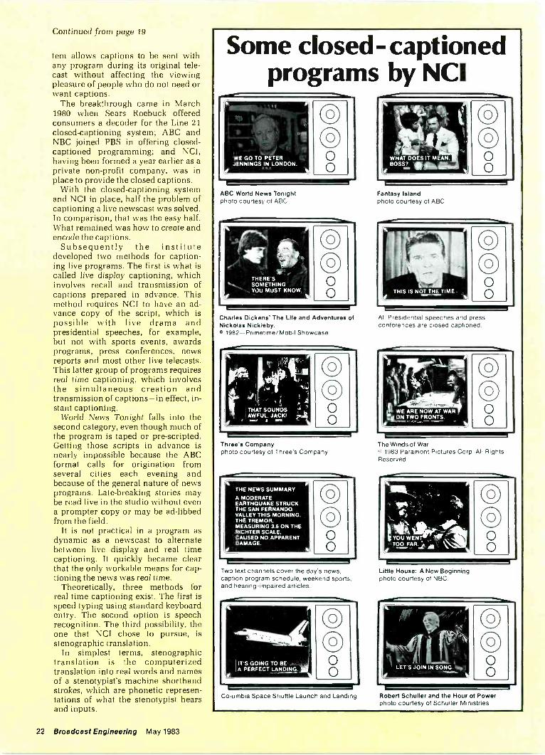
Some closed -captionedprograms by NCI
OO00
ABC World News Tonightphoto courtesy of ABC
000
Charles Dickens' The Life and Adventures ofNickolas Nickleby.0 1982-Primetime/Mobil Showcase
Three's Companyphoto courtesy of Three's Company
THE NEWS SUMMARY
A MODERATEEARTHQUAKE STRUCKTHE SAN FERNANDOVALLEY THIS MORNING.THE TREMOR,MEASURING 3.6 ON THERICHTER SCALE,CAUSED NO APPARENTDAMAGE.
CD00
Two text channels cover the day's news,caption program schedule, weekend sports,and hearing -impaired articles.
IT'S GOING TO BEA PERFECT LANDING. al
00
WHAT DOES IT MEAN,BOSS? 1.41111k,
4
00
Fantasy Islandphoto courtesy of ABC
All Presidential speeches and pressconferences are closed captioned.
II WE ARE NOW AT WAR;SONTWO FRONTS.
00O
The Winds of War© 1983 Paramont Pictures Corp. All RightsReserved.
tYOU ENT'TOO FAR..ii
000
Little House: A New Beginningphoto courtesy of NBC.
00
Columbia Space Shuttle Launch and Landing Robert Schuller and the Hour of Powerphoto courtesy of Schuller Ministries
22 Broadcast Engineering May 1983
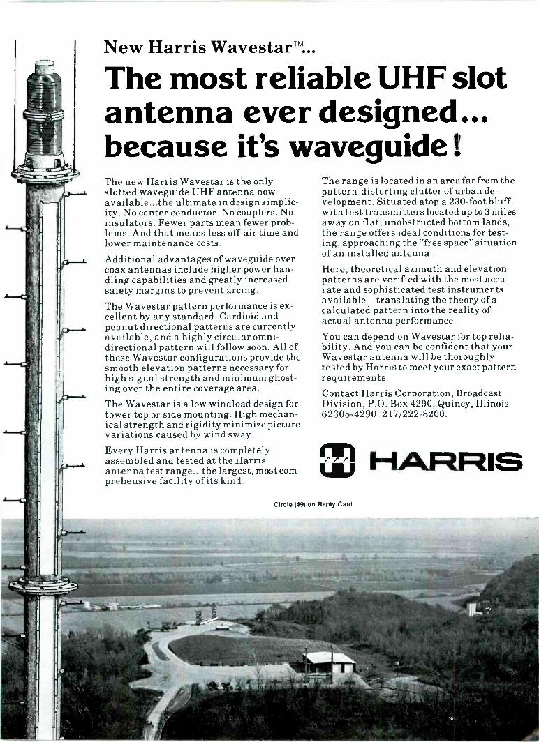
New Harris Wavestar"...
The most reliable UHF slotantenna ever designed...because it's waveguide !The new Harris Wavestar is the onlyslotted waveguide UHF antenna nowavailable...the ultimate in design simplic-ity. No center conductor. No couplers. Noinsulators. Fewer parts mean fewer prob-lems. And that means less off -air time andlower maintenance costs.Additional advantages of waveguide overcoax antennas include higher power han-dling capabilities and greatly increasedsafety margins to prevent arcing.The Wavestar pattern performance is ex-cellent by any standard. Cardioid andpeanut directional patterns are currentlyavailable, and a highly circular omni-directional pattern will follow soon. All ofthese Wavestar configurations provide thesmooth elevation patterns necessaryhigh signal strength and minimum ghost-ing over the entire coverage area.The Wavestar is a low windload design fortower top or side mounting. High mechan-ical strength and rigidity minimize picturevariations caused by wind sway.
Every Harris antenna is completelyassembled and tested at the Harrisantenna test range...the largest, most com-prehensive facility of its kind.
The range is located in an area far from thepattern -distorting clutter of urban de-velopment. Situated atop a 230 -foot bluff,with test transmitters located up to 3 milesaway on flat, unobstructed bottom lands,the range offers ideal conditions for test-ing, approaching the "free space" situationof an installed antenna.Here, theoretical azimuth and elevationpatterns are verified with the most accu-rate and sophisticated test instrumentsavailable-translating the theory of acalculated pattern into the reality ofactual antenna performance.You can depend on Wavestar for top relia-bility. And you can be confident that yourWavestar antenna will be thoroughlytested by Harris to meet your exact patternrequirements.Contact Harris Corporation, BroadcastDivision, P.O. Box 4290, Quincy, Illinois62305-4290. 217/222-8200.
HARRISULFCircle (49) on Reply Card
Three dictionaries usedDevelopment of this system covered
more than two decades. A number ofentrepreneurs over the years refinedthis new technology, but TranslationSystems Inc. (TSI) of Maryland cameup with a unique approach. Briefly, itcalled for a combination of three dic-tionaries containing the possiblestenographic outlines for each Englishword.
The main dictionary, the one uniqueto TSI, is the universal dictionary.Containing thousands of words likelyto be used frequently, it is permanentand can be increased in size.
Next Is the personal dictionary inwhich a stenotypist makes entries,such as special abbreviations, usedonly by him or her, or specializedvocabulary not found in the universaldictionary. Because each stenotypisthas a unique style of writing, carefulmaintenance of the personal dic-tionary tailors the system and in-creases the likelihood of making ac-curate translations.
The third dictionary to which thecomputer turns to look up a word isthe dope sheet, which contains entriesappropriate to a specific task, such asnames and places likely to be men-tioned in a given newscast. The dopesheet is not permanent unless addedto one of the other dictionaries, but it
can be used to complement any userbringing up any personal dictionary.
A team effortWork on captioning the evening edi-
tion of World News Tonight beginsearly each day as a team of text editorsscans a number of major dailynewspapers and the weekly newsmagazines for names and places likelyto be mentioned in the program laterthat day. The wires are checked forlate -breaking news reports. Followinga story conference, the results of thisday -long research are used to preparethe daily dope sheet.
In making its translations, the com-puter checks each of the three dic-tionaries and matches thestenographic outline entered on thestenotype machine with the cor-responding English word or words.NCI's two stenotypists, Marty Blockand Bobbie Showers, have a 97% ac-curacy rate using this process.
If the computer does not find a dic-tionary match, the word will appear inits original stenotype form, a phoneticrepresentation that may or may not beunderstandable. For example, theword "should" would appear"S -H -U -D," which most persons wouldrecognize. But the word "copyright"would be "K -O -E -P" and "R -A -0 -I -T."
The dictionaries are stored on a
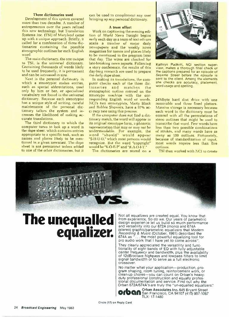
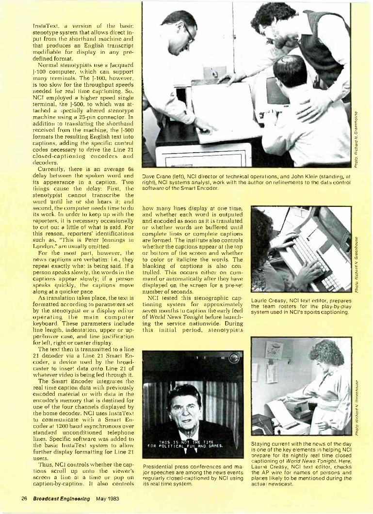
Kathryn Puckett, NCI section super-visor, makes a thorough final check ofthe captions prepared for an episode ofSesame Street before the episode issent to the client. Among the elementsshe checks are accuracy, placement,word usage and spelling.
24Mbyte hard disc drive with oneremovable and three fixed platters.Massive storage is necessary becauseeach word in the dictionary must beentered with all the permutations ofsteno outlines that might be used totranscribe that word. Few words haveless than two possible combinationsof strokes, and many words have asmany as 100 outlines. Fortunately,because of standardization of input,most words require less than fiveoutlines.
TSI then worked with NCI to create
The unequalledequalizer.
Not all equalizers are created equal. You know thatfrom experience. So do we. Our years of parametricdesign experience let us build so much performanceand versatility into our 672A (mono) and 674A(stereo) graphic/parametric equalizers that ModernRecording & Music (October, 1981) described the674A as "...the most powerful equalizing tool forpro audio work that I have yet to come across".They clearly appreciated the versatility and func-tionality of eight bands of EQ with fully adjustablecenter frequency and bandwidth, plus the availabilityof 12dB/octave highpass and lowpass filters to limitsignal bandwidth or to serve as a full electroniccrossover.No matter what your application-production, pro-gram shaping, room tuning, reinforcement work, orclean-up chores-you can count on Orban's heavy-duty professional construction and equally profes-sional documentation and service. Find out why theOrban 672A/674A's are truly the "un-equalled equalizers'?
Sannan Associates Inc. 645 Bryant Streetorban Francisco, CA 94107 (415) 957-1067
TLX: 17-1480
24 Broadcast Engineering May 1983
Circle (17) on Reply Card
THE VPR-80/TBC-80 COMBINATIONFOR TYPE "C" PERFORMANCE.
AT THE LOWEST COST.
$49,50(rThe VPR-80, and its new TBC-80
digital time base corrector, are the keyelements in a full -featured, economy -priced one -inch type "C" format VTRsystem. The VPR-80/TBC-80 packageassures you highest performance forunder $50,000.
VPR-80 and TBC-80 together offeryou slow motion and still -frame playbackwith AST' Automatic Scan Tracking as astandard feature. Other high-performancefeatures include: picture in shuttle up to300 ips, a built-in editor with keypad foredit point entry and trim, slow-motionplayback from stop to 1.5X play speed,an advanced tape transport for playbackof spot or two-hour reels, and dual -microprocessor design for comprehen-sive diagnostics.
The new TBC-80, designed as acompanion to the VPR-80, features thevery latest in video processing technologyto enhance the VPR-80's playback signal.In addition, TBC-80 includes selectableheterodyne processing for use with eithery," or 3/4" VTRs.
Compare These Features: Flawless slow motion playback
(stop to 1.5X play) Picture in shuttle ASP" standard on all machines Powerful frame -accurate editing Comprehensive diagnostics
with test probe Dual -microprocessor design Many configurations (including
tabletop, rack mount, pedestal,consolette and full studioconsole)
The VPR-80/TBC-80. A per-fect match. And the price is right.For more details about the VPR-80/TBC-80 combination, simply contact yourlocal Ampex AVSD sales office: Atlanta404/451-7112 Chicago 312/593-6000Dallas 214/960-1162 Los Angeles213/240-5000 New York/New Jersey201/825-9600 San Francisco 408/255-4800Washington, D.C. 301/530-8800
AM PEXAmpex Corporation One of The Signal Companie,
SETTINGTHE FASHION
IN BROADCASTVIDEO
.List price U.S.A.Circle (18) on Reply Card
InstaText, a version of the basicstenotype system that allows direct in-put from the shorthand machine andthat produces an English transcriptmodifiable for display in any pre-defined format.
Normal stenotypists use a JacquardJ-100 computer, which can supportmany terminals. The J-100, however,is too slow for the throughput speedsneeded for real time captioning. So,NCI employed a higher speed singleterminal, the J-500, to which was at-tached a specially altered stenotypemachine using a 25 -pin connector. Inaddition to translating the shorthandreceived from the machine, the 1-500formats the resulting English text intocaptions, adding the specific controlcodes necessary to drive the Line 21closed -captioning encoders anddecoders.
Currently, there is an average 6sdelay between the spoken word andits appearance in a caption. Twothings cause the delay: First, thestenotypist cannot transcribe theword until he or she hears it; andsecond, the computer needs time to doits work. In order to keep up with thereporters, it is necessary occasionallyto cut out a little of what is said. Forthis reason, reporters' identificationssuch as, "This is Peter Jennings inLondon," are usually omitted.
For the most part, however, thenews captions are verbatim: i.e., theyrepeat exactly what is being said. If aperson speaks slowly, the words in thecaptions appear slowly; if a personspeaks quickly, the captions movealong at a quicker pace.
As translation takes place, the text isformatted according to parameters setby the stenotypist or a display editoroperating the main computerkeyboard. These parameters includeline length, indentation, upper or up-per/lower case, and line justificationfor left, right or center display.
The text then is transmitted to a line21 decoder via a Line 21 Smart En-coder, a device used by the broad-caster to insert data onto Line 21 ofwhatever video is being fed through it.
The Smart Encoder integrates thereal time caption data with previouslyencoded material or with data in theencoder's memory that is destined forone of the four channels displayed bythe home decoder. NCI uses InstaTextto communicate with a Smart En-coder at 1200 baud asynchronous overstandard unconditioned telephonelines. Specific software was added tothe basic InstaText system to allowfurther display formatting for Line 21users.
Thus, NCI controls whether the cap-tions scroll up onto the viewer'sscreen a line at a time or pop oncaption -by -caption. It also controls
Dave Crane (left), NCI director of technical operations, and John Klein (standing, atright), NCI systems analyst, work with the author on refinements to the data controlsoftware of the Smart Encoder.
how many lines display at one time,and whether each word is outputedand encoded as soon as it is translatedor whether words are buffered untilcomplete lines or complete captionsare formed. The institute also controlswhether the captions appear at the topor bottom of the screen and whetherto color or italicize the words. Theblanking of captions is also con-trolled. This occurs either on com-mand or automatically after they havedisplayed on the screen for a pre-setnumber of seconds.
NCI tested this stenographic cap-tioning system for approximatelyseven months to caption the early feedof World News Tonight before launch-ing the service nationwide. Duringthis initial period, stenotypists
THIS IS N T THE TIMEF PO, I T I CAL FUN AND GAMES.
Presidential press conferences and ma-jor speeches are among the news eventsregularly closed -captioned by NCI usingits real time system.
Laurie Creasy, NCI text editor, preparesthe team rosters for the play-by-playsystem used in NCI's sports captioning.
Staying current with the news of the dayis one of the key elements in helping NCIprepare for its nightly real time closedcaptioning of World News Tonight. Here,Laurie Creasy, NCI text editor, checksthe AP wire for names of persons andplaces likely to be mentioned during theactual newscast.
26 Broadcast Engineering May 1983
THE ALL-AMERICAN WINNERFOR QUALITY INSID OUT.
THE BCC- 20/21 CAMERA SYSTEM.No other camera system matches the BCC -20/21
Digicam for superb pictures and total operationalflexibility. The BCC -21 is a top-quality, fully auto-matic camera for both studio and mobile operation.Simply remove the BCC -20 from the -47,studio frame and you have a corn -pact EFP camera perfect for anyportable situation where size andweight are critical, and performancecannot be compromised.
The Digicam cameras come withimpressive features, including:"computer -in -the -head", SpatialError Correction for outstandingregistration and sharpness, remotecontrol, and an optional AutomaticSetup Unit for more accurate,
faster and simpler setup.The Digicam system. It gives you the most flexi-
bility with a single camera-inside and cut. Fordetails, call your nearest Ampex sales office.
Atlanta 404/451-7112 Chicago312/593-6000 Dallas 214/960-1162 Los Angeles 213/240-5000 NewYork/New Jersey 201/825-9600 San Francisco 408/255-4800 Washington, D.C. 301r530-8800
AMPEXAmpex Corporation One of The Siena! Companies -
SETTINGTHE FASHION
IN BROADCASTVIDEO
Circle (19) on Reply Card
transcribed the program in real timeduring the 6:30 p.m. EST feed. Ratherthan transmitting the captions at thattime, however, the transcript wascopied onto floppy discs in small in-crements. Editors then transferred thefloppy disc to a word processor toclean up any mistakes while thestenotypist continued to transcribethe next portion of the program. Thecorrected files were then used to pro-duce captions for the 7 p.m. EST feedusing another InstaText feature thatallows previously created text files tobe recalled and outputed in the livedisplay mode.
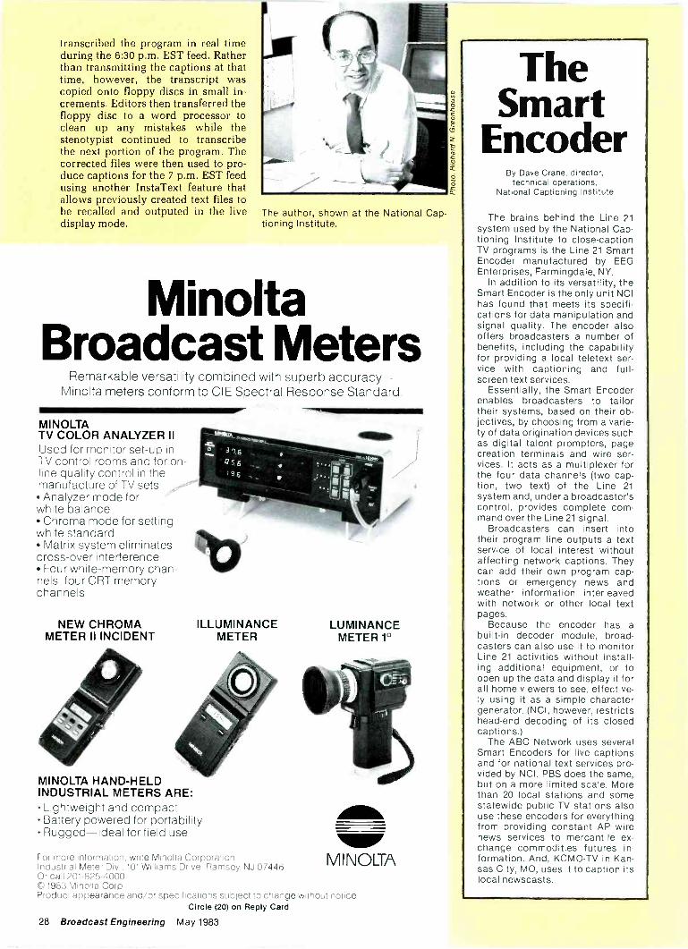
The author. shown at the National Cap-tioning Institute.
MinoltaBroadcast Meters
Remarkable versatility combined with superb accuracy-Minolta meters conform to CIE Spectral Response Standard.
MINOLTATV COLOR ANALYZER IIUsed for monitor set-up inTV control rooms and for on-line quality control in themanufacture of TV sets. Analyzer mode forwhite balance Chroma mode for settingwhite standard Matrix system eliminatescross -over interference Four white -memory chan-nels; four CRT memorychannels
NEW CHROMAMETER II INCIDENT
MINOLTA HAND-HELDINDUSTRIAL METERS ARE: Lightweight and compact Battery powered for portability Rugged-ideal for field use
ILLUMINANCEMETER
For more information. write Minolta Corporation,Industrial Meter Div . 101 Williams Drive, Ramsey NJ 07446Or call 201-825-4000CD 1983 Minolta Corp.Product appearance and/or specifications subject to ctlat tge w thou, 110:100
Circle (20) on Reply Card
28 Broadcast Engineering May 1983
LUMINANCEMETER 1°
MINOLTA
TheSmart
EncoderBy Dave Crane, director,
technical operations,National Captioning Institute
The brains behind the Line 21system used by the National Cap-tioning Institute to close -captionTV programs is the Line 21 SmartEncoder manufactured by EEGEnterprises, Farmingdale, NY.
In addition to its versatility, theSmart Encoder is the only unit NCIhas found that meets its specifi-cations for data manipulation andsignal quality. The encoder alsooffers broadcasters a number ofbenefits, including the capabilityfor providing a local teletext ser-vice with captioning and full -screen text services.
Essentially, the Smart Encoderenables broadcasters to tailortheir systems, based on their ob-jectives, by choosing from a varie-ty of data origination devices suchas digital talent prompters, pagecreation terminals and wire ser-vices. It acts as a multiplexer forthe four data channels (two cap-tion, two text) of the Line 21
system and, under a broadcaster'scontrol, provides complete com-mand over the Line 21 signal.
Broadcasters can insert intotheir program line outputs a textservice of local interest withoutaffecting network captions. Theycan add their own program cap-tions or emergency news andweather information interleavedwith network or other local textpages.
Because the encoder has abuilt-in decoder module, broad-casters can also use it to monitorLine 21 activities without install-ing additional equipment, or toopen up the data and display it forall home viewers to see, effective-ly using it as a simple charactergenerator. (NCI, however, restrictshead -end decoding of its closedcaptions.)
The ABC Network uses severalSmart Encoders for live captionsand for national text services pro-vided by NCI. PBS does the same,but on a more limited scale. Morethan 20 local stations and somestatewide public TV stations alsouse these encoders for everythingfrom providing constant AP wirenews services to mercantile ex-change commodities futures in-formation. And, KCMO-TV in Kan-sas City, MO, uses it to caption itslocal newscasts.
With state-of-the-art technology in theirrecording studios, Lucasfilm Ltd. didn't settlefor do it yourself jackfields.
t *0 0 000. 0000' i.
eeeeeeeeeeee . -
coop 00 00 0000 00 00 0°06.,.......... ................
0000000) 00000 0000 000
J00000000000000000
00000000000,
.0.. ..... .
cop00 000U 000000000ocm, ............. 4.....
'C. -1,J. 1
... 4..4
If.00
11!
Lucasfilm's special effects in sightanc sound have become the hall-ma:ks of the STAR WARS saga. Toachieve those other -world sound ef-fects takes a lot of patching, switch-ing, and mixing.
When Lucasfilm's audio patchingrequirements called for a unique andcomplex design to provide high -quality audio throughout its com-plex, Chief Audio Engineer TomHo_man selected ADC to manufac-ture jackfields to fit those require-ments. All Tom had to do was plugthem in, and the jackfields wereready to go-guaranteed and pre-tested-eliminating the hours of wir-ing, testing, and correcting thatdo-it-yourself jackfields often re-quire. ADC custom and standardjackfields can save as much as 50% ofthe cost of do-it-yourself jackfields.
In addition, we offer more than 240configurations in 1/4" or Bantamjacks, wire wrap or solder termina-tions, variable cable lengths, plus avariety of normalling configurationsanc types of terminations (includingou: revolutionary new "punch -down" connectors, introduced at thisyear's NAB). We inspect andcomputer -test every circuit to makesure it lives up to spec. That's why wecar_ offer a five-year warranty on everyunit.
Best of all, we can have any of ourstandard jackfields on their way toyou in only two to four weeks. Andthat's a promise we can deliver. Forinformation about ADC's standardor custom jackfields, write ADC,4900 West 78th Street, Minneapolis,MN 55435. Or call our toll -freehotline -1-800-328-6188. In Minne-sota, call (612) 835-6800.
(Above) ADC custom jackfields form an integral part ofLucasfilm's state-of-the-art audio technology.(Right) Tom Holman, Chief Audio Engineer for Lucasfilm Ltd.,selected ADC for responsiveness, quality and reliability.
Ci c e (21) on Reply Card
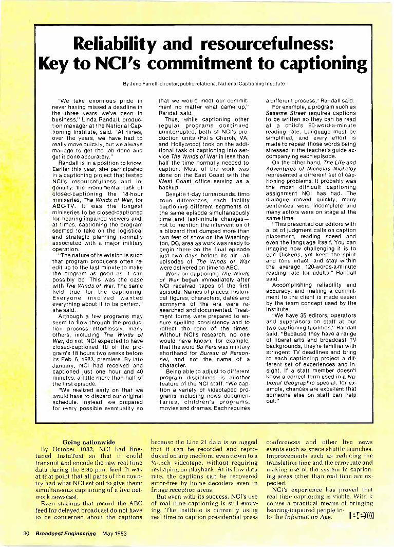
Reliability and resourcefulness:Key to NCI's commitment to captioning
By June Farrell, director, public relations, National Captioning Institute
"We take enormous pride innever having missed a deadline inthe three years we've been inbusiness," Linda Randall, produc-tion manager at the National Cap-tioning Institute, said. "At times,over the years, we have had toreally move quickly, but we alwaysmanage to get the job done andget it done accurately."
Randall is in a position to know.Earlier this year, she participatedin a captioning project that testedNCI's resourcefulness and in-genuity: the monumental task ofclosed -captioning the 18 -hourminiseries, The Winds of War, forABC-TV. It was the longestminiseries to be closed -captionedfor hearing -impaired viewers and,at times, captioning the programseemed to take on the logisticaland strategic planning normallyassociated with a major militaryoperation.
"The nature of television is suchthat program producers often re-edit up to the last minute to makethe program as good as it canpossibly be. This was the casewith The Winds of War. The sameheld true for the captioning.Everyone involved wantedeverything about it to be perfect,"she said.
Although a few programs mayseem to flow through the produc-tion process effortlessly, manyothers, including The Winds ofWar, do not. NCI expected to haveclosed -captioned 10 of the pro-gram's 18 hours two weeks beforeits Feb. 6, 1983, premiere. By lateJanuary, NCI had received andcaptioned just one hour and 40minutes, a little more than half ofthe first episode.
"We realized early on that wewould have to discard our originalschedule. Instead, we preparedfor every possible eventuality so
that we would meet our commit-ment no matter what came up,"Randall said.
Thus, while captioning otherregular programs continueduninterrupted, both of NCI's pro-duction units (Falls Church, VA,and Hollywood) took on the addi-tional task of captioning into ser-vice The Winds of War in less thanhalf the time normally needed tocaption. Most of the work wasdone on the East Coast with theWest Coast office serving as abackup.
Despite 1 -day turnarounds, timezone differences, each facilitycaptioning different segments ofthe same episode simultaneouslytime and last-minute changes-not to mention the intervention ofa blizzard that dumped more thantwo feet of snow on the Washing-ton, DC, area as work was ready tobegin there on the final episodejust two days before its air-allepisodes of The Winds of Warwere delivered on time to ABC.
Work on captioning The Windsof War began immediately afterNCI received tapes of the firstepisode. Names of places, histori-cal figures, characters, dates andacronyms of the era were re-searched and documented. Treat-ment forms were prepared to en-sure spelling consistency and toreflect the tone of the times.Without NCI's research, no onewould have known, for example,that the word Bu Pers was militaryshorthand for Bureau of Person-nel, and not the name of acharacter.
Being able to adjust to differentprogram disciplines is anotherfeature of the NCI staff. "We cap-tion a variety of videotaped pro-grams including news documen-taries, children's programs,movies and dramas. Each requires
a different process," Randall said.For example, a program such as
Sesame Street requires captionsto be written so they can be readat a child's 60 -word -a -minutereading rate. Language must besimplified, and every effort ismade to repeat those words beingstressed in the teacher's guide ac-companying each episode.
On the other hand, The Life andAdventures of Nicholas Nickelbyrepresented a different set of cap-tioning problems. It probably wasthe most difficult captioningassignment NCI has had. Thedialogue moved quickly, manysentences were incomplete andmany actors were on stage at thesame time.
"This presented our editors witha lot of judgment calls on captionplacement, reading speed andeven the language itself. You canimagine how challenging it is toedit Dickens, yet keep the spiritand tone intact, and stay withinthe average 120 -words -a -minutereading rate for adults," Randallsaid.
Accomplishing reliability andaccuracy, and making a commit-ment to the client is made easierby the team concept used by theinstitute.
"We have 35 editors, operatorsand supervisors on staff at ourtwo captioning facilities," Randallsaid. "Because they have a rangeof liberal arts and broadcast TVbackgrounds, they're familiar withstringent TV deadlines and bringto each captioning project a dif-ferent set of experiences and in-sight. If a staff member doesn'tknow a correct term used in a Na-tional Geographic special, for ex-ample, chances are excellent thatsomeone else on staff can helpout."
Going nationwideBy October 1982, NCI had fine-
tuned InstaText so that it couldtransmit and encode the raw real timedata during the 6:30 p.m. feed. It wasat that point that all parts of the coun-try had what NCI set out to give them:simultaneous captioning of a live net-work newscast.
Even stations that record the ABCfeed for delayed broadcast do not haveto be concerned about the captions
because the Line 21 data is so ruggedthat it can be recorded and repro-duced on any medium, even down to a1/2 -inch videotape, without requiringreshaping on playback. At its low datarate, the captions can be recoverederror -free by home decoders even infringe reception areas.
But even with its success, NCI's useof real time captioning is still evolv-ing. The institute is currently usingreal time to caption presidential press
conferences and other live newsevents such as space shuttle launches.Improvements such as reducing thetranslation time and the error rate andmaking use of the system in caption-ing areas other than real time are ex-pected.
NCI's experience has proved thatreal time captioning is viable. With itcomes a practical means of bringinghearing -impaired people in-to the Information Age. :I))))1
30 Broadcast Engineering May 1983
The Asaca Shibasoku monitor likethe hi.man eye resolves certaincolors best: reds, oranges. yellows,and flesh tones. The I-0 decodingsystem enables the monitor todisplay these colors at a higherresolLtion using wide banddemodulation of 1.3 MHz rather than0.5 M-iz as in B -Y systems.
We cared enough to give you amonitor with the I -C) to reproduce thebest possible pictures. We knowyo..fre smart enough to buy it.
SMART SHARP COLORAsaca Shibasoku s nsw highresolution monitors have thecapability to deliver co orperformance other monitors simplycannot produce. Usirr. R -Y, B -Ydecoding no longer meets thedemands of today s professionalstandards. 4
11110
l -Q axes in color bangle.
100 00 p o0 000c.i30 0000 0
FEATURES 20" anc 14" models amailable-
high resolutior delta CRTs. I-0 wide band demodulation
system. Complete board interchangeability
between models. Switchable high performance comb
filLir and aperture correction. Multi -standard capabilties (NTSC,
PP.L, SECAM)on all models.Switchalble from the frcnt panel(20" mcdel). No adjustmentsnecessary because of digital synccircuitry
Ovnamc focus insures perfectfocus on all areas of CRT.Adjustaale from the front panel.
Special feedback circuits guardagainst color dhanges due tovariations in temperature.
Active convergence -40 controlsalbw precise adjustment on allareas o- CRT
Pulse cross wih exparded verticalblanking inter.al.
OPTIONS BJilt-in color bar orcross hatch patterns. Euilt-in safetitle marker generator.Multi -standards. RGB inputs.
TWO YEAR WARRANTY ON ALLPARTS AND LABOR INCLUDINGTHE CRT.
AS/AV\ AE/ZA AE/1:11ASACA/SHIBASOKU CORP. OF AMERICA
12509 Beatrice Street Los Angeles, CA 90066 (213) 827-7144 (800) 423-6347Circle (23) on Reply Card
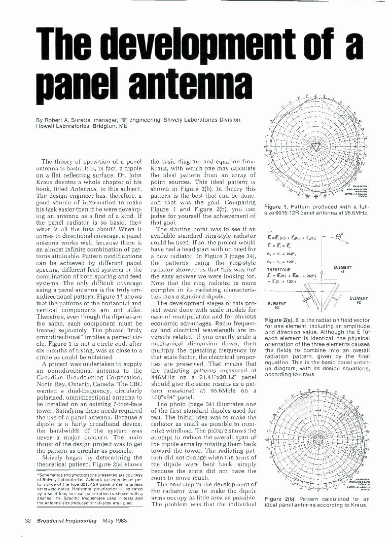
The development of apanel antennaBy Robert A. Surette, manager, RF engineering, Shively Laboratories Division,Howell Laboratories, Bridgton, ME
The theory of operation of a panelantenna is basic; it is, in fact, a dipoleon a flat reflecting surface. Dr. JohnKraus devotes a whole chapter of hisbook, titled Antennas, to this subject.The design engineer has, therefore, agood source of information to makehis task easier than if he were develop-ing an antenna as a first of a kind. Ifthe panel radiator is so basic, thenwhat is all the fuss about? When itcomes to directional coverage, a panelantenna works well, because there isan almost infinite combination of pat-terns attainable. Pattern modificationscan be achieved by different panelspacing, different feed systems or thecombination of both spacing and feedsystems. The only difficult coverageusing a panel antenna is the truly om-nidirectional pattern. Figure 1* showsthat the patterns of the horizontal andvertical components are not alike.Therefore, even though the dipoles arethe same, each component must betreated separately. The phrase "trulyomnidirectional" implies a perfect cir-cle. Figure 1 is not a circle and, aftersix months of trying, was as close to acircle as could be obtained.
A project was undertaken to supplyan omnidirectional antenna to theCanadian Broadcasting Corporation,North Bay, Ontario, Canada. The CBCwanted a dual -frequency, circularlypolarized, omnidirectional antenna tobe installed on an existing 7 -foot -facetower. Satisfying these needs requiredthe use of a panel antenna. Because adipole is a fairly broadband device,the bandwidth of the system wasnever a major concern. The mainthrust of the design project was to getthe pattern as circular as possible.
Shively began by determining thetheoretical pattern. Figure 2(a) shows
'Schematics and photographs presented are courtesyof Shively Laboratories. Azimuth patterns depict per-formance of the type 6015-12R panel antenna unlessotherwise noted. Horizontal polarization is Indicatedby a solid line; vertical polarization is shown with adashed line. Specific frequencies used in tests andthe antenna size (reduced or full-size) are noted.
the basic diagram and equation fromKraus, with which one may calculatethe ideal pattern from an array ofpoint sources. This ideal pattern} isshown in Figure 2(b). In theory thispattern is the best that can be done,and that was the goal. ComparingFigure 1 and Figure 2(b), you canjudge for yourself the achievement ofthat goal.
The starting point was to see if anavailable standard ring -style radiatorcould be used. If so, the project wouldhave had a head start with no need fora new radiator. In Figure 3 (page 34),the patterns using the ring -styleradiator showed us that this was notthe easy answer we were looking for.Note that the ring radiator is morecomplex in its radiating characteris-tics than a standard dipole.
The development stages of this pro-ject were done with scale models forease of manipulation and for obviouseconomic advantages. Radio frequen-cy and electrical wavelength are in-versely related. If you exactly scale amechanical dimension down, thenmultiply the operating frequency bythat scale factor, the electrical proper-ties are preserved. That means thatthe radiating patterns measured at446MHz on a 21.41"x20.12" panelshould give the same results as a pat-tern measured at 95.6MHz on a100"x94" panel.
The photo (page 34) illustrates oneof the first standard dipoles used fortest. The initial idea was to make theradiator as small as possible to mini-mize windload. The picture shows theattempt to reduce the overall span ofthe dipole arms by rotating them backtoward the tower. The radiating pat-tern did not change when the arms ofthe dipole were bent back, simplybecause the arms did not have theroom to move much.
The next step in the development ofthe radiator was to make the dipolearms occupy as little area as possible.The problem was that the individual
Figure 1. Pattern produced with a full-size 6015-12R panel antenna at 95.6MHz.
IF:
= r0,1+ r,(0,) + r,(%),
= E, =
0, = 0, + 240°,
0, = 0, + 120°,
THEREFORE:
E, = r,(0,) r;(8, + 240°)+ + 120°)
ELEMENT#3
ELEMENT41
ELEMENT42
Figure 2(a). E is the radiation field vectorfor one element, including an amplitudeand direction value. Although the E foreach element is identical, the physicalorientation of the three elements causesthe fields to combine into an overallradiation pattern, given by the finalequation. This is the basic panel anten-na diagram, with its design equations,according to Kraus.
Figure 2(b). Pattern calculated for anideal panel antenna according to Kraus.
32 Broadcast Engineering May 1983

MOBILETELEVISION UNITS
$189,000Leasing Plans
Available
Hitachi 3 -FP 22 3 tube cameras with microprocesso forautomatic set-up, 10:1 lens and all equipment for studio orENG use 3 O'Connor Fluid Heads Tripods, spreadersand dollies 3 Christie Reflex 20 batteries and 1 charger
16001 -AN Grass Valley Production Switcher
Character Generator System with Chyron VP -1and Sony SMC 70 Microcomputer Sony 3/4' VTRs5850/5800 HVS516/16L TBC Tektronix TestEquipment Yamaha 12 Input Audio Board Fullymonitored - B&W and color Full audio and video patching On board power and air conditioning
$312,600 Hitachi 3-SK91 3 tube color cameras
0:1 lens, Plumbicons or Saticons and all equipment forstudio or ENG use 3 O'Connor Fluid Heads Tripods,spreaders and dollies 3 Christie Reflex 20 batteries with1 charger 16001 -AN Grass Valley Production Switcher Character Generator System with Chyron VP -1 andSony SMC 70 Microcomputer Sony 3/4" VTRs 5850/5800 Quantel DFS 1750 B TBC /Synchronizer TektronixTest Equipment Yamaha 16 Input Audio Board Fullymonitored - B&W and color Full audio and video patching On board power and air conditioning
DESIGNED TO ACCOMMODATE 1" HITACHI VTRs - TRIAX ADAPTORS ALSO AVAILABLE
LERROELECTRICAL CORPORATION
3125 N. Broad Street, Philadelphia, Pa 19132
For more information, call Bob McTamney at (215) 223-8200
MOBILE UNITS ENGINEERED AND BUILT TO YOUR REQUIREMENTS
arms need to be 1/4 -wavelength -long(X14) at a frequency ft, to tune that fre-quency. The shape of the arms mini-mized their length. Also, vertical para-sitic elements helped shape the ver-tical pattern and gave general infor-mation on how to manipulate a pat-tern.
With the shape of the dipole fixed,the method of feeding the dipoles wasnext. Because the bandwidth was notcritical, a common shunt feedlinesystem was chosen to feed the radia-tors, instead of a broadband branchfeed. That left the type of balun to bedeveloped. Because the standard feedsystem provides only one tap per bay,a 4 -post balun with two inputs was notworkable. The hope was to have asingle input with four arms attached-two for horizontal and two for verticalcomponents. The first model wassimilar to that shown in the photo(page 38, upper left), except it only hadone feed point instead of two. A sec-ond feed point was added becausethe single -feed balun lacked symmetryof radiation. The model shown in thephoto radiated with one set of arms alittle longer than X/4 and the other setof arms shorter than X/4. The overalltuning of the radiator was 446MHz.The two sets of arms were phased 90°apart to yield circular radiation.Figure 4 (page 38) shows the meas-
Figure 3. Pattern produced by a reduced -
size type 6810 antenna using a ring -styleradiator at 446MHz.
ured pattern of the radiator on ascreen made of 1/2"x1/2" wire mesh.Figure 5 on page 38 shows the arraypatterns measured when three ofthese radiators were driven in phasewith equal amplitude. The patternsobtained using this type of balun metpresent industry -acceptable standardsof ± 2.4dB. However, the goal of theproject was ± 1.5dB, so a differentbalun was tested.
The photo (upper right, page 38)shows a close view of the final design
Standard dipoles used in early testswere rotated back toward the tower toreduce span and wind loading. Areduced -size model is shown.
of the radiator. It consists of a stan-dard 2 -post balun with two sets ofarms attached to each post. The bot-tom arms are the driven elements orpositive arms of the dipoles, and thetop set are the negative arms. Thread-ed rods at the dipole ends are used fortuning. Note that two arms have morethreaded rod showing than the othertwo. The longer arms are defined as
Continued on page 38
SCH/Phase-with simplicity!
Why guess what the real SC/H phase iswhen you can read it directly on theModel 3258?
precise SC/H phase measurementtime base error measurementcorrect color frame identificationaccurate digital readout
Available in both NTSC and PAL versions.
THE GRASS VALLEY GROUP, INC.P.O. Box 1114 Grass Valley, Ca. 95945 USA TEL (916)273-8421 TWX 910 530 8280
A TEKTRONIX COMPANY
34 Broadcast Engineering May 1983
Circle (24) on Reply Card
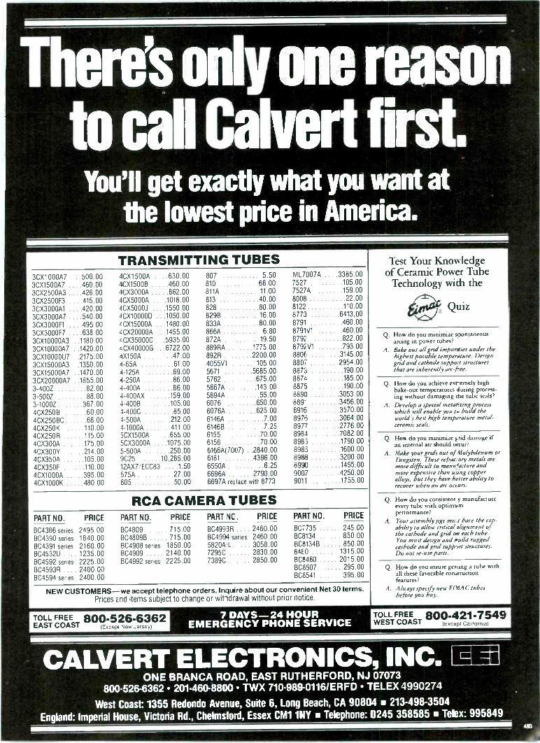
There's only one reasonto call Calvert first.
You'll get exactly what you want atthe lowest price in America.
TRANSMITTING TUBES3CX1000A7 ...500.00 4CX1500A ....630.00 807 5.50 ML7007A ....3385.003CX1500A7 ....460.00 4CX1500B 460.00 810 68.00 7527 105.00
3CX2500A3 ....426.00 4CX3000A 862.00 811A 11 00 7527A 159.00
3CX2500F3 ....415.00 4CX5000A . . . .1018.00 813 40.00 8008 22.00
3CX3000A1 ....420.00 4CX5000J . ...1550.00 828 80.00 8122 110.00
3CX3000A7 ....540.00 4CX10000D ...1050.00 829B 16.00 8773 6413.00
3CX3000F1 ....495.00 'CX15000A ...1480.00 833A 80.00 8791 460.00
3CX3000F7 ....638.00 4CX20000A ...1455.00 866A 6.80 8791V1 460.00
3CX10000A3 ..1180.00 LCX35000C ...5935.00 872A 19.50 8792 822.00
3CX10000A7 ..1420.00 4CX40000G ...6722.00 889RA .. ..1775.00 8792V1 793.00
3CX10000U7 ..2175.00 4X150A 47.00 892R . 2200.00 8806 3145.00
3CX15000A3 ..1350.00 4-65A 61 00 4055V1 105.00 8807 2954.00
3CX15000A7 ..1470.00 4-125A 69.00 5671 .5685.00 8873 190.00
3CX20000A7 ..1855.00 4-250A 86.00 5762 675.00 8874 185.00
3-400Z 82.00 4-400A 86.00 5867A .....143.00 8875 190.00
3-500Z 88.00 4-400AX 159.00 5894A . . 55.00 8890 3053.00
3-1000Z 367.00 4-400B 105.00 6076 . .....650.00 889" 3456.00
4CX250B 60.00 4-400C 85.00 6076A .....625.00 8916 3570.00
4CX250BC 68.00 4-500A 212.00 6146A 7.00 8976 3064.00
4CX250K 110.00 4-1000A 411.00 6146E1 7.25 8977 2776.00
4CX250R 115.00 5CX1500A 655.00 6155 70.00 8984 7082.00
4CX300A 175.00 5CX3000A ..1075.00 6156 70.00 8985 1790.00
4CX300Y 214.00 5-500A 250.00 6166A(7007) .2840.00 8985 1600.00
4CX350A 105.00 9C25 10,285.00 6181 4396.00 8988 3200.00
4CX350F 110.00 12AX7/ECC83 .1.50 6550A 6 25 8990 1455.00
4CX1000A 395.00 575A . 27.00 6696A 2790.00 9007 4250.00
4CX1000K 480.00 805 50.00 6697A rer lace with 8773 9011 1755.00
RCA CAMERA TUBESPART NO. PRICE PART NO. PRICE PART NC. PRICE PART NO. PRICE
BC4386 series 2495.00 BC4809 715.00 BC4993R 2460.00 BC7735 245.00
BC4390 series 1840.00 BC4809B 715.00 BC4994 series 2460.00 BC8134 850.00
BC4391 series 2160.00 BC4908 series 1850.00 5820A'L 3058.00 BC8134B 850.00
BC4532U .... 1235.00 BC4909 2140.00 7295C 2830.00 84E0 1315.00
BC4592 series 2225.00 BC4992 series 2225.00 7389C . .... 2850.00 BC8480 2015.00
BC4593R .... 2400.00 BC8507 295.00
BC4594 series 2400.00 BC8541 395.00
NEW CUSTOMERS -we accept telephone orders. Inquire about our convenient Net 30 terms.Prices End items subject to change or witidrawal without prior notice
Test Your Knowledgeof Ceramic Power Tube
Technology with the
fie Quiz
Q. How do you minimize spontaneousarcing in power tubes?
A. Bake out all grid impurities under thehighest possible temperature. Designgrid and cathode support structuresthat are inherently arc -free.
Q. How do you achieve exremely highbake -out temperatures fluting process-ing without damaging the tube seals?
A. Develop a special metatizing processwhich will enable you to build theworld's best high temperature metal -ceramic seals.
Q. How do you minimize grid damage ifan internal arc should occur?
A. Make your grids out of Molybdenum orTungsten. These refrac.-ory metals aremore difficult to mameacture andmore expensive than using copperalloys, but they have better ability torecover when an arc occurs.
Q. How do you consistent y manufactureevery tube with optimumperformance?
A. Your assembly figs must have the cap-ability to allow critical alignment ofthe cathode and grid ow each tube.You must design and Build ruggedcathode and grid support structures.Do not re -use parts.
Q. How do you insure getting a tube withall these favorable constructionfeatures?
A. Always specify new EIMAC tubesbefore you buy.
TOLLFREECOAST
800-526-6362(Except New Jersey)
7 DAYS -24 HOUREMERGENCY PHONE SERVICE
TOLL FREEWEST COAST
800-421-7549Except California)
CALVERT ELECTRONICS, INC.ONE BRANCA ROAD, EAST RUTHERFORD, NJ 07073
800-526-6362 201.460-8800 TWX 710-989-0116/ERFD TELEX 4990274
West Coast: 1355 Redondo Avenue, Suite 6, Long Beach, CA 90804 213-498-3504
England: Imperial House, Victoria Rd., Chelmsford, Essex CM1 1NY Telephone: 0245 358585 Telex: 995849493
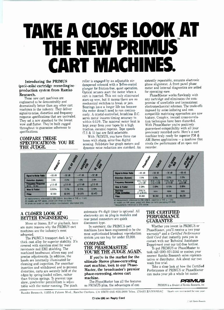
TAKE A CLOSE LOOK ATTHE NEW PRIMUS'CART MACHINES.
Introducing the PRIMUS(prei-mils) cartridge recording/re-production system from RamkoResearch.
These new cart machines areengineered to be demonstrably anddramatically better than any other cartmachines in the industry. They deliversignal-to-noise, distortion and frequencyresponse specifications that are unrivaled.They set a new standard for the lowestwow and flutter. They're built ruggedthroughout to guarantee adherence tospecifications.
COMPARE THESESPECIFICATIONS: YOU BETHE JUDGE.
roller is engaged by an adjustable air -dampened solenoid with a 'Ibflon-coatedplunger for friction -free, quiet operation.Optical sensors start the motor when acart is inserted. This not only eliminatedstart-up wow, but it means there are nomechanical switches to break or jam.Bearings have a longer life too becausethe motor doesn't need to run continu-ously. A crystal -controlled, brushless D.C.servo motor insures timing accuracy towithin 0.05%. The minimal motor heat iskept away from your tapes by a hightraction, ceramic capstan. 'Pape speeds(7.5 & 15 ips) are field selectable.
With PRIMUS, you have three cuetones with sharp, error -free digitalsensing. Solidstate bar graph meters anddynamic noise reduction are standard. An
sistently repeatable, accurate electronicphase alignment. A front panel phasemeter and internal diagnostics are addedfor operating ease.
PhaseMaster works flawlessly withany cartridge and eliminates the com-promise of unreliable and inconsistentelectromechanical schemes. The trade-offsimposed by noise -inducing and non -compatible matrixing approaches are nowhistory. Complex, inexact cross -correla-tion techniques have been discarded.With PhaseMaster you're positivelyguaranteed compatibility with all yourpreviously recorded carts. Here's a cartmachine truly ready for superior FM &AM Stereo applications -a machine thatrivals the performance of an open reelrecorder.
Signal -to -Noise Ratio -60 dB -50 dB -47 013 -52 cell
Distortion (SystemT 3 9% 2 0°A 1 03'0 2 011,
Frequency Response:50 Hz 16 YHZ
±1 5 dB ±2 0 dB ±2 0 dB ±2 0 18
Wow 8 Flutter: 0095% 0.2% 015% 0.15°
Price: 02 550 82.810 81,979 52.4M
All ineasurements referenced a 160 nWb m dislortiOn Is TAD a 1 kHz
All models are RIP stereo. priced with to en cue tones.All prices are based on latest le rotation 3/83.
RIP
co 0es,
Slonalito-Noise Ratio: -65 dB -59 1B -56 a8 -60 06
Distortion (Sylern1: 0.9% 0.84 0.8% 030%
gut . le kHzFrequency Res30 ±1.5 dB
ie az . r we+5.-1J dB
315 Pt *WI±10 dB
':-': " 'E-:j2 0 dB
Wow 6 Flutter: 0.08% 0.09'- 0.15% 0 06%
Real -tine locks toPhase Crteeticn: 5° 0161thze
nen: nOne 901e
Price: f3,850 $5200 55.330 56 230
usuremen41 refer chstortm is TH0 r 1
400
A CLOSER LOOK ATBETTER ENGINEERING
Mono or Stereo, RiP or playback, hereare more reasons why the PRIMUS cartmachines are the industry's mostadvanced.
The PRIMUS transport deck is %"thick cast alloy for superior stability. It'scovered with stainless steel for wearresistance and EMI shielding. Themachined headmount allows easy andprecise adjustments. In addition, theheads are internally illuminated forcleaning and inspection. For smootherinsertion and withdrawal and to preventdistortion, carts are securely held at theedges by spring -loaded rollers, ratherthan friction springs. lb prevent tapeskew, pinchroller parallellism is adjus-table with the motor running. The pinch
automatic 41/2 digit timer is optional. Allelectronics are on plug-in modules andrear panel connectors are quickdisconnect type.
In summary, the PRIMUS cartmachines have been engineered to be themost sophisticated broadcast reproductionsystem you can buy for under $3,000.
COMPARETHE PHASEMASTERTYOU'RE THE JUDGE AGAIN.
If you're in the market for theultimate Stereo phase -correctingcart machine, look to our Phase -Master, the broadcaster's premierphase -correcting, stereo cartmachine.
The PhaseMaster has all the featuresas PRIMUS plus, the advantages of con -
THE CERTIFIEDPERFORMANCEGUARANTEE
Whether you invest in PRIMUS orPhaseMaster, you'll receive a two yearwarranty* and a Certified PerformanceGold Card that instantly puts you incontact with our lbchnical AssistanceDepartment over our toll -free hotline.
lb put PRIMUS or PhaseMaster totask call (800) 821-2545 or contact yournearest Ramko Research sales represen-tative or distributor. Ask about our twoweek free trial.
Take a close look at how the CertifiedPerformance of PRIMUS or PhaseMastercan make your job a whole lot easier.
PRIMUSPRIMUS is a division of Ramko Research, Inc.
Ramko Research, 11355-A Folsom Blvd., Rancho Cordova, CA 95670 (9161 635-3600 'Flex: 176493 RAMKOSAC *Heads are warranted for one year.
Circle (26) on Reply Card1983 Ramko Research
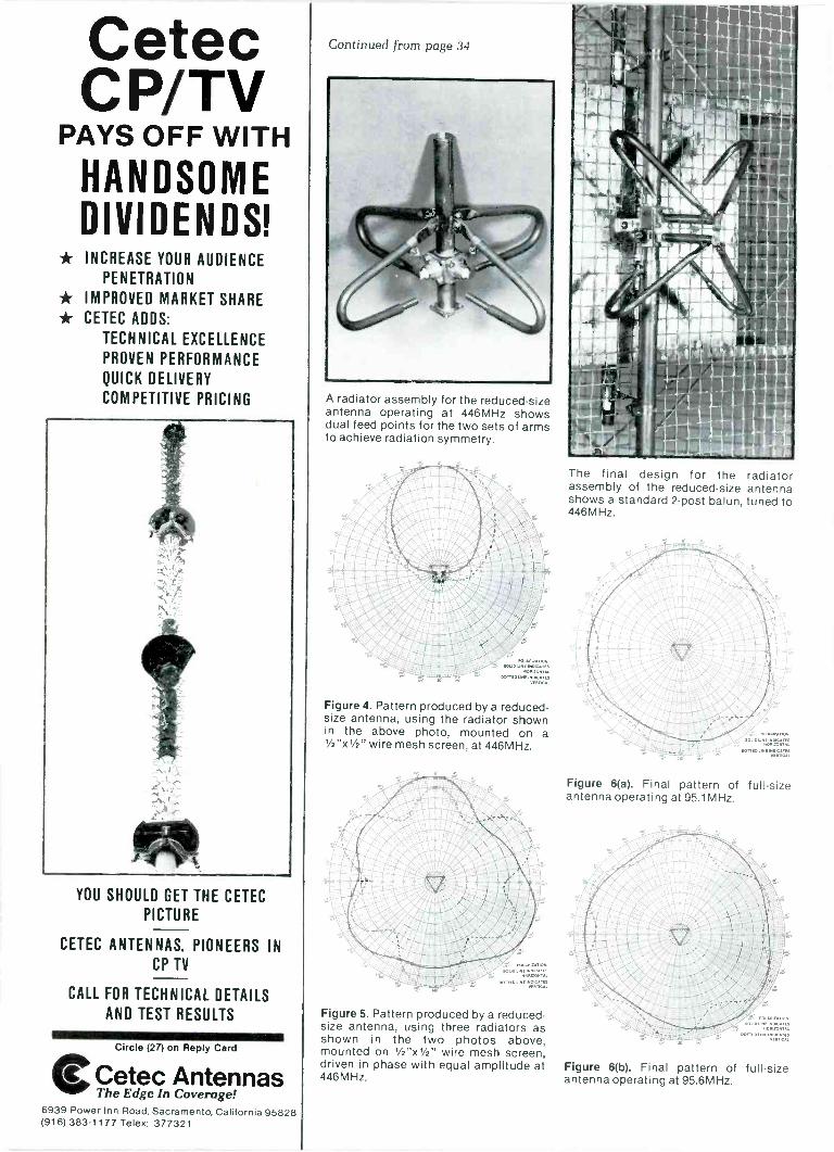
CetecCP/TV
PAYS OFF WITH
HANDSOMEDIVIDENDS!
* INCREASE YOUR AUDIENCEPENETRATION
* IMPROVED MARKET SHARE* CETEC ADDS:
TECHNICAL EXCELLENCE
PROVEN PERFORMANCE
QUICK DELIVERY
COMPETITIVE PRICING
YOU SHOULD GET THE CETEC
PICTURE
CETEC ANTENNAS, PIONEERS INCP TV
CALL FOR TECHNICAL DETAILS
AND TEST RESULTS
Circle (27) on Reply Card
Cetec Antennas
Continued from page 34
A radiator assembly for the reduced -sizeantenna operating at 446MHz showsdual feed points for the two sets of armsto achieve radiation symmetry.
Figure 4. Pattern produced by a reduced -
size antenna, using the radiator shownin the above photo, mounted on a1/2'50/2" wire mesh screen, at 446MHz.
Figure 5. Pattern produced by a reduced -
size antenna, using three radiators asshown in the two photos above,mounted on 1/2"x1/2" wire mesh screen,driven in phase with equal amplitude at446MHz.
The final design for the radiatorassembly of the reduced -size antennashows a standard 2 -post balun, tuned to446MHz.
Figure 6(a). Final pattern of full-sizeantenna operating at 95.1 MHz.
Figure 6(b). Final pattern of full-sizeantenna operating at 95.6MHz.
The Edge In Coverage!6939 Power Inn Road, Sacramento, California 95828(916) 383-1 177 Telex: 377321
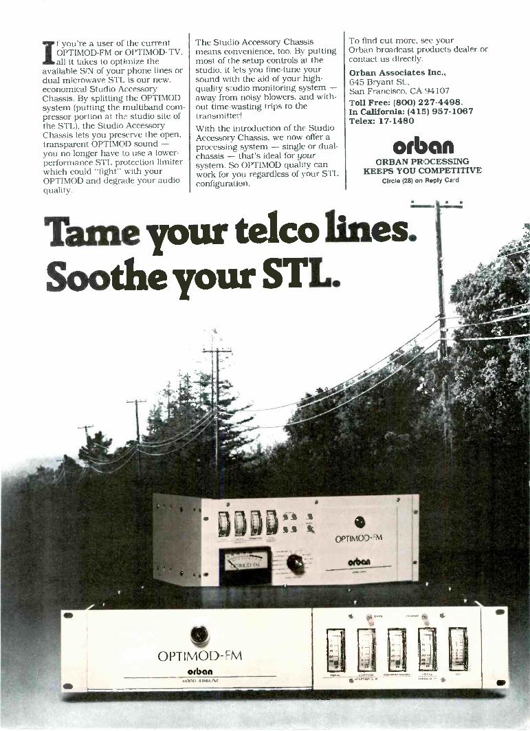
If you're a user of the currentOPTIMOD-FM or OPTIMOD-TV,all it takes to optimize the
available S/N of your phone lines ordual microwave STL is our new,economical Studio AccessoryChassis. By splitting the OPTIMODsystem (putting the multiband com-pressor portion at the studio site ofthe STL), the Studio AccessoryChassis lets you preserve the open,transparent OPTIMOD sound -you no longer have to use a lower -performance STL protection limiterwhich could "fight" with yourOPTIMOD and degrade your audioquality.
The Studio Accessory Chassismeans convenience, too. By puttingmost of the setup controls at thestudio, it lets you fine-tune yoursound with the aid of your high -quality studio monitoring system -away from noisy blowers, and with-out time -wasting trips to thetransmitter!With the introduction of the StudioAccessory Chassis, we now offer aprocessing system - single or dual -chassis - that's ideal for yoursystem. So OPTIMOD quality canwork for you regardless of your STLconfiguration.
To find out more, see yourOrban broadcast products dealer orcontact us directly.
Orban Associates Inc.,645 Bryant St.,San Francisco, CA 94107Toll Free: (800) 227-4498.In California: (415) 957-1067Telex: 17-1480
orbanORBAN PROCESSING
KEEPS YOU COMPETITIVECircle (28) on Reply Ca d
Tame your telco lines.Sootheyour STL.
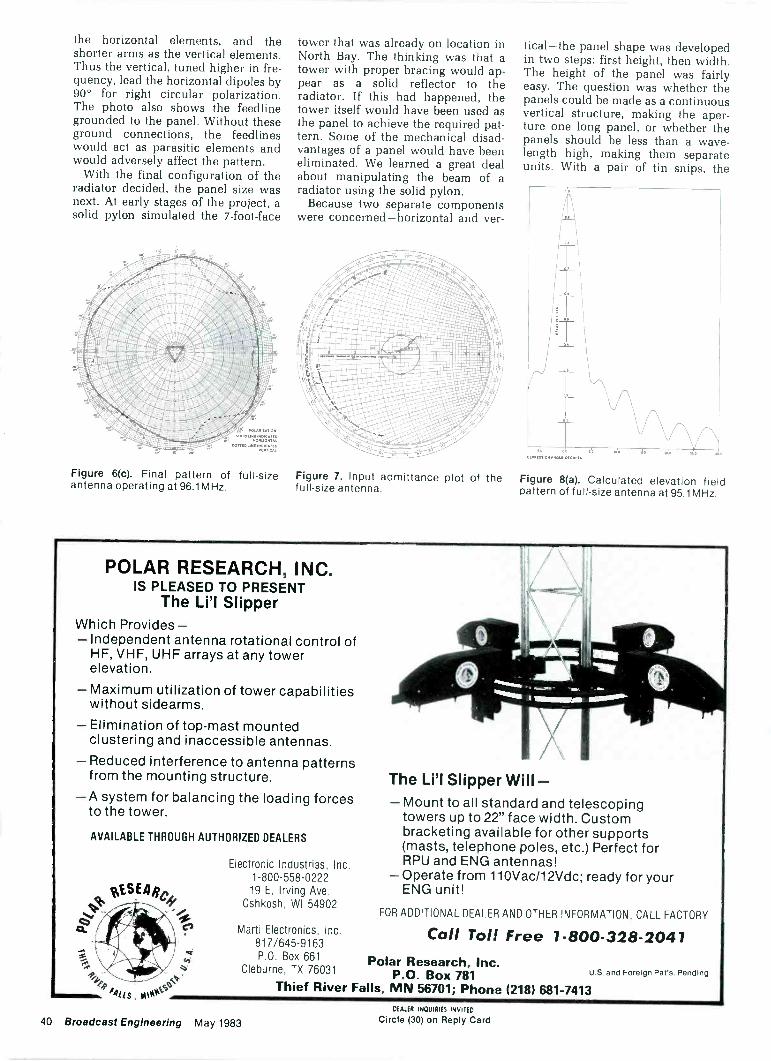
the horizontal elements, and theshorter arms as the vertical elements.Thus the vertical, tuned higher in fre-quency, lead the horizontal dipoles by90° for right circular polarization.The photo also shows the feedlinegrounded to the panel. Without theseground connections, the feedlineswould act as parasitic elements andwould adversely affect the pattern.
With the final configuration of theradiator decided, the panel size wasnext. At early stages of the project, asolid pylon simulated the 7 -foot -face
tower that was already on location inNorth Bay. The thinking was that atower with proper bracing would ap-pear as a solid reflector to theradiator. If this had happened, thetower itself would have been used asthe panel to achieve the required pat-tern. Some of the mechanical disad-vantages of a panel would have beeneliminated. We learned a great dealabout manipulating the beam of aradiator using the solid pylon.
Because two separate componentswere concerned-horizontal and ver-
tical -the panel shape was developedin two steps: first height, then width.The height of the panel was fairlyeasy. The question was whether thepanels could be made as a continuousvertical structure, making the aper-ture one long panel, or whether thepanels should be less than a wave-length high, making them separateunits. With a pair of tin snips, the
1/011.1.610.10.1(100 0.016 IS "10 0 IS 0
Figure 6(c). Final pattern of full-size Figure 7. Input admittance plot of the Figure 8(a). Calculated elevation fieldantenna operating at 96.1MHz. full-size antenna. pattern of full-size antenna at 95.1MHz.
POLAR RESEARCH, INC.IS PLEASED TO PRESENT
The Li'l SlipperWhich Provides-- Independent antenna rotational control of
HF, VHF, UHF arrays at any towerelevation.
Maximum utilization of tower capabilitieswithout sidearms.
Elimination of top -mast mountedclustering and inaccessible antennas.
Reduced interference to antenna patternsfrom the mounting structure.
A system for balancing the loading forcesto the tower.
AVAILABLE THROUGH AUTHORIZED DEALERS
sESEAc'N
ca. C,
trTo
44...
ommom....
4,2,.
11. .
r41 IS. IMW6tc3.r
Electronic Industries, Inc.1-800-558-022219 E. Irving Ave.
Oshkosh, WI 54902
Marti Electronics, Inc.817/645-9163P.O. Box 661
Cleburne, TX 76031
The Li'l Slipper Will -- Mount to all standard and telescoping
towers up to 22" face width. Custombracketing available for other supports(masts, telephone poles, etc.) Perfect forRPU and ENG antennas!
- Operate from 110Vac/12Vdc; ready for yourENG unit!
FOR ADDITIONAL DEALER AND OTHER INFORMATION, CALL FACTORY
Call Toll Free 1-800-328-2041Polar Research, Inc.
P.O. Box 781Thief River Falls, MN 56701; Phone (218) 681-7413
U.S. and Foreign Pat's. Pending
40 Broadcast Engineering May 1983DEALER INQUIRIES INVITED
Circle (30) on Reply Card
ART BIGGS ONMASTER CONTROLAUTOMATION.
In the 1950's, twoin Tulsa built a small, crude, mechanicaldevice to automate station breaks. One ofthose engineers, Art Biggs, is now VicePresident Engineering, Corinthian Broad-casting-and his interest in master controlautomation remains strong. The respected,34 -year veteran of the industry works withthe engineering staffs of all six Corinthianstations, of which two-WISH-TV Indiana-polis, and KXTV Sacramento-are nowusing BIAS Master Control Automation.
EVEN FORMER SKEPTICS LIKE IT"At first, some of the engineering staff wereenthusiastic, some were skeptical. But withinthree weeks after it was released to them,they did their first total day's operation onthe MCA system. And now, even the mostskeptical depend upon it."
CREATES 'TOGETHERNESS"MCA brings the traffic department andtechnical department closer together. Thismakes everything go more smoothly foreveryone."
GIVES MORE CONTROL"I think some engineers are afraid that withMCA, they'll be giving control of theiroperation to a machine and be a robot,sitting there, watching it. Actually, the exactopposite is true. Even the most vocal of our
engineers who opposed the idea havefound that MCA frees them from so manynitty-gritty, demanding, split-second, buttonpushers, that they have more time to learnwhat all the machine can do and can doeven more than they could before. Now, ifyou take it away from them for somereason, there's a lot of yelling to get it back.They've learned they didn't relinquish control-they gained a tool that gives them greatercontrol."
WHO NEEDS IT?"How do you know if you need MCA? If thechief engineer is constantly trouble -shootingswitching errors or one engineer is a totalslave to switcher buttons, MCA can cer-tainly help. It also liberates personnel frommany manual chores, such as log -keeping,to make their time more productive."
FOR BIAS OR NON -BIAS SYSTEMS"All of our stations are on the BIAS traffic sys-tem, so by using the BIAS MCA, we're dealingwith one manufacturer, one computer, andone system that embraces the master controloperation, the traffic operation, the finan-cial operation, word processing, film inven-tory. One source for everything."
For a free brochure on how BIAS MasterControl Automation can interface with youron -air switcher and traffic system, write BIASMarketing.
111/A11®A PRODUCT OF DATA COMMUNICATIONS CORPORATION3000 Directors Row, Memphis, Tennessee 38131, 901-345-3544
Circle (31) on Reply Card
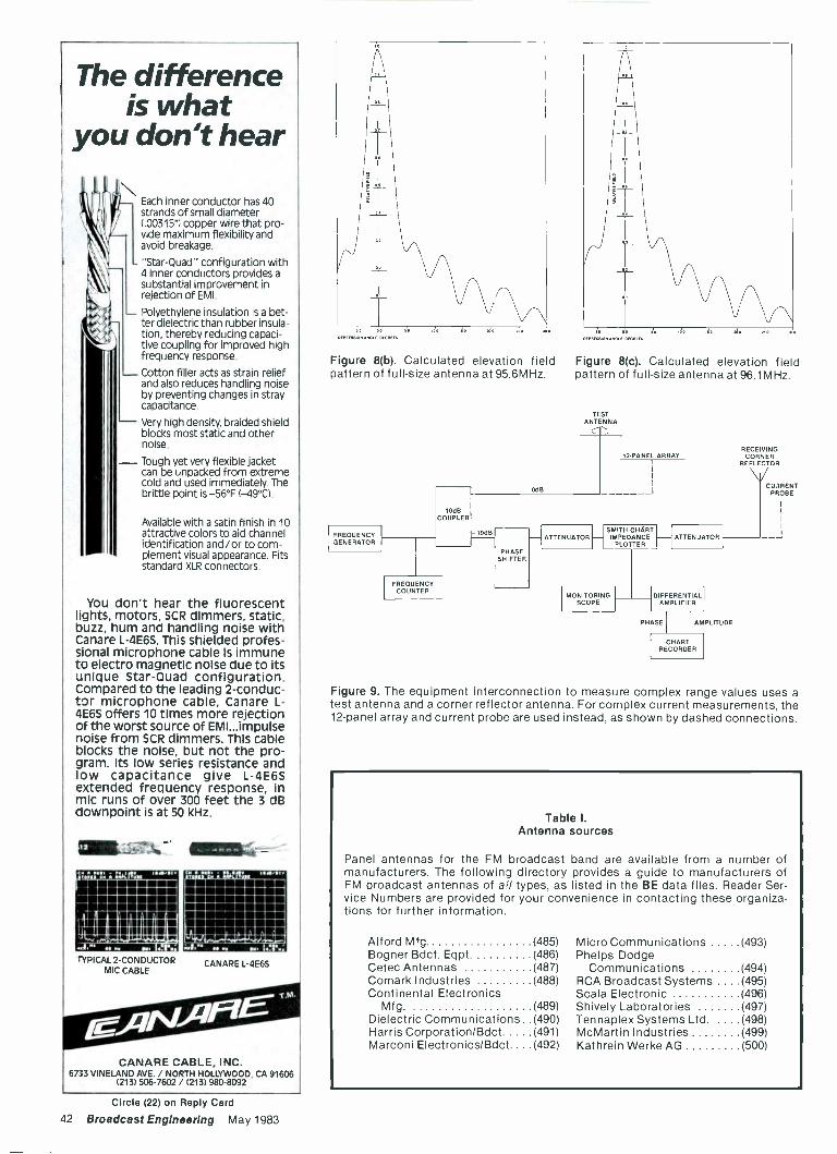
The differenceis what
you don't hear
Each inner conductor has 40strands of small diameter(.00315") copper wire that pro-vide maximum flexibility andavoid breakage.
"Star -Quad" configuration with4 inner conductors provides asubstantial improvement inrejection of EMI.
Polyethylene insulation is a bet-ter dielectric than rubber insula-tion, thereby reducing capaci-tive coupling for improved highfrequency response.
Cotton filler acts as strain reliefand also reduces handling noiseby preventing changes in straycapacitance.
Very high density, braided shieldblocks most static and othernoise.
- Tough yet very flexible jacketcan be unpacked from extremecold and used immediately. Thebrittle point is -56°F (-49°C).
Available with a satin finish in 10attractive colors to aid channelidentification and/or to com-plement visual appearance. Fitsstandard XLR connectors.
You don't hear the fluorescentlights, motors, SCR dimmers, static,buzz, hum and handling noise withCanare L -4E65. This shielded profes-sional microphone cable is immuneto electro magnetic noise due to itsunique Star -Quad configuration.Compared to the leading 2 -conduc-tor microphone cable, Canare L-4E6S offers 10 times more rejectionof the worst source of EMI...impulsenoise from SCR dimmers. This cableblocks the noise, but not the pro-gram. Its low series resistance andlow capacitance give L-4E6Sextended frequency response, inmic runs of over 300 feet the 3 dBdownpoint is at 50 kHz.
1F1111L.77,%. 11111111114
MMEIIMMINNIM
PN11111111,11111
-111111111.111MMIE
ISM minunvolnomminiminiam
BM
5124TYPICAL 2 -CONDUCTOR
MIC CABLE
C MIN 1 MUM II IIIMIIIII=11111111=111
MEMOHR'.112:71PAPNP
MOO I...
CANARE L-4E6S
CANARE CABLE, INC.6733 VINELAND AVE. / NORTH HOLLYWOOD, CA 91606
(213) 506-7602 / (213) 980-8092
A 0DEM DOLE DEORUS DEPRESS. EKE'. 'DECREES
- S 0
Figure 8(b). Calculated elevation field Figure 8(c). Calculated elevation fieldpattern of full-size antenna at 95.6MHz. pattern of full-size antenna at 96.1MHz.
FREQUENCYGENERATOR
TESTANTENNA
OdB
12.PANEL ARRAY
10dBCOUPLER
FREQUENCYCOUNTER
00B
PHASESHIFTER
ATTENUATORSMITH CHARTIMPEDANCE
PLOTTER
MONITORINGSCOPE
ATTENUATOR
DIFFERENTIALAMPLIFIER
PHASE AMPLITUDE
CHARTRECORDER
RECEIVINGCORNER
REFLECTOR
CURRENTPROBE
Figure 9. The equipment interconnection to measure complex range values uses atest antenna and a corner reflector antenna. For complex current measurements, the12 -panel array and current probe are used instead, as shown by dashed connections.
Table I.Antenna sources
Panel antennas for the FM broadcast band are available from a number ofmanufacturers. The following directory provides a guide to manufacturers ofFM broadcast antennas of al/ types, as listed in the BE data files. Reader Ser-vice Numbers are provided for your convenience in contacting these organiza-tions for further information.
Alford Mfg. (485) Micro Communications (493)Bogner Bdct. Eqpt. (486) Phelps DodgeCetec Antennas (487) Communications (494)Comark Industries (488) RCA Broadcast Systems . (495)Continental Electronics Scala Electronic (496)
Mfg. (489) Shively Laboratories (497)Dielectric Communications . . (490) Tennaplex Systems Ltd. . . (498)Harris Corporation/Bdct (491) McMartin Industries (499)Marconi Electronics/Bdct.. . . (492) Kathrein Werke AG (500)
Circle (22) on Reply Card
42 Broadcast Engineering May 1983
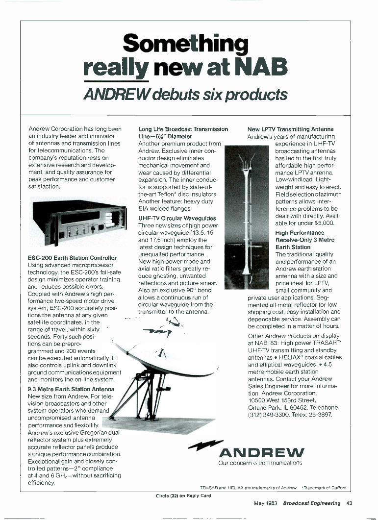
Somethingreally new at NABANDREW debuts six products
Andrew Corporation has long beenan industry leader and innovatorof antennas and transmission linesfor telecommunications. Thecompany's reputation rests onextensive research and develop-ment, and quality assurance forpeak performance and customersatisfaction.
ESC -200 Earth Station ControllerUsing advanced microprocessortechnology, the ESC -200's fail-safedesign minimizes operator trainingand reduces possible errors.Coupled with Andrew's high per-formance two -speed motor drivesystem, ESC -200 accurately posi-tions the antenna at any givensatellite coordinates, in therange of travel, within sixtyseconds. Forty such posi-tions can be prepro-grammed and 200 eventscan be executed automatically. Italso controls uplink and downlinkground communications equipmentand monitors the on-line system.
9.3 Metre Earth Station AntennaNew size from Andrew. For tele-vision broadcasters and othersystem operators who demanduncompromised antennaperformance and flexibility.Andrew's exclusive Gregorian dualreflector system plus extremelyaccurate reflector panels producea unique performance combination.Exceptional gain and closely con-trolled patterns -2° complianceat 4 and 6 GHz-without sacrificingefficiency.
Long Life Broadcast TransmissionLine -6'A" DiameterAnother premium product fromAndrew. Exclusive inner con-ductor design eliminatesmechanical movement andwear caused by differentialexpansion. The inner conduc-tor is supported by state-of-the-art Teflon* disc insulators.Another feature: heavy dutyEIA welded flanges.
UHF -TV Circular WaveguidesThree new sizes of high powercircular waveguide (13.5, 15and 17.5 inch) employ thelatest design techniques forunequalled performance.New high power mode andaxial ratio filters greatly re-duce ghosting, unwantedreflections and picture smear.Also an exclusive 90° bendallows a continuous run ofcircular waveguide from thetransmitter to the antenna.
-10405-.
New LPTV Transmitting AntennaAndrew's years of manufacturing
experience in UHF -TVbroadcasting antennashas led to the first trulyaffordable high perfor-mance LPTV antenna.Low-windload. Light-weight and easy to erect.Field selection of azimuthpatterns allows inter-ference problems to bedealt with directly. Avail-able for under $5,000.
High PerformanceReceive -Only 3 MetreEarth StationThe traditional qualityand performance of anAndrew earth stationantenna with a size andprice ideal for LPTV,small community and
private user applications. Seg-mented all -metal reflector for lowshipping cost, easy installation anddependable service. Assembly canbe completed in a matter of hours.
Other Andrew Products on displayat NAB '83: High power TRASAR°UHF -TV transmitting and standbyantennas HELIAX' coaxial cablesand elliptical waveguides 4.5metre mobile earth stationantennas. Contact your AndrewSales Engineer for more informa-tion. Andrew Corporation,10500 West 153rd Street,Orland Park, IL 60462. Telephone(312) 349-3300. Telex: 25-3897.
00°'ANDREWOur concern is communications
TRASAR and HELIAX are trademarks of Andrew *Trademark of DuPont.
Circle (32) on Reply Card
May 1983 Broadcast Engineering 43
height was reduced an inch at a cut. Asection of 1/2 -inch mesh was removedfrom the top and the bottom eachtime. This kept the radiator in thecenter of the panel. When the hori-zontal pattern changed for the worse,we stopped and backed up one cut.
Figure 10(a). Complex range real and im-aginary values of horizontal polarizationcomponent.
The height of the panel was 201/8inches, reduced scale (94 inches in fullsize). Constant checks during this pro-cess ensured that the hori-zontal pattern was not affected by theheight of the panel.
The width of the panel was not as
Figure 10(b). Complex range real and im-aginary values of vertical polarizationcomponent.
easy to determine, because the edgesof the panels had a significant impacton the horizontal pattern. The mountswere close to the edges of the panel. Ifthe panel edges touched anotherpanel, the patterns were adversely af-fected. On a later project, the mountswere attached just behind the solidsection of the panel, and the edges hadlittle effect on the pattern. Later an RF
Figure 10(c). Pattern for reduced -sizeantenna at 446MHz, calculated fromcomplex range real and imaginaryvalues given in Figures 10(a) and 10(b).
Shintron's NewEdit Code Generator
Edit Code Reader/Raster DisplayThe Shintron Model 646 reads SMPTE or EBU
code, displays data in eight digit, half inch high LED nu-merals and lets you key in data on the video raster inblack or reverse letters. Readable tape speed is from1/16 to 40 X. Front panel selection switch displays usercode.
The Model 647 generates SMPTE/EBU codeeither independently or in sync with incoming video.Time data is easily reset and user bits are set by thumbwheels on the front panel.
Circle reader service card or call (617) 491-8700for information.SHIPITRON
144 Rogers Street, Cambridge, MA 02142 Tel: (617) 491-8700 Telex: 921497Shintron Europe 198 Avenue Brugmann, 1180 Brussels, Belgium Tel: 02-347-2629 Telex 61202
Circle (33) on Reply Card
44 Broadcast Engineering May 1983
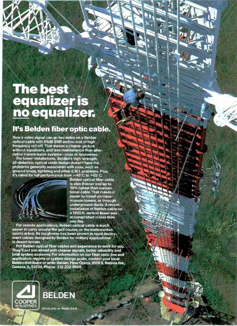
Now a video signal can go two miles on a Beldenoptical cable with 60dB SNR and no hint of highfrequency roll -off That means a cleaner picturewithout equalizers, and less maintenance than alter-native transmission systems-coax or microwave.
For tawer installations, Belden's high -strength,all -dielectric optical cable design doesn't have theproblems generally associated with coax, such asground loops, lightning and other E.M.I. problems. Plus,it's rated for full performance from -40 'C to +60 C.
Belden optical fiber cableis also thinner and up to30% lighter than conven-tional cable.That makes iteasier to install ontrans-mission towers, or throughunderground ducts. A recentinstallation of Belden cable ona 1500 ft. vertical tower wasaccomplished in less thanone day.
For remote applications, Belden optical cable is mucheasier to carry around the golf course, or the metropolitansports arena. Its toughness has been proven in rapid deploy-ment cables designed by Belden for military applicationsin desert terrain.
Pig Belden optical fiber cables and experience to work for you.They II put you ahead with cleaner signals, better reliability andtotal system economy. For information on our fiber optic line andapplication reports or system design guide, contact your localBelden distributor or write: Belden, Fiber Optics, 2000 S. Batavia Ave.,Geneva, IL 60134. Phone: 312-232-8900.
COOPERINDUSTRIES
BELDENCircle (34) on Reply Card
Figure 10(d). Vertical directivity is shownfor the reduced -size antenna describedby Figure 10(c).
One level of a type 6015P circularlypolarized FM antenna on the pattern testrange.
engineer from England related thesame type of effect with his panelantenna. But not knowing all of this, agreat deal of time was used to definethe panel width and the mountingbracket location. During the process,upper and lower frequencies werechecked to determine how sensitivepanel size was to frequency. It wasfound that patterns did change, butnot enough to cause problems.
More tests were made on the overalldesign, but with the- antenna designcompleted, it was time to build thefull-size panel and radiator. Duringthe model stages, all components werescaled from existing production itemsor were made so that the full-sizecould be easily built. Modifications tothe final design were not desiredunless absolutely necessary. When thefull-size antenna was built and set upon the pattern range, the results wereexactly as predicted. The transitionfrom scale model to full-size was asuccess. Not only did physical con-struction of the antenna work out, butmeasuring techniques developed atthe higher frequencies helped makethe testing of the full-size unit easier.
FREQUENCYGENERATOR
10dBOUPLER
It
HYBRIDCOUPLER
0d13
(voileHYBRID
COUPLER
3
AY
10dB
FREQUENCYCOUNTER
PHASESHIFTER
ANTENNAUNDER
TEST
HYBRIDCOUPLER
1- SMITH CHARTATTENUATOR IMPEDANCE
PLOTTER
MONITORINGSCOPE
ATTENUATOR
DIFFERENTIALAMPLIFIER
PHASE AMPLITUDE
CHARTRECORDER
Figure 11. Equipment interconnection to measure Smith Chart impedance.
The major adjustment was the amountof time needed to do anything in full-size. For example, the model was setup and taken in from the patternrange every day. A week was neededto get the full-size antenna on therotor. Once up, the full-size designstayed on the range until final accept-ance by the CBC. With the scalemodel, a whole series of changescould be made in a matter of hours. Infull-size, the same series would take aweek or more.
The final radiation patterns ac-cepted by the CBC are shown inFigures 6(a), 6(b), and 6(c) on page 38.The pattern changes with frequency,but the design goal of omnidirec-tionality, within ± 1.5dB, holds on allthree patterns. Another requirementof acceptance was minimum im-pedance change over the band. Figure7 (page 40) shows that the bandwidthof the system was never a problem. Toverify the elevation pattern for theCBC, phase and amplitude measure-ments were made on one completeface of the antenna. The photo (thispage) shows the 12 -panel array set outon the test rack. The data were fed in-to a computer and Figures 8(a), 8(b)and 8(c) resulted (page 40). Again, thepattern changes with frequency, butnot enough to cause problems.
When a project of this kind is under-taken, a great deal of time and effortgo into developing new test pro-cedures and manufacturing tech-niques that are needed for the specificproject. These techniques and pro-cedures are also useful in the test andmanufacture of standard products.One of the most important of thesedevelopments was called the complexrange. (See Figure 9, page 42.) Thecomplex range allows measurement
of the phase and amplitude of far -fieldpatterns of a radiating element, in-stead of the more common amplitude -only measurement. Figures 10(a) and10(b) show the measured complexsingle -panel pattern, and Figures 10(c)and 10(d) show the patterns calculatedfrom the measured data (page 44).
With a slight modification of thesystem, the near -field (complex) cur-rents of a radiator can be measured.This allows direct calculation of theelevation pattern of an array. Additionof quadrature hybrids (See Figure 11)changed the complex range to aSmith Chart impedance network. Thisnetwork was used to measure an ele-ment while driving the two adjacentelements in an array. This particularmeasuring technique is valuable whenthe mutuals coupling between baysare large enough to upset the self -impedance of a bay within an array.
Manufacturers in the United Statesand Europe are still producing panelsthey offered seven years ago. Anomnidirectionality of ± 2.4dB is thebest they offer for three panels perlevel. A project engineer from theCBC remarked that other manufac-turers said the advertising of Omni± 1.5dB was deceiving, because it wastheoretically impossible to achieve.The information in Figure 6 and thefact that the CBC has three such panelantennas in operation that meet theradiating patterns of Figure 6 shouldeventually show that the theoreticallyimpossible can be achievedwith some time and effort. :r:))))1
Editor's note:Portions of the material in this article were
presented to the Society of Broadcast Engineers inMarch 1982. The concepts covered in design and per-formance are presented to help broadcasters betterunderstand the equipment being used.
46 Broadcast Engineering May 1983
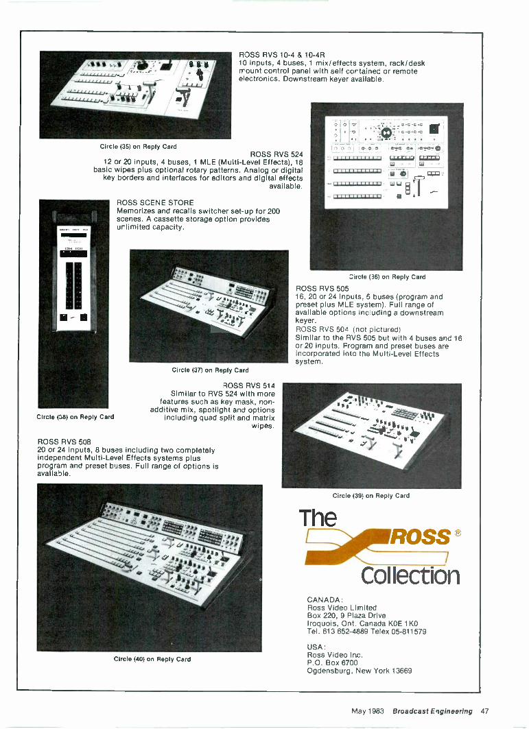
ROSS RVS 10-4 & 10-4R10 inputs, 4 buses, 1 mix/effects system, rack/deskmount control panel with self contained or remoteelectronics. Downstream keyer available.
Circle (35) on Reply CardROSS RVS 524
12 or 20 inputs, 4 buses, 1 MLE (Multi -Level Effects), 18basic wipes plus optional rotary patterns. Analog or digital
key borders and interfaces for editors and digital effectsavailable.
-
Circle (38) on Reply Card
ROSS SCENE STOREMemorizes and recalls switcher set-up for 200scenes. A cassette storage option providesunlimited capacity.
Circle (37) on Reply Card
ROSS RVS 514Similar to RVS 524 with more
features such as key mask, non -additive mix, spotlight and options
including quad split and matrixwipes.
ROSS RVS 50820 or 24 inputs, 8 buses including two completelyindependent Multi -Level Effects systems plusprogram and preset buses. Full range of options isavailable.
Circle (40) on Reply Card
C C
CCCC:
D D D C.vC C. C.C.°Fl
FI-7-171-1-T1-1
asiLo 6LLI;u
reW1.1tivi
07JZI;1-1-117.1:7;1 U
Circle (36) on Reply Card
ROSS RVS 50516, 20 or 24 inputs, 5 buses (program andpreset plus MLE system). Full range ofavailable options inchuding a downstreamkeyer.ROSS RVS 504 (not pictured)Similar to the RVS 505 but with 4 buses and 16or 20 inputs. Program and preset buses areincorporated into the Multi -Level Effectssystem.
Circle (39) on Reply Card
TheAritimcoss®
CollectionCANADA:Ross Video LimitedBox 220, 9 Plaza DriveIroquois, Ont. Canada KOE 1 K0Tel. 613 652-4889 Telex 05-811579
USA:Ross Video Inc.P.O. Box 6700Ogdensburg, New York 13669
May 1983 Broadcast Engineering 47
By Edgar Lee Howard, supervisor of special projects, WOSU-AM/FM/TV, Columbus, OH
Shortly after man invented televi-sion, he discovered timing and phas-ing problems. Since this discovery, hehas been confused.
One of the things that creates confu-sion is the fact that the terminologyand techniques of timing and phasinghave evolved for historical reasons. Asa result, when you come into the in-dustry, you are plugged into thesystem as it stands, and tend toassume that all that has gone before iswritten in stone, and all that follows isthe result of inspired reasoning. Morelikely, all that has gone before is akluge, and all that follows is the resultof deadline panic. The first order ofbusiness is a look at some basics.
Signal timingThe gospel, according to the Fed,
with respect to composite signal tim-ings is paragraph 73.699 of the FCCRules and Regulations. A morestringent and, therefore, more usefulstatement is to be found in the EIARS -170 standard, which is now in theprocess of becoming officially the RS -170A standard.* These standards dealwith the composite video signal asthough it were a never-ending stream,with no thought given to the necessityof combining different programsources into this never-ending stream.Therefore, they are of little help in adirect way.
The standards deal with the inter-relation of timings of sync, blankingand color burst position-parametersthat in this day and age are relativelyeasy to maintain within tolerance.This relative ease stems from severalfactors, one of which is the fact thatfewer separate drive signals are usedin contemporary equipment toprompt it into proper operation, com-
*For more information regarding RS -170A, see thesidebar on page 58.
pared to the amount used originally.Because each separate pulse distribu-tion system contributes one more timedelay that has to be conformed if thedriven piece of equipment is to makestandard signals, reducing the countof these drive signals to two (sync andsubcarrier), or better yet, one (RS -170A black reference), means that thenumber of variables is substantiallyreduced. To this is added the markedincrease in stability of modern solid-state design, and the popular use of acounting sync generator in each pieceof equipment, which is then gen-locked to the master black referencesignal. Thus, it becomes more com-mon to see equipment that producesfully standard signals with no setupadjustments, and that requires onlyone phasing adjustment to fully con-form the equipment to system timingrequirements. Less contemporaryhardware may require two ad-justments-one for subcarrier phaseand one for sync or system timing.
So the first item of business is todetermine whether each piece ofequipment makes standard compositesignal timings at its output and, if not,to cause it to do so. If only one videosignal source was to be used on anygiven day, that would be all. But theindustry has a discouraging tendencyto deviate from the engineer's favoriteprogramming -color bars and tone-and to combine several video sourcesin various plain and fancy ways into acompleted program.
Let's go on with some more basics.Figure 1 (page 52) shows ahypothetical test setup that may be ofsome use in establishing definitions.What we have is the output end of avideo DA, with its Of2 out point beingsplit, in this case, into four 75f2 out-puts. We carefully terminate two ofthem, and call these terminated pointsA and B respectively. The points aretaken through identical -value resistors
to the input node of a summingamplifier. Taking this figure as sym-bolic, and for the moment presumingthe box labeled D is not present in itspath, it should be obvious that thevideo signal coming out of the sum-mer is the same as the signal presenton the Of2 point of the VDA. Each 75E2output attenuates the signal to halfthat of the Oft point and creates twoidentical signals at points A and B,then the summer adds them togetheragain.
So far, all this seems to have done isuse a bunch of parts; but now con-sider what happens if box D, a delayelement, is inserted in the path from Bto the summer. Now the two halvesthat go together to form the videosignal at the output of the summer areno longer in time coincidence. Thereare steps on the edges of the pulses aswide as the element D is long. Also,the color burst has been rotated inphase with reference to the inputvideo by the vector sum of the two nolonger phased components, and itsamplitude has been reduced. If Dwere to increase to 14Ons, the burstvectors fed to the summer would beout of phase, and the output videoburst amplitude would go to zero.Calculation of burst phase andamplitude for intermediate values ofD is left as an exercise for the reader.
This leads up to a definition. Twovideo signals are said to be in phasewhen they can be combined additivelywithout producing any shift in burstphase or any steps on the edges of thepulses. Conversely, if additive com-bining of two signals results in a shiftof burst phase or in steps on the edgesof pulses, then the signals are notphased. In our example, we havecarefully split one signal into twoidentical signals at points A and B,then added a controlled delay to one
Continued on page 52
48 Broadcast Engineering May 1983
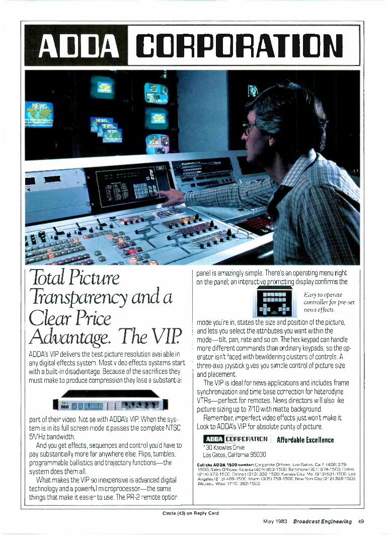
Total PictureTransparency and aClear PriceAdvantage. The VII?ADDA's VIP delivers the best picture resolution available in
any digital effects system. Most video effects systems startwith a built-in disadvantage. Because of the sacrifices they
must make to produce compression they lose a substantial
11411111111t1 111111111.111
part of their video. Not so with ADDA's VIP. When the sys-
tem is in its full screen mode it passes the complete NTSC
5MHz bandwidth.
And you get effects, sequences and control you'd have to
pay substantially more for anywhere else. Flips, tumbles,
programmable ballistics and trajectory functions-thesystem does them all.
What makes the VIP so inexpensive is advanced digital
technology and a powerful microprocessor-the samethings that make it easier to use. The PR -2 remote option
panel is amazingly simple. There's an operating menu right
on the panel; an interactive display confirms the
Easy to operatecontroller for pre-setJ Mini news effects.n
mode you're in, states the size and position of the picture,
and lets you select the attributes you want within the
mode-tilt, pan, rate and so on. The hex keypad can handle
more different commands than ordinary keypads; so the op-
erator isn't faced with bewildering clusters of controls. A
three -axis joystick gives you simple control of picture size
and placement.
The VIP is ideal for news applications and includes f-ame
synchronization and time base correction for heterodyne
VTRs-perfect for remotes. News directors will also likepicture sizing up to 7/10 with matte background.
Remember, imperfect video effects just won't make it.
Look to ADDA's VIP for absolute purity of picture.
A1:11:1A Affordable Excellence
Call the ADDA 1500 number: Corporate Offices, Los Gatos. Calif. (4081379-1500: Sales Offices: Atlanta (4041953-1500; Baltimore (3011974-1500; Dallas(214)373-1500; Detroit (313) 332-1500; Kansas City, Mo. (9131631-1500; LosAngeles (2131489-1500; Miami (3051759-1500; New York City (212) 398-1500;Wausau, Wisc. (715) 362-1500.
CORPORATION
130 Knowles Drive
Los Gatos, California 95030
Circle (43) on Reply Card
May 1983 Broadcast Engineering 49
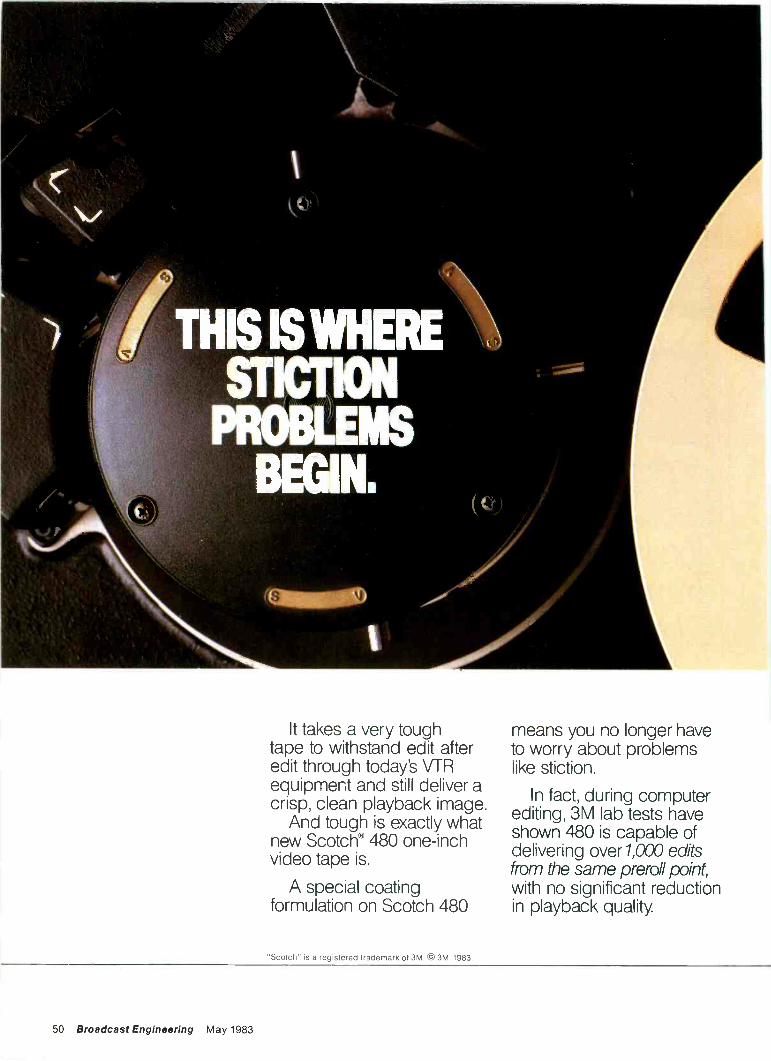
It takes a very toughtape to withstand edit afteredit through today's VTRequipment and still deliver acrisp, clean playback image.
And tough is exactly whatnew Scotch® 480 one -inchvideo tape is.
A special coatingformulation on Scotch 480
"Scotch" is a registered trademark of 3M © 3M, 1983
means you no longer haveto worry about problemslike stiction.
In fact, during computerediting, 3M lab tests haveshown 480 is capable ofdelivering over 1,000 editsfrom the same preroll point,with no significant reductionin playback quality.
50 Broadcast Engineering May 1983
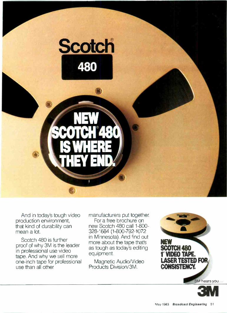
And in today's tough videoproduction environment,that kind of durability canmean a lot.
Scotch 480 is furtherproof of why 3M is the leaderin professional use videotape. And why we sell moreone -inch tape for professionaluse than all other
manufacturers put together.For a free brochure on
new Scotch 480 call 1-800-328-1684 (1-800-792-1072in Minnesota). And find outmore about the tape that'sas tough as today's editingequipment.
Magnetic Audio/VideoProducts Division/3M.
3MMay 1983 Broadcast Engineering 51
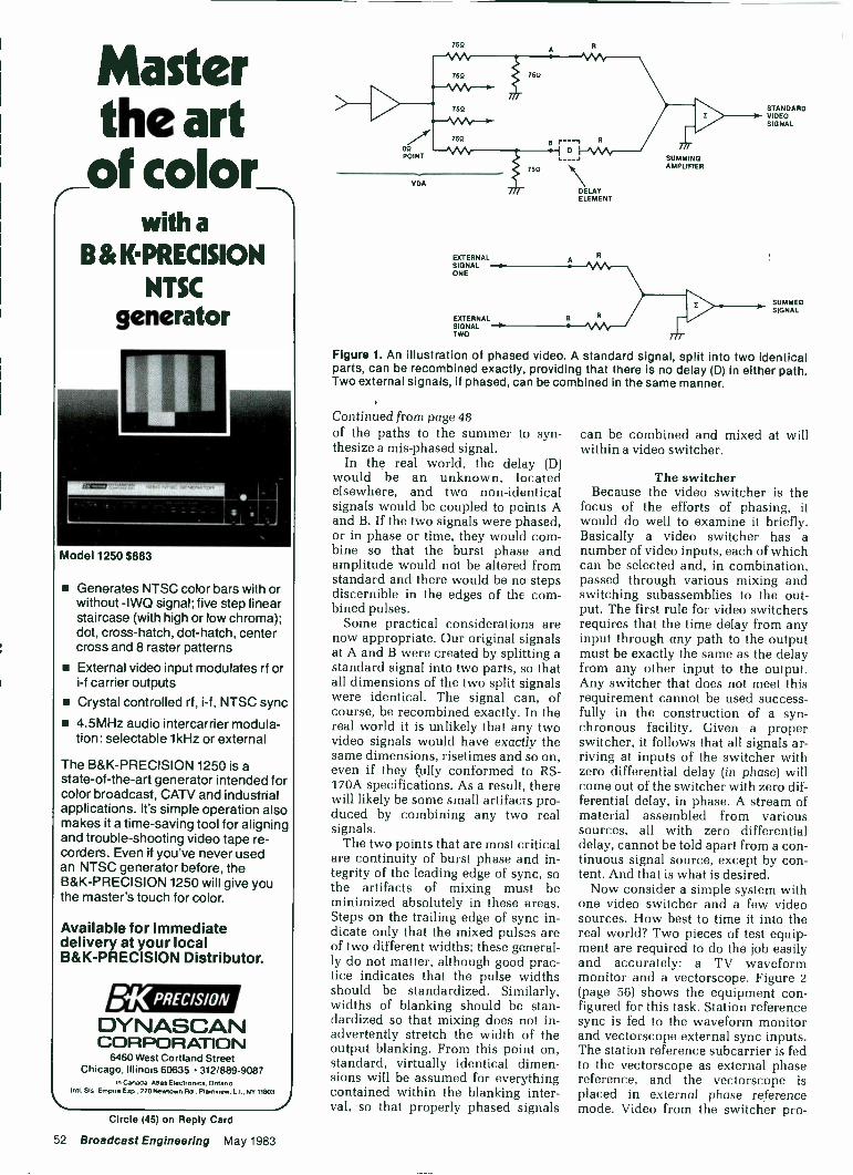
Masterthe artof color
with aB&* PRECISION
NTSCgenerator
Model 1250 $883
Generates NTSC color bars with orwithout -IWO signal; five step linearstaircase (with high or low chroma);dot, cross -hatch, dot -hatch, centercross and 8 raster patterns
External video input modulates rf ori-f carrier outputs
Crystal controlled rf, i-f, NTSC sync
4.5MHz audio intercarrier modula-tion: selectable 1kHz or external
The B&K-PRECISION 1250 is astate-of-the-art generator intended forcolor broadcast, CAN and industrialapplications. It's simple operation alsomakes it a time -saving tool for aligningand trouble -shooting video tape re-corders. Even if you've never usedan NTSC generator before, theB&K-PRECISION 1250 will give youthe master's touch for color.
Available for immediatedelivery at your localB&K-PRECISION Distributor.
:KPREC/SION
DYNASCANCORPORATION
6460 West Cortland StreetChicago. Illinois 60635 312/889-9087
In Canada. Atlas Electronics. OntanoIntl. Sin E mrote Exp.. 270 Newtown Rd.. Mansura. L.I.. NY 11903
\ft
755
EXTERNALSIGNALONE
EXTERNALSIGNALTWO
DELAYELEMENT
A
SUMMINGAMPLIFIER
STANDARDVIDEOSIGNAL
SUMMEDSIGNAL
Figure 1. An illustration of phased video. A standard signal, split into two identicalparts, can be recombined exactly, providing that there is no delay (D) in either path.Two external signals, if phased, can be combined in the same manner.
Continued from page 48
of the paths to the summer to syn-thesize a mis-phased signal.
In the real world, the delay (D)would be an unknown, locatedelsewhere, and two non -identicalsignals would be coupled to points Aand B. If the two signals were phased,or in phase or time, they would com-bine so that the burst phase andamplitude would not be altered fromstandard and there would be no stepsdiscernible in the edges of the com-bined pulses.
Some practical considerations arenow appropriate. Our original signalsat A and B were created by splitting astandard signal into two parts, so thatall dimensions of the two split signalswere identical. The signal can, ofcourse, be recombined exactly. In thereal world it is unlikely that any twovideo signals would have exactly thesame dimensions, risetimes and so on,even if they fully conformed to RS -170A specifications. As a result, therewill likely be some small artifacts pro-duced by combining any two realsignals.
The two points that are most criticalare continuity of burst phase and in-tegrity of the leading edge of sync, sothe artifacts of mixing must beminimized absolutely in these areas.Steps on the trailing edge of sync in-dicate only that the mixed pulses areof two different widths; these general-ly do not matter, although good prac-tice indicates that the pulse widthsshould be standardized. Similarly,widths of blanking should be stan-dardized so that mixing does not in-advertently stretch the width of theoutput blanking. From this point on,standard, virtually identical dimen-sions will be assumed for everythingcontained within the blanking inter-val, so that properly phased signals
can be combined and mixed at willwithin a video switcher.
The switcherBecause the video switcher is the
focus of the efforts of phasing, itwould do well to examine it briefly.Basically a video switcher has anumber of video inputs, each of whichcan be selected and, in combination,passed through various mixing andswitching subassemblies to the out-put. The first rule for video switchersrequires that the time delay from anyinput through any path to the outputmust be exactly the same as the delayfrom any other input to the output.Any switcher that does not meet thisrequirement cannot be used success-fully in the construction of a syn-chronous facility. Given a properswitcher, it follows that all signals ar-riving at inputs of the switcher withzero differential delay (in phase) willcome out of the switcher with zero dif-ferential delay, in phase. A stream ofmaterial assembled from varioussources, all with zero differentialdelay, cannot be told apart from a con-tinuous signal source, except by con-tent. And that is what is desired.
Now consider a simple system withone video switcher and a few videosources. How best to time it into thereal world? Two pieces of test equip-ment are required to do the job easilyand accurately: a TV waveformmonitor and a vectorscope. Figure 2(page 56) shows the equipment con-figured for this task. Station referencesync is fed to the waveform monitorand vectorscope external sync inputs.The station reference subcarrier is fedto the vectorscope as external phasereference, and the vectorscope isplaced in external phase referencemode. Video from the switcher pro -
Circle (45) on Reply Card
52 Broadcast Engineering May 1983
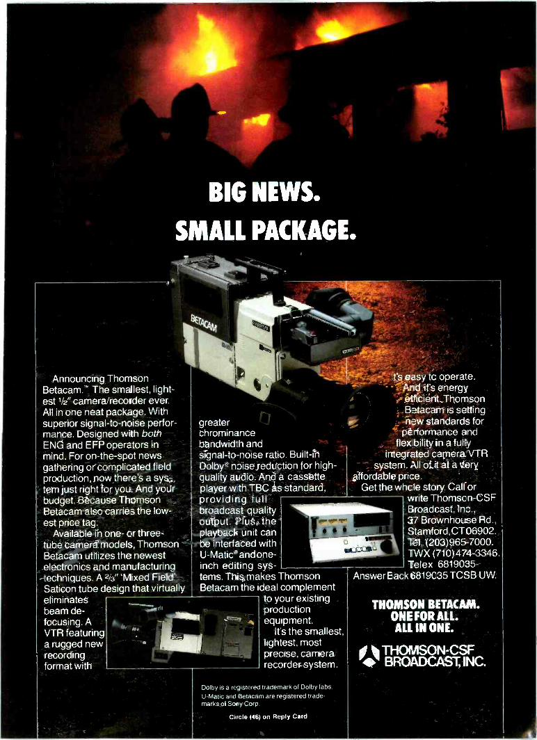
BIG NEWS.
SMALL PACKAGE.
Announcing ThomsonBetacam.. The smallest, light-est ' 2" camera recorder ever.All in one neat package. Withsuperior signal-to-noise perfor-mance. Designed with bothENG and EFP operators inmind. For on -the -spot newsgathering or complicated fieldproduction, now there's a sys-tem just right for you. And yourbudget. Because ThomsonBetacam also carries the low-est price tag.
Available in one- or three -tube camera models, ThomsonBetacam utilizes the newestelectronics and manufacturingtechniques. A 2 3"'Mixed Field'Saticon tube design that virtuallyeliminatesbeam de-focusing. AVTR featuringa rugged newrecordingformat with
greaterchrominancebandwid'h andsignal-to-noise ratio. Built-inDolby' noise reduction for high -quality audio. And a cassetteplayer w th TBC as standard,providing fullbroadcast qualityoutput. Plus, theplayback unit canbe interfaced withU-Matic and one -inch editing sys-tems. This makes ThomsonBetacam the ideal complement
to your existingproductionequipment.
It's the smallest,lightest, mostprecise, camerarecorder system.
Alt
t's easy tc opera -eAnd it's energyefficient. ThomsonBetacam is settingnew standards for
performance andflex bility in a fully
integrated camera VTRsystem. All of it at a very
affordable price.Get the whcle story. Call or
write Thomscn-CSFBroadcast, Inc.,27 Brownhouse Rd.,Stamford, CT 06902.Tel. (21)3)965-7000.TWX (710)474-3346.Telex 6819035 -
Answer Eack 6819C35 TCSB UW.
Dolby is a registered trademark of Dolby labs.U-Matic and Betacam are registered trade-marks of SortyCorp.
THOMSON BETACAM.ONE FOR ALL.ALL IN ONE.
THOMSON-CSF BROADCAST, INC.
Circle (46) on Reply Card
THE SOURCEFor all your equipment needs
AKG Amperex Ampel Atlas Audiopak
AudioTechnica Belden Broadcast Electronics CRL CSI Crown
Cablewove Systems DBX Deltolab Electro-Voice EXR
Fidelipoc Inovonics Jampro-Cetec JBL LeaderInstruments Lexicon 3-M
Marti Micro-Trak NortronicsOrban Associates Otari Phelps Dodge Revox Russco
Shure Solo Staco Stanton Surcom Tapco Technics Telex Urei VIF and many more.
Call us for fast shipmentsfrom stock 305- 651-5752
l*,ECTREX COMPANY©1983
Telex 51-4733 ELECTREX MIA
18680 N E 2nd Avenue. Miami. Florida 33179
Circle (47) on Reply Card
In satellite communications,go with total systems engineering
experience.
Spectrum Planning provides the fullspectrum of services for planning reliableand interference -free satellite earth stations:
*i Site selection/design Frequency coordination Frequency protection RFI measurements Site shielding design FCC filings
/We believe no other frequencycoordination company can match ourexperience. And in this rapidly changingfield, experience is worth its weight in gold.
Call us now at (214) 699-3536 or write formore information.
111 SPECTRUM PLANNING INC.P. 0. Box 1360 Richardson, Texas 75080
gram output is looped through thewaveform monitor and terminated atthe vectorscope.
To begin with, one of the switcherinput sources, say source one, isdesignated as the reference source,the one to which all others will bematched. It is selected to the output ofthe switcher, and the vectorscopephase adjustment is rotated to put theburst vector dot over its target on thevectorscope display. It is worth form-ing the habit of checking to be surethat the vectorscope is in externalreference mode, which it must be forphasing adjustments. The waveformmonitor should show a clear, full -bandwidth, somewhat expandeddisplay of the horizontal sync regionof the video waveform.
Now a second source is selected.The vector display is observedwithout altering any of its ad-justments, and the system subcarrierphase adjustment on the video sourceis adjusted to place the burst vectordot once more over its target. At thispoint, an additive mix betweensources one and two will not alter theoutput burst phase, because a zero dif-ferential delay situation has beenestablished for burst signals, irrespec-tive of cable lengths or other timedelays associated with the sources.
It is necessary also to check the tim-ing of the sync signals, because whatwe have done so far is a necessary butnot sufficient condition for completephasing and timing of the signal. Theburst vector is intact, but there mustalso be no steps in the leading edge ofsync. A half-and-half additive mix isselected between the reference inputand the second input, and the condi-tion of the leading edge of sync isobserved on the waveform monitor. Ifa step is present, it must be removed.
How the step is removed dependson the type of equipment providingthe signals. If the equipment is of theolder, independent sync and subcar-rier design, there will usually be async delay or sync timing adjustmentthat can be rotated to move all pulsetimings in the video signal and,thereby, to eliminate the step at themixed output of the switcher. If theequipment is of newer design, incor-porating RS -170A outputs, there maybe only one phasing adjustment,which will move both the timing ofthe pulses and the phase of the systemsubcarrier that creates burst.
If any RS -170A sources are presentin the system, it is generally best touse one of them as the referencesource, because it is not possible (or,for that matter, desirable) to try to con-form an RS -170A output that has fixedand defined sync-to-subcarrier rela-tionships to another signal with ran-dom sync-to-subcarrier relationships.
Circle (48) on Reply Card
54 Broadcast Engineering May 1983
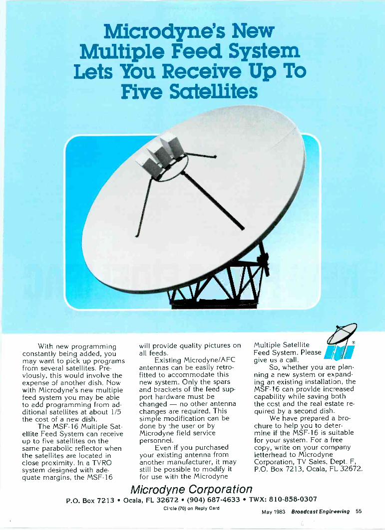
Microdyne's NewMultiple Feed System
Lets You Receive Up ToFive Satellites
With new programmingconstantly being added, youmay want to pick up programsfrom several satellites. Pre-viously, this would involve theexpense of another dish. Nowwith Microdyne's new multiplefeed system you may be ableto add programming from ad-ditional satellites at about 1/5the cost of a new dish.
The MSF-16 Multiple Sat-ellite Feed System can receiveup to five satellites on thesame parabolic reflector whenthe satellites are located inclose proximity. In a TVROsystem designed with ade-quate margins, the MSF-16
will provide quality pictures onall feeds.
Exisiing Microdyne/AFCantennas can be easily retro-fitted to accommodate thisnew system. Only the sparsand brackets of the feed sup-port hardware must bechanged - no other antennachanges are required. Thissimple modification can bedone by the user or byMicrodyne field servicepersonnel.
Even if you purchasedyour existing antenna fromanother manufacturer, it maystill be possible to modify itfor use with the Microdyne
Multiple SatelliteFeed System. Please gar,give us a call.
So, whether you are plan-ning a new system or exoand-ing an existing installation, theMSF-16 can provide increasedcapability while saving boththe cost and the real estate re-quires by a second dish.
We have prepared a bro-chure to help you to deter-mine if the MSF-16 is suitablefor your system. For a freecopy, write on your companyletterhead to MicrodyneCorporation, TV Sales, Dept. F,P.O. Box 7213, Ocala, FL 32672.
Microdyne CorporationP.O. Box 7213 Ocala, FL 32672 (904) 687-4633 TWX: 810-858-0307
Circle (70) on Reply CardMay 1983 Broadcast Engir oaring 55
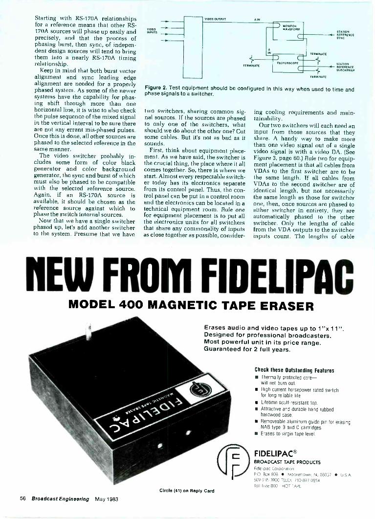
Starting with RS -170A relationshipsfor a reference means that other RS -
170A sources will phase up easily andprecisely, and that the process ofphasing burst, then sync, of indepen-dent design sources will tend to bringthem into a nearly RS -170A timingrelationship.
Keep in mind that both burst vectoralignment and sync leading edgealignment are needed for a properlyphased system. As some of the newersystems have the capability for phas-ing shift through more than onehorizontal line, it is wise to also checkthe pulse sequence of the mixed signalin the vertical interval to be sure thereare not any errant mis-phased pulses.Once this is done, all other sources arephased to the selected reference in thesame manner.
The video switcher probably in-cludes some form of color blackgenerator and color backgroundgenerator, the sync and burst of whichmust also be phased to be compatiblewith the selected reference source.Again, if an RS -170A source isavailable, it should be chosen as thereference source against which tophase the switch internal sources.
Now that we have a single switcherphased up, let's add another switcherto the system. Presume that we have
n
VIDEO OUTPUT
VIDEOINPUTS
A IN
TERMINATE
TERMINATE
TERMINATE
STATIONREFERENCESYNC
STATIONREFERENCESUBCARRIER
Figure 2. Test equipment should be configured in this way when used to time andphase signals to a switcher.
two switchers, sharing common sig-nal sources. If the sources are phasedto only one of the switchers, whatshould we do about the other one? Cutsome cables. But it's not as bad as itsounds.
First, think about equipment place-ment. As we have said, the switcher isthe crucial thing, the place where it allcomes together. So, there is where westart. Almost every respectable switch-er today has its electronics separatefrom its control panel. Thus, the con-trol panel can be put in a control roomand the electronics can be located in atechnical equipment room. Rule onefor equipment placement is to put allthe electronics units for all switchersthat share any commonality of inputsas close together as possible, consider-
ing cooling requirements and main-tainability.
Our two switchers will each need aninput from those sources that theyshare. A handy way to make morethan one video signal out of a singlevideo signal is with a video DA. (SeeFigure 3, page 60.) Rule two for equip-ment placement is that all cables fromVDAs to the first switcher are to bethe same length. If all cables fromVDAs to the second switcher are ofidentical length, but not necessarilythe same length as those for switcherone, then, once sources are phased toeither switcher in entirety, they areautomatically phased to the otherswitcher. Only the lengths of cablefrom the VDA outputs to the switcherinputs count. The lengths of cable
EW FROM FIDELIPACMODEL 400 MAGNETIC TAPE ERASER
Erases audio and video tapes up to 1"x 11".Designed for professional broadcasters.Most powerful unit in its price range.Guaranteed for 2 full years.
Check these Outstanding Features Thermally protected core-
will not burn out. High current horsepower rated switch
for long reliable life.
Lifetime scuff -resistant top. Attractive and durable hand rubbed
hardwood case.
Removeable aluminum guide pin for erasingNAB type B and C cartridges.
Erases to virgin tape level.
FIDELIPAC°BROADCAST TAPE PRODUCTS
Fidelipac Corporation
PO Box 808 Moorestown, NJ 08057 U SA609-235-3900 TELEX 710-897-0254
Toll Free 800-HOT TAPECircle (41) on Reply Card
56 Broadcast Engineering May 1983
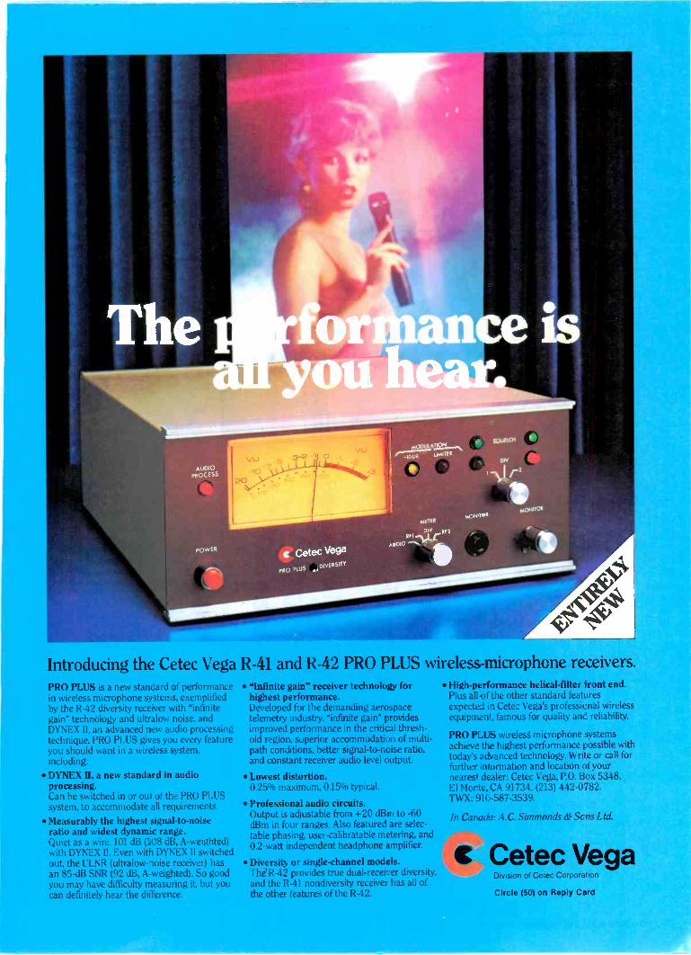
Introducing the Cetec Vega R-41 and R-42 PRO PLUS wireless -microphone receivers.PRO PLUS is a new standard of performancein wireless microphone systems. exemplifiedby the R-42 diversity receiver with "infinitegain" technology and ultralow noise, andDYNEX II, an advanced new audio processingtechnique. PRO PLUS gives you every featureyou should want in a wireless system,including:
DYNEX II, a new standard in audioprocessing.Can be switched in or out of the PRO PLUSsystem. to accommodate all requirements.
Measurably the highest signal-to-noiseratio and widest dynamic range.Quiet as a wire. 101 dB (108 dB, A -weighted)with DYNEX II. Even with DYNEX II switchedout, the ULNR lultralow-loise receiver) hasan 85 -dB SNR (92 dB, A -weighted). So goodyou may have difficulty measuring it, but youcan definitely hear the difference.
"Infinite gain" receiver technology forhighest performance.Developed for the demanding aerospacetelemetry industry, Infinite gain" providesimproved performance in the critical thresh-old region, superior accommodation of multi -path conditions, better signal-to-noise ratio,and constant receiver audio level output.
Lowest distortion.0.25% maximum. 015% typical.
Professional audio circuits.Output is adjustable from +20 dBm to -60dBm in four ranges. Also featured are selec-table phasing, user-calibratable metering, and0.2 -watt independent headphone amplifier.
Diversity or single -channel models.The R-42 provides true dual -receiver diversity,and the R-41 nondiversity receiver has all ofthe other features of the R-42.
High-performance helical -filter front end.Plus all of the other standard featuresexpected in Cetec Vega's professional wirelessequipment. famous for quality and reliability.
PRO PLUS wireless microphone systemsachieve the highest performance possible withtoday's advanced technology. Write or call forfurther information and location of yournearest dealer: Cetec Vega, P.O. Box 5348,El Monte, CA 91734. (213) 442-0782.TWX: 91(.-587-3539.
In Canada: A.C. Simmonds & Scns Ltd.
Cetec VegaDivision al Cecec Corporation
Circle (50) co Reply Card
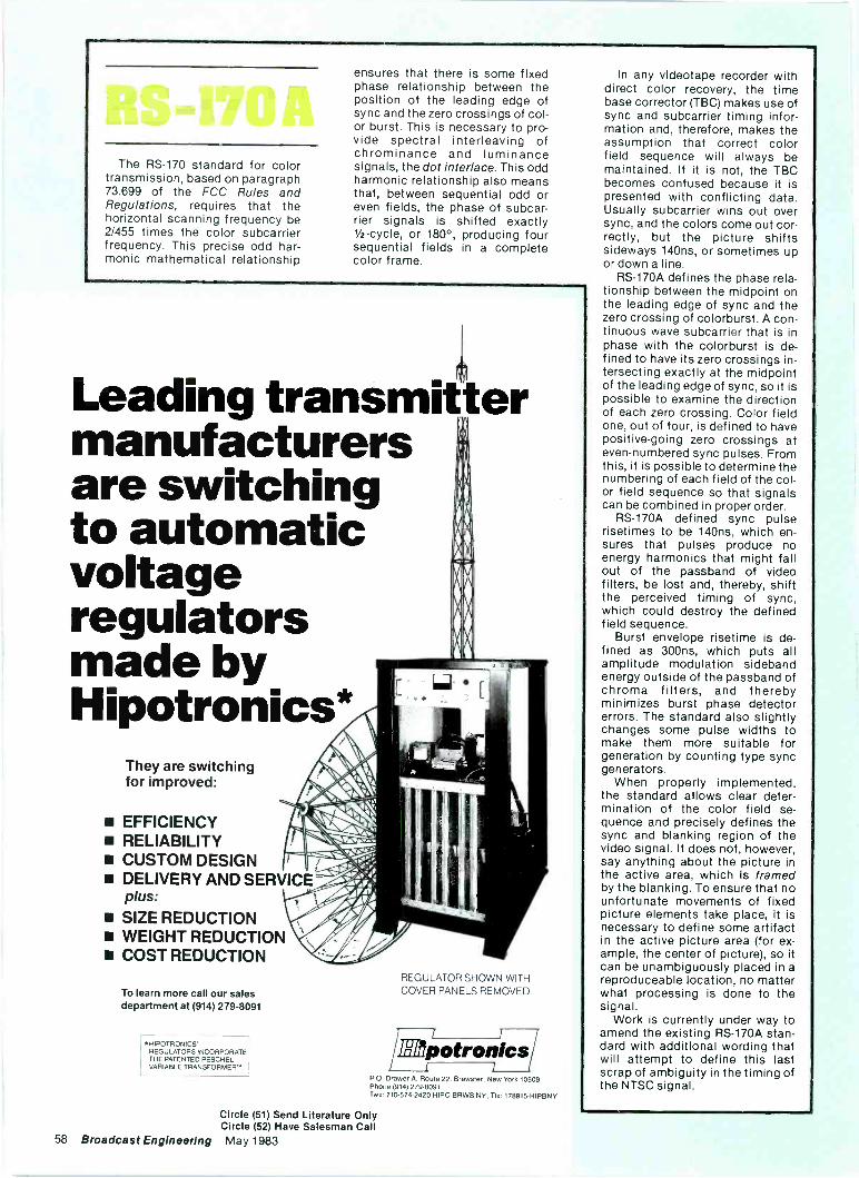
The RS -170 standard for colortransmission, based on paragraph73.699 of the FCC Rules andRegulations, requires that thehorizontal scanning frequency be2/455 times the color subcarrierfrequency. This precise odd har-monic mathematical relationship
ensures that there is some fixedphase relationship between theposition of the leading edge ofsync and the zero crossings of col-or burst. This is necessary to pro-vide spectral interleaving ofchrominance and luminancesignals, the dot interlace. This oddharmonic relationship also meansthat, between sequential odd oreven fields, the phase of subcar-rier signals is shifted exactly1/2 -cycle, or 180°, producing foursequential fields in a completecolor frame.
Leading transmittermanufacturersare switchingto automaticvoltageregulatorsmade byHipotronics*
They are switchingfor improved:
EFFICIENCY RELIABILITY CUSTOM DESIGN DELIVERY AND SERVICE
plus: SIZE REDUCTION WEIGHT REDUCTION COST REDUCTION
To learn more call our salesdepartment at (914) 279-8091
HIPOTRONICS'REGULATORS INCORPORATETHE PATENTED PESCHELVARIABLE TRANSFORMER'.
REGULATOR SHOWN WITHCOVER PANELS REMOVED.
ilapotronicsP.O.Drawer A. Route 22, Brewster, New York 10509Phone (914) 279-8091Two 710-574-2420 HIPO BRWS NV. Tlx 178915-HIPBNY
In any videotape recorder withdirect color recovery, the timebase corrector (TBC) makes use ofsync and subcarrier timing infor-mation and, therefore, makes theassumption that correct colorfield sequence will always bemaintained. If it is not, the TBCbecomes confused because it ispresented with conflicting data.Usually subcarrier wins out oversync, and the colors come out cor-rectly, but the picture shiftssideways 140ns, or sometimes upor down a line.
RS -170A defines the phase rela-tionship between the midpoint onthe leading edge of sync and thezero crossing of colorburst. A con-tinuous wave subcarrier that is inphase with the colorburst is de-fined to have its zero crossings in-tersecting exactly at the midpointof the leading edge of sync, so it ispossible to examine the directionof each zero crossing. Color fieldone, out of four, is defined to havepositive -going zero crossings ateven -numbered sync pulses. Fromthis, it is possible to determine thenumbering of each field of the col-or field sequence so that signalscan be combined in proper order.
RS -170A defined sync pulserisetimes to be 140ns, which en-sures that pulses produce noenergy harmonics that might fallout of the passband of videofilters, be lost and, thereby, shiftthe perceived timing of sync,which could destroy the definedfield sequence.
Burst envelope risetime is de-fined as 300ns, which puts allamplitude modulation sidebandenergy outside of the passband ofchroma filters, and therebyminimizes burst phase detectorerrors. The standard also slightlychanges some pulse widths tomake them more suitable forgeneration by counting type syncgenerators.
When properly implemented,the standard allows clear deter-mination of the color field se-quence and precisely defines thesync and blanking region of thevideo signal. It does not, however,say anything about the picture inthe active area, which is framedby the blanking. To ensure that nounfortunate movements of fixedpicture elements take place, it isnecessary to define some artifactin the active picture area (for ex-ample, the center of picture), so itcan be unambiguously placed in areproduceable location, no matterwhat processing is done to thesignal.
Work is currently under way toamend the existing RS -170A stan-dard with additional wording thatwill attempt to define this lastscrap of ambiguity in the timing ofthe NTSC signal.
Circle (51) Send Literature OnlyCircle (52) Have Salesman Call
58 Broadcast Engineering May 1983
11,
Nh.
NN. N.
ka
N. N.N. N.
0100 NM L. 1.0 .1 .0 NI MP11.0 MI UM N.
~On
own ow. wax tow WW1 se, L. It .1 iwtaw eRN
.0010 )111. 101. >ma MtMOW
oW
www oat sus sow nue .4 01114 1 WO case sowWONOrotIM I
woo
on .lm. <to ww Ws owe tow s ww. --aNCIOMITide_liltI-II -II -II 4(IF 3.6144
DigitalTest
Generator
OM -1100H
Troialobo lb
orvA nia
Price/ Performance at its PeakIf cost effectiveness of your equipmentdollar is as important to you as state-of-the-art tecinology, then you cannotafford to igno-e the DTG-1-00N.In just one rock unit you get 35 computergenerated, precision video test signals andmicroprocesso- controlled signal selection.The user-friendly front panel menu andstatus indicators let you look and select...easy as 1-2-3!Full remote control is also available.
NEW FOR NAB '83The VIP -11011'4 Vertical Interval Processor isa sophisticated, versatile companion for TheDTG-1100N Digital Test Generator. It is astand-alone unit featuring a digital sync generatorwhich always maintains RS170A in the digitallygenerated black output. Microprocessor controlwith digital read-out allows insertion/de etion ofVIT signals or data in lines 10 to 21 of eitherfield. The unit is scheduled to be shows at NABDon't miss it!
Leitch Video of America, Inc.825k Greenbrier CircleChesapeake, VA 23320Tel: (804) 424-7920Telex II: 710 882 4342
Leitch Video Limited10 Dyas Road
Don Mills, Ontario M3B 1V5Tel: (4]6) 445-9640
Telex: 06 986 241
'83.
LEITCH
Circle (53) on Replly Card May 1983 Broadcast Engineering 59
from equipment to VDA inputs can beanything practical, as they areautomatically compensated out whenthe sources are phased to the switch-er, just as they are for a single switch-er system.
Because the only lengths of cablethat matter are those from VDA out-puts to switcher inputs, it follows thatVDAs should be mounted physicallyas close to the switcher electronics aspossible. There is an old rule of thumbthat says 6 inches of cable is just about1° of time delay at 3.58MHz, so cableshave to be cut to greater precisionthan 6 inches if phase uncertainty is tobe kept below 1°. In practice, a 10 -footpiece of cable can be made exactly10 feet long easier than a 100 -footpiece can be made exactly 100 feetlong. Short cables can be measuredand connectors installed more exact-ly; cables can then be installedwithout need for trial -and -error trim-ming. This saves money on cable, con-nectors and labor.
Parallel switchersSwitchers can be added in this
parallel manner to whatever level ofcomplexity is desired, because everyswitcher and its input harness is in-dependent. There is, however, a prac-tice in the industry of entering the out-put of one or more switchers as inputsto another switcher, along with manyof the same sources as feed the firstswitchers. This is usually the casewhen one or more studio level switch-ers are fed to a master control switch-er with some of the cameras, filmchains and other sources that alsofeed the studio switchers (Figure 4.)
The problem with this is obvious.One source, say source A, travelingthrough switcher one to switcher twohas an additional delay, the electricallength of switcher one, over the directpath from source A to switcher two.And the same is true for any sourcefeeding switcher two, except, ofcourse, for the output of anotherswitcher. Because we cannot advancethe output video of other switchers,we have no choise but to delayeverything else to match it. So a wholebunch of delay lines appear, one ineach of the direct paths from a sourceto switcher two, and their lengths areequal to the electrical length or delayof switcher one.
What is the electrical length of theswitcher? This, of course, depends onthe particular switcher, but it wouldlikely be a half -cycle of subcarrier atminimum, and maybe as much as afull cycle or more. For one full cycle ofsubcarrier delay, a delay cable wouldbe roughly 360° x 6 inches, or 180 feet.Even considering the quality of sweptvideo cable, 180 feet is long enough torequire equalization and level com-
SOURCE A
SOURCE B
SOURCE C
-Wse-
VIDEO DA.
SWIMMERONE
TRIMMINGDELAY
SWITCHERTWO
TESTETC.
AUDIO4
AUDIOOUT
0
oVIDEO0000
SWITCHERTHREE
AUDIO.FOLLOW.
VIDEOROUTER
Figure 3. Switchers (shown in shaded area) can be corrected in parallel to videosources using VDAs, providing that all cables from VDAs to each switcher are thesame length. Cable lengths to different switchers need not be the same. A cut -onlyswitcher easily combines the outputs of many studio and master control switcherswith only a few short trimming delay cables.
SOURCE A -411.
SOURCE B
SOURCE C
VIDEO DASDAS
SWITCHERONE
VDA
LJ17-1->
VDA
SWITCHERTWO
Figure 4. If switchers are connected downstream, long delay elements and, usually,cable equalization are required on all direct inputs to delay them to match the outputof upstream switchers.
pensation if video quality is to be ab-solutely preserved. If the input cardsor modules of switcher two do nothave cable compensation provisions,then the delay cables need to beequalized with outboard cable equaliz-ing video DAs. As an alternative tocoils of wire, lumped constant delayline boxes can be used, but these areless transparent electrically than thecable and probably require equaliza-tion. Also, at least for moderatelengths of cable, the delay boxes aremore costly.
So, for a 20 -input switcher asswitcher two, being fed from one ortwo studio level switchers, we arelooking at 18 or 19 pieces of delaycable, each approximately 180 feetlong, and 18 or 19 equalizing videoDAs, added complexity and expense.
A much more electrically sound so-
lution to this problem is simply toavoid it. Returning to the unshadedconfiguration of Figure 3, specify thatswitcher two is the master controlswitcher. Then add a single -rowaudio -and -video router, perhaps a10 -by -1 self-contained unit, con-figured to switch between the variousstudio switchers and the master con-trol switcher and whatever test signalsdesired. The output of this switcher,audio following video, is presented tothe network or the transmitter as theprogram output.
Phasing in this configuration isalmost trivial. From a practical sense,because switcher three is a vertical -interval cut -only switcher, little distur-bance will arise from switching be-tween non -precisely phased inputs.To do it right, all relevant inputs, suchas those from the other switchers,
60 Broadcast Engineering May 1983
Amid the hostility, the confusion, the competition,one microphone stands above the crowd.
The SM63.No matter how rough things get in the field, the ShureSM63 Omnidirectional Dynamic Microphone givesyour crew the whole story with a lot less handling noisethan any microphone in its class. When Shure's en-gineers developed the SM63 and SM63L (with longerhandle), their objective was to create a high -output,lightweight microphone perfect for the needs of elec-tronic news journalists.
With the SM63's patented internal mechanical isola-tion system reducing undesirable handling noise, itshigh output and smooth extended frequency responselets your story come through crisp and clear. Its om-nidirectional polar pattern prevents boominess that isoften encountered during close miking situations. Andits overall lightness makes continuous hand-heldENG/EFP assignments less fatiguing, without sacrific-ing ruggedness. Even its profile is small and elegant so itwon't obscure faces on camera.
The output of the SM63 is a full 6dB higher than comparable hand-heldinterview microphones.
And there are even more precision -engineered re-finements. A highly effective internal humbucking coilrejects strong magnetic fields encountered aroundlights and other broadcast situations. And when thingsget really tough, the Shure -developed VERAFLEX®grille is virtually impervious to rust, moisture and dents.This system includes a highly effective internal anti -wind and -pop filter; and for more adverse conditions, adual -density two -layer windscreen also is supplied.
The Shure SM63. The hard-working micro-phone for the working press.
For more information on the completeline of professional broadcast products,call or write Shure Brothers Inc.,222 Hartrey Ave.,Evanston, IL 60204,(312) 866-2553.
RE®THE SOUND OF THE PROFESSIONALS '`...WORLDWIDE
Circle (54) on Reply Card
On if. ISOlig gig0 t NO
,,...4%79 775".. a'514i -irovArfil Al .vr.4y,
ZY. *hyvaior top *effiawinimpo'.It's everything you needfor fast, accurate one-third -octave sound -leveland reverberation -timeanalysis...all in oneeasy -to -use package.
0 Weighted or un-weighted SPL analysis
0 Automatic or manualreference -leveladjustment
CI Digital display of RT60with decay character-istic plotted on screen
0 Built-in pink -noisegenerator
0 Rear -panel connectorsfor external oscillo-scope and digitalperipherals
0 AC and batteryoperation
Inovonics' Model 500Acoustic Analyzer. Thesound choice for analy-sis at the airport,auditorium, or labora-tory. For all the details,call or write us today.
Inovonics Inc. a503-B Vandell WayCampbell, CA 95008(408) 374-8300 1
Circle (55) on Reply Card
The AUTOMATICAudio Test System
That Measures.. .
MODEL AT -51AUDIO TEST SYSTEM
Harmonic Distortion Intermodulation Distor-
tion Volts dB Signal + Noise /
Noise Ratio
Wow and Flutter Stereo Phasing
Differential Gain inStereo Channels
Contact Us Now For CompleteDetails And Descriptive Literature.
932 PHILADELPHIA AVE.
PTOMAC INSTRUMENTS SILVER589
SPRING, MD. 20910(30 11 -2662
should be phased. The number ofdelay cables is low, just the number ofthe other switchers. Also their lengthis short, just enough to compensatefor the differential delay through theother switchers. That is, the output ofthe electrically shortest switcher isdelayed to match the output of theelectrically longest switcher.
If this is done, levels are matchedprecisely and matched sources are se-lected on appropriate switchers, it ispossible to cut between switchers onswitcher three without notice. If thecontrols for switcher three aremounted next to those for the mastercontrol switcher, they become, in ef-fect, an extension of the master con-trol switcher, and can be operated inthat manner. It would be sensible tohave color bars and whatever othertest signals that might be appropriateavailable on switcher three-alongwith a panic source of network, notprecisely phased, and perhaps apatchable access, audio and video.This solution is no more costly thanthe properly implemented delay linesolution, and has the added benefits ofbeing electrically more sound. It alsoprovides some maintenance andemergency flexibility around themaster control switcher.
The signal sourceThis brings us to the end of the
signal chain, nicely timed and phased.There is one other item that deservesat least a brief mention: the signalsource itself. Early on, we presumedstandard dimension video signalscoming from the sources to be phased,and we presumed these sources to beagile, that is, able to maintain the stan-dard dimensions while at the sametime being adjusted in terms of sub -carrier phase and sync timing. All ofthe newer equipment is agile-timebase correctors, tape machines andcameras -so these are no problem toconfigure. But there is still quite a bitof fixed video generating equipmentout there. For these, the subcarriermay be adjustable through 360°, butthe sync and blanking dimensions,once set for standard signals, do notmove.
The only sensible way to move themis by moving the drives that feed them.There are two easy ways to do this:with pulse delaying pulse DAs, keep-ing in mind that all outputs of thePDA will move the same amount asthe delay is varied; and with delaylines. Here is a good place to use thelittle lumped constant switch -pro-grammable delay modules, becausetheir small distortions do not matterin pulse service. Keep in mind that ifsync and blanking are required, bothmust be delayed by exactly the sameamount.
Another approach to this problem isCircle (56) on Reply Card
62 Broadcast Engineering May 1983
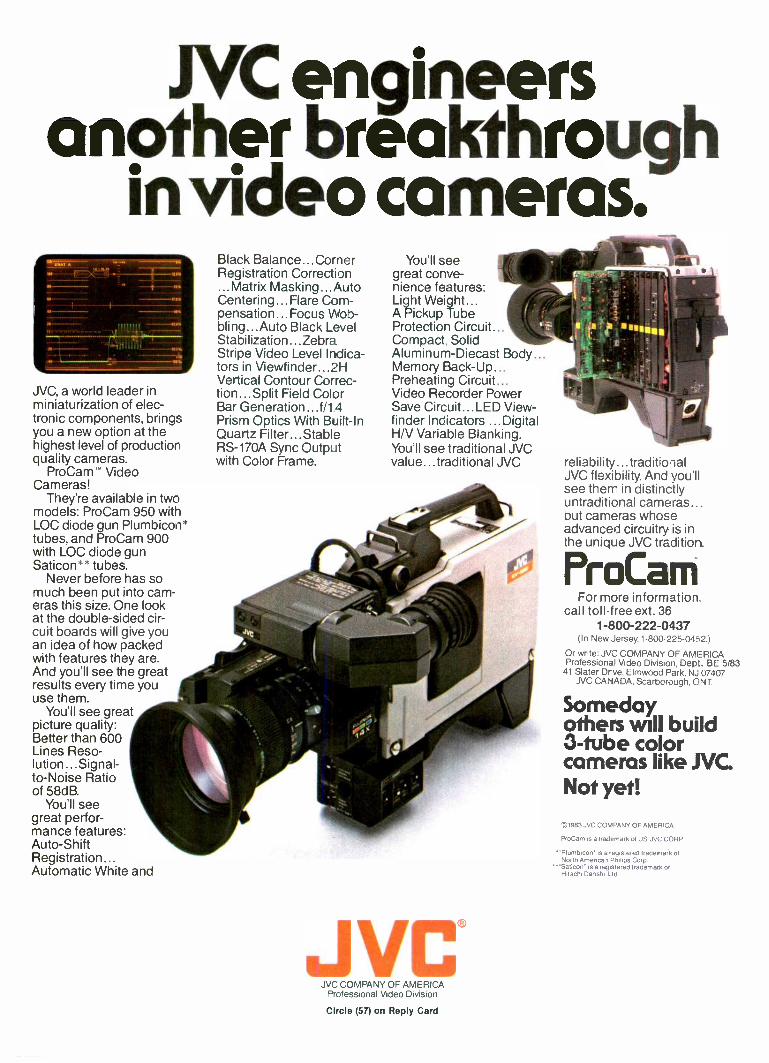
NC engineersanother breakthrough
in video cameras.
JVC, a world leader inminiaturization of elec-tronic components, bringsyou a new option at thehighest level of productionquality cameras.
ProCam' VideoCameras!
They're available in twomodels: ProCam 950 withLOC diode gun Plumbicon*tubes, and ProCam 900with LOC diode gunSaticon** tubes.
Never before has somuch been put into cam-eras this size. One lookat the double -sided cir-cuit boards will give youan idea of how packedwith features they are.And you'll see the greatresults every time youuse them.
You'll see greatpicture quality:Better than 600Lines Reso-lution...Signal-to-Noise Ratioof 58dB.
You'll seegreat perfor-mance features:Auto -ShiftRegistration...Automatic White and
Black Balance...CornerRegistration Correction...Matrix Masking...AutoCentering...Flare Com-pensation...Focus Wob-bling...Auto Black LevelStabilization...ZebraStripe Video Level Indica-tors in Viewfinder... 2HVertical Contour Correc-tion...Split Field ColorBar Generation...f/14Prism Optics With Built -InQuartz Filter...StableRS -170A Sync Outputwith Color Frame.
You'll seegreat conve-nience features:Light Weight...A Pickup TubeProtection Circuit...Compact. SolidAluminum-Diecast BodyMemory Back -Up...Preheating Circuit...Video Recorder PowerSave Circuit...LED View-finder Indicators ...DigitalH/V Variable Blanking.You'll see traditional JVCvalue...traditional JVC
Jvc®JVC COMPANY OF AMERICA
Professional Video Division
reliability... traditionalJVC flexibility. And you'llsee them in distinctlyuntraditional cameras..._but cameras whoseadvanced circuitry is inthe unique JVC tradition.
F'roCarn"For more information
call toll -free ext. 361-800-222-0437
(In New Jersey. 1-800-225-0452.)
Or write: JVC COMPANY OF AMERICAProfessional Video Divison, Dept. BE 5/83
41 Slater Drve, Elmwood Park, NJ C17407JVC CANADA, Scarborough, ONT.
Somedayothers will build3 -tube colorcameras like NC.Not yet!
c,19133 JVC COMPANY OF AMERCA
ProCam is a trademark of US JVC, CORP
'''Plumbicon- is a registered trademark ofNorth Arnerical Philips Corp
-Saticon is a registered trademark ofHitachi Denshi Ltd.
Circle (57) on Reply Card
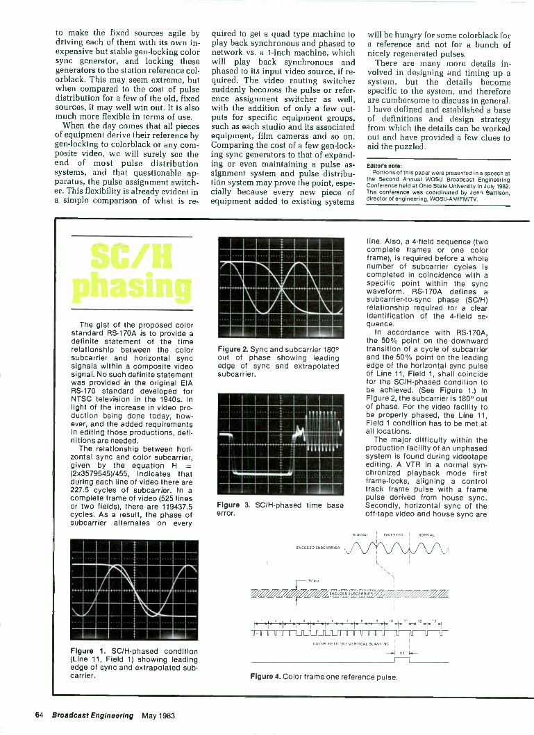
to make the fixed sources agile bydriving each of them with its own in-expensive but stable gen-locking colorsync generator, and locking thesegenerators to the station reference col-orblack. This may seem extreme, butwhen compared to the cost of pulsedistribution for a few of the old, fixedsources, it may well win out. It is alsomuch more flexible in terms of use.
When the day comes that all piecesof equipment derive their reference bygen-locking to colorblack or any com-posite video, we will surely see theend of most pulse distributionsystems, and that questionable ap-paratus, the pulse assignment switch-er. This flexibility is already evident ina simple comparison of what is re-
quired to get a quad type machine toplay back synchronous and phased tonetwork vs. a 1 -inch machine, whichwill play back synchronous andphased to its input video source, if re-quired. The video routing switchersuddenly becomes the pulse or refer-ence assignment switcher as well,with the addition of only a few out-puts for specific equipment groups,such as each studio and its associatedequipment, film cameras and so on.Comparing the cost of a few gen-lock-ing sync generators to that of expand-ing or even maintaining a pulse as-signment system and pulse distribu-tion system may prove the point, espe-cially because every new piece ofequipment added to existing systems
will be hungry for some colorblack fora reference and not for a bunch ofnicely regenerated pulses.
There are many more details in-volved in designing and timing up asystem, but the details becomespecific to the system, and thereforeare cumbersome to discuss in general.I have defined and established a baseof definitions and design strategyfrom which the details can be workedout and have provided a few clues toaid the puzzled.
Editor's note:Portions of this paper were presented in a speech at
the Second Annual WOSU Broadcast EngineeringConference held at Ohio State University in July 1982.The conference was coordinated by John Battison,director of engineering, WOSU-AM/FM/TV.
The gist of the proposed colorstandard RS -170A is to provide adefinite statement of the timerelationship between the colorsubcarrier and horizontal syncsignals within a composite videosignal. No such definite statementwas provided in the original EIARS -170 standard developed forNTSC television in the 1940s. Inlight of the increase in video pro-duction being done today, how-ever, and the added requirementsin editing those productions, defi-nitions are needed.
The relationship between hori-zontal sync and color subcarrier,given by the equation H
(2x3579545)/455, indicates thatduring each line of video there are227.5 cycles of subcarrier. In acomplete frame of video (525 linesor two fields), there are 119437.5cycles. As a result, the phase ofsubcarrier alternates on every
Figure 1. SC/H-phased condition(Line 11, Field 1) showing leadingedge of sync and extrapolated sub -carrier.
1111111111111111111111111111111511111111
1111111111111111111111111
1111111111111M11111111111111111011110
Figure 2. Sync and subcarrier 180°out of phase showing leadingedge of sync and extrapolatedsubcarrier.
Figure 3. SC/H-phased time baseerror.
line. Also, a 4 -field sequence (twocomplete frames or one colorframe), is required before a wholenumber of subcarrier cycles iscompleted in coincidence with aspecific point within the syncwaveform. RS -170A defines asubcarrier-to-sync phase (SC/H)relationship required for a clearidentification of the 4 -field se-quence.
In accordance with RS -170A,the 50% point on the downwardtransition of a cycle of subcarrierand the 50% point on the leadingedge of the horizontal sync pulseof Line 11, Field 1, shall coincidefor the SC/H-phased condition tobe achieved. (See Figure 1.) InFigure 2, the subcarrier is 180° outof phase. For the video facility tobe properly phased, the Line 11,Field 1 condition has to be met atall locations.
The major difficulty within theproduction facility of an unphasedsystem is found during videotapeediting. A VTR in a normal syn-chronized playback mode firstframe -locks, aligning a controltrack frame pulse with a framepulse derived from house sync.Secondly, horizontal sync of theoff -tape video and house sync are
NORMAL INVERTED NORMAL
ENCODED SUBCAPPIER
L
IV P,
.7,=ff7ZZ, 6Z2 ; 71II
-9 11 12 13
COLOR FIELD DM VERTICAL BLANKING
VI
Figure 4. Color frame one reference pulse.
64 Broadcast Engineering May 1983
01,NAIPPS -2115C
A thing of beauty . . . this Dynair System21.Begin with this single, high density frame using as few as 10 inputs and 10
outputs. Selectcombinations of video, audio tim3 code, data, tally, or
-ill11111111111, ...Machine control switch modules.Grow sensialy, easily and cost effectively to impressive matrices of onethousand inputs and one thousand outputs of every module type bysimply adding frames and modules.Grow into high definition TV, if this possibility is in your future, withoutchanging 71 thing. Bandwidth of the System 21 is 3Ireacy 30 MHz.Write or phone. We would like to send you additional
information. Giveus a chance to begin with you as you upgrade
your plant.
DYNAIR5275 Market Street, San Diego, CA 92114 U.S.A. Phone (61.c) 262-7711 TWX (910) 335-2040
Circle (58) on Reply Card
A.144 AbAl .11.111
Revox PR99.Not just another pretty faceplate.
Before you buy a compact audio recorder, be sure to compare what you're getting onthe inside. Look at the chassis, the headblock, the motors. the switches, the PC boards,and the wiring. When you do, you'll notice a difference between the PR99 and everythingelse in its price range. The PR99 looks better because it must adhere to stricter stand-ards of quality. Standards that have made Studer Revox the world's most respectedname in audio recording.
PR99 features: Balanced and floating line in and line out Calibrate/uncalibrateswitches Servo controlled capstan motor Edit mode switch Tape dump Self sync Optional remote control and vari-speed Cabinet, console, and rack mount versions.
I J
REVOXAMERICA INC.
STUDER REVOX OF AMERICA, INC. 1425 Elm Hill Pike Nashville, TN 37210 . (615) 254-5651
Circle (59) on Reply Card
WE MAKE AMPEX BETTERSAKI hot -pressed, glass -bonded ferrite recording heads.
The best is now available for your Ampex recorder.in all sizes and models.
Airimen.SAKI SAKI MAGNETICS, INC.A CALIFORNIA CORPORATION
8650 Hayden Place, Culver City, CA 90230 213 / 559-6704 (TWX-910-328-6100)
made coincident. Finally, the col-or time base corrector locks to thehouse subcarrier signal. On 50%of the attempts of a VTR to lockup with house sync, statisticallythe subcarrier will be out of phaseby 180° maximum, or a time errorof about 140ns (1/2 -cycle). Whenthe VTR finds that such an errorexists it must accomplish the3 -step sequence again, with tear-ing in the video occurring duringthe momentary unlocked state.Within an editing program, if the1/2 -cycle error occurs, a horizontalshift of video will be present. Inpictures of similar background in-formation, the shifting becomesobvious.
Use of a 15Hz framer is one ap-proach to solving this problem. Asvideo is recorded on the tape, onlyevery other frame pulse (a colorframe pulse) is recorded. If therecorded tape is moved to anotherVTR, the relationship between theframe pulse on the control trackand the house color frame pulse iseasily re-established.
Several considerations shouldbe made if purchase of equipmentis planned to accomplish an SC/H-phased plant. The sync generator,for example, should be capable ofa low sync-to-subcarrier time baseerror (less than 5ns), a long termSC/H phase stability (less than1Ons) and a consistent SC/Hphase. If multiple sync generatorunits are to be used, the slavegenerators must also meet theserequirements, as well as be ableto precisely color frame -lock tothe master generator. Any equip-ment within the plant that con-tains a sync generator must alsomeet the multiple requirements.
Special requirements are placedon video processing equipmentwithin the plant. The circuitrymust provide accurate pickoff ofthe 50% point of sync, accurateregeneration of subcarrier andstable regeneration of sync andburst, even in the presence ofhum, noise and possible phasemodulation during the burstperiod. A properly SC/H-phased in-put must not be altered. Thecapability for applying externallyreferenced sync and subcarrier tovideo from a switcher (for exam-ple, for a constant phase relation-ship) must be present.
The main problems en-countered with an improperlySC/H-phased studio include SC/Hphase errors, phase drift,timebase errors and timing drift.The phase errors and drift can beapparent in subcarrier andhorizontal phase individually.Phase errors are corrected bycareful adjustment of thegenerating equipment, usually inconjunction with phase meteringdevices or systems that displaythe sync and subcarrier relation -
Continued on page 70
Circle (60) on Reply Card
66 Broadcast Engineering May 1983
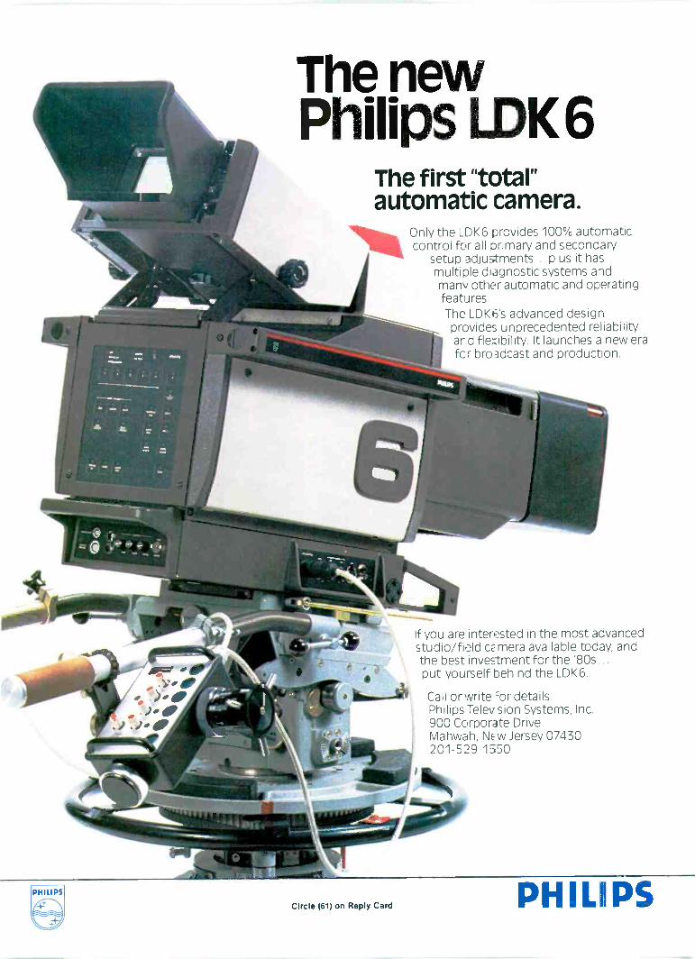
The newPhilips LDK6
The first "total"automatic camera.
Only the LDK6 provides 100% automaticcontrol for all primary and secondary
setup adjustments... plus it hasmultiple diagnostic systems andmany other automatic and operatingfeatures.The LDKI3's advanced designprovides unprecedented reliabilityand flexibility. It launches a new erafcr broadcast and production.
If you are interested in the most advancedstudio/field cz mera available today, andthe best investment for the '80s...put yourself behind the LDK6.
las..--41 Call or write =or details.Philips Televsion Systems, Inc.900 Corporate DriveMahwah, NEW Jersey 07430
e. 201-529-1550
- Mai
Circle (61) on Reply Card PHILIPS
And that's tha
Meet the Press-NBC-11/20/47to present
Army vs McCarthy HearingsApril 1954
Vietnam War
John Cameron Swayze-NBC-Camel News Cabman 1948 to 1956
Huntfey/Brinkle2 Report NBC News10/15/56 to 7/5/70
Dave Garroway-GarrowayGarroway-Garroway at Large1949, Today Show 1952 to 1961
Kennedy -Nixon Debates-ABC -10/3/60
60 Minutes News Magazine 7/24/68 U.S. Lands Men on the Mom Julyto present 1969
Garroway was introducing early risers to a show called Today andConrac was introducing its first black and white monitor.
Swayze was anchoring network news, the McCarthy -Army hearingswere being held in America's living rooms, and Conrac was introducingthe first color monitor.
News and newspeople changed year after year, decade upon decade.All the while, Conrac was earning a position of trust and respect through-out the broadcast community.
Special acknowledgement to CBS, NBC. ABC.
Senator Estes Kefauver CrimeHearings 1951
Edward R. Murrow-CBS-See ItNow 4/20/52 to 7/5/55
Walter Cronkite-CBS Evening. News John Kennedy Assassination1962 to 1980 11/22/63
Coronation of Queen ElizabethJune 1953
Lee Harve,Gswald Killed on Nation-wide TV 1I104/63
Iran 11/4/79 to 1/20/81 Space Shurle on a Model 6142(Nixon Resigns) Conrac Wilt -for
Today, Conrac is working on the next generation of broadcast moni-tors. To give you the highest resolution. The truest colors. The best value.
CONRACCircle (62) on Reply Card
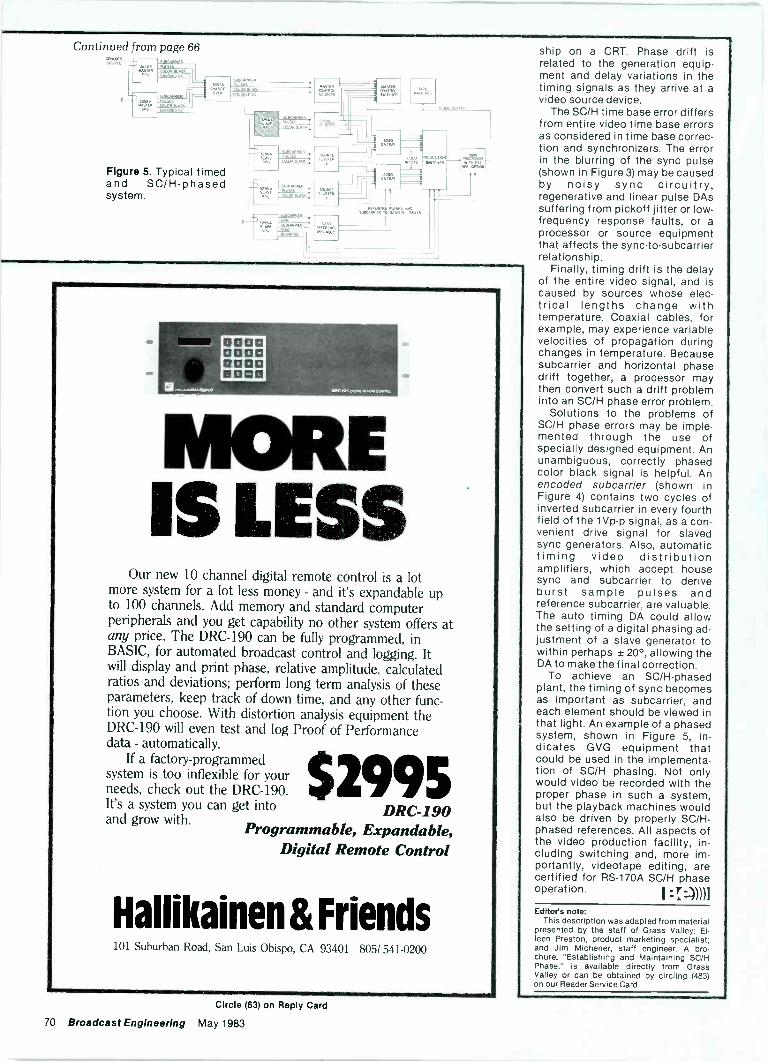
Continued from page 66
IIIASTLACONTROL5.0,104ER
Figure 5. Typical timedand SC/H-phasedsystem.
IMO
MBINN
MOREIS LESS
Our new 10 channel digital remote control is a lotmore system for a lot less money - and it's expandable upto 100 channels. Add memory and standard computerperipherals and you get capability no other system offers atany price. The DRC-190 can be fully programmed, inBASIC, for automated broadcast control and logging. Itwill display and print phase, relative amplitude, calculatedratios and deviations; perform long term analysis of theseparameters, keep track of down time, and any other func-tion you choose. With distortion analysis equipment theDRC-190 will even test and log Proof of Performancedata - automatically.
2995If a factory -programmed
system is too inflexible for yourneeds, check out the DRC-190.It's a system you can get into DRC-190and grow with.
Programmable, Expandable,Digital Remote Control
Hallikainen & Friends101 Suburban Road, San Luis Obispo, CA 93401 805/ 541-0201)
ship on a CRT. Phase drift isrelated to the generation equip-ment and delay variations in thetiming signals as they arrive at avideo source device.
The SC/H time base error differsfrom entire video time base errorsas considered in time base correc-tion and synchronizers. The errorin the blurring of the sync pulse(shown in Figure 3) may be causedby noisy sync circuitry,regenerative and linear pulse DAssuffering from pickoff jitter or low -frequency response faults, or aprocessor or source equipmentthat affects the sync-to-subcarrierrelationship.
Finally, timing drift is the delayof the entire video signal, and iscaused by sources whose elec-trical lengths change withtemperature. Coaxial cables, forexample, may experience variablevelocities of propagation duringchanges in temperature. Becausesubcarrier and horizontal phasedrift together, a processor maythen convert such a drift probleminto an SC/H phase error problem.
Solutions to the problems ofSC/H phase errors may be imple-mented through the use ofspecially designed equipment. Anunambiguous, correctly phasedcolor black signal is helpful. Anencoded subcarrier (shown inFigure 4) contains two cycles ofinverted subcarrier in every fourthfield of the 1Vp-p signal, as a con-venient drive signal for slavedsync generators. Also, automatictiming video distributionamplifiers, which accept housesync and subcarrier to deriveburst sample pulses andreference subcarrier, are valuable.The auto timing DA could allowthe setting of a digital phasing ad-justment of a slave generator towithin perhaps ±20°, allowing theDA to make the final correction.
To achieve an SC/H-phasedplant, the timing of sync becomesas important as subcarrier, andeach element should be viewed inthat light. An example of a phasedsystem, shown in Figure 5, in-dicates GVG equipment thatcould be used in the implementa-tion of SC/H phasing. Not onlywould video be recorded with theproper phase in such a system,but the playback machines wouldalso be driven by properly SC/H-phased references. All aspects ofthe video production facility, in-cluding switching and, more im-portantly, videotape editing, arecertified for RS -170A SC/H phaseoperation. I :I:))))1Editors note:
This description was adapted from materialpresented by the staff of Grass Valley: Ei-leen Preston, product marketing specialist;and Jim Michener, staff engineer. A bro-chure, "Establishing and Maintaining SC/HPhase," is available directly from GrassValley or can be obtained by circling (483)on our Reader Service Card.
Circle (63) on Reply Card
70 Broadcast Engineering May 1983
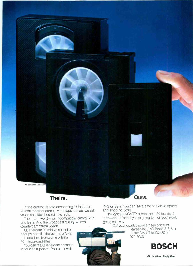
All cassettes actual size
Theirs.
In the current debate concerning 1/2 -inch and1/4 -inch recorder -camera videotape formats, we askyou to consider these simple facts:
There are two 1/2 -inch incompatible formats, VHSand Beta. And the broadcast quality 1/4 -inchQuartercamTM from Bosch.
Quartercam 20 -minute cassettesoccupy one -fifth the volume of VHSand one-third the volume of Beta20 -minute cassettes.
You can fit a Quartercam cassettein your shirt pocket. You can't with
Ours.
VHS or Beta. You can save a lot of archive spaceand shipping costs.
The logical ENG/EFP successor to 3/4 -inch is 1/4-inch-not 1/2 -inch. If you're going 1/2 -inch you're onlygoing half -way.
Call your local Bosch-Fernseh office, orFernseh Inc., P.O. Box 31816, Salt
Lake City, UT 84131, (801)972-8000.
BOSCHCircle (64) on Reply Card
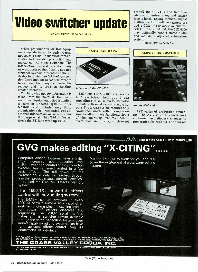
Video switcher updateBy Carl Bentz, technical editor
When preparations for this equip-ment update began in early March,notices were sent to manufacturers ofstudio and portable production andmaster control video switchers. Theinformation request specified anynew products or significantly updatedswitcher systems presented to the in-dustry following the NAB -'82 conven-tion. Introductions at NAB -'83 were tobe included. For many companies, therequest and its pre -NAB deadlinecreated problems.
The following update information istaken from the materials that weresent to us. Equipment listed is limitedto new or updated systems, afterNAB -'82, and includes only thoseorganizations that responded. For ad-ditional information on new systemsthat appear at NAB-'83/Las Vegas,check the BE June wrap-up issue.
AMERICAN DATA
American Data MC 4000
MC 4000. The MC 4000 master con-trol switcher includes inputcapabilities to 32 audio -follow -videocircuits with eight separate audio in-puts. The largest system requires onlyseven rack units, with microproces-sors handling many functions. Someof the operating features includeover/under audio mix, single -event
pre -roll for 10 VTRs and two filmislands, downstream key and masterfade -to -black. Keying includes digitalmatting, background/black generatorsand a CCD title edger. Available forNTSC, PAL or PAL -M, the MC 4000may optionally handle stereo audioand include a 40 -event automationsystem.
Circle (505) on Reply Card
AMPEX CORPORATION
Ampex AVC series
AVC series of production switch-ers. The AVC series has undergonecontinuing evolutionary changes inpreparation for NAB -'83. The changes
AA GRASS VALLEY GROUP
GVG makes editing "X -CITING"Computer editing systems have signific-antly increased post -production cap-abilities, yet editor control of the productionswitcher has remained limited to a fewbasic effects. The full power of theswitcher could only be reached throughless than precise manual control. Until GVGintroduced the E-MEMTM Effects MemorySystem.
The 1600-1X; powerful effectscontrol with any editing system!The E-MEM system standard in every1600-1X permits automated control of allswitcher functions plus the exciting produc-tion power of effects dissolves andsequencing. The E-MEM Serial Interfacemakes all this switcher power availablethrough the computer editing system. Evenlimited capability editing systems can haveframe accurate effects control using GPI(contact closure) interface.
Put the 1600-1X to work for you and dis-cover the excitement of a complete editingsystem.
GVG Sales Offices: Edison, NJ (201)549-9600; Atlanta, GA (404)321-4318; Elkhart, IN (219)264-0931; Arden Hills,MN (612)483-2594; Fort Worth, TX (817)921-9411; Palo Alto, CA (415)968-6680; Woodland Hills, CA (213)999-2303
THE GRASS VALLEY GROUP, INC.SO BOX 1114 GRASS VALLEY CALIFORNIA 95945 USA TEL (916)2739421 TWX 9/05308280
l[K IRON"( COMPANY
Circle (65) on Reply Card
72 Broadcast Engineering May 1983
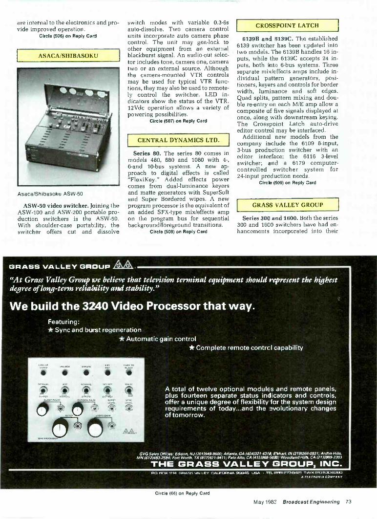
are internal to the electronics and pro-vide improved operation.
Circle (506) on Reply Cad
ASACA/SHIBASOKIJ
AsacaiShibasoku ASW-50
ASW-50 video switcher. Joining theASW-100 and ASW-200 portable pro-duction switchers is the ASW-50.With shoulder -case portability, theswitcher offers cut and dissolve
switch modes with variable 0.3-6sauto -dissolve. Two camera controlunits incorporate auto camera phasecontrol. The unit may gen-lock toother equipment from an externalblackburst signal. An audio -out selec-tor includes tone, camera one, cameratwo or an external source. Althoughthe camera -mounted VTR controlsmay be used for typical VTR func-tions, they may also be used to remote-ly control the switcher. LED in-dicators show the status of the VTR.12Vdc operation allows a variety ofpowering possibilities.
Circle (507) on Reply Card
CENTRAL DYNAMICS LTD.
Series 80. The series 80 comes inmodels 480, 680 and 1080 with 4-,6 -and 10 -bus systems. A new ap-proach to digital effects is called"FlexiKey." Added effects powercomes from dual -luminance keyersand matte generators with SuperSoftand Super Bordered wipes. A newprogram processor is the equivalent ofan added SFX-type mix/effects ampon the program bus for sequentialbackground/foreground transitions.
Circle (508) on Reply Card
CROSSPOINT LATCH
6139B and 6139C. The established6139 switcher has been updated intotwo models. The 6139B handles 16 in-puts, while the 6139C accepts 24 in-puts, both into 6 -bus systems. Threeseparate mix/effects amps include in-dividual pattern generators, posi-tioners, keyers and controls for borderwidth, luminance and soft edges.Quad splits, pattern mixing and dou-ble re-entry on each M/E amp allow acomposite of five signals displayed atonce, along with downstream keying.The Crosspoint Latch auto -driveeditor control may be interfaced.
Additional new models from thecompany include the 6109 8 -input,3 -bus production switcher with aneditor interface; the 6116 3 -levelswitcher; and a 6179 computer -controlled switcher system for24 -input production needs.
Circle (509) on Reply Card
GRASS VALLEY GROUP
Series 300 and 1600. Both the series300 and 1600 switchers have had en-hancements incorporated into their
GRASS VALLEY GROUP
"At Grass Valley Group ire believe that television terminal equipment should represent the highestdegree of long-term reliability and stability."
We build the 3240 Video Processor that way.Featuring:*Sync and burst regeneration
*Automatic gain control*Complete remote contrc I capability
UNLOCK BYPASSEATBEE
En'TC NORMAL ,47 01,[
1.tt6s41. e'n'ss E XSTTfifROMA ,4,4 SORE,
LEVEL
3740 PAM
..-KTKieSEMIMIN
V KOK TOSt
SPARE
sYNc
AA.
A total of twelve optional modules and remote panels,plus fourteen separate status indicators and controls,offer a unique degree of flexibility for the system designrequirements of today...and the evolutionary changesof tomorrow.
GVG Sales Of I Edison, NJ (201)549-9600; Atlanta, GA (404)321-431J, rkhart, IN (219)264-0931, Ard?nMN (612)483-2594, Fort Worth, TX (817)921-9411, Palo Alto, CA (415)968-3680; Woodland Halts, CA (213039-2303
THE GRASS VALLEY GROUP, INC.PO. 60). 1114 GRASS VALLEY CALIFORNIA 95945 USA TEL (9161273E1421 TWX 910530E3290
A T1CTRONIX C 3MPANY
Circle (66) on Reply Card
May 1983 Broadcast Engineering 73
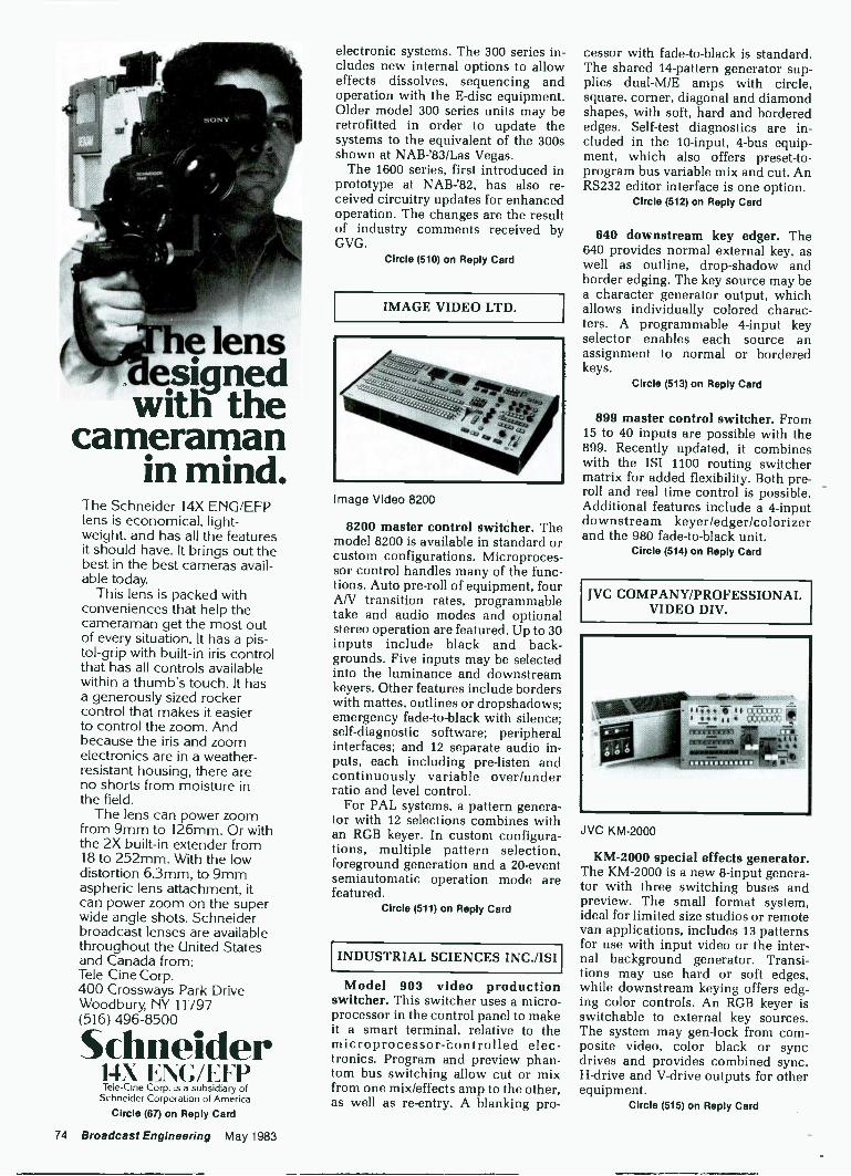
e lensesigned
with thecameraman
in mind.The Schneider 14X ENG/EFPlens is economical, light-weight, and has all the featuresit should have. It brings out thebest in the best cameras avail-able
This lens is packed withconveniences that help thecameraman get the most outof every situation. It has a pis-tol -grip with built-in iris controlthat has all controls availablewithin a thumb's touch. It hasa generously sized rockercontrol that makes it easierto control the zoom. Andbecause the iris and zoomelectronics are in a weather-
resistant housing, there areno shorts from moisture inthe field.
The lens can power zoomfrom 9mm to 126mm. Or withthe 2X built-in extender from18 to 252mm. With the lowdistortion 6.3mm, to 9mmaspheric lens attachment, itcan power zoom on the superwide angle shots. Schneiderbroadcast lenses are availablethroughout the United Statesand Canada from:Tele-Cine Corp.400 Crossways Park DriveWoodbury, NY 11797(516) 496-8500
Schneider14X ENC/EITTele-fine Corp. is a subsidiary of
Schneider Corporation of America
Circle (67) on Reply Card
electronic systems. The 300 series in-cludes new internal options to alloweffects dissolves, sequencing andoperation with the E -disc equipment.Older model 300 series units may beretrofitted in order to update thesystems to the equivalent of the 300sshown at NAB-'83/Las Vegas.
The 1600 series, first introduced inprototype at NAB -'82, has also re-ceived circuitry updates for enhancedoperation. The changes are the resultof industry comments received byGVG.
Circle (510) on Reply Card
IMAGE VIDEO LTD.
Image Video 8200
8200 master control switcher. Themodel 8200 is available in standard orcustom configurations. Microproces-sor control handles many of the func-tions. Auto pre -roll of equipment, fourAN transition rates, programmabletake and audio modes and optionalstereo operation are featured. Up to 30inputs include black and back-grounds. Five inputs may be selectedinto the luminance and downstreamkeyers. Other features include borderswith mattes, outlines or dropshadows;emergency fade -to -black with silence;self -diagnostic software; peripheralinterfaces; and 12 separate audio in-puts, each including pre -listen andcontinuously variable over/underratio and level control.
For PAL systems, a pattern genera-tor with 12 selections combines withan RGB keyer. In custom configura-tions, multiple pattern selection,foreground generation and a 20 -eventsemiautomatic operation mode arefeatured.
Circle (511) on Reply Card
INDUSTRIAL SCIENCES INC./ISI
Model 903 video productionswitcher. This switcher uses a micro-processor in the control panel to makeit a smart terminal, relative to themicroprocessor-bontrolled elec-tronics. Program and preview phan-tom bus switching allow cut or mixfrom one mix/effects amp to the other,as well as re-entry. A blanking pro-
cessor with fade -to -black is standard.The shared 14 -pattern generator sup-plies dual-M/E amps with circle,square, corner, diagonal and diamondshapes, with soft, hard and borderededges. Self -test diagnostics are in-cluded in the 10 -input, 4 -bus equip-ment, which also offers preset -to -program bus variable mix and cut. AnRS232 editor interface is one option.
Circle (512) on Reply Card
840 downstream key edger. The640 provides normal external key, aswell as outline, drop -shadow andborder edging. The key source may bea character generator output, whichallows individually colored charac-ters. A programmable 4 -input keyselector enables each source anassignment to normal or borderedkeys.
Circle (513) on Reply Card
899 master control switcher. From15 to 40 inputs are possible with the899. Recently updated, it combineswith the ISI 1100 routing switchermatrix for added flexibility. Both pre-roll and real time control is possible.Additional features include a 4 -inputdownstream keyer/edger/colorizerand the 980 fade -to -black unit.
Circle (514) on Reply Card
JVC COMPANY/PROFESSIONALVIDEO DIV.
JVC KM -2000
KM -2000 special effects generator.The KM -2000 is a new 8 -input genera-tor with three switching buses andpreview. The small format system,ideal for limited size studios or remotevan applications, includes 13 patternsfor use with input video or the inter-nal background generator. Transi-tions may use hard or soft edges,while downstream keying offers edg-ing color controls. An RGB keyer isswitchable to external key sources.The system may gen-lock from com-posite video, color black or syncdrives and provides combined sync,H -drive and V -drive outputs for otherequipment.
Circle (515) on Reply Card
74 Broadcast Engineering May 1983
INTRODUCINGTHE NEW PRIMUS
AUDIO COMPONENTSOUTPUT OUTPUT
. . .
A
P-42 MX
/)/ L4 OOO
D OFFMIC, LINE AMP MIX
ct)88/ A
N% NIL,
ivb Powerful performance
engineered audio electronics from Ramko Research.PRIMUS (Pr -ere -mils): an array of compact, performance -
in the palm of your hand.
81:**equipment you've ever used. Never before has so much advancedThe new PRIMUS components are unlike any professional audio
per-formance been put into such compact and rugged packages. Rarely haveyou had available so many features and options to help get the job done.Never have you had a three-year warranty that's backed up by factorycertified proof -of -performance.
PRIMUS is a comprehensive range of components that give you theflexibility to configure an audio sysem limited only by your imagination.Whether you choose from tabletop or rack mounting versions, there'shardly an audio job that can't be improved upon.
Here's a partial list of models currently available:O Lab standard mono or stereo turntable preamplifiers.O Dual and quad input, gain selectable microphone/line amplifier mixers.O Audio distribution amps from three (3) stereo/six (6) mono up toeight (8) stereo/sixteen (16) mono outputs. All models featureindividual recessed front panel adjustments or optional highresolution, conductive plastic potentiometers. Mic/Line equalizer amplifiers with balanced 1/0 and up to±15 db of reciprocal equalization. Expandable audio console mixers with cueing, selectable EQ,metering phones and monitor.O Voicegard' combination limiter/compressor, noise gatewith variable threshold and slope ratio; gain reduction metering.E Signal processing VCA's with six (6) independently con-trolled channels. DC remote control with balanced outputs. R/P and playback, stereo and mono NAB cart machines.
Whichever combination of precision PRIMUS audio com-ponents you choose, you're guaranteed outstanding specifica-tions. For example, our stereo turntable preamplifier measures:
Signal-to-noise Ratio: -93 dB (A weighted)Total Harmonic Distortion: Below .0018%Frequency Response: 10 Hz to 20 kHZ, ±.25 dBStereo Separation: -70 dB @ 1 kHzOutput Level: +25 dBm (10 Hz - 20 kHz)
The simplified and modular packaging of PRIMUS allowsus to concentrate the quality where it belongs: in state-of-the-art circuitry. High slew -rate integrated circuits and ex-tensive ground planes insure the highest RFI protection.
All IC's pluginto gold plated sockets. All modelsfeature quick disconnect 110 connectors andrequire only I% inch standard rack height.
We've taken another important step, too.When you invest in PRIMUS, you receive a Certified
Performance Gold Card that instantly puts you in touch withour Technical Assistance Department on a toll -free line. Just callin your registered serial number and you're in touch with the adviceyou need.
To put PRIMUS audio components to task on a free two-week trial,call toll free (800) 821-2545 or contact your nearest Ramko Researchsales representative or distributor. Put the powerful performance ofPRIMUS in the palm of your hand.
PRIMUS audio components a -e anarray of compact, performance -engineered rack mounting ortabletop packages.
PRIMUS is a division of Ramko Research, Inc. 11355.A Folsom Blvd., Rancho Cordova, California 95670 (916) 635.360C
Circle (68) on Reply Card 1983 Ramko Research
LANG VIDEO SYSTEMS McCURDY RADIOINDUSTRIES LTD.
PANASONIC AUDIO -VIDEOSYSTEMSOne Shot. Enhancements to the
One Shot have been provided, makingit a totally plug-in system for mobileand helicopter ENG production. Fourline or mic audio inputs and fourvideo inputs may use straight cut oroptional vertical interval switching. Acolor bar/ID feature now includesSMPTE reverse bars as an option andmay be purchased in the PAL stan-dard format. Four outputs from theswitcher are standard, and a 1 -inchvideo monitor is an optional feature.
Circle (516) on Reply Card
MCS-1004. MCS-1004 designates asmall format video switcher from Mc-Curdy Radio Industries. Ideally suitedto small studio operations or portableproduct on units, the 10 -input, 4 -busunit fits into an 19"x7"x3.5" controlpanel. Standard features include mixand key functions, on -air tallies,momentary push-button control, automix/auto key with adjustable rate andcolor background generator.
Circle (517) on Reply Card
The Wireless Intercomby HME.
Now You canCOMMUNIC4TECONTINUOUSLY - Up to, five stations
in hands -free, continuous full -duplex modeCONVENIENTLY - Ultra ompact,
10 ounce all metal belt -pack transceiversCLEARLY- HME Dynamic xpansion
gives full 80dB dynamic rangeCOMPLETELY - Built-in in erface
and controls for hard -wired systemsCONFIDENTLY - Loop -around
sidetone verifies completion of thecommunications,
h m
150E Series
*1
WirelessIntercomSystem
HM Electronics, Inc 6151 Fairmount Ave., San Diego, CA 9212C (619)280-6050 TELEX. 697-122
Circle (69) on Reply Card
Panasonic WJ-5500B
W1-4600B/W1-5500B. The WJ-4600A/WJ-5500A switcher/effectsgenerator systems have been up-graded to the WJ-4600B/WJ-5500Bsystems. Added features include abuilt-in audio amp for the intercomwith level control for carbon micheadsets and additional blackburstoutputs on BNC connectors. The4600B provides six inputs and six ef-fects wipe patterns. The 5500B haseight inputs and nine patterns. Bothare compact systems for mobile/porta-ble or studio operation.
Circle (518) on Reply Card
AS -6100. The 5 -bus AS -6100 pro-duction system offers 10 -input capa-bility with spotlighting, downstreamkeying and a 14 -pattern generator.Two inputs may be selected for thekeyer. Color background matting andeffects positioning controls are pro-vided. Completing the 6100 system isthe AS -2000 chroma-key generator andthe AS -100 color sync generator, form-ing a system that backs Panasonic'snew thrust into the broadcast realm.
Circle (519) on Reply Card
ROSS VIDEO LTD.
Ross Video Ltd. RVS-524
RVS-524. Answering a demand forfull -featured, low cost switching insmall studios, Ross presents theRVS-524. Many features of previousmodels are incorporated: Multi -LevelEffects (MLE) for up to four sourceswithout locking up the switcher;preview transition viewing; SceneStore memory; analog key borders;and a variety of interfacing for digitaleffects units. Nine rotary wipes add totraditional ones, with RGB and en-coded chroma-keying, foreground/
76 Broadcast Engineering May 1983
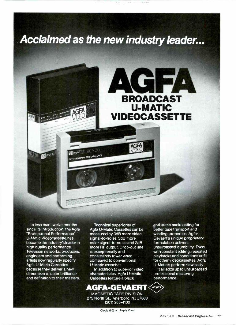
OF710.1C
sooNAL pERFORmANC
In less than twelve monthssince its introduction, the Agfa"Professional Performance"U-Matic Videocassette hasbecome the induEtry's leader inhigh quality performance.Television networks, producers,engineers and performingartists now regularly specifyAgfa U-Matic Cassettesbecause they del ver a newdimension of color brillianceand definition to -heir masters.
BROADCASTU-MATIC
VIDEOCASSETTE
Technical superiority ofAgfa U-Matic Cassettes car bemeasured by 3dB more videosignal-to-noise, 3dB morecolor signal-to-noise and 2d13more RF output. Drop -out rateis exceptionally andconsisten:ly lower whencomparec to conventionalU-Matic cassettes.
In addition to superior videocharactenstics, Agfa U-MaticCassettes feature a black
AGFA-GEVAERTMAGNETIC TAPE DIVISION
275 North St.. Teterboro. NJ J7608(201) 288-4100
anti-stat c backcoating forbetter tapE transport andwinding properties. Agfa-Gevaerts unique proprietaryformulation deliversunsurpassed durabilry. Evenwith constant editing, repeatedplaybacKs and condit ons untitfor other v deocassettes, AgfaU-Matic s Derform flawlessly.
It all aics up to unsurpassedprofessiDral mastenr gperformance.
Circle (96) on Reply Card
May 1983 Broadcast Engineering 77
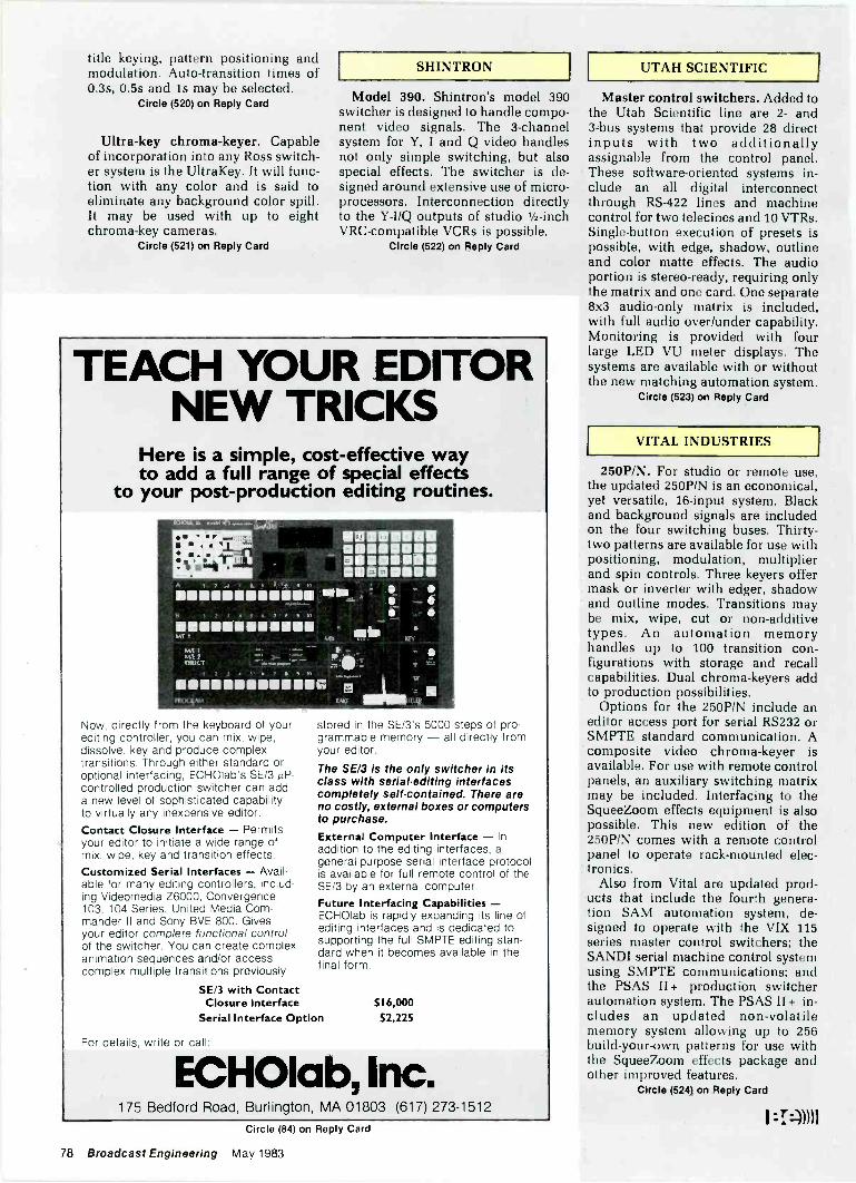
title keying, pattern positioning andmodulation. Auto -transition times of0.3s, 0.5s and 1s may be selected.
Circle (520) on Reply Card
Ultra -key chroma-keyer. Capableof incorporation into any Ross switch-er system is the UltraKey. It will func-tion with any color and is said toeliminate any background color spill.It may be used with up to eightchroma-key cameras.
Circle (521) on Reply Card
SHINTRON
Model 390. Shintron's model 390switcher is designed to handle compo-nent video signals. The 3 -channelsystem for Y, I and Q video handlesnot only simple switching, but alsospecial effects. The switcher is de-signed around extensive use of micro-processors. Interconnection directlyto the Y-I/Q outputs of studio 1/2 -inchVRC-compatible VCRs is possible.
Circle (522) on Reply Card
TEACH YOUR EDITORNEW TRICKS
Here is a simple, cost-effective wayto add a full range of special effects
to your post -production editing routines.
8
121111111111111111111111
01111111111111111111
map -
1111111111111111111111111111MI 1
MIX
Mrk 1WE 2 }- ei(NWT :*,,......". _., ..
7 a 9 to
19,,,o,.11111.1111111.11.1111 rg olio
I AM
Now, directly from the keyboard of yourediting controller, you can mix, wipe,dissolve, key and produce complextransitions. Through either standard oroptional interfacing, ECHOIab's SE/3 µP -controlled production switcher can adda new level of sophisticated capabilityto virtually any inexpensive editor.Contact Closure Interface - Permitsyour editor to initiate a wide range ofmix, wipe, key and transition effects.Customized Serial Interfaces - Avail-able for many editing controllers, includ-ing Videomedia Z6000, Convergence103, 104 Series, United Media Com-mander II and Sony BVE 800. Givesyour editor complete functional controlof the switcher. You can create complexanimation sequences and/or accesscomplex multiple transitions previously
stored in the SE/3's 5000 steps of pro-grammable memory - all directly fromyour editor.
The SE/3 is the only switcher in itsclass with serial -editing interfacescompletely self-contained. There areno costly, external boxes or computersto purchase.
External Computer Interface - Inaddition to the editing interfaces, ageneral-purpose serial interface protocolis available for full remote control of theSE/3 by an external computer.Future Interfacing Capabilities -ECHOlab is rapidly expanding its line ofediting interfaces and is dedicated tosupporting the full SMPTE editing stan-dard when it becomes available in thefinal form.
5E/3 with ContactClosure Interface
Serial Interface Option
For details, write or call.
$16,00052,225
ECHOIab, Inc.
UTAH SCIENTIFIC
Master control switchers. Added tothe Utah Scientific line are 2- and3 -bus systems that provide 28 directinputs with two additionallyassignable from the control panel.These software -oriented systems in-clude an all digital interconnectthrough RS -422 lines and machinecontrol for two telecines and 10 VTRs.Single -button execution of presets ispossible, with edge, shadow, outlineand color matte effects. The audioportion is stereo -ready, requiring onlythe matrix and one card. One separate8x3 audio -only matrix is included,with full audio over/under capability.Monitoring is provided with fourlarge LED VU meter displays. Thesystems are available with or withoutthe new matching automation system.
Circle (523) on Reply Card
VITAL INDUSTRIES
250P/N. For studio or remote use,the updated 250P/N is an economical,yet versatile, 16 -input system. Blackand background signals are includedon the four switching buses. Thirty-two patterns are available for use withpositioning, modulation, multiplierand spin controls. Three keyers offermask or inverter with edger, shadowand outline modes. Transitions maybe mix, wipe, cut or non -additivetypes. An automation memoryhandles up to 100 transition con-figurations with storage and recallcapabilities. Dual chroma-keyers addto production possibilities.
Options for the 250P/N include aneditor access port for serial RS232 orSMPTE standard communication. Acomposite video chroma-keyer isavailable. For use with remote controlpanels, an auxiliary switching matrixmay be included. Interfacing to theSqueeZoom effects equipment is alsopossible. This new edition of the250P/N comes with a remote controlpanel to operate rack -mounted elec-tronics.
Also from Vital are updated prod-ucts that include the fourth genera-tion SAM automation system, de-signed to operate with the VIX 115series master control switchers; theSANDI serial machine control systemusing SMPTE communications; andthe PSAS II + production switcherautomation system. The PSAS II + in-cludes an updated non-volatilememory system allowing up to 256build -your -own patterns for use withthe SqueeZoom effects package andother improved features.
Circle (524) on Reply Card
175 Bedford Road, Burlington, MA 01803 (617) 273-1512Circle (84) on Reply Card
78 Broadcast Engineering May 1983
I
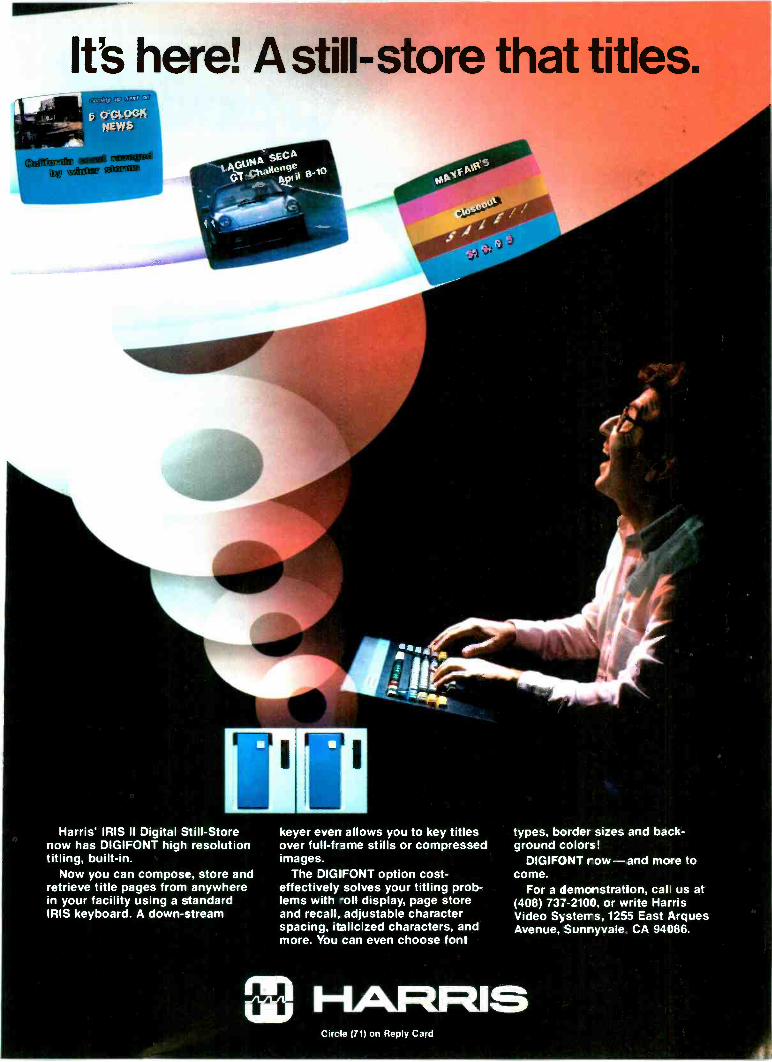
It's here! A still -store that titles.
Harris' IRIS II Digital Still -Storenow has DIGIFONT high resolutiontitling, built-in.
Now you can compose, store andretrieve title pages from anywherein your facility using a standardIRIS keyboard. A down -stream
keyer even allows you to key titlesover full -frame stills or compressedimages.
The DIGIFONT option cost-effectively solves your titling prob-lems with -oll display, page storeand recall, adjustable characterspacing, italicized characters, andmore. You can even choose font
Circ e (71) on Reply Card
types, border sizes and back-ground colors!
DIGIFONT row-and more tocome.
For a demonstration, call us at(408) 737-2100, or write HarrisVideo Systems, 1255 East ArguesAvenue, Sunryvale CA 94086.
The evolutionof TV production
switchingBy Craig Birkmaier and Donald Lambert, Production Systems Marketing Group, Grass Valley Group, Grass Valley, CA
The video production switcher isone of the most complex electronicdevices in the TV production system,yet it is usually operated by a personwhose primary concern is not thequality of the waveform, but rather thecontent of the program that is beingcreated. The evolution of the switcher(or vision mixer) into a productionsystem has been guided primarily bythe operators of the system and byprogram producers, who determinethe manner in which special effectsare used.
With respect to the electronics at theother end of the control cables, theguiding force has remained basicallyunchanged over the years..."I wanttransparent video performance and Inever want to tweak it." Maintainingthe balance between more featuresand less maintenance has thrust thedevelopment of production systemsinto a perpetual race at the leadingedge of technology.
Little activity took place in switcherdevelopment in the early years oftelevision, while the camera, transmit-ter and receiver were reaching accept-able quality for commercialization.With the start of commercial broad-casting, the need for programminggave birth to the first mixer: two rowsof mechanical switches selectingvideo inputs, their output feeding a750 pot to mix between the rows.Mechanical switches gave way torelays, and the 7511 pot was replacedwith a tube mixer. The tube mixerallowed the first special effects:luminance keying and simple wipes.
Early special effects generatorswere separate units. But then the
special effects generator was inte-grated into the switcher, where twobuses feed signals into special effectscircuitry, which subsequently feed asignal into the mixer buses. Largeswitchers also had program and pre-set/preview buses, and the output ofthe special effects generator and themixer were re-entered into thesebuses.
By now, videotape had become areality, and the switcher started togrow in the number of inputs. Also theadvent of color created a world ofproblems in the design of the produc-tion switcher. Suddenly system timingbecame critical, and random switch-ing, acceptable in black -and -white,was unacceptable for color. The solu-tion was found in timing the switchbetween inputs, so that the glitch oc-curred in the vertical interval, safelyout of view. In order to achieve thedegree of control and speed of switch-ing necessary to correctly time theswitch, the relay gave way to a newdevice that has revolutionized ourlives -the transistor. Although thetransistor was a major breakthroughin switching, some time went bybefore the tube gave way completelyto solid-state devices in the video mixamplifier and control processor.
The advent of color made a newspecial effect possible: chrome -keying. Instead of detecting a videolevel threshold in encoded videosignal (as in luminance -keying), thekeyer detected a threshold in onechannel of the camera RGB outputs.The first chroma-keyers used the blueoutput, because the blue channel wasleast responsive in areas of flesh
tones. A person, standing in front of ablue wall, could be matted intoanother picture.
Nearly simultaneously withchroma-keying, electronic videotapeediting became possible, foreshadow-ing a new set of demands on the pro-duction switching system.
Keying grew in importance as amethod of adding graphics and mat-ting signals together. The keyer usual-ly used one of the two mixer inputs tocreate a control signal, which was ap-plied to the mix amplifier. The resultwas a self -key with the same video,which "cut the hole," then filled thehole. Also the keyer could create thehole with a chroma-key input or exter-nal video inputs. Inverting the controlsignal allowed keying black graphicsonto a white background.
Solid-state mixers provided anothermajor advancement in switcherdesign. A third input was added to thevideo mixer for a matte signal. Thehole, created by the key signal, couldbe filled by one of the video inputs ormatte. Wipe transitions were createdby applying another control signal tothe video mixer, similar to the keysignal. The wipe control signalresulted from moving a pickoff pointalong an electrically generatedwaveform. From a second pickoffpoint, the wipe border was generatedby inserting the matte signal duringthe time between the two controlsignals. The need for more effects ledto more switchers in the form of thetwo mix/effects units with a cascadingre-entry system. Because of color tim-
Continued on page 84
80 Broadcast Engineering May 1983
st:. 1981 Fuji Photo Film U.S.A., Inc.. Magnetic Tape Division, 350 Fifth Avenue, NY, NY 10118
IKEGAMI'S NEW HL -79ETHE HEIR TO THE THRONE
IkegamiS latest technological triumph, the HL -79E,heralds a new generation of hEnd-held broadcastcamera excellence.
Engineered to surpass the most rigorousstandards of performance anc introducing fea-tures that a -e masterpieces of innovative thinking.the HL-79Es picture quality even exceeds that ofother manufacturers' top -of -the -line studio cameras.
In the fiercely competitive video market whereothers hope to be as gcod as II --e HL -79D, Ikegamiis the unque.stioned leader. And the HL -79E willsoon ascend to a loftier throne as King of theJurgle. Only by seeing this remarkable camerain action can it be fully appreciated.
How great a camera is itr-o begin with, it isSmaller and lighter than the world's standard forcomparison, the Ikegami HL -79D Series. And ithas features as yet unknown to even sophisticatedcamera uses: Dynamic Detail Correction, ChromaAperture Correction, Highlight Aperture Correc-tion and Auto Contrast Compression. Plus theHL -79E offers improvements it contrast range,S/11 ratio, registration. accuracy, resolutionviewfinder performance and more.
Optional accessories induce the ADC -79EAuto Set -Up Digital Control, the RDC-79E RemoteDigital Control and the VF 45-3 Large Viewfinder.The HL -79E is compatible for use with existingHL -79A and HL -79D lenses. poser supplies. VTRcab es. and other accessories. Plus. it can
be adapted to theMA -79 Multicore BaseStaton and TA -79/79CTriax Base Station.
The HL -79E is partof the great and proudfamiiy of Ikegami cam-eras and monitors serv-ing many satisfiedusers worldwide. For acorn alete demonstra-tion of Ikegami Cam-eras and Monitors. con--,tact your local dealer orcall I cegami Electronics
ADC :3E Auto Set -tip Digital Control
II) H L-79 ECircle (751 on Reply Co .d
kegami Electronics (USA) Inc. 37 Brook Avenue Maylitiop Northeast '201) 368-9171 Midwest (219) 277-82d0 West Coast (213)i53
Southwest (713) 445-0100 Southeast (813 884-2046
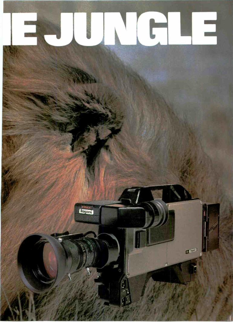
Continued from page 80
ing requirements, the re-entryamplifiers required video delays andequalization amplifiers. These ampli-fiers, in series with the bus output andvideo mixing amplifiers, caused theswitcher path length to grow-to thelimits of acceptable video perform-ance.
The readability of keyed graphicsoften suffered because of the similari-ty in some portions of the picture be-tween color or luminance levels ofbackground and keyed inserts. By
delaying the key control signalthrough two delay lines, each withone horizontal line delay, it was possi-ble to anticipate key transitionchanges and process them to create awider key hole. The hole was filledpartially with matte corresponding tothe original key signal. The resultingBorderline generator allowed a 1 -lineblack border or 2 -line drop shadow tobe placed around the key. Using thedifference of the control signals, a col-or outline of the key could also begenerated.
By now computer control of video -
split equalizer design forflawless stereo performance
PHONOGRAPH PREAMPLIFIERINPUT INPUT
A
NEW HARRIS PX-90PHONO PREAMP
Split equalizer meets strin-gent dynamic requirementsnot addressed by commonstatic specifications.
Polypropylene equalizationcomponents insure impec-cable transient response.
Unmatched immunity to RFIand other extraneoussignals.
Adjustable cartridge loadingand high accuracy equaliza-tion of +0.25 dB from idealRIAA curve provide optimumdynamic performance.
Performance commensuratewith Technics SP-10MKIIturntable.
Unmeasurable transient in-termod and dynamic distor-tions assure faithful repro-duction of demanding cuts,such as the cannon shot inTelarc's special recording ofthe 1812 Overture.
Buy the best-the Harris PX-90"Mastering Quality" PhonoPreamps...for your "best shot".
Contact Harris for the rest ofthe facts. Harris Corporation,Broadcast Division,P.O. Box 4290, Quincy, Illinois62305-4290. 217-222-8200.
(7-1 HARRIStau
tape editing was possible, and crudecontrol of the switcher through aparallel interface of the computer andswitcher electronics was attempted.Switcher limitations, which had neverbeen noticed in live productions,became apparent in post -production.If the levels of switching bus and mixamplifier outputs were not identical,shifts were noticed in match frameedits. Switcher alignment became acritical factor. The problem was ag-gravated by increased demands on theproduction switching system.
Improvements in video mixertechnology made it possible to adjustthe rise time of control signal changes.These shaped control signals im-proved key transitions, allowinganother new effect, the soft wipe.Along with performance enhance-ments, another milestone was reachedin switcher design. It was possible tocombine control signals to the mixamplifier for transitions such as a mixor wipe to a keyed insert or preset pat-tern (pattern limit). The need for re-entry to create many effects wasreduced, but program producerspushed for more. Continuing work inamplifier design permitted extendingthe switcher's path lengths again, andsoon production switchers with threemix/effects systems were available.The control panel was becoming socomplex that qualified operators werevirtually guaranteed job security.
To lend the operator a hand, thecomputer was brought to the aid ofthe operator. As with equipment fromother manufacturers, the GVGE-MEM effects memory system couldlearn control panel configurations andstore them in memory registers for useduring productions. The capability forstoring analog control informationopened the door for another signifi-cant capability, effects dissolves. Theoperator could store a beginninggroup of analog settings, and an end-ing group of settings; the computerdetermined the information in-between. Thus smooth transitions ofanalog controls, such as the patternpositioner, could be programmed atany rate the operator desired. Later se-quences could be created by linkingmix/effects registers together, combin-ing panel setup changes and effectsdissolves for complete production se-quences. This capability was extreme-ly attractive for computer -assistedpost -production. To provide theediting computer with more control ofthe production switcher, a serial inter-face was developed for the E-MEMsystem and others.
The computer rapidly appeared inother production devices, such ascharacter generators and in a revolu-tionary device, the digital video ef-fects system. Now pictures could be
Circle (76) on Reply Card
84 Broadcast Engineering May 1983
MODEL DSS-11 DIGITAL STILL -STOREMEL
MEETS THE FIVE VS41414a.CONDIITr1ONSirFOR4ALLS
1. Simple operation. (Touching the digitalstill -store causes it to be operated instan-taneously and freely.)
2. Fast read time. (0.35 seconds for 1 field,2 fields, and 4 fields storage)
3. Large storage capacity. (500 field pictureson internal disk. 1,000 field pictures by
csi
;11111r..0i
%11111/lit
16.5" 11111111111111011111110111111111111111111
adding an equivalent external disk.)4. Natural picture quality. (CC-SPF system
acclaimed for its excellent picture quality)5. Small size. (only 12.2" high, including
internal disk. Mounts in a standard rackor a relay vehicle.)
a.
a)
0
Only the body and operation board need be purchased.Simple installation. Simply connect the body and
operation panel with a 1cm diameter cable.Program transmission possible.Convenient AS mode for emergency picture transmission.AS is the abbreviation for "picture after setting" and isused for picture material that arrives after transmissionpreparations are complete and for emergency messages.For example, if the AS switch is pressed, then 0 - 9 ispressed, the AS image is inserted directly during LISTtransmission or in the next picture and operation is
resumed according to that LIST.The output picture is switched over to the next pictureunder two modes;One with common switch and the other under dissolve(switched over to the next picture as if the last picture isdissolved).Control can be made by three types of monitor connection.Control can be made thoroughly with any method.Moreover, the comment can be watched on a 9" monitor.1. Use one unit of on -air color monitor.
Operate by watching the on -air image output withcomment.
2. Use one unit of on -air color monitor, and one unit ofnext preview color monitor.Operate with the on -air image output and next previewoutput with comment connected to the on -air monitorand next monitor respectively.
3. Operate with the on -air image output, next previewoutput and comment output connected respectivelyto the on -air monitor, next monitor and monochromemonitor.
The operation panel is small enough (1/2 letter size) to beinstalled anywhere.Alphabetic comments are also included.The switch section of the ope-ation panel can be removedand used up to 3 m away throJgh an extension cable.Therefore, the operation board can be freely designed byinstalling the switches at the desired desk and connectingthem to the operation panel with this extension cable.All operations which can be performed from the standardoperation panel can also be remotely controlled from anexternal EDP.For the additionally installed disk, series connection whichincreases image capacty and parallel connection whichmakes the system to presently used type and stand-bytype can be switched over by the switch in the main unit.
Our still equipment is being used by the NHK News Center and many public broadcasting stations, and incorporate the know-how gained from long experience. For example, all this technology is included in this one unit. Therefore, performance ishigh and stable, and operation is extremely easy.
NTI NTI America Inc. 1680 North Vine Street13-462-8945LOS ANGELES, California 90028
Phone 2
Circle 177) on Reply CardMay 1983 Broadcast Engineering 85
If you're using video or audio tapes, you want to erasethem and use them over.
But with today's high tape coercivity you've got problems.With every erase/record pass, the signal-to-noise ratio
gets worse. Or your cleaner/evaluator leaves atough RF signal embedded.
Either way you probably end up with increas-ing control track and time code miscuing, orother difficulties.Only maxERASE-16, successor to the widely
proven Optek 8000 bulk tape degausser, canmake your tapes like new with its 16KW, verticallyconcentrated magnetic field, which delivers
many times the erasing power of other machines.Usually, one fu.ly automatic 30 -second pass is allthat's needed.
Only maxERASE-16 can degauss every formatregardless of whether it is 3/4 -inch video cassette.
1- or 2 -inch cassette or reel, audio tape, or35mm magnetic film.
Only maxERASE-l6 can be usedwith most tapes on a continuous
basis without overheating and shutdown.You won't have to degauss many tapes before
maxERASE-16 pays for itself.For full details contact SteveHeller at Christie Electric Corp., 41111111111020665 Manhattan Place, lbr-rance, California 90501, 800-421-2955 (in California 213-320- ..,
0808), TWX 910-349-6260. \
CHRISTI'Since 1929
HEW
TAPESFROAk
Circle (72) on Reply Card
McMartin dprezallogage
"Our transmitters are so good we wantyou to try our other products.
We not only manufacture a complete lineof AM and FM transmitters, but also produce
audio consoles, monitors and amplifiers,FM/SCA equipment and satellite receivers. We
have over 300 products.
We have 27 years of experience, and inbroadcast, experience counts!"
3-77,/.47Ray B. McMartin
PresidentMcMartin Industries, Inc.
McMartin Industries, Inc. 4500 S. 76th St. Omaha, NE 68127(402) 331-2000Circle (73) on Reply Card
86 Broadcast Engineering May 1983
manipulated in size, flipped andtumbled. These new productiondevices placed a great deal of strainon existing switchers. There werenever enough keyers, and an entiremix/effects bank was consumed toprovide the input to the DVE. Mostunits offered a separate key signalfrom the video, so the DVE couldtrack the picture size and charactergenerators could pass edging informa-tion.
The industry responded in a varietyof ways: One approach placed buskeyers over each switching bus inputto the mix amplifier, allowing threekeys on a single mix/effects system.Another approach added key inputs tothe mix amplifier allowing a back-ground transition behind two keyinglevels. Both systems are currentlyavailable. The system with two keysover a background transition seems tobe more popular, due largely to theoperating technique. These systemsemploy non -directional transitionlevers and preview capabilities. Theoperator chooses which levels (back-ground, key 1, key 2)are to be changed,and the preview system shows theresult of the next level transition. Thissystem virtually eliminates the lock -upthat could occur in operating earliersystems.
Along with the new switcher ar-chitecture came other new capabili-ties: soft -bordered wipes; vastly ex-panded pattern generators with wiperotation and matrix wipes; multiplelatch keyers, which could key severalinputs simultaneously, such as twochannels from a character generator;and separate key mask generators. Ad-ditional provisions were made fordigital video effects generators, suchas auxiliary switching buses, talley im-plementation and with some systems,integration into the switcher controlpanel.
Thus we have arrived at the produc-tion switching systems of today. To-day's equipment is intelligent, com-municating with other devices in thesystem, such as computerized editors,frame stores and charactergenerators. The system provides vir-tually transparent performance andgreatly reduced maintenance. Andyet, it is still changing, to meet thedemands of the next newtechnology.
Editors note:In putting together this issue of BE, we planned to
insert into the "Video Switcher Update" article asidebar that pinpointed milestones In the history ofthe systems' development. However, the people atGrass Valley thought that they could shed some lighton this evolution in switcher equipment provided wewould not pin them down on specific dates.
This article is the author's narrative presentation(omitting dates) of historical landmarks in switcherdevelopment. Readers who think that other highlightsshould be pinpointed are welcome to submit lettersdetailing points for inclusion in a future update on thistopic.
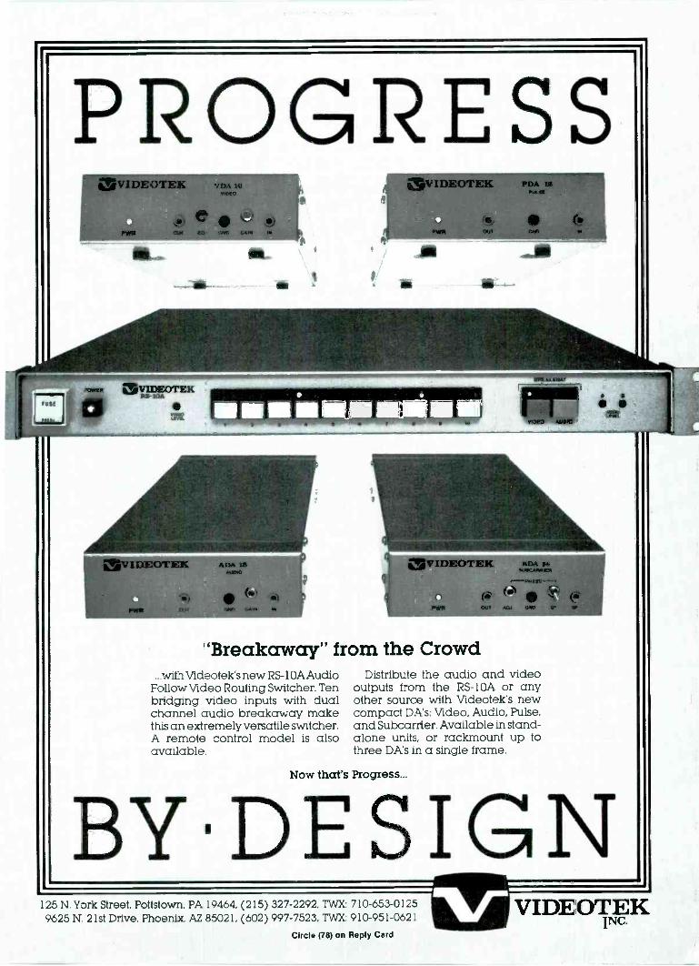
PROGRESSOR
WrA DA IAtre-
N11111. CA.
(a.
an
ayIDEOTEK
=
P DA to*ix 91
EOTKK X DA 14
"Breakaway" from the Crowd...with Videotek's new RS -1 OA Audio
Follow Video Routing Switcher. Tenbridging video inputs with dualchannel audio breakaway makethis an extremely versatile switcher.A remote control model is alsoavailable.
WIPCMWHIEN
(0
Distribute the audio and videooutputs from the RS -10A or anyother source with Videotek's newcompact DA's: Video, Audio, Pulse,and Subcarrien Available in stand-alone units, or rackmount up tothree DA's in a single frame.
Now that's Progress...
BY1DESIGN125 N. York Street, Pottstown, PA 19464, (215) 327-2292, TWX: 710-653-01259625 N. 21st Drive, Phoenix, AZ 85021, (602) 997-7523, TWX: 910-951-062:
Circle (78) on Reply Card
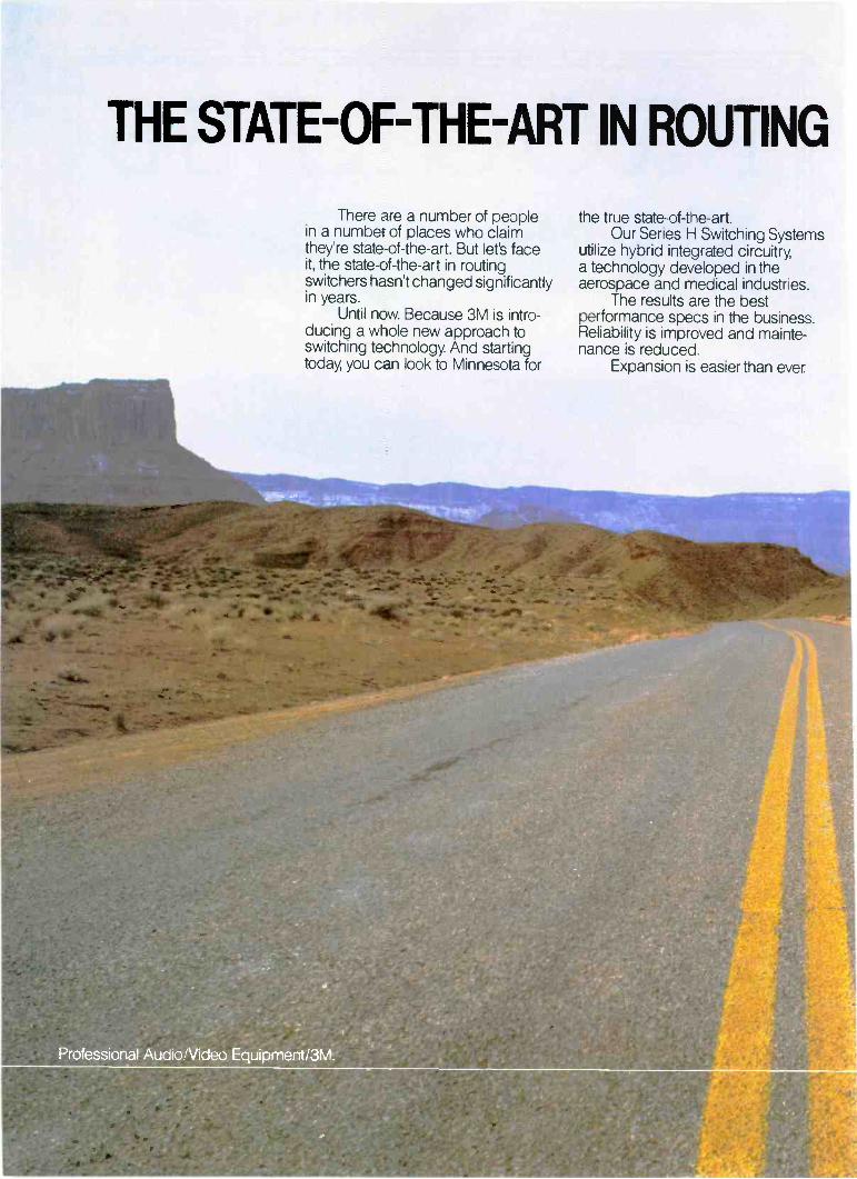
THE STATE-OF-THE-ART IN ROUTING
There are a number of peoplein a number of places who claimthey're state-of-the-art. But let's faceit, the state-of-the-art in routingswitchers hasn't changed significantlyin years.
Until now. Because 3M is intro-ducing a whole new approach toswitching technology. And startingtoday, you can look to Minnesota for
the true state-of-the-art.Our Series H Switching Systems
utilize hybrid integrated circuitry,a technology developed in theaerospace and medical industries.
The results are the bestperformance specs in the business.Reliability is improved and mainte-nance is reduced.
Expansion is easier than ever.
of-the-art in terms of yesterday'stechnology, call us toll -free at1-800-328-1684. In Minnesota, calltoll -free 1-800-792-1072. Outsidethe continental U.S., call Interna-tional Operations collect at 1-612-736-2549. We'll give you a wholenew sense of direction.
SWITCHERS JUST CHANGED STATES.
And thanks to miniaturization,there's at least a 300% increasein crosspoints-per-rack-unit. Whatused to take up an entire room cannow fit in a closet.
Best of all, we offer all theseadvantages at a price that's actuallycomparable to the price of conven-tional switching systems.
So if you still think of the state-
31VISt. Paul
Minn ataa
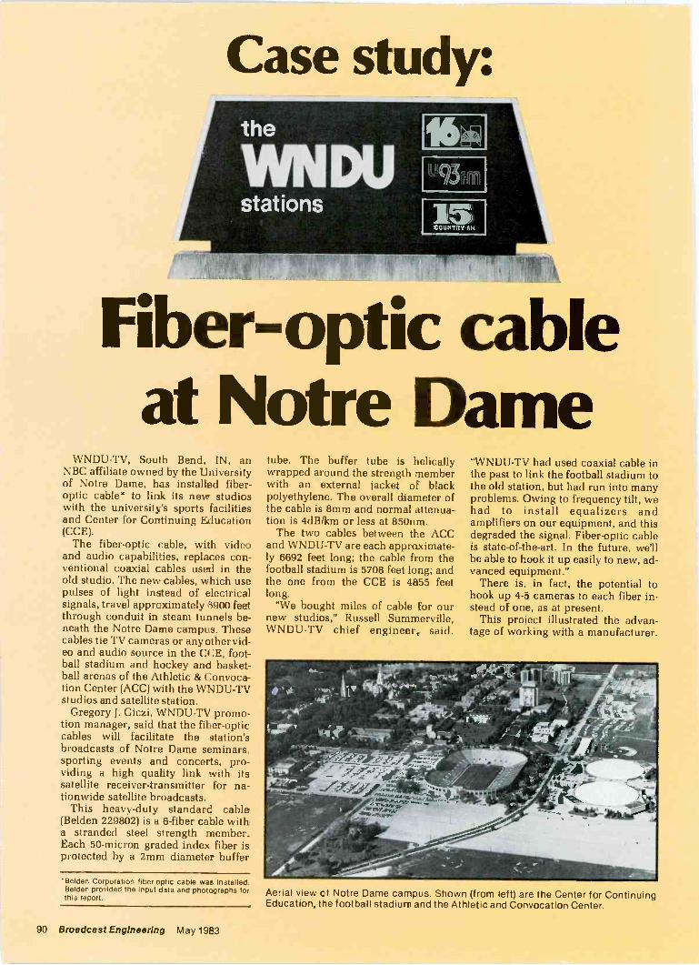
Case study:the
VVNDUstations 15
tOUNTRY.AM
Fiber-optic cableat Notre Dame
WNDU-TV, South Bend, IN, anNBC affiliate owned by the Universityof Notre Dame, has installed fiber-optic cable* to link its new studioswith the university's sports facilitiesand Center for Continuing Education(CCE).
The fiber-optic cable, with videoand audio capabilities, replaces con-ventional coaxial cables used in theold studio. The new cables, which usepulses of light instead of electricalsignals, travel approximately 6900 feetthrough conduit in steam tunnels be-neath the Notre Dame campus. Thesecables tie TV cameras or any other vid-eo and audio source in the CCE, foot-ball stadium and hockey and basket-ball arenas of the Athletic & Convoca-tion Center (ACC) with the WNDU-TVstudios and satellite station.
Gregory J. Giczi, WNDU-TV promo-tion manager, said that the fiber-opticcables will facilitate the station'sbroadcasts of Notre Dame seminars,sporting events and concerts, pro-viding a high quality link with itssatellite receiver -transmitter for na-tionwide satellite broadcasts.
This heavy-duty standard cable(Belden 229802) is a 6 -fiber cable witha stranded steel strength member.Each 50 -micron graded index fiber isprotected by a 2mm diameter buffer
'Belden Corporation fiber-optic cable was Installed.Belden provided the input data and photographs forthis report.
tube. The buffer tube is helicallywrapped around the strength memberwith an external jacket of blackpolyethylene. The overall diameter ofthe cable is 8mm and normal attenua-tion is 4dB/km or less at 850nm.
The twa cables between the ACCand WNDU-TV are each approximate-ly 6692 feet long; the cable from thefootball stadium is 5708 feet long; andthe one from the CCE is 4855 feetlong.
"We bought miles of cable for ournew studios," Russell Summerville,WNDU-TV chief engineer, said.
"WNDU-TV had used coaxial cable inthe past to link the football stadium tothe old station, but had run into manyproblems. Owing to frequency tilt, wehad to install equalizers andamplifiers on our equipment, and thisdegraded the signal. Fiber-optic cableis state-of-the-art. In the future, we'llbe able to hook it up easily to new, ad-vanced equipment."
There is, in fact, the potential tohook up 4-5 cameras to each fiber in-stead of one, as at present.
This project illustrated the advan-tage of working with a manufacturer.
Aerial view of Notre Dame campus. Shown (from left) are the Center for ContinuingEducation, the football stadium and the Athletic and Convocation Center.
90 Broadcast Engineering May 1983
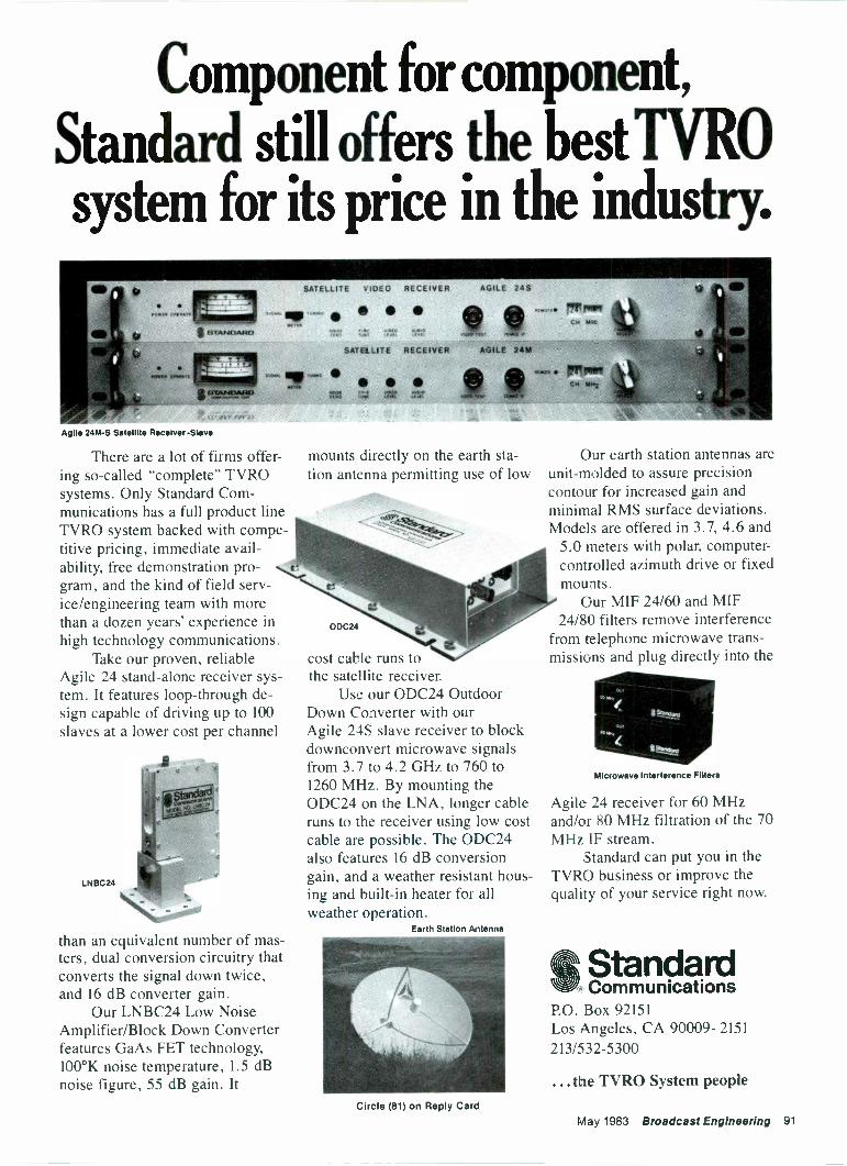
Component for component,
Standard still offers the best TYROsystem for its price in the industry.
SATELLITE vlDie RECEIVER AGILE 24S
SATM.LITE RECE R AGILE 24M
Agile 24M -S Satellite Receiver -Slave
There are a lot of firms offer-ing so-called "complete" TVROsystems. Only Standard Com-munications has a full product lineTVRO system backed with compe-titive pricing, immediate avail-ability, free demonstration pro-gram, and the kind of field serv-ice/engineering team with morethan a dozen years' experience inhigh technology communications.
Take our proven, reliableAgile 24 stand-alone receiver sys-tem. It features loop -through de-sign capable of driving up to 100slaves at a lower cost per channel
than an equivalent number of mas-ters, dual conversion circuitry thatconverts the signal down twice,and 16 dB converter gain.
Our LNBC24 Low NoiseAmplifier/Block Down Converterfeatures GaAs FET technology,100°K noise temperature, 1.5 dBnoise figure, 55 dB gain. It
mounts directly on the earth sta-tion antenna permitting use of low
ODC24
cost cable runs tothe satellite receiver.
Use our ODC24 OutdoorDown Converter with ourAgile 24S slave receiver to blockdownconvert microwave signalsfrom 3.7 to 4.2 GHz to 760 to1260 M1-lz. By mounting theODC24 on the LNA, longer cableruns to the receiver using low costcable are possible. The ODC24also features 16 dB conversiongain, and a weather resistant hous-ing and built-in heater for allweather operation.
Earth Station Antenna
Our earth station antennas areunit -molded to assure precisioncontour for increased gain andminimal RMS surface deviations.Models are offered in 3.7, 4.6 and
5.0 meters with polar, computer -controlled azimuth drive or fixedmounts.
Our MIF 24/60 and MIF24/80 filters remove interference
from telephone microwave trans-missions and plug directly into the
Microwave Interference Filters
Agile 24 receiver for 60 MHzand/or 80 MHz filtration of the 70MHz IF stream.
Standard can put you in theTVRO business or improve thequality of your service right now.
StandardCommunications
P.O. Box 92151Los Angeles, CA 90009- 2151213/532-5300
the TVRO System peopleCircle (81) on Reply Card
May 1983 Broadcast Engineering 91
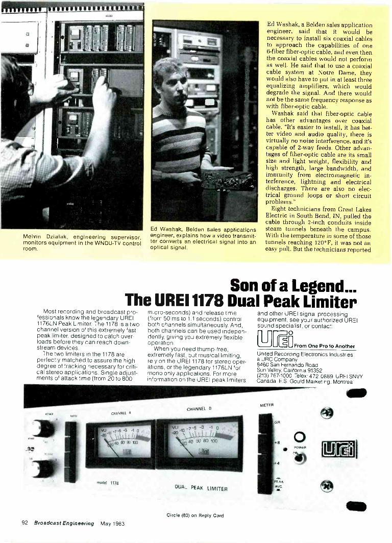
1ttrrf
Melvin Dzialak, engineering supervisor,monitors equipment in the WNDU-TV controlroom.
Washak, Belden sales applicationsengineer, explains how a video transmit-ter converts an electrical signal into anoptical signal.
Ed Washak, a Belden sales applicationengineer, said that it would benecessary to install six coaxial cablesto approach the capabilities of one6 -fiber fiber-optic cable, and even thenthe coaxial cables would not performas well. He said that to use a coaxialcable system at Notre Dame, theywould also have to put in at least threeequalizing amplifiers, which woulddegrade the signal. And there wouldnot be the same frequency response aswith fiber-optic cable.
Washak said that fiber-optic cablehas other advantages over coaxialcable. "It's easier to install, it has bet-ter video and audio quality, there isvirtually no noise interference, and it'scapable of 2 -way feeds. Other advan-tages of fiber-optic cable are its smallsize and light weight, flexibility andhigh strength, large bandwidth, andimmunity from electromagnetic in-terference, lightning and electricaldischarges. There are also no elec-trical ground loops or short circuitproblems."
Eight technicians from Great LakesElectric in South Bend, IN, pulled thecable through 2 -inch conduits insidesteam tunnels beneath the campus.With the temperature in some of thosetunnels reaching 120°F, it was not aneasy pull. But the technicians reported
Son of a Legend...The UREI 1178 Dual Peak Limiter
Most recording and broadcast pro-fessionals know the legendary UREI1176LN Peak Limiter. The 1178 is a twochannel version of this extremely fastpeak limiter, designed to catch over-loads before they can reach down-stream devices.
The two limiters in the 1178 areperfectly matched to assure the highdegree of tracking necessary for criti-cal stereo applications. Single adjust-ments of attack time (from 20 to 800
anusCHANNEL A
mode: 1178
micro -seconds) and release time(from 50 ms to 1.1 seconds) controlboth channels simultaneously. And,both channels can be used indepen-dently, giving you extremely flexibleoperation.
When you need thump -free,extremely fast, but musical limiting,rely on the UREI 1178 for stereo oper-ations, or the legendary 1176LN formono only applications. For moreinformation on the UREI peak limiters
CHANNEL
DUA_ PEAK LIMITER
and other UREI signal processingequipment, see your authorized UREIsound specialist, or contact:
-111 From One Pro to Another
United Recording Electronics Industriesa URC Company8460 San Fernando RoadSun Valley, California 91352(213) 767-1000 Telex: 472 0889 UREI SNVYCanada: E.S. Gould Marketing, Montreal
METER
+8
PE AK
AV(,a -
0POWER
92 Broadcast Engineering May 1983
Circle (80) on Reply Card
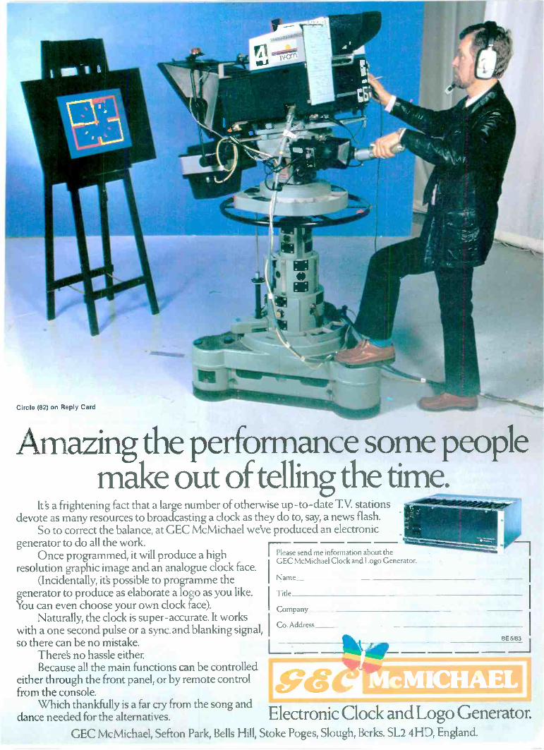
Circle (82) on Reply Card
Amazing the performance some people. .
make out oftelling the time.It's a frightening fact that a large number of otherwise up-to-date T.V. stations --111111.1011iiiiimmAr
devote as many resources to broadcasting a clock as they do to, say, a news flash.So to correct the balance, at GEC McMichael we've produced an electronic
IIPP-1generator to do all the work.Once programmed, it will produce a high I Please send me information about the
GEC McMichael Clock and Logo Generator.resolution graphic image and an analogue clock face.
I(Incidentally, it's possible to programme the I Name
generator to produce as elaborate a logo as you like. Title
IYou can even choose your own clock face). CompanyNaturally, the clock is super -accurate. It works
with a one second pulse or a sync. and blanking signal,I
Co. Address I
so there can be no mistake.I___.
BE
L.!There's no hassle either.Because all the main functions can be controlled 1:44sieltinz 0
either through the front panel, or by remote controlfrom the console.
Which thankfully is a far cry from the song and 11111111=11r VW
dance needed for the alternatives. Electronic Clock and Logo Generator.GEC McMichael, Sefton Park, Bells Hill, Stoke Poges, Slough, Berks. SL2 4HD, England.
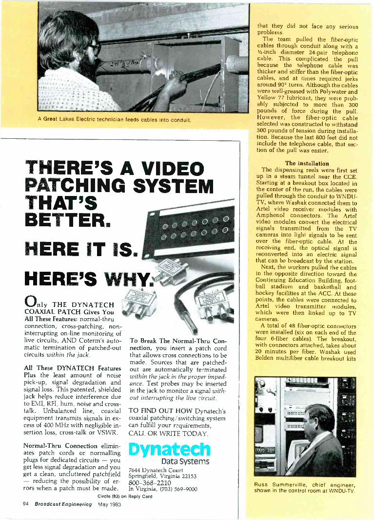
A Great Lakes Electric technician feeds cables into conduit.
THERE'S A VIDEOPATCHING SYSTEMTHAT'SBETTER.HERE IT IS.
HERE'S WHY:Only THE DYNATECH
COAXIAL PATCH Gives YouAll These Features: normal-thruconnection, cross -patching, non -interrupting on-line monitoring oflive circuits, AND Coterm's auto-matic termination of patched -outcircuits within the jack.
All These DYNATECH FeaturesPlus the least amount of noisepick-up, signal degradation andsignal loss. This patented, shieldedjack helps reduce interference dueto EMI, RFI, hum, noise and cross-talk. Unbalanced line, coaxialequipment transmits signals in ex-cess of 400 MHz with negligible in-sertion loss, cross -talk or VSWR.
Normal-Thru Connection elimin-ates patch cords or normallingplugs for dedicated circuits - youget less signal degradation and youget a clean, uncluttered patchfield- reducing the possibility of er-rors when a patch must be made.
Circle (83)
94 Broadcast Engineering May 1983
To Break The Normal-Thru Con-nection, you insert a patch cordthat allows cross connections to bemade. Sources that are patched -
out are automatically terminatedwithin the jack in the proper imped-ance. Test probes may be insertedin the jack to monitor a signal with-out interrupting the live circuit.
TO FIND OUT HOW Dynatech'scoaxial patching,' switching systemcan fulfill your requirements,CALL OR WRITE TODAY.
DynatechData Systems
7644 Dynatech CourtSpringfield, Virginia 22153800-368-2210In Virginia, (703) 569-9000
on Reply Card
that they did not face any seriousproblems.
The team pulled the fiber-opticcables through conduit along with a1/2 -inch diameter 24 -pair telephonecable. This complicated the pullbecause the telephone cable wasthicker and stiffer than the fiber-opticcables, and at times required jerksaround 90° turns. Although the cableswere well -greased with Polywater andYellow 77 lubricant, they were prob-ably subjected to more than 300pounds of force during the pull.However, the fiber-optic cableselected was constructed to withstand500 pounds of tension during installa-tion. Because the last 800 feet did notinclude the telephone cable, that sec-tion of the pull was easier.
The installationThe dispensing reels were first set
up in a steam tunnel near the CCE.Starting at a breakout box located inthe center of the run, the cables werepulled through the conduit to WNDU-TV, where Washak connected them toArtel video receiver modules withAmphenol connectors. The Artelvideo modules convert the electricalsignals transmitted from the TVcameras into light signals to be sentover the fiber-optic cable. At thereceiving end, the optical signal isreconverted into an electric signalthat can be broadcast by the station.
Next, the workers pulled the cablesin the opposite direction toward theContinuing Education Building, foot-ball stadium and basketball andhockey facilities at the ACC. At thesepoints, the cables were connected toArtel video transmitter modules,which were then linked up to TVcameras.
A total of 48 fiber-optic connectorswere installed (six on each end of thefour 6 -fiber cables). The breakout,with connectors attached, takes about20 minutes per fiber. Washak usedBelden multifiber cable breakout kits
Russ Summerville, chief engineer,shown in the control room at WNDU-TV.
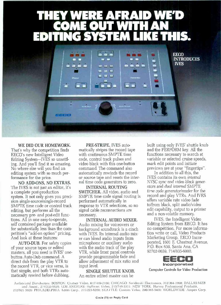
THEY WERE AFRAID WE'DCOME OUT WITH AN
EDITING SYSTEM LIKE THIS.
WE DID OUR HOMEWORK.That's why the competition findsEECO's new Intelligent VideoEditing System-IVES so unsettl-ing. And you'll find it so amazing.No where else will you find anediting system with so much per-formance for the price.
NO ADD-ONS, NO EXTRAS.The IVES is not just an editor, it'sa complete post -productionsystem. It not only gives you preci-sion single-source/single-recordSMPTE time code or control trackediting, but performs all thenecessary pre- and post -edit func-tions. All in one easy -to -operate,self contained package availablefor substantially less than the com-petition's "add-on option" pricing.And look at these features:
AUTO -DUB. For safety copiesof your source tapes or editedmasters, all you need is IVES' one -button Auto -Dub command. Adirect dub from the play VTR tothe record VTR, or vice versa, isthat simple, and both VTRs auto-matically rewind before dubbing.
PRE -STRIPE. IVES auto-matically stripes the record tapewith continuous SMPTE timecode, control track pulses andvideo black with this one -buttoncommand. The command alsoautomatically rewinds the recordor source tape and resets the inter-nal time code generators to zero.
INTERNAL ROUTINGSWITCHER. All video, audio andSMPTE time code signal routing isperformed automatically inresponse to VTR selections, so nosignal cable reconnections arenecessary.
INTERNAL AUDIO MIXER.Audio mixing for voiceovers orbackground soundtrack is a cinchwith IVES. Its internal audio mix-er can blend audio inputs frommicrophone or auxiliary audiowith the audio track of the playVTR, while front panel controlsprovide programmable fade andallow adjustment of mix ratio andinput level.
SINGLE SHUTTLE KNOB.An entire edited master can be
EECOINTRODUCESIVES
built using only IVES' shuttle knoband the PERFORM key. All thefunctions necessary to search atvariable or selected cruise speeds,mark edit points and initiatepreviews are at your "fingertips".
In addition to all this, theIVES contains its own internalNTSC sync and video black gener-ators and dual internal SMPTEtime code generator/reader for therecord and play VTRs. And IVESoffers variable rate video fadeto/from black, split audio/videoedit capability, output to a printerand a non-volatile memory.
IVES, the Intelligent VideoEditing System from EECO. It hasno competition. For more informa-tion write or call, Video ProductsMarketing Group, EECO Incor-porated, 1601 E. Chestnut Avenue,P.O. Box 659, Santa Ana, CA92702-0659, 714/835-6000.
EECOIncorporated
Computer Controls for Video Production
Authorized Distributors: BOSTON: Cramer Video, 617;449-2100; CHICAGO: Swiderski Electronics, 312/364-1900; DALEAS:MZBand Assoc., 214/233-5535; LOS ANGELES: Hoffman Video, 213/749-3311; NEW YORK: Harvey Professional Products,
212/921-5920; PHILADELPHIA: Lerro Corp., 215/223-8200; SEATTLE: Custom Video, 206/365-5400; WORLDWIDE: Ampex Corp.
Circle (75) on Reply Card
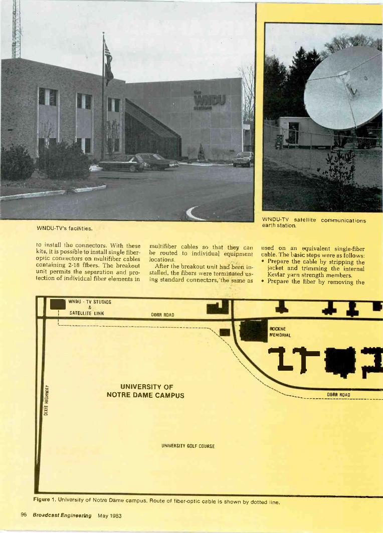
WNDU-TV's facilities.
to install the connectors. With thesekits, it is possible to install single fiber-optic connectors on multifiber cablescontaining 2-18 fibers. The breakoutunit perm,ts the separation and pro-tection of individual fiber elements in
III WNDU - TV STUDIOS
: SATELLITE LINK
multifiber cables so that they canbe routed to individual equipmentlocations.
After the breakout unit had been in-stalled, the fibers were terminated us-ing standard connectors, "the same as
DORR ROADNIa
WNDU-TV satellite communicationsearth station.
used on an equivalent single -fibercable. The basic steps were as follows: Prepare the cable by stripping the
jacket and trimming the internalKevlar yarn strength members.
Prepare the tiber by removing the
ROCKNE
MEMORIAL
UNIVERSITY OFNOTRE DAME CAMPUS
UNIVERSITY GOLF COURSE
DORR ROAD
Figure 1. University of Notre Dame campus. Route of fiber-optic cable is shown by dotted Vine.
96 Broadcast Engineering May 1983
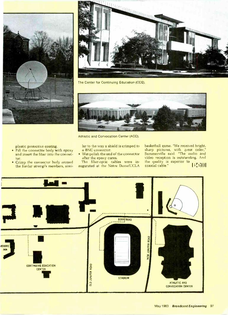
The Center for Continuing Education (GCE).
plastic protective coating. Fill the connector body with epoxy
and insert the fiber into the connec-tor.
Crimp the connector body aroundthe Kevlar strength members, simi-
CONTINUING EDUCATION
CENTERT
Athletic and Corvocation Center (ACC).
lar to the way a shield is crimped toa BNC connector.
Wet -polish the end of the connectorafter the epoxy cures.The fiber-optic cables were in-
augurated at the Notre Dame/UCLA
dct0CC
CC
0
basketball game. "We received bright,sharp pictures, with great color,"Summerville said. "The audio andvideo reception is outstanding. Andthe quality is superior tocoaxial cable." I =T-))))1
DORR: ROAD-4
STADIUM
ATHLETIC AND
CONVOCATION CENTER
May 19E3 Broadcast Engineering 97
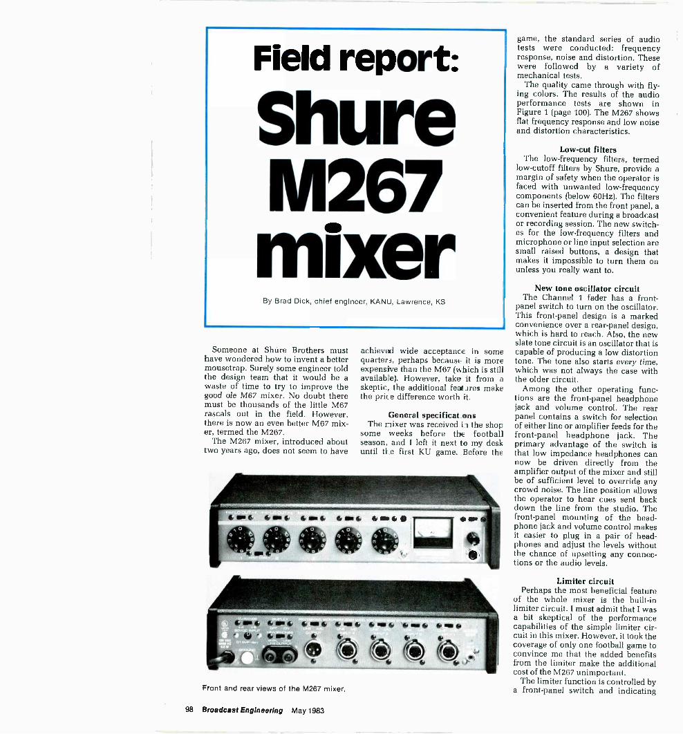
Field report:
ShureM267mixer
By Brad Dick, chief engineer, KANU, Lawrence, KS
Someone at Shure Brothers musthave wondered how to invent a bettermousetrap. Surely some engineer toldthe design team that it would be awaste of time to try to improve thegood ole M67 mixer. No doubt theremust be thousands of the little M67rascals out in the field. However,there is now an even better M67 mix-er, termed the M267.
The M267 mixer, introduced abouttwo years ago, does not seem to have
cront and rear views of the M267 mixer.
achieved wide acceptance in somequarters, perhaps because it is moreexpensive than the M67 (which is stillavailable). However, take it from askeptic, the additional features makethe price difference worth it.
General specificat_ensThe nixer was received iz the shop
some weeks before the footballseason, and I left it next to my deskuntil the first KU game. Before the
game, the standard series of audiotests were conducted: frequencyresponse, noise and distortion. Thesewere followed by a variety ofmechanical tests.
The quality came through with fly-ing colors. The results of the audioperformance tests are shown inFigure 1 (page 100). The M267 showsflat frequency response and low noiseand distortion characteristics.
Low-cut filtersThe low -frequency filters, termed
low -cutoff filters by Shure, provide amargin of safety when the operator isfaced with unwanted low -frequencycomponents (below 60Hz). The filterscan be inserted from the front panel, aconvenient feature during a broadcastor recording session. The new switch-es for the low -frequency filters andmicrophone or line input selection aresmall raised buttons, a design thatmakes it impossible to turn them onunless you really want to.
New tone oscillator circuitThe Channel 1 fader has a front-
panel switch to turn on the oscillator.This front -panel design is a markedconvenience over a rear -panel design,which is hard to reach. Also, the newslate tone circuit is an oscillator that iscapable of producing a low distortiontone. The tone also starts every time,which was not always the case withthe older circuit.
Among the other operating func-tions are the front -panel headphonejack and volume control. The rearpanel contains a switch for selectionof either line or amplifier feeds for thefront -panel headphone jack. Theprimary advantage of the switch isthat low impedance headphones cannow be driven directly from theamplifier output of the mixer and stillbe of sufficient level to override anycrowd noise. The line position allowsthe operator to hear cues sent backdown the line from the studio. Thefront -panel mounting of the head-phone jack and volume control makesit easier to plug in a pair of head-phones and adjust the levels withoutthe chance of upsetting any connec-tions or the audio levels.
Limiter circuitPerhaps the most beneficial feature
of the whole mixer is the built-inlimiter circuit. I must admit that I wasa bit skeptical of the performancecapabilities of the simple limiter cir-cuit in this mixer. However, it took thecoverage of only one football game toconvince me that the added benefitsfrom the limiter make the additionalcost of the M267 unimportant.
The limiter function is controlled bya front -panel switch and indicating
98 Broadcast Engineering May 1983
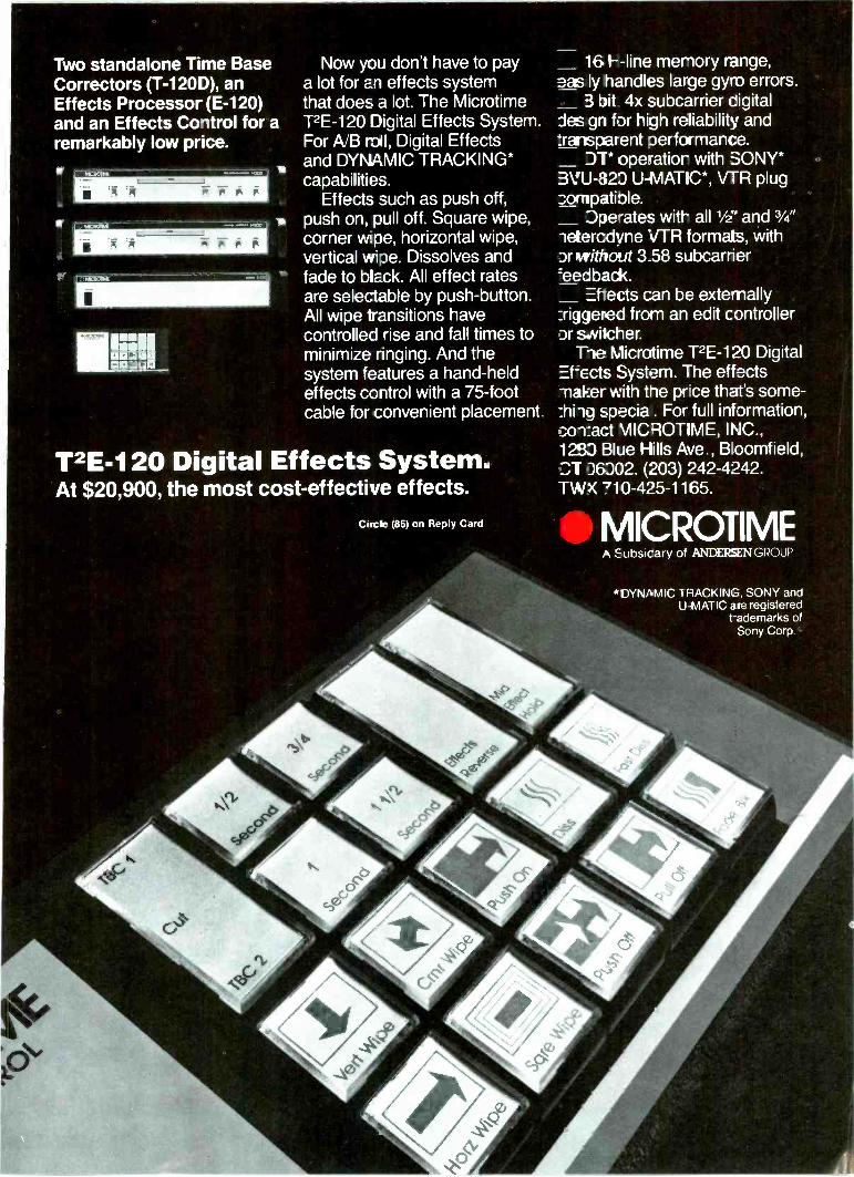
Two standalone Time BaseCorrectors (T -120D), anEffects Processor (E-120)and an Effects Control for aremarkably low price.
Now you don't have to paya lot for an effects systemthat does a lot. The MicrotimeT2E-120 Digital Effects System.For A/B roll, Digital Effectsand DYNAMIC TRACKING*capabilities.
Effects such as push off,push on, pull off. Square wipe,corner wpe, horizontal wipe,vertical wipe. Dissolves andfade to black. All effect ratesare selectable by push-button.All wipe transitions havecontrolled rise and fall times tominimize ringing. And thesystem features a hand-heldeffects control with a 75 -footcable for convenient placement.
T2E-120 Digital Effects System.At $20,900, the most cost-effective effects.
ClotIle (85) on Reply Card
16 I --line memory range,eas ly handles large gyro errors.
3 bit 4x subcarrier cigitaldes gn for high reliability and:rartsparent performance.
DT* operatior with SONY*3VU-820 U-IV1ATIC*, VTR plug2.ornpatiole.
Dperates wit all 1/2" and 3/4"ietercdyne VTR formats, withDr without 3.58 subcarrier:eedback.
Eftects can be externallyJiggered from an edit controllerDr switcher.
The Microtime T2E-120 Digitalf=acts System. The effects
maker with the pr ce that's some -:hi -1g Epecia . For full information,co-Eact MICROTIME, INC.,1283 Blue Hills Ave., Bloomfield,.7_,T D6302. (203) 242-4242.TWX 710-425-1165.
MICROTIMEEubsicary of ANDERSEN GROUP
*DYNAMIC TRACKING, SONY andU-NlATIC are registered
hademarks ofSony Corp
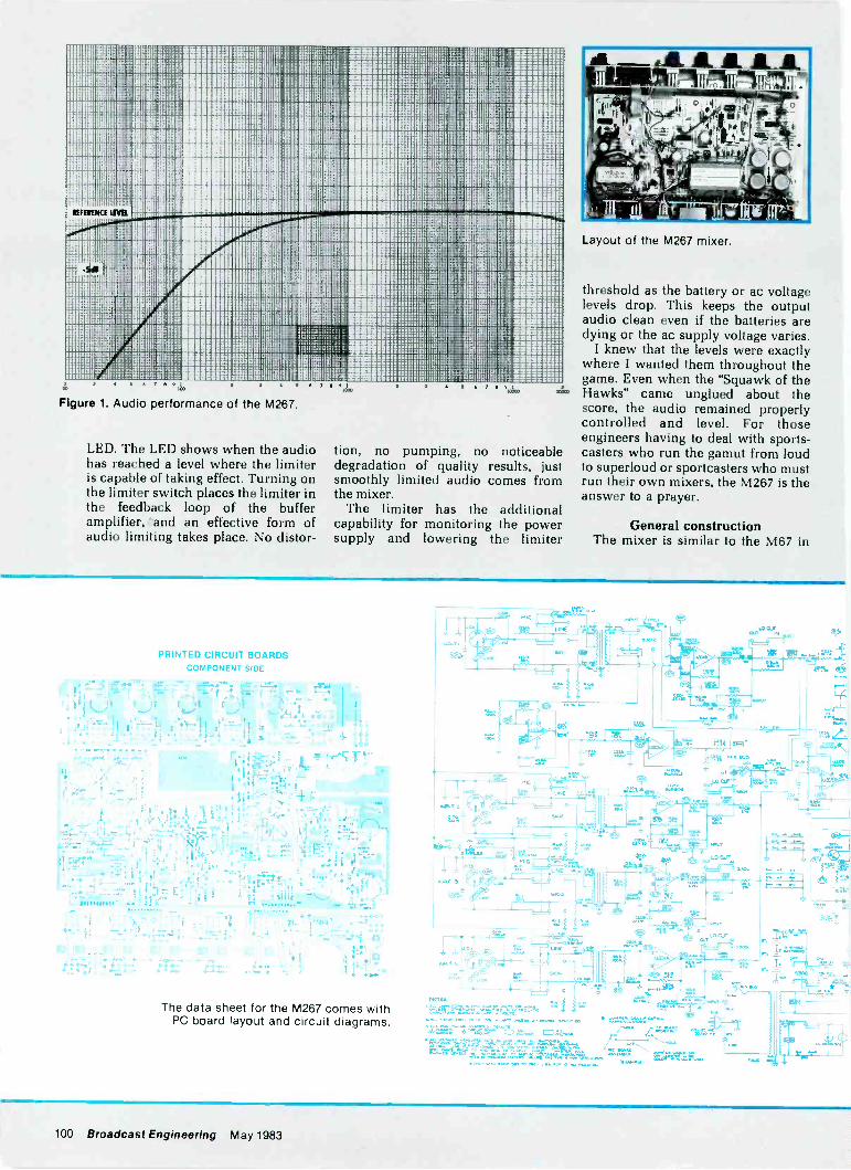
MIMI IR 111111 1:i I' ,11M1111111 I 11111i1:47---:111111111 11 II 1!'11111111311liill111111111111 I 111111 E
11111 ill 111 it 111 111 11 '111111111111 1111111111 1111walli-1111111 11 111 111111111111 11111111111111 II d,1111111M-11fa=1111111 NII 1 1111 11 I 1 111111 111111 III I 111111111111111111E1,1 NM I 'MIRE111111111 11111 111 11E11 111 11 ' 1111 Ill MI i KW II 1111111111111111E1 ANN 1 i11111111
1111111 1 110 ,111111 I 11111 I .111 I 111111111111115111 J 1®11611111= 111111111111,11111 SINOPMI 1 I lir 1114I/101 IN11111111111 111111
III 1 1 1 0 1 1
11111111 li!1111111 1. 11MEIN! di 1I1M111. 11
III 1 111114111111111! 'i' 111III el o 1111111/NiiiMPIW hs111111111111:
. - . diiiiri; Psi 11111 Nilllir-MR1111111111 '411111011
1111111 111 1111, 11 pirll I 11111111 I
diggg mi'Ll1101 /1111111 I 111111 Ind 1111 ' kJI :41.1111111 1 111111
1111 IBM 11111 1111141111111111 II MI1 11 L ' 1E11 1411111111111111 11111111E11111111' IF 1P.;11 III M1111111111 111.1111.11111 1 1 111 1'111111 ' 11111kg911111.111d / 111 111 1111111111111111111r 11 411 1111E11
11 :dt1.ar. 1E111115 6 7
Figure 1. Audio performance of the M267.
LED. The LED shows when the audiohas reached a level where the limiteris capable of taking effect. Turning onthe limiter switch places the limiter inthe feedback loop of the bufferamplifier, 'and an effective form ofaudio limiting takes place. No distor-
I 19 t
tion, no pumping, no noticeabledegradation of quality results, justsmoothly limited audio comes fromthe mixer.
The limiter has the additionalcapability for monitoring the powersupply and lowering the limiter
AL AL. ALA ILulna
Layout of the M267 mixer.
threshold as the battery or ac voltagelevels drop. This keeps the outputaudio clean even if the batteries aredying or the ac supply voltage varies.
I knew that the levels were exactlywhere I wanted them throughout thegame. Even when the "Squawk of theHawks" came unglued about thescore, the audio remained properlycontrolled and level. For thoseengineers having to deal with sports-casters who run the gamut from loudto superloud or sportcasters who mustrun their own mixers, the M267 is theanswer to a prayer.
General constructionThe mixer is similar to the M67 in
PRINTED CIRCUIT BOARDSCOMPONENT SIDE
The data sheet for the M267 comes withPC board layout and circuit diagrams.
/32222222-.-
H,..__,,-"217LT
. 7".
eIT NY 11Ft
cz-
Ca,
52.02
MEM
LNE -
c.-14
tit
cur
NO.
,r'
uS`sj et -VC,*
. ..r,^4 1%.. 3 7-,; I -L 4-'--
, r,iil . . . ..., ,,,,, =r- :: - - " --'I , ,..-5-- 4 A -,,
l'-.a
d
..1. - 3. ''. PM , '1.
.,1 43 .. Ir.
Ow..
H.f;
I,...' ik
''''-'''.4.4-.2.F..i..:.:4"V`r''''W;'-7.t'2. 01222202, -,20 VI. ...222-2,246111211. a22.2,2ea 2.2022272.1LA,2112;'''''
1.6112.21..rj 22,tot-. r
L -.
100 Broadcast Engineering May 1983
layout and construction. A major elec-trical improvement is in the quality ofsemiconductors. The mixer usesRC4559NB and RC4156DB integratedcircuits for most of the low levelsignals, thereby providing low noiseand superior performance overprevious designs. All inputs are trans-former -balanced and well -shieldedfrom RF interference. In those in-stances in which RF has been a prob-lem with other mixers, the M267 mayprovide an extra margin of safety.
The input XLR connectors nolonger have the captive latch commonto most XLR inputs. However, thisfact is actually a benefit to the user.The inputs will not accidentally comeunplugged in most cases; even with-out the captive latches the fitting issecure. It is now easier to unplug theconnectors.
The mixer has XLR and banana out-put connectors. The XLR output isswitch -selectable to microphone orline levels. This feature allows anoperator to standardize on cables, allwith XLR fittings. The mixer also pro-vides two transformer -isolated line -level outputs, with output levels se-lectable to either + 4dBm or + 8dBmvia a rear -panel switch.
The M267 no longer requires an ex-ternal battery supply because there is
f,S'
e"'' 74;
-0-.s t ,a.: .10,
1
--* --; ', ra- ,- ,,.
--r-
4:1, i:r! '711= ' 4''' 1
ft:Z:,r
1.. 1'1" "'71? i T. ,,..,,,0 L, .. . ,
0.
:....' '7,7 .i!id ,_,,,,..,_ 4,4ti,
`40'": ; --- ,._,..,..
; ^,-.., .,......,
0,1'2:01 .
. ,...1.:
,tit---
4.10./.I:
aTTPIT
TT- T T .01
1:CY. 41,TOuT,T
,.
eaT, ,.
F11^.7
OW
ler VW Odr
..=ktci b
mules loma.
CD 22 .10
A dramatic character generatorin a dramatically inexpensive
time code readerIn Will's day $2295 would
have fought you all of St -at -ford. F:ight now it buys you theT6011) from Telcom Research. ATime Code Reader/CharacterGenerator which reads anysource recorded to SMPTE/EBUstandards. And it's backed witha 5 year warranty!
The T6010 decodes time anduser data and displays eitheron its -ead-at-a-glance .8' highLED' 3. Use it to insert da-a onthe monitor as you view themaste-, and on the working dubfor edit selection. 80 times playspee] is fast enough for anyVTR, and 1/10 play speed pluscolor framing indicator lets yoube very picky!
Key data characters ar y-wher?, on the screen with orwithciLt box. Unique characters,bordered for easy readinc, canbe reversed or removedfrom the video. Fingertipcontrol lets you
freeze front panel and videoreadingE.
Microprocessor designmeans fewer parts, higherreliability and lower operatingtemperatures than traditionalmodels. Tre result? A cool -running, thin un t you :;anmount imnnedia:ely atove orbelow other equipment. In cor-trol room cr mobile. Plusfeatures like parallel time out-put for edit controller andautomation inte'face, or userdata output for compLter inter-face to control special effects
Telcom Research designedthose and ether state-of-the-artfeatures into the T6010 after 14years' experience in meetingthe hi -tech needs of major TVstations arid productionhouses. Ask your nearestdistributor for technical specs
and a full I st of featureso- contact us directly.Say Will sent you.
telcamresearch1163 King Road Burlington, Ontario (416)681-2450
Circle (86) on Reply Card
May 1983 Broadcast Engineering 101
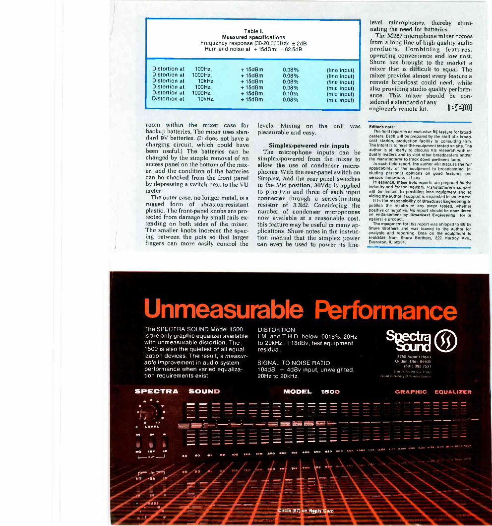
Table I.Measured specifications
Frequency response (30-20,000Hz): ± 2dBHum and noise at + 15dBm: - 62.5dB
Distortion atDistortion atDistortion atDistortion atDistortion atDistortion at
100Hz,1000Hz,
10kHz,100Hz,
1000Hz,10kHz,
+ 15dBm+ 15dBm+ 15dBm+ 15dBm+ 15dBm+ 15dBm
0.08%0.08%0.08%0.08%0.10%0.08%
(line input)(line input)(line input)(mic input)(mic input)(mic input)
room within the mixer case forbackup batteries. The mixer uses stan-dard 9V batteries. (It does not have acharging circuit, which could havebeen useful.) The batteries can bechanged by the simple removal of anaccess panel on the bottom of the mix-er, and the condition of the batteriescan be checked from the front panelby depressing a switch next to the VUmeter.
The outer case, no longer metal, is arugged form of abrasion -resistantplastic. The front -panel knobs are pro-tected from damage by small rails ex-tending on both sides of the mixer.The smaller knobs increase the spac-ing between the pots so that largerfingers can more easily control the
levels. Mixing on the unit waspleasurable and easy.
Simplex -powered mic inputsThe microphone inputs can be
simplex -powered from the mixer toallow the use of condenser micro-phones. With the rear -panel switch onSimplex, and the rear -panel switchesin the Mic position, 30Vdc is appliedto pins two and three of each inputconnector through a series -limitingresistor of 3.3k0. Considering thenumber of condenser microphonesnow available at a reasonable cost,this feat -ire may be useful in many ap-plications. Shure notes in the instruc-tion manual that the simplex powercan even be used to power its line -
level microphones, thereby elimi-nating the need for batteries.
The M267 microphone mixer comesfrom a long line of high quality audioproducts. Combining features,operating convenience and low cost,Shure has brought to the market amixer that is difficult to equal. Themixer provides almost every feature aremote broadcast could need, whilealso providing studio quality perform-ance. This mixer should be con-sidered a standard of anyengineer's remote kit. :7.:))))]
Editor's note:The field report is an exclusive BE feature for broad-
casters. Each will be prepared by the staff of a broad-cast station, production facility or consulting firm.The intent is to have the equipment tested on -site. Theauthor is at liberty to discuss his research with in-dustry leaders and to visit other broadcasters and/orthe manufacturer to track down pertinent facts.
In each field report, the author will discuss the fullapplicability of the equipment to broadcasting, in-cluding personal opinions on good features andserious limitations-if any.
In essence, these field reports are prepared by theIndustry and for the Industry. Manufacturers supportwill be limited to providing loan equipment and toaiding the author If support is requested in some area.
It is the responsibility of Broadcast Engineering topublish the results of any piece tested, whetherpositive or negative. No report should be consideredan endorsement by Broadcast Engineering for oragainst a product.
The equipment for this report was shipped to BE byShure Brothers and was loaned to the author foranalysis and reporting. Data on the equipment isavailable from Shure Brothers, 222 Harney Ave.,Evanston, IL 60204.
Unmeasurable PerformanceThe SPECTRA SOUND Model 1500is the only graphic equalizer availablewith unmeasurable distortion. The1500 is also the quietest of all equal-ization devices. The result, a measur-able improvement in audio systemperformance when varied equaliza-tion requirements exist.
SPECTRA SOUND
L/sr-r(.1
DISTOF TIONI M anc T H D below 0018% 20Hzto 20kHz, +18dBv, test equipmentresidua
SIGNAL TO NOISE RATIO104dB, + 4dBv input, unweighted,20Hz to 20kHz.
MODEL 1500
3 e'50 A1Fpor I HoadOgden. Utah 84403
(801) 392-7531SP,i,1S011111i .1 NlIcr11,
ilW11.41,11,....Insry of Six,,,.,
GRAPHIC EQUALIZER
00 SOO IMO SOO 1100 100 a,. 400 000 GOO 000 1.014 1.240 $.1.14 00% 4.40 4140 4.04 DA. 4Int .014 1004 IMAM 1404
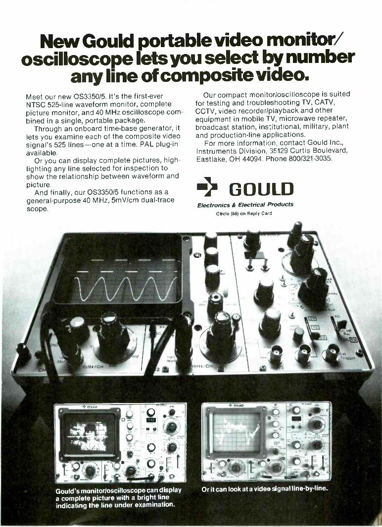
New Gould portable video monitor/oscilloscope lets you select by number
any line of composite video.Meet our new 0S335015. It's the first -everNTSC 525 -line waveform monitor, completepicture monitor, and 40 MHz oscilloscope com-bined in a single, portable package.
Through an onboard time -base generator, itlets you examine each of the composite videosignal's 525 lines-one at a time. PAL plug-inavailable.
Or you can display complete pictures, high-lighting any line selected for inspection toshow the relationship between waveform andpicture.
And finally, our 0S3350/5 functions as ageneral-purpose 40 MHz, 5mV/cm dual -tracescope.
Gould's monitorloscilloscope can displaya complete picture with a bright lineindicating the line under examination.
1' taclet
Our compact monitorsoscilloscope is suitedfor testing and troubleshooting TV, CATV,CCTV, video recorder/playback and otherequipment in mobile TV, microwave repeater,broadcast station, institutional, military, plantand production -line appiications.
For more information, contact Gould Inc.,Instruments Division, 3E129 Curtis Boulevard,Eastlake, OH 44094. Phone 800/321-3035.
m> GOULDElectronics & Electrical Products
Circle (88) on Reply Card
olts C
BOulD
Or it can look at a video signal line -by-line.
"TO RELIEVE MY CAMERAMEN'S BACKACHES AND MY
Art Biggs coordinates major engineering purchases forthe six Corinthian stations. After careful evaluation of all the1/2 -inch camera/recorders on the market, he made a multi-million -dollar purchase of the Sony Betacam' system.
"Betacam has several pluses. The most obvious of themare size and weight. We have one-man camera crews at all ourstations. The camera/recorder that they take into the field is
right at 54'/2 pounds. Betacam will reduce this load by morethan half-a significant reduction.
"As for quality of playback, you can see the difference withthe naked eye. Its superiority is most apparent in scenes of fullysaturated colors, particularly reds. It's cleaner. It doesn't havequite as much of the heavy, stringy -type noise we've grown totolerate over the years.
CI983 Sony Corp. of America. 9 W. 57th St.. New York. NY 10019. Sony is a registered trademarkand Betacam is a trademark of the Sony Corp.
CONTROLLERS,HEADACHES,
I TOOK ALL OF THESE,-Art Biggs, Vice President, Engineering, Corinthian Broadcasting Corporation
"Another Betacam plus is that it's not a patchwork ap-proach. It's a total Sony system developed fmm the camera tothe recorder to the player.
"Then there's the bottom line. Betacam is at a very attrac-tive price. It would have cost me hundreds of thousands ofdollars more to get the same amount of camera/recorders thateven approach this kind of quality fmm someone else.
"I'll definitely be back for more'For more information on the Sony Betacam system, and
there's a lot more to know, contact Sony Broadcast in New York/New Jersey at (201) 368-5085; in Chicago at (312) 860-7800;in Los Angeles at (213) 841-8711; S0in Atlanta at (404) 451-7671; or inDallas at (214) 659-3600. liroakkat
/ 2 ,
rb
Artist's sketch of the Abuja Tower.
One of the world's major tower proj-ects is a combination broadcastingfacility and national monument forAbuja, the new capital of Nigeria.This 327m structure will be thirdhighest in the world and tallest inAfrica.
The broadcast facilitiesThe Nigerian Television Authority
(NTA) will operate four 10kW VHFand eight 25kW UHF TV transmittersthat will be served by an 80m broad-band antenna through two combiners.The Federal Radio Corporation ofNigeria (FCRN) will operate four20kW FM transmitters through onecombiner with provision for fourfuture 10kW units.
Among a multitude of communica-tions users are Nigeria External Tele-communications (NET) and Ministryof Communications P&T, which willhave extensive microwave installa-tions on two levels approximately200m above ground. The antennagallery is proposed to be enclosed formaintenance safety and aestheticreasons, using a compound curvedstressed glass fiber fabric.
Public accommodations include arevolving restaurant and observationgallery, as well as a banquet floor forspecial functions. At the tower baseextensive office space for technicalusers will be situated, plus a majortheater, exhibition gallery andrestaurant complex.
Design challengesForemost among the many chal-
lenges to designers of tall towers arethe problems of integrating a vastnumber of services within a confinedspace and eliminating physical andelectrical interference. In addition to
Case study:
TheAbujaTower
By Edward R. Baldwin, architect, Toronto, Ontario, Canada
avoiding these problems, they mustalso take into consideration relativefire hazards and prevention systems,separations in the event of fire, securi-ty and the type of personnel to begiven access to each area.
At the Abuja Tower, as at the CNTower in Toronto, the general publicwill be given access to substantial por-tions of the tower. These areas requirebackup maintenance areas. At the CNTower, the service areas are availableto all staff members, whether theirjobs relate to serving the public or tothe broadcast and communicationsusers' operations. An attempt hasbeen made at the Abuja Tower tosegregate support staff throughout sothat the broadcast and communica-tions users have complete controlover their allocated premises. Thisshould be a more successful arrange-ment.
aS
a
.224
a
a
aoo
1,
At Abuja, the tower configurationprovides for numerous equipmentspaces within the relatively low costvolume of the structure itself. In thisway, floor areas within the higher costupper accommodation are minimized.The bracket structures that occur onfour faces of the octagonal shaft arecapable of accommodating transform-er vaults, elevator motor generatorsets, high voltage switchgear andgenerous cableways for antenna feed -lines, etc.
Also featured are the void areas be-tween each upper accommodationsupport bracket. These areas allowwall penetrations for louvers and win-dows that would otherwise detractfrom the external appearance of thetower itself. This is a big improvementover the CN Tower for those that mustwork in the broadcast and kitchenareas. Makeup air for transmitter heat
O. Ofirolipog mum.. listooto O.10 bap. Oa.O. me oo to* us us
Figure 1. Heights of towers in the world.
laI o..&loofio too 4. Oro.. .06.tO 11O to to
fT0 061
ONOMA
106 Broadcast Engineering May 1983
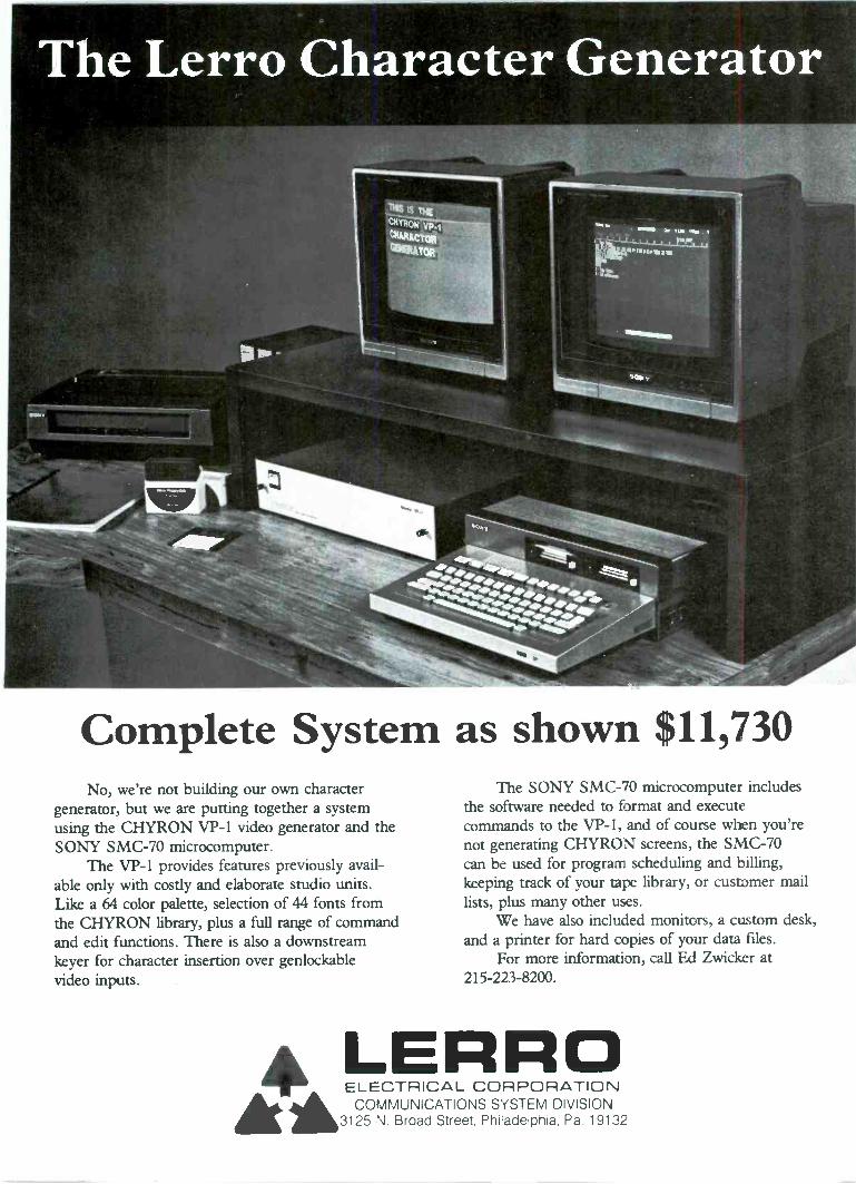
AA
The Lerro Character Generator
Complete System as shown $11,730No, we're not building our own character
generator, but we are putting together a systemusing the CHYRON VP -1 video generator and theSONY SMC-70 microcomputer.
The VP -1 provides features previously avail-able only with costly and elaborate studio units.Like a 64 color palette, selection of 44 fonts fromthe CHYRON library, plus a full range of commandand edit functions. There is also a downstreamkeyer for character insertion over genlockablevideo inputs.
Aki ELECTRICAL CORPORATIONCOMMUNICATIONS SYSTEM DIVISION
3125 N. Broad Street, Philadelphia, Pa. 19132
The SONY SMC-70 microcomputer includesthe software needed to format and executecommands to the VP -I, and of course when you'renot generating CHYRON screens, the SMC-70can be used for program scheduling and billing,keeping track of your tape library, or customer maillists, plus many other uses.
We have also included monitors, a custom desk,and a printer for hard copies of your data files.
For more information, call Ed Zwicker at215-223-8200.
LERRO
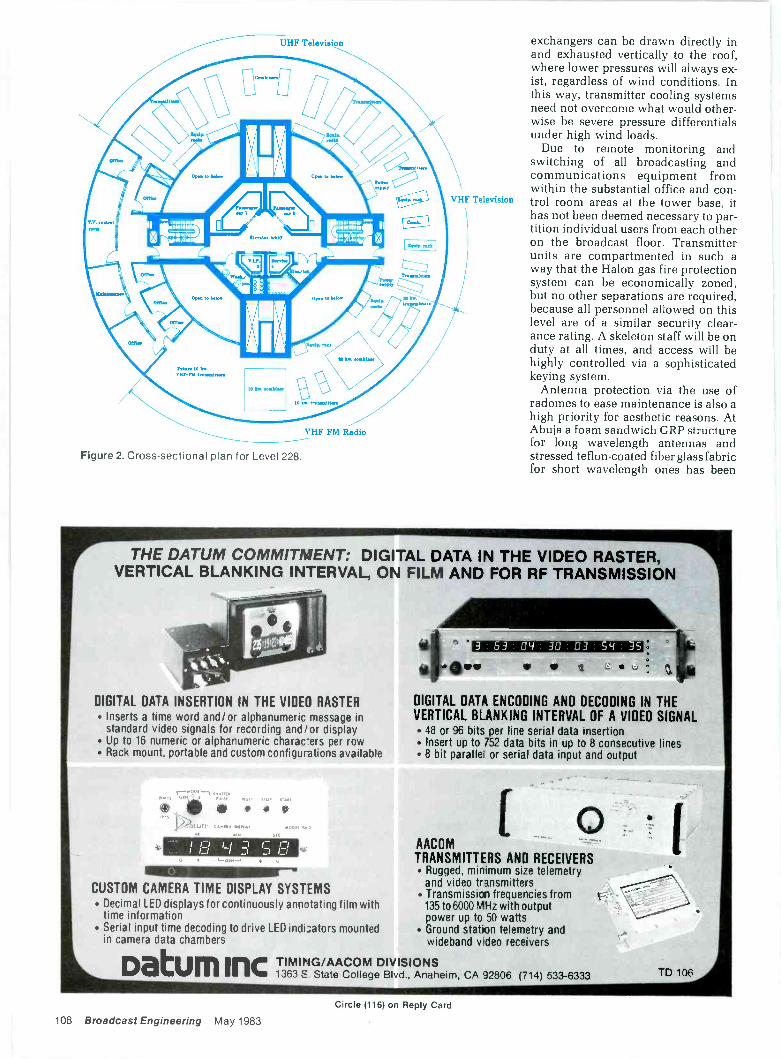
UHF Television
VHF Television
VHF FM Radio
Figure 2. Cross-sectional plan for Level 228.
exchangers can be drawn directly inand exhausted vertically to the roof,where lower pressures will always ex-ist, regardless of wind conditions. Inthis way, transmitter cooling systemsneed not overcome what would other-wise be severe pressure differentialsunder high wind loads.
Due to remote monitoring andswitching of all broadcasting andcommunications equipment fromwithin the substantial office and con-trol room areas at the tower base, ithas not been deemed necessary to par-tition individual users from each otheron the broadcast floor. Transmitterunits are compartmented in such away that the Halon gas fire protectionsystem can be economically zoned,but no other separations are required,because all personnel allowed on thislevel are of a similar security clear-ance rating. A skeleton staff will be onduty at all times, and access will behighly controlled via a sophisticatedkeying system.
Antenna protection via the use ofradomes to ease maintenance is also ahigh priority for aesthetic reasons. AtAbuja a foam sandwich GRP structurefor long wavelength antennas andstressed teflon-coated fiber glass fabricfor short wavelength ones has been
THE DATUM COMMITMENT: DIGITAL DATA IN THE VIDEO RASTER,VERTICAL BLANKING INTERVAL, ON FILM AND FOR RF TRANSMISSION
DIGITAL DATA INSERTION IN THE VIDEO RASTER Inserts a time word and/or alphanumeric message in
standard video signals for recording and/or display Up to 16 numeric or alphanumeric charac-ers per row Rack mount, portable and custom configurations available
I nI o .7.1 _I CI
CUSTOM CAMERA TIME DISPLAY SYSTEMS Decimal LED displays for continuously annotating film with
time information Serial input time decoding to drive LED indi3ators mounted
in camera data chambers
Datum Inc
A111111111=1116,rilit ' 3 63 04 30 03 54 35
g 3.. IPoDIGITAL DATA ENCODING AND DECODING IN THEVERTICAL BLANKING INTERVAL OF A VIDEO SIGNAL 48 or 96 bits per line serial data insertion Insert up to 752 data bits in up to 8 consecutive lines 8 bit paralle or serial data input and output
[ 0AACOMTRANSMITTERS AND RECEIVERS Rugged, minimum size telemetry
and video transmitters Transmission frequencies from
135 to 6000 MHz with outputpower up to 50 watts
Ground station telemetry andwideband v deo receivers
TIMING/AACOM DIVISIONS1363 S. State College Blvd., Anaheim, CA 32806 (714) 533-6333 TD 106
Circle (116) on Reply Card
108 Broadcast Engineering May 1983
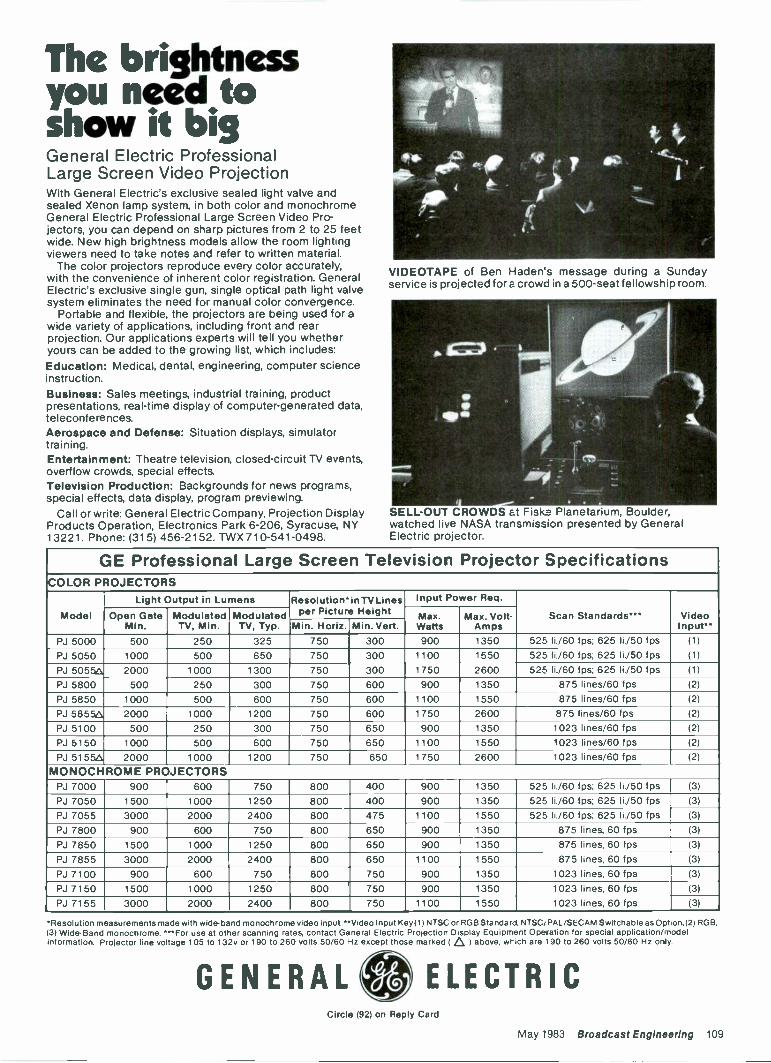
The brightness
showyou neeit
bigd
General Electric ProfessionalLarge Screen Video ProjectionWith General Electric's exclusive sealed light valve andsealed Xenon lamp system, in both color and monochromeGeneral Electric Professional Large Screen Video Pro-jectors, you can depend on sharp pictures from 2 to 25 feetwide. New high brightness models allow the room lightingviewers need to take notes and refer to written material.
The color projectors reproduce every color accurately,with the convenience of inherent color registration. GeneralElectric's exclusive single gun, single optical path light valvesystem eliminates the need for manual color convergence.
Portable and flexible, the projectors are being used for awide variety of applications, including front and rearprojection. Our applications experts will tell you whetheryours can be added to the growing list, which includes:Education: Medical, dental, engineering, computer scienceinstruction.Business: Sales meetings, industrial training, productpresentations, real-time display of computer -generated data,teleconferences.Aerospace and Defense: Situation displays, simulatortraining.Entertainment: Theatre television, closed-circuit TV events,overflow crowds, special effects.Television Production: Backgrounds for news programs,special effects, data display, program previewing.
Call or write: General Electric Company, Projection DisplayProducts Operation, Electronics Park 6-206, Syracuse, NY13221. Phone: (315) 456-2152. TWX 710-541-0498.
VIDEOTAPE of Ben Haden's message during a Sundayservice is projected fora crowd in a 500 -seat fellowship room.
SELL-OUT CROWDS at Fiske. Planetarium, Boulder,watched live NASA transmission presented by GeneralElectric projector.
GE Professional Large Screen Television Projector SpecificationsCOLOR PROJECTORS
Model
Light Output in Lumens Resolution`inTVLinesper Picture Height
Input Power Req.
Scan Standards*** VideoInput**
Open GateMin.
ModulatedTV, Min.
ModulatedTV, Typ.
Max.Watts
Max. Volt-AmpsMin. Horiz. Min. Vert.
PJ 5000 500 250 325 750 300 900 1350 525 li./60 fps; 625 li./50 fps (1)
PJ 5050 1000 500 650 750 300 1100 1550 525 li./60 fps; 625 11./50 fps (1)
PJ 50556 2000 1000 1300 750 300 1750 2600 525 11./60 fps; 625 li./50 fps (1)
PJ 5800 500 250 300 750 600 900 1350 875 lines/60 fps (2)
PJ 5850 1000 500 600 750 600 1100 1550 875 lines/60 fps (2)
PJ 58556 2000 1000 1200 750 600 1750 2600 875 lines/60 fps (2)
PJ 5100 500 250 300 750 650 900 1350 1023 lines/60 fps (2)
PJ 6150 1000 500 600 750 650 1100 1550 1023 lines/60 fps (2)
PJ 51554 2000 1000 1200 750 650 1750 2600 1023 lines/60 fps (2)
MONOCHROME PROJECTORSPJ 7000 900 600 750 800 400 900 1350 525 li./60 fps; 625 li./50 fps (3)
PJ 7050 1500 1000 800 900 1350 525 11./60 fps; 625 li./50 fps (3)
PJ 7055 3000 2000 2400 800 475 1100 1550 525 li./60 fps; 625 11./50 fps (3)
PJ 7800 900 600 750 800 650 900 1350 875 lines, 60 fps (3)
PJ 7850 1500 1000 1250 800 650 900 1350 875 lines, 60 fps (3)
PJ 7855 3000 2000 2400 800 650 1100 1550 875 lines, 60 fps (3)
PJ 7100 900 600 750 800 750 900 1350 1023 lines, 60 fps (3)
PJ 7150 1500 1000 1250 800 . 750 900 1350 1023 lines, 60 fps (3)
PJ 7155 3000 2000 2400 800 750 1100 1550 1023 lines, 60 fps (3)
*Resolution measurements made with wide -band monochrome video input **Video Input Key(1) NTSC or ROB Standard, NTSCIPAL/SECAM Switchable as Opt'on,(2) RGB,(3) Wide -Band monochrome. ***For use at other scanning rates, contact General Electric Projection Display Equipment Operation for special application/modelinformation. Projector line voltage 105 to 132v or 190 to 260 volts 50/60 Hz except those marked (Q 1 above, which are 190 to 260 volts 50/60 Hz orgy.
GENERALO ELECTRICCircle (92) on Reply Card
May 1983 Broadcast Engineering 109
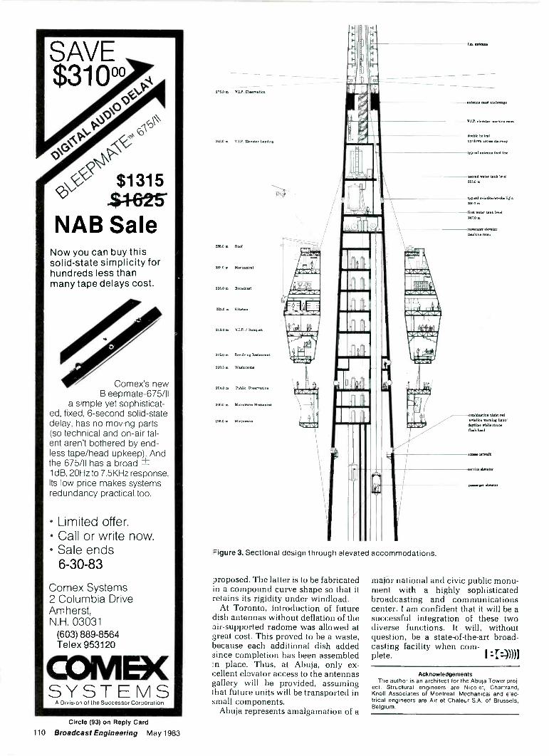
SAVE$3100°
V` -
PAP
\o
$1315$4-625
NAB SaleNow you can buy thissolid-state simplicity forhundreds less thanmany tape delays cost.
Comex's newBleepmate-675/11
a simple yet sophisticat-ed, fixed, 6 -second solid-statedelay, has no moving parts(so technical and on -air tal-ent aren't bothered by end-less tape/head upkeep). Andthe 675/11 has a broad ±ldB, 20Hz to 7.5KHz response.Its low price makes systemsredundancy practical. too.
Limited offer. Call or write now. Sale ends
6-30-83
Comex Systems2 Columbia DriveAmherst,N.H. 03031
(603) 889-8564Telex 953120
COMB(SYSTEMS
A Division of the Successor Corporation
276.0 m V.IP. Chwarvation
263.0 in V.I.P. Elevator Landing
238.0 m Roof
233.0 m Mechanical
229.0 In Broad..
229.0 m Kitchen
2180 in V.I.P./ Ban..
212.0 in Revolving Rwitaurant
209.3 se Washrooms
204.0 m Public Obaertation
200.0 m Microwave Meusinine
196.0 in Microwave
Odle
"ver.I erd
I-
17.1
1101\IN
fe
4..?..:: i
rA 10 FA FA
11.501151.01FAA
=figure 3. Sectional design through elevated accommodations.
proposed. The latter is to be fabricatedin a compound curve shape so that itretains its rigidity under windload.
At Toronto, introduction of futuredish antennas without deflation of theair -supported radome was allowed atgreat cost. This proved to be a waste,because each additional dish addedsince completion has been assembledin place. Thus, at Abuja, only ex-cellent elevator access to the antennasgallery will be provided, assumingthat future units will be transported insmall components.
Abuja represents amalgamation of a
4- Mad IISCh01.,11
V.I.P. elevator machine room
d hie laicalup/down eaten ...irony
typical ant.. feed line
rand ..ter tank level253.0 m
typical aviation/Kroh. light.0.0 m
first water tank level241.0 m
aueanger elevatormachine atom
- eight rsa
aviatIou warning KEWdept.. whit. Ambitnub head
ewe. catwalk
writes Arent.
won.,
major national and civic public monu-ment with a highly sophisticatedbroadcasting and communicationscenter. I am confident that it will be asuccessful integration of these twodiverse functions. It will, withoutquestion, be a state-of-the-art broad-casting facility when com-plete. 7::))))i
AcknowledgementsThe author is an architect for the Abuja Tower proj-
ect. Structural engineers are Nicolet, Chartrand,Knoll Associates of Montreal. Mechanical and elec-trical engineers are Air et Chaleur S.A. of Brussels,Belgium.
Circle (93) on Reply Card
110 Broadcast Engineering May 1983
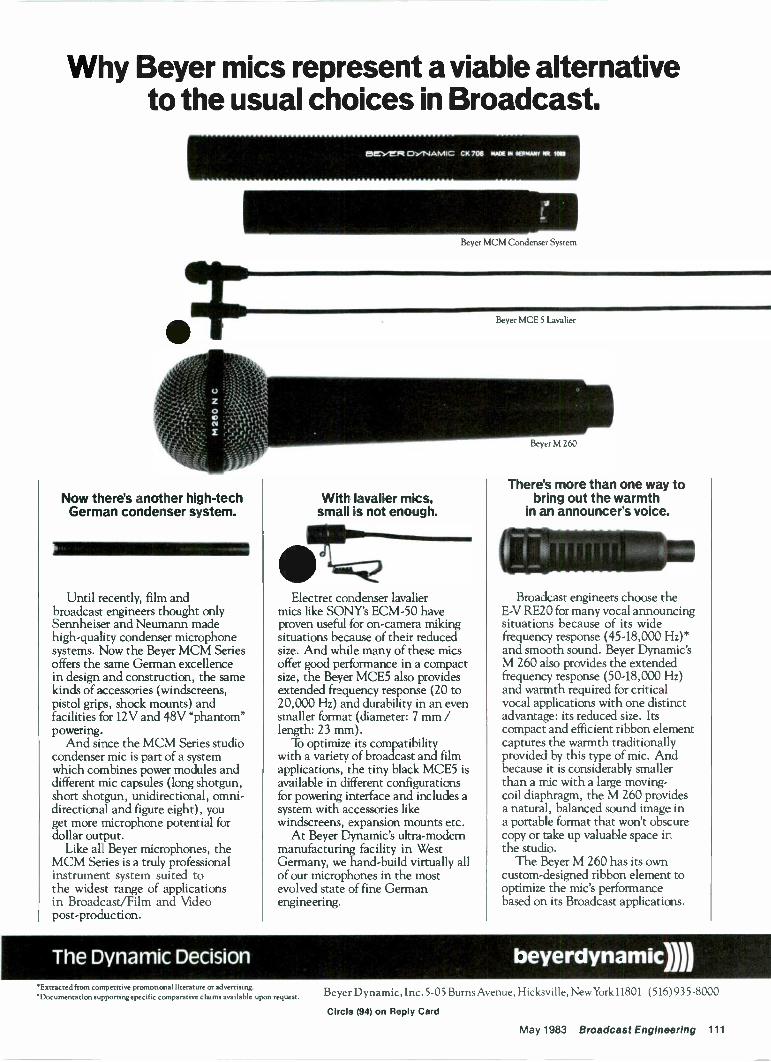
Why Beyer mics represent a viable alternativeto the usual choices in Broadcast.
eiff",,e.2 DYNAMIC. CK 706 04ADE Ia Ocimbuir 55 1052
Now there's another high-techGerman condenser system.
1111111111111=1111MIIIIIIIII
Until recently, film andbroadcast engineers thought onlySennheiser and Neumann madehigh -quality condenser microphonesystems. Now the Beyer MCM Seriesoffers the same German excellencein design and construction, the samekinds of accessories (windscreens,pistol grips, shock mounts) andfacilities for 12V and 48V "phantom"powering.
And since the MCM Series studiocondenser mic is part of a systemwhich combines power modules anddifferent mic capsules (long shotgun,short shotgun, unidirectional, omni-directional and figure eight), youget more microphone potential fordollar output.
Like all Beyer microphones, theMCM Series is a truly professionalinstrument system suited tothe widest range of applicationsin Broadcast/Film and Videopost -production.
Beyer MCM Condenser System
With lavalier mics,small is not enough.
`TiQElectret condenser lavalier
mics like SONY'S ECM -50 haveproven useful for on -camera mikingsituations because of their reducedsize. And while many of these micsoffer good performance in a compactsize, the Beyer MCE5 also providesextended frequency response (20 to20,000 Hz) and durability in an evensmaller format (diameter: 7 mm /length: 23 mm).
To optimize its compatibilitywith a variety of broadcast and filmapplications, the tiny black MCE5 isavailable in different configurationsfor powering interface and includes asystem with accessories likewindscreens, expansion mounts etc.
At Beyer Dynamic's ultra -modemmanufacturing facility in WestGermany, we hand -build virtually allof our microphones in the mostevolved state of fine Germanengineering.
Beyer MCE 5 Lavalier
There's more than one way tobring out the warmth
in an announcer's voice.
Broadcast engineers choose theE -V RE20 for many vocal announcingsituations because of its widefrequency response (45-18,000 Hz)*and smooth sound. Beyer Dynamic'sM 260 also provides the extendedfrequency response (50-18,000 Hz)and warmth required for criticalvocal applications with one distinctadvantage: its reduced size. Itscompact and efficient ribbon elementcaptures the warmth traditionallyprovided by this type of mic. Andbecause it is considerably smallerthan a mic with a large moving -coil diaphragm, the M 260 providesa natural, balanced sound image ina portable format that won't obscurecopy or take up valuable space inthe studio.
The Beyer M 260 has its owncustom -designed ribbon element tooptimize the mic's performancebased on its Broadcast applications.
The Dynamic Decision beyerdynamilll*Extracted from competitive promotional literature or advertising.*Documentation supporting -specific comparative claims available upon request. Beyer Dynamic , Inc. 5-05 Burns Avenue, Hicksville, New York 11801 (516) 935-8000
Circle (94) on Reply Card
May 1983 Broadcast Engineering 111
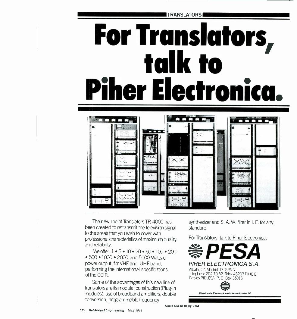
TRANSLATORS
For Translators,talk to
Piherl'ATE1125% uffirjem I
ri
The new line of Translators TR-4000 hasbeen created to retransmit the television signalto the areas that you wish to cover withprofessional characteristics of maximum qualityand reliability.
We offer. 1 5 10.20. 50 100 200 500 1000 2000 and 5000 Watts ofpower output, for VHF and UHF band,performing the international specificationsof the CCI R.
Some of the advantages of this new line oftranslators are its modular construction (Plug-inmodules), use of broadband amplifiers, doubleconversion, programmable frequency
synthesizer and S. A. W. filter in I. F. for anystandard.
For Translators, talk to Piher Electronica.
,kfjp
PESAPIHER ELECTRONICA S.A.Albala, 12. Madrid -17. SPAINTelephone 204 70 32. Telex 43203 PINE E.Cables PIELESA. P. 0. Box 35015V
Division de Electninica e Informatica del IN1
112 Broadcast Engineering May 1983
Circle (95) on Reply Card
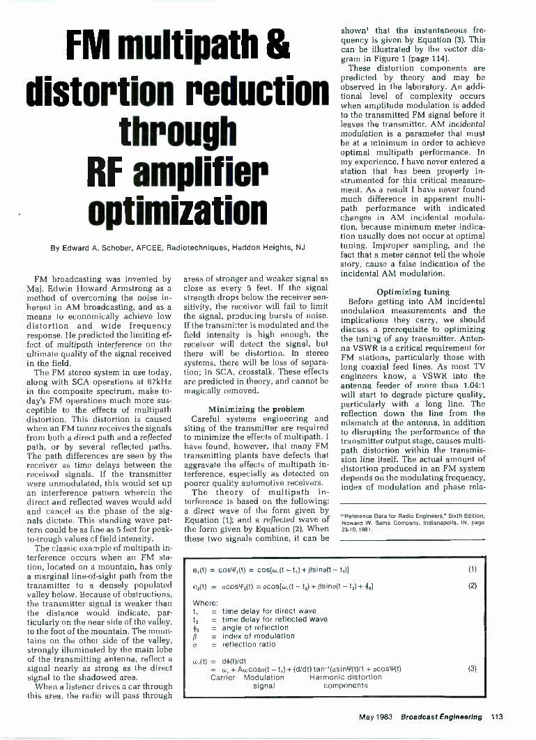
FM multipath &distortion reduction
throughRF amplifieroptimization
By Edward A. Schober, AFCEE, Rad otechniques, Haddon Heights, NJ
FM broadcasting was invented byMaj. Edwin Howard Armstrong as amethod of overcoming the noise in-herent in AM broadcasting, and as ameans to economically achieve lowdistortion and wide frequencyresponse. He predicted the limiting ef-fect of multipath interference on theultimate quality of the signal receivedin the field.
The FM stereo system in use today,along with SCA operations at 67kHzin the composite spectrum, make to-day's FM operations much more sus-ceptible to the effects of multipathdistortion. This distortion is causedwhen an FM tuner receives the signalsfrom both a direct path and a reflectedpath, or by several reflected paths.The path differences are seen by thereceiver as time delays between thereceived signals. If the transmitterwere unmodulated, this would set upan interference pattern wherein thedirect and reflected waves would addand cancel as the phase of the sig-nals dictate. This standing wave pat-tern could be as fine as 5 feet for peak -to -trough values of field intensity.
The classic example of multipath in-terference occurs when an FM sta-tion, located on a mountain, has onlya marginal line -of -sight path from thetransmitter to a densely populatedvalley below. Because of obstructions,the transmitter signal is weaker thanthe distance would indicate, par-ticularly on the near side of the valley.to the foot of the mountain. The moun-tains on the other side of the valley,strongly illuminated by the main lobeof the transmitting antenna, reflect a
signal nearly as strong as the directsignal to the shadowed area.
When a listener drives a car throughthis area, the radio will pass through
areas of stronger and weaker signal asclose as every 5 feet. If the signalstrength drops below the receiver sen-sitivity, the receiver will fail to limitthe signal, producing bursts of noise.If the transmitter is modulated and thefield intensity is high enough, thereceiver will detect the signal, butthere will be distortion. In stereosystems, there will be loss of separa-tion; in SCA, crosstalk. These effectsare predicted in theory, and cannot bemagically removed.
Minimizing the problemCareful systems engineering and
siting of the transmitter are requiredto minimize the effects of multipath. Ihave found, however, that many FMtransmitting plants have defects thataggravate the effects of multipath in-terference, especially as detected onpoorer quality automotive receivers.
The theory of multipath in-terference is based on the following -a direct wave of the form given byEquation (1); and a reflected wave ofthe form given by Equation (2). Whenthese two signals combine, it can be
shown' that the instantaneous fre-quency is given by Equation (3). Thiscan be illustrated by the vector dia-gram in Figure 1 (page 114).
These distortion components arepredicted by theory and may beobserved in the laboratory. An addi-tional level of complexity occurswhen amplitude modulation is addedto the transmitted FM signal before itleaves the transmitter. AM incidentalmodulation is a parameter that mustbe at a minimum in order to achieveoptimal multipath performance. Inmy experience, I have never entered astation that has been properly in-strumented for this critical measure-ment. As a result I have never foundmuch difference in apparent multi -path performance with indicatedchanges in AM incidental modula-tion, because minimum meter indica-tion usually does not occur at optimaltuning. Improper sampling, and thefact that a meter cannot tell the wholestory, cause a false indication of theincidental AM modulation.
Optimizing tuningBefore getting into AM incidental
modulation measurements and theimplications they carry, we shoulddiscuss a prerequisite to optimizingthe tuning of any transmitter. Anten-na VSWR is a critical requirement forFM stations, particularly those withlong coaxial feed lines. As most TVengineers know, a VSWR into theantenna feeder of more than 1.04:1will start to degrade picture quality,particularly with a long line. Thereflection down the line from themismatch at the antenna, in additionto disrupting the performance of thetransmitter output stage, causes multi -path distortion within the transmis-sion line itself. The actual amount ofdistortion produced in an FM systemdepends on the modulating frequency,index of modulation and phase rela-
I"Reference Data for Radio Engineers," Sixth Edition,Howard W. Sams Company, Indianapolis, IN, page23-10, MI.
e1(t) = cos'1(t) = coskojt - t1) + psina(t - ti)1
e2(t) = ocosW2(t) = ocos[cojt - t2) + psino(t - t2) + clio]
Where:t, = time delay for direct wavet2 = time delay for reflected wave
angle of reflection= index of modulation
o = reflection ratio
cor(t) = d4(t)/dt= w, + Acocoso(t - t,) + (d/dt) tan-losin41(t)/1 + ocostY(t)Carrier Modulation Harmonic distortion
signal components
( 3 )
May 1983 Broadcast Engineering 113
tionship of the reflected wave within aBessel function; it is exponentiallyrelated to the reflection coefficient.
Consider a situation in which anantenna reflects some incidentalpower; some of that power echosdown the line, reflects off the trans-mitter (which is not matched for re-flected power) and returns to theantenna to be radiated, with the delayof the propagation through the trans-mission line. The portion not radiatedis reflected, echos and returns withstill more delay. In such a case, a sta-tion can have built-in multipathdistortion before the signal leaves theantenna. An example of the relation-ship of this problem to VSWR follows.For a situation in which the combina-tion of modulating frequencies, indexof modulation and phase angle of thereflection, etc., produce a harmonicdistortion of 1.6% due to line reflec-tion multipath for a 1.5:1 VSWR, thisdistortion would reduce to 0.7% for1.22:1 and would increase to 2.5% at1.87:1. A 3:1 VSWR would producealmost 5% distortion.
It is fortunate that many FM sta-tions operate with reasonably shorttransmission lines. The severity ofmultipath distortion is related to thelength of the delay in relation to thebandwidth of the transmitted signal. If
the delay is short in relation to themodulating frequency, the major har-monic distortion components fall out-side the received bandwidth and donot disrupt reception. To put theamount of delay in perspective. it ishelpful to imagine that a signal arriv-ing with a modulating signal phase of0°, combining at the receiver with asignal arriving with a modulatingsignal phase of 180°, would cancel.This is partially the case, although theresult also includes distortion com-ponents because FM is not a linearmodulation system. In order toacheive tiis 180° phase shift, the timedelay must equal half of the period ofthe modulating wave. These condi-tions are shown in Table I (below)
for 38kHz and 76kHz modulating fre-quencies.
We may evaluate the disruption ofthe frequency response of the com-posite baseband and ignore otherdistortion components. Assume use ofa 3 -inch semiflexible cable, and thatthe transmitter reflects all power back
-..--REFLECTED WAVEe,(t)
VI,+
Figure 1. Vector diagram for combiningdirect and reflected signals.
Table I.Conditions for 180° phase shift
Reflectionsat modulating
Line frequencylength(feet)
38kHz 76kHz
300015001000760
SecondFourthSixthEighth
FirstSecondThirdFourth
SONY FORMALLYINTRODUCES
THE ECM 50-PBW.Covering the Emmys? The Grammys? The Oscars? Or
merely having a little tete-a-tete with the President ofthe United States in front of 40 million people? You'll find theworld's most preferred broadcast mic is now even moresuited for the occasion. Because the legendary Sony ECM 50lavaliere mic now comes in an elegant, black satin finish.
Ask your Sony dealer about the ECM 50. It's what allthe best -dressed newscasters will be SONwearing this year. Professional AudioSony Communications Products Company, Sony Drive, Park Ridge, New Jersey 07656. ©1983Sony Corp. of America. Sony is a registered trademark of the Sony Corp.
REPLACEMENT TRANSFORMERSGATES, COLLINS, RCA, CCA
PLATE TRANSFORMERS
COLLINS 20V-1, 20V-2,20V-3 $550
CCA FM -4000E $650GATES BC1 E, BC1 F $550GATES BC1G, BC1H $550GATES BC1J $550GATES BC1T $550GATES BC5P 3 Phase . . $1200GATES BC500T $400GATES FM -250 $275GATES FM -1 B $575RCA BTA1G, BTA1H . $550RCA BTA1R, BTA1S $550RCA BTA5G, BTA5H
(Main or Teaser)RCA BTA1OH (Main or
Teaser)
COLLINS 21E Series . . . 1350GATES BC1 Series $695GATES BC5 Series $1350RCA BTA1 Series $695
MODULATION REACTORS
GATES BC1 Series, 40 Hy@ 600 MA DC $400
GATES BC5 Series, 35 Hy@ 1.4 AMP DC $650
10KW Universal, 20 Hy@ 2.5 AMP DC $850
FILTER REACTORS3 Hy @ 2.5 AMP DC, 10 KV
$750 INS $2505 Hy @ 1.0 AMP DC, 10KV
$1500 INS $17510 Hy @ 1.0 AMP DC, 10KV
INS $200MODULATION TRANSFORMERS 10 Hy @ 2.5 AMP DC, 10 KV
INS $35015 Hy @ 1.0 AMP DC, 10 KV
COLLINS 20V Series .. . . $695 INS $250
Many other transformers also available. Call us for freequotations. Large stock and fast delivery. 12 MonthGuarantee on all Items.
PETER W. DAHL CO., INC.4007 Fort Blvd., El Paso, Texas 79930
Telephone: (915)566-5365
BAUER 707 Series $695
114 Broadcast Engineering May 1983
Circle (101) on Reply Card
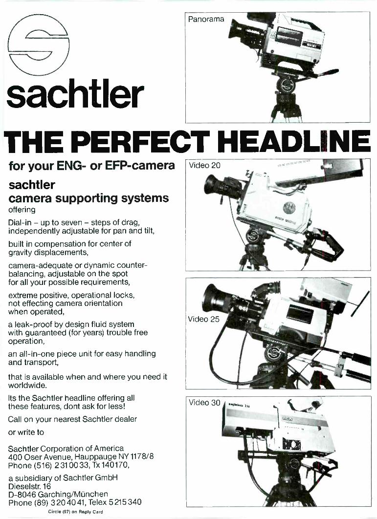
sachtlerTHE PERFECT HEADLINEfor your ENG- or EFP-camera
sachtlercamera supporting systemsoffering
Dial -in - up to seven - steps of drag,independently adjustable for pan and tilt,
built in compensation for center ofgravity displacements,
camera -adequate or dynamic counter-balancing, adjustable on the spotfor all your possible requirements,
extreme positive, operational locks,not effecting camera orientationwhen operated,
a leak -proof by design fluid systemwith guaranteed (for years) trouble freeoperation,
an all -in -one piece unit for easy handlingand transport,
that is available when and where you need itworldwide.
Its the Sachtler headline offering allthese features, dont ask for less!
Call on your nearest Sachtler dealer
or write to
Sachtler Corporation of America400 Oser Avenue, Hauppauge NY 1178/8Phone (516) 2310033, Tx 140170,
a subsidiary of Sachtler GmbHDieselstr. 16D-8046 Garching/MunchenPhone (89) 3204041, Telex 5 215 340
Circle (97) on Reply Card
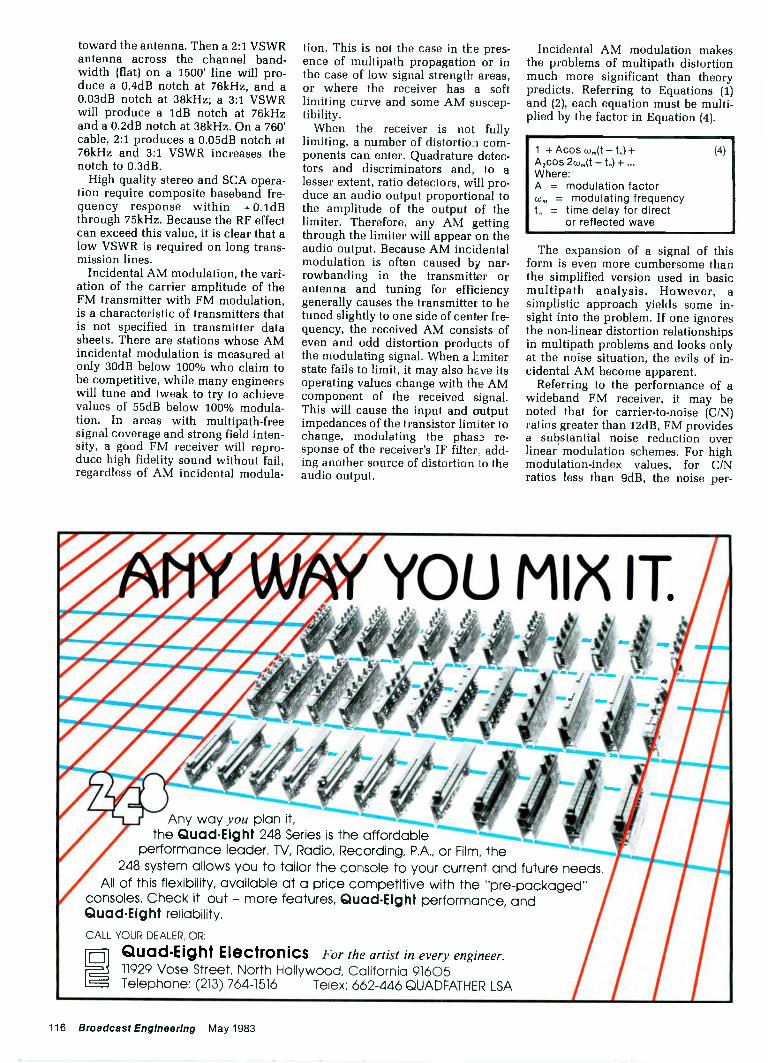
toward the antenna. Then a 2:1 VSWRantenna across the channel band-width (flat) on a 1500' line will pro-duce a 0.4dB notch at 76kHz, and a0.03dB notch at 38kHz; a 3:1 VSWRwill produce a 1dB notch at 76kHzand a 0.2dB notch at 38kHz. On a 760'cable, 2:1 produces a 0.05dB notch at76kHz and 3:1 VSWR increases thenotch to 0.3dB.
High quality stereo and SCA opera-tion require composite baseband fre-quency response within + 0.1dBthrough 75kHz. Because the RF effectcan exceed this value, it is clear that alow VSWR is required on long trans-mission lines.
Incidental AM modulation, the vari-ation of the carrier amplitude of theFM transmitter with FM modulation,is a characteristic of transmitters thatis not specified in transmitter datasheets. There are stations whose AMincidental modulation is measured atonly 30dB below 100% who claim tobe competitive, while many engineerswill tune and tweak to try to achievevalues of 55dB below 100% modula-tion. In areas with multipath-freesignal coverage and strong field inten-sity, a good FM receiver will repro-duce high fidelity sound without fail,regardless of AM incidental modula-
tion. This is not the case in the pres-ence of multipath propagation or inthe case of low signal strength areas,or where the receiver has a softlimiting curve and some AM suscep-tibility.
When the receiver is not fullylimiting, a number of distortion com-ponents can enter. Quadrature detec-tors and discriminators and, to alesser extent, ratio detectors, will pro-duce an audio output proportional tothe amplitude of the output of thelimiter. Therefore, any AM gettingthrough the limiter will appear on theaudio output. Because AM incidentalmodulation is often caused by nar-rowbanding in the transmitter orantenna and tuning for efficiencygenerally causes the transmitter to betuned slightly to one side of center fre-quency, the received AM consists ofeven and odd distortion products ofthe modulating signal. When a kmiterstate fails to limit, it may also have itsoperating values change with the AMcomponent of the received signal.This will cause the input and outputimpedances of the transistor limiter tochange, modulating the phase re-sponse of the receiver's IF filter. add-ing another source of distortion to theaudio output.
Incidental AM modulation makesthe problems of multipath distortionmuch more significant than theorypredicts. Referring to Equations (1)and (2), each equation must be multi-plied by the factor in Equation (4).
1 + Acos -t)+A2cos 2w,,(t -t)+...Where:A = modulation factor(0, = modulating frequencyt = time delay for direct
or reflected wave
(4)
The expansion of a signal of thisform is even more cumbersome thanthe simplified version used in basicmultipath analysis. However, asimplistic approach yields some in-sight into the problem. If one ignoresthe non-linear distortion relationshipsin multipath problems and looks onlyat the noise situation, the evils of in-cidental AM become apparent.
Referring to the performance of awideband FM receiver, it may benoted that for carrier -to -noise (C/N)ratios greater than 12dB, FM providesa substantial noise reduction overlinear modulation schemes. For highmodulation -index values, for C/Nratios less than 9dB, the noise per -
YOU MIX IT
Quad -Eight reliability.
Quad -Eight Electronics
r :
All of this flexibility, available at a price competitive with the "pre-packaged"consoles. Check it out - more features, Quad -Eight performance, and
248 system allows you to tailor the console to your current and future needs.
11929 Vose Street, North Hollywood, California 91605Telephone: (213) 764-1516 Telex: 662-446 QUADFATHER LSA
For the artist in every engineer.
Any way you plan it,the Quad -Eight 248 Series is the affordable
performance leader. TV, Radio, Recording, P.A., or Film, the
CALL YOUR DEALER, OR:
116 Broadcast Engineering May 1983
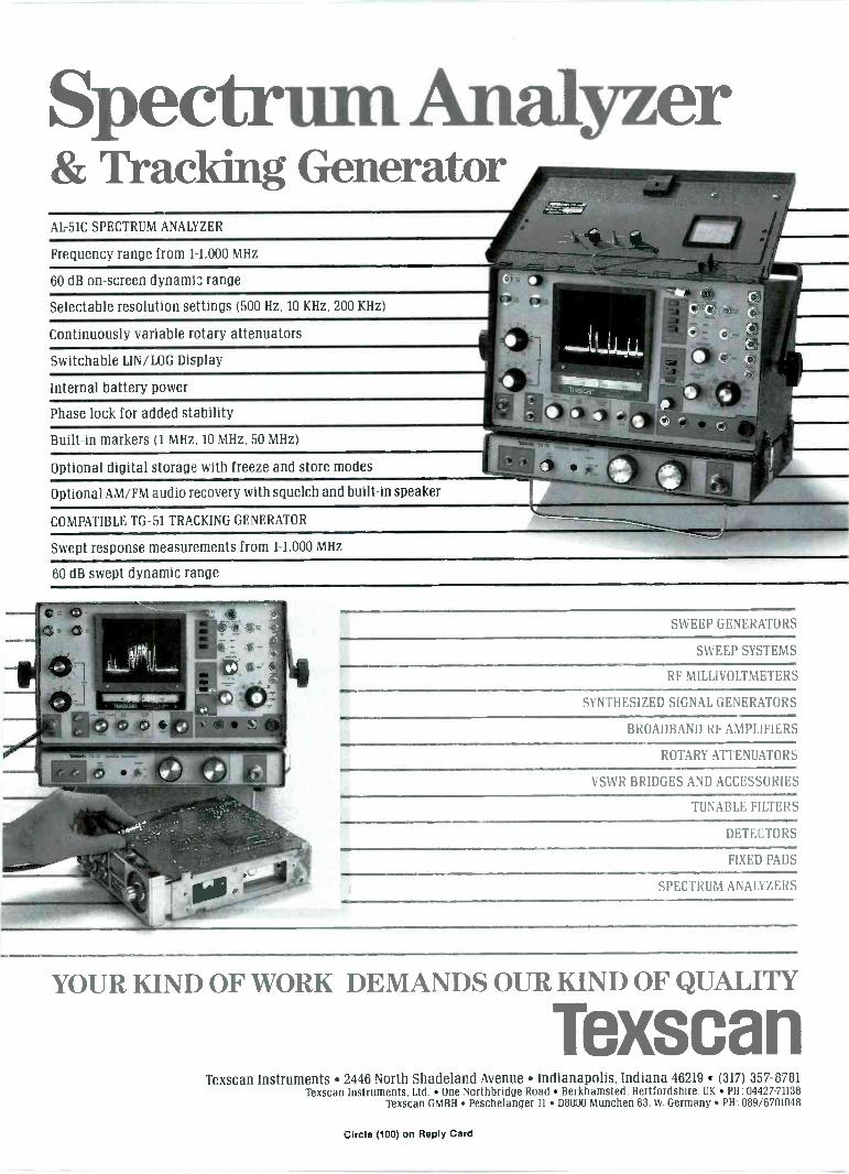
Spectrum Analyzer& Tracking GeneratorAL -51C SPECTRUM ANALYZER
Frequency range from 1-1,000 MHz
60 dB on -screen dynamic range
Selectable resolution settings (500 Hz, 10 KHz, 200 KHz)
Continuously variable rotary attenuators
Switchable LIN/LOG Display
Internal battery power
Phase lock for added stability
Built-in markers (1 MHz, 10 MHz, 50 MHz)
Optional digital storage with freeze and store modes
Optional AM/FM audio recovery with squelch and built-in speaker
COMPATIBLE TG -51 TRACKING GENERATOR
Swept response measurements from 1-1,000 MHz
60 dB swept dynamic range
SWEEP GENERATORS
SWEEP SYSTEMS
RF MILLIVOLTMETERS
\ I HESIZED SIGNAL GENERATORS
BROADBAND RF AMPLIFIERS
ROTARY ATTENUATORS
1, St% R BRIDGES AND ACCESSORIES
TUNABLE FILTERS
DETECTORS
FIXED PADS
SPECTRUM ANALYZERS
YOUR KIND OF WORK DEMANDS OUR KIND OF QUALITY
TexscanTexscan Instruments 2446 North Shadeland Avenue Indianapolis, Indiana 46219 (317) 357-8781
Texscan Instruments. Ltd. One Northbridge Road Berkhamsted, Hertfordshire, UK PH: 04427-71138Texscan GMBH Peschelanger 11 08000 Munchen 83. W. Germany PH: 089/6701048
Circle (100) on Reply Card

Why this magazineandmore than
75 0 others fetusgo over their books
once a year.Some magazines, we're sorry to say, keep their
readers undercover. They steadfastly refuse to let BPA(Business Publications Audit of Circulation, Inc.) or anyother independent, not -for-profit organization audit theircirculation records.
We think the reason is obvious: These magazines areless than proud of the quantity and quality of their readers.
On the other hand, over 750 publications (like thisone) belong to BPA. Once a year, BPA auditors examineand verify the accuracy of our circulation records.
This audit provides the name, company, industry andjob title of every reader each publication reaches. Theinformation helps advertisers to determine if they aresaying the right thing to the right people in the right place.
It also helps somebody else important: you. Becausethe more a publication and its advertisers know about you,the better they can provide you with articles andadvertisements that meet your informational needs.
BPA. For readers it stands for meaningful information.For advertisers it stands for meaningful readers. BusinessPublications Audit of Circulation, Inc.360 Park Ave. So., New York, NY 10010. BPA
We make star you get what you pay for.
118 Broadcast Engineering May 1983
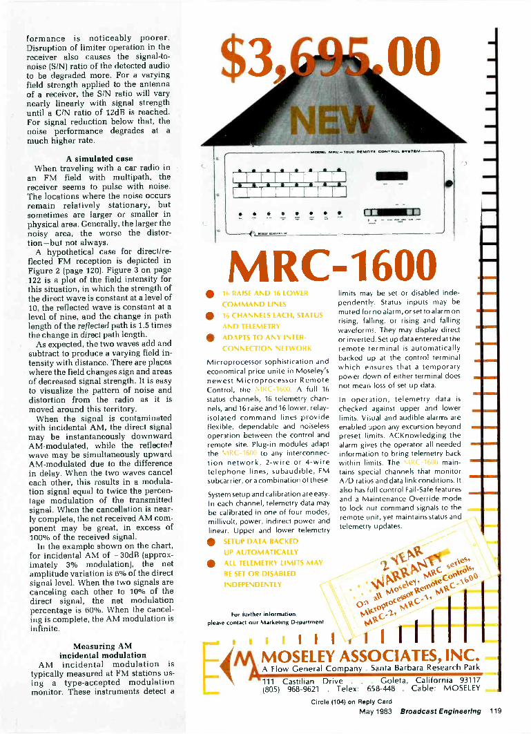
formance is noticeably poorer.Disruption of limiter operation in thereceiver also causes the signal-to-noise (SIN) ratio of the detected audioto be degraded more. For a varyingfield strength applied to the antennaof a receiver, the SIN ratio will varynearly linearly with signal strengthuntil a C/N ratio of 12dB is reached.For signal reduction below that, thenoise performance degrades at amuch higher rate.
A simulated caseWhen traveling with a car radio in
an FM field with multipath, thereceiver seems to pulse with noise.The locations where the noise occursremain relatively stationary, butsometimes are larger or smaller inphysical area. Generally, the larger thenoisy area, the worse the distor-tion-but not always.
A hypothetical case for direct/re-flected FM reception is depicted inFigure 2 (page 120). Figure 3 on page122 is a plot of the field intensity forthis situation, in which the strength ofthe direct wave is constant at a level of10, the reflected wave is constant at alevel of nine, and the change in pathlength of the reflected path is 1.5 timesthe change in direct path length.
As expected, the two waves add andsubtract to produce a varying field in-tensity with distance. There are placeswhere the field changes sign and areasof decreased signal strength. It is easyto visualize the pattern of noise anddistortion from the radio as it ismoved around this territory.
When the signal is contaminatedwith incidental AM, the direct signalmay be instantaneously downwardAM -modulated, while the reflectedwave may be simultaneously upwardAM -modulated due to the differencein delay. When the two waves canceleach other, this results in a modula-tion signal equal to twice the percen-tage modulation of the transmittedsignal. When the cancellation is near-ly complete, the net received AM com-ponent may be great, in excess of100% of the received signal.
In the example shown on the chart,for incidental AM of - 30dB (approx-imately 3% modulation), the netamplitude variation is 6% of the directsignal level. When the two signals arecanceling each other to 10% of thedirect signal, the net modulationpercentage is 60%. When the cancel-ing is complete, the AM modulation isinfinite.
Measuring AMincidental modulation
AM incidental modulation istypically measured at FM stations us-ing a type -accepted modulationmonitor. These instruments detect a
00
ILICIONL MOB ...WOO INKNICITIN COMITACIL
a i a JO JD
* *****
MRC-1600lb RAISE AND 16 LOWER
COMMAND LINES
1.) CHANNELS EACH, STATUSAND TELEMETRY
ADAPTS TO ANY INTER-CONNECTION NETWORK
Microprocessor sophistication andeconomical price unite in Moseley'snewest Microprocessor RemoteControl, the . A full 16status channels, 16 telemetry chan-nels, and 16 raise and 16 lower, relay -isolated command lines provideflexible, dependable and noiselessoperation between the control andremote site. Plug-in modules adaptthe to any interconnec-tion network, 2 -wire or 4 -wiretelephone lines, subaudible, FMsubcarrier, or a combination of these
System setup and calibration are easy.In each channel, telemetry data maybe calibrated in one of four modes;millivolt, power, indirect power andlinear. Upper and lower telemetry
SETUP DATA BACKEDUP AUTOMATICALLY
ALL TELEMETRY LIMITS MAYBE SET OR DISABLED
INDEPENDENTLY
For further information,please contact our Marketing Department
limits may be set or disabled inde-pendently. Status inputs may bemuted forno alarm, or set to alarm onrising, falling, or rising and fallingwaveforms. They may display director inverted. Set up data entered at theremote terminal is automaticallybacked up at the control terminalwhich ensures that a temporarypower down of either terminal doesnot mean loss of set up data.
In operation, telemetry data ischecked against upper and lowerlimits. Visual and audible alarms areenabled upon any excursion beyondpreset limits. ACKnowledging thealarm gives the operator all neededinformation to bring telemetry backwithin limits. The main-tains special channels that monitorA/D ratios and data link conditions. Italso has full control Fail -Safe featuresand a Maintenance Override modeto lock out command signals to theremote unit, yet maintains status andtelemetry updates.
=MI
itcs
..ov,ke\ei
is' gpC (3°
z. °cess°1 A%00S/1 /40C-
4At
I IIIMOSELEY ASSOCIATES, INC.A Flow General Company . Santa Barbara Research Park
111 Castilian Drive . . . Goleta, California 93117(805) 968-9621 . Telex: 658-448 . Cable: MOSELEY
Circle (104) on Reply Card
May 1983 Broadcast Engineering 119
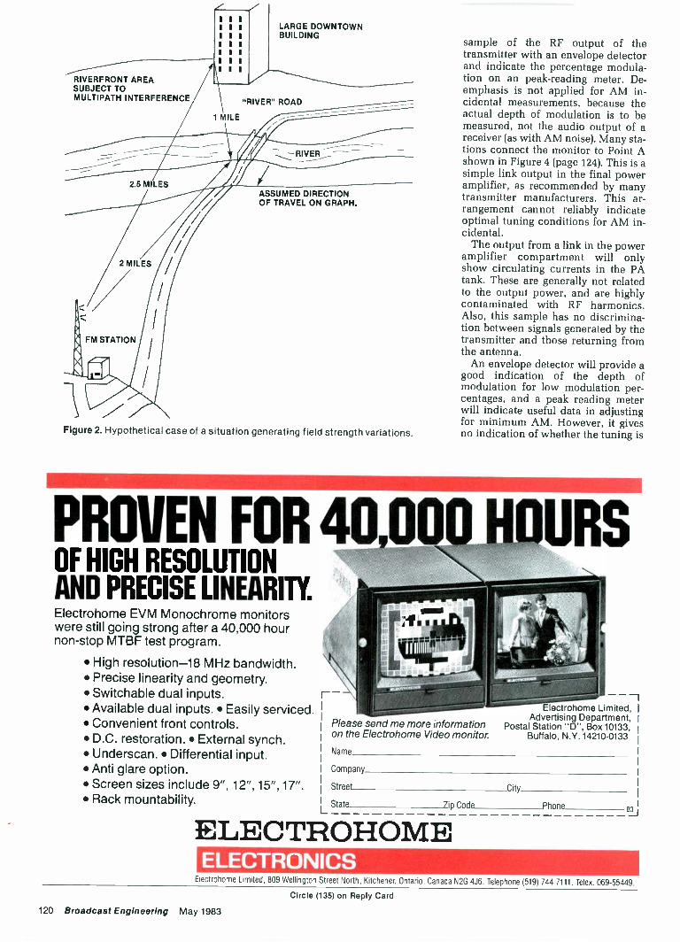
I II II II II II II I
RIVERFRONT AREASUBJECT TOMULTIPATH INTERFERENCE
1 MILE
2.5 MILES
2 MILES
FM STATION
LARGE DOWNTOWNBUILDING
"RIVER" ROAD
ASSUMED DIRECTIONOF TRAVEL ON GRAPH.
Figure 2. Hypothetical case of a situation generating field strength variations.
sample of the RF output of thetransmitter with an envelope detectorand indicate the percentage modula-tion on an peak -reading meter. De-
emphasis is not applied for AM in-cidental measurements, because theactual depth of modulation is to bemeasured, not the audio output of areceiver (as with AM noise). Many sta-tions connect the monitor to Point Ashown in Figure 4 (page 124). This is asimple link output in the final poweramplifier, as recommended by manytransmitter manufacturers. This ar-rangement cannot reliably indicateoptimal tuning conditions for AM in-cidental.
The output from a link in the poweramplifier compartment will onlyshow circulating currents in the PAtank. These are generally not relatedto the output power, and are highlycontaminated with RF harmonics.Also, this sample has no discrimina-tion between signals generated by thetransmitter and those returning fromthe antenna.
An envelope detector will provide agood indication of the depth ofmodulation for low modulation per-centages, and a peak reading meterwill indicate useful data in adjustingfor minimum AM. However, it givesno indication of whether the tuning is
PROVEN FOR 40,00011OURSOF HIGH RESOLUTIONAND PRECISE LINEARITY.Electrohome EVM Monochrome monitorswere still going strong after a 40,000 hournon-stop MTBF test program.
High resolution -18 MHz bandwidth. Precise linearity and geometry. Switchable dual inputs. Available dual inputs. Easily serviced. Convenient front controls. D.C. restoration. External synch. Underscan. Differential input. Anti glare option. Screen sizes include 9", 12", 15", 17". Rack mountability.
I( h
1111111'!,[,,
\ \
Please send me more informationon the Electrohome Video monitor.
Name
Company
Street
I State
Electrohome Limited,Advertising Department,
Postal Station "D", Box 10133,Buffalo, N.Y. 14210-0133
City
7ip Code Phone
ELECTROHOMEBJ
ELECTRONICSElectrohome Limited, 809 Wellington Street North, Kitchener, Ontario, Canada N2G 4J6. Telephone (519) 744-7111. Telex. 069-55449.
Circle (135) on Reply Card
120 Broadcast Engineering May 1983
JBL Compact Monitors.
Refined. And Redefined.In 1967, the introduction of the first professional quality compact monitor created a smallrevolution in the recording and broadcast industries. Combining high power capacity, accuracy,and extended bandwidth, the loudspeaker was ideal for close monitoring, yet flexible enough toprovide a practical alternative to full size monitors. That speaker was to evolve into the JBL 4311.And since its introduction, it has literally set the standard for compact monitors.
At JBL, we're proud of this heritage. So over the years we've worked to mai rtain it throughdesign improvement and innovation. And now, JBL engineers have created a new generationof compact monitors-loudspeakers that range from the subtly refined to the totally redefined.
Our new 4312, for example, represents the next step in the evolution of the 4311.Improvements include a new high resolution dividing network for better transient response and amirror -imaged design that provides enhanced stereo imaging. These refinements significantlyimprove the loudspeaker's performance, yet maintain the unique sound character that made it anindustry standard. And best of all, the 4312 is still priced to fit comfortably in evenmodest budgets.
For those that require a more flexible or compact monitor, we've created the 4411 and 4401.These loudspeakers incorporate our most advanced component and design technologies. Boththe 4401 and 4411 utilize newly developed transducers arranged in a tight cluster to provide out-standing coherency of sound for close monitoring. This design also minimizes off -axis variationsin the far field. Additionally, the 4411s are mirror imaged for improved stereo perspective.
For maximum flexibility, the continuously variable levels controls on the 4411 are calibratedfor both a flat direct -field response and a rising axial response that produces a flatter power response.And for ease of adjustment, each of the monitors' level controls are baffle mounted. Finally, thelow frequency loading has been optimized for flat response when the speakers are placed awayfrom room surfaces. Because of this, the 4401 and 4411 may be console mounted without theloss of low frequency response typical of other designs.
For additional technical data and a complete demonstration of the 4312, 4401, or 4411,contact your local JBL Professional Products dealer. And discover the next generation of compactmonitors. From the refined to the redefined.
JBLProfessionalProducts JBL Incorporated
Division 8500 Balboa Boulevard, P.O. Box 2200Northridge, California 91329 U.S_A.
UBL/harman internationalCiicle (102) on Reply Card
Iv 'ay 1983 Broadcast Engineering 121
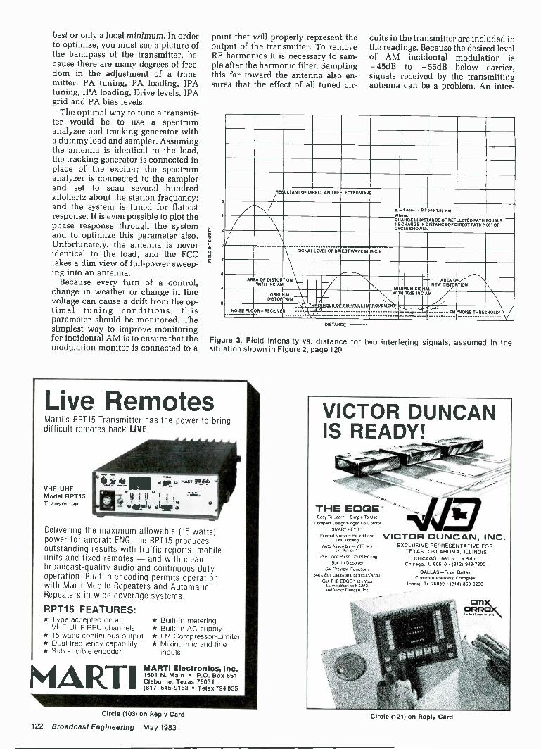
best or only a local minimum. In orderto optimize, you must see a picture ofthe bandpass of the transmitter, be-cause there are many degrees of free-dom in the adjustment of a trans-mitter: PA tuning, PA loading, IPAtuning, IPA loading, Drive levels, IPAgrid and PA bias levels.
The optimal way to tune a transmit-ter would be to use a spectrumanalyzer and tracking generator witha dummy load and sampler. Assumingthe antenna is identical to the load,the tracking generator is connected inplace of the exciter; the spectrumanalyzer is connected to the samplerand set to scan several hundredkilohertz about the station frequency;and the system is tuned for flattestresponse. It is even possible to plot thephase response through the systemand to optimize this parameter also.Unfortunately, the antenna is neveridentical to the load, and the FCCtakes a dim view of full -power sweep-ing into an antenna.
Because every turn of a control,change in weather or change in linevoltage can cause a drift from the op-timal tuning conditions, thisparameter should be monitored. Thesimplest way to improve monitoringfor incidental AM is to ensure that themodulation monitor is connected to a
point that will properly represent theoutput of the transmitter. To removeRF harmonics it is necessary tc sam-ple after the harmonic filter. Samplingthis far toward the antenna also en-sures that the effect of all tuned cir-
O
4
2
a
4
2
cuits in the transmitter are included inthe readings. Because the desired levelof AM incidental modulation is- 45dB to - 55dB below carrier,signals received by the transmittingantenna can be a problem. An inter-
RESULTANT OF DIRECT AND REFLECTED WAVE
4.=Wham
I cos+ .I- 0.9 coM1.5+ + x)
CHANGE IN DISTANCEIA CHANGE IN DISTANCECYCLE SHOWN).
OF REFLECTEDOF DIRECT
PATH EQUALS -PATH (130° OF
SIGNAL LEVEL OF DRECT WAVE 30dB CIN
AREA OF DISTORTIONWITH INC AM 7 MINIMUM SIGNAL
AREA OFNEW DIST TION
ORIGINALDISTORTION
igag_124_E4:_e_g6LAgm
WITH
vete E
30dB INC M
..
NOISE FLOOR-RECEIVERT
FM 'NOISE THREtHOLD.}NOISE
DISTAICE
Figure 3. Field intensity vs. distance for two interfering signals, assumed in thesituation shown in Figure 2, page 120.
Live RemotesMarti's RPT15 Transmitter has the power to bringdifficult remotes back LIVE.
VHF -UHFModel RPT15Transmitter
Delivering the maximum allowable (15 watts)power for aircraft ENG, the RPT15 producesoutstanding results with traffic reports, mobileunits and fixed remotes - and with cleanbroadcast -quality audio and continuous -dutyoperation. Built-in encoding permits operationwith Marti Mobile Repeaters and AutomaticRepeaters in wide coverage systems.
RPT15 FEATURES:* Type accepted on all
VHF -UHF RPU channels* 15 watts continuous output* Dual frequency capability* Sub audible encoder
MARTI
* Built-in metering* Built-in AC supply* FM Compressor -Limiter* Mixing mic and line
inputs
MARTI Electronics, Inc.1501 N. Main P.O. Box 661Cleburne, Texas 76031(817) 645-9163 Telex 794 835
VICTOR DUNCAN, INC.EXCLUSIVE REPRESENTATIVE FOR
TEXAS. OKLAHOMA. ILLINOISCHICAGO -661 N. La Salle
Chicago. IL 60610 (312) 943-7300
DALLAS-Four DallasCommunications Complex
Irving. Tx 75039 12141 869-0200
VICTOR DUNCANIS READY! ,
THE EDGE'Easy To Learr, - Simple To Use
Compact Design Finger Tip Control
SMART KEYS"Internal Memory Re -Edit and
Lot RipplingAuto Assembly-VTR Mix
Time Code Pulse Count EdgingBuilt In Dissolver
Six Preview Functions3400 Edo Decision List Input/Output
Get THE EDGE'- On YourCompanion with CMSand Victor Duncan. Inc
Circle (103) on Reply Card
122 Broadcast Engineering May 1983
Circle (121) on Reply Card
The only way to go.
AUDIOEDITING
Up to 12 audio orvideo machines may
be controlled orsynchronized.
As many as 999 frameaccurate, automated
punch in/punch outsmay be recorded at
time.
The time codelocations of yoursound effects and
theme music librarycan be stored in a
computerized directoryand easily recalled
when needed.
Options includecontrol of some of the
most widely usedoutboard processorsfor time compression
or scene -by -scenecorrection of reverb,
equalization, etc.
%W in 0712.79,CO21.57
Minifiedtudki:chuingirs
Together.Yesterday's editing systems just can't
meet today's demand for high quality audio.Automated Studio Technologies solves thisproblem by introducing electronic audioediting techniques as sophisticated as thosetaken for granted in video production.Bridging the gap between these twoindustries allows us to provide the oneediting system that is truly at home in eitheran audio or video post -productionenvironment.
VIDEOEDITINGTwo machine recordcapability permits A/Broll video editingwhile recording basictracks on asynchronized multi-track audio master.
Many switcher electsand audio sweeteningdecisions can be madeon the off-line editdecision list.Elaborate audio andvideo decision listscan be separatelycreated and combinedprior to final on-lineassembly.
Edit lists may bealternately iormated toconform to proposedSMPTE standards.
Production switcherinterfaces available toorder.
AIMM1111111111=110"Edward Joseph
Audio sweetening has never been easieror more accurate. Recording an entiresequence of tightly timed sound effects, forexample, becomes a simple matter of findingthe cue points. Making changes is noproblem either. We've even provided a way toput your entire music and effects library rightat your fingertips! Combining this capabilitywith frame accurate video editing means justthree things: saving time, money and yournerves.
D,str,buted through Harvey Professional Auchoz V,deo, 25 West 45th St . New York. NY 10036 (212) 398-0995
Circle (136) on Reply Card
May 1983 Broadcast Engineering 123
fering signal of 1W on the transmis-sion line can contaminate the indica-tions of a peak reading meter whenmonitoring a 10kW transmitter. Anextra 10dB of isolation can generallybe obtained from interfering signals ifthe monitor sample is taken with adirectional coupler sampling the for-ward power.
Using a monitor as the indicatingdevice will suffice for general tuningwhere there are no interface sourcesand the antenna is broadbanded. Forserious optimization, it is necessary toprovide a clearer view of band
TM
SAMSBOOKS
limiting and visual feedback on the ef-fect of each control on the transmitter.
Connecting the vertical input of ahigh frequency scope to the output ofan RF detector fed from a directionalcoupler and connecting the high fre-quency horizontal input of the scopeto the composite audio driving the ex-citer will provide a swept display ofthe AM incidental modulation of atransmitter. The display appearsmuch like the multipath display onmany high quality FM receivers withscopes. (Note: The vertical channel isac -coupled and set at a high enough
FOCUS ON VIDEO WITH SAMSSams library of video booksclearly shows you everythingyou need to produce and enjoyyour own video. Be your ownproducer with these books fromSams:
HOME VIDEO HANDBOOK(3rd Edition) covers the big homevideo picture and shows youhow to use everything fromVCRs and videodiscs to large -screen projection systems. Easy -to -read info from video industryexpert Charles Bensinger.No. 22052, $13.95
VIDEO PRODUCTION GUIDEtakes you through the entireproduction process from scriptto distribution. Covers all detailsof in -studio and remoteproductions for videoprofessionals and seriousamateurs. Also makes anexcellent textbook. Edited byCharles Bensinger. No. 22053,$28.95
VIDEO GUIDE (3rd Edition),also by Charles Bensinger, is afully -illustrated, hardware -oriented introduction to theuse and operation of videoequipment. A classic referenceguide to professional andamateur use of cameras, editingsystems, lenses, accessories and
more. No. 22051, $18.95SATELUTE TV HANDBOOK
shows you how to build yourown earth station, seeblacked -out and uneditednetwork TV shows, legally andprivately cut your cable costs inhalf, and much more. Written byAnthony T. Easton, No. 22055,$16.95 (tentative)
BASICS OF AUDIO ANDVISUAL SYSTEMS DESIGNprovides valuable NAVA-sanctioned information fordesigners and installers ofcommercial, audience -orientedAV systems, and especiallynewcomers to this field of AVGives you a full background infundamental system designconcepts and procedures,updated with currenttechnology. No. 22038, $15.95
Get your act together withthese Sams Books, and act now!To order call 800-428-3696 or317-298-5566 and referenceAD282.
Offer good in USA only andexpires 8/31/83.Prices subjectto change without notice. InCanada, contact LenbrookIndustries, Ltd., Scarborough,Ontario.
HOWARDW SAMSRCO INC 4300Wes162ndStreet,P0 Box7092,Inchanapolis,IN46206
Circle (105) on Reply Card
STEREOGENERATOR
FMEXCITER
TRANSMITTIPA
COMPOSITE
Figure 4. Equipment connectiondiagram for basic incidental AM modula-tion measurements.
gain to show curvature under modula-tion.)
A numerical relationship betweenthe carrier level and the amount ofAM modulation may be obtained by
RF detector when the scope is dc -
coupled; switching to ac -coupling;adding 20dB for each 10X sensitivityincrease with range changes; and tak-ing the ratio of trace height to theoriginal dc value. This represents thevalue of the AM noise and AM in-cidental plus interference.
For most applications, the stationplug-in RF wattmeter provides a com-bination directional coupler and RFdetector. Field experience indicatesthat simply connecting a high im-pedance scope input across the metermovement gives adequate resultswhen there is no interference.
The driving signal for this displaydeserves some consideration. Theaudio input to the exciter provides thesweeping action. For best and clearestrepresentation, a triangle wave ofabout 100Hz will give the transmittera relatively slow and even sweep tothe legal extent of ± 75kHz. Thisresults in an evenly illuminated trace,with a minimum of fuzz or apparentnoise and phase shift through thesystem that causes a broadening of thetrace. As a practical matter, many sta-tions do not permit breaks in program-ming, even overnight, to apply such asignal to the transmission system. For-tunately, highly processed stereo com-posite signals also give reasonablyclean traces. This permits the AM in-cidental characteristics of the station
124 Broadcast Engineering May 1983
FM4NTENNA
DIRECTIONAL( COUPLER
RFWATTMETER
TRANSMITTERPA
IODULATIONMONITOR
HARMONICFILTER
POINT A
FORWARD
CILLOSCOPE
)RIZ VERT
DETECTED SIGNALFROM WATTMETER
to be monitored at any time duringprogramming.
Field TestingField testing of these techniques
was undertaken at KEBC, OklahomaCity, with the assistance of RandyMullinax, chief engineer. Thetransmitter, a popular 20kW unit, wasfirst tuned to approximate the designfigures. This generally corresponds tothe point of best efficiency. An areaknown to have severe multipath in-terferences was monitored using apickup truck with a standard FMradio. As we traveled through thearea, we found locations extending20-40 feet along the road where thestation program was lost. We traveledthe same route again, noting the loca-tion and extent of loss of usable signal.
Returning to the station, we re-tuned the transmitter, using the tech-niques presented here, and repeatedthe field survey. The areas of distor-tion and noise magically disappearedor were drastically reduced. Picketfencing was still detachable, butnowhere did the signal distort formore than two or three feet.
We returned to the station again andre -tuned for lowest indicated AM in-cidental with the modulation monitorconnected to the link on the poweramplifier. Field surveys showed an in-termediate amount of interference,with loss of signal over areas of 10-15feet along the road.
AM incidental modulation con-taminates an FM broadcaster's signalin a particularly unfortunate way.Substantial areas of listenership maybe lost due to a worsening of the ef-fects of multipath interference indepth and affected areas. Multipath
interference also occurs most com-monly within the high signal strengthcoverage of a station. The sources ofmultipath affect the denselypopulated downtown areas with highbuildings and river valleys that do nothave line -of -sight viewing of the trans-mitter.
AM incidental modulation isgenerally not detected at the studio ofa station that uses good monitoringequipment and employs a good multi -path -free signal for studio monitoring.Conventional methods of indicatingAM incidental modulation are inade-
quate for adjusting transmission sys-tems to the levels of AM incidentalthat will not compound the problemsof multipath interference.
The methods outlined here are astep in the direction of ensuring thatstations will be able to reach as manyof their listeners as the transmittersiting and facilities allow. There arerefinements of these techniques to ex-tend their usefulness to stations withnarrowband antennas, diplexed sta-tions and stations with large amountsof RF received by the sta-tion antenna. I :r:))))1
For Your Peace of Mind.. .
Towers ByStainless!
e. W.41
a! I Z11111 JO1416
MIAMI 1 i T.r 1 . Argil 91 FAI 0.1
I MAU It I 11/41 I I r i X
Ili X
Al IZIPA lik I % AFA 74
A X..
OC
Alrlag li i tr4 0 A X
'OITA! it\ Ts' 'AVrAV
aII6.nAa.INll 1i\ \ "IA
!MI 11\E la- -J. z. %AM'GM
itaill 1 Irk:A*4.4 WkWlii, '1 iig,,IIIIIValyate, II I iill\,:iii:,,fiz
rii71.11 I FrAli:ikvilii!;5_,14 !I
All\vdr:
W.5111
Searching for a reliable tower fab-ricator? The logical choice is thecompany with over 35 years andmore than 1,000,000 feet of exper-ience-STAINLESS!
Our one and only business is de-signing and building towersfor radio,
CATV, microwave and radar, andno one understands, better thanwe do, the importance of depend-able engineering and construction.
A large part of being dependablein engineering consists of knowingthe best possible ways to meetspecific needs. For example, thedesign and fabrication require-ments of tall towers are far morecomplex than those of smaller ones.Because we understand that, withall of its implications, we designaccordingly and never compromise.As a result, our towers span theworld, excelling in performance anddurability. And of course, we arefully insured, for your protection.
Stainless... There are many rea-sons why we are number one.
The TowerPeople
Stainless, inc.North Wales, PA 19454 U.S.A.Phone: (21 5) 699-4871TWX: 510-661.8097
C0183
Circle (106) on Reply Card
May 1983 Broadcast Engineering 125
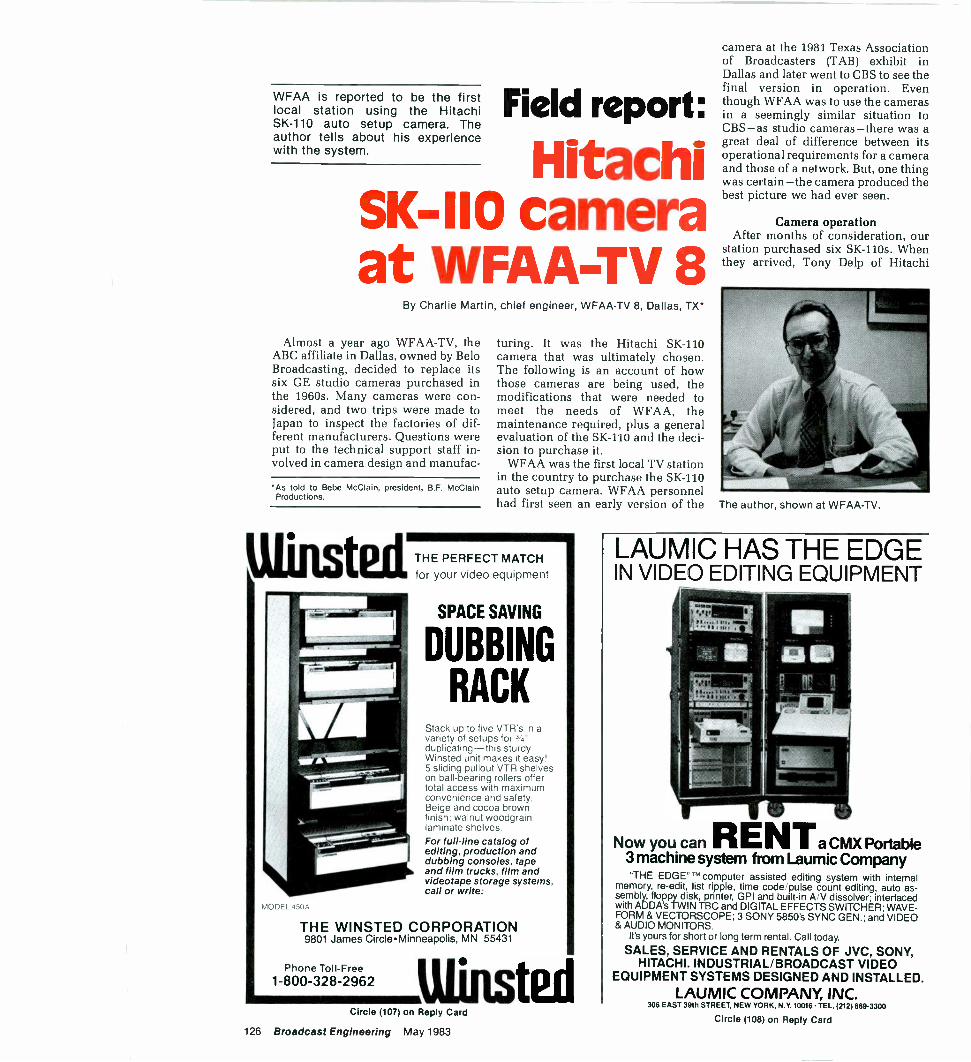
WFAA is reported to be the firstlocal station using the HitachiSK -110 auto setup camera. Theauthor tells about his experiencewith the system.
Field report:
HitachiSK -I10 cameraat WFAA-TV 8
By Charlie Martin, chief engineer, WFAA-TV 8, Dallas, TX*
Almost a year ago WFAA-TV, theABC affiliate in Dallas, owned by BeloBroadcasting, decided to replace itssix GE studio cameras purchased inthe 1960s. Many cameras were con-sidered, and two trips were made toJapan to inspect the factories of dif-ferent manufacturers. Questions wereput to the technical support staff in-volved in camera design and manufac-
As told to Bebe McClain, president, B.F. McClainProductions.
Misted
turing. It was the Hitachi SK -110camera that was ultimately chosen.The following is an account of howthose cameras are being used, themodifications that were needed tomeet the needs of WFAA, themaintenance required, plus a generalevaluation of the SK -110 and the deci-sion to purchase it.
WFAA was the first local TV stationin the country to purchase the SK -110auto setup camera. WFAA personnelhad first seen an early version of the
THE PERFECT MATCHfor your video equipment
SPACE SAVING
DUBBING
RACKStack up to five VTR s in avariety of setups forduplicating-this sturdyWinsted unit makes it easy!5 sliding pullout VTR shelveson ball -bearing rollers offertotal access with maximumconvenience and safetyBeige and cocoa brownfinish, walnut woodgrainlaminate shelves.For full -line catalog ofediting, production anddubbing consoles, tapeand film trucks, film andvideotape storage systems,call or write:
THE WINSTED CORPORATION9801 James Circle Minneapolis, MN 55431
Phone Toll -Free1-800-328-2962
Circle (107) on Reply Card
126 Broadcast Engineering May 1983
camera at the 1981 Texas Associationof Broadcasters (TAB) exhibit inDallas and later went to CBS to see thefinal version in operation. Eventhough WFAA was to use the camerasin a seemingly similar situation toCBS -as studio cameras -there was agreat deal of difference between itsoperational requirements for a cameraand those of a network. But, one thingwas certain -the camera produced thebest picture we had ever seen.
Camera operationAfter months of consideration, our
station purchased six SK -110s. Whenthey arrived, Tony Delp of Hitachi
The author, shown at WFAA-TV.
LAUMIC HAS THE EDGEIN VIDEO EDITING EQUIPMENT
Now you can RENTa CMX Portable3 machine system from Laumic Company"THE EDGE" computer assisted editing system with internal
memory, re-edit, list ripple, time code pulse count editing, auto as-sembly, floppy disk, printer, GPI and built-in A/V dissolver; interfacedwith ADDA's TWIN TBC and DIGITAL EFFECTS SWITCHER; WAVE-FORM & VECTORSCOPE; 3 SONY 5850's SYNC GEN.; and VIDEO& AUDIO MONITORS.
It's yours for short or long term rental. Call today.
SALES, SERVICE AND RENTALS OF JVC, SONY,HITACHI. INDUSTRIAL/BROADCAST VIDEO
EQUIPMENT SYSTEMS DESIGNED AND INSTALLED.LAUMIC COMPANY, INC.
306 EAST 39th STREET, NEW YORK, N.Y. 10016 TEL. (212) 889-3300
Circle (108) on Reply Card
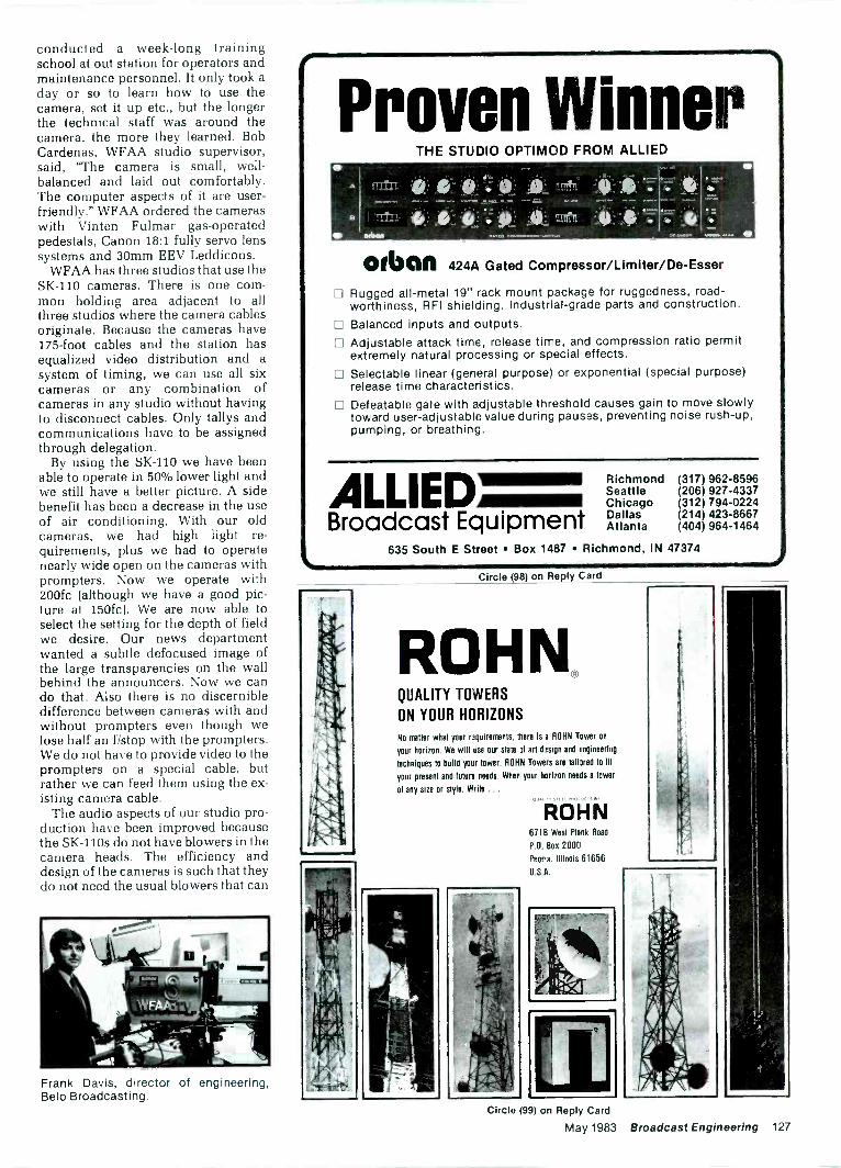
conducted a week-long trainingschool at out station for operators andmaintenance personnel. It only took aday or so to learn how to use thecamera, set it up etc., but the longerthe technical staff was around thecamera, the more they learned. BobCardenas, WFAA studio supervisor,said, "The camera is small, well-balanced and laid out comfortably.The computer aspects of it are user-friendly." WFAA ordered the cameraswith Vinten Fulmar gas -operatedpedestals, Canon 18:1 fully servo lenssystems and 30mm EEV Leddicons.
WFAA has three studios that use theSK -110 cameras. There is one com-mon holding area adjacent to allthree studios where the camera cablesoriginate. Because the cameras have175 -foot cables and the station hasequalized video distribution and asystem of timing, we can use all sixcameras or any combination ofcameras in any studio without havingto disconnect cables. Only tallys andcommunications have to be assignedthrough delegation.
By using the SK -110 we have beenable to operate in 50% lower light andwe still have a better picture. A sidebenefit has been a decrease in the useof air conditioning. With our oldcameras, we had high light re-quirements, plus we had to operatenearly wide open on the cameras withprompters. Now we operate with200fc (although we have a good pic-ture at 150fc). We are now able toselect the setting for the depth of fieldwe desire. Our news departmentwanted a subtle defocused image ofthe large transparencies on the wallbehind the announcers. Now we cando that. Also there is no discernibledifference between cameras with andwithout prompters even though welose half an f/stop with the prompters.We do not have to provide video to theprompters on a special cable, butrather we can feed them using the ex-isting camera cable.
The audio aspects of our studio pro-duction have been improved becausethe SK -110s do not have blowers in thecamera heads. The efficiency anddesign of the cameras is such that theydo not need the usual blowers that can
Frank Davis, director of engineering,Belo Broadcasting.
Proven WinnerTHE STUDIO OPTIMOD FROM ALLIED
A Ten°
.41 offl.n.OIN
()glum 424A Gated Compressor/Limiter/De-Esser
Rugged all -metal 19" rack mount package for ruggedness, road-worthiness, RFI shielding. Industrial -grade parts and construction.
Balanced inputs and outputs. Adjustable attack time, release time, and compression ratio permit
extremely natural processing or special effects. Selectable linear (general purpose) or exponential (special purpose)
release time characteristics. Defeatable gate with adjustable threshold causes gain to move slowly
toward user -adjustable value during pauses, preventing noise rush -up,pumping, or breathing.
ALLIEDBroadcast Equipment
Richmond (317) 962-8596Seattle (206) 927-4337Chicago (312) 794-0224Dallas (214) 423-8667Atlanta (404) 964-1464
635 South E Street Box 1487 Richmond, IN 47374
Circle (98) on Reply Card
ROHN.QUALITY TOWERS
ON YOUR HORIZONS
No matter what your raquiremenls. there is a ROHN Tower on
your horizon. We will use our state of art design and engineering
techniques to build your tower. ROHN Towers are tailored to lit
your present and future needs. When your horizon needs a tower
of any size or style. Write ..
ROHN6718 West Plank Road
P.O. Box 2000
Peoria. Illinois 61656
U.S A.
Circle 99) on Reply Card
May 1983 Broadcast Engineering 127
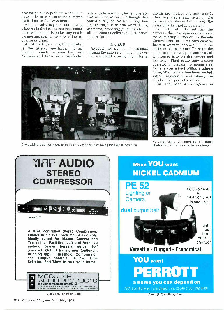
present an audio problem when micshave to be used close to the cameras(as is done in the newsroom).
Another advantage of not havinga blower in the head is that the camerahead system and its optics stay muchcleaner and there is no blower filter tochange or clean.
A feature that we have found usefulis the swivel viewfinder. If anoperator stands between the twocameras and turns each viewfinder
sideways toward him, he can operatetwo cameras at once. Although thiswould rarely be needed during liveproduction, it is helpful when tapingsegments, preparing graphics, etc. Inall, the camera delivers a 100% betterpicture for us.
The RCUAlthough we put all the cameras
through the auto setup daily, I believethat we could operate them for a
Davis with the author in one of three production studios using the SK -110 cameras.
(
IMP AUDIOSTEREO
COMPRESSOR
Model 7102
A VCA controlled Stereo Compressor/Limiter in a 1-3/4" rack mount assembly.Ideally suited for Master Control andTransmitter Facilities. Left and Right Vumeters. Barrier terminal strips. Selfpowered. Output transformer (optional).Bridging input. Threshold, Compressionand Output controls. Release TimeSelector, Fast/Slow to suit your format.
P
MODULARAUDIO PRODUCTSIR A UNIT OF MODULAR DEVICES, INC
#. . ,cer nat:cnr)., 516 567.962C)
month and not find any serious drift.They are stable and reliable. Thecameras are always left on with thebeam off when not in operation.
To automatically set up thecameras, the video operator depressesthe Auto setup button on the RemoteControl Unit (RCU) for each camera.Because we monitor one at a time, wedo them one at a time. To begin theauto setup, a diascope is automatical-ly inserted between the camera andthe lens. (Final setup may includeoperator adjustment to compensatefor lens aberration.) Within a minuteor so, 90 + camera functions, includ-ing full registration and balance, arechecked and perfectly set up.
Carl Thompson, a TV engineer in
Holding room, common to all threestudios where camera cables originate.
When YOU want
NICKEL CADMIUM
PE 52Lighting orCamera
dual output belt
28.8 volt 4 AHOr
14.4 volt 8 AHin one unit
withfourhour
built-incharger
Versatile Rugged Economical
YOU want
PERROTTa name you can depend on
7201 Lee Highway. Falls Church. Va 22046 (703) 532-0700
Circle (109) on Reply Card
128 Broadcast Engineering May 1983
Circle (110) on Reply Card
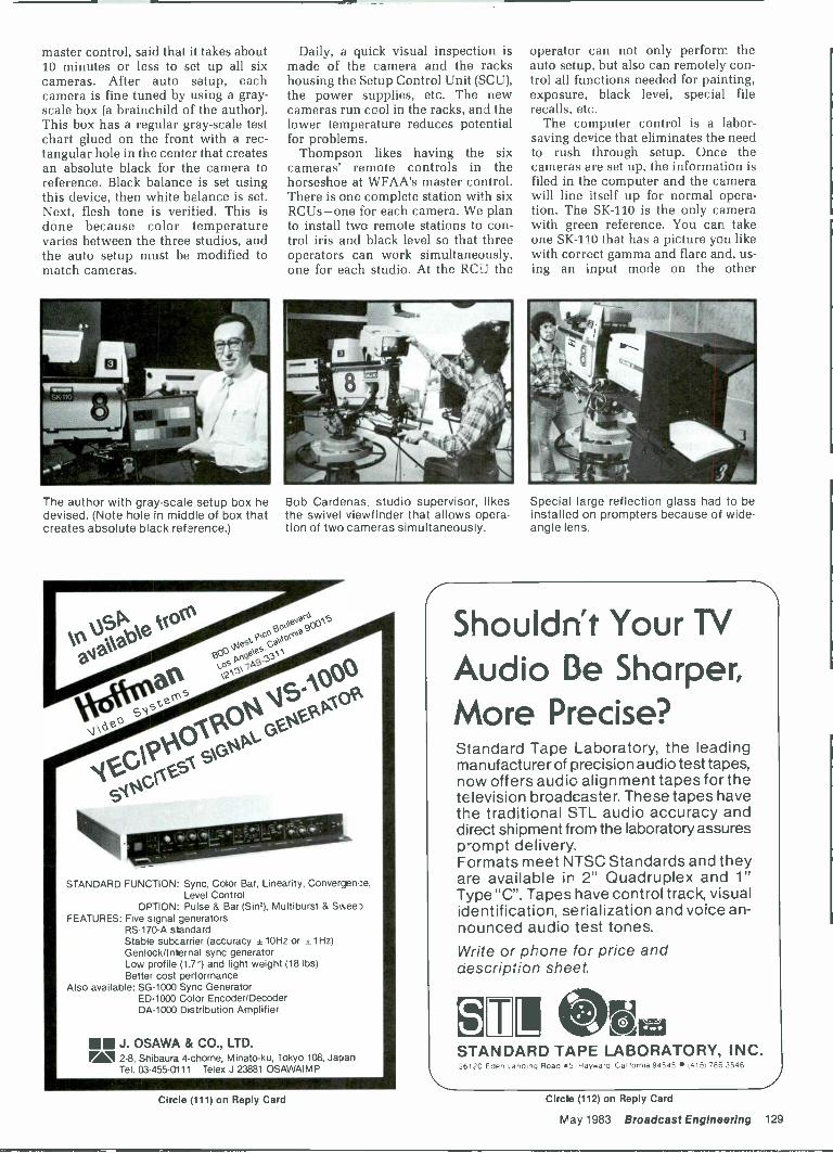
master control, said that it takes about10 minutes or less to set up all sixcameras. After auto setup, eachcamera is fine tuned by using a gray -scale box (a brainchild of the author).This box has a regular gray -scale testchart glued on the front with a rec-tangular hole in the center that createsan absolute black for the camera toreference. Black balance is set usingthis device, then white balance is set.Next, flesh tone is verified. This isdone because color Temperaturevaries between the three studios, andthe auto setup must be modified tomatch cameras.
The author with gray -scale setup box hedevised. (Note hole in middle of box thatcreates absolute black reference.)
Daily, a quick visual inspection ismade of the camera and the rackshousing the Setup Control Unit (SCU),the power supplies, etc. The newcameras run cool in the racks, and thelower temperature reduces potentialfor problems.
Thompson likes having the sixcameras' remote controls in thehorseshoe at WFAA's master control.There is one complete station with sixRCUs -one for each camera. We planto install two remote stations to con-trol iris and black level so that threeoperators can work simultaneously,one for each studio. At the RCU the
Bob Cardenas, studio supervisor, likesthe swivel viewfinder that allows opera-tion of two cameras simultaneous y.
d,
te'z:coo
vosII 0,33
a'\ '3\an
GPOIC4)14 4SA°3143°CN°
S04
904P*.k.
G03iX
STANDARD FUNCTION: Sync, Color Bar, Linearity, Convergen:e,Level Control
OPTION: Pulse & Bar (Sin,), Multiburst & SweepFEATURES: Five signal generators
RS -170-A standardStable subcarrier (accuracy ± 10Hz or ± 1Hz)Genlock/Internal sync generatorLow profile (1.7") and light weight (18 lbs)Better cost performance
Also available: SG -1000 Sync GeneratorED -1000 Color Encoder/DecoderDA -1000 Distribution Amplifier
MIE J. OSAWA & CO., LTD.PM 2-8. Shibaura 4-chome, Minato-ku. Tokyo 108, Japan
Tel. 03-455-C111 Telex J 23881 OSAWAIMP
operator can not only perform theauto setup, but also can remotely con-trol all functions needed for painting,exposure, black level, special filerecalls, etc.
The computer control is a labor-saving device that eliminates the needto rush through setup. Once thecameras are set up, the information isfiled in the computer and the camerawill line itself up for normal opera-tion. The SK -110 is the only camerawith green reference. You can takeone SK -110 that has a picture you likewith correct gamma and flare and, us-ing an input mode on the other
Special large reflection glass had to beinstalled on prompters because of wide-angle lens.
Shouldn't Your TVAudio Be Sharper,More Precise?Standard Tape Laboratory, the leadingmanufacturer of precision audio test tapes,now offers audio alignment tapes for thetelevision broadcaster. These tapes havethe traditional STL audio accuracy anddirect shipment from the laboratory assuresprompt delivery.Formats meet NTSC Standards and theyare available in 2" Quadruplex and 1"Type "C". Tapes have control track, visualidentification, serialization and voice an-nounced audio test tones.Write or phone for price andaescription sheet.
STANDARD TAPE LABORATORY, INC.
Circle (111) on Reply Card Circle (112) on Reply Card
May 1983 Broadcast Engineering 129

cameras, you can set the othercameras to the one you like. That wayeverything, in terms of video, is alike.To our knowledge, no other cameradoes that.
Maintenance and the SCUBeaven Els, maintenance super-
visor, said that the SK -110 makes himfeel like the proverbial Maytag repair-man. He has not gained much experi-ence maintaining the new cameras be-cause there have been virtually noproblems. Consequently, he has beenable to attend to the installation ofother new equipment, such as thesophisticated routing switcher thatthe station purchased.
The maintenance routine involvessitting at the SCU and checking theauto setup of the camera. Themaintenance engineer might makeslight corrections for the lens aberra-tion, adjust the slope of the knee set-ting, the gamma, the enhancement,the subcarrier phase or the horizontalphase. Most of this would be done togive the cameras the look that WFAAlikes. Generally, these changes aresubjective judgments to override theauto setup.
When Els sees a camera in opera-tion that has a perfect look, he willoften print out a hard copy of thecamera's parameters so that if thereever is a problem he can run anotherhard copy to compare against theperfect one. It might give him a clue towhat the problem might be.
Actually, these cameras are sostable that they require little or nomaintenance. We have not even had torun a computer diagnostic check onany of the six. It was the geometry ofthe camera and the diagnostics thatwere two of the main reasons I
wanted the cameras. The cornergeometry from first auto setup isgood, and it is adjustable dynamicallyto tight specs. Concerning thediagnostics, there is no other camera
Master control horseshoe arrangement presently houses one set of six RCUs. WFAAplans to add two more sets on left and right side.
like it on the market. For instance, youcan go to the camera and put a prob-lem in the red preamp, then run thecomputer program and the wordsfault in the red preamp will printout.Other cameras will print out theparameters of the cameras, but theywill not diagnose the problem.
The Hitachi camera control unitsand power supplies are rack -mountedbeside the SCUs that have everythingthe RCUs have, plus file data, com-plete painting and precise control ofmany of the system parameters.
Even though we were impressed bythe easy access to the pull-out boardsin the camera head, we have not hadthe occasion to touch these boards.Any routine adjustments that need tobe made can be done at the SCU.
6 RCUto be installed
MASTERCONTROL
1 2 3 4 5 6
6 RCU
SCU
scu
STUDIO 1
CABLES
CABLES
Figure 1. WFAA-TV camera arrangementand control of the SK -110s.
-4
STUDIO 3
STUDIO2
Long camera support bar with weight at-tached on end opposite prompter had tobe custom-made for cameras usingprompters. Note how operator's handmust leave handle to operate motorizedzoom.
Art Henderson, maintenance technician,shown at the SCU, checks the registra-tion of one SK -110 camera.
130 Broadcast Engineering May 1983

An ExclusiveInvitation
Broadcast Engineering invites you to jointhis high level delegation.
You and a limited number of other select internationalbroadcast executives and equipment manufacturers willhave a rare opportunity to meet with China's top oroad-cast station and equipment manufacturing officials andspecialists. You will participate in one of the most com-plete technical tours of the Chinese broadcast industryever organized. And the first such tour ever offered tothe entire broadcast industry.
Sponsored by BROADCAST ENGINEERING in cooperationwith The Ministry of Broadcasting and Television. t-iis exclusivetechnical tour delegation is open to internationa broadcast stationexecutives, consultants, equipment manufacturers and prominenteducators.Itinerary:Organized with your needs and interests in mind, the itinerary includes vis is to key technical facilities ineach Chinese city visited. Delegates will have the opportunity to tal< frankly with Chinese broadcast facility and plant
operators at the plant and facility sites.
China Broadcast Tour Cities:BeijingShanghai
GuangzhouHong Kong
NEW Date:14 day tour departsDecember 1, 1983
Tour Leader:Cameron Bishop, Publisher, Broad-cast Engineering, IntertecPublishing Corp.
Contact:George H. Roman, Roman Special-ty Tours, P.O. Box 1607, Lafayette,CA, 94549 USA (415) 284-9180
Special Note:The number of tour delegates willbe strictly limited. Persons in-terested in participating should in-quire early.
Some China Broadcast Tour Highlights:Radio Peking Shanghai Radio and TelevisionBroadcast Technical Institute Guangzhou Radio and TelevisionCentral Broadcasting Station Broadcast equipment factories
R&D Foreign Language Dept. Ard more
Mail to:China Broadcast TourRoman Specialty ToursP.O. Sox 1607Lafayette, CA 94549 USAPlease send me without obligation informaton about theCHINA BROADCAST TECHNICAL TOUR:
Name Title
Company Name
Address
City State or Province
Country Postal Code
Tele< TelepioneSponsored Dy BRoaasciEG
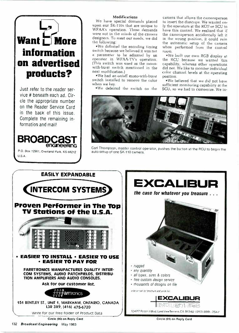
Want Moreinformation
on advertisedproducts?
Just refer to the reader ser-vice # beneath each ad. Cir-cle the appropriate numberon the Reader Service Cardin the back of this issue.Complete the remaining in-formation and mail!
BROaDCaSTenaneeRinG
P.O. Box 12901, Overland Park, KS 66212
U.S.A.
ModificationsWe have special demands placed
upon our SK -110s that are unique toWFAA's operation. These demandswere not in the minds of the cameradesigners. To meet our needs, we didthe following:
*We defeated the encoding timingswitch because we believed it was nota parameter to be adjusted by anoperator in WFAA-TV's operation.(This switch was used as the mono -
with -burst switch mentioned in thenext modification.)
We had an on/off mono -with -burstswitch installed to remove the colorwhen we key.
oWe defeated the switch on the
camera that allows the camerapersonto insert the diascope. We wanted on-ly the operators at the RCU or SCU tohave this control. We realized that ifthe cameraperson accidentally left itin the wrong position, it could ruinthe automatic setup of the camerawhen performed from the controlroom.
We built our own RGB display atthe RCU because we wanted thiscapability, whereas other operationsdid not. We like to monitor individualcolor channel levels at the operatingposition.
*We believed that we did not havesufficient monitoring capability at theSCU, so we had to customize. We in-
Carl Thompson, master control operator, pushes the button at the RCU to begin theauto setup of one SK -110 camera.
EASILY EXPANDABLE
Proven Performer in The TopTV Stations of the U.S.A.
fl
Ahik.riv 111Na31 I
EASIER TO INSTALL EASIER TO USE EASIER TO PAY FOR
FARRTRONICS MANUFACTURES QUALITY INTER-COM SYSTEMS, AUDIO PATCHFIELDS, DISTRIBU-TION AMPLIFIERS AND AUDIO CONSOLES.
Ask for our customer list.
'arrtronics
151 BENTLEY ST., UNIT 1, MARKHAM, ONTARIO, CANADAL3R 3X9, (416) 475-6720
Write for our free folder of Product Data 1
EXCALIBURthe case for whatever you treasure . . .
rugged any quantity
all types, sizes & colorsfree custom design service
thousands of designs on file
write or call for brochure and price list.
IEXCALIBUR
12427 Foothill Blvd.,LakeViewTerrace, CA 91342 .( 213) 899 - 2547
Circle (90) on Reply Card
132 Broadcast Engineering May 1983
Circle (91) on Reply Card
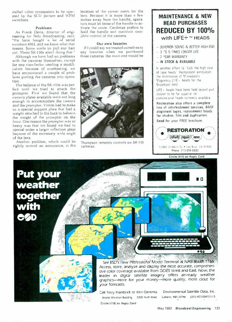
stalled video crosspoints to be oper-ated by the SCU picture and WFMswitchers.
ProblemsAs Frank Davis, director of engi-
neering for Belo Broadcasting, said,"We have bought a lot of serialnumbers #001, and we know what thatmeans. Some made us pull our hairout. These SK -110s aren't doing that."
Although we have had no problemswith the cameras themselves, exceptfor one viewfinder needing a modifi-cation because of overheating, wehave encountered a couple of prob-lems putting the cameras into opera-tion.
The balance of the SK -110s was per-fect until we tried to attach theprompter. First we found that thecamera plates available were not longenough to accommodate the cameraand the prompter. Vinten had to makeus a special support plate that had aweight attached to the back to balancethe weight of the prompter on thefront. One reason the prompter was soheavy was that we found we had tospecial order a larger reflection glassbecause of the extremely wide angleof the lens.
Another problem, which could berightly termed an annoyance, is the
Put yourweathertogetherwithCOD
location of the power zoom for thelens. Because it is more than a fewinches away from the handle, opera-tors must let loose of the handle to ac-tivate the zoom. Cardenas prefers tohold the handle and maintain com-plete control of the camera.
Our own luxuriesIf I could say we treated ourselves to
any luxuries when we purchasedthese cameras, the main one would be
Thompson remotely controls six SK -110cameras.
MAINTENANCE & NEWHEAD PURCHASES
REDUCED BY 100%with LIFE+ im HEADS
- SUPERIOR SOUND & BETTER HIGH END
- 3 TO 5 TIMES LONGER LIFE
- 2 YEAR WARRANTY
- IN STOCK & AVAILABLE
In another effort to "Lick the high costof tape heads" Restoration announcesthe distribution of MinneapolisMagnetics LIFE,- heads for theBroadcast field.
LIFE heads have been field tested and
proven to be far superior toconventional heads currently available.
Restoration also offers a completeline of refurbishment services, BASFalignment tapes, replacement headsfor studios, film and duplicators.Send for your FREE brochure.
IESTORATIOIItty racer
15904 Strathern St Van Nuys. CA 91400Phone: 213 994 6602
Circle (117) on Reply Card
NM I= =II I= NO WM M IMO .....IM MOM all OM NO =I WMall IIIIII INS
WI MI MO le INI =I NOIle I= =MI MP all IMP IIIIII MI NM INII
See ESD's new Professiona Model Terminal at NAB Booth 1766.Access, store, analyze and display the most accurate, comprehen-sive color coverage available from GOES West and East. Now, theleader in digita satellite imagery offers air -ready weathergraphics-more for your money-more quality, more clout foryour forecasts.
:all Terry Hambrick or Ken Geremia. Environmental Satellite Data, Inc.
World Weather Building 5200 Auth Road Suitland, MD 20746 (3011 423-8247/2113
Circle (118) on Reply Card
May 1983 Broadcast Engineering 133
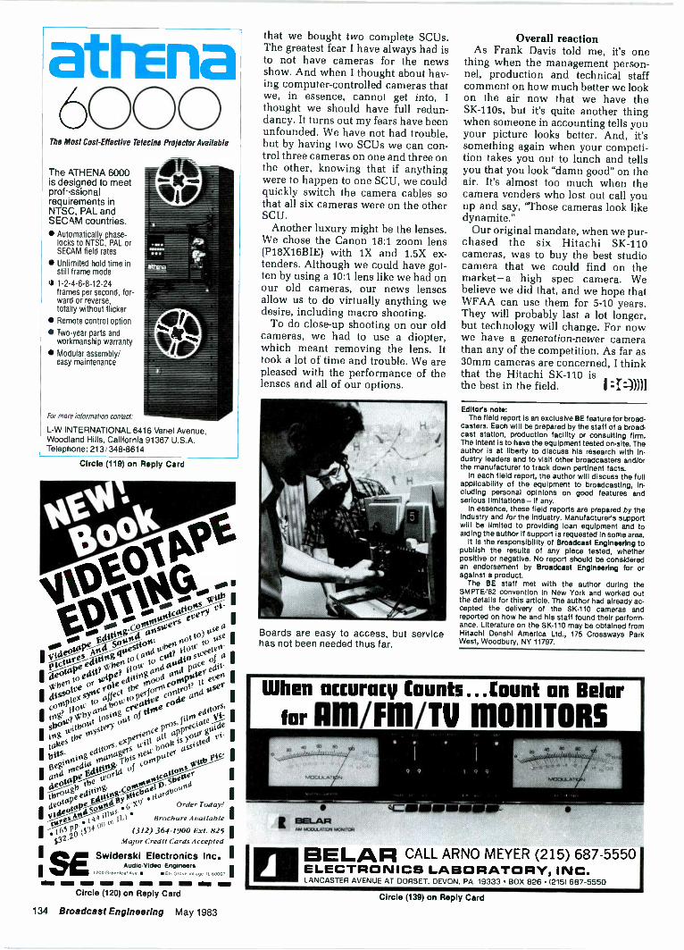
atrEna6000
The Most Cost -Effective Telecine Projector Available
The ATHENA 6000is designed to meetprof,ssionalrequirements inNTSC, PAL andSECAM countries. Automatically phase -
locks to NTSC, PAL orSECAM field rates
Unlimited hold time instill frame mode
5 1-2-4-6-8-12-24frames per second, for-ward or reverse,totally without flicker
Remote control option
Two-year parts andworkmanship warranty
Modular assembly/easy maintenance
For more information contact:
L -W INTERNATIONAL 6416 Variel Avenue,Woodland Hills, California 91367 U.S.A.Telephone: 213/348-8614
Circle (119) on Reply Card
editsIit p War.ape
00, ;tope or or .6 Order Today!
IV", -"te S n.41 )11,4 L ) Brochure Available I
I 165 11:31. ($34 (312) 364-1900 Ext. 825'$32. Major Credit Cards Accepted
SESwiderski Electronics Inc. I
s 00 00 10000.
OS00
0000004100
2
0000p¢EititingConsinuni
1Pictores
MitiSonod
ansiversevecy
eouspeeitttsg,
4t.estioo:
e 4inettto edit?
NI/benlit° (and
Whenoot
to) use(.1
I rlissoWe
ort ou)
to codHow
tOOse
2 coolie%sync
to editingOA
astitiosueeteo
I log?fiott:
to affectOn
04 art4pace
of a
I sbotet41 try
andbow
to perforroconspoter
edit.
nd t
Itvitbout
losingcreative
coo.trol?
It eve"
Ieditors,
e%perieoce
pros,filot.eleitorts:
I
. tahesthe
toystery
out of tonecoae
a
andotecha.roartagers
Willall ap
cisV____
I
eouspeEaitis
. Thisnett,
book,is your
guide
theWorld
of co/Outer
as
its
otont
00 Pic.I
I 109.
acrid
I
I
AudioNideo Engineers200 Greenleaf Ave Elk Grove Velage It 600, '
Circle (120) on Reply Card
134 Broadcast Engineering May 1983
that we bought two complete SCUs.The greatest fear I have always had isto not have cameras for the newsshow. And when I thought about hav-ing computer -controlled cameras thatwe, in essence, cannot get into, Ithought we should have full redun-dancy. It turns out my fears have beenunfounded. We have not had trouble,but by having two SCUs we can con-trol three cameras on one and three onthe other, knowing that if anythingwere to happen to one SCU, we couldquickly switch the camera cables sothat all six cameras were on the otherSCU.
Another luxury might be the lenses.We chose the Canon 18:1 zoom lens(P18X16BIE) with 1X and 1.5X ex-tenders. Although we could have got-ten by using a 10:1 lens like we had onour old cameras, our news lensesallow us to do virtually anything wedesire, including macro shooting.
To do close-up shooting on our oldcameras, we had to use a diopter,which meant removing the lens. Ittook a lot of time and trouble. We arepleased with the performance of thelenses and all of our options.
Boards are easy to access, but servicehas not been needed thus far.
Overall reactionAs Frank Davis told me, it's one
thing when the management person-nel, production and technical staffcomment on how much better we lookon the air now that we have theSK -110s, but it's quite another thingwhen someone in accounting tells youyour picture looks better. And, it'ssomething again when your competi-tion takes you out to lunch and tellsyou that you look "damn good" on theair. It's almost too much when thecamera venders who lost out call youup and say, "Those cameras look likedynamite."
Our original mandate, when we pur-chased the six Hitachi SK -110cameras, was to buy the best studiocamera that we could find on themarket-a high spec camera. Webelieve we did that, and we hope thatWFAA can use them for 5-10 years.They will probably last a lot longer,but technology will change. For nowwe have a generation -newer camerathan any of the competition. As far as30mm cameras are concerned, I thinkthat the Hitachi SK -110 isthe best in the field.
Editors note:The field report is an exclusive BE feature for broad-
casters. Each will be prepared by the staff of a broad-cast station, production facility or consulting firm.The Intent Is to have the equipment tested on -site. Theauthor is at liberty to discuss his research with in-dustry leaders and to visit other broadcasters and/orthe manufacturer to track down pertinent facts.
In each field report, the author will discuss the fullapplicability of the equipment to broadcasting, in-cluding personal opinions on good features andserious limitations-If any.
In essence, these field reports are prepared by theindustry and for the Industry. Manufacturer's supportwill be limited to providing loan equipment and toaiding the author if support is requested in some area.
It Is the responsibility of Broadcast Engineering topublish the results of any piece tested, whetherpositive or negative. No report should be consideredan endorsement by Broadcast Engineering for oragainst a product.
The BE staff met with the author during theSMPTE-'82 convention In New York and worked outthe details for this article. The author had already ac-cepted the delivery of the SK -110 cameras andreported on how he and his staff found their perform-ance. Literature on the SK -110 may be obtained fromHitachi Denshi America Ltd., 175 Crossways ParkWest, Woodbury, NY 11797.
When accuracy Counts...Count on Beierfor Arnim/Tv MONITORS
BO so
,,,:\\.,,,,\:61APotkm
NIOCILA.9 9
I BIELAPIMCOULATION MONITOR
BELAR CALL ARNO MEYER (215) 687-5550ELECTRONICS LABORATORY, INC.LANCASTER AVENUE AT DORSET. DEVON. PA. 19333 BOX 826 (2151 687-5550
Circle (139) on Reply Card
associationsAFBAArmed Forces
Broadcasters AssociationP.O. Box 12013
Arlington, VA 222091-202-696-5268
Broadcasters form AFBABroadcasters and others who have
previously served or are now servingin military radio and television ascivilians or as service members haveformed the Armed Forces Broad-casters Association (AFBA). Sup-porters of military broadcasting andindividuals now in the media are alsoeligible to participate and corporateand associate memberships areavailable.
The AFBA plans to support the pro-fessional growth of present andformer military broadcasters, as wellas provide an opportunity for socialand professional contacts for allmembers. A newsletter, job informa-tion center, seminars and other pro-grams are being planned.
National RadioBroadcasters' Association
1705 De Sales Street, NWWashington, DC 20036
1-202-466-2030
SCA pagingregulations supported
In reply comments filed with theFCC in Docket #82-536 last week,NRBA reiterated its position in sup-port of the FCC proposal that wouldauthorize the use of FM subcarriersfor paging. Replying to many negativecomments that have been submittedby opponents of the FCC proposal,NRBA said that nearly all of the op-position to allowing FM broadcastersto operate paging systems withoutcommon carrier regulations weremotivated by fear of competitionamong presently entrenched radiocommon carriers. NRBA also saidthat "if broadcasters are permitted toenter the paging field, they will be ableto provide paging services to millionsof people, such as those who live inrural areas and in small communities,who presently don't have access tosuch services. In addition, because thecost of providing the paging servicewill be shared with the cost of pro-viding the broadcast signal, the FMlicensee will be able to provide thisservice on a more economical basisthan is presently offered."
NRBA urged the FCC to permit the
SCA use proposed in its Notice ofRulemaking and not to apply commoncarrier regu:ations as some interestshave suggested.
9871 radio stations authorizedAs of Jan 31, 1983, the FCC had
authorized 4848 AM radio stations,3779 FM stations and 1244 FM educa-tional stations (including 279 affiliatedwith National Public Radio). Thegrand total is 9871, an increase of 709stations since July 31 of last year.
Industry employmentfigures released
The 1982 employment profiles forbroadcast stations having five or morefull-time employees, and a state -by -state trend report for the past fiveyears in each class of service, havebeen released by the commission.
Total broadcast employment for sta-tions with five or more employeesrose 3.2% over 1981 figures. Employ-ment in the top four job categories (of-ficials and managers, professionals,technicians and sales workers) rose3.46% since 1981. However, femaleand minority employment in thosejobs was largely unchanged. In 1982,women made up 25.9% of top -fouremployees, while minorities com-prised 12.7%. The comparable figuresfor 1981 were 24.9% and 12.7%,respectively.
National Associationof Broadcasters
1771 N Street, NWWashington, DC 20036
1-202-293-3570
FCC spectrum schemeneeds more evaluation
William L. Stakelin, NAB boardchairman, said recently he wasshocked by the FCC's staff refusal togrant an extension of time for filingcomments on its new microwavespectrum allocation plan, whichStakelin said would have a"devastating impact" on TV broad-casters' ability to serve the public. Hisremarks followed a discussion duringan NAB executive committee meetingof FCC Docket #82-334, which wouldrequire TV broadcasters to share theirauxiliary broadcast service spectrumwith displaced occupants of the12GHz band, which has beenallocated for DBS service. Numerousparties, including the NAB, had re-quested an extension of time to filecommen:s on the proposal, but theFCC rejected their re-quests. :I:-)))))
BROADCASTBEST BUY!
\WM. . . from
audiotechniques
FOR SERVICE & PRICEWE'RE THE BEST!
audiotechniques inc.NEW YORK CITY212/586-5989STAMFORD, CT203/359-2312
Circle (122) on Reply Card
REEL TO REEL TAPEAmpex, 3M. All grades.On reels or hubs.
CASSETTES, C -10-C-90With Agfa, TDK tape.
LEADER & SPLICING TAPEEMPTY REELS & BOXES
All widths, sizes.
Competitive!Shipped from Stock!
Ask for our recording supplies catalog.
Polyig,==-ECorp. 312/298-53001233 Rand Rd. Des Plaines, IL 60016
15
Circle (123) on Reply Card
May 1983 Broadcast Engineering 135
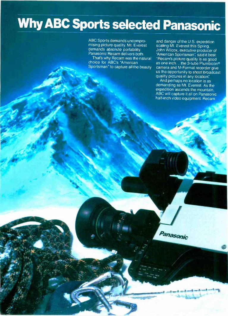
Why ABC Sports selected PanasonicABC Sports demands uncompro-mising picture quality. Mt. Everestdemands absolute portability.Panasonic Recam delivers both
That's why Recam was the naturalchoice for ABC's "AmericanSportsman" to capture all the beauty
and danger of the U.S.expeditionscaling Mt. Everest this Spring.John Wilcox, executive producer ofAmerican Sportsman'', said it best:'Recam's picture quality is as goodas one inch the 3 -tube Plumbicon'camera and M -Format recorder giveus the opportunity to shoot broadcastquality pictures in any location
And perhaps no location is asdemanding as Mt. Everest. As theexpedition ascends the mountain,ABC will capture it all on Panasonichalf -inch video equipment. Recam
recorder/cameras wil trarsmitpictures via microwave to a basestation specially outf tted with twoPanasonic AU -300 source decks,an AU -A70 editing control er,an AS -6100 switcher and anotherAU -300 for mastering. These high -quality Recam pictures wi I then be
beamed via satellite to the U.S.But this is just the beginning.
Recam's pictu-e quality and port-ability will be used by ABC Sportsfor future remote locationswhenever the going gets rough.
Look into Recam for yourself andsee why it's becoming the choice ofdemanding professionals whatevertheir EFP needs.
Panasonic.AUDIO -VIDEO SYSTEMS DIVISION
Circle (124) on Reply Card
24 -HR.PROFESSIONAL
SERVICE FORCOLLINS &
CONTINENTALAM & FM
TRANSMITTERSContinental Electronics offersparts and engineering servicefor all Collins AM & FMtransmitters.
Whenever you want parts orservice for your Collins orContinental equipment, phoneour service numbers day or night,
(214) 327.4532 parts(214) 327.4533 serviceContinental Electronics Mfg. Co.Box 270879, Dallas, Texas 75227Phone (214) 381-71611 kW thru 50 kW AM & FM transmitters andrelated equipment.
'A New Strength in Radio Broadcasting Equipment"
Circle (125) on Reply Card
Having TroubleErasing 1 InchTape? 4:00.
Priced at $129.5.00
Try the
TABERASER 409Thoroughly erases all audio, video.instrumentation tapes and magneticfilms.
Send for free brochure.
TABERManufacturing & Engineering Co.
(415)635-38312081 Edison Ave. San Leandro, CA 94577
FCC updateContinued from page 6
long-awaited lottery rules on March31. Also on the agenda for that daywas a reconsideration order refiningthe basic LPTV rules adopted inMarch 1982.
Under the lottery system, applicantswill be given preference points de-pending on their minority status andextent of other media interests. Afterthe commission has identified a groupof mutually exclusive applications andhas completed the process of assign-ing lottery preference points, a com-puter will decide the winner of theconstruction permit. The first suchlotteries are expected to take placelate this year.
Major issues scheduled to be de-cided in the LPTV reconsiderationorder were as follows: reservation offrequencies for LPTV applicants pro-posing non-commercial, educationalservice; revision of operator require-ments; and a redefinition of "major"change to permit the filing of amend-ments and modification applicationsthat do not propose coverage of newterritory.
Once the new rules are in place, thecommission will be in a position tobegin processing its 8000 LPTV ap-plications. The computer that thecommission needed for this purposehas been delivered and the programsto be used in processing are nearlycompleted. If the entire computersystem tests out, the commission willbegin issuing "B" cut-off lists next fall.These lists will identify groups ofmutually exclusive applications and,if current plans are implemented, willreport the assignment of lotterypreference points. Applicants whoseproposals are placed on the lists willbe given an opportunity to alter theirproposals.
In identifying groups of mutuallyexclusive applications, the commis-sion's system will compute HAATthrough the use of a terrain databaseobtained from the US GeologicalSurvey. Coupled with the technical in-formation included in FCC Form 346,this will permit interference studies tobe made entirely by computer. Forthis reason, it is essential for ap-plicants to provide the FCC with ac-curate and complete data on theirantenna systems, including polardiagrams for directional proposals.Existing stations have been urged tofile such information to ensure thatthey will receive the interference pro-tection afforded by the rules.
If the computer system works well,and the Court of Appeals denies ex-pected requests for stays of the lotteryrules, meaningful progress in reduc-ing the LPTV application backlog
should be made by thistime in 1984. I :I: -N11
Satellite updateContinued from page 14
Network radioThe first major satellite radio net-
work, National Public Radio, has beenbroadcasting via satellite to hundredsof affiliates for the past five years inconjunction with the Public Broad-casting System's TV network. NowABC, CBS, NBC and RKO are commit-ting their national radio networks tosatellite distribution via dedicatedtransponders, using a digital time divi-sion multiplex (TDM) technique. Thistechnique provides 19 radio channels(15kHz each) in a transponder andgives the networks what they believeis the best combination of channelquality, flexibility, network controlfeatures and cost per channel for thetype of distribution systems involved.
These major networks distributeprogramming from New York to theiraffiliate broadcasters all over thecountry. The affiliates will have theability to select any number of chan-nels simultaneously, with a singledigital decoder. Because a total of ap-proximately 3000 local broadcasterswill have receiving earth terminalsbefore the end of 1984, it is obviouswhy the TDM multiplexing techniquewas used for this type of distributionnetwork.
Other types of broadcasting net-works have different requirements.For example, regional or state net-works generally require programfeeds from participating affiliates,making necessary a network designwith low cost earth terminals fortransmitting as well as receiving. Forthis type of network, a satellitetransponder is best used in a frequen-cy division multiplex (FDM) mode,with a single channel per carrier(SCPC) technique. SCPC has beenused since the mid -1970s for satellitetelephony networks in remote regionsor underdeveloped countries. Theeconomics required for radio net-works, however, did not make thetechnique attractive until recentlywhen lower cost hardware hasbecome available. The development ofreceivers that can work at much lowersignal levels has made it possible toreduce the transmit levels required bythe same amount, allowing the use ofsolid-state transmitting hardware andreducing the cost of a transmit stationfrom $500,000 to $80,000. Thisdramatic cost reduction makes itpossible for many more regional (andnational) networks to be realized,opening up a whole newera in radio broadcasting. :r:)))11Circle (126) on Reply Card
138 Broadcast Engineering May 1983
FeedbackContinued from page 16
manufacturers? Conversely mostmedium and small market stations areforced to purchase equipment just tomake tests!
What about the interfacing of audioprocessing equipment with thevarious AM stereo exciters? Are thereunique problems indigenous to eachsystem? I have heard that the use ofpre -emphasis with AM stereo can be aproblem.
As a consulting engineer, I am quiteconcerned about the effects of direc-tional antenna systems on the stereosignal when transmitted. Little, if any,meaningful data has been publishedon this topic.
If the marketplace is to make a pru-dent decision as to which AM stereosystem to adopt as a standard, shouldnot the relative merits of each systembe dealt with extensively?
I believe that it is time for the tradepublications of this industry to makean effort to publish articles by reliable,competent sources regarding AMstereo test data during actual opera-tion in the field.
James S. StanleyHesperia, CA
HEAD RE -LAPPINGAND NEW HEADS FOR AMPEXWorn cartridge and reel to reel heads re -contoured and re -lapped for original perfor-mance. Send for free brochure.
R.K. Morrison Co.819 Coventry Road Kensington, CA 94707
(415) 525-9409
Circle (138) on Reply Card
To continue receivingyour free subscription,
Please fill out yourreverification card
in this issue.
BROa1:2
SM PT E -'82 updateOur coverage of the fall SMPTE-'82
convention held in New York lastNovember is contained in our January1983 issue, pages 92-110. A couple ofexhibitors who shared booths withmain exhibitors were inadvertentlymissed in this coverage. The followingnotes are an update to correct theseomissions:
Film/Video Equipment ServiceCompany of Denver, CO, shared abooth with Cinema Products. The com-pany exhibited the Wide Eye I and IIwide-angle lens attachments forENG/EFP video zoom lenses; sealedlead -acid battery packs and chargersfor camera power sources that theymarket for Portable Energy Products;and their capabilities to provide serviceon lenses far TV and film cameras/ -equipment.
Product literature from Film/Videomay be obtained by circling (481) onour Reader Service Card.
Artel Cammunicaitons was missedin the fiber -optics story on pp. 126-127.They were at the show in a corner ofthe Camera Mart booth. Details of theArtel fiber -optics line may be obtainedby circling (482) on our Reader ServiceCard.
BE staff
:I:))))1
UNIVERSALSURGE PROTECTOR
FOR ALL LINE VOLTAGES!
Never obsolete! Unique re-settable strapping protectson all power systems-even3-phase-if you shouldchange line voltage. "On" allthe time, to protect con-stantly. Immediate shipment.Quantity discounts. Moneyback guarantee. Order today.
CALL BILL JOHNSON215/544-8879
EAGLE HILL ELECTRONICS, INC.41 Linden Avenue Rutledge. PA 19070
Circle (113) on Reply Card
SIro Mono Ow, AA, 171.17.
FREE 32pg :a :alog 8 50Video47:01.111:..
T
c.ANS. ACM,
41141.111 8 -in 2 -out. 12-m 4-ou1, 113 -in 4 -out
Vitloo Atmllo C at t mole TV Audio& Recd Prod ConoleOPAMP LXIII3 INC (213) 934-35681033 N Syc more Av LOS ANGELES :A, 90038
Circle (114) on Reply Card
SENINHIEISERMK H416T U/P48UMK H8167U/P48U 729.-HMD224 139.-
MD421U......5208.-MD441U 289.-HD414 50.-
1-800-431-3232.MICROPHONICS P 0 Boo 37 Brooklyn. NY 11204
(212)438-6400
Cicla (115) on Reply Card
(Need a new tower?)
CASH FORYOUR TOWER-/ Sale leaseback
arrangement Professional
managementand maintenanceRelief from liabilityRelief from towermaintenance
Repurchase option Low monthly
lease payments Free up cash from
your fixed asset New construction or
existing tower
CALL US TODAY
(817) 261.5353Ask for
Jim liner, President,liner Associates, Inc.
24 Hour Phone
N
TINER COMMUNICATIONSERVICES, INC.
A complete tower service system616 Six Flags Drive, Suite '36
Arlington, Texas 76011
Circle (127) on Reply Card
Goodthingshave been happeningat Singer Broadcast
Designimprovements
Higher qualitycomponents
A new FM exciterFor more information contact us.
SINGER BROADCASTPRODUCTS, INC.P.O. BOX 5500CHERRY HILL. NEW JERSEY 08034TEL: 609-424-1500
Circle (137) on Reply Card
May 1983 Broadcast Engineering 139
newproducts
TEC feature addedSince Jan. 1, 1983, all Forte] Y-68832 total error correc-
tors have included DYNA-TRAC. The new feature allowsthe equipment to operate with Sony BVU-820 slow-motion U-Matic systems for full reverse play speed to 3Xforward capabilities. A field modification for previousproduction models of the Y-68832 is available.
Circle (530) on Reply Card
Greater delay timesThe Eventide Clockworks 1745M digital delay line is
now available with delay lengths eight times longer thanoriginal models. Delays of 2.5s (or 5s in the double mode)are possible. Retrofits for previous 1745M models areavailable.
Circle (531) on Reply Card
Phono preampA 3 -year warranty backs the Ramko Research PRIMUS
series laboratory -standard turntable preamplifiers. THDat 0.0018% maximum, unmeasurable IM distortion and a- 93dB A weighted hum and noise rating are claimed.Maximum output is + 26dBm.
Circle (532) on Reply Card
Tension gaugeThe CB series of tape tension gauges from Tentel are
designed for use with 1 -inch C Format machines, such asthe Sony BVH 2000 and Ampex VPR 2. The product usesminiaturized ball -bearing rollers on the three measuringprobes.
Circle (533) on Reply Card
Video projectorAQUARAY color video projectors include micropro-
cessor circuitry to maintain monitor alignment andanalyze circuit operations. Produced by ElectronicSystems Products, the projectors produce 4001m peakwhite output on curved or flat screens, 4-20 feet wide.The AQUARAY is portable.
Circle (534) on Reply Card
Shipping casesFrom three to 10 3/4 -inch or 1/2 -inch videocassettes, with
or without storage boxes, may be contained in Plastic ReelCorporation of America's new shipping containers. Plio-Magic positive locking of the polyethylene polymer caseensures safe shipping. Carrying handle and address cardholder are featured.
Circle (535) on Reply Card
CRT cleanerComplementing its line of recording heads and
recorder maintenance products, Nortronics offers theCMP-160 antistatic CRT screen cleaner. The non -corro-sive spray is usable on metals, plastics, painted surfacesand elastomers.
Circle (538) on Reply Card
Tape evaluatorThe Elcon 254, marketed by Television Equipment
Associates, accommodates 1 -inch tape exclusively. Animproved display of tape conditions includes three linearLED units representing "top edge," "video" and "bottomedge." A printout of the evaluation is produced. Tape iscleaned during evaluation.
Circle (537) on Reply Card
Cable bundling deviceNew from Dennison Mfg. Company is the Flip -Clip
fastener. Molded from type 6/6 nylon, the devices areavailable in various colors. No tools are required for in-stallation. Reuse and removal are possible. Bundlediameters to 1/2 -inch are fastened with a simple twist.
Circle (538) on Reply Card
Digitizing cameraDirect camera to disc storage of high resolution digital
images is possible with the Datacopy 322D solid-statecamera. A selectable data rate is possible. A motor -drivenCCD array captures images to a resolution of 1720x2592.
Circle (539) on Reply Card
Improved softwareCMX/Orrox has announced improved software for THE
EDGE editing controller system. Faster match framing,simpler list manipulation and easier A/B roll editing arethe result.
Circle (540) on Reply Card
ENG cablingCustom-built cable assemblies for any combination of
ENG camera and VTR have been termed "gorilla -proof."The Connector Systems (BIW) cables include a highly flex-ible stainless steel armor covered by a rubber jacket. Con-nectors are molded directly to the armor.
Circle (417) on Reply Card
Remote control
-MODEL MI. - ,soo 19.101. =WI./ Ir., 6
NMI
!
Raise and lower commands with LED status indicatorsand analog telemetry return for 16 channels are availablein the Moseley Associates MRC-1600. This microproces-sor -designed remote control system includes digitallydisplayed data for increased accuracy of meter readings.
Circle (418) on Reply Card
Uplink terminalA 90% efficient switching cathode power supply is in-
cluded in the MCL model 10717 3kW C -Band TWTAuplink terminal. The single cabinet system provides2.8kW of flat usable power in the 5.925-6.425GHz spec-trum. A Thomson-CSF 3640 TWT tube is used.
Circle (541) on Reply Card
Turntable systemGotham Audio Corporation, which represents the EMT -
Franz organization in the United States, has introducedthe EMT938 turntable system. Including the turntable,tonearm and built-in equalizer amplifiers, the system pro-vides a nominal + 4dB into 200D. Direct drive and threespeeds (331/3 rpm, 45 rpm and 78 rpm) accompany a 0.5sstart time.
Circle (542) on Reply Card I :r:-)))11
140 Broadcast Engineering May 1983
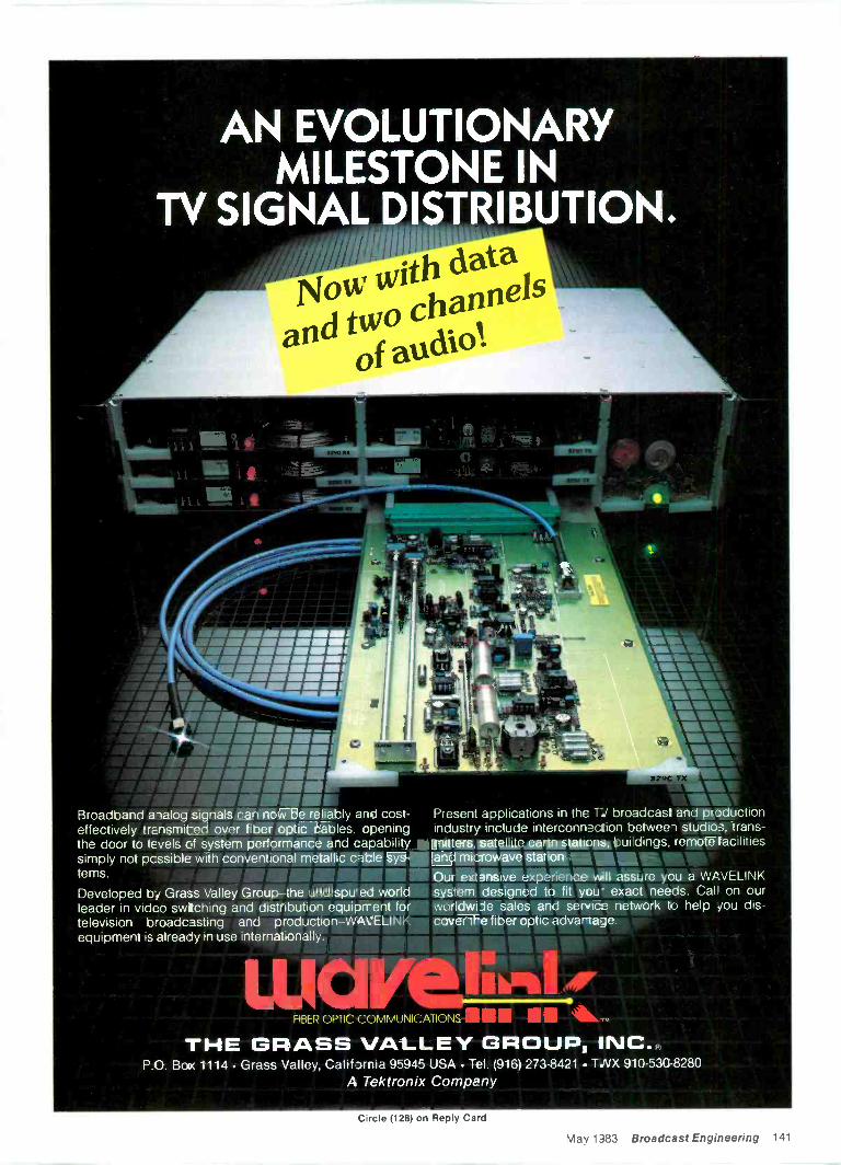
AN EVOLUTIONARYMILESTONE IN
TV SIGNAL DISTRIBUTION.
AV MA'I/IfMIMI/
Broadband analog signals can now be reliably and cost-effectively transmitted over fiber optic cables, openingthe door to levels of system performance and capabilitysimply not pcssible with conventional metallic cable sys-tems.
Developed bj Grass Valley Group -the undispu ed worldleader in video swiching and distribution equipment fortelevision broadcasting and production WAVELINKequipment is already in use internationally.
VI LWUMW.WMAK.MIMI"
11\111311111111111111
vviliogarrPresent applications in the TV broadcast and productionindustry include interconnection between studios, trans-mitters, satellite earth stalpikOuidings, remote facilitiesand microwave stations. imumniami.Our extensive experience'will assure you a WAVELINKsystem designed to fit you exact needs. Cal! on ourworldwide sales and servic network to help you dis-cover the fiber optic advartage
wavFIBER OPTIC COMMUNICATIONS U
THE GRASS VALLEY GROUP, INC.P O. Boa 1114 Grass Valley, California 95945 USA Tel. (916) 273-8421 TNX 910-53C-8280
A Tektronix Company
Circle (128) on Reply Card
May 1383 Broadcast Engineering 141
Oh God!
You're sitting there - working hardwhen someone yells that the audio has gone!Of course you turned the sound off on 20monitors - if you hadn't, you couldn't hearyourself think. Then comes that phone call,someone yelling or an irate superior,"You've lost the !x*!xl.! sound!"
"Oh God!" - you think to yourself. Wehave $100,000 worth of equipment and I can'ttell if we lost the audio! It happens to all of usat one time or another, but why hasn'tsomeone come up with a simple, inexpensivedevice to help all of us.
Well, thank goodness! Video Aids ofColorado has! It took our engineers 261/2minutes to design, develop and test a productthat may just save you a lot of problems,hassles and ugly words. It is designed so ifthere should be any loss of volume (and youcan set the sensitivity) it will set off an alarmbell and/or a light, as well as cause yourdigital clock to flash. Thus you have apermanent record (as required by the FCC) asto any interruptions.
Where else could you use an AUDIO ALARM?
Control room to/from... Relays ...Cameras to van ...Remote units to ...Helicopters to ...Transmitters to...
Video to control . . .
Security ...# of monitors...Other...
Just think of what one minute off theair will cost you! Now you will be the first toknow of an audio problem (not get it 2nd, 3rdor 4th hand). The Audio Alarm is very easy toinstall, as it comes in a complete, ready toplug-in unit.
Call your video dealer NOW! If you can'tremember your dealer's phone number, callus immediately and we will be glad to directyou to one of our stocking dealers.
VIDEO AIDS OF COLORADO(303) 443-4950
(800) 821-0426P.S. Yes, we have Video Alarms too!
Ask us about them!Circle (129) on Reply Card
businessSony Betacam flys high
A recent episode of NBC' Fantasy series used tapedsegments produced by two Sony Betacam units, whichwere suspended from a hang glider used in the dreams -to -reality program.
Harris Digifont adds capability to Iris IIHarris Video Systems has announced that the Digifont
character generator is now available for the HarrisDigigraphix graphics equipment for use with its IRIS IIdigital still -store units. Chyron Corporation engineeredthe font generator.
Dubner CBG 2 provides animationA Dubner Computer Systems CBG 2 graphics generator
is in operation at WRAL-TV, Raleigh, NC, providinganimated weather displays. The CBG 2 system has alsobeen used for graphics and screen animation in the NBCKnightrider series.
WCIU broadcasts Italian programsStation WCIU-TV 26, Chicago, and its affiliate in
Telex Communications has announced the acquisi-tion of the Singer Audio Visual Division of SingerCompany of Canada Ltd. in Scarborough, Ontario.The company name was changed to Telex Com-munications Ltd.
Orrox Corporation has announced that its Satcomsubsidiary has suspended manufacturing of DBSsystems following a reduction of perceived oppor-tunities in the DBS industry brought about by intenseprice competition from Japan and the lack ofavailable external funding for Satcom's operations.
The West Coast sales office of Gotham Audio Cor-poration and its subsidiary Gotham Export Corpora-tion has been relocated on the premises of QuantumAudio Labs, a company recently acquired byGotham. The new address is 1909 Riverside Drive,Glendale, CA 91201; 1-213-841-1111.
Quad/Eight Electronics has announced thatKenneth C. Davis, Jr. has acquired the company. BudBennett, who founded Quad/Eight in 1962, will re-main with the company as chairman of the boardand Davis will assume the duties of president.
AF Associates has delivered a 45' x 8' mobile unit tothe NBC-TV Network for its major sporting events.
Crawford Communications has purchased Ampexaudio and video equipment valued at $1.2 million forinstallation in its new post -production facility inAtlanta.
Satellite Television Corporation (STC) has signed atime and materials contract, estimated at $250,000,with the Communications Systems Division of RCACorporation to provide design work for the integra-tion of equipment for STC's Broadcast Center to bebuilt near Las Vegas, NV.
142 Broadcast Engineering May 1983
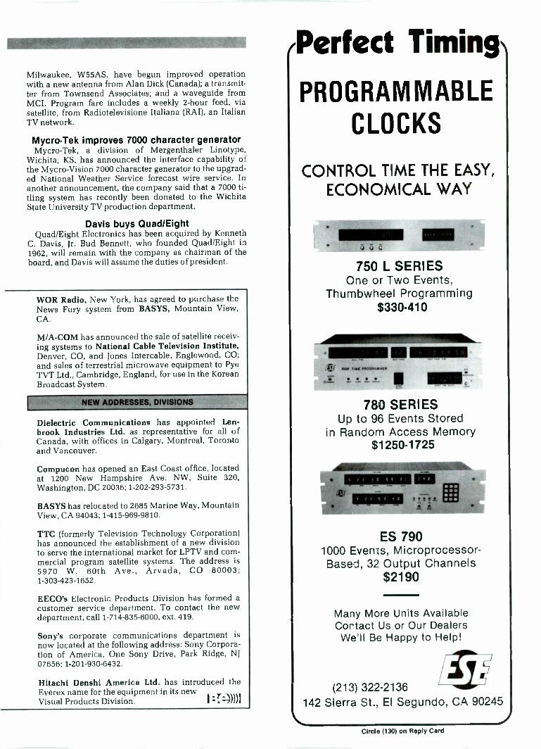
Milwaukee, W55AS, have begun improved operationwith a new antenna from Alan Dick (Canada); a transmit-ter from Townsend Associates; and a waveguide fromMCI. Program fare includes a weekly 2 -hour feed, viasatellite, from. Radiotelevisione Italiana (RAI), an ItalianTV network.
Mycro-Tek improves 7000 character generatorMycro-Tek, a division of Mergenthaler Linotype,
Wichita, KS, has announced the interface capability ofthe Mycro-Vision 7000 character generator to the upgrad-ed National Weather Service forecast wire service. Inanother announcement, the company said that a 7000 ti-tling system has recently been donated to the WichitaState University TV production department.
Davis buys Quad/EightQuad/Eight Electronics has been acquired by Kenneth
C. Davis, Jr. Bud Bennett, who founded Quad/Eight in1962, will remain with the company as chairman of theboard, and Davis will assume the duties of president.
WOR Radio, New York, has agreed to purchase theNews Fury system from BASYS, Mountain View,CA.
M/A-COM has announced the sale of satellite receiv-ing systems to National Cable Television Institute,Denver, CO, and Jones Intercable, Englewood, CO;and sales of terrestrial microwave equipment to PyeTVT Ltd., Cambridge, England, for use in the KoreanBroadcast System.
Dielectric Communications has appointed Len -brook Industries Ltd. as representative for all ofCanada, with offices in Calgary, Montreal, Torontoand Vancouver.
Compucon has opened an East Coast office, locatedat 1200 New Hampshire Ave. NW, Suite 320,Washington, DC 20036; 1-202-293-5731.
BASYS has relocated to 2685 Marine Way, MountainView, CA 94043; 1-415-969-9810.
TTC (formerly Television Technology Corporation)has announced the establishment of a new divisionto serve the international market for LPTV and com-mercial program satellite systems. The address is5970 W. 60th Ave., Arvada, CO 80003;1-303-423-1652.
EECO's Electronic Products Division has formed acustomer service department. To contact the newdepartment, call 1-714-835-6000, ext. 419.
Sony's corporate communications department isnow located at the following address: Sony Corpora-tion of America, One Sony Drive, Park Ridge, NJ07656; 1-201-930-6432.
Hitachi Denshi America Ltd. has introduced theEverex name for the equipment in its newVisual Products Division.
/Perfect Timing
PROGRAMMABLECLOCKS
CONTROL TIME THE EASY,ECONOMICAL WAY
750 L SERIESOne or Two Events,
Thumbwheel Programming$330-410
1101111 P00011.40WER
.17
780 SERIESUp to 96 Events Stored
in Random Access Memory$1250.1725
41111111111111111111-
e t 3 5 8 S 9
r3 S9 q8
4111111111MID-
IN
ES 7901000 Events, Microprocessor -Based, 32 Output Channels
$2190
Many More Units AvailableContact Us or Our DealersWe'll Be Happy to Help!
(213) 322-2136142 Sierra St., El Segundo, CA 90245
Circle (130) on Reply Card
newsuInternational Wholesalers
INDUSTRIAL &PROFESSIONAL
VIDEO PRICELIST
%" Color MonitorSONY VP 5000 $1390 SONY CVM 1250 $602SONY VO 5600 $1690 SONY CVM 1900 $870SONY VO 5800 S3270 SONY PVM 8000 S600SONY VO 5850 $5295 NEC 12" COLOR MONITOR ....5299SONY VO 4800 $2410 NEC 25" COLOR MONITOR . . . S699JVC CP 5550 S2200 PANASONIC CT 110MA $360JVC CR 6650 S2900 PANASONIC CT 1350MG $490JVC CR 8250 $4470 PANASONIC BTS 1300N S515NC CR 4700 $3100 PANASONIC BTS 1900N S620PANASONIC NV 9100 $1060 PANASONIC CT 1920M $499PANASONIC NV 9240 S3100 PANASONIC CT 2000 $760PANASONIC NV 9600 $4990 PANASONIC CT 10,000M $5400PANASONIC NV 9400 S2100 PANASONIC WV 5203B $600PANASONIC AU 700 $6000 NC TM 22U $320
Special EffectsJVC AV 2000 $599
Generator CamerasSONY SEG 2000 S3600 SONY DXC-11100K $2350PANASONIC WJ 4600 S1650 SONY DXC-6000L $9100PANASONIC WJ 5500 S3000 JVC KYI900 CHLIO $4300PANASONIC AS 6100 S5900 PANASONIC VVV3060 $590JVC KM 2000 $4100 PANASONIC WV3070 $720ROSS POINT LATCH 6112 ....56360 PANASONIC WV3400 S920SCITECHH-1 $1400 PANASONIC WV3400 6X S920
PANASONIC WV3400 6AF $1000Y5" Industrial PANASONIC WV3400 12X
PANASONIC WV3890 BS1050S1750
SONY SLO 383 S2000 PANASONIC %W3990 II $2350PANASONIC NV 8350 $950 PANASONIC WV777 0490PANASONIC NV 8950 $1420 HITACHI FP 10 UC S2900PANASONIC NV 8500 $2500 HITACHI FP 21 57000NC eR 6400 $1300 IKEGAMI ITC 730 $6000JVC BR 6200 $939
1.1-matic Tape LightingSMITH VICTOR K74 5675
KCS 10 $11.99 SMITH VICTOR K76 $900KCS 20 S14.20KCA 30 .KCA 60KCS 10 BR
$15.19$21.19$13.25
Automatic EditingControl
KCS 20 BR S15.39 SONY RM 440 $1300KCA 30 BR $16.99 JVC RM 88 $2500KCA 60 BR $23.65 NC VE 90 $4100
Tripods -Heads -Dollies PANASONIC NVA 500PANASONIC NVA 970
S1125S2900
BOGEN 3069 S375 PANASONIC AUA 70 S5900
1-800-327.0596International Wholesalers
17866 Ipco Road, N. Miami, FL 33162 (305) 940-7542Send $5.00 for our complete industrial catalog.
We carry the complete line of SONY, JVC, PANASONIC, HITACHI, NEC. IKEGAMI,CROSS POINT LATCH, SMITH VICTOR, SENNHEISER, SHURE, QUICKSET, ITE, BOGEN, &LOWEL. Phone or write us for the lowest prices anywhere! We gladly honorAmerican Express. Visa, and MasterCard by phone or mail.
First US multi -trackdigital recorder sale
Anyone who has heard digital audio compared to evenpresent analog audio technologies is impressed. For thosewho are not able to hear the difference, perhaps somenumbers would be equally impressive.
Dynamic range: > 90dBFrequency response-flat: 20Hz-20kHzHarmonic distortion: <0.05%Wow/Flutter: inmeasurableThese specification values did impress John Moran of
Digital Services, a Houston equipment rental firm.However, several other characteristics of the SonyPCM-3324 professional multi -track digital audio recorderalso played a part in culminating the first sale of the Sonysystem outside Japan to the Texas organization. Moransaid that he is convinced that the PCM-3324 representsthe first standardized digital machine, and that othermanufacturers will follow the Sony lead with the formatto maintain compatibility.
The 24 -channel audio recorder includes separate timecode and internal control tracks. Using 1/2 -inch tapematerials, the system also records two analog tracks,designed as part of a system that adds a provision forrazor blade editing capabilities to the sound technicians.
'Digital TV signals transmittedbetween BBC studio centers on optical fiberDigital TV signals of the recently approved CCIR stan-
dard were successfully transmitted by optical fiber linkbetween two TV studio centers in December 1982. Theexperimental transmission used equipment developedand built by the BBC Research Department at KingswoodWarren.
The optical fiber cable, containing eight graded -indexmultimode fibers, was installed by British Telecom in theexisting ducts between the BBC studios at Lime Groveand Television Centre, a path length of about 800 meters.The signals were carried on a single fiber, the basic bitrate of 216Mbit/s being increased to 270Mbit/s by channelcoding. A direct modulated 820nm laser transmitter wasused, the power launched into the fiber being 600µW.
As the TV signal was in separate component form,original RGB quality was obtained at the receiving ter-minal. Avoiding intermediate PAL coding will allowremote downstream processing (for example, colorseparation overlay and special effects), to be done with aprecision that has up to now been achieved only at thesource itself.
Editoes note:For more information, see "Optical Fibers For Digital Studio Interconnections,"BE March 1983, page 300.
Alexanderson inducted intoInventors Hall of Fame
Dr. Ernst F. W. Alexanderson, the late General ElectricCompany engineer whose high frequency alternator gavethe United States its start in the field of radio communica-tion, was inducted recently into the National InventorsHall of Fame in Arlington, VA.
A native of Sweden, Alexanderson worked at GE'sengineering laboratories in Schenectady, NY, from1901-1948. His inventive genius made it possible totransmit the human voice for many thousands of miles,linking country to country and continent tocontinent. He died in 1975. I :::))))I
Circle (131) on Reply Card144 Broadcast Engineering May 1983
calendarMay 21
"Production Lighting Techniques" is the subject of anall -day seminar organized by the Hollywood Section ofthe SMPTE. It will be held at Universal Studios, Stages 43and 44.
Some of Hollywood's directors of photography willdemonstrate and discuss typical, full-scale lighting situa-tions for film and television, as well as possible solutionsto some of the problems inherent in lighting certain in-terior and exterior sequences. Ample time has been setaside for questions and discussion. For further detailsand seminar registration forms, contact: Jack Spring,Eastman Kodak Company, 6706 Santa Monica Blvd.,Hollywood, CA 90038; 1-213-464-6131. You may also con-tact Howard La Zare, Consolidated Film Industries, 959N. Seward St., Hollywood, CA 90038; 1-213-462-3161.
May 25-26, July 19-20Two-day workshops for those involved with video -tele-
conferencing will be held in May in Washington, DC, andin July in San Francisco. The workshops feature an over-view of the video -teleconferencing field, from basic defi-nitions to the latest technological developments. Forregistration information, contact: PSSC, 1660 L Street,NW, #907, Washington, DC 20036.
May 28 -June 2The 13th International TV Symposium will be held
in Montreux, Switzerland. A technical exhibition isplanned. Keynote addresses will focus on HDTV.Wireless TV broadcasting, cable TV broadcasting,digitization of video signals and home terminals will beincluded as session topics. A roundtable discussionamong invited speakers, other experts and symposiumparticipants will also be featured. For more information,contact the International TV Symposium and Exhibition,P.O. Box 122, CH -1820, Montreux, Switzerland.
June 1-3The 1983 IEEE MIT -S International Microwave Sym-
posium will be held at the Sheraton Boston Hotel. Papertopics include the following: solid-state devices and cir-cuits, filters and multiplexers, passive components,microwave systems and high power techniques. Forregistration information, contact Frank Leith, Alpha In-dustries, 20 Sylvan Road, Woburn, MA 01801.
June 19-22The 19th Annual International Conference on Communi-
cations will be held at the Sheraton -Boston Hotel, Boston.Approximately 2000 scientists, engineers and electronicindustry leaders are expected to attend. For more infor-mation, contact Dr. Leon J. Ricardi, MIT LincolnLaboratory, P.O. Box 73, Room D-422, Lexington, MA02173.
June 27-29Videotex '83 will be held at the New York Hilton. Ses-
sions include the following: "Videotex and the Media:Contending with Dollar Decisions"; "Advertising onVideotex: Can You Count on It?"; "Content and Design:Getting it Right"; and "Focus on Teletext: Setting a FastPace." For more information, contact: Pam Fendel. Lon-don Online, 1133 Avenue of the Americas, 33rdFloor, New York, NY 10036; 1-212-692-9003. I =T-)))1
INDUSTRIAL SCIENCES, INC.3521 S.W. 42nd AvenueP.O. Box 1495Gainesville, Florida 326.32U.S.A.
TELEPHONEOutside U.S.A. 01 (904) 373-6782
In Florida (904) 373-6783Sales (800) 874-7590
Service (800) 874.7874CABLE
TWX 810-825-2307
Cir.:le (132) on Reply Card
May 1983 Broadcast Engineering 145
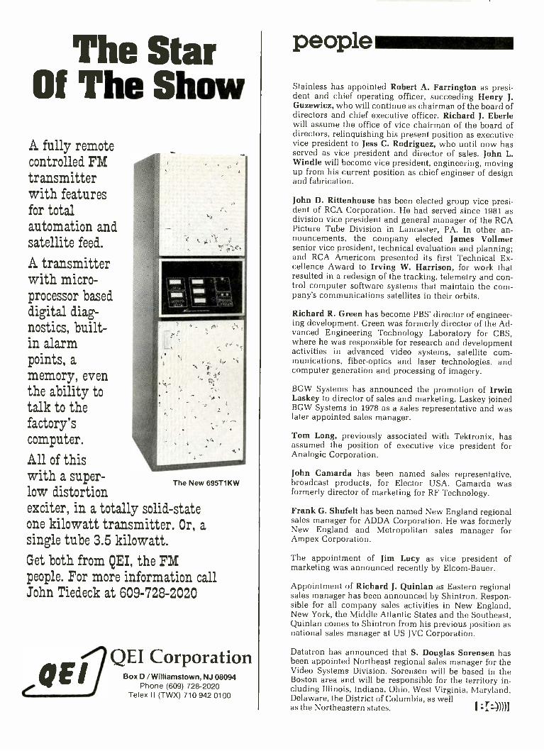
The StarOf The Show
A fully remotecontrolled FMtransmitterwith featuresfor totalautomation andsatellite feed.
A transmitterwith micro-processor baseddigital diag-nostics, built-in alarmpoints, amemory, eventhe ability totalk to thefactory'scomputer.
All of thiswith a super -
low distortionexciter, in a totally solid-stateone kilowatt transmitter. Or, asingle tube 3.5 kilowatt.
Get both from QEI, the FMpeople. For more information callJohn Tiedeck at 609-728-2020
egE
The New 695T1KW
QEI CorporationBox D / Williamstown, NJ 08094
Phone (609) 728-2020Telex II (TWX) 710 942 0100
peopleStainless has appointed Robert A. Farrington as presi-dent and chief operating officer, succeeding Henry J.Guzewicz, who will continue as chairman of the board ofdirectors and chief executive officer. Richard J. Eberlewill assume the office of vice chairman of the board ofdirectors, relinquishing his present position as executivevice president to Jess C. Rodriguez, who until now hasserved as vice president and director of sales. John L.Windle will become vice president, engineering, movingup from his current position as chief engineer of designand fabrication.
John D. Rittenhouse has been elected group vice presi-dent of RCA Corporation. He had served since 1981 asdivision vice president and general manager of the RCAPicture Tube Division in Lancaster, PA. In other an-nouncements, the company elected James Vollmersenior vice president, technical evaluation and planning;and RCA Americom presented its first Technical Ex-cellence Award to Irving W. Harrison, for work thatresulted in a redesign of the tracking, telemetry and con-trol computer software systems that maintain the com-pany's communications satellites in their orbits.
Richard R. Green has become PBS' director of engineer-ing development. Green was formerly director of the Ad-vanced Engineering Technology Laboratory for CBS,where he was responsible for research and developmentactivities in advanced video systems, satellite com-munications, fiber -optics and laser technologies, andcomputer generation and processing of imagery.
BGW Systems has announced the promotion of IrwinLaskey to director of sales and marketing. Laskey joinedBGW Systems in 1978 as a sales representative and waslater appointed sales manager.
Tom Long, previously associated with Tektronix, hasassumed the position of executive vice president forAnalogic Corporation.
John Camarda has been named sales representative,broadcast products, for Elector USA. Camarda wasformerly director of marketing for RF Technology.
Frank G. Shufelt has been named New England regionalsales manager for ADDA Corporation. He was formerlyNew England and Metropolitan sales manager forAmpex Corporation.
The appointment of Jim Lucy as vice president ofmarketing was announced recently by Elcom-Bauer.
Appointment of Richard J. Quinlan as Eastern regionalsales manager has been announced by Shintron. Respon-sible for all company sales activities in New England,New York, the Middle Atlantic States and the Southeast,Quinlan comes to Shintron from his previous position asnational sales manager at US JVC Corporation.
Datatron has announced that S. Douglas Sorensen hasbeen appointed Northeast regional sales manager for theVideo Systems Division. Sorensen will be based in theBoston area and will be responsible for the territory in-cluding Illinois, Indiana, Ohio, West Virginia, Maryland,Delaware, the District of Columbia, as wellas the Northeastern states. :::))))1
ad indexADC Products 29ADDA Corp. 49ADM Technology IFCAgfa-Geveart Inc 77Allied Broadcast Equipment 127Ampex Corp. 8-9,25,27Andrew Corp. 43Asaca/Shibasoku Corp. of America 31
Audiotechniques Inc. 135B&K Precision Tool 52Belar Electronic Labs 134Belden Corp. 45Beyer Dynamics 111Bosch-Fernseh 71
Calvert Electronics Inc 35Canare Cable, Inc 42Cetec Antenna 38Cetec Vega 57Christie Electric Corp. 86Comex Systems 110Comtech Data Corp. 4Conrac Corp 68-69Continental Electric Mfg. 138Crosspoint Latch Corp 152Peter W. Dahl Inc 114Data Communications Corp. 41
Datum Inc. 108Victor Duncan Inc 122Dynair Electronics Inc. 65Dynatech Data Systems 94EECO Inc. 95ESE 143Eagle Hill Electronics Inc 139ECHOlab, Inc. 78Electrex Co 54Electrohome Ltd 120Environmental Satellite Data 133Excalibur Industries 132Farrtronics Inc 132Fidelipac Corp. 56Fuji Photo U.S.A. Inc. 81GEC Michael 93General Electric Video 109Gould Inc 103Grass Valley Group 7,34,72-73,141HM Electronics, Inc. 76Hallikainen & Friends 70Harris Corp 23,84Harris Video Systems 79Harvey Professional Audio/Video 123Hipotronics, Inc. 58Hitachi Denshi America Ltd. 3Ikegami Electronics Inc. 82-83Industrial Sciences Inc. 145Inovonics Inc 62International Wholesalers 144JBL, Inc. 121JVC Corp. of America 63L -W International 134Laumic Co. Inc. 126Leitch Video Ltd. 59
Lerro Electrical Corp 33,107McMartin Industries, Inc. 863M Magnetic Tape 50-513M Professional A/V 88-89MCl/Quantel 5Marti Electronics 122McCurdy Radio Industries IBCMicrodyne Corp. 55Microphonics 139Microtime, Inc 99Midwest Corp. 1
Minolta Corp. 28Modular Audio Products 128R. K. Morrison Co. 139Moseley Associates Inc 119NTI America Inc. 85Opamp Labs 139Orban Associates 24,39J. Osawa & Co., Ltd. 129Otari Corp 20-21Panasonic CoPerrott Engineering LabsPESA Piher Electronics, S.A.Philips Television SystemsPolar Research IncPolyline Corp.
136-1371281126740
135Potomac Instruments 62Q.E.I. 146Quad -Eight Electronics 116Ramko Research 36-37,75Restoration 133Ross Video 47Sachtler GmbH/Sachtler Corp. of America . . .. 115Saki Magnetic 66Howard W. Sams & Co., Inc 124Sencore 11
Shintron 44Shure Bros. Inc. 61Singer Broadcast Products Inc 139Sony Corp. 104-105,114SpectraSonics 102Spectrum Planning Inc. 54Stainless Inc. 125Standard Communications 91Standard Tape Laboratory Inc. 129Studer ReVox America Inc. 66Swiderski Electronics Inc. 134Taber Mfg. Co. 138Tascam div TEAC Corp. of America 18Tektronix, Inc 12-13,15,17Telcom Research 101
Tele-Cine Corp. 74Texscan Instruments 117Thomson-CSF Broadcast 53Tiner Communications Services, Inc 139UNR Rohn 127UREI 92Video Aids of Colorado 142Videotek Inc. 92Ward -Beck Systems Ltd. BCWinsted Corp. 126
May 1983 Broadcast Engineering 147
professionalservices
VIR JAMES P.C.CONSULTING ENGINEERS
Applications and Field EngineeringComputerized Frequency Surveys
3137 W. Kentucky Ave. -80219(303) 937-1900
DENVER, COLORADOMember AFCCE & NAB
ATLANTIC RESEARCH CORPORATIONJansky & Bailey
Telecommunications Consulting
Member AFCCE
5390 Cherokee AvenueAlexandria, Virginia 22314(703) 642-4000
R. L. HOOVERConsulting Telecommunications
Engineer11704 Seven Locks RoadPotomac, Maryland 20854
301.983-0054Member AFCCE
NRADIO ENGINEERING CO.
CONSULTANTSc NORWOOD J. PATTERSON
BOX 420SANTA YNEZ CA 93460
(805) 688.2333Serving Broadcasters over 35 years
BROADCAST ENGINEERINGSERVICE COMPANY
TV -FM -AM Field Engineering-Emergency Maintenance-Turnkey Installation-
System Design-Survey and Critique-Interim Maintenance or Chief Engineer
B E S COMPANY100 Star Trail. New Port Richey. Fla. 33553, 813-868-2989
STEIGER, HURRAY &ASSOCIATES INC.
Broadcast Technical ConsultantsANTENNA SYSTEM SPECIALISTS
6816 Westview DriveCleveland, OH 44141
(216) 526-7187
eat9WCFle incAM FM TV LPTV
ComputerizedAllocation Studies/Directories1302 18th St., N.W., Suite 502
Washington, D.C. 20036(800) 368-5754 (202) 296-4790
Established 1971
CHARLES F. KOCHER, P.E.Consulting Radio and TV Engineer
Allocation EngineeringAntenna Systems
27235 Berkshire DriveSouthfield, Michigan 48076
(313) 357-2304Member AFCCE
ii
MIDWEST ENGINEERING ASSOCIATESConsulting Engineers
150 Wesley Rd.Crave Coeur, Illinois 61611
FPhone (309) 698-3160
F. W. Hannel, P.E.Member AFCCE
SMITH and POWSTENKOBroadcasting and Telecommunications
Consultants
2000 N Street, N.W.Washington, D. C. 20036
(202) 293-7742
RALPH E. EVANS ASSOCIATESCONSULTING COMMUNICATIONS ENGINEERS
216 N. Green Bay RoadSuite 208
Thiensville, WI 53082Phone: (414) 242-6000 Member AFCCE
D. L. MARKLEY& Associates, Inc.CONSULTING ENGINEERS
206 North BerganPeoria, Illinois 61604
(309) 673-7511Member AFCCE
-IRADIO CONSULTING ENGINEERS
STATION DESIGN AND SERVICEELECTRONIC PRODUCT DESIGN
Edward A. Schober, P.E.402 Tenth Avenue. Haddon Heights. NJ 08035
16091 546-1841
SINCE 1952 MCI Tel. 201-627-7400
MICROWAVE SERVICESINTERNATIONAL, INC.
SATELLITE AND TERRESTRIAL SYSTEMSCONSULTANTS ENGINEERS CONSTRUCTORS
FREQUENCY COORDINATORS
VICTOR J. NEXON, PE 288 W. MAIN ST.PRESIDENT DENVILLE, NJ 07834
MEMBER AFCEE
EFFICIENT USE OF AVIATION ASSETSPAUL F. KELLEY C.P.
AVIATION CONSULTANTSMEL, R -H, INST. A -H, CFII, CGI-AI, A&P
15 yrs. Broadcast Exp. FCC General Lic.ENG Installations, Heliport
Construction Maintenance and PilotOualifications
165 Garfield Ave., Hyde Park, Ma.. 02136
BROaDCaSTenGineeRinG
Advertising Sales Offices
NEW YORK, NEW YORKJoe Concert,Phone: (212) 682-6630Anita K. GoldPhone: (212) 682-6040630 Third Ave., Eighth FloorNew York, NY 10017
KANSAS CITY, MISSOURIJan Winters,P.O. Box 12901, Overland Park, KS 66212Phone: (913) 888-4664
SANTA MONICA, CALIFORNIAHerbert A. Schiff,Schiff & Associates1408 Santa Monica Mall, Suite 200Santa Monica, CA 90401Phone: (213) 393-9285
LONDON, ENGLANDJohn Ashcroft & Co., John Ashcraft12 Bear StreetLeicester Square, London WC2H 7ASEnglandPhone: 930-0525Telex: 895-2387
AMSTERDAM, HOLLANDJohn Ashcraft & Co., John J. LucassenAkerdijk 150A, 1171 PV-Badhoevedorp,HollandPhone: 0-2968-6226Telex: 11640
TOKYO, JAPANSumio OkaInternational Media Representatives, Ltd.,2.29, Toranomon 1-chome, Minato-kuTokyo 105, JapanPhone: 502-0656
TAIWAN, R.O.C.Antony LiuLong Life Advertisement Agency Co.P.O. Box 36-10948F-3.50.sec 5Naking E RoadTaipei, TaiwanTelephone: (02) 760.2468Telex: 25923 FondlandCable: Longad Taipei
NORWOOD, AUSTRALIAHastwell, Williamson, Rouse Pty. Ltd.P.O. Box 419Norwood 5067, AustraliaPhone: 332-3322Telex: AA87113
148 Broadcast Engineering May 1983
classifiedAdvertising rates in Classified Section are 75 cents
per word, each Insertion, and must be accompaniedby cash to insure publication.
Each initial or abbreviation counts a full word.Minimum classified charge, $10.00.
For ads on which replies are sent to us for forward-ing (blind ads), there is an additional charge of $10.00per insertion, to cover department number, processingof replies, and mailing costs.
Classified columns are not open to advertising ofany products regularly produced by manufacturersunless used and no longer owned by the manufactureror distributor.
TRAINING
ELECTRONICS DEGREE by correspondence. EarnA.S.E.T., then B.S.E.T. Free catalog. Grantham Collegeof Engineering, 2500 La Clenega, Los Angeles, Califor-nia 90034. 7-82-tfn
FCC GENERAL RADIOTELEPHONE operators licensethrough cassette recorded lessons at home plus oneweek seminar in Boston, Washington, Detroit orPhiladelphia. Our twentieth year teaching FCC licensecourses. Bob Johnson Radio License Preparation.1201 Ninth, Manhattan Beach, Calif. 90266, Telephone(213) 379-4461. 8-81-tfn
SERVICES
ONE STOP FOR ALL YOUR PROFESSIONAL AUDIOREQUIREMENTS. Bottom line oriented. F.T.C. BrewerCompany, P.O. Box 8057, Pensacola, Florida 32506.
7-71-tf
HELIAX-STYROFLEX. Large stock - bargain prices-tested and certified. Write for price and stock lists.Sierra Western Electric, Box 23872, Oakland, Calif.94623. Telephone (415) 832-3527. 1-73-tf
TRANSMITTER TUBES REPROCESSED-Save 40 to50%. 3CX2500, 4CX5000, 4CX15000 and many others.Write for details. FREELAND PRODUCTS CO., Rt. 7,Box 628, Covington, LA 70433. (504) 893-1243. 6.79 -tin
HEAD RE -LAPPING SERVICE. We expertly refinish allprofessional non -glass heads. Fine hard crafted workby professionals. 1/2" heads - $35, y "-$135, 1" -$250, 2" 16TK -$460, 2" 24TK -$590. Price Includesshipping. Compare our prices over buying new heads.TUCKER ENTERPRISES, P.O. Box 10120, Alexandria,Virginia 22310-0120. 1-83-tfn
DO YOU HAVE A NOISY TAPE RECORDER motor? Wecan provide quick economical service on cart machineand reel to reel motors. Write for price list. .1 & R Enter-prises, 10335 Cambridge Street, Westchester, IL60153. 3-83-3t
YOUR FRIENDS WITH THE GOOD CARTRIDGE re-winding service are still here. Reasonable rates. Allcartridges guaranteed. Broadcast EquipmentRebuilders, Box 1628, Windsor, CO 80550. (303)686-2791. 5-83-1t
EQUIPMENT FOR SALE
IVC 7000P CAMERA with tubes, mini -control unit, autoiris, two 200 foot cables, one 100 foot. Angenleux 15two 1 zoom lens, body support brace. Never used onmobile. Call Bob Canaday at (515) 255-2122. 12-82-61
COMMUNICATIONS TOWER-Insulated, 350'galvanized w/48" face. Includes guys & atarmounts$12,500. Owensboro, KY 502-275-4769 Nights. 4-83-2t
IVC 9000 VTRS: Two fully loaded machines with sparescanner, tension modulator and 4 drums. Datatroneditor with Interfaces. Package $140,000- FOB Wash-ington, D.C. Call Don Doughty (301)654-2800. 4-83-2t
VIDEO EQUIPMENT FOR SALE...NEW COLOR VIDEOCAMERAS: JVC KY2700, JVC KY 2700A, HITACHIFP3060....USED COLOR VIDEO CAMERAS:PANASONIC WV3800, UNITED MEDIA COMMANDERI....NEW 34" EDITING CONTROLLER....USED JVC 728013" COLOR MONITOR. CALL RAY BRUMFIELD,800-654-6744. 5-83-1t
EQUIPMENT FOR SALE (CONT.)
HARRIS SYSTEM S-90 AUTOMATION 3-42 tray go-carts, RPD, time announce, instacart, 5 -ITC R to R, en-coding, logging with 2 printers, 3 consoles. $37,500 orbest offer. 408-475-5527. 4-83-4t
CCU FOR HL79A with 300 feet of twin coax. CinemaProducts model COE-A purchased two years ago byFreelancer and used 14 times. Looks and works likenew. (702) 739-7705. 5-83-2t
"TOYS* AND PARTS VALUE. 50 Magnecord PT -6stereo reel-to-reel recorders. Two -track stereo. All inreasonable working condition. Electronics in mintcondition. $165 each. Shipped freight collect. Broad-cast Equipment Rebuilders, Box 1628, Windsor, CO80550. (303) 686-2791. 5-83-1t
SONY VO. 2880A $3500.00, RM-430 $800.00. Both inSuper Condition. Larry Hellman, Topeka, Kansas (913)235-3481. 5-83-1t
MISCELLANEOUS FOR SALE
COPPER STRAP, WIRE, SCREEN. Check our prices.(317) 962-8596 ask for copper sales. 1-83-6t
QUALITY BROADCAST EQUIPMENT: New and Used,Buy and Sell! Transmission, Video and Audio. Formedmy own company. Call Ray LaRue, (813) 685-2938.
10-82-tfn
REQUESTS FOR BIDS: Aurora Community Broad-casting, Inc. Invites bids for the following FM Broad-cast Transmission System composed of these com-ponents: McMartin BF 3.5K Transmitter and Exciter(103.1 MHz); Jampro JPSC 3 bay circularly polarizedantenna; McMartin TBM 3700 FM monitor and TBM2200A Stereo monitor; 135 feet of gas pressurized An-drew H..1-6 Heliax; Optimod Stereo Generator. Allequipment sold as Is, where is. Equipment was per-forming normally when removed from service. KSKAreserves the right to reject any or all bids for cause, orto accept partial bids. Total ERP capability approx-imately 5500 watts. Sealed bids will be opened May 3,1983 at 10:00 A.M. at KSKA's offices. Direct inquiriesand bids after April 1, 1983 to Denis Allen, ChiefEngineer, KSKA-FM, 4101 University Drive, Anchor.age, AK 99508, (907) 561-1161. Final decision to acceptor reject any bid Is made solely by KSKA's Board ofDirectors. 5-83-1 t
WANTED TO BUY
WANTED: Pre -1923 radio equipment and tubes.August J. Link, Surcom Associates, 305 WisconsinAve., Oceanside, CA 92054, (619) 722-6162. 3-76-tf
HIGHEST PRICES PAID for 112 Phase Monitors andfor clean, 12 year old or less, 1 KW and 10 KW AMTransmitters. All duty and transportation paid.Surplus Equipment Sales, 2 Thorncliffe Park Dr., Unit28, Toronto, Canada M4H 1H2, 416-421-5631. 2-79-tfn
WANTED: STATION LIBRARIE'S OF MUSIC, 16" ET's,12" Transcriptions, 45's, 78's, LP's. Boyd Robeson,2425 W. Maple, Wichita, KS 67213, (316) 942-3673,722-7785. 5-82-tfn
COMPLETE BROADCAST SOFTWARE SYSTEM, A/P,general ledger, payroll for the Wang 2200. Write Dept.598, Broadcast Engineering, P.O. Box 12901, OverlandPark, KS 66212. 4-83-2t
FM TRANSMITTER, 10-20kW, cash or tax deduction.Scott Holladay, KABF, 1501 Arch, Little Rock AR72202, 501-372-6119. 5-83-1t
HELP WANTED
ASSISTANT CHIEF ENGINEER - KCSO TV Channel 19has an opening for an Assistant Chief Engineer. Mustbe capable of extensive studio maintenance.Knowledge of RCA TR-22, TK-27, TP-66, Sony 2860,studio camera set-up and maintenance helpful. UHFtransmitter experience an asset. Equal OpportunityEmployer. Send resume. Chief Engineer, KCSO-TV,Post Office Box 3689, Modesto, California 95352.
4-83-3t
CAREERSIN DIGITAL
VIDEOMCl/Quartel, world leader in ad-
vanced digital video systems forbroadcasting and teleproduction, hasseveral outstanding career opportuni-ties for sales and technical people.
Sales RepresentativesImmediate openings for sales personsto be district managers in Dallas/Fort Worth and Mid -Atlantic loca-tions. Some experience in broadcastor teleproduction equipment re-
quired, together with good trackrecord in sales.
TechniciansSenior video systems test techniciansrequired at our handsome newheadquarters in Palo Alto, California.Ideal background would includeexperience with digital video systems,but experience in computers orperipherals may suffice.
Field Service EngineersImmediate opening for East Coastlocation. Experience required inmaintenance of digital video systemsor computer -related equipment. In-stallation experience a plus.
MCl/Quantel offers an excellentstarting salary, good benefits package,and plenty of room for advancement.Plus the prestige of being associatedwith the top company in an excitingindustry. We're changing the look oftelevision - and you can be a partof it.
Send your resume to MCl/Quantel,P.O. Box 50810, Palo Alto, CA94303 Or call Marsha Verse at (415)856-6226.
An equal opportunity employer.
MCl/QUANITELThe digital video people
May 1983 Broadcast Engineering 149
HELP WANTED (CONT.)
WE PLACETV and Video Engineers
Come to the sourceCOME TO
KEY SYSTEMSWestminster Road
Wilkes-Barre, PA 18702
Phone Alan Kornish at(717) 655-1458
ENGINEER: TELEVISION PRODUCTION ENGINEERfor public broadcast station. Responsible for produc-tion recording, editing and remotes. Completed mini-mum of two years studies in electronics technology ata reputable Institute or equivalent military training.Minimum two years experience in production record-ing, editing and repairing electronic equipment in atelevision station. FCC license required. Send resumeand salary requirements to Chief Engineer, 42 Col-iseum Drive, Charlotte, N.C. 28205. EOE. 3-83-31
Use
BROaDCaSTenGineeRinG
classified ads
ENGINEERING SUPERVISORFor transmitter and studio maintenance. 5 years ex-perience. Openings in Dallas and Houston. Join fastgrowing chain. You will be given authority and sup-port to build a successful operation. $30,000. Call orwrite Ed Reid, Director of Engineering, 1712 E.
Randol Mill Rd., Arlington, TX 76011. (817) 265-2100.
ENGINEERS, TV Systems Engineers, ElectronicTechnicians, Technical Supervisors, Maintenance. Im-mediate openings. Experienced. Full time. Full bene-fits, plus Pension. Excellent salary plus commissions.Send resume to Technical Operations, Inc., P.O. Box840, New Hyde Park, N.Y. 11040, or call Personnel Mgr.(516) 352-2238. 9-80-tfn
VIDEO SALES-Major N.J. video dealer offers achallenging opportunity for professional video salespeople. Previous industrial and/or broadcast experi-ence required. Salary commensurate with experience.Commission, car, excellent fringe benefits. Reply inconfidence to: Video Corporation of America, 1913Route 27, P.O. Box 697, Edison, N.J. 08818. 1-82-tfn
TELEVISION MAINTENANCEENGINEER
For the experienced -qualified maintenanceengineer that would prefer a Virginia Beachlocation, we would like to talk to you about ex-cellent employee benefits. Send resume tothe Personnel Department, 5200 HamptonBoulevard, Norfolk, VA 23508. Deadline isMay 27, 1983.
"EQUAL OPPORTUNITY EMPLOYER"5-83-1t
AUDIO MAINTENANCE ENGINEER needed. Musthave experience with RTS intercom 1/4" and 1/2" andcassette audio machines, plus 1" C format machines.Must have high maintenance skills, some design, andbe willing to travel in and out of the continental UnitedStates. Send resumes to: Broadcast Engineering,Dept. 590, P.O. Box 12920, Overland Park, KS 66212.
5-83-1t
TECHNICIAN: Excellent opportunity with growingvideotape company. '/3" and 3/4" VCR repair ex-perience a must. Electronics background required. Ex-citing growth position. Call Mr. Caputo 977-9338.
5-83-1t
BROADCAST ENGINEER, FM RADIO- Public radiostation seeks Chief Engineer qualified to install, main-tain, and repair all station equipment. Position reportsto General Manager and functions as one persondepartment. Remote village translator system alsopart of operation. Send resumes to General Manager,KMXT(FM), Box 484, Kodiak, Alaska 99615. 5-83-11
PORTABLE UPLINK ENGINEER - Dallas based withextensive travel, duties include: set-up, maintenance,and satellite location. Two years experience withremote spots, conventions, and teleconferencing.Reply in confidence to: N.B.N. Productions, 1333Harry Hines, Dallas, Texas 75201, (214) 745-1425. Attn.Jim Bruce. 5-83-1t
BOSCH FLD-60 OPERATOR: Highly visible full serviceMichigan production/post facility wants experiencedtechnician. Write: P.O. Box 451, Lathrup Village, MI48078. 5-83-1t
ENGINEER/TECHNICIAN. A midwest CBS affiliate isseeking an engineer/technician to maintain studio,transmitter, and ENG equipment. If interested, send aresume and salary requirements to: Supervisor ofEngineering, WENT -TV, P.O. Box 25, Evansville, In-diana 47701. EOE-M/F. 5-83-2t
TRAD MAGAZINE EDITOR
Exceptional opportunity for editor withMidwest -based publisher. Will participate inthe development, launch and direction of newelectronics magazine. Publication will be thefifth magazine in group of high -growth elec-tronics magazines.
Must have substantial knowledge in one ormore of the following or related areas: soundreinforcement, pro sound, electronic com-munications, broadcast audio, low -voltagewiring or technical magazine editing. Strongwriting skills and familiarity with magazineproduction are also important.
Strong industry contacts, all administrativeand interpersonal skills a must since respon-siblities encompass editorial travel, editorialplanning, industry analysis, budget prepara-tion and supervision of associate editor.
We offer a top salary, benefit program of For-tune 100 company and continuing growthpotential. Send complete resume and salaryrequirements to:
EOE MIF/H
Personnel DirectorIntertec Publishing Corp.P.O. Box 12901Overland park, KS 66212
150 Broadcast Engineering May 1983
NOW.. The leading magazineof broadcast technology,
brings you an importantnew technical tool...
DIRECTIONAL ANTENNA HANDBOOKby Robert A. Jones, PE Igt
Go:rpotA AD
ONLY $1
Based on the recent Broadcast Engineeringseries, this 104 page volume focuses on theessentials of directional antennas then expandsto encompass the entire arena of design, froma two tower array through twelve towersystems. Chapters cover such important areasas:
Design of nightime directional antennas. Calculating RMS efficiency. The FCC's Standard Method of calculating directional
antennas for submission with FCC applications.Additional sections review the basic math used incalculations and provide tips on using computers andhand calculators for computation.
Whether you use a consultant or design your ownsystems, this book is an absolute must. Order yourstoday!
The Latest From The Leader In Broadcast Technology...Broadcast Engine ring's Directional Antenna HandbookONLY
fq ORDER FORM
P.O. Box 12901, Overland Park, KS 66212
Please send me copies of the Directional Antenna Handbookat...WAS...each. (Postage Included.)
-ifcte25o.r money order is enclosed.
Name
Address
City
State Zip
May 1983 Broadcast Engineering 151
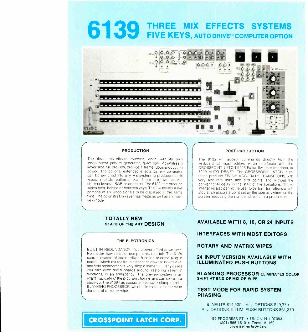
6139 THREE MIX EFFECTS SYSTEMSFIVE KEYS, AUTO DRIVETM COMPUTER OPTION
61:39 C=MEN
PRODUCTION
The three mix -effects systems, each with its ownindependent pattern generator, quad split, downstreamkeyer and full preview, provide a tremendous productionpower. The optional extended effects pattern generatorcan be switched into any ME system to produce matrixwipes, multiple patterns, etc. There are two optionalchroma keyers, RGB or encoded. The 6139 can producewipes over, behind or between keys. The five keyers allowportions of six video signals to be displayed at the sametime. The downstream keyer has matte as well as an insertkey mode.
TOTALLY NEWSTATE OF THE ART DESIGN
ITHE ELECTRONICS
BUILT IN REDUNDANCY. You cannot afford down time.No matter how reliable, components can fail. The 6139uses a system of standardized function oriented plug-inboards, which makes trouble shooting down to board leveland field replacement a very simple matter. In many casesyou can even swap boards around, restoring essentialfunctions, in an emergency. The preview system is anexact duplicate of the program channel and can serve as aback-up. The 6139 has accurate feed -back clamps, and aBLANKING PROCESSOR, which eliminates color shifts atthe end of a mix or wipe.
POST PRODUCTION
The 6139 will accept commands directly from thekeyboard of most editors when interfaced with theCROSSPOINT LATCH 6403 Editor Switcher Interface, or7200 AUTO DRIVETM. The CROSSPOINT LATCH Irter-faces produce FRAME ACCURATE TRANSITIONS withvery accurate start and end points, and without theconventional delay in the start of the transitions. Theseinterfaces also permit the user to perform transitions whichstop at an accurate point set by the user anywhere on thescreen, reducing the number of edits in a production.
AVAILABLE WITH 8, 16, OR 24 INPUTS
INTERFACES WITH MOST EDITORS
ROTARY AND MATRIX WIPES
24 INPUT VERSION AVAILABLE WITHILLUMINATED PUSH BUTTONS
BLANKING PROCESSOR ELIMINATES COLORSHIFT AT END OF MIX OR WIPE
TEST MODE FOR RAPID SYSTEMPHASING
8 INPUTS $14,500 ALL OPTIONS $49,370ALL OPTIONS, ILLUM. PUSH BUTTONS $61,370
CROSSPOINT LATCH CORP.4.
95 PROGRESS ST. UNION, N.J. 07083(201) 688-1510 Telex 181160
Circle (134) on Reply Card
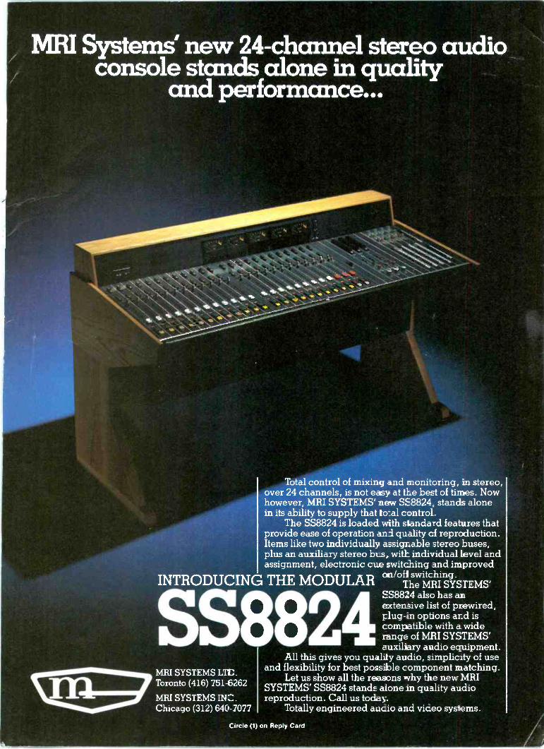
MRI Systems new 24 -channel stereo audioconsole stands alone in quality
and performance...
INTRODUCING THE MODULAR
SS88MRI SYSTEMS LTC.Toronto (416) 751-6262
MRI SYSTEMS INC.Chicago (312) 640-7077
Total control of mixing and monitoring, in stereo,over 24 channels, is not easy at the best of times. Nowhowever, MRI SYSTEMS' new SE8824, stands alonein its ability to supply that to:al control.
The SS8824 is loaded with standard features thatprovide ease of operation a.n1 quality cf reproduction.Items like two individually assigr_able stereo buses,plus an auxiliary stereo bLs, with individual level andassignment, electronic cue switching and improved
oin/ofi switching.The MRI SYSTEMS'
SS8824 also has anextensive list of prewired,plug-in options and iscompatible with a widerange of MRI SYSTEMS'auxiliary audio equipment.
All this gives you quality audio, simplic.ty of useand flexibility for best possible component matching.
Let us show all the reasons why the new MRISYSTEMS' SS8824 stands alone in quality audioreproduction. Call us today.
Totally engineered aucio and vireo systems.
Circle (1) on Reply Card
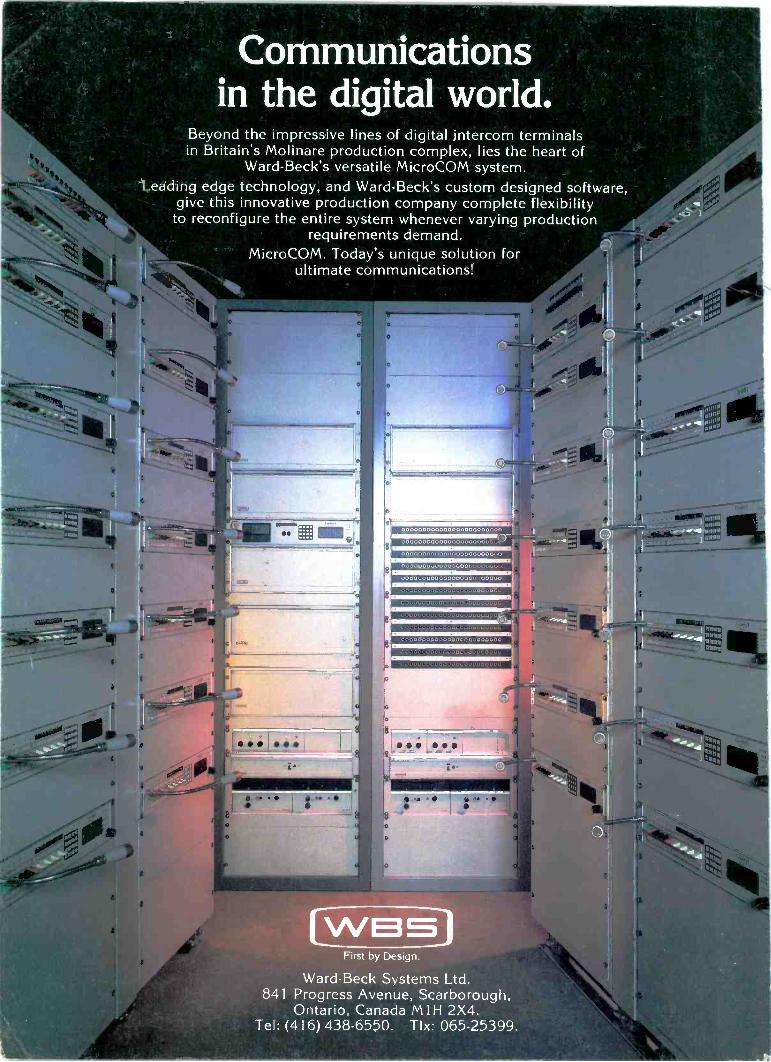
Beyond the im
pressive lines of digital intercom term
inalsin B
ritain's Molinare production com
plex, lies the heart ofW
ard -Beck's versatile M
icroCO
M system
.Leading edge technology, and W
ard -Beck's custom
designed software,
give this innovative production company com
plete flexibilityto reconfigure the entire system
whenever varying production
requirements dem
and.M
icroCO
M. T
oday's unique solution forultim
ate comm
unications!
00000000000000000000o,,
000000000000000000OG
O,,,,,,
First by D
esign.
Ward -B
eck System
s Ltd.841 P
rogress Avenue. S
carborough,O
ntario. Canada M
1H 2X
4.T
el: (416) 438-6550.T
lx: 065-25399.