Embed Size (px)
Citation preview

Edition 01 / 2014

2 www.eupen.com
www.eupen.com 3
1. Introduction
100 Years of Experience . . . . . . . . . . . . . . . . . . . . . . . . . . . . . 6Over the World . . . . . . . . . . . . . . . . . . . . . . . . . . . . . . . . . . . . . . . . . . . 8
2. Introduction to Eupen Radiating Cables& Technical Parameters . . . . . . . . . . . . . . . . . . . . . . . . . 12Cable Selection Guide . . . . . . . . . . . . . . . . . . . . . . . . . . . . . 18
3. Cables Characteristics
LSC 12. . . . . . . . . . . . . . . . . . . . . . . . . . . . . . . . . . . . . . . . . . . . . . . . . . . . . . . 22LSC 78. . . . . . . . . . . . . . . . . . . . . . . . . . . . . . . . . . . . . . . . . . . . . . . . . . . . . . . 24RMC 12 . . . . . . . . . . . . . . . . . . . . . . . . . . . . . . . . . . . . . . . . . . . . . . . . . . . . . 26RMC 12-A. . . . . . . . . . . . . . . . . . . . . . . . . . . . . . . . . . . . . . . . . . . . . . . . . . 28RMC 12-T . . . . . . . . . . . . . . . . . . . . . . . . . . . . . . . . . . . . . . . . . . . . . . . . . . 30RMC 12-CL . . . . . . . . . . . . . . . . . . . . . . . . . . . . . . . . . . . . . . . . . . . . . . . . 32RMC 12-CH . . . . . . . . . . . . . . . . . . . . . . . . . . . . . . . . . . . . . . . . . . . . . . . 34RMC 58 . . . . . . . . . . . . . . . . . . . . . . . . . . . . . . . . . . . . . . . . . . . . . . . . . . . . . 36RMC 58-T . . . . . . . . . . . . . . . . . . . . . . . . . . . . . . . . . . . . . . . . . . . . . . . . . . 38RMC 78 . . . . . . . . . . . . . . . . . . . . . . . . . . . . . . . . . . . . . . . . . . . . . . . . . . . . . 40RMC 78-T ”A” Series. . . . . . . . . . . . . . . . . . . . . . . . . . . . . . . . . . 42RMC 78-B ”A” Series. . . . . . . . . . . . . . . . . . . . . . . . . . . . . . . . . . 44RMC 78-CL ”A” Series. . . . . . . . . . . . . . . . . . . . . . . . . . . . . . . . 46RMC 114 ”A” Series . . . . . . . . . . . . . . . . . . . . . . . . . . . . . . . . . . . 48RMC 114-T ”A” Series. . . . . . . . . . . . . . . . . . . . . . . . . . . . . . . . 50RMC 114-B ”A” Series. . . . . . . . . . . . . . . . . . . . . . . . . . . . . . . . 52RMC 158 ”A” Series . . . . . . . . . . . . . . . . . . . . . . . . . . . . . . . . . . . 54RMC 158-T ”A” Series. . . . . . . . . . . . . . . . . . . . . . . . . . . . . . . . 56RMC 158-B ”A” Series. . . . . . . . . . . . . . . . . . . . . . . . . . . . . . . . 58CMC 12 . . . . . . . . . . . . . . . . . . . . . . . . . . . . . . . . . . . . . . . . . . . . . . . . . . . . . 60Radiating Cable with Integrated Messenger Wire . . . . . . . . . . . . . . . . . . . . . 62
Technical data, designs and specifications presented in thiscatalogue are not binding and are subject to change with-out prior notice.
4. Accessories for Cables
Connectors . . . . . . . . . . . . . . . . . . . . . . . . . . . . . . . . . . . . . . . . . . . . . . . 66Cable Preparation Tools . . . . . . . . . . . . . . . . . . . . . . . . . . . 68Jumper Cables . . . . . . . . . . . . . . . . . . . . . . . . . . . . . . . . . . . . . . . . . 69Grounding Kits . . . . . . . . . . . . . . . . . . . . . . . . . . . . . . . . . . . . . . . . . 70Additional Weatherproofing Solutions . . . 71Hook Hanger . . . . . . . . . . . . . . . . . . . . . . . . . . . . . . . . . . . . . . . . . . . . 72Clic Clamp . . . . . . . . . . . . . . . . . . . . . . . . . . . . . . . . . . . . . . . . . . . . . . . . 73Stainless Steel Clamping Solutions . . . . . . . . . 76
5. EPC (Eupen Passive Components)
Dummy Loads . . . . . . . . . . . . . . . . . . . . . . . . . . . . . . . . . . . . . . . . . . 80DC Isolators . . . . . . . . . . . . . . . . . . . . . . . . . . . . . . . . . . . . . . . . . . . . . . 81Splitters . . . . . . . . . . . . . . . . . . . . . . . . . . . . . . . . . . . . . . . . . . . . . . . . . . . . 82
6. Packing Information
. . . . . . . . . . . . . . . . . . . . . . . . . . . . . . . . . . . . . . . . . . . . . . . . . . . . . . . . . . . . . . . . . . 86


100 Years of Experience
Eupen is a global cable manufacturer offering a widerange of cables and accessories.
Our product range includes:
Radiating cables
Transmission lines
Safety cables
Power cables
Fibre optic cables
Instrumentation cables
As a leading supplier of transmission lines and accesso-ries to global wireless communications markets, EUPENhas the experience and resources to effectively servicecustomers in today’s challenging wireless communica-tions markets.
Since broadband transmission became possible, EUPENhas been involved in the design and manufacture oftransmission lines.
The introduction of Cable Television in 1962 was decisi-ve for the start of coaxial cables on a larger scale.
At a time when wireless communication in confinedareas, such as underground, street and service tunnels,became an important business to the network opera-tors, EUPEN developed high quality radiating cables.
Today, customers worldwide rely upon EUPEN productsfor wireless transmission of data, voice and video.
Underground communication systems using EUPENradiating cables operate worldwide:
in the Metros of:
Brussels
Caracas
Instambul
Kiev
Moscow
Rome
Santiago de Chile
Washington, DC
....
in road tunnels in
Austria
Belgium
France
Germany
Greece
Norway
Singapore
Spain
the Netherlands
...
and many other challenging locations.
6 www.eupen.com
Introduction
in Railway Tunnels of:
Austria
Belgium
Germany
Malaysia
Spain
Switzerland
The Netherlands
...

7
Research & Development
EUPEN’s expertise in the wireless communications mar-ket is an invaluable resource to our customers.
To anticipate and to follow the continuously changingdemand of the market, we carefully evaluate customerfeedback, which serves as stimulant for future improve-ments and developments of EUPEN’s product portfolio.
Innovative designs, a careful choice of raw materialstogether with consistent manufacturing and qualityassurance techniques, ensure the electrical and mecha-nical superiority of Eupen cables for the needs ofmodern radio communication systems such as:
FM
VHF
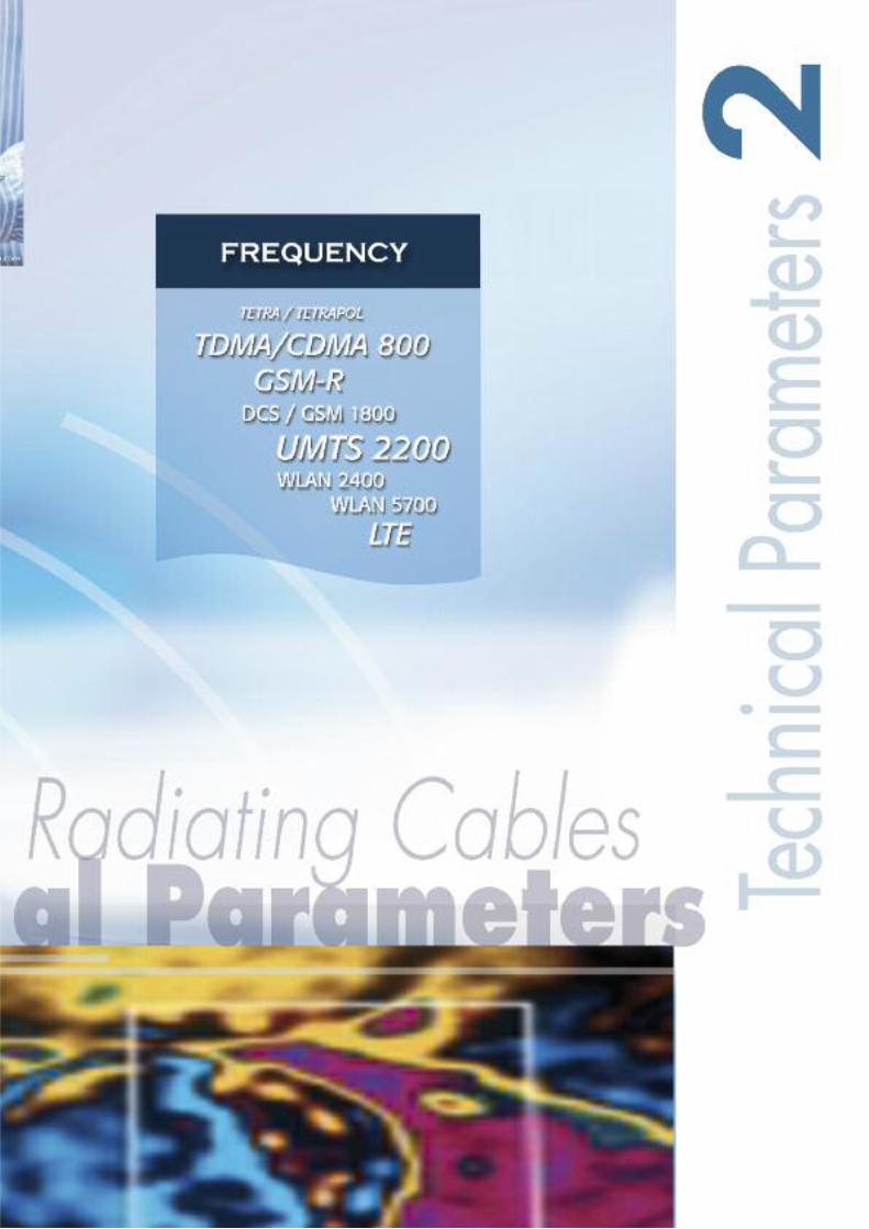
TETRA / TETRAPOL
TDMA / CDMA 800
GSM 900/1800
GSM-R (European Railway)
PCN / PCS 1900
UMTS 2200
LTE
W-CDMA 2200
WLAN 2400
WLAN 5700
Together the cables and the connectors fromEUPEN are an unbeatable match that optimises theentire system performance:
• Low attenuation
• Excellent field strength with low coupling loss
• Increased amplifier spacing due to very low
system loss
• Simple connector installation
• Quick cable installation
• Halogen-free and fire retardant jacketing
EUPEN Support
EUPEN provides tailor made support for all kind of RFSystem needs.
To meet customer demand for independent and unbia-sed support in the expert field of Specialised RFCoverage Solutions, Eupen has gathered a Team of dedi-cated advisors, who can provide complete support on allaspects of RF Coverage Solutions.
Based on the Teams knowledge, that spans more thantwo decades, combined with good local knowledge ofall major market places and by keeping close liaison withConsultants, Manufacturers, System Integrators andInstallers world-wide, this Team is able to deliver advicethat is combines state of the art technology, latest legis-lation and cost effectiveness.

8 www.eupen.com
Agencies America
CanadaMexicoUSA
FloridaNew JerseyTexas
Guatemala
Agencies Africa
EgyptSouth Africa
Agencies Europe
AustriaBulgariaFinlandGermanyHungaryIrelandItalyNorwayPolandRomaniaRussiaSpainSloveniaSwedenTchech RepublikTurkeyUkraine
Over the World

www.eupen.com 9
EUPEN CABLE USA Inc.
5181 110th Avenue North
Unit D,
Clearwater, Florida - 33760
USA
EUPEN CABLE MEXICO SA
Avenida Manta 705
Lindavista,
07300 Mexico, D.F.
MEXICO
EUPEN CABLES FRANCE
Z.A. La Haie Griselle
24, rue du 8 mai 1945
94470 Boissy St Leger
FRANCE
KABELWERK RHENANIA GmbH
Karl-Kuck-Str. 3
52078 Aachen
GERMANY
Agencies Asia
IndiaIranPakistanKingdom of Saudi ArabiaSingaporeSyriaThailandTaiwan R.O.C.UAE
Agencies Oceania
AustraliaNew Zealand
KABELWERK EUPEN AG
Malmedyer Strasse 9
4700 Eupen
BELGIUM

10 www.eupen.com
www.eupen.com 11
12 www.eupen.com
Eupen Cables
General
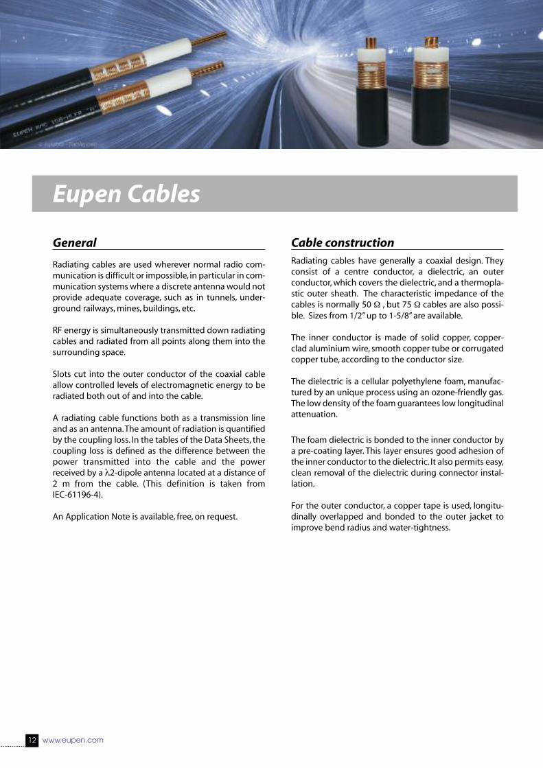
Radiating cables are used wherever normal radio com-munication is difficult or impossible, in particular in com-munication systems where a discrete antenna would notprovide adequate coverage, such as in tunnels, under-ground railways, mines, buildings, etc.
RF energy is simultaneously transmitted down radiatingcables and radiated from all points along them into thesurrounding space.
Slots cut into the outer conductor of the coaxial cableallow controlled levels of electromagnetic energy to beradiated both out of and into the cable.
A radiating cable functions both as a transmission lineand as an antenna. The amount of radiation is quantifiedby the coupling loss. In the tables of the Data Sheets, thecoupling loss is defined as the difference between thepower transmitted into the cable and the powerreceived by a λ2-dipole antenna located at a distance of2 m from the cable. (This definition is taken fromIEC-61196-4).
An Application Note is available, free, on request.
Cable constructionRadiating cables have generally a coaxial design. Theyconsist of a centre conductor, a dielectric, an outerconductor, which covers the dielectric, and a thermopla-stic outer sheath. The characteristic impedance of thecables is normally 50 Ω , but 75 Ω cables are also possi-ble. Sizes from 1/2” up to 1-5/8” are available.
The inner conductor is made of solid copper, copper-clad aluminium wire, smooth copper tube or corrugatedcopper tube, according to the conductor size.
The dielectric is a cellular polyethylene foam, manufac-tured by an unique process using an ozone-friendly gas.The low density of the foam guarantees low longitudinalattenuation.
The foam dielectric is bonded to the inner conductor bya pre-coating layer. This layer ensures good adhesion ofthe inner conductor to the dielectric. It also permits easy,clean removal of the dielectric during connector instal-lation.
For the outer conductor, a copper tape is used, longitu-dinally overlapped and bonded to the outer jacket toimprove bend radius and water-tightness.

www.eupen.com 13
Halogen-free, Flame-retardant andFire-resistant features
The standard cable construction uses a weather-resi-stant Halogen-free, Low-smoke and Flame-Retardant(HLFR) outer jacket.
This construction meets such international standards asIEC 60332-3 (for flame propagation), IEC 61034 (smokedensity) and IEC 60754 (acidity of evolved gases).
If a fire barrier tape (e.g., of mica) is added and placedbetween dielectric and outer conductor (HLFR/M outerjacket) the cable meets also the requirements ofIEC 60331 electrical test (circuit integrity).
The barrier tape does not affect the transmission charac-teristics of the cable.
Flammability
a) Test on flammability of single cables
Test in accordance with: IEC 60332-1-2EN 60332-1-2
b) Test on flammability of cable bundles
Test in accordance with: IEC 60332-3 Cat. CEN 50266-2-4 Cat. C
also available: UL 1685, FT4, IEEE 1202
Smoke densityTest in accordance with: IEC 61034-1 and -2
EN 61034-1 and -2
also available: UL 1685, LS
Corrosive gas emissionsTest in accordance with: IEC 60754-2
EN 50267-2-2
Insulation integrity (HLFR/M jacket only)Test in accordance with: IEC 60331-23
VDE 0472 Part 814

Theory of radiation
In a coaxial cable a Transverse Electromagnetical (TEM)-wave travels from the transmitter to the cable end.
In the case of a cable with a metallically fully closedouter conductor, the wave inside the cable is totallyscreened from the surrounding.
Outside the coaxial cable, no electromagnetic field, or inother terms no electromagnetic radiation, can be mea-sured. In the same case, no electromagnetic field outsi-de the cable has any influence on the inside wave.
By applying apertures to the outer conductor of a coaxi-al cable, a part of the energy from inside the cable istransferred to the outside surrounding.
Also energy can intrude into the cable from the environ-ment.
Openings in the outer conductor cause electromagneticcoupling between the field of the inner wave and theouter wave of the outer space of the cable. The arrange-ment of the openings determines the mechanism of thecoupling.
The typical example of a radiating cable is a coaxial cablewith a braided outer conductor. The largest part of theenergy travels as an inside wave through the cable.
At any point of inhomogeneity of the outer conductor,surface waves will be induced which travel in both, for-ward and backward direction along the outside of thecable and interfere with each other.
The quality of the radio communication varies verymuch, due to level variation of the field outside thecable.
The installation and the surrounding of the cable affectsthe radiated field along the cable.
Most tunnels contain metallic conductors, such as powercables along the lateral walls, or rails, water pipes, etc.
Such conductors can change drastically the electromag-netic field properties.
The main electrical characteristics of a radiating cableare:Frequency rangesLongitudinal lossesCoupling lossesSystem losses
Frequency ranges
To determine the right cable for an application, the usedfrequency ranges has to be known precisely. The designof the apertures in the outer conductor influences thefrequency range for which the cable is optimised.
Three kinds of radiating coaxial cables are distinguished:
CMC (Coupled Mode) Cables:
These radiating cables are designed for in-building
applications (where the system length is typically
less than 100 m), for which a leaky section cable
may not be appropriate.
LSC (Leaky Section) Cables:
Best performances up to 1 GHz. Although this cable
can be used at higher frequencies, the sharp increa-
se of its longitudinal losses generally limits its use
above 1 GHz.
RMC (Radiated Mode) Cables:
Designed for a frequency range up to 6 GHz, these
cables can be broadband, or are tuned for specific
frequency ranges or applications. The particular
design of the apertures creates some resonant
frequencies. These resonant frequencies are well
chosen and do not fall within the currently used
communication bands.
14 www.eupen.com
Technical Parameters

www.eupen.com 15
Longitudinal loss
The most important characteristic for energy transporta-tion along a cable by the inner wave, is the longitudinalloss (or attenuation loss).
A coaxial cable attenuates the signal travelling inside infunction of the frequency.
The higher the frequency, the higher the attenuation los-ses.
The type of dielectric and the size of the cable mainlyinfluence the longitudinal attenuation. The longitudinalloss depends also on the arrangement of the aperturesin the outer conductor.
Coupling loss
The coupling loss describes the signal loss between thecable and a receiver. It is defined as the ratio of the recei-ved power, at a certain distance, to the power in thecable.
Because of the reciprocity, analogue considerations arevalid for the transmission from an antenna into thecable.
The coupling loss is affected by the arrangement of theopenings as well as by interferences and reflections ofthe cable surrounding.
An intensive radiation means a low coupling loss over abroad frequency range.
Two different physical modes carry the energy from thecable into the air : coupling mode and radiating mode.
System loss
The system loss is the sum of longitudinal and couplingloss and of various losses depending on the installationand the environment. Detailed information about theenvironmental influences are given in the chapter“Installation”.
To design a radio communications systems the systemloss needs to be calculated for the uplink and downlinkconnection.
Resonant frequencies
The cable design, more precisely the arrangement of theapertures in the outer conductor, can lead to resonantfrequencies.
This occurs when a certain wavelength interferes withthe regular structure of the apertures. The reflectioncoefficient (SWR) jumps up and the longitudinal lossincreases.
While LSC and CMC cables don’t show this behaviour,RMC cables are designed to present this resonance fre-quency (stop band) in frequency ranges, where thecables are generally not used.
An Application Note is available, free, on request.

CMC Cables
These radiating cables are designed for in-buildingapplications (where the system length is typically lessthan 100 m), for which a leaky section cable may not beappropriate.
Radiating cables of this type are suited for high-perfor-mance applications in the 450 MHz, 900 MHz and 1800MHz bands.
The electromagnetic field diffracted by the apertures ofthis cable type induces an external mode outside theouter conductor. A current flows on the outer part of theouter conductor and the cable radiates as a long trave-ling wave antenna. The coupled mode cable is thereforeequivalent to a long electrical antenna.
The “coupled mode” corresponds to a power flow, whichis parallel to the cable axis. The electromagnetic energyis concentrated in the close vicinity of the cable anddecreases quickly with distance: this is the reason whythese modes are sometimes referred to as “surfacewaves”. The modes, confined around the cable axis, arepartially diffracted by surrounding obstacles and discon-tinuities (clamps, walls, ...): a fraction of the power is ran-domly radiated radially.
LSC Cables
Leaky sections are pre-punched into the outer conduc-tor; the distance between sections is set to optimise lowcoupling loss and low longitudinal attenuation over awide bandwidth.
With this unique construction the distance betweenrepeaters can be increased, and the broadband couplingloss is not significantly degraded from that obtainedusing continuously-slotted coupled-mode cables orradiating-mode cables.
LSC cables are mode converters. They consist of a sectionof leaky cable, inserted in a non-leaky cable.
A leaky section is equivalent to a directive antenna con-nected to the coaxial cable through a power divider.Only a small part of the power propagated inside thecable is extracted and converted into radiation. The spa-cing between leaky sections has to be chosen in order toprovide acceptable results at various frequencies.
Cables with leaky sections, designed in this way, can beused under the same conditions as continuous leaky fee-ders, but with better characteristics for longitudinal andcoupling loss.
The leaky sections are efficient mode converters and canproduce a controlled field level in the cable vicinity, as afunction of their length and their electrical characteri-stics.
16 www.eupen.com
Cable Characteristics

RMC Cables
Radiated Mode cables are designed for applications atfrequencies of 75 MHz to 6 GHz. The slots are arrangedso that the direction of radiation is predominantly ortho-gonal to the cable axis. This results in optimised, redu-ced coupling loss variations over specific frequencybands.
With a radiated mode cable, the electric field is producedby periodic apertures (slots) on the cable’s outer con-ductor. The aperture spacing d is comparable to theoperational wavelength (λc).
The radiated modes correspond to the “in-phase addi-tion” of all apertures. They appear for only very well defi-ned slot arrangements and over a well-defined“Radiated mode frequency band”. The coupling loss islow only in a certain frequency band. Above and belowthis frequency band it is increased due to interference. The direction of propagation is radially oriented.
RMC Cables for Digital Trunk Radio
The advent of new Digital Trunk Radio Services,demands improved products to support these techni-ques. Eupen has met this challenge by including special-ly designed RMC cables that provide industry leadingperformances by being optimised for use with this newtechnology.
www.eupen.com 17

18 www.eupen.com
Frequency Bands 75 - 100 MHz 150 - 170 MHz 400 - 500 MHz
Applications FM PMR PMRPMR TETRA
TETRAPOL page
LSC 12 22
RMC 12 26
RMC 12-A 28
RMC 58 36
RMC 78 40
RMC 114 ”A” Series 48
RMC 158 ”A” Series 54
RMC 12-T 30
RMC 12-CL 32
RMC 12-CH 34
RMC 58-T 38
RMC 78-T ”A” Series 42
RMC 78-B ”A” Series 44
RMC 78-CL ”A” Series 46
RMC 114-T ”A” Series 50
RMC 114-B ”A” Series 52
RMC 158-T ”A” Series 56
RMC 158-B ”A” Series 58
CMC 12 60
Jacket Type IEC 60754-1/-2 IEC 61034 (suffix of Cable Name)
Requirements Halogen free Low smoke density non corrosive smoke emission
PE •
HLFR • • • •
HLFR/M • • • • •
Cable Selection Guide
Jacket Selection Guide
best good not recommended

www.eupen.com 19
800 - 1000 MHz 1.7 - 1.9 GHz 2.2 - 2.3 GHz 2.4 - 2.5 GHz 6 GHz
TDMA PCN UMTS ISM WLANCDMA DECT WLANGSM 900 GSM 1800 WIFIGSM - RTETRA
IEC 60332-1 IEC 60332-3C IEC 60331
Flame retardant Fire retardant DC Circuit integrity
• •
• • •
Important: please always check for resonant frequencies


22 www.eupen.com
PRODUCT DESCRIPTION
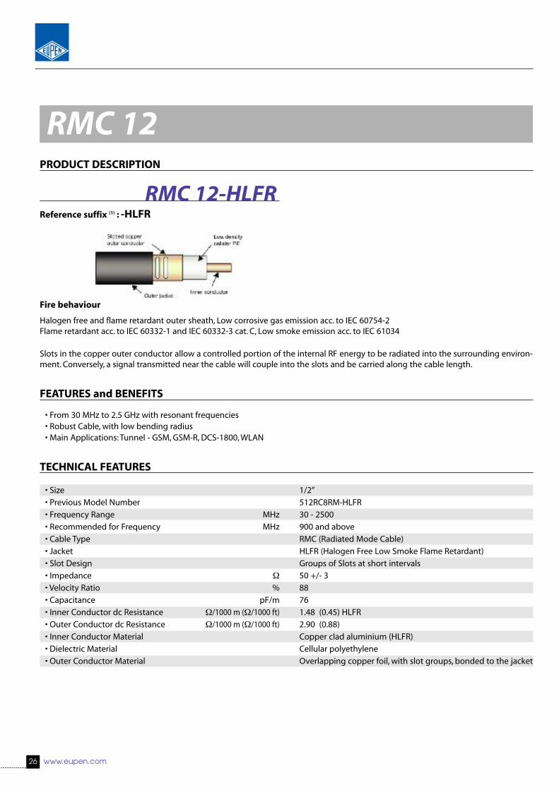
Slots in the copper outer conductor allow a controlled portion of the internal RF energy to be radiated into the surrounding environ-ment. Conversely, a signal transmitted near the cable will couple into the slots and be carried along the cable length.
FEATURES and BENEFITS
• Broadband from 30 MHz to 1.9 GHz• Robust Cable, with low bending radius• No Resonant Frequencies• No Cable Orientation Required• Main Applications: Tunnel - FM, TETRA, GSM, GSM-R, DCS-1800• Only for use in Tunnels - Not suitable for use in Buildings
TECHNICAL FEATURES
• Size 1/2”• Previous Model Number 512RC8R-HLFR• Frequency Range MHz 30 - 2000• Recommended for Frequency MHz N.A. • Cable Type LSC (Leaky Section Cable)• Jacket HLFR (Halogen Free Low Smoke Flame Retardant)• Slot Design Groups of Slots at longer intervals• Impedance Ω 50 +/- 2• Velocity Ratio % 88• Capacitance pF/m 76• Inner Conductor dc Resistance Ω/1000 m (Ω/1000 ft) 1.48 (0.45) HLFR• Outer Conductor dc Resistance Ω/1000 m (Ω/1000 ft) 2.62 (0.80)• Inner Conductor Material Copper clad aluminium wire (HLFR)• Dielectric Material Cellular polyethylene• Outer Conductor Material Overlapping copper foil, with slot groups, bonded to the jacket
Reference suffix (1) : -HLFR
LSC 12-HLFR
Fire behaviour
Halogen free and flame retardant outer sheath, Low corrosive gas emission acc. to IEC 60754-2Flame retardant acc. to IEC 60332-1 and IEC 60332-3 cat. C, Low smoke emission acc. to IEC 61034
LSC 12

www.eupen.com 23
LSC 12TECHNICAL FEATURES (continued)
• Diameter Inner Conductor mm (in) 4.8 (0.19)• Diameter Dielectric mm (in) 12.4 (0.49)• Diameter over Jacket mm (in) 15.5 (0.61)• Minimum Bending Radius, Single Bend mm (in) 200 (7.87)• Cable Weight kg/m (lb/ft) 0.33 (0.22) HLFR• Tensile Strength daN (lb) 110 (242)• Indication of Slot Alignment N.A.• Storage Temperature °C (°F) -70 to +85 (-94 to +185)• Installation Temperature °C (°F) -25 to +60 (-13 to +140)• Operation Temperature °C (°F) -40 to +85 (-40 to +185)• Longitudinal Loss and Coupling Loss (2)
Frequency Longitudinal Loss Coupling LossdB/100 m (dB/100 ft) C50% [dB] C95% [dB]
75 MHz 1.87 (0.57) 65 75150 MHz 2.69 (0.82) 67 77225 MHz 3.35 (1.02) 67 78450 MHz 4.93 (1.50) 68 79900 MHz 7.43 (2.26) 63 751800 MHz 11.7 (3.57) 64 751900 MHz 12.2 (3.70) 64 752200 MHz - - -2400 MHz - - -
• Resonant Frequencies MHz None• Clamp Spacing Recommended / Maximum m (ft) 0.5 (1.64) / 1.20 (3.90)• Distance to Wall Recommended / Minimum mm (in) 80 - 180 (3.15 - 7.00) / 50 (1.96)
1) Must be specified in case of order - standard PE jacket available on request.(2) Measured in tunnel according to IEC 61196-4 - Ground Level Method.Distance = 2m. C50 & (C95) are the average coupling losses with 50% (95%) probability calculated in accordance with the standard.
The above stated values are nominal values and subject to manufacturing tolerances as follows: Longitudinal Loss +/-5 % and Coupling Loss +/- 3dB.
As with any radiating cable, the performance in building or tunnel may deviate from figures measured according to the IEC 61196-4 standard.
Coupling loss measurements taken in accordance with IEC 61196-4 - Free Space Method are available on request
These Radiating Cables have been especially developed for use in Tunnels. Due to the Cables inherent design, based on Groups of Slots at longer intervals,these Radiating Cables are not suitable for In-Building use.

24 www.eupen.com
PRODUCT DESCRIPTION
Slots in the copper outer conductor allow a controlled portion of the internal RF energy to be radiated into the surrounding environ-ment. Conversely, a signal transmitted near the cable will couple into the slots and be carried along the cable length.
FEATURES and BENEFITS
• Broadband from 30 MHz to 1.9 GHz• Robust Cable, with low bending radius• No Resonant Frequencies• No Cable Orientation Required• Main Applications: Tunnel - FM, TETRA, GSM, GSM-R, DCS-1800• Only for use in Tunnels - Not suitable for use in Buildings
TECHNICAL FEATURES
• Size 7/8”
• Previous Model Number 522RC8R-HLFR
• Frequency Range MHz 30 - 2000
• Recommended for Frequency MHz N.A.
• Cable Type LSC (Leaky Section Cable)
• Jacket HLFR (Halogen Free Low Smoke Flame Retardant)
• Slot Design Groups of Slots at longer intervals
• Impedance Ω 50 +/- 2
• Velocity Ratio % 88
• Capacitance pF/m 76
• Inner Conductor dc Resistance Ω/1000 m (Ω/1000 ft) 1.63 (0.49)
• Outer Conductor dc Resistance Ω/1000 m (Ω/1000 ft) 1.40 (0.43)
• Inner Conductor Material Smooth copper tube
• Dielectric Material Cellular polyethylene
• Outer Conductor Material Overlapping copper foil, with slot groups, bonded to the jacket
LSC 78
Reference suffix (1) : -HLFR
LSC 78-HLFR
Fire behaviour
Halogen free and flame retardant outer sheath, Low corrosive gas emission acc. to IEC 60754-2Flame retardant acc. to IEC 60332-1 and IEC 60332-3 cat. C, Low smoke emission acc. to IEC 61034

www.eupen.com 25
TECHNICAL FEATURES (continued)
• Diameter Inner Conductor mm (in) 9.2 (0.36)
• Diameter Dielectric mm (in) 23.5 (0.93)
• Diameter over Jacket mm (in) 27.0 (1.06)
• Minimum Bending Radius, Single Bend mm (in) 350 (13.80)
• Cable Weight kg/m (lb/ft) 0.480 (0.32) HLFR
• Tensile Strength daN (lb) 130 (287)
• Indication of Slot Alignment N.A.
• Storage Temperature °C (°F) -70 to +85 (-94 to +185)
• Installation Temperature °C (°F) -25 to +60 (-13 to +140)
• Operation Temperature °C (°F) -40 to +85 (-40 to +185)
• Longitudinal Loss and Coupling Loss (2)
Frequency Longitudinal Loss Coupling Loss
dB/100 m (dB/100 ft) C50% [dB] C95% [dB]75 MHz 1.06 (0.32) 62 73150 MHz 1.58 (0.48) 59 69225 MHz 2.01 (0.61) 59 68450 MHz 3.09 (0.94) 58 65900 MHz 4.86 (1.48) 63 731800 MHz 10.10 (3.08) 63 731900 MHz 11.20 (3.41) 63 732200 MHz - - -2400 MHz - - -
• Resonant Frequencies MHz None
• Clamp Spacing Recommended / Maximum m (ft) 0.5 (1.64) / 1.20 (3.90)
• Distance to Wall Recommended / Minimum mm (in) 80 - 180 (3.15 - 7.00) / 50 (1.96)
1) Must be specified in case of order - standard PE jacket available on request.(2) Measured in tunnel according to IEC 61196-4 - Ground Level Method.Distance = 2m. C50 & (C95) are the average coupling losses with 50% (95%) probability calculated in accordance with the standard.
The above stated values are nominal values and subject to manufacturing tolerances as follows: Longitudinal Loss +/-5 % and Coupling Loss +/- 3dB.
As with any radiating cable, the performance in building or tunnel may deviate from figures measured according to the IEC 61196-4 standard.
Coupling loss measurements taken in accordance with IEC 61196-4 - Free Space Method are available on request
These Radiating Cables have been especially developed for use in Tunnels. Due to the Cables inherent design, based on Groups of Slots at longer intervals,these Radiating Cables are not suitable for In-Building use.
LSC 78
26 www.eupen.com
PRODUCT DESCRIPTION
Slots in the copper outer conductor allow a controlled portion of the internal RF energy to be radiated into the surrounding environ-ment. Conversely, a signal transmitted near the cable will couple into the slots and be carried along the cable length.
FEATURES and BENEFITS
• From 30 MHz to 2.5 GHz with resonant frequencies• Robust Cable, with low bending radius• Main Applications: Tunnel - GSM, GSM-R, DCS-1800, WLAN
TECHNICAL FEATURES
• Size 1/2”
• Previous Model Number 512RC8RM-HLFR
• Frequency Range MHz 30 - 2500
• Recommended for Frequency MHz 900 and above
• Cable Type RMC (Radiated Mode Cable)
• Jacket HLFR (Halogen Free Low Smoke Flame Retardant)
• Slot Design Groups of Slots at short intervals
• Impedance Ω 50 +/- 3
• Velocity Ratio % 88
• Capacitance pF/m 76
• Inner Conductor dc Resistance Ω/1000 m (Ω/1000 ft) 1.48 (0.45) HLFR
• Outer Conductor dc Resistance Ω/1000 m (Ω/1000 ft) 2.90 (0.88)
• Inner Conductor Material Copper clad aluminium (HLFR)
• Dielectric Material Cellular polyethylene
• Outer Conductor Material Overlapping copper foil, with slot groups, bonded to the jacket
RMC 12
Reference suffix (1) : -HLFR
RMC 12-HLFR
Fire behaviour
Halogen free and flame retardant outer sheath, Low corrosive gas emission acc. to IEC 60754-2Flame retardant acc. to IEC 60332-1 and IEC 60332-3 cat. C, Low smoke emission acc. to IEC 61034

www.eupen.com 27
TECHNICAL FEATURES (continued)
• Diameter Inner Conductor mm (in) 4.8 (0.19)
• Diameter Dielectric mm (in) 12.4 (0.49)
• Diameter over Jacket mm (in) 15.5 (0.61)
• Minimum Bending Radius, Single Bend mm (in) 200 (7.87)
• Cable Weight kg/m (lb/ft) 0.23 (0.16) HLFR
• Tensile Strength daN (lb) 110 (243)
• Indication of Slot Alignment embossed line 180° opposite
• Storage Temperature °C (°F) -70 to +85 (-94 to +185)
• Installation Temperature °C (°F) -25 to +60 (-13 to +140)
• Operation Temperature °C (°F) -40 to +85 (-40 to +185)
• Longitudinal Loss and Coupling Loss (2)
Frequency Longitudinal Loss Coupling Loss
dB/100 m (dB/100 ft) C50% [dB] C95% [dB]75 MHz 2.35 (0.72) 52 66150 MHz 3.25 (0.99) 62 74225 MHz 3.70 (1.13) 72 82450 MHz 5.00 (1.53) 79 88900 MHz 7.70 (2.36) 60 631800 MHz 12.25 (3.76) 60 701900 MHz 12.70 (3.90) 60 702200 MHz 14.80 (4.54) 61 702400 MHz 16.50 (5.07) 60 68
• Resonant Frequencies MHz 547, 1641, 2734
• Clamp Spacing Recommended / Maximum m (ft) 0.5 (1.64) / 1.20 (3.90)
• Distance to Wall Recommended / Minimum mm (in) 80 - 180 (3.15 - 7.00) / 50 (1.96)
1) Must be specified in case of order - standard PE jacket available on request.(2) Measured in tunnel according to IEC 61196-4 - Ground Level Method.Distance = 2m. C50 & (C95) are the average coupling losses with 50% (95%) probability calculated in accordance with the standard.
The above stated values are nominal values and subject to manufacturing tolerances as follows: Longitudinal Loss +/-5 % and Coupling Loss +/- 3dB.
As with any radiating cable, the performance in building or tunnel may deviate from figures measured according to the IEC 61196-4 standard.
Coupling loss measurements taken in accordance with IEC 61196-4 - Free Space Method are available on request
RMC 12

28 www.eupen.com
RMC 12-APRODUCT DESCRIPTION
Slots in the copper outer conductor allow a controlled portion of the internal RF energy to be radiated into the surrounding environ-ment. Conversely, a signal transmitted near the cable will couple into the slots and be carried along the cable length.
FEATURES and BENEFITS
• From 30 MHz to 2.5 GHz with resonant frequencies• Robust Cable, with low bending radius• Main Applications: AIRCRAFT - GSM, DCS-1800, UMTS, WLAN-short length• Specially designed for use in Aircraft
TECHNICAL FEATURES
• Size 1/2”
• Previous Model Number 512RC8RMA-HLFR
• Frequency Range MHz 30 - 2500
• Recommended for Frequency MHz 450 and above
• Cable Type RMC (Radiated Mode Cable)
• Jacket HLFR (Halogen Free Low Smoke Flame Retardant)
• Slot Design Groups of Slots at short intervals
• Impedance Ω 50 +/- 3
• Velocity Ratio % 88
• Capacitance pF/m 76
• Inner Conductor dc Resistance Ω/1000 m (Ω/1000 ft) 1.48 (0.45)
• Outer Conductor dc Resistance Ω/1000 m (Ω/1000 ft) 3 (0.91)
• Inner Conductor Material Copper clad aluminium wire
• Dielectric Material Cellular polyethylene
• Outer Conductor Material Overlapping copper foil, with slot groups, bonded to the jacket
Reference suffix (1) : -HLFR
RMC 12-A-HLFR
Fire behaviour
Halogen free and flame retardant outer sheathLow corrosive gas emission acc. to IEC 60754-2Flame retardant acc. to IEC 60332-1 and IEC 60332-3 cat. CLow smoke emission acc. to IEC 61034

www.eupen.com 29
RMC 12-ATECHNICAL FEATURES (continued)
• Diameter Inner Conductor mm (in) 4.8 (0.19)
• Diameter Dielectric mm (in) 12.4 (0.49)
• Diameter over Jacket mm (in) 15.5 (0.61)
• Minimum Bending Radius, Single Bend mm (in) 200 (7.87)
• Cable Weight kg/m (lb/ft) 0.21 (0.14) HLFR
• Tensile Strength daN (lb) 110 (242)
• Indication of Slot Alignment embossed line 180° opposite
• Storage Temperature °C (°F) -70 to +85 (-94 to +185)
• Installation Temperature °C (°F) -25 to +60 (-13 to +140)
• Operation Temperature °C (°F) -40 to +85 (-40 to +185)
• Longitudinal Loss and Coupling Loss (2)
Frequency Longitudinal Loss Coupling Loss
dB/100 m (dB/100 ft) C50% [dB] C95% [dB]75 MHz 3.59 (1.09) 61 65150 MHz 4.26 (1.30) 67 78225 MHz 4.67 (1.42) 63 67450 MHz 5.85 (1.78) 62 67900 MHz 9.52 (2.90) 59 661800 MHz 20.8 (6.34) 52 591900 MHz 22.7 (6.92) 52 592200 MHz 30.4 (9.27) 52 632400 MHz 37.8 (11.52) 51 62
• Resonant Frequencies MHz 184, 552, 920 ±5, 1288, 1656, 2024, 2392
• Clamp Spacing Recommended / Maximum m (ft) 0.5 (1.64) / 1.20 (3.90)
• Distance to Wall Recommended / Minimum mm (in) 80 - 180 (3.15 - 7.00) / 50 (1.96)
1) Must be specified in case of order - standard PE jacket available on request.(2) Measured in tunnel according to IEC 61196-4 - Ground Level Method.Distance = 2m. C50 & (C95) are the average coupling losses with 50% (95%) probability calculated in accordance with the standard.
The above stated values are nominal values and subject to manufacturing tolerances as follows: Longitudinal Loss +/-5 % and Coupling Loss +/- 3dB.
As with any radiating cable, the performance in building or tunnel may deviate from figures measured according to the IEC 61196-4 standard.
Coupling loss measurements taken in accordance with IEC 61196-4 - Free Space Method are available on request

30 www.eupen.com
PRODUCT DESCRIPTION
Slots in the copper outer conductor allow a controlled portion of the internal RF energy to be radiated into the surrounding environ-ment. Conversely, a signal transmitted near the cable will couple into the slots and be carried along the cable length.
FEATURES and BENEFITS
• From 30 MHz to 1 GHz with resonant frequencies• Robust Cable, with low bending radius• Main Applications: Tunnel - FM, TETRA
TECHNICAL FEATURES
• Size 1/2”
• Previous Model Number 512RC8RMT-HLFR
• Frequency Range MHz 30 - 1000
• Recommended for Frequency MHz 450
• Cable Type RMC (Radiated Mode Cable)
• Jacket HLFR (Halogen Free Low Smoke Flame Retardant)
• Slot Design Groups of Slots at short intervals
• Impedance Ω 50 +/- 3
• Velocity Ratio % 88
• Capacitance pF/m 76
• Inner Conductor dc Resistance Ω/1000 m (Ω/1000 ft) 1.48 (0.45) HLFR
• Outer Conductor dc Resistance Ω/1000 m (Ω/1000 ft) 2.80 (0.85)
• Inner Conductor Material Copper clad aluminium (HLFR)
• Dielectric Material Cellular polyethylene
• Outer Conductor Material Overlapping copper foil, with slot groups, bonded to the jacket
RMC 12-T
Reference suffix (1) : -HLFR
RMC 12-T-HLFR
Fire behaviour
Halogen free and flame retardant outer sheath, Low corrosive gas emission acc. to IEC 60754-2Flame retardant acc. to IEC 60332-1 and IEC 60332-3 cat. C, Low smoke emission acc. to IEC 61034

www.eupen.com 31
TECHNICAL FEATURES (continued)
• Diameter Inner Conductor mm (in) 4.8 (0.19)
• Diameter Dielectric mm (in) 12.4 (0.49)
• Diameter over Jacket mm (in) 15.5 (0.61)
• Minimum Bending Radius, Single Bend mm (in) 200 (7.87)
• Cable Weight kg/m (lb/ft) 0.22 (0.15) HLFR
• Tensile Strength daN (lb) 110 (243)
• Indication of Slot Alignment embossed line 180° opposite
• Storage Temperature °C (°F) -70 to +85 (-94 to +185)
• Installation Temperature °C (°F) -25 to +60 (-13 to +140)
• Operation Temperature °C (°F) -40 to +85 (-40 to +185)
• Longitudinal Loss and Coupling Loss (2)
Frequency Longitudinal Loss Coupling Loss
dB/100 m (dB/100 ft) C50% [dB] C95% [dB]75 MHz 2.2 (0.67) 55 67150 MHz 3.0 (0.91) 59 70225 MHz 3.8 (1.16) 56 63400 MHz 5.4 (1.65) 55 57450 MHz 5.9 (1.80) 53 56900 MHz 10.6 (3.23) 63 741800 MHz - - -1900 MHz - - -2200 MHz - - -2400 MHz - - -
• Resonant Frequencies MHz 37, 111, 185, 259, 334, 408, 482, 556, 630, 704, 778, 853, 927, 1001
• Clamp Spacing Recommended / Maximum m (ft) 0.5 (1.64) / 1.20 (3.90)
• Distance to Wall Recommended / Minimum mm (in) 80 - 180 (3.15 - 7.00) / 50 (1.96)
1) Must be specified in case of order - standard PE jacket available on request.(2) Measured in tunnel according to IEC 61196-4 - Ground Level Method.Distance = 2m. C50 & (C95) are the average coupling losses with 50% (95%) probability calculated in accordance with the standard. All Values are going to beconfirmed by independent Test Centre soonest.
The above stated values are nominal values and subject to manufacturing tolerances as follows: Longitudinal Loss +/-5 % and Coupling Loss +/- 3dB.
As with any radiating cable, the performance in building or tunnel may deviate from figures measured according to the IEC 61196-4 standard.
Coupling loss measurements taken in accordance with IEC 61196-4 - Free Space Method are available on request
RMC 12-T

32 www.eupen.com
PRODUCT DESCRIPTION
Slots in the copper outer conductor allow a controlled portion of the internal RF energy to be radiated into the surrounding environ-ment. Conversely, a signal transmitted near the cable will couple into the slots and be carried along the cable length.
FEATURES and BENEFITS
• Low Fading at short Aerial to Cable distance• Robust Cable• Main Applications: WLAN controlled Transportation Systems• Optimised for WLAN applications in the 2.40 - 2.485 GHz band
TECHNICAL FEATURES
• Size 1/2”
• Previous Model Number N.A.
• Frequency Range MHz 75 - 2900
• Recommended for Frequency MHz 2400 - 2485
• Cable Type RMC (Radiated Mode Cable)
• Jacket HLFR (Halogen Free Low Smoke Flame Retardant)
• Slot Design Groups of Slots at short intervals
• Impedance Ω 50 +/- 3
• Velocity Ratio % 88
• Capacitance pF/m 76
• Inner Conductor dc Resistance Ω/1000 m (Ω/1000 ft) 1.48 (0.45)
• Outer Conductor dc Resistance Ω/1000 m (Ω/1000 ft) 2.8 (0.85)
• Inner Conductor Material Copper clad aluminium wire
• Dielectric Material Cellular polyethylene
• Outer Conductor Material Overlapping copper foil, with slot groups, bonded to the jacket
RMC 12-CL
Reference suffix (1) : -HLFR
RMC 12-CL-HLFR
Fire behaviour
Halogen free and flame retardant outer sheathLow corrosive gas emission acc. to IEC 60754-2Flame retardant acc. to IEC 60332-1 and IEC 60332-3 cat. CLow smoke emission acc. to IEC 61034

www.eupen.com 33
RMC 12-CLTECHNICAL FEATURES (continued)
• Diameter Inner Conductor mm (in) 4.8 (0.19)
• Diameter Dielectric mm (in) 12.4 (0.49)
• Diameter over Jacket mm (in) 15.5 (0.61)
• Minimum Bending Radius, Single Bend mm (in) 200 (7.87)
• Cable Weight kg/m (lb/ft) 0.23 (0.16) HLFR
• Tensile Strength daN (lb) 110 (243)
• Indication of Slot Alignment embossed line 180° opposite
• Storage Temperature °C (°F) -70 to +85 (-94 to +185)
• Installation Temperature °C (°F) -25 to +60 (-13 to +140)
• Operation Temperature °C (°F) -40 to +85 (-40 to +185)
• Longitudinal Loss and Coupling Loss (2)
Frequency Longitudinal Loss Coupling Loss
dB/100 m (dB/100 ft) C50% [dB] C95% [dB]75 MHz 1.87 (0.57) 54 66150 MHz 2.75 (0.83) 64 75225 MHz 3.42 (1.04) 62 66450 MHz 4.96 (1.51) 65 69900 MHz 7.32 (2.22) 63 731800 MHz 11.94 (3.63) 59 671900 MHz 12.45 (3.78) 59 672200 MHz 13.90 (4.22) 58 672400 MHz 14.71 (4.47) 54 60
• Resonant Frequencies MHz 156, 469, 781, 1094, 1406, 1718, 2031, 2344, 2656
• Clamp Spacing Recommended / Maximum m (ft) 0.5 (1.64) / 1.20 (3.90)
• Distance to Wall Recommended / Minimum mm (in) 80 - 180 (3.15 - 7.00) / 50 (1.96)
1) Must be specified in case of order - standard PE jacket available on request.(2) Measured in tunnel according to IEC 61196-4 - Ground Level Method.Distance = 2m. C50 & (C95) are the average coupling losses with 50% (95%) probability calculated in accordance with the standard.
The above stated values are nominal values and subject to manufacturing tolerances as follows: Longitudinal Loss +/-5 % and Coupling Loss +/- 3dB.
As with any radiating cable, the performance in building or tunnel may deviate from figures measured according to the IEC 61196-4 standard.
Coupling loss measurements taken in accordance with IEC 61196-4 - Free Space Method are available on request

34 www.eupen.com
RMC 12-CHPRODUCT DESCRIPTION
Slots in the copper outer conductor allow a controlled portion of the internal RF energy to be radiated into the surrounding environ-ment. Conversely, a signal transmitted near the cable will couple into the slots and be carried along the cable length.
FEATURES and BENEFITS
• Low Fading at short Aerial to Cable distance• Robust Cable• Main Applications: WLAN controlled Transportation Systems• Optimised for WLAN applications in the 5.15 - 5.35 and 5.47 - 5.85 GHz bands
TECHNICAL FEATURES
• Size 1/2”
• Previous Model Number N.A.
• Frequency Range MHz 5000 - 6000
• Recommended for Frequency MHz 5150 - 5350 and 5470 - 5850
• Cable Type RMC (Radiated Mode Cable)
• Jacket HLFR (Halogen Free Low Smoke Flame Retardant)
• Slot Design Groups of Slots at short intervals
• Impedance Ω 50 +/- 3
• Velocity Ratio % 88
• Capacitance pF/m 76
• Inner Conductor dc Resistance Ω/1000 m (Ω/1000 ft) 1.48 (0.45)
• Outer Conductor dc Resistance Ω/1000 m (Ω/1000 ft) 2.8 (0.85)
• Inner Conductor Material Copper clad aluminium wire
• Dielectric Material Cellular polyethylene
• Outer Conductor Material Overlapping copper foil, with slot groups, bonded to the jacket
Reference suffix (1) : -HLFR
RMC 12-CH-HLFR
Fire behaviour
Halogen free and flame retardant outer sheathLow corrosive gas emission acc. to IEC 60754-2Flame retardant acc. to IEC 60332-1 and IEC 60332-3 cat. CLow smoke emission acc. to IEC 61034

www.eupen.com 35
RMC 12-CHTECHNICAL FEATURES (continued)
• Diameter Inner Conductor mm (in) 4.8 (0.19)
• Diameter Dielectric mm (in) 12.4 (0.49)
• Diameter over Jacket mm (in) 15.5 (0.61)
• Minimum Bending Radius, Single Bend mm (in) 200 (7.87)
• Cable Weight kg/m (lb/ft) 0.23 (0.16) HLFR
• Tensile Strength daN (lb) 110 (243)
• Indication of Slot Alignment embossed line 180° opposite
• Storage Temperature °C (°F) -70 to +85 (-94 to +185)
• Installation Temperature °C (°F) -25 to +60 (-13 to +140)
• Operation Temperature °C (°F) -40 to +85 (-40 to +185)
• Longitudinal Loss and Coupling Loss (2)
Frequency Longitudinal Loss Coupling Loss
dB/100 m (dB/100 ft) C50% [dB] C95% [dB]5200 MHz 19.1 (5,82) 62 715500 MHz 20.0 (6,10) 60 615800 MHz 21.5 (6,55) 55 59
• Resonant Frequencies MHz 415, 1246, 2077, 2907, 3738, 4568, 5399, 6230
• Clamp Spacing Recommended / Maximum m (ft) 0.5 (1.64) / 1.20 (3.90)
• Distance to Wall Recommended / Minimum mm (in) 80 - 180 (3.15 - 7.00) / 50 (1.96)
1) Must be specified in case of order - standard PE jacket available on request.(2) Measured in tunnel according to IEC 61196-4 - Ground Level Method.Distance = 2m. C50 & (C95) are the average coupling losses with 50% (95%) probability calculated in accordance with the standard.
The above stated values are nominal values and subject to manufacturing tolerances as follows: Longitudinal Loss +/-5 % and Coupling Loss +/- 3dB.
As with any radiating cable, the performance in building or tunnel may deviate from figures measured according to the IEC 61196-4 standard.
Coupling loss measurements taken in accordance with IEC 61196-4 - Free Space Method are available on request

36 www.eupen.com
PRODUCT DESCRIPTION
Slots in the copper outer conductor allow a controlled portion of the internal RF energy to be radiated into the surrounding environ-ment. Conversely, a signal transmitted near the cable will couple into the slots and be carried along the cable length.
FEATURES and BENEFITS
• Broadband from 30 MHz to 1.9 GHz• Robust Cable, with low bending radius• Main Applications: Tunnel - GSM, GSM-R, DCS-1800
TECHNICAL FEATURES
• Size 5/8”
• Previous Model Number 517RC8RM-HLFR
• Frequency Range MHz 30 - 1900
• Recommended for Frequency MHz 900 and 1800
• Cable Type RMC (Radiated Mode Cable)
• Jacket HLFR (Halogen Free Low Smoke Flame Retardant)
• Slot Design Groups of Slots at short intervals
• Impedance Ω 50 +/- 2
• Velocity Ratio % 88
• Capacitance pF/m 76
• Inner Conductor dc Resistance Ω/1000 m (Ω/1000 ft) 1.9 (0.58)
• Outer Conductor dc Resistance Ω/1000 m (Ω/1000 ft) 2.04 (0.62)
• Inner Conductor Material Smooth copper tube
• Dielectric Material Cellular polyethylene
• Outer Conductor Material Overlapping copper foil, with slot groups, bonded to the jacket
RMC 58
Reference suffix (1) : -HLFR
RMC 58-HLFR
Fire behaviour
Halogen free and flame retardant outer sheath, Low corrosive gas emission acc. to IEC 60754-2Flame retardant acc. to IEC 60332-1 and IEC 60332-3 cat. C, Low smoke emission acc. to IEC 61034

www.eupen.com 37
TECHNICAL FEATURES (continued)
• Diameter Inner Conductor mm (in) 6.8 (0.27)
• Diameter Dielectric mm (in) 17.6 (0.69)
• Diameter over Jacket mm (in) 21.0 (0.83)
• Minimum Bending Radius, Single Bend mm (in) 300 (11.8)
• Cable Weight kg/m (lb/ft) 0.380 (0.25)
• Tensile Strength daN (lb) 90 (198)
• Indication of Slot Alignment embossed line 180° opposite
• Storage Temperature °C (°F) -70 to +85 (-94 to +185)
• Installation Temperature °C (°F) -25 to +60 (-13 to +140)
• Operation Temperature °C (°F) -40 to +85 (-40 to +185)
• Longitudinal Loss and Coupling Loss (2)
Frequency Longitudinal Loss Coupling Loss
dB/100 m (dB/100 ft) C50% [dB] C95% [dB]75 MHz 1.36 (0.41) 60 70150 MHz 1.99 (0.61) 57 61225 MHz 2.48 (0.76) 64 68450 MHz 3.58 (1.09) 66 71900 MHz 5.26 (1.60) 62 651800 MHz 9.09 (2.77) 58 621900 MHz 9.55 (2.91) 58 622200 MHz2400 MHz
• Resonant Frequencies MHz 116, 348, 580, 812, 1044, 1276, 1508,1740 ±5
• Clamp Spacing Recommended / Maximum m (ft) 0.5 (1.64) / 1.20 (3.90)
• Distance to Wall Recommended / Minimum mm (in) 80 - 180 (3.15 - 7.00) / 50 (1.96)
1) Must be specified in case of order - standard PE jacket available on request.(2) Measured in tunnel according to IEC 61196-4 - Ground Level Method.Distance = 2m. C50 & (C95) are the average coupling losses with 50% (95%) probability calculated in accordance with the standard.
The above stated values are nominal values and subject to manufacturing tolerances as follows: Longitudinal Loss +/-5 % and Coupling Loss +/- 3dB.
As with any radiating cable, the performance in building or tunnel may deviate from figures measured according to the IEC 61196-4 standard.
Coupling loss measurements taken in accordance with IEC 61196-4 - Free Space Method are available on request
RMC 58

38 www.eupen.com
PRODUCT DESCRIPTION
Slots in the copper outer conductor allow a controlled portion of the internal RF energy to be radiated into the surrounding environ-ment. Conversely, a signal transmitted near the cable will couple into the slots and be carried along the cable length.
FEATURES and BENEFITS
• Broadband from 30 MHz to 1 GHz with resonant frequencies• Robust Cable, with low bending radius• Main Applications: Tunnel - FM, TETRA
TECHNICAL FEATURES
• Size 5/8”
• Previous Model Number 517RC8RMT-HLFR / 517MRC8RMT-HLFR (with Mica)
• Frequency Range MHz 30 - 1000
• Recommended for Frequency MHz 450
• Cable Type RMC (Radiated Mode Cable)
• Jacket HLFR (Halogen Free Low Smoke Flame Retardant)
• Slot Design Groups of Slots at short intervals
• Impedance Ω 50 +/- 2
• Velocity Ratio % 88
• Capacitance pF/m 76
• Inner Conductor dc Resistance Ω/1000 m (Ω/1000 ft) 1.9 (0.58)
• Outer Conductor dc Resistance Ω/1000 m (Ω/1000 ft) 2.18 (0.66)
• Inner Conductor Material Smooth copper tube
• Dielectric Material Cellular polyethylene
• Outer Conductor Material Overlapping copper foil, with slot groups, bonded to the jacket
RMC 58-T
Reference suffix (1) : -HLFR
RMC 58-T-HLFR
Fire behaviour
Halogen free and flame retardant outer sheath, Low corrosive gas emission acc. to IEC 60754-2Flame retardant acc. to IEC 60332-1 and IEC 60332-3 cat. C, Low smoke emission acc. to IEC 61034
www.eupen.com 39
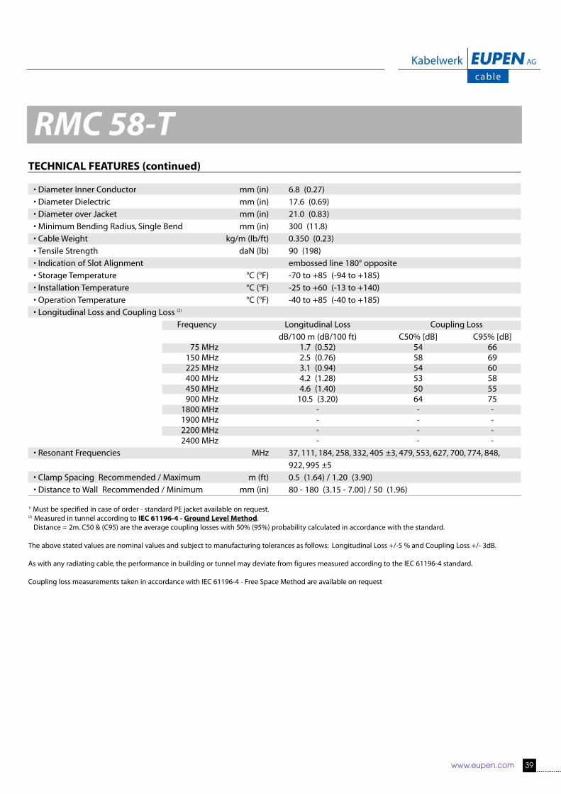
TECHNICAL FEATURES (continued)
• Diameter Inner Conductor mm (in) 6.8 (0.27)
• Diameter Dielectric mm (in) 17.6 (0.69)
• Diameter over Jacket mm (in) 21.0 (0.83)
• Minimum Bending Radius, Single Bend mm (in) 300 (11.8)
• Cable Weight kg/m (lb/ft) 0.350 (0.23)
• Tensile Strength daN (lb) 90 (198)
• Indication of Slot Alignment embossed line 180° opposite
• Storage Temperature °C (°F) -70 to +85 (-94 to +185)
• Installation Temperature °C (°F) -25 to +60 (-13 to +140)
• Operation Temperature °C (°F) -40 to +85 (-40 to +185)
• Longitudinal Loss and Coupling Loss (2)
Frequency Longitudinal Loss Coupling Loss
dB/100 m (dB/100 ft) C50% [dB] C95% [dB]75 MHz 1.7 (0.52) 54 66150 MHz 2.5 (0.76) 58 69225 MHz 3.1 (0.94) 54 60400 MHz 4.2 (1.28) 53 58450 MHz 4.6 (1.40) 50 55900 MHz 10.5 (3.20) 64 751800 MHz - - -1900 MHz - - -2200 MHz - - -2400 MHz - - -
• Resonant Frequencies MHz 37, 111, 184, 258, 332, 405 ±3, 479, 553, 627, 700, 774, 848,
922, 995 ±5
• Clamp Spacing Recommended / Maximum m (ft) 0.5 (1.64) / 1.20 (3.90)
• Distance to Wall Recommended / Minimum mm (in) 80 - 180 (3.15 - 7.00) / 50 (1.96)
1) Must be specified in case of order - standard PE jacket available on request.(2) Measured in tunnel according to IEC 61196-4 - Ground Level Method.Distance = 2m. C50 & (C95) are the average coupling losses with 50% (95%) probability calculated in accordance with the standard.
The above stated values are nominal values and subject to manufacturing tolerances as follows: Longitudinal Loss +/-5 % and Coupling Loss +/- 3dB.
As with any radiating cable, the performance in building or tunnel may deviate from figures measured according to the IEC 61196-4 standard.
Coupling loss measurements taken in accordance with IEC 61196-4 - Free Space Method are available on request
RMC 58-T

40 www.eupen.com
PRODUCT DESCRIPTION
Slots in the copper outer conductor allow a controlled portion of the internal RF energy to be radiated into the surrounding environ-ment. Conversely, a signal transmitted near the cable will couple into the slots and be carried along the cable length.
FEATURES and BENEFITS
• From 30 MHz to 2.8 GHz with resonant frequencies• Robust Cable, with low bending radius• Main Applications: Tunnel - FM, TETRA, GSM, DCS-1800, UMTS, WLAN
TECHNICAL FEATURES
• Size 7/8”
• Previous Model Number 522RC8RM-HLFR
• Frequency Range MHz 30 - 2800
• Recommended for Frequency MHz 900, 1800, 2200, 2400 and 2700
• Cable Type RMC (Radiated Mode Cable)
• Jacket HLFR (Halogen Free Low Smoke Flame Retardant)
• Slot Design Groups of Slots at short intervals
• Impedance Ω 50 +/- 2
• Velocity Ratio % 88
• Capacitance pF/m 76
• Inner Conductor dc Resistance Ω/1000 m (Ω/1000 ft) 1.63 (0.49)
• Outer Conductor dc Resistance Ω/1000 m (Ω/1000 ft) 1.50 (0.46)
• Inner Conductor Material Smooth copper tube
• Dielectric Material Cellular polyethylene
• Outer Conductor Material Overlapping copper foil, with slot groups, bonded to the jacket
RMC 78
Reference suffix (1) : -HLFR
RMC 78-HLFR
Fire behaviour
Halogen free and flame retardant outer sheath, Low corrosive gas emission acc. to IEC 60754-2Flame retardant acc. to IEC 60332-1 and IEC 60332-3 cat. C, Low smoke emission acc. to IEC 61034

www.eupen.com 41
RMC 78TECHNICAL FEATURES (continued)
• Diameter Inner Conductor mm (in) 9.2 (0.36)
• Diameter Dielectric mm (in) 23.5 (0.93)
• Diameter over Jacket mm (in) 27.0 (1.06)
• Minimum Bending Radius, Single Bend mm (in) 350 (13.8)
• Cable Weight kg/m (lb/ft) 0.480 (0.32) HLFR
• Tensile Strength daN (lb) 130 (287)
• Indication of Slot Alignment embossed line 180° opposite
• Storage Temperature °C (°F) -70 to +85 (-94 to +185)
• Installation Temperature °C (°F) -25 to +60 (-13 to +140)
• Operation Temperature °C (°F) -40 to +85 (-40 to +185)
• Longitudinal Loss and Coupling Loss (2)
Frequency Longitudinal Loss Coupling Loss
dB/100 m (dB/100 ft) C50% [dB] C95% [dB]75 MHz 1.02 (0.31) 61 71150 MHz 1.42 (0.43) 73 84225 MHz 1.74 (0.53) 69 73450 MHz 2.50 (0.76) 69 74900 MHz 3.82 (1.16) 66 731800 MHz 6.17 (1.88) 64 691900 MHz 6.42 (1.96) 64 692200 MHz 7.22 (2.20) 62 732400 MHz 7.81 (2.38) 64 732600 MHz 8.47 (2.58) 64 732800 MHz 9.43 (2.87) 65 73
• Resonant Frequencies MHz 184, 552, 920 ±5, 1288, 1656, 2024, 2392
• Clamp Spacing Recommended / Maximum m (ft) 0.5 (1.64) / 1.20 (3.90)
• Distance to Wall Recommended / Minimum mm (in) 80 - 180 (3.15 - 7.00) / 50 (1.96)
1) Must be specified in case of order - standard PE jacket available on request.(2) Measured in tunnel according to IEC 61196-4 - Ground Level Method.Distance = 2m. C50 & (C95) are the average coupling losses with 50% (95%) probability calculated in accordance with the standard.
The above stated values are nominal values and subject to manufacturing tolerances as follows: Longitudinal Loss +/-5 % and Coupling Loss +/- 3dB.
As with any radiating cable, the performance in building or tunnel may deviate from figures measured according to the IEC 61196-4 standard.
Coupling loss measurements taken in accordance with IEC 61196-4 - Free Space Method are available on request
42 www.eupen.com
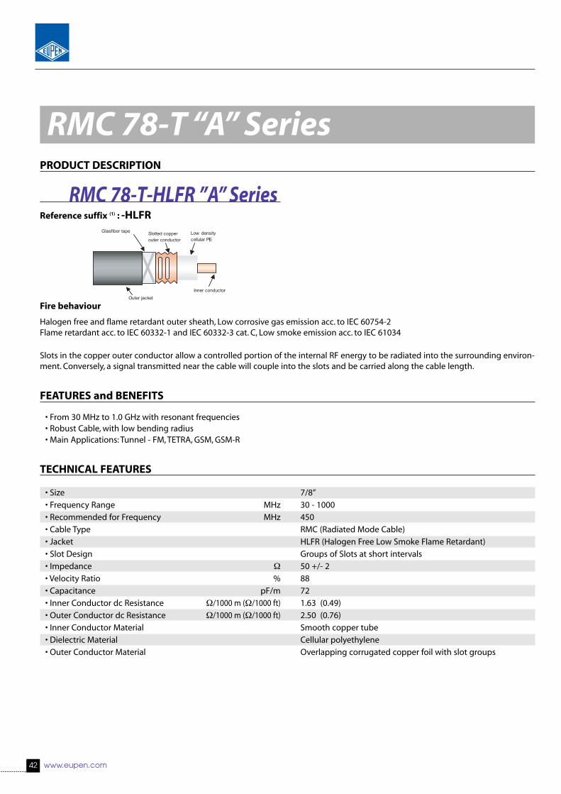
RMC 78-T “A” SeriesPRODUCT DESCRIPTION
Slots in the copper outer conductor allow a controlled portion of the internal RF energy to be radiated into the surrounding environ-ment. Conversely, a signal transmitted near the cable will couple into the slots and be carried along the cable length.
FEATURES and BENEFITS
• From 30 MHz to 1.0 GHz with resonant frequencies• Robust Cable, with low bending radius• Main Applications: Tunnel - FM, TETRA, GSM, GSM-R
TECHNICAL FEATURES
• Size 7/8”
• Frequency Range MHz 30 - 1000
• Recommended for Frequency MHz 450
• Cable Type RMC (Radiated Mode Cable)
• Jacket HLFR (Halogen Free Low Smoke Flame Retardant)
• Slot Design Groups of Slots at short intervals
• Impedance Ω 50 +/- 2
• Velocity Ratio % 88
• Capacitance pF/m 72
• Inner Conductor dc Resistance Ω/1000 m (Ω/1000 ft) 1.63 (0.49)
• Outer Conductor dc Resistance Ω/1000 m (Ω/1000 ft) 2.50 (0.76)
• Inner Conductor Material Smooth copper tube
• Dielectric Material Cellular polyethylene
• Outer Conductor Material Overlapping corrugated copper foil with slot groups
Reference suffix (1) : -HLFR
Outer jacket
Slotted copper outer conductor
Low densitycellular PE
Inner conductor
Glasfiber tape
RMC 78-T-HLFR ”A” Series
Fire behaviour
Halogen free and flame retardant outer sheath, Low corrosive gas emission acc. to IEC 60754-2Flame retardant acc. to IEC 60332-1 and IEC 60332-3 cat. C, Low smoke emission acc. to IEC 61034

www.eupen.com 43
RMC 78-T “A” SeriesTECHNICAL FEATURES (continued)
• Diameter Inner Conductor mm (in) 9.2 (0.36)
• Diameter Dielectric mm (in) 23.5 (0.93)
• Diameter over Jacket mm (in) 27.0 (1.06)
• Minimum Bending Radius, Single Bend mm (in) 350 (13.8)
• Cable Weight kg/m (lb/ft) 0.350 (0.29) HLFR
• Tensile Strength daN (lb) 130 (287)
• Indication of Slot Alignment embossed line 180° opposite
• Storage Temperature °C (°F) -70 to +85 (-94 to +185)
• Installation Temperature °C (°F) -25 to +60 (-13 to +140)
• Operation Temperature °C (°F) -40 to +85 (-40 to +185)
• Longitudinal Loss and Coupling Loss (2)
Frequency Longitudinal Loss Coupling Loss
dB/100 m (dB/100 ft) C50% [dB] C95% [dB]75 MHz 1.27 (0.39) 57 69150 MHz 1.73 (0.53) 60 71225 MHz 2.14 (0.65) 56 61450 MHz 3.29 (1.00) 52 53900 MHz 5.41 (1.65) 66 77
• Resonant Frequencies MHz 37; 111; 184; 258; 332; 405 ±5; 479; 553; 627; 700; 774; 848; 922; 995
• Clamp Spacing Recommended / Maximum m (ft) 0.5 (1.64) / 1.20 (3.90)
• Distance to Wall Recommended / Minimum mm (in) 80 - 180 (3.15 - 7.00) / 50 (1.96)
1) Must be specified in case of order - standard PE jacket available on request.(2) Measured in tunnel according to IEC 61196-4 - Ground Level Method.Distance = 2m. C50 & (C95) are the average coupling losses with 50% (95%) probability calculated in accordance with the standard.
The above stated values are nominal values and subject to manufacturing tolerances as follows: Longitudinal Loss +/-5 % and Coupling Loss +/- 3dB.
As with any radiating cable, the performance in building or tunnel may deviate from figures measured according to the IEC 61196-4 standard.
Coupling loss measurements taken in accordance with IEC 61196-4 - Free Space Method are available on request.

44 www.eupen.com
PRODUCT DESCRIPTION
Slots in the copper outer conductor allow a controlled portion of the internal RF energy to be radiated into the surrounding environ-ment. Conversely, a signal transmitted near the cable will couple into the slots and be carried along the cable length.
FEATURES and BENEFITS
• From 30 MHz to 2.4 GHz with resonant frequencies• Robust Cable, with low bending radius• Main Applications: Tunnel - FM, TETRA, GSM, GSM-R• Specially designed for GSM-R
TECHNICAL FEATURES
• Size 7/8”
• Previous Model Number 522RC8RMB-HLFR
• Frequency Range MHz 30 - 2400
• Recommended for Frequency MHz 900
• Cable Type RMC (Radiated Mode Cable)
• Jacket HLFR (Halogen Free Low Smoke Flame Retardant) Anti Termite
• Slot Design Groups of Slots at short intervals
• Impedance Ω 50 +/- 2
• Velocity Ratio % 88
• Capacitance pF/m 72
• Inner Conductor dc Resistance Ω/1000 m (Ω/1000 ft) 1.63 (0.49)
• Outer Conductor dc Resistance Ω/1000 m (Ω/1000 ft) 2.50 (0.76)
• Inner Conductor Material Smooth copper tube
• Dielectric Material Cellular polyethylene
• Outer Conductor Material Overlapping copper foil, with slot groups
RMC 78-B “A” Series
Reference suffix (1) : -HLFR
RMC 78-B-HLFR “A” Series
Fire behaviour
Halogen free and flame retardant outer sheath, Low corrosive gas emission acc. to IEC 60754-2Flame retardant acc. to IEC 60332-1 and IEC 60332-3 cat. C, Low smoke emission acc. to IEC 61034
Outer jacket
Slotted copper outer conductor
Low densitycellular PE
Inner conductor
Glasfiber tape

www.eupen.com 45
RMC 78-B “A” SeriesTECHNICAL FEATURES (continued)
• Diameter Inner Conductor mm (in) 9.2 (0.36)
• Diameter Dielectric mm (in) 23.5 (0.93)
• Diameter over Jacket mm (in) 27.0 (1.06)
• Minimum Bending Radius, Single Bend mm (in) 350 (13.8)
• Cable Weight kg/m (lb/ft) 0.350 (0.29) HLFR
• Tensile Strength daN (lb) 130 (287)
• Indication of Slot Alignment embossed line 180° opposite
• Storage Temperature °C (°F) -70 to +85 (-94 to +185)
• Installation Temperature °C (°F) -25 to +60 (-13 to +140)
• Operation Temperature °C (°F) -40 to +85 (-40 to +185)
• Longitudinal Loss and Coupling Loss (2)
Frequency Longitudinal Loss Coupling Loss
dB/100 m (dB/100 ft) C50% [dB] C95% [dB]75 MHz 1.30 (0.40) 56 67150 MHz 1.62 (0.49) 60 65225 MHz 1.91 (0.58) 62 72450 MHz 2.72 (0.83) 59 63900 MHz 4.19 (1.28) 53 561800 MHz 6.97 (2.12) 66 781900 MHz 7.27 (2.22) 65 772200 MHz 8.17 (2.49) 65 762400 MHz 8.77 (2.67) 64 75
• Resonant Frequencies MHz 63, 189, 315, 441, 567, 693, 819, 945 ±5, 1071
• Clamp Spacing Recommended / Maximum m (ft) 0.5 (1.64) / 1.20 (3.90)
• Distance to Wall Recommended / Minimum mm (in) 80 - 180 (3.15 - 7.00) / 50 (1.96)
1) Must be specified in case of order - standard PE jacket available on request.(2) Measured in tunnel according to IEC 61196-4 - Ground Level Method.Distance = 2m. C50 & (C95) are the average coupling losses with 50% (95%) probability calculated in accordance with the standard.
The above stated values are nominal values and subject to manufacturing tolerances as follows: Longitudinal Loss +/-5 % and Coupling Loss +/- 3dB.
As with any radiating cable, the performance in building or tunnel may deviate from figures measured according to the IEC 61196-4 standard.
Coupling loss measurements taken in accordance with IEC 61196-4 - Free Space Method are available on request

46 www.eupen.com
PRODUCT DESCRIPTION
Slots in the copper outer conductor allow a controlled portion of the internal RF energy to be radiated into the surrounding environ-ment. Conversely, a signal transmitted near the cable will couple into the slots and be carried along the cable length.
FEATURES and BENEFITS
• Low Fading at short aerial to cable distance• Robust Cable, with low bending radius• Main Applications: WLAN• Optimised for WLAN applications in the 2.40 - 2.485 GHz band
TECHNICAL FEATURES
• Size 7/8”
• Frequency Range MHz 1800 - 2800
• Recommended for Frequency MHz 2400 - 2485
• Cable Type RMC (Radiated Mode Cable)
• Jacket HLFR (Halogen Free Low Smoke Flame Retardant) Anti Termite
• Slot Design Groups of Slots at short intervals
• Impedance Ω 50 +/- 2
• Velocity Ratio % 88
• Capacitance pF/m 72
• Inner Conductor dc Resistance Ω/1000 m (Ω/1000 ft) 1.63 (0.49)
• Outer Conductor dc Resistance Ω/1000 m (Ω/1000 ft) 2.50 (0.76)
• Inner Conductor Material Smooth copper tube
• Dielectric Material Cellular polyethylene
• Outer Conductor Material Overlapping copper foil, with slot groups
RMC 78-CL “A” Series
Reference suffix (1) : -HLFR
RMC 78-CL-HLFR “A” Series
Fire behaviour
Halogen free and flame retardant outer sheath, Low corrosive gas emission acc. to IEC 60754-2Flame retardant acc. to IEC 60332-1 and IEC 60332-3 cat. C, Low smoke emission acc. to IEC 61034
Outer jacket
Slotted copper outer conductor
Low densitycellular PE
Inner conductor
Glasfiber tape

www.eupen.com 47
RMC 78-CL “A” SeriesTECHNICAL FEATURES (continued)
• Diameter Inner Conductor mm (in) 9.2 (0.36)
• Diameter Dielectric mm (in) 23.5 (0.93)
• Diameter over Jacket mm (in) 27.0 (1.06)
• Minimum Bending Radius, Single Bend mm (in) 350 (13.8)
• Cable Weight kg/m (lb/ft) 0.350 (0.29) HLFR
• Tensile Strength daN (lb) 130 (287)
• Indication of Slot Alignment embossed line 180° opposite
• Storage Temperature °C (°F) -70 to +85 (-94 to +185)
• Installation Temperature °C (°F) -25 to +60 (-13 to +140)
• Operation Temperature °C (°F) -40 to +85 (-40 to +185)
• Longitudinal Loss and Coupling Loss (2)
Frequency Longitudinal Loss Coupling Loss
dB/100 m (dB/100 ft) C50% [dB] C95% [dB]1800 MHz 5.86 (1.79) 64 692400 MHz 7.65 (2.33) 60 67
• Resonant Frequencies MHz 2054; 2370; 2686
• Clamp Spacing Recommended / Maximum m (ft) 0.5 (1.64) / 1.20 (3.90)
• Distance to Wall Recommended / Minimum mm (in) 80 - 180 (3.15 - 7.00) / 50 (1.96)
11) Must be specified in case of order - standard PE jacket available on request.(2) Measured in tunnel according to IEC 61196-4 - Ground Level Method.Distance = 2m. C50 & (C95) are the average coupling losses with 50% (95%) probability calculated in accordance with the standard.
The above stated values are nominal values and subject to manufacturing tolerances as follows: Longitudinal Loss +/-5 % and Coupling Loss +/- 3dB.
As with any radiating cable, the performance in building or tunnel may deviate from figures measured according to the IEC 61196-4 standard.
Coupling loss measurements taken in accordance with IEC 61196-4 - Free Space Method are available on request.

48 www.eupen.com
RMC 114 “A” SeriesPRODUCT DESCRIPTION
Slots in the copper outer conductor allow a controlled portion of the internal RF energy to be radiated into the surrounding environ-ment. Conversely, a signal transmitted near the cable will couple into the slots and be carried along the cable length.
FEATURES and BENEFITS
• From 30 MHz to 2800 MHz with resonant frequencies• Robust Cable, with low bending radius• Main Applications: Tunnel - GSM, DCS-1800, UMTS, WLAN
TECHNICAL FEATURES
• Size 1-1/4”
• Frequency Range MHz 30 - 2800
• Recommended for Frequency MHz 900, 1800, 2200, 2400 & 2700
• Cable Type RMC (Radiated Mode Cable)
• Jacket HLFR (Halogen Free Low Smoke Flame Retardant)
• Slot Design Groups of Slots at short intervals
• Impedance Ω 50 +/- 2
• Velocity Ratio % 89
• Capacitance pF/m 76
• Inner Conductor dc Resistance Ω/1000 m (Ω/1000 ft) 0.87 (0.26)
• Outer Conductor dc Resistance Ω/1000 m (Ω/1000 ft) 1.65 (0.50)
• Inner Conductor Material Smooth copper tube
• Dielectric Material Cellular polyethylene
• Outer Conductor Material Overlapping corrugated copper foil with slot groups
Reference suffix (1) : -HLFR
Outer jacket
Slotted copper outer conductor
Low densitycellular PE
Inner conductor
Glasfiber tape
RMC 114-HLFR ”A” Series
Fire behaviour
Halogen free and flame retardant outer sheath, Low corrosive gas emission acc. to IEC 60754-2Flame retardant acc. to IEC 60332-1 and IEC 60332-3 cat. C, Low smoke emission acc. to IEC 61034(2)
.

www.eupen.com 49
TECHNICAL FEATURES (continued)
• Diameter Inner Conductor mm (in) 13.0 (0.51)
• Diameter Dielectric mm (in) 33.5 (1.32)
• Diameter over Jacket mm (in) 38.0 (1.50)
• Minimum Bending Radius, Single Bend mm (in) 350 (13.8)
• Cable Weight kg/m (lb/ft) 0.875 (0.58) HLFR
• Tensile Strength daN (lb) 180 (397)
• Indication of Slot Alignment embossed line 180° opposite
• Storage Temperature °C (°F) -70 to +85 (-94 to +185)
• Installation Temperature °C (°F) -25 to +60 (-13 to +140)
• Operation Temperature °C (°F) -40 to +85 (-40 to +185)
• Longitudinal Loss and Coupling Loss (3)
Frequency Longitudinal Loss Coupling Loss
dB/100 m (dB/100 ft) C50% [dB] C95% [dB]75 MHz 0.85 (0.26) 64 74150 MHz 1.21 (0.37) 69 79225 MHz 1.50 (0.46) 61 64450 MHz 2.18 (0.66) 68 73900 MHz 3.18 (0.97) 64 691800 MHz 5.36 (1.63) 59 652200 MHz 7.36 (2.24) 59 652400 MHz 8.86 (2.70) 52 572600 MHz 10.80 (3.29) 53 582800 MHz 13.66 (4.16) 53 59
• Resonant Frequencies MHz 199; 598; 997; 1396; 1795; 2193; 2592; 2991
• Clamp Spacing Recommended / Maximum m (ft) 0.5 (1.64) / 1.20 (3.90)
• Distance to Wall Recommended / Minimum mm (in) 80 - 180 (3.15 - 7.00) / 50 (1.96)
1) Must be specified in case of order - standard PE jacket available on request.(2) The smoke density test is performed, based on the IEC 61034. Considering the usual application of radiating cables, the test is done with one sample (>7/8”)(3) Measured in tunnel according to IEC 61196-4 - Ground Level Method.Distance = 2m. C50 & (C95) are the average coupling losses with 50% (95%) probability calculated in accordance with the standard.
The above stated values are nominal values and subject to manufacturing tolerances as follows: Longitudinal Loss +/-5 % and Coupling Loss +/- 3dB.
As with any radiating cable, the performance in building or tunnel may deviate from figures measured according to the IEC 61196-4 standard.
RMC 114 “A” Series

50 www.eupen.com
RMC 114-T “A” SeriesPRODUCT DESCRIPTION
Slots in the copper outer conductor allow a controlled portion of the internal RF energy to be radiated into the surrounding environ-ment. Conversely, a signal transmitted near the cable will couple into the slots and be carried along the cable length.
FEATURES and BENEFITS
• From 30 MHz to 1.0 GHz with resonant frequencies• Robust Cable, with low bending radius• Main Applications: Tunnel - FM, TETRA, GSM, GSM-R
TECHNICAL FEATURES
• Size 1-1/4”
• Frequency Range MHz 30 - 1000
• Recommended for Frequency MHz 450
• Cable Type RMC (Radiated Mode Cable)
• Jacket HLFR (Halogen Free Low Smoke Flame Retardant)
• Slot Design Groups of Slots at short intervals
• Impedance Ω 50 +/- 2
• Velocity Ratio % 88
• Capacitance pF/m 76
• Inner Conductor dc Resistance Ω/1000 m (Ω/1000 ft) 0.87 (0.27)
• Outer Conductor dc Resistance Ω/1000 m (Ω/1000 ft) 1.65 (0.50)
• Inner Conductor Material Smooth copper tube
• Dielectric Material Cellular polyethylene
• Outer Conductor Material Overlapping corrugated copper foil with slot groups
Reference suffix (1) : -HLFR
Outer jacket
Slotted copper outer conductor
Low densitycellular PE
Inner conductor
Glasfiber tape
RMC 114-T-HLFR ”A” Series
Fire behaviour
Halogen free and flame retardant outer sheath, Low corrosive gas emission acc. to IEC 60754-2Flame retardant acc. to IEC 60332-1 and IEC 60332-3 cat. C, Low smoke emission acc. to IEC 61034(2)

www.eupen.com 51
RMC 114-T “A” SeriesTECHNICAL FEATURES (continued)
• Diameter Inner Conductor mm (in) 13.0 (0.51)
• Diameter Dielectric mm (in) 33.5 (1.32)
• Diameter over Jacket mm (in) 38.0 (1.50)
• Minimum Bending Radius, Single Bend mm (in) 350 (13.8)
• Cable Weight kg/m (lb/ft) 0.875 (0.58) HLFR
• Tensile Strength daN (lb) 180 (397)
• Indication of Slot Alignment embossed line 180° opposite
• Storage Temperature °C (°F) -70 to +85 (-94 to +185)
• Installation Temperature °C (°F) -25 to +60 (-13 to +140)
• Operation Temperature °C (°F) -40 to +85 (-40 to +185)
• Longitudinal Loss and Coupling Loss (3)
Frequency Longitudinal Loss Coupling Loss
dB/100 m (dB/100 ft) C50% [dB] C95% [dB]75 MHz 0.78 (0.24) 51 64150 MHz 1.16 (0.35) 59 70225 MHz 1.46 (0.44) 59 64450 MHz 2.13 (0.65) 54 58900 MHz 3.01 (0,92) 66 76
• Resonant Frequencies MHz 37; 111; 184; 258; 332; 405 ±5; 479; 553; 627; 700; 774; 848; 922; 995
• Clamp Spacing Recommended / Maximum m (ft) 0.5 (1.64) / 1.20 (3.90)
• Distance to Wall Recommended / Minimum mm (in) 80 - 180 (3.15 - 7.00) / 50 (1.96)
1) Must be specified in case of order - standard PE jacket available on request.(2) The smoke density test is performed, based on the IEC 61034. Considering the usual application of radiating cables, the test is done with one sample (>7/8”)(3) Measured in tunnel according to IEC 61196-4 - Ground Level Method.Distance = 2m. C50 & (C95) are the average coupling losses with 50% (95%) probability calculated in accordance with the standard.
The above stated values are nominal values and subject to manufacturing tolerances as follows: Longitudinal Loss +/-5 % and Coupling Loss +/- 3dB.
As with any radiating cable, the performance in building or tunnel may deviate from figures measured according to the IEC 61196-4 standard.
Coupling loss measurements taken in accordance with IEC 61196-4 - Free Space Method are available on request.

52 www.eupen.com
RMC 114-B “A” SeriesPRODUCT DESCRIPTION
Slots in the copper outer conductor allow a controlled portion of the internal RF energy to be radiated into the surrounding environ-ment. Conversely, a signal transmitted near the cable will couple into the slots and be carried along the cable length.
FEATURES and BENEFITS
• From 30 MHz to 2600 MHz with resonant frequencies• Robust Cable, with low bending radius• Main Applications: Tunnel - GSM, GSM-R, TETRA
TECHNICAL FEATURES
• Size 1-1/4”
• Frequency Range MHz 30 - 2600
• Recommended for Frequency MHz 75 to 900
• Cable Type RMC (Radiated Mode Cable)
• Jacket HLFR (Halogen Free Low Smoke Flame Retardant)
Anti Termite & Anti Rodent
• Slot Design Groups of Slots at short intervals
• Impedance Ω 50 +/- 2
• Velocity Ratio % 89
• Capacitance pF/m 76
• Inner Conductor dc Resistance Ω/1000 m (Ω/1000 ft) 0.87 (0.26)
• Outer Conductor dc Resistance Ω/1000 m (Ω/1000 ft) 1.65 (0.50)
• Inner Conductor Material Smooth copper tube
• Dielectric Material Cellular polyethylene
• Outer Conductor Material Overlapping corrugated copper foil with slot groups
Reference suffix (1) : -HLFR
Outer jacket
Slotted copper outer conductor
Low densitycellular PE
Inner conductor
Glasfiber tape
RMC 114-B-HLFR ”A” Series
Fire behaviour
Halogen free and flame retardant outer sheath, Low corrosive gas emission acc. to IEC 60754-2Flame retardant acc. to IEC 60332-1 and IEC 60332-3 cat. C, Low smoke emission acc. to IEC 61034(2)
.

www.eupen.com 53
TECHNICAL FEATURES (continued)
• Diameter Inner Conductor mm (in) 13.0 (0.51)
• Diameter Dielectric mm (in) 33.5 (1.32)
• Diameter over Jacket mm (in) 38.0 (1.50)
• Minimum Bending Radius, Single Bend mm (in) 350 (13.8)
• Approximate Cable Weight kg/km (lb/ft) 0.809 (0.54) HLFR
• Tensile Strength daN (lb) 180 (397)
• Indication of Slot Alignment embossed line 180° opposite
• Storage Temperature °C (°F) -70 to +85 (-94 to +185)
• Installation Temperature °C (°F) -25 to +60 (-13 to +140)
• Operation Temperature °C (°F) -40 to +85 (-40 to +185)
• Longitudinal Loss and Coupling Loss (3)
Frequency Longitudinal Loss Coupling Loss
dB/100 m (dB/100 ft) C50% [dB] C95% [dB]75 MHz 0.89 (0.27) 52 61150 MHz 1.25 (0.38) 62 70225 MHz 1.52 (0.46) 63 70450 MHz 2.17 (0.66) 60 64900 MHz 3.28 (1.00) 55 581800 MHz 5.70 (1.74) 60 712200 MHz 6.98 (2.13) 60 682400 MHz 7.68 (2.43) 61 692600 MHz 8.42 (2.57) 61 69
• Resonant Frequencies MHz 65; 195; 325; 455; 585; 715; 845; 975; 1105; 1235; 1365; 1496; 1626; 1756; 1886; 2016; 2146; 2276; 2406; 2536
• Clamp Spacing Recommended / Maximum m (ft) 0.5 (1.64) / 1.20 (3.90)
• Distance to Wall Recommended / Minimum mm (in) 80 - 180 (3.15 - 7.00) / 50 (1.96)
1) Must be specified in case of order - standard PE jacket available on request.(2) The smoke density test is performed, based on the IEC 61034. Considering the usual application of radiating cables, the test is done with one sample (>7/8”)(3) Measured in tunnel according to IEC 61196-4 - Ground Level Method.Distance = 2m. C50 & (C95) are the average coupling losses with 50% (95%) probability calculated in accordance with the standard.
The above stated values are nominal values and subject to manufacturing tolerances as follows: Longitudinal Loss +/-5 % and Coupling Loss +/- 3dB.
As with any radiating cable, the performance in building or tunnel may deviate from figures measured according to the IEC 61196-4 standard.
RMC 114-B “A” Series

54 www.eupen.com
PRODUCT DESCRIPTION
Slots in the copper outer conductor allow a controlled portion of the internal RF energy to be radiated into the surrounding environ-ment. Conversely, a signal transmitted near the cable will couple into the slots and be carried along the cable length.
FEATURES and BENEFITS
• From 30 MHz to 3.5 GHz with resonant frequencies• Robust Cable, with low bending radius• Main Applications: Tunnel - GSM, DCS-1800, UMTS, WLAN, LTE
TECHNICAL FEATURES
• Size 1-5/8”
• Frequency Range MHz 30 - 3500
• Recommended for Frequency MHz 400, 450, 900, 1800, 2200, 2400 and 2700
• Cable Type RMC (Radiated Mode Cable)
• Jacket HLFR (Halogen Free Low Smoke Flame Retardant)
• Slot Design Groups of Slots at short intervals
• Impedance Ω 50 +/- 2
• Velocity Ratio % 89
• Capacitance pF/m 75
• Inner Conductor dc Resistance Ω/1000 m (Ω/1000 ft) 1.44 (0.44)
• Outer Conductor dc Resistance Ω/1000 m (Ω/1000 ft) 1.28 (0.39)
• Inner Conductor Material Corrugated copper tube
• Dielectric Material Cellular polyethylene
• Outer Conductor Material Overlapping corrugated copper foil with slot groups
Reference suffix (1) : -HLFR
RMC 158-HLFR ”A” Series
Fire behaviour
Halogen free and flame retardant outer sheath, Low corrosive gas emission acc. to IEC 60754-2Flame retardant acc. to IEC 60332-1 and IEC 60332-3 cat. C, Low smoke emission acc. to IEC 61034
.
RMC 158 “A” Series

www.eupen.com 55
TECHNICAL FEATURES (continued)
• Diameter Inner Conductor mm (in) 17.7 (0.70)
• Diameter Dielectric mm (in) 43.0 (1.69)
• Diameter over Jacket mm (in) 48.0 (1.89)
• Minimum Bending Radius, Single Bend mm (in) 400 (15.7)
• Cable Weight kg/m (lb/ft) 0.92 (0.62) HLFR
• Tensile Strength daN (lb) 200 (441)
• Indication of Slot Alignment embossed line 180° opposite
• Storage Temperature °C (°F) -70 to +85 (-94 to +185)
• Installation Temperature °C (°F) -25 to +60 (-13 to +140)
• Operation Temperature °C (°F) -40 to +85 (-40 to +185)
• Longitudinal Loss and Coupling Loss (3)
Frequency Longitudinal Loss Coupling Loss
dB/100 m (dB/100 ft) C50% [dB] C95% [dB]75 MHz 0.58 (0.18) 66 77150 MHz 0.84 (0.26) 76 85225 MHz 1.06 (0.32) 61 64450 MHz 1.59 (0.48) 71 76900 MHz 2.44 (0.74) 70 751800 MHz 4.27 (1.33) 57 621900 MHz 4.55 (1.39) 56 602200 MHz 5.60 (1.71) 54 582400 MHz 6.50 (1.98) 52 602800 MHz 8.99 (2.74) 55 623500 MHz 16.56 (5.05) 52 60
• Resonant Frequencies MHz 199, 598, 997, 1396, 1795, 2193, 2592, 2991
• Clamp Spacing Recommended / Maximum m (ft) 0.5 (1.64) / 1.20 (3.90)
• Distance to Wall Recommended / Minimum mm (in) 80 - 180 (3.15 - 7.00) / 50 (1.96)
1) Must be specified in case of order - standard PE jacket available on request.(2) The smoke density test is performed, based on the IEC 61034. Considering the usual application of radiating cables, the test is done with one sample (>7/8”)(3) Measured in tunnel according to IEC 61196-4 - Ground Level Method.Distance = 2m. C50 & (C95) are the average coupling losses with 50% (95%) probability calculated in accordance with the standard.
The above stated values are nominal values and subject to manufacturing tolerances as follows: Longitudinal Loss +/-5 % and Coupling Loss +/- 3dB.
As with any radiating cable, the performance in building or tunnel may deviate from figures measured according to the IEC 61196-4 standard.
Coupling loss measurements taken in accordance with IEC 61196-4 - Free Space Method are available on request.
RMC 158 “A” Series

56 www.eupen.com
RMC 158-T “A” SeriesPRODUCT DESCRIPTION
Slots in the copper outer conductor allow a controlled portion of the internal RF energy to be radiated into the surrounding environ-ment. Conversely, a signal transmitted near the cable will couple into the slots and be carried along the cable length.
FEATURES and BENEFITS
• From 30 MHz to 1.0 GHz with resonant frequencies• Robust Cable, with low bending radius• Main Applications: Tunnel - FM, TETRA, GSM, GSM-R
TECHNICAL FEATURES
• Size 1-5/8”
• Frequency Range MHz 30 - 1000
• Recommended for Frequency MHz 450
• Cable Type RMC (Radiated Mode Cable)
• Jacket HLFR (Halogen Free Low Smoke Flame Retardant)
• Slot Design Groups of Slots at short intervals
• Impedance Ω 50 +/- 2
• Velocity Ratio % 89
• Capacitance pF/m 75
• Inner Conductor dc Resistance Ω/1000 m (Ω/1000 ft) 1.44 (0.44)
• Outer Conductor dc Resistance Ω/1000 m (Ω/1000 ft) 1.28 (0.39)
• Inner Conductor Material Corrugated copper tube
• Dielectric Material Cellular polyethylene
• Outer Conductor Material Overlapping corrugated copper foil with slot groups
Reference suffix (1) : -HLFR
RMC 158-T-HLFR ”A” Series
Fire behaviour
Halogen free and flame retardant outer sheath, Low corrosive gas emission acc. to IEC 60754-2Flame retardant acc. to IEC 60332-1 and IEC 60332-3 cat. C, Low smoke emission acc. to IEC 61034(2)

www.eupen.com 57
TECHNICAL FEATURES (continued)
• Diameter Inner Conductor mm (in) 17.7 (0.70)
• Diameter Dielectric mm (in) 43.0 (1.69)
• Diameter over Jacket mm (in) 48.0 (1.89)
• Minimum Bending Radius, Single Bend mm (in) 400 (15.7)
• Cable Weight kg/m (lb/ft) 0.925 (0.62) HLFR
• Tensile Strength daN (lb) 200 (441)
• Indication of Slot Alignment embossed line 180° opposite
• Storage Temperature °C (°F) -70 to +85 (-94 to +185)
• Installation Temperature °C (°F) -25 to +60 (-13 to +140)
• Operation Temperature °C (°F) -40 to +85 (-40 to +185)
• Longitudinal Loss and Coupling Loss (3)
Frequency Longitudinal Loss Coupling Loss
dB/100 m (dB/100 ft) C50% [dB] C95% [dB]75 MHz 0.80 (0.24) 57 69150 MHz 1.09 (0.33) 59 68225 MHz 1.32 (0.40) 57 61450 MHz 1.86 (0.57) 53 56900 MHz 2.76 (0.84) 64 75
• Resonant Frequencies MHz 37; 111; 184; 258; 332; 405 ±5; 479; 553; 627; 700; 774; 848; 922; 995
• Clamp Spacing Recommended / Maximum m (ft) 0.5 (1.64) / 1.20 (3.90)
• Distance to Wall Recommended / Minimum mm (in) 80 - 180 (3.15 - 7.00) / 50 (1.96)
1) Must be specified in case of order - standard PE jacket available on request.(2) The smoke density test is performed, based on the IEC 61034. Considering the usual application of radiating cables, the test is done with one sample (>7/8”)(3) Measured in tunnel according to IEC 61196-4 - Ground Level Method.Distance = 2m. C50 & (C95) are the average coupling losses with 50% (95%) probability calculated in accordance with the standard.
The above stated values are nominal values and subject to manufacturing tolerances as follows: Longitudinal Loss +/-5 % and Coupling Loss +/- 3dB.
As with any radiating cable, the performance in building or tunnel may deviate from figures measured according to the IEC 61196-4 standard.
Coupling loss measurements taken in accordance with IEC 61196-4 - Free Space Methode are available on request.
RMC 158-T “A” Series

58 www.eupen.com
RMC 158-B “A” SeriesPRODUCT DESCRIPTION
Slots in the copper outer conductor allow a controlled portion of the internal RF energy to be radiated into the surrounding environ-ment. Conversely, a signal transmitted near the cable will couple into the slots and be carried along the cable length.
FEATURES and BENEFITS
• From 30 MHz to 2600 MHz with resonant frequencies• Robust Cable, with low bending radius• Main Applications: Tunnel - GSM, DCS-1800, UMTS, WLAN
TECHNICAL FEATURES
• Size 1-5/8”
• Frequency Range MHz 30 - 2600
• Recommended for Frequency MHz 75 to 900
• Cable Type RMC (Radiated Mode Cable)
• Jacket HLFR (Halogen Free Low Smoke Flame Retardant)
• Slot Design Groups of Slots at short intervals
• Impedance Ω 50 +/- 2
• Velocity Ratio % 89
• Capacitance pF/m 75
• Inner Conductor dc Resistance Ω/1000 m (Ω/1000 ft) 1.44 (0.44)
• Outer Conductor dc Resistance Ω/1000 m (Ω/1000 ft) 1.28 (0.39)
• Inner Conductor Material Corrugated copper tube
• Dielectric Material Cellular polyethylene
• Outer Conductor Material Overlapping corrugated copper foil with slot groups
Reference suffix (1) : -HLFR
RMC 158-B-HLFR ”A” Series
Fire behaviour
Halogen free and flame retardant outer sheath, Low corrosive gas emission acc. to IEC 60754-2Flame retardant acc. to IEC 60332-1 and IEC 60332-3 cat. C, Low smoke emission acc. to IEC 61034(2)

www.eupen.com 59
RMC 158-B “A” SeriesTECHNICAL FEATURES (continued)
• Diameter Inner Conductor mm (in) 17.7 (0.70)
• Diameter Dielectric mm (in) 43.0 (1.69)
• Diameter over Jacket mm (in) 48.0 (1.89)
• Minimum Bending Radius, Single Bend mm (in) 400 (15.7)
• Cable Weight kg/m (lb/ft) 0.945 (0.63) HLFR
• Tensile Strength daN (lb) 200 (441)
• Indication of Slot Alignment embossed line 180° opposite
• Storage Temperature °C (°F) -70 to +85 (-94 to +185)
• Installation Temperature °C (°F) -25 to +60 (-13 to +140)
• Operation Temperature °C (°F) -40 to +85 (-40 to +185)
• Longitudinal Loss and Coupling Loss (3)
Frequency Longitudinal Loss Coupling Loss
dB/100 m (dB/100 ft) C50% [dB] C95% [dB]75 MHz 0.70 (0.21) 58 68150 MHz 0.98 (0.30) 63 69225 MHz 1.20 (0.37) 71 80450 MHz 1.74 (0.53) 62 68900 MHz 2.66 (0.81) 58 621800 MHz 4.73 (1.44) 65 762200 MHz 5.84 (1.78) 65 752400 MHz 6.44 (1.96) 65 762600 MHz 7.09 (2.16) 65 76
• Resonant Frequencies MHz 58; 174; 290; 406; 522; 638; 754; 870; 986; 1102; 1218; 1334; 1450; 1566; 1682; 1798; 1914; 2029; 2145; 2261
• Clamp Spacing Recommended / Maximum m (ft) 0.5 (1.64) / 1.20 (3.90)
• Distance to Wall Recommended / Minimum mm (in) 80 - 180 (3.15 - 7.00) / 50 (1.96)
1) Must be specified in case of order - standard PE jacket available on request.(2) The smoke density test is performed, based on the IEC 61034. Considering the usual application of radiating cables, the test is done with one sample (>7/8”)(3) Measured outside according to IEC 61196-4 - Free Space Method. Distance = 2m. C50 & (C95) are the average coupling losses with 50% (95%) probability calculated in accordance with the standard.
The above stated values are nominal values and subject to manufacturing tolerance.
As with any radiating cable, the performance in building or tunnel may deviate from figures measured according to the IEC 61196-4 standard.
Coupling loss measurements taken inside Tunnel in accordance with IEC 61196-4 - Ground Level Method are available on request.

60 www.eupen.com
CMC 12PRODUCT DESCRIPTION
The Slot in the copper outer conductor allows a controlled portion of the internal RF energy to be radiated into the surroundingenvironment. Conversely, a signal transmitted near the cable will couple into the slots and be carried along the cable length.
FEATURES and BENEFITS
• Broadband from 30 MHz to 2.5 GHz• Robust Cable, with low bending radius• No Resonant Frequencies• No Cable Orientation Required• Main Applications: Inhouse, Short Length, FM, TETRA, GSM, DCS-1800, WLAN
TECHNICAL FEATURES
• Size 1/2”
• Previous Model Number 512RC8RI-HLFR
• Frequency Range MHz 30 - 2500
• Recommended for Frequency MHz N.A.
• Cable Type CMC (Coupled Mode Cable)
• Jacket HLFR (Halogen Free Low Smoke Flame Retardant)
• Slot Design Continous slot
• Impedance Ω 50 +/- 2
• Velocity Ratio % 88
• Capacitance pF/m 76
• Inner Conductor dc Resistance Ω/1000 m (Ω/1000 ft) 1.48 (0.45)
• Outer Conductor dc Resistance Ω/1000 m (Ω/1000 ft) 3.3 (1.01)
• Inner Conductor Material Copper clad aluminium wire
• Dielectric Material Cellular polyethylene
• Outer Conductor Material Copper foil, with continous slot, bonded to the jacket
Reference suffix (1) : -HLFR
CMC 12-HLFR
Fire behaviour
Halogen free and flame retardant outer sheathLow corrosive gas emission acc. to IEC 60754-2Flame retardant acc. to IEC 60332-1 and IEC 60332-3 cat. CLow smoke emission acc. to IEC 61034

www.eupen.com 61
CMC 12TECHNICAL FEATURES (continued)
• Diameter Inner Conductor mm (in) 4.8 (0.19)
• Diameter Dielectric mm (in) 12.4 (0.49)
• Diameter over Jacket mm (in) 15.5 (0.61)
• Minimum Bending Radius mm (in) 150 (5.9)
• Cable Weight kg/m (lb/ft) 0.23 (0.15) HLFR
• Tensile Strength daN (lb) 110 (242)
• Indication of Slot Alignment N.A.
• Storage Temperature °C (°F) -70 to +85 (-94 to +185)
• Installation Temperature °C (°F) -25 to +60 (-13 to +140)
• Operation Temperature °C (°F) -40 to +85 (-40 to +185)
• Longitudinal Loss and Coupling Loss (2)
Frequency Longitudinal Loss Coupling Loss
dB/100 m (dB/100 ft) C50% [dB] C95% [dB]75 MHz 2.06 (0.63) 61 72150 MHz 3.10 (0.94) 68 80225 MHz 3.95 (1.20) 69 81450 MHz 5.90 (1.80) 83 94900 MHz 8.63 (2.63) 82 941800 MHz 12.75 (3.89) 80 931900 MHz 13.19 (4.02) 80 932200 MHz 14.47 (4.41) 82 972400 MHz 15.25 (4.65) 82 97
• Resonant Frequencies MHz None
• Clamp Spacing Recommended / Maximum m (ft) 0.5 (1.64) / 1.20 (3.90)
• Distance to Wall Recommended / Minimum mm (in) 80 - 180 (3.15 - 7.00) / 50 (1.96)
1) Must be specified in case of order - standard PE jacket available on request.(2) Measured in tunnel according to IEC 61196-4 - Ground Level Method.Distance = 2m. C50 & (C95) are the average coupling losses with 50% (95%) probability calculated in accordance with the standard.
The above stated values are nominal values and subject to manufacturing tolerances.
As with any radiating cable, the performance in building or tunnel may deviate from figures measured according to the IEC 61196-4 standard.
Coupling loss measurements taken in accordance with IEC 61196-4 - Free Space Method are available on request

62 www.eupen.com

PRODUCT DESCRIPTION
Integrated messenger wire is available as an option on radiating cables 7/8” to 1-5/8”.Please consult us.
TECHNICAL FEATURES 7/8” 1-1/4” 1-5/8”
• Cable Weight (HLFR) kg/m 0.75 1.1 1.2
lb/ft 0.61 0.83 0.83
• Breaking Strength of Messenger daN (lb) 1225 (2700) 1900 (4190) 1900 (4190)
• Indication of Slot Alignment Opposite of messenger
• Material of Messenger galvanised steel stainless steel stainless steel
• Diameter over Messenger Jacket mm (in) 7.5 (0.3) 11 (0.43) 11 (0.43)
• Maximum Pole Spacing m (ft) 20 (65) 20 (65) 20 (65)
PRODUCT REFERENCE
for example: F-RMC114-HLFR
www.eupen.com 63
Inner conductorSlotted copperouter conductorOuter jacket
MessengerLow densitycellular PE
Reference prefix : F- suffix : -HLFR
Radiating Cable with Integrated Messenger Wire


PRODUCT DESCRIPTION
The connectors are designed according the standard inter-faces as N or DIN 7-16. The special quick trimming toolmakes installation very easy and cost effective in time.
FEATURES and BENEFITS
• High contact force through inner contacts made of high-strength copper alloy• Watertight (IP67/IP68)• Corrosion resistant• Quick trimming tool• Installation "fit on and tighten it"
TECHNICAL FEATURES
Connector type N-male N-female 7-16 male 7-16 female
Electrical specifications• Nominal impedance [Ω] 50
• Reflection coefficient @ 3 GHz [dB] ≥ 35
• Insulation resistance [GΩ] ≥ 5 ≥ 10
• Test voltage (at sea level) [kV rms, 50Hz] 2.5 4
• Working voltage (at sea level) [kV rms,50Hz] 1 2.7
• Contact resistance (outer contact) [mΩ] ≤ 2
• Contact resistance (inner contact) [mΩ] ≤ 2
Mechanical specifications• Torque of coupling mechanism [Nm] 8 30
• Tensile strength of coupling mechanism [N] 400 700
• Cable retention [N] > 500 > 1000
• Mechanical endurance (Nr of couplings) ≥ 500
66 www.eupen.com
Connectors for LSC/RMC radiating cables
NM50R78
NF50R12
716FR158MPA

TECHNICAL FEATURES (continued)
Connector type N-male N-female 7-16 male 7-16 female
Environmental specifications• Temperature range -40 °C to +85 °C (-40 °F to +185 °F)
• Degree of protection IP67/IP68 (mated connectors)
Connectors codes• 1/2” NM50R12 NF50R12 - 716FR12
• 5/8” NM50R58 NF50R58 - -
• 7/8” NM50R78 NF50R78 - 716FR78
• 1-1/4” NM50R114MPA NF50R114MPA * 716FR114MPA
• 1-5/8” NM50R158MPA NF50R158MPA * 716FR158MPA
* Availble on request - MOQ may apply.
www.eupen.com 67
Connectors for LSC/RMC radiating cables

PRODUCT DESCRIPTION
The use of the appropriate EUPEN stripping tools enables EUPEN connectors to be fitted with a consistently high standard.
FEATURES and BENEFITS
• Fast and reliable preparation of cables• One-step operation• Removable handle allowing cutting head to be fitted on a power drill• Long-lasting cutting blades
68 www.eupen.com
Cable Preparation Tools
Cable type Connector Connector Connector Tool type Tool part Picturereference type part number number
1/2" NM50R12 N male 0087 SPTC50R12 0088
CMC12 NF50R12 N female B712
LSC12 716FR12 7-16 female 4075
RMC12
5/8" NM50R58 N male 7087 SPTC50R58 0875
LSC58 716FR58 7-16 female 7090
RMC58
7/8" NM50R78 N male J990 SPTC50R78 9323
LSC78 NF50R78 N female J991
RMC78 716FR78 7-16 male J989
1-1/4" NM50R114 N male 0971 SPTC50R114 0972
LSC114 NF50R114 N female 2146
RMC114 716MR114 7-16 male B884
“A” Series 716FR114 7-16 female 5921
NM50R114MPA N male I508
NF50R114MPA N female I511
716MR114MPA 7-16 male I501
716FR114MPA 7-16 female I502
1-5/8" NM50R158 N male 5886 SPTC50R158 0876
LSC158 NF50R158 N female B887
RMC158 716FR158 7-16 female 0874
1-5/8" NM50R158MPA N male J939
“A” Series NF50R158MPA N female J938
716FR158MPA 7-16 female J937

Jumper Cables
www.eupen.com 69
PRODUCT DESCRIPTION
EUPEN offers jumper cables manufactured with
1/2“-HIFLEX cable (EC4-50-HF / 5092) or 1/2“ standard cable (EC4-50 / 5128) and soldered DIN 7-16 or N type connectors in straight or right angle version.Available in standard PE or optional HLFR jacketing.
The high quality silver plated connectors are designed for watertight applications and optimized for optimum performances.
EUPEN offers jumper cables with a complete watertight DIN 7-16 connectors:• watertight connector front side by means of two O-rings: one between the inner contact and the dielectric, the other
one between the dielectric and the connector body.
• the cable outer conductor is soldered over 360° to the connector body to ensure a perfect water tightness.
• the overmolding of the connector acts as a first protection against water ingress.
FEATURES and BENEFITS
• easy, fast and reliable installation
• excellent return loss (VSWR) values
• high screening effectiveness
• low level and stable 3rd oder intermodulation products (IM3)
• water tight according to IP 68
• high mechanical stability
• LTE compliant

For connectors
PRODUCT DESCRIPTION
• All-purpose earthing clip with 16 mm2 grounding conductor for all connector sizes from 1/2” to 1-5/8”.
FEATURES and BENEFITS
• Fast, easy and reliable installation• Corrosion resistant • Multiple use for connector sizes from 1/2” to 1-5/8”
TECHNICAL FEATURES
Strip earthing clip• Tightening block and screws material Nickel-plated brass
• Tightening strap material Stainless steel
• Clamping diameter range mm 10 ... 150
• Connection options mm2 max. 2 conductors 2.5 - 25
Grounding conductor• Insulation PVC (free of lead)
• Color black
• Cross section mm2 16 (copper)
• Length mm 600
• Cable lug mm 16 x 8
• Screw: Stainless steel, hex socket cap screw mm M6 x 20
PRODUCT OVERVIEW
Product reference Contents• CGC 12-158 • 1 strip earthing clip
• 1 earth lead (60 cm) with attached lug + M6 + washer + nut
70 www.eupen.com
Grounding Kits
Grounding conductor Strip earthing clip
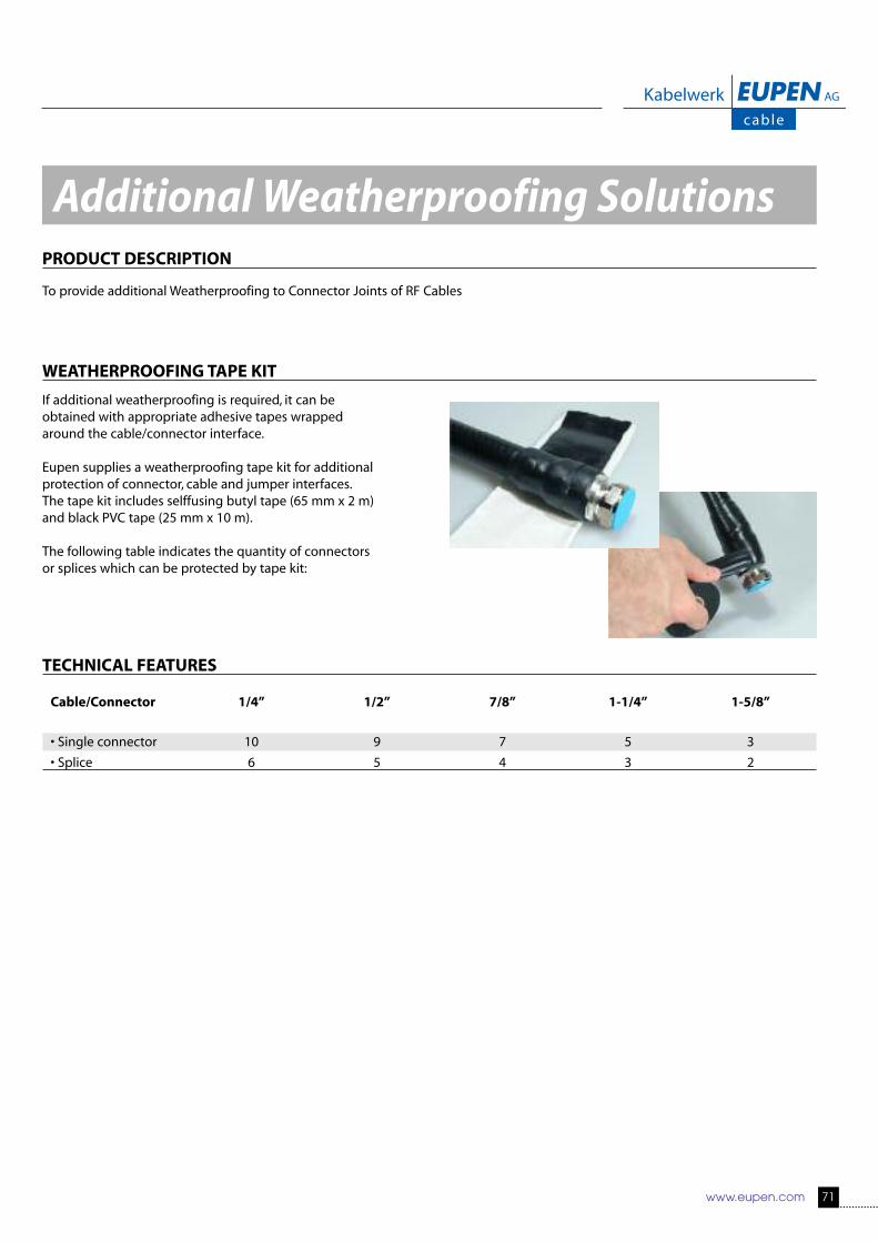
www.eupen.com 71
Additional Weatherproofing SolutionsPRODUCT DESCRIPTION
To provide additional Weatherproofing to Connector Joints of RF Cables
WEATHERPROOFING TAPE KIT
If additional weatherproofing is required, it can beobtained with appropriate adhesive tapes wrappedaround the cable/connector interface.
Eupen supplies a weatherproofing tape kit for additionalprotection of connector, cable and jumper interfaces. The tape kit includes selffusing butyl tape (65 mm x 2 m)and black PVC tape (25 mm x 10 m).
The following table indicates the quantity of connectors or splices which can be protected by tape kit:
TECHNICAL FEATURES
Cable/Connector 1/4” 1/2” 7/8” 1-1/4” 1-5/8”
• Single connector 10 9 7 5 3
• Splice 6 5 4 3 2
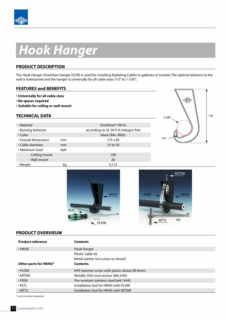
72 www.eupen.com
PRODUCT DESCRIPTION
The Hook Hanger (Durethan Hanger HLFR) is used for installing Radiating Cables in galleries or tunnels. The optimal distance to thewall is maintained and the hanger is universally for all cable sizes (1/2” to 1-5/8”).
FEATURES and BENEFITS
• Universally for all cable sizes• No spacer required• Suitable for ceiling or wall mount
TECHNICAL DATA
• Material Durethan® (PA 6)
• Burning behavior according to UL 94 V-0, halogen free
• Color black (RAL 9005)
• Overall dimensions mm 175 x 85
• Cable diameter mm 15 to 50
• Maximum load daN
- Ceiling mount 100
- Wall mount 20
• Weight kg 0.115
PRODUCT OVERVIEUW
Product reference Contents
• HKHG Hook hanger
Plastic cable tie
Metal washer (no screw, no dowel)
Other parts for HKHG* Contents
• PLDW HPS hammer screw with plastic dowel (Ø 6mm)
• MTDW Metallic HSA stud anchor (M6, V4A)
• FRSB Fire resistant stainless steel belt (V4A)
• PLTL Installation tool for HKHG with PLDW
• MTTL Installation tool for HKHG with MTDW
* must be ordered separately
Hook Hanger
HKHG HKHGFRSB
MTDW
MTTL
PLTL
PLDW

PRODUCT DESCRIPTION
Clic clamps are used for installing radiating cables in galleriesand tunnels with or without spacers. The installation is verysimple and quick.
FEATURES and BENEFITS
• Lock with 1 or 2 locking positions• Automatic locking by pushing cable into clamp, reusable• Unlocks with screwdriver• Pivoted hangers allow installation down to -25°C• Slot design allows installation correction of up to 4.5 mm• Slot for insertion of flange for rod and stud mounting
TECHNICAL FEATURES
Clic type Clic Clamp
• Material Pure Polyamide, halogen free,
fire class UL94HB, UV-resistant
• Environmental
Operating Temperature °C -40 to +110
Installation Temperature °C -25 to +60
• Color standard: black
light grey (RAL 7035) by request
Clic type for 1/2” for 5/8” for 7/8” for 1-1/4” for 1-5/8”
• Clamping range mm 14.3 - 16.8 19.5 - 21.8 27.8 - 31.2 35.5 - 39.5 46.5 - 50.5
• Max. load N 600 700 850 1100 1300
• Part reference CC12 CC58 CC78 CC114 CC158
Clic Clamp
www.eupen.com 73
CC78

Clic Clamp - Accessories
74 www.eupen.com
SPACERS and ACCESSORIES
Reference Description Use with Picture
Spacers
• RB80 Round base spacer 80 mm WS125, B6/90-SS
• RB50 Round base spacer 50 mm WS90, B6/60-SS
• SP45 Rectangular base spacer 45 mm WS90
• SP85 Rectangular base spacer 85 mm WS125
• SSP6/75/8 Stainless steel spacer 75 mm HPM8, FN6
Flat nuts
• FN6 Flat nut M6, stainless steel All clic clamps
Wood screws, stainless steel
• WS40 Wood screw 4.5 x 40 Clic Clamp without spacer
• WS90 Wood screw 4.5 x 90 SP45 or RB50
• WS125 Wood screw 4.5 x 125 SP85 or RB80
Bolt with metric thread, stainless steel
• B6/90-SS M6 x 90, hex socket head RB80, HPM6
• B6/60-SS M6 x 60, hex socket head RB50, HPM6
Plugs
• P6 Nylon plug for wood screw diameter 4.5 mm Wood screws
• HPM6-SS Stainless steel plug M6 Bolt B6/90-SS
• HPM8-SS Stainless steel plug M8 Spacer SSP6/75/8
• HSP6/84 Stainless steel hammer set plug FN6, RB80
• HSP6/90 Stainless steel hammer set plug FN6, SP85
• Drill HSP Drill for installation of the hammer set plugs HSP6/90
• Tool HSP Setting tool of the hammer set plugs HSP6/90

www.eupen.com 75
Clic Clamp - Installation examples
Single-hand installation – a matter of course withCLIC, place the cable, apply slight pressure andthe clamp locks itself with a sharp clic.
SP85
RB80
WS125
HSP6/90
SSP6/75/8HPM8-SS
CC78
CC78
CC78
HSP6/84CC78
CC78
WS40
FN6
FN6SP85
RB80
FN6
1. Installation with wood screw and Nylon plug
2. Installation with Spacers, buttonhead wood screw pressed-on washer and Nylon plug
3. Installation with Hammer Set Plug (with or without spacer)
4. Installation with M8/M6 stainless steel spacer, FN6 and flush metal anchor

PRODUCT DESCRIPTION
Stainless Stell Cable Clamps are used to provide Fire Resistant installationsof Radiating Cables in galleries or tunnels with or without spacers. Theinstallation is very simple and quick. To limit the interference that could becaused by Metal Objects on the RF Field generated by a Radiating Cable,only every 10th fixing should be metallic.
Stainless Steel Cable Clamp
Cable type Clamp type Use with
• 1/2” DN 20 Hammer set plug
• 5/8” DN 25 HSP6/90
• 7/8” DN 32 or
• 1-1/4” DN 46 Stainless Steel spacer
• 1-5/8” DN 50 SSP6/75/8
TECHNICAL FEATURES
Product Reference Clamp Type Ø min. mm Max. Load (N)
• MCFR12 DN 20 19 450
• MCFR58 DN 25 24 380
• MCFR78 DN 32 31 300
• MCFR114 DN 40 39 230
• MCFR158 DN 50 48 180
Installation with M8/M6 spacer and stainless steel clamp
Stainless Steel Clamping Solutions (Recomended every 10 m)
76 www.eupen.com
HPM8
MCFR114
HSP 6/84
SSP6/75/8

Stainless Steel Clip Hangers
Cable type Hanger type Use with
• 1/2” EUCH-12-NH Round base RB80
• 5/8” EUCH-58-NH and
• 7/8” EUCH-78-NH hex head bolt
• 1-1/4” EUCH-114-NH B6/90
• 1-5/8” EUCH-158-NH
Installation with hex head bold and stainless steel clip hanger
www.eupen.com 77
HPM6 B6/90-SS
RB80 EUCH-78-NH
Stainless Steel Clamping Solutions (Recomended every 10 m)


FEATURES and BENEFITS
• Broadband
• Low VSWR
• Nm interface (7-16 on request)
• 1,2 or 10 W (other rating on request)
80 www.eupen.com
EPC DL - Dummy Loads
SPECIFICATIONS
0 - 6 GHz 0 - 18 GHz 0 - 18 GHzN male N male N male
• Part Number EPC DL-T1 01 EPC DL-T2 01 EPC DL-T10 01
• Frequency Range GHz 0 - 6 GHz 0 - 18 GHz 0 - 18 GHz
• Max. Input power W 1 2 10
• Impedance Nom. 50 Ω Nom. 50 Ω Nom. 50 Ω
• VSWR <1.15 / 6 GHz <1.15 / 4 GHz <1.15/ 4 GHz
• Temperature Range °C -30 to +60 -30 to +60 -30 to +60
• Dimensions (L x Ø) mm 34.5 x 20.8 34.5 x 20.8 73 x 52

www.eupen.com 81
FEATURES and BENEFITS
• High RF power rating
• High DC voltage rating
• Small size
• IP 65 rated
• Low Passive Intermodulation
• In-line protection against induced DC(inner/inner & outer/outer)
EPC DB - DC Isolators (DC Block)
SPECIFICATIONS
N female-female N male-female 7-16 DIN 7-16 DIN(*) female-female male-female
(*) (*)
• Part number EPC DB-P 01 EPC DB-P 02 EPC DB-P 03 EPC DB-P 04
R1: 50 - 500
• Frequency Range MHz R2: 800 - 1100
R3: 1700 - 2500
R1: < 0.1
• Insertion Loss dB R2: < 0.2
R3: < 0.4
R1, R2: < 1.2
R3: < 1.3
1 kV (Input centre to output centre conductor)
• Max. voltage DC 1.4 kV (Centre conductor to ground)
2 kV (Input ground to output ground)
R1, R2: Max. 250 W
R3: Max. 100 W
• Dimensions (L x W x H) mm 80 x 42 x 42 with N-connectors
100 x 42 x 42 with 7-16 DIN connectors
(*) Consult us for MOQ
• VSWR
• Power handling

82 www.eupen.com
SPECIFICATIONS
800 - 2500 MHz 10 - 1000 MHz 50 - 1000 MHzN female N female N female
• Part Number EPC SP-P2 01 EPC SP-P2 02 EPC SP-P4 03
• Frequency Range MHz 800 - 2500 40 - 1000 50 - 1000
• Way 2 2 4
• VSWR < 1.2 < 1.5 ≤ 1.3
• Max. Input power W 200 10 2
• Total loss dB < 3.5 ≤ 4.8 dB @ 1000 MHz < 6.8
• Impedance Nom. 50 Ω Nom. 50 Ω Nom. 50 Ω
• Temperature Range °C -35 to +50 -30 to +60 -30 to +60
• Dimensions (L x W x H) mm 212 x 61 x 26 138 x152 x 35 89 x 39 x 29
• Weight approx. g 401 360 200
FEATURES and BENEFITS
• Low loss
• Good balance
• Wide bandwidth
• Isolated outputs
• Suitable for low power combining
EPC SP - Splitters

www.eupen.com 83


86 www.eupen.com
A
w
W
d D
Cable Packing Information
The coaxial cable will be supplied on wooden drums made
of planed wooden boards or plywood. In order to protect
the cable during transportation and storage, the drums will
be battened with wooden boards nailed on the flanges.
The drums are provided with a label containing cable infor-
mation as cable type, cable length and production batch.
The drums can be impregnated on request.
The standard drum sizes used for the different cable typesare shown in the table below.
To calculate the total weight, add the approximate cableweight to the drum weight.
* battened + 5 cm
** Cables with mica tape: see cable data sheet
*** Depending on the humidity of the wood, drum weights can vary greatly !
Cable length Outer dim.* Drum dim. D d W w A V
Cable type Drum type m (ft) cm (in) cm (in)
RMC, LSC, CMC 1/2” HE 10 500 (1640) 100 (39.37) 46 (18.11)
HE 12 1000 (3280) 120 (47.24) 40 (15.74)
HE 12 1500 (4921) 120 (47.24) 40 (15.74)
RMC 5/8” HE 14S 600 (1968) 140 (55.11) 80 (31.49)
HE 14B 1100 (3600) 140 (55.11) 80 (31.49)
HF 17S 1800 (5900) 170 (66.92) 90 (35.43)
RMC, LSC 7/8” HE 14 500 (1640) 140 (55.11) 80 (31.49)
HF 17B 1000 (3280) 170 (66.92) 90 (35.43)
HF 20 1500 (4921) 200 (78.74) 90 (35.43)
RMC, LSC 1-1/4” HF 17S 500 (1640) 170 (66.92) 90 (35.43)
HF 20 1000 (3280) 200 (78.74) 90 (35.43)
RMC, LSC 1-5/8” HF 17B 350 (1148) 170 (66.92) 90 (35.43)
HF 20 600 (1968) 200 (78.74) 90 (35.43)
F-RMC, F-LSC 7/8” HF 17B 500 (1640) 170 (66.92) 90 (35.43)
HF 20 1000 (3280) 200 (78.74) 90 (35.43)
F-RMC, F-LSC 1-1/4” HF 17B 500 (1640) 170 (66.92) 90 (35.43)
HF 20 1000 (3280) 200 (78.74) 90 (35.43)
F-RMC 1-5/8” HF 20 600 (1968) 200 (78.74) 90 (35.43)

www.eupen.com 87
Drum label
Outer width Inner width Shaft hole Drum freight Approx. Drum weight*** Approx.W w A Volume drum / battened drum Cable weight**
cm (in) cm (in) cm (in) m3 (ft3) kg (Lb) kg/km (Lb)
70 (27.55) 64 (25.19) 6.5 (2.55) 0.69 (24.36) 16 / 46 (35 / 101) 240 (530)
54 (21.25) 50 (19.68) 6.5 (2.55) 0.78 (27.54) 25 / 55 (55 / 121) 240 (530)
54 (21.25) 50 (19.68) 6.5 (2.55) 0.78 (27.54) 25 / 55 (55 / 121) 240 (530)
42 (16.53) 38.2 (15.03) 8 (3.14) 0.83 (29.31) 40 / 65 (88 / 143) 380 (840)
76 (29.92) 72.2 (28.42) 8 (3.14) 1.50 (52.97) 40 / 85 (88 / 187) 380 (840)
74 (29.13) 64.4 (25.35) 9 (3.54) 2.20 (77.69) 232 / 275 (511 / 605) 380 (840)
76 (29.92) 72 (28.34) 8 (3.14) 1.49 (52.61) 40 / 100 (88 / 220) 500 (1104)
104 (40.94) 98 (38.58) 9 (3.54) 3.03 (107.00) 380 / 470 (837 / 1034) 500 (1104)
116 (45.66) 104 (40.94) 9 (3.54) 4.75 (167.74) 440 / 555 (970 / 1221) 500 (1104)
70 (27.55) 64 (25.19) 9 (3.54) 2.20 (77.69) 232 / 275 (511 / 605) 895 (1980)
116 (45.66) 104 (40.94) 9 (3.54) 4.75 (167.74) 440 / 555 (970 / 1221) 895 (1980)
104 (40.94) 98 (38.58) 9 (3.54) 3.03 (107.00) 380 / 470 (837 / 1034) 925 (2040)
116 (45.66) 104 (40.94) 9 (3.54) 4.75 (167.74) 440 / 555 (970 / 1221) 925 (2040)
104 (40.94) 98 (38.58) 9 (3.54) 3.03 (107.00) 380 / 470 (837 / 1034) 750 (1675)
116 (45.66) 104 (40.94) 9 (3.54) 4.75 (167.74) 440 / 555 (970 / 1221) 750 (1675)
104 (40.94) 98 (38.58) 9 (3.54) 3.03 (107.00) 380 / 470 (837 / 1034) 1230 (2711)
116 (45.66) 104 (40.94) 9 (3.54) 4.75 (167.74) 440 / 555 (970 / 1221) 1230 (2711)
116 (45.66) 104 (40.94) 9 (3.54) 4.75 (167.74) 440 / 555 (970 / 1221) 1300 (2870)

Malmedyer Str. 9 - 4700 EUPEN - BELGIUM
Tel.: +32(0)87.59.70.00 Fax: +32(0)87.59.71.00http://www.eupen.com e-mail:[email protected] ISO Certified Company 01
/2014 - 300