Embed Size (px)
Citation preview
July 30 2001 Printed in Taiwan
Owner’s Guide
www.alcon-stc.com.tw
3 4
TABLE OF CONTENTS
CT-88 FEATURES .................................................................................................................3
STANDARD PACKAGE .......................................................................................................4
FUNCTION KEYS.................................................................................................................5
ANSWERING A CALL.........................................................................................................6
PLACING A CALL................................................................................................................7
INTERCOM FUNCTION {BETWEEN REMOTE/MOBILE AND BASE UNIT} ...................................9
TRANSFERRING CALLS ..................................................................................................10
TEMPORARY TONE DIALING.........................................................................................11
SETTING A REPRESENTATIVE NUMBER FOR REMOTE/ MOBILE UNIT...............11
ANTENNA INSTALLATION..............................................................................................13
CT-88SS/SM OPERATION GUIDEALCON TELECOMMUNICATIONS CO., LTD. a professional maker of high quali-
ty communication equipment, is proud to present its newest model : CT-88SS Point toPoint/Point to Mobile cordless telephone system. This ALCON product will give you yearsof performance if you read and follow carefully the instructions contained in this manual.
♦ POINT-TO-POINT OR POINT-TO-MOBlLE USE
♦ HIGH PERFORMANCE
♦ UNlVERSAL INTERFACE ON THE REMOTE/MOBILE FOR FAX / DATA OR OTHER
TELECOM EQUIPMENT USE
♦ ECONOMlCAL AND EASY TO USE
♦ EXCELLENT SIGNAL QUALITY FOR LONG RANGE USE
♦ RF STABlLITY & DURABILlTY
♦ SCRAMBLER FUNCTlON
♦ 4O CHANNELS FREQUENCY AUTO SCAN
♦ TWO-WAY PAGING & lNTERCOM
♦ MODULAR DESIGN
FEATURES:
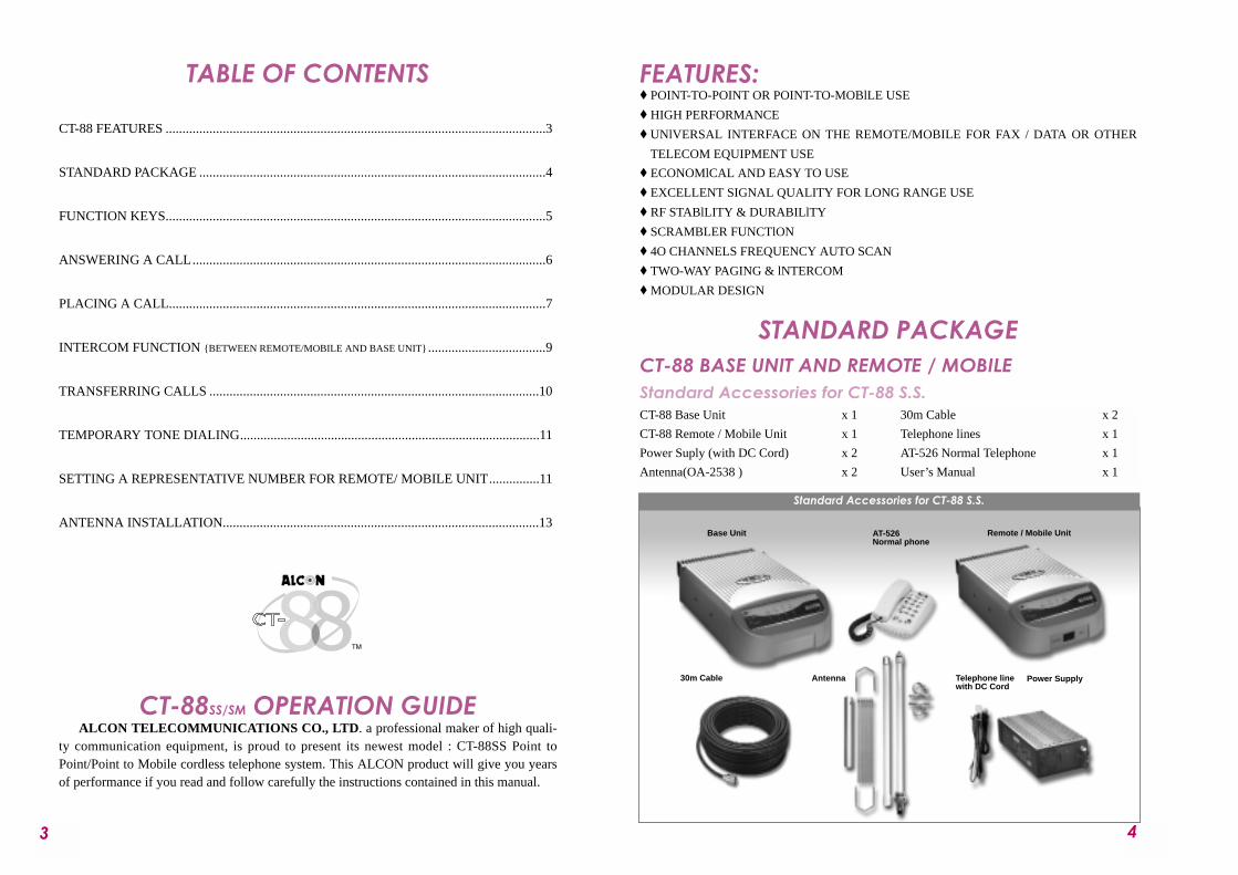
STANDARD PACKAGECT-88 BASE UNIT AND REMOTE / MOBILEStandard Accessories for CT-88 S.S.CT-88 Base Unit x 1
CT-88 Remote / Mobile Unit x 1
Power Suply (with DC Cord) x 2
Antenna(OA-2538 ) x 2
30m Cable x 2
Telephone lines x 1
AT-526 Normal Telephone x 1
User’s Manual x 1
Base Unit
Power SupplyTelephone linewith DC Cord
Antenna
Remote / Mobile UnitAT-526 Normal phone
Standard Accessories for CT-88 S.S.
30m Cable
5 6
Base Unit AT- 80Telephone
Power Supply
1/2 λCar Antenna& MagneticCar AntennaMount
Base UnitAntenna
Remote / Mobile Unit
Remote / Mobile Unit
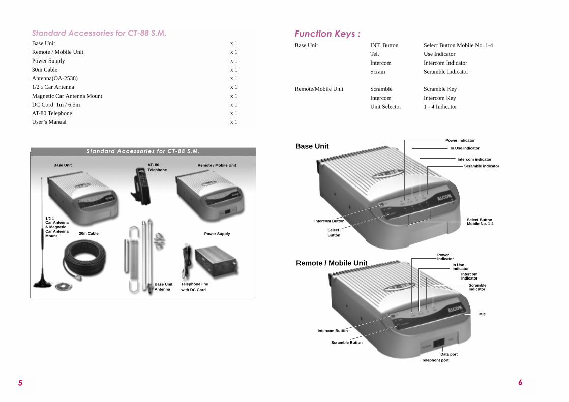
Standard Accessories for CT-88 S.M.
30m Cable
Standard Accessories for CT-88 S.M.Base Unit x 1
Remote / Mobile Unit x 1
Power Supply x 1
30m Cable x 1
Antenna(OA-2538) x 1
1/2 λ Car Antenna x 1
Magnetic Car Antenna Mount x 1
DC Cord 1m / 6.5m x 1
AT-80 Telephone x 1
User’s Manual x 1
Function Keys :Base Unit INT. Button Select Button Mobile No. 1-4
Tel. Use Indicator
Intercom Intercom Indicator
Scram Scramble Indicator
Remote/Mobile Unit Scramble Scramble Key
Intercom Intercom Key
Unit Selector 1 - 4 Indicator
Powerindicator
Scramble Button
Select ButtonMobile No. 1-4
Mic
Telephont port
Data port
In Useindicator
Intercomindicator
Intercom Button
Power indicator
In Use indicator
Intercom indicator
Scramble indicator
Intercom Button
SelectButton
Scrambleindicator
Base Unit
Telephone line
with DC Cord
87
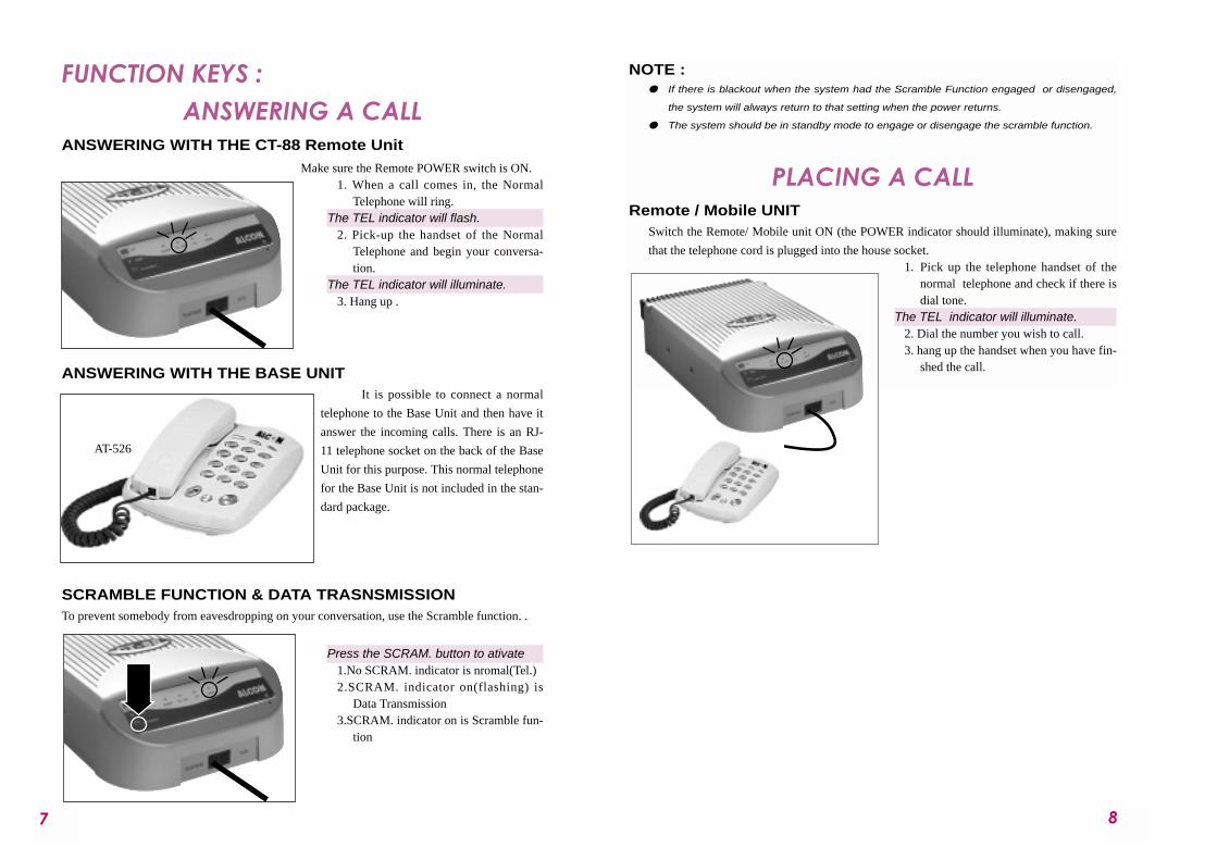
FUNCTION KEYS :ANSWERING A CALL
ANSWERING WITH THE CT-88 Remote UnitMake sure the Remote POWER switch is ON.
1. When a call comes in, the NormalTelephone will ring.
The TEL indicator will flash.2. Pick-up the handset of the Normal
Telephone and begin your conversa-tion.
The TEL indicator will illuminate.3. Hang up .
ANSWERING WITH THE BASE UNITIt is possible to connect a normal
telephone to the Base Unit and then have it
answer the incoming calls. There is an RJ-
11 telephone socket on the back of the Base
Unit for this purpose. This normal telephone
for the Base Unit is not included in the stan-
dard package.
SCRAMBLE FUNCTION & DATA TRASNSMISSIONTo prevent somebody from eavesdropping on your conversation, use the Scramble function. .
Press the SCRAM. button to ativate1.No SCRAM. indicator is nromal(Tel.)2.SCRAM. indicator on(flashing) is
Data Transmission3.SCRAM. indicator on is Scramble fun-
tion
NOTE : " If there is blackout when the system had the Scramble Function engaged or disengaged,
the system will always return to that setting when the power returns.
" The system should be in standby mode to engage or disengage the scramble function.
PLACING A CALLRemote / Mobile UNIT
Switch the Remote/ Mobile unit ON (the POWER indicator should illuminate), making sure
that the telephone cord is plugged into the house socket. 1. Pick up the telephone handset of the
normal telephone and check if there isdial tone.
The TEL indicator will illuminate.2. Dial the number you wish to call.3. hang up the handset when you have fin-
shed the call.
AT-526
109
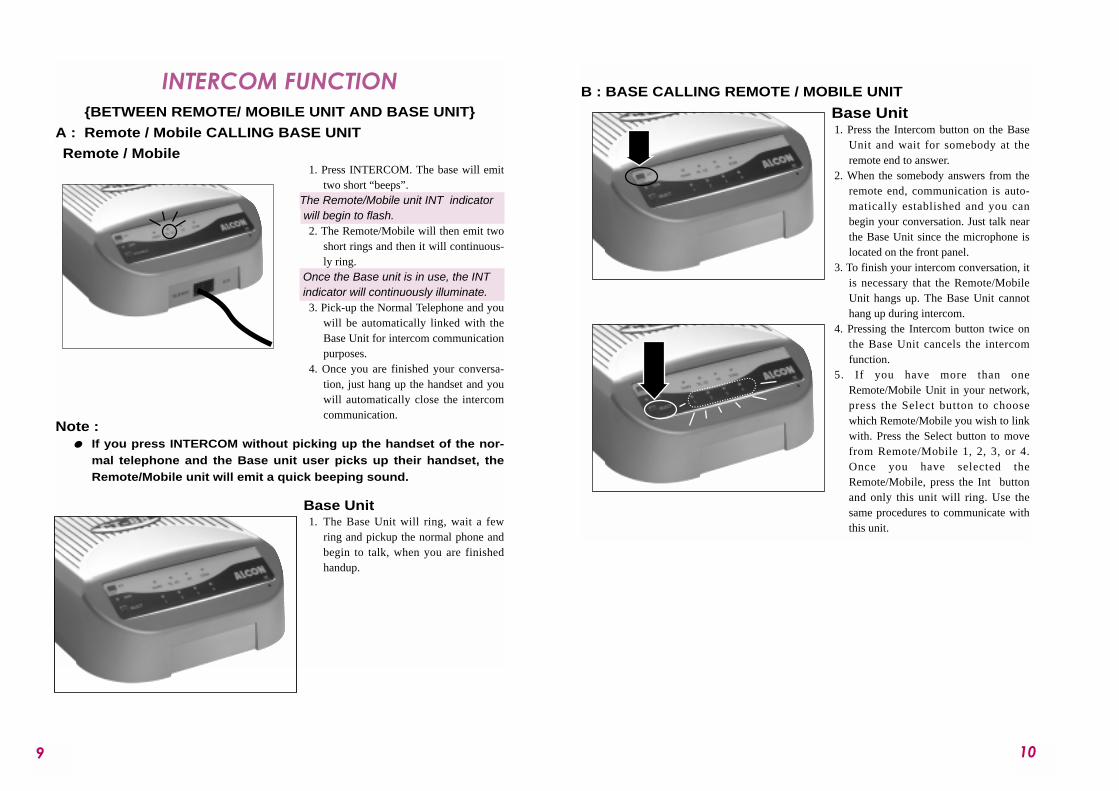
INTERCOM FUNCTION {BETWEEN REMOTE/ MOBILE UNIT AND BASE UNIT}
A : Remote / Mobile CALLING BASE UNIT
Remote / Mobile 1. Press INTERCOM. The base will emit
two short “beeps”. The Remote/Mobile unit INT indicatorwill begin to flash. 2. The Remote/Mobile will then emit two
short rings and then it will continuous-ly ring.
Once the Base unit is in use, the INTindicator will continuously illuminate.
3. Pick-up the Normal Telephone and youwill be automatically linked with theBase Unit for intercom communicationpurposes.
4. Once you are finished your conversa-tion, just hang up the handset and youwill automatically close the intercomcommunication.
Note :" If you press INTERCOM without picking up the handset of the nor-
mal telephone and the Base unit user picks up their handset, theRemote/Mobile unit will emit a quick beeping sound.
Base Unit1. The Base Unit will ring, wait a few
ring and pickup the normal phone andbegin to talk, when you are finishedhandup.
B : BASE CALLING REMOTE / MOBILE UNIT
Base Unit1. Press the Intercom button on the Base
Unit and wait for somebody at theremote end to answer.
2. When the somebody answers from theremote end, communication is auto-matically established and you canbegin your conversation. Just talk nearthe Base Unit since the microphone islocated on the front panel.
3. To finish your intercom conversation, itis necessary that the Remote/MobileUnit hangs up. The Base Unit cannothang up during intercom.
4. Pressing the Intercom button twice onthe Base Unit cancels the intercomfunction.
5. If you have more than oneRemote/Mobile Unit in your network,press the Select button to choosewhich Remote/Mobile you wish to linkwith. Press the Select button to movefrom Remote/Mobile 1, 2, 3, or 4.Once you have selected theRemote/Mobile, press the Int buttonand only this unit will ring. Use thesame procedures to communicate withthis unit.
1211
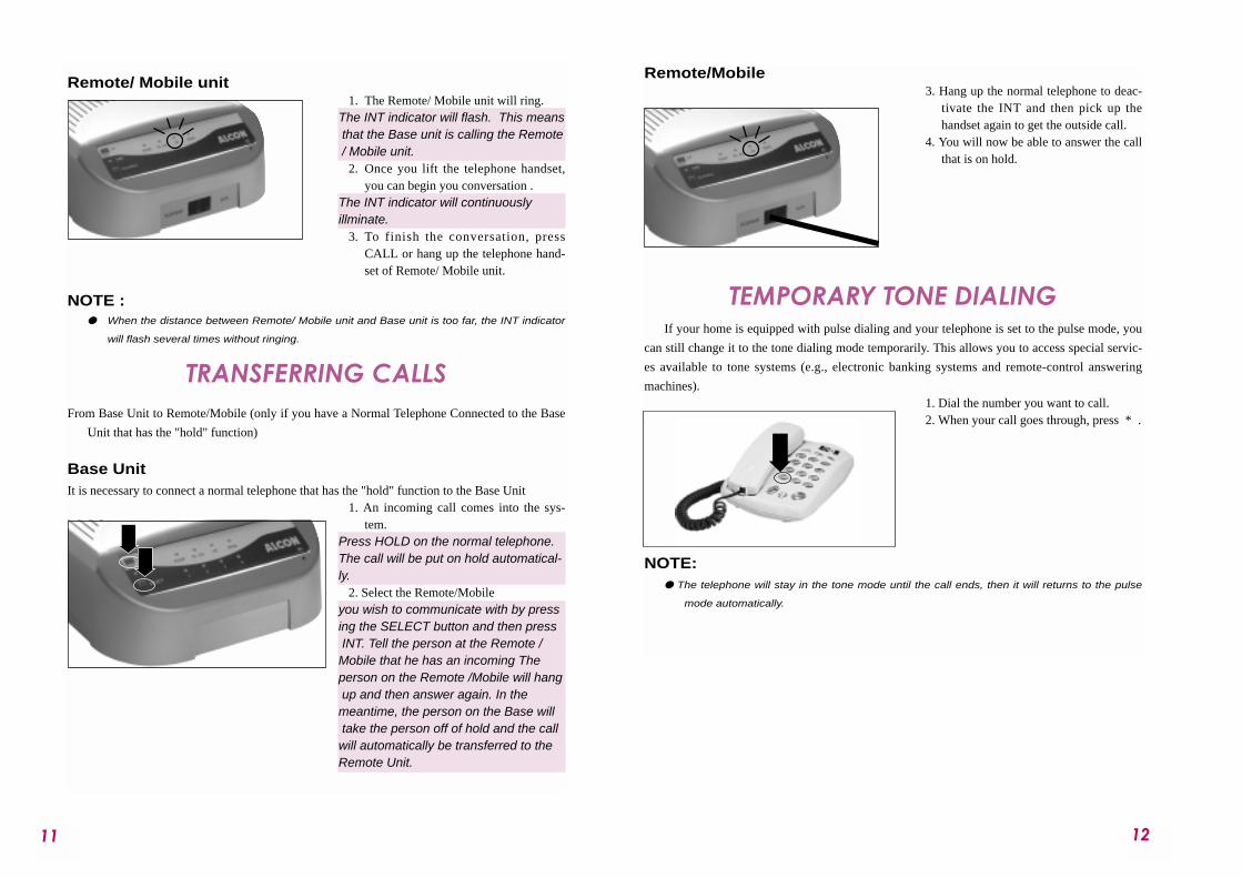
Remote/ Mobile unit1. The Remote/ Mobile unit will ring.
The INT indicator will flash. This meansthat the Base unit is calling the Remote/ Mobile unit.
2. Once you lift the telephone handset,you can begin you conversation .
The INT indicator will continuously illminate.
3. To finish the conversation, pressCALL or hang up the telephone hand-set of Remote/ Mobile unit.
NOTE : " When the distance between Remote/ Mobile unit and Base unit is too far, the INT indicator
will flash several times without ringing.
TRANSFERRING CALLS From Base Unit to Remote/Mobile (only if you have a Normal Telephone Connected to the Base
Unit that has the "hold" function)
Base UnitIt is necessary to connect a normal telephone that has the "hold" function to the Base Unit
1. An incoming call comes into the sys-tem.
Press HOLD on the normal telephone.The call will be put on hold automatical-ly.
2. Select the Remote/Mobile you wish to communicate with by pressing the SELECT button and then pressINT. Tell the person at the Remote / Mobile that he has an incoming Theperson on the Remote /Mobile will hangup and then answer again. In themeantime, the person on the Base willtake the person off of hold and the call will automatically be transferred to theRemote Unit.
Remote/Mobile3. Hang up the normal telephone to deac-
tivate the INT and then pick up thehandset again to get the outside call.
4. You will now be able to answer the callthat is on hold.
TEMPORARY TONE DIALINGIf your home is equipped with pulse dialing and your telephone is set to the pulse mode, you
can still change it to the tone dialing mode temporarily. This allows you to access special servic-
es available to tone systems (e.g., electronic banking systems and remote-control answering
machines).1. Dial the number you want to call.2. When your call goes through, press * .
NOTE:" The telephone will stay in the tone mode until the call ends, then it will returns to the pulse
mode automatically.
1413
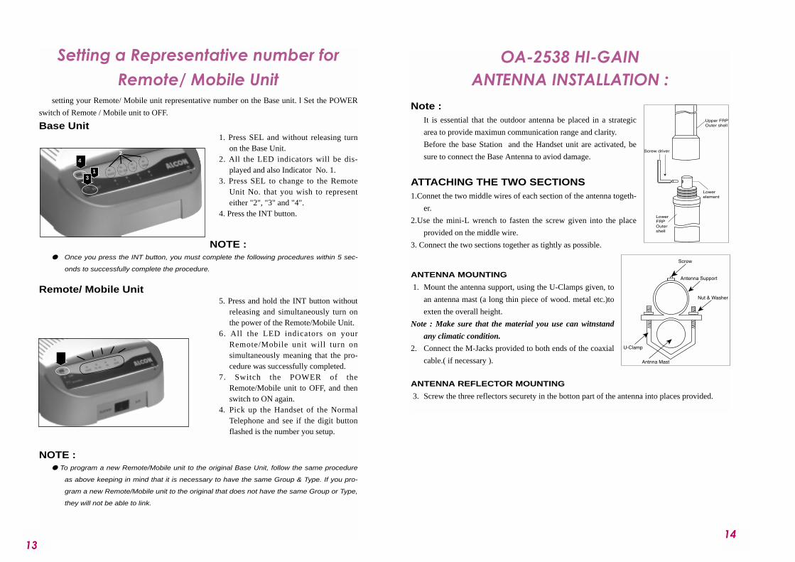
Setting a Representative number forRemote/ Mobile Unit
setting your Remote/ Mobile unit representative number on the Base unit. l Set the POWER
switch of Remote / Mobile unit to OFF.
Base Unit1. Press SEL and without releasing turn
on the Base Unit. 2. All the LED indicators will be dis-
played and also Indicator No. 1. 3. Press SEL to change to the Remote
Unit No. that you wish to representeither "2", "3" and "4".
4. Press the INT button.
NOTE :" Once you press the INT button, you must complete the following procedures within 5 sec-
onds to successfully complete the procedure.
Remote/ Mobile Unit5. Press and hold the INT button without
releasing and simultaneously turn onthe power of the Remote/Mobile Unit.
6. All the LED indicators on yourRemote/Mobile unit will turn onsimultaneously meaning that the pro-cedure was successfully completed.
7. Switch the POWER of theRemote/Mobile unit to OFF, and thenswitch to ON again.
4. Pick up the Handset of the NormalTelephone and see if the digit buttonflashed is the number you setup.
NOTE :" To program a new Remote/Mobile unit to the original Base Unit, follow the same procedure
as above keeping in mind that it is necessary to have the same Group & Type. If you pro-
gram a new Remote/Mobile unit to the original that does not have the same Group or Type,
they will not be able to link.
OA-2538 HI-GAIN ANTENNA INSTALLATION :
Note : It is essential that the outdoor antenna be placed in a strategic
area to provide maximun communication range and clarity.
Before the base Station and the Handset unit are activated, be
sure to connect the Base Antenna to aviod damage.
ATTACHING THE TWO SECTIONS1.Connet the two middle wires of each section of the antenna togeth-
er.
2.Use the mini-L wrench to fasten the screw given into the place
provided on the middle wire.
3. Connect the two sections together as tightly as possible.
ANTENNA MOUNTING
1. Mount the antenna support, using the U-Clamps given, to
an antenna mast (a long thin piece of wood. metal etc.)to
exten the overall height.
Note : Make sure that the material you use can witnstand
any climatic condition.
2. Connect the M-Jacks provided to both ends of the coaxial
cable.( if necessary ).
ANTENNA REFLECTOR MOUNTING
3. Screw the three reflectors securety in the botton part of the antenna into places provided.
3
42
1
1615
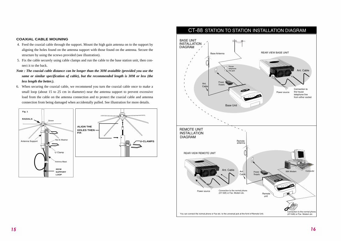
COAXIAL CABLE MOUNING
4. Feed the coaxial cable through the support. Mount the high gain antenna on to the support by
aligning the holes found on the antenna support with those found on the antenna. Secure the
structure by using the screws provided (see illustration).
5. Fix the cable securely using cable clamps and run the cable to the base station unit, then con-
nect it to the back.
Note : The coaxial cable distance can be longer than the 30M avaialble (provided you use the
same or similar specification of cable), but the recommended length is 30M or less (the
less length the better.).
6. When securing the coaxial cable, we recommend you turn the coaxial cable once to make a
small loop (about 15 to 25 cm in diameter) near the antenna support to prevent excessive
load from the cable on the antenna connection and to protect the coaxial cable and antenna
connection from being damaged when accidentally pulled. See illustration for more details.
RADIALS
Fig. 1
30CM
SUPPORT
LOOP
ALIGN THE
HOLES THENFIX
U-CLAMPS