Embed Size (px)
Citation preview
Jsc
www.jscvalve.com
JSC
VALVE
API6D fully welded body ball valve
GDR-3 FULLY WELDED BODY BALL VALVE
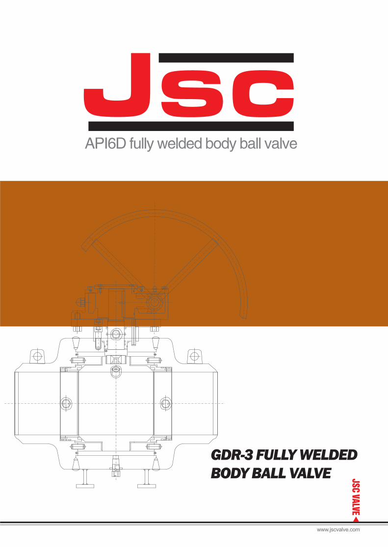
JSC Union is committed to enhancing our
customers' working site safety,system stability,
and convevientoperations through our valve
product offerings,our diversre and innovative
valves will have more safety design
longer working life and more reliable operation.
located in the city with a more than forty years'
history to make industrial valve,JSC has carried
on the maturevalve manufacturing tradition of zigong
city.by our advanced seat design and special
workmanship,we are makinghigh quality ball valve
and through conduit gate valve,range from
complete size and pressure for petroleum,
chemica,and energy industrial use.to be a
professional API6D valve company,we are
making for reliability.
Fully welded body ball valve
Range of product
Applications· · · · · · · · · ·
Feature· · · · · · · · · ·
Assembly drawing··········
Transition pups··········
Dynamic drawing··········
Materials· · · · · · · · · ·
Standard· · · · · · · · · ·
P-T rating· · · · · · · · · ·
Dimensions· · · · · · · · · ·
Test procedure· · · · · · · · · ·
Fig No.· · · · · · · · · ·
·········· Page 1
Page 1
Page 2
Page 5
Page 6
Page 7
Page 8
Page 9
Page 9
Page 10
Page 13
Page 14
PRODUCTS CONTENTSJsc
20
7
18
19
17
15
13
14
10
6
8 9 6 4 2 1 3 11 12 16 5 21 21
www.jscvalve.com
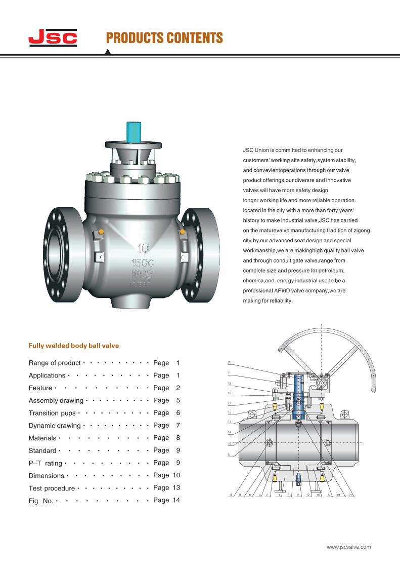
RANGE OF PRODUCT
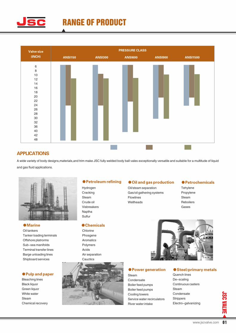
APPLICATIONS
A wide variety of body designs,materials,and trim make JSC fully welded body ball vales exceptionally versatile and suitable for a multitude of liquid
and gas fluid applications.
●Marine
Oil tankers
Tanker loading terminals
Offshore platrorms
Sub-sea manifolds
Terminal transfer lines
Barge unloading lines
Shipboard services
●Pulp and paper
Bleaching lines
Black liquor
Green liquor
White water
Steam
Chemical recovery
●Petroleum refining
Hydrogen
Cracking
Steam
Crude oil
Visbreakers
Naptha
Sulfur
●Chemicals
Chlorine
Phosgene
Aromatics
Polymers
Acids
Air separation
Cauctics
●Oil and gas production
Oil/steam separation
Gas/oil gathering systems
Flowlines
Wellheads
●Petrochemicals
Tehylene
Propylene
Steam
Reboilers
Gases
●Power generation
Steam
Condensate
Boiler feed pumps
Boiler feed pumps
Cooling towers
Service water recirculators
River water intake
●Steel/primary metalsQuench lines
De-scaling
Continuous casters
Steam
Condensate
Strippers
Electro-galvanizing
Valve size
(INCH) ANSI150 ANSI300 ANSI600 ANSI900 ANSI1500
PRESSURE CLASS
6
8
10
12
14
16
18
20
22
24
26
28
30
32
36
40
42
48
Jsc
01
JSC
VALVE
www.jscvalve.com
JSC FULLY WELDED BODY BALL VALVE FEATURE
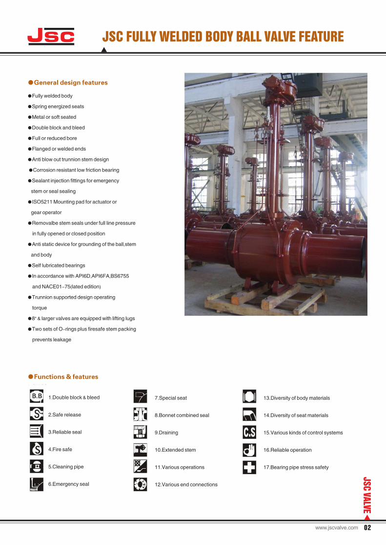
●General design features
●Fully welded body
●Spring energized seats
●Metal or soft seated
●Double block and bleed
●Full or reduced bore
●Flanged or welded ends
●Anti blow out trunnion stem design
●Corrosion resistant low friction bearing
●Sealant injection fittings for emergency
stem or seal sealing
●ISO5211 Mounting pad for actuator or
gear operator
●Removalbe stem seals under full line pressure
in fully opened or closed position
●Anti static device for grounding of the ball,stem
and body
●Self lubricated bearings
●In accordance with API6D,API6FA,BS6755
and NACE01-75(lated edition)
●Trunnion supported design operating
torque
●8" & larger valves are equipped with lifting lugs
●Two sets of O-rings plus firesafe stem packing
prevents leakage
●Functions & features
1.Double block & bleed
2.Safe release
3.Reliable seal
4.Fire safe
5.Cleaning pipe
6.Emergency seal
7.Special seat
8.Bonnet combined seal
9.Draining
10.Extended stem
11.Various operations
12.Various end connections
13.Diversity of body materials
14.Diversity of seat materials
15.Various kinds of control systems
16.Reliable operation
17.Bearing pipe stress safety
02
JSC
VALVE
Jsc
www.jscvalve.com
JSC FULLY WELDED BODY BALL VALVE FEATURE
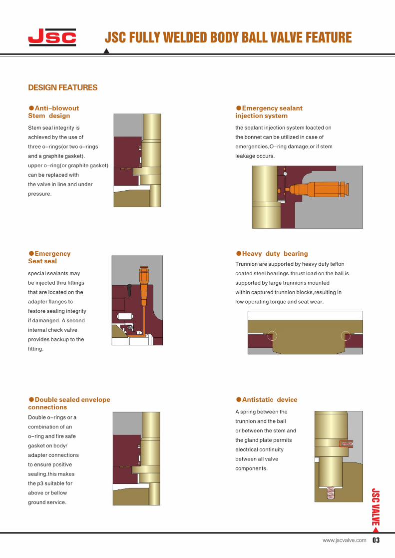
DESIGN FEATURES
●Stem design
Anti-blowout
Stem seal integrity is
achieved by the use of
three o-rings(or two o-rings
and a graphite gasket).
upper o-ring(or graphite gasket)
can be replaced with
the valve in line and under
pressure.
●injection system
Emergency sealant
the sealant injection system loacted on
the bonnet can be utilized in case of
emergencies,O-ring damage,or if stem
leakage occurs.
●Seat seal
Emergency
special sealants may
be injected thru fittings
that are located on the
adapter flanges to
festore sealing integrity
if damanged. A second
internal check valve
provides backup to the
fitting.
●Heavy duty bearing
Trunnion are supported by heavy duty teflon
coated steel bearings.thrust load on the ball is
supported by large trunnions mounted
within captured trunnion blocks,resulting in
low operating torque and seat wear.
●connections
Double sealed envelope
Double o-rings or a
combination of an
o-ring and fire safe
gasket on body/
adapter connections
to ensure positive
sealing.this makes
the p3 suitable for
above or bellow
ground service.
●Antistatic device
A spring between the
trunnion and the ball
or between the stem and
the gland plate permits
electrical continuity
between all valve
components.
Jsc
03
JSC
VALVE
www.jscvalve.com
Jsc TECHNICAL SEATING FEATURES
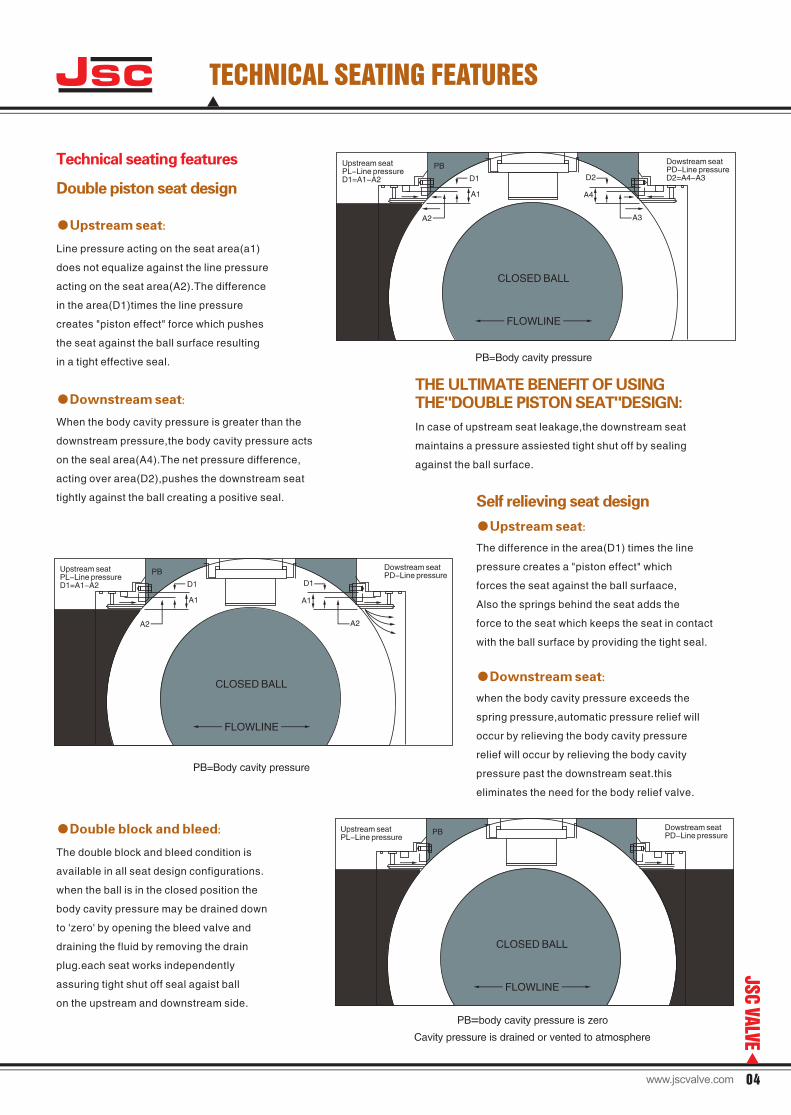
Technical seating features
Double piston seat design
●Upstream seat:
Line pressure acting on the seat area(a1)
does not equalize against the line pressure
acting on the seat area(A2).The difference
in the area(D1)times the line pressure
creates "piston effect" force which pushes
the seat against the ball surface resulting
in a tight effective seal.
●Downstream seat:
When the body cavity pressure is greater than the
downstream pressure,the body cavity pressure acts
on the seal area(A4).The net pressure difference,
acting over area(D2),pushes the downstream seat
tightly against the ball creating a positive seal. Self relieving seat design
●Upstream seat:
The difference in the area(D1) times the line
pressure creates a "piston effect" which
forces the seat against the ball surfaace,
Also the springs behind the seat adds the
force to the seat which keeps the seat in contact
with the ball surface by providing the tight seal.
●Downstream seat:
when the body cavity pressure exceeds the
spring pressure,automatic pressure relief will
occur by relieving the body cavity pressure
relief will occur by relieving the body cavity
pressure past the downstream seat.this
eliminates the need for the body relief valve.
●Double block and bleed:
The double block and bleed condition is
available in all seat design configurations.
when the ball is in the closed position the
body cavity pressure may be drained down
to 'zero' by opening the bleed valve and
draining the fluid by removing the drain
plug.each seat works independently
assuring tight shut off seal agaist ball
on the upstream and downstream side.
PB=body cavity pressure is zero
Cavity pressure is drained or vented to atmosphere
THE ULTIMATE BENEFIT OF USING THE"DOUBLE PISTON SEAT"DESIGN:
In case of upstream seat leakage,the downstream seat
maintains a pressure assiested tight shut off by sealing
against the ball surface.
CLOSED BALL
FLOWLINE
PB=Body cavity pressure
Upstream seatPL-Line pressureD1=A1-A2
Dowstream seatPD-Line pressureD2=A4-A3
PB
A2
D1
A1
D2
A4
A3
Dowstream seatPD-Line pressure
Dowstream seatPD-Line pressure
CLOSED BALL
FLOWLINE
PB=Body cavity pressure
Upstream seatPL-Line pressureD1=A1-A2
PB
A2
D1
A1
D1
A1
A2
Upstream seatPL-Line pressure
CLOSED BALL
FLOWLINE
PB
04
JSC
VALVE
www.jscvalve.com
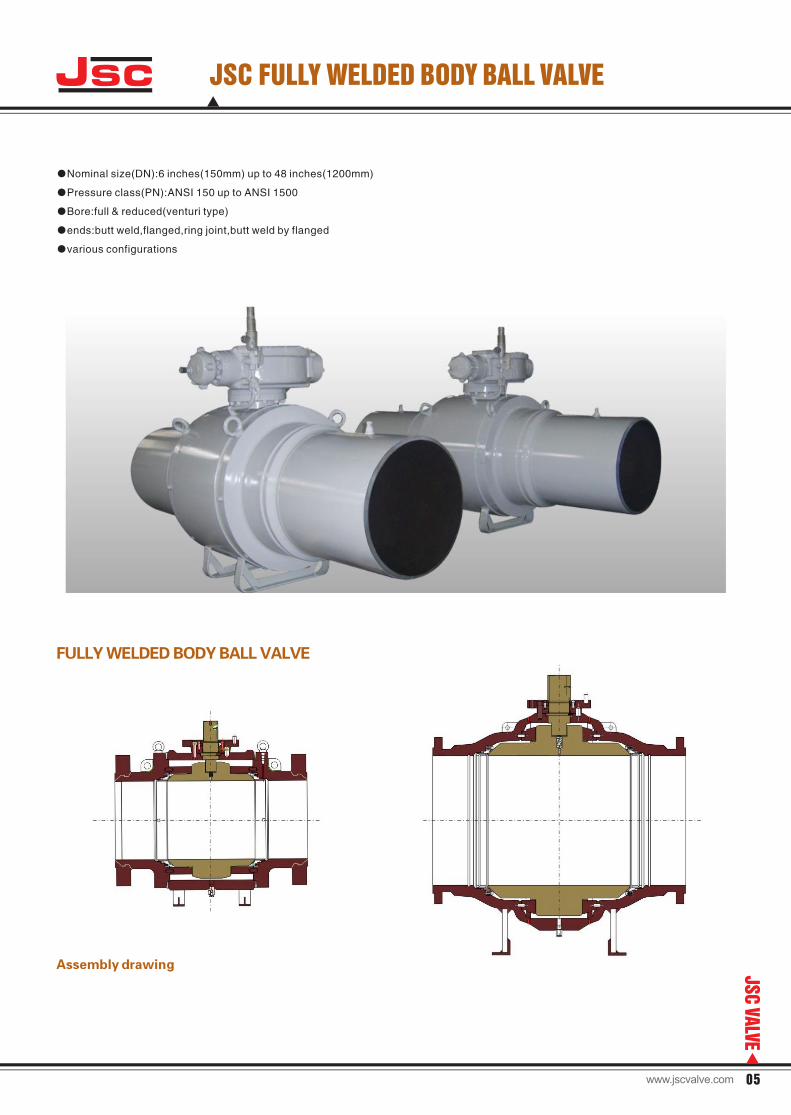
JSC FULLY WELDED BODY BALL VALVE
●Nominal size(DN):6 inches(150mm) up to 48 inches(1200mm)
●Pressure class(PN):ANSI 150 up to ANSI 1500
●Bore:full & reduced(venturi type)
●ends:butt weld,flanged,ring joint,butt weld by flanged
●various configurations
FULLY WELDED BODY BALL VALVE
Assembly drawing
Jsc
05
JSC
VALVE
www.jscvalve.com
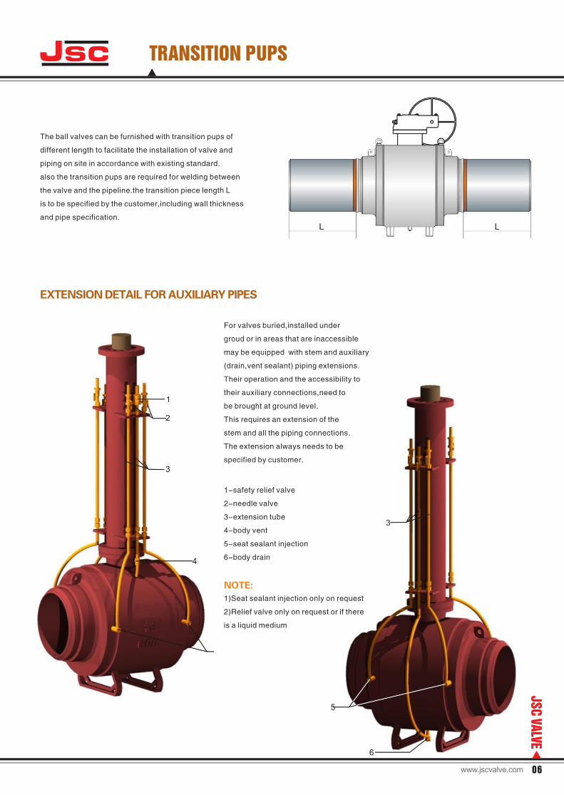
The ball valves can be furnished with transition pups of
different length to facilitate the installation of valve and
piping on site in accordance with existing standard.
also the transition pups are required for welding between
the valve and the pipeline.the transition piece length L
is to be specified by the customer,including wall thickness
and pipe specification.
TRANSITION PUPS
EXTENSION DETAIL FOR AUXILIARY PIPES
For valves buried,installed under
groud or in areas that are inaccessible
may be equipped with stem and auxiliary
(drain,vent sealant) piping extensions.
Their operation and the accessibility to
their auxiliary connections,need to
be brought at ground level.
This requires an extension of the
stem and all the piping connections.
The extension always needs to be
specified by customer.
1-safety relief valve
2-needle valve
3-extension tube
4-body vent
5-seat sealant injection
6-body drain
NOTE:
1)Seat sealant injection only on request
2)Relief valve only on request or if there
is a liquid medium
Jsc
06
JSC
VALVE
www.jscvalve.com
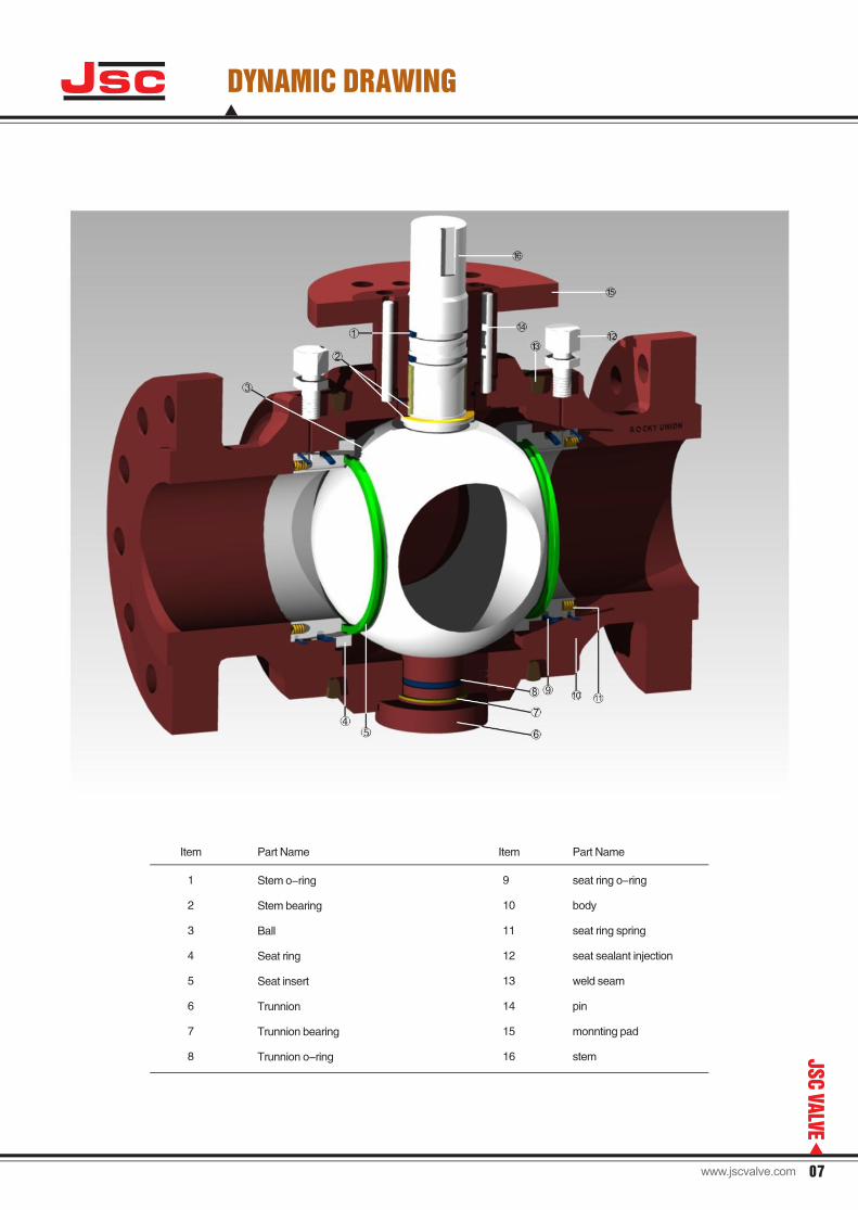
DYNAMIC DRAWING
Stem o-ring
Stem bearing
Ball
Seat ring
Seat insert
Trunnion
Trunnion bearing
Trunnion o-ring
1
2
3
4
5
6
7
8
Item Part Name Item Part Name
9
10
11
12
13
14
15
16
seat ring o-ring
body
seat ring spring
seat sealant injection
weld seam
pin
monnting pad
stem
Jsc
07
JSC
VALVE
www.jscvalve.com
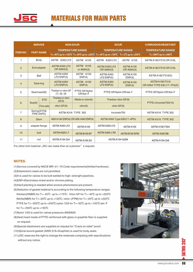
Jsc MATERIALS FOR MAIN PARTS
(1)Service covered by NACE MR-01-75 Code requirements(limited hardness).
(2)Elastomeric seals are not permitted.
(3)It is used for valves to be butt welded to high-strenght pipelines.
(4)ENP=Electroless nickel and/or chrome plating.
(5)Hard planting is needed when erosive phenomena are present.
(6)Selection of gasket material is according to the following temperature ranges:
therban(HNBR) for T=-45℃ up to +175℃: Viton GF for T=-40℃ up to +220℃
Nitrile(NBR) for T=-29℃ up to +130℃; viton-(FPM) for T=-20℃ up to +220℃
PTFE for T=-200℃ up to +240℃;nylon 12G for T=-50℃ up to +120℃;kel-F
for T=-250℃ up to +150℃
(7)Nylon 12G is used for valves pressure>ANSI600
(8)Seat insert made of PTFE reinforced with glass or graphite fiber is supplied
on request.
(9)Special elastomers are supplied on request for "Crack on relief "proof.
(10)Spiral wound gasket (ANSI 316+Graphite) is used for body seals.
(11)JSC reserves the right to change the materials complying with sepcifications
without any notice.
NOTES:
ITEM NO PART NAME
NON SOUR CORROSION RESISTANTSERVICE SOUR
Body
End adapter
Ball
Seat ring
Seat insert(6)
STD
Fire safe
Sea(6)
Spring(STD& FIRE SAFE)
Stem
adapter flange
bolt
nut
1
2
3
4
5
6
7
8
9
10
11
ASTM A350 LF2
ASTM A350 LF2 OR A694(3)
ASTM A350 LF2 ENP(4)
ASTM A350 LF2 ENP(4)
Therban or viton GF(7) (8) (9)
Therban or viton GF(9)
viton GF(9)
ASTM A316 TYPE 302
AISI14140 ENP(4) OR AISI 4340 ENP(4)
ASTM A350 LF2
ASTM A320 L7
ASTM A194 Gr4
ASTM A105
ASTM B193 B7
ASTM A194 2H
ASTM A350 LF2
ASTM A320 L7M
ASTM A194 Gr2M
ASTM A105
ASTM B192 B7M
ASTM A182 F304
ASTM A320 B8
ASTM A194 Gr8
ASTM A105
ASTM A105
or A694(3)
ASTM A105ENP(4)
ASTM A105ENP(4)
PTFE OR Nylon
OR Kel-F
Nitrile or viton(9)
viton(9) viton GF(9)
Inconelx750
Therban viton GF(9)
PTFE OR Nylon OR kel-F
ASTM A564 Type 630(17-4PH)
PTFE+Inconelx750(10)
ASTM A316 TYPE 302
ASTM A316 TYPE 302
ASTM A350 LF2
ASTM A350 LF2 OR A694(3)
ASTM A350 LF2 ENP(4)
ASTM A350 LF2 ENP(4)
ASTM A105
ASTM A105OR A694(3)
ASTM A105ENP(4)
ASTM A105ENP(4)
ASTM A182 F316 OR 316L
ASTM A182 F316 OR 316L
ASTM A182 F316(5)
ASTM A182 F316
OR A564 TYPE 630 (17-PH)(5)
PTFE OR Nylon OR Kel-F
TEMPERATURE RANGE
T=-45℃ up to +120℃ T=-29℃ up to +220℃
TEMPERATURE RANGE TEMPERATURE RANGE
T=-45℃ up to +120℃ T=-2℃ up to +220℃ T=-200℃ up to +200℃
For other trim material ,JSC can make then at customer’s request.
08
JSC
VALVE
www.jscvalve.com
Jsc APOLICABLE STANDARD
●BRITISH STANDRAD
BS 1503
BS 5404
BS 1560
BS 5351
BS2080
BS 6755Part2
BS3239
Specification for steel forging for pressure
purpose
Flanges and bolting for pipes valves and fittings
Steel pipe falnges and flanged fittings
Steel ball valves for the petroleum,petrochemicals
and allied industrials
Face to face center to center,end to end and
center to end dimension of flanged butt-welding
end steel valves for petroleum,petrochemical
and allied industries
Testing of valves :specification for fire type
testing requirements
Carbon steel pipe flanges for the petroleum industry
●API AMERICAN PETROLEUM INSTITUTE
Spec.6D
Spec.598
Spec.5L
Spec.6FA
Std.607
Std.5B
Specification for pipeline vavles
Valve inspection and test
Sepecification for line pipe
Specification fo fire test for valves
Fire test for soft seated ball valves
Threading gauging and ghread inspection
of casting and line pipe thread
●DIN DEUTSCHE INSTITU FUR NORMUNG
●ANSI/ASME AMERICAN STANDARDS
B 1.20.1
B 16.5
B 16.10
B 16.25
B 16.34
B 31.3
B 31.4
B 31.8
B 46.1
Pipe treads,general purpose
Pipe flanges and flanged fittings
Face to face and end to end dimessions of valves
Butt-welding end
Valves flanged,threaded and welding end
ASME-Boiler and pressure vessel code section V,VIII & IX
Chemical plant and petroleum refinery piping
Liquid petroleum transportation piping system
Gas transmission and distribution piping system
Surface texture(surface roughness,waviness,and lay)
MSS SP
SP-6
SP-25
SP-44
SP-45
SP-61
SP-72
SP-82
NACE
MR-01-75
MT-01-77
Standard finish for contract face of
pipe flanges and connecting end flanges
of valves and fittings
Standard marketing system for valves,fittings,
flanges and unions
Ssteel pipe line flanges
By pass and drain connection standard
Hydrostatic testing of steel valves
Ball valves with flanged or butt welding ends
for general service
Valve pressure testing methods
Sulfide stress cracking resistant material
for oil field equipment
Laboratory corrosion testing of metals for the
process industry
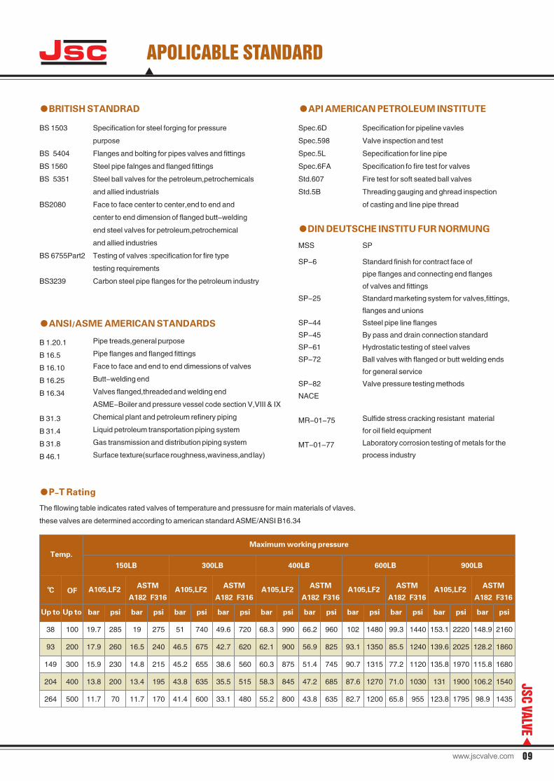
●P-T Rating
The fllowing table indicates rated valves of temperature and pressusre for main materials of vlaves.
these valves are determined according to american standard ASME/ANSI B16.34
Up to
38
93
149
204
264
Up to
100
200
300
400
500
bar
19.7
17.9
15.9
13.8
11.7
psi
285
260
230
200
70
bar
19
16.5
14.8
13.4
11.7
psi
275
240
215
195
170
bar
51
46.5
45.2
43.8
41.4
psi
740
675
655
635
600
bar
49.6
42.7
38.6
35.5
33.1
psi
720
620
560
515
480
bar
68.3
62.1
60.3
58.3
55.2
psi
990
900
875
845
800
bar
66.2
56.9
51.4
47.2
43.8
psi
960
825
745
685
635
bar
102
93.1
90.7
87.6
82.7
psi
1480
1350
1315
1270
1200
bar
99.3
85.5
77.2
71.0
65.8
psi
1440
1240
1120
1030
955
bar
153.1
139.6
135.8
131
123.8
psi
2220
2025
1970
1900
1795
bar
148.9
128.2
115.8
106.2
98.9
psi
2160
1860
1680
1540
1435
150LB 300LB 400LB 600LB 900LB
ASTM
A182 F316A105,LF2 A105,LF2
ASTM
A182 F316A105,LF2
ASTM
A182 F316A105,LF2
ASTM
A182 F316A105,LF2
ASTM
A182 F316
Temp.
℃ OF
Maximum working pressure
09
JSC
VALVE
www.jscvalve.com
Jsc
6
8
10
12
14
16
18
20
22
24
26
28
30
32
152
203
254
305
337
387
438
489
540
591
635
686
737
781
457
521
559
635
762
838
914
991
1092
1143
1245
1346
1397
1524
394
457
533
610
686
762
864
914
991
1067
1143
1245
1295
1372
270
325
362
405
440
430
490
535
585
635
685
730
780
820
225
265
299
340
371
410
457
500
540
585
627
667
716
750
345
425
485
560
695
792
870
950
1040
1115
1190
1280
1345
55
55
55
55
75
75
90
90
90
120
120
120
120
120
70
70
70
70
85
85
115
115
115
140
140
140
140
140
185
250
400
550
820
1100
1400
17500
2200
2800
2900
3400
4800
5500
220
290
430
620
900
1220
1550
1950
2350
3050
3250
3700
5300
6000
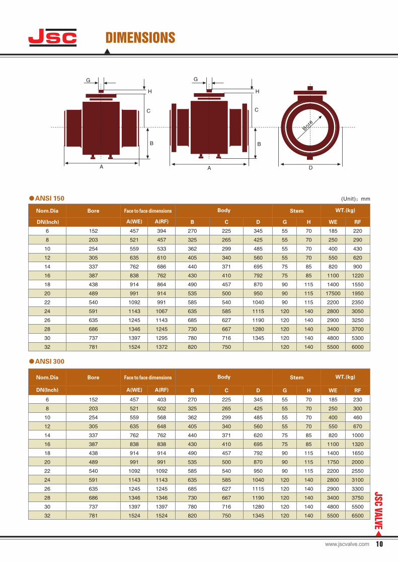
●ANSI 150
DN(Inch)
Bore Face to face dimensions Body Stem WT.(kg)Nom.Dia
(Unit):mm
6
8
10
12
14
16
18
20
22
24
26
28
30
32
A(WE) A(RF)
152
203
254
305
337
387
438
489
540
591
635
686
737
781
457
521
559
635
762
838
914
991
1092
1143
1245
1346
1397
1524
403
502
568
648
762
838
914
991
1092
1143
1245
1346
1397
1524
270
325
362
405
440
430
490
535
585
635
685
730
780
820
225
265
299
340
371
410
457
500
540
585
627
667
716
750
345
425
485
560
620
695
792
870
950
1040
1115
1190
1280
1345
55
55
55
55
75
75
90
90
90
120
120
120
120
120
70
70
70
70
85
85
115
115
115
140
140
140
140
140
185
250
400
550
820
1100
1400
1750
2200
2800
2900
3400
4800
5500
230
300
460
670
1000
1320
1650
2000
2550
3100
3300
3750
5500
6500
Body Stem WT.(kg)Nom.Dia
DN(Inch)
Bore
●ANSI 300
B C D G H WE RF
B C D G H WE RFA(WE) A(RF)
G
C
H
G
H
C
Bore
A
B B
A D
10
JSC
VALVE
DIMENSIONS
Face to face dimensions
www.jscvalve.com
Jsc
6
8
10
12
14
16
18
20
22
24
26
28
30
32
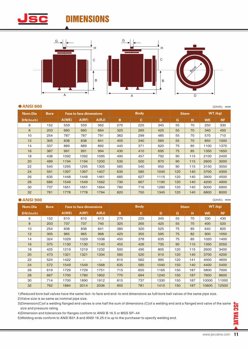
●ANSI 600
Stem WT.(kg)
(Unit):mm
A(WE) A(RF) B C D G H WE RFA(RJ)
152
203
254
305
337
387
438
489
540
591
635
686
737
781
559
660
787
838
889
991
1092
1194
1295
1397
1448
1549
1651
1778
559
660
787
838
889
991
1092
1194
1295
1397
1448
1549
1651
1778
562
664
791
841
892
994
1095
1200
1305
1407
1461
1562
1664
1794
270
325
362
405
440
430
490
535
585
635
685
730
780
820
225
265
299
340
371
410
457
500
540
585
627
667
716
750
345
425
485
560
620
695
792
870
950
1040
1115
1190
1280
1345
55
55
55
55
75
75
90
90
90
120
120
120
120
120
70
70
70
70
85
85
115
115
115
140
140
140
140
140
250
340
570
850
1100
1350
2100
2600
3150
3700
3900
4200
6000
6800
330
450
710
1000
1370
1650
2400
3000
3550
4300
4500
4900
6900
8000
●ANSI 900
6
8
10
12
14
16
18
20
22
24
26
28
30
32
152
203
254
305
324
375
425
473
524
572
619
667
714
762
610
737
838
965
1029
1130
1219
1321
1422
1549
1729
1700
1700
1884
610
737
838
965
1029
1130
1219
1321
-
1549
1729
1780
1890
2014
613
740
841
968
1038
1140
1232
1334
-
1568
1751
1802
1912
2036
270
325
380
425
450
455
500
560
615
635
715
770
815
855
225
265
320
355
378
426
495
520
562
585
655
694
737
781
345
425
525
595
635
735
805
910
995
1040
1165
1240
1330
1410
55
55
75
75
75
90
120
120
120
150
150
150
150
150
70
70
85
82
85
115
115
140
141
140
187
187
187
187
330
400
640
900
1020
1350
2600
3700
4000
4400
5800
7600
10000
10600
430
520
820
1050
1400
2050
3400
4200
4600
5400
7000
8600
11000
12500
DN(Inch)
Bore Face to face dimensions BodyNom.Dia
DN(Inch)
Bore Face to face dimensions Body Stem WT.(kg)Nom.Dia
A(WE) A(RF) B C D G H RFA(RJ) WE
(Unit):mm
1)Reduced bore ball valves have the same fact-to face and end-to end dimensions as fulll bore ball valves of the same pipe size.
2)Valve size is as same as nominal pipe size.
3)Dimension(C)of a welding flanged end valves is one half the sum of dimensions (C)of a welding end and a flanged end valve of the same
size and pressure rating.
4)Dimension and tolerances for flanges conform to ANSI B 16.5 or MSS SP-44
5)Welding ends conform to ANSI B31.8 and ANSI 16.25 it is up to the purchaser to specify welding end.
G
C
H
G
H
C
Bore
A
B B
A D
DIMENSIONS
11
JSC
VALVE
www.jscvalve.com
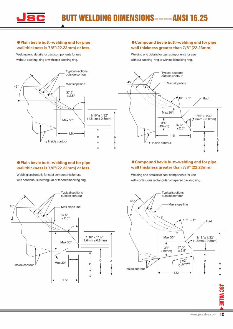
●
wall thickness is 7/8"(22.23mm) or less.
Plain bevle butt-welding end for pipe
Welding end details for cast components for use
without backing ring or with split backing ring.
●
wall thickness greater than 7/8" (22.23mm)
Compound bevle butt-welding end for pipe
Welding end details for cast components for use
without backing ring or with split backing ring.
●
wall thickness is 7/8"(22.23mm) or less.
Plain bevle butt-welding end for pipe
Welding end details for cast components for use
with continuous rectangular or tapered backing ring.
●
wall thickness greater than 7/8" (22.23mm)
Compound bevle butt-welding end for pipe
Welding end details for cast components for use
with continuous rectangular or tapered backing ring.
Typical sectionsoutside contour
Max slope line
Inside contour
37.5°±2.5°
45°
Max 30°
1.5tAB
1/16" 1/32"(1.6mm±0.8mm)
±
45°
Typical sectionsoutside contour
Max slope line
Inside contourAB
1.5t
1/16" 1/32"(1.6mm±0.8mm)
±Max 30°
10°±1° Rad
37.5°±2.5°
3/4"(19mm)
A
1/16" 1/32"(1.6mm±0.8mm)
±
Typical sectionsoutside contour
Max slope line
Inside contour
37.5°±2.5°
45°
Max 30°
1.5t
BMax 30°C
45°
Typical sectionsoutside contour
Max slope line
Inside contour
AB
1.5t
1/16" 1/32"(1.6mm±0.8mm)
±Max 30°
10°±1° Rad
37.5°±2.5°
3/4"(19mm)
7/32"
(5.6mm)
Jsc
12
JSC
VALVE
BUTT WELLDING DIMENSIONS----ANSI 16.25
www.jscvalve.com
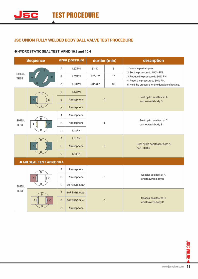
Jsc TEST PROCEDURE
JSC UNION FULLY WELDED BODY BALL VALVE TEST PROCEDURE
●HYDROSTATIC SEAL TEST API6D 10.3 and 10.4
SHELL
TEST
Sequence area pressure durtion(min) description
A
B
C
A
B
C
A
B
C
A
B
C
A
B
C
A
B
C
SHELL
TEST
SHELL
TEST
1.5XPN
1.5XPN
1.5XPN
1.1XPN
Atmospheric
Atmospheric
Atmospheric
Atmospheric
1.1xPN
1.1xPN
Atmospheric
1.1xPN
Atmospheric
Atmospheric
80PSIG(5.5bar)
80PSIG(5.5bar)
80PSIG(5.5bar)
Atmospheric
6"-10"
12"-18"
20"-60"
5
15
30
5
5
5
5
5
1.Valve in partial open.
2.Set the pressure to 150% PN.
3.Reduce the pressure to 50% PN.
4.Reset the pressure to 50% PN.
5.Hold the pressure for the duration of testing.
Seat hydro seal test at A
end toawrds body B
Seat hydro seal test at C
end toawrds body B
Seat hydro seal tes for both A
and C DBB
Seat air seal test at A
end toawrds body B
Seat air seal test at C
end toawrds body B
B
B
C
B
B
CA
A
B
B
CA
B
B
CA
B
B
CA
A
B
B
C
●AIR SEAL TEST API6D 10.4
13
JSC
VALVE
www.jscvalve.com
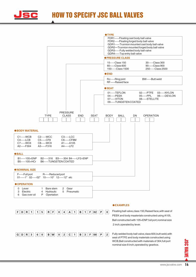
HOW TO SPECIFY JSC BALL VALVES
FDR1---Floating cast body ball valveFDR2---Floating forged body ball valveGDR1---Trunnion mounted cast body ball valveGDR2—Trunnion mounted forged body ball valveGDR3---Fully welded body ball valveGDR4---Top entry ball valve
●TYPE
●PRESSURE CLASS
15---Class 15060---Class 600150---Class 1500
30---Class 30090---Class 900250---Class 2500
●END
RJ---Ring jointRF---Raised face
BW---Butt weld
●SEAT
01---TEFLON04---PEEK07---VITON09---TUNGSTEN COATED
02---PTFE05---PPL08---STELLITE
03---NYLON06---DEVLON
●BODY MATERIAL
●BALL
●NOMINAL SIZE
C1---WCBC4---LCBC7---WC6A2---F304
C2---WCCC5---CF8C8---WC9A3---F316
C3---LCCC6---CF8MA1---A105A4---LF2
B1---105+ENPB5---105+HCr
B2---316B6---TUNGSTEN COATED
B3---304 B4---LF2+ENP
●EXAMPLES
Floating ball valve,class 150,Raised face,with seat of
PEEK and body maaterials constructed using A105,
Ball constructed with 105+ENP,full port,nominal size
2 inch,operated by lever.
Fully welded body ball valve,class 600,butt weld,with
seat of PTFE and body materials constructed using
WCB,Ball constructed with materials of 304,full port
nominal size 8 inch,operated by gearbox.
F D R 1 R F PA B F1 1 15 0 4 02 0
B0 0 1 PD R B FG 3 6 2 C 08 23W
F---Full port01---1" 02---02"
R---Reduced port10---10" 12---12" etc
●OPERATION
0 Lever3 Electric6 Gas over oil
1 Bare stem4 HydraulicP Opertation
2 Gear5 Pneumatic
TYPEPRESSURE
CLASS END SEAT BODY BALL DN OPERATION
Jsc
14
JSC
VALVE
www.jscvalve.com
Add:Anfeng Industrial Zone, Oubei Town,
Wenzhou, Zhejiang Province 325105, China
Tel:+86-577-67120997
Fax:+86-577-67120989
www.jscvalve.com
Email:[email protected]
JscAPI6D fully welded body ball valve