Embed Size (px)
Citation preview

По вопросам продаж и поддержки обращайтесь:
Архангельск (8182)63‐90‐72
Астана (7172)727‐132
Белгород (4722)40‐23‐64
Брянск (4832)59‐03‐52
Владивосток (423)249‐28‐31
Волгоград (844)278‐03‐48
Вологда (8172)26‐41‐59
Воронеж (473)204‐51‐73
Екатеринбург (343)384‐55‐89
Иваново (4932)77‐34‐06
Ижевск (3412)26‐03‐58
Казань (843)206‐01‐48
Калининград (4012)72‐03‐81
Калуга (4842)92‐23‐67
Кемерово (3842)65‐04‐62
Киров (8332)68‐02‐04
Краснодар (861)203‐40‐90
Красноярск (391)204‐63‐61
Курск (4712)77‐13‐04
Липецк (4742)52‐20‐81
Магнитогорск (3519)55‐03‐13
Москва (495)268‐04‐70
Мурманск (8152)59‐64‐93
Набережные Челны (8552)20‐53‐41
Нижний Новгород (831)429‐08‐12
Новокузнецк (3843)20‐46‐81
Новосибирск (383)227‐86‐73
Орел (4862)44‐53‐42
Оренбург (3532)37‐68‐04
Пенза (8412)22‐31‐16
Пермь (342)205‐81‐47
Ростов‐на‐Дону (863)308‐18‐15
Рязань (4912)46‐61‐64
Самара (846)206‐03‐16
Санкт‐Петербург (812)309‐46‐40
Саратов (845)249‐38‐78
Смоленск (4812)29‐41‐54
Сочи (862)225‐72‐31
Ставрополь (8652)20‐65‐13
Тверь (4822)63‐31‐35
Томск (3822)98‐41‐53
Тула (4872)74‐02‐29
Тюмень (3452)66‐21‐18
Ульяновск (8422)24‐23‐59
Уфа (347)229‐48‐12
Челябинск (351)202‐03‐61
Череповец (8202)49‐02‐64
Ярославль (4852)69‐52‐93
Единый адрес: [email protected] Веб‐сайт: www.burkert.nt-rt.ru
Ручные мембранные клапаны Burkert

2034 - B
p. 1/13
Multifunction Bloc Solution
The Bürkert bloc configurations are designed
for the control of ultrapure, sterile, aggressive
or abrasive fluids. They are designed to be fully
drainable and can be operated by either pneu-
matic actuator or manual handwheel.
Available accessories include Positioner/PID
controllers, stroke limiters, electrical feedback,
pneumatic pilot valves.
Type 2034 can be combined with...
Technical data
Orifice DN08 to DN100
Body material • Stainless steel 1.4435 / 316L• Stainless steel 1.4435 acc. to BN2 / ASME BPE, Fe < 0.5%• Other on request
Port connections
Weld end
Clamp
• DIN EN ISO 1127 / ISO 4200 / DIN 11866 Serie B• DIN 11850 Serie 2 / DIN 11866 Serie A• ASME BPE / DIN 11866 Serie C• DIN 32676 Serie A (DIN tube)• DIN 32676 Serie B (ISO tube)• ASME BPE
Surface finish
Mechanical polishedElectro polished
Ra [µm] internal0.60.4Other on request
Ra [µlnch] internal2515Other on request
Seal materials EPDM, PTFE/EPDM, advanced PTFE/EPDM, FKMActuator material
Element (DN08-50)
Classic (DN65-100)
RoboluxManual
PPS, cover in Stainless steel 1.4561 (316Ti)
PA, socle in Stainless steel 1.43081.4308 Stainless steel (CF8)
PPS/PPS, PPS/St. steel (DN65, 80, 100 in full stainless steel)
Pilot air ports G 1/8” or Push-InMedia temperature
EPDM (AD)
advanced PTFE/EPDM (EU)1)
advanced PTFE laminated on EPDM (EK)2)
-5 to +143°C (SIP: up to +150°C, 60 min.)
+5 to +130°C (SIP: up to +143 °C, 60 min.)2)
-10 to +130°C (SIP: up to +140°C, 60 min.)
+5 to+90°C (no steam)
Ambient temperature +5 to +60ºC
Control medium Neutral gases, air
Installation for self-draining See configuration option on page 61) Advanced PTFE/EPDM is recommended for sterilization cycle 2) only Robolux
• Fully integrated in Burkert’s Process ControlSystems
• Quality certifications , USP
Type 8691
Control Head
Type 8686
Control Head
Robolux
Type 8690
Pneum. control unit
with feedback
Type 8685
Control unit
Robolux
Type 8692
Positioner Top-
Control continuous
Stroke limitation
Min./max. stroke
limitation
2034 - B
p. 2/13
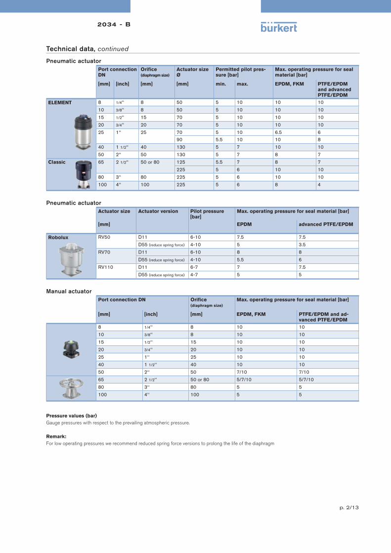
Technical data, continued
Pneumatic actuator
Port connection
DN
Orifice
(diaphragm size)
Actuator size
Ø
Permitted pilot pres-
sure [bar]
Max. operating pressure for seal
material [bar]
[mm] [inch] [mm] [mm] min. max. EPDM, FKM PTFE/EPDM
and advanced
PTFE/EPDM
ELEMENT 8 1/4‘‘ 8 50 5 10 10 10
10 3/8‘‘ 8 50 5 10 10 10
15 1/2‘‘ 15 70 5 10 10 10
20 3/4‘‘ 20 70 5 10 10 10
25 1‘‘ 25 70 5 10 6.5 690 5.5 10 10 8
40 1 1/2‘‘ 40 130 5 7 10 10
50 2‘‘ 50 130 5 7 8 7
Classic 65 2 1/2‘‘ 50 or 80 125 5.5 7 8 7
225 5 6 10 10
80 3‘‘ 80 225 5 6 10 10
100 4‘‘ 100 225 5 6 8 4
Pneumatic actuator
Actuator size Actuator version Pilot pressure
[bar]
Max. operating pressure for seal material [bar]
[mm] EPDM advanced PTFE/EPDM
Robolux RV50 D11 6-10 7.5 7.5
D55 (reduce spring force) 4-10 5 3.5
RV70 D11 6-10 8 8
D55 (reduce spring force) 4-10 5.5 6
RV110 D11 6-7 7 7.5
D55 (reduce spring force) 4-7 5 5
Manual actuator
Port connection DN Orifice
(diaphragm size)
Max. operating pressure for seal material [bar]
[mm] [inch] [mm] EPDM, FKM PTFE/EPDM and ad-
vanced PTFE/EPDM
8 1/4‘‘ 8 10 10
10 3/8‘‘ 8 10 10
15 1/2‘‘ 15 10 10
20 3/4‘‘ 20 10 10
25 1‘‘ 25 10 10
40 1 1/2‘‘ 40 10 10
50 2‘‘ 50 7/10 7/10
65 2 1/2‘‘ 50 or 80 5/7/10 5/7/10
80 3‘‘ 80 5 5
100 4‘‘ 100 5 5
Pressure values (bar)
Gauge pressures with respect to the prevailing atmospheric pressure.
Remark:
For low operating pressures we recommend reduced spring force versions to prolong the life of the diaphragm

2034 - B
p. 3/13
Materials
ELEMENT actuator DN08- DN50
Optical position indicator Transparent cap polysulfone PSU
Pilot air ports Push-in connector PP (standard)
on request: Thread 1/8‘‘ stainless steel 1.4305
Actuator cover PPS
Cover Stainless steel 1.4561 (316Ti)
Piston seal FKM
Socle Stainless steel 1.4308
Screws Stainless steel
Diaphragm EPDM, PTFE/EPDM
(advanced PTFE/EPDM, FKM on request)
Classic actuator DN65- DN100
Optical position indicator Transparent cap polycarbonate PC
Actuator PA Polyamide
Pilot air ports Thread 1/8‘‘ stainless steel 1.4305
Piston seal NBR
Socle Stainless steel 1.4308
Screws Stainless steel
Diaphragm EPDM, PTFE/EPDM
(advanced PTFE/EPDM, FKM on request)
Robolux actuator
Optical position indicator Transparent cap Polyamide 12
Actuator Stainless steel 1.4308/PPS
Piston seal FKM
Screws Stainless steel
Diaphragm EPDM, advanced PTFE/EPDM

2034 - B
p. 4/13
Materials, continued
Manual actuator DN08 - DN100
Handwheel PPS or 316L stainless steel*
Socle PPS or 316L stainless steel*
Screws Stainless steel
Diaphragm EPDM, PTFE/EPDM
advanced PTFE/EPDM
* DN65 to DN100 only in stainless steel
Approvals/certifications
• Certification of Conformity for Raw Material EN-ISO 10204 3.1
• Attestation of compliance with the order EN-ISO 10204 2.1
• Test report EN-ISO 10204 2.2
• Certification of Conformity for Pickling and Electropolishing Processes
• Certification of Conformity for the Surface Quality DIN4762-DIN4768-ISO/4287/1
• Certification for the fulfillment of FDA CFR No. 21.177.1550 for PTFE/EPDM and advanced PTFE/EPDM and 21.177.2600 for EPDM
• USP CLASS VI certification for EPDM and PTFE diaphragm
• Test Certification and Conformity Certification for the Final Assembly of Diaphragm Valves
• ISO 9001 Certification
Note: Retrospective manufacturing certification for process diaphragm valves can not be made, therefore please notify when ordering.
Example of available diaphragm materials
Developed to handle the unique challenges of hygienic and sterile applications, Bürkert offers diaphragms with precise material formula and physical
tolerances. Bürkert diaphragms are available in a wide range of materials which have been proven in food & beverage, biotechnology, pharmaceutical
and cosmetic industry applications. Diaphragms are tested during development and production to ensure reliability in critical processing environments.
• EPDM
• PTFE/EPDM
• advanced PTFE/EPDM
• FKM

2034 - B
p. 5/13
Valve features, specification key 1
Example 2034 B 04 05 E R VI EU 25 0403
Specification key2034
(Please make a choice)
ACTUATOR VERSION
E ELEMENT actuator
K CLASSIC actuator
R Robolux actuator
X Robolux & CLASSIC
Y Robolux & ELEMENT
Z ELEMENT & CLASSIC
AMOUNT OF VALVE SEATS
01 Seat
02 Seats
… Seats
05 Seats
06 Seats
NUMBER OF PORTS
01 Connection
02 Connections
… Connections
07 Connections
08 Connections
BODY MATERIAL
VH 1.4435/AISI 316LVI 1.4435 acc. to BN2/ASME BPE SEAL MATERIAL
AB EPDM
EU Advanced PTFE
FF FKM
AD EPDM for high temperature
EKAdvanced PTFE laminated on EPDM (only Robolux)
OPERATION
M Manual
P Pneumatic
R Pneumatic with control
X Manual & Pneumatic
CONFIGURATION
0201see next page for further info 0202
0203
0227
0233
0234
0236
GMP3
GMP4
GMP5
GMP6
SAP1
SAP2
SAP3
SAP4
SAP7
SAP8
0235
0325
0301
0303
0319
0413
0403
0416
0417
0501
0602
CSBS
PRODUCTION OF BODY
B Bloc material
MAIN ORIFICE [mm]
8
15
20
25
40
50
65
80
100

2034 - B
p. 6/13
Configurations
0201 0202 0203
C3/H
C1/H
C2/H S1
S2
C3/V
C1/V
C2/V
S1 S2
C3/V
C1/V
C2/V
S1 S2
C3/V C4/V
C2/HS1 S2
C1/H
C2
C1
C3 S1
S2
C3
C1
C2
S2S1
C3
C1
C2S2
S2
C4
0227 0233 0234
C3/H
C1/V
C2/HS1 S2
C1/H
C3/V
C2/HS1 S2
C1/H
C3/V
C2/H
S1
S2
C3
C1
S2
S1
C2
C3
C1
C2
S2
S1
C3
C1
C2
S2
S1
0235 0236
C2/HC1/HS1
C4/V
S2
C3/V
C1/H
C3/V
C2/H
S1
S2
C3
C1
C2
S1
C4
S2
C3
C1
C2
S1
S2

2034 - B
p. 7/13
Configurations, continued
GMP3 GMP4 GMP5
C3/H
C1/V
C2/V
S1
S2
C3/H
C1/V
C2/V
S1S2
C3/H
C1/V
C2/V
S1 S2
S1
C3
C1
C2
S2
C3
C1
C2
S2
S1
C1
C2
S2
C3
S1
GMP6
C3/H
C1/V
C2/V
S1
S2
C1
C2
S2
C3
S1
SAP1 SAP2 SAP3
C1/H
C3/V
C2/H
S1
S2
C1/H
C3/V
C2/H
S1
S2
C1/H
C3/H
C2/HS1
S2
C1
C2
C3
S1
S2C1
C2
C3
S1
S2
C3
C1 C2
S2 S1

2034 - B
p. 8/13
Configurations, continued
SAP4 SAP7 SAP8
C1/H
C3/H
C2/HS1
S2C1/H
C3/V
C2/H
S1
S2
C2/HC1/H
C3/V
S1
S2
C3
C1 C2
S2 S1
C1
C2
C3
S1
S2
C3
C1
C2
S1
S2
0301 0303 0319
C2/HC1/H
C4/V
S3S2
C3/V
S1
C2/HC1/H
C4/V
S3S2
C3/V
S1C3/V C4/VC2/V
S2 S3S1
C1/V
C3
C1
C2
S1
S3S2
C4
C3
C1
C2
S1S3
S2
C4
C3
C1
C2S1
S3S2
C4
0325
C1/H
C3/H
C2/HS1
S2
S3
C1
C2S1
C3
S3
S2

2034 - B
p. 9/13
Configurations, continued
0403 0413 0416
C2/V
S1
C5/V
S4
C3/V
S2
C4/V
S3
C1/V
C1/H
S1
C4/H
S4
C2/H
S2
C3/H
S3
C2/H C5/H
S4
C3/H C4/H
S3
C1/V
S2S1
C3
C1
C2
S1
S3
S2
C4
S4
C5
C3
C1
C2
S1
S3
S2
C4
S4
C3
C1
C2
S1
S3
S2
C4
S4
C5
0417
C2/HC1/HS1
C4/V
S2
C3/V
S3
C6/V
S4
C5/V
C3
C1
C2
C4C5
C6
S1S2
S3S4
0501 0602
C1/H S5
S1 S2
S3S4
C3/H
C4/H
C2/H
C3/V
S1
S4
C6/V
C4/V
S2
S5
C7/V
C5/V
S3
S6
C8/V
C1/H C2/H
C3
C1
C2
S1 C4
S2
S3
S4
S5
C3
C1
C2
S1
C4C5
C6C7
C8
S2S3
S5S4
S6

2034 - B
p. 10/13
Valve features, specification key 2
Example2034 25 A 25 A 25 A 20 A - - - -
SODF SODF SODF SA93 SODF - - - NK52 + NO23
Specification key
2034
(Please make a choice)
VALVE/SEAT n°1
Orifice
DN [mm]Actuator version
08 Pneumatic
15 A normally closed by spring action
20 B normally open by spring action
25 I double acting
40 Manual
50 D050 Handwheel PPS / bonnet PPS
80 D052Handwheel stainless steel / bonnet stainless steel (only DN65-DN100)
100 D058Handwheel PPS / bonnet stainless steel with hole for bolts
VALVE/SEAT n°2, 3..... x
Orifice DN
[mm]Actuator version
08 Pneumatic
15 A normally closed by spring action
20 B normally open by spring action
25 I double acting
40 Manual
50 D050 Handwheel PPS / bonnet PPS
80 D052Handwheel stainless steel / bonnet stainless steel (only DN65-DN100)
100 D058Handwheel PPS / bonnet stainless steel with hole for bolts
+
Port connection Valve/Seat S1
C3
C1
C2
S1
S3
S2
C4
S4
C5
VARIABLE CODES
Surface finish, external
NO22 glass bead blasted Ra=3.2 µmNO34 Mechanical polished Ra=1.2 µmNO15 Electro polished Ra=0.8 µm
Surface finish, internal
NO23 Mechanical polished Ra=0.6µmNO16 Electro polished Ra=0.6µmNO14 Mechanical polished Ra=0.5µmNO17 Elektropoliert Ra=0.4µm
Certificat
NK52 3.1 Certificate integrated
Port connection Valve/Seat S2, S3... Sx
Port connection weld end
DN
[mm]
EN ISO 1127/
ISO 4200
DIN 11866 S. B
SMS 3008 DIN 11850 S. 0 DIN 11850 S. 1 DIN 11850 S. 2
DIN 11866 S. A
DIN 11850 S. 3 BS4825 ASME BPE
DIN 11866 S. C
4 SC40 - 6.0x1.06 SA78 - 10.2x1.6 SC41 - 8.0x1.0 SA89 - 3.17x0.568 SA40 - 13.5x1.6 SC42 - 10.0x1.0 SODB - 6.35x1.2 SA90 - 6.35x0.89
10 SA41 - 17.2x1.6 SF40 - 12.0x1.0 SD40 - 13.0x1.5 SE40 - 14.0x2.0 SODC - 9.53x1.2 SA91 - 9.53x0.8915 SA42 - 21.3x1.6 SA58 - 12.0x1.0 SC43 - 18.0x1.5 SF41 - 18.0x1.0 SD42 - 19.0x1.5 SE42 - 20.0x2.0 SODD - 12.7x1.2 SA92 - 12.7x1.6520 SA43 - 26.9x1.6 SA59 - 18.0x1.0 SC44 - 22.0x1.5 SF42 - 22.0x1.0 SD43 - 23.0x1.5 SE43 - 24.0x2.0 SODE - 19.05x1.2 SA93 - 19.05x1.6525 SA44 - 33.7x2.0 SA60 - 25.0x1.2 SC45 - 28.0x1.5 SF43 - 28.0x1.0 SD44 - 29.0x1.5 SE44 - 30.0x2.0 SODF - 25.4x1.6532 SA45 - 42.4x2.0 SA61 - 33.7x1.2 SC46 - 34.0x1.5 SF44 - 34.0x1.0 SD45 - 35.0x1.5 SE45 - 36.0x2.040 SA46 - 48.3x2.0 SA62 - 38.0x1.2 SC47 - 40.0x1.5 SF45 - 40.0x1.0 SD46 - 41.0x1.5 SE46 - 42.0x2.0 SODH - 38.1x1.6550 SA47 - 60.3x2.0 SA63 - 51.0x1.2 SC48 - 52.0x1.5 SF46 - 52.0x1.0 SD47 - 53.0x1.5 SE47 - 54.0x2.0 SODI - 50.8x1.6565 SA48 - 76.1x2.0 SA64 - 63.5x1.6 SD48 - 70.0x2.0 SODJ - 63.5x1.6580 SA49 - 88.9x2.3 SA65 - 76.1x1.6 SD49 - 85.0x2.0 SODK - 76.2x1.65
100 SA39 - 114.3x2.3 SA66 - 101.6x2.0 SD50 - 104.0x2.0 SODL - 101.6x2.11
Port connection Clamp
DN
[mm]
Clamp 34,0 like DIN 32676 S. B
(ISO-tube (ISO4200))
DIN 32676 S. A
(DIN-tube (DIN11850))
DIN 32676 S. B
(ISO-tube (ISO4200))
ASME BPE BS 4825
(Clamp BS 4825-3, tube BS 4825-1)
8 TC51 - 13.5x1.6 Cl: 34.0 TD40 - 10.0x1.0 Cl: 25.0 TC40 - 13.5x1.6 Cl: 25.0 TG50 - 6.35x0.89 Cl: 25.010 TC41 - 17.2x1.6 Cl: 34.0 TD41 - 13.0x1.5 Cl: 34.0 TC53 - 17.2x1.6 Cl: 25.0 TG01 - 9.53x0.89 Cl: 25.015 TC42 - 21.3x1.6 Cl: 34.0 TD42 - 19..0x1.5 Cl: 34.0 TC52 - 21.3x1.6 Cl: 50.5 TG02 - 12.7x1.65 Cl: 25.0 TH42 - 12.7x1.2 Cl: 25.020 TD43 - 23.0x1.5 Cl: 34.0 TC43 - 26.9x1.6 Cl: 50.5 TG03 - 19.05x1.65 Cl: 25.0 TH43 - 19.05x1.2 Cl: 25.025 TD44 - 29.0x1.5 Cl: 50.5 TC44 - 33.7x2.0 Cl: 50.5 TG04 - 25.4x1.65 Cl: 50.53240 TD46 - 41.0x1.5 Cl: 50.5 TC46 - 48.3x2.0 Cl: 64.0 TG05 - 38.1x1.65 Cl: 50.550 TD47 - 53.0x1.5 Cl: 64.0 TC47 - 60.3x2.0 Cl: 77.5 TG06 - 50.8x1.65 Cl: 64.065 TC48 - 76.1x2.0 Cl: 91.0 TG07 - 63.5x1.65 Cl: 77.580 TC49 - 88.9x2.3 Cl: 106.0 TG08 - 76.2x.65 Cl: 91.0
100 TC50 - 114.3x2.3 Cl: 130.0 TG09 - 101.6x2.11 Cl: 119.0

2034 - B
p. 11/13
Standard configuration – request for quotation
Please fill out and send to your nearest Bürkert facility* with your inquiry or order
Company Contact person
Customer no. Department
Address Tel./Fax
Postcode/town E-Mail
= mandatory fields to fill out Quantity Required delivery date
Operating data
Process medium
Type of media Liquid Steam Gas
Nominal Unit
Flow rate (Q, QN, W) 1)
1) standard unit: Liquid Q = m3/h; Steam W = kg/h; Gas Qn = nm3/h
Temperature at valve inlet
Absolute pressure at valve inlet
Absolute pressure at valve outlet
Steam pressure Pv
Valve features
Specification key 1 2034
(automatically transfered from p 5 )
Specification key 2 2034
(automatically transfered from p. 10 ) +
Accessories
Click on the orange box „More info.“ below... you will come to our website for the resp. product where you can download the datasheet.
Pilot valve Stroke limitation Position feedback/Control head
Type 6012 Type 8690
Min./max. stroke limitation, with visual position indicator Type 8691
Max. stroke limitation, without visual position indicator Type 8695
Type 8697
Type 8685
Type 8686
Please specify item no. (if known): Please specify item no. (if known): Please specify item no. (if known):
for actuator (A1, A2,...) for actuator (A1, A2,...) for actuator (A1, A2,...)
Certifications
Attestation of compliance with the order EN-ISO 10204 2.1 Certification of Conformity for Pickling and Electropolishing Processes
Test report EN-ISO 10204 2.2 FDA and USP compliance
Certification of Conformity for Raw Material EN-ISO 10204 3.1
Certification of Conformity for the Surface Quality DIN4762-DIN4768-ISO/4287/1
Moreinfo.
Moreinfo.
Moreinfo.
Moreinfo.
Moreinfo.
Moreinfo.
Moreinfo.
Moreinfo.
Note
You can fill out
the fields directly
in the PDF file
before printing
out the form.

p. 12/13
2034 - BSPECIFICATION SHEET
Multifunction bloc Type 2034
Bloc solution
Sales data
Project name:
Quantities:single enquiry
enquiry for series
Flow schematic LegendeWarning: connection and valve description should be in accordance with the table that filled below!
C3/H
C1/V
C2/HA2
A1
A3
A4
C3/V
Diaphragm valve - one seat
Area with minimum volume
Drain direction
Flow direction
Connection C1, C2, ... - System / Bloc C1 ... CnA1, A2, ... actuator (Bloc valves) A1 ... AnOptional indication of inlet and outlet ( V / H )
Please sketch the schematic (horizontal or vertical available)
Technical data -Fluidic
Medium nature Medium pressure
Medium temperature Medium viscosity
Kv value or flow rate Bürkert standard in blue
Material for the bloc 1.4535 / 316L 1.4435 acc. to BN2 / ASME BPE Specific material:
Surface finish (internal) 0.8 0.6 0.4 0.25
Specific surface finish (Ra in µm):
Electropolish
Surface finish (external) 1.6 Specific surface finish (Ra in µm):
Diaphragm material EPDM PTFE FKM Silicone (only Robolux)
Connection definition
Nominal size Weld end ClampC-Nr. DN DIN 11850 S.2
DIN 11866 S.A
ISO 4200
EN ISO 1127
DIN 11866 S.B
ASME BPE
DIN 11866 S.C
DIN 32676 S. A DIN 32676 S. B ASME BPE Divers
C1
C2
C3
C4
C5
C6
C7
C8
Actuator and actuation see specification on next page.
Customized configuration – request for quotation
Please fill out and send to your nearest Bürkert facility* with your inquiry or order
Company Contact person
Customer no. Department
Address Tel./Fax
Postcode/town E-Mail

p. 13/13
2034 - BSPECIFICATION SHEET
Actuator / Actuation Type 2034
In case of special application conditions,please consult for advice.
Subject to alteration.© Christian Bürkert GmbH & Co. KG 1401/2_EU-en_00895250
Customized configuration – request for quotation, continued
Automation system (product overview)
ELEMENT actuator system Robolux actuator system
compact stainless steel design
designed for modular actuation
fresh air system
double actuator with 2 valve function
optimum designed for modular actuator
concept
high life time with double piston actuator
ELEMENT control head Type 8691 Robolux double feedback head Type 8685
integrated pilot valve
position teach in
large LED indication
ASI and device net communication possible
contactless position detection
LED indicator
ASI communication
Namur / Ex (without LED)
ELEMENT control head Type 8695 for actua-
tor 50mm
Robolux double control head Type 8686
2 pilot valve for multi port valve
contactless position detection
LED indicator
ASI communication
integrated pilot valve
position teach in
Large LED indication
ASI and device net communication possible
ELEMENT feeedback head Type 8690 / 8697
mechanical electrical feedback
inductive feedback
Eexi version
Technical data - ActuationRemarks:
Pilot pressure Bürkert standard in blue
C3/H
C1/V
C2/HA2
A1
A3
A4
C3/V
Ambient temperature
Cycle per year
Implementation (clean room, outside...)
Hazardous location
(EX / ATEX / NAMUR)
Actuator material St. steel/Plastic Plastic Other actuator material
Power supply 8 V Namur 24 V/DC 230 V/50-60 Hz Other protection / application conditions
IP protection IP65 IP67 Other power supply
Automation ASI DeviceNet Other automation (PLC / Fieldbus)
Definition actuation, feedback, pilote valves control head
Nominal size Actuator Control feedback Control head Control functionA-Nr. DN Pneumatic Manual Position ON Position OFF + Pilot valve normally
closed
normally
open
A1
A2
A3
A4
A5
A6
A7
A8
Fluidic specification, connections, norms see previous page.
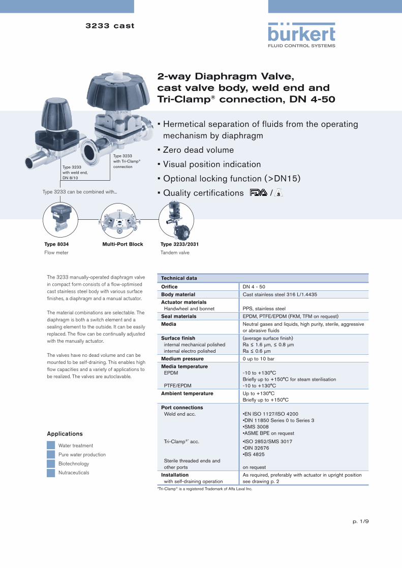
3233 cast
p. 1/9
2-way Diaphragm Valve,cast valve body, weld end andTri-Clamp® connection, DN 4-50
The 3233 manually-operated diaphragm valve
in compact form consists of a fl ow-optimised
cast stainless steel body with various surface
fi nishes, a diaphragm and a manual actuator.
The material combinations are selectable. The
diaphragm is both a switch element and a
sealing element to the outside. It can be easily
replaced. The fl ow can be continually adjusted
with the manually actuator.
The valves have no dead volume and can be
mounted to be self-draining. This enables high
fl ow capacities and a variety of applications to
be realized. The valves are autoclavable.
Technical data
Orifi ce DN 4 - 50
Body material Cast stainless steel 316 L/1.4435
Actuator materials
Handwheel and bonnet PPS, stainless steel
Seal materials EPDM, PTFE/EPDM (FKM, TFM on request)
Media Neutral gases and liquids, high purity, sterile, aggressive
or abrasive fl uids
Surface fi nish
internal mechanical polished
internal electro polished
(average surface fi nish)
Ra ≤ 1.6 μm, ≤ 0.8 μm
Ra ≤ 0.6 μm
Medium pressure 0 up to 10 bar
Media temperature
EPDM
PTFE/EPDM
-10 to +130°C
Briefl y up to +150°C for steam sterilisation
-10 to +130°C
Ambient temperature Up to +130°C
Briefl y up to +150°C
Port connections
Weld end acc.
Tri-Clamp®* acc.
Sterile threaded ends and
other ports
•EN ISO 1127/ISO 4200
•DIN 11850 Series 0 to Series 3
•SMS 3008
•ASME BPE on request
•ISO 2852/SMS 3017
•DIN 32676
•BS 4825
on request
Installation
with self-draining operation
As required, preferably with actuator in upright position
see drawing p. 2
Type 8034
Flow meter
Multi-Port Block Type 3233/2031
Tandem valve
Type 3233 can be combined with...
• Hermetical separation of fluids from the operating
mechanism by diaphragm
• Zero dead volume
• Visual position indication
• Optional locking function (>DN15)
• Quality certifications /
Water treatment
Pure water production
Biotechnology
Nutraceuticals
Applications
Type 3233
with weld end,
DN 8/10
Type 3233
with Tri-Clamp®
connection
*Tri-Clamp® is a registered Trademark of Alfa Laval Inc.

3233 cast
p. 2/9
Technical data, continued
Kv-values and weight
Installation for self-draining operation
Port connection Kv-value water Max. operating pressure
Weight [kg]
[mm] [inch] [m3/h] [bar]Handwheel PPS/bonnet stainless steel
Handwheel andbonnet PPS
4/6 – 0.8 10 0.4 0.3
8 1/4” 1.0 10 0.4 0.3
10 3/8” 1.0 10 0.4 0.3
15 1/2” 6.0 10 0.7 0.6
20 3/4” 11.0 10 1.0 0.9
25 1” 16.0 10 1.8 1.6
32 1 1/4” 29.0 10 3.4 3.1
40 1 1/2” 29.0 10 3.4 3.1
50 2” 50.0 7/10 1) 4.2 3.7
Flow rate: Kv-value water (m3/h)
Measured at +20°C, 1 bar pressure at valve inlet and free outlet.
Pressure values (bar)
Gauge pressures with respect to the prevailing atmospheric pressure.
α = 15 up to 35° plus 3° to 5° inclination to the pipe axis.For detailed installation angle values, please contact your local Bürkert representative.
1) See ordering charts
α

3233 cast
p. 3/9
Materials
Approvals
Suitable for foodstuffs / sterile applications
• The composition of the EPDM and PTFE/EPDM diaphragms corresponds to the Code of Federal Regulations,
published by the FDA (Food and Drug Administration, USA).
• The EPDM diaphragms correspond to the KTW-Recommendation (Plastics in the Drinking Water Sector).
A Manufacturer‘s Declaration will be supplied on request.
• The diaphragm valves are 3-A approved
(3-A Sanitary Standards Symbol Administrative Council)
Handwheel: PPS
Bonnet: PPS or stainless steel 1.4581
Mounting
nut: Stainless steel 316L
Mounting
screw: Stainless steel 316L
Valve body: Cast stainless steel 316L/1.4435
Seal:
EPDM or PTFE/EPDM
(FKM, TFM on request)

3233 cast
p. 4/9
[mm
]
[in
ch
]
Exte
rna
l Ø
[m
m]
Kv-v
alu
e
wa
ter
[m3/h
]
Ma
x.
op
era
tin
g
pre
ssu
re
[ba
r]
Me
ch
.p
oli
sh
ed
, R
a ≤
1.6
/6.3
μ
m
Me
ch
.p
oli
sh
ed
,R
a ≤
0.8
/6.3
μ
m
Ele
ctr
o
po
lish
ed
, R
a ≤
0.6
/3.2
μ
m
Acc. EN ISO 1127/ ISO 4200, diaphragm material EPDM
Handwheel PPS/bonnet PPS
8 1/4” 13.5 1.0 10 442 146 442 147 442 148
10 3/8” 17.2 1.0 10 442 170 442 171 442 172
15 1/2” 21.3 6.0 10 442 269 442 270 442 271
20 3/4” 26.9 11.0 10 442 308 442 309 442 310
25 1” 33.7 16.0 10 442 351 442 352 442 353
32 1 1/4” 42.4 29.0 10 – 551 965 554 966
40 1 1/2” 48.3 29.0 10 442 409 442 410 442 411
50 2” 60.3 50.0 7 442 464 442 465 442 466
Handwheel PPS/bonnet stainless steel
8 1/4” 13.5 1.0 10 440 976 440 977 440 978
10 3/8” 17.2 1.0 10 441 014 441 015 441 016
15 1/2” 21.3 6.0 10 441 060 441 061 441 062
20 3/4” 26.9 11.0 10 441 118 441 119 441 120
25 1” 33.7 16.0 10 441 172 441 173 441 174
32 1 1/4” 42.4 29.0 10 – 554 967 554 968
40 1 1/2” 48.3 29.0 10 440 956 440 957 440 958
50 2” 60.3 50.0 10 440 960 440 961 440 962
Acc. EN ISO 1127/ ISO 4200, diaphragm material PTFE/EPDM
Handwheel PPS/bonnet PPS
8 1/4” 13.5 1.0 10 441 809 441 810 441 811
10 3/8” 17.2 1.0 10 441 813 441 814 441 815
15 1/2” 21.3 6.0 10 441 817 441 818 441 819
20 3/4” 26.9 11.0 10 441 821 441 822 441 823
25 1” 33.7 16.0 10 441 825 441 826 441 827
32 1 1/4” 42.4 29.0 10 550 767 554 969
40 1 1/2” 48.3 29.0 10 441 829 441 830 441 831
50 2” 60.3 50.0 7 441 833 441 834 441 835
Handwheel PPS/bonnet stainless steel
8 1/4” 13.5 1.0 10 441 032 441 033 441 034
10 3/8” 17.2 1.0 10 441 090 441 091 441 092
15 1/2” 21.3 6.0 10 441 144 441 145 441 146
20 3/4” 26.9 11.0 10 440 972 440 973 440 974
25 1” 33.7 16.0 10 441 010 441 011 441 012
32 1 1/4” 42.4 29.0 10 554 970 554 971
40 1 1/2” 48.3 29.0 10 441 052 441 053 441 054
50 2” 60.3 50.0 10 441 110 441 111 441 112
Ordering chart for valves (other versions on request)
Body with weld end, acc. EN ISO 1127/ISO 4200
Item no.: internal/external surface
Port connection size equals the orifi ce diaphragm size except for port connection 32 mm. At port
connection 32 mm the orifi ce diaphragm size equals 40 mm.
Port connection
Port connectionSterile threaded ends
MaterialSeal: FKM, TFM
AdditionalLocking function (not for DN 8/10)
3233 cast
p. 5/9
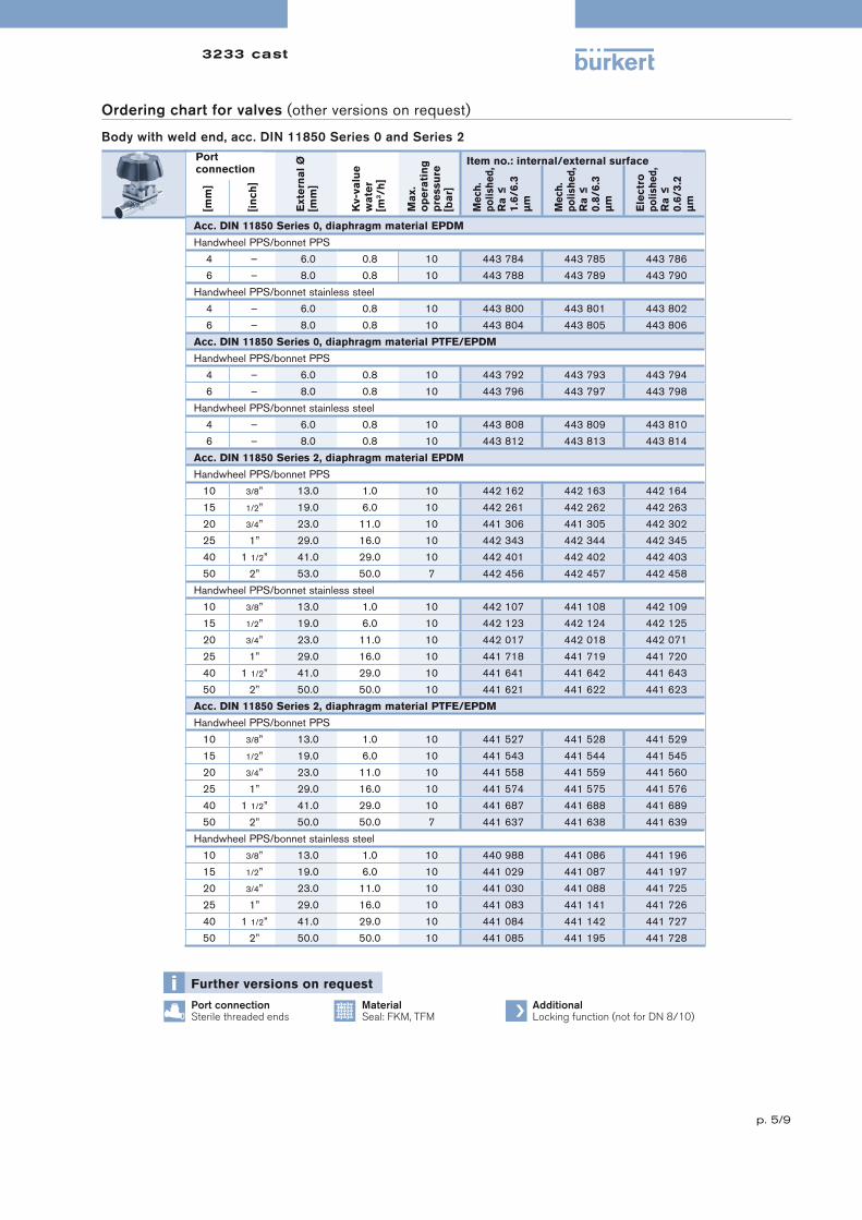
Ordering chart for valves (other versions on request)
Body with weld end, acc. DIN 11850 Series 0 and Series 2
[mm
]
[in
ch
]
Exte
rna
l Ø
[m
m]
Kv-v
alu
e
wa
ter
[m3/h
]
Ma
x.
op
era
tin
g
pre
ssu
re
[ba
r]
Me
ch
.p
oli
sh
ed
, R
a ≤
1.6
/6.3
μ
m
Me
ch
.p
oli
sh
ed
,R
a ≤
0.8
/6.3
μ
m
Ele
ctr
o
po
lish
ed
, R
a ≤
0.6
/3.2
μ
m
Acc. DIN 11850 Series 0, diaphragm material EPDM
Handwheel PPS/bonnet PPS
4 – 6.0 0.8 10 443 784 443 785 443 786
6 – 8.0 0.8 10 443 788 443 789 443 790
Handwheel PPS/bonnet stainless steel
4 – 6.0 0.8 10 443 800 443 801 443 802
6 – 8.0 0.8 10 443 804 443 805 443 806
Acc. DIN 11850 Series 0, diaphragm material PTFE/EPDM
Handwheel PPS/bonnet PPS
4 – 6.0 0.8 10 443 792 443 793 443 794
6 – 8.0 0.8 10 443 796 443 797 443 798
Handwheel PPS/bonnet stainless steel
4 – 6.0 0.8 10 443 808 443 809 443 810
6 – 8.0 0.8 10 443 812 443 813 443 814
Acc. DIN 11850 Series 2, diaphragm material EPDM
Handwheel PPS/bonnet PPS
10 3/8” 13.0 1.0 10 442 162 442 163 442 164
15 1/2” 19.0 6.0 10 442 261 442 262 442 263
20 3/4” 23.0 11.0 10 441 306 441 305 442 302
25 1” 29.0 16.0 10 442 343 442 344 442 345
40 1 1/2” 41.0 29.0 10 442 401 442 402 442 403
50 2” 53.0 50.0 7 442 456 442 457 442 458
Handwheel PPS/bonnet stainless steel
10 3/8” 13.0 1.0 10 442 107 441 108 442 109
15 1/2” 19.0 6.0 10 442 123 442 124 442 125
20 3/4” 23.0 11.0 10 442 017 442 018 442 071
25 1” 29.0 16.0 10 441 718 441 719 441 720
40 1 1/2” 41.0 29.0 10 441 641 441 642 441 643
50 2” 50.0 50.0 10 441 621 441 622 441 623
Acc. DIN 11850 Series 2, diaphragm material PTFE/EPDM
Handwheel PPS/bonnet PPS
10 3/8” 13.0 1.0 10 441 527 441 528 441 529
15 1/2” 19.0 6.0 10 441 543 441 544 441 545
20 3/4” 23.0 11.0 10 441 558 441 559 441 560
25 1” 29.0 16.0 10 441 574 441 575 441 576
40 1 1/2” 41.0 29.0 10 441 687 441 688 441 689
50 2” 50.0 50.0 7 441 637 441 638 441 639
Handwheel PPS/bonnet stainless steel
10 3/8” 13.0 1.0 10 440 988 441 086 441 196
15 1/2” 19.0 6.0 10 441 029 441 087 441 197
20 3/4” 23.0 11.0 10 441 030 441 088 441 725
25 1” 29.0 16.0 10 441 083 441 141 441 726
40 1 1/2” 41.0 29.0 10 441 084 441 142 441 727
50 2” 50.0 50.0 10 441 085 441 195 441 728
Port connection
Item no.: internal/external surface
Port connectionSterile threaded ends
MaterialSeal: FKM, TFM
AdditionalLocking function (not for DN 8/10)
3233 cast
p. 6/9
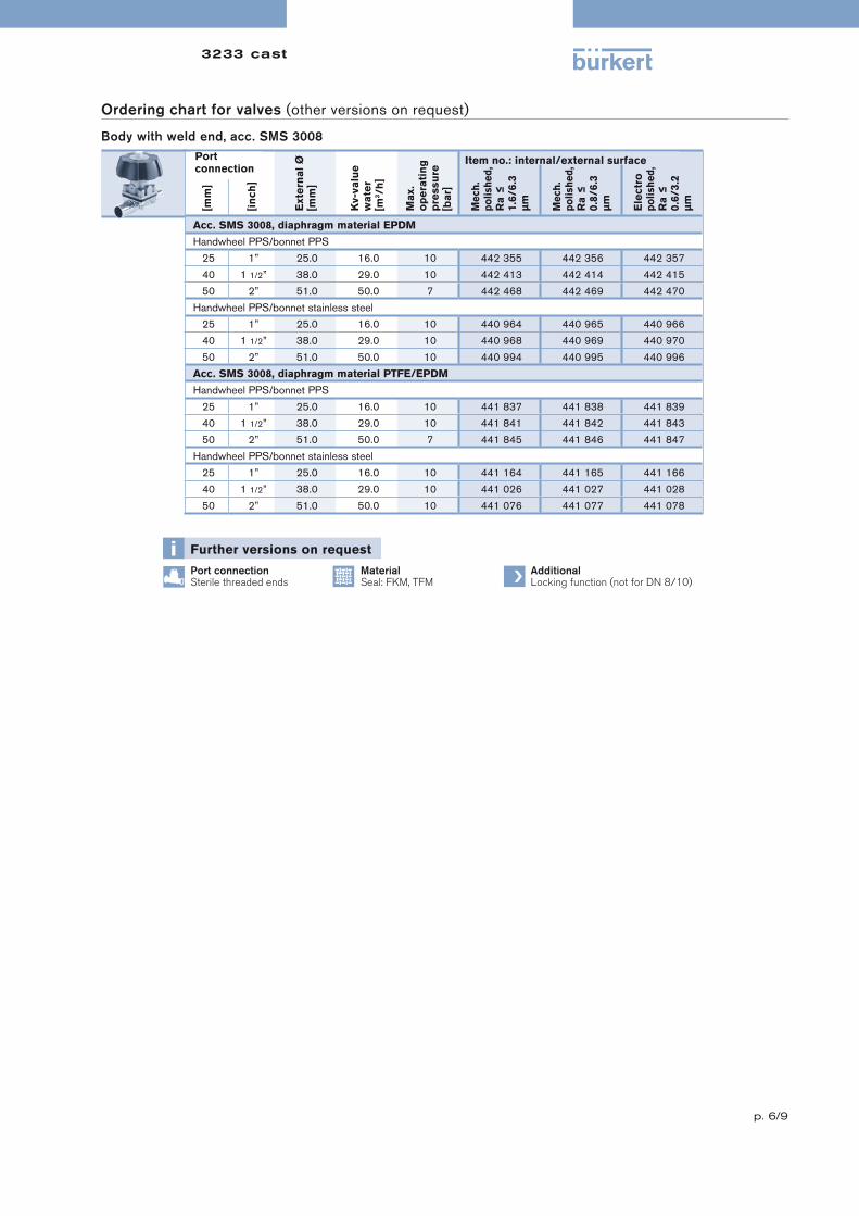
Ordering chart for valves (other versions on request)
Body with weld end, acc. SMS 3008
[mm
]
[in
ch
]
Exte
rna
l Ø
[m
m]
Kv-v
alu
e
wa
ter
[m3/h
]
Ma
x.
op
era
tin
g
pre
ssu
re
[ba
r]
Me
ch
.p
oli
sh
ed
, R
a ≤
1.6
/6.3
μ
m
Me
ch
.p
oli
sh
ed
,R
a ≤
0.8
/6.3
μ
m
Ele
ctr
o
po
lish
ed
, R
a ≤
0.6
/3.2
μ
m
Acc. SMS 3008, diaphragm material EPDM
Handwheel PPS/bonnet PPS
25 1” 25.0 16.0 10 442 355 442 356 442 357
40 1 1/2” 38.0 29.0 10 442 413 442 414 442 415
50 2” 51.0 50.0 7 442 468 442 469 442 470
Handwheel PPS/bonnet stainless steel
25 1” 25.0 16.0 10 440 964 440 965 440 966
40 1 1/2” 38.0 29.0 10 440 968 440 969 440 970
50 2” 51.0 50.0 10 440 994 440 995 440 996
Acc. SMS 3008, diaphragm material PTFE/EPDM
Handwheel PPS/bonnet PPS
25 1” 25.0 16.0 10 441 837 441 838 441 839
40 1 1/2” 38.0 29.0 10 441 841 441 842 441 843
50 2” 51.0 50.0 7 441 845 441 846 441 847
Handwheel PPS/bonnet stainless steel
25 1” 25.0 16.0 10 441 164 441 165 441 166
40 1 1/2” 38.0 29.0 10 441 026 441 027 441 028
50 2” 51.0 50.0 10 441 076 441 077 441 078
Port connection
Item no.: internal/external surface
Port connectionSterile threaded ends
MaterialSeal: FKM, TFM
AdditionalLocking function (not for DN 8/10)

3233 cast
p. 7/9
Ordering chart for valves (other versions on request)
Body with Tri-Clamp® connection, acc. ISO 2852 - SMS 3017 and DIN 32676
[mm
]
[in
ch
]
Exte
rna
l Ø
[m
m]
Kv-v
alu
e
wa
ter
[m3/h
]
Ma
x.
op
era
tin
g
pre
ssu
re
[ba
r]
Me
ch
.p
oli
sh
ed
, R
a ≤
1.6
/6.3
μ
m
Me
ch
.p
oli
sh
ed
,R
a ≤
0.8
/6.3
μ
m
Ele
ctr
o
po
lish
ed
, R
a ≤
0.6
/3.2
μ
m
Acc. ISO 2852 - SMS 3017, diaphragm material EPDM
Handwheel PPS/bonnet PPS
25 1” 50.5 16 10 442 371 442 372 442 373
40 1 1/2” 50.5 29 10 442 429 442 430 442 431
50 2” 64.0 50 7 442 484 442 485 442 486
Handwheel PPS/bonnet stainless steel
25 1” 50.5 16 10 440 998 440 999 441 000
40 1 1/2” 50.5 29 10 441 002 441 003 441 004
50 2” 64.0 50 10 441 006 441 007 441 008
Acc. ISO 2852 - SMS 3017, diaphragm material PTFE/EPDM
Handwheel PPS/bonnet PPS
25 1” 50.5 16 10 441 849 441 850 441 851
40 1 1/2” 50.5 29 10 441 853 441 854 441 855
50 2” 64.0 50 7 441 857 441 858 441 859
Handwheel PPS/bonnet stainless steel
25 1” 50.5 16 10 441 134 441 135 441 136
40 1 1/2” 50.5 29 10 441 188 441 189 441 190
50 2” 64.0 50 10 440 984 440 985 440 986
Acc. DIN 32676, diaphragm material EPDM
Handwheel PPS/bonnet PPS
15 1/2” 34.0 6.0 10 442 281 442 282 442 283
20 3/4” 34.0 11.0 10 442 320 442 321 442 322
25 1” 50.5 16.0 10 442 367 442 368 442 369
40 1 1/2” 50.5 29.0 10 442 425 442 426 442 427
50 2” 64.0 50.0 7 442 480 442 481 442 482
Handwheel PPS/bonnet stainless steel
15 1/2” 34.0 6.0 10 441 036 441 037 441 038
20 3/4” 34.0 11.0 10 441 040 441 041 441 042
25 1” 50.5 16.0 10 441 044 441 045 441 046
40 1 1/2” 50.5 29.0 10 441 048 441 049 441 050
50 2” 64.0 50.0 10 441 094 441 095 441 096
Acc. DIN 32676, diaphragm material PTFE/EPDM
Handwheel PPS/bonnet PPS
15 1/2” 34.0 6.0 10 441 861 441 862 441 863
20 3/4” 34.0 11.0 10 442 178 442 179 442 180
25 1” 50.5 16.0 10 442 182 442 183 442 184
40 1 1/2” 50.5 29.0 10 442 186 442 187 442 188
50 2” 64.0 50.0 7 442 190 442 191 442 192
Handwheel PPS/bonnet stainless steel
15 1/2” 34.0 6.0 10 441 022 441 023 441 024
20 3/4” 34.0 11.0 10 441 068 441 069 441 070
25 1” 50.5 16.0 10 441 126 441 127 441 128
40 1 1/2” 50.5 29.0 10 441 180 441 181 441 182
50 2” 64.0 50.0 10 440 980 440 981 440 982
Port connection
Item no.: internal/external surface
Port connectionSterile threaded ends
MaterialSeal: FKM, TFM
AdditionalLocking function (not for DN 8/10)

3233 cast
p. 8/9
Ordering chart for valves (other versions on request)
Body with Tri-Clamp® connection, acc. BS 4825
[mm
]
[in
ch
]
Exte
rna
l Ø
[m
m]
Kv-v
alu
e
wa
ter
[m3/h
]
Ma
x.
op
era
tin
g
pre
ssu
re
[ba
r]
Me
ch
.p
oli
sh
ed
, R
a ≤
1.6
/6.3
μ
m
Me
ch
.p
oli
sh
ed
,R
a ≤
0.8
/6.3
μ
m
Ele
ctr
o
po
lish
ed
, R
a ≤
0.6
/3.2
μ
m
Acc. BS 4825, diaphragm material EPDM
Handwheel PPS/bonnet PPS
8 1/4” 25.0 1.0 10 442 234 442 235 442 236
10 3/8” 25.0 1.0 10 442 242 442 243 442 244
15 1/2” 25.0 6.0 10 442 324 442 325 442 326
25 1” 50.5 16.0 10 442 375 442 376 442 377
40 1 1/2” 50.5 29.0 10 442 433 442 434 442 435
50 2” 64.0 50.0 7 442 488 442 489 442 490
Handwheel PPS/bonnet stainless steel
8 1/4” 25.0 1.0 10 441 098 441 099 441 100
10 3/8” 25.0 1.0 10 441 102 441 103 441 104
15 1/2” 25.0 6.0 10 441 106 441 107 441 108
25 1” 50.5 16.0 10 441 148 441 149 441 150
40 1 1/2” 50.5 29.0 10 441 152 441 153 441 154
50 2” 64.0 50.0 10 441 156 441 157 441 158
Acc. BS 4825, diaphragm material PTFE/EPDM
Handwheel PPS/bonnet PPS
8 1/4” 25.0 1.0 10 442 194 442 195 442 196
10 3/8” 25.0 1.0 10 442 198 442 199 442 200
15 1/2” 25.0 6.0 10 442 202 442 203 442 204
25 1” 50.5 16.0 10 442 206 442 207 442 208
40 1 1/2” 50.5 29.0 10 442 210 442 211 442 212
50 2” 64.0 50.0 7 442 214 442 215 442 216
Handwheel PPS/bonnet stainless steel
8 1/4” 25.0 1.0 10 441 018 441 019 441 020
10 3/8” 25.0 1.0 10 441 064 441 065 441 066
15 1/2” 25.0 6.0 10 441 122 441 123 441 124
25 1” 50.5 16.0 10 441 176 441 177 441 178
40 1 1/2” 50.5 29.0 10 441 056 441 057 441 058
50 2” 64.0 50.0 10 441 114 441 115 441 116
Port connection
Item no.: internal/external surface
Port connectionSterile threaded ends
MaterialSeal: FKM, TFM
AdditionalLocking function (not for DN 8/10)

3233 cast
p. 9/9
Dimensions [mm]
Body with weld end
Body with Tri-Clamp® connection
Port connection
EN ISO 1127 / ISO 4200
DIN 11850Serie 0 Serie 2
SMS 3008
[mm] [inch] ØD2 H1 H2 L ØD1 s ØD1 s ØD1 s ØD1 s
4 – 35.0 56.0 – 90.0 – – 6.0 1.0 – – – –
6 – 35.0 56.0 – 90.0 – – 8.0 1.0 – – –
8 1/4” 35.0 56.0 – 90.0 13.5 1.6 – – – – – –
10 3/8” 35.0 56.0 – 90.0 17.2 1.6 – – 13.0 1.5 – –
15 1/2” 80.0 85.0 7.0 110.0 21.3 1.6 – – 19.0 1.5 – –
20 3/4” 80.0 93.0 11.0 119.0 26.9 1.6 – – 23.0 1.5 – –
25 1” 80.0 94.0 12.0 129.0 33.7 2.0 – – 29.0 1.5 25.0 1.2
32 1 1/4” 114.0 116.0 19.0 161.0 42.4 2.0 – – – – 38.0 1.2
40 1 1/2” 114.0 116.0 19.0 161.0 48.3 2.0 – – 41.0 1.5 38.0 1.2
50 2” 114.0 133.0 25.0 192.0 60.3 2.0 – – 53.0 1.5 51.0 1.2
Port connection
ISO 2852 – SMS 3017
DIN 32676 BS 4825
[mm] [inch] ØD2 H1 H2 L ØD1 ØD4 ØD5 L ØD1 ØD4 ØD5 L ØD1 ØD4 ØD5
8 1/4” 35.0 56.0 – – – – – – – – – 89.0 25.0 20.22 7.1
10 3/8” 35.0 56.0 – – – – – – – – – 89.0 25.0 20.22 10.3
15 1/2” 80.0 85.0 7.0 – – – – 110.0 34.0 27.5 16.0 102.0 25.0 20.22 16.7
20 3/4” 80.0 93.0 11.0 – – – – 119.0 34.0 27.5 20.0 – – 20.22 –
25 1” 80.0 94.0 12.0 129.0 50.5 43.5 22.6 129.0 50.5 43.5 26.0 114.0 50.5 43.5 22.2
40 1 1/2” 114.0 116.0 19.0 161.0 50.5 43.5 35.6 161.0 50.5 43.5 38.0 140.0 50.5 43.5 34.9
50 2” 114.0 133.0 25.0 192.0 64.0 56.5 48.6 192.0 64.0 56.5 50.0 159.0 64.0 56.5 47.6
In case of special application conditions,
please consult for advice.
We reserve the right to make technical changes without notice.
© Christian Bürkert GmbH & Co. KG 0804/5_EU-en_00891702
To fi nd your nearest Bürkert facility, click on the orange box

3234
p. 1/10
Zero Deadleg T-Valve, manually operated, stainless steel block material, DN 8-50
The Burkert Zero Deadleg T Valve system is
designed for control of ultra pure, sterile, ag-
gressive or abrasive fl uids. Enables especially
optimal sampling, draining or diverting of criti-
cal process fl uids. The valve body is machined
from a single piece of block material (mono-
block – no weld seam).
The high quality diaphragms separate her-
metically critical fl uids from the actuator. The
manual actuator in PPS or stainless steel can
be sterilized.
Type 8034
Flow meter
Multi-Port Block Type 3233/2031
Tandem valve
Type 3234 can be combined with...
Pharma
Biotechnology
Food Industry
Applications
• Fully integrated in Burkert’s Process
Control Systems
• Zero dead volume
• Monoblock – no welds
• Quality certifications FDA/
Technical data
Body materials • Monoblock stainless steel
• 316 L/1.4435/BN2
Fe < 0.5%/C≤ 0.03%
Actuator materials
Actuator and bonnet PPS, stainless steel 1.4581
Seal material EPDM, PTFE/EPDM
Media Neutral gases and liquids, high purity, sterile, aggressive
or abrasive
Viscosity Up to viscous
Surface qualities
(average roughness)
Internal mechanical polished
Internal electro polished
Internal mirror fi nish1)
Ra ≤ 0.5 μm (20 μInch or 240 grit)
Ra ≤ 0.4 μm (16 μInch or 280 grit)
Ra ≤ 0.25 μm (10 μInch or 330 grit)
Temperatures
Media
Ambient
-10°C to +130°C (briefl y up to +150°C)
+5°C to +140°C
Port connections
Weld end acc. to
Clamp acc. to
• EN ISO 1127/ISO 4200
• DIN 11850 Series 0 to 3
• ASME BPE
• SMS 3008
• BS 4825
• ISO 2852
• ASME BPE
• DIN 32676
Installation As required
Option
(on request, not for DN 8/10)
Locking function
1) Internal Ra < 0.1 μm/4 μInch/500 Grit: on request

3234
p. 2/10
Technical data, continued
Specifications
Orifi ce diaphragm[mm]
Kv value water (m3/h)
Max. operating pressure (medium) for seal materialEPDM and PTFE/EPDM [bar]
8 1.0 10
10 1.0 10
15 6.0 10
20 11.0 10
25 16.0 10
40 29.0 10
50 50.0 101)
1) Max. operating pressure 7 bar for bonnet and manual actuator in PPS
Orifi ce DN 65, DN 80 and DN 100 on request
Various other Clamp and Sterile threaded end connection combination are available, please consult for advice.

3234
p. 3/10
Approvals/certifications
•Certifi cation of Conformity for Raw Material EN-ISO 10204 3.1
•Attestation of compliance with the order EN-ISO 10204 2.1
•Test report EN-ISO 10204 2.2
•3A Certifi cation
•Certifi cation of Conformity for Pickling and Electropolishing Processes
•Certifi cation of Conformity for the Surface Quality DIN4762-DIN4768-ISO/4287/1
•Attestation of compliance with FDA CFR No. 21.177.1550 for PTFE/EPDM and TFM/EPDM and 21.177.2600 for EPDM
•USP CLASS VI certifi cation for EPDM and PTFE diaphragm
•Test Certifi cation and Conformity Certifi cation for the Final Assembly of Diaphragm Valves
•ISO 9001 Certifi cation
Note: Retrospective manufacturing certifi cation for process diaphragm valves can not be made, therefore please notify when ordering.
Materials
Example of available diaphragm materials
Developed to handle the unique challenges of hygienic and sterile applications, Bürkert offers diaphragms with precise material formula and physical
tolerances. Bürkert diaphragms are available in a wide range of materials which have been proven in food & beverage, biotechnology, pharmaceutical
and cosmetic industry applications. Diaphragms are tested during development and production to ensure reliability in critical processing environments.
• EPDM (Ethylene Propylene Rubber)
• PTFE/EPDM
• TFM/EPDM
• FKM
• PTFE/FKM
• NBR
PPS or 316L stainless steel
PPS or 316L stainless steel
EPDM, PTFE/EPDM
Stainless steel316L/1.4435/BN2 Fe<0.5%
316L stainless steel

3234
p. 4/10
Dimensions [mm]
Welded body acc. to EN ISO 1127/ISO 4200
Orifi ce ØD1 s1 ØD2 s2 A B C E F G H I
8 17.2 1.6 17.2 1.6 78.0 20 49.00 20 60 29 18 8.0
21.3 1.6 17.2 1.6 78.0 20 51.05 20 64 34 21 11.0
26.9 1.6 13.5 1.6 88.0 25 53.85 20 70 38 23 13.0
33.7 2.0 13.5 1.6 88.0 25 56.85 20 76 45 26 16.0
42.4 2.0 13.5 1.6 88.0 25 61.20 20 84 52 29 19.0
42.4 2.0 17.2 1.6 88.0 25 61.20 20 84 52 29 19.0
48.3 2.0 13.5 1.6 88.0 25 64.15 20 90 57 31 21.0
15 13.5 1.6 13.5 1.6 93.0 20 52.05 20 70 27 17 4.5
17.2 1.6 13.5 1.6 93.0 20 53.90 20 70 31 18 4.5
21.3 1.6 21.3 1.6 93.0 20 55.95 20 71 35 21 6.5
26.9 1.6 21.3 1.6 103.0 25 58.75 20 78 42 25 11.5
33.7 2.0 21.3 1.6 103.0 25 62.75 20 82 47 28 14.5
42.4 2.0 21.3 1.6 103.0 25 67.10 20 91 56 32 18.5
48.3 2.0 13.5 1.6 103.0 25 69.05 20 97 61 34 20.5
48.3 2.0 21.3 1.6 103.0 25 69.05 20 97 63 35 21.5
60.3 2.0 13.5 1.6 113.0 30 76.05 20 109 71 38 24.5
60.3 2.0 21.3 1.6 113.0 30 76.05 20 109 72 38 24.5
76.1 2.0 13.5 1.6 113.0 30 83.95 20 125 85 44 30.5
76.1 2.0 21.3 1.6 113.0 30 83.95 20 125 85 44 30.5
88.9 2.3 13.5 1.6 113.0 30 90.05 20 140 99 52 38.5
20 26.9 1.6 26.9 1.6 114.0 25 70.25 25 88 42 24 6.0
33.7 2.0 26.9 1.6 114.0 25 73.25 25 94 48 28 10.0
42.4 2.0 26.9 1.6 114.0 25 78.60 25 102 57 33 15.0
48.3 2.0 26.9 1.6 114.0 25 80.55 25 108 63 35 17.0
60.3 2.0 26.9 1.6 124.0 30 86.55 25 121 74 40 22.0
76.1 2.0 26.9 1.6 124.0 30 94.45 25 136 86 45 27.0
25 33.7 2.0 33.7 2.0 124.5 25 78.55 25 98 53 33 13.0
42.4 2.0 33.7 2.0 124.5 25 82.90 25 107 62 38 18.0
76.1 2.0 33.7 2.0 134.5 30 99.75 25 142 94 52 32.0
40 42.4 2.0 42.4 2.0 152.0 25 97.00 25 122 62 37 8.4
48.3 2.0 48.3 2.0 152.0 25 99.95 25 128 68 41 12.4
60.3 2.0 48.3 2.0 162.0 30 105.95 25 140 82 48 19.4
76.1 2.0 48.3 2.0 162.0 30 113.85 25 155 97 55 26.4
50 60.3 2.0 60.3 2.0 188.0 30 120.15 30 154 82 48 12.5
76.1 2.0 60.3 2.0 188.0 30 128.05 30 172 100 56 20.5
88.9 2.3 60.3 2.0 188.0 30 134.15 30 183 110 61 25.5
For all actutors
Orifi ce J ØK
8 48 34
15 77 85
20 84 85
25 86 85
40 105 114
50 120 114

3234
p. 5/10
Dimensions [mm], continued
Welded body acc. to ASME BPE
Orifi ce ØD1 s1 ØD2 s2 A B C E F G H I
15 12.70 1.65 12.70 1.65 93.0 20 51.60 20 70 27 13.5 0.0
19.05 1.65 12.70 1.65 103.0 20 54.78 20 70 31 18.5 5.0
25.40 1.65 12.70 1.65 103.0 20 57.95 20 75 40 24 10.5
38.10 1.65 12.70 1.65 103.0 25 64.30 20 88 54 31 17.5
50.80 1.65 12.70 1.65 113.0 30 71.65 20 100 64 35 21.5
63.50 1.65 12.70 1.65 113.0 30 78.80 20 113 73 38 24.5
76.20 1.65 12.70 1.65 113.0 30 84.35 20 125 85 44 30.5
20 19.05 1.65 19.05 1.65 114.0 25 66.28 25 85 36 18 0.0
25.40 1.65 19.05 1.65 114.0 25 69.45 25 90 40 24 6.0
38.10 1.65 19.05 1.65 114.0 25 75.80 25 98 53 31 13.0
50.80 1.65 19.05 1.65 124.0 30 82.15 25 111 66 37 19.0
63.50 1.65 19.05 1.65 124.0 30 88.50 25 123 75 40 22.0
76.20 1.65 19.05 1.65 124.0 30 94.85 25 137 87 45 27.0
25 25.40 1.65 25.40 1.65 124.5 25 74.75 25 95 42 26 6.0
38.10 1.65 25.40 1.65 124.5 25 81.10 25 103 58 36 16.0
50.80 1.65 25.40 1.65 134.5 30 87.45 25 120 75 44 24.0
63.50 1.65 25.40 1.65 134.5 30 93.80 25 130 83 48 28.0
76.20 1.65 25.40 1.65 134.5 30 100.15 25 142 94 52 32.0
40 38.10 1.65 38.10 1.65 152.0 25 95.20 25 121 58 35 6.4
50.80 1.65 38.10 1.65 162.0 30 101.55 25 131 72 43 14.4
50 50.80 1.65 50.80 1.65 188.0 30 115.75 30 145 71 42 6.5
63.50 1.65 63.50 1.65 188.0 30 122.10 30 158 86 50 14.5
For all actutors
Orifi ce J ØK
8 48 34
15 77 85
20 84 85
25 86 85
40 105 114
50 120 114

3234
p. 6/10
Dimensions [mm], continued
Welded body acc. to DIN 11850 Series 0 and 2
Orifi ce ØD1 s1 ØD2 s2 A B C E F G H I
Series 0
08 6.0 1.0 6.0 1.0 78.0 20 43.0 20 60 17 6.5 0.0
40.0 1.5 6.0 1.0 88.0 25 60.5 20 83 51 29 19.0
40.0 1.5 10.0 1.0 88.0 25 60.5 20 83 51 29 19.0
52.0 1.5 6.0 1.0 98.0 30 66.5 20 95 60 32 22.0
25 28.0 1.5 28.0 1.5 124.5 25 76.2 25 95 46 29 9.0
52.0 1.5 28.0 1.5 134.5 30 88.2 25 117 71 42 22.0
40 28.0 1.5 34.0 1.5 152.0 25 90.3 25 122 58 32 3.4
52.0 1.5 34.0 1.5 162.0 30 102.3 25 132 75 45 16.4
50 52.0 1.5 52.0 1.5 188.0 30 116.5 30 147 73 43 7.5
Series 2
15 19.0 1.5 19.0 1.5 93.0 20 54.9 20 70 33 20 6.5
23.0 1.5 19.0 1.5 103.0 20 56.9 20 72 37 22.5 8.5
35.0 1.5 19.0 1.5 103.0 25 62.9 20 84 50 29 14.5
41.0 1.5 19.0 1.5 103.0 25 65.9 20 91 56 32 18.5
20 23.0 1.5 23.0 1.5 114.0 25 68.4 25 88 42 21 3.0
35.0 1.5 23.0 1.5 114.0 25 74.4 25 95 50 29 11.0
41.0 1.5 23.0 1.5 114.0 25 77.4 25 101 56 32 14.0
25 29.0 1.5 29.0 1.5 124.5 25 76.7 25 98 48 30 10.0
40 41.0 1.5 41.0 1.5 152.0 25 96.8 25 121 62 37 8.4
50 53.0 1.5 53.0 1.5 188.0 30 117.0 30 147 74 44 8.5
For all actutors
Orifi ce J ØK
8 48 34
15 77 85
20 84 85
25 86 85
40 105 114
50 120 114

3234
p. 7/10
Dimensions [mm], continued
Welded body acc. to SMS 3008
Orifi ce ØD1 s1 ØD2 s2 A B C E F G H I
25 25.0 1.2 25.0 1.2 124.5 25 75.0 25 95 43 27 7.0
38.0 1.2 25.0 1.2 124.5 25 81.5 25 105 59 36 16.0
51.0 1.2 25.0 1.2 134.5 30 88.0 25 118 72 42 22.0
40 38.0 1.2 38.0 1.2 152.0 25 95.6 25 121 58 35 6.4
51.0 1.2 38.0 1.2 162.0 30 102.1 25 131 73 44 15.4
50 51.0 1.2 51.0 1.2 188.0 30 116.3 30 147 73 43 7.5
For all actutors
Orifi ce J ØK
8 48 34
15 77 85
20 84 85
25 86 85
40 105 114
50 120 114

3234
p. 8/10
Dimensions [mm], continued
Clamp body
ASME BPE
Orifi ce A s ØD3 E
[mm] [inch]
08 1/4” 6.35 0.89 25.0 28.6
10 3/8” 9.53 0.89 25.0 28.6
15 1/2” 12.7 1.65 25.0 28.6
20 3/4” 19.05 1.65 25.0 28.6
25 1” 25.4 1.65 50.5 28.6
40 1 1/2” 38.1 1.65 50.5 28.6
50 2” 50.8 1.65 64.0 28.6
65 2 1/2” 63.5 1.65 77.5 28.6
80 3” 76.2 1.65 91.0 28.6
100 4” 101.6 2.11 119.0 28.6
DIN 32676
Orifi ce [mm] A s ØD3 E
10 1.5 34.0 18 18
15 19 1.5 34.0 18
20 23 1.5 34.0 18
25 29 1.5 50.5 21.5
32 35 1.5 50.5 21.5
40 41 1.5 50.5 21.5
50 53 1.5 64.0 21.5
65 70 2.0 91.0 28
ISO 2852 for pipe ISO 4200
Orifi ce [mm] A s ØD3 E
8 13.5 1.6 25.0 28.6
8 13.5 1.6 34.0 28.6
10 17.2 1.6 34.0 28.6
15 21.3 1.6 34.0 28.6
15 21.3 1.6 50.5 28.6
20 26.9 1.6 50.5 28.6
25 33.7 2 50.5 28.6
32 42.4 2 50.5 28.6
40 48.3 2 64.0 28.6
50 60.3 2 77.5 28.6
65 76.1 2 91.0 28.6
100 114.3 2.3 130.0 28.6
SMS
Orifi ce [mm] A s ØD3 E
25 25 1.2 50.5 21.5
40 38 1.2 50.5 28.6
50 51 1.2 64.0 28.6

3234
p. 9/10
Specification key
Operating data
= mandatory fi elds to fi ll out Quantity Required delivery date
Pipe dimensions
Process medium
Type of media Liquid Steam Gas
Temperature at valve inlet T1
Valve features
Main tube øD1 x s1 Outlet tube øD2 x s2
Clamp main tube Clamp outlet
Company Contact person
Customer no. Department
Address Tel./Fax
Postcode/town E-Mail
Diaphragm valves – request for quotation
Please fill out and send to your nearest Bürkert facility* with your inquiry or order
nominal unitFlow rate (Q, QN, W) 1)
Absolute pressure at valve inlet P1
Absolute pressure at valve outlet P2
Steam pressure Pv
1) standard unit:
Liquid Q = m3/h;
Steam W = kg/h;
Gas QN = Nm3/h
Pipe material
Surface finish Ra int.
automatically transferred from next page
3234 + +
Certifications
Comment / sketch
Attestation of compliance with the order EN-ISO 10204 2.1
Test report EN-ISO 10204 2.2
Certifi cation of Conformity for Raw Material EN-ISO 10204 3.1
Certifi cation of Conformity for the Surface Quality
DIN4762-DIN4768-ISO/4287/1
Certifi cation of Conformity for Pickling
and Electropolishing Processes
FDA and USP compliance
3A certifi cate
To fi nd your nearest Bürkert facility, click on the orange box*
3234
p. 10/10
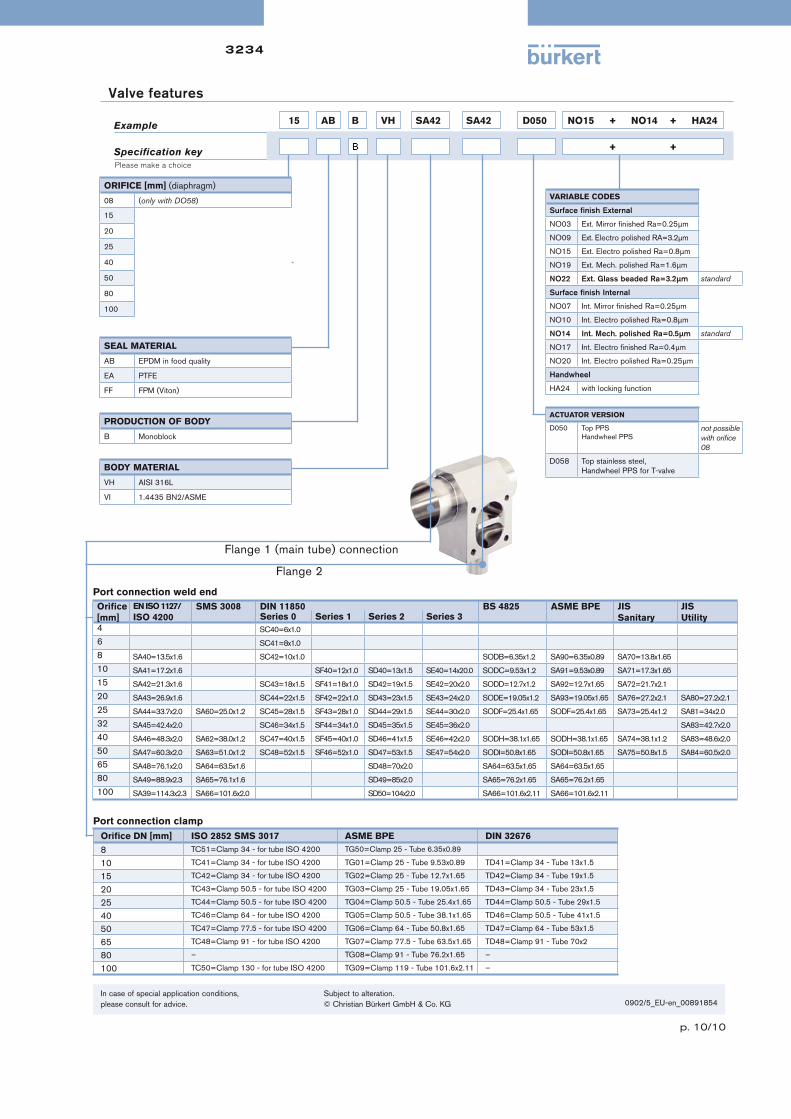
Example
Specification key
Port connection weld end
Orifi ce
[mm]
EN ISO 1127/
ISO 4200SMS 3008 DIN 11850 BS 4825 ASME BPE JIS
Sanitary
JIS
UtilitySeries 0 Series 1 Series 2 Series 3
4 SC40=6x1.0
6 SC41=8x1.0
8 SA40=13.5x1.6 SC42=10x1.0 SODB=6.35x1.2 SA90=6.35x0.89 SA70=13.8x1.65
10 SA41=17.2x1.6 SF40=12x1.0 SD40=13x1.5 SE40=14x20.0 SODC=9.53x1.2 SA91=9.53x0.89 SA71=17.3x1.65
15 SA42=21.3x1.6 SC43=18x1.5 SF41=18x1.0 SD42=19x1.5 SE42=20x2.0 SODD=12.7x1.2 SA92=12.7x1.65 SA72=21.7x2.1
20 SA43=26.9x1.6 SC44=22x1.5 SF42=22x1.0 SD43=23x1.5 SE43=24x2.0 SODE=19.05x1.2 SA93=19.05x1.65 SA76=27.2x2.1 SA80=27.2x2.1
25 SA44=33.7x2.0 SA60=25.0x1.2 SC45=28x1.5 SF43=28x1.0 SD44=29x1.5 SE44=30x2.0 SODF=25.4x1.65 SODF=25.4x1.65 SA73=25.4x1.2 SA81=34x2.0
32 SA45=42.4x2.0 SC46=34x1.5 SF44=34x1.0 SD45=35x1.5 SE45=36x2.0 SA83=42.7x2.0
40 SA46=48.3x2.0 SA62=38.0x1.2 SC47=40x1.5 SF45=40x1.0 SD46=41x1.5 SE46=42x2.0 SODH=38.1x1.65 SODH=38.1x1.65 SA74=38.1x1.2 SA83=48.6x2.0
50 SA47=60.3x2.0 SA63=51.0x1.2 SC48=52x1.5 SF46=52x1.0 SD47=53x1.5 SE47=54x2.0 SODI=50.8x1.65 SODI=50.8x1.65 SA75=50.8x1.5 SA84=60.5x2.0
65 SA48=76.1x2.0 SA64=63.5x1.6 SD48=70x2.0 SA64=63.5x1.65 SA64=63.5x1.65
80 SA49=88.9x2.3 SA65=76.1x1.6 SD49=85x2.0 SA65=76.2x1.65 SA65=76.2x1.65
100 SA39=114.3x2.3 SA66=101.6x2.0 SD50=104x2.0 SA66=101.6x2.11 SA66=101.6x2.11
Flange 1 (main tube) connection
Flange 2
Please make a choice
In case of special application conditions,
please consult for advice.
Subject to alteration.
© Christian Bürkert GmbH & Co. KG 0902/5_EU-en_00891854
15 AB B VH SA42 SA42 D050 NO15 + NO14 + HA24
+
ORIFICE [mm] (diaphragm)
08 (only with DO58)
15
20
25
40
50
80
100
SEAL MATERIAL
AB EPDM in food quality
EA PTFE
FF FPM (Viton)
PRODUCTION OF BODY
B Monoblock
BODY MATERIAL
VH AISI 316L
VI 1.4435 BN2/ASME
Valve features
VARIABLE CODES
Surface fi nish External
NO03 Ext. Mirror fi nished Ra=0.25μm
NO09 Ext. Electro polished RA=3.2μm
NO15 Ext. Electro polished Ra=0.8μm
NO19 Ext. Mech. polished Ra=1.6μm
NO22 Ext. Glass beaded Ra=3.2μm standard
Surface fi nish Internal
NO07 Int. Mirror fi nished Ra=0.25μm
NO10 Int. Electro polished Ra=0.8μm
NO14 Int. Mech. polished Ra=0.5μm standard
NO17 Int. Electro fi nished Ra=0.4μm
NO20 Int. Electro polished Ra=0.25μm
Handwheel
HA24 with locking function
ACTUATOR VERSION
D050 Top PPS
Handwheel PPSnot possible
with orifi ce
08
D058 Top stainless steel,
Handwheel PPS for T-valve
+ +
Port connection clamp
Orifi ce DN [mm] ISO 2852 SMS 3017 ASME BPE DIN 32676
8 TC51=Clamp 34 - for tube ISO 4200 TG50=Clamp 25 - Tube 6.35x0.89
10 TC41=Clamp 34 - for tube ISO 4200 TG01=Clamp 25 - Tube 9.53x0.89 TD41=Clamp 34 - Tube 13x1.5
15 TC42=Clamp 34 - for tube ISO 4200 TG02=Clamp 25 - Tube 12.7x1.65 TD42=Clamp 34 - Tube 19x1.5
20 TC43=Clamp 50.5 - for tube ISO 4200 TG03=Clamp 25 - Tube 19.05x1.65 TD43=Clamp 34 - Tube 23x1.5
25 TC44=Clamp 50.5 - for tube ISO 4200 TG04=Clamp 50.5 - Tube 25.4x1.65 TD44=Clamp 50.5 - Tube 29x1.5
40 TC46=Clamp 64 - for tube ISO 4200 TG05=Clamp 50.5 - Tube 38.1x1.65 TD46=Clamp 50.5 - Tube 41x1.5
50 TC47=Clamp 77.5 - for tube ISO 4200 TG06=Clamp 64 - Tube 50.8x1.65 TD47=Clamp 64 - Tube 53x1.5
65 TC48=Clamp 91 - for tube ISO 4200 TG07=Clamp 77.5 - Tube 63.5x1.65 TD48=Clamp 91 - Tube 70x2
80 – TG08=Clamp 91 - Tube 76.2x1.65 –
100 TC50=Clamp 130 - for tube ISO 4200 TG09=Clamp 119 - Tube 101.6x2.11 –

3235
p. 1/7
Tank bottom valve, manually operated, stainless steel block material
The Bürkert Tank Bottom Valve system is
designed for control of ultra pure, sterile, ag-
gressive or abrasive fl uids. Enables especially
optimal fi lling and emptying vessels with less
dead leg.
The valve body consists of a block with no weld
seam, machined out of high quality stainless
steel. The tank bottom valve has two welding
bevels to ease the welding and valve position-
ing operations.
The high quality diaphragms separate her-
metically critical fl uids from the actuator. The
manual actuator in PPS or stainless steel can
be sterilized.
Type 3235 can be combined with...
Technical data
Orifi ce DN 15-100
Body materials Stainless steel 1.4435BN2 / ASME BPE
Fe < 0,5% / C < 0,03%
Diaphragm materials EPDM, PTFE/EPDM, advanced PTFE
Actuator materials PPS (PA on request)
Pilot air ports Stainless steel 1.4305
Surface fi nish Ra [μm]
internal
Ra [μlnch]
internal
Ra [Grit #]
internal
satin fi nished 0.5 20 240
electro polished 0.4 16 280
mirror fi nished 1) 0.25 10 330
Media temperature -10 °C to +130 °C (briefl y up to +150 °C)
Ambient temperature
Actuator size < 100 mm
Actuator size > 100 mm
+5 °C to +140 °C
+5 °C to +90 °C (briefl y up to +140 °C)
(-10 °C to +60 °C with PA actuator)
Port connections
Weld end acc. to
Clamp acc. to
• EN ISO 1127 / ISO 4200
• DIN 11850 RG2
• SMS 3008
• ASME BPE
• BS 4825
• ISO 2852
• ASME BPE
• DIN 32676
Type 8034
Flow meter
• Fully integrated in Bürkert’s
Process Control Systems
• Monoblock – no welds
• Quality certifications
1) Internal Ra < 0.1 μm/4 μInch/500 Grit: on request
Type 2033
Tank bottom valve
Type 2103
Diaphragm valve

3235
p. 2/7
Technical data, continued
Orifi ce DN diaphragm [mm]
Kv-value water[m3/h]
Max. operating pressure (medium) for seal materialEPDM and PTFE/EPDM [bar]
8 1.0 10
15 6.0 10
20 11.0 10
25 16.0 10
40 29.0 10
50 50.0 101)
80 160.0 10
100 235.0 5
1) Max. operating pressure 7 bar for bonnet and manual actuator in PPS.

3235
p. 3/7
Approvals/certifications
•Certifi cation of Conformity for Raw Material EN-ISO 10204 3.1
•Attestation of compliance with the order EN-ISO 10204 2.1
•Test report EN-ISO 10204 2.2
•3A Certifi cation on request
•Certifi cation of Conformity for Pickling and Electropolishing Processes
•Certifi cation of Conformity for the Surface Quality DIN4762-DIN4768-ISO/4287/1
•Attestation of compliance with FDA CFR No. 21.177.1550 for PTFE/EPDM and advanced PTFE/EPDM and 21.177.2600 for EPDM
•Test Certifi cation and Conformity Certifi cation for the Final Assembly of Diaphragm Valves
• ISO 9001 Certifi cation
Note: Retrospective manufacturing certifi cation for process diaphragm valves can not be made, therefore please notify when ordering.
Materials
Example of available diaphragm materials
Developed to handle the unique challenges of hygienic and sterile applications, Bürkert offers diaphragms with precise material formula and physical
tolerances. Bürkert diaphragms are available in a wide range of materials which have been proven in food & beverage, biotechnology, pharmaceutical
and cosmetic industry applications. Diaphragms are tested during development and production to ensure reliability in critical processing environments.
• EPDM (Ethylene Propylene Rubber)
• PTFE/EPDM
• advanced PTFE/EPDM
• FKM
• PTFE/FKM
• NBR
Stainless steel 316:/1.4435/BN2 Fe<0,5%
EPDM, PTFE/EPDM, advanced PTFE
PPS or stainless steel 316L
Stainless steel 316L
PPS or stainless steel 316L

3235
p. 4/7
Dimensions [mm]
Body with weld end
EN ISO 1127 / ISO 4200
Orifi ce seat [mm] Port connection [mm] øA s øB C1 C2 C3 D øK L
08 08 13.5 1.6 50 8 65 65 35° 34 5
15 15 21.3 1.6 65 12 103 103 35° 85 3
85 103 109 8
20 20 26.9 1.6 85 12 109 118 35° 85 5.6
25 25 33.7 2 120 16 117 129 35° 85 8
40 32 42.4 2 150 18 147 180 35° 114 20
40 48.3 2 15
50 50 60.3 2 180 22 162 194 35° 114 12
80 65 76.1 2 225 20 293 345 40° 223 16
80 88.9 2.3 10
ASME BPE
Orifi ce seat [mm] Port connection [mm] øA s øB C1 C2 C3 D øK L
08 08 6.35 0.89 50 8 65 65 35° 34 9
15 15 12.7 1.65 85 12 103 109 35° 85 10
20 20 19.05 1.65 85 12 109 118 35° 85 8
25 25 25.4 1.65 120 16 117 129 35° 85 8
40 40 38.1 1.65 150 18 147 180 35° 114 15
50 40 38.1 1.65 180 22 162 194 35° 114 25
50 50.8 1.65 15
65 63.5 1.65 11
80 65 63.5 1.65 225 20 388 422 40° – 25
80 76.2 1.65 225 20 293 345 40° 223 16
DIN 11850 RG2
Orifi ce seat [mm] Port connection [mm] øA s øB C1 C2 C3 D øK L
08 10 13 1.5 50 8 65 65 35° 34 6
15 15 19 1.5 85 12 103 109 35° 85 8
20 20 23 1.5 85 12 109 118 35° 85 7
25 25 29 1.5 120 16 117 129 35° 85 8
40 40 41 1.5 150 18 147 180 35° 114 20
50 50 53 1.5 180 22 162 194 35° 114 15
80 80 85 2.0 225 20 293 345 40° 223 16

3235
p. 5/7
Dimensions [mm], continued
Body with Clamp
ASME BPE
Orifi ce A s D3 E
[mm] [inch]
08 1/4” 6.35 0.89 25.0 28.6
10 3/8” 9.53 0.89 25.0 28.6
15 1/2” 12.7 1.65 25.0 28.6
20 3/4” 19.05 1.65 25.0 28.6
25 1” 25.4 1.65 50.5 28.6
40 1 1/2” 38.1 1.65 50.5 28.6
50 2” 50.8 1.65 64.0 28.6
65 2 1/2” 63.5 1.65 77.5 28.6
80 3” 76.2 1.65 91.0 28.6
100 4” 101.6 2.11 119.0 28.6
DIN 32676
Orifi ce [mm] A s D3 E
10 1.5 34.0 18
15 19 1.5 34.0 18
20 23 1.5 34.0 18
25 29 1.5 50.5 21.5
32 35 1.5 50.5 21.5
40 41 1.5 50.5 21.5
50 53 1.5 64.0 21.5
65 70 2.0 91.0 28
ISO 2852 for pipe ISO 4200
Orifi ce [mm] A s D3 E
8 13.5 1.6 25.0 28.6
8 13.5 1.6 34.0 28.6
10 17.2 1.6 34.0 28.6
15 21.3 1.6 34.0 28.6
15 21.3 1.6 50.5 28.6
20 26.9 1.6 50.5 28.6
25 33.7 2 50.5 28.6
32 42.4 2 50.5 28.6
40 48.3 2 64.0 28.6
50 60.3 2 77.5 28.6
65 76.1 2 91.0 28.6
100 114.3 2.3 130.0 28.6
SMS
Orifi ce [mm] A s D3 E
25 25 1.2 50.5 21.5
40 38 1.2 50.5 28.6
50 51 1.2 64.0 28.6

3235
p. 6/7
Specification key
Ventildaten
3235automatically transferred from next page
= mandatory fi elds to fi ll out Quantity Required delivery date
Valve features
Company Contact person
Customer no. Department
Address Tel./Fax
Postcode/town E-Mail
Diaphragm valves – request for quotation
Please fill out and send to your nearest Bürkert facility* with your inquiry or order
Note
You can fill out
the fields directly
in the PDF file
before printing
out the form.
Certifications
Comment / sketch
Attestation of compliance with the order EN-ISO 10204 2.1
Test report EN-ISO 10204 2.2
Certifi cation of Conformity for Raw Material EN-ISO 10204 3.1
Certifi cation of Conformity for the Surface Quality
DIN4762-DIN4768-ISO/4287/1
Certifi cation of Conformity for Pickling
and Electropolishing Processes
FDA and USP compliance
3A certifi cate
Operating data
Process medium
Type of media Liquid Steam Gas
Temperature at valve inlet
nominal unitFlow rate (Q, QN, W) 1)
Absolute pressure at valve inlet
Absolute pressure at valve outlet
Steam pressure Pv
1) standard unit:
Liquid Q = m3/h;
Steam W = kg/h;
Gas QN = Nm3/h
+ +
*To fi nd your nearest Bürkert facility, click on the orange box

3235
p. 7/7
15 AB B VI F085 SA42 D050 NO09 + NO17 + AF71
+ +
Standard
Standard
Standard
Valve features
Specification key
Example
Please make a choice
ACTUATOR VERSIOND050 Top PPS, handwheel PPS
D058 Top stainless steel,
Handwheel PPS for tank bottom
D085 Grey cast iron, white epoxy painted
VARIABLE CODESSurface fi nish external
NO03 Ext. Mirror fi nished Ra=0.25 μm
NO15 Ext. Electro polished Ra=0.8μm
NO19 Ext. Mech. polished Ra=1.6μm
NO22 Ext. Glassbeaded Ra= 3.2 μm
Surface fi nish internal
NO07 Int. Mirror fi nished Ra=0.25 μm
NO14 Int. Satin fi nished Ra=0.5μm
NO17 Int. Electro fi nished Ra=0.4μm
NO20 Int. Electro polished Ra=0.25μm
Specifi c angle
AF71 45° outlet angle
ORIFICE [mm] (diaphragm)
08
15
20
25
40
50
80
100
SEAL MATERIALAB EPDM in food quality
EA PTFE
FF FKM, advanced PTFE
PRODUCTION OF BODYB Monoblock
BODY MATERIALVH 1.4435/AISI 316L
VI 1.4435BN2/ASME BPE
FLANGEF050 DN08 (Ø 50 mm)
F085 DN15 (Ø 85 mm)
F085 DN20 (Ø 85 mm)
F120 DN25 (Ø 120 mm)
F150 DN40 (Ø 150 mm)
F180 DN50 (Ø 180 mm)
F225 DN80 (Ø 225 mm)
F300 DN100 (Ø 300 mm)
PORT CONNECTION
In case of special application conditions,
please consult for advice.
Subject to alteration.
© Christian Bürkert GmbH & Co. KG
1509/7_EU-en_00891855
Clamp
Orifi ce
DN [mm]
ISO 2852
SMS 3017
ASME BPE DIN 32676
8 TC51=Clamp 34 - for tube ISO 4200 TG50=Clamp 25 - Tube 6.35x0.89
10 TC41=Clamp 34 - for tube ISO 4200 TG01=Clamp 25 - Tube 9.53x0.89 TD41=Clamp 34 - Tube 13x1.5
15 TC42=Clamp 34 - for tube ISO 4200 TG02=Clamp 25 - Tube 12.7x1.65 TD42=Clamp 34 - Tube 19x1.5
20 TC43=Clamp 50.5 - for tube ISO 4200 TG03=Clamp 25 - Tube 19.05x1.65 TD43=Clamp 34 - Tube 23x1.5
25 TC44=Clamp 50.5 - for tube ISO 4200 TG04=Clamp 50.5 - Tube 25.4x1.65 TD44=Clamp 50.5 - Tube 29x1.5
40 TC46=Clamp 64 - for tube ISO 4200 TG05=Clamp 50.5 - Tube 38.1x1.65 TD46=Clamp 50.5 - Tube 41x1.5
50 TC47=Clamp 77.5 - for tube ISO 4200 TG06=Clamp 64 - Tube 50.8x1.65 TD47=Clamp 64 - Tube 53x1.5
Weld end
Orifi ce
[mm]
EN ISO 1127/ISO 4200 SMS 3008
DIN 11850
BS 4825 ASME BPE
JIS
Sanitary
JIS
UtilitySeries 0 Series1 Series 2 Series 3
08 SA40=13.5x1.6 SC42=10x1.0 SODB=6.35x1.2 SA90=6.35x0.89 SA70=13.8x1.65
15 SA42=21.3x1.6 SC43=18x1.5 SF41=18x1.0 SD42=19x1.5 SE42=20x2.0 SODD=12.7x1.2 SA92=12.7x1.65 SA72=21.7x2.1
20 SA43=26.9x1.6 SC44=22x1.5 SF42=22x1.0 SD43=23x1.5 SE43=24x2.0 SODE=19.05x1.2 SA93=19.05x1.65 SA76=27.2x2.1 SA80=27.2x2.1
25 SA44=33.7x2.0 SA60=25.0x1.2 SC45=28x1.5 SF43=28x1.0 SD44=29x1.5 SE44=30x2.0 SODF=25.4x1.65 SODF=25.4x1.65 SA73=25.4x1.2 SA81=34x2.0
32 SA45=42.4x2.0 SC46=34x1.5 SF44=34x1.0 SD45=35x1.5 SE45=36x2.0 SA83=42.7x2.0
40 SA46=48.3x2.0 SA62=38.0x1.2 SC47=40x1.5 SF45=40x1.0 SD46=41x1.5 SE46=42x2.0 SODH=38.1x1.65 SODH=38.1x1.65 SA74=38.1x1.2 SA84=60.5x2.0
50 SA47=60.3x2.0 SA63=51.0x1.2 SC48=52x1.5 SF46=52x1.0 SD47=53x1.5 SE47=54x2.0 SODI=50.8x1.65 SODI=50.8x1.65 SA75=50.8x1.5
65 SA48=76.1x2.0 SA64=63.5x1.6 SD48=70x2.0 SA64=63.5x1.65 SA64=63.5x1.65
80 SA49=88.9x2.3 SA65=76.1x1.6 SD49=85x2.0 SA65=76.2x1.65 SA65=76.2x1.65
100 SA39=114.3x2.3 SA66=101.6x2.0 SD50=104x2.0 SA66=101.6x2.11 SA66=101.6x2.11
По вопросам продаж и поддержки обращайтесь:
Архангельск (8182)63‐90‐72
Астана (7172)727‐132
Белгород (4722)40‐23‐64
Брянск (4832)59‐03‐52
Владивосток (423)249‐28‐31
Волгоград (844)278‐03‐48
Вологда (8172)26‐41‐59
Воронеж (473)204‐51‐73
Екатеринбург (343)384‐55‐89
Иваново (4932)77‐34‐06
Ижевск (3412)26‐03‐58
Казань (843)206‐01‐48
Калининград (4012)72‐03‐81
Калуга (4842)92‐23‐67
Кемерово (3842)65‐04‐62
Киров (8332)68‐02‐04
Краснодар (861)203‐40‐90
Красноярск (391)204‐63‐61
Курск (4712)77‐13‐04
Липецк (4742)52‐20‐81
Магнитогорск (3519)55‐03‐13
Москва (495)268‐04‐70
Мурманск (8152)59‐64‐93
Набережные Челны (8552)20‐53‐41
Нижний Новгород (831)429‐08‐12
Новокузнецк (3843)20‐46‐81
Новосибирск (383)227‐86‐73
Орел (4862)44‐53‐42
Оренбург (3532)37‐68‐04
Пенза (8412)22‐31‐16
Пермь (342)205‐81‐47
Ростов‐на‐Дону (863)308‐18‐15
Рязань (4912)46‐61‐64
Самара (846)206‐03‐16
Санкт‐Петербург (812)309‐46‐40
Саратов (845)249‐38‐78
Смоленск (4812)29‐41‐54
Сочи (862)225‐72‐31
Ставрополь (8652)20‐65‐13
Тверь (4822)63‐31‐35
Томск (3822)98‐41‐53
Тула (4872)74‐02‐29
Тюмень (3452)66‐21‐18
Ульяновск (8422)24‐23‐59
Уфа (347)229‐48‐12
Челябинск (351)202‐03‐61
Череповец (8202)49‐02‐64
Ярославль (4852)69‐52‐93
Единый адрес: [email protected] Веб‐сайт: www.burkert.nt-rt.ru