Embed Size (px)
Citation preview
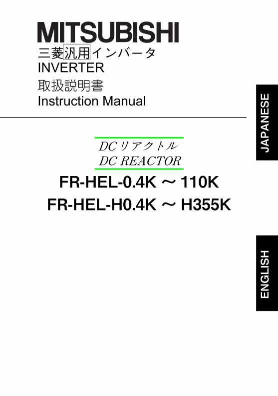
三菱汎用インバータINVERTER取扱説明書Instruction Manual
JAPANESE
ENGLISH
FR-HEL-0.4K ~ 110KFR-HEL-H0.4K ~ H355K
DCリアクトルDC REACTOR
JAPANESE
このたびは、三菱汎用インバータオプションをご採用いただき、誠にありがとうございます。この取扱説明書は、ご使用いただく場合の取扱い、留意点について述べてあります。誤った取扱いは思わぬ不具合を引き起こしますので、ご使用前に必ずこの取扱説明書を一読され、正しくご使用くださいますようお願いいたします。なお、本取扱説明書は、ご使用になるお客様の手元に届くようご配慮をお願いいたします。
1.感電防止のために
2.火災防止のために
3.傷害防止のために
安全上の注意据付け、運転、保守・点検の前に必ずこの取扱説明書とその付属書類をすべて熟読し、正しくご使用ください。機器の知識、安全の情報そして注意事項のすべてについて習熟してからご使用ください。この取扱説明書では、安全注意事項のランクを「危険」、「注意」として区分してあります。
取扱いを誤った場合に、危険な状況が起こりえて、死亡または重傷を受ける可能性が想定される場合。
取扱いを誤った場合に、危険な状況が起こりえて、中程度の傷害や軽傷を受ける可能性が想定される場合および物的損害だけの発生が想定される場合。
なお、 に記載した事項でも、状況によっては重大な結果に結びつく可能性があります。いずれも重要な内容を記載していますので必ず守ってください。
危険
注意
注意
安全にお使いいただくために
危 険●通電中および運転中はオプションの端子台カバーを開けないでください。感電の原因となります。
●オプションの端子台カバーをはずしての運転は行わないでください。高電圧の端子および充電部が露出していますので感電の原因となります。
●配線作業や点検は専門の技術者が行ってください。
●インバータ本体を据え付けてから配線してください。感電、傷害の原因になります。
●濡れた手でオプションに触れたり、ケーブル類の抜き差しをしないでください。感電の原因となります。
●ケーブルは傷つけたり、無理なストレスをかけたり、重いものを載せたり、挟み込んだりしないでください。感電の原因になります。
注 意●本オプションは、不燃物に取り付けてください。可燃物への取付けおよび可燃物近くへの取り付けは、火災の原因になります。
注 意●各端子には取扱説明書に決められた電圧以外は印加しないでください。破裂・破損などの原因になります。●端子接続を間違えないでください。破裂・破損などの原因になります。●極性(+、-)を間違えないでください。破裂・破損の原因になります。●通電中や電源遮断後のしばらくの間は、オプションは高温になっていますので触らないでください。火傷の原因になります。
A-1
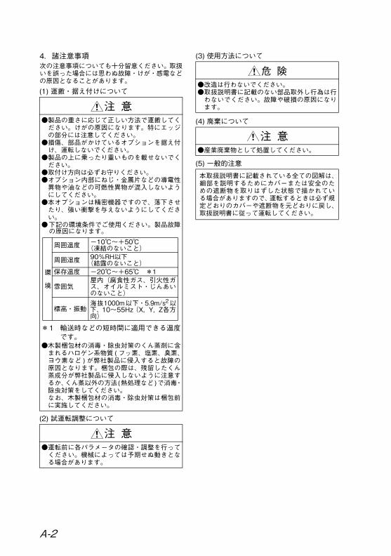
4.諸注意事項次の注意事項についても十分留意ください。取扱いを誤った場合には思わぬ故障・けが・感電などの原因となることがあります。(1) 運搬・据え付けについて
(2) 試運転調整について
(3) 使用方法について
(4) 廃棄について
(5) 一般的注意
注 意●製品の重さに応じて正しい方法で運搬してください。けがの原因になります。特にエッジの部分には注意してください。
●損傷、部品がかけているオプションを据え付け、運転しないでください。
●製品の上に乗ったり重いものを載せないでください。
●取付け方向は必ずお守りください。●オプション内部にねじ・金属片などの導電性異物や油などの可燃性異物が混入しないようにしてください。
●本オプションは精密機器ですので、落下させたり、強い衝撃を与えないようにしてください。
●下記の環境条件でご使用ください。製品故障の原因になります。
*1 輸送時などの短時間に適用できる温度です。
●木製梱包材の消毒・除虫対策のくん蒸剤に含まれるハロゲン系物質 (フッ素、塩素、臭素、ヨウ素など ) が弊社製品に侵入すると故障の原因となります。梱包の際は、残留したくん蒸成分が弊社製品に侵入しないように注意するか、くん蒸以外の方法(熱処理など)で消毒・除虫対策をしてください。なお、木製梱包材の消毒・除虫対策は梱包前に実施してください。
注 意●運転前に各パラメータの確認・調整を行ってください。機械によっては予期せぬ動きとなる場合があります。
環
境
周囲温度 -10℃~+50℃(凍結のないこと)
周囲湿度 90%RH以下(結露のないこと)
保存温度 -20℃~+65℃ *1
雰囲気屋内(腐食性ガス、引火性ガス、オイルミスト・じんあいのないこと)
標高・振動海抜1000m以下・5.9m/s2以下、10~55Hz(X,Y,Z各方向)
危 険●改造は行わないでください。●取扱説明書に記載のない部品取外し行為は行わないでください。故障や破損の原因になります。
注 意●産業廃棄物として処置してください。
本取扱説明書に記載されている全ての図解は、細部を説明するためにカバーまたは安全のための遮断物を取りはずした状態で描かれている場合がありますので、運転するときは必ず規定どおりのカバーや遮断物を元どおりに戻し、取扱説明書に従って運転してください。
A-2
1
JAPANESE
目 次
1 製品の確認........................................................................... 2
2 据 付 け................................................................................ 2
3 配 線............................................................................... 3
4 電線サイズと圧着端子 ....................................................... 4
5 仕 様............................................................................... 6
6 外形寸法図........................................................................... 7
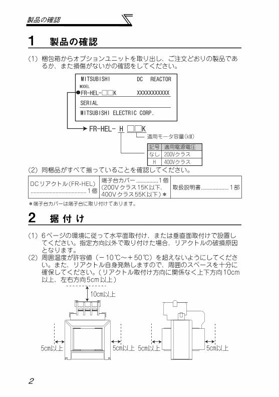
製品の確認
1 製品の確認(1) 梱包箱からオプションユニットを取り出し、ご注文どおりの製品であ
るか、また損傷がないかの確認をしてください。
(2) 同梱品がすべて揃っていることを確認してください。
*端子台カバーは端子台に取り付けてあります。
2 据 付 け(1) 6ページの環境に従って水平面取付け、または垂直面取付けで設置し
てください。指定方向以外で取り付けた場合、リアクトルの破損原因となります。
(2) 周囲温度が許容値(-10℃~+50℃)を超えないようにしてください。また、リアクトル自身発熱しますので、周囲のスペースを十分に確保してください。(リアクトル取付け方向に関係なく上下方向10cm以上、左右方向5cm以上)
DCリアクトル(FR-HEL)...................................... 1個
端子台カバー...............1個(200Vクラス15K以下、400Vクラス55K以下)*
取扱説明書................... 1部
DC REACTOR
FR-HEL-□□K
FR-HEL- H □□K
XXXXXXXXXXX
SERIALMITSUBISHI ELECTRIC CORP.
MODEL
適用モータ容量(kW)
適用電源電圧記号なし 200Vクラス
MITSUBISHI
H 400Vクラス
10cm以上
5cm以上5cm以上 5cm以上 5cm以上
2
JAPANESE
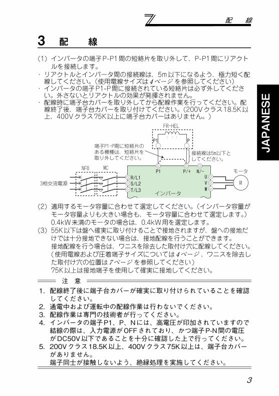
配 線
3 配 線(1) インバータの端子P-P1間の短絡片を取り外して、P-P1間にリアクト
ルを接続します。・リアクトルとインバータ間の接続線は、5m以下になるよう、極力短く配線してください。(使用電線サイズは4ページ を参照してください)
・インバータの端子P1-P間に接続されている短絡片は必ず外してください。外さないとリアクトルの効果が発揮されません。
・配線時に端子台カバーを取り外してから配線作業を行ってください。配線終了後、端子台カバーを取り付けてください。(200Vクラス18.5K以上、400Vクラス75K以上に端子台カバーはありません。)
(2) 適用するモータ容量に合わせて選定してください。(インバータ容量がモータ容量よりも大きい場合も、モータ容量に合わせて選定します。)0.4kW未満のモータの場合は、0.4kW用を選定します。
(3) 55K以下は盤へ確実に取り付けることで接地されますが、盤への接地だけでは十分接地できない場合は、接地配線を行うことができます。接地配線を行う場合は、ワニスを除去した取付け穴に配線してください。(使用電線および圧着端子サイズについては4ページ 、ワニスを除去した取付け穴の位置は7ページ を参照してください)75K以上は接地端子を使用して確実に接地してください。注 意
1. 配線終了後に端子台カバーが確実に取り付けられていることを確認してください。
2. 通電中および運転中の配線作業は行わないでください。3. 配線作業は専門の技術者が行ってください。4. インバータの端子P1、P、Nには、高電圧が印加されていますので結線の際は、入力電源がOFFされており、かつ端子P-N間の電圧がDC50V以下であることを十分に確認した上で行ってください。
5. 200Vクラス18.5K以上、400Vクラス75K以上は、端子台カバーがありません。端子同士が接触しないよう、絶縁処理を実施してください。
3相交流電源
NFB
R/L1S/L2T/L3
モータUVW
P1
P1 P
MC
M
P/+ N/-
FR-HEL
インバータ
端子P1-P間に短絡片のある機種は、短絡片を取り外してください。
接続線は5m以下としてください。
3
電線サイズと圧着端子
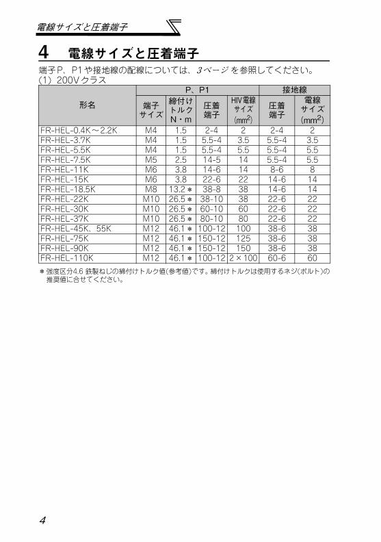
4 電線サイズと圧着端子端子P、P1や接地線の配線については、3ページ を参照してください。(1) 200Vクラス
*強度区分4.6 鉄製ねじの締付けトルク値(参考値)です。締付けトルクは使用するネジ(ボルト)の推奨値に合せてください。
形名
P、P1 接地線
端子サイズ
締付けトルクN・m
圧着端子
HIV電線サイズ(mm2)
圧着端子
電線サイズ(mm2)
FR-HEL-0.4K~2.2K M4 1.5 2-4 2 2-4 2FR-HEL-3.7K M4 1.5 5.5-4 3.5 5.5-4 3.5FR-HEL-5.5K M4 1.5 5.5-4 5.5 5.5-4 5.5FR-HEL-7.5K M5 2.5 14-5 14 5.5-4 5.5FR-HEL-11K M6 3.8 14-6 14 8-6 8FR-HEL-15K M6 3.8 22-6 22 14-6 14FR-HEL-18.5K M8 13.2* 38-8 38 14-6 14FR-HEL-22K M10 26.5* 38-10 38 22-6 22FR-HEL-30K M10 26.5* 60-10 60 22-6 22FR-HEL-37K M10 26.5* 80-10 80 22-6 22FR-HEL-45K、55K M12 46.1* 100-12 100 38-6 38FR-HEL-75K M12 46.1* 150-12 125 38-6 38FR-HEL-90K M12 46.1* 150-12 150 38-6 38FR-HEL-110K M12 46.1* 100-12 2×100 60-6 60
4
JAPANESE
電線サイズと圧着端子
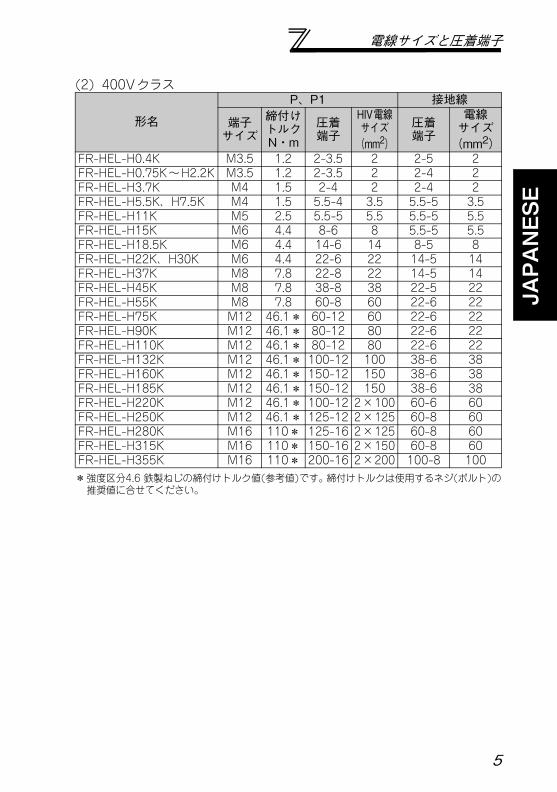
(2) 400Vクラス
*強度区分4.6 鉄製ねじの締付けトルク値(参考値)です。締付けトルクは使用するネジ(ボルト)の推奨値に合せてください。
形名
P、P1 接地線
端子サイズ
締付けトルクN・m
圧着端子
HIV電線サイズ(mm2)
圧着端子
電線サイズ(mm2)
FR-HEL-H0.4K M3.5 1.2 2-3.5 2 2-5 2FR-HEL-H0.75K~H2.2K M3.5 1.2 2-3.5 2 2-4 2FR-HEL-H3.7K M4 1.5 2-4 2 2-4 2FR-HEL-H5.5K、H7.5K M4 1.5 5.5-4 3.5 5.5-5 3.5FR-HEL-H11K M5 2.5 5.5-5 5.5 5.5-5 5.5FR-HEL-H15K M6 4.4 8-6 8 5.5-5 5.5FR-HEL-H18.5K M6 4.4 14-6 14 8-5 8FR-HEL-H22K、H30K M6 4.4 22-6 22 14-5 14FR-HEL-H37K M8 7.8 22-8 22 14-5 14FR-HEL-H45K M8 7.8 38-8 38 22-5 22FR-HEL-H55K M8 7.8 60-8 60 22-6 22FR-HEL-H75K M12 46.1* 60-12 60 22-6 22FR-HEL-H90K M12 46.1* 80-12 80 22-6 22FR-HEL-H110K M12 46.1* 80-12 80 22-6 22FR-HEL-H132K M12 46.1* 100-12 100 38-6 38FR-HEL-H160K M12 46.1* 150-12 150 38-6 38FR-HEL-H185K M12 46.1* 150-12 150 38-6 38FR-HEL-H220K M12 46.1* 100-12 2×100 60-6 60FR-HEL-H250K M12 46.1* 125-12 2×125 60-8 60FR-HEL-H280K M16 110* 125-16 2×125 60-8 60FR-HEL-H315K M16 110* 150-16 2×150 60-8 60FR-HEL-H355K M16 110* 200-16 2×200 100-8 100
5
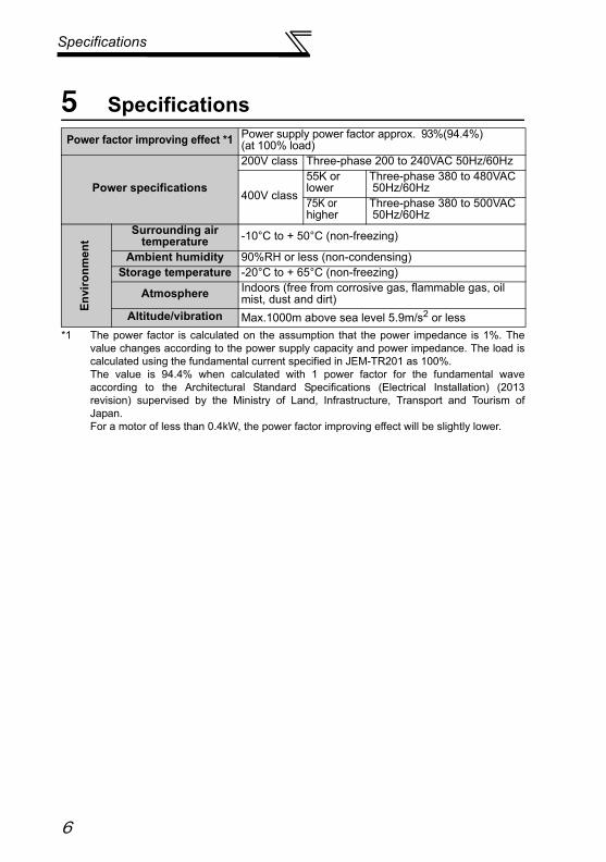
仕 様
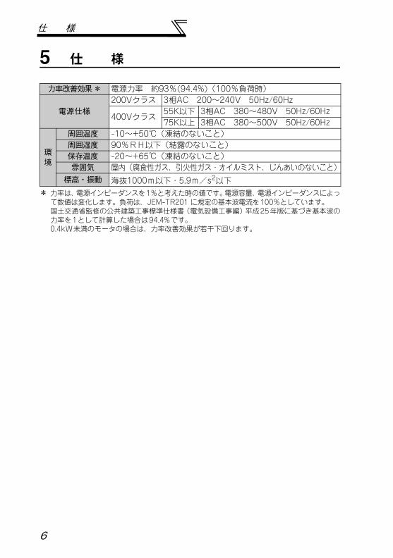
5 仕 様
* 力率は、電源インピーダンスを1%と考えた時の値です。電源容量、電源インピーダンスによって数値は変化します。負荷は、JEM-TR201 に規定の基本波電流を100%としています。国土交通省監修の公共建築工事標準仕様書(電気設備工事編)平成25年版に基づき基本波の力率を1として計算した場合は94.4%です。0.4kW未満のモータの場合は、力率改善効果が若干下回ります。
力率改善効果 * 電源力率 約93%(94.4%)(100%負荷時)
電源仕様200Vクラス 3相AC 200~240V 50Hz/60Hz
400Vクラス55K以下 3相AC 380~480V 50Hz/60Hz75K以上 3相AC 380~500V 50Hz/60Hz
環境
周囲温度 -10~+50℃(凍結のないこと)周囲湿度 90%RH以下(結露のないこと)保存温度 -20~+65℃(凍結のないこと)雰囲気 屋内(腐食性ガス、引火性ガス・オイルミスト、じんあいのないこと)標高・振動 海抜1000m以下・5.9m/s2以下
6
JAPANESE
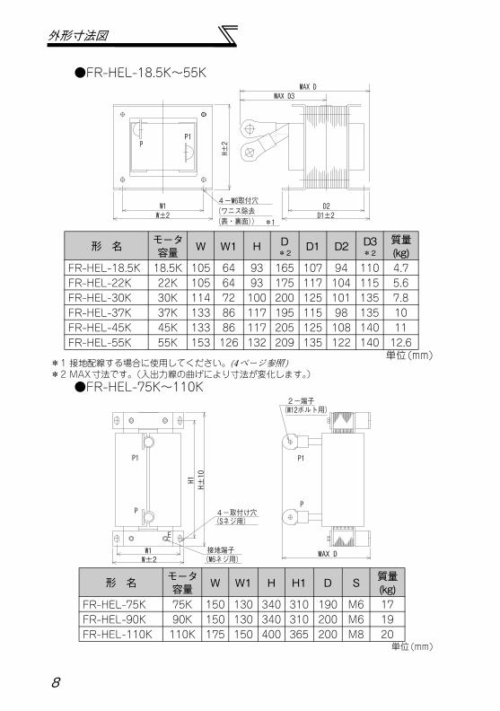
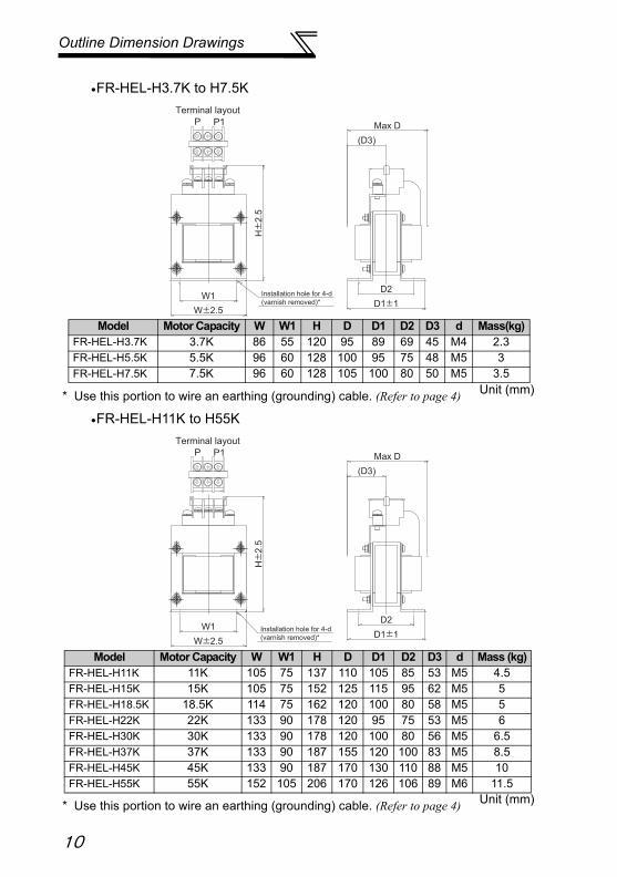
外形寸法図
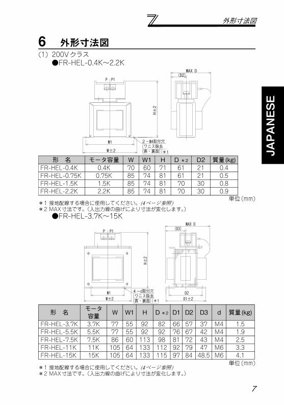
6 外形寸法図(1) 200Vクラス●FR-HEL-0.4K~2.2K
単位(mm)*1 接地配線する場合に使用してください。(4ページ参照)*2 MAX寸法です。(入出力線の曲げにより寸法が変化します。)●FR-HEL-3.7K~15K
単位(mm)*1 接地配線する場合に使用してください。(4ページ参照)*2 MAX寸法です。(入出力線の曲げにより寸法が変化します。)
P P1
W1
W±2
2-M4取付穴(ワニス除去(表・裏面))*1
H±2
MAX D(D2)
形 名 モータ容量 W W1 H D *2 D2 質量(kg)FR-HEL-0.4K 0.4K 70 60 71 61 21 0.4FR-HEL-0.75K 0.75K 85 74 81 61 21 0.5FR-HEL-1.5K 1.5K 85 74 81 70 30 0.8FR-HEL-2.2K 2.2K 85 74 81 70 30 0.9
P1P
W±2W1 D2
MAX D
4-d取付穴(ワニス除去 (表・裏面))*1
(D3)
H±2
D1±2
形 名 モータ容量 W W1 H D *2 D1 D2 D3 d 質量(kg)
FR-HEL-3.7K 3.7K 77 55 92 82 66 57 37 M4 1.5FR-HEL-5.5K 5.5K 77 55 92 92 76 67 42 M4 1.9FR-HEL-7.5K 7.5K 86 60 113 98 81 72 43 M4 2.5FR-HEL-11K 11K 105 64 133 112 92 79 47 M6 3.3FR-HEL-15K 15K 105 64 133 115 97 84 48.5 M6 4.1
7
外形寸法図
●FR-HEL-18.5K~55K
単位(mm)*1 接地配線する場合に使用してください。(4ページ参照)*2 MAX寸法です。(入出力線の曲げにより寸法が変化します。)●FR-HEL-75K~110K
単位(mm)
PP1
W1W±2
H±2
D1±2
MAX D
4-M6取付穴(ワニス除去 (表・裏面)) *1
MAX D3
D2
形 名 モータ容量 W W1 H D
*2D1 D2 D3
*2質量(kg)
FR-HEL-18.5K 18.5K 105 64 93 165 107 94 110 4.7FR-HEL-22K 22K 105 64 93 175 117 104 115 5.6FR-HEL-30K 30K 114 72 100 200 125 101 135 7.8FR-HEL-37K 37K 133 86 117 195 115 98 135 10FR-HEL-45K 45K 133 86 117 205 125 108 140 11FR-HEL-55K 55K 153 126 132 209 135 122 140 12.6
E
P1
P
P1
P
W1W±2
MAX D
H1H±10
4-取付け穴 (Sネジ用)
(M6ネジ用)接地端子
(M12ボルト用)2-端子
形 名 モータ容量 W W1 H H1 D S 質量
(kg)FR-HEL-75K 75K 150 130 340 310 190 M6 17FR-HEL-90K 90K 150 130 340 310 200 M6 19FR-HEL-110K 110K 175 150 400 365 200 M8 20
8
JAPANESE
外形寸法図
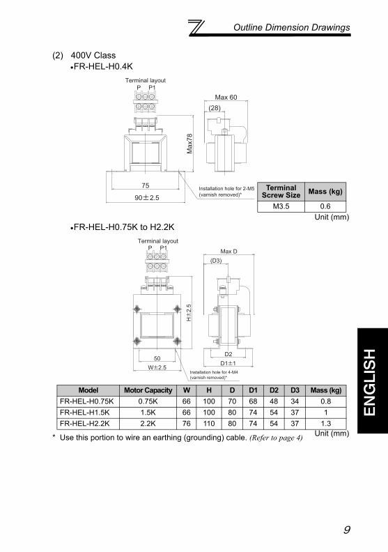
(2) 400Vクラス●FR-HEL-H0.4K
単位(mm)●FR-HEL-H0.75K~H2.2K
単位(mm)* 接地配線する場合に使用してください。(4ページ参照)
2 - M5用取付穴(ワニス除去)*
Max78
90±2.5
75
Max 60
(28)
端子配列P P1
端子ねじサイズ 質量(kg)
M3.5 0.6
(D3)
H±2.5
Max D
4 - M4用取付穴(ワニス除去)*
D2
W±2.550
D1±1
端子配列P P1
形 名 モータ容量 W H D D1 D2 D3 質量(kg)FR-HEL-H0.75K 0.75K 66 100 70 68 48 34 0.8FR-HEL-H1.5K 1.5K 66 100 80 74 54 37 1FR-HEL-H2.2K 2.2K 76 110 80 74 54 37 1.3
9
外形寸法図
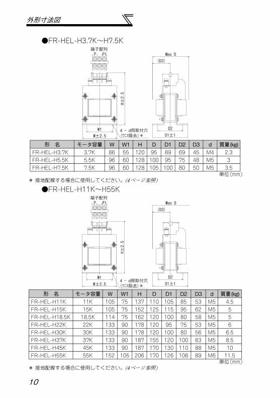
●FR-HEL-H3.7K~H7.5K
単位(mm)* 接地配線する場合に使用してください。(4ページ参照)
●FR-HEL-H11K~H55K
単位(mm)* 接地配線する場合に使用してください。(4ページ参照)
(D3)
H±2.5
Max D
4 - d用取付穴(ワニス除去)*
D2
W±2.5W1
D1±1
端子配列P P1
形 名 モータ容量 W W1 H D D1 D2 D3 d 質量(kg)FR-HEL-H3.7K 3.7K 86 55 120 95 89 69 45 M4 2.3FR-HEL-H5.5K 5.5K 96 60 128 100 95 75 48 M5 3FR-HEL-H7.5K 7.5K 96 60 128 105 100 80 50 M5 3.5
(D3)
H±2.5
Max D
4 - d用取付穴(ワニス除去)*
D2W±2.5W1
D1±1
端子配列P P1
形 名 モータ容量 W W1 H D D1 D2 D3 d 質量(kg)FR-HEL-H11K 11K 105 75 137 110 105 85 53 M5 4.5FR-HEL-H15K 15K 105 75 152 125 115 95 62 M5 5FR-HEL-H18.5K 18.5K 114 75 162 120 100 80 58 M5 5FR-HEL-H22K 22K 133 90 178 120 95 75 53 M5 6FR-HEL-H30K 30K 133 90 178 120 100 80 56 M5 6.5FR-HEL-H37K 37K 133 90 187 155 120 100 83 M5 8.5FR-HEL-H45K 45K 133 90 187 170 130 110 88 M5 10FR-HEL-H55K 55K 152 105 206 170 126 106 89 M6 11.5
10
JAPANESE
外形寸法図
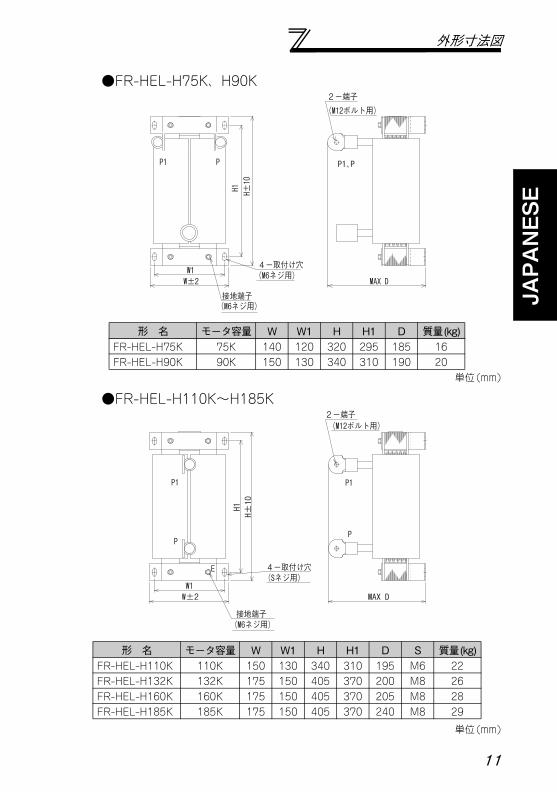
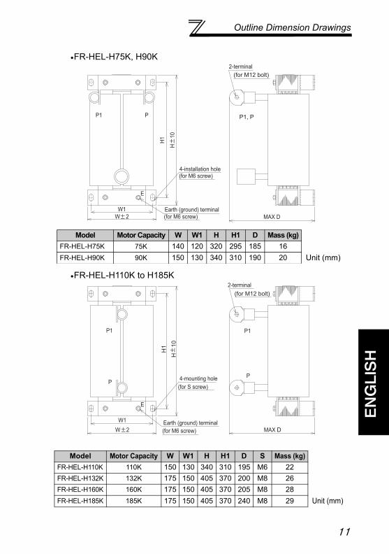
●FR-HEL-H75K、H90K
単位(mm)
●FR-HEL-H110K~H185K
単位(mm)
(M6ネジ用)4-取付け穴
(M6ネジ用)接地端子
(M12ボルト用)
P1 P P1、P
H1 H±10
W1W±2 MAX D
2-端子
形 名 モータ容量 W W1 H H1 D 質量(kg)FR-HEL-H75K 75K 140 120 320 295 185 16FR-HEL-H90K 90K 150 130 340 310 190 20
E
P1
P
P1
P
W1W±2 MAX D
H1H±10
(Sネジ用)4-取付け穴
(M6ネジ用)接地端子
(M12ボルト用)2-端子
形 名 モータ容量 W W1 H H1 D S 質量(kg)FR-HEL-H110K 110K 150 130 340 310 195 M6 22FR-HEL-H132K 132K 175 150 405 370 200 M8 26FR-HEL-H160K 160K 175 150 405 370 205 M8 28FR-HEL-H185K 185K 175 150 405 370 240 M8 29
11
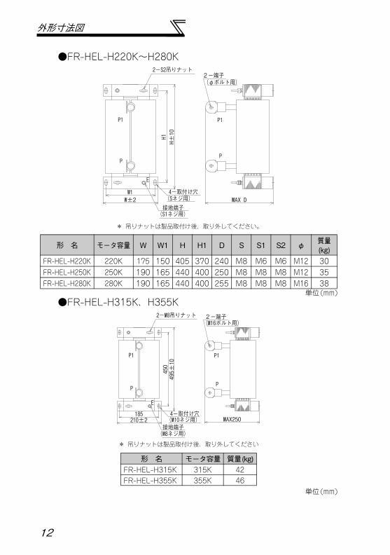
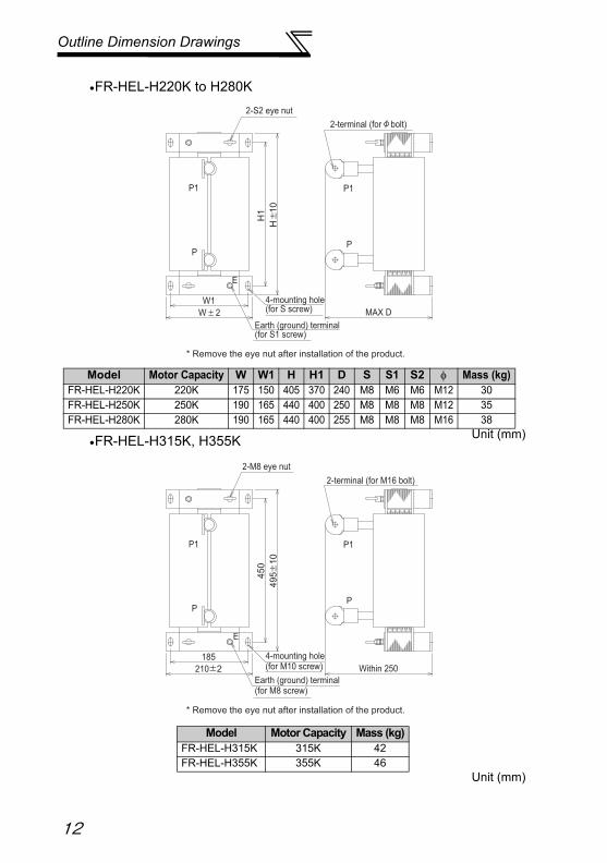
外形寸法図
●FR-HEL-H220K~H280K
単位(mm)●FR-HEL-H315K、H355K
単位(mm)
E
P1
P
P1
P
W1W±2 MAX D
H1H±10
(Sネジ用)4-取付け穴
(S1ネジ用)接地端子
2-S2吊りナット
(φボルト用)
* 吊りナットは製品取付け後、取り外してください。
2-端子
形 名 モータ容量 W W1 H H1 D S S1 S2 φ 質量(kg)
FR-HEL-H220K 220K 175 150 405 370 240 M8 M6 M6 M12 30FR-HEL-H250K 250K 190 165 440 400 250 M8 M8 M8 M12 35FR-HEL-H280K 280K 190 165 440 400 255 M8 M8 M8 M16 38
E
P1
P
P1
P
185210±2 MAX250
450
495±10
(M10ネジ用)4-取付け穴
(M8ネジ用)接地端子
2-M8吊りナット(M16ボルト用)
* 吊りナットは製品取付け後、取り外してください
2-端子
形 名 モータ容量 質量(kg)FR-HEL-H315K 315K 42FR-HEL-H355K 355K 46
12
ENGLISH
Thank you for choosing this Mitsubishi Inverter option.This instruction manual gives handling information and precautions for use of this equipment.Incorrect handling might cause an unexpected fault. Before using the equipment, please readthis manual carefully to use the equipment to its optimum.Please forward this instruction manual to the end user.
1. Electric Shock Prevention
2. Fire Prevention
3. Injury Prevention
This section is specifically about safety mattersDo not attempt to install, operate, maintain or inspect this product until you have read throughthis instruction manual and appended documents carefully and can use the equipmentcorrectly. Do not use this product until you have a full knowledge of the equipment, safetyinformation and instructions.In this instruction manual, the safety instruction levels are classified into "WARNING" and"CAUTION".
Assumes that incorrect handling may cause hazardous conditions,resulting in death or severe injury.
Assumes that incorrect handling may cause hazardous conditions,resulting in medium or slight injury, or may cause physical damageonly.
Note that even the level may lead to a serious consequence according to conditions. Please follow the instructions of both levels because they are important to personnel safety.
WARNING
CAUTION
CAUTION
SAFETY INSTRUCTIONS
WARNING While power is on or when the option is
running, do not open the terminal blockcover. You may get an electric shock.
Do not run the option with the terminalblock cover removed. Otherwise, you mayaccess the exposed high-voltage terminalsand charging part and get an electricshock.
Any person who is involved in the wiringor inspection of this equipment should befully competent to do the work.
Always install the inverter before wiring.Otherwise, you may get an electric shockor be injured.
Do not touch the option with wet hands.You may get an electric shock.
Do not subject the cables to scratches,excessive stress, heavy loads or pinching.Otherwise you may get an electric shock.
CAUTION Mount the option to unflammable material.
Mounting it to or near combustible material can cause a fire.
CAUTION Apply only the voltage specified in the
instruction manual to each terminal.Otherwise, burst, damage, etc. may occur.
Ensure that the cables are connected tothe correct terminals. Otherwise, burst,damage, etc. may occur.
Always make sure that polarity is correctto prevent damage, etc. Otherwise, burst,damage may occur.
While power is on or for some time afterpower-off, do not touch the option as it ishot. Otherwise, you may get burnt.
A-1
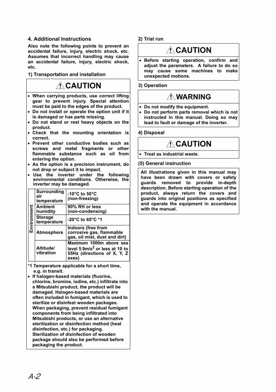
4. Additional InstructionsAlso note the following points to prevent anaccidental failure, injury, electric shock, etc.Assumes that incorrect handling may causean accidental failure, injury, electric shock,etc.
1) Transportation and installation
2) Trial run
3) Operation
4) Disposal
(5) General instruction
CAUTION When carrying products, use correct lifting
gear to prevent injury. Special attentionmust be paid to the edges of the product.
Do not install or operate the option unit if itis damaged or has parts missing.
Do not stand or rest heavy objects on theproduct.
Check that the mounting orientation iscorrect.
Prevent other conductive bodies such asscrews and metal fragments or otherflammable substance such as oil fromentering the option.
As the option is a precision instrument, donot drop or subject it to impact.
Use the inverter under the followingenvironmental conditions. Otherwise, theinverter may be damaged.
*1 Temperature applicable for a short time, e.g. in transit.
If halogen-based materials (fluorine, chlorine, bromine, iodine, etc.) infiltrate into a Mitsubishi product, the product will be damaged. Halogen-based materials are often included in fumigant, which is used to sterilize or disinfest wooden packages. When packaging, prevent residual fumigant components from being infiltrated into Mitsubishi products, or use an alternative sterilization or disinfection method (heat disinfection, etc.) for packaging.Sterilization of disinfection of wooden package should also be performed before packaging the product.
E
nv
iro
nm
ent
Surrounding air temperature
-10°C to 50°C(non-freezing)
Ambienthumidity
90% RH or less(non-condensing)
Storagetemperature -20°C to 65°C *1
AtmosphereIndoors (free from corrosive gas, flammable gas, oil mist, dust and dirt)
Altitude/vibration
Maximum 1000m above sealevel 5.9m/s2 or less at 10 to55Hz (directions of X, Y, Zaxes)
CAUTION Before starting operation, confirm and
adjust the parameters. A failure to do somay cause some machines to makeunexpected motions.
WARNING Do not modify the equipment. Do not perform parts removal which is not
instructed in this manual. Doing so maylead to fault or damage of the inverter.
CAUTION Treat as industrial waste.
All illustrations given in this manual mayhave been drawn with covers or safetyguards removed to provide in-depthdescription. Before starting operation of theproduct, always return the covers andguards into original positions as specifiedand operate the equipment in accordancewith the manual.
A-2
1
ENGLISH
Contents
1 Product Checking............................................................................ 2
2 Installation ....................................................................................... 2
3 Wiring ............................................................................................... 3
4 Cable Size and Crimping Terminal ................................................ 4
5 Specifications .................................................................................. 6
6 Outline Dimension Drawings ......................................................... 7
Product Checking
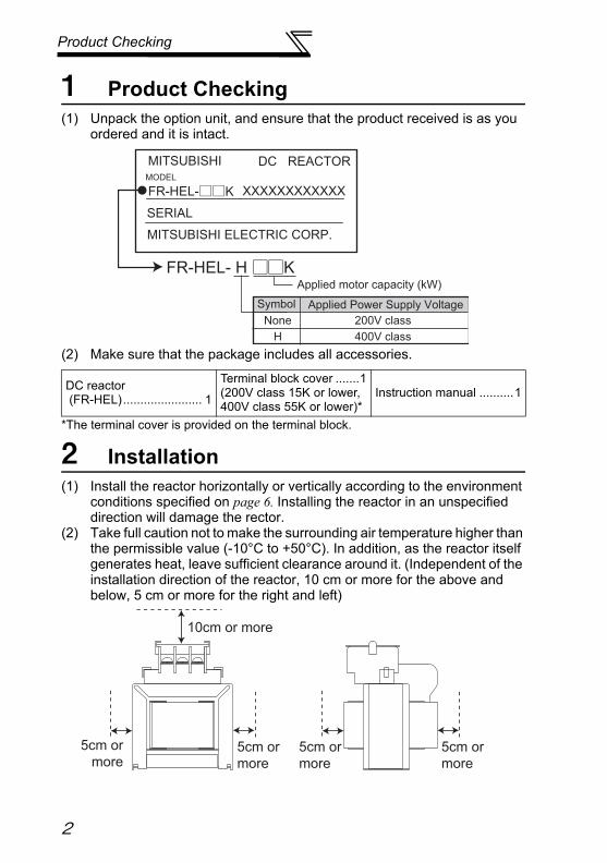
1 Product Checking(1) Unpack the option unit, and ensure that the product received is as you
ordered and it is intact.
(2) Make sure that the package includes all accessories.
*The terminal cover is provided on the terminal block.
2 Installation(1) Install the reactor horizontally or vertically according to the environment
conditions specified on page 6. Installing the reactor in an unspecified direction will damage the rector.
(2) Take full caution not to make the surrounding air temperature higher than the permissible value (-10°C to +50°C). In addition, as the reactor itself generates heat, leave sufficient clearance around it. (Independent of the installation direction of the reactor, 10 cm or more for the above and below, 5 cm or more for the right and left)
DC reactor (FR-HEL)....................... 1
Terminal block cover .......1(200V class 15K or lower, 400V class 55K or lower)*
Instruction manual ..........1
DC REACTOR
FR-HEL-
FR-HEL- H K
XXXXXXXXXXXX
SERIAL
MITSUBISHI ELECTRIC CORP.
MODEL
Applied motor capacity (kW)
Applied Power Supply VoltageSymbol
None 200V class
MITSUBISHI
K
H 400V class
10cm or more
5cm or
more
5cm or
more
5cm or
more
5cm or
more
2
Wiring
ENGLISH
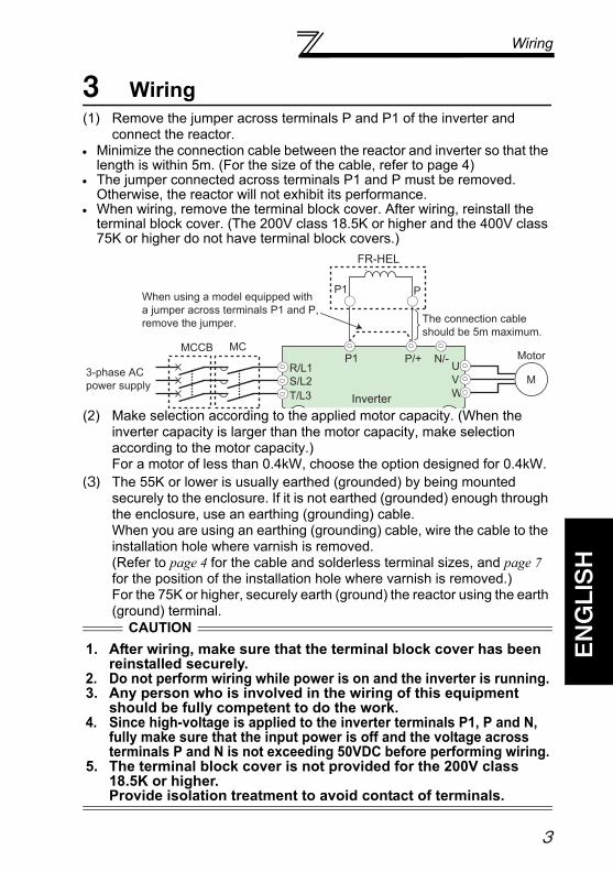
3 Wiring(1) Remove the jumper across terminals P and P1 of the inverter and
connect the reactor. Minimize the connection cable between the reactor and inverter so that the
length is within 5m. (For the size of the cable, refer to page 4) The jumper connected across terminals P1 and P must be removed.
Otherwise, the reactor will not exhibit its performance. When wiring, remove the terminal block cover. After wiring, reinstall the
terminal block cover. (The 200V class 18.5K or higher and the 400V class 75K or higher do not have terminal block covers.)
(2) Make selection according to the applied motor capacity. (When the inverter capacity is larger than the motor capacity, make selection according to the motor capacity.)For a motor of less than 0.4kW, choose the option designed for 0.4kW.
(3) The 55K or lower is usually earthed (grounded) by being mounted securely to the enclosure. If it is not earthed (grounded) enough through the enclosure, use an earthing (grounding) cable.When you are using an earthing (grounding) cable, wire the cable to the installation hole where varnish is removed.(Refer to page 4 for the cable and solderless terminal sizes, and page 7 for the position of the installation hole where varnish is removed.)For the 75K or higher, securely earth (ground) the reactor using the earth (ground) terminal.
CAUTION
1. After wiring, make sure that the terminal block cover has been reinstalled securely.
2. Do not perform wiring while power is on and the inverter is running.3. Any person who is involved in the wiring of this equipment
should be fully competent to do the work.4. Since high-voltage is applied to the inverter terminals P1, P and N,
fully make sure that the input power is off and the voltage across terminals P and N is not exceeding 50VDC before performing wiring.
5. The terminal block cover is not provided for the 200V class 18.5K or higher.Provide isolation treatment to avoid contact of terminals.
3-phase AC
power supply
MCCB
R/L1
S/L2
T/L3
MotorU
V
W
P1
P1 P
MC
M
P/+ N/-
FR-HEL
Inverter
When using a model equipped with
a jumper across terminals P1 and P,
remove the jumper. The connection cable
should be 5m maximum.
3
Cable Size and Crimping Terminal
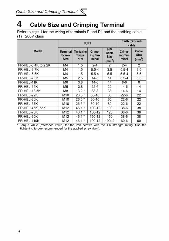
4 Cable Size and Crimping TerminalRefer to page 3 for the wiring of terminals P and P1 and the earthing cable.(1) 200V class
* Torque value (reference value) for the iron screws with the 4.6 strength rating. Use thetightening torque recommended for the applied screw (bolt).
Model
P, P1Earth (Ground)
cable
Terminal Screw Size
TighteningTorque
Nm
Crimp-ing Ter-minal
HIV Cable Size
(mm2)
Crimp-ing Ter-minal
Cable Size
(mm2)
FR-HEL-0.4K to 2.2K M4 1.5 2-4 2 2-4 2FR-HEL-3.7K M4 1.5 5.5-4 3.5 5.5-4 3.5FR-HEL-5.5K M4 1.5 5.5-4 5.5 5.5-4 5.5FR-HEL-7.5K M5 2.5 14-5 14 5.5-4 5.5FR-HEL-11K M6 3.8 14-6 14 8-6 8FR-HEL-15K M6 3.8 22-6 22 14-6 14FR-HEL-18.5K M8 13.2 * 38-8 38 14-6 14FR-HEL-22K M10 26.5 * 38-10 38 22-6 22FR-HEL-30K M10 26.5 * 60-10 60 22-6 22FR-HEL-37K M10 26.5 * 80-10 80 22-6 22FR-HEL-45K, 55K M12 46.1 * 100-12 100 38-6 38FR-HEL-75K M12 46.1 * 150-12 125 38-6 38FR-HEL-90K M12 46.1 * 150-12 150 38-6 38FR-HEL-110K M12 46.1 * 100-12 1002 60-6 60
4
Cable Size and Crimping Terminal
ENGLISH
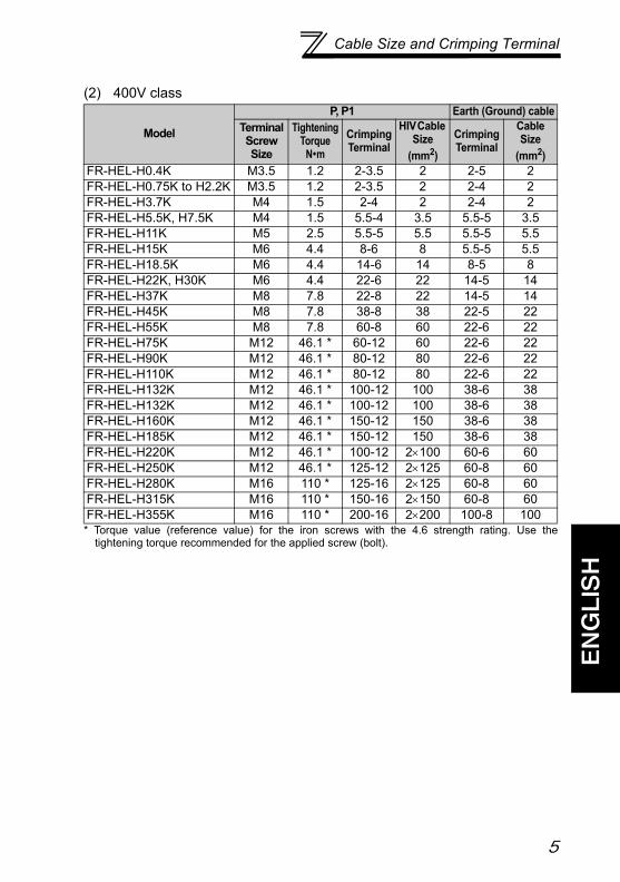
(2) 400V class
* Torque value (reference value) for the iron screws with the 4.6 strength rating. Use thetightening torque recommended for the applied screw (bolt).
Model
P, P1 Earth (Ground) cableTerminal Screw Size
TighteningTorque
Nm
Crimping Terminal
HIV Cable Size
(mm2)
Crimping Terminal
Cable Size
(mm2)FR-HEL-H0.4K M3.5 1.2 2-3.5 2 2-5 2FR-HEL-H0.75K to H2.2K M3.5 1.2 2-3.5 2 2-4 2FR-HEL-H3.7K M4 1.5 2-4 2 2-4 2FR-HEL-H5.5K, H7.5K M4 1.5 5.5-4 3.5 5.5-5 3.5FR-HEL-H11K M5 2.5 5.5-5 5.5 5.5-5 5.5FR-HEL-H15K M6 4.4 8-6 8 5.5-5 5.5FR-HEL-H18.5K M6 4.4 14-6 14 8-5 8FR-HEL-H22K, H30K M6 4.4 22-6 22 14-5 14FR-HEL-H37K M8 7.8 22-8 22 14-5 14FR-HEL-H45K M8 7.8 38-8 38 22-5 22FR-HEL-H55K M8 7.8 60-8 60 22-6 22FR-HEL-H75K M12 46.1 * 60-12 60 22-6 22FR-HEL-H90K M12 46.1 * 80-12 80 22-6 22FR-HEL-H110K M12 46.1 * 80-12 80 22-6 22FR-HEL-H132K M12 46.1 * 100-12 100 38-6 38FR-HEL-H132K M12 46.1 * 100-12 100 38-6 38FR-HEL-H160K M12 46.1 * 150-12 150 38-6 38FR-HEL-H185K M12 46.1 * 150-12 150 38-6 38FR-HEL-H220K M12 46.1 * 100-12 2100 60-6 60FR-HEL-H250K M12 46.1 * 125-12 2125 60-8 60FR-HEL-H280K M16 110 * 125-16 2125 60-8 60FR-HEL-H315K M16 110 * 150-16 2150 60-8 60FR-HEL-H355K M16 110 * 200-16 2200 100-8 100
5
Specifications
5 Specifications
*1 The power factor is calculated on the assumption that the power impedance is 1%. Thevalue changes according to the power supply capacity and power impedance. The load iscalculated using the fundamental current specified in JEM-TR201 as 100%.The value is 94.4% when calculated with 1 power factor for the fundamental waveaccording to the Architectural Standard Specifications (Electrical Installation) (2013revision) supervised by the Ministry of Land, Infrastructure, Transport and Tourism ofJapan.For a motor of less than 0.4kW, the power factor improving effect will be slightly lower.
Power factor improving effect *1 Power supply power factor approx. 93%(94.4%) (at 100% load)
Power specifications
200V class Three-phase 200 to 240VAC 50Hz/60Hz
400V class
55K or lower
Three-phase 380 to 480VAC 50Hz/60Hz
75K or higher
Three-phase 380 to 500VAC 50Hz/60Hz
En
viro
nm
ent
Surrounding air temperature -10°C to + 50°C (non-freezing)
Ambient humidity 90%RH or less (non-condensing)Storage temperature -20°C to + 65°C (non-freezing)
Atmosphere Indoors (free from corrosive gas, flammable gas, oil mist, dust and dirt)
Altitude/vibration Max.1000m above sea level 5.9m/s2 or less
6
Outline Dimension Drawings
ENGLISH
6 Outline Dimension Drawings(1) 200V Class
FR-HEL-0.4K to 2.2K
(Unit: mm)*1 Use this portion to wire an earthing (grounding) cable. (Refer to page 4)*2 Maximum size (The size changes according to the bending of the input and output cable.)
FR-HEL-3.7K to 15K
(Unit: mm)*1 Use this portion to wire an earthing (grounding) cable. (Refer to page 4)*2 Maximum size (The size changes according to the bending of the input and output cable.)
Model Motor Capacity W W1 H D *2 D2 Mass (kg)
FR-HEL-0.4K 0.4K 70 60 71 61 21 0.4
FR-HEL-0.75K 0.75K 85 74 81 61 21 0.5
FR-HEL-1.5K 1.5K 85 74 81 70 30 0.8
FR-HEL-2.2K 2.2K 85 74 81 70 30 0.9
Model Motor Capacity W W1 H D *2 D1 D2 D3 d Mass (kg)
FR-HEL-3.7K 3.7K 77 55 92 82 66 57 37 M4 1.5
FR-HEL-5.5K 5.5K 77 55 92 92 76 67 42 M4 1.9
FR-HEL-7.5K 7.5K 86 60 113 98 81 72 43 M4 2.5
FR-HEL-11K 11K 105 64 133 112 92 79 47 M6 3.3
FR-HEL-15K 15K 105 64 133 115 97 84 48.5 M6 4.1
P P1
W1
MAX D(D2)
Installation hole for 2-M4(varnish removed(front / rear side)) *1
W 2H
2
P1P
D2
MAX D
*
(D3)
Installation hole for 4-d(varnish removed(front / rear side))
W 2
W1
D1 2
H
2
7
Outline Dimension Drawings
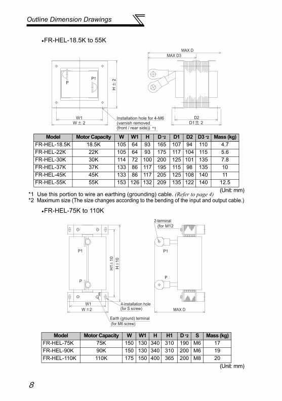
FR-HEL-18.5K to 55K
(Unit: mm)*1 Use this portion to wire an earthing (grounding) cable. (Refer to page 4)*2 Maximum size (The size changes according to the bending of the input and output cable.)
FR-HEL-75K to 110K
(Unit: mm)
Model Motor Capacity W W1 H D *2 D1 D2 D3 *2 Mass (kg)
FR-HEL-18.5K 18.5K 105 64 93 165 107 94 110 4.7
FR-HEL-22K 22K 105 64 93 175 117 104 115 5.6
FR-HEL-30K 30K 114 72 100 200 125 101 135 7.8
FR-HEL-37K 37K 133 86 117 195 115 98 135 10
FR-HEL-45K 45K 133 86 117 205 125 108 140 11
FR-HEL-55K 55K 153 126 132 209 135 122 140 12.5
Model Motor Capacity W W1 H H1 D *2 S Mass (kg)
FR-HEL-75K 75K 150 130 340 310 190 M6 17
FR-HEL-90K 90K 150 130 340 310 200 M6 19
FR-HEL-110K 110K 175 150 400 365 200 M8 20
PP1
MAX D
MAX D3
D2Installation hole for 4-M6(varnish removed(front / rear side)) *1
D1 2W 2W1
H
2
E
P1
P
P1
P
W1(for S screw)4-installation hole
(for M6 screw)
Earth (ground) terminal
MAX D
(for M12
2-terminal
H
10
H1
1
0
W 2
8
Outline Dimension Drawings
ENGLISH
(2) 400V ClassFR-HEL-H0.4K
Unit (mm)FR-HEL-H0.75K to H2.2K
Unit (mm)* Use this portion to wire an earthing (grounding) cable. (Refer to page 4)
Installation hole for 2-M5
(varnish removed)*M
ax7
8
90 2.5
75
Max 60
(28)
Terminal layout
P P1
Terminal Screw Size Mass (kg)
M3.5 0.6
(D3)
H 2
.5
Max D
Installation hole for 4-M4
(varnish removed)*
D2
W 2.5
50D1 1
Terminal layout
P P1
Model Motor Capacity W H D D1 D2 D3 Mass (kg)
FR-HEL-H0.75K 0.75K 66 100 70 68 48 34 0.8
FR-HEL-H1.5K 1.5K 66 100 80 74 54 37 1
FR-HEL-H2.2K 2.2K 76 110 80 74 54 37 1.3
9
Outline Dimension Drawings
FR-HEL-H3.7K to H7.5K
Unit (mm)* Use this portion to wire an earthing (grounding) cable. (Refer to page 4)
FR-HEL-H11K to H55K
Unit (mm)* Use this portion to wire an earthing (grounding) cable. (Refer to page 4)
(D3)
H 2
.5
Max D
Installation hole for 4-d
(varnish removed)*
D2
W 2.5
W1D1 1
Terminal layout
P P1
Model Motor Capacity W W1 H D D1 D2 D3 d Mass(kg)FR-HEL-H3.7K 3.7K 86 55 120 95 89 69 45 M4 2.3FR-HEL-H5.5K 5.5K 96 60 128 100 95 75 48 M5 3FR-HEL-H7.5K 7.5K 96 60 128 105 100 80 50 M5 3.5
(D3)
H 2
.5
Max D
Installation hole for 4-d
(varnish removed)*
D2
W 2.5
W1D1 1
Terminal layout
P P1
Model Motor Capacity W W1 H D D1 D2 D3 d Mass (kg)FR-HEL-H11K 11K 105 75 137 110 105 85 53 M5 4.5FR-HEL-H15K 15K 105 75 152 125 115 95 62 M5 5FR-HEL-H18.5K 18.5K 114 75 162 120 100 80 58 M5 5FR-HEL-H22K 22K 133 90 178 120 95 75 53 M5 6FR-HEL-H30K 30K 133 90 178 120 100 80 56 M5 6.5FR-HEL-H37K 37K 133 90 187 155 120 100 83 M5 8.5FR-HEL-H45K 45K 133 90 187 170 130 110 88 M5 10FR-HEL-H55K 55K 152 105 206 170 126 106 89 M6 11.5
10
Outline Dimension Drawings
ENGLISH
FR-HEL-H75K, H90K
FR-HEL-H110K to H185K
(for M6 screw)4-installation hole
(for M6 screw)
Earth (ground) terminal
2-terminal
E
P1 P P1, P
(for M12 bolt)
MAX D
W1
H1
H
1
0
W 2
Model Motor Capacity W W1 H H1 D Mass (kg)
FR-HEL-H75K 75K 140 120 320 295 185 16
FR-HEL-H90K 90K 150 130 340 310 190 20 Unit (mm)
E
P1
P
P1
P
W1
MAX D
(for S screw)
4-mounting hole
(for M6 screw)
Earth (ground) terminal
(for M12 bolt)
2-terminal
H1
H
10
W 2
Model Motor Capacity W W1 H H1 D S Mass (kg)
FR-HEL-H110K 110K 150 130 340 310 195 M6 22
FR-HEL-H132K 132K 175 150 405 370 200 M8 26
FR-HEL-H160K 160K 175 150 405 370 205 M8 28
FR-HEL-H185K 185K 175 150 405 370 240 M8 29 Unit (mm)
11
Outline Dimension Drawings
FR-HEL-H220K to H280K
Unit (mm)FR-HEL-H315K, H355K
Unit (mm)
E
P1
P
P1
P
H1
H
10
Earth (ground) terminal (for S1 screw)
2-S2 eye nut
* Remove the eye nut after installation of the product.
4-mounting hole (for S screw) MAX D
2-terminal (for bolt)
W1
W 2
Model Motor Capacity W W1 H H1 D S S1 S2 Mass (kg)FR-HEL-H220K 220K 175 150 405 370 240 M8 M6 M6 M12 30FR-HEL-H250K 250K 190 165 440 400 250 M8 M8 M8 M12 35FR-HEL-H280K 280K 190 165 440 400 255 M8 M8 M8 M16 38
E
P1
P
P1
P
185
210 2
45
0
49
5
10
Earth (ground) terminal (for M8 screw)
2-M8 eye nut
* Remove the eye nut after installation of the product.
4-mounting hole (for M10 screw) Within 250
2-terminal (for M16 bolt)
Model Motor Capacity Mass (kg)FR-HEL-H315K 315K 42FR-HEL-H355K 355K 46
12
13
改 訂 履 歴※取扱説明書番号は、本説明書の裏表紙の左下に記載してあります。
印刷日付 ※取扱説明書番号 改 定 内 容2004年3月 IB(名)-0600183-A 初版印刷2004年11月 IB(名)-0600183-B
・FR-HEL-0.4K~55K・電線サイズと圧着端子
2011年8月 IB(名)-0600183-C
・接地線サイズ2013年4月 IB(名)-0600183-D
・FR-HEL-75K~110K・FR-HEL-H75K~H132K
2013年11月 IB(名)-0600183-E
・FR-HEL-H160K~355K
Print Date ※Manual Number RevisionMar. 2004 IB(NA)-0600183-A First editionNov. 2004 IB(NA)-0600183-B
・FR-HEL-0.4K to 55k・Cable Size and Crimping Terminal
Aug. 2011 IB(NA)-0600183-C
・Earthing(Grounding) cable size Apr. 2013 IB(NA)-0600183-D
・FR-HEL-75K to 110K・FR-HEL-H75K to H132K
Nov. 2013 IB(NA)-0600183-E
・FR-HEL-H160K to 355K
追加
追加
追加
追加
Addition
Addition
Addition
Addition

14
MEMO
●アフターサービスネットワーク三菱電機システムサービス株式会社の17拠点が24時間365日受付体制でお応えします。●24時間受付サービス拠点
●サービス網一覧表(三菱電機システムサービス株式会社)
サービス拠点名 番号 住所 電話番号 時間外修理受付窓口【機器全般】*2 ファックス専用
SC北日本支社 〒983-0005 宮城県仙台市宮城野区福室字明神西31 022-353-7814
(052)719-4337
(022)238-9257
北海道支店 〒004-0041 北海道札幌市厚別区大谷地東2-1-18 (011)890-7515 (011)890-7516
SC東京機電支社 〒108-0022 東京都港区海岸3-19-22(三菱倉庫芝浦ビル) (03)3454-5521 (03)5440-7783
神奈川機器サービスステーション 〒224-0053 神奈川県横浜市都筑区池辺町3963-1 (045)938-5420 (045)935-0066
関越機器サービスステーション 〒338-0822 埼玉県さいたま市桜区中島2-21-10 (048)859-7521 (048)858-5601
新潟機器サービスステーション 〒950-8504 新潟県新潟市中央区東大通2-4-10日本生命ビル6F (025)241-7261 (025)241-7262
SC中部支社 〒461-8675 愛知県名古屋市東区矢田南5-1-14 (052)722-7601 (052)719-1270
静岡機器サービスステーション 〒422-8058 静岡県静岡市駿河区中原877-2 (054)287-8866 (054)287-8484
北陸支店 〒920-0811 石川県金沢市小坂町北255 (076)252-9519 (076)252-5458
SC関西機電支社 〒531-0076 大阪府大阪市北区大淀中1-4-13(三菱電機システムサービス関西支社ビル) (06)6458-9728 (06)6458-6911
京滋機器サービスステーション 〒612-8444 京都府京都市伏見区竹田田中宮町8番地 (075)611-6211 (075)611-6330
姫路機器サービスステーション 〒670-0836 兵庫県姫路市神屋町6-76 (079)281-1141 (079)224-3419
SC中四国支社 〒732-0802 広島県広島市南区大州4-3-26 (082)285-2111 (082)285-7773
岡山機器サービスステーション 〒700-0951 岡山県岡山市北区田中606-8 (086)242-1900 (086)242-5300
四国支店 〒760-0072 香川県高松市花園町1-9-38 (087)831-3186 (087)833-1240
SC九州支社 〒812-0007 福岡県福岡市博多区東比恵3-12-16 (092)483-8208 (092)483-8228
長崎機器サービスステーション 〒852-8004 長崎県長崎市丸尾町4番4号 (095)818-0700 (095)861-7566
三菱電機機器製品アフターサービス技術相談ダイヤル【機器全般】*1 ― (052)719-4333 ― ―
*1 平日: 9:00~19:00、休日(土日祝祭日): 9:00~17:30*2 平日: 19:00~翌 9:00、休日(土日祝祭日): 24時間
1213 14
1516
17
1
2
3
9
5
4
6
78
10
11
2
1
3
4
5
6
7
8
9
10
11
12
13
14
15
16
17
15
●グローバルFAセンター
●上海FAセンターMITSUBISHI ELECTRIC AUTOMAITON (CHINA) LTD.10F, Mitsubishi Electric Automation Center, No.1386 Hongqiao Road, Changning District, Shanghai, ChinaTEL. 86-21-2322-3030 FAX. 86-21-2322-3000 (9611#)
●北京FAセンターMITSUBISHI ELECTRIC AUTOMATION (CHINA) LTD. Beijing OfficeUnit 908, Office Tower 1, Henderson Centre, 18 Jianguomennei Avenue, Dongcheng District, Beijing, ChinaTEL. 86-10-6518-8830FAX. 86-10-6518-3907(Before Service)FAX. 86-10-6518-2938(After Service)
●天津FAセンターMITSUBISHI ELECTRIC AUTOMATION (CHINA) LTD. Tianjin OfficeRoom 2003 City Tower, No.35, Youyi Road, Hexi District, Tianjin, ChinaTEL. 86-22-2813-1015 FAX. 86-22-2813-1017
●広州FAセンターMITSUBISHI ELECTRIC AUTOMATION (CHINA) LTD. Guangzhou OfficeRoom 1609, North Tower, The Hub Center, No.1068, Xingang East Road, Haizhu District, Guangzhou, ChinaTEL. 86-20-8923-6730 FAX. 86-20-8923-6715
●韓国FAセンターMITSUBISHI ELECTRIC AUTOMATION KOREA CO., LTD.B1F, 2F, 1480-6, Gayang-Dong, Gangseo-Gu, Seoul, 157-200, KoreaTEL. 82-2-3660-9630 FAX. 82-2-3663-0475
●台湾FAセンターSETSUYO ENTERPRISE CO., LTD.3F, No.105, Wugong 3rd Road, Wugu District, New Taipei City 24889, Taiwan, R.O.C.TEL. 886-2-2299-9917 FAX. 886-2-2299-9963MITSUBISHI ELECTRIC TAIWAN CO.,LTD.No.8-1, Industrial 16th Road, Taichung Industrial Park, Taichung City 40768 Taiwan, R.O.C.TEL. 886-4-2359-0688 FAX. 886-4-2359-0689
●タイFAセンターMITSUBISHI ELECTRIC FACTORY AUTOMATION (THAILAND) CO., LTD.12th Floor, SV.City Building, Office Tower 1, No. 896/19 and 20 Rama 3 Road, Kwaeng Bangpongpang, Khet Yannawa, Bangkok 10120, ThailandTEL. 66-2682-6522~31 FAX. 66-2682-6020
●アセアンFAセンターMITSUBISHI ELECTRIC ASIA PTE. LTD.307, Alexandra Road, Mitsubishi Electric Building, Singapore 159943TEL. 65-6470-2480 FAX. 65-6476-7439
●インドネシアFAセンターPT. MITSUBISHI ELECTRIC INDONESIAGedung Jaya 11th Floor, JL MH. Thamrin No.12, Jakarta, Pusat 10340, IndonesiaTEL. 62-21-3192-6461 FAX. 62-21-3192-3942
●ハノイFAセンターMITSUBISHI ELECTRIC VIETNAM COMPANY LIMITED Hanoi BranchUnit 9-05, 9th Floor, Hanoi Central Office Building, 44B Ly Thuong Kiet Street, Hoan Kiem District, Hanoi City, VietnamTEL. 84-4-3937-8075 FAX. 84-4-3937-8076
●ホーチミンFAセンターMITSUBISHI ELECTRIC VIETNAM COMPANY LIMITED Unit 01 - 04, 10th Floor, Vincom Center, 72 Le Thanh Ton Street, District 1, Ho Chi Minh City, VietnamTEL. 84-8-3910-5945 FAX. 84-8-3910-5947
●インド・プネFAセンターMITSUBISHI ELECTRIC INDIA PVT. LTD. Pune BranchEmerald House, EL-3, J Block, M.I.D.C., Bhosari, Pune, 411026, Maharastra State, IndiaTEL. 91-20-2710-2000 FAX. 91-20-2710-2100
●インド・グルガオンFAセンターMITSUBISHI ELECTRIC INDIA PVT. LTD. Gurgaon Head Office2nd Floor, Tower A & B, Cyber Greens, DLF Cyber City, DLF Phase - Ⅲ, Gurgaon - 122002 Haryana, IndiaTEL. 91-124-463-0300 FAX. 91-124-463-0399
●インド・バンガロールFAセンターMITSUBISHI ELECTRIC INDIA PVT. LTD. Bangalore Branch Prestige Emerald, 6th Floor, Municipal No.2, Madras Bank Road, Bangalore 560001, IndiaTEL. 91-80-4020-1600 FAX. 91-80-4020-1699
●北米FAセンターMITSUBISHI ELECTRIC AUTOMATION, INC.500 Corporate Woods Parkway, Vernon Hills, IL 60061, U.S.A.TEL. 1-847-478-2334 FAX. 1-847-478-2253
●メキシコFAセンターMITSUBISHI ELECTRIC AUTOMATION, INC. Mexico BranchMariano Escobedo #69, Col.Zona Industrial, Tlalnepantla Edo, C.P.54030, MexicoTEL. 52-55-3067-7511
●ブラジルFAセンターMITSUBISHI ELECTRIC DO BRASIL COMERCIO E SERVICOS LTDA.Rua Jussara, 1750- Bloco B Anexo, Jardim Santa Cecilia, CEP 06465-070, Barueri - SP, BrasilTEL. 55-11-4689-3000 FAX. 55-11-4689-3016
●ブラジル・ボイトゥバFAセンターMELCO CNC DO BRASIL COMERCIO E SERVICOS S.A.Acesso Jose Sartorelli, KM 2.1 CEP 18550-000 Boituva-SP, BrasilTEL. 55-15-3363-9900 FAX. 55-15-3363-9911
●欧州FAセンターMITSUBISHI ELECTRIC EUROPE B.V. Polish Branch32-083 Balice ul. Krakowska 50, PolandTEL. 48-12-630-47-00 FAX. 48-12-630-47-01
●ドイツFAセンターMITSUBISHI ELECTRIC EUROPE B.V. German BranchGothaer Strasse 8, D-40880 Ratingen, GermanyTEL. 49-2102-486-0 FAX. 49-2102-486-1120
●英国FAセンターMITSUBISHI ELECTRIC EUROPE B.V. UK BranchTravellers Lane, Hatfield, Hertfordshire, AL10 8XB, UK.TEL. 44-1707-28-8780 FAX. 44-1707-27-8695
●チェコFAセンターMITSUBISHI ELECTRIC EUROPE B.V. Czech BranchAvenir Business Park, Radicka 751/113e, 158 00 Praha5, Czech RepublicTEL. 420-251-551-470 FAX. 420-251-551-471
●ロシアFAセンターMITSUBISHI ELECTRIC EUROPE B.V. Russian Branch St.Petersburg officePiskarevsky pr. 2, bld 2, lit "Sch", BC "Benua", office 720; 195027, St. Petersburg, RussiaTEL. 7-812-633-3497 FAX. 7-812-633-3499
●トルコFAセンターMITSUBISHI ELECTRIC TURKEY AS Umraniye BranchSerifali Mahallesi Nutuk Sokak No:5 TR-34775 Umraniye, Istanbul, TurkeyTEL. 90-216-526-3990 FAX. 90-216-526-3995
16 IB( 名 )-0600183-E
三菱汎用インバータ
IB(名)-0600183-E(1311)MDOC この印刷物は、2013年11月の発行です。なお、お断りなしに仕様を変更することがありますのでご了承ください。
〒100-8310東京都千代田区丸の内2-7-3(東京ビル)
お問合せは下記へどうぞ本社................〒100-8310 東京都千代田区丸の内2-7-3(東京ビル7階).............................................................................................................................................(03)3218-6721北海道支社...〒060-8693 北海道札幌市中央区北2条西4丁目1(北海道ビル)................................................................................................................................(011)212-3793東北支社.......〒980-0011 宮城県仙台市青葉区上杉1-17-7(仙台上杉ビル)....................................................................................................................................(022)216-4546関越支社.......〒330-6034 埼玉県さいたま市中央区新都心11番地2(明治安田生命さいたま新都心ビル ランド・アクシス・タワー34階)........(048)600-5845新潟支店.......〒950-8504 新潟県新潟市中央区東大通2-4-10(日本生命ビル)...............................................................................................................................(025)241-7227神奈川支社...〒220-8118 神奈川県横浜市西区みなとみらい2-2-1(横浜ランドマークタワー18階)....................................................................................(045)224-2623北陸支社.......〒920-0031 石川県金沢市広岡3-1-1(金沢パークビル)...............................................................................................................................................(076)233-5502中部支社.......〒451-8522 愛知県名古屋市西区牛島6番1号(名古屋ルーセントタワー).........................................................................................................(052)565-3323豊田支店.......〒471-0034 愛知県豊田市小坂本町1-5-10(矢作豊田ビル)........................................................................................................................................(0565)34-4112関西支社.......〒530-8206 大阪府大阪市北区堂島2-2-2(近鉄堂島ビル)...........................................................................................................................................(06)6347-2831中国支社.......〒730-8657 広島県広島市中区中町7-32(ニッセイ広島ビル)...................................................................................................................................(082)248-5345四国支社.......〒760-8654 香川県高松市寿町1-1-8(日本生命高松駅前ビル)..................................................................................................................................(087)825-0055九州支社.......〒810-8686 福岡県福岡市中央区天神2-12-1(天神ビル).............................................................................................................................................(092)721-2236
電話技術相談窓口
おかけ間違いのないように、電話番号をよくお確かめください。
FAX技術相談窓口三菱電機FAサイト、仕様・機能に関するお問い合わせのWebフォームもご利用ください。なお、お急ぎの場合は、お手数ですが、上記電話技術相談窓口までご相談ください。
※1:春季・夏季・年末年始の休日を除く※2:土・日・祝祭日、春季・夏季・年末年始の休日を除く通常業務日
海外(FAセンター )のお問合せ先は裏面を参照してください。Refer to the reverse side for the international FA Centers abroad.
三菱電機FA機器技術相談
対象機種 電話番号 受付時間※1
インバータ FREQROLシリーズ 052-722-2182 月曜~金曜 9:00~19:00土曜・日曜・祝日 9:00~17:00
対象機種 FAX番号 受付時間※2上記対象機種 052-719-6762 9:00~16:00(受信は常時※1)