Embed Size (px)
Citation preview
© 2014 WILEY-VCH Verlag GmbH & Co. KGaA, Weinheim4302
www.advmat.dewww.MaterialsViews.com
wileyonlinelibrary.com
CO
MM
UN
ICATI
ON Continuous Self-Healing Life Cycle in Vascularized
Structural Composites
Jason F. Patrick , Kevin R. Hart , Brett P. Krull , Charles E. Diesendruck , Jeffrey S. Moore , Scott R. White , * and Nancy R. Sottos *
J. F. Patrick Civil and Environmental Engineering Department Beckman Institute for Advanced Science and Technology University of Illinois at Urbana-Champaign Urbana , IL 61801 , USA K. R. Hart, Prof. S. R. White Aerospace Engineering Department Beckman Institute for Advanced Science and Technology University of Illinois at Urbana-Champaign Urbana , IL 61801 , USA E-mail: [email protected] Dr. C. E. Diesendruck, Prof. J. S. Moore Chemistry Department Beckman Institute for Advanced Science and Technology University of Illinois at Urbana-Champaign Urbana , IL 61801 , USA B. P. Krull, Prof. N. R. Sottos Materials Science and Engineering Department Beckman Institute for Advanced Science and Technology University of Illinois at Urbana-Champaign Urbana , IL 61801 , USA E-mail: [email protected]
DOI: 10.1002/adma.201400248
can open on the order of hundreds of microns in the thick-ness direction and span length scales ranging from millimeters to centimeters in-plane. [ 12 ] The size scale of the damage com-bined with the goal of fully autonomous, multiple healing cycles precludes remendable and microcapsule based healing approaches. [ 2,7,8,13,14 ] Motivated by successful repeated in situ healing in glassy polymers, we integrate fl uid-fi lled vascular networks directly into the woven, reinforcing textile architec-ture. [ 15–19 ] Delamination damage ruptures the capillary network and triggers the delivery and subsequent polymerization of reactive chemical species.
In neat polymers, three-dimensional (3D) vascular networks are created by direct write assembly of fugitive wax scaffolds, but these temporary structures are too delicate to survive com-posites manufacturing. [ 20 ] Isolated, one-dimensional (1D) vas-cules have been formed in fi brous polymer composites via embedment of hollow glass fi bers, manual extraction of steel wires coated with chemical release agent, and removal of melted solder wires under heat and vacuum. [ 9,10,21,22 ] Healing employing these vasculatures has been limited to a single repair event either from depletion of healing agents contained within sealed capillaries or polymerization within the vascular network resulting from circulation of pre-mixed reactive components. The pivotal feature of the current self-healing system is highly tailorable 3D vascular networks formed via the vaporization of sacrifi cial components (VaSC) process, that are seamlessly inte-grated with traditional fi ber-reinforced composite processing. [ 11 ] The resulting microvascular features enable circulation of func-tional fl uids throughout the composite volume.
Pre-vascularized composite textile reinforcement is produced by stitching catalyst-infused, sacrifi cial poly(lactic acid) (PLA) monofi lament (300 μm diameter), in a precise pattern through interior layers (plies) of aerospace-grade woven fabric. The fi ber-composite preform is then consolidated into a structural lami-nate via vacuum assisted resin transfer molding (VARTM) of a thermoset epoxy matrix exhibiting high-temperature stability ( T g ≈ 150 °C) following a conventional post-cure cycle. The fi nal thermal PLA evacuation (VaSC) step creates inverse replica, three-dimensional (3D) microvasculature throughout the com-posite heterostructure (Supporting Information, Section S1–S4). The VaSC thermal treatment does not result in any statistically signifi cant change to the fracture properties of the neat com-posite (Supporting Information, Table S1).
A two-part healing chemistry is selected on the basis of rheology, reaction kinetics, and post-polymerized mechanical properties. The diglycidyl ether of bisphenol A (DGEBA) based epoxy resin (EPON 8132) and aliphatic triethylenetetramine
Internal delamination damage in fi ber-reinforced composites is diffi cult to detect and nearly impossible to repair by conven-tional methods. [ 1,2 ] To date, this failure mechanism remains one of the most signifi cant factors limiting reliability and leads to conservative design of composites for lightweight struc-tures. [ 3–5 ] In contrast to the remarkable progress in self-healing polymers, autonomous and recurrent repair of fi ber-composites still presents signifi cant challenges due to stringent processing and integration requirements. [ 6–10 ] Here, we report multiple cycles of in situ delamination healing achieved through micro-vascular delivery of reactive fl uids. Three-dimensional vascular networks are introduced in the composite by vaporization of sacrifi cial fi bers, with no degradation of inherent fracture properties. [ 11 ] The vascular architecture is critical for in situ mixing, polymerization, and repeated healing of delamina-tion damage. An interpenetrating vascular network results in full recovery (>100%) of fracture resistance after delamination, demonstrating the potential for improved safety and durability throughout the service life of high-performance composite structures.
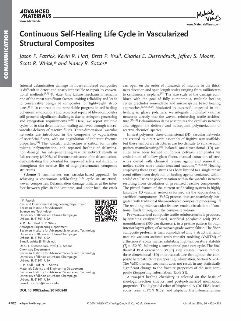
Scheme 1 summarizes our vascular-based approach for achieving a continuous self-healing life cycle in structural, woven composites. Delamination damage initiates at the inter-face between plies in the laminate, and under load, the crack
Adv. Mater. 2014, 26, 4302–4308
4303
www.advmat.dewww.MaterialsViews.com
wileyonlinelibrary.com© 2014 WILEY-VCH Verlag GmbH & Co. KGaA, Weinheim
CO
MM
UN
ICATIO
N
(TETA) based hardener (EPIKURE 3046) components possess low viscosity (<10 P) such that modest pressurized delivery produces adequate coverage of fracture surface(s), the ability to polymerize under non-stoichiometric ratios at ambient tem-perature (Supporting Information, Section S5), and suffi cient bonding/fracture toughness to restore structural integrity. [ 19 ] Additionally, each healing agent exhibits excellent compatibility and chemical stability when sequestered in separate vascular networks of a cured epoxy matrix. [ 16 ]
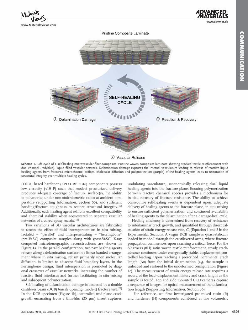
Two variations of 3D vascular architectures are fabricated to assess the effect of fl uid interspersion on in situ mixing. Isolated – “parallel” and interpenetrating – “herringbone” (pre-VaSC) composite samples along with (post-VaSC) X-ray computed microtomographic reconstructions are shown in Figure 1 a. In the parallel confi guration, two-part healing agents release along a delamination surface in a linear banded arrange-ment where in situ mixing, reliant primarily upon molecular diffusion, is limited to adjacent fl uid boundary layers. In the herringbone design, fl uid interspersion is promoted by diag-onal crossover of vascular networks, increasing the number of reactive fl uid interfaces and further facilitating in situ mixing and subsequent polymerization.
Self-healing of delamination damage is assessed by a double cantilever beam (DCB) tensile opening (mode-I) fracture test. [ 23 ] In the DCB specimen (Figure 1 b), controlled mid-plane crack growth emanating from a thin-fi lm (25 µm) insert ruptures
undulating vasculature, autonomically releasing dual liquid healing agents into the fracture plane. Ensuing polymerization between reactive chemical species provides a mechanism for in situ recovery of fracture resistance. The ability to achieve consecutive self-healing events is dependent upon: adequate delivery of healing agents to the fracture plane, in situ mixing to ensure suffi cient polymerization, and continued availability of healing agents to the delamination after a damage-heal cycle.
Healing effi ciency is determined from recovery of resistance to interlaminar crack growth, and quantifi ed through direct cal-culation of strain energy release rate, G I (Equation 1 and 2 in the Experimental Section). A virgin DCB sample is quasi-statically loaded in mode-I through the cantilevered arms, where fracture propagation commences upon reaching a critical force. For the 8-harness (8H) satin woven textile reinforcement, steady crack-advance continues under energetically stable, displacement-con-trolled loading. Upon reaching a prescribed incremental crack length (Δ a ) from the initial delamination ( a 0 ), the sample is unloaded and restored to the undeformed confi guration (Figure 1 c). The measurement of strain energy release rate requires a record of the load–displacement history and crack length as the sample is tested. Top and side mounted CCD cameras capture a sequence of images for optical measurement of the delamina-tion length (Supporting Information, Section S6).
For reference, we fi rst investigated pre-mixed resin (R) and hardener (H) components combined at two volumetric
Adv. Mater. 2014, 26, 4302–4308
Scheme 1. Life-cycle of a self-healing microvascular fi ber-composite. Pristine woven composite laminate showing stacked textile reinforcement with dual-channel (red/blue), liquid fi lled vascular network. Delamination damage ruptures the internal vasculature leading to release of reactive liquid healing agents from fractured microchannel orifi ces. Molecular diffusion and polymerization (purple) of the healing agents leads to restoration of structural integrity over multiple healing cycles.
4304
www.advmat.dewww.MaterialsViews.com
wileyonlinelibrary.com © 2014 WILEY-VCH Verlag GmbH & Co. KGaA, Weinheim
CO
MM
UN
ICATI
ON
proportions (1R:1H, 2R:1H) and manually applied to fully cover delaminated surfaces (Δ a = 70 mm) of non-vascularized DCB specimens. The specimens were healed under controlled conditions at 30 °C for 48 h. The samples were then reloaded from the same initial pre-crack length ( a 0 ) until complete failure. Stable crack propagation behavior was observed for both the virgin and reference healed tests (Supporting Infor-mation, Section S7). Healing effi ciency is defi ned herein as the ratio of the healed to the virgin critical strain energy release
rate ( G Ic ) over the entire delamination length, IcHealed
IcVirgin
ˆ G
Gη ≡ . [ 24,25 ]
For both pre-mixed proportions, over 100% healing effi ciency
was achieved on account of the healed polymer having higher fracture toughness than the underlying structural matrix. The 2R:1H volumetric ratio provided slightly higher recovery as it more closely approximates stoichiometry (1.9R:1H) and was thus adopted for self-healing samples. Control experiments (not shown) evaluating resin and hardener components indi-vidually according to the same reference test conditions, did not heal.
In situ self-healing tests are conducted by fi rst fi lling the dual-vascular networks with their respective healing agents. The DCB samples are loaded until the resulting crack rup-tures the fi rst set of vascular channels (Figure 1 d) autonomi-cally releasing a 2R:1H ratio of pressurized healing agents to the delamination zone (Supporting Information, Section S8,S9). Loading continues as healing agents are concurrently delivered until reaching a preselected incremental crack length, Δ a = 30 mm for the fi rst cycle (Figure 1 c,d), upon which the fl ow ceases and the sample is unloaded. Owing to crack-tip blunting, both parallel and herringbone networks have increased virgin fracture resistance (3 and 10% respectively) compared to control composites (Supporting Information, Table S1). [ 26 ] After healing at 30 °C for 48 h, the next cycle begins (e.g., Δ a = 50 mm) and the sample is reloaded from the same initial pre-crack length ( a 0 ) until the delamination front again reaches virgin material and pressurized delivery of healing agents resumes through newly ruptured vasculature.
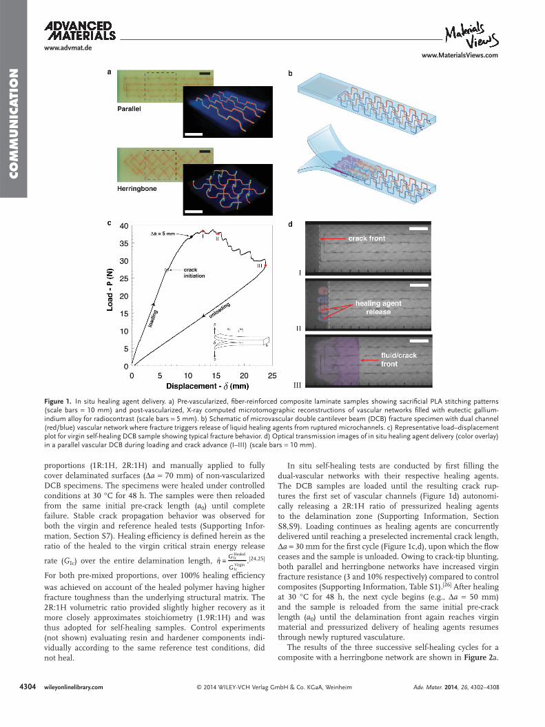
The results of the three successive self-healing cycles for a composite with a herringbone network are shown in Figure 2 a.
Adv. Mater. 2014, 26, 4302–4308
Figure 1. In situ healing agent delivery. a) Pre-vascularized, fi ber-reinforced composite laminate samples showing sacrifi cial PLA stitching patterns (scale bars = 10 mm) and post-vascularized, X-ray computed microtomographic reconstructions of vascular networks fi lled with eutectic gallium-indium alloy for radiocontrast (scale bars = 5 mm). b) Schematic of microvascular double cantilever beam (DCB) fracture specimen with dual channel (red/blue) vascular network where fracture triggers release of liquid healing agents from ruptured microchannels. c) Representative load–displacement plot for virgin self-healing DCB sample showing typical fracture behavior. d) Optical transmission images of in situ healing agent delivery (color overlay) in a parallel vascular DCB during loading and crack advance (I–III) (scale bars = 10 mm).
4305
www.advmat.dewww.MaterialsViews.com
wileyonlinelibrary.com© 2014 WILEY-VCH Verlag GmbH & Co. KGaA, Weinheim
CO
MM
UN
ICATIO
N
Remarkably, after each healing cycle, higher loads are required to propagate the crack. Figure 2 b presents a comparison of the cyclic self-healing response for both vascular architectures. We calculate the recovery of fracture energy G I (Equation 2 ) for each cycle using the area method. [ 27 ] For the herringbone network, the recovered fracture energy increased with each cycle, leading to healing effi ciencies greater than 100%. The increased performance of the interpenetrating herringbone vas-culature over the isolated parallel confi guration, particularly in the fi rst heal cycle, is attributed to improved fl uid interspersion in the fracture plane. Importantly, the herringbone “mixing” geometry with 2R:1H delivery closely approximating stoichiom-etry, approaches the maximum values established in pre-mixed, manual (reference) tests.
Microstructural anaylsis was conducted to reveal in situ delam-ination recovery mechanisms for the two-part healing system. Scanning electron micrographs (SEM) of the fracture plane from successive regions of a herringbone DCB sample after self-healing cycle � are provided in Figure 2 c. A representative image from the Δ a = 0–30 mm region of the crack plane reveals a landscape indicative of the accumulation of solid, fractured polymer over three cycles of healing agent delivery. Less polymer is observed in the Δ a = 30–50 mm region (two cycles of delivery experienced) where underlying, debonded glass fi bers are clearly
visible. The rupturing of glass fi bers, i.e., fi ber-bridging, pro-vides another energy absorption mechanism that contributes to damage recovery. [ 3,28 ] Finally, in a representative image from the Δ a = 50–70 mm region (one cycle of delivery), a portion of the fracture surface is overlaid with only partially polymerized healing agents (smooth surface), providing evidence of reduced mixing and lower healing effi ciencies in regions of close proximity to the terminal crack front.
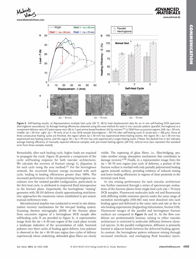
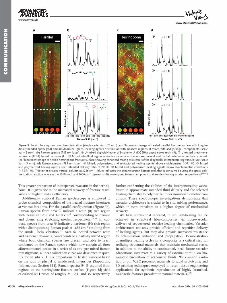
In situ mixing performance for each vascular architecture was further examined through a series of spectroscopic evalua-tions of the fracture planes from single-heal cycle (Δ a = 70 mm) DCB samples. Fluorescent molecules (nile red and fl uorescein) with differing visible emission spectra under the same range of excitation wavelengths (450–465 nm) were dissolved into each healing agent and delivered at the same ratio and rate as the in situ healing experiments (Supporting Information, Section S10). Fluorescent images of the parallel and herringbone fracture surfaces are compared in Figure 3 a and 3 c. As the fl ow con-ditions are predominately laminar, mixing in either vascular architecture is restricted to molecular diffusion between chem-ical species. In the parallel confi guration, diffusion is primarily limited to adjacent bands between the delivered healing agents. In contrast, the herringbone pattern enhances mixing through increased interfacial, and overlapping fl uid boundary layers.
Adv. Mater. 2014, 26, 4302–4308
Figure 2. Self-healing results. a) Representative multiple heal cycle (30 °C, 48 h) load–displacement data for an in situ self-healing DCB specimen (herringbone vasculature). b) Average healing effi ciencies obtained using the area method for each in situ vascular pattern (parallel, herringbone) at a component delivery ratio of 2-parts epoxy resin (R) to 1-part amine based hardener (H) by volume. [ 27 ] c) SEM from successive regions (left: Δ a = 30 mm, middle: Δ a = 50 mm, right: Δ a = 70 mm) of an in situ DCB sample (herringbone – 2R:1H) after self-healing cycle � (scale bars = 300 μm). Once all three consecutive healing cycles are fi nished, the region where Δ a ≤ 30 mm has experienced three healing events, the region 30 < Δ a ≤ 50 mm has experienced two healing events, and the region 50 < Δ a ≤ 70 mm has only experienced a single healing event. [*Note: the dashed line in (b) indicates average healing effi ciency of manually repaired reference samples with pre-mixed healing agents (2R:1H); vertical error bars represent the standard error from three samples tested].
4306
www.advmat.dewww.MaterialsViews.com
wileyonlinelibrary.com © 2014 WILEY-VCH Verlag GmbH & Co. KGaA, Weinheim
CO
MM
UN
ICATI
ON
This greater proportion of interspersed reactants in the herring-bone DCB gives rise to the increased recovery of fracture resist-ance and higher healing effi ciency.
Additionally, confocal Raman spectroscopy is employed to probe chemical composition of the healed fracture interfaces at various locations. For the parallel confi guration (Figure 3 b), Raman spectra from area � indicate a resin (R) rich region with peaks at 1256 and 1610 cm −1 corresponding to oxirane and phenyl ring stretching modes, respectively. [ 29,30 ] In con-trast, spectra from area � indicate a hardener (H) rich region with a distinguishing Raman peak at 1656 cm −1 resulting from the amide-I helix vibration. [ 31 ] Area � located between resin and hardener channels, corresponds to a partially mixed region where both chemical species are present and able to react, confi rmed by the Raman spectra which now contain all three aforementioned peaks. In a series of ex situ, pre-mixed Raman investigations, a linear calibration curve was developed to quan-tify the in situ R:H mix proportions of healed material based on the ratio of phenyl to amide peak intensities (Supporting Information, Section S11). Raman spectra �–� acquired from regions on the herringbone fracture surface (Figure 3 d) yield calculated R:H ratios of roughly 3:1, 2:1, and 3:2 respectively,
further confi rming the abilities of the interpenetrating vascu-lature to approximate intended fl uid delivery and the selected healing chemistry to polymerize under non-stoichiometric con-ditions. These spectroscopic investigations demonstrate that vascular architecture is crucial to in situ mixing performance, which in turn translates to a higher degree of mechanical recovery.
We have shown that repeated, in situ self-healing can be achieved in structural fi ber-composites via microvascular delivery of sequestered, reactive healing chemistries. Vascular architectures not only provide effi cient and repetitive delivery of healing agents, but they also provide increased resistance to delamination initiation and propagation. Demonstration of multiple healing cycles in a composite is a critical step for realizing structural materials that maintain mechanical stasis. In addition to the ability to continuously heal, future vascular adaptations may react to a variety of external stimuli via bio-mimetic circulation of responsive fl uids. We envision evolu-tion of our VaSC precursor materials to rapid prototyping and 3D printing techniques employed in recent tissue engineering applications for synthetic reproduction of highly branched, multiscale features prevalent in natural materials. [ 32 ]
Adv. Mater. 2014, 26, 4302–4308
Figure 3. In situ healing reaction characterization (single cycle, Δ a = 70 mm). (a) Fluorescent image of healed parallel fracture surface with longitu-dinally banded epoxy (red) and amidoamine (green) healing agents distribution with adjacent regions of mixed/diffused (orange) components (scale bar = 5 mm). (b) Raman spectra (785 nm laser). � Unmixed diglycidyl ether of bisphenol A (DGEBA) based epoxy resin (R), � Unmixed triethylene-tetramine (TETA) based hardener (H), � Mixed inter-fl uid region where both chemical species are present and partial polymerization has occurred. (c) Fluorescent image of healed herringbone fracture surface showing enhanced mixing as a result of the diagonally, interpenetrating vasculature (scale bar = 5 mm). (d) Raman spectra (785 nm laser). � Mixed, polymerized, and re-fractured healing agents above stoichiometry (≈3R:1H). � Mixed and polymerized healing agents near intended delivery ratio of 2R:1H. � Mixed and polymerized healing agents below stoichiometric conditions (≈ 1.5R:1H). [ * Note: the shaded vertical column at 1256 cm −1 (blue) indicates the oxirane stretch Raman peak that is consumed during the epoxy poly-merization reaction whereas the 1610 (red) and 1656 cm −1 (green) shifts correspond to invariant phenyl and amide vibratory modes, respectively]. [ 29–31 ]
4307
www.advmat.dewww.MaterialsViews.com
wileyonlinelibrary.com© 2014 WILEY-VCH Verlag GmbH & Co. KGaA, Weinheim
CO
MM
UN
ICATIO
N
Experimental Section Microvascular Specimen Fabrication : The VaSC procedure was used
to create microvascular networks in a woven fi ber-reinforced composite laminate. [ 11 ] Eight plies of an 8-harness (8H) satin weave E-glass fabric (Style 7781, Fibre Glast Developments Corp.) were stacked in a [90/0] 4 layup sequence. 300 μm sacrifi cial fi bers were prepared according to a modifi ed tin (II) oxalate catalyst incorporation procedure, and stitched through the textile reinforcement in respective parallel and herringbone vascular patterns using CAD generated templates which were removed post-stitching (Supporting Information, Section S1,S2). [ 11 ] Four additional layers of reinforcement were placed on both the top and bottom of the stitched preform in accordance to the alternating woven cross-ply stacking sequence. An ethylene tetrafl uoroethylene (ETFE) fi lm (25 μm thick) was placed at the midplane serving as a pre-crack and offset 7.5 mm from the closest fi ber stitch. Epoxy resin infi ltration (Araldite LY/Aradur 8605, 100:35 by wt., Hunstman Advanced Materials LLC) was achieved using vacuum assisted resin transfer molding (VARTM) at 38 Torr (abs) until complete fabric wetting and then decreased to 76 Torr (abs) for 36 h at room temperature (RT) = 23 °C until resin solidifi cation. The fi ber-composite panel was post-cured for 2 h at 121 °C followed by 3 h at 177 °C to yield a fi nal glass-transition temperature ( T g ≈ 150 °C) as measured by differential scanning calorimetry (Supporting Information, Section S5). DCB samples were cut using a diamond-blade wet saw from the 4 mm thick panel to approximately 30 mm wide and 180 mm long exposing the sacrifi cial fi ber cross sections. Air-dried composite samples were then placed in an oven for 36 h at 200 °C under 12 Torr (abs) vacuum. The evacuated vascular samples were removed, air-cooled to RT, and trimmed to fi nal areal dimensions of 27 mm wide by 155 mm long. The vasculature was then fl ushed with water, followed by ethyl alcohol, and fi nally compressed air. Brass hinges (25 mm × 25 mm, McMaster-Carr) were bonded to outer composite faces on the pre-crack end using a high-strength structural adhesive (Scotch-Weld DP 460, 3M) and allowed to cure for 48 h at RT. One side (4 mm × 155 mm) of the DCB sample was spray painted white and allowed to air-dry at RT for 48 h. Delineations of 5 mm were marked on both the painted side and coincident top edge beginning at the interior pre-crack interface and extending along the vascular segment (95 mm) to the end of the sample.
Fracture test : Individual cantilever arms of the microvascular fi ber-composite DCB specimens were loaded through the bonded hinges in quasi-static tension to induce mode-I fracture propagation along the mid-ply interlaminar region. The initial pre-crack region ( a 0 ) from the hinge-loading line to the interior ETFE fi lm termination interface was ≈ 46 mm. Top and side CCD cameras (A631fc, Basler AG) with mexapixel lenses (LM16HC, Kowa Optimed, Inc.) were mounted in the testing area to monitor delamination propagation and capture images (1024 × 768 pixels, Mono8) every 1 s for crack-length measurements (Supporting Information, Section S6). Displacement-controlled crosshead speed was (+)5 mm min −1 during loading and (−)25 mm min −1 for unloading. Time, load, displacement, and time-stamped image data for crack-length correlation was collected using LabVIEW (v. 2009, National Instruments) software.
Pressurized Fluid Delivery : In situ healing agent delivery through 300 μm diameter vascular networks was achieved via pressurized fl uid pumping (Supporting Information, Section S8,S9). Precision stainless steel (310 μm OD, 150 μm ID) micro-dispense tips (part # 7018424, Nordson EFD) were inserted into the vascular orifi ces and connected via laboratory tubing (E-3603, Tygon) to 5 cc fl uid syringe barrel reservoirs with internal pistons (part # 7012096, Nordson EFD). Pressure was supplied to individual syringe barrels ( 2 ) containing separate healing agents using two high precision, compressed-air powered fl uid dispensing units (Ultimus V, Nordson EFD). The electronically pressure regulated fl uid dispensers were controlled using LabVIEW (v. 2009, National Instruments) software.
Fracture analysis : Calculations of mode-I strain energy release rate ( G I ), a measure of crack-growth resistance, were performed according to two independent methodologies. [ 23,27 ] G I calculations using modifi ed beam theory (MBT) were performed according to:
G
Pb a
32I
δΔ( )=
+ (1)
where P is the applied load, δ is the crosshead displacement, b is the specimen width, a is the total crack length ( a = a 0 + Δ a ), and | Δ | is a correction factor to account for non-zero rotation at the delamination front. [ 23,27 ] This correction factor, | Δ |, is defi ned as the absolute value of the x -intercept of the line generated from a least squares plot of the cube root of compliance, C 1/3 = ( δ / P ) 1/3 , versus crack length ( a ).
G I calculations using the area method were performed according to the expression: [ 27 ]
IG
Ub a
= ΔΔ
(2)
where Δ U is the change in internal work or strain energy due to elastic bending in the cantilever arms, and derived from fi rst energy principles as the area under the load–displacement curve at a particular incremental crack length (Δ a ):
U P ad
0
�∫ δΔ =δ
Δ
(3)
The healing effi ciency, η̂, is defi ned as the ability of a healed sample
to recover crack growth resistance: [ 24,25 ]
ˆ Ic
Healed
IcVirgin
G
Gη ≡
(4)
For the MBT calculations, Ic
VirginG is the average virgin critical strain energy release rate over a delamination length and Ic
HealedG is the average healed critical strain energy release rate over the same delamination. For the area method, as the specimen width and incremental crack length are equivalent, the healing effi ciency defi nition reduces to a canonical expression involving only the ratio of areas under the load–displacement curves:
ˆ
Healed
VirginUU
η = ΔΔ
(5)
Fluorescence Imaging : Post-heal (30 °C, 48 h) mid-plane fracture surface images (Figure 3 a,c) were acquired on a CCD camera (A631fc, Basler AG) with a longpass optical fi lter (>500 nm, O.D. 2) placed over the 50 mm lens to eliminate light from the LED (450–465 nm) excitation source (Supporting Information, Section S10).
Confocal Raman Spectroscopy : Raman scattering spectra were acquired on a HORIBA LabRAM HR confocal system with Lab-Spec 5 (v. 5.78.24) spectroscopy software suite using a 785 nm near-IR laser source. Ex situ experiments were conducted under the following acquisition parameters: Confocal hole diameter: 500 μm; Slit width: 100 μm; Diffraction grating: 300 grooves mm −1 blazed at 600 nm; Objective: 20×, NA: 0.4; Exposure: 10 s. (Resulting spot size: 10 μm.) For the in situ experiments, the spot size was reduced from 10 to 2 μm while maintaining similar peak intensities to the ex situ samples by augmenting the following acquisition parameters: Objective: 100×, NA: 0.8; Exposure: 120 s (Supporting Information, Section S11). Ex situ Raman spectra acquired from DCB composite matrix material do not show the amide-I band at 1656 cm −1 , which is spectrally present in the healed polymer, and thus the two were easily distinguished during in situ experiments.
X-ray Computed Microtomography : X-ray computed microtomographic (μCT) images are acquired on an Xradia MicroXCT-400 after fi lling the empty microvascular networks with liquid, eutectic gallium–indium alloy (EGaIn: 76% Ga – 24% In, by weight) serving as a radiocontrast agent. 202° scans are obtained in rotation intervals of 0.25° using a 0.5× objective at 1 s exposure times with 80 keV (8 W, 100 μA). 3D image reconstructions are performed using Xradia TXM Reconstructor software (v. 7.0.2817).
Supporting Information Supporting Information is available from the Wiley Online Library or from the author.
Adv. Mater. 2014, 26, 4302–4308
4308
www.advmat.dewww.MaterialsViews.com
wileyonlinelibrary.com © 2014 WILEY-VCH Verlag GmbH & Co. KGaA, Weinheim
CO
MM
UN
ICATI
ON
Adv. Mater. 2014, 26, 4302–4308
Acknowledgements This work has been fi nancially supported by the Air Force Offi ce of Scientifi c Research (grant number FA9550–10–1–0255), the Department of Homeland Security (DHS) Center of Excellence for Explosives Detection, Mitigation, and Response (award number 2008-ST-061-ED0002), the Army Research Laboratory (grant number W911NF-08–2–0010), and the National Science Foundation Division of Materials Research (grant number 10–39479 EQ). The authors extend their gratitude to the following people: Laura Richardson, undergraduate research assistant in Aerospace Engineering (UIUC) for assistance with composite preform fabrication. Jacques Poincloux of Huntsman Advanced Materials LLC for material procurement. Dr. Chris Mangun of CU Aerospace for peer-review and research discussions. J.F.P carried out the experiments and analyses. N.R.S., S.R.W., and J.F.P. conceived the microvascular specimen. N.R.S. and S.R.W. directed the research. K.R.H. obtained the scanning electron micrographs and assisted with composite fabrication. B.P.K. performed the LabVIEW programming and rheometry. J.S.M. and C.E.D. provided expertise and assistance with Raman spectroscopy and fl uorometry. All authors participated in discussions of the research and wrote the manuscript.
Received: January 16, 2014 Revised: February 28, 2014
Published online: April 14, 2014
[1] S. S. Kessler , S. M. Spearing , M. J. Atalla , C. E. S. Cesnik , C. Soutis , Composites, Part B 2002 , 33 , 87 .
[2] A. J. Patel , N. R. Sottos , E. D. Wetzel , S. R. White , Composites, Part A 2010 , 41 , 360 .
[3] J. Kim , M. Sham , Compos. Sci. Technol. 2000 , 60 , 745 . [4] V. P. Veedu , A. Cao , X. Li , K. Ma , C. Soldano , S. Kar , P. M. Ajayan ,
M. N. Ghasemi-Nejhad , Nat. Mater. 2006 , 5 , 457 . [5] K. Senthil , A. Arockiarajan , R. Palaninathan , B. Santhosh ,
K. M. Usha , Compos. Struct. 2013 , 106 , 139 . [6] B. J. Blaiszik , S. L. B. Kramer , S. C. Olugebefola , J. S. Moore ,
N. R. Sottos , S. R. White , Annu. Rev. Mater. Res. 2010 , 40 , 179 .
[7] M. R. Kessler , N. R. Sottos , S. R. White , Composites, Part A 2003 , 34 , 743 .
[8] S. Meure , S. Furman , S. Khor , Macromol. Mater. Eng. 2010 , 295 , 420 .
[9] C. J. Norris , J. A. P. White , G. McCombe , P. Chatterjee , I. P. Bond , R. S. Trask , Smart Mater. Struct. 2012 , 21 , 1 .
[10] C. J. Norris , I. P. Bond , R. S. Trask , Composites, Part A 2013 , 44 , 78 .
[11] A. P. Esser-Kahn , P. R. Thakre , H. Dong , J. F. Patrick , V. K. Vlasko-Vlasov , N. R. Sottos , J. S. Moore , S. R. White , Adv. Mater. 2011 , 23 , 3654 .
[12] P. J. Withers , M. Preuss , Annu. Rev. Mater. Res. 2012 , 42 , 81 . [13] X. Chen , M. A. Dam , K. Ono , A. Mal , H. Shen , S. R. Nutt , K. Sheran ,
F. Wudl , Science 2002 , 295 , 1698 . [14] S. R. White , N. R. Sottos , P. H. Geubelle , J. S. Moore , M. R. Kessler ,
S. R. Sriram , E. N. Brown , S. Viswanathan , Nature 2001 , 409 , 794 .
[15] K. S. Toohey , N. R. Sottos , J. A. Lewis , J. S. Moore , S. R. White , Nat. Mater. 2007 , 6 , 581 .
[16] K. S. Toohey , C. J. Hansen , J. A. Lewis , S. R. White , N. R. Sottos , Adv. Funct. Mater. 2009 , 19 , 1399 .
[17] C. J. Hansen , W. Wu , K. S. Toohey , N. R. Sottos , S. R. White , J. A. Lewis , Adv. Mater. 2009 , 21 , 4143 .
[18] A. R. Hamilton , N. R. Sottos , S. R. White , Adv. Mater. 2010 , 22 , 5159 .
[19] A. R. Hamilton , N. R. Sottos , S. R. White , J. R. Soc. Interface 2012 , 9 , 1020 .
[20] D. Therriault , S. R. White , J. A. Lewis , Nat. Mater. 2003 , 2 , 265 . [21] J. W. C. Pang , I. P. Bond , Compos. Sci. Technol. 2005 , 65 , 1791 . [22] C. J. Norris , G. J. Meadway , M. J. O’Sullivan , I. P. Bond , R. S. Trask ,
Adv. Funct. Mater. 2011 , 21 , 3624 . [23] Handbook of the American Society for Testing and Materials: Standard
D-5528 , ASTM International , West Conshohocken, PA, USA 2007 . [24] E. N. Brown , N. R. Sottos , S. R. White , Exp. Mech. 2002 , 42 ,
372 . [25] J. D. Rule , E. N. Brown , N. R. Sottos , S. R. White , J. S. Moore , Adv.
Mater. 2005 , 17 , 205 . [26] A. Kousourakis , A. P. Mouritz , M. K. Bannister , Compos. Struct.
2006 , 75 , 610 . [27] S. Hashemi , A. J. Kinloch , J. G. Williams , J. Mater. Sci. Lett. 1989 ,
8 , 125 . [28] N. Alif , L. A. Carlsson , L. Boogh , Composites, Part B 1998 , 29 , 603 . [29] S. Farquharson , W. Smith , J. Rose , M. Shaw , J. Process Anal. Chem.
2002 , 7 , 45 . [30] L. Merad , M. Cochez , S. Margueron , F. Jauchem , M. Ferriol ,
B. Benyoucef , P. Bourson , Polym. Test. 2009 , 28 , 42 . [31] N. C. Maiti , M. M. Apetri , M. G. Zagorski , P. R. Carey ,
V. E. Anderson , J. Am. Chem. Soc. 2004 , 126 , 2399 . [32] J. S. Miller , K. R. Stevens , M. T. Yang , B. M. Baker , D. T. Nguyen ,
D. M. Cohen , E. Toro , A. A. Chen , P. A. Galie , X. Yu , R. Chaturvedi , S. N. Bhatia , C. S. Chen , Nat. Mater. 2012 , 11 , 768 .