Embed Size (px)
Citation preview

1000 Park Drive • Lawrence, PA 15055-1018 • 724-746-5500 • Fax 724-746-0746
© Copyright 1998. Black Box Corporation. All rights reserved.

Order toll-free in the U.S.: Call 877-877-BBOX (outside U.S. call 724-746-5500)FREE technical support 24 hours a day, 7 days a week: Call 724-746-5500 or fax 724-746-0746Mailing address: Black Box Corporation, 1000 Park Drive, Lawrence, PA 15055-1018Web site: www.blackbox.com • E-mail: [email protected]
CUSTOMER SUPPORT
INFORMATION
AUGUST 1998LB3104A-AUI-R3 LB3135A-AUI-R3 LB3804A-AUI-R3 LB3835A-AUI-R3LB3104A-BNC-R3 LB3135A-BNC-R3 LB3804A-BNC-R3 LB3835A-BNC-R3LB3104A-BT-R3 LB3135A-BT-R3 LB3804A-BT-R3 LB3835A-BT-R3LB3124A-AUI-R3 LB3136A-AUI-R3 LB3824A-AUI-R3 LB3836A-AUI-R3LB3124A-BNC-R3 LB3136A-BNC-R3 LB3824A-BNC-R3 LB3836A-BNC-R3LB3124A-BT-R3 LB3136A-BT-R3 LB3824A-BT-R3 LB3836A-BT-R3
Ethernet ExtendersConfiguration Guide
ETHERNET EXTENDER
CONTROL
RESET
READYPOWER
REMOTE
MAINLINK
LAN
ERRRx
Tx


FCC INFORMATION
1
FEDERAL COMMUNICATIONS COMMISSIONAND
INDUSTRY CANADARADIO FREQUENCY INTERFERENCE STATEMENTS
This equipment generates, uses, and can radiate radio-frequency energy, and if not installed and usedproperly, that is, in strict accordance with the manufacturer’s instructions, may cause interference to radiocommunication. It has been tested and found to comply with the limits for a Class A computing device inaccordance with the specifications in Subpart B of Part 15 of FCC rules, which are designed to providereasonable protection against such interference when the equipment is operated in a commercialenvironment. Operation of this equipment in a residential area is likely to cause interference, in which case the user at his own expense will be required to take whatever measures may be necessary to correct the interference.
Changes or modifications not expressly approved by the party responsible for compliance could void the user’sauthority to operate the equipment.
This digital apparatus does not exceed the Class A limits for radio noise emission from digital apparatus set out in the RadioInterference Regulation of Industry Canada.
Le présent appareil numérique n’émet pas de bruits radioélectriques dépassant les limites applicables aux appareils numériquesde la classe A prescrites dans le Règlement sur le brouillage radioélectrique publié par Industrie Canada.

ETHERNET EXTENDERS—CONFIGURATION GUIDE
2
INSTRUCCIONES DE SEGURIDAD (Normas Oficiales Mexicanas Electrical Safety Statement)1. Todas las instrucciones de seguridad y operación deberán ser leídas antes de que el aparato eléctrico sea operado.
2. Las instrucciones de seguridad y operación deberán ser guardadas para referencia futura.
3. Todas las advertencias en el aparato eléctrico y en sus instrucciones de operación deben ser respetadas.
4. Todas las instrucciones de operación y uso deben ser seguidas.
5. El aparato eléctrico no deberá ser usado cerca del agua—por ejemplo, cerca de la tina de baño, lavabo, sótanomojado o cerca de una alberca, etc..
6. El aparato eléctrico debe ser usado únicamente con carritos o pedestales que sean recomendados por el fabricante.
7. El aparato eléctrico debe ser montado a la pared o al techo sólo como sea recomendado por el fabricante.
8. Servicio—El usuario no debe intentar dar servicio al equipo eléctrico más allá a lo descrito en las instrucciones deoperación. Todo otro servicio deberá ser referido a personal de servicio calificado.
9. El aparato eléctrico debe ser situado de tal manera que su posición no interfiera su uso. La colocación del aparatoeléctrico sobre una cama, sofá, alfombra o superficie similar puede bloquea la ventilación, no se debe colocar enlibreros o gabinetes que impidan el flujo de aire por los orificios de ventilación.
10. El equipo eléctrico deber ser situado fuera del alcance de fuentes de calor como radiadores, registros de calor, estufasu otros aparatos (incluyendo amplificadores) que producen calor.
11. El aparato eléctrico deberá ser connectado a una fuente de poder sólo del tipo descrito en el instructivo deoperación, o como se indique en el aparato.
12. Precaución debe ser tomada de tal manera que la tierra fisica y la polarización del equipo no sea eliminada.
13. Los cables de la fuente de poder deben ser guiados de tal manera que no sean pisados ni pellizcados por objetoscolocados sobre o contra ellos, poniendo particular atención a los contactos y receptáculos donde salen del aparato.
14. El equipo eléctrico debe ser limpiado únicamente de acuerdo a las recomendaciones del fabricante.
15. En caso de existir, una antena externa deberá ser localizada lejos de las lineas de energia.
16. El cable de corriente deberá ser desconectado del cuando el equipo no sea usado por un largo periodo de tiempo.
17. Cuidado debe ser tomado de tal manera que objectos liquidos no sean derramados sobre la cubierta u orificios deventilación.
18. Servicio por personal calificado deberá ser provisto cuando:
A: El cable de poder o el contacto ha sido dañado; u
B: Objectos han caído o líquido ha sido derramado dentro del aparato; o
C: El aparato ha sido expuesto a la lluvia; o
D: El aparato parece no operar normalmente o muestra un cambio en su desempeño; o
E: El aparato ha sido tirado o su cubierta ha sido dañada.

TRADEMARKS USED AND TELECOMMUNICATION SAFETY
3
TRADEMARKS USED IN THIS MANUAL
Any trademarks mentioned in this manual are acknowledged to be the property of the trademark owners.
Telecommunication SafetyThe safety status of each of the ports on the Ethernet Extender is declared according to EN 41003 and isdetailed in the table below:
Safety Status PortsSELV V.24, V.35, V.36, LANTNV-1 4W
SELV = Safety Extra-Low VoltageTNV-1 = Telecommunications Network Voltage within the limits of SELV and subject to overvoltages

ETHERNET EXTENDERS—CONFIGURATION GUIDE
4
ContentsChapter Page
1. Introduction ............................................................................................................................................................61.1 A General Description ............................................................................................................................61.2 How “Single IP” Address Translation Works ..........................................................................................7
1.2.1 What Single IP Does ..........................................................................................................................71.2.2 The Benefits of Single IP....................................................................................................................8
1.3 Solid Firewall ............................................................................................................................................91.4 Ethernet Extender Features ....................................................................................................................91.5 Ethernet Extender Applications ..........................................................................................................11
1.5.1 Bridging ............................................................................................................................................111.5.2 4-Wire Modem ..................................................................................................................................111.5.3 Single IP ............................................................................................................................................12
2. Configuration Introduction ..................................................................................................................................132.1 How to Start Configuring the Ethernet Extender ..............................................................................13
2.1.1 Connecting to the Internet/Intranet as a Public IP Net ..............................................................132.1.2 Connecting to the Internet/Intranet as a Private IP Net (Using Single IP)................................14
2.2 Initial Setup ............................................................................................................................................152.2.1 Connecting to the Terminal ............................................................................................................152.2.2 Setting a Password ............................................................................................................................162.2.3 Changing and Deleting the Password ............................................................................................16
2.3 The Quick Setup Menu ........................................................................................................................172.4 Menus and Screens ................................................................................................................................17
2.4.1 The Main Menu ................................................................................................................................172.4.2 Quick Setup ......................................................................................................................................172.4.3 Security Setup ..................................................................................................................................172.4.4 Advanced Menu ................................................................................................................................182.4.5 View....................................................................................................................................................182.4.6 Diagnostic Tools................................................................................................................................182.4.7 Exit ....................................................................................................................................................18
3. Quick Setup Menu ................................................................................................................................................193.1 Quick Setup Menu Parameters ............................................................................................................19
3.1.1 Link Mode ........................................................................................................................................213.1.2 Routing ..............................................................................................................................................213.1.3 Connection........................................................................................................................................213.1.4 WAN IP Address................................................................................................................................213.1.5 BOOTP Address................................................................................................................................213.1.6 Modem Type ....................................................................................................................................213.1.7 Baud Rate ..........................................................................................................................................213.1.8 Host IP Setup ....................................................................................................................................223.1.9 Security Setup ..................................................................................................................................23
3.2 Where To Go From Here ......................................................................................................................24

CONTENTS
5
Chapter Page
4. Security Setup Menu..............................................................................................................................................254.1 Enabling TELNET Access......................................................................................................................264.2 Enabling SNMP Access ..........................................................................................................................274.3 Enabling/Disabling the Solid Firewall ................................................................................................28
5. Advanced Setup Menu ..........................................................................................................................................305.1 Advanced Menu and Setup Menu ........................................................................................................305.2 Device Control Menu ............................................................................................................................795.3 List of Operations ..................................................................................................................................85
Appendix A: Important ISDN Issues (For U.S. Users Only) ....................................................................................89A.1 Which ISDN Service Should You Order? ............................................................................................89A.2 Ordering ISDN ......................................................................................................................................89A.3 Provisioning ISDN..................................................................................................................................89A.4 ISDN Parameters ....................................................................................................................................89
Appendix B: BOOT Manager ....................................................................................................................................92B.1 Preface ....................................................................................................................................................92B.2 Accessing BOOT Manager ....................................................................................................................92
B.2.1 Access via Software Download Menu ..............................................................................................92B.2.2 Rescue................................................................................................................................................93
B.3 The BOOT Manager Menu ..................................................................................................................93B.3.1 Load New Software ..........................................................................................................................94B.3.2 Partitions Status ................................................................................................................................94B.3.3 Run Second Partition ......................................................................................................................94B.3.4 Reactivate Second Partition ............................................................................................................95B.3.5 Duplicate First Partition ..................................................................................................................95B.3.6 Erase Configuration..........................................................................................................................95B.3.7 Erase All FLASH ..............................................................................................................................95B.3.8 Set Baud Rate ....................................................................................................................................95B.3.9 Exit ....................................................................................................................................................96

ETHERNET EXTENDERS—CONFIGURATION GUIDE
6
1. IntroductionEthernet Extenders can be used for various bridging and routing functions, and can connect an Ethernet orToken Ring LAN to the Internet or Intranet via ISDN, Frame Relay, asynchronous or synchronous dialup, orDigital Data Service (DDS) links operating at data rates up to 1.5 Mbps.
This manual gives a general introduction to the Ethernet Extender and describes how to configure it. Forinformation about the physical features or installing Ethernet Extenders, refer to the Ethernet ExtenderInstallation and Operation Guide.
1.1 A General DescriptionEthernet Extenders are standalone bridges and IP/IPX routers for the small office. Quick setup and advancedconfiguration menus provide on-screen instructions that guide you through the configuration procedures.
The Ethernet Extender features:
• Bridging.
• IP Routing.
• IPX Routing.
• Address Translation.
• Firewall.
Bridging
The Ethernet Extender supports standard bridging functions. Because bridging is the Ethernet Extender’sdefault, you can use the Ethernet Extender as a bridge with little or no configuration.
IP Routing
The Ethernet Extender is an IP router that supports:
• Static IP net configuration.
• Dynamic IP net learning using the RIP and RIP-2 protocols.
• CIDR topologies.
• Multiple IP nets on the LAN or WAN interfaces.
• Numbered and unnumbered I/F.
• IP fragmentation.
IPX Routing
In addition to IP routing, the Ethernet Extender also supports standard IPX routing and includes support forRIP and SAP.

CHAPTER 1: Introduction
7
1.2 How “Single IP” Address Translation WorksSingle IP allows users in a small-office LAN to connect to the Internet/Intranet quickly and transparently withjust one assigned IP address.
1.2.1 WHAT SINGLE IP DOES
Single IP is an Ethernet Extender feature that translates multiple IP addresses on a small-office LAN to onesingle IP address on the Internet.
Figure 1-1. IP connection to the Ethernet Extender.
Normally, a LAN requires a complete statically assigned, unique and legal subnet, with one IP address for everystation, in order to connect to the Internet or Intranet. Single IP allows an entire small office to connect to theInternet or corporate intranet using only one dynamically or statically assigned IP address received from theISP via a dial-up modem, ISDN connection, leased line, DDS, or Frame Relay line.
Figure 1-2. Ethernet Extender with Single IP enabled.
Small Office
Ethernet
Ethernet Extender
Internet (ISP)or Intranet
IP1
IP2
IP3
IP4
EthernetExtenderSingle IP
IPInternet/Intranet

ETHERNET EXTENDERS—CONFIGURATION GUIDE
8
Configure the Ethernet Extender to dial an Internet/Intranet Access Router and to supply a user name andpassword over PPP. The Internet/Intranet Access Router automatically supplies the Ethernet Extender with asingle temporary IP address using the IPCP protocol—the same way that a single PC would connect directly tothe ISP.
You can connect a complete small-office LAN with a private subnet to the Ethernet Extender. Through theEthernet Extender you can access the Internet/Intranet. The Internet/Intranet provider does not need tospecially coordinate with the office or allocate subnets.
Figure 1-3. Ethernet Extender in Single IP Mode.
1.2.2 THE BENEFITS OF SINGLE IP
• Allows a small office to connect to the Internet/Intranet in the same way as a single PC.
• Requires only one legal IP address.
• Obtains a single legal IP address from the Internet/Intranet Access Router using standard IPCP.
• Allows a small office to access any public IP subnet.
• Allows Web browsing, FTP, Telnet, e-mail, news and other IP applications using any TCP/IP stack on anytype of station in the small office.
• Provides security against Internet hackers using the Solid Firewall feature.
• Allows automatic connection and disconnection of the link based on actual or specific use of theInternet/Intranet.
• Allows filtering of traffic on the link to reduce waste of bandwidth and to improve security.
Private Subnet 192.168.1.RFC 1918
16 potential users3 concurrent users (.4, .11, .14)
Ethernet Extender(Single IP feature enabled)
192.168.1.1.
Ethernet ExtenderISDNFR
PSTNLeased Line
Central AccessRouter
Internet/Intranet

CHAPTER 1: Introduction
9
IP Applications: Web Browsing, FTP, Telnet, E-mail, News and Others
Single IP allows the use of any Web browser, such as Netscape or Internet Explorer, to access the World-WideWeb. Refer to the list below for some of the types of Internet and Intranet access supported by Single IP:
• World Wide Web browsing.
• E-mail.
• FTP client.
• News reader.
• Telnet client.
• Ping (outbound).
Single IP supports any SOCKS-compatible client application (for example, Netscape). Access to FTP withinNetscape, Gopher access, and access to secure servers is also supported. POP3 clients (for example, Eudora,Pegasus mail, Microsoft Exchange) and other e-mail packages and news readers are allowed access to e-mailservers through Single IP e-mail support.
Single IP allows use of FTP client applications that support the username@hostname method of firewallcrossing; for example, WS_FTP, CuteFTP, and command-line FTP clients. Connection through another firewallusing the same mechanism is also allowed.
1.3 Solid FirewallThe Solid Firewall feature prevents access from the Internet/Intranet into the small-office LAN. This featuremakes the small-office LAN invisible to outside users. The Solid Firewall feature is a simple and foolproof way ofprotecting security sensitive small offices (for example, doctors and lawyers) from Internet hackers. Refer toChapter 4 for more information about the Firewall.
1.4 Ethernet Extender Features• Supports bridging.
• Supports IP, IPX, and IP+IPX routing.
• Supports Single IP feature (IP Address Translation) which allows a user to connect to the Internet/Intranet.
• Supports static nets and multi-nets. Refer to Chapter 5.
• Supports IP fragmentation. Refer to Chapter 5.
• PPP multi-link support enables maximum utilization of ISDN lines. Refer to Chapter 5.
• Supports bandwidth on demand (BOD). Refer to Chapter 5.
• Integral Frame Relay operating at data rates up to T1. Refer to Chapter 5.
• Supports 4-wire, asynchronous, synchronous, ISDN and CSU/DSU WAN interfaces.
• Supports Token Ring, 10BASE2, 10BASE5, or 10BASE-T LAN interface.

ETHERNET EXTENDERS—CONFIGURATION GUIDE
10
• Supports backup links for bridge and router links.
• Supports TELNET, allowing configuration and control of the device over WAN and LAN. Refer toChapter 3.
• Supports RADIUS. Refer to Chapter 5.
• Fast configuration can be performed from a terminal emulator, and via TELNET. Refer to Chapter 3.
• An SNMP agent provides management by any standard SNMP management station. Refer to Chapter 5.
• Software downloading is available using XMODEM or TFTP. Refer to Chapter 5.
• Dual-image flash enables downloading two software versions. Refer to Chapter 5.
• Independent ISDN code downloading is available using XMODEM. Refer to Chapter 5.
• Indicates ISDN link integrity. Refer to Chapter 5.
• Connection on Demand feature reduces WAN costs. Refer to Chapter 5.
• PAP/CHAP provides access authentication. Refer to Chapter 5.
• Solid Firewall feature allows the user to block all access from the outside into the LAN. Refer to Chapter 4.
• Undesired access to Ethernet Extender via TELNET or SNMP can also be blocked or password-protected.Refer to Chapter 4.

CHAPTER 1: Introduction
11
1.5 Ethernet Extender ApplicationsThe Ethernet Extender can be used in a large variety of applications. Some examples follow.
1.5.1 BRIDGING
Two Ethernet Extenders can be used opposite each other in a standard bridging application. The EthernetExtender connected to the larger network or to a network with connections to other networks, is the MainEthernet Extender. The Ethernet Extender connected to the smaller network is the Remote Ethernet Extender.Refer to Figure 1-4.
Figure 1-4. Standard Bridging Application.
1.5.2 4-WIRE MODEM
The Ethernet Extender has a built-in 4-wire modem and can be used for one or more PCs to connect to eachother or to the Internet. Refer to Figure 1-5.
Figure 1-5. Connecting to the Ethernet Extender via a 4-Wire Modem.
4-Wire Modem4-Wire Modem
Ethernet Extender
PC
Internet
Internet
Router
Ethernet Extender Ethernet Extender
RemoteMain

ETHERNET EXTENDERS—CONFIGURATION GUIDE
12
1.5.3 SINGLE IP
The Ethernet Extender can be used as a point of presence on the Internet. A home user can dial in to theEthernet Extender, and use the Ethernet Extender Single IP feature to access the Internet. Refer to Figure 1-6.
Figure 1-6. Ethernet Extender Using Single IP.
Internet
ISPWAN
Home User
Solid Firewall
Single IP Enabled Ethernet Extender

CHAPTER 2: Configuration Introduction
13
2. Configuration Introduction2.1 How to Start Configuring the Ethernet ExtenderThe Ethernet Extender can be configured as either a bridge or a router. By default, it’s configured in bridgemode. Decide whether the Ethernet Extender will be used as a bridge or a router before you start theconfiguration.
Before you configure the Ethernet Extender as a bridge, set the location switch to Remote or Main. One of thetwo Ethernet Extenders in the bridge must have the location switch set to Remote and the other set to Main:
• Remote—If the Ethernet Extender you are configuring as a bridge is connected to the network that issmaller, and has no connections via a router to other networks.
• Main—If the Ethernet Extender you are configuring as a bridge is connected to the network that is largeror has connections via a router to other networks.
For more information, refer to the Ethernet Extender Installation and Operation Guide.
Before you configure the Ethernet Extender as a router, follow the appropriate checklists, listed below.
NOTEIf you are using the Ethernet Extender as a router, set the location switch to Main. Formore information, refer to the Ethernet Extender Installation and Operation Guide.
2.1.1 CONNECTING TO THE INTERNET/INTRANET AS A PUBLIC IP NET
Use the following check list to make sure you are ready to connect to the Internet/Intranet.
Internet Check List
• Subscribe to the Internet Service Provider (ISP) and request a static IP subnet.
• Request a dialup telephone number, your username, and your password from the ISP. Configure this intothe Ethernet Extender using the Quick Setup option. Check whether a login script is necessary to access theISP. If it is, call Technical Support.
• Disable the Single IP in the Ethernet Extender Quick Setup option.
• Make sure the line (ISDN, PSTN, Frame Relay, or DDS) to the ISP is working properly.
• Use the static IP subnet you have obtained to configure the LAN IP host addresses of the EthernetExtender.

ETHERNET EXTENDERS—CONFIGURATION GUIDE
14
Preparing Your PCs
• Make sure your PCs have a correctly installed TCP/IP stack such as WinSock or Chameleon.
• Assign an IP address from the static IP subnet to each PC.
• Make sure that each PC has the correct subnet mask.
• Configure each PC with the Ethernet Extender as the Default Gateway.
• Configure each PC with the ISP’s DNS IP address.
• Check that your small-office LAN is correctly set up to work with IP.
2.1.2 CONNECTING TO THE INTERNET/INTRANET AS A PRIVATE IP NET (USING SINGLE IP)
Use the following checklist to make sure you are ready to connect to the Internet/Intranet.
Internet Check list
• Subscribe to the Internet Service Provider (ISP) and request a single subscription connection.
• Decide on a private IP net for your small-office LAN (Reference RFC 1918).
• Request a dialup telephone number, your username, and your password from the ISP. Configure this intothe Ethernet Extender using the Quick Setup option. Check whether a login script is necessary to access theISP. If it is, call Technical Support.
• Enable the Single IP in the Ethernet Extender Setup option.
• Make sure the line (ISDN, PSTN, Frame Relay, or DDS) to the ISP is working properly.
• Use the private IP subnet you have obtained to configure the private host addresses of the EthernetExtender.
• Check that your small-office LAN is correctly set up to work with IP.
Preparing your PCs
• Make sure your PCs have a correctly installed TCP/IP stack such as WinSock or Chameleon.
• Assign an IP address, unique to the LAN, to each PC.
• Configure each PC with the Ethernet Extender as the Default Gateway.
• Make sure that each PC has a correct subnet mask.
• Configure each PC with the ISP’s DNS IP address.
• Check that your small-office LAN is correctly set up to work with IP.

CHAPTER 2: Configuration Introduction
15
2.2 Initial SetupThe Ethernet Extender features a setup program that is invoked and run from an ASCII terminal or a PCterminal emulator. The terminal/terminal-emulator is connected to the CONTROL port on the EthernetExtender’s front panel.
This section describes the procedures necessary to connect to the terminal and to access the setup program’sMain menu.
2.2.1 CONNECTING TO THE TERMINAL
To connect the terminal:
1.Connect a control cable between the Ethernet Extender RJ-45 CONTROL port and the connector on theterminal; or between the Ethernet Extender RJ-45 CONTROL port and the PC communication port (referto Figure 2-1).
2.Set the terminal to work at any baud rate from 2.4 to 19.2 kbps, no parity, 8 data bits. The baud rate is self-adaptable.
3.Set the hardware control to OFF.
4.Switch on the Ethernet Extender. The operational status screen appears. Press ENTER several times toinvoke the password message.
Figure2-1. Connecting to the Terminal.

ETHERNET EXTENDERS—CONFIGURATION GUIDE
16
2.2.2 SETTING A PASSWORD
For first-time operation, or if no configuration password has been specified, the following message appears:
WARNING: No configuration password exists.Define configuration password? (Y/N):
To set a password:
1.Type Y to set a configuration password. A message appears, prompting you to enter a new configurationpassword.
2.Type a password. The password can be up to twelve characters. Press the ENTER key. A message appears,prompting you to retype the password for verification.
3.Re-type the password and press ENTER. The Main menu screen appears.
The password protects entry to the configuration module, preventing unauthorized personnel fromchanging setup and configuration parameters.
NOTEAll Ethernet Extender password-verification routines are case-sensitive. Once apassword has been set, always use the same case as in the original when typing thepassword. (For example, “password” and “Password” are two different passwords.)
2.2.3 CHANGING AND DELETING THE PASSWORD
To change the password during normal operation:
1.From the Main menu, select option 0, Exit, to return to the Operational Status Messages screen.
2.Press ENTER several times. You will be prompted to enter the current password.
3.Enter the current password. A message appears, asking if you want to update the current password. Type Y.You will be prompted to re-enter the current password.
4.Re-enter the current password. A message appears prompting you to enter the new password.
5.Enter the new password, and re-enter the same password for verification. The Main menu appears.
To delete the current password:
1.Follow steps 1-5 above to change the password. When prompted to enter a new password, press ENTERwithout typing a new password. This deletes the current password and removes password protection.
2.Press ENTER again when prompted for verification. The Main menu appears. If the unit doesn’t have an IPAddress, the Quick Setup menu appears.
NOTEUse of password protection for the configuration module is recommended. Always usethe “Exit” option in the Main menu once the unit has been configured. Using the Exitoption will force personnel requiring access to the configuration module to use thepassword.

CHAPTER 2: Configuration Introduction
17
2.3 The Quick Setup MenuThe Quick Setup menu is used to define the basic parameters for your Ethernet Extender. The Quick Setupmenu allows you to adjust setup and link configuration parameters while the Ethernet Extender is in operation.The line-by-line prompting guides you throughout the procedure. On-screen instructions and explanationsguide you through the setup procedure.
The parameters include:
• IP Parameters.
• WAN Interface.
• Security (Password) Setup.
For a complete description of the Quick Setup menu, refer to Chapter 3.
2.4 Menus and ScreensThis section provides a brief description of the available Ethernet Extender menus and screens.
2.4.1 THE MAIN MENU
The name of the device (Ethernet Extender) connected to the terminal is listed at the top of the screen. TheMain menu has five options. To choose an option, you type the number preceding the option.
MAIN MENU ( Device name - Name )—————
1. Quick setup2. Security setup3. Advanced setup4. View5. Diagnostic tools
0. Exit
Figure 2-2. Ethernet Extender Main Screen.
2.4.2 QUICK SETUP
The Quick Setup menu allows you to adjust setup and link configuration parameters while the EthernetExtender is in operation. Line-by-line prompting simplifies the setup. On-screen instructions and explanationsguide you through the setup procedure.
2.4.3 SECURITY SETUP
Use the options in the Security Setup menu to control Ethernet Extender management and entry to your LANby unauthorized users.

ETHERNET EXTENDERS—CONFIGURATION GUIDE
18
2.4.4 ADVANCED MENU
The Advanced menu lists Ethernet Extender configuration parameters and their current values. You canchange these parameters and perform advanced configuration operations not available through the QuickSetup menu. Resetting the device and software downloads are also performed via the Advanced menu.
2.4.5 VIEW
Use the options in the View menu to view configuration screens and information on interface connections,routing tables, and statistics.
2.4.6 DIAGNOSTIC TOOLS
Use the Diagnostic Tools menu to verify WAN and LAN connectivity. The Ping feature allows you to dial (Ping)another user on the LAN or WAN. If the remote user replies, WAN connectivity is confirmed up to andincluding the IP level.
2.4.7 EXIT
Select this option to return to the Operational Status Messages screen. From the Operational Status Messagesscreen, you can remove or change the password.

CHAPTER 3: Quick Setup Menu
19
3. Quick Setup MenuThe Quick Setup menu allows you to enter the minimum number of parameters needed to operate yourEthernet Extender. You can access the Quick Setup menu via:
• ASCII terminal.
• Telnet.
For more extensive control of your Ethernet Extender, refer to Chapters 4 and 5.
3.1 Quick Setup Menu ParametersThe Quick Setup screen guides you through the configuration, port by port. The Quick Setup screen asks youfor the appropriate parameters depending on the type of port you are configuring and how you have alreadyconfigured other ports.
• To accept the current parameter, press ENTER.
• The parameter options are enclosed in brackets [ ]. To view the options, toggle with the space bar and pressENTER.
• To enter new information, type in the new parameters and press ENTER.
After all parameters have been accepted or changed, you can view them on the screen. A confirmation messageappears requesting that you confirm all the setup changes. The device resets after the changes are saved.
To configure the setup parameters:
1.From the Main menu, select option 1, Quick Setup.
2.Follow the on-screen instructions to accept or modify the setup parameters.
3.Press Y to save the setup parameters.

ETHERNET EXTENDERS—CONFIGURATION GUIDE
20
QUICK SETUP—————-
WARNING: This device automatically exits to Operational Messages10 minutes after last keyboard action without saving parameters
‘ENTER’ - Accept parameter , ‘SPACE’ - Change parameter .WAN interface #1 - V.35 Connection type: [Uplink ]Link mode: [Synchronous ]Routing: [BRIDGE ], Protocol: [PROPRIETARY]Connection : [Always ]
WAN interface #2 - V.24 Connection type: [Answer ]Link mode: [Asynchronous ]Routing: [IP ROUTER ], Protocol: [SLIP ]WAN IP address: 0.0.0.0 , enter new : 0.0.0.0BOOTP address: 0.0.0.0 , enter new :0.0.0.0Modem type: Direct Connection
Do you want to change modem type (Y/N)? : [N] Baud rate: [57.6 ] KbpsHost IP setup:LAN IP address : 192.168.218.1 , enter new : 192.168.218.1LAN IP mask : 255.255.255.000 , enter new : 255.255.255.000Default gateway setting by: [Interface ]Default gateway interface: 1
SECURITY setupDevice access name : Ethernet ExtenderNo password at present - do you want to create password (Y/N)? : [N]Security type: [Disabled]
Saving the changes might cause RESET the unit.Do you want to save QUICK SETUP (Y/N) ? Y
Figure 3-1.Quick Setup Example.

CHAPTER 3: Quick Setup Menu
21
The fields in the Quick Setup example are described below:
3.1.1 LINK MODE
Select this parameter to determine how data is transmitted across the link. There are three modes:
1. When the mode is synchronous, data bits are transmitted at a fixed rate. The sender and the receiver aresynchronized.
2. When the mode is asynchronous, data units are transmitted character-by-character. The characters arepreceded by start bits and followed by stop bits. The start and stop bits provide synchronization at the receiverside.
3. Frame Relay is a packet-switching protocol for connecting devices on a WAN.
Use the space bar to switch to synchronous, asynchronous, or Frame Relay mode.
3.1.2 ROUTING
Select this parameter to assign the link type. Use the space bar to switch to Bridge, IP, IPX, or IP & IPX.
Selecting IPX link type disables the Single IP and WAN IP Address features, and eliminates the correspondingparameters from the screen.
3.1.3 CONNECTION
Select this parameter to determine when the link between the local LAN and the Internet should be activated.Selecting upon traffic to WAN activates the link only when there is traffic to be sent on the link. Selectingalways keeps the link active independent of traffic. If you pay for your connection by the minute, selecting upontraffic to WAN will reduce your operating costs.
Choose always or upon traffic to WAN. If you choose upon traffic to WAN, the Disconnect Timeout parameterdisplays.
3.1.4 WAN IP ADDRESS
Select this parameter to enter the IP address for the WAN interface.
3.1.5 BOOTP ADDRESS
Select this parameter to enter the IP address for the BOOTP server.
3.1.6 MODEM TYPE
Select this parameter to change the modem type.
3.1.7 BAUD RATE
Select this parameter to display the rate at which data is sent between the Ethernet Extender and the modem.Use the space bar to run through the different baud rates. The Quick Setup default value is recommended foryour modem.

ETHERNET EXTENDERS—CONFIGURATION GUIDE
22
Figure 3-2. Setting Baud Rate.
3.1.8 HOST IP SETUP
LAN IP Address
Select this parameter to enter the IP address. Every device on a TCP/IP network must have an address toidentify it. The IP address is a value consisting of the network address and the host address on that network.The value assigned to a network depends on the number of computers on that network.
The IP address is a 32-bit number. The number is made up of 4 parts, with each part consisting of 3 digits. Onepart of the address identifies the network and another part of the address identifies the host. Which numbers inthe address identifies the host is dependent of the class.
There are 5 classes of IP addresses. Each class represents a network having a certain number of computers. Forexample, a Class C address is given to a network having from 1 to 255 computers. Table 3-1 gives the ranges fordifferent classes of IP addresses.
Table 3-1. IP ClassesClass Range
A 0.0.0.0 to 127.255.255.255B 128.0.0.0 to 191.255.255.255C 192.0.0.0 to 223.255.255.255D 224.0.0.0 to 239.255.255.255E 240.0.0.0 to 247.255.255.255
The numbers in each part of the code is translated into binary. The binary code identifies the network and thehost.
IP addresses are assigned by the Internet Network Information Center (InterNIC). InterNIC assigns thenetwork ID. Host IDs are assigned by the network administrator.
Public Access Service
Modem 28.8 kbps
baud rate
V.24
Ethernet Extender

CHAPTER 3: Quick Setup Menu
23
LAN IP Mask
Select this parameter to enter the IP mask. The mask is configured automatically from the IP address class. Ifyou want to change the default mask, enter a new mask. For example, the IP mask is usually 225.225.225.0. Amask of this sort would allow 254 hosts on the LAN. If you want to create a subnet which allows 6 users,including the Ethernet Extender, configure the mask as 22.225.225.248. on the Ethernet Extender and eachhost that is included on the subnet. Refer to Figure 3-3.
Figure 3-3. Setting up the IP Mask.
3.1.9 SECURITY SETUP
Device Access Name
Select this parameter to display the name assigned to the Ethernet Extender for identification by the Internetservice provider. To change the device access name, type in the new name and press ENTER.
Device Access Password
Select this parameter to assign or update a password. The password is used to access the Internet.
The Ethernet Extender’s default setup does not include a password. Use the space bar to toggle between no (donot change the password) and yes (enter a new password). If you choose yes, the following appears:
Enter new password : ***Enter new password verification : ***
Type the new password and verify it.
Ethernet Extender
LAN IP address 192.168.1.1Mask 255.255.255.248
IP address 192.168.1.2 .3 .4 .5 .6Mask 255.255.255.248 .248 .248 .248 .248Default Gateway 192.168.1.1 192.168.1.1 192.168.1.1 192.168.1.1 192.168.1.1

ETHERNET EXTENDERS—CONFIGURATION GUIDE
24
3.2 Where To Go From Here
If you want to.. Refer to..Prevent management of the Ethernet Extender and entry to your Chapter 4, Security Setup MenuLAN by unauthorized users.
Change the Ethernet Extender configuration parameters and Chapter 5, Advanced Setup Menuperform advanced configuration operations not available through the Quick Setup menu, reset the device, or download software.

CHAPTER 4: Security Setup Menu
25
4. Security Setup Menu
Figure 4-1. Security Setup Menu Outline.
The Security Setup menu allows you to control access to the Ethernet Extender and the LAN. The EthernetExtender is protected against access by unauthorized users by disabling access via SNMP, TELNET, and Webbrowsers. The Solid Firewall is used to protect the LAN against undesired entry.
To access the Security Setup menu:
1. In the Main menu, press 2. The following screen appears:
SECURITY SETUP ( Device name - Name )
1. TELNET access - Disabled 2. SNMP access - Disabled3. FIREWALL options - Disabled
ESC - Return to previous menu
Choose one of the above:
Diagnostic Tools5
View4
Advanced Setup3
Security Setup2
Quick Setup1
FIREWALL options3
SNMP access2
TELENET access1

ETHERNET EXTENDERS—CONFIGURATION GUIDE
26
4.1 Enabling TELNET AccessThe Ethernet Extender supports TELNET. This allows the Ethernet Extender to be configured and controlledover the WAN and LAN using TCP/IP.
Access to TELNET requires authentication by the device, using username and password.
By default, TELNET access to the Ethernet Extender is disabled, to prevent changes being made to the unit’sconfiguration parameters.
Enabling TELNET access allows configuration of the Ethernet Extender via TELNET.
To enable TELNET access:
1.From the Main menu, select option 2, Security Setup.
2.From the Security Setup menu, select option 1, TELNET access.
TELNET access setup
‘ENTER’ - Accept parameter , ‘SPACE’ - Change parameter .
Do you want to permit TELNET management of the device ? [ Y ]
TELNET user name : lanDo you want to change TELNET password ? [ N ]YCurrent password : ***Enter new password : ***Enter new password verification : ***
Do you want to save TELNET parameters (Y/N) ? Y
3.Toggle to Y.
4.Press ENTER.
5.Follow the on-screen instructions to allocate a username and password. Save the new setup.
The Ethernet Extender can now be accessed using your TELNET username and password.

CHAPTER 4: Security Setup Menu
27
4.2 Enabling SNMP AccessBy default, access to the Ethernet Extender via SNMP is disabled. Blocking SNMP access prevents changesbeing made to the unit’s configuration parameters. Enabling SNMP access prompts the user to define SNMPmanagement parameters.
To enable SNMP access:
1.From the Main menu, select option 2, Security Setup.
2.From the Security Setup menu, select option 2, SNMP access.
3.Toggle to Y.
4.Press ENTER.
5.Enter the read, write, and trap communities. Save the new setup.
SNMP access setup
‘ENTER’ - Accept parameter , ‘SPACE’ - Change parameter .
Do you want to permit SNMP management of the device ? [ N ]Y
SNMP read community : publicSNMP write community : privateSNMP trap community : public
Do you want to save SNMP parameters (Y/N) ? Y
The Ethernet Extender can now be accessed for SNMP operation using the appropriate communities.

ETHERNET EXTENDERS—CONFIGURATION GUIDE
28
4.3 Enabling/Disabling the Solid FirewallSolid Firewall, when enabled, prevents all access from the WAN or Internet/Intranet into the small-office LAN.Outgoing traffic from the LAN will be forwarded to the WAN. Incoming traffic from the WAN will be blockedfrom entering the LAN. Only those applications that are enabled via the Firewall Forward Application List (forexample, Web browsing, FTP, email servers, etc.) will be allowed to enter the LAN. By default, the Solid Firewallis disabled. In Single IP mode, Solid Firewall is always enabled by default and cannot be disabled.
To enable the Solid Firewall feature (in regular router mode):
1.From the Main menu, select option 2, Security Setup.
2.From the Security Setup menu, select option 3, Firewall Options.
FIREWALL options setup
Enabling FIREWALL will forward outgoing sessions from LAN to WAN and block incoming sessions fromentering the LAN except for applications that areenabled by the FIREWALL FORWARD APPLICATION LIST.
Do you want to enable firewall options ? [ N ]YEnter link from which to be protected by FIREWALL: 1
3.Toggle to Y and press ENTER to enable the Solid Firewall and get the Firewall Forward Application Listscreen.
4.Press ESC and save the Firewall setup to block all incoming traffic from the WAN.

CHAPTER 4: Security Setup Menu
29
To enable a specific application to enter the Solid Firewall (both in regular router and Single IP modes)
1. In the Firewall Forward Application List screen, press A to add an application.
FIREWALL FORWARD APPLICATION LIST ( Device name - Name )
List of applications which may pass the FIREWALL.
APPLICATION ADVANCED SETUP IP ADDRESS
1. TELNET server NO 194.090.182.0402. PING request NO 194.090.182.040
Telnet server, Ping request, DNS server, E_Mail POP3, E-Mail SMTP,FTP server, WWW server, TFTP server, SNMP, User definedApplication type: [E-MAIL POP3 ] [Default ] AdvancedHost IP address interval: [SINGLE ]Host IP Address: 194.90.182.39Guest IP address interval: [INTERVAL ]Guest start IP Address: 194.90.182.30Guest end IP Address: 194.90.182.40Host port interval: [SINGLE ]Host port: 110Guest port interval: [ALL ]Frame type: [TCP ]
2.To select an application, toggle the SPACE bar.
3. If a specific application has a specific IP destination on the LAN, select DEFAULT and type the IPdestination address.
4.The advanced option includes the following possibilities for forwarding an IP session to the secured LAN:
• Host IP address interval—range of destination addresses on the LAN (only one address for Single IP).
• Guest IP address interval—range of source addresses in the Internet/Intranet.
• Host port interval—range of UDP or TCP destination ports of the applications.
• Guest port—range of UDP or TCP source ports of the applications.
• Frame type—UDP, TCP, or ICMP protocol. Select Single, All, or Interval and type the IP address foreach option listed above.
5.Press ESC and save the Firewall setup.
NOTEIn Single IP mode, for each application, only one destination address from the securedLAN can be used. Incoming traffic from the WAN should be destined to the single IPaddress. The Ethernet Extender forwards the application to the destination address onthe LAN, as listed in the Firewall Forward Application List.

ETHERNET EXTENDERS—CONFIGURATION GUIDE
30
5. Advanced Setup MenuThe Advanced menu contains the majority of Ethernet Extender configuration parameters. These parameterscan be used to configure the Ethernet Extender in great detail. You can change these parameters and performadvanced configuration operations not available through the Quick Setup menu. You can also reset theEthernet Extender and download software.
Figure 5-1. Advanced Menu Outline.
5.1 Advanced Menu and Setup MenuTo access the Advanced menu:
In the Main menu, press 3. The Advanced menu appears.
ADVANCED MENU (Device name — Name)
1. Setup2. Device control
ESC — Return to previous menu
Choose on of the above:
Figure 5-2. Ethernet Extender Advanced Menu.
The options in the Advanced menu are described below.
Setup: Select this option to modify setup parameters.
Device Control: Select this option to download the software, perform reset operations, and choose a terminaltype.
Device Control2
Setup1
Advanced Menu

CHAPTER 5: Advanced Setup Menu
31
Figure 5-3. Setup Menu Outline.
To access the Setup menu:
In the Advanced menu, press 1. The Setup menu appears.
SETUP (Device name — Name)
1. Host parameters2. Routing/Bridging3. Interface parameters4. Access control (Security)5. WAN economy6. Factory-default options
ESC — Return to previous menu
Choose one of the above:
The options in the Setup menu are briefly described below. For a detailed description of the sub-menus, referto the sections that follow.
HOST PARAMETERS
Select this option to enter reference information about the device, the IP Host, the SNMP agent, and TFTP.
ROUTING/BRIDGING
Select this option to enter routing or bridging information for the device.
INTERFACE PARAMETERS
Select this option to set link, ISDN, or Frame Relay parameters.
ACCESS CONTROL (SECURITY)
Select this option to perform security operations.
Device Control2
Setup1
Advanced Menu
HostParameters
1
Routing/Bridging
2Interface
Parameters
3Access
Control (Security)
4WAN
Economy
5Factory
Default Options
6

ETHERNET EXTENDERS—CONFIGURATION GUIDE
32
WAN ECONOMY
Select this option to reduce traffic over the WAN and to keep the link up only when necessary.
FACTORY-DEFAULT OPTIONS
Select this option to return settings to the factory default.
Figure 5-4. Host Parameters Menu Outline.
To access the Host Parameters menu
1. In the Advanced menu, press 1. The Setup menu appears.
2. In the Setup menu, press 1. The Host Parameters menu appears.
HOST PARAMETERS (Device name — Name)
1. Device ID2. IP host3. SNMP manager table4. TFTP5. RADIUS
ESC — Return to previous menu
Choose one of the above:
Device Control2
Setup1
Advanced Menu
Device Control
1
IP Host
2SNMP
Manager Table
3
TFTP
4
RADIUS
5
1. Device Name 1. IP Address 1. Manager Table 1. File Server IPAddress
1. Radius ServerIP Address
2. Contact Person 2. IP Mask 2. File Name 2. RadiusAuthenticator
3. SystemLocation
3. DefaultGateway
3. RetransmittingTimeout
3. RadiusAccounting
System Type
4. Mac Address 4. Total Timeout 4. RetransmissionTimeout
5. Total Timeout

CHAPTER 5: Advanced Setup Menu
33
The options in the Host Parameters menu are described below.
DEVICE ID
Select this option to view and/or modify the following arbitrary parameters.
Device NameSelect this parameter to assign an arbitrary name to Ethernet Extender for identification by the systemmanager; for example, “Accounting.”
Contact PersonSelect this parameter to enter the name of the person to be contacted with matters pertaining to the system; forexample, “John Doe.”
System LocationSelect this parameter to enter the physical location of the device; for example, “Building 3 Floor 4.”
MAC AddressSelect this parameter to assign a MAC address locally. This allows you additional control of the devices in theLAN. The Ethernet Extender can be used with the burned-in (default) address provided by the manufactureror with a locally administered address; for example, 4020 2D16 123.4. Locally administered addresses are veryuseful for managing large networks.
IP HOST
Select this option to configure the following IP parameters.
IP AddressEvery device on a TCP/IP network must have an address to identify it. The IP address is a value consisting ofthe network address and the host address on that network. The value assigned to a network depends on thenumber of computers on that network.
The IP address is a 32-bit number. The number is made up of 4 parts, with each part consisting of 3 digits. Onepart of the address identifies the network and another part of the address identifies the host. Which numbers inthe address identify the host depends on the class.
There are 5 classes of IP addresses. Each class represents a network having a certain number of computers. Forexample, a Class C address is given to a network having from 1 to 255 computers. Table 5-1 gives the ranges fordifferent classes of IP addresses.
Table 5-1. IP Classes
Class RangeA 0.0.0.0 to 127.255.255.255B 128.0.0.0 to 191.255.255.255C 192.0.0.0 to 223.255.255.255D 224.0.0.0 to 239.255.255.255E 240.0.0.0 to 247.255.255.255
The numbers in each part of the code are translated into binary. The binary code identifies the network andthe host.

ETHERNET EXTENDERS—CONFIGURATION GUIDE
34
IP addresses are assigned by the Internet Network Information Center (InterNIC). InterNIC assigns thenetwork ID. Host IDs are assigned by the network administrator.
IP MaskA subnet is a portion of a network that shares a common address component. On TCP/IP networks, subnetsare defined as all devices whose IP addresses have the same prefix. For example, all devices with IP addressesthat start with 133.100.100. would be part of the same subnet. An IP mask allows filtering of IP addresses on asubnet.
When an IP address is configured, the IP mask is automatically configured according to the following table:
IP Network Class IP Address Range Default IP MaskA 0.0.0.0–125.255.255.255 255.0.0.0B 128.0.0.0–191.255.255.255 255.255.0.0C 192.0.0.0–223.255.255.255 255.255.255.0D 224.0.0.0–239.255.255.255 255.255.255.255
The default IP mask can be edited.
Default GatewayThe default gateway is the address to which frames are sent if no other address is defined in the routing table.The station compares the destination IP address net ID with the station’s own net ID. If they are not the same,the Ethernet Extender automatically sends the packets to the default gateway MAC address—in this case, theEthernet Extender. The Extender then passes the packets to the Central Access Router link. From there theyare routed onward.
The default gateway can be an IP address or a WAN interface. If you choose to use an IP address, enter theaddress of the router which will deliver the frames. Specifying an IP address for the default gateway is done withshared media, such as LAN interface.
If you choose to use a WAN interface, the connection to the router is point-to-point. Choose “by interface” andInterface 1 is automatically set.
Figure 5-5. Default Gateway.
LAN interface IP addressshould be Default Gateway
for all stations on LAN
Ethernet ExtenderCentral Access Router
Internet

CHAPTER 5: Advanced Setup Menu
35
NOTEIt is very important to obtain the correct parameters from the system administrator orISP. The most common problem when establishing an IP connection is incorrectconfiguration of the IP parameters and default gateway. Do not try to guess theseparameters.
SNMP MANAGER TABLE
Select this option to add, clear, or delete parameters from the manager table. The manager table lists the SNMPmanager IP addresses and masks.
Simple Network Management Protocol (SNMP) is an application-layer protocol designed to facilitate theexchange of management information between network devices. By using SNMP to access managementinformation data (such as packets per second and network error rates), network administrators can more easilymanage network performance and find and solve network problems.
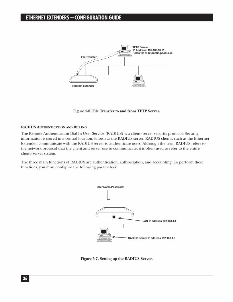
TFTP (TRIVIAL FILE TRANSFER PROTOCOL)
TFTP is a file transfer protocol used for downloading boot code to diskless workstations.
TFTP is used in a server designated as the TFTP server. The server needs to provide concurrency to allowmultiple users to boot up simultaneously. To do this, TFTP creates a UDP port for each client. By creating aUDP port, the different client input datagrams can be demultiplexed by the server’s UDP module.Demultiplexing in the module increases the server efficiency.
One characteristic of TFTP is that it is not secure. There is no password or firewall associated with TFTP.Anyone with the IP address of the TFTP server can enter the server and download files. Security can beprovided by creating a directory which contains only those files which you want to be downloaded. Thisprevents access to any other files.
You must configure the following parameters in a TFTP server:
File Server IP AddressSelect this parameter to enter the IP address of the TFTP server; for example, 192.168.10.11.
File NameSelect this parameter to enter the name and path of the file to be transferred; for example, c:\booting\boot.exe.
Retransmitting TimeoutSelect this parameter to enter the amount of time that is allowed to pass before a file is retransmitted; forexample, 30 seconds.
Total TimeoutSelect this parameter to enter the amount of time the Ethernet Extender should wait for an acknowledgmentfrom the TFTP server; for example, 60 seconds.
ETHERNET EXTENDERS—CONFIGURATION GUIDE
36
Figure 5-6. File Transfer to and from TFTP Server.
RADIUS AUTHENTICATION AND BILLING
The Remote Authentication Dial-In User Service (RADIUS) is a client/server security protocol. Securityinformation is stored in a central location, known as the RADIUS server. RADIUS clients, such as the EthernetExtender, communicate with the RADIUS server to authenticate users. Although the term RADIUS refers tothe network protocol that the client and server use to communicate, it is often used to refer to the entireclient/server system.
The three main functions of RADIUS are authentication, authorization, and accounting. To perform thesefunctions, you must configure the following parameters:
Figure 5-7. Setting up the RADIUS Server.
TFTP ServerIP Address: 192.168.10.11Holds file at C:\booting\boot.exe
Ethernet Extender
File Transfer
RADIUS Server IP address 192.168.1.9
LAN IP address 192.168.1.1
User Name/Password

CHAPTER 5: Advanced Setup Menu
37
RADIUS Server IP AddressSelect this parameter to enter the IP address of the RADIUS server; for example, 192.168.1.9.
In addition, select this parameter to enable/disable accounting.
RADIUS AuthenticatorSelect this parameter to enter the shared secret. The shared secret is a password used by RADIUS toauthenticate the client. It is important to remember that the client is the Ethernet Extender. The user is notrequested to supply the shared secret.
NOTEWhen configuring the RADIUS Authenticator, be sure to use the same value in theRADlUS server and Ethernet Extender.
RADIUS Accounting System TypeSelect this parameter to track link up/link down activity. This information is often used for billing purposes.Use the space bar to toggle between ON and OFF.
Retransmission TimeoutSelect this parameter to enter the maximum time the Ethernet Extender waits for a response from the RADIUSserver; for example 30 seconds.
Total TimeoutSelect this parameter to enter the total time the Ethernet Extender tries to communicate with the Radius server.
Figure 5-8. Routing/Bridging Menu Outline.
Device Control2
Setup1
Advanced Menu
LinkRouting/Bridging
Mode
1Static
Stationand Nets
2IP Routing
Setting
3IPX Routing
Setting
4
RADIUS
5
1. Link Type Add 1. InterfaceAddress
New StationsAgeing Time
Link Number
Routing/Bridging
2
2. LinkProtocol Clear 2. RIP Mode
3. LinkCost/Metric Delete 3. Maximum
Transmit Unit
4. PPP Setting 4. PC RemoteAccess
1. Header andControl FieldCompression
1. SharedIP Net
2. Protocol FieldCompression
2. RemoteWorkstation IP
Address Allocation
3. IP Compression(V. Jacobson-
RFC1144)
3. RemoteWorkstation IPAddress Pool
4. DataCompression
Mode (RFC-1974Compatible)
4. PrimaryDomain Name
Server
5. Multilink
5. SecondaryDomain Name
Server

ETHERNET EXTENDERS—CONFIGURATION GUIDE
38
To access the Routing menu:
In the Advanced menu, press 1. The Setup menu appears.
In the Setup menu, press 2. The Routing menu appears.
ROUTING (Device name — Name)
Link 1 - IP & IPX ROUTER PPP
Link 2 - IP ROUTER SLIP
Setup Menu
1. Link Routing/Bridging mode2. Static stations & nets3. IP routing settings4. IPX routing settings5. Station ageing (minutes): 30
ESC — Return to previous menu
Choose one of the above:
The options in the Routing menu are described below.
LINK ROUTING/BRIDGING MODE
Link TypeSelect this parameter to assign the link type. Use the space bar to choose Bridge, IP, IPX, or IP & IPX routing.
Figure 5-9. Routing Modes.
Ethernet Extender
Routing/Bridging Mode:• Bridge• IP• IPX• IP/IPX
Central Access Router

CHAPTER 5: Advanced Setup Menu
39
Link ProtocolSelect this parameter to assign the link protocol. Link protocols available for asynchronous link are: SLIP,CSLIP, or PPP.
• SLIP — SLIP stands for Serial Line Internet Protocol. It is a simple form of encapsulation for IP datagramson serial lines. SLIP is often used in connecting home systems to the Internet, through the RS-232 serialport. The following rules specify the framing used by SLIP. The IP datagram is terminated by the ENDcharacter (0xc0). Most datagrams transmit an END character at the beginning of a datagram as well.Placing an END at the beginning prevents interpreting line noise as being part of the datagram. Any databefore the END character is removed and erased.
• If a byte of the IP datagram equals the END character, the 2-byte sequence 0xdb, 0xdc istransmitted instead. This special character, 0xdb, is called the SLIP ESC character. (This is notthe same as the ASCII ESC character.
• If a byte of the IP datagram equals the SLIP ESC character, the 2-byte sequence is transmittedinstead.
SLIP has several drawbacks:
• Each end must know the other’s IP address. There is no method for one informing the other ofits IP address.
• There is no type field. If a serial line is using SLIP, the line cannot be used for some otherprotocol.
• There is no checksum added by SLIP. If a noisy phone line corrupts a datagram being transferredby SLIP, the higher levels must detect the corruption.
SLIP is specified in RFC 1055.
• CSLIP — CSLIP stands for Compressed Serial Line Internet Protocol. CSLIP is used to solve a problemassociated with SLIP. SLIP lines are often slow (19200 bits/second or less). They are often used forinteractive traffic, such as Telnet, which uses TCP. TCP adds many small packets to the data. To carry 1 byteof data requires a 20-byte IP header on a 20-byte TCP header, an overhead of 40 bytes. To overcome thisdrawback, CSLIP reduces the header from 40 bytes to 3 or 5 bytes. By reducing the header size, responsetime is improved. CSLIP maintains the state of up to 16 TCP connections on each end of the CSLIP link.
CSLIP is specified in RFC 1144.
• PPP — PPP stands for Point-to-Point Protocol. PPP consists of 3 components:
• A way to encapsulate IP datagrams on a serial link. PPP supports either an asynchronous link with8 bits of data and no parity, or bit-oriented synchronous links.
• A link control procedure (LCP) to establish, configure, and test the data-link connection. Havingan LCP allows each end to negotiate various options.
• A family of network control protocols (NCPs) specific to different network-layer protocols. TheNCPs allow each end to configure network control parameters.

ETHERNET EXTENDERS—CONFIGURATION GUIDE
40
Each frame begins and ends with a flag byte whose value is 0x7e. The flag byte is followed by an address bytewhose value is Oxff. The address byte is followed by a control byte whose value is 0x03.
The control byte is followed by the protocol field. The value of the protocol field determines the type ofinformation field. A value of 0x0021 means the information filed is an IP datagram. A value of 0xc21 meansthat the information field is link control data, and a value of 0x8021 means that the information field is fornetwork control data. The CRC field is a cyclic redundancy check, used to detect errors in the frame.
PPP is often used across slow serial lines. It is therefore important to reduce the number of bytes per frameto reduce the latency time. Using the LCP, most implementations negotiate to omit the constant addressand control fields and to reduce the size of the protocol fields from 2 bytes to 1 byte. In addition, whenusing the IP NCP, most implementations use Van Jacobson header compression to reduce the size of the IPand TCP headers.
Link protocols available for synchronous or ISDN links are: PPP or Native.
Figure 5-10. Link Protocols.Link Cost/MetricSelect this parameter to assign a cost to each WAN link for routing purposes.
Metrics are hop counts. Hop counts are the number of routers through which a packet must go to get to itsdestination. Adjacent interfaces have a hop count of 1. If a packet must go through 2 routers to get to itsdestination, the hop count is 2. The higher the hop count, the longer the route.
A router will automatically send packets using the lowest possible metric. If a router is not functioning, theEthernet Extender will send the packets through an interface with a higher metric.
Protocol:•PPP• SLIP• CSLIP
Central AccessRouter
Ethernet Extender

CHAPTER 5: Advanced Setup Menu
41
PPP SettingsThis option is only available for PPP link protocol.
The PPP Setting screen has the following options:
• Header and Control Field Compression—This parameter is used for troubleshooting only. Do not changethe entry unless there is a problem.
• Protocol Field Compression—This parameter is used for troubleshooting only. Do not change the entryunless there is a problem.
• IP Compression—This parameter activates Van Jacobson TCP Header Compression on a specified link.
PPP is normally used on slow bandwidths, such as modems. Data transmission is therefore slower whenusing this protocol. To quicken the transmission, certain parts of the data packets can be compressed. InVan Jacobson TCP Header Compression the packet header is compressed. Every IP data packet contains aheader. The header contains the source address, destination address, and other information.
Since PPP is used for point-to-point transmissions, both the local and remote devices must have VanJacobson TCP Header Compression enabled for compression to be performed. To verify that Van JacobsonTCP Header Compression is being performed, open the Interface Connections Screen (refer to Chapter6).
• Data Compression Negotiation Mode—the Ethernet Extender supports IP and IPX data compressionaccording to RFC 1974 using the STAC Compression Method. The following modes are supported:
• Disabled.
• No History.
• Sequence.
• Extended.
When the Ethernet Extender attempts to negotiate with another unit, a message is sent stating in whichmode the data will be sent. If the mode is acceptable to the receiving unit, data transmission begins. If themode is not acceptable (in other words, if the second unit does not support this mode), another mode istried, until an acceptable mode is found. This process is called auto-negotiation. When you choose a mode,you are choosing the first mode used during auto-negotiation. Do not change this parameter unless aproblem arises with the auto-negotiation. If a problem does arise, consult the opposite unit’s user manual.
Figure 5-11. Auto-Negotiation.
Ethernet Extender
Data compressionset at LCB
Auto-Negotiation
Data compressionset at Extended

ETHERNET EXTENDERS—CONFIGURATION GUIDE
42
In Figure 6-10, the Ethernet Extender data compression is set at LCB. In the remote unit the datacompression is set to Extended. Messages are sent between the 2 units, until a common data compressionmode is found.
• Multilink—This parameter determines if a line supports multilink PPP. You may choose between:
• Disabled—The line does not support multilink PPP.
• Bandwidth on Demand (BOD)—The first ISDN line functions according to the COD configuration.Refer to Connection on Demand for more information. The second line is connected when thetraffic on the first line exceeds a set threshold. This option is available for ISDN only. Refer to Figure5-12.
• Permanent—Both ISDN channels function simultaneously according to the Connection on Demandparameters. Refer to Connection on Demand for more information.
Both BOD and Permanent setup enable multilink PPP support to this link.
Figure 5-12. Bandwidth on Demand.Fine Tuning BODIf you choose BOD, there are 2 parameters to configure:
• Sensibility Direction—Select this parameter to define the traffic direction to be counted in determiningwhether to connect the second line. The direction can be:
• Transmit.
• Receive.
• Both.
• Sensibility Timeout—Select this parameter to define the time interval for the utilization count.
B2 B2
B1B1
Ethernet ExtenderISDNISPInternet/Intranet

CHAPTER 5: Advanced Setup Menu
43
STATIC STATIONS AND NETS
STATIC STATIONS AND NETS (IP, IPX) (Device name — Name)
1. IP - 194.090.182.056 mask-255.255.255.248 interface-2/16 cost-12. IPX - 19490182 interface-3 cost-1
A - Add, C - Clear all, D - DeleteEsc - Return to previous menu.
Select this parameter to add, delete, or clear static entries in the IP/IPX Routing table. When adding, staticentries can be defined in several ways:
• IP Net—IP Net defines a network as the destination. IP Net consists of 2 parts: the frame pathway anddestination. The pathway is specified either as an interface number (meaning a port number) or as NextHop IP address. Next Hop IP means that the frames are sent to another router; from there they will be sentto their final destination. To define the destination enter the subnet IP address and IP mask. For example,194.90.182.32 is a subnet IP address and 255.255.255.240 is the IP mask.
Figure 5-13. Router 2 set to “Next Hop” in the Ethernet Extender.
• IP Station—IP Station defines a single host as the destination. IP Station consists of 2 parts: the framepathway and destination. The pathway is specified as in IP Net, above. To define the destination enter thehost IP address; for example, 194.90.182.1 1.
• IPX Net—IPX Net is used for IPX routing. Define the IPX Net and the interface number in hexadecimal.
• MAC—MAC is used in the remote device for Bridging. MAC defines the MAC address of the static station inthe bridge station list.
Address 194.90.182.32Mask 255.255.255.240
IP NET 1
IP NET 2
Router 2
Ethernet Extender
ISP Router
Internet
WAN

ETHERNET EXTENDERS—CONFIGURATION GUIDE
44
IP ROUTING SETTINGS
IP ROUTING SETTINGS (Device name — Name)
1. Interface address2. RIP mode3. Maximum transmit unit4. PC remote access
Interface AddressSelect this parameter to enter an IP address for the WAN interface and one or more IP addresses for the LANinterface. Multiple IP addresses on the LAN are useful in environments with multiple IP nets on the LAN (referto Figure 5-14).
Figure 5-14. WAN and LAN Interface Addresses.
RIP ModeSelect this parameter to set the type of RIP to be sent. Choose RIP1, RIP2, RIP1+2, or No RIP for eachinterface. Since most Internet applications don’t use RIP, the default setting is No RIP.
RIP stands for Routing Information Protocol. Every router has a routing table which directs packets. A routeruses the routing table to send the packets through a designated gateway (if the packet was sent to anothernetwork) or sends the packets directly to a host. The routing table is built when the host is booted up. RIPsends a request to all active interfaces, asking for the others’ routing table. Using the information received, thehost builds its own routing table in which the packet destinations are entered. Refer to Figure 5-15.
1. Regular Router ModeNone (“un-numbered”)configured by setting0.0.0.0 in Quick Setupmenu under WAN IPAddress option.
2. Regular Router ModePredefined (“numbered”)configured by settinga.b.c.d. in Quick Setupmenu under WAN IPAddress option.
3. Single IP ModePredefined (“Fixed IPaddress”) configured bysetting a.b.c.d. in QuickSetup menu under WAN IPAddress option.
4. Single IP ModeNone (“Dynamic IPaddress”) configured bysetting 0.0.0.0. in QuickSetup menu under WAN IPAddress option. (IPaddress is receiveddynamically over the WANusing IPCP.)
IP NET 1 IP NET 2
LAN
Ethernet Extender
WAN IP Address
LAN IP Address
WAN

CHAPTER 5: Advanced Setup Menu
45
By sending requests for information, RIP both builds the table and updates the entries. RIP updates the tableusing the responses received every 30 seconds.
If a router is not functioning, the packets must be redirected and sent to a second router. The routing tablecontains the address of a backup router. RIP informs all of the other routers in a network on how to go aroundthe non-functioning router.
Figure 5-15. Routers Exchanging Routing Tables.
Maximum Transmit UnitSelect this parameter to set the maximum transmit unit (MTU) for IP fragmentation. The MTU must be set foreach interface.
Both Ethernet and 802.3 encapsulation have frame size limits. If a frame is larger than the MTU, IP fragmentsthe frame into smaller units.
PC Remote AccessPC Remote Access (Device name — Name)
1. Shared IP net - 194.090.182.032 mask - 255.255.255.2402. Remote workstation IP address allocation (BOOT/IPCP) - Enabled]3. Remote workstation IP addresses pool4. Primary domain name server (DNS) - 194.090.182.0345. Secondary domain name server (DNS) - 194.090.001.005
ESC - Return to previous menu
Choose one of the above:
Select this parameter to define the remote access. The PC Remote Access Option is important if the EthernetExtender is used as a remote access server for remote PCs accessing the LAN.
Shared IP Net—Select this parameter to enter the Shared IP net address. The Shared IP net address is used byall remote workstations connecting to the remote access server on the WAN links.
Remote Workstation IP Address Allocation—Select this parameter to enable or disable allocation of remoteworkstation IP addresses via BootP or IPCP negotiations.
Remote Workstation IP Address Pool—Select this parameter to enter and display a pool of addresses to beallocated by the remote access server to remote workstations connected over the WAN links. These addressesbelong to the Shared IP Net.
A DCB
Ethernet ExtenderEthernet Extender
Central AccessRouter
Central AccessRouter

aETHERNET EXTENDERS—CONFIGURATION GUIDENAME
46
Primary Domain Name Server (DNS)—Select this parameter to enter a primary DNS to be obtained by theremote PC during the IPCP negotiations.
Secondary Domain Name Server (DNS)—Select this parameter to enter a secondary DNS to be obtained by theremote PC during the IPCP negotiations.
DNS is a distributed database that is used by TCP/IP applications to map between host names and addresses,and to provide electronic mail routing information. The term distributed is used because no single site on theInternet knows all of the information. Each site (university department, company etc.) maintains its owndatabase and runs a server program that other systems across the Internet can query. The DNS provides theprotocol that allows clients and servers to communicate with each other.
IPX Routing Settings
IPX ROUTING SETTINGS (Device name — Name)
1. Learn LAN IPX nets for all frame types - [Automatic]2. LAN IPX net for frame type 802.3 - 000A80233. LAN IPX net for frame type Ethernet II - 04FD9F164. LAN IPX net for frame type 802.2 - 000A80225. LAN IPX net for frame type SNAP - 05FD9F166. Dial-in IPX net - D2FD9F167. RIP/SAP mode
ESC - Return to previous menu
Choose one of the above:
Select this parameter to specify how the Ethernet Extender learns IPX Nets. The Ethernet Extender can learnIPX Nets in 3 ways:
• Learn LAN IPX Nets for all Frame Types—If you set this parameter to Automatic, the Ethernet Extenderlearns IPX Nets from RIP/SAP frames sent by other IPX routers on the same LAN. Refer to Figure 5-16. Ifthere are no other IPX routers on the Ethernet Extender LAN, this parameter must be set to Manual, andyou must configure the IPX Nets for each frame type.
Figure 5-16. Automatic Learning from IPX Frames.
Ethernet Extender
LAN
IPX Frames
IPX
Fram
es
IPX
Fra
mesIPX Router
IPX Router
IPX Router

CHAPTER 5: Advanced Setup Menu
47
• LAN IPX Net for Frame Type—Each of these parameters specifies the IPX Nets associated with a particularframe type. Each frame type is supported by the LAN. The Ethernet Extender supplies default values forthese frame types.
• Dial-in IPX Net—This parameter specifies the IPX Net definition for a WAN interface.
RIP/SAP Mode
RIP/SAP MODE SETUP (Device name — Name)
1. Link 1 RIP/SAP mode: [Enabled]2. LAN RIP/SAP mode: [Enabled]
ESC - Return to previous menu
Choose one of the above:
Link I RlP/SAP ModeSelect this parameter to Enable/Disable the RIP/SAP mode. The default setting enables sending RIP and SAPtables for all updates and interfaces (Link and LAN).
When disabled, the Ethernet Extender does not send RIP/SAP frames. The Ethernet Extender receives andprocesses RIP/SAP frames sent from other routers.
STATION AGING
Station aging determines the amount of time a station is allowed to be inactive before it is removed from thenetwork. A station is inactive when no IP traffic is forwarded or received to the Ethernet Extender LANinterface. For example, in Figure 5-17, IP address 192.18.1.1 has an aging time of 120 seconds. If no frames arereceived from IP address 192.18.1.1 within 120 seconds, the station will be removed from the EthernetExtender IP net table.
Figure 5-17. Station Aging.
Station Aging120 seconds
IP address 192.18.1.1
Ethernet Extender

NAME
48
Interface Parameters
Figure 5-18. Interface Parameters Menu Outline.
To access the Interface Parameters menu:
In the Advanced menu, press 1. The Setup menu appears.
In the Setup menu, press 3. The Interface Parameters menu appears.
INTERFACE PARAMETERS (Device name — Name)
1. Link settings2. ISDN protocol settings3. Frame relay DLCI settings4. X.25 module setting
ESC - Return to previous menu
Choose one of the above:
Device Control2
Setup1
Advanced Menu
Link Setting
1ISDN
Protocol Setting
2Frame RelayDLCI Setting
3X.25 Module
Setting
4
1. Status 1. ISDN Protocol& SPID
InterfaceParameters
3
2. Type
3. ConnectionType
4. ConnectionTimeout (sec)
5. ControlSignals Mode
6. Baud Rate(Kbps)
7. Parity
8. Stop Bit
9. Modem Setting
1. Asynchronous
2. Synchronous
3. ISDN
4. X.25
5. Frame Relay
1. Modem Name
2. ModemInitialization
String
3. Autobaudingto Modem Speed
4. Reset ModemBefore Setup
5. AnalyzeModem Answer
6. ModemSpeaker On
7. ModemDialing Number
8. Local Number(for Dialback)
9. Number ofRings Before
Answer

CHAPTER 5: Advanced Setup Menu
49
The options in the Interface Parameters menu are described below.
LINK SETTING
Figure 5-19. Link Settings.StatusSelect this parameter to specify the status of a link: enabled or disabled. An enabled link transmits frames.Normally you would want all links enabled. If a router is not working, however, the link to that router should bedisabled. All frames are then rerouted.
TypeSelect this parameter to specify the type of interface in use: Asynchronous, Synchronous, X.25, or ISDN. For aDDS or 4-wire link interface, the only link types available are Synchronous or Frame Relay.
1. When the mode is synchronous, data bits are transmitted at a fixed rate. The sender and the receiver aresynchronized.
2. When the mode is asynchronous, data units are transmitted character-by-character. The characters arepreceded by start bits and followed by stop bits. The start and stop bits provide synchronization at the receiverside.
3. Frame Relay is a packet-switching protocol for connecting devices on a WAN.
Connection TypeSelect this parameter to specify the type of connection:
• Originate only—If the link is to be used to connect to the Internet or Intranet.
• Answer only—If the link is to be used for receiving remote access connections.
• Answer&Originate—If the link is to be used for both incoming and outgoing connections (notsimultaneously).
Connection Timeout (sec)Select this parameter to specify the connection timeout. The remote side has to answer within the time allottedby the Connection Timeout. If within this time there is no response, you are informed that the remote side isno longer active.
Connection timeout is only configured when the PPP protocol is used. The parameter consists of two parts:
• Time (1 to 255 seconds).
• Number <N> of attempts.
Ethernet ExtenderLink

ETHERNET EXTENDERS—CONFIGURATION GUIDE
50
Within the designated time, the Ethernet Extender will send frames <N> times. For example, if the time isconfigured to 120 and the number is configured to 6, every 20 seconds a frame is sent. If there is no response,the Ethernet Extender assumes that the remote unit has failed.
Figure 5-20. Connection Timeout.
Control Signals ModeThe Ethernet Extender can be set to ignore or acknowledge the following control signals: RTS (Request tosend), CTS (Clear to send), and CD (Carrier Detect). This parameter is only relevant to asynchronousconnections to dial-up modems.
Figure 5-21. Control Signals Mode.
Baud Rate (kbps)Select this parameter to specify the rate at which data is sent across the link.
ParitySelect this parameter to specify the parity. Parity is a method of checking for errors. A parity bit is a non-information bit that is added to a group of bits to ensure that the total number of bits in a character is odd oreven. If you know that the total number of bits must be odd any group of bits whose total number is even mustbe erroneous. Choose odd, even, or none.
Figure 5-22. Parity Bit.
Time: 120 secondstotal, 6 attempts
Ethernet ExtenderPPP
Remote Side
Modem
RTS, CTS,CD
Ethernet Extender
Parity bit

CHAPTER 5: Advanced Setup Menu
51
The parity must be configured with the sending party. The parity setting of both the sender and receiver mustbe the same.
For example if the parity was odd, and a group of bits whose total number was 6 arrived, this group would beerroneous and would be erased.
Stop BitSelect this parameter to specify the number of stop bits. The stop bit is a signal at the end of a character thatinstructs a receiving device to wait for a subsequent signal. Select this parameter to choose 1 or 2 stop bits.
Figure 5-23. Stop Bit.
Modem SettingSelect this parameter to display a menu which allows configuration of modem parameters.
ISDN PROTOCOL SETTINGS
The Ethernet Extender with ISDN connects your Ethernet LAN to the Internet/Intranet at a rate of 64 or128 Kbps. Ethernet Extender with an ISDN interface was designed to reduce WAN costs to a minimum, withautomatic spoofing and connection on demand. Refer to Appendix A for more information.
Figure 5-24. Connection to the Internet over ISDN.
S/T or U-InterfaceEthernet Extender
ISDN
ISDN (BRI)64/128 kbps
Internet
stop bits
length dependent on protocol
ETHERNET EXTENDERS—CONFIGURATION GUIDE
52
ISDN Features• ISDN BRI.
• Standard S/T interface.
• Optional U-interface eliminates the need for an external NT1 device.
• Connection rate from 64 to 128 Kbps.
• Protocols supported: ETSI (Europe), NTT (Japan), NI-I (U.S.), 5ESS (U.S.), DMS-100 (U.S.), V1 andLeased ISDN (I.430).
Implementing ISDNTo activate the ISDN line:
Choose the ISDN protocol.
Choose the connection rate (bandwidth): 56, 64, 112, or 128 Kbps.
Enter the destination phone number.
The diagram below maps the options in the Advanced menu that are used to configure the Ethernet Extenderfor operation with an ISDN interface.
The ISDN interface parameter has the following subparameters:
• Dialing mode parameters.
• Answering mode parameters.
• Local number for Dialback.
A brief explanation of the ISDN Parameters follows.

CHAPTER 5: Advanced Setup Menu
53
Figure 5-25. ISDN options in the Advanced Menu.
DIALING-MODE PARAMETERS
Destination Phone NumberSelect this parameter to enter the phone number of the station you want to dial. This parameter is mandatoryfor dialing out. The other dialing-mode parameters are optional.
Figure 5-26. Destination Phone Number.
MainMenu
AdvancedSetup
DeviceControl
ResetOptions
ResetInterfaceModule
Reset ISDNModule
View
Configuration
View ISDNParameters
Setup
InterfaceParameters
ISDNProtocolSetting
LinkSetting
Choose theISDN Protocol
(Dial-In &Dial-Out)
Enter Dial-OutPhone Number
(Dial-Out)
Answer toSpecific
Sub Number
(Dial-In)
Provide theLocal PhoneNumber forDial Backto that line
(Dial-Out)
Dialing ModeParameters
AnsweringMode
Parameters
Local NumberFor
Dial Back
Destination ISDNNumber
Central AccessRouter
Source ISDNNumber
Ethernet Extender
ISDN

ETHERNET EXTENDERS—CONFIGURATION GUIDE
54
Destination Sub-NumberSelect this parameter to enter the extension number of the destination phone number.
Source Phone NumberSelect this parameter to enter the phone number of the person dialing out. This parameter is used by thedestination station to identify the caller.
Source Sub-NumberSelect this parameter to enter the extension number of the person dialing out.
ANSWERING MODE PARAMETERS
Local Phone NumberSelect this parameter to enter the number to which incoming calls are directed.
Local Sub-NumberSelect this parameter to enter the extension to which incoming calls are directed.
LOCAL NUMBER FOR DIALBACK
Dialback Phone Number
Figure 5-27. Dialback Phone Number.
Select this parameter to enter the phone number which is used by the ISP to dial back the Ethernet Extender.When the Ethernet Extender wants to dial the ISP, the ISP uses this number to identify and dial back theEthernet Extender (similar to reverse charging). In this way, the PTT bills the ISP and not the caller. Thisfeature is only useful when dialback is enabled on both sides.
Dialback Sub-NumberSelect this parameter to enter the extension used by the ISP for dialback purposes.
Ethernet Extender
Dialback phonenumber
ISDN
Central AccessRouter
CorporateHeadquarters

CHAPTER 5: Advanced Setup Menu
55
FRAME RELAY
Frame Relay is a form of WAN which is designed to maximize throughput and minimize cost by simplifyingnetwork processing.
Figure 5-28. Connection to the Internet over Frame Relay.
Frame Relay Features• Supports permanent virtual circuits (PVC).
• Supports Frame Relay (IP/IPX) encapsulation based on RFC 1490.
• Supports different management and maintenance protocols:
• Tl.617/ANNEX D.
• Q.933/ANNEX A.
• LMI.
• Supports self-learning of the maintenance protocol and the DLCI, which allows connection to the FrameRelay network without configuring Frame Relay parameters.
• Executes congestion control when an explicit congestion notification is received for the DLCI from theFrame Relay network. The unit reduces the transmitted information rate of the DLCI and increases it whenthe congestion condition is cleared.
• Supports the Frame Relay SNMP MIB.
Ethernet Extender
InternetFrame Relay
LAN

ETHERNET EXTENDERS—CONFIGURATION GUIDE
56
Implementing Frame RelayThe diagram below maps the options in the Advanced menu that are used to configure the Ethernet Extenderfor operation over a Frame Relay network.
Figure 5-29. Frame Relay Options in the Advanced Menu.
LINK SETTING
The parameters in the Frame Relay Links Parameters menu are described below.
Self Learn DLCI/MaintenanceSelect this parameter to specify whether the Ethernet Extender will self learn the maintenance protocol on theFrame Relay link and the DLCI status (UP or DOWN). When this parameter is disabled (OFF), you need toconfigure the maintenance protocol and the DLCI manually.
CLLM StatusSelect this parameter to specify whether CLLM frames, used for congestion indication, will be supported (ON)or not (OFF).
Maintenance ProtocolSelect this parameter to specify the maintenance protocol of the Frame Relay link: T1.617/ANNEX D,Q.933/ANNEX A, LMI, or None. This parameter can only be configured if Self learn DLCI /Maintenanceparameter is disabled (OFF).
Polling IntervalSelect this parameter to specify the number of seconds between transmission of two successive status inquiryframes.
MainMenu
AdvancedMenu
DeviceControl
ResetOptions
View
Frame RelayDLCIs’
View Frame RelayDLCI Parameters
Setup
InterfaceParameters
Reset Link
LinkSetting
Frame RelayDLCI Setting
CIRStateDLCI ThroughputExcess
Self LearnDLCI/
Maintenance
MaintenanceProtocol
CLLMStatus
PollingInterval
Full EnquiryInterval
ErrorThreshold
MonitoredEvents

CHAPTER 5: Advanced Setup Menu
57
Full Enquiry IntervalSelect this parameter to specify the number of polling intervals after which a full status request frame istransmitted.
Figure 5-30. Polling Intervals.
Error ThresholdSelect this parameter to specify the number of unacknowledged monitored events (status inquiry frames andfull status inquiry frames) that can occur in a sliding monitored events window before the link is declaredDOWN.
Monitored EventsSelect this parameter to specify the number of monitored events (status inquiry frames and full status inquiryframes) in a sliding monitored events window.
Status Enquiry ReplyStatus Enquiry
10 secondsStatus Enquiry
Status Enquiry Reply
10 secondsStatus Enquiry
Status Enquiry Reply
10 secondsStatus Enquiry
Status Enquiry Reply
10 secondsStatus Enquiry
Status Enquiry Reply
10 secondsStatus Enquiry
Status Enquiry Reply
Time
Frame Relay NetworkEthernet Extender
Polling Interval = 10Full Inquiry Interval = 4

ETHERNET EXTENDERS—CONFIGURATION GUIDE
58
Figure 5-31. Monitored Events.
After the link is declared DOWN, it can only be declared UP again when the sliding monitored events windowcontains only successfully monitored events.
Figure 5-32. Monitored Events—Link Down.
� ?
Link is UP Link is UP again
Link is DOWN
� � � � � �? ? ? ? ?
S.E.Frame
S.E.Frame
S.E.Frame
S.E.Frame
F.S.E.Frame
S.E.Frame
S.E.Frame
� ? � ? ?
Error Threshold = 3Monitored Events = 5
Sliding Monitored Events Window
Monitored Events(status enquiring framesand full status enquiry
frame = 5)Unacknowledged.Frame
Acknowledged.Frame
Link is DOWN when unacknowledged monitored events > 3Link is UP when unacknowledged monitored events < 3
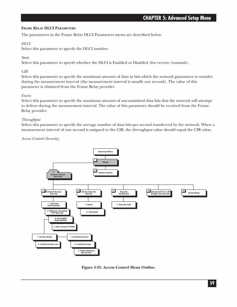
CHAPTER 5: Advanced Setup Menu
59
FRAME RELAY DLCI PARAMETERS
The parameters in the Frame Relay DLCI Parameters menu are described below.
DLCISelect this parameter to specify the DLCI number.
StateSelect this parameter to specify whether the DLCI is Enabled or Disabled (for receive/transmit).
CIRSelect this parameter to specify the maximum amount of data in bits which the network guarantees to transferduring the measurement interval (the measurement interval is usually one second). The value of thisparameter is obtained from the Frame Relay provider.
ExcessSelect this parameter to specify the maximum amount of uncommitted data bits that the network will attemptto deliver during the measurement interval. The value of this parameter should be received from the FrameRelay provider.
ThroughputSelect this parameter to specify the average number of data bits per second transferred by the network. When ameasurement interval of one second is assigned to the CIR, the throughput value should equal the CIR value.
Access Control (Security)
Figure 5-33. Access Control Menu Outline.
Device Control2
Setup1
Advanced Menu
Access Control(security)
4
External AccessSecurity
1 Device SecurityIdentity
2 SecurityHost/Guest
3 Advanced PC to LANBridge Link Security
4Script Setup
5
1. SecurityAuthorization 1. Name 1. Security Link
2. Minimum AcceptedPPP Security 2. Password
3. AccessibleStations/Nets
4. User Access Profiles
1. Access Mode
2. Limited Access List
1. Unlimited Access
2. Limited Access
3. Static Stations/Net Access

ETHERNET EXTENDERS—CONFIGURATION GUIDE
60
To access the Access Control menu:
In the Advanced menu, press 1. The Setup menu appears.
In the Setup menu, press 4. The Access Control menu appears.
ACCESS CONTROL (Device name — Name)
1. External access security2. Device security identity3. Security Host/Guest4. Advanced PC to LAN Bridge link security5. Script setup
ESC - Return to previous menu
Choose one of the above :
The options in the Access Control menu are described below:
EXTERNAL ACCESS SECURITY
Select this parameter to protect your LAN against unwanted entry by outside users. Choose from the followingoptions:
• None—Access denied to all users.
• User Access Profile—Allow/deny access according to the User Access Profile (see below).
• RADIUS—Allow/deny access according to the RADIUS Authenticator.
• User Access Profile+RADIUS—Access is allowed if the User Access Profile allows it—OR if the User AccessProfile denies access but the RADIUS Authenticator allows it.
NOTEIf you select RADIUS, configure the RADIUS Access parameters from the HostParameters menu.
Minimum Accepted PPP SecuritySelect this option to specify the minimum security to none, PAP, or CHAP.
PPP supports 2 types of security systems:
• CHAP (Challenge Handshake Authentication Protocol)—CHAP is a type of authentication in which theauthentication agent (typically a network server) sends the client program a key to be used to encrypt theusername and password. This enables the username and password to be transmitted in an encrypted formto protect them against hackers.

CHAPTER 5: Advanced Setup Menu
61
• PAP (Password Authentication Protocol)—PAP is the most basic form of authentication, in which a user’sname and password are transmitted over a network and compared to a table of name-password pairs.Typically, the passwords stored in the table are encrypted. The main weakness of PAP is that both theusername and password are transmitted in an unencrypted form.
Accessible Stations/NetsSelect this parameter to define parameters which limit public access to the network. Access can be allowed forall stations/nets, only certain stations/nets, or only stations/nets which are static. When the access mode is“limited,” use the access list to define which stations/nets have access.
User Access ProfilesSelect this parameter to view and modify user access profiles in the access control users list. The list containsuser names, security parameters, and dialback options.
DEVICE SECURITY IDENTITY
NameSelect this parameter to assign a name to the Ethernet Extender for access to the ISP’s central access router.The maximum length is 30 characters.
PasswordSelect this parameter to assign a password to the Ethernet Extender for access to the ISP’s central access router.The maximum length is 30 characters.
SECURITY HOST/GUEST
Select this parameter to define a link’s security status. When a link is defined as a Host, users are approvedaccording to your profile list. When a link is defined as a Guest, the device sends its name and password to beapproved by the host. The Guest mode is the default.
ADVANCED PC TO LAN BRIDGE LINK SECURITY
Use this parameter to configure advanced security for remote access from a PC client, when the EthernetExtender is configured as a bridge.
SCRIPT SETUP
The Ethernet Extender scripting tool allows you to negotiate an initial login, required by some ISPs. The initiallogin usually consists of a username, a password, and possibly some other information that has to be entered togain access to the ISP.
The Ethernet Extender script is a sequence of commands, with a maximum of 20 commands in the script. Assoon as a physical connection to the remote host is achieved (and the script is enabled), the Ethernet Extenderbegins to forward the script. Script processing finishes when the last script command has been forwarded.
The Ethernet Extender script comprises one or more command lines. Each command line consists of aCommand Code followed by an Argument.

ETHERNET EXTENDERS—CONFIGURATION GUIDE
62
Command CodeThe command codes are described below.
waitcase pattern Waits until the specified case-sensitive pattern is received from the remote host. Then, forwards the next command. The maximum pattern length is 24 characters.
Or, waits until timeout (default = 15 seconds). The link then disconnects and the Ethernet Extender performs the same actions as required during authentication failure.
waitnocase pattern As above, with no case sensitivity.
send pattern Transmits specified pattern to remote host. The pattern can contain any recognized control symbols. The maximum pattern length is 24 characters.
sendhide pattern As above. However, the pattern is displayed on the screen as asterisks. The control symbol is displayed as two asterisks when editing and as one when viewing.
timeout number Changes the timeout for waitcase, waitnocase, and getip commands. The number is the timeout value, in seconds. This value can be any number from 1 to 99 and will be used until the next timeout command.
delay number The delay in seconds between sending commands. All symbols received during this time will be ignored. This value can be any number from 1 to 99.
getip number This command waits for an IP address from the remote host. If the ISP returns several IP addresses in a string, the number specified by this command will determine which IP address should be used.
If an IP address is received successfully from the host, and the Single IP feature is enabled, the IP address will be used on the Ethernet Extender WAN interface. If an IP address is not received successfully within the specified timeout period, the link disconnects.
ArgumentThe argument is any string without apostrophes, quotation marks, or unsigned integers (depending on thecommand). In addition to ASCII symbols, the argument string can include any control characters with ASCIIcodes from 1 to 31. While editing scripting commands, these symbols are entered in the “control” mode: Eachsymbol is entered as “^,” followed by the corresponding ASCII character from “A” to “[.” The letters must be inupper case.
Example:
Code to wait/send Control Sequence0x0A (line feed) ^J0x0D (carriage return) ^M0x0B (escape) ^[

CHAPTER 5: Advanced Setup Menu
63
WAN Economy Menu
Figure 5-34. WAN Economy Menu Outline.
To access the WAN Economy menu:
In the Advanced menu, press 1. The Setup menu appears.
In the Setup menu, press 5. The WAN Economy menu appears.
Device Control2
Setup1
Advanced Menu
Filters
1ConnectionOn Demand
2IP/IPX
Spoofing
3Fast
RetransmissionFrame Limit
4
WAN Economy
5
1. Block andForwarding
1. StartConnection
1. Keep AliveMode
2. Link to LinkTraffic
2. TerminateConnection
2. RIP/SAPSpoofing TablesUpdated Timeout
3. IP/IPXBroadcast
Control
3. Minimum TimeBetween Two
Connects3. Change LinkSpoofing Mode
4. Quick Filters4. Minimum Time
Between TwoDisconnects
5. AdvancedFilters
5. ConnectManually
6. DisconnectManually

ETHERNET EXTENDERS—CONFIGURATION GUIDE
64
WAN ECONOMY (Device name — Name)
Use these features:- to reduce traffic over the WAN to a minimum and increase throughput- to keep the link up only when it is required
1. Filters2. Connection on demand3. Spoofing4. Fast retransmission frame limit: 2
ESC - Return to previous menu
Choose one of the above:
The options in the WAN Economy menu are described below:
FILTERS
Filtering allows you to limit the amount of traffic which enters and exits the small-office LAN via the EthernetExtender. Filtering is used to:
• Increase security.
• Reduce traffic to the link.
The Ethernet Extender features two types of filters:
• Quick Filters.
• Advanced Filters.
Quick Filters are used to regulate IP and IPX. A Quick Filter can neutralize IP and/or IPX protocol by blockingall traffic of that protocol. Refer to Figure 5-35.
Figure 5-35. Action of a Quick Filter.
Traffic to the Link isblocked by Quick FilterTraffic to the LAN is
blocked by Quick Filter
Ethernet Extender
Quick Filter
Quick Filter
LINK

CHAPTER 5: Advanced Setup Menu
65
Advanced Filters are used to regulate traffic in both directions. (Refer to Figure 5-36).
• From LAN to the Link. Using filters here will forward or block traffic from the LAN outwards.
• From Link to the LAN. Using filters here will forward or block traffic from the link inwards.
Using a variety of parameters, Advanced Filters can be used to regulate different protocols, to totally or partiallyblock traffic, and to control traffic between links.
Figure 5-36. Action of an Advanced Filter.
There are two modes through which filtering can be implemented: blocking and forwarding.
BlockingThe block command causes the Ethernet Extender to test every packet of data that is sent to or from the LAN.If the packet passes the test, passage is denied.
Example:You want to ensure that IP/UDP packets do not go on to the link in the direction of the Internet/Intranet.Thus, you design a filter which tests each packet to see if it is an IP/UDP packet. If the packet tests positive, it isautomatically blocked.
ForwardingThe forward command works in the same way as the block command. However, with forwarding, if the packetpasses the test, it is allowed passage to or from the LAN.
Example:You want to allow a certain user on the small-office LAN to access the Internet for FTP purposes. To do this, youcreate a filter to test each packet for the IP host address of the specified user and the FTP socket of the packet.If the packet passes the test, it is forwarded to the Internet/Intranet.
Ethernet Extender
Link to LAN Filter
LAN to Link Filter
LAN
LINK
Traffic is regulated
Traffic is regulated
ETHERNET EXTENDERS—CONFIGURATION GUIDE
66
Multiple FiltersUp to 18 filters can be defined. If there are 2 filters which have contradictory operations, forwarding takesprecedence over blocking.
Example:You want to allow only one particular user on the small-office LAN to access the Internet for FTP purposes. Toensure that no one else is able to access the Internet, create a blocking filter for all traffic going to the link. Todo this, from the Blocking and Forwarding menu enter “Block all traffic for Link1.” In addition, create a filterto test each packet for the IP host address of the specified user and the FTP socket of the packet. Sinceforwarding takes precedence over blocking, that user’s frames are forwarded.
Definition of Filter TestsYou need to define the filter test which will be applied to every packet that is transmitted. Use any combinationof the following parameters to define the filter test:
• Protocol.
• Operation (block, forward, etc.).
• Interface (LAN, Link).
• Destination and/or source IP address of the packet.
• Destination and/or source MAC address of the packet (layer 2).
• IP socket (upper and lower level).
• IP packet type (broadcast, multicast).
NOTEUp to 18 filters can be defined. To avoid reducing Ethernet Extender performance,minimize the number of active filters.
DEFINING FILTERS
Filters can be defined through the control port, TELNET, or SNMP. First decide on the mode and conditionsfor a filter, then follow the instructions below to set filter parameters.
NOTERemember that forwarding takes precedence over blocking. If there is combination offilters which contain both operations, the frame will be forwarded.

CHAPTER 5: Advanced Setup Menu
67
QUICK FILTERS MENU
There are 4 steps in defining a Quick Filter:
1.From the Advanced Setup menu, choose Set up→WAN Economy→Filters.
2.Configure the operation.
3.Configure the broadcast control.
4.Configure the Quick Filter parameters.
FILTERS (Device name - Name)
1. Block and Forwarding2. Link to link traffic: [FORWARD]3. IP / IPX broadcast control - [Full Propagation]4. Quick filters5. Advanced filters
Esc - Return to main menu
Choose one of the above:
To configure the operation:
From the Filters menu, choose Block and Forwarding.
Toggle between Block and Forward.
To configure the broadcast control:
The broadcast control filter manages special frames which are normally propagated throughout the network.The frames managed are:
• IP—Local broadcast propagation.
• IPX—Zero destination propagation, IPX Type 20 frames propagation.
• NETBIOS over IP—IP frames with TCP/UDP ports 137, 138, 139 propagation.
From the Filters menu, press “2” to toggle between Full Propagation and Block Propagation. The default isBlock Propagation.
To configure the link to traffic:
Use this to configure whether traffic will be sent or blocked when the Ethernet Extender is configured as abridge:
• Forward—forward all traffic.
• Blocked—block all traffic.

ETHERNET EXTENDERS—CONFIGURATION GUIDE
68
To configure the Quick Filter parameters:
Quick Filters are defined per protocol. Configure each protocol that you want to block or forward.
1. From the Filters menu, choose Quick Filters.
2. To toggle between No Filters/Forward/Block, press the number of the protocol that you want to filter.
QUICK FILTERS (Device name - Name)
Choose the protocols you want to block or forward!!:
1. IP NO FILTERS2. IPX NO FILTERS3. SNA NO FILTERS4. NetBIOS NO FILTERS5. AppleTalk NO FILTERS6. DECnet NO FILTERS7. Others NO FILTERS
ESC - Return to previous menu
Choose one of the above: Press Enter.
ADVANCED FILTER MENU
There are 4 steps in defining an Advanced Filter:
1.From the Advanced Setup menu, choose Set up→WAN Economy→Filters.
2.Choose Advanced Filter.
3. If you are defining a new filter, choose Add. If you are editing a filter, choose edit and enter the filternumber.
4.Define the desired parameters.
Advanced Filter ConceptsWhen defining an advanced filter, the following parameters must be determined:
• Filter ID—A selection number used to view, edit, or delete a particular file. To work with any filter, the FilterID number must be entered.

CHAPTER 5: Advanced Setup Menu
69
ADD FILTERS (Device name - Name)
ENTER - Enter dataT - Toggle (parameters inside [] )N - Next line (skip this one)SPACE - Move rightBACKSPACE - Move leftESC - Return to previous menu
Filter ID - 1
• Protocol—The protocol on which the filter operates.
• Operation—Used to define the action of the filter.
• Interface—Used to determine the filter interface.
• Source Address—Used to define the source address of passing frames.
• Destination Address—Used to define the destination address of passing frames.
• High level (IP only)—Used to include or exclude high-level protocols.
• Source/Destination Port—Used to define the port source/destination address of an application.
• Source/Destination Socket—Used to define the socket source/destination address of an application.
• Low Level—Used to include or exclude the low-level protocols.
• Mask—Used to define a mask filter.
• Status—Used to define the filter’s status.
True-False MenusMany of the Advanced Filter parameters can be configured so that:
• Frames with that parameter pass (true); or
• Frames without that parameter pass (false).
For example, if you choose BroadCast-True, any frame which is BroadCast will pass. If you choose BroadCast-False, any frame which is not BroadCast will pass.
Advanced Filter Parameters• Filter ID—The system automatically assigns a new number to each filter.
• Protocol—The protocol on which the filter operates.
• Operation—The action which the filter applies to a frame that passes. They are Forward, Block, Connect,and Disconnect.
The operations are listed in their order of priority. For example if the connect and disconnect commands areapplied to a frame, the connect command takes precedence.

ETHERNET EXTENDERS—CONFIGURATION GUIDE
70
NOTEConnect and disconnect are only relevant to Connection on Demand. When accessedthrough the Filter menu, only they appear disabled. Refer to Connection on Demandon page 72 for more information.
• Interface—The area where the filters will act. If you want to filter traffic going to the LAN, choose LAN. Ifyou want to filter traffic going to the link, choose Link.
• Source Address—Toggle to the desired address type (MAC or NET). The address format (hexadecimal orbinary) appears. Type in the complete source address.
If you want to include a group of addresses, type <x> to indicate “Don’t care.” For example, a filter with theMAC source address the 4020.D2FE.xxxx will pass any address beginning with 4020.D2FE.
• Destination Address—Toggle to the desired address type (MAC, NET, All, BroadCast, MultiCast). Theaddress format (hexadecimal or binary) appears. Type in the complete destination address. Choose True orFalse.
Normally, a frame has a particular destination, as specified in the destination address field of the frame.Such frames are referred to as “All” frames. “BroadCast” frames are intended for all stations. If you specify“BroadCast,” do not specify a mask pattern.
• High Level—When you choose this parameter, 2 choices appear: Yes and No.
When “Yes” is chosen, a list of high-level protocols appear. The high-level protocols are: FTP, WWW,TELNET, E-MAIL, TFTP, SNMP, DNS, and RIP. Select the protocols you want to filter. Choose True or False.
• Source/Destination Sockets—This parameter differs for IP and IPX:
IP—The Destination Port is enabled when no high-level protocol is specified. If you define a portnumber in decimal numbers, define the low-level protocol as UTP or TCP. If no port number isdefined, define the low-level protocol as UTP, TCP, or ICMP. Choose True or False.
IPX—If a socket address or low-level protocol is not defined, a socket number may be specified. ChooseTrue or False.
• Low Level (IP protocol)—Toggle to the required low-level protocol for the filter. If the port number isdefined in decimal format, specify the low-level protocol as UTP or TCP. If the no port number is defined,specify the low-level protocol as UTP, TCP, or ICMP. Choose True or False.
• Low Level (IPX protocol)—Toggle to the required low-level protocol for the filter. If a socket is defined inthe destination address, a low-level protocol or socket number may not be specified. Conversely, if a socketaddress or low-level protocol is not defined, a socket number may be specified.

CHAPTER 5: Advanced Setup Menu
71
• Mask—A mask is a test pattern that is used to allow certain frame patterns only. You define a code againstwhich the frame is compared.
To create a mask, toggle to “Yes.” 3 pairs of codes and offsets must be created. The offset defines the pointin the frame at which the comparison is made. For example, an offset of 8 means that the 8th byte iscompared to the code. The offset can be from the 7th byte onwards. The frame is made of 3 differentportions:
• MAC—is at the beginning of the frame.
• LLC—is after the source address in the frame.
• DATA—is after the LLC section in the frame.
For each code-offset pair, select the code format:
• Binary—specify 48 address bits to be either 0, 1, or X (don’t care).
• Hexadecimal—specify 12 hex digits to be 0-F or X (don’t care).
For each code-offset pair, choose True or False.
Every frame, at the designated offsets, is compared to the 3 codes in the mask. If all 3 codes and the True-False condition match the code written in the frame, the frame passes.
NOTEOnly 1 mask per filter can be defined.
• Status—Toggle between:
• Active.
• Not Active—Not active allows you to define filters which can be stored and used at a later time.
Saving Filter ParametersAll filters are stored in the Flash Memory, thereby preserving them if the power goes down. When filtering isselected, all of the filters are copied into the RAM. The RAM copy is then used to activate the software-filteringprocess. Any filter which is modified (by clearing all, deleting one, or changing a parameter) goes into effectimmediately. The previous filter also remains in effect until the system is rebooted.
To exit filtering and return to the main Setup menu, press Esc. The following prompt appears: ‘up’ (Y/N)?
Press Y to save changes in the Flash Memory. Press N to cancel your changes. The system loads the previous setof masks the next time the system is rebooted.

ETHERNET EXTENDERS—CONFIGURATION GUIDE
72
CONNECTION ON DEMAND
In order to save money, you may want to limit the time that a link is kept open. COD allows you to determinethe traffic conditions that open and close the link. Using COD, a line is opened only when traffic conditionsfulfill specified conditions. When there is no need for a connection, the line is automatically terminated.
COD is only effective if:
• The line is connected to a modem or ISDN (a dialup link).
• The link is asynchronous.
• The Connection Type is Originate or Answer&Originate.
If the Connection Type is Answer Only, the line connection is started when the unit is turned on in order toreceive calls. If the Connection Type is Originate Only or Answer&Originate, the connection will start when atelephone number is defined.
You need to configure:
• Start Connection.
• Terminate Connection.
Start ConnectionStart Connection is used to determine under which conditions is a line established. To use this function, theline must not be designated as Answer Only. After a physical connection is made, data is transferred.
Start Connection has 4 possible options:
• Upon Power Up—The connection is established when the unit is turned on. Upon Power Up isrecommended for leased lines only.
• Any Frame to Forward—The connection is established when any frame that is directed to the link arrives.
• Specific Frame to Forward—The connection is established only when specific types of frames directed tothe link arrives. To determine which frames are establish a line, filters are used to. Specify the type of frame.
Any number of filters can be used. Filters work as an Boolean “OR”; by specifying a filter for frame type Aand filter for frame type B, you establish a line for Frame type A or Frame type B.
Choosing this option will automatically open the Advanced Filter menu, with Connect Operation selected.
• Never—The line is permanently cut off. In this case, you manually decide when to activate a line.

CHAPTER 5: Advanced Setup Menu
73
Terminate ConnectionTerminate Connection is used to determine under which conditions a link terminates. Termination takes placeonly after a physical connection is made.
Terminate Connection has 4 options:
• Never—The line is never terminated. Never is usually used only when Upon Power Up is used.
• No Frame to Forward—The line is terminated after a specified time passes without a frame passing throughthe line. You specify the time in which a frame must pass. 60 seconds is the default.
• Upon time out—The line is terminated after a fixed period of time regardless of the traffic. 60 seconds isthe default.
• No Specific Frame to Forward—The line is terminated if the traffic of a specific type of frame falls below acertain rate over a period of time. You determine the number of frames and the time period in which theymust pass. Using filters, you specify which type of frames are counted. If frame other than those specifiedpass through, they are not counted.
Choosing this option will automatically open the Advanced Filter menu.
COD includes 4 other options which can be used to regulate line time.
• Minimum Time Between 2 Connections—This option determines how much time there must be between aline being terminated and then reactivated. This option is only used when Upon Power Up is chosen inStart Connection. All other options are determined by the frame traffic.
• Minimum Time Between 2 Disconnections—This option determines the minimum time between twodisconnections. Using this option allows you to determine a minimum time-up. This option overrides otherTerminate Connection options.
• Connect Manually—This option activates a line immediately. This option overrides any other Connectionoption, including Minimum Time Between 2 Connections.
• Disconnect Manually—This option terminates a line immediately. This option overrides any otherTerminate option, including Minimum Time Between 2 Disconnections.
The following examples demonstrate how COD can be used.

ETHERNET EXTENDERS—CONFIGURATION GUIDE
74
Example 1:A company needs their Ethernet Extender to be connected to the Internet 24 hours a day. Therefore thefollowing must be defined:
• Start Connection is Upon Power Up.
• Terminate Connection is Never.
Figure 5-37. Permanent Connection.
Example 2:To lower expenses, Ethernet Extender is configured so that a line to the Internet is activated when there is aneed to connect to the Internet and terminates when no frames are transmitted for 60 seconds. Therefore thefollowing must be defined:
• Start Connection is Any Frame to Forward.
• Terminate Connection is No Frame to Forward for 60 seconds.
Figure 5-38. Any Frame Starts a Connection.
Connection isnever terminated
ISDN
Internet
Ethernet Extender
The connection is permanent
Connection isterminated if 3 framesare not forwarded in60 seconds
Internet
ISDN
Ethernet Extender
Any frame starts a connection

CHAPTER 5: Advanced Setup Menu
75
Example 3:The company management wants to allow only the PC with the IP address 1.2.3.4 access to the Internet. Inaddition, the connection to the Internet is to be terminated if 3 frames every 60 seconds are not transmittedfrom Using the Specific Frame to Forward option ensures that only the specified PC has access this PC.
Therefore the following must be defined:
• Start Connection must be Specific Frame to Forward. A filter which allows only frames from the 1.2.3.4 IPaddress must be defined.
• Terminate Connection must be No Specific Frame to Forward. A filter which counts only frames from the1.2.3.4 IP address must be defined. In addition, the rate must be defined at 3 frames/60 seconds.
Figure 5-39. Limiting Access to a specific PC.
Example 4:A company uses a phone line which uses a phone and modem to connect to the Internet. The only time thatthe employees may connect to the Internet is if they need to upload files to or download files from a FTP site.Any connection to the Internet is to be done manually. After the file has been uploaded or downloaded, theconnection is to be terminated automatically. Therefore the following must be defined:
• Start Connection must be Never. Any time someone wants to connect, the user must connect manually.
• Terminate Connection must be Upon Time Out. The time is set to 30 seconds.
• Set filter to FTP Only Forwarded.
Connection is terminatedif 3 frames from PC1.2.3.4 are not forwardedin 60 seconds
InternetP.T.T.
Modem
PC 1.2.3.7 is blockedfrom the Internet
Ethernet Extender
PC 1.2.3.6 is blockedfrom the Internet
PC 1.2.3.5 is blockedfrom the Internet
PC 1.2.3.4 is able toconnect to Internet
1.2.3.7
1.2.3.6
1.2.3.5
1.2.3.4

ETHERNET EXTENDERS—CONFIGURATION GUIDE
76
Figure 5-40. Manual Connection.
IP/IPX SpoofingSpoofing is a technique used to reduce network overhead, especially in wide-area networks (WANs). Somenetwork protocols send frequent packets for management purposes. These can be routing updates or keep-alive messages. In a WAN, this can introduce significant overhead, due to the typically smaller bandwidth ofWAN connections.
Spoofing reduces the required bandwidth by having devices, such as bridges or routers, answer for the remotedevices. This fools (spoofs) the LAN device into thinking the remote LAN is still connected, even though it’snot. The spoofing saves the WAN bandwidth, because no packet is ever sent out on the WAN.
IP/IPX SPOOFING ( Device name - Name)
Keep Alive (IPX)1. Keep Alive mode: [Disabled]2. Timeout - PC-LAN bridge links (minutes): 120
RIP/SAP spoofing (IP/IPX)3. RIP/SAP spoofing tables updated timeout (minutes): 304. Change link spoofing mode
Link 1 spoofing mode: DisabledLink 2 spoofing mode: DisabledESC - Return to previous menu
Choose one of the above:
Connection is terminated if noframe passes within 30 seconds
Internet
Modem Ethernet Extender
The connection is manual

CHAPTER 5: Advanced Setup Menu
77
The parameters in the Spoofing menu are described below:
Keep Alive (IPX)
Keep Alive ModeSelect this parameter to enable or disable the Keep Alive mode. Keep Alive mode allows the remote user toremain on the local server station list for a specified period of time during link disconnection.
TimeoutThe amount of time inactive PC to LAN links are kept open when the Ethernet Extender is configured as abridge.
NOTESPx spoofing is not supported.
RIP / SAP Spoofing (IP/IPX)Spoofing is a technique used to reduce network overhead, especially in a WAN. Some network protocols sendfrequent packets for management purposes. These can be routing updates or keep-alive messages. In a WAN,this can introduce significant overhead, due to the typically smaller bandwidth of WAN connections.
Select this parameter to determine the length of time (in minutes) between exchange of RIP and IPX SAPtables over the WAN. This parameter is applicable unless spoofing mode is set to “Upon Change” only.
Change Link Spoofing ModeThis parameter can have the following values:
• Disabled (default). When disabled, RIP/SAP updates are sent:
• After a defined time (default time is 30 seconds IP, 60 seconds IPX RIP and SAP);
• AND when there is a change in the network topology; for example an interface goes up or down, or arouting entry is aged.
• Enabled. When enabled, RIP/SAP updates are sent:
• After a defined time.
• When there is a change in the network topology.
• After a defined time and a change in network topology.
• Enabled COD. When this parameter is set to Enabled COD, updates are sent according the:
• Disabled parameter when the line is up.
• Enabled parameter when the line down.

ETHERNET EXTENDERS—CONFIGURATION GUIDE
78
FAST TRANSMISSION FRAME LIMIT
This option allows you to insert the maximum number of acknowledge frames in the buffer to preventunnecessary retransmissions on the WAN.
FACTORY DEFAULT
The Factory Default menu allows you to change all configuration parameters back to their factory defaults.
To access the Factory Default menu:
1. In the Advanced Setup menu, press 1. The Setup menu appears.
2.From the Setup menu, press 6. A string of text appears, prompting you to reset certain parameters.
3.Press Y to reset the parameters to the factory default, or N to avoid reset. The next string of text appears.The screen below displays all the parameters that can be reset.
Reset MONITOR parameters to factory default ? (Y/N): NReset DEVICE ID parameters to factory default ? (Y/N): NReset MASKS parameters to factory default ? (Y/N): NReset FORWARDING parameters to factory default ? (Y/N): NReset SPOOFING parameters to factory default ? (Y/N): NReset SNMP parameters to factory default ? (Y/N): NReset LINKS parameters to factory default ? (Y/N): NReset DOWNLOAD parameters to factory default ? (Y/N): NReset COD parameters to factory default ? (Y/N): NReset MODEMS parameters to factory default ? (Y/N): NReset ISDN parameters to factory default ? (Y/N): NReset FRAME RELAY parameters to factory default ? (Y/N): NReset PPP parameters to factory default ? (Y/N): NReset HOST IP parameters to factory default ? (Y/N): NReset TELNET parameters to factory default ? (Y/N): NReset RADIUS parameters to factory default ? (Y/N): NReset SECURITY parameters to factory default ? (Y/N):

CHAPTER 5: Advanced Setup Menu
79
5.2 Device Control Menu
Figure 5-41. Device Control Menu.
To access the Device Control menu:
In the Advanced menu, press 3. The Device Control menu appears.
DEVICE CONTROL ( Device name - Name)
1. Software download2. Upload device parameters to TFTP server3. Download device parameters from TFTP server4. Reset options5. Control other device (bridge link only)6. Terminal type
ESC - Return to previous menu
Choose one of the above :
The options in the Device Control menu are described on the next page.
Device Control2
Setup1
Advanced Menu
SoftwareDownload
1 UploadDevice
Parametersto TFTP Server
2 DownloadDevice
Parameters fromTFTP Server
3Reset
Options
4Control
Other Device
5Terminal
Type
6
1.Download fromTFTP Server 1. Reset Device
1. VT-100,UT-200, VT-220ANSI Terminals
2. XMODEM viaControl Port
(Boot Manager)2. Reset Link 2. VT-52, IBM
3101 Terminals
3. DownloadSoftware toISDN Module
3. ResetInterface Module
3. OtherTerminals

ETHERNET EXTENDERS—CONFIGURATION GUIDE
80
Software Download
SOFTWARE PARAMETERS IN THE DOWNLOAD (Device name - Name)
1. The parameters in the download from TFTP Server2. The parameters in the XMODEM via control port (BOOT Manager)3. The parameters in the download software to ISDN module
ESC - Return to previous menu
Choose one of the above :
Select this option to download a new software version.
The Ethernet Extender includes a Dual Image Flash, capable of storing two different versions of software in twodifferent partitions.
Upon reset (or boot; refer to Appendix B), the Ethernet Extender automatically runs the program stored in theprimary (active) partition.
New software versions are loaded into the secondary (backup) partition. If loading succeeds, the backuppartition becomes primary active and reset is automatically performed, running the new software version. Ifloading fails, however, the device will be still capable of working, since the flash partition storing the old versionis still primary. Refer to Figure 5-42.
Figure 5-42. Using the Dual Image Flash.
Dual Image Flash can be controlled by the BOOT Manager. You use the BOOT Manager to manually defineactive and backup partition, run backup partition, erase some or all information from Flash, etc. The BOOTManager is accessible via the above menu or immediately after resetting the hardware. Refer to Appendix B fora detailed description of the BOOT Manager.
OriginalS/W Version
Copy 1
OriginalS/W Version
Copy 2
OriginalS/W Version
NewS/W Version
OriginalS/W Version
NewS/W Version
Primary Partition Secondary Partition
Step 1
Primary Partition Secondary Partition
Step 2
Primary PartitionSecondary Partition
Step 3

CHAPTER 5: Advanced Setup Menu
81
The options in the Software Download menu are described below:
DOWNLOAD FROM TFTP SERVER
TFTP is a IP/UDP client-server application. The unit is a TFTP client. Operating opposite the client, you needa TFTP server connected to the LAN or WAN interface via an IP network.
Figure 5-43. Downloading from a TFTP Server.
To download a new software version via TFTP server:
1.Select option 1 from the Software Download menu.
Do you want to download new software version? (y/n): Y
TFTP server IP address: 194.90.182.34New software file name: webebraseb.mbi
Download process will erase the program codein the second partition of the device.
Upon completion of the download,the device will be reset automatically.
Press ‘S’ to start the download processorESC to return to previous menu:
2.Confirm that the Do You Want To Download New Software Version? field is set to Yes.
3. In the TFTP Server IP Address field, type the IP address of the TFTP server.
4. In the New Software File Name field, type the path and file name of the new software version.
NOTEThe IP address and the new software version file name can also be defined throughthe Setup menu.
5.Press S to start the download process.
Ethernet Extender
File Transfer
TFTP ServerIP Address: 192.168.10.11Holds file at C:\booting\boot.exe

ETHERNET EXTENDERS—CONFIGURATION GUIDE
82
During the process, the new program code is downloaded to the FLASH backup partition, thus erasing itsprevious contents.
Upon completion, the newly downloaded FLASH partition becomes active, while the old version’s partitionbecomes backup. The device automatically resets, running the new program stored in the active partition.
During the download process, a counter shows the number of packets that have passed. Downloading canbe interrupted at any time by pressing the ESC key.
XMODEM VIA CONTROL PORT (BOOT MANAGER)
You use this option to access the BOOT Manager via the control port.
The BOOT Manager is discussed in Appendix B.
DOWNLOAD SOFTWARE TO ISDN MODULE
The ISDN program is stored in a dedicated Flash Memory.
Downloading a new ISDN version is performed using an XMODEM protocol, via the control port only.
To download a new ISDN version:
1.Select option 3 from the Software Download menu.

CHAPTER 5: Advanced Setup Menu
83
DOWNLOAD TO ISDN MODULE (Device name - Name)
1. ISDN Module 2 2. ISDN Module 33. ISDN Module 4
Choose one of the above: 1
You have chosen ISDN Module 2.
The device will be STOPPED now,the existing ISDN software will be ERASED,and you will be able to download new softwareto the ISDN module using XMODEM protocol.
Press ‘P’ to proceed or ESC to return to previous menu:
Do you want to change your terminal data rate? (Y/N): Y1. 192002. 384003. 576004. 115200Choose one of the above: 4Change your terminal data rate to 115200 bps and press ENTER
Contacting ISDN module....doneErasing ISDN software.........doneContacting ISDN module............doneErasing FLASH........done
You may start now the XMODEM process....( —Here you start XMODEM file transfer at your terminal emulator— )Done.Change your terminal data rate to 9600 bps and press ENTER.
2.Choose ISDN Module.
3.Press P to proceed.
4.To change the baud rate, press Y. Choose the appropriate rate.
5.Change the terminal baud rate to the rate chosen in Step 4. Press ENTER. The ISDN software is erased.
6.Via XMODEM, download the ISDN software. At the end of the XMODEM process, the unit resets itself andstarts working with the new software version.

ETHERNET EXTENDERS—CONFIGURATION GUIDE
84
Device Configuration Parameters Upload/DownloadThis option allows you to save the device configuration in a file or load a saved configuration to the device,using the TFTP protocol. TFTP is an UDP/IP client-server application. The unit is a client TFTP. Operatingopposite the client, you need to connect a TFTP server to the LAN or WAN interface via an IP network.
Upload Device Parameters to TFTP ServerSelect this parameter to save device configuration parameters into a file by uploading to the TFTP server. Thisoperation sends all unit parameters to the TFTP server and will be saved under a filename that you specify.
Figure 5-44. Downloading/Uploading Parameters.
To upload device parameters:
1.Activate the TFTP server application connected to the unit via an IP network.
2.Configure the following IP parameters: IP address, IP mask, and IP default gateway.
3.Select the TFTP upload option.
4.Enter the TFTP server IP address.
5.Assign a name to the configuration file you want to save on the server (for example, web_isdn.cfg).
6.Press S to start the upload process.
DOWNLOAD DEVICE PARAMETERS FROM TFTP SERVER
Select this option to load device configuration parameters from a file by downloading from the TFTP server.
To download device parameters:
1.Activate the TFTP server application connected to the unit via an IP network.
2.Configure the following IP parameters: IP address, IP mask, and IP default gateway.
3.Select the TFTP download option.
4.Enter the TFTP server IP address.
5.Enter the name of the configuration file you want to download from the server (for example,web_isdn.cfg).
6.Press S to start the download process.
TFTP server
Parameter file download/upload
IP
Ethernet Extender

CHAPTER 5: Advanced Setup Menu
85
NOTEUpon completion of the download process, the unit performs reset. The newparameters only come into effect after resetting.
Reset OptionsSelect this option to reset the device, link, or interface module. The interface module reset relates to ISDNoptions only.
Control Other DeviceThis option is only applicable when the Ethernet Extender is configured as a bridge. Select this option toconfigure the Ethernet Extender on the other side of the bridge link.
Terminal TypeSelect this option to choose a terminal type. Since each terminal type uses different ASCII control codes forcursor control, the Ethernet Extender requires this information to clearly display the screens clearly.
5.3 List of OperationsThis section contains a quick-reference table of operations, divided into sections according to the Advancedmenu. For your convenience, the keystrokes to carry out these operations are included, starting from theAdvanced menu. Browse through the list to find the action you want to perform and simply type the figures inthe order in which they appear. This brings you to the required screen. Follow the on-screen instructions tocomplete the action.
To… You Press…Host ParametersChange the device name 1.1.1.1Enter name of contact person 1.1.1.2Enter the location of the device 1.1.1.3Set local administered address 1.1.1.4.1Set active address to local or burned-in 1.1.1.4.2Enter IP address 1.1.2.1Enter IP mask 1.1.2.2Enter default gateway 1.1.2.3Enter IP host interface 1.1.2.4Set read community 1.1.3.1Set write community 1.1.3.2Set trap community 1.1.3.3Add parameters to manager table 1.1.3.4.aClear parameters in manager table 1.1.3.4.cDelete specific parameters in manager table 1.1.3.4.dEnter file server IP address 1.1.4.1Enter file name to be transferred 1.1.4.2Set retransmitting timeout 1.1.4.3Set total timeout 1.1.4.4To enable/disable TELNET access 1.1.5.1To enter a TELNET username 1.1.5.2To enter a TELNET password 1.1.5.3

ETHERNET EXTENDERS—CONFIGURATION GUIDE
86
To… You Press…RoutingChange link protocol to SLIP 1.2.1.1.1Change link protocol to CSLIP 1.2.1.1.2Change link protocol to PPP 1.2.1.1.3Change link cost/metric 1.2.1.3Set header and control field compression 1.2.1.4.1Set protocol field compression 1.2.1.4.2Set IP compression 1.2.1.4.3Enable/disable Multilink 1.2.1.4.4Add static station and net 1.2.2.aClear all static stations and nets 1.2.2.cDelete static station and net 1.2.2.dEnter shared IP net 1.2.3.1Enable/disable remote workstation IP address 1.2.3.2Add remote workstation to IP address pool 1.2.3.3.aDelete remote workstation from IP address pool 1.2.3.3.dClear all IP addresses from IP address pool 1.2.3.3.cEnter primary domain name server 1.2.3.4Enter secondary domain name server 1.2.3.5Enter aging time for stations on the network 1.2.5Interface Parameters Enable/disable link status 1.3.1.1Set link type to asynchronous 1.3.1.2.1Set link type to synchronous 1.3.1.2.2Set link type to ISDN 1.3.1.2.3Set link type to leased ISDN 1.3.1.2.4Set link type to frame relay 1.3.1.2.5Set link connection type 1.3.1.3Set link connection timeout 1.3.1.4Set control signals mode 1.3.1.5Set baud rate 1.3.1.6Set parity to on or off 1.3.1.7Set number of stop bits 1.3.1.8Set modem settings 1.3.1.9Set ISDN protocol 1.3.2.1Set Frame Relay DLCI parameters 1.3.3Access Control (Security)Enable/disable external access security 1.4.1.1Set minimum accepted PPP security 1.4.1.2Set access mode to unlimited access 1.4.1.3.1.1Set access mode to limited access 1.4.1.3.1.2Set access mode to static stations/nets only 1.4.1.3.1.3Edit access list 1.4.1.3.2View user access profiles 1.4.1.4Enter external device name for security identification 1.4.2.1Enter external device password for security identification 1.4.2.2

CHAPTER 5: Advanced Setup Menu
87
To… You Press…Define a link as a host or guest 1.4.3.1Work with scripting tool 1.4.4WAN Economy Block/forward filters 1.5.1.1IP broadcast control 1.5.1.2Quick filters—IP 1.5.1.3.1Advanced filters 1.5.1.4Set connection start condition to always 1.5.2.1.1Set connection start condition to never 1.5.2.1.2Set connection start condition to conditional 1.5.2.1.3Set connection terminate condition to never 1.5.2.2.1Set connection terminate condition to timeout 1.5.2.2.2Set connection terminate condition to conditional 1.5.2.2.3Set minimum time between two connects 1.5.2.3Set minimum time between two disconnects 1.5.2.4Connect link manually 1.5.2.5Disconnect link manually 1.5.2.6Update timeout for RIP/SAP spoofing tables 1.5.3.1Change link spoofing mode 1.5.3.2Enter new fast retransmission frame limit 1.5.4Factory-Default Options Reset monitor parameters to factory-default settings 1.6Reset device parameters to default settings 1.6Reset masks parameters to default settings 1.6Reset forwarding parameters to default settings 1.6Reset spoofing parameters to default settings 1.6Reset SNMP parameters to default settings 1.6Reset links parameters to default settings 1.6Reset download parameters to default settings 1.6Reset COD parameters to default settings 1.6Reset modem parameters to default settings, 1.6Reset ISDN parameters to default settings 1.6Reset Frame Relay parameters to default settings 1.6Reset PPP parameters to default settings 1.6Reset host IP parameters to default settings 1.6Reset security parameters to default settings 1.6VIEWING PARAMETERSView advanced configuration parameters 2.1.Link numberView interface connections status 2.2View IP routing tables 2.3.1.View ARP routing tables 2.3.2View LAN statistics 2.4Clear LAN statistics 2.4.cUpdate average LAN statistics 2.4.uView Frame Relay DLCI settings 2.5

ETHERNET EXTENDERS—CONFIGURATION GUIDE
88
To… You Press…DEVICE CONTROL Download new software 3.1Upload device parameters to TFTP server 3.2Download device parameters from TFTP server 3.3Reset device 3.3.1Reset link 3.3.2Reset interface module 3.3.3Set terminal type to VT-100, UT-200, VT-220, ANSI terminals 3.4.1Set terminal type to VT-52, IBM 3101 terminals 3.4.2Set terminal type to other terminals 3.4.3

APPENDIX A: Important ISDN Issues
89
Appendix A: Important ISDNIssues (For U.S. Users Only)
A.1 Which ISDN Service Should You Order?Your telephone company can offer one or more of the following ISDN switch protocols:
• National ISDN-1 (NI-1)
• AT&T Multipoint (5ESS)
• AT&T Point-to-Point (5ESS with no SPIDs)
• Northern Telecom DMS-100 Custom (DMS-100)
The Ethernet Extender operates with all of the above ISDN services. However, National ISDN-1 isrecommended, as it is common to the three North American switches:
• AT&T (5ESS)
• Northern Telecom (DMS-100) and
• Siemens (EWSD)
A.2 Ordering ISDNTo order your ISDN line:
1.Request the type of ISDN service available from the telephone company’s ISDN Ordering Center.
2.Provide the required provisioning information to the telephone company.
3.When the telephone company installs your ISDN line, obtain the following information:
• ISDN switch protocol.
• ISDN telephone numbers (two telephone numbers are highly recommended)
• ISDN Service Profile Identifier (SPID) numbers (preferably 2 SPIDs)
NOTEVerify the SPIDs and the telephone numbers with the telephone company. An incorrecttelephone number or SPID number could prevent you from accessing your ISDN line.

ETHERNET EXTENDERS—CONFIGURATION GUIDE
90
A.3 Provisioning ISDNThe Ethernet Extender passed the interoperability and ISDN Ordering Codes (IOC) tests at Bellcore with allthree North American switches (AT&T, Northern Telecom, and Siemens). The IOC program is designed tosimplify ordering an ISDN line for National ISDN. The Ethernet Extender is registered at Bellcore underpackages R and EZ1.
When ordering your ISDN line:
• If your ISDN switch protocol is National ISDN-1 (NI-1), request the local exchange carrier for packages R orEZ1. Your line will be configured according to the recommended provisioning for the Ethernet Extender.
• If your ISDN switch protocol is AT&T Multipoint (5ESS/MP) or Northern Telecom DMS-100 Custom,request the local exchange carrier for a line with:
• Data only,
• 2 SPIDs, and
• 2 phone numbers.
• If your ISDN switch protocol is AT&T Point-to-Point (5ESS/PTP), request the local exchange carrier for aline with data only. In this case, no SPIDs are used and you will receive only one telephone number that willbe used for both B channels.
A.4 ISDN ParametersProtocol:
• Channel A—Service provider ID (SPID).
• Channel A—Local phone (directory) number.
• Channel B—Service provider ID (SPID).
• Channel B—Local phone (directory) number.
The SPIDs and the telephone numbers assigned to an ISDN line are not tied to a particular B channel. Bothtelephone numbers can access both or either of the B channels.
If your ISDN switch protocol is National ISDN-1 (NI-1), AT&T Multipoint (5ESS/MP), or Northern TelecomDMS-100 Custom:
1.Choose the correct protocol.
2.Enter the service provider ID (SPID) and the local phone (directory) number for both channels, asprovided by the local exchange carrier.
If your ISDN switch protocol is AT&T Point-to-Point (5ESS/PTP):
Set the Protocol to 5ESS. The service provider ID (SPID) and the local phone (directory) number settingare not required.

APPENDIX A: Important ISDN Issues
91
An inconsistency exists between the ISDN protocols used on different types of switches. National ISDN-1standard does not allow access to both B channels with only one SPID. If you use National ISDN-1 or AT&TMultipoint protocols on a 5ESS switch, it is possible that you will receive only 1 SPID for both B channels. TheEthernet Extender also supports this configuration.
If this is the case, set the service provider ID (SPID) and the local phone (directory) number of channel A. It isnot necessary to set Channel B. This allows access to both B channels using the same phone number.

ETHERNET EXTENDERS—CONFIGURATION GUIDE
92
Appendix B: BOOT ManagerB.1 PrefaceThe Ethernet Extender includes a Dual Image Flash, capable of storing two different versions of software in twodifferent partitions.
Upon reset, the Ethernet Extender automatically runs the program stored in the primary (active) partition.
New software versions are loaded into the secondary (backup) partition. If loading succeeds, the secondarypartition becomes the primary partition and the Ethernet Extender is reset automatically, running the newsoftware version. If loading fails, the device is still capable of working, since the FLASH partition storing the oldversion remains active.
Dual Image Flash can be controlled by the BOOT Manager. You use the BOOT Manager to:
• Download new software.
• Manually define the primary and secondary partitions.
• Run the secondary partition.
• Erase some or all information from Flash.
B.2 Accessing BOOT ManagerThere are two ways to access BOOT Manager:
• Via option 2 in the Software Download menu.
• Via the “Rescue” option.
B.2.1 ACCESS VIA SOFTWARE DOWNLOAD MENU
1. In the Advanced menu, press 3. The Device Control menu appears.
DEVICE CONTROL ( Device name - Name )
1. Software download2. Upload device parameters to TFTP server3. Download device parameters from TFTP server4. Reset options5. Terminal type

APPENDIX B: BOOT Manager
93
2.Press 1. The Software Download menu appears.
SOFTWARE DOWNLOAD (Device name - Name)
1. Download from TFTP Server2. XMODEM via control port (BOOT Manager)3. Download software to ISDN module
3.Press 2 to display the BOOT Manager menu.
B.2.2 RESCUE
If the Ethernet Extender does not respond properly, try the Rescue option:
1.Connect to the terminal emulator.
2.Switch on the Ethernet Extender and immediately press R. The BOOT Manager menu appears.
B.3 The BOOT Manager Menu
BOOT 302 Version 1.01 (Mar 18 1997)First : 1997 Apr 30 12:32 MBEBOOT.X 7.0A5 test1Second: 1997 May 01 14:46 RE70A6.X Testing ISDN download in RAS (LK)
1) Load new software2) Partitions status3) Run second partition4) Reactivate second partition5) Duplicate first partition6) Erase configuration7) Erase all FLASH8) Set baud rate
0) Exit
Choose one of the above:
The options in the BOOT Manager menu are described on the following pages.

ETHERNET EXTENDERS—CONFIGURATION GUIDE
94
B.3.1 LOAD NEW SOFTWARE
Select this option to download new software via the control port using the XMODEM protocol. During theprocess, the new program code is downloaded to the FLASH secondary partition, thus erasing its previouscontents.
Upon completion, the newly downloaded FLASH partition becomes the primary partition, while the oldversion’s partition becomes the secondary partition. The device automatically resets, running the new programstored in the primary partition.
Figure B-1. Dual Image Flash.
NOTEThe terminal emulator in Windows 95—HyperTerminal—has a bug: After changingbaud rate the status line presents the new value, but this value will not come intoeffect unless you perform the disconnect and connect commands immediately afterthe change.
B.3.2 PARTITIONS STATUS
Select this option to display information about the status of the active (first) and the backup (second) FLASHpartitions. Note that the BOOT Manager menu also displays a partial status at its upper part:
First : 1997 Apr 30 12:32 MBEBOOT.X 7.0A5 test1Second: 1997 May 01 14:46 RE70A6.X Testing ISDN download in RAS (LK)
B.3.3 RUN SECOND PARTITION
Select this option to run the program stored in the secondary partition of the FLASH memory. Normally thatprogram is the previous software version.
The “backup” program runs once. The next hardware reset or Boot will run the program stored in the primarypartition.
OriginalS/W Version
Copy 1
OriginalS/W Version
Copy 2
OriginalS/W Version
NewS/W Version
OriginalS/W Version
NewS/W Version
Primary Partition Secondary Partition
Step 1
Primary Partition Secondary Partition
Step 2
Primary PartitionSecondary Partition
Step 3

APPENDIX B: BOOT Manager
95
B.3.4 REACTIVATE SECOND PARTITION
Select this option to turn the secondary partition into the primary partition (and vice versa). In this way you canreturn to the previous software version permanently.
This command may be executed up to 16 times, after which downloading of the new software will be required.Therefore avoid using this option for a one-time run of the old version (use the Run Second Partition optionfor that purpose).
B.3.5 DUPLICATE FIRST PARTITION
Select this option to duplicate the program stored in the active (first) partition into the backup (second)partition.
B.3.6 ERASE CONFIGURATION
Select this option to erase the device configuration parameters which are also stored in the flash memory.Sometimes it is needed after downloading a new version, if its parameter set is not fully compatible with theprevious version parameters. You may also use this command to set the device to the default settings. The EraseConfiguration command is also useful if you forget the password.
B.3.7 ERASE ALL FLASH
Select this option to erase the device configuration parameters, and the programs stored in both partitions.Remember to download a new software before attempting to operate the device.
B.3.8 SET BAUD RATE
Select this option to set the device’s baud rate to 9600, 19,200, 38,400, 57,600, or 115,200 bps. For software codedownload, use the highest rate possible—that is, 115,200 bps. (The baud rate must be higher than 9600 bps toenable downloading.)
Figure B-2. Setting the Baud Rate.
XModem
Download Code(115.2 ) kbps
Control Port
Ethernet Extender

ETHERNET EXTENDERS—CONFIGURATION GUIDE
96
Change your terminal baud rate and press Enter 2 or 3 times to ensure that the device identifies the new value.
NOTEThe terminal emulator of Windows 95—HyperTerminal—has a bug: After changingbaud rate the status line presents the new value, but this value will not come intoeffect unless you perform the disconnect and connect commands immediately afterperforming the change.
B.3.9 EXIT
Select this option to exit from the BOOT Manager menu and perform BOOT/RESET Ethernet Extender.
If the BOOT Manager is idle for more the two minutes, exit will be performed automatically.