Embed Size (px)
Citation preview

Markes International Ltd T: +44 (0)1443 230935 F: +44 (0)1443 231531 E: [email protected]
Micro-Chamber/Thermal Extractor™
(µ-CTE™)Operators’ Manual
DECEMbEr 2011
QUI-1022
VErsIOn 3.5
ww
w.m
ark
es.c
om

µ-CTE™ Operators’ Manual Markes International
Markes International Ltd T: +44 (0)1443 230935 F: +44 (0)1443 231531 E: [email protected]
This page left intentionally blank
ww
w.m
ark
es.c
om

-i-QUI-1022 V3.5 December 2011
µ-CTE™ Operators’ Manual Markes International
Markes International Ltd T: +44 (0)1443 230935 F: +44 (0)1443 231531 E: [email protected]
Table of Contents
Preface iii
I. Regulatory Compliance iii
II. Warnings iii
III. Technical specifications iii
IV. Environment operating conditions iii
V. Safety alerts iv
VI. Technical support contact details iv
1. Introduction 1
1.1. summary of Operation 1
2. system Installation and set-up 2
2.1. Pre-installation 2
2.1.2. Services Required 2
2.1.2.1. Power 2
2.1.2.2. Laboratory requirements 2
2.1.2.2.1. Laboratory conditions 2
2.1.2.3. Gas supply 2
2.1.2.3.1. Cleanliness of gas lines and supply 2
2.2. Unpacking the Micro-Chamber/Thermal Extractor 2
2.2.1. Packing List 2
2.2.2. Installation - tools required 2
2.3. Installing the gas lines 3
2.3.1. Checking the cleanliness of the gas supply 3
2.3.2. Connecting the gas supply to the µ-CTE inlet 3
2.4. Connecting the Micro-Chamber/Thermal Extractor 5
2.5. setting the temperature 5
3. sampling methods and testing 6
3.1. sorbent selection 6
3.1.1. Typical sorbents 6
3.1.2. Conditioning and storage of sorbent tubes 7
3.2. bulk emission testing 7
3.3. surface emissions testing 8
4. Maintenance 8
4.1. Cleaning 8
ww
w.m
ark
es.c
om
4.1.1. Removing pot lids 9
4.1.2. Securing pot lids 10
4.2. Changing O-ring seals 11
Appendix One - sorbent selection 12
List of figures
Figure 1. The Micro-chamber/Thermal Extractor (µ-CTE) 1
Figure 2. Rear view of µ-CTE 3
Figure 3. Schematic showing where to put tube 4
Figure 4. Front of µ-CTE 5
Figure 5. Temperature controller 6
Figure 6. Lid assembly top elevation 9
Figure 7. Lid assembly bottom elevation 10
Figure 8. Removed pot lid - side elevation 10
Figure 9. Lid assembly with chamber pot lid removed - bottom elevation 11
-ii-QUI-1022 V3.5 December 2011
µ-CTE™ Operators’ Manual Markes International
Markes International Ltd T: +44 (0)1443 230935 F: +44 (0)1443 231531 E: [email protected]
ww
w.m
ark
es.c
om

Preface
This manual provides detailed instructions on the use of the Micro Chamber/ThermalExtractor (µ-CTE). It is suitable for users with little or no prior experience of the system,and details the software/hardware interface and procedure for first sample runs.
I. regulatory compliance
Our products are thoroughly tested and evaluated to ensure compliance with applicabledomestic and international regulations. This system (hardware and software) is CEcompliant and meets Electromagnetic Compatibility (EMC) Directive and the Low VoltageDirective. The product has been evaluated to the following safety standards: UL61010/CSA C22.2 NO 61010-1-04 UPD 1, IEC 61010-1.
II. Warnings
• If the equipment is not used in a way specified by the manufacturer, the protectionprovided by the equipment may be reduced. System failures arising from such use maynot be covered in standard warranty and service contract documents.• Ensure that the plug (electrical isolator) can be easily and quickly accessed duringequipment use.• This instrument must be earthed.
III. Technical specifications
Physical Electrical
Height (cm/inches): 31.5/12.4 Maximum Power (W): 360Width (cm/inches): 12/4.7 Line voltage: 100-240Length (cm/inches): 50/19.7 Frequency (Hz): 50-60Mass (kg/lbs): 10.2/22.5 Input inrush current (A): <25 (cold start)
Input/output connections are described in section 2.3
IV. Environment operating conditions
It is advisable to operate the system in a clean laboratory environment, with minimalatmospheric concentrations of organic vapours. Performance can be affected by sourcesof heat and cold from heating, air conditioning systems, or drafts.
Temperature: Recommended operating ambient temperature range is 15 to 30°C.
Humidity: Recommended operating humidity range is 5 to 95% non-condensing.
NOTE: For storage or shipping the allowable temperature range is -40 to 70°C and theallowable humidity range is 5-95% non-condensing. After instrument exposure toextremes of temperature or humidity, allow 2 hours for return to the recommendedranges before switching on.
The instrument should be protected from conditions that could cause exposure to frost,dew, percolating water, rain, excessive direct sunlight, etc.
The instrument has an IP20 rating.
-iii-QUI-1022 V3.5 December 2011
µ-CTE™ Operators’ Manual Markes International
Markes International Ltd T: +44 (0)1443 230935 F: +44 (0)1443 231531 E: [email protected]
ww
w.m
ark
es.c
om

V. safety alerts
Warning: Precautions must be taken when preparing liquid samples. These should beprepared away from the Microchamber, with care taken not to allow liquid to be split intothe chamber manifold. It is recommended that liquid samples are placed into a PTFEsample plate, glass dish or aluminium boat and not directly into the Microchamber.Liquids for use in permeation devices should be injected into the permeation device,sealed and then placed into the Microchamber manifold. If a spillage does occur switchthe Microchamber off. For further information or assistance please call Markes Technicalsupport on +44 (0)1443 230935.
The ‘CAUTION – HOT SURFACE’ symbol indicates a burn hazard. Makesure the instrument is at room temperature before touching, or youmay incur burn injuries.
VI. Technical support contact details
In the first instance please contact your supplier. If they are unable to resolve yourquery, please contact Markes International on the details below.
Address: Gwaun Elai Medi Science Campus LLANTRISANT RCT United Kingdom CF72 8XL
Website: www.markes.comE-Mail: [email protected]: +44 (0) 1443 230935Fax: +44 (0) 1443 231531
-iv-QUI-1022 V3.5 December 2011
µ-CTE™ Operators’ Manual Markes International
Markes International Ltd T: +44 (0)1443 230935 F: +44 (0)1443 231531 E: [email protected]
ww
w.m
ark
es.c
om

1. Introduction
The Micro-Chamber/Thermal Extractor (µ-CTE™) from Markes International providesindustry and researchers with a versatile and automated tool for testing materials.
Key applications include:
l Testing emissions from material surfaces at low temperatures for:
Ø correlation with data from conventional emission chambers/cells
Ø intercomparison of products within a range (e.g. different colours/patterns)
Ø testing prototype, “low-emission” materials
Ø monitoring product uniformity in-between formal certification tests
l Testing VOCs and Semi-VOCs (SVOCs) in bulk materials for routine quality control(content and emissions testing)
l Testing vapour permeation into and through materials at various temperatures
l Flavour and Fragrance profiling
1.1. summary of Operation
The system (figure 1) comprises six microchambers (up to 28 mm deep and ~45 mm indiameter) which allow surface or bulk emissions to be tested from up to six samplessimultaneously. The µ-CTE is compatible with a range of sampling tubes and multiplestandard analytical methods.
Conditioned sorbent tubes are attached toeach micro-chamber and a controlled flow ofair or inert gas is passed through all sixchambers simultaneously. (S)VOC vapours areswept from the sample material in the micro-chamber and onto the attached sorbent tube.After sample collection, trapped vapours arethermally desorbed and analysed by GC(/MS)as per standard methods.
The thermal desorption analytical process iscarried out off-line allowing a fresh set ofsamples to be introduced to the µ-CTE evenwhile analysis of vapours emitted by theprevious set of samples is being performed.This also facilitates chemical analysis by thirdparty laboratories, if preferred.
Alternative analysers, combining thermal desorption with process MS or ENosedetectors, are also applicable in some cases - particularly during quality control offragrance/odour of foods and consumer products.
-1-QUI-1022 V3.5 December 2011
µ-CTE™ Operators’ Manual Markes International
Markes International Ltd T: +44 (0)1443 230935 F: +44 (0)1443 231531 E: [email protected]
ww
w.m
ark
es.c
om
Figure 1: The Micro-chamber/Thermal Extractor (µ-CTE)

2. system Installation and set-up
2.1. Pre-installation
2.1.2. services required
2.1.2.1. Power
µ-CTE is automatically compatible with all conventional mains power supplies rangingfrom 115 to 230 V and 50 or 60 Hz. It is not necessary to manually select or switchvoltages. The maximum power consumption is 205 W.
2.1.2.2. Laboratory requirements
The µ-CTE occupies minimal bench space, (50 cm x 12 cm) and requires sufficientspace to allow unhindered access to all of the microchambers. Access to the rear ofthe µ-CTE will be required when changing the gas inlet line (see section 2.3.2).
2.1.2.2.1. Laboratory conditions
As the µ-CTE is a powerful concentrator of VOCs and is often used to determinetrace levels of organic analytes, it is advisable to store and operate the µ-CTE in aclean laboratory environment with minimal atmospheric concentrations of organicvapours.
2.1.2.3. Gas supply
The µ-CTE requires a pressure regulated supply of clean air, nitrogen or helium,between the ranges of 10-60 psi as a carrier gas through the microchambers.
2.1.2.3.1. Cleanliness of gas lines and supply
As the µ-CTE is a concentrator, even trace level contaminants in laboratory gaslines can become significant interferents in the sample obtained. It isrecommended that the gas line be constructed of refrigeration-grade copper tubingconnected using approved swage-fittings. Laboratory gas line joins and connectionsmust never be brazed. Position the gas supply as close to the µ-CTE gas inlet(Figure 2) so that the gas lines are as short as possible. Use a high quality,stainless steel diaphragm cylinder head regulator for the gas supply. Thecleanliness of the gas and supply can be validated prior to installation of the µ-CTE(see section 2.3.1).
2.2. Unpacking the Micro-Chamber/Thermal Extractor
Remove the instrument from its packaging and inspect the contents. Check every itemagainst the packing list (see 2.2.1. below). Retain the instrument packaging and re-useif ever the system is to be shipped using conventional carriers.
2.2.1. Packing List
Please refer to the customer check list included in your order package.
2.2.2. Installation - tools required
To complete the installation you will need the following tools: 7/16 wrench/spanner
-2-QUI-1022 V3.5 December 2011
µ-CTE™ Operators’ Manual Markes International
Markes International Ltd T: +44 (0)1443 230935 F: +44 (0)1443 231531 E: [email protected]
ww
w.m
ark
es.c
om
-3-QUI-1022 V3.5 December 2011
µ-CTE™ Operators’ Manual Markes International
Markes International Ltd T: +44 (0)1443 230935 F: +44 (0)1443 231531 E: [email protected]
2.3. Installing the gas lines
Unique technology maintains a constant flow of air or gas through each sample chamberat any given backing pressure, independent of sorbent tube impedance and whether ornot a sorbent tube is attached. No pump or mass flow controller is required.
2.3.1. Checking the cleanliness of the gas supply
It is recommended that the gas supply and lines are checked for cleanliness prior tousing the µ-CTE. This can be quickly and easily checked by sampling ~ 10 L of gasthrough a conditioned Tenax tube and then analysing the tube using a Markes UNITY -GC(-MS/FID) system. Artefact levels of less than 30 ng total compounds are generallyacceptable depending on the type of application to be undertaken. If the gas supply isnot sufficiently clean then a suitable filter should be placed in-line immediately prior tothe µ-CTE. The cleanliness of supply should be re-checked after fitting the filter.
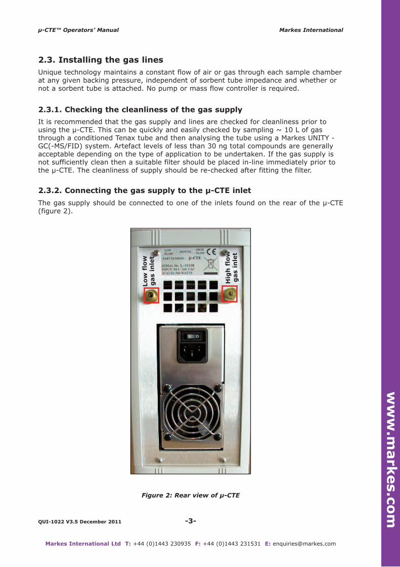
2.3.2. Connecting the gas supply to the µ-CTE inlet
The gas supply should be connected to one of the inlets found on the rear of the µ-CTE(figure 2).
Figure 2: Rear view of µ-CTE
ww
w.m
ark
es.c
om
Lo
w f
low
g
as i
nle
t
Hig
h f
low
g
as i
nle
t

The left-hand inlet is the low-flow gas inlet which allows the user to operate at flowsbetween 10 and 70 mL/min. The right-hand inlet is the high-flow gas inlet which allowsthe user to operate at flows between 50 and 500 mL/min. In both cases a gas backingpressure of between 10 and 60 psi must be maintained to ensure flow stability of thegas particularly at the lower flow rates.
Once the gas supply is connected, ensure that the unused inlet is capped with theblanking plug supplied.
The flow rate is determined by measuring the flow (with an appropriate flow meter)from the back of a sorbent tube inserted into the lid of the µ-CTE with the lid closed(figure 3). The choice of sorbent tube used for setting flow rates will ideally be the sametype of tube being used during sampling from the µ-CTE. The flow rate is adjusted byregulating the carrier gas pressure. The flow rate can be set with the µ-CTE heated tothe desired temperature if required (see section 2.5).
Figure 3: Schematic showing where to put tube
Markes InternationalSample tube/DNPH cartridge
Sample
Spacers
Heated airsupply
Heated block
Detachable micro-chambersample top
Micro-chamber
Unique flowcontrol
O-ring specific to tube type
-4-QUI-1022 V3.5 December 2011
µ-CTE™ Operators’ Manual Markes International
Markes International Ltd T: +44 (0)1443 230935 F: +44 (0)1443 231531 E: [email protected]
ww
w.m
ark
es.c
om
-5-QUI-1022 V3.5 December 2011
µ-CTE™ Operators’ Manual Markes International
Markes International Ltd T: +44 (0)1443 230935 F: +44 (0)1443 231531 E: [email protected]
2.4. Connecting the µ-CTE
Connect the power cable supplied to the power socket on the rear of the µ-CTE (figure2) and turn the power switch on.
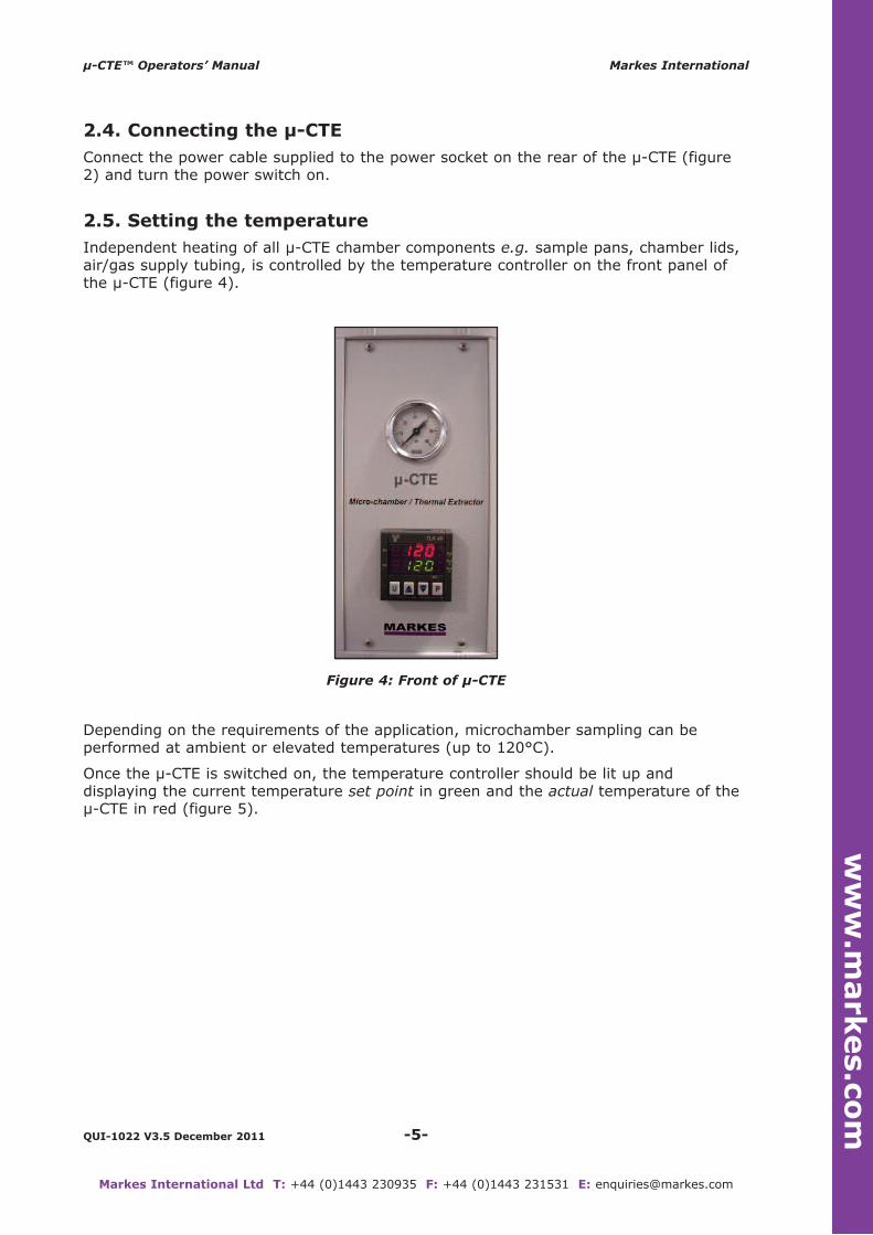
2.5. setting the temperature
Independent heating of all µ-CTE chamber components e.g. sample pans, chamber lids,air/gas supply tubing, is controlled by the temperature controller on the front panel ofthe µ-CTE (figure 4).
Figure 4: Front of µ-CTE
Depending on the requirements of the application, microchamber sampling can beperformed at ambient or elevated temperatures (up to 120°C).
Once the µ-CTE is switched on, the temperature controller should be lit up anddisplaying the current temperature set point in green and the actual temperature of theµ-CTE in red (figure 5).
ww
w.m
ark
es.c
om
-6-QUI-1022 V3.5 December 2011
µ-CTE™ Operators’ Manual Markes International
Markes International Ltd T: +44 (0)1443 230935 F: +44 (0)1443 231531 E: [email protected]
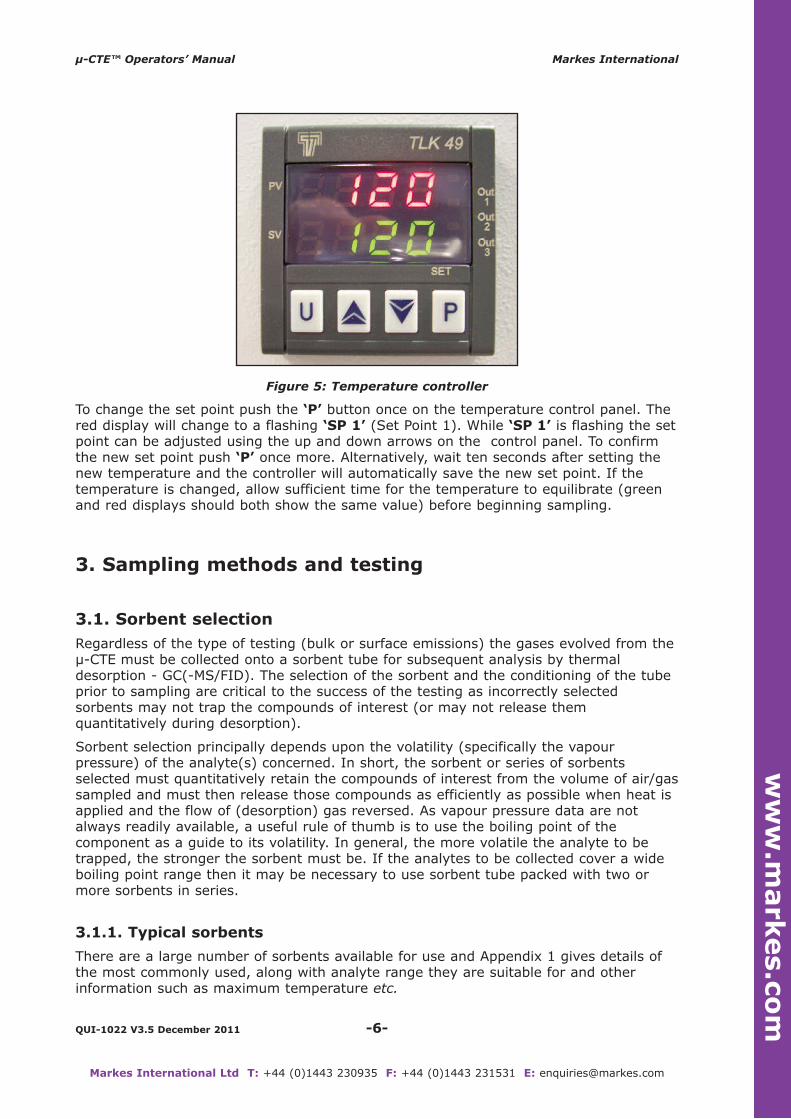
Figure 5: Temperature controller
To change the set point push the ‘P’ button once on the temperature control panel. Thered display will change to a flashing ‘sP 1’ (Set Point 1). While ‘sP 1’ is flashing the setpoint can be adjusted using the up and down arrows on the control panel. To confirmthe new set point push ‘P’ once more. Alternatively, wait ten seconds after setting thenew temperature and the controller will automatically save the new set point. If thetemperature is changed, allow sufficient time for the temperature to equilibrate (greenand red displays should both show the same value) before beginning sampling.
3. sampling methods and testing
3.1. sorbent selection
Regardless of the type of testing (bulk or surface emissions) the gases evolved from theµ-CTE must be collected onto a sorbent tube for subsequent analysis by thermaldesorption - GC(-MS/FID). The selection of the sorbent and the conditioning of the tubeprior to sampling are critical to the success of the testing as incorrectly selectedsorbents may not trap the compounds of interest (or may not release themquantitatively during desorption).
Sorbent selection principally depends upon the volatility (specifically the vapourpressure) of the analyte(s) concerned. In short, the sorbent or series of sorbentsselected must quantitatively retain the compounds of interest from the volume of air/gassampled and must then release those compounds as efficiently as possible when heat isapplied and the flow of (desorption) gas reversed. As vapour pressure data are notalways readily available, a useful rule of thumb is to use the boiling point of thecomponent as a guide to its volatility. In general, the more volatile the analyte to betrapped, the stronger the sorbent must be. If the analytes to be collected cover a wideboiling point range then it may be necessary to use sorbent tube packed with two ormore sorbents in series.
3.1.1. Typical sorbents
There are a large number of sorbents available for use and Appendix 1 gives details ofthe most commonly used, along with analyte range they are suitable for and otherinformation such as maximum temperature etc.
ww
w.m
ark
es.c
om

-7-QUI-1022 V3.5 December 2011
µ-CTE™ Operators’ Manual Markes International
Markes International Ltd T: +44 (0)1443 230935 F: +44 (0)1443 231531 E: [email protected]
Generally, sorbents can be classified as weak, medium or strong as follows:
Weak - porous polymers such as Tenax TA, Tenax GR, graphitised carbon blackssuch as Carbograph 2TD, Carbotrap C, Carbopack C.
Medium - porous polymers such as the Chromosorb series, Porapak series,HayeSep series, graphitised carbon blacks such as Carbograph 1TD, Carbopack B,Carbotrap.
strong - molecular sieves 13X & 5Å, carbonised molecular sieves such as theCarboxen series, Carbosieve SIII, UniCarb
3.1.2. Conditioning and storage of sorbent tubes
After selecting the correct sorbent tube for the analytes of interest, it is essential thatthe sorbent tubes are correctly conditioned prior to sampling. It is advisable to checkthe cleanliness of a representative proportion of tubes prior to sampling. Appendix 1gives further information regarding conditioning temperatures and attainable artefactlevels.
Conditioned tubes and sampled sorbent tubes should be capped with a 0.25 inch brassSwageLok type caps fitted with PTFE ferrules. Single sorbent tubes are generally stablefor periods of over 1 year at room temperature. However, multi-bed tubes should usuallybe analysed within 1 week of sampling. Storage times longer than 1 week are possibleunder refrigerated conditions. However, in this case care must be taken to ensure thatthe brass caps remain tight after refrigeration and the tubes must be allowed toequilibrate to room temperature before analysis. Further information is given in MarkesInternational Thermal Desorption Technical Support Note 19 (‘Minimising artefacts -considerations for storage and transportation of sorbent tubes’). This can be downloadedafter registering on the Markes website (www.markes.com).
3.2. bulk emission testing
After setting the required gas flow rate and temperature, materials for bulk emissionstesting, (or odour/fragrance profiling), may simply be weighed and placed directly intoan empty microchamber - or into a custom made inert “sample boat” which is placeddirectly into the chamber itself.
Allow the sample to equilibrate - typically for 5 - 10 minutes - and then insert aconditioned sample tube into the µ-CTE tube insert to commence collecting emissions.At the end of the sampling interval, remove the tube and cap with brass storage caps asdescribed above.
Sampled tubes are thermally desorbed and analysed by GC (-MS/FID) followingstandard methods such as ISO 16000-6, ASTM WK 3464, ISO/EN 16017-1, ASTMD6196-03 etc. Alternative analysers, for example systems combining thermal desorptionwith process MS or ENose detectors, are also applicable in some cases.
note: If sampling at elevated temperatures, sample tubes may be hot when they areremoved from the µ-CTE.
Depending on the type of sample material analysed, after sampling the chamber mayrequire cleaning before subsequent use. See Section 4.1 for cleaning techniques.
ww
w.m
ark
es.c
om

-8-QUI-1022 V3.5 December 2011
µ-CTE™ Operators’ Manual Markes International
Markes International Ltd T: +44 (0)1443 230935 F: +44 (0)1443 231531 E: [email protected]
3.3. surface emissions testing
Surface emissions testing requires a 4.5 cm diameter circular sample specimen to be cutfrom the product/material so that it fits snugly into the microchamber on top of thesupplied spacers. A collar projecting down from the chamber lid helps define both theexposed sample surface area and the depth of the air space above the sample (figure3). When testing surface emissions 12.82 cm2 of sample surface area is exposed to theair/gas flow, and the air/gas volume above the sample surface is 3.2 cm3.
The µ-CTE is supplied with a complete set of sample spacers which are used to raise thesurface of the test sample so that it is flush with the top of the microchamber pot. Thespacers are placed inside the microchamber, underneath the sample, such that theemitting surface is presented to the air flow at the correct height, whatever its originalthickness. When using the spring mounted stage (p/n M-SPGSC), ensure that the nutsto the 3 screws are facing down and the stage is supported by at least 1 aluminiumspacer ring. Failure to do so will prevent the stage from compressing.
After setting the required gas flow rate and temperature, place the sample inside themicrochamber and allow the sample to equilibrate - typically for 5 - 10 minutes - andthen insert a conditioned sample tube into the µ-CTE tube insert to commence collectingemissions. At the end of the sampling interval, remove the tube and cap with brassstorage caps as described above.
Sampled tubes are thermally desorbed and analysed by GC(-MS/FID) followingstandard methods such as ISO 16000-6, ASTM WK 3464, ISO/EN 16017-1, ASTMD6196-03 etc. Alternative analysers, for example systems combining thermal desorptionwith process MS or ENose detectors, are also applicable in some cases.
note: If sampling at elevated temperatures, sample tubes may be hot when they areremoved from the µ-CTE.
Depending on the type of sample material analysed, the chamber may require cleaningafter sampling, before subsequent use. See Section 4.1 for cleaning techniques.
4. Maintenance
4.1. Cleaning
The µ-CTE (p/n M-CTE100) sample pots, tube inserts and lids are constructed fromstainless steel to minimise contamination and carryover effects. However, cleaning of thechamber pots and lids may occasionally be required depending upon the type of sampleanalysed and the conditions in which they were sampled.
note: The inert microchamber (M-CTE100i) has sample pots, tube inserts and lidsconstructed in inert coated stainless steel to minimise breakdown of labile compounds.
The physical nature of some samples e.g. viscous compounds, molten polymers etc. willbe more prone to contaminating the chamber than more rigid samples. As a result,cleaning of the sample pots and lids in between sampling such products may benecessary. For more rigid samples, cleaning of the sample pots and lids will be requiredless frequently and less rigorously.
Having first removed all sealing O-rings, the micro-chamber pots, chamber lids andspacers can be cleaned by one of two methods:
1.The inner surface can be washed with detergent, followed by two separate rinsings
ww
w.m
ark
es.c
om

with freshly distilled water. The surface is then rinsed again with non-denaturedethanol or another appropriate solvent.
2. Inserting all components, with the exception of the chamber lids, into a vacuumoven.
Individual microchamber pots and lids can be removed from the µ-CTE and placeddirectly into a vacuum oven at an elevated temperature (200-300°C) forapproximately 2 hours. Instructions on how to remove pot lids are described inSection 4.1.1. Before placing the sample pots into an oven, ensure that the O-ringshave been removed from the rim of the microchamber pots, from the tube connectorattached to the lids, and from the sample pot lid. See section 4.2 for further detailson O-ring removal.
4.1.1. removing pot lids
note: Under no circumstances should the 4 posidrive screws (M3) on top of the hingedcover be adjusted (see figure 6)
1. Unscrew the cap from the tube connector and remove O-ring
2. Using a 7 mm nut drive spanner remove the M4 nut and washer located in the centreof the hinged µ-CTE lid (see figure 6)
3. Grasp the edges of the removable pan lid (see figure 7) and gently pull away fromthe hinged cover
4. Remove gas inlet O-ring (see figure 8)
5. Place in a vacuum oven up to 300°C for approximately 2 hours
6. O-rings can be cleaned by placing in a vacuum oven (<200°C) for approximately 2hours
Figure 6: Lid assembly top elevation
Tube connector capHinged cover
M4 flanged nuton the end ofsecuring stud
M3 Posidrivescrews x 4
-9-QUI-1022 V3.5 December 2011
µ-CTE™ Operators’ Manual Markes International
Markes International Ltd T: +44 (0)1443 230935 F: +44 (0)1443 231531 E: [email protected]
ww
w.m
ark
es.c
om

-10-QUI-1022 V3.5 December 2011
µ-CTE™ Operators’ Manual Markes International
Markes International Ltd T: +44 (0)1443 230935 F: +44 (0)1443 231531 E: [email protected]
Figure 7: Lid assembly bottom elevation
Figure 8: Removed pot lid - side elevation
4.1.2. securing pot lids
1. Ensure that gas inlet O-ring is in place
2. Ensure that the tube connector cap IS NOT in place
3. While using oil free, lint free, gloves (so that the clean lid is not contaminated fromhandling) position the removable lid so that the tube connector, securing studs and gasinlet are aligned with their corresponding orifices (see figure 9)
Gas inlet
Securing stud (without M4 nut)
Tubeconnector/cap 006 OD O-ring
Gas outlet orificeHinged cover
Microchamberremovable potlid
Gas inletorifice
ww
w.m
ark
es.c
om

4. Gently push pot lid towards the hinged cover until the lid can go no further
5. Using a 7 mm drive spanner tighten the M4 flanged nut onto the securing stud
(Tip: Use the drive spanner to hold onto the M4 flanged nut. Open the hinged lid anduse the drive spanner to position the flanged nut onto the securing stud beforetightening. Lower the lid onto the pot and lock before the final tightening of the M4flanged nut)
6. Place O-ring into tube connector and attach tube connector cap
Figure 9: Lid assembly with chamber pot lid removed - bottom elevation
4.2. Changing O-ring sealsThe microchamber pot O-ring seal (p/n M-MCHOR (pk 6)) can be found on the top rimof the pot. The tube insert O-ring can be found by unscrewing the retaining cap.
If the O-rings require removal they should be hooked out with the O-ring extraction tool(p/n SERZ-0351) available from Markes International.
New seals should be pushed into position using the O-ring insertion tool (p/n SERZ-0285) available from Markes International, and gently nudged evenly into the seating.Also use the O-ring insertion tool to smooth around the inner diameter of the O-ring asit is being pushed into place to avoid distortion.
Tube connector orificeHinged cover
Orifice for M4securing stud
Gas inletrecess
Securing studs
-11-QUI-1022 V3.5 December 2011
µ-CTE™ Operators’ Manual Markes International
Markes International Ltd T: +44 (0)1443 230935 F: +44 (0)1443 231531 E: [email protected]
ww
w.m
ark
es.c
om

-12-QUI-1022 V3.5 December 2011
µ-CTE™ Operators’ Manual Markes International
Markes International Ltd T: +44 (0)1443 230935 F: +44 (0)1443 231531 E: [email protected]
Appendix One - sorbent selection
What follows is summary information on a selection of the most commonly usedsorbents including maximum operating temperatures, recommended conditioningtemperatures and typical operating temperatures. Sorbent tubes should typically beconditioned using higher temperatures and faster gas flows than those selected foranalysis, however this must nOT exceed the temperature limit of the sorbents selected.
When using multi-bed tubes with two, three or even four sorbents it is essential to notethe following points:
- sorbents should be packed into the tubes in order of increasing strength, with theweakest sorbent nearest the front (grooved/fritted) end of the tube.
- multi-bed tubes should only contain mixtures of sorbents of similar maximumtemperatures otherwise it will not be possible to comprehensively condition thetubes.
Commonly Used sorbents
Carbograph 2TD (20/40; 40/60; 60/80)
Carbopack C (60/80)
Carbotrap C (20/40)
Sorbent Type: Graphitised carbon blackSorbent Strength: Very weakSpecific Surface Area (m2/g): ~12Approx analyte volatility range: n-C8 to n-C20
Example analytes: Alkyl benzenesHydrocarbons to n-C20
Sorbent Max Temperature: >400°CRecommended ConditioningTemperature: 350°C to 400°CRecommended DesorptionTemperature: 300°C to 350°CNotes: Hydrophobic
Minimal (<0.1 ng) artefactsSome activity with labile compoundsFriable
Tenax TA (35/60; 60/80)
Tenax Gr (35/60; 60/80)
Sorbent Type: Porous polymerSorbent Strength: WeakSpecific Surface Area (m2/g): ~35Approx analyte volatility range: n-C7 to n-C30
Bp 100°C to 450°CExample analytes: Aromatic compounds except benzene
Apolar compounds bp >100°CPolar compounds bp >150°CPAHs and PCBs
Sorbent Max Temperature: 350°C
ww
w.m
ark
es.c
om

-13-QUI-1022 V3.5 December 2011
µ-CTE™ Operators’ Manual Markes International
Markes International Ltd T: +44 (0)1443 230935 F: +44 (0)1443 231531 E: [email protected]
Recommended ConditioningTemperature: 325°CRecommended DesorptionTemperature: Up to 300°C Notes: Hydrophobic
Low inherent (<1 ng) artefactsInertGraphitised form best for PAHs/PCBsEfficient desorption Use 35/60 mesh to minimise fines and eliminate “leakage” through conventional sorbent retaining gauzes
Carbograph 1TD (20/40; 40/60; 60/80)
Carbopack b (60/80)
Carbotrap (20/40)
Sorbent Strength: Medium / WeakSpecific Surface Area (m2/g): ~100Approx analyte volatility range: n-C5 to n-C14
Example Analytes: Ketones, alcohols, aldehydes & apolar components within the above volatility rangePerfluorocarbon tracer gases
Sorbent Maximum Temperature: >400°CRecommended Conditioning Temperature: 350°C to 400°CRecommended Desorption Temperature: 300°C to 350°CNotes: Hydrophobic
Low artefacts (<0.1 ng)Some activity with labile compoundsFriable
Chromosorb 102 (60/80)
Sorbent Strength: MediumSpecific Surface Area (m2/g): ~350Approx analyte volatility range: Bp 50°C to 200°C Example Analytes: Alcohols, oxygenated compounds
haloforms less volatile than methylene chlorideSorbent Maximum Temperature: 250°CRecommended Conditioning Temperature: 225°C (250°C for short (<15 mins) periods only)Recommended Desorption Temperature: No higher than 220°CNotes: High artefacts (at least 10 ng) - for trace level analysis
condition at 225°C and desorb sample tubes no higherthan 200°C to reduce background levelsArtefacts generated on storage - for trace level analysis analyse tubes immediately after sampling
ww
w.m
ark
es.c
om
HydrophobicInert
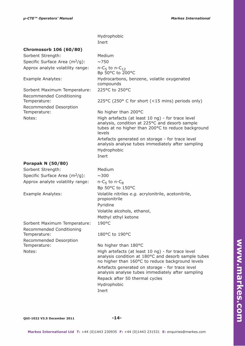
Chromosorb 106 (60/80)
Sorbent Strength: MediumSpecific Surface Area (m2/g): ~750Approx analyte volatility range: n-C5 to n-C12
Bp 50°C to 200°C Example Analytes: Hydrocarbons, benzene, volatile oxygenated
compounds Sorbent Maximum Temperature: 225°C to 250°CRecommended Conditioning Temperature: 225°C (250° C for short (<15 mins) periods only)Recommended Desorption Temperature: No higher than 200°CNotes: High artefacts (at least 10 ng) - for trace level
analysis, condition at 225°C and desorb sample tubes at no higher than 200°C to reduce background levelsArtefacts generated on storage - for trace level analysis analyse tubes immediately after samplingHydrophobicInert
Porapak n (50/80)
Sorbent Strength: MediumSpecific Surface Area (m2/g): ~300Approx analyte volatility range: n-C5 to n-C8
Bp 50°C to 150°C Example Analytes: Volatile nitriles e.g. acrylonitrile, acetonitrile,
propionitrilePyridineVolatile alcohols, ethanol, Methyl ethyl ketone
Sorbent Maximum Temperature: 190°C Recommended Conditioning Temperature: 180°C to 190°C Recommended Desorption Temperature: No higher than 180°CNotes: High artefacts (at least 10 ng) - for trace level
analysis condition at 180°C and desorb sample tubesno higher than 160°C to reduce background levelsArtefacts generated on storage - for trace level analysis analyse tubes immediately after samplingRepack after 50 thermal cyclesHydrophobicInert
-14-QUI-1022 V3.5 December 2011
µ-CTE™ Operators’ Manual Markes International
Markes International Ltd T: +44 (0)1443 230935 F: +44 (0)1443 231531 E: [email protected]
ww
w.m
ark
es.c
om

-15-QUI-1022 V3.5 December 2011
µ-CTE™ Operators’ Manual Markes International
Markes International Ltd T: +44 (0)1443 230935 F: +44 (0)1443 231531 E: [email protected]
Porapak Q (50/80)
Sorbent Strength: MediumSpecific Surface Area (m2/g): ~550Approx analyte volatility range: n-C5 to n-C12
Boiling point 50°C to 200°C Example Analytes: VOCs within volatility range above
Oxygenated compoundsSorbent Maximum Temperature: 250°CRecommended Conditioning Temperature: 225°C (250°C for short (<15 mins) periods only)Recommended Desorption Temperature: No higher than 225°CNotes: High artefacts (at least 10ng) - for trace level
analysis, condition at 180°C and desorb sample tubes at no higher than 160°C to reduce background levelsArtefacts generated on storage - for trace level analysis, analyse tubes immediately after samplingRepack after 50 thermal cyclesHydrophobicInert
UniCarb (60/80)
Sorbent Strength: StrongSpecific Surface Area (m2/g): ~1200Approx analyte volatility range: C3 to n-C8
Bp 30°C to 100°C Example Analytes: Very volatile compounds e.g. VCM, ethylene oxide,
carbon disulphide, dichloromethane, chloromethaneVolatile polar compounds e.g. methanol, ethanol, acetone
Sorbent Maximum Temperature: >400°CRecommended Conditioning 350°C to 400°CTemperature: N.B. Increase temp from 250°C stepwise and slowlyRecommended Desorption Temperature: 300°C to 350°CNotes: Some hydrophilicity
Low artefacts (<0.1 ng) Excellent batch-to-batch reproducibilityInertNon-friable
Carbosieve sIII (60/80)
Sorbent Strength: Very StrongSpecific Surface Area (m2/g): ~800, but primarily operates on molecular sieve
principle with 15/40Å poresApprox analyte volatility range: Primarily for C2 hydrocarbons and smaller molecules.
Bp -60°C to 80°C Example Analytes: Ultra volatile hydrocarbons
ww
w.m
ark
es.c
om

Sorbent Maximum Temperature: >400°CRecommended Conditioning 350°CTemperature: N.B. Slow conditioning required as for UniCarb Recommended Desorption Temperature: 300°C Notes: Some hydrophilicity
Low artefacts (<0.1 ng)Easily & irreversibly contaminated by higher boiling components - protect with front bed of weaker sorbent
Carboxen 1000 (range of mesh sizes available)
Sorbent Strength: Very strong for small molecules Specific Surface Area (m2/g): >1200 Approx analyte volatility range: Permanent gases and light hydrocarbons (C2, C3).
Bp -60°C to 80°C Example Analytes: Ultra volatile hydrocarbons Sorbent Maximum Temperature: >400°CRecommended Conditioning 350°CTemperature: N.B. Slow conditioning required as for UniCarb Recommended Desorption Temperature: To suit analyteNotes: Some hydrophilicity
Low artefacts (<0.1 ng)Easily & irreversibly contaminated by higher boiling components - protect with front bed of weaker sorbent
Molecular sieve (13X, 5Å)
Sorbent Strength: Very strong for small molecules Approx analyte volatility range: Bp -60°C to 80°C Example Analytes: 1,3 butadiene (13X), nitrous oxide (5Å)Sorbent Maximum Temperature: 350°CRecommended Conditioning Temperature: 300°C (increase temperature gradually) Recommended Desorption Temperature: To suit analyteNotes: Significantly hydrophilic - do not use in humid
conditionsHigh artefacts (>10 ng)Easily & irreversibly contaminated by higher boiling components
-16-QUI-1022 V3.5 December 2011
µ-CTE™ Operators’ Manual Markes International
Markes International Ltd T: +44 (0)1443 230935 F: +44 (0)1443 231531 E: [email protected]
ww
w.m
ark
es.c
om