Embed Size (px)
Citation preview

Industrial Single-head Embroidery Machine
INSTRUCTION BOOKProgram Ver. *2.14 ~
HCD2
PROVISIONALVERSION
DAR801-30


-DA -3
CONTENTSIMPORTANT SAFETY INSTRUCTIONS ... 1-1WARNING LABELS & THEIR LOCATIONS ..... 1-2SETTING UP THE MACHINE
Assemble machine unit ........................... 2-1How to carry machine ............................. 2-2Machine installation ................................ 2-3Assemble safety sensor (Option) ...................... 2-4Assemble Wide X-carriage (Option) ................ 2-4bAssemble table (Option) ......................... 2-5Assemble border frame (Option) ............ 2-5bAssemble Expand side table (Option) .... 2-5cAssemble bobbin thread guide (Option) 2-6Grounding instruction (for type of 120V) 2-7Disposal of a battery .............................. 2-7
MAIN PARTS ............................................. 3-1THE CONTROL BOX ................................ 3-3DRIVE MODE .................................. 3-4MENU ................................................... 3-AINSERTING A NEEDLE ............................. 4-1SELECT NEEDLES AND THREADS ....... 4-2BACKING MATERIALS ............................. 4-3BORDER FRAMEのCLIP ........................... 4-3aWINDING
Winding the bobbin (Option) ................... 4-4Removing the bobbin .............................. 4-5Inserting the bobbin ................................ 4-5Adjusting bobbin thread tension .............. 4-5Inserting the bobbin case ........................ 4-5
THREADING THE MACHINEHow to thread upper thread .................... 4-6
HOW TO READ THESE INSTRUCTIONS, SCROLLBAR ... 4-8DISPLAYING THE PATTERN IN SETTING MODE ... 4-9TURNING THE MACHINE ON
How to turn on the machine .................... 5-1Calendar and clock setting ...................... 5-2
MESSAGES .............................................. 5-3PREPARATION OF PATTERN DATA
Connecting to a PC ................................. 5-4Reading embroidery pattern data from the PC . 5-4bReading embroidery pattern data ........... 5-5
Selection of folders ................................. 5-9How to select patterns from memory ... 5-AErasing patterns from memory .............. 5-B
NEEDLE BAR SELECTION .................... 5--ESEWING WITH TUBULAR FRAMES
Installing and removing the frame base .. 6-1How to hoop ............................................ 6-2Mounting the hoop on the machine ......... 6-3Starting to embroider .............................. 6-4
CAP FRAME (option)Cap frame settings .................................. 7-1Installing and removing the cap drive frame ...7-2Normal cap frames .................................. 7-5Wide cap frames ..................................... 7-8Starting to embroider ........................... 7-B
ADJUSTING THE THREAD TENSION ..... 8-1ADJUSTING THE LASER POINTER (OPTION) .. 8-2BORER (Option) ........................................ 8-4SEWING
What to do if the thread breaks while sewing 9-1Stopping and resuming sewing ............... 9-1Loss of power while embroidering .......... 9-2Moving the hoop while embroidering and then returning to the correct location (Position) ............................. 9-3Moving back to the starting point (Origin) 9-3Going back to the beginning of the design (Top) ... 9-4Placing the design in the center of the selected embroidery frame (Center) ........................... 9-4Rotating and mirroring designs (Convert) ..... 9-5Starting in the middle of a design (Position) ...9-6
POSITION ALIGNMENT BY DEFINING 2 POINTS .. 9-8POSITION ................................................. 9-B
Piece number ..........................................9-CBobbin thread alarm ..............................9-Cb
REGISTER ................................................9-D
Entry ........................................................9-EReturn ..................................................... 9-F
READINGJoin ....................................................... 10-1Pattern read settings ............................. 10-3
0_1 R801
0-1

-DA -4
CONTENTS
0_2 R821
0-2PATTERNS IN MEMORY
Locking pattern data ..............................11-1Trace type ..............................................11-2Export .....................................................11-3Renaming patterns .................................11-5Copying pattern data ..............................11-6Moving pattern data ...............................11-7Renaming folders ...................................11-9Sort ........................................................11-AThread break report .............................. 11-BRetrieve built-in design data .................11-CSearching pattern data ..........................11-D
NEEDLE BAR SELECTION .................... 12-1Auto setting ........................................... 12-2Thread color .......................................... 12-4Color change data registration .............. 12-6Color change data read ........................ 12-7Repetition of color group setting ........... 12-8
FRAME CONFIRMATION ....................... 13-1Frame selection ....................................... 13-2Adjusted for embroidery area ................ 13-4User-defined frames (1 ~ 5) .................. 13-7User-defined frames (6 ~ 20) .................13-AHow to change center point of frame (1 ~ 5, 6 ~ 20) ........13-HNon registered frame .............................13-J
PATTERN SETTINGS ............................. 14-1Scaling .................................................. 14-2Width adjustment .................................. 14-3Angle ..................................................... 14-4Repeat sewing ...................................... 14-5Auto origin ............................................. 14-7Offset .................................................... 14-8Frame out ...............................................14-D
MACHINE SETTINGS ............................. 15-1LOCK STITCHES .................................... 15-5OPTIONAL DEVICE SETTING ............... 15-6LETTER ................................................... 16-1QUEUE .................................................... 17-1
Alter and Execution ............................... 17-2Needle bar selection and Pattern settings ... 17-4
Registration of QUEUE setting ............. 17-6Read QUEUE setting ............................ 17-7
OTHER SETTINGSCreate network ...................................... 18-1Version information and software update .... 18-3Language .............................................. 18-5Calibrate ................................................ 18-6User maintenance mode ....................... 18-8
Report ...................................................... 19-1
GUIDE .................................................. 20-1SCREEN SAVER ..................................... 21-1i-CUSTOM ............................................... 22-1
LAN connection .........................................22-2aTASK RESERVATION ............................... 22-2b
Reading ................................................. 22-2cNeedle bar selection ............................. 22-2dSetting ................................................... 22-2eSearch ................................................... 22-2fList ........................................................ 22-2g
USER MANAGEMENTRegistration of administrator ................. 22-3Registration of user ............................... 22-6Selection of user (Login) ....................... 22-8Selection of user (Login) at power ON .. 22-9
LAYOUT ...................................................22-A
SPECIFICATIONS • MAINTENANCESpecifications ........................................ 23-1Oiling ..................................................... 23-1Cleaning the rotary hookCleaning the thread cutting knife .......... 23-2
ERRORS AND WHAT TO DO ................. 24-1INITIALIZING OF MACHINE SETTINGS
Re-Initialization of machine system ...... 25-1Initializing of machine speed ................. 25-2
HELPFUL HINTS ..................................... 26-1EMBROIDERY TERMS ........................... 26-2BUILT-IN FONT LIST ............................... 26-3BUILT-IN PATTERNS LIST ...................... 26-4

-CD -5
IMPORTANT SAFETY INSTRUCTIONS
1_1 F701
1-1When using an electrical appliance, basic safety precautions should always be followed, includ-ing the following.
Read all instructions before using this appliance.
DANGER - To reduce the risk of electric shock:1. An appliance should never be left unattended when plugged in. Always unplug this appliance
from the electric outlet immediately after using and before cleaning.
WARNING - To reduce the risk of burns, fire, electric shock, or injury to persons:1. Do not allow to be used as a toy. Close attention is necessary when this appliance is used
by or near children.2. Use this appliance only for its intended use as described in this manual. Use only
attachments recommended by the manufacturer as contained in this manual.3. Never operate this appliance if it has a damaged cord or plug, if it is not working properly, if it
has been dropped or damaged, or dropped into water. Return the appliance to the nearestauthorized dealer or service center for examination, repair, electrical or mechanicaladjustment.
4. Never operate the appliance with any air openings blocked. Keep ventilation openings of thesewing machine free from the accumulation of lint, dust, and loose cloth.
5. Never drop or insert any object into any opening.6. Do not use outdoors.7. Do not operate where aerosol (spray) products are being used or where oxygen is being
administered.8. To disconnect, turn all controls to the off (“0”) position, then remove plug from outlet.9. Do not unplug by pulling on cord. To unplug, grasp the plug, not the cord.10.Keep fingers away from all moving parts. Special care is required around the sewing
machine needle.11.Always use the proper needle plate. The wrong plate can cause the needle to break.12.Do not use bent needles.13.Do not pull or push fabric while stitching. It may deflect the needle causing it to break.14.Switch the sewing machine off (“0”) when making any adjustments in the needle area, such
as threading needle, changing needle, threading bobbin, or changing presser foot, etc.15.Always unplug sewing machine from the electrical outlet when removing covers, lubricating,
or when making any other user servicing adjustments mentioned in the instruction manual.
SAVE THESE INSTRUCTIONS
-D2 -5
WARNING LABELS & THEIR LOCATIONS
1_2 M101
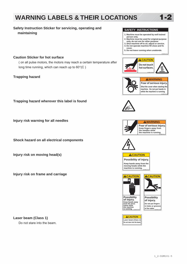
1-2Safety Instruction Sticker for servicing, operating and
maintaining
Caution Sticker for hot surface( on all pulse motors, the motors may reach a certain temperature afterlong time running, which can reach up to 60°(C )
Trapping hazard( please see sketch for location )
Trapping hazard wherever this label is found
Injury risk warning for all needles
Shock hazard on all electrical components
Injury risk on moving head(s)
Injury risk on frame and carriage
Laser beam (Class 1)Do not stare into the beam.
ES-HMF-5113-0
WARNING
Shut the cover when starting themachine. Do not put hands inwhile the machine is running.
Fear of serious injury.
ES-HMF-5127-0
SAFETY INSTRUCTIONS
1. Machine must be operated by well trainedperson only.
2. Machine must be used for original purposeonly, do not use for other purpose.
3. Shut machine off to oil, adjust or service.4. Do not operate machine fill close and fix
cover.5. Do not leave running when unattende.
ES-HMF-5128-0
Do not touchhot surfaces.
CAUTION
ES-HMF-5112-1
Fear of serious injury.Keep fingers away fromthe needles whilethe machine is running.
WARNING
ES-HMF-5117-0
CAUTION
Keep hands away from themoving heads while themachine is running.
Possibility of injury.
ES-HMF-5114-0
CAUTION
Possibilityof injury.Keep hands awayfrom the driveframe whilethe machineis running. ES-HMF-5115-0
CAUTION
Possibilityof injury.Do not put fingersin holes or groovesof the table.
Laser beam (Class 1)
CAUTION
Do not stare into the beam.

-D2 -8
SETTING UP THE MACHINE
2_1 N401
2-1Assemble machine unit
1. Insert thread stand felt on the thread stand.
2. Turn the thread guide pillar clockwise with a3 mm hexagonal driver until tight.
3. Install the thread guide bracket withsupplied screws (pan head screw M4 X 8 2pcs).
4. Loosen the screw with a offset driver andremove the red shipping collars that areequipped on the both side of the guide bar.(Keep the shipping collars. It is necessarywhen packing.)
5. Raise slowly the control box to the frontthen fix it with 2 screws (upper and lower).
6. Install the tubular frame arm for embroidery.Please refer to (page 6-1) "Installing andremoving the tubular frame arm".Or, Install the cap frame for the capembroidery. Please refer to (page 7-1)"Installing and removing the cap driveframe".
7. Insert built-in stylus into the holder (slot) ofcontrol box.
When taking the machine apart in case ofpacking, the process is opposite ofassembling the machine. Please do exactlythe opposite way of assembling.
When packing the machine up fortransportation, be sure to select the eighthneedle and fix it with shipping collars on theboth side of the guide bar.
12
3
Thread standfelt
Thread guide pillar
Thread guide
5
Screw
4
Screw
Screws
Stylus
7

-D2M4 -92-2 LC01
2-2SETTING UP THE MACHINE for qualified personnel only
How to carry machineThe unpacked machine should be carried by 3
person with the hand position at markshown in photos.
2 Ocasionaladjusters
Adjusters
Rubber mount1
Right side
Left side
Rear side
Machine installation
Do not run the machine before setting itproperly.Make sure of taking the following steps toset the machine.
1. Pick up rubber mount (3 places) on thestand then mount machine on the stand.Then adjust machine level by adjuster onfoot and lock the each nut.
Be sure to use rubber mounts. Also be sureto use robust stand that enables to adjustlevel of the machine and endure machineweight and vibration.
2. Please two occasional adjuster light touchto stand and lock.

-D22-3 M201
2-3SETTING UP THE MACHINE for qualified personnel only
3. Remove needle plates and bobbin casesfrom all the heads.
4. Lower the needle holder by pressing downwith fingers on Fig. 4.
5. Turn main shaft by using the hexagonaldriver in direction shown with arrow mark onFig. 5 and set the angle of the adjustmentdisk as shown in fig. 6.
6. Check the needle depth on all needles.Pull white plastic ø17 measuring gauge inand out of rotary hook in fig. 7. If heightgauge brushes lightly against tip of needle,needle height is correct. If not, loosenneedle bar block screw to adjust, then re-tighten after adjustment.(Remove the gauge when finished).Note: Height gauge is contained in tool box.
7. Turn main shaft slightly in direction shownby the arrow mark.Then set the angle of adjustment disc asshown in Fig. 8.Note the space or timing between needleand tip of rotary hook as shown Fig. 9, 10.If the space is too open or too close, loosen3 screws of shuttle to adjust. Make sure totighten 3 screws after adjusted the space.(The timing is set exactly at the factory.However, in some cases timing is inadvert-ently thrown off from handling during ship-ment.)
8. Turn main shaft in direction and set to Cpoint.Place the bobbin and bobbin case in thehook and replace the needle plate andtighten.
9. Machine is now ready for sewing.
Needle holder
Tip of rotary hookNeedle
L+5°
CordRotary hookNeedle
ø17 Measuring gauge
L+23°
ScrewsNeedleTip of rotary hook
0.1~0.15mmHead bed
C
Fig. 10
Fig. 9
Fig. 8
Fig. 7
Fig. 6
Fig. 5
Fig. 4

-DA -112-4 Q701
2-4SETTING UP THE MACHINEAssemble safety sensor (Option)
Safety sensors are set at a provisional positionfor transportation. Please reset the safety sen-sors at normal positions for adjustment.
1. Unscrew set screws at lower points on the safety sensors on right and left sides. Loosen set screws slightly at upper points on the safety sensors.
2. Set the right and left safety sensors at the positions as shown in a photo by turning them to the front side. At this time, make sure the part on the sensors indicated by an arrow shall be set vertically, and set safety sensors both right and left at parallel positions each other with viewing them from the side. The set screw on the right safety sensor shall be tightened to the level that the positions of the safety sensors can be adjusted vertically.
3. Turnonthemachineandconfirmalampforreceiving ray (orange) is on when the way of sensor ray is not blocked.
4. Confirmifthelampforreceivingray(orange)is turned off by blocking the way of sensor ray by a hand or other. Tightenthesetscrewfirmly.
1
2
3
Set screw
Sensor left
Sensor right
Sensor rightSensor left
Ray receiver Ray projector
Power indicatorLamp for receiving ray
Power indicator
Way of sensor ray
4

-D22-4b M201-9
2-4bSETTING UP THE MACHINEAssemble Wide X-carriage
(Option)
Wide X-carriage is packed separately frommachine.When you set machine up, please install WideX-carriage on machine.
1. Move Stay at middle of Y-carriage.
2. Put Wide X-Carriage on Stay and adjustscrew hole position.
3. Fix Carriage by Flat head screw (M4x8) athole position [1] and [2](for the purpose ofpositioning).
4. [3][4] Fix Carriage by Fixing screw (CapM4x8, Spring washer, Plain washer) at holeposition [3] and [4].
5. Unscrew Flat head screw from [1] and [2]and fix by Fixing screw (Cap M4x8, Springwasher, Plain washer).
6. Loosen screws on BOX terminal and takecover out.
7. Insert X-Motor cable into BOX terminal andconnect with X-Motor relay cable.Fix terminal for earth connection for X-Motorcable and X-Motor relay cable together.
8. Fix X-Motor cable by Cable clamp.
9. Close cover of BOX terminal.
Please be sure cables do not get caught bycover.
Please reverse procedure when remove theX-Carriage.
Wide X-carriage
X-Motor cable
1 2
Cable clamp
Terminal for earth connection
Stay (left) Stay (right)
Stay (left) Stay (right)
1 4
3 2
14
32
X-Motor relay cable
BOX terminal
Cover ofBOXterminal
8
9
3 4 5
6 7
Front

-DA -132-5 OC10
2-5SETTING UP THE MACHINE
1. Insert Knob screw to right and left side of machine. And set table like right side picture. Please insert table bracket trench to the knob screw.
2. Tight 2 knob screw on under the table for fix table.
3. Tight 2 knob screw on side of the table.
Please reverse procedure when remove the table.
Knob screw
Knob screw
1
Assemble table (Option)Installing theTable or the Table (border).
2

-DA -142-5b OC10
2-5bSETTING UP THE MACHINE
1. Fix the border frame under the bracket of the X carriage and tighten the knob screw completely.
Clearance between X-carriage and Border Frame at right edge and left edge should be equal.
2. Select Frame Type “Border”. Please refer in this manual page “FRAME CONFIRMATION” for “Frame selection”.
20-2
Please reverse procedure when remove the border frame.
1
X carriage
Border frame
Assemble border frame (Option)
Bracket
Knob screw
-CD -152-5c J520
2-5cSETTING UP THE MACHINE
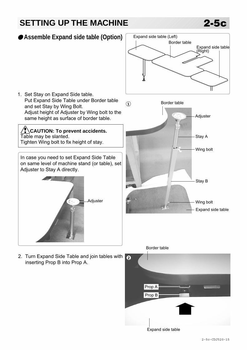
Assemble Expand side table (Option)
1. Set Stay on Expand Side table.Put Expand Side Table under Border tableand set Stay by Wing Bolt.Adjust height of Adjuster by Wing bolt to thesame height as surface of border table.
Stay A
Border table1
2
Wing bolt
Stay B
Adjuster
Wing bolt
Expand side table
In case you need to set Expand Side Tableon same level of machine stand (or table), setAdjuster to Stay A directly.
Adjuster
2. Turn Expand Side Table and join tables withinserting Prop B into Prop A.
Border tableExpand side table (Left)
Expand side table(Right)
CAUTION: To prevent accidents.Table may be slanted.Tighten Wing bolt to fix height of stay.
Border table
Expand side table
Prop A
Prop B

-CD -16
3. Confirm that Middle support plate enters tothe space between table and Prop plate andthere is no opening between tables.Tighten Knob bolt of Prop A at Border tableand fix Lock nut.Then set Clamp.
4. Adjust height of Expand Side Table byAdjuster and fix by Lock nut.
Please reverse procedure when remove theExpand Side Table.
2-5d J520
2-5dSETTING UP THE MACHINELock nutKnob bolt
Clamp
Prop plate
Middle table supportplate
Border table Expand sidetable (R)
3
Lock nutFix by Lock nut
Higher Lower
4
CAUTION: To prevent accidents.Table may be slanted.Please do not load any objects on Expandside table.

-CD -122-6 FB01
2-6SETTING UP THE MACHINE
Assemble bobbin thread guide
(Option)
1. Install the bobbin thread guide with suppliedscrews (pan head screw M4 X 6 2 pcs).( Showing following pictures, Please squareleft end of sticker with right end of threadstand)
Bobbin thread guideScrewsSticker
1

-CS -11
Grounding instruction (for type of 120V)
This product must be grounded. In the event of malfunction or breakdown, grounding provides apath of least resistance for electric current to reduce the risk of electric shock. This product isequipped with a cord having an equipment-grounding conductor and a grounding plug. The plugmust be plugged into an appropriate outlet that is properly installed and grounded in accordancewith all local codes and ordinances.
DANGER – Improper connection of the equipment-grounding conductor can result in arisk of electric shock. The conductor with insulation having an outer surface that is green with orwithout yellow stripes is the equipment-grounding conductor. If repair or replacement of the cordor plug is necessary, do not connect the equipment-grounding conductor to a live terminal.
Check with a qualified electrician or serviceman if the grounding instructions are not completelyunderstood, or if in doubt as to whether the product is properly grounded.
Do not modify the plug provided with the product – if it will not fit the outlet, have a proper outletinstalled by a qualified electrician.
This product is for use on a nominal 120 V circuit, and has a grounding plug that looks like theplug illustrated in sketch A in Figure. A temporary adaptor, which looks like the adaptor illus-trated in sketches B and C, may be used to connect this plug to a 2-pole receptacle as shown insketch B if a properly grounded outlet is not available. The temporary adaptor should be usedonly until a properly grounded outlet can be installed by a qualified electrician. The green col-ored rigid ear, lug, and the like, extending from the adaptor must be connected to a permanentground such as a properly grounded outlet box cover. Whenever the adaptor is used, it must beheld in place by the metal screw.
2_6 I916
2-7SETTING UP THE MACHINE
Disposal of a battery
A battery is had built-in to this embroidery machine.When you dispose of a battery, according to each country or a method determined in each area,please dispose appropriately.
Metal screw
Cover of groundedoutlet box
Grounding pin
Grounding means
Grounding methods
Adapter
A B
C

-DA -15
MAIN PARTS
1. Hook cover2. Hook3. Bobbin case4. Needle plate5. Take-up lever6. Lower rectifier7. Thread tension8. Upper rectifier9. Guide tube10. Thread guide support
11. Thread guide12. Thread check spring13. Thread stand pin14. Thread stand felt15. Needle bar selection knob16. Control box17. LAN port18. USB port
(Standard-A receptacle)19. Frame hold arm20. Carriage
21. Fuse (6A)22. Terminal box23. Power switch24. USB port
(Standard-B receptacle)
3_1 R101
3-1
1
23
4
5
7
8
9
10
11
12
13
1415
16
1920
21
17
22
23
18
6
24
-D2 -153_2 M717
3-2MAIN PARTS
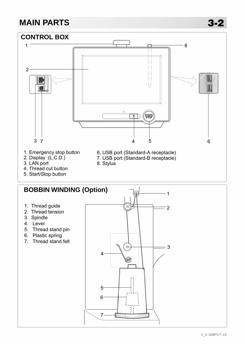
CONTROL BOX
4 5
1. Emergency stop button2. Display (L.C.D.)3. LAN port4. Thread cut button5. Start/Stop button
6
5
7
6
1
4
2
3
1. Thread guide2. Thread tension3. Spindle4. Lever5. Thread stand pin6. Plastic spring7. Thread stand felt
BOBBIN WINDING (Option)
3 7
1
2
16
8
6. USB port (Standard-A receptacle)7. USB port (Standard-B receptacle)8. Stylus

-DA -21
THE CONTROL BOX
3_8 NB25
3-3
5. Start/Stop buttonThis button starts the machine.When pressed, while the machine is running, the machine will stop.
Green .......... Machine ready to sew. Main menu also accessible by pressing MENU, which causes menu to display.
Blinking red .. Indicates the upper thread has bro-ken or the Bobbin thread has run out.
Red .............. Machine is running.Orange ........ Machine has detected an error.
An error number will be shown on the Display. 24-1
6. USB port (Standard-A receptacle) USB memory socket.
USB mouse socket.Menu and keys in the display can be operated with a commercial USB mouse.Press right mouse button to show a mouse pointer in the display.
7. USB port (Standard-B receptacle)Use this port to connect the machine with PC via USB.
8. StylusStylus can be used for pressing menu and keys in place of fingers.Most operation can be done by fingers. Stylus is required for some operation such as calibration for the touch panel LCD. 18-6 Insert a stylus into the holder (slot) of control box when not used to prevent loss of the stylus.
CAUTION: To prevent accidents.If you Press thread trim button, the needle will penetrate the fabric. Please keep your hands clear for your safety.
1
2
4 5
1. Emergency stop button2. Display (L.C.D.)3. LAN port4. Thread cut button5. Start/Stop button6. USB port
6
16
EMERGENCY1. Emergency stop buttonWhen pressed , the power is switched off and the machine stops immediately.The emergency button locks whenpressed.To unlock, turn the emergency button to the right(Arrow direction) then release. The button willunlock.Use this button only for emergency.
2. Display (Touch screen)Shows the embroidery design name, the number of the current needle and other machine generated messages. Menu and keys in the display can be operated with a finger or built-in stylus.
3. LAN portYou can connect PC with a LAN.
4. Thread trim buttonThe Machine will cut the upper and lower thread when this button is pressed.In case you press and keep (around 2 sec.), you can cut only bobbin thread.
73
8
CAUTIONThe touch screen can be operated by finger, but in some cases sensitivity of the screen will be affected by condition of the finger.In such cases, please use the fingertip or built-in stylus to hit small touch targets.

-3A -273_9 R801
3-4DRIVE MODEDrive keyThe each key menu will be shown.
3 Forward and Back-ward
2 Needle bar selection
4 Needle change
6 Frame move
1 Speed control
3 Forward and Back-ward
2 Needle bar selection
4 Needle change
6 Frame move
1 Speed control
5 i-Custom (default display)
5 i-Custom (default display)
7 Quick menu
MenuDisplay menu mode. 3-A
MenuDisplay menu mode. 3-A
HomeDisplay drive mode
3-5
STANDARD CONTROL BOX
10.4” CONTROL BOX (Option)
-3A -283_9b R801
3-5DRIVE MODE
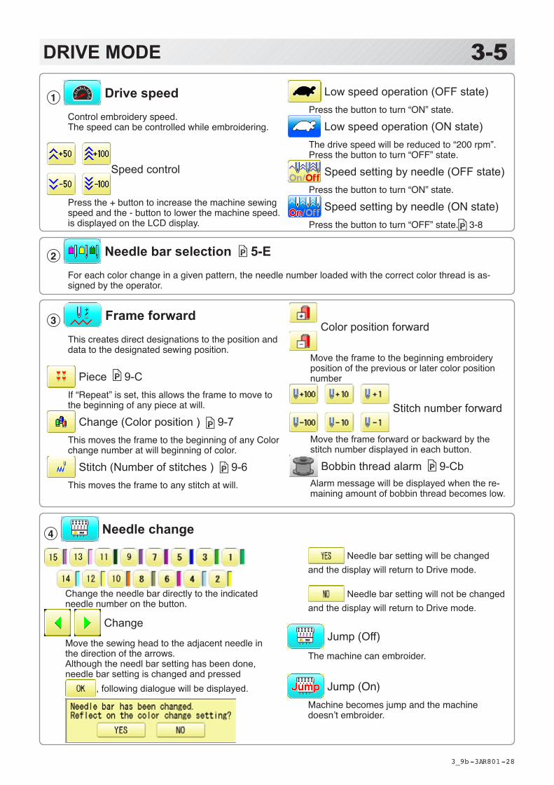
4 Needle change
Change the needle bar directly to the indicated needle number on the button.
Change
Move the sewing head to the adjacent needle in the direction of the arrows.Although the needl bar setting has been done, needle bar setting is changed and pressed
, following dialogue will be displayed.
Needle bar setting will be changed and the display will return to Drive mode.
Needle bar setting will not be changed and the display will return to Drive mode.
Jump (Off)
The machine can embroider.
Jump (On)Machine becomes jump and the machine doesn’t embroider.
3 Frame forwardThis creates direct designations to the position and data to the designated sewing position.
Piece 9-CIf “Repeat” is set, this allows the frame to move to the beginning of any piece at will.
Change (Color position ) 9-7This moves the frame to the beginning of any Color change number at will beginning of color.
Stitch (Number of stitches ) 9-6This moves the frame to any stitch at will.
1 Drive speedControl embroidery speed.The speed can be controlled while embroidering.
Speed control
Press the + button to increase the machine sewingspeed and the - button to lower the machine speed.is displayed on the LCD display.
2 Needle bar selection 5-EFor each color change in a given pattern, the needle number loaded with the correct color thread is as-signed by the operator.
Low speed operation (OFF state)Press the button to turn “ON” state.
Low speed operation (ON state)The drive speed will be reduced to “200 rpm”. Press the button to turn “OFF” state.
Speed setting by needle (OFF state)Press the button to turn “ON” state.
Speed setting by needle (ON state)Press the button to turn “OFF” state. 3-8
Color position forward
Move the frame to the beginning embroidery position of the previous or later color position number
Stitch number forward
Move the frame forward or backward by the stitch number displayed in each button.
Bobbin thread alarm 9-CbAlarm message will be displayed when the re-maining amount of bobbin thread becomes low.
-R3 -263_9c O512
3-6DRIVE MODE
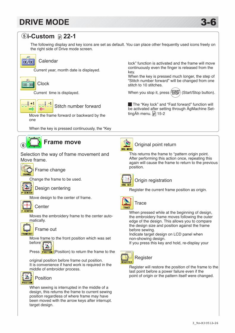
Original point return
This returns the frame to *pattern origin point.After performing this action once, repeating thisagain will cause the frame to return to the previous position.
Origin registration
Register the current frame position as origin.
Trace
When pressed while at the beginning of design,the embroidery frame moves following the outeredge of the design. This allows you to comparethe design size and position against the framebefore sewing.Indicate target design on LCD panel when non-showing design.If you press this key and hold, re-display your
Register
Register will restore the position of the frame to the last point before a power failure even if thepoint of origin or the pattern itself were changed.
6 Frame move
Selection the way of frame movement and Move frame.
Frame change
Change the frame to be used.
Design centering
Move design to the center of frame.
Center
Moves the embroidery frame to the center auto-matically.
Frame out
Move frame to the front position which was set before.
Press (Position) to return the frame to the
original position before frame out position.It is convenience if hand work is required in the middle of embroider process.
Position
When sewing is interrupted in the middle of a design, this returns the frame to current sewingposition regardless of where frame may have been moved with the arrow keys after interrupt.target design.
5 i-Custom 22-1The following display and key icons are set as default. You can place other frequently used icons freely on the right side of Drive mode screen.
Calendar
Current year, month date is displayed.
Clock
Current time is displayed.
Stitch number forward
Move the frame forward or backward by the one
When the key is pressed continuously, the “Key
lock” function is activated and the frame will move continuously even the finger is released from the key.When the key is pressed much longer, the step of “Stitch number forward” will be changed from one stitch to 10 stitches.
When you stop it, press (Start/Stop button).
The “Key lock” and “Fast forward” function will be activated after setting through ÅgMachine Set-tingÅh menu. 15-2

-R3 -253_9d O512
3-7DRIVE MODE
Fast move (OFF state)Press the button to turn “ON” state.
Fast move (ON state)Press this key one time to move the frame faster toward the direction of the arrow.Press the button to turn “OFF” state.
Fast move speed setting (High)
Fast move speed setting (Middle)
Fast move speed setting (Low)The speed of “Fast move” can be adjusted.
Pointer (Option)Turn on and off the laser pointer.
X Direction frame move
YDirection frame moveThe frame can be moved with specified distance along X axis or Y axis. (Unit: mm) The function allows you to move the frame pre-cisely with a pitch of 0.1mm.
Select the number, and press .
The frame will move specified distance.
Changing is cancelled.
Numbers are deleted.
Quick move
First press this key and then the arrow key to move the frame toward the edge of the embroi-dery area in the direction of the arrow.
Quick embroidery design data position
moveFirst press this key and then the arrow key to move the frame where the design data can be embroidered at the edge in the direction of the arrow.
Frame move key
The frame moves toward direction of the arrow mark.
You can move the embroidery frame by pressing desired posi-tion on thescreen.

-R3 -283_9d O901
3-7bDRIVE MODE7 Quick menu (10.4ʼ CONTROL BOX)
Display menu icons at lower part of the screen.
You can choose menu icons ( top line of the menu screen ) directly without pressing .
Top line of the menu screen
-3A -323_A R801
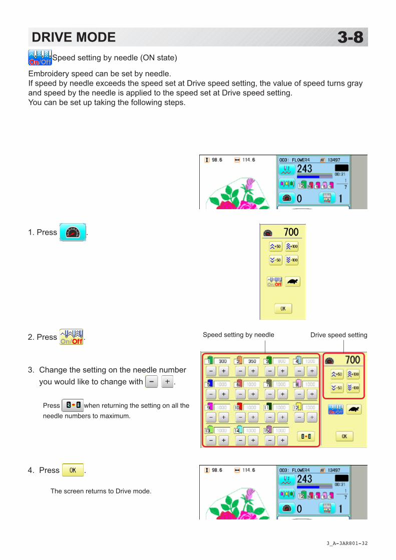
3-8DRIVE MODESpeed setting by needle (ON state)
Embroidery speed can be set by needle.If speed by needle exceeds the speed set at Drive speed setting, the value of speed turns gray and speed by the needle is applied to the speed set at Drive speed setting.You can be set up taking the following steps.
1. Press .
2. Press .
3. Change the setting on the needle number you would like to change with .
Press when returning the setting on all the needle numbers to maximum.
4. Press .
The screen returns to Drive mode.
Speed setting by needle Drive speed setting

-DA -26
Memory # of selected pattern
Currently-selected nee-
Number of stitches sewn up to now
Name of selected patternTop
When beginning an embroidery
Machine stopped during embroidering
Display example
Status
TopThis indicates that themachine is ready to startsewing from the “top” mem-ory position of the pattern.
Frame outThis indicates that aframe out is occuring.
3_B R801
3-9DRIVE MODE
Pointer
Color change number
Stitches of pattern
Needle number and color
*Color change number
Pointer indicates the position of actual stitch point.
If a needle number is not assigned to a Col-or change number, the default color will be as-signed automatically.
Shift to left when color
Size of pattern and distance Heigh
t WidthCurrent *Color change
Mark for color
Mark for frame out
Selected frame
Display if the ma-chine has no design in memory
Remaining embroidery time, Hour : Minute.When over 24 hours, Day(s).
Bar graph
Remaining amount of bobbin thread. 9-CbWhen "Bobbin thread alarm" is set, bar graph will be appeared.
-R3 -303_C Q201
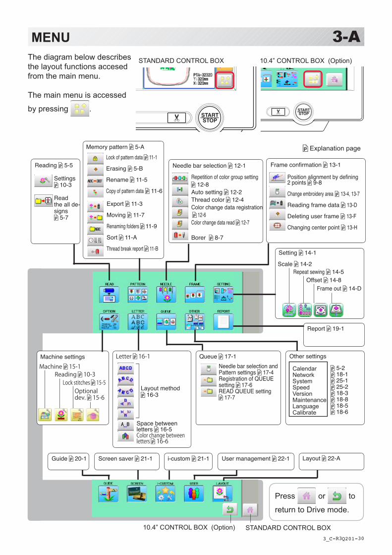
3-AMENUThe diagram below describesthe layout functions accesedfrom the main menu.
The main menu is accessed
by pressing .
STANDARD CONTROL BOX 10.4” CONTROL BOX (Option)
Setting 14-1
Scale 14-2Repeat sewing 14-5
Offset 14-8Frame out 14-D
Needle bar selection 12-1
Repetition of color group setting 12-8
Auto setting 12-2Thread color 12-4Color change data registration 12-6Color change data read 12-7
Borer 8-7
Frame confirmation 13-1
Screen saver 21-1 i-custom 21-1Guide 20-1
Explanation page
Report 19-1
Position alignment by defining 2 points 9-8
Change embroidery area 13-4, 13-7
Reading frame data 13-D
Deleting user frame 13-F
Changing center point 13-H
Queue 17-1Needle bar selection and Pattern settings 17-4Registration of QUEUE setting 17-6READ QUEUE setting
17-7
CalendarNetworkSystemSpeedVersionMaintenanceLanguageCalibrate
Other settings
5-2 18-1 25-1 25-2 18-3 18-8 18-5 18-6
Machine settingsMachine 15-1
Reading 10-3Lock stitches 15-5
Optional dev. 15-6
Letter 16-1
Layout method 16-3
Space between letters 16-5Color change between letters 16-6
Reading 5-5
Settings 10-3
Read the all de-signs
5-7
Memory pattern 5-A
Export 11-3
Moving 11-7
Renaming folders 11-9
Sort 11-A
Thread break report 11-B
Lock of pattern data 11-1
Erasing 5-B
Rename 11-5
Copy of pattern data 11-6
Press or to
return to Drive mode.
STANDARD CONTROL BOX10.4” CONTROL BOX (Option)
User management 22-1 Layout 22-A
-CS -21
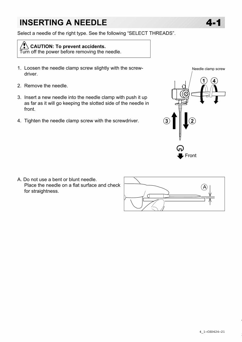
Select a needle of the right type. See the following “SELECT THREADS”.
1
2
4
3
A
4_1 D424
4-1
Needle clamp screw
INSERTING A NEEDLE
Front
T
S
CAUTION: To prevent accidents.Turn off the power before removing the needle.
1. Loosen the needle clamp screw slightly with the screw-driver.
2. Remove the needle.
3. Insert a new needle into the needle clamp with push it upas far as it will go keeping the slotted side of the needle infront.
4. Tighten the needle clamp screw with the screwdriver.
A. Do not use a bent or blunt needle.Place the needle on a flat surface and checkfor straightness.

-CS -22
SELECT NEEDLES AND THREADSAbout needlePlease select needles by type of material .Normally, We supply a DB X K5 needle as in the machine accessory kit.
4_2 D607
4-2
Relation of needle and upper threadPlease select type of needle and upper thread by flowing list.
eziS daerhtreppudnaeldeenfonoitaleR
nagrO namreG #nottoC kliS retseyloP noyaR
8# 06# 031~001 061~041 002~051 07~05
9 5608~07 021~001 051~031 001~07
01 07
11 5706~05 001~08 031~001 031~001
21 08
31 5804~63 07~06 001~08 051~031
41 09
51 59
61 001 63~03 06~05 08~06 061~051
71 501
81 011 03~42 05~04 06~05 032~081
Normal em-broidery field
Normal use embroidery needle and upper thread.
Upper thread : Rayon 120 d/2 (120 denier)Polyester 120 d/2 (120 denier)
Needle : #11 ( DB X K5 )
If the relationship of needle size and thread type is incorrect, it is possible to have any of thefollowing problems.
• Thread break• Skip stitch (Upper thread does not catch bobbin thread)• Other stitch quality problem
EPYT NOITACILPPA eziSeldeeN
32K-BD tinkroF 21~9
5KXBD yrediorbmelamronroF 81~9
-R3 -18
BACKING MATERIALS
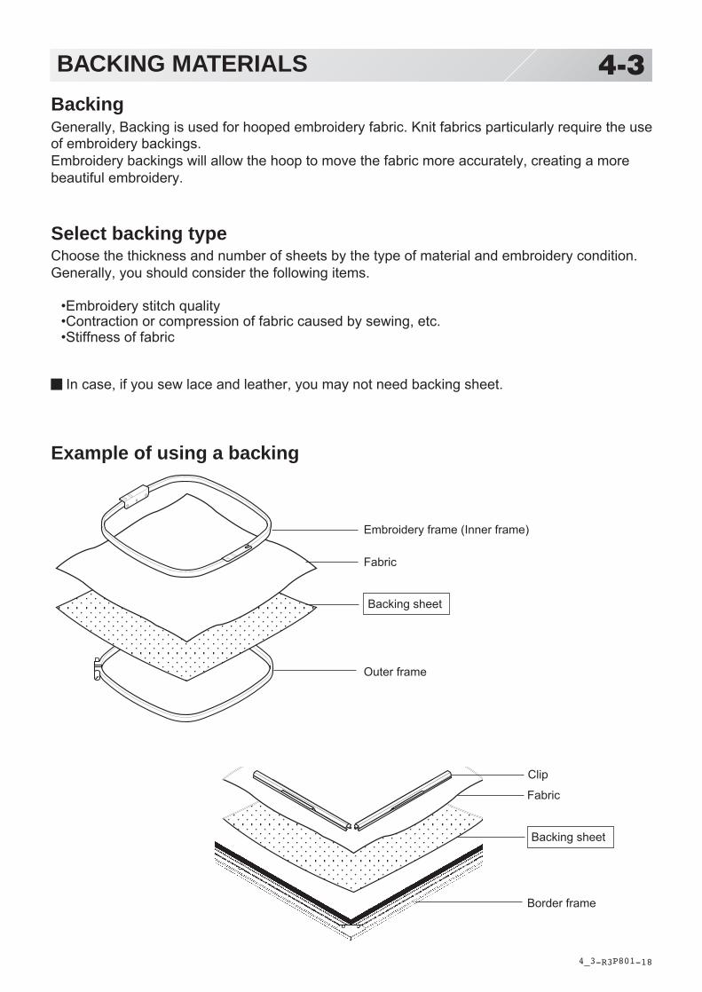
BackingGenerally, Backing is used for hooped embroidery fabric. Knit fabrics particularly require the useof embroidery backings.Embroidery backings will allow the hoop to move the fabric more accurately, creating a morebeautiful embroidery.
Select backing typeChoose the thickness and number of sheets by the type of material and embroidery condition.Generally, you should consider the following items.
•Embroidery stitch quality•Contraction or compression of fabric caused by sewing, etc.•Stiffness of fabric
In case, if you sew lace and leather, you may not need backing sheet.
Example of using a backing
4_3 P801
4-3
Embroidery frame (Inner frame)
Fabric
Backing sheet
Outer frame
Clip
Fabric
Backing sheet
Border frame

-DA -28
140
280
300
300 300
300
140
280300 x 8
280 x 2140 x 2
300
300
300
300
180 x 4170 x 2140 x 6
140
140
140
180
180
180
180
170
170
140
140
140
1501
X1501
SETTING POSITION OF CLIPS ON BORDER FRAME 4-3aWhen using border frame(option), the clips should be set continuously without gaps in order to get good embroidery quality.Please refer the drawing below and set the clips to specified position.
Clip
Embroidery frame
4_3a R801

-CD -27
1
2
34
BOBBIN WINDINGWinding the bobbin (OPTION)
4_4 H808
4-4
Thread the bobbin winder as shown below:
1. Thread guide
2. Thread tension – Be sure to thread throughthe small eye before going between the disks.
3. Bobbin (Place the bobbin on the bobbinwinder spindle.)
4. Press the limit lever as indicated by the arrowto start the winder. The lever stops the winderautomatically after the winding is complete.
Increase Decrease
TensionWhen adjusting bobbin winder tension:
• Ensure thread winds evenly on bobbin asshown.
Confirm that the bobbin is wound properly..
• Keep the tension constant while winding.
Tighten thread tension if thread winds too loosely.
-CD -29
BA
4_5 K101
4-5
A
B
B
C
B
A
A
BOBBIN WINDING
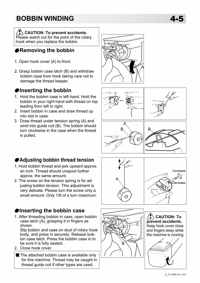
Removing the bobbin
1. Open hook cover (A) to front.
2. Grasp bobbin case latch (B) and withdrawbobbin case from hook taking care not todamage the thread keeper.
Inserting the bobbin case1. After threading bobbin in case, open bobbin
case latch (A), grasping it in fingers asshown.Slip bobbin and case on stud of rotary hookbody, and press in securely. Release bob-bin case latch. Press the bobbin case in tobe sure it is fully seated.
2. Close hook cover.
Inserting the bobbin1. Hold the bobbin case in left hand. Hold the
bobbin in your right hand with thread on topleading from left to right.
2. Insert bobbin in case and draw thread upinto slot in case.
3. Draw thread under tension spring (A) andwind into guide coil (B). The bobbin shouldturn clockwise in the case when the threadis pulled.
Adjusting bobbin thread tension1. Hold bobbin thread and jerk upward approx.
an inch. Thread should unspool furtherapprox. the same amount.
2. The screw on the tension spring is for ad-justing bobbin tension. This adjustment isvery delicate. Please turn the screw only asmall amount. Only 1/8 of a turn maximum.
CAUTION: To prevent accidents.Please watch out for the point of the rotaryhook when you replace the bobbin.
Increase
Decrease
The attached bobbin case is available onlyfor this machine. Thread may be caught inthread guide coil if other types are used.
CAUTION: Toprevent accidents.Keep hook cover closeand fingers away whilethe machine is running.

-D2 -21
THREADING THE MACHINE
4_6 LC01
4-6How to thread upper thread
Pass upper threads in order according to the figure:
1. Thread standPut felt on thread stand and set thread cone.
2. Thread guideThread through the thread guide above eachthread cone.
3. Guide wirePut guide wire in thread guide tube and put endsof guide wire and thread together, then pull theguide wire to your side according to figure.
Continued next page
2
3
Guide wire
1
Felt

-DA -28
THREADING THE MACHINE
4_7 M201
4-7
4. Upper rectifier
5. Minor thread tension
6. Thread tensionWind upper threads one time around rotarytension disc clock-wise.
7. Thread guide
8. Guide pin
9. Lower rectifier
10.Thread adjusting spring
11.Take-up lever
12.Thread guide
13.Thread guide plate lower
14.Needle bar thread guide
15.NeedleThread from front side of needle.Pull upper threads slowly and see that the rotarytension disc moves smoothly by pulling the threaddownward as much as possible.
16.Pressure foot
When checking thread, pull upper threadsfrom needle and check if detecting rollermoves smoothly.
CAUTION: To prevent accidents.Please be careful of the sharp point of theneedles when threading upper threadsthrough the needle.
11
4
6
8
9
10
12
5
7
13
141516
-SA -12
HOW TO READ THESE INSTRUCTIONS and SCROLLBAR 4-8
3_3 NB01
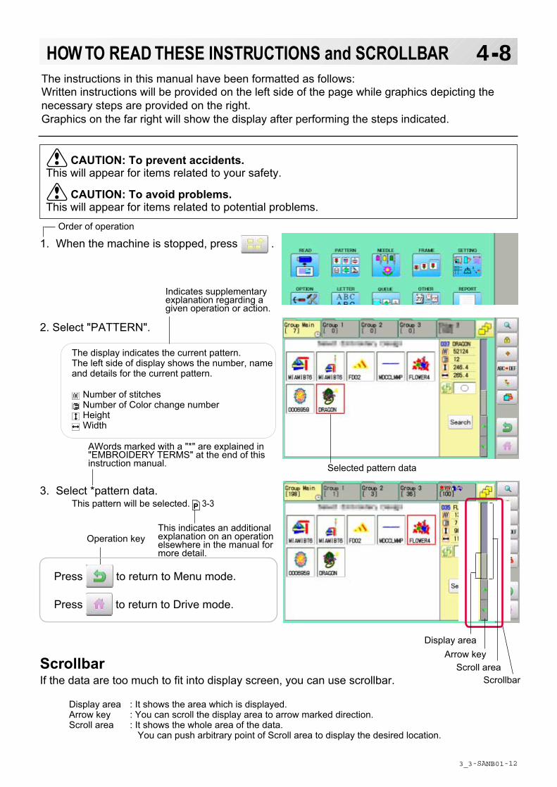
The instructions in this manual have been formatted as follows:Written instructions will be provided on the left side of the page while graphics depicting thenecessary steps are provided on the right.Graphics on the far right will show the display after performing the steps indicated.
This indicates an additionalexplanation on an operationelsewhere in the manual formore detail.
AWords marked with a "*" are explained in"EMBROIDERY TERMS" at the end of thisinstruction manual.
CAUTION: To prevent accidents.This will appear for items related to your safety.
CAUTION: To avoid problems.This will appear for items related to potential problems.
Order of operation
Indicates supplementaryexplanation regarding agiven operation or action.
1. When the machine is stopped, press .
2. Select "PATTERN".
The display indicates the current pattern.The left side of display shows the number, nameand details for the current pattern.
Number of stitches Number of Color change number Height Width
3. Select *pattern data.This pattern will be selected. 3-3
Selected pattern data
Operation key
Press to return to Menu mode.
Press to return to Drive mode.
Scrollbar
Display area
Scroll areaArrow key
ScrollbarIf the data are too much to fit into display screen, you can use scrollbar.
Display area : It shows the area which is displayed.Arrow key : You can scroll the display area to arrow marked direction.Scroll area : It shows the whole area of the data.
You can push arbitrary point of Scroll area to display the desired location.

-SA -33
4-9DISPLAYING THE PATTERN IN SETTING MODE
1. When the machine is stopped, press .
2. Select desired menu.Icon of will be shown in sub-menu.
3. Press .Illustration of the pattern selected will be dis-played.Right side of display shows the detail informationof the current pattern data.
4. Press .The display returns to the view of Step 2.
10_1 NB01
When there is shows on the right side menu, the pattern data may be shown on thescreen.
Press to return to Menu mode.
Press to return to Drive mode.

-DA -18
TURNING THE MACHINE ON
2. Connect the power plug to an electrical outlet.
3. Turn on the power switch.Indicates the select frame. Please confirm the emergency stop button has been released.Push the power switch firmly so it will remain on.
4. In case you do not need to change frame type, Press .
After the carriage and frame move slightly, the embroidery frame will return to the previous position automatically. Machine becomes ready for operation.
3_5 R801
5-1
CAUTION: To prevent accidents.The embroidery frame and carriage will move. Please keep hands clear for your safety.
Power switch
1. Connect the power cord to the inlet on the right side of the machine.
In case you want to change frame type, Press .
ON
OFF
How to turn on the machine
CAUTIONThe touch screen can be operated by finger, but in some cases sensitivity of the screen will be affected by condition of the finger.In such cases, please use the fingertip or built-in stylus to hit small touch targets.
Selected frame
-DA -19
TURNING THE MACHINE ON
3_6 PC01
5-1b
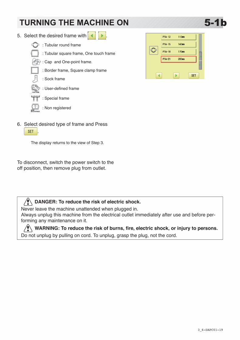
DANGER: To reduce the risk of electric shock.Never leave the machine unattended when plugged in.Always unplug this machine from the electrical outlet immediately after use and before per-forming any maintenance on it.
WARNING: To reduce the risk of burns, fire, electric shock, or injury to persons.Do not unplug by pulling on cord. To unplug, grasp the plug, not the cord.
5. Select the desired frame with .
: Tubular round frame
: Tubular square frame, One touch frame
: Cap and One-point frame.
: Border frame, Square clamp frame
: Sock frame
:User-definedframe
: Special frame
: Non registered
6. Select desired type of frame and Press .
The display returns to the view of Step 3.
To disconnect, switch the power switch to the off position, then remove plug from outlet.
-DA -20
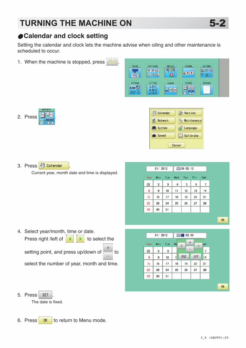
1. When the machine is stopped, press .
2. Press .
3. Press .Current year, month date and time is displayed.
4. Select year/month, time or date. Press right /left of to select the
setting point, and press up/down of to
select the number of year, month and time.
5. Press .The date is fixed.
6. Press to return to Menu mode.
Calendar and clock settingSetting the calendar and clock lets the machine advise when oiling and other maintenance is scheduled to occur.
TURNING THE MACHINE ON 5-2
3_6 O901

-DA -17
MESSAGES 5-3
3_4 Q701
Below is a list of possible messages that may appear while operating the machine, along withan brief explanation and suggested actions to take as a result.The message with mark will be appeared with beep sound.Press the screen (any location is okay) or button, then message and buzzer will be stopped.
Start/Stop button
Message >>Stop Switch
CAUTION: To prevent accidents.The embroidery frame may move. Please keep hands clear for your safety.
MESSAGE EXPLANATION OPERATION PAGE
Place to oil
Designated letter on the display is due to be lubricated.
Push [Done] and lubricate indicated location with instruction in the reference page.Push [Leter], if you can not lubricate right away.The message will be disappeared temporary, but it will come up later.
23-1
Cleaning of rotary fook
Cleaning of thread cut knife
Clean the rotary hook and the thread cutting knife.
Clean with instruction in the reference page. 23-2
>>Stop Switch The machine is stoppedbecause the stop button was pressed while embroidering the design.
Press the start/stop button to resume sewing.
>>End The machine is stoppedbecause it has finished thedesign.
If you wish to sew design again, please newly hooped item on machine & press start/stop button.
>>Change Stop Machine stopped, because you used "Stop at color change point" function.
When you press the start/stop button,the machine will select the next colorand resume embroidering automatically.
>>Color ? Machine stopped, because you used "Stop at color change point" function.
Please select next needle number by needle selection button then press the start/stop button.
>>Thread BreakMachine stopped, because upper or bobbin thread is broken at displayed needle number.
Please thread upper thread or checkbobbin thread then press start/stopbutton to resume sewing.
>>Frame out The "Frame out" function has been executed.
Press the start/stop button if OK. 14-D
>>Sequin Empty Sequin is empty. Please set the new sequin then pressstart button to resume sewing.
-DA -32
USB port
5-4PREPARATION OF PATTERN DATA
5_4 MB29
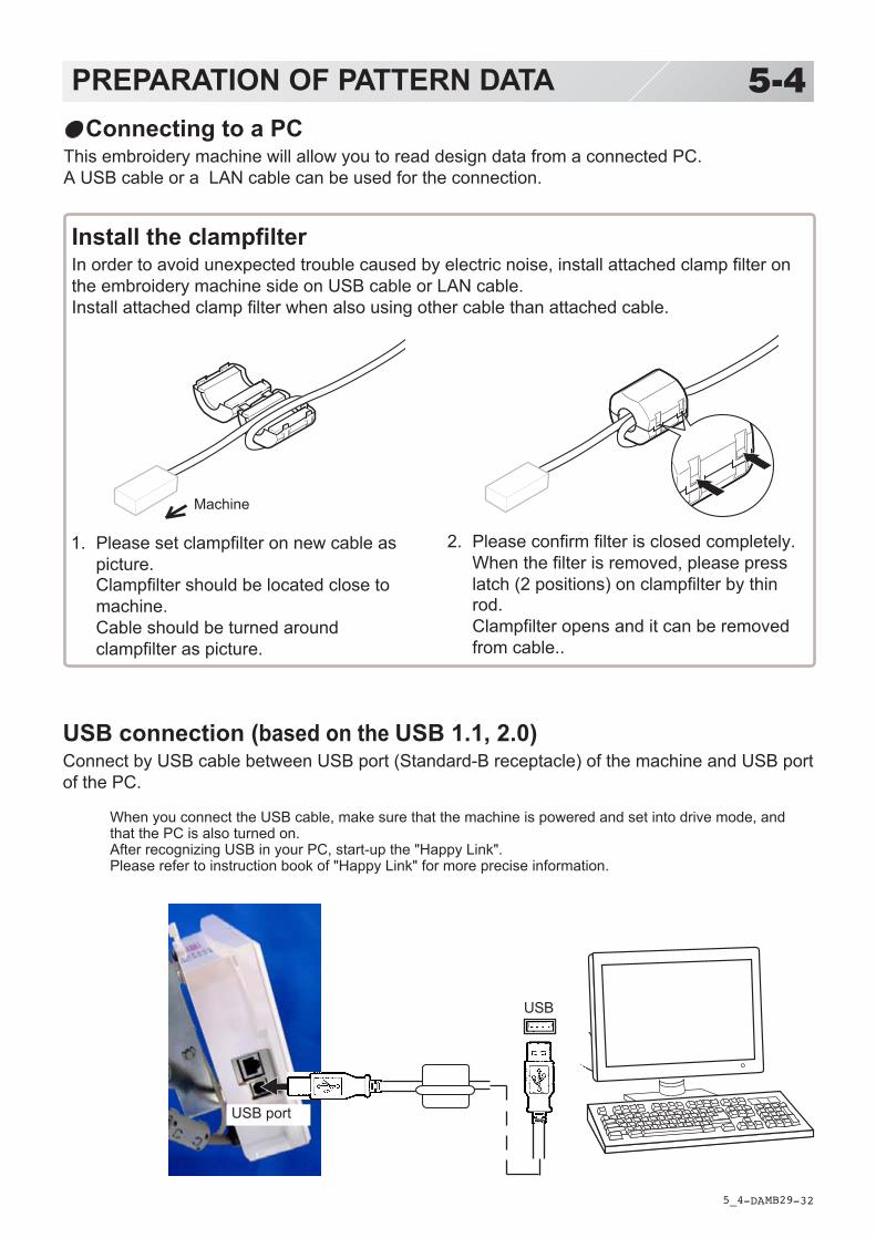
Connecting to a PCThis embroidery machine will allow you to read design data from a connected PC.A USB cable or a LAN cable can be used for the connection.
Install the clampfilterIn order to avoid unexpected trouble caused by electric noise, install attached clamp filter onthe embroidery machine side on USB cable or LAN cable.Install attached clamp filter when also using other cable than attached cable.
1. Please set clampfilter on new cable aspicture.Clampfilter should be located close tomachine.Cable should be turned aroundclampfilter as picture.
2. Please confirm filter is closed completely.When the filter is removed, please presslatch (2 positions) on clampfilter by thinrod.Clampfilter opens and it can be removedfrom cable..
Machine
USB connection (based on the USB 1.1, 2.0)Connect by USB cable between USB port (Standard-B receptacle) of the machine and USB portof the PC.
When you connect the USB cable, make sure that the machine is powered and set into drive mode, andthat the PC is also turned on.After recognizing USB in your PC, start-up the "Happy Link".Please refer to instruction book of "Happy Link" for more precise information.
USB
-DA -33
Reading embroidery pattern data from the PCDesigns can be transferred to the machine along with some functions by using the “Happy Link LAN” software.Please refer to the “Happy Link” or “Happy Link LAN” software manual for instructions.The maximum number of registrable pattern will be 999.Please use following software version which supports the “max. registrable pattern” function. ” Happy Link Ver. Ver. 4.03 or later” ” Happy Link LAN Ver. A2.03 or later”
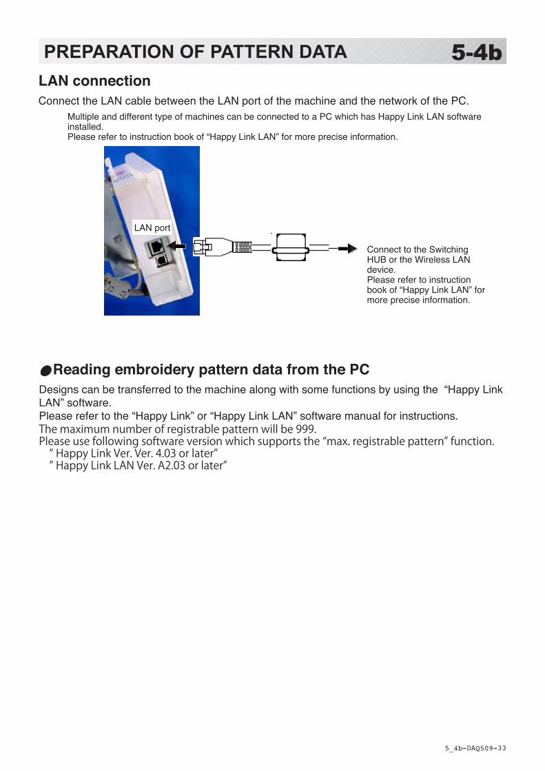
LAN connectionConnect the LAN cable between the LAN port of the machine and the network of the PC.
Multiple and different type of machines can be connected to a PC which has Happy Link LAN software installed. Please refer to instruction book of “Happy Link LAN” for more precise information.
Connect to the Switching HUB or the Wireless LAN device. Please refer to instruction book of “Happy Link LAN” for more precise information.
LAN port
PREPARATION OF PATTERN DATA 5-4b
5_4b Q509

-DA -355_5 M201
5-5PREPARATION OF PATTERN DATARead embroidery pattern data
Read the pattern to be embroidered from the memory media.
These types of memory media can be used.This machine is able to read different kinds of memory media, which are generally used.
•USB memory
If you initialize the memory media with your PC, please proceed with FAT or FAT32 format.
Handling note of memory media.Do not bend, drop, disassemble, charge or heat the memory media.Keep away from humidity or direct sunlight.
To insert a USB memory
1. Insert the USB memory all the way into theUSB memory port of the machine (right sideof controller).
2. Read embroidery design data according tofollowing “Memory card reading” in the nextsection.
To remove a USB memory
Please handle USB memory carefully.

-DA -36
Reading pattern dataThis reads pattern data and writes into memory.When the HAPPY format pattern data with *various function settings are read in memory, vari-ous functions such as needle bar selection, pattern data adjustments and etc. will be set auto-matically. (It is necessary to set “etc.func read”. 10-3)In addition to memory media, this machine can read pattern data saved in the PC connected with “Happy Link LAN”.Design folder settings on the “Happy Link LAN” is required before reading pattern data.Please refer to “Happy Link LAN” System INSTRUCTION MANUAL regarding the settings meth-od.The pattern data can be read through the designated folder and sub-folders by accessing from the machine.
If the Happy or Tajima pattern data has Barudan or ZSK *data. (Tajima file : DSB [Barudan] or DSZ [ZSK]) The machine can read HAPPY and Tajima pattern data normally when “Auto” is selected at SETTING RANGE of SETTING ITEM 7 data format of Pattern read settings on page 10-3. If the machine dose not read pattern data cannot at “Auto”, please try with other data format
5-6PREPARATION OF PATTERN DATA
5_6 Q201
1. Insert the USB memory into the machine as described in “Inserting USB memory”.
2. When the machine is stopped, press .
3. Select “READ”.
4. Select (USB memory) or (Pattern
data in the PC).Indicates pattern data.
TAP : HAPPY DST : Tajima DSB : Tajima (Barudan) DSZ : Tajima (ZSK)
Folder : Contents of folder will be displayed
when you select this icon.
The designs new ID number in the machines memory.Free memory
Folder
--- Serch pattern ---
Un-recognized device will be shown with gray color.
-D2 -37
5-7PREPARATION OF PATTERN DATA
5_7c NB01
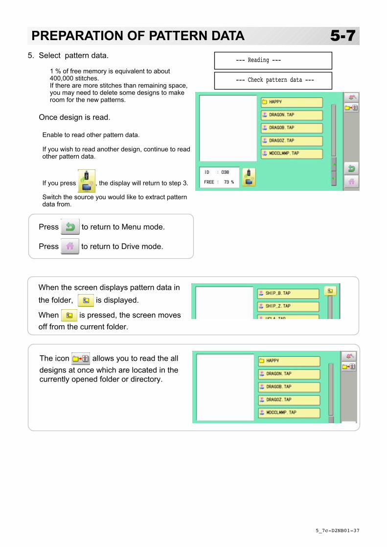
5. Select pattern data.
1 % of free memory is equivalent to about400,000 stitches.If there are more stitches than remaining space,you may need to delete some designs to makeroom for the new patterns.
Once design is read.
Enable to read other pattern data.
If you wish to read another design, continue to readother pattern data.
If you press , the display will return to step 3.
Switch the source you would like to extract patterndata from.
When the screen displays pattern data inthe folder, is displayed.
When is pressed, the screen movesoff from the current folder.
--- Check pattern data ---
--- Reading ---
Press to return to Menu mode.
Press to return to Drive mode.
The icon allows you to read the alldesigns at once which are located in thecurrently opened folder or directory.

-D2 -38
5-9PREPARATION OF PATTERN DATA
5_9 NB01
Selection of foldersThe pattern data memory is consist of 20 individual folders.Select desired folder to choose or input pattern data.
Selected folder
1. When the machine is stopped, press .
2. Select "PATTERN".
The pattern data of the selected folder willappear on the display.
3. Go on to step 4, if you want to select patternfrom displayed folder.
Press to select from whole folders.
4. Select desired folder.The selected folder has been switched.
You cannot switch to the folder without patterndata.
Selected folder
Press to return to Menu mode.
Press to return to Drive mode.
-D2 -39
5-APREPARATION OF PATTERN DATA
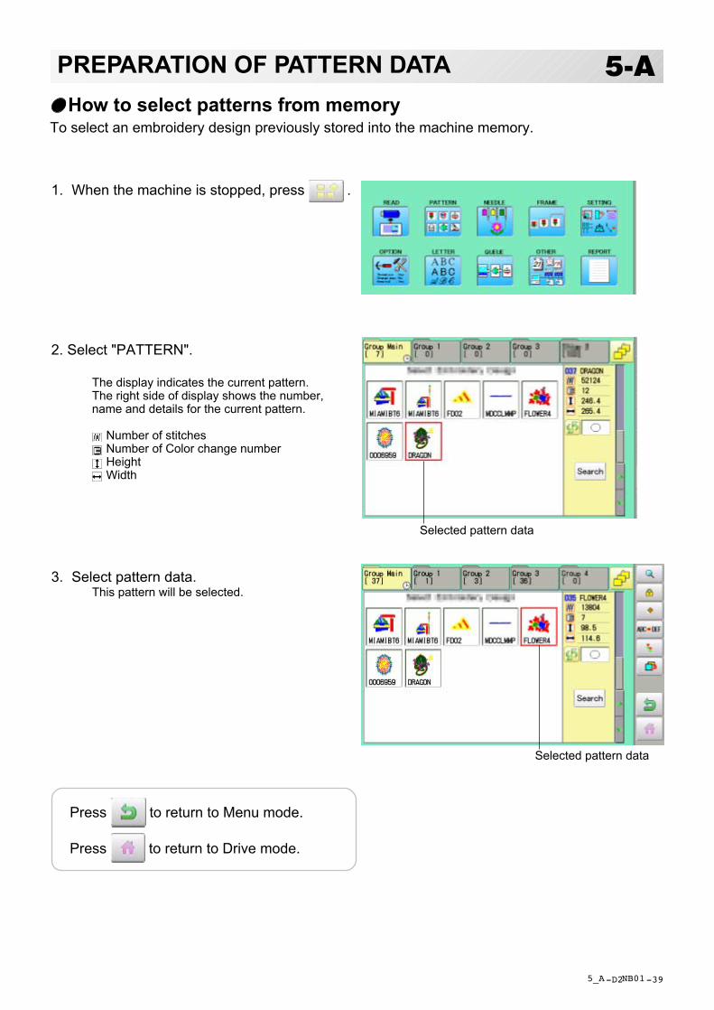
1. When the machine is stopped, press .
2. Select "PATTERN".
The display indicates the current pattern.The right side of display shows the number,name and details for the current pattern.
Number of stitches Number of Color change number Height Width
3. Select pattern data.This pattern will be selected.
5_A NB01
How to select patterns from memoryTo select an embroidery design previously stored into the machine memory.
Selected pattern data
Selected pattern data
Press to return to Menu mode.
Press to return to Drive mode.

-D2 -40
5-BPREPARATION OF PATTERN DATA
5_B NB01
1. When the machine is stopped, press .
2. Select "PATTERN".
3. Press from right submenu.
4. Select desired pattern.
Mark will appear left of the pattern.Make will be cleared by press it again.
Multiple pattern data can be selected.
: Select all the pattern data
: Cancel pattern data erasing
Erasing patterns from memoryThis is to erase an unnecessary design data from the machine memory.
Pattern data cannot be erased if the lock is set.
Mark

-RA -38
5-CPREPARATION OF PATTERN DATA
5_C O512
5. Press .
6. Push "OK" to delete.The item will be deleted.To delete other patterns, repeat steps 3 to 6.
Press “Cancel” to cancel the delete.The display will return to step 2.
Delete pattern? < 2>
Cancel OK
Showing number of delete design(s)
Press to return to Menu mode.
Press to return to Drive mode.
Erasing all patterns from memoryThis is to erase alldesign data from the machine memory.
Pattern data can be erased if the lock is set.
1. When the machine is stopped, press .
Please note that this function can not beactivated through "PATTERN" icon at"Quick menu".In this case, open normal ÅgMENUÅh by
pressing and follow the procedure
as below.
2. Select "PATTERN" while pressing the
and
3. Press .
The item will be deleted.

-RA -34
1. When the machine is stopped, press .
2. Select "NEEDLE".The screen of color number 1 selection is dis-played.The current color number is showed in the patterndata display portion.
3. Select the needle number.After setting the needle number on color number,the following color number selection is displayed.You can also select color number directly.You can switch color change numbers with
if the color change number has morethan 5.
4. Select the needle number on all the colorchange numbers.
Press to return to Menu mode.
5-ENEEDLE BAR SELECTION
5_E NB01
For each color change in a given pattern, the needle number loaded with the correct colorthread is assigned by the operator. When this is set, the machine automatically changes to theprogrammed needle when the design reaches that point in the course of sewing the design.
You can not setting "NEEDLE" for selected "LOCK" design.Please release "LOCK" from design. 11-1
Needlenumber
Current colorchange number
Needle number
Color change number
Press to on the sub menu to checkthe setting.
Number of colorchange number

-R2 -33
5-FNEEDLE BAR SELECTION
5_F N701
Color change stop markFrame out mark
Color change stop functionWhen a color change stop is set to a color change number, the machine will stop after itfinishes sewing the marked needle number, then following message will be shown:
When you wish to start again, Press (Start/Stop button).
1. Select a color change number and press .The mark is displayed on the color change number.
2. Set it to the same on other color change number if necessary.
Selection of color change numberSet Color change number to execute frameout.A frame out command can be added to a design. By setting frameout to a *Color changenumber in a design, you can move the frame to a desired position automatically and stop itafter the machine finishes sewing of that color change number.When you resume operation, the frame has an automatic return to previous position and youcan continue sewing. 14-D
1. Select a color change number and press .The mark is displayed on the color change number.
2. Set it to the same on other color change number if necessary.
When you turn frameout "On" without setting the movement distance offrameout,the framewill move automatically to the position which was set already with "20 Frameout position"at "MACHINE SETTINGS". 15-2.
No thread cut after color changeWhen "no thread cut after color change" is set on a color change number, thread cut is notdone after colorchange at the specified color change number and the machine switches to the next colorchange number.
"No thread cut after color change" function can be set by combining color change stop orframe out function.
No thread cut mark
-SA -29
6-1SEWING WITH TUBULAR FRAMES
6_1 O901
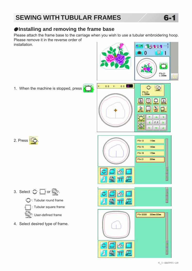
1. When the machine is stopped, press .
2. Press .
3. Select or .
: Tubular round frame
: Tubular square frame
: User-defined frame
4. Select desired type of frame.
Installing and removing the frame basePlease attach the frame base to the carriage when you wish to use a tubular embroidering hoop.Please remove it in the reverse order ofinstallation.

-D2 -45
6-1bSEWING WITH TUBULAR FRAMES
6_1 M620
X carriage
Bracket
5. Press .
6. Move the carriage to the position shown by
press .
7. Fix the Tubular frame arm to the bracket ofthe X carriage and tighten completely.
Press to return to Drive mode.Tubular frame arm R
Tubular frame arm L
360
520500
Mount Tubular
frame armMount tubular framearm in tubular framebracket per mount-ing dimension fortubular frames (360,500, and 520cm).Insert tubular framearm in the arrowdirection and mountthe arm in thebracket by tighteningset screws.When removing thearm, loosen setscrews. You do nothave to remove setscrews.
Set screw

-CS -51
6-2SEWING WITH TUBULAR FRAMES
6_2 D610
How to hoop
Inner frame
Cloth
Backing
Outer frame
Please stretch the embroidery cloth in thedirections of the arrow to smooth the cloth.
Do not stretch the elastic cloth too much.Please smooth the embroidery cloth while adjustingtightness of outer frame. i
LoosenTighten
-DA -46
6-3SEWING WITH TUBULAR FRAMES
6_3 Q701
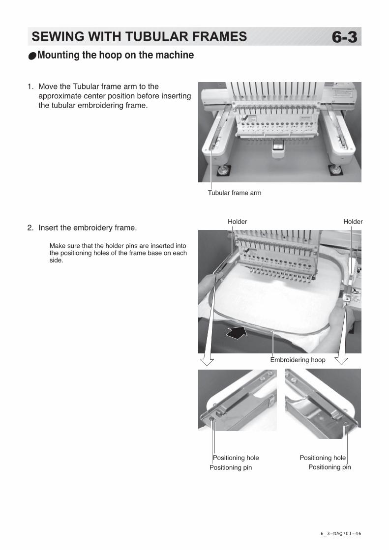
Mounting the hoop on the machine
1. Move the Tubular frame arm to the approximate center position before inserting the tubular embroidering frame.
2. Insert the embroidery frame.
Make sure that the holder pins are inserted into the positioning holes of the frame base on each side.
Holder Holder
Embroidering hoop
Positioning holePositioning pin
Positioning holePositioning pin
Tubular frame arm

-S2 -18
6-3bSEWING WITH TUBULAR FRAMES
6_3b M701
Use TAJIMA made tubular frameYou can use TAJIMA made tubular fame which has the same installation width (space be-tween left and right positioning pin) as HAPPY's frame by changing the position of both leftand right hold springs and left and right hold spring bases.Follow the procedure below after removing tubular frame.
1. Loosen screws (2 each at both left and right).2. Move both left and right hold spring bases deep into screws.3. Move both left and right hold springs forward until the spring touches screws and stops
moving.4. Tighten screws (2 each at both left and right).5. Install tubular frame and check if the tip of both left and right hold springs enters receiving
hole on tubular frame.If the tip dose not enter receiving hole, loosen screw, rotate hold springs left or right sothat the tip can enter the hole, and tighten screw.Please reverse the procedure above when returning to the position of something beforechange has been made.
HAPPY TAJIMA
Hold spring
Hold spring base
Screws
Positioning pin
1
2
3
4
5
5
Receiving hole

-DA -51
6-4SEWING WITH TUBULAR FRAMES
6_4 R801
Starting to embroider
1. Press and move the frame to the
original point with the .
2. Press .
Press , and the embroidering frame moves for the design trace. 14-5 Make sure that the pressure foot and needle do not touch the frame.Press , and trace is stopped.
Go on to step 4 if you want to start embroidering without tracing.
3. Press after the trace is completed.The embroidering frame has moved to the first stitch point of the pattern.
4. Press .The embroidery will start.
5. After embroidering your design is complete, show “>>End” and the machine will stop.
The embroidery frame returns to the original point automatically if the “Auto origin” function has been activated.
: Original point (Start point)
You can confirm outline trace and the position of the design.
>>End
Forward only when pressing
Frame move
Backward only when pressing

-DA -48
7-1CAP FRAME option
Cap frame settings2 types of cap frames, Normal and Wide, are available with this model. When you embroider byusing a cap frame, please ensure that a correct setting is selected according to each.
CAUTION: To avoid problems.The machine and/or cap frame may be dam-aged if the incorrect frame settings are used.
1. When the machine is stopped, press .
2. Press .
3. Select “Cap and One-point frame”.
4. Select desired type of frame.Then Cap frame will be set.
5. Press and .The embroidery frame will move to the center .
7-1 O901
CAUTION: To prevent accidents.The embroidery frame and carriage will move.Please keep hands clear for your safety.
Press to return to Drive mode.

-DA -53
7-2CAP FRAME optionInstalling and removing the cap drive frame
The cap drive frame must be installed onto the carriage to embroider a cap.Please remove by reverse order of these step.
CAUTION: To prevent accidents.The frame moves quickly.Keep hands away from the frame.
7-2 R801
3. Press and Press .
The embroidery frame will move to the center .
1. Turn on the power switch.Push the power switch firmly so it will remain on.
Confirm that there are “Cap (Std.)” or “Cap (Wide)” in the display.
If these icons are not in the display, please return to “How to turn on the machine” on previous page and change the cap frame.
2. Press .
The carriage and frame will move slightly and then the embroidery frame will return to the previous position automatically.
ON
OFF
CAUTION: To prevent accidents.The frame moves quickly.Keep hands away from the frame.
ON
OFF
4. Turn off the machine.
-D2 -51
7-3CAP FRAME option
7_3 M401
Connecting plateRotary cylinder
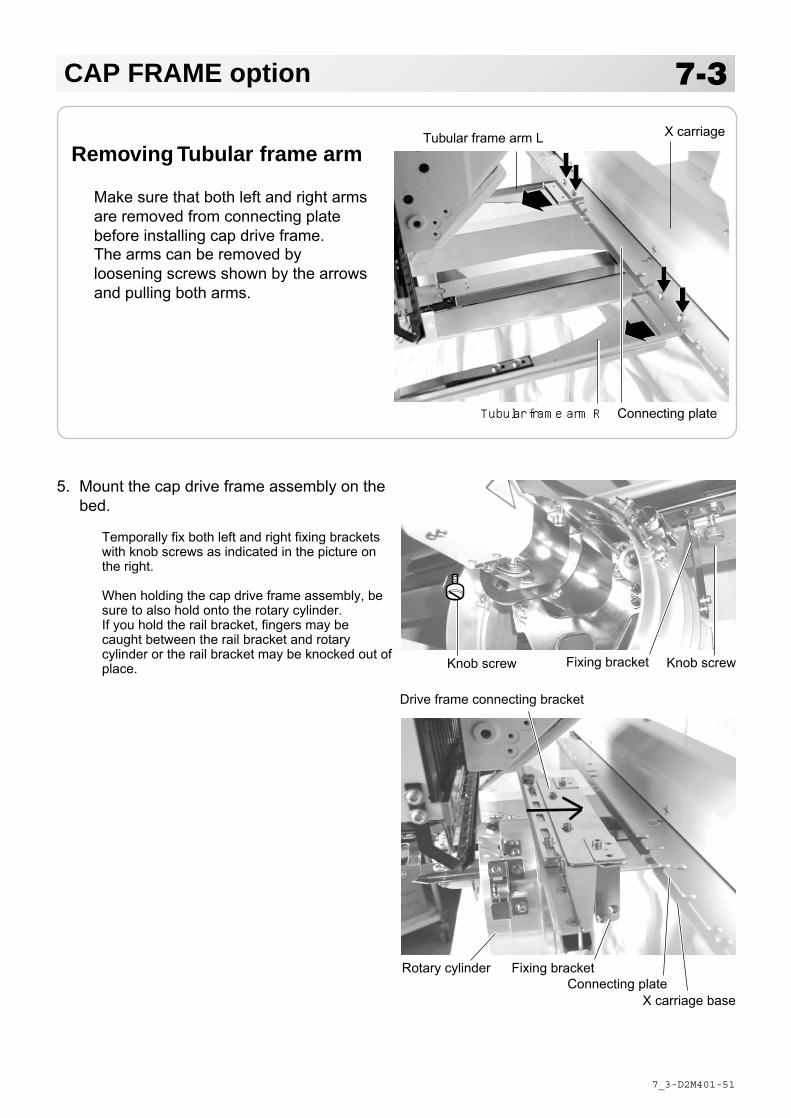
Removing Tubular frame arm
Make sure that both left and right armsare removed from connecting platebefore installing cap drive frame.The arms can be removed byloosening screws shown by the arrowsand pulling both arms.
X carriage
Connecting plateTubular frame arm R
Tubular frame arm L
Knob screwKnob screw Fixing bracket
5. Mount the cap drive frame assembly on thebed.
Temporally fix both left and right fixing bracketswith knob screws as indicated in the picture onthe right.
When holding the cap drive frame assembly, besure to also hold onto the rotary cylinder.If you hold the rail bracket, fingers may becaught between the rail bracket and rotarycylinder or the rail bracket may be knocked out ofplace.
Fixing bracket
Drive frame connecting bracket
X carriage base

-D2 -52
7-4CAP FRAME option
7_4 N312
6. Temporally fix both left and right fixing Driveframe connecting bracket with knob screws.Push Drive frame connecting bracket to thecarriage side (direction of the arrow in thepicture on the right.) so that position pins fitslots of connecting plate.Fix firmly drive frame connecting bracketand connecting plate with the knob screws.
7. Fix firmly X carriage base with both left andright lower knob screws while pushing leftand right fixing brackets in the direction ofthe arrow.
8. Move the rail bracket completely right andleft to confirm that the rails are in thegrooves of the rotary cylinder.
Grooves of rotary cylinder Rail
Rail bracketKnob screwFixing bracket
X carriage baseKnob screw
Positioning pin
Knob screw
Knob screw
Connecting plateDrive frame connecting bracket

-RA -48
7-5CAP FRAME (OPTION)
4_5 O806
AdjustmentWhen you hoop a cap on the cap frame, pleaseadjust in the following manner:
1. Adjust up and down position of the hookaccording to the thickness of the cap toadjust clamp tension. At this moment, thehook should open and close without feelingtoo tight.(For adjustment, proceed to procedure 5below).Use the wing nuts for adjustment. (Fig. 1)
If the hook is extremely tight, it will damage thecap frame permanently.
2. Adjust the guide position to suit the heightof the cap.Remove screws at left and right to adjust.(Fig. 2)
Wing nut
Hook Fig. 1
Normal cap frame
Cap driveframe
High Low
Guide Screw
Fig. 2

-CS -60
Cap stretcherCap frame
Notchedportion
Clamp
Fig. 5
Sweatband
Flange
Clamp
Hooping caps
1. Place cap stretcher securelyon a sturdy work bench.
2. As shown in Fig. 5, hold capframe with both hands andplace on cap stretcher. Bypushing locking levers at 2places with fingers, place capframe so that center guide ofcap stretcher fits in concavearea of cap frame.
Confirm that the cap frame is securelyplaced on cap stretcher.
3. As shown in Fig. 6, open clamp andkeep open to the right.
4. Take the front half of the sweatband outof the cap and cover the cap stretcherwith the sweatband.Cover the cap stretcher with the sweat-band so that the edge of the sweatbandcontacts the flange of the cap frame.
Please place one or two sheets of non-woven fabric (backing) of standard thick-ness under unstructured caps.
5. As shown in Fig. 7, pull back part of capand hook it temporarily on the hook andsmooth out wrinkles on cap.At this time, align the center of the capto the center mark on the cap frame sothat notched portion of the clamp fitsinto the seam of the visor of the cap.
6. Latch the hook, taking care not tocause wrinkles in the cap.
If you can't get rid of wrinkles on the cap,adjust the cap frame again according to"Adjustment" of the previous page.
Center guideConcave
Hook
Seam
Fig. 7
Fig. 6
7-6CAP FRAME (OPTION)
7_6 E201
Nonwoven fabric
Locking levers

-DA -52
7-7CAP FRAME option
7-7 OC10
7. Remove the cap frame from the capstretcher.
8. As shown in Fig. 8, install the cap frame oncap in the drive frame.Rotate the cap frame as show in the Fig 8so that the brim of the cap cannot hit themachine.Then, push the holder lever in the 2 placesshown in the arrow in Fig. 8, and install thecap frame in the cap drive frame so that sothat the center guide of the drive frame fitsthe concave area of the cap frame.
Confirm that the cap frame is firmly installed onthe cap drive frame without any gap.If there is a gap between the cap frame and thecap frame drive or the holder lever does not fitthe hole of the cap frame, adjust loosen the setscrew on the hold lever to adjust the position.
Centerguide
Hold lever
Cap driveframe
Fig. 8

-CS -61
7-8CAP FRAME (OPTION)
7_8 KC10
Adjusting screwCap gripHook
Hook
Cap drive frame
High Low
Cap stretcher
Guide Screw
Loosen
(Thick fabric)
Tighten
(Thin fabric)
Wide cap frame
AdjustmentWhen you fix cap to cap hold frame, pleaseadjust in the following manner.
Make sure to do the adjustment of the caphold frame. If it is not adjusted properly, itmay cause the deformity, damage of thecap, damage of the cap hold frame andbreak of the cap grip.After adjusting the cap hold frame, makesure the cap to be set properly.
1. Adjust the length of the cap grip to suitthe thickness of the fabric. At this mo-ment, hook should open and closewithout feeling heavy.(For the adjustment follow the next page"Hooping caps" item 1 to 5.)The adjustment to be done by twoadjusting screws. (Fig. 1)
If the cap grip is loose, even afterhooked the cap is not fixed tightly andthe cap is moving. (Fig. 2)
If the cap grip is too tight, you feelheavy when it is hooked and the gripbites into the cap too much. (Fig. 3)
If you feel hook extremely heavy in openingand closing, there is a case that cap holdframe will lose its shape or damaged.
2. Adjust the guide position to suit theheight of the cap.Remove screws at left and right toadjust. (Fig. 4)
Fig. 4
Fig. 2
Fig. 3
Fig. 1
-CS -63
7-9CAP FRAME (OPTION)
7_9 KC10
Hold lever
Cap strecherCap hold frame
Hold lever
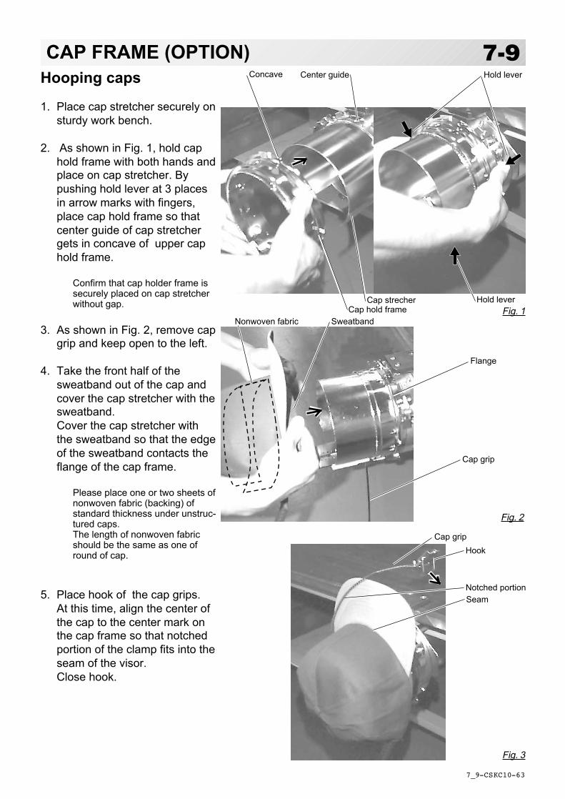
Hooping caps
1. Place cap stretcher securely onsturdy work bench.
2. As shown in Fig. 1, hold caphold frame with both hands andplace on cap stretcher. Bypushing hold lever at 3 placesin arrow marks with fingers,place cap hold frame so thatcenter guide of cap stretchergets in concave of upper caphold frame.
Confirm that cap holder frame issecurely placed on cap stretcherwithout gap.
3. As shown in Fig. 2, remove capgrip and keep open to the left.
4. Take the front half of thesweatband out of the cap andcover the cap stretcher with thesweatband.Cover the cap stretcher withthe sweatband so that the edgeof the sweatband contacts theflange of the cap frame.
Please place one or two sheets ofnonwoven fabric (backing) ofstandard thickness under unstruc-tured caps.The length of nonwoven fabricshould be the same as one ofround of cap.
5. Place hook of the cap grips.At this time, align the center ofthe cap to the center mark onthe cap frame so that notchedportion of the clamp fits into theseam of the visor.Close hook.
Center guideConcave
HookCap grip
SeamNotched portion
Sweatband
Cap grip
Flange
Fig. 2
Fig. 3
Fig. 1Nonwoven fabric

-DA -53
7-ACAP FRAME option
7-A M717
7. Remove the cap holder frame from the capstretcher.
8. As shown in Fig. 5, install the cap frame oncap in the drive frame.Rotate the cap frame as show in the Fig 5 sothat the brim of the cap cannot hit themachine. Then, push the holder lever in the3 places shown in the arrow in Fig. 5, andinstall the cap frame in the cap drive frameso that so that the center guide of the driveframe fits the concave area of the cap frame.
Confirm that the cap frame is firmly installed onthe cap drive frame without any gap.
Clip ClipLever for clip6. As shown in Fig. 4, tip the capstretcher forward.Clip the back of the cap andnonwoven fabric in two places.
Make the clip livers face each other.
Fig. 4
Fig. 5
Holdlever
Cap driveframe
Centerguide
If there is a gap between the cap frame and thecap frame drive or the holder lever does not fitthe hole of the cap frame, adjust loosen the setscrew on the hold lever to adjust the position.

-RA -58
:Original point (Start point)
Embroidery area
Embroidery area (Max. *1)
180mm (Normal cap frame)360mm (Wide cap frame)
You can confirm the outline and position of design.
70mm(Normal cap frame)85mm(Wide cap frame)
7-BCAP FRAME optionStarting to embroider
1. Press and move the frame to the
original point of pattern data by .
2. Press .
When you Press , the frame will start mov-ing for the design trace. 14-5 Make sure that the pressure foot and needle does not touch the frame. When you Press , the machine will stop.
Go on to step 4 if you want to start embroidering without tracing first.
3. Press , the design trace fineished.
The cap frame will return to the original point.
7_B R801
* The actual embroidery area will be restricted by the design and shape of a cap.
Forward only when pressing
Frame move
Backward only when pressing

-D2 -47
7-CCAP FRAME option
7_C M201
4. Press the .Embroidery will start.
5. After finishing your design, the display willshow ">>End" and the machine will stop.
The embroidery frame will return to the originalpoint automatically if the auto origin function hasbeen activated. 12-7
>>End
:Original point (Start point)

-RA -56
8-1ADJUSTING THE THREAD TENSIONS
8_1 N101
1. With the thread going through the hole ofthe pressure foot, pull it out slowly towardthe front.
2. Adjust the Minor thread tension by the firsttension knob and then the second Threadtension knob.
According to the type of upper thread and cloth.
Pressure foot
LoosenTighten
First tension
Second tension

-DA -57
8-2ADJUSTING THE LASER POINTER (OPTION)
8_2 O901
1. For switch ON laser pointer, Press
and Press on the submenu.
For switch OFF laser pointer, Press .
2. Press to return to Drive mode, and
press and set a position of moving
head to needle No. 1.
3. Set fabric on the frame, then put whitepaper to the position of needle and fix byScotch tape.
4. Press and Press .
5. Press .
6. Press to cancel "Jump".
7. Press and keep until needle reachs to
the paper and make hole.
Laser pointer indicates the needle position.The beam of laser is coming from right upper side, thus the position of laser pointer can bechanged depending on the height of surface of fabric.Please adjust the angle of laser pointer depending on thickness of fabric and type of frame.
CAUTION: To prevent accidents.The needle will penetrate the fabric.Please keep your hands clear for your safety.
CAUTION: Laser beam (Class 1)Do not stare into the beam.

-DA -58
8-3ADJUSTING THE LASER POINTER (OPTION)
8_3 O901
Fixing screw for X8. Unscrew a fixing screw for X directionslightly and change angle of support(X).
9. Unscrew a fixing screw for Y directionslightly and change angle of support(Y).
10. Fix the fixing screw for X and the fixingscrew for Y.
11.Check the hole position on paper and thepoint of laser beam, and take paper out.
12.Press .
13.Press .
Fixing screw for Y
Hole on paper Laser beam Source of laser
Support (Y)
Support (X)
X direction
Y direction
Press to return to Drive mode.
14.Press .
CAUTION: To prevent accidents.The needle will penetrate the fabric.Please keep your hands clear for your safety.
C point
OK

-RA -68
BORER (Option)
15_1 M717
8-4Important safety instructionsWhen using an appliance, basic safety precautions should always be followed, including the following.
WARNING - To reduce the risk of injury to persons:1. An appliance should never be left unattended when plugged in. Always unplug this appliance
from the electric outlet or switch main breaker OFF after using and before cleaning.2. Do not allow to be used as a toy. Close attention is necessary when this appliance is used by
or near children.3. Use this appliance only for its intended use as described in this manual. Use only
attachments recommended by the manufacturer as contained in this manual.4. Keep fingers away from all moving parts. Special care is required around the sewing
machine needle and borer blade.5. Switch the sewing machine off (“0”) when making any adjustments in the borer device area,
such as changing borer blade, etc.
SAVE THESE INSTRUCTIONS
ES-HMF-5112-1
Fear of serious injury.Keep fingers away fromthe needles whilethe machine is running.
WARNING
ES-HMF-5112-1
Fear of serious injury.Keep fingers away fromthe needles whilethe machine is running.
WARNING
For safe use of this device, we highly recommend to use “Safety Sensor” (option) together. “Safety Sensor” will stop machine, when your hand gets closer to needles or knife. Please contact your local distributor to get more detail information.
Borer
Borer blade

-RA -69
1. When the machine is stopped, press .
2. Select “NEEDLE”.
3. Press from right submenu.
4. Select 15th needle number. Display on right side of needle number. If you press again, cancel the BORER setting.
5. For fix the setting, press .
If you like to cancel this setting, press .
8-5BORER (Option)
15_2 NB01
(If your machine 12 needle ma-chine, select 12th)
Select needle number for Borer deviceSelect needle number which Borer device is installed.
Press to return to Menu mode.
Press to return to Drive mode.
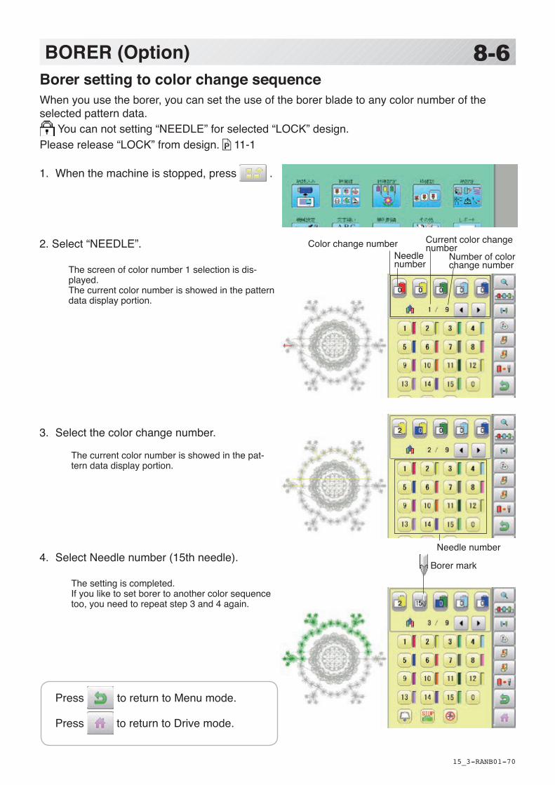
-RA -70
1. When the machine is stopped, press .
2. Select “NEEDLE”.
The screen of color number 1 selection is dis-played. The current color number is showed in the pattern data display portion.
3. Select the color change number.
The current color number is showed in the pat-tern data display portion.
4. Select Needle number (15th needle).
The setting is completed. If you like to set borer to another color sequence too, you need to repeat step 3 and 4 again.
8-6BORER (Option)
15_3 NB01
Borer setting to color change sequenceWhen you use the borer, you can set the use of the borer blade to any color number of theselected pattern data.
You can not setting “NEEDLE” for selected “LOCK” design. Please release “LOCK” from design. 11-1
Borer mark
(If your machine 12 needle machine, select 12th)
Number of color change number
Needle number
Current color change number
Needle number
Color change number
Press to return to Menu mode.
Press to return to Drive mode.

-RA -71
8-7BORER (Option)
15_4 M717
1. Loosen the set screw and remove old borer blade from bracket.
2. Please set position of Top of borer blade 3 mm higher than surface of Bracket, and Cutting point of blade should be on front and back, right and left.
Exchange the borer blade (option)If the Borer blade become bunt or should chip, exchange the Blade in the following procedures.
CAUTION: To prevent accidents;Please do not push up Blade guard by finger.
CAUTION: To prevent accidents;Be sure power switch is “OFF”.
Bracket
Set screw
Borer blade
Top of Borer blade
3mm
Blade guard
Borer blade
Standard Borer blade position is that position of Top of borer blade is 3mm higher than surface of Bracket.Depending on cutting result this height can be adjusted between 0mm to 3mm.
Borer blade
RightLeft
Back
Front

-DA -59
9-1SEWING
9_1 O901
What to do if the thread breaks while sewingIf the thread breaks or runs out while sewing, the machine senses the break, stops, and movesback several stitches from the break point.(This prevents open sections in the design when sewing is resumed. See the thread breaksection. 5-1)
If the upper thread breaksThread the upper thread again.(Refer to 4-6)In case bobbin thread breaksThread lower thread again.(See bobbin winding 4-5)
CAUTION: To prevent accidents.When performing a thread trim, be careful ofthe needle which will pierce the fabric.
Example: An unsatisfactory gap between linesbecause the machine stopped at a half point inembroidery and the material shrunk.
Stopping and resuming sewingEven if you need to turn off the machine in themiddle of embroidering, you will be able toresume sewing from the stop point after turningon the machine back on.
If you leave the machine off for too long, thefabric may distort which will create gaps inthe embroidery design.
To suspend sewing
1. Stop the sewing by pressing the
button.2. Press button.
The needle will go down and trim the thread.3. Turn off the power switch.
To resume sewing from the last sewn position:4. Turn on the power switch.
5. Press button.After the carriage and frame move slightly, theembroidery frame will return to the previousposition automatically.
6. Press and back up several stitches
from the stop point by pressing the 3-4times.
7. Press .
8. Start sewing again by pressing the .
ON
OFF
ON
OFF
>>Stop Switch
CAUTION: To prevent accidents.The frame moves quickly.Keep your hands and body clear of the ma-chine.

-DA -60
9-2SEWING
9_2 O901
Loss of power while embroideringIf you have a power failure while embroidering, follow these instructions and you can restore theposition of the frame and the pattern data to its state before the failure.
1. Turn on the power switch.
2. Press .
3. Press .
4. Press .The main shaft will make one rotation and stop atthe "C" point (proper stop position).
5. Press .The needle will go down and trim the thread.
6. Press .After the carriage and frame move slightly, theembroidery frame will return to the previousposition automatically.
7. Press and back up several stitches
from the stop point by pressing the 3-4times.
8. Press .
9. Start sewing again by pressing the .
ON
OFF
E-050 C point
OK
CAUTION: To prevent accidents.When performing a thread trim, be careful ofthe needle which will pierce the fabric.
CAUTION: To prevent accidents.The frame moves quickly.Keep your hands and body clear of the ma-chine.

-DA -65
9-3SEWING
9_3 R801
Moving the hoop while embroidering and then returning to the correct location
1. Stop the sewing by pressing the while embroidering.
2. Press and move frame with
.
3. Press .The frame will automatically return to the current sewing position.
縫縫縫縫縫縫縫縫
1. 矢印ボタン(上下左右)を押して刺繍枠を柄データの原点にあわせます。
2. 開始ボタンを押します。刺刺刺刺刺刺刺刺刺刺刺刺刺刺刺刺刺刺刺 5-2 刺刺刺刺刺刺刺刺刺刺刺刺刺刺刺刺刺刺刺刺刺刺刺刺刺刺刺刺刺刺刺刺刺刺刺刺刺刺刺刺刺刺刺刺刺刺刺刺刺刺刺刺刺刺刺刺刺刺刺刺刺刺刺刺刺
3. “>>Traceend”と表示して、刺繍枠が停止します。
刺刺刺刺刺刺刺刺刺刺刺刺刺刺刺刺刺刺
4. 開始ボタンを押します。刺刺刺刺刺刺刺刺刺刺
5. 刺繍が終了すると“>>End”と表示され機械が停止します。
Moving back to the starting point (Origin)The frame returns to the origin point (beginning position of design).
1. Press and press .The frame will move to the origin point and the pattern data will return to the start point.
(Top) will be shown on the display. If you would like the frame to be restored to the previous state of origin point (before
pressing ), press again.
(Top) will be cleared on the display.
2. Press .
>>Stop Switch
CAUTION: To prevent accidents.The frame moves quickly. Keep hands away from the frame.
CAUTION: To prevent accidents.The frame moves quickly. Keep hands away from the frame.
Pointer
4. Press .
Pointer

-DA -66
9-4SEWING
9_4 R801
Going back to the beginning of the design (Top)Stopping sewing in the middle of a design, changing the design’s location in the hoop, and then restarting from the beginning.If you use “Top”, you will return to the start point the frame position left where it is.
1. Press and Press .
2. Press .The pattern data will return to the start point.
(Top) will be shown on the display.
3. Press .
Placing the design in the center of the selected embroidery frame
1. Press and Press .
The embroidery frame will move to the center automatically. If you want to get back to the previous status
from “Center”. Do procedure of “Position”.
9-3
2. Press .
CAUTION: To prevent accidents.The frame moves quickly. Keep hands away from the frame.
Pointer
Pointer

-D2 -63
9-5SEWING
9_5 NB01
Rotating and mirroring designs (Convert)Convert selected pattern data.
1. When the machine is stopped, Press .
2. Press "SETTING".
3. Press .
4. Press to select conversion of positionrequired.
The setting is fixed.
Normal Mirror reverse
0° 90° 180° 270° 0° 90° 180° 270°
Normal angleNormal
Setting example
Mirror reverse + 90°With the start point of pattern as apivot, the machine changes theangle in 90 degree increments.
: Start point of pattern
Press to return to Menu mode.
Press to return to Drive mode.

-DA -68
9-6SEWING
9_6 R801
Starting in the middle of a design (POSITION)This function allows you to go directly to a stitch number or a color change and positions the hoop correctly.
CAUTION: To prevent accidents.The frame moves quickly. Keep hands away from the frame.
Stitch1. Press ”Frame forward”.
2. Press .
3. Input the stitich number and press .
The frame will move to the selected stitch number position.
Pointer shows you the current position of the frame.
: Beginning of any couloir num-ber
+ : Any stitches
+
Stitch (Number of stitches )This moves the frame to any stitch number desired.
Change (Color position )This moves the frame to the beginning of any Color change number.
Press to return to Drive mode.

-DA -69
9-7SEWING
9_7 R801
Change
1. Press ”Frame forward”.
2. Press .
3. Input the color change number and press .
The frame moves to the selected color position.
Pointer shows you the current position of the frame.
CAUTION: To prevent accidents.The frame moves quickly. Keep hands away from the frame.
Press to return to Drive mode.
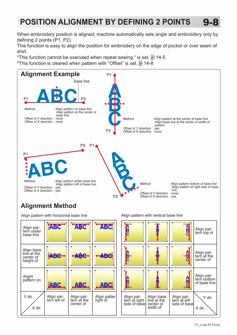
-SA -60
9-8POSITION ALIGNMENT BY DEFINING 2 POINTS
15_1 N122
When embroidery position is aligned, machine automatically sets angle and embroidery only by defining 2 points (P1, P2).This function is easy to align the position for embroidery on the edge of pocket or over seam of shirt. *This function cannot be executed when repeat sewing “ is set. 14-5*This function is cleared when pattern with “Offset” is set. 14-8
Align pat-tern left of
Align pat-tern at the center of
Align patter right of
Align pattern with horizontal base line
Align pat-tern under base line
Align base line at the center of height of
Alight pattern on
Align pat-tern at right side of base
Align base line at the center of width of
Align pat-tern at left side of base
Align pattern with vertical base line
Align pat-tern top of
Align pat-tern at the center of
Align pat-tern bottom of base line
Alignment Example
Method : Align pattern on base line Align pattern at the center of base line
Offset of Y direction : noneOffset of X direction : none
Alignment Method
ABC
ABC
ABC
ABC
P1 P2
P1
P2
P1
P2 P1
P2
base line
Y dir.
X dir.
Y dir.
X dir.
Method : Align pattern at the center of base line Align base line at the center of width of pattern
Offset of Y direction : yesOffset of X direction : none
Method : Align pattern under base line Align pattern left of base line
Offset of Y direction : yesOffset of X direction : yes
Method : Align pattern bottom of base line Align pattern at right side of base line
Offset of Y direction : noneOffset of X direction : yes

-RA -73
9-9POSITION ALIGNMENT BY DEFINING 2 POINTS
15_2 R801
P1
P1 P2
Base line
1. Hoop a shirt on embroidery frame. (Diagonal position of pocket on frame is okay.) Set the frame on the machine.
2. Press .
Press and to turn the pointer on when laser pointer is installed.
3. Press .
4. Select alignment method
Select in this case.
5. Move frame with and align the
pointer or pressure foot on the left edge (P1) of pocket.
6. Press and move frame with
, and align the pointer or
pressure foot on the right edge (P2) of pocket.
Line connected between P1 and P2 is base line.
The procedure is explained as an example of embroidering pattern on pocket of shirt.

-RA -74
7. Press . Enter movement of arrow from base line (edge of pocket) to pattern.
Enter “15.0”(15mm) in this case.
8. Press . Enter movement of arrow from base line (edge of pocket) to pattern.
Leave “0.0” when pattern is aligned to the center of base line (width of pocket).
9. Press .
10.Press .
Angle and position of embroidery are automati-cally set.
9-APOSITION ALIGNMENT BY DEFINING 2 POINTS
15_3 R801
P1P2
Base line
P1P2
Complete
Movement
Movement

-D2 -114
9-BPOSITION
16_1 M717
This creates direct designations to the number of stitches and *color change number, as well assetting the frame and data to the designated sewing position.
PieceIf "Repeat" is set, this allows the frame to move to the beginning of any piece at will.
You can specify sewing position at specified pattern data number and specified number ofstitch or color change number by entering the specified information.
Change (Color position ) 9-7
This moves the frame to the beginning of any Color change number at will beginning of color.
Stitch (Number of stitches ) 9-6
This moves the frame to any stitch at will.
Piece Stitch(Number of stitches )
Change(Color position )
+ : Any stitches
+
: Beginning of any pieces
1
3
2
: Beginning of any couloir number
2
13
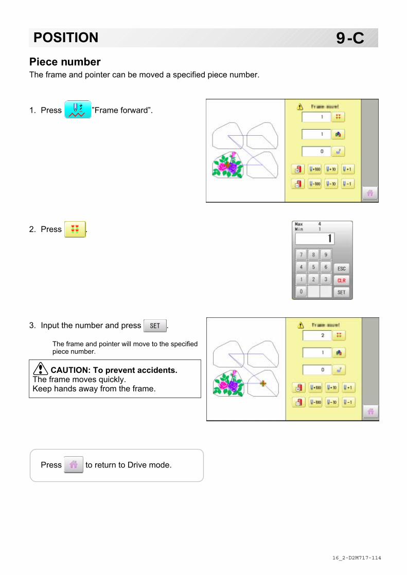
-D2 -114
9-CPOSITION
16_2 M717
Piece numberThe frame and pointer can be moved a specified piece number.
1. Press ”Frame forward”.
2. Press .
3. Input the number and press .
The frame and pointer will move to the specifiedpiece number.
CAUTION: To prevent accidents.The frame moves quickly.Keep hands away from the frame.
Press to return to Drive mode.

-DA -106
9-CbPOSITION / BOBBIN THREAD ALARM
16_2 R801
Bobbin thread alarmBy entering the number of stitches per one bobbin, the machine can be stopped automatically when the remaining amount of bobbin thread becomes low.Also, the alarm message will be displayed on the screen.
When the number of stitches is entered, the bobbin thread progress bar will be displayed just below the embroidery progress bar.The bobbin thread progress bar shows rough remaining amount, and then the bobbin can be exchanged before empty completely.
Setting
1. Press ”Frame forward”.
2. Press .
Setting value : Setting value: Register the num-ber of stitches possible per one bobbin.
Current value : Current value: Display the current number of stitches after exchange the bobbin. Press to reset the value.
Auto stop at cut. : sAuto stop at cut: The ma-chine will be stopped automatically at first thread cut point after exceeding the preset stitches.
Stop at count over. : Stop at count over: The ma-chine will be stopped automatically when the machine reaches the preset stitches.
Remaining amount of bobbin thread

-DA -107
9-CcPOSITION / BOBBIN CHANGE ALERT
16_2 R801
4. Input the stitich number and press .
The standard bobbin which is winded with #120 cotton thread will be used around 30000 stitches. But, the consumption of bobbin thread is varied depending on embroidery conditions such as stich type, stitch length and thread tension.It is recommended to enter the value to 30000 stitches as first setting. The option of auto stop function can be selected ( ) from “stitch number” and “thread cut point".
5. Press .
6. Press to return to Drive mode.
1. Press . During embroidery, the red progress bar which shows the remaining amount of bobbin thread will be extended until the preset stitches.
When the auto stop function is activated.
The machine stops automatically.
When the machine is stopped by manually.
2. Press when the bobbin is not required to exchange.
The setting value will not be reset and the stitch will be counted continuously.
Press when the bobbin is required to exchange.
The setting value will be reset to “zero” and the progress bar becomes blue.
Auto stop option
Remaining amount of bobbin thread
Setting correctionCorrect the setting value to display the alarm message at proper timing.

-DA -108
9-CdPOSITION / BOBBIN CHANGE ALERT
16_2 R801
3. Remove the bobbin and check the remaining amount. When the remaining amount is suitable, it is no need to correct the value. Please continue embroidery. The correction of setting value is required when the remaining amount is overage or shortage. Go on to step 4.
4. Press “Frame forward”.
5. Press .
6. Press .
7. Reduce the setting vale when the bobbin is almost empty.
Increase the setting vale when the remaining amount is too much.
The total stitch number which is calculated after the last bobbin exchange is displayed as “Current value”. Please refer the “Current value” to find suitable setting.
8. Press and .
9. Press to return to Drive mode. Please note that several corrections may be required to find suitable setting.

-DA -102
9-DREGISTER
17_1 Q501
Register will restore the position of the frame to the last point before a power failure even if the point of origin or the pattern itself were changed.
If register is used with a cap drive frame, make sure that the machine recognizes it by showing “Cap” (Cap frame) or “OnePoint” (One Point frame) the appropriate frame or the machine could be damaged. If register is used with indication of frames that do not require cap drive frame, carriage moves and exceeds embroidery area of cap drive frame and damages the machine and cap drive frame.
When you use “REGISTER”, keep clear of the frame and table. It is dangerous as the frame could make sudden movements. Never use register with the needle bar and presser foot lowered, as they could hit the cap drive frame and break.
It is not always necessary to set “Entry”, but you can’t set “Return”. Once “Entry” is set, it is retained even if power is turned off. If you change the position of the original point, set it again.
Even if you set “Entry”, the frame may not return exactly to the original position in process of time. Reset this monthly.
EntryRegistering the start point in the selected pattern.
Return (Registered position)When position of the frame changes because of power loss, this will restore the frame to theregistered point.
Selected frame

-D2 -103
1. Press .
2. Confirm that there is indication of (Top)in the display and go on to procedure no. 3.
Press "Top", if there is not a
indication.
Upper right indication of will be shown.
3. Move the frame to the original point with the
.
If the frame is located at the origin point,proceed to Step 4.
4. Press .
5. Press .
The origin point is registered.
9-EREGISTER
17_2 NB01
EntryThis registers the original point of the selected pattern.
Press to return to Drive mode.

-DA -104
1. Press .
2. Confirmthatthereisindicationof (Top) inthedisplayandgoontoprocedureno.3.
Press “Top”,ifthereisnotaindication.
Upperrightindicationof willbeshown.
3. Press .
4. press.
Theframewillreturntotheoriginpointyouregistered.
9-F REGISTER
17_3 Q101
ReturnIncaseofpowerfailureyoucanreturntotheoriginalpointyouregistered.
CAUTION: To prevent accidents.Theframemovesquickly. Keepyourhandsawayfromtheframe.
Press toreturntoDrivemode.

-D2 -97
10-1READING
1. Insert the memory media into the machineas described in "Inserting memory media”.
2. When the machine is stopped, press .
3. Select "READ".
4. Select (USB memory).
Indicates pattern data of the memory media.
TAP : HAPPY DST : Tajima DSB : Tajima (Barudan) DSZ : Tajima (ZSK)
Folder : Contents of folder will be displayedwhen you select this icon.
1 % of free memory is equivalent to about400,000 stitches.
If there are more stitches than remaining space,you may need to delete some designs to makeroom for the new patterns.
14_1 NB01
JoinJoining 2 patterns into 1 pattern data to be read from a memory media.Function of joining patterns is not valid for pattern data in PC connected with LAN.
In case you would like to use "Join" function, please set "Join design data" to "YES" on"READING" setting in advance.
Holder
--- Serch pattern ---
Free memoryThe designs new ID number inthe machines memory.

-D2 -98
10-2READING
14_2 NB01
--- Check pattern data ---
--- Reading ---
--- Check pattern data ---
--- Reading ---5. Select the pattern.
Once design is read.
Enable to read other pattern data.
6. Press .
Shift the Memory media if the pattern data youdesire to Join is in the other Memory media.
7. Select the pattern data to be Joined.
8. Press .The pattern data selected to be joined is joinednext to the pattern data previously read in themachine as one pattern data and the screenreturns to Menu screen.Pattern name is registered as the name of thefirst pattern data read in the machine in patterndatum joined.
Press if you desire to join morepatters.
Necessary pattern data can be read byperforming step 6 to 8.
When the screen displays pattern data inthe folder, is displayed.
When is pressed, the screen movesoff from the current folder.

-RA -65
10-3READING
14_4 Q101
Pattern read settingsSettings related to pattern data reading:
Detailed explanation of machine setting
4 Stitch sweeperThis removes stitches that are extremely narrow when reading pattern data and writing tomachine memory. If thread breaks occur often at the same point in a pattern, this may bebecause of narrow stitches.
If the thread still breaks in the same place you can use this function again but repeated usage may distort the shape of the stitch.
1. Save the pattern to USB memory.
2. Conduct a stitch sweeping of the pattern and load it into the machine again.
End
7 Data formatThis enables you to select a different format and read the pattern again if the machine did notread it correctly the first time.
SETTING ITEM SETTING RANGE (Difult is underlined)
1 Keep null (CHG.) Yes•No : This function lets the machine read zero stitches as they are before color change when reading pattern data.
2 Skip null stitch Yes•No : This lets you choose to ignore all null stitches when reading pattern data.
3 Combine jump Yes•No : Allows you to combine multiple, consecutive jump stitches when read-ing pattern data, if desired. It combines them into jump stitches of the maximum 12.7mm and reads the pattern with the combined jumps.
4 Stitch sweeper Yes•No : This function eliminates extremely short stitch for stitch width when reading pattern data.
5 Sweep length 0 ~ 0.4 ~ 0.8 : This setting controls the length of the stitches eliminated by the Stitch (mm) sweeper. Stitches shorter than this setting will be eliminated.6 DST name display Yes•No : When patterns in Tajima format are read in, the display shows the file name.7 Data format Auto ➞Automatic : Turn data format for reading patterns. Usually, set it to Automatic. Happy➞HAPPY, Tajima Brd ➞Barudan Zsk ➞Zsk8 Design information Yes•No : This function reads various function setting which are set in pattern data to-
gether with pattern data (type TAP).9 Trace type : Lets you select the type of trace data that is created as a pattern is read in. ➞ Maximum embroidery area of pattern ➞ Out line10 Join design data Yes•No : It is appeared that other pattern data is joined to the data previously read in the
machine. You can make one pattern data by joining multiple pattern data read in the machine.
11 Folder select Yes•No : When reading pattern data, the list for selection of folders will be displayed.12 Completion msg. Yes•No : Completion msg. will appear after reading pattern data.

-D2 -99
8 Design information*Various settings are saved together with a pattern. If some settings are changed in thepattern and you wish to return to the originals, simply reload.
The data may only be HAPPY format (TAP).
9 Trace typeYou can compare the design size and design position to the embroidery frame before you startsewing.The embroidery frame will move around the actual design size.At this time you can choose which type of trace from the two types as seen in the followingfigure:
10-4READING
14_5 NB01
● Start point
Area Outline

-DA -98
10-5READING
14_6 NB01
1. When the machine is stopped, press .
2. Select “OPTION”.
3. Select .
4. Select desired setting item and change the setting.
You can move to next page by pressing .
Press , all settings are returned to the de-fault.
Press to return to Menu mode.
Press to return to Drive mode.

-D2 -66
11-1PATTERNS IN MEMORY
5_B NB01
1. When the machine is stopped, press .
2. Select "PATTERN".
3. Press from right submenu.
4. Select desired pattern.
Mark will appear right of the pattern.Make will be cleared by press it again.Multiple pattern data can be selected.
Locking pattern dataLocking pattern data stored in the machine memory will prevent deletion and changes in set-tings.
Mark
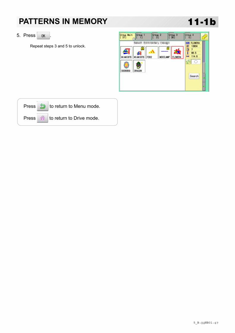
-D2 -67
11-1bPATTERNS IN MEMORY
5_B NB01
5. Press .
Repeat steps 3 and 5 to unlock.
Press to return to Menu mode.
Press to return to Drive mode.

-D2 -68
11-2PATTERNS IN MEMORY
11_2 NB01
Trace typeChanging the trace type of the pattern data in the machine memory. 10-4
1. When the machine is stopped, press .
2. Select "PATTERN".
3. Select desired pattern.
Maximum embroidery area of pattern
Outline of pattern
4. Press and select or .
Trace type is changed.
--- Calculating ---
Press to return to Menu mode.
Press to return to Drive mode.
Trace type
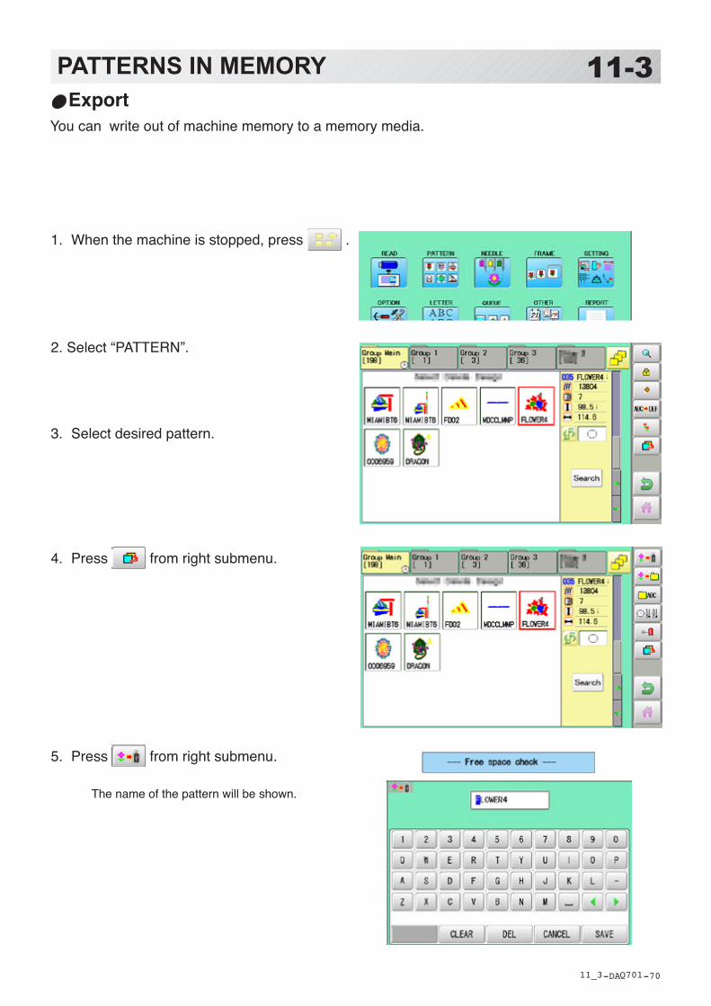
-DA -70
11-3PATTERNS IN MEMORY
11_3 Q701
ExportYou can write out of machine memory to a memory media.
1. When the machine is stopped, press .
2. Select “PATTERN”.
3. Select desired pattern.
4. Press from right submenu.
5. Press from right submenu.
The name of the pattern will be shown.

-DA -71
11-4PATTERNS IN MEMORY
11_4 Q701
7. Press if the pattern name is not to be changed.
The pattern data will be written.
Choose the column with . Then select each digit in the existing name.
Select word and press .The pattern data will be written.The maximum number of characters in a design name is eight letters or numbers.
All the letters and/or numbers are deleted.
Selected letter or number is deleted.
Changing name is cancelled.
The display returns to the view of Step 5.
Press to return to Menu mode.
Press to return to Drive mode.

-DA -72
11-5PATTERNS IN MEMORY
11_5 Q701
Renaming patternsRename pattern in memory.
1. When the machine is stopped, press .
2. Select “PATTERN”.
3. Select desired pattern.
4. Press from right submenu.
5. Choose the column with . Then select each digit in the existing name.
Select word.The maximum number of characters in a design name is eight letters or numbers.
All the letters and/or numbers are deleted.
Selected letter or number is deleted.
Renaming is cancelled.
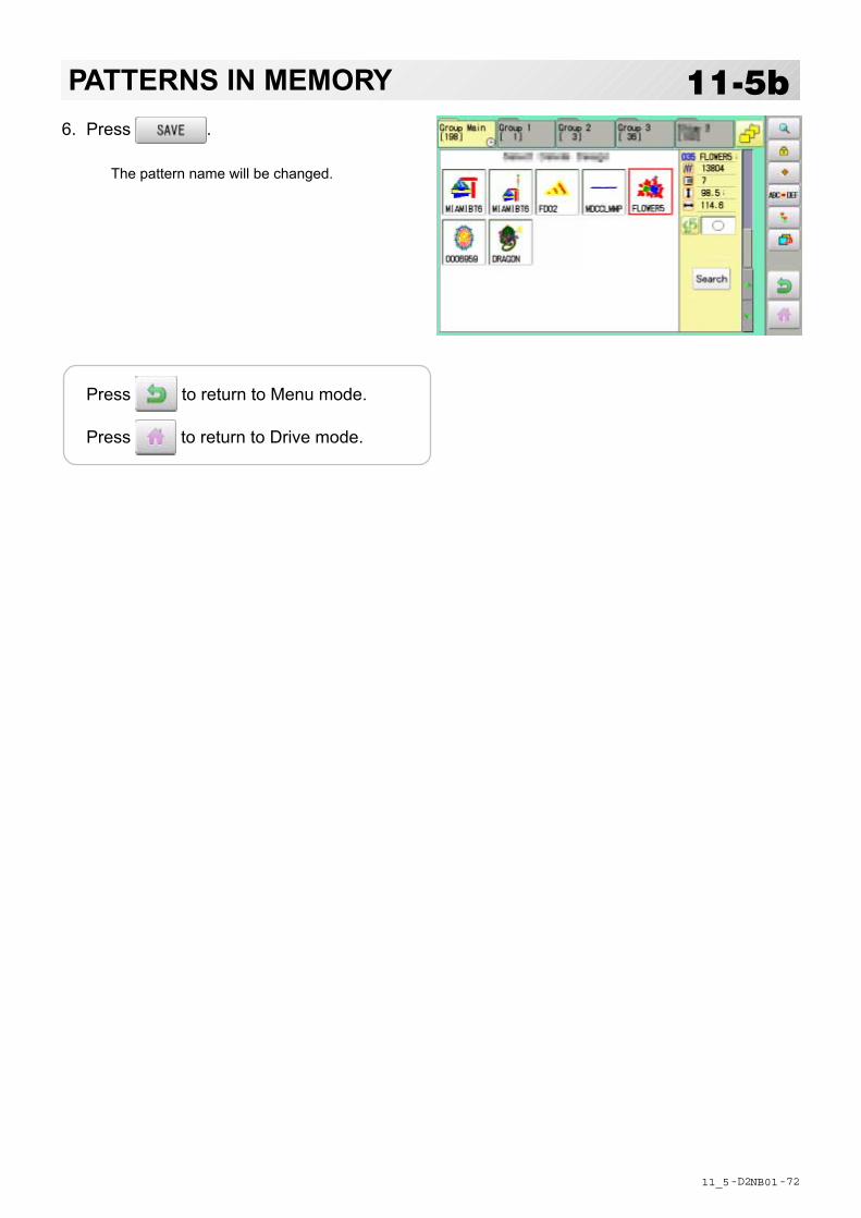
-D2 -72
6. Press .
The pattern name will be changed.
11-5bPATTERNS IN MEMORY
11_5 NB01
Press to return to Menu mode.
Press to return to Drive mode.

-D2 -73
11-6PATTERNS IN MEMORY
11_6 NB01
Copying pattern dataCopying of the pattern data stored in the machine memory is available.
Copied pattern data
1. When the machine is stopped, press .
2. Select "PATTERN".
3. Select desired pattern.
4. Press from right submenu.
Copy of the selected pattern will be made.
Press to return to Menu mode.
Press to return to Drive mode.
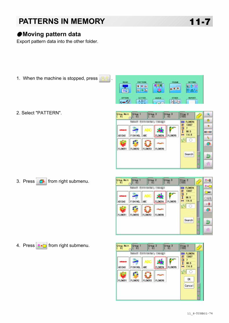
-D2 -74
11-7PATTERNS IN MEMORYMoving pattern data
Export pattern data into the other folder.
1. When the machine is stopped, press .
2. Select "PATTERN".
3. Press from right submenu.
4. Press from right submenu.
11_8 NB01

-D2 -75
11-8PATTERNS IN MEMORY
11_8 NB01
Importing folder
4. Select desired pattern.
Mark will appear left of the pattern.Make will be cleared by press it again.
Multiple pattern data can be selected.
: Cancel pattern data moving
5. Press .
6. Select the importing folder.
The pattern data will be transferred.
Mark
Press to return to Menu mode.
Press to return to Drive mode.

-D2 -76
11-9PATTERNS IN MEMORY
11_9 NB01
Renaming foldersRename folder in memory.
1. When the machine is stopped, press .
2. Select "PATTERN".
3. Press from right submenu.
4. Press from right submenu.

-DA -78
11-9aPATTERNS IN MEMORY
11_9 Q701
5. Select desired folder.
6. Choose the column with . Then select each digit in the existing name.
Select word.The maximum number of characters in a design name is 12 letters or numbers.
Uppercase and lowercase letter are switched.
All the letters are deleted.
Selected letter or number is deleted.
Renaming is cancelled.
7. Press .
The folder name will be changed.
Renamed folder
Press to return to Menu mode.
Press to return to Drive mode.
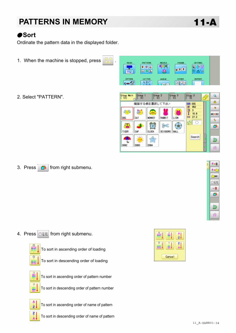
-SA -34
11-APATTERNS IN MEMORY
11_A NB01
SortOrdinate the pattern data in the displayed folder.
1. When the machine is stopped, press .
2. Select "PATTERN".
3. Press from right submenu.
4. Press from right submenu.
To sort in ascending order of loading
To sort in descending order of loading
To sort in ascending order of pattern number
To sort in descending order of pattern number
To sort in ascending order of name of pattern
To sort in descending order of name of pattern
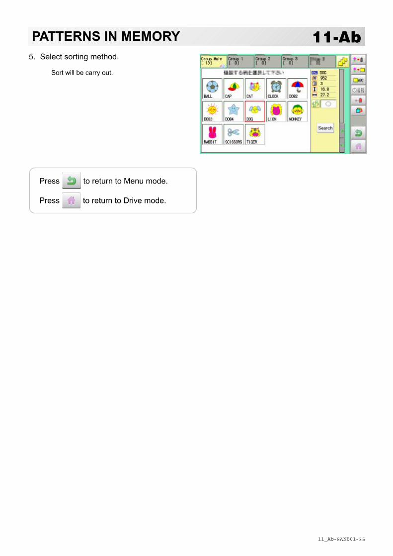
-SA -35
11-AbPATTERNS IN MEMORY
11_Ab NB01
5. Select sorting method.
Sort will be carry out.
Press to return to Menu mode.
Press to return to Drive mode.

-D2 -78
11-BPATTERNS IN MEMORY
11_B NB01
Thread break reportThis function will show recorded thread break of pattern data. The machine detects break threadduring operation and records by pattern the number of stitches at the stopped position.If thread break is happening at same number of stitches, please check construction of stitchdesign.
1. When the machine is stopped, press .
2. Select "PATTERN".
3. Select desired pattern.
4. Press from right submenu.
5. Press from right submenu.
Thread break report will appear in the window.The maximum memory is up to No. 30.If the record exceeds No. 30, the new recordswill be added to the latest 29 records.
To delete the record
6. Press .
Exit the mode.
Pattern numberPuttern name
Number of stitches
Number of stitches at the stopped positionby thread break
Press to return to Menu mode.
Press to return to Drive mode.
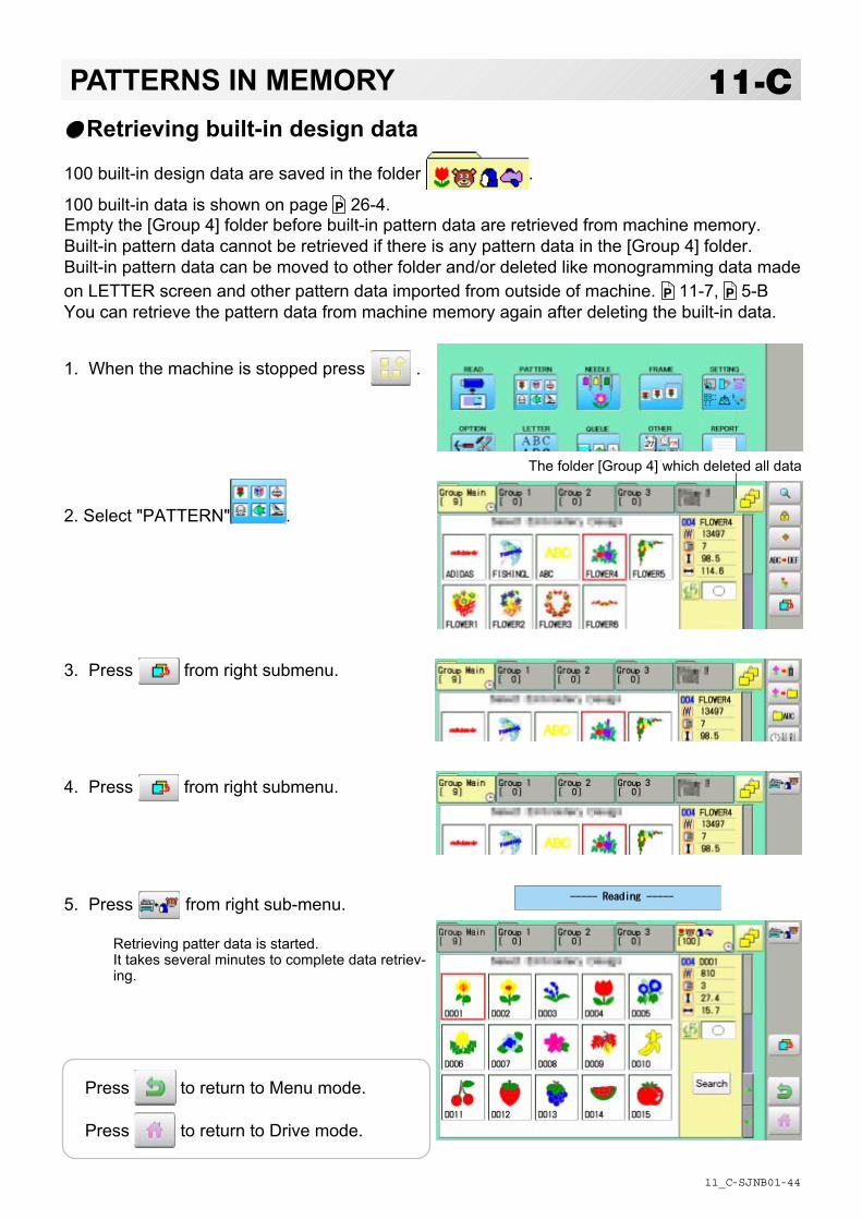
-SJ -44
11-CPATTERNS IN MEMORY
11_C NB01
Retrieving built-in design data
100 built-in design data are saved in the folder .
100 built-in data is shown on page 26-4.Empty the [Group 4] folder before built-in pattern data are retrieved from machine memory.Built-in pattern data cannot be retrieved if there is any pattern data in the [Group 4] folder.Built-in pattern data can be moved to other folder and/or deleted like monogramming data madeon LETTER screen and other pattern data imported from outside of machine. 11-7, 5-BYou can retrieve the pattern data from machine memory again after deleting the built-in data.
1. When the machine is stopped press .
2. Select "PATTERN" .
3. Press from right submenu.
4. Press from right submenu.
5. Press from right sub-menu.
Retrieving patter data is started.It takes several minutes to complete data retriev-ing.
The folder [Group 4] which deleted all data
Press to return to Menu mode.
Press to return to Drive mode.
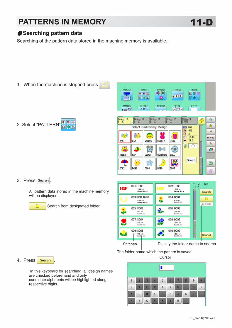
-SA -49
11-DPATTERNS IN MEMORY
11_D Q701
Searching pattern dataSearching of the pattern data stored in the machine memory is available.
1. When the machine is stopped press .
2. Select “PATTERN” .
3. Press . All pattern data stored in the machine memory will be displayed.
Search from designated folder.
4. Press . In this keyboard for searching, all design names are checked beforehand and only candidate alphabets will be highlighted along respective digits.
Display the folder name to search
The folder name which the pattern is savedCursor
Stitches
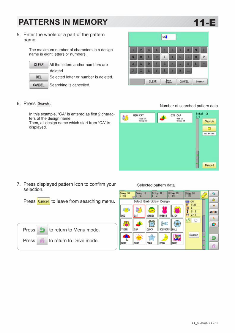
-SA -50
Press to return to Menu mode.
Press to return to Drive mode.
PATTERNS IN MEMORY
11_C Q701
11-E5. Enter the whole or a part of the pattern
name.
The maximum number of characters in a design name is eight letters or numbers.
All the letters and/or numbers are deleted.
Selected letter or number is deleted.
Searching is cancelled.
6. Press . In this example, “CA” is entered as first 2 charac-ters of the design name.Then, all design name which start from “CA” is displayed.
7. Press displayed pattern icon to confirm your selection. Press to leave from searching menu.
Number of searched pattern data
Selected pattern data

-D2 -101
12-1NEEDLE BAR SELECTION
13_1 MA05
Needle number settings 5-E
A needle number can be assigned to a *color change number.When the needle number is assigned, the machine will embroider and automatically switch tothe programmed for each color change number.
Color change stop function 5-F
A *color change stop can be assigned to a color change number.When this is done, the machine embroiders the stitches for that color change number and thenstops, displaying the following message:
Auto settingChanges all designated needle numbers at once.
Thread colorThis sets the background color or color assigned to each needle bar to be shown in the display.
Color change data registration, Color change data readYou can use the color change data from a saved pattern, register it, and then export the regis-tered data to the selected pattern for use.
Repetition of color group settingIf your design has repetition of the group of the same color sequence, only set first sequenceand set other automatically by following steps.
>>Change Stop

-RA -58
1. When the machine is stopped, press .
2. Select “NEEDLE”.
3. Press from right submenu.
4. Select the current needle number you would like to change.
5. Select the needle number to be changed.
12-2NEEDLE BAR SELECTION
13_2 N701
Needle number to be changed
Auto settingThis changes all designated needle numbers at once.For example, if you want to change all needles numbered “3” to “5”, just select one of the color change numbers in which “5” is set, then all color change numbers can be changed into “3”.
Needle number to be changed after

-RA -59
12-3NEEDLE BAR SELECTION
13_2 B701
The needle number has been changed from 3 to5.
6. Press .
Setting is cancelled.
Preview screen is displayed.
7. Press .
The setting is fixed.
Press to return to Menu mode.
Press to return to Drive mode.

-RA -60
12-4NEEDLE BAR SELECTION
13_3 O512
Yellowish greenSet needle number : 3
Set needle number : 2
Set needle number : 1 Red
Color stteing 1 : Red 2 : Yellowish green 3 : Green
Green
Thread colorThis sets the background color or color assigned to each needle bar to be shown in the display.This is useful to help confirm the correct color setup of a pattern.
You will find difficulty to see the pattern if you set same color on both pattern and background.
1. When the machine is stopped, press .
2. Select “NEEDLE”.
3. Press from right submenu.
Cloth (back-

-RA -61
12-5NEEDLE BAR SELECTION
13_4 O512
4. Select the needle number or cloth (background color).
You chan change the color palette.
5. Select the color to be changed at the palette.
You can select the color with .
Current color will be shown.
6. Press .
7. Press .
The setting is fixed.
Preview screen is displayed.
current colorColor to be changed after
Press to return to Menu mode.
Press to return to Drive mode.
256 colors palette 70 colors palette

-RA -62
1. When the machine is stopped, press .
2. Select “NEEDLE”.
3. Press from right submenu.
4. Press .
The color change data will be saved into memo-ry.
12-6NEEDLE BAR SELECTION
13_5 B701
Color change data registrationYou can import and apply color change data from saved patterns (Including color change stops) to the current pattern. This function lets you apply the same color change data from other patterns.
The color change data is limited to one and the color change numbers are limited to 250.
Color change number
Press to return to Menu mode.
Press to return to Drive mode.
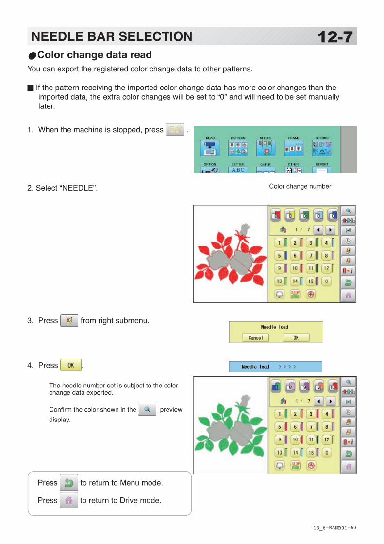
-RA -63
1. When the machine is stopped, press .
2. Select “NEEDLE”.
3. Press from right submenu.
4. Press .
The needle number set is subject to the color change data exported. Confirm the color shown in the preview display.
12-7NEEDLE BAR SELECTION
13_6 NB01
Color change data readYou can export the registered color change data to other patterns.
If the pattern receiving the imported color change data has more color changes than the imported data, the extra color changes will be set to “0” and will need to be set manually later.
Color change number
Press to return to Menu mode.
Press to return to Drive mode.

-RA -64
1. When the machine is stopped, press .
2. Select “NEEDLE”.
3. Set first color sequence group.
Please confirm that the next number of the group is “0”.
4. Press from right submenu.
Set other color change setting automatically.
If the number of total color change does not be-come the first number of group multiple number. Machine display warning.
12-8NEEDLE BAR SELECTION
13_7 NB01
Repetition of color group settingIf your design has repetition of the group of the same color sequence, only set first sequence and set other automatically by following steps.(If you have some function in the needle “Example: color change stop”, the function also will set)
Fig. 1
First sequence
● : Start point of pattern■ : End point of pattern
Check repeat setting. OK
First sequence
Press to return to Menu mode.
Press to return to Drive mode.

-D2 -125
13-1FRAME CONFIRMATION
20_1 M401
By default the machine checks if the pattern fits the embroidery area.This helps you to check whether or not the selected pattern fits in the desired hoop.This helps confirm positioningbetween the embroidery area and the pattern.If you change the frame position by the frame move key, the display will be changed and youcan check the position onscreen.
The "monitor display" checks whether or not the pattern fits the embroidery area of theframe you are going to use before starting the operation.This is not a safety device that will prevent crashes if pattern size is too large for the frame;it is intended for your reference only when judging the fit of a pattern to a given size frame.After using "monitor display", do not move the frame. If you do so the machine may bedamaged due to the needle or pressure foot hitting the frame.
Make sure to perform "Registration number selection" when changing hoop size. If notdone, the machine may be damaged from the needle or pressure foot hitting the frame.

-DA -113
13-2FRAME CONFIRMATION
20_2 P801
1. When the machine is stopped, press .
2. Select “FRAME”. Tubular round frame
Tubular square frame
Cap and One-point frame
Border frame ( for HCD2, HCR2)
Sock frame
User-defined frame
Special frame ( Except HCR2)
Non registered
3. Select type of frame.
Change the type of frame.
Frame selectionSelecting a frame.The embroidery area for each registered frame is set to the inside of the frame edge to allow for pressure foot clearance. (Fig. 1)This allows confirmation of positioning between the embroidery area and the pattern.
Embroi-dery area
Fig. 1
Inner size (Length-
Embroi-dery area
Inner size (Sidewise)Inner size
Round frame Square frame

-DA -119
13-3FRAME CONFIRMATION
20_3 R801
4. Select desired size of frame and press .
The embroidery area appear in red.
5. Confirmthat (Top) appears in the display and go to step 7. If this does not appear, go to step 6.
6. Press “Top”.
Upper right indication of will be shown.
7. By position of design can be
moved.
8. Press .
The display returns to Drive mode.
Start sewing by pressing .

-DA -115
13-4FRAME CONFIRMATION
20_4 O901
Adjusted for embroidery area
Cap frameThe embroidery area of HAPPY semi-wide and wide cap frames is saved in the machine.The Y axis of the embroidery area can be ad-justed for a variety of caps. (Fig. 1)
Embroidery area
Embroidery area (Side wise) Fig. 1
Embroidery area (Lengthwise)
1. When the machine is stopped, press .
2. Select “FRAME”.
3. Select ”Cap and One-point frame”.
4. Select desired size of frame and press .
The embroidery area appear in red.
5. Press .

-DA -118
13-5FRAME CONFIRMATION
20_5 R201
6. Press .
7. Press .
8. Select the number .
Enter the width of the cap. Standard 40 ~ 70mm Width 40 ~ 95mm
9. Press .
10. Press .
The setting is fixed.
Settings are returned to the default.

-D2 -117
13-6FRAME CONFIRMATION
20_5 NB01
11.Press .
Press to return to Drive mode.
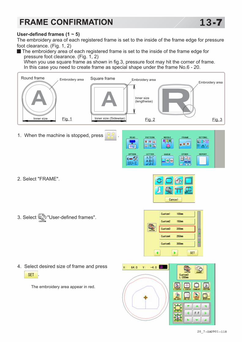
-DA -118
13-7FRAME CONFIRMATION
20_7 O901
1. When the machine is stopped, press .
2. Select "FRAME".
3. Select "User-defined frames".
4. Select desired size of frame and press.
The embroidery area appear in red.
User-defined frames (1 ~ 5)The embroidery area of each registered frame is set to the inside of the frame edge for pressurefoot clearance. (Fig. 1, 2)
The embroidery area of each registered frame is set to the inside of the frame edge forpressure foot clearance. (Fig. 1, 2)When you use square frame as shown in fig.3, pressure foot may hit the corner of frame.In this case you need to create frame as special shape under the frame No.6 - 20.
Fig. 1
Embroidery areaRound frame Embroidery areaSquare frame
Fig. 3Fig. 2
Embroidery area
Inner size (Sidewise)Inner size
Inner size(lengthwise)
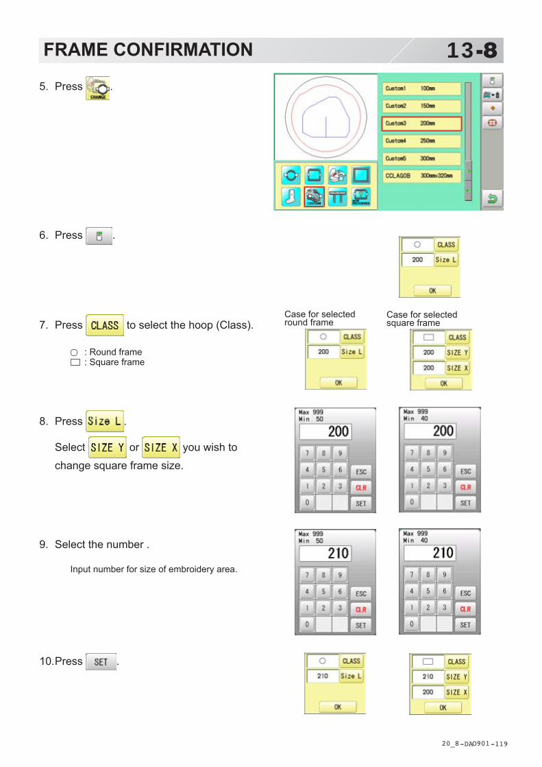
-DA -119
13-8FRAME CONFIRMATION
20_8 O901
5. Press .
6. Press .
7. Press to select the hoop (Class).
: Round frame: Square frame
8. Press .
Select or you wish to
change square frame size.
9. Select the number .
Input number for size of embroidery area.
10.Press .
Case for selectedround frame
Case for selectedsquare frame

-DA -120
13-9FRAME CONFIRMATION
20_9 O901
11.Press .
The date is fixed.
12.Press .
Case for selectedround frame
Case for selectedsquare frame
Press to return to Drive mode.

-D2 -133
13-AFRAME CONFIRMATION
20_A M401
User-defined frames (6 ~ 20)You need to prepare for the data which entered the shape of the frame and entry the entereddata.You can entry the data up to 15 different size of custom frames.You need to prepare custom frame size data for entry the size to your machine. 13-BThe embroidery area for each registered frame is set to the inside of the frame edge to allow forpressure foot clearance. (Fig. 1)
Embroideryarea
Fig. 1
Embroideryarea
Round frame Square frame

-D2 -136
13-BFRAME CONFIRMATION
20_B K101
Frame data constitution
Type = [Type of data]Name = "[Name of frame]"Form = [L00],[L10],[L20],[L30],[L40],[L50],[L60],[L70],[L80],[L90] (Frame shape)
Type : Select type of data by following number. 1 : Frame size 2 : Possible embroidery size
Note: If select "1", machine will memory reduced size for Presser food diameterautomatically.If select "2", machine will memory exactly same size as can embroider it on.
Name : Naming the your User-custom frame. Pick up to 10 letters up with a "mark.
Form : Refer the above figure. Please fill it out every 10 degrees of dimensions to the inside ofthe frame in a frame heartily. (20 to 500mm)Fill it out length from point from No. L00 till L90 total 10 points size using ", " between theeach size data.If your frame shape is Round, the every 10 points length frame size data should besame.If you select Type (Type of data) "2", please put length data of L00 and L90 only.
END : Please fill out the line of the last of data. Please make entry of "END" by all means.
Please use half width character for the length data.
Please cut off the decimal of the length.Example: 102.3mm -> 102
How to make frame size data of your User-defined frames (6 ~ 20)We need to use text edit software of PC like "WordPad" and make frame size data with follow-ing constitution, then entry the data to your machine.
Fig. 1
Center ofuser-definedframe
Fig. 2
90°
0°
L90
L00
90°
0°
L10L20
L30
L40
L50L60L70L80L90
L00
Type = 1 (Type of data) Type = 2 (Type of data)
Center ofuser-definedframe

-CR -126
13-CFRAME CONFIRMATIONWhen you save the frame size data, please save as text document form and file name shouldbe less than 8 characters.Extension should be ".TXT"Example: ROUND250.TXT
Please save the frame size data to machine usable memory media and read the data byembroidery machine. 13-D
Example of making the frame size dataSample for each teaching method.
20_C N525
Ex. Round frame
Type = 1Name = "Round"Form = 125,125,125,125,125,125,125,125,125,125END
Ex. Square frame
Type = 1Name = "PS240"Form = 120,122,126,130,128,120,106,100,96,94END
Ex. Possible embroidery size
Type = 2Name = "T-SC-01"Form = 90,60END
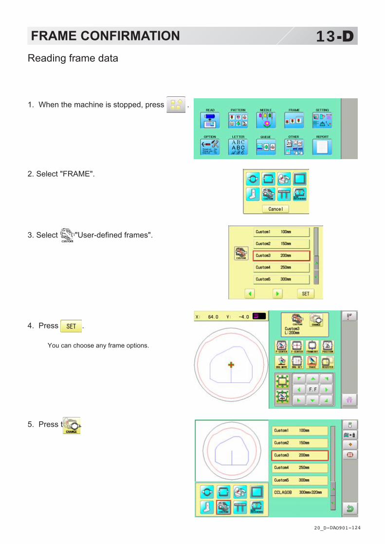
-DA -124
13-DFRAME CONFIRMATION
20_D O901
Reading frame data
1. When the machine is stopped, press .
2. Select "FRAME".
3. Select "User-defined frames".
4. Press .
You can choose any frame options.
5. Press t .

-DA -125
6. Press .
7. Select the frame data “CCLAGOB.txt”.
The frame data has been read.
8. Press .
13-EFRAME CONFIRMATION
20_E O901
Press to return to Drive mode.
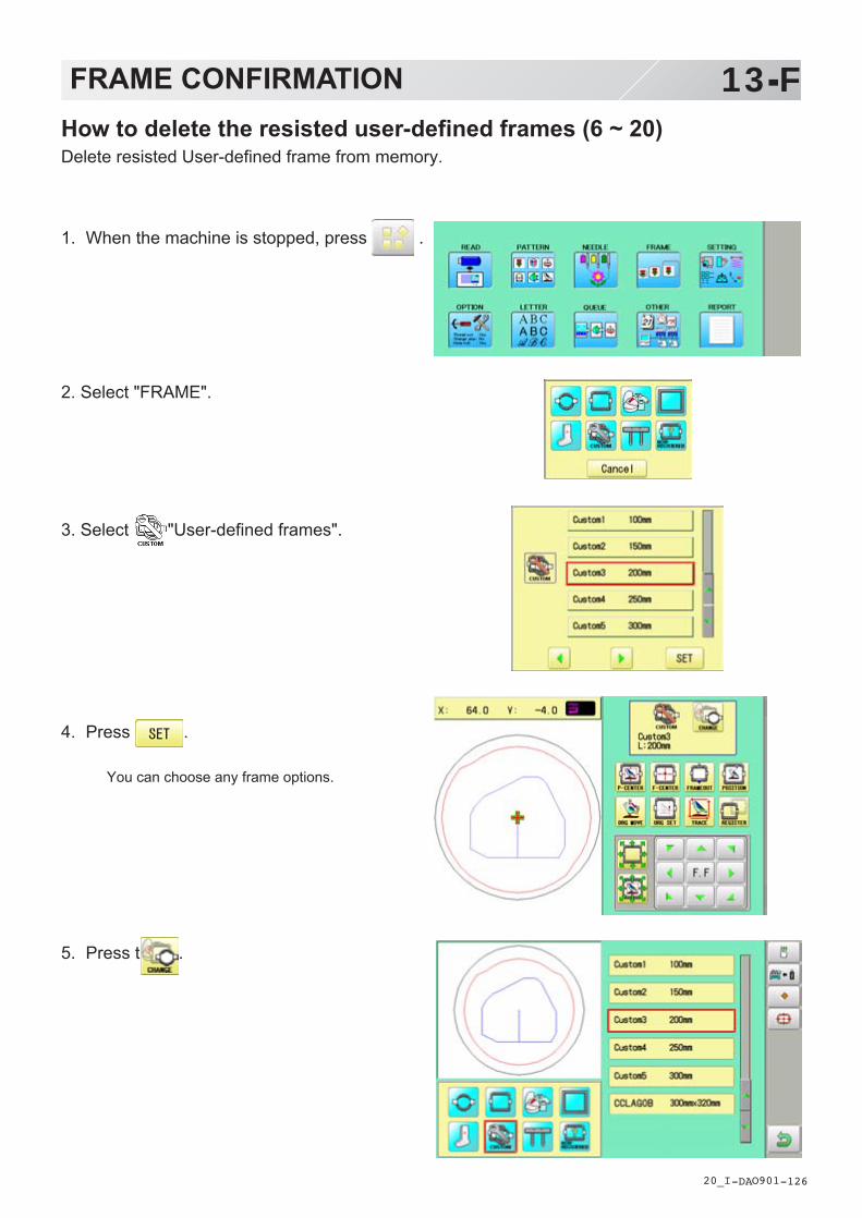
-DA -126
13-FFRAME CONFIRMATION
20_I O901
1. When the machine is stopped, press .
2. Select "FRAME".
3. Select "User-defined frames".
4. Press .
You can choose any frame options.
5. Press t .
How to delete the resisted user-defined frames (6 ~ 20)Delete resisted User-defined frame from memory.
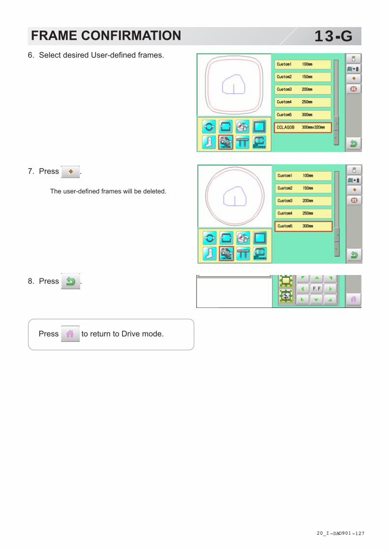
-DA -127
13-GFRAME CONFIRMATION
20_I O901
6. Select desired User-defined frames.
7. Press .
The user-defined frames will be deleted.
8. Press .
Press to return to Drive mode.

-DA -128
13-HFRAME CONFIRMATION
20_J O901
How to change center point of frame (1 ~ 5, 6 ~ 20)You can change memorized frame center point.When you set your frame and use machine function of “Frame move” and “Center” ( 3-6), If your frame is not center, please practice following steps for center setting again.
1. When the machine is stopped, press .
2. Select “FRAME”.
3. Select “User-defined frames”.
4. Press .
You can choose any frame options.
5. Press t .

-DA -129
13-IFRAME CONFIRMATION
20_K O901
6. Select desired User-defined frames.
7. Press .
8. Press .
9. Move embroidery frame to frame center
point by .
10.Press .
Memorized frame center point coordinate to themachine.
11.Press .
Press to return to Drive mode.
CAUTION: To prevent accidents.The frame moves quickly.Keep hands away from the frame.

-DA -135
13-JFRAME CONFIRMATION
20_L R801
1. When the machine is stopped, press .
2. Select “FRAME”.
3. Select “Non registered” or “Special frame”.
4. Press .
Iindication of frame type disappears. It means that “Non Registered (Special frame) “ is selected.
When you need to change from Non Registered frame (Special frame) to other type of frame, please powor machine off and start again. Without re-starting machine, machine will move incorrectly.
Non registered, Special frame ( Except HCR2)In case Non Registered Frame is selected, carriage does not have movement for creating the coordinates of frame position at the time of turning machine on.Please select Non Registered Frame, when you need use special frame which can hit pressure foot or other machine parts by movement of carriage for creating the coordinates of frame posi-tion.The following functions is canceled by selecting Non Registered Frame;
* Frame confirmation* Restore the position at the time of power failure* Locate* Autostop function when movement exceeds the carriage limit.
Frame Iindication disappears
Except using special shape frame, please do not select Non Registered Frame.In case you have operation mistake, needle and/or pressure foot may hit frame and machine and/or frame can be damaged.

-D2 -83
14-1PATTERN SETTINGS
12_1 N525
Various settings such as the scaling, repeat sewing, offset and frame out can be applied to apattern.
AdjustThis menu contains settings such as scaling, width adjustment, angle and convert design.
Repeat sewingThe machine repeats the pattern a number of times in the X and Y directions as set by the user.
OffsetSets the start point of the frame in the selected pattern.
Frame outInserts a frame out command in the selected pattern.
Various settings are executed in assortment.
Adjust
ScalingThis adjusts the scale of the selected pattern.
Width adjustmentThis adjusts the width of the selected pattern.
AngleThis adjusts the angle of the selected pattern.
Convert design 9-5This sets the rotation of the selected pattern in increments of 90 degrees, normal or reversed.

-D2 -82
14-2PATTERN SETTINGS
12_2 NB01
ScalingThe pattern's scale can be increased or de-creased in 1% increments.
Setting example
1. When the machine is stopped, press .
2. Select "SETTING".
3. Select (Scaling X) or (Scaling Y).
4. Select the number.
Changing is cancelled.
Numbers are deleted.
5. Press .
The setting is fixed.
: Start point of pattern
Normal X 100 %, Y 150 %
Default : X,Y 100%
Adjust
The pattern data may be shown.
Setting is returned to the default.
To return to Menu mode.
to return to Drive mode.
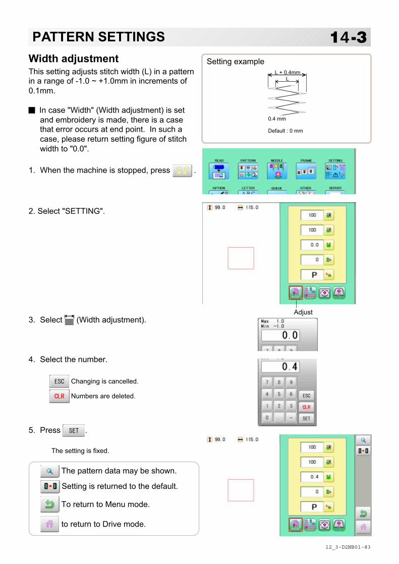
-D2 -83
14-3PATTERN SETTINGS
12_3 NB01
Width adjustmentThis setting adjusts stitch width (L) in a patternin a range of -1.0 ~ +1.0mm in increments of0.1mm.
In case "Width" (Width adjustment) is setand embroidery is made, there is a casethat error occurs at end point. In such acase, please return setting figure of stitchwidth to "0.0".
Setting example
1. When the machine is stopped, press .
2. Select "SETTING".
3. Select (Width adjustment).
4. Select the number.
Changing is cancelled.
Numbers are deleted.
5. Press .
The setting is fixed.
LL + 0.4mm
0.4 mm
Default : 0 mm
Adjust
The pattern data may be shown.
Setting is returned to the default.
To return to Menu mode.
to return to Drive mode.

-D2 -84
14-4PATTERN SETTINGS
12_4 NB01
AngleWith the start point of the pattern as a pivot,the machine rotates the angle clockwise.
Setting example
1. When the machine is stopped, press .
2. Select "SETTING".
3. Select (Angle).
4. Select the number.
Changing is cancelled.
Numbers are deleted.
5. Press .
The setting is fixed.
30°Normal
: Start point of pattern
Default : 0°
Adjust
The pattern data may be shown.
Setting is returned to the default.
To return to Menu mode.
to return to Drive mode.

-D2 -89
14-5PATTERN SETTINGS
12_5 FA21
Repeat sewingThe machine embroiders a user-specified number of copies in the X and Y directions.
Setting example
SETTING ITEM SETTING RANGE DEFAULT
Piece X 1 ~ 30 1 This sets number of pieces side wise and length wise when youperform repeat.
Piece Y 1 ~ 30 1 The number of pieces to be embroidered is product obtained bymultiplying numbers in X and Y.
Space X -999.9 ~ 999.9 mm 0 This sets side wise distance between start point of each pattern whenyou perform repeat.When plus number is input, the machine makes repeat toward right. Incase of minus number, toward left.
Space Y -999.9 ~ 999.9 mm 0 This sets length wise distance between start point of each patternwhen you perform repeat.When plus number is input, the machine makes repeat upward. Incase of minus number, downward.
Priority X (Side)• Y (Length) X When you set more than 2 pieces for repeat length wise and side wise,this selects direction to embroider 2nd piece.
Space X
Space Y
Piece X 2Piece Y 3Space X -30.0Space Y 32.0Priority Y
This is the case that "Priority" in the left list is set to X
● : Start point of pattern■ : End point of pattern
1
2
3
4
5
6
1
3
5
2
4
6

-D2 -86
1. When the machine is stopped, press .
2. Select "SETTING" and select (Repeat).
3. Select each setting item and select thenumber.
Changing is cancelled.
Numbers are deleted.
4. Press .
The setting is fixed.
5. Set necessary item by performingprocedure no. 3 to no.4.
Set all the necessary items.
14-6PATTERN SETTINGS
12_6 NB01
Repeat
The pattern data may be shown.
Setting is returned to the default.
To return to Menu mode.
to return to Drive mode.

-D2 -87
14-7PATTERN SETTINGS
12_7 NB01
Auto originWhen a pattern has different start and end points, the frame returns to the start point.
Setting example
1. When the machine is stopped, press .
2. Select "SETTING" and select (Offset).
3. Press (Auto origin) and select (ON)or (OFF).
The setting is fixed.
● : Start point of pattern■ : End point of pattern
Offset
The pattern data may be shown.
Setting is returned to the default.
To return to Menu mode.
to return to Drive mode.
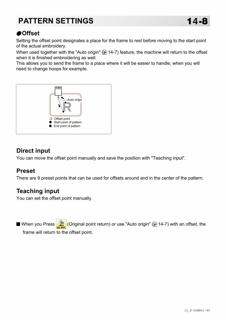
-D2 -86
14-8PATTERN SETTINGS
12_8 NB01
OffsetSetting the offset point designates a place for the frame to rest before moving to the start pointof the actual embroidery.When used together with the "Auto origin" ( 14-7) feature, the machine will return to the offsetwhen it is finished embroidering as well.This allows you to send the frame to a place where it will be easier to handle, when you willneed to change hoops for example.
Direct inputYou can move the offset point manually and save the position with "Teaching input".
PresetThere are 9 preset points that can be used for offsets around and in the center of the pattern.
Teaching inputYou can set the offset point manually.
When you Press (Original point return) or use "Auto origin" ( 14-7) with an offset, the
frame will return to the offset point.
❍ : Offaet point● : Start point of pattern■ : End point of pattern
Auto origin
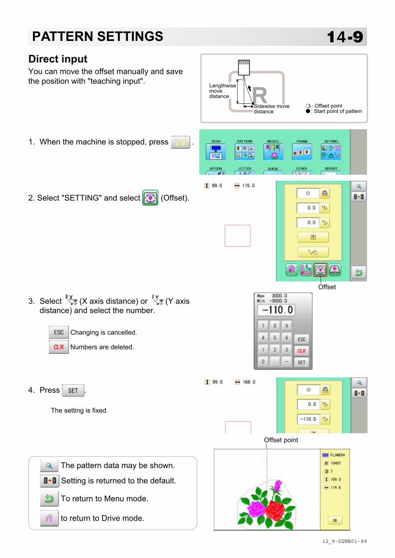
-D2 -89
Direct inputYou can move the offset manually and savethe position with "teaching input".
1. When the machine is stopped, press .
2. Select "SETTING" and select (Offset).
3. Select (X axis distance) or (Y axisdistance) and select the number.
Changing is cancelled.
Numbers are deleted.
4. Press .
The setting is fixed.
14-9PATTERN SETTINGS
12_9 NB01
Offset point
Sidewise movedistance
Lengthwisemovedistance
❍ : Offaet point● : Start point of pattern
Offset
The pattern data may be shown.
Setting is returned to the default.
To return to Menu mode.
to return to Drive mode.

-D2 -90
1. When the machine is stopped, press .
2. Select "SETTING" and select (Offset).
3. Select .
4. Select the offset point and press .
The setting is fixed.
Setting is unset.
14-APATTERN SETTINGS
12_A NB01
PresetThere are 9 preset points that can be used for offsets around the or in the center of the pattern.
Offset
Offset point
The pattern data may be shown.
Setting is returned to the default.
To return to Menu mode.
to return to Drive mode.

-D2 -91
Teaching inputYou can set the offset position manually.
1. When the machine is stopped, press .
2. Select "SETTING" and select (Offset).
3. Select .
4. Press .
5. Move the frame to the pattern start point.
Setting is cancelled.
6. Press .
The setting is fixed.
14-BPATTERN SETTINGS
12_B NB01
Sidewise movedistance
Lengthwisemovedistance
❍ : Offaet point● : Start point of pattern
Offset
CAUTION: To prevent accidents.The frame moves quickly.Keep hands away from the frame.

-D2 -92
14-CPATTERN SETTINGS
12_C NB01
Complete
Offset point
7. Move the frame to the offset point.
8. Press .
The setting is fixed.
The pattern data may be shown.
Setting is returned to the default.
To return to Menu mode.
to return to Drive mode.

-D2 -97
14-DPATTERN SETTINGS
12_D M401
Frame outA frame out command can be added to a design. By setting frameout to a *Color change num-ber in a design, you can move the frame to a desired position automatically and stop it after themachine finishes sewing of that color change number.When you resume operation, the frame has an automatic return to previous position and youcan continue sewing. (Fig.1)This function will be convenient for trimming threads while embroidering or for sewing appliqueetc.
Selection of color change number 5-F
Set Color change number to execute frameout.
Teaching inputSet position of frame out and the distance of movement will be the frame out distance.Usually move distance to frame out point is input, with original point as pivot.(Fig.1)In case offset is set, the move distance is input with offset point as pivot.(Fig.2)
You can set number of stitches or Color change number to make frame out in plural, butframe out point is limited to one place. The point set finally becomes good for making frameout. The point set finally becomes good for making frame out.
Direct inputYou can set the position of frame out directly by inputting by the number keys. You can alsochange the position of a frame out set by "Teaching input".Normally, the distance to the frameout point is input with the original point as a pivot. (Fig. 1) Incase where an offset is set, the move distance to frameout position is input with offset point aspivot. (Fig.2)
Lengthwisemovedistance 1
5
: Frame out point● : Original point (Start point of pattern)■ : Last position of Color change number❍ : Offset point
Sidewise movedistance
Lengthwisemovedistance
Sidewisemovedistance
Fig.2Fig.1

-D2 -94
1. When the machine is stopped, press .
2. Select "SETTING" and select (Frame
out).
3. Select .
4. Move the frame to the frame out position.
Setting is cancelled.
5. Press .
The setting is fixed.
14-EPATTERN SETTINGS
12_F NB01
Teaching inputMove the frame and the position will be savedas the frame out.
: Frame out point● : Original point (Start point of pattern)
: Last position of Color change number
Lengthwisemovedistance 1
5
Sidewise movedistance
Frame out
The pattern data may be shown.
Setting is returned to the default.
To return to Menu mode.
to return to Drive mode.
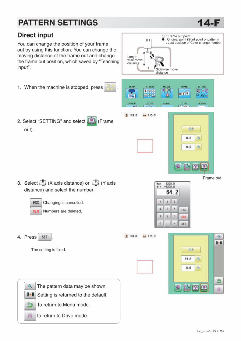
-DA -93
Direct inputYou can change the position of your frame out by using this function. You can change the moving distance of the frame out and change the frame out position, which saved by “Teaching input”.
1. When the machine is stopped, press .
2. Select “SETTING” and select (Frame out).
3. Select (X axis distance) or (Y axis distance) and select the number.
Changing is cancelled.
Numbers are deleted.
4. Press .
The setting is fixed.
14-FPATTERN SETTINGS
12_G P801
: Frame out point● : Original point (Start point of pattern)
: Last position of Color change number
Length-wise move distance 1
5
Sidewise move distance
Frame out
The pattern data may be shown. Setting is returned to the default.
To return to Menu mode.
to return to Drive mode.

-SA -26
15-1MACHINE SETTINGS
5_1 R701
Before embroidering, check the basic settings of the machine.The rest of the settings can be left at default values (as indicated by underline or blue icon).
No. Display Settings(std : Underlined or Blue)
Contents
1 Fine mode
The machine emphasizes stitch quality by controlling embroidery speed.By default it is set to "NO".
2 Tightness level
- (Loos))□ (Normal)+ (Tight)
The machine adjusts thread tightness level by controlling the timing of frame move.By default it is set to "Normal".
3 TRD. break back
1- 50 (6)...0 .........
On thread breaks, this causes sewing position & frame to move backwards by several stitches before the detected break before stopping.
・The frame will be moved backward by the preset stitch numbers・ The frame will not be moved
5 Width data limit
1 - 13mm
(13=12.7)
When stitch length exceeds this length, the machine divides it by this jump length and creates multiple movements. Width data limit becomes 12.7mm only when setting value is set to 13.Please use a smaller number when you use thick and heavy material.
Stitch length
Jump JumpStitchStitch
StitchStitch
Jump length Jump length Jump length
6 Quick start mode If you set to "No", the machine will increase speed slowly. Please
select "No"when you have a problem with skipped stitches on the beginning stitch after thread trim.
YES : The machine sews up to 3 stitches slowly after thread cut.NO : The machine sews up to 5 stitches slowly after thread cut.
7 Auto thread cut This performs automatic thread cut after color change and stop.
8 Cut at jump data
1- 8 (3) .
When a set number of continuous jumps exists in pattern data, the machine cuts threads before jumping.• Machine trims the thread on setting number of constant jump.• Does not trim.
Jump Jump Jump
Auto thread cut
StitchStitch

-SJ -34
15-1aMACHINE SETTINGS
5_1 R701
No. Display Settings(std : Underlined or Blue)
Contents
9 Cut at null jump This sets thread cuts before null jumps (isolated jumps with no net movement)
YES : Does trim on empty jump data.
Auto thread cut
JumpNull jump StitchStitch
10 CHG. always cut Forces a trim at every color change.YES : Always thread trim before color change.
Jump Jump Jump
Color changeor Sop
Auto thread cut
NO : If data does not have trim function at color change point, machine does not trim.
Jump Jump Jump
Color changeor Sop
11 Length of TRD. cut
Min.ShortNormalLongMax.Needle........
The machine cuts upper threads to a longer length.
• The upper threads of each needle will be cut off by registered length. 15-3
13 Width data all
-1.0~1.0mm 0.0mm ....
This is to alter the widths of all satin stitches for all the designs in the memory.
• Adjust satin stitch width by selected amount.
LL + Xmm Sat in st i tch width by selected
Widths of satin stitches for the designs in the memory
14 TRD. break detect
Off ~ Slow 3~ Norma ~ Quick 3 ~
Needle........
Sensitivity selection of the thread break detect sensor.Select "Quick" to increase sensitivity.Select "Slow" to decrease sensitivity. By default it is set to "Normal".
• You can set sensitivity of thread break detection needle by needle. 15-4

-DA -31
15-1bMACHINE SETTINGS
5_1 R701
No. Display Settings(std : Underlined or Blue)
Contents
15 Convert cap When using cap frame, the vertical direction of the embroidery design should be turned 180 degrees because cap is set on the drive frame upside down.With this function, the vertical direction of the embroidery design will be turned 180 degrees automatically when cap frame is selected on the menu.
16 Revers ramemove
Frame will be moved in the opposite direction of the arrow key.
17 STR.Auto Position
When machine is stopped in the middle of design and frame is moved for treating thread, the frame should be returned to last stopped point with Position key.With this function, you just need to press Start button, then the frame will be returned to the last stopped point automatically and start embroidery without pressing Position key.
❍ : Moved point● : Last stopped point
18 Embroidery weight
This setting for heavy duty material depends by material weight.Normally, please select "middle" or "Heavy" for Border frame.Machine speed is decreased automatically, when you sellect "middle "or "heavy".
19 Expand cap limit
1 ~ 10mm0 .........
The direction of Y-axis of the embroidery area (standard) is extended in the direction of the brim of the cap.
If the embroidery area is extended too much, there is a possibility that a needle and pressure foot may hit a frame and may be damaged.Before start sewing, please check carefully the embroidery area by trace function etc..
• The embroidery area is extended with the set-up size.• The embroidery area is not extended.
Extended embroidery area
Embroidery area
20 Frameout position
0 ~ 100 ~ 330mm
Set movement of frameout in the Framemove. 3-6
❍ : Frameout position● : Stop position
Movement
21 Display inch N0 : Display the unit of dimensions by millimeters meter.YES : Display the unit of dimensions at an inch.
22 Trace speed
0 ~ 100 ~ 300
You can change the Tracing speed. "100" mean the normal speed.If you change the number bigger, the speed decrease.
23 Display off timer
1 ~ 240 (min.)
The machine turns off the display screen when the time without any operation exceeds the time entered in the parameter.Timer function is "off" when setting value is set to "0"

-SJ -36
15-2MACHINE SETTINGS
5_1 R701
No. Display Settings(std : Underl ined or Blue)
Contents
24 Design disp mode All : When drive mode, highlight all color change number on the LCD Display.Change: Highlight only current color change number.
All Change number
25 Drawing“Real Pattern” Display pattern with realistic image on the screen.
26 Operation Sound Make beep sound when button or key of touch panel is pressed.
27 Notification Sound Make beep sound when the machine is stopped.
28 FW/BW Lock Count (1st.)
0 ~ 100
In "Stitch number forward", when the key is pressed continuously, the "Key lock" function is activated and the frame will move by the one stitchcontinuously even the finger is released from the key.Set number of stitches until "Key lock" function is activated.The "Key lock" function will be disabled when the number of stitches is set to "0".
29 FW/BW Lock Count (10st.)
0 ~ 100
In "Stitch number forward", when the key is pressed continuously, the "Fast forward"(10 stitches) function is activated and the frame will move continuously even the finger is released from the key.Set number of stitches until "Fast forward" function is activated.The “ Fast forward” function will be disabled when the number of stitches is set to "0".
30 Cross mark type Selection of the cross mark (pointer) type.
31 PC Keyboard Layout Selection of the keyboard layout.YES : PC (QWERTY)NO : Alphabetical order
32 2 Step Frame Return After the power switch is turned on, the frame (X and Y carriage) will move for Frame Position Initialization.When pre-registered frame is selected, the frame returns as 1 step (X and Y axes move together).When User-defined frame is selected, the frame returns as 2 steps (X and Y axes move individually).This individual movement will prevent the Pressure foot from collision damage with objects (Clamp etc.) of the User-defined frame.Please select “2 Steps Frame Return” when you use the User-defined frames frequently.
YES : 2 Step Frame ReturnNO : 1 Step Frame Return

-R3 -32
MACHINE SETTINGS 15-2a
5_2a O512
1. When the machine is stopped, press .
2. Select “OPTION”.
3. Select .
4. Select desired setting item and change the setting.
You can move to next page by pressing .
Press to return to Menu mode.
Press to return to Drive mode.

-R3 -33
15-3MACHINE SETTINGS
5_2b N722
Detailed explanation of machine settings
11 Length of TRD.cutIf you select “Needle” with this setting, the upper threads of each needle will be cut off by registered length.The length of each thread can be set up taking the following steps.
1. Follow the steps 1.- 3. on the previous page and the display shows machine setting page.
2. Press .
3. Change the setting on the needle number you would like to change with .
Press when returning the setting on all the needle numbers to default.
4. Press .
Needle number

-RA -35
15-3aMACHINE SETTINGS
5_2c O901
13 Width data allThis function adds additional width to all satinstitches in a design.This is otherwise set in the "Settings" function( 14-3), in which case any changes made tothe setting from this screen will have no effect.
You can also set detailed adjustment withusing “Width data multi-step” function.Please note that the value of "Width data all"should be set “0.0mm” to activate above func-tion.The step of setting is as follows.
1. Follow the steps 1.- 3. on the previous pageand the display shows machine settingpage.
2. Press .
3. Change the setting on the each width youwould like to change with .
Press when the setting on all the eachwidth.
Press when returning the setting on all theeach t width to “ 0% “.
4. Press .
Width
Width data all
LL + Xmm
Setting : X mm
Width data multi-step
LL x X%
Setting : X%

-R3 -34
15-4MACHINE SETTINGS
5_3 N701
Needle number
15 TRD. break detectIf you select “Needle” with this setting, you can set sensitivity of thread break detection needle by needle.You can be set up taking the following steps.
1. Follow the steps 1.- 3. on the page 15-2a and the display shows machine setting page.
2. Press .
3. Change the setting on the needle number you would like to change with .
Press when returning the setting on all the needle numbers to default.

-DA -32
LOCK STITCHES 15-5
5_3b N401
This machine adds lock stitches automatically as default setting at start and thread cut point.These lock stitches prevent upper thread from fraying and coming off from needle hole.The length and number of lock stitches (start / thread cut) can be adjusted with following setting items.
* At start of embroidery, if upper thread comes off often even default setting, it is recommendable to change setting of STR. Lock stitch from AUTO to ON and adjust STR. Lock Length longer.
SETTING ITEM SETTING RANGE CONTENTS (Default is underlined)
1 Cut Lock stitch OFF : Remove lock stitch when the machine cuts threads. ON : Add lock stitch per SETTING ITEM 2 and 3 when the machine cuts threads. AUTO : Add lock stitch when length of the stitch before thread cut is longer than length
set at SETTING ITEM 2.
2 Cut Lock Length 0.4~0.7~1.2mm : Set lock stitch length when “ON” or “AUTO” on SETTING ITEM 1 Cut Lock stitch is selected.
3 Cut Lock Count 1 ~ 2 ~ 3 : Set number of lock stitch when “ON” on SETTING ITEM 1 Cut Lock stitch is
selected.
4 STR. Lock stitch Add Lock stitch when the machine starts sewing. OFF : Remove lock stitch when the machine stars. ON : Add lock stitch per SETTING ITEM 5 and 6. AUTO : Add lock stitch when length of the stitch before the machine starts sewing cut is
longer than length set at SETTING ITEM 5.
5 STR. Lock Length 0.4~0.7~1.6mm : Set length of lock stitch when “ON” or “AUTO” on SETTING ITEM 4 Cut Lock stitch is selected.
6 STR. Lock Count 1 ~ 2 : Set number of lock stitch when “ON” on SETTING ITEM 4 Cut Lock stitch is
selected.
Ex. STR. Lock stitch
Ex. Cut Lock stitchLock Length
Lock Length

-DA -33
LOCK STITCHES 15-5a
5_3b Q701
1. When the machine is stopped, press .
2. Select “OPTION”.
3. Select .
4. Select desired setting item and change the setting.
Press when returning the setting to default.
Press to return to Menu mode.
Press to return to Drive mode.

-RA -36
OPTIONAL DEVICE SETTING 15-6
5_3c P801
1. When the machine is stopped, press .
2. Select “OPTION”.
3. Select .
4. Select setting item and change its setting.
Press to reset all the sequin settings to default.
When the optional device is mounted to the machine, setting at the embroidery machine is required.Concerning the details of setting, please refer the instruction manual of each device.In case the embroidery machine has no optional device, please skip this page.
Press to return to Menu mode.
Press to return to Drive mode.

-SJ -49
16-1Selecting letters using the built-in fonts.You can create monogramming data by using built-in alphabet, numbers and symbols.You can choose layout method of monogramming data from horizontal, arch, or circle layout.Save lettering embroidery data to design memory automatically.
ベースラインの右に寄せて配置
ベースラインの右に配置
Layout method
Base line
Horizontal
(straight line)
Base line is horizontally laidout.
Arch (upward)Increase or decrease by 5. Setby entering value.Baseline is formed a round arch inan upward direction.Change settings of baseline'swidth and height.
Press after setting is firmed.
Arch (downward)Cap line is formed a roundarch in a downward direction.Change settings of capline'swidth and depth.Press after setting is firmed.
Press after setting is firmed.
Circle (upward)Baseline is formed a circle inan upward direction.Change settings of baseline'sdiameter and angle.
Press after setting is firmed.
Circle (downward)Capline is formed a circle in andownward direction.Change settings of cap line'sdiameter and angle.
Press after setting is firmed.
Width
Increase or decreaseby 5(mm or degrees)
Height
Set by enteringvalue.
Diameter
Angle
Base line
Base line
Cap line
LETTER
18_1 N401
Cap line
Cap line
Width
Height
Diameter
Angle

-SJ -70
The display of Cyrillic script after pressing .
16-2LETTER
18_1b Q701
1. When the machine is stopped, press .
2. Select “LETTER”.
Letter selectionSelect letters. One data can contain up to 26 letters including space.
3. Select letter. The screen is switched to basic script or cyrillic script.
All the letters are deleted.
Basic script
Biacritic script
Cyrillic script
Symbol
The screen returns to menu.
Selected letter or number is deleted.
The cursor moves left and right.
Except for the space between letters, space is elimi-nated.
4. Press when you are finished with the letter selection.
Fix your setting and you can select fonts. For fonts, refer to [BUILT-IN FONT LIST]. 26-3
Font SelectionEnables you to select the preferred font. 26-3
5. Select the font.
Fix your setting and go to next step.
Cyrillic scriptBasic script (Diacritic)
Space or Delete
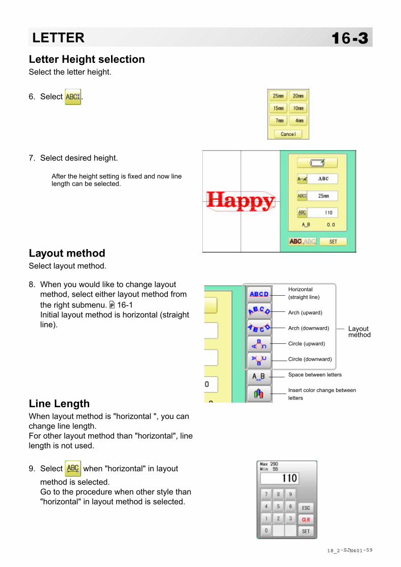
-SJ -59
16-3LETTER
18_2 N401
Letter Height selectionSelect the letter height.
6. Select .
7. Select desired height.
After the height setting is fixed and now linelength can be selected.
Layout methodSelect layout method.
8. When you would like to change layoutmethod, select either layout method fromthe right submenu. 16-1Initial layout method is horizontal (straightline).
Line LengthWhen layout method is "horizontal ", you canchange line length.For other layout method than "horizontal", linelength is not used.
9. Select when "horizontal" in layout
method is selected.Go to the procedure when other style than"horizontal" in layout method is selected.
Horizontal(straight line)
Arch (upward)
Arch (downward)
Circle (upward)
Circle (downward)
Space between letters
Insert color change betweenletters
Layoutmethod

-SJ -76
16-4LETTER9. Select the number.
Setting is canceled.
10. Press .
Return to the Letter selection.
Return to the Font Selection.
Return to the Letter Height selection.
Return to the Line Length.
You can change start point of monogramming data.
: Start point is the center of mono-gramming data.
: Start point is the center of mono-gramming data. Start point is the center of baseline or capline for “arch” and “circle” layout.
CreateYou can create embroidery data from the letter settings.
11. Press .The new pattern data will be created. Then you will return to menu mode.
Press and go to Running Screen.
You can see letter created as embroidery data. The first 8 letters will be shown as the name of the pattern which you have made by letter selec-tion.
Start point
Start point
18_3 R801
Press to return to Menu mode.
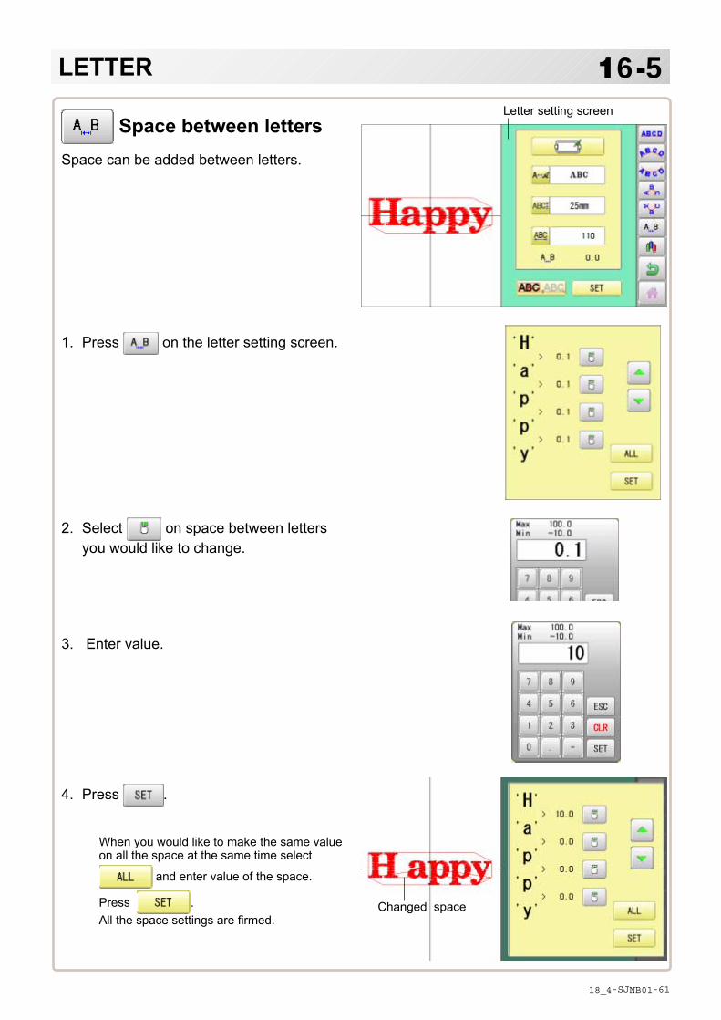
-SJ -61
16-5
Space between lettersSpace can be added between letters.
1. Press on the letter setting screen.
2. Select on space between lettersyou would like to change.
3. Enter value.
4. Press .
When you would like to make the same valueon all the space at the same time select
and enter value of the space.
Press .All the space settings are firmed.
Letter setting screen
Changed space
LETTER
18_4 NB01

-SJ -62
16-6
1. Press on the letter setting screen.
2. Select on space between lettersyou would like to change.
Setting of space between letters is ON.
Setting of space between le is OFF.
Setting of space can switched by pressing
and .
Press .The settings are firmed.
Letter setting screen
Color change setting is made
Color change between lettersColor change can be made between letters.
When color change setting is made for the space between letters you can set needlenumber of the letters of both sides of the space whose color change setting is ON.
3-9, 5-E
LETTER
18_5 NB01

-D2 -119
17-1QUEUE
19_1 M401
This sets up a succession of patterns that can be embroidered in any desired sequence.The machine will proceed with the *various settings set to each pattern.
If you embroider a pattern like in Fig.1, you will need to set an offset as a pivot to eachpattern in advance. If the offset is set to the first pattern like in Fig. 2, you will need to set asetoff point to the first pattern with the offset of the other pattern as a pivot. 14-8
If automatic original point return is set, the machine will return to the original point whenfinished. If automatic original point return is not set, the embroider will finish at the end pointof the last pattern.
Setting example
Alter and ExecutionThis registers Queued patterns in order, and executes.
Needle bar selection and Pattern settingsNeedle bar selection and Pattern Settings for patterns selected to QUEUE operation can beapplied by the following steps.
Registration of QUEUE settingUp to 10 QUEUE settings can be registered.
Read QUEUE settingRead registered QUEUE setting.
Pat.#03
Pat.#02
Pat.#14
Sidewise offsetof pat.#02
Sidewise offsetof pat.#14 Fig.1
❍ : Original point● : Start point of pattern■ : Offset point
Lengthwiseoffset of pat.#02 Lengthwise
offset ofpat.#14
Pat.#03
Pat.#02
Pat.#14
Sidewise offset of pat.#14
Sidewiseoffset ofpat.#02
Sidewise offset of pat.#03
Lengthwiseoffset ofpat.#02
Lengthwiseoffset ofpat.#03
Lengthwiseoffset ofpat.#14
Fig.2
■
❍ : Original point● : Start point of pattern■ : Offset point
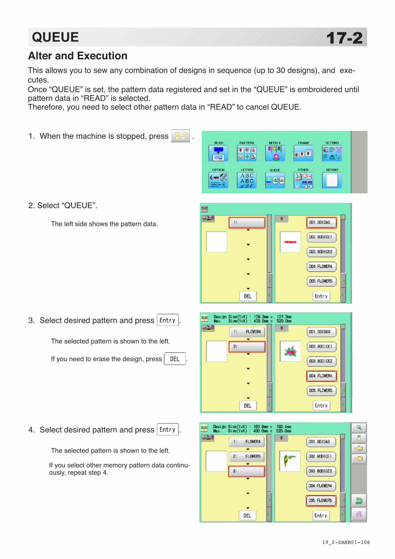
-DA -106
17-2QUEUE
1. When the machine is stopped, press .
2. Select “QUEUE”.
The left side shows the pattern data.
3. Select desired pattern and press .
The selected pattern is shown to the left. If you need to erase the design, press .
4. Select desired pattern and press .
The selected pattern is shown to the left.
If you select other memory pattern data continu-ously, repeat step 4.
19_2 NB01
Alter and ExecutionThis allows you to sew any combination of designs in sequence (up to 30 designs), and exe-cutes.Once “QUEUE” is set, the pattern data registered and set in the “QUEUE” is embroidered until pattern data in “READ” is selected.Therefore, you need to select other pattern data in “READ” to cancel QUEUE.
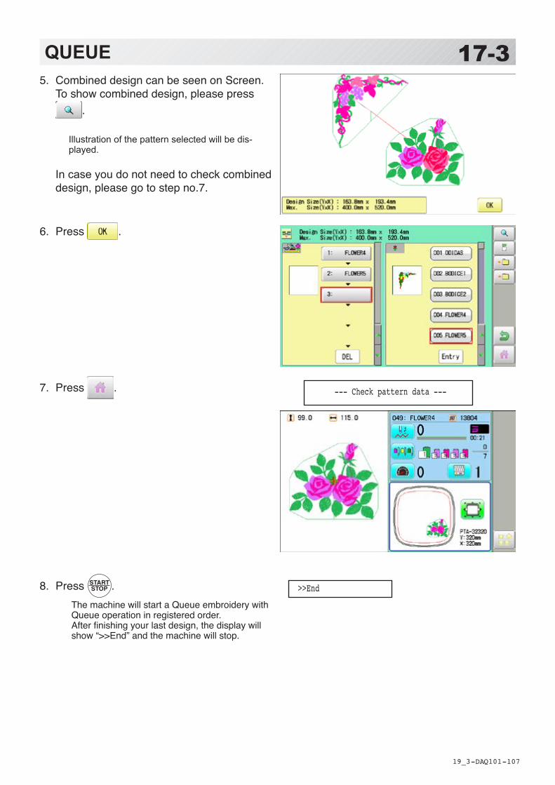
-DA -107
17-3QUEUE
19_3 Q101
5. Combined design can be seen on Screen. To show combined design, please press
.
Illustration of the pattern selected will be dis-played.
In case you do not need to check combined design, please go to step no.7.
6. Press .
7. Press .
8. Press .The machine will start a Queue embroidery withQueue operation in registered order.After finishing your last design, the display will show “>>End” and the machine will stop.
--- Check pattern data ---
>>End

-DA -108
17-4QUEUE
1. When the machine is stopped, press .
2. Select “QUEUE”.
The selected pattern is shown to the left.
3. Select desired pattern.
4. Press .
5. Select desired setting.
Please refer pages mentioned below for setting. “Needle bar selection” 5-E, “Pattern settings” 14-1
19_4 Q701
Needle bar selection and Pattern settingsNeedle bar selection and Pattern Settings for patterns selected to QUEUE operation can be ap-plied by the following steps.
Needle bar selection
Pattern settings
(Setting can be done without returning MENU screen.)You can do these setting also from MENU screen, and the last setting will be valid.

-DA -10919_4b NB01
6. After setting, press .
For setting of “Needle Bar Selection”[NEEDLE] and “Pattern Setting”[SETTING] to other design, please do steps no.3-6.
17-5QUEUE
Press to return to Menu mode.
Press to return to Drive mode.

-DA -110
17-6QUEUE
1. According to step 1-8 of “Alter”, select patterns.
2. Select .
3. Select registration No. and press .
When pattern data is not displayed on the left side on the screen, no pattern data is registered in the holder of the setting No.
Registration is deleted.
4. Press .
QUEUE setting is registered as setting No.2.
19_5 NB01
Registration of QUEUE settingUp to 10 QUEUE settings can be registered.Once you register QUEUE you can select registered QUEUE setting anytime.
In case you delete pattern from machine memory, QUEUE setting which has deleted pattern will be deleted too. (Erasing patterns from memory 5-B)
Press to return to Menu mode.
Press to return to Drive mode.

-DA -111
17-7QUEUE
19_6 NB01
Read QUEUE settingRead registered QUEUE setting.
1. When the machine is stopped, press .
2. Select “QUEUE”.
3. Select .
4. Select number and press .
QUEUE setting is selected.
Press to return to Menu mode.
Press to return to Drive mode.

-SA -76
18-1OTHER SETTINGSCreate network
Network setting is required in order to connect the embroidery machine with PC's network man-agement software (HAPPY link LAN) .You do not have to do this setting when you do not connect the machine with the network.
Note: HAPPY link LAN is a software designed to be used at LAN (Local Area Network) con-nection between the software installed PC (server) and the software-enabled embroiderymachine(s).If this network is connected with other network, you might not be able to communicate due tothe overlapping of IP address and other code.If PC or machine that is connected with other network has to be inevitably connected withHappy link LAN, you might change network settings as specified in this manual.In this case, the settings are required by your network administrator or person(s) of networkknowledge.
22_1 P401

-SA -77
18-2OTHER SETTINGS
22_2 M510
Wired LAN connectionWired LAN connection create network connection between the embroidery machine and PCwith a LAN cable.There are 2 types of Wired LAN connection methods.
HUB connectionPC via switching HUB connects with the embroidery machine.You can connect PC with multiple embroidery machines.
Direct connectionYou can connect PC with a machine with crossover cable and without HUB if you connect PCwith only one machine.However, a straight cable can be also used for this connection if your PC's LAN port recognizesthe type of cable.You cannot connect PC with multiple embroidery machines.
HUB connection
Direct connection ...
Embroiderymachine
PC (HAPPY LinK LAN)
PC (HAPPY LinK LAN)
Switching HUB
LAN cable LAN cable
LAN cable (Cross cable)
1st embroi-dery machine
2nd embroi-dery machine
3rd embroi-dery machine

-SA -79
1. When the machine is stopped, press .
2. Select "OTHER".
3. Press .
18-2aOTHER SETTINGSWire LAN connection setting
Set the value based on network management software (HAPPY link LAN).Boot the network management software (HAPPY link LAN) on the PC before setting the em-broidery machine.
22_4 NB01

-SA -80
18-2bOTHER SETTINGS
22_5 NB01
4. When you set values on the embroiderymachine as the 1st machine connected tonetwork, check if each setting item shall bedefault settings.
Press and and move to opera-
tion no 9 if there is no change of settingrequired.
Default settingsPort No. : 7891Server IP : 192.168. 1. 1Machine IP : 192.168. 1. 10Subnet mask : 255.255.255. 0
Set values on the 2nd machine or latermachine based on the following "Setup ofMachine IP address".
Press to change.
Press right /left of to select the
setting point, and press up/down of to
select the number.
5. Press .
Setup of Machine IP addressExamples : 192.168. 1. XX
If you have 2 or more machines, add one to the number enclosed in boxes on the right cor-ner of Machine IP address like the examples shown below.Leave other values than Machine IP address as they are and do not make any changes ofthese values.Add one to default value [10] such as [11] for 2nd machine and [12] for 3rd machine.Machine IP address is a Decimal number.Machine IP address is shown by incrementing the number by one as follows.10, 11, 12, 13, 14, 15, 16, 17, 18, 19, 20, 21, 22, 23, 24, 25, 26, 27 ~
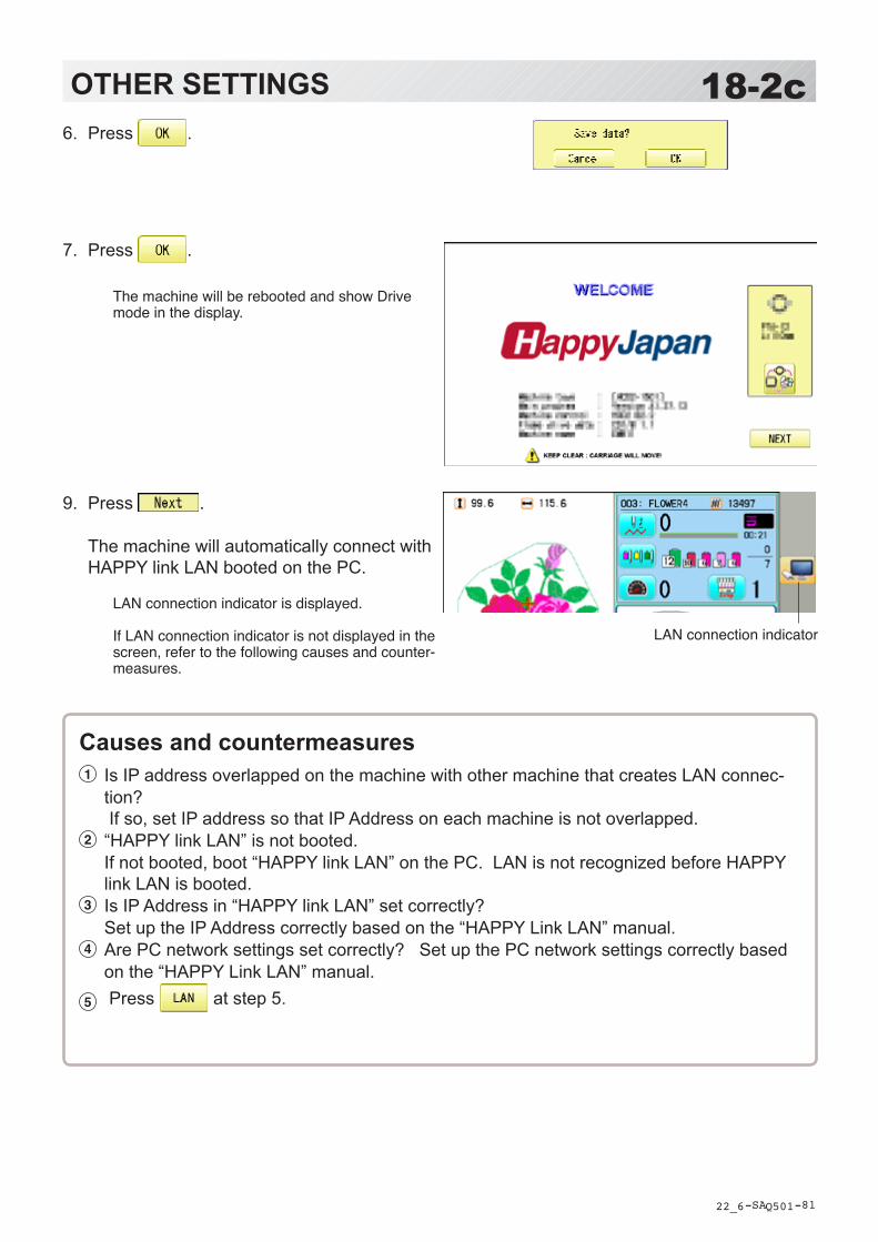
-SA -81
6. Press .
7. Press .
The machine will be rebooted and show Drive mode in the display.
9. Press .
The machine will automatically connect with HAPPY link LAN booted on the PC.
LAN connection indicator is displayed. If LAN connection indicator is not displayed in the screen, refer to the following causes and counter-measures.
18-2cOTHER SETTINGS
22_6 Q501
LAN connection indicator
Causes and countermeasures1 Is IP address overlapped on the machine with other machine that creates LAN connec-
tion? If so, set IP address so that IP Address on each machine is not overlapped.
2 “HAPPY link LAN” is not booted. If not booted, boot “HAPPY link LAN” on the PC. LAN is not recognized before HAPPY link LAN is booted.
3 Is IP Address in “HAPPY link LAN” set correctly? Set up the IP Address correctly based on the “HAPPY Link LAN” manual.
4 Are PC network settings set correctly? Set up the PC network settings correctly based on the “HAPPY Link LAN” manual.
5 Press at step 5.

-SA -73
18-3OTHER SETTINGSVersion information and software update
Software version installed in the machine is displayed.Software can be updated to the latest version.
1. When the machine is stopped, press .
2. Select “OTHER”.
3. Press .
4. Confirmversionnumber. Press to return to MENU screen.
The display returns to MENU.
When updating, insert USB memory includ-ingupdatefileintothecontrollerandpress
.
22_3 PA01
Preparation for update file
Contactyourdistributortoobtainthelatestupdatefile.Usetheappropriateupdatefileforyourmachine.PutupdatefileintherootdirectoryofUSBmemory.

-FR -47
18-4OTHER SETTINGS
22_3a Q701
5. Press to update the machine software.
Press to update the software which is related to installed attachment (sequin device etc.).
Update is starts.Do not turn on power during updating.
The machine will reboot once update is com-plete.
6. Press .
The display will return to Drive mode.
[ Install_HAPPY_***.*** ] version *.*.*In preparation . . .Starting UpDate

-DA -138
18-5OTHER SETTINGSLanguage
Change the language displayed on control box.
22_3b Q509
1. When the machine is stopped, press .
2. Select “OTHER”.
3. Press .
4. Select the Language.
The language has been changed,and the display returns to Drive mode.

-DA -140
18-6OTHER SETTINGSCalibrate
Calibration for the touch panel LCD.Touch panel is already adjusted and you do not need adjustment of the panel.If the screen does not recognize correct position of each icon and you cannot operate, pleaseadjust the screen as follows:
22_3 O901
1
2
3 4
5
1. When the machine is stopped, press .
2. Select "OTHER".
3. Press .
4. Press .
Prepare built-in stylus.
5. Press the center of "+" displayed in screenin numerical order by a stylus.
"+" will appear in numerical order.
6. Press the 5th "+" by stylus.
The screen shows "New calibration settings havebeen measure ..." at small letters.

-DA -141
18-7OTHER SETTINGS
22_3 NB01
7. Press the screen with a finger (any locationis okay).
After this operation, you can press the screenwith a finger.Adjustment is complete, and the screen returnsto Menu mode.
Press to return to Drive mode.

-DA -137
18-8OTHER SETTINGSUser maintenance mode
User maintenance mode has 8 items as below.Indicates point which sensors are active.
22_5 M717
ConditionsL point sensor The point that indicator becomes RED is L-point, when upper shaft is turned.C point sensor The point that indicator becomes RED is C-point, when upper shaft is turned.Needle sensor The point that indicator becomes RED is needle position, when moving head is
moved.Origin point of cutter The point that indicator becomes RED is origin point of cutter.Origin point of thread catcher The point that indicator becomes RED is origin point of thread catcher.
AngleIndicate angle of upper shaft.Please use dial when you need to know precision angle.
Button Machine movement
Change jump Changetheneedlebar’smovement. “JUMP” : Needle Jump, “DRIVE” : Needle Drive
Upper shaft turns Upper shaft turns clockwise and counterclockwise. When release button, upper shaft stops.
Caution: please be careful that Needle move at once.Needle change Move the sewing head to the adjustment needle in the direction of the arrows.
Cutter Open/Close When cutter is open position, cutter move to close position. When cutter is close position, cutter move to open position.
Caution: please be careful that cutter move at once.
Catcher Open/Close When catcher is open position, cutter move to close position. When catcher is close position, cutter move to open position.
Clip-type thread holder (option) When clip is open position, clip move to close position. When clip is close position, clip move to open position.
Keeper When keeper is open position, keeper move to close position. When keeper is close position, keeper move to open position.
Standby position In case, each equipment position without standby position, as example “Upper shaft is not at C point, Thread cut blade is not at stop position, Thread Catcher is open position”, this key work for back to standby position automatically.

-DA -138
18-9OTHER SETTINGS
22_6 O901
1. When the machine is stopped, press .
2. Press ”OTHER”.
3. Press .
4. Press one key and check machine movement.
CAUTION: To prevent accidents;The machine moves quickly.Keep hands away from the machine.
One equipment was not standby position, machine show following messagewhen you press key. C point : Upper shaft is not at C point. Cut blade : Thread cut blade is not at standby position. Thread Catcher : Thread Catcher is open position.
Please press for back to standby potion and repeat step 4 again.
**********
OK
Press to return to Menu mode.

-SA -78
Time of power off(1st raw is time ofreporting.)
Time of power onmonth/day/year/hour:minute:second
Numberof stitches
Time of deletingrecord or power on
Current time(time of viewingthe report)
Number ofstitches afterdeleting record
1. When the machine is stopped, press .
2. Select “REPORT”.
3. Select .
4. In order to exit the mode, proceed to thestep 5.
If you want to delete the record, press.
5. Press .
The display returns to MENU.
19-1REPORT
22_4 O901
Indicating operation record of machine.
Production dataLast 10 records of following production data will be displayed.Time of power on/off, and number of operated stitches will be recorded in machine memory.If the machine is switched on without embroidery operation, it will not be recorded in memory.
[Power ON] he time when machine main switch is turned on[Power OFF] The time when machine main switch is turned off[Embroidery Stitches] The number of embroidered stiches while main switch is turned on
Press to return to Drive mode.
Save the reportYou can save the displayed records in CSV format.Insert the USB memory into the machine and press button then, new folder named"Production Report" will be made and the report data will be saved as file name "StitchReport_*****".

-SA -79
1. When the machine is stopped, press .
2. Select “REPORT”.
3. Select .
4. In order to exit the mode, proceed to thestep 5.
If you want to delete the record, press.
4. Press .
The display returns to MENU.
19-1bREPORT
22_4b O901
Detailed production dataYou can view following detailed production data for each user. (Max 4,096 data)
ITEMS [No.] Number : Sequence number of the records [User] *1 User ID : The ID number of embroidery machine operator
User Name : The name of embroidery machine operator [Design] Design ID : The ID number of embroidery design
Design Name : The name of embroidery design [Stitche] Stitches : The number of stitches of embroidery design [Pro.] Output : Quantities of production [TTL.] Total time (min.) : The total required time (minutes) to complete the embroidery design [RUN] Running time (min.) : The machine running time to embroider the design [PAUSE] Pause time (min.) : The pause time in the middle of embroidery [Run %] Operating rate (%) : Running time / Total time [Pro./H] Productivity : Quantity of the production per hour [BRK.] Number of thread breakage : The number of thread breakage within one production cycle
*1 :When machine main switch is operated (On/Off), "Power off <> on" will be displayed in "User Name" section.
Press to return to Drive mode.

-SA -88
19-1cREPORT
22_4c Q701
Save the reportYou can save the displayed records in CSV format.Insert the USB memory into the machine and press button then, new folder named “ProductionReport” and "RunningLog" will be made and the following files will be saved.
ProductionReport (Holder)“ProductionReport-Standard_*****” : This file contains the output data in each piece of embroidery produc-tion.“ProductionReport-Arranged_*****” : This file contains the output data which is totalized in user and design.“ProductionReport-Arranged2_*****” : This file contains the output data in each day of running ratio.
RunningLog (Holder)"RunLog_*****" :The monthly report of running time par hour of each day.
This report is remained after 13 months.
ITEMS [No.] : Sequence number of the records [User ID] : The ID number of embroidery machine operator [User Name]*1 : The name of embroidery machine operator [Machine Name] *2 : The embroidery machine name of embroidery design [Design ID] : The ID number of embroidery design [Design Name] : The name of embroidery design [Stitches] : The number of stitches of embroidery design [Output] : Quantities of production [Start of Design] *2 : The time embroidery is started [End of Design] *2 : The time embroidery is completed [Total time (min.)] : The total required time (minutes) to complete the embroidery design [Run (min.)] : The machine running time to embroider the design [Pause (min.)] : The pause time in the middle of embroidery [Power OFF] *2 : The time main switch is turned off [Power ON] *2 : he time main switch is turned on [Power OFF time] *2 : The elapsed time while main switch is turned off. [Run Ratio] : Running time / Total time [Pause Ratio] *2 : Pause time / Total time [Productivity/hour] : Quantity of the production per hour [Thread Break] : The number of thread breakage within one production cycle [Error] *2 : The number of error message within one production cycle [Interval (min.)] *2 : The time period from machine power on till start of embroidery or the time after completion of embroidery until it starts the next embroidery.
*1 :When machine main switch is operated (On/Off), “Power off <> on” will be displayed.*2 :These items will not be shown in the display.

-SA -81
1. When the machine is stopped, press .
2. Select “REPORT”.
3. Select .
4. In order to exit the mode, proceed to thestep 5.
If you want to delete the record, press.
4. Press .
The display returns to MENU.
19-1dREPORT
22_4d O901
Record of thread breakThis function will show thread break data of each needles.In case of Multi-head embroidery machine, data line for each head will be displayed.
Press to return to Drive mode.
Needle number
Total
Head number
Save the reportYou can save the displayed records in CSV format.Insert the USB memory into the machine and press button then, new folder named"Production Report" will be made and the report data will be saved as file name"BreakReport_*****".
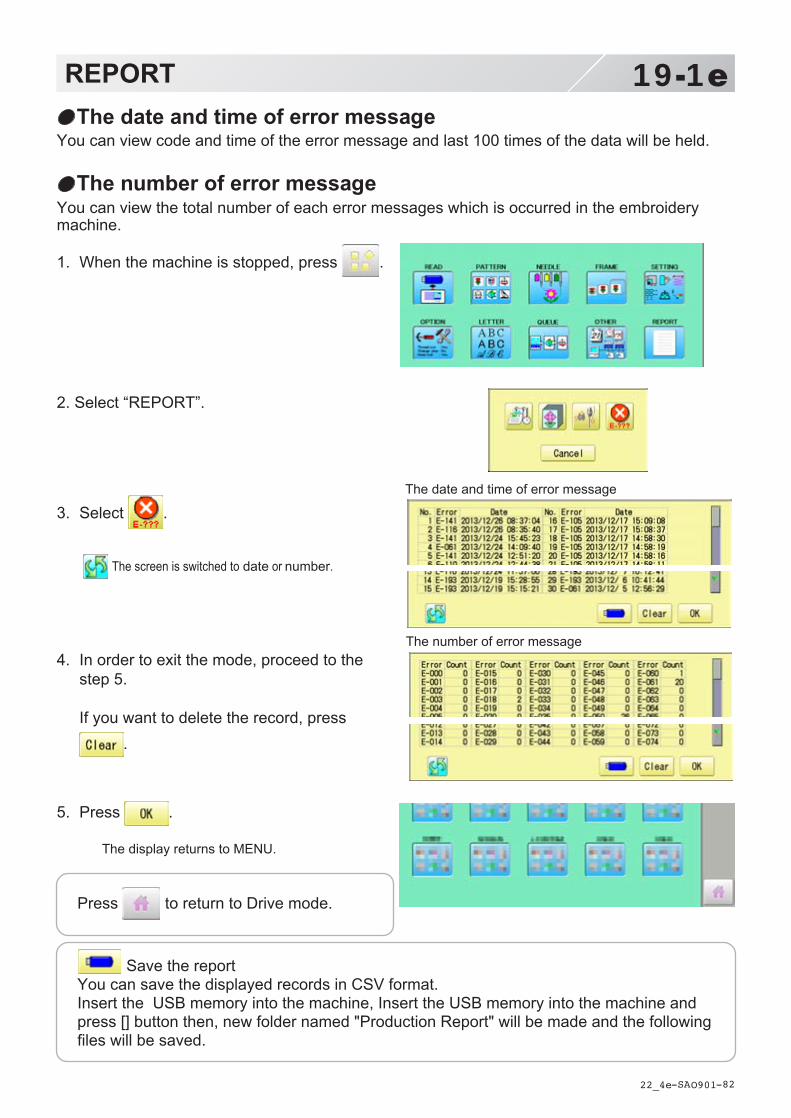
-SA -82
1. When the machine is stopped, press .
2. Select “REPORT”.
3. Select .
The screen is switched to date or number.
4. In order to exit the mode, proceed to thestep 5.
If you want to delete the record, press.
5. Press .
The display returns to MENU.
19-1eREPORT
22_4e O901
The date and time of error messageYou can view code and time of the error message and last 100 times of the data will be held.
The number of error messageYou can view the total number of each error messages which is occurred in the embroiderymachine.
Press to return to Drive mode.
Save the reportYou can save the displayed records in CSV format.Insert the USB memory into the machine, Insert the USB memory into the machine andpress [] button then, new folder named "Production Report" will be made and the followingfiles will be saved.
The date and time of error message
The number of error message

-DA -26
GUIDE
3_D O901
20-1
1. When the machine is stopped, press .
2. Select "GUIDE".
3. Select desired item.
4. You can move to next page by pressing
.
5. Press .
You will return to the guide menu.
The GUIDE offers tips and step-by-step help for embroidering with the machine.In each stage of embroidery operation there is an easy to follow guide available.
Press to return to Menu mode.

-DA -142
1. When the machine is stopped, press .
2. Select “SCREEN”.
3. Press .
4. Select the number. (Unit : minute)
Changing is cancelled.
Numbers are deleted.
5. Press .
6. Press . The setting is fixed and display returns to MENU.
21-1SCREEN SAVER
22_6 O901
If screen saver is set, images saved in the machine are displayed on the screen in numerical order when the machine is stopped and is not in operation for a certain amount of time.Screen saver is cancelled when any place on the touch screen is touched.
If the setting time of “display off timer” on “OPTION” is shorter than one of screen saver, screen saver is not displayed. Make sure the setting time of “display off timer” is longer than one of screen saver when both screen saver and “display off timer” are used. 15-2
Start-up timeSet the time to start screen saver
Press to return to Drive mode.

-DA -143
1. When the machine is stopped, press .
2. Select “SCREEN”.
3. Press .
4. Select the direction.
5. Press . The setting is fixed and display returns to MENU.
21-2SCREEN SAVER
22_8 O901
Slide directionSet the slide direction of the screen saver image switched to the next image displayed on the screen.
Press to return to Drive mode.
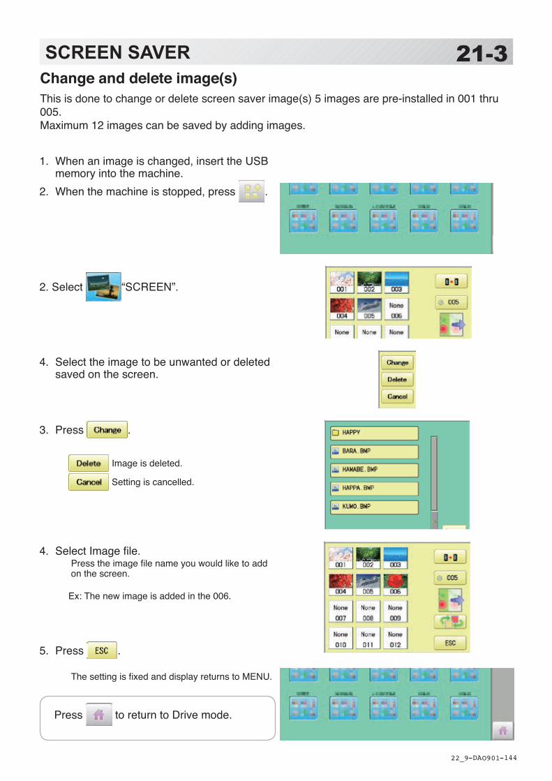
-DA -144
1. When an image is changed, insert the USB memory into the machine.
2. When the machine is stopped, press .
2. Select “SCREEN”.
4. Select the image to be unwanted or deleted saved on the screen.
3. Press .
Image is deleted.
Setting is cancelled.
4. Select Image file.Press the image file name you would like to add on the screen.
Ex: The new image is added in the 006.
5. Press . The setting is fixed and display returns to MENU.
21-3SCREEN SAVER
22_9 O901
Change and delete image(s)This is done to change or delete screen saver image(s) 5 images are pre-installed in 001 thru 005.Maximum 12 images can be saved by adding images.
Press to return to Drive mode.

-DA -145
1. When the machine is stopped, press .
2. Select “SCREEN”.
3. Press .
4. Press .
Initialization is cancelled.
5. Press . The setting is fixed and display returns to MENU.
21-4SCREEN SAVER
22_A O901
Initialization of registered images in the machineScreen saver images to set current status to initial status (factory setting).Original images in 001 to 005 are restored although they are deleted.All the images saved in 006 to 012 are deleted.
Press to return to Drive mode.
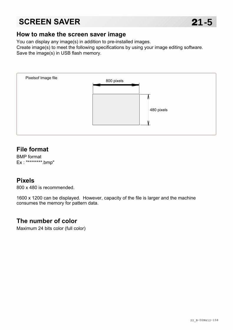
-D2 -158
21-5SCREEN SAVER
22_B M412
How to make the screen saver imageYou can display any image(s) in addition to pre-installed images.Create image(s) to meet the following specifications by using your image editing software.Save the image(s) in USB flash memory.
800 pixels
480 pixels
Pixelsof Image file
File formatBMP formatEx : "********.bmp"
Pixels800 x 480 is recommended.
1600 x 1200 can be displayed. However, capacity of the file is larger and the machineconsumes the memory for pattern data.
The number of colorMaximum 24 bits color (full color)

-SA -66
22-1i-CUSTOM
21_1 R801
You can place frequently used key icons freely on the right side of Drive mode screen.
i-Custom
Ex. 1
Ex. 2
Ex. 3
Display icons to be placed Calendar
Current year, month date is displayed.
Clock Current time is displayed.
LAN connection 22-2a This indicates the machine connects with LAN. By pressing this icon, you can retrieve embroi-dery design from connected PC and load the design to the machine.
Wireless LAN (Option) This indicates the machine recognizes wireless LAN device.
Keys icons to be placed Stitch number forward
Move the frame forward or backward by the one stitch.
Design centering Move design to the center of frame.
Center Moves the embroidery frame to the center auto-matically.
Frame out 15-2 Move frame to the front position which was set before.
Original point return 3-6 This returns the frame to *pattern origin point.
Origin registration Register the current frame position as origin.
Trace When pressed while at the beginning of design, the embroidery frame moves following the outer edge of the design.
Register Register will restore the position of the frame to the last point before a power failure even if the point of origin or the pattern itself were changed.

-SA -67
22-1bi-CUSTOM
21_1 R821
Pointer (Option) Turn on and off the laser pointer.
Jump
Turn on and off the Jump. 3-5
Low speed operation 3-5 Turn on and off the Low speed operation.
Position alignment by defining 2 points Embroidery position is aligned by defining 2
points. 9-8
Convert 9-5 Rotate and mirror invert selected pattern data.
Width adjustment This setting adjusts stitch width. 14-3
Preset (Offset) This select the Offset position. 14-A
Read USB Read embroidery data from USB memory.
Read PC Read embroidery data from PC.
Task reservation 22-2b It is possible to perform reading design and other operations even while machine is embroidering.
Bobbin thread alarm Alarm message will be displayed when the remaining amount of bobbin thread becomes low.
9-Cb

-SA -65
1. When the machine is stopped, press .
2. Select “i-CUSTOM”.
3. Select a desired custom icon.
4. Select display or key icon(s) from the gray frame. When changing to other display or key icon(s),.
When you select the desired display or key, re-peat steps 3 and 4 .
Changed to the page of i-CUSTOM.
Selected i-CUSTOM is deleted.
Setting is returned to the default.
5. Press .
The setting is fixed and to return to Menu mode.
6. Press .
Custom icon change is made.
i-CUSTOM currently selected
The desired key change has been made.
22-2i-CUSTOM
21_2 Q101

-SA -66
22-2ai-CUSTOM
21_2 R201
1. Press .
2. Enter the pattern name.The maximum number of characters in a de-sign name is 24 letters or numbers. For correct retrieval, all characters need to match exactly. Normally, extension name is not required when the pattern name is displayed correctly.
The cursor moves left and right.
The screen is switched.
Enter the extension.
All the letters are deleted.
The letter is deleted before the cursor position.
The screen returns to drive mode.
Read retrieved pattern from PC.
3. Press .
Machine return to Drive mode.
Currently selected pattern name is displayed.
LAN connectionThis indicates the machine connects with LAN. Design folder settings on the “Happy Link LAN” is required before reading pattern data.Please refer to “Happy Link LAN” System INSTRUCTION MANUAL regarding the settings method.The pattern data can be read through the designated folder and sub-folders.
The retrieval function will not work when same pattern name is saved in selected folder and sub-folder.
Barcode readerBarcode reader from third parties which is connected to USB port of the control box (Standard-A receptacle) can also be used for retrieving design name.The barcode reader should be set to add code "CR+LF" at end of the data.Please refer to instruction manual of the barcode reader for setting and operation.

-3A -72
TASK RESERVATION
22_2b R821
22-2bThis function allows you to perform following operations even while machine is embroidering.After the task reservation, it is also possible to reserve the pattern to the embroidery sequence list. (max. 30 patterns)By this reserve function, the embroidery patterns can be changed sequentially in accordance with the list.The below confirmation message will be shown before changing the patterns.
Reading : This reads pattern data and writes into memory. 22-2c
Needle bar selection : A needle number can be assigned to a color change number of pattern
data. 22-2d
Setting : Settings such as the scaling, repeat sewing, offset and frame out can be
applied to a pattern data. 22-2e
Search : Search and read embroidery patterns which are saved in the PC connected
through LAN. 22-2f
List : Open the embroidery sequence list to access the patterns.
Also some editing functions are available such as delete, sort and copy. 22-2g
Please note that the Task reservation function is only available when the Task
reservation icon is placed on the drive mode screen with using i-CUSTOM beforehand. 22-1
Icon of "Task reservation"
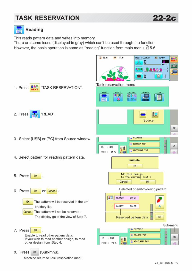
-3A -73
TASK RESERVATION
22_2c R821
22-2c
1. Press “TASK RESERVATION”.
2. Press “READ”.
3. Select [USB] or [PC] from Source window.
4. Select pattern for reading pattern data.
5. Press .
6. Press or .
The pattern will be reserved in the em-broidery list.
The pattern will not be reserved. The display go to the view of Step 7.
7. Press .Enable to read other pattern data. If you wish to read another design, to read other design from Step 4.
8. Press (Sub-mnu). Machine return to Task reservation menu.
Source
Task reservation menu
Reading
This reads pattern data and writes into memory.There are some icons (displayed in gray) which can’t be used through the function.However, the basic operation is same as “reading” function from main menu. 5-6
Reserved pattern data
Selected or embroidering pattern
Sub-menu
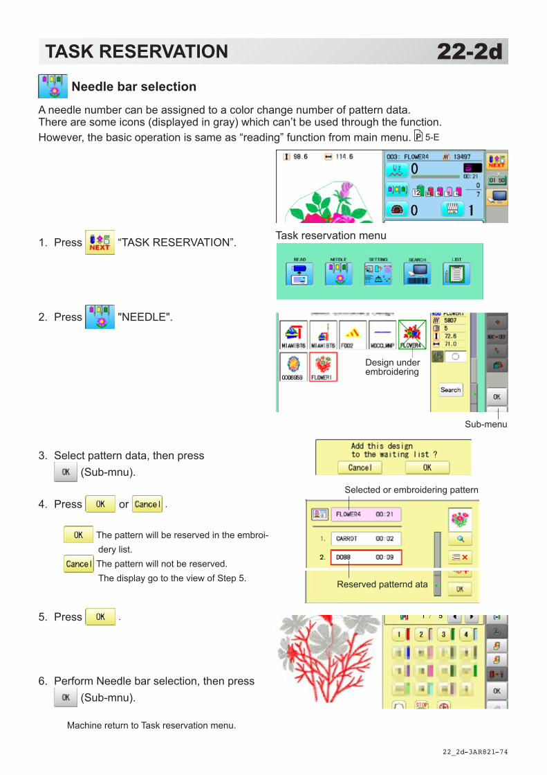
-3A -74
1. Press “TASK RESERVATION”.
2. Press "NEEDLE".
3. Select pattern data, then press (Sub-mnu).
4. Press or .
The pattern will be reserved in the embroi-dery list.
The pattern will not be reserved. The display go to the view of Step 5.
5. Press .
6. Perform Needle bar selection, then press (Sub-mnu).
Machine return to Task reservation menu.
Design under embroidering
Sub-menu
TASK RESERVATION
22_2d R821
22-2d
Task reservation menu
Needle bar selection
A needle number can be assigned to a color change number of pattern data.There are some icons (displayed in gray) which can’t be used through the function.However, the basic operation is same as “reading” function from main menu. 5-E
Reserved patternd ata
Selected or embroidering pattern

-3A -75
Sub-menu
1. Press “TASK RESERVATION”.
2. Press "SETTING".
3. Select pattern data, then press (Sub-mnu).
4. Press or .
The pattern will be reserved in the em-broidery list.
The pattern will not be reserved. The display go to the view of Step 5.
5. Press .
6. Perform Pattern setting, then press (Sub-mnu).
Machine return to Task reservation menu.
TASK RESERVATION
22_2e R821
22-2e Setting
Settings such as the scaling, repeat sewing, offset and frame out can be applied to a pattern data.There are some icons (displayed in gray) which can’t be used through the function.However, the basic operation is same as “reading” function from main menu. 14-1
Task reservation menu
Reserved pattern data
Selected or embroidering pattern

-3A -76
1. Press “TASK RESERVATION”.
2. Press "SEEARCH".
3. Enter the pattern name.
4. Press .
5. Press or .
The pattern will be reserved in the embroi-dery list.
The pattern will not be reserved. Machine return to Task reservation menu.
6. Press .
Machine return to Task reservation menu.
TASK RESERVATION
22_2f R821
22-2f
Task reservation menu
Search
Design folder settings on the “Happy Link LAN” is required before reading pattern data.The basic operation is same as “LAN connection” function. 22-2a
Reserved pattern data
Selected or embroidering pattern
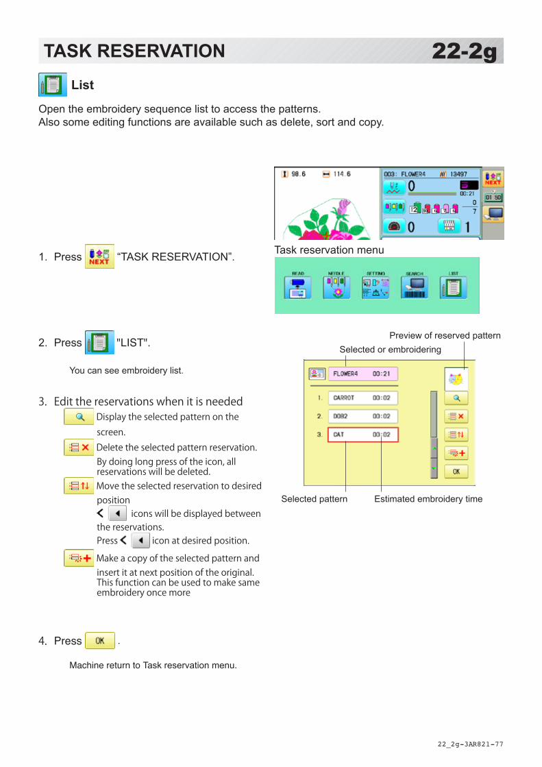
-3A -77
List
Open the embroidery sequence list to access the patterns.Also some editing functions are available such as delete, sort and copy.
TASK RESERVATION
22_2g R821
22-2g
Task reservation menu1. Press “TASK RESERVATION”.
2. Press "LIST". You can see embroidery list.
3. Edit the reservations when it is needed Display the selected pattern on the screen.
Delete the selected pattern reservation. By doing long press of the icon, all reservations will be deleted.
Move the selected reservation to desired position
icons will be displayed between the reservations. Press icon at desired position.
Make a copy of the selected pattern and insert it at next position of the original. This function can be used to make same embroidery once more
4. Press . Machine return to Task reservation menu.
Selected pattern
Selected or embroidering Preview of reserved pattern
Estimated embroidery time
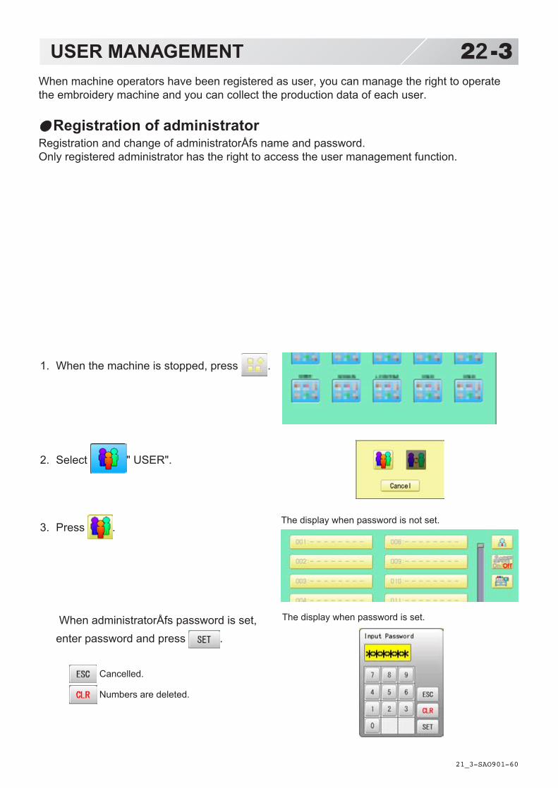
-SA -60
1. When the machine is stopped, press .
2. Select " USER".
3. Press .
When administratorÅfs password is set,enter password and press .
Cancelled.
Numbers are deleted.
USER MANAGEMENT
21_3 O901
22-3When machine operators have been registered as user, you can manage the right to operatethe embroidery machine and you can collect the production data of each user.
Registration of administratorRegistration and change of administratorÅfs name and password.Only registered administrator has the right to access the user management function.
The display when password is not set.
The display when password is set.

-SA -68
4. Press .
5. Press , in case you do not need to change the administratorÅfs name. When you prefer to change the administra-tor’s name, move cursor with then, enter new name from the keyboard and press .
The maximum number of characters is 16 letters.
Uppercase and lowercase letter are switched.
All the letters are deleted.
Selected number is deleted.
Cancelled.
6. Enter arbitrary 6 digits number as pass-word.
Enter “000000” if you do not want to use pass-word. Please keep your password safe.
Cancelled.
Numbers are deleted.
7. Press .
Password is fixed.
8. Push to activate the User manage-ment function.
The icon will be changed to .
Proceed to step 9, if you do not want to use the User management function.
USER MANAGEMENT
21_4 Q701
22-4
CAUTION If you lost the pass-word, you may not be able to access the User management function.Please contact your dealer, if you have forgotten or lost your password.

-SA -69
9. Press , when you want to change the machine name.
10. Enter new [Machine name] and press .
Please note that the [Machine name] will be re-corded as an item of the Production data.The maximum number of characters is 15 letters.
If the Machine name is not to be changed, proceed to Step 11.
11. Press .
The setting is fixed and to return to Menu mode.
USER MANAGEMENT
21_5 Q701
22-5
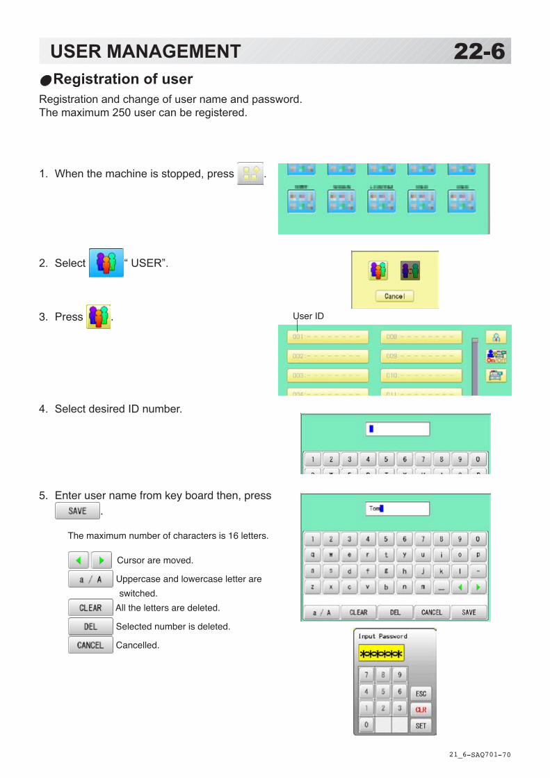
-SA -70
1. When the machine is stopped, press .
2. Select “ USER”.
3. Press .
4. Select desired ID number.
5. Enter user name from key board then, press .
The maximum number of characters is 16 letters.
Cursor are moved.
Uppercase and lowercase letter are switched.
All the letters are deleted.
Selected number is deleted.
Cancelled.
USER MANAGEMENT
21_6 Q701
22-6Registration of user
Registration and change of user name and password.The maximum 250 user can be registered.
User ID
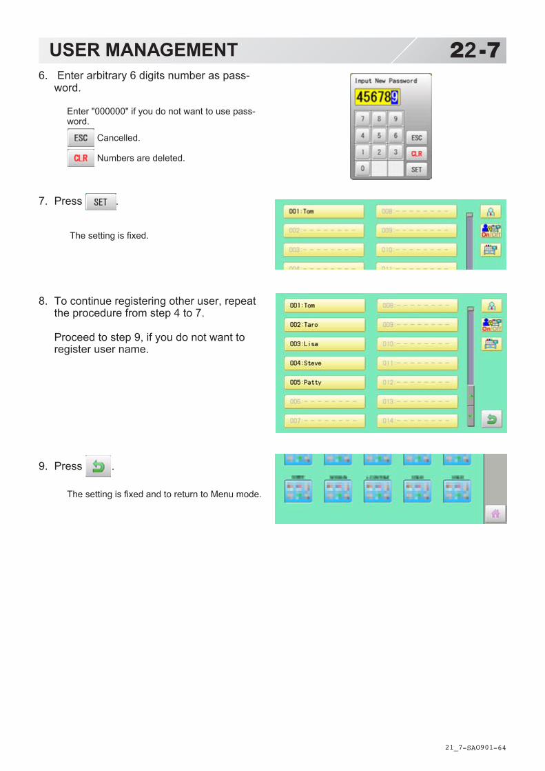
-SA -64
6. Enter arbitrary 6 digits number as pass-word.
Enter "000000" if you do not want to use pass-word.
Cancelled.
Numbers are deleted.
7. Press .
The setting is fixed.
8. To continue registering other user, repeatthe procedure from step 4 to 7.
Proceed to step 9, if you do not want toregister user name.
9. Press .
The setting is fixed and to return to Menu mode.
USER MANAGEMENT
21_7 O901
22-7
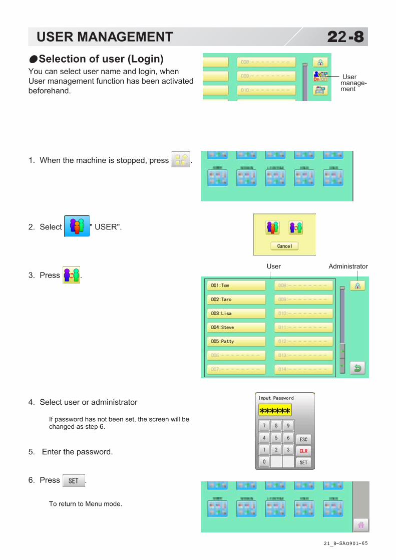
-SA -65
1. When the machine is stopped, press .
2. Select " USER".
3. Press .
4. Select user or administrator
If password has not been set, the screen will bechanged as step 6.
5. Enter the password.
6. Press .
To return to Menu mode.
USER MANAGEMENT
21_8 O901
22-8Selection of user (Login)
You can select user name and login, whenUser management function has been activatedbeforehand.
Usermanage-ment
User Administrator
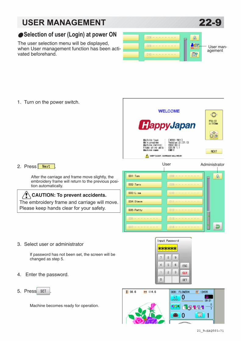
-SA -71
1. Turn on the power switch.
2. Press .
After the carriage and frame move slightly, the embroidery frame will return to the previous posi-tion automatically.
3. Select user or administrator
If password has not been set, the screen will be changed as step 5.
4. Enter the password.
5. Press .
Machine becomes ready for operation.
USER MANAGEMENT
21_9 Q501
22-9
User
Selection of user (Login) at power ON The user selection menu will be displayed, when User management function has been acti-vated beforehand.
Administrator
User man-agement
CAUTION: To prevent accidents.The embroidery frame and carriage will move. Please keep hands clear for your safety.

-RA -87
Combined pattern data can be made by putting pattern(s) and letter(s) anywhere you like on thelayout window.The pattern data can be saved to the machine for embroidering.
When “PATTERN SETTING” is set on the selected design, these setting will be taken over to the new design.
The number of color change function (Color change) for combined pattern data shall not exceed 250.
LAYOUT 22-A
21_A O901
Letter Others
Selection
Layout areaDisplay the area for pattern layout
With "Layout area" key, you can change
the area for pattern layout.
Letter
LettersChanging the Letter.
FontChanging the font.
HeightChanging the hightt.
Line lengthChanging the line length.
Space 16-5Changing the spacet.
Color change between letters 16-6Color change can be made between letters.
Layout metodh 16-1Changing the layout method of the letterst.
Layout
CenteringMove the pattern to center of the Layout area.
Pattern settings 14-2 ~ 14-4, 9-5Various pattern settings such as scaling, widthadjustment, rotate angle and convert design.
Repeat 14-5Copy the design as user-specified number in the Xand Y directions.Please note that the repeat function does not workat letter layout.
Multiple patterns movement 22-FSelect multiple patterns and move position to-gether.
Selection
Selecting the pattern.Display selected pattern number (sequencenumber of layout) and pattern name.
Layout
Moving keys
Layout area

-RA -88
LAYOUT 22-B
21_ B O901
Moving keys
Move selected pattern.You can also move the pattern bypressing desired position on the screen.
With pressing , you can change the steps
of movement to 1.0mm.
Others
Layout area 22-GChange display area for pattern layout.
Pattern selectionSelect desired pattern for layout
Letter selectionEnter desired letters for layout.
DeleteDelete selected pattern (letters)
Zoom 22-HZoom in and zoom out the pattern layout.The selected patterns can be moved with keepingdesired scale.
View allDisplay whole pattern image when the layoutarea is set more than 100mm.
Grid 22-IDisplay grid with desired scale.
This instruction is based on an example inthe right drawing.
1. When the machine is stopped, press .
2. Select "LAYOUT".
Pattern selection
3. Press .
All pattern data stored in the machine memorywill be displayed.
Searching the patterns. 11-D
Selecting the folder.
Display the folder name to searchThe folder name which the pattern is saved
Stitchesof pattern
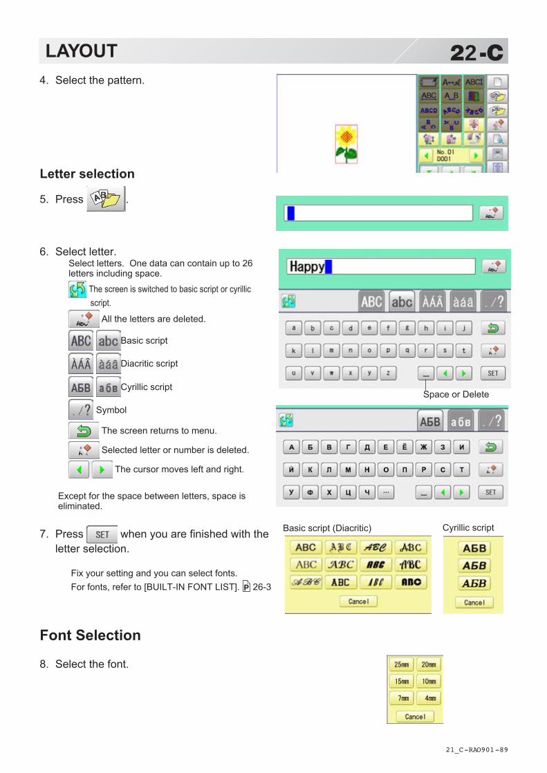
-RA -89
LAYOUT 22-C
21_C O901
Space or Delete
4. Select the pattern.
Letter selection
5. Press .
6. Select letter.Select letters. One data can contain up to 26letters including space.
The screen is switched to basic script or cyrillic script.
All the letters are deleted.
Basic script
Diacritic script
Cyrillic script
Symbol
The screen returns to menu.
Selected letter or number is deleted.
The cursor moves left and right.
Except for the space between letters, space iseliminated.
7. Press when you are finished with theletter selection.
Fix your setting and you can select fonts.For fonts, refer to [BUILT-IN FONT LIST]. 26-3
Font Selection
8. Select the font.
Cyrillic scriptBasic script (Diacritic)

-RA -90
LAYOUT 22-D
21_D O901
9. Select desired height.
10.Move letters with .
The selected letters (pattern) can be moved.
Layout method
11.Select .
Adjust width and height of arch if necessary. 16-1
You can move letters with .
12.Press .
13.Move letters with .
The selected letter (pattern) is displayed with rectangularframe.

-RA -91
LAYOUT 22-E
21_E O901
SavingSave the laid pattern data.
14.Press or .
15.Press .
Select start point of embroidery from 9 presetpoints which are located around or center of thepattern.
The start point of first selected pattern will be set as the start point of combined deign.
16.Press .
Saving pattern name is displayed.
17.Go on to next step, if the pattern name isnot to be changed.
When you would like to change the letters,select each digit in the existing name with
.Then select each digit in the existing name.Select word.
The maximum number of characters in a designname is eight letters or numbers.
All the letters and/or numbers are deleted.
Selected letter or number is deleted.
Renaming is cancelled.
18.Press .
The new design is saved and the display return toMenu mode or Drive mode.
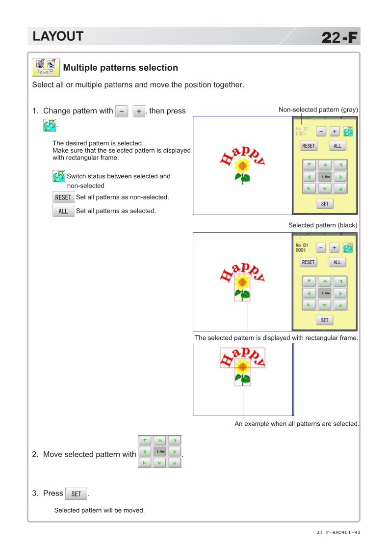
-RA -92
LAYOUT 22-F
21_F O901
Multiple patterns selection
Select all or multiple patterns and move the position together.
Non-selected pattern (gray)
Selected pattern (black)
The selected pattern is displayed with rectangular frame.
An example when all patterns are selected.
1. Change pattern with , then press
.
The desired pattern is selected.Make sure that the selected pattern is displayedwith rectangular frame.
Switch status between selected and non-selected
Set all patterns as non-selected.
Set all patterns as selected.
2. Move selected pattern with .
3. Press .
Selected pattern will be moved.

-RA -93
LAYOUT 22-G
21_G O901
Layout area
Change the size of layout area.
1. Enter X axis distance.
2. Press .
3. Enter Y axis distance.
4. Press .
The size of layout area is changed.
X direction is displayed in red. (It is ready to enter figure)
選択されている柄に枠が表示されます。
Y direction is displayed in red.(It is ready to enter figure)

-RA -94
LAYOUT 22-H
21_H O901
1. Change display scale with .
2. Press .
The pattern is displayed with desired scale.
Switch zoom function between on and off.
Move selected pattern.
3. Press .
Exit from zoom function.
It is the area to display design after zooming function.
Zoom
Zoom in and zoom out the display of pattern.The selected patterns can be moved with keeping desired display scale.

-RA -95
LAYOUT 22-I
21_I O901
Grid
Display grid in the layout area with desired scale.The snap function will work when you move the pattern by finger or stylus.Then, the center of the pattern and cross line of the grid will match automatically.
1. Enter size of the grid.
2. Press .
The grid is displayed.
Enter "0" if you do not use the grid.

-DA -147
23-1SPECIFICATIONS • MAINTENANCE
23_1 Q509
Specifications
CAUTION: To prevent accidents.When performing maintenance, be sure to disconnect the power cord.
Oiling
*1 Actual embroidery area will be restricted in accordance with inner frame size.*2 Actual embroidery area will be restricted in accordance with shape of a cap.*3 Maximum machine speed may change by sewing condition, such as pattern, material and etc.
Specifications are subject to change without notice.
The machine will periodically prompt periodically for lubrication basedon the number of stitches sewn.When powered on, the machine will display an icon and letter to indi-cate that lubrication is necessary. 5-3
When oiling the head shaft, please move the head to the left and set it to needle No. 1.
Too much oil may stain fabrics and threads.
Please lubricate the specified oil locations according to the instruc-tions below.Running the machine without proper oiling will damage the machine.Lint will gather in and around the rotary hook. Rotary hooks then wear which will cause the threads to break. Please clean lint with a brush and run the machine idly for 2 ~ 3 minutes.
kraM .oN liootecalP liodeificepS
A 1 koohyratoRdnahsurbllamsahtiwylthgilsliohtiwetacirbuL(rennidnaretuoehtneewteblioenihcamgniwes
).strapkoohyrator
gniweSlioenihcam
B 2 rabeldeeN
3 tfahsdaeH
4 revelknarC
Place to oilPlace to oil
1
3
4
2 3
Voltage 1 phase 100V ~ 115V -10% ~ +5% 1 phase 200V ~ 230V -10% ~ +10%
Electricity consumption 240 Wh 240 Wh
Frequency 50 / 60Hz
Noise level Under 72dB(A) (at 0.5m away from needle point)
Environmental condition Temperature 0 ~ 40° CMoisture 45 ~ 85 %
Dimension(Width x Height x Depth)
845 mm x 871 mm x 778 mm, 33.3 x 34.3" x 30.6" (Standard)1,522 mm x 871 mm x 778 mm, 59.9" x 34.3" x 30.6" (Wide X-Carriage Option)
Weight 106 Kg (Standard)109 Kg (Wide X-Carriage Option)
Embroidery area (Y x X)Standard 400 mm x 520 mm, 15.7"" x 20.5"" Max.*1(Wide X-Carriage Option) 400 mm x1,200 mm, 15.7"" x 47.2"" Max.*1Standard cap frame (Option) 70 mm x 180 mm, 2.8"" x 7.1"" Max.*2Wide cap frame (Option) 95 mm x 360 mm, 3.7"" x 14.2"" Max.*2
Max speed 1,200 rpm *3 (Standard)1,000 rpm *3 (Wide X-Carriage Option)
Memory capacity About 40,000,000 stitches
Registered pattern 999 pat.

-DA -149
23-2MAINTENANCE
23_2 O901
Cleaning the rotary hookIf the rotary hook is clogged with waste threador dust, it will degrade the stitch quality of theembroidery or may cause other problems.For a long sewing life, please keep the rotaryhook clean.Use the included brush for cleaning the hook.
Cleaning the thread cutting knifeIf the thread cutting knife is clogged with wastethread or dust, the knife will not work correctly.Please keep the thread cutting knife and deviceclean.
1. Remove set screw (2 pieces) by offsetdriver and remove the needle plate.
2. When the machine is stopped, press
and Press ”OTHER”.
3. Press .
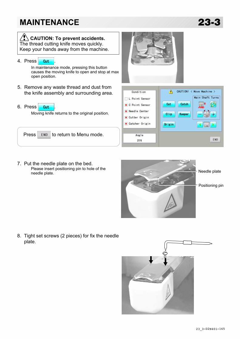
-D2 -165
4. Press .In maintenance mode, pressing this buttoncauses the moving knife to open and stop at maxopen position.
5. Remove any waste thread and dust fromthe knife assembly and surrounding area.
6. Press .Moving knife returns to the original position.
23-3MAINTENANCE
23_3 N401
CAUTION: To prevent accidents.The thread cutting knife moves quickly.Keep your hands away from the machine.
Needle plate
Positioning pin
Press to return to Menu mode.
7. Put the needle plate on the bed.Please insert positioning pin to hole of theneedle plate.
8. Tight set screws (2 pieces) for fix the needleplate.

-D2 -110
24-1ERRORS AND WHAT TO DO
24_1 M201
.oN yalpsiD rorrE snoituloS egaP
100 draobtiucriC tiucriclortnocnidetcetedytilamronbAdraob
01retfa,dnaenihcamnwodrewoP.niaganorewop,sdnoces
200 ecruosrewoP egatlovlamronbaroeruliafrewoP
400 yromemmetsyS tluafyromemmetsyS
410 mralAnaF tluafnafgnilooC .relaeDruoytcatnoC
510 pirtretrevnI .elbuortdetaler-rotomgniweShtiwelbuort,tiucrictrohs,daolrevO
tinuevirdrotom
.dnahybtfahsniamnrutdnarewoptuC.niaganorewop,yllamronsnrutfI
2.giF610 tinuXmralA rotom-x.e.i,elbuortdetaler-rotom-X
htiwmelborp,tiucrictrohs,daolrevotinuevirdrotom
hpargotnaptset,enihcamfforewoPynarofkcehC.yllaunamtnemevomfoegnarlluftuohguorhtytilamronba
.noitomniaganorewop,dnuofenonfI
710 tinuYmralA rotom-x.e.i,elbuortdetaler-rotom-Yhtiwmelborp,tiucrictrohs,daolrevo
tinuevirdrotom810 tfahsniaM .nruttonlliwtfahsniaM lluf1tsaeltayllaunamtfahsniamnruT
gniraelc,yleerfsnruttitahterusne&nrutenihcamezilaitini-er,nehT.majyna
.deepsdnametsys
1-522-52
020 tcetedeldeeN #eldeentnerrucgnitcetedtonenihcaMsitinunoitcelesrabeldeenro,yltcerroc
htiwelbuorT.noitisoppotsstiffo.draobtiucricgnitceted-noitisop
dexifehtotrotcelesrabeldeennruTniwolebnwohsaeradekram(noitisop
.)1.giF
Turn the disk with3mm hexagonaldriver clockwise.
CAUTION: To prevent accidents.In case of "Automatic errors backup", the machine's sudden movement might be causedwithout showing errors or messages after its stoppage.
E-050 C point
OK
C
Fig. 1 Fig. 2
Situationalposition
Turn the needle barselection knob to themoving headsituational position.
The machine has an extensive error code list to aid in trouble-shooting when problems occur, as listed below. Upon error,press the to release the error and correct it accordingto the list below.When errors occur frequently, please contact your dealer.
Automatic errors backupThe machine recovers from some errors (E-050, E-190, E-193) automatically after detecting theerror(s) by it self. In cases where the machine does not recover from the error automatically,follow the “Soluions” below according to the indicated error number.

-D2 -155
24-2ERRORS AND WHAT TO DO
24_2 NC13
.oN yalpsiD rorrE snoituloS egaPp g021022
Needle move Motor for needle bar selection unit hasstopped partway through its path.No movement due to malfunction ofthread take-up lever or trouble ofposition-detecting circuit board
After fixing malfunction of needle andthread take-up lever, turn needle barselector shaft with wrench to have it setat center of fixed position (range withinwhich needle bar selector doesn't move)Fig. 1
024 Needle center Needle bar stop position is off-center;needle bar stop position is out of place.
Turn needle bar selector with 3mm hexwrench to have it set at center of fixedposition (scope within which needle barselector doesn't move).Fig. 1
025 Needle over Needle # out of range of actual needleson given machine.
026 Needle differ Needle # differs between
030 Slow mismatch Improper speed adjustment at lowspeed. Speed does not decrease below100rpm at low speed.
Re-initialize machine system and speed. 25-125-2
050 C point Main shaft is stopped in a position otherthan "C" point
See Fig. 2 below. 24-5
051 L sensor Timing detection board fault, or marredphoto-sensor. Malfunction of "Lowestneedle position" sensor [PH2] ondetection circuit board.Improper adjustment of slit plate.
Check to see if photo sensor is clean or ifthe slit plate contacts sensor.Re-initialize machine system and speed.
25-125-2
052 C sensor Timing board detection fault, or marredphoto-sensor. Malfunction of "Colorchange position" sensor [PH1] on timingdetection circuit board.Improper adjustment of slit plate.
060 X limit Frame/pantograph has moved beyondsewing area along X-axis.
Return frame within sewing area usingthe frame movement keys on the controlboxl.Check pattern size and center mark toensure that it is within size range ofselected hoop and also properlycentered.
061 Y limit Frame/pantograph has moved beyondsewing area along Y-axis.
063 Drive Setup During embroidery, preparation for framemovement did not complete withinpredetermined time.
Malfunction of "Lowest needle position"sensor on detection circuit board,Improper adjustment. Re-initializemachine speed. If this condition occursfrequently, contact your Dealer.
25-2
064 X Center sens. Trouble with X-Carriage sensor,Improper position adjustment, sensorrelay board fault, cable fault.
Contact your Dealer.
065 Y Center sens. Trouble with Y-Carriage sensor,Improper position adjustment, sensorrelay board fault, cable fault.
066 Frame drive During embroidery, frame movement didnot complete within predeterminedmoving time.
If this condition occurs frequently, contactyour Dealer.
Fig. 1
Situationalposition
Turn the needle barselection knob to themoving headsituational position.
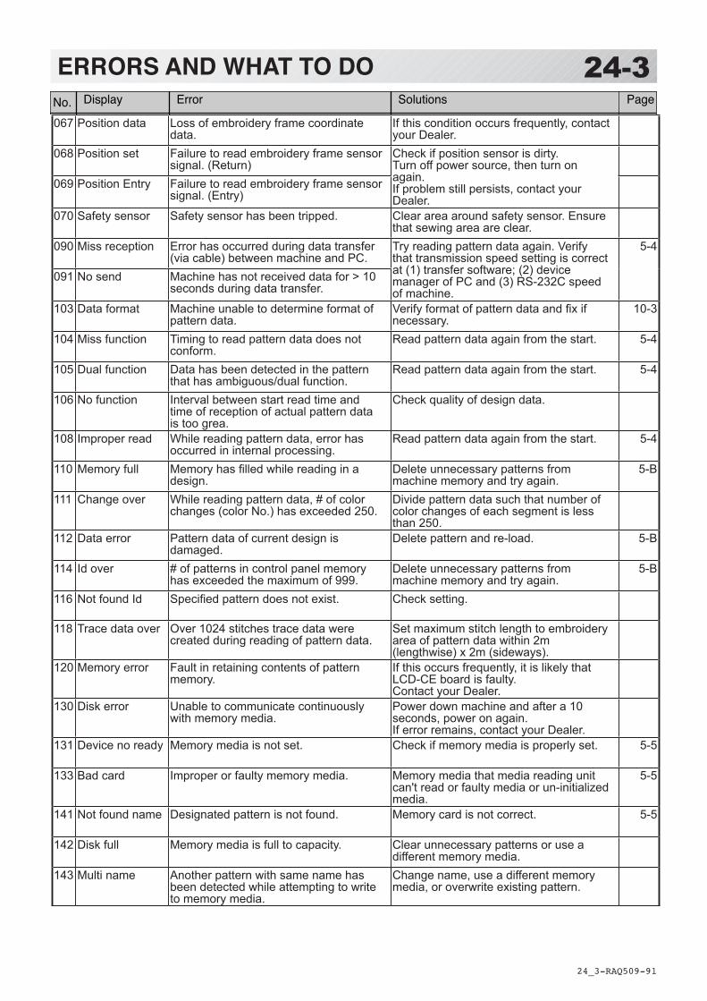
-RA -91
24-3ERRORS AND WHAT TO DO
24_3 Q509
No. Display Error Solutions Page
001 Circuit board Abnormality was detected in controlcircuit board.
Turn off power source and turn it onagain.
002 Power source Power failure or lowered voltage
004 System memory System memory is out of order
014 Fan Alarm Contact your Dealer.
015 Inverter trip Sewing motor related troubleOver-load on sewing motor, short circuit,trouble of motor drive unit
Cut power and turn main shaft with hand.If no abnormality is found, turn on again.Fig. 2
016 Alarm X unit X axis motor related troubleOver-load on X carriage motor, shortcircuit, trouble of motor drive unit
Turn power off, move drive frame anddrive motor with a hand. If no abnormalityis found, turn power on again.
017 Alarm Y unit Y axis motor related troubleOver-load on Y carriage motor, shortcircuit, trouble of motor drive unit
018 Main shaft Main shaft doesn't turn Make sure if main shaft or drives arenormal.Initialize the machine system and themachine speed.
25-125-2
020 Needle detect Needle position is not detected. Needlebar selection unit is off its stop position.Trouble of position detecting circuitboard
Turn needle bar selection knob to thefixed position (Marked area).Fig. 1
021022
Needle move Motor for needle bar selection unitstopped halfway.No movement owing to malfunction ofthread take-up lever or trouble ofposition detecting circuit board.
After fixing malfunction of needle andthread take-up lever, turn needle barselection knob to the fixed position(Marked area).Fig. 1
024 Needle center Needle bar stop position is off center.Needle bar stop position is out of place.
Turn needle bar selection knob to thefixed position (Marked area).Fig. 1025 Needle over Needle number not existing in the
machine was specified.026 Needle differ Needle number at time of finish and start
of operation differs. It was changed tocorrect one.
030 Slow mismatch Improper speed adjustment at lowspeed. Speed doesn't decrease below100rpm at low speed.
Initialize the machine system and themachine speed.
25-125-2
050 C point Stop position of main shaft is out of itsplac
See Fig. 2 below. 10-6
051 L sensor Trouble of timing detecting board, dirtyphoto sensor [PH2](L.P.)Malfunction of "Lowest needle position"sensor on detecting circuit board.Improper adjustment of slit plate.
Photo sensor is dirty or the slit platecontacts sensor.Initialize the machine system and themachine speed.
25-125-2
052 C sensor Trouble of timing detecting board, stainof photo sensor [PH1](C.P.).Malfunction of "Color change position"sensor on timing detecting circuit board.
060 X limit Frame moved beyond sewing area side-ways.
Return frame within sewing area by useof the arrow button.Check pattern size and contents ofsettings.061 Y limit Frame moved beyond sewing area
length-wise.
066 Frame drive
If this condition occurs frequently, contactyour Dealer.
067 Position data Follow the instructions below.If this condition occurs frequently, contactyour Dealer.
24-8
068 Position set Check if position sensor is stained.Turn off power source once and turn it onagain.If not OK, contact your dealer.
069 Position Entry
070 Safety sensor Safety sensor activated by concerningdanger.
Be confirmed of nothing is put around thesafety sensor. Confirm the safety ofembroidery area.
090 Miss reception Error occurred during communication ofdata.
Read pattern data again from thebeginning.
5-4
091 No send Data did not sent in for over 10 seconds.
103 Data format The machine cannot automaticallydetermine the format of the pattern data.
Check data format of pattern data.Set data format properly.
14-5
104 Miss function Timing to read pattern data doesn'tconform.
Read pattern data again from thebeginning.
5-4
105 Dual function One stitch has more than 2 functions. Read pattern data again from thebeginning.
5-4
106 No function Distance between start point of readingand start point of pattern is too longwhen reading.
108 Improper read While reading pattern data, an erroroccurred.
Read pattern data again from thebeginning.
5-4
110 Memory full While reading a pattern, memoryexceeded its capacity.
Delete unnecessary patterns and readfrom the outset.
10-1
111 Change over While reading pattern data, thefrequency of color change (color No.)exceeded 250 times.
Reduce frequency of color change of onepattern to less than 250 times.
112 Data error Pattern data of pattern to beembroidered is damaged.
Delete pattern and read pattern dataagain.
5-8
114 Id over The number of patterns in memory hasreached maximum of 99.
Delete unnecessary patterns and readagain from the bebinning.
5-8
116 Not found Id Specified pattern doesn't exist. Check setting.
118 Trace data over Over 1024 stitches trace data werecreated during reading of pattern data.
Set maximum stitch length to Embroideryarea of pattern data within 2m(lengthwise) x 2m(side wise).
120 Memory error It became impossible to retain contentsof memory.
If this condition occurs frequently, CPUcircuit board is out of order.Contact your Dealer.
130 Card error Incapable of disposing of memory cardcontinuously.
Turn off power source once and turn it onagain.If not OK, contact your dealer.
131 Card no ready Memory card is not set. Check if memory card is properly set. 5-5
132 Write protect Disk write protect. Make write protect tab in data disk"Writing possible".
2-?
133 Bad card Memory card is not proper or broken. Memory card cannot be read or brokenmemory card or memory card notinitialized.Contact your Dealer.
5-5
134 Disk unit Trouble in disk drive unit. Turn off power source once and turn it onagain. If not recovered, it will be trouble indisk drive unit.
140 Entry over Capacity is full for registeringpatterns.(refer to page of""SPECIFICATIONS"")
Clear unnecessary patterns. Or useother data disk.
141 Not found name Designated pattern is not found. Memory card is not correct. 5-5
142 Disk full Capacity is full for storing. (refer to page of "SPECIFICATIONS")
Clear unnecessary patterns. Or useother data disk.
21-1
143 Multi name If there is multi name of data whenwriting.
Change name, write in another disk.(Over write)
190 Cut blade Thread cut knife is not at stop position. Follow the instructions below. 24-6
193 Catcher Thread catch hook is off its positionLimit switch to detect position is not"OFF".
Please follow the exsample below.1. Check if it does not cut thread.If thread is not cut, cut it and return thethread catch hook to its normal position.2. If threads are cut, check if thread catchhook on head has returned to its positioncompletely.
24-7
215 Frm. drive err If this condition occurs frequently, contactyour Dealer.
217 Frm.drive data
220 Calendar Stop
Contact your Dealer.
3-7
221 Battery Low
Contact your Dealer.222 Calendar Data
Contact your Dealer.
3-7
067 Position data Loss of embroidery frame coordinatedata.
If this condition occurs frequently, contactyour Dealer.
068 Position set Failure to read embroidery frame sensorsignal. (Return)
Check if position sensor is dirty.Turn off power source, then turn onagain.If problem still persists, contact yourDealer.
069 Position Entry Failure to read embroidery frame sensorsignal. (Entry)
070 Safety sensor Safety sensor has been tripped. Clear area around safety sensor. Ensurethat sewing area are clear.
090 Miss reception Error has occurred during data transfer(via cable) between machine and PC.
Try reading pattern data again. Verifythat transmission speed setting is correctat (1) transfer software; (2) devicemanager of PC and (3) RS-232C speedof machine.
5-4
091 No send Machine has not received data for > 10seconds during data transfer.
103 Data format Machine unable to determine format ofpattern data.
Verify format of pattern data and fix ifnecessary.
10-3
104 Miss function Timing to read pattern data does notconform.
Read pattern data again from the start. 5-4
105 Dual function Data has been detected in the patternthat has ambiguous/dual function.
Read pattern data again from the start. 5-4
106 No function Interval between start read time andtime of reception of actual pattern datais too grea.
Check quality of design data.
108 Improper read While reading pattern data, error hasoccurred in internal processing.
Read pattern data again from the start. 5-4
110 Memory full Memory has filled while reading in adesign.
Delete unnecessary patterns frommachine memory and try again.
5-B
111 Change over While reading pattern data, # of colorchanges (color No.) has exceeded 250.
Divide pattern data such that number ofcolor changes of each segment is lessthan 250.
112 Data error Pattern data of current design isdamaged.
Delete pattern and re-load. 5-B
114 Id over # of patterns in control panel memoryhas exceeded the maximum of 999.
Delete unnecessary patterns frommachine memory and try again.
5-B
116 Not found Id Specified pattern does not exist. Check setting.
118 Trace data over Over 1024 stitches trace data werecreated during reading of pattern data.
Set maximum stitch length to embroideryarea of pattern data within 2m(lengthwise) x 2m (sideways).
120 Memory error Fault in retaining contents of patternmemory.
If this occurs frequently, it is likely thatLCD-CE board is faulty.Contact your Dealer.
130 Disk error Unable to communicate continuouslywith memory media.
Power down machine and after a 10seconds, power on again.If error remains, contact your Dealer.
131 Device no ready Memory media is not set. Check if memory media is properly set. 5-5
133 Bad card Improper or faulty memory media. Memory media that media reading unitcan't read or faulty media or un-initializedmedia.
5-5
141 Not found name Designated pattern is not found. Memory card is not correct. 5-5
142 Disk full Memory media is full to capacity. Clear unnecessary patterns or use adifferent memory media.
143 Multi name Another pattern with same name hasbeen detected while attempting to writeto memory media.
Change name, use a different memorymedia, or overwrite existing pattern.

-RA -90
24-4ERRORS AND WHAT TO DO
24_4 O512
y190 Cut blade Thread cut knife is not at stop position. Follow the instructions below. 24-5
191 Cut Sensor Thread cut knife is not at stop position. Check if threads are jammed aroundthe thread cutting knife.Press the thread cutting button 2~3 times.If error remains, contact your Dealer.
23-223-4
193 Catcher Thread catch hook is off its position.Limit switch to detect position is not"OFF".
Please follow the example below:1. Check whether thread was actually cutby thread cutting knife. If not, cut threadand return catch hook to its normalposition.2. If thread is actually cut, check if threadcatch hook on head has returned to itsposition completely.
24-6
203 Install data Error has occurred during update ofprogram.
Check an update program.
215 Frm. drive err Frame movement did not completeduring normal movement. (Time over)
If this condition occurs frequently, contactyour Dealer.
217 Frm.drive data Frame movement data loose.
255 Default Error During embroidery, frame movement didnot complete until main shaft reach"Lowest needle position".
Re-initialize machine speed setting.Check adjustment of upper shaft timing.(C point / L point)If this condition occurs frequently, contactyour Dealer
25-2
.oN yalpsiD rorrE snoituloS egaP

-DA -154
24-5ERRORS AND WHAT TO DO
24_5 Q101
1. Press .
2. Select “Auto”.
The main shaft turns 2 to 3 times and returns to a stop position (“C” point ) automatically. The display returns to drive mode.
What to do when Stop position of main shaft is out of place (error
1. Press .
2. Select “Manual”.
The error status is released and the display shows “drive mode”.
3. Remove the cap over the small hole in the rear of the machine. Using a 3 mm hexagonal driver, Please turn the main shaft and adjust it to the “C” point.
CAUTION! <Main shaft turns>
C
When you cannot clear by the method above (Auto)
E-050 C point
OK
E-050 C point
OK

-DA -155
24-6ERRORS AND WHAT TO DO
24_6 Q101
1. Press .
2. Select “Auto”. The display returns to the drive mode.
What to do for “Thread cut knife is not at the stop position (error E-190)”
1. Press .
2. Select “Manual”.
The error status is released and the display shows “drive mode”.
3. Using a 3 mm hexagonal driver, Please turn the main shaft and adjust it to the “C” point. C
When you cannot clear by the method above (Auto)
E-190 Cut blade
OK
E-190 Cut blade
OK

-DA -157
24-7ERRORS AND WHAT TO DO
24_7 O901
4. When the machine is stopped, press
and Press ”OTHER”.
5. Press .
6. Press .You should hear the sound of moving knifeopening.
7. Press .You should hear the sound of moving knifereturning to the closed position.
Press to return to Menu mode.
Press once again to return to Drive
mode.

-DA -157
24-8ERRORS AND WHAT TO DO
24_8 Q101
1. Press .
2. Select “Auto”.
The thread catch hook returns to the original position. The display returns to drive mode.
What to do for “Thread catch hook is off its position (error E-193)”
1. Press .
2. Select “Manual”.
The Error status is cleared and the display shows “drive mode”.
3. Refer to the page in the section (ERRORS AND WHAT TO DO), and determine what may be preventing the hook from returning to the original position, and follow the steps outlined. 24-3
When you cannot clear by the method above (Auto)
E-193 Catcher
OK
E-193 Catcher
OK

-RA -95
25-1INITIALIZING OF MACHINE SETTINGS
25_1 Q501
Re-Initialization of machine systemPerform this function only to fix problems with the machine.When performed, all settings in the “OPTION” menu are lost.Be sure to reset the “OPTION” menu after performing this function.
System initialize OK?
Cancel OK
1. When the machine is stopped, press
and Press “OTHER”.
2. Press .
3. Press to carry out.
Formatting of the machines systems are carried out. Indicate HAPPY logo in screen.
If you cancel, press the .
The display returns to MENU.

-RA -95
1. When the machine is stopped, press
and Press “OTHER”.
2. Press .
3. Press to execute.
The machine will display a warning, then start turning the main shaft automatically. The speed will slowly increase from slowest speed to maximum and then stop automatically and return to Drive mode.
If you cancel, press the .
The display returns to MENU.
25-2INITIALIZING OF MACHINE SETTINGS
25_2 Q101
Initializing of machine speedIf you have E-18, E-30, E-51 or E-52 while sewing, Please try initializing the machine settings.
Speed setting OK? CAUTION! <Main shaft turns> Cancel OK
CAUTION! <Main shaft turns>
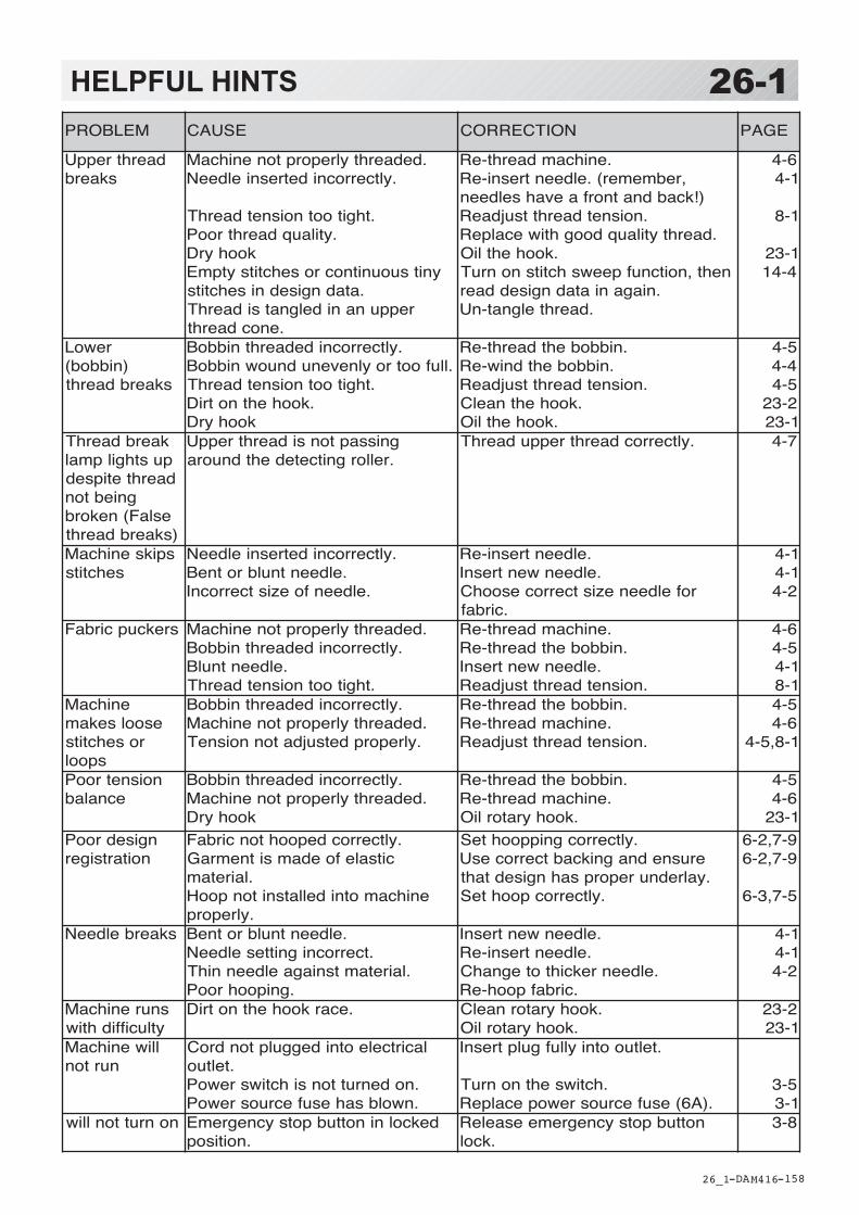
-DA -158
MELBORP ESUAC NOITCERROC EGAP
daerhtreppUskaerb
.dedaerhtylreporptonenihcaM.yltcerrocnidetresnieldeeN
.thgitootnoisnetdaerhT.ytilauqdaerhtrooP
koohyrDynitsuounitnocrosehctitsytpmE
.atadngisednisehctitsreppunanidelgnatsidaerhT
.enocdaerht
.enihcamdaerht-eR,rebmemer(.eldeentresni-eR)!kcabdnatnorfaevahseldeen
.noisnetdaerhttsujdaeR.daerhtytilauqdooghtiwecalpeR
.koohehtliOneht,noitcnufpeewshctitsnonruT
.niaganiatadngiseddaer.daerhtelgnat-nU
6-41-4
1-8
1-324-41
rewoL)nibbob(
skaerbdaerht
.yltcerrocnidedaerhtnibboB.llufootroylnevenudnuownibboB
.thgitootnoisnetdaerhT.koohehtnotriD
koohyrD
.nibbobehtdaerht-eR.nibbobehtdniw-eR
.noisnetdaerhttsujdaeR.koohehtnaelC
.koohehtliO
5-44-45-42-321-32
kaerbdaerhTpusthgilpmaldaerhtetipsed
gniebtoneslaF(nekorb)skaerbdaerht
gnissaptonsidaerhtreppU.rellorgnitcetedehtdnuora
.yltcerrocdaerhtreppudaerhT 7-4
spiksenihcaMsehctits
.yltcerrocnidetresnieldeeN.eldeentnulbrotneB
.eldeenfoezistcerrocnI
.eldeentresni-eR.eldeenwentresnI
rofeldeenezistcerrocesoohC.cirbaf
1-41-42-4
srekcupcirbaF .dedaerhtylreporptonenihcaM.yltcerrocnidedaerhtnibboB
.eldeentnulB.thgitootnoisnetdaerhT
.enihcamdaerht-eR.nibbobehtdaerht-eR
.eldeenwentresnI.noisnetdaerhttsujdaeR
6-45-41-41-8
enihcaMesoolsekam
rosehctitsspool
.yltcerrocnidedaerhtnibboB.dedaerhtylreporptonenihcaM.ylreporpdetsujdatonnoisneT
.nibbobehtdaerht-eR.enihcamdaerht-eR
.noisnetdaerhttsujdaeR
5-46-41-8,5-4
noisnetrooPecnalab
.yltcerrocnidedaerhtnibboB.dedaerhtylreporptonenihcaM
koohyrD
.nibbobehtdaerht-eR.enihcamdaerht-eR
.koohyratorliO
5-46-41-32
ngisedrooPnoitartsiger
.yltcerrocdepoohtoncirbaFcitsalefoedamsitnemraG
.lairetamenihcamotnidellatsnitonpooH
.ylreporp
.yltcerrocgnippoohteSerusnednagnikcabtcerrocesU.yalrednureporpsahngisedtaht
.yltcerrocpoohteS
9-7,2-69-7,2-6
5-7,3-6
skaerbeldeeN .eldeentnulbrotneB.tcerrocnignitteseldeeN
.lairetamtsniagaeldeennihT.gnipoohrooP
.eldeenwentresnI.eldeentresni-eR
.eldeenrekcihtotegnahC.cirbafpooh-eR
1-41-42-4
snurenihcaMytluciffidhtiw
.ecarkoohehtnotriD .koohyratornaelC.koohyratorliO
2-321-32
lliwenihcaMnurton
lacirtceleotnideggulptondroC.teltuo
.nodenruttonsihctiwsrewoP
.nwolbsahesufecruosrewoP
.teltuootniyllufgulptresnI
.hctiwsehtnonruT.)A6(esufecruosrewopecalpeR
5-31-3
nonruttonlliw dekcolninottubpotsycnegremE.noitisop
nottubpotsycnegremeesaeleR.kcol
8-3
HELPFUL HINTS
26_1 M416
26-1
-D2 -168
EMBROIDERY TERMS
26_2 M401
26-2Thread break back
With this setting, drive frame backs up severalstitches after a thread break before stopping.
Color change numberThe Needle number (thread color) to be sewn canbe set to each Color change number. For ex-ample, if a pattern is divided by a color changefunction in 2 places, 3 color change numbers existin the pattern. When the needle number is set toits respective color change number, the pattern issewn in 3 colors.
Memory patternPatterns stored in memory.
Start point of the frameThis is the point where the frame begins to movebefore the machine starts sewing.
Various function settingsA general term for Needle bar selection, Convert,Pattern adjustment, Repeat sewing, Offset andframe out which are set in the pattern data.
Zero stitchThis is a stitch whose net movement in both the X-and Y- direction is zero, and the needle lands inthe same position.
Original PointThe frame position where the machine embroidersthe pattern from the beginning is automaticallyregistered as the original point.
StitchesThis is the minimum unit within the pattern data.There are different types of such “stitches”:“stitches” that command determine the sewingsequence; “functions” that dictate functions suchas jumps, thread cut, etc; “sideways movementdistance” and “lengthwise movement distance”that command the movement distance of theframe.
Auto originThis returns the frame automatically to the originalpoint upon finishing the embroidery.
Tubular round frame, Tubular square frame
The frames made by HAPPY and used for cylindersewing, such as on T-shirts, bags, etc. Theseframes have brackets at both sides.
Memory mediaWhat saves design data by things, such asmemory card and a USB memory.
Data formatThis is the format that the pattern data is con-verted into/
Color change stopWhen a color change stop is assigned to a colorchange number, the machine embroiders the setcolor change and stops.
ConversionThis is a user-adjustable design setting of a givenpattern that allows rotation in increments of 90degrees.

-RA -110
26-3BUILT-IN FONT LIST
26_3 P401
Basic script, Diacritic script

-RA -111
26-3aBUILT-IN FONT LIST
26_3a P401

-RA -112
26-3bBUILT-IN FONT LIST
26_3b P401
Those fonts are created by (www.i-cliqq.com)
Cyrillic script

-SJ -93
BUILT IN PATTERN includes clip art from [Master clip] created by H2soft (Fax:+81-422-28-5211E-mail:[email protected]).
26-4BUILT-IN PATTERN LIST
26_4 N602

OA01E
HEAD OFFICE 3-3515, Tachiyagawa, Yamagata-city, 990-2251, JapanPhone: +81-23-686-2272 Fax: +81-23-686-2243
TOKYO OFFICE 2-9-5, Taito, Taito-Ku, Tokyo 110-0016, JapanPhone: +81-3-3834-0711 Fax: +81-3-3835-8917