Embed Size (px)
Citation preview

Dual Channel Universal Process Indicator
Operating Manual for Models :
Model 4015 / 5015
Rev 1.1 - English - 14082014

Cleaning
Do not clean the instrument while the instrument is on. Harsh abrasives, solvents, scouring cleaners and alkaline cleaning solutions, such as washing soda, should not be used especially on the display window. The outside of the instrument may be wiped down with a slightly damp clean cloth (lightly moistened with water only).Under no circumstances should you attempt to wipe the inside of the instrument.
Safety
This equipment is supplied by a mains voltage which can cause an electric shock injury. Before removing the circuit board from its housing, switch the instrument off, isolate it from the mains power supply and make sure that it cannot be connected inadvertently by other persons.
If the circuit board is removed from its housing, do not apply power to the instrument unless specifically instructed to do so in these instructions. When working on live equipment, exercise great care, use insulated tools and test equipment, and do not work alone.
When fitting option boards, always put the circuit boards back in the housing with the back-plate securely fastened before powering up the instrument.
When handling circuit boards, ensure that full anti-static precautions are observed.
Replace external mains fuse with one of an equivalent type.
Contents
Introduction ....................................................................... Page 3Electrical specifications ..................................................... Page 3Input ranges ...................................................................... Page 3Sensor excitation................................................................Page 3Power supply .....................................................................Page 4Programmable specifications ............................................ Page 4Other specifications ...........................................................Page 4Installation (panel cutout) .................................................. Page 5Installation (fastening) ....................................................... Page 5Display & keypad (during normal display mode) ...............Page 5Display & keypad (during programming mode) .................Page 5Connections & links ...........................................................Page 6
Hardware link selection for J4 ......................................Page 6Power supply links ....................................................... Page 6
Programming chart ............................................................Page 7Programming chart continued............................................ Page 8Display codes explained ................................................... Page 9Programming example ...................................................... Page 10Asciibus protocol ............................................................... Page 11Option 3000, 3001-P / M, 3002, 3003, 3004-P / M ........... Page 12Option 3006, 3007, 3008, 3009, 3010 ,3012, 3013 ...........Page 13Option 3014, 3017-P / M, 3018-P.......................................Page 14Option 3018-M, 3025, 3026 .............................................. Page 15Diagram “P” .......................................................................Page 16Diagram “M” ...................................................................... Page 16Declaration of conformity .................................................. Page 16Guarantee ......................................................................... Page 16
Page 2

0 - 20 mA, 4 - 20 mA, 0 - 200mV, 0 - 2 V, 0 - 10 V
Electrical Specifications
Sensor Excitation
Accuracy & linearity : 0.05% of F.S., or 1 countInternal resolution : 20000 counts (bi-polar)Temperature coefficient : 20 ppm / °C typicalSettling time for process inputs : 0.5 secondsSettling time for frequency input : 5 milliseconds (with no filter)Operating temperature range : -10 to +50°CStorage temperature range : -40 to +80°CHumidity : < 85% non-condensingWarm-up time : None required
Electro-mechanical relays : 250V AC, 30V DC, 2A, PF=1Solid state relays : 400 V AC/DC, 0.5A, PF=1Analog output accuracy : 0.1% of full scale, 12 bitsCurrent analogue output load : 500 W maximumVoltage analogue output load : 1 kW minimumMemory retention : Full non-volatile operationOption 3006 isolation rating : 1500 VDeclaration of conformity : See last page
24V DC: (17-26V), current limited. For 2-wire transmitters, proximity switches or encoders. With option 3010, current capability increases to 100mA
5V DC: ± 1%, maximum 25mA2.5V DC: Precision reference, 2mA max for pot (2 kW min)
Input Ranges
The Model 4015, 5015 are Dual Channel Process Indicators
which can be applied to many applications which require a
dual input and a single display eg. Temperature and humidity
monitoring. Each channel is individually setup for zero, span,
input type and more. The unit boasts a number of useful
mathematically functions such as addition, subtraction,
multiplication and division of the two input channels. The
display as well as alarms, analogue out, peak hold can be
selected using channel A, Channel B or the above mentioned
mathematical functions.
Options include linearisation, analog output and set-points
up to a total of four. Excitation is standard and is link
selectable for 2-wire / 3-wire transmitters and a
potentiometer input.
Selected options now feature ‘Plug & Play’ technology,
allowing option boards to be ordered separately & field fitted
when required.
Model 4015 is a 4 digit (-1999 to 9999) indicator while the 5015 is a 5½ digit (-199999 to 199999) indicator.
Introduction
Page 3

Programmable Specifications
5½ Digit Models
Zero & full scale setting : -199999 to 199999Decimal point : Adjustable on all digitsProcess filtering : 0.0 to 10.0 seconds
Options :
Analog output zero & span : -199999 to 199999Alarm setpoint values : -199999 to 199999Alarm hysteresis : 0 to 255 (default 1)Alarm delay : 0 to 255 seconds (default 0)Alarm relay settings : Selectable HIGH or LOW alarmAlarm relay state : Selectable NO or NCUnit address : 0 to 99Baud rate : 2400, 4800, 9600, 19200
Standard115 / 230 VAC ± 10%, link selectable, 50/60Hz, 5VA typ
Optional8-30VDC isolated power supply (Option 3008), 5VA typ10-30VDC non-isolated power supply (Option 3028), 5VA typ95V-265V AC/DC isolated power supply (Option 3010), 5VA typ
Power Supply
4 Digit Models
Zero & full scale setting : -1999 to 9999Decimal point : Adjustable on all digits
Options :
Analog output zero & span : -1999 to 9999Alarm setpoint values : -1999 to 9999Alarm hysteresis : 0 to 255 (default 1)Alarm delay : 0 to 255 seconds (default 0)Alarm relay settings : Selectable HIGH or LOW alarmAlarm relay state : Selectable NO or NCUnit address : 0 to 99Baud rate : 2400, 4800, 9600, 19200
Other Specifications
DIN 48 x 96 housing, 147mm depthIndustrial strength single piece housing
Housing is flame retardant ABS plastic that meets UL94 V-0Circuit board is flame retardant material that meets UL94 V-0
Front facia rating : IP65 (with o-ring seal supplied as standard)
Page 4

Fastening
The supplied fastening clips may be fitted on the side or the top / bottom of the housing. Ensure that the clip & screw is mounted as shown here.
Caution : Do not overtighen the screws.
Min12
45
92
Installation
To gain access to the circuit boards, switch power off and remove terminals from the back of the housing. Observe safety precautions. Use a screwdriver to clip the back-plate off.
During programming mode Display & Keypad
147
Panel CutoutInstallation
48
96
Enter
Programming menu
Move to next digit
Increment digit / change selection
Channel 2(illuminated
whenselected)
48
96
2 3 41
Auto-zero (option 3014 only)
Print on demand (comms option only)
Reset peak value (option 3012 only) /Change display selection
Show normal / peak hold value(option 3012 only)
2 3 41
%All dimensions in mm
During normal display mode Display & Keypad
Page 5
Min12
DIN 1/8 cutout
O-ring sealinggasket suppliedas standard
Channel 1 (illuminated when selected)
Alarm LEDs(illuminated wheneverrelays are energised)
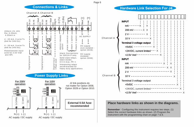
Power Supply Links
Place hardware links as shown in the diagrams.
Remember : Configuring this instrument requires two steps. (1) Select the correct hardware links as shown. (2) Program the instrument with the programming chart on page 7 & 8.
Page 6
X X
X X
X
X
X
X
X
+24VDC, current limited
X
X
X
Terminal 3 voltage output
X
+24VDC, current limited
Terminal 3 voltage output
mA
200 mV
2 V
10 V
+5VDC
+2.5V Vref
INPUT
mA
200 mV
2 V
10 V
+5VDC
+2.5V Vref
INPUT
mA
200 mV
2 V
10 V
+5VDC
+2.5V Vref
INPUT
mA
200 mV
2 V
10 V
+5VDC
+2.5V Vref
INPUT
X
X
Terminal 3 voltage output
+24VDC, current limited
X
X
X
Channel A
Channel B
J5
4 - 20 mA, 2-wire Tx(link for 24V/ Ex)
Potentiometer input(Link for 2.5V Vref and SP)
200mV, 2V, 10V,Pot, 0-20mA, 4-20mA in
4 - 20 mA, 3-wire Tx(link for 24V/ Ex)
6
DC supply(non-isolated -option 3028)
DC supply(isolated -option 3008)
2 3
AC SUPPLY
8 951 4 7 10 11 12
In L
o
In H
i
+ V
ou
t
+ V
ou
t
In H
i
+ D
(R
x)
- D
(T
x)
Dig
In
In L
o-+
N L
N L
Liv
e
Ne
ut
(+) -( )
Interposing relaysrecommended forheavy duty applications
Alarm Connectionsfor 3001/4-P only
RS
23
2 / R
S4
85
option
Ala
rm 1
option
Ala
rm 2
option
Ala
rm c
om
mon
+-
S
S
+-
+-
Dig
ital gro
un
d
- +
Dig
ital In
pu
t\ P
eak r
eset
+-
S
S
+-
+-
Dig
ital gro
un
d
- +
Channel A Channel B
For 115Voperation
AC supply / DC supply
N (+) L (-)
J2
Ne
ut (+
)
Live
(-)
J2 link positions do not matter for Option 3008,
Option 3028 or Option 3010.
Solid state relays,400V AC/DC,0.5 A max, PF=1
For 230Voperation
AC supply / DC supply
N (+) L (-)
J2
Ne
ut (+
)
Live
(-) External 0.5A fuserecommended
to toggle thefollowing options
,, ,, , , , ,
READ ME FIRST !
,
, ,
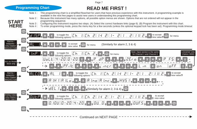
Note 1 : This programming chart is a simplified flowchart for users that have previous experience with this instrument. A programming example is available in the next few pages to assist new users in understanding this programming chart.
Note 2 : Because this instrument has many options, all possible option menus are shown. Options that are not ordered will not appear in the programming sequence.
Note 3 : Configuring this instrument requires two steps. (A) Select the correct hardware links (page 6). (B) Program the instrument with this chart.Note 4 : To enter programming mode, press the menu key for a few seconds (unless the optional keypad lock has been set). Programming mode timeout
Alarms / setpoints /
only (Option3001/4/17/18)
STARTHERE
Programming Chart
, , , , for menuto acceptnew value
(Similarly for alarm 2, 3 & 4)
, to acceptnew value, for menuto toggle the
following options
Alarms / setpoints /
only (Option3001/4/17/18)
, , , , ,
, , , , , , , , , ,
(Similarly for alarm 2, 3 & 4)
Analog output only (Option3003 / 3007)
Page 7
, , , for menu,, , , , , , ,, , ,,
,, , , ,, , , , ,, ,Incr on Model
5015 only
Note: Input section is the same for Channel 1 and Channel 2
Lineariser only(Option 3000)
, , to acceptnew value,to toggle the
following options,
, ,, to acceptnew value
to toggle thefollowing options,
Continued on NEXT PAGE
,

READ ME FIRST !Programming Chart (cont.)
Page 8
, ,
, ,, ,, ,,,, ,Auto-zero,
Peak / Valley hold only
(3012 / 3014)
“END”. Instrument returns to normal display mode.
, ,
, ,, ,
, ,, ,
, ,,,, ,Auto-zero,
Peak / Valley hold only
(3012 / 3014)
, to acceptnew value,to toggle the
following options
RS485 / 232 only (Option3002 / 3013)
, ,, , , , ,,
, ,,, , to accept
new value,to toggle thefollowing options
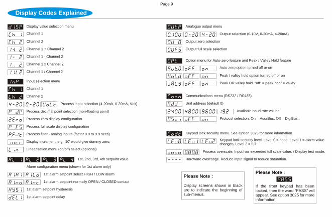
Display Codes Explained
Please Note :
If the front keypad has been locked, then the word “PASS” will appear. See option 3025 for more information.
Page 9
Output selection (0-10V, 0-20mA, 4-20mA)
Analogue output menu
Output zero selection
Output full scale selection
Protocol selection. On = AsciiBus. Off = DigiBus.
Unit address (default 0)
Communications menu (RS232 / RS485)
Available baud rate values
Peak OR valley hold. “off” = peak. “on” = valley
Auto-zero option turned off or on
Peak / valley hold option turned off or on
Option menu for Auto-zero feature and Peak / Valley Hold feature
Keypad lock security level. Level 0 = none, Level 1 = alarm value changes, Level 2 = full
Keypad lock security menu. See Option 3025 for more information.
Hardware overrange. Reduce input signal to reduce saturation.
Process overscale. Input has exceeded full scale value. / Display test mode.
Please Note :
Display screens shown in black are to indicate the beginning of sub-menus.
Display value selection menu
Channel 1
Channel 2
Input selection menu
1st, 2nd, 3rd, 4th setpoint value
Alarm configuration menu (shown for 1st alarm only)
1st alarm setpoint select HIGH / LOW alarm
1st alarm setpoint normally OPEN / CLOSED contact
1st alarm setpoint hysteresis
1st alarm setpoint delay
Process input selection (4-20mA, 0-20mA, Volt)
Process decimal point selection (non-floating point)
Process zero display configuration
Process filter - analog inputs (factor 0.0 to 9.9 secs)
Display increment. e.g. '10' would give dummy zero.
Linearisation menu (on/off) select (optional)
Process full scale display configuration
Channel 1
Channel 2
Channel 1 + Channel 2
Channel 1 - Channel 2
Channel 1 x Channel 2
Channel 1 / Channel 2

Remember, the symbols on the keypad have the following definitions during programming.
Press “Menu” for3 seconds and continueuntil AL 1 appears
Next MenuItem Increment digit Next Digit
Enter / Accept value
Press “Next digit” toamend the next digit
Press “Increment digit”to increase value
Press “Enter” to seeAlarm / Trip 1 value.
Amend the other digits in the same way until the desired trip value is entered.
The entire programming menu operates in a manner similar to the example described above.
Press “Menu” toproceed to nexttrip value.
Press “Enter” to acceptAlarm 1 value.
Setting Up Alarm Values (Option)Programming Example
Use the same menu steps above to change trip levels for trip 2, 3 and 4.
Page 10

IGNORE THIS PAGE unless communications option has been ordered. When the RS232 (option 3013) or RS485 (option 3002) is ordered, two protocols are made available, namely ASCIIbus & DIGIbus protocols. DIGIbus is the default protocol which is used for the calibration and configuration of the instruments, and whenever the instrument is connected to master-slave systems. DIGIbus protocol is therefore used in complex bus systems, and is NOT described here. Please contact factory for the DIGIbus protocol.
ASCIIbus, which is described here, is much easier to use as it can easily interface to third party systems with very little engineering work required. It is a purely ASCII based (7 bit) protocol. The protocol is essentially designed for one way communications (instrument to PC). Under the "Conn" (connection) programming menu, ASCIIbus is enabled by selecting "ASCI" to "ON". If "OFF" is selected, the DIGIbus protocol will be active. Although designed for one way communications only, the ASCIIbus protocol contains an address. The address range is "00" to "99".
Using address "00" : If this address is selected, the instrument will only transmit data on demand by either momentarily pressing the 'menu' key, or by transmitting a byte (any ASCII character) to the DPM. This mode is useful for interfacing to printers. In addition, field ' A A ' will contain the ASCII character "blank/space". Field ' P ' will also contain the ASCII character "blank/space".Using address "01" to "99". If any of these addresses are used, the meter continuously transmits information at approximately 5 times a second.
The data format string output from the indicator is (7 bit ASCII code is used):Line Settings : 7 Data Bits, 1 Parity bit, Odd Parity, 1 Stop Bit.Baud Rate : Selectable 2400, 4800, 9600, 19200.Data Bits : Numerical ASCII characters : 0, 1, 2, 3, 4, 5, 6, 7, 8, 9
Other ASCII characters : #, blank/space, +, -, CR, LFProtocol format is : # A A S D D D D D D D D P CR LF
where : # = indicates start of message: A A = Instrument address. ASCII 00 to 99. 00 is default.: S = sign (polarity) ( ASCII "+" or "-" ).: D = data bits (data for 8 numerals). See Note (1).: P = decimal point position. ASCII 0 to 8.: CR = ASCII carriage return.: LF = ASCII line feed.
Note 1 : This protocol allows for future expansion. Therefore if Model 4015 is used for example, the first four digit data will contain the ASCII character "blank/space" and the last four digits will contain the display reading. Similarly, if the Model 5015 is used for example, the first 2 digit data will contain the ASCII character "blank/space" and the last six digits will contain the display reading.
Asciibus Protocol (for Option 3002 / 3013)Communications
Page 11

This option is similar to Option 3001-P but with a single alarm only. See page 6 for connection details. Wire for AL1 only.
This option is similar to Option 3001-M but with a one alarm set point only. See diagram “M” on page 16 for connections. Wire for AL1 only.
See page 7 for connection details.
See page 7 for connection details. Wire for AL1 & AL2 only.
If fitted, this option will accurately linearise signals for flow applications (square root extraction), s-curve (cylinder applications) and other non-linear signals. The type of linearisation required is specified at time of order and cannot be user selectable. However, the user has the option of toggling the lineariser feature 'ON' or 'OFF' in the channel (’ch 1' & ‘ch 2') menu. See page 7 for programming
See page 7 for connection details. Select DIGIbus or ASCIIbus protocol from the program menu. See additional protocol documents.
One Set Point (Electro-Mechanical Relay)Option 3004-M
One Set Point (Solid-State Relay)Option 3004-P
0 - 20mA / 4 - 20mA Analogue Output OptionOption 3003
RS485 Serial Interface OptionOption 3002
Two Set Point (Electro-Mechanical Relays)Option 3001-M
Two Set Point (Solid-State Relays)Option 3001-P
Lineariser (Square Root / Cylinder / Sphere etc)Option 3000
This option provides two alarm set points with electro-mechanical relays. This option board slots into the upper slot of the panel meter box. The upper terminals are clearly numbered 13-28 to differentiate them from the lower terminals. Both normally open and normally closed contacts are provides with each relay. The relays are rated at 250VAC / 30VDC @ 2A. Visual LED alarm indication is provided on the panel meter front. For connection wiring details, see diagram “M” on page 16. Connect wires for AL1 & AL2 only.
Page 12

This option displays and holds the max or min value (not both) of an input signal. This option is activated in the programming menu “Opt” by selecting whether “Hold” should be “On” or “Off”, and selecting valley (”valy” = “On”) or peak (”valy” = “Off”) mode.
To show peak / normal value, press the “up” arrow for 3 seconds. To reset the peak / valley hold value, press the “star” key for 3 seconds, or use an external potential free contact (see page 6 for connection details). If analog output option is fitted, the output will hold as well. This option cannot be used with option 3014.
Peak Or Valley (Max or Min) Hold OptionOption 3012
Parallel BCD Output OptionOption 3009
This power supply option provides 8V-30VDC supply isolation. See page 6 for connection details.
This option is supplied as an additional slot in card in the top part of the instrument housing. See additional documentation.
This options allows the instrument to operate from a wide range of AC & DC power supplies. The supply connections are on page 7.
95V-265V AC / DC Power Supply OptionOption 3010
See page 16 for connection details.
This is ordered with option 3002, 3003, 3007 or 3013. It provides a minimum of 1500V isolation between input and output signal. Wiring connections are different for these isolated options. Use diagram “P” or diagram “M” on page 16 for wiring connections.
Galvanic Isolation (8V - 30VDC Supply) OptionOption 3008
0 - 10V Analog Output OptionOption 3007
Isolated Options (Analogue Output / RS232 / RS485)Option 3006
Page 13
See the additional pages supplied for protocol details & page 6 for connection details. Ensure that maximum cable length from instrument to PC is less than 15 metres.
RS232 Serial Interface OptionOption 3013

Three Set Points (Electro-Mechanical Relays)Option 3017-M
Three Set Points (Solid-State Relays)Option 3017-P
This option provides three alarm set points with solid state relays. This option board slots into the upper slot of the panel meter box. The upper terminals are clearly numbered 13-28 to differentiate them from the lower terminals. Only normally open contacts are provided, which means that should the contacts be closed and the power fails, they will revert to a normally open condition. The relays are rated at 400V AC /DC @ 0.5A. Visual LED alarm indication is provided on the panel meter front. For connection wiring details, see diagram “P” on page 16. Connect wires for AL1, AL2 & AL3 only.
This option provides three alarm set points with electro-mechanical relays. This option board slots into the upper slot of the panel meter box. The upper terminals are clearly numbered 13-28 to differentiate them from the lower terminals. Both normally open and normally closed contacts are provides with each relay. The relays are rated at 250VAC / 30VDC @ 2A. Visual LED alarm indication is provided on the panel meter front. For connection wiring details, see diagram “M” on page 16. Connect wires for AL1, AL2 & AL3 only.
Auto-zero OptionOption 3014
This option allows the operator to zero the display at any time and continue the measurement from that zero point. This option is activated "ON" or "OFF" in the "Opt” menu during programming (see page 7).
During normal operations, pressing the “star key” for 3 seconds will zero the display. The display can be zeroed at any time over and over again. If the analog output option is fitted, the output will follow the display.
Page 14
This option is similar to option 3017-P, but contains four relays (see option 3017-P). For connection wiring details, see diagram “P” on page 16. Connect wires for AL1, AL2, AL3 & AL4.
Four Set Points (Solid-State Relays)Option 3018-P

This option is similar to option 3017-M, but contains four relays (see option 3017-M). For connection wiring details, see diagram “M” on page 16. Connect wires for AL1, AL2, AL3 & AL4.
Four Set Points (Electro-Mechanical Relays)Option 3018-M
Page 15
Keypad Lock OptionOption 3025
The keypad lock option is used to prevent un-authorised access to the programming menu. When this option is ordered, a new sub-menu called “CODE” appears at the end of the programming sequence. See programming page 8. Three levels of keypad lockout are available: Level 0 - Full access to programming menu. Level 1 - User only has access to alarm set point values. Level 2 - Total programming menu lockout.If this option is ordered, the factory default is “Lev 0”. If the keypad has been locked with either level 1 or 2, then the word “PASS” will appear on the display if the user attempts to enter programming mode. Pressing the menu key will return the instrument to normal display mode. However, if the user wishes to enter the programming menu, then when the word “PASS” appears, press in succession, 1 second apart, all four keys from right to left.

Diagram “P”
+ V
olta
ge
ou
tpu
t
- O
utp
ut
+ C
urr
en
t o
utp
ut
NO
AL4NCNO
AL3NCNO
AL2NC
AL1NC NO
Diagram “M”
Dual channel universal process indicator
Lower Terminals(Mother board)
Upper Terminals(Option boards)
19 20 25 26 27 2813 14 15 16 17 18 21 22 23 24
N(+) L(-)1 2 3 4 5 6 7 8 9 10 11 12
AL2 AL3AL1 AL4
+ V
olta
ge
ou
tpu
t
- O
utp
ut
+D
(R
x)
-D (
Tx)
Co
mm
s G
ND
+ C
urr
en
t o
utp
ut
NO NO NONO
Lower Terminals(Mother board)
Upper Terminals(Option boards)
19 20 25 26 27 2813 14 15 16 17 18 21 22 23 24
N(+) L(-)1 2 3 4 5 6 7 8 9 10 11 12
Declaration of Conformity
Corresponds to the requirements of the following EC directives:
EMC directive : 89/336/EECLow voltage directive : 73/23/EECThe applicable harmonised standards are : EN 50081-1
: EN 50082-1: EN 61010
Guarantee
Page 16
INSTROTECH undertakes to replace without charge all defective equipment which is returned during the period of guarantee (transportation costs prepaid) provided there is no evidence that the equipment has been abused or mishandled in any way.
In the interests of continuous product improvement, INSTROTECH reserves the right to alter any specification without prior notice.
Instrotech Australia Pty Ltd
Guarantee
PO Box 3137Newton SA 5073
Tel (08) 8337 8033Fax +61 8 8337 8656
This product is guaranteed against faulty workmanship or defective material, for a period of 2 (two) years from the date of delivery byINSTROTECH.
Manufacturer : DPM / Calog / Instrotech
Type : 4015 / 5015Options : 3000 to 3028