Embed Size (px)
Citation preview
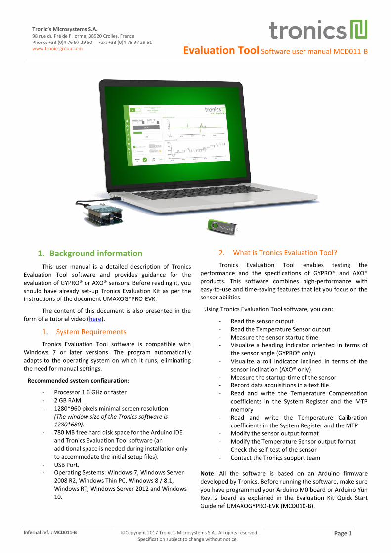
Evaluation Tool Software user manual MCD011-B
Infernal ref. : MCD011-B Copyright 2017 Tronic’s Microsystems S.A.. All rights reserved. Specification subject to change without notice.
Page 1
Tronic’s Microsystems S.A. 98 rue du Pré de l’Horme, 38920 Crolles, France Phone: +33 (0)4 76 97 29 50 Fax: +33 (0)4 76 97 29 51 www.tronicsgroup.com
1. Background information
This user manual is a detailed description of Tronics Evaluation Tool software and provides guidance for the evaluation of GYPRO® or AXO® sensors. Before reading it, you should have already set-up Tronics Evaluation Kit as per the instructions of the document UMAXOGYPRO-EVK.
The content of this document is also presented in the form of a tutorial video (here).
System Requirements
Tronics Evaluation Tool software is compatible with Windows 7 or later versions. The program automatically adapts to the operating system on which it runs, eliminating the need for manual settings.
Recommended system configuration:
- Processor 1.6 GHz or faster - 2 GB RAM - 1280*960 pixels minimal screen resolution
(The window size of the Tronics software is 1280*680).
- 780 MB free hard disk space for the Arduino IDE and Tronics Evaluation Tool software (an additional space is needed during installation only to accommodate the initial setup files).
- USB Port. - Operating Systems: Windows 7, Windows Server
2008 R2, Windows Thin PC, Windows 8 / 8.1, Windows RT, Windows Server 2012 and Windows 10.
What is Tronics Evaluation Tool?
Tronics Evaluation Tool enables testing the performance and the specifications of GYPRO® and AXO® products. This software combines high-performance with easy-to-use and time-saving features that let you focus on the sensor abilities.
Using Tronics Evaluation Tool software, you can:
- Read the sensor output - Read the Temperature Sensor output - Measure the sensor startup time - Visualize a heading indicator oriented in terms of
the sensor angle (GYPRO® only) - Visualize a roll indicator inclined in terms of the
sensor inclination (AXO® only) - Measure the startup-time of the sensor - Record data acquisitions in a text file - Read and write the Temperature Compensation
coefficients in the System Register and the MTP memory
- Read and write the Temperature Calibration coefficients in the System Register and the MTP
- Modify the sensor output format - Modify the Temperature Sensor output format - Check the self-test of the sensor - Contact the Tronics support team
Note: All the software is based on an Arduino firmware developed by Tronics. Before running the software, make sure you have programmed your Arduino M0 board or Arduino Yùn Rev. 2 board as explained in the Evaluation Kit Quick Start Guide ref UMAXOGYPRO-EVK (MCD010-B).
Evaluation Tool Software user manual MCD011-B
Page 2 Copyright 2017 Tronic’s Microsystems S.A.. All rights reserved. Specification subject to change without notice.
Infernal ref. : MCD011-B
Tronic’s Microsystems S.A. 98 rue du Pré de l’Horme, 38920 Crolles, France
Phone: +33 (0)4 76 97 29 50 Fax: +33 (0)4 76 97 29 51 www.tronicsgroup.com
2. Tronics Evaluation Tool software description
Introduction
The Tronics Evaluation Tool is made of 5 tabs:
Reading GYPRO® /AXO® (Main Tab): To read the sensor data (Angular rate / Linear Acceleration and Temperature) and to display them on two real-time charts.
System Register (SR): To enable reading, writing or changing the output format of the data (Raw, Compensated or Calibrated) by modifying the sensor System Register.
Multi-Time-Programmable (MTP): Useful to read and program new temperature compensation coefficients in the MTP of the sensor.
Others: To check Hardware and Logic Self-Test, to measure startup time, to read Drive Frequency and to generate debug reports for Tronics support team.
Compass / Plane: To display a real-time compass using GYPRO® or plane using AXO®.
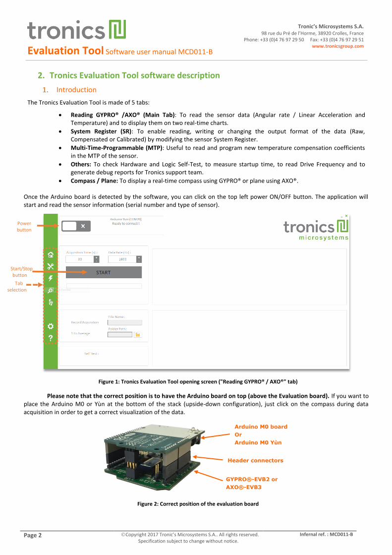
Once the Arduino board is detected by the software, you can click on the top left power ON/OFF button. The application will start and read the sensor information (serial number and type of sensor).
Figure 1: Tronics Evaluation Tool opening screen ("Reading GYPRO® / AXO®" tab)
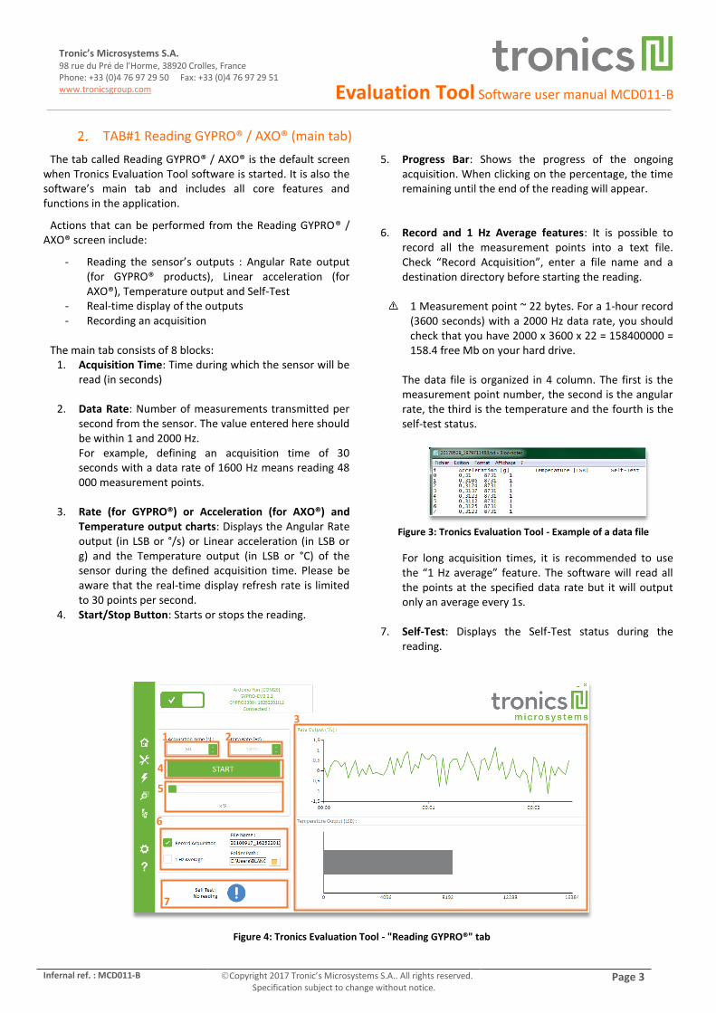
Please note that the correct position is to have the Arduino board on top (above the Evaluation board). If you want to place the Arduino M0 or Yùn at the bottom of the stack (upside-down configuration), just click on the compass during data acquisition in order to get a correct visualization of the data.
Figure 2: Correct position of the evaluation board
Arduino M0 board
Or
Arduino M0 Yùn
Header connectors
GYPRO®-EVB2 or
AXO®-EVB3
Power button
Start/Stop button
Tab selection
Evaluation Tool Software user manual MCD011-B
Infernal ref. : MCD011-B Copyright 2017 Tronic’s Microsystems S.A.. All rights reserved. Specification subject to change without notice.
Page 3
Tronic’s Microsystems S.A. 98 rue du Pré de l’Horme, 38920 Crolles, France Phone: +33 (0)4 76 97 29 50 Fax: +33 (0)4 76 97 29 51 www.tronicsgroup.com
TAB#1 Reading GYPRO® / AXO® (main tab)
The tab called Reading GYPRO® / AXO® is the default screen when Tronics Evaluation Tool software is started. It is also the software’s main tab and includes all core features and functions in the application.
Actions that can be performed from the Reading GYPRO® / AXO® screen include:
- Reading the sensor’s outputs : Angular Rate output (for GYPRO® products), Linear acceleration (for AXO®), Temperature output and Self-Test
- Real-time display of the outputs - Recording an acquisition
The main tab consists of 8 blocks:
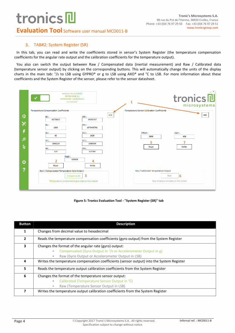
1. Acquisition Time: Time during which the sensor will be read (in seconds)
2. Data Rate: Number of measurements transmitted per second from the sensor. The value entered here should be within 1 and 2000 Hz. For example, defining an acquisition time of 30 seconds with a data rate of 1600 Hz means reading 48 000 measurement points.
3. Rate (for GYPRO®) or Acceleration (for AXO®) and Temperature output charts: Displays the Angular Rate output (in LSB or °/s) or Linear acceleration (in LSB or g) and the Temperature output (in LSB or °C) of the sensor during the defined acquisition time. Please be aware that the real-time display refresh rate is limited to 30 points per second.
4. Start/Stop Button: Starts or stops the reading.
5. Progress Bar: Shows the progress of the ongoing acquisition. When clicking on the percentage, the time remaining until the end of the reading will appear.
6. Record and 1 Hz Average features: It is possible to record all the measurement points into a text file. Check “Record Acquisition”, enter a file name and a destination directory before starting the reading.
1 Measurement point ~ 22 bytes. For a 1-hour record (3600 seconds) with a 2000 Hz data rate, you should check that you have 2000 x 3600 x 22 = 158400000 = 158.4 free Mb on your hard drive.
The data file is organized in 4 column. The first is the measurement point number, the second is the angular rate, the third is the temperature and the fourth is the self-test status.
Figure 3: Tronics Evaluation Tool - Example of a data file
For long acquisition times, it is recommended to use the “1 Hz average” feature. The software will read all the points at the specified data rate but it will output only an average every 1s.
7. Self-Test: Displays the Self-Test status during the reading.
Figure 4: Tronics Evaluation Tool - "Reading GYPRO®" tab
1 2
3
4
5
6
7
Evaluation Tool Software user manual MCD011-B
Page 4 Copyright 2017 Tronic’s Microsystems S.A.. All rights reserved. Specification subject to change without notice.
Infernal ref. : MCD011-B
Tronic’s Microsystems S.A. 98 rue du Pré de l’Horme, 38920 Crolles, France
Phone: +33 (0)4 76 97 29 50 Fax: +33 (0)4 76 97 29 51 www.tronicsgroup.com
TAB#2: System Register (SR)
In this tab, you can read and write the coefficients stored in sensor’s System Register (the temperature compensation coefficients for the angular rate output and the calibration coefficients for the temperature output).
You also can switch the output between Raw / Compensated data (inertial measurement) and Raw / Calibrated data (temperature sensor output) by clicking on the corresponding buttons. This will automatically change the units of the display charts in the main tab: °/s to LSB using GYPRO® or g to LSB using AXO® and °C to LSB. For more information about these coefficients and the System Register of the sensor, please refer to the sensor datasheet.
Figure 5: Tronics Evaluation Tool - "System Register (SR)" tab
Button Description
1 Changes from decimal value to hexadecimal
2 Reads the temperature compensation coefficients (gyro output) from the System Register
3 Changes the format of the angular rate (gyro) output:
- Compensated (Gyro Output in °/s or Accelerometer Output in g)
- Raw (Gyro Output or Accelerometer Output in LSB)
4 Writes the temperature compensation coefficients (sensor output) into the System Register
5 Reads the temperature output calibration coefficients from the System Register
6 Changes the format of the temperature sensor output:
- Calibrated (Temperature Sensor Output in °C)
- Raw (Temperature Sensor Output in LSB)
7 Writes the temperature output calibration coefficients from the System Register
1
2 4
3
5
6
7
Evaluation Tool Software user manual MCD011-B
Infernal ref. : MCD011-B Copyright 2017 Tronic’s Microsystems S.A.. All rights reserved. Specification subject to change without notice.
Page 5
Tronic’s Microsystems S.A. 98 rue du Pré de l’Horme, 38920 Crolles, France Phone: +33 (0)4 76 97 29 50 Fax: +33 (0)4 76 97 29 51 www.tronicsgroup.com
TAB#3: Multi-Time-Programmable (MTP)
In this tab you can program the coefficients in the sensor’s Multi Time Programmable memory (MTP).
Programming is irreversible. The temperature compensation coefficients for the angular rate output can be programmed up to 5 or 7 additional times. The temperature sensor calibration coefficients however can be programmed only one time. For more information on the sensor’s MTP, please refer to the sensor product datasheet.
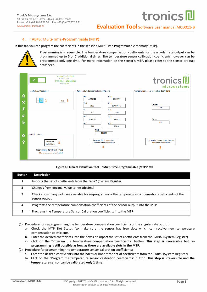
Figure 6 : Tronics Evaluation Tool – “Multi-Time-Programmable (MTP)” tab
Button Description
1 Imports the set of coefficients from the Tab#2 (System Register)
2 Changes from decimal value to hexadecimal
3 Checks how many slots are available for re-programming the temperature compensation coefficients of the sensor output
4 Programs the temperature compensation coefficients of the sensor output into the MTP
5 Programs the Temperature Sensor Calibration coefficients into the MTP
(1) Procedure for re-programming the temperature compensation coefficients of the angular rate output: a- Check the MTP Slot Status (to make sure the sensor has free slots which can receive new temperature
compensation coefficients) b- Enter the desired coefficients into the boxes or import the set of coefficients from the TAB#2 (System Register) c- Click on the “Program the temperature compensation coefficients” button. This step is irreversible but re-
programming is still possible as long as there are available slots in the MTP. (2) Procedure for programming the temperature sensor calibration coefficients:
a- Enter the desired coefficients into the boxes or import the set of coefficients from the TAB#2 (System Register) b- Click on the “Program the temperature sensor calibration coefficients” button. This step is irreversible and the
temperature sensor can be calibrated only 1 time.
1 2
3 4 5

Evaluation Tool Software user manual MCD011-B
Page 6 Copyright 2017 Tronic’s Microsystems S.A.. All rights reserved. Specification subject to change without notice.
Infernal ref. : MCD011-B
Tronic’s Microsystems S.A. 98 rue du Pré de l’Horme, 38920 Crolles, France
Phone: +33 (0)4 76 97 29 50 Fax: +33 (0)4 76 97 29 51 www.tronicsgroup.com
TAB#4: Others
This tab includes several features such as checking self-test status, measuring the startup time, reading the drive frequency of the sensor and generating automatic debug reports to be sent to Tronics support team.
(1) Self-test : There are two ways to check the self-test status of the sensor: a- A dedicated pin (‘Hardware Self-Test’) b- A dedicated bit in the SPI register (‘Logic Self-
Test’) Here you can request the status of the Self-Test and get
results from the 2 methods.
(2) Startup-Time: You can measure the startup time of
the sensor by clicking on the “Start” button.
(3) Support: In case you encounter any issue during the evaluation of the sensor, you can generate here debug reports which will be useful for Tronics support team to understand the problem.
First, you need to enter your name and company information, as well as a short description of the problem.
Then click on the “Support” button to generate the debug reports and make sure you don’t touch the Evaluation Kit or disconnect the USB cable while the procedure is ongoing.
The procedure will generate 3 text files into a folder called ‘Support’ at the same location as the software .exe.
- XX_SupportSensorInfo.txt contains information about the sensor (Serial Number, Drive Frequency…), and the computer (OS and Environment).
- XXX_SupportRead.txt is a 30-seconds data acquisition of the sensor output. The sensor should be at rest during this acquisition.
- XXX_SupportSystemRegister.txt is a copy of the complete System Register of the sensor.
Once the procedure is finished, you need to send these 3 files by e-mail at [email protected]
Figure 7: Tronics Evaluation Tool - "Others" tab
Button Description
1 Checks the two self-test status:
Hardware : Voltage Level on TMUX3 pin
Logic : Bit 0, address 0x3 of the SPI Register
2 Measure the sensor startup-time
3 Generates 3 debug files
2
1
3
Evaluation Tool Software user manual MCD011-B
Infernal ref. : MCD011-B Copyright 2017 Tronic’s Microsystems S.A.. All rights reserved. Specification subject to change without notice.
Page 7
Tronic’s Microsystems S.A. 98 rue du Pré de l’Horme, 38920 Crolles, France Phone: +33 (0)4 76 97 29 50 Fax: +33 (0)4 76 97 29 51 www.tronicsgroup.com
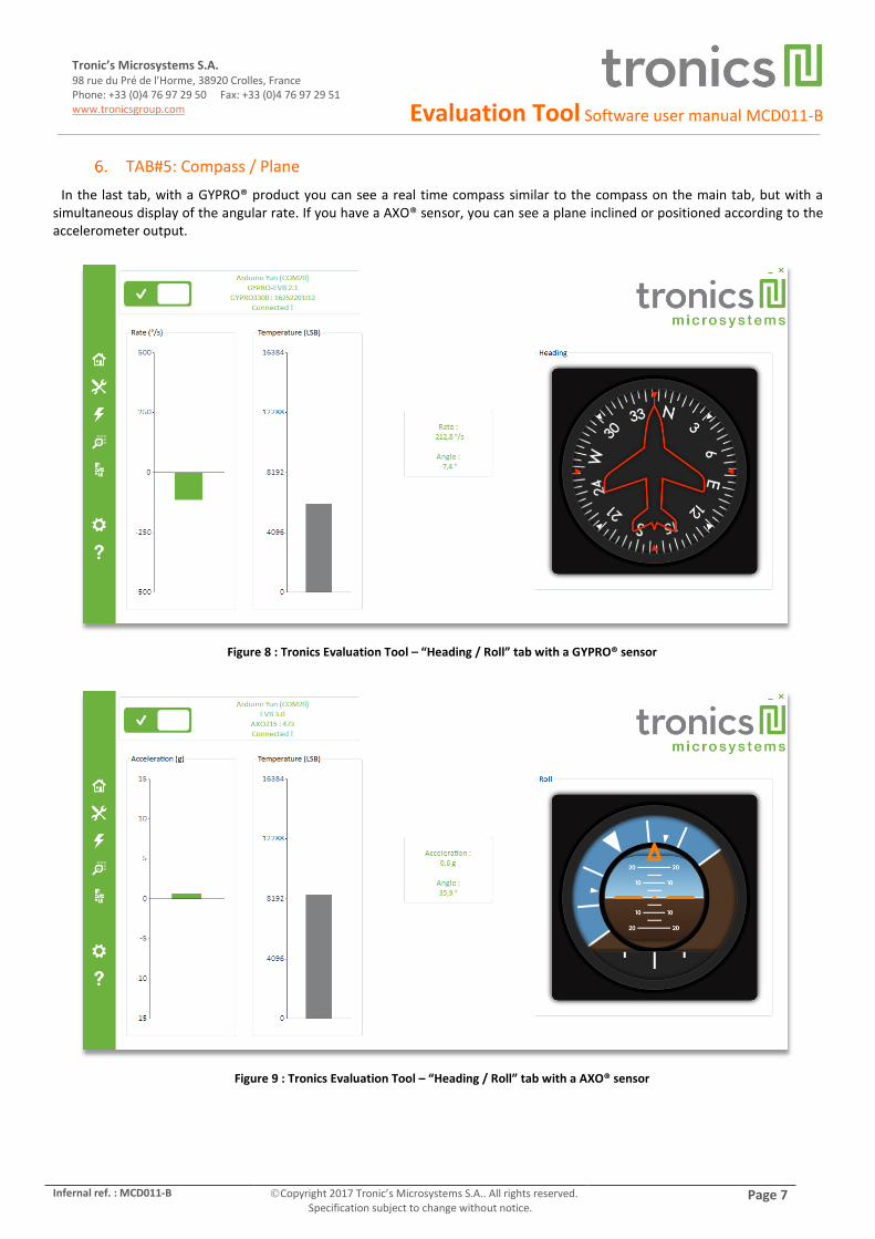
TAB#5: Compass / Plane
In the last tab, with a GYPRO® product you can see a real time compass similar to the compass on the main tab, but with a simultaneous display of the angular rate. If you have a AXO® sensor, you can see a plane inclined or positioned according to the accelerometer output.
Figure 8 : Tronics Evaluation Tool – “Heading / Roll” tab with a GYPRO® sensor
Figure 9 : Tronics Evaluation Tool – “Heading / Roll” tab with a AXO® sensor

Evaluation Tool Software user manual MCD011-B
Page 8 Copyright 2017 Tronic’s Microsystems S.A.. All rights reserved. Specification subject to change without notice.
Infernal ref. : MCD011-B
Tronic’s Microsystems S.A. 98 rue du Pré de l’Horme, 38920 Crolles, France
Phone: +33 (0)4 76 97 29 50 Fax: +33 (0)4 76 97 29 51 www.tronicsgroup.com
Settings and About Evalution Tool
On the settings tab, you have three parameters if you want change something during the software use:
- Reading Display: You can deactivate charts display of the “Reading GYPRO®” tab to optimize computer performance.
- Roll / Heading: You can disable the “auto-calibration” of the Roll / Heading display. By default, at the beginning of the Roll / Heading utilization, an auto-calibration is done. This calibration calculates the initial bias offset, and remove it during the sensor reading.
- Manual Connection: This parameter can be use if you have multiple devices connected to the computer, or you want to use the RS422 connection (in this case, please refer to MCD012-B Technical note).
Figure 10: Tronics Evaluation Tool – “Settings” tab
If you click on “About Tronics Evaluation Tool”, a pop-up will appear with information on the software version:
Figure 11: Tronics Evaluation Tool – About Tronics Evaluation Tool window

Evaluation Tool Software user manual MCD011-B
Infernal ref. : MCD011-B Copyright 2017 Tronic’s Microsystems S.A.. All rights reserved. Specification subject to change without notice.
Page 9
Tronic’s Microsystems S.A. 98 rue du Pré de l’Horme, 38920 Crolles, France Phone: +33 (0)4 76 97 29 50 Fax: +33 (0)4 76 97 29 51 www.tronicsgroup.com
3. For further details
You are now ready to use Evaluation Kit and Tronics Evaluation Tool software.
Please note that the latest versions of all documents related to GYPRO® or AXO® sensors and evaluation kit can be downloaded from Tronics website: sensor datasheets, evaluation kit user manuals, software, etc.
Should you encounter any issue while using GYPRO® or AXO® Evaluation Kit, please contact Tronics technical support by sending an email to [email protected].
Evaluation Tool Software user manual MCD011-B
Page 10 Copyright 2017 Tronic’s Microsystems S.A.. All rights reserved. Specification subject to change without notice.
Infernal ref. : MCD011-B
Tronic’s Microsystems S.A. 98 rue du Pré de l’Horme, 38920 Crolles, France
Phone: +33 (0)4 76 97 29 50 Fax: +33 (0)4 76 97 29 51 www.tronicsgroup.com
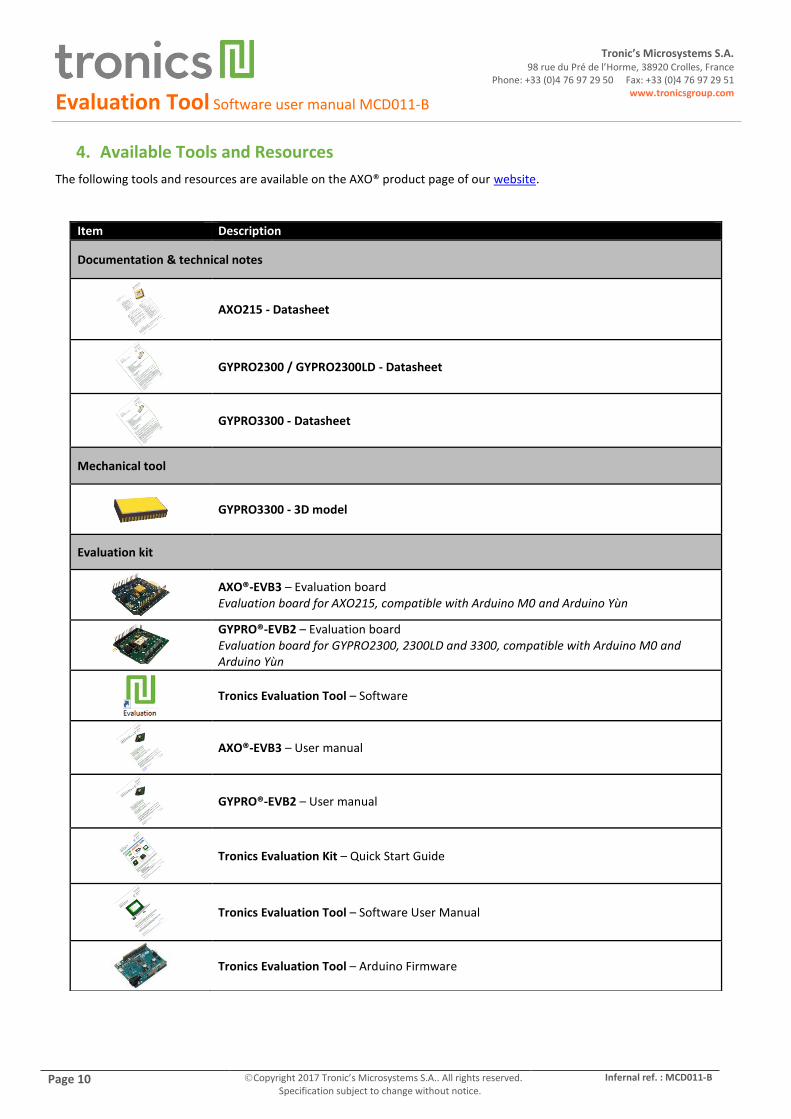
4. Available Tools and Resources
The following tools and resources are available on the AXO® product page of our website.
Item Description
Documentation & technical notes
AXO215 - Datasheet
GYPRO2300 / GYPRO2300LD - Datasheet
GYPRO3300 - Datasheet
Mechanical tool
GYPRO3300 - 3D model
Evaluation kit
AXO®-EVB3 – Evaluation board Evaluation board for AXO215, compatible with Arduino M0 and Arduino Yùn
GYPRO®-EVB2 – Evaluation board Evaluation board for GYPRO2300, 2300LD and 3300, compatible with Arduino M0 and Arduino Yùn
Tronics Evaluation Tool – Software
AXO®-EVB3 – User manual
GYPRO®-EVB2 – User manual
Tronics Evaluation Kit – Quick Start Guide
Tronics Evaluation Tool – Software User Manual
Tronics Evaluation Tool – Arduino Firmware