Embed Size (px)
Citation preview
IEEE Robotics & Automation Magazine122 1070-9932/08/$25.00ª2008 IEEE JUNE 2008
Surgical andInterventional Robotics
Core Concepts, Technology, and Design
BY PETER KAZANZIDES, GABOR FICHTINGER, GREGORY D. HAGER,
ALLISON M. OKAMURA, LOUIS L. WHITCOMB, AND RUSSELL H. TAYLOR
Two decades after the first reported robotic surgicalprocedure [1], surgical robots are just beginning tobe widely used in the operating room or interven-tional suite. The da Vinci telerobotic system (Intui-tive Surgical, Inc.), for example, has recently become
more widely employed for minimally invasive surgery [2]. Thisarticle, the first in a three-part series, examines the core conceptsunderlying surgical and interventional robots, including thepotential benefits and technical approaches, followed by asummary of the technical challenges in sensing, manipulation,user interfaces, and system design. The article concludes with areview of key design aspects, particularly in the areas of risk anal-ysis and safety design. Note that medical care can be delivered ina surgical suite (operating room) or an interventional suite, butfor convenience, we will henceforth use the term surgical to referto both the surgical and interventional domains.
Core ConceptsThis section describes some of the potential benefits of surgicalrobots, followed by an overview of the two technical para-digms, surgical computer-aided design and computer-aidedmanufacturing (CAD/CAM) and surgical assistance, whichwill be the subjects of the second and third articles in this series.
Potential BenefitsThe development of surgical robots is motivated primarily by thedesire to enhance the effectiveness of a procedure by couplinginformation to action in the operating room or interventionalsuite. This is in contrast to industrial robots, which were
developed primarily to automate dirty, dull, and dangerous tasks.There is an obvious reason for this dichotomy: medical carerequires human judgment and reasoning to handle the varietyand complexity of human anatomy and disease processes. Medi-cal actions are chosen based on information from a number ofsources, including patient-specific data (e.g., vital signs andimages), general medical knowledge (e.g., atlases of human anat-omy), and physician experience. Computer-assisted interven-tional systems can gather and present information to thephysician in a more meaningful way and, via the use of robots,enable this information to influence the performance of an inter-vention, thereby potentially improving the consistency and qual-ity of the clinical result. It is, therefore, not surprising that surgicalrobots were introduced in the 1980s, after the dawn of the infor-mation age, whereas the first industrial robot was used in 1961.
There are, however, cases where surgical robots sharepotential benefits with industrial robots and teleoperators.First, a robot can usually perform a task more accurately than ahuman; this provides the primary motivation for surgicalCAD/CAM systems, which are described later in the ‘‘Surgi-cal CAD/CAM’’ section. Second, industrial robots and teleop-erators can work in areas that are not human friendly (e.g.,toxic fumes, radioactivity, or low-oxygen environments) ornot easily accessible to humans (e.g., inside pipes, the surfaceof a distant planet, or the sea floor). In the medical domain,inhospitable environments include radiation (e.g., X-rays) andinaccessible environments include space-constrained areassuch as the inside of a patient or imaging system. This alsomotivates the development of surgical CAD/CAM systemsand is one of the primary motivations for surgical assistant sys-tems, described in the ‘‘Surgical Assistance’’ section.Digital Object Identifier 10.1109/MRA.2008.926390
© EYEWIRE
In contrast to industrial robots, surgical robots are rarelydesigned to replace a member of the surgical or interventionalteam. Rather, they are intended to augment the medical staffby imparting superhuman capabilities, such as high motionaccuracy, or to enable interventions that would otherwise bephysically impossible. Therefore, methods for effectivehuman-robot cooperation are one of the unique and centralaspects of medical robotics.
Technical ParadigmsIn our research, we find it useful to categorize surgical robotsas surgical CAD/CAM or surgical assistance systems, based ontheir primary mode of operation [3]. Note, however, thatthese categories are not mutually exclusive and some surgicalrobots may exhibit characteristics from both categories. Thefollowing sections briefly describe these categories, withrepresentative examples.
Surgical CAD/CAM
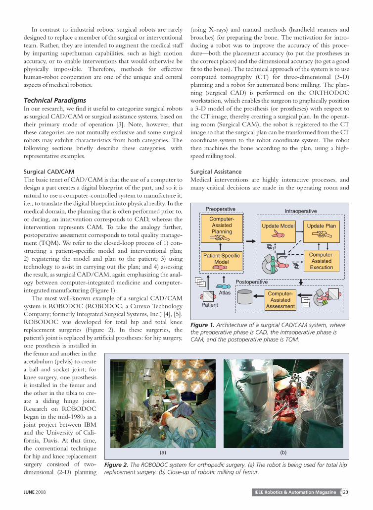
The basic tenet of CAD/CAM is that the use of a computer todesign a part creates a digital blueprint of the part, and so it isnatural to use a computer-controlled system to manufacture it,i.e., to translate the digital blueprint into physical reality. In themedical domain, the planning that is often performed prior to,or during, an intervention corresponds to CAD, whereas theintervention represents CAM. To take the analogy further,postoperative assessment corresponds to total quality manage-ment (TQM). We refer to the closed-loop process of 1) con-structing a patient-specific model and interventional plan;2) registering the model and plan to the patient; 3) usingtechnology to assist in carrying out the plan; and 4) assessingthe result, as surgical CAD/CAM, again emphasizing the anal-ogy between computer-integrated medicine and computer-integrated manufacturing (Figure 1).
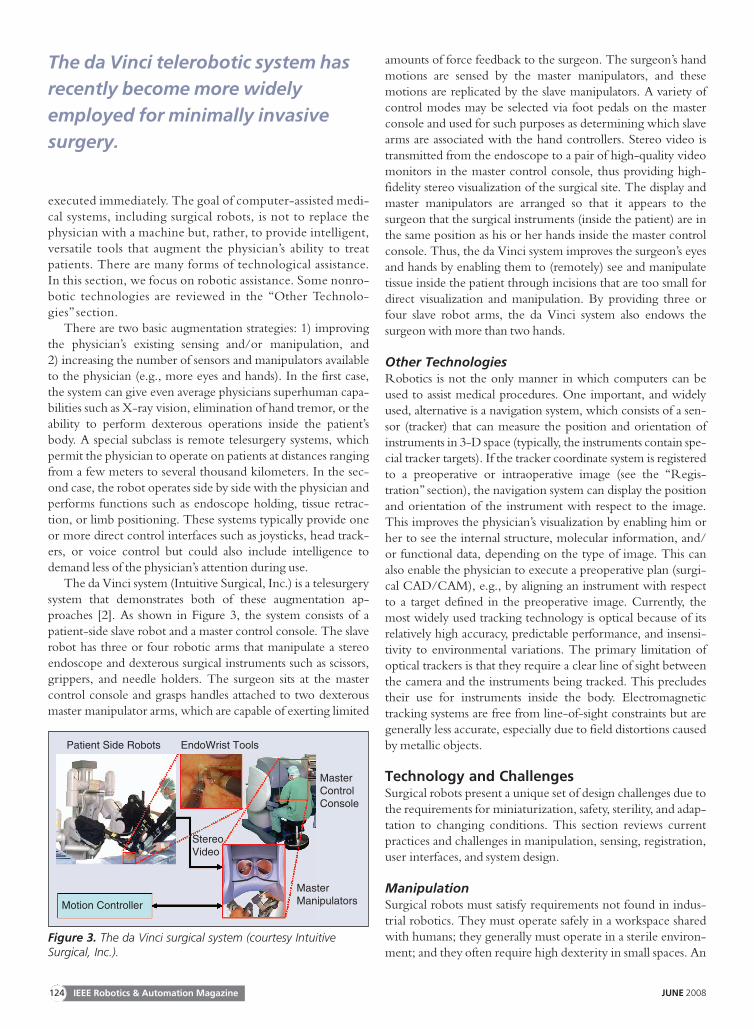
The most well-known example of a surgical CAD/CAMsystem is ROBODOC (ROBODOC, a Curexo TechnologyCompany; formerly Integrated Surgical Systems, Inc.) [4], [5].ROBODOC was developed for total hip and total kneereplacement surgeries (Figure 2). In these surgeries, thepatient’s joint is replaced by artificial prostheses: for hip surgery,one prosthesis is installed inthe femur and another in theacetabulum (pelvis) to createa ball and socket joint; forknee surgery, one prosthesisis installed in the femur andthe other in the tibia to cre-ate a sliding hinge joint.Research on ROBODOCbegan in the mid-1980s as ajoint project between IBMand the University of Cali-fornia, Davis. At that time,the conventional techniquefor hip and knee replacementsurgery consisted of two-dimensional (2-D) planning
(using X-rays) and manual methods (handheld reamers andbroaches) for preparing the bone. The motivation for intro-ducing a robot was to improve the accuracy of this proce-dure—both the placement accuracy (to put the prostheses inthe correct places) and the dimensional accuracy (to get a goodfit to the bones). The technical approach of the system is to usecomputed tomography (CT) for three-dimensional (3-D)planning and a robot for automated bone milling. The plan-ning (surgical CAD) is performed on the ORTHODOCworkstation, which enables the surgeon to graphically positiona 3-D model of the prosthesis (or prostheses) with respect tothe CT image, thereby creating a surgical plan. In the operat-ing room (Surgical CAM), the robot is registered to the CTimage so that the surgical plan can be transformed from the CTcoordinate system to the robot coordinate system. The robotthen machines the bone according to the plan, using a high-speed milling tool.
Surgical Assistance
Medical interventions are highly interactive processes, andmany critical decisions are made in the operating room and
Computer-AssistedPlanning
Patient-SpecificModel
Update Model
Computer-Assisted
Execution
Update Plan
Computer-Assisted
Assessment
Preoperative Intraoperative
Atlas
Postoperative
Patient
Figure 1. Architecture of a surgical CAD/CAM system, wherethe preoperative phase is CAD, the intraoperative phase isCAM, and the postoperative phase is TQM.
(a) (b)
Figure 2. The ROBODOC system for orthopedic surgery. (a) The robot is being used for total hipreplacement surgery. (b) Close-up of robotic milling of femur.
IEEE Robotics & Automation MagazineJUNE 2008 123
executed immediately. The goal of computer-assisted medi-cal systems, including surgical robots, is not to replace thephysician with a machine but, rather, to provide intelligent,versatile tools that augment the physician’s ability to treatpatients. There are many forms of technological assistance.In this section, we focus on robotic assistance. Some nonro-botic technologies are reviewed in the ‘‘Other Technolo-gies’’ section.
There are two basic augmentation strategies: 1) improvingthe physician’s existing sensing and/or manipulation, and2) increasing the number of sensors and manipulators availableto the physician (e.g., more eyes and hands). In the first case,the system can give even average physicians superhuman capa-bilities such as X-ray vision, elimination of hand tremor, or theability to perform dexterous operations inside the patient’sbody. A special subclass is remote telesurgery systems, whichpermit the physician to operate on patients at distances rangingfrom a few meters to several thousand kilometers. In the sec-ond case, the robot operates side by side with the physician andperforms functions such as endoscope holding, tissue retrac-tion, or limb positioning. These systems typically provide oneor more direct control interfaces such as joysticks, head track-ers, or voice control but could also include intelligence todemand less of the physician’s attention during use.
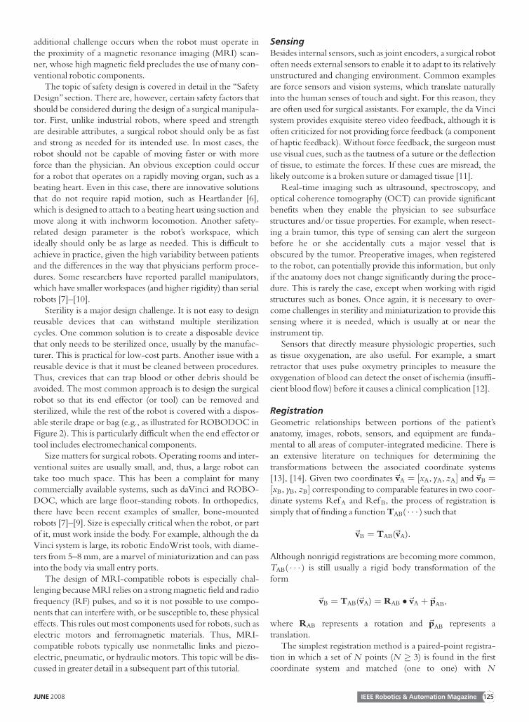
The da Vinci system (Intuitive Surgical, Inc.) is a telesurgerysystem that demonstrates both of these augmentation ap-proaches [2]. As shown in Figure 3, the system consists of apatient-side slave robot and a master control console. The slaverobot has three or four robotic arms that manipulate a stereoendoscope and dexterous surgical instruments such as scissors,grippers, and needle holders. The surgeon sits at the mastercontrol console and grasps handles attached to two dexterousmaster manipulator arms, which are capable of exerting limited
amounts of force feedback to the surgeon. The surgeon’s handmotions are sensed by the master manipulators, and thesemotions are replicated by the slave manipulators. A variety ofcontrol modes may be selected via foot pedals on the masterconsole and used for such purposes as determining which slavearms are associated with the hand controllers. Stereo video istransmitted from the endoscope to a pair of high-quality videomonitors in the master control console, thus providing high-fidelity stereo visualization of the surgical site. The display andmaster manipulators are arranged so that it appears to thesurgeon that the surgical instruments (inside the patient) are inthe same position as his or her hands inside the master controlconsole. Thus, the da Vinci system improves the surgeon’s eyesand hands by enabling them to (remotely) see and manipulatetissue inside the patient through incisions that are too small fordirect visualization and manipulation. By providing three orfour slave robot arms, the da Vinci system also endows thesurgeon with more than two hands.
Other TechnologiesRobotics is not the only manner in which computers can beused to assist medical procedures. One important, and widelyused, alternative is a navigation system, which consists of a sen-sor (tracker) that can measure the position and orientation ofinstruments in 3-D space (typically, the instruments contain spe-cial tracker targets). If the tracker coordinate system is registeredto a preoperative or intraoperative image (see the ‘‘Regis-tration’’ section), the navigation system can display the positionand orientation of the instrument with respect to the image.This improves the physician’s visualization by enabling him orher to see the internal structure, molecular information, and/or functional data, depending on the type of image. This canalso enable the physician to execute a preoperative plan (surgi-cal CAD/CAM), e.g., by aligning an instrument with respectto a target defined in the preoperative image. Currently, themost widely used tracking technology is optical because of itsrelatively high accuracy, predictable performance, and insensi-tivity to environmental variations. The primary limitation ofoptical trackers is that they require a clear line of sight betweenthe camera and the instruments being tracked. This precludestheir use for instruments inside the body. Electromagnetictracking systems are free from line-of-sight constraints but aregenerally less accurate, especially due to field distortions causedby metallic objects.
Technology and ChallengesSurgical robots present a unique set of design challenges due tothe requirements for miniaturization, safety, sterility, and adap-tation to changing conditions. This section reviews currentpractices and challenges in manipulation, sensing, registration,user interfaces, and system design.
ManipulationSurgical robots must satisfy requirements not found in indus-trial robotics. They must operate safely in a workspace sharedwith humans; they generally must operate in a sterile environ-ment; and they often require high dexterity in small spaces. An
MasterControlConsole
MasterManipulators
EndoWrist Tools
StereoVideo
Motion Controller
Patient Side Robots
Figure 3. The da Vinci surgical system (courtesy IntuitiveSurgical, Inc.).
The da Vinci telerobotic system has
recently become more widely
employed for minimally invasive
surgery.
IEEE Robotics & Automation Magazine124 JUNE 2008
additional challenge occurs when the robot must operate inthe proximity of a magnetic resonance imaging (MRI) scan-ner, whose high magnetic field precludes the use of many con-ventional robotic components.
The topic of safety design is covered in detail in the ‘‘SafetyDesign’’ section. There are, however, certain safety factors thatshould be considered during the design of a surgical manipula-tor. First, unlike industrial robots, where speed and strengthare desirable attributes, a surgical robot should only be as fastand strong as needed for its intended use. In most cases, therobot should not be capable of moving faster or with moreforce than the physician. An obvious exception could occurfor a robot that operates on a rapidly moving organ, such as abeating heart. Even in this case, there are innovative solutionsthat do not require rapid motion, such as Heartlander [6],which is designed to attach to a beating heart using suction andmove along it with inchworm locomotion. Another safety-related design parameter is the robot’s workspace, whichideally should only be as large as needed. This is difficult toachieve in practice, given the high variability between patientsand the differences in the way that physicians perform proce-dures. Some researchers have reported parallel manipulators,which have smaller workspaces (and higher rigidity) than serialrobots [7]–[10].
Sterility is a major design challenge. It is not easy to designreusable devices that can withstand multiple sterilizationcycles. One common solution is to create a disposable devicethat only needs to be sterilized once, usually by the manufac-turer. This is practical for low-cost parts. Another issue with areusable device is that it must be cleaned between procedures.Thus, crevices that can trap blood or other debris should beavoided. The most common approach is to design the surgicalrobot so that its end effector (or tool) can be removed andsterilized, while the rest of the robot is covered with a dispos-able sterile drape or bag (e.g., as illustrated for ROBODOC inFigure 2). This is particularly difficult when the end effector ortool includes electromechanical components.
Size matters for surgical robots. Operating rooms and inter-ventional suites are usually small, and, thus, a large robot cantake too much space. This has been a complaint for manycommercially available systems, such as daVinci and ROBO-DOC, which are large floor-standing robots. In orthopedics,there have been recent examples of smaller, bone-mountedrobots [7]–[9]. Size is especially critical when the robot, or partof it, must work inside the body. For example, although the daVinci system is large, its robotic EndoWrist tools, with diame-ters from 5–8 mm, are a marvel of miniaturization and can passinto the body via small entry ports.
The design of MRI-compatible robots is especially chal-lenging because MRI relies on a strong magnetic field and radiofrequency (RF) pulses, and so it is not possible to use compo-nents that can interfere with, or be susceptible to, these physicaleffects. This rules out most components used for robots, such aselectric motors and ferromagnetic materials. Thus, MRI-compatible robots typically use nonmetallic links and piezo-electric, pneumatic, or hydraulic motors. This topic will be dis-cussed in greater detail in a subsequent part of this tutorial.
SensingBesides internal sensors, such as joint encoders, a surgical robotoften needs external sensors to enable it to adapt to its relativelyunstructured and changing environment. Common examplesare force sensors and vision systems, which translate naturallyinto the human senses of touch and sight. For this reason, theyare often used for surgical assistants. For example, the da Vincisystem provides exquisite stereo video feedback, although it isoften criticized for not providing force feedback (a componentof haptic feedback). Without force feedback, the surgeon mustuse visual cues, such as the tautness of a suture or the deflectionof tissue, to estimate the forces. If these cues are misread, thelikely outcome is a broken suture or damaged tissue [11].
Real-time imaging such as ultrasound, spectroscopy, andoptical coherence tomography (OCT) can provide significantbenefits when they enable the physician to see subsurfacestructures and/or tissue properties. For example, when resect-ing a brain tumor, this type of sensing can alert the surgeonbefore he or she accidentally cuts a major vessel that isobscured by the tumor. Preoperative images, when registeredto the robot, can potentially provide this information, but onlyif the anatomy does not change significantly during the proce-dure. This is rarely the case, except when working with rigidstructures such as bones. Once again, it is necessary to over-come challenges in sterility and miniaturization to provide thissensing where it is needed, which is usually at or near theinstrument tip.
Sensors that directly measure physiologic properties, suchas tissue oxygenation, are also useful. For example, a smartretractor that uses pulse oxymetry principles to measure theoxygenation of blood can detect the onset of ischemia (insuffi-cient blood flow) before it causes a clinical complication [12].
RegistrationGeometric relationships between portions of the patient’sanatomy, images, robots, sensors, and equipment are funda-mental to all areas of computer-integrated medicine. There isan extensive literature on techniques for determining thetransformations between the associated coordinate systems[13], [14]. Given two coordinates~vA ¼ ½xA, yA, zA� and~vB ¼½xB, yB, zB� corresponding to comparable features in two coor-dinate systems Ref A and Ref B, the process of registration issimply that of finding a function TAB( � � � ) such that
~vB ¼ TAB(~vA):
Although nonrigid registrations are becoming more common,TAB( � � � ) is still usually a rigid body transformation of theform
~vB ¼ TAB(~vA) ¼ RAB �~vA þ~pAB,
where RAB represents a rotation and ~pAB represents atranslation.
The simplest registration method is a paired-point registra-tion in which a set of N points (N � 3) is found in the firstcoordinate system and matched (one to one) with N
IEEE Robotics & Automation MagazineJUNE 2008 125
corresponding points in the second coordinate system. Theproblem of finding the transformation that best aligns the twosets of points is often called the Procrustes problem, and thereare well-known solutions based on quaternions [15] and rota-tion matrices [16], [17]. This method works best when it ispossible to identify distinct points in the image and on thepatient. This is usually straightforward when artificial fiducialsare used. For example, ROBODOC initially used a fiducial-based registration method, with three metal pins (screws)inserted into the bone prior to the CT scan. It was easy tolocate the pins in the CT image, via image processing, due tothe high contrast between metal and bone. Similarly, it wasstraightforward for the surgeon to guide the robot’s measure-ment probe to physically contact each of the pins.
Point-to-surface registration methods can be employedwhen paired-point registration is not feasible. Typically, thisinvolves matching a cloud of points that is collected intraoper-atively to a 3-D surface model that is constructed from the pre-operative image. The most widely used method is iterativeclosest point (ICP) [18]. Briefly, ICP starts with an initial guessof the transformation, which is used to transform the points tothe same coordinate system as the surface model. The closestpoints on the surface model are identified and a paired-pointregistration method is used to compute a new estimate of thetransformation. The process is repeated with the new transfor-mation until a termination condition is reached. AlthoughICP often works well, it is sensitive to the initial guess and canfail to find the best solution if the guess is poor. Several ICPvariations have been proposed to improve its robustness in thiscase, and other techniques, such as an unscented Kalman filter[19], have recently been proposed. These methods can also beused for surface-to-surface registration by sampling one of thesurfaces.
Nonrigid (elastic or deformable) registration is often neces-sary because many parts of the anatomy (e.g., soft tissue andorgans) change shape during the procedure. This is more diffi-cult than rigid registration and remains an active area ofresearch. To date, most surgical CAD/CAM systems havebeen applied to areas such as orthopedics, where deformationsare small and rigid registration methods can be employed.
User Interfaces and VisualizationStandard computer input devices, such as keyboards and mice,are generally inappropriate for surgical or interventional envi-ronments because it is difficult to use them in conjunctionwith other medical instrumentation and maintain sterility.Foot pedals are often used because they do not interfere withwhatever the physician is doing with his or her hands, and they
do not require sterilization. Handheld pendants (button boxes)are also used; in this case, the pendant is either sterilized orcovered by a sterile drape. It is important to note, however,that the robot itself can often provide a significant part of theuser interface. For example, the da Vinci system relies on thetwo master manipulators (one for each hand), with foot pedalsto change modes. The ROBODOC system not only includesa five-button pendant to navigate menus but also uses a force-control (hand guiding) mode that enables the surgeon to man-ually move the robot.
Computer output is traditionally provided by graphical dis-plays. Fortunately, these can be located outside the sterile field.Unfortunately, the ergonomics are often poor because thephysician must look away from the operative site (where his orher hands are manipulating the instruments) to see thecomputer display. Some proposed solutions include heads-updisplays, image overlay systems [20], [21], and lasers, whichproject information onto the operative field [22].
Surgical Robot System DesignA surgical robot includes many components, and it is difficultto design one from scratch. There is no off-the-shelf surgicalrobot for research, and it is unlikely that one robot or family ofrobots will ever satisfy the requirements of the diaspora ofmedical procedures. In the software realm, however, there areopen source software packages that can help. The most maturepackages are for medical image visualization and processing,particularly the Visualization Toolkit (VTK, www.vtk.org)and the Insight Toolkit (ITK, www.itk.org). Customizableapplications, such as 3-D Slicer (www.slicer.org), packageVTK, ITK, and a plethora of research modules.
Few packages exist for computer-assisted interventions.The Image Guided Surgery Toolkit (IGSTK, www.igstk.org)enables researchers to create a navigation system by connectinga tracking system to a computer. At Johns Hopkins University,we are creating a software framework for a surgical assistantworkstation (SAW), based on our Computer-IntegratedSurgical Systems and Technology (CISST) libraries [23](www.cisst.org), which focus on the integration of robot con-trol and real-time sensing with the image processing and visu-alization toolkits described previously.
Surgical Robot Design ProcessThis section presents a detailed discussion of the risk analysis,safety design, and validation phases of the design process.Although these topics are not unique to surgical robots, theyare obviously of extreme importance.
Risk AnalysisSafety is an important consideration for both industrial andsurgical robots [24]. In an industrial setting, safety can often beachieved by keeping people out of the robot’s workspace or byshutting down the system if a person comes too close. In con-trast, for surgical robots it is generally necessary for humanbeings, including the patient and the medical staff, to be insidethe robot’s workspace. Furthermore, the robot may be holdinga potentially dangerous device, such as a cutting instrument,
The development of surgical robots
is motivated primarily by the desire
to enhance the effectiveness
of a procedure.
IEEE Robotics & Automation Magazine126 JUNE 2008
that is supposed to actually contact the patient (in the correctplace, of course). If the patient is anesthetized, it is not possiblefor him or her to actively avoid injury.
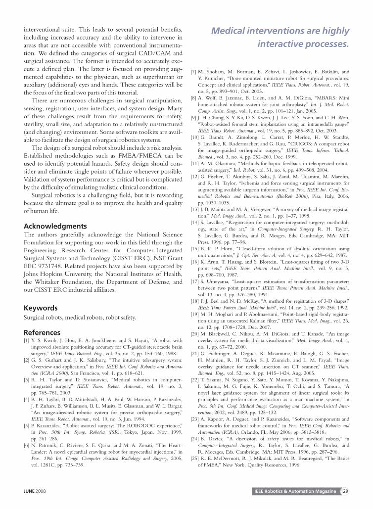
Proper safety design begins with a risk (or hazard) analysis.A failure modes effects analysis (FMEA) or failure modeseffects and criticality analysis (FMECA) are the most commonmethods [25]. These are bottom-up analyses, where potentialcomponent failures are identified and traced to determine theireffect on the system. Methods of control are devised to miti-gate the hazards associated with these failures. The informationis generally presented in a tabular format (see Table 1). TheFMECA adds the criticality assessment, which consists of threenumerical parameters: the severity (S), occurrence (O), anddetectability (D) of the failure. A risk priority number (RPN)is computed from the product of these parameters, whichdetermines whether additional methods of control arerequired. The FMEA/FMECA is a proactive analysis thatshould begin early in the design phase and evolve as hazards areidentified and methods of control are developed. Anotherpopular method is a fault tree analysis (FTA), which is a top-down analysis and is generally more appropriate for analyzing asystem failure after the fact.
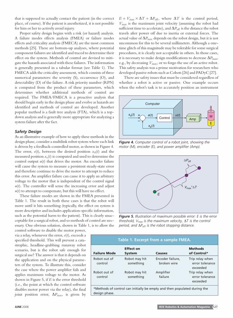
Safety DesignAs an illustrative example of how to apply these methods in thedesign phase, consider a multilink robot system where each linkis driven by a feedback-controlled motor, as shown in Figure 4.The error, e(t), between the desired position xd(t) and themeasured position xa(t) is computed and used to determine thecontrol output u(t) that drives the motor. An encoder failurewill cause the system to measure a persistent steady-state errorand therefore continue to drive the motor to attempt to reducethis error. An amplifier failure can cause it to apply an arbitraryvoltage to the motor that is independent of the control signalu(t). The controller will sense the increasing error and adjustu(t) to attempt to compensate, but this will have no effect.
These failure modes are shown in the FMEA presented inTable 1. The result in both these cases is that the robot willmove until it hits something (typically, the effect on system ismore descriptive and includes application-specific information,such as the potential harm to the patient). This is clearly unac-ceptable for a surgical robot, and so methods of control are nec-essary. One obvious solution, shown in Table 1, is to allow thecontrol software to disable the motor power,via a relay, whenever the error, e(t), exceeds aspecified threshold. This will prevent a cata-strophic, headline-grabbing runaway robotscenario, but is the robot safe enough forsurgical use? The answer is that it depends onthe application and on the physical parame-ters of the system. To illustrate this, considerthe case where the power amplifier fails andapplies maximum voltage to the motor. Asshown in Figure 5, if E is the error threshold(i.e., the point at which the control softwaredisables motor power via the relay), the finaljoint position error, DPmax, is given by
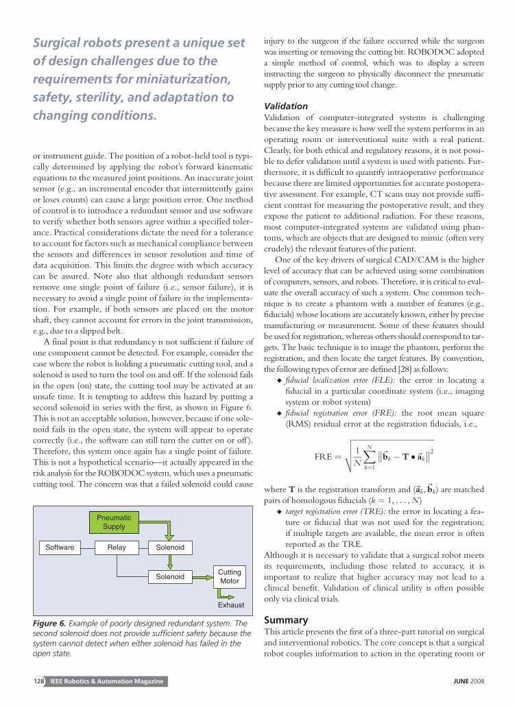
E þ Vmax 3 DT þ DPoff , where DT is the control period,Vmax is the maximum joint velocity (assuming the robot hadsufficient time to accelerate), and DPoff is the distance the robottravels after power off due to inertia or external forces. Theactual value of DPmax depends on the robot design, but it is notuncommon for this to be several millimeters. Although a one-time glitch of this magnitude may be tolerable for some surgicalprocedures, it is clearly not acceptable in others. In those cases,it is necessary to make design modifications to decrease DPmax,e.g., by decreasing Vmax, or to forgo the use of an active robot.This safety analysis was a prime motivation for researchers whodeveloped passive robots such as Cobots [26] and PADyC [27].
There are safety issues that must be considered regardless ofwhether a robot is active or passive. One example occurswhen the robot’s task is to accurately position an instrument
Controle(t)xd(t)
xa(t)
+
–E
MAmp
Computer
u(t)
Figure 4. Computer control of a robot joint, showing themotor (M), encoder (E), and power amplifier (Amp).
Table 1. Excerpt from a sample FMEA.
Failure Mode
Effect on
System Causes
Methods
of Control*
Robot out of
control
Robot may hit
something
Encoder failure,
broken wire
Trip relay when
error tolerance
exceeded
Robot out of
control
Robot may hit
something
Amplifier
failure
Trip relay when
error tolerance
exceeded
*Methods of control can initially be empty and then populated during the
design phase.
E
Vmax*ΔT
ΔPoff
Figure 5. Illustration of maximum possible error: E is the errorthreshold, Vmax is the maximum velocity, DT is the controlperiod, and DPoff is the robot stopping distance.
IEEE Robotics & Automation MagazineJUNE 2008 127
or instrument guide. The position of a robot-held tool is typi-cally determined by applying the robot’s forward kinematicequations to the measured joint positions. An inaccurate jointsensor (e.g., an incremental encoder that intermittently gainsor loses counts) can cause a large position error. One methodof control is to introduce a redundant sensor and use softwareto verify whether both sensors agree within a specified toler-ance. Practical considerations dictate the need for a toleranceto account for factors such as mechanical compliance betweenthe sensors and differences in sensor resolution and time ofdata acquisition. This limits the degree with which accuracycan be assured. Note also that although redundant sensorsremove one single point of failure (i.e., sensor failure), it isnecessary to avoid a single point of failure in the implementa-tion. For example, if both sensors are placed on the motorshaft, they cannot account for errors in the joint transmission,e.g., due to a slipped belt.
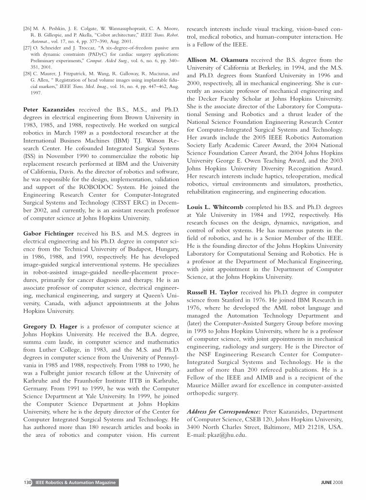
A final point is that redundancy is not sufficient if failure ofone component cannot be detected. For example, consider thecase where the robot is holding a pneumatic cutting tool, and asolenoid is used to turn the tool on and off. If the solenoid failsin the open (on) state, the cutting tool may be activated at anunsafe time. It is tempting to address this hazard by putting asecond solenoid in series with the first, as shown in Figure 6.This is not an acceptable solution, however, because if one sole-noid fails in the open state, the system will appear to operatecorrectly (i.e., the software can still turn the cutter on or off ).Therefore, this system once again has a single point of failure.This is not a hypothetical scenario—it actually appeared in therisk analysis for the ROBODOC system, which uses a pneumaticcutting tool. The concern was that a failed solenoid could cause
injury to the surgeon if the failure occurred while the surgeonwas inserting or removing the cutting bit. ROBODOC adopteda simple method of control, which was to display a screeninstructing the surgeon to physically disconnect the pneumaticsupply prior to any cutting tool change.
ValidationValidation of computer-integrated systems is challengingbecause the key measure is how well the system performs in anoperating room or interventional suite with a real patient.Clearly, for both ethical and regulatory reasons, it is not possi-ble to defer validation until a system is used with patients. Fur-thermore, it is difficult to quantify intraoperative performancebecause there are limited opportunities for accurate postopera-tive assessment. For example, CT scans may not provide suffi-cient contrast for measuring the postoperative result, and theyexpose the patient to additional radiation. For these reasons,most computer-integrated systems are validated using phan-toms, which are objects that are designed to mimic (often verycrudely) the relevant features of the patient.
One of the key drivers of surgical CAD/CAM is the higherlevel of accuracy that can be achieved using some combinationof computers, sensors, and robots. Therefore, it is critical to eval-uate the overall accuracy of such a system. One common tech-nique is to create a phantom with a number of features (e.g.,fiducials) whose locations are accurately known, either by precisemanufacturing or measurement. Some of these features shouldbe used for registration, whereas others should correspond to tar-gets. The basic technique is to image the phantom, perform theregistration, and then locate the target features. By convention,the following types of error are defined [28] as follows:
u fiducial localization error (FLE): the error in locating afiducial in a particular coordinate system (i.e., imagingsystem or robot system)
u fiducial registration error (FRE): the root mean square(RMS) residual error at the registration fiducials, i.e.,
FRE ¼
ffiffiffiffiffiffiffiffiffiffiffiffiffiffiffiffiffiffiffiffiffiffiffiffiffiffiffiffiffiffiffiffiffiffiffiffiffiffiffiffiffiffiffi1
N
XNk¼1
~bk � T �~ak
�� ��2
vuut
where T is the registration transform and (~ak,~bk) are matchedpairs of homologous fiducials (k ¼ 1, . . . , N )
u target registration error (TRE): the error in locating a fea-ture or fiducial that was not used for the registration;if multiple targets are available, the mean error is oftenreported as the TRE.
Although it is necessary to validate that a surgical robot meetsits requirements, including those related to accuracy, it isimportant to realize that higher accuracy may not lead to aclinical benefit. Validation of clinical utility is often possibleonly via clinical trials.
SummaryThis article presents the first of a three-part tutorial on surgicaland interventional robotics. The core concept is that a surgicalrobot couples information to action in the operating room or
Software Relay Solenoid
CuttingMotor
Exhaust
PneumaticSupply
Solenoid
Figure 6. Example of poorly designed redundant system. Thesecond solenoid does not provide sufficient safety because thesystem cannot detect when either solenoid has failed in theopen state.
Surgical robots present a unique set
of design challenges due to the
requirements for miniaturization,
safety, sterility, and adaptation to
changing conditions.
IEEE Robotics & Automation Magazine128 JUNE 2008
interventional suite. This leads to several potential benefits,including increased accuracy and the ability to intervene inareas that are not accessible with conventional instrumenta-tion. We defined the categories of surgical CAD/CAM andsurgical assistance. The former is intended to accurately exe-cute a defined plan. The latter is focused on providing aug-mented capabilities to the physician, such as superhuman orauxiliary (additional) eyes and hands. These categories will bethe focus of the final two parts of this tutorial.
There are numerous challenges in surgical manipulation,sensing, registration, user interfaces, and system design. Manyof these challenges result from the requirements for safety,sterility, small size, and adaptation to a relatively unstructured(and changing) environment. Some software toolkits are avail-able to facilitate the design of surgical robotics systems.
The design of a surgical robot should include a risk analysis.Established methodologies such as FMEA/FMECA can beused to identify potential hazards. Safety design should con-sider and eliminate single points of failure whenever possible.Validation of system performance is critical but is complicatedby the difficulty of simulating realistic clinical conditions.
Surgical robotics is a challenging field, but it is rewardingbecause the ultimate goal is to improve the health and qualityof human life.
AcknowledgmentsThe authors gratefully acknowledge the National ScienceFoundation for supporting our work in this field through theEngineering Research Center for Computer-IntegratedSurgical Systems and Technology (CISST ERC), NSF GrantEEC 9731748. Related projects have also been supported byJohns Hopkins University, the National Institutes of Health,the Whitaker Foundation, the Department of Defense, andour CISST ERC industrial affiliates.
KeywordsSurgical robots, medical robots, robot safety.
References[1] Y. S. Kwoh, J. Hou, E. A. Jonckheere, and S. Hayati, ‘‘A robot with
improved absolute positioning accuracy for CT-guided stereotactic brainsurgery,’’ IEEE Trans. Biomed. Eng., vol. 35, no. 2, pp. 153–160, 1988.
[2] G. S. Guthart and J. K. Salisbury, ‘‘The intuitive telesurgery system:Overview and application,’’ in Proc. IEEE Int. Conf. Robotics and Automa-tion (ICRA 2000), San Francisco, vol. 1. pp. 618–621.
[3] R. H. Taylor and D. Stoianovici, ‘‘Medical robotics in computer-integrated surgery,’’ IEEE Trans. Robot. Automat., vol. 19, no. 3,pp. 765–781, 2003.
[4] R. H. Taylor, B. D. Mittelstadt, H. A. Paul, W. Hanson, P. Kazanzides,J. F. Zuhars, B. Williamson, B. L. Musits, E. Glassman, and W. L. Bargar,‘‘An image-directed robotic system for precise orthopaedic surgery,’’IEEE Trans. Robot. Automat., vol. 10, no. 3, Jun. 1994.
[5] P. Kazanzides, ‘‘Robot assisted surgery: The ROBODOC experience,’’in Proc. 30th Int. Symp. Robotics (ISR), Tokyo, Japan, Nov. 1999,pp. 261–286.
[6] N. Patronik, C. Riviere, S. E. Qarra, and M. A. Zenati, ‘‘The Heart-Lander: A novel epicardial crawling robot for myocardial injections,’’ inProc. 19th Int. Congr. Computer Assisted Radiology and Surgery, 2005,vol. 1281C, pp. 735–739.
[7] M. Shoham, M. Burman, E. Zehavi, L. Joskowicz, E. Batkilin, andY. Kunicher, ‘‘Bone-mounted miniature robot for surgical procedures:Concept and clinical applications,’’ IEEE Trans. Robot. Automat., vol. 19,no. 5, pp. 893–901, Oct. 2003.
[8] A. Wolf, B. Jaramaz, B. Lisien, and A. M. DiGioia, ‘‘MBARS: Minibone-attached robotic system for joint arthroplasty,’’ Int. J. Med. Robot.Comp. Assist. Surg., vol. 1, no. 2, pp. 101–121, Jan. 2005.
[9] J. H. Chung, S. Y. Ko, D. S. Kwon, J. J. Lee, Y. S. Yoon, and C. H. Won,‘‘Robot-assisted femoral stem implantation using an intramedulla gauge,’’IEEE Trans. Robot. Automat., vol. 19, no. 5, pp. 885–892, Oct. 2003.
[10] G. Brandt, A. Zimolong, L. Carrat, P. Merloz, H. W. Staudte,S. Lavallee, K. Radermacher, and G. Rau, ‘‘CRIGOS: A compact robotfor image-guided orthopedic surgery,’’ IEEE Trans. Inform. Technol.Biomed., vol. 3, no. 4, pp. 252–260, Dec. 1999.
[11] A. M. Okamura, ‘‘Methods for haptic feedback in teleoperated robot-assisted surgery,’’ Ind. Robot, vol. 31, no. 6, pp. 499–508, 2004.
[12] G. Fischer, T. Akinbiyi, S. Saha, J. Zand, M. Talamini, M. Marohn,and R. H. Taylor, ‘‘Ischemia and force sensing surgical instruments foraugmenting available surgeon information,’’ in Proc. IEEE Int. Conf. Bio-medical Robotics and Biomechatronics (BioRob 2006), Pisa, Italy, 2006,pp. 1030–1035.
[13] J. B. Maintz and M. A. Viergever, ‘‘A survey of medical image registra-tion,’’ Med. Image Anal., vol. 2, no. 1, pp. 1–37, 1998.
[14] S. Lavallee, ‘‘Registration for computer-integrated surgery: methodol-ogy, state of the art,’’ in Computer-Integrated Surgery, R. H. Taylor,S. Lavallee, G. Burdea, and R. Mosges, Eds. Cambridge, MA: MITPress, 1996, pp. 77–98.
[15] B. K. P. Horn, ‘‘Closed-form solution of absolute orientation usingunit quaternions,’’ J. Opt. Soc. Am. A, vol. 4, no. 4, pp. 629–642, 1987.
[16] K. Arun, T. Huang, and S. Blostein, ‘‘Least-squares fitting of two 3-Dpoint sets,’’ IEEE Trans. Pattern Anal. Machine Intell., vol. 9, no. 5,pp. 698–700, 1987.
[17] S. Umeyama, ‘‘Least-squares estimation of transformation parametersbetween two point patterns,’’ IEEE Trans. Pattern Anal. Machine Intell.,vol. 13, no. 4, pp. 376–380, 1991.
[18] P. J. Besl and N. D. McKay, ‘‘A method for registration of 3-D shapes,’’IEEE Trans. Pattern Anal. Machine Intell., vol. 14, no. 2, pp. 239–256, 1992.
[19] M. H. Moghari and P. Abolmaesumi, ‘‘Point-based rigid-body registra-tion using an unscented Kalman filter,’’ IEEE Trans. Med. Imag., vol. 26,no. 12, pp. 1708–1728, Dec. 2007.
[20] M. Blackwell, C. Nikou, A. M. DiGioia, and T. Kanade, ‘‘An imageoverlay system for medical data visualization,’’ Med. Image Anal., vol. 4,no. 1, pp. 67–72, 2000.
[21] G. Fichtinger, A. Deguet, K. Masamune, E. Balogh, G. S. Fischer,H. Mathieu, R. H. Taylor, S. J. Zinreich, and L. M. Fayad, ‘‘Imageoverlay guidance for needle insertion on CT scanner,’’ IEEE Trans.Biomed. Eng., vol. 52, no. 8, pp. 1415–1424, Aug. 2005.
[22] T. Sasama, N. Sugano, Y. Sato, Y. Momoi, T. Koyama, Y. Nakajima,I. Sakuma, M. G. Fujie, K. Yonenobu, T. Ochi, and S. Tamura, ‘‘Anovel laser guidance system for alignment of linear surgical tools: Itsprinciples and performance evaluation as a man-machine system,’’ inProc. 5th Int. Conf. Medical Image Computing and Computer-Assisted Inter-vention, 2002, vol. 2489, pp. 125–132.
[23] A. Kapoor, A. Deguet, and P. Kazanzides, ‘‘Software components andframeworks for medical robot control,’’ in Proc. IEEE Conf. Robotics andAutomation (ICRA), Orlando, FL, May 2006, pp. 3813–3818.
[24] B. Davies, ‘‘A discussion of safety issues for medical robots,’’ inComputer-Integrated Surgery, R. Taylor, S. Lavallee, G. Burdea, andR. Moesges, Eds. Cambridge, MA: MIT Press, 1996, pp. 287–296.
[25] R. E. McDermott, R. J. Mikulak, and M. R. Beauregard, ‘‘The Basicsof FMEA,’’ New York, Quality Resources, 1996.
Medical interventions are highly
interactive processes.
IEEE Robotics & Automation MagazineJUNE 2008 129
[26] M. A. Peshkin, J. E. Colgate, W. Wannasuphoprasit, C. A. Moore,R. B. Gillespie, and P. Akella, ‘‘Cobot architecture,’’ IEEE Trans. Robot.Automat., vol. 17, no. 4, pp. 377–390, Aug. 2001.
[27] O. Schneider and J. Troccaz, ‘‘A six-degree-of-freedom passive armwith dynamic constraints (PADyC) for cardiac surgery applications:Preliminary experiments,’’ Comput. Aided Surg., vol. 6, no. 6, pp. 340–
351, 2001.[28] C. Maurer, J. Fitzpatrick, M. Wang, R. Galloway, R. Maciunas, and
G. Allen, ‘‘ Registration of head volume images using implantable fidu-cial markers,’’ IEEE Trans. Med. Imag., vol. 16, no. 4, pp. 447–462, Aug.1997.
Peter Kazanzides received the B.S., M.S., and Ph.D.degrees in electrical engineering from Brown University in1983, 1985, and 1988, respectively. He worked on surgicalrobotics in March 1989 as a postdoctoral researcher at theInternational Business Machines (IBM) T.J. Watson Re-search Center. He cofounded Integrated Surgical Systems(ISS) in November 1990 to commercialize the robotic hipreplacement research performed at IBM and the Universityof California, Davis. As the director of robotics and software,he was responsible for the design, implementation, validationand support of the ROBODOC System. He joined theEngineering Research Center for Computer-IntegratedSurgical Systems and Technology (CISST ERC) in Decem-ber 2002, and currently, he is an assistant research professorof computer science at Johns Hopkins University.
Gabor Fichtinger received his B.S. and M.S. degrees inelectrical engineering and his Ph.D. degree in computer sci-ence from the Technical University of Budapest, Hungary,in 1986, 1988, and 1990, respectively. He has developedimage-guided surgical interventional systems. He specializesin robot-assisted image-guided needle-placement proce-dures, primarily for cancer diagnosis and therapy. He is anassociate professor of computer science, electrical engineer-ing, mechanical engineering, and surgery at Queen’s Uni-versity, Canada, with adjunct appointments at the JohnsHopkins University.
Gregory D. Hager is a professor of computer science atJohns Hopkins University. He received the B.A. degree,summa cum laude, in computer science and mathematicsfrom Luther College, in 1983, and the M.S. and Ph.D.degrees in computer science from the University of Pennsyl-vania in 1985 and 1988, respectively. From 1988 to 1990, hewas a Fulbright junior research fellow at the University ofKarlsruhe and the Fraunhofer Institute IITB in Karlsruhe,Germany. From 1991 to 1999, he was with the ComputerScience Department at Yale University. In 1999, he joinedthe Computer Science Department at Johns HopkinsUniversity, where he is the deputy director of the Center forComputer Integrated Surgical Systems and Technology. Hehas authored more than 180 research articles and books inthe area of robotics and computer vision. His current
research interests include visual tracking, vision-based con-trol, medical robotics, and human-computer interaction. Heis a Fellow of the IEEE.
Allison M. Okamura received the B.S. degree from theUniversity of California at Berkeley, in 1994, and the M.S.and Ph.D. degrees from Stanford University in 1996 and2000, respectively, all in mechanical engineering. She is cur-rently an associate professor of mechanical engineering andthe Decker Faculty Scholar at Johns Hopkins University.She is the associate director of the Laboratory for Computa-tional Sensing and Robotics and a thrust leader of theNational Science Foundation Engineering Research Centerfor Computer-Integrated Surgical Systems and Technology.Her awards include the 2005 IEEE Robotics AutomationSociety Early Academic Career Award, the 2004 NationalScience Foundation Career Award, the 2004 Johns HopkinsUniversity George E. Owen Teaching Award, and the 2003Johns Hopkins University Diversity Recognition Award.Her research interests include haptics, teleoperation, medicalrobotics, virtual environments and simulators, prosthetics,rehabilitation engineering, and engineering education.
Louis L. Whitcomb completed his B.S. and Ph.D. degreesat Yale University in 1984 and 1992, respectively. Hisresearch focuses on the design, dynamics, navigation, andcontrol of robot systems. He has numerous patents in thefield of robotics, and he is a Senior Member of the IEEE.He is the founding director of the Johns Hopkins UniversityLaboratory for Computational Sensing and Robotics. He isa professor at the Department of Mechanical Engineering,with joint appointment in the Department of ComputerScience, at the Johns Hopkins University.
Russell H. Taylor received his Ph.D. degree in computerscience from Stanford in 1976. He joined IBM Research in1976, where he developed the AML robot language andmanaged the Automation Technology Department and(later) the Computer-Assisted Surgery Group before movingin 1995 to Johns Hopkins University, where he is a professorof computer science, with joint appointments in mechanicalengineering, radiology and surgery. He is the Director ofthe NSF Engineering Research Center for Computer-Integrated Surgical Systems and Technology. He is theauthor of more than 200 refereed publications. He is aFellow of the IEEE and AIMB and is a recipient of theMaurice M€uller award for excellence in computer-assistedorthopedic surgery.
Address for Correspondence: Peter Kazanzides, Departmentof Computer Science, CSEB 120, Johns Hopkins University,3400 North Charles Street, Baltimore, MD 21218, USA.E-mail: [email protected].
IEEE Robotics & Automation Magazine130 JUNE 2008


![© EYEWIRE Surgical and Interventional Robotics: Part II...Figure 3. MRI-guided focused US surgery of brain tumors [12]. (a) Patient in treatment position on the MRI couch. (b) Insonification](https://img.pdfslide.net/doc/110x75/603c7786bb25a43972624428/-eyewire-surgical-and-interventional-robotics-part-ii-figure-3-mri-guided.jpg)


![© EYEWIRE Surgical and Interventional Robotics: …...Teleoperators can include impedance or admittance masters and slaves in various combinations [16]. However, the impedance type](https://img.pdfslide.net/doc/110x75/5f9e6a44fe992e3a0d04e367/-eyewire-surgical-and-interventional-robotics-teleoperators-can-include-impedance.jpg)