Embed Size (px)
Citation preview

1000 112th Circle N, Suite 100 • St. Petersburg, FL 33716(800) 451-9444 • (727) 530-3602 • (727) 539-0550 [FAX] * www.sensidyne.com
Revision J • Document No. F-PRO-3100
Gilian®
AIRCON-2HIGH VOLUME AIR SAMPLER
OPERATION & SERVICE MANUAL
CYCLE MODE LOW BATTERY FAULT ERROR
RUNHOLD PROGRAMMINGSINGLE MODEDELAY TIMERUN TIMEHOLD TIME#CYCLESPRESSURE
PROGTIME
PRESS.ACCEPT
RUN
HOLD

3
Gilian® AIRCON-2 HIGH VOLUME AIR SAMPLER
Sensidyne Document No. F-PRO-3100 (Rev J)
PROPRIETARY NOTICE
This manual was prepared by Sensidyne, LP exclusively for the owner of the AirCon-2 High Volume Air Sampler. The
material within this manual is the proprietary information of Sensidyne, LP and is to be used only to understand, operate,
and service the instrument. By receiving this document, the recipient agrees that neither this document nor the information
disclosed within nor any part shall be reproduced or transferred, physically, electronically or in any form or used or
disclosed to others for manufacturing or for any other purpose except as specifically authorized in writing by Sensidyne,
LP.
COPYRIGHT NOTICE
© 1998-2008, Sensidyne, LP. ALL RIGHTS RESERVED. Information contained in this document is protected by copyright.
No part of this document may be photocopied, reproduced, or translated to another program or system without prior written
authorization from Sensidyne, LP.
TRADEMARK NOTICE
Sensidyne, the Sensidyne logo, Gilian, and the Gilian logo are registered trademarks of Sensidyne, LP. These trademarks are
protected through use and registration in the United States. The trademarks and servicemarks used in this document are the
property of their respective companies and are used only for informational and explanatory purposes.
DISCLAIMER
THE SELLER ASSUMES NO RESPONSIBILITY WHATSOEVER, TO ANY PARTY WHOSOEVER, FOR ANY
PROPERTY DAMAGE, PERSONAL INJURY, OR DEATH RECEIVED BY OR RESULTING FROM, IN
WHOLE, OR IN PART, THE IMPROPER USE, INSTALLATION, OR STORAGE OF THIS PRODUCT BY THE
USER, PERSON, FIRM, ENTITY, CORPORATION OR PARTY NOT ADHERING TO THE INSTRUCTIONS
AND WARNINGS IN THIS MANUAL, OR OTHERWISE PROVIDED BY THE SELLER OR FROM NOT
ADHERING TO ALL FEDERAL, STATE, AND LOCAL ENVIRONMENTAL AND OCCUPATIONAL HEALTH
AND SAFETY LAWS AND REGULATIONS.
THE SELLER SHALL NOT BE LIABLE FOR DIRECT, INDIRECT, CONSEQUENTIAL, INCIDENTAL OR
OTHER DAMAGES RESULTING FROM THE SALE AND USE OF ANY GOODS AND SELLERS’ LIABILITY
HEREUNDER SHALL BE LIMITED TO REPAIR OR REPLACEMENT OF ANY GOODS FOUND DEFECTIVE.
THIS WARRANTY IS IN LIEU OF ALL OTHER WARRANTIES, EXPRESSED OR IMPLIED, INCLUDING BUT
NOT LIMITED TO THE IMPLIED WARRANTIES OF MERCHANTABILITY AND FITNESS FOR USE OR FOR
A PARTICULAR PURPOSE WHICH ARE EXPRESSLY DISCLAIMED.
— PRELIMINARY —
Gilian® AIRCON-2 HIGH VOLUME AIR SAMPLER
4 Sensidyne Document No. F-PRO-3100 (Rev J)
TABLE OFCONTENTS
• PREFACE
• WARNINGS ........................................................................................................................... 7
• Packing List .......................................................................................................................... 8
SECTION ONE: INTRODUCTION
1.1 Description ................................................................................................................. 9
1.2 Power Sources ...........................................................................................................10
1.2.1 AC Power .......................................................................................................101.2.2 DC Power.......................................................................................................101.2.3 Power Module ...............................................................................................10
1.3 Controls & Indicators ..............................................................................................12
1.3.1 On/Off Switch ...............................................................................................121.3.2 Flow Adjustment ............................................................................................121.3.3 LCD Display ...................................................................................................121.3.4 Touch-Pad Buttons ........................................................................................12
1.4 Standard Parts ...........................................................................................................12
1.4.1 Telescopic Sampling Mast .............................................................................121.4.2 Air House & Hose Support Tip......................................................................12
SECTION TWO: SET-UP
2.1 General Set-Up ..........................................................................................................16
2.1.1 Sampling Mast ................................................................................................162.1.2 Air Hose .........................................................................................................162.1.3 Filter Cassettes ...............................................................................................16
2.2 Charging .....................................................................................................................17
2.2.1 Using The DC Unit .........................................................................................172.2.2 Charging With The Power module................................................................17

5
Gilian® AIRCON-2 HIGH VOLUME AIR SAMPLER
Sensidyne Document No. F-PRO-3100 (Rev J)
TABLE OFCONTENTS
SECTION THREE: OPERATION
3.1 Overview ....................................................................................................................21
3.2 Basic Operation ........................................................................................................21
3.2.1 Single Mode ...................................................................................................213.2.2 Cycle Mode Operation...................................................................................21
3.3 Faults ...........................................................................................................................24
3.3.1 Fault Function ................................................................................................243.3.2 Correcting Fault Conditions ...........................................................................243.3.3 Low Battery Indication ..................................................................................24
3.4 Programming Examples .........................................................................................25
3.4.1 Cycle Mode Programming Example .............................................................253.4.2 Other Programming Examples ......................................................................25
SECTION FOUR: AFTER SAMPLING
4.1 Unit Shut Down ........................................................................................................32
4.2 Sampling Mast ...........................................................................................................32
4.3 Battery Pack Maintenance ......................................................................................32

— PRELIMINARY —
Gilian® AIRCON-2 HIGH VOLUME AIR SAMPLER
6 Sensidyne Document No. F-PRO-3100 (Rev J)
SECTION FIVE: APPENDICES
• Appendix A: Parts List .....................................................................................................33
• Appendix B: Specifications .............................................................................................34
• Appendix C: Returned Material Authorization ...........................................................35
• Returned Material Authorization ............................................................................35• Service Options .......................................................................................................35
LIST OF FIGURES
1.1 AirCon-2 Air Sampler with Sampling Mast & Air Hose ...........................................11
1.2 Front Panel ...............................................................................................................13
1.3 Liquid Crystal Display ..............................................................................................14
1.4 AirCon-2 Accessory Configurations ........................................................................15
2.1 DC Sampler Set-Up ..................................................................................................18
2.2 Power Module Set-Up (Single Pack) ......................................................................19
2.3 Power Module Set-Up (Multiple Packs) .................................................................20
3.1 Cycle Mode Programming Example .......................................................................25
LIST OF TABLES
3.1 Setting Air Flow .......................................................................................................22
3.2 Single-Mode Operation............................................................................................23
3.3 Pre-Programmed Data .............................................................................................26
3.4 Entering Program Mode ..........................................................................................27
3.5 Delay Time ...............................................................................................................28
3.6 Run Time .................................................................................................................29
3.7 Hold Time ................................................................................................................30
3.8 Run Cycles ................................................................................................................31
TABLE OFCONTENTS

7
Gilian® AIRCON-2 HIGH VOLUME AIR SAMPLER
Sensidyne Document No. F-PRO-3100 (Rev J)
READ AND UNDERSTAND ALL WARNINGS BEFORE USE
Read and understand ALL warnings before using this product. Failure to read, understand, and comply withALL warnings could result in property damage, severe personal injury, or death.
Read and understand ALL applicable Federal, State, and Local environmental health and safety laws andregulations, including OSHA. Ensure complete compliance with ALL applicable laws and regulations beforeand during use of this product.
UNDER NO CIRCUMSTANCES should this product be used except by qualified, trained, technicallycompetent personnel and not until the warnings, Operation and Service Manual, labels, and other literatureaccompanying this product have been read and understood.
The Operation and Service Manual must be read and understood by each user before operating this productor using its accessories, in order to ensure proper and safe use and installation of this product and to ensurefamiliarity with the proper treatment and safety procedures in the event of an accident.
Caution: Risk of electrical shock.
Warning: Line cord must be removed to remove all power from equipment.
DO NOT remove, cover, or alter any label or tag on this product, its accessories, or related products.
DO NOT operate this product should it malfunction or require repair. Operation of a malfunctioning product,or a product requiring repair may result in serious personal injury or death. DO NOT attempt to repair ormodify the instrument, except as specified in the Operation and Service Manual. Contact the SensidyneService Department to arrange for a Returned Material Authorization (RMA).
Use ONLY genuine Sensidyne® replacement parts when performing any maintenance procedures describedin this manual Specifically the DC version of the AirCon-2 is designed for use with AirCon-2 Battery Packs,and should not be used in conjunction with any other equipment. Rechargeable Battery Packs are designedto be charged with the AirCon-2 Power Module and in strict accordance with the charging instructionscontained in this manual. Failure to follow these warnings may seriously impair instrument performance.Repair or alteration of the product beyond the scope of these maintenance instructions, or by anyone otherthan a certified Sensidyne® serviceman, could cause the product to fail to perform as designed, and personswho rely on this product for their safety could sustain severe personal injury or death.
DO NOT operate unit in excessive chemical or water vapor atmospheres. Failure to follow instructions maycause permanent damage to the equipment.
NEVER block the cooling air inlets (located at the top/back of unit) when the unit is operating.
NEVER block any of the venting holes (located on the sides of the case) when the unit is operating.
ALWAYS place the unit on a secure and level surface when operating.
ALWAYS operate unit within the intrinsically safe environmental regime specified (non-hazardous loca-tions).
WARNINGS !

— PRELIMINARY —
Gilian® AIRCON-2 HIGH VOLUME AIR SAMPLER
8 Sensidyne Document No. F-PRO-3100 (Rev J)
The items listed below are shipped with the Gilian AirCon-2 High Volume Air Sampler:
• AirCon-2 DC Air Sampler unit, requires a Battery Pack (sold separately)
• Air Hose (Tubing)
• Hose Support Tip
• Sampling Mast
• Operation and Service Manual
• Registration Card/Warranty Card
PACKING LIST
ALWAYS check to make certainyou have received all of the items listed above.
If you have any questions or need assistance,contact your Sales Representative, or call
(800) 451-9444OR
(727) 530-3602

9
Gilian® AIRCON-2 HIGH VOLUME AIR SAMPLER
Sensidyne Document No. F-PRO-3100 (Rev J)
SECTION ONEINTRODUCTION
1.1 DESCRIPTION
IMPORTANT
You must read this manual in its entirety to ensure properoperation of your unit.
The AirCon-2 Air Sampling System (PNº 801012) is apowerful environmental air sampler used to collect airsamples indoors and outdoors. It is equipped withuseful performance features industrial hygienists needmost; easy set-up, compact size, Battery Packoperation, programmable timing functions and DCportability. The unit may be operated on AC currentwhen used with the optional Power Module.
The Aircon-2 Air Sampling kit includes main samplingunit, air hose, hose support tip, sampling mast, andmanual. The unit requires a 4-hour Battery Pack and/or Power Module for operation (sold separately).
The AirCon-2 high volume air sampling systemconsists of a positive displacement pump with aunique patented regulator system which maintainsflow constant over a flow range of 2-30 LPM. Thesampler maintains air flow constant for sampling ofairborne particulate, hazardous dust and lowconcentration pollutants using many popular filtercassettes. The volume of air that passes through thefilter cassette is determined by the following:
Air flow x Elapsed time = Volume
For example:
10 L/min x 500 minutes = 5000L or 5M3
The unit is set up in the required location andoperated using a 4-hour Battery Pack and/or to aPower Module which is designed to power the unitfrom a standard AC source.
The AirCon-2 system provides a telescopic samplingmast which is extended to nose height and to whichthe air hose/support tip is connected. The media,typically a filter cassette, is inserted into the end ofthe sampling hose. The other end of the air hose isconnected to the “Air Inlet” located at the front ofthe sampler.
After positioning the unit and setting up thesampling mast stand, the unit can be turned on. Airflow is set by use of the external flow adjust knoband is indicated on the built-in rotameter.
The Aircon-2 is programmable and offers a touchkeypad and LCD display which allow the user toprogram sampling routines. Programmable timingfunctions include: start and stop times, intermittentrun, delay, run/hold and memory storage of up tothree custom timing programs. The full-functiondisplay and touch pad offer key-in programmingand visual monitoring of all timing functions duringprogramming and sampler operation.
— PRELIMINARY —
Gilian® AIRCON-2 HIGH VOLUME AIR SAMPLER
10 Sensidyne Document No. F-PRO-3100 (Rev J)
1.2 POWER SOURCES
1.2.1 AC Power
AC power is provided through the Power Module. A2-prong Euro plug is provided for 230 VAC operation.
1.2.2 DC Power
DC Power is provided by a four-hour Battery Pack.The Battery Packs can be stacked and interconnectedto achieve the ampere hour rating required to meetthe most stringent sampling conditions. Battery packsare recharged with the optional Power Module.
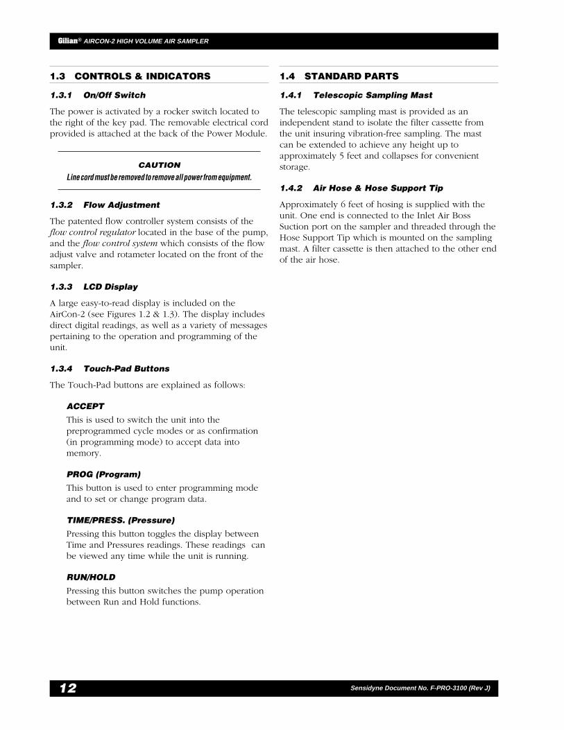
1.2.3 Power Module
The AirCon-2 can be run directly off the PowerModule. If the battery module is also attached, it willslowly charge the battery while still providingsufficient power to run the sampler. It will rapidlycharge the battery if the sampler is turned off underthe same circumstances. The Power Module may alsobe used as a stand-alone battery charger and maycharge one or more batteries.
NOTE
Stacking batteries on the Power Module will increase the timerequired for full charge.
The unit will automatically reduce the chargingcurrents as the battery becomes fully charged. An LEDindicator illuminates when charging and flashes whencharging is complete. If no battery is attached it willflash indicating sufficient voltage to run the sampler.The Power Module can operate on 115–230 VAC, 47–63 Hz.

11
Gilian® AIRCON-2 HIGH VOLUME AIR SAMPLER
Sensidyne Document No. F-PRO-3100 (Rev J)
Figure 1.1AirCon-2 Air Sampler with Sampling Mast & Air Hose
20
EnclosureHandleMounting Feet (4)Cooling Air InletCooling Air DischargeDischarge Air BossAC Power InletDC Supply LatchDC Interconnect PlugOn/Off SwitchLCD DisplayACCEPT Key
1.2.3.4.5.6.7.8.9.
10.11.12.
PROGRAM KeyTIME/PRESS. KeyRUN/HOLD KeyInlet Air Boss SuctionFlow Adjust KnobFlowmeterSampling MastAir HoseHose SupportSampling Media (ref only)
13.14.15.16.17.18.19.20.21.22.
2
18
17
2
5
53
12
7
8
6
419
21
22
13 149
15 10
11
16
1
CYCLE MODE LOW BATTERY FAULT ERROR
RUNHOLD PROGRAMMINGSINGLE MODEDELAY TIMERUN TIMEHOLD TIME#CYCLESPRESSURE
PROGTIME
PRESS.ACCEPT
RUN
HOLD
— PRELIMINARY —
Gilian® AIRCON-2 HIGH VOLUME AIR SAMPLER
12 Sensidyne Document No. F-PRO-3100 (Rev J)
1.3 CONTROLS & INDICATORS
1.3.1 On/Off Switch
The power is activated by a rocker switch located tothe right of the key pad. The removable electrical cordprovided is attached at the back of the Power Module.
CAUTION
Line cord must be removed to remove all power from equipment.
1.3.2 Flow Adjustment
The patented flow controller system consists of theflow control regulator located in the base of the pump,and the flow control system which consists of the flowadjust valve and rotameter located on the front of thesampler.
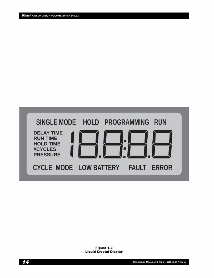
1.3.3 LCD Display
A large easy-to-read display is included on theAirCon-2 (see Figures 1.2 & 1.3). The display includesdirect digital readings, as well as a variety of messagespertaining to the operation and programming of theunit.
1.3.4 Touch-Pad Buttons
The Touch-Pad buttons are explained as follows:
ACCEPT
This is used to switch the unit into thepreprogrammed cycle modes or as confirmation(in programming mode) to accept data intomemory.
PROG (Program)
This button is used to enter programming modeand to set or change program data.
TIME/PRESS. (Pressure)
Pressing this button toggles the display betweenTime and Pressures readings. These readings canbe viewed any time while the unit is running.
RUN/HOLD
Pressing this button switches the pump operationbetween Run and Hold functions.
1.4 STANDARD PARTS
1.4.1 Telescopic Sampling Mast
The telescopic sampling mast is provided as anindependent stand to isolate the filter cassette fromthe unit insuring vibration-free sampling. The mastcan be extended to achieve any height up toapproximately 5 feet and collapses for convenientstorage.
1.4.2 Air Hose & Hose Support Tip
Approximately 6 feet of hosing is supplied with theunit. One end is connected to the Inlet Air BossSuction port on the sampler and threaded through theHose Support Tip which is mounted on the samplingmast. A filter cassette is then attached to the other endof the air hose.

13
Gilian® AIRCON-2 HIGH VOLUME AIR SAMPLER
Sensidyne Document No. F-PRO-3100 (Rev J)
Figure 1.2Front Panel
PROGRUN
HOLD
TIME
PRESS.ACCEPT
OFF
ON
Made in USAGilian®
High Volume Air Sampler
CYCLE MODE LOW BATTERY FAULT ERROR
RUNHOLD PROGRAMMINGSINGLE MODEDELAY TIMERUN TIMEHOLD TIME#CYCLESPRESSURE I
O
— PRELIMINARY —
Gilian® AIRCON-2 HIGH VOLUME AIR SAMPLER
14 Sensidyne Document No. F-PRO-3100 (Rev J)
Figure 1.3Liquid Crystal Display
MODE LOW BATTERY FAULT ERROR
RUNHOLD PROGRAMMINGSINGLE MODEDELAY TIMERUN TIMEHOLD TIME#CYCLESPRESSURE
CYCLE
15
Gilian® AIRCON-2 HIGH VOLUME AIR SAMPLER
Sensidyne Document No. F-PRO-3100 (Rev J)
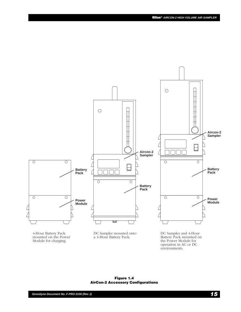
Figure 1.4AirCon-2 Accessory Configurations
PROGTIME
PRESS.ACCEPT
RUN
HOLD
CYCLE MODE LOW BATTERY FAULT ERROR
RUNHOLD PROGRAMMINGSINGLE MODEDELAY TIMERUN TIMEHOLD TIME#CYCLESPRESSURE
PROGTIME
PRESS.ACCEPT
RUN
HOLD
CYCLE MODE LOW BATTERY FAULT ERROR
RUNHOLD PROGRAMMINGSINGLE MODEDELAY TIMERUN TIMEHOLD TIME#CYCLESPRESSURE
4-Hour Battery Packmounted on the PowerModule for charging.
DC Sampler mounted ontoa 4-Hour Battery Pack.
DC Sampler and 4-HourBattery Pack mounted onthe Power Module foroperation in AC or DCenvironments.
Aircon-2Sampler
BatteryPack
BatteryPack
PowerModule
Aircon-2Sampler
BatteryPack
PowerModule

— PRELIMINARY —
Gilian® AIRCON-2 HIGH VOLUME AIR SAMPLER
16 Sensidyne Document No. F-PRO-3100 (Rev J)
SECTION TWOSET-UP
2.1 GENERAL SET-UP
Place the unit in the desired sampling area. Makecertain the unit is standing in a vertical position.
NOTE
When using rotameters, it is important to maintain a verticalposition for optimum accuracy. The rotameter provided in thissampler has been tested for accuracy and is within ± 5% of fullscale.
2.1.1 Sampling Mast
To set up the Sampling Mast, perform the followingsteps:
1) First, unfold the legs at the bottom of the maststand by opening the locking knob and pullingthe legs outwards as far as they will extend.
2) Loosen the largest locking collar at the bottom ofthe stand and pull out by the second largestlocking collar. Tighten the largest collar.
3) Holding the extended section, loosen the secondlargest locking collar and extend the next sectionof the mast. Tighten the second largest collar.
4) Repeat this procedure until the mast is extendedto its full or required height.
5) Be sure to tighten each locking collar beforeproceeding to loosen the next. Position theextended mast next to sampler.
2.1.2 Air Hose
To attach the Air Hose, perform the following steps:
1) Connect one end of the flexible tubing to the airinlet valve located at the back of the sampler.
2) Connect the hose support tip to the top of theextended sampling mast.
3) Insert tubing through the hose support tip, with2–3" of the hosing extending out.
4) Insert filter cassette or other media into air hoseend.
2.1.3 Filter Cassettes
To install the Filter Cassette, do the following:
1) First, remove any cap plugs from the filtercassette. These may be colored in red and blue.Also remove the end of the filter cassette toexpose the filter, if the test method requires it(e.g., asbestos sampling). This is called “open-face” filter sampling. This allows air to enter thecassette freely with minimal back pressure.
2) Plug the filter cassette into the end of thesampling hose.

17
Gilian® AIRCON-2 HIGH VOLUME AIR SAMPLER
Sensidyne Document No. F-PRO-3100 (Rev J) 3.4
2.2 CHARGING
2.2.1 Using The DC Unit
Connecting the DC Unit
1) Place the Battery Pack or Power Module on a flatsurface, orienting the guide pins either to the leftor right.
2) Tilt the sampler approximately 10°, as shown inFigure 2.1, and engage the female guide-pinreceptacle into the guide pins of the Battery Packor Power Module. Rotate the unit around theguide pins such that the back lip of the BatteryPack or Power Module slides over the recess onthe back bottom of the sampler.
NOTE
Once the guide pins are aligned and seated, the electricalconnector on the sampler and Battery Pack (or Power Module)will connect automatically.
3) Pull the latch on the rear of the Battery Pack (orPower Module) over the latch keeper on the backof the sampler, pushing down on the latch tosecure it.
4) Repeat this procedure for any additional BatteryPacks and/or Power Modules.
Disconnecting the DC Unit
1) Disengage the latch hook.
2) Rotate the sampler about guide pin until the backof the sampler disengages the Battery Pack orPower Module.
3) Disengage the female receptacle and guide pinsof the sampler from the Battery Pack or PowerModule respectively.
2.2.2 Charging With The Power Module
The Power Module may be plugged into any linevoltage from 115 to 230 VAC, 50/60 Hz without anyswitch adjustments.
To charge the Battery Pack independently:
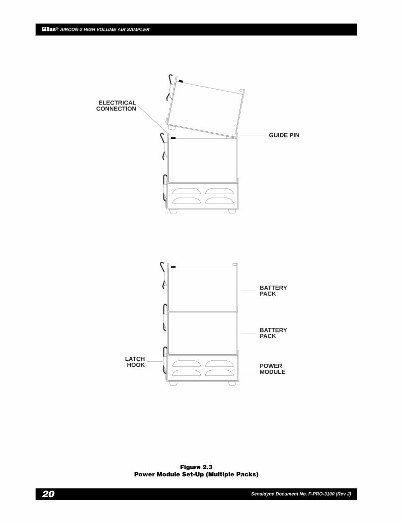
1) Connect the Battery Pack to the Power Module(refer to Figure 2.2). Multiple Battery Packs maybe connected to the Power Module (refer toFigure 2.3).
NOTE
Charging multiple Battery Packs will increase the requiredcharging time.
2) Attach the line cord to the receptacle located atthe back of the Power Module.
3) Plug the line cord into the AC receptacle.
4) An LED, located on the back of the Power Modulewill light, indicating whether there is sufficient DCvoltage available to the sampler. If a Battery Packis attached and is not fully charged, the LED willremain illuminated until the battery is charged.When fully charged, the LED will start to pulse. Ifno battery is attached, the unit will pulse.

— PRELIMINARY —
Gilian® AIRCON-2 HIGH VOLUME AIR SAMPLER
18 Sensidyne Document No. F-PRO-3100 (Rev J)
Figure 2.1DC Sampler Set-Up
ELECTRICALCONNECTION
LATCHHOOK
GUIDE PIN
DC PACK

19
Gilian® AIRCON-2 HIGH VOLUME AIR SAMPLER
Sensidyne Document No. F-PRO-3100 (Rev J)
Figure 2.2Power Module Set-Up (Single Pack)
ELECTRICALCONNECTION
GUIDE PIN
LATCHHOOK
POWERMODULE
POWERMODULE
BATTERYPACK
— PRELIMINARY —
Gilian® AIRCON-2 HIGH VOLUME AIR SAMPLER
20 Sensidyne Document No. F-PRO-3100 (Rev J)
Figure 2.3Power Module Set-Up (Multiple Packs)
ELECTRICALCONNECTION
GUIDE PIN
LATCHHOOK POWER
MODULE
BATTERYPACK
BATTERYPACK

21
Gilian® AIRCON-2 HIGH VOLUME AIR SAMPLER
Sensidyne Document No. F-PRO-3100 (Rev J)
SECTION THREEOPERATION
3.1 OVERVIEW
This section covers the operation of the AirCon-2.Basic operating procedures are described in Section3.2. Fault conditions are described in Section 3.3.Section 3.4 provides detailed information on how toprogram the unit.
OPERATION NOTE
The rotameter provided has been tested for accuracy and iswithin ± 5% of full scale. However, the rotameter should beperiodically checked against a primary standard, such as theGilibrator. Be sure to maintain the sampler in a verticalposition to ensure accurate operation of the rotameter.
The unit offers versatile programming, suctionpressure load indication, and an instant fault functionwhen the flow deviates by more than ± 5%.
In situations where the 5% envelope is violated formore than 30 seconds, the unit stops sampling andfreezes the sample time display, allowing for properflow rate/volume calculation.
The AirCon-2 has a unique modular Battery Pack/Power Module operating system. The sampler alsofeatures a unique hold function. When a fault occurs,the hold function keeps the display visible so long asadequate battery power is available. If the batterylevel drops further, the display is erased. However,the unit stores the “lost” data in internal memory forlater recovery. When the unit is connected to a freshBattery Pack and turned on, the previous run-timedata are re-displayed on the screen.
3.2 BASIC OPERATION
3.2.1 Single Mode
Single-Mode operation provides complete manualcontrol of sampling (refer to Tables 3.1 & 3.2 fordetails). The unit is turned on, the flow is set, and theACCEPT button is pressed. This enters the flow faultinformation into the on-board computer. Pressing Runstarts the sampler. The sampler continues to run untilthe Hold button is pressed, or the unit is turned off.You can use the Run/Hold and Time/Press buttons atany time while the unit is sampling.
Single-Mode operation provides complete manualcontrol of sampling. The unit is turned on, the air flowis set, and the ACCEPT button is pressed. This entersthe flow fault information into the on-board computer.Pressing Run starts sampling. Sampling continues untilthe Hold button is pressed, or the unit is turned off.You can use the Run/Hold and Time/Press buttons atany time while the unit is sampling. Tables 3.1 and 3.2provide step-by-step instructions for performingSingle-Mode sampling.
3.2.2 Cycle Mode Operation
Cycle mode runs the sampler from previously createdprograms. An example of cycle mode programming isshown in Section 3.4.

— PRELIMINARY —
Gilian® AIRCON-2 HIGH VOLUME AIR SAMPLER
22 Sensidyne Document No. F-PRO-3100 (Rev J)
Table 3.1Setting Air Flow
NoteOnce set, do not adjust the air flow during operation. This can cause a fault to occur. Alwaysturn the unit off and back on again. Then, follow the steps above to reset the flow.
Step Switch/Button Action Display Example
FAULT
PROGRAMMING
HOLDSINGLE MODE
RUN TIME
RUNSINGLE MODE
RUN TIME
PROGRAMMING
ON/OFF
FLOW ADJ.KNOB
ACCEPT
Option 1:RUN
Option 2:PROG
ACCEPT
Note:
Switch power to the ON position.Display showsPROGRAMMING/FAULT
At this time, you may press RUNto start sampling. The sampler willrun continuously until you shut itoff.
Run the sampler from pre-programmed data. Press PROGto enter programming mode.Select the program no. (1–3) bypressing PROG addtional times.
If you are unfamiliar withprogramming data, review allprogramming tables insuccession.
Set the air flow rate by turningcounter-clockwise to increase, orclockwise to decrease. Flow rateis shown on the flowmeter.
Press to enter the flow rate faultlimits into memory. The pump willstop and the display will readSINGLE MODE/ HOLD.
1
2
3
4
5
6

23
Gilian® AIRCON-2 HIGH VOLUME AIR SAMPLER
Sensidyne Document No. F-PRO-3100 (Rev J)
Table 3.2Single-Mode Operation
Step Switch/Button Action Display Example
FAULT
PROGRAMMING
HOLDSINGLE MODE
RUN TIME
RUNSINGLE MODE
RUN TIME
HOLDSINGLE MODE
RUN TIME
RUNSINGLE MODE
PRESSURE
RUNSINGLE MODE
RUN TIME
ON/OFF
FLOW ADJ.KNOB
ACCEPT
RUN
HOLD
TIME/PRESS
1
2
3
4
5
6
7
Switch power to the ON position.Display showsPROGRAMMING/FAULT
Set the air flow rate by turningcounter-clockwise to increase, or
Press to take unit out of RunMode and put into Hold Mode.Motor turnsOFF, clock stopscounting, colon stops flashing.Display indicates SINGLE MODE/HOLD.
Press at any time during RUNoperation to view current RunTime or Back Pressure readings.
Unit is in Single Mode Hold. Torun sampler continuously withouttiming program continue to step 5.
Press to take unit out of HoldMode and put into Run Mode.Motor turns ON, internal clockbegins counting in real time.Sampler runs until it is shut off.Display indicates SINGLE MODE/
clockwise to decrease. Flow isindicated on the flowmeter.
Press to enter the flow rate faultlimits into memory. The pump willstop and display will read SINGLEMODE/ HOLD.
RUN.

— PRELIMINARY —
Gilian® AIRCON-2 HIGH VOLUME AIR SAMPLER
24 Sensidyne Document No. F-PRO-3100 (Rev J)
3.3 FAULTS
3.3.1 Fault Function
When the pressure in the bypass path differs morethan ± 5% from the value that was stored initiallyduring flow adjust set-up, the display will showFAULT for approximately 25 seconds.
If a fault condition still exists, the following occurs:
1) The motor will turn off.
2) The display will show the collected Run Time tofault shutdown.
3) FAULT will flash on the display.
3.3.2 Correcting Fault Conditions
1) Turn the power switch to the OFF position.
2) Turn it back to the ON position. This resets thesystem, clearing the fault.
3) At this time, you should:
a) Check the filter cassette for excessive buildup.
b) Check the air hose for any obstructions orkinks.
c) Re-select a program number 1-3 (refer toTable 3.4 for details).
3.3.3 Low Battery Indication
When a DC Battery Pack is running out of charge, theAirCon-2 indicates this condition on the display asLOW BATTERY and the motor stops running. Thedisplay remains on until all power is gone. TheAirCon-2 stores the collected run time data in memoryfor safekeeping when showdown occurs. A newBattery Pack must be connected to access the RUNTIME of the sample. To restart the sampler and accessthe stored sampling data, do the following:
1) Turn the power OFF and remove the used BatteryPack from the sampler.
2) Replace with a fully charged Battery Pack.
3) Turn the power switch ON. At this time, themotor is not running. The display indicates RUNTIME information.
4) To clear the low battery fault condition, pressACCEPT. At this time, the motor will beginrunning. You can now go into single modeoperation, use preprogrammed data, or enter yourown programming parameters.

25
Gilian® AIRCON-2 HIGH VOLUME AIR SAMPLER
Sensidyne Document No. F-PRO-3100 (Rev J)
3.4 PROGRAMMING EXAMPLES
3.4.1 Cycle Mode Programming Example
A cycle mode programming example is presentedbelow (Figure 3.1) in both tabular and graphic forms.The unit has been programmed to start in DELAYmode. When in DELAY mode, the display countsdown the time remaining in the delay period. Whenthe countdown reaches zero, the RUN phase begins.The time shown on the display during the run phaserepresents the actual elapsed time since the programwas started, and not the programmed run time (i.e.,16:47).
After the first RUN phase has been completed, the unitgoes into its first HOLD phase. While in the HOLDphase, the display counts down the time remaining inthe hold period. When the countdown reaches zero,the second RUN phase begins. The time shown on thedisplay during the second RUN phase represents thetotal accumulated run time since the program started.
After the second RUN phase has been completed, theunit goes into its second HOLD phase. While in theHOLD phase, the display counts down the timeremaining in the hold period. When the countdownreaches zero, the third (and final) RUN phase begins.The time shown on the display during the third RUNphase represents the total accumulated run time sincethe program started. When the third RUN phase iscompleted, the program concludes and the unit goesinto a HOLD phase without countdown.
3.4.2 Other Programming Examples
The tables on the following pages (Table 3.3–3.9) showsome of the basic operations available with theAirCon-2.
These examples should be read in sequence.Examples of displays at each programming step areprovided as visual aids. When you are familiar withthe programming procedures, you can enter your ownprogramming parameters.
Figure 3.1Cycle Mode Programming Example
Delay2:25
(9:12)Hold
16:47
Run
16:47
Run
16:47
Run
(9:12)Hold
Power Switch(Motor) ON
Adjust FlowProgram 1, 2, 3
Power Switch(Motor) OFF
Start One ofThree Programs
Hold
ProgramConcludesCycle 1 Cycle 2 Cycle 3
Can Program Remaining Programs
ecneuqeS sruoH setuniM
EMITYALED 2 52
EMITNUR 61 74
EMITDLOH 9 21
SELCYC# 3
)emiTnuRdetcelloClatoT(53:05=)74:61x3(EMITNURxSELCYC#
— PRELIMINARY —
Gilian® AIRCON-2 HIGH VOLUME AIR SAMPLER
26 Sensidyne Document No. F-PRO-3100 (Rev J)
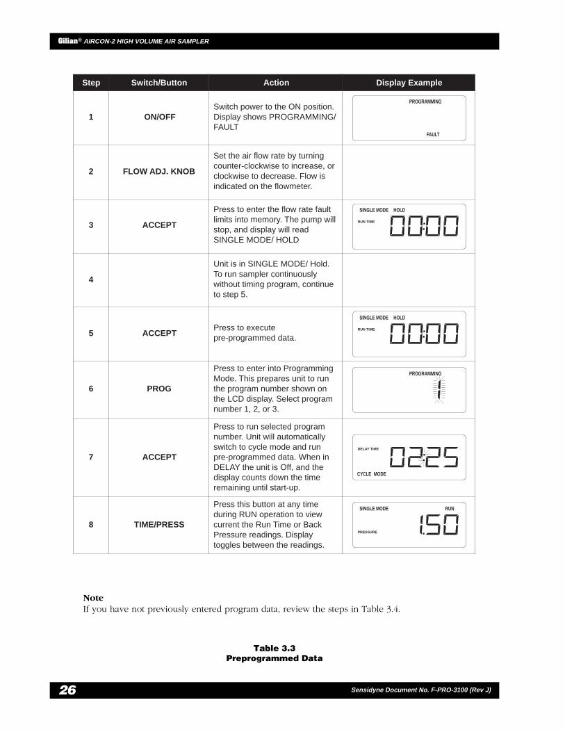
Table 3.3Preprogrammed Data
NoteIf you have not previously entered program data, review the steps in Table 3.4.
Step Switch/Button Action Display Example
FAULT
PROGRAMMING
HOLDSINGLE MODE
RUN TIME
HOLDSINGLE MODE
RUN TIME
PROGRAMMING
CYCLE MODE
DELAY TIME
RUNSINGLE MODE
PRESSURE
1
2
3
4
5
6
7
8
ON/OFF
FLOW ADJ. KNOB
ACCEPT
ACCEPT
PROG
ACCEPT
TIME/PRESS
Press to run selected programnumber. Unit will automaticallyswitch to cycle mode and runpre-programmed data. When inDELAY the unit is Off, and thedisplay counts down the timeremaining until start-up.
Press this button at any timeduring RUN operation to viewcurrent the Run Time or BackPressure readings. Displaytoggles between the readings.
Press to executepre-programmed data.
Press to enter into ProgrammingMode. This prepares unit to runthe program number shown onthe LCD display. Select programnumber 1, 2, or 3.
Press to enter the flow rate faultlimits into memory. The pump willstop, and display will readSINGLE MODE/ HOLD
Unit is in SINGLE MODE/ Hold.To run sampler continuouslywithout timing program, continueto step 5.
Set the air flow rate by turningcounter-clockwise to increase, orclockwise to decrease. Flow isindicated on the flowmeter.
Switch power to the ON position.Display shows PROGRAMMING/FAULT
27
Gilian® AIRCON-2 HIGH VOLUME AIR SAMPLER
Sensidyne Document No. F-PRO-3100 (Rev J)
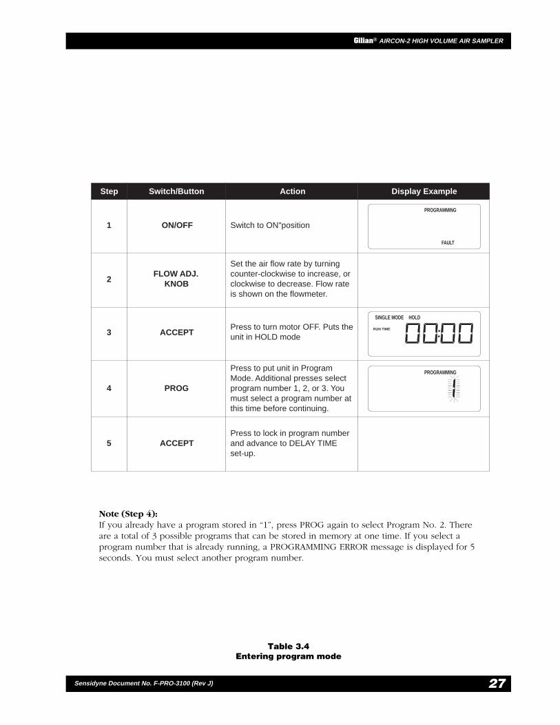
Table 3.4Entering program mode
Note (Step 4):If you already have a program stored in “1”, press PROG again to select Program No. 2. Thereare a total of 3 possible programs that can be stored in memory at one time. If you select aprogram number that is already running, a PROGRAMMING ERROR message is displayed for 5seconds. You must select another program number.
Step Switch/Button Action Display Example
FAULT
PROGRAMMING
HOLDSINGLE MODE
RUN TIME
PROGRAMMING
1
2
3
4
5
ON/OFF
FLOW ADJ.KNOB
ACCEPT
PROG
ACCEPT
Switch to ON"position
Set the air flow rate by turningcounter-clockwise to increase, orclockwise to decrease. Flow rateis shown on the flowmeter.
Press to turn motor OFF. Puts theunit in HOLD mode
Press to put unit in ProgramMode. Additional presses selectprogram number 1, 2, or 3. Youmust select a program number atthis time before continuing.
Press to lock in program numberand advance to DELAY TIMEset-up.
— PRELIMINARY —
Gilian® AIRCON-2 HIGH VOLUME AIR SAMPLER
28 Sensidyne Document No. F-PRO-3100 (Rev J)
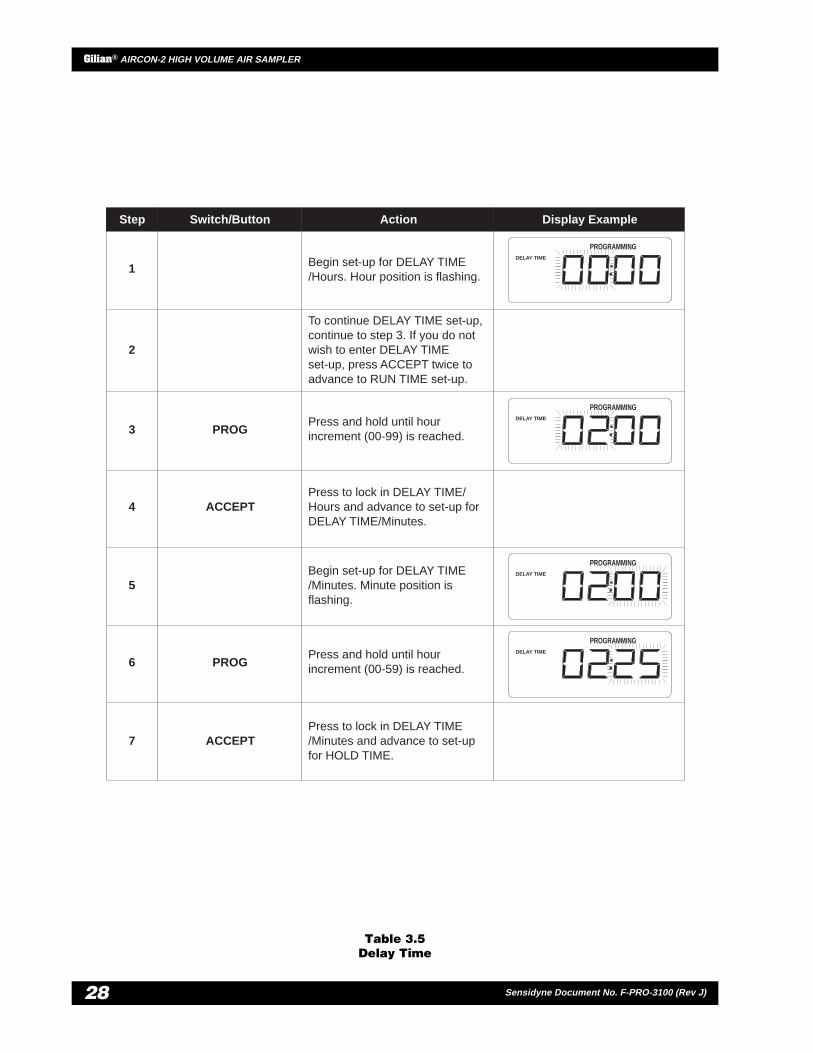
Table 3.5Delay Time
PROGRAMMINGDELAY TIME
PROGRAMMINGDELAY TIME
PROGRAMMINGDELAY TIME
PROGRAMMINGDELAY TIME
1
2
3 PROG
4 ACCEPT
5
6 PROG
7 ACCEPT
set-up, press ACCEPT twice toadvance to RUN TIME set-up.
Press and hold until hourincrement (00-99) is reached.
Press to lock in DELAY TIME/Hours and advance to set-up forDELAY TIME/Minutes.
Begin set-up for DELAY TIME/Minutes. Minute position isflashing.
Press and hold until hourincrement (00-59) is reached.
Press to lock in DELAY TIME/Minutes and advance to set-upfor HOLD TIME.
Begin set-up for DELAY TIME/Hours. Hour position is flashing.
To continue DELAY TIME set-up,continue to step 3. If you do notwish to enter DELAY TIME
Step Switch/Button Action Display Example

29
Gilian® AIRCON-2 HIGH VOLUME AIR SAMPLER
Sensidyne Document No. F-PRO-3100 (Rev J)
Table 3.6Run Time
Step Switch/Button Action Display Example
PROGRAMMING
RUN TIME
PROGRAMMING
RUN TIME
PROGRAMMING
RUN TIME
PROGRAMMING
RUN TIME
1
2
3
4
5
6
PROG
ACCEPT
PROG
ACCEPT
Begin set-up for RUN TIME/Hours. Hour position is flashing.
Press and hold until hourincrement (00-99) is reached. Youmust enter a value greater thanzero for unit to operate.
Press to lock in RUN TIME/ Hoursand advance to set-up for RUNTIME/ Minutes.
Begin set-up for RUN TIME/Minutes. Minute position isflashing.
Press and hold until hourincrement (00-59) is reached.
Press to lock in RUN TIME/Minutes and advance to set-up forHold Time.

— PRELIMINARY —
Gilian® AIRCON-2 HIGH VOLUME AIR SAMPLER
30 Sensidyne Document No. F-PRO-3100 (Rev J)
Table 3.7Hold Time
PROGRAMMING
HOLD TIME
PROGRAMMING
HOLD TIME
PROGRAMMING
HOLD TIME
PROGRAMMING
HOLD TIME
1
2
3
4
5
6
7
PROG
ACCEPT
PROG
ACCEPT
Begin set-up for HOLD TIME/Hours. Hour position is flashing.
If you do not want to enter HOLDTIME data, press ACCEPT twiceto advance display to #RUNCYCLES, or continue to step 3.
Press and hold until hourincrement (00-99) is reached.
Press to lock in HOLD TIME/Hours and advance to set-up forHOLD TIME/ MInutes
Begin set-up for HOLD TIME/Minutes. Minute position isflashing.
Press and hold until minuteincrement (00-59) is reached.
Press to lock in HOLD TIME/Minutes and advance to set-up for# RUN CYCLES.
Step Switch/Button Action Display Example

31
Gilian® AIRCON-2 HIGH VOLUME AIR SAMPLER
Sensidyne Document No. F-PRO-3100 (Rev J)
Table 3.8Run Cycles
* NOTE (Step 2)
If you do not select a minimum of 1 cycle and enter ACCEPT, the unit will display a PROGRAMMINGERROR message and return you to SELECT PROGRAM NUMBER. You will have to forward through thetime menus to # RUN CYCLES to re-enter your selection.
** NOTE (Step 3)
The collected RUN TIME (total time) equals the number of cycles times the programmed run time. The totaltime cannot exceed 199:59 (hours:minutes). When you press ACCEPT, the unit automatically checks thecollected run time to see if it exceeds this limit. If it does, a PROGRAMMING ERROR message appears onthe display for 5 seconds. If this occurs, you must change the program RUN TIME and/or the # RUNCYCLES be within the total time limit.
PROGRAMMING
#CYCLES
PROGRAMMING
#CYCLES
HOLDSINGLE MODE
RUN TIME
1
2*
3**
4
PROG
ACCEPT
Begin set-up for RUN CYCLES.Run Cycles position is flashing.
must select a minimum of 1 cyclefor the sampler to run.
Press and hold until the numberof cycles (00-99) is reached. You
Press to lock in RUN CYCLES.
Programming complete forProgram No. 1.
Puts unit in SINGLE MODE/HOLD.
Step Switch/Button Action Display Example

— PRELIMINARY —
Gilian® AIRCON-2 HIGH VOLUME AIR SAMPLER
32 Sensidyne Document No. F-PRO-3100 (Rev J)
SECTION FOURAFTER SAMPLING
4.1 UNIT SHUTDOWN
1) Turn the power “Off”.
2) If sampling through the Power Module from anAC source, remove the plug from AC wall outletand rewind cord.
3) Remove the filter cassette or media carefully andlabel for safe record keeping.
4) Disconnect tubing from the sampler’s air inlet.Remove connection tip from the top of thesampling mast. Recoil tubing for future use.
4.2 SAMPLING MAST
1) To collapse the sampling mast, start with thesmallest locking collar. Loosen the collar and pushin the extension. Tighten the smallest collar.Continue with this procedure all the way downthe mast until the mast is collapsed.
2) Unlock the locking knob at the bottom of themast stand and fold in the legs until they areparallel with the mast. The mast is now collapsedand ready for storage.
4.3 BATTERY PACK MAINTENANCE
The AirCon-2 Battery Pack is capable of four hours ofDC operation with full charge. Prior to use, theBattery Pack will require full charging to obtain a fourhour sampling period. Recharge Battery Pack(s) withthe AirCon-2 Power Module accessory.

33
Gilian® AIRCON-2 HIGH VOLUME AIR SAMPLER
Sensidyne Document No. F-PRO-3100 (Rev J)
APPENDIX APARTS LIST
rebmuNtraP noitpircseD/metI
100108 kcaPyrettaBruoH-ruoF
2-000108 )citsemoD(ECregrahCeludoMrewoP
3-000108 )naeporuE(ECregrahCeludoMrewoP
630104 tsaMgnilpmaS
27-640202 )gnibuT(esoHriA
754002 piTtroppuSesoH
265104 )citsemoD(droCeniLCA
707007 )naeporuE(droCeniLCA
1-171108 esaCrelloR
— PRELIMINARY —
Gilian® AIRCON-2 HIGH VOLUME AIR SAMPLER
34 Sensidyne Document No. F-PRO-3100 (Rev J)
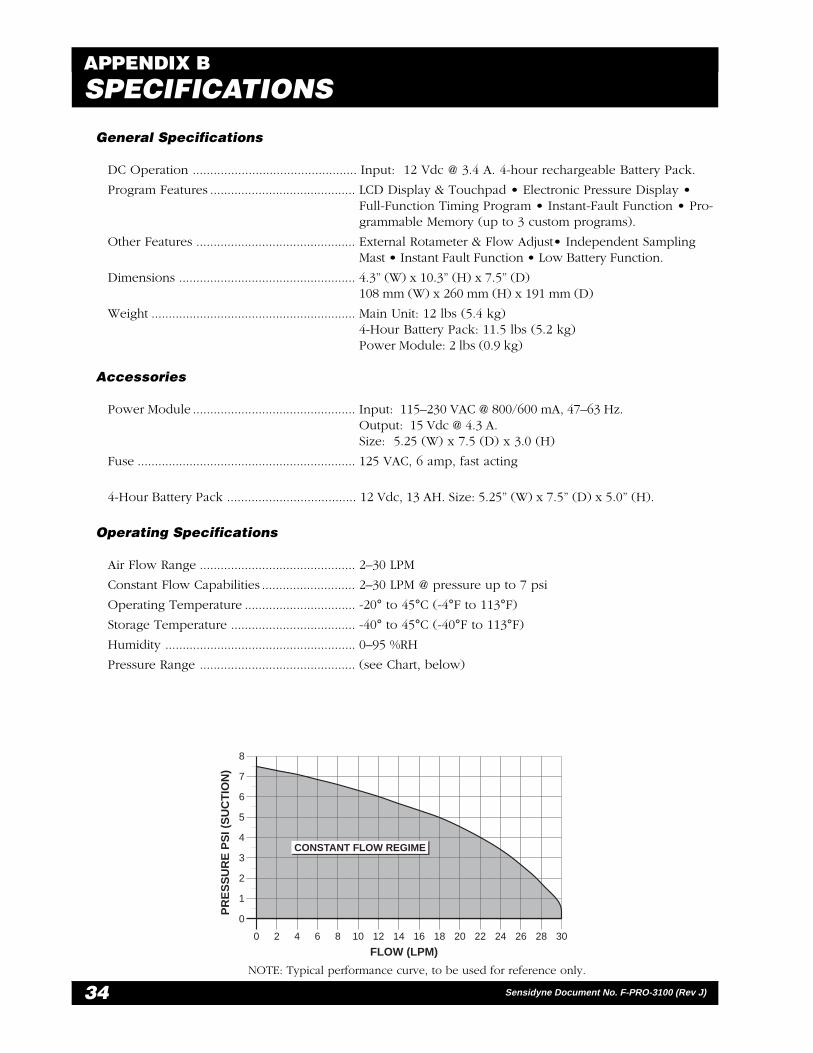
General Specifications
DC Operation ............................................... Input: 12 Vdc @ 3.4 A. 4-hour rechargeable Battery Pack.
Program Features .......................................... LCD Display & Touchpad • Electronic Pressure Display •Full-Function Timing Program • Instant-Fault Function • Pro-grammable Memory (up to 3 custom programs).
Other Features .............................................. External Rotameter & Flow Adjust• Independent SamplingMast • Instant Fault Function • Low Battery Function.
Dimensions ................................................... 4.3” (W) x 10.3” (H) x 7.5” (D)108 mm (W) x 260 mm (H) x 191 mm (D)
Weight ........................................................... Main Unit: 12 lbs (5.4 kg)4-Hour Battery Pack: 11.5 lbs (5.2 kg)Power Module: 2 lbs (0.9 kg)
Accessories
Power Module ............................................... Input: 115–230 VAC @ 800/600 mA, 47–63 Hz.Output: 15 Vdc @ 4.3 A.Size: 5.25 (W) x 7.5 (D) x 3.0 (H)
Fuse ............................................................... 125 VAC, 6 amp, fast acting
4-Hour Battery Pack ..................................... 12 Vdc, 13 AH. Size: 5.25” (W) x 7.5” (D) x 5.0” (H).
Operating Specifications
Air Flow Range ............................................. 2–30 LPM
Constant Flow Capabilities ........................... 2–30 LPM @ pressure up to 7 psi
Operating Temperature ................................ -20° to 45°C (-4°F to 113°F)
Storage Temperature .................................... -40° to 45°C (-40°F to 113°F)
Humidity ....................................................... 0–95 %RH
Pressure Range ............................................. (see Chart, below)
APPENDIX BSPECIFICATIONS
8
7
6
5
4
3
2
1
0
0 2 4 6 8 10 12 14 16 18 20 22 24 26 28 30
FLOW (LPM)
PR
ES
SU
RE
PS
I (S
UC
TIO
N)
CONSTANT FLOW REGIME
NOTE: Typical performance curve, to be used for reference only.
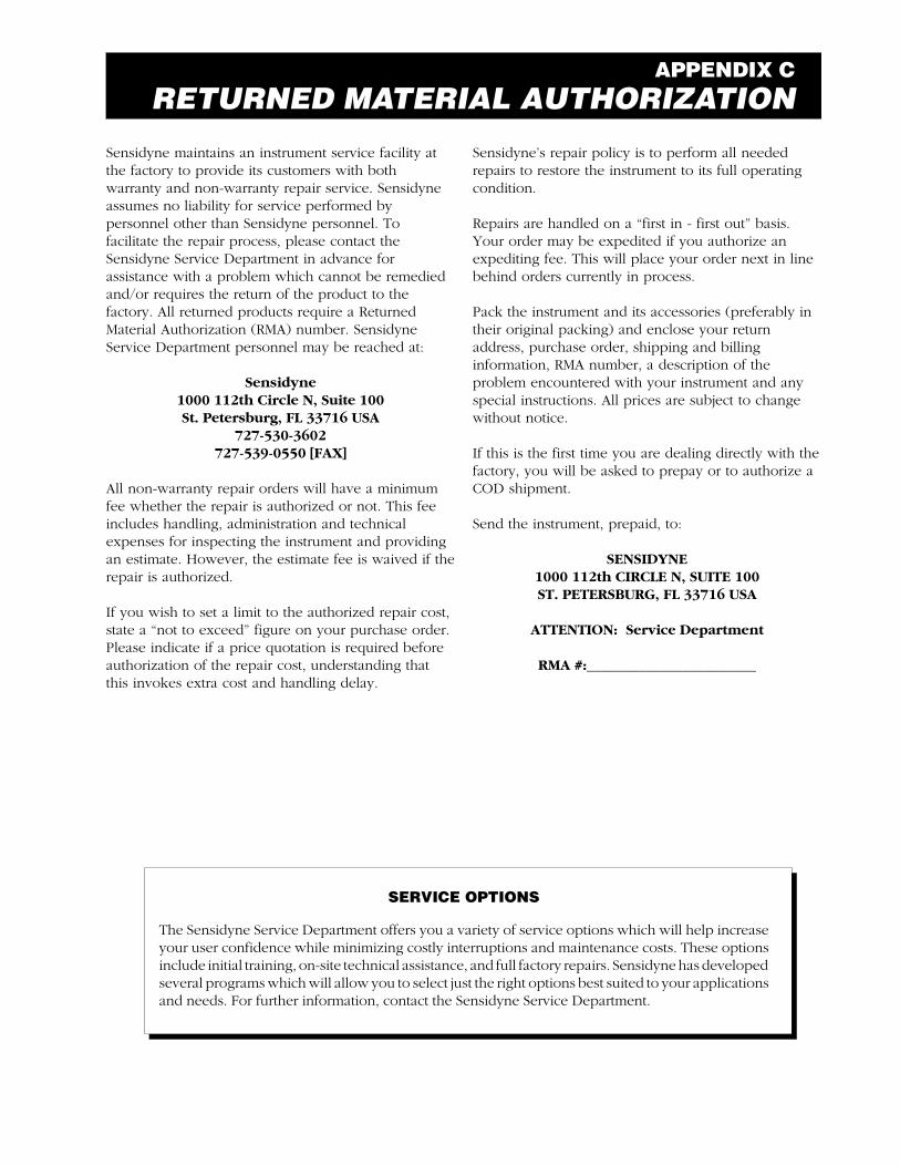
APPENDIX CRETURNED MATERIAL AUTHORIZATION
SERVICE OPTIONS
The Sensidyne Service Department offers you a variety of service options which will help increaseyour user confidence while minimizing costly interruptions and maintenance costs. These optionsinclude initial training, on-site technical assistance, and full factory repairs. Sensidyne has developedseveral programs which will allow you to select just the right options best suited to your applicationsand needs. For further information, contact the Sensidyne Service Department.
Sensidyne maintains an instrument service facility atthe factory to provide its customers with bothwarranty and non-warranty repair service. Sensidyneassumes no liability for service performed bypersonnel other than Sensidyne personnel. Tofacilitate the repair process, please contact theSensidyne Service Department in advance forassistance with a problem which cannot be remediedand/or requires the return of the product to thefactory. All returned products require a ReturnedMaterial Authorization (RMA) number. SensidyneService Department personnel may be reached at:
Sensidyne1000 112th Circle N, Suite 100St. Petersburg, FL 33716 USA
727-530-3602727-539-0550 [FAX]
All non-warranty repair orders will have a minimumfee whether the repair is authorized or not. This feeincludes handling, administration and technicalexpenses for inspecting the instrument and providingan estimate. However, the estimate fee is waived if therepair is authorized.
If you wish to set a limit to the authorized repair cost,state a “not to exceed” figure on your purchase order.Please indicate if a price quotation is required beforeauthorization of the repair cost, understanding thatthis invokes extra cost and handling delay.
Sensidyne’s repair policy is to perform all neededrepairs to restore the instrument to its full operatingcondition.
Repairs are handled on a “first in - first out” basis.Your order may be expedited if you authorize anexpediting fee. This will place your order next in linebehind orders currently in process.
Pack the instrument and its accessories (preferably intheir original packing) and enclose your returnaddress, purchase order, shipping and billinginformation, RMA number, a description of theproblem encountered with your instrument and anyspecial instructions. All prices are subject to changewithout notice.
If this is the first time you are dealing directly with thefactory, you will be asked to prepay or to authorize aCOD shipment.
Send the instrument, prepaid, to:
SENSIDYNE1000 112th CIRCLE N, SUITE 100ST. PETERSBURG, FL 33716 USA
ATTENTION: Service Department
RMA #:_______________________

1000 112th Circle N, Suite 100 • St. Petersburg, FL 33716800-451-9444 • 727-530-3602 • fax: 727-539-0550
web: www.sensidyne.com • e-mail: [email protected]
Revision J • Document No. F-PRO-3100