Embed Size (px)
Citation preview

· !
.,.. ". ~
i ,. ELECTRON ACCELERATORS FOR .N~USTRIAL P~OCESSING - A REVIEW Waldemar Scharf, Wioletta Wieszczycka
N Warsaw University of Technology, Nowowiejska Street 15/19, PL 06-665 Warsaw, Poland
The applications of over 1000 EB accelerator processors used recently worldwide span technological fields from material modification to medical sterilization and food processing. The performance level achieved by the main manufacturers is demonstrated by some selected parameters of processors in the energy range from 0.1 MeV to 10 MeV. The design of the new generation of low cost compact in-line and stand-alone accelerators is discussed.
TABLE 1 Total world accelerator population (1998) 1 Introduction
NUMBER IN CATEGORY OF ACCELERATORS1.1� Particle Accelerators Family USE There are, unfortunately, no current world statistics on High Energy Accelerators
1)particle accelerators. Therefore, we have to resort to some more [E> 1 GeV] or less accurate estimations. The total world accelerator BIOMEDICAL ACCELERATORS population for the year 1998 has been estimated by one of the
2) Radiotherapy� >4500authors at 13400 and breaks down as shown in Table 1. National data of accelerators are compiled only in a small Research Acc. incl. Biomedical3)� 1000
..._l J number of countries. For example, in Japan in 1982 there were Research in all 466 accelerators in operation, among which were 4) Medical Radioisotope Production -200 included 3 synchrotrons, 3 synchrocyclotrons, 15 cyclotrons, Accelerators for Radiation Industrial 73 betatrons, 248 linear rf accelerators, and 38 van de Graaf 5)� >1500
and Research Processingaccelerators. In 1996 there are in total 1035 accelerators (Table Ion Implanters incl. Surface -6000 2)2):� 25 synchrotrons, 53 cyclotrons, 16 betatrons, 639linear 6)
Modification Centers
-0accelerators, 54 van de Graaf accelerators, 97 Cockroft
7) Synchrotron Radiation Sources -60Walton accelerators, 25 transformer - type accelerators and 28 =r'- microtrons (1). TOTAL in 1998 -13372....... Ij Data after Catalogue of High Energy Accelerators, HEACC'92 (1)
-=m� 2) Data after G. A. Norton (2)~IG 15_U1 ::1_0
1.-0
~= 0 TABLE 2 Japanese family of accelerators as of March 31, 1996 (Data after "Statistics on the Use of Radiation in Japan 1996) without ..;:= ion implanters [1]
.... �0liliiii Category of Organization ~-----------_......---------
Total (Ratio %)
Hospitals & Clinics
Educational Organizations
Research Institutions
Industrial Firms
Other
Radiation Generators Total 1035 657 53 161 158 6 (%) (100) (63.5) (5.1) (15.6) (15.3) (0.6) Cyclotrons 53(5.1) 16 - 18 18 1 Synchrotrons 25(2.4) . 1 19 5 -Linear Accelerators 736(71.1) 608 6 43 76 3 Betatrons 16(1.5) 11 1 1 3 --Vande Graaf Acc. 54(5.2) - 15 28 11 -Cockroft-Walton Acc. 97(9.4) - 27 32 36 2 Transformer-type Acc. 25(2.4) - I 19 5 --Microtrons 28(2.7) 22 2 - 4 -Plasma Generators 1(0.1) - - I - -

~.. r"""'"� ~~~ ,,,.,...... /
1.2� Beam Processing Parameters A process accelerator is a machine intended for
processing various materials with the use of electron beam (EB) radiation or after conversion with bremsstrahlung. Table 3 provides typical dose ranges used for radiation processing in various fields of application. The material under treatment is usually fed in the form of strips, sheets, blocks or packings.
Polymer modification using accelerated electrons such as cross-linking of cable insulation, tubes, pipes and modings, vulcanization of elastomers, grafting of polymer surfaces, processes of foamed plastics and heat shrinkable materials have gained wide industrial acceptance. A steadily growing electron beam technology is curing of paints, laquers, printing inks and functional coatings.
Electron beam processing offers high productivity, the possibility to treat the materials at normal temperature and pressure, excellent process control and clean production conditions.
TABLE 3 Dose requirements for various radiation technologies.
DOSERADIAnON TECHNOLOGIES REOUIREMENTS
Sprout inhibition (potatoes, onions) 30 to 200 Gy Potable water cleanup 250 to 500 Gy Insect control (grain, fruits) 100 to 1000 Gy Food irradiation (spices, vegetable, 0,05 to 30 kGy fruits, meat) Waste water disinfecting 0,5 to 1 kGy Fungi and mould control 1 to 3 kGy Municipal sludge disinfection 1 to 3 kGy Bacterial spore sterilization 3 to 10 kGy Sanitation 10kGy Virus particle sterilization 10 to 30Gy Smoke scrubbing (S02 and NOx) 10 to 30kGy Aging of rayon pulp 10 to 30 kGy Sterilization of medical devices 10 to 35 kGy Polymerization ofmonomers 10 to 50 kGy Modification ofpolymers 10 to 250 kGy Sterilization ofpackaging material 25kGy Crosslinking of wire cable 50 to200kGyinsulation and plastic film Degradation of cellulosic materials 100 to 500 kGy Degradation of scrap Teflon~ 0,5 to 1,5 MGy
Numbers of high current electron beam (EB) processing installations are given in Table 4.
TABLE 4 High current EB processing installations (after M. Cleland (4»
Voltage Range Number of Units Average Power [kW]fMeVl
0.1 - 0,3 300 100 05 - 5.0 700 40 5,0 - 15 35 15
TOTAL 1035 Absorbed dose ranges. From economical pomt of
view, the most significant processes are (1) cross-linking, (2) medical sterilization, (3) radiation cure. In technological practice absorbed dose of the order of several tens of kilograys (several megarads) are used. They should be delivered to the product under treatment in the shortest possible time, i.e. in seconds. It is only then that the accelerator throughput can be matched to the particular line yield. This yield is, in fact, called accelerator throughput rate defmed as amount of material per unit time irradiated by the accelerator with a predetermined dose. What is usually specified in surface treatment is either the material area per one minute (m2min -I) irradiated with a
predetermined dose, e.g. 10 kGY (l Mrad), or only the linear velocity v, the material stream which refers to the predetermined dose level and the given stream width w. It is usually expressed in m min-I. Typically, the surface throughput rates nowadays range from several tens to several hundreds of m2min-·. The linear throughput rates range also from several tens to several hundred m min-I, although in high yield processors they may be as high as 1200 m min-·.
The throughput of accelerators intended for bulk processing is usually determined by the number of kilograms or tons to be irradiated in one hour with a predetermined dose (kgh-I or t h-l for a dose of, e.g. 10 kGy, i.e. 1 Mrad). Typically, throughputs of this kind range from several thousand ofkgh-l. For materials in package form, for example, intended of sterilization, the throughput is expressed in terms of the volume of packages per unit time (e.g. m3 h-l or m3 year"l for typical sterilization dose of25 kGy or 2.5 Mrad).
In practice, the possibility of employing techniques requiring higher doses, i.e. those above 10 kGy (l Mrad), is dependent on the dose rate, which is the basic parameter of a radiation processor. It determines the rate at which energy is delivered to the irradiated object and is equivalent to the dose rate produced by the machine. That is why it is usually expressed in terms of gray per second or by derivative units such as kGy sol or MGy s-·.
Fig. 1 gives the irradiation time as a function of dose rate for three main types of processors: 6OCO gamma sources, accelerator bremsstrahlung generators (X-ray) and electron generators. The curves represent two dose levels: 10 kGy (1 Mrad) and 100 kGy (10 Mrad), thus covering a typical range used in radiation processing. It can easir bee seen from Fig. 1 that the dose rates of the order of 102.10 Gy S"l (104_108rad S-I) can be achieved with electron accelerators. Therefore, the required doses can be delivered to the irradiated product in the period of seconds or even less than one second. In respect of the production throughput rate, electron processors predominate over any others types of radiation processors.
ly
:§: II)
~
~ 1d
..Q
~ 1h
10 2 1 min
10
10-2 1(;1 1 10 102 10 3 104tC..5 10 6101 108 rads 10-4 10-3 Hj21011 10 10210310410'5106 Gys
Dose ra.te
FIGURE 1 Irradiation time as a function of dose rate.
When using a 1.0 kW power beam, whose energy is totally absorbed in the radiated material, an average dose of 10 kGy (1.0 Mrad) can be obtained in the amount of material of 360 kg h-l. Thus the throughput or prodUction rate of a processor is given by
3600f 360f kg 3155f t w =---- -� Eq.l
m D(kGy) D(Mrad) kW h D(Mrad) kW year
wheref is total radiation energy utilization coefficient; D is the mean absorbed dose in the product. Typically, f values range
2
from 25 to 75%, strongly depending on the type of radiation employed and the shape and size of the product processed. For the beam power, P (kW), Eq. (1) becomes
360Pf (k h-1) E 2 mW D(Mrad) g q.
For example, if the beam power is 100 kW, and coefficient f =50%, then, using a technique which requires a dose of 10 Mrad, the mass throughput rate is wm = 1800kg h-1
.
High Voltage Process Accelerators
Figure 2 shows a basic schematic of a high - voltage processing accelerator. It consists of a particle source, an accelerating chamber which ends with a window or target, a high - vacuum pump and hv generator.
This hv accelerator· is a single - stage machine in which the maximum particle energy corresponds to the maximum voltage delivered by the generator. The voltages generated at present range from 100 keV to about 5 MeV and to 15 MeV - from linacs.
The. beam of accelerated particles is usually circular in cross-section and its diameter ranges from about 1 mm to several centimeters. The area of the material under treatment is as rule much larger than the cross - section of the beam, and therefore the accelerator is equipped with a special device, called a scanner, which sweeps the beam.
The beam is swept transversely to the direction of the material displaced by means of suitable conveyor. The swept beam is shown on the right - hand side of Fig. 2.
In order to avoid the troublesome swept the beam construction process accelerators have been developed with a linear or planar cathode. The length of this
FIGURE 2 Radiation processing by means of hv accelerator with linear cathode (left - hand side) and beam scanning device, i.e. scanner (right - hand side).
cathode corresponds to the width of the material to be irradiated (left hand - side of Fig. 2). Thus the effective width of the treatment zone, w, in Fig. 2 becomes much larger. This system, however, is appropriate only for low beam energies, i.e., those not higher than 300 keV. Machines of this kind are referred to as linear cathode accelerators.
The material under treatment may be irradiated from one side, usually from the above, or both sides as shown in Fig. 2. Hence, we can speak of accelerators for one side processing and those for double side processing.
Energy classification. Radiation process accelerators can be classified in three groups in respect to the energies used: 1) low - energy (low - voltage) machines: 100 to 300 (500) keV; 2) medium - energy: 300 keV to 5 MeV: 3) highenergy: 5 to 10 or 15 MeV.
a)ln,..,.,.__~_...__~--------_
60 120 180 240 300 360 .w 480 La:~r thickDe•• (R 1m~
o� 1 :2 3 4 .5 6 7 8 em 10000 40000 70000 g~
Layer thic~ss
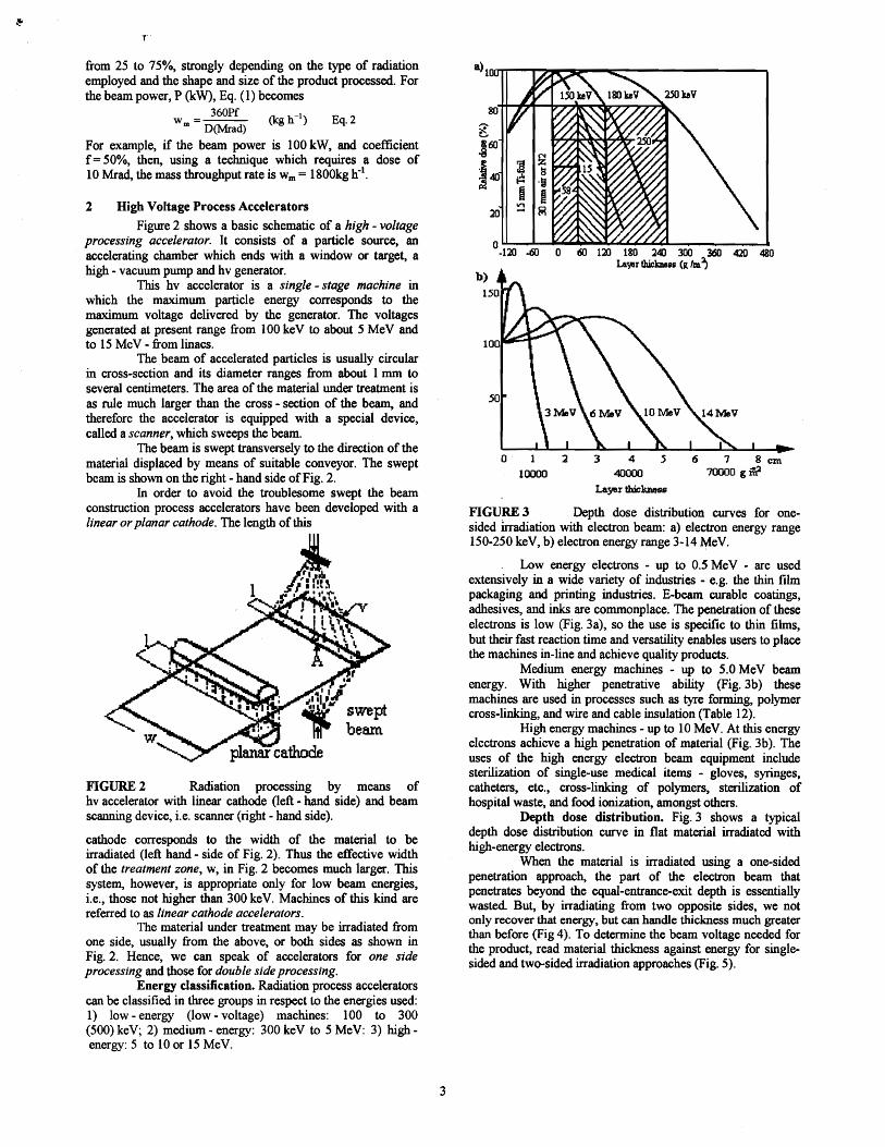
FIGURE 3 Depth dose distribution curves for onesided irradiation with electron beam: a) electron energy range 150-250 keV, b) electron energy range 3-14 MeV.
Low energy electrons - up to 0.5 MeV - are used extensively in a wide variety of industries - e.g. the thin film packaging and printing industries. E-beam curable coatings, adhesives, and inks are commonplace. The penetration of these electrons is low (Fig. 3a), so the use is specific to thin films, but their fast reaction time and versatility enables users to place the machines in-line and achieve quality products.
Medium energy machines - up to 5.0 MeV beam energy. With higher penetrative ability (Fig.3b) these machines are used in processes such as tyre forming, polymer cross-linking, and wire and cable insulation (Table 12).
High energy machines - up to 10 MeV. At this energy electrons achieve a high penetration of material (Fig. 3b). The uses of the high energy electron beam equipment include sterilization of single-use medical items - gloves, syringes, catheters, etc., cross-linking of polymers, sterilization of hospital waste, and food ionization, amongst others.
Depth dose distribution. Fig. 3 shows a typical depth dose distribution curve in flat material irradiated with high-energy electrons.
When the material is irradiated using a one-sided penetration approach, the part of the electron beam that penetrates beyond the equal-entrance-exit depth is essentially wasted. But, by irradiating from two opposite sides, we not only recover that energy, but can handle thickness much greater than before (Fig 4). To determine the beam voltage needed for the product, read material thickness against energy for singlesided and two-sided irradiation approaches (Fig. 5).
3

Deph penetration in mils at unit density example, when a 6OCO source is used with gamma energies of 80 120 160 200 240 1.17 and 1.33 MeV, the maximum area-weight range for two
sided irradiation is 20 g cm-2.
oI 0.1 0.2 0.3 0.4 0.5 0.6 0.7 0.8
I Deph penetraliln in g I em1 I . I LO}:tim1ll'l\ thickrItsI fOil dolille-Iided imdiaIion with 1MeV electrol'lS....
FIGURE 4 Depth dose distribution for two-sided irradiation with 1 MeV electrons
(1) One sided (2) Two sided500
~ ..... .... 400 1j
300~ ]
200 ~
100
0 a 4 6 8 10
EMrg}l; MeV
FIGURE 5 Material thickness for one-sided irradiation (curve ') and two-sided irradiation (curve. ') versus beam energy
Cob t 0� X-ray�
Box dimeIlSion, em
FIGURE 6 Two sided penetration of medical products for 2-10 MeV electron beam and X-ray after conversion to bremsstralung.
Currently, electron treatment is considered to be most efficient method of radiation processing. The electron energy of over 10 MeV cannot, however, be employed because of the possibility of inducing radioactivity in the material to be processed. It is particularly undesirable in case of foodstuffs and medicines, for which special is needed if the energy of 10 MeV is to be exceeded. Thus the above energy value is used to determine the maximum area-weight of material processed. For example, if irradiated with 12 MeV electrons the maximum area-weight of material is 4.44 g cm-2
, and for two-sided irradiation it can be as high as 10 g cm-2
. If, however, the product is to be processed in bulk (because of the packing). harder gamma or bremsstrahlung must be employed. For
3 Low Energy Accelerators In accordance with the previously mentioned
classification of accelerators, low-energy or low-voltage processors operate in the energy range between 100 and 300 keV. In view of the low penetration capability of electrons in this energy range. low-voltage accelerators are intended exclusively for surface treatment in the weight-area range from about 50 to about 400 g m-2
• Depending on their construction they can be classified into linear or planar cathode accelerator and scanning accelerators.
Electrocurtain System. The concept of using an elongated cathode for producing a wide, low-energy electron beam without scanning was introduced in early 1970s by Energy Science Inc. [F 1]. These Electrocurtains are mainly used for high-speed curing of inks and coatings on heatsensitive substrates, but some have been adapted to the sterilization of packaging materials for medical products. Energy Science, Inc. is now owned by Iwasaki Electric Company, Ltd. (1988).
Electrocurtain System is a typical linear cathode processor. Its block diagram is given in Fig. 7. The upper part of the head contains the accelerating chamber proper (Fig. 7a). A heated linear cathode made of tungsten emits electrons. In the latest models, denoted by EPZ (Extended Process Zone), two to four parallel cathodes are installed (Fig. 7 shows two cathode).The accelerating system is supplied with an hv ranging from 120 to 300 kV. This cathode, or in other words, the electron gun operates at a high voltage, while the anode, which forms the external envelope of accelerating chamber, is grounded. A vacuum of less than lO-s mbar exists in the chamber through a thin 12 lJlII-thick titanium foil window which allows 80 per cent of the total number of electrons in the beam to reach the product process zone. To ensure that the window has a long life a cooling system is employed.
The process chamber proper is located in the lower part of the head (Fig.7a). Its construction is detcnnined by the fact that a large number of surface treatment techniques must require an atmosphere of nitrogen which acts as protective gas. If the material to be treated is in the form of flexible strip, the chamber ensures that the level of harmful oxygen in the air is less than 500 ppm for productio rates of up to 300 m min-I.
The head is housed in a shielding which fully protects against any radiation. The mean annual dose to the personnel is about 16.3 mrem, i.e., approx. 10 per cent of the dose from natural sources ofradiactivity.
Electrocurtain installations are 0.15 to 2 m long in the direction of the production line. which corresponds to the width of the product to be treated (w dimension in Fig 7). For a 70 % inhomogeneous depth dose (Fig. 3a) the useful range of the area-weight processed varies from 1 to 380 g m-2 (300 kV). The upper limits of the above range are 120, 180 and 270 g m-2 for the voltages of 175, 200 and 250 kV, respectively.
The accelerator throughputs for the dose of 10 kGy (1 Mrad) depend on the type of machine and range from 450 to 1600 m min-I. For the Electrocurtain EPZ-2 and EPZ-3 models they are 900 m min-I, respectively. The energy efficiency ix approx. 70 per cent.
4

chamber b) linear fi1 amema) ~ ectron gt.Il8 e1 ctroo source
beem caoltetminal assembly O1y
web a sheets
FIGURE 7 Electrocurtain System with linear cathode (ESI) [Fl] for surface radiation processing: a) construction of head assembly with accelerating chamber, b) view of head assembly.
TABLE 5 Processing accelerators produced by ESI (Energy Science, Inc) (5)
Accelerator Type 7969 I) 7964 1) 7966 J) 7954 4) 7953 5)
Voltage [kV] 150-300 150-200 125-200 120-200 125-150 I Mrad at 600 m min-I 1 Mrad at1 Mrad at 525 m min- I Mrad at 1050m min- 1 Mrad at Dose/Speed typical, 1200 mlmin 1075 m min-I typical,
I, 1200 mlmin max I, 1200 mlmin max 1200 mmin-1
max 1200 mlmin max� cross�
Beam 7.5 7.5 7.5 7.5 7.5web
Uniformity down[%] 5 5 5 5 5web
Yield Value 1.4 Mrad 1.42 Mrad.ppm rnA-I 2.1 Mrad.ppm rnA-I 1.3 IvIrad.ppm rnA-I 3.13 Mrad.ppm mA-1
Determination ±0.4 Mrad.ppm rnA-I 165 cm typical, 150 cm typical, 180 cm typical,
Product Width 120cm 75cm225 cm maximum 225 cm maximum 225 cm maximum Web, 0.90 rom to Web, 0.025 rom to Web, 0.025 rom to Web, 0.02 rom to Web, 0.025 rom to
Product Type 3 rom thick 0.40mm 0.40mm 0.10 mm paper 0.40 mm typical
1) Model EC 300/1651525 Type 7969; 2) Model EC 200112011050 Cassette type 7964; 3) Model EC 200/150/600 Drum type 7966; 4) Model EC 200/180/1075 Type 7954; S) Model EC 150107511200 Cassette type 7963
linear tungsten mament as electron emitter but in contrast toMODEL EC200/180/1075 TY~E 7954 other electron processors with similar characteristics they doproduct entrance not employ any grid between cathode and anode. The
acceler tor acceleration takes place within the single potential gap formed by the cathode on high voltage and the exit window on ground. A cross sectional view of a typical LEA accelerator head is shown in FiS: 9.
lIighvoltage accelemtionvessel iris 1 r
FIGURES ESI linear cathode system type 7954 (5)
Fig. 8 represents ESI linear cathode system, type electrons7954. Some ESI accelerators performance characteristics are
listed in Table 5. FIGURE 9 Cross sectional view of LEA acceleratos In 1995 ESI introduced UVfEB thermal EB hybrid (Institute of Surface Modification, Leipzing, Germany); after
processing systems. R Mehnert et a1. (6)LEA System. The so-called LEA accelerators use a
5

Electrons emitted from the heated cathode are forced to move on trajectories illuminating homogeneously the exit window of the accelerator head. This can be achieved by using a cylindrical shaping electrode. The electron beam envelope can be adapted to the exit window dimensions by varying diameter and slit width of the shaping electrode. and/or the diameter of the cylindrical accelerator head. At acceleration voltages above 120 kV this diode-type accelerator is working in the current saturation mode.
Some main characteristics of different LEA-type accelerators are summarized in Table 6. These accelerators are now manufactured by Polymer Physik, Tubingen [F2], a wellknown manufacturer of scanning type low-energy accelerators.
TABLE 6 Low-energy Electron Accelerators of the LEA Family; after R Mehnert et al. (6)
Electron Electron Window Typical Type Energy Current Dimensions Applicati
(keV) (rnA) (mmxmm) ons LEA 1 150-200 30 900x20 Lab unit LEA 2 150-200 50 900x50 Furniture LEA 31) 150-250 150 900xlO0 Printing LEA 4 150-200 300 900x200 Printing
I) M8Xlmum WlDdow length 1500 mm As indicated in Fig. 10 LEA accelerators can be used
in all main application areas of electron beam curing as furniture element coatings, web converting and printing.
.fi 15'0 200 2 0 3QO
] ClQ
.S 1 --e-fumiture ~ ~ -----...":; i webE···'!§ 0 -++-.--I;f-converting
! -£1 ---_._--1 ........, : .Ii�
g 2 ----- ----t--J�
6 : § ----..---+- printing (offset)
-e 3 ~ .............:a:......__..
FIGURE 10 Application field of LEA Accelerators
RPC Industries, System. RPC [F4] made BroadBeam accelerators with multiple cathodes for large-area, low-energy beam without scanning. They were also developing a cold-cathode system called Wire Ion Plasma (WIP or WIPL) because wire is used for turning on plasma which yield ions.
mnchamber
high vol1age� p:nwr supply _cathode�
200kV typcal
300kV typical
plasma p:nwr .....------t~....., supply
How the beam of accelerated electron is produced in WlP electron processor is shown in Fig. 11. A vacuum chamber, which is evacuated with turbo-molecular pump, has a subchamber where plasma is generated. Helium gas is injected to the plasma chamber, then ions are generated in the low density plasma which is fired and sustained by a wire anode. The plasma is shielded by honeycomb grid which can pass a part of the Helium ions. Ions, coming through the grid, are accelerated toward a cathode which is supported with a ceramic insulator, then secondary electrons are generated and accelerated in the inverse direction to the grid. The electrons, coming through the plasma and a window foil, fmally reach to products. WIP electron gun has neither filament nor its power supply. This configuration can help to make the size small and to reduce its costs.
1,......--~-------~--------.
6
15 --.~ 4 l---t'JI~::2~2:.•2::::~_=--_::~.._.= .__-"'l~-1
~3 -e ]2<
1
o -20 -10 o 10 Width. cm
FIGURE 12 Dose Uniformity of WIP-6 (HV=165 kV, beam intensity 17.1 rnA, He 20 mTorr, AI. foil 6.5 J.UD, web 14.5 m min-I); after Y. Kumata et al. (9)
The result of WIP-6 is shown in Fig. 12. The uniformity is better than ±10% and typically ±5%. This uniformity is much depend on the plasma density, hence it is necessary to control the plasma discharge current and Helium gas pressure at optimum values.
TABLE 7 Processing accelerators produced by Sumitomo Heavy Industries, Ltd (+RPC)
±10 (typically 5) ±10 (typically 5) ±l0 (typically 5)
WIPL-165-3oo WIPL-200-600 WlPL-250-600 VoltaRe,kV 130-165 lSO-2oo 150-250 Beam width. mm 320 600 600 Maximum dose, Mrad mol minol 80 500 500
Beam power, kW 5 40 50 Max web mminol
speed, - 40 50
Dose uniformity, %
Some WIPL accelerators performance characteristics are listed� in Table 7.� Figure 13 shows the view ofWIP·8 system.�
FIGURE 11 Production of a beam of accelerated electrons in WIP Electron Processor manufactured by Sumitomo Heavy Industries [F3]
6

FIGURE 13 A view of a WIP-8 System (mfd by Sumitomo Heavy Industries and RPC)
Polymer Physik Scanning System. This was developed in the late sixties by Polymer-Physik Company [F2] and at present being manufactured under license by OttoDurr (10) as the ESH 150 System. Its construction is shown in Fig. 14.
FIGURE 14 ESH 150 (Polymer Physik) processor
The accelerating chamber is powered by a cablecoupled 250 kV generator. A heated tungsten cathode placed in the so-called Wehnelt electrode (used in oscilloscope tubes) serves an electron source. The purpose of this electrode is both to control the beam current and to focus electrons. As in other accelerators, the beam intensity is controlled here by controlling the filament current, i.e. the cathode temperature (typically, the temperature range from 2600° to 29000 K), and by controlling the Wehnelt electrode voltage.
The accelerating chamber is evacuated by a molecular pump operating in conjunction with a fIrst stage vacuum oil pump. This system of pump need be started only 10 min before the processor commences operation.
By the end of the accelerating process the the electron beam becomes approx. 4 mm in diameter. The scanning device consists of two pairs of crossed coils placed inside the the anode in the vacuum part of the chamber. The fIrst and the second pair deflect the beam in the x and y direction, respectively. Both pairs of coils are powered independently, which enables the motion to be programmed separately in each direction, if required.
The ESH 150 system scanner is provided with a 12 J.I11l-thick titanium exit window whose width is all models is 100 mm, while the length can be 200, 400, 600, 1300 and 2000 m. The window is supported by segments in which cooling water circulates. The penetration capability of the supporting part of the window is 70% and that of the window itself is 80% of the total number of electrons. These figures
depend to some extend of the accelerating voltage. In the worst case, the total penetration capability is higher than 50%, i.e. for a 15 kW beam the power losses in the window and its support can be as high as 7.5 kW.
When the scanner is switched off, the undeflected beam at the exit window would be 10 mm in diameter, while the energy density distribution at the beam cross-section would correspond to a Gaussian distribution. When the scanner is in operation, the irradiated fIeld is IOOx 130 mm and the irradiation intensity drops otT at the fIeld edges following roughly the Gauss distribution of the undeflected beam.
Fig. 3a shows radiation characteristics of the ESH 150 processor. For 80% irradiation inhomogeneity the useful ranges are 115 g m-2 and 250 g m-2 for beam energies of 180 keY and 250 keY, respectively. What is meant by a usefUl range is a net range, i.e., the range value reduced by that due to the absorption in the 15 J.I11l-thick titanium window and the 3 cm-thick protective gas or air layer (Fig. 3a).
Experienced values for industrial acceleration voltage area as follows:
• thin layers in the fIeld of printing inks or 130-150 kV silicon-release material • furniture foil, pressure-sensitive material 165-180 kV • boards, parquet, panels� 180-250 kV
Comparison of LEA. The low-energy electron accelerators mentioned in Table 8 can be used as computercontrolled subsystems in coating machines, printing presses, laminating machines, etc. Their operation parameters such as electron energy, beam power, irradiation width and dose rate can be precisely matched to the demands of the industrial proccss. In all accelerators mentioned electrons are produced by a hot cathode at high voltage potential. In a single gap the electrons are accelerated to the anode (usually the accelerator window). Up to electron energies of about 300 keY a stable acceleration is only one stage and self-shielding is possible. An upper limit of the electron beam power is given by the maximum possible current per square centimeter of window area is 0.2 rnA cm·2 (10).
TABLE 8 Low-energy Electron Accelerators used in Industry; after R. Mehnert (10)
Electron BeamManufacturer, Cathode� Max beam energy, power,Model configuration� width, mkeV kW Energy Sciences, Inc.
(ES!), US, linear cathode I) 150-300 2,3 Electrocurtain head
Electrocure2) multicathode 200 Radiation Polymer multicathode
150-300 200 2,3Co. (RPC) with 2 grids Broad Beam Dual multicathode3
) 300 980 2,3 Polymer Physik (PP), needle
130-280 100 6 ) 2,2Germany, Scanner cathode4)�
linear cathode� LEA5) with no control 120-250 60 1,0�
grid� Nissin High Voltage linear cathode 150-200 200 10� Co. (NHV), Japan� ,
Scanner needle cathode 300-500 65 1 2 " Up to 4 cathode-systems per accelerator, ") Used m printing mdustry;
3)Cons;sts of two accelerators; 4) 2 cathodes possible; 5) Used chiefly in printing
industry; 6) 65 kW at s~ of 100 m min" and a working width of 1300 mm
4 Medium Energy Accelerators
4.1� Transformer Accelerators
Conventional Transformers. This term is taken to mean standard high-voltage transformers whose magnetic core is grounded. In view of the insulating difficulties involved,
7
transformers of this kind are relatively seldom used in particle a) hv electrodtacceleration.
High-voltage generators provided with traditional b) transformers are manufactw"ed by a Japanese company, the 104..-.--.-----" t Nissin High-Voltage Co. [F5], wholly owned by Nissin Electric. The transformer feeds a suitable rectifying system and operates either in a single-phase or three-phase fashion. These transformers are built for the voltage range 300 to 1000 kV. A single-phase system is used for 300 to 500 kV with the load capacity of up to 100 mA, while three-phase systems are employed for the 750 to 1000 kV range. Oil-impregnated paper, whose dielectric strength is 10 to 20 times greater than the strength of oil itself, is used as an insulator. This results in a considerable reduction in the dimension of the insulation.
NHV makes several types of electron beam processing machines including low-energy (0.1 to 0.3 MeV) for curing coatings and medium -energy (up to 1 MeV) for cross-linking plastic and rubber sheets.
Maximum beam powers of accelerators equipped with the Nissin transformer generator mfd. by Nissin Company attain at present 100 kW and 1 MY, and their beam intensity is 100 mAo The generators are coupled by cable with the accelerating chamber. The versions of accelerating chambers are characterized by maximum current load of 100 mA, and types with a load of up to 150 mA are being designed. The advantage of generators provided with traditional groundedcore transformers is that the mains energy is transformed into beam energy in a simple way. Their relatively high efficiency amounts to 90 per cent.
Insulating-core Transformers. Since 1960s they have been manufactured by the High Voltage Engineering Corporation, HVEC and its European Division, High Voltage Engineering Europa B. V. [F6]. They are known as insulatingcore transformers (ICT) and they are used as electron beam process accelerators for medium energies of 300 to 3000 keV and beam powers of the order ofseveral tens of kilowatts (up to 120kW).
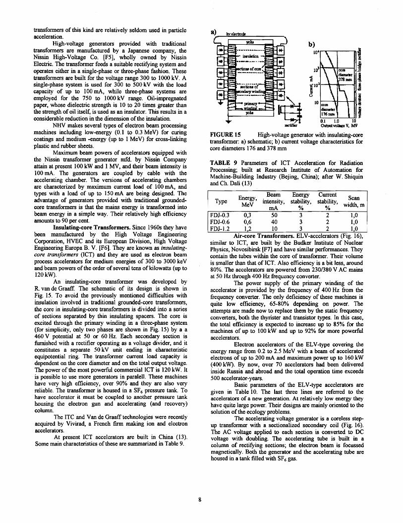
An insulating-core transformer was developed by R. van de Graaff. The schematic of its design is shown in Fig. 15. To avoid the previously mentioned difficulties with insulation involved in traditional grounded-core transformers, the core in insulating-core transformers is divided into a series of sections separated by thin insulating spacers. The core is excited through the primary winding in a three-phase system (for simplicity, only two phases are shown in Fig. 15) by a a 460 V potential at 50 or 60 Hz. Each secondary section is furnished with a rectifier operating as a voltage divider, and it constitutes a separate 50 kV unit ending in characteristic equipotential ring. The transformer current load capacity is dependent on the core diameter and on the total output voltage. The power of the most powerful commercial ICT is 120 kW. It is possible to use more generators in paralell. These machines have very high efficiency, over 90% and they are also very reliable. The transformer is housed in a SF6 pressure tank. To have accelerator it must be coupled to another pressure tank housing the electron gun and accelerating (and recovery) column.
The ITC and Van de Graafftechnologies were recently acquired by Vivirad, a French firm making ion and electron accelerators.
At present ICT accelerators are built in China (13). Some main characteristics of these are summarized in Table 9.
Itt·1-'lIr---"Il..+----IJj
~'0' i ~ I10 I-C:O-J'l---'H----+--n "l:I
ctiImnlr j 176mm J 0.1 1.0 10 OutwtvoUlce V. MV
FIGURE 15 High-voltage generator with insulating-core transformer: a) schematic; b) current voltage characteristics for core diameters 176 and 378 mm
TABLE 9 Parameters of ICT Acceleration for Radiation Processing; built at Research Institute of Automation for Machine-Building Industry (Bejing, China); after W. Shiquin and Ch. Dali (13)
Beam Energy CurrentEnergy, ScanType intensity, stability, stability,MeV width, m rnA % %
FDJ-OJ 0,3 50 3 2 1,0 FDJ-0.6 0,6 40 3 2 1,0 FDJ-l.2 1,2 10 3 2 1,0
Air-core Transformers. ELV-accelerators (Fig. 16), similar to ICT, are built by the Budker Institute of Nuclear Physics, Novosibirsk [F7] and have similar performances. They contain the tubes within the core of transformer. Their volume is smaller than that of ICT. Also efficiency is a bit less, around 80%. The accelerators are powered from 230/380 V AC mains at 50 Hz through 400 Hz frequency converter.
The power supply of the primary winding of the accelerator is provided by the frequency of 400 Hz from the frequency converter. The only deficiency of these machines is quite low efficiency, 65-80% depending on power. The attempts are made now to replace them by the static frequency converters, both the thyrister and transistor types. In this case, the total efficiency is expected to increase up to 85% for the machines of up to 100 kW and up to 92% for more powerful accelerators.
Electron accelerators of the ELV-type covering the energy range from 0.2 to 2.5 MeV with a beam of accelerated electrons of up to 200 mA and maximum power up to 160 kW (400 kW). By now, over 70 accelerators had been delivered inside Russia and abroad and the total operation time exceeds 500 accelerator-years.
Basic parameters of the ELV-type accelerators are given in Table 10. The last three lines are referred to the accelerators of a new generation. At relatively low energy they have quite large power. Their designs are mainly oriented to the solution of the ecology problems.
The accelerating voltage generator is 8 coreless stepup transformer with a sectionalized secondary coil (Fig. 16). The AC voltage applied to each section is converted to DC voltage with doubling. The accelerating tube is built in a column of rectifying sections; the electron beam is focussed magnetically. Both the generator and the accelerating tube are housed in a tank filled with SF6 gas.
8

FIGURE 16 Air transformer generator
TABLE 10 Parameters of ELV accelerators mfd. by Budker Institute of Nuclear Physics SB RAS [F7]; after Y. Golubenko et al. (15)
Energy range, Beam power, Max beam Type MeV kW current, rnA
ELV-mini 0,2-0,4 20 50 ELV-0.5 0,4-0,7 25 40 ELV-1 0,4-0,8 25 40 ELV-2 0,8-1,5 20 25 ELV-3 0,5-0,7 50 100 ELV-4 1,0-1,5 50 100 ELV-6 0,8-1,2 100 100 ELV-8 1,0-2,5 90 50 ELV-6a 0,75-0,95 160 200 Torch 0,5-0,8 500 800 ELV-12 0.6-1.0 400 400
Typically the ELV-type accelerators are desIgned for installation in a vertical position. However, accelerators for either horizontal beam extraction or for installation in a horizontal position are available on special order. The time required to attain rated operating conditions after a short idle time is 5 min, after a long idle time, 1 h, and after an idle time requiring fIlling with gas, 3h. The scheduled maintenance time does not exceed 10% of the calendar time.
Two versions of beam extraction into air provided: linear scanning (with the beam being extracted through foil and with linear scanning over the entire extraction window) and concentrated beam (with the beam being extracted through a system ofdiaphragms with wholes) (15).
The maximum current extracted through the foil window is 70 rnA m-I. The use of radiation in the large scale industrial production (flue gas treatment of HES, metallurgy, waste water treatment, etc.) require an increase in accelerator power up to a few hundred kilowatts. The electron beam optimum energy for the majority of these application lies within the range 0.7-1.5 MeV. Therefore, in order to achieve the required power one has to extract into air an electron beam with a current of few hundred rnA at quite low current density, i.e. the extraction window area should be enlarged. The use of support grids in the given range of energies is not reasonable since their transparency is 80-90%. In case of the use of the single window, its width is determined by the mechanical strength of the foil and does not exceed 7-10 cm . Therefore, it was decided to develop a new extraction device with two extraction foils enabling thus to expand the extraction window area twice with no substantial change in the device overall dimensions (15).
The accelerators available have the power mainly of up to 100 kW and cannot satisfy the need of power-intensive
radiation technologies (mainly ecological) where the accelerators are required with total electron beam power of units and tens of megawatts. For the manufacturing of such complexes the modules of the unit power of hundreds of kilowatts as a minimum are required.
At the Budker INP, a new generation of high voltage accelerators is being developed with the required power of an extracted beam. The representatives of a new family of accelerators are the ELV-6M with an energy of 0.75-1.0 MeV and the power of 160 kW; the TORCH accelerator with an energy of 0.5-0.8 MeV at a power of 500 kW, and ELV-12 accelerator of a power of400 kW at energy of 0.6-1.0 MeV.
In the TORCH accelerator, the high voltage rectifier is placed in a separate tank and it is connected with a accelerating tube through the gas feeder. The rectifier consists of two parallel columns with an output of high voltage in between. The sections of each columns are connected in seriesparallel and there is no filter capacitors in them. The primary winding with the central magnitude is located inside the column of the high voltage rectifier. The accelerator operation frequency is 1000 Hz and it is supplied from the converter PPFV-500. The accelerator schematic diagram is shown in Fig. 17. It was equipped with the device for the extraction into air of the adiabatically compressed electron beam which was described above. The maximum parameters obtained on this accelerator are the following: beam intensity of 0.8 A at energy of 0.5 MeV, beam intensity of 0,5 A at energy of 0.8 MeV, the beam power 500 kW (0.7 MeV*0.7 A).
accelerating tube
syltemrL raster farm ation lU'Jd'VllCl.Ul\ system
FIGURE 17 TORCH accelerator; after Y. Golubenko et al. (15)
4.2� Cascade Accelerators (Cockroft-Walton Accelerators) The asymeric cascade electrical circuit was developed
in 1920 and is known in electrical engineering as Greinacher doubling voltage circuit. Cockroft and Walton were first to use it in acceleration to produce voltages of several hundred kilovolts. This is why accelerators equipped with cascade generators are often referred to as Cockroft-Walton accelerators.
The asymeric cascade generator includes n identical stages, called cascades, consisting of capacitors C and rectifiers Re. The first stage, consisting of capacitor C1 and rectifier ReI. gets its power from the secondary winding of transformer Tr supplying an alternating voltage with amplitude u (Fig. 18). ,At point a of the circuit the transformer produces an alternatmg voltage which oscillates between the peak values ±u. The first stage also contains rectifier ReI which conducts when its anode has a positive potential relative the cathode. Thus in the
9

positive halfperiod of the supply voltage the rectifier conducts and charges the capacitor C1 to the value u. In the next halfperiod the capacitor is unable to discharge becouse rectifier is then reverse-biased and does not conduct. The potential at point c thus increases by u and now oscillates between the value of 0 and u. This causes the capacitor C2 to be charged through rectifier R~ to a voltage of 2u; point d is then at a constant potential of2u.
a)� b)
(6~~-.....-.....,{i! (4ut)u)
Cs .
~~"'~1IIe (2uAu)
C3�
~-.....- ....c (O;2u)�
2C
FIGURE 18 Cascade accelerator: a) asymmetric circuit; b) symmetric circuit
If the cascade generator circuit consists of n identical stages, a constant output voltage ofUo=2nu is set up in the case of operation with no current load. The insulation of the elements making up each stage, i.e. the capacitors and rectifiers, must thus withstand voltages of only 2u.
Since the voltage drop and the ripple amplitude in the above two kinds of cascade systems vary inversely with supply voltage frequency f, cascade generators often get their supply power from frequency convertors which operate in the range from 0.5 to 10 kHz.
The efficiency of the machine depends mainly upon the oscillator, and is usually more than 75%. As for the power, it depends on the number of oscillators driving the machine and on the current achievable with the rectifiers. These latter limit the power that is possible to transfer form grounded up to the top of Cockroft-Walton ladder. The diode technology of today allows very powerful (100 rnA, dc) and fast diodes (20 ns recovery time), which, further, can withstand very high power for short time.
TABLE 11 Parameters of Cockroft-Walton accelerators for radiation processing - Medium and High Energy Series, mfd. by Nissin High Voltage, Co [F5]
EPS EPS EPS EPS EPS EPS EPSType
500 800 1000 1500 2000 3000 5000 Accelerator 5000
500 800 1000 1500 2000 3000Voltae;e. kV�
Beam current,� 100 100 100 65 50 30 30rnA
Irradiation 180 180 180 120 120 120 120
width, cm x2� m2 min-1 t hr-I�
g 80 66 56 9,4 9,5 8,8 14,6:~"[ 2Mrad
{I)"i 5Mrad 32 26 22 3,7 3,8 3,5 5,8
J3 IOMrad 16 13 11 1,9 1,9 1,8 2,9 Power,kW 65 100 125 130 135 120 215
The construcbon of cascade accelerators was pioneered by Swiss company, Haefely. At present Nissin High Voltage (NHV)� [F5] offers symmetrical Cockroft-Walton generators which use multistage rectifier circuits energized with seriesconnected filter capacitors at frequency of 3 kHz. Such
machines can produce 100 kW of dc beam power with electron from 1 to 5 MeV and 150 kW at 5 MeV (Table 11). Nissin High Voltage is a major supplier of industrial accelerators in Japan (Fig. 18 and Table 12)
TABLE 12 NHV (Nissin High Voltage Co, Ltd) Electron Processing Systems, as for April, 1995, after T. Fujisawa (15).
200-300 kV
35Q-1200kV 15005000kV Total
Research and Development 49 6 5 60
Wire & Cable 1 50 5 56 Polyethylene Foam - 15 1 16
Heat-shrinkable Sheet and Tube 3 3 4 10
Curring &Convertine; 14 2 - 16
Automobile Tire 4 22 - 26 Sterilization - 1 1*1) 2 Flue Gas Treatment - 5 - 5
Others 5 10 4*2) 19 TOTAL 76 114 20 210
• mcluding Wlder constructlon I) SOOOkV, 30mA, 1991 Radial. Ind. hradiation Service 2)SOOOkV.300mA, 1994 S. Co. Sterilization
FIGURE 19 Total number of NHV electron beam systems (1971-1995); after T. Fujisawa (15)
4.3� Dynamitrons Radiation Dynamics, Inc. (RDI) [F8], formerly a
subsidiary of Monsanto, is now owned by Sumitomo Heavy Industries (SHI). During the 19608, RDI developed the Dynamitron type of accelerator which utilizes a multistage rectifier circuit energized through a parallel array of gasinsulated coupling capacitors. This system converts highfrequency ac power (75 to 100 kHz) to high-voltage dc power in the energy range of 0.5 to 5 MeV with electron beam power ratings as high as 200 kW (Table 12)
Radiation Dynamics, Inc. is a major supplier of industrial electron accelerators in North America, Western Europe and Japan. Most of these machines are devoted to cross-linking plastic and rubber products, but several Dynamitrons rated for 150 kW at 4.5 MeV are being used routinely for electron beam sterilization of medical devices.
10

The largest model, which is capable of 200 kW at 5 MeV, is used for a variety of processes such as the modification of polymers and semiconductors and sterilization with electrons and x-rays (13).
The D}namitron's operating principle is illustrated in Fig. 20. Two large D-shaped electrodes powered by an rf generator at 100 kHz are installed inside pressure tank. The voltage from those electrodes, which acts as antennae, is used to induce the corresponding secondary voltages in separate segments of the receiving unit. The segments are coupled with rectifiers and the rectified voltages from each segment are added together to supply an hv electrode. The accelerating chamber, as in Fig. 20, is mounted inside these segments. The tank is filled with an insulating gas, SF6. The direct voltage produced by a single segment is 50 kV.
TABLE 13 Standard Dynamitron models mfd. by RDI [F8]
Rated volta e kV Rated beam current mA� 550 70/100/160� 800 70/100/160� 1000 60/100� 1500 40/65� 2500 40� 3000 34/50� 4500 20/34� 5000 10/20/34�
FIGURE 20 Dynamitron-type accelerator; mfd by Radiation Dynamics (RDI).
The Dynamitron (Fig. 20) is similar to the previous machine: it is, in fact, based on a stack of Greinacher doublers connected in series, but with the important difference that the capacitors are fed in parallel. Some Dynamitrons performance characteristics are listed in Table 13.
The material throughput capabilities of RDI's new 550 keV an 800 keV Dynamitron accelerators (Fig.21) have been enhanced by increasing their beam current ratings from 100 mA to 160 mAo Future requirements up to 200 mA have been anticipated in the designs (18).
The concentrated electron beams are accelerated through elongated. multiple-gas tubes and then dispersed across the product conveyors by scanning through +30° and -30°. The thin, metallic windows through which the beams emerge from the high-vacuum systems are 1.65 m long and 12.7 cm wide and do not need supporting grids. They are cooled by transverse high-velocity air streams from manifolds located alongside the windows.
FIGURE 21 View of Dynamitron accelerator mfd. by RDI, Co [F8]
The electron beams are scanned in two dimensions to cover most of the available window area. The longitudinal (x) scan frequency is about 200 Hz and the transverse (y) scan frequency is about 4 kHz. Both of these waveforms are triangular. The x waveform can be modified to improve the dose uniformity at the edges of the product conveyors. Typical dose uniformities across the conveyors are ±5% of the average value. 4.4 Comparison of Medium Energy Accelerators.
Commercial Facilities Typical technologies used for radiation processing in various fields of application are listed in Table3. In technological practice, the irradiation parameters should be differentiated and adapted to technological process. Possibilities of use medium energy machines are shown in Table 14. It concerns the accelerators installed in Beta-Gamma Service [F12], which is a commercial facility. This facility is equipped with four medium energy accelerators which energy ranges from 0.6 to 4.5 MeV (beam power 11-150 kW).
The name commercial facilities is taken to embrace multifunction accelerator facilities which provide irradiation service to customers. The first of this type were founded in USA in the early sixties. For example in Europe, there are above mentioned BGS in Germany, Studer AG Bereich Elektronenbestrahlung in Switzerland [F13], CARIC in France [F14], SCANCARIC in Sweden [F15].
Accelerator techniques are highly cost-effective only on large, i.e. mass-production,· scale. The above facilities, however, made it also possible to perform radiation processing on a smaller scale. They had pioneered the way for pilot experiments and semi-industrial processing, which were preliminary to decisions about the purchase of one's own accelerator.
Today, the role of commercial facilities has been greatly modified and enlarged. Many of the chief industrial manufacturers have installed their own accelerators. Since radiation processing most frequently involves quality improvement of a product and is economically advantageous, small entrepreneurs have been forced to adopt this technique or else be eliminated from the market. This was the main reason
11

5
why the interest in commercial service facilities considerably increased.
The customers of commercial radiation centers are usualIy those same big manufacturers who already have accelerators of their own. Their machines are, however, permanently set up for a given production line and are not flexible enough to be used when another technique or product is to be employed. The introduction of radiation processing stimulates within the whole company the interest in this new tool and other irradiated products will be developed which cannot be processed in the existing facility and for which an additional facility cannot be justified. Sometimes the throughput of one's own facility is not high enough to handle the surplus production. In all these cases commercial radiation centers seem to provide the best solution to the problem.
TABLE 14 Technological possibilities of medium energy range processing accelerators (BGS- Beta-Gamma Service, Wiehl-Bruchsal, Germany [F12].
Energy, MeV 0,3-0,6 0,8-1,5 1,5-2,8 2,5-4,5 Power, kW II 75 100 ISO Application cables / wires
max insulation thickness, 0,7 1,5 3,5 8 mm�
max outside diameter of� 1000 1000 2000 2800drums,mm
max width, mm 800 800 1460 1500 Application tubes / pipes
max wall thickness, mm 0,7 1,4 2,8 6 max outside diameter of
1000 1000 2000 2800drums,mm max width, mm 800 800 1460 1500
foils / Applications films foils I profiles
max product thickness, mm 2 4 - 6 max production width, mm 800 1800 - 1000
max outside diameter of .. 1000 1000 - 2800drums,mm
max width, mm 800 2000 - 1500 Aoolication - - cardboxes
max weight per surface ·2 - - 2,5 3,5
area, gem max product area - - 490x1000 1200xl600
Radiation Processing Linacs More than 1500 accelerators are functioning
contemporary in the industry and in the R&D processing centers alI over the world (Table 1) and about 200 machines from this park are linacs. Several companies now offer rf linear accelerators in the 10 MeV region (Table 16). Used in the electron mode, a higher energy beam has better penetration and will process a wider range of product. For example, the high energy systems at 10 MeV can penetrate and treat up to 50 rom of water, whereas the low energy system of about 1 MeV can only treat about 3 mm of water. Less dense materials, e.g. cardboxes for medical sterilization (-(US g cm,3) are penetrated proportionally deeper (Fig. 6).
These high energy levels are required to penetrate the product while the sterilized product is contained in fmal shipping packaging. The in-line sterilization system is one where the electron beam irradiation system is integrated directly into the production process. This can be accomplished with a small electron beam system dedicated to each production line or several lines feeding a singls electron beam system. In either configuration the type electron beam system can be designed to process cartons or single products in their sterile packaging (Table 15).
A stand-alone system differs from the in-line approach in that the electron beam system is not directly integrated into the production process. This approach is generally used to process many different types of products in their final shipping carton configurations. Stand-alone systems come in many sizes and are generally classified according to the power of the accelerator (smalI 1-5 kW, medium 10-20 kW and large 2550 kW) - the larger to the power, the more product volume can be processed. Power ranges above 35 kW are available but are seldom applied to medical device sterilization applications due to the difficulty in control issues at such high process rates.
2,00
1,50
1,00
0,50
0,00
FIGURE 22 Cost of sterilization as a function of power (throughput)
TABLE 15 Comparison of Sterilization Processes
High-pressur EOG Gamma Ray lectron BeamSteam
~terilization Sterilization SterilizationSterilization ~terilization exposing big} exposing jirradiation of irradiation of !Mechanism pressure stear~ylene oxide Gamma-ray bighenergy
over 121 0 gas fromCo60 electron beam !Penetrability l.less than
~alTuna.ray
no ~. penetrability- bighpenetrability ~dson ~ergyof !electron beam
!Processing batch batch continuous continuous Mode processinll. processinll. processiniZ orocessiruz Processing less thanseveral hours more than 10 several hoursTime hours minute Other electron beamdry up waste to stop ~bletostop is stoppedtreatment treatment is Gamma-ray
when powerrequired required radiation source is cut ..
The cost for electron stenhzatlon IS a strong functlon of volume treated (Fig. 22). In the past the maximum reliable power level for electron accelerator was between 10 and 20 kW. At this power, gamma rays from cobalt 60 provide strong price competition. At higher powers the economics of the process becomes limited more by the availability of the product to be treated in anyone place rather than the power of accelerator.
Today, however, rf electron Iinaes are frequently limited to an average beam power of only 20 or 30 kW (Table 16). The design of these accelerators is restricted by the characteristics of commercially available klystrons (usually Sband or L-band). To achieve higher beam power, higher duty cycle and/or the use of lower frequencies are necessary.
12

TABLE 16 Electron rf Linear Accelerators for Industrial Processing
Electron BeamManufacturer Frequency
Model energy, power, kW MeV
Medium Energy Rao&e Denki Kogo Co, Ltd.
0,3-0,9 1,2-6 200 MHz Electronshower RPC, Industries 2 10 S-band BudkerInstitute of Nuclear Physics 0,1-2,5 up to 40 120 MHz ILV
High Energy Range Varian
2-10 0,6-5 S-bandMega Ray-Series TORYI
2-10 6-12 L-bandElektronika D.V. Efremov
4-12 12 S-bandInstitute, VELV-8 ThomsonCSF
5-10 10-20 S-bandCIRCE WIll Mitsubishi Heavy Ind. 8-11 25 S-bad Scanditronix
10 30 L-bandEB 10 Titan Beta, Titan Scan 3-10 1-50 S-band Technical Systems,
10 50 L-bandLtd. (Harwel) rnA 3,3-10 50 (100) 107,5 MHz Rhodotron AECL
10 50 (250) L-bandIMPELA
5.1� High Energy Linae! Thomson-CSF Linaes. In 1956 Thomson-CSF created
the department of Electron Accelerators. In 1987 General Electric buys the branch CGR and concentrates on the medical business. Industrial and scientific market are being covered by a new founded company MeV Industrie which is joint venture between SHI and GE. Table 17 lists characteristics of CIRCE linacs manufactured by Thomson-CSF [F16].
TABLE 17 Parameters of CIRCE accelerators mfd. by Thomson-CSF [F16]
CIRCE II CIRCE II CIRCE II CIRCE III 10 20 20-B -10
Energy, MeV
10 10 10 5& 10
Beam power kW 10 20 18 10
Max pulse repetition 310 550 500 450 rate Hzl)
Scanning width. em
30 to 100 30 to 100 30 to 100 30 to 100
1lJ3eam pulse lengh 12.5J.1S In 1986 Thomson-CSF Linac installed the first
accelerator used for food preservation in a chicken factory called SPI. This machine produced 5 kW power and 7 MeV energy. They could treat 3 tons of deboned meat per hour at 3 kGy. This machine was operating three shifts per day and 230 days per year. Variable costs were less than 0.02 $ per kilo. In 1990 this machine was replaced by a new accelerator type CIRCE 10 MeV 10 kW, allowing them to double the throughput.
The subsidiary in Belgium of Molnlycke, a Swedish company (number one in non-woven medical disposable supplies) uses Thomson linacs for sterilization. Their
throughput is 70.000 m3 per year and the density ranges from 0.11 to 0.20.
This facility is equipped with 2 accelerators type CIRCE 10 MeV 20 kW placed vertically, facing each other, so as to irradiate products from both sides at the same time (Fig.23).
FIGURE 23 System for radiation sterilization equipped with two 10 MeV, 20 kW CIRCE opposite rf linacs (SCA M6lnlycke SA Clinical Products, Belgium [F22])
The advantages of this modular system are the following: 1) if the machine breaks down, the other can be used, 2) simple handling system: all-in, all-out (it allows to avoid the use of a turning-over device). This facility is an example of big in-house facility (the project started beginning in 1989). The 10 MeV electrons, in cases of double side irradiation admit a maximal surface weigh of approximately 6.5 gcm-2•
At present Thomson-CSF developed STERBOX (Fig. 24) sterilization system for use in-line. ll)
FIGURE 24 STERBOX Sterilization System: a) View, b) Principle of Product Transport System
Table 18 lists STERBOX throughput and dose parameters for sterilization and food processing.
13
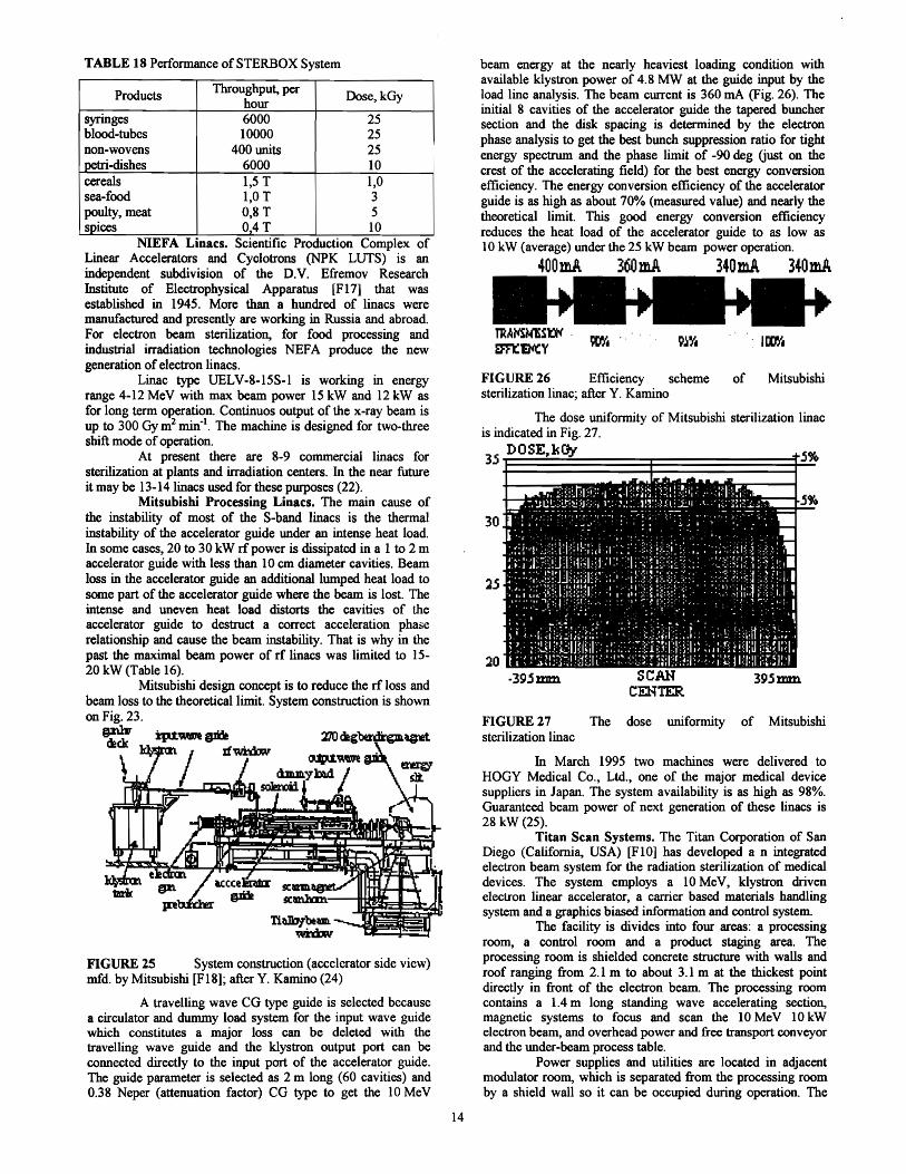
TABLE 18 Performance ofSTERBOX System
Throughput, per Products Dose,kGyhour
syringes 6000 25 blood-tubes 10000 25 non-wovens 400 units 25 petri-dishes 6000 10 cereals 1,5 T 1,0 sea-food 1,0 T 3 poulty, meat 0,8 T 5 spices 0,4T 10
NIEFA LlDaes. SCientIfic ProductIon Complex of Linear Accelerators and Cyclotrons (NPK LUTS) is an independent subdivision of the D.V. Efremov Research Institute of Electrophysical Apparatus [F17] that was established in 1945. More than a hundred of linacs were manufactured and presently are working in Russia and abroad. For electron beam sterilization, for food processing and industrial irradiation technologies NEFA produce the new generation of electron linacs.
Linac type UELV-8-15S-l is working in energy range 4-12 MeV with max beam power 15 kW and 12 kW as for long term operation. Continuos output of the x-ray beam is up to 300 Gy m2 min-I. The machine is designed for two-three shift mode of operation.
At present there are 8-9 commercial linacs for sterilization at plants and irradiation centers. In the near future it may be 13-141inacs used for these purposes (22).
Mitsubishi Processing Linaes. The main cause of the instability of most of the S-band linacs is the thermal instability of the accelerator guide under an intense heat load. In some cases, 20 to 30 kW rf power is dissipated in a 1 to 2 m accelerator guide with less than 10 em diameter cavities. Beam loss in the accelerator guide an additional lumped heat load to some part of the accelerator guide where the beam is lost. The intense and uneven heat load distorts the cavitit.~s of the accelerator guide to destruct a correct acceleration phase relationship and cause the beam instability. That is why in the past the maximal beam power of rf linacs was limited to 1520 kW (Table 16).
Mitsubishi design concept is to reduce the rf loss and beam loss to the theoretical limit. System construction is shown on Fig. 23.
pU1r 11Odeg~~dlck�
tUp.1'\W1t�
rfItI~e....J,;,;li~~so:.~mtbJilI
FIGURE 25 System construction (accelerator side view) mfd. by Mitsubishi [FI8]; after y. Kamino (24)
A travelling wave CG type guide is selected because a circulator and dummy load system for the input wave guide which constitutes a major loss can be deleted with the travelling wave guide and the klystron output port can be connected directly to the input port of the accelerator guide. The guide parameter is selected as 2 m long (60 cavities) and 0.38 Neper (attenuation factor) CG type to get the 10 MeV
beam energy at the nearly heaviest loading condition with available klystron power of 4.8 MW at the guide input by the load line analysis. The beam current is 360 rnA (Fig. 26). The initial 8 cavities of the accelerator guide the tapered buncher section and the disk spacing is determined by the electron phase analysis to get the best bunch suppression ratio for tight energy spectrum and the phase limit of -90 deg Gust on the crest of the accelerating field) for the best energy conversion efficiency. The energy conversion efficiency of the accelerator guide is as high as about 70% (measured value) and nearly the theoretical limit. This good energy conversion efficiency reduces the heat load of the accelerator guide to as low as 10 kW (average) under the 25 kW beam power operation.
400mA 360mA 340mA 340mA
FIGURE 26 Efficiency scheme of Mitsubishi sterilization linac; after Y. Kamino
The dose uniformity of Mitsubishi sterilization linac is indicated in Fig. 27.
35 DOSE~kOy 5%
30
20 SCAN
CEHTER. -395:mm 395J:Dm
FIGURE 27 The dose uniformity of Mitsubishi sterilization linac
In March 1995 two machines were delivered to HOGY Medical Co., Ltd., one of the major medical device suppliers in Japan. The system availability is as high as 98%. Guaranteed beam power of next generation of these linacs is 28 kW (25).
Titan Scan Systems. The Titan Corporation of San Diego (California, USA) [F 10] has developed a n integrated electron beam system for the radiation sterilization of medical devices. The system employs a 10 MeV, klystron driven electron linear accelerator, a carrier based materials handling system and a graphics biased information and control system.
The facility is divides into four areas: a processing room, a control room and a product staging area. The processing room is shielded concrete structure with walls and roof ranging from 2.1 m to about 3.1 m at the thickest point directly in front of the electron beam. The processing room contains a 1.4 m long standing wave accelerating section, magnetic systems to focus and scan the 10 MeV 10 kW electron beam, and overhead power and free transport conveyor and the under-beam process table.
Power supplies and utilities are located in adjacent modulator room, which is separated from the processing room by a shield wall so it can be occupied during operation. The
14

control room· houses the computers and sub-systems that control, monitor and document the sterilization process. An isolated dosimetry lab is located in the control room area. Processed and unprocessed product is separated by a chain-link fence to prevent intermixing. Denver, Colorado facility occupies about 2700 square meters including office space.
Because the linac system is specifically designed to function as part of a medical product sterilization system, it is built with a component safety margin allowing continuous, 24 hour per day operations. The horizontal accelerator axis provides for two-sided irradiation of medical products with bulk density in the range from 0.03 to 0.30 g cm . The beam is scanned in the vertical direction to accommodate packages up to 51 em in height at the front surface of the carrier (26).
The new Surebeam 10/15 is designed as an end-ofline sterilization system which sterilizes the product in its fmal shipping case configuration. Processing rates will vary dependent on dose and product density and will average from 10 to 13 cubic meters (350 to 450 cubic feed) per hour. The customers have been able to achieve economic payback on Surebeam systems in less than 3 years (27).
IDA Rbodotron System. Ion Beam Application (IBA) is a small Belgian company producing a particle accelerators [FI9].
The Rhodotron invented by Pottier (28) is a new kind of electron accelerator, based on the principle of recirculating a cw beam through a single coaxial cavity resonating in metric waves. The rose-shaped pattern described by the acceleration path gives rise to the name Rhodotron, rhodos in Greek means rose.
This design makes it possible to easily achieve the acceleration of high intensity electron beams to high energies. The beam passes several times along different diameters in the median plane. After each pass, the beam is bent by a magnet and then sent back to the accelerating cavity, the trajectories having a rosaceous shape. In the Rhodotron cavity (TEM mode), the electric field is ra~~ and the magnetic field is azimuthal having zero value in'the median plane. Focusing of the beam is achieved by proper edge shaping of the deflecting magnets.
FIGURE 28 Median section of Rhodotron, with electron trajectories shown; after J. Pottier (28)
A continuous mode (100% duty cycle) is the best solution for industrial processes. The size of the machine is defmed by the fundamental resonance frequency of the cavity. The available commercial powerful amplifiers are limited in frequency to about 100 MHz. The number of passes is limited to about 10 by the size of magnets and the energy gain per pass
is limited to abut 2 MeV by power of existing continuous rf cavity. Hence the energy range of the Rhodotron beam is 1 to 20 MeV. The electrons are generated in a vacuum environment by the electron gun, located at the outer wall of cavity (Fig. 28). The electrons are then drawn away and accelerated by the radial electric field which transmits energy to them. The electrons undergo a first acceleration toward the inner wall of the cavity. They then pass through openings in the center conductor.
This accelerating cavity is a half-wavelength coaxial cavity (a tube surrounding a central conductor, both tubes having coincident axes), shorted at both ends and resonating in metric waves at 107.5 MHz. The cavity is brought to an alternative electric potential which creates an electric field between external tube and the central conductor. This electric field is radial and exhibits rotating symmetry. In the median plane the electric field is maximum and magnetic field is zero. This plane makes it convenient for an accelerated beam to be recirculated along several different diameters without perturbation of the electron trajectories by the magnetic field.
Because the Rhodotron operates in a continuous wave (cw) mode, it does not need a klystron to amplify the accelerating rf signal. Instead, it uses a cathode driven tetrode which, by design, always operates at peak efficiency.
Rhodotron is available in three models: 1) TTIOO: 310 MeV, 1-35 kW, 2) TT200: 3-10 MeV, 1-80 kW and 3) TT300: 3-10 MeV, 1-150 kW. As yet eight systems are sold (30).
Rhodotron models have "wall-plug to beam power" electrical efficiency of better than 20, 31, 43% respectively. With a model TTI00 footprint of only 1.6 m in diameter and a height about 1.75 m. The Rhodotron is far and away the most compact accelerator in its class, what reduce shielding expense by as much as 30% or more.
At 10 MeV J35 kW Rhodotron based sterilization unit, for example, a realistic capacity of about 100.000 m3Jyear a Rhodotron -based sterilization facility can demonstrate and unit sterilization cost of about $14 per cubic meter (less than $0.40 per cubic foot), inclusive of investment and operating expenses.
IMPELA System. AECL [F20] is developing a family of industrial irradiators based on high-power electron linear accelerators to cover beam energies around 10 MeV at average beam powers from 50 to 60 kW. This family of industrial irradiators, called IMPELA (Industrial Materials Electron Linear Accelerators), has been designed for applications where combinations of dose, penetration, and volume are high. Processing can be done in electron or x-ray mode. The electron beam energies ranging from 5 to 18 MeV at beam powers of 20 to 250 kW.
This pulse (-200 J.lS) accelerator was designed to provide low electrical stress «100 kV, -2.5 MW, 3 MeV mol), low thermal stress (20-45°C) and low mechanical stress (1.3 GHz) in a shielded vault (-400 m2
) and provide sufficient energy and power to meet the requirements of the established cross-linking and sterilization industries. Three accelerators have been built so far and have reached over 20.000 hours of commercial operation in Canada and the United States.
IMPELA beam energy 10 MeV can penetrate at typical shipper of medical products 60 cm (24 inches) thick. Beam power of 50 kW makes it possible to sterylize up to 2.5 tonnes of such product per hour.
5.2� Medium Energy Linacs Single Cavity Accelerators ILU-type. An resonant
single-cavity accelerator was developed at Budker Institute of Nuclear Physics [F7] to cover the electron energy range from 0.1 to 2.5 MeV with the average beam power up to 40 kW (34). Fig. 29 shows the principle of operation of the accelerator.
15

~~-~-Q-c] / Lei, I " \ I ,.
• . I ----__i.:. :..J·I,6,�
the scanning magnet. The magnet is made of stacked thin iron plates .5 mm thick to reduce the eddy current and the pole piece has a semi-circular boundary to keep the beam spot rather insensitive to the deflection angles. The waveform of current exciting the magnet can be adjusted to obtain a good uniformity of dose over a scanning length. The beam is scanned over a length of 25 cm and extracted through the window (titanium foil, 0.Q3 mm thick). Samples are placed in a box below the foil and are irradiated. The window is cooled by nitrogen gas and
'tl':ID,. I I o'
FIGURE 29 Principle of operation of an accelerator based on one pass single cavity coaxial resonator: I) high frequency generator, 2) electron gun, a) simplified electric diagram, b) electric field density distribution across the resonant cavity, c) cross section of a coaxial resonant cavity
The toroidal cavity is made of two isolated halves one half partly entering the order - is mounted inside the stainless steel vacuum tank. The side surfaces of these halves form a coaxial capacitor which shorts out the cavity rf current. The lower half of cavity is isolated from the body and is supplied via the inductivity with a constant negative voltage for suppressing the multipacktion discharge and preventing the ion leakage from the accelerating gap. For exciting the cavity the auto-generator with a common grid circuit is used. The cavity is connected to the generator tube anode via the inductive loop without the use of intermediate feeder and produces the anode circuit. The use of such a scheme simplifies substantially the accelerator design and decreases the accelerator overall dimensions. The generator· back-coupling mode is tuned by varying the gap in air capacitance between the cathode and anode and with the cathode tail length.
The constant voltage (1 kV) from the separate power source is applied to the autogenerator anode in order to improve its operation stability. This power source is connected to the secondary winding of the pulse transformer. In this case, the autogenerator is operated in continuous mode (115. 120 MHz) at a low level of supplied power. When the pulse high power is applied to the tube anode, the rf voltage envelope on the accelerating gap has practically the same form as that of the pulse anode power at high load of resonator with the beam of accelearted electrons.
In period 1978-93 about 32 !LV-type accelerators was manufactured.
Deoki Kogyo, Co. Electronshower System. Denki Kogyo developed an electron beam irradiation system, similar to ILV, without a bending magnet, in which the beam is accelerated vertically and scanned in the horizontal plane because in most cases materials are irradiated in the horizontal plane. The system is named Electronshower (ES) and has an energy range of 300 to 900 keY. The maximum energy rating of 900 keV is not a technical limit but is chosen for the practical reason that electron machines whose beam energy is lower than I MeV can be used without governmental permission (Japan). Fig. 30a shows a cross sectional scheme of Electronshower and Fig 30b its view.
An electron beam is extracted with the dc anode voltage of 5.5 kV from an electron gun mounted in the entrance side stem. The velocity of the extracted beam is modulated by the rf field at the bunch gap and electrons are concentrated at the acceleration gap in the narrow phase of the main acceleration field. The beam accelerated at the gap is focused by the solenoid coil in the exit side steam and transported into
the oxygen density in the box can be kept lower than 100 ppm.
Elee<hon
"""
FIGURE 30 Electronshower system: a) cross sectional scheme, b) view; mfd by Denki Kogyo [F21], after 1. Fujisawa et a1. (37)
The self-excited oscillator delivers an output power of more than 100 kW in the accelerating cavity in pulse mode at frequency more than 200 MHz. Footprint of accelerator is l.5xO,9 m and height 1.85 m (Fig. 30b).
RPC Industries Linac System. RPC Industries has developed a 10 kW scanned electron linac system for medium energy industrial processing such as in-line sterilization. The parameters are: electron energy: 2 MeV, average beam current: 5.0 rnA and scanned width: 0.5 m. Accelerator is vertically mounted, the system height above the floor is 3.4 m, and the footprint is 0.9x 1.2 m2
• The typical processing cell inside dimensions are 3.0 m by 4.2 m high with concrete side walls 0.5 m thick aboveground level. The products to be sterilized
16
have densities ranging from 0.19 to 0.58 gcm-2 (41). Estimated operated cost is $5 per m3 (annual output 12.700 cubic meters).
Comparison of Linacs. The reason why dc machines are used in energy ranges lower than 5 MeV, are because the electric power efficiency of a dc machine is better than that of an rf machine, and the principle and technology of dc machines are well established compared to those of rf type. An rf accelerator, however, is much smaller than a dc machine in energy ranges higher than 300 keY and no accessory is required such as reservoir of SF6 gas for a dc machine. Furthermore, an rf accelerator is more reliable than a dc machine because no insulator is used in the area where the strong electric field is generated,.
Medium and high energy linacs are mainly devoted to medical sterilization. By the end of 1993 there were 18 plants doing commercial sterilization on large scale; 7 in North America, 8 in Europe and 3 in Japan. It is expected that in 2000 this number will be doubled. Performance comparison of modem linac systems for medical sterilization is given in Table 19 (33). The present designs routinely achieve a 24 hour per day duty cycle. Today, systems routinely operate more then 7000 hours per year, with maintenance performed in less than 8 hours per week. Unscheduled down time has been measured consistently at least than 5%.
TABLE 19 Performance Comparison of Linac Systems for Medical Sterilization; after Titan Scan Electron Beam Systems (33)
System size Parameter
Small Medium Beam energy 1
2-3MeV 1 1,5kW 4-6MeV 1 lOkWPower System 651) 651)
footprint, m2
e approx 4,000single 70-90.sThroughput products Ishift I
~ m3/shiftJweekl )
en weekI)
Capital cost .S System $1,800,00 System $2,300,000 .. 0
approx. Facility $100,000 Facility $100,000 .S irradiate individual
irradiate individual packaged
Capabilities cartons single or components single
double sided sided
Small Medium Lar~e
Beam energy I IOMeV 14 lOMeV 110 10MeV 125Power 6kW 20kW 50kW System
footprint, m2
Throughput
Capital cost approx.
e 561)
.s en approx 70>. en 90 m3/shift 10
6 weekI)ta
] System $2,300,00
en Facility
3501)
267534m3/shiftJ
weekI)
System $4,000,000
Facility
667-1,332 m3
IshiftJweekl )
System $5,300,000
Facility $100,000 $800,000 $1,300,000
irradiate individual cartons single or Capabilities double sided
....1) dose 25 kGy m matenal With <0.05 g em density
Irradiation of food has been approved in 37 countries for more than 40 products (42). Low doses up to 1 kGy control the trichina parasite in fresh pork, inhibit maturation in fruits and vegetables, and control insects, mites and other arthropod pest in food. Medium doses, up to 10 kGy, control bacteria in poultry and high doses - above 10 kGy - control microorganisms in herbs, spices, teas, and other dried vegetable substances. Quantities irradiated are not well documented,
however, it is generally accepted that alone for spices the per annum treatment increased from about 25.000 t in 1992 to Ca. 100.000 t in 1994 with still increasing tendency until today (42).
Use of EB facilities would supplement gamma processing, especially in a situation where existing gamma irradiatiors. Could not meet a sudden increase in demand for processing capacity. For example, in Germany alone annual consumption of poultry was about 1.000.000 t in 1994, to Freat the quantity at a dose of 1 kGy a processing capacity of about 15 commercial facilities - each 2-3 MCi Cobalt - 60 or 10 kW IOMeV-electrons - would be required, 24 h per day and 365 days per year (43). Until now only a few accelerator systems are in operating worlwide for commercial processing.
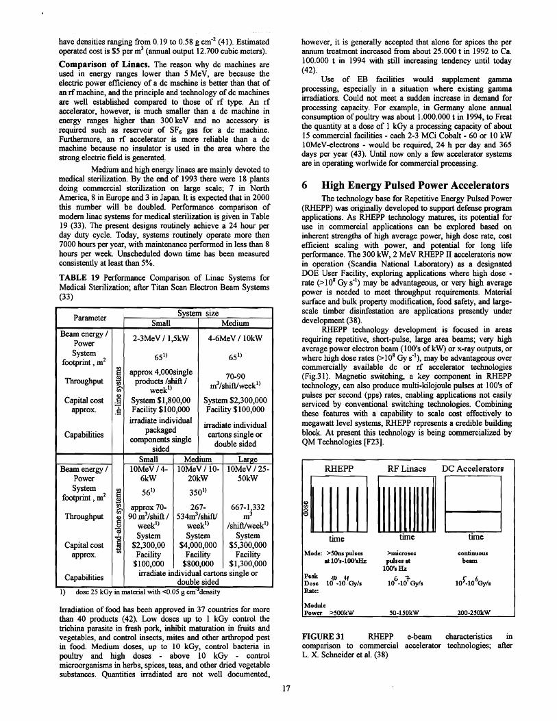
6 High Energy Pulsed Power Accelerators The technology base for Repetitive Energy Pulsed Power
(RHEPP) was originally developed to support defense program applications. As RHEPP technology matures, its potential for use in commercial applications can be explored based on inherent strengths of high average power, high dose rate, cost efficient scaling with power, and potential for long life performance. The 300 kW, 2 MeV RHEPP II acceleratoris now in operation (Scandia National Laboratory) as a designated DOE User Facility, exploring applications where high dose rate (>108 Gy s·l) may be advantageous, or very high average power is needed to meet throughput requirements. Material surface and bulk property modification, food safety, and largescale timber disinfestation are applications presently under development (38).
RHEPP technology development is focused in areas requiring repetitive, short-pulse, large area beams; very high average power electron beam (100's ofkW) or x-ray ()utputs, or where high dose rates (>108 Gy sol), may be advantageous over commercially available dc or rf accelerator technologies (Fig.31). Magnetic switching, a key component in RHEPP technology, can also produce multi-kilojoule pulses at 100's of pulses per second (Pps) rates, enabling applications not easily serviced by conventional switching technologies. Combining these features with a capability to scale cost effectively to megawatt level systems, RHEPP represents a credible building block. At present this technology is being commercialized by QM Technologies [F23].
RHEPP RF Linacs DC Accelerators
Go) en o
time time time
Mode: >5Ons pulses >microsec continuous at 10's-I00's& pulses at bealll
l00's& Peak Dose
-1U« 10 -10 Oy/s
6 :flO -10 Oy/s
Rate::
Module Power >~OOkW ~O·l~OkW 200·2~OkW
FIGURE 31 RHEPP e-beam characteristics in comparison to commercial accelerator technologies; after L. X. Schneider et al. (38)
17

7 Conclusion The situation in the field of low energy, i.e. 0.1-0.5 MeV
processors, is stable: it is mainly the production of the updated 1960s and 19708 designs that has been continued. The growth in the use of these self-shielded high current accelerators is being pulled by the attention to the elimination of solvents and air pollutants from coating and printing operations. The different situation obtains for the accelerators in the medium energy range of 0.5-5.0 MeV. The core of the industrial accelerator business remains in this medium-voltage area, where the traditional use of EB processing for the crosslinking of wire and cable jacketing and films remains the major end use
Work on new designs is being focused mainly on the high-energy (5.0-10 MeV) machines. All the desi~ns of the new generation accelerators are low-cost compact tn-line and stand-alone systems featuring high reliability (over 95-98%). From the point of view of accelerator technology, there have been considerable advances in this high-energy area. However, the market acceptance for these new generation of machines, with their ability to deliver beams with greater penetration, is still evolving What seems to be a decisive factor in the more intensive future development of applications of accelerator processors is their cost-effectiveness, with special emphasis placed on unit cost ofprocessing.
There is still lack of commercially manufactured highpower (~I000 kW) accelerators which would lead to a widespread use of accelerator techniques that require high power beams.
References (1)� Anonym: Statistics on the Use of Radiation in Japan
(1996) (2)� G. A. Norton, G. M. Klody: The Application of
Electrostatic Accelerator in Research and Industry a Summary, 1109-14 in (39)
(3)� S. Machi: Radiation Technology for Sustainable Development, Radiat. Phys. Chern. 46, No. 4-6, 399-410 (1995)
(4)� M Cleland: Electron Beam Workshop Addresses Future Needs, (1998)
(5)� Electron Beam Processing, http://www.ebeam.com (1998) (6)� R Mehnert et a1.: Low-energy electron accelerator for
industrial radiation processing, 525-29 in (7) (7)� H. Quitao et al. (eds):Proc. of [fit Int. Meeting on
Radiation Processing, 13-18 Sept. 1992, Bejing, Radial. Phys. Chern. 42, No. 1-6 (1993)
(8)� P. Hool, E. Fool: Electron Beam for Non-Thermal Curing and Crosslinking of Lacquers, Printing Inks and Adhesives, Polymer Physik GmbH Pub., Tubingen (1993)
(9)� Y. Kumata et al.: Development ofNew-Type Low Energy Electron Beam Processor, private communication (1996)
(10) P. Holl, E. FoIl: High ScrufResistant Surfaces, Polymer Physik GmbH Pub., Tubingen (1994)
(11) R Mehnert et al.: Materials Modifications Using Electron Beams in (12)
(12) NATO Advanced Study Institute: Application ofParticle and Laser Beam in Materials Technology, 8-21 May, Chalkidki (1994)
(13) M. R Cleland, 1. A. Beck: Electron Beam Sterilization, 105-36, in 1. Swarbrick, J. C. Boylan: Encyclopedia of Pharmaceutical Technology, Vol. 5, Marcel Dekker, Inc., New York (1992)
(14) Shiguin, Ch. Dali:� ITC Accelerator fOr Radiation Applications, 559-62 in (7)
(15) Y. Golubenko et al.: Accelerators of ELV·Type: Status, Development, Applications, 1-29, private communication
(16) Techsnabexport:� Accelerators for Industrial Radiation TechnolOgical Processes, Moskwa (1987)
(17) T. Fujisawa, NHV, private communication (1993) (18) M. R. Cleland et al.: New High.Cu"ent Dynamitron
Accelerators for Electron Beam Processing, Nuc!. Instr. Meth. B79, 861-64 (1993)
(19) Th. Descamps: The Practical Experience of a Total Conversion to High Energy Electron Beam Processing, Radiat. Phys. Chern., Vol. 46,439-42 (1995)
(20) Th. Descamps:� Design an Development of a Unique Electron Accelerator Facility, Molnlycke, Waremme (1997)
(21) M. F. Vorogushin et al.: Electron Linacs ofD. V. Efremov Institute for Industry, Doc. EC411, St Petersburg (1997)
(22) M. F. Vorogushin, private communicate (Feb. 1998) (23) Y. Hoshi et al.: X-ray Irradiation System for a
Sterilization Application, Nuc!. Instr. Meth. A 353, 6-9 (1994)
(24) Y. Kamino: 10MeV 25 kW Industrial Electron Linac, 836-838, in Proceedings of the XVIII Int. Linear Ace. Conference Linac'96, CERN Pub, 96-07 (Nov. 1996)
(25) Y. Kamino, private communication (Nov. 1997) (26) H. Anamkath: 10MeV 10 kW E-beam processing linac,
Mucl. Instr. Meth. B99, 725-727 (1995) (27) SureBeam@ 10115 System, http://www.titan.com/lO
15.html (1998) (28) 1. Pottier: A new Typeof rf Electron Accelerator: the
Rhodotron, Nuc!. Instr. Meth. B40/41, 943-45 (1989) (29) Y. Jongen et al.: Rhodotron Accelerators for Industrial
Electron-Beam Processing: Progress Report, 2687-89, in 5thEPAC'96 - Proceeding of the European Particle
Accelerator Conference, Inst. of Physics Publishing~
Bristol (1997) (30) J. Pottier, private communication (Jan. 1998) (31) 1. McKeown et al.: The IMPELA Accelerator, Field
Performance andNew Developments in (39) (32) N. H. Drewell: Characterization and Stability of
accelerator parameters for Industrial Applications, in (39) (33) Electron Beam Systems for Medical Device Sterilization,
http://www.titan.comlscansystems/mdm.html (34) V. L. Auslender. 1. N. Meskov: Powerful Single Cavity rf
accelerators and their Uses in the Radiation Chemical Processing Line, Radiat. Phys. Chern. 35~ 627-31 (1990)
(35) V. L. Auslenderet al.: Installations for Electron Beams Treatment ofTubes and Bands on the Base of ILU-8 Accelerator, 531-34, in (7)
(36) V. L. Auslender, V. A. Polyakov: The Installation for the Single Use Medical Devices Based on the ILU, 563-66, in (7)
(37) T. Fujisawa et al: Compact rf Accelerator fOr Electron Beam Irradiation, Nuc!. Instr. Meth. B124, 120-27 (1997)
(38) L. X. Schneider et al.: Repetitive High Energy Pulsed Power Technology Development for Industrial Applications 1085-88, in (39)
(39) CAARI'96,1. L. Duggan 1. L. Morgan, CP392, AlP Press~
New York (1997) (40) E. L.Neau: Pulsed, low impedance accelerator for
industrial applications, 1171-74, in (39) (41) R. R. Smith, S. R. Farrell: 2 MeV Linear Accelerators for
Industrial Applications, 1093-96 in (39) (42) P. Redlinger, D. Nelson: Food i"adiation, HTML written
by UMSCHPS (1998) (43) A. E. Ehlermann: Status offood irradiation in Europe,
3-7, in Proc. of the 22nd Japan Conf. on Radiation and Isotopes, Dec. 17-19, 1996, Yokohama
(44) B. Mager, D. A. E. Ehlermann: Electron beam processing of chicken carcasses, 144-146, in R. Jowitt(ed): Engineering and food at ICEF 7, Part 2, Sheffield Academic Press, Sheffield (1997)
18

List of Firms [F1] ESI - Energy Science, Incorporation, 42 Industrial Way,
Wilmington, MA 01887, USA Geneva Branch: Chemin du Pre-de-Ia-Fontaine 12, CH1217 Meryin, Switzerland
[F2] Polymer Physik GmbH & Co. KG, Sieben-Hofe-Str. 91, D-7400 Tubingen, Germany
[F3] SHI - Sumitomo Heavy Industries, Ltd, Quantum Equipment Division, 5-10-11 Kiba, Koto-ku, Tokyo, Japan
[F4] RPC Industries, 21325 Cabot Blvd, Hayward, California, USA
[F5] NHV - Nissin High Voltage Co., Ltd., 47 Umezu-Tanasecho, Ukyo-ku, Kyoto 615,'Japan
[F6] High Voltage Engineering Europe B. Y., AmsterdamSeweg 61, P.O. Box 99,3800 AB Amersfoort, The Netherlands
(F7] Budker Institute of Nuclear Physics, 630090, Novosibirsk, Russia
[F8] RDI- Radiation Dynamics, Inc, 151 Heartland Blvd., Edgewood, NY 11717-8374
[F9] Denki Kogyo 3-3-1, Marunouchi Chioda-Ku, Tokyo 100, Japan
[F10]a) Titan Beta, 6780 Sierra Court, Dublin, CA 94568, USA; b) Titan Scan, 6750 East 46th AvenueDrive, Denver, CO 80216, USA
[F11]Mitsubishi Heavy Industries, Ltd., 10 Dye-Cho, MinatoKu, Nagoya, 455, Japan
[F12]BGS - Beta-Gamma-Service, Fitz-Kotz-Strasse 16, D-51674 Wiehl, Germany
[F13] Industrial Contract Irradiation Center Studer AG, Hogenweidstrasse 2, CH-4658 Daniken, Switzerland
[F14]CARIC, Domaine de Corbeville, 91400 Orsay, France [F15]SCANCARIC, 71400 Kopparberg, Sweden [F16]Thomson-CSF, Parc Technologique, Gemini II, Route de
l'Onne, F-91195 Saint-Aubin Cedex, France [F17]D.Y. Efremov Scienific Reaearch Institute of
Electrophysicsl Apparatus, Scientific Production Complex of Linear Accelerators and Cyclotrons, NPK LUTS NIEFA, 189631, St Petersburg, Russia
[F18]Mitsubishi Heavy Industries, Ltd., Nagoya Aerospace� Systems, 10 Oye-Cho Minato-ku, Nagoya, 455 Japan�
[F19]Ion Beam Application, mA, Chemain du Cyclotrone,� Louvain-Ia-Neuve, Belgium
[F20]AECL Accelerators, 10 Hearst Way, Kanata, Ontario K2P4, Canada
[F21]Denki Kogyo Co., Ltd., Nakatu-Sakuradai 4052-1, Aikawa-machi, Aikou-gun, Kanagawa 243-03, Japan
[F22]SCA Molnlycke, S.A. Clinical Products Pare Industriel, B-4300 Waremme, Belgique
[F23]QM Technologies, 3701 Hawkings St. NE, Albuquerque, New Mexico 87109, USA
19


![АТОЛ FPrint 22ПТK - kktmo.rukktmo.ru/images/tovary/kassovye-apparaty/files/atol_FPrint-22PTK... · 6 Введение] Введение Руководство по эксплуатации](https://img.pdfslide.net/doc/110x75/5a791dd67f8b9a9d218e035d/-fprint-22k-kktmo-.jpg)