Embed Size (px)
Citation preview

1
OWNER’S MANUAL
50-3755
WARNING: If the information in this manual is not followed exactly, a fire or explosion may result causing property damage, personal injury
or loss of life. Installation and service must be performed by a qualified installer, service agency or the gas supplier.
Version Française: www.enviro.com/fr.html
C#4001609
WARRANTY REGISTRATION
enviro.com/warranty
G50LID I R E C T V E N T F I R E P L A C E - I P I
CERTIFIED TO: ANSI Z21.88-2017/CSA 2.33-2017 VENTED GAS FIREPLACE HEATERS
CSA 2.17-2017 GAS FIRED APPLIANCES FOR HIGH ALTITUDES
2
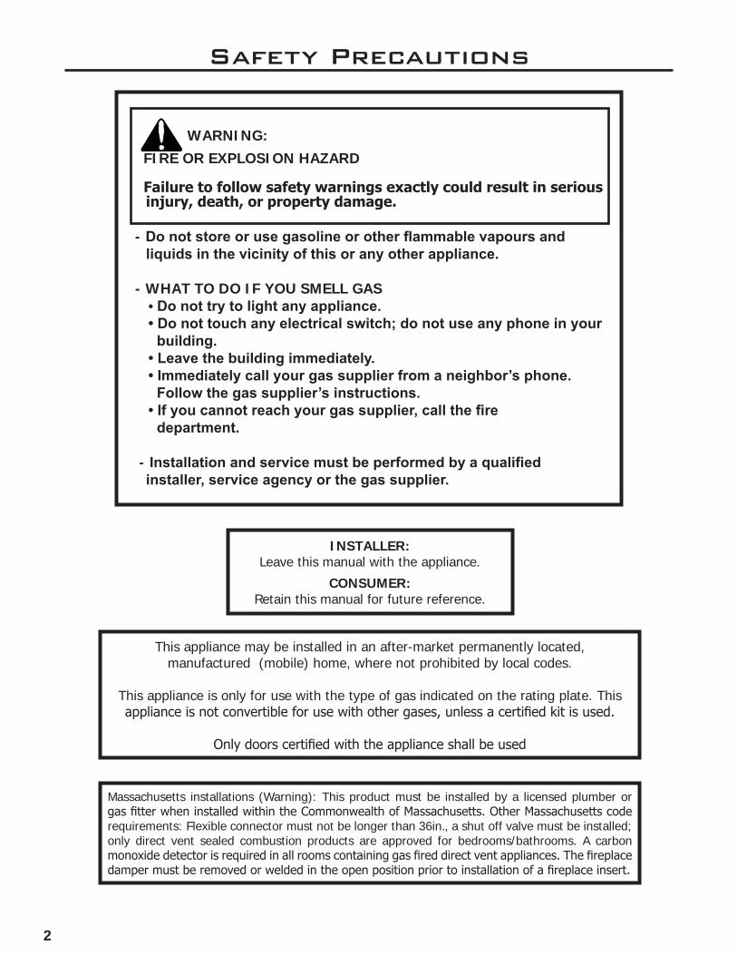
This appliance may be installed in an after-market permanently located, manufactured (mobile) home, where not prohibited by local codes.
This appliance is only for use with the type of gas indicated on the rating plate. This appliance is not convertible for use with other gases, unless a certified kit is used.
Only doors certified with the appliance shall be used
WARNING: FIRE OR EXPLOSION HAZARD Failure to follow safety warnings exactly could result in serious
injury, death, or property damage.
- Do not store or use gasoline or other flammable vapours and liquids in the vicinity of this or any other appliance.
- WHAT TO DO IF YOU SMELL GAS• Do not try to light any appliance.• Do not touch any electrical switch; do not use any phone in your
building.• Leave the building immediately.• Immediately call your gas supplier from a neighbor’s phone.
Follow the gas supplier’s instructions.• If you cannot reach your gas supplier, call the fire
department.
- Installation and service must be performed by a qualified installer, service agency or the gas supplier.
Massachusetts installations (Warning): This product must be installed by a licensed plumber or gas fitter when installed within the Commonwealth of Massachusetts. Other Massachusetts code requirements: Flexible connector must not be longer than 36in., a shut off valve must be installed; only direct vent sealed combustion products are approved for bedrooms/bathrooms. A carbon monoxide detector is required in all rooms containing gas fired direct vent appliances. The fireplace damper must be removed or welded in the open position prior to installation of a fireplace insert.
Safety Precautions
INSTALLER: Leave this manual with the appliance.
CONSUMER:Retain this manual for future reference.
3
Safety PrecautionsFOR SAFE INSTALLATION AND OPERATION OF YOUR “ENVIRO” HEATER, PLEASE CAREFULLY READ THE FOLLOWING INFORMATION:
• All ENVIRO gas-fired appliances must be installed in accordance with their instructions. Carefully read all the instructions in this manual first. Consult the building authority having jurisdiction to determine the need for a permit prior to commencing the installation.
• NOTE: Failure to follow these instructions could cause a malfunction of the fireplace, which could result in death, serious bodily injury, and/or property damage.
• Failure to follow these instructions may also void your fire insurance and/or warranty.
GENERAL
• Installation and repair should be done by a qualified service person. The appliance should be inspected before the first use and, at least, annually by a qualified service person. More frequent cleaning may be required due to excessive lint from carpeting, bedding material, etc. It is imperative the control compartments, burners and circulating air passageways of the appliance be kept clean.
• Due to high temperatures, the appliance should be located out of high traffic areas and away from furniture and draperies.
Children and adults should be alerted to the hazards of high surface temperatures and should stay away to avoid burn or clothing ignition.
• Young children should be carefully supervised when in the same room as the appliance. Toddlers, young children and others may be susceptible to accidental contact burns. A physical barrier is required if there is a risk for individuals in the house. To restrict access to a fireplace or stove install an adjustable safety gate to keep toddlers, young children and other at risk individuals out of the room and away from hot surfaces. Any safety screen, guard, or barrier removed for servicing an appliance must be replaced prior to operating the appliance.
• Clothing or other flammable materials should not be placed on or near the appliance.
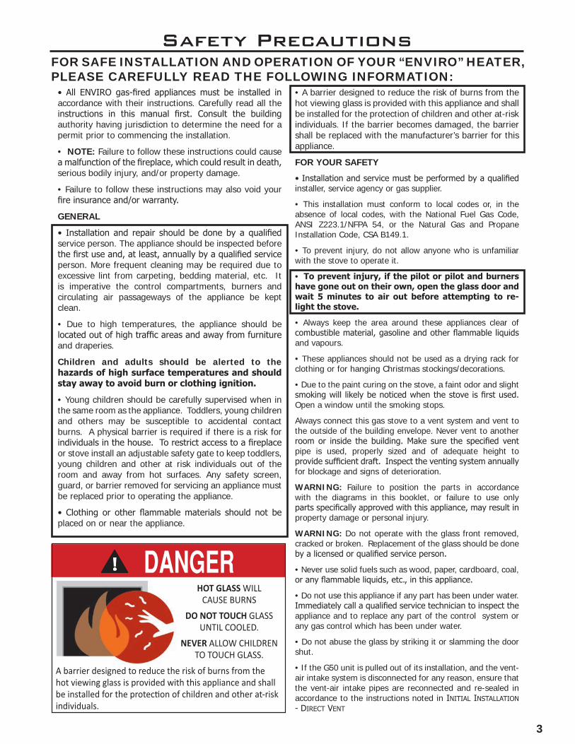
• A barrier designed to reduce the risk of burns from the hot viewing glass is provided with this appliance and shall be installed for the protection of children and other at-risk individuals. If the barrier becomes damaged, the barrier shall be replaced with the manufacturer’s barrier for this appliance.
FOR YOUR SAFETY
• Installation and service must be performed by a qualified installer, service agency or gas supplier.
• This installation must conform to local codes or, in the absence of local codes, with the National Fuel Gas Code, ANSI Z223.1/NFPA 54, or the Natural Gas and Propane Installation Code, CSA B149.1.
• To prevent injury, do not allow anyone who is unfamiliar with the stove to operate it.
• To prevent injury, if the pilot or pilot and burners have gone out on their own, open the glass door and wait 5 minutes to air out before attempting to re-light the stove.
• Always keep the area around these appliances clear of combustible material, gasoline and other flammable liquids and vapours.
• These appliances should not be used as a drying rack for clothing or for hanging Christmas stockings/decorations.
• Due to the paint curing on the stove, a faint odor and slight smoking will likely be noticed when the stove is first used. Open a window until the smoking stops.
Always connect this gas stove to a vent system and vent to the outside of the building envelope. Never vent to another room or inside the building. Make sure the specified vent pipe is used, properly sized and of adequate height to provide sufficient draft. Inspect the venting system annually for blockage and signs of deterioration.
WARNING: Failure to position the parts in accordance with the diagrams in this booklet, or failure to use only parts specifically approved with this appliance, may result in property damage or personal injury.
WARNING: Do not operate with the glass front removed, cracked or broken. Replacement of the glass should be done by a licensed or qualified service person.
• Never use solid fuels such as wood, paper, cardboard, coal, or any flammable liquids, etc., in this appliance.
• Do not use this appliance if any part has been under water. Immediately call a qualified service technician to inspect the appliance and to replace any part of the control system or any gas control which has been under water.
• Do not abuse the glass by striking it or slamming the door shut.
• If the G50 unit is pulled out of its installation, and the vent-air intake system is disconnected for any reason, ensure that the vent-air intake pipes are reconnected and re-sealed in accordance to the instructions noted in InItIal InstallatIon - DIrect Vent
HOT GLASS WILL CAUSE BURNS
DO NOT TOUCH GLASS UNTIL COOLED.
NEVER ALLOW CHILDRENTO TOUCH GLASS.
A barrier designed to reduce the risk of burns from thehot viewing glass is provided with this appliance and shall
individuals.
4
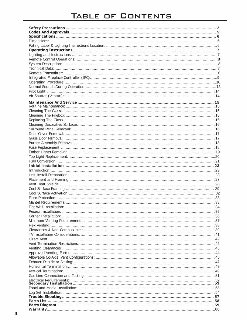
Table of ContentsSafety Precautions .............................................................................................................................. 2Codes And Approvals ........................................................................................................................... 5Specifications ...................................................................................................................................... 6Dimensions: .................................................................................................................................................6Rating Label & Lighting Instructions Location: ................................................................................................6Operating Instructions ........................................................................................................................ 7Lighting and Instructions:..............................................................................................................................7Remote Control Operations:...........................................................................................................................8System Description:.......................................................................................................................................8Technical Data:.............................................................................................................................................8Remote Transmitter:......................................................................................................................................8Integrated Fireplace Controller (IFC):.............................................................................................................9Operating Procedure:...................................................................................................................................10Normal Sounds During Operation:.................................................................................................................13Pilot Light: ................................................................................................................................................. 14Air Shutter (Venturi): .................................................................................................................................. 14
Maintenance And Service .................................................................................................................. 15Routine Maintenance: ................................................................................................................................. 15Cleaning The Glass: .................................................................................................................................... 15Cleaning The Firebox: ................................................................................................................................. 15Replacing The Glass: .................................................................................................................................. 15Cleaning Decorative Surfaces: ..................................................................................................................... 16Surround Panel Removal: ........................................................................................................................... 16Door Cover Removal: .................................................................................................................................. 17Glass Door Removal: ................................................................................................................................. 17Burner Assembly Removal:.......................................................................................................................... 18Fuse Replacement: ..................................................................................................................................... 18Ember Lights Removal:................................................................................................................................19Top Light Replacement:...............................................................................................................................20Fuel Conversion: ........................................................................................................................................ 21Initial Installation ............................................................................................................................. 23Introduction: .............................................................................................................................................. 23Unit Install Preparation: .............................................................................................................................. 23Placement and Framing: ............................................................................................................................. 27Vent Heat Shields: ...................................................................................................................................... 28Cool Surface Framing:................................................................................................................................ 29Cool Surface Activation:...............................................................................................................................32Floor Protection: ........................................................................................................................................ 33Mantel Requirements: ................................................................................................................................. 33Flat Wall Installation: .................................................................................................................................. 34Recess Installation: .................................................................................................................................... 35Corner Installation: .................................................................................................................................... 36Minimum Venting Requirements: ................................................................................................................. 37Flex Venting: .............................................................................................................................................. 38Clearances & Non-Combustible : ................................................................................................................. 39TV Installation Considerations: .................................................................................................................... 41Direct Vent: ............................................................................................................................................... 42 Vent Termination Restrictions: ..................................................................................................................... 42Venting Clearances: .................................................................................................................................... 43Approved Venting Parts: ............................................................................................................................. 44 Allowable Co-Axial Vent Configurations: ....................................................................................................... 45 Exhaust Restrictor Setting: .......................................................................................................................... 47Horizontal Termination: ............................................................................................................................... 48Vertical Termination: ................................................................................................................................... 49Gas Line Connection and Testing: ................................................................................................................ 51Electrical Requirements: ............................................................................................................................. 52Secondary Installation ...................................................................................................................... 53Panel and Media Installation: ...................................................................................................................... 53Log Set Installation: ................................................................................................................................... 54 Trouble Shooting ............................................................................................................................... 57Parts List ........................................................................................................................................... 58Parts Diagram .................................................................................................................................... 59Warranty.............................................................................................................................................60

5
DIRECT VENT ONLY: This type is identified by the suffix DV. This appliance draws all of its air for combustion from outside the dwelling, through a specially designed vent pipe system.This appliance has been tested and approved for installations from 0 feet to 4500 feet (1372 m) above sea level.
In the USA: The appliance may be installed at higher altitudes. Please refer to your American Gas Association guidelines which state: the sea level rated input of Gas Designed Appliances installed at elevations above 2000 (610 m) feet is to be reduced 4% for each 1000 feet (305 m) above sea level. Refer also to local authorities or codes which have jurisdiction in your area regarding the de-rate guidelines.
In Canada: When the appliance is installed at elevations above 4500 feet (1372 m), the certified high altitude rating shall be reduced at the rate of 4% for each additional 1000 feet (305 m).
• This appliance has been tested by INTERTEK and found to comply with the established VENTED GAS FIREPLACE HEATER standards in CANADA and the USA as follows:
VENTED GAS FIREPLACE HEATER (G50; NATURAL GAS, PROPANE GAS)
CERTIFIED TO: ANSI Z21.88-2017/CSA 2.33-2017 VENTED GAS FIREPLACE HEATERS
CSA 2.17-2017 GAS FIRED APPLIANCES FOR HIGH ALTITUDES
This ENVIRO G50 Fireplace:
• Has been certified for use with either natural gas or propane (see rating label).
• Is not for use with solid fuels.
• Is approved for a bedroom or bed sitting room. (IN CANADA: must be installed with a listed wall
thermostat. IN USA: see current ANSI Z223.1 for installation instructions.)• Must be installed in accordance with local codes. If none exist, use current installation code CAN/CGA
B149.1 in Canada or ANSI Z223.1/NFPA 54 in the USA.
Codes And Approvals
• Must be properly connected to an approved venting system and not connected to a chimney flue serving a separate solid-fuel burning appliance.
IMPORTANT NOTICE (Regarding first fire up): When the unit is turned on for the first time, it should be turned onto high without the fan on (if equipped) for the first 4 hours. This will cure the paint, logs, gasket material and other products used in the manufacturing process. It is advisable to open a window or door, as the unit will start to smoke and can irritate some people. After the unit has gone through the first burn, turn the unit off including the pilot, let the unit get cold then remove the glass door and clean it with a good gas fireplace glass cleaner, available at your local ENVIRO dealer.

6
SpecificationsG50 Dimensions:
RatinG LabeL & LiGhtinG instRuctions Location:
Remove the surround completely to access the rating label and lighting instructions. The sheet is attached to a length of chain and are never to be tampered with or removed. All important information for your fireplace is on this label as well as the model specific serial number which you will need for warranty information. The sheet is located inside the cabinet under the gas valve.
Figure 1. G50 Dimensions
50"1270
51"1295
34 "
19
40"1016
39 716 "
1002
41 12 "
1054
8 716 "
214
47"1194
35 716 "
900
2 14 "
58
10 116 "
256
49 78 "
1267
2 516 "
58
9 1116 "
245
Gas InletRight Side
54 716 "
1383
22 1116 "
577
36 1516 "
938
8 38 "
212
27 38 "
696
ElectricalInlet LeftSide

7
Operating InstructionsFor Your Safety, Read Safety Precautions And
Lighting Instructions Before Operating
WARNING: IF YOU DO NOT FOLLOW THESE INSTRUCTIONS EXACTLY A FIRE OR EXPLOSION MAY RESULT, CAUSING PROPERTY DAMAGE, PERSONAL INJURY OF LOSS OF LIFE.
LiGhtinG anD instRuctions:
Figure 2. Lighting Instruction Label
WARNING:IF YOU DO NOT FOLLOW THESE INSTRUCTIONS EXACTLY, A FIRE OR EXPLOSION MAY RESULT CAUSING PROPERTY DAMAGE, PERSONAL INJURY OR LOSS OF LIFE.
A. This appliance is equipped with an ignition device which automatically lights the pilot. Do not try to light the pilot by hand.B. BEFORE OPERATING smell all around the appliance area for gas. Be sure to smell next to the floor because some gas is heavier than air and will settle on the floor. WHAT TO DO IF YOU SMELL GAS: Do not try to light any appliance. Do not touch any electrical switch; do not use any phone in your building. Immediately call your gas supplier from a neighbor’s phone. Follow the gas supplier’s instructions. If you cannot reach your gas supplier, call the fire department.
C. Use only your hand to push in or turn the gas control knob. Never use tools. If the knob will not push in or turn by hand, don’t try to repair it, call a qualified service technician. Force or attempted repair may result in a fire or explosion.D. Do not use this appliance if any part has been under water. Immediately call a qualified service technician to inspect the appliance and to replace any part of the control system and any gas control which has been under water.
OPERATING INSTRUCTIONS
1. STOP! Read the safety information above on this label.2. Read the owner's manual including the section on "Remote Control" operation.3. Set the thermostat to the lowest setting.4. Turn off all electric power to the appliance.5. Do not attempt to light the pilot by hand.6. Wait five (5) minutes to clear out any gas. Then smell for gas, including near the floor. If you smell gas, STOP! Follow "B" in the safety information above on this label. If you don't smell gas, go to the next step.7. Turn on all electric power to the appliance.8. Using the remote control, set thermostat to desired setting, or press the ON/OFF key on the remote. "ON" will be indicated on the display of the remote and an audible "beep" will be heard at the unit to indicate the command has been received.
TO TURN OFF GAS TO APPLIANCE1. Set thermostat to lowest setting, or press the ON/OFF Key. "OFF" will be indicated on the display and an audible "Beep" will be heard at the unit to indicate the command has been received.2. Turn off all electric power to the appliance if service is to be performed.
FOR YOUR SAFETY READ BEFORE OPERATING
C-12455
9. This appliance is equipped with a completely automatic ignition and lighting control. The control will attempt to light the pilot several times if necessary. If it is unsuccessful, it will discontinue operations. If the appliance will not operate, follow the instructions "To Turn Off Gas To Appliance" and call your service technician or gas supplier.
Blue LCD Display
THERMOSTAT KeyON/OFF Key
UP/DOWN Arrow KeyMODE Key
Blue LCD Display
ON/OFF KeyThermostat KeyMode Key
UP/DownArrow Key

8
Operating InstructionsFor Your Safety, Read Safety Precautions And
Lighting Instructions Before Operating
technicaL Data:
Transmitter (Remote Control): Supply voltage: 4.5 V (three 1.5 V AAA batteries) Radio frequency: 315 MHz Integrated Fireplace Controller (IFC): Supply voltage: AC IN - 120 V / 60 Hz Battery Backup IN - 6 Vdc - 200mA (four 1.5 V AA batteries) Spark voltage / frequency: >10kV / 1Hz Comfort modulating fan: 120 V / 60 Hz / 2A Ember Lights: 120 V / 60 Hz / 850mA [total] Top Light: 120 V / 60Hz / 200mA
Remote tRansmitteR:
The Proflame 2 uses a streamline design remote transmitter to allow the user to interact with the system. The simple button layout and LCD display offer a user friendly experience. The MODE key is used to cycle through different features and the THERMOSTAT key is used to manage thermostatic functions. The transmitter is powered by three (3) AAA type batteries.
Figure 3: Proflame 2 Transmitter.
system DescRiption:
The Proflame 2 Remote Control System consists of two (2) elements:1. Proflame 2 Transmitter.2. Integrated Fireplace Controller (IFC) and a wiring harness to connect to the gas valve and stepper
motor.
ATTENTION!
- TURN “OFF” THE MAIN GAS SUPPLY OF THE APPLIANCE DURING INSTALLATION OR MAINTENANCE OF THE IFC.
- TURN “OFF” MAIN GAS SUPPLY TO THE APPLIANCE PRIOR TO REMOVING OR REINSERTING THE BATTERIES IN THE BATTERY HOLDER
Blue Back lit LCD display
UP/DOW N Arrow Key
ON/OFF KeyTHERMOSTAT Key
MODE Key
Remote contRoL opeRations:
Proflame 2 is a modular remote control system that directs the functions of the fireplace. The Proflame 2 remote transmitter is configured to control the on and off function of the main burner and split flow valve. The systems also allows your to modulate the flame level, fan speed, and accent light features.
9
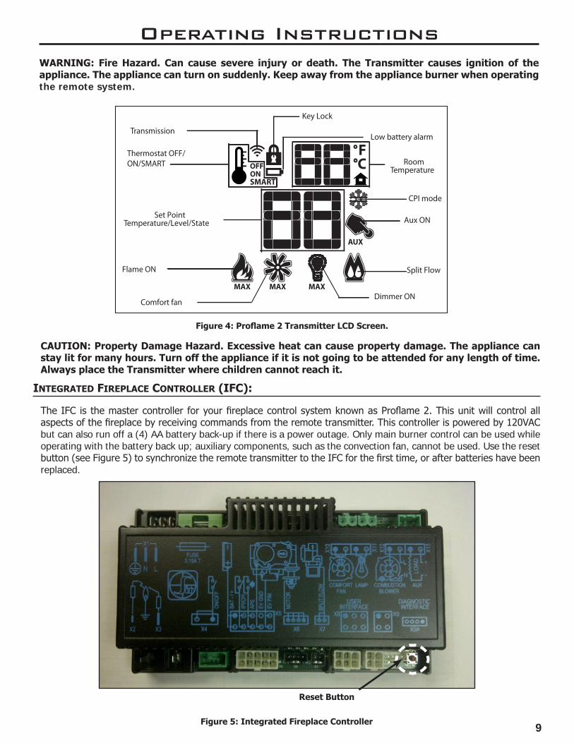
Figure 4: Proflame 2 Transmitter LCD Screen.
Figure 5: Integrated Fireplace Controller
Low battery alarm
Key Lock
RoomTemperature
Dimmer ON
Set PointTemperature/Level/State
Flame ON
Thermostat OFF/ON/SMART
Comfort fan
Transmission
Split Flow
Aux ON
CPI mode
Operating Instructions
inteGRateD FiRepLace contRoLLeR (iFc):
Reset Button
The IFC is the master controller for your fireplace control system known as Proflame 2. This unit will control all aspects of the fireplace by receiving commands from the remote transmitter. This controller is powered by 120VAC but can also run off a (4) AA battery back-up if there is a power outage. Only main burner control can be used while operating with the battery back up; auxiliary components, such as the convection fan, cannot be used. Use the reset button (see Figure 5) to synchronize the remote transmitter to the IFC for the first time, or after batteries have been replaced.
CAUTION: Property Damage Hazard. Excessive heat can cause property damage. The appliance can stay lit for many hours. Turn off the appliance if it is not going to be attended for any length of time. Always place the Transmitter where children cannot reach it.
WARNING: Fire Hazard. Can cause severe injury or death. The Transmitter causes ignition of the appliance. The appliance can turn on suddenly. Keep away from the appliance burner when operating the remote system.

10
opeRatinG pRoceDuRe:
Initializing The System Install the four (4) supplied AA batteries into the IFC battery holder. The remote transmitter should come from the manufacturer with the batteries already installed. Press the reset button on the IFC (see Figure 5) and listen for three (3) beeps. Press the ON key on the remote transmitter and listen for another beep sequence. Once the command has been accepted then the system is initialized and ready for use.
Note: Other remote transmitters may interfere with the system if you have another within the vicinity.
Figure 6: Temperature Scale Display
Operating Instructions
Figure 7: CPI Pilot Mode.
Note: If the pilot takes too long to ignite there may be air in the gas line. The system will enter a 5 minute lock-out and cancel the start-up procedure if too many spark attempts have been made. If pilot cannot light after 3 lock-out cycles then contact your gas fitter.
Temperature Indication Display Press the Thermostat key and the Mode key simultaneously while the system is OFF. The remote transmitter will indicate which temperature scale is being displayed (°C or °F). Repeat this sequence to change the scale (see Figure 6).
Turn off the AppliancePress the ON/OFF key on the transmitter to turn the fireplace off. The IFC will confirm your command with a single beep. The pilot light (IPI) and the main burner will turn off. The pilot will remain lit if the fireplace is in CPI mode. Room temperature information will still be displayed on the remote when the unit is off.
Note: It is recommended to use CPI mode when the temperature outside is below 50°F (10°C) to keep the vent sufficiently heated to assist with warm-up procedure. Using CPI will also eliminate excessive condensation on the glass during start-up.
Continuous Pilot Mode Press the Mode key with the fireplace turned off. Use the UP/DOWN key to cycle between intermittent pilot ignition (IPI) and continuous pilot ignition (CPI). Press the mode key to make your selection and the IFC will beep to confirm your command.
Turn on the Appliance Press the ON/OFF key on the remote transmitter; the display will illuminate and show all active icons. A single beep from the IFC will confirm the command from the remote and the start up sequence will begin. The spark electrode will ignite the pilot flame which will engulf the flame sensor hook. After the sensor reaches sufficient temperature, the main burner valve will open and the flame will ignite moments after.
11
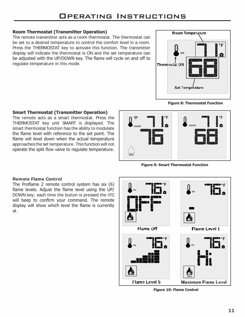
Smart Thermostat (Transmitter Operation) The remote acts as a smart thermostat. Press the THERMOSTAT key unit SMART is displayed. The smart thermostat function has the ability to modulate the flame level with reference to the set point. The flame will level down when the actual temperature approaches the set temperature. This function will not operate the split flow valve to regulate temperature.
Room Temperature
Set Temperature
Thermostat ON
Figure 8: Thermostat Function
Figure 9: Smart Thermostat Function
Figure 10: Flame Control
Flame Off Flame Level 1
Flame Level 5 Maximum Flame Level
Operating Instructions
Room Thermostat (Transmitter Operation)The remote transmitter acts as a room thermostat. The thermostat can be set to a desired temperature to control the comfort level in a room. Press the THERMOSTAT key to activate this function. The transmitter display will indicate the thermostat is ON and the set temperature can be adjusted with the UP/DOWN key. The flame will cycle on and off to regulate temperature in this mode.
Remote Flame Control The Proflame 2 remote control system has six (6) flame levels. Adjust the flame level using the UP/DOWN key; each time the button is pressed the IFC will beep to confirm your command. The remote display will show which level the flame is currently at.
12
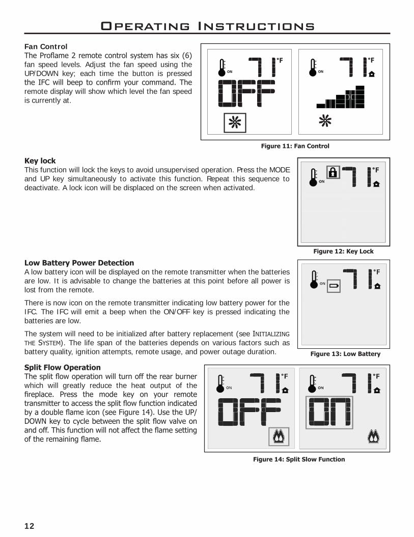
Figure 13: Low Battery
Split Flow OperationThe split flow operation will turn off the rear burner which will greatly reduce the heat output of the fireplace. Press the mode key on your remote transmitter to access the split flow function indicated by a double flame icon (see Figure 14). Use the UP/DOWN key to cycle between the split flow valve on and off. This function will not affect the flame setting of the remaining flame.
Figure 14: Split Slow Function
Low Battery Power DetectionA low battery icon will be displayed on the remote transmitter when the batteries are low. It is advisable to change the batteries at this point before all power is lost from the remote.
There is now icon on the remote transmitter indicating low battery power for the IFC. The IFC will emit a beep when the ON/OFF key is pressed indicating the batteries are low.
The system will need to be initialized after battery replacement (see InItIalIzIng the system). The life span of the batteries depends on various factors such as battery quality, ignition attempts, remote usage, and power outage duration.
Figure 12: Key Lock
Key lockThis function will lock the keys to avoid unsupervised operation. Press the MODE and UP key simultaneously to activate this function. Repeat this sequence to deactivate. A lock icon will be displaced on the screen when activated.
Figure 11: Fan Control
Fan ControlThe Proflame 2 remote control system has six (6) fan speed levels. Adjust the fan speed using the UP/DOWN key; each time the button is pressed the IFC will beep to confirm your command. The remote display will show which level the fan speed is currently at.
Operating Instructions
13
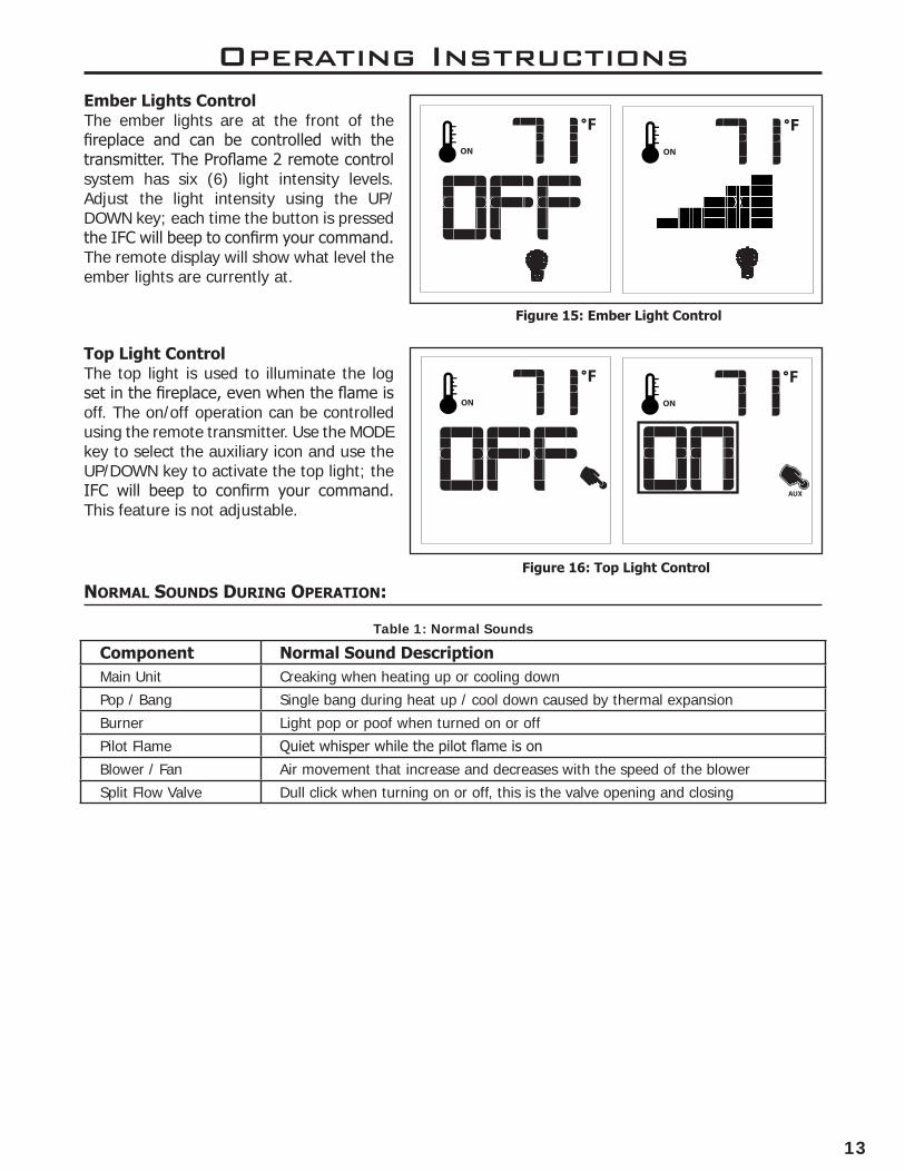
noRmaL sounDs DuRinG opeRation:
Table 1: Normal Sounds
Component Normal Sound Description Main Unit Creaking when heating up or cooling down
Pop / Bang Single bang during heat up / cool down caused by thermal expansion
Burner Light pop or poof when turned on or off
Pilot Flame Quiet whisper while the pilot flame is on
Blower / Fan Air movement that increase and decreases with the speed of the blower
Split Flow Valve Dull click when turning on or off, this is the valve opening and closing
Ember Lights ControlThe ember lights are at the front of the fireplace and can be controlled with the transmitter. The Proflame 2 remote control system has six (6) light intensity levels. Adjust the light intensity using the UP/DOWN key; each time the button is pressed the IFC will beep to confirm your command. The remote display will show what level the ember lights are currently at.
Top Light ControlThe top light is used to illuminate the log set in the fireplace, even when the flame is off. The on/off operation can be controlled using the remote transmitter. Use the MODE key to select the auxiliary icon and use the UP/DOWN key to activate the top light; the IFC will beep to confirm your command. This feature is not adjustable.
Operating Instructions
Figure 16: Top Light Control
Figure 15: Ember Light Control
14
Operating Instructions
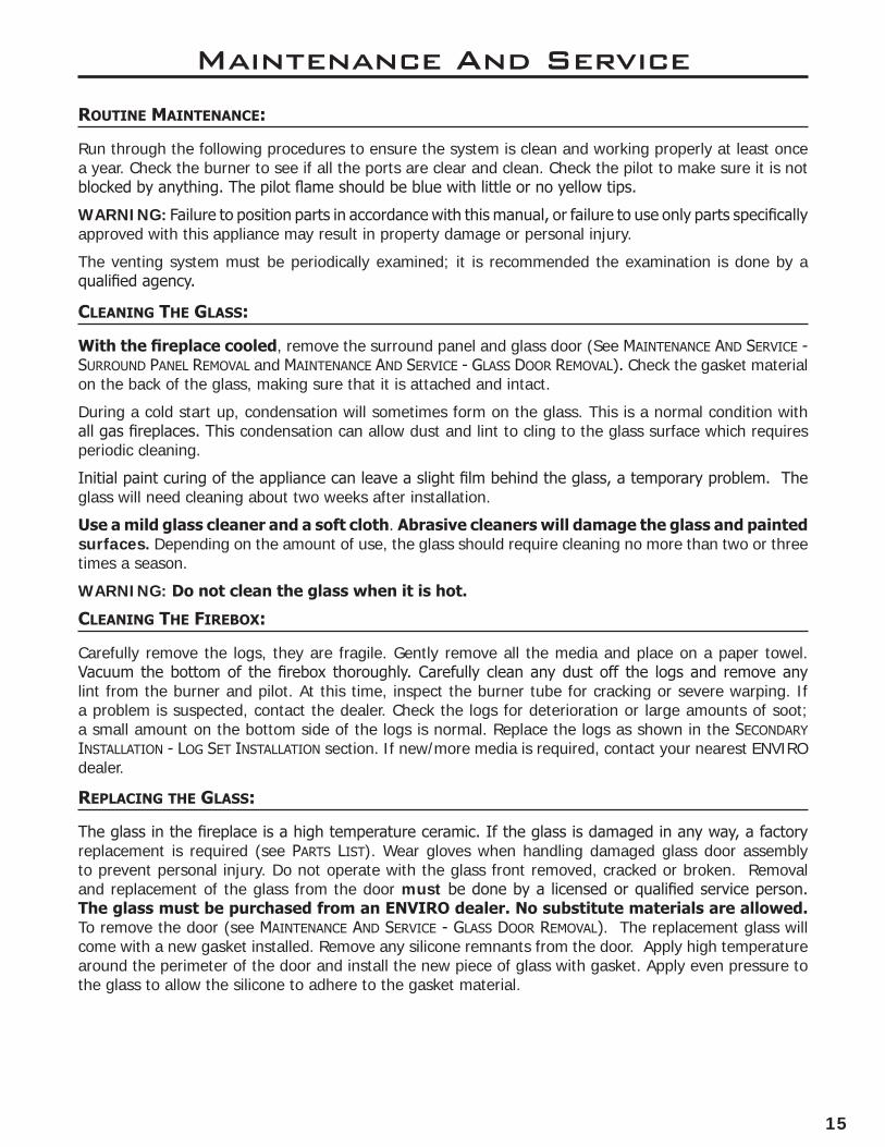
aiR shutteR (VentuRi):
The air shutter plays a very important role in flame appearence and combustion quality. The shutter adjusts how much air gets mixed with the gas before it ignites; adjustments can be made to accomodate various climates and vent configurations.
Remove surround to access the air shutter. Find the two levers underneath the firebox (see Figure 18). The front and rear burners can be controlled independently. Moving either lever inward will make the flame appear more yellow and tall; moving the lever outward will make the flames appear more blue and short.
Typically natural gas flames will require the shutter to be more closed.
Typically LP flames will require the shutter to be more open.
If you cannot attain a healthy flame by making air shutter adjustments, you may have the incorrect restrictor setting or venting problem.
If the flame is very flickery, fast moving, and low then increase the restriction.
If the flame is very tall, lazy, and dirty then decrease the restriction.
More details can be found in the venting section of this manual.
Caution: Wear heat resistent gloves when making adjustments to the air shutter. Perform adjustments after 15 minutes.
Figure 18. Air Shutter Location
piLot LiGht:
B
DETAIL B
SCALE 2 : 5
Rear BurnerFront Burner
+_
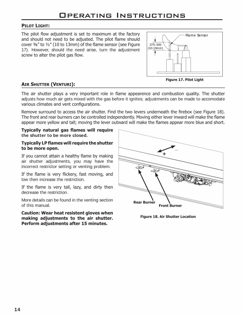
The pilot flow adjustment is set to maximum at the factory and should not need to be adjusted. The pilot flame should cover ⅜” to ½” (10 to 13mm) of the flame sensor (see Figure 17). However, should the need arise, turn the adjustment screw to alter the pilot gas flow.
Figure 17. Pilot Light
.375-.500(10-13mm)
Flame Sensor
15
Maintenance And Service
Routine maintenance:
Run through the following procedures to ensure the system is clean and working properly at least once a year. Check the burner to see if all the ports are clear and clean. Check the pilot to make sure it is not blocked by anything. The pilot flame should be blue with little or no yellow tips.
WARNING: Failure to position parts in accordance with this manual, or failure to use only parts specifically approved with this appliance may result in property damage or personal injury.
The venting system must be periodically examined; it is recommended the examination is done by a qualified agency.
cLeaninG the GLass:
With the fireplace cooled, remove the surround panel and glass door (See maIntenance anD serVIce - surrounD Panel remoVal and maIntenance anD serVIce - glass Door remoVal). Check the gasket material on the back of the glass, making sure that it is attached and intact.
During a cold start up, condensation will sometimes form on the glass. This is a normal condition with all gas fireplaces. This condensation can allow dust and lint to cling to the glass surface which requires periodic cleaning.
Initial paint curing of the appliance can leave a slight film behind the glass, a temporary problem. The glass will need cleaning about two weeks after installation.
Use a mild glass cleaner and a soft cloth. Abrasive cleaners will damage the glass and painted surfaces. Depending on the amount of use, the glass should require cleaning no more than two or three times a season.
WARNING: Do not clean the glass when it is hot.
cLeaninG the FiRebox:
Carefully remove the logs, they are fragile. Gently remove all the media and place on a paper towel. Vacuum the bottom of the firebox thoroughly. Carefully clean any dust off the logs and remove any lint from the burner and pilot. At this time, inspect the burner tube for cracking or severe warping. If a problem is suspected, contact the dealer. Check the logs for deterioration or large amounts of soot; a small amount on the bottom side of the logs is normal. Replace the logs as shown in the seconDary InstallatIon - log set InstallatIon section. If new/more media is required, contact your nearest ENVIRO dealer.
RepLacinG the GLass:
The glass in the fireplace is a high temperature ceramic. If the glass is damaged in any way, a factory replacement is required (see Parts lIst). Wear gloves when handling damaged glass door assembly to prevent personal injury. Do not operate with the glass front removed, cracked or broken. Removal and replacement of the glass from the door must be done by a licensed or qualified service person. The glass must be purchased from an ENVIRO dealer. No substitute materials are allowed. To remove the door (see maIntenance anD serVIce - glass Door remoVal). The replacement glass will come with a new gasket installed. Remove any silicone remnants from the door. Apply high temperature around the perimeter of the door and install the new piece of glass with gasket. Apply even pressure to the glass to allow the silicone to adhere to the gasket material.
16
Maintenance And Service
cLeaninG DecoRatiVe suRFaces:
Painted and porcelain faces should be wiped with a damp cloth periodically. If a plated face has been purchased, it should be unpackaged carefully to avoid getting anything on the surface of the finish, including cleaners, polish and finger prints. It is important to note that fingerprints and other marks can leave a permanent stain on plated finishes. To avoid this, give the face a quick wipe with denatured alcohol on a soft cloth BEFORE lighting the fireplace. Never clean the face when it is hot. Do not use other cleaners as they may leave a residue, which can become permanently etched into the surface.
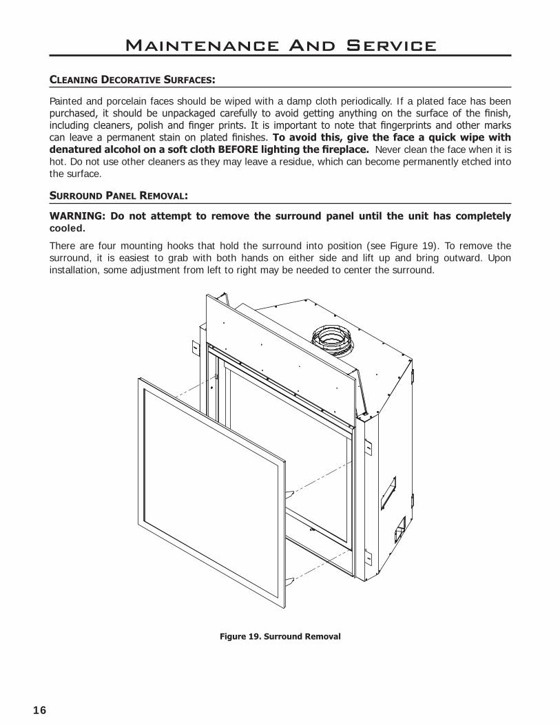
Figure 19. Surround Removal
WARNING: Do not attempt to remove the surround panel until the unit has completely cooled.
There are four mounting hooks that hold the surround into position (see Figure 19). To remove the surround, it is easiest to grab with both hands on either side and lift up and bring outward. Upon installation, some adjustment from left to right may be needed to center the surround.
suRRounD paneL RemoVaL:

17
Maintenance And Service
GLass DooR RemoVaL:
To remove the glass door use a 3/8 socket to remove the 5 door bolts, rotate outward, and lift. To replace the door simply reverse the order; do not over tighten the bolts or they may strip.
WARNING: Do not touch or attempt to remove the glass door if the fireplace is not completely cold.
WARNING: Never operate the fireplace with the glass door removed.
Figure 20. Door Cover Removal
DooR coVeR RemoVaL:
A
DETAIL A
SCALE 1 : 6
Figure 21. Glass Door Removal
WARNING: Do not touch or attempt to remove the glass door if the fireplace is not completely cold.
To remove the door cover, remove the two (2) wing nuts using your fingers then lift up and outward. Wing nuts are only for shipping and do not need to be reinstalled.
18
buRneR assembLy RemoVaL:
1. Remove the surround panel (see maIntenance anD serVIce - surrounD Panel remoVal).
2. Remove the door cover (see maIntenance anD serVIce - Door coVer remoVal).
3. Remove the glass door (see maIntenance anD serVIce - glass Door remoVal)
4. Remove log set (if installed).
5. Remove the Log Grate by removing T20 screws.
Maintenance And Service
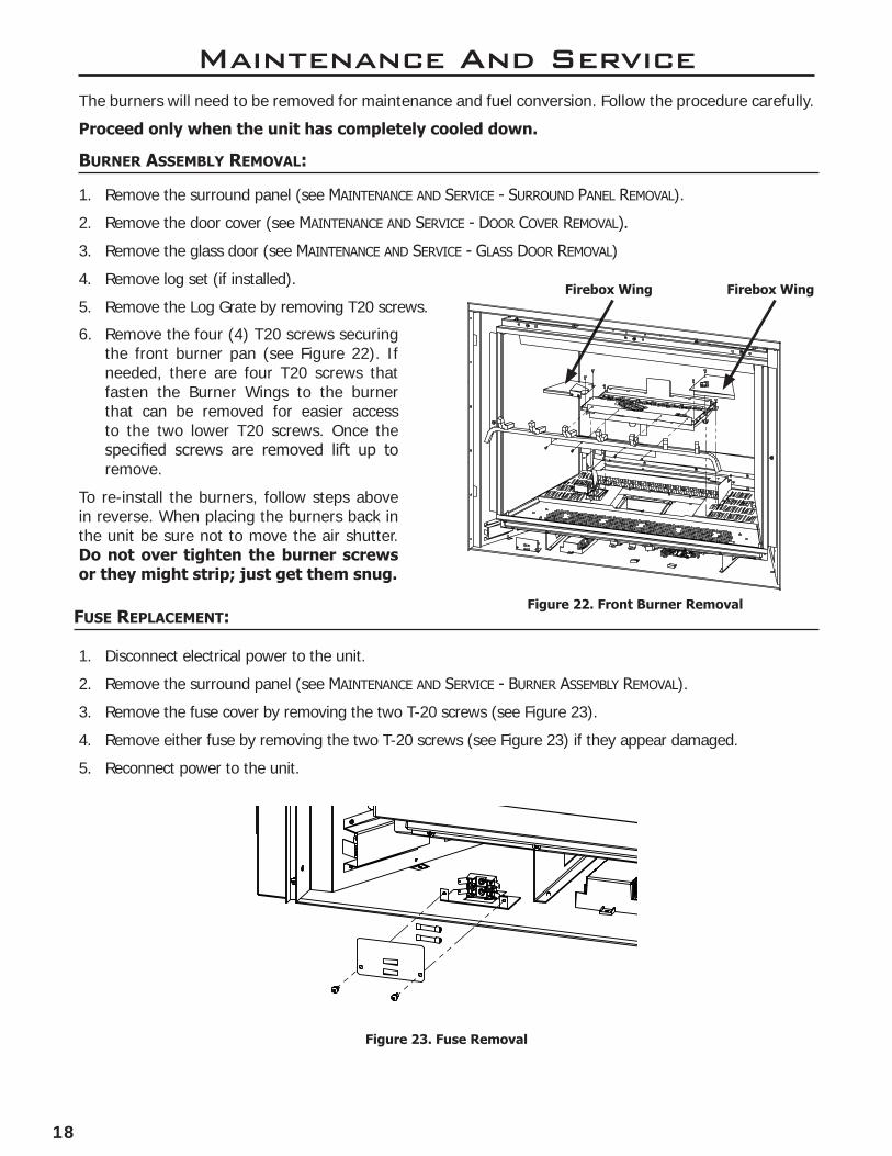
Firebox Wing Firebox Wing
6. Remove the four (4) T20 screws securing the front burner pan (see Figure 22). If needed, there are four T20 screws that fasten the Burner Wings to the burner that can be removed for easier access to the two lower T20 screws. Once the specified screws are removed lift up to remove.
To re-install the burners, follow steps above in reverse. When placing the burners back in the unit be sure not to move the air shutter. Do not over tighten the burner screws or they might strip; just get them snug.
A
DETAIL A
SCALE 1 : 10
Figure 22. Front Burner Removal
Figure 23. Fuse Removal
Fuse RepLacement:
1. Disconnect electrical power to the unit.
2. Remove the surround panel (see maIntenance anD serVIce - Burner assemBly remoVal).
3. Remove the fuse cover by removing the two T-20 screws (see Figure 23).
4. Remove either fuse by removing the two T-20 screws (see Figure 23) if they appear damaged.
5. Reconnect power to the unit.
The burners will need to be removed for maintenance and fuel conversion. Follow the procedure carefully.
Proceed only when the unit has completely cooled down.
19
Maintenance And Service
A
DETAIL A
SCALE 1 : 5
A
B
DETAIL A
SCALE 1 : 8
DETAIL B
SCALE 1 : 1
A
B
C
DETAIL A
SCALE 1 : 8
DETAIL B
SCALE 1 : 1
DETAIL C
SCALE 1 : 3
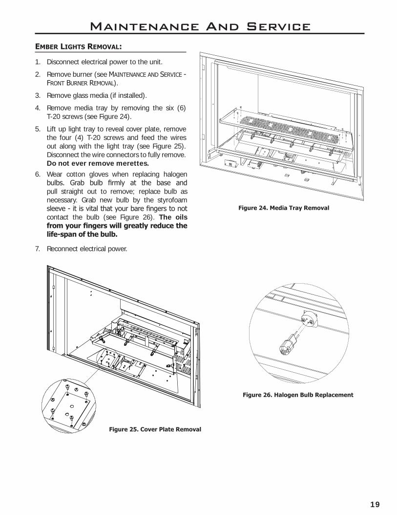
embeR LiGhts RemoVaL:
1. Disconnect electrical power to the unit.
2. Remove burner (see maIntenance anD serVIce - Front Burner remoVal).
3. Remove glass media (if installed).
4. Remove media tray by removing the six (6) T-20 screws (see Figure 24).
5. Lift up light tray to reveal cover plate, remove the four (4) T-20 screws and feed the wires out along with the light tray (see Figure 25). Disconnect the wire connectors to fully remove. Do not ever remove merettes.
6. Wear cotton gloves when replacing halogen bulbs. Grab bulb firmly at the base and pull straight out to remove; replace bulb as necessary. Grab new bulb by the styrofoam sleeve - it is vital that your bare fingers to not contact the bulb (see Figure 26). The oils from your fingers will greatly reduce the life-span of the bulb.
7. Reconnect electrical power.
Figure 24. Media Tray Removal
Figure 25. Cover Plate Removal
Figure 26. Halogen Bulb Replacement
20
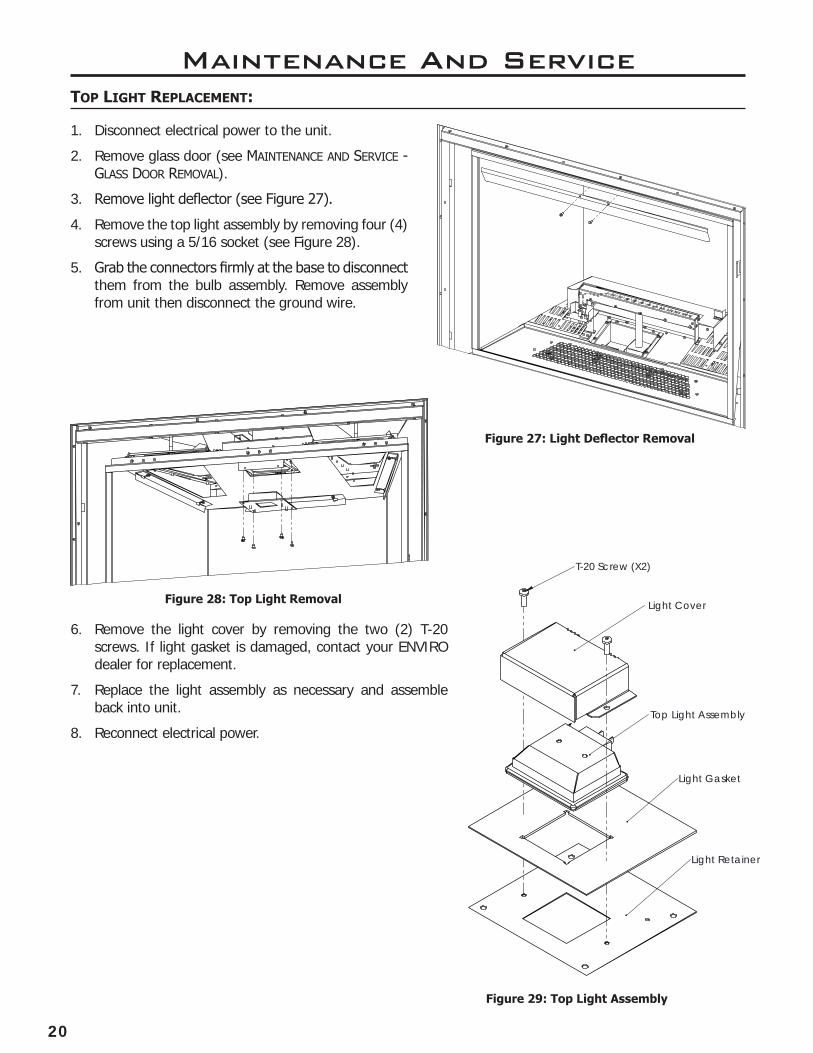
Maintenance And Servicetop LiGht RepLacement:
A
DETAIL A
SCALE 1 : 5
Figure 27: Light Deflector Removal
1. Disconnect electrical power to the unit.
2. Remove glass door (see maIntenance anD serVIce - glass Door remoVal).
3. Remove light deflector (see Figure 27).
4. Remove the top light assembly by removing four (4) screws using a 5/16 socket (see Figure 28).
5. Grab the connectors firmly at the base to disconnect them from the bulb assembly. Remove assembly from unit then disconnect the ground wire.
A
DETAIL A
SCALE 1 : 6
T-20 Screw (X2)
Light Cover
Top Light Assembly
Light Gasket
Light Retainer
6. Remove the light cover by removing the two (2) T-20 screws. If light gasket is damaged, contact your ENVIRO dealer for replacement.
7. Replace the light assembly as necessary and assemble back into unit.
8. Reconnect electrical power.
Figure 28: Top Light Removal
Figure 29: Top Light Assembly

21
FueL conVeRsion:
TO BE INSTALLED BY A QUALIFIED SERVICE AGENCY ONLY
Please read and understand these instructions before installing.
Warning: This conversion kit shall be installed by a qualified service agency in accordance with the manufacturer’s instructions and all applicable codes and requirements of the authority having jurisdiction. If the information in these instructions is not followed exactly, a fire, explosion or production of carbon monoxide may result causing property damage, personal injury or loss of life. The qualified service agency is responsible for the proper installation of this kit. The installation is not proper or complete until the operation of the converted appliance is checked as specified in the manufacturer’s instructions supplied with the kit.
Kit Parts List for G50LI Model:
1 - LP Stepper Motor w/ Hardware 2 - Burner Orifices (LP - Front #53 Rear #52 DMS) as marked [included with unit]3 - Conversion Labels [included with unit] 1 - Installation Instruction Sheet [included in Owner’s Manual]
Carefully inspect all parts supplied with this conversion kit. If any parts have been damaged or are missing, contact your dealer, distributor or courier company to have them replaced before starting this installation.
Maintenance And Service
A
DETAIL A
SCALE 2 : 3
Figure 30: Orifice Locations
conVeRsion Kit instaLLation:
Front orifice: #53 (smaller)
Rear orifice: #52 (larger)
C
D
DETAIL C
SCALE 1 : 5
DETAIL D
SCALE 2 : 5
FrontOrifice
RearOrifice
Figure 29: Orifice Locations
1. Disconnect the gas supply completely as well as any electrical power source before proceeding.
2. Remove surround panel, door cover, glass door, front burner, and rear burner (see maIntenance anD serVIce section of Owner’s Manual).
3. Convert the existing burner orifices with the ones provided in this kit using a 3/8 inch deep socket. WARNING: BE SURE TO INSTALL THE CORRECT ORIFICE INTO THE CORRECT PORT
22
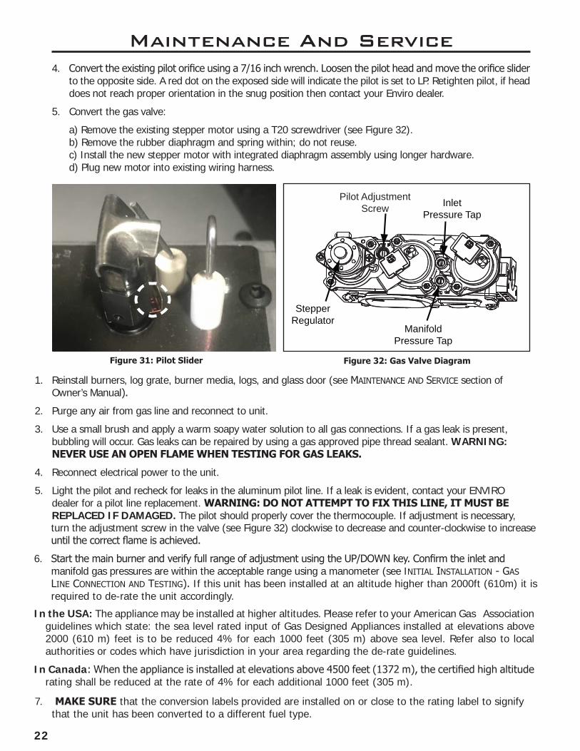
Maintenance And Service4. Convert the existing pilot orifice using a 7/16 inch wrench. Loosen the pilot head and move the orifice slider
to the opposite side. A red dot on the exposed side will indicate the pilot is set to LP. Retighten pilot, if head does not reach proper orientation in the snug position then contact your Enviro dealer.
5. Convert the gas valve:
a) Remove the existing stepper motor using a T20 screwdriver (see Figure 32). b) Remove the rubber diaphragm and spring within; do not reuse. c) Install the new stepper motor with integrated diaphragm assembly using longer hardware. d) Plug new motor into existing wiring harness.
Pilot Adjustment Screw
ManifoldPressure Tap
InletPressure Tap
StepperRegulator
1. Reinstall burners, log grate, burner media, logs, and glass door (see maIntenance anD serVIce section of Owner’s Manual).
2. Purge any air from gas line and reconnect to unit.
3. Use a small brush and apply a warm soapy water solution to all gas connections. If a gas leak is present, bubbling will occur. Gas leaks can be repaired by using a gas approved pipe thread sealant. WARNING: NEVER USE AN OPEN FLAME WHEN TESTING FOR GAS LEAKS.
4. Reconnect electrical power to the unit.
5. Light the pilot and recheck for leaks in the aluminum pilot line. If a leak is evident, contact your ENVIRO dealer for a pilot line replacement. WARNING: DO NOT ATTEMPT TO FIX THIS LINE, IT MUST BE REPLACED IF DAMAGED. The pilot should properly cover the thermocouple. If adjustment is necessary,
In the USA: The appliance may be installed at higher altitudes. Please refer to your American Gas Association guidelines which state: the sea level rated input of Gas Designed Appliances installed at elevations above 2000 (610 m) feet is to be reduced 4% for each 1000 feet (305 m) above sea level. Refer also to local authorities or codes which have jurisdiction in your area regarding the de-rate guidelines.
In Canada: When the appliance is installed at elevations above 4500 feet (1372 m), the certified high altitude rating shall be reduced at the rate of 4% for each additional 1000 feet (305 m).
turn the adjustment screw in the valve (see Figure 32) clockwise to decrease and counter-clockwise to increase until the correct flame is achieved.
6. Start the main burner and verify full range of adjustment using the UP/DOWN key. Confirm the inlet and manifold gas pressures are within the acceptable range using a manometer (see InItIal InstallatIon - gas lIne connectIon anD testIng). If this unit has been installed at an altitude higher than 2000ft (610m) it is required to de-rate the unit accordingly.
Figure 31: Pilot Slider Figure 32: Gas Valve Diagram
7. MAKE SURE that the conversion labels provided are installed on or close to the rating label to signify that the unit has been converted to a different fuel type.
23
Initial InstallationQUALIFIED INSTALLERS ONLY
intRoDuction:
This section of the owner’s manual is for the use of qualified technicians only. There are several installation safety guidelines that must be adhered to; please carefully read the safety precautions at the front of this manual.
4
5
7
10
98
3
2
61
11Diagram 1: Additional Parts
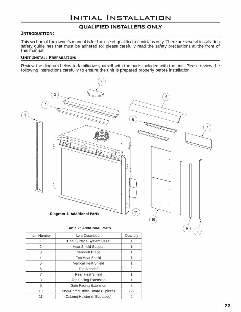
unit instaLL pRepaRation:
Review the diagram below to familiarize yourself with the parts included with the unit. Please review the following instructions carefully to ensure the unit is prepared properly before installation.
Item Number Item Description Quantity1 Cool Surface System Bezel 12 Heat Shield Support 13 Standoff Brace 14 Top Heat Shield 15 Vertical Heat Shield 16 Top Standoff 27 Rear Heat Shield 18 Top Facing Extension 19 Side Facing Extension 2
10 Non-Combustible Board (2 piece) (2)11 Cabinet Holster (If Equipped) 2
Table 2: Additional Parts
24
Initial InstallationQUALIFIED INSTALLERS ONLY
A
DETAIL A
SCALE 2 : 5
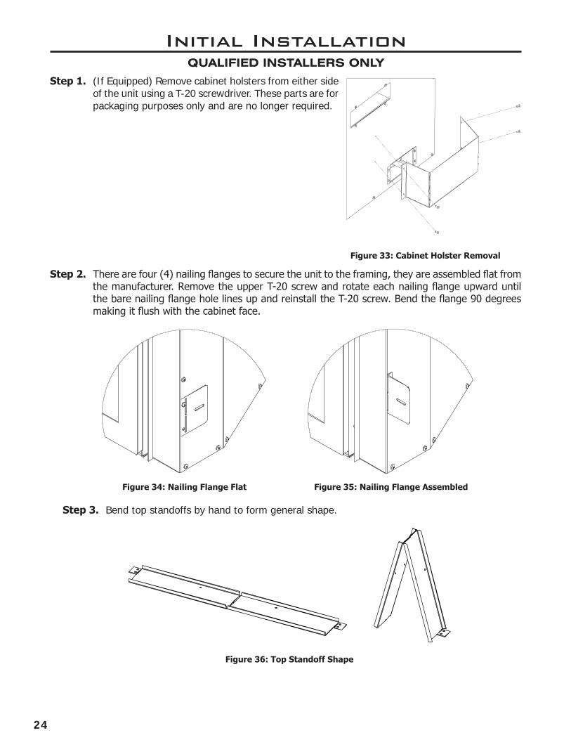
Step 1. (If Equipped) Remove cabinet holsters from either side of the unit using a T-20 screwdriver. These parts are for packaging purposes only and are no longer required.
Figure 33: Cabinet Holster Removal
Step 3. Bend top standoffs by hand to form general shape.
Figure 36: Top Standoff Shape
A
DETAIL A
SCALE 1 : 2
A
DETAIL A
SCALE 1 : 2
Step 2. There are four (4) nailing flanges to secure the unit to the framing, they are assembled flat from the manufacturer. Remove the upper T-20 screw and rotate each nailing flange upward until the bare nailing flange hole lines up and reinstall the T-20 screw. Bend the flange 90 degrees making it flush with the cabinet face.
Figure 34: Nailing Flange Flat Figure 35: Nailing Flange Assembled

25
Figure 37: Top Standoff Install
A
DETAIL A
SCALE 1 : 5
A
DETAIL A
SCALE 1 : 5
Step 3. Install top standoffs into position using supplied T-20 screws.
Initial InstallationQUALIFIED INSTALLERS ONLY
Step 4. Install heat shield support using four (4) supplied T-20 screws.
Figure 38: Heat Shield Support Install
A
DETAIL A
SCALE 1 : 10
Figure 39: Standoff Brace Install
Step 5. Install standoff brace using nine (9) supplied T-20 screws.
26
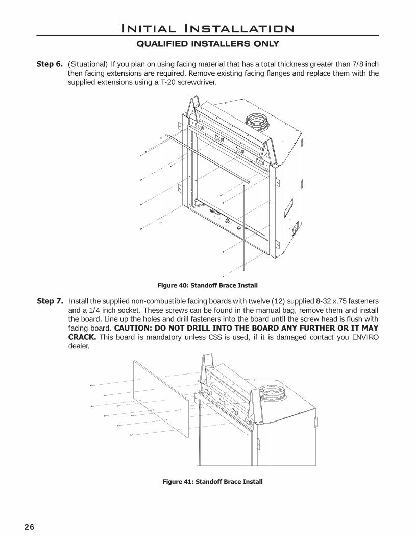
Step 6. (Situational) If you plan on using facing material that has a total thickness greater than 7/8 inch then facing extensions are required. Remove existing facing flanges and replace them with the supplied extensions using a T-20 screwdriver.
Initial InstallationQUALIFIED INSTALLERS ONLY
Step 7. Install the supplied non-combustible facing boards with twelve (12) supplied 8-32 x.75 fasteners and a 1/4 inch socket. These screws can be found in the manual bag, remove them and install the board. Line up the holes and drill fasteners into the board until the screw head is flush with facing board. CAUTION: DO NOT DRILL INTO THE BOARD ANY FURTHER OR IT MAY CRACK. This board is mandatory unless CSS is used, if it is damaged contact you ENVIRO dealer.
Figure 40: Standoff Brace Install
Figure 41: Standoff Brace Install
A
DETAIL A
SCALE 1 : 5
27
Initial InstallationQUALIFIED INSTALLERS ONLY
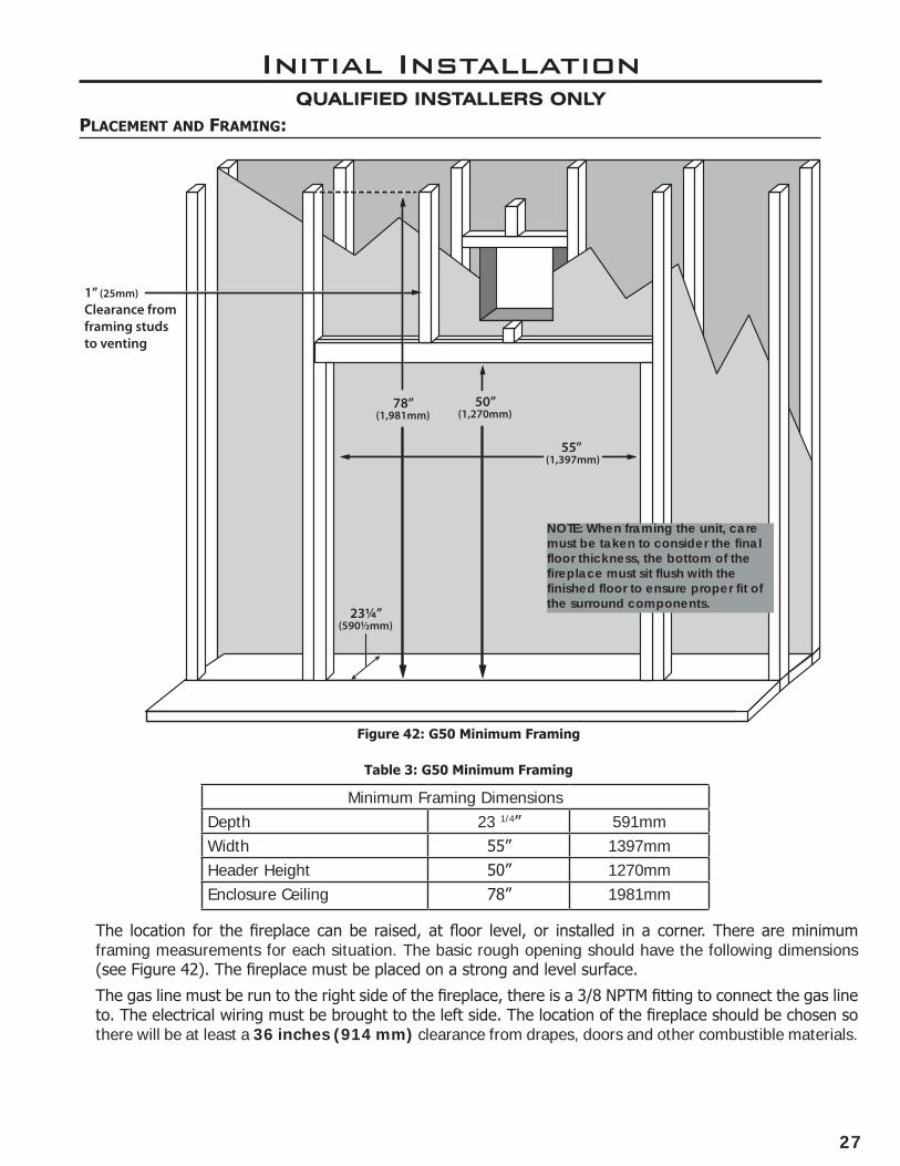
pLacement anD FRaminG:
78”(1,981mm)
23¼”(590½mm)
55”(1,397mm)
50”(1,270mm)
1” (25mm) Clearance from framing studs to venting
Minimum Framing DimensionsDepth 23 1/4” 591mmWidth 55” 1397mmHeader Height 50” 1270mmEnclosure Ceiling 78” 1981mm
Table 3: G50 Minimum Framing
The location for the fireplace can be raised, at floor level, or installed in a corner. There are minimum framing measurements for each situation. The basic rough opening should have the following dimensions (see Figure 42). The fireplace must be placed on a strong and level surface.
The gas line must be run to the right side of the fireplace, there is a 3/8 NPTM fitting to connect the gas line to. The electrical wiring must be brought to the left side. The location of the fireplace should be chosen so there will be at least a 36 inches (914 mm) clearance from drapes, doors and other combustible materials.
Figure 42: G50 Minimum Framing
NOTE: When framing the unit, care must be taken to consider the final floor thickness, the bottom of the fireplace must sit flush with the finished floor to ensure proper fit of the surround components.

28
A
DETAIL A
SCALE 1 : 5
Initial InstallationQUALIFIED INSTALLERS ONLY
Any venting configuration that passes through a vertical exterior wall requires the rear heat shield installation. Center the shield over the vent pipe and secure to exterior wall framing (see Figure 44). The bottom of the mounting flange should be approximately 1 inch (254mm) above the top of the vent pipe.
Figure 44: Rear Heat Shield
Vent heat shieLDs:
A
DETAIL A
SCALE 1 : 5
All vent configurations require installation of the vertical vent heat shield. Remove the three (3) T-20 screws from their respective locations and use to secure the shield in position (see Figure 43).
The horizontal vent heat shield is only required for minimum vertical rise vent configurations. Use three (3) supplied T-20 screws to secure it to the vertical vent heat shield (see Figure 43).
Figure 43: Vent Shields

29
Initial InstallationQUALIFIED INSTALLERS ONLY
Combustible material may be brought up to any finishing edge ONLY if the Cool Surface System (CSS) has been correctly activated allowing heat in the chase to be vented. This system keeps the front wall cool enough for any combustible materials. The supplied non-combustible board can still be used but is not mandatory when the CSS is activated, combustible material may overlap in this situation.
If the CSS has NOT been activated (Traditional Install) you MUST use a non-combustible material directly above the fireplace extending up the front wall 11 3/4” from the top finishing edge, it is rec-ommended to use the supplied non-combustible board. Combustible material must NOT be brought up to the top finishing edge. Also combustible material CANNOT overlap the non-combustible board on a traditional installation.
cooL suRFace actiVation:
WARNING: IT IS ESSENTIAL THAT THE CHASE IS VENTED IN A MANNER THAT RELIEVES THE ADDITIONAL HEAT ENTERING THE CHASE. ENSURE ONE OF THE AVAILABLE FRAMING OPTIONS HAVE BEEN CONSTRUCTED IN ACCORDANCE WITH THIS MANUAL. FAILURE TO DO SO CAN CREATE AN OVERHEATING SITUATION THAT COULD LEAD TO BUILDING FIRE. Ensure your chase has been constructed in a manner that vents the chase into the same room. It is not permitted to vent the chase into an adjoining room. The CSS bleeds heat off the fireplace into the chase as opposed to climbing up the front face. This dramatically lowers the front wall temperatures allowing the placement of delicate objects above the fireplace. Review the guidelines in the previous sections to ensure your install is in accordance with the framing specifications. Follow these instructions to activate the CSS feature. The non-combustible board included with the fireplace is no longer required when using CSS.
NOTE: These are exact dimensions, add tolerance when cutting finishing material to ensure fit around the finishing edge.
Figure 46: Front Cover Removal
A
DETAIL A
SCALE 1 : 5
Step 1. Remove top portion of the facing flange using a T-20 screwdriver.
Step 2. Remove CSS front cover using a T-20 screwdriver (see Figure 46).
The CSS system is now activated.
40"
51"
Figure 45: Finishing Edge Dims
30
Initial InstallationQUALIFIED INSTALLERS ONLY
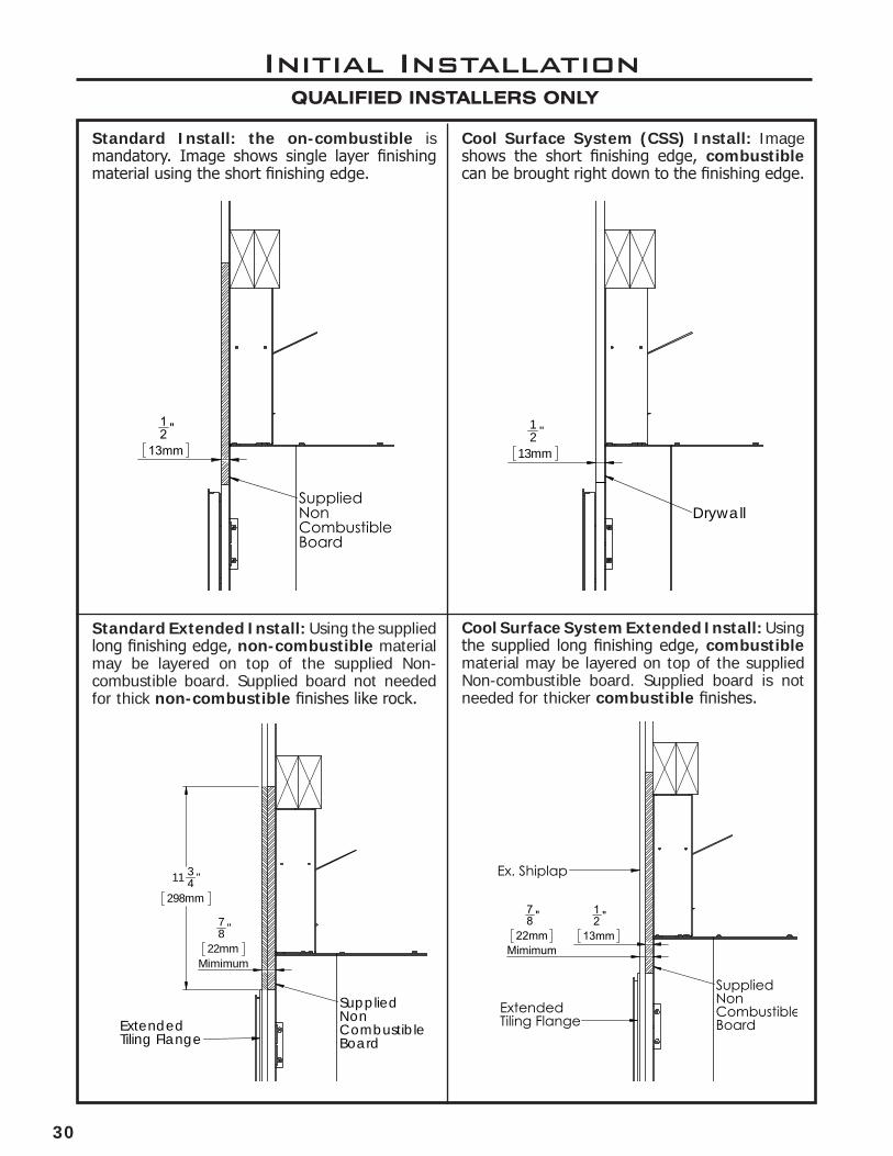
Cool Surface System (CSS) Install: Image shows the short finishing edge, combustible can be brought right down to the finishing edge.
Standard Install: the on-combustible is mandatory. Image shows single layer finishing material using the short finishing edge.
Standard Extended Install: Using the supplied long finishing edge, non-combustible material may be layered on top of the supplied Non-combustible board. Supplied board not needed for thick non-combustible finishes like rock.
Cool Surface System Extended Install: Using the supplied long finishing edge, combustible material may be layered on top of the supplied Non-combustible board. Supplied board is not needed for thicker combustible finishes.
12 "
13mm
78 "
22mmMimimum
SuppliedNonCombustibleBoard
Ex. Shiplap
ExtendedTiling Flange
12 "
13mm
Drywall
78 "
22mmMimimum
11 34 "
298mm
SuppliedNonCombustibleBoard
ExtendedTiling Flange
12 "
13mm
SuppliedNonCombustibleBoard
31
cooL suRFace FRaminG:
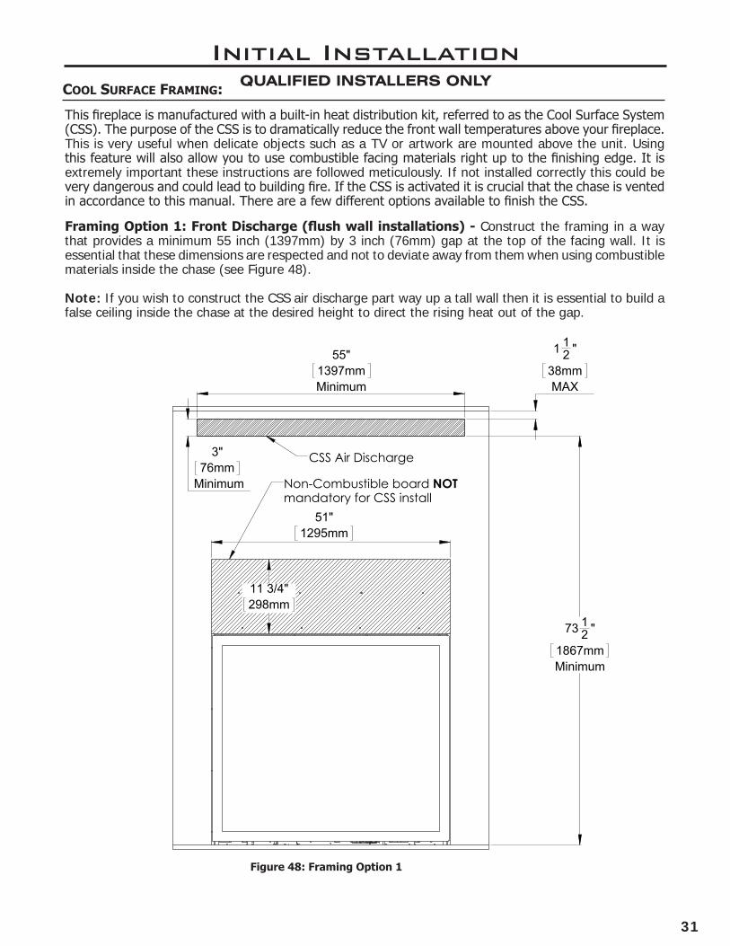
This fireplace is manufactured with a built-in heat distribution kit, referred to as the Cool Surface System (CSS). The purpose of the CSS is to dramatically reduce the front wall temperatures above your fireplace. This is very useful when delicate objects such as a TV or artwork are mounted above the unit. Using this feature will also allow you to use combustible facing materials right up to the finishing edge. It is extremely important these instructions are followed meticulously. If not installed correctly this could be very dangerous and could lead to building fire. If the CSS is activated it is crucial that the chase is vented in accordance to this manual. There are a few different options available to finish the CSS.
Figure 48: Framing Option 1
Initial InstallationQUALIFIED INSTALLERS ONLY
Framing Option 1: Front Discharge (flush wall installations) - Construct the framing in a way that provides a minimum 55 inch (1397mm) by 3 inch (76mm) gap at the top of the facing wall. It is essential that these dimensions are respected and not to deviate away from them when using combustible materials inside the chase (see Figure 48).
Note: If you wish to construct the CSS air discharge part way up a tall wall then it is essential to build a false ceiling inside the chase at the desired height to direct the rising heat out of the gap.
3"76mm
Minimum
55"1397mmMinimum
73 12 "
1867mmMinimum
11 3/4"298mm
51"1295mm
1 12 "
38mmMAX
Non-Combustible board NOT mandatory for CSS install
CSS Air Discharge
32
Minimum 4"102mm
1"25mm
Maximum Minimum 5"127mm
6"152mm
Minimum
3"76mm
6"152mm
Minimum
Wall Mounted Object
Initial InstallationQUALIFIED INSTALLERS ONLY
Figure 49: Option 2
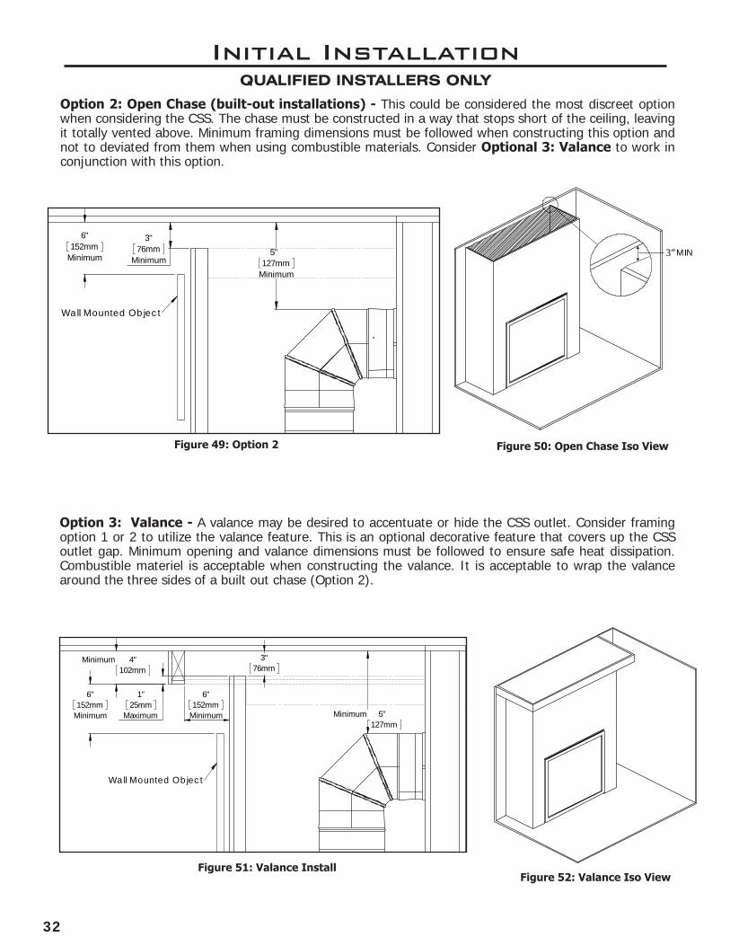
Option 2: Open Chase (built-out installations) - This could be considered the most discreet option when considering the CSS. The chase must be constructed in a way that stops short of the ceiling, leaving it totally vented above. Minimum framing dimensions must be followed when constructing this option and not to deviated from them when using combustible materials. Consider Optional 3: Valance to work in conjunction with this option.
Option 3: Valance - A valance may be desired to accentuate or hide the CSS outlet. Consider framing option 1 or 2 to utilize the valance feature. This is an optional decorative feature that covers up the CSS outlet gap. Minimum opening and valance dimensions must be followed to ensure safe heat dissipation. Combustible materiel is acceptable when constructing the valance. It is acceptable to wrap the valance around the three sides of a built out chase (Option 2).
Figure 52: Valance Iso View
2" MIN
Figure 51: Valance Install
Figure 50: Open Chase Iso View
3"76mm
Minimum5"
127mmMinimum
6"152mm
Minimum
Wall Mounted Object
3”
33
Initial InstallationQUALIFIED INSTALLERS ONLY
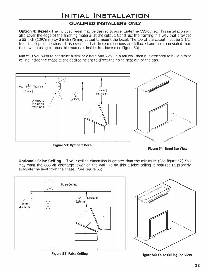
Option 4: Bezel - The included bezel may be desired to accentuate the CSS outlet. This installation will also cover the edge of the finishing material at the cutout. Construct the framing in a way that provides a 55 inch (1397mm) by 3 inch (76mm) cutout to mount the bezel. The top of the cutout must be 1 1/2” from the top of the chase. It is essential that these dimensions are followed and not to deviated from them when using combustible materials inside the chase (see Figure 53).
Note: If you wish to construct a similar cutout part way up a tall wall then it is essential to build a false ceiling inside the chase at the desired height to direct the rising heat out of the gap.
Figure 53: Option 3 Bezel
Optional: False Ceiling - If your ceiling dimension is greater than the minimum (See figure 42) You may want the CSS Air discharge lower on the wall. To do this a false ceiling is required to properly evacuate the heat from the chase. (See Figure 55).
Figure 55: False Ceiling
Figure 54: Bezel Iso View
Figure 56: False Ceiling Iso View
5"127mm
Minimum
0 to 1 12 "
38mm
Maximum
3 18 "
79mm
CSS BezelIncluded With Unit
5"127mm
Minimum3"
76mmMinimum
False Ceiling
34
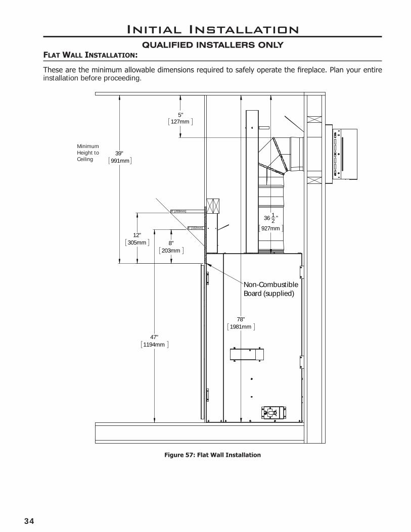
47"1194mm
78"1981mm
36 12 "
927mm
5"
127mm
39"991mm
8"203mm
12"
305mm
8" [203mm]
Non-CombustibleBoard (supplied)
4" [102mm]
Initial InstallationQUALIFIED INSTALLERS ONLY
Figure 57: Flat Wall Installation
Minimum Height to Ceiling
FLat WaLL instaLLation:
These are the minimum allowable dimensions required to safely operate the fireplace. Plan your entire installation before proceeding.
35
57"1448mm
17 78 "
455mm
3 12 "
90mm
5 12 "
138mm
78"1981mm
36 12 "
927mm
Non-CombustibleBoard (supplied)
Initial InstallationQUALIFIED INSTALLERS ONLY
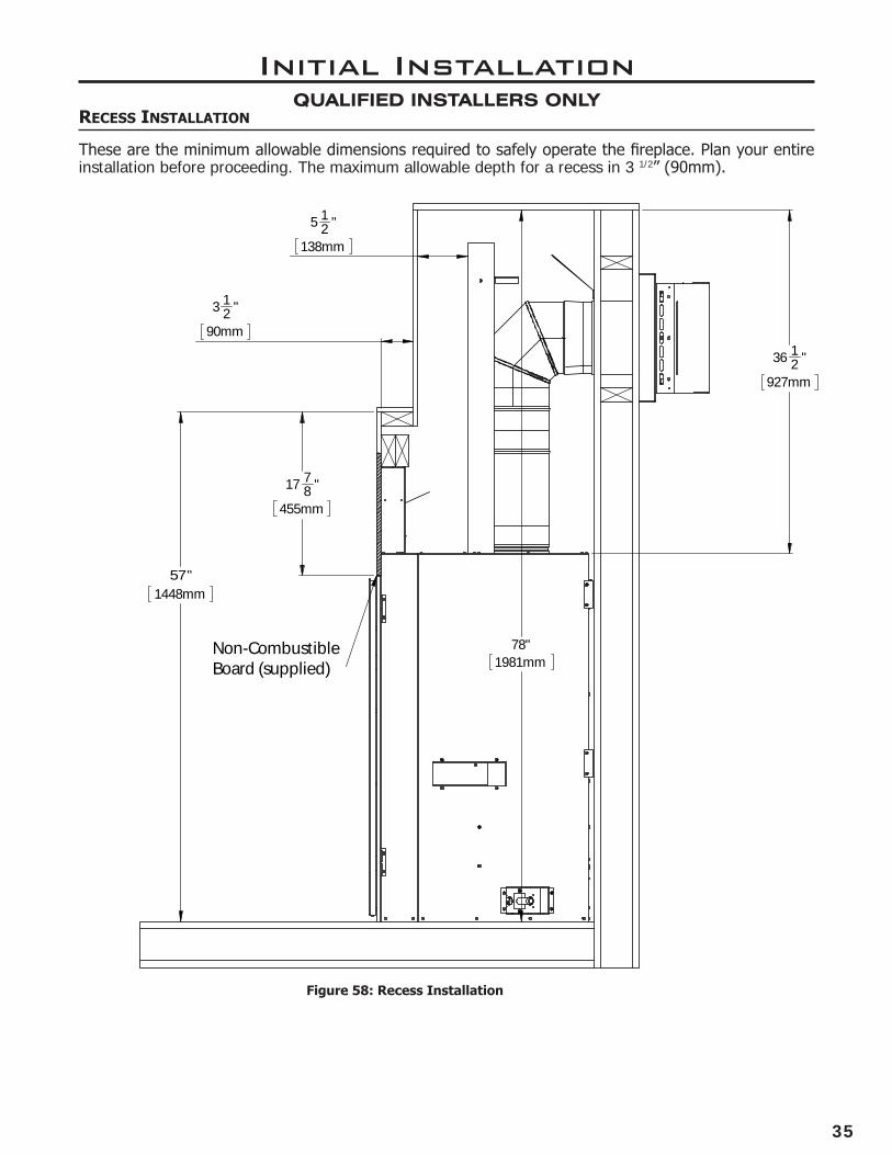
Recess instaLLation
These are the minimum allowable dimensions required to safely operate the fireplace. Plan your entire installation before proceeding. The maximum allowable depth for a recess in 3 1/2” (90mm).
Figure 58: Recess Installation
36
Initial InstallationQUALIFIED INSTALLERS ONLY
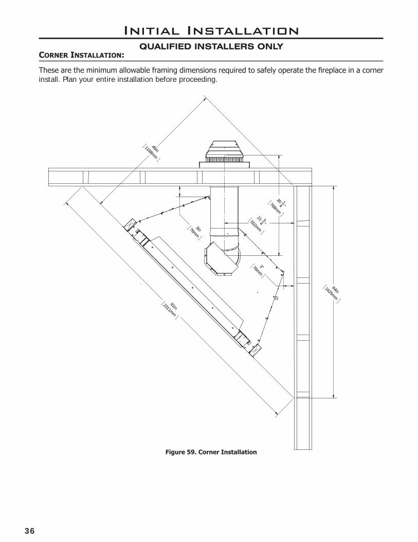
coRneR instaLLation:
These are the minimum allowable framing dimensions required to safely operate the fireplace in a corner install. Plan your entire installation before proceeding.
Figure 59. Corner Installation
3"76mm
3in76mm
30 1
4 "768mm
21 34 "552mm
91in
2311mm
46in
1168mm
64in
1625mm

37
Initial InstallationQUALIFIED INSTALLERS ONLY
manteL RequiRements:
First determine what mantel height or depth you would like and use the graph to determine the minimum corresponding dimension. Mantel graph dimensions are measured from the bottom of the fireplace, if you wish to reference the mantel height from the tiling edge subtract 39 inches (991mm) from the mantel height depicted on the graph. If you plan to install a TV above your fireplace refer to the appropriate section for available options. It is acceptable to install a combustible mantel over top of the non-combustible board. If you are activating the cooL suRFace system you are eligible to subtract 4” (102mm) from the mantel height shown in this diagram.
1 2 3 4 5 6 7 8 9 10 11 12 13 14
MA
NT
EL
HE
IGH
T
M A N T E L D E P T H
Minimum Mantle Clearances
8” MANTEL
4”MANTEL
52”
51”
50”
49”
48”
47”
46”
44”
45”
12” MANTEL
Diagram 2: Mantel Graph
FLooR pRotection:
Figure 60: Air Gap Warning 34"
19mm
A
Non Combustible Board
34"
19mm
DETAIL A
SCALE 1 : 8
The fireplace must be placed on a solid and level floor; plywood is recommended for basic installations. A protective hearth is not required but highly recommended for the longevity of sensitive flooring materials in front of the fireplace.
If masonry is to be used, prepare the necessary foundation for the masonry load. When masonry construction is being used, a lintel must be used over top of the fireplace to support the added weight.
Consider the height of hearth finish material (stone, brick, etc.) when building a fireplace platform. The bottom of the fireplace must be level with finished hearth.WARNING: DO NOT OBSTRUCT THE BOTTOM AIR GAP WITH FLOORING MATERIAL. RAISE THE FIREPLACE TO MATCH FLOOR THICKNESS.
3"76mm
3in76mm
30 1
4 "768mm
21 34 "552mm
91in
2311mm
46in
1168mm
64in
1625mm
38
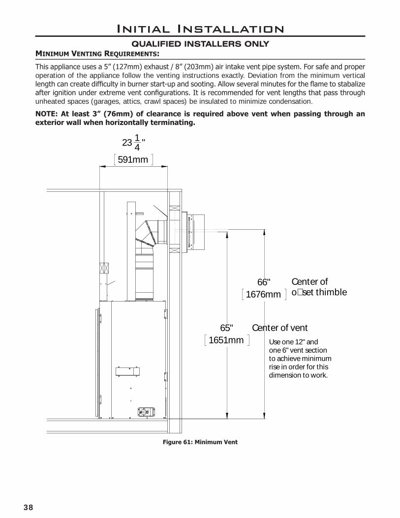
minimum VentinG RequiRements:
23 14 "
591mm
65"1651mm
66"1676mm
Use one 12" and one 6" vent section to achieve minimum rise in order for this dimension to work.
Center of o�set thimble
Center of vent
Figure 61: Minimum Vent
This appliance uses a 5” (127mm) exhaust / 8” (203mm) air intake vent pipe system. For safe and proper operation of the appliance follow the venting instructions exactly. Deviation from the minimum vertical length can create difficulty in burner start-up and sooting. Allow several minutes for the flame to stabalize after ignition under extreme vent configurations. It is recommended for vent lengths that pass through unheated spaces (garages, attics, crawl spaces) be insulated to minimize condensation.
NOTE: At least 3” (76mm) of clearance is required above vent when passing through an exterior wall when horizontally terminating.
Initial InstallationQUALIFIED INSTALLERS ONLY

39
Initial InstallationQUALIFIED INSTALLERS ONLY
Figure 62. Flex Adapter Kit Install
FLex VentinG:
This fireplace is certified to work with aluminium co-axial flex venting. Flex venting can be used in the same configurations as rigid pipe, see venting diagram for details. Flex venting is only to be used for the run, it must be adapted to rigid piping for exterior wall penetration and termination. Note: Adhere to all rigid venting safety measures and clearances.
Use 5X8 Flex Adapter Kit [50-3789]: This kit will allow you to adapt co-axial flex to the fireplace, make your vent run, then adapt back to rigid venting (flex not included).
Any Q, C, or G Series Fireplace
Flex Starter Adapter
DV Flex Venting (not supplied)
Flex End Adapter
Any Enviro ApprovedRigid Venting
Use gear clamps to secure inner and outer vent. No sealant required
INSTALLATION NOTES:• Do not bend flex vent over 90 degrees.
• All horizontal runs should have a minimum 1/4” (6mm) rise per foot for optimal performance.
• Do not allow the inner flex pipe to contact the outer pipe, keep it pulled tight and use spacer springs.
• Spacers are required at the start, middle, and end of each elbow to ensure gap is maintained.
• Do not add any extensions to the preset kits, if more length is required, use rigid pipe.
• No need for liquid sealant; secure flex venting with aluminum vent tape and apply sufficient self-tapping screws.
Any 5X8 CSA or UL flue gas certified aluminum or stainless steel flex is acceptable. Proper spacers must be used to keep pipes from contacting each other. Proper venting spacers must be used, nothing makeshift. Examples of allowable flex pipe brands include, but are not limited to, the following:
• M&G Duravent
• Selkirk Corp
• ICC
• Z-Flex
• Flexmaster
• Chim Flex
• Olympia
• BDM
• Metal-Fab
Only the flex venting and spacers are needed. You must use the flex adapter kit and a certified rigid pipe termination cap.
40
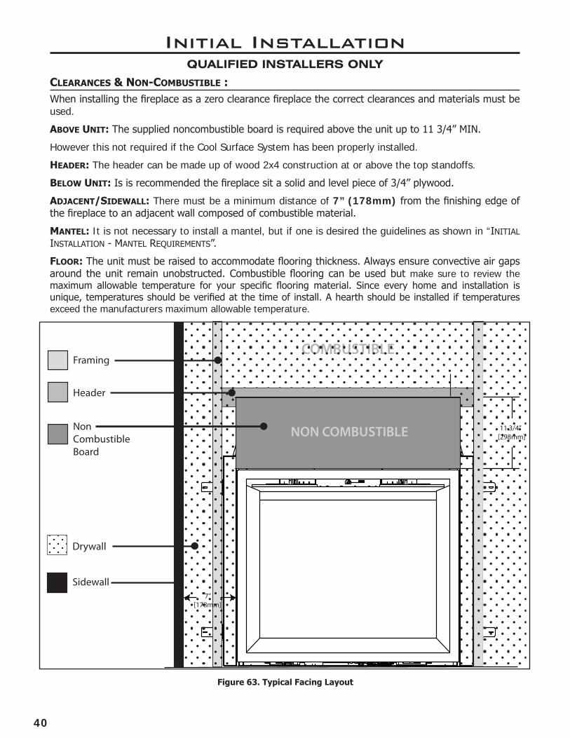
Figure 63. Typical Facing Layout
cLeaRances & non-combustibLe :When installing the fireplace as a zero clearance fireplace the correct clearances and materials must be used.
aboVe unit: The supplied noncombustible board is required above the unit up to 11 3/4” MIN.
However this not required if the Cool Surface System has been properly installed.
heaDeR: The header can be made up of wood 2x4 construction at or above the top standoffs.
beLoW unit: Is is recommended the fireplace sit a solid and level piece of 3/4” plywood.
aDjacent/siDeWaLL: There must be a minimum distance of 7” (178mm) from the finishing edge of the fireplace to an adjacent wall composed of combustible material.
manteL: It is not necessary to install a mantel, but if one is desired the guidelines as shown in “InItIal InstallatIon - mantel requIrements”.
FLooR: The unit must be raised to accommodate flooring thickness. Always ensure convective air gaps around the unit remain unobstructed. Combustible flooring can be used but make sure to review the maximum allowable temperature for your specific flooring material. Since every home and installation is unique, temperatures should be verified at the time of install. A hearth should be installed if temperatures exceed the manufacturers maximum allowable temperature.
Initial InstallationQUALIFIED INSTALLERS ONLY
COMBUSTIBLE
NON COMBUSTIBLE
Framing
Header
Drywall
NonCombustible Board
Sidewall
11 3/4”[298mm]
7”[178mm]
41
Initial InstallationQUALIFIED INSTALLERS ONLY
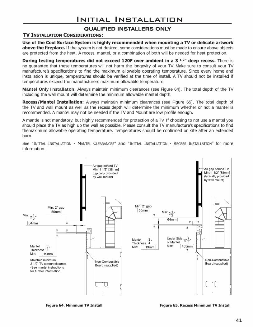
tV instaLLation consiDeRations:Use of the Cool Surface System is highly recommended when mounting a TV or delicate artwork above the fireplace. If the system is not desired, some considerations must be made to ensure above objects are protected from the heat. A recess, mantel, or a combination of both will be needed for heat protection.
During testing temperatures did not exceed 120F over ambient in a 3 1/2” deep recess. There is no guarantee that these temperatures will not harm the longevity of your TV. Make sure to consult your TV manufacture’s specifications to find the maximum allowable operating temperature. Since every home and installation is unique, temperatures should be verified at the time of install. A TV should not be installed if temperatures exceed the manufacturers maximum allowable temperature.
Mantel Only Installaton: Always maintain minimum clearances (see Figure 64). The total depth of the TV including the wall mount will determine the minimum allowable mantel depth.
Recess/Mantel Installation: Always maintain minimum clearances (see Figure 65). The total depth of the TV and wall mount as well as the recess depth will determine the minimum whether or not a mantel is recommended. A mantel may not be needed if the TV and Mount are low profile enough.
A mantle is not mandatory, but highly recommended for protection of a TV. If choosing to not use a mantel you should place the TV as high up the wall as possible. Please consult the TV manufacture’s specifications to find themaximum allowable operating temperature. Temperatures should be confirmed on site after an extended burn.
See “InItIal InstallatIon - mantel clearances” and “InItIal InstallatIon - recess InstallatIon” for more information.
Figure 64. Minimum TV Install Figure 65. Recess Minimum TV Install
34 "
19mm
17 78 "
455mm
2 12 "
64mm
Min: 2" gap50mm
Air gap behind TVMin: 1 1/2" [38mm](typically providedby wall mount)
Min:
Under Sideof MantelMin:
Non-CombustibleBoard (supplied)
Mantel ThicknessMin: 3
4 "
19mm
Min: 2" gap50mm
2 12 "
64mm
Non-CombustibleBoard (supplied)
Air gap behind TVMin: 1 1/2" [38mm](typically providedby wall mount)
MantelThicknessMin:
Min:
Maintain minimum2 1/2" TV screen distance-See mantel instructionsfor further information
42
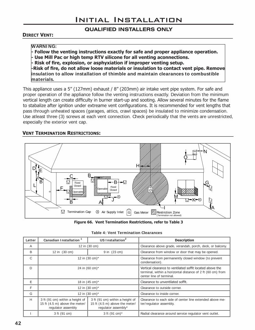
Figure 66. Vent Termination Restrictions, refer to Table 3
Initial InstallationQUALIFIED INSTALLERS ONLY
AA
D E
LB
C
F
B
BB
JM
K
G
H
I
Openable
FixedClosed
OpenableFixedClosed
Termination Cap Air Supply Inlet Gas MeterG
G
Restriction Zone(Termination not allowed)
NO
Letter Canadian Installation 1 US Installation2 Description
A 12 in (30 cm) Clearance above grade, verandah, porch, deck, or balcony.
B 12 in (30 cm) 9 in (23 cm) Clearance from window or door that may be opened.
C 12 in (30 cm)* Clearance from permanently closed window (to prevent condensation).
D 24 in (60 cm)* Vertical clearance to ventilated soffit located above the terminal, within a horizontal distance of 2 ft (60 cm) from center line of terminal.
E 18 in (45 cm)* Clearance to unventilated soffit.
F 12 in (30 cm)* Clearance to outside corner.
G 12 in (30 cm)* Clearance to inside corner.
H 3 ft (91 cm) within a height of 15 ft (4.5 m) above the meter/
regulator assembly
3 ft (91 cm) within a height of 15 ft (4.5 m) above the meter/
regulator assembly*
Clearance to each side of center line extended above me-ter/regulator assembly.
I 3 ft (91 cm) 3 ft (91 cm)* Radial clearance around service regulator vent outlet.
Table 4: Vent Termination Clearances
Vent teRmination RestRictions:
WARNING:- Follow the venting instructions exactly for safe and proper appliance operation.- Use Mill Pac or high temp RTV silicone for all venting aconnections.- Risk of fire, explosion, or asphyxiation if improper venting setup.-Risk of fire, do not allow loose materials or insulation to contact vent pipe. Remove insulation to allow installation of thimble and maintain clearances to combustible materials.
DiRect Vent:
This appliance uses a 5” (127mm) exhaust / 8” (203mm) air intake vent pipe system. For safe and proper operation of the appliance follow the venting instructions exactly. Deviation from the minimum vertical length can create difficulty in burner start-up and sooting. Allow several minutes for the flame to stabalize after ignition under extreame vent configurations. It is recommended for vent lengths that pass through unheated spaces (garages, attics, crawl spaces) be insulated to minimize condensation. Use atleast three (3) screws at each vent connection. Check periodically that the vents are unrestricted, especially the exterior vent cap.

43
Initial InstallationQUALIFIED INSTALLERS ONLY
J 12 in (30 cm) 9 in (23 cm) Clearance to non-mechanical air supply inlet to building, or the combustion air inlet to any other appliance.
K 6 ft (1.83 m) 3 ft (91 cm) above if within 10 ft (3 m) horizontally
Clearance to mechanical air supply inlet.
L 7 ft (2.13 m)t 7 ft (2.13 m)*t Clearance above paved sidewalk or paved driveway located on public property.
M 12 in / 30 cm+ 12 in / 30 cm*+ Clearance under verandah, porch, deck, or balcony.
N 12 in (30 cm)* Clearance horizontally to any surface (such as an exterior wall) for vertical terminations.
O 12 in (30 cm) Clearance above roof line for vertical terminations.
1 In accordance with the current CSA B149.1, Natural Gas and Propane Installation Code.2 In accordance with the current ANSI Z223.1 NFPA 54, National Fuel Gas Code.* These numbers are only estimates.t A vent shall not terminate directly above a side walk or paved driveway that is located between two single family dwellings and it serves both dwellings.+ Permitted only if verandah, porch, deck, or balcony is fully open on a minimum of two sides beneath the floor.
Clearances must be in accordance with local installation codes and requirements of the gas supplier.
NOTE: Venting terminals shall not be recessed into walls or siding.
GeneRaL VentinG cLeaRances:
A 1” (25 mm) clearance to combustibles must be maintained around any vertical vent pipe. Around a horizontal vent pipe, the clearance to combustibles should be 3” (76 mm) above and 1” (25 mm) on the sides and bottom. When combustible materials are directly above the first 90° elbow, 5” (127 mm) of clearance is necessary.
Table 5. Vent Pipe Minimum Clearances
Vertical Pipe to the Side Walls
Horizontal Pipe to the Sides & Bottom
Above First Elbow
Above Subsequent Elbows
Above Horizontal Vent Pipe
Wall Frame 8” (203mm) or less
Hard Pipe
1”(25mm)
1”(25 mm)
5”(127mm)
3”(76 mm)
3”(76 mm)
3” top (76mm)
See certified thimbles in venting section and frame accordingly (see Figure 67). A thimble will assure the proper support and spacing requirements for the vent pipe as it passes through the exterior wall. Installations in Canada require that a wall thimble be used for passing through walls and ceilings. All sealing and vapour barriers must comply with local building codes. Not all standard 8” thimbles can be used; you MUST maintain 3” (76mm) clearance above a vent pipe running through a wall.
The venting configuration depends on the locations of walls, ceilings, and studs. However, the pipes cannot be of arbitrary length and arrangement. Certain guidelines have been set in “InItIal InstallatIon - allowaBle co-axIal Vent conFIguratIons” because the length of the vertical and horizontal sections dramatically affects the burning efficiency of the fireplace.
x”x”
Figure 67. Thimble FramingWARNING:
-This gas appliance must be direct vented and can’t be connected to a chimney flue serving a separate solid-burning appliances.
-Venting terminals cannot be recessed into a wall or siding.

44
Table 6: Vent Part Numbers (must state if galvanized or black wanted)Direct Vent Pro EXCELDirect DIRECT-TEMP AMV DV Description
58DVA-06 5DL6 5DT-06 6” pipe length
5D7 7” pipe length
58DVA-09 5DL9 5DT-09 9” pipe length
58DVA-12 5DL1 5DT-12 5D12 12” pipe length
58DVA-18 5DT-18 18” pipe length
58DVA-24 5DL2 5DT-24 5D2 24” pipe length
58DVA-36 5DL3 5DT-36 5D3 36” pipe length
58DVA-48 5DL4 5DT-48 5D4 48” pipe length
58DVA-60 60” pipe length
58DVA-E30 30° elbow, black
58DVA-E45 5DE45 5DT-EL45 5D45L 45° elbow, black
58DVA-E90 5DE90 5DT-EL90 5D90L 90° elbow, black
58DVA-VSS, DVA-BVS VSS 5DT-VS/VSK 5DHVS, DVSK Vinyl siding standoff/sheild
58DVA-WT3, 58DVA-WTU3 5WT 5DT-WT 5DWT Wall thimble
58DVA-SC SQSC, SC 5DT-SC 5DSC Storm collar
58DVA-WFS 5DT-FS Wall Fire stop
58DVA-FS 5CS 5DT-FS 5DFSP Ceiling Fire stop
58DVA-IS 5AS 5DT-AIS 5DAIS12, AIS36 Attic Insulation Shield
58DVA-WS 5WS 5DT-WS/B 5DWS Wall strap/support/band
58DVA-VCH 5SVT 5DT-VT 5DVC High wind vertical termination
58DVA-HSCH, 58DVA-HC 5HT 5DT-HC 5DHCS High wind horizontal termination
58DVA-17TA 11” to 17” pipe, adjustable
58DVA-24TA 17” to 24” pipe, adjustable
5DLA30 16.5” to 29” pipe , adjustable
5DLS1 1 7/8” to 9” slip length pipe
5DLS2 1 7/8” to 21” slip length pipe
58DVA-F6 6EFA 5DT-AF6 5DF Flashing, 0/12 to 6/12 roof pitch
58DVA-F12 6EFB 5DT-AF12 5DF12 Flashing, 7/12 to 12/12 roof pitch
58DVA-FF 6EF Flat Roof Flashings
58DVA-CFK 4MF Masonary Flashing
Initial InstallationQUALIFIED INSTALLERS ONLY
Table 6: Approved Vent Manufacturers
Manufacturer Trade Name Nominal Sizes
ICC EXCELDirect 5” - 8”
M&G Dura-Vent Direct Vent Pro 5” - 8”
Selkirk DIRECT-TEMP 5” - 8”
Amerivent DIRECT-VENT 5” - 8”
This fireplace has been tested and certified for use with M&G DuraVent DirectVent Pro, ICC EXCEL Direct, Selkirk DIRECT-TEMP, and Amerivent DIRECT-VENT venting systems. Refer to the table below for part numbers of commonly used parts for both venting systems. For more venting parts please visit the respective manufacturers’ website.
WARNING: Do not mix parts from different vent manufacturers’ systems.
EXCEPTION TO WARNING: This product has been evaluated by Intertek for using a DirectVent Pro starting collar in conjunction with other approved venting systems. Use of this system with the DirectVent Pro starting collar is deemed acceptable and does not affect the Intertek listing of the appliance.
appRoVeD VentinG paRts:
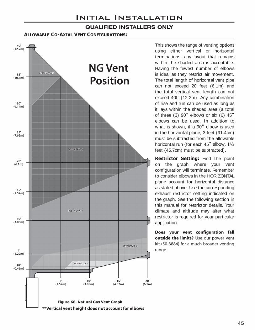
45
Initial InstallationQUALIFIED INSTALLERS ONLY
Figure 68. Natural Gas Vent Graph
aLLoWabLe co-axiaL Vent conFiGuRations:
This shows the range of venting options using either vertical or horizontal terminations; any layout that remains within the shaded area is acceptable. Having the fewest number of elbows is ideal as they restrict air movement. The total length of horizontal vent pipe can not exceed 20 feet (6.1m) and the total vertical vent length can not exceed 40ft (12.2m). Any combination of rise and run can be used as long as it lays within the shaded area (a total of three (3) 90˚ elbows or six (6) 45˚ elbows can be used. In addition to what is shown, if a 90˚ elbow is used in the horizontal plane, 3 feet (91.4cm) must be subtracted from the allowable horizontal run (for each 45˚ elbow, 1½ feet (45.7cm) must be subtracted).
Restrictor Setting: Find the point on the graph where your vent configuration will terminate. Remember to consider elbows in the HORIZONTAL plane account for horizontal distance as stated above. Use the corresponding exhaust restrictor setting indicated on the graph. See the following section in this manual for restrictor details. Your climate and altitude may alter what restrictor is required for your particular application.
5’(1.52m)
4’(1.22m)
18”(0.46m)
10’(3.05m)
10’(3.05m)
15’(4.57m)
15’(1.52m)
20’(6.1m)
20’(6.1m)
25’(7.62m)
30’(9.14m)
35’(10.7m)
40’(12.2m)
NG Vent Position
RESTRICTOR 1RESTRICTOR 1
RESTRICTOR 2RESTRICTOR 2
RESTRICTOR 3RESTRICTOR 3
RESTRICTOR 4RESTRICTOR 4
RESTRICTOR 5RESTRICTOR 5
**Vertical vent height does not account for elbows
Does your vent configuration fall outside the limits? Use our power vent kit (50-3884) for a much broader venting range.
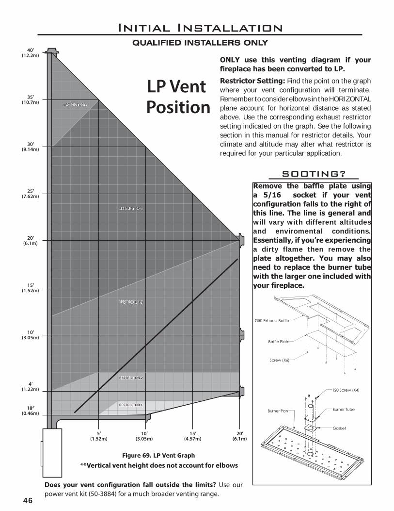
46
Initial InstallationQUALIFIED INSTALLERS ONLY
ONLY use this venting diagram if your fireplace has been converted to LP.
Restrictor Setting: Find the point on the graph where your vent configuration will terminate. Remember to consider elbows in the HORIZONTAL plane account for horizontal distance as stated above. Use the corresponding exhaust restrictor setting indicated on the graph. See the following section in this manual for restrictor details. Your climate and altitude may alter what restrictor is required for your particular application.
Figure 69. LP Vent Graph
5’(1.52m)
4’(1.22m)
18”(0.46m)
10’(3.05m)
10’(3.05m)
15’(4.57m)
15’(1.52m)
20’(6.1m)
20’(6.1m)
25’(7.62m)
30’(9.14m)
35’(10.7m)
40’(12.2m)
LP Vent Position
RESTRICTOR 1RESTRICTOR 1
RESTRICTOR 2RESTRICTOR 2
RESTRICTOR 3RESTRICTOR 3
RESTRICTOR 4RESTRICTOR 4
RESTRICTOR 5RESTRICTOR 5
Remove the baffle plate using a 5/16 socket if your vent configuration falls to the right of this line. The line is general and will vary with different altitudes and enviromental conditions. Essentially, if you’re experiencing a dirty flame then remove the plate altogether. You may also need to replace the burner tube with the larger one included with your fireplace.
G50 Exhaust Baffle
Baffle Plate
Screw (X6)
T20 Screw (X4)
Burner Tube
Gasket
Burner Pan
SOOTING?
**Vertical vent height does not account for elbows
Does your vent configuration fall outside the limits? Use our power vent kit (50-3884) for a much broader venting range.

47
exhaust RestRictoR settinG:
WARNING: Improperly set restrictor setting can cause overheating issues which can lead to building fire.
It may be necessary to adjust the exhaust restrictor in order to control combustion quality and flame appearance. There are six different restrictor settings.
Determine what restrictor setting you require using the vent graphs in “InItIal InstallatIon - allowaBle co-axIal Vent conFIguratIons. The restrictor is set to 1 when the flat edge of the dial is vertical (see Figure 71). Rotate the dial counter-clockwise to increase the restriction level successively until the appropriate setting is achieved. When the flat edge is horizontal the restrictor level is at its maximum (see Figure 70). The proper setting is crucial for an efficient burn and best possible flame appearance.
It may be necessary to deviate from the recommended setting as different altitudes and climates can vary the operation of the fireplace. With LP fueled fireplaces, it is always a good idea to offer slightly less restriction for higher altitudes to reduce the risk of sooting over an extended period.
Initial InstallationQUALIFIED INSTALLERS ONLY
Figure 71. Restrictor Setting 1Figure 70. Restrictor Setting 6
9.00 9.00
AB
DETAIL A
SCALE 2 : 5
DETAIL B
SCALE 4 : 5
9.00 9.00
A
B
DETAIL A
SCALE 2 : 5
DETAIL B
SCALE 4 : 5
Step 1. Remove surround panel to gain access to restrictor control.
Step 2. Use a 7/16 socket with long extension to adjust the restrictor dial to desired setting.
Step 3. Allow unit to warn up sufficently and make adjustment as needed.
Step 4. Allow unit to cool down and reinstall surround panel.
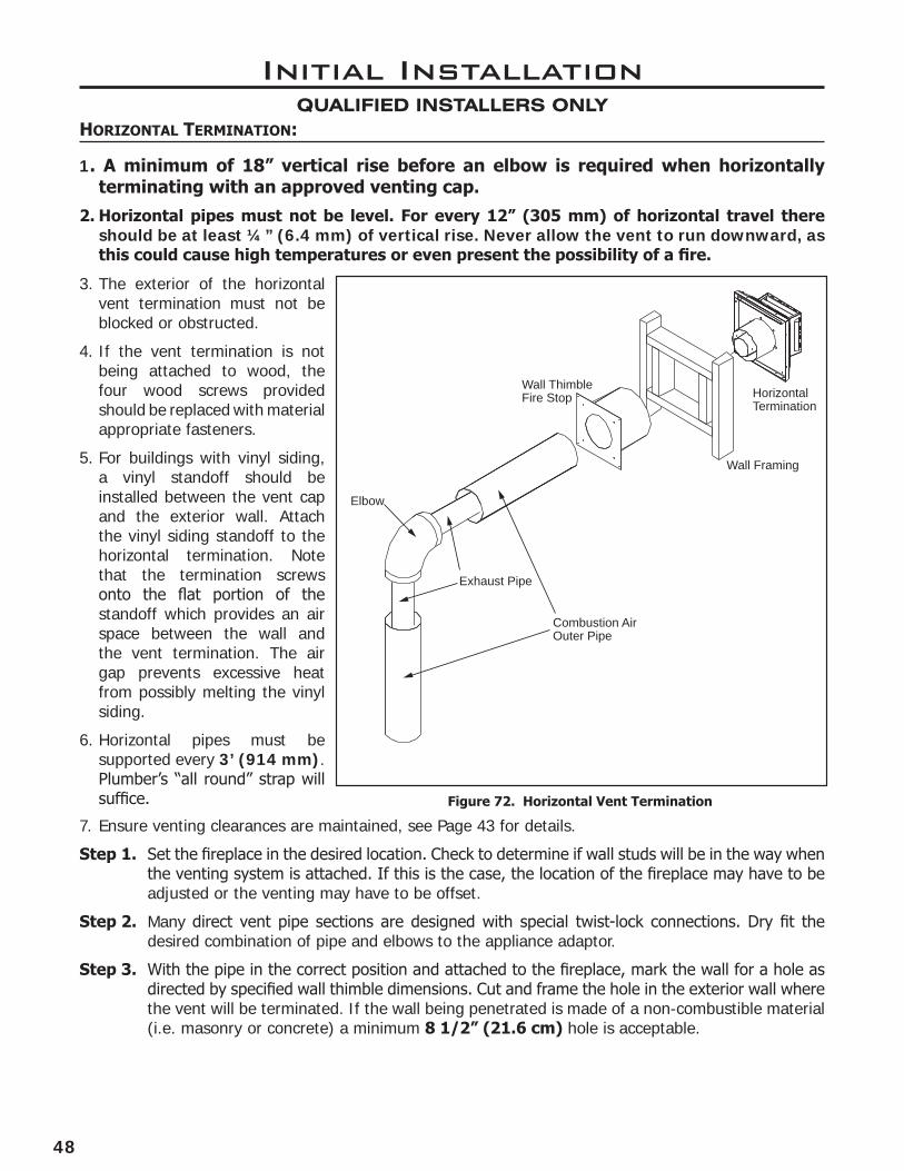
48
Wall Framing
Horizontal Termination
Wall ThimbleFire Stop
Exhaust Pipe
Combustion AirOuter Pipe
Elbow
Initial InstallationQUALIFIED INSTALLERS ONLY
hoRizontaL teRmination:
1. A minimum of 18” vertical rise before an elbow is required when horizontally terminating with an approved venting cap.
2. Horizontal pipes must not be level. For every 12” (305 mm) of horizontal travel there should be at least ¼” (6.4 mm) of vertical rise. Never allow the vent to run downward, as this could cause high temperatures or even present the possibility of a fire.
3. The exterior of the horizontal vent termination must not be blocked or obstructed.
4. If the vent termination is not being attached to wood, the four wood screws provided should be replaced with material appropriate fasteners.
5. For buildings with vinyl siding, a vinyl standoff should be installed between the vent cap and the exterior wall. Attach the vinyl siding standoff to the horizontal termination. Note that the termination screws onto the flat portion of the standoff which provides an air space between the wall and the vent termination. The air gap prevents excessive heat from possibly melting the vinyl siding.
6. Horizontal pipes must be supported every 3’ (914 mm). Plumber’s “all round” strap will suffice.
7. Ensure venting clearances are maintained, see Page 43 for details.
Step 1. Set the fireplace in the desired location. Check to determine if wall studs will be in the way when the venting system is attached. If this is the case, the location of the fireplace may have to be adjusted or the venting may have to be offset.
Step 2. Many direct vent pipe sections are designed with special twist-lock connections. Dry fit the desired combination of pipe and elbows to the appliance adaptor.
Step 3. With the pipe in the correct position and attached to the fireplace, mark the wall for a hole as directed by specified wall thimble dimensions. Cut and frame the hole in the exterior wall where the vent will be terminated. If the wall being penetrated is made of a non-combustible material (i.e. masonry or concrete) a minimum 8 1/2” (21.6 cm) hole is acceptable.
Figure 72. Horizontal Vent Termination

49
Initial InstallationQUALIFIED INSTALLERS ONLY
Figure 73. Vertical Vent Termination
Step 4. The vent pipe must extend into the vent cap at least 1¼” (320 mm). Secure the connection between the vent cap and the pipe by attaching the two (2) sheet metal straps, which extend from the vent cap assembly to the outer wall of the vent pipe. Bend any remaining portion of the strap back towards the vent cap.
Step 5. Position the horizontal vent termination in the center of the thimble and attach to the exterior wall with the four screws provided. The arrow on the vent termination must be pointing up. Run a bead of high-temp silicone around the edges of the vent cap to make a seal with the wall. Ensure the proper clearances to combustibles have been maintained.
VeRticaL teRmination:
Vertical Termination
Storm Collar
Flashing
Roofing nails
Elbow Strap
Step 1. Check “InItIal InstallatIon - VentIng clearances” for required clearances to combustibles when passing through ceilings, walls, roofs, enclosures, attic rafters, or other nearby combustible surfaces. Do not pack air spaces with insulation.
Step 2. Set the fireplace in the desired location. Drop a plumb bob down from the ceiling to the fireplace flue exit and mark the location where the vent will penetrate the ceiling. Drill a small hole at this point. Next, drop a plumb bob from the roof to the hole and mark the spot where the vent will penetrate the roof. Determine if ceiling joists, roof rafters, or other framing will obstruct the venting system. Relocate the fireplace or offset the venting to avoid cutting load bearing members.
Step 3. To determine the length of pipe required, measure room height, ceiling thickness, and vertical rise in an attic or second story. Firestops are required at each floor level beyond the first floor ceiling support/wall thimble cover or cathedral ceiling support box. If an offset is required to avoid obstructions, use a pair of 45 degree elbows. For proper support, use elbow straps with offsets. Use wall straps for long vertical runs. Attic insulation shield is required in attic.
Step 4. Measure roof pitch. Select the proper flashing and storm collar and determine the height above the roof (see Figure 74). A non-corrosive pipe material must be used for all exterior pipe lengths. Seal nail heads with silicone.

50
Initial InstallationQUALIFIED INSTALLERS ONLY
H
Dimension ‘H’ obtainedfrom table below
Table 7: Minimum ‘H’ for Figure 69.
Roof Pitch Minimum Height (H)
Feet Meters
Flat to 7/12 1 0.3
Over 7/12 to 8/12 1.5 0.46
Over 8/12 to 9/12 2 0.61
Over 9/12 to 10/12 2.5 0.76
Over 10/12 to 11/12 3.25 0.99
Over 11/12 to 12/12 4 1.22
Over 12/12 to 14/12 5 1.52
Over 14/12 to 16/12 6 1.83
Over 16/12 to 18/12 7 2.13
Over 18/12 to 20/12 7.5 2.29
Over 20/12 to 21/12 8 2.44Figure 74: Height of Vertical Termination;
Reference Table 7
45° elbows (x2)
Wall strap
Plumber’s tapeconnected towal strap
Figure 76: Use of Wall Straps.
Figure 75: Multi-Story Vent Pipe Installation
NOTES:
1. If an offset is necessary in the attic to avoid obstructions, it is important to support the vent pipe every 3’ (914 mm) using wall straps to avoid excessive stress on the elbows.
2. Use 45° degree elbows instead of 90° degree elbows when ever possible. The 45° degree elbow offers less restriction to the flow of flue gases and intake air.
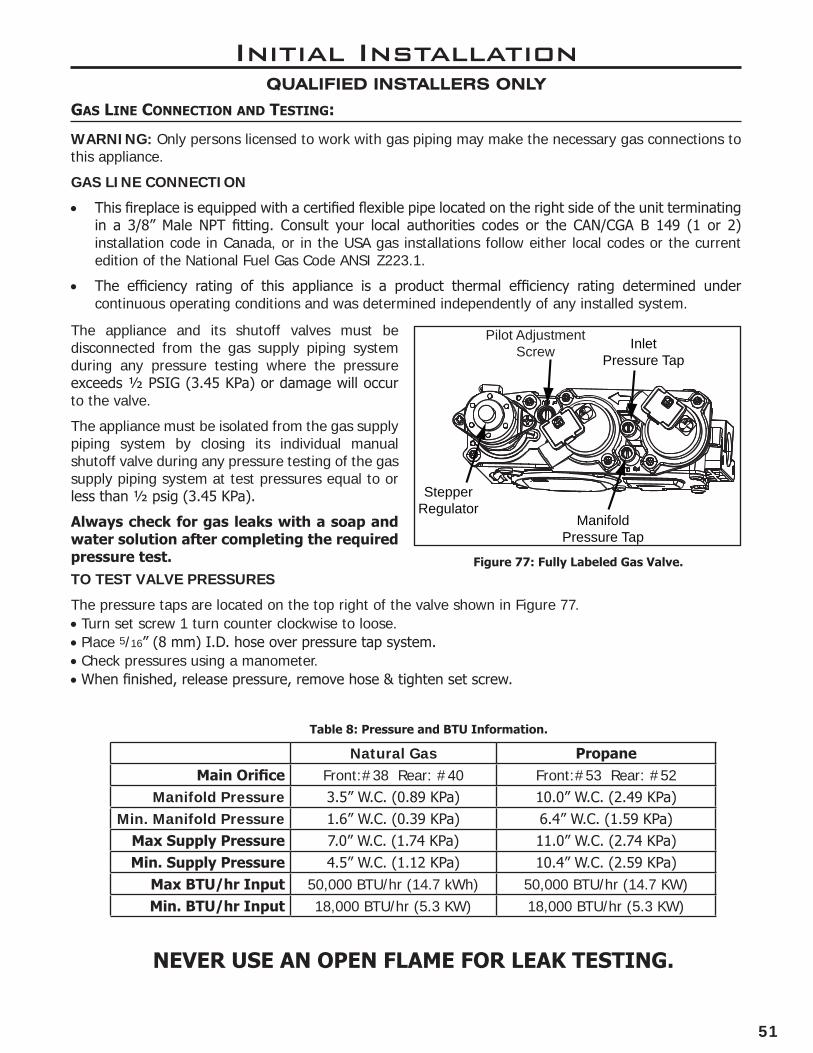
51
Pilot Adjustment Screw
ManifoldPressure Tap
InletPressure Tap
StepperRegulator
Initial InstallationQUALIFIED INSTALLERS ONLY
Gas Line connection anD testinG:
WARNING: Only persons licensed to work with gas piping may make the necessary gas connections to this appliance.
GAS LINE CONNECTION
• This fireplace is equipped with a certified flexible pipe located on the right side of the unit terminating in a 3/8” Male NPT fitting. Consult your local authorities codes or the CAN/CGA B 149 (1 or 2) installation code in Canada, or in the USA gas installations follow either local codes or the current edition of the National Fuel Gas Code ANSI Z223.1.
• The efficiency rating of this appliance is a product thermal efficiency rating determined under continuous operating conditions and was determined independently of any installed system.
Figure 77: Fully Labeled Gas Valve.
Table 8: Pressure and BTU Information.
The appliance and its shutoff valves must be disconnected from the gas supply piping system during any pressure testing where the pressure exceeds ½ PSIG (3.45 KPa) or damage will occur to the valve.
The appliance must be isolated from the gas supply piping system by closing its individual manual shutoff valve during any pressure testing of the gas supply piping system at test pressures equal to or less than ½ psig (3.45 KPa).
Always check for gas leaks with a soap and water solution after completing the required pressure test.TO TEST VALVE PRESSURES
The pressure taps are located on the top right of the valve shown in Figure 77.•Turn set screw 1 turn counter clockwise to loose.•Place 5/16” (8 mm) I.D. hose over pressure tap system. •Check pressures using a manometer.•When finished, release pressure, remove hose & tighten set screw.
Natural Gas PropaneMain Orifice Front:#38 Rear: #40 Front:#53 Rear: #52
Manifold Pressure 3.5” W.C. (0.89 KPa) 10.0” W.C. (2.49 KPa)Min. Manifold Pressure 1.6” W.C. (0.39 KPa) 6.4” W.C. (1.59 KPa)
Max Supply Pressure 7.0” W.C. (1.74 KPa) 11.0” W.C. (2.74 KPa)Min. Supply Pressure 4.5” W.C. (1.12 KPa) 10.4” W.C. (2.59 KPa)
Max BTU/hr Input 50,000 BTU/hr (14.7 kWh) 50,000 BTU/hr (14.7 KW)Min. BTU/hr Input 18,000 BTU/hr (5.3 KW) 18,000 BTU/hr (5.3 KW)
NEVER USE AN OPEN FLAME FOR LEAK TESTING.

52
eLectRicaL RequiRements:
WARNING: The fireplace must be electrically connected and grounded in accordance with local codes or, in the absence of local codes, with the current CSA C22.1 Canadian Electrical Code Part 1, Safety Standards For Electrical Installations, or The National Electrical Code ANSI / NFPA 70 in the US.
WARNING: Disconnect electrical power supply before working on receptacle wiring.
CAUTION: When servicing controls, label all wires prior to disconnection. Wiring errors can cause improper and dangerous operation. Verify proper operation after servicing. If any of the original wire supplied with the appliance must be replaced, it must be replaced with 18 AWG wire with a temperature rating of 105°C.
Initial InstallationQUALIFIED INSTALLERS ONLY
IFCMain
Harness
Transmitter
885 Gas Valve
IPI Pilot
Convection Fan
Main On/Off
Power Cord
ToBattery Holder
Flam
e Se
nso
r
Spar
k El
ectr
od
e
EmberLights
TopLight
Fuse
Fuse
Figure 78: Proflame 2 Wiring Diagram
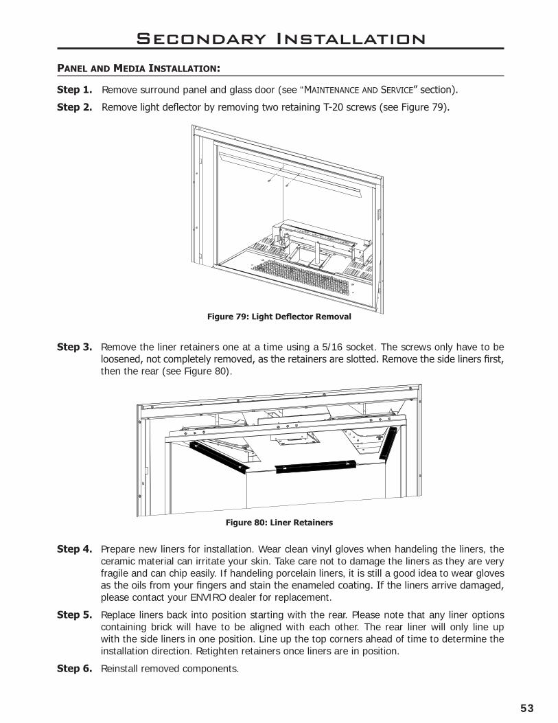
53
Secondary InstallationpaneL anD meDia instaLLation:
Step 1. Remove surround panel and glass door (see “maIntenance anD serVIce” section).
Step 2. Remove light deflector by removing two retaining T-20 screws (see Figure 79).
A
DETAIL A
SCALE 1 : 5
Step 3. Remove the liner retainers one at a time using a 5/16 socket. The screws only have to be loosened, not completely removed, as the retainers are slotted. Remove the side liners first, then the rear (see Figure 80).
Step 4. Prepare new liners for installation. Wear clean vinyl gloves when handeling the liners, the ceramic material can irritate your skin. Take care not to damage the liners as they are very fragile and can chip easily. If handeling porcelain liners, it is still a good idea to wear gloves as the oils from your fingers and stain the enameled coating. If the liners arrive damaged, please contact your ENVIRO dealer for replacement.
Step 5. Replace liners back into position starting with the rear. Please note that any liner options containing brick will have to be aligned with each other. The rear liner will only line up with the side liners in one position. Line up the top corners ahead of time to determine the installation direction. Retighten retainers once liners are in position.
Step 6. Reinstall removed components.
Figure 79: Light Deflector Removal
Figure 80: Liner Retainers
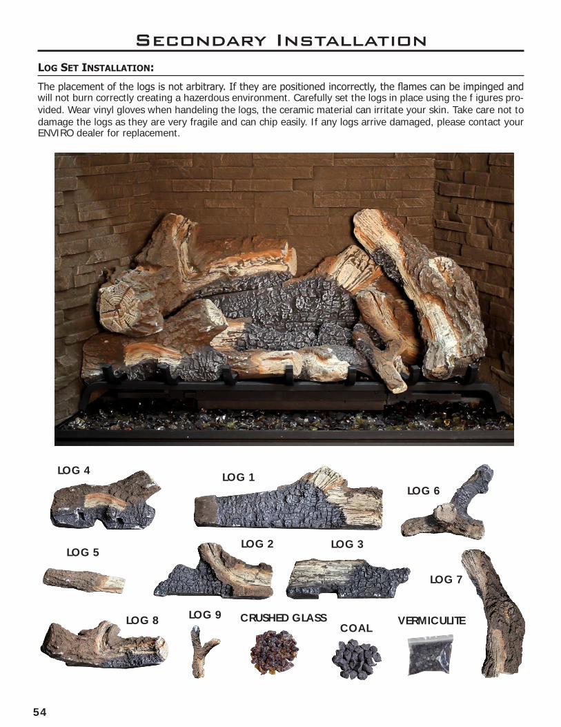
54
Secondary InstallationLoG set instaLLation:
The placement of the logs is not arbitrary. If they are positioned incorrectly, the flames can be impinged and will not burn correctly creating a hazerdous environment. Carefully set the logs in place using the f igures pro-vided. Wear vinyl gloves when handeling the logs, the ceramic material can irritate your skin. Take care not to damage the logs as they are very fragile and can chip easily. If any logs arrive damaged, please contact your ENVIRO dealer for replacement.
LOG 8 LOG 9COAL
CRUSHED GLASS VERMICULITE
LOG 6
LOG 5
LOG 7
LOG 2 LOG 3
LOG 1LOG 4
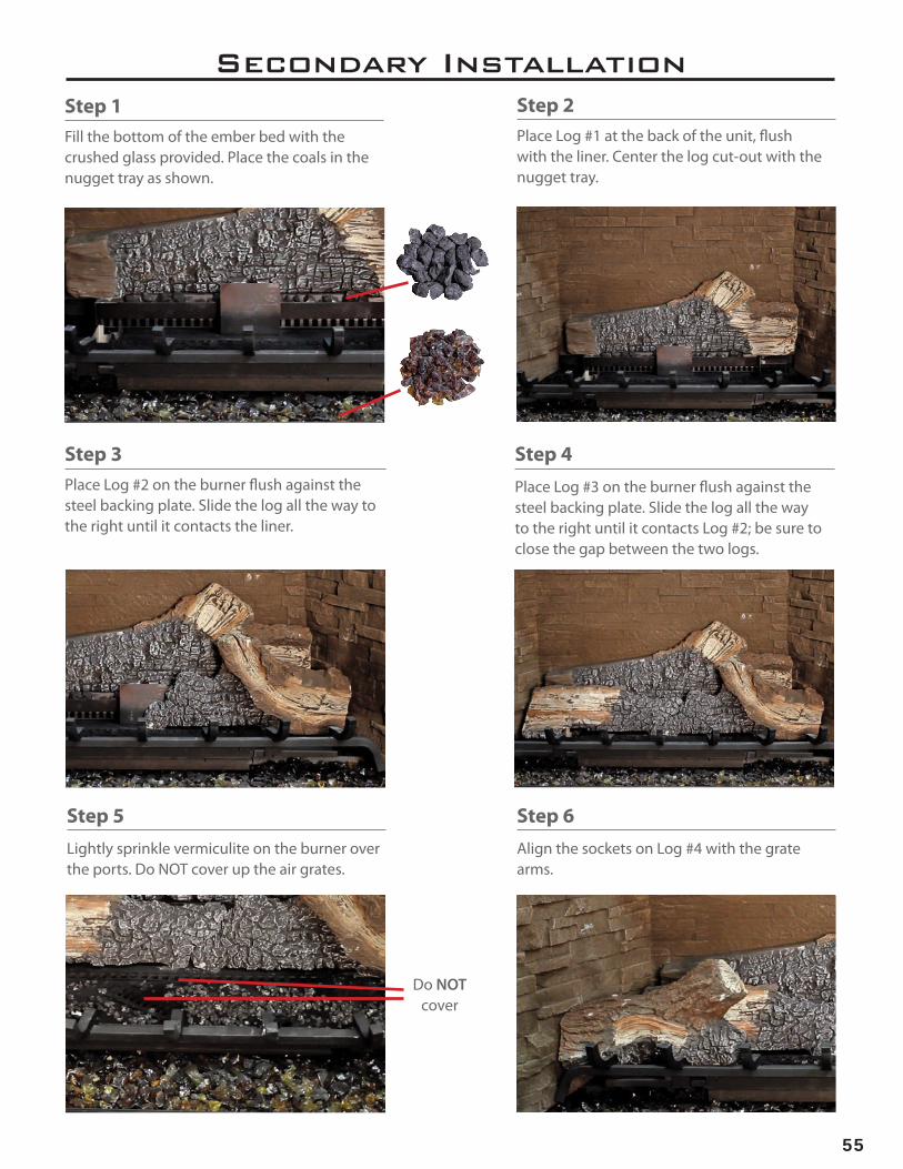
55
Secondary InstallationStep 2Place Log #1 at the back of the unit, flush with the liner. Center the log cut-out with the nugget tray.
Step 1Fill the bottom of the ember bed with the crushed glass provided. Place the coals in the nugget tray as shown.
Step 3Place Log #2 on the burner flush against the steel backing plate. Slide the log all the way to the right until it contacts the liner.
Step 4Place Log #3 on the burner flush against the steel backing plate. Slide the log all the way to the right until it contacts Log #2; be sure to close the gap between the two logs.
Step 5Lightly sprinkle vermiculite on the burner over the ports. Do NOT cover up the air grates.
Step 6Align the sockets on Log #4 with the grate arms.
Do NOT cover

56
Secondary Installation
Step 9Place the end of Log #7 on the flat area of Log #1. Align the bottom of Log #7 on the grate arm. The log should naturally want to rotate clockwise. The log should NOT contact Log #2.
Step 8Position Log #6 on the burner, prop the log on top on the stand near the air grate. Align the lower end on the grate arm.
Step 10Place Log #8 on top of Log #1 and Log #4. Keep the log flush with the rear and side liners. Align the log along the natural crease of Log #1.
Step 11Place the arms of Log #9 on the alignment pads on Log #6. Ensure the lower log contacts the grate arm to the right. The log set is now complete.
Step 7Align the sockets on Log #5 with the grate arm.
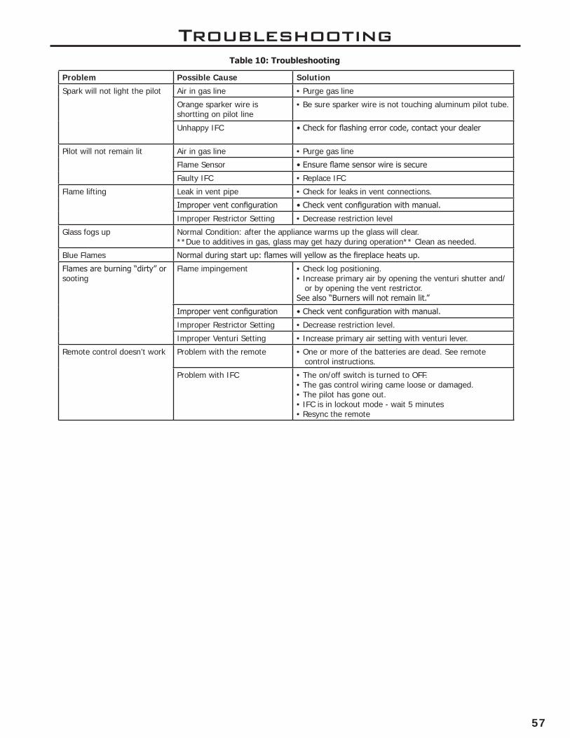
57
Troubleshooting
Problem Possible Cause Solution
Spark will not light the pilot Air in gas line • Purge gas line
Orange sparker wire is shortting on pilot line
• Be sure sparker wire is not touching aluminum pilot tube.
Unhappy IFC • Check for flashing error code, contact your dealer
Pilot will not remain lit Air in gas line • Purge gas line
Flame Sensor • Ensure flame sensor wire is secure
Faulty IFC • Replace IFC
Flame lifting Leak in vent pipe • Check for leaks in vent connections.
Improper vent configuration • Check vent configuration with manual.
Improper Restrictor Setting • Decrease restriction level
Glass fogs up Normal Condition: after the appliance warms up the glass will clear.**Due to additives in gas, glass may get hazy during operation** Clean as needed.
Blue Flames Normal during start up: flames will yellow as the fireplace heats up.
Flames are burning “dirty” or sooting
Flame impingement • Check log positioning.• Increase primary air by opening the venturi shutter and/
or by opening the vent restrictor.See also “Burners will not remain lit.”
Improper vent configuration • Check vent configuration with manual.
Improper Restrictor Setting • Decrease restriction level.
Improper Venturi Setting • Increase primary air setting with venturi lever.
Remote control doesn’t work Problem with the remote • One or more of the batteries are dead. See remote control instructions.
Problem with IFC • The on/off switch is turned to OFF.• The gas control wiring came loose or damaged.• The pilot has gone out.• IFC is in lockout mode - wait 5 minutes• Resync the remote
Table 10: Troubleshooting
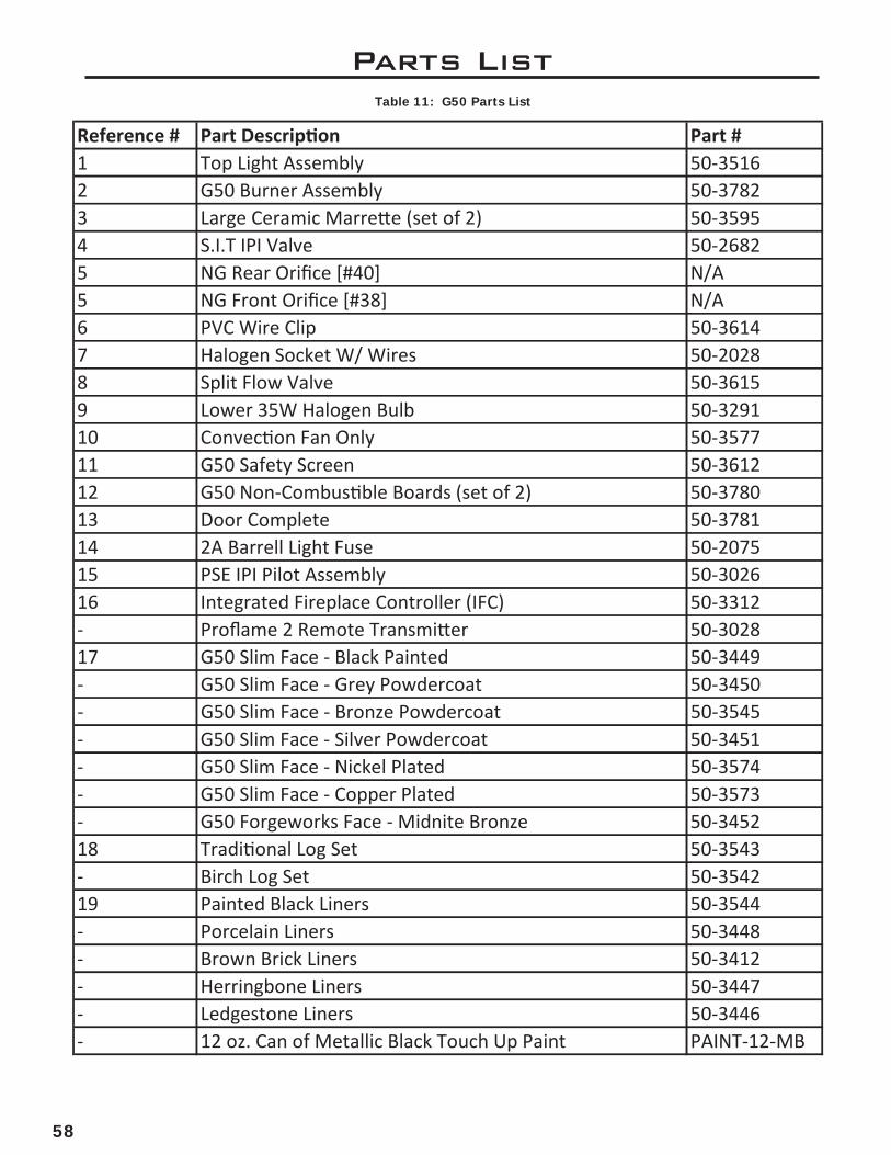
58
Parts ListTable 11: G50 Parts List
Reference # Part Description Part #1 Top Light Assembly 50-35162 G50 Burner Assembly 50-37823 Large Ceramic Marrette (set of 2) 50-35954 S.I.T IPI Valve 50-26825 NG Rear Orifice [#40] N/A5 NG Front Orifice [#38] N/A6 PVC Wire Clip 50-36147 Halogen Socket W/ Wires 50-20288 Split Flow Valve 50-36159 Lower 35W Halogen Bulb 50-329110 Convection Fan Only 50-357711 G50 Safety Screen 50-361212 G50 Non-Combustible Boards (set of 2) 50-378013 Door Complete 50-378114 2A Barrell Light Fuse 50-207515 PSE IPI Pilot Assembly 50-302616 Integrated Fireplace Controller (IFC) 50-3312- Proflame 2 Remote Transmitter 50-302817 G50 Slim Face - Black Painted 50-3449- G50 Slim Face - Grey Powdercoat 50-3450- G50 Slim Face - Bronze Powdercoat 50-3545- G50 Slim Face - Silver Powdercoat 50-3451- G50 Slim Face - Nickel Plated 50-3574- G50 Slim Face - Copper Plated 50-3573- G50 Forgeworks Face - Midnite Bronze 50-345218 Traditional Log Set 50-3543- Birch Log Set 50-354219 Painted Black Liners 50-3544- Porcelain Liners 50-3448- Brown Brick Liners 50-3412- Herringbone Liners 50-3447- Ledgestone Liners 50-3446- 12 oz. Can of Metallic Black Touch Up Paint PAINT-12-MB

59
Parts Diagram
19
18
1
2
5 6 7 89
4
10
3
11
13
12
1716
14
15
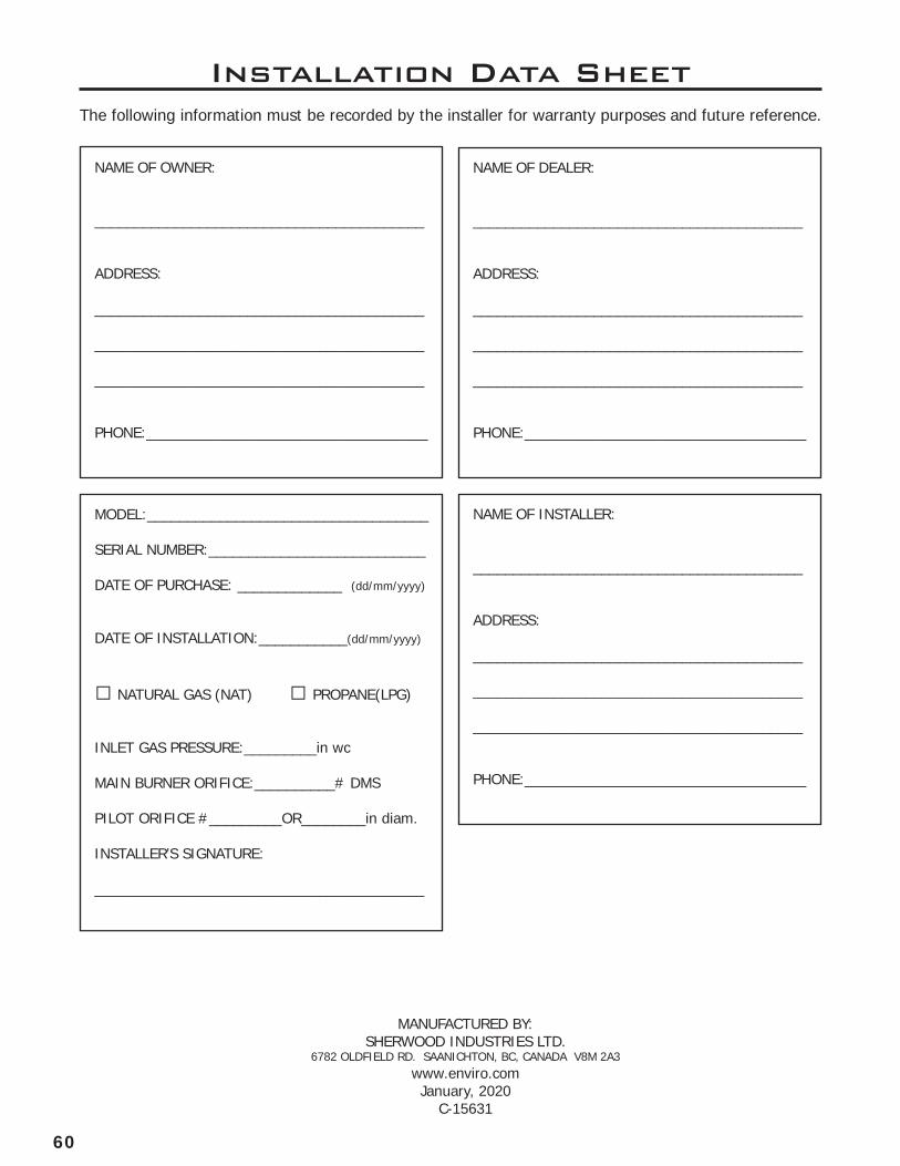
60
Installation Data SheetThe following information must be recorded by the installer for warranty purposes and future reference.
NAME OF OWNER:
_________________________________________
ADDRESS:
_________________________________________
_________________________________________
_________________________________________
PHONE:___________________________________
NAME OF DEALER:
_________________________________________
ADDRESS:
_________________________________________
_________________________________________
_________________________________________
PHONE:___________________________________
MODEL:___________________________________
SERIAL NUMBER:___________________________
DATE OF PURCHASE: _____________ (dd/mm/yyyy)
DATE OF INSTALLATION:___________(dd/mm/yyyy)
� NATURAL GAS (NAT) � PROPANE(LPG)
INLET GAS PRESSURE:_________in wc
MAIN BURNER ORIFICE:__________# DMS
PILOT ORIFICE #_________OR________in diam.
INSTALLER’S SIGNATURE:
_________________________________________
NAME OF INSTALLER:
_________________________________________
ADDRESS:
_________________________________________
_________________________________________
_________________________________________
PHONE:___________________________________
MANUFACTURED BY:SHERWOOD INDUSTRIES LTD.
6782 OLDFIELD RD. SAANICHTON, BC, CANADA V8M 2A3www.enviro.comJanuary, 2020
C-15631