Embed Size (px)
Citation preview
اإلهداءالزمن طال لو األقصى يدفن ال القدر مرابعنا في تفني يوم
وفي ، هدوءك الطبيعة هدوء وفي ، حنانك األم حنان وفي ، جمالك الربيع جمال فيو … … … وأملك وغضبك فرحك في سنعشقك أحبك ال فكيف صفاءك البحر صفاء
ومستقبلك … … … . وماضيك حاضرك في يأسكسرمدي … نتنفس أصبحنا حتى وجداننا في وترعرعت داخلنا في خلقت فقد
فلسطين … " " عطرك أريح وننتشي نهواكوالعطاء التضحية مثال إلى
الوفاء و الكرم نبعوالضياء ……. " الشمس نور
ابائنا "الروح بذلن اللواتي إلى
والحنان العطاء نبوع إلىأخجلتنا اللواتي إلى
" امهاتنا ..............." دموعهنوالسند العون نعم كانو الذين إلى
و ………………………" أخواننا األبد إلى نحبهم سنبقىأخواتنا "
األيام أحلى و الذكريات أجمل معهم قضينا الذين إلىواالخالص الحب أعطيناهم
زمالئنا …………. أصدقائناو االقدام علمونا و الوفاء فأعطونا
آمن وطن ألجل بأنفسهم ضحوا الذين األبرار الشهداء روح إلى. بسالم فيه نعيش
PCB milling 1
PCB milling 2
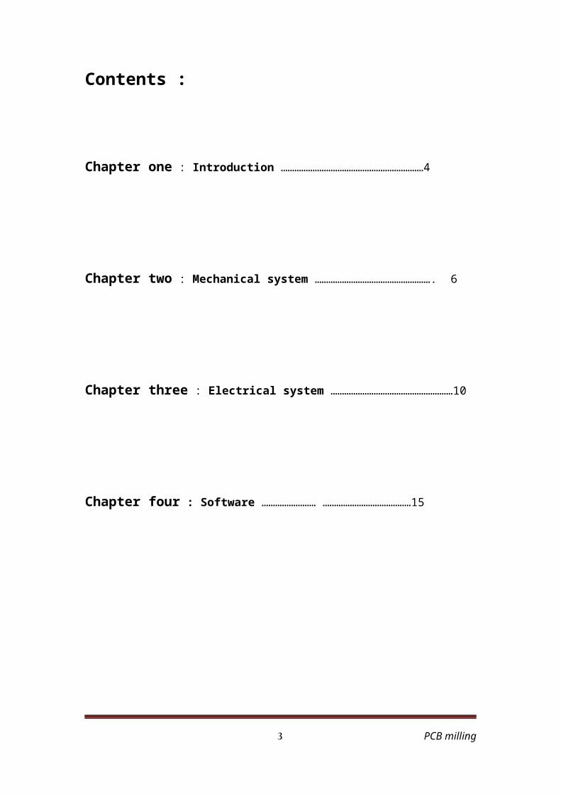
Contents :
Chapter one : Introduction ………………………………………………………4
Chapter two : Mechanical system ……………………………………………. 6
Chapter three : Electrical system ………………………………………………10
Chapter four : Software …………………… …………………………………15
PCB milling 3
Abstract
Our project is type of CNC miller that mil printed board circuit in order to
install the electronic chips in there places. This PCB miller is divided into
two parts ,
Part one :- hard ware i.e the body of the machine that contain stepper
motors moves the miller in (x-y) -axis movement in order to reach the
point that will be milled by the miller which represent the z-axis , and
there is another hardware part which we called it malty loading arm , this
part is a box contains the PCB 's and there a mechanical arm pushes one
board each time to put it in its specific place , so in this way we can
perform many PCB's .
The other part is the software which control the micro controller and give
it the proper orders to perform them , and it will give the controller the
matrix of x-y dimension of the holes , then the controller will move the
stepper motor to perform the orders.
And we will put some accessories to the project such LCD some warning
lights or voice, with a beautiful interface and the important is easy to use
by any person with littlie help.
PCB milling 4
Chapter one :
1_ Introduction
1.1 What is PCB mill?
It’s a CNC (Computer Numerical Control) machine which remove areas
of copper from a sheet of printed circuit board material to recreate the
pads, signal traces and structures according to patterns from a digital
circuit board plan known as a layout file. A PCB milling system is similar
to a miniature and highly accurate NC milling table. For machine control,
positioning information and machine control commands are sent from the
controlling software via a serial port or parallel port connection to the
milling machine's on-board controller.
1.2 Design Concepts
The main concepts commonly used to make a milling device consist of a
threaded travel mechanism, a combination X-axis and Y-axis, a precisely
controlled motor (either a stepper motor or a DC motor with a position
encoder), and a controller for the milling mechanism to correctly position
it. For each axis (X_Y) and Z – a motor is connected to the threaded
travel mechanism. As the motor turns the screw-like device, a guide on to
pot the thread moved back and forth in a straight 1-dimensional line.
Combining the X-axis and the Y-axis, an XY-plane is created. This
allows a platform to be positioned anywhere in a 2-dimensional plane.
The Z axis, either mounted as port of the XY plane or separately above it,
allows for a 3rd dimension.
PCB milling 5
1.3 Proposed Design
The design I am proposing uses 3 stepper motors to control the 3 axis of Operation.Each stepper motor is connected to a push pull (l_298) with (l_297)
driver circuit which is controlled by a PIC16F877 microcontroller, the
PIC chip receive the current position (G_code) serially by serial cable
which connected to PC which use (Kcam4) software, there is an interface
between the PIC chip and Kcam4 software by using c-sharp language in
order to receive the position of milling holes serially. The code which
tracks the G_code in order to move to the specified positions is written in
c++ language.
PCB milling 6
Chapter two :
2. The Mechanical System
2.1 Mechanical Design
The complete mechanical system was designed in 3D solid working
environment using Autodesk inverter .In our project we moved the base
(y-axes ) and the drill ( z- axes ) .
Our model of consist of base ( 26x38 ) cm , and vertical arm ( 50 cm ) .
x-axes = 94cm .
y-axes =45cm.
z-axes =40cm.
2.2 Tools:
-Stepper motors .
-Hand Drill.
-Hacksaw.
-Hacksaw Blades.
PCB milling 7
The modeling and building BCB:
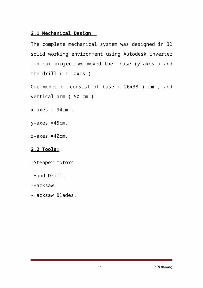
The stepper motor of the y-axis.
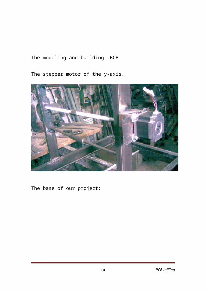
The base of our project:
PCB milling 8
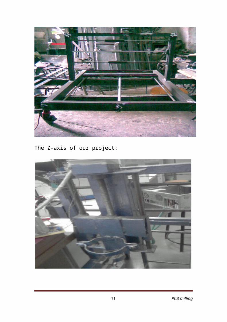
The Z-axis of our project:
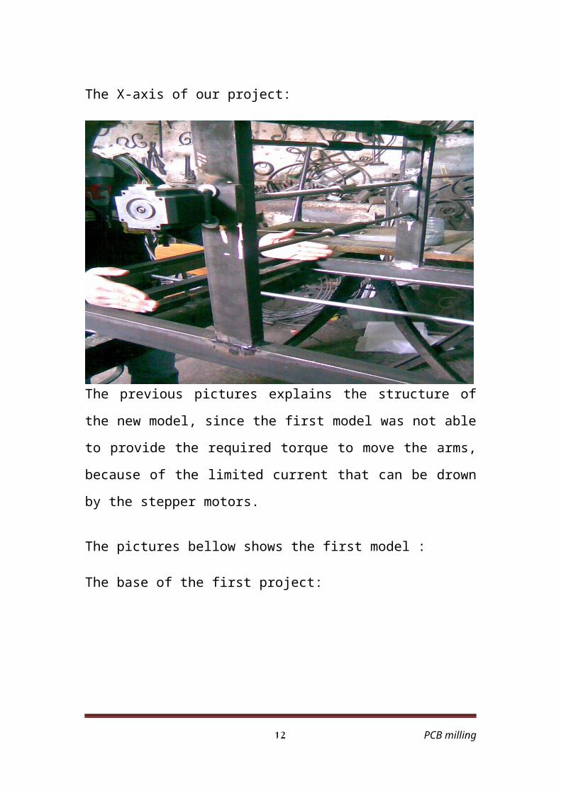
The X-axis of our project:
PCB milling 9
The previous pictures explains the structure of the new model, since the
first model was not able to provide the required torque to move the arms,
because of the limited current that can be drown by the stepper motors.
The pictures bellow shows the first model :
The base of the first project:
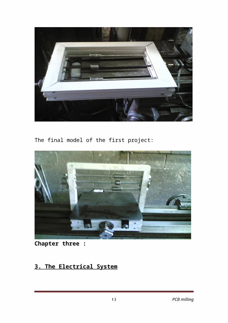
The final model of the first project:
PCB milling 10
Chapter three :
3. The Electrical System
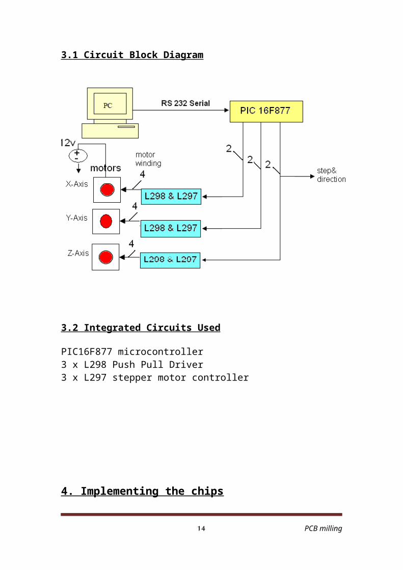
3.1 Circuit Block Diagram
3.2 Integrated Circuits Used
PIC16F877 microcontroller3 x L298 Push Pull Driver3 x L297 stepper motor controller
PCB milling 11
4. Implementing the chips
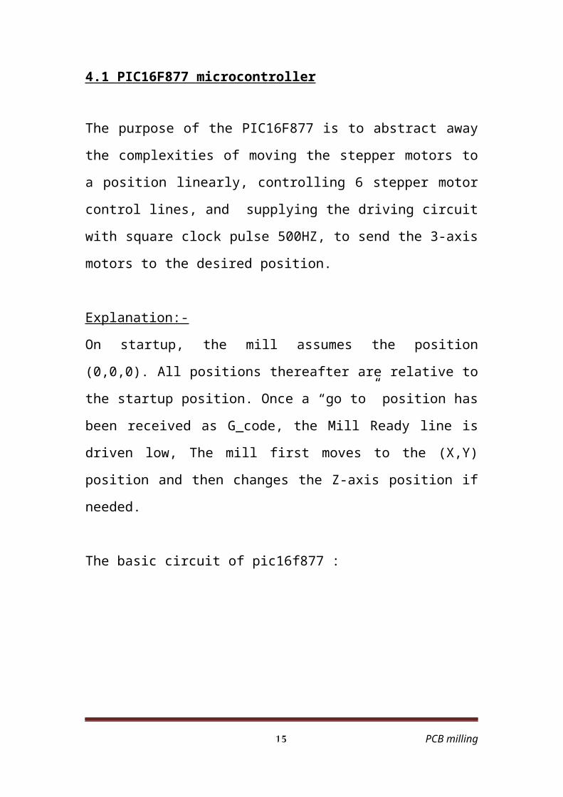
4.1 PIC16F877 microcontroller
The purpose of the PIC16F877 is to abstract away the complexities of
moving the stepper motors to a position linearly, controlling 6 stepper
motor control lines, and supplying the driving circuit with square clock
pulse 500HZ, to send the 3-axis motors to the desired position.
Explanation:-
On startup, the mill assumes the position (0,0,0). All positions thereafter
are relative to the startup position. Once a “go to” position has been
received as G_code, the Mill Ready line is driven low, The mill first
moves to the (X,Y) position and then changes the Z-axis position if
needed.
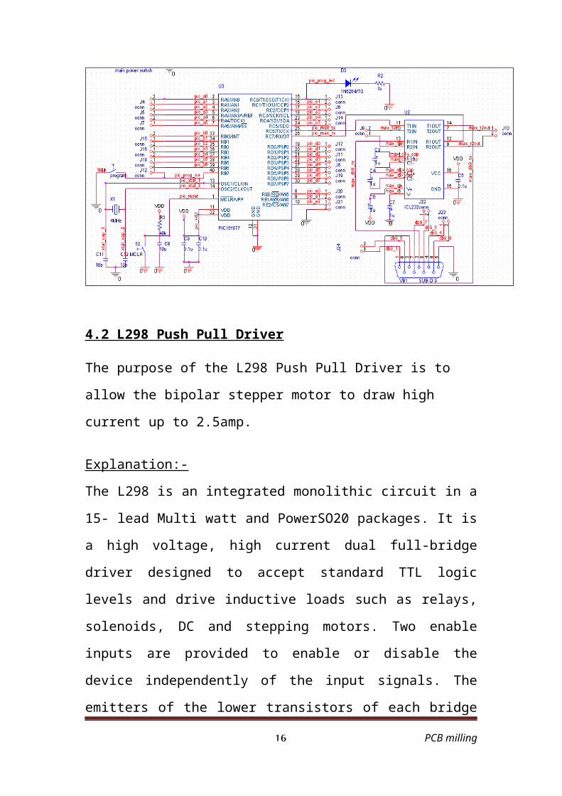
The basic circuit of pic16f877 :
PCB milling 12
4.2 L298 Push Pull Driver
The purpose of the L298 Push Pull Driver is to allow the bipolar stepper
motor to draw high current up to 2.5amp.
Explanation:-
The L298 is an integrated monolithic circuit in a 15- lead Multi watt and
PowerSO20 packages. It is a high voltage, high current dual full-bridge
driver designed to accept standard TTL logic levels and drive inductive
loads such as relays, solenoids, DC and stepping motors. Two enable
inputs are provided to enable or disable the device independently of the
input signals. The emitters of the lower transistors of each bridge are
connected together and the corresponding external terminal can be used
for the connection of an external sensing resistor. An additional supply
input is provided so that the logic works at a lower voltage.
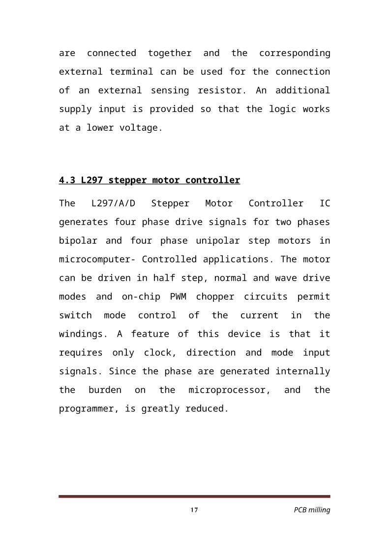
4.3 L297 stepper motor controller
The L297/A/D Stepper Motor Controller IC generates four phase drive
signals for two phases bipolar and four phase unipolar step motors in
microcomputer- Controlled applications. The motor can be driven in half
step, normal and wave drive modes and on-chip PWM chopper circuits
permit switch mode control of the current in the windings. A feature of
this device is that it requires only clock, direction and mode input signals.
Since the phase are generated internally the burden on the
microprocessor, and the programmer, is greatly reduced.
PCB milling 13
Circuit schematic
Driving circuit:
PCB milling 14
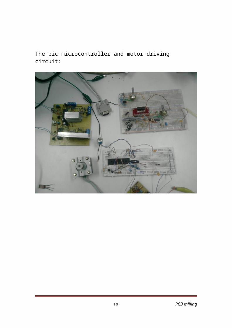
The pic microcontroller and motor driving circuit:
PCB milling 15
Chapter four :
5. PCB Mill Software
5.1Purpose
The purpose of the PCB Mill software is to provide a graphical
environment that allows the user to easily create, modify, visualize, and
convert different types of plotter files to DXF (AutoCAD) file, we use for
this purpose two programs
1-Image-CAD
2-ExpressPCB
Image-CAD can convert any type of plotter files into DXF, EMF, WMF,
HPGL, Text file, but we take DXF file. ExpressPCB is more specified it
can just convert ExpressPCB files to DXF file with these options
1- silk screen layer.
2- Pads on top copper layer.
3- Text on top copper layer.
4- Pads on bottom copper layer.
5- Holes.
PCB milling 16
Examples
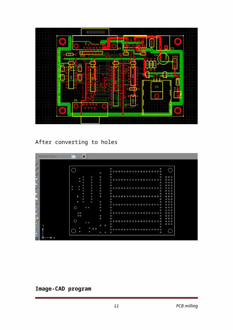
Express PCB picture before converting
After converting to holes
PCB milling 17
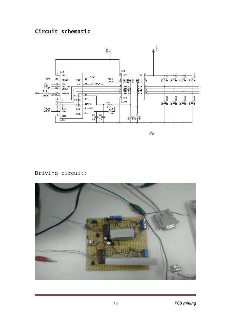
Image-CAD program
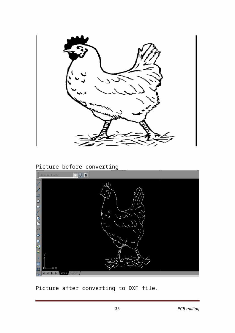
Picture before converting
Picture after converting to DXF file.
PCB milling 18
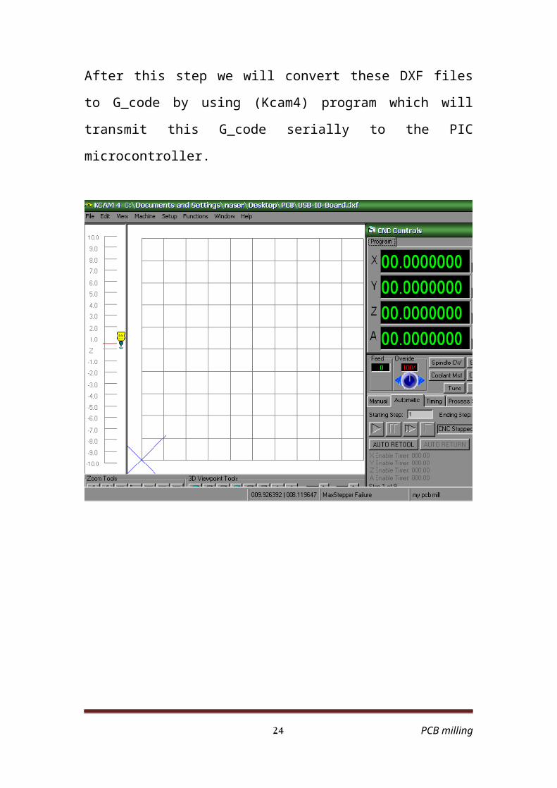
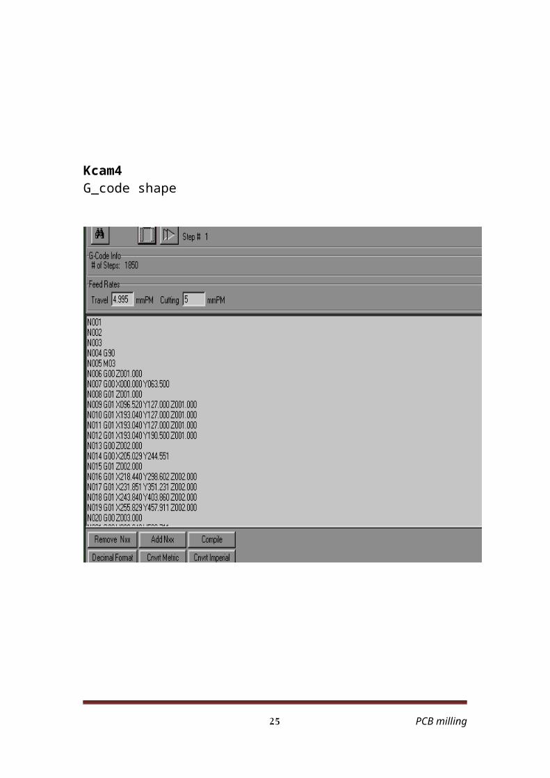
After this step we will convert these DXF files to G_code by using
(Kcam4) program which will transmit this G_code serially to the PIC
microcontroller.
PCB milling 19
Kcam4G_code shape
PCB milling 20
References:
1- http://www.alldatasheet.com .
2- www.microkinetics.com
3- www. cnc masters.com
4- Build your own CNC machine
5- CNC robotic by Ceoff Williams
PCB milling 21
Appendix
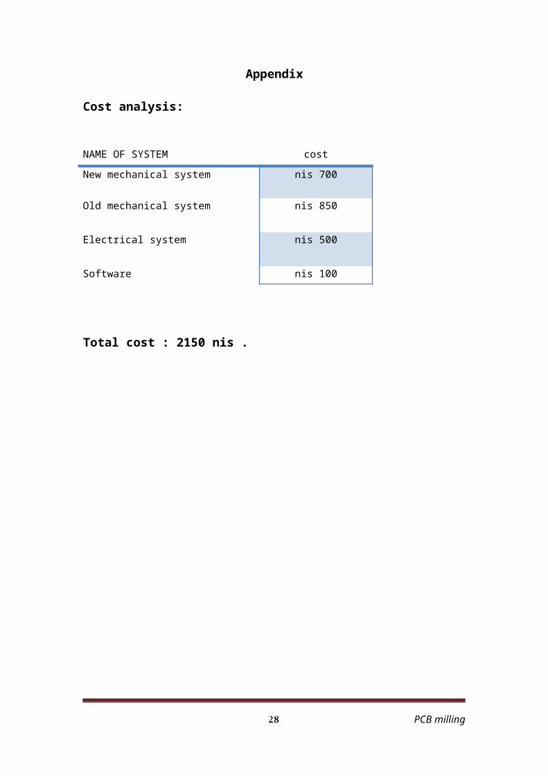
Cost analysis:
NAME OF SYSTEM cost
New mechanical system 700 nis
Old mechanical system 850 nis
Electrical system 500 nis
Software 100 nis
Total cost : 2150 nis .
PCB milling 22
The pic code:
#include "C:\Documents and Settings\naser\Desktop\PICC Code\Final Code.h"
#include <string.h<#include <stdlib.h<#include <math.h<
int i,k; signed int32 drag,oil; //vars dealing with feedrate and delay func
int feedrate; unsigned int stepnum;
signed int32 x1,y1; //starting point signed int32 x2,y2; //relative position
signed int32 x3,y3; //endpoint signed int8 x0,y0; //direction of output: +1, -1, or 0
signed int32 dx,dy; //differentials of x and y signed int32 fxy; //value of function
int f,a,b,d; signed int32 rad,radrad;
char Gcode[2]; char c;
char xx[5]; char yy[5]; char zz[5];
char ii[5]; char jj[5];
signed int32 iv; signed int32 jv;
signed int32 dxx,dyy;
void go_up)({output_low)pin_d1(; // enable the clock pulseoutput_high)pin_d2(; // make move into CW directiondelay_ms)15(;
}void go_down)(
{output_low)pin_d1(; // enable the clock pulseoutput_low)pin_d2(; // make move into CCW direction
PCB milling 23
delay_ms)15(;}
void go_right)({output_low)pin_d3(; // enable the clock pulseoutput_high)pin_d4(; // make move into CW directiondelay_ms)15(;
}void go_left)(
{output_low)pin_d3(; // enable the clock pulseoutput_low)pin_d4(; // make move into CCW directiondelay_ms)15(;
}
void go_pos)signed int32 x,signed int32 y({int count;signed int32 k;signed int32 xxx,yyy;
for)count=0;count<4;count++(}xx[count]='.';{for)count=0;count<4;count++(}yy[count]='.';{
xxx=x-x1;yyy=y-y1;
//delay_ms)1(;if)yyy>0({
output_a)0x00(; for)k=0;k<yyy;k++(
{ go_up;)(
} }else if)yyy<0({
yyy=abs)yyy(; output_a)0x00(;
for)k=0;k<yyy;k++({
go_down;)(
}
PCB milling 24
}if)xxx>0({
output_d)0x00(; for)k=0;k<xxx;k++(
{ go_right;)(
} }else if)xxx<0({
xxx=abs)xxx(; output_d)0x00(;
for)k=0;k<xxx;k++({
go_left;)(
} }
x1=x; y1=y;
// printf;)"*"(
}void movex)signed int x0({
if )x0==-1({
// output_d)0x00(; go_left;)(
}
else if)x0==1({
// output_d)0x00(; go_right;)(
}
PCB milling 25
}void movey)signed int y0({
if)y0==-1({
// output_a)0x00(; go_down;)(
}
else if)y0==1({
// output_a)0x00(; go_up;)(
}
}void delay)(
{ int i=0;
while )++i != ))feedrate + drag( / 30((continue;
if)drag > 0({
drag =drag - )oil*oil(;-- oil;
if)drag < 0( drag =0;
} }
****************************//Circular Interpolation*************************
void getdir)({
int binrep; binrep = 0; x0 = y0 = 0;
if)d(binrep = binrep + 8; if)f(binrep = binrep + 4;
PCB milling 26
if)a(binrep = binrep + 2; if)b(binrep = binrep + 1;
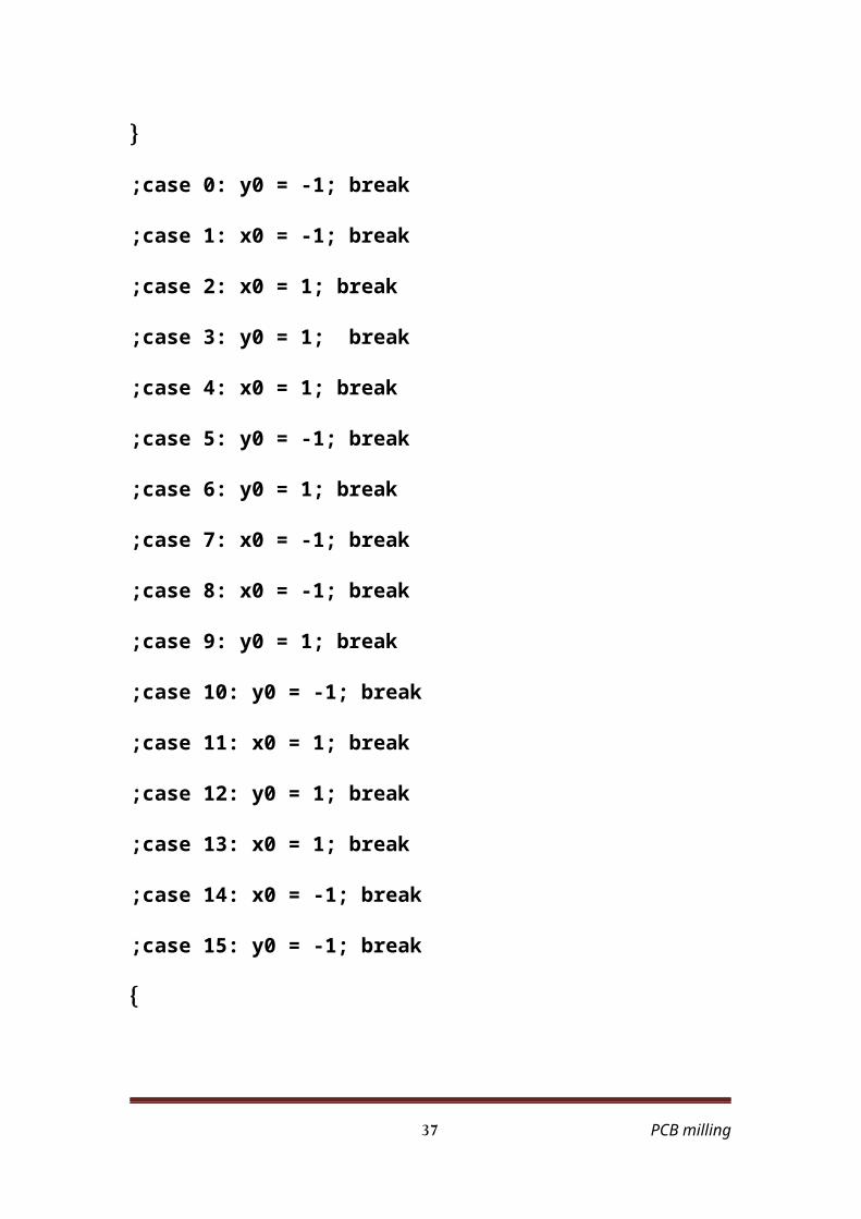
switch)binrep({
case 0: y0 = -1; break; case 1: x0 = -1; break;
case 2: x0 = 1; break; case 3: y0 = 1; break; case 4: x0 = 1; break; case 5: y0 = -1; break;
case 6: y0 = 1; break; case 7: x0 = -1; break; case 8: x0 = -1; break;
case 9: y0 = 1; break; case 10: y0 = -1; break;
case 11: x0 = 1; break; case 12: y0 = 1; break; case 13: x0 = 1; break; case 14: x0 = -1; break; case 15: y0 = -1; break;
}
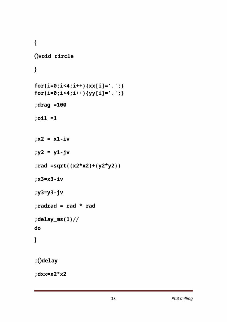
}void circle)(
{
for)i=0;i<4;i++(}xx[i]='.';{ for)i=0;i<4;i++(}yy[i]='.';{
drag =100; oil =1;
x2 = x1-iv; y2 = y1-jv;
rad =sqrt))x2*x2(+)y2*y2((; x3=x3-iv; y3=y3-jv;
radrad = rad * rad;// delay_ms)1(;
do{
PCB milling 27
delay;)( dxx=x2*x2; dyy=y2*y2;
fxy = dxx+dyy-)radrad(; dx = 2*x2; dy = 2*y2;
f = )fxy < 0(? 0 : 1; a = ) dx < 0(? 0 : 1; b = ) dy < 0(? 0 : 1;
getdir;) ( movex)x0(; movey)y0(;
x2 = x2 + x0; y2 = y2 + y0;
} while))x2 != x3( || )y2 != y3((;
x1=x2+iv; y1=y2+jv;
}
****************************//Linear Interpolation **************************void setdirection)( //sets output directions and initial fxy value for line{
dy =y3 - y1; if)dy < 0(
{ y0 =-1;
} else
{ y0 =1;
} dy =abs)y3 - y1(;
dx =x3 - x1;
if)dx < 0({
PCB milling 28
x0 =-1;}
else{
x0 =1;}
dx =abs)x3 - x1(; fxy =dx - dy;
}
void doLine)({
stepnum =x2 =y2 =fxy =0; drag =100;
oil =1; setdirection;)(
// delay_ms)1(; while))x2 != dx( || )y2 != dy(( // at endpoint?
{
delay;)( if)fxy > 0(
{
movex)x0(;++ x2;
fxy = fxy - dy;}
else{
movey)y0(;++ y2;
fxy = fxy + dx;}
} x1 = x3; y1 = y3;
PCB milling 29
}
int flag;void Recv_file)(
{ flag =0;
restart_wdt;)( while)!flag(
{ c =getc;)(
if)c == 'G' || c == 'M'( flag =1;
}
if)c == 'G'({
Gcode[0] = getc;)( Gcode[1] = getc;)(
if)Gcode[0] == '0'({
switch)Gcode[1]({
case '0:'
c = getc;)( c = getc;)( if)c == 'X'(
{
for)i=0;i<4;i++({
c = getc;)(
if)c == ' '({
xx[i];"."= break;
} xx[i] = c;
// printf)"%c",xx[i](;
PCB milling 30
} xx[4] = '\0;'
while)getc)( != 'Y'(}{
for)i=0;i<4;i++({
c = getc;)( if)c == ' '(
{ yy[i];"."=
break;}
yy[i] = c; // printf)"%c",yy[i](;
} yy[4] = '\0;'
while)getc)( != ';'(}{
} else if)c == 'Z'(
{ for)i=0;i<4;i++(
{ xx[i] = '0;' yy[i] = '0;'
} while)getc)( != ';'(;}{
} break;
case '1:'
c = getc;)( c = getc;)( if)c == 'Z'(
{
for)i=0;i<4;i++({
c = getc;)(
PCB milling 31
if)c == ' '({
zz[i];"."= break;
} zz[i] = c;
// printf)"%c",zz[i](;
} if)c != ';'(
{ while)getc)( != ';'(
}{ }
// } End if)c == 'Z'(
else if)c == 'X'({
for)i=0;i<4;i++({
c = getc;)(
if)c == ' '({
xx[i];"."= break;
} else
{ xx[i] = c;
// printf)"%c",xx[i](;}
} xx[4] = '\0;'
// printf)"%s",xx(; while)getc)( != 'Y'(}{
PCB milling 32
for)i=0;i<4;i++({
c = getc;)( if)c == ' '(
{ yy[i];"."=
break;}
else{
yy[i] = c;// printf)"%c",yy[i](;
}
} yy[4] = '\0;'
while)getc)( != ';'(}{
} break;
case '2:'
c = getc;)( c = getc;)(
if)c == 'X'({
for)i=0;i<4;i++({
c = getc;)( if)c == ' '(
{ xx[i];"."=
break;}
xx[i] = c;// printf)"%c",xx[i](;
PCB milling 33
} xx[4] = '\0;'
while)getc)( != 'Y'(}{
for)i=0;i<4;i++({
c = getc;)( if)c == ' '(
{ yy[i];"."=
break;}
yy[i] = c;
} yy[4] = '\0;'
while)getc)( != 'I'(}{
for)i=0;i<4;i++({
c = getc;)( if)c == ' '(
{ ii[i];"."=
break;}
ii[i] = c; // printf)"%c",ii[i](;
} ii[4] = '\0;'
while)getc)( != 'J'(}{
for)i=0;i<4;i++({
c = getc;)( if)c == ' '(
{ jj[i];"."=
PCB milling 34
break;}
jj[i] = c;// printf)"%c",jj[i](;
} jj[4] = '\0;'
if)c != ';'({
while)getc)( != ';'(}{}
} d = 1; break;
//} End Switch Statment
// } End if)Gcode[0] == '0'(
else{
break;}
}
else if)c == 'M'({
c = getc;)( if)c == '3'(
{ c =getc;)( if)c == '0'(
{ printf)"End"(;
return;} }
PCB milling 35
} restart_wdt;)(
}
void main)({
char cc; int counter;
int linecounter; int circlecounter;
setup_adc_ports)NO_ANALOGS(; setup_adc)ADC_OFF(;
setup_psp)PSP_DISABLED(; setup_spi)FALSE(;
setup_timer_2)T2_DISABLED,0,1(;
// TODO: USER CODE!! set_tris_b)0x00(;
x1=0;y1=0; x2=0;y2=0; x3=0;y3=0;
iv=0;jv=0; feedrate=100;
counter = 0; linecounter = 0;
circlecounter = 0;
output_high)pin_a5(; // Active Enable Pin output_low)pin_b2(; // Active INH1 and INH2 for Control pin
output_low)pin_b3(; // Active the full step Half/Full pin
while)1({
if)kbhit)(( cc = getc;)( if)cc == '1'(
{ cc;' '=
Recv_file;)( y3 = atoi32)yy(;
PCB milling 36
x3 = atoi32)xx(; go_pos)x3,y3(;
delay_ms)9000(;
printf;)"*"(
} else if)cc == '2'(
{ cc;' '=
Recv_file;)( y3 = atoi32)yy(; x3 = atoi32)xx(;
doLine;)(
printf;)"*"(
} else if)cc == '3'(
{ cc;' '=
Recv_file;)( y3 = atoi32)yy(; x3 = atoi32)xx(;
iv = atoi32)ii(; jv = atoi32)jj(;
circle;)( printf;)"*"(
} else if)cc == '4'(
{ cc;' ' =
Recv_file;)( // output_low)pin_a4(; // output_low)pin_a5(;
// output_low)pin_d4(; // output_low)pin_d5(;
printf;)"*"(
PCB milling 37
} else if)cc == 'A'(
{ cc;' '=
printf;)"*"(}
else if)cc == '!'({
// Reset Pin // output_low)pin_a4(; // chnage to the pin that connect to
ResetPin // Enable Pin
// output_low)pin_a5(; // disable the cip and put the status to low
} else if)cc == '*'(
{ cc;' '=
printf;)"*"(}
} }
PCB milling 38