Embed Size (px)
Citation preview
A Course Material on
ELECTROMAGNETIC FIELDS
By
Mr. N.RAM KUMAR
HEAD & ASSISTANT PROFESSOR
DEPARTMENT OF ELECTRONICS & COMMUNICATION ENGINEERING
SASURIE COLLEGE OF ENGINEERING
VIJAYAMANGALAM – 638 056
www.vidyarthiplus.com
www.vidyarthiplus.com
QUALITY CERTIFICATE
This is to certify that the e-course material
Subject Code : EC6403
Scubject : ELECTROMAGNETIC FIELDS
Class : II Year ECE
being prepared by me and it meets the knowledge requirement of the university curriculum.
Designation: Assistant Professor
This is to certify that the course material being prepared by Mr.N.RAM KUMAR is of adequatequality. He has referred more than five books among them minimum one is from abroad author.
Signature of the Author
Name:N.RAMKUMAR
Signature of HD
N.RAM KUMAR
www.vidyarthiplus.com
www.vidyarthiplus.com
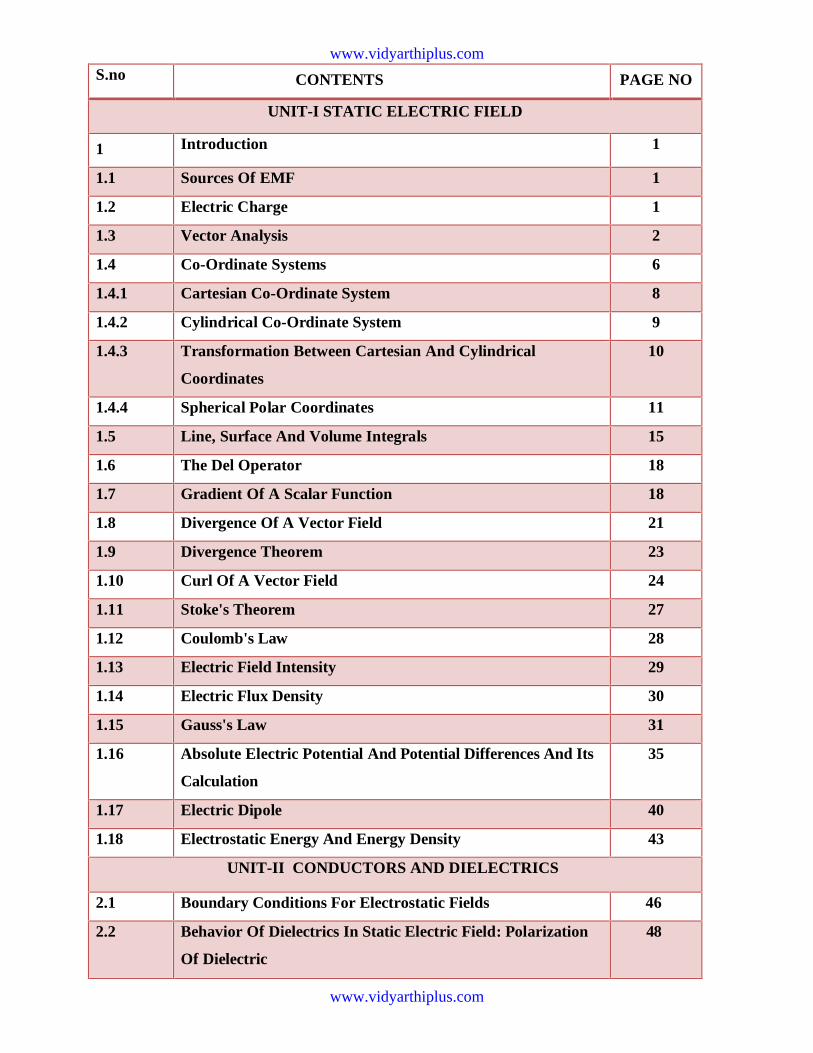
S.no CONTENTS PAGE NO
UNIT-I STATIC ELECTRIC FIELD
1 Introduction 1
1.1 Sources Of EMF 1
1.2 Electric Charge 1
1.3 Vector Analysis 2
1.4 Co-Ordinate Systems 6
1.4.1 Cartesian Co-Ordinate System 8
1.4.2 Cylindrical Co-Ordinate System 9
1.4.3 Transformation Between Cartesian And Cylindrical
Coordinates
10
1.4.4 Spherical Polar Coordinates 11
1.5 Line, Surface And Volume Integrals 15
1.6 The Del Operator 18
1.7 Gradient Of A Scalar Function 18
1.8 Divergence Of A Vector Field 21
1.9 Divergence Theorem 23
1.10 Curl Of A Vector Field 24
1.11 Stoke's Theorem 27
1.12 Coulomb's Law 28
1.13 Electric Field Intensity 29
1.14 Electric Flux Density 30
1.15 Gauss's Law 31
1.16 Absolute Electric Potential And Potential Differences And Its
Calculation
35
1.17 Electric Dipole 40
1.18 Electrostatic Energy And Energy Density 43
UNIT-II CONDUCTORS AND DIELECTRICS
2.1 Boundary Conditions For Electrostatic Fields 46
2.2 Behavior Of Dielectrics In Static Electric Field: Polarization
Of Dielectric
48
www.vidyarthiplus.com
www.vidyarthiplus.com
2.3 Method Of Images 52
2.4 Continuity Of Equation 52
2.5 Boundary Conditions For Perfect Electric Fields 52
2.6 Capacitance And Capacitors 54
2.6.1 Parallel Plate Capacitor 55
2.6.2 Series And Parallel Connection Of Capacitors 56
2.7 Poisson’s And Laplace’s Equations 57
2.8 Application Of Poisons And Laplace’s Equations 58
UNIT III MAGNETOSTATICS
3.1 Introduction 61
3.2 Laws Governing Magneto Static Fields-Biot Savarts 61
3.3 Amperes Law And In Point Form 64
3.3.1 Estimation Of Magnetic Field Intensity For Straight And
Circular Conductors
64
3.4 Magnetic Flux And Density 67
3.5 Magnetic Scalar And Vector Potentials 68
3.6 Boundary Condition For Magnetic Fields And Steady
Magnetic Field Laws
72
UNIT IV MAGNETIC FORCES AND MATERIALS
4.1 Force On A Moving Charge 75
4.2 Force On A Differential Current Element 75
4.3 Force On A Current-Carrying Conductor 77
4.4 Force And Torque On A Current Loop 77
4.5 Magnetic Materials 77
4.6 Boundary Conditions 78
www.vidyarthiplus.com
www.vidyarthiplus.com
4.7 Inductance 80
4.7.1 Self Inductance And Mutual Inductance 80
4.7.2 Solenoid 81
4.7.3 Toroid 82
4.7.4 Coaxial Transmission Line 82
4.8 Energy Stored In a Magnetic Field 84
UNIT V ENERGY STORED INA MAGNETIC FIELD
5.1 Fundamental Relations For Electrostatic And Magnetic Fields 85
5.2 Faraday's Law Of Electromagnetic Induction 85
5.3 Ideal Transformers 87
5.4 Motional EMF 89
5.5 Maxwell's Equation 90
5.6 Boundary Conditions For Electromagnetic Fields 93
5.7 Wave Equation And Their Solution 94
5.8 Time Harmonic Fields 99
5.8.1 Plane Waves In Lossless Medium 100
5.8.2 TEM Waves 105
5.9 Poynting Vector And Power Flow In Electromagnetic Fields 111
5.9.1 Poynting Vector For The Time Harmonic Case 113
5.10 Electromagnetic Spectrum 115
5.10.1 Behaviour Of Plane Waves At The Inteface Of Two Media 119
5.10.2 Oblique Incidence At A Plane Dielectric Interface 131
5.11 Electromagnetic Spectrum 137
APPENDIX
(I) 2 Marks Question & Answers, 16 Marks With Hint Answers 138
(Ii) University Question Papers 158
www.vidyarthiplus.com
www.vidyarthiplus.com
EC6403 ELECTROMAGNETIC FIELDS L T P C 3 1 0 4 OBJECTIVES:
To impart knowledge on the basics of static electric and magnetic field and the associated laws.
To give insight into the propagation of EM waves and also to introduce the methods in computational electromagnetics.
To make students have depth understanding of antennas, electronic devices, Waveguides is
UNIT V TIME VARYING FIELDS AND MAXWELL’S EQUATIONS 9 Fundamental relations for Electrostatic and Magnetostatic fields, Faraday‟s law for Electromagnetic induction, Transformers, Motional Electromotive forces, Differential form of Maxwell‟s equations, Integral form of Maxwell‟s equations, Potential functions, Electromagnetic boundary conditions, Wave equations and their solutions, Poynting‟s theorem, Time harmonic fields, Electromagnetic Spectrum.
TOTAL (L:45+T:15): 60 PERIODS OUTCOMES: Upon completion of the course, the students would be able to
Analyze field potentials due to static changes and static magnetic fields.
Explain how materials affect electric and magnetic fields.
Analyze the relation between the fields under time varying situations.
Discuss the principles of propagation of uniform plane waves.
Solution of Laplace equation, Application of Poisson‟s and Laplace‟s equations.
UNIT III STATIC MAGNETIC FIELDS 9 Biot -Savart Law, Magnetic field Intensity, Estimation of Magnetic field Intensity for straight and circular conductors, Ampere‟s Circuital Law, Point form of Ampere‟s Circuital Law, Stokes theorem, Magnetic flux and magnetic flux density, The Scalar and Vector Magnetic potentials, Derivation of Steady magnetic field Laws. UNIT IV MAGNETIC FORCES AND MATERIALS 9 Force on a moving charge, Force on a differential current element, Force between current elements, Force and torque on a closed circuit, The nature of magnetic materials, Magnetization and permeability, Magnetic boundary conditions involving magnetic fields, The magnetic circuit, Potential energy and forces on magnetic materials, Inductance, Basic expressions for self and mutual inductances, Inductance evaluation for solenoid, toroid, coaxial cables and transmission lines, Energy stored in Magnetic fields.
possible. UNIT I STATIC ELECTRIC FIELD 9 Vector Algebra, Coordinate Systems, Vector differential operator, Gradient, Divergence, Curl, Divergence theorem, Stokes theorem, Coulombs law, Electric field intensity, Point, Line, Surface and Volume charge distributions, Electric flux density, Gauss law and its applications, Gauss divergence theorem, Absolute Electric potential, Potential difference, Calculation of potential differences for different configurations. Electric dipole, Electrostatic Energy and Energy density. UNIT II CONDUCTORS AND DIELECTRICS 9 Conductors and dielectrics in Static Electric Field, Current and current density, Continuity equation, Polarization, Boundary conditions, Method of images, Resistance of a conductor, Capacitance, Parallel plate, Coaxial and Spherical capacitors, Boundary conditions for perfect dielectric materials,
www.vidyarthiplus.com
www.vidyarthiplus.com
EC6403 ELECTROMAGNETIC FIELDS
1
UNIT-1 STATIC ELECTRIC FIELD
RF communication, Microwave Engineering, Antennas, Electrical Machines, SatelliteCommunication, Atomic and nuclear research ,Radar Technology, Remote sensing, EMIEMC, Quantum Electronics, VLSI
1. Electromagnetic theory is a prerequisite for a wide spectrum of studies in the field ofElectrical Sciences and Physics. Electromagnetic theory can be thought of asgeneralization of circuit theory. There are certain situations that can be handledexclusively in terms of field theory. In electromagnetic theory, the quantitiesinvolved can be categorized as source quantities and field quantities. Source ofelectromagnetic field is electric charges: either at rest or in motion. However anelectromagnetic field may cause a redistribution of charges that in turn change thefield and hence the separation of cause and effect is not always visible.
1.1 Sources of EMF:Current carrying conductors.Mobile phones.Microwave oven.Computer and Television screen.High voltage Power lines.
1.1.1 Effects of Electromagnetic fields:Plants and Animals.Humans.Electrical components.
1.1.2 Fields are classified asScalar fieldVector field.
1.2 Electric charge is a fundamental property of matter. Charge exist only in positive or
negative integral multiple of electronic charge, -e, e= 1.60 × 10⁻¹⁹ coulombs. [It maybe noted here that in 1962, Murray Gell-Mann hypothesized Quarks as the basicbuilding blocks of matters. Quarks were predicted to carry a fraction of electronic chargeand the existence of Quarks have been experimentally verified.] Principle ofconservation of charge states that the total charge (algebraic sum of positive andnegative charges) of an isolated system remains unchanged, though the charges mayredistribute under the influence of electric field. Kirchhoff's Current Law (KCL) is anassertion of the conservative property of charges under the implicit assumption thatthere is no accumulation of charge at the junction.
INTRODUCTION: Electromagnetic theory is a discipline concerned with the study ofcharges at rest and in motion. Electromagnetic principles are fundamental to the study ofelectrical engineering and physics. Electromagnetic theory is also indispensable to theunderstanding, analysis and design of various electrical, electromechanical and electronicsystems. Some of the branches of study where electromagnetic principles find applicationare:
www.vidyarthiplus.com
www.vidyarthiplus.com
EC6403 ELECTROMAGNETIC FIELDS
2
Electromagnetic theory deals directly with the electric and magnetic field vectors whereas circuit theory deals with the voltages and currents. Voltages and currents are integratedeffects of electric and magnetic fields respectively. Electromagnetic field problemsinvolve three space variables along with the time variable and hence the solution tends tobecome correspondingly complex. Vector analysis is a mathematical tool with whichelectromagnetic concepts are more conveniently expressed and best comprehended. Sinceuse of vector analysis in the study of electromagnetic field theory results in real economyof time and thought, we first introduce the concept of vector analysis.
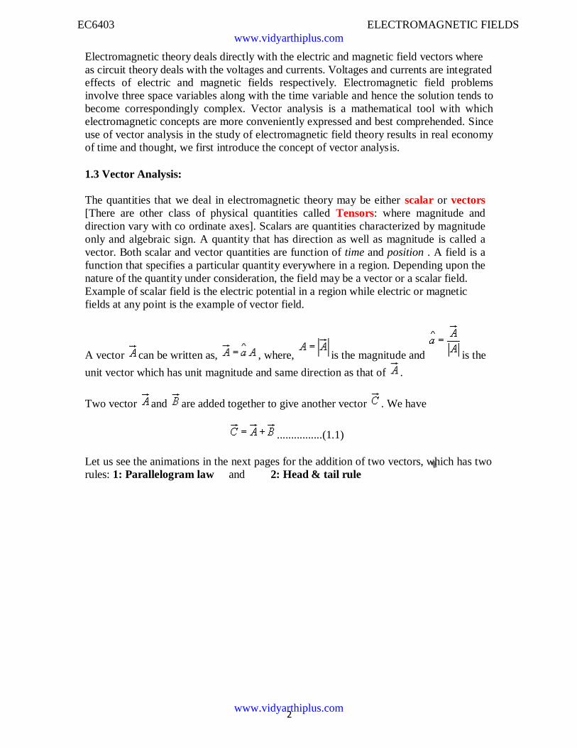
1.3 Vector Analysis:
The quantities that we deal in electromagnetic theory may be either scalar or vectors[There are other class of physical quantities called Tensors: where magnitude anddirection vary with co ordinate axes]. Scalars are quantities characterized by magnitudeonly and algebraic sign. A quantity that has direction as well as magnitude is called avector. Both scalar and vector quantities are function of time and position . A field is afunction that specifies a particular quantity everywhere in a region. Depending upon thenature of the quantity under consideration, the field may be a vector or a scalar field.Example of scalar field is the electric potential in a region while electric or magneticfields at any point is the example of vector field.
A vector can be written as, , where, is the magnitude and is the
unit vector which has unit magnitude and same direction as that of .
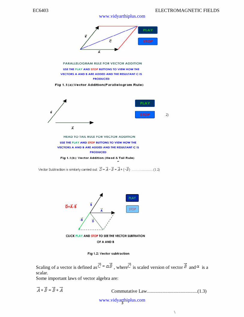
Two vector and are added together to give another vector . We have
................(1.1)
Let us see the animations in the next pages for the addition of two vectors, which has tworules: 1: Parallelogram law and 2: Head & tail rule
www.vidyarthiplus.com
www.vidyarthiplus.com
EC6403 ELECTROMAGNETIC FIELDS
3
Scaling of a vector is defined as , where is scaled version of vector and is ascalar.Some important laws of vector algebra are:
Commutative Law..........................................(1.3)
www.vidyarthiplus.com
www.vidyarthiplus.com
EC6403 ELECTROMAGNETIC FIELDS
4
Associative Law.............................................(1.4)
Distributive Law ............................................(1.5)
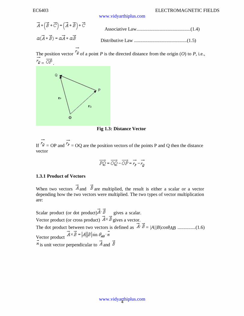
The position vector of a point P is the directed distance from the origin (O) to P, i.e.,
= .
Fig 1.3: Distance Vector
If = OP and = OQ are the position vectors of the points P and Q then the distancevector
1.3.1 Product of Vectors
When two vectors and are multiplied, the result is either a scalar or a vectordepending how the two vectors were multiplied. The two types of vector multiplicationare:
Scalar product (or dot product) gives a scalar.
Vector product (or cross product) gives a vector.
The dot product between two vectors is defined as = |A||B|cosθAB ...............(1.6)
Vector product
is unit vector perpendicular to and
www.vidyarthiplus.com
www.vidyarthiplus.com
EC6403 ELECTROMAGNETIC FIELDS
5
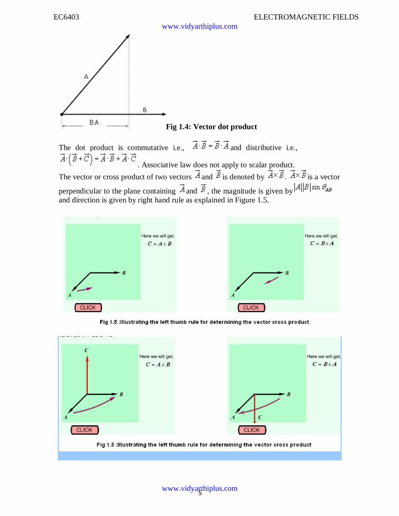
Fig 1.4: Vector dot product
The dot product is commutative i.e., and distributive i.e.,
. Associative law does not apply to scalar product.
The vector or cross product of two vectors and is denoted by . is a vector
perpendicular to the plane containing and , the magnitude is given byand direction is given by right hand rule as explained in Figure 1.5.
www.vidyarthiplus.com
www.vidyarthiplus.com
EC6403 ELECTROMAGNETIC FIELDS
SCE 6 Dept of ECE
............................................................................................(1.7)
where is the unit vector given by, . The
following relations hold for vector product.
= i.e., cross product is non commutative ..........(1.8)
i.e., cross product is distributive.......................(1.9)
i.e., cross product is non associative..............(1.10)
1.3.2 Scalar and vector triple product :
Scalar triple product .................................(1.11)
Vector triple product ...................................(1.12)
1.4 Co-ordinate Systems
In order to describe the spatial variations of the quantities, we require usingappropriate co-ordinate system. A point or vector can be represented in a curvilinearcoordinate system that may be orthogonal or non-orthogonal .
An orthogonal system is one in which the co-ordinates are mutually perpendicular.Non- orthogonal co-ordinate systems are also possible, but their usage is very limited inpractice .
Let u = constant, v = constant and w = constant represent surfaces in a coordinate system,
the surfaces may be curved surfaces in general. Furthur, let , and be the unitvectors in the three coordinate directions(base vectors). In a general right handedorthogonal curvilinear systems, the vectors satisfy the following relations :
www.vidyarthiplus.com
www.vidyarthiplus.com
EC6403 ELECTROMAGNETIC FIELDS
SCE 7 Dept of ECE
.....................................(1.13)
These equations are not independent and specification of one will automatically implythe other two. Furthermore, the following relations hold
................(1.14)
A vector can be represented as sum of its orthogonal
components, ...................(1.15)In general u, v and w may not represent length. We multiply u, v and w by conversion
factors h1,h2 and h3 respectively to convert differential changes du, dv and dw tocorresponding changes in length dl1, dl2, and dl3. Therefore
...............(1.16)
In the same manner, differential volume dv can be written as and
differential area ds1 normal to is given by, . In the same manner,
differential areas normal to unit vectors and can be defined.
In the following sections we discuss three most commonly used orthogonal co-ordinate systems, viz:
1. Cartesian (or rectangular) co-ordinate system2. Cylindrical co-ordinate system
3. Spherical polar co-ordinate system
1.4.1 Cartesian Co-ordinate System :
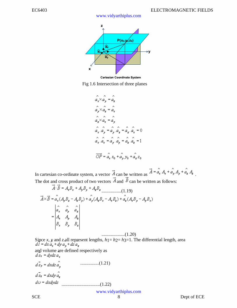
In Cartesian co-ordinate system, we have, (u,v,w) = (x,y,z). A point P(x0, y0, z0) inCartesian co-ordinate system is represented as intersection of three planes x = x0, y =y0 and z = z0. The unit vectors satisfies the following relation:
www.vidyarthiplus.com
www.vidyarthiplus.com
EC6403 ELECTROMAGNETIC FIELDS
SCE 8 Dept of ECE
Fig 1.6 Intersection of three planes
In cartesian co-ordinate system, a vector can be written as .
The dot and cross product of two vectors and can be written as follows:
.................(1.19)
....................(1.20)Since x, y and z all represent lengths, h1= h2= h3=1. The differential length, area
and volume are defined respectively as
................(1.21)
.................................(1.22)
www.vidyarthiplus.com
www.vidyarthiplus.com
EC6403 ELECTROMAGNETIC FIELDS
SCE 9 Dept of ECE
Fig Fig 1.7 cylindrical co-ordinate system
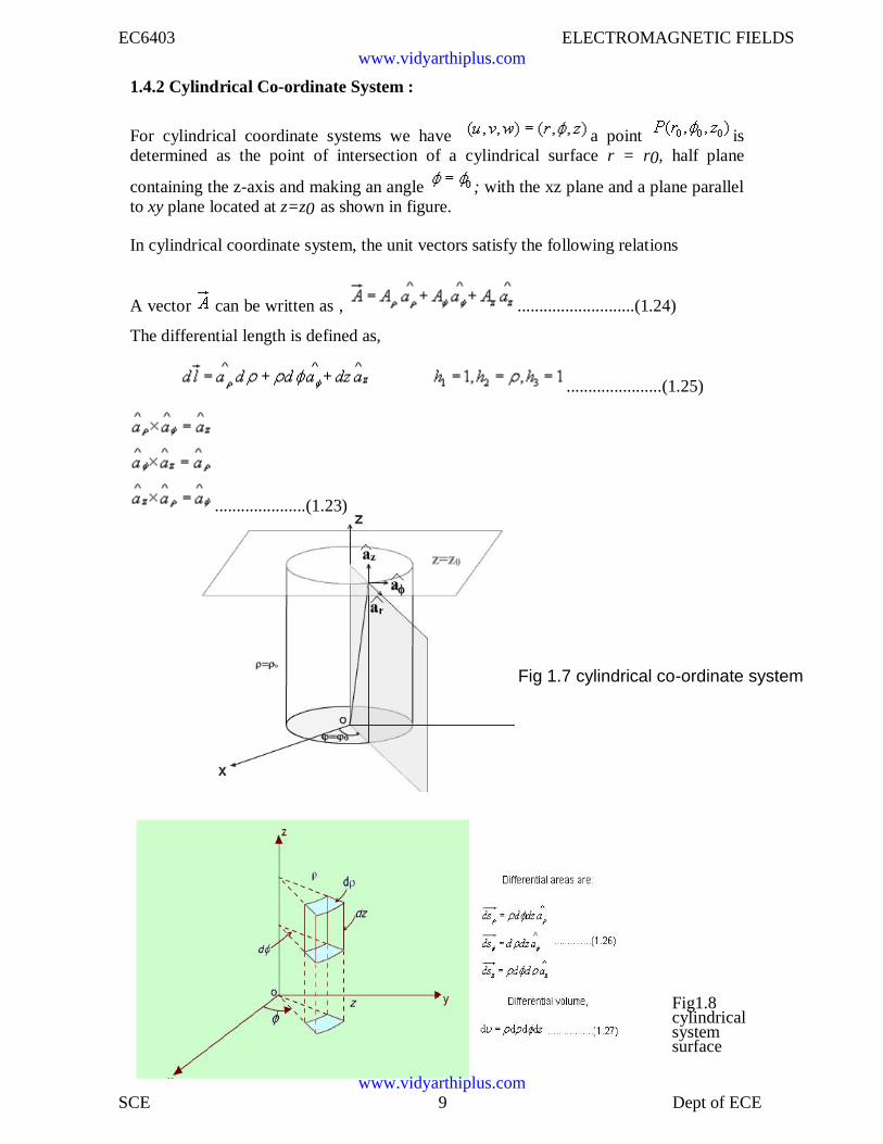
1.4.2 Cylindrical Co-ordinate System :
For cylindrical coordinate systems we have a point isdetermined as the point of intersection of a cylindrical surface r = r0, half plane
containing the z-axis and making an angle ; with the xz plane and a plane parallelto xy plane located at z=z0 as shown in figure.
In cylindrical coordinate system, the unit vectors satisfy the following relations
A vector can be written as , ...........................(1.24)
The differential length is defined as,
......................(1.25)
.....................(1.23)
Fig1.8cylindricalsystemsurface
www.vidyarthiplus.com
www.vidyarthiplus.com
EC6403 ELECTROMAGNETIC FIELDS
SCE 10 Dept of ECE
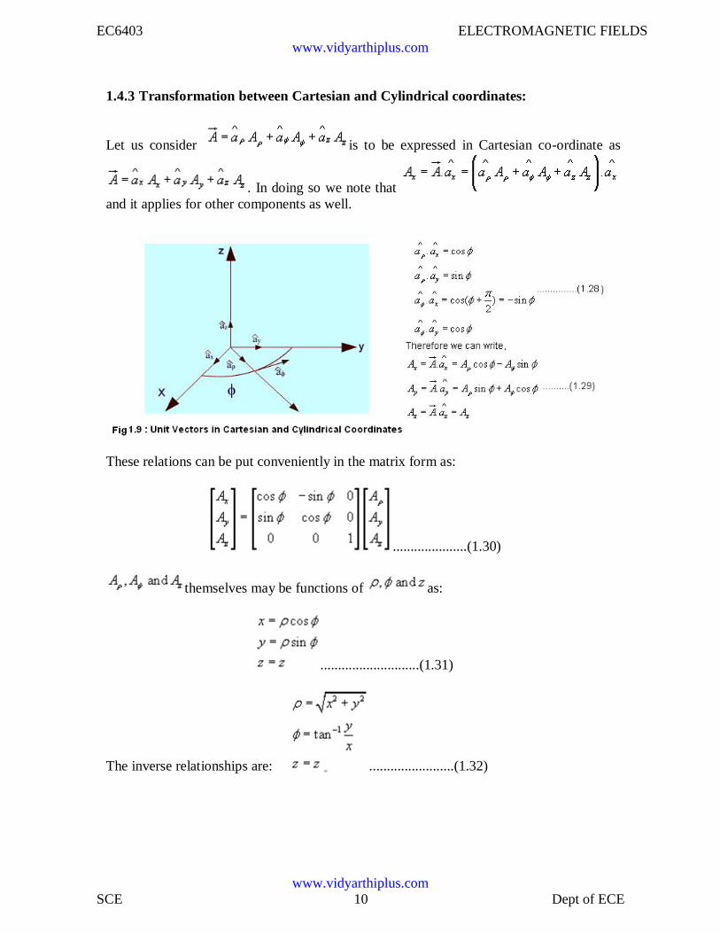
1.4.3 Transformation between Cartesian and Cylindrical coordinates:
Let us consider is to be expressed in Cartesian co-ordinate as
. In doing so we note thatand it applies for other components as well.
These relations can be put conveniently in the matrix form as:
.....................(1.30)
themselves may be functions of as:
............................(1.31)
The inverse relationships are: ........................(1.32)
www.vidyarthiplus.com
www.vidyarthiplus.com
EC6403 ELECTROMAGNETIC FIELDS
SCE 11 Dept of ECE
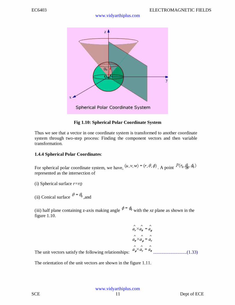
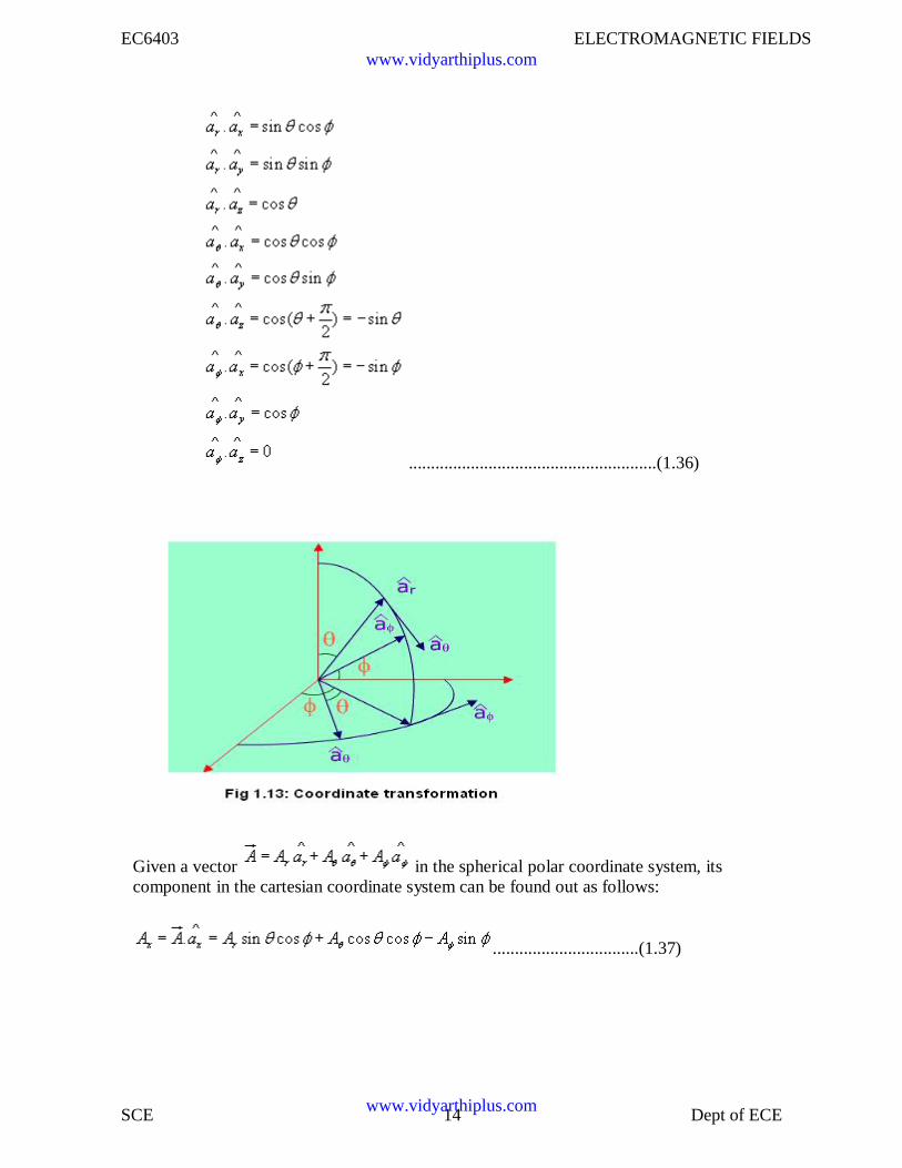
Fig 1.10: Spherical Polar Coordinate System
Thus we see that a vector in one coordinate system is transformed to another coordinatesystem through two-step process: Finding the component vectors and then variabletransformation.
1.4.4 Spherical Polar Coordinates:
For spherical polar coordinate system, we have,represented as the intersection of
. A point is
(i) Spherical surface r=r0
(ii) Conical surface ,and
(iii) half plane containing z-axis making angle with the xz plane as shown in thefigure 1.10.
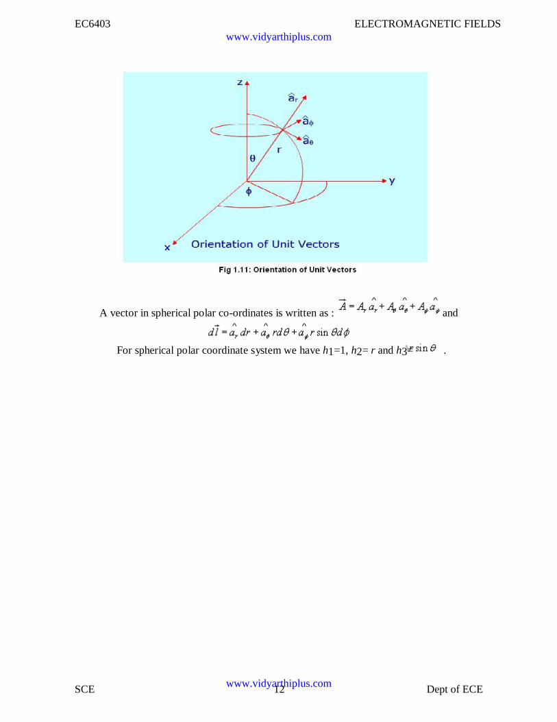
The unit vectors satisfy the following relationships: .............................(1.33)
The orientation of the unit vectors are shown in the figure 1.11.
www.vidyarthiplus.com
www.vidyarthiplus.com
EC6403 ELECTROMAGNETIC FIELDS
SCE 12 Dept of ECE
A vector in spherical polar co-ordinates is written as : and
For spherical polar coordinate system we have h1=1, h2= r and h3= .
www.vidyarthiplus.com
www.vidyarthiplus.com
EC6403 ELECTROMAGNETIC FIELDS
SCE 13 Dept of ECE
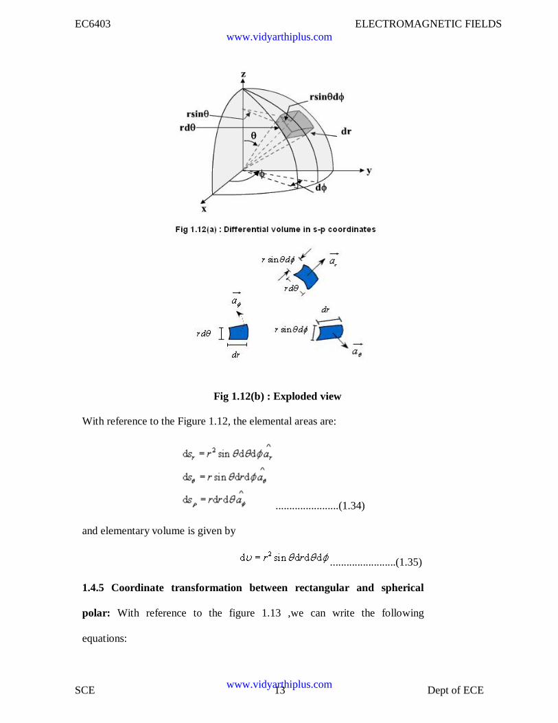
Fig 1.12(b) : Exploded view
With reference to the Figure 1.12, the elemental areas are:
.......................(1.34)
and elementary volume is given by
........................(1.35)
1.4.5 Coordinate transformation between rectangular and spherical
polar: With reference to the figure 1.13 ,we can write the following
equations:
www.vidyarthiplus.com
www.vidyarthiplus.com
EC6403 ELECTROMAGNETIC FIELDS
SCE 14 Dept of ECE
........................................................(1.36)
Given a vector in the spherical polar coordinate system, itscomponent in the cartesian coordinate system can be found out as follows:
.................................(1.37)
www.vidyarthiplus.com
www.vidyarthiplus.com
EC6403 ELECTROMAGNETIC FIELDS
SCE 15 Dept of ECE
Similarly,
.................................(1.38a)
.................................(1.38b)
The above equation can be put in a compact form:
.................................(1.39)
The components themselves will be functions of . arerelated to x,y and z as:
....................(1.40)
and conversely,
.......................................(1.41a)
.................................(1.41b)
.....................................................(1.41c)
Using the variable transformation listed above, the vector components, which arefunctions of variables of one coordinate system, can be transformed to functions ofvariables of other coordinate system and a total transformation can be done.
1.5 Line, surface and volume integrals
In electromagnetic theory, we come across integrals, which contain vector functions.Some representative integrals are listed below:
www.vidyarthiplus.com
www.vidyarthiplus.com
EC6403 ELECTROMAGNETIC FIELDS
SCE 16 Dept of ECE
In the above integrals, and respectively represent vector and scalar function of spacecoordinates. C,S and V represent path, surface and volume of integration. All theseintegrals are evaluated using extension of the usual one-dimensional integral as the limitof a sum, i.e., if a function f(x) is defined over arrange a to b of values of x, then theintegral is given by
.................................(1.42)
where the interval (a,b) is subdivided into n continuous interval of lengths .
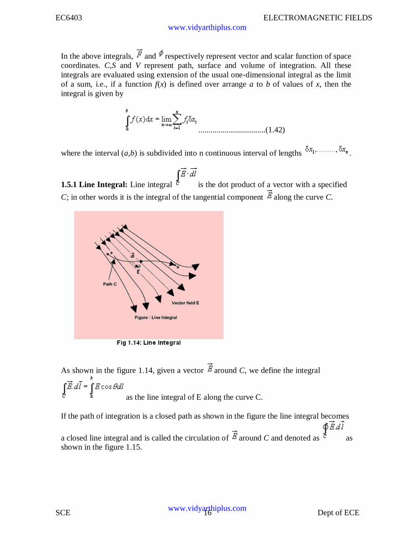
1.5.1 Line Integral: Line integral is the dot product of a vector with a specified
C; in other words it is the integral of the tangential component along the curve C.
As shown in the figure 1.14, given a vector around C, we define the integral
as the line integral of E along the curve C.
If the path of integration is a closed path as shown in the figure the line integral becomes
a closed line integral and is called the circulation of around C and denoted as asshown in the figure 1.15.
www.vidyarthiplus.com
www.vidyarthiplus.com
EC6403 ELECTROMAGNETIC FIELDS
SCE 17 Dept of ECE
Fig 1.15: Closed Line Integral
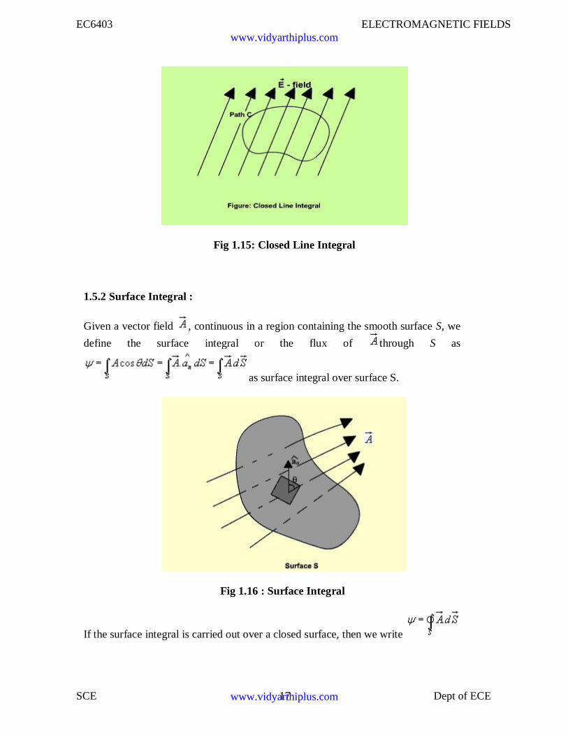
1.5.2 Surface Integral :
Given a vector field , continuous in a region containing the smooth surface S, we
define the surface integral or the flux of through S as
as surface integral over surface S.
Fig 1.16 : Surface Integral
If the surface integral is carried out over a closed surface, then we write
www.vidyarthiplus.com
www.vidyarthiplus.com
EC6403 ELECTROMAGNETIC FIELDS
SCE 18 Dept of ECE
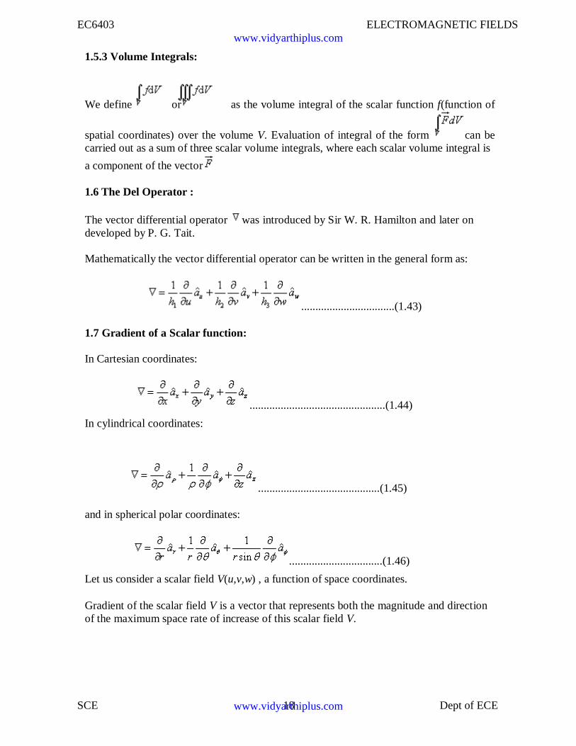
1.5.3 Volume Integrals:
We define or as the volume integral of the scalar function f(function of
spatial coordinates) over the volume V. Evaluation of integral of the form can becarried out as a sum of three scalar volume integrals, where each scalar volume integral is
a component of the vector
1.6 The Del Operator :
The vector differential operator was introduced by Sir W. R. Hamilton and later ondeveloped by P. G. Tait.
Mathematically the vector differential operator can be written in the general form as:
.................................(1.43)
1.7 Gradient of a Scalar function:
In Cartesian coordinates:
................................................(1.44)
In cylindrical coordinates:
...........................................(1.45)
and in spherical polar coordinates:
.................................(1.46)
Let us consider a scalar field V(u,v,w) , a function of space coordinates.
Gradient of the scalar field V is a vector that represents both the magnitude and directionof the maximum space rate of increase of this scalar field V.
www.vidyarthiplus.com
www.vidyarthiplus.com
EC6403 ELECTROMAGNETIC FIELDS
SCE 19 Dept of ECE
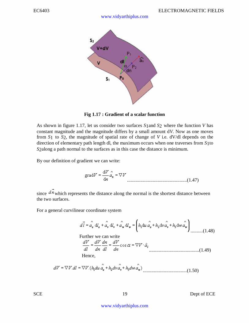
Fig 1.17 : Gradient of a scalar function
As shown in figure 1.17, let us consider two surfaces S1and S2 where the function V hasconstant magnitude and the magnitude differs by a small amount dV. Now as one movesfrom S1 to S2, the magnitude of spatial rate of change of V i.e. dV/dl depends on thedirection of elementary path length dl, the maximum occurs when one traverses from S1toS2along a path normal to the surfaces as in this case the distance is minimum.
By our definition of gradient we can write:
.................................................(1.47)
since which represents the distance along the normal is the shortest distance betweenthe two surfaces.
For a general curvilinear coordinate system
..........(1.48)Further we can write
.........................................(1.49)Hence,
....................................(1.50)
www.vidyarthiplus.com
www.vidyarthiplus.com
EC6403 ELECTROMAGNETIC FIELDS
SCE 20 Dept of ECE
Also we can write,
............................(1.51)
By comparison we can write,
....................................................................(1.52)
Hence for the Cartesian, cylindrical and spherical polar coordinate system, theexpressions for gradient can be written as:In Cartesian coordinates:
...................................................................................(1.53)
In cylindrical coordinates:
..................................................................(1.54)
and in spherical polar coordinates:
..........................................................(1.55)
The following relationships hold for gradient operator.
...............................................................................(1.56)
www.vidyarthiplus.com
www.vidyarthiplus.com
EC6403 ELECTROMAGNETIC FIELDS
SCE 21 Dept of ECE
where U and V are scalar functions and n is an integer.
It may further be noted that since magnitude of depends on the direction of
dl, it is called the directional derivative. If is called the scalar potential
function of the vector function .
1.8 Divergence of a Vector Field:
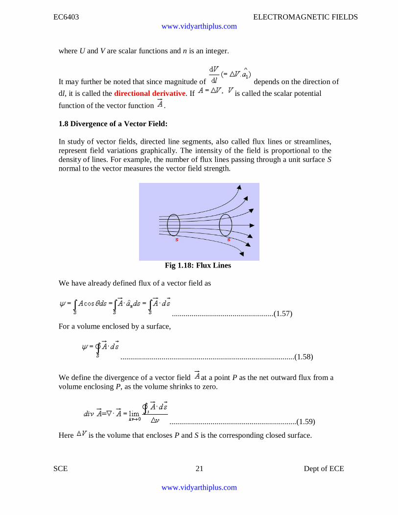
In study of vector fields, directed line segments, also called flux lines or streamlines,represent field variations graphically. The intensity of the field is proportional to thedensity of lines. For example, the number of flux lines passing through a unit surface Snormal to the vector measures the vector field strength.
Fig 1.18: Flux Lines
We have already defined flux of a vector field as
....................................................(1.57)
For a volume enclosed by a surface,
.........................................................................................(1.58)
We define the divergence of a vector field at a point P as the net outward flux from avolume enclosing P, as the volume shrinks to zero.
.................................................................(1.59)
Here is the volume that encloses P and S is the corresponding closed surface.
www.vidyarthiplus.com
www.vidyarthiplus.com
EC6403 ELECTROMAGNETIC FIELDS
SCE 22 Dept of ECE
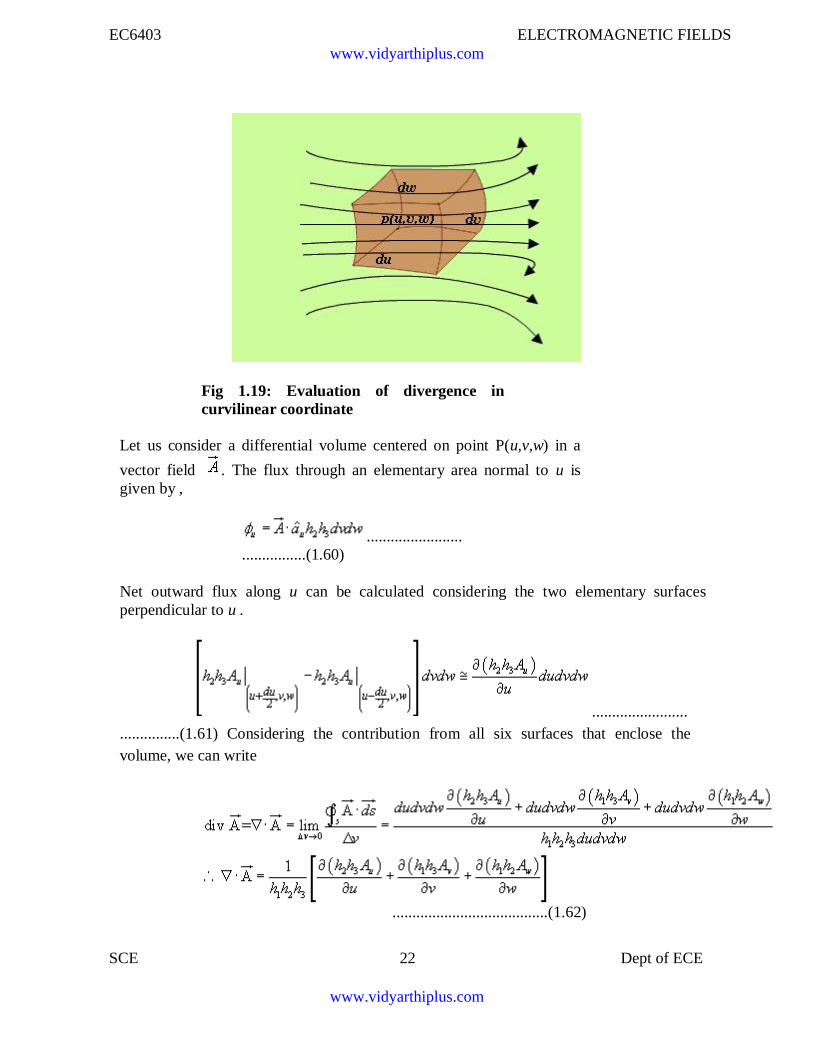
Fig 1.19: Evaluation of divergence incurvilinear coordinate
Let us consider a differential volume centered on point P(u,v,w) in a
vector field . The flux through an elementary area normal to u isgiven by ,
........................................(1.60)
Net outward flux along u can be calculated considering the two elementary surfacesperpendicular to u .
.......................................(1.61) Considering the contribution from all six surfaces that enclose thevolume, we can write
.......................................(1.62)
www.vidyarthiplus.com
www.vidyarthiplus.com
EC6403 ELECTROMAGNETIC FIELDS
SCE 23 Dept of ECE
Hence for the Cartesian, cylindrical and spherical polar coordinate system, the expressionsfor divergence ca written as:
In Cartesian coordinates:
................................(1.63)
In cylindrical coordinates:
....................................................................(1.64)
and in spherical polar coordinates:
......................................(1.65)
In connection with the divergence of a vector field, the following can be noted
Divergence of a vector field gives a scalar.
..............................................................................(1.66)
1.9 Divergence theorem :Divergence theorem states that the volume integral of the divergence of vector field isequal to the net outward flux of the vector through the closed surface that bounds the
volume. Mathematically,
Proof:
Let us consider a volume V enclosed by a surface S . Let us subdivide the volume in large
www.vidyarthiplus.com
www.vidyarthiplus.com
EC6403 ELECTROMAGNETIC FIELDS
SCE 24 Dept of ECE
number of cells. Let the kth cell has a volume and the corresponding surface isdenoted by Sk. Interior to the volume, cells have common surfaces. Outward flux throughthese common surfaces from one cell becomes the inward flux for the neighboring cells.Therefore when the total flux from these cells are considered, we actually get the netoutward flux through the surface surrounding the volume. Hence we can write:
......................................(1.67)
In the limit, that is when and the right hand of the expression can be
written as .
Hence we get , which is the divergence theorem.
1.10 Curl of a vector field:
We have defined the circulation of a vector field A around a closed path as .
Curl of a vector field is a measure of the vector field's tendency to rotate about a point.
Curl , also written as is defined as a vector whose magnitude is maximum of thenet circulation per unit area when the area tends to zero and its direction is the normaldirection to the area when the area is oriented in such a way so as to make the circulationmaximum.
Therefore, we can write:
......................................(1.68)
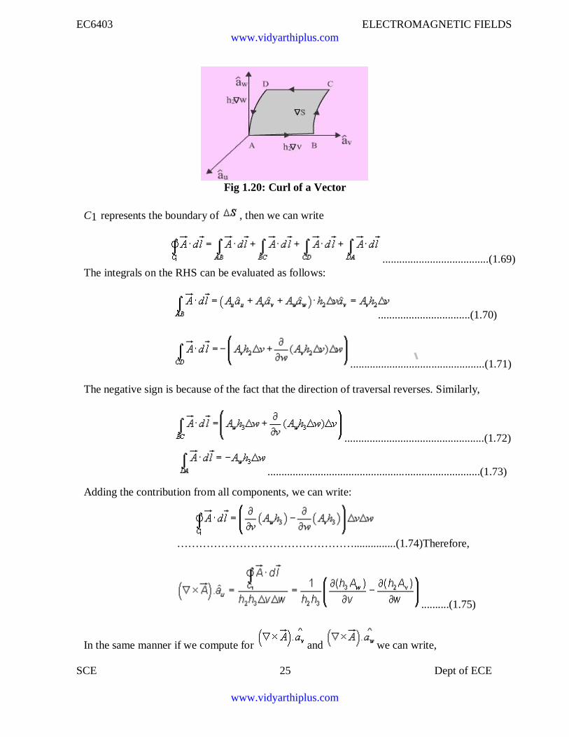
To derive the expression for curl in generalized curvilinear coordinate system, we first
compute and to do so let us consider the figure 1.20 :
www.vidyarthiplus.com
www.vidyarthiplus.com
EC6403 ELECTROMAGNETIC FIELDS
SCE 25 Dept of ECE
Fig 1.20: Curl of a Vector
C1 represents the boundary of , then we can write
The integrals on the RHS can be evaluated as follows:......................................(1.69)
.................................(1.70)
................................................(1.71)
The negative sign is because of the fact that the direction of traversal reverses. Similarly,
..................................................(1.72)
............................................................................(1.73)
Adding the contribution from all components, we can write:
…………………………………………...............(1.74)Therefore,
..........(1.75)
In the same manner if we compute for and we can write,
www.vidyarthiplus.com
www.vidyarthiplus.com
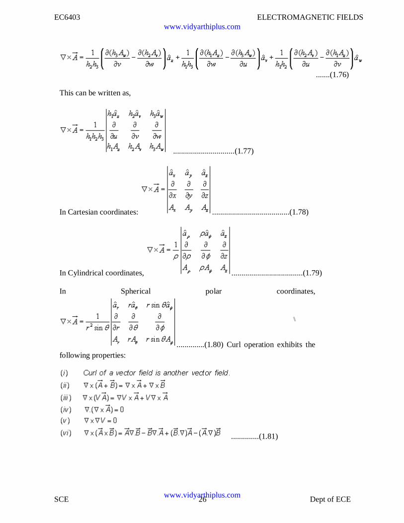
EC6403 ELECTROMAGNETIC FIELDS
SCE 26 Dept of ECE
.......(1.76)
This can be written as,
...............................(1.77)
In Cartesian coordinates: .......................................(1.78)
In Cylindrical coordinates, ....................................(1.79)
In Spherical polar coordinates,
..............(1.80) Curl operation exhibits thefollowing properties:
..............(1.81)
www.vidyarthiplus.com
www.vidyarthiplus.com
EC6403 ELECTROMAGNETIC FIELDS
SCE 27 Dept of ECE
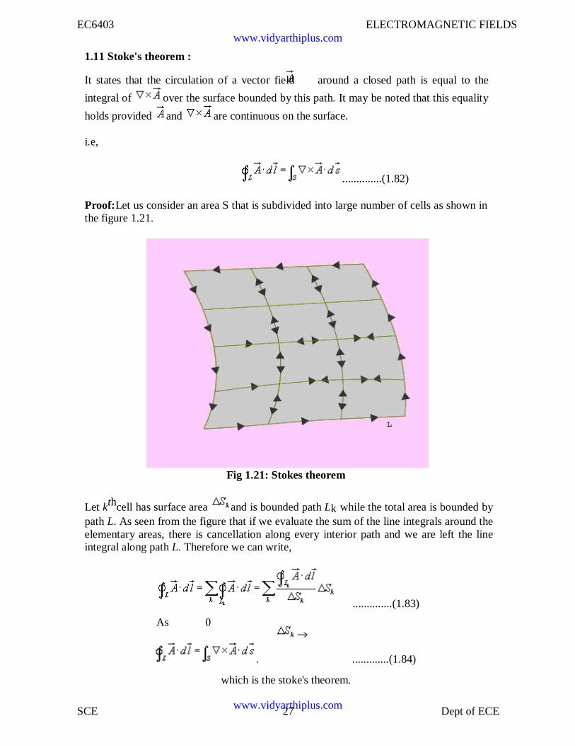
1.11 Stoke's theorem :
It states that the circulation of a vector field around a closed path is equal to the
integral of over the surface bounded by this path. It may be noted that this equality
holds provided and are continuous on the surface.
i.e,
..............(1.82)
Proof:Let us consider an area S that is subdivided into large number of cells as shown inthe figure 1.21.
Fig 1.21: Stokes theorem
Let kthcell has surface area and is bounded path Lk while the total area is bounded bypath L. As seen from the figure that if we evaluate the sum of the line integrals around theelementary areas, there is cancellation along every interior path and we are left the lineintegral along path L. Therefore we can write,
..............(1.83)
As 0
. .............(1.84)
which is the stoke's theorem.
www.vidyarthiplus.com
www.vidyarthiplus.com
EC6403 ELECTROMAGNETIC FIELDS
SCE 28 Dept of ECE
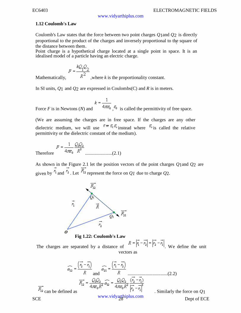
1.12 Coulomb's Law
Coulomb's Law states that the force between two point charges Q1and Q2 is directlyproportional to the product of the charges and inversely proportional to the square ofthe distance between them.Point charge is a hypothetical charge located at a single point in space. It is anidealised model of a particle having an electric charge.
Mathematically, ,where k is the proportionality constant.
In SI units, Q1 and Q2 are expressed in Coulombs(C) and R is in meters.
Force F is in Newtons (N) and , is called the permittivity of free space.
(We are assuming the charges are in free space. If the charges are any other
dielectric medium, we will use instead where is called the relativepermittivity or the dielectric constant of the medium).
Therefore .......................(2.1)
As shown in the Figure 2.1 let the position vectors of the point charges Q1and Q2 are
given by and . Let represent the force on Q1 due to charge Q2.
Fig 1.22: Coulomb's Law
The charges are separated by a distance of . We define the unitvectors as
and ..................................(2.2)
can be defined as . Similarly the force on Q1
www.vidyarthiplus.com
www.vidyarthiplus.com
EC6403 ELECTROMAGNETIC FIELDS
SCE 29 Dept of ECE
due to charge Q2 can be calculated and if represents this force then we can write
When we have a number of point charges, to determine the force on a particular chargedue to all other charges, we apply principle of superposition. If we have N number ofcharges
Q1,Q2,.........QN located respectively at the points represented by the position vectors ,
,...... , the force experienced by a charge Q located at is given by,
.................................(2.3)
1.13 Electric Field
The electric field intensity or the electric field strength at a point is defined as the forceper unit charge. That is
or, .......................................(2.4)
The electric field intensity E at a point r (observation point) due a point charge Q located at
(source point) is given by:
..........................................(2.5)
For a collection of N point charges Q1 ,Q2 ,.........QN located at , ,...... , the electric
field intensity at point is obtained as
........................................(2.6)
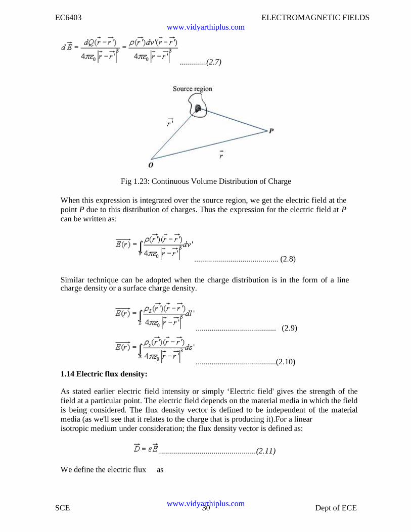
The expression (2.6) can be modified suitably to compute the electric filed dueto a continuous distribution of charges.In figure 2.2 we consider a continuous volume distribution of charge d(t) in theregion denoted as the source region.
For an elementary charge , i.e. considering this charge as point charge,we can write the field expression as:
www.vidyarthiplus.com
www.vidyarthiplus.com
EC6403 ELECTROMAGNETIC FIELDS
SCE 30 Dept of ECE
.............(2.7)
Fig 1.23: Continuous Volume Distribution of Charge
When this expression is integrated over the source region, we get the electric field at thepoint P due to this distribution of charges. Thus the expression for the electric field at Pcan be written as:
.......................................... (2.8)
Similar technique can be adopted when the charge distribution is in the form of a linecharge density or a surface charge density.
........................................ (2.9)
........................................(2.10)
1.14 Electric flux density:
As stated earlier electric field intensity or simply ‘Electric field' gives the strength of thefield at a particular point. The electric field depends on the material media in which the fieldis being considered. The flux density vector is defined to be independent of the materialmedia (as we'll see that it relates to the charge that is producing it).For a linearisotropic medium under consideration; the flux density vector is defined as:
................................................(2.11)
We define the electric flux as
www.vidyarthiplus.com
www.vidyarthiplus.com
EC6403 ELECTROMAGNETIC FIELDS
SCE 31 Dept of ECE
.....................................(2.12)
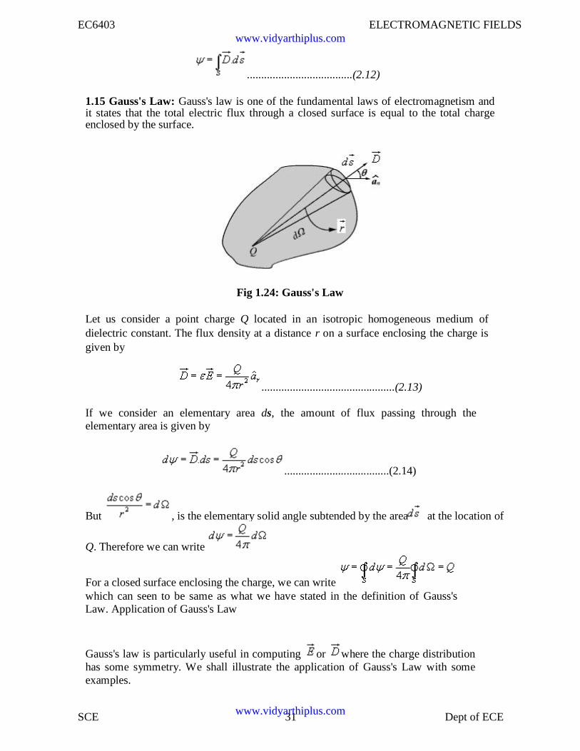
1.15 Gauss's Law: Gauss's law is one of the fundamental laws of electromagnetism andit states that the total electric flux through a closed surface is equal to the total chargeenclosed by the surface.
Fig 1.24: Gauss's Law
Let us consider a point charge Q located in an isotropic homogeneous medium ofdielectric constant. The flux density at a distance r on a surface enclosing the charge isgiven by
...............................................(2.13)
If we consider an elementary area ds, the amount of flux passing through theelementary area is given by
.....................................(2.14)
But , is the elementary solid angle subtended by the area at the location of
Q. Therefore we can write
For a closed surface enclosing the charge, we can writewhich can seen to be same as what we have stated in the definition of Gauss'sLaw. Application of Gauss's Law
Gauss's law is particularly useful in computing or where the charge distributionhas some symmetry. We shall illustrate the application of Gauss's Law with someexamples.
www.vidyarthiplus.com
www.vidyarthiplus.com
EC6403 ELECTROMAGNETIC FIELDS
SCE 32 Dept of ECE
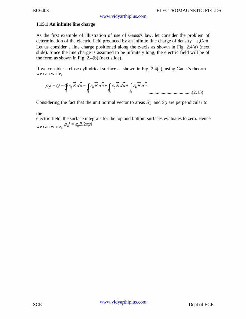
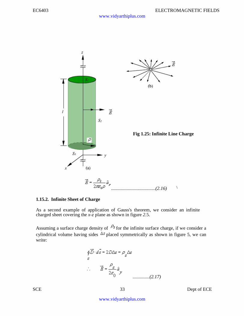
1.15.1 An infinite line charge
As the first example of illustration of use of Gauss's law, let consider the problem ofdetermination of the electric field produced by an infinite line charge of density LC/m.Let us consider a line charge positioned along the z-axis as shown in Fig. 2.4(a) (nextslide). Since the line charge is assumed to be infinitely long, the electric field will be ofthe form as shown in Fig. 2.4(b) (next slide).
If we consider a close cylindrical surface as shown in Fig. 2.4(a), using Gauss's theormwe can write,
.....................................(2.15)
Considering the fact that the unit normal vector to areas S1 and S3 are perpendicular to
theelectric field, the surface integrals for the top and bottom surfaces evaluates to zero. Hence
we can write,
www.vidyarthiplus.com
www.vidyarthiplus.com
EC6403 ELECTROMAGNETIC FIELDS
SCE 33 Dept of ECE
Fig 1.25: Infinite Line Charge
.....................................(2.16)
1.15.2. Infinite Sheet of Charge
As a second example of application of Gauss's theorem, we consider an infinitecharged sheet covering the x-z plane as shown in figure 2.5.
Assuming a surface charge density of for the infinite surface charge, if we consider acylindrical volume having sides placed symmetrically as shown in figure 5, we canwrite:
..............(2.17)
www.vidyarthiplus.com
www.vidyarthiplus.com
EC6403 ELECTROMAGNETIC FIELDS
SCE 34 Dept of ECE
Fig 1.26: Infinite Sheet of Charge
It may be noted that the electric field strength is independent of distance. This is true forthe infinite plane of charge; electric lines of force on either side of the charge will beperpendicular to the sheet and extend to infinity as parallel lines. As number of lines offorce per unit area gives the strength of the field, the field becomes independent ofdistance. For a finite charge sheet, the field will be a function of distance.
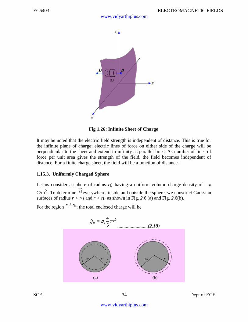
1.15.3. Uniformly Charged Sphere
Let us consider a sphere of radius r0 having a uniform volume charge density of v
C/m3. To determine everywhere, inside and outside the sphere, we construct Gaussiansurfaces of radius r < r0 and r > r0 as shown in Fig. 2.6 (a) and Fig. 2.6(b).
For the region ; the total enclosed charge will be
.........................(2.18)
www.vidyarthiplus.com
www.vidyarthiplus.com
EC6403 ELECTROMAGNETIC FIELDS
SCE 35 Dept of ECE
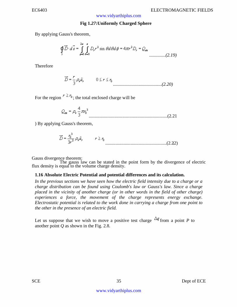
Fig 1.27:Uniformly Charged Sphere
By applying Gauss's theorem,
..............(2.19)
Therefore
..........................................(2.20)
For the region ; the total enclosed charge will be
....................................................................(2.21
) By applying Gauss's theorem,
.....................................................(2.22)
Gauss divergence theorem:The gauss law can be stated in the point form by the divergence of electric
flux density is equal to the volume charge density.
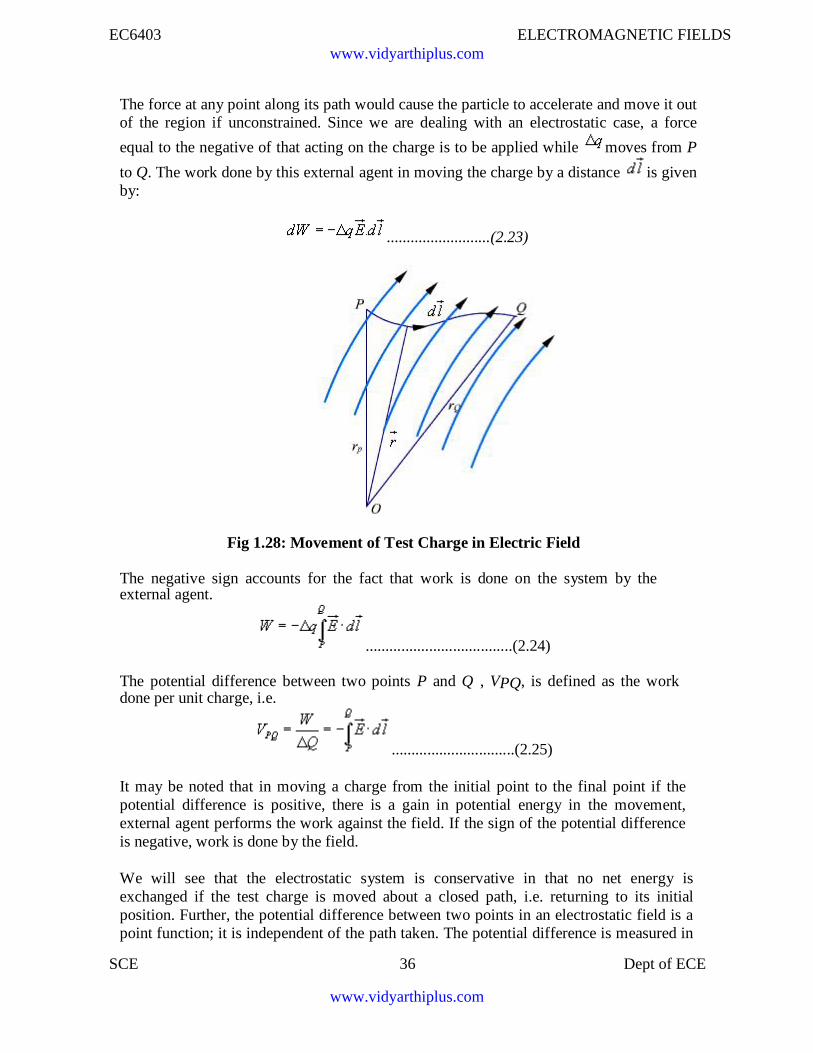
1.16 Absolute Electric Potential and potential differences and its calculation.In the previous sections we have seen how the electric field intensity due to a charge or acharge distribution can be found using Coulomb's law or Gauss's law. Since a chargeplaced in the vicinity of another charge (or in other words in the field of other charge)experiences a force, the movement of the charge represents energy exchange.Electrostatic potential is related to the work done in carrying a charge from one point tothe other in the presence of an electric field.
Let us suppose that we wish to move a positive test charge from a point P toanother point Q as shown in the Fig. 2.8.
www.vidyarthiplus.com
www.vidyarthiplus.com
EC6403 ELECTROMAGNETIC FIELDS
SCE 36 Dept of ECE
The force at any point along its path would cause the particle to accelerate and move it outof the region if unconstrained. Since we are dealing with an electrostatic case, a force
equal to the negative of that acting on the charge is to be applied while moves from P
to Q. The work done by this external agent in moving the charge by a distance is givenby:
..........................(2.23)
Fig 1.28: Movement of Test Charge in Electric Field
The negative sign accounts for the fact that work is done on the system by theexternal agent.
.....................................(2.24)
The potential difference between two points P and Q , VPQ, is defined as the workdone per unit charge, i.e.
...............................(2.25)
It may be noted that in moving a charge from the initial point to the final point if thepotential difference is positive, there is a gain in potential energy in the movement,external agent performs the work against the field. If the sign of the potential differenceis negative, work is done by the field.
We will see that the electrostatic system is conservative in that no net energy isexchanged if the test charge is moved about a closed path, i.e. returning to its initialposition. Further, the potential difference between two points in an electrostatic field is apoint function; it is independent of the path taken. The potential difference is measured in
www.vidyarthiplus.com
www.vidyarthiplus.com
EC6403 ELECTROMAGNETIC FIELDS
SCE 37 Dept of ECE
Joules/Coulomb which is referred to as Volts.
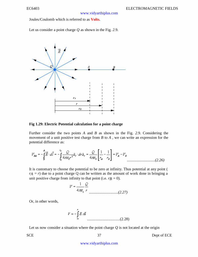
Let us consider a point charge Q as shown in the Fig. 2.9.
Fig 1.29: Electric Potential calculation for a point charge
Further consider the two points A and B as shown in the Fig. 2.9. Considering themovement of a unit positive test charge from B to A , we can write an expression for thepotential difference as:
.............................(2.26)
It is customary to choose the potential to be zero at infinity. Thus potential at any point (rA = r) due to a point charge Q can be written as the amount of work done in bringing aunit positive charge from infinity to that point (i.e. rB = 0).
..............................(2.27)
Or, in other words,
..................................(2.28)
Let us now consider a situation where the point charge Q is not located at the origin
www.vidyarthiplus.com
www.vidyarthiplus.com
EC6403 ELECTROMAGNETIC FIELDS
SCE 38 Dept of ECE
as shown in Fig. 2.10.
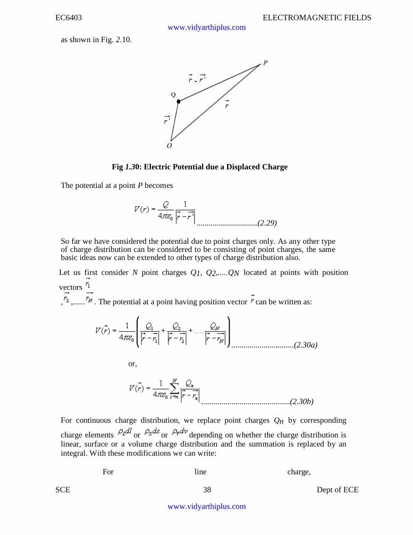
Fig 1.30: Electric Potential due a Displaced Charge
The potential at a point P becomes
..............................(2.29)
So far we have considered the potential due to point charges only. As any other typeof charge distribution can be considered to be consisting of point charges, the samebasic ideas now can be extended to other types of charge distribution also.
Let us first consider N point charges Q1, Q2,.....QN located at points with position
vectors
, ,...... . The potential at a point having position vector can be written as:
...............................(2.30a)
or,
............................................(2.30b)
For continuous charge distribution, we replace point charges Qn by corresponding
charge elements or or depending on whether the charge distribution islinear, surface or a volume charge distribution and the summation is replaced by anintegral. With these modifications we can write:
For line charge,
www.vidyarthiplus.com
www.vidyarthiplus.com
EC6403 ELECTROMAGNETIC FIELDS
SCE 39 Dept of ECE
..................................(2.31)
For surface charge, .................................(2.32)
For volume charge, .................................(2.33)
It may be noted here that the primed coordinates represent the source coordinates andthe unprimed coordinates represent field point.
Further, in our discussion so far we have used the reference or zero potential atinfinity. If any other point is chosen as reference, we can write:
..............................(2.34)
where C is a constant. In the same manner when potential is computed from a knownelectric field we can write:
.............................(2.35)
The potential difference is however independent of the choice of reference.
.....................(2.36)
We have mentioned that electrostatic field is a conservative field; the work done inmoving a charge from one point to the other is independent of the path. Let us considermoving a charge from point P1 to P2 in one path and then from point P2 back to P1 overa different path.If the work done on the two paths were different, a net positive or negative amount ofwork would have been done when the body returns to its original position P1. In aconservative field there is no mechanism for dissipating energy corresponding to anypositive work neither any source is present from which energy could be absorbed in thecase of negative work. Hence the question of different works in two paths is untenable,the work must have to be independent of path and depends on the initial and finalpositions.
Since the potential difference is independent of the paths taken, VAB = - VBA , andover a closed path,
www.vidyarthiplus.com
www.vidyarthiplus.com
EC6403 ELECTROMAGNETIC FIELDS
SCE 40 Dept of ECE
.............................(2.37)
Applying Stokes's theorem, we can write:
.........................(2.38)
from which it follows that for electrostatic field,
...................................(2.39)
Any vector field that satisfies is called an irrotational
field. From our definition of potential, we can write
.............................(2.40)
from which we obtain,
.....................................(2.41)
From the foregoing discussions we observe that the electric field strength at any point is
the negative of the potential gradient at any point, negative sign shows that is directed
from higher to lower values of . This gives us another method of computing theelectric field, i. e. if we know the potential function, the electric field may be computed.
We may note here that that one scalar function contain all the information that three
components of carry, the same is possible because of the fact that three components of
are interrelated by the relation .
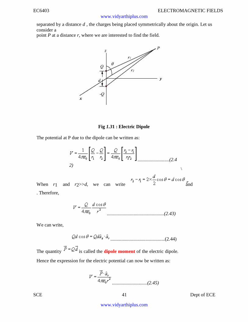
1.17 Electric Dipole
An electric dipole consists of two point charges of equal magnitude but of opposite signand separated by a small distance.
As shown in figure 2.11, the dipole is formed by the two point charges Q and -Q
www.vidyarthiplus.com
www.vidyarthiplus.com
EC6403 ELECTROMAGNETIC FIELDS
SCE 41 Dept of ECE
separated by a distance d , the charges being placed symmetrically about the origin. Let usconsider apoint P at a distance r, where we are interested to find the field.
Fig 1.31 : Electric Dipole
The potential at P due to the dipole can be written as:
..........................(2.42)
When r1 and r2>>d, we can write and
. Therefore,
...............................................(2.43)
We can write,
.............................................(2.44)
The quantity is called the dipole moment of the electric dipole.
Hence the expression for the electric potential can now be written as:
.............................(2.45)
www.vidyarthiplus.com
www.vidyarthiplus.com
EC6403 ELECTROMAGNETIC FIELDS
SCE 42 Dept of ECE
It may be noted that while potential of an isolated charge varies with distance as 1/rthat of an electric dipole varies as 1/r2 with distance.
www.vidyarthiplus.com
www.vidyarthiplus.com
EC6403 ELECTROMAGNETIC FIELDS
SCE 43 Dept of ECE
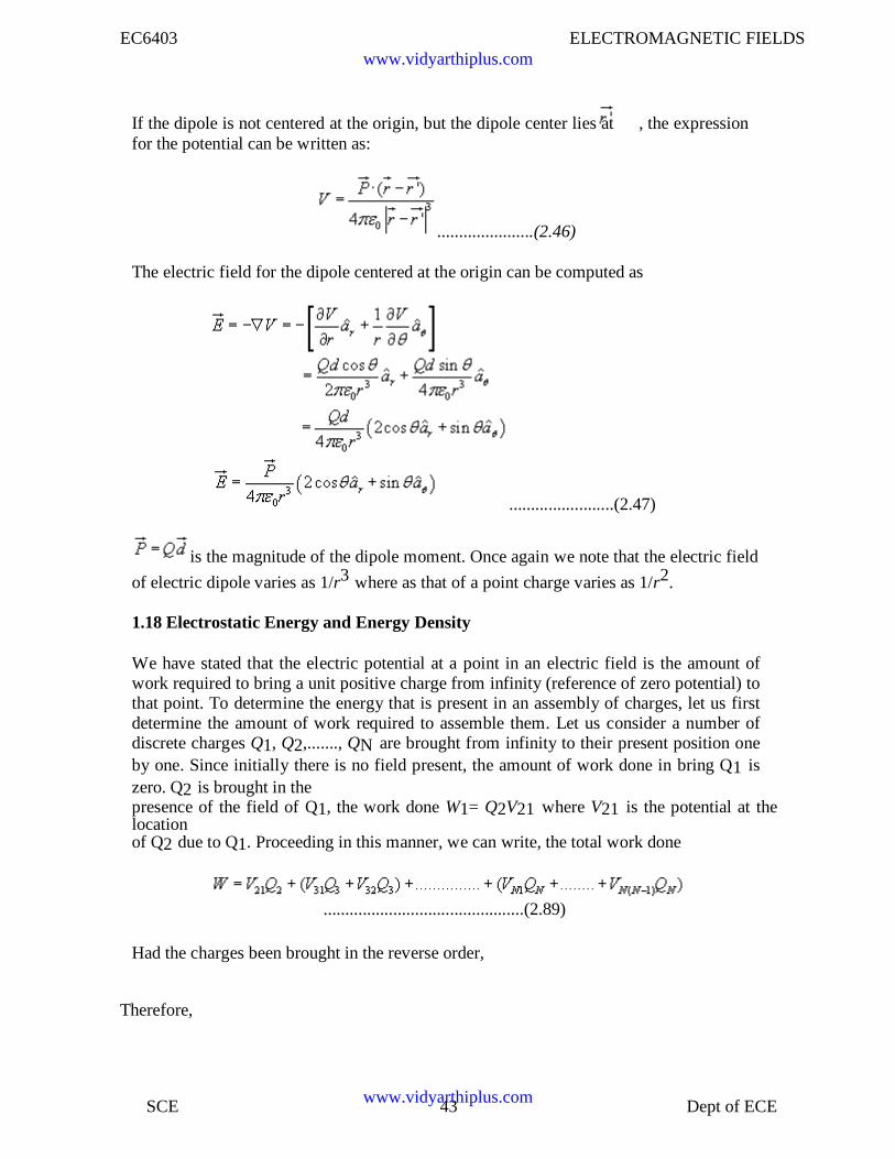
If the dipole is not centered at the origin, but the dipole center lies at , the expressionfor the potential can be written as:
......................(2.46)
The electric field for the dipole centered at the origin can be computed as
........................(2.47)
is the magnitude of the dipole moment. Once again we note that the electric field
of electric dipole varies as 1/r3 where as that of a point charge varies as 1/r2.
1.18 Electrostatic Energy and Energy Density
We have stated that the electric potential at a point in an electric field is the amount ofwork required to bring a unit positive charge from infinity (reference of zero potential) tothat point. To determine the energy that is present in an assembly of charges, let us firstdetermine the amount of work required to assemble them. Let us consider a number ofdiscrete charges Q1, Q2,......., QN are brought from infinity to their present position oneby one. Since initially there is no field present, the amount of work done in bring Q1 iszero. Q2 is brought in thepresence of the field of Q1, the work done W1= Q2V21 where V21 is the potential at thelocationof Q2 due to Q1. Proceeding in this manner, we can write, the total work done
..............................................(2.89)
Had the charges been brought in the reverse order,
Therefore,
www.vidyarthiplus.com
www.vidyarthiplus.com
EC6403 ELECTROMAGNETIC FIELDS
SCE 44 Dept of ECE
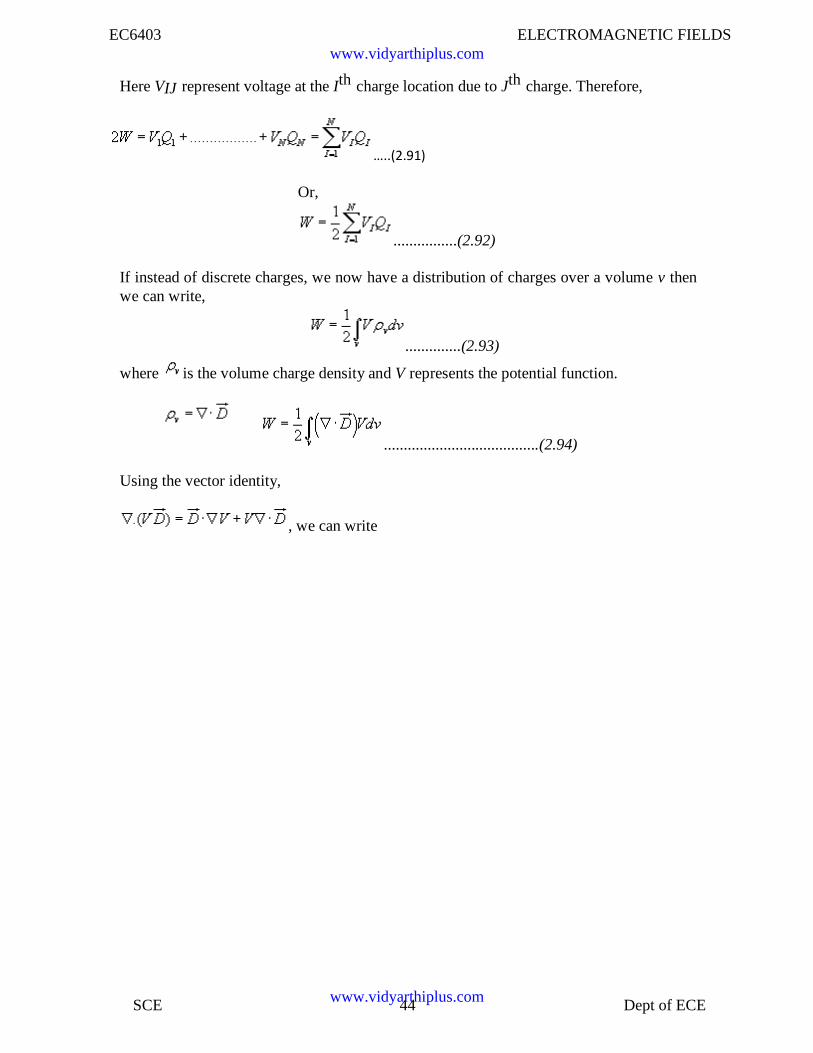
Here VIJ represent voltage at the Ith charge location due to Jth charge. Therefore,
…..(2.91)
Or,
................(2.92)
If instead of discrete charges, we now have a distribution of charges over a volume v thenwe can write,
..............(2.93)
where is the volume charge density and V represents the potential function.
.......................................(2.94)
Using the vector identity,
, we can write
www.vidyarthiplus.com
www.vidyarthiplus.com
EC6403 ELECTROMAGNETIC FIELDS
SCE 45 Dept of ECE
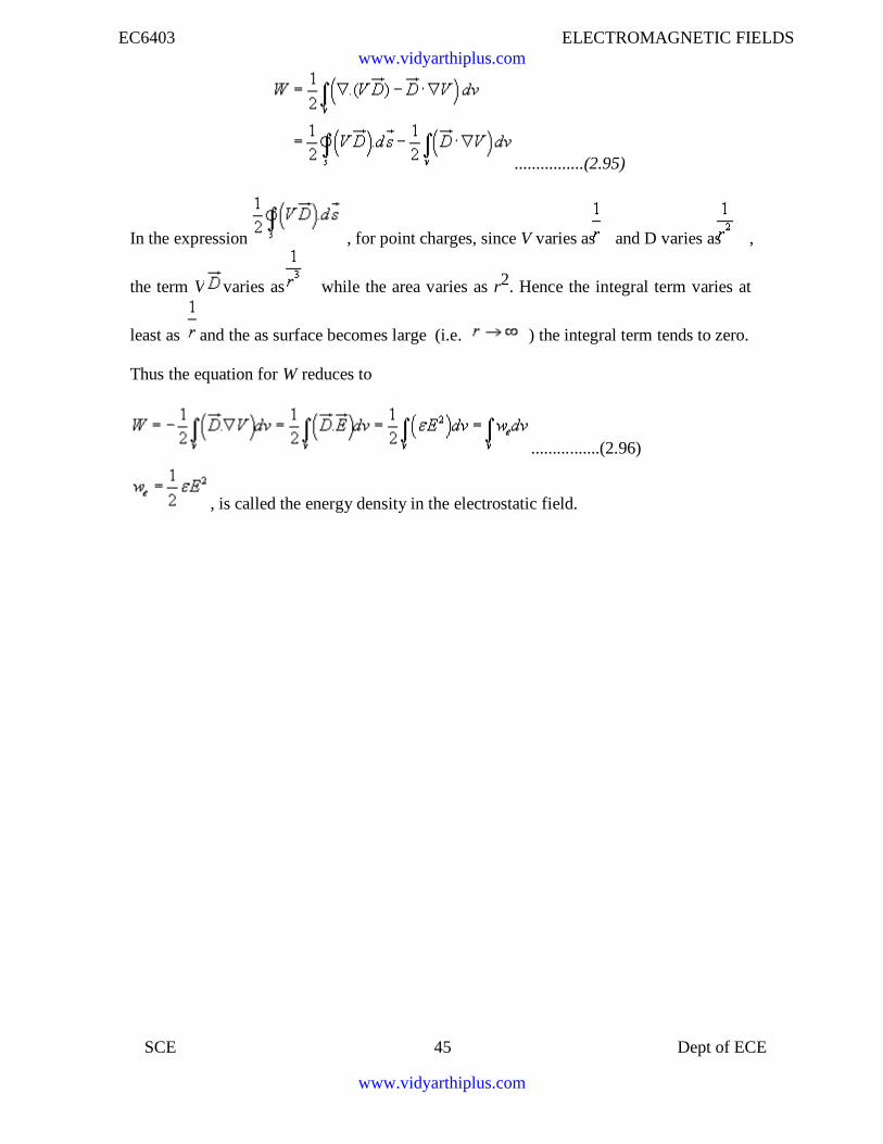
................(2.95)
In the expression , for point charges, since V varies as and D varies as ,
the term V varies as while the area varies as r2. Hence the integral term varies at
least as and the as surface becomes large (i.e. ) the integral term tends to zero.
Thus the equation for W reduces to
................(2.96)
, is called the energy density in the electrostatic field.
www.vidyarthiplus.com
www.vidyarthiplus.com
EC6403 ELECTROMAGNETIC FIELDS
SCE 46 Dept of ECE
UNIT-2 CONDUCTORS AND DIELECTRICS
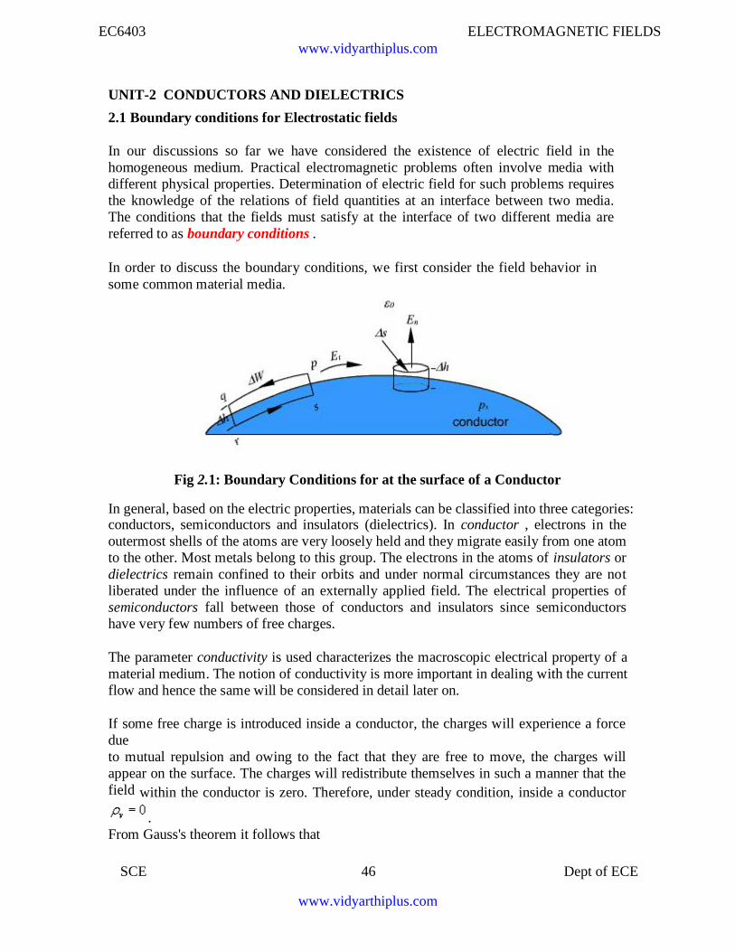
2.1 Boundary conditions for Electrostatic fields
In our discussions so far we have considered the existence of electric field in thehomogeneous medium. Practical electromagnetic problems often involve media withdifferent physical properties. Determination of electric field for such problems requiresthe knowledge of the relations of field quantities at an interface between two media.The conditions that the fields must satisfy at the interface of two different media arereferred to as boundary conditions .
In order to discuss the boundary conditions, we first consider the field behavior insome common material media.
Fig 2.1: Boundary Conditions for at the surface of a Conductor
In general, based on the electric properties, materials can be classified into three categories:conductors, semiconductors and insulators (dielectrics). In conductor , electrons in theoutermost shells of the atoms are very loosely held and they migrate easily from one atomto the other. Most metals belong to this group. The electrons in the atoms of insulators ordielectrics remain confined to their orbits and under normal circumstances they are notliberated under the influence of an externally applied field. The electrical properties ofsemiconductors fall between those of conductors and insulators since semiconductorshave very few numbers of free charges.
The parameter conductivity is used characterizes the macroscopic electrical property of amaterial medium. The notion of conductivity is more important in dealing with the currentflow and hence the same will be considered in detail later on.
If some free charge is introduced inside a conductor, the charges will experience a forcedueto mutual repulsion and owing to the fact that they are free to move, the charges willappear on the surface. The charges will redistribute themselves in such a manner that thefield within the conductor is zero. Therefore, under steady condition, inside a conductor
.From Gauss's theorem it follows that
www.vidyarthiplus.com
www.vidyarthiplus.com
EC6403 ELECTROMAGNETIC FIELDS
SCE 47 Dept of ECE
=0.......................(2.51)
The surface charge distribution on a conductor depends on the shape of the conductor.The charges on the surface of the conductor will not be in equilibrium if there is atangential component of the electric field is present, which would produce movement ofthe charges. Hence under static field conditions, tangential component of the electricfield on the conductor surface is zero. The electric field on the surface of the conductor isnormal everywhere to the surface . Since the tangential component of electric field is
zero, the conductor surface is an equipotential surface. As = 0 inside the conductor, theconductor as a whole has the same potential. We may further note that charges require a
finite time to redistribute in a conductor. However, this time is very small sec forgood conductor like copper.
Let us now consider an interface between a conductor and free space as shown in the figure2.1
Let us consider the closed path pqrsp for which we can write,
.............................(2.52)
For and noting that inside the conductor is zero, we can write
=0..................................(2.53)
Et is the tangential component of the field. Therefore we find that
Et=0 .........................(2.54)
In order to determine the normal component En, the normal component of , at thesurface of the conductor, we consider a small cylindrical Gaussian surface as shown inthe Fig.12. Let represent the area of the top and bottom faces and represents theheight of the cylinder. Once again, as , we approach the surface of the conductor.
Since = 0 inside the conductor is zero,
............(2.55)
..................(2.56)
Therefore, we can summarize the boundary conditions at the surface of a conductor as:
Et = 0
www.vidyarthiplus.com
www.vidyarthiplus.com
EC6403 ELECTROMAGNETIC FIELDS
SCE 48 Dept of ECE
.......................(2.57)
.....................(2.58)
2.2 Behavior of dielectrics in static electric field: Polarization of dielectric
Here we briefly describe the behavior of dielectrics or insulators when placed in staticelectric field. Ideal dielectrics do not contain free charges. As we know, all material media
are composed of atoms where a positively charged nucleus (diameter ~ 10-15m) is
surrounded by negatively charged electrons (electron cloud has radius ~ 10-10m) movingaround the nucleus. Molecules of dielectrics are neutral macroscopically; an externallyapplied field causes small displacement of the charge particles creating small electricdipoles.These induced dipole moments modify electric fields both inside and outsidedielectric material.
Molecules of some dielectric materials posses permanent dipole moments even in theabsence of an external applied field. Usually such molecules consist of two or moredissimilar atoms and are called polar molecules. A common example of such molecule iswater molecule H2O. In polar molecules the atoms do not arrange themselves to make thenet dipole moment zero. However, in the absence of an external field, the moleculesarrange themselves in a random manner so that net dipole moment over a volume becomeszero.Under the influence of an applied electric field, these dipoles tend to align themselvesalong the field as shown in figure 2.15. There are some materials that can exhibit netpermanent dipole moment even in the absence of applied field. These materials are calledelectrets that made by heating certain waxes or plastics in the presence of electric field.The applied field aligns the polarized molecules when the material is in the heated stateand they are frozen to their new position when after the temperature is brought down to itsnormal temperatures. Permanent polarization remains without an externally applied field.
As a measure of intensity of polarization, polarization vector (in C/m2) is defined as:
.......................(2.59)
n being the number of molecules per unit volume i.e. is the dipole moment per unit
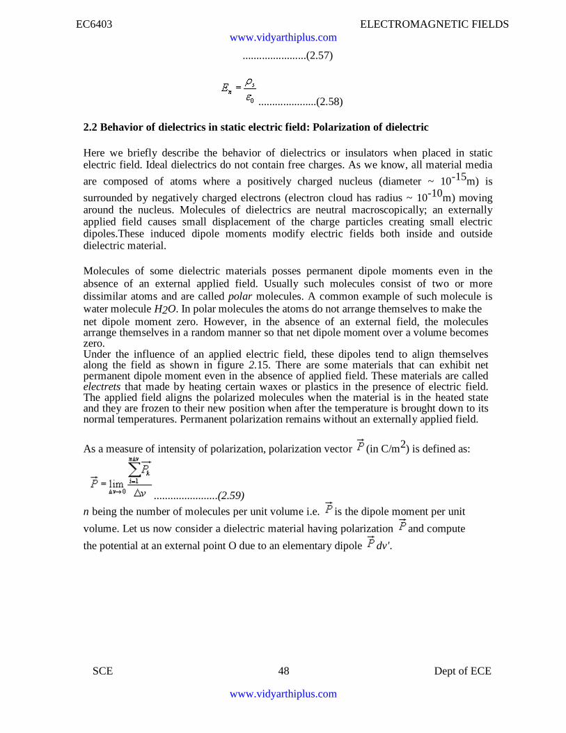
volume. Let us now consider a dielectric material having polarization and compute
the potential at an external point O due to an elementary dipole dv'.
www.vidyarthiplus.com
www.vidyarthiplus.com
EC6403 ELECTROMAGNETIC FIELDS
SCE 49 Dept of ECE
. ...................(2.61)
Fig 2.2: Potential at an External Point due to an Elementary Dipoledv'.
With reference to the figure 2.16, we can write:
..........................................(2.60)
Therefore,
where x,y,z represent the coordinates of the external point O and x',y',z' are thecoordinates of the source point.
From the expression of R, we can verify that
. .............................................(2.63)
....................................(2.64)
Using the vector identity, ,where f is a scalar quantity , we
have,
.....................(2.65)
www.vidyarthiplus.com
www.vidyarthiplus.com
EC6403 ELECTROMAGNETIC FIELDS
SCE 50 Dept of ECE
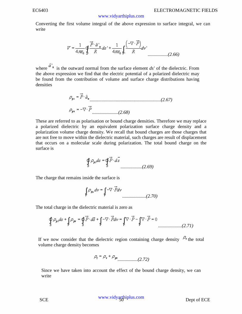
Converting the first volume integral of the above expression to surface integral, we canwrite
.................(2.66)
where is the outward normal from the surface element ds' of the dielectric. Fromthe above expression we find that the electric potential of a polarized dielectric maybe found from the contribution of volume and surface charge distributions havingdensities
............................................................(2.67)
......................(2.68)
These are referred to as polarisation or bound charge densities. Therefore we may replacea polarized dielectric by an equivalent polarization surface charge density and apolarization volume charge density. We recall that bound charges are those charges thatare not free to move within the dielectric material, such charges are result of displacementthat occurs on a molecular scale during polarization. The total bound charge on thesurface is
..................(2.69)
The charge that remains inside the surface is
....................(2.70)
The total charge in the dielectric material is zero as
....................(2.71)
If we now consider that the dielectric region containing charge density the totalvolume charge density becomes
.................(2.72)
Since we have taken into account the effect of the bound charge density, we canwrite
www.vidyarthiplus.com
www.vidyarthiplus.com
EC6403 ELECTROMAGNETIC FIELDS
SCE 51 Dept of ECE
....................(2.73)
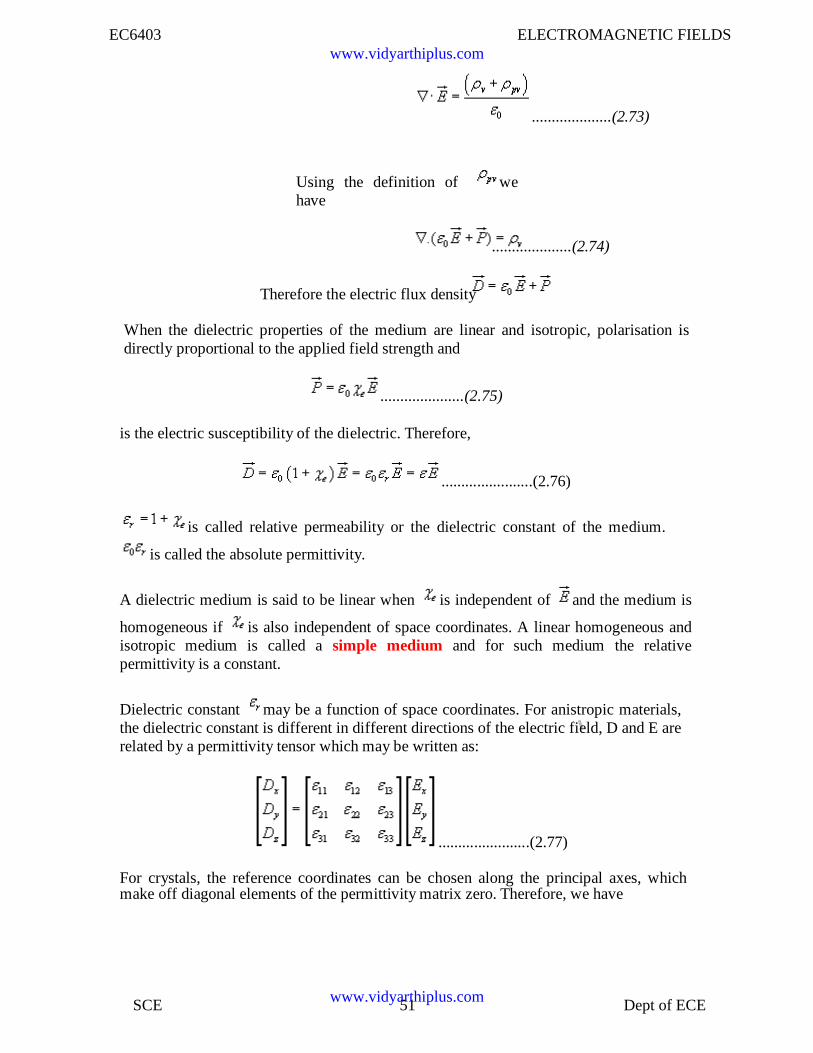
Using the definition of wehave
....................(2.74)
Therefore the electric flux density
When the dielectric properties of the medium are linear and isotropic, polarisation isdirectly proportional to the applied field strength and
.....................(2.75)
is the electric susceptibility of the dielectric. Therefore,
.......................(2.76)
is called relative permeability or the dielectric constant of the medium.
is called the absolute permittivity.
A dielectric medium is said to be linear when is independent of and the medium is
homogeneous if is also independent of space coordinates. A linear homogeneous andisotropic medium is called a simple medium and for such medium the relativepermittivity is a constant.
Dielectric constant may be a function of space coordinates. For anistropic materials,the dielectric constant is different in different directions of the electric field, D and E arerelated by a permittivity tensor which may be written as:
.......................(2.77)
For crystals, the reference coordinates can be chosen along the principal axes, whichmake off diagonal elements of the permittivity matrix zero. Therefore, we have
www.vidyarthiplus.com
www.vidyarthiplus.com
EC6403 ELECTROMAGNETIC FIELDS
SCE 52 Dept of ECE
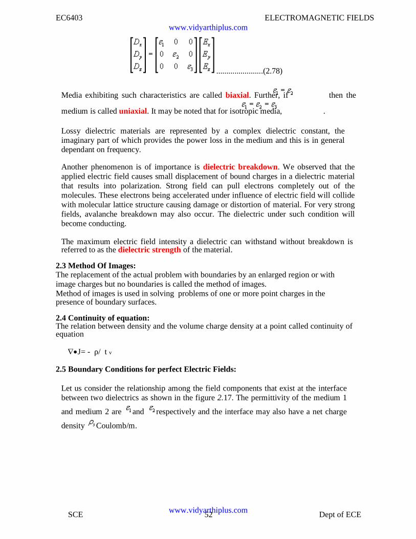
.......................(2.78)
Media exhibiting such characteristics are called biaxial. Further, if then the
medium is called uniaxial. It may be noted that for isotropic media, .
Lossy dielectric materials are represented by a complex dielectric constant, theimaginary part of which provides the power loss in the medium and this is in generaldependant on frequency.
Another phenomenon is of importance is dielectric breakdown. We observed that theapplied electric field causes small displacement of bound charges in a dielectric materialthat results into polarization. Strong field can pull electrons completely out of themolecules. These electrons being accelerated under influence of electric field will collidewith molecular lattice structure causing damage or distortion of material. For very strongfields, avalanche breakdown may also occur. The dielectric under such condition willbecome conducting.
The maximum electric field intensity a dielectric can withstand without breakdown isreferred to as the dielectric strength of the material.
2.3 Method Of Images:The replacement of the actual problem with boundaries by an enlarged region or withimage charges but no boundaries is called the method of images.Method of images is used in solving problems of one or more point charges in thepresence of boundary surfaces.
2.4 Continuity of equation:The relation between density and the volume charge density at a point called continuity ofequation
J= - ρ/ t v
2.5 Boundary Conditions for perfect Electric Fields:
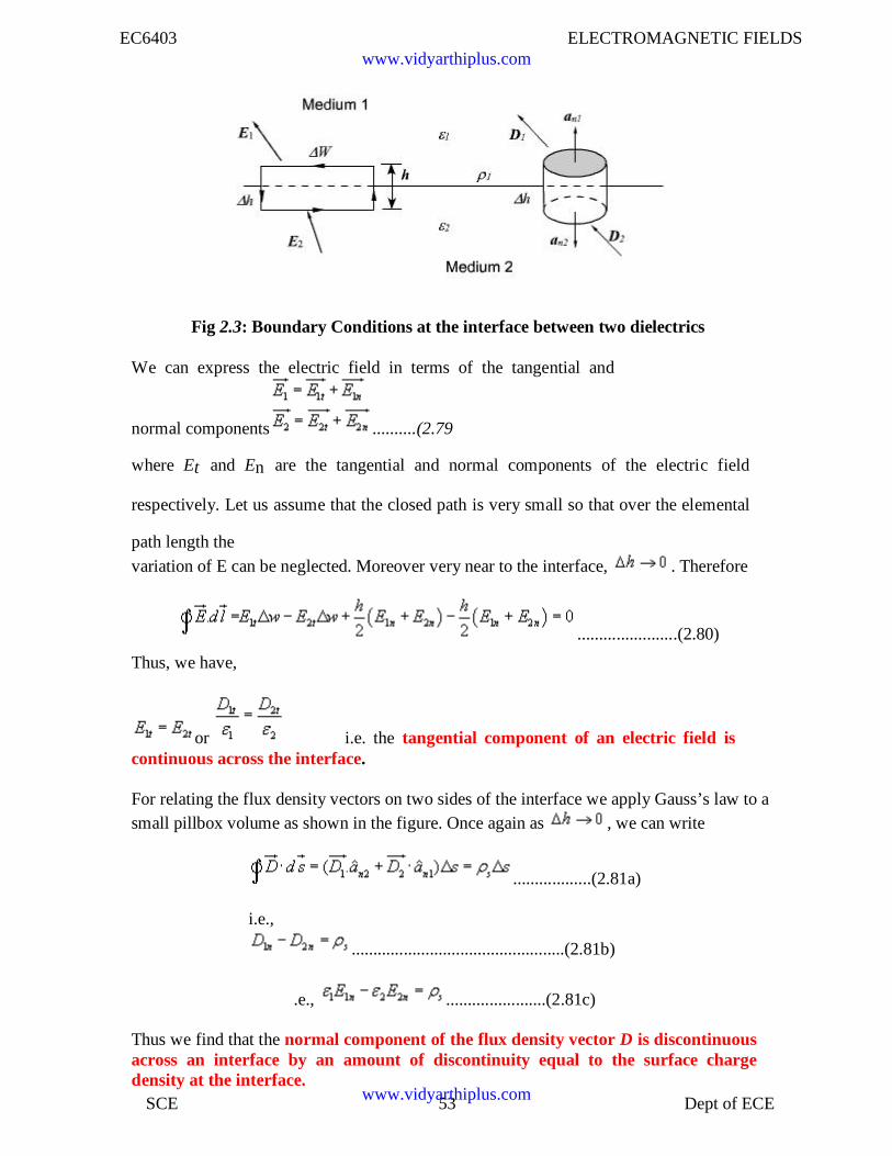
Let us consider the relationship among the field components that exist at the interfacebetween two dielectrics as shown in the figure 2.17. The permittivity of the medium 1
and medium 2 are and respectively and the interface may also have a net charge
density Coulomb/m.
www.vidyarthiplus.com
www.vidyarthiplus.com
EC6403 ELECTROMAGNETIC FIELDS
SCE 53 Dept of ECE
Fig 2.3: Boundary Conditions at the interface between two dielectrics
We can express the electric field in terms of the tangential and
normal components ..........(2.79
where Et and En are the tangential and normal components of the electric field
respectively. Let us assume that the closed path is very small so that over the elemental
path length thevariation of E can be neglected. Moreover very near to the interface, . Therefore
.......................(2.80)
Thus, we have,
or i.e. the tangential component of an electric field iscontinuous across the interface.
For relating the flux density vectors on two sides of the interface we apply Gauss’s law to asmall pillbox volume as shown in the figure. Once again as , we can write
..................(2.81a)
i.e.,
.................................................(2.81b)
.e., .......................(2.81c)
Thus we find that the normal component of the flux density vector D is discontinuousacross an interface by an amount of discontinuity equal to the surface chargedensity at the interface.
www.vidyarthiplus.com
www.vidyarthiplus.com
EC6403 ELECTROMAGNETIC FIELDS
SCE 54 Dept of ECE
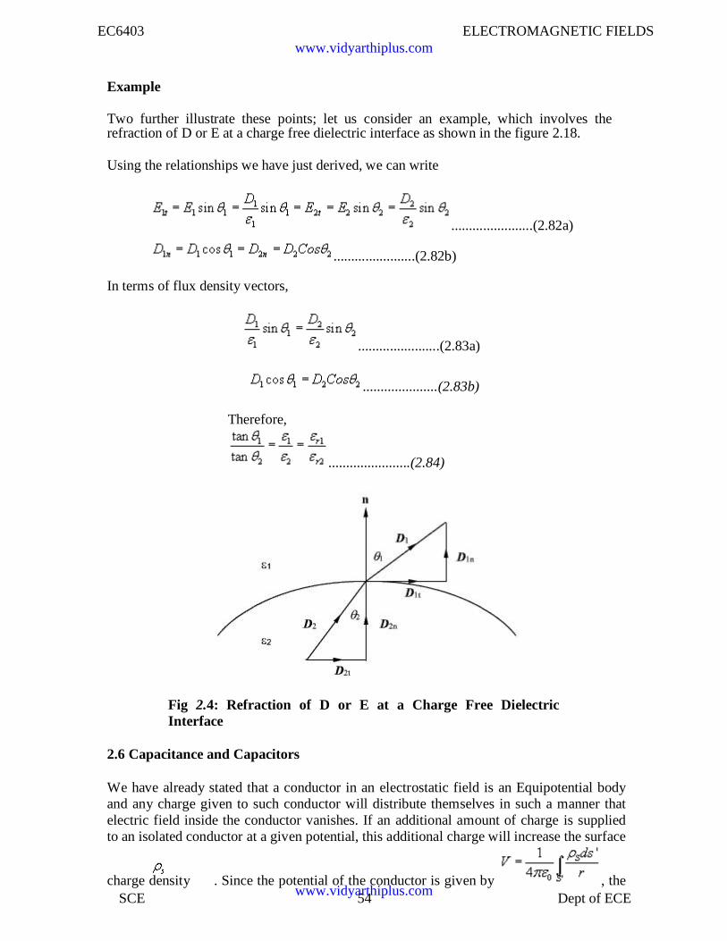
Example
Two further illustrate these points; let us consider an example, which involves therefraction of D or E at a charge free dielectric interface as shown in the figure 2.18.
Using the relationships we have just derived, we can write
.......................(2.82a)
.......................(2.82b)
In terms of flux density vectors,
.......................(2.83a)
.....................(2.83b)
Therefore,
.......................(2.84)
Fig 2.4: Refraction of D or E at a Charge Free DielectricInterface
2.6 Capacitance and Capacitors
We have already stated that a conductor in an electrostatic field is an Equipotential bodyand any charge given to such conductor will distribute themselves in such a manner thatelectric field inside the conductor vanishes. If an additional amount of charge is suppliedto an isolated conductor at a given potential, this additional charge will increase the surface
charge density . Since the potential of the conductor is given by , the
www.vidyarthiplus.com
www.vidyarthiplus.com
EC6403 ELECTROMAGNETIC FIELDS
SCE 55 Dept of ECE
potential
of the conductor will also increase maintaining the ratio same. Thus we can write
where the constant of proportionality C is called the capacitance of the isolated conductor.SIunit of capacitance is Coulomb/ Volt also called Farad denoted by F. It can It can be seenthat if V=1, C = Q. Thus capacity of an isolated conductor can also be defined as theamount of charge in Coulomb required to raise the potential of the conductor by 1 Volt.
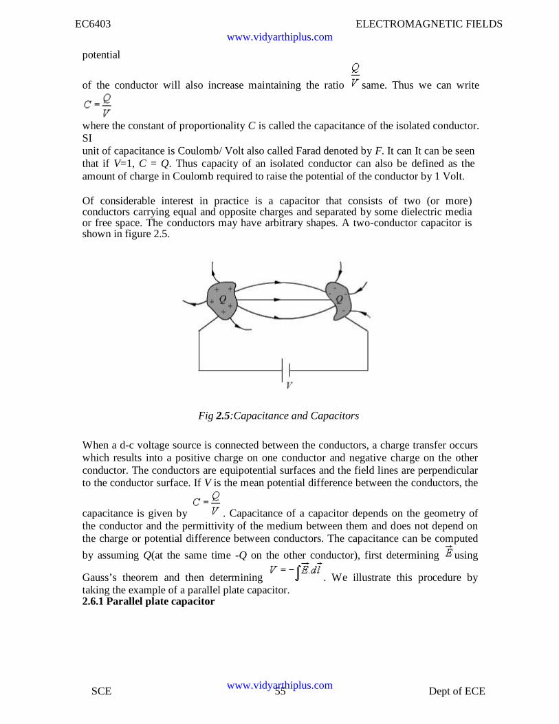
Of considerable interest in practice is a capacitor that consists of two (or more)conductors carrying equal and opposite charges and separated by some dielectric mediaor free space. The conductors may have arbitrary shapes. A two-conductor capacitor isshown in figure 2.5.
Fig 2.5:Capacitance and Capacitors
When a d-c voltage source is connected between the conductors, a charge transfer occurswhich results into a positive charge on one conductor and negative charge on the otherconductor. The conductors are equipotential surfaces and the field lines are perpendicularto the conductor surface. If V is the mean potential difference between the conductors, the
capacitance is given by . Capacitance of a capacitor depends on the geometry ofthe conductor and the permittivity of the medium between them and does not depend onthe charge or potential difference between conductors. The capacitance can be computed
by assuming Q(at the same time -Q on the other conductor), first determining using
Gauss’s theorem and then determining . We illustrate this procedure bytaking the example of a parallel plate capacitor.2.6.1 Parallel plate capacitor
www.vidyarthiplus.com
www.vidyarthiplus.com
EC6403 ELECTROMAGNETIC FIELDS
SCE 56 Dept of ECE
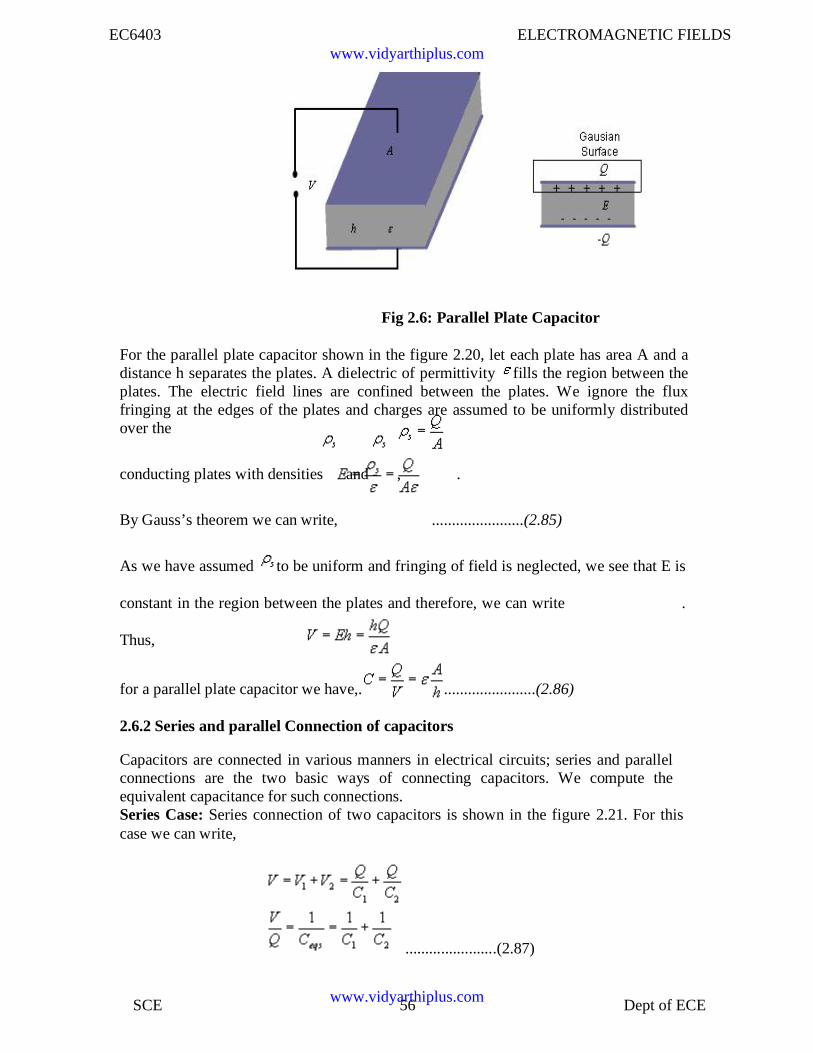
Fig 2.6: Parallel Plate Capacitor
For the parallel plate capacitor shown in the figure 2.20, let each plate has area A and adistance h separates the plates. A dielectric of permittivity fills the region between theplates. The electric field lines are confined between the plates. We ignore the fluxfringing at the edges of the plates and charges are assumed to be uniformly distributedover the
conducting plates with densities and - , .
By Gauss’s theorem we can write, .......................(2.85)
As we have assumed to be uniform and fringing of field is neglected, we see that E is
constant in the region between the plates and therefore, we can write .
Thus,
for a parallel plate capacitor we have,. .......................(2.86)
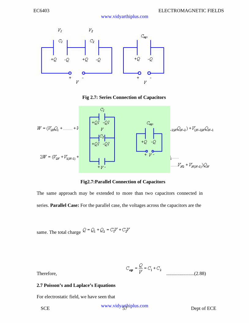
2.6.2 Series and parallel Connection of capacitors
Capacitors are connected in various manners in electrical circuits; series and parallelconnections are the two basic ways of connecting capacitors. We compute theequivalent capacitance for such connections.Series Case: Series connection of two capacitors is shown in the figure 2.21. For thiscase we can write,
.......................(2.87)
www.vidyarthiplus.com
www.vidyarthiplus.com
EC6403 ELECTROMAGNETIC FIELDS
SCE 57 Dept of ECE
Fig 2.7: Series Connection of Capacitors
Fig2.7:Parallel Connection of Capacitors
The same approach may be extended to more than two capacitors connected in
series. Parallel Case: For the parallel case, the voltages across the capacitors are the
same. The total charge
Therefore, .......................(2.88)
2.7 Poisson’s and Laplace’s Equations
For electrostatic field, we have seen that
www.vidyarthiplus.com
www.vidyarthiplus.com
EC6403 ELECTROMAGNETIC FIELDS
SCE 58 Dept of ECE
......................................................(2.97)
Form the above two equations we can write
..................................................................(2.98)
Using vector identity we can write, ...............(2.99)
For a simple homogeneous medium, is constant and . Therefore,
................(2.100)
This equation is known as Poisson’s equation. Here we have introduced a new
operator, ( del square), called the Laplacian operator. In Cartesian coordinates,
...............(2.101)
Therefore, in Cartesian coordinates, Poisson equation can be written as:
...............(2.102)
In cylindrical coordinates,
...............(2.103)
In spherical polar coordinate system,
...............(2.104)
At points in simple media, where no free charge is present, Poisson’s equation reduces to
...................................(2.105)
which is known as Laplace’s equation.2.8 Application of poisons and Laplace’s equations:
Laplace’s and Poisson’s equation are very useful for solving many practical electrostaticfield problems where only the electrostatic conditions (potential and charge) at some
www.vidyarthiplus.com
www.vidyarthiplus.com
EC6403 ELECTROMAGNETIC FIELDS
SCE 59 Dept of ECE
boundaries are known and solution of electric field and potential is to be found throughoutthe volume. We shall consider such applications in the section where we deal withboundary value problems.
ASSIGNMENT PROBLEMS
1. A charged ring of radius carrying a charge of C/m lies in the x-y plane with its
centre at the origin and a charge C is placed at the point Determine in
terms of and so that a test charge placed at does not experienceany force.
www.vidyarthiplus.com
www.vidyarthiplus.com
EC6403 ELECTROMAGNETIC FIELDS
SCE 60 Dept of ECE
2. A semicircular ring of radius lies in the free space and carries a charge densityC/m. Find the electric field at the centre of the semicircle.
3. Consider a uniform sphere of charge with charge density and radius b , centeredat the origin. Find the electric field at a distance r from the origin for the two cases:r<b and r>b . Sketch the strength of the electric filed as function of r .
4. A spherical charge distribution is given by
is the radius of the sphere. Find the following:
i. The total charge.
ii.
iii
.
for and .
The value of where
the
becomesmaximum.
5. With reference determine the potential and field at the point if the shaded
region contains uniform charge density /m2 .
6. A capacitor consists of two coaxial metallic cylinders of length , radius of theinner conductor and that of outer conductor . A dielectric material havingdielectric
constant , where is the radius, fills the space betweenthe conductors. Determine the capacitance of the capacitor.
7. Determine whether the functions given below satisfy Laplace 's equation
i)
ii)
www.vidyarthiplus.com
www.vidyarthiplus.com
EC6403 ELECTROMAGNETIC FIELDS
SCE 61 Dept of ECE
UNIT III MAGNETOSTATICS
3.1IntroductionIn previous chapters we have seen that an electrostatic field is produced by static or
stationary charges. The relationship of the steady magnetic field to its sources is muchmore complicated.
3.2 Laws governing magneto static fieldsThe source of steady magnetic field may be a permanent magnet, a direct current
or an electric field changing with time. In this chapter we shall mainly consider themagnetic field produced by a direct current. The magnetic field produced due to timevarying electric field will be discussed later. Historically, the link between the electricand magnetic field was established Oersted in 1820. Ampere and others extended theinvestigation of magnetic effect of electricity . There are two major laws governing themagnetostatic fields are:
Biot-Savart Law
Ampere's Law
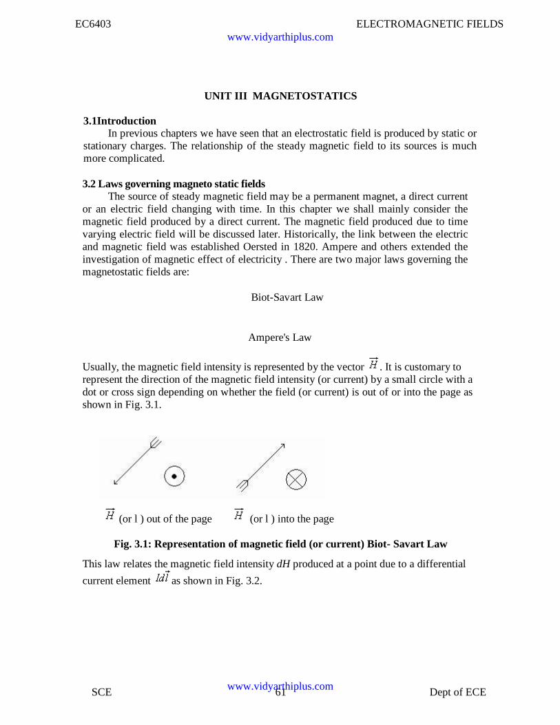
Usually, the magnetic field intensity is represented by the vector . It is customary torepresent the direction of the magnetic field intensity (or current) by a small circle with adot or cross sign depending on whether the field (or current) is out of or into the page asshown in Fig. 3.1.
(or l ) out of the page (or l ) into the page
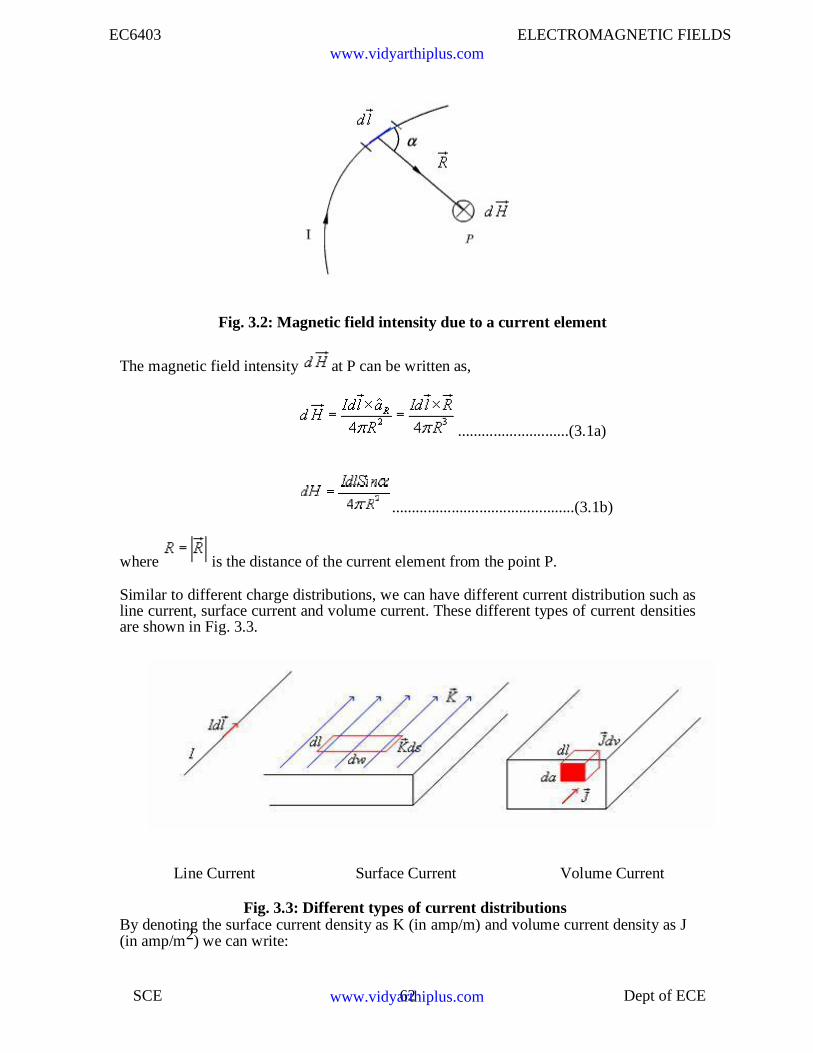
Fig. 3.1: Representation of magnetic field (or current) Biot- Savart Law
This law relates the magnetic field intensity dH produced at a point due to a differential
current element as shown in Fig. 3.2.
www.vidyarthiplus.com
www.vidyarthiplus.com
EC6403 ELECTROMAGNETIC FIELDS
SCE 62 Dept of ECE
Fig. 3.2: Magnetic field intensity due to a current element
The magnetic field intensity at P can be written as,
............................(3.1a)
..............................................(3.1b)
where is the distance of the current element from the point P.
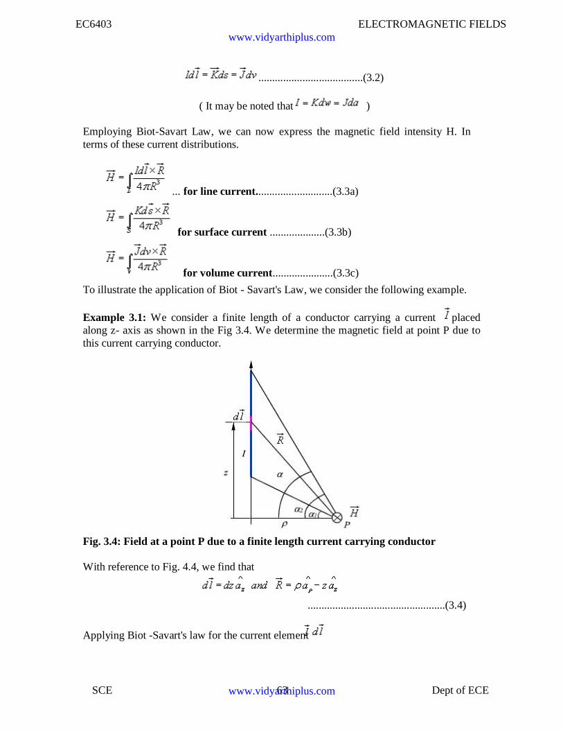
Similar to different charge distributions, we can have different current distribution such asline current, surface current and volume current. These different types of current densitiesare shown in Fig. 3.3.
Line Current Surface Current Volume Current
Fig. 3.3: Different types of current distributionsBy denoting the surface current density as K (in amp/m) and volume current density as J(in amp/m2) we can write:
www.vidyarthiplus.com
www.vidyarthiplus.com
EC6403 ELECTROMAGNETIC FIELDS
SCE 63 Dept of ECE
......................................(3.2)
( It may be noted that )
Employing Biot-Savart Law, we can now express the magnetic field intensity H. Interms of these current distributions.
... for line current............................(3.3a)
for surface current ....................(3.3b)
for volume current......................(3.3c)
To illustrate the application of Biot - Savart's Law, we consider the following example.
Example 3.1: We consider a finite length of a conductor carrying a current placedalong z- axis as shown in the Fig 3.4. We determine the magnetic field at point P due tothis current carrying conductor.
Fig. 3.4: Field at a point P due to a finite length current carrying conductor
With reference to Fig. 4.4, we find that
..................................................(3.4)
Applying Biot -Savart's law for the current element
www.vidyarthiplus.com
www.vidyarthiplus.com
EC6403 ELECTROMAGNETIC FIELDS
SCE 64 Dept of ECE
we can write,
.................(3.5)
Substituting we can write,
.........................(3.6)
We find that, for an infinitely long conductor carrying a current I , and
Therefore, .........................................................................................(3.7)
3.3 Ampere's Circuital Law:
Ampere's circuital law states that the line integral of the magnetic field (circulation of H) around a closed path is the net current enclosed by this path. Mathematically,
.....................................(3.8)
The total current I enc can be written as,
......................................(3.9)By applying Stoke's theorem, we can write
......................................(3.10)which is the Ampere's law in the point form.
3.3.1 Estimation of Magnetic field intensity for straight and circular conductors:
We illustrate the application of Ampere's Law with some examples.
We compute magnetic field due to an infinitely long thin current carrying conductoras shown in Fig. 4.5. Using Ampere's Law, we consider the close path to be a circleof radius as shown in the Fig. 4.5.
If we consider a small current element , is perpendicular to the plane
www.vidyarthiplus.com
www.vidyarthiplus.com
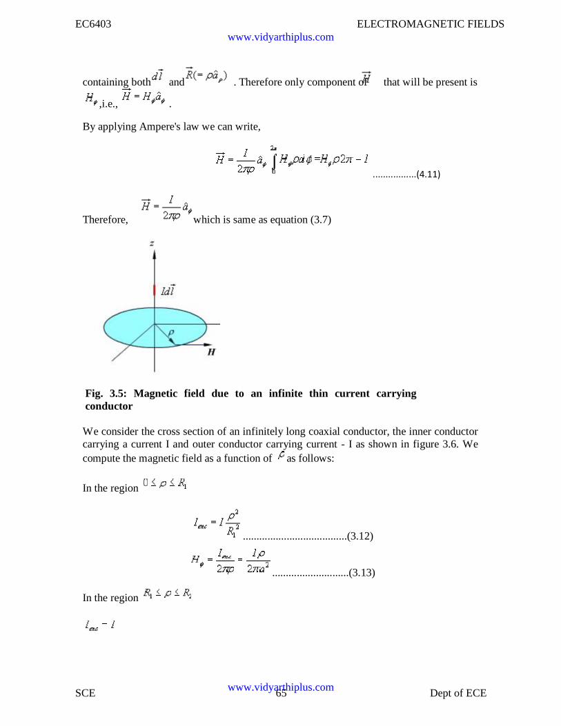
EC6403 ELECTROMAGNETIC FIELDS
SCE 65 Dept of ECE
containing both and . Therefore only component of that will be present is
,i.e., .
By applying Ampere's law we can write,
.................(4.11)
Therefore, which is same as equation (3.7)
Fig. 3.5: Magnetic field due to an infinite thin current carryingconductor
We consider the cross section of an infinitely long coaxial conductor, the inner conductorcarrying a current I and outer conductor carrying current - I as shown in figure 3.6. Wecompute the magnetic field as a function of as follows:
In the region
......................................(3.12)
............................(3.13)
In the region
www.vidyarthiplus.com
www.vidyarthiplus.com
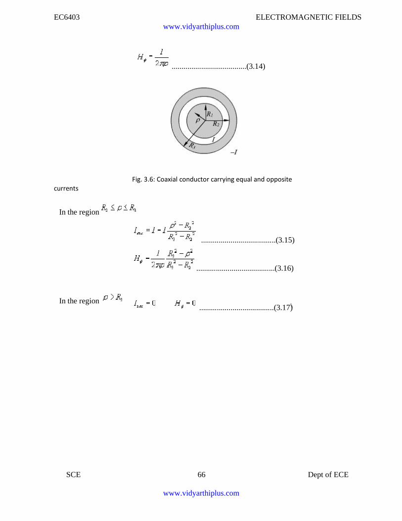
EC6403 ELECTROMAGNETIC FIELDS
SCE 66 Dept of ECE
......................................(3.14)
currents
In the region
In the region
Fig. 3.6: Coaxial conductor carrying equal and opposite
......................................(3.15)
........................................(3.16)
......................................(3.17)
www.vidyarthiplus.com
www.vidyarthiplus.com
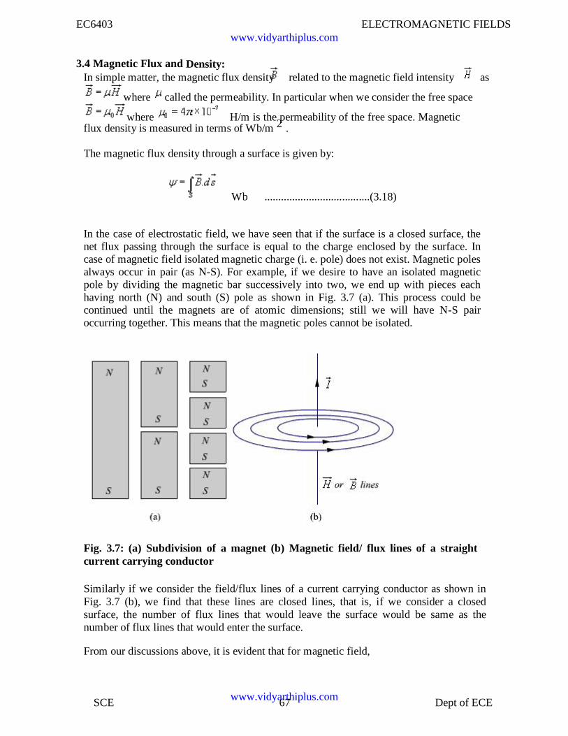
EC6403 ELECTROMAGNETIC FIELDS
SCE 67 Dept of ECE
3.4 Magnetic Flux and Density:In simple matter, the magnetic flux density related to the magnetic field intensity as
where called the permeability. In particular when we consider the free space
where H/m is the permeability of the free space. Magneticflux density is measured in terms of Wb/m 2 .
The magnetic flux density through a surface is given by:
Wb ......................................(3.18)
In the case of electrostatic field, we have seen that if the surface is a closed surface, thenet flux passing through the surface is equal to the charge enclosed by the surface. Incase of magnetic field isolated magnetic charge (i. e. pole) does not exist. Magnetic polesalways occur in pair (as N-S). For example, if we desire to have an isolated magneticpole by dividing the magnetic bar successively into two, we end up with pieces eachhaving north (N) and south (S) pole as shown in Fig. 3.7 (a). This process could becontinued until the magnets are of atomic dimensions; still we will have N-S pairoccurring together. This means that the magnetic poles cannot be isolated.
Fig. 3.7: (a) Subdivision of a magnet (b) Magnetic field/ flux lines of a straightcurrent carrying conductor
Similarly if we consider the field/flux lines of a current carrying conductor as shown inFig. 3.7 (b), we find that these lines are closed lines, that is, if we consider a closedsurface, the number of flux lines that would leave the surface would be same as thenumber of flux lines that would enter the surface.
From our discussions above, it is evident that for magnetic field,
www.vidyarthiplus.com
www.vidyarthiplus.com
EC6403 ELECTROMAGNETIC FIELDS
SCE 68 Dept of ECE
......................................(3.19)
which is the Gauss's law for the magnetic
field. By applying divergence theorem, we
can write:
Hence, ......................................(3.20)
which is the Gauss's law for the magnetic field in point form.
3.5 Magnetic Scalar and Vector Potentials:
In studying electric field problems, we introduced the concept of electric potential thatsimplified the computation of electric fields for certain types of problems. In the samemanner let us relate the magnetic field intensity to a scalar magnetic potential and write:
...................................(3.21)
From Ampere's law , we know that
......................................(3.22)
Therefore, ...........................(3.23)
But using vector identity, we find that is valid only where
. Thus the scalar magnetic potential is defined only in the region where .Moreover, Vm in general is not a single valued function of position.
This point can be illustrated as follows. Let us consider the cross section of a coaxial lineas shown in fig 3.8.
In the region , and
www.vidyarthiplus.com
www.vidyarthiplus.com
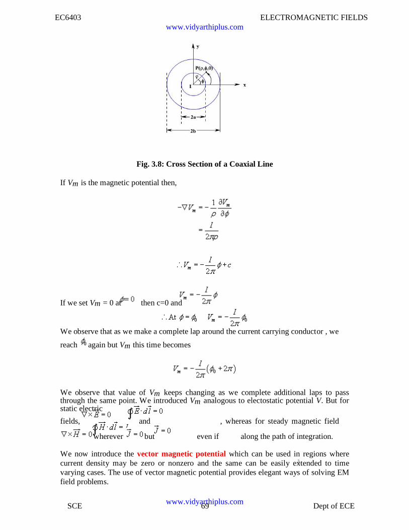
EC6403 ELECTROMAGNETIC FIELDS
SCE 69 Dept of ECE
Fig. 3.8: Cross Section of a Coaxial Line
If Vm is the magnetic potential then,
If we set Vm = 0 at then c=0 and
We observe that as we make a complete lap around the current carrying conductor , we
reach again but Vm this time becomes
We observe that value of Vm keeps changing as we complete additional laps to passthrough the same point. We introduced Vm analogous to electostatic potential V. But forstatic electric
fields, and , whereas for steady magnetic field
wherever but even if along the path of integration.
We now introduce the vector magnetic potential which can be used in regions wherecurrent density may be zero or nonzero and the same can be easily extended to timevarying cases. The use of vector magnetic potential provides elegant ways of solving EMfield problems.
www.vidyarthiplus.com
www.vidyarthiplus.com
EC6403 ELECTROMAGNETIC FIELDS
SCE 70 Dept of ECE
Since and we have the vector identity that for any vector , , we
can write .
Here, the vector field is called the vector magnetic potential. Its SI unit is Wb/m.
Thus if can find of a given current distribution, can be found from through a
curl operation.
We have introduced the vector function and related its curl to . A vector function is
defined fully in terms of its curl as well as divergence. The choice of is made asfollows.
...........................................(3.24)
By using vector identity,
.................................................(3.25)
.........................................(3.26)
Great deal of simplification can be achieved if we choose .
Putting , we get which is vector poissonequation.In Cartesian coordinates, the above equation can be written in terms of the componentsas
......................................(3.27a)
......................................(3.27b)
................................(3.27c)
The form of all the above equation is same as thatof
..........................................(3.28)
for which the solution is
..................(3.29)
www.vidyarthiplus.com
www.vidyarthiplus.com
EC6403 ELECTROMAGNETIC FIELDS
SCE 71 Dept of ECE
In case of time varying fields we shall see t`hat , which is known asLorentz condition, V being the electric potential. Here we are dealing with static
magnetic field, so .
By comparison, we can write the solution for Axas
...................................(3.30)
Computing similar solutions for other two components of the vector potential, thevector potential can be written as
.......................................(3.31)
This equation enables us to find the vector potential at a given point because of a v
olume current density . Similarly for line or surface current density we can write
...................................................(3.32)
respectively. ..............................(3.33)
The magnetic flux through a given area S is given by
Substituting
.............................................(3.34)
.........................................(3.35)
www.vidyarthiplus.com
www.vidyarthiplus.com
EC6403 ELECTROMAGNETIC FIELDS
SCE 72 Dept of ECE
Vector potential thus have the physical significance that its integral around any closedpath is equal to the magnetic flux passing through that path.
Boundary Condition for Magnetic Fields:
Similar to the boundary conditions in the electro static fields, here we will consider the
behavior of and at the interface of two different media. In particular, we determinehow the tangential and normal components of magnetic fields behave at the boundary oftwo regions having different permeabilities.
The figure 3.9 shows the interface between two media having permeabities and ,
being the normal vector from medium 2 to medium 1.
Figure 3.9: Interface between two magnetic media
To determine the condition for the normal component of the flux density vector , weconsider a small pill box P with vanishingly small thickness h and having an elementaryarea for the faces. Over the pill box, we can write
....................................................(3.36)
Since h --> 0, we can neglect the flux through the sidewall of the pill box.
...........................(3.37)
and ..................(3.38)
www.vidyarthiplus.com
www.vidyarthiplus.com
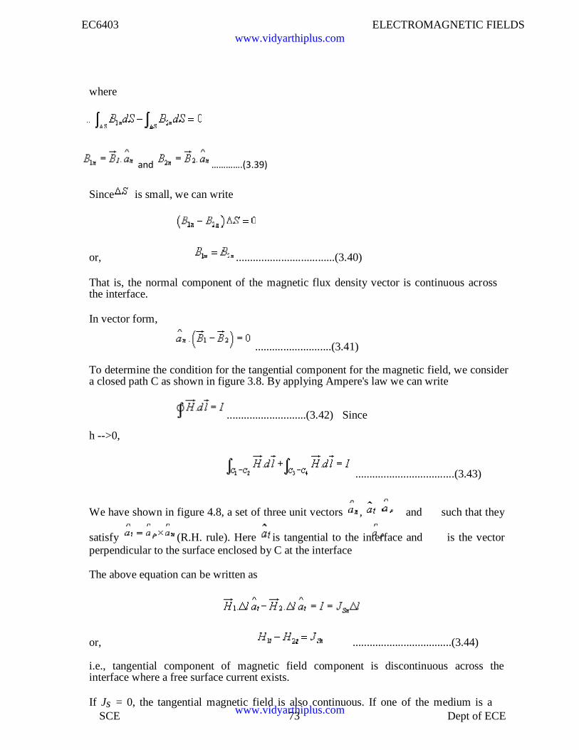
EC6403 ELECTROMAGNETIC FIELDS
SCE 73 Dept of ECE
where
and ………….(3.39)
Since is small, we can write
or, ...................................(3.40)
That is, the normal component of the magnetic flux density vector is continuous acrossthe interface.
In vector form,
...........................(3.41)
To determine the condition for the tangential component for the magnetic field, we considera closed path C as shown in figure 3.8. By applying Ampere's law we can write
............................(3.42) Since
h -->0,
...................................(3.43)
We have shown in figure 4.8, a set of three unit vectors , and such that they
satisfy (R.H. rule). Here is tangential to the interface and is the vectorperpendicular to the surface enclosed by C at the interface
The above equation can be written as
or, ...................................(3.44)
i.e., tangential component of magnetic field component is discontinuous across theinterface where a free surface current exists.
If Js = 0, the tangential magnetic field is also continuous. If one of the medium is a
www.vidyarthiplus.com
www.vidyarthiplus.com
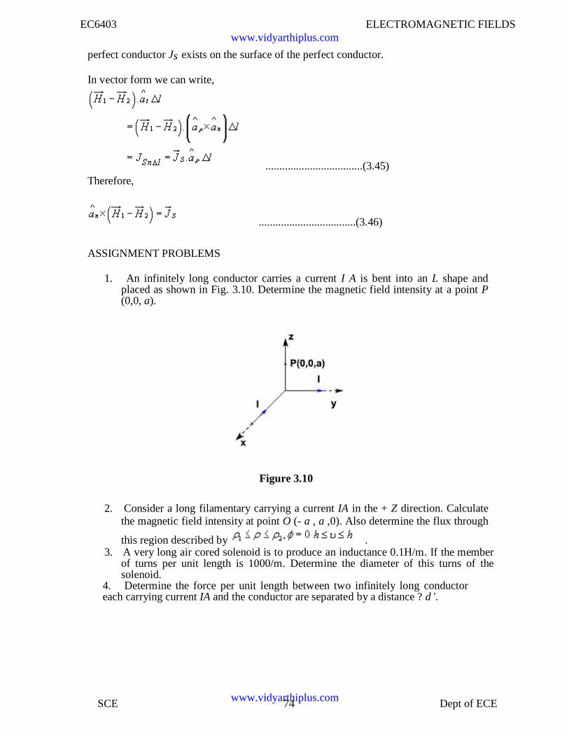
EC6403 ELECTROMAGNETIC FIELDS
SCE 74 Dept of ECE
perfect conductor Js exists on the surface of the perfect conductor.
In vector form we can write,
...................................(3.45)Therefore,
...................................(3.46)
ASSIGNMENT PROBLEMS
1. An infinitely long conductor carries a current I A is bent into an L shape andplaced as shown in Fig. 3.10. Determine the magnetic field intensity at a point P(0,0, a).
Figure 3.10
2. Consider a long filamentary carrying a current IA in the + Z direction. Calculatethe magnetic field intensity at point O (- a , a ,0). Also determine the flux through
this region described by .3. A very long air cored solenoid is to produce an inductance 0.1H/m. If the member
of turns per unit length is 1000/m. Determine the diameter of this turns of thesolenoid.
4. Determine the force per unit length between two infinitely long conductoreach carrying current IA and the conductor are separated by a distance ? d '.
www.vidyarthiplus.com
www.vidyarthiplus.com
EC6403 ELECTROMAGNETIC FIELDS
SCE 75 Dept of ECE
UNIT IV MAGNETIC FORCES AND MATERIALS
4.1: Force On A Moving Charge:
In electric field, force on a charged particle is
F=QE
Force is in the same direction as the electric field intensity(positive charge)
A charged particle in motion in a magnetic field force magnitude is proportional to theproduct of magnitudes of the charge Q, its velocity V and the flux density B and to the sineof the angle between the vectors V and B.
The direction of force is perpendicular to both V and B and is given by a unit vector in thedirection of V x B.
The force may therefore be expressed as
F=QV x B
Force on a moving particle due to combined electric and magnetic fields is obtained bysuperposition.
F=Q (E + V x B)
This equation is known as Lorentz force equation.
4.2 Force On A Differential Current Element:
The force on a charged particle moving through a steady magnetic field may be written asthe differential; force exerted on a differential element of charge.
dF dQ
Convection current density in terms of the velocity of the volume charge density
Differential element of charge may also be expressed in terms of volume charge density.
Thus,dQ v dv
dF v dvVxB
www.vidyarthiplus.com
www.vidyarthiplus.com
EC6403 ELECTROMAGNETIC FIELDS
SCE 76 Dept of ECE
dFJxBdv
JdV is the differential current element
Jdv Kds IdL
Lorentz force equation may be applied to surface current density.
dFKxBds
Differential current element
dF IdLxB
Integrating the above equations over a volume, surface open or closed
Fvol
JxBdv
FKxBds
sTo a straight conductor in a uniform magnetic field
F= IdLxB
I BxdL
F ILxB
The magnitude of the force is given by the familiar equation
F=BILsin
www.vidyarthiplus.com
www.vidyarthiplus.com
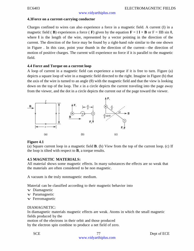
EC6403 ELECTROMAGNETIC FIELDS
SCE 77 Dept of ECE
4.3Force on a current-carrying conductor
Charges confined to wires can also experience a force in a magnetic field. A current (I) in amagnetic field ( B) experiences a force ( F) given by the equation F = I l × B or F = IlB sin θ,where l is the length of the wire, represented by a vector pointing in the direction of thecurrent. The direction of the force may be found by a right‐hand rule similar to the one shownin Figure . In this case, point your thumb in the direction of the current—the direction ofmotion of positive charges. The current will experience no force if it is parallel to the magneticfield.
4.4 Force and Torque on a current loopA loop of current in a magnetic field can experience a torque if it is free to turn. Figure (a)depicts a square loop of wire in a magnetic field directed to the right. Imagine in Figure (b) thatthe axis of the wire is turned to an angle (θ) with the magnetic field and that the view is lookingdown on the top of the loop. The x in a circle depicts the current traveling into the page awayfrom the viewer, and the dot in a circle depicts the current out of the page toward the viewer.
Figure 4.1(a) Square current loop in a magnetic field B. (b) View from the top of the current loop. (c) Ifthe loop is tilted with respect to B, a torque results.
4.5 MAGNETIC MATERIALS:All material shows some magnetic effects. In many substances the effects are so weak thatthe materials are often considered to be non magnetic.
A vacuum is the truly nonmagnetic medium.
Material can be classified according to their magnetic behavior intov Diamagneticv Paramagneticv Ferromagnetic
DIAMAGNETIC:In diamagnetic materials magnetic effects are weak. Atoms in which the small magneticfields produced by themotion of the electrons in their orbit and those producedby the electron spin combine to produce a net field of zero.
www.vidyarthiplus.com
www.vidyarthiplus.com
EC6403 ELECTROMAGNETIC FIELDS
SCE 78 Dept of ECE
The fields produced by the electron motion itself in the absence of any external magneticfield.
This material as one in which the permanent magnetic moment m0 of each atom is zero.Such a material is termed diamagnetic.
PARAMAGNETIC:
In paramagnetic materials the magnetic moments of adjacent atoms align in oppositedirections so that the net magnetic moment of a specimen is nil even in the presence ofapplied field.
FERROMAGNETIC:
In ferromagnetic substance the magnetic moments of adjacent atoms are also alignedopposite, but the moments are not equal, so there is a net magnetic moment.
It is less than in ferromagnetic materials.
The ferrites have a low electrical conductivity, which makes them useful in the cores of acinductors and transformers.
Since induced currents are less and ohmic losses are reduced.
4.6 BOUNDARY CONDITIONS:
A boundary between two isotropic homogeneous linearmaterials with permeability 1 and 2.
The boundary condition on the normal components is determined by allowing the surface tocut a small cylindrical gaussian surface.
Applying gauss' s law for the magnetic field.
We find that
B.ds 0
s
BN 1 S BN 2 S 0
BN 1 BN 2
1
2
H N1
H N 2
www.vidyarthiplus.com
www.vidyarthiplus.com
EC6403 ELECTROMAGNETIC FIELDS
SCE 79 Dept of ECE
The normal component of B is continuous, but the normal componentof H is discontinuous by the ratio
1.2
www.vidyarthiplus.com
www.vidyarthiplus.com
EC6403 ELECTROMAGNETIC FIELDS
SCE 80 Dept of ECE
The relationship between the normal components of M,is fixed once the relationship betweenthe normal components of H is known .
For linear magnetic materials, the result is written simply asM N 2Next, Ampere' s circuital law
H .dL I
Is applied about a small closed path in a plane normal to the boundary surface.
Taking trip around the path, we find that
Ht1 L Ht 2 L K L
Boundary may carry a surface current K whose component normal to the plane of the closedpath is K.Thus
Ht1 Ht 2 K
The direction are specified more exactly by using the cross product to identify the tangentialcomponents,
(H1 H2 )xaN 12 K
Where aN12 is the normal at the boundary directed from region 1 to region 2.
An equivalent formulation in term of the vector tangential components may be moreconvenient for H:
Ht1 Ht2
K x aN 12
For tangential B, we have
Bt1
1
Bt 2 K2
4.7 INDUCTANCE:4.7.1 self inductance and mutual inductance:Like capacitance, inductance L is a property of a physical arrangement of conduc- tors.It is a measure of magnetic flux which links the circuit when a current I flows in thecircuit. It is also a measure of how much energy is stored in the magnetic field of aninductor, such as a coil, solenoid, etc.
The definition of inductance rests on the concept of flux linkage. It is not a veryprecise concept unless one is willing to introduce a complicated topological description.For our purposes it will be sufficient to define flux linkage A as the flux that links all
www.vidyarthiplus.com
www.vidyarthiplus.com
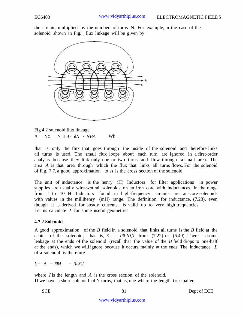
EC6403 ELECTROMAGNETIC FIELDS
SCE 81 Dept of ECE
the circuit, multiplied by the number of turns N. For example, in the case of thesolenoid shown in Fig. , flux linkage will be given by
Fig 4.2 solenoid flux linkageA = N¢ = N JJ B· dA ~ NBA Wb
that is, only the flux that goes through the inside of the solenoid and therefore linksall turns is used. The small flux loops about each turn are ignored in a first-orderanalysis because they link only one or two turns and flow through a small area. Thearea A is that area through which the flux that links all turns flows. For the solenoidof Fig. 7.7, a good approximation to A is the cross section of the solenoid
The unit of inductance is the henry (H). Inductors for filter applications in powersupplies are usually wire-wound solenoids on an iron core with inductances in the rangefrom 1 to 10 H. Inductors found in high-frequency circuits are air-core solenoidswith values in the millihenry (mH) range. The definition for inductance, (7.28), eventhough it is derived for steady currents, is valid up to very high frequencies.Let us calculate L for some useful geometries.
4.7.2 Solenoid
A good approximation of the B field in a solenoid that links all turns is the B field at thecenter of the solenoid; that is, B = J10 Ni]l from (7.22) or (6.40). There is someleakage at the ends of the solenoid (recall that the value of the B field drops to one-halfat the ends), which we will ignore because it occurs mainly at the ends. The inductance Lof a solenoid is therefore
L= A = NBA = J1oN2A
where I is the length and A is the cross section of the solenoid.If we have a short solenoid of N turns, that is, one where the length I is smaller
www.vidyarthiplus.com
www.vidyarthiplus.com
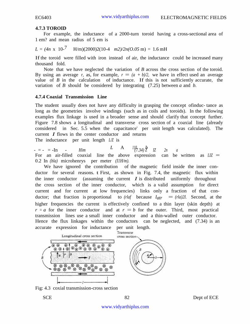
EC6403 ELECTROMAGNETIC FIELDS
SCE 82 Dept of ECE
4.7.3 TOROIDFor example, the inductance of a 2000-turn toroid having a cross-sectional area of
1 em? and mean radius of 5 em is
L = (4n x 10-7 H/m)(2000)2(10-4 m2)/2n(O.05 m) = 1.6 mH
If the toroid were filled with iron instead of air, the inductance could be increased manythousand fold.
Note that we have neglected the variation of B across the cross section of the toroid.By using an average r, as, for example, r = (a + b)/2, we have in effect used an averagevalue of B in the calculation of inductance. If this is not sufficiently accurate, thevariation of B should be considered by integrating (7.25) between a and b.
4.7.4 Coaxial Transmission Line
The student usually does not have any difficulty in grasping the concept ofinduc- tance aslong as the geometries involve windings (such as in coils and toroids). In the followingexamples flux linkage is used in a broader sense and should clarify that concept further.Figure 7.8 shows a longitudinal and transverse cross section of a coaxial line (alreadyconsidered in Sec. 5.5 when the capacitance' per unit length was calculated). Thecurrent I flows in the center conductor and returnsThe inductance per unit length L/Z is
L A 110 b- = - = -In - Him (7.34) Z IZ 2n aFor an air-filled coaxial line the above expression can be written as LIZ =0.2 In (bla) microhenrys per meter (I1H/m).
We have ignored the contribution of the magnetic field inside the inner con-ductor for several reasons. t First, as shown in Fig. 7.4, the magnetic flux withinthe inner conductor (assuming the current I is distributed uniformly throughoutthe cross section of the inner conductor, which is a valid assumption for directcurrent and for current at low frequencies) links only a fraction of that con-ductor; that fraction is proportional to (rlaf because Iatr = (rla)2I. Second, at the
higher frequencies the current is effectively confined to a thin layer (skin depth) atr = a for the inner conductor and at r = b for the outer. Third, most practicaltransmission lines use a small inner conductor and a thin-walled outer conductor.Hence the flux linkages within the conductors can be neglected, and (7.34) is anaccurate expression for inductance per unit length.
Fig: 4.3 coxial transmission-cross section
www.vidyarthiplus.com
www.vidyarthiplus.com
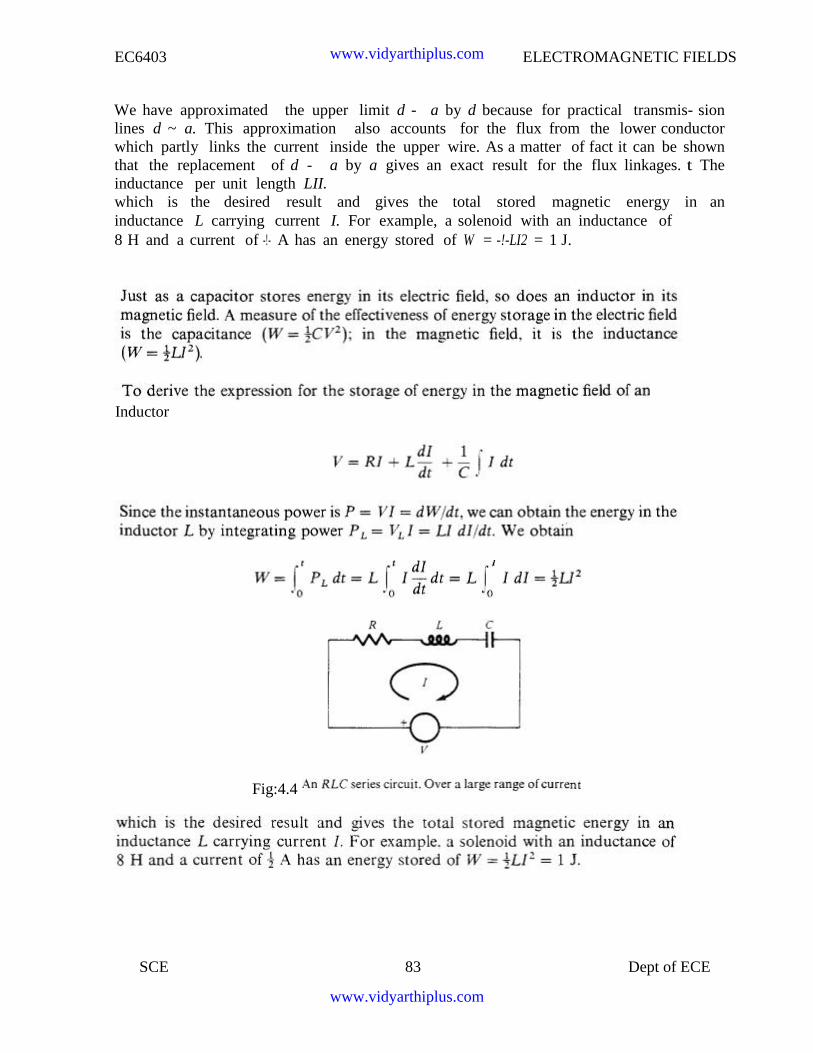
EC6403 ELECTROMAGNETIC FIELDS
SCE 83 Dept of ECE
We have approximated the upper limit d - a by d because for practical transmis- sionlines d ~ a. This approximation also accounts for the flux from the lower conductorwhich partly links the current inside the upper wire. As a matter of fact it can be shownthat the replacement of d - a by a gives an exact result for the flux linkages. t Theinductance per unit length LII.which is the desired result and gives the total stored magnetic energy in aninductance L carrying current I. For example, a solenoid with an inductance of8 H and a current of -!- A has an energy stored of W = -!-LI2 = 1 J.
Inductor
Fig:4.4
www.vidyarthiplus.com
www.vidyarthiplus.com
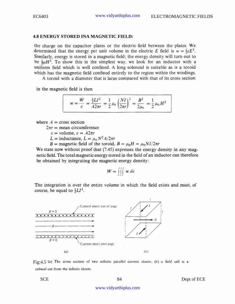
EC6403 ELECTROMAGNETIC FIELDS
SCE 84 Dept of ECE
4.8 ENERGY STORED INA MAGNETIC FIELD:
Fig:4.5
www.vidyarthiplus.com
www.vidyarthiplus.com
EC6403 ELECTROMAGNETIC FIELDS
SCE 85 Dept of ECE
UNIT V TIME VARYING FIELDS AND MAXWELL’S EQUATIONS
5.1 Introduction:
In our study of static fields so far, we have observed that static electric fields are producedby electric charges, static magnetic fields are produced by charges in motion or by steadycurrent. Further, static electric field is a conservative field and has no curl, the staticmagnetic field is continuous and its divergence is zero. The fundamental relationships forstatic electric fields among the field quantities can be summarized as:
(5.1a)
(5.1b)
For a linear and isotropic medium,
(5.1c)
Similarly for the magnetostatic case
(5.2a)
(5.2b)
(5.2c)
It can be seen that for static case, the electric field vectors and and magnetic field
vectors and form separate pairs.
In this chapter we will consider the time varying scenario. In the time varying case wewill observe that a changing magnetic field will produce a changing electric field andvice versa.
We begin our discussion with Faraday's Law of electromagnetic induction and thenpresent the Maxwell's equations which form the foundation for the electromagnetictheory.
5.2 Faraday's Law of electromagnetic Induction
Michael Faraday, in 1831 discovered experimentally that a current was induced in aconducting loop when the magnetic flux linking the loop changed. In terms of fields, wecan say that a time varying magnetic field produces an electromotive force (emf) whichcauses a current in a closed circuit. The quantitative relation between the induced emf(the voltage that arises from conductors moving in a magnetic field or from changingmagnetic fields) and the rate of change of flux linkage developed based on experimentalobservation is known as Faraday's law. Mathematically, the induced emf can be writtenas
www.vidyarthiplus.com
www.vidyarthiplus.com
EC6403 ELECTROMAGNETIC FIELDS
SCE 86 Dept of ECE
Emf = Volts (5.3)
where is the flux linkage over the closed path.
A non zero may result due to any of the following: (a) time changing flux linkage a
stationary closed path.
(b) relative motion between a steady flux a closed path.
(c) a combination of the above two cases.
The negative sign in equation (5.3) was introduced by Lenz in order to comply with thepolarity of the induced emf. The negative sign implies that the induced emf will cause acurrent flow in the closed loop in such a direction so as to oppose the change in thelinking magnetic flux which produces it. (It may be noted that as far as the induced emfis concerned, the closed path forming a loop does not necessarily have to beconductive).
If the closed path is in the form of N tightly wound turns of a coil, the change in themagnetic flux linking the coil induces an emf in each turn of the coil and total emf is thesum of the induced emfs of the individual turns, i.e.,
Emf = Volts (5.4)
By defining the total flux linkage as
(5.5)
The emf can be written as
Emf = (5.6)
Continuing with equation (5.3), over a closed contour 'C' we canwrite
Emf = (5.7)
www.vidyarthiplus.com
www.vidyarthiplus.com
EC6403 ELECTROMAGNETIC FIELDS
SCE 87 Dept of ECE
where is the induced electric field on the conductor to sustain the
current. Further, total flux enclosed by the contour 'C ' is given by
(5.8)
Where S is the surface for which 'C' is the contour.
From (5.7) and using (5.8) in (5.3) we can write
(5.9)
By applying stokes theorem
(5.10)
Therefore, we can write
(5.11)
which is the Faraday's law in the point form
We have said that non zero can be produced in a several ways. One particular case iswhen a time varying flux linking a stationary closed path induces an emf. The emfinduced in a stationary closed path by a time varying magnetic field is called atransformer emf .
5.3 Ideal transformers
As shown in figure 5.1, a transformer consists of two or more numbers of coils coupledmagnetically through a common core. Let us consider an ideal transformer whosewinding has zero resistance, the core having infinite permittivity and magnetic lossesare zero.
www.vidyarthiplus.com
www.vidyarthiplus.com
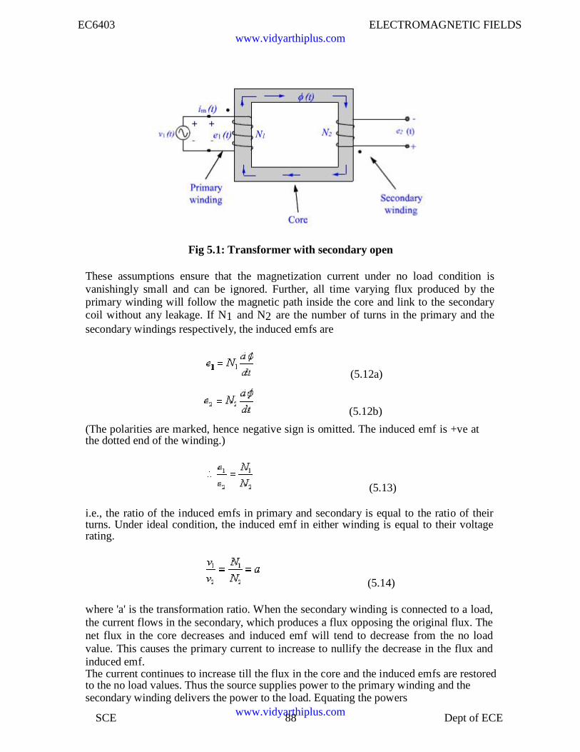
EC6403 ELECTROMAGNETIC FIELDS
SCE 88 Dept of ECE
Fig 5.1: Transformer with secondary open
These assumptions ensure that the magnetization current under no load condition isvanishingly small and can be ignored. Further, all time varying flux produced by theprimary winding will follow the magnetic path inside the core and link to the secondarycoil without any leakage. If N1 and N2 are the number of turns in the primary and thesecondary windings respectively, the induced emfs are
(5.12a)
(5.12b)
(The polarities are marked, hence negative sign is omitted. The induced emf is +ve atthe dotted end of the winding.)
(5.13)
i.e., the ratio of the induced emfs in primary and secondary is equal to the ratio of theirturns. Under ideal condition, the induced emf in either winding is equal to their voltagerating.
(5.14)
where 'a' is the transformation ratio. When the secondary winding is connected to a load,the current flows in the secondary, which produces a flux opposing the original flux. Thenet flux in the core decreases and induced emf will tend to decrease from the no loadvalue. This causes the primary current to increase to nullify the decrease in the flux andinduced emf.The current continues to increase till the flux in the core and the induced emfs are restoredto the no load values. Thus the source supplies power to the primary winding and thesecondary winding delivers the power to the load. Equating the powers
www.vidyarthiplus.com
www.vidyarthiplus.com
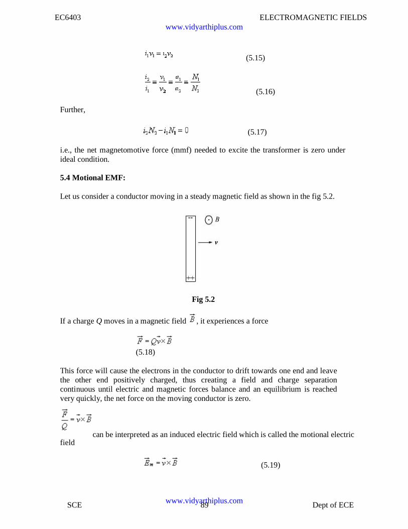
EC6403 ELECTROMAGNETIC FIELDS
SCE 89 Dept of ECE
(5.15)
(5.16)
Further,
(5.17)
i.e., the net magnetomotive force (mmf) needed to excite the transformer is zero underideal condition.
5.4 Motional EMF:
Let us consider a conductor moving in a steady magnetic field as shown in the fig 5.2.
Fig 5.2
If a charge Q moves in a magnetic field , it experiences a force
(5.18)
This force will cause the electrons in the conductor to drift towards one end and leavethe other end positively charged, thus creating a field and charge separationcontinuous until electric and magnetic forces balance and an equilibrium is reachedvery quickly, the net force on the moving conductor is zero.
fieldcan be interpreted as an induced electric field which is called the motional electric
(5.19)
www.vidyarthiplus.com
www.vidyarthiplus.com
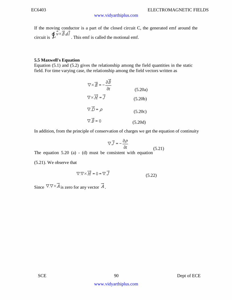
EC6403 ELECTROMAGNETIC FIELDS
SCE 90 Dept of ECE
If the moving conductor is a part of the closed circuit C, the generated emf around the
circuit is . This emf is called the motional emf.
5.5 Maxwell's EquationEquation (5.1) and (5.2) gives the relationship among the field quantities in the staticfield. For time varying case, the relationship among the field vectors written as
(5.20a)
(5.20b)
(5.20c)
(5.20d)
In addition, from the principle of conservation of charges we get the equation of continuity
The equation 5.20 (a) - (d) must be consistent with equation
(5.21). We observe that
(5.21)
Since is zero for any vector .
(5.22)
www.vidyarthiplus.com
www.vidyarthiplus.com
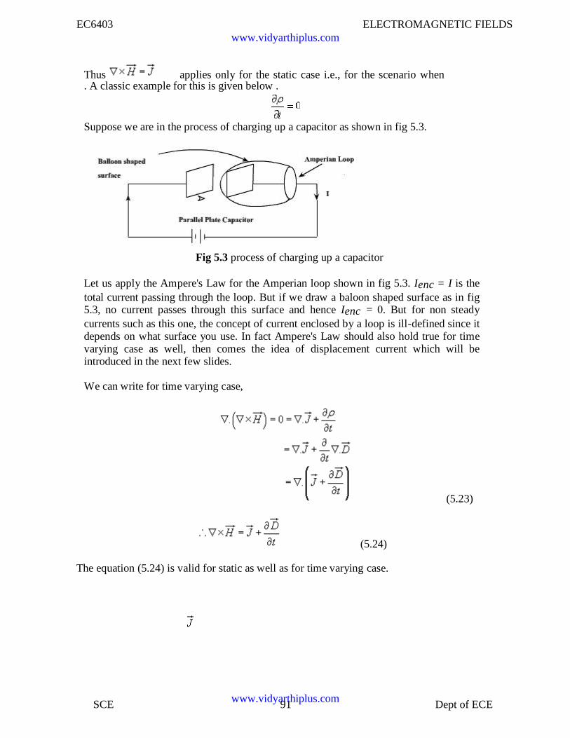
EC6403 ELECTROMAGNETIC FIELDS
SCE 91 Dept of ECE
Thus applies only for the static case i.e., for the scenario when. A classic example for this is given below .
Suppose we are in the process of charging up a capacitor as shown in fig 5.3.
Fig 5.3 process of charging up a capacitor
Let us apply the Ampere's Law for the Amperian loop shown in fig 5.3. Ienc = I is thetotal current passing through the loop. But if we draw a baloon shaped surface as in fig5.3, no current passes through this surface and hence Ienc = 0. But for non steadycurrents such as this one, the concept of current enclosed by a loop is ill-defined since itdepends on what surface you use. In fact Ampere's Law should also hold true for timevarying case as well, then comes the idea of displacement current which will beintroduced in the next few slides.
We can write for time varying case,
(5.24)
The equation (5.24) is valid for static as well as for time varying case.
(5.23)
www.vidyarthiplus.com
www.vidyarthiplus.com
EC6403 ELECTROMAGNETIC FIELDS
Equation (5.24) indicates that a time varying electric field will give rise to a magnetic
field even in the absence of . The term has a dimension of current densitiesand is called the displacement current density.
Introduction of in equation is one of the major contributions of Jame's ClerkMaxwell. The modified set of equations
(5.25b)
(5.25c)
(5.25d)
is known as the Maxwell's equation and this set of equations apply in the time
varying scenario, static fields are being a particular case .
In the integral form
(5.26d)
(5.26a)
(5.26b)
(5.26c)
www.vidyarthiplus.com
www.vidyarthiplus.com
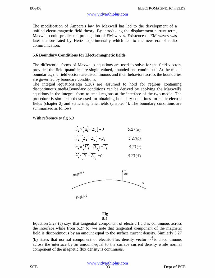
EC6403 ELECTROMAGNETIC FIELDS
SCE 93 Dept of ECE
The modification of Ampere's law by Maxwell has led to the development of aunified electromagnetic field theory. By introducing the displacement current term,Maxwell could predict the propagation of EM waves. Existence of EM waves waslater demonstrated by Hertz experimentally which led to the new era of radiocommunication.
5.6 Boundary Conditions for Electromagnetic fields
The differential forms of Maxwell's equations are used to solve for the field v ectorsprovided the field quantities are single valued, bounded and continuous. At the mediaboundaries, the field vectors are discontinuous and their behaviors across the boundariesare governed by boundary conditions.The integral equations(eqn 5.26) are assumed to hold for regions containingdiscontinuous media.Boundary conditions can be derived by applying the Maxwell'sequations in the integral form to small regions at the interface of the two media. Theprocedure is similar to those used for obtaining boundary conditions for static electricfields (chapter 2) and static magnetic fields (chapter 4). The boundary conditions aresummarized as follows
With reference to fig 5.3
Fig5.4
Equation 5.27 (a) says that tangential component of electric field is continuous acrossthe interface while from 5.27 (c) we note that tangential component of the magneticfield is discontinuous by an amount equal to the surface current density. Similarly 5.27
(b) states that normal component of electric flux density vector is discontinuousacross the interface by an amount equal to the surface current density while normalcomponent of the magnetic flux density is continuous.
www.vidyarthiplus.com
www.vidyarthiplus.com
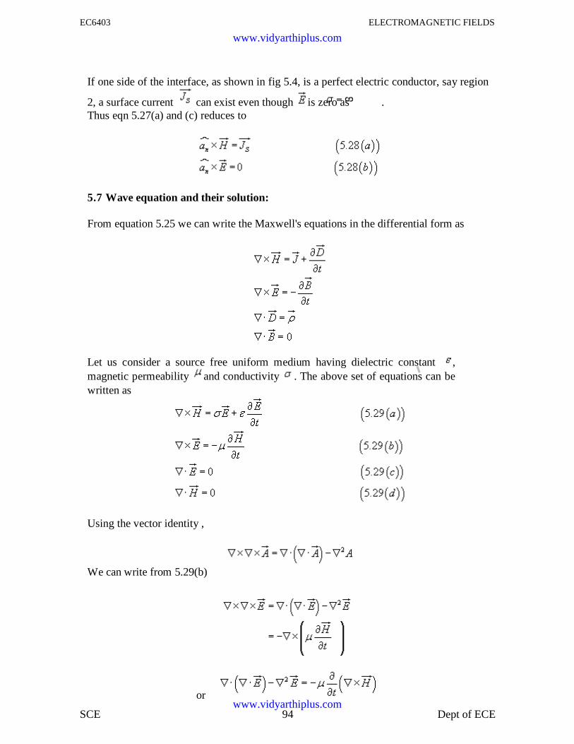
EC6403 ELECTROMAGNETIC FIELDS
SCE 94 Dept of ECE
If one side of the interface, as shown in fig 5.4, is a perfect electric conductor, say region
2, a surface current can exist even though is zero as .Thus eqn 5.27(a) and (c) reduces to
5.7 Wave equation and their solution:
From equation 5.25 we can write the Maxwell's equations in the differential form as
Let us consider a source free uniform medium having dielectric constant ,magnetic permeability and conductivity . The above set of equations can bewritten as
Using the vector identity ,
We can write from 5.29(b)
or
www.vidyarthiplus.com
www.vidyarthiplus.com
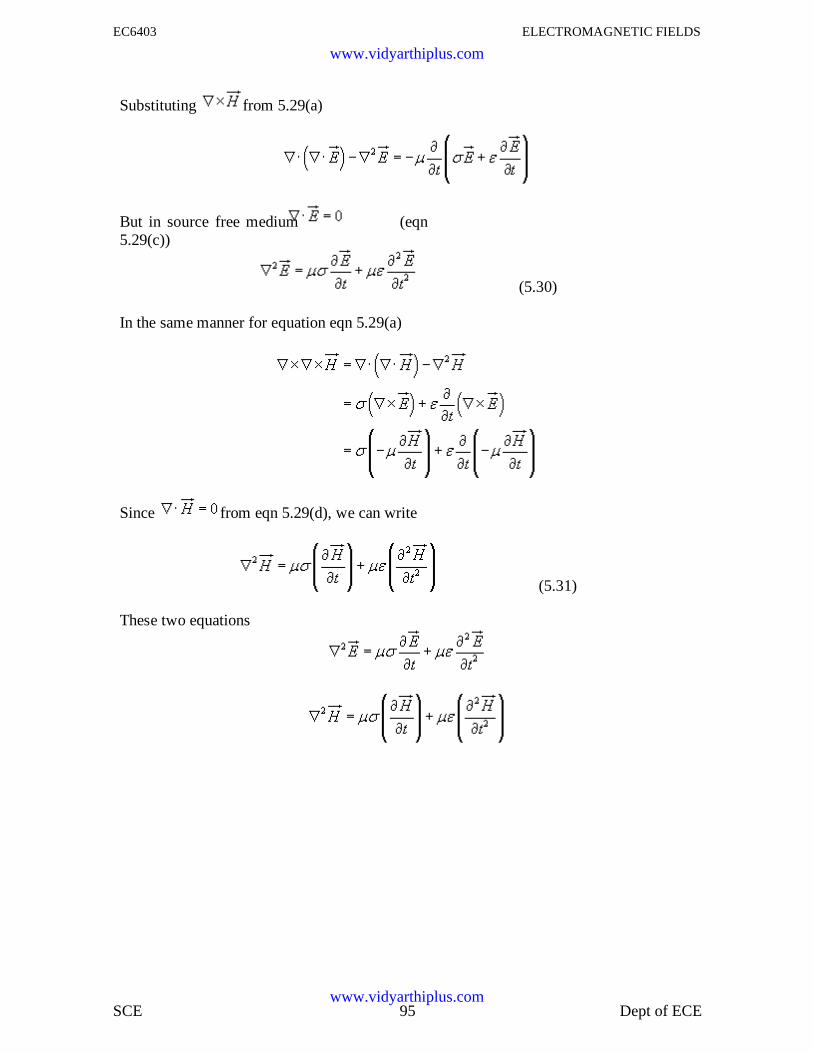
EC6403 ELECTROMAGNETIC FIELDS
SCE 95 Dept of ECE
Substituting from 5.29(a)
But in source free medium (eqn5.29(c))
(5.30)
In the same manner for equation eqn 5.29(a)
Since from eqn 5.29(d), we can write
(5.31)
These two equations
www.vidyarthiplus.com
www.vidyarthiplus.com
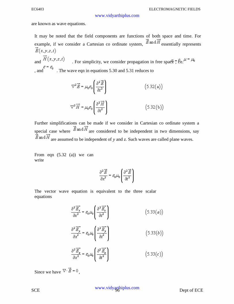
EC6403 ELECTROMAGNETIC FIELDS
SCE 96 Dept of ECE
are known as wave equations.
It may be noted that the field components are functions of both space and time. For
example, if we consider a Cartesian co ordinate system, essentially represents
and . For simplicity, we consider propagation in free space , i.e.
, and . The wave eqn in equations 5.30 and 5.31 reduces to
Further simplifications can be made if we consider in Cartesian co ordinate system a
special case where are considered to be independent in two dimensions, say
are assumed to be independent of y and z. Such waves are called plane waves.
From eqn (5.32 (a)) we canwrite
The vector wave equation is equivalent to the three scalarequations
Since we have ,
www.vidyarthiplus.com
www.vidyarthiplus.com
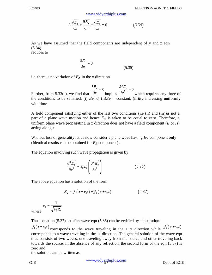
EC6403 ELECTROMAGNETIC FIELDS
SCE 97 Dept of ECE
As we have assumed that the field components are independent of y and z eqn(5.34)reduces to
(5.35)
i.e. there is no variation of Ex in the x direction.
Further, from 5.33(a), we find that implies which requires any three ofthe conditions to be satisfied: (i) Ex=0, (ii)Ex = constant, (iii)Ex increasing uniformlywith time.
A field component satisfying either of the last two conditions (i.e (ii) and (iii))is not apart of a plane wave motion and hence Ex is taken to be equal to zero. Therefore, auniform plane wave propagating in x direction does not have a field component (E or H)acting along x.
Without loss of generality let us now consider a plane wave having Ey component only(Identical results can be obtained for Ez component) .
The equation involving such wave propagation is given by
The above equation has a solution of the form
where
Thus equation (5.37) satisfies wave eqn (5.36) can be verified by substitution.
corresponds to the wave traveling in the + x direction whilecorresponds to a wave traveling in the -x direction. The general solution of the wave eqnthus consists of two waves, one traveling away from the source and other traveling backtowards the source. In the absence of any reflection, the second form of the eqn (5.37) iszero andthe solution can be written as
www.vidyarthiplus.com
www.vidyarthiplus.com
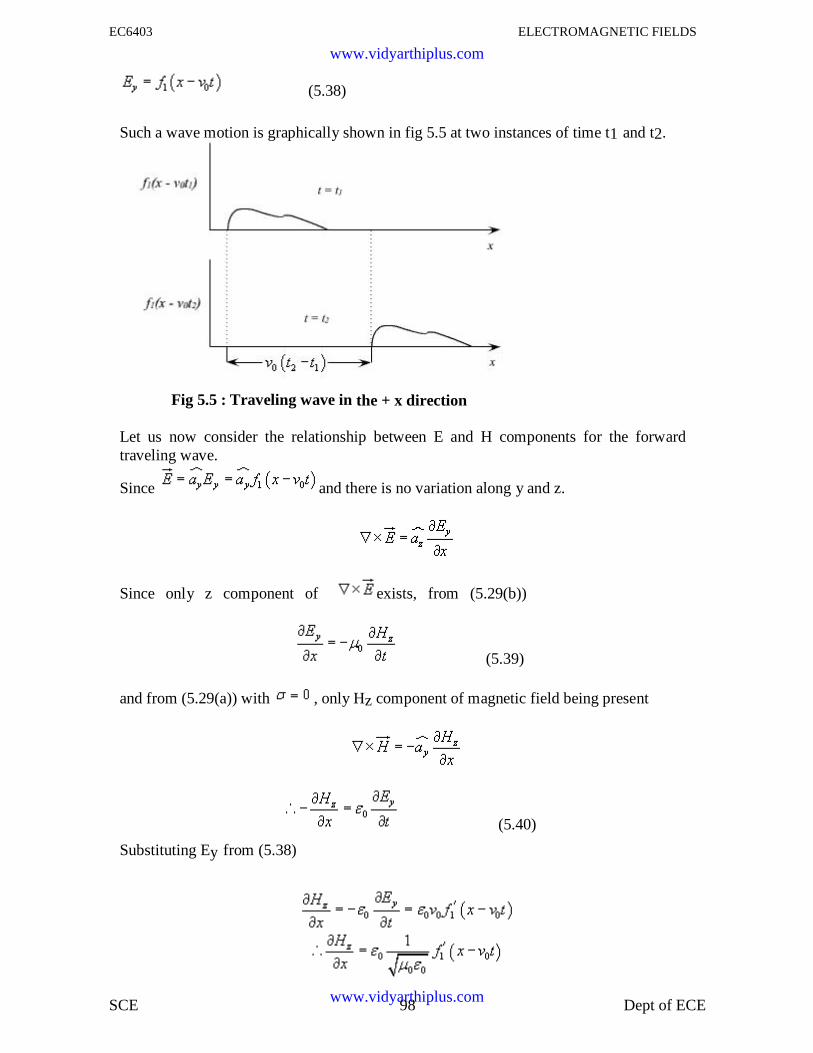
EC6403 ELECTROMAGNETIC FIELDS
SCE 98 Dept of ECE
(5.38)
Such a wave motion is graphically shown in fig 5.5 at two instances of time t1 and t2.
Fig 5.5 : Traveling wave in the + x direction
Let us now consider the relationship between E and H components for the forwardtraveling wave.
Since and there is no variation along y and z.
Since only z component of exists, from (5.29(b))
(5.39)
and from (5.29(a)) with , only Hz component of magnetic field being present
(5.40)
Substituting Ey from (5.38)
www.vidyarthiplus.com
www.vidyarthiplus.com
EC6403 ELECTROMAGNETIC FIELDS
SCE 99 Dept of ECE
The constant of integration means that a field independent of x may also exist. However,this field will not be a part of the wave motion.
Hence (5.41)
which relates the E and H components of the traveling wave.
is called the characteristic or intrinsic impedance of the free space
5.8 Harmonic fieldsIn the previous section we introduced the equations pertaining to wave propagation
and discussed how the wave equations are modified for time harmonic case. In thissection we discuss in detail a particular form of electromagnetic wave propagation called'plane waves'. The Helmhotz Equation:
In source free linear isotropic medium, Maxwell equations in phasor form are,
or,
www.vidyarthiplus.com
www.vidyarthiplus.com
EC6403 ELECTROMAGNETIC FIELDS
SCE 100 Dept of ECE
or,
or, where
An identical equation can be derived for .
i.e.,
These equations
are called homogeneous vector Helmholtz's equation.
is called the wave number or propagation constant of the medium.
5.8.1 Plane waves in Lossless medium:
In a lossless medium, are real numbers, so k is real.
In Cartesian coordinates each of the equations 6.1(a) and 6.1(b) are equivalent tothree scalar Helmholtz's equations, one each in the components Ex, Ey and Ez or Hx, Hy, Hz.
For example if we consider Ex component we can write
.................................................(6.2)
A uniform plane wave is a particular solution of Maxwell's equation assuming electricfield (and magnetic field) has same magnitude and phase in infinite planesperpendicular to the direction of propagation. It may be noted that in the strict sense auniform plane wave doesn't exist in practice as creation of such waves are possiblewith sources of infinite extent. However, at large distances from the source, thewavefront or the surface of the constant phase becomes almost spherical and a smallportion of this large sphere can be considered to plane. The characteristics of planewaves are simple and useful for studying many practical scenarios.
Let us consider a plane wave which has only Ex component and propagating along z .Since the plane wave will have no variation along the plane perpendicular to z i.e., xy
plane, . The Helmholtz's equation (6.2) reduces to,
www.vidyarthiplus.com
www.vidyarthiplus.com
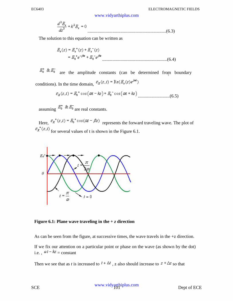
EC6403 ELECTROMAGNETIC FIELDS
SCE 101 Dept of ECE
.....................................................................(6.3)
The solution to this equation can be written as
.........................................................(6.4)
are the amplitude constants (can be determined from boundary
conditions). In the time domain,
............................(6.5)
assuming are real constants.
Here, represents the forward traveling wave. The plot of
for several values of t is shown in the Figure 6.1.
Figure 6.1: Plane wave traveling in the + z direction
As can be seen from the figure, at successive times, the wave travels in the +z direction.
If we fix our attention on a particular point or phase on the wave (as shown by the dot)i.e. , = constant
Then we see that as t is increased to , z also should increase to so that
www.vidyarthiplus.com
www.vidyarthiplus.com
EC6403 ELECTROMAGNETIC FIELDS
SCE 102 Dept of ECE
Or,
Or,
When ,
we write = phase velocity .
.....................................(6.6)
If the medium in which the wave is propagating is free space i.e.,
Then
Where 'C' is the speed of light. That is plane EM wave travels in free space with thespeed of light.
The wavelength is defined as the distance between two successive maxima (or minimaor any other reference points).
i.e.,
or,
Substituting ,
or,
www.vidyarthiplus.com
www.vidyarthiplus.com
EC6403 ELECTROMAGNETIC FIELDS
SCE 103 Dept of ECE
or, ................................(6.7)
Thus wavelength also represents the distance covered in one oscillation of the wave.
Similarly, represents a plane wave traveling in the -z
direction.
The associated magnetic field can be found as follows:
From (6.4),
=
= ............(6.8)
where is the intrinsic impedance of the
medium. When the wave travels in free space
is the intrinsic impedance of the free space.
In the time domain,
www.vidyarthiplus.com
www.vidyarthiplus.com
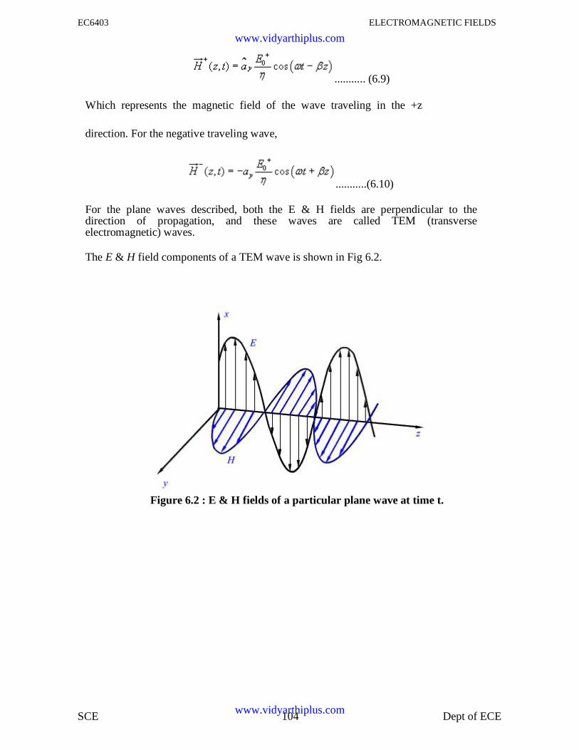
EC6403 ELECTROMAGNETIC FIELDS
SCE 104 Dept of ECE
........... (6.9)
Which represents the magnetic field of the wave traveling in the +z
direction. For the negative traveling wave,
...........(6.10)
For the plane waves described, both the E & H fields are perpendicular to thedirection of propagation, and these waves are called TEM (transverseelectromagnetic) waves.
The E & H field components of a TEM wave is shown in Fig 6.2.
Figure 6.2 : E & H fields of a particular plane wave at time t.
www.vidyarthiplus.com
www.vidyarthiplus.com
EC6403 ELECTROMAGNETIC FIELDS
105
5.8.2 TEM Waves:
So far we have considered a plane electromagnetic wave propagating in the z-direction.Let us now consider the propagation of a uniform plane wave in any arbitrary directionthat doesn't necessarily coincides with an axis.
For a uniform plane wave propagating in z-direction
is a constant vector...........................
(6.11) The more general form of the above equation is
...........................................
(6.12) This equation satisfies Helmholtz's equation
provided,
........................... (6.13)
We define wave number vector ...........................
(6.14) And radius vector from the origin
........................... (6.15)
Therefore we can write
........................... (6.16)
Here =constant is a plane of constant phase and uniform amplitude just in the case of
,
z =constant denotes a plane of constant phase and uniform
amplitude. If the region under consideration is charge free,
Using the vector identity and noting that is constant we
www.vidyarthiplus.com
www.vidyarthiplus.com
EC6403 ELECTROMAGNETIC FIELDS
106
can write,
......................(6.17)
i.e., is transverse to the direction of thepropagation.
The corresponding magnetic field can be computed asfollows:
Using the vectoridentity,
Since is constant we canwrite,
.....................(6.18)
Where is the intrinsic impedance of the medium. We observe that is perpendicular
to both and . Thus the electromagnetic wave represented by and is aTEM wave.
www.vidyarthiplus.com
www.vidyarthiplus.com
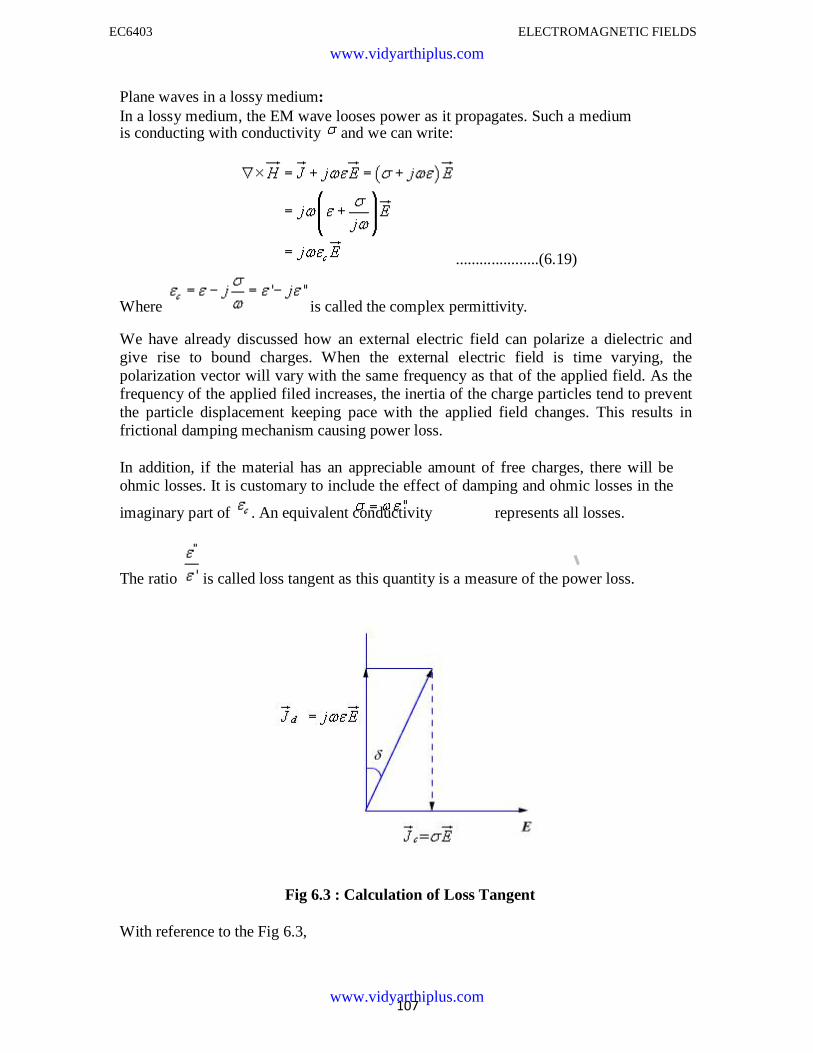
EC6403 ELECTROMAGNETIC FIELDS
107
Plane waves in a lossy medium:In a lossy medium, the EM wave looses power as it propagates. Such a mediumis conducting with conductivity and we can write:
.....................(6.19)
Where is called the complex permittivity.
We have already discussed how an external electric field can polarize a dielectric andgive rise to bound charges. When the external electric field is time varying, thepolarization vector will vary with the same frequency as that of the applied field. As thefrequency of the applied filed increases, the inertia of the charge particles tend to preventthe particle displacement keeping pace with the applied field changes. This results infrictional damping mechanism causing power loss.
In addition, if the material has an appreciable amount of free charges, there will beohmic losses. It is customary to include the effect of damping and ohmic losses in the
imaginary part of . An equivalent conductivity represents all losses.
The ratio is called loss tangent as this quantity is a measure of the power loss.
Fig 6.3 : Calculation of Loss Tangent
With reference to the Fig 6.3,
www.vidyarthiplus.com
www.vidyarthiplus.com
EC6403 ELECTROMAGNETIC FIELDS
108
.......................... (6.20)
where is the conduction current density and is displacement current density. Theloss tangent gives a measure of how much lossy is the medium under consideration. For
a good dielectric medium is very small and the medium is a good
conductor if . A material may be a good conductor at low frequencies butbehave as lossy dielectric at higher frequencies.
For a source free lossy medium we can write
...........................(6.21)
.................... (6.22)
Where
Proceeding in the same manner we can write,
is called the propagation constant.
The real and imaginary parts and of the propagation constant can be computedas follows:
And
www.vidyarthiplus.com
www.vidyarthiplus.com
EC6403 ELECTROMAGNETIC FIELDS
SCE 109 Dept of ECE
................... (6.23a)
Similarly .................. (6.23b)
Let us now consider a plane wave that has only x -component of electric field andpropagate along z .
................................... (6.24)
Considering only the forward traveling wave
................................... (6.25)
Similarly, from , we can find
..................................... (6.26)
Where
..................................... (6.27)
www.vidyarthiplus.com
www.vidyarthiplus.com
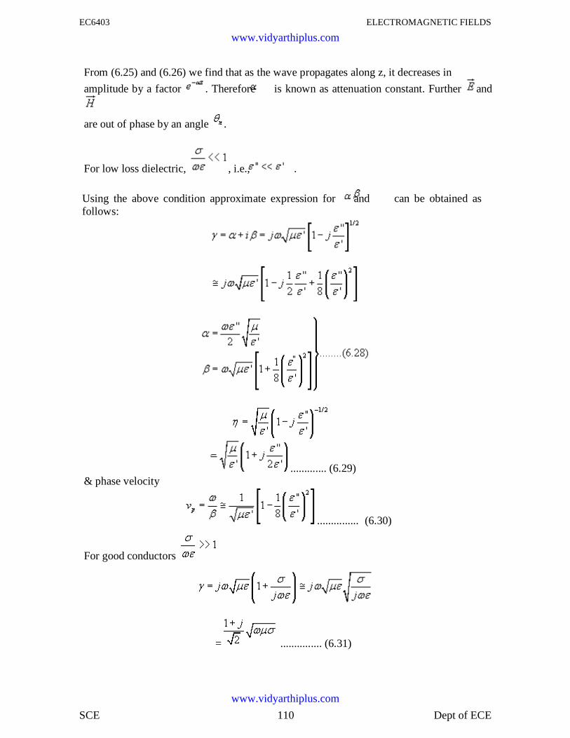
EC6403 ELECTROMAGNETIC FIELDS
SCE 110 Dept of ECE
From (6.25) and (6.26) we find that as the wave propagates along z, it decreases in
amplitude by a factor . Therefore is known as attenuation constant. Further and
are out of phase by an angle .
For low loss dielectric, , i.e., .
Using the above condition approximate expression for and can be obtained asfollows:
............. (6.29)& phase velocity
............... (6.30)
For good conductors
= ............... (6.31)
www.vidyarthiplus.com
www.vidyarthiplus.com
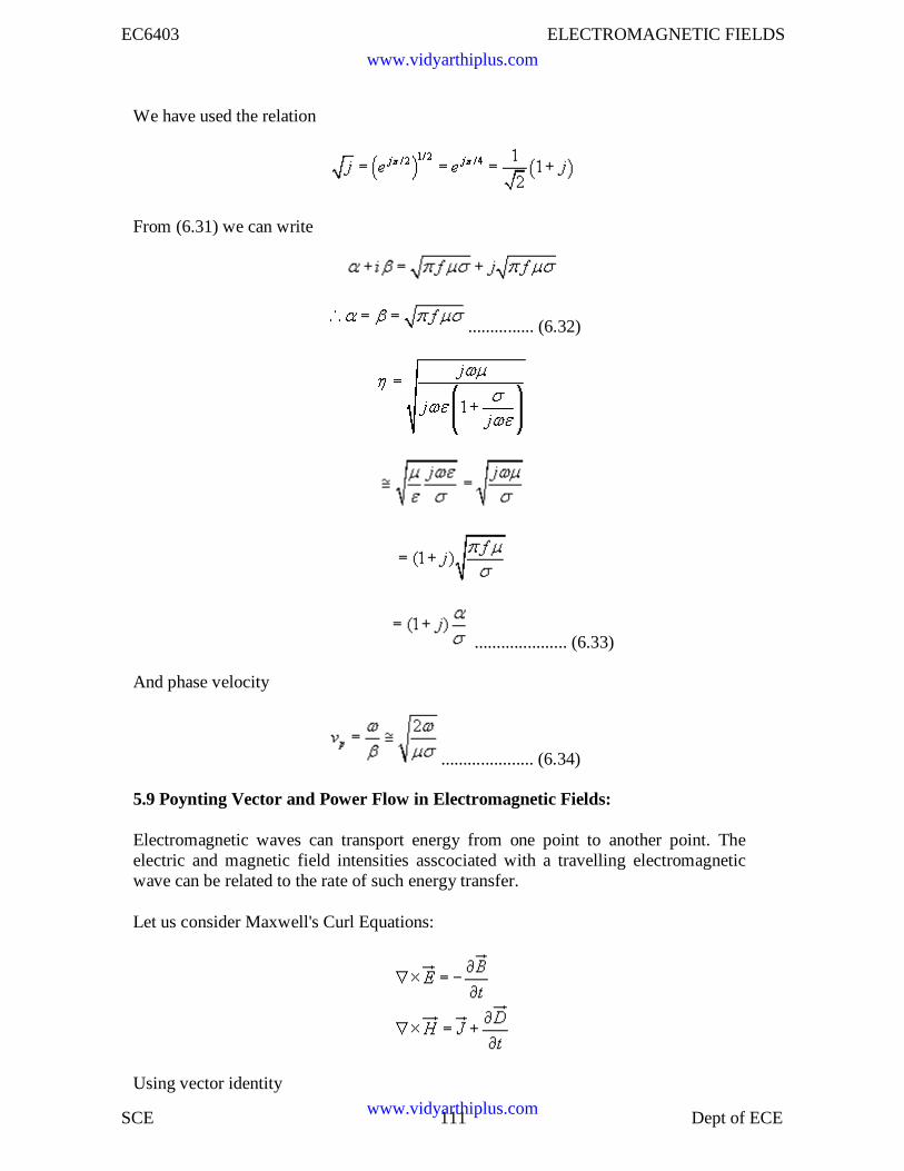
EC6403 ELECTROMAGNETIC FIELDS
SCE 111 Dept of ECE
We have used the relation
From (6.31) we can write
............... (6.32)
..................... (6.33)
And phase velocity
..................... (6.34)
5.9 Poynting Vector and Power Flow in Electromagnetic Fields:
Electromagnetic waves can transport energy from one point to another point. Theelectric and magnetic field intensities asscociated with a travelling electromagneticwave can be related to the rate of such energy transfer.
Let us consider Maxwell's Curl Equations:
Using vector identity
www.vidyarthiplus.com
www.vidyarthiplus.com
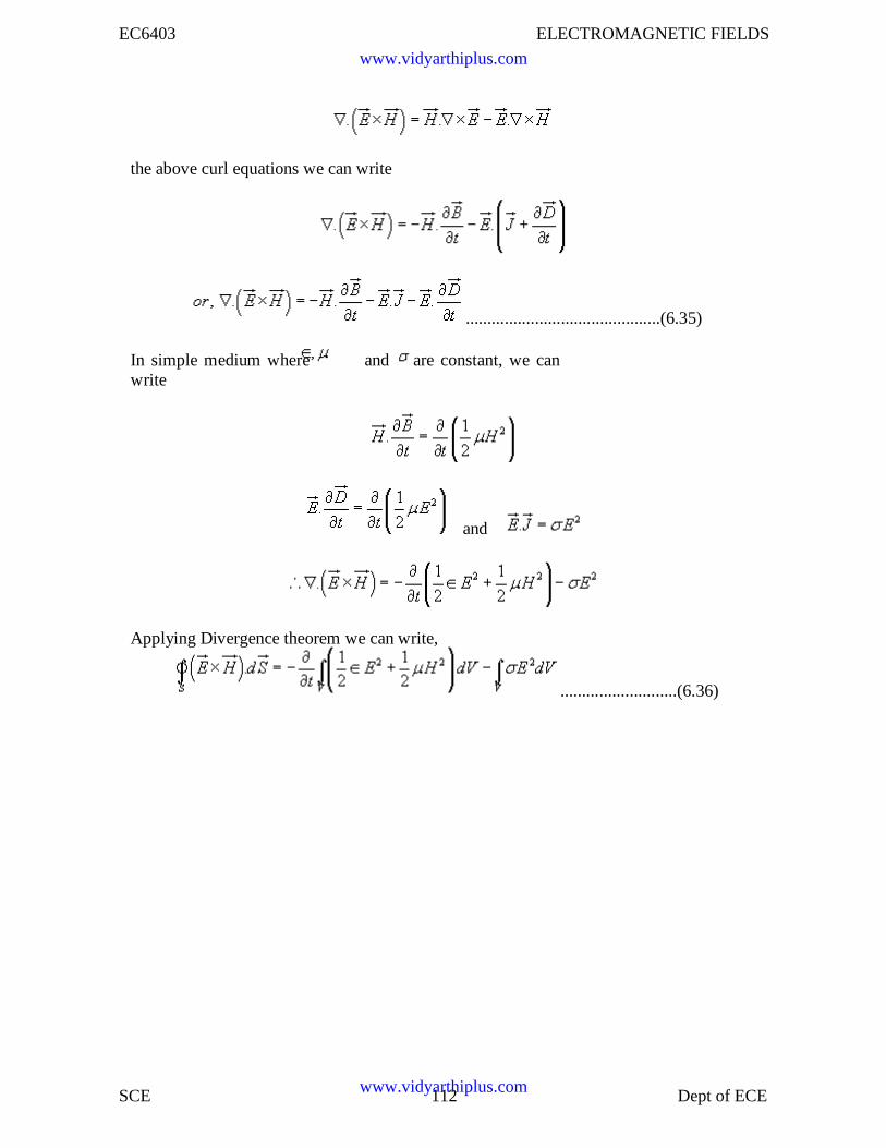
EC6403 ELECTROMAGNETIC FIELDS
SCE 112 Dept of ECE
the above curl equations we can write
.............................................(6.35)
In simple medium where and are constant, we canwrite
and
Applying Divergence theorem we can write,
...........................(6.36)
www.vidyarthiplus.com
www.vidyarthiplus.com
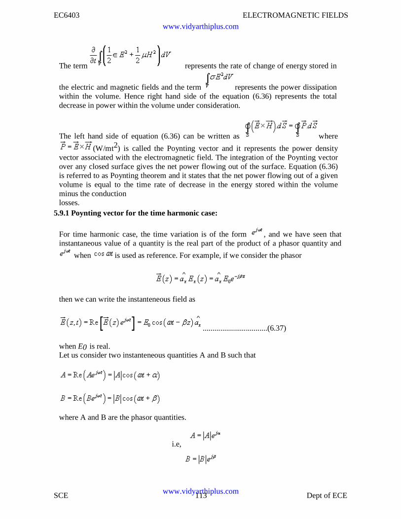
EC6403 ELECTROMAGNETIC FIELDS
SCE 113 Dept of ECE
The term represents the rate of change of energy stored in
the electric and magnetic fields and the term represents the power dissipationwithin the volume. Hence right hand side of the equation (6.36) represents the totaldecrease in power within the volume under consideration.
The left hand side of equation (6.36) can be written as where
(W/mt2) is called the Poynting vector and it represents the power densityvector associated with the electromagnetic field. The integration of the Poynting vectorover any closed surface gives the net power flowing out of the surface. Equation (6.36)is referred to as Poynting theorem and it states that the net power flowing out of a givenvolume is equal to the time rate of decrease in the energy stored within the volumeminus the conductionlosses.
5.9.1 Poynting vector for the time harmonic case:
For time harmonic case, the time variation is of the form , and we have seen thatinstantaneous value of a quantity is the real part of the product of a phasor quantity and
when is used as reference. For example, if we consider the phasor
then we can write the instanteneous field as
.................................(6.37)
when E0 is real.Let us consider two instanteneous quantities A and B such that
where A and B are the phasor quantities.
i.e,
www.vidyarthiplus.com
www.vidyarthiplus.com
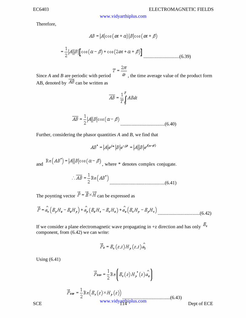
EC6403 ELECTROMAGNETIC FIELDS
SCE 114 Dept of ECE
Therefore,
..............................(6.39)
Since A and B are periodic with period , the time average value of the product form
AB, denoted by can be written as
.....................................(6.40)
Further, considering the phasor quantities A and B, we find that
and , where * denotes complex conjugate.
..............................................(6.41)
The poynting vector can be expressed as
...................................(6.42)
If we consider a plane electromagnetic wave propagating in +z direction and has onlycomponent, from (6.42) we can write:
Using (6.41)
........................................(6.43)
www.vidyarthiplus.com
www.vidyarthiplus.com
EC6403 ELECTROMAGNETIC FIELDS
SCE 115 Dept of ECE
where and , for the plane wave under
consideration. For a general case, we can write
.....................(6.44)
We can define a complex Poynting vector
and time average of the instantaneous Poynting vector is given by .
The polarisation of a plane wave can be defined as the orientation of the electric fieldvector as a function of time at a fixed point in space. For an electromagnetic wave, thespecification of the orientation of the electric field is sufficent as the magnetic fieldcomponents are related to electric field vector by the Maxwell's equations.
Let us consider a plane wave travelling in the +z direction. The wave has both Ex and Eycomponents.
..........................................(6.45)
The corresponding magnetic fields are given by,
Depending upon the values of Eox and Eoy we can have several possibilities:
1. If Eoy = 0, then the wave is linearly polarised in the x-direction.
2. If Eoy = 0, then the wave is linearly polarised in the y-direction.
3. If Eox and Eoy are both real (or complex with equal phase), once again we get a
5.10 Electromagnetic Spectrum:
www.vidyarthiplus.com
www.vidyarthiplus.com
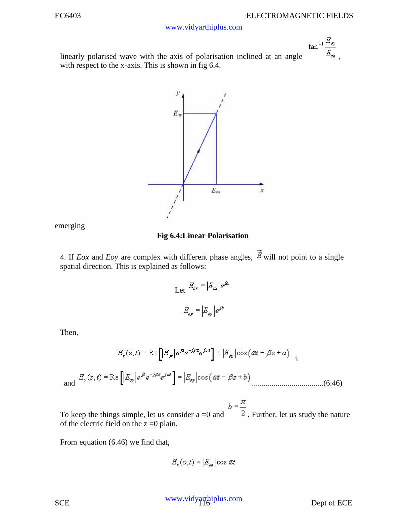
EC6403 ELECTROMAGNETIC FIELDS
SCE 116 Dept of ECE
linearly polarised wave with the axis of polarisation inclined at an angle ,with respect to the x-axis. This is shown in fig 6.4.
emergingFig 6.4:Linear Polarisation
4. If Eox and Eoy are complex with different phase angles, will not point to a singlespatial direction. This is explained as follows:
Let
Then,
and ....................................(6.46)
To keep the things simple, let us consider a =0 and . Further, let us study the natureof the electric field on the z =0 plain.
From equation (6.46) we find that,
www.vidyarthiplus.com
www.vidyarthiplus.com
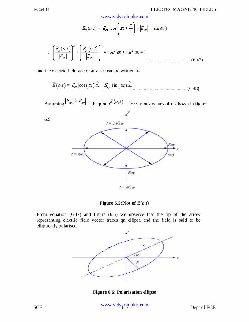
EC6403 ELECTROMAGNETIC FIELDS
SCE 117 Dept of ECE
.....................................(6.47)
and the electric field vector at z = 0 can be written as
.............................................(6.48)
Assuming , the plot of for various values of t is hown in figure
6.5.
Figure 6.5:Plot of E(o,t)
From equation (6.47) and figure (6.5) we observe that the tip of the arrowrepresenting electric field vector traces qn ellipse and the field is said to beelliptically polarised.
Figure 6.6: Polarisation ellipse
www.vidyarthiplus.com
www.vidyarthiplus.com
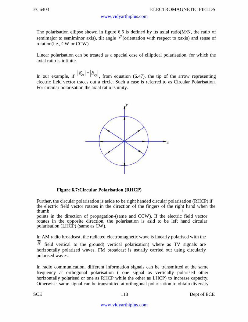
EC6403 ELECTROMAGNETIC FIELDS
SCE 118 Dept of ECE
The polarisation ellipse shown in figure 6.6 is defined by its axial ratio(M/N, the ratio ofsemimajor to semiminor axis), tilt angle (orientation with respect to xaxis) and sense ofrotation(i.e., CW or CCW).
Linear polarisation can be treated as a special case of elliptical polarisation, for which theaxial ratio is infinite.
In our example, if , from equation (6.47), the tip of the arrow representingelectric field vector traces out a circle. Such a case is referred to as Circular Polarisation.For circular polarisation the axial ratio is unity.
Figure 6.7:Circular Polarisation (RHCP)
Further, the circular polarisation is aside to be right handed circular polarisation (RHCP) ifthe electric field vector rotates in the direction of the fingers of the right hand when thethumbpoints in the direction of propagation-(same and CCW). If the electric field vectorrotates in the opposite direction, the polarisation is asid to be left hand circularpolarisation (LHCP) (same as CW).
In AM radio broadcast, the radiated electromagnetic wave is linearly polarised with the
field vertical to the ground( vertical polarisation) where as TV signals arehorizontally polarised waves. FM broadcast is usually carried out using circularlypolarised waves.
In radio communication, different information signals can be transmitted at the samefrequency at orthogonal polarisation ( one signal as vertically polarised otherhorizontally polarised or one as RHCP while the other as LHCP) to increase capacity.Otherwise, same signal can be transmitted at orthogonal polarisation to obtain diversity
www.vidyarthiplus.com
www.vidyarthiplus.com
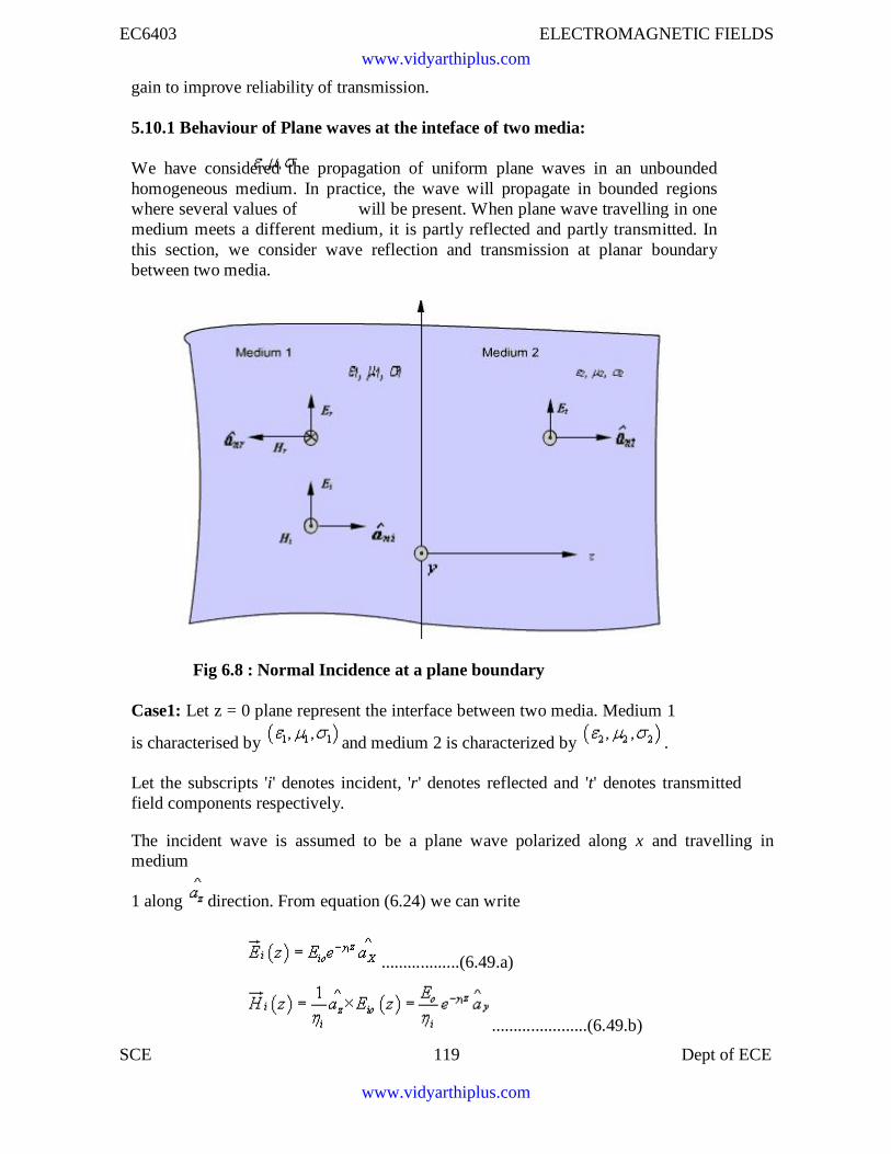
EC6403 ELECTROMAGNETIC FIELDS
SCE 119 Dept of ECE
gain to improve reliability of transmission.
5.10.1 Behaviour of Plane waves at the inteface of two media:
We have considered the propagation of uniform plane waves in an unboundedhomogeneous medium. In practice, the wave will propagate in bounded regionswhere several values of will be present. When plane wave travelling in onemedium meets a different medium, it is partly reflected and partly transmitted. Inthis section, we consider wave reflection and transmission at planar boundarybetween two media.
Fig 6.8 : Normal Incidence at a plane boundary
Case1: Let z = 0 plane represent the interface between two media. Medium 1
is characterised by and medium 2 is characterized by .
Let the subscripts 'i' denotes incident, 'r' denotes reflected and 't' denotes transmittedfield components respectively.
The incident wave is assumed to be a plane wave polarized along x and travelling inmedium
1 along direction. From equation (6.24) we can write
..................(6.49.a)
......................(6.49.b)
www.vidyarthiplus.com
www.vidyarthiplus.com
EC6403 ELECTROMAGNETIC FIELDS
SCE 120 Dept of ECE
where and .
Because of the presence of the second medium at z =0, the incident wave willundergo partial reflection and partial transmission.The reflected wave will travel along in medium
1. The reflected field components are:
...............................................(6.50a)
.........(6.50b)
The transmitted wave will travel in medium 2 along for which the field components are
............................................(6.51a)
............................................(6.51b)
where and
In medium 1,and
and in medium 2,
and
www.vidyarthiplus.com
www.vidyarthiplus.com
EC6403 ELECTROMAGNETIC FIELDS
SCE 121 Dept of ECE
Applying boundary conditions at the interface z = 0, i.e., continuity of tangentialfield components and noting that incident, reflected and transmitted fieldcomponents are tangential at the boundary, we can write
&
From equation 6.49 to 6.51 we get,
..............................................................(6.52a)
..............................................................(6.52b)
EliminatingEto ,
or,
or,
...............(6.53)
is called the reflection coefficient.
From equation (6.52), we can
write
or,
www.vidyarthiplus.com
www.vidyarthiplus.com
EC6403 ELECTROMAGNETIC FIELDS
SCE 122 Dept of ECE
........................................(6.54)
is called the transmission
coefficient. We observe that,
........................................(6.55)
The following may be noted
(i) both and T are dimensionless and may be complex
(ii)
www.vidyarthiplus.com
www.vidyarthiplus.com
EC6403 ELECTROMAGNETIC FIELDS
SCE 123 Dept of ECE
Let us now consider specific cases:
Case I: Normal incidence on a plane conducting boundary
The medium 1 is perfect dielectric and medium 2 is perfectly conducting
.
From (6.53) and (6.54)
= -1
and T =0
Hence the wave is not transmitted to medium 2, it gets reflected entirely from theinterface to the medium 1.
&
.................................(6.56)
Proceeding in the same manner for the magnetic field in region 1, we can show that,
...............................................................................(6.57)
The wave in medium 1 thus becomes a standing wave due to the super position of a
forward travelling wave and a backward travelling wave. For a given ' t', both and
varysinusoidally with distance measured from z = 0. This is shown in figure 6.9.
www.vidyarthiplus.com
www.vidyarthiplus.com
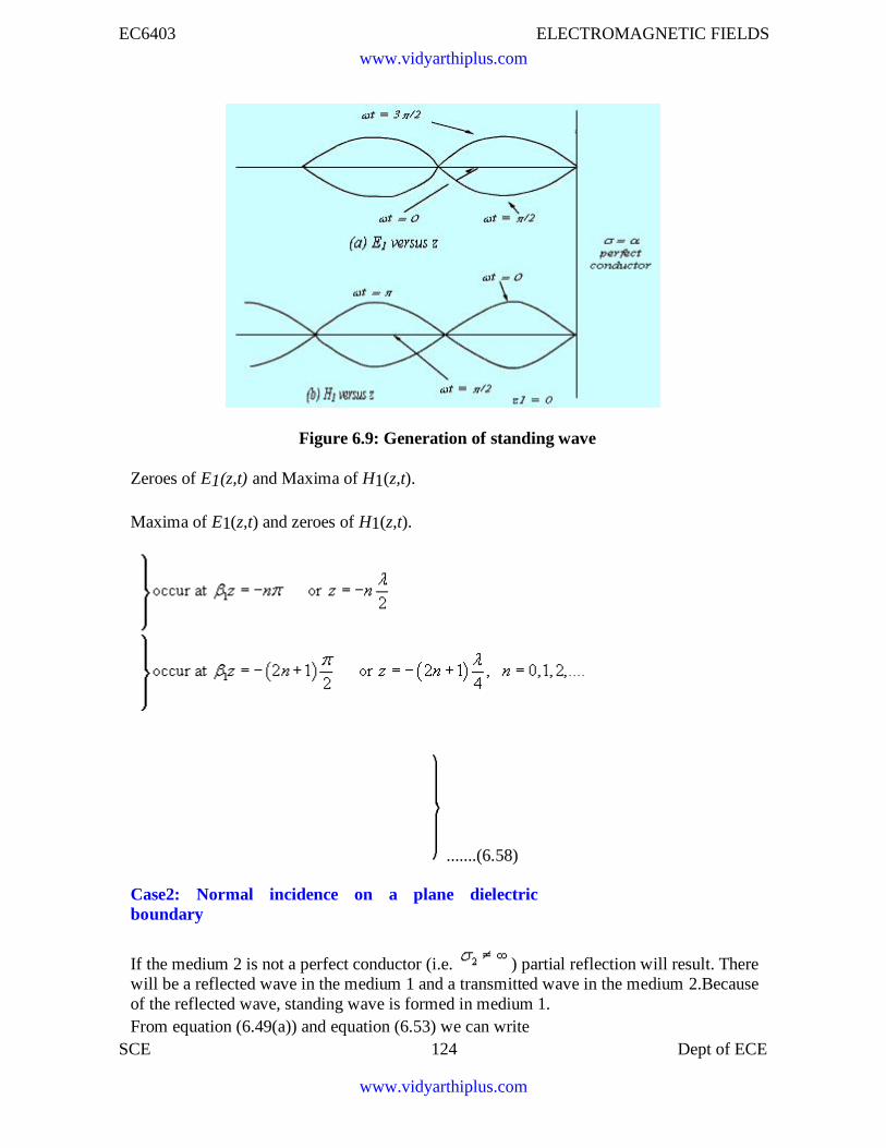
EC6403 ELECTROMAGNETIC FIELDS
SCE 124 Dept of ECE
Figure 6.9: Generation of standing wave
Zeroes of E1(z,t) and Maxima of H1(z,t).
Maxima of E1(z,t) and zeroes of H1(z,t).
.......(6.58)
Case2: Normal incidence on a plane dielectricboundary
If the medium 2 is not a perfect conductor (i.e. ) partial reflection will result. Therewill be a reflected wave in the medium 1 and a transmitted wave in the medium 2.Becauseof the reflected wave, standing wave is formed in medium 1.From equation (6.49(a)) and equation (6.53) we can write
www.vidyarthiplus.com
www.vidyarthiplus.com
EC6403 ELECTROMAGNETIC FIELDS
SCE 125 Dept of ECE
..................(6.59)
Let us consider the scenario when both the media are dissipation less i.e. perfect
dielectrics ( )
..................(6.60)
In this case both and become real numbers.
..................(6.61)
From (6.61), we can see that, in medium 1 we have a traveling wave componentwith amplitude TEio and a standing wave component with amplitude 2JEio.
The location of the maximum and the minimum of the electric and magnetic fieldcomponents in the medium 1from the interface can be found as follows.
The electric field in medium 1 can be written as
..................(6.62)
If i.e. >0
The maximum value of the electric field is
..................(6.63)
and this occurs when
www.vidyarthiplus.com
www.vidyarthiplus.com
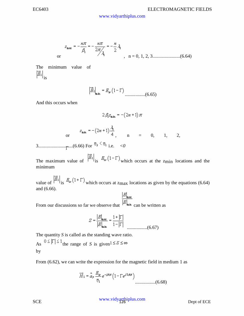
EC6403 ELECTROMAGNETIC FIELDS
SCE 126 Dept of ECE
or , n = 0, 1, 2, 3.......................(6.64)
The minimum value of
is
.................(6.65)
And this occurs when
or , n = 0, 1, 2,
3.............................(6.66) For i.e. <0
The maximum value of is which occurs at the zmin locations and theminimum
value of is which occurs at zmax locations as given by the equations (6.64)and (6.66).
From our discussions so far we observe that can be written as
.................(6.67)
The quantity S is called as the standing wave ratio.
As the range of S is given
by
From (6.62), we can write the expression for the magnetic field in medium 1 as
.................(6.68)
www.vidyarthiplus.com
www.vidyarthiplus.com
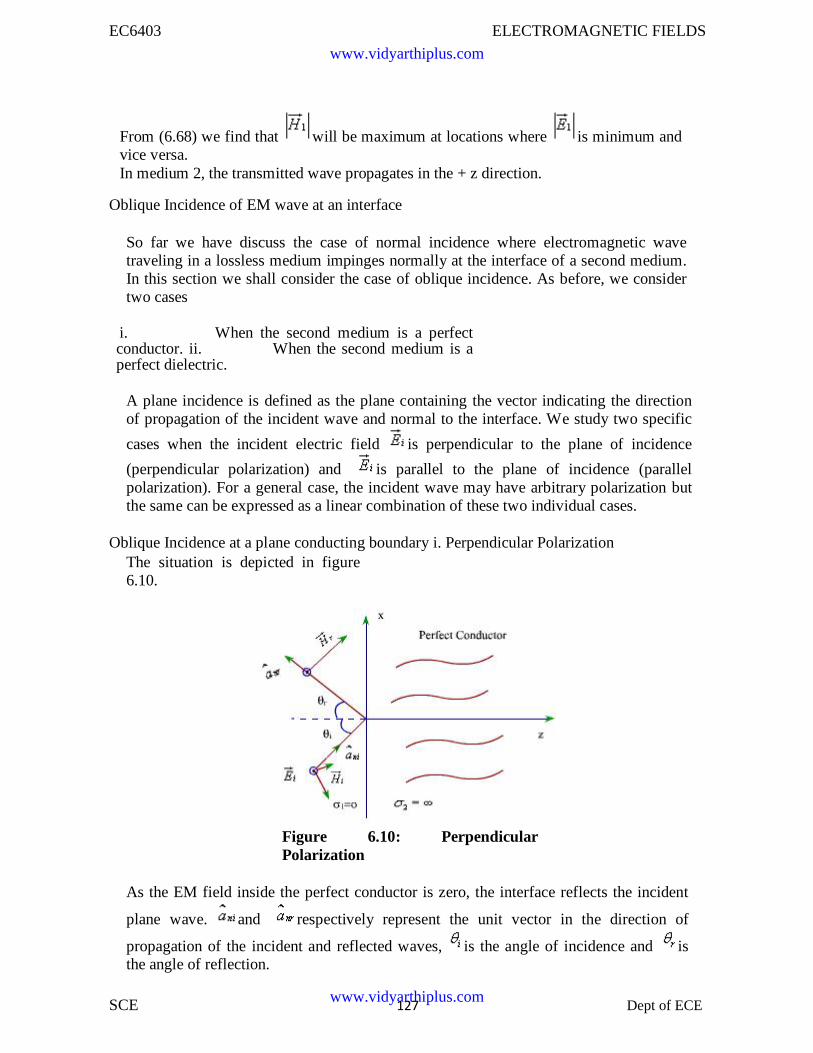
EC6403 ELECTROMAGNETIC FIELDS
SCE 127 Dept of ECE
From (6.68) we find that will be maximum at locations where is minimum andvice versa.In medium 2, the transmitted wave propagates in the + z direction.
Oblique Incidence of EM wave at an interface
So far we have discuss the case of normal incidence where electromagnetic wavetraveling in a lossless medium impinges normally at the interface of a second medium.In this section we shall consider the case of oblique incidence. As before, we considertwo cases
i. When the second medium is a perfectconductor. ii. When the second medium is aperfect dielectric.
A plane incidence is defined as the plane containing the vector indicating the directionof propagation of the incident wave and normal to the interface. We study two specific
cases when the incident electric field is perpendicular to the plane of incidence
(perpendicular polarization) and is parallel to the plane of incidence (parallelpolarization). For a general case, the incident wave may have arbitrary polarization butthe same can be expressed as a linear combination of these two individual cases.
Oblique Incidence at a plane conducting boundary i. Perpendicular PolarizationThe situation is depicted in figure6.10.
Figure 6.10: PerpendicularPolarization
As the EM field inside the perfect conductor is zero, the interface reflects the incident
plane wave. and respectively represent the unit vector in the direction of
propagation of the incident and reflected waves, is the angle of incidence and isthe angle of reflection.
www.vidyarthiplus.com
www.vidyarthiplus.com
EC6403 ELECTROMAGNETIC FIELDS
SCE 128 Dept of ECE
We findthat
............................(6.69)
Since the incident wave is considered to be perpendicular to the plane of incidence,which for the present case happens to be xz plane, the electric field has only y-component.
The corresponding magnetic field is given by
...........................(6.70)
www.vidyarthiplus.com
www.vidyarthiplus.com
EC6403 ELECTROMAGNETIC FIELDS
SCE 129 Dept of ECE D
Similarly, we can write the reflected waves as
...................................................(6.71)
Since at the interface z=o, the tangential electric field is zero.
...........................................(6.72)
Consider in equation (6.72) is satisfied if we have
..................................(6.73)
The condition is Snell's law of reflection.
..................................(6.74)
..................................(6.75)The total electric field is given by
..................................(6.76)
Similarly, total magnetic field is given by
............................(6.77)
From eqns (6.76) and (6.77) we observe that
1. Along z direction i.e. normal to the boundary
y component of and x component of maintain standing wave patterns
according to and where . No average powerpropagates along z
www.vidyarthiplus.com
www.vidyarthiplus.com
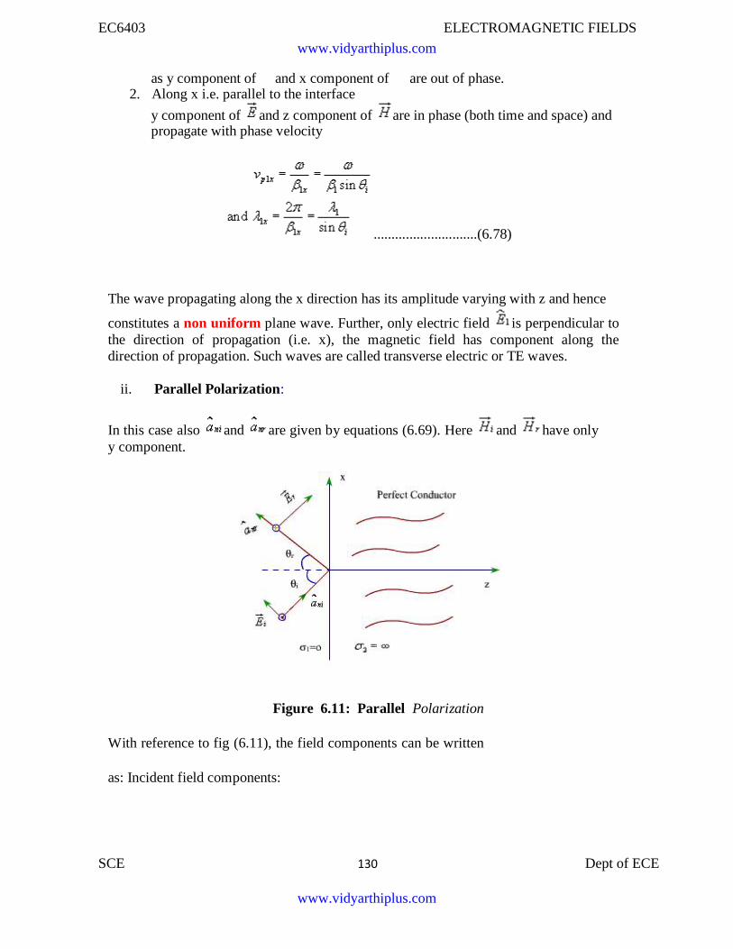
EC6403 ELECTROMAGNETIC FIELDS
SCE 130 Dept of ECE D
as y component of and x component of are out of phase.2. Along x i.e. parallel to the interface
y component of and z component of are in phase (both time and space) andpropagate with phase velocity
.............................(6.78)
The wave propagating along the x direction has its amplitude varying with z and hence
constitutes a non uniform plane wave. Further, only electric field is perpendicular tothe direction of propagation (i.e. x), the magnetic field has component along thedirection of propagation. Such waves are called transverse electric or TE waves.
ii. Parallel Polarization:
In this case also and are given by equations (6.69). Here and have onlyy component.
Figure 6.11: Parallel Polarization
With reference to fig (6.11), the field components can be written
as: Incident field components:
www.vidyarthiplus.com
www.vidyarthiplus.com
EC6403 ELECTROMAGNETIC FIELDS
SCE 131 Dept of ECE D
............................(6.79)Reflected field components:
............................(6.80)Since the total tangential electric field component at the interface is zero.
Which leads to and as before.
Substituting these quantities in (6.79) and adding the incident and reflected electricand magnetic field components the total electric and magnetic fields can be writtenas
...........................(6.81)
Once again, we find a standing wave pattern along z for the x and y components of and
, while a non uniform plane wave propagates along x with a phase velocity given
by where . Since, for this propagating wave, magnetic field isin
transverse direction, such waves are called transverse magnetic or TM waves.
5.10.2 Oblique incidence at a plane dielectric interface
We continue our discussion on the behavior of plane waves at an interface; this time weconsider a plane dielectric interface. As earlier, we consider the two specific cases,namely parallel and perpendicular polarization.
www.vidyarthiplus.com
www.vidyarthiplus.com
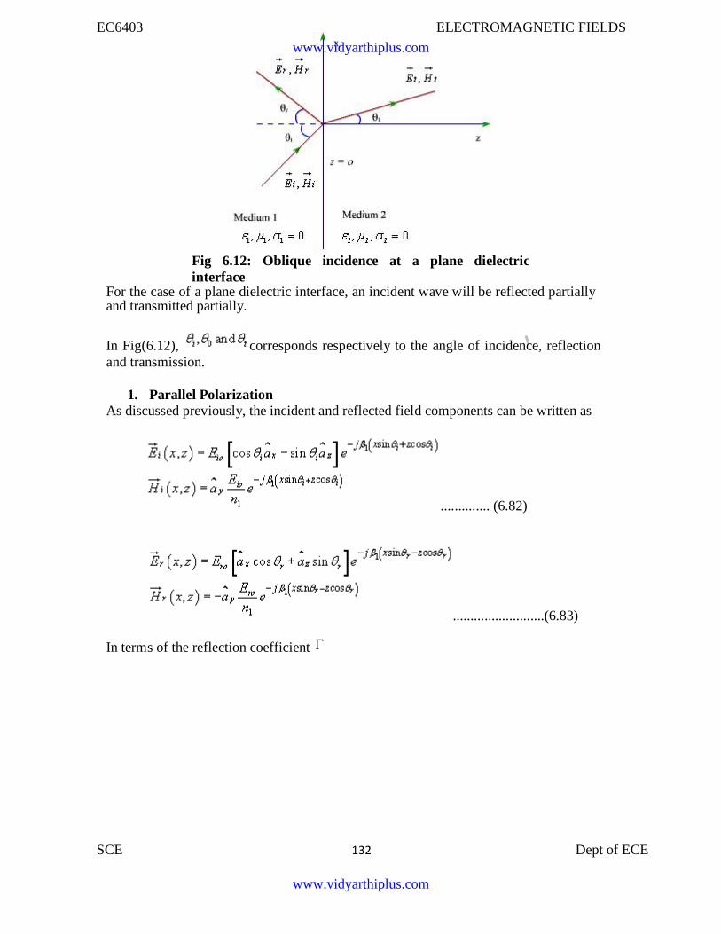
EC6403 ELECTROMAGNETIC FIELDS
SCE 132 Dept of ECE D
Fig 6.12: Oblique incidence at a plane dielectricinterface
For the case of a plane dielectric interface, an incident wave will be reflected partiallyand transmitted partially.
In Fig(6.12), corresponds respectively to the angle of incidence, reflectionand transmission.
1. Parallel PolarizationAs discussed previously, the incident and reflected field components can be written as
.............. (6.82)
In terms of the reflection coefficient
..........................(6.83)
www.vidyarthiplus.com
www.vidyarthiplus.com
EC6403 ELECTROMAGNETIC FIELDS
SCE 133 Dept of ECE
. .........................(6.84)
The transmitted filed can be written in terms of the transmission coefficient T
..........................(6.85)
We can now enforce the continuity of tangential field components at the boundary i.e. z=0
..........................(6.86)
If both and are to be continuous at z=0 for all x , then form the phase matchingwe have
We find that
..........................(6.87)
Further, from equations (6.86) and (6.87) we have
..........................(6.88)
www.vidyarthiplus.com
www.vidyarthiplus.com
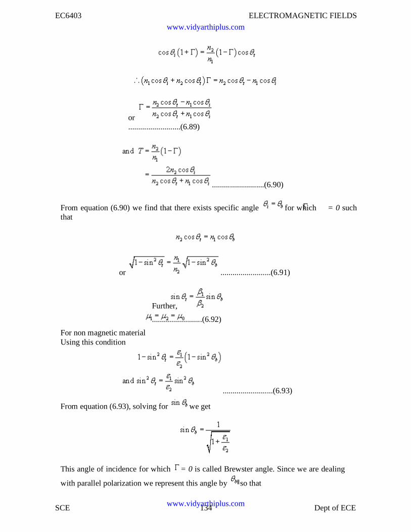
EC6403 ELECTROMAGNETIC FIELDS
SCE 134 Dept of ECE
or..........................(6.89)
..........................(6.90)
From equation (6.90) we find that there exists specific angle for which = 0 suchthat
or .........................(6.91)
Further,
.........................(6.92)
For non magnetic materialUsing this condition
.........................(6.93)
From equation (6.93), solving for we get
This angle of incidence for which = 0 is called Brewster angle. Since we are dealing
with parallel polarization we represent this angle by so that
www.vidyarthiplus.com
www.vidyarthiplus.com
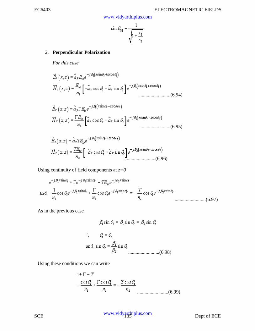
EC6403 ELECTROMAGNETIC FIELDS
SCE 135 Dept of ECE
2. Perpendicular Polarization
For this case
.........................(6.94)
.........................(6.95)
.........................(6.96)
Using continuity of field components at z=0
.........................(6.97)
As in the previous case
.........................(6.98)
Using these conditions we can write
.........................(6.99)
www.vidyarthiplus.com
www.vidyarthiplus.com
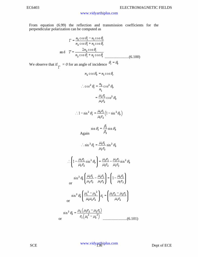
EC6403 ELECTROMAGNETIC FIELDS
SCE 136 Dept of ECE
From equation (6.99) the reflection and transmission coefficients for theperpendicular polarization can be computed as
.........................(6.100)
We observe that if = 0 for an angle of incidence
Again
or
or
or .........................(6.101)
www.vidyarthiplus.com
www.vidyarthiplus.com
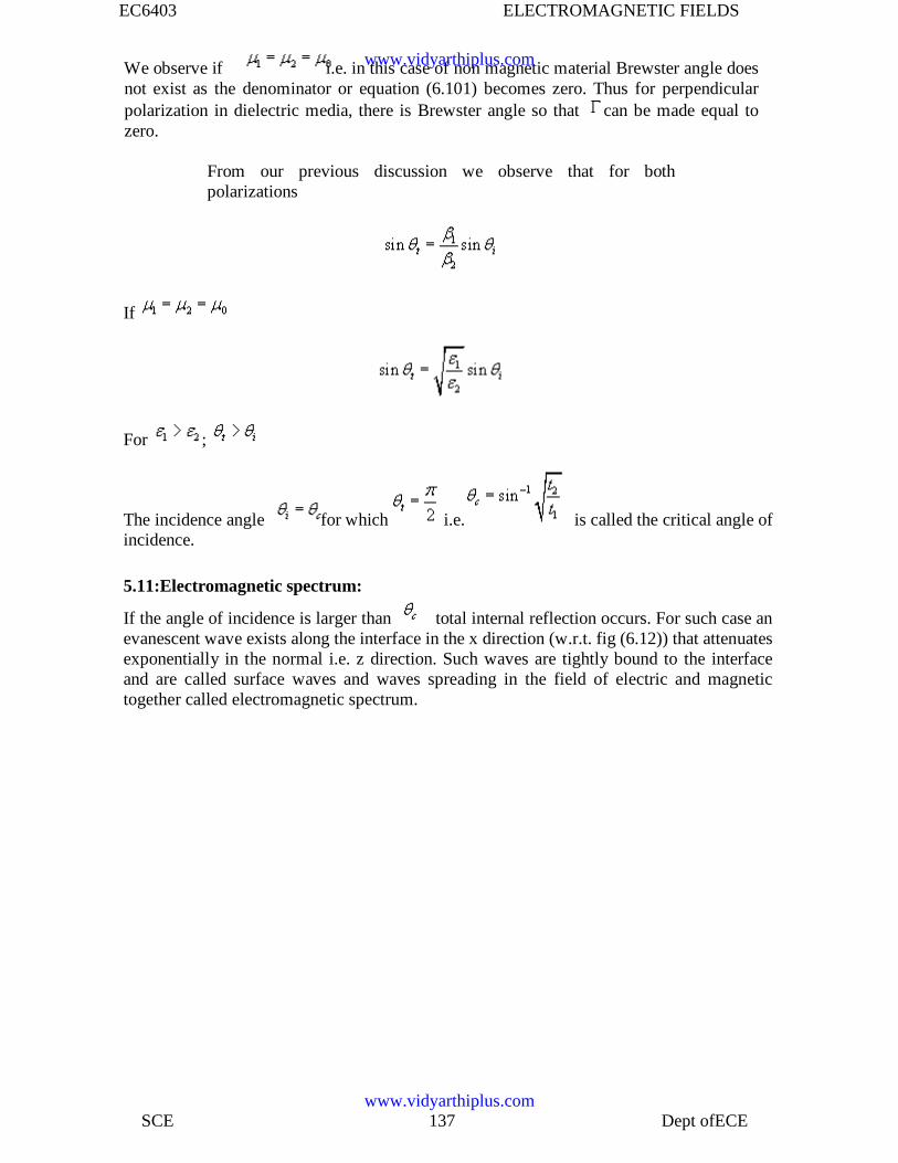
EC6403 ELECTROMAGNETIC FIELDS
SCE 137 Dept ofECE
We observe if i.e. in this case of non magnetic material Brewster angle doesnot exist as the denominator or equation (6.101) becomes zero. Thus for perpendicularpolarization in dielectric media, there is Brewster angle so that can be made equal tozero.
From our previous discussion we observe that for bothpolarizations
If
For ;
The incidence angle for which i.e. is called the critical angle ofincidence.
5.11:Electromagnetic spectrum:
If the angle of incidence is larger than total internal reflection occurs. For such case anevanescent wave exists along the interface in the x direction (w.r.t. fig (6.12)) that attenuatesexponentially in the normal i.e. z direction. Such waves are tightly bound to the interfaceand are called surface waves and waves spreading in the field of electric and magnetictogether called electromagnetic spectrum.
www.vidyarthiplus.com
www.vidyarthiplus.com
EC6403 ELECTROMAGNETIC FIELDS
SCE 138 Dept ofECE
2-Marks and 16 Marks ELECTROMAGNETIC FIELDS(EC6403)
1.State stokes theorem.
The line integral of a vector around a closed path is equal to the surface integral of thenormal component of its curl over any surface bounded by the path
H.dl = (ÑxH)ds
2.State coulombs law.
Coulombs law states that the force between any two point charges is directlyproportional to the product of their magnitudes and inversely proportional to the squareof the distance between them. It is directed along the line joining the two charges.
F=Q1Q2 / 4πεr2 ar
3.State Gauss law for electric fields
The total electric flux passing through any closed surface is equal to the total chargeenclosed by that surface.
4.Define electric flux.
The lines of electric force is electric flux.
5.Define electric flux density.
Electric flux density is defined as electric flux per unit area.
6.Define electric field intensity.
Electric field intensity is defined as the electric force per unit positive charge.E =F/ Q
=Q/4πεr2 V/m
www.vidyarthiplus.com
www.vidyarthiplus.com
EC6403 ELECTROMAGNETIC FIELDS
SCE 139 Dept ofECE
7.Name few applications of Gauss law in electrostatics.
Gauss law is applied to find the electric field intensity from a closed surface.e.g)Electricfield can be determined for shell, two concentric shell or cylinders etc.
8.What is a point charge?
Point charge is one whose maximum dimension is very small in comparison with anyother length.
9.Define linear charge density.
It is the charge per unit length.
10.Write poisson’s and laplace ’s equations.
Poisson ‘s eqn:Ñ2V= - ρv / ε
Laplace’ s eqn:
Ñ2V= 0
11.State the condition for the vector F to be solenoidal.
Ñ·F =0
12. .State the condition for the vector F to be irrotational.
ÑxF =0
13.Define potential difference.
Potential difference is defined as the work done in moving a unit positive chargefrom one point to another point in an electric field.
www.vidyarthiplus.com
www.vidyarthiplus.com
EC6403 ELECTROMAGNETIC FIELDS
SCE 140 Dept ofECE
14.Define potential.
Potential at any point is defined as the work done in moving a unit positive chargefrom infinity to that point in an electric field.
V=Q / 4πεr
15.Give the relation between electric field intensity and electric flux density.
D=εE C/m2
16.Give the relationship between potential gradiant and electric field.
E= - ÑV
17.What is the physical significance of div D ?
Ñ·D=-ρvThe divergence of a vector flux density is electric flux per unit volume leaving a small
volume. This is equal to the volume charge density.
18. Define current density.
Current density is defined as the current per unit area.J= I/A Amp/m2
19.Write the point form of continuity equation and explain its significance.
Ñ·J= - ρv / t
20.Write the expression for energy density in electrostatic field.
W=1 / 2 εE2
21.Write the boundary conditions at the interface between two perfect dielectrics.
i)The tangential component of electric field is continuous i.e)Et1=Et2
ii)The normal component of electric flux density is continuous I.e)Dn1=Dn2
www.vidyarthiplus.com
www.vidyarthiplus.com
EC6403 ELECTROMAGNETIC FIELDS
SCE 141 Dept ofECE
22.Write down the expression for capacitance between two parallel plates.
C=εA / d
23.What is meant by displacement current?
Displacement current is nothing but the current flowing through capacitor.J= D / t
24.State point form of ohms law.
Point form of ohms law states that the field strength within a conductor isproportional to the current density.
J=σE
25 Define surface charge density.
It is the charge per surface area.
26.State amperes circuital law.
Magnetic field intensity around a closed path is equal to the current enclosed by thepath.
H·dl=I
27.State Biot –Savarts law.
It states that the magnetic flux density at any point due to current element isproportional to the current element and sine of the angle between the elemental lengthand inversely proportional to the square of the distance between them
dB=µ 0Idl sinθ / 4πr2
28.Define magnetic vector potential.
It is defined as that quantity whose curl gives the magnetic flux density.B=Ñ x A
=µ / 4π J/r dv web/m2
www.vidyarthiplus.com
www.vidyarthiplus.com
EC6403 ELECTROMAGNETIC FIELDS
SCE 142 Dept ofECE
29.Write down the expression for magnetic field at the centre of the circular coil.
H = I/2a.
30.Give the relation between magnetic flux density and magnetic field intensity.
B =µ H
31.Write down the magnetic boundary conditions.
i) The normal components of flux density B is continuous across the boundary.ii) The tangential component of field intensity is continuous across the boundary.
32.Give the force on a current element.
dF = BIdlsinθ
33..Define magnetic moment.
Magnetic moment is defined as the maximum torque per magnetic induction offlux density.
m=IA
34.State Gauss law for magnetic field.
The total magnetic flux passing through any closed surface is equal to zero.B.ds =0
35.Define a wave.
If a physical phenomenon that occurs at one place at a given time is reproduced atother places at later times , the time delay being proportional to the space separationfrom the first location then the group of phenomena constitutes a wave.
www.vidyarthiplus.com
www.vidyarthiplus.com
EC6403 ELECTROMAGNETIC FIELDS
SCE 143 Dept ofECE
36. Mention the properties of uniform plane wave.
i) At every point in space ,the electric field E and magnetic field H are perpendicularto each other.ii)The fields vary harmonically with time and at the same frequency everywhere inspace.
37.Write down the wave equation for E and H in free space.
Ñ2H– µ 0ε0 2H / t 2 =0.
38.Define intrinsic impedance or characteristic impedance.
It is the ratio of electric field to magnetic field.or It is the ratio of square root ofpermeability to permittivity of medium.
39.Give the characteristic impedance of free space.
377ohms
40.Define propagation constant.
Propagation constant is a complex number
γ =α +jβwhere α is attenuation constant
β is phase constantγ = jωµ ( σ +jωε)
41.Define skin depth
It is defined as that depth in which the wave has been attenuated to 1/e orapproximately 37% of its original value.
∆ = 1/α = 2 / jωσ
42.Define Poynting vector.
The pointing vector is defined as rate of flow of energy of a wave as it propagates.P =E X H
www.vidyarthiplus.com
www.vidyarthiplus.com
EC6403 ELECTROMAGNETIC FIELDS
SCE 144 Dept ofECE
43. State Poyntings Theorem.The net power flowing out of a given volume is equal to the time rate of decrease
of the the energy stored within the volume- conduction losses.
44.Give significant physical difference between poisons and laplaces equations.
When the region contains charges poisons equation is used and whenthere is no charges laplaces equation is applied.
45.Give the difficulties in FDM.
FDM is difficult to apply for problems involving irregular boundaries and nonhomogenious material properties.
46.Explain the steps in finite element method.
i) Discretisation of the solution region into elements.ii) Generation of equations for fields at each elementiii) Assembly of all elementsiv) Solution of the resulting system
47.State Maxwells fourth equation.
The net magnetic flux emerging through any closed surface is zero.
48. State Maxwells Third equation
The total electric displacement through the surface enclosing a volume is equal to thetotal charge within the volume.
49.State the principle of superposition of fields.
The total electric field at a point is the algebraic sum of the individual electric field atthat point.
50.Define ohms law at a point
Ohms law at appoint states that the field strength within a conductor is proportionalto current density.
www.vidyarthiplus.com
www.vidyarthiplus.com
EC6403 ELECTROMAGNETIC FIELDS
SCE 145 Dept ofECE
51.Define self inductance.
Self inductance is defined as the rate of total magnetic flux linkage to the currentthrough the coil.
52.Define pointing vector.
The vector product of electric field intensity and magnetic field intensity at a point isa measure of the rate of energy flow per unit area at that point.
53.Give the formula to find potential at a point which is surrounded by fourorthogonal points in FDM.
V0= ¼(V1+V2+V3+V4)
54.Give the formula to find potential at a point which is surrounded by sixorthogonal points inFDM.
V0= ¼(V1+V2+V3+V4 +V5+V6)
55.State Lenz law.
Lenz’s law states that the induced emf in a circuit produces a current which opposes thechange in magnetic flux producing it.
56.What is the effect of permittivity on the force between two charges?
Increase in permittivity of the medium tends to decrease the force between twocharges and decrease in permittivity of the medium tends to increase the force betweentwo charges.
57.State electric displacement.
The electric flux or electric displacement through a closed surface is equal to the chargeenclosed by the surface.
www.vidyarthiplus.com
www.vidyarthiplus.com
EC6403 ELECTROMAGNETIC FIELDS
SCE 146 Dept ofECE
58.What is displacement flux density?
The electric displacement per unit area is known as electric displacement density orelectric flux density.
59.What is the significance of displacement current?
The concept of displacement current was introduced to justify the production ofmagnetic field in empty space. It signifies that a changing electric field induces amagnetic field .In empty space the conduction current is zero and the magnetic fields areentirely due to displacement current.
60.Distinguish between conduction and displacement currents.
The current through a resistive element is termed as conduction current whereas thecurrent through a capacitive element is termed as displacement current.
61.Define magnetic field strength.
The magnetic field strength (H) is a vector having the same direction as magnetic fluxdensity.
H=B/µ
62.Give the formula to find the force between two parallel current carryingconductors.
F=µI I1 / 2πR
63.Give the expression for torque experienced by a current carrying loop situated ina magnetic field.
T = IABsinθ
64What is torque on a solenoid?
T = NIABsinθ
65.Explain the conservative property of electric field.
The work done in moving a point charge around a closed path in a electric field is zero.
www.vidyarthiplus.com
www.vidyarthiplus.com
EC6403 ELECTROMAGNETIC FIELDS
SCE 147 Dept ofECE
Such a field is said to be conservative./ E.dl = 0
66.Write he expression for field intensity due to a toroid carrying a filamentarycurrent I
H=NI / 2пR
67.What are equipotential surfaces?
An equipotential surface is a surface in which the potential energy at every point is of thesame vale.
68.Define loss tangent.
Loss tangent is the ratio of the magnitude of conduction current density to displacementcuurrent density of the medium.
Tan δ = σ / ωε
69.Defie reflection and transmission coefficients.
Reflection coefficient is defined as the ratio of the magnitude of the reflected field to thatof the incident field.
70. Define transmission coefficients.
Transmission coefficient is defined as the ratio of the magnitude of thetransmitted field to that of incident field.
71.What will happen when the wave is incident obliquely over dielectric –dielectricboundary?
When a plane wave is incident obliquely on the surface of a perfect dielectric part of theenergy is transmitted and part of it is reflected .But in this case the transmitted wave willbe refracted, that is the direction of propagation is altered.
www.vidyarthiplus.com
www.vidyarthiplus.com
EC6403 ELECTROMAGNETIC FIELDS
SCE 148 Dept ofECE
72.What is the expression for energy stored in a magnetic field?
W = ½ LI2
73.What is energy density in magnetic field?
W = ½ µH2
74.Distinguish between solenoid and toroid.
Solenoid is a cylindrically shaped coil consisting of a large number of closely spacedturns of insulated wire wound usually on a non magnetic frame.
If a long slender solenoid is bent into the form of a ring and there by closed on itself itbecomes a toroid.
75.Describe what are the sources of electric field and magnetic field?
Stationary charges produce electric field that are constant in time, hence the termelectrostatics. Moving charges produce magnetic fields hence the term magnetostatics.
76.What are the significant physical differences between Poisson ‘s and laplace ‘sequations.
Poisson ‘s and laplace ‘s equations are useful for determining the electrostatic potentialV in regions whose boundaries are known.
When the region of interest contains charges poissons equation can be used to find thepotential.
When the region is free from charge laplace equation is used to find the potential.
77.State Divergence Theorem.
The integral of the divergence of a vector over a volume v is equal to the surface integralo f the normal component of the vector over the surface bounded by the volume.
www.vidyarthiplus.com
www.vidyarthiplus.com
EC6403 ELECTROMAGNETIC FIELDS
SCE 149 Dept ofECE
78.Give the expression for electric field intensity due to a single shell of charge
E = Q / 4πεr2
79.Give the expression for potential between two spherical shells
V= 1/ 4π (Q1/a – Q2/b)
80.Define electric dipole.
Electric dipole is nothing but two equal and opposite point charges separated by a finitedistance.
81.What is electrostatic force?
The force between any two particles due to existing charges is known as electrostaticforce, repulsive for like and attractive for unlike.
82.Define divergence.
The divergence of a vector F at any point is defined as the limit of its surface integral perunit volume as the volume enclosed by the surface around the point shrinks to zero.
83.How is electric energy stored in a capacitor?
In a capacitor, the work done in charging a capacitor is stored in the form of electricenergy.
84.What are dielectrics?
Dielectrics are materials that may not conduct electricity through it but on applyingelectric field induced charges are produced on its faces .The valence electron in atoms ofa dielectric are tightly bound to their nucleus.
85.What is a capacitor?A capacitor is an electrical device composed of two conductors which are separated
through a dielectric medium and which can store equal and opposite charges ,independentof whether other conductors in the system are charged or not.
www.vidyarthiplus.com
www.vidyarthiplus.com
EC6403 ELECTROMAGNETIC FIELDS
SCE 150 Dept ofECE
86.Define dielectric strength.The dielectric strength of a dielectric is defined as the maximum value of electric fieldthat can b applied to the dielectric without its electric breakdown.
87.What meaning would you give to the capacitance of a single conductor?
A single conductor also possess capacitance. It is a capacitor whose one plate is atinfinity.
88.Why water has much greater dielectric constant than mica.?
Water has a much greater dielectric constant than mica .because water ha a permanentdipole moment, while mica does not have.
89.What is lorentz force?
Lorentz force is the force experienced by the test charge .It is maximum if the directionof movement of charge is perpendicular to the orientation of field lines.
90.Define magnetic moment.
Magnetic moment is defined as the maximum torque on the loop per unit magneticinduction.
91.Define inductance.
The inductance of a conductor is defined as the ratio of the linking magnetic flux to thecurrent producing the flux.
L = NФ / I
92.What is main cause of eddy current?
The main cause of eddy current is that it produces ohmic power loss and causes localheating.
www.vidyarthiplus.com
www.vidyarthiplus.com
EC6403 ELECTROMAGNETIC FIELDS
SCE 151 Dept ofECE
93.How can the eddy current losses be eliminated?
The eddy current losses can be eliminated by providing laminations. It can be provedthat the total eddy current power loss decreases as the number of laminations increases.
94.What is the fundamental difference between static electric and magnetic fildlines?
There is a fundamental difference between static electric and magnetic field lines .Thetubes of electric flux originate and terminates on charges, whereas magnetic flux tubesare continuous.
95.What are uniform plane waves?
Electromagnetic waves which consist of electric and magnetic fields that areperpendicular to each other and to the direction of propagation and are uniform in planeperpendicular to the direction of propagation are known as uniform plane waves.
96.Write short notes on imperfect dielectrics.
A material is classified as an imperfect dielectrics for σ <<ωε, that is conduction currentdensity is small in magnitude compared to the displacement current density.
97.What is the significant feature of wave propagation in an imperfect dielectric ?
The only significant feature of wave propagation in an imperfect dielectric compared tothat in a perfect dielectric is the attenuation undergone by the wave.
98.What is the major drawback of finite difference method?
The major drawback of finite difference method is its inability to handle curvedboundaries accurately.
99.What is method of images?
The replacement of the actual problem with boundaries by an enlarged region or withimage charges but no boundaries is called the method of images.
100.When is method of images used?
Method of images is used in solving problems of one or more point charges in thepresence of boundary surfaces.
www.vidyarthiplus.com
www.vidyarthiplus.com
EC6403 ELECTROMAGNETIC FIELDS
SCE 152 Dept ofECE
Part-B
1.Find the electric field intensity of a straight uniformly charged wire of length ‘L’mand having a linear charge density of +λ C/m at any point at a distance of ‘h’ m.Hence deduce the expression for infinitely long conductor.
Hints: Field due to charge element is given by:dE = λdi/ 4πξr2
Ex=λ [cos α1+cosα2] /4πεh
Ey=λ [sin α1-sinα2] /4πεhFor infinitely long conductor
E = λl / 4πεh
2.Derive the boundary relations for electric fields.
Hints:
i)The tangential component of the electric field is continuous at the surface.Et1 = Et2
ii)The normal component of the electric flux density is continuous if there is no surfacecharge density.
Dn1 = Dn2
3.Find the electric field intensity produced by a point charge distribution atP(1,1,1)caused by four identical 3nC point charges located at P1(1,1,0)P2(-1,1,0) P3(-1,-1,0) and P4(1,-1,0).
Hints:Find the field intensity at P by using the formula
Ep = 1/4επ[( Q1/r1p2 u1p ) +(q2/r2p2 u2p) +(q3/r3p2 u3p)+(q4/r4p2)u4p)]
www.vidyarthiplus.com
www.vidyarthiplus.com
EC6403 ELECTROMAGNETIC FIELDS
SCE 153 Dept ofECE
4.A circular disc of radius ‘a’ m is charged with a charge density of σC/m2 .Findthe electric field intensity at a point ‘h’m from the disc along its axis.
Hints:Find the field due to the tangential and normal componentsTotal field is given byE =ρs /2ε [1-cos α]
5. Four positive charges of 10–9 C each are situated in the XY plane at points(0,0) (0,1) (1,0) and (1,1).Find the electric field intensity and potential at(1/2 ,1/2).
Hints:Find the field intensity at point using the formula
E = Q / 4πεr2 ur
Find the potential at point using the formulaV = Q / 4πεr
Find the field intensity at the point due to all four charges by using the superpositionprinciple.
6. Given a electric field E = (-6y/x2) x + 6/x y + 5 z .Find the potential difference VABgiven A(-7,2,1) and B( 4,1,2)
Hint:
Find the potential using the formula v=-/E.dl and substitute the points
www.vidyarthiplus.com
www.vidyarthiplus.com
EC6403 ELECTROMAGNETIC FIELDS
SCE 154 Dept ofECE
7.Derive an expression for potential difference between two points in an electricfield.
Hint:
The potential difference between two points r1 and r2 is
V = V1 –V2
V = Q / 4πεr1 _ Q / 4πεr 2
8.Find the magnetic flux density at a point Z on the axis of a circular loop of radius ‘a’that carries a direct current I.
Hints:The magnetic flux density at a point due to the current element is given by
dB = µIdl / 4π r2
B = µIa2 / 2(a2 + z2)3/2
9.Determine the force per meter length between two long parallel wires A and Bseparated by 5cm in air and carrying currents of 40A in the same direction.
Hints:
Calculate the force per metre length using the formulaF/L = µI1I2 / 2πd
In the same direction force is attractive.
10.Derive an expression for magnetic vector potential.
Hint:
magnetic vector potential is
A = µ / 4π ///J / r dv
www.vidyarthiplus.com
www.vidyarthiplus.com
EC6403 ELECTROMAGNETIC FIELDS
SCE 155 Dept ofECE
11.Derive the magnetic boundary relations.
i)The tangential component of the magnetic field is continuous across the boundary.Ht1 = Ht2
ii)The normal component of the magnetic flux density is continuous across the boundary
Dn1 = Dn2
12.Find the magnetic field intensity at a distance ‘h’m above an infinite straight wirecarrying a steady current I.
Hints:The magnetic flux density is calculated starting from Biot savarts law.The magnetic flux density at any point due to aninfinite long conductor is given by
B = µI / 2πd
13.Two conducting concentric spherical shells with radii a and b are at potentials V0and 0 respectively. Determine the capacitance of the capacitor.
Hint:Derive the capacitance between concentric spheres using the formula
C = Q /V
= 4πε [ ab /(b-a) ]
14State and derive an expression for Poyntings theorem.
Hints:The net power flowing out of a given volume v is equal to the time rate of decrease of theenergy stored within the volume minus the conduction losses.
15.Find the forces /length between two long straight parallel conductors carrying acurrent of 10A in the same direction. A distance of 0.2m separates the conductors.Also find the force/length when the conductors carry currents in opposite directions.
Hints:
Calculate the force per metre length using the formulaF/L = µI1I2 / 2πd
In opposite direction force is repulsive
www.vidyarthiplus.com
www.vidyarthiplus.com
EC6403 ELECTROMAGNETIC FIELDS
SCE 156 Dept ofECE
16 Derive an expression for torque acting on a loop.
Hints:When a current loop is placed parallel to a magnetic field forces act on the loop thattends to rotate the tangential force times the radial distance at which it acts iscalledtorque or mechanicl moment of the loop.
T = m X B
17.Derive an expression for energy and energy density in a electric field.
Energy =CV2/2
Energy density = εE2/2
18. .Derive an expression for energy and energy density in a magnetic field.
Energy =LI2/2
Energy density = µH2/2
19.Derive all the maxwells equations.
Hints:i)Maxwells equation from electric Gauss law.ii) Maxwells equation from magnetic Gauss law.iii)Maxwells equation from Amperes law.iv) Maxwells equation from Faradays law.
20.Derive an expression for displacement, conduction current densities. Also obtain anexpression for continuity current relations
Hints:Displacement current density Jd = εδE/δt
Conduction current density Jcond = σE
21.Derive the general Electromagnetic wave equation.
Hint:
Starting from the maxwells equation from Faradays law and Amperes law derive theEquation
www.vidyarthiplus.com
www.vidyarthiplus.com
EC6403 ELECTROMAGNETIC FIELDS
SCE 157 Dept ofECE
˘ 2 E - µ σ(δ E/ δt )-µε (δ2 E/δt2 )
22.Briefly explain reflection by a perfect dielectric when a wave is incident normally on aperfect dielectric and derive expression for reflection coefficient.
Hints:When a plane electromagnetic wave is incident on the surface of aperfect dielectric partof the energy is transmitted and part of it is reflected.
Er / Ei = ( 2 – 1) /( 2 + 1)
23. Briefly explain reflection by a perfect dielectric when a wave is incident normally ona perfect conductor.
Hints:When the plane wave is incident normally upon the surface of a perfect conductor thewave is entirely reflected. Since there can be no loss within a perfect conductor none ofthe energy is absorbed.
E (x,t) = 2Ei sinβx sinω t
24. Derive the relation between field theory and circuit theory for an RLC series circuit.
Hints :
Starting from field theory erquation for a series RLC circuit derive the circuit equation
V= IR + L dI/dt +(1 /C) / Idt
25.State and explain Faradays and Lenzs law of induction and derive maxwells equation.
Hints:The total emf induced in a circuit is equal to the time rate of decrease of the totalmagnetic flux linking the circuit.
˘ X E = -δB/ δt
www.vidyarthiplus.com
www.vidyarthiplus.com
EC6403 ELECTROMAGNETIC FIELDS
SCE 158 Dept ofECE
Reg. No. :
Question Paper Code: E3078
B.E./B.Tech. DEGREE EXAMINATION, APRIL/MAY2010
Fourth Semester
Electronics and Communication
Engineering EC2253 —
ELECTROMAGNETIC FIELDS
(Regulation 2008)
Time: Three hours Maximum: 100Marks
Answer ALLQuestions
PART A — (10 2 = 20Marks)
1. State Stoke’s theorem.
2. Define electric scalar potential.
3. State Biot-Savart law.
4. Write down Lorentz force equation.
5. Define dielectric strength of material and give its unit.
6. What do you mean by Magnetization?
7. What is Displacement current density?
8. State Poynting vector.
9. What is skin effect?
10. Define Brewster angle.
PART B — (5 * 16 = 80Marks)
11. (a) (i) Given the two points
A x 2, y 3, z 1 and B r 4, 250 , 1200 .
Find the spherical co-ordinates of A and Cartesian Co-ordinates ofB .(8)
(ii) Find curl H , ifH 2cos a
www.vidyarthiplus.com
www.vidyarthiplus.com
EC6403 ELECTROMAGNETIC FIELDS
SCE 159 Dept ofECE
4 sina 3az .
(8)
Or
(b) (i) A circular disc of radius ‘a’ m is charged uniformly with a
charge of c/m2. Find the electric field intensity at a point ‘h’metre from the disc along its axis.(8)
2 4 (ii) If V 2x
y 20z x2 2 volts, find E and D at P 6, 2.5, 3 .
y
(8)
www.vidyarthiplus.com
www.vidyarthiplus.com
EC6403 ELECTROMAGNETIC FIELDS
SCE 160 Dept ofECE
z
12. (a) (i) State and explain Ampere’s circuital law. (8)
(ii) Find an expression for H at anypointconductor carrying I amperes.
due to a long,straight
(8)
Or
(b) (i) Find the maximum torque on an 85 turns, rectangular coil withdimension 0.2
0.3 m, carrying a current of 5 Amps in a field
B 6.5T .(8)
(ii) Derive an expression for Magnetic vector potential.(8)
13. (a) (i) Derive Poisson’s and Laplace’s equation.
(8) (ii) A parallel plate capacitor has an area of 0.8 m2,
separation of60.1 mm with a dielectric for which r
1000and a field of 10 V/m.
Calculate C and V .
(8) Or
(b) (i) Derive an expression for the inductance of solenoid.(8)
(ii) Derive the boundary conditions at an interface betweentwo magnetic Medias.(8)
14. (a) (i) Derive modified form of Ampere’s circuital law in Integraland differential forms.(8)
(ii) Find the amplitude of displacement current density insidea capacitor where r 600 and
D 310 6
sin 6106 t 0.3464x
ac/m2 . (8)
Or
(b) (i) Derive Maxwell’s equation derived fromFaraday’s
law bothinIntegral and point forms. (8)
(ii) In freespace,
H 0.2 cos wt x az A/m. Find the total power
passing through a circular disc of radius 5 cm. (8)
15. (a) (i) Derive the general wave equation.
www.vidyarthiplus.com
www.vidyarthiplus.com
EC6403 ELECTROMAGNETIC FIELDS
SCE 161 Dept ofECE
(8) (ii) Discuss the wave motion in good conductors.
(8)
Or
(b) Explain the reflection of plane waves by a perfect dielectric.(16)
—————————
www.vidyarthiplus.com
www.vidyarthiplus.com
EC6403 ELECTROMAGNETIC FIELDS
SCE 162 Dept ofECE
Reg. No.
Question Paper Code: 53119
B.E./B.Tech.Degree Examinations,Novomber/December 2010Regulations 2008
Fourth Semester
Electronics and Communication Engineering
EC 2253 Electromagnetic Fields
Time: Three Hours Maximum: 100 Marks
Answer ALL Questions
Part A - (10 x 2 = 20 Marks)
1. Convert the given rectangular coordinate A(x = 2, y = 3, z = 1) into the corre-sponding cylindrical coordinate.
2. What is an electric dipole? Write down the potential due to an electric dipole.
3. Write Lorentz’s force equation for a moving charge.
4. Find the magnetic field intensity at a point P (0.01, 0, 0) m, if the current through aco-axial cable is 6A, which is along the z axis and a = 3 mm, b = 9 mm and c = 11mm.
5. State the difference between Poisson’s equation and Laplace’s equation.
6. Draw the B-H curve for classifying Magnetic materials.
7. Write down the Maxwell’s equation derived from Faraday’s law.
8. Write down instantaneous, average an d complex poynting vectors.
9. Write the point form of four Maxwell’s equations in the Phasor form.
10. What is meant by polarization of a uniform plane wave?
www.vidyarthiplus.com
www.vidyarthiplus.com
EC6403 ELECTROMAGNETIC FIELDS
SCE 165 Dept of ECE
Part B - (5 x 16 = 80 Marks)
11. (a) (i) Find the electric field intensity at a point P located at (0, 0, h) m due to
charge of surface charge density σ C/m2 uniformly distributed over thecircular disc r ≤ a, z = 0 m.
(10)(ii) Determine the divergence and curl of the given field F = 30ax + 2xyay
+5xz2 az at (1, 1, −0.2) and hence state the nature of the field. (6)
OR
11. (b) (i) Derive the expression for potential due to an electric dipole at any pointP. Also find electric field intensity at the same point. (10)
(ii) Two point charges, 1.5 nC at (0, 0, 0.1) and −1.5 nC at (0, 0, −0.1), ar ein free space. Treat the two charges as a dipole at the origin and findpotential at P (0.3, 0, 0.4). (6)
12. (a) (i) Derive an expression for magnetic field intensity due to a linear conductorof infinite length carrying current I at a distant point P. Assume R to bethe distance between conductor and point P. Use Biot Savart’s law. (8)
(ii) Derive an expression for magnetic field intensity on the axis of a circularloop of radius ’a’ carrying current I. (8)
OR
2. (b) (i) Obtain the expressions for scalar an d vector magnetic potential. (8)
(ii)
The vector magnetic potential−→A = (3y − 3)→−a x + 2xy−→a y Wb/m in a
certain region of free space.
(1) Show that ∇ ·−→A = 0 (3)
(2) Find the magnetic flux density→−B and the magnetic field intensity
−→H
at P (2, −1, 3). (5)
13. (a) (i) Write down the Poisson’s an d Laplace’s equations. State their significancein electrostatic problems. (4)
(ii) Two parallel conducting plates ar e separated by distance ‘d’ apart andfilled with dielectric medium having ‘εr ’ as relative permittivity.Using Laplace’s equation, derive a n expression for capacitance per unitlength of parallel plate capacitor, if it i s connected to a DC sourcesupplying ‘V’ volts.(12)
OR
13. (b) (i) Derive the expression for inductance of a toroidal coil carrying current.(8)
www.vidyarthiplus.com
www.vidyarthiplus.com
EC6403 ELECTROMAGNETIC FIELDS
SCE 166 Dept of ECE
(ii) A solenoid is 50 cm long, 2 cm in diameter and contains 1500 turns. Thecylindrical core has a diameter of 2 cm and a relative permeability of 75.This coil is co-axial with a second solenoid, also 50 cm long, but 3 cmdiameter and 1200 turns. Calculate L for the inner solenoid; and L for theouter solenoid. (8)
14. (a) (i) Generalise Ampere’s law for time varying fields. (8)(ii) List the Maxwell’s equations in integral an d point form for free space
conditions. (8)
OR
14. (b) (i) Explain the following: Poynting vector, average power and instantaneouspower. (8)
(ii) In free space, H = 0.2 cos(ωt −βx)az A/m. Find the total power passingthrough a circular disc of radius 5 cm. (8)
15. (a) (i) From the Maxwell’s equation, derive the electromagnetic wave equation inconducting medium for E and H fields. (10)
(ii) The Electric fields associated with a plane wave traveling in a perfectdielectric medium is given by Ex (z, t) = 10 cos[2π × 107 t − 0.1π x] V/m.Find the velocity of propagation, and intrinsic impedance. Assume µ = µ0 .(6)
OR
15. (b) (i) Explain different types of polarizations of uniform plane waves. (8)
(ii)−→E and
−→H waves, traveling in free space, are normally incident on the
interface with perfect dielectric with εr = 3. Compute the magnitudes ofincident, reflected an d transmitted
−→E and
−→H waves at the surface. (8)
www.vidyarthiplus.com
www.vidyarthiplus.com
EC6403 ELECTROMAGNETIC FIELDS
SCE 165 Dept of ECE
az
ax z
Reg. No.
Question Paper Code: 11285
B.E./B.Tech.Degree Examinations, April/May 2011Regulations 2008
Fourth Semester
Electronics and Communication Engineering
EC 2253 Electromagnetic Fields
Time: Three Hours Maximum: 100 marks
Answer ALL Questions
Part A - (10 x 2 = 20 marks)
1. State Divergence theorem.
2. A point charge +2 nC is located at the origin. What is the value of potential at P (1, 0,0) m?
3. State Ampere’s circuital law.
4. A loop with magnetic dipole moment 8 x 10⁻³
b
A.m2, lies in a uniform magnetic field
B = 0.2 b + 0.4 ab W blm2. Calculate the torque.
5. What do you understand from current continuity equation?
6. Draw the B-H curve for classifying Magnetic materials.
7. Give the situations, when the rate of change of flux results in a non-zero value.
8. Define complex poynting vector.
9. What is meant by skin effect? Mention its significance.
10. What is meant by polarization of a uniform plane wave?
www.vidyarthiplus.com
www.vidyarthiplus.com
EC6403 ELECTROMAGNETIC FIELDS
SCE 166 Dept of ECE
Part B - (5 x 16 = 80 marks)
11. (a) (i) Find the total electric field at the origin due to 10-8 C charge located at P (0, 4,4) m an d a −0.5 x 10⁻⁸ C charge at P(4, 0, 2) m. (8)
(ii) Derive an expression for the electric field intensity at any point due to a uniformly
charged sheet with density ρS Clm2.(8)
OR
11. (b) (i) Point charges Q and −Q are located at (0, 0, dl2) and (0, 0, − dl2). Show that the potential at a point (r, θ, φ) is inversely proportional to r2, noting that r À d.(8)
(ii) Given a field E =6y
a6
+ a + 5a V/m, find the potential difference Vx2 x x y zAB
between A(−7, 2,1) and B(4,1,2).(8)
12. (a) (i) Using Biot-Savart’s law, derive the magnetic field intensity on the axis of a circularloop carrying a steady current I.
(8)(ii) Using Ampere’s circuital law, derive the magnetic field intensity due to a co-axial
cable carrying a steady current I. (8)
OR
12. (b) (i) Derive an expression for a torque on a closed rectangular loop carrying current.(8)
(ii) In cylindrical co-ordinates, A = 50ρ2 az Wb/m is a vector magnetic potential ina certain region of free space. Find the magnetic field intensity (H), magneticflux density (B) and current density (J). (8)
13. (a) (i) Determine whether or not the following potential fields satisfy the Laplace’s equa-tion.
(1) V = x2 − y2 + z2
(2) (2) V = r cos ϕ + z (3) (3) V = r
cos θ + ϕ (3)
(ii) Solve the Laplace’s equation for the potential field in the homogenous regionbetween the two concentric conducting spheres with radius ‘a’ and ‘b’ where b > a,V = 0 at r = b and V = V0 at r = a. Find the capacitance between the twoconcentric spheres. (8)
OR
www.vidyarthiplus.com
www.vidyarthiplus.com
EC6403 ELECTROMAGNETIC FIELDS
SCE 167 Dept of ECE
13. (b) (i) Find the permeability of the material whose magnetic susceptibility is 49. (4)(ii) The inner and outer conductors of a co-axial cable are having radii ‘a’ and ‘b’
respectively. If the inner conductor is carrying current ‘I’ an d outer conductor iscarrying the return current ’I’ in the opposite direction. Derive the expressionsfor (1) the internal inductance and (2) the external inductance. (12)
14. (a) (i14. a(i) Find the magnetic field intensity H .
(ii) If electric field intensity in free space is given by E = cos(1O8t− 1Oz)aρ V1m.
OR
14. (b) (i) State and prove Poynting theorem. (8)
(ii) Derive the expression for total power flow in co-axial cable. (8)
15. (a) (i) From the Maxwell’s equation, derive the electromagnetic waveequation in con- ducting medium for E and H fields.(1O)
(ii) Calculate th e attenuation constant and phase constant for t heuniform plane wave with the frequency of 1OO GHz in a conductingmedium for which µr = 1 a nd σ = 58 x 1O6 S/m.(6)
OR
15. (b) (i) Explain different types of polarizations of uniform plane waves.(8)
(ii)−→E an d
−→H waves, traveling in free space, are normally incident on the
interface with perfect dielectric with εr = 3. Compute the magnitudes ofincident, reflected
an d transmitted→−E and
−→H waves at the surface. (8)
www.vidyarthiplus.com
www.vidyarthiplus.com

EC6403 ELECTROMAGNETIC FIELDS
SCE 168 Dept of ECE
www.vidyarthiplus.com
www.vidyarthiplus.com


![SHORT QUESTIONS & ANSWERS: [ Each carries 02 Marks]](https://img.pdfslide.net/doc/110x75/62766322f96ed621360ef354/short-questions-amp-answers-each-carries-02-marks.jpg)